US10154835B2 - Vascular closure device with conforming plug member - Google Patents
Vascular closure device with conforming plug memberDownload PDFInfo
- Publication number
- US10154835B2 US10154835B2US14/274,466US201414274466AUS10154835B2US 10154835 B2US10154835 B2US 10154835B2US 201414274466 AUS201414274466 AUS 201414274466AUS 10154835 B2US10154835 B2US 10154835B2
- Authority
- US
- United States
- Prior art keywords
- plug member
- ridges
- plug
- along
- puncture
- Prior art date
- Legal status (The legal status is an assumption and is not a legal conclusion. Google has not performed a legal analysis and makes no representation as to the accuracy of the status listed.)
- Active, expires
Links
Images


Classifications
- A—HUMAN NECESSITIES
- A61—MEDICAL OR VETERINARY SCIENCE; HYGIENE
- A61B—DIAGNOSIS; SURGERY; IDENTIFICATION
- A61B17/00—Surgical instruments, devices or methods
- A61B17/0057—Implements for plugging an opening in the wall of a hollow or tubular organ, e.g. for sealing a vessel puncture or closing a cardiac septal defect
- A61B2017/00575—Implements for plugging an opening in the wall of a hollow or tubular organ, e.g. for sealing a vessel puncture or closing a cardiac septal defect for closure at remote site, e.g. closing atrial septum defects
- A61B2017/00597—Implements comprising a membrane
- A—HUMAN NECESSITIES
- A61—MEDICAL OR VETERINARY SCIENCE; HYGIENE
- A61B—DIAGNOSIS; SURGERY; IDENTIFICATION
- A61B17/00—Surgical instruments, devices or methods
- A61B17/0057—Implements for plugging an opening in the wall of a hollow or tubular organ, e.g. for sealing a vessel puncture or closing a cardiac septal defect
- A61B2017/00575—Implements for plugging an opening in the wall of a hollow or tubular organ, e.g. for sealing a vessel puncture or closing a cardiac septal defect for closure at remote site, e.g. closing atrial septum defects
- A61B2017/00619—Locking means for locking the implement in expanded state
- A—HUMAN NECESSITIES
- A61—MEDICAL OR VETERINARY SCIENCE; HYGIENE
- A61B—DIAGNOSIS; SURGERY; IDENTIFICATION
- A61B17/00—Surgical instruments, devices or methods
- A61B17/0057—Implements for plugging an opening in the wall of a hollow or tubular organ, e.g. for sealing a vessel puncture or closing a cardiac septal defect
- A61B2017/00575—Implements for plugging an opening in the wall of a hollow or tubular organ, e.g. for sealing a vessel puncture or closing a cardiac septal defect for closure at remote site, e.g. closing atrial septum defects
- A61B2017/00623—Introducing or retrieving devices therefor
- A—HUMAN NECESSITIES
- A61—MEDICAL OR VETERINARY SCIENCE; HYGIENE
- A61B—DIAGNOSIS; SURGERY; IDENTIFICATION
- A61B17/00—Surgical instruments, devices or methods
- A61B17/0057—Implements for plugging an opening in the wall of a hollow or tubular organ, e.g. for sealing a vessel puncture or closing a cardiac septal defect
- A61B2017/00575—Implements for plugging an opening in the wall of a hollow or tubular organ, e.g. for sealing a vessel puncture or closing a cardiac septal defect for closure at remote site, e.g. closing atrial septum defects
- A61B2017/00628—T-shaped occluders
- A—HUMAN NECESSITIES
- A61—MEDICAL OR VETERINARY SCIENCE; HYGIENE
- A61B—DIAGNOSIS; SURGERY; IDENTIFICATION
- A61B17/00—Surgical instruments, devices or methods
- A61B17/0057—Implements for plugging an opening in the wall of a hollow or tubular organ, e.g. for sealing a vessel puncture or closing a cardiac septal defect
- A61B2017/00637—Implements for plugging an opening in the wall of a hollow or tubular organ, e.g. for sealing a vessel puncture or closing a cardiac septal defect for sealing trocar wounds through abdominal wall
- A—HUMAN NECESSITIES
- A61—MEDICAL OR VETERINARY SCIENCE; HYGIENE
- A61B—DIAGNOSIS; SURGERY; IDENTIFICATION
- A61B17/00—Surgical instruments, devices or methods
- A61B17/0057—Implements for plugging an opening in the wall of a hollow or tubular organ, e.g. for sealing a vessel puncture or closing a cardiac septal defect
- A61B2017/00646—Type of implements
- A61B2017/00659—Type of implements located only on one side of the opening
- A—HUMAN NECESSITIES
- A61—MEDICAL OR VETERINARY SCIENCE; HYGIENE
- A61B—DIAGNOSIS; SURGERY; IDENTIFICATION
- A61B17/00—Surgical instruments, devices or methods
- A61B17/0057—Implements for plugging an opening in the wall of a hollow or tubular organ, e.g. for sealing a vessel puncture or closing a cardiac septal defect
- A61B2017/00646—Type of implements
- A61B2017/00663—Type of implements the implement being a suture
- A—HUMAN NECESSITIES
- A61—MEDICAL OR VETERINARY SCIENCE; HYGIENE
- A61B—DIAGNOSIS; SURGERY; IDENTIFICATION
- A61B17/00—Surgical instruments, devices or methods
- A61B17/04—Surgical instruments, devices or methods for suturing wounds; Holders or packages for needles or suture materials
- A61B17/0469—Suturing instruments for use in minimally invasive surgery, e.g. endoscopic surgery
- A61B2017/0474—Knot pushers
- A—HUMAN NECESSITIES
- A61—MEDICAL OR VETERINARY SCIENCE; HYGIENE
- A61B—DIAGNOSIS; SURGERY; IDENTIFICATION
- A61B17/00—Surgical instruments, devices or methods
- A61B17/04—Surgical instruments, devices or methods for suturing wounds; Holders or packages for needles or suture materials
- A61B17/0469—Suturing instruments for use in minimally invasive surgery, e.g. endoscopic surgery
- A61B2017/0475—Suturing instruments for use in minimally invasive surgery, e.g. endoscopic surgery using sutures having a slip knot
- A—HUMAN NECESSITIES
- A61—MEDICAL OR VETERINARY SCIENCE; HYGIENE
- A61B—DIAGNOSIS; SURGERY; IDENTIFICATION
- A61B17/00—Surgical instruments, devices or methods
- A61B17/04—Surgical instruments, devices or methods for suturing wounds; Holders or packages for needles or suture materials
- A61B2017/0496—Surgical instruments, devices or methods for suturing wounds; Holders or packages for needles or suture materials for tensioning sutures
Definitions
- the present disclosurerelates to a vascular closure, and in particular, to a vascular closure device that includes a plug member configured to cover a puncture in a vessel and conform around the vessel.
- Percutaneous access of the vascular system for vascular device deliveryis a common medical procedure. Typically, this involves using a hollow needle to puncture a vessel, then introducing an introducer sheath to open the puncture for the introduction of catheters and wire guides for navigation through the vascular system to facilitate delivery. For example, in many cases, vascular access requires introduction of catheters and wire guides through the femoral artery. Once the procedure is completed, the devices are removed from the patient and pressure is applied to the puncture to stop the bleeding. Thereafter, the puncture may be sealed using a closure device. As the size of percutaneous sheaths become larger to accommodate larger vascular devices, the size of the resulting puncture increases. Larger punctures are harder to seal with typical vascular closure devices.
- An embodiment of the present disclosureis a vascular closure device.
- the vascular closure deviceincludes a delivery assembly configured to be inserted into a puncture of a vessel, an anchor member carried by the delivery assembly, and a suture attached to the anchoring member and extending into the delivery assembly.
- the vascular closure deviceincludes a plug member disposed in the delivery assembly and attached to suture such that the plug member is proximal to the anchor member.
- the plug memberincludes a plug body, a pair of ridges that project from the plug body, and a select location disposed between the pair of ridges.
- the plug memberconfigured to, in response to a force applied to the select location, transition from an insertion configuration, whereby the plug member is elongate along an insertion direction, into a collapsed configuration, whereby the plug member is collapsed along the insertion direction.
- a vascular closure devicehaving a plug member.
- the plug memberis elongate along a first axis and further includes a plug body, a first ridge, and a second ridge spaced from the first ridge along a second axis that intersects and is angularly offset with respect to the first axis.
- the first and second ridgeseach project from the plug body.
- the plug memberis configured to, in response to a force applied the plug body between the first and ridges, transition from an insertion configuration, whereby the plug member is elongate along an insertion direction, into a collapsed configuration, whereby the plug member is collapsed along the insertion direction.
- a portion of the first and second ridges and a portion of the plug bodyat least partially define a vessel engaging portion that conforms to a shape of the of a vessel along the puncture.
- Another embodiment of the present disclosureincludes a method for sealing a puncture in a vessel.
- the methodincludes the step of advancing a closure device toward the puncture along an insertion direction.
- the closure deviceincludes an anchor member, a suture attached to the anchor member, and a plug member carried by the suture and being moveable along the suture toward the anchor member in the insertion direction.
- the plug memberincludes at least one pair of ridges that are spaced apart along a direction that is angularly offset with respect to the insertion direction.
- the methodcan include positioning the anchor member relative to an inner surface of vessel at the puncture. Further, the method can include causing the plug member to collapse along the insertion direction against the vessel opposite the anchor member, such that, a portion of the at least one pair of ridges and the plug body covers the puncture and conforms to a shape of the vessel.
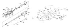
- FIG. 1is a perspective view of a puncture sealing device having a deployment assembly and a closure device disposed within the deployment assembly, according to an embodiment of the present disclosure
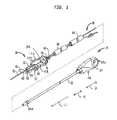
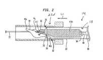
- FIG. 2is a detailed partial sectional view of a portion of the puncture sealing device shown in FIG. 1 ;
- FIG. 3is a perspective view of a portion of the sealing device shown in FIG. 1 , showing a plug member of the closure device in an insertion configuration;
- FIG. 4is a perspective view of a portion of the sealing device shown in FIG. 1 , showing the plug member in an collapsed configuration and covering a puncture of a vessel;
- FIG. 5is a perspective view of the plug member shown in FIG. 1 ;
- FIG. 6Ais a perspective view of a portion of the sealing device shown in FIG. 1 , showing the plug member according to another embodiment of the present disclosure
- FIG. 6Bis a perspective view of a portion of the sealing device shown in FIG. 1 , showing a plug member according to another embodiment of the present disclosure
- FIG. 7Ais an end view of a plug member according to another embodiment of the present disclosure.
- FIG. 7Bis an end view of a plug member according to another embodiment of the present disclosure.
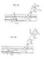
- FIG. 8Ais a schematic end view of a portion of the sealing device shown in FIG. 1 , showing an anchor member inside the vessel and the plug member in an insertion configuration;
- FIG. 8Bis a cross-sectional view of the sealing device and the vessel taken along lines 8 B- 8 B in FIG. 8A ;
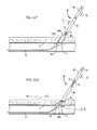
- FIG. 9Ais a schematic an end view of a portion of the sealing device in FIG. 1 , showing the plug member in an intermediate configuration partially collapsed on the vessel;
- FIG. 9Bis a cross-sectional view of the sealing device and the vessel taken along lines 9 B- 9 B in FIG. 9A ;
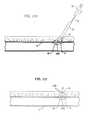
- FIG. 10Ais a schematic end view of a portion of the sealing device shown in FIG. 1 , showing the toggle inside the vessel and the plug member locked in a collapsed configuration over a puncture;
- FIG. 10Bis a cross-sectional view of the sealing device and the vessel taken along lines 10 B- 10 B in FIG. 10A ;
- FIG. 11Ais a schematic showing an access sheath partially disposed within the vessel through the puncture in the vessel;
- FIG. 11Bis a schematic showing the closure device of FIG. 1 translated into an access channel of the access sheath such that a distal end of the toggle is positioned distal to a distal end of the access sheath;
- FIG. 11Cis a schematic showing the access sheath and closure device combination pulled proximally such that the toggle is proximate to the puncture;
- FIG. 11Dis a schematic showing the release tube being moved proximally relative to the delivery tube to thereby release the toggle;
- FIG. 11Eis a schematic showing the release tube being moved distally relative to the delivery tube such that the release tube abuts the toggle to thereby orient the toggle in a sealing position;
- FIG. 11Fis a schematic showing the deployment assembly being pulled proximally such that the toggle abuts the vessel wall and a plug that is coupled to the toggle with a suture is deployed from the delivery tube;
- FIG. 11Gis a schematic showing the plug being pressed against the vessel wall with a locking member while the guide wire remains in place;
- FIG. 11His a schematic showing the locking member being tamped against the plug with a tamper of the closure device after the guide wire has been removed.
- FIG. 11Iis a schematic showing the plug member in collapsed configuration covering the puncture.
- a puncture sealing device 10in accordance with an embodiment of the present disclosure can include a deployment assembly 14 and a closure device 18 at least partially disposed within the deployment assembly 14 .
- the closure device 18is deployed from the deployment assembly 14 and locked against the puncture 4 to thereby seal or otherwise close the puncture of the vessel 1 .
- the closure device 18can include a plug member 100 with first and second ridges 116 and 118 arranged on the plug member 100 so that the plug member 100 can partially surround a portion of the vessel 1 and properly cover the puncture when the closure device 18 is locked in place.
- the first and second ridges 116 and 118abut the vessel 1 at locations adjacent or spaced from opposed transverse ends of the puncture 4 . Accordingly, when the closure device 18 is locked in place against the puncture, locking forces are distributed across the plug member 100 at least in a direction transverse to the length of the vessel 1 such that ridges 116 and 118 abut and are compressed against the surface of vessel 1 , thereby sealing the puncture 4 and improving hemostasis.
- the deployment assembly 14is elongate along a longitudinal direction L and includes a proximal end 25 p and a distal end 25 d spaced from the proximal end 25 p in the longitudinal direction L.
- the longitudinal direction Lcan include and define a proximal direction 7 that extends from distal end 25 d of the closure device 18 toward the proximal end 25 p the closure device 18 .
- the longitudinal direction Lcan include and define a distal direction 9 that is opposite to the proximal direction 7 and extends from the proximal end 25 p toward the distal end 25 d .
- the deployment assembly 14is configured to insert at least a portion of the closure device 18 into the vessel along an insertion direction I (see FIG. 4 ).
- the longitudinal direction Lcan be aligned with the insertion direction I during a portion of the sealing procedure.
- the deployment assembly 14includes a housing 24 and a release tube 22 that extends relative to the housing 24 in a longitudinal direction L.
- the release tube 22is elongate along the longitudinal direction L and defines a release tube channel 26 that extends through the release tube 22 along the longitudinal direction L.
- the release tube 22is configured to restrain an anchor member 40 , for instance a toggle 40 , of the closure device 18 during insertion of the sealing device 10 into the vessel and subsequently release the toggle 40 so that the toggle 40 can be oriented for the sealing procedure.
- the deployment assembly 14further includes a delivery tube 30 that is disposed within the release tube channel 26 .
- the deployment assembly 14is configured such that at least one of the release tube 22 and the delivery tube 30 is movable relative to the other along the longitudinal direction L. Therefore, the release tube 22 and the delivery tube 30 can be configured such that at least one of the release tube 22 and the delivery tube 30 is movable relative to the other to thereby release the toggle 40 and subsequently orient the toggle 40 for the sealing procedure.
- the deployment assembly 14further includes actuator 27 supported by the housing 24 .
- the actuator 27is configured to be coupled to at least one of the release tube 22 and the delivery tube 30 ( FIG. 2 ) (coupling between actuator 27 not shown).
- the actuator 27can be pulled in the proximal direction 7 so as to cause at least one of the release tube 22 and the delivery tube 30 to move relative to the other to thereby release the toggle 40 and subsequently orient the toggle 40 for the sealing procedure.
- any type of actuatorcan be used to cause the movement of the release tube 22 and/or the delivery tube 30 relative to each other.
- one or more actuatorscan be used to cause the release of the toggle 40 from the delivery tube 30 and tension of the suture 52 .
- the deployment assembly 14can include an actuator coupled to the release tube 22 and the housing 24 .
- the release tube 22can be operatively associated with a tensioning device 92 ( FIG. 1 ) such that continuous movement of the actuator relative to the housing 24 will move the release tube 22 to thereby release the toggle 40 from the release tube 22 and subsequently apply tension to the suture 52 .
- the suture 52can be tensioned as the toggle 40 is being released.
- the deployment assembly 14can include a first actuator to release the toggle 40 and a second actuator that applies tension to the suture 52 .
- the one or more actuatorscan be configured similarly to the actuator as described in U.S. Provisional Application Ser. No. 61/920,207, filed Dec. 23, 2013 and pending at the filing of the present application.
- the contents of U.S. Provisional Application Ser. No. 61/920,207are incorporated by the reference in this disclosure as if set forth in its entirety herein.
- the delivery tube 30includes an angled portion 31 at its distal end.
- the angled portion 31angles toward a central axis of the delivery tube 30 such that a retention cavity 32 is defined between the angled portion 31 and the release tube 22 .
- the retention cavity 32is sized to receive and retain a portion of the toggle 40 to thereby trap the toggle 40 between the delivery tube 30 and the release tube 22 such that the toggle 40 is angled by a first angle ⁇ 1 relative to a central axis 21 of the release tube 22 . While the toggle 40 is trapped, the closure device 18 and deployment assembly 14 can be inserted into the vessel.
- the closure device 18is at least partially disposed within the delivery tube 30 prior to being inserted into the vessel. As shown in FIGS. 1 and 2 , the closure device 18 further includes the plug member 100 , a locking member 48 , and a suture 52 that couples the toggle 40 , plug member 100 , and locking member 48 together such that the toggle 40 is distal to the plug member 100 and the locking member 48 is proximal to the plug member 100 . As shown in FIG. 1 , the suture 52 extends through the locking member 48 , plug member 100 , and toggle 40 in the longitudinal direction L, for instance the distal direction 9 , and then back through the toggle 40 and plug member 100 in the proximal direction 7 .
- the suture 52is then formed into a slidable knot 56 that is slidable along the suture 52 between the plug member 100 and the locking member 48 .
- the suture 52can be any elongate member, such as, for example a filament, thread, or braid.
- the locking member 48 and toggle 40squeeze the plug member 100 against the puncture 4 to sealing the puncture.
- a force Fcan be applied to the plug member 100 in the longitudinal direction L, which compresses the plug member 100 against the vessel, as will be further detailed below.
- the toggle 40can be an elongate member that is configured to be seated inside the vessel against the vessel wall contiguous with the puncture.
- the toggle 40defines a distal end 40 a that is distal to a distal end of the release tube 22 and a proximal end 40 b that is trapped within the retention cavity 32 between the release tube 22 and the delivery tube 30 during insertion of the toggle 40 into the vessel.
- the togglefurther defines a first suture receiving aperture 60 that receives the suture 52 as it passes through the toggle 40 along the longitudinal direction L, for instance in the distal direction 9 , a second suture receiving aperture 64 that receives the suture 52 as it passes through the toggle 40 in the proximal direction 7 , and a guide wire aperture 68 that is configured to receive a guide wire 72 such that the closure device 18 is translatable along the guide wire 72 and is guided toward the puncture by the guide wire 72 .
- the toggle 40can be made of any biocompatible material.
- the toggle 40can made of a polylactic-coglycolic acid or other synthetic absorbable polymer that degrades in the presence of water into naturally occurring metabolites.
- the togglecan be made of stainless steel, biocorrodible iron, and biocorrodible magnesium. It should be appreciated, however, that the toggle 40 can be made of other materials and can have other configurations so long as it can be seated inside the vessel against the vessel wall.
- the plug member 100is coupled to suture 52 between the toggle 40 and the locking member 48 .
- the plug member 100is moveable along the suture toward the toggle 40 along the longitudinal direction L for instance in the insertion direction I.
- the plug member 100is configured to transition along the suture 52 from the insertion configuration shown in FIG. 3 , whereby the plug member 100 is elongate along the longitudinal direction L, into the collapsed configuration shown in FIG. 4 , whereby the plug member 100 is collapsed against the puncture 4 and conforms to the curvature of the vessel 1 .
- the plug member 100When the plug member 100 is in the collapsed configuration against the vessel wall 2 , a portion of the ridges 116 and 118 can be aligned with a longitudinal vessel direction VL such that the first and second ridges 116 and 118 contact the vessel wall 2 at spaced apart locations proximate to from opposed transverse ends 5 a and 5 b of the puncture 4 .
- the plug member 100is configured to fold about one or more fold axes 158 a and 158 b as the plug member 100 collapses into the collapsed configuration along the insertion direction I.
- the plug member 100can be configured to collapse via mechanisms other than folding.
- the plug member 100includes a plug body 110 and the first and second ridges 116 and 118 project from the plug body 110 .
- the plug member 100is elongate along the longitudinal direction L when the plug member 100 is in the insertion configuration, and the first and second ridges 116 and 118 are spaced apart with respect to each other along a lateral direction A that is angularly offset with respect to the longitudinal direction L.
- the ridges 116 and 118can project from the body 110 along a transverse direction T that is angularly offset with respect to the lateral and longitudinal directions A and L.
- the longitudinal direction Lcan be referred to as a first direction and the lateral direction A can be referred to a second direction, and the transverse direction T may be referred to herein as a third direction.
- the longitudinal, lateral and transverse directions L, A and Tcan include first and second directional components that are opposite with respect to each other.
- the longitudinal direction Lcan define a first longitudinal direction and a second longitudinal direction that is opposite to the first longitudinal direction.
- the lateral direction Acan define a first lateral direction and a second lateral direction that is opposite to the first lateral direction.
- the transverse direction Tcan define a first transverse direction and a second transverse direction that is opposite to the first transverse direction.
- the plug member 100can define a first or distal end 120 and a second or proximal end 124 spaced from the first end 120 along the longitudinal direction L.
- the plug member 100can define a longitudinal or first axis 104 that extends through the first and second ends 120 and 124 and is aligned with the longitudinal direction L.
- the plug member 100is elongate along a first axis 104 that is aligned with the longitudinal direction L.
- the plug member 100is collapsed along the insertion direction I such that the first axis 104 has a collapsed shape (collapsed axis 104 not shown).
- the plug member 100defines a first edge 140 and a second edge 144 spaced apart from the first edge 140 along the lateral direction A.
- the plug membercan define a lateral or second axis 106 aligned with the lateral direction A.
- the second axis 106extends through the first and second edges 140 and 144 and intersects the first axis 104 .
- the plug body 110can further include a first surface 132 and a second surface 136 spaced from the first surface 132 along the transverse direction T.
- the plug member 100can also define a transverse or third axis 108 that is aligned with transverse direction T.
- the third axis 108extends through the first and second surfaces 132 and 136 and intersects the first and second axes 104 and 106 .
- the first surface 132is disposed between the first and second ridges 116 and 118 .
- the first and second ridges 116 and 118project from the plug body 110 .
- the first and second of ridges 116 and 118can project from the plug body 110 along the transverse direction T in a direction T 1 away from at least one of the first surface 132 .
- the first and second ridges 116 and 118project away from the first surface 132 of the plug body 110 such that the first and second ridges 116 and 118 extend from the plug body 110 in the same general direction.
- the first and second ridges 116 and 118can project from the plug body 110 along the transverse direction T away from at least one of the first surface 132 and the second surface 136 .
- the plug members 400 and 500 shown FIGS. 7A and 7B and discussed belowinclude ridges that project from the plug body 110 along the transverse direction T in respective first and second directions that are not aligned in the same general direction.
- the ridges 116 and 118are spaced apart along the lateral direction A such that the ridges 116 and 118 and the plug body 110 disposed between the ridges 116 and 118 at least partially define a region 160 .
- the ridges 116 and 118include respective proximal portions (not numbered) and distal portions 121 a and 121 b spaced from the proximal portion toward the distal end 120 in the longitudinal direction L.
- the distal portions 121 a and 121 b of the ridges 116 118abut the surface of the vessel along opposed transverse ends 5 a and 5 b of the puncture 4 (see FIG.
- the distal portions 121 a and 121 b of the ridges 116 and 118can be aligned with the longitudinal vessel direction VL (not shown) when collapsed against the vessel.
- the plug member 100can be sized and configured such that the plug member 100 can partially surround and generally conform to the curvature of the vessel when in the collapsed configuration.
- the plug body 110defines a plug length 111 that extends from the first end 120 to the second end 124 along the first axis 104 .
- the plug body 110defines a first thickness dimension 112 that extends from the first surface 132 to the second surface 136 along the second axis 108 .
- the first and second ridges 116 and 118each define respective second thickness dimensions 113 a and 113 b that extend from the first surface 132 of the plug body 110 to respective terminal ends 126 and 128 of the first and second ridges 116 and 118 along the third or transverse axis 108 .
- each second thickness dimension 113 a and 113 bis each at least twice the first dimension 112 .
- the plug body 110defines a plug width 114 that extends from the first edge 140 to the second edge 144 along the second axis 106 .
- the first ridge 116includes opposite sides 117 a and 117 b and the second ridge 118 includes opposed sides 119 a and 119 b .
- the first ridge 116defines a first ridge width 115 a that extends along the second axis 106 from the side 117 a to the side 117 b .
- the second ridge 118defines a second ridge width 115 b that extends along the second axis 106 from the side 119 a to the side 119 b .
- the combined first and second widths 115 a and 115 bare no greater than 25% of the plug width 114 .
- the first and second ridges 116 and 118can disposed along at least a portion of a respective one of the first and second edges 140 and 144 .
- the first and second ridges 116 and 118are aligned or coextensive with the respective edges 140 and 144 .
- the ridge 116 and 118can be spaced inwardly with respect to each other and away from the respective edges 140 and 144 as needed.
- the first and second ridges 116 and 118can extend along at least a portion of plug body 110 in the longitudinal direction L along the respective edges 140 and 144 .
- each ridge 116 and 118extend along respective edges 140 and 140 from the first end 120 to the second along an entirety of the length 111 of the plug member 100 .
- ridges 116 and 118extend along a portion of the length 111 of the plug member 100 , for example, as illustrated in FIGS. 6A and 6B and discussed next.
- a plug member 200can be attached to the suture 52 proximal to the toggle 40 and distal to locking member as discussed above with respect to embodiments shown FIG. 3 .
- the plug member 200can be constructed similarly the plug member 100 and similar reference numbers will be used to refer to common elements between plug member 100 and plug member 200 .
- the plug member 200can be elongate along the first axis 104 that is aligned with the longitudinal direction L and include a first or distal end 120 and a second or proximal end 124 spaced from the first end 120 along the longitudinal direction L.
- the first axis 104can extend through the first and second ends 120 and 124 .
- the plug member 200can include first and second edges 140 and 144 , opposed surfaces 132 and 136 similar to the plug member 100 described above.
- the plug member 200includes a plug body 210 and a plurality of first ridges 216 a , 216 b , and 216 c and a plurality of second ridges 218 a , 218 b , and 218 c .
- Each of the first ridges 216 a - 216 c and second ridges 218 a - 218 cextend along a portion of the length 111 (length 111 not shown in FIG. 6A ).
- the first ridges 216 a , 216 b , and 216 care separated by a first set of grooves 226 a and 226 b .
- the first set of groovesincludes a distal groove 226 a and a proximal groove 226 b .
- the second ridges 218 a , 218 b , and 218 care separated by a second set of grooves 228 a and 228 b .
- the second set of groovesincludes a distal grove 228 a and a proximal groove 228 b .
- the first set grooves 226 a and 226 bcan be aligned with corresponding second set grooves 228 a and 228 b along the lateral direction A.
- the distal grooves 226 a and 228 acan extend along and be aligned with each other along a first fold axis 258 a and the proximal grooves 218 b and 228 b can extend along and be aligned with each other along a second fold axis 258 b . Presence of the grooves along the respective fold axes 258 a and 258 b can facilitate collapse of the plug member about the fold axes 258 a and 258 b .
- the ridges 216 a and 218 acan abut the surface of the vessel along opposed transverse ends of the puncture while a region 260 disposed between the ridges 216 a and 218 a spans the puncture 4 .
- the first ridges 216 a - 216 c and the second ridges 218 a - 218 cproject from the plug body 210 along the transverse direction T in a first transverse direction T 1 as illustrated, the first or second ridges can project from the plug body 210 along a second transverse direction T 2 that is different than, for instance opposite to, the first transverse direction T 1 .
- the first and second transverse direction T 1 and T 1can be angularly offset with respect to the longitudinal direction L. While three first ridges 216 a , 216 b , and 216 c and three second ridges 218 a , 218 b , and 218 c are illustrated, the plug member 200 can include more, for instance greater than two, of the first ridges and the second ridges. Alternatively, the plug member 200 can include two of the first ridges and two of the second ridges.
- the plug body 210 , the first ridges 216 a , 216 b , and 216 c , and the second ridges 218 a , 218 b , and 218 ccan be constructed to have similar dimension as described above with respect to plug member 100 and first and second ridges 116 and 118 .
- a plug member 300can be attached to the suture 52 proximal to the toggle 40 and distal to the locking member 48 as discussed above with respect to embodiment shown FIG. 3 .
- the plug member 300can be constructed similarly the plug member 100 and similar reference numbers will be used in FIG. 6A to refer to common elements between plug member 100 and plug member 300 .
- the plug member 200includes a plug body 310 , a first ridge 316 and a second ridge 318 extend along a portion of the length 111 (length 111 not shown in FIG. 6A ). The first and second ridges 316 and 318 are disposed toward the distal end 120 of the plug member 300 .
- the first and second ridgesare disposed distal to the fold axis 158 a .
- the ridges 316 and 318can extend across the fold axis 158 a as needed.
- the first and second ridges 316 and 318define a ridge length (not labeled) that extends along the longitudinal L that is less than half the length 111 of the plug member 300 .
- the ridges 316 and 318are spaced apart along the lateral direction A, such that the ridges 316 and 318 and the plug body 310 disposed between the ridges 316 and 318 at least partially define a region 360 .
- the ridges 316 and 318project from the plug body 310 such that when the plug member 300 is collapsed, the first and second ridges 316 and 318 abut the surface of the vessel along opposed transverse ends of the puncture while the region 360 disposed between the ridges 316 and 318 spans the puncture 4 . Further, the ridges 316 and 318 can be aligned with the longitudinal vessel direction VL (not shown) when collapsed against the vessel.
- plug members 400 and 500are illustrated that are configured collapsed against the vessel and cover the puncture as described above with respect to plug member 100 , 200 and 300 .
- Plug members 400 and 500can be attached to the suture 52 proximal to the toggle 40 and distal to the locking member 48 as discussed above with respect to plug member 100 shown FIG. 3 .
- each plug member 400 and 500can be constructed similarly the plug member 100 and similar reference numbers will be used in FIGS. 7A and 7B to refer to common elements between plug member 100 and plug member 400 and 500 .
- the plug member 400includes plug body 410 , first ridge 416 and second ridge 418 that project from the plug body 410 along transverse direction T that is aligned with the transverse axis 108 .
- the first ridge 416can project from the plug body in a first transverse direction T 1 and the second ridge can project from the plug body 410 in the second transverse direction T 2 that is different from the first transverse direction T 2 .
- the first and second ridges 316 and 318can be spaced apart with respect to each along the lateral direction A or an axis 406 that is angularly offset with respect to the first axis 104 (not shown) and transverse axis 108 . As shown in FIG.
- the plug member 500can include a plug body 510 , a first pair of ridges 550 that project from the plug body 510 in a first transverse direction T 1 , and a second pair of ridges 560 that project from the plug body 510 along the second direction T 2 .
- the first pair of ridges 550includes a first and second ridge 516 and 518 .
- the second pair of ridges 560includes first and second ridges 526 and 528 . It should be appreciated that each respect ridges 516 , 518 , 526 , and 528 can project along a respective direction away from the plug body 510 .
- first and second ridges 516 and 518 of the first pair of ridges 550can be extend along parallel directions as illustrated, or the first and second ridges can be angularly offset with respect to each other.
- first and second ridges 526 and 528 of the second pair of ridges 560can be extend along parallel directions as illustrated, or the first and second ridges 526 and 528 can be angularly offset with respect to each other.
- the plug member 100can have a plurality of suture receiving apertures 76 that receive the suture 52 along the proximal and distal directions 7 and 9 to thereby couple the plug member 100 to the suture 52 .
- Each of the suture receiving apertures 76are disposed between the opposed first and second edges 140 and 144 of the plug member body 110 .
- At least one of the aperturescan be aligned along the first axis 104 .
- an aperture 77can be aligned along the first axis 104 .
- the plug member 100can further include a series of guide wire apertures 80 that receive the guide wire 72 during insertion of the closure device 18 into the vessel.
- Further plug member 100can include a select location 148 aligned with one of the apertures 76 .
- the select location 148is aligned the aperture 77 such that the select location 148 is aligned with the first axis 104 .
- the location of the apertures 77direct a force to the select location 148 of the plug body 110 as the plug member 100 is being collapsed against the puncture 4 , as will be further detailed below.
- the plug member 100can comprise a strip of compressible, resorbable, collagen foam and can be made of a fibrous collagen mix of insoluble and soluble collagen that is cross linked for strength. It should be appreciated, however, that the plug member 100 can have any configuration as desired and can be made from any material as desired.
- the locking member 48is configured to frictionally engage the suture 52 as the locking member 48 is moved along the suture 52 toward the toggle 40 to thereby seal the puncture. That is, the locking member 48 is configured to remain in place on the suture 52 when no force is placed on the locking member 48 , and only overcomes its frictional engagement with the suture 52 in response to an application of force on the locking member 48 . Application of the force to the locking member 48 urges the locking member 48 in contact with the select location 148 of the plug body 110 . When the locking member 48 engages the select location 148 , forces are distributed along the plug member 100 along a direction transverse to the direction that the force is applied to the select location 148 .
- the locking member 48can be configured as a cylindrical member that is crimped onto the suture 52 . It should be appreciated, however, that the locking member 48 can have other configurations as desired.
- the locking member 48can be the slideable knot 56 . In such an embodiment, the slidable knot 56 can be a locking knot.
- the closure device 18further includes a tamper 90 proximal to the locking member 48 and a tensioning device 92 proximal to the tamper 90 .
- the guide wire 72 and the suture 52extend through both the tamper 90 and the tensioning device 92 .
- the tamper 90is configured to be translated along the suture 52 to thereby move the locking member 48 against the plug member 100 toward the select location 148 . In this way, the tamper 90 can transition the plug member 100 from the insertion configuration in the collapsed configuration, and or further compress the plug member 100 when the plug member is in a collapsed configuration but not fully seated against the vessel wall. In this way, the tamper 90 can help fully seal the puncture.
- the tensioning device 92is configured to maintain the suture 52 in tension during the sealing procedure.
- FIGS. 8A through 10Billustrate transition of the plug member 100 from the initial configuration as shown FIGS. 8A and 8B , whereby the plug member is elongate along the suture 52 , into an intermediate configuration shown in FIGS. 9A and 9B , when the plug member 100 is collapsed along the insertion direction I yet the plug member 100 is not fully seated or compressed against the vessel, and further into the collapsed configuration shown FIGS. 10A and 10B , whereby the locking member 48 is compressed against the collapsed plug member 100 , locking the plug member 100 against the puncture 4 .
- FIGS. 8A through 10Billustrate transition of the plug member 100 from the initial configuration as shown FIGS. 8A and 8B , whereby the plug member is elongate along the suture 52 , into an intermediate configuration shown in FIGS. 9A and 9B , when the plug member 100 is collapsed along the insertion direction I yet the plug member 100 is not fully seated or compressed against the vessel, and further into the collapsed configuration shown FIGS. 10A and 10B
- the toggle 40when the toggle 40 is inserted in the vessel 1 and positioned against an inner surface of the vessel wall 2 adjacent to the puncture 4 , the distal end 120 of the plug member 100 is disposed above the vessel wall 2 opposite the toggle 40 .
- the first and second ridges 116 and 118project from plug body 110 along the transverse direction T.
- the ridges 116 and 118are spaced apart with respect to each other along the lateral direction A so as to be positioned adjacent to or disposed outwardly from the opposed transverse ends 5 a and 5 b of the puncture 4 .
- At least one of a tension applied to the suture 52 and a force applied to the select location 148 of the plug body 110causes the plug member 100 to collapse along the insertion direction I such that the distal portions 121 a and 121 b ridges 116 and 118 are in contact with the vessel wall 2 and the region 160 of the plug body 110 between the distal portions 121 a and 121 b of the ridges 116 and 118 span the puncture 4 along the transverse direction VT of the vessel.
- the distal portions 121 a and 121 b of the ridges 116 and 118are also aligned along the longitudinal direction of the vessel VL such that puncture 4 extends along vessel transverse direction VT between the location where the first and second ridges 116 and 118 contact the vessel wall 2 .
- FIGS. 10A and 10Bapplication of a force F to the locking member 48 causes the locking member 48 to move into engagement the with the select location 148 of the plug member 100 , which compresses the plug member 100 against the vessel wall 2 .
- the ridges 116 and 118project from the plug body 110 toward the and away from the puncture 4 , and plug body region 160 spans the puncture 4 , compression of the plug member 100 at the select location 148 causes the plug member 100 to conform to the curvature of the vessel 1 .
- a portion of the ridges 116 and 118 and a portion of the plug member body 110define a vessel-engaging portion 152 the shape of the vessel wall 2 .
- the vessel-engaging portion 152can include a curved surface that conforms to the curvature of the vessel.
- Embodiments of the present technologywill now be described with respect to exemplary large bore procedures that utilize the puncture sealing device 10 .
- the usergains percutaneous access to, for example, the femoral artery, causing a puncture in the artery.
- the Seldinger techniquemay be used. For example, a hollow bore needle is inserted into the artery.
- the guide wire 72is then advanced through the hollow needle and into the femoral artery a sufficient distance to allow removal of the needle without the guide wire 72 pulling out of the vessel. Removing the needle leaves the guide wire 72 in place, with a portion of the guide wire 72 extending into the artery.
- the guide wire 72extending from outside the patient into the femoral artery, provides for an entry guide for other medical devices including the puncture sealing device 10 . Therefore, once the guide wire 72 is positioned in the vessel of the patient, catheters, or introducers, or gradually increasing diameters are advanced over the guidewire and through the puncture into the artery to further open the puncture. Then, an introducer/procedure access sheath set (i.e. an introducer inside an access tube or sheath) is moved along the guide wire 72 such that a distal end of the sheath moves into the vessel through the puncture. And once positioned, the introducer can be removed such that the sheath provides for sizable access to the vessel interior from outside the body.
- an introducer/procedure access sheath seti.e. an introducer inside an access tube or sheath
- FIGS. 11A-11Ishow schematic views of the puncture-sealing device 10 during the process of closing a puncture 4 in a vessel wall 2 .
- the introducer/procedure sheath setis replaced with a closure access sheath 94 .
- the procedure sheathis exchanged for the closure access sheath 94 by removing the procedure sheath from the patient, leaving the guide wire 72 in place, and subsequently moving the closure access sheath 94 along the guide wire 72 or otherwise positioning the access sheath 94 , such that a portion of the access sheath 94 is disposed within the vessel through the puncture 4 .
- FIG. 11Athe procedure sheath is exchanged for the closure access sheath 94 by removing the procedure sheath from the patient, leaving the guide wire 72 in place, and subsequently moving the closure access sheath 94 along the guide wire 72 or otherwise positioning the access sheath 94 , such that a portion of the access sheath 94 is disposed within the vessel through the puncture 4 .
- the access sheath 94defines a distal end 95 d , a proximal end 95 p , and an access channel 96 that extends from the proximal end 95 p to the distal end 95 d along an insertion direction I.
- the insertion direction Ican be aligned with the longitudinal direction L.
- the access sheath 94further includes a sheath hub 98 at its proximal end 95 p .
- the sheath hub 98is configured to couple to the puncture sealing device 10 when the puncture sealing device 10 is inserted into the access channel 96 along the insertion direction I.
- the puncture sealing device 10can be positioned by translating the puncture sealing device 10 into the access channel 96 (not shown) along the insertion direction I such that at least the distal end 40 a of the toggle 40 protrudes from the distal end D of the access sheath 94 and into the vessel. Once fully inserted, the puncture-sealing device 10 can couple to the sheath hub 98 . As shown in FIG. 11B , the proximal end 40 b of the toggle 40 is trapped within the retention cavity 32 between the release tube 22 and the delivery tube 30 while the puncture sealing device 10 is being moved into the vessel through the puncture 4 of the vessel.
- the toggle 40While the proximal end 40 b of the toggle 40 is trapped, the toggle 40 is oriented in a pre-sealing position whereby at least the proximal end 40 b of the toggle 40 is prevented from dragging against the vessel wall during positioning of the toggle 40 within the vessel.
- the toggle 40and in particular, the entire access sheath 94 and puncture-sealing device 10 combination can be moved in the proximal direction 7 such that the toggle 40 is adjacent the puncture 4 .
- the toggle 40is in the pre-sealing position as shown in FIG. 11C .
- at least one of the delivery tube 30 and the release tube 22can be moved relative to the other such that the proximal end 40 b of the toggle 40 is released from the release tube 22 or is otherwise removed from the retention cavity 32 defined between the release tube 22 and the delivery tube 30 .
- the actuator 27can be moved along the proximal direction 7 such that the release tube 22 is moved proximally relative to the delivery tube 30 to thereby release the proximal end 40 b of the toggle 40 from the retention cavity 32 .
- At least one of the delivery tube 30 and the release tube 22can be moved relative to the other such that a distal end of the release tube 22 abuts the toggle 40 to thereby orient the toggle 40 in a sealing position whereby the toggle is angled by a second angle ⁇ 2 relative to the central axis of the release tube 22 that is different than the first angle ⁇ 1 .
- the second angle ⁇ 2is smaller than the first angle ⁇ 1 .
- the release tube 22is moved distally relative to the delivery tube 30 so that the release tube 22 can abut the toggle 40 and orient it in the sealing position.
- the toggle 40is angled relative to the delivery tube 30 when in the sealing position. The angled orientation of the toggle 40 is such that the toggle 40 remains within the vessel when the toggle 40 is pulled against the vessel wall 2 .
- a tensioncan be applied to the suture 52 .
- the suture 52can be pulled proximally relative to the delivery tube 30 to thereby ensure that the toggle 40 remains in the sealing position whereby the toggle 40 abuts the release tube 22 .
- the tensioncan be applied to the suture prior to the release tube 22 being moved to abut the toggle 40 , after the release tube 22 has been moved to abut the toggle 40 , or at the same time the release tube 22 is being moved.
- the deployment assembly 14along with the access sheath 94 can together be pulled proximally such that the plug member 100 and other components of the closure device 18 emerge from the delivery tube 30 .
- the closure device 18including the toggle 40 , plug member 100 , locking member 48 , suture 52 , tamper 90 , and tensioning device 92 , are fully withdrawn from the delivery tube 30 .
- the tensioning device 92By pulling on the tensioning device 92 in the proximal direction 7 away from the vessel (i.e. in a direction opposite the insertion direction I) the suture 52 is tensioned and the toggle 40 is moved fully into position against an inner surface of the vessel wall 2 at the puncture 4 .
- the tension in the suture 52also pulls the plug member 100 into the puncture 4 , and causes the plug member 100 to fill the tissue opening proximate the vessel puncture 4 as shown in FIG. 11F . After the plug member 100 is in contact with blood or other fluids within the puncture 4 , the plug member 100 will expand and fill the remainder of the tissue bore.
- the useradvances the tamper 90 along the guide wire 72 and the suture 52 .
- the tamper 90contacts the locking member 48 and advances the locking member 48 along the suture 52 until the locking member 48 contacts the selection location 148 of the plug member 100 and presses the plug member 100 against an outer surface of the vessel, thereby collapsing the plug member 100 into the collapsed configuration.
- a portion of the ridges 116 and 118are aligned along the longitudinal vessel direction VL.
- the plug member 100As the plug member 100 is compressed by the tamper 90 the plug member 100 folds over the top of and inside the puncture 4 . It should be appreciated, however, that in some embodiments, the delivery tube 30 is pulled such that the plug member 100 is removed from the delivery tube 30 within the release tube 22 and the tamper 90 is employed within the release tube 22 . In such an embodiment, the release tube 22 helps control the plug member 100 as it is being tamped against the puncture.
- the locking member 48together with the plug member 100 and the toggle 40 effect a seal of the puncture 4 .
- tensionis maintained on the tensioning device 92 throughout the deployment of the plug member 100 from the delivery tube 30 .
- the guide wire 72can be removed as shown in FIG. 11H .
- the suture 52remains in tension and the user can re-compress the plug member 100 with the tamper 90 as desired to confirm a proper seal of the puncture 4 .
- the suture 52can be cut below the tamper 90 so that the remaining suture 52 , tamper 90 , and tensioning device 92 can be removed from the puncture 4 , as shown in FIG. 11I .
- Remaining portions of the closure device 18including the toggle 40 , plug member 100 , portion of suture 52 , and locking member 48 (depending on material used) will resorb into the body of the patient over time.
Landscapes
- Health & Medical Sciences (AREA)
- Surgery (AREA)
- Life Sciences & Earth Sciences (AREA)
- Biomedical Technology (AREA)
- Nuclear Medicine, Radiotherapy & Molecular Imaging (AREA)
- Engineering & Computer Science (AREA)
- Cardiology (AREA)
- Heart & Thoracic Surgery (AREA)
- Medical Informatics (AREA)
- Molecular Biology (AREA)
- Animal Behavior & Ethology (AREA)
- General Health & Medical Sciences (AREA)
- Public Health (AREA)
- Veterinary Medicine (AREA)
- Surgical Instruments (AREA)
Abstract
Description
Claims (9)
Priority Applications (1)
| Application Number | Priority Date | Filing Date | Title |
|---|---|---|---|
| US14/274,466US10154835B2 (en) | 2013-05-09 | 2014-05-09 | Vascular closure device with conforming plug member |
Applications Claiming Priority (2)
| Application Number | Priority Date | Filing Date | Title |
|---|---|---|---|
| US201361821478P | 2013-05-09 | 2013-05-09 | |
| US14/274,466US10154835B2 (en) | 2013-05-09 | 2014-05-09 | Vascular closure device with conforming plug member |
Publications (2)
| Publication Number | Publication Date |
|---|---|
| US20140336672A1 US20140336672A1 (en) | 2014-11-13 |
| US10154835B2true US10154835B2 (en) | 2018-12-18 |
Family
ID=51865335
Family Applications (1)
| Application Number | Title | Priority Date | Filing Date |
|---|---|---|---|
| US14/274,466Active2036-06-25US10154835B2 (en) | 2013-05-09 | 2014-05-09 | Vascular closure device with conforming plug member |
Country Status (1)
| Country | Link |
|---|---|
| US (1) | US10154835B2 (en) |
Cited By (7)
| Publication number | Priority date | Publication date | Assignee | Title |
|---|---|---|---|---|
| US11364024B2 (en) | 2013-12-23 | 2022-06-21 | Teleflex Life Sciences Limited | Vascular closure device |
| US11419592B2 (en) | 2013-03-15 | 2022-08-23 | Teleflex Life Sciences Limited | Vascular closure devices and methods of use |
| US11576663B2 (en) | 2015-06-26 | 2023-02-14 | Teleflex Life Sciences Limited | Vascular closure device with removable guide member |
| US11589855B2 (en) | 2011-10-25 | 2023-02-28 | Teleflex Life Sciences Limited | Instrument and methods for surgically closing percutaneous punctures |
| US12089828B2 (en) | 2021-02-26 | 2024-09-17 | Teleflex Life Sciences Llc | Aortic closure system and related methods |
| US12285160B2 (en) | 2012-07-19 | 2025-04-29 | Teleflex Life Sciences Llc | Multi-lumen tamper tube |
| US12390249B2 (en) | 2020-07-31 | 2025-08-19 | Teleflex Life Sciences Llc | Access sheath with valve assembly |
Families Citing this family (7)
| Publication number | Priority date | Publication date | Assignee | Title |
|---|---|---|---|---|
| EP4147649A1 (en)* | 2015-02-10 | 2023-03-15 | Teleflex Life Sciences Limited | Closure device for sealing percutaneous opening in a vessel |
| EP4349276A3 (en) | 2016-05-05 | 2024-06-19 | Teleflex Life Sciences LLC | Releasable elongated assembly |
| WO2018031539A1 (en)* | 2016-08-12 | 2018-02-15 | Essential Medical, Inc. | Vascular closure device with locking assembly for a tamper |
| US10542996B2 (en) | 2017-06-27 | 2020-01-28 | Covidien Lp | Vessel closure device |
| US11534154B2 (en)* | 2017-08-31 | 2022-12-27 | Medos International Sarl | Devices and methods for tissue repair |
| WO2022002086A1 (en)* | 2020-07-01 | 2022-01-06 | 杭州德诺电生理医疗科技有限公司 | Occluder and occlusion system |
| CN119423862A (en)* | 2023-07-31 | 2025-02-14 | 杭州矩正医疗科技有限公司 | Closure devices used to seal openings in blood vessel walls |
Citations (228)
| Publication number | Priority date | Publication date | Assignee | Title |
|---|---|---|---|---|
| US3125095A (en) | 1964-03-17 | Flexible stainless steel sutures | ||
| EP0165881A1 (en) | 1984-05-15 | 1985-12-27 | Rhone-Poulenc Chimie | Process for the preparation of aldehydes |
| US4665918A (en) | 1986-01-06 | 1987-05-19 | Garza Gilbert A | Prosthesis system and method |
| US4744364A (en) | 1987-02-17 | 1988-05-17 | Intravascular Surgical Instruments, Inc. | Device for sealing percutaneous puncture in a vessel |
| US4760847A (en) | 1986-08-18 | 1988-08-02 | Vincent Vaillancourt | Depth measuring device |
| US4852568A (en) | 1987-02-17 | 1989-08-01 | Kensey Nash Corporation | Method and apparatus for sealing an opening in tissue of a living being |
| US4852586A (en) | 1988-02-26 | 1989-08-01 | Haines Bernard M | Sensory transmitting membrane device |
| WO1989011301A1 (en) | 1988-05-16 | 1989-11-30 | Kensey Nash Corporation | Device for sealing percutaneous puncture in a vessel |
| WO1990014796A1 (en) | 1989-05-29 | 1990-12-13 | Muijs Van De Moer Wouter Matth | Occlusion assembly for sealing openings in blood vessels and a method for sealing openings in blood vessels |
| US4990151A (en) | 1988-09-28 | 1991-02-05 | Medinvent S.A. | Device for transluminal implantation or extraction |
| US5021059A (en) | 1990-05-07 | 1991-06-04 | Kensey Nash Corporation | Plug device with pulley for sealing punctures in tissue and methods of use |
| US5026377A (en) | 1989-07-13 | 1991-06-25 | American Medical Systems, Inc. | Stent placement instrument and method |
| US5061274A (en) | 1989-12-04 | 1991-10-29 | Kensey Nash Corporation | Plug device for sealing openings and method of use |
| US5192301A (en)* | 1989-01-17 | 1993-03-09 | Nippon Zeon Co., Ltd. | Closing plug of a defect for medical use and a closing plug device utilizing it |
| US5192302A (en) | 1989-12-04 | 1993-03-09 | Kensey Nash Corporation | Plug devices for sealing punctures and methods of use |
| WO1993008743A1 (en) | 1991-10-25 | 1993-05-13 | Kensey Nash Corporation | Plug devices for sealing punctures and methods of use |
| WO1993008746A2 (en) | 1991-11-08 | 1993-05-13 | Kensey Nash Corp | Hemostatic puncture closure system and method of use |
| US5222974A (en) | 1991-11-08 | 1993-06-29 | Kensey Nash Corporation | Hemostatic puncture closure system and method of use |
| US5258015A (en) | 1991-05-03 | 1993-11-02 | American Cyanamid Company | Locking filament caps |
| US5269809A (en) | 1990-07-02 | 1993-12-14 | American Cyanamid Company | Locking mechanism for use with a slotted suture anchor |
| US5292309A (en) | 1993-01-22 | 1994-03-08 | Schneider (Usa) Inc. | Surgical depth measuring instrument and method |
| WO1994007421A1 (en) | 1992-10-01 | 1994-04-14 | Kensey Nash Corporation | Vessel position locating device |
| US5304187A (en) | 1992-06-30 | 1994-04-19 | United States Surgical Corporation | Surgical element deployment apparatus |
| US5312435A (en) | 1993-05-17 | 1994-05-17 | Kensey Nash Corporation | Fail predictable, reinforced anchor for hemostatic puncture closure |
| US5324306A (en) | 1991-10-30 | 1994-06-28 | Howmedica, Inc. | Hemostatic implant introducer |
| US5342393A (en) | 1992-08-27 | 1994-08-30 | Duke University | Method and device for vascular repair |
| US5350399A (en) | 1991-09-23 | 1994-09-27 | Jay Erlebacher | Percutaneous arterial puncture seal device and insertion tool therefore |
| US5370661A (en) | 1990-11-06 | 1994-12-06 | Branch; Thomas P. | Method and apparatus for re-approximating tissue |
| US5411520A (en) | 1991-11-08 | 1995-05-02 | Kensey Nash Corporation | Hemostatic vessel puncture closure system utilizing a plug located within the puncture tract spaced from the vessel, and method of use |
| US5478353A (en) | 1987-05-14 | 1995-12-26 | Yoon; Inbae | Suture tie device system and method for suturing anatomical tissue proximate an opening |
| US5486196A (en) | 1992-02-13 | 1996-01-23 | Medchem Products, Inc. | Apparatus for the closure of wide skin defects by stretching of skin |
| US5531759A (en) | 1994-04-29 | 1996-07-02 | Kensey Nash Corporation | System for closing a percutaneous puncture formed by a trocar to prevent tissue at the puncture from herniating |
| US5545178A (en) | 1994-04-29 | 1996-08-13 | Kensey Nash Corporation | System for closing a percutaneous puncture formed by a trocar to prevent tissue at the puncture from herniating |
| US5549633A (en) | 1994-08-24 | 1996-08-27 | Kensey Nash Corporation | Apparatus and methods of use for preventing blood seepage at a percutaneous puncture site |
| US5620461A (en) | 1989-05-29 | 1997-04-15 | Muijs Van De Moer; Wouter M. | Sealing device |
| US5643318A (en) | 1994-03-31 | 1997-07-01 | Boston Scientific Corporation | Vascular plug with vessel locator |
| US5662681A (en) | 1996-04-23 | 1997-09-02 | Kensey Nash Corporation | Self locking closure for sealing percutaneous punctures |
| US5676689A (en) | 1991-11-08 | 1997-10-14 | Kensey Nash Corporation | Hemostatic puncture closure system including vessel location device and method of use |
| US5690674A (en) | 1996-07-02 | 1997-11-25 | Cordis Corporation | Wound closure with plug |
| US5700277A (en) | 1993-06-04 | 1997-12-23 | Kensey Nash Corporation | Hemostatic vessel puncture closure with filament lock |
| WO1998005259A1 (en) | 1996-08-06 | 1998-02-12 | Quinton Instrument Company | Insertion assembly and method of inserting a hemostatic closure device into an incision |
| US5725551A (en) | 1993-07-26 | 1998-03-10 | Myers; Gene | Method and apparatus for arteriotomy closure |
| US5725345A (en) | 1994-09-26 | 1998-03-10 | Zhov; Peng | Tire repair screw with sealing material |
| US5759193A (en) | 1994-04-21 | 1998-06-02 | Medchem Products, Inc. | Single needle skin stretching device |
| US5810884A (en) | 1996-09-09 | 1998-09-22 | Beth Israel Deaconess Medical Center | Apparatus and method for closing a vascular perforation after percutaneous puncture of a blood vessel in a living subject |
| WO1999022646A1 (en) | 1997-10-31 | 1999-05-14 | Sherwood Services Ag | Hemostatic puncture closure device |
| US6086607A (en) | 1998-05-01 | 2000-07-11 | Sub-Q, Inc. | Device and method for facilitating hemostasis of a biopsy tract |
| US6120524A (en) | 1999-02-16 | 2000-09-19 | Taheri; Syde A. | Device for closing an arterial puncture and method |
| WO2000078226A1 (en) | 1999-06-18 | 2000-12-28 | Radi Medical Systems Ab | A tool, a sealing device, a system and a method for closing a wound |
| US6190400B1 (en) | 1991-10-22 | 2001-02-20 | Kensey Nash Corporation | Blood vessel sealing device and method of sealing an opening in a blood vessel |
| US6200328B1 (en) | 1998-05-01 | 2001-03-13 | Sub Q, Incorporated | Device and method for facilitating hemostasis of a biopsy tract |
| US6261309B1 (en) | 1998-11-02 | 2001-07-17 | Datascope Investment Corp. | Collapsible hemostatic plug |
| US6293961B2 (en) | 1998-12-30 | 2001-09-25 | Ethicon, Inc. | Suture locking device |
| US6306159B1 (en) | 1998-12-23 | 2001-10-23 | Depuy Orthopaedics, Inc. | Meniscal repair device |
| US20010044639A1 (en) | 1999-07-13 | 2001-11-22 | Levinson Melvin E. | Suture with toggle and delivery system |
| US6329564B1 (en) | 1999-11-29 | 2001-12-11 | Michael Lebner | Bandage for wound or incision closure |
| US20010051815A1 (en) | 2000-03-15 | 2001-12-13 | Esplin Vermon S. | Soft tissue anchor |
| EP1169968A1 (en) | 2000-11-03 | 2002-01-09 | Radi Medical Systems Ab | Sealing and wound closure device |
| US6366341B1 (en) | 1999-08-20 | 2002-04-02 | Nikon Corporation | Exposure method and exposure apparatus |
| EP1222896A2 (en) | 2001-01-12 | 2002-07-17 | Radi Medical Systems Ab | Arterial wall sealing device with positioning indicator |
| US6425911B1 (en) | 2001-05-09 | 2002-07-30 | Radi Medical Systems Ab | Positioning device and incision closure device |
| US6471715B1 (en) | 1998-01-19 | 2002-10-29 | Wisebands Ltd | Suture tightening device for closing wounds and method for its use |
| EP1254634A1 (en) | 2001-05-03 | 2002-11-06 | Radi Medical Systems Ab | Guiding tool for wound closure element |
| US6494848B1 (en) | 1996-12-19 | 2002-12-17 | St. Jude Medical Puerto Rico B.V. | Measuring device for use with a hemostatic puncture closure device |
| US6508828B1 (en) | 2000-11-03 | 2003-01-21 | Radi Medical Systems Ab | Sealing device and wound closure device |
| US20030060846A1 (en) | 2001-06-15 | 2003-03-27 | Radi Medical Systems Ab | Tamping mechanism |
| US20030078616A1 (en) | 2000-12-14 | 2003-04-24 | Core Medical, Inc. | Plug with detachable guidewire element and methods for use |
| US20030088271A1 (en) | 1998-05-01 | 2003-05-08 | Cragg Andrew M. | System and method for facilitating hemostasis of blood vessel punctures with absorbable sponge |
| WO2003094740A1 (en) | 2002-05-08 | 2003-11-20 | Radi Medical Systems Ab | Dissolvable medical sealing device |
| EP1371333A1 (en) | 2002-06-12 | 2003-12-17 | Radi Medical Systems Ab | Closure device |
| US6712837B2 (en) | 2001-05-03 | 2004-03-30 | Radi Medical Systems Ab | Guiding tool for wound closure element |
| EP1413255A1 (en) | 2002-10-25 | 2004-04-28 | Radi Medical Systems Ab | Absorbable surgical sealing device |
| US20040093025A1 (en) | 2002-10-25 | 2004-05-13 | Radi Medical Systems Ab | Absorbable medical sealing device |
| US20040138674A1 (en) | 2003-01-14 | 2004-07-15 | Radi Medical Systems Ab | Introducer sheath |
| US6764500B1 (en) | 1989-05-29 | 2004-07-20 | Kensey Nash Corporation | Sealing device |
| EP1440661A1 (en) | 2003-01-14 | 2004-07-28 | Radi Medical Systems Ab | Closure device and method |
| US6786915B2 (en) | 2000-04-19 | 2004-09-07 | Radi Medical Systems Ab | Reinforced absorbable medical sealing device |
| US20040204741A1 (en) | 2003-01-14 | 2004-10-14 | Radi Medical Systems Ab | Closure device and method for sealing a puncture in a blood vessel |
| US20040215232A1 (en) | 2003-04-24 | 2004-10-28 | Belhe Kedar Ravindra | Device and method for positioning a closure device |
| US20040225305A1 (en) | 1999-06-25 | 2004-11-11 | Usgi Medical | Apparatus and methods for forming and securing gastrointestinal tissue folds |
| US6822133B2 (en) | 1999-11-29 | 2004-11-23 | Clozex Medical, Llc | Bandage for wound or incision closure |
| US20040243007A1 (en) | 2001-01-12 | 2004-12-02 | Radi Medical Systems Ab | Technique to confirm correct positioning with respect to arterial wall |
| US20040267308A1 (en) | 2003-06-04 | 2004-12-30 | Accessclosure, Inc. | Auto-retraction apparatus and methods for sealing a vascular puncture |
| WO2005002451A1 (en) | 2003-07-03 | 2005-01-13 | Radi Medical Systems Ab | Wound closure and sealing device |
| US20050049634A1 (en) | 2003-08-07 | 2005-03-03 | Scimed Life Systems, Inc. | Medical closure device |
| US20050080452A1 (en) | 2002-06-12 | 2005-04-14 | Radi Medical Systems Ab | Closure device |
| US20050085851A1 (en) | 2003-10-15 | 2005-04-21 | William Fiehler | Tissue puncture closure device with automatic tamping |
| US20050085852A1 (en) | 2003-10-15 | 2005-04-21 | Theresa Ditter | Vascular sealing device with locking hub |
| US20050085855A1 (en) | 2003-10-17 | 2005-04-21 | Forsberg Andrew T. | Automatic suture locking device |
| US20050090860A1 (en) | 2003-10-23 | 2005-04-28 | Paprocki Loran J. | Segmented plug for tissue tracts |
| US20050096696A1 (en) | 2003-11-04 | 2005-05-05 | Forsberg Andrew T. | Arteriotomy closure device with anti-roll anchor |
| US20050096697A1 (en) | 2003-11-04 | 2005-05-05 | Forsberg Andrew T. | Vascular insertion sheath with stiffened tip |
| US20050107820A1 (en) | 2003-11-13 | 2005-05-19 | Forsberg Andrew T. | Vascular puncture depth locator |
| US20050107827A1 (en) | 2003-11-13 | 2005-05-19 | Loran Paprocki | Method and apparatus for sealing an internal tissue puncture incorporating a block and tackle |
| US20050125030A1 (en) | 2003-12-03 | 2005-06-09 | Forsberg Andrew T. | Vascular puncture seal anchor nest |
| US20050121042A1 (en) | 2003-12-03 | 2005-06-09 | Belhe Kedar R. | Suture based vascular closure apparatus and method incorporating a pre-tied knot |
| US20050125031A1 (en)* | 2003-12-03 | 2005-06-09 | Pipenhagen Catherine A. | Vascular sealing device with high surface area sealing plug |
| US20050131459A1 (en) | 2002-06-12 | 2005-06-16 | Radi Medical Systems Ab | Closure device |
| US20050137624A1 (en) | 2003-12-19 | 2005-06-23 | Radi Medical Systems Ab | Technique for securing a suture |
| US20050149069A1 (en) | 2001-12-04 | 2005-07-07 | Bertolero Arthur A. | Left atrial appendage devices and methods |
| US20050161459A1 (en) | 2004-01-22 | 2005-07-28 | Shelstad Scott A. | Reusable cup identification clip |
| US20050166974A1 (en) | 2004-02-03 | 2005-08-04 | Denso Corporation | Fuel feed apparatus having inner connecting structure |
| US6932824B1 (en) | 2004-03-02 | 2005-08-23 | St. Jude Medical Puerto Rico B.V. | Three-needle closure device |
| US20050204035A1 (en) | 2004-03-12 | 2005-09-15 | Dan Kalish | System and method for identifying content service within content server |
| US20050234396A1 (en) | 2004-04-20 | 2005-10-20 | Forsberg Andrew T | Method and apparatus for locating vascular punctures |
| US20050251210A1 (en) | 2004-05-07 | 2005-11-10 | Usgi Medical Inc. | Methods and apparatus for grasping and cinching tissue anchors |
| US20050267521A1 (en) | 2004-05-13 | 2005-12-01 | St. Jude Medical Puerto Rico B.V. | Collagen sponge for arterial sealing |
| US20050277981A1 (en) | 2004-06-09 | 2005-12-15 | Usgi Medical Inc. | Apparatus and methods for optimizing anchoring force |
| US20050283193A1 (en) | 2004-06-18 | 2005-12-22 | Radi Medical Systems Ab | Introducer guide |
| US20060004408A1 (en) | 2001-06-08 | 2006-01-05 | Morris Edward J | Method and apparatus for sealing access |
| US20060058844A1 (en) | 2004-09-13 | 2006-03-16 | St. Jude Medical Puerto Rico B.V. | Vascular sealing device with locking system |
| US7025776B1 (en) | 2001-04-24 | 2006-04-11 | Advanced Catheter Engineering, Inc. | Arteriotomy closure devices and techniques |
| US7066944B2 (en) | 2004-03-11 | 2006-06-27 | Laufer Michael D | Surgical fastening system |
| US20060142797A1 (en) | 2004-12-16 | 2006-06-29 | Radi Medical Systems Ab | Medical sealing device |
| WO2006075228A1 (en) | 2005-01-14 | 2006-07-20 | Radi Medical Systems Ab | Medical closure device |
| US20060173492A1 (en) | 2003-07-03 | 2006-08-03 | Radi Medical Systems Ab | Wound closure and sealing device |
| US7101381B2 (en) | 2002-08-02 | 2006-09-05 | C.R. Bard, Inc. | Implantable prosthesis |
| US20060206146A1 (en) | 2005-03-11 | 2006-09-14 | Radi Medical Systems Ab | Medical sealing device |
| US20060229672A1 (en) | 2005-04-11 | 2006-10-12 | St. Jude Medical Puerto Rico B.V. | Tissue puncture closure device with automatic torque sensing tamping system |
| US20060229675A1 (en) | 2005-04-07 | 2006-10-12 | Roberto Novoa | Anchoring System for Valve Replacement |
| US20060229673A1 (en) | 2005-04-11 | 2006-10-12 | Forsberg Andrew T | Tissue puncture closure device with magazine fed tamping system |
| US20060229674A1 (en) | 2005-04-12 | 2006-10-12 | St. Jude Medical Puerto Rico B.V. | Tissue puncture closure device with scroll gear transmission tamping system |
| US7131973B2 (en) | 2002-05-16 | 2006-11-07 | Boston Scientific Scimed, Inc. | Bone anchor implantation device |
| US20060265007A1 (en) | 2005-05-17 | 2006-11-23 | St. Jude Medical Puerto Rico B.V. | Tissue puncture closure system with retractable sheath |
| US20060265006A1 (en) | 2005-05-17 | 2006-11-23 | White John O | Tissue puncture closure device with disengagable automatic tamping system |
| US20070032824A1 (en) | 2005-08-04 | 2007-02-08 | St. Jude Medical Puerto Rico B.V. | Tissue puncture closure device with track plug |
| US20070032823A1 (en) | 2005-08-04 | 2007-02-08 | St. Jude Medical Puerto Rico B.V. | Tissue puncture closure device with coiled automatic tamping system |
| US7175646B2 (en) | 1995-09-15 | 2007-02-13 | Boston Scientific Scimed, Inc. | Apparatus and method for percutaneous sealing of blood vessel punctures |
| US20070123936A1 (en) | 2005-11-15 | 2007-05-31 | Aoi Medical, Inc. | Arterial Closure Button |
| US20070135842A1 (en) | 1991-10-22 | 2007-06-14 | Kensey Nash Corporation | Sealing device |
| US20070150002A1 (en) | 2005-12-23 | 2007-06-28 | Ethicon, Inc. | Systems and methods for closing a vessel wound |
| US20070156084A1 (en) | 2006-01-04 | 2007-07-05 | St. Jude Medical Puerto Rico B.V. | Balloon insertion apparatus and method of sealing a tissue puncture |
| US20070156245A1 (en) | 1999-10-20 | 2007-07-05 | Cauthen Joseph C Iii | Method and apparatus for the treatment of the intervertebral disc annulus |
| EP1836967A1 (en) | 2006-03-22 | 2007-09-26 | Radi Medical Systems Ab | Medical closure device |
| EP1836968A1 (en) | 2006-03-22 | 2007-09-26 | Radi Medical Technologies AB | Closure device |
| US20070225755A1 (en) | 2006-03-22 | 2007-09-27 | Radi Medical Systems Ab | Closure device |
| US20070225756A1 (en) | 2006-03-22 | 2007-09-27 | Radi Medical Systems Ab | Closure device and insertion assembly |
| US20070255314A1 (en) | 2005-04-11 | 2007-11-01 | St. Jude Medical Puerto Rico B.V. | Tissue puncture closure device with automatic torque sensing tamping system |
| US20070276435A1 (en) | 2005-12-13 | 2007-11-29 | Cardiva Medical, Inc. | Vascular closure devices and methods providing hemostatic enhancement |
| US20070276433A1 (en) | 2006-05-23 | 2007-11-29 | St. Jude Medical Puerto Rico B.V. | Puncture closure apparatuses, sealing plugs, and related methods |
| US20070282373A1 (en) | 2003-11-25 | 2007-12-06 | Mark Ashby | Hemostatic Pressure Plug |
| US20080071311A1 (en) | 2006-09-18 | 2008-03-20 | St. Jude Medical Puerto Rico B.V. | Flexible tamping device |
| US20080097521A1 (en) | 2004-11-05 | 2008-04-24 | Accessclosure, Inc. | Apparatus and methods for sealing a vascular puncture |
| US20080097509A1 (en) | 2003-12-15 | 2008-04-24 | Mordechay Beyar | Biodegradable Closure Device |
| US20080221616A1 (en) | 2000-01-05 | 2008-09-11 | Integrated Vascular Systems, Inc. | Integrated vascular device with puncture site closure component and sealant and methods of use |
| US20090024161A1 (en) | 2006-02-07 | 2009-01-22 | Bonutti Peter M | Methods and devices for utilizing thermal energy to bond, stake and/or remove implants |
| US20090030450A1 (en) | 2006-03-22 | 2009-01-29 | Radi Medical Systems Ab | Closure device |
| US20090036919A1 (en) | 2006-03-22 | 2009-02-05 | Radi Medical Systems Ab | Closure device |
| US20090036920A1 (en) | 2006-03-22 | 2009-02-05 | Radi Medical Systems Ab | Closure device |
| WO2009025836A1 (en) | 2007-08-21 | 2009-02-26 | St. Jude Medical Puerto Rico Llc | Extra-vascular sealing device and method |
| US20090062850A1 (en) | 2007-08-31 | 2009-03-05 | Ken Christopher G M | Closure medical device |
| US20090069844A1 (en) | 2007-09-12 | 2009-03-12 | Transluminal Technologies, Llc | Closure Device, Deployment Apparatus, and Method of Deploying a Closure Device |
| US20090112257A1 (en) | 2007-10-31 | 2009-04-30 | Radi Medical Systems Ab | Method and device for sealing a puncture hole in a bodily organ |
| EP2064999A2 (en) | 2007-11-30 | 2009-06-03 | Radi Medical Systems Ab | Insertion tool |
| US20090171387A1 (en) | 2007-12-31 | 2009-07-02 | Pipenhagen Catherine A | Vascular closure device having an improved plug |
| US20090171281A1 (en) | 2007-12-31 | 2009-07-02 | Pipenhagen Catherine A | Systems and methods for locating and closing a tissue puncture |
| US20090216267A1 (en) | 2008-02-26 | 2009-08-27 | Boston Scientific Scimed, Inc. | Closure device with rapidly dissolving anchor |
| US20090234377A1 (en) | 2008-03-14 | 2009-09-17 | Radi Medical Systems Ab | Medical closure device |
| US20090248064A1 (en) | 2008-03-31 | 2009-10-01 | Radi Medical Systems Ab | Insertion tool for a closure device |
| US20090254110A1 (en) | 2008-04-04 | 2009-10-08 | Accessclosure, Inc. | Apparatus and Methods for Sealing a Vascular Puncture |
| US20090270911A1 (en) | 2008-04-24 | 2009-10-29 | Shipp John I | Vessel Sealing Device and Method of Using Same |
| US20090270885A1 (en) | 2005-09-29 | 2009-10-29 | Terumo Kabushiki Kaisha | Tissue closing device |
| US7641694B1 (en) | 2005-01-06 | 2010-01-05 | IMDS, Inc. | Line lock graft retention system and method |
| US20100042144A1 (en) | 2008-08-12 | 2010-02-18 | Steven Bennett | Medical Device for Wound Closure and Method of Use |
| US20100049245A1 (en) | 2000-07-14 | 2010-02-25 | Boston Scientific Scimed, Inc. | Sheath-mounted arterial plug delivery device |
| US7678135B2 (en) | 2004-06-09 | 2010-03-16 | Usgi Medical, Inc. | Compressible tissue anchor assemblies |
| US7691127B2 (en) | 2005-12-13 | 2010-04-06 | Cardiva Medical, Inc. | Drug eluting vascular closure devices and methods |
| US7695493B2 (en) | 2004-06-09 | 2010-04-13 | Usgi Medical, Inc. | System for optimizing anchoring force |
| US20100145385A1 (en) | 2008-12-05 | 2010-06-10 | Wilson-Cook Medical, Inc. | Tissue anchors for purse-string closure of perforations |
| US7736376B2 (en) | 2006-07-05 | 2010-06-15 | Olympus Medical Systems Corp. | Living body wall fixing tool used in endoscope |
| US7736379B2 (en) | 2004-06-09 | 2010-06-15 | Usgi Medical, Inc. | Compressible tissue anchor assemblies |
| US20100168789A1 (en) | 2008-11-12 | 2010-07-01 | Bagaoisan Celso J | Apparatus and methods for sealing a vascular puncture |
| US7749250B2 (en) | 2006-02-03 | 2010-07-06 | Biomet Sports Medicine, Llc | Soft tissue repair assembly and associated method |
| US20100179588A1 (en) | 2009-01-14 | 2010-07-15 | Medtronic Vascular, Inc. | Vascular puncture closure system with guide sheath stabilizer |
| US20100179589A1 (en) | 2009-01-09 | 2010-07-15 | Abbott Vascular Inc. | Rapidly eroding anchor |
| US20100185234A1 (en) | 2009-01-16 | 2010-07-22 | Abbott Vascular Inc. | Closure devices, systems, and methods |
| US20100211000A1 (en) | 2008-08-26 | 2010-08-19 | Killion Douglas P | Method and system for sealing percutaneous punctures |
| US20100217311A1 (en) | 2009-02-20 | 2010-08-26 | Boston Scientific Scimed, Inc. | Tissue puncture closure device |
| US20100217310A1 (en) | 2009-02-20 | 2010-08-26 | Boston Scientific Scimed, Inc. | Modified plug for arteriotomy closure |
| US20100217308A1 (en) | 2009-02-20 | 2010-08-26 | Boston Scientific Scimed, Inc. | Locking element for vascular closure device |
| US20100217309A1 (en) | 2009-02-20 | 2010-08-26 | Boston Scientific Scimed, Inc. | Plug for arteriotomy closure and method of use |
| US20100217312A1 (en) | 2009-02-20 | 2010-08-26 | Boston Scientific Scimed, Inc. | Composite plug for arteriotomy closure and method of use |
| US20100222796A1 (en) | 2005-04-29 | 2010-09-02 | Vivasure Medical Ltd. | Interventional medical closure device |
| US20100256673A1 (en) | 2006-02-03 | 2010-10-07 | James Coleman | Wound Closure Devices and System |
| US20100275432A1 (en) | 2009-02-20 | 2010-11-04 | Boston Scientific Scimed, Inc. | Locking element for vascular closure device |
| US20100286727A1 (en) | 2009-05-05 | 2010-11-11 | St. Jude Medical Puerto Rico Llc | Tissue puncture closure device with actuatable automatic spool driven compaction system |
| US20110009853A1 (en) | 2001-12-04 | 2011-01-13 | Bertolero Arthur A | Left atrial appendage devices and methods |
| WO2011014244A1 (en) | 2009-07-28 | 2011-02-03 | St. Jude Medical Puerto Rico Llc | Vascular closure device with automatic suture cutter |
| WO2011019374A1 (en) | 2009-08-14 | 2011-02-17 | St. Jude Medical Puerto Rico Llc | Carrier tube for vascular closure device and methods |
| US20110046665A1 (en) | 2007-09-12 | 2011-02-24 | Transluminal Technologies, Llc | Closure Device, Deployment Apparatus, and Method of Deploying a Closure Device |
| US20110046663A1 (en) | 2009-08-24 | 2011-02-24 | St. Jude Medical Puerto Rico Llc | Polymer membrane locator with built-in stress relief structure |
| WO2011025543A2 (en) | 2009-08-31 | 2011-03-03 | St. Jude Medical Puerto Rico Llc | Monorail system for vascular closure device and methods |
| US20110054456A1 (en) | 2005-07-21 | 2011-03-03 | Tyco Healthcare Group, Lp | Systems for treating a hollow anatomical structure |
| WO2011025529A1 (en) | 2009-08-24 | 2011-03-03 | St. Jude Medical Puerto Rico Llc | Single piece, dual component sealing pad and methods |
| US7905902B2 (en) | 2003-06-16 | 2011-03-15 | Ethicon Endo-Surgery, Inc. | Surgical implant with preferential corrosion zone |
| US20110066181A1 (en) | 2009-02-20 | 2011-03-17 | Boston Scientific Scimed, Inc. | Tissue puncture closure device |
| US20110077598A1 (en) | 2009-09-25 | 2011-03-31 | St. Jude Medical Puerto Rico Llc | Vascular access to closure sheath and methods |
| US20110196388A1 (en) | 2010-02-11 | 2011-08-11 | Boston Scientific Scimed, Inc. | Automatic vascular closure deployment devices and methods |
| US20110213410A1 (en) | 2010-02-26 | 2011-09-01 | ProMed, Inc. | Method for vessel access closure |
| US20110224728A1 (en) | 2009-12-30 | 2011-09-15 | Vivasure Medical Ltd. | Closure system and uses thereof |
| WO2011146729A2 (en) | 2010-05-19 | 2011-11-24 | Cook Incorporated | Devices and methods useful for sealing bodily openings |
| US20110301619A1 (en) | 2010-06-08 | 2011-12-08 | Walters Greg A | Deployment instrument for closure device for percutaneously sealing punctures |
| US20120010634A1 (en) | 2010-07-12 | 2012-01-12 | St. Jude Medical Puerto Rico Llc | Compactionless tissue puncture closure device and methods |
| US20120022585A1 (en) | 2010-07-22 | 2012-01-26 | Boston Scientific Scimed, Inc. | Vascular closure device with biodegradable anchor |
| WO2012045356A1 (en) | 2010-10-07 | 2012-04-12 | Bredent Gmbh & Co. Kg | Abutment and dental-prosthetic arrangement having such an abutment |
| US20120116446A1 (en) | 2010-11-09 | 2012-05-10 | Transluminal Technologies, Llc | Specially Designed Magnesium-Aluminum Alloys and Medical Uses Thereof in a Hemodynamic Environment |
| US20120158044A1 (en) | 2010-12-17 | 2012-06-21 | Boston Scientific Scimed, Inc. | Tissue puncture closure device |
| US8273094B2 (en) | 2005-05-17 | 2012-09-25 | St. Jude Medical Puerto Rico Llc | Puncture locating device |
| US20120245624A1 (en) | 2011-03-23 | 2012-09-27 | St. Jude Medical Puerto Rico Llc | Snap-on vascular closure device and methods |
| US20120245597A1 (en) | 2011-03-23 | 2012-09-27 | St. Jude Medical Puerto Rico Llc | Vascular closure device with compaction tube suture cutting port and methods |
| US20120245517A1 (en) | 2011-03-23 | 2012-09-27 | St. Jude Medical Puerto Rico Llc | Dual lumen bond for vascular closure device and methods |
| WO2012145356A1 (en) | 2011-04-20 | 2012-10-26 | St. Jude Medical Puerto Rico Llc | Tissue puncture closure device with limited force auto compaction |
| WO2012145362A1 (en) | 2011-04-19 | 2012-10-26 | St. Jude Medical Puerto Rico Llc | Vascular locator device and method for locating a vessel |
| WO2012148745A1 (en) | 2011-04-25 | 2012-11-01 | St. Jude Medical Puerto Rico Llc | Distal balloon bond for temporary sealing location device and methods |
| WO2012148747A1 (en) | 2011-04-25 | 2012-11-01 | St. Jude Medical Puerto Rico Llc | Method and device for locating a vessel and for closing a vascular puncture site |
| US20120283770A1 (en) | 2009-08-31 | 2012-11-08 | St. Jude Medical Puerto Rico Llc | Compressible arteriotomy locator for vascular closure devices and methods |
| WO2012158931A1 (en) | 2011-05-19 | 2012-11-22 | St. Jude Medical Puerto Rico Llc | Procedural sheath adapter for vascular closure device |
| US20120296275A1 (en) | 2011-05-16 | 2012-11-22 | Vivasure Medical Limited | Sheath-dilator system and uses thereof |
| WO2012158737A1 (en) | 2011-05-18 | 2012-11-22 | St. Jude Medical Puerto Rico Llc | Suture locking device and methods |
| WO2012158662A1 (en) | 2011-05-16 | 2012-11-22 | St. Jude Medical Puerto Rico Llc | Filled balloon arteriotomy locator for vascular closure devices and methods |
| WO2012158740A1 (en) | 2011-05-19 | 2012-11-22 | St. Jude Medical Puerto Rico Llc | Vascular closure device with a plug having a variable expansion rate and method for using the same |
| WO2012158738A1 (en) | 2011-05-18 | 2012-11-22 | St. Jude Medical Puerto Rico Llc | Improved method and system for closing a vascular hole |
| US20130072949A1 (en) | 2011-04-11 | 2013-03-21 | St. Jude Medical Puerto Rico Llc | Suture locking device and methods |
| WO2013063227A1 (en) | 2011-10-25 | 2013-05-02 | Essential Medical , Llc | Surgically closing percutaneously punctures |
| US20130144316A1 (en) | 2011-06-07 | 2013-06-06 | St. Jude Medical Puerto Rico Llc | Large bore closure device and methods |
| EP2611366B1 (en) | 2010-08-30 | 2014-07-02 | St. Jude Medical Puerto Rico LLC | Disengagable cam system for tissue puncture closure device |
| US20140188160A1 (en) | 2011-06-07 | 2014-07-03 | St. Jude Medical Puerto Rico Llc | Circumferentially located suture release mechanism for vascular closure device |
| EP2605707B1 (en) | 2010-08-20 | 2014-10-08 | St. Jude Medical Puerto Rico LLC | Clutch release mechanism for vascular closure device |
- 2014
- 2014-05-09USUS14/274,466patent/US10154835B2/enactiveActive
Patent Citations (357)
| Publication number | Priority date | Publication date | Assignee | Title |
|---|---|---|---|---|
| US3125095A (en) | 1964-03-17 | Flexible stainless steel sutures | ||
| EP0165881A1 (en) | 1984-05-15 | 1985-12-27 | Rhone-Poulenc Chimie | Process for the preparation of aldehydes |
| US4665918A (en) | 1986-01-06 | 1987-05-19 | Garza Gilbert A | Prosthesis system and method |
| US4760847A (en) | 1986-08-18 | 1988-08-02 | Vincent Vaillancourt | Depth measuring device |
| US4744364A (en) | 1987-02-17 | 1988-05-17 | Intravascular Surgical Instruments, Inc. | Device for sealing percutaneous puncture in a vessel |
| US4852568A (en) | 1987-02-17 | 1989-08-01 | Kensey Nash Corporation | Method and apparatus for sealing an opening in tissue of a living being |
| US4890612A (en) | 1987-02-17 | 1990-01-02 | Kensey Nash Corporation | Device for sealing percutaneous puncture in a vessel |
| US5478353A (en) | 1987-05-14 | 1995-12-26 | Yoon; Inbae | Suture tie device system and method for suturing anatomical tissue proximate an opening |
| US4852586A (en) | 1988-02-26 | 1989-08-01 | Haines Bernard M | Sensory transmitting membrane device |
| WO1989011301A1 (en) | 1988-05-16 | 1989-11-30 | Kensey Nash Corporation | Device for sealing percutaneous puncture in a vessel |
| US4990151A (en) | 1988-09-28 | 1991-02-05 | Medinvent S.A. | Device for transluminal implantation or extraction |
| US5192301A (en)* | 1989-01-17 | 1993-03-09 | Nippon Zeon Co., Ltd. | Closing plug of a defect for medical use and a closing plug device utilizing it |
| US7169168B2 (en) | 1989-05-29 | 2007-01-30 | Kensey Nash Corporation | Sealing device |
| EP0474752B1 (en) | 1989-05-29 | 1995-06-28 | MUIJS VAN DE MOER, Wouter Matthijs | Occlusion assembly for sealing openings in blood vessels |
| WO1990014796A1 (en) | 1989-05-29 | 1990-12-13 | Muijs Van De Moer Wouter Matth | Occlusion assembly for sealing openings in blood vessels and a method for sealing openings in blood vessels |
| US6764500B1 (en) | 1989-05-29 | 2004-07-20 | Kensey Nash Corporation | Sealing device |
| US5620461A (en) | 1989-05-29 | 1997-04-15 | Muijs Van De Moer; Wouter M. | Sealing device |
| US5916236A (en) | 1989-05-29 | 1999-06-29 | Kensey Nash Corporation | Occlusion assembly for sealing openings in blood vessels and a method for sealing openings in blood vessels |
| US5026377A (en) | 1989-07-13 | 1991-06-25 | American Medical Systems, Inc. | Stent placement instrument and method |
| US5061274A (en) | 1989-12-04 | 1991-10-29 | Kensey Nash Corporation | Plug device for sealing openings and method of use |
| US5192302A (en) | 1989-12-04 | 1993-03-09 | Kensey Nash Corporation | Plug devices for sealing punctures and methods of use |
| US5021059A (en) | 1990-05-07 | 1991-06-04 | Kensey Nash Corporation | Plug device with pulley for sealing punctures in tissue and methods of use |
| US5269809A (en) | 1990-07-02 | 1993-12-14 | American Cyanamid Company | Locking mechanism for use with a slotted suture anchor |
| US5372146A (en) | 1990-11-06 | 1994-12-13 | Branch; Thomas P. | Method and apparatus for re-approximating tissue |
| US5370661A (en) | 1990-11-06 | 1994-12-06 | Branch; Thomas P. | Method and apparatus for re-approximating tissue |
| US5258015A (en) | 1991-05-03 | 1993-11-02 | American Cyanamid Company | Locking filament caps |
| US5350399A (en) | 1991-09-23 | 1994-09-27 | Jay Erlebacher | Percutaneous arterial puncture seal device and insertion tool therefore |
| US6190400B1 (en) | 1991-10-22 | 2001-02-20 | Kensey Nash Corporation | Blood vessel sealing device and method of sealing an opening in a blood vessel |
| US20070135842A1 (en) | 1991-10-22 | 2007-06-14 | Kensey Nash Corporation | Sealing device |
| WO1993008743A1 (en) | 1991-10-25 | 1993-05-13 | Kensey Nash Corporation | Plug devices for sealing punctures and methods of use |
| US5324306A (en) | 1991-10-30 | 1994-06-28 | Howmedica, Inc. | Hemostatic implant introducer |
| EP1532929A1 (en) | 1991-11-08 | 2005-05-25 | Kensey Nash Corporation | Hemostatic puncture closure system |
| EP0797953A2 (en) | 1991-11-08 | 1997-10-01 | Kensey Nash Corporation | Hemostatic puncture closure system |
| WO1993008746A2 (en) | 1991-11-08 | 1993-05-13 | Kensey Nash Corp | Hemostatic puncture closure system and method of use |
| US5441517A (en) | 1991-11-08 | 1995-08-15 | Kensey Nash Corporation | Hemostatic puncture closure system and method of use |
| US5222974A (en) | 1991-11-08 | 1993-06-29 | Kensey Nash Corporation | Hemostatic puncture closure system and method of use |
| US5707393A (en) | 1991-11-08 | 1998-01-13 | Kensey Nash Corporation | Hemostatic puncture closure system and method of use |
| US5282827A (en) | 1991-11-08 | 1994-02-01 | Kensey Nash Corporation | Hemostatic puncture closure system and method of use |
| US20010003158A1 (en) | 1991-11-08 | 2001-06-07 | Kensey Nash Corporation | Hemostatic puncture closure system and method of use |
| US6179863B1 (en) | 1991-11-08 | 2001-01-30 | Kensey Nash Corporation | Hemostatic puncture closure system and method of use |
| EP0766947A2 (en) | 1991-11-08 | 1997-04-09 | Kensey Nash Corporation | Hemostatic puncture closure device |
| EP1695667A1 (en) | 1991-11-08 | 2006-08-30 | Kensey Nash Corporation | Hemostatic puncture closure system |
| US6090130A (en) | 1991-11-08 | 2000-07-18 | Kensey Nash Corporation | Hemostatic puncture closure system including blood vessel locator and method of use |
| US6045569A (en) | 1991-11-08 | 2000-04-04 | Kensey Nash Corporation | Hemostatic puncture closure system including closure locking means and methods of use |
| US5861004A (en) | 1991-11-08 | 1999-01-19 | Kensey Nash Corporation | Hemostatic puncture closure system including closure locking means and method of use |
| US5676689A (en) | 1991-11-08 | 1997-10-14 | Kensey Nash Corporation | Hemostatic puncture closure system including vessel location device and method of use |
| US6007563A (en) | 1991-11-08 | 1999-12-28 | Kensey Nash Corporation | Method of deploying percutaneous puncture closure |
| US5935147A (en) | 1991-11-08 | 1999-08-10 | Kensey Nash Corporation | Hemostatic puncture closure system and method of use |
| US5411520A (en) | 1991-11-08 | 1995-05-02 | Kensey Nash Corporation | Hemostatic vessel puncture closure system utilizing a plug located within the puncture tract spaced from the vessel, and method of use |
| US5486196A (en) | 1992-02-13 | 1996-01-23 | Medchem Products, Inc. | Apparatus for the closure of wide skin defects by stretching of skin |
| US5304187A (en) | 1992-06-30 | 1994-04-19 | United States Surgical Corporation | Surgical element deployment apparatus |
| US5342393A (en) | 1992-08-27 | 1994-08-30 | Duke University | Method and device for vascular repair |
| US5306254A (en) | 1992-10-01 | 1994-04-26 | Kensey Nash Corporation | Vessel position locating device and method of use |
| WO1994007421A1 (en) | 1992-10-01 | 1994-04-14 | Kensey Nash Corporation | Vessel position locating device |
| EP0664687B2 (en) | 1992-10-01 | 2003-08-20 | Kensey Nash Corporation | Vessel position locating device |
| US5292309A (en) | 1993-01-22 | 1994-03-08 | Schneider (Usa) Inc. | Surgical depth measuring instrument and method |
| US5312435A (en) | 1993-05-17 | 1994-05-17 | Kensey Nash Corporation | Fail predictable, reinforced anchor for hemostatic puncture closure |
| US5700277A (en) | 1993-06-04 | 1997-12-23 | Kensey Nash Corporation | Hemostatic vessel puncture closure with filament lock |
| US5725551A (en) | 1993-07-26 | 1998-03-10 | Myers; Gene | Method and apparatus for arteriotomy closure |
| US5643318A (en) | 1994-03-31 | 1997-07-01 | Boston Scientific Corporation | Vascular plug with vessel locator |
| US5759193A (en) | 1994-04-21 | 1998-06-02 | Medchem Products, Inc. | Single needle skin stretching device |
| US5531759A (en) | 1994-04-29 | 1996-07-02 | Kensey Nash Corporation | System for closing a percutaneous puncture formed by a trocar to prevent tissue at the puncture from herniating |
| US5545178A (en) | 1994-04-29 | 1996-08-13 | Kensey Nash Corporation | System for closing a percutaneous puncture formed by a trocar to prevent tissue at the puncture from herniating |
| US5681334A (en) | 1994-08-24 | 1997-10-28 | Kensey Nash Corporation | Apparatus and methods of use for preventing blood seepage at a percutaneous puncture site |
| US5728114A (en) | 1994-08-24 | 1998-03-17 | Kensey Nash Corporation | Apparatus and methods of use for preventing blood seepage at a percutaneous puncture site |
| US5549633A (en) | 1994-08-24 | 1996-08-27 | Kensey Nash Corporation | Apparatus and methods of use for preventing blood seepage at a percutaneous puncture site |
| US5725345A (en) | 1994-09-26 | 1998-03-10 | Zhov; Peng | Tire repair screw with sealing material |
| US7175646B2 (en) | 1995-09-15 | 2007-02-13 | Boston Scientific Scimed, Inc. | Apparatus and method for percutaneous sealing of blood vessel punctures |
| US5662681A (en) | 1996-04-23 | 1997-09-02 | Kensey Nash Corporation | Self locking closure for sealing percutaneous punctures |
| US5690674A (en) | 1996-07-02 | 1997-11-25 | Cordis Corporation | Wound closure with plug |
| WO1998005259A1 (en) | 1996-08-06 | 1998-02-12 | Quinton Instrument Company | Insertion assembly and method of inserting a hemostatic closure device into an incision |
| US5810884A (en) | 1996-09-09 | 1998-09-22 | Beth Israel Deaconess Medical Center | Apparatus and method for closing a vascular perforation after percutaneous puncture of a blood vessel in a living subject |
| US6494848B1 (en) | 1996-12-19 | 2002-12-17 | St. Jude Medical Puerto Rico B.V. | Measuring device for use with a hemostatic puncture closure device |
| WO1999022646A1 (en) | 1997-10-31 | 1999-05-14 | Sherwood Services Ag | Hemostatic puncture closure device |
| US6471715B1 (en) | 1998-01-19 | 2002-10-29 | Wisebands Ltd | Suture tightening device for closing wounds and method for its use |
| US20030088271A1 (en) | 1998-05-01 | 2003-05-08 | Cragg Andrew M. | System and method for facilitating hemostasis of blood vessel punctures with absorbable sponge |
| US6086607A (en) | 1998-05-01 | 2000-07-11 | Sub-Q, Inc. | Device and method for facilitating hemostasis of a biopsy tract |
| US6200328B1 (en) | 1998-05-01 | 2001-03-13 | Sub Q, Incorporated | Device and method for facilitating hemostasis of a biopsy tract |
| US6440153B2 (en) | 1998-05-01 | 2002-08-27 | Sub-Q, Inc. | Device and method for facilitating hemostasis of a biopsy tract |
| US6440151B1 (en) | 1998-05-01 | 2002-08-27 | Sub-Q, Inc. | Device and method for facilitating hemostasis of a biopsy tract |
| US6447534B2 (en) | 1998-05-01 | 2002-09-10 | Sub-Q, Inc. | Device and method for facilitating hemostasis of a biopsy tract |
| US6261309B1 (en) | 1998-11-02 | 2001-07-17 | Datascope Investment Corp. | Collapsible hemostatic plug |
| US6306159B1 (en) | 1998-12-23 | 2001-10-23 | Depuy Orthopaedics, Inc. | Meniscal repair device |
| US6319271B1 (en) | 1998-12-30 | 2001-11-20 | Depuy Orthopaedics, Inc. | Suture locking device |
| US6293961B2 (en) | 1998-12-30 | 2001-09-25 | Ethicon, Inc. | Suture locking device |
| US6432123B2 (en) | 1998-12-30 | 2002-08-13 | Ethicon, Inc. | Suture locking device |
| US6120524A (en) | 1999-02-16 | 2000-09-19 | Taheri; Syde A. | Device for closing an arterial puncture and method |
| WO2000078226A1 (en) | 1999-06-18 | 2000-12-28 | Radi Medical Systems Ab | A tool, a sealing device, a system and a method for closing a wound |
| US6860895B1 (en) | 1999-06-18 | 2005-03-01 | Radi Medical Systems Ab | Tool, a sealing device, a system and a method for closing a wound |
| US20040225305A1 (en) | 1999-06-25 | 2004-11-11 | Usgi Medical | Apparatus and methods for forming and securing gastrointestinal tissue folds |
| US20010044639A1 (en) | 1999-07-13 | 2001-11-22 | Levinson Melvin E. | Suture with toggle and delivery system |
| US6366341B1 (en) | 1999-08-20 | 2002-04-02 | Nikon Corporation | Exposure method and exposure apparatus |
| US20070156245A1 (en) | 1999-10-20 | 2007-07-05 | Cauthen Joseph C Iii | Method and apparatus for the treatment of the intervertebral disc annulus |
| US6329564B1 (en) | 1999-11-29 | 2001-12-11 | Michael Lebner | Bandage for wound or incision closure |
| US6831205B2 (en) | 1999-11-29 | 2004-12-14 | Clozex Medical, Llc | Bandage for wound or incision closure |
| US6822133B2 (en) | 1999-11-29 | 2004-11-23 | Clozex Medical, Llc | Bandage for wound or incision closure |
| US20080221616A1 (en) | 2000-01-05 | 2008-09-11 | Integrated Vascular Systems, Inc. | Integrated vascular device with puncture site closure component and sealant and methods of use |
| US20010051815A1 (en) | 2000-03-15 | 2001-12-13 | Esplin Vermon S. | Soft tissue anchor |
| US6786915B2 (en) | 2000-04-19 | 2004-09-07 | Radi Medical Systems Ab | Reinforced absorbable medical sealing device |
| US20100049245A1 (en) | 2000-07-14 | 2010-02-25 | Boston Scientific Scimed, Inc. | Sheath-mounted arterial plug delivery device |
| EP1169968A1 (en) | 2000-11-03 | 2002-01-09 | Radi Medical Systems Ab | Sealing and wound closure device |
| US6508828B1 (en) | 2000-11-03 | 2003-01-21 | Radi Medical Systems Ab | Sealing device and wound closure device |
| US20030078616A1 (en) | 2000-12-14 | 2003-04-24 | Core Medical, Inc. | Plug with detachable guidewire element and methods for use |
| US7073509B2 (en) | 2001-01-12 | 2006-07-11 | Radi Medical Systems Ab | Technique to confirm correct positioning of arterial wall sealing device |
| US20040172059A1 (en) | 2001-01-12 | 2004-09-02 | Radi Medical Systems Ab | Technique to confirm correct positioning of arterial wall sealing device |
| US7044916B2 (en) | 2001-01-12 | 2006-05-16 | Radi Medical Systems Ab | Technique to confirm correct positioning of arterial wall sealing device |
| US7285097B2 (en) | 2001-01-12 | 2007-10-23 | Radi Medical System Ab | Technique to confirm correct positioning with respect to arterial wall |
| US6682489B2 (en) | 2001-01-12 | 2004-01-27 | Radi Medical Systems Ab | Technique to confirm correct positioning of arterial wall sealing device |
| US20040098046A1 (en) | 2001-01-12 | 2004-05-20 | Radi Medical Systems Ab | Technique to confirm correct positioning of arterial wall sealing device |
| US20040243007A1 (en) | 2001-01-12 | 2004-12-02 | Radi Medical Systems Ab | Technique to confirm correct positioning with respect to arterial wall |
| EP1222896A2 (en) | 2001-01-12 | 2002-07-17 | Radi Medical Systems Ab | Arterial wall sealing device with positioning indicator |
| US7025776B1 (en) | 2001-04-24 | 2006-04-11 | Advanced Catheter Engineering, Inc. | Arteriotomy closure devices and techniques |
| US6712837B2 (en) | 2001-05-03 | 2004-03-30 | Radi Medical Systems Ab | Guiding tool for wound closure element |
| EP1254634A1 (en) | 2001-05-03 | 2002-11-06 | Radi Medical Systems Ab | Guiding tool for wound closure element |
| US6425911B1 (en) | 2001-05-09 | 2002-07-30 | Radi Medical Systems Ab | Positioning device and incision closure device |
| US20060004408A1 (en) | 2001-06-08 | 2006-01-05 | Morris Edward J | Method and apparatus for sealing access |
| US20030060846A1 (en) | 2001-06-15 | 2003-03-27 | Radi Medical Systems Ab | Tamping mechanism |
| US6929655B2 (en) | 2001-06-15 | 2005-08-16 | Radi Medical Systems Ab | Tamping mechanism |
| US20110009853A1 (en) | 2001-12-04 | 2011-01-13 | Bertolero Arthur A | Left atrial appendage devices and methods |
| US20050149069A1 (en) | 2001-12-04 | 2005-07-07 | Bertolero Arthur A. | Left atrial appendage devices and methods |
| US20050169974A1 (en) | 2002-05-08 | 2005-08-04 | Radi Medical Systems Ab | Dissolvable medical sealing device |
| WO2003094740A1 (en) | 2002-05-08 | 2003-11-20 | Radi Medical Systems Ab | Dissolvable medical sealing device |
| US7131973B2 (en) | 2002-05-16 | 2006-11-07 | Boston Scientific Scimed, Inc. | Bone anchor implantation device |
| US20050131459A1 (en) | 2002-06-12 | 2005-06-16 | Radi Medical Systems Ab | Closure device |
| US20030233120A1 (en) | 2002-06-12 | 2003-12-18 | Radi Medical Systems Ab | Closure device |
| US6939363B2 (en) | 2002-06-12 | 2005-09-06 | Radi Medical Systems Ab | Closure device |
| EP1371333A1 (en) | 2002-06-12 | 2003-12-17 | Radi Medical Systems Ab | Closure device |
| US20050080452A1 (en) | 2002-06-12 | 2005-04-14 | Radi Medical Systems Ab | Closure device |
| US7785334B2 (en) | 2002-08-02 | 2010-08-31 | C.R. Bard, Inc. | Implantable prosthesis |
| US7806905B2 (en) | 2002-08-02 | 2010-10-05 | C.R. Bard, Inc. | Implantable prosthesis |
| US7101381B2 (en) | 2002-08-02 | 2006-09-05 | C.R. Bard, Inc. | Implantable prosthesis |
| EP1413255A1 (en) | 2002-10-25 | 2004-04-28 | Radi Medical Systems Ab | Absorbable surgical sealing device |
| US20040093025A1 (en) | 2002-10-25 | 2004-05-13 | Radi Medical Systems Ab | Absorbable medical sealing device |
| US20120109192A1 (en) | 2003-01-14 | 2012-05-03 | Radi Medical Systems Ab | Closure device and method for sealing a puncture in a blood vessel |
| US8382793B2 (en) | 2003-01-14 | 2013-02-26 | Radi Medical Systems Ab | Introducer sheath |
| US20040138674A1 (en) | 2003-01-14 | 2004-07-15 | Radi Medical Systems Ab | Introducer sheath |
| EP1440661A1 (en) | 2003-01-14 | 2004-07-28 | Radi Medical Systems Ab | Closure device and method |
| US20040204741A1 (en) | 2003-01-14 | 2004-10-14 | Radi Medical Systems Ab | Closure device and method for sealing a puncture in a blood vessel |
| US20040215232A1 (en) | 2003-04-24 | 2004-10-28 | Belhe Kedar Ravindra | Device and method for positioning a closure device |
| WO2004096056A2 (en) | 2003-04-24 | 2004-11-11 | St. Jude Medical Puerto Rico B.V. | Device and method for positioning a closure device |
| US7850654B2 (en) | 2003-04-24 | 2010-12-14 | St. Jude Medical Puerto Rico B.V. | Device and method for positioning a closure device |
| US20040267308A1 (en) | 2003-06-04 | 2004-12-30 | Accessclosure, Inc. | Auto-retraction apparatus and methods for sealing a vascular puncture |
| US7905902B2 (en) | 2003-06-16 | 2011-03-15 | Ethicon Endo-Surgery, Inc. | Surgical implant with preferential corrosion zone |
| WO2005002451A1 (en) | 2003-07-03 | 2005-01-13 | Radi Medical Systems Ab | Wound closure and sealing device |
| US20060173492A1 (en) | 2003-07-03 | 2006-08-03 | Radi Medical Systems Ab | Wound closure and sealing device |
| US20080097522A1 (en) | 2003-08-07 | 2008-04-24 | Boston Scientific Scimed, Inc. | Medical closure device |
| US20050049634A1 (en) | 2003-08-07 | 2005-03-03 | Scimed Life Systems, Inc. | Medical closure device |
| US20050085851A1 (en) | 2003-10-15 | 2005-04-21 | William Fiehler | Tissue puncture closure device with automatic tamping |
| US20050085852A1 (en) | 2003-10-15 | 2005-04-21 | Theresa Ditter | Vascular sealing device with locking hub |
| WO2005039387A2 (en) | 2003-10-15 | 2005-05-06 | St. Jude Medical Puerto Rico B.V. | Tissue puncture closure device with automatic tamping |
| US8337522B2 (en) | 2003-10-15 | 2012-12-25 | St. Jude Medical Puerto Rico Llc | Vascular sealing device with locking hub |
| US20110172702A1 (en) | 2003-10-15 | 2011-07-14 | St. Jude Medical Puerto Rico Llc | Tissue puncture closure device with automatic tamping |
| US20130103077A1 (en) | 2003-10-15 | 2013-04-25 | St. Jude Medical Puerto Rico Llc | Vascular sealing device with locking hub |
| US20050085855A1 (en) | 2003-10-17 | 2005-04-21 | Forsberg Andrew T. | Automatic suture locking device |
| US20050090860A1 (en) | 2003-10-23 | 2005-04-28 | Paprocki Loran J. | Segmented plug for tissue tracts |
| US20050096697A1 (en) | 2003-11-04 | 2005-05-05 | Forsberg Andrew T. | Vascular insertion sheath with stiffened tip |
| US20050096696A1 (en) | 2003-11-04 | 2005-05-05 | Forsberg Andrew T. | Arteriotomy closure device with anti-roll anchor |
| US20050107820A1 (en) | 2003-11-13 | 2005-05-19 | Forsberg Andrew T. | Vascular puncture depth locator |
| US20050107827A1 (en) | 2003-11-13 | 2005-05-19 | Loran Paprocki | Method and apparatus for sealing an internal tissue puncture incorporating a block and tackle |
| US20070282373A1 (en) | 2003-11-25 | 2007-12-06 | Mark Ashby | Hemostatic Pressure Plug |
| WO2005060514A2 (en) | 2003-12-03 | 2005-07-07 | St. Jude Medical Puerto Rico B.V. | Vascular sealing device with high surface area sealing plug |
| US20070073345A1 (en) | 2003-12-03 | 2007-03-29 | St. Jude Medical Puerto Rico B.V. | Vascular sealing device with high surface area sealing plug |
| US20090312790A1 (en) | 2003-12-03 | 2009-12-17 | St. Jude Medical Puerto Rico Llc | Vascular puncture seal anchor nest |
| US20050121042A1 (en) | 2003-12-03 | 2005-06-09 | Belhe Kedar R. | Suture based vascular closure apparatus and method incorporating a pre-tied knot |
| US20050125030A1 (en) | 2003-12-03 | 2005-06-09 | Forsberg Andrew T. | Vascular puncture seal anchor nest |
| US20120071919A1 (en) | 2003-12-03 | 2012-03-22 | St. Jude Medical Puerto Rico Llc | Vascular sealing device with high surface area sealing plug |
| US20050125031A1 (en)* | 2003-12-03 | 2005-06-09 | Pipenhagen Catherine A. | Vascular sealing device with high surface area sealing plug |
| US7597705B2 (en) | 2003-12-03 | 2009-10-06 | St. Jude Medical Puerto Rico Llc | Vascular puncture seal anchor nest |
| US7621937B2 (en) | 2003-12-03 | 2009-11-24 | St. Jude Medical Puerto Rico LC | Vascular sealing device with high surface area sealing plug |
| US20080097509A1 (en) | 2003-12-15 | 2008-04-24 | Mordechay Beyar | Biodegradable Closure Device |
| US20050137624A1 (en) | 2003-12-19 | 2005-06-23 | Radi Medical Systems Ab | Technique for securing a suture |
| US20050161459A1 (en) | 2004-01-22 | 2005-07-28 | Shelstad Scott A. | Reusable cup identification clip |
| US20050166974A1 (en) | 2004-02-03 | 2005-08-04 | Denso Corporation | Fuel feed apparatus having inner connecting structure |
| US20100145366A1 (en) | 2004-03-02 | 2010-06-10 | St. Jude Medical Puerto Rico Llc | Three-needle closure device |
| US6932824B1 (en) | 2004-03-02 | 2005-08-23 | St. Jude Medical Puerto Rico B.V. | Three-needle closure device |
| US7066944B2 (en) | 2004-03-11 | 2006-06-27 | Laufer Michael D | Surgical fastening system |
| US20050204035A1 (en) | 2004-03-12 | 2005-09-15 | Dan Kalish | System and method for identifying content service within content server |
| US20050234396A1 (en) | 2004-04-20 | 2005-10-20 | Forsberg Andrew T | Method and apparatus for locating vascular punctures |
| US7648493B2 (en) | 2004-04-20 | 2010-01-19 | St. Jude Medical Puerto Rico Llc | Method and apparatus for locating vascular punctures |
| US20050251210A1 (en) | 2004-05-07 | 2005-11-10 | Usgi Medical Inc. | Methods and apparatus for grasping and cinching tissue anchors |
| US20050267521A1 (en) | 2004-05-13 | 2005-12-01 | St. Jude Medical Puerto Rico B.V. | Collagen sponge for arterial sealing |
| US20050277981A1 (en) | 2004-06-09 | 2005-12-15 | Usgi Medical Inc. | Apparatus and methods for optimizing anchoring force |
| US7695493B2 (en) | 2004-06-09 | 2010-04-13 | Usgi Medical, Inc. | System for optimizing anchoring force |
| US7678135B2 (en) | 2004-06-09 | 2010-03-16 | Usgi Medical, Inc. | Compressible tissue anchor assemblies |
| US7736379B2 (en) | 2004-06-09 | 2010-06-15 | Usgi Medical, Inc. | Compressible tissue anchor assemblies |
| US20100174312A1 (en) | 2004-06-09 | 2010-07-08 | Usgi Medical, Inc. | Compressible tissue anchor assemblies |
| US20050283193A1 (en) | 2004-06-18 | 2005-12-22 | Radi Medical Systems Ab | Introducer guide |
| US20060058844A1 (en) | 2004-09-13 | 2006-03-16 | St. Jude Medical Puerto Rico B.V. | Vascular sealing device with locking system |
| US20080097521A1 (en) | 2004-11-05 | 2008-04-24 | Accessclosure, Inc. | Apparatus and methods for sealing a vascular puncture |
| US20060142797A1 (en) | 2004-12-16 | 2006-06-29 | Radi Medical Systems Ab | Medical sealing device |
| US7641694B1 (en) | 2005-01-06 | 2010-01-05 | IMDS, Inc. | Line lock graft retention system and method |
| WO2006075228A1 (en) | 2005-01-14 | 2006-07-20 | Radi Medical Systems Ab | Medical closure device |
| US20080114395A1 (en) | 2005-01-14 | 2008-05-15 | Radi Medical Systems Ab | Closure Device |
| US20060206146A1 (en) | 2005-03-11 | 2006-09-14 | Radi Medical Systems Ab | Medical sealing device |
| US20110178548A1 (en) | 2005-03-11 | 2011-07-21 | Radi Medical Systems Ab | Medical sealing device |
| US20060229675A1 (en) | 2005-04-07 | 2006-10-12 | Roberto Novoa | Anchoring System for Valve Replacement |
| US7250057B2 (en) | 2005-04-11 | 2007-07-31 | St. Jude Medical Puerto Rico B.V. | Tissue puncture closure device with automatic torque sensing tamping system |
| WO2006110615A2 (en) | 2005-04-11 | 2006-10-19 | St. Jude Medical Puerto Rico B.V. | Tissue puncture closure device with automatic torque sensing tamping system |
| US20070255314A1 (en) | 2005-04-11 | 2007-11-01 | St. Jude Medical Puerto Rico B.V. | Tissue puncture closure device with automatic torque sensing tamping system |
| US7713283B2 (en) | 2005-04-11 | 2010-05-11 | St. Jude Medical Puerto Rico, Llc | Tissue puncture closure device with magazine fed tamping system |
| US20060229672A1 (en) | 2005-04-11 | 2006-10-12 | St. Jude Medical Puerto Rico B.V. | Tissue puncture closure device with automatic torque sensing tamping system |
| US20060229673A1 (en) | 2005-04-11 | 2006-10-12 | Forsberg Andrew T | Tissue puncture closure device with magazine fed tamping system |
| US20100191280A1 (en) | 2005-04-11 | 2010-07-29 | St. Jude Medical Puerto Rico Llc | Tissue puncture closure device with magazine fed tamping system |
| US20110270302A1 (en) | 2005-04-11 | 2011-11-03 | St. Jude Medical Puerto Rico Llc | Tissue puncture closure device with automatic torque sensing tamping system |
| EP1874195B1 (en) | 2005-04-11 | 2012-01-11 | St. Jude Medical Puerto Rico B.V. | Tissue puncture closure device with magazine fed tamping system |
| WO2007035187A2 (en) | 2005-04-12 | 2007-03-29 | St. Jude Medical Puerto Rico B.V. | Tissue puncture closure device with scroll gear transmission tamping system |
| US20060229674A1 (en) | 2005-04-12 | 2006-10-12 | St. Jude Medical Puerto Rico B.V. | Tissue puncture closure device with scroll gear transmission tamping system |
| US7618436B2 (en) | 2005-04-12 | 2009-11-17 | St. Jude Medical Puerto Rico Llc | Tissue puncture closure device with scroll gear transmission tamping system |
| US20100222796A1 (en) | 2005-04-29 | 2010-09-02 | Vivasure Medical Ltd. | Interventional medical closure device |
| EP1893099B1 (en) | 2005-05-17 | 2012-06-27 | St. Jude Medical Puerto Rico LLC | Tissue puncture closure system with retractable sheath |
| US8273094B2 (en) | 2005-05-17 | 2012-09-25 | St. Jude Medical Puerto Rico Llc | Puncture locating device |
| US20060265006A1 (en) | 2005-05-17 | 2006-11-23 | White John O | Tissue puncture closure device with disengagable automatic tamping system |
| US20060265007A1 (en) | 2005-05-17 | 2006-11-23 | St. Jude Medical Puerto Rico B.V. | Tissue puncture closure system with retractable sheath |
| EP2213247A1 (en) | 2005-05-17 | 2010-08-04 | St. Jude Medical Puerto Rico B.V. | Tissue puncture closure device with automatic tamping |
| EP1893100B1 (en) | 2005-05-17 | 2012-03-28 | St. Jude Medical Puerto Rico B.V. | Tissue puncture closure device with disengagable automatic tamping system |
| US8591542B2 (en) | 2005-05-17 | 2013-11-26 | St. Jude Medical Puerto Rico Llc | Tissue puncture closure method with disengagable automatic tamping system |
| US20100023051A1 (en) | 2005-05-17 | 2010-01-28 | St. Jude Medical Puerto Rico Llc | Tissue puncture closure method with disengagable automatic tamping system |
| EP1893098B1 (en) | 2005-05-17 | 2014-01-15 | St. Jude Medical Puerto Rico LLC | Puncture locating device |
| US7618438B2 (en) | 2005-05-17 | 2009-11-17 | St. Jude Medical Puerto Rico Llc | Tissue puncture closure device with disengagable automatic tamping system |
| US20110054456A1 (en) | 2005-07-21 | 2011-03-03 | Tyco Healthcare Group, Lp | Systems for treating a hollow anatomical structure |
| US20070032823A1 (en) | 2005-08-04 | 2007-02-08 | St. Jude Medical Puerto Rico B.V. | Tissue puncture closure device with coiled automatic tamping system |
| US20070032824A1 (en) | 2005-08-04 | 2007-02-08 | St. Jude Medical Puerto Rico B.V. | Tissue puncture closure device with track plug |
| US7749247B2 (en) | 2005-08-04 | 2010-07-06 | St. Jude Medical Puerto Rico, Llc | Tissue puncture closure device with coiled automatic tamping system |
| EP1919367B1 (en) | 2005-08-04 | 2011-10-19 | St. Jude Medical Puerto Rico B.V. | Tissue puncture closure device with coiled automatic tamping system |
| US20090270885A1 (en) | 2005-09-29 | 2009-10-29 | Terumo Kabushiki Kaisha | Tissue closing device |
| US20070123936A1 (en) | 2005-11-15 | 2007-05-31 | Aoi Medical, Inc. | Arterial Closure Button |
| US7691127B2 (en) | 2005-12-13 | 2010-04-06 | Cardiva Medical, Inc. | Drug eluting vascular closure devices and methods |
| US20070276435A1 (en) | 2005-12-13 | 2007-11-29 | Cardiva Medical, Inc. | Vascular closure devices and methods providing hemostatic enhancement |
| US20100145383A1 (en) | 2005-12-13 | 2010-06-10 | Cardiva Medical, Inc. | Drug eluting vascular closure devices and methods |
| US20070150002A1 (en) | 2005-12-23 | 2007-06-28 | Ethicon, Inc. | Systems and methods for closing a vessel wound |
| US20070156084A1 (en) | 2006-01-04 | 2007-07-05 | St. Jude Medical Puerto Rico B.V. | Balloon insertion apparatus and method of sealing a tissue puncture |
| US20130150884A1 (en) | 2006-01-04 | 2013-06-13 | St. Jude Medical Puerto Rico Llc | Balloon insertion apparatus and method of sealing a tissue puncture |
| US7749250B2 (en) | 2006-02-03 | 2010-07-06 | Biomet Sports Medicine, Llc | Soft tissue repair assembly and associated method |
| US20100256673A1 (en) | 2006-02-03 | 2010-10-07 | James Coleman | Wound Closure Devices and System |
| US20090024161A1 (en) | 2006-02-07 | 2009-01-22 | Bonutti Peter M | Methods and devices for utilizing thermal energy to bond, stake and/or remove implants |
| US20070225758A1 (en) | 2006-03-22 | 2007-09-27 | Radi Medical Systems Ab | Closure device |
| US20070225755A1 (en) | 2006-03-22 | 2007-09-27 | Radi Medical Systems Ab | Closure device |
| US20070225756A1 (en) | 2006-03-22 | 2007-09-27 | Radi Medical Systems Ab | Closure device and insertion assembly |
| US20070225757A1 (en) | 2006-03-22 | 2007-09-27 | Radi Medical Systems Ab | Closure device |
| US20090030450A1 (en) | 2006-03-22 | 2009-01-29 | Radi Medical Systems Ab | Closure device |
| EP1836968A1 (en) | 2006-03-22 | 2007-09-26 | Radi Medical Technologies AB | Closure device |
| US20090036919A1 (en) | 2006-03-22 | 2009-02-05 | Radi Medical Systems Ab | Closure device |
| US20090036920A1 (en) | 2006-03-22 | 2009-02-05 | Radi Medical Systems Ab | Closure device |
| US20090043333A1 (en) | 2006-03-22 | 2009-02-12 | Radi Medical Systems Ab | Closure device and insertion assembly |
| EP1836967A1 (en) | 2006-03-22 | 2007-09-26 | Radi Medical Systems Ab | Medical closure device |
| US20110077683A1 (en) | 2006-05-23 | 2011-03-31 | St. Jude Medical Puerto Rico Llc | Puncture closure apparatuses, sealing plugs, and related methods |
| US20070276433A1 (en) | 2006-05-23 | 2007-11-29 | St. Jude Medical Puerto Rico B.V. | Puncture closure apparatuses, sealing plugs, and related methods |
| US7736376B2 (en) | 2006-07-05 | 2010-06-15 | Olympus Medical Systems Corp. | Living body wall fixing tool used in endoscope |
| US20100234883A1 (en) | 2006-09-18 | 2010-09-16 | St. Jude Medical Puerto Rico Llc | Flexible tamping device |
| WO2008036634A1 (en) | 2006-09-18 | 2008-03-27 | St. Jude Medical Puerto Rico B.V. | Flexible tamping device |
| US20080071311A1 (en) | 2006-09-18 | 2008-03-20 | St. Jude Medical Puerto Rico B.V. | Flexible tamping device |
| US7749248B2 (en) | 2006-09-18 | 2010-07-06 | St. Jude Medical Puerto Rico Llc | Flexible tamping device |
| WO2009005722A1 (en) | 2007-06-29 | 2009-01-08 | St. Jude Medical Puerto Rico Llc | Tissue puncture closure device with automatic torque sensing tamping system |
| US20090054926A1 (en) | 2007-08-21 | 2009-02-26 | St. Jude Medical Puerto Rico B.V. | Extra-vascular sealing device and method |
| WO2009025836A1 (en) | 2007-08-21 | 2009-02-26 | St. Jude Medical Puerto Rico Llc | Extra-vascular sealing device and method |
| US20090062850A1 (en) | 2007-08-31 | 2009-03-05 | Ken Christopher G M | Closure medical device |
| US7771455B2 (en) | 2007-08-31 | 2010-08-10 | Ken Christopher G M | Closure medical device |
| US7731732B2 (en) | 2007-08-31 | 2010-06-08 | Ken Christopher G M | Closure medical device |
| US20090069844A1 (en) | 2007-09-12 | 2009-03-12 | Transluminal Technologies, Llc | Closure Device, Deployment Apparatus, and Method of Deploying a Closure Device |
| WO2009035921A2 (en) | 2007-09-12 | 2009-03-19 | Transluminal Technologies, Llc | Closure device, deployment apparatus, and method of deploying a closure device |
| US20110046665A1 (en) | 2007-09-12 | 2011-02-24 | Transluminal Technologies, Llc | Closure Device, Deployment Apparatus, and Method of Deploying a Closure Device |
| EP2055236A1 (en) | 2007-10-31 | 2009-05-06 | Radi Medical Systems Ab | Device for sealing a puncture hole in a bodily organ |
| US20090112257A1 (en) | 2007-10-31 | 2009-04-30 | Radi Medical Systems Ab | Method and device for sealing a puncture hole in a bodily organ |
| EP2215974A2 (en) | 2007-10-31 | 2010-08-11 | Radi Medical Systems Ab | Device for sealing a puncture hole in a bodily organ |
| EP2064999A2 (en) | 2007-11-30 | 2009-06-03 | Radi Medical Systems Ab | Insertion tool |
| US20090143817A1 (en) | 2007-11-30 | 2009-06-04 | Radi Medical Systems Ab | Insertion tool for a medical closure device |
| WO2009088440A1 (en) | 2007-12-31 | 2009-07-16 | St. Jude Medical Puerto Rico Llc | Vascular closure device having an improved plug |
| WO2009088441A1 (en) | 2007-12-31 | 2009-07-16 | St. Jude Medical Puerto Rico Llc | System for and method of locating and closing a tissue puncture |
| US20090171387A1 (en) | 2007-12-31 | 2009-07-02 | Pipenhagen Catherine A | Vascular closure device having an improved plug |
| US20090171281A1 (en) | 2007-12-31 | 2009-07-02 | Pipenhagen Catherine A | Systems and methods for locating and closing a tissue puncture |
| EP2227148B1 (en) | 2007-12-31 | 2012-04-18 | St. Jude Medical Puerto Rico Llc | System for locating and closing a tissue puncture |
| US20090216267A1 (en) | 2008-02-26 | 2009-08-27 | Boston Scientific Scimed, Inc. | Closure device with rapidly dissolving anchor |
| WO2009112930A2 (en) | 2008-03-14 | 2009-09-17 | Radi Medical Systems Ab | Medical closure device |
| US20090234377A1 (en) | 2008-03-14 | 2009-09-17 | Radi Medical Systems Ab | Medical closure device |
| US20090248064A1 (en) | 2008-03-31 | 2009-10-01 | Radi Medical Systems Ab | Insertion tool for a closure device |
| US20090254110A1 (en) | 2008-04-04 | 2009-10-08 | Accessclosure, Inc. | Apparatus and Methods for Sealing a Vascular Puncture |
| US20090270911A1 (en) | 2008-04-24 | 2009-10-29 | Shipp John I | Vessel Sealing Device and Method of Using Same |
| US20100042144A1 (en) | 2008-08-12 | 2010-02-18 | Steven Bennett | Medical Device for Wound Closure and Method of Use |
| US20100211000A1 (en) | 2008-08-26 | 2010-08-19 | Killion Douglas P | Method and system for sealing percutaneous punctures |
| US20100168789A1 (en) | 2008-11-12 | 2010-07-01 | Bagaoisan Celso J | Apparatus and methods for sealing a vascular puncture |
| US20100145385A1 (en) | 2008-12-05 | 2010-06-10 | Wilson-Cook Medical, Inc. | Tissue anchors for purse-string closure of perforations |
| US20100179589A1 (en) | 2009-01-09 | 2010-07-15 | Abbott Vascular Inc. | Rapidly eroding anchor |
| US20100179588A1 (en) | 2009-01-14 | 2010-07-15 | Medtronic Vascular, Inc. | Vascular puncture closure system with guide sheath stabilizer |
| US20100185234A1 (en) | 2009-01-16 | 2010-07-22 | Abbott Vascular Inc. | Closure devices, systems, and methods |
| US20100217309A1 (en) | 2009-02-20 | 2010-08-26 | Boston Scientific Scimed, Inc. | Plug for arteriotomy closure and method of use |
| US20130035719A1 (en) | 2009-02-20 | 2013-02-07 | Boston Scientific Scimed, Inc. | Composite plug for arteriotomy closure and method of use |
| US20100217310A1 (en) | 2009-02-20 | 2010-08-26 | Boston Scientific Scimed, Inc. | Modified plug for arteriotomy closure |
| US20100217312A1 (en) | 2009-02-20 | 2010-08-26 | Boston Scientific Scimed, Inc. | Composite plug for arteriotomy closure and method of use |
| US20100275432A1 (en) | 2009-02-20 | 2010-11-04 | Boston Scientific Scimed, Inc. | Locking element for vascular closure device |
| US20110066181A1 (en) | 2009-02-20 | 2011-03-17 | Boston Scientific Scimed, Inc. | Tissue puncture closure device |
| US20100217311A1 (en) | 2009-02-20 | 2010-08-26 | Boston Scientific Scimed, Inc. | Tissue puncture closure device |
| US20100217308A1 (en) | 2009-02-20 | 2010-08-26 | Boston Scientific Scimed, Inc. | Locking element for vascular closure device |
| US20100286727A1 (en) | 2009-05-05 | 2010-11-11 | St. Jude Medical Puerto Rico Llc | Tissue puncture closure device with actuatable automatic spool driven compaction system |
| WO2010129042A1 (en) | 2009-05-05 | 2010-11-11 | St. Jude Medical Puerto Rico Llc | Tissue puncture closure device with actuatable automatic spool driven compaction system |
| US20130006298A1 (en) | 2009-05-05 | 2013-01-03 | St. Jude Medical Puerto Rico Llc | Tissue puncture closure device with actuatable automatic spool driven compaction system |
| WO2011014244A1 (en) | 2009-07-28 | 2011-02-03 | St. Jude Medical Puerto Rico Llc | Vascular closure device with automatic suture cutter |
| WO2011019374A1 (en) | 2009-08-14 | 2011-02-17 | St. Jude Medical Puerto Rico Llc | Carrier tube for vascular closure device and methods |
| US20120143245A1 (en) | 2009-08-14 | 2012-06-07 | St. Jude Medical Puerto Rico Llc | Carrier tube for vascular closure device and methods |
| US20110046663A1 (en) | 2009-08-24 | 2011-02-24 | St. Jude Medical Puerto Rico Llc | Polymer membrane locator with built-in stress relief structure |
| WO2011025529A1 (en) | 2009-08-24 | 2011-03-03 | St. Jude Medical Puerto Rico Llc | Single piece, dual component sealing pad and methods |
| WO2011025543A2 (en) | 2009-08-31 | 2011-03-03 | St. Jude Medical Puerto Rico Llc | Monorail system for vascular closure device and methods |
| US20120283770A1 (en) | 2009-08-31 | 2012-11-08 | St. Jude Medical Puerto Rico Llc | Compressible arteriotomy locator for vascular closure devices and methods |
| US20110077598A1 (en) | 2009-09-25 | 2011-03-31 | St. Jude Medical Puerto Rico Llc | Vascular access to closure sheath and methods |
| WO2011037635A1 (en) | 2009-09-25 | 2011-03-31 | St. Jude Medical Puerto Rico Llc | Vascular access to closure sheath and methods |
| US20110224728A1 (en) | 2009-12-30 | 2011-09-15 | Vivasure Medical Ltd. | Closure system and uses thereof |
| US20110196388A1 (en) | 2010-02-11 | 2011-08-11 | Boston Scientific Scimed, Inc. | Automatic vascular closure deployment devices and methods |
| US20110213411A1 (en) | 2010-02-26 | 2011-09-01 | ProMed, Inc. | Method for vessel access closure |
| US20110213412A1 (en) | 2010-02-26 | 2011-09-01 | ProMed, Inc. | Apparatus for vessel access closure |
| US20120083829A1 (en) | 2010-02-26 | 2012-04-05 | ProMed, Inc. | System and method for vessel access closure |
| US20120065668A1 (en) | 2010-02-26 | 2012-03-15 | ProMed, Inc. | System and method for vessel access closure |
| US20110295316A1 (en) | 2010-02-26 | 2011-12-01 | ProMed, Inc. | System and method for vessel access closure |
| US20110213410A1 (en) | 2010-02-26 | 2011-09-01 | ProMed, Inc. | Method for vessel access closure |
| US20110213449A1 (en) | 2010-02-26 | 2011-09-01 | ProMed, Inc. | Apparatus for vessel access closure |
| US20110288580A1 (en) | 2010-02-26 | 2011-11-24 | ProMed, Inc. | System and method for vessel access closure |
| WO2011146729A2 (en) | 2010-05-19 | 2011-11-24 | Cook Incorporated | Devices and methods useful for sealing bodily openings |
| US20150068009A1 (en) | 2010-06-08 | 2015-03-12 | Essential Medical Llc | Deployment instrument for closure device for percutaneously sealing punctures |
| WO2011156498A1 (en) | 2010-06-08 | 2011-12-15 | Essential Medical, Llc. | Self-locking closure device for percutaneously sealing punctures |
| US20110301638A1 (en)* | 2010-06-08 | 2011-12-08 | Essential Medical, Llc | Self-locking closure device for percutaneously sealing punctures |
| US20110301619A1 (en) | 2010-06-08 | 2011-12-08 | Walters Greg A | Deployment instrument for closure device for percutaneously sealing punctures |
| WO2012009007A1 (en) | 2010-07-12 | 2012-01-19 | St. Jude Medical Puerto Rico Llc | Compactionless tissue puncture closure device and methods |
| US20120010634A1 (en) | 2010-07-12 | 2012-01-12 | St. Jude Medical Puerto Rico Llc | Compactionless tissue puncture closure device and methods |
| WO2012012641A1 (en) | 2010-07-22 | 2012-01-26 | Boston Scientific Scimed, Inc. | Locking element for vascular closure device |
| US20120022585A1 (en) | 2010-07-22 | 2012-01-26 | Boston Scientific Scimed, Inc. | Vascular closure device with biodegradable anchor |
| EP2605707B1 (en) | 2010-08-20 | 2014-10-08 | St. Jude Medical Puerto Rico LLC | Clutch release mechanism for vascular closure device |
| EP2611366B1 (en) | 2010-08-30 | 2014-07-02 | St. Jude Medical Puerto Rico LLC | Disengagable cam system for tissue puncture closure device |
| WO2012045356A1 (en) | 2010-10-07 | 2012-04-12 | Bredent Gmbh & Co. Kg | Abutment and dental-prosthetic arrangement having such an abutment |
| WO2012061486A2 (en) | 2010-11-02 | 2012-05-10 | Transluminal Technologies, Inc. | Closure device, deployment apparatus, and method of deploying a closure device |
| WO2012064888A2 (en) | 2010-11-09 | 2012-05-18 | Transluminal Technologies, Llc | Specially designed magnesium-aluminum alloys and medical uses thereof in a hemodynamic environment |
| US20120116446A1 (en) | 2010-11-09 | 2012-05-10 | Transluminal Technologies, Llc | Specially Designed Magnesium-Aluminum Alloys and Medical Uses Thereof in a Hemodynamic Environment |
| WO2012083045A1 (en) | 2010-12-17 | 2012-06-21 | Boston Scientific Scimed, Inc. | Tissue puncture closure device |
| US20120158044A1 (en) | 2010-12-17 | 2012-06-21 | Boston Scientific Scimed, Inc. | Tissue puncture closure device |
| US8974476B2 (en) | 2011-03-23 | 2015-03-10 | St. Jude Medical Puerto Rico Llc | Vascular closure device with compaction tube suture cutting port and methods |
| US8540750B2 (en) | 2011-03-23 | 2013-09-24 | St. Jude Medical Puerto Rico Llc | Dual lumen bond for vascular closure device and methods |
| US20120245624A1 (en) | 2011-03-23 | 2012-09-27 | St. Jude Medical Puerto Rico Llc | Snap-on vascular closure device and methods |
| US20120245517A1 (en) | 2011-03-23 | 2012-09-27 | St. Jude Medical Puerto Rico Llc | Dual lumen bond for vascular closure device and methods |
| US20120245597A1 (en) | 2011-03-23 | 2012-09-27 | St. Jude Medical Puerto Rico Llc | Vascular closure device with compaction tube suture cutting port and methods |
| WO2013081659A1 (en) | 2011-04-11 | 2013-06-06 | St. Jude Medical Puerto Rico Llc | Suture locking device and methods |
| US20130072949A1 (en) | 2011-04-11 | 2013-03-21 | St. Jude Medical Puerto Rico Llc | Suture locking device and methods |
| WO2012145362A1 (en) | 2011-04-19 | 2012-10-26 | St. Jude Medical Puerto Rico Llc | Vascular locator device and method for locating a vessel |
| US20140046217A1 (en) | 2011-04-19 | 2014-02-13 | St. Jude Medical Puerto Rico Llc | Vascular locator device and method for locating a vessel |
| WO2012145356A1 (en) | 2011-04-20 | 2012-10-26 | St. Jude Medical Puerto Rico Llc | Tissue puncture closure device with limited force auto compaction |
| WO2012148745A1 (en) | 2011-04-25 | 2012-11-01 | St. Jude Medical Puerto Rico Llc | Distal balloon bond for temporary sealing location device and methods |
| US20140046220A1 (en) | 2011-04-25 | 2014-02-13 | St. Jude Medical Puerto Rico Llc | Method and device for locating a vessel and for closing a vascular puncture site |
| WO2012148747A1 (en) | 2011-04-25 | 2012-11-01 | St. Jude Medical Puerto Rico Llc | Method and device for locating a vessel and for closing a vascular puncture site |
| WO2012158662A1 (en) | 2011-05-16 | 2012-11-22 | St. Jude Medical Puerto Rico Llc | Filled balloon arteriotomy locator for vascular closure devices and methods |
| US20120296275A1 (en) | 2011-05-16 | 2012-11-22 | Vivasure Medical Limited | Sheath-dilator system and uses thereof |
| WO2012158738A1 (en) | 2011-05-18 | 2012-11-22 | St. Jude Medical Puerto Rico Llc | Improved method and system for closing a vascular hole |
| US20130079802A1 (en) | 2011-05-18 | 2013-03-28 | St. Jude Medical Puerto Rico Llc | Suture locking device and methods |
| WO2012158737A1 (en) | 2011-05-18 | 2012-11-22 | St. Jude Medical Puerto Rico Llc | Suture locking device and methods |
| US20140094846A1 (en) | 2011-05-19 | 2014-04-03 | St. Jude Medical Puerto Rico Llc | Vascular closure device with a plug having a variable expansion rate and method for using the same |
| WO2012158740A1 (en) | 2011-05-19 | 2012-11-22 | St. Jude Medical Puerto Rico Llc | Vascular closure device with a plug having a variable expansion rate and method for using the same |
| WO2012158931A1 (en) | 2011-05-19 | 2012-11-22 | St. Jude Medical Puerto Rico Llc | Procedural sheath adapter for vascular closure device |
| US20130144316A1 (en) | 2011-06-07 | 2013-06-06 | St. Jude Medical Puerto Rico Llc | Large bore closure device and methods |
| US20140188160A1 (en) | 2011-06-07 | 2014-07-03 | St. Jude Medical Puerto Rico Llc | Circumferentially located suture release mechanism for vascular closure device |
| US20130178895A1 (en) | 2011-10-25 | 2013-07-11 | Essential Medical, Llc | Surgically closing percutaneously punctures |
| WO2013063227A1 (en) | 2011-10-25 | 2013-05-02 | Essential Medical , Llc | Surgically closing percutaneously punctures |
| US20150100083A1 (en) | 2011-10-25 | 2015-04-09 | Essential Medical, Inc. | Surgically closing percutaneously punctures |
Non-Patent Citations (2)
| Title |
|---|
| International Patent Application No. PCT/US/2012/061855; International Search Report dated Jan. 22, 2013, 21 pages. |
| U.S. Appl. No. 61/920,207, filed Dec. 23, 2013, Walters et al. |
Cited By (9)
| Publication number | Priority date | Publication date | Assignee | Title |
|---|---|---|---|---|
| US11589855B2 (en) | 2011-10-25 | 2023-02-28 | Teleflex Life Sciences Limited | Instrument and methods for surgically closing percutaneous punctures |
| US12285160B2 (en) | 2012-07-19 | 2025-04-29 | Teleflex Life Sciences Llc | Multi-lumen tamper tube |
| US11419592B2 (en) | 2013-03-15 | 2022-08-23 | Teleflex Life Sciences Limited | Vascular closure devices and methods of use |
| US12426865B2 (en) | 2013-03-15 | 2025-09-30 | Teleflex Life Sciences Llc | Vascular closure devices and methods of use |
| US11364024B2 (en) | 2013-12-23 | 2022-06-21 | Teleflex Life Sciences Limited | Vascular closure device |
| US11779320B2 (en) | 2013-12-23 | 2023-10-10 | Teleflex Life Sciences Limited | Vascular closure device |
| US11576663B2 (en) | 2015-06-26 | 2023-02-14 | Teleflex Life Sciences Limited | Vascular closure device with removable guide member |
| US12390249B2 (en) | 2020-07-31 | 2025-08-19 | Teleflex Life Sciences Llc | Access sheath with valve assembly |
| US12089828B2 (en) | 2021-02-26 | 2024-09-17 | Teleflex Life Sciences Llc | Aortic closure system and related methods |
Also Published As
| Publication number | Publication date |
|---|---|
| US20140336672A1 (en) | 2014-11-13 |
Similar Documents
| Publication | Publication Date | Title |
|---|---|---|
| US10154835B2 (en) | Vascular closure device with conforming plug member | |
| US11779320B2 (en) | Vascular closure device | |
| US11576663B2 (en) | Vascular closure device with removable guide member | |
| US12178427B2 (en) | Closure devices and methods | |
| US10682128B2 (en) | Vascular closure device with locking assembly for a tamper | |
| US12285160B2 (en) | Multi-lumen tamper tube | |
| US8574244B2 (en) | System for closing a puncture in a vessel wall | |
| US12426865B2 (en) | Vascular closure devices and methods of use | |
| US20240325011A1 (en) | Vascular closure system with introducer for sheath transfer | |
| US20140200611A1 (en) | Vascular closure system toggle placement | |
| EP4190248B1 (en) | Surgically closing percutaneously punctures | |
| US20110029012A1 (en) | Dual hypotube suture cutting device and methods | |
| US20250049425A1 (en) | Vascular closure device with retraction element for repositioning a sealing plug | |
| US20250049426A1 (en) | Vascular closure device with retraction assembly for repositioning a footplate | |
| US12089828B2 (en) | Aortic closure system and related methods | |
| HK40055241A (en) | Vascular closure device | |
| HK40055241B (en) | Vascular closure device | |
| EP3689260B1 (en) | Apparatus for forming a suture connector in situ |
Legal Events
| Date | Code | Title | Description |
|---|---|---|---|
| AS | Assignment | Owner name:ESSENTIAL MEDICAL, INC., PENNSYLVANIA Free format text:ASSIGNMENT OF ASSIGNORS INTEREST;ASSIGNORS:WALTERS, GREG;SORZANO, TODD;VALENTINE, HUNTER;SIGNING DATES FROM 20150128 TO 20160215;REEL/FRAME:037784/0707 | |
| STCF | Information on status: patent grant | Free format text:PATENTED CASE | |
| FEPP | Fee payment procedure | Free format text:ENTITY STATUS SET TO UNDISCOUNTED (ORIGINAL EVENT CODE: BIG.); ENTITY STATUS OF PATENT OWNER: LARGE ENTITY | |
| AS | Assignment | Owner name:ARROW INTERNATIONAL, INC., PENNSYLVANIA Free format text:ASSIGNMENT OF ASSIGNORS INTEREST;ASSIGNOR:ESSENTIAL MEDICAL, INC.;REEL/FRAME:052053/0461 Effective date:20191231 | |
| AS | Assignment | Owner name:ARROW INTERNATIONAL LLC, PENNSYLVANIA Free format text:CHANGE OF NAME;ASSIGNOR:ARROW INTERNATIONAL, INC.;REEL/FRAME:054386/0009 Effective date:20200313 | |
| AS | Assignment | Owner name:TELEFLEX LIFE SCIENCES LIMITED, MALTA Free format text:ASSIGNMENT OF ASSIGNORS INTEREST;ASSIGNOR:ARROW INTERNATIONAL LLC;REEL/FRAME:058570/0001 Effective date:20211210 | |
| AS | Assignment | Owner name:TELEFLEX LIFE SCIENCES LIMITED, MALTA Free format text:ASSIGNMENT OF ASSIGNORS INTEREST;ASSIGNOR:ARROW INTERNATIONAL LLC;REEL/FRAME:058917/0270 Effective date:20211210 | |
| MAFP | Maintenance fee payment | Free format text:PAYMENT OF MAINTENANCE FEE, 4TH YEAR, LARGE ENTITY (ORIGINAL EVENT CODE: M1551); ENTITY STATUS OF PATENT OWNER: LARGE ENTITY Year of fee payment:4 | |
| AS | Assignment | Owner name:TELEFLEX LIFE SCIENCES III LLC, DELAWARE Free format text:ASSIGNMENT OF ASSIGNORS INTEREST;ASSIGNOR:TELEFLEX LIFE SCIENCES LIMITED;REEL/FRAME:066304/0770 Effective date:20231211 Owner name:TELEFLEX LIFE SCIENCES LLC, DELAWARE Free format text:MERGER;ASSIGNOR:TELEFLEX LIFE SCIENCES III LLC;REEL/FRAME:066305/0796 Effective date:20231212 | |
| AS | Assignment | Owner name:TELEFLEX LIFE SCIENCES III LLC, DELAWARE Free format text:ASSIGNMENT OF ASSIGNORS INTEREST;ASSIGNOR:TELEFLEX LIFE SCIENCES LIMITED;REEL/FRAME:066617/0582 Effective date:20231211 Owner name:TELEFLEX LIFE SCIENCES LLC, DELAWARE Free format text:MERGER;ASSIGNOR:TELEFLEX LIFE SCIENCES III LLC;REEL/FRAME:066621/0980 Effective date:20231212 |