US10154290B2 - System and method for wireless distribution of television channels in a venue - Google Patents
System and method for wireless distribution of television channels in a venueDownload PDFInfo
- Publication number
- US10154290B2 US10154290B2US15/050,352US201615050352AUS10154290B2US 10154290 B2US10154290 B2US 10154290B2US 201615050352 AUS201615050352 AUS 201615050352AUS 10154290 B2US10154290 B2US 10154290B2
- Authority
- US
- United States
- Prior art keywords
- multimedia data
- venue
- port number
- video
- data packets
- Prior art date
- Legal status (The legal status is an assumption and is not a legal conclusion. Google has not performed a legal analysis and makes no representation as to the accuracy of the status listed.)
- Active, expires
Links
Images


Classifications
- H—ELECTRICITY
- H04—ELECTRIC COMMUNICATION TECHNIQUE
- H04N—PICTORIAL COMMUNICATION, e.g. TELEVISION
- H04N21/00—Selective content distribution, e.g. interactive television or video on demand [VOD]
- H04N21/20—Servers specifically adapted for the distribution of content, e.g. VOD servers; Operations thereof
- H04N21/21—Server components or server architectures
- H04N21/214—Specialised server platform, e.g. server located in an airplane, hotel, hospital
- H04N21/2143—Specialised server platform, e.g. server located in an airplane, hotel, hospital located in a single building, e.g. hotel, hospital or museum
- H—ELECTRICITY
- H04—ELECTRIC COMMUNICATION TECHNIQUE
- H04L—TRANSMISSION OF DIGITAL INFORMATION, e.g. TELEGRAPHIC COMMUNICATION
- H04L63/00—Network architectures or network communication protocols for network security
- H04L63/08—Network architectures or network communication protocols for network security for authentication of entities
- H04L63/0876—Network architectures or network communication protocols for network security for authentication of entities based on the identity of the terminal or configuration, e.g. MAC address, hardware or software configuration or device fingerprint
- H—ELECTRICITY
- H04—ELECTRIC COMMUNICATION TECHNIQUE
- H04L—TRANSMISSION OF DIGITAL INFORMATION, e.g. TELEGRAPHIC COMMUNICATION
- H04L69/00—Network arrangements, protocols or services independent of the application payload and not provided for in the other groups of this subclass
- H04L69/16—Implementation or adaptation of Internet protocol [IP], of transmission control protocol [TCP] or of user datagram protocol [UDP]
- H04L69/164—Adaptation or special uses of UDP protocol
- H—ELECTRICITY
- H04—ELECTRIC COMMUNICATION TECHNIQUE
- H04N—PICTORIAL COMMUNICATION, e.g. TELEVISION
- H04N21/00—Selective content distribution, e.g. interactive television or video on demand [VOD]
- H04N21/20—Servers specifically adapted for the distribution of content, e.g. VOD servers; Operations thereof
- H04N21/21—Server components or server architectures
- H04N21/218—Source of audio or video content, e.g. local disk arrays
- H04N21/2187—Live feed
- H—ELECTRICITY
- H04—ELECTRIC COMMUNICATION TECHNIQUE
- H04N—PICTORIAL COMMUNICATION, e.g. TELEVISION
- H04N21/00—Selective content distribution, e.g. interactive television or video on demand [VOD]
- H04N21/20—Servers specifically adapted for the distribution of content, e.g. VOD servers; Operations thereof
- H04N21/21—Server components or server architectures
- H04N21/222—Secondary servers, e.g. proxy server, cable television Head-end
- H04N21/2223—Secondary servers, e.g. proxy server, cable television Head-end being a public access point, e.g. for downloading to or uploading from clients
- H—ELECTRICITY
- H04—ELECTRIC COMMUNICATION TECHNIQUE
- H04N—PICTORIAL COMMUNICATION, e.g. TELEVISION
- H04N21/00—Selective content distribution, e.g. interactive television or video on demand [VOD]
- H04N21/20—Servers specifically adapted for the distribution of content, e.g. VOD servers; Operations thereof
- H04N21/23—Processing of content or additional data; Elementary server operations; Server middleware
- H04N21/234—Processing of video elementary streams, e.g. splicing of video streams or manipulating encoded video stream scene graphs
- H04N21/2343—Processing of video elementary streams, e.g. splicing of video streams or manipulating encoded video stream scene graphs involving reformatting operations of video signals for distribution or compliance with end-user requests or end-user device requirements
- H—ELECTRICITY
- H04—ELECTRIC COMMUNICATION TECHNIQUE
- H04N—PICTORIAL COMMUNICATION, e.g. TELEVISION
- H04N21/00—Selective content distribution, e.g. interactive television or video on demand [VOD]
- H04N21/40—Client devices specifically adapted for the reception of or interaction with content, e.g. set-top-box [STB]; Operations thereof
- H04N21/41—Structure of client; Structure of client peripherals
- H04N21/414—Specialised client platforms, e.g. receiver in car or embedded in a mobile appliance
- H04N21/41407—Specialised client platforms, e.g. receiver in car or embedded in a mobile appliance embedded in a portable device, e.g. video client on a mobile phone, PDA, laptop
- H—ELECTRICITY
- H04—ELECTRIC COMMUNICATION TECHNIQUE
- H04N—PICTORIAL COMMUNICATION, e.g. TELEVISION
- H04N21/00—Selective content distribution, e.g. interactive television or video on demand [VOD]
- H04N21/40—Client devices specifically adapted for the reception of or interaction with content, e.g. set-top-box [STB]; Operations thereof
- H04N21/43—Processing of content or additional data, e.g. demultiplexing additional data from a digital video stream; Elementary client operations, e.g. monitoring of home network or synchronising decoder's clock; Client middleware
- H04N21/436—Interfacing a local distribution network, e.g. communicating with another STB or one or more peripheral devices inside the home
- H04N21/43615—Interfacing a Home Network, e.g. for connecting the client to a plurality of peripherals
- H—ELECTRICITY
- H04—ELECTRIC COMMUNICATION TECHNIQUE
- H04N—PICTORIAL COMMUNICATION, e.g. TELEVISION
- H04N21/00—Selective content distribution, e.g. interactive television or video on demand [VOD]
- H04N21/40—Client devices specifically adapted for the reception of or interaction with content, e.g. set-top-box [STB]; Operations thereof
- H04N21/43—Processing of content or additional data, e.g. demultiplexing additional data from a digital video stream; Elementary client operations, e.g. monitoring of home network or synchronising decoder's clock; Client middleware
- H04N21/436—Interfacing a local distribution network, e.g. communicating with another STB or one or more peripheral devices inside the home
- H04N21/4363—Adapting the video stream to a specific local network, e.g. a Bluetooth® network
- H04N21/43637—Adapting the video stream to a specific local network, e.g. a Bluetooth® network involving a wireless protocol, e.g. Bluetooth, RF or wireless LAN [IEEE 802.11]
- H—ELECTRICITY
- H04—ELECTRIC COMMUNICATION TECHNIQUE
- H04N—PICTORIAL COMMUNICATION, e.g. TELEVISION
- H04N21/00—Selective content distribution, e.g. interactive television or video on demand [VOD]
- H04N21/40—Client devices specifically adapted for the reception of or interaction with content, e.g. set-top-box [STB]; Operations thereof
- H04N21/43—Processing of content or additional data, e.g. demultiplexing additional data from a digital video stream; Elementary client operations, e.g. monitoring of home network or synchronising decoder's clock; Client middleware
- H04N21/438—Interfacing the downstream path of the transmission network originating from a server, e.g. retrieving encoded video stream packets from an IP network
- H04N21/4383—Accessing a communication channel
- H—ELECTRICITY
- H04—ELECTRIC COMMUNICATION TECHNIQUE
- H04N—PICTORIAL COMMUNICATION, e.g. TELEVISION
- H04N21/00—Selective content distribution, e.g. interactive television or video on demand [VOD]
- H04N21/40—Client devices specifically adapted for the reception of or interaction with content, e.g. set-top-box [STB]; Operations thereof
- H04N21/47—End-user applications
- H04N21/472—End-user interface for requesting content, additional data or services; End-user interface for interacting with content, e.g. for content reservation or setting reminders, for requesting event notification, for manipulating displayed content
- H—ELECTRICITY
- H04—ELECTRIC COMMUNICATION TECHNIQUE
- H04N—PICTORIAL COMMUNICATION, e.g. TELEVISION
- H04N21/00—Selective content distribution, e.g. interactive television or video on demand [VOD]
- H04N21/40—Client devices specifically adapted for the reception of or interaction with content, e.g. set-top-box [STB]; Operations thereof
- H04N21/47—End-user applications
- H04N21/482—End-user interface for program selection
- H—ELECTRICITY
- H04—ELECTRIC COMMUNICATION TECHNIQUE
- H04N—PICTORIAL COMMUNICATION, e.g. TELEVISION
- H04N21/00—Selective content distribution, e.g. interactive television or video on demand [VOD]
- H04N21/60—Network structure or processes for video distribution between server and client or between remote clients; Control signalling between clients, server and network components; Transmission of management data between server and client, e.g. sending from server to client commands for recording incoming content stream; Communication details between server and client
- H04N21/61—Network physical structure; Signal processing
- H04N21/6106—Network physical structure; Signal processing specially adapted to the downstream path of the transmission network
- H04N21/6131—Network physical structure; Signal processing specially adapted to the downstream path of the transmission network involving transmission via a mobile phone network
- H—ELECTRICITY
- H04—ELECTRIC COMMUNICATION TECHNIQUE
- H04N—PICTORIAL COMMUNICATION, e.g. TELEVISION
- H04N21/00—Selective content distribution, e.g. interactive television or video on demand [VOD]
- H04N21/60—Network structure or processes for video distribution between server and client or between remote clients; Control signalling between clients, server and network components; Transmission of management data between server and client, e.g. sending from server to client commands for recording incoming content stream; Communication details between server and client
- H04N21/63—Control signaling related to video distribution between client, server and network components; Network processes for video distribution between server and clients or between remote clients, e.g. transmitting basic layer and enhancement layers over different transmission paths, setting up a peer-to-peer communication via Internet between remote STB's; Communication protocols; Addressing
- H04N21/643—Communication protocols
- H04N21/64322—IP
- H—ELECTRICITY
- H04—ELECTRIC COMMUNICATION TECHNIQUE
- H04N—PICTORIAL COMMUNICATION, e.g. TELEVISION
- H04N21/00—Selective content distribution, e.g. interactive television or video on demand [VOD]
- H04N21/60—Network structure or processes for video distribution between server and client or between remote clients; Control signalling between clients, server and network components; Transmission of management data between server and client, e.g. sending from server to client commands for recording incoming content stream; Communication details between server and client
- H04N21/63—Control signaling related to video distribution between client, server and network components; Network processes for video distribution between server and clients or between remote clients, e.g. transmitting basic layer and enhancement layers over different transmission paths, setting up a peer-to-peer communication via Internet between remote STB's; Communication protocols; Addressing
- H04N21/647—Control signaling between network components and server or clients; Network processes for video distribution between server and clients, e.g. controlling the quality of the video stream, by dropping packets, protecting content from unauthorised alteration within the network, monitoring of network load, bridging between two different networks, e.g. between IP and wireless
- H04N21/64707—Control signaling between network components and server or clients; Network processes for video distribution between server and clients, e.g. controlling the quality of the video stream, by dropping packets, protecting content from unauthorised alteration within the network, monitoring of network load, bridging between two different networks, e.g. between IP and wireless for transferring content from a first network to a second network, e.g. between IP and wireless
- H—ELECTRICITY
- H04—ELECTRIC COMMUNICATION TECHNIQUE
- H04N—PICTORIAL COMMUNICATION, e.g. TELEVISION
- H04N21/00—Selective content distribution, e.g. interactive television or video on demand [VOD]
- H04N21/80—Generation or processing of content or additional data by content creator independently of the distribution process; Content per se
- H04N21/83—Generation or processing of protective or descriptive data associated with content; Content structuring
- H04N21/84—Generation or processing of descriptive data, e.g. content descriptors
- H—ELECTRICITY
- H04—ELECTRIC COMMUNICATION TECHNIQUE
- H04W—WIRELESS COMMUNICATION NETWORKS
- H04W12/00—Security arrangements; Authentication; Protecting privacy or anonymity
- H04W12/06—Authentication
- H—ELECTRICITY
- H04—ELECTRIC COMMUNICATION TECHNIQUE
- H04W—WIRELESS COMMUNICATION NETWORKS
- H04W4/00—Services specially adapted for wireless communication networks; Facilities therefor
- H04W4/80—Services using short range communication, e.g. near-field communication [NFC], radio-frequency identification [RFID] or low energy communication
- H—ELECTRICITY
- H04—ELECTRIC COMMUNICATION TECHNIQUE
- H04W—WIRELESS COMMUNICATION NETWORKS
- H04W76/00—Connection management
- H04W76/40—Connection management for selective distribution or broadcast
- H—ELECTRICITY
- H04—ELECTRIC COMMUNICATION TECHNIQUE
- H04W—WIRELESS COMMUNICATION NETWORKS
- H04W8/00—Network data management
- H04W8/18—Processing of user or subscriber data, e.g. subscribed services, user preferences or user profiles; Transfer of user or subscriber data
- H04W8/186—Processing of subscriber group data
- H—ELECTRICITY
- H04—ELECTRIC COMMUNICATION TECHNIQUE
- H04W—WIRELESS COMMUNICATION NETWORKS
- H04W8/00—Network data management
- H04W8/18—Processing of user or subscriber data, e.g. subscribed services, user preferences or user profiles; Transfer of user or subscriber data
- H04W8/20—Transfer of user or subscriber data
- H04W8/205—Transfer to or from user equipment or user record carrier
- H—ELECTRICITY
- H04—ELECTRIC COMMUNICATION TECHNIQUE
- H04W—WIRELESS COMMUNICATION NETWORKS
- H04W88/00—Devices specially adapted for wireless communication networks, e.g. terminals, base stations or access point devices
- H04W88/02—Terminal devices
- H04W88/04—Terminal devices adapted for relaying to or from another terminal or user
- H—ELECTRICITY
- H04—ELECTRIC COMMUNICATION TECHNIQUE
- H04L—TRANSMISSION OF DIGITAL INFORMATION, e.g. TELEGRAPHIC COMMUNICATION
- H04L69/00—Network arrangements, protocols or services independent of the application payload and not provided for in the other groups of this subclass
- H04L69/16—Implementation or adaptation of Internet protocol [IP], of transmission control protocol [TCP] or of user datagram protocol [UDP]
- H04L69/161—Implementation details of TCP/IP or UDP/IP stack architecture; Specification of modified or new header fields
- H04L69/162—Implementation details of TCP/IP or UDP/IP stack architecture; Specification of modified or new header fields involving adaptations of sockets based mechanisms
- H—ELECTRICITY
- H04—ELECTRIC COMMUNICATION TECHNIQUE
- H04W—WIRELESS COMMUNICATION NETWORKS
- H04W84/00—Network topologies
- H04W84/18—Self-organising networks, e.g. ad-hoc networks or sensor networks
Definitions
- the present inventionis directed generally to wireless communication devices and, more particularly, to a system and method of video streaming of multiple video channels using wireless communication devices.
- Wireless communication networkshave become commonplace.
- a vast array of base stationsis provided by a wireless service provider to form a public mobile land network (PLMN).
- PLMNpublic mobile land network
- a number of known PLMNsare provided by different service providers and may or may not be compatible with each other depending on the particular implementation of the network.
- Wireless communication devicessuch as cell phones, personal communication system (PCS) devices, personal digital assistant (PDA) devices, and web-enabled wireless devices communicate with the various base stations using one or more known communication protocols. While early cell phone devices were limited to analog operation and voice-only communication, modern wireless devices use digital signal protocols and have sufficient bandwidth to enable the transfer of voice signals, image data, and even video streaming. In addition, web-enabled devices provide network access, such as Internet access.
- the individual wireless communication devicescommunicate with one or more base stations. Even when two wireless communication devices are located a few feet from each other, there is no direct communication between the wireless devices. That is, the wireless devices communicate with each other via one or more base stations and other elements of the respective PLMNs of the two wireless communication devices.
- PCpersonal computers
- wireless interfacessuch as Bluetooth and WiFi
- WiFiwireless routers
- WiFiwireless routers
- WiFiwireless routers
- the same WiFi connectionsare often used on laptop PCs to gain network access (e.g., the Internet) in hotels, airports, coffee shops, and the like.
- the usermust search for an available wireless network and select one of the available networks for connection thereto.
- a password and encryptionare required to connect to the selected network.
- State of the art mobile communication devicestypically include a network transceiver to communicate with the service provider PLMN, as described above, and one or more short-range transceivers, such as Bluetooth and WiFi.
- the Bluetooth transceiveris often used to establish a connection with an automobile sound system to facilitate hands-free communication with the service provider PLMN using the network transceiver.
- the WiFi interface in the mobile communication devicescan be used to provide network access (e.g., the Internet) in the same manner described above with respect to PCs and laptop computers. That is, the user must search for an available wireless network and select one of the available networks for connection thereto.
- a new family of computing devicessuch as tablet computers and electronic readers, have wireless communication capability as well.
- the computing devicesinclude both network transceivers and short-range transceivers, such as those described above.
- the PLMN implementationtypically requires a contract with a service provider.
- the network transceiverhas been eliminated, thus eliminating the need for a service provider contract, but also eliminating the ability to communicate via the service provider PLMN.
- network accessis available only through a short-range transceiver that communicates with an access point (AP), such as may be found in hotels, airports, coffee shops, and the like.
- the APsare typically implemented as wireless access points and the portable computing device must connect to the AP in the same manner described above with respect to PCs and laptop computers. That is, the user must search for an available wireless network and select one of the available networks for connection thereto.
- a popular use for network accessis to download video or multimedia data.
- a request or demand for multimedia datarequires a significant amount of bandwidth.
- a public settingsuch as an airport
- simultaneous or overlapping requests for on-demand videowill cause a slow down in the delivery of data to all devices connected to the particular AP.
- FIG. 1is an example of network architecture of a dynamic network illustrating communication between user equipment and wireless access points.
- FIG. 2is functional block diagram of one of the wireless communication devices of FIG. 1 .
- FIG. 3illustrates a venue with a large number of distributed wireless access points.
- FIG. 4illustrates a system architecture in which a venue communicates with a Cloud network.
- FIG. 5illustrates the Cloud network of FIG. 4 communicating with multiple venues.
- FIG. 6illustrates a large array of wireless access points distributed throughout a sports venue.
- FIG. 7illustrates an array of wireless access points distributed throughout a concert venue.
- FIG. 1illustrates a system 100 that illustrates an exemplary embodiment of the video distribution system.
- a plurality of video sources 102are illustrated in FIG. 1 as VIDEO 1 , VIDEO 2 , VIDEO X.
- the video sources 102may be live video, such as produced by a video camera, or may be remote video feeds, such as provided by a television network. Then video feed could also be an instant replay channel under control of a server.
- a video server 104is configured to receive the individual video streams from the video sources 102 .
- the video server 104is implemented by one or more conventional computing devices.
- the general operation of a serveris well known in the art and need not be described herein except as related to the specific video processing.
- the video server 104processes the multiple individual video streams and creates a single stream of video data packets.
- the video server 104creates a single stream video data packet in accordance with a User Datagram Protocol (UDP), which is a conventional Internet communication protocol.
- UDPUser Datagram Protocol
- TCPTransmission Control Protocol
- UDPalso provides for port numbers to be included in each UDP data packet.
- the video server 104creates video data packets for each of the video streams from the video sources 102 but assigns a different port number for each of the respective video sources.
- VIDEO 1will be packetized into a stream of UDP packets where each of the packets corresponding to the VIDEO 1 stream has the same port number.
- the VIDEO 2is encoded into a plurality of UDP data packets, but uses a different port number than the VIDEO 1 data stream.
- the video server 104encodes each video stream into separate UDP packets where the UDP packets corresponding to each video stream are assigned different port numbers.
- the video server 104creates a single stream of UDP packets where the individual packets have different port numbers that correspond to the video streams from the respective video sources 102 .
- the stream of UDP packetsare routed through an infrastructure 106 to a plurality of wireless access points (APs) 108 .
- the particular form of the infrastructure 102depends on the specific implementation of the system 100 .
- the infrastructure 106typically includes routers, switches, and may include a gateway.
- the function of the infrastructure 106is to route the UDP video packets from the video server 104 to one or more of the APs 108 .
- the infrastructure 106routes data from the APs 108 to the video server 104 .
- the APs 108are illustrated as AP 1 , AP 2 , AP Y.
- the UDP video data packetsare routed to all the APs 108 such that each AP receives the same video data packets.
- the data packets for different video sourcescan be routed to selected ones of the APs 108 . For example, all UDP packets with a port number corresponding to the VIDEO 1 data stream can be routed only to AP 1 and AP 2 . In contrast, the UDP data packets with a port number corresponding to the VIDEO 2 stream can be routed to all APs 108 .
- the system 100has the ability to selectively route the UDP video packets to one or more of the APs 108 under control of the video server 104 .
- the APs 108must be configured to broadcast UDP data frames and not block the broadcast of any UDP data frames.
- FIG. 1also illustrates a plurality of wireless communication devices, sometimes referred to as user equipment (UE) 110 .
- UEuser equipment
- the term UEis intended to include any wireless communication device capable of processing audio, video, and text messaging. This includes smart phones, that may or may not include a network transceiver for communication with a public land mobile network (PLMN), laptops, PDAs, computer tablets (e.g., an iPadTM), and the like.
- PLMNpublic land mobile network
- laptopslaptops
- PDAspersonal digital assistants
- computer tabletse.g., iPadTM
- the system 100is not limited by the particular form of the communication device.
- the UEs 110are illustrated as UE 1 , UE 2 , . . . UE Z.
- the UEs 110include programming that allows the individual UEs 110 to selectively receive UDP data packets having a single selectable port number.
- each UE 110can select a particular video stream for viewing on a display of the UE 110 by selecting the port number corresponding to the desired video stream.
- the UEs 110may be able to establish a communication link with more than one AP 108 .
- UE 1can communicate with both the AP 1 and AP 2 via respective wireless communication links 112 .
- FIG. 1illustrates UE 2 as coupled only to the AP 2 via wireless communication link 112 while UE Z communicates with AP Y via wireless communication link 112 .
- the UEs 110are in wireless communication with one or more of the APs 108 .
- the APs 108are multicasting multiple video channels to any UE 110 within range of an AP.
- This multicast approachis in contrast to conventional unicast streaming.
- unicast streamingthe AP 108 receives a data stream for each individual UE 110 .
- the requirement of one video stream for each end userwill quickly consume all of the available bandwidth for the AP.
- the UDP multicasting in accordance with the system 100 described hereinmakes video streams available for an unlimited number of UEs 110 that may be connected to an AP 108 .
- the approachovercomes the bandwidth limitations of unicast streaming.
- the application associated with the UDP multicast streamingfunctions as an equivalent to a TV guide for watching different channels or video streams broadcast from the AP 108 .
- a display on the UE 110can be dynamically configured by the video server 104 .
- the video server 104can also send out a list of channels that are being provided via the APs 108 .
- the number of video streams from different video sources 102is limited by the bandwidth capacity of a particular AP 108 .
- APs 108use improved technology, the number of video sources 102 available for multicast streaming can also increase accordingly.
- the number of available video streamsis not limited by the number of UEs 110 receiving data from any particular AP 108 .
- the system 100permits the equivalent of broadcast television on the display 154 (see FIG. 1 ) as opposed to a classical television screen.
- the video server 104can receive the various video streams from the video sources 102 in different formats. However, those skilled in the art will appreciate that certain formats may simplify the process of transcoding from a video stream to the UDP video packets.
- the video datais formatted in accordance with MPEG-2. If the data is multimedia data, the audio data is formatted in accordance with MPEG standards. If the video sources 102 provide video in the MPEG-2 video format, the video server need not perform any conversion.
- there are other optimization settings that are imposed by the video server 104or more may already be provided by the video sources 102 . For example, a video frame rate of 24-30 frames per second provides a relatively smooth video display on the UE 110 .
- the video server 104may provide the video data at a rate of 64,000 bits per second (bps) to 300,000 bps.
- the audio signalmay be sampled at approximately 32,000 bps.
- a video size of 320 pixels by 240 pixels or smalleris generally satisfactory for the typical display 154 on the UE 110 .
- the video sources 102may already provide the data in this format. If the video sources 102 provide video data as an analog signal, the video server 104 must process the data accordingly.
- the video server 104utilizes MPEG-TS, which refers to a conventional encoding process for a transport stream.
- the video server 104provides UDP broadcast streaming and uses a UDP broadcast address that is computed using the net mask and IP address.
- a WiFi sourcesuch as the AP 108
- receives setting backsthat include a submet net mask, IP address, and gateway.
- the broadcast addressis processed in a conventional manner using this data.
- Current APs 108may be configured for operation in accordance with IEEE 802.11n. These devices are dual-banned (i.e., 2.4 GHz and 5 GHz).
- AP 108can generally support 10 or more video streams with each video stream requiring approximately 1 megabit per second (Mbps).
- Mbpsmegabit per second
- APs 108can be positioned to provide a high quality signal level to the UE 110 .
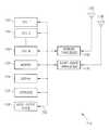
- FIG. 2is a functional block diagram illustrative of one of the UEs 110 illustrated in FIG. 1 .
- the system 100takes advantage of current implementations of the UE 110 that typically include multiple processors.
- one processor in the UEis configured to handle communications with the AP 108 while a second processor is configured for playback of received video data.
- the UE 110 in FIG. 2includes a plurality of central processing units (CPUs) 150 .
- the CPUs 150are illustrated in FIG. 2 as CPU 1 , CPU 2 , . . . CPU W.
- the CPUs 150may be implemented as conventional microprocessors, an application specific integrated circuit (ASIC), digital signal processor (DSP), programmable gate array (PGA), or the like.
- ASICapplication specific integrated circuit
- DSPdigital signal processor
- PGAprogrammable gate array
- the UE 110is not limited by the specific form of the CPUs 150 .
- the UE 110 in FIG. 2also contains a memory 152 .
- the memory 152stores instructions and data to control operation of the CPUs 150 .
- the memory 152may include random access memory, read-only memory, programmable memory, flash memory, and the like.
- the UE 110is not limited by any specific form of hardware used to implement the memory 152 .
- the memory 152may also be integrally formed in whole or in part with the CPUs 150 .
- the UE 110 of FIG. 2also includes conventional components, such as a display 154 , a keypad or keyboard 156 , and an audio output device 158 .
- the display 154is a touch-sensitive display that incorporates the functionality of the display 154 and the keyboard 156 .
- Theseare conventional components that operate in a known manner and need not be described in greater detail.
- Other conventional components found in wireless communication devices, such as a USB interface, Bluetooth interface, camera/video device, infrared device, and the like,may also be included in the UE 110 . For the sake of clarity, these conventional elements are not illustrated in the functional block diagram of FIG. 2 .
- the UE 110 of FIG. 2also includes a network transceiver 166 such as may be used by the UE 110 for the conventional wireless communication network with the service provider PLMN (not shown), as described above.
- the network transceiver 166is connected to an antenna 168 .
- the network transceiver 166is illustrated as a generic transceiver.
- the UEs 110may be implemented in accordance with any known wireless communication protocol including, but not limited to, CDMA, WCDMA, GSM, UMTS, 3G, 4G, WiMAX, LTE, or the like. Operation of the network transceiver 166 and the antenna 168 for communication with the PLMN (not shown) is well-known in the art and need not be described in greater detail herein.
- the UE 110 of FIG. 2also includes a short-range transceiver 176 that is used by the UEs 110 to communicate with the APs 108 of FIG. 1 .
- the short-range transceiver 176is connected to an antenna 178 .
- the antennas 168 and 178may have common components are implemented as a single antenna.
- the various components illustrated in FIG. 2are coupled together by a bus system 180 .
- the bus systemmay include an address bus, data bus, power bus, control bus, and the like.
- the various busses in FIG. 2are illustrated as the bus system 180 .
- the short-range transceiver 176may be designed for operation in accordance with IEEE standard 802.11, sometimes referred to as WiFi. Most modern wireless communication devices are equipped with WiFi and may be readily upgraded to support the functionality described herein.
- WiFiIEEE standard 802.11, sometimes referred to as WiFi.
- a technique for establishing communication between the UEs 110 and the APs 108 using WiFiis described in U.S. patent application Ser. No. 12/397,225, filed on Mar. 3, 2009, now U.S. Pat. No. 7,970,351. Because the UEs 108 all include WiFi capability, the UEs may be designed for communication with the APs 108 , regardless of the type of service provider PLMN or, indeed, in the total absence of the network transceiver 166 (see FIG. 1 ).
- the UE 110may operate under IEEE 802.11a at 5 gigahertz (GHz) under IEEE 802.11b/g at 2.4 GHz, or IEEE 802.11n, which operates at both 2.4 GHz and 5 GHz.
- IEEE 802.11aat 5 gigahertz (GHz)
- IEEE 802.11b/gat 2.4 GHz
- IEEE 802.11nwhich operates at both 2.4 GHz and 5 GHz.
- the wireless communication device of the system 100may be readily adapted for operation with future versions of IEEE 802.11.
- the user of a conventional wireless communication devicecan search for a wireless access point and connect to that access point, as is common in public areas, such as an airport terminal, coffee shop, or the like.
- the goal of this connectionis generally to provide Internet access.
- the UEs 110 described hereincan include an application program interface (API) that can be programmed into the UE at the time of manufacture or downloaded in a conventional manner. Some functionality of the API will be described herein. A more complete description of the API is provided by U.S. patent application Ser. No. 13/093,998, now U.S. Pat. No. 8,995,923, and titled “System and Method for Management of a Dynamic Network Using Wireless Communication Devices,” filed on Apr. 26, 2011, and incorporated herein by reference in its entirety.
- the APIbecomes part of the operating system in that it is always executing in the background. In this manner, the API is different from a conventional application software program that must be activated by the user.
- the APIincludes a “heartbeat” signal that periodically communicates with any available AP 108 and provides identification data, location data and the like to a database server 232 (see FIG. 4 ).
- the APIadvantageously simplifies authentication of the UE whenever it enters a venue that is part of the system described herein.
- the UE 1has established the wireless communication links 112 with the AP 1 and AP 2 , respectively.
- the usermoves from one location to another in a particular venue, he may move in or out of range of one AP 108 or the other.
- the UE 110can receive the video stream from one of the plurality of APs 108 distributed throughout the venue.
- the API or a separate application programprovides a set of instructions to two of the CPUs 150 to perform specific tasks.
- a first processore.g., CPU 1
- native coderefers to software code that has been compiled to processor-specific machine code.
- CPU 1is responsible for capturing all data packets that have a specified port number.
- the CPU 1is programmed to provide the singular function of capturing UDP data packets having the designated port number and storing those captured data packets in the memory 152 .
- a second processore.g., the CPU 2
- the CPU 2is also programmed with native code to perform the function of retrieving the stored data packets and playing them on the display 154 .
- the CPU 2also provides audio data to the audio output device 158 .
- the CPU 1stores the UDP data packets for a short time and then closes the file in which the received data packets are stored. This permits a second processor, the CPU 2 , to open the file and play back the received data packets on the display 154 .
- the CPU 1saves the received UDP data packets as a series of files that are closed after a short period of time while the CPU 2 opens the closed files and plays the received UDP packets on the display. If the received data packets are multimedia data packets, the CPU 2 also sends data to the audio output device 158 .
- the operation of the CPU 1 and CPU 2is tightly integrated so that both the CPU 1 and the CPU 2 can access the same file in the memory 152 .
- there is only a single data filewith the CPU 1 placing received data packets in the data file in the memory 152 while the CPU 2 retrieves and plays the data packets from the single data file in the memory 152 on the display 154 and the audio output device 158 if the video stream is a multimedia file.
- the efficient native code programming of the CPU 1 and CPU 2allows the UE 110 to effectively capture and play back a video data stream.
- the CPU 1is programmed for the singular function of capturing and storing UDP data packets while the CPU 2 is programmed for the singular function of retrieving and playing the stored UDP data packets.
- the tight operation of the CPU 1 and CPU 2permit the effective capture and play of UDP data packets at an acceptable frame rate to effectively provide streaming video or streaming multimedia to the UE 110 from the APs 108 within a venue.
- FIG. 3illustrates a large venue 200 , such as a casino.
- a large venuesuch as a casino.
- the related business 202may be a performance venue for singers, comedy acts, and the like.
- the related business 204may be a nightclub while the related business 206 may be a restaurant.
- the position and coverage area of the APs 108can be determined based on the particular hardware implementation.
- the actual distribution and installation of the APs 108 using the infrastructure 106 (see FIG. 1 ) within the venue 200is within the engineering knowledge of one skilled in the art and need not be described in greater detail herein.
- all of the APs 108are coupled to the video server 104 in FIG. 1 .
- the UE 110moves throughout the venue 200 , it is making and breaking wireless communication devices with one or more of the APs 108 .
- the UE 110can receive a selected streaming video channel anywhere within the venue 200 .
- the identity of the UE 110can be verified by the UE providing a profile and user information and signing up for the WiFi service and downloading the API. Initially this may be accomplished through a portal page, as will be described in greater detail below.
- the video server 104can provide a selection of available video streams.
- a selection of available video streamsmay be shown on the display 154 , which may also be a touch-sensitive display.
- the usersimply taps the display 154 near the description of the desired video stream.
- the port number associated with the selected video streamis supplied to the CPU 1 to begin the video streaming process.
- the CPU 1 and CPU 2may use progressive downloading so that a short segment of the video stream is captured by the CPU 1 before the CPU 2 begins the play-out process. This allows a smoother transition to video streaming and avoids any initial buffer starvation.
- the available video streamscould be parimutuel events (i.e., horse races), sporting events (e.g., football, baseball, basketball, etc.), instructional videos, such as rules and/or tips on playing certain games within the casino, or the like.
- the usersimply taps the display 154 near the desired video stream and the video streaming will begin.
- the UE 110remains within the venue 200 , it is in substantially continuous contact with the APs 108 and may receive data therefrom.
- the venuemay provide its own advertising or other information to the UE 110 .
- the adsmay take the form of still images, videos similar to commercial television ads, or the like.
- the received videoscan also have banner ads included or the video server 104 (see FIG. 1 ) can modify the video feeds to include advertising spliced into the video feed. This requires video processing equipment that is known in the art for this purpose.
- the heartbeat datacan be used to provide a personal targeted advertising for an individual UE 110 as part of a streaming video on a particular channel.
- the UE 110could receive an ad for free or discounted tickets to the performance venue 202 or an invitation to happy hour at the nightclub venue 204 or a discounted meal at the restaurant venue 206 .
- the APs 108could send an invitation or ad to book a room in the venue 200 .
- the UE 110can communicate with the video server 104 or another server (not shown) within the venue 200 via the APs 108 to accept one or more of the ad offers.
- the UE 110could transmit an acceptance and book tickets at the performance venue 202 .
- the user of the UE 110can book a room in the venue 200 .
- FIG. 4illustrates a system architecture that allows operation of the system 100 across multiple venues.
- the venue 200may have a large number of APs 108 distributed throughout the venue.
- the various APs 108are coupled together using the infrastructure 106 .
- the infrastructureallows an interconnection to a network 210 via a communication link 212 .
- the network 210may be implemented as the Internet.
- the infrastructure 106provides a backhaul 214 to a cloud computing environment designated herein as a JUMMMP Cloud 216 .
- the backhaul 214may be implemented in a variety of different manners using known technology. In one embodiment, the backhaul 214 may be routed to the JUMMMP Cloud 216 via the network 210 .
- a web portal page and policy controller server 220controls user authentication across a number of different venues in addition to the venue 200 .
- a network management element 222controls overall operation of the network in the JUMMMP Cloud 216 including registration and authentication services.
- FIG. 4illustrates a log-in web page 224 .
- a local ad server 230 in the JUMMMP Cloud 216may provide ads for the venue 200 .
- the adsmay be still images or streaming video and may be directed to the venue 200 itself or for the related businesses 202 - 206 (see FIG. 3 ).
- the adsmay be for businesses near the venue 200 (or for other venues in the JUMMMP network).
- the centralized ad server 230 in the JUMMMP Cloud 216simplifies the network architecture within the venue 200 and other venues by eliminating the need for an ad server within each venue.
- a data base server 232 in the JUMMMP Cloud 216may be configured to collect a broad range of information regarding the UEs 110 (including the user profile information stored in the memory 156 (see FIG. 2 ) of the UE that was provided when the UE was first identified in the venue.
- the profile informationwill help provide targeting marketing and advertising to the UE 110 as it traverses the venue.
- the profile informationmay be used to select the streaming videos that may be provided to the user. For example, if the user profile indicates that the owner of the UE 110 is an avid football fan, the selections of video streams may include multiple football games.
- the heartbeat signal from the UE 110may include geo-location data.
- the database server 232is configured to store location information, along with time/date data to thereby track movements of the UE 110 .
- the UE 110must register with the system 100 at some initial point in time.
- the initial registrationcan be performed remotely using, by way of example, a personal computer (not shown) connected to the JUMMMP Cloud 216 via the network 210 .
- the UE 110can perform an initial registration as it enters the venue 200 illustrated in FIG. 4 , as described above.
- the policy controller server 220will not have any data related to the particular UE 110 .
- that initial AP 108 in the venue 200may perform an initial registration.
- the UE 110can connect to the initial AP 108 and provide identification information.
- the usercan complete the initial registration process by providing data, such as the telephone ID (i.e., the phone number), a device ID, a user ID, and an email address as well as other information, such as the user profile data stored in the memory 156 (see FIG. 2 ) of the UE 110 .
- the user IDmay be a user generated name, nickname, or the like.
- the device IDmay vary based on the particular type of the UE 110 . For example, if the UE 110 utilizes an AndroidTM operating system, the device will be assigned an AndroidTM ID. In addition, the UE 110 may typically be assigned an international mobile equipment identification (IMEI). Any of these device identifications alone may be transmitted to the registration server 222 .
- IMEIinternational mobile equipment identification
- a unique hash of one or more device IDsmay be generated and transmitted to the registration server 222 as the device ID.
- the short-range transceiver 176may also include an identification, such as a MAC address that is unique to the UE 110 .
- the registration data described abovecan be provided to the registration server 222 along with the MAC address. The registration data may be stored in association with the MAC address. Once the initial registration process has been completed, subsequent authentications are greatly simplified.
- a previously-registered UE 110may come within range of the initial AP 108 in the venue 200 of FIG. 4 and establish a wireless communication link therewith.
- the UE 110transmits its MAC address and/or the phone ID or IMEI.
- the AP 108transmits an authentication request message to the registration server 222 to determine whether the UE 110 is a registered device. Based on the MAC address, the registration server 222 can confirm that the UE 110 has previously registered.
- the UE 110is authenticated whenever it comes into range of an AP 108 of the system 100 . This may occur transparently to the user. This automatic authentication process can occur even if the initial registration was in a completely different part of the country.
- the UE 110may move from one venue 200 to another in the same city or region or may be in a completely different part of the country and be automatically identified and authenticated with APs 108 that are part of the system 100 described herein. This convenient registration and authentication avoids the need for constantly searching for a WiFi connection as required by other systems. Based on this automatic authentication process, the UE 110 may be automatically connected to the WiFi network created by the APs 108 in the venue 200 .
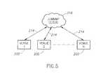
- the JUMMMP Cloud 216also advantageously provides a centralized registration function for multiple venues, as illustrated in FIG. 5 .
- the multiple venues 200are each connected to the JUMMMP Cloud 216 via individual respective backhauls 214 . If a UE 110 initially registers at Venue 1 , using the registration process described above, that registration information is stored in the JUMMMP Cloud 416 . At a later point in time when the user enters, by way of example, Venue 2 illustrated in FIG. 5 , the UE 110 will automatically identify the AP 108 and begin to communicate therewith.
- the UE 110Because the UE 110 has already been registered, that information is passed along to the JUMMMP Cloud 216 and the UE is automatically authenticated. This is true even if the various venues 200 are located far from one another. For example, an initial registration of the UE 110 may take place at a sports venue in, by way of example, New York City. However, if the UE 110 is carried to a casino in, by way of example, Las Vegas, Nev., the UE 110 will automatically begin to communicate with the AP 108 in the new venue in Las Vegas. Because each venue is coupled to the JUMMMP Cloud 216 , the UE 110 need not undergo another registration process when it enters the venue 200 in Las Vegas. Thus, a single registration process at any venue is sufficient for registration with the JUMMMP Cloud 216 . Whenever the UE 110 goes into a different venue 200 that is coupled to the JUMMMP Cloud 216 , the UE 110 is automatically recognized and authenticated.
- the venue 200may be a football stadium, as illustrated in FIG. 6 , or some other sports venue.
- the APs 108are distributed throughout the structure of the sports venue.
- the UE 110communicates with one or more of the APs 108 in the manner described above.
- the UE 110can perform an initial registration process or an automatic authentication process, as described above.
- the APs 108maintain virtually continuous contact with the UE 110 while it is within the sports venue 200 .
- the APs 108are coupled to the infrastructure 106 to allow the distribution of multiple video channels to all of the UEs 110 within the sports venue 200 .
- one video channelcan provide an overall view of the playing field while other video channels may provide close-up video streams of the line play, the quarterback, the receivers, and the like.
- the usermay select which video stream to view on the UE 110 .
- all of the video streams described abovemay be made available for selection by any of the UEs 110 within the venue 200 .
- the JUMMMP Cloud 216can disseminate information to the UEs 110 in the manner described above.
- the disseminated informationmay be in the form of advertisements from vendors within the venue 200 , future availability of videos (e.g., upcoming sports events), and the like.
- the JUMMMP Cloud 216may also provide streaming video to the UE 110 .
- the JUMMMP Cloud 216may provide streaming video highlights or even complete games from a different football stadium that is also coupled to the JUMMMP Cloud 216 . While some stadiums provide selected replays on a large screen TV or other display 228 for fans, such displays are not available if the user is away from the field to get a drink, go to the bathroom, etc.
- the instant replaymay be provided directly to the UE 110 at virtually any location throughout the sports venue 200 . In this embodiment, the instant replay may be multicast to all UEs 110 within the sports venue 200 by the multitude of APs 108 .
- the system 100can provide a video channel with a delay (e.g., 30 seconds) so that the UE 110 can always go back and review recent plays.
- a delaye.g. 30 seconds
- the instant replay described hereinis distinct from an “on-demand” form of instant replay.
- An on-demand systemrequires unicast delivery of the instant replay to each and every UE that transmits such a request. As discussed above, unicast delivery of video would quickly consume all available bandwidth in a typical AP 108 . Accordingly, the instant replay described herein refers to video replay that is under control of the sender (e.g., the video server 104 in FIG. 1 ).
- the video server 104selects the video that will be made available as a replay and transmits the replay video as a series of UDP packets with a separate port number, as described above.
- the instant replayis a multicast video stream available to all UEs 110 as a separate channel. The user can simply switch to the replay channel to view this video stream.
- the instant replay for the venue 200may be provided by the JUMMMP Cloud 216 to the video server 104 (see FIG. 1 ).
- the video server 104receives a local feed of the streaming media or instant replay for activities within that local sports stadium.
- the APs 108are in fixed locations throughout the venue 200 to maximize coverage throughout the venue. This is true whether the venue 200 is a fixed facility, such as the casino venue or sports venue.
- the system described hereinis flexible enough to provide temporary coverage in a venue that does not have preexisting coverage.
- a concert hallmay not have existing coverage through a network of APs as described above.
- a concert venue at the state fairmay be temporary in nature.
- a concert venuemay be constructed temporarily at an open air location (e.g., Woodstock or a speedway).
- some venues, such as a racetrack or a golf coursemay not have an existing infrastructure of APs 108 .
- the system described hereincan provide a temporary mobile venue infrastructure, which may be referred to herein as “WiFi on Wheels” (WoW).
- WiWWiFi on Wheels
- FIG. 7An example of a WoW implementation is illustrated in FIG. 7 .
- the example of FIG. 7is a temporary concert venue, such as may be common at a state fair or other location.
- a stage 240 and grandstands 242may be positioned within the venue 200 .
- the location of the APs 108 throughout the venue 200may be dependent on the location of the stage 240 and the grandstands 242 to provide the necessary coverage.
- the APs 108may be mounted on existing infrastructure, such as telephone poles, light poles, and the like.
- the APs 108may also be mounted directly to the stage 240 or the grandstand 242 .
- a control truck 244 or other mobile vehiclemay contain the additional infrastructure for the temporary concert venue 200 .
- the control truck 244may contain the video server and infrastructure 106 (see FIG. 1 ) to provide the necessary connection to the JUMMMP Cloud 216 .
- the control truck 244may also include a satellite link to implement the backhaul 214 .
- the backhaul 214can also be implemented as a microwave link from the control truck 244 or a hardwired connection if available.
- the WoW implementation of FIG. 7can be set up and removed in a relatively short period of time.
- the concert venue 200operates in the same manner described above with respect to other venues. That is, the UE 110 is automatically authenticated if the UE 110 has previously been authenticated with the JUMMMP Cloud 216 . If the UE 110 has never been registered with the JUMMMP Cloud 216 , the UE undergoes an initial registration process described above with respect to FIG. 4 .
- the concert venue 200operates in a functionally identical manner to the fixed venues described above.
- the concert venue 200 in FIG. 7may offer multiple video channels such as an overall view of the concert stage, close-ups of the concert stage, close-ups of individual performers on the stage, or the like. The user can simply select the desired streaming video channel from the available selection shown on the display 154 (see FIG. 2 ).
- the venue 200may provide video advertisements on the selected channel.
- the video server 104can send command data to all APs 108 within the venue 200 or to selected APs within the venue to force the UEs 110 to change port numbers for processing by the CPU 1 (see FIG. 2 ).
- the CPU 1will identify and save all UDP data packets having a selected port number. In this instance, the initial port number is altered via a data command from the video server 104 .
- the UEs 110may be caused to change channels and receive a commercial during a time out. After the commercial, or when the time out ends, the individual UEs 110 can automatically revert back to the original channel by reinstating the initial port number used by the CPU 1 . Alternatively, the UEs 110 can switch back to the initial port number upon receipt of an additional data command from the video server 104 .
- a race tracki.e., an auto race track or a horse race track
- a race tracki.e., an auto race track or a horse race track
- the UE 110can simply select which streaming video to receive by selecting the appropriate channel in the manner described above.
- the usercan readily change channels at the push of a button.
- APs 108may be distributed around a golf course during a golf tournament. Because a golf tournament generally lasts only a few days, the temporary installation described above with respect to a concert venue may be applicable here as well. That is, APs 108 may be distributed throughout the golf course and coupled to the control truck 244 (see FIG. 7 ) or other control installation.
- the video server 104(see FIG. 1 ) is typically installed within the control truck 244 or other control installation.
- various video streamscould be provided for different holes on the golf course, video of individual players, such as the current leaders, fan favorites or the like.
- the UE 110simply selects the desired video stream from among the available selections by activating a selected channel on the display 154 (see FIG. 2 ).
- systemis not limited to these examples.
- system described hereinenables the delivery of a large number of video streams via a network of APs and allows each UE to select which channel to view.
- any two components herein combined to achieve a particular functionalitycan be seen as “associated with” each other such that the desired functionality is achieved, irrespective of architectures or intermedial components.
- any two components so associatedcan also be viewed as being “operably connected,” or “operably coupled,” to each other to achieve the desired functionality.
Landscapes
- Engineering & Computer Science (AREA)
- Signal Processing (AREA)
- Computer Networks & Wireless Communication (AREA)
- Multimedia (AREA)
- Computer Security & Cryptography (AREA)
- Databases & Information Systems (AREA)
- General Engineering & Computer Science (AREA)
- Human Computer Interaction (AREA)
- Power Engineering (AREA)
- Computer Hardware Design (AREA)
- Computing Systems (AREA)
- Mobile Radio Communication Systems (AREA)
Abstract
Description
Claims (14)
Priority Applications (1)
| Application Number | Priority Date | Filing Date | Title |
|---|---|---|---|
| US15/050,352US10154290B2 (en) | 2009-03-03 | 2016-02-22 | System and method for wireless distribution of television channels in a venue |
Applications Claiming Priority (7)
| Application Number | Priority Date | Filing Date | Title |
|---|---|---|---|
| US12/397,225US7970351B2 (en) | 2009-03-03 | 2009-03-03 | System and method for direct communication between wireless communication devices |
| US12/616,958US8190119B2 (en) | 2009-03-03 | 2009-11-12 | System and method for direct communication between wireless communication devices |
| US12/958,296US9077564B2 (en) | 2009-03-03 | 2010-12-01 | System and method for dynamic formation of a communication network using wireless communication devices |
| US13/093,998US8995923B2 (en) | 2009-03-03 | 2011-04-26 | System and method for management of a dynamic network using wireless communication devices |
| US13/363,943US9179296B2 (en) | 2009-03-03 | 2012-02-01 | System and method for device authentication in a dynamic network using wireless communication devices |
| US13/834,359US9271054B2 (en) | 2009-03-03 | 2013-03-15 | System and method for WiFi video streaming |
| US15/050,352US10154290B2 (en) | 2009-03-03 | 2016-02-22 | System and method for wireless distribution of television channels in a venue |
Related Parent Applications (1)
| Application Number | Title | Priority Date | Filing Date |
|---|---|---|---|
| US13/834,359DivisionUS9271054B2 (en) | 2009-03-03 | 2013-03-15 | System and method for WiFi video streaming |
Publications (2)
| Publication Number | Publication Date |
|---|---|
| US20160173938A1 US20160173938A1 (en) | 2016-06-16 |
| US10154290B2true US10154290B2 (en) | 2018-12-11 |
Family
ID=48904070
Family Applications (5)
| Application Number | Title | Priority Date | Filing Date |
|---|---|---|---|
| US13/834,359Active2030-02-03US9271054B2 (en) | 2009-03-03 | 2013-03-15 | System and method for WiFi video streaming |
| US15/050,347Active2029-03-29US10051293B2 (en) | 2009-03-03 | 2016-02-22 | System and method for operation of a temporary control facility for video distribution in a venue |
| US15/050,332Active2029-04-08US10129568B2 (en) | 2009-03-03 | 2016-02-22 | System and method for transmission of multiple video streams to mobile communication devices |
| US15/050,335Active2029-04-15US10142661B2 (en) | 2009-03-03 | 2016-02-22 | Mobile communication device and method of operation |
| US15/050,352Active2029-04-09US10154290B2 (en) | 2009-03-03 | 2016-02-22 | System and method for wireless distribution of television channels in a venue |
Family Applications Before (4)
| Application Number | Title | Priority Date | Filing Date |
|---|---|---|---|
| US13/834,359Active2030-02-03US9271054B2 (en) | 2009-03-03 | 2013-03-15 | System and method for WiFi video streaming |
| US15/050,347Active2029-03-29US10051293B2 (en) | 2009-03-03 | 2016-02-22 | System and method for operation of a temporary control facility for video distribution in a venue |
| US15/050,332Active2029-04-08US10129568B2 (en) | 2009-03-03 | 2016-02-22 | System and method for transmission of multiple video streams to mobile communication devices |
| US15/050,335Active2029-04-15US10142661B2 (en) | 2009-03-03 | 2016-02-22 | Mobile communication device and method of operation |
Country Status (1)
| Country | Link |
|---|---|
| US (5) | US9271054B2 (en) |
Families Citing this family (19)
| Publication number | Priority date | Publication date | Assignee | Title |
|---|---|---|---|---|
| US9271054B2 (en) | 2009-03-03 | 2016-02-23 | Mobilitie, Llc | System and method for WiFi video streaming |
| US9986268B2 (en) | 2009-03-03 | 2018-05-29 | Mobilitie, Llc | System and method for multi-channel WiFi video streaming |
| US10616619B2 (en) | 2009-03-03 | 2020-04-07 | Mobilitie, Llc | System and method for multi-channel WiFi video streaming |
| US20130201907A1 (en)* | 2012-02-06 | 2013-08-08 | Avermedia Technologies, Inc. | Wireless Data Distributor, Network System and Method for Receiving Audio and Video Streaming Data and Internet Website Data |
| US9874414B1 (en)* | 2013-12-06 | 2018-01-23 | Google Llc | Thermal control system |
| US9498678B2 (en) | 2014-07-11 | 2016-11-22 | ProSports Technologies, LLC | Ball tracker camera |
| US9591336B2 (en) | 2014-07-11 | 2017-03-07 | ProSports Technologies, LLC | Camera feed distribution from event venue virtual seat cameras |
| US9760572B1 (en) | 2014-07-11 | 2017-09-12 | ProSports Technologies, LLC | Event-based content collection for network-based distribution |
| US9655027B1 (en)* | 2014-07-11 | 2017-05-16 | ProSports Technologies, LLC | Event data transmission to eventgoer devices |
| WO2016007967A1 (en) | 2014-07-11 | 2016-01-14 | ProSports Technologies, LLC | Ball tracker snippets |
| US9729644B1 (en) | 2014-07-28 | 2017-08-08 | ProSports Technologies, LLC | Event and fantasy league data transmission to eventgoer devices |
| US9699523B1 (en) | 2014-09-08 | 2017-07-04 | ProSports Technologies, LLC | Automated clip creation |
| FR3069995B1 (en)* | 2017-08-02 | 2019-09-06 | Jcdecaux Sa | PERIPHERAL SERVER FOR DIGITAL CONTENT BROADCASTING NETWORK, AND DIGITAL CONTENT DISTRIBUTION NETWORK COMPRISING SUCH PERIPHERAL SERVERS |
| CN107800989B (en)* | 2017-10-16 | 2021-01-05 | 深圳市天视通电子科技有限公司 | Video display method and system based on dynamic frame rate detection and network video recorder |
| CN107846616B (en)* | 2017-10-18 | 2021-07-02 | 安徽工程大学 | A data acquisition device for digital television terminal equipment |
| US11245947B1 (en)* | 2017-10-24 | 2022-02-08 | Theodore Joseph Sabo | Device and method for capturing, processing, linking and monetizing a plurality of video and audio recordings from different points of view (POV) |
| KR102643885B1 (en) | 2018-12-11 | 2024-03-08 | 삼성전자주식회사 | Electronic apparatus and controlling method thereof |
| CN109982098B (en)* | 2019-03-11 | 2020-12-01 | 烽火通信科技股份有限公司 | IPTV channel switching method and system |
| US11700353B2 (en)* | 2020-04-06 | 2023-07-11 | Eingot Llc | Integration of remote audio into a performance venue |
Citations (83)
| Publication number | Priority date | Publication date | Assignee | Title |
|---|---|---|---|---|
| US5708961A (en) | 1995-05-01 | 1998-01-13 | Bell Atlantic Network Services, Inc. | Wireless on-premises video distribution using digital multiplexing |
| US6212208B1 (en) | 1996-11-11 | 2001-04-03 | Matsushita Electric Industrial Co., Ltd. | Method for coding and multiplexing multimedia data, apparatus for coding and multiplexing multimedia data, record media containing program for coding and multiplexing multimedia data |
| US20020047861A1 (en) | 2000-06-23 | 2002-04-25 | Labrie David William | Site information system and method |
| US20020077118A1 (en) | 2000-12-19 | 2002-06-20 | Zellner Samuel N. | Location blocking service from a wireless service provider |
| US20020105931A1 (en) | 2000-12-21 | 2002-08-08 | Tomi Heinonen | Address sharing |
| US20030106067A1 (en) | 2001-11-30 | 2003-06-05 | Hoskins Steve J. | Integrated internet protocol (IP) gateway services in an RF cable network |
| US20030159153A1 (en) | 2002-02-20 | 2003-08-21 | General Instrument Corporation | Method and apparatus for processing ATVEF data to control the display of text and images |
| US20030192055A1 (en) | 2002-04-03 | 2003-10-09 | Fumihiko Aoki | Access point for local area radio communication and radio communication system using the same |
| US20040032495A1 (en) | 2000-10-26 | 2004-02-19 | Ortiz Luis M. | Providing multiple synchronized camera views for broadcast from a live venue activity to remote viewers |
| US20040098745A1 (en) | 2002-11-15 | 2004-05-20 | Marston Scott E. | Broadband wireless distribution system for mobile platform interior |
| US6751673B2 (en) | 2001-01-03 | 2004-06-15 | Akamai Technologies, Inc. | Streaming media subscription mechanism for a content delivery network |
| US20040250273A1 (en) | 2001-04-02 | 2004-12-09 | Bellsouth Intellectual Property Corporation | Digital video broadcast device decoder |
| US6839080B2 (en) | 2001-12-31 | 2005-01-04 | Nokia Corporation | Remote server switching of video streams |
| US20050041596A1 (en) | 2003-07-07 | 2005-02-24 | Matsushita Electric Industrial Co., Ltd. | Relay device and server, and port forward setting method |
| US20050055708A1 (en) | 2003-09-04 | 2005-03-10 | Kenneth Gould | Method to block unauthorized network traffic in a cable data network |
| US20050152287A1 (en) | 2004-01-09 | 2005-07-14 | Matsushita Electric Industrial Co., Ltd. | IP device, management server, and network system |
| US20060053448A1 (en) | 2000-01-04 | 2006-03-09 | United Video Properties, Inc. | Interactive program guide with graphic program listings |
| US20060075449A1 (en) | 2004-09-24 | 2006-04-06 | Cisco Technology, Inc. | Distributed architecture for digital program insertion in video streams delivered over packet networks |
| US20060085834A1 (en)* | 2004-10-19 | 2006-04-20 | Cayin Technology Co., Ltd. | System and method for transmitting multi-channel signals |
| US20060161960A1 (en) | 2005-01-20 | 2006-07-20 | Benoit Brian V | Network security system appliance and systems based thereon |
| US20060288375A1 (en) | 2000-10-26 | 2006-12-21 | Ortiz Luis M | Broadcasting venue data to a wireless hand held device |
| US20070008435A1 (en) | 2005-07-08 | 2007-01-11 | Samsung Electronics Co., Ltd | Broadcast receiving apparatus offering a multi-stream and method of offering a multi-stream |
| US20070055989A1 (en) | 2005-09-08 | 2007-03-08 | The Directv Group, Inc. | Mosaic channel video stream with interactive services |
| US20070089145A1 (en) | 2005-10-18 | 2007-04-19 | Sbc Knowledge Ventures, L.P. | System and method of delivering video data |
| US20070094691A1 (en) | 2005-10-24 | 2007-04-26 | Gazdzinski Robert F | Method and apparatus for on-demand content transmission and control over networks |
| US20070107034A1 (en) | 2003-10-31 | 2007-05-10 | Gotwals Michael D | Combination meter for evaluating video delivered via Internet protocol |
| US7230917B1 (en) | 2001-02-22 | 2007-06-12 | Cisco Technology, Inc. | Apparatus and technique for conveying per-channel flow control information to a forwarding engine of an intermediate network node |
| US20070204294A1 (en)* | 2006-02-27 | 2007-08-30 | Qualcomm Incorporated | Methods, apparatus, and system for venue-cast |
| US20070288978A1 (en) | 2006-06-08 | 2007-12-13 | Ajp Enterprises, Llp | Systems and methods of customized television programming over the internet |
| US20080022352A1 (en) | 2006-07-10 | 2008-01-24 | Samsung Electronics Co.; Ltd | Multi-screen display apparatus and method for digital broadcast receiver |
| US20080036851A1 (en) | 2006-08-14 | 2008-02-14 | Patel Mehul B | System, method, and device for providing content on a wireless communication device |
| US20080060025A1 (en) | 2006-08-30 | 2008-03-06 | Ying-Chung Chen | Car theater video and audio entertainment system |
| US20080068252A1 (en) | 2006-09-19 | 2008-03-20 | Mehta Pratik M | Simulcasting content information on WiFi |
| US20080092202A1 (en) | 2006-09-30 | 2008-04-17 | Cg Holdings, Llc | Portable golf spectator information system |
| US20080104642A1 (en) | 2006-10-12 | 2008-05-01 | Avion Engineering Services Inc., Dba Avionpartners | Cabin management and entertainment system |
| US20080127257A1 (en) | 2006-11-28 | 2008-05-29 | Verizon Services Organization Inc. | System and method for viewing a TV program guide on a mobile device background |
| US20080151885A1 (en) | 2005-02-08 | 2008-06-26 | Uwe Horn | On-Demand Multi-Channel Streaming Session Over Packet-Switched Networks |
| US20080212583A1 (en) | 2004-06-21 | 2008-09-04 | Matsushita Electric Industrial Co., Ltd. | Adaptive and Scalable Qos Architecture for Single-Bearer Multicast/Broadcast Services |
| US20080253368A1 (en) | 2007-04-11 | 2008-10-16 | Nokia Siemens Networks Oy | Policy control of multiplexed real time protocol and real time control protocol |
| US20080301744A1 (en) | 2007-05-30 | 2008-12-04 | General Instrument Corporation | Method and Apparatus for Locating Content in an Internet Protocol Television (IPTV) System |
| US20080313691A1 (en) | 2007-06-13 | 2008-12-18 | Chris Cholas | Premises gateway apparatus and methods for use in a content-based network |
| US20090041118A1 (en) | 2000-05-05 | 2009-02-12 | Activevideo Networks, Inc. | Method for Bandwidth Regulation on a Cable Television System Channel |
| US20090064246A1 (en) | 2007-08-30 | 2009-03-05 | Bell Gregory P | Distributed and interactive globecasting system |
| US20090077267A1 (en) | 2007-09-17 | 2009-03-19 | Gm Global Technology Operations, Inc. | Method and apparatus for implementing a mobile server |
| US20090183217A1 (en) | 2008-01-10 | 2009-07-16 | At&T Knowledge Ventures, L.P. | System for managing media content for a personal television channel |
| US20090199254A1 (en) | 2008-02-05 | 2009-08-06 | At&T Knowledge Ventures, L.P. | Managing media content for a personal television channel |
| US20090217318A1 (en) | 2004-09-24 | 2009-08-27 | Cisco Technology, Inc. | Ip-based stream splicing with content-specific splice points |
| US20090222854A1 (en) | 2008-02-29 | 2009-09-03 | Att Knowledge Ventures L.P. | system and method for presenting advertising data during trick play command execution |
| US20090282438A1 (en) | 2008-05-09 | 2009-11-12 | At&T Knowledge Ventures, L.P. | Community Content Ratings System |
| US20100020794A1 (en) | 2007-05-29 | 2010-01-28 | Chris Cholas | Methods and apparatus for using tuners efficiently for delivering one or more programs |
| US20100023842A1 (en) | 2008-07-25 | 2010-01-28 | Nortel Networks Limited | Multisegment loss protection |
| US20100070997A1 (en) | 2008-09-12 | 2010-03-18 | At&T Intellectual Property I, L.P. | System for managing media presentations |
| US20100077436A1 (en) | 2008-09-19 | 2010-03-25 | At&T Intellectual Property I, L.P. | Synchronized home and vehicle audio visual system and method |
| US20100080163A1 (en) | 2008-09-30 | 2010-04-01 | Qualcomm Incorporated | Apparatus and methods of providing and receiving venue level transmissions and services |
| US20100192183A1 (en) | 2009-01-29 | 2010-07-29 | At&T Intellectual Property I, L.P. | Mobile Device Access to Multimedia Content Recorded at Customer Premises |
| US20100195623A1 (en) | 2009-01-30 | 2010-08-05 | Priya Narasimhan | Systems and methods for providing interactive video services |
| US20100227554A1 (en) | 2009-03-03 | 2010-09-09 | Gary Bernard Jabara | System and method for direct communication between wireless communication devices |
| US20100226288A1 (en) | 2009-03-04 | 2010-09-09 | At&T Intellectual Property I, Lp. | Method and apparatus for group media consumption |
| US20100242075A1 (en) | 2006-06-14 | 2010-09-23 | Markku Vimpari | Method and Device for Wireless Transmissions of Internet Protocol TV |
| US20100293301A1 (en) | 2009-05-14 | 2010-11-18 | International Business Machines Corporation | Dynamically Composing Data Stream Processing Applications |
| US20100306801A1 (en) | 2008-08-22 | 2010-12-02 | Filippov Vasily B | Methods and apparatus for delivering content from a television channel |
| US20110066745A1 (en) | 2009-09-14 | 2011-03-17 | Sony Ericsson Mobile Communications Ab | Sharing video streams in commnication sessions |
| US20110103374A1 (en) | 2009-10-30 | 2011-05-05 | Lajoie Michael L | Methods and apparatus for packetized content delivery over a content delivery network |
| US20110158146A1 (en) | 2009-12-29 | 2011-06-30 | Jeelan Poola | Method and system for multicast video streaming over a wireless local area network (wlan) |
| US20120062800A1 (en) | 2010-09-10 | 2012-03-15 | Sisto John F | Monitor Chaining and Docking Mechanism |
| US8139581B1 (en) | 2007-04-19 | 2012-03-20 | Owl Computing Technologies, Inc. | Concurrent data transfer involving two or more transport layer protocols over a single one-way data link |
| US20120077466A1 (en) | 2010-09-24 | 2012-03-29 | O'mahony Barry A | Techniques to wirelessly transmit data |
| US8190119B2 (en) | 2009-03-03 | 2012-05-29 | E3 Llc | System and method for direct communication between wireless communication devices |
| US20120137332A1 (en) | 2010-11-26 | 2012-05-31 | Pranay Kumar | Mobile tv delivery system |
| US20120140645A1 (en) | 2010-12-03 | 2012-06-07 | General Instrument Corporation | Method and apparatus for distributing video |
| US20120144445A1 (en) | 2010-12-03 | 2012-06-07 | General Instrument Corporation | Method and apparatus for distributing video |
| US20120202565A1 (en) | 1999-12-01 | 2012-08-09 | Silverbrook Research Pty Ltd | Mobile phone for retrieving and playing video |
| US20130036234A1 (en) | 2011-08-01 | 2013-02-07 | Qualcomm Incorporated | Method and apparatus for transport of dynamic adaptive streaming over http (dash) initialization segment description fragments as user service description fragments |
| US20130083843A1 (en) | 2011-07-20 | 2013-04-04 | Broadcom Corporation | Adaptable media processing architectures |
| US20130205341A1 (en) | 2009-03-03 | 2013-08-08 | E3, Llc | System and method for wifi video streaming |
| US8565578B2 (en) | 2001-12-06 | 2013-10-22 | Harold J. Plourde, Jr. | Dividing and managing time-shift buffering into program specific segments based on defined durations |
| US20130305297A1 (en) | 2009-03-03 | 2013-11-14 | Mobilitie, Llc | System and method for multi-channel wifi video streaming |
| US20140157325A1 (en)* | 2009-03-03 | 2014-06-05 | Mobilitie, Llc | System and method for multi-channel wifi video streaming |
| US8752092B2 (en) | 2008-06-27 | 2014-06-10 | General Instrument Corporation | Method and apparatus for providing low resolution images in a broadcast system |
| US20140344847A1 (en) | 2009-03-03 | 2014-11-20 | Mobilitie, Llc | System and method for multi-channel video streaming |
| US8995923B2 (en) | 2009-03-03 | 2015-03-31 | Mobilitie, Llc | System and method for management of a dynamic network using wireless communication devices |
| US9077564B2 (en) | 2009-03-03 | 2015-07-07 | Mobilitie, Llc | System and method for dynamic formation of a communication network using wireless communication devices |
| US9179296B2 (en) | 2009-03-03 | 2015-11-03 | Mobilitie, Llc | System and method for device authentication in a dynamic network using wireless communication devices |
- 2013
- 2013-03-15USUS13/834,359patent/US9271054B2/enactiveActive
- 2016
- 2016-02-22USUS15/050,347patent/US10051293B2/enactiveActive
- 2016-02-22USUS15/050,332patent/US10129568B2/enactiveActive
- 2016-02-22USUS15/050,335patent/US10142661B2/enactiveActive
- 2016-02-22USUS15/050,352patent/US10154290B2/enactiveActive
Patent Citations (89)
| Publication number | Priority date | Publication date | Assignee | Title |
|---|---|---|---|---|
| US5708961A (en) | 1995-05-01 | 1998-01-13 | Bell Atlantic Network Services, Inc. | Wireless on-premises video distribution using digital multiplexing |
| US6212208B1 (en) | 1996-11-11 | 2001-04-03 | Matsushita Electric Industrial Co., Ltd. | Method for coding and multiplexing multimedia data, apparatus for coding and multiplexing multimedia data, record media containing program for coding and multiplexing multimedia data |
| US20120202565A1 (en) | 1999-12-01 | 2012-08-09 | Silverbrook Research Pty Ltd | Mobile phone for retrieving and playing video |
| US20060053448A1 (en) | 2000-01-04 | 2006-03-09 | United Video Properties, Inc. | Interactive program guide with graphic program listings |
| US20090041118A1 (en) | 2000-05-05 | 2009-02-12 | Activevideo Networks, Inc. | Method for Bandwidth Regulation on a Cable Television System Channel |
| US20020047861A1 (en) | 2000-06-23 | 2002-04-25 | Labrie David William | Site information system and method |
| US20060288375A1 (en) | 2000-10-26 | 2006-12-21 | Ortiz Luis M | Broadcasting venue data to a wireless hand held device |
| US20040032495A1 (en) | 2000-10-26 | 2004-02-19 | Ortiz Luis M. | Providing multiple synchronized camera views for broadcast from a live venue activity to remote viewers |
| US20020077118A1 (en) | 2000-12-19 | 2002-06-20 | Zellner Samuel N. | Location blocking service from a wireless service provider |
| US20020105931A1 (en) | 2000-12-21 | 2002-08-08 | Tomi Heinonen | Address sharing |
| US6751673B2 (en) | 2001-01-03 | 2004-06-15 | Akamai Technologies, Inc. | Streaming media subscription mechanism for a content delivery network |
| US7230917B1 (en) | 2001-02-22 | 2007-06-12 | Cisco Technology, Inc. | Apparatus and technique for conveying per-channel flow control information to a forwarding engine of an intermediate network node |
| US20040250273A1 (en) | 2001-04-02 | 2004-12-09 | Bellsouth Intellectual Property Corporation | Digital video broadcast device decoder |
| US20030106067A1 (en) | 2001-11-30 | 2003-06-05 | Hoskins Steve J. | Integrated internet protocol (IP) gateway services in an RF cable network |
| US8565578B2 (en) | 2001-12-06 | 2013-10-22 | Harold J. Plourde, Jr. | Dividing and managing time-shift buffering into program specific segments based on defined durations |
| US6839080B2 (en) | 2001-12-31 | 2005-01-04 | Nokia Corporation | Remote server switching of video streams |
| US20030159153A1 (en) | 2002-02-20 | 2003-08-21 | General Instrument Corporation | Method and apparatus for processing ATVEF data to control the display of text and images |
| US20030192055A1 (en) | 2002-04-03 | 2003-10-09 | Fumihiko Aoki | Access point for local area radio communication and radio communication system using the same |
| US20040098745A1 (en) | 2002-11-15 | 2004-05-20 | Marston Scott E. | Broadband wireless distribution system for mobile platform interior |
| US20050041596A1 (en) | 2003-07-07 | 2005-02-24 | Matsushita Electric Industrial Co., Ltd. | Relay device and server, and port forward setting method |
| US20050055708A1 (en) | 2003-09-04 | 2005-03-10 | Kenneth Gould | Method to block unauthorized network traffic in a cable data network |
| US20070107034A1 (en) | 2003-10-31 | 2007-05-10 | Gotwals Michael D | Combination meter for evaluating video delivered via Internet protocol |
| US20050152287A1 (en) | 2004-01-09 | 2005-07-14 | Matsushita Electric Industrial Co., Ltd. | IP device, management server, and network system |
| US20080212583A1 (en) | 2004-06-21 | 2008-09-04 | Matsushita Electric Industrial Co., Ltd. | Adaptive and Scalable Qos Architecture for Single-Bearer Multicast/Broadcast Services |
| US20060075449A1 (en) | 2004-09-24 | 2006-04-06 | Cisco Technology, Inc. | Distributed architecture for digital program insertion in video streams delivered over packet networks |
| US20090217318A1 (en) | 2004-09-24 | 2009-08-27 | Cisco Technology, Inc. | Ip-based stream splicing with content-specific splice points |
| US20060085834A1 (en)* | 2004-10-19 | 2006-04-20 | Cayin Technology Co., Ltd. | System and method for transmitting multi-channel signals |
| US20060161960A1 (en) | 2005-01-20 | 2006-07-20 | Benoit Brian V | Network security system appliance and systems based thereon |
| US20080151885A1 (en) | 2005-02-08 | 2008-06-26 | Uwe Horn | On-Demand Multi-Channel Streaming Session Over Packet-Switched Networks |
| US20070008435A1 (en) | 2005-07-08 | 2007-01-11 | Samsung Electronics Co., Ltd | Broadcast receiving apparatus offering a multi-stream and method of offering a multi-stream |
| US20070055989A1 (en) | 2005-09-08 | 2007-03-08 | The Directv Group, Inc. | Mosaic channel video stream with interactive services |
| US20070089145A1 (en) | 2005-10-18 | 2007-04-19 | Sbc Knowledge Ventures, L.P. | System and method of delivering video data |
| US20070094691A1 (en) | 2005-10-24 | 2007-04-26 | Gazdzinski Robert F | Method and apparatus for on-demand content transmission and control over networks |
| US20070204294A1 (en)* | 2006-02-27 | 2007-08-30 | Qualcomm Incorporated | Methods, apparatus, and system for venue-cast |
| US20070288978A1 (en) | 2006-06-08 | 2007-12-13 | Ajp Enterprises, Llp | Systems and methods of customized television programming over the internet |
| US20100242075A1 (en) | 2006-06-14 | 2010-09-23 | Markku Vimpari | Method and Device for Wireless Transmissions of Internet Protocol TV |
| US20080022352A1 (en) | 2006-07-10 | 2008-01-24 | Samsung Electronics Co.; Ltd | Multi-screen display apparatus and method for digital broadcast receiver |
| US20080036851A1 (en) | 2006-08-14 | 2008-02-14 | Patel Mehul B | System, method, and device for providing content on a wireless communication device |
| US20080060025A1 (en) | 2006-08-30 | 2008-03-06 | Ying-Chung Chen | Car theater video and audio entertainment system |
| US20080068252A1 (en) | 2006-09-19 | 2008-03-20 | Mehta Pratik M | Simulcasting content information on WiFi |
| US20080092202A1 (en) | 2006-09-30 | 2008-04-17 | Cg Holdings, Llc | Portable golf spectator information system |
| US20080104642A1 (en) | 2006-10-12 | 2008-05-01 | Avion Engineering Services Inc., Dba Avionpartners | Cabin management and entertainment system |
| US20080127257A1 (en) | 2006-11-28 | 2008-05-29 | Verizon Services Organization Inc. | System and method for viewing a TV program guide on a mobile device background |
| US20080253368A1 (en) | 2007-04-11 | 2008-10-16 | Nokia Siemens Networks Oy | Policy control of multiplexed real time protocol and real time control protocol |
| US20120151075A1 (en) | 2007-04-19 | 2012-06-14 | Owl Computing Technologies, Inc. | Concurrent data transfer involving two or more transport layer protocols over a single one-way data link |
| US8139581B1 (en) | 2007-04-19 | 2012-03-20 | Owl Computing Technologies, Inc. | Concurrent data transfer involving two or more transport layer protocols over a single one-way data link |
| US20100020794A1 (en) | 2007-05-29 | 2010-01-28 | Chris Cholas | Methods and apparatus for using tuners efficiently for delivering one or more programs |
| US20080301744A1 (en) | 2007-05-30 | 2008-12-04 | General Instrument Corporation | Method and Apparatus for Locating Content in an Internet Protocol Television (IPTV) System |
| US20080313691A1 (en) | 2007-06-13 | 2008-12-18 | Chris Cholas | Premises gateway apparatus and methods for use in a content-based network |
| US20090064246A1 (en) | 2007-08-30 | 2009-03-05 | Bell Gregory P | Distributed and interactive globecasting system |
| US20090077267A1 (en) | 2007-09-17 | 2009-03-19 | Gm Global Technology Operations, Inc. | Method and apparatus for implementing a mobile server |
| US20090183217A1 (en) | 2008-01-10 | 2009-07-16 | At&T Knowledge Ventures, L.P. | System for managing media content for a personal television channel |
| US20090199254A1 (en) | 2008-02-05 | 2009-08-06 | At&T Knowledge Ventures, L.P. | Managing media content for a personal television channel |
| US20090222854A1 (en) | 2008-02-29 | 2009-09-03 | Att Knowledge Ventures L.P. | system and method for presenting advertising data during trick play command execution |
| US20090282438A1 (en) | 2008-05-09 | 2009-11-12 | At&T Knowledge Ventures, L.P. | Community Content Ratings System |
| US8752092B2 (en) | 2008-06-27 | 2014-06-10 | General Instrument Corporation | Method and apparatus for providing low resolution images in a broadcast system |
| US20100023842A1 (en) | 2008-07-25 | 2010-01-28 | Nortel Networks Limited | Multisegment loss protection |
| US20100306801A1 (en) | 2008-08-22 | 2010-12-02 | Filippov Vasily B | Methods and apparatus for delivering content from a television channel |
| US20100070997A1 (en) | 2008-09-12 | 2010-03-18 | At&T Intellectual Property I, L.P. | System for managing media presentations |
| US20100077436A1 (en) | 2008-09-19 | 2010-03-25 | At&T Intellectual Property I, L.P. | Synchronized home and vehicle audio visual system and method |
| US20100080163A1 (en) | 2008-09-30 | 2010-04-01 | Qualcomm Incorporated | Apparatus and methods of providing and receiving venue level transmissions and services |
| US20100192183A1 (en) | 2009-01-29 | 2010-07-29 | At&T Intellectual Property I, L.P. | Mobile Device Access to Multimedia Content Recorded at Customer Premises |
| US20100195623A1 (en) | 2009-01-30 | 2010-08-05 | Priya Narasimhan | Systems and methods for providing interactive video services |
| US20160173913A1 (en)* | 2009-03-03 | 2016-06-16 | Mobilitie, Llc | System and method for transmission of multiple video streams to mobile communication devices |
| US20150106855A1 (en) | 2009-03-03 | 2015-04-16 | Mobilitie, Llc | System and method for multi-channel wifi video streaming |
| US9271054B2 (en) | 2009-03-03 | 2016-02-23 | Mobilitie, Llc | System and method for WiFi video streaming |
| US7970351B2 (en) | 2009-03-03 | 2011-06-28 | E3 Llc | System and method for direct communication between wireless communication devices |
| US9179296B2 (en) | 2009-03-03 | 2015-11-03 | Mobilitie, Llc | System and method for device authentication in a dynamic network using wireless communication devices |
| US8190119B2 (en) | 2009-03-03 | 2012-05-29 | E3 Llc | System and method for direct communication between wireless communication devices |
| US9077564B2 (en) | 2009-03-03 | 2015-07-07 | Mobilitie, Llc | System and method for dynamic formation of a communication network using wireless communication devices |
| US20140157325A1 (en)* | 2009-03-03 | 2014-06-05 | Mobilitie, Llc | System and method for multi-channel wifi video streaming |
| US8995923B2 (en) | 2009-03-03 | 2015-03-31 | Mobilitie, Llc | System and method for management of a dynamic network using wireless communication devices |
| US20160173956A1 (en)* | 2009-03-03 | 2016-06-16 | Mobilitie, Llc | Mobile communication device and method of operation |
| US20130305297A1 (en) | 2009-03-03 | 2013-11-14 | Mobilitie, Llc | System and method for multi-channel wifi video streaming |
| US20140344847A1 (en) | 2009-03-03 | 2014-11-20 | Mobilitie, Llc | System and method for multi-channel video streaming |
| US20100227554A1 (en) | 2009-03-03 | 2010-09-09 | Gary Bernard Jabara | System and method for direct communication between wireless communication devices |
| US20130205341A1 (en) | 2009-03-03 | 2013-08-08 | E3, Llc | System and method for wifi video streaming |
| US20100226288A1 (en) | 2009-03-04 | 2010-09-09 | At&T Intellectual Property I, Lp. | Method and apparatus for group media consumption |
| US20100293301A1 (en) | 2009-05-14 | 2010-11-18 | International Business Machines Corporation | Dynamically Composing Data Stream Processing Applications |
| US20110066745A1 (en) | 2009-09-14 | 2011-03-17 | Sony Ericsson Mobile Communications Ab | Sharing video streams in commnication sessions |
| US20110103374A1 (en) | 2009-10-30 | 2011-05-05 | Lajoie Michael L | Methods and apparatus for packetized content delivery over a content delivery network |
| US20110158146A1 (en) | 2009-12-29 | 2011-06-30 | Jeelan Poola | Method and system for multicast video streaming over a wireless local area network (wlan) |
| US20120062800A1 (en) | 2010-09-10 | 2012-03-15 | Sisto John F | Monitor Chaining and Docking Mechanism |
| US20120077466A1 (en) | 2010-09-24 | 2012-03-29 | O'mahony Barry A | Techniques to wirelessly transmit data |
| US20120137332A1 (en) | 2010-11-26 | 2012-05-31 | Pranay Kumar | Mobile tv delivery system |
| US20120144445A1 (en) | 2010-12-03 | 2012-06-07 | General Instrument Corporation | Method and apparatus for distributing video |
| US20120140645A1 (en) | 2010-12-03 | 2012-06-07 | General Instrument Corporation | Method and apparatus for distributing video |
| US20130083843A1 (en) | 2011-07-20 | 2013-04-04 | Broadcom Corporation | Adaptable media processing architectures |
| US20130036234A1 (en) | 2011-08-01 | 2013-02-07 | Qualcomm Incorporated | Method and apparatus for transport of dynamic adaptive streaming over http (dash) initialization segment description fragments as user service description fragments |
Non-Patent Citations (4)
| Title |
|---|
| International Search Report issued in international application No. PCT/US2014/027586, dated Sep. 16, 2014 (2 pages). |
| International Search Report issued in international application No. PCT/US2014/027606, dated Dec. 9, 2014 (5 pages). |
| International Search Report issued in international application No. PCT/US2014/027629, dated Aug. 19, 2014 (3 pages). |
| SONICblue, ReplayTV 5000, User Guide, 2002, 86 pages. |
Also Published As
| Publication number | Publication date |
|---|---|
| US20160173912A1 (en) | 2016-06-16 |
| US9271054B2 (en) | 2016-02-23 |
| US10142661B2 (en) | 2018-11-27 |
| US20160173956A1 (en) | 2016-06-16 |
| US20160173913A1 (en) | 2016-06-16 |
| US20130205341A1 (en) | 2013-08-08 |
| US20160173938A1 (en) | 2016-06-16 |
| US10129568B2 (en) | 2018-11-13 |
| US10051293B2 (en) | 2018-08-14 |
Similar Documents
| Publication | Publication Date | Title |
|---|---|---|
| US10154290B2 (en) | System and method for wireless distribution of television channels in a venue | |
| US10009638B2 (en) | System and method for multi-channel WiFi video streaming | |
| US10616619B2 (en) | System and method for multi-channel WiFi video streaming | |
| KR101132935B1 (en) | Generating and selecting media streams | |
| KR101426178B1 (en) | Method and apparatus for ad hoc venue-cast service | |
| US8520662B2 (en) | Location-aware application based quality of service (QOS) via a broadband access gateway | |
| US8625662B2 (en) | Modification of delivery of video stream to wireless device based upon position/motion of wireless device | |
| KR20060095090A (en) | Personal broadcasting service providing system and service providing method using mobile communication terminal | |
| US20140344847A1 (en) | System and method for multi-channel video streaming | |
| US20140215532A1 (en) | System and method for delivering media content to wireless electronic device | |
| US20170064407A1 (en) | Broadcast system and method for transmitting advertisements based on user preference | |
| US20210211481A1 (en) | Network controlled uplink media transmission for a collaborative media production in network capacity constrained scenarios | |
| WO2014152695A1 (en) | System and method for multi-channel wifi video streaming | |
| WO2014152658A2 (en) | System and method for wifi video streaming | |
| WO2014152677A2 (en) | System and method for multi-channel wifi video streaming | |
| Wang et al. | Machine-to-Machine Technology Applied to Integrated Video Services via Context Transfer | |
| Kostopoulos et al. | 5G edge network acceleration for crowd events | |
| AU2024227201A1 (en) | System and method for distributing media content |
Legal Events
| Date | Code | Title | Description |
|---|---|---|---|
| AS | Assignment | Owner name:MOBILITIE, LLC, CALIFORNIA Free format text:ASSIGNMENT OF ASSIGNORS INTEREST;ASSIGNOR:E3, LLC;REEL/FRAME:037836/0935 Effective date:20130913 | |
| AS | Assignment | Owner name:MOBILITIE, LLC, CALIFORNIA Free format text:ASSIGNMENT OF ASSIGNORS INTEREST;ASSIGNORS:JABARA, GARY B.;LINDER, LLOYD FREDERICK;SIMON, DAVID BRETT;REEL/FRAME:047084/0804 Effective date:20130319 | |
| AS | Assignment | Owner name:E3, LLC, CALIFORNIA Free format text:CORRECTIVE ASSIGNMENT TO CORRECT THE ASSIGNEE'S NAME PREVIOUSLY RECORDED AT REEL: 047084 FRAME: 0804. ASSIGNOR(S) HEREBY CONFIRMS THE ASSIGNMENT;ASSIGNORS:JABARA, GARY B.;LINDER, LLOYD FREDERICK;SIMON, DAVID BRETT;REEL/FRAME:047695/0121 Effective date:20130319 | |
| STCF | Information on status: patent grant | Free format text:PATENTED CASE | |
| AS | Assignment | Owner name:CIT BANK, N.A., AS ADMINISTRATIVE AGENT, NEW JERSE Free format text:SECURITY INTEREST;ASSIGNOR:MOBILITIE, LLC;REEL/FRAME:050797/0058 Effective date:20191018 Owner name:CIT BANK, N.A., AS ADMINISTRATIVE AGENT, NEW JERSEY Free format text:SECURITY INTEREST;ASSIGNOR:MOBILITIE, LLC;REEL/FRAME:050797/0058 Effective date:20191018 | |
| FEPP | Fee payment procedure | Free format text:ENTITY STATUS SET TO UNDISCOUNTED (ORIGINAL EVENT CODE: BIG.); ENTITY STATUS OF PATENT OWNER: SMALL ENTITY Free format text:ENTITY STATUS SET TO UNDISCOUNTED (ORIGINAL EVENT CODE: BIG.); ENTITY STATUS OF PATENT OWNER: LARGE ENTITY | |
| FEPP | Fee payment procedure | Free format text:ENTITY STATUS SET TO SMALL (ORIGINAL EVENT CODE: SMAL); ENTITY STATUS OF PATENT OWNER: SMALL ENTITY | |
| AS | Assignment | Owner name:MOBILITIE, LLC, CALIFORNIA Free format text:RELEASE BY SECURED PARTY;ASSIGNOR:CIT BANK, N.A., AS ADMINISTRATIVE AGENT;REEL/FRAME:057698/0335 Effective date:20210930 | |
| AS | Assignment | Owner name:IP INVESTEMENT HOLDINGS, LLC, CALIFORNIA Free format text:ASSIGNMENT OF ASSIGNORS INTEREST;ASSIGNOR:MOBILITIE, LLC;REEL/FRAME:057972/0773 Effective date:20210928 | |
| MAFP | Maintenance fee payment | Free format text:PAYMENT OF MAINTENANCE FEE, 4TH YR, SMALL ENTITY (ORIGINAL EVENT CODE: M2551); ENTITY STATUS OF PATENT OWNER: SMALL ENTITY Year of fee payment:4 |