US10151314B2 - Gear-driven flow-through pitot tube pump - Google Patents
Gear-driven flow-through pitot tube pumpDownload PDFInfo
- Publication number
- US10151314B2 US10151314B2US14/209,409US201414209409AUS10151314B2US 10151314 B2US10151314 B2US 10151314B2US 201414209409 AUS201414209409 AUS 201414209409AUS 10151314 B2US10151314 B2US 10151314B2
- Authority
- US
- United States
- Prior art keywords
- rotor
- pump
- fluid
- rotating sleeve
- suction
- Prior art date
- Legal status (The legal status is an assumption and is not a legal conclusion. Google has not performed a legal analysis and makes no representation as to the accuracy of the status listed.)
- Active, expires
Links
- 239000012530fluidSubstances0.000claimsdescription113
- 239000000411inducerSubstances0.000claimsdescription9
- 210000004907glandAnatomy0.000description8
- 238000004519manufacturing processMethods0.000description3
- 230000002093peripheral effectEffects0.000description3
- 238000010276constructionMethods0.000description2
- 238000012986modificationMethods0.000description2
- 230000004048modificationEffects0.000description2
- 238000005086pumpingMethods0.000description2
- 238000007792additionMethods0.000description1
- 230000004075alterationEffects0.000description1
- 230000009286beneficial effectEffects0.000description1
- 230000000903blocking effectEffects0.000description1
- 230000005465channelingEffects0.000description1
- 230000001010compromised effectEffects0.000description1
- 230000003247decreasing effectEffects0.000description1
- 238000007599dischargingMethods0.000description1
- 238000011143downstream manufacturingMethods0.000description1
- 230000009977dual effectEffects0.000description1
- 230000000694effectsEffects0.000description1
- 239000007788liquidSubstances0.000description1
- 238000005461lubricationMethods0.000description1
- 239000000203mixtureSubstances0.000description1
- 238000007789sealingMethods0.000description1
- 238000004513sizingMethods0.000description1
- 239000007787solidSubstances0.000description1
Images


Classifications
- F—MECHANICAL ENGINEERING; LIGHTING; HEATING; WEAPONS; BLASTING
- F04—POSITIVE - DISPLACEMENT MACHINES FOR LIQUIDS; PUMPS FOR LIQUIDS OR ELASTIC FLUIDS
- F04D—NON-POSITIVE-DISPLACEMENT PUMPS
- F04D1/00—Radial-flow pumps, e.g. centrifugal pumps; Helico-centrifugal pumps
- F04D1/14—Pumps raising fluids by centrifugal force within a conical rotary bowl with vertical axis
- F—MECHANICAL ENGINEERING; LIGHTING; HEATING; WEAPONS; BLASTING
- F04—POSITIVE - DISPLACEMENT MACHINES FOR LIQUIDS; PUMPS FOR LIQUIDS OR ELASTIC FLUIDS
- F04D—NON-POSITIVE-DISPLACEMENT PUMPS
- F04D1/00—Radial-flow pumps, e.g. centrifugal pumps; Helico-centrifugal pumps
- F04D1/12—Pumps with scoops or like paring members protruding in the fluid circulating in a bowl
- F—MECHANICAL ENGINEERING; LIGHTING; HEATING; WEAPONS; BLASTING
- F04—POSITIVE - DISPLACEMENT MACHINES FOR LIQUIDS; PUMPS FOR LIQUIDS OR ELASTIC FLUIDS
- F04D—NON-POSITIVE-DISPLACEMENT PUMPS
- F04D29/00—Details, component parts, or accessories
- F04D29/40—Casings; Connections of working fluid
- F04D29/42—Casings; Connections of working fluid for radial or helico-centrifugal pumps
- F04D29/426—Casings; Connections of working fluid for radial or helico-centrifugal pumps especially adapted for liquid pumps
- F04D29/4293—Details of fluid inlet or outlet
Definitions
- This disclosurerelates in general to centrifugal pumps and, in particular, to an improved centrifugal pump of the pitot type having a flow-through, gear-driven configuration.
- Centrifugal pumpsare well known and widely used in a variety of industries to pump fluids or liquid/solid components of fluid mixtures.
- Centrifugal pumpsparticularly those of the pitot type, generally comprise a pump housing having an inlet and an outlet and a rotor assembly which rotates within the pump housing by means of a drive unit.
- the fluid inlet and the fluid discharge in conventional pitot pumpsare positioned in parallel orientation on the same side of the pump housing, in a side-by-side arrangement. Oftentimes, the inlet is concentric with the fluid discharge.
- Fluidis directed through the pump inlet into the rotor chamber and as the rotor assembly rotates, the fluid is directed toward the inner peripheral surface of the rotor chamber as a result of centrifugal forces.
- the fluidis intercepted by a stationary pitot tube and fluid moves through the inlet of the pitot tube and through the pitot tube arm toward the discharge outlet of the pump.
- Typical centrifugal pumps of the pitot tube typeare disclosed in U.S. Pat. No. 3,822,102 to Erickson, et al.; U.S. Pat. No. 3,960,319 to Brown, et al.; U.S. Pat. No. 4,161,448 to Erickson, et al.; U.S. Pat. No. 4,280,790 to Crichlow; U.S. Pat. No. 4,332,521 to Erickson and U.S. Pat. No. 4,674,950 to Erickson.
- the fluid inlet and discharge outletare positioned on the same side of the pump casing.
- the inlet of the rotorsurrounds the entry point of the pitot tube into the interior of the rotor.
- Pitot tube pumps of this conventional constructioncan experience various disadvantages, including limitations on pump sizing and design to maximize pump efficiencies, poor or inefficient balancing of the very heavy rotor, bearing load designs that compromise the ability to resist the moment of an overhung rotor and seal leakage issues. As a result of these limitations, pump efficiencies can be compromised and the life of the pump can be shortened.
- centrifugal pumps of the pitot typeare disclosed in U.S. Pat. No. 3,791,757 to Tarifa, et al.; U.S. Pat. No. 4,875,826 to Readman; U.S. Pat. No. 2,376,071 to Miess and U.S. Pat. No. 3,384,024 to King.
- These patentsdisclose varying designs of pumps that employ one or more pitot tubes in a rotor. They disclose varying configurations for directing fluid into the rotor and discharging fluid from the rotor, typically in parallel directions on a single side of the pump, or they disclose ingress and egress of fluid at perpendicular angles to each other.
- a pump assemblycomprises a rotating assembly having a rotor and a rotating sleeve, a stationary pitot tube assembly having at least one pitot tube positioned within said rotor, a fluid inlet positioned to deliver fluid to said rotor along a defined axis and a fluid discharge axially arranged with the defined axis of said fluid inlet and being axially spaced from said fluid inlet, wherein said rotor is journalled between said rotating sleeve and said axially spaced fluid inlet.
- This aspect of the disclosurehas particular advantages over conventional pitot type pumps in enabling the ability to provide a rotor inlet of increased area, compared to conventional pitot tube pumps, without the need to increase the size of the seal.
- the configurationtherefore, reduces velocity characteristics in the pump inlet, which improves NPSH (net positive suction head). Because the pump configuration enables an increased rotor inlet dimension without increasing the seal size, the pump is capable of operating at more advantageous speeds and at higher suction pressures.
- the pumpis also less expensive to manufacture since increased seal sizes increase production costs.
- the pump assemblyis configured wherein the rotating sleeve is concentrically positioned about the fluid discharge.
- the pump assemblyis configured wherein the fluid discharge comprises a portion of the stationary pitot tube assembly.
- the fluid inlet of the pump assemblyfurther comprises a suction shaft that rotates as part of the rotating assembly.
- the rotoris comprised of a rotor bottom connected to a rotor cover forming a rotor chamber therebetween within which at least one pitot tube is positioned.
- the rotor coveris configured with enclosed vanes providing enclosed, channeled ingress of fluid into the rotor chamber.
- the pump assemblyfurther comprises a drive mechanism connected to the rotating sleeve.
- the drive mechanismat least in part, is positioned to encircle the discharge outlet.
- the pump assemblyfurther comprises a pump housing having a seal housing portion and a rotor housing portion and the pump assembly further comprises a suction shaft defining the fluid inlet, wherein the suction shaft extends through the seal housing portion of the pump housing, the seal housing portion being arranged to provide an air gap in contact with a seal mechanism positioned in the seal housing.
- the pump assemblyfurther comprises a drive housing portion of the pump housing that is configured to receive a drive mechanism in contact with the rotating sleeve.
- the discharge outletextends through the drive housing portion and further extends through a discharge housing portion of the pump housing.
- the pump assemblyfurther comprises an inducer positioned at the fluid inlet.
- a centrifugal pumpcomprises a pump housing having a rotor housing portion, a rotor disposed within the rotor housing portion, the rotor having axially opposed sides defined by a rotor bottom positioned on one side and a rotor cover positioned on the axially opposing side thereto, the rotor bottom and rotor cover being secured together to form a closed chamber within the rotor, at least one pitot tube positioned within the closed chamber and a rotating sleeve connected to and extending away from one side of the rotor, the rotating sleeve being connected to a drive mechanism, and a fluid inlet extending from one side of the rotor, the fluid inlet being positioned to deliver fluid to the rotor cover for directing fluid to the closed chamber, and a fluid discharge extending from the axially opposing side of the rotor, wherein the fluid inlet and the fluid discharge each have a central axis, and the central axes are
- the centrifugal pump of this aspectprovides advantages over conventional centrifugal pumps in having the ability to provide a rotor or fluid inlet of increased area, compared to conventional pitot tube pumps, without the need to increase the size of the seal.
- the configurationtherefore, reduces velocity characteristics in the pump inlet, which improves NPSH (net positive suction head). Because the pump configuration enables an increased rotor of fluid inlet without increasing the seal size, the pump is capable of operating at more advantageous speeds and at higher suction pressures.
- the pumpis also less expensive to manufacture.
- the configurations of the centrifugal pump of the disclosurehave the further advantage of eliminating leakage of fluid from the rotor chamber at the inlet into the rotor.
- the point at which the pitot tube is positioned or enters into the rotoralso comprises the inlet to the rotor, and in conventional pitot tube configurations, some fluid is allowed to leak from the interior of the rotor back to the rotor inlet.
- the leakagealso increases the flow volume into the entrance to the rotor, thereby increasing the velocity and decreasing the NPSH performance.
- the centrifugal pump of this aspect of the disclosurehas the additional advantage in having improved hydraulic axial, or thrust, force balance as a result of opposing openings in the rotor to accommodate the fluid inlet on one side and the entry point of the pitot tube on the other side.
- the configurationtherefore, provides improved bearing life and allows the pump to tolerate higher suction pressures.
- the fluid dischargeis stationary and is connected to at least one pitot tube.
- the fluid inletfurther includes a suction shaft connected to the rotor cover.
- the suction shaftrotates with said rotor.
- the pump housingfurther comprises a seal housing, and the suction shaft extends from one side of the rotor through the seal housing, the seal housing providing an air gap about the suction shaft and in contact with a seal mechanism positioned in a space formed in the seal housing, preventing fluid from entering the drive housing in the event of seal failure.
- the fluid dischargeextends from the rotor through a discharge housing formed in the pump housing.
- the centrifugal pumpfurther comprises a seal mechanism positioned between the rotating sleeve and the discharge housing of the pump housing.
- the drive mechanismis a driven gear arrangement.
- the centrifugal pumpfurther comprises an inducer positioned at said fluid inlet.
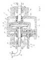
- FIG. 1is a view in longitudinal cross section of a first embodiment of a pump in accordance with this disclosure
- FIG. 2is an exploded view of the pump shown in FIG. 1 ;
- FIG. 3is a view in longitudinal cross section of a second embodiment of a pump in accordance with the present disclosure.
- FIG. 4is a graph illustrating the improved operation of a pump in accordance with the present disclosure in comparison with a conventional pitot tube pump.
- FIGS. 1 and 2illustrate a first embodiment of a pitot tube assembly and pump 10 in accordance with the present disclosure.
- the pump 10comprises a pump casing or pump housing 12 having a first end 14 and a second end 16 , the two ends being in axially opposed orientation to each other.
- the pump housing 12may be configured with a suction seal housing portion 20 , a gear frame portion 22 , a drive housing portion 24 , a discharge housing portion 26 and a rotor housing portion 28 .
- the pump 10is further comprised of a rotor 30 that is positioned in the rotor housing portion 28 .
- the rotor housing portion 28may be structured with a cavity 29 in which the rotor 30 is disposed.
- the rotor 30has axially opposed sides that, in some embodiments, may be defined by a rotor bottom 32 , comprising one side, and a rotor cover 34 , comprising the opposing side that is axially spaced or axially positioned relative to the other side of the rotor 30 .
- the rotor bottom 32 and rotor cover 34are secured together.
- the rotor cover 34has a central opening that defines a rotor inlet 40 through which fluid enters the rotor 30 .
- the rotor cover 34may have enclosed vanes 42 formed in the interior of the rotor cover 34 .
- the enclosed vanes 42may generally be radially oriented and aid in channeling or directing fluid that is entering into the rotor 30 via the rotor inlet 40 toward the peripheral inner surface of the rotor 30 .
- the pump 10includes a fluid inlet arrangement 44 for directing fluid into the rotor 30 for pumping.
- the fluid inlet arrangement 44includes a suction shaft 46 that extends from the rotor inlet 40 , through the suction seal housing portion 20 , to a gland end cap 50 that is attached to the first end 14 of the pump housing 12 by means such as bolts 52 .
- the suction shaft 46registers against the rotor inlet 40 of the rotor 30 and is sealed against the rotor cover 34 by an 0-ring 56 .
- the suction shaft 46extends through an axially extending portion 60 of the rotor housing portion 28 .
- a shaft sleeve 62encircles the suction shaft 46 , extending from an inwardly extending shoulder 64 of the shaft sleeve 46 to an inner wall 66 of the gear frame portion 22 .
- a labyrinth seal 68is positioned between the shaft sleeve 62 and the axially extending portion 60 , and an oil ring 70 is positioned against the labyrinth seal 68 , thereby sealing the rotor housing portion 28 from the gear frame portion 22 .
- the suction shaft 46is supported by a suction shaft bearing 74 that is positioned in an opening 75 between the suction seal housing portion 20 and the gear frame housing portion 22 .
- a bearing isolator plate 76is positioned against the suction shaft bearing 74 and is secured in place by a securement ring 78 .
- a suction seal arrangement 80Spaced from the bearing isolator plate 76 is a suction seal arrangement 80 that registers against the gland end cap 50 and seals the suction seal housing portion 20 of the pump housing. Further, the construction of the suction seal housing portion 20 with a space 83 therein, and the suction seal arrangement 90 disposed in the space 83 , provides an advantageous air gap 82 that assures, in the event of a catastrophic failure of the seal arrangement 80 , that pumping fluid does not infiltrate into the gear frame portion 22 of the pump casing 12 .
- the seal arrangements in conventional pitot tube pumpsare situated in a manner that frequently leads to damage of the components within the pump casing when a catastrophic seal failure occurs.
- a flanged inlet end 84is secured to or formed with the gland end cap 50 , and provides the point of ingress of fluid into the suction shaft 46 , which defines a fluid inlet 86 having a central axis 88 .
- a stationary pitot tube 90is positioned in the rotor chamber 92 of the rotor 30 .
- the stationary pitot tube 90 shown in FIG. 1has a dual inlet configuration; however, a single inlet pitot tube may also be used in the pump.
- the pitot tube 90is connected to or formed with a discharge tube 94 that defines a fluid discharge 96 having a central axis 98 .
- the pitot tube 90 and fluid discharge 96comprise a pitot tube assembly.
- the central axis 98 of the fluid discharge 96is axially aligned with and co-axially arranged relative to the central axis 88 of the fluid inlet 86 .
- the central axis 98 of the fluid discharge 96may be axially aligned with the central axis 88 of the fluid inlet 86 .
- the end 100 of the discharge tube 94 that is distanced from the pitot tube 90is received in an opening 102 in a discharge end gland plate 104 that is secured to the end 106 of the discharge housing portion 26 by such means as bolts 108 .
- An o-ring 110is positioned between the end 100 of the discharge tube 94 and the discharge end gland plate 104 to provide a seal therebetween.
- Additional discharge pipingmay be provided to direct discharge fluid from the discharge tube 94 to downstream processing, the piping including, for example, a flanged end member 112 having a discharge elbow 114 and a flanged discharge outlet pipe 116 defining an ultimate discharge outlet 118 .
- a drive mechanism 120is attached to the rotor 30 to provide rotation of the rotor 30 .
- the drive mechanism 120 as shown in FIG. 1includes a rotating sleeve 130 that is secured at one end 132 to the rotor bottom 32 , defining one axial side of the rotor 30 .
- the rotating sleeve 130is tubular in configuration and is sized to receive the discharge tube 94 therethrough in a concentric arrangement therewith while allowing the rotating sleeve 130 to rotate freely about the stationary discharge tube 94 .
- a labyrinth seal 136is positioned between an opening in the rotor housing portion 28 , through which the rotating sleeve 130 and discharge tube 94 extend, and seal ring 138 that surrounds the rotating sleeve 130 to seal the rotor housing portion 28 from the drive housing portion 24 .
- a bearing 140is positioned in an opening 142 formed between the drive housing portion 24 and the discharge housing portion 26 of the pump casing 12 , and is held in place by a bearing isolator plate 148 that is positioned in the discharge housing portion 26 and locked in place by a locking nut 149 .
- the rotor 30is journalled by and between the rotating sleeve 130 , on one side of the rotor 30 , and the fluid inlet 86 , on the other, axially opposing side of the rotor 30 .
- the rotor 30is effectively supported by the bearing 68 in the rotor housing portion 28 and the bearing 140 located between the rotor housing portion 28 and the discharge housing portion 26 .
- the position of the two bearings, 68 , 140advantageously provides improved axial or thrust force balance for the rotor 30 , which is very heavy.
- the balancing of the rotor 30 achieved by the configuration of the present disclosureprovides a significant advantage over conventional cantilevered pitot tube arrangements in providing better stability, enhanced smoothness of operation and enhanced operational speeds.
- a seal arrangement 150surrounds the other end 152 of the rotating sleeve 130 .
- the seal arrangement 150is received in the discharge end gland plate 104 , and centrally positions the rotating sleeve 130 relative to the discharge end gland plate 104 , as well as providing a seal therebetween.
- the drive mechanismfurther comprises a first gear disk 160 that is positioned about and secured to the rotating sleeve 130 , and is positioned in the drive housing portion 24 of the pump casing 12 .
- the outer surface of the first gear disk 160is structured with teeth or similar devices in known fashion.
- a drive element 170is provided to effect rotation of the first gear disk 160 , and consequently the rotor 30 by way of the rotating sleeve 130 .
- the drive element 170may include a second gear disk 172 that is registered against the first gear disk 160 , and is positioned within the drive housing portion 24 of the pump casing 12 .
- the second gear disk 172has an outer surface 174 that is configured with teeth or similar devices that interface with the teeth or similar devices on the first gear disk 170 to thereby impart rotation to the first gear disk 160 .
- the second gear disk 172is attached to a drive shaft 176 that is connected to a motor (not shown) which imparts rotation to the drive shaft 176 in known fashion.
- a first end 178 of the drive shaft 176is carried in a space 180 provided in the pump casing or housing 12 , such as in the rotor housing portion 28 .
- a bearing 182 ringis positioned to support the first end 178 of the drive shaft 176 .
- the drive shaft 176is also positioned through the pump casing 12 via an opening 186 formed in the drive housing portion 24 .
- the drive shaft 176is centrally positioned and supported in the opening 186 by a second bearing 188 .
- the second bearing 188is secured within the opening 186 by means of a wave spring 189 and a drive end plate 190 .
- a drive shaft seal 192is positioned against the drive end plate 190 and is held in place with a washer 194 and a locking nut 196 .
- An oil pan 198may be positioned in the drive housing portion 24 to lubricate the gear disks or to receive excess lubrication fluid. While drive gears are illustrated herein, other types of drives, including a bevel gear arrangement, may be employed.
- the pump of the present disclosureprovides a fluid inlet 86 and a fluid discharge 96 that are axially positioned at opposing ends 14 , 16 of the pump casing 12 .
- the central axis 88 of fluid inlet 86is co-axial with the central axis 98 of the fluid discharge 96 .
- the drive mechanismmay be associated with a rotating sleeve that is concentrically formed about the fluid inlet 86 , rather than a drive mechanism being arranged as shown in FIG. 1 .
- Other suitable arrangementsare within the scope of the disclosure.
- the pump of the disclosuremay include an inducer 220 that is positioned at the rotor inlet 40 of the rotor 30 .
- the inducer 220increases pressure at the rotor inlet 40 , thereby reducing cavitation at the inlet of the rotor cover 34 .
- the inducer 220may be any suitable configuration that facilitates the flow direction of fluid moving into and through the rotor inlet 40 .
- the inducer 220is beneficial in increasing the NPSH performance of the pump, but may not be required or desirable in all applications.
- a centrifugal pump that is constructed in the manner described hereinprovides significant advantages over centrifugal pitot tube pumps of the conventional variety where the suction inlet and fluid discharge are positioned on the same side of the rotor.
- the graph of FIG. 4illustrates test results of performance comparisons between a pump constructed in accordance with the present disclosure and a centrifugal pitot pump configured with a fluid inlet that enters on one side of the rotor, the fluid inlet concentrically surrounding a fluid discharge in the form of a pitot tube arm positioned on the same side of the rotor (i.e., “prior known pump”).
- Net Positive Suction Headis the net positive pressure above the vapor pressure of the working fluid at the pump inlet required for the pump to operate.
- Lower NPSHallows the pump to operate on systems with lower tank and or sump elevations and at lower pressures, reducing the overall cost of fluid system operation.
- the test resultsindicate that the prior known pump has a higher NPSH profile (upper smooth line in the graph) than a pump constructed in accordance with the present disclosure (lower dotted line in the graph).
- the improved, or lower, NPSH profile of the pump of the present disclosureis consistently better in comparison to the prior known pump as flow rate, measured in gallons per minute (GPM), increases.
Landscapes
- Engineering & Computer Science (AREA)
- Mechanical Engineering (AREA)
- General Engineering & Computer Science (AREA)
- Structures Of Non-Positive Displacement Pumps (AREA)
- Rotary Pumps (AREA)
Abstract
Description
Claims (18)
Priority Applications (10)
| Application Number | Priority Date | Filing Date | Title |
|---|---|---|---|
| US14/209,409US10151314B2 (en) | 2013-03-15 | 2014-03-13 | Gear-driven flow-through pitot tube pump |
| JP2016502410AJP6341988B2 (en) | 2013-03-15 | 2014-03-14 | Pump assembly and centrifugal pump |
| HK16108128.0AHK1220245A1 (en) | 2013-03-15 | 2014-03-14 | Gear-driven flow-through pitot tube pump |
| RU2015143866ARU2662845C2 (en) | 2013-03-15 | 2014-03-14 | Suction pump with pitot tubes with the gear drive |
| PCT/US2014/027351WO2014152448A1 (en) | 2013-03-15 | 2014-03-14 | Gear-driven flow-through pitot tube pump |
| EP14770955.4AEP2971784B8 (en) | 2013-03-15 | 2014-03-14 | Flow-through pitot tube pump |
| CN201480023876.6ACN105308325B (en) | 2013-03-15 | 2014-03-14 | Gear Drive Flow-through Pitot Tube Pumps |
| CN201711159117.4ACN107842507B (en) | 2013-03-15 | 2014-03-14 | Gear-driven flow-through pitot tube pump |
| JP2018093601AJP6621115B2 (en) | 2013-03-15 | 2018-05-15 | Pump assembly and centrifugal pump |
| HK18111057.7AHK1251636B (en) | 2013-03-15 | 2018-08-28 | Gear-driven flow-through pitot tube pump |
Applications Claiming Priority (2)
| Application Number | Priority Date | Filing Date | Title |
|---|---|---|---|
| US201361798539P | 2013-03-15 | 2013-03-15 | |
| US14/209,409US10151314B2 (en) | 2013-03-15 | 2014-03-13 | Gear-driven flow-through pitot tube pump |
Publications (2)
| Publication Number | Publication Date |
|---|---|
| US20140271127A1 US20140271127A1 (en) | 2014-09-18 |
| US10151314B2true US10151314B2 (en) | 2018-12-11 |
Family
ID=51527703
Family Applications (1)
| Application Number | Title | Priority Date | Filing Date |
|---|---|---|---|
| US14/209,409Active2036-05-19US10151314B2 (en) | 2013-03-15 | 2014-03-13 | Gear-driven flow-through pitot tube pump |
Country Status (7)
| Country | Link |
|---|---|
| US (1) | US10151314B2 (en) |
| EP (1) | EP2971784B8 (en) |
| JP (2) | JP6341988B2 (en) |
| CN (2) | CN105308325B (en) |
| HK (1) | HK1220245A1 (en) |
| RU (1) | RU2662845C2 (en) |
| WO (1) | WO2014152448A1 (en) |
Cited By (1)
| Publication number | Priority date | Publication date | Assignee | Title |
|---|---|---|---|---|
| US20240026903A1 (en)* | 2019-12-06 | 2024-01-25 | Kinetic Technology Systems, Llc | Energy-conserving fluid pump |
Families Citing this family (9)
| Publication number | Priority date | Publication date | Assignee | Title |
|---|---|---|---|---|
| CN108138782B (en)* | 2015-09-14 | 2021-01-29 | 特种泵和系统有限责任公司 | Pitot tube stabilizing device |
| CN106884812A (en)* | 2017-04-21 | 2017-06-23 | 王现明 | A kind of agricultural fluid pump |
| CN108131296A (en)* | 2018-01-25 | 2018-06-08 | 辽宁工程技术大学 | A kind of coil formula centrifugal pump |
| CA3093393A1 (en) | 2018-03-06 | 2019-09-12 | Steven Bitterly | Water purification system and process |
| CN109915339B (en)* | 2019-04-03 | 2020-07-31 | 铜陵市兆林工贸有限责任公司 | High-pressure jet pump |
| CN111237196B (en)* | 2020-01-02 | 2020-11-13 | 浙江理工大学 | A double-suction rotary shell pump supported at both ends, low-vibration and high-efficiency |
| CN111503003B (en)* | 2020-05-25 | 2025-03-14 | 浙江理工大学 | Small flow, high head and high efficiency multi-stage volute centrifugal pump |
| RU204503U1 (en)* | 2020-12-07 | 2021-05-28 | Нещадименко Максим Олегович | FLOW PUMP |
| CN115467833A (en)* | 2021-08-11 | 2022-12-13 | 江苏泓懋节能科技有限公司 | Two-end supporting type rotary jet pump |
Citations (67)
| Publication number | Priority date | Publication date | Assignee | Title |
|---|---|---|---|---|
| US2376071A (en) | 1940-08-27 | 1945-05-15 | Miess Fred | Centrifugal pump |
| DE888048C (en)* | 1950-04-29 | 1953-08-27 | Richard Dipl-Ing Schiel | Single-stage hollow rotor centrifugal pump |
| GB852653A (en) | 1957-02-11 | 1960-10-26 | New York Air Brake Co | Improvements relating to rotary 'scoop' pumps |
| US3004495A (en) | 1957-02-11 | 1961-10-17 | New York Air Brake Co | High speed hydrodynamic pump |
| US3384024A (en) | 1967-01-09 | 1968-05-21 | Mckenzie Pump Corp | Centrifugal pump |
| US3776658A (en) | 1972-08-14 | 1973-12-04 | Kobe Inc | Pitot tube for pitot pump |
| US3791757A (en) | 1970-09-11 | 1974-02-12 | Sener Tecnica Industrial | New type of rotary pump for liquids |
| US3795459A (en) | 1973-03-21 | 1974-03-05 | Kobe Inc | Pitot pump with slotted inlet passages in rotor case |
| US3795457A (en) | 1973-02-26 | 1974-03-05 | Kobe Inc | Multistage pitot pump with means for feeding clean fluid to seals |
| US3817446A (en) | 1973-01-08 | 1974-06-18 | Kabe Inc | Pitot pump with centrifugal separator |
| US3822102A (en) | 1973-03-05 | 1974-07-02 | Kobe Inc | Pitot pump with thrust balance |
| US3838939A (en) | 1973-08-20 | 1974-10-01 | Kobe Inc | Pitot pump with means for excluding leakage from bearings |
| GB1388563A (en) | 1971-07-10 | 1975-03-26 | Lucas Industries Ltd | Pumps for liquids |
| DE2443788A1 (en) | 1974-09-13 | 1976-03-25 | Kobe Inc | Pitot pump has housing with hollow rotor - having blades to gas-pressurise bearing seal preventing liq. leakage from inlet into housing |
| GB1433283A (en) | 1973-03-19 | 1976-04-22 | Kobe Inc | Pitot pump with a jet pump charging system |
| GB1440301A (en) | 1974-09-16 | 1976-06-23 | Kobe Inc | Pitot pump with means for excluding leakage from bearings |
| GB1440533A (en) | 1974-04-29 | 1976-06-23 | Kobe Inc | Pitot pump with thrust balance |
| US3977810A (en) | 1974-09-23 | 1976-08-31 | Kobe, Inc. | Multiple outlet, constant flow, pitot pump |
| US3994618A (en) | 1975-01-13 | 1976-11-30 | Kobe, Inc. | Multiple outlet pitot pump with different output flows and/or pressures |
| US3999881A (en) | 1975-09-02 | 1976-12-28 | Kobe, Inc. | Centrifugal pump of the pitot type |
| GB1469885A (en) | 1974-04-29 | 1977-04-06 | Kobe Inc | Pitot pump with centrifugal separator |
| US4036427A (en) | 1975-06-06 | 1977-07-19 | Kobe, Inc. | Combination pitot pump and centrifugal separator |
| US4045145A (en) | 1975-12-19 | 1977-08-30 | Kobe, Inc. | Pitot pump with turbulence elimination |
| US4073596A (en) | 1976-03-18 | 1978-02-14 | Kobe, Inc. | Lubricant cooling for high-speed pitot pump |
| GB1515955A (en) | 1976-06-26 | 1978-06-28 | Kobe Inc | Centrifugal pumps and compressors of the pitot type |
| GB1535642A (en) | 1977-10-07 | 1978-12-13 | Kobe Inc | Pitot pumps |
| SU652351A1 (en) | 1977-10-10 | 1979-03-15 | Предприятие П/Я В-8413 | Scoop pump |
| US4161448A (en) | 1978-02-21 | 1979-07-17 | Kobe, Inc. | Combined separator and pump with dirty phase concentrator |
| US4183713A (en) | 1975-11-17 | 1980-01-15 | Kobe, Inc. | Pitot pump with jet pump operated thrust balance |
| EP0013038A1 (en) | 1978-12-22 | 1980-07-09 | Max Theodore Kardoes | A pump of the Pitot type |
| US4230564A (en) | 1978-07-24 | 1980-10-28 | Keefer Bowie | Rotary reverse osmosis apparatus and method |
| GB2045351A (en) | 1979-03-23 | 1980-10-29 | Kobe Inc | Rotary Pitot Pumps |
| US4252499A (en) | 1979-10-01 | 1981-02-24 | Kobe, Inc. | Centrifugal pump |
| US4264269A (en) | 1978-09-25 | 1981-04-28 | Kobe, Inc. | Centrifugal pitot pump with improved pitot |
| JPS5655799U (en) | 1979-10-08 | 1981-05-14 | ||
| US4267964A (en) | 1979-10-01 | 1981-05-19 | Kobe, Inc. | Centrifugal separator with rotating pick-up tube |
| US4279571A (en) | 1979-10-01 | 1981-07-21 | Kobe, Inc. | Pitot pump with fluid lubricated bearings |
| US4280790A (en) | 1979-02-26 | 1981-07-28 | Kobe, Inc. | Centrifugal pitot pump with means for improving net positive suction head |
| US4281962A (en) | 1979-03-23 | 1981-08-04 | Kobe, Inc. | High pressure centrifugal pump |
| US4283005A (en) | 1979-10-01 | 1981-08-11 | Kobe, Inc. | Pump and centrifugal separator apparatus |
| US4355951A (en) | 1980-05-02 | 1982-10-26 | Internorth, Inc. | Full admission pitot pump |
| JPS62113885A (en) | 1985-11-12 | 1987-05-25 | ドレツサ−・インダストリ−ズ・インコ−ポレ−テツド | Pitot type centrifugal pump |
| US4679980A (en) | 1984-12-27 | 1987-07-14 | Sundstrand Corporation | Gravity insensitive inventory control device for a two-phase flow system |
| SU1373876A1 (en) | 1986-07-01 | 1988-02-15 | Предприятие П/Я М-5356 | Scoop-type pump |
| US4875826A (en) | 1988-07-26 | 1989-10-24 | Sundstrand Corporation | Pitot pump assembly for a rotating fluid management device |
| WO1989012170A1 (en) | 1988-06-10 | 1989-12-14 | Genevac Limited | Method and apparatus for processing fluids |
| US5098255A (en) | 1991-01-23 | 1992-03-24 | Sundstrand Corporation | VAriable geometry pitot pump |
| US5135353A (en) | 1991-04-09 | 1992-08-04 | Sundstrand Corporation | Variable pressure pitot pump with reduced heating of pumped fluid |
| US5145314A (en) | 1991-04-18 | 1992-09-08 | Sundstrand Corporation | Low drag pitot pump and method of operating same |
| WO1992015787A1 (en) | 1991-03-08 | 1992-09-17 | Baker Hughes Incorporated | Pitot pump with improved rotor cover |
| US5261784A (en) | 1990-10-30 | 1993-11-16 | Sundstrand Corporation | Variable pressure pitot pump |
| WO1995004226A1 (en) | 1993-07-30 | 1995-02-09 | Baker Hughes Incorporated | Vertical pump and method for accessing same |
| CA2241508A1 (en) | 1997-08-27 | 1999-02-27 | Rudy Struylaart | Pitot tube pump |
| WO1999022144A1 (en) | 1997-10-29 | 1999-05-06 | Envirotech Pumpsystems, Inc. | Pitot tube pump having axial-stabilizing construction |
| US6325594B1 (en) | 2000-03-17 | 2001-12-04 | Thomas Pump & Machinery, Inc. | Sealed drain for rotating case pumps |
| US6364059B1 (en) | 1997-10-13 | 2002-04-02 | Claes Lorentz Uno Wellton Persson | Lubricating system, preferably for refrigerating machinery and comprising a pitot tube pump |
| WO2003089788A1 (en) | 2002-04-19 | 2003-10-30 | Envirotech Pumpsystems, Inc. | Centrifugal pump with switched reluctance motor drive |
| US20050112007A1 (en) | 2003-11-24 | 2005-05-26 | Deka Products Limited Partnership | System and method of fluid transfer using devices with rotatable housings |
| WO2006096448A2 (en) | 2005-03-03 | 2006-09-14 | Envirotech Pumpsystems, Inc. | Wear ring for a centrifugal pitot tube pump |
| RU2309296C1 (en) | 2006-04-10 | 2007-10-27 | Государственное образовательное учреждение высшего профессионального образования "Орловский государственный технический университет" (ОрелГТУ) | Electric pump |
| DE102007033644A1 (en) | 2007-07-19 | 2009-01-22 | Katharina Diener | Pitot tube jet pump has cartridge seal comprising seal mounting on pump casing and hub seal on rotor casing cap, cartridge seal having radial shaft sealing ring with sealing lip |
| US7824149B2 (en) | 2005-11-23 | 2010-11-02 | Momentum Technologies Corporation | Turbine |
| US20110097190A1 (en)* | 2008-04-02 | 2011-04-28 | Bronswerk Radiax Technology B.V. | Rotation Device |
| CN201916204U (en) | 2010-12-28 | 2011-08-03 | 涿州市铁工石化设备制造有限公司 | Double-support-type rotary shell pump |
| US20120107093A1 (en) | 2009-05-19 | 2012-05-03 | Ksb Aktiengesellschaft | Pitot Tube Pump |
| CN202468201U (en) | 2012-01-10 | 2012-10-03 | 曲云芹 | Low-flow and high-pressure rotary jet pump |
| DE102011050658A1 (en) | 2011-05-26 | 2012-11-29 | Fachhochschule Köln | Apparatus for use in arrangement for conveying or compressing fluids, has container rotatably mounted around rotational axis, where container is fastened at shaft in rotationally fixed manner |
Family Cites Families (9)
| Publication number | Priority date | Publication date | Assignee | Title |
|---|---|---|---|---|
| BE769541A (en)* | 1970-09-11 | 1971-11-16 | Sener Tecnica Industrial | IMPROVEMENTS TO ROTARY PUMPS FOR LIQUIDS |
| US3960319A (en) | 1974-10-21 | 1976-06-01 | Kobe Inc. | Centrifugal separator |
| SU693050A1 (en)* | 1977-01-03 | 1979-10-25 | Всесоюзный Научно-Исследовательский И Проектно-Конструкторский Институт Промышленных Гидроприводов И Гидроавтоматики Вниигидропривод | Scoop pump |
| US4332521A (en) | 1980-02-11 | 1982-06-01 | Kobe, Inc. | High speed jet rotating casing apparatus |
| US6709227B2 (en)* | 2001-09-07 | 2004-03-23 | Envirotech Pumpsystems, Inc. | Pitot tube insert |
| CN2921384Y (en)* | 2006-06-27 | 2007-07-11 | 江苏海狮泵业制造有限公司 | Ratary case pump with labyrinth groove structure on liquid collecting pipe |
| CN101275570A (en)* | 2007-03-29 | 2008-10-01 | 江苏海狮泵业制造有限公司 | Rotary case pump of rotor cavity with straight radial blade without impeller |
| RU2365789C1 (en)* | 2008-02-04 | 2009-08-27 | Государственное образовательное учреждение высшего профессионального образования "Орловский государственный технический университет" (ОрелГТУ) | Monoblock scoop electric pump |
| CN101922452B (en)* | 2010-09-25 | 2012-07-04 | 朱生 | Pitot-turbo booster pump |
- 2014
- 2014-03-13USUS14/209,409patent/US10151314B2/enactiveActive
- 2014-03-14EPEP14770955.4Apatent/EP2971784B8/enactiveActive
- 2014-03-14HKHK16108128.0Apatent/HK1220245A1/enunknown
- 2014-03-14RURU2015143866Apatent/RU2662845C2/enactive
- 2014-03-14WOPCT/US2014/027351patent/WO2014152448A1/enactiveApplication Filing
- 2014-03-14JPJP2016502410Apatent/JP6341988B2/enactiveActive
- 2014-03-14CNCN201480023876.6Apatent/CN105308325B/enactiveActive
- 2014-03-14CNCN201711159117.4Apatent/CN107842507B/enactiveActive
- 2018
- 2018-05-15JPJP2018093601Apatent/JP6621115B2/enactiveActive
Patent Citations (69)
| Publication number | Priority date | Publication date | Assignee | Title |
|---|---|---|---|---|
| US2376071A (en) | 1940-08-27 | 1945-05-15 | Miess Fred | Centrifugal pump |
| DE888048C (en)* | 1950-04-29 | 1953-08-27 | Richard Dipl-Ing Schiel | Single-stage hollow rotor centrifugal pump |
| GB852653A (en) | 1957-02-11 | 1960-10-26 | New York Air Brake Co | Improvements relating to rotary 'scoop' pumps |
| US3004495A (en) | 1957-02-11 | 1961-10-17 | New York Air Brake Co | High speed hydrodynamic pump |
| US3384024A (en) | 1967-01-09 | 1968-05-21 | Mckenzie Pump Corp | Centrifugal pump |
| US3791757A (en) | 1970-09-11 | 1974-02-12 | Sener Tecnica Industrial | New type of rotary pump for liquids |
| GB1388563A (en) | 1971-07-10 | 1975-03-26 | Lucas Industries Ltd | Pumps for liquids |
| US3776658A (en) | 1972-08-14 | 1973-12-04 | Kobe Inc | Pitot tube for pitot pump |
| US3817446A (en) | 1973-01-08 | 1974-06-18 | Kabe Inc | Pitot pump with centrifugal separator |
| US3795457A (en) | 1973-02-26 | 1974-03-05 | Kobe Inc | Multistage pitot pump with means for feeding clean fluid to seals |
| US3822102A (en) | 1973-03-05 | 1974-07-02 | Kobe Inc | Pitot pump with thrust balance |
| GB1433283A (en) | 1973-03-19 | 1976-04-22 | Kobe Inc | Pitot pump with a jet pump charging system |
| US3795459A (en) | 1973-03-21 | 1974-03-05 | Kobe Inc | Pitot pump with slotted inlet passages in rotor case |
| US3838939A (en) | 1973-08-20 | 1974-10-01 | Kobe Inc | Pitot pump with means for excluding leakage from bearings |
| GB1440533A (en) | 1974-04-29 | 1976-06-23 | Kobe Inc | Pitot pump with thrust balance |
| GB1469885A (en) | 1974-04-29 | 1977-04-06 | Kobe Inc | Pitot pump with centrifugal separator |
| DE2443788A1 (en) | 1974-09-13 | 1976-03-25 | Kobe Inc | Pitot pump has housing with hollow rotor - having blades to gas-pressurise bearing seal preventing liq. leakage from inlet into housing |
| GB1440301A (en) | 1974-09-16 | 1976-06-23 | Kobe Inc | Pitot pump with means for excluding leakage from bearings |
| US3977810A (en) | 1974-09-23 | 1976-08-31 | Kobe, Inc. | Multiple outlet, constant flow, pitot pump |
| US3994618A (en) | 1975-01-13 | 1976-11-30 | Kobe, Inc. | Multiple outlet pitot pump with different output flows and/or pressures |
| US4036427A (en) | 1975-06-06 | 1977-07-19 | Kobe, Inc. | Combination pitot pump and centrifugal separator |
| US3999881A (en) | 1975-09-02 | 1976-12-28 | Kobe, Inc. | Centrifugal pump of the pitot type |
| US4183713A (en) | 1975-11-17 | 1980-01-15 | Kobe, Inc. | Pitot pump with jet pump operated thrust balance |
| US4045145A (en) | 1975-12-19 | 1977-08-30 | Kobe, Inc. | Pitot pump with turbulence elimination |
| US4073596A (en) | 1976-03-18 | 1978-02-14 | Kobe, Inc. | Lubricant cooling for high-speed pitot pump |
| GB1515955A (en) | 1976-06-26 | 1978-06-28 | Kobe Inc | Centrifugal pumps and compressors of the pitot type |
| GB1535642A (en) | 1977-10-07 | 1978-12-13 | Kobe Inc | Pitot pumps |
| SU652351A1 (en) | 1977-10-10 | 1979-03-15 | Предприятие П/Я В-8413 | Scoop pump |
| US4161448A (en) | 1978-02-21 | 1979-07-17 | Kobe, Inc. | Combined separator and pump with dirty phase concentrator |
| US4230564A (en) | 1978-07-24 | 1980-10-28 | Keefer Bowie | Rotary reverse osmosis apparatus and method |
| US4264269A (en) | 1978-09-25 | 1981-04-28 | Kobe, Inc. | Centrifugal pitot pump with improved pitot |
| EP0013038A1 (en) | 1978-12-22 | 1980-07-09 | Max Theodore Kardoes | A pump of the Pitot type |
| US4280790A (en) | 1979-02-26 | 1981-07-28 | Kobe, Inc. | Centrifugal pitot pump with means for improving net positive suction head |
| GB2045351A (en) | 1979-03-23 | 1980-10-29 | Kobe Inc | Rotary Pitot Pumps |
| US4281962A (en) | 1979-03-23 | 1981-08-04 | Kobe, Inc. | High pressure centrifugal pump |
| US4267964A (en) | 1979-10-01 | 1981-05-19 | Kobe, Inc. | Centrifugal separator with rotating pick-up tube |
| US4279571A (en) | 1979-10-01 | 1981-07-21 | Kobe, Inc. | Pitot pump with fluid lubricated bearings |
| US4252499A (en) | 1979-10-01 | 1981-02-24 | Kobe, Inc. | Centrifugal pump |
| US4283005A (en) | 1979-10-01 | 1981-08-11 | Kobe, Inc. | Pump and centrifugal separator apparatus |
| JPS5655799U (en) | 1979-10-08 | 1981-05-14 | ||
| US4355951A (en) | 1980-05-02 | 1982-10-26 | Internorth, Inc. | Full admission pitot pump |
| US4679980A (en) | 1984-12-27 | 1987-07-14 | Sundstrand Corporation | Gravity insensitive inventory control device for a two-phase flow system |
| JPS62113885A (en) | 1985-11-12 | 1987-05-25 | ドレツサ−・インダストリ−ズ・インコ−ポレ−テツド | Pitot type centrifugal pump |
| US4674950A (en) | 1985-11-12 | 1987-06-23 | Dresser Industries, Inc. | Pitot tube for pitot type centrifugal pump |
| SU1373876A1 (en) | 1986-07-01 | 1988-02-15 | Предприятие П/Я М-5356 | Scoop-type pump |
| WO1989012170A1 (en) | 1988-06-10 | 1989-12-14 | Genevac Limited | Method and apparatus for processing fluids |
| US4875826A (en) | 1988-07-26 | 1989-10-24 | Sundstrand Corporation | Pitot pump assembly for a rotating fluid management device |
| US5261784A (en) | 1990-10-30 | 1993-11-16 | Sundstrand Corporation | Variable pressure pitot pump |
| US5098255A (en) | 1991-01-23 | 1992-03-24 | Sundstrand Corporation | VAriable geometry pitot pump |
| WO1992015787A1 (en) | 1991-03-08 | 1992-09-17 | Baker Hughes Incorporated | Pitot pump with improved rotor cover |
| US5135353A (en) | 1991-04-09 | 1992-08-04 | Sundstrand Corporation | Variable pressure pitot pump with reduced heating of pumped fluid |
| US5145314A (en) | 1991-04-18 | 1992-09-08 | Sundstrand Corporation | Low drag pitot pump and method of operating same |
| WO1995004226A1 (en) | 1993-07-30 | 1995-02-09 | Baker Hughes Incorporated | Vertical pump and method for accessing same |
| CA2241508A1 (en) | 1997-08-27 | 1999-02-27 | Rudy Struylaart | Pitot tube pump |
| US6364059B1 (en) | 1997-10-13 | 2002-04-02 | Claes Lorentz Uno Wellton Persson | Lubricating system, preferably for refrigerating machinery and comprising a pitot tube pump |
| WO1999022144A1 (en) | 1997-10-29 | 1999-05-06 | Envirotech Pumpsystems, Inc. | Pitot tube pump having axial-stabilizing construction |
| US6325594B1 (en) | 2000-03-17 | 2001-12-04 | Thomas Pump & Machinery, Inc. | Sealed drain for rotating case pumps |
| WO2003089788A1 (en) | 2002-04-19 | 2003-10-30 | Envirotech Pumpsystems, Inc. | Centrifugal pump with switched reluctance motor drive |
| US20050112007A1 (en) | 2003-11-24 | 2005-05-26 | Deka Products Limited Partnership | System and method of fluid transfer using devices with rotatable housings |
| WO2006096448A2 (en) | 2005-03-03 | 2006-09-14 | Envirotech Pumpsystems, Inc. | Wear ring for a centrifugal pitot tube pump |
| US7824149B2 (en) | 2005-11-23 | 2010-11-02 | Momentum Technologies Corporation | Turbine |
| RU2309296C1 (en) | 2006-04-10 | 2007-10-27 | Государственное образовательное учреждение высшего профессионального образования "Орловский государственный технический университет" (ОрелГТУ) | Electric pump |
| DE102007033644A1 (en) | 2007-07-19 | 2009-01-22 | Katharina Diener | Pitot tube jet pump has cartridge seal comprising seal mounting on pump casing and hub seal on rotor casing cap, cartridge seal having radial shaft sealing ring with sealing lip |
| US20110097190A1 (en)* | 2008-04-02 | 2011-04-28 | Bronswerk Radiax Technology B.V. | Rotation Device |
| US20120107093A1 (en) | 2009-05-19 | 2012-05-03 | Ksb Aktiengesellschaft | Pitot Tube Pump |
| US8403625B2 (en) | 2009-05-19 | 2013-03-26 | Ksb Aktiengesellschaft | Pitot tube pump |
| CN201916204U (en) | 2010-12-28 | 2011-08-03 | 涿州市铁工石化设备制造有限公司 | Double-support-type rotary shell pump |
| DE102011050658A1 (en) | 2011-05-26 | 2012-11-29 | Fachhochschule Köln | Apparatus for use in arrangement for conveying or compressing fluids, has container rotatably mounted around rotational axis, where container is fastened at shaft in rotationally fixed manner |
| CN202468201U (en) | 2012-01-10 | 2012-10-03 | 曲云芹 | Low-flow and high-pressure rotary jet pump |
Non-Patent Citations (1)
| Title |
|---|
| SU1373876 English translation.* |
Cited By (2)
| Publication number | Priority date | Publication date | Assignee | Title |
|---|---|---|---|---|
| US20240026903A1 (en)* | 2019-12-06 | 2024-01-25 | Kinetic Technology Systems, Llc | Energy-conserving fluid pump |
| US12313087B2 (en)* | 2019-12-06 | 2025-05-27 | Kinetic Technology Systems, Llc | Energy-conserving fluid pump |
Also Published As
| Publication number | Publication date |
|---|---|
| EP2971784A1 (en) | 2016-01-20 |
| JP6621115B2 (en) | 2019-12-18 |
| RU2015143866A (en) | 2017-04-26 |
| HK1220245A1 (en) | 2017-04-28 |
| HK1251636A1 (en) | 2019-02-01 |
| EP2971784B1 (en) | 2020-10-28 |
| CN107842507A (en) | 2018-03-27 |
| EP2971784A4 (en) | 2016-10-19 |
| JP2016512304A (en) | 2016-04-25 |
| US20140271127A1 (en) | 2014-09-18 |
| CN105308325B (en) | 2017-12-05 |
| EP2971784B8 (en) | 2020-12-23 |
| CN105308325A (en) | 2016-02-03 |
| CN107842507B (en) | 2020-09-15 |
| WO2014152448A1 (en) | 2014-09-25 |
| JP2018150939A (en) | 2018-09-27 |
| RU2662845C2 (en) | 2018-07-31 |
| JP6341988B2 (en) | 2018-06-13 |
Similar Documents
| Publication | Publication Date | Title |
|---|---|---|
| US10151314B2 (en) | Gear-driven flow-through pitot tube pump | |
| US5340273A (en) | Sealing and pumping means and methods environmentally leak-proof pump with misting chamber defined therein | |
| CA2693876C (en) | Thrust and intake chamber for pump | |
| US2569563A (en) | Centrifugal pump | |
| CN104411977A (en) | Motorized centrifugal pump with a rotary seal | |
| US2898864A (en) | Rotary pumps | |
| CN220354120U (en) | Pump with a pump body | |
| US11460013B2 (en) | Bent axis hydraulic pump with centrifugal assist | |
| US2240782A (en) | Hydraulic pump with leak-preventing construction | |
| HK1251636B (en) | Gear-driven flow-through pitot tube pump | |
| RU197435U1 (en) | Vertical single-stage centrifugal pump unit | |
| CN114127424A (en) | Pump unit with lubrication and cooling system | |
| CN118622721B (en) | Leakage-free liquid pump | |
| JP2801722B2 (en) | Pump device | |
| RU2505709C1 (en) | Chemical horizontal pump with enclosed impeller (versions) | |
| RU2708480C1 (en) | Vertical single-stage centrifugal electrical pump unit | |
| RU47060U1 (en) | CENTRIFUGAL MULTI-STAGE PUMP | |
| RU68610U1 (en) | CENTRIFUGAL PUMP | |
| JP2017025857A (en) | Fluid machine and shaft seal device | |
| US3900273A (en) | Centrifugal auto-priming pump | |
| KR101083725B1 (en) | Pump sealing structure using return flow | |
| CN108223420A (en) | Horizontal lying type multi-impeller pump connecting axial inlet device and connecting structure thereof | |
| CN111051700A (en) | Pipeline axial-flow pump | |
| UA25971U (en) | Centrifugal pump |
Legal Events
| Date | Code | Title | Description |
|---|---|---|---|
| AS | Assignment | Owner name:ENVIROTECH PUMPSYSTEMS, INC., UTAH Free format text:ASSIGNMENT OF ASSIGNORS INTEREST;ASSIGNOR:NEILSON, BRYCE;REEL/FRAME:032432/0782 Effective date:20140313 | |
| STCF | Information on status: patent grant | Free format text:PATENTED CASE | |
| AS | Assignment | Owner name:ENVIROTECH PUMPSYSTEMS LLC, UTAH Free format text:CERTIFICATE OF CONVERSION;ASSIGNOR:ENVIROTECH PUMPSYSTEMS, INC.;REEL/FRAME:048708/0497 Effective date:20171230 | |
| AS | Assignment | Owner name:SPECIALTY PUMPS & SYSTEMS LLC, UTAH Free format text:CHANGE OF NAME;ASSIGNOR:ENVIROTECH PUMPSYSTEMS LLC;REEL/FRAME:048720/0896 Effective date:20190228 | |
| AS | Assignment | Owner name:BNP PARIBAS, NEW YORK Free format text:PATENT SHORT FORM SECURITY AGREEMENT;ASSIGNORS:SPECIALTY PUMPS & SYSTEMS LLC;WEIR FLOWAY, INC.;REEL/FRAME:049679/0077 Effective date:20190628 | |
| MAFP | Maintenance fee payment | Free format text:PAYMENT OF MAINTENANCE FEE, 4TH YEAR, LARGE ENTITY (ORIGINAL EVENT CODE: M1551); ENTITY STATUS OF PATENT OWNER: LARGE ENTITY Year of fee payment:4 | |
| AS | Assignment | Owner name:TRILLIUM PUMPS USA SLC LLC, UTAH Free format text:CHANGE OF NAME;ASSIGNOR:SPECIALTY PUMPS & SYSTEMS LLC;REEL/FRAME:069620/0456 Effective date:20190628 | |
| AS | Assignment | Owner name:BLUE OWL CAPITAL CORPORATION, AS COLLATERAL AGENT, NEW YORK Free format text:PATENT SHORT FORM SECURITY AGREEMENT;ASSIGNORS:FR FLOW CONTROL VALVES US BIDCO, INC.;TRILLIUM PUMPS USA, INC.;TRILLIUM FLOW TECHNOLOGIES UK LIMITED;REEL/FRAME:069746/0751 Effective date:20241220 | |
| AS | Assignment | Owner name:TRILLIUM PUMPS USA, INC., CALIFORNIA Free format text:MERGER;ASSIGNOR:TRILLIUM PUMPS USA SLC LLC;REEL/FRAME:069659/0443 Effective date:20200323 | |
| AS | Assignment | Owner name:TRILLIUM PUMPS USA, INC., CALIFORNIA Free format text:RELEASE BY SECURED PARTY;ASSIGNOR:BNP PARIBAS;REEL/FRAME:069664/0420 Effective date:20241220 |