US10150158B2 - Method and assembly for forming components having internal passages using a jacketed core - Google Patents
Method and assembly for forming components having internal passages using a jacketed coreDownload PDFInfo
- Publication number
- US10150158B2 US10150158B2US14/972,638US201514972638AUS10150158B2US 10150158 B2US10150158 B2US 10150158B2US 201514972638 AUS201514972638 AUS 201514972638AUS 10150158 B2US10150158 B2US 10150158B2
- Authority
- US
- United States
- Prior art keywords
- component
- inner core
- hollow structure
- core
- internal passage
- Prior art date
- Legal status (The legal status is an assumption and is not a legal conclusion. Google has not performed a legal analysis and makes no representation as to the accuracy of the status listed.)
- Active
Links
- 238000000034methodMethods0.000titleclaimsabstractdescription67
- 239000011162core materialSubstances0.000claimsabstractdescription264
- 239000000463materialSubstances0.000claimsabstractdescription140
- 238000001816coolingMethods0.000claimsabstractdescription11
- 230000000295complement effectEffects0.000claimsdescription15
- 238000007373indentationMethods0.000claimsdescription11
- 238000005495investment castingMethods0.000claimsdescription10
- 238000002788crimpingMethods0.000claimsdescription3
- 230000000593degrading effectEffects0.000claimsdescription3
- PXHVJJICTQNCMI-UHFFFAOYSA-NNickelChemical compound[Ni]PXHVJJICTQNCMI-UHFFFAOYSA-N0.000description16
- 230000006870functionEffects0.000description12
- 229910045601alloyInorganic materials0.000description8
- 239000000956alloySubstances0.000description8
- 239000000567combustion gasSubstances0.000description8
- 238000003754machiningMethods0.000description8
- 229910052759nickelInorganic materials0.000description8
- XEEYBQQBJWHFJM-UHFFFAOYSA-NIronChemical compound[Fe]XEEYBQQBJWHFJM-UHFFFAOYSA-N0.000description6
- 229910000601superalloyInorganic materials0.000description6
- 229910010293ceramic materialInorganic materials0.000description5
- 238000005336crackingMethods0.000description5
- 208000010392Bone FracturesDiseases0.000description4
- 206010017076FractureDiseases0.000description4
- 239000000919ceramicSubstances0.000description4
- 238000010586diagramMethods0.000description4
- 239000007789gasSubstances0.000description4
- 238000007493shaping processMethods0.000description4
- RTAQQCXQSZGOHL-UHFFFAOYSA-NTitaniumChemical compound[Ti]RTAQQCXQSZGOHL-UHFFFAOYSA-N0.000description3
- 239000010941cobaltSubstances0.000description3
- 229910017052cobaltInorganic materials0.000description3
- GUTLYIVDDKVIGB-UHFFFAOYSA-Ncobalt atomChemical compound[Co]GUTLYIVDDKVIGB-UHFFFAOYSA-N0.000description3
- 239000012809cooling fluidSubstances0.000description3
- 238000005553drillingMethods0.000description3
- 229910052742ironInorganic materials0.000description3
- 238000002386leachingMethods0.000description3
- 230000002787reinforcementEffects0.000description3
- 239000000126substanceSubstances0.000description3
- 239000010936titaniumSubstances0.000description3
- 229910052719titaniumInorganic materials0.000description3
- VYPSYNLAJGMNEJ-UHFFFAOYSA-NSilicium dioxideChemical compoundO=[Si]=OVYPSYNLAJGMNEJ-UHFFFAOYSA-N0.000description2
- 238000000429assemblyMethods0.000description2
- 230000000712assemblyEffects0.000description2
- 230000015572biosynthetic processEffects0.000description2
- -1but not limited toSubstances0.000description2
- 238000004891communicationMethods0.000description2
- 239000000446fuelSubstances0.000description2
- VNWKTOKETHGBQD-UHFFFAOYSA-NmethaneChemical compoundCVNWKTOKETHGBQD-UHFFFAOYSA-N0.000description2
- 239000011214refractory ceramicSubstances0.000description2
- 239000002002slurrySubstances0.000description2
- PNEYBMLMFCGWSK-UHFFFAOYSA-Naluminium oxideInorganic materials[O-2].[O-2].[O-2].[Al+3].[Al+3]PNEYBMLMFCGWSK-UHFFFAOYSA-N0.000description1
- 239000000470constituentSubstances0.000description1
- 230000003247decreasing effectEffects0.000description1
- KZHJGOXRZJKJNY-UHFFFAOYSA-Ndioxosilane;oxo(oxoalumanyloxy)alumaneChemical compoundO=[Si]=O.O=[Si]=O.O=[Al]O[Al]=O.O=[Al]O[Al]=O.O=[Al]O[Al]=OKZHJGOXRZJKJNY-UHFFFAOYSA-N0.000description1
- 238000009826distributionMethods0.000description1
- 230000000694effectsEffects0.000description1
- 238000011515electrochemical drillingMethods0.000description1
- 239000000295fuel oilSubstances0.000description1
- 238000002347injectionMethods0.000description1
- 239000007924injectionSubstances0.000description1
- 239000000314lubricantSubstances0.000description1
- 238000004519manufacturing processMethods0.000description1
- 229910052751metalInorganic materials0.000description1
- 239000002184metalSubstances0.000description1
- 229910001092metal group alloyInorganic materials0.000description1
- 239000007769metal materialSubstances0.000description1
- 239000000203mixtureSubstances0.000description1
- 229910052863mulliteInorganic materials0.000description1
- 239000003345natural gasSubstances0.000description1
- 230000003014reinforcing effectEffects0.000description1
- 239000000377silicon dioxideSubstances0.000description1
- 238000003860storageMethods0.000description1
Images


Classifications
- B—PERFORMING OPERATIONS; TRANSPORTING
- B22—CASTING; POWDER METALLURGY
- B22C—FOUNDRY MOULDING
- B22C9/00—Moulds or cores; Moulding processes
- B22C9/10—Cores; Manufacture or installation of cores
- B22C9/103—Multipart cores
- B—PERFORMING OPERATIONS; TRANSPORTING
- B22—CASTING; POWDER METALLURGY
- B22D—CASTING OF METALS; CASTING OF OTHER SUBSTANCES BY THE SAME PROCESSES OR DEVICES
- B22D19/00—Casting in, on, or around objects which form part of the product
- B22D19/0054—Casting in, on, or around objects which form part of the product rotors, stators for electrical motors
- B—PERFORMING OPERATIONS; TRANSPORTING
- B22—CASTING; POWDER METALLURGY
- B22C—FOUNDRY MOULDING
- B22C9/00—Moulds or cores; Moulding processes
- B22C9/02—Sand moulds or like moulds for shaped castings
- B22C9/04—Use of lost patterns
- B—PERFORMING OPERATIONS; TRANSPORTING
- B22—CASTING; POWDER METALLURGY
- B22C—FOUNDRY MOULDING
- B22C9/00—Moulds or cores; Moulding processes
- B22C9/06—Permanent moulds for shaped castings
- B—PERFORMING OPERATIONS; TRANSPORTING
- B22—CASTING; POWDER METALLURGY
- B22C—FOUNDRY MOULDING
- B22C9/00—Moulds or cores; Moulding processes
- B22C9/10—Cores; Manufacture or installation of cores
- B22C9/106—Vented or reinforced cores
- B—PERFORMING OPERATIONS; TRANSPORTING
- B22—CASTING; POWDER METALLURGY
- B22C—FOUNDRY MOULDING
- B22C9/00—Moulds or cores; Moulding processes
- B22C9/10—Cores; Manufacture or installation of cores
- B22C9/108—Installation of cores
- B—PERFORMING OPERATIONS; TRANSPORTING
- B22—CASTING; POWDER METALLURGY
- B22C—FOUNDRY MOULDING
- B22C9/00—Moulds or cores; Moulding processes
- B22C9/22—Moulds for peculiarly-shaped castings
- B22C9/24—Moulds for peculiarly-shaped castings for hollow articles
- B—PERFORMING OPERATIONS; TRANSPORTING
- B22—CASTING; POWDER METALLURGY
- B22D—CASTING OF METALS; CASTING OF OTHER SUBSTANCES BY THE SAME PROCESSES OR DEVICES
- B22D25/00—Special casting characterised by the nature of the product
- B22D25/02—Special casting characterised by the nature of the product by its peculiarity of shape; of works of art
- B—PERFORMING OPERATIONS; TRANSPORTING
- B22—CASTING; POWDER METALLURGY
- B22D—CASTING OF METALS; CASTING OF OTHER SUBSTANCES BY THE SAME PROCESSES OR DEVICES
- B22D29/00—Removing castings from moulds, not restricted to casting processes covered by a single main group; Removing cores; Handling ingots
- B22D29/001—Removing cores
Definitions
- the field of the disclosurerelates generally to components having an internal passage defined therein, and more particularly to forming such components using a jacketed core.
- Some componentsrequire an internal passage to be defined therein, for example, in order to perform an intended function.
- some componentssuch as hot gas path components of gas turbines, are subjected to high temperatures. At least some such components have internal passages defined therein to receive a flow of a cooling fluid, such that the components are better able to withstand the high temperatures.
- some componentsare subjected to friction at an interface with another component. At least some such components have internal passages defined therein to receive a flow of a lubricant to facilitate reducing the friction.
- At least some known components having an internal passage defined thereinare formed in a mold, with a core of ceramic material extending within the mold cavity at a location selected for the internal passage. After a molten metal alloy is introduced into the mold cavity around the ceramic core and cooled to form the component, the ceramic core is removed, such as by chemical leaching, to form the internal passage.
- a molten metal alloyis introduced into the mold cavity around the ceramic core and cooled to form the component
- the ceramic coreis removed, such as by chemical leaching, to form the internal passage.
- at least some known ceramic coresare fragile, resulting in cores that are difficult and expensive to produce and handle without damage.
- some molds used to form such componentsare formed by investment casting, and at least some known ceramic cores lack sufficient strength to reliably withstand injection of a material, such as, but not limited to, wax, used to form a pattern for the investment casting process.
- At least some known components having an internal passage defined thereinare initially formed without the internal passage, and the internal passage is formed in a subsequent process.
- at least some known internal passagesare formed by drilling the passage into the component, such as, but not limited to, using an electrochemical drilling process.
- drilling processesare relatively time-consuming and expensive.
- at least some such drilling processescannot produce an internal passage curvature required for certain component designs.
- a method of forming a component having an internal passage defined thereinincludes positioning a jacketed core with respect to a mold.
- the jacketed coreincludes a hollow structure formed from a first material, and an inner core formed from an inner core material disposed within the hollow structure.
- the methodalso includes introducing a component material in a molten state into a cavity of the mold, such that the component material in the molten state at least partially absorbs the first material from a portion of the jacketed core within the cavity.
- the methodfurther includes cooling the component material in the cavity to form the component, and removing the inner core material from the component to form the internal passage.
- a mold assemblyfor use in forming a component having an internal passage defined therein.
- the componentis formed from a component material.
- the mold assemblyincludes a mold that defines a mold cavity therein.
- the mold assemblyalso includes a jacketed core positioned with respect to the mold.
- the jacketed coreincludes a hollow structure formed from a first material, and an inner core formed from an inner core material disposed within the hollow structure.
- the first materialis at least partially absorbable by the component material in a molten state.
- a portion of the jacketed coreis positioned within the mold cavity such that the inner core of the portion defines a position of the internal passage within the component.
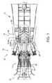
- FIG. 1is a schematic diagram of an exemplary rotary machine
- FIG. 2is a schematic perspective view of an exemplary component for use with the rotary machine shown in FIG. 1 ;
- FIG. 3is a schematic perspective view of an exemplary mold assembly for making the component shown in FIG. 2 , the mold assembly including a jacketed core positioned with respect to a mold;
- FIG. 4is a schematic cross-section of an exemplary jacketed core for use with the mold assembly shown in FIG. 3 , taken along lines 4 - 4 shown in FIG. 3 ;
- FIG. 5is a schematic perspective view of a portion of another exemplary component for use with the rotary machine shown in FIG. 1 , the component including an internal passage having a plurality of passage wall features;
- FIG. 6is a schematic perspective cutaway view of another exemplary jacketed core for use with the mold assembly shown in FIG. 3 to form the component having passage wall features as shown in FIG. 5 ;
- FIG. 7is a schematic perspective view of a portion of yet another exemplary component for use with the rotary machine shown in FIG. 1 , the component including an internal passage having another plurality of passage wall features;
- FIG. 8is a schematic perspective cutaway view of yet another exemplary jacketed core for use with the mold assembly shown in FIG. 3 to form the component having passage wall features as shown in FIG. 7 ;
- FIG. 9is a schematic perspective view of a portion of another exemplary component for use with the rotary machine shown in FIG. 1 , the component including an internal passage having a contoured cross-section;
- FIG. 10is a schematic perspective cutaway view of another exemplary jacketed core for use with the mold assembly shown in FIG. 3 to form the component having the internal passage shown in FIG. 9 ;
- FIG. 11is a flow diagram of an exemplary method of forming a component having an internal passage defined therein, such as any of the components shown in FIGS. 2, 5, 7, and 9 ;
- FIG. 12is a continuation of the flow diagram from FIG. 11 .
- Approximating languagemay be applied to modify any quantitative representation that could permissibly vary without resulting in a change in the basic function to which it is related. Accordingly, a value modified by a term or terms such as “about,” “approximately,” and “substantially” is not to be limited to the precise value specified. In at least some instances, the approximating language may correspond to the precision of an instrument for measuring the value.
- range limitationsmay be identified. Such ranges may be combined and/or interchanged, and include all the sub-ranges contained therein unless context or language indicates otherwise.
- the exemplary components and methods described hereinovercome at least some of the disadvantages associated with known assemblies and methods for forming a component having an internal passage defined therein.
- the embodiments described hereinprovide a jacketed core positioned with respect to a mold.
- the jacketed coreincludes (i) a hollow structure formed from a first material, and (ii) an inner core formed from an inner core material disposed within the hollow structure.
- the inner coreextends within the mold cavity to define a position of the internal passage within the component to be formed in the mold.
- the first materialstructurally reinforces the inner core, and is selected to be substantially absorbable by a component material introduced into the mold cavity to form the component.
- the hollow structurefurther enables forming an exterior surface of the inner core to form complementary passage wall features in the internal passage, while reducing or eliminating fragility problems associated with forming the exterior surface of the inner core.
- FIG. 1is a schematic view of an exemplary rotary machine 10 having components for which embodiments of the current disclosure may be used.
- rotary machine 10is a gas turbine that includes an intake section 12 , a compressor section 14 coupled downstream from intake section 12 , a combustor section 16 coupled downstream from compressor section 14 , a turbine section 18 coupled downstream from combustor section 16 , and an exhaust section 20 coupled downstream from turbine section 18 .
- a generally tubular casing 36at least partially encloses one or more of intake section 12 , compressor section 14 , combustor section 16 , turbine section 18 , and exhaust section 20 .
- rotary machine 10is any rotary machine for which components formed with internal passages as described herein are suitable.
- embodiments of the present disclosureare described in the context of a rotary machine for purposes of illustration, it should be understood that the embodiments described herein are applicable in any context that involves a component suitably formed with an internal passage defined therein.
- turbine section 18is coupled to compressor section 14 via a rotor shaft 22 .
- the term “couple”is not limited to a direct mechanical, electrical, and/or communication connection between components, but may also include an indirect mechanical, electrical, and/or communication connection between multiple components.
- compressor section 14compresses the air to a higher pressure and temperature. More specifically, rotor shaft 22 imparts rotational energy to at least one circumferential row of compressor blades 40 coupled to rotor shaft 22 within compressor section 14 . In the exemplary embodiment, each row of compressor blades 40 is preceded by a circumferential row of compressor stator vanes 42 extending radially inward from casing 36 that direct the air flow into compressor blades 40 . The rotational energy of compressor blades 40 increases a pressure and temperature of the air. Compressor section 14 discharges the compressed air towards combustor section 16 .
- combustor section 16the compressed air is mixed with fuel and ignited to generate combustion gases that are channeled towards turbine section 18 . More specifically, combustor section 16 includes at least one combustor 24 , in which a fuel, for example, natural gas and/or fuel oil, is injected into the air flow, and the fuel-air mixture is ignited to generate high temperature combustion gases that are channeled towards turbine section 18 .
- a fuelfor example, natural gas and/or fuel oil
- Turbine section 18converts the thermal energy from the combustion gas stream to mechanical rotational energy. More specifically, the combustion gases impart rotational energy to at least one circumferential row of rotor blades 70 coupled to rotor shaft 22 within turbine section 18 .
- each row of rotor blades 70is preceded by a circumferential row of turbine stator vanes 72 extending radially inward from casing 36 that direct the combustion gases into rotor blades 70 .
- Rotor shaft 22may be coupled to a load (not shown) such as, but not limited to, an electrical generator and/or a mechanical drive application.
- the exhausted combustion gasesflow downstream from turbine section 18 into exhaust section 20 .
- Components of rotary machine 10are designated as components 80 .
- Components 80 proximate a path of the combustion gasesare subjected to high temperatures during operation of rotary machine 10 .
- components 80include any component suitably formed with an internal passage defined therein.
- FIG. 2is a schematic perspective view of an exemplary component 80 , illustrated for use with rotary machine 10 (shown in FIG. 1 ).
- Component 80includes at least one internal passage 82 defined therein.
- a cooling fluidis provided to internal passage 82 during operation of rotary machine 10 to facilitate maintaining component 80 below a temperature of the hot combustion gases.
- Only one internal passage 82is illustrated, it should be understood that component 80 includes any suitable number of internal passages 82 formed as described herein.
- Component 80is formed from a component material 78 .
- component material 78is a suitable nickel-based superalloy.
- component material 78is at least one of a cobalt-based superalloy, an iron-based alloy, and a titanium-based alloy.
- component material 78is any suitable material that enables component 80 to be formed as described herein.
- component 80is one of rotor blades 70 or stator vanes 72 .
- component 80is another suitable component of rotary machine 10 that is capable of being formed with an internal passage as described herein.
- component 80is any component for any suitable application that is suitably formed with an internal passage defined therein.
- rotor blade 70or alternatively stator vane 72 , includes a pressure side 74 and an opposite suction side 76 .
- pressure side 74 and suction side 76extends from a leading edge 84 to an opposite trailing edge 86 .
- rotor blade 70 , or alternatively stator vane 72extends from a root end 88 to an opposite tip end 90 , defining a blade length 96 .
- rotor blade 70 , or alternatively stator vane 72has any suitable configuration that is capable of being formed with an internal passage as described herein.
- blade length 96is at least about 25.4 centimeters (cm) (10 inches). Moreover, in some embodiments, blade length 96 is at least about 50.8 cm (20 inches). In particular embodiments, blade length 96 is in a range from about 61 cm (24 inches) to about 101.6 cm (40 inches). In alternative embodiments, blade length 96 is less than about 25.4 cm (10 inches). For example, in some embodiments, blade length 96 is in a range from about 2.54 cm (1 inch) to about 25.4 cm (10 inches). In other alternative embodiments, blade length 96 is greater than about 101.6 cm (40 inches).
- internal passage 82extends from root end 88 to tip end 90 .
- internal passage 82extends within component 80 in any suitable fashion, and to any suitable extent, that enables internal passage 82 to be formed as described herein.
- internal passage 82is nonlinear.
- component 80is formed with a predefined twist along an axis 89 defined between root end 88 and tip end 90 , and internal passage 82 has a curved shape complementary to the axial twist.
- internal passage 82is positioned at a substantially constant distance 94 from pressure side 74 along a length of internal passage 82 .
- a chord of component 80tapers between root end 88 and tip end 90 , and internal passage 82 extends nonlinearly complementary to the taper, such that internal passage 82 is positioned at a substantially constant distance 92 from trailing edge 86 along the length of internal passage 82 .
- internal passage 82has a nonlinear shape that is complementary to any suitable contour of component 80 .
- internal passage 82is nonlinear and other than complementary to a contour of component 80 .
- internal passage 82 having a nonlinear shapefacilitates satisfying a preselected cooling criterion for component 80 .
- internal passage 82extends linearly.
- internal passage 82has a substantially circular cross-section. In alternative embodiments, internal passage 82 has a substantially ovoid cross-section. In other alternative embodiments, internal passage 82 has any suitably shaped cross-section that enables internal passage 82 to be formed as described herein. Moreover, in certain embodiments, the shape of the cross-section of internal passage 82 is substantially constant along a length of internal passage 82 . In alternative embodiments, the shape of the cross-section of internal passage 82 varies along a length of internal passage 82 in any suitable fashion that enables internal passage 82 to be formed as described herein.
- FIG. 3is a schematic perspective view of a mold assembly 301 for making component 80 (shown in FIG. 2 ).
- Mold assembly 301includes a jacketed core 310 positioned with respect to a mold 300 .
- FIG. 4is a schematic cross-section of jacketed core 310 taken along lines 4 - 4 shown in FIG. 3 .
- an interior wall 302 of mold 300defines a mold cavity 304 .
- Interior wall 302defines a shape corresponding to an exterior shape of component 80 , such that component material 78 in a molten state can be introduced into mold cavity 304 and cooled to form component 80 .
- component 80 in the exemplary embodimentis rotor blade 70 or, alternatively stator vane 72
- component 80is any component suitably formable with an internal passage defined therein, as described herein.
- Jacketed core 310is positioned with respect to mold 300 such that a portion 315 of jacketed core 310 extends within mold cavity 304 .
- Jacketed core 310includes a hollow structure 320 formed from a first material 322 , and an inner core 324 disposed within hollow structure 320 and formed from an inner core material 326 .
- Inner core 324is shaped to define a shape of internal passage 82 , and inner core 324 of portion 315 of jacketed core 310 positioned within mold cavity 304 defines a position of internal passage 82 within component 80 .
- Hollow structure 320is shaped to substantially enclose inner core 324 along a length of inner core 324 .
- hollow structure 320defines a generally tubular shape.
- hollow structure 320is initially formed from a substantially straight metal tube that is suitably manipulated into a nonlinear shape, such as a curved or angled shape, as necessary to define a selected nonlinear shape of inner core 324 and, thus, of internal passage 82 .
- hollow structure 320defines any suitable shape that enables inner core 324 to define a shape of internal passage 82 as described herein.
- hollow structure 320has a wall thickness 328 that is less than a characteristic width 330 of inner core 324 .
- Characteristic width 330is defined herein as the diameter of a circle having the same cross-sectional area as inner core 324 .
- hollow structure 320has a wall thickness 328 that is other than less than characteristic width 330 .
- a shape of a cross-section of inner core 324is circular in the exemplary embodiment shown in FIGS. 3 and 4 .
- the shape of the cross-section of inner core 324corresponds to any suitable shape of the cross-section of internal passage 82 that enables internal passage 82 to function as described herein.
- Mold 300is formed from a mold material 306 .
- mold material 306is a refractory ceramic material selected to withstand a high temperature environment associated with the molten state of component material 78 used to form component 80 .
- mold material 306is any suitable material that enables component 80 to be formed as described herein.
- mold 300is formed by a suitable investment casting process.
- a suitable pattern materialsuch as wax
- a suitable pattern dieis injected into a suitable pattern die to form a pattern (not shown) of component 80 , the pattern is repeatedly dipped into a slurry of mold material 306 which is allowed to harden to create a shell of mold material 306 , and the shell is dewaxed and fired to form mold 300 .
- mold 300is formed by any suitable method that enables mold 300 to function as described herein.
- jacketed core 310is secured relative to mold 300 such that jacketed core 310 remains fixed relative to mold 300 during a process of forming component 80 .
- jacketed core 310is secured such that a position of jacketed core 310 does not shift during introduction of molten component material 78 into mold cavity 304 surrounding jacketed core 310 .
- jacketed core 310is coupled directly to mold 300 .
- a tip portion 312 of jacketed core 310is rigidly encased in a tip portion 314 of mold 300 .
- a root portion 316 of jacketed core 310is rigidly encased in a root portion 318 of mold 300 opposite tip portion 314 .
- mold 300is formed by investment casting as described above, and jacketed core 310 is securely coupled to the suitable pattern die such that tip portion 312 and root portion 316 extend out of the pattern die, while portion 315 extends within a cavity of the die.
- the pattern materialis injected into the die around jacketed core 310 such that portion 315 extends within the pattern.
- the investment castingcauses mold 300 to encase tip portion 312 and/or root portion 316 .
- jacketed core 310is secured relative to mold 300 in any other suitable fashion that enables the position of jacketed core 310 relative to mold 300 to remain fixed during a process of forming component 80 .
- First material 322is selected to be at least partially absorbable by molten component material 78 .
- component material 78is an alloy
- first material 322is at least one constituent material of the alloy.
- component material 78is a nickel-based superalloy
- first material 322is substantially nickel, such that first material 322 is substantially absorbable by component material 78 when component material 78 in the molten state is introduced into mold cavity 304 .
- component material 78is any suitable alloy
- first material 322is at least one material that is at least partially absorbable by the molten alloy.
- component material 78is a cobalt-based superalloy
- first material 322is substantially cobalt.
- component material 78is an iron-based alloy
- first material 322is substantially iron.
- component material 78is a titanium-based alloy
- first material 322is substantially titanium.
- wall thickness 328is sufficiently thin such that first material 322 of portion 315 of jacketed core 310 , that is, the portion that extends within mold cavity 304 , is substantially absorbed by component material 78 when component material 78 in the molten state is introduced into mold cavity 304 .
- first material 322is substantially absorbed by component material 78 such that no discrete boundary delineates hollow structure 320 from component material 78 after component material 78 is cooled.
- first material 322is substantially absorbed such that, after component material 78 is cooled, first material 322 is substantially uniformly distributed within component material 78 .
- a concentration of first material 322 proximate inner core 324is not detectably higher than a concentration of first material 322 at other locations within component 80 .
- first material 322is nickel and component material 78 is a nickel-based superalloy, and no detectable higher nickel concentration remains proximate inner core 324 after component material 78 is cooled, resulting in a distribution of nickel that is substantially uniform throughout the nickel-based superalloy of formed component 80 .
- wall thickness 328is selected such that first material 322 is other than substantially absorbed by component material 78 .
- first material 322is other than substantially uniformly distributed within component material 78 .
- a concentration of first material 322 proximate inner core 324is detectably higher than a concentration of first material 322 at other locations within component 80 .
- first material 322is partially absorbed by component material 78 such that a discrete boundary delineates hollow structure 320 from component material 78 after component material 78 is cooled.
- first material 322is partially absorbed by component material 78 such that at least a portion of hollow structure 320 proximate inner core 324 remains intact after component material 78 is cooled.
- inner core material 326is a refractory ceramic material selected to withstand a high temperature environment associated with the molten state of component material 78 used to form component 80 .
- inner core material 326includes at least one of silica, alumina, and mullite.
- inner core material 326is selectively removable from component 80 to form internal passage 82 .
- inner core material 326is removable from component 80 by a suitable process that does not substantially degrade component material 78 , such as, but not limited to, a suitable chemical leaching process.
- inner core material 326is selected based on a compatibility with, and/or a removability from, component material 78 .
- inner core material 326is any suitable material that enables component 80 to be formed as described herein.
- jacketed core 310is formed by filling hollow structure 320 with inner core material 326 .
- inner core material 326is injected as a slurry into hollow structure 320 , and inner core material 326 is dried within hollow structure 320 to form jacketed core 310 .
- hollow structure 320substantially structurally reinforces inner core 324 , thus reducing potential problems that would be associated with production, handling, and use of an unreinforced inner core 324 to form component 80 in some embodiments.
- inner core 324is a relatively brittle ceramic material subject to a relatively high risk of fracture, cracking, and/or other damage.
- forming and transporting jacketed core 310presents a much lower risk of damage to inner core 324 , as compared to using an unjacketed inner core 324 .
- forming a suitable pattern around jacketed core 310 to be used for investment casting of mold 300such as by injecting a wax pattern material into a pattern die around jacketed core 310 , presents a much lower risk of damage to inner core 324 , as compared to using an unjacketed inner core 324 .
- jacketed core 310presents a much lower risk of failure to produce an acceptable component 80 having internal passage 82 defined therein, as compared to the same steps if performed using an unjacketed inner core 324 rather than jacketed core 310 .
- jacketed core 310facilitates obtaining advantages associated with positioning inner core 324 with respect to mold 300 to define internal passage 82 , while reducing or eliminating fragility problems associated with inner core 324 .
- characteristic width 330 of inner core 324is within a range from about 0.050 cm (0.020 inches) to about 1.016 cm (0.400 inches), and wall thickness 328 of hollow structure 320 is selected to be within a range from about 0.013 cm (0.005 inches) to about 0.254 cm (0.100 inches). More particularly, in some such embodiments, characteristic width 330 is within a range from about 0.102 cm (0.040 inches) to about 0.508 cm (0.200 inches), and wall thickness 328 is selected to be within a range from about 0.013 cm (0.005 inches) to about 0.038 cm (0.015 inches).
- characteristic width 330is any suitable value that enables the resulting internal passage 82 to perform its intended function
- wall thickness 328is selected to be any suitable value that enables jacketed core 310 to function as described herein.
- hollow structure 320prior to introduction of inner core material 326 within hollow structure 320 to form jacketed core 310 , hollow structure 320 is pre-formed to correspond to a selected nonlinear shape of internal passage 82 .
- first material 322is a metallic material that is relatively easily shaped prior to filling with inner core material 326 , thus reducing or eliminating a need to separately form and/or machine inner core 324 into a nonlinear shape.
- the structural reinforcement provided by hollow structure 320enables subsequent formation and handling of inner core 324 in a non-linear shape that would be difficult to form and handle as an unjacketed inner core 324 .
- jacketed core 310facilitates formation of internal passage 82 having a curved and/or otherwise non-linear shape of increased complexity, and/or with a decreased time and cost.
- hollow structure 320is pre-formed to correspond to the nonlinear shape of internal passage 82 that is complementary to a contour of component 80 .
- component 80is one of rotor blade 70 and stator vane 72
- hollow structure 320is pre-formed in a shape complementary to at least one of an axial twist and a taper of component 80 , as described above.
- FIG. 5is a schematic perspective view of a portion of another exemplary component 80 that includes internal passage 82 having a plurality of passage wall features 98 .
- passage wall features 98are turbulators that improve a heat transfer capability of a cooling fluid provided to internal passage 82 during operation of rotary machine 10 .
- FIG. 6is a schematic perspective cutaway view of another exemplary jacketed core 310 for use in mold assembly 301 to form component 80 having passage wall features 98 as shown in FIG. 5 .
- a portion of hollow structure 320is cut away in the view of FIG. 6 to illustrate features of inner core 324 .
- internal passage 82is defined by an interior wall 100 of component 80 , and passage wall features 98 extend radially inward from interior wall 100 generally towards a center of internal passage 82 .
- the shape of inner core 324defines the shape of internal passage 82 .
- an exterior surface 332 of inner core 324includes at least one recessed feature 334 that has a shape complementary to a shape of at least one passage wall feature 98 .
- exterior surface 332 and recessed features 334 of inner core 324define a shape of interior wall 100 and passage wall features 98 of internal passage 82 .
- recessed features 334include a plurality of grooves 350 defined in exterior surface 332 , such that when molten component material 78 is introduced into mold cavity 304 surrounding jacketed core 310 and first material 322 is absorbed into molten component material 78 , molten component material 78 fills the plurality of grooves 350 . Cooled component material 78 within grooves 350 forms the plurality of passage wall features 98 after inner core 324 is removed, such as but not limited to by using a chemical leaching process.
- each groove 350is defined with a groove depth 336 and a groove width 338
- each corresponding passage wall feature 98is formed with a feature height 102 substantially equal to groove depth 336 and a feature width 104 substantially equal to groove width 338 .
- hollow structure 320is pre-formed to define a selected shape of exterior surface 332 and recessed features 334 of inner core 324 , and thus to define a selected shape of passage wall features 98 , prior to filling hollow structure 320 with inner core material 326 .
- hollow structure 320is crimped at a plurality of locations to define a plurality of indentations 340 , and each indentation 340 defines a corresponding recessed feature 334 when hollow structure 320 is filled with inner core material 326 .
- a depth 342 of each indentation 340in cooperation with wall thickness 328 , defines depth 336 of the corresponding groove 350 .
- shaping hollow structure 320 to define the selected shape of exterior surface 332 of inner core 324 prior to filling hollow structure 320reduces potential problems associated with shaping exterior surface 332 after inner core 324 is formed.
- inner core material 326is a relatively brittle ceramic material, such that a relatively high risk of fracture, cracking, and/or other damage to inner core 324 would be presented by machining or otherwise manipulating exterior surface 332 directly to form recessed features 334 .
- jacketed core 310facilitates shaping inner core 324 such that passage wall features 98 are formed integrally with internal passage 82 , while reducing or eliminating fragility problems associated with inner core 324 .
- each recessed feature 334extends circumferentially around inner core 324 , such that each corresponding passage wall feature 98 extends circumferentially around a perimeter of internal passage 82 .
- each recessed feature 334has a shape selected to form any suitable shape for each corresponding passage wall feature 98 .
- FIG. 7is a schematic perspective cutaway view of a portion of another exemplary component 80 that includes internal passage 82 having another plurality of passage wall features 98 .
- FIG. 8is a schematic perspective view of another exemplary jacketed core 310 for use with mold assembly 301 to form component 80 with passage wall features 98 as shown in FIG. 7 .
- each recessed feature 334is a notch 352 that extends through less than an entirety of the circumference of inner core 324 , such that each corresponding passage wall feature 98 extends around less than an entirety of the circumference of internal passage 82 .
- jacketed core 310is manipulated to define a selected shape of exterior surface 332 and recessed features 334 of inner core 324 , and thus to define a selected shape of passage wall features 98 , after forming inner core 324 within jacketed core 310 .
- jacketed core 310is formed initially without recessed features 334 , and then manipulated at a plurality of locations to form notches 352 in inner core 324 , using any suitable process, such as, but not limited to, a machining process.
- a portion of hollow structure 320 proximate at least one recessed feature 334is removed, creating an aperture 348 in hollow structure 320 to enable access to exterior surface 332 of inner core 324 for machining.
- portions of hollow structure 320 proximate notches 352are machined away in a process of machining notches 352 into exterior surface 332 .
- manipulating jacketed core 310 to define the selected shape of exterior surface 332 of inner core 324 after forming inner core 324 within jacketed core 310reduces potential problems associated with filling hollow structure 320 having pre-formed indentations 340 (shown in FIG. 6 ) with inner core material 326 , such as ensuring that inner core material 326 adequately fills in around a shape each indentation 340 .
- a shape of recessed features 334is selected to reduce the above-described potential problems associated with machining inner core material 326 . For example, machining notches 352 that extend only partially circumferentially around inner core 324 reduces a risk of fracture, cracking, and/or other damage to inner core 324 .
- hollow structure 320enhances a structural integrity of inner core 324 during machining operations on jacketed core 310 , further reducing a risk of fracture, cracking, and/or other damage to inner core 324 .
- jacketed core 310again facilitates shaping inner core 324 such that passage wall features 98 are formed integrally with internal passage 82 , while reducing or eliminating fragility problems associated with inner core 324 .
- recessed features 334defined in exterior surface 332 solely as grooves 350 and notches 352 to define a shape of passage wall features 98
- other shapes of recessed features 334are used to define a shape of exterior surface 332 .
- at least one recessed feature 334extends at least partially longitudinally and/or obliquely along inner core 324 .
- at least one recessed feature 334is a dimple is defined in exterior surface 332 to define a corresponding passage wall feature 98 having a stud shape.
- any suitable shape of exterior surface 332is used to define a corresponding shape of passage wall features 98 that enables internal passage 82 to function for its intended purpose.
- the illustrated embodimentsshow each embodiment of inner core 324 as having recessed features 334 of a substantially identical repeating shape, it should be understood that inner core 324 has any suitable combination of differently shaped recessed features 334 that enables inner core 324 to function as described herein.
- inner core 324shaped to define internal passage 82 having a generally circular cross-section
- inner core 324is shaped to define internal passage 82 having any suitably shaped cross-section that enables internal passage 82 to function for its intended purpose.
- jacketed core 310facilitates forming component 80 with internal passage 82 having contoured cross-sectional shapes that conform to a geometry of component 80 .
- each embodiment of inner core 324shows each embodiment of inner core 324 as having a generally constant shape of the cross-section along its length, it should be understood that inner core 324 has any suitable variation in the shape of the cross-section along its length that enables inner core 324 to function as described herein.
- FIG. 9is a schematic perspective view of a portion of another exemplary component 80 that includes internal passage 82 having a contoured cross-section.
- FIG. 10is a schematic perspective cutaway view of another exemplary jacketed core 310 for use with mold assembly 301 to form component 80 having internal passage 82 as shown in FIG. 9 .
- a portion of hollow structure 320is cut away in the view of FIG. 10 to illustrate features of inner core 324 .
- component 80is one of rotor blade 70 and stator vane 72
- internal passage 82is defined in component 80 proximate trailing edge 86 .
- internal passage 82is defined by interior wall 100 of component 80 to have a contoured cross-sectional circumference corresponding to a tapered geometry of trailing edge 86 .
- Passage wall features 98are defined along opposing elongated edges 110 of internal passage 82 to function as turbulators, and extend inward from interior wall 100 towards a center of internal passage 82 .
- passage wall features 98are illustrated as a repeating pattern of elongated ridges each transverse to an axial direction of internal passage 82 , it should be understood that in alternative embodiments, passage wall features 98 have any suitable shape, orientation, and/or pattern that enables internal passage 82 to function for its intended purpose.
- the shape of exterior surface 332 and recessed features 334 of inner core 324define the shape of interior wall 100 and passage wall features 98 of internal passage 82 . More specifically, inner core 324 has an elongated, tapered cross-section corresponding to the contoured cross-section of internal passage 82 .
- recessed features 334are defined as elongated notches 354 in opposing elongated sides 346 of exterior surface 332 , and have a shape complementary to a shape of passage wall features 98 , as described above.
- hollow structure 320is pre-formed to define the selected shape of exterior surface 332 of inner core 324 , and thus to define the selected shape of passage wall features 98 , prior to injecting inner core material 326 into hollow structure 320 .
- hollow structure 320is crimped at a plurality of locations to define a plurality of indentations 340 , and each indentation 340 forms a corresponding notch 354 when hollow structure 320 is filled with inner core material 326 .
- component 80has any suitable geometry
- inner core 324is shaped to form internal passage 82 having any suitable shape that suitably corresponds to the geometry of component 80 .
- exemplary method 1100 of forming a component, such as component 80 , having an internal passage defined therein, such as internal passage 82 ,is illustrated in a flow diagram in FIGS. 11 and 12 .
- exemplary method 1100includes positioning 1102 a jacketed core, such as jacketed core 310 , with respect to a mold, such as mold 300 .
- the jacketed coreincludes a hollow structure, such as hollow structure 320 , formed from a first material, such as first material 322 .
- the jacketed corealso includes an inner core, such as inner core 324 , formed from an inner core material, such as inner core material 326 , disposed within the hollow structure.
- Method 1100also includes introducing 1104 a component material, such as component material 78 , in a molten state into a cavity of the mold, such as mold cavity 304 , such that the component material in the molten state at least partially absorbs the first material from a portion of the jacketed core, such as portion 315 , within the cavity.
- Method 1100further includes cooling 1106 the component material in the cavity to form the component, and removing 1108 the inner core material from the component to form the internal passage.
- method 1100also includes securing 1110 the jacketed core to the mold such that the jacketed core remains fixed relative to the mold during the steps of introducing 1104 and cooling 1106 the component material.
- the step of removing 1108 the inner core material from the componentincludes removing 1112 the inner core material from the component without degrading the component material.
- method 1100also includes filling 1114 the hollow structure with the inner core material to form the jacketed core. In some such embodiments, method 1100 further includes, prior to the step of filling 1114 the hollow structure with the inner core material, pre-forming 1116 the hollow structure to correspond to a selected nonlinear shape of the internal passage.
- the componentincludes one of a rotor blade and a stator vane, such as rotor blade 70 or stator vane 72 , and the step of pre-forming 1116 the hollow structure further comprises pre-forming 1118 the hollow structure to correspond to the nonlinear shape of the internal passage that is complementary to an axial twist of the component.
- an exterior surface of the inner coresuch as exterior surface 332
- method 1100further includes forming 1120 the internal passage with at least one passage wall feature, such as passage wall feature 98 , complementary to the shape of the at least one recessed feature.
- method 1100also includes, prior to the step of filling 1114 the hollow structure with the inner core material, pre-forming 1122 the hollow structure to define the shape of the at least one recessed feature.
- the step of pre-forming 1122 the hollow structurecomprises crimping 1124 the hollow structure to form at least one indentation, such as indentation 340 .
- method 1100also includes, after the step of filling 1114 the hollow structure with the inner core material, manipulating 1126 the jacketed core to define the shape of the at least one recessed feature.
- the step of manipulating 1126 the jacketed coreincludes forming 1128 at least one notch, such as notch 352 , in the inner core.
- the step of forming 1128 the at least one notch in the inner coreincludes forming 1130 elongated notches, such as elongated notches 354 , in opposing elongated sides, such as elongated sides 346 , of the exterior surface.
- method 1100also includes forming 1132 the mold by an investment casting process, and at least one of a tip portion and a root portion of the jacketed core, such as tip portion 312 and/or root portion 316 , becomes encased in the mold during the investment casting process.
- the jacketed coreprovides a cost-effective method for structurally reinforcing the core used to form components having internal passages defined therein, especially but not limited to internal passages having nonlinear and/or complex shapes, thus reducing or eliminating fragility problems associated with the core.
- the jacketed coreincludes the inner core, which is positioned within the mold cavity to define the position of the internal passage within the component, and also includes the hollow structure within which the inner core is disposed.
- the hollow structureprovides structural reinforcement to the inner core, enabling the reliable handling and use of cores that are, for example, but without limitation, longer, heavier, thinner, and/or more complex than conventional cores for forming components having an internal passage defined therein.
- the hollow structureis formed from a material that is at least partially absorbable by the molten component material introduced into the mold cavity to form the component.
- the use of the hollow structuredoes not interfere with the structural or performance characteristics of the component, and does not interfere with the later removal of the inner core material from the component to form the internal passage.
- the jacketed core described hereinprovides a cost-effective and high-accuracy method to integrally form any of a variety of passage wall features on the walls defining the internal passage.
- the ability to pre-shape the hollow structure to define the exterior surface of the inner corefacilitates adding, for example, turbulator-defining features to the exterior surface without machining the inner core, thus avoiding a risk of cracking or damaging the core.
- the hollow structureprovides structural reinforcement that facilitates limiting cracks and other damage to the core.
- An exemplary technical effect of the methods, systems, and apparatus described hereinincludes at least one of: (a) reducing or eliminating fragility problems associated with forming, handling, transport, and/or storage of the core used in forming a component having an internal passage defined therein; (b) enabling the use of longer, heavier, thinner, and/or more complex cores as compared to conventional cores for forming internal passages for components; and (c) reducing or eliminating fragility problems associated with adding features to the exterior surface of the core that complementarily define passage wall features in the component.
- jacketed coresExemplary embodiments of jacketed cores are described above in detail.
- the jacketed cores, and methods and systems using such jacketed coresare not limited to the specific embodiments described herein, but rather, components of systems and/or steps of the methods may be utilized independently and separately from other components and/or steps described herein.
- the exemplary embodimentscan be implemented and utilized in connection with many other applications that are currently configured to use cores within mold assemblies.
Landscapes
- Engineering & Computer Science (AREA)
- Mechanical Engineering (AREA)
- Molds, Cores, And Manufacturing Methods Thereof (AREA)
- Turbine Rotor Nozzle Sealing (AREA)
Abstract
Description
The field of the disclosure relates generally to components having an internal passage defined therein, and more particularly to forming such components using a jacketed core.
Some components require an internal passage to be defined therein, for example, in order to perform an intended function. For example, but not by way of limitation, some components, such as hot gas path components of gas turbines, are subjected to high temperatures. At least some such components have internal passages defined therein to receive a flow of a cooling fluid, such that the components are better able to withstand the high temperatures. For another example, but not by way of limitation, some components are subjected to friction at an interface with another component. At least some such components have internal passages defined therein to receive a flow of a lubricant to facilitate reducing the friction.
At least some known components having an internal passage defined therein are formed in a mold, with a core of ceramic material extending within the mold cavity at a location selected for the internal passage. After a molten metal alloy is introduced into the mold cavity around the ceramic core and cooled to form the component, the ceramic core is removed, such as by chemical leaching, to form the internal passage. However, at least some known ceramic cores are fragile, resulting in cores that are difficult and expensive to produce and handle without damage. In addition, some molds used to form such components are formed by investment casting, and at least some known ceramic cores lack sufficient strength to reliably withstand injection of a material, such as, but not limited to, wax, used to form a pattern for the investment casting process.
Alternatively or additionally, at least some known components having an internal passage defined therein are initially formed without the internal passage, and the internal passage is formed in a subsequent process. For example, at least some known internal passages are formed by drilling the passage into the component, such as, but not limited to, using an electrochemical drilling process. However, at least some such drilling processes are relatively time-consuming and expensive. Moreover, at least some such drilling processes cannot produce an internal passage curvature required for certain component designs.
In one aspect, a method of forming a component having an internal passage defined therein is provided. The method includes positioning a jacketed core with respect to a mold. The jacketed core includes a hollow structure formed from a first material, and an inner core formed from an inner core material disposed within the hollow structure. The method also includes introducing a component material in a molten state into a cavity of the mold, such that the component material in the molten state at least partially absorbs the first material from a portion of the jacketed core within the cavity. The method further includes cooling the component material in the cavity to form the component, and removing the inner core material from the component to form the internal passage.
In another aspect, a mold assembly for use in forming a component having an internal passage defined therein is provided. The component is formed from a component material. The mold assembly includes a mold that defines a mold cavity therein. The mold assembly also includes a jacketed core positioned with respect to the mold. The jacketed core includes a hollow structure formed from a first material, and an inner core formed from an inner core material disposed within the hollow structure. The first material is at least partially absorbable by the component material in a molten state. A portion of the jacketed core is positioned within the mold cavity such that the inner core of the portion defines a position of the internal passage within the component.
In the following specification and the claims, reference will be made to a number of terms, which shall be defined to have the following meanings.
The singular forms “a”, “an”, and “the” include plural references unless the context clearly dictates otherwise.
“Optional” or “optionally” means that the subsequently described event or circumstance may or may not occur, and that the description includes instances where the event occurs and instances where it does not.
Approximating language, as used herein throughout the specification and claims, may be applied to modify any quantitative representation that could permissibly vary without resulting in a change in the basic function to which it is related. Accordingly, a value modified by a term or terms such as “about,” “approximately,” and “substantially” is not to be limited to the precise value specified. In at least some instances, the approximating language may correspond to the precision of an instrument for measuring the value. Here and throughout the specification and claims, range limitations may be identified. Such ranges may be combined and/or interchanged, and include all the sub-ranges contained therein unless context or language indicates otherwise.
The exemplary components and methods described herein overcome at least some of the disadvantages associated with known assemblies and methods for forming a component having an internal passage defined therein. The embodiments described herein provide a jacketed core positioned with respect to a mold. The jacketed core includes (i) a hollow structure formed from a first material, and (ii) an inner core formed from an inner core material disposed within the hollow structure. The inner core extends within the mold cavity to define a position of the internal passage within the component to be formed in the mold. The first material structurally reinforces the inner core, and is selected to be substantially absorbable by a component material introduced into the mold cavity to form the component. In certain embodiments, the hollow structure further enables forming an exterior surface of the inner core to form complementary passage wall features in the internal passage, while reducing or eliminating fragility problems associated with forming the exterior surface of the inner core.
In the exemplary embodiment,turbine section 18 is coupled tocompressor section 14 via arotor shaft 22. It should be noted that, as used herein, the term “couple” is not limited to a direct mechanical, electrical, and/or communication connection between components, but may also include an indirect mechanical, electrical, and/or communication connection between multiple components.
During operation ofgas turbine 10,intake section 12 channels air towardscompressor section 14.Compressor section 14 compresses the air to a higher pressure and temperature. More specifically,rotor shaft 22 imparts rotational energy to at least one circumferential row ofcompressor blades 40 coupled torotor shaft 22 withincompressor section 14. In the exemplary embodiment, each row ofcompressor blades 40 is preceded by a circumferential row ofcompressor stator vanes 42 extending radially inward from casing36 that direct the air flow intocompressor blades 40. The rotational energy ofcompressor blades 40 increases a pressure and temperature of the air.Compressor section 14 discharges the compressed air towardscombustor section 16.
Incombustor section 16, the compressed air is mixed with fuel and ignited to generate combustion gases that are channeled towardsturbine section 18. More specifically,combustor section 16 includes at least onecombustor 24, in which a fuel, for example, natural gas and/or fuel oil, is injected into the air flow, and the fuel-air mixture is ignited to generate high temperature combustion gases that are channeled towardsturbine section 18.
In the exemplary embodiment,component 80 is one of rotor blades70 or stator vanes72. In alternative embodiments,component 80 is another suitable component ofrotary machine 10 that is capable of being formed with an internal passage as described herein. In still other embodiments,component 80 is any component for any suitable application that is suitably formed with an internal passage defined therein.
In the exemplary embodiment, rotor blade70, or alternatively stator vane72, includes apressure side 74 and anopposite suction side 76. Each ofpressure side 74 andsuction side 76 extends from a leadingedge 84 to anopposite trailing edge 86. In addition, rotor blade70, or alternatively stator vane72, extends from aroot end 88 to anopposite tip end 90, defining a blade length96. In alternative embodiments, rotor blade70, or alternatively stator vane72, has any suitable configuration that is capable of being formed with an internal passage as described herein.
In certain embodiments, blade length96 is at least about 25.4 centimeters (cm) (10 inches). Moreover, in some embodiments, blade length96 is at least about 50.8 cm (20 inches). In particular embodiments, blade length96 is in a range from about 61 cm (24 inches) to about 101.6 cm (40 inches). In alternative embodiments, blade length96 is less than about 25.4 cm (10 inches). For example, in some embodiments, blade length96 is in a range from about 2.54 cm (1 inch) to about 25.4 cm (10 inches). In other alternative embodiments, blade length96 is greater than about 101.6 cm (40 inches).
In the exemplary embodiment,internal passage 82 extends fromroot end 88 to tipend 90. In alternative embodiments,internal passage 82 extends withincomponent 80 in any suitable fashion, and to any suitable extent, that enablesinternal passage 82 to be formed as described herein. In certain embodiments,internal passage 82 is nonlinear. For example,component 80 is formed with a predefined twist along anaxis 89 defined betweenroot end 88 andtip end 90, andinternal passage 82 has a curved shape complementary to the axial twist. In some embodiments,internal passage 82 is positioned at a substantiallyconstant distance 94 frompressure side 74 along a length ofinternal passage 82. Alternatively or additionally, a chord ofcomponent 80 tapers betweenroot end 88 andtip end 90, andinternal passage 82 extends nonlinearly complementary to the taper, such thatinternal passage 82 is positioned at a substantiallyconstant distance 92 from trailingedge 86 along the length ofinternal passage 82. In alternative embodiments,internal passage 82 has a nonlinear shape that is complementary to any suitable contour ofcomponent 80. In other alternative embodiments,internal passage 82 is nonlinear and other than complementary to a contour ofcomponent 80. In some embodiments,internal passage 82 having a nonlinear shape facilitates satisfying a preselected cooling criterion forcomponent 80. In alternative embodiments,internal passage 82 extends linearly.
In some embodiments,internal passage 82 has a substantially circular cross-section. In alternative embodiments,internal passage 82 has a substantially ovoid cross-section. In other alternative embodiments,internal passage 82 has any suitably shaped cross-section that enablesinternal passage 82 to be formed as described herein. Moreover, in certain embodiments, the shape of the cross-section ofinternal passage 82 is substantially constant along a length ofinternal passage 82. In alternative embodiments, the shape of the cross-section ofinternal passage 82 varies along a length ofinternal passage 82 in any suitable fashion that enablesinternal passage 82 to be formed as described herein.
Hollow structure320 is shaped to substantially enclose inner core324 along a length of inner core324. In certain embodiments, hollow structure320 defines a generally tubular shape. For example, but not by way of limitation, hollow structure320 is initially formed from a substantially straight metal tube that is suitably manipulated into a nonlinear shape, such as a curved or angled shape, as necessary to define a selected nonlinear shape of inner core324 and, thus, ofinternal passage 82. In alternative embodiments, hollow structure320 defines any suitable shape that enables inner core324 to define a shape ofinternal passage 82 as described herein.
In the exemplary embodiment, hollow structure320 has awall thickness 328 that is less than acharacteristic width 330 of inner core324.Characteristic width 330 is defined herein as the diameter of a circle having the same cross-sectional area as inner core324. In alternative embodiments, hollow structure320 has awall thickness 328 that is other than less thancharacteristic width 330. A shape of a cross-section of inner core324 is circular in the exemplary embodiment shown inFIGS. 3 and 4 . Alternatively, the shape of the cross-section of inner core324 corresponds to any suitable shape of the cross-section ofinternal passage 82 that enablesinternal passage 82 to function as described herein.
In certain embodiments, jacketedcore 310 is secured relative to mold300 such that jacketedcore 310 remains fixed relative tomold 300 during a process of formingcomponent 80. For example, jacketedcore 310 is secured such that a position of jacketedcore 310 does not shift during introduction ofmolten component material 78 intomold cavity 304 surrounding jacketedcore 310. In some embodiments, jacketedcore 310 is coupled directly tomold 300. For example, in the exemplary embodiment, atip portion 312 of jacketedcore 310 is rigidly encased in atip portion 314 ofmold 300. Additionally or alternatively, aroot portion 316 of jacketedcore 310 is rigidly encased in aroot portion 318 ofmold 300opposite tip portion 314. For example, but not by way of limitation,mold 300 is formed by investment casting as described above, and jacketedcore 310 is securely coupled to the suitable pattern die such thattip portion 312 androot portion 316 extend out of the pattern die, whileportion 315 extends within a cavity of the die. The pattern material is injected into the die around jacketedcore 310 such thatportion 315 extends within the pattern. The investment casting causesmold 300 to encasetip portion 312 and/orroot portion 316. Additionally or alternatively,jacketed core 310 is secured relative tomold 300 in any other suitable fashion that enables the position of jacketedcore 310 relative to mold300 to remain fixed during a process of formingcomponent 80.
First material322 is selected to be at least partially absorbable bymolten component material 78. In certain embodiments,component material 78 is an alloy, and first material322 is at least one constituent material of the alloy. For example, in the exemplary embodiment,component material 78 is a nickel-based superalloy, and first material322 is substantially nickel, such that first material322 is substantially absorbable bycomponent material 78 whencomponent material 78 in the molten state is introduced intomold cavity 304. In alternative embodiments,component material 78 is any suitable alloy, and first material322 is at least one material that is at least partially absorbable by the molten alloy. For example,component material 78 is a cobalt-based superalloy, and first material322 is substantially cobalt. For another example,component material 78 is an iron-based alloy, and first material322 is substantially iron. For another example,component material 78 is a titanium-based alloy, and first material322 is substantially titanium.
In certain embodiments,wall thickness 328 is sufficiently thin such that first material322 ofportion 315 of jacketedcore 310, that is, the portion that extends withinmold cavity 304, is substantially absorbed bycomponent material 78 whencomponent material 78 in the molten state is introduced intomold cavity 304. For example, in some such embodiments, first material322 is substantially absorbed bycomponent material 78 such that no discrete boundary delineates hollow structure320 fromcomponent material 78 aftercomponent material 78 is cooled. Moreover, in some such embodiments, first material322 is substantially absorbed such that, aftercomponent material 78 is cooled, first material322 is substantially uniformly distributed withincomponent material 78. For example, a concentration of first material322 proximate inner core324 is not detectably higher than a concentration of first material322 at other locations withincomponent 80. For example, and without limitation, first material322 is nickel andcomponent material 78 is a nickel-based superalloy, and no detectable higher nickel concentration remains proximate inner core324 aftercomponent material 78 is cooled, resulting in a distribution of nickel that is substantially uniform throughout the nickel-based superalloy of formedcomponent 80.
In alternative embodiments,wall thickness 328 is selected such that first material322 is other than substantially absorbed bycomponent material 78. For example, in some embodiments, aftercomponent material 78 is cooled, first material322 is other than substantially uniformly distributed withincomponent material 78. For example, a concentration of first material322 proximate inner core324 is detectably higher than a concentration of first material322 at other locations withincomponent 80. In some such embodiments, first material322 is partially absorbed bycomponent material 78 such that a discrete boundary delineates hollow structure320 fromcomponent material 78 aftercomponent material 78 is cooled. Moreover, in some such embodiments, first material322 is partially absorbed bycomponent material 78 such that at least a portion of hollow structure320 proximate inner core324 remains intact aftercomponent material 78 is cooled.
In the exemplary embodiment, inner core material326 is a refractory ceramic material selected to withstand a high temperature environment associated with the molten state ofcomponent material 78 used to formcomponent 80. For example, but without limitation, inner core material326 includes at least one of silica, alumina, and mullite. Moreover, in the exemplary embodiment, inner core material326 is selectively removable fromcomponent 80 to forminternal passage 82. For example, but not by way of limitation, inner core material326 is removable fromcomponent 80 by a suitable process that does not substantially degradecomponent material 78, such as, but not limited to, a suitable chemical leaching process. In certain embodiments, inner core material326 is selected based on a compatibility with, and/or a removability from,component material 78. In alternative embodiments, inner core material326 is any suitable material that enablescomponent 80 to be formed as described herein.
In some embodiments, jacketedcore 310 is formed by filling hollow structure320 with inner core material326. For example, but not by way of limitation, inner core material326 is injected as a slurry into hollow structure320, and inner core material326 is dried within hollow structure320 to form jacketedcore 310. Moreover, in certain embodiments, hollow structure320 substantially structurally reinforces inner core324, thus reducing potential problems that would be associated with production, handling, and use of an unreinforced inner core324 to formcomponent 80 in some embodiments. For example, in certain embodiments, inner core324 is a relatively brittle ceramic material subject to a relatively high risk of fracture, cracking, and/or other damage. Thus, in some such embodiments, forming and transportingjacketed core 310 presents a much lower risk of damage to inner core324, as compared to using an unjacketed inner core324. Similarly, in some such embodiments, forming a suitable pattern around jacketedcore 310 to be used for investment casting ofmold 300, such as by injecting a wax pattern material into a pattern die around jacketedcore 310, presents a much lower risk of damage to inner core324, as compared to using an unjacketed inner core324. Thus, in certain embodiments, use of jacketedcore 310 presents a much lower risk of failure to produce anacceptable component 80 havinginternal passage 82 defined therein, as compared to the same steps if performed using an unjacketed inner core324 rather than jacketedcore 310. Thus, jacketedcore 310 facilitates obtaining advantages associated with positioning inner core324 with respect tomold 300 to defineinternal passage 82, while reducing or eliminating fragility problems associated with inner core324.
For example, in certain embodiments, such as, but not limited to, embodiments in whichcomponent 80 is rotor blade70,characteristic width 330 of inner core324 is within a range from about 0.050 cm (0.020 inches) to about 1.016 cm (0.400 inches), andwall thickness 328 of hollow structure320 is selected to be within a range from about 0.013 cm (0.005 inches) to about 0.254 cm (0.100 inches). More particularly, in some such embodiments,characteristic width 330 is within a range from about 0.102 cm (0.040 inches) to about 0.508 cm (0.200 inches), andwall thickness 328 is selected to be within a range from about 0.013 cm (0.005 inches) to about 0.038 cm (0.015 inches). For another example, in some embodiments, such as, but not limited to, embodiments in whichcomponent 80 is a stationary component, such as but not limited to stator vane72,characteristic width 330 of inner core324 greater than about 1.016 cm (0.400 inches), and/orwall thickness 328 is selected to be greater than about 0.254 cm (0.100 inches). In alternative embodiments,characteristic width 330 is any suitable value that enables the resultinginternal passage 82 to perform its intended function, andwall thickness 328 is selected to be any suitable value that enables jacketedcore 310 to function as described herein.
Moreover, in certain embodiments, prior to introduction of inner core material326 within hollow structure320 to form jacketedcore 310, hollow structure320 is pre-formed to correspond to a selected nonlinear shape ofinternal passage 82. For example, first material322 is a metallic material that is relatively easily shaped prior to filling with inner core material326, thus reducing or eliminating a need to separately form and/or machine inner core324 into a nonlinear shape. Moreover, in some such embodiments, the structural reinforcement provided by hollow structure320 enables subsequent formation and handling of inner core324 in a non-linear shape that would be difficult to form and handle as an unjacketed inner core324. Thus, jacketedcore 310 facilitates formation ofinternal passage 82 having a curved and/or otherwise non-linear shape of increased complexity, and/or with a decreased time and cost. In certain embodiments, hollow structure320 is pre-formed to correspond to the nonlinear shape ofinternal passage 82 that is complementary to a contour ofcomponent 80. For example, but not by way of limitation,component 80 is one of rotor blade70 and stator vane72, and hollow structure320 is pre-formed in a shape complementary to at least one of an axial twist and a taper ofcomponent 80, as described above.
With reference toFIGS. 5 and 6 ,internal passage 82 is defined by aninterior wall 100 ofcomponent 80, and passage wall features98 extend radially inward frominterior wall 100 generally towards a center ofinternal passage 82. As discussed above, the shape of inner core324 defines the shape ofinternal passage 82. In certain embodiments, anexterior surface 332 of inner core324 includes at least one recessed feature334 that has a shape complementary to a shape of at least onepassage wall feature 98. Thus, in certain embodiments,exterior surface 332 and recessed features334 of inner core324 define a shape ofinterior wall 100 and passage wall features98 ofinternal passage 82.
For example, in certain embodiments, recessed features334 include a plurality of grooves350 defined inexterior surface 332, such that whenmolten component material 78 is introduced intomold cavity 304 surrounding jacketedcore 310 and first material322 is absorbed intomolten component material 78,molten component material 78 fills the plurality of grooves350. Cooledcomponent material 78 within grooves350 forms the plurality of passage wall features98 after inner core324 is removed, such as but not limited to by using a chemical leaching process. For example, each groove350 is defined with agroove depth 336 and agroove width 338, and each correspondingpassage wall feature 98 is formed with afeature height 102 substantially equal togroove depth 336 and afeature width 104 substantially equal togroove width 338.
In certain embodiments, hollow structure320 is pre-formed to define a selected shape ofexterior surface 332 and recessed features334 of inner core324, and thus to define a selected shape of passage wall features98, prior to filling hollow structure320 with inner core material326. For example, hollow structure320 is crimped at a plurality of locations to define a plurality ofindentations 340, and eachindentation 340 defines a corresponding recessed feature334 when hollow structure320 is filled with inner core material326. For example, adepth 342 of eachindentation 340, in cooperation withwall thickness 328, definesdepth 336 of the corresponding groove350.
In some embodiments, shaping hollow structure320 to define the selected shape ofexterior surface 332 of inner core324 prior to filling hollow structure320 reduces potential problems associated with shapingexterior surface 332 after inner core324 is formed. For example, inner core material326 is a relatively brittle ceramic material, such that a relatively high risk of fracture, cracking, and/or other damage to inner core324 would be presented by machining or otherwise manipulatingexterior surface 332 directly to form recessed features334. Thus, jacketedcore 310 facilitates shaping inner core324 such that passage wall features98 are formed integrally withinternal passage 82, while reducing or eliminating fragility problems associated with inner core324.
In the exemplary embodiment, each recessed feature334 extends circumferentially around inner core324, such that each correspondingpassage wall feature 98 extends circumferentially around a perimeter ofinternal passage 82. In alternative embodiments, each recessed feature334 has a shape selected to form any suitable shape for each correspondingpassage wall feature 98.
In certain embodiments, jacketedcore 310 is manipulated to define a selected shape ofexterior surface 332 and recessed features334 of inner core324, and thus to define a selected shape of passage wall features98, after forming inner core324 within jacketedcore 310. For example, jacketedcore 310 is formed initially without recessed features334, and then manipulated at a plurality of locations to form notches352 in inner core324, using any suitable process, such as, but not limited to, a machining process. In some such embodiments, a portion of hollow structure320 proximate at least one recessed feature334 is removed, creating anaperture 348 in hollow structure320 to enable access toexterior surface 332 of inner core324 for machining. For example, in the exemplary embodiment, portions of hollow structure320 proximate notches352 are machined away in a process of machining notches352 intoexterior surface 332.
In some embodiments, manipulating jacketedcore 310 to define the selected shape ofexterior surface 332 of inner core324 after forming inner core324 within jacketedcore 310 reduces potential problems associated with filling hollow structure320 having pre-formed indentations340 (shown inFIG. 6 ) with inner core material326, such as ensuring that inner core material326 adequately fills in around a shape eachindentation 340. In addition, in some such embodiments, a shape of recessed features334 is selected to reduce the above-described potential problems associated with machining inner core material326. For example, machining notches352 that extend only partially circumferentially around inner core324 reduces a risk of fracture, cracking, and/or other damage to inner core324. Additionally or alternatively, in some such embodiments, hollow structure320 enhances a structural integrity of inner core324 during machining operations on jacketedcore 310, further reducing a risk of fracture, cracking, and/or other damage to inner core324. Thus, jacketedcore 310 again facilitates shaping inner core324 such that passage wall features98 are formed integrally withinternal passage 82, while reducing or eliminating fragility problems associated with inner core324.
With reference toFIGS. 5-8 , although the illustrated embodiments show recessed features334 defined inexterior surface 332 solely as grooves350 and notches352 to define a shape of passage wall features98, in alternative embodiments, other shapes of recessed features334 are used to define a shape ofexterior surface 332. For example, but not by way of limitation, in certain embodiments (not shown), at least one recessed feature334 extends at least partially longitudinally and/or obliquely along inner core324. For another example, but not by way of limitation, in some embodiments (not shown), at least one recessed feature334 is a dimple is defined inexterior surface 332 to define a correspondingpassage wall feature 98 having a stud shape. In alternative embodiments, any suitable shape ofexterior surface 332 is used to define a corresponding shape of passage wall features98 that enablesinternal passage 82 to function for its intended purpose. Moreover, although the illustrated embodiments show each embodiment of inner core324 as having recessed features334 of a substantially identical repeating shape, it should be understood that inner core324 has any suitable combination of differently shaped recessed features334 that enables inner core324 to function as described herein.
With further reference toFIGS. 5-8 , although the illustrated embodiments show inner core324 shaped to defineinternal passage 82 having a generally circular cross-section, in alternative embodiments, inner core324 is shaped to defineinternal passage 82 having any suitably shaped cross-section that enablesinternal passage 82 to function for its intended purpose. In particular, but not by way of limitation, jacketedcore 310 facilitates formingcomponent 80 withinternal passage 82 having contoured cross-sectional shapes that conform to a geometry ofcomponent 80. Moreover, although the illustrated embodiments show each embodiment of inner core324 as having a generally constant shape of the cross-section along its length, it should be understood that inner core324 has any suitable variation in the shape of the cross-section along its length that enables inner core324 to function as described herein.
For example,FIG. 9 is a schematic perspective view of a portion of anotherexemplary component 80 that includesinternal passage 82 having a contoured cross-section.FIG. 10 is a schematic perspective cutaway view of another exemplaryjacketed core 310 for use withmold assembly 301 to formcomponent 80 havinginternal passage 82 as shown inFIG. 9 . In particular, a portion of hollow structure320 is cut away in the view ofFIG. 10 to illustrate features of inner core324.
With reference toFIGS. 9 and 10 , in the exemplary embodiment,component 80 is one of rotor blade70 and stator vane72, andinternal passage 82 is defined incomponent 80proximate trailing edge 86. More specifically,internal passage 82 is defined byinterior wall 100 ofcomponent 80 to have a contoured cross-sectional circumference corresponding to a tapered geometry of trailingedge 86. Passage wall features98 are defined along opposingelongated edges 110 ofinternal passage 82 to function as turbulators, and extend inward frominterior wall 100 towards a center ofinternal passage 82. Although passage wall features98 are illustrated as a repeating pattern of elongated ridges each transverse to an axial direction ofinternal passage 82, it should be understood that in alternative embodiments, passage wall features98 have any suitable shape, orientation, and/or pattern that enablesinternal passage 82 to function for its intended purpose.
As discussed above, the shape ofexterior surface 332 and recessed features334 of inner core324 define the shape ofinterior wall 100 and passage wall features98 ofinternal passage 82. More specifically, inner core324 has an elongated, tapered cross-section corresponding to the contoured cross-section ofinternal passage 82. In the exemplary embodiments, recessed features334 are defined as elongated notches354 in opposingelongated sides 346 ofexterior surface 332, and have a shape complementary to a shape of passage wall features98, as described above. In certain embodiments, hollow structure320 is pre-formed to define the selected shape ofexterior surface 332 of inner core324, and thus to define the selected shape of passage wall features98, prior to injecting inner core material326 into hollow structure320. For example, hollow structure320 is crimped at a plurality of locations to define a plurality ofindentations 340, and eachindentation 340 forms a corresponding notch354 when hollow structure320 is filled with inner core material326.
In alternative embodiments,component 80 has any suitable geometry, and inner core324 is shaped to forminternal passage 82 having any suitable shape that suitably corresponds to the geometry ofcomponent 80.
Anexemplary method 1100 of forming a component, such ascomponent 80, having an internal passage defined therein, such asinternal passage 82, is illustrated in a flow diagram inFIGS. 11 and 12 . With reference also toFIGS. 1-10 ,exemplary method 1100 includes positioning1102 a jacketed core, such as jacketedcore 310, with respect to a mold, such asmold 300. The jacketed core includes a hollow structure, such as hollow structure320, formed from a first material, such as first material322. The jacketed core also includes an inner core, such as inner core324, formed from an inner core material, such as inner core material326, disposed within the hollow structure.
In certain embodiments,method 1100 also includes securing1110 the jacketed core to the mold such that the jacketed core remains fixed relative to the mold during the steps of introducing1104 and cooling1106 the component material.
In some embodiments, the step of removing1108 the inner core material from the component includes removing1112 the inner core material from the component without degrading the component material.
In certain embodiments,method 1100 also includes filling1114 the hollow structure with the inner core material to form the jacketed core. In some such embodiments,method 1100 further includes, prior to the step of filling1114 the hollow structure with the inner core material, pre-forming1116 the hollow structure to correspond to a selected nonlinear shape of the internal passage. Moreover, in some such embodiments, the component includes one of a rotor blade and a stator vane, such as rotor blade70 or stator vane72, and the step of pre-forming1116 the hollow structure further comprises pre-forming1118 the hollow structure to correspond to the nonlinear shape of the internal passage that is complementary to an axial twist of the component.
In some embodiments, an exterior surface of the inner core, such asexterior surface 332, has at least one recessed feature, such as recessed feature334, andmethod 1100 further includes forming1120 the internal passage with at least one passage wall feature, such aspassage wall feature 98, complementary to the shape of the at least one recessed feature. In some such embodiments,method 1100 also includes, prior to the step of filling1114 the hollow structure with the inner core material, pre-forming1122 the hollow structure to define the shape of the at least one recessed feature. Moreover, in some such embodiments, the step of pre-forming1122 the hollow structure comprises crimping1124 the hollow structure to form at least one indentation, such asindentation 340. Alternatively or additionally, in some such embodiments,method 1100 also includes, after the step of filling1114 the hollow structure with the inner core material, manipulating1126 the jacketed core to define the shape of the at least one recessed feature. In some such embodiments, the step of manipulating1126 the jacketed core includes forming1128 at least one notch, such as notch352, in the inner core. Moreover, in some such embodiments, the step of forming1128 the at least one notch in the inner core includes forming1130 elongated notches, such as elongated notches354, in opposing elongated sides, such aselongated sides 346, of the exterior surface.
In certain embodiments,method 1100 also includes forming1132 the mold by an investment casting process, and at least one of a tip portion and a root portion of the jacketed core, such astip portion 312 and/orroot portion 316, becomes encased in the mold during the investment casting process.
The above-described jacketed core provides a cost-effective method for structurally reinforcing the core used to form components having internal passages defined therein, especially but not limited to internal passages having nonlinear and/or complex shapes, thus reducing or eliminating fragility problems associated with the core. Specifically, the jacketed core includes the inner core, which is positioned within the mold cavity to define the position of the internal passage within the component, and also includes the hollow structure within which the inner core is disposed. The hollow structure provides structural reinforcement to the inner core, enabling the reliable handling and use of cores that are, for example, but without limitation, longer, heavier, thinner, and/or more complex than conventional cores for forming components having an internal passage defined therein. Also, specifically, the hollow structure is formed from a material that is at least partially absorbable by the molten component material introduced into the mold cavity to form the component. Thus, the use of the hollow structure does not interfere with the structural or performance characteristics of the component, and does not interfere with the later removal of the inner core material from the component to form the internal passage.
In addition, the jacketed core described herein provides a cost-effective and high-accuracy method to integrally form any of a variety of passage wall features on the walls defining the internal passage. Specifically, the ability to pre-shape the hollow structure to define the exterior surface of the inner core facilitates adding, for example, turbulator-defining features to the exterior surface without machining the inner core, thus avoiding a risk of cracking or damaging the core. Additionally or alternatively, for applications in which features on the exterior surface of the inner core that define passage wall features are machined directly into the exterior surface of the inner core, the hollow structure provides structural reinforcement that facilitates limiting cracks and other damage to the core.
An exemplary technical effect of the methods, systems, and apparatus described herein includes at least one of: (a) reducing or eliminating fragility problems associated with forming, handling, transport, and/or storage of the core used in forming a component having an internal passage defined therein; (b) enabling the use of longer, heavier, thinner, and/or more complex cores as compared to conventional cores for forming internal passages for components; and (c) reducing or eliminating fragility problems associated with adding features to the exterior surface of the core that complementarily define passage wall features in the component.
Exemplary embodiments of jacketed cores are described above in detail. The jacketed cores, and methods and systems using such jacketed cores, are not limited to the specific embodiments described herein, but rather, components of systems and/or steps of the methods may be utilized independently and separately from other components and/or steps described herein. For example, the exemplary embodiments can be implemented and utilized in connection with many other applications that are currently configured to use cores within mold assemblies.
Although specific features of various embodiments of the disclosure may be shown in some drawings and not in others, this is for convenience only. In accordance with the principles of the disclosure, any feature of a drawing may be referenced and/or claimed in combination with any feature of any other drawing.
This written description uses examples to disclose the embodiments, including the best mode, and also to enable any person skilled in the art to practice the embodiments, including making and using any devices or systems and performing any incorporated methods. The patentable scope of the disclosure is defined by the claims, and may include other examples that occur to those skilled in the art. Such other examples are intended to be within the scope of the claims if they have structural elements that do not differ from the literal language of the claims, or if they include equivalent structural elements with insubstantial differences from the literal language of the claims.
Claims (16)
1. A method of forming a component having an internal passage defined therein, said method comprising:
pre-forming a hollow structure to correspond to a selected nonlinear shape of the internal passage, wherein the selected nonlinear shape is complementary to an axial twist of the component, wherein the hollow structure is formed from a first material, and wherein the component includes one of a rotor blade and a stator vane;
after providing the hollow structure, filling the hollow structure with an inner core material to form a jacketed core;
positioning the jacketed core with respect to a mold;
introducing a component material in a molten state into a cavity of the mold, such that the component material in the molten state at least partially absorbs the first material from a portion of the jacketed core within the cavity;
cooling the component material in the cavity to form the component, wherein the component material solidifies to include the at least partially absorbed first material; and
removing the inner core material from the component to form the internal passage.
2. The method ofclaim 1 further comprising securing the jacketed core relative to the mold such that the jacketed core remains fixed relative to the mold during said introducing and said cooling the component material.
3. The method ofclaim 1 , wherein said removing the inner core material from the component comprises removing the inner core material from the component without degrading the component material.
4. A method of forming a component having an internal passage defined therein, said method comprising:
providing a hollow structure, wherein the hollow structure is formed from a first material;
after providing the hollow structure, filling the hollow structure with an inner core material to form a jacketed core, wherein the inner core material forms an inner core, and wherein an exterior surface of the inner core has at least one recessed feature;
positioning the jacketed core with respect to a mold;
introducing a component material in a molten state into a cavity of the mold, such that the component material in the molten state at least partially absorbs the first material from a portion of the jacketed core within the cavity;
cooling the component material in the cavity to form the component, wherein the component material solidifies to include the at least partially absorbed first material; and
removing the inner core material from the component to form the internal passage having at least one passage wall feature complementary to the shape of the at least one recessed feature.
5. The method ofclaim 4 , wherein said providing the hollow structure comprises pre-forming the hollow structure to define the shape of the at least one recessed feature.
6. The method ofclaim 5 , wherein said pre-forming the hollow structure comprises crimping the hollow structure to form at least one indentation.
7. The method ofclaim 4 further comprising:
after said filling the hollow structure with the inner core material, manipulating the jacketed core to define the shape of the at least one recessed feature.
8. The method ofclaim 7 , wherein said manipulating the jacketed core comprises forming at least one notch in the inner core.
9. The method ofclaim 8 , wherein said forming the at least one notch in the inner core comprises forming elongated notches in opposing elongated sides of the exterior surface.
10. A method of forming a component having an internal passage defined therein, said method comprising:
providing a hollow structure, wherein the hollow structure is formed from a first material;
after providing the hollow structure, filling the hollow structure with an inner core material to form a jacketed core, wherein the jacketed core includes a tip portion and a root portion;
positioning the jacketed core with respect to a mold, wherein said positioning comprises forming the mold by an investment casting process, wherein at least one of the tip portion and the root portion becomes encased in the mold during the investment casting process;
introducing a component material in a molten state into a cavity of the mold, such that the component material in the molten state at least partially absorbs the first material from a portion of the jacketed core within the cavity;
cooling the component material in the cavity to form the component, wherein the component material solidifies to include the at least partially absorbed first material; and
removing the inner core material from the component to form the internal passage.
11. A method of forming a component having an internal passage defined therein, said method comprising:
providing a hollow structure formed from a first material that is metallic;
after providing the hollow structure, injecting an inner core material into the hollow structure to form a jacketed core;
positioning the jacketed core with respect to a mold;
introducing a component material in a molten state into a cavity of the mold, such that a portion of the jacketed core is submerged, and such that the component material in the molten state contacts the first material along substantially an entire outer perimeter of the submerged portion of the jacketed core, wherein the component material in the molten state at least partially absorbs the first material from a portion of the jacketed core within the cavity;
cooling the component material in the cavity to form the component, wherein the component material solidifies to include the at least partially absorbed first material;
removing the inner core material from the component to form the internal passage; and
further comprising, prior to said injecting the inner core material, pre-forming the hollow structure to correspond to a selected nonlinear shape of the internal passage, wherein the component includes one of a rotor blade and a stator vane, said pre-forming the hollow structure comprises pre-forming the hollow structure to correspond to the nonlinear shape of the internal passage that is complementary to an axial twist of the component.
12. The method ofclaim 11 further comprising securing the jacketed core relative to the mold such that the jacketed core remains fixed relative to the mold during said introducing and said cooling the component material.
13. The method ofclaim 11 , wherein said removing the inner core material from the component comprises removing the inner core material from the component without degrading the component material.
14. The method ofclaim 11 , wherein the inner core material forms an inner core, an exterior surface of the inner core has at least one recessed feature, said method further comprises forming the internal passage with at least one passage wall feature complementary to the shape of the at least one recessed feature.
15. The method ofclaim 14 further comprising:
prior to said injecting the inner core material, pre-forming the hollow structure to define the shape of the at least one recessed feature.
16. The method ofclaim 15 , wherein said pre-forming the hollow structure comprises crimping the hollow structure to form at least one indentation.
Priority Applications (4)
| Application Number | Priority Date | Filing Date | Title |
|---|---|---|---|
| US14/972,638US10150158B2 (en) | 2015-12-17 | 2015-12-17 | Method and assembly for forming components having internal passages using a jacketed core |
| JP2016237191AJP6862162B2 (en) | 2015-12-17 | 2016-12-07 | Methods and Assemblies for Forming Components with Internal Passages Using Jacketed Cores |
| DE102016123772.8ADE102016123772A1 (en) | 2015-12-17 | 2016-12-08 | Method and assembly for producing internal passage components using a jacketed core |
| CN201611177454.1ACN107030260B (en) | 2015-12-17 | 2016-12-19 | Method and assembly for forming a member with internal passages using a sheathed core |
Applications Claiming Priority (1)
| Application Number | Priority Date | Filing Date | Title |
|---|---|---|---|
| US14/972,638US10150158B2 (en) | 2015-12-17 | 2015-12-17 | Method and assembly for forming components having internal passages using a jacketed core |
Publications (2)
| Publication Number | Publication Date |
|---|---|
| US20170173680A1 US20170173680A1 (en) | 2017-06-22 |
| US10150158B2true US10150158B2 (en) | 2018-12-11 |
Family
ID=58994633
Family Applications (1)
| Application Number | Title | Priority Date | Filing Date |
|---|---|---|---|
| US14/972,638ActiveUS10150158B2 (en) | 2015-12-17 | 2015-12-17 | Method and assembly for forming components having internal passages using a jacketed core |
Country Status (4)
| Country | Link |
|---|---|
| US (1) | US10150158B2 (en) |
| JP (1) | JP6862162B2 (en) |
| CN (1) | CN107030260B (en) |
| DE (1) | DE102016123772A1 (en) |
Families Citing this family (3)
| Publication number | Priority date | Publication date | Assignee | Title |
|---|---|---|---|---|
| US10099283B2 (en) | 2015-12-17 | 2018-10-16 | General Electric Company | Method and assembly for forming components having an internal passage defined therein |
| US10344599B2 (en) | 2016-05-24 | 2019-07-09 | General Electric Company | Cooling passage for gas turbine rotor blade |
| FI3633072T3 (en) | 2017-06-01 | 2025-09-09 | Mitsubishi Materials Corp | High-purity electrolytic copper |
Citations (292)
| Publication number | Priority date | Publication date | Assignee | Title |
|---|---|---|---|---|
| US2687278A (en) | 1948-05-26 | 1954-08-24 | Chrysler Corp | Article with passages |
| GB731292A (en) | 1951-10-10 | 1955-06-08 | Gen Motors Corp | Improvements in processes of making turbine and compressor blades |
| US2756475A (en)* | 1953-02-24 | 1956-07-31 | Gen Motors Corp | Investment mold and core assembly |
| GB800228A (en) | 1955-10-03 | 1958-08-20 | Howard Foundry Company | Formation of cored passageways in metal castings |
| US2991520A (en) | 1956-01-13 | 1961-07-11 | Howard Foundry Company | Cored passageway formation |
| US3160931A (en) | 1961-01-03 | 1964-12-15 | Union Carbide Corp | Core casting method |
| US3222435A (en) | 1963-04-30 | 1965-12-07 | Jr Edward J Mellen | Injection molding of ceramic cores |
| US3222737A (en)* | 1962-07-19 | 1965-12-14 | Nalco Chemical Co | Method of preparing ceramic molds |
| US3475375A (en) | 1967-06-23 | 1969-10-28 | Du Pont | Novel amorphous guanidine silicates,and compositions thereof with synthetic resins |
| US3563711A (en) | 1968-07-18 | 1971-02-16 | Trw Inc | Process for removal of siliceous cores from castings |
| US3596703A (en) | 1968-10-01 | 1971-08-03 | Trw Inc | Method of preventing core shift in casting articles |
| US3597248A (en) | 1967-06-23 | 1971-08-03 | Du Pont | Novel guanidine silicates,compositions and uses |
| US3662816A (en) | 1968-10-01 | 1972-05-16 | Trw Inc | Means for preventing core shift in casting articles |
| US3678987A (en) | 1970-12-28 | 1972-07-25 | Gen Electric | Elastomeric mold lining for making wax replica of complex part to be cast |
| US3689986A (en)* | 1967-04-01 | 1972-09-12 | Nippon Piston Ring Co Ltd | Method of casting composite cam shafts |
| US3694264A (en) | 1970-09-28 | 1972-09-26 | Stuart L Weinland | Core removal |
| US3773506A (en) | 1971-03-26 | 1973-11-20 | Asea Ab | Method of manufacturing a blade having a plurality of internal cooling channels |
| US3824113A (en) | 1972-05-08 | 1974-07-16 | Sherwood Refractories | Method of coating preformed ceramic cores |
| US3844727A (en) | 1968-03-20 | 1974-10-29 | United Aircraft Corp | Cast composite structure with metallic rods |
| US3863701A (en)* | 1972-01-17 | 1975-02-04 | Toyota Motor Co Ltd | Process for manufacturing heat-insulated castings |
| US3866448A (en) | 1973-01-02 | 1975-02-18 | Gen Electric | Apparatus for constructing air cooled turbomachinery blading |
| US3921271A (en) | 1973-01-02 | 1975-11-25 | Gen Electric | Air-cooled turbine blade and method of making same |
| US3996048A (en) | 1975-10-16 | 1976-12-07 | Avco Corporation | Method of producing holes in powder metallurgy parts |
| US4096296A (en) | 1975-03-07 | 1978-06-20 | Office National D'etudes Et De Recherches Aerospatiales | Process for forming surface diffusion alloy layers on refractory metallic articles |
| US4130157A (en) | 1976-07-19 | 1978-12-19 | Westinghouse Electric Corp. | Silicon nitride (SI3 N4) leachable ceramic cores |
| US4148352A (en)* | 1975-08-15 | 1979-04-10 | Nissan Motor Company, Limited | Method of preparing an exhaust port arrangement of a cylinder head |
| US4236568A (en) | 1978-12-04 | 1980-12-02 | Sherwood Refractories, Inc. | Method of casting steel and iron alloys with precision cristobalite cores |
| EP0025481A1 (en) | 1979-09-10 | 1981-03-25 | Hans Schneider | Process for the production of castings by investment casting |
| US4285634A (en) | 1978-08-09 | 1981-08-25 | Motoren-Und Turbinen-Union Munchen Gmbh | Composite ceramic gas turbine blade |
| US4352390A (en) | 1978-12-04 | 1982-10-05 | Sherwood Refractories, Inc. | Precision silica cones for sand casting of steel and iron alloys |
| GB2102317A (en) | 1981-07-03 | 1983-02-02 | Rolls Royce | Internally reinforced core for casting |
| US4372404A (en) | 1980-09-10 | 1983-02-08 | Reed Rock Bit Company | Cutting teeth for rolling cutter drill bit |
| US4375233A (en)* | 1979-11-10 | 1983-03-01 | Axel Rossmann | Method of making a turbine blade having a metal core and a ceramic airfoil |
| GB2118078A (en) | 1982-04-12 | 1983-10-26 | Howmet Turbine Components | System for locating cores in casting molds |
| US4417381A (en) | 1981-04-14 | 1983-11-29 | Rolls-Royce Limited | Method of making gas turbine engine blades |
| CH640440A5 (en) | 1979-06-29 | 1984-01-13 | Fischer Ag Georg | Method for the production of a metal casting with at least one hole and a die for its production |
| US4432798A (en) | 1980-12-16 | 1984-02-21 | The Duriron Company, Inc. | Aluminosilicate hydrogel bonded aggregate articles |
| EP0111600A1 (en) | 1982-12-13 | 1984-06-27 | Reed Rock Bit Company | Improvements in or relating to cutting tools |
| US4557691A (en) | 1983-04-11 | 1985-12-10 | Johnson & Johnson Dental Products Company | Dental porcelain paste and method of using the same |
| US4576219A (en) | 1982-10-22 | 1986-03-18 | Certech Incorporated | Molten metals filter apparatus |
| US4583581A (en) | 1984-05-17 | 1986-04-22 | Trw Inc. | Core material and method of forming cores |
| EP0190114A1 (en) | 1985-02-01 | 1986-08-06 | Ab Volvo | Molded metal object and method to manufacture the same |
| US4604780A (en) | 1983-02-03 | 1986-08-12 | Solar Turbines Incorporated | Method of fabricating a component having internal cooling passages |
| US4637449A (en) | 1981-07-03 | 1987-01-20 | Rolls-Royce Limited | Component casting |
| US4738587A (en) | 1986-12-22 | 1988-04-19 | United Technologies Corporation | Cooled highly twisted airfoil for a gas turbine engine |
| EP0319244A2 (en) | 1987-11-30 | 1989-06-07 | Theratronics International Limited | Air cooled metal ceramic x-ray tube construction |
| EP0324229A2 (en) | 1988-01-13 | 1989-07-19 | ROLLS-ROYCE plc | Apparatus for supporting a core in a mould |
| US4859141A (en) | 1986-09-03 | 1989-08-22 | Mtu-Motoren-Und Turbinen-Union Muenchen Gmbh | Metallic hollow component with a metallic insert, especially turbine blade with cooling insert |
| US4905750A (en) | 1988-08-30 | 1990-03-06 | Amcast Industrial Corporation | Reinforced ceramic passageway forming member |
| US4911990A (en) | 1988-02-05 | 1990-03-27 | United Technologies Corporation | Microstructurally toughened metallic article and method of making same |
| US5052463A (en)* | 1989-03-11 | 1991-10-01 | Messerschmitt-Boelkow-Blohm Gmbh | Method for producing a pipe section with an internal heat insulation lining |
| US5083371A (en) | 1990-09-14 | 1992-01-28 | United Technologies Corporation | Hollow metal article fabrication |
| EP0539317A1 (en) | 1991-09-20 | 1993-04-28 | United Technologies Corporation | Process for making cores used in investment casting |
| EP0556946A1 (en) | 1992-02-20 | 1993-08-25 | ROLLS-ROYCE plc | An assembly for making a pattern of a hollow component |
| EP0559251A1 (en) | 1992-02-18 | 1993-09-08 | General Motors Corporation | Single-cast, high-temperature thin wall structures and methods of making the same |
| US5243759A (en) | 1991-10-07 | 1993-09-14 | United Technologies Corporation | Method of casting to control the cooling air flow rate of the airfoil trailing edge |
| US5248869A (en) | 1992-07-23 | 1993-09-28 | Ford Motor Company | Composite insulating weld nut locating pin |
| JPH05330957A (en)* | 1992-05-27 | 1993-12-14 | Mitsubishi Materials Corp | Core for precision casting |
| EP0585183A1 (en) | 1992-08-10 | 1994-03-02 | Howmet Corporation | Investment casting using core with integral wall thickness control means |
| US5291654A (en) | 1993-03-29 | 1994-03-08 | United Technologies Corporation | Method for producing hollow investment castings |
| US5332023A (en) | 1992-05-08 | 1994-07-26 | Rolls-Royce Plc | Leaching of ceramic materials |
| US5355668A (en) | 1993-01-29 | 1994-10-18 | General Electric Company | Catalyst-bearing component of gas turbine engine |
| US5371945A (en) | 1991-12-23 | 1994-12-13 | United Technologies Corporation | Method of making a tubular combustion chamber construction |
| US5387280A (en) | 1994-01-18 | 1995-02-07 | Pechiney Recherche | Ceramic core for investment casting and method for preparation of the same |
| US5394932A (en) | 1992-01-17 | 1995-03-07 | Howmet Corporation | Multiple part cores for investment casting |
| US5398746A (en) | 1993-11-23 | 1995-03-21 | Igarashi; Lawrence Y. | Golf club head with integrally cast sole plate and fabrication method for same |
| US5413463A (en) | 1991-12-30 | 1995-05-09 | General Electric Company | Turbulated cooling passages in gas turbine buckets |
| EP0661246A1 (en) | 1993-12-28 | 1995-07-05 | Cadic Corporation | Process for preparing refractory molded articles and binders therefor |
| US5465780A (en) | 1993-11-23 | 1995-11-14 | Alliedsignal Inc. | Laser machining of ceramic cores |
| US5468285A (en) | 1994-01-18 | 1995-11-21 | Kennerknecht; Steven | Ceramic core for investment casting and method for preparation of the same |
| US5467528A (en) | 1991-12-23 | 1995-11-21 | United Technologies Corporation | Method of making a tubular thermal structure |
| US5482054A (en) | 1990-05-10 | 1996-01-09 | Symbiosis Corporation | Edoscopic biopsy forceps devices with selective bipolar cautery |
| US5505250A (en) | 1993-08-23 | 1996-04-09 | Rolls-Royce Plc | Investment casting |
| US5507336A (en) | 1995-01-17 | 1996-04-16 | The Procter & Gamble Company | Method of constructing fully dense metal molds and parts |
| WO1996015866A1 (en) | 1994-11-21 | 1996-05-30 | Pechiney Recherche (G.I.E.) | Ceramic core for investment casting and method for preparation of the same |
| US5524695A (en) | 1993-10-29 | 1996-06-11 | Howmedica Inc. | Cast bone ingrowth surface |
| WO1996018022A1 (en) | 1994-12-07 | 1996-06-13 | Pall Corporation | Filter for subterranean wells |
| EP0750957A1 (en) | 1995-06-07 | 1997-01-02 | Allison Engine Company, Inc. | Single-cast, high-temperature, thin wall structures having a high thermal conductivity member connecting the walls and methods of making the same |
| US5679270A (en) | 1994-10-24 | 1997-10-21 | Howmet Research Corporation | Method for removing ceramic material from castings using caustic medium with oxygen getter |
| EP0818256A1 (en) | 1996-07-10 | 1998-01-14 | General Electric Company | Composite, internal reinforced ceramic cores and related methods |
| JPH1052731A (en) | 1996-06-04 | 1998-02-24 | Shozo Iwai | Core and forming mold, manufacture thereof, and casting method using core and forming mold |
| US5738493A (en) | 1997-01-03 | 1998-04-14 | General Electric Company | Turbulator configuration for cooling passages of an airfoil in a gas turbine engine |
| US5778963A (en) | 1996-08-30 | 1998-07-14 | United Technologies Corporation | Method of core leach |
| US5820774A (en) | 1996-10-28 | 1998-10-13 | United Technologies Corporation | Ceramic core for casting a turbine blade |
| EP0899039A2 (en) | 1997-08-29 | 1999-03-03 | Howmet Research Corporation | Reinforced quartz cores for directional solidification casting processes |
| US5927373A (en) | 1996-10-24 | 1999-07-27 | The Procter & Gamble Company | Method of constructing fully dense metal molds and parts |
| US5976457A (en) | 1997-08-19 | 1999-11-02 | Amaya; Herman E. | Method for fabrication of molds and mold components |
| US6039763A (en) | 1998-10-27 | 2000-03-21 | Disc Replacement Technologies, Inc. | Articulating spinal disc prosthesis |
| US6041679A (en) | 1991-04-04 | 2000-03-28 | Symbiosis Corporation | Endoscopic end effectors constructed from a combination of conductive and non-conductive materials and useful for selective endoscopic cautery |
| EP1055800A2 (en) | 1999-05-24 | 2000-11-29 | General Electric Company | Turbine airfoil with internal cooling |
| EP1070829A2 (en) | 1999-07-22 | 2001-01-24 | General Electric Company | Internally cooled airfoil |
| US6221289B1 (en) | 1998-08-07 | 2001-04-24 | Core-Tech, Inc. | Method of making ceramic elements to be sintered and binder compositions therefor |
| US6251526B1 (en) | 1998-02-05 | 2001-06-26 | Sulzer Innotec Ag | Coated cast part |
| EP1142658A1 (en) | 2000-04-05 | 2001-10-10 | General Electric Company | Reinforced ceramic shell molds, and related processes |
| US20010044651A1 (en) | 1998-02-17 | 2001-11-22 | Steinke Thomas A. | Expandable stent with sliding and locking radial elements |
| US6327943B1 (en) | 1998-03-02 | 2001-12-11 | Emerson Electric Co. | Laminated self-adjusting pliers |
| EP1161307A1 (en) | 1999-03-05 | 2001-12-12 | Cybersonics, Inc. | Method and apparatus for cleaning medical instruments and the like |
| EP1163970A1 (en) | 2000-06-16 | 2001-12-19 | General Electric Company | Method of forming cooling holes in ceramic matrix composite turbine components |
| EP1178769A1 (en) | 1999-05-20 | 2002-02-13 | Boston University | Polymer re-inforced anatomically accurate bioactive prostheses |
| US20020029567A1 (en) | 1997-07-15 | 2002-03-14 | Kamen Dean L. | Stirling engine thermal system improvements |
| US6359254B1 (en) | 1999-09-30 | 2002-03-19 | United Technologies Corporation | Method for producing shaped hole in a structure |
| US6474348B1 (en) | 1999-09-30 | 2002-11-05 | Howmet Research Corporation | CNC core removal from casting passages |
| US20020182056A1 (en) | 2001-05-29 | 2002-12-05 | Siemens Westinghouse Power Coporation | Closed loop steam cooled airfoil |
| US20020187065A1 (en) | 2001-06-06 | 2002-12-12 | Amaya Herman Ernesto | Method for the rapid fabrication of mold inserts |
| US20020197161A1 (en) | 2001-06-11 | 2002-12-26 | Norman Roeloffs | Gas turbine airfoill |
| US6505678B2 (en) | 2001-04-17 | 2003-01-14 | Howmet Research Corporation | Ceramic core with locators and method |
| EP0951579B1 (en) | 1996-03-12 | 2003-01-29 | United Technologies Corporation | Method of manufacturing hollow metal objects with elaborated cavities |
| EP1284338A2 (en) | 2001-08-13 | 2003-02-19 | General Electric Company | Tangential flow baffle |
| US20030062088A1 (en) | 2001-10-02 | 2003-04-03 | Frank Perla | Water delivery device and method of forming same |
| US6557621B1 (en) | 2000-01-10 | 2003-05-06 | Allison Advanced Development Comapny | Casting core and method of casting a gas turbine engine component |
| US6578623B2 (en) | 1999-06-24 | 2003-06-17 | Howmet Research Corporation | Ceramic core and method of making |
| US20030150092A1 (en) | 1997-12-15 | 2003-08-14 | Corderman Reed Roeder | System and method for repairing cast articles |
| US6626230B1 (en) | 1999-10-26 | 2003-09-30 | Howmet Research Corporation | Multi-wall core and process |
| US6637500B2 (en) | 2001-10-24 | 2003-10-28 | United Technologies Corporation | Cores for use in precision investment casting |
| US20030201087A1 (en) | 2002-04-25 | 2003-10-30 | Devine Robert H. | Way to manufacture inserts for steam cooled hot gas path components |
| US6644921B2 (en) | 2001-11-08 | 2003-11-11 | General Electric Company | Cooling passages and methods of fabrication |
| EP1367224A1 (en) | 2002-05-31 | 2003-12-03 | General Electric Company | Methods and apparatus for cooling gas turbine engine nozzle assemblies |
| US20040055725A1 (en) | 2002-06-10 | 2004-03-25 | Ranjan Ray | Castings of metallic alloys with improved surface quality, structural integrity and mechanical properties fabricated in titanium carbide coated graphite molds under vacuum |
| US20040056079A1 (en) | 2002-09-19 | 2004-03-25 | Siemens Westinghouse Power Corporation | Method of sealing a hollow cast member |
| EP1425483A2 (en) | 2001-06-06 | 2004-06-09 | University Of Virginia Patent Foundation | Multifunctional periodic cellular solids and the method of making the same |
| US6773231B2 (en) | 2002-06-06 | 2004-08-10 | General Electric Company | Turbine blade core cooling apparatus and method of fabrication |
| US20040154252A1 (en) | 2002-06-06 | 2004-08-12 | Sypeck David J. | Multifunctional periodic cellular solids and the method of making same |
| US20040159985A1 (en) | 2003-02-18 | 2004-08-19 | Altoonian Mark A. | Method for making ceramic setter |
| US20050006047A1 (en) | 2003-07-10 | 2005-01-13 | General Electric Company | Investment casting method and cores and dies used therein |
| US20050016706A1 (en) | 2003-07-23 | 2005-01-27 | Ranjan Ray | Castings of metallic alloys with improved surface quality, structural integrity and mechanical properties fabricated in refractory metals and refractory metal carbides coated graphite molds under vacuum |
| EP1519116A1 (en) | 2003-09-26 | 2005-03-30 | Siemens Westinghouse Power Corporation | Catalytic combustors |
| US20050087319A1 (en) | 2003-10-16 | 2005-04-28 | Beals James T. | Refractory metal core wall thickness control |
| US6896036B2 (en) | 2002-08-08 | 2005-05-24 | Doncasters Precision Castings-Bochum Gmbh | Method of making turbine blades having cooling channels |
| US20050133193A1 (en)* | 2003-12-19 | 2005-06-23 | Beals James T. | Investment casting cores |
| US6913064B2 (en)* | 2003-10-15 | 2005-07-05 | United Technologies Corporation | Refractory metal core |
| US6955522B2 (en) | 2003-04-07 | 2005-10-18 | United Technologies Corporation | Method and apparatus for cooling an airfoil |
| US20050247429A1 (en) | 2004-05-06 | 2005-11-10 | Turkington Michael K | Investment casting |
| US20060032604A1 (en) | 2003-10-29 | 2006-02-16 | Thomas Beck | Casting mold |
| US20060048553A1 (en) | 2004-09-03 | 2006-03-09 | Keyworks, Inc. | Lead-free keys and alloys thereof |
| US20060065383A1 (en) | 2004-09-24 | 2006-03-30 | Honeywell International Inc. | Rapid prototype casting |
| US7036556B2 (en) | 2004-02-27 | 2006-05-02 | Oroflex Pin Development Llc | Investment casting pins |
| EP1659264A2 (en) | 2004-11-23 | 2006-05-24 | United Technologies Corporation | Airfoil with supplemental cooling channel adjacent leading edge |
| US7073561B1 (en) | 2004-11-15 | 2006-07-11 | Henn David S | Solid freeform fabrication system and method |
| US7093645B2 (en) | 2004-12-20 | 2006-08-22 | Howmet Research Corporation | Ceramic casting core and method |
| EP1382403B1 (en) | 2002-07-17 | 2006-09-06 | Pratt & Whitney Rocketdyne, Inc. | Method for forming a tube-walled article |
| US7108045B2 (en) | 2004-09-09 | 2006-09-19 | United Technologies Corporation | Composite core for use in precision investment casting |
| US20060283168A1 (en) | 2004-10-28 | 2006-12-21 | Humcke Michael W | Investment cast, stainless steel chain link and casting process therefor |
| US20070044936A1 (en) | 2005-09-01 | 2007-03-01 | United Technologies Corporation | Cooled turbine airfoils and methods of manufacture |
| US7185695B1 (en) | 2005-09-01 | 2007-03-06 | United Technologies Corporation | Investment casting pattern manufacture |
| US20070059171A1 (en) | 2005-09-15 | 2007-03-15 | Rolls-Royce Plc | Method of forming a cast component |
| US20070116972A1 (en) | 2005-11-21 | 2007-05-24 | United Technologies Corporation | Barrier coating system for refractory metal core |
| US20070114001A1 (en) | 2004-10-29 | 2007-05-24 | United Technologies Corporation | Investment casting cores and methods |
| US7240718B2 (en) | 2005-09-13 | 2007-07-10 | United Technologies Corporation | Method for casting core removal |
| US7243700B2 (en) | 2005-10-27 | 2007-07-17 | United Technologies Corporation | Method for casting core removal |
| US7246652B2 (en) | 2004-06-11 | 2007-07-24 | Rolls-Royce Plc | Ceramic core recovery method |
| US20070169605A1 (en) | 2006-01-23 | 2007-07-26 | Szymanski David A | Components having sharp edge made of sintered particulate material |
| EP1813775A2 (en) | 2006-01-27 | 2007-08-01 | United Technologies Corporation | Film cooling method and method of manufacturing a hole in gas turbine engine part |
| EP1815923A1 (en) | 2006-01-30 | 2007-08-08 | United Technologies Corporation | Metallic coated cores to facilitate thin wall casting |
| EP1849965A2 (en) | 2006-04-26 | 2007-10-31 | United Technologies Corporation | Vane platform cooling |
| US20080003849A1 (en) | 2000-09-08 | 2008-01-03 | Gabe Cherian | S&P2 CWW1 connector with wipe |
| US7325587B2 (en) | 2005-08-30 | 2008-02-05 | United Technologies Corporation | Method for casting cooling holes |
| US7334625B2 (en) | 2005-09-19 | 2008-02-26 | United Technologies Corporation | Manufacture of casting cores |
| US20080080979A1 (en) | 2005-02-21 | 2008-04-03 | General Electric Company | Airfoil cooling circuits and method |
| US7371049B2 (en) | 2005-08-31 | 2008-05-13 | United Technologies Corporation | Manufacturable and inspectable microcircuit cooling for blades |
| US7371043B2 (en) | 2006-01-12 | 2008-05-13 | Siemens Power Generation, Inc. | CMC turbine shroud ring segment and fabrication method |
| EP1927414A2 (en) | 2006-11-30 | 2008-06-04 | United Technologies Corporation | RMC-Defined tip blowing slots for turbine blades |
| EP1930098A1 (en) | 2006-12-06 | 2008-06-11 | General Electric Company | Ceramic cores, methods of manufacture thereof and articles manufactured from the same |
| EP1930099A1 (en) | 2006-12-06 | 2008-06-11 | General Electric Company | Disposable insert, and use thereof in a method for manufactoring an airfoil |
| EP1930097A1 (en) | 2006-12-09 | 2008-06-11 | Rolls-Royce plc | A core for use in a casting mould |
| US20080138209A1 (en) | 2006-12-11 | 2008-06-12 | United Technologies Corporation | High aspect ratio blade main core modifications for peripheral serpentine microcircuits |
| EP1932604A1 (en) | 2006-12-11 | 2008-06-18 | General Electric Company | Disposable thin wall core die, methods of manufacture thereof and articles manufactured therefrom |
| US20080145235A1 (en) | 2006-12-18 | 2008-06-19 | United Technologies Corporation | Airfoil cooling with staggered refractory metal core microcircuits |
| US7410342B2 (en) | 2005-05-05 | 2008-08-12 | Florida Turbine Technologies, Inc. | Airfoil support |
| EP1984162A1 (en) | 2006-02-15 | 2008-10-29 | Mold-Masters Limited | Plate heater for a manifold of an injection molding apparatus |
| US7461684B2 (en) | 2002-08-20 | 2008-12-09 | The Ex One Company, Llc | Casting process and articles for performing same |
| EP2000234A2 (en) | 2007-06-05 | 2008-12-10 | United Technologies Corporation | Machining of parts having holes |
| US20090041587A1 (en) | 2007-08-08 | 2009-02-12 | Alstom Technology Ltd | Turbine blade with internal cooling structure |
| US7575039B2 (en) | 2003-10-15 | 2009-08-18 | United Technologies Corporation | Refractory metal core coatings |
| US7588069B2 (en) | 2006-04-10 | 2009-09-15 | Kurtz Gmbh | Method for manufacturing open porous components of metal, plastic or ceramic with orderly foam lattice structure |
| US20090255742A1 (en) | 2008-04-15 | 2009-10-15 | Mr. Dana Allen Hansen | Self-contained & self-propelled magnetic alternator & wheel DirectDrive units aka:MAW-DirectDrives |
| US20100021643A1 (en) | 2008-07-22 | 2010-01-28 | Siemens Power Generation, Inc. | Method of Forming a Turbine Engine Component Having a Vapor Resistant Layer |
| US7686065B2 (en) | 2006-05-15 | 2010-03-30 | United Technologies Corporation | Investment casting core assembly |
| WO2010036801A2 (en) | 2008-09-26 | 2010-04-01 | Michael Appleby | Systems, devices, and/or methods for manufacturing castings |
| US7713029B1 (en) | 2007-03-28 | 2010-05-11 | Florida Turbine Technologies, Inc. | Turbine blade with spar and shell construction |
| US7722327B1 (en) | 2007-04-03 | 2010-05-25 | Florida Turbine Technologies, Inc. | Multiple vortex cooling circuit for a thin airfoil |
| US7727495B2 (en) | 2006-04-10 | 2010-06-01 | United Technologies Corporation | Catalytic reactor with swirl |
| US20100150733A1 (en) | 2008-12-15 | 2010-06-17 | William Abdel-Messeh | Airfoil with wrapped leading edge cooling passage |
| US7753104B2 (en) | 2006-10-18 | 2010-07-13 | United Technologies Corporation | Investment casting cores and methods |
| US7757745B2 (en) | 2006-05-12 | 2010-07-20 | United Technologies Corporation | Contoured metallic casting core |
| EP2212040A1 (en) | 2007-09-24 | 2010-08-04 | Goodwin Plc | Apparatus for investment casting and method of investment casting |
| US20100200189A1 (en) | 2009-02-12 | 2010-08-12 | General Electric Company | Method of fabricating turbine airfoils and tip structures therefor |
| US7779892B2 (en) | 2007-05-09 | 2010-08-24 | United Technologies Corporation | Investment casting cores and methods |
| US7789626B1 (en) | 2007-05-31 | 2010-09-07 | Florida Turbine Technologies, Inc. | Turbine blade with showerhead film cooling holes |
| US7798201B2 (en) | 2007-08-24 | 2010-09-21 | General Electric Company | Ceramic cores for casting superalloys and refractory metal composites, and related processes |
| US20100304064A1 (en) | 2007-05-16 | 2010-12-02 | Mtu Aero Engines Gmbh | Method for producing a cast part, casting mould and cast part produced therewith |
| WO2010151833A2 (en) | 2009-06-26 | 2010-12-29 | Havasu | Methods and apparatus for manufacturing metal components with ceramic injection molding core structures |
| WO2010151838A2 (en) | 2009-06-26 | 2010-12-29 | Havasu | Methods for forming faucets and fixtures |
| US7861766B2 (en) | 2006-04-10 | 2011-01-04 | United Technologies Corporation | Method for firing a ceramic and refractory metal casting core |
| WO2011019667A1 (en) | 2009-08-09 | 2011-02-17 | Rolls-Royce Corporation | Corrosion resistance for a leaching process |
| US20110068077A1 (en) | 2009-09-21 | 2011-03-24 | Strato, Inc. | Knuckle for a railway car coupler |
| US20110132563A1 (en) | 2009-12-08 | 2011-06-09 | Merrill Gary B | Investment casting process for hollow components |
| US20110135446A1 (en) | 2009-12-04 | 2011-06-09 | United Technologies Corporation | Castings, Casting Cores, and Methods |
| EP2336493A2 (en) | 2009-12-18 | 2011-06-22 | General Electric Company | Methods for making a turbine blade |
| EP2336494A2 (en) | 2009-12-18 | 2011-06-22 | General Electric Company | A turbine blade |
| EP2366476A1 (en) | 2010-03-10 | 2011-09-21 | General Electric Company | Method for Fabricating Turbine Airfoils and Tip Structures Therefor |
| US20110236221A1 (en) | 2010-03-26 | 2011-09-29 | Campbell Christian X | Four-Wall Turbine Airfoil with Thermal Strain Control for Reduced Cycle Fatigue |
| US20110240245A1 (en) | 2009-12-30 | 2011-10-06 | Max Eric Schlienger | Systems and methods for filtering molten metal |
| US20110250078A1 (en) | 2010-04-12 | 2011-10-13 | General Electric Company | Turbine bucket having a radial cooling hole |
| US8057183B1 (en) | 2008-12-16 | 2011-11-15 | Florida Turbine Technologies, Inc. | Light weight and highly cooled turbine blade |
| US8066483B1 (en) | 2008-12-18 | 2011-11-29 | Florida Turbine Technologies, Inc. | Turbine airfoil with non-parallel pin fins |
| US20110293434A1 (en) | 2010-06-01 | 2011-12-01 | Ching-Pang Lee | Method of casting a component having interior passageways |
| EP2392774A1 (en) | 2010-06-04 | 2011-12-07 | United Technologies Corporation | Turbine engine airfoil with wrapped leading edge cooling passage |
| US20110315337A1 (en) | 2007-06-27 | 2011-12-29 | United Technologies Corporation | Investment Casting Cores and Methods |
| US8100165B2 (en) | 2008-11-17 | 2012-01-24 | United Technologies Corporation | Investment casting cores and methods |
| US8113780B2 (en) | 2008-11-21 | 2012-02-14 | United Technologies Corporation | Castings, casting cores, and methods |
| US8137068B2 (en) | 2008-11-21 | 2012-03-20 | United Technologies Corporation | Castings, casting cores, and methods |
| US8167537B1 (en) | 2009-01-09 | 2012-05-01 | Florida Turbine Technologies, Inc. | Air cooled turbine airfoil with sequential impingement cooling |
| US8171978B2 (en) | 2008-11-21 | 2012-05-08 | United Technologies Corporation | Castings, casting cores, and methods |
| US8181692B2 (en) | 1998-11-20 | 2012-05-22 | Rolls-Royce Corporation | Method and apparatus for production of a cast component |
| US8196640B1 (en) | 2010-07-02 | 2012-06-12 | Mikro Systems, Inc. | Self supporting core-in-a-core for casting |
| US20120161498A1 (en) | 2008-04-15 | 2012-06-28 | Mr. Dana Allen Hansen | MAW-DirectDrives |
| US20120163995A1 (en) | 2010-12-27 | 2012-06-28 | Wardle Brian Kenneth | Turbine blade |
| US20120168108A1 (en)* | 2010-12-30 | 2012-07-05 | United Technologies Corporation | Casting core assembly methods |
| US20120183412A1 (en) | 2011-01-14 | 2012-07-19 | General Electric Company | Curved cooling passages for a turbine component |
| US20120193841A1 (en) | 2011-01-28 | 2012-08-02 | Hsin-Pang Wang | Three-dimensional powder molding |
| US8251660B1 (en) | 2009-10-26 | 2012-08-28 | Florida Turbine Technologies, Inc. | Turbine airfoil with near wall vortex cooling |
| US8261810B1 (en) | 2012-01-24 | 2012-09-11 | Florida Turbine Technologies, Inc. | Turbine airfoil ceramic core with strain relief slot |
| US20120237786A1 (en) | 2011-03-17 | 2012-09-20 | Morrison Jay A | Process for making a wall with a porous element for component cooling |
| US8291963B1 (en) | 2011-08-03 | 2012-10-23 | United Technologies Corporation | Hybrid core assembly |
| US20120276361A1 (en) | 2011-04-27 | 2012-11-01 | James Allister W | Hybrid manufacturing process and product made using laminated sheets and compressive casing |
| US8303253B1 (en) | 2009-01-22 | 2012-11-06 | Florida Turbine Technologies, Inc. | Turbine airfoil with near-wall mini serpentine cooling channels |
| US8302668B1 (en) | 2011-06-08 | 2012-11-06 | United Technologies Corporation | Hybrid core assembly for a casting process |
| US8307654B1 (en) | 2009-09-21 | 2012-11-13 | Florida Turbine Technologies, Inc. | Transition duct with spiral finned cooling passage |
| US8317475B1 (en) | 2010-01-25 | 2012-11-27 | Florida Turbine Technologies, Inc. | Turbine airfoil with micro cooling channels |
| US8322988B1 (en) | 2009-01-09 | 2012-12-04 | Florida Turbine Technologies, Inc. | Air cooled turbine airfoil with sequential impingement cooling |
| US8342802B1 (en) | 2010-04-23 | 2013-01-01 | Florida Turbine Technologies, Inc. | Thin turbine blade with near wall cooling |
| EP2549186A2 (en) | 2011-07-21 | 2013-01-23 | United Technologies Corporation | Multi-stage amplification vortex mixture for gas turbine engine combustor |
| EP2551592A2 (en) | 2011-07-29 | 2013-01-30 | United Technologies Corporation | Microcircuit cooling for gas turbine engine combustor |
| EP2551593A2 (en) | 2011-07-29 | 2013-01-30 | United Technologies Corporation | Distributed cooling for gas turbine engine combustor |
| US8366394B1 (en) | 2010-10-21 | 2013-02-05 | Florida Turbine Technologies, Inc. | Turbine blade with tip rail cooling channel |
| US20130064676A1 (en) | 2011-09-13 | 2013-03-14 | United Technologies Corporation | Composite filled metal airfoil |
| US8414263B1 (en) | 2012-03-22 | 2013-04-09 | Florida Turbine Technologies, Inc. | Turbine stator vane with near wall integrated micro cooling channels |
| US20130139990A1 (en) | 2011-12-06 | 2013-06-06 | Michael Appleby | Systems, Devices, and/or Methods for Producing Holes |
| US20130177448A1 (en) | 2012-01-11 | 2013-07-11 | Brandon W. Spangler | Core for a casting process |
| US8500401B1 (en) | 2012-07-02 | 2013-08-06 | Florida Turbine Technologies, Inc. | Turbine blade with counter flowing near wall cooling channels |
| US8506256B1 (en) | 2007-01-19 | 2013-08-13 | Florida Turbine Technologies, Inc. | Thin walled turbine blade and process for making the blade |
| US20130220571A1 (en) | 2011-05-10 | 2013-08-29 | Howment Corporation | Ceramic core with composite insert for casting airfoils |
| US20130266816A1 (en) | 2012-04-05 | 2013-10-10 | Jinquan Xu | Additive manufacturing hybrid core |
| EP2650062A2 (en) | 2012-04-09 | 2013-10-16 | General Electric Company | Composite core for casting processes, and processes of making and using same |
| US20130280093A1 (en) | 2012-04-24 | 2013-10-24 | Mark F. Zelesky | Gas turbine engine core providing exterior airfoil portion |
| US20130323033A1 (en) | 2012-06-04 | 2013-12-05 | United Technologies Corporation | Blade outer air seal with cored passages |
| US20130327602A1 (en) | 2012-06-07 | 2013-12-12 | Akebono Brake Corporation | Multi-plane brake rotor hat holes and method of making the same |
| US20130333855A1 (en) | 2010-12-07 | 2013-12-19 | Gary B. Merrill | Investment casting utilizing flexible wax pattern tool for supporting a ceramic core along its length during wax injection |
| US8622113B1 (en) | 2012-09-16 | 2014-01-07 | Charles B. Rau, III | Apparatus and method for controlled optimized rapid directional solidification of mold shaped metal castings |
| US20140023497A1 (en) | 2012-07-19 | 2014-01-23 | General Electric Company | Cooled turbine blade tip shroud with film/purge holes |
| US20140031458A1 (en) | 2010-08-13 | 2014-01-30 | Klaus Jansen | Method for producing and monitoring an object at least partially made of plastic, and component |
| WO2014022255A1 (en) | 2012-08-03 | 2014-02-06 | United Technologies Corporation | Gas turbine engine component cooling circuit |
| US20140068939A1 (en) | 2012-09-12 | 2014-03-13 | General Electric Company | Method for manufacturing an airfoil |
| US20140076857A1 (en) | 2012-09-14 | 2014-03-20 | General Electric Company | System and method for manufacturing an airfoil |
| US20140076868A1 (en) | 2012-09-14 | 2014-03-20 | General Electric Company | System and method for manufacturing an airfoil |
| US8678766B1 (en) | 2012-07-02 | 2014-03-25 | Florida Turbine Technologies, Inc. | Turbine blade with near wall cooling channels |
| US20140093387A1 (en) | 2012-09-28 | 2014-04-03 | Solar Turbines Incorporated | Method of manufacturing a cooled turbine blade with dense cooling fin array |
| US20140140860A1 (en) | 2012-01-20 | 2014-05-22 | Rolls-Royce Plc | Aerofoil cooling |
| US8734108B1 (en) | 2011-11-22 | 2014-05-27 | Florida Turbine Technologies, Inc. | Turbine blade with impingement cooling cavities and platform cooling channels connected in series |
| WO2014093826A2 (en) | 2012-12-14 | 2014-06-19 | United Technologies Corporation | Multi-shot casting |
| US20140169981A1 (en) | 2012-12-14 | 2014-06-19 | United Technologies Corporation | Uber-cooled turbine section component made by additive manufacturing |
| WO2014105108A1 (en) | 2012-12-28 | 2014-07-03 | United Technologies Corporation | Gas turbine engine component having vascular engineered lattice structure |
| US8770931B2 (en) | 2011-05-26 | 2014-07-08 | United Technologies Corporation | Hybrid Ceramic Matrix Composite vane structures for a gas turbine engine |
| US8777571B1 (en) | 2011-12-10 | 2014-07-15 | Florida Turbine Technologies, Inc. | Turbine airfoil with curved diffusion film cooling slot |
| WO2014109819A1 (en) | 2013-01-09 | 2014-07-17 | United Technologies Corporation | Airfoil and method of making |
| US20140202650A1 (en) | 2013-01-23 | 2014-07-24 | Sikorsky Aircraft Corporation | Quasi self-destructive core for investment casting |
| US8807943B1 (en) | 2010-02-15 | 2014-08-19 | Florida Turbine Technologies, Inc. | Turbine blade with trailing edge cooling circuit |
| US8813812B2 (en) | 2010-02-25 | 2014-08-26 | Siemens Energy, Inc. | Turbine component casting core with high resolution region |
| WO2014133635A2 (en) | 2012-12-14 | 2014-09-04 | United Technologies Corporation | Hybrid turbine blade for improved engine performance or architecture |
| EP2777841A1 (en) | 2013-03-13 | 2014-09-17 | Howmet Corporation | Ceramic core with composite fugitive insert for casting airfoils |
| US20140284016A1 (en) | 2013-03-15 | 2014-09-25 | Coorstek Medical Llc D/B/A Imds | Systems and Methods for Undercut Features on Injected Patterns |
| US8858176B1 (en) | 2011-12-13 | 2014-10-14 | Florida Turbine Technologies, Inc. | Turbine airfoil with leading edge cooling |
| US8864469B1 (en) | 2014-01-20 | 2014-10-21 | Florida Turbine Technologies, Inc. | Turbine rotor blade with super cooling |
| US20140311315A1 (en) | 2013-04-22 | 2014-10-23 | Troy Isaac | Musical instrument with aggregate shell and foam filled core |
| US20140314581A1 (en) | 2013-04-19 | 2014-10-23 | United Technologies Corporation | Method for forming single crystal parts using additive manufacturing and remelt |
| US8870524B1 (en) | 2011-05-21 | 2014-10-28 | Florida Turbine Technologies, Inc. | Industrial turbine stator vane |
| US8876475B1 (en) | 2012-04-27 | 2014-11-04 | Florida Turbine Technologies, Inc. | Turbine blade with radial cooling passage having continuous discrete turbulence air mixers |
| US8893767B2 (en) | 2011-05-10 | 2014-11-25 | Howmet Corporation | Ceramic core with composite insert for casting airfoils |
| US20140356560A1 (en) | 2013-06-03 | 2014-12-04 | United Technologies Corporation | Castings and Manufacture Methods |
| WO2015006026A1 (en) | 2013-07-12 | 2015-01-15 | United Technologies Corporation | Gas turbine engine component cooling with resupply of cooling passage |
| WO2015009448A1 (en) | 2013-07-19 | 2015-01-22 | United Technologies Corporation | Additively manufactured core |
| WO2015042089A1 (en) | 2013-09-23 | 2015-03-26 | United Technologies Corporation | Method of generating support structure of tube components to become functional features |
| WO2015050987A1 (en) | 2013-10-04 | 2015-04-09 | United Technologies Corporation | Additive manufactured fuel nozzle core for a gas turbine engine |
| WO2015053833A2 (en) | 2013-07-09 | 2015-04-16 | United Technologies Corporation | High temperature additive manufacturing for organic matrix composites |
| WO2015073657A1 (en) | 2013-11-15 | 2015-05-21 | Dow Global Technologies Llc | Interfacial surface generators and methods of manufacture thereof |
| US9038706B2 (en) | 2009-12-15 | 2015-05-26 | Rolls-Royce Plc | Casting of internal features within a product |
| WO2015080854A1 (en) | 2013-11-27 | 2015-06-04 | United Technologies Corporation | Method and apparatus for manufacturing a multi-alloy cast structure |
| US9061350B2 (en) | 2013-09-18 | 2015-06-23 | General Electric Company | Ceramic core compositions, methods for making cores, methods for casting hollow titanium-containing articles, and hollow titanium-containing articles |
| WO2015094636A1 (en) | 2013-12-16 | 2015-06-25 | United Technologies Corporation | Gas turbine engine blade with ceramic tip and cooling arrangement |
| US20150174653A1 (en) | 2013-12-19 | 2015-06-25 | United Technologies Corporation | System and methods for removing core elements of cast components |
| EP2937161A1 (en) | 2014-04-24 | 2015-10-28 | Howmet Corporation | Ceramic casting core made by additive manufacturing |
| US9174271B2 (en) | 2008-07-02 | 2015-11-03 | United Technologies Corporation | Casting system for investment casting process |
Family Cites Families (7)
| Publication number | Priority date | Publication date | Assignee | Title |
|---|---|---|---|---|
| GB1424532A (en)* | 1972-03-20 | 1976-02-11 | Brown Sons Ltd James | Components using cast-in cooling tubes |
| JP3053042B2 (en)* | 1993-05-14 | 2000-06-19 | 宇部興産株式会社 | Manufacturing method of molding die having heating / cooling passage hole |
| JPH073857U (en)* | 1993-06-14 | 1995-01-20 | 三菱重工業株式会社 | Thin wall castings with through holes |
| JP4136208B2 (en)* | 1999-07-28 | 2008-08-20 | 本田技研工業株式会社 | Casting core and method for producing casting core |
| CN201132201Y (en)* | 2007-11-30 | 2008-10-15 | 李春奎 | Combined casting die with metal inner core |
| KR101365192B1 (en)* | 2013-07-26 | 2014-02-19 | 주식회사 디알액시온 | Longitudinal-irregular equipped with a motor housing core mould and manufacturing method thereof |
| CN204075072U (en)* | 2014-09-30 | 2015-01-07 | 成都市翻鑫家科技有限公司 | A kind of improvement valve body casting mould |
- 2015
- 2015-12-17USUS14/972,638patent/US10150158B2/enactiveActive
- 2016
- 2016-12-07JPJP2016237191Apatent/JP6862162B2/enactiveActive
- 2016-12-08DEDE102016123772.8Apatent/DE102016123772A1/enactivePending
- 2016-12-19CNCN201611177454.1Apatent/CN107030260B/enactiveActive
Patent Citations (499)
| Publication number | Priority date | Publication date | Assignee | Title |
|---|---|---|---|---|
| US2687278A (en) | 1948-05-26 | 1954-08-24 | Chrysler Corp | Article with passages |
| GB731292A (en) | 1951-10-10 | 1955-06-08 | Gen Motors Corp | Improvements in processes of making turbine and compressor blades |
| US2756475A (en)* | 1953-02-24 | 1956-07-31 | Gen Motors Corp | Investment mold and core assembly |
| GB800228A (en) | 1955-10-03 | 1958-08-20 | Howard Foundry Company | Formation of cored passageways in metal castings |
| US2991520A (en) | 1956-01-13 | 1961-07-11 | Howard Foundry Company | Cored passageway formation |
| US3160931A (en) | 1961-01-03 | 1964-12-15 | Union Carbide Corp | Core casting method |
| US3222737A (en)* | 1962-07-19 | 1965-12-14 | Nalco Chemical Co | Method of preparing ceramic molds |
| US3222435A (en) | 1963-04-30 | 1965-12-07 | Jr Edward J Mellen | Injection molding of ceramic cores |
| US3689986A (en)* | 1967-04-01 | 1972-09-12 | Nippon Piston Ring Co Ltd | Method of casting composite cam shafts |
| US3597248A (en) | 1967-06-23 | 1971-08-03 | Du Pont | Novel guanidine silicates,compositions and uses |
| US3475375A (en) | 1967-06-23 | 1969-10-28 | Du Pont | Novel amorphous guanidine silicates,and compositions thereof with synthetic resins |
| US3844727A (en) | 1968-03-20 | 1974-10-29 | United Aircraft Corp | Cast composite structure with metallic rods |
| US3563711A (en) | 1968-07-18 | 1971-02-16 | Trw Inc | Process for removal of siliceous cores from castings |
| US3662816A (en) | 1968-10-01 | 1972-05-16 | Trw Inc | Means for preventing core shift in casting articles |
| US3596703A (en) | 1968-10-01 | 1971-08-03 | Trw Inc | Method of preventing core shift in casting articles |
| US3694264A (en) | 1970-09-28 | 1972-09-26 | Stuart L Weinland | Core removal |
| US3678987A (en) | 1970-12-28 | 1972-07-25 | Gen Electric | Elastomeric mold lining for making wax replica of complex part to be cast |
| US3773506A (en) | 1971-03-26 | 1973-11-20 | Asea Ab | Method of manufacturing a blade having a plurality of internal cooling channels |
| US3863701A (en)* | 1972-01-17 | 1975-02-04 | Toyota Motor Co Ltd | Process for manufacturing heat-insulated castings |
| US3824113A (en) | 1972-05-08 | 1974-07-16 | Sherwood Refractories | Method of coating preformed ceramic cores |
| US3866448A (en) | 1973-01-02 | 1975-02-18 | Gen Electric | Apparatus for constructing air cooled turbomachinery blading |
| US3921271A (en) | 1973-01-02 | 1975-11-25 | Gen Electric | Air-cooled turbine blade and method of making same |
| US4096296A (en) | 1975-03-07 | 1978-06-20 | Office National D'etudes Et De Recherches Aerospatiales | Process for forming surface diffusion alloy layers on refractory metallic articles |
| US4148352A (en)* | 1975-08-15 | 1979-04-10 | Nissan Motor Company, Limited | Method of preparing an exhaust port arrangement of a cylinder head |
| US3996048A (en) | 1975-10-16 | 1976-12-07 | Avco Corporation | Method of producing holes in powder metallurgy parts |
| US4130157A (en) | 1976-07-19 | 1978-12-19 | Westinghouse Electric Corp. | Silicon nitride (SI3 N4) leachable ceramic cores |
| US4285634A (en) | 1978-08-09 | 1981-08-25 | Motoren-Und Turbinen-Union Munchen Gmbh | Composite ceramic gas turbine blade |
| US4236568A (en) | 1978-12-04 | 1980-12-02 | Sherwood Refractories, Inc. | Method of casting steel and iron alloys with precision cristobalite cores |
| US4352390A (en) | 1978-12-04 | 1982-10-05 | Sherwood Refractories, Inc. | Precision silica cones for sand casting of steel and iron alloys |
| CH640440A5 (en) | 1979-06-29 | 1984-01-13 | Fischer Ag Georg | Method for the production of a metal casting with at least one hole and a die for its production |
| EP0025481A1 (en) | 1979-09-10 | 1981-03-25 | Hans Schneider | Process for the production of castings by investment casting |
| EP0025481B1 (en) | 1979-09-10 | 1983-02-16 | Hans Schneider | Process for the production of castings by investment casting |
| US4375233A (en)* | 1979-11-10 | 1983-03-01 | Axel Rossmann | Method of making a turbine blade having a metal core and a ceramic airfoil |
| US4372404A (en) | 1980-09-10 | 1983-02-08 | Reed Rock Bit Company | Cutting teeth for rolling cutter drill bit |
| US4432798A (en) | 1980-12-16 | 1984-02-21 | The Duriron Company, Inc. | Aluminosilicate hydrogel bonded aggregate articles |
| US4417381A (en) | 1981-04-14 | 1983-11-29 | Rolls-Royce Limited | Method of making gas turbine engine blades |
| GB2102317A (en) | 1981-07-03 | 1983-02-02 | Rolls Royce | Internally reinforced core for casting |
| US4637449A (en) | 1981-07-03 | 1987-01-20 | Rolls-Royce Limited | Component casting |
| GB2118078A (en) | 1982-04-12 | 1983-10-26 | Howmet Turbine Components | System for locating cores in casting molds |
| US4576219A (en) | 1982-10-22 | 1986-03-18 | Certech Incorporated | Molten metals filter apparatus |
| EP0111600A1 (en) | 1982-12-13 | 1984-06-27 | Reed Rock Bit Company | Improvements in or relating to cutting tools |
| US4604780A (en) | 1983-02-03 | 1986-08-12 | Solar Turbines Incorporated | Method of fabricating a component having internal cooling passages |
| US4557691A (en) | 1983-04-11 | 1985-12-10 | Johnson & Johnson Dental Products Company | Dental porcelain paste and method of using the same |
| US4583581A (en) | 1984-05-17 | 1986-04-22 | Trw Inc. | Core material and method of forming cores |
| EP0190114A1 (en) | 1985-02-01 | 1986-08-06 | Ab Volvo | Molded metal object and method to manufacture the same |
| US4859141A (en) | 1986-09-03 | 1989-08-22 | Mtu-Motoren-Und Turbinen-Union Muenchen Gmbh | Metallic hollow component with a metallic insert, especially turbine blade with cooling insert |
| US4738587A (en) | 1986-12-22 | 1988-04-19 | United Technologies Corporation | Cooled highly twisted airfoil for a gas turbine engine |
| EP0319244A2 (en) | 1987-11-30 | 1989-06-07 | Theratronics International Limited | Air cooled metal ceramic x-ray tube construction |
| EP0319244B1 (en) | 1987-11-30 | 1994-05-25 | Theratronics International Limited | Air cooled metal ceramic x-ray tube construction |
| US4964148A (en) | 1987-11-30 | 1990-10-16 | Meicor, Inc. | Air cooled metal ceramic x-ray tube construction |
| US4986333A (en) | 1988-01-13 | 1991-01-22 | Rolls-Royce, Plc | Method of supporting a core in a mold |
| EP0324229A2 (en) | 1988-01-13 | 1989-07-19 | ROLLS-ROYCE plc | Apparatus for supporting a core in a mould |
| EP0324229B1 (en) | 1988-01-13 | 1992-07-29 | ROLLS-ROYCE plc | Apparatus for supporting a core in a mould |
| US4911990A (en) | 1988-02-05 | 1990-03-27 | United Technologies Corporation | Microstructurally toughened metallic article and method of making same |
| US4905750A (en) | 1988-08-30 | 1990-03-06 | Amcast Industrial Corporation | Reinforced ceramic passageway forming member |
| US5052463A (en)* | 1989-03-11 | 1991-10-01 | Messerschmitt-Boelkow-Blohm Gmbh | Method for producing a pipe section with an internal heat insulation lining |
| US5482054A (en) | 1990-05-10 | 1996-01-09 | Symbiosis Corporation | Edoscopic biopsy forceps devices with selective bipolar cautery |
| US5083371A (en) | 1990-09-14 | 1992-01-28 | United Technologies Corporation | Hollow metal article fabrication |
| US6041679A (en) | 1991-04-04 | 2000-03-28 | Symbiosis Corporation | Endoscopic end effectors constructed from a combination of conductive and non-conductive materials and useful for selective endoscopic cautery |
| EP0539317A1 (en) | 1991-09-20 | 1993-04-28 | United Technologies Corporation | Process for making cores used in investment casting |
| EP0539317B1 (en) | 1991-09-20 | 1995-11-29 | United Technologies Corporation | Process for making cores used in investment casting |
| US5273104A (en) | 1991-09-20 | 1993-12-28 | United Technologies Corporation | Process for making cores used in investment casting |
| US5243759A (en) | 1991-10-07 | 1993-09-14 | United Technologies Corporation | Method of casting to control the cooling air flow rate of the airfoil trailing edge |
| US5371945A (en) | 1991-12-23 | 1994-12-13 | United Technologies Corporation | Method of making a tubular combustion chamber construction |
| US5467528A (en) | 1991-12-23 | 1995-11-21 | United Technologies Corporation | Method of making a tubular thermal structure |
| US5413463A (en) | 1991-12-30 | 1995-05-09 | General Electric Company | Turbulated cooling passages in gas turbine buckets |
| US5394932A (en) | 1992-01-17 | 1995-03-07 | Howmet Corporation | Multiple part cores for investment casting |
| US5498132A (en) | 1992-01-17 | 1996-03-12 | Howmet Corporation | Improved hollow cast products such as gas-cooled gas turbine engine blades |
| EP0715913B1 (en) | 1992-02-05 | 2002-04-17 | Howmet Corporation | Multiple part cores for investment casting |
| EP0715913A1 (en) | 1992-02-05 | 1996-06-12 | Howmet Corporation | Multiple part cores for investment casting |
| US5295530A (en) | 1992-02-18 | 1994-03-22 | General Motors Corporation | Single-cast, high-temperature, thin wall structures and methods of making the same |
| US5810552A (en) | 1992-02-18 | 1998-09-22 | Allison Engine Company, Inc. | Single-cast, high-temperature, thin wall structures having a high thermal conductivity member connecting the walls and methods of making the same |
| US5924483A (en) | 1992-02-18 | 1999-07-20 | Allison Engine Company, Inc. | Single-cast, high-temperature thin wall structures having a high conductivity member connecting the walls and methods of making the same |
| US6244327B1 (en) | 1992-02-18 | 2001-06-12 | Allison Engine Company, Inc. | Method of making single-cast, high-temperature thin wall structures having a high thermal conductivity member connecting the walls |
| EP0750956B1 (en) | 1992-02-18 | 1999-05-12 | General Motors Corporation | Method of making single-cast, high-temperature thin wall structures |
| EP0559251A1 (en) | 1992-02-18 | 1993-09-08 | General Motors Corporation | Single-cast, high-temperature thin wall structures and methods of making the same |
| EP0750956A2 (en) | 1992-02-18 | 1997-01-02 | General Motors Corporation | Single-cast, high-temperature thin wall structures and methods of making the same |
| EP0556946A1 (en) | 1992-02-20 | 1993-08-25 | ROLLS-ROYCE plc | An assembly for making a pattern of a hollow component |
| EP0556946B1 (en) | 1992-02-20 | 1998-04-01 | ROLLS-ROYCE plc | An assembly for making a pattern of a hollow component |
| US5350002A (en) | 1992-02-20 | 1994-09-27 | Rolls-Royce Plc | Assembly and method for making a pattern of a hollow component |
| US5332023A (en) | 1992-05-08 | 1994-07-26 | Rolls-Royce Plc | Leaching of ceramic materials |
| JPH05330957A (en)* | 1992-05-27 | 1993-12-14 | Mitsubishi Materials Corp | Core for precision casting |
| US5248869A (en) | 1992-07-23 | 1993-09-28 | Ford Motor Company | Composite insulating weld nut locating pin |
| EP0585183A1 (en) | 1992-08-10 | 1994-03-02 | Howmet Corporation | Investment casting using core with integral wall thickness control means |
| EP0585183B1 (en) | 1992-08-10 | 1999-03-10 | Howmet Corporation | Investment casting using core with integral wall thickness control means |
| US5355668A (en) | 1993-01-29 | 1994-10-18 | General Electric Company | Catalyst-bearing component of gas turbine engine |
| US5291654A (en) | 1993-03-29 | 1994-03-08 | United Technologies Corporation | Method for producing hollow investment castings |
| EP0691894B1 (en) | 1993-03-29 | 1997-10-29 | United Technologies Corporation | Method for producing hollow investment castings |
| US5909773A (en) | 1993-05-25 | 1999-06-08 | Pall Corporation | Method of repairing a damaged well |
| US5664628A (en) | 1993-05-25 | 1997-09-09 | Pall Corporation | Filter for subterranean wells |
| US5505250A (en) | 1993-08-23 | 1996-04-09 | Rolls-Royce Plc | Investment casting |
| US5524695A (en) | 1993-10-29 | 1996-06-11 | Howmedica Inc. | Cast bone ingrowth surface |
| EP0725606A1 (en) | 1993-10-29 | 1996-08-14 | Howmedica Inc. | Cast bone ingrowth surface |
| EP0725606B1 (en) | 1993-10-29 | 1999-12-01 | Stryker Technologies Corporation | Cast bone ingrowth surface |
| US5398746A (en) | 1993-11-23 | 1995-03-21 | Igarashi; Lawrence Y. | Golf club head with integrally cast sole plate and fabrication method for same |
| US5465780A (en) | 1993-11-23 | 1995-11-14 | Alliedsignal Inc. | Laser machining of ceramic cores |
| US5509659A (en) | 1993-11-23 | 1996-04-23 | Igarashi; Lawrence Y. | Golf club head with integrally cast sole plate |
| US5611848A (en) | 1993-12-28 | 1997-03-18 | Cadic Corporation | Process for preparing refractory molded articles and binders therefor |
| EP0661246A1 (en) | 1993-12-28 | 1995-07-05 | Cadic Corporation | Process for preparing refractory molded articles and binders therefor |
| EP0661246B1 (en) | 1993-12-28 | 1999-09-01 | Cadic Corporation | Process for preparing refractory molded articles and binders therefor |
| US5569320A (en) | 1993-12-28 | 1996-10-29 | Cadic Corporation | Process for preparing refractory molded articles and binders therefor |
| US5387280A (en) | 1994-01-18 | 1995-02-07 | Pechiney Recherche | Ceramic core for investment casting and method for preparation of the same |
| US5468285A (en) | 1994-01-18 | 1995-11-21 | Kennerknecht; Steven | Ceramic core for investment casting and method for preparation of the same |
| US5679270A (en) | 1994-10-24 | 1997-10-21 | Howmet Research Corporation | Method for removing ceramic material from castings using caustic medium with oxygen getter |
| WO1996015866A1 (en) | 1994-11-21 | 1996-05-30 | Pechiney Recherche (G.I.E.) | Ceramic core for investment casting and method for preparation of the same |
| WO1996018022A1 (en) | 1994-12-07 | 1996-06-13 | Pall Corporation | Filter for subterranean wells |
| EP0792409A1 (en) | 1994-12-07 | 1997-09-03 | Pall Corporation | Filter for subterranean wells |
| EP0805729B1 (en) | 1995-01-17 | 2000-08-23 | Milwaukee School of Engineering | Method of constructing fully dense metal molds and parts |
| US5507336A (en) | 1995-01-17 | 1996-04-16 | The Procter & Gamble Company | Method of constructing fully dense metal molds and parts |
| EP0805729A2 (en) | 1995-01-17 | 1997-11-12 | The Procter & Gamble Company | Method of constructing fully dense metal molds and parts |
| EP0750957B1 (en) | 1995-06-07 | 2003-03-19 | Rolls-Royce Corporation | Single-cast, high-temperature, thin wall structures having a high thermal conductivity member connecting the walls and methods of making the same |
| EP0750957A1 (en) | 1995-06-07 | 1997-01-02 | Allison Engine Company, Inc. | Single-cast, high-temperature, thin wall structures having a high thermal conductivity member connecting the walls and methods of making the same |
| EP0951579B1 (en) | 1996-03-12 | 2003-01-29 | United Technologies Corporation | Method of manufacturing hollow metal objects with elaborated cavities |
| JPH1052731A (en) | 1996-06-04 | 1998-02-24 | Shozo Iwai | Core and forming mold, manufacture thereof, and casting method using core and forming mold |
| US5947181A (en) | 1996-07-10 | 1999-09-07 | General Electric Co. | Composite, internal reinforced ceramic cores and related methods |
| EP0818256B1 (en) | 1996-07-10 | 2004-02-25 | General Electric Company | Composite, internal reinforced ceramic cores and related methods |
| EP0818256A1 (en) | 1996-07-10 | 1998-01-14 | General Electric Company | Composite, internal reinforced ceramic cores and related methods |
| US5778963A (en) | 1996-08-30 | 1998-07-14 | United Technologies Corporation | Method of core leach |
| US5927373A (en) | 1996-10-24 | 1999-07-27 | The Procter & Gamble Company | Method of constructing fully dense metal molds and parts |
| US5951256A (en) | 1996-10-28 | 1999-09-14 | United Technologies Corporation | Turbine blade construction |
| US6068806A (en) | 1996-10-28 | 2000-05-30 | United Technologies Corporation | Method of configuring a ceramic core for casting a turbine blade |
| US5820774A (en) | 1996-10-28 | 1998-10-13 | United Technologies Corporation | Ceramic core for casting a turbine blade |
| US5738493A (en) | 1997-01-03 | 1998-04-14 | General Electric Company | Turbulator configuration for cooling passages of an airfoil in a gas turbine engine |
| EP0968062A1 (en) | 1997-02-12 | 2000-01-05 | The Procter & Gamble Company | Method of constructing fully dense metal molds and parts |
| EP0968062B1 (en) | 1997-02-12 | 2002-05-02 | Milwaukee School of Engineering | Method of constructing fully dense metal molds |
| US20040144089A1 (en) | 1997-07-15 | 2004-07-29 | Deka Products Limited Partnership | Stirling engine thermal system improvements |
| US6694731B2 (en) | 1997-07-15 | 2004-02-24 | Deka Products Limited Partnership | Stirling engine thermal system improvements |
| US20020029567A1 (en) | 1997-07-15 | 2002-03-14 | Kamen Dean L. | Stirling engine thermal system improvements |
| US5976457A (en) | 1997-08-19 | 1999-11-02 | Amaya; Herman E. | Method for fabrication of molds and mold components |
| US6029736A (en) | 1997-08-29 | 2000-02-29 | Howmet Research Corporation | Reinforced quartz cores for directional solidification casting processes |
| EP0899039B1 (en) | 1997-08-29 | 2005-11-30 | Howmet Research Corporation | Reinforced quartz cores for directional solidification casting processes |
| EP0899039A2 (en) | 1997-08-29 | 1999-03-03 | Howmet Research Corporation | Reinforced quartz cores for directional solidification casting processes |
| US6467534B1 (en) | 1997-10-06 | 2002-10-22 | General Electric Company | Reinforced ceramic shell molds, and related processes |
| US20030150092A1 (en) | 1997-12-15 | 2003-08-14 | Corderman Reed Roeder | System and method for repairing cast articles |
| US6615470B2 (en) | 1997-12-15 | 2003-09-09 | General Electric Company | System and method for repairing cast articles |
| US6251526B1 (en) | 1998-02-05 | 2001-06-26 | Sulzer Innotec Ag | Coated cast part |
| US20030199969A1 (en) | 1998-02-17 | 2003-10-23 | Steinke Thomas A. | Expandable stent with sliding and locking radial elements |
| US6623521B2 (en) | 1998-02-17 | 2003-09-23 | Md3, Inc. | Expandable stent with sliding and locking radial elements |
| US20010044651A1 (en) | 1998-02-17 | 2001-11-22 | Steinke Thomas A. | Expandable stent with sliding and locking radial elements |
| US6327943B1 (en) | 1998-03-02 | 2001-12-11 | Emerson Electric Co. | Laminated self-adjusting pliers |
| US6221289B1 (en) | 1998-08-07 | 2001-04-24 | Core-Tech, Inc. | Method of making ceramic elements to be sintered and binder compositions therefor |
| US6039763A (en) | 1998-10-27 | 2000-03-21 | Disc Replacement Technologies, Inc. | Articulating spinal disc prosthesis |
| EP1124509A1 (en) | 1998-10-27 | 2001-08-22 | Disc Replacement Technologies, Inc. | Articulating spinal disc prosthesis |
| EP1124509B1 (en) | 1998-10-27 | 2004-03-03 | Disc Replacement Technologies, Inc. | Articulating spinal disc prosthesis |
| US8181692B2 (en) | 1998-11-20 | 2012-05-22 | Rolls-Royce Corporation | Method and apparatus for production of a cast component |
| EP1161307A1 (en) | 1999-03-05 | 2001-12-12 | Cybersonics, Inc. | Method and apparatus for cleaning medical instruments and the like |
| EP1178769A1 (en) | 1999-05-20 | 2002-02-13 | Boston University | Polymer re-inforced anatomically accurate bioactive prostheses |
| US7052710B2 (en) | 1999-05-20 | 2006-05-30 | Trustees Of Boston University | Polymer re-inforced anatomically accurate bioactive protheses |
| US20040024470A1 (en) | 1999-05-20 | 2004-02-05 | Giordano Russell A. | Polymer re-inforced anatomically accurate bioactive protheses |
| EP1178769B1 (en) | 1999-05-20 | 2006-07-26 | Boston University | Polymer re-inforced anatomically accurate bioactive prostheses |
| US6605293B1 (en) | 1999-05-20 | 2003-08-12 | Trustees Of Boston University | Polymer re-inforced anatomically accurate bioactive protheses |
| US6234753B1 (en) | 1999-05-24 | 2001-05-22 | General Electric Company | Turbine airfoil with internal cooling |
| EP1055800A2 (en) | 1999-05-24 | 2000-11-29 | General Electric Company | Turbine airfoil with internal cooling |
| EP1055800B1 (en) | 1999-05-24 | 2004-10-27 | General Electric Company | Turbine airfoil with internal cooling |
| US6578623B2 (en) | 1999-06-24 | 2003-06-17 | Howmet Research Corporation | Ceramic core and method of making |
| EP1070829B1 (en) | 1999-07-22 | 2008-01-30 | General Electric Company | Internally cooled airfoil |
| US6186741B1 (en) | 1999-07-22 | 2001-02-13 | General Electric Company | Airfoil component having internal cooling and method of cooling |
| EP1070829A2 (en) | 1999-07-22 | 2001-01-24 | General Electric Company | Internally cooled airfoil |
| US20030047197A1 (en) | 1999-09-30 | 2003-03-13 | Howmet Research Corporation | CNC core removal from casting passages |
| US6359254B1 (en) | 1999-09-30 | 2002-03-19 | United Technologies Corporation | Method for producing shaped hole in a structure |
| US6474348B1 (en) | 1999-09-30 | 2002-11-05 | Howmet Research Corporation | CNC core removal from casting passages |
| US6626230B1 (en) | 1999-10-26 | 2003-09-30 | Howmet Research Corporation | Multi-wall core and process |
| US6557621B1 (en) | 2000-01-10 | 2003-05-06 | Allison Advanced Development Comapny | Casting core and method of casting a gas turbine engine component |
| EP1142658A1 (en) | 2000-04-05 | 2001-10-10 | General Electric Company | Reinforced ceramic shell molds, and related processes |
| EP1142658B1 (en) | 2000-04-05 | 2008-03-19 | General Electric Company | Reinforced ceramic shell molds, and related processes |
| US6670026B2 (en) | 2000-06-16 | 2003-12-30 | General Electric Company | Ceramic matrix composite turbine components |
| US20020190039A1 (en) | 2000-06-16 | 2002-12-19 | Steibel James Dale | Ceramic matrix composite turbine components |
| EP1163970A1 (en) | 2000-06-16 | 2001-12-19 | General Electric Company | Method of forming cooling holes in ceramic matrix composite turbine components |
| EP1163970B1 (en) | 2000-06-16 | 2005-03-02 | General Electric Company | Method of forming cooling holes in ceramic matrix composite turbine components |
| US6441341B1 (en) | 2000-06-16 | 2002-08-27 | General Electric Company | Method of forming cooling holes in a ceramic matrix composite turbine components |
| US7517225B2 (en) | 2000-09-08 | 2009-04-14 | Gabe Cherian | Connector with wipe |
| US20080003849A1 (en) | 2000-09-08 | 2008-01-03 | Gabe Cherian | S&P2 CWW1 connector with wipe |
| US20090181560A1 (en) | 2000-09-08 | 2009-07-16 | Gabe Cherian | S&p3 cww2 connectors with wipe |
| US7771210B2 (en) | 2000-09-08 | 2010-08-10 | Gabe Cherian | Connector with wipe |
| EP1341481B1 (en) | 2000-12-14 | 2015-03-18 | Reva Medical, Inc. | Expandable stent with sliding and locking radial elements |
| EP1341481A2 (en) | 2000-12-14 | 2003-09-10 | Reva Medical, Inc. | Expandable stent with sliding and locking radial elements |
| US6505678B2 (en) | 2001-04-17 | 2003-01-14 | Howmet Research Corporation | Ceramic core with locators and method |
| US20020182056A1 (en) | 2001-05-29 | 2002-12-05 | Siemens Westinghouse Power Coporation | Closed loop steam cooled airfoil |
| US7028747B2 (en) | 2001-05-29 | 2006-04-18 | Siemens Power Generation, Inc. | Closed loop steam cooled airfoil |
| US20030133799A1 (en) | 2001-05-29 | 2003-07-17 | Widrig Scott M. | Closed loop steam cooled airfoil |
| US20110250385A1 (en) | 2001-06-06 | 2011-10-13 | University Of Virginia Patent Foundation | Multifunctional Periodic Cellular Solids and the Method of Making the Same |
| EP1425483A2 (en) | 2001-06-06 | 2004-06-09 | University Of Virginia Patent Foundation | Multifunctional periodic cellular solids and the method of making the same |
| US20020187065A1 (en) | 2001-06-06 | 2002-12-12 | Amaya Herman Ernesto | Method for the rapid fabrication of mold inserts |
| US20020197161A1 (en) | 2001-06-11 | 2002-12-26 | Norman Roeloffs | Gas turbine airfoill |
| US6634858B2 (en) | 2001-06-11 | 2003-10-21 | Alstom (Switzerland) Ltd | Gas turbine airfoil |
| EP1284338A2 (en) | 2001-08-13 | 2003-02-19 | General Electric Company | Tangential flow baffle |
| US6817379B2 (en) | 2001-10-02 | 2004-11-16 | Frank Perla | Water delivery device and method of forming same |
| US20030062088A1 (en) | 2001-10-02 | 2003-04-03 | Frank Perla | Water delivery device and method of forming same |
| US6637500B2 (en) | 2001-10-24 | 2003-10-28 | United Technologies Corporation | Cores for use in precision investment casting |
| US6644921B2 (en) | 2001-11-08 | 2003-11-11 | General Electric Company | Cooling passages and methods of fabrication |
| EP1358958B1 (en) | 2002-04-25 | 2005-03-30 | General Electric Company | A way to manufacture inserts for steam cooled hot gas path components |
| US20030201087A1 (en) | 2002-04-25 | 2003-10-30 | Devine Robert H. | Way to manufacture inserts for steam cooled hot gas path components |
| EP1358958A1 (en) | 2002-04-25 | 2003-11-05 | General Electric Company | A way to manufacture inserts for steam cooled hot gas path components |
| EP1367224A1 (en) | 2002-05-31 | 2003-12-03 | General Electric Company | Methods and apparatus for cooling gas turbine engine nozzle assemblies |
| US20040154252A1 (en) | 2002-06-06 | 2004-08-12 | Sypeck David J. | Multifunctional periodic cellular solids and the method of making same |
| US6773231B2 (en) | 2002-06-06 | 2004-08-10 | General Electric Company | Turbine blade core cooling apparatus and method of fabrication |
| US7963085B2 (en) | 2002-06-06 | 2011-06-21 | University Of Virginia Patent Foundation | Multifunctional periodic cellular solids and the method of making same |
| US20040055725A1 (en) | 2002-06-10 | 2004-03-25 | Ranjan Ray | Castings of metallic alloys with improved surface quality, structural integrity and mechanical properties fabricated in titanium carbide coated graphite molds under vacuum |
| US6799627B2 (en) | 2002-06-10 | 2004-10-05 | Santoku America, Inc. | Castings of metallic alloys with improved surface quality, structural integrity and mechanical properties fabricated in titanium carbide coated graphite molds under vacuum |
| EP1382403B1 (en) | 2002-07-17 | 2006-09-06 | Pratt & Whitney Rocketdyne, Inc. | Method for forming a tube-walled article |
| US6896036B2 (en) | 2002-08-08 | 2005-05-24 | Doncasters Precision Castings-Bochum Gmbh | Method of making turbine blades having cooling channels |
| US7461684B2 (en) | 2002-08-20 | 2008-12-09 | The Ex One Company, Llc | Casting process and articles for performing same |
| US6837417B2 (en) | 2002-09-19 | 2005-01-04 | Siemens Westinghouse Power Corporation | Method of sealing a hollow cast member |
| US20040056079A1 (en) | 2002-09-19 | 2004-03-25 | Siemens Westinghouse Power Corporation | Method of sealing a hollow cast member |
| US20040159985A1 (en) | 2003-02-18 | 2004-08-19 | Altoonian Mark A. | Method for making ceramic setter |
| US6955522B2 (en) | 2003-04-07 | 2005-10-18 | United Technologies Corporation | Method and apparatus for cooling an airfoil |
| US20050006047A1 (en) | 2003-07-10 | 2005-01-13 | General Electric Company | Investment casting method and cores and dies used therein |
| US6986381B2 (en) | 2003-07-23 | 2006-01-17 | Santoku America, Inc. | Castings of metallic alloys with improved surface quality, structural integrity and mechanical properties fabricated in refractory metals and refractory metal carbides coated graphite molds under vacuum |
| US20050016706A1 (en) | 2003-07-23 | 2005-01-27 | Ranjan Ray | Castings of metallic alloys with improved surface quality, structural integrity and mechanical properties fabricated in refractory metals and refractory metal carbides coated graphite molds under vacuum |
| EP1519116A1 (en) | 2003-09-26 | 2005-03-30 | Siemens Westinghouse Power Corporation | Catalytic combustors |
| US7575039B2 (en) | 2003-10-15 | 2009-08-18 | United Technologies Corporation | Refractory metal core coatings |
| US6913064B2 (en)* | 2003-10-15 | 2005-07-05 | United Technologies Corporation | Refractory metal core |
| EP1531019B1 (en) | 2003-10-16 | 2010-03-03 | United Technologies Corporation | Refractory metal core wall thickness control |
| US20060118262A1 (en) | 2003-10-16 | 2006-06-08 | United Technologies Corporation | Refractory metal core wall thickness control |
| US7174945B2 (en) | 2003-10-16 | 2007-02-13 | United Technologies Corporation | Refractory metal core wall thickness control |
| EP1531019A1 (en) | 2003-10-16 | 2005-05-18 | United Technologies Corporation | Refractory metal core wall thickness control |
| US20050087319A1 (en) | 2003-10-16 | 2005-04-28 | Beals James T. | Refractory metal core wall thickness control |
| US20060032604A1 (en) | 2003-10-29 | 2006-02-16 | Thomas Beck | Casting mold |
| US7237595B2 (en) | 2003-10-29 | 2007-07-03 | Siemens Aktiengesellschaft | Casting mold |
| US20050133193A1 (en)* | 2003-12-19 | 2005-06-23 | Beals James T. | Investment casting cores |
| US7270170B2 (en) | 2003-12-19 | 2007-09-18 | United Technologies Corporation | Investment casting core methods |
| US6929054B2 (en) | 2003-12-19 | 2005-08-16 | United Technologies Corporation | Investment casting cores |
| US7036556B2 (en) | 2004-02-27 | 2006-05-02 | Oroflex Pin Development Llc | Investment casting pins |
| EP1604753B1 (en) | 2004-05-06 | 2008-11-12 | United Technologies Corporation | Investment casting |
| US7207375B2 (en) | 2004-05-06 | 2007-04-24 | United Technologies Corporation | Investment casting |
| EP1604753A1 (en) | 2004-05-06 | 2005-12-14 | United Technologies Corporation | Investment casting |
| US7448434B2 (en) | 2004-05-06 | 2008-11-11 | United Technologies Corporation | Investment casting |
| US20050247429A1 (en) | 2004-05-06 | 2005-11-10 | Turkington Michael K | Investment casting |
| US20060237163A1 (en) | 2004-05-06 | 2006-10-26 | Turkington Michael K | Investment casting |
| US7246652B2 (en) | 2004-06-11 | 2007-07-24 | Rolls-Royce Plc | Ceramic core recovery method |
| US20060048553A1 (en) | 2004-09-03 | 2006-03-09 | Keyworks, Inc. | Lead-free keys and alloys thereof |
| US7270173B2 (en) | 2004-09-09 | 2007-09-18 | United Technologies Corporation | Composite core for use in precision investment casting |
| US7108045B2 (en) | 2004-09-09 | 2006-09-19 | United Technologies Corporation | Composite core for use in precision investment casting |
| US20060065383A1 (en) | 2004-09-24 | 2006-03-30 | Honeywell International Inc. | Rapid prototype casting |
| US7448433B2 (en) | 2004-09-24 | 2008-11-11 | Honeywell International Inc. | Rapid prototype casting |
| US7237375B2 (en) | 2004-10-28 | 2007-07-03 | Humcke Michael W | Investment cast, stainless steel chain link and casting process therefor |
| US7343730B2 (en) | 2004-10-28 | 2008-03-18 | Humcke Michael W | Investment cast, stainless steel chain link and casting process therefor |
| US20060283168A1 (en) | 2004-10-28 | 2006-12-21 | Humcke Michael W | Investment cast, stainless steel chain link and casting process therefor |
| US20070107412A1 (en) | 2004-10-28 | 2007-05-17 | Humcke Michael W | Investment cast, stainless steel chain link and casting process therefor |
| US7673669B2 (en) | 2004-10-29 | 2010-03-09 | United Technologies Corporation | Investment casting cores and methods |
| US7278463B2 (en) | 2004-10-29 | 2007-10-09 | United Technologies Corporation | Investment casting cores and methods |
| US20070114001A1 (en) | 2004-10-29 | 2007-05-24 | United Technologies Corporation | Investment casting cores and methods |
| US20080169412A1 (en) | 2004-10-29 | 2008-07-17 | United Technologies Corporation | Investment casting cores and methods |
| US7073561B1 (en) | 2004-11-15 | 2006-07-11 | Henn David S | Solid freeform fabrication system and method |
| EP1659264A2 (en) | 2004-11-23 | 2006-05-24 | United Technologies Corporation | Airfoil with supplemental cooling channel adjacent leading edge |
| EP1659264B1 (en) | 2004-11-23 | 2012-11-07 | United Technologies Corporation | Airfoil with supplemental cooling channel adjacent leading edge |
| US7478994B2 (en) | 2004-11-23 | 2009-01-20 | United Technologies Corporation | Airfoil with supplemental cooling channel adjacent leading edge |
| US20060107668A1 (en) | 2004-11-23 | 2006-05-25 | United Technologies Corporation | Airfoil with supplemental cooling channel adjacent leading edge |
| US7278460B2 (en) | 2004-12-20 | 2007-10-09 | Howmet Corporation | Ceramic casting core and method |
| US7234506B2 (en) | 2004-12-20 | 2007-06-26 | Howmet Research Corporation | Ceramic casting core and method |
| US7093645B2 (en) | 2004-12-20 | 2006-08-22 | Howmet Research Corporation | Ceramic casting core and method |
| US7377746B2 (en) | 2005-02-21 | 2008-05-27 | General Electric Company | Airfoil cooling circuits and method |
| US20080080979A1 (en) | 2005-02-21 | 2008-04-03 | General Electric Company | Airfoil cooling circuits and method |
| US7410342B2 (en) | 2005-05-05 | 2008-08-12 | Florida Turbine Technologies, Inc. | Airfoil support |
| US7325587B2 (en) | 2005-08-30 | 2008-02-05 | United Technologies Corporation | Method for casting cooling holes |
| US7371049B2 (en) | 2005-08-31 | 2008-05-13 | United Technologies Corporation | Manufacturable and inspectable microcircuit cooling for blades |
| US7185695B1 (en) | 2005-09-01 | 2007-03-06 | United Technologies Corporation | Investment casting pattern manufacture |
| US7306026B2 (en) | 2005-09-01 | 2007-12-11 | United Technologies Corporation | Cooled turbine airfoils and methods of manufacture |
| EP1759788A2 (en) | 2005-09-01 | 2007-03-07 | United Technologies Corporation | Investment casting of cooled turbine airfoils |
| EP2537606A1 (en) | 2005-09-01 | 2012-12-26 | United Technologies Corporation | Investment casting of cooled turbine airfoils |
| US7438118B2 (en) | 2005-09-01 | 2008-10-21 | United Technologies Corporation | Investment casting pattern manufacture |
| US20070044936A1 (en) | 2005-09-01 | 2007-03-01 | United Technologies Corporation | Cooled turbine airfoils and methods of manufacture |
| US7240718B2 (en) | 2005-09-13 | 2007-07-10 | United Technologies Corporation | Method for casting core removal |
| US20070059171A1 (en) | 2005-09-15 | 2007-03-15 | Rolls-Royce Plc | Method of forming a cast component |
| EP1764171A1 (en) | 2005-09-15 | 2007-03-21 | Rolls-Royce plc | Method of forming a cast component |
| US7334625B2 (en) | 2005-09-19 | 2008-02-26 | United Technologies Corporation | Manufacture of casting cores |
| US7882884B2 (en) | 2005-10-27 | 2011-02-08 | United Technologies Corporation | Method for casting core removal |
| US7243700B2 (en) | 2005-10-27 | 2007-07-17 | United Technologies Corporation | Method for casting core removal |
| US20070116972A1 (en) | 2005-11-21 | 2007-05-24 | United Technologies Corporation | Barrier coating system for refractory metal core |
| US7371043B2 (en) | 2006-01-12 | 2008-05-13 | Siemens Power Generation, Inc. | CMC turbine shroud ring segment and fabrication method |
| US20070169605A1 (en) | 2006-01-23 | 2007-07-26 | Szymanski David A | Components having sharp edge made of sintered particulate material |
| US7322795B2 (en) | 2006-01-27 | 2008-01-29 | United Technologies Corporation | Firm cooling method and hole manufacture |
| EP1813775A2 (en) | 2006-01-27 | 2007-08-01 | United Technologies Corporation | Film cooling method and method of manufacturing a hole in gas turbine engine part |
| US20070177975A1 (en) | 2006-01-27 | 2007-08-02 | United Technologies Corporation | Film cooling method and hole manufacture |
| US20100276103A1 (en) | 2006-01-30 | 2010-11-04 | United Technologies Corporation | Metallic Coated Cores to Facilitate Thin Wall Casting |
| US20100219325A1 (en)* | 2006-01-30 | 2010-09-02 | United Technologies Corporation | Metallic coated cores to facilitate thin wall casting |
| EP1815923A1 (en) | 2006-01-30 | 2007-08-08 | United Technologies Corporation | Metallic coated cores to facilitate thin wall casting |
| US7802613B2 (en) | 2006-01-30 | 2010-09-28 | United Technologies Corporation | Metallic coated cores to facilitate thin wall casting |
| US7806681B2 (en) | 2006-02-15 | 2010-10-05 | Mold-Masters (2007) Limited | Plate heater for a manifold of an injection molding apparatus |
| EP1984162A1 (en) | 2006-02-15 | 2008-10-29 | Mold-Masters Limited | Plate heater for a manifold of an injection molding apparatus |
| US7861766B2 (en) | 2006-04-10 | 2011-01-04 | United Technologies Corporation | Method for firing a ceramic and refractory metal casting core |
| US7588069B2 (en) | 2006-04-10 | 2009-09-15 | Kurtz Gmbh | Method for manufacturing open porous components of metal, plastic or ceramic with orderly foam lattice structure |
| US7947233B2 (en) | 2006-04-10 | 2011-05-24 | United Technologies Corporation | Method of catalytic reaction |
| US7727495B2 (en) | 2006-04-10 | 2010-06-01 | United Technologies Corporation | Catalytic reactor with swirl |
| EP1849965A2 (en) | 2006-04-26 | 2007-10-31 | United Technologies Corporation | Vane platform cooling |
| US20070253816A1 (en) | 2006-04-26 | 2007-11-01 | Walz Christopher S | Vane platform cooling |
| US7625172B2 (en) | 2006-04-26 | 2009-12-01 | United Technologies Corporation | Vane platform cooling |
| EP1849965B1 (en) | 2006-04-26 | 2015-02-18 | United Technologies Corporation | Vane platform cooling |
| US7757745B2 (en) | 2006-05-12 | 2010-07-20 | United Technologies Corporation | Contoured metallic casting core |
| US7686065B2 (en) | 2006-05-15 | 2010-03-30 | United Technologies Corporation | Investment casting core assembly |
| US7753104B2 (en) | 2006-10-18 | 2010-07-13 | United Technologies Corporation | Investment casting cores and methods |
| US20080131285A1 (en) | 2006-11-30 | 2008-06-05 | United Technologies Corporation | RMC-defined tip blowing slots for turbine blades |
| EP1927414B1 (en) | 2006-11-30 | 2013-01-23 | United Technologies Corporation | RMC-Defined tip blowing slots for turbine blades |
| EP2246133A1 (en) | 2006-11-30 | 2010-11-03 | United Technologies Corporation | RMC-defined tip blowing slots for turbine blades |
| EP2246133B1 (en) | 2006-11-30 | 2014-07-09 | United Technologies Corporation | RMC-defined tip blowing slots for turbine blades |
| EP1927414A2 (en) | 2006-11-30 | 2008-06-04 | United Technologies Corporation | RMC-Defined tip blowing slots for turbine blades |
| US7624787B2 (en) | 2006-12-06 | 2009-12-01 | General Electric Company | Disposable insert, and use thereof in a method for manufacturing an airfoil |
| US20080135718A1 (en) | 2006-12-06 | 2008-06-12 | General Electric Company | Disposable insert, and use thereof in a method for manufacturing an airfoil |
| US7938168B2 (en) | 2006-12-06 | 2011-05-10 | General Electric Company | Ceramic cores, methods of manufacture thereof and articles manufactured from the same |
| US20080190582A1 (en) | 2006-12-06 | 2008-08-14 | General Electric Company | Ceramic cores, methods of manufacture thereof and articles manufactured from the same |
| EP1930099A1 (en) | 2006-12-06 | 2008-06-11 | General Electric Company | Disposable insert, and use thereof in a method for manufactoring an airfoil |
| EP1930098A1 (en) | 2006-12-06 | 2008-06-11 | General Electric Company | Ceramic cores, methods of manufacture thereof and articles manufactured from the same |
| EP1930098B1 (en) | 2006-12-06 | 2012-02-29 | General Electric Company | Ceramic cores, methods of manufacture thereof and articles manufactured from the same |
| US20080138208A1 (en) | 2006-12-09 | 2008-06-12 | Rolls-Royce Plc | Core for use in a casting mould |
| EP1930097A1 (en) | 2006-12-09 | 2008-06-11 | Rolls-Royce plc | A core for use in a casting mould |
| EP1930097B1 (en) | 2006-12-09 | 2011-07-06 | Rolls-Royce plc | A core for use in a casting mould |
| US7993106B2 (en) | 2006-12-09 | 2011-08-09 | Rolls-Royce Plc | Core for use in a casting mould |
| EP1936118A2 (en) | 2006-12-11 | 2008-06-25 | United Technologies Corporation | Turbine blade main core modifications for peripheral serpentine microcircuits |
| US7717676B2 (en) | 2006-12-11 | 2010-05-18 | United Technologies Corporation | High aspect ratio blade main core modifications for peripheral serpentine microcircuits |
| EP1932604A1 (en) | 2006-12-11 | 2008-06-18 | General Electric Company | Disposable thin wall core die, methods of manufacture thereof and articles manufactured therefrom |
| US20080138209A1 (en) | 2006-12-11 | 2008-06-12 | United Technologies Corporation | High aspect ratio blade main core modifications for peripheral serpentine microcircuits |
| EP1939400A2 (en) | 2006-12-18 | 2008-07-02 | United Technologies Corporation | Airfoil cooling with staggered refractory metal cores forming microcircuits |
| US20080145235A1 (en) | 2006-12-18 | 2008-06-19 | United Technologies Corporation | Airfoil cooling with staggered refractory metal core microcircuits |
| US7731481B2 (en) | 2006-12-18 | 2010-06-08 | United Technologies Corporation | Airfoil cooling with staggered refractory metal core microcircuits |
| US8506256B1 (en) | 2007-01-19 | 2013-08-13 | Florida Turbine Technologies, Inc. | Thin walled turbine blade and process for making the blade |
| US7713029B1 (en) | 2007-03-28 | 2010-05-11 | Florida Turbine Technologies, Inc. | Turbine blade with spar and shell construction |
| US7722327B1 (en) | 2007-04-03 | 2010-05-25 | Florida Turbine Technologies, Inc. | Multiple vortex cooling circuit for a thin airfoil |
| US7779892B2 (en) | 2007-05-09 | 2010-08-24 | United Technologies Corporation | Investment casting cores and methods |
| US20100304064A1 (en) | 2007-05-16 | 2010-12-02 | Mtu Aero Engines Gmbh | Method for producing a cast part, casting mould and cast part produced therewith |
| US7789626B1 (en) | 2007-05-31 | 2010-09-07 | Florida Turbine Technologies, Inc. | Turbine blade with showerhead film cooling holes |
| US8122583B2 (en) | 2007-06-05 | 2012-02-28 | United Technologies Corporation | Method of machining parts having holes |
| EP2000234B1 (en) | 2007-06-05 | 2013-07-24 | United Technologies Corporation | Machining of parts having holes |
| US20090095435A1 (en) | 2007-06-05 | 2009-04-16 | United Technologies Corporation | Machining of parts having holes |
| US20130318771A1 (en) | 2007-06-05 | 2013-12-05 | United Technologies Corporation | Machining of parts having holes |
| EP2000234A2 (en) | 2007-06-05 | 2008-12-10 | United Technologies Corporation | Machining of parts having holes |
| US20110315337A1 (en) | 2007-06-27 | 2011-12-29 | United Technologies Corporation | Investment Casting Cores and Methods |
| US8336606B2 (en) | 2007-06-27 | 2012-12-25 | United Technologies Corporation | Investment casting cores and methods |
| EP2025869B1 (en) | 2007-08-08 | 2010-12-15 | Alstom Technology Ltd | Gas turbine blade with internal cooling structure |
| US20090041587A1 (en) | 2007-08-08 | 2009-02-12 | Alstom Technology Ltd | Turbine blade with internal cooling structure |
| EP2025869A1 (en) | 2007-08-08 | 2009-02-18 | ALSTOM Technology Ltd | Gas turbine blade with internal cooling structure |
| US7798201B2 (en) | 2007-08-24 | 2010-09-21 | General Electric Company | Ceramic cores for casting superalloys and refractory metal composites, and related processes |
| EP2212040A1 (en) | 2007-09-24 | 2010-08-04 | Goodwin Plc | Apparatus for investment casting and method of investment casting |
| US20090255742A1 (en) | 2008-04-15 | 2009-10-15 | Mr. Dana Allen Hansen | Self-contained & self-propelled magnetic alternator & wheel DirectDrive units aka:MAW-DirectDrives |
| US20120161498A1 (en) | 2008-04-15 | 2012-06-28 | Mr. Dana Allen Hansen | MAW-DirectDrives |
| US9174271B2 (en) | 2008-07-02 | 2015-11-03 | United Technologies Corporation | Casting system for investment casting process |
| US20100021643A1 (en) | 2008-07-22 | 2010-01-28 | Siemens Power Generation, Inc. | Method of Forming a Turbine Engine Component Having a Vapor Resistant Layer |
| WO2010036801A2 (en) | 2008-09-26 | 2010-04-01 | Michael Appleby | Systems, devices, and/or methods for manufacturing castings |
| EP2559535A2 (en) | 2008-09-26 | 2013-02-20 | Mikro Systems Inc. | Systems, devices, and/or methods for manufacturing castings |
| EP2559534A2 (en) | 2008-09-26 | 2013-02-20 | Mikro Systems Inc. | Systems, devices, and/or methods for manufacturing castings |
| EP2559533A2 (en) | 2008-09-26 | 2013-02-20 | Mikro Systems Inc. | Systems, devices, and/or methods for manufacturing castings |
| US20130338267A1 (en) | 2008-09-26 | 2013-12-19 | Mikro Systems, Inc. | Systems, Devices, and/or Methods for Manufacturing Castings |
| US20110189440A1 (en) | 2008-09-26 | 2011-08-04 | Mikro Systems, Inc. | Systems, Devices, and/or Methods for Manufacturing Castings |
| EP2362822A2 (en) | 2008-09-26 | 2011-09-07 | Mikro Systems Inc. | Systems, devices, and/or methods for manufacturing castings |
| US8100165B2 (en) | 2008-11-17 | 2012-01-24 | United Technologies Corporation | Investment casting cores and methods |
| US8911208B2 (en) | 2008-11-21 | 2014-12-16 | United Technologies Corporation | Castings, casting cores, and methods |
| US8137068B2 (en) | 2008-11-21 | 2012-03-20 | United Technologies Corporation | Castings, casting cores, and methods |
| US8171978B2 (en) | 2008-11-21 | 2012-05-08 | United Technologies Corporation | Castings, casting cores, and methods |
| US8113780B2 (en) | 2008-11-21 | 2012-02-14 | United Technologies Corporation | Castings, casting cores, and methods |
| US20100150733A1 (en) | 2008-12-15 | 2010-06-17 | William Abdel-Messeh | Airfoil with wrapped leading edge cooling passage |
| US8057183B1 (en) | 2008-12-16 | 2011-11-15 | Florida Turbine Technologies, Inc. | Light weight and highly cooled turbine blade |
| US8162609B1 (en) | 2008-12-18 | 2012-04-24 | Florida Turbine Technologies, Inc. | Turbine airfoil formed as a single piece but with multiple materials |
| US8066483B1 (en) | 2008-12-18 | 2011-11-29 | Florida Turbine Technologies, Inc. | Turbine airfoil with non-parallel pin fins |
| US8167537B1 (en) | 2009-01-09 | 2012-05-01 | Florida Turbine Technologies, Inc. | Air cooled turbine airfoil with sequential impingement cooling |
| US8322988B1 (en) | 2009-01-09 | 2012-12-04 | Florida Turbine Technologies, Inc. | Air cooled turbine airfoil with sequential impingement cooling |
| US8303253B1 (en) | 2009-01-22 | 2012-11-06 | Florida Turbine Technologies, Inc. | Turbine airfoil with near-wall mini serpentine cooling channels |
| US20100200189A1 (en) | 2009-02-12 | 2010-08-12 | General Electric Company | Method of fabricating turbine airfoils and tip structures therefor |
| WO2010151838A2 (en) | 2009-06-26 | 2010-12-29 | Havasu | Methods for forming faucets and fixtures |
| US20120186768A1 (en) | 2009-06-26 | 2012-07-26 | Donald Sun | Methods for forming faucets and fixtures |
| EP2445668A2 (en) | 2009-06-26 | 2012-05-02 | Havasu | Methods for forming faucets and fixtures |
| EP2445669A2 (en) | 2009-06-26 | 2012-05-02 | Havasu | Methods and apparatus for manufacturing metal components with ceramic injection molding core structures |
| WO2010151833A2 (en) | 2009-06-26 | 2010-12-29 | Havasu | Methods and apparatus for manufacturing metal components with ceramic injection molding core structures |
| US20120186681A1 (en) | 2009-06-26 | 2012-07-26 | Donald Sun | Methods and apparatus for manufacturing metal components with ceramic injection molding core structures |
| EP2461922A1 (en) | 2009-08-09 | 2012-06-13 | Rolls-Royce Corporation | Corrosion resistance for a leaching process |
| WO2011019667A1 (en) | 2009-08-09 | 2011-02-17 | Rolls-Royce Corporation | Corrosion resistance for a leaching process |
| US20110048665A1 (en) | 2009-08-09 | 2011-03-03 | Max Eric Schlienger | Corrosion resistance for a leaching process |
| US8307654B1 (en) | 2009-09-21 | 2012-11-13 | Florida Turbine Technologies, Inc. | Transition duct with spiral finned cooling passage |
| US20120298321A1 (en) | 2009-09-21 | 2012-11-29 | Strato, Inc. | Knuckle for a railway car coupler |
| US20110068077A1 (en) | 2009-09-21 | 2011-03-24 | Strato, Inc. | Knuckle for a railway car coupler |
| US8381923B2 (en) | 2009-09-21 | 2013-02-26 | Strato, Inc. | Knuckle for a railway car coupler |
| US8297455B2 (en) | 2009-09-21 | 2012-10-30 | Strato, Inc. | Knuckle for a railway car coupler |
| US8251660B1 (en) | 2009-10-26 | 2012-08-28 | Florida Turbine Technologies, Inc. | Turbine airfoil with near wall vortex cooling |
| EP2335845A1 (en) | 2009-12-04 | 2011-06-22 | United Technologies Corporation | Castings, Casting Cores, and Methods |
| US20110135446A1 (en) | 2009-12-04 | 2011-06-09 | United Technologies Corporation | Castings, Casting Cores, and Methods |
| US20110132563A1 (en) | 2009-12-08 | 2011-06-09 | Merrill Gary B | Investment casting process for hollow components |
| US20110132564A1 (en) | 2009-12-08 | 2011-06-09 | Merrill Gary B | Investment casting utilizing flexible wax pattern tool |
| US9038706B2 (en) | 2009-12-15 | 2015-05-26 | Rolls-Royce Plc | Casting of internal features within a product |
| EP2336494A2 (en) | 2009-12-18 | 2011-06-22 | General Electric Company | A turbine blade |
| US20110150666A1 (en) | 2009-12-18 | 2011-06-23 | Brian Thomas Hazel | Turbine blade |
| EP2336493A2 (en) | 2009-12-18 | 2011-06-22 | General Electric Company | Methods for making a turbine blade |
| US20110146075A1 (en) | 2009-12-18 | 2011-06-23 | Brian Thomas Hazel | Methods for making a turbine blade |
| EP2519367A2 (en) | 2009-12-30 | 2012-11-07 | Rolls-Royce Corporation | Systems and methods for filtering molten metal |
| US20110240245A1 (en) | 2009-12-30 | 2011-10-06 | Max Eric Schlienger | Systems and methods for filtering molten metal |
| US8794298B2 (en) | 2009-12-30 | 2014-08-05 | Rolls-Royce Corporation | Systems and methods for filtering molten metal |
| US8317475B1 (en) | 2010-01-25 | 2012-11-27 | Florida Turbine Technologies, Inc. | Turbine airfoil with micro cooling channels |
| US8807943B1 (en) | 2010-02-15 | 2014-08-19 | Florida Turbine Technologies, Inc. | Turbine blade with trailing edge cooling circuit |
| US8813812B2 (en) | 2010-02-25 | 2014-08-26 | Siemens Energy, Inc. | Turbine component casting core with high resolution region |
| EP2366476B1 (en) | 2010-03-10 | 2014-07-02 | General Electric Company | Method for Fabricating Turbine Airfoils and Tip Structures Therefor |
| EP2366476A1 (en) | 2010-03-10 | 2011-09-21 | General Electric Company | Method for Fabricating Turbine Airfoils and Tip Structures Therefor |
| US8535004B2 (en) | 2010-03-26 | 2013-09-17 | Siemens Energy, Inc. | Four-wall turbine airfoil with thermal strain control for reduced cycle fatigue |
| US20110236221A1 (en) | 2010-03-26 | 2011-09-29 | Campbell Christian X | Four-Wall Turbine Airfoil with Thermal Strain Control for Reduced Cycle Fatigue |
| US20110250078A1 (en) | 2010-04-12 | 2011-10-13 | General Electric Company | Turbine bucket having a radial cooling hole |
| US8342802B1 (en) | 2010-04-23 | 2013-01-01 | Florida Turbine Technologies, Inc. | Thin turbine blade with near wall cooling |
| US8936068B2 (en) | 2010-06-01 | 2015-01-20 | Siemens Energy, Inc. | Method of casting a component having interior passageways |
| US20110293434A1 (en) | 2010-06-01 | 2011-12-01 | Ching-Pang Lee | Method of casting a component having interior passageways |
| EP2576099A1 (en) | 2010-06-01 | 2013-04-10 | Siemens Energy, Inc. | Method of casting a component having interior passageways |
| EP2392774A1 (en) | 2010-06-04 | 2011-12-07 | United Technologies Corporation | Turbine engine airfoil with wrapped leading edge cooling passage |
| US8196640B1 (en) | 2010-07-02 | 2012-06-12 | Mikro Systems, Inc. | Self supporting core-in-a-core for casting |
| US20140031458A1 (en) | 2010-08-13 | 2014-01-30 | Klaus Jansen | Method for producing and monitoring an object at least partially made of plastic, and component |
| US8366394B1 (en) | 2010-10-21 | 2013-02-05 | Florida Turbine Technologies, Inc. | Turbine blade with tip rail cooling channel |
| US20130333855A1 (en) | 2010-12-07 | 2013-12-19 | Gary B. Merrill | Investment casting utilizing flexible wax pattern tool for supporting a ceramic core along its length during wax injection |
| US9051838B2 (en) | 2010-12-27 | 2015-06-09 | Alstom Technology Ltd. | Turbine blade |
| US20120163995A1 (en) | 2010-12-27 | 2012-06-28 | Wardle Brian Kenneth | Turbine blade |
| US8251123B2 (en) | 2010-12-30 | 2012-08-28 | United Technologies Corporation | Casting core assembly methods |
| US20120168108A1 (en)* | 2010-12-30 | 2012-07-05 | United Technologies Corporation | Casting core assembly methods |
| US8753083B2 (en) | 2011-01-14 | 2014-06-17 | General Electric Company | Curved cooling passages for a turbine component |
| US20120183412A1 (en) | 2011-01-14 | 2012-07-19 | General Electric Company | Curved cooling passages for a turbine component |
| US20120193841A1 (en) | 2011-01-28 | 2012-08-02 | Hsin-Pang Wang | Three-dimensional powder molding |
| US8793871B2 (en) | 2011-03-17 | 2014-08-05 | Siemens Energy, Inc. | Process for making a wall with a porous element for component cooling |
| US20120237786A1 (en) | 2011-03-17 | 2012-09-20 | Morrison Jay A | Process for making a wall with a porous element for component cooling |
| US20140342175A1 (en) | 2011-03-17 | 2014-11-20 | Mikro Systems, Inc. | Process for Making a Wall with a Porous Element for Component Cooling |
| US8940114B2 (en) | 2011-04-27 | 2015-01-27 | Siemens Energy, Inc. | Hybrid manufacturing process and product made using laminated sheets and compressive casing |
| US20120276361A1 (en) | 2011-04-27 | 2012-11-01 | James Allister W | Hybrid manufacturing process and product made using laminated sheets and compressive casing |
| US8997836B2 (en) | 2011-05-10 | 2015-04-07 | Howmet Corporation | Ceramic core with composite insert for casting airfoils |
| US20150053365A1 (en) | 2011-05-10 | 2015-02-26 | Howmet Corporation | Ceramic core with composite insert for casting airfoils |
| US20130220571A1 (en) | 2011-05-10 | 2013-08-29 | Howment Corporation | Ceramic core with composite insert for casting airfoils |
| US8915289B2 (en) | 2011-05-10 | 2014-12-23 | Howmet Corporation | Ceramic core with composite insert for casting airfoils |
| US8899303B2 (en) | 2011-05-10 | 2014-12-02 | Howmet Corporation | Ceramic core with composite insert for casting airfoils |
| US8893767B2 (en) | 2011-05-10 | 2014-11-25 | Howmet Corporation | Ceramic core with composite insert for casting airfoils |
| US8870524B1 (en) | 2011-05-21 | 2014-10-28 | Florida Turbine Technologies, Inc. | Industrial turbine stator vane |
| US8770931B2 (en) | 2011-05-26 | 2014-07-08 | United Technologies Corporation | Hybrid Ceramic Matrix Composite vane structures for a gas turbine engine |
| US8302668B1 (en) | 2011-06-08 | 2012-11-06 | United Technologies Corporation | Hybrid core assembly for a casting process |
| US20130019604A1 (en) | 2011-07-21 | 2013-01-24 | Cunha Frank J | Multi-stage amplification vortex mixture for gas turbine engine combustor |
| EP2549186A2 (en) | 2011-07-21 | 2013-01-23 | United Technologies Corporation | Multi-stage amplification vortex mixture for gas turbine engine combustor |
| US20130025288A1 (en) | 2011-07-29 | 2013-01-31 | Cunha Frank J | Microcircuit cooling for gas turbine engine combustor |
| EP2551593A2 (en) | 2011-07-29 | 2013-01-30 | United Technologies Corporation | Distributed cooling for gas turbine engine combustor |
| US8978385B2 (en) | 2011-07-29 | 2015-03-17 | United Technologies Corporation | Distributed cooling for gas turbine engine combustor |
| US20130025287A1 (en) | 2011-07-29 | 2013-01-31 | Cunha Frank J | Distributed cooling for gas turbine engine combustor |
| US20150184857A1 (en) | 2011-07-29 | 2015-07-02 | United Technologies Corporation | Microcircuit cooling for gas turbine engine combustor |
| US9057523B2 (en) | 2011-07-29 | 2015-06-16 | United Technologies Corporation | Microcircuit cooling for gas turbine engine combustor |
| EP2551592A2 (en) | 2011-07-29 | 2013-01-30 | United Technologies Corporation | Microcircuit cooling for gas turbine engine combustor |
| US8291963B1 (en) | 2011-08-03 | 2012-10-23 | United Technologies Corporation | Hybrid core assembly |
| US20130064676A1 (en) | 2011-09-13 | 2013-03-14 | United Technologies Corporation | Composite filled metal airfoil |
| US8734108B1 (en) | 2011-11-22 | 2014-05-27 | Florida Turbine Technologies, Inc. | Turbine blade with impingement cooling cavities and platform cooling channels connected in series |
| US20130139990A1 (en) | 2011-12-06 | 2013-06-06 | Michael Appleby | Systems, Devices, and/or Methods for Producing Holes |
| US8813824B2 (en) | 2011-12-06 | 2014-08-26 | Mikro Systems, Inc. | Systems, devices, and/or methods for producing holes |
| US9057277B2 (en) | 2011-12-06 | 2015-06-16 | Mikro Systems, Inc. | Systems, devices, and/or methods for producing holes |
| US20140342176A1 (en) | 2011-12-06 | 2014-11-20 | Mikro Systems, Inc. | Systems, Devices, and/or Methods for Producing Holes |
| US8777571B1 (en) | 2011-12-10 | 2014-07-15 | Florida Turbine Technologies, Inc. | Turbine airfoil with curved diffusion film cooling slot |
| US8858176B1 (en) | 2011-12-13 | 2014-10-14 | Florida Turbine Technologies, Inc. | Turbine airfoil with leading edge cooling |
| US20130177448A1 (en) | 2012-01-11 | 2013-07-11 | Brandon W. Spangler | Core for a casting process |
| EP2614902A2 (en) | 2012-01-11 | 2013-07-17 | United Technologies Corporation | Core for a casting process |
| US20140140860A1 (en) | 2012-01-20 | 2014-05-22 | Rolls-Royce Plc | Aerofoil cooling |
| US8261810B1 (en) | 2012-01-24 | 2012-09-11 | Florida Turbine Technologies, Inc. | Turbine airfoil ceramic core with strain relief slot |
| US8414263B1 (en) | 2012-03-22 | 2013-04-09 | Florida Turbine Technologies, Inc. | Turbine stator vane with near wall integrated micro cooling channels |
| EP2834031A2 (en) | 2012-04-05 | 2015-02-11 | United Technologies Corporation | Additive manufacturing hybrid core |
| US9079803B2 (en) | 2012-04-05 | 2015-07-14 | United Technologies Corporation | Additive manufacturing hybrid core |
| WO2014011262A2 (en) | 2012-04-05 | 2014-01-16 | United Technologies Corporation | Additive manufacturing hybrid core |
| US20130266816A1 (en) | 2012-04-05 | 2013-10-10 | Jinquan Xu | Additive manufacturing hybrid core |
| EP2650062A2 (en) | 2012-04-09 | 2013-10-16 | General Electric Company | Composite core for casting processes, and processes of making and using same |
| WO2013163020A1 (en) | 2012-04-24 | 2013-10-31 | United Technologies Corporation | Gas turbine engine core providing exterior airfoil portion |
| EP2841710A1 (en) | 2012-04-24 | 2015-03-04 | United Technologies Corporation | Gas turbine engine core providing exterior airfoil portion |
| US20130280093A1 (en) | 2012-04-24 | 2013-10-24 | Mark F. Zelesky | Gas turbine engine core providing exterior airfoil portion |
| US8876475B1 (en) | 2012-04-27 | 2014-11-04 | Florida Turbine Technologies, Inc. | Turbine blade with radial cooling passage having continuous discrete turbulence air mixers |
| WO2014028095A2 (en) | 2012-06-04 | 2014-02-20 | United Technologies Corporation | Blade outer air seal with cored passages |
| US20130323033A1 (en) | 2012-06-04 | 2013-12-05 | United Technologies Corporation | Blade outer air seal with cored passages |
| EP2855857A2 (en) | 2012-06-04 | 2015-04-08 | United Technologies Corporation | Blade outer air seal with cored passages |
| US9079241B2 (en) | 2012-06-07 | 2015-07-14 | Akebono Brake Corporation | Multi-plane brake rotor hat holes and method of making the same |
| US20130327602A1 (en) | 2012-06-07 | 2013-12-12 | Akebono Brake Corporation | Multi-plane brake rotor hat holes and method of making the same |
| US8500401B1 (en) | 2012-07-02 | 2013-08-06 | Florida Turbine Technologies, Inc. | Turbine blade with counter flowing near wall cooling channels |
| US8678766B1 (en) | 2012-07-02 | 2014-03-25 | Florida Turbine Technologies, Inc. | Turbine blade with near wall cooling channels |
| US20140023497A1 (en) | 2012-07-19 | 2014-01-23 | General Electric Company | Cooled turbine blade tip shroud with film/purge holes |
| EP2880276A1 (en) | 2012-08-03 | 2015-06-10 | United Technologies Corporation | Gas turbine engine component cooling circuit |
| US20140033736A1 (en) | 2012-08-03 | 2014-02-06 | Tracy A. Propheter-Hinckley | Gas turbine engine component cooling circuit |
| WO2014022255A1 (en) | 2012-08-03 | 2014-02-06 | United Technologies Corporation | Gas turbine engine component cooling circuit |
| US20140068939A1 (en) | 2012-09-12 | 2014-03-13 | General Electric Company | Method for manufacturing an airfoil |
| US8969760B2 (en) | 2012-09-14 | 2015-03-03 | General Electric Company | System and method for manufacturing an airfoil |
| US20140076857A1 (en) | 2012-09-14 | 2014-03-20 | General Electric Company | System and method for manufacturing an airfoil |
| US20140076868A1 (en) | 2012-09-14 | 2014-03-20 | General Electric Company | System and method for manufacturing an airfoil |
| US8993923B2 (en) | 2012-09-14 | 2015-03-31 | General Electric Company | System and method for manufacturing an airfoil |
| US8622113B1 (en) | 2012-09-16 | 2014-01-07 | Charles B. Rau, III | Apparatus and method for controlled optimized rapid directional solidification of mold shaped metal castings |
| US20140093387A1 (en) | 2012-09-28 | 2014-04-03 | Solar Turbines Incorporated | Method of manufacturing a cooled turbine blade with dense cooling fin array |
| WO2014133635A2 (en) | 2012-12-14 | 2014-09-04 | United Technologies Corporation | Hybrid turbine blade for improved engine performance or architecture |
| US20140363305A1 (en) | 2012-12-14 | 2014-12-11 | United Technologies Corporation | Hybrid Turbine Blade for Improved Engine Performance or Architecture |
| WO2014093826A2 (en) | 2012-12-14 | 2014-06-19 | United Technologies Corporation | Multi-shot casting |
| US20140169981A1 (en) | 2012-12-14 | 2014-06-19 | United Technologies Corporation | Uber-cooled turbine section component made by additive manufacturing |
| WO2014105108A1 (en) | 2012-12-28 | 2014-07-03 | United Technologies Corporation | Gas turbine engine component having vascular engineered lattice structure |
| WO2014109819A1 (en) | 2013-01-09 | 2014-07-17 | United Technologies Corporation | Airfoil and method of making |
| US20140199177A1 (en) | 2013-01-09 | 2014-07-17 | United Technologies Corporation | Airfoil and method of making |
| US20140202650A1 (en) | 2013-01-23 | 2014-07-24 | Sikorsky Aircraft Corporation | Quasi self-destructive core for investment casting |
| EP2777841A1 (en) | 2013-03-13 | 2014-09-17 | Howmet Corporation | Ceramic core with composite fugitive insert for casting airfoils |
| US20140284016A1 (en) | 2013-03-15 | 2014-09-25 | Coorstek Medical Llc D/B/A Imds | Systems and Methods for Undercut Features on Injected Patterns |
| US20140314581A1 (en) | 2013-04-19 | 2014-10-23 | United Technologies Corporation | Method for forming single crystal parts using additive manufacturing and remelt |
| US20140311315A1 (en) | 2013-04-22 | 2014-10-23 | Troy Isaac | Musical instrument with aggregate shell and foam filled core |
| WO2014179381A1 (en) | 2013-05-03 | 2014-11-06 | Siemens Energy, Inc. | Investment casting utilizing flexible wax pattern tool for supporting a ceramic core along its length during wax injection |
| US20140356560A1 (en) | 2013-06-03 | 2014-12-04 | United Technologies Corporation | Castings and Manufacture Methods |
| WO2015073068A2 (en) | 2013-07-09 | 2015-05-21 | United Technologies Corporation | Lightweight metal parts produced by plating polymers |
| WO2015053833A2 (en) | 2013-07-09 | 2015-04-16 | United Technologies Corporation | High temperature additive manufacturing for organic matrix composites |
| WO2015006026A1 (en) | 2013-07-12 | 2015-01-15 | United Technologies Corporation | Gas turbine engine component cooling with resupply of cooling passage |
| WO2015009448A1 (en) | 2013-07-19 | 2015-01-22 | United Technologies Corporation | Additively manufactured core |
| US9061350B2 (en) | 2013-09-18 | 2015-06-23 | General Electric Company | Ceramic core compositions, methods for making cores, methods for casting hollow titanium-containing articles, and hollow titanium-containing articles |
| WO2015042089A1 (en) | 2013-09-23 | 2015-03-26 | United Technologies Corporation | Method of generating support structure of tube components to become functional features |
| WO2015050987A1 (en) | 2013-10-04 | 2015-04-09 | United Technologies Corporation | Additive manufactured fuel nozzle core for a gas turbine engine |
| WO2015073657A1 (en) | 2013-11-15 | 2015-05-21 | Dow Global Technologies Llc | Interfacial surface generators and methods of manufacture thereof |
| WO2015080854A1 (en) | 2013-11-27 | 2015-06-04 | United Technologies Corporation | Method and apparatus for manufacturing a multi-alloy cast structure |
| WO2015094636A1 (en) | 2013-12-16 | 2015-06-25 | United Technologies Corporation | Gas turbine engine blade with ceramic tip and cooling arrangement |
| US20150174653A1 (en) | 2013-12-19 | 2015-06-25 | United Technologies Corporation | System and methods for removing core elements of cast components |
| US8864469B1 (en) | 2014-01-20 | 2014-10-21 | Florida Turbine Technologies, Inc. | Turbine rotor blade with super cooling |
| EP2937161A1 (en) | 2014-04-24 | 2015-10-28 | Howmet Corporation | Ceramic casting core made by additive manufacturing |
| US20150306657A1 (en) | 2014-04-24 | 2015-10-29 | Howmet Corporation | Ceramic casting core made by additive manufacturing |
Non-Patent Citations (13)
| Title |
|---|
| European Search Report and Opinion issued in connection with corresponding EP Application No. 17168418.6 dated Aug. 10, 2017. |
| European Search Report and Opinion issued in connection with corresponding EP Application No. 7168418.6 dated Aug. 10, 2017. |
| European Search Report and Opinion issued in connection with related EP Application No. 16202422.8 dated May 8, 2017. |
| European Search Report and Opinion issued in connection with related EP Application No. 16204602.3 dated May 12, 2017. |
| European Search Report and Opinion issued in connection with related EP Application No. 16204605.6 dated May 26, 2017. |
| European Search Report and Opinion issued in connection with related EP Application No. 16204607.2 dated May 26, 2017. |
| European Search Report and Opinion issued in connection with related EP Application No. 16204608.0 dated May 26, 2017. |
| European Search Report and Opinion issued in connection with related EP Application No. 16204609.8 dated May 12, 2017. |
| European Search Report and Opinion issued in connection with related EP Application No. 16204610.6 dated May 17, 2017. |
| European Search Report and Opinion issued in connection with related EP Application No. 16204613.0 dated May 22, 2017. |
| European Search Report and Opinion issued in connection with related EP Application No. 16204614.8.0 dated Jun. 2, 2017. |
| European Search Report and Opinion issued in connection with related EP Application No. 16204617.1 dated May 26, 2017. |
| Ziegelheim, J. et al., "Diffusion bondability of similar/dissimilar light metal sheets," Journal of Materials Processing Technology 186.1 (May 2007): 87-93. |
Also Published As
| Publication number | Publication date |
|---|---|
| CN107030260A (en) | 2017-08-11 |
| US20170173680A1 (en) | 2017-06-22 |
| JP6862162B2 (en) | 2021-04-21 |
| JP2017109244A (en) | 2017-06-22 |
| CN107030260B (en) | 2020-12-08 |
| DE102016123772A1 (en) | 2017-06-22 |
Similar Documents
| Publication | Publication Date | Title |
|---|---|---|
| US9975176B2 (en) | Method and assembly for forming components having internal passages using a lattice structure | |
| US10137499B2 (en) | Method and assembly for forming components having an internal passage defined therein | |
| EP3184198B1 (en) | Method and assembly for forming components having internal passages using a jacketed core | |
| US9968991B2 (en) | Method and assembly for forming components having internal passages using a lattice structure | |
| EP3184197B1 (en) | Method and assembly for forming components having an internal passage defined therein | |
| US10981221B2 (en) | Method and assembly for forming components using a jacketed core | |
| EP3181262B1 (en) | Method and assembly for forming components having an internal passage defined therein | |
| EP3238860A1 (en) | Method and assembly for forming components using a jacketed core | |
| US10150158B2 (en) | Method and assembly for forming components having internal passages using a jacketed core | |
| EP3184199B1 (en) | Method for forming components having internal passages using a jacketed core | |
| EP3181265A1 (en) | Method and assembly for forming components having internal passages using a lattice structure | |
| US9987677B2 (en) | Method and assembly for forming components having internal passages using a jacketed core |
Legal Events
| Date | Code | Title | Description |
|---|---|---|---|
| AS | Assignment | Owner name:GENERAL ELECTRIC COMPANY, NEW YORK Free format text:ASSIGNMENT OF ASSIGNORS INTEREST;ASSIGNOR:RUTKOWSKI, STEPHEN FRANCIS;REEL/FRAME:037323/0513 Effective date:20151215 | |
| STCF | Information on status: patent grant | Free format text:PATENTED CASE | |
| MAFP | Maintenance fee payment | Free format text:PAYMENT OF MAINTENANCE FEE, 4TH YEAR, LARGE ENTITY (ORIGINAL EVENT CODE: M1551); ENTITY STATUS OF PATENT OWNER: LARGE ENTITY Year of fee payment:4 | |
| AS | Assignment | Owner name:GE INFRASTRUCTURE TECHNOLOGY LLC, SOUTH CAROLINA Free format text:ASSIGNMENT OF ASSIGNORS INTEREST;ASSIGNOR:GENERAL ELECTRIC COMPANY;REEL/FRAME:065727/0001 Effective date:20231110 |