US10149712B2 - Layered ferromagnetic coated conductor thermal surgical tool - Google Patents
Layered ferromagnetic coated conductor thermal surgical toolDownload PDFInfo
- Publication number
- US10149712B2 US10149712B2US14/804,343US201514804343AUS10149712B2US 10149712 B2US10149712 B2US 10149712B2US 201514804343 AUS201514804343 AUS 201514804343AUS 10149712 B2US10149712 B2US 10149712B2
- Authority
- US
- United States
- Prior art keywords
- conductor
- ferromagnetic
- tissue
- coating
- thermal
- Prior art date
- Legal status (The legal status is an assumption and is not a legal conclusion. Google has not performed a legal analysis and makes no representation as to the accuracy of the status listed.)
- Active, expires
Links
- 239000004020conductorSubstances0.000titleclaimsabstractdescription325
- 230000005294ferromagnetic effectEffects0.000titleclaimsdescription302
- 239000003302ferromagnetic materialSubstances0.000claimsabstractdescription60
- 238000000576coating methodMethods0.000claimsdescription174
- 239000011248coating agentSubstances0.000claimsdescription163
- 238000000034methodMethods0.000claimsdescription51
- WFKWXMTUELFFGS-UHFFFAOYSA-NtungstenChemical compound[W]WFKWXMTUELFFGS-UHFFFAOYSA-N0.000claimsdescription11
- 229910052721tungstenInorganic materials0.000claimsdescription11
- 239000010937tungstenSubstances0.000claimsdescription11
- PXHVJJICTQNCMI-UHFFFAOYSA-NNickelChemical compound[Ni]PXHVJJICTQNCMI-UHFFFAOYSA-N0.000claimsdescription9
- 229910045601alloyInorganic materials0.000claimsdescription6
- 239000000956alloySubstances0.000claimsdescription6
- 238000004891communicationMethods0.000claimsdescription6
- PCHJSUWPFVWCPO-UHFFFAOYSA-NgoldChemical compound[Au]PCHJSUWPFVWCPO-UHFFFAOYSA-N0.000claimsdescription6
- 229910052737goldInorganic materials0.000claimsdescription6
- 239000010931goldSubstances0.000claimsdescription6
- 238000009713electroplatingMethods0.000claimsdescription5
- 229910052759nickelInorganic materials0.000claimsdescription4
- RTAQQCXQSZGOHL-UHFFFAOYSA-NTitaniumChemical compound[Ti]RTAQQCXQSZGOHL-UHFFFAOYSA-N0.000claimsdescription2
- 239000010935stainless steelSubstances0.000claimsdescription2
- 229910001220stainless steelInorganic materials0.000claimsdescription2
- 239000010936titaniumSubstances0.000claimsdescription2
- 229910052719titaniumInorganic materials0.000claimsdescription2
- 238000004519manufacturing processMethods0.000claims1
- 230000000694effectsEffects0.000abstractdescription43
- 230000006378damageEffects0.000abstractdescription14
- 238000005452bendingMethods0.000abstractdescription9
- 230000015271coagulationEffects0.000abstractdescription8
- 238000005345coagulationMethods0.000abstractdescription8
- 238000001356surgical procedureMethods0.000abstractdescription7
- 238000010276constructionMethods0.000abstractdescription6
- 210000001519tissueAnatomy0.000description177
- 239000010410layerSubstances0.000description169
- 239000000463materialSubstances0.000description77
- 238000010438heat treatmentMethods0.000description71
- 238000005520cutting processMethods0.000description55
- 230000008901benefitEffects0.000description23
- 230000005291magnetic effectEffects0.000description22
- 230000023597hemostasisEffects0.000description18
- 238000002679ablationMethods0.000description17
- 238000007747platingMethods0.000description14
- 239000000758substrateSubstances0.000description14
- 230000001225therapeutic effectEffects0.000description13
- 238000003466weldingMethods0.000description13
- 238000007789sealingMethods0.000description10
- RYGMFSIKBFXOCR-UHFFFAOYSA-NCopperChemical compound[Cu]RYGMFSIKBFXOCR-UHFFFAOYSA-N0.000description9
- 229910052802copperInorganic materials0.000description9
- 239000010949copperSubstances0.000description9
- 230000003511endothelial effectEffects0.000description8
- 230000006870functionEffects0.000description8
- 230000001939inductive effectEffects0.000description8
- 239000012212insulatorSubstances0.000description8
- 238000012546transferMethods0.000description8
- 238000011282treatmentMethods0.000description8
- 230000004044responseEffects0.000description7
- 239000007787solidSubstances0.000description7
- 239000000126substanceSubstances0.000description7
- 230000002792vascularEffects0.000description7
- 239000000560biocompatible materialSubstances0.000description6
- 238000001816coolingMethods0.000description6
- 230000006698inductionEffects0.000description6
- 229910052751metalInorganic materials0.000description6
- 239000002184metalSubstances0.000description6
- 150000002739metalsChemical class0.000description6
- 239000000835fiberSubstances0.000description5
- 235000013372meatNutrition0.000description5
- 230000003647oxidationEffects0.000description5
- 238000007254oxidation reactionMethods0.000description5
- 229910052709silverInorganic materials0.000description5
- 239000004332silverSubstances0.000description5
- 238000009834vaporizationMethods0.000description5
- 230000008016vaporizationEffects0.000description5
- 238000000137annealingMethods0.000description4
- AYTAKQFHWFYBMA-UHFFFAOYSA-Nchromium dioxideChemical compoundO=[Cr]=OAYTAKQFHWFYBMA-UHFFFAOYSA-N0.000description4
- 239000010408filmSubstances0.000description4
- 230000004907fluxEffects0.000description4
- 239000000696magnetic materialSubstances0.000description4
- 239000000203mixtureSubstances0.000description4
- 238000012544monitoring processMethods0.000description4
- 229910001000nickel titaniumInorganic materials0.000description4
- 210000003101oviductAnatomy0.000description4
- 239000010409thin filmSubstances0.000description4
- 230000000451tissue damageEffects0.000description4
- 231100000827tissue damageToxicity0.000description4
- -1Haynes 188Chemical compound0.000description3
- 230000004913activationEffects0.000description3
- 210000004556brainAnatomy0.000description3
- 230000008859changeEffects0.000description3
- 230000001276controlling effectEffects0.000description3
- 230000000875corresponding effectEffects0.000description3
- 238000013461designMethods0.000description3
- 238000010586diagramMethods0.000description3
- 230000002500effect on skinEffects0.000description3
- 230000002262irrigationEffects0.000description3
- 238000003973irrigationMethods0.000description3
- 230000003902lesionEffects0.000description3
- 239000007788liquidSubstances0.000description3
- 238000002844meltingMethods0.000description3
- 230000008018meltingEffects0.000description3
- HLXZNVUGXRDIFK-UHFFFAOYSA-Nnickel titaniumChemical compound[Ti].[Ti].[Ti].[Ti].[Ti].[Ti].[Ti].[Ti].[Ti].[Ti].[Ti].[Ni].[Ni].[Ni].[Ni].[Ni].[Ni].[Ni].[Ni].[Ni].[Ni].[Ni].[Ni].[Ni].[Ni]HLXZNVUGXRDIFK-UHFFFAOYSA-N0.000description3
- 230000035699permeabilityEffects0.000description3
- 229910001285shape-memory alloyInorganic materials0.000description3
- 239000002356single layerSubstances0.000description3
- 238000001228spectrumMethods0.000description3
- 230000007704transitionEffects0.000description3
- 241000282414Homo sapiensSpecies0.000description2
- 229910001030Iron–nickel alloyInorganic materials0.000description2
- 206010028980NeoplasmDiseases0.000description2
- 208000037062PolypsDiseases0.000description2
- 239000004809TeflonSubstances0.000description2
- 229920006362Teflon®Polymers0.000description2
- 238000007792additionMethods0.000description2
- 230000004075alterationEffects0.000description2
- 230000003466anti-cipated effectEffects0.000description2
- 230000001746atrial effectEffects0.000description2
- 239000011324beadSubstances0.000description2
- 239000012620biological materialSubstances0.000description2
- 230000000740bleeding effectEffects0.000description2
- 239000000919ceramicSubstances0.000description2
- 238000004140cleaningMethods0.000description2
- 230000002596correlated effectEffects0.000description2
- 230000003247decreasing effectEffects0.000description2
- 230000003292diminished effectEffects0.000description2
- 238000002224dissectionMethods0.000description2
- 238000005516engineering processMethods0.000description2
- 239000011521glassSubstances0.000description2
- 238000003384imaging methodMethods0.000description2
- 208000014674injuryDiseases0.000description2
- UGKDIUIOSMUOAW-UHFFFAOYSA-Niron nickelChemical compound[Fe].[Ni]UGKDIUIOSMUOAW-UHFFFAOYSA-N0.000description2
- 238000002955isolationMethods0.000description2
- 230000004807localizationEffects0.000description2
- 230000007246mechanismEffects0.000description2
- 238000012978minimally invasive surgical procedureMethods0.000description2
- 210000003205muscleAnatomy0.000description2
- 238000002355open surgical procedureMethods0.000description2
- 230000005298paramagnetic effectEffects0.000description2
- 230000002265preventionEffects0.000description2
- 230000008569processEffects0.000description2
- 230000001105regulatory effectEffects0.000description2
- 239000000523sampleSubstances0.000description2
- 230000003595spectral effectEffects0.000description2
- 230000001954sterilising effectEffects0.000description2
- 238000004659sterilization and disinfectionMethods0.000description2
- 230000002123temporal effectEffects0.000description2
- BFKJFAAPBSQJPD-UHFFFAOYSA-NtetrafluoroetheneChemical compoundFC(F)=C(F)FBFKJFAAPBSQJPD-UHFFFAOYSA-N0.000description2
- 210000004881tumor cellAnatomy0.000description2
- 230000000007visual effectEffects0.000description2
- 239000011800void materialSubstances0.000description2
- 229910000859α-FeInorganic materials0.000description2
- 229910016555CuOFe2O3Inorganic materials0.000description1
- 229910052692DysprosiumInorganic materials0.000description1
- 229910016697EuOInorganic materials0.000description1
- 229910015191FeOFe2O3Inorganic materials0.000description1
- 229910052688GadoliniumInorganic materials0.000description1
- 241000282412HomoSpecies0.000description1
- 241001465754MetazoaSpecies0.000description1
- 229910017955MgOFe2O3Inorganic materials0.000description1
- 229910016629MnBiInorganic materials0.000description1
- 229910016987MnOFe2O3Inorganic materials0.000description1
- 229910016964MnSbInorganic materials0.000description1
- 229910005857NiOFe2O3Inorganic materials0.000description1
- BQCADISMDOOEFD-UHFFFAOYSA-NSilverChemical compound[Ag]BQCADISMDOOEFD-UHFFFAOYSA-N0.000description1
- 208000031737Tissue AdhesionsDiseases0.000description1
- NRTOMJZYCJJWKI-UHFFFAOYSA-NTitanium nitrideChemical compound[Ti]#NNRTOMJZYCJJWKI-UHFFFAOYSA-N0.000description1
- 208000027418Wounds and injuryDiseases0.000description1
- 229910009493Y3Fe5O12Inorganic materials0.000description1
- HCHKCACWOHOZIP-UHFFFAOYSA-NZincChemical compound[Zn]HCHKCACWOHOZIP-UHFFFAOYSA-N0.000description1
- WAIPAZQMEIHHTJ-UHFFFAOYSA-N[Cr].[Co]Chemical compound[Cr].[Co]WAIPAZQMEIHHTJ-UHFFFAOYSA-N0.000description1
- 230000002159abnormal effectEffects0.000description1
- 238000010521absorption reactionMethods0.000description1
- 230000009471actionEffects0.000description1
- 230000003213activating effectEffects0.000description1
- 230000006978adaptationEffects0.000description1
- 229910052782aluminiumInorganic materials0.000description1
- XAGFODPZIPBFFR-UHFFFAOYSA-NaluminiumChemical compound[Al]XAGFODPZIPBFFR-UHFFFAOYSA-N0.000description1
- 230000003444anaesthetic effectEffects0.000description1
- 230000003064anti-oxidating effectEffects0.000description1
- 238000013459approachMethods0.000description1
- QVGXLLKOCUKJST-UHFFFAOYSA-Natomic oxygenChemical compound[O]QVGXLLKOCUKJST-UHFFFAOYSA-N0.000description1
- 230000004888barrier functionEffects0.000description1
- 230000033228biological regulationEffects0.000description1
- 238000001574biopsyMethods0.000description1
- 239000008280bloodSubstances0.000description1
- 210000004369bloodAnatomy0.000description1
- 230000017531blood circulationEffects0.000description1
- 238000009529body temperature measurementMethods0.000description1
- 210000000988bone and boneAnatomy0.000description1
- 239000003990capacitorSubstances0.000description1
- 238000003763carbonizationMethods0.000description1
- 238000006243chemical reactionMethods0.000description1
- 230000001112coagulating effectEffects0.000description1
- 210000001072colonAnatomy0.000description1
- 230000001010compromised effectEffects0.000description1
- 238000002788crimpingMethods0.000description1
- 238000007405data analysisMethods0.000description1
- 230000009849deactivationEffects0.000description1
- 230000007423decreaseEffects0.000description1
- 238000001514detection methodMethods0.000description1
- 230000002828effect on organs or tissueEffects0.000description1
- 230000001700effect on tissueEffects0.000description1
- 230000005684electric fieldEffects0.000description1
- 230000005611electricityEffects0.000description1
- 238000007772electroless platingMethods0.000description1
- 230000008030eliminationEffects0.000description1
- 238000003379elimination reactionMethods0.000description1
- 230000002708enhancing effectEffects0.000description1
- 238000005530etchingMethods0.000description1
- 230000008713feedback mechanismEffects0.000description1
- 230000005307ferromagnetismEffects0.000description1
- 235000011389fruit/vegetable juiceNutrition0.000description1
- 239000002223garnetSubstances0.000description1
- 230000017525heat dissipationEffects0.000description1
- 230000013632homeostatic processEffects0.000description1
- 238000005286illuminationMethods0.000description1
- 238000007654immersionMethods0.000description1
- 238000002513implantationMethods0.000description1
- 230000006872improvementEffects0.000description1
- 238000003780insertionMethods0.000description1
- 230000037431insertionEffects0.000description1
- 230000003993interactionEffects0.000description1
- XEEYBQQBJWHFJM-UHFFFAOYSA-NironSubstances[Fe]XEEYBQQBJWHFJM-UHFFFAOYSA-N0.000description1
- 229910052742ironInorganic materials0.000description1
- MTRJKZUDDJZTLA-UHFFFAOYSA-Niron yttriumChemical compound[Fe].[Y]MTRJKZUDDJZTLA-UHFFFAOYSA-N0.000description1
- SZVJSHCCFOBDDC-UHFFFAOYSA-Niron(II,III) oxideInorganic materialsO=[Fe]O[Fe]O[Fe]=OSZVJSHCCFOBDDC-UHFFFAOYSA-N0.000description1
- 238000002357laparoscopic surgeryMethods0.000description1
- 239000000314lubricantSubstances0.000description1
- 239000012528membraneSubstances0.000description1
- 239000013081microcrystalSubstances0.000description1
- 230000004048modificationEffects0.000description1
- 238000012986modificationMethods0.000description1
- 239000003607modifierSubstances0.000description1
- 208000016366nasal cavity polypDiseases0.000description1
- 229910001120nichromeInorganic materials0.000description1
- 239000012811non-conductive materialSubstances0.000description1
- 229910052755nonmetalInorganic materials0.000description1
- 150000002843nonmetalsChemical class0.000description1
- 239000013307optical fiberSubstances0.000description1
- 230000000399orthopedic effectEffects0.000description1
- 230000010355oscillationEffects0.000description1
- 229910052760oxygenInorganic materials0.000description1
- 239000001301oxygenSubstances0.000description1
- 239000004033plasticSubstances0.000description1
- 229920001343polytetrafluoroethylenePolymers0.000description1
- 239000004810polytetrafluoroethyleneSubstances0.000description1
- 238000012545processingMethods0.000description1
- 230000009467reductionEffects0.000description1
- 230000004043responsivenessEffects0.000description1
- 238000000926separation methodMethods0.000description1
- 238000003860storageMethods0.000description1
- 239000013077target materialSubstances0.000description1
- 238000002560therapeutic procedureMethods0.000description1
- 230000003685thermal hair damageEffects0.000description1
- 230000008646thermal stressEffects0.000description1
- 229920001169thermoplasticPolymers0.000description1
- 239000004416thermosoftening plasticSubstances0.000description1
- 230000009466transformationEffects0.000description1
- 230000008733traumaEffects0.000description1
- 238000007740vapor depositionMethods0.000description1
- 238000012800visualizationMethods0.000description1
- XLYOFNOQVPJJNP-UHFFFAOYSA-NwaterSubstancesOXLYOFNOQVPJJNP-UHFFFAOYSA-N0.000description1
- 238000004804windingMethods0.000description1
- 229910052725zincInorganic materials0.000description1
- 239000011701zincSubstances0.000description1
Images


Classifications
- A—HUMAN NECESSITIES
- A61—MEDICAL OR VETERINARY SCIENCE; HYGIENE
- A61B—DIAGNOSIS; SURGERY; IDENTIFICATION
- A61B18/00—Surgical instruments, devices or methods for transferring non-mechanical forms of energy to or from the body
- A61B18/04—Surgical instruments, devices or methods for transferring non-mechanical forms of energy to or from the body by heating
- A61B18/08—Surgical instruments, devices or methods for transferring non-mechanical forms of energy to or from the body by heating by means of electrically-heated probes
- A61B18/082—Probes or electrodes therefor
- A—HUMAN NECESSITIES
- A61—MEDICAL OR VETERINARY SCIENCE; HYGIENE
- A61B—DIAGNOSIS; SURGERY; IDENTIFICATION
- A61B18/00—Surgical instruments, devices or methods for transferring non-mechanical forms of energy to or from the body
- A61B18/04—Surgical instruments, devices or methods for transferring non-mechanical forms of energy to or from the body by heating
- A61B18/08—Surgical instruments, devices or methods for transferring non-mechanical forms of energy to or from the body by heating by means of electrically-heated probes
- A61B18/10—Power sources therefor
- C—CHEMISTRY; METALLURGY
- C23—COATING METALLIC MATERIAL; COATING MATERIAL WITH METALLIC MATERIAL; CHEMICAL SURFACE TREATMENT; DIFFUSION TREATMENT OF METALLIC MATERIAL; COATING BY VACUUM EVAPORATION, BY SPUTTERING, BY ION IMPLANTATION OR BY CHEMICAL VAPOUR DEPOSITION, IN GENERAL; INHIBITING CORROSION OF METALLIC MATERIAL OR INCRUSTATION IN GENERAL
- C23C—COATING METALLIC MATERIAL; COATING MATERIAL WITH METALLIC MATERIAL; SURFACE TREATMENT OF METALLIC MATERIAL BY DIFFUSION INTO THE SURFACE, BY CHEMICAL CONVERSION OR SUBSTITUTION; COATING BY VACUUM EVAPORATION, BY SPUTTERING, BY ION IMPLANTATION OR BY CHEMICAL VAPOUR DEPOSITION, IN GENERAL
- C23C28/00—Coating for obtaining at least two superposed coatings either by methods not provided for in a single one of groups C23C2/00 - C23C26/00 or by combinations of methods provided for in subclasses C23C and C25C or C25D
- C23C28/02—Coating for obtaining at least two superposed coatings either by methods not provided for in a single one of groups C23C2/00 - C23C26/00 or by combinations of methods provided for in subclasses C23C and C25C or C25D only coatings only including layers of metallic material
- A—HUMAN NECESSITIES
- A61—MEDICAL OR VETERINARY SCIENCE; HYGIENE
- A61B—DIAGNOSIS; SURGERY; IDENTIFICATION
- A61B18/00—Surgical instruments, devices or methods for transferring non-mechanical forms of energy to or from the body
- A61B18/04—Surgical instruments, devices or methods for transferring non-mechanical forms of energy to or from the body by heating
- A61B18/12—Surgical instruments, devices or methods for transferring non-mechanical forms of energy to or from the body by heating by passing a current through the tissue to be heated, e.g. high-frequency current
- A61B18/14—Probes or electrodes therefor
- A61B18/1442—Probes having pivoting end effectors, e.g. forceps
- A—HUMAN NECESSITIES
- A61—MEDICAL OR VETERINARY SCIENCE; HYGIENE
- A61B—DIAGNOSIS; SURGERY; IDENTIFICATION
- A61B17/00—Surgical instruments, devices or methods
- A61B2017/00526—Methods of manufacturing
- A—HUMAN NECESSITIES
- A61—MEDICAL OR VETERINARY SCIENCE; HYGIENE
- A61B—DIAGNOSIS; SURGERY; IDENTIFICATION
- A61B18/00—Surgical instruments, devices or methods for transferring non-mechanical forms of energy to or from the body
- A61B2018/00053—Mechanical features of the instrument of device
- A61B2018/00107—Coatings on the energy applicator
- A61B2018/00148—Coatings on the energy applicator with metal
- A—HUMAN NECESSITIES
- A61—MEDICAL OR VETERINARY SCIENCE; HYGIENE
- A61B—DIAGNOSIS; SURGERY; IDENTIFICATION
- A61B18/00—Surgical instruments, devices or methods for transferring non-mechanical forms of energy to or from the body
- A61B2018/00571—Surgical instruments, devices or methods for transferring non-mechanical forms of energy to or from the body for achieving a particular surgical effect
- A61B2018/00601—Cutting
- A—HUMAN NECESSITIES
- A61—MEDICAL OR VETERINARY SCIENCE; HYGIENE
- A61B—DIAGNOSIS; SURGERY; IDENTIFICATION
- A61B18/00—Surgical instruments, devices or methods for transferring non-mechanical forms of energy to or from the body
- A61B2018/00636—Sensing and controlling the application of energy
- A61B2018/00642—Sensing and controlling the application of energy with feedback, i.e. closed loop control
- A—HUMAN NECESSITIES
- A61—MEDICAL OR VETERINARY SCIENCE; HYGIENE
- A61B—DIAGNOSIS; SURGERY; IDENTIFICATION
- A61B18/00—Surgical instruments, devices or methods for transferring non-mechanical forms of energy to or from the body
- A61B18/04—Surgical instruments, devices or methods for transferring non-mechanical forms of energy to or from the body by heating
- A61B18/12—Surgical instruments, devices or methods for transferring non-mechanical forms of energy to or from the body by heating by passing a current through the tissue to be heated, e.g. high-frequency current
- A61B18/14—Probes or electrodes therefor
- A61B2018/1405—Electrodes having a specific shape
- A61B2018/1407—Loop
- A—HUMAN NECESSITIES
- A61—MEDICAL OR VETERINARY SCIENCE; HYGIENE
- A61B—DIAGNOSIS; SURGERY; IDENTIFICATION
- A61B18/00—Surgical instruments, devices or methods for transferring non-mechanical forms of energy to or from the body
- A61B18/04—Surgical instruments, devices or methods for transferring non-mechanical forms of energy to or from the body by heating
- A61B18/12—Surgical instruments, devices or methods for transferring non-mechanical forms of energy to or from the body by heating by passing a current through the tissue to be heated, e.g. high-frequency current
- A61B18/14—Probes or electrodes therefor
- A61B2018/1405—Electrodes having a specific shape
- A61B2018/1412—Blade
- A—HUMAN NECESSITIES
- A61—MEDICAL OR VETERINARY SCIENCE; HYGIENE
- A61B—DIAGNOSIS; SURGERY; IDENTIFICATION
- A61B18/00—Surgical instruments, devices or methods for transferring non-mechanical forms of energy to or from the body
- A61B18/04—Surgical instruments, devices or methods for transferring non-mechanical forms of energy to or from the body by heating
- A61B18/12—Surgical instruments, devices or methods for transferring non-mechanical forms of energy to or from the body by heating by passing a current through the tissue to be heated, e.g. high-frequency current
- A61B18/14—Probes or electrodes therefor
- A61B2018/1405—Electrodes having a specific shape
- A61B2018/1417—Ball
Definitions
- the present inventionrelates to surgical tools. More specifically, the present invention relates to thermal surgical tools used in open and minimally invasive surgical procedures and interventional surgical and therapeutic procedures and methods for making the same.
- Surgerygenerally involves cutting, repairing and/or removing tissue or other materials. These applications are generally performed by cutting tissue, fusing tissue, or tissue destruction.
- electrosurgery modalitiesused for cutting, coagulating, desiccating, ablating, or fulgurating tissue, which have undesirable side effects and drawbacks. These include monopolar and bipolar electrosurgery modalities, electrocautery resistive heating elements, ferrite beads and alloy mixes in ceramics, lasers, and microwave antenna.
- Tissue destruction instrumentsgenerally heat tissue to a predetermined temperature for a period of time to kill, or ablate, the tissue.
- each of these modalitieshas inherent disadvantages.
- One challenge with ferromagnetic electrosurgery instrumentsis obtaining a proper rigidity in the working element, and in ensuring proper conductivity and attachment of the ferromagnetic layer. While some materials work well for rigidity, such as tungsten, their less desirable conductivity may cause resistive heating in the conductor. This can create latent heat in the electrosurgical instrument and reduce the ability of the instrument to cool down when the working element is not active.
- the devicewill be referred to as a surgical tool and the user referred to as surgeon. It will be understood however, the devices may be used for therapeutic purposes other than surgery and may be used for a variety of non-medical purposes as well.
- a thermal surgical toolis provided with a support which forms part of a working element of the surgical tool. At least one conductive intervening layer is disposed on the support with a ferromagnetic coating disposed in communication with the at least one conductive intervening layer.
- the supportmay be selected from a material with desired rigidity/flexibility characteristics for the particular procedure being performed and may be conductive or non-conductive.
- the toolis typically disposed in communication with a source of oscillating electrical energy to cause heating of the ferromagnetic coating.
- the ferromagnetic coatingmay heat rapidly when the surgical tool is actuated, e.g. oscillating electrical energy is directed through the conductor.
- the surgical toolmay also cool rapidly once the oscillating electrical energy is no longer passed through the conductor due to a small heat latency. This may provide the advantage of allowing a surgeon to deliver a thermal effect only at desired locations, and also limit or prevent the accidental delivery of undesired thermal effects to a patient while waiting for the surgical tool to cool.
- the at least one intervening layeris a highly conductive material, such as copper, silver or other highly conductive materials, so that the intervening layer forms a conductor through which the majority of the energy is passed to thereby heat the ferromagnetic layer.
- a highly conductive intervening layerallows use of a variety of materials for the support, including non-conductive materials and materials which are conductive but might be prone to resistive heating or have other undesirable properties.
- At least one intervening layermay be an attachment or bonding layer which helps in the attachment of the ferromagnetic material.
- a desirable bonding layermay include, for example, nickel strike plate, gold flash or other materials to which a particular ferromagnetic material or other intervening layers can be more easily attached.
- a conductormay include a tungsten support having a bonding layer, such as nickel strike or gold flash, attached to the support and extending along at least a portion of the support.
- the bonding layermay then have one or more conductive layers, such as copper, silver, gold, etc., attached to the bonding layer and extending along at least a portion of the bonding layer.
- the ferromagnetic materialmay then be attached to the conductor via the one or more conductive layers. Such a configuration may improve the connection of the ferromagnetic material to the conductor.
- a conductor having optimal desired propertiescan be achieved, e.g. resistance to bending (i.e. Young's Modulus), electrical and thermal conductivity, resistivity, attachability of the ferromagnetic layer, heat capacity, etc.
- the ferromagnetic coatingmay be a first material and may be coated with a second material made of a different material which is biocompatible.
- the biocompatible layermay also minimize oxidation of underlying materials, e.g. the plurality of layers forming the conductor and/or the ferromagnetic material.
- FIG. 1shows a perspective view of a thermal surgical tool system in accordance with the principles of the present invention
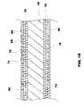
- FIG. 1Ashows a close-up cross-sectional view of a portion of a tip of the thermal surgical tool system of FIG. 1 ;
- FIG. 1Bshows a close-up cross-sectional view of a portion of another tip according to principles of the present invention
- FIG. 1Cshows a close-up cross-sectional view of a portion of another tip according to principles of the present invention
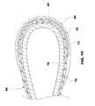
- FIG. 1Dshows a fragmented cross-sectional view of a tip having a loop geometry
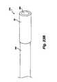
- FIG. 2shows a perspective view of a thermal surgical tool system in accordance with the present invention
- FIG. 3shows a diagram of a thermal surgical tool system in accordance with the principles of the present invention
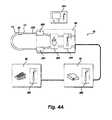
- FIG. 4Ashows a thermal surgical tool system with heat prevention terminals, heat sink, and wireless communication devices
- FIG. 4Bshows a portion of a thermal surgical tool system with an impedance matching network
- FIG. 4Cshows a side cross-sectional view of a portion of a thermal surgical tool system according to principles of the present invention
- FIG. 4Dshows a side cross-sectional view of a portion of a thermal surgical tool system according to principles of the present invention
- FIG. 5shows a close-up, side cross-sectional view of a single layer ferromagnetic coated conductor tip in accordance with one aspect of the present invention
- FIG. 6shows a close-up, side cross-sectional view of a single layer ferromagnetic coated conductor tip with a thermal insulator in accordance with one aspect of the present invention
- FIG. 7Ashows a close-up view of ferromagnetic coated conductor surgical tool tip with a loop geometry in accordance with one aspect of the present invention
- FIG. 7Bshows a close-up view of a ferromagnetic coated conductor surgical tool tip with a generally square geometry in accordance with one aspect of the present invention
- FIG. 7Cshows a close-up view of a ferromagnetic coated conductor surgical tool tip with a pointed geometry
- FIG. 7Dshows a close-up view of a ferromagnetic coated conductor surgical tool tip with an asymmetrical loop geometry
- FIG. 7Eshows a close-up view of a ferromagnetic coated conductor surgical tool tip with a hook geometry in which the concave portion may be used for therapeutic effect, including cutting;
- FIG. 7Fshows a close up view of a ferromagnetic coated conductor surgical tool tip with a hook geometry in which the convex portion may be used for therapeutic effect, including cutting;
- FIG. 7Gshows a close up view of a ferromagnetic coated conductor surgical tool tip with an angled geometry
- FIG. 8shows a cut-away view of a retracted snare
- FIG. 9Ashows a side view of an extended snare
- FIG. 9Bshows an alternate embodiment of an extended snare
- FIG. 10Ashows a close-up view of a ferromagnetic coated conductor surgical tool with a loop geometry and linear array of coatings
- FIG. 10Bshows a close up view of a ferromagnetic coated conductor surgical tool with an alternate hook geometry and linear array
- FIG. 11shows a cut-away view of a retracted snare with an array of coatings
- FIG. 12shows a side view of an extended snare with an array of coatings
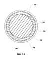
- FIG. 13shows an axial cross-sectional view of a single layer ferromagnetic coated conductor surgical tool in the ferromagnetic-coated region
- FIG. 14Ashows a perspective view of a multi-layer ferromagnetic coated conductor surgical tool tip
- FIG. 14Bshows a side cross-sectional view of a multi-layer ferromagnetic coated conductor surgical tool tip shown in 14 A;
- FIG. 15shows an axial cross-section of the multi-layer ferromagnetic coated conductor surgical tool tip shown in FIG. 14A ;
- FIG. 16shows a cross-sectional view of a flattened side cylindrical geometry ferromagnetic coated conductor showing electromagnetic lines of flux
- FIG. 17shows a closed conductor tip in accordance with another aspect of the present invention.
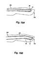
- FIG. 18Ashows a single edge ferromagnetic coated conductor surgical tool tip in accordance with one aspect of the invention
- FIG. 18Bshows a double edge ferromagnetic coated conductor surgical tool tip
- FIG. 18Cshows a three wire ferromagnetic coated conductor surgical tool tip
- FIG. 18Dshows a receptacle for the tips shown in FIGS. 18A through 18C ;
- FIG. 19Ashows a normally cold cutting scalpel with alternate ferromagnetic thermal function
- FIG. 19Bshows a normally cold cutting scalpel with alternate ferromagnetic thermal function
- FIG. 20Ashows a thermal surgical tool with a spatula shaped geometry
- FIG. 20Bshows a thermal surgical tool with a spatula shaped geometry in a forceps configuration
- FIG. 20Cshows a top view of the thermal surgical tool of FIG. 20A with a ferromagnetic coated conductor upon the primary geometry
- FIG. 20Dshows a top view of the thermal surgical tool of FIG. 20A with a ferromagnetic coated conductor embedded within the primary geometry;
- FIG. 20Eshows a close-up, side cross-sectional view of a thermal surgical tool with a ferromagnetic coated conductor disposed thereon;
- FIG. 20Fshows a perspective view of a heating element of the present invention that may be disposed on a primary geometry
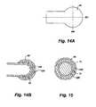
- FIG. 21Ashows a thermal surgical tool with a ball shaped geometry and horizontal winding
- FIG. 21Bshows an alternate embodiment of a thermal surgical tool with a ball shaped geometry and horseshoe configuration
- FIG. 21Cshows an alternate embodiment of a thermal surgical tool with a ball shaped geometry and vertical orientation
- FIG. 22Ashows a thermal surgical tool with a pointed geometry
- FIG. 22Bshows a thermal surgical tool with a pointed geometry in a forceps configuration
- FIG. 22Cshows a thermal surgical tool having two different activatable thermal zones
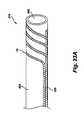
- FIG. 23Ashows a perspective view of a catheter having a coil of ferromagnetic coated conductor disposed around the tip of the catheter;
- FIG. 23Bshows a perspective view of an ferromagnetic coated conductor surgical tool catheter tip
- FIG. 24shows a side view of an alternate embodiment of an ferromagnetic coated conductor surgical tool catheter tip
- FIG. 25shows an alternate embodiment of a ferromagnetic coated conductor surgical tool ferromagnetic tip disposed within an endoscope
- FIG. 26shows a tissue ablation tool
- FIG. 27shows a thermal spectrum as related to tissue effects.
- the term “ferromagnetic,” “ferromagnet,” and “ferromagnetism”refers to any ferromagnetic-like material that is capable of producing heat via magnetic induction, including but not limited to ferromagnets and ferrimagnets. It is not intended that such materials must be heated exclusively by magnetic induction unless otherwise indicated and such may acquire heat from resistive heating, eddy currents, etc., in addition to magnetic induction.
- FIG. 1there is shown a perspective view of a thermal surgical tool system, generally indicated at 10 .
- the thermal tool systempreferably uses a ferromagnetic coated conductor to treat or destroy tissue (i.e. cutting, endothelial tissue welding, homeostasis, ablation, etc.).
- the thermal surgical tooluses heat to incise tissue and may not cut tissue in the sense of a sharp edge being drawn across the tissue as with a conventional scalpel. While the embodiments of the present invention could be made with a relatively sharp edge so as to form a cutting blade, such is not necessary as the heated coating discussed herein will separate tissue without the need for a cutting blade or sharp edge. However, for convenience, the term cutting is used when discussing separating tissue.
- a control mechanismsuch as a foot pedal 20 is used to control output energy produced by a power subsystem 30 .
- the energy from the power subsystem 30may be sent via radio frequency (RF) or oscillating electrical energy along a cable 40 to a handheld surgical tool 50 , which contains a conductor portion 60 having a section thereof circumferentially coated with a ferromagnetic portion 65 .
- the ferromagnetic portion 65may transfer the electrical energy into available thermal energy. This may be done, for example, via induction and corresponding hysteresis losses in the ferromagnetic material disposed around a conductor wire 66 .
- conductor wiremay be used for ease of reference, it will be appreciated that the conductor material need not be a wire and those skilled in the art will be familiar with multiple conductors which will work in light of the disclosure of the present invention. Additionally, as will be explained below, the conductor wire 66 may be include a support (either conductive or not) covered by a conductive coating).
- Electrodeposited filmssuch as a nickel-iron coating like PERMALLOYTM, may form an array of randomly aligned microcrystals, resulting in randomly aligned domains, which together may have an open loop hysteresis curve when a high frequency current is passed through the conductor.
- the RF energymay travel along the conductor's surface in a manner known as the “skin effect”.
- the current densityis generally greatest at the surface and decreases in magnitude farther into the material where the electric field approaches zero.
- the depth at which the skin effect current is reduced to about 37 percent of its surface valueis referred to as the skin depth and is a function of the electrical resistivity, the magnetic permeability of the material conducting the current, and the frequency of the applied alternating RF current.
- the alternating RF current in the conductor's surfaceproduces an alternating magnetic field, which may excite the domains in the ferromagnetic portion 65 .
- hysteresis losses in the coatingmay cause inductive heating. Heating of the ferromagnetic portion 65 due to hysteresis loss ceases above the Curie point because the material loses its magnetic properties.
- the RF conductor from the signal source up to and including the tipmay form a resonant circuit at a specific frequency (also known as a tuned circuit). Changes in the tip “detune” the circuit. Thus, should the ferromagnetic portion 65 or the conductor 66 become damaged, the circuit may likely become detuned. This detuning should reduce the efficiency of the heating of the ferromagnetic portion 65 such that the temperature will be substantially reduced. The reduced temperature should ensure little or no tissue damage after breakage.
- the surgical tool 50may include indicia of the power being applied and may even include a mechanism for controlling the power.
- a series of lights 52could be used to indicate power level
- the handheld surgical tool 50could include a switch, rotary dial, set of buttons, touchpad or slide 54 that communicates with the power source 30 to regulate power and thereby affect the temperature at the ferromagnetic portion 65 to having varying effects on tissue.
- the controlsare shown on the foot pedal 20 or the handheld surgical tool 50 , they may also be included in the power subsystem 30 or even a separate control instrument.
- Safety featuressuch as a button or touchpad that must be contacted to power the handheld surgical tool 50 may be employed, and may include a dead man's switch.
- the ferromagnetic material 65such as a ferromagnetic coating 78 may have a calculable Curie temperature.
- a Curie temperatureis the temperature at which the material becomes paramagnetic, such that the magnetic properties of the coating are lost.
- the ferromagnetic heatingmay be significantly reduced or even cease. Theoretically, this should cause the temperature of the ferromagnetic material 65 to stabilize around the Curie temperature if sufficient power is provided to reach the Curie temperature.
- the temperature of the ferromagnetic material 65may exceed its calculated Curie temperature under certain operational conditions.
- the tip temperaturecan continue to rise due to resistive heating in the overall conductor and the tip can potentially exceed the Curie temperature.
- an increase in currentis observed while operating at a constant power level. It is believed that this may be due, at least in part to an increase in the skin depth and a resulting drop in impedance above the Curie temperature. The increase may also be due to the resistance of the ferromagnetic coating dropping and raising the current level for a fixed power level. The increased current may then cause more resistive heating in the non-ferromagnetic portion of the conductor. Thus, it may be preferable to have a high conductivity in the conductor.
- the thermal surgical tool system 10allows the power output to be adjustable in order to adjust the temperature of the tool and its effect on tissue. This adjustability gives the surgeon precise control over the effects that may be achieved by the handheld surgical tool 50 . Tissue effects such as cutting, hemostasis, tissue welding, tissue vaporization and tissue carbonization occur at different temperatures.
- the foot pedal 20or some other user control, such as a dial 32 on the power subsystem 30 ) to adjust the power output, the surgeon (or other physician, etc.) can adjust the power delivered to the ferromagnetic portion 65 and consequently control the tissue effects to achieve a desired result.
- the foot pedal 20may also be configured only to provide on and off, with the dial controlling power level.
- Thermal power deliverycan be controlled by varying the amplitude, frequency or duty cycle of the alternating current waveform, or alteration of the circuit to affect the standing wave driving the ferromagnetic coated conductor, which may be achieved by input received by the foot pedal 20 , the power subsystem 30 , or the controls on the handheld surgical tool 50 .
- the inductive or other ferromagnetic heatingis that the ferromagnetic material can be heated to a cutting temperature in a small fraction of a second (typically as short as one quarter of a second). Additionally, because of the relatively low mass of the coating, the small thermal mass of the conductor, and the localization of the heating to a small region due to construction of the handheld surgical tool 50 , the material will also cool extremely rapidly (i.e. as low as approximately one half of a second). This provides a surgeon with a precise thermal tool while reducing accidental tissue damage caused by touching tissue when the thermal tool is not activated.
- the time period required to heat and cool the handheld surgical tool 50will depend, in part, on the relative dimensions of the conductor 60 and the ferromagnetic portion 65 and the heat capacity of the structure of the surgical tool.
- the above time periods for heating and cooling of the handheld surgical tool 50can be achieved with a tungsten conductor having a diameter of about 0.375 mm and a ferromagnetic coating of a Nickel Iron alloy (such as NIRONTM available from Enthone, Inc. of West Haven, Conn.) about the tungsten conductor about 0.0375 mm thick and two centimeters long.
- a Nickel Iron alloysuch as NIRONTM available from Enthone, Inc. of West Haven, Conn.
- One advantage of the present inventionis that a sharp edge is not needed.
- the toolWhen power is not being supplied to the surgical tool, the tool will not inadvertently cut tissue of the patient or of the surgeon if it is dropped or mishandled. If power is not being supplied to the conductor 66 and coating 78 , the “cutting” portion of the tool may be touched without risk of injury. This is in sharp contrast to a cutting blade which may injure the patient or the surgeon if mishandled.
- Thismay include a sensor stem 12 including a sensor to report temperature or a light to illuminate the surgical area.
- FIG. 1Athere is shown a cross-sectional view of a portion of a surgical tip having a conductor 66 , such as a conductor wire, in accordance with one aspect of the invention.
- a conductor 66such as a conductor wire
- the conductor 66may have a relatively small diameter or cross-section so as to make precise cuts in tissue, or other materials.
- the conductor 66may include a support 70 which will resist bending even when the support has a fairly small diameter or cross-section. Examples of metals having this property may include tungsten, titanium, stainless steel, Haynes 188 , Haynes 25 , etc.
- the Young's Modulus of the support 70may be important. These properties may include the resistivity of the material, the thermal and electrical conductivity of the material, the material's heat capacity, the material's coefficient of thermal expansion, the annealing temperature of the material, and the ability to plate a second material to the material comprising the support 70 .
- the support 70it may be important that such material have the greatest amount of resistance to bending while having low resistivity to minimize heating of the conductor 66 due to resistance heating. Additionally, it may also be important that the material have a low heat capacity so that heat is not stored in the conductor 66 thus allowing the surgical tip to cool rapidly when not being used. This may help limit or prevent collateral damage to structures adjacent the surgical site.
- the support 70be comprised of material having a sufficiently high annealing temperature.
- the surgical tipmay be operated at temperatures, for example, between 400 degrees Celsius and 450 degrees Celsius.
- the annealing temperature of the material used as the support 70should be sufficiently higher than the expected operating ranges of the surgical tip.
- the support 70be comprised of a material having a coefficient of thermal expansion value that is close to the coefficient of thermal expansion of the ferromagnetic material 65 , such as a ferromagnetic coating 78 , to facilitate plating of the ferromagnetic coating 78 to the support 70 in some configurations.
- one or more intervening layers having an intermediate coefficient of thermal expansionmay be plated on the support 70 and then the ferromagnetic layer or coating 78 plated on the one or more intervening layers to provide for a transition to accommodate the difference between the coefficients of thermal expansion of the support 70 and the ferromagnetic material 65 , as described in more detail below.
- a conductor 66may be comprised of multiple layers of different material so as to minimize any undesirable property or properties of the support 70 .
- the support 70may be conductive or non-conductive, and may have a one or more conductive intervening layers 74 disposed thereon, such as copper, silver, etc. or other conductive material.
- the intervening layerallows the energy to pass without significant resistive heating, thus allowing the tip to cool down more rapidly.
- the cross-sectional view of FIG. 1Ais not necessarily to scale and the support may be much larger in diameter than the thickness of the other layers discussed herein.
- the conductive intervening layer 74may extend the entire length of the conductor 66 as will be discussed in more detail below).
- the material or substrate used as the support 70may have an optimal thermal conductivity to allow for conductive cooling of the surgical tip when energy is not being delivered to the conductor 66 . Furthermore, the support 70 will have a sufficiently high Young's modulus to resist bending when the surgical tool is being used to provide a thermal therapeutic effect to tissue during a procedure.
- the support 70may be comprised of a material having a Young's Modulus (modulus of elasticity) of greater than 17 psi (118 GPa).
- the support 70may be comprised of a material having a Young's Modulus of about 58 psi (400 GPa) or greater, such as tungsten.
- the intervening layer 74be readily attachable to the support 70 . This may be accomplished by using a substrate as the support 70 that allows for electroplating of the intervening layer 74 thereto under reasonable commercial standards.
- the substratemay be easily deoxidized (“activated”) to facilitate plating of the intervening layer 74 to the support 70 .
- the one or more conductive intervening layers 74may comprise a variety of materials, such as copper, silver, etc., having desired properties.
- the intervening layer 74may be disposed along a portion of the support or substantially extend along the entire length of the support 70 .
- An important property of the intervening layer 74is that it be a good electrical conductor having low resistivity such that heating due to the resistance of the intervening layer 74 is minimized.
- it is desirable in some configurations that one of the intervening layer(s) 74not only be readily attachable to the support 70 , but also be a good substrate for attaching the ferromagnetic material 65 , such as a ferromagnetic layer or coating 78 thereto.
- thismay be accomplished by using a substrate as the intervening layer 74 that allows for electroplating of a ferromagnetic coating 78 thereto under reasonable commercial standards, such as a substrate that is easily activated to facilitate plating of the ferromagnetic layer 78 .
- the intervening layer 74may have to be sufficiently malleable so that the integrity of the intervening layer 74 is not easily compromised when subjected to the thermal conditions under which the surgical tip is operated.
- a surgical tip including an intervening layer 74 comprised of copper having a linear coefficient of thermal expansion of approximately 17 ⁇ m/° C. attached to a support 70 comprised of tungsten having a linear coefficient of thermal expansion of approximate 4.5 ⁇ m/° C.may be sufficient to withstand the heat variability that the surgical tip undergoes under normal operation.
- the conductor 66 of FIG. 1Aalso shows a ferromagnetic layer or coating 78 disposed adjacent to the intervening layer 74 .
- the ferromagnetic layer of coating 78may be plated on the intervening layer 74 .
- the ferromagnetic material 78may be located along a portion of the conductor 66 at a defined location (or locations) so as to provide for localized heating along the surgical tip only in an area where heating is desired.
- the ferromagnetic layer or coating 78may be located along less than about 90%, 50%, 10%, etc. of the length of the conductor 66 so as to provide localized heating in a desired area.
- the length which the ferromagnetic material extendsmay be less than the length of the conductor 66 .
- the ferromagnetic coating 78may have high permeability to facilitate inductive or other ferromagnetic heating of the ferromagnetic material, such as NIRONTM, PERMALLOYTM, Co, CrO2, etc. Additionally, the ferromagnetic coating 78 may have a relatively high thermal conductance and low heat capacity to facilitate rapid heating and cooling of the surgical tip.
- the surgical tipmay include a ferromagnetic material 65 , such as a ferromagnetic coating 78 , having a coefficient of thermal expansion that varies significantly from the coefficient of thermal expansion of the support 70 .
- a surgical tipmay also include at least one intervening layer 74 having a coefficient of thermal expansion with an intermediate value to accommodate the differences in the coefficient of thermal expansions of the ferromagnetic coating 78 and the support 70 .
- Such a configurationmay help maintain the integrity of the surgical tip under expected operating conditions.
- the ferromagnetic coating 78may be exposed or may be covered with an exterior coating 80 made from a biocompatible material to ensure that there is no reaction between the ferromagnetic coating 78 and the patient tissues.
- the exterior coating 80may also act as a lubricant between the surgical tip and tissue which is being treated by reducing the attachment of biologic tissues to the surgical tip.
- the exterior coating 80may be titanium nitride (or one of its variants), TEFLON or a host of other biocompatible materials.
- the exterior layer 80may also act as an oxygen barrier to prevent oxidation of the layer of ferromagnetic material 65 , any intervening layer 74 , and/or the support 70 .
- oxidation of the support 70may cause the support 70 to become brittle making the support 70 more susceptible to damage.
- the exterior layer 80may be disposed on the conductor 66 so as to substantially cover the ferromagnetic material and the entire conductor 66 .
- the exterior layermay be disposed on the conductor 66 so as to cover the ferromagnetic coating 78 and only a portion of the conductor 66 .
- a conductor 66may comprise a support 70 having a diameter of about 500-750 ⁇ m, an intervening layer 74 having a cross-sectional thickness of about 20-50 ⁇ m (or about 2-5 skin depths), and a ferromagnetic material 65 (e.g. a coating 78 ) having a cross-sectional thickness of about 2-10 ⁇ m.
- the thickness of the ferromagnetic material forming the layer or coating 78may be selected as a function of the skin depths of the intervening layer 74 , or the combined skin depths of multiple intervening layers if such are included in a surgical tip as described below.
- the antioxidation layermay be very thin, such as 1-3 ⁇ m.
- FIG. 1Bthere is shown a close-up cross-sectional view of a portion of another surgical tip according to principles of the present invention.
- the tip in FIG. 1Bis similar to the tip in FIG. 1A with the addition of a second intervening layer 76 .
- the second intervening layer 76may be a strike layer, such as nickel strike or gold flash, for facilitating plating of the first intervening layer 74 to the support.
- the second intervening layer 76may be relatively thin, for example, about 1-2 ⁇ m.
- the second intervening layer 76may provide for better attachment or bonding of the first intervening layer 74 to the support 70 .
- the second intervening layer 76may have a coefficient of thermal expansion which provides a transition to accommodate any differences in the coefficient of thermal expansions between the support 70 and the ferromagnetic material 65 (typically a ferromagnetic coating 78 ), and any other intervening layers, such as the first intervening layer 74 . It will be appreciated that taking into account the coefficients of thermal expansion of the different layers which may be used in constructing a surgical tip of the present invention may increase the durability of the surgical tip. It will also be appreciated that additional intervening layers, other than those shown, may be included to further provide for a more gradual transition of coefficients of thermal expansion between layers. For example, the conductor 66 may include a strike layer in addition to multiple intervening layers.
- the surgical tipmay comprise a conductor 66 having a support 70 that is tubular.
- the wall 70 awhich circumscribes a void 70 b of the support 70 can be seen.
- the conductor 66is shown as being generally linear, it will be appreciated that the conductor can be formed into a variety of shapes.
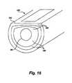
- FIG. 1Dshows a fragmented cross-sectional view of a portion of a surgical tip having loop geometry.
- the surgical tip in FIG. 1Dmay include a conductor 66 having one or more intervening layers, a ferromagnetic material, and a biocompatible layer disposed thereon.
- the multiple layersare shown disposed on one side of the support 70 , but it will be appreciated that one or more of the multiple layers shown may be circumferentially disposed on the support 70 ).
- the various layers which make up the surgical tipmay be disposed on and extend along the support 70 at various lengths.
- the second intervening layer 76may substantially extend the entire length of the support 70 .
- first intervening layer 74(and/or any additional intervening layers) and a biocompatible layer 80 may substantially extend along the entire length of the support 70 .
- first intervening layer 74 and the biocompatible layer 80may extend a short distance beyond the ferromagnetic material 65 .
- the ferromagnetic material 65may be disposed along only a portion of the conductor 66 at a defined location (or locations) so as to provide for localized heating along the surgical tip only in an area(s) where heating is desired.
- the length of the ferromagnetic materialmay depend, in large part, on the desired use of the device.
- the length at which each of the multiple layers is disposed along the substrate 70may vary depending on the treatment for which the surgical tip formed by the conductor 66 is to be used. For example, in some situations, it may be desirable to have very localized heating in order to cause as little trauma to adjacent tissue as possible. Thus, if the surgical tip is trying to cut through a thin membrane without damaging tissue thereunder or conducting brain surgery, the ferromagnetic material may be half a centimeter or less in length to provide a very precise cutting region. In contrast, if the surgical tip is being used to cut through muscle, thicker tissue, or is being used as a loop to cut out and cauterize tissue, such as removing a large tumor, it may be desirable to have the ferromagnetic material be several centimeters long.
- FIG. 2a perspective view of an alternate embodiment of a thermal surgical system 10 is shown.
- the power source 30is contained within the foot pedal 20 .
- the instrumentmay even be entirely battery powered for relatively low power applications.
- An alternate embodiment for low power requirementsmay include the battery, power adjustment and power delivery, all self-contained in the handle 51 of the handheld surgical tool 50 .
- a wireless communication modulecan be employed to send and receive information from the handheld surgical tool 50 , including status and control settings that would enable users to monitor system performance and alter power settings remotely from the handheld surgical tool 50 itself.
- this thermal solutionmay provide advantages over monopolar and bipolar electrical systems currently available because the thermal damage may remain very close to the ferromagnetic surface of the coated region, whereas monopolar and bipolar electrical tissue ablation may frequently cause tissue damage for a distance away from the point of contact. It is our understanding that this method may also overcome disadvantages of other thermal devices based upon resistive heating, which may require more time to heat and cool, and thus present greater patient risk, while potentially having higher voltage requirements at the point of heating.
- the thin ferromagnetic portion 65may reduce the heating of other non-target material in the body, such as blood when working within the heart in atrial ablation—which can lead to complications if a clot is formed.
- the small thermal mass of the conductor wire 66 , the one or more intervening layers 74 , 76 , ferromagnetic coating 78 and exterior layer 80 (if any), as well as localization of the heating to a small region provided by the construction of the tool (i.e. ferromagnetic portion 65 and adjacent structures)provides a reduced thermal path for heat transfer in directions away from the location of the ferromagnetic portion 65 . This reduced thermal path may result in the precise application of heat at only the point desired.
- risks of ignitionsuch as by anesthetic gasses within or around the patient by sparks, are also reduced.
- the thermal surgical tool system 10may be used for a variety of therapeutic means—including sealing, “cutting” or separating tissue, coagulation, or vaporization of tissue.
- the thermal surgical tool system 10may be used like a knife or sealer, wherein the surgeon is actively “cutting” or sealing tissue by movement of the ferromagnetic portion 65 through tissue.
- the thermal action of the embodiments disclosed heremay have distinct advantages including substantial reduction, if not elimination, of deep tissue effects compared with those associated with monopolar and bipolar RF energy devices.
- the ferromagnetic coated conductor 60may be inserted into a lesion and set to a specific power delivery or variable power delivery based on monitored temperature.
- the thermal effects on the lesion and surrounding tissuemay be monitored until the desired thermal effect is achieved or undesired effects are noticed.
- One advantage of the application of the ferromagnetic coated conductoris that it may be cost-effective compared to microwave or thermal laser modalities and avoids the undesired tissue effects of microwave lesion destruction.
- a surgeoncan insert the ferromagnetic coated conductor into a tumor or other tissue to be destroyed and precisely control the tissue damage that is created by activating the handheld surgical tool 50 .
- Sensorsmay be used to monitor conditions of the handheld surgical tool 50 or the tissue, such as an infrared detector or sensor stem 12 .
- the temperature of the device or tissuemay be important in performing a procedure.
- a sensor in the form of a thermocouple, a junction of dissimilar metals, thermistor or other temperature sensormay detect the temperature at or near the ferromagnetic portion 65 or tissue.
- the sensormay be part of the device, such as a thermocouple placed as a part of the conductor or near the ferromagnetic coating, or separate from the handheld surgical tool 50 , such as a separate tip placed near the tissue or ferromagnetic portion 65 .
- the temperaturesmay also be correlated with tissue effects, seen in FIG. 27 .
- Other useful conditions to monitormay include, but are not limited to, color, spectral absorption, spectral reflection, temperature range, water content, proximity, tissue type, transferred heat, tissue status, impedance, resistance, voltage and visual feedback (i.e. a camera, fiberoptic or other visualization device).
- the handheld surgical tool 50may be configured for repeat sterilization or single patient uses. More complex devices may be useful for repeat sterilization, while more simple devices may be more useful for single patient use.
- a method for treating or cutting tissuemay include the steps of: selecting a surgical tool having a cutting edge and a conductor disposed adjacent the cutting edge, at least a portion of which is coated with a ferromagnetic material; cutting tissue with the cutting edge; and applying oscillating electrical energy to the conductor to heat the ferromagnetic material and thereby treating the cut tissue.
- Optional steps of the methodmay include the steps of: causing hemostasis within the cut tissue; using the heated ferromagnetic material to incise tissue; or using the heated ferromagnetic material to cause vascular endothelial welding.
- FIG. 3a diagram of an embodiment of the adjustable thermal surgical tool system 10 is shown.
- the power delivery to the ferromagnetic portion 65is controlled by a modulated high frequency waveform.
- the modulated waveformallows power delivery to be controlled in a manner that adjustably modifies, allows or blocks portions of the waveform based on the desired power delivery.
- an initial waveform 110is passed through a modulator 120 receiving commands from a foot pedal 20 .
- the waveformis created by an oscillator 130 to the desired frequency, and modulated by the modulator 120 , which may include, but is not limited to, one or more of amplitude, frequency or duty cycle modulation, including a combination thereof.
- the resultant signalis then amplified by an amplifier 140 .
- the amplified signalis sent across a tuned cable 150 , meaning that the cable is tuned to provide a standing wave with maximum current and minimum voltage at the location of the ferromagnetic portion 65 of the handheld surgical tool 50 .
- the cable 150may not be tuned, but a circuit may be placed in the handle 51 to impedance match the ferromagnetic coated conductor 60 as a load to the power source 30 .
- the thermal surgical tool system 10may be tuned by specifying the location of the ferromagnetic portion 65 with respect to the amplifier 140 (such as cable length) and tuning the high frequency signal to approximately a resonant standing wave such that current is maximized at the location of the ferromagnetic portion 65 .
- approximately a standing wavemeans that a circuit may be tuned such that the signal may be near an optimal standing wave but may not achieve it, may only achieve the wave for small amounts of time, or may successfully achieve a standing wave for longer periods of time.
- any use of “standing wave” without the modifier of approximateshould be understood to be approximate in the context of the thermal surgical tool.
- One method for achieving such current maximizationis to connect the ferromagnetic coated conductor 60 to a cable 150 that is an odd multiple of one-quarter wavelengths in length and connected to the output of the amplifier 140 .
- the design of the circuit having a resonant standing waveis intended to optimize power delivery to the ferromagnetic coating.
- the power source 30could be positioned at the location of (or closely adjacent to) the ferromagnetic portion 65 , and tuning could be achieved with electrical components, all within a single handheld, battery-powered instrument.
- electrical components necessary for impedance matchingcan be located at the output stage of the amplifier 140 .
- electrical componentssuch as a capacitor or inductor, can be connected in parallel or series to the ferromagnetic coated conductor 60 at the location of the connection of the conductor wire 66 to the cable 150 , in order to complete a resonant circuit.
- Dynamic load issuescan be caused by the interaction of the ferromagnetic coated conductor 60 with various tissues. These issues may be minimized by the standing current wave being maximized at the load location.
- Multiple different frequenciescan be used, including frequencies from 5 megahertz to 24 gigahertz, preferably between 40 MHz and 928 MHz. In some regulated countries it may be preferable choose frequencies in the ISM bands such as bands with the center frequencies of 6.78 MHz, 13.56 MHz, 27.12 MHz, 40.68 MHz, 433.92 MHz, 915 MHz, 2.45 GHz, 5.80 GHz, 24.125 GHz, 61.25 GHz, 122.5 GHz, 245 GHz.
- the oscillator 130uses an ISM Band frequency of 40.68 MHz, a class E amplifier 140 , and a length of coaxial cable 150 , all of which may be optimized for power delivery to a ferromagnetic coated tungsten conductor 60 with a ferromagnetic portion 65 consisting of a thickness of between 0.05 micrometer and 500 micrometers, and preferably between 1 micrometer and 50 micrometers.
- a useful estimatemay be to start the ferromagnetic coating thickness at 10% of the conductor diameter, and up to 5 cm long.
- the ferromagnetic coatingmay be disposed as far along the length or along multiple regions of the conductor as where heating may be desired.
- the ferromagnetic portion 65may be formed from a Nickel Iron (NiFe) alloy, such as NIRONTM from Enthone, Inc. of West Haven, Conn., or other ferromagnetic coatings, including, but not limited to Co, Fe, FeOFe 2 O 3 , NiOFe 2 O 3 , CuOFe 2 O 3 , MgOFe 2 O 3 , MnBi, Ni, MnSb, MnOFe 2 O 3 , Y 3 Fe 5 O 12 , CrO 2 , MnAs, Gd, Dy, EuO, magnetite, yttrium iron garnet, aluminum, PERMALLOYTM, zinc, etc.)
- NiFeNickel Iron
- the size of the conductor(which may include a support having one or more intervening layers disposed thereon), size of the ferromagnetic coating, associated thicknesses, shape, primary geometry, composition, power supply and other attributes may be selected based on the type of procedure and surgeon preferences. For example, a brain surgeon may desire a small instrument in light handheld package designed for quick application within the brain, while an orthopedic surgeon may require a larger device with more available power for operation on muscle.
- the conductormay be comprised of one or more metals, wherein connection of two dissimilar metals may form a thermocouple. If the thermocouple were placed in the vicinity of or within of the ferromagnetic coating, the thermocouple may provide a temperature feedback mechanism for the device. Further, some conductors, or parts of the conductor, may have a resistivity that correlates to temperature, which may also be used to measure temperature.
- the tuning of the power source 30also reduces the amount of high frequency energy radiating into the patient to near zero, as voltage is low, and ideally zero, at the location of the ferromagnetic portion 65 . This is in contrast to monopolar devices, which require a grounding pad to be applied to the patient, or bipolar devices, both of which pass current through the tissue itself.
- monopolar deviceswhich require a grounding pad to be applied to the patient
- bipolar devicesboth of which pass current through the tissue itself.
- the combination of cable length, frequency, capacitance and inductancemay also be used to adjust efficiency and tool geometry by tuning the power source 30 to deliver maximum power to the ferromagnetic portion 65 , and therefore, maximum heat to the tissue.
- a tuned systemalso provides for inherent safety benefits; if the conductor were to be damaged, the system would become detuned, causing the power delivery efficiency to drop, and may even shut down if monitored by an appropriate safety circuit.
- the amount of power delivered to the patient tissuemay be modified by several means to provide precise control of tissue effects.
- the power source 30may incorporate a modulator 120 for power delivery as described above.
- Another embodimentuses modification of the magnetic field by altering the geometry of the conductor wire 66 and the ferromagnetic portion 65 through which it passes, such as would be caused by a magnet. Placement of the magnet nearby the ferromagnetic portion 65 would similarly alter the induction effect and thereby change the thermal effect.
- the output power, and correspondingly the temperature, of the toolis controlled by tuning or detuning the drive circuit, including the conductor wire 66 and ferromagnetic coated conductor 60 .
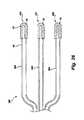
- FIG. 4Aa thermal surgical tool system 10 with connectors which attach to opposing first and second ends of a conductor is shown.
- the conductormay be a wire conductor or other configuration as discussed herein).
- the conductors as shown in FIG. 4Amay be formed by heat prevention terminals 280 , such as crimp connectors that provide thermal isolation.
- One or more heat sinks 282 , and wireless communication devices 286may also be included.
- the conductor 220may be connected to the handheld surgical tool 50 by terminals 280 and/or a heat sink 282 at opposing first and second ends of the conductor. Portions of the conductor may extend into the handle into terminals, while the ferromagnetic coating portion of the conductor may extend beyond the handle.
- the terminals 280may have a poor thermal conductance such that the terminals 280 reduce the heat transfer from the conductor into the handheld surgical tool 50 .
- the heat sink 282may draw any residual heat from the terminals 280 and dissipate the heat into other mediums, including the air.
- Connectors and connectionsmay also be achieved by wire bonding, spot and other welding, in addition to crimping.
- terminals 280are used to conduct the electric current, but prevent or reduce thermal conduction beyond the ferromagnetic coated conductor.
- the thermal surgical toolmay also communicate wirelessly.
- the user interface for monitoring and adjusting power levelsmay be housed in a remote, wirelessly coupled device 284 .
- the wirelessly coupled devicemay communicate with a wireless module 286 contained within the thermal surgical tool system 10 , including the handheld surgical tool 50 , the control system (such as footpedal 20 ), and/or the power subsystem 30 .
- the control interface and displayBy housing the control interface and display in a separate device, the cost of the handheld surgical tool 50 portion may be decreased.
- the external devicemay be equipped with more processing power, storage and, consequently, better control and data analysis algorithms.
- the impedance matching networkmay match the output impedance of the signal source to the input impedance of the load. This impedance matching may aid in maximizing power and minimizing reflections from the load.
- the impedance matching networkmay be a balun 281 .
- Thismay aid in power transfer as the balun 281 may match the impedance of the ferromagnetic coated conductor terminals 287 to the amplifier cable terminals 283 (shown here as a coaxial cable connection).
- some balunsmay be able to act as a heat sink and provide thermal isolation to prevent thermal spread from the thermal energy at the ferromagnetic portion 65 transferred by the conductor 220 to terminals 287 .
- the appropriate matching circuitrymay also be placed on a ceramic substrate to further sink heat away or isolate heat away from the rest of the system, depending on the composition of the substrate.
- FIGS. 4A and 4Bcan be used in conjunction with any of the embodiments shown herein.
- the thermal surgical tool systemmay include a conductor 66 comprising a support 70 and one or more intervening layers 74 (including a strike layer 76 shown in FIG. 1B ), a ferromagnetic portion 65 (typically formed by a ferromagnetic layer 78 ), and a biocompatible layer 80 .
- the conductor 66 of the thermal surgical tool systemmay be attached to a printed circuit board 79 .
- attachment of the conductor to the printed circuit board 79may be facilitated by conductively connecting the conductor to the printed circuit board 79 via the intervening layer 74 .
- an intervening layer 74 comprised of coppermay be more readily attachable to the printed circuit board 79 than a support comprised of tungsten.
- the support 70could be attached mechanically and have an intervening layer to connect the conductor 66 to the printed circuit board electrically.
- a sleeve 75may be disposed on the support 70 to facilitate attachment of the conductor 66 to the printed circuit board 79 as is shown in FIG. 4D .
- the sleeve 75may be attached to the support 70 , for example by TIG welding the sleeve 75 to the support 70 .
- the sleeve 75may be disposed on the support 70 such that the sleeve 75 is in contact with or connected to the intervening layer 74 , as indicated by location 71 , so that electrical energy may be transferred from the sleeve 75 to the intervening layer 74 and thereby cause heating of the ferromagnetic portion 65 .
- the intervening layer 74 shown in FIG. 4Ddoes not extend along the entire length of the support.
- FIG. 5a longitudinal cross section of a ferromagnetic coated conductor according to principles of the present invention is shown.
- a time varying magnetic field 68is induced around conductor 66 .
- a majority of the alternating currentmay travel through one or more conductive layers 74 and, in some embodiments, a strike layer as described in more detail above.
- the time varying magnetic field 68is resisted by the ferromagnetic portion 65 , causing the ferromagnetic coating 78 to dissipate the inductive resistance to the time varying magnetic field 68 as heat.
- the magnetic resistive properties of ferromagnetic coating 78become substantially reduced, resulting in substantially decreased resistance to time varying magnetic field 68 .
- the magnetic fieldcauses the ferromagnetic portion 65 to quickly heat.
- the ferromagnetic coating 78is small in mass compared to conductor wire 66 and therefore heat will quickly dissipate therefrom due to thermal transfer from the hot ferromagnetic coating 78 to the cooler and larger conductor 66 and other structures, as well as from the ferromagnetic coating 78 to the surrounding environment.
- the conductor cross-sectionmay have various geometries.
- the conductormay be a hollow tubing such that it reduces thermal mass as is shown in FIG. 1C .
- the conductormay also be shaped such that it has an oval, triangular, square or rectangular cross-section.
- the ferromagnetic coatingmay be between a first section (or proximal portion) and a second section (or distal portion) of the conductor. This may provide the advantage of limiting the active heating to a small area, instead of the entire conductor.
- a power supplymay also connect to the conductor 66 via the first and second section to include the ferromagnetic coating within a circuit providing power.
- a method of forming the surgical toolmay include the steps of: selecting a conductor and plating a ferromagnetic coating upon the conductor, or plating one or more intervening layers and then plating the ferromagnetic coating on one of the intervening layers as was discussed above.
- Optional steps to the methodmay include: selecting a size of a conductor having a ferromagnetic coating disposed on a portion thereof according to a desired procedure; selecting a thermal mass of a conductor having a ferromagnetic coating disposed on a portion thereof according to a desired procedure; selecting a conductor from the group of loop, solid loop, square, pointed, hook and angled; configuring the oscillating electrical signal to heat the coating to between 37 and 600 degrees Centigrade; configuring the oscillating electrical signal to heat the coating to between 40 and 500 degrees Centigrade; causing the coating to heat to between about 58-62 degrees Centigrade to cause vascular endothelial welding; causing the coating to heat to between about 70-80 degrees Centigrade to promote tissue hemostasis; causing the coating to heat to between about 80-200 degrees Centigrade to promote tissue searing and sealing; causing the coating to heat to between about 200-400 degrees Centigrade to create tissue incisions; or causing the coating to heat to between about 400-500 degrees
- the conductor and the ferromagnetic coatingcan be configured in a wide variety of shapes. These may include, for example, loops, hooks, snares, and a variety of other shapes may be used.
- FIG. 6a close-up, longitudinal cross-sectional view of a conductor 66 with a thermal insulator 310 is shown.
- a layer of thermal insulator 310may be placed between the ferromagnetic coating 78 and the conductor wire 66 .
- Putting a layer of thermal insulator 310may aid in the quick heating and cool-down (also known as thermal response time) of the tool by reducing the thermal mass by limiting the heat transfer to the conductor wire 66 .
- a surgical tip of the present inventionmay include a non-conductive or conductive support 70 , one or more conductive intervening layer 74 (which may include a strike layer 76 shown in FIG. 1B ), an insulative intervening layer 310 , the ferromagnetic coating 78 , and/or a biocompatible layer (not shown)).
- the thickness and composition of the thermal insulatormay be adjusted to change the power delivery and thermal response time characteristics to a desired application.
- a thicker coating of thermal insulator 310may better insulate the conductor 66 from the ferromagnetic coating 78 , but may require increased power compared with a thinner coating of thermal insulator 310 in order to induce a magnetic field sufficient to cause the ferromagnetic coating to heat.
- FIGS. 7A-7Ga plurality of surgical tips 210 a - 210 g are shown in which the surgical tip has a conductor 220 and a ferromagnetic portion 65 which may be formed by relatively thin layer of ferromagnetic coating 78 .
- the conductor 220 of the surgical tip 210may include a non-conductive or conductive support, one or more conductive intervening layers (which may include a strike layer), and/or a biocompatible layer (which are shown in FIGS. 1A-1B above).
- conductor 220may be substantially the same as conductor 66 as discussed above.
- FIGS. 1A-1BAs shown in FIGS.
- the ferromagnetic coating 78(or a layer forming the ferromagnetic portion 65 ) may be a circumferential coating around a conductor 220 .
- the conductor 220When the conductor 220 is excited by a high frequency oscillator, the ferromagnetic coating 78 will heat according to the power delivered, via induction or other means with a limitation being provided in some configurations by its Curie temperature. Because of the small thickness of ferromagnetic coating 78 and the tuned efficiency of high frequency electrical conduction of the wire at the position of the ferromagnetic layer or coating 78 , the ferromagnetic portion 65 will heat very quickly (i.e. a small fraction of a second) when the current is directed through the conductor 220 , and cool down quickly (i.e. a fraction of a second) when the current is stopped.
- FIGS. 7A, 7B, 7C, 7D, 7E, 7F and 7Gspecifically, ferromagnetic coated conductor surgical tips 210 a , 210 b , 210 c , 210 d , 210 e , 210 f and 210 g are shown.
- a portion of conductor 220(which may be formed similar to conductor 66 discussed above) is bent or formed and coated with a ferromagnetic portion 65 (typically a coating) such that the ferromagnetic coating 78 is only exposed to tissue (or covered with an outer layer) where the desired heating is to occur.
- FIGS. 7A, 7B, 7C, 7D, 7E, 7F and 7Gspecifically, ferromagnetic coated conductor surgical tips 210 a , 210 b , 210 c , 210 d , 210 e , 210 f and 210 g are shown.
- a portion of conductor 220(which may be formed similar to conductor
- FIG. 7A and 7Bare loop shapes that can be used for tissue cutting or excision, depending upon the orientation of the tool to the tissue.
- FIG. 7Ashows a rounded geometry
- FIG. 7Bshows a squared geometry.
- FIG. 7Cshows a pointed geometry for heated tip applications that can be made very small because the process of tissue dissection, ablation, and hemostasis requires only a small contact point.
- FIG. 7Dshows an asymmetric tool with a loop geometry, where the ferromagnetic coating 78 is only disposed on one side of the tool.
- FIG. 7Eshows a hook geometry where the ferromagnetic coating 78 is disposed on the concave portion of the hook.
- FIG. 7Fshows a hook geometry where the ferromagnetic coating 78 is disposed on the convex portion of the hook.
- FIG. 7Gshows an angled geometry, which may be used in similar situations as a scalpel. Use of these various geometries of ferromagnetic coating 78 upon a conductor 220 may allow the surgical tip to act very precisely when active and to be atraumatic when non-active.
- the electrical conductormay have a diameter of 0.01 millimeter to 1 millimeter and preferably 0.125 to 0.5 millimeters, and a similar sized support can be used and coated with a thin layer of conductor.
- the electrical conductor or coating on the supportmay be tungsten, copper, other metals and conductive non-metals, or a combination such as two dissimilar metals joined to also form a thermocouple for temperature measurement.
- the electrical conductormay also be a thin coating of conductor, such as copper, dispersed around a non-metallic rod, fiber or tube, such as glass or high-temperature plastic or other materials having desired firmness/flexibility and heat dissipation characteristics.
- the conductive materialin-turn, may be coated with a thin layer of ferromagnetic material.
- the magnetic filmforms a closed magnetic path around the electrically conductive wire.
- the thin magnetic filmmay have a thickness about 0.01-50% and preferably about 0.1% to 20% of the cross-sectional diameter of the wire. Due to the close proximity of the coating to the wire, a small current can produce high magnetic fields in the coating and result in significant temperatures. Since the magnetic permeability of this film is high and it is tightly coupled to the electrical conductor, low levels of current can result in significant hysteresis losses.
- the toolhaving low thermal mass, provides a rapid means for temperature regulation across a therapeutic range between about 37 degrees Celsius and 600 degrees Celsius, and preferably between 40 and 500 degrees Celsius.
- Curie pointhas been previously described as a temperature cap, instead, a material with a Curie point beyond the anticipated therapeutic need may be selected and the temperature can be regulated below the Curie point.
- tip geometriesare shown in FIGS. 7A through 7G , it is anticipated that multiple different geometries of the ferromagnetic coated conductor 66 or 220 may be used.
- FIG. 8a cut-away view of a snare 350 in a retracted position is orientation is shown.
- a ferromagnetic coating 355is placed on a conductor which is formed as a snare and then placed within a sheath 360 .
- the conductor 365may be a solid conductor, a hollow conductor or a conductor coated support as discussed above. Additionally, the ferromagnetic coating 355 may be exposed, or may be covered by a biocompatible material.
- the snare loop 350may rest within a sheath 360 (or some other applicator, including a tube, ring or other geometry designed to reduce the width of the snare when retracted).
- the sheath 360compresses the snare loop 350 within its hollow body.
- the sheath 360may then be inserted into a cavity where the target tissue may be present.
- the snare loop 350may be extended outside the sheath 360 , and end up deployed similar to FIG. 9A .
- the conductor 365may pushed or pulled to cause extension and retraction of the snare loop 355 .
- the conductor 365 of the snare 350may comprise a non-conductive or conductive support, one or more conductive intervening layers 74 (including a strike layer), and/or a biocompatible layer (as shown in FIGS. 1A-1D above). It is desirable that the conductor 365 of the snare 350 be made from a material that is relatively flexible and can “spring” into the loop shape when deployed from the sheath 360 . Additionally, the material used as the conductor 365 should have a sufficiently high annealing temperature as it may be subjected to high temperature during normal operation of the snare 350 . Thus, suitable materials which may be used as the conductor 365 , or one or more layers of the conductor 365 , include, but are not limited to, Nichrome alloys or Haynes alloys.
- the snare 350 loopmay be used in several different ways.
- the snare loop 350may be placed substantially around the target tissue, such that the tissue is within the snare loop 350 .
- the ferromagnetic coating 355may then be caused to be inductively heated (and/or heated by skin effect and/or eddy currents) as discussed above.
- the snare loop 350is then retracted back into the sheath 360 such that the target tissue is separated and removed from tissue adjacent the target tissue.
- the desired temperature range or power levelmay be selected for hemostasis, increased tissue separation effectiveness or other desired setting.
- the snare 350is configured for nasal cavity polyp removal.
- the snare 350may be configured for tissue destruction. Once within the desired cavity, the snare may be extended such that a portion of the snare loop 350 touches the target tissue. The snare loop 350 may then be inductively heated such that a desired tissue effect occurs. For example, in one embodiment, the sheath may be placed near or in the heart and the snare loop 350 inductively heated to cause an interruption of abnormal areas of conduction in the heart, such as in atrial ablation.
- the applicatormay be a ring 361 instead of a sheath as in FIG. 9A . Similar to the sheath, the ring 361 may be used to force the loop into an elongated position. Various devices could be used to hold the ring in place during use. As with the previous configurations, the conductor 365 could be a solid conductor, or could be a conductive covered support. Likewise, the ferromagnetic material may be exposed or covered by a biocompatible material depending on the particular situation.
- a method of separating tissuemay include the steps of: selecting a conductor having a ferromagnetic coating disposed on a portion thereof; placing the portion of the conductor having the ferromagnetic coating within a tube; inserting the tube into a cavity; deploying the portion of the conductor having the ferromagnetic coating within the cavity; and delivering an oscillating electrical signal to the conductor so as to heat the ferromagnetic coating while the heated ferromagnetic coating is in contact with a target tissue.
- Optional stepsmay include: deploying step further comprises placing the ferromagnetic coating substantially around the target tissue; retracting the ferromagnetic coating portion of the conductor into the tube; causing hemostasis in the target tissue; forming the conductor into a bent geometry such that a portion of the conductor remains within the tube; and touching a ferromagnetic covered portion of the bent geometry to the target tissue.
- a method of removing tissuemay include the steps of: selecting a conductor having at least one portion having a ferromagnetic conductor disposed thereon; and placing the ferromagnetic conductor around at least a portion of the tissue and pulling the ferromagnetic conductor into contact with the tissue so that the ferromagnetic conductor cuts the tissue.
- Optional stepsmay include: using a conductor having a plurality of ferromagnetic conductors in an array or passing an oscillating electrical signal through the conductor while the ferromagnetic material is in contact with the tissue.
- FIG. 10Aa close-up view of a cutting tip with a loop geometry and linear array of coatings is shown. While the above embodiments have disclosed a continuous ferromagnetic coating on a conductor, in another embodiment, there is more than one coating separated by gaps on a single conductor. This is termed a linear array of ferromagnetic elements (an example of a parallel array of ferromagnetic elements can be seen in FIGS. 18A-18C ).
- a loop geometry 270 amay have multiple ferromagnetic portions 65 , 65 ′, and 65 ′′ which are separated by gaps on a conductor 220 (which may be formed as conductor 66 discussed above). If desired, the ferromagnetic portions formed by the ferromagnetic layers or coatings 78 may be covered with a biocompatible material, etc.
- FIG. 10Ba close up view of a cutting tip with an alternate hook geometry 270 b and linear array of ferromagnetic portions 65 and 65 ′ is shown on a conductor 220 .
- the linear arraymay include the advantage of allowing flexibility in building a desired thermal geometry.
- the conductor 220which may be formed of an alloy having shape memory, such as Nitinol (nickel titanium alloy).
- a Nitinol or other shape memory alloy conductorcan be bent into one shape at one temperature, and then return to its original shape when heated above its transformation temperature. Thus, a physician could deform it for a particular use at a lower temperature and then use the ferromagnetic coating to heat the conductor to return it to its original configuration.
- a shape memory alloy conductorcould be used to form a snare which changes shape when heated.
- a serpentine shape conductorcan be made of Nitinol or other shape memory alloy to have one shape during use at a given temperature and a second shape at a higher temperature. Another example would be for a conductor which would change shape when heated to expel itself from a catheter or endoscope, and then enable retraction when cooled.
- the ferromagnetic portionsmay be formed in such a way that an individual coating among the linear array may receive more power by tuning the oscillating electrical energy.
- the tuningmay be accomplished by adjusting the frequency and/or load matching performed by the power source to specific ferromagnetic coatings.
- FIG. 11a cut-away view of a snare tool 370 with a linear array of coatings in a retracted position is shown.
- some ferromagnetic portionsmay lack the elasticity to effectively bend into a retracted position. Therefore, individual ferromagnetic segments 375 may be separated by gaps 380 such that the conductor 365 may be flexed while the ferromagnetic segments 375 may remain rigid. For example, a number of small segments of ferromagnetic material may be used and then covered with a more flexible outer layer which would convey the heat to the tissue to be treated.
- the snare tool 370may be extended, as seen in FIG. 12 .
- the gaps 380 between the ferromagnetic segments 375may be adjusted such that the heating effect will be similar in the gaps 380 as the segments.
- the snare tool 370 with linear arraymay act similar to the snare with flexible coating in FIGS. 8 and 9 .
- the ferromagnetic portion 65may be disposed circumferentially about a conductor 220 .
- the surgical tipmay be constructed of multiple layers. Each of the multiple layers may comprise a different material, or combinations of the same or different materials, so as to take advantage of the different properties of the various materials when used as a surgical tip.
- the conductor 220may include a support 70 which may be comprised of a material having high a Young's modulus, i.e. strength to resist bending.
- the conductor 220may also include an the intervening layer 76 , which may be a strike layer to facilitate attachment of additional layers, and an intervening layer 74 , which may comprise one or more layers of copper, silver, or other material which is highly conductive.
- the ferromagnetic material 65which may be a thin layer or coating 78 is then attached to the intervening layer 74 and a biocompatible material 80 may be disposed over substantially all or a portion of the length of the conductor 220 .
- the ferromagnetic coating 78 of the ferromagnetic portion 65may provide several advantages. First, the ferromagnetic coating 78 is less fragile when subjected to thermal stress than ferrite beads, which have a tendency to crack when heated and then immersed in liquid. The ferromagnetic coated conductor 60 has been observed to survive repeated liquid immersion without damage. Further, the ferromagnetic portion 65 has a quick heating and quick cooling quality. This is likely because of the small amount of ferromagnetic coating 78 that is acted upon by the magnetic field, such that the power is concentrated over a small area. The quick cooling is likely because of the small amount of thermal mass that is active during the heating. Also, the composition of the ferromagnetic coating 78 may be altered to achieve a different Curie temperature, which would provide a maximum self-limiting thermal ceiling attribute to the device.
- FIGS. 14A, 14B and 15a multilayer surgical tool tip is shown.
- a cross section of 14 A along the 221 linemay result in FIG. 14B which shows alternating layers of conductor 220 and 220 ′ and ferromagnetic layers or coatings 78 at ferromagnetic portions 65 and 65 ′.
- Heating capacitymay be increased by layering thin layers of alternating conductor material 220 and 220 ′ and ferromagnetic coating 78 at portions 65 and 65 ′, while still maintaining quick heating and cooling advantages.
- FIG. 15shows an axial cross-sectional view from FIG. 14A along the 390 line (For clarity purposes, intervening layers and the biocompatible layer have been omitted from FIGS. 14A, 14B and 15 ).
- the alternating layers of conductor 220 and 220 ′, and ferromagnetic coatings 78 and 78may also be seen.
- the flat surface 180can be manufactured to cause a thin plating 182 of ferromagnetic coating on the conductor 66 relative to the thicker plating around the rest of the conductor 66 .
- This thin plating 182may result in selective first onset heating in this flat surface 180 .
- Inductive heatingmay be proportional to flux density within the magnetically permeable coating.
- an asymmetrically thinned coatinghas a small cross sectional thickness and may generate higher hysteresis losses in the form of heat.
- a therapeutic temperaturemay be achieved with yet lower power at the flat surface 180 with higher flux density 192 compared to a cooler opposite side with a diminished flux density 190 .
- An advantageis that fast temporal response and distributed optimal heating at the tissue interface may be enhanced.
- the ferromagnetic portion 65may also be configured to focus the temperature increase on the outside of the ferromagnetic layer or coating 78 of the ferromagnetic portion, further reducing the time needed to cool the ferromagnetic portion 65 in a relatively high power application.
- An example of such a configurationis shown in FIG. 17 , wherein the fields generated by the current flow 230 and 230 ′ (the arrows) may have a cancelling effect with respect to each other within the ferromagnetic layer or coating 78 surrounding both conductors, keeping the ferromagnetic material between the looped conductor 441 cooler than the ferromagnetic material at the perimeter.
- FIGS. 18A-18Dseveral surgical tip 194 geometries are demonstrated.
- a surgical tip 194 a with a single small diameter electrically conductive wire plated with the thin film magnetic material 196is shown.
- the surgical tip 194 b with two small diameter electrically conductive wires plated with the thin film magnetic material 196 ′is shown.
- a surgical tip 194 c with three small diameter electrically conductive wires plated with the thin film magnetic material 196 ′′are shown. It is thus contemplated that a tip geometry may consist of a plurality of small diameter electrically conductive wires plated with the thin film magnetic material.
- Such a designmaintains the temporal heat responsiveness (rapid onset, rapid offset) essential to the dynamic surgical environment due to minimal mass of the ferromagnetic coated conductor. It is thus possible to configure a flat tine with two or more spaced wires as a practical monothermal or multithermal tool. Further, the tips 194 a , 194 b and 194 c may also be exchangeable as seen in FIG. 18D , which has a receptacle 198 for the tips 194 in FIGS. 18A-18C . It will be appreciated that the generator system may be configured to adjust the power jointly delivered to two or more of the conductors and that a user control (as shown in other figures) can be provided for that purpose.
- the ferromagnetic coating 78can be used to contact the tissue directly, or, a non-stick coating, such as TEFLON (PTFE), or similar material, could be applied over the ferromagnetic coating and conductor around the ferromagnetic portion 65 to prevent sticking to the tissue.
- a non-stick coatingsuch as TEFLON (PTFE), or similar material
- the ferromagnetic coatingcould be coated with another material, such as gold, to improve biocompatibility, and/or polished, to reduce drag force when drawing through tissue.
- the ferromagnetic coatingcould also be coated by a thermally-conductive material to improve heat transfer. In fact, a single coating may be selected to have multiple desirable properties.
- the ferromagnetic coated conductormay be attached to a primary geometry.
- the primary geometrymay provide an attachment surface or an internal site for the conductor with a ferromagnetic coating.
- the primary geometrymay be selected for various reasons, including but not limited to, material strength, rigidity, heat conduction, resistance to thermal heat transfer, surface area, or additional functionality.
- a primary geometrymeans a structure to which a ferromagnetic coated conductor may be attached and which defines the shape of the tool.
- a primary geometrycould be a scalpel, tines of forceps, the face of a spatula, or a ball shape at the end of a probe.
- the conductor geometrytherefore, may be disposed upon the primary geometry, may extend through a hole in the primary geometry, and/or be embedded in the primary geometry.
- a primary geometrymay be a scalpel, while the conductor geometry may be the serpentine shape of a ferromagnetic coated wire upon the primary geometry.
- FIGS. 19A and 19Ba cold cutting scalpel 223 with alternate inductive ferromagnetic thermal function is shown.
- the cold cutting scalpel 223may be used for cutting through the application of a blade having a cutting edge and having a secondary thermal function activated when required, such as for coagulation. In the embodiments shown in FIGS. 19A and 19B , this is achieved by placing a ferromagnetic coated conductor 220 upon the side of a scalpel shaped primary geometry, which can cut tissue without activation of the conductor or ferromagnetic portion 65 .
- the cold cutting scalpel 223may be used classically to make incisions in tissue.
- the cold cutting scalpel 223 operatormay activate the ferromagnetic coated conductor and place the side of the cold cutting scalpel 223 (and correspondingly, the ferromagnetic coated conductor) upon the bleeding tissue. The thermal effect may then cause the tissue to seal and cease bleeding. After deactivation of the ferromagnetic coated conductor, the scalpel operator may then return to making incisions with the benefits of a cold cutting scalpel.
- the dual-use tooldoes not require the cold cutting scalpel 223 operator to remove one tool and replace it with another, causing risk of further damage and delay.
- the cold cutting scalpel 223may also have a quick thermal response time (the heat-up and cool-down time) in the ferromagnetic portion 65 such that the cold cutting scalpel 223 may be used on the targeted area and reduce waiting time.
- thermal response timemay be further reduced by removing a center portion 222 of the blade (as seen in FIG. 19B ), resulting in a non-contiguous portion of the blade that may occur between or adjacent to the conductor path. Removing the center portion 222 of the blade may further reduce the thermal mass and correspondingly the thermal response time.
- the ferromagnetic coatingmay be limited to a defined part or parts of the scalpel, such as the tip of the cold cutting scalpel 223 . This limiting would cause only the tip to heat, while the remaining portions of the primary geometry would remain at a lower temperature. This limiting of the heating to a portion of the primary geometry in proximity to the ferromagnetic coating may provide a higher degree of accuracy and usefulness in smaller spaces.
- the ferromagnetic coated conductor 220may form a pattern, such as a zigzag or serpentine pattern, across the surface of the cold cutting scalpel 223 to increase the heating coverage of the surface.
- Scalpel effectsmay also be enhanced by the thermal effects of the ferromagnetic coated conductor 220 .
- the scalpelmay have multiple parts with different temperature ranges addressable to each part. For example, energy to the scalpel blade may be used to cut, while energy to the sides of the blade may be used to coagulate tissue walls.
- the ferromagnetic coated conductor 220may be activated to provide additional cutting ability when moving through more difficult tissue.
- the ferromagnetic coated conductormay be activated to provide a more smooth cutting process in conjunction with the scalpel blade.
- a user controlmay be used to select a power setting to be delivered by a power source, which may be correlated with a desired temperature or tissue effect.
- the spatula 224may have a ferromagnetic portion 65 with a ferromagnetic coating 78 on a conductor 220 (or intervening layer forming part of the conductor) that follows the perimeter of the spatula shape as shown.
- the ferromagnetic coated portion of the conductor 220may form a pattern across the surface of the geometry such that the surface is more evenly covered by the ferromagnetic portion 65 of the conductor 220 .
- a spatula geometrymay be useful for various tissue effects and procedures.
- the spatulais used for hemostasis or tissue welding during surgery. After an incision has been made, if needed, the spatula may be applied to the incised tissue to achieve hemostasis or even tissue welding. In another embodiment, the spatula pressed into tissue and thermal energy is used for tissue ablation.
- the thermal surgical tool with a spatula shaped geometryis shown in forceps form.
- the spatula forceps 225may be used in combination such that each spatula has a separate power control or the forceps may have a power control in common.
- Such a toolcan be used to clamp vessels to stop blood flow, and then cause hemostasis and cutting of the vessels with heat.
- FIGS. 20C and 20Da side view of FIG. 20A is shown in two different embodiments.
- the ferromagnetic coating and conductormay be attached to the primary geometry in several ways.
- the ferromagnetic coating 78 and conductormay be attached to the surface of the primary geometry.
- the ferromagnetic portion 65 and conductormay be embedded within the primary geometry.
- the tools depicted in FIGS. 20A, 20B, 20C and 20Dcan be applied to tissue in such a manner that the side of the tool on which the ferromagnetic coated conductor 65 is located can contact the tissue, or the opposite side can be applied to the tissue.
- FIGS. 20E and 20Fa close-up, side cross-section view of a thermal heating element comprising a ferromagnetic coated conductor is shown in FIG. 20E .
- the heating elementmay be formed on or attached to a surgical tool, such as the configurations shown in FIGS. 20C and 20D , or a variety of other tools discussed herein.
- a ferromagnetic heating element 227may comprise multiple layers of different materials.
- the material comprising each of the layersmay be selected to enhance construction and/or provide a desired property to ensure efficient operation of the heating element.
- the heating elementmay include a support 70 to provide rigidity to the heating element.
- a support 70to provide rigidity to the heating element.
- Attached to the support 70may be one or more intervening layers 74 , 76 .
- the intervening layer 76may be a strike layer for enhancing the ability of outer layers of the heating element to attach to the support 70 .
- the intervening layer 74may comprise a highly conductive material through which a majority of the electrical current that is applied to the heating element passes.
- a ferromagnetic portion 65such as a thin layer or coating 78 of ferromagnetic material, may be attached to one of the intervening layers 74 or 76 .
- a biocompatible layer 80may cover all or a portion of the heating element including the ferromagnetic layer or coating 78 , which is attached to the intervening layer 74 .
- the biocompatible layer 80may prevent oxidation of the underlying layers of the heating element and also substantially prevent biological materials from sticking to the surface of the heating element when in use.
- the biocompatible layer 80may also extend along the surfaces 70 a , 70 b of the support to prevent oxidation at the surfaces 70 a , 70 b and provide a lubricant-like property to those surfaces.
- FIG. 20Fshows a perspective view of a heating element of the present invention that may be disposed on a primary geometry.
- the heating elementmay be constructed similarly to the heating element disposed on the primary geometry shown in FIG. 20E .
- the electrical conductor 66may include connection site(s) 81 for connecting to an electrical power source independent the ferromagnetic portion 65 .
- the conductor 66may be connectable to the power source via leads 73 .
- electrical currentmay pass through the conductor 66 and cause the ferromagnetic portion 65 to inductively heat.
- the heating elementmay be disposed on a variety of primary geometries so as to allow a surgeon to provide a thermal therapeutic effect to tissue during a procedure.
- the heating elementis shown as generally rectangular in shape, it will be appreciated that the shape of the heating element may be constructed in a variety of shapes.
- the heating elementmay be constructed so as to conform to the contours of a primary geometry such as a scalpel or forceps having a pointed end.
- a thermal surgical tool with a ball shaped geometryis shown.
- a horizontally wrapped ball 226 or a vertically wrapped ball 231may be internally or externally wrapped with a conductor 220 with a ferromagnetic portion 65 having a ferromagnetic coating 78 as seen in FIG. 21A and FIG. 21C .
- a ball geometry 227may contain a conductor 220 with a ferromagnetic coating prepared in another shape, such as a horseshoe shape.
- a ball-shaped heating elementmay be formed which can be used to coagulate or provide a therapeutic effect over a large surface area of tissue.
- the ballmay also be effective in tissue ablation, as it may radiate thermal energy in most, if not all, directions.
- the pointed tool 228may have a ferromagnetic portion 65 with a ferromagnetic coating or layer 78 on a conductor 220 that follows the perimeter of the pointed tool shape as shown.
- the ferromagnetic coated portion of the conductor 220may form a pattern across the point surface of the geometry such that the point surface is more evenly covered by the ferromagnetic coated portion of the conductor 220 .
- the pointed tool 228may be particularly useful for making incisions that penetrate layers of tissue, providing a means for coagulation while cutting, such as coagulation of tissue around the site of trocar insertion for laparoscopic surgery.
- the thermal surgical tool with a pointed geometryis shown in forceps form.
- the pointed forceps 229may be used in combination such that each pointed geometry has a separate power control or the forceps may have a power control in common.
- Such a toolcan be configured for achieving hemostasis and cutting in small vessel ligation.
- the primary geometriesmay be used in combination. This may include two or more of the same primary geometry or differing primary geometries, including forceps applications. Each primary geometry may be commonly controlled for power or have separate power controls for each primary geometry. Furthermore, solid primary geometries may be altered similar to the scalpel primary geometry shown above such that portions of the primary geometries may be removed to reduce thermal mass and correspondingly, thermal response time.
- the primary geometriesmay have asymmetrical or directional construction such that only a portion of the primary geometry would be active. This may be accomplished by placing the ferromagnetic coating only on the portion of conductor wire residing on the area of the primary geometry desired to be active.
- the spatula geometrymay be configured to be active in one area if the ferromagnetic coated conductor is not symmetrically positioned on the spatula structure. This may be further enhanced by providing a pattern, such as a zigzag or serpentine pattern, on the desired active portion of the geometry.
- a portion of the primary geometrymay be activated.
- a portion of the primary geometrymay be selectively activated.
- a scalpel geometry 232may be divided into a tip portion 234 and a face portion 236 as shown in FIG. 22C .
- a scalpel operatormay then choose whether to activate only the tip or the tip in conjunction with the face of the scalpel geometry, depending on the surface area desired.
- the forcepsmay be divided into inside and outside portions.
- the internal portionsmay be activated while the external portions remain deactivated. If opposing sides of a void need to be sealed, the outside surfaces of the forceps may be activated.
- different portions of the primary geometrymay be activated at the same time for different uses or effects. For example, an edge portion of a primary geometry may be activated for cutting while the blade portion may be activated for hemostasis.
- a method of treating tissuemay thus include the steps of: selecting a primary geometry having a conductor disposed thereon, the conductor having a ferromagnetic coating disposed on a portion thereof; disposing the ferromagnetic coating into contact with the tissue; and delivering an oscillating electrical signal to the conductor so as to heat the ferromagnetic coating and treat the tissue.
- Optional steps of the methodmay include choosing a primary geometry selected from the group of scalpel, spatula, ball and pointed geometry. Treating of the tissue may include incising, causing hemostasis, ablating or vascular endothelial welding.
- a method for tissue destructionmay include the steps of selecting a conductor having a ferromagnetic coating disposed on a portion thereof; and delivering an oscillating electrical signal to the conductor so as to heat the ferromagnetic coating and destroy tissue.
- Optional steps of the methodmay include monitoring the tissue and ceasing delivery of the oscillating electrical signal to the conductor when the desired tissue destruction has occurred or undesired tissue effects are to be prevented.
- a method for forming a surgical instrumentmay include the steps of: selecting a primary geometry; coating a conductor with ferromagnetic material; and disposing the conductor on the primary geometry.
- Optional steps of the methodmay include providing electrical connections on the conductor configured for receiving oscillating electrical energy.
- FIG. 23Aa catheter 270 having a conductor 220 which is at least partially coated with ferromagnetic material disposed around the tip of the catheter is shown.
- the location of the coil of ferromagnetic coating 78could instead be inside the catheter tip, or a single loop of ferromagnetic coated conductor having a circumference which approximates that of the catheter central channel 260 could be located at the end of the catheter tip.
- FIG. 23Banother ferromagnetic coated catheter 270 is shown. While in some embodiments the conductor may be a wire, coil, or annular structure, a ferromagnetic coated catheter 270 could also be formed which would serve as an alternate conductor 250 with a ferromagnetic portion 65 . In this embodiment, the catheter could consist of two coaxial conductors, separated by an insulator. At the distal tip of the catheter 270 , a conductive coating can be applied such that a continuous electrical path is created by the coaxial conductors. The ferromagnetic coating can be dispersed about the external diameter surface near the distal tip of the catheter, as shown in FIG.
- the ferromagnetic coated catheter 270could be used to provide access to other sensing modalities, including, but not limited to, impedance and pH.
- any of the configurations discussed hereinmay use a conductor which may be formed with a support and/or which may include intervening layers to promote attachment and/or serve as a conductive layer.
- a covering of biocompatible or other materialcould be used over the ferromagnetic portion as discussed in detail with respect to FIGS. 1A-1D, 4C-4D , etc.
- the conductormay consist of a ferromagnetic coated conductor positioned on a substrate 285 forming a body with a central channel.
- the ferromagnetic coatingmay consist of a plated ferromagnetic coating 275 on top of a conductor 289 .
- the conductor 289may be comprised of one or more intervening layers and/or a biocompatible layer.
- the conductor 289may be placed on the outside of the substrate 285 such that the thermal effects are directed externally. This may allow the catheter tip to apply thermal tissue effects to tissue walls.
- the inside of the substratemay contain the conductor 289 and ferromagnetic layer or coating 275 such that the thermal effects are directed internally.
- An internal coatingmay allow delivery of a meltable solid to a desired area, such as in fallopian tube sealing and osteosynthesis applications.
- the ferromagnetic layer or coating 275may surround the entrance to the central channel 260 , such that the thermal effects may be directed in front of the tip. Having the thermal energy be directed in front of the central channel 260 entrance may aid in taking a tissue sample or removal of material, such as a polyp.
- the platingmay be accomplished through multiple methods.
- the substrate 285may be extruded, molded or formed from various materials including high temperature thermoplastic, glass, or other suitable substrate material.
- the actual platingmay be accomplished through electroplating, electroless plating, vapor deposition, or etching, or some combination thereof.
- a catheter tip 288may be formed with a ferromagnetic layer or coating 275 on a conductor 280 with a continuous path.
- the cathetermay also have multiple channels.
- One channelmay be a deployment channel for the ferromagnetic coated conductor.
- Another channelmay be used for one or more sensors or sources, or even each sensor or source in its own channel—such as a temperature sensor, illumination source and endoscope.
- Other channelsmay include delivery, irrigation or aspiration of substances, including those associated with treatment, such as in osteosynthesis or fallopian tube sealing.
- the ferromagnetic coatingmay aid in the melting of such substances.
- an endoscope 240 with a viewing channel 262 of rod lens type or organized fiber bundle type aside a light emitting source 266is shown.
- a loop coagulator/cutter 264is shown which consists of the ferromagnetic coated conductor 65 .
- Such an adaptationis contemplated in snare applications such as colon polypectomy or sealing and cutting applications in various laparoscopic procedures.
- Other sensing modalitiesinclude near field tumor cell detection or infrared heat monitoring.
- Tool configurations similar to the described endoscope 240can be embodied in tools that can be delivered to target tissue through the lumen of a catheter.
- tumor cellsare caused to be tagged with materials that fluoresce when exposed to ultra-violet light.
- the endoscope 240may contain a light source 266 , and sensor or optics within the channel 262 that return the detected florescence. The ferromagnetic portion 65 portion of the endoscope 240 may then be directed at the tagged tissue for destruction.
- materialsare deposited around target tissue or bone in a solidified condition. Once delivered, the materials are melted to conformation at the site by activation by the endoscope 240 described above. Examples of use of this embodiment include fallopian tube sealing and osteosynthesis. Furthermore, such materials could be removed by melting with the same or similar endoscope 240 , and aspirated through a central lumen of the endoscope 240 . In yet further applications, materials may be delivered in liquid form, and cured by a thermal heating process induced by the endoscope 240 .
- the conductormay be part of a bundle of fibers.
- the fibersmay be contained within a catheter or otherwise bundled together.
- the conductormay have a ferromagnetic coating, while the other fibers may have other purposes that include visual observation, sensing, aspiration, or irrigation.
- a method of tissue ablationmay include the steps of: selecting a catheter with a ferromagnetic covered conductor; causing the ferromagnetic covered conductor to touch tissue to be ablated; and delivering power to the ferromagnetic covered conductor.
- Optional stepsmay include: directing the catheter to the tissue through the aid of an endoscope; selecting a ferromagnetic coated conductor disposed on the catheter; selecting a ferromagnetic coated conductor contained within the catheter; causing the ferromagnetic coated conductor to be deployed from the catheter; or touching the ferromagnetic coated conductor to the tissue to be ablated.
- a method of delivering a substance into a bodymay include the steps of: selecting a catheter with a ferromagnetic coated conductor; placing a substance in the catheter; inserting the catheter into a body; and causing power to be sent to the ferromagnetic coated conductor.
- Optional stepsmay include: selecting a substance for osteosynthesis; selecting a substance for fallopian tube sealing; or melting the substance in the catheter.
- a method of treating tissuemay include the steps of: selecting a catheter with a ferromagnetic coated conductor; placing the catheter in contact with tissue; and selecting a power setting.
- the temperature rangemay correspond to a temperature range or desired tissue effect.
- the desired tissue effectmay be selected from the group of vascular endothelial welding, hemostasis, searing, sealing, incision, ablation, or vaporization.
- the power settingmay correspond to a desired tissue effect.
- tissue ablation tool 290is shown.
- an arm or tine 295is inserted into undesired tissue.
- One or more tips 300may be activated such that the tissue temperature is raised to a desired level for a desired amount of time. After the activation has succeed in holding a temperature for a desired amount of time, or undesired effects are noticed, the one or more tips 300 may be deactivated and removed from the tissue.
- a conductormay be contained in one or more arms or tines 295 with tips 300 that may contain ferromagnetic coatings 65 .
- the tips 300may be inserted into tissue and temperature controlled until tissue destruction occurs or one or more undesired tissue effects occur. The tissue effects may be monitored through sensors in the tines 295 or externally.
- Sensorsmay be placed in multiple ways.
- the sensoris placed in the tine and away from a ferromagnetic coated tip 300 .
- one tip 300may have a ferromagnetic coating, while an alternate tip 300 may have no coating, but a sensor contained within.
- the sensorsmay monitor tissue effects or return signals to be observed or processed. This may include sensors such as temperature sensors, cameras and remote imaging. In another embodiment, the temperature may be monitored through external imaging.
- the sensormay thus form part of a feedback loop.
- the ablation toolmay self-adjust power settings. This self-adjustment may allow the system to operate below the Curie point and still maintain a desired tissue effect and/or temperature range.
- the tips 300 with a ferromagnetic portion 65 having a ferromagnetic layer or coating 78may be individually controlled such that the thermal profile is concentrated in the desired area. This may also allow a second tine to monitor tissue effects, while a primary tine is used to perform the thermal function.
- a single tissue ablation toolmay be made in a configuration similar to FIG. 7C .
- the surgical toolmay also be self-cleaning.
- the toolwhen activated in air, the tool may achieve a temperature sufficient to carbonize or vaporize tissue debris.
- Tissuemay react differently at different temperatures with a tissue treatment element (such as a ferromagnetic coated conductor) and thus temperature ranges will result in different treatments for tissue.
- tissue treatment elementsuch as a ferromagnetic coated conductor
- Specific tissue treatmentsare somewhat variable due to inconsistencies including tissue type and patient differences.
- the following temperatureshave been found to be useful.
- Vascular endothelial weldingmay be optimal at 58-62 degrees Centigrade.
- Tissue hemostasis without stickingmay be achieved at 70-80 degrees Centigrade.
- tissue searing and sealingmay occur more quickly, but coagulum may build-up on the instrument.
- Tissue incisionmay be achieved at 200 degrees Centigrade with some drag due to tissue adhesion at the edges.
- Tissue ablation and vaporizationmay occur rapidly in the 400-500 degree Centigrade range.
- the “treatment” of tissue which the device deliverscan be controlled, be it vascular endothelial welding, tissue incision, hemostasis or tissue ablation.
- the surgical toolmay also be self-cleaning.
- the toolwhen activated in air, the tool may achieve a temperature sufficient to carbonize or vaporize tissue debris.
- power delivery settings corresponding to the desired temperature rangemay be included in the power delivery switch.
- the foot pedalmay have several stops that indicate to the surgeon the likely tip temperature range of the current setting.
- thermal surgical tool systemin accordance with the present invention will have a wide variety of uses. Not only can it be used on humans, it can also be use to cut tissue of other animals, such as in the context of a veterinarian or simply cutting tissues or biomaterials, such as those used for implantation, into smaller pieces for other uses.
- Certain embodiments of the surgical systemmay have broad application within surgery as well.
- a loop geometrymay have advantages in cutting, coagulation and biopsy applications.
- a blade geometrymay have advantages for cutting and hemostasis applications.
- the point geometrymay have advantages in dissection and coagulation applications, and in particular, neurodissection and coagulation.
- the application of a geometrymay be further configured and tailored to an application by diameter, length, material characteristics and other characteristics discussed above.
- a tool made in accordance with the present invention and the methods discussed hereinmay have other uses.
- a cutting toolcould be formed for butchering meat. Whether the meat is fresh or frozen, the tool can be useful.
- a cutting blade which is heated to a high temperaturewill cut through frozen meat. However, when power is no longer supplied, the “cutting” edge is safe to the touch.
- cutting meat with a hemostasis settingwould slightly sear the exterior of the meat, locking in juices.
- Other uses of the instruments discussed hereinwill be understood by those skilled in the art in light of the present description.
Landscapes
- Health & Medical Sciences (AREA)
- Engineering & Computer Science (AREA)
- Surgery (AREA)
- Life Sciences & Earth Sciences (AREA)
- Medical Informatics (AREA)
- General Health & Medical Sciences (AREA)
- Nuclear Medicine, Radiotherapy & Molecular Imaging (AREA)
- Plasma & Fusion (AREA)
- Biomedical Technology (AREA)
- Heart & Thoracic Surgery (AREA)
- Physics & Mathematics (AREA)
- Molecular Biology (AREA)
- Animal Behavior & Ethology (AREA)
- Otolaryngology (AREA)
- Public Health (AREA)
- Veterinary Medicine (AREA)
- Chemical & Material Sciences (AREA)
- Chemical Kinetics & Catalysis (AREA)
- Materials Engineering (AREA)
- Mechanical Engineering (AREA)
- Metallurgy (AREA)
- Organic Chemistry (AREA)
- Surgical Instruments (AREA)
Abstract
Description
1. The Field of the Invention
The present invention relates to surgical tools. More specifically, the present invention relates to thermal surgical tools used in open and minimally invasive surgical procedures and interventional surgical and therapeutic procedures and methods for making the same.
2. State of the Art
Surgery generally involves cutting, repairing and/or removing tissue or other materials. These applications are generally performed by cutting tissue, fusing tissue, or tissue destruction. There are currently a number of electrosurgery modalities used for cutting, coagulating, desiccating, ablating, or fulgurating tissue, which have undesirable side effects and drawbacks. These include monopolar and bipolar electrosurgery modalities, electrocautery resistive heating elements, ferrite beads and alloy mixes in ceramics, lasers, and microwave antenna.
Tissue destruction instruments generally heat tissue to a predetermined temperature for a period of time to kill, or ablate, the tissue. However, each of these modalities has inherent disadvantages.
A significant improvement in electrosurgery was developed wherein a thin ferromagnetic coating is placed over a conductor. As an oscillating electrical energy source is passed through the conductor, inductive and/or other types of heating may be caused in the ferromagnetic coating. Moreover, the surgeon may be able to quickly turn the surgical or therapeutic tool on and off due to a small heat latency in the thin ferromagnetic coating. A detailed discussion of the design and use of ferromagnetic surgical instruments is contained in U.S. Patent Publication Nos. 2010-0268207, 2010-0268214, 2010-0268208, 2010-0268209, 2010-0268215, 2010-0268205, 2010-0268210, 2010-0268212, 2010-0268213, 2010-0268211, and 2010-0268216, 2010-0268206, which are applications related to the present application and are incorporated herein by reference.
One challenge with ferromagnetic electrosurgery instruments is obtaining a proper rigidity in the working element, and in ensuring proper conductivity and attachment of the ferromagnetic layer. While some materials work well for rigidity, such as tungsten, their less desirable conductivity may cause resistive heating in the conductor. This can create latent heat in the electrosurgical instrument and reduce the ability of the instrument to cool down when the working element is not active.
Additionally, some materials are difficult to securely attach the ferromagnetic material to. If the ferromagnetic material does not adhere well, there is a risk of some of the material coming off in the patient.
Still another concern with electrosurgical instruments is that the material should be biocompatible. While some materials work well as a ferromagnetic coating to create the desired heat, they may not be desirable for direct contact with human tissues. Thus, there is a need for an improved ferromagnetic electrosurgical instrument.
It is an object of the present invention to provide an improved thermally adjustable surgical or therapeutic tool. For ease of references, the device will be referred to as a surgical tool and the user referred to as surgeon. It will be understood however, the devices may be used for therapeutic purposes other than surgery and may be used for a variety of non-medical purposes as well.
According to one aspect of the invention, a thermal surgical tool is provided with a support which forms part of a working element of the surgical tool. At least one conductive intervening layer is disposed on the support with a ferromagnetic coating disposed in communication with the at least one conductive intervening layer. The support may be selected from a material with desired rigidity/flexibility characteristics for the particular procedure being performed and may be conductive or non-conductive. The tool is typically disposed in communication with a source of oscillating electrical energy to cause heating of the ferromagnetic coating. The ferromagnetic coating may heat rapidly when the surgical tool is actuated, e.g. oscillating electrical energy is directed through the conductor. The surgical tool may also cool rapidly once the oscillating electrical energy is no longer passed through the conductor due to a small heat latency. This may provide the advantage of allowing a surgeon to deliver a thermal effect only at desired locations, and also limit or prevent the accidental delivery of undesired thermal effects to a patient while waiting for the surgical tool to cool.
According to one aspect of the invention the at least one intervening layer is a highly conductive material, such as copper, silver or other highly conductive materials, so that the intervening layer forms a conductor through which the majority of the energy is passed to thereby heat the ferromagnetic layer. A highly conductive intervening layer allows use of a variety of materials for the support, including non-conductive materials and materials which are conductive but might be prone to resistive heating or have other undesirable properties.
According to another aspect of the invention, at least one intervening layer may be an attachment or bonding layer which helps in the attachment of the ferromagnetic material. A desirable bonding layer may include, for example, nickel strike plate, gold flash or other materials to which a particular ferromagnetic material or other intervening layers can be more easily attached.
According to another aspect of the invention, a plurality of intervening layers may be used to both increase conductivity of energy and to increase the attachability of the ferromagnetic material. Thus, for example, a conductor may include a tungsten support having a bonding layer, such as nickel strike or gold flash, attached to the support and extending along at least a portion of the support. The bonding layer may then have one or more conductive layers, such as copper, silver, gold, etc., attached to the bonding layer and extending along at least a portion of the bonding layer. The ferromagnetic material may then be attached to the conductor via the one or more conductive layers. Such a configuration may improve the connection of the ferromagnetic material to the conductor. Additionally, by constructing the conductor from several materials which may form a plurality of layers, a conductor having optimal desired properties can be achieved, e.g. resistance to bending (i.e. Young's Modulus), electrical and thermal conductivity, resistivity, attachability of the ferromagnetic layer, heat capacity, etc.
According to yet another aspect of the invention, the ferromagnetic coating may be a first material and may be coated with a second material made of a different material which is biocompatible. The biocompatible layer may also minimize oxidation of underlying materials, e.g. the plurality of layers forming the conductor and/or the ferromagnetic material.
Various embodiments of the present invention are shown and described in reference to the numbered drawings wherein:
It will be appreciated that the drawings are illustrative and not limiting of the scope of the invention which is defined by the appended claims. The embodiments and configurations shown accomplish various aspects and objects of the invention. It is appreciated that it is not possible to clearly show each element and aspect of the invention in a single figure, and as such, multiple figures are presented to separately illustrate the various details of the invention in greater clarity. Similarly, not every embodiment need accomplish all advantages of the present invention.
The invention and accompanying drawings will now be discussed in reference to the numerals provided therein so as to enable one skilled in the art to practice the present invention. The drawings and descriptions are exemplary of various aspects of the invention and are not intended to narrow the scope of the appended claims. As used herein, the term “ferromagnetic,” “ferromagnet,” and “ferromagnetism” refers to any ferromagnetic-like material that is capable of producing heat via magnetic induction, including but not limited to ferromagnets and ferrimagnets. It is not intended that such materials must be heated exclusively by magnetic induction unless otherwise indicated and such may acquire heat from resistive heating, eddy currents, etc., in addition to magnetic induction.
Turning now toFIG. 1 , there is shown a perspective view of a thermal surgical tool system, generally indicated at10. As will be discussed in additional detail below, the thermal tool system preferably uses a ferromagnetic coated conductor to treat or destroy tissue (i.e. cutting, endothelial tissue welding, homeostasis, ablation, etc.).
It will be appreciated that the thermal surgical tool uses heat to incise tissue and may not cut tissue in the sense of a sharp edge being drawn across the tissue as with a conventional scalpel. While the embodiments of the present invention could be made with a relatively sharp edge so as to form a cutting blade, such is not necessary as the heated coating discussed herein will separate tissue without the need for a cutting blade or sharp edge. However, for convenience, the term cutting is used when discussing separating tissue.
In thermalsurgical tool system 10, a control mechanism, such as afoot pedal 20 is used to control output energy produced by apower subsystem 30. The energy from thepower subsystem 30 may be sent via radio frequency (RF) or oscillating electrical energy along acable 40 to a handheldsurgical tool 50, which contains aconductor portion 60 having a section thereof circumferentially coated with aferromagnetic portion 65. Theferromagnetic portion 65 may transfer the electrical energy into available thermal energy. This may be done, for example, via induction and corresponding hysteresis losses in the ferromagnetic material disposed around aconductor wire 66. (While conductor wire may be used for ease of reference, it will be appreciated that the conductor material need not be a wire and those skilled in the art will be familiar with multiple conductors which will work in light of the disclosure of the present invention. Additionally, as will be explained below, theconductor wire 66 may be include a support (either conductive or not) covered by a conductive coating).
Application of a magnetic field (or magnetizing) to the ferromagnetic coating may produce an open loop B-H curve (also known as an open hysteresis loop), resulting in hysteresis losses and the resultant thermal energy. Electrodeposited films, such as a nickel-iron coating like PERMALLOY™, may form an array of randomly aligned microcrystals, resulting in randomly aligned domains, which together may have an open loop hysteresis curve when a high frequency current is passed through the conductor.
The RF energy may travel along the conductor's surface in a manner known as the “skin effect”. The current density is generally greatest at the surface and decreases in magnitude farther into the material where the electric field approaches zero. The depth at which the skin effect current is reduced to about 37 percent of its surface value is referred to as the skin depth and is a function of the electrical resistivity, the magnetic permeability of the material conducting the current, and the frequency of the applied alternating RF current.
The alternating RF current in the conductor's surface produces an alternating magnetic field, which may excite the domains in theferromagnetic portion 65. As the domains realign with each oscillation of the current, hysteresis losses in the coating may cause inductive heating. Heating of theferromagnetic portion 65 due to hysteresis loss ceases above the Curie point because the material loses its magnetic properties.
The RF conductor from the signal source up to and including the tip may form a resonant circuit at a specific frequency (also known as a tuned circuit). Changes in the tip “detune” the circuit. Thus, should theferromagnetic portion 65 or theconductor 66 become damaged, the circuit may likely become detuned. This detuning should reduce the efficiency of the heating of theferromagnetic portion 65 such that the temperature will be substantially reduced. The reduced temperature should ensure little or no tissue damage after breakage.
It should be understood that thesurgical tool 50 may include indicia of the power being applied and may even include a mechanism for controlling the power. Thus, for example, a series oflights 52 could be used to indicate power level, or the handheldsurgical tool 50 could include a switch, rotary dial, set of buttons, touchpad or slide54 that communicates with thepower source 30 to regulate power and thereby affect the temperature at theferromagnetic portion 65 to having varying effects on tissue. While the controls are shown on thefoot pedal 20 or the handheldsurgical tool 50, they may also be included in thepower subsystem 30 or even a separate control instrument. Safety features such as a button or touchpad that must be contacted to power the handheldsurgical tool 50 may be employed, and may include a dead man's switch.
Theferromagnetic material 65, such as aferromagnetic coating 78 may have a calculable Curie temperature. A Curie temperature is the temperature at which the material becomes paramagnetic, such that the magnetic properties of the coating are lost. When the material becomes paramagnetic, the ferromagnetic heating may be significantly reduced or even cease. Theoretically, this should cause the temperature of theferromagnetic material 65 to stabilize around the Curie temperature if sufficient power is provided to reach the Curie temperature. However, it has been found that the temperature of theferromagnetic material 65 may exceed its calculated Curie temperature under certain operational conditions. It has been observed that if sufficient power has been applied, the tip temperature can continue to rise due to resistive heating in the overall conductor and the tip can potentially exceed the Curie temperature. When this occurs, an increase in current is observed while operating at a constant power level. It is believed that this may be due, at least in part to an increase in the skin depth and a resulting drop in impedance above the Curie temperature. The increase may also be due to the resistance of the ferromagnetic coating dropping and raising the current level for a fixed power level. The increased current may then cause more resistive heating in the non-ferromagnetic portion of the conductor. Thus, it may be preferable to have a high conductivity in the conductor.
The thermalsurgical tool system 10 allows the power output to be adjustable in order to adjust the temperature of the tool and its effect on tissue. This adjustability gives the surgeon precise control over the effects that may be achieved by the handheldsurgical tool 50. Tissue effects such as cutting, hemostasis, tissue welding, tissue vaporization and tissue carbonization occur at different temperatures. By using the foot pedal20 (or some other user control, such as adial 32 on the power subsystem30) to adjust the power output, the surgeon (or other physician, etc.) can adjust the power delivered to theferromagnetic portion 65 and consequently control the tissue effects to achieve a desired result. Thefoot pedal 20 may also be configured only to provide on and off, with the dial controlling power level.
Thermal power delivery can be controlled by varying the amplitude, frequency or duty cycle of the alternating current waveform, or alteration of the circuit to affect the standing wave driving the ferromagnetic coated conductor, which may be achieved by input received by thefoot pedal 20, thepower subsystem 30, or the controls on the handheldsurgical tool 50.
One additional advantage achieved by the inductive or other ferromagnetic heating is that the ferromagnetic material can be heated to a cutting temperature in a small fraction of a second (typically as short as one quarter of a second). Additionally, because of the relatively low mass of the coating, the small thermal mass of the conductor, and the localization of the heating to a small region due to construction of the handheldsurgical tool 50, the material will also cool extremely rapidly (i.e. as low as approximately one half of a second). This provides a surgeon with a precise thermal tool while reducing accidental tissue damage caused by touching tissue when the thermal tool is not activated.
It will be appreciated that the time period required to heat and cool the handheldsurgical tool 50 will depend, in part, on the relative dimensions of theconductor 60 and theferromagnetic portion 65 and the heat capacity of the structure of the surgical tool. For example, the above time periods for heating and cooling of the handheldsurgical tool 50 can be achieved with a tungsten conductor having a diameter of about 0.375 mm and a ferromagnetic coating of a Nickel Iron alloy (such as NIRON™ available from Enthone, Inc. of West Haven, Conn.) about the tungsten conductor about 0.0375 mm thick and two centimeters long.
One advantage of the present invention is that a sharp edge is not needed. When power is not being supplied to the surgical tool, the tool will not inadvertently cut tissue of the patient or of the surgeon if it is dropped or mishandled. If power is not being supplied to theconductor 66 andcoating 78, the “cutting” portion of the tool may be touched without risk of injury. This is in sharp contrast to a cutting blade which may injure the patient or the surgeon if mishandled.
Other additions may also be placed on the handpiece in various locations. This may include asensor stem 12 including a sensor to report temperature or a light to illuminate the surgical area.
Turning now toFIG. 1A , there is shown a cross-sectional view of a portion of a surgical tip having aconductor 66, such as a conductor wire, in accordance with one aspect of the invention. It may be desirable that theconductor 66 have a relatively small diameter or cross-section so as to make precise cuts in tissue, or other materials. However, it is also desirable to have theconductor 66 be relatively stiff and resist bending when encountering tissue. To accomplish these ends, theconductor 66 may include asupport 70 which will resist bending even when the support has a fairly small diameter or cross-section. Examples of metals having this property may include tungsten, titanium, stainless steel, Haynes188, Haynes25, etc.
In addition to the Young's Modulus of thesupport 70, other properties of the material used for thesupport 70 may be important. These properties may include the resistivity of the material, the thermal and electrical conductivity of the material, the material's heat capacity, the material's coefficient of thermal expansion, the annealing temperature of the material, and the ability to plate a second material to the material comprising thesupport 70.
In choosing a material to use as thesupport 70, it may be important that such material have the greatest amount of resistance to bending while having low resistivity to minimize heating of theconductor 66 due to resistance heating. Additionally, it may also be important that the material have a low heat capacity so that heat is not stored in theconductor 66 thus allowing the surgical tip to cool rapidly when not being used. This may help limit or prevent collateral damage to structures adjacent the surgical site.
Additionally, it is desirable that thesupport 70 be comprised of material having a sufficiently high annealing temperature. At times, the surgical tip may be operated at temperatures, for example, between 400 degrees Celsius and 450 degrees Celsius. Thus, to avoid alterations in the properties of thesupport 70, the annealing temperature of the material used as thesupport 70 should be sufficiently higher than the expected operating ranges of the surgical tip.
Furthermore, it may be desirable that thesupport 70 be comprised of a material having a coefficient of thermal expansion value that is close to the coefficient of thermal expansion of theferromagnetic material 65, such as aferromagnetic coating 78, to facilitate plating of theferromagnetic coating 78 to thesupport 70 in some configurations.
It has been observed, however, that some materials having adequate resistance to bending (Young's modulus) during normal operation of the surgical tip may have a coefficient of thermal expansion that is too low for adequate plating integrity. Thus, one or more intervening layers having an intermediate coefficient of thermal expansion may be plated on thesupport 70 and then the ferromagnetic layer orcoating 78 plated on the one or more intervening layers to provide for a transition to accommodate the difference between the coefficients of thermal expansion of thesupport 70 and theferromagnetic material 65, as described in more detail below.
Another important factor regarding the material used for thesupport 70 is its ability to conduct electricity. There are multiple materials which provide adequate support, but which are not sufficiently conductive. Thus aconductor 66 may be comprised of multiple layers of different material so as to minimize any undesirable property or properties of thesupport 70.
For example, thesupport 70 may be conductive or non-conductive, and may have a one or more conductive intervening layers74 disposed thereon, such as copper, silver, etc. or other conductive material. The intervening layer allows the energy to pass without significant resistive heating, thus allowing the tip to cool down more rapidly. (It will be appreciated that the cross-sectional view ofFIG. 1A is not necessarily to scale and the support may be much larger in diameter than the thickness of the other layers discussed herein. Moreover, it will be appreciated that theconductive intervening layer 74 may extend the entire length of theconductor 66 as will be discussed in more detail below).
The material or substrate used as thesupport 70 may have an optimal thermal conductivity to allow for conductive cooling of the surgical tip when energy is not being delivered to theconductor 66. Furthermore, thesupport 70 will have a sufficiently high Young's modulus to resist bending when the surgical tool is being used to provide a thermal therapeutic effect to tissue during a procedure. For example, thesupport 70 may be comprised of a material having a Young's Modulus (modulus of elasticity) of greater than 17 psi (118 GPa). According to one aspect of the invention, thesupport 70 may be comprised of a material having a Young's Modulus of about 58 psi (400 GPa) or greater, such as tungsten.
Furthermore, it is desirable that the interveninglayer 74 be readily attachable to thesupport 70. This may be accomplished by using a substrate as thesupport 70 that allows for electroplating of the interveninglayer 74 thereto under reasonable commercial standards. For example, the substrate may be easily deoxidized (“activated”) to facilitate plating of the interveninglayer 74 to thesupport 70.
The one or more conductive intervening layers74 may comprise a variety of materials, such as copper, silver, etc., having desired properties. The interveninglayer 74 may be disposed along a portion of the support or substantially extend along the entire length of thesupport 70. An important property of the interveninglayer 74 is that it be a good electrical conductor having low resistivity such that heating due to the resistance of the interveninglayer 74 is minimized. Furthermore, it is desirable in some configurations that one of the intervening layer(s)74 not only be readily attachable to thesupport 70, but also be a good substrate for attaching theferromagnetic material 65, such as a ferromagnetic layer orcoating 78 thereto. Like thesupport 70, this may be accomplished by using a substrate as the interveninglayer 74 that allows for electroplating of aferromagnetic coating 78 thereto under reasonable commercial standards, such as a substrate that is easily activated to facilitate plating of theferromagnetic layer 78.
Another important property of the interveninglayer 74 in some configurations may be malleability. If the coefficient of thermal expansion of the interveninglayer 74 differs significantly from the coefficient of thermal expansion of thesupport 70, the interveninglayer 74 may have to be sufficiently malleable so that the integrity of the interveninglayer 74 is not easily compromised when subjected to the thermal conditions under which the surgical tip is operated. For example, a surgical tip including an interveninglayer 74 comprised of copper having a linear coefficient of thermal expansion of approximately 17 μm/° C. attached to asupport 70 comprised of tungsten having a linear coefficient of thermal expansion of approximate 4.5 μm/° C. may be sufficient to withstand the heat variability that the surgical tip undergoes under normal operation.
Theconductor 66 ofFIG. 1A also shows a ferromagnetic layer orcoating 78 disposed adjacent to the interveninglayer 74. As discussed above, the ferromagnetic layer ofcoating 78 may be plated on the interveninglayer 74. Theferromagnetic material 78 may be located along a portion of theconductor 66 at a defined location (or locations) so as to provide for localized heating along the surgical tip only in an area where heating is desired. For example, the ferromagnetic layer orcoating 78 may be located along less than about 90%, 50%, 10%, etc. of the length of theconductor 66 so as to provide localized heating in a desired area. In other words, the length which the ferromagnetic material extends may be less than the length of theconductor 66. Theferromagnetic coating 78 may have high permeability to facilitate inductive or other ferromagnetic heating of the ferromagnetic material, such as NIRON™, PERMALLOY™, Co, CrO2, etc. Additionally, theferromagnetic coating 78 may have a relatively high thermal conductance and low heat capacity to facilitate rapid heating and cooling of the surgical tip.
According to one aspect of the invention the surgical tip may include aferromagnetic material 65, such as aferromagnetic coating 78, having a coefficient of thermal expansion that varies significantly from the coefficient of thermal expansion of thesupport 70. Such a surgical tip may also include at least one interveninglayer 74 having a coefficient of thermal expansion with an intermediate value to accommodate the differences in the coefficient of thermal expansions of theferromagnetic coating 78 and thesupport 70. Such a configuration may help maintain the integrity of the surgical tip under expected operating conditions.
Theferromagnetic coating 78 may be exposed or may be covered with anexterior coating 80 made from a biocompatible material to ensure that there is no reaction between theferromagnetic coating 78 and the patient tissues. Theexterior coating 80 may also act as a lubricant between the surgical tip and tissue which is being treated by reducing the attachment of biologic tissues to the surgical tip. For example, theexterior coating 80 may be titanium nitride (or one of its variants), TEFLON or a host of other biocompatible materials.
Theexterior layer 80 may also act as an oxygen barrier to prevent oxidation of the layer offerromagnetic material 65, any interveninglayer 74, and/or thesupport 70. For example, it has been observed that oxidation of thesupport 70 may cause thesupport 70 to become brittle making thesupport 70 more susceptible to damage. It will be appreciated that theexterior layer 80 may be disposed on theconductor 66 so as to substantially cover the ferromagnetic material and theentire conductor 66. Alternatively, the exterior layer may be disposed on theconductor 66 so as to cover theferromagnetic coating 78 and only a portion of theconductor 66.
According to one aspect of the invention, a conductor66 (such as the one shown inFIG. 1A ) may comprise asupport 70 having a diameter of about 500-750 μm, an interveninglayer 74 having a cross-sectional thickness of about 20-50 μm (or about 2-5 skin depths), and a ferromagnetic material65 (e.g. a coating78) having a cross-sectional thickness of about 2-10 μm. The thickness of the ferromagnetic material forming the layer orcoating 78 may be selected as a function of the skin depths of the interveninglayer 74, or the combined skin depths of multiple intervening layers if such are included in a surgical tip as described below. The antioxidation layer may be very thin, such as 1-3 μm.
Turning now toFIG. 1B , there is shown a close-up cross-sectional view of a portion of another surgical tip according to principles of the present invention. The tip inFIG. 1B is similar to the tip inFIG. 1A with the addition of asecond intervening layer 76. Thesecond intervening layer 76 may be a strike layer, such as nickel strike or gold flash, for facilitating plating of thefirst intervening layer 74 to the support. Thesecond intervening layer 76 may be relatively thin, for example, about 1-2 μm. Thesecond intervening layer 76 may provide for better attachment or bonding of thefirst intervening layer 74 to thesupport 70.
Thesecond intervening layer 76 may have a coefficient of thermal expansion which provides a transition to accommodate any differences in the coefficient of thermal expansions between thesupport 70 and the ferromagnetic material65 (typically a ferromagnetic coating78), and any other intervening layers, such as thefirst intervening layer 74. It will be appreciated that taking into account the coefficients of thermal expansion of the different layers which may be used in constructing a surgical tip of the present invention may increase the durability of the surgical tip. It will also be appreciated that additional intervening layers, other than those shown, may be included to further provide for a more gradual transition of coefficients of thermal expansion between layers. For example, theconductor 66 may include a strike layer in addition to multiple intervening layers.
Turning now toFIG. 1C , there is shown a close-up cross-sectional view of a portion of another surgical tip according to principles of the present invention. The surgical tip may comprise aconductor 66 having asupport 70 that is tubular. Thus, in the cross-sectional view thewall 70awhich circumscribes a void70bof thesupport 70 can be seen. By using atubular support 70 the amount of material comprising thesupport 70 is reduced. Thus, the heat capacity of thetubular support 70 will be reduced allowing the surgical tip to cool more rapidly. While theconductor 66 is shown as being generally linear, it will be appreciated that the conductor can be formed into a variety of shapes.
As discussed above, theferromagnetic material 65 may be disposed along only a portion of theconductor 66 at a defined location (or locations) so as to provide for localized heating along the surgical tip only in an area(s) where heating is desired. The length of the ferromagnetic material may depend, in large part, on the desired use of the device.
The length at which each of the multiple layers is disposed along thesubstrate 70 may vary depending on the treatment for which the surgical tip formed by theconductor 66 is to be used. For example, in some situations, it may be desirable to have very localized heating in order to cause as little trauma to adjacent tissue as possible. Thus, if the surgical tip is trying to cut through a thin membrane without damaging tissue thereunder or conducting brain surgery, the ferromagnetic material may be half a centimeter or less in length to provide a very precise cutting region. In contrast, if the surgical tip is being used to cut through muscle, thicker tissue, or is being used as a loop to cut out and cauterize tissue, such as removing a large tumor, it may be desirable to have the ferromagnetic material be several centimeters long.
Turning now toFIG. 2 , a perspective view of an alternate embodiment of a thermalsurgical system 10 is shown. InFIG. 2 , thepower source 30 is contained within thefoot pedal 20. Depending on the application and power required, the instrument may even be entirely battery powered for relatively low power applications. An alternate embodiment for low power requirements may include the battery, power adjustment and power delivery, all self-contained in thehandle 51 of the handheldsurgical tool 50. Furthermore, a wireless communication module can be employed to send and receive information from the handheldsurgical tool 50, including status and control settings that would enable users to monitor system performance and alter power settings remotely from the handheldsurgical tool 50 itself.
It is our understanding that this thermal solution may provide advantages over monopolar and bipolar electrical systems currently available because the thermal damage may remain very close to the ferromagnetic surface of the coated region, whereas monopolar and bipolar electrical tissue ablation may frequently cause tissue damage for a distance away from the point of contact. It is our understanding that this method may also overcome disadvantages of other thermal devices based upon resistive heating, which may require more time to heat and cool, and thus present greater patient risk, while potentially having higher voltage requirements at the point of heating.
Furthermore, the thinferromagnetic portion 65, disposed along a small segment of the conductor, may reduce the heating of other non-target material in the body, such as blood when working within the heart in atrial ablation—which can lead to complications if a clot is formed. The small thermal mass of theconductor wire 66, the one or more intervening layers74,76,ferromagnetic coating 78 and exterior layer80 (if any), as well as localization of the heating to a small region provided by the construction of the tool (i.e.ferromagnetic portion 65 and adjacent structures) provides a reduced thermal path for heat transfer in directions away from the location of theferromagnetic portion 65. This reduced thermal path may result in the precise application of heat at only the point desired. As this technology alone does not employ a spark or an arc like monopolar or bipolar technology, risks of ignition, such as by anesthetic gasses within or around the patient by sparks, are also reduced.
The thermalsurgical tool system 10 may be used for a variety of therapeutic means—including sealing, “cutting” or separating tissue, coagulation, or vaporization of tissue. In one configuration, the thermalsurgical tool system 10 may be used like a knife or sealer, wherein the surgeon is actively “cutting” or sealing tissue by movement of theferromagnetic portion 65 through tissue. The thermal action of the embodiments disclosed here may have distinct advantages including substantial reduction, if not elimination, of deep tissue effects compared with those associated with monopolar and bipolar RF energy devices.
In another configuration, the ferromagnetic coatedconductor 60 may be inserted into a lesion and set to a specific power delivery or variable power delivery based on monitored temperature. The thermal effects on the lesion and surrounding tissue may be monitored until the desired thermal effect is achieved or undesired effects are noticed. One advantage of the application of the ferromagnetic coated conductor is that it may be cost-effective compared to microwave or thermal laser modalities and avoids the undesired tissue effects of microwave lesion destruction. Thus, for example, a surgeon can insert the ferromagnetic coated conductor into a tumor or other tissue to be destroyed and precisely control the tissue damage that is created by activating the handheldsurgical tool 50.
Sensors may be used to monitor conditions of the handheldsurgical tool 50 or the tissue, such as an infrared detector orsensor stem 12. For instance, the temperature of the device or tissue may be important in performing a procedure. A sensor in the form of a thermocouple, a junction of dissimilar metals, thermistor or other temperature sensor may detect the temperature at or near theferromagnetic portion 65 or tissue. The sensor may be part of the device, such as a thermocouple placed as a part of the conductor or near the ferromagnetic coating, or separate from the handheldsurgical tool 50, such as a separate tip placed near the tissue orferromagnetic portion 65. The temperatures may also be correlated with tissue effects, seen inFIG. 27 . Other useful conditions to monitor may include, but are not limited to, color, spectral absorption, spectral reflection, temperature range, water content, proximity, tissue type, transferred heat, tissue status, impedance, resistance, voltage and visual feedback (i.e. a camera, fiberoptic or other visualization device).
The handheldsurgical tool 50 may be configured for repeat sterilization or single patient uses. More complex devices may be useful for repeat sterilization, while more simple devices may be more useful for single patient use.
A method for treating or cutting tissue may include the steps of: selecting a surgical tool having a cutting edge and a conductor disposed adjacent the cutting edge, at least a portion of which is coated with a ferromagnetic material; cutting tissue with the cutting edge; and applying oscillating electrical energy to the conductor to heat the ferromagnetic material and thereby treating the cut tissue.
Optional steps of the method may include the steps of: causing hemostasis within the cut tissue; using the heated ferromagnetic material to incise tissue; or using the heated ferromagnetic material to cause vascular endothelial welding.
Referring now toFIG. 3 , a diagram of an embodiment of the adjustable thermalsurgical tool system 10 is shown. The power delivery to theferromagnetic portion 65 is controlled by a modulated high frequency waveform. The modulated waveform allows power delivery to be controlled in a manner that adjustably modifies, allows or blocks portions of the waveform based on the desired power delivery.
InFIG. 3 , aninitial waveform 110 is passed through amodulator 120 receiving commands from afoot pedal 20. The waveform is created by anoscillator 130 to the desired frequency, and modulated by themodulator 120, which may include, but is not limited to, one or more of amplitude, frequency or duty cycle modulation, including a combination thereof. The resultant signal is then amplified by anamplifier 140. The amplified signal is sent across a tuned cable150, meaning that the cable is tuned to provide a standing wave with maximum current and minimum voltage at the location of theferromagnetic portion 65 of the handheldsurgical tool 50. Alternatively, the cable150 may not be tuned, but a circuit may be placed in thehandle 51 to impedance match the ferromagnetic coatedconductor 60 as a load to thepower source 30.
The thermalsurgical tool system 10 may be tuned by specifying the location of theferromagnetic portion 65 with respect to the amplifier140 (such as cable length) and tuning the high frequency signal to approximately a resonant standing wave such that current is maximized at the location of theferromagnetic portion 65.
It should be recognized that the surgical tool may operate in a dynamic environment. Thus when used herein, approximately a standing wave means that a circuit may be tuned such that the signal may be near an optimal standing wave but may not achieve it, may only achieve the wave for small amounts of time, or may successfully achieve a standing wave for longer periods of time. Similarly, any use of “standing wave” without the modifier of approximate should be understood to be approximate in the context of the thermal surgical tool.
One method for achieving such current maximization is to connect the ferromagnetic coatedconductor 60 to a cable150 that is an odd multiple of one-quarter wavelengths in length and connected to the output of theamplifier 140. The design of the circuit having a resonant standing wave is intended to optimize power delivery to the ferromagnetic coating. However, in one embodiment, thepower source 30 could be positioned at the location of (or closely adjacent to) theferromagnetic portion 65, and tuning could be achieved with electrical components, all within a single handheld, battery-powered instrument. Alternatively, electrical components necessary for impedance matching can be located at the output stage of theamplifier 140. Further, electrical components, such as a capacitor or inductor, can be connected in parallel or series to the ferromagnetic coatedconductor 60 at the location of the connection of theconductor wire 66 to the cable150, in order to complete a resonant circuit.
Dynamic load issues can be caused by the interaction of the ferromagnetic coatedconductor 60 with various tissues. These issues may be minimized by the standing current wave being maximized at the load location. Multiple different frequencies can be used, including frequencies from 5 megahertz to 24 gigahertz, preferably between 40 MHz and 928 MHz. In some regulated countries it may be preferable choose frequencies in the ISM bands such as bands with the center frequencies of 6.78 MHz, 13.56 MHz, 27.12 MHz, 40.68 MHz, 433.92 MHz, 915 MHz, 2.45 GHz, 5.80 GHz, 24.125 GHz, 61.25 GHz, 122.5 GHz, 245 GHz. In one embodiment, theoscillator 130 uses an ISM Band frequency of 40.68 MHz, aclass E amplifier 140, and a length of coaxial cable150, all of which may be optimized for power delivery to a ferromagneticcoated tungsten conductor 60 with aferromagnetic portion 65 consisting of a thickness of between 0.05 micrometer and 500 micrometers, and preferably between 1 micrometer and 50 micrometers. A useful estimate may be to start the ferromagnetic coating thickness at 10% of the conductor diameter, and up to 5 cm long. However, the ferromagnetic coating may be disposed as far along the length or along multiple regions of the conductor as where heating may be desired. (Theferromagnetic portion 65 may be formed from a Nickel Iron (NiFe) alloy, such as NIRON™ from Enthone, Inc. of West Haven, Conn., or other ferromagnetic coatings, including, but not limited to Co, Fe, FeOFe2O3, NiOFe2O3, CuOFe2O3, MgOFe2O3, MnBi, Ni, MnSb, MnOFe2O3, Y3Fe5O12, CrO2, MnAs, Gd, Dy, EuO, magnetite, yttrium iron garnet, aluminum, PERMALLOY™, zinc, etc.)
The size of the conductor (which may include a support having one or more intervening layers disposed thereon), size of the ferromagnetic coating, associated thicknesses, shape, primary geometry, composition, power supply and other attributes may be selected based on the type of procedure and surgeon preferences. For example, a brain surgeon may desire a small instrument in light handheld package designed for quick application within the brain, while an orthopedic surgeon may require a larger device with more available power for operation on muscle.
The conductor may be comprised of one or more metals, wherein connection of two dissimilar metals may form a thermocouple. If the thermocouple were placed in the vicinity of or within of the ferromagnetic coating, the thermocouple may provide a temperature feedback mechanism for the device. Further, some conductors, or parts of the conductor, may have a resistivity that correlates to temperature, which may also be used to measure temperature.
The tuning of thepower source 30 also reduces the amount of high frequency energy radiating into the patient to near zero, as voltage is low, and ideally zero, at the location of theferromagnetic portion 65. This is in contrast to monopolar devices, which require a grounding pad to be applied to the patient, or bipolar devices, both of which pass current through the tissue itself. The disadvantages of these effects are well known in the literature.
In many of these embodiments discussed herein, the combination of cable length, frequency, capacitance and inductance may also be used to adjust efficiency and tool geometry by tuning thepower source 30 to deliver maximum power to theferromagnetic portion 65, and therefore, maximum heat to the tissue. A tuned system also provides for inherent safety benefits; if the conductor were to be damaged, the system would become detuned, causing the power delivery efficiency to drop, and may even shut down if monitored by an appropriate safety circuit.
The amount of power delivered to the patient tissue may be modified by several means to provide precise control of tissue effects. Thepower source 30 may incorporate amodulator 120 for power delivery as described above. Another embodiment uses modification of the magnetic field by altering the geometry of theconductor wire 66 and theferromagnetic portion 65 through which it passes, such as would be caused by a magnet. Placement of the magnet nearby theferromagnetic portion 65 would similarly alter the induction effect and thereby change the thermal effect.
While modulation has been discussed as a method to control power delivery, other methods may be used to control power delivery. In one embodiment, the output power, and correspondingly the temperature, of the tool is controlled by tuning or detuning the drive circuit, including theconductor wire 66 and ferromagnetic coatedconductor 60.
Turning now toFIG. 4A , a thermalsurgical tool system 10 with connectors which attach to opposing first and second ends of a conductor is shown. (It will be appreciated that the conductor may be a wire conductor or other configuration as discussed herein). The conductors as shown inFIG. 4A may be formed byheat prevention terminals 280, such as crimp connectors that provide thermal isolation. One ormore heat sinks 282, andwireless communication devices 286 may also be included. Theconductor 220 may be connected to the handheldsurgical tool 50 byterminals 280 and/or aheat sink 282 at opposing first and second ends of the conductor. Portions of the conductor may extend into the handle into terminals, while the ferromagnetic coating portion of the conductor may extend beyond the handle. Theterminals 280 may have a poor thermal conductance such that theterminals 280 reduce the heat transfer from the conductor into the handheldsurgical tool 50. In contrast, theheat sink 282 may draw any residual heat from theterminals 280 and dissipate the heat into other mediums, including the air. Connectors and connections may also be achieved by wire bonding, spot and other welding, in addition to crimping.
Preventing thermal spread may be desirable because the other heated portions of the handheldsurgical tool 50 may cause undesired burns, even to the operator of the handheldsurgical tool 50. In one embodiment,terminals 280 are used to conduct the electric current, but prevent or reduce thermal conduction beyond the ferromagnetic coated conductor.
The thermal surgical tool may also communicate wirelessly. In one embodiment, the user interface for monitoring and adjusting power levels may be housed in a remote, wirelessly coupleddevice 284. The wirelessly coupled device may communicate with awireless module 286 contained within the thermalsurgical tool system 10, including the handheldsurgical tool 50, the control system (such as footpedal20), and/or thepower subsystem 30. By housing the control interface and display in a separate device, the cost of the handheldsurgical tool 50 portion may be decreased. Similarly, the external device may be equipped with more processing power, storage and, consequently, better control and data analysis algorithms.
Turning now toFIG. 4B , a thermal surgical tool system with impedance matching network is shown. The impedance matching network may match the output impedance of the signal source to the input impedance of the load. This impedance matching may aid in maximizing power and minimizing reflections from the load.
In one embodiment, the impedance matching network may be a balun281. This may aid in power transfer as the balun281 may match the impedance of the ferromagneticcoated conductor terminals 287 to the amplifier cable terminals283 (shown here as a coaxial cable connection). In such a configuration, some baluns may be able to act as a heat sink and provide thermal isolation to prevent thermal spread from the thermal energy at theferromagnetic portion 65 transferred by theconductor 220 toterminals 287. The appropriate matching circuitry may also be placed on a ceramic substrate to further sink heat away or isolate heat away from the rest of the system, depending on the composition of the substrate.
It should be recognized that these elements discussed inFIGS. 4A and 4B can be used in conjunction with any of the embodiments shown herein.
Turning now toFIG. 4C , there is shown a portion of a thermal surgical tool system according to principles of the present invention. The thermal surgical tool system may include aconductor 66 comprising asupport 70 and one or more intervening layers74 (including astrike layer 76 shown inFIG. 1B ), a ferromagnetic portion65 (typically formed by a ferromagnetic layer78), and abiocompatible layer 80. Theconductor 66 of the thermal surgical tool system may be attached to a printedcircuit board 79. Depending on the material used as thesupport 70, attachment of the conductor to the printedcircuit board 79 may be facilitated by conductively connecting the conductor to the printedcircuit board 79 via the interveninglayer 74. For example, an interveninglayer 74 comprised of copper may be more readily attachable to the printedcircuit board 79 than a support comprised of tungsten. Additionally, thesupport 70 could be attached mechanically and have an intervening layer to connect theconductor 66 to the printed circuit board electrically.
Alternatively, asleeve 75 may be disposed on thesupport 70 to facilitate attachment of theconductor 66 to the printedcircuit board 79 as is shown inFIG. 4D . Thesleeve 75 may be attached to thesupport 70, for example by TIG welding thesleeve 75 to thesupport 70. Thesleeve 75 may be disposed on thesupport 70 such that thesleeve 75 is in contact with or connected to the interveninglayer 74, as indicated bylocation 71, so that electrical energy may be transferred from thesleeve 75 to the interveninglayer 74 and thereby cause heating of theferromagnetic portion 65. Thus, in contrast to the interveninglayer 74 shown inFIG. 4C , the interveninglayer 74 shown inFIG. 4D does not extend along the entire length of the support.
Turning now toFIG. 5 , a longitudinal cross section of a ferromagnetic coated conductor according to principles of the present invention is shown. As an alternating current67 is passed throughconductor 66, a time varyingmagnetic field 68 is induced aroundconductor 66. According to one aspect of the invention, a majority of the alternating current may travel through one or moreconductive layers 74 and, in some embodiments, a strike layer as described in more detail above. The time varyingmagnetic field 68 is resisted by theferromagnetic portion 65, causing theferromagnetic coating 78 to dissipate the inductive resistance to the time varyingmagnetic field 68 as heat. Should theferromagnetic coating 78 reach it's Curie point, the magnetic resistive properties offerromagnetic coating 78 become substantially reduced, resulting in substantially decreased resistance to time varyingmagnetic field 68. As there is very little mass to theferromagnetic coating 78, the magnetic field causes theferromagnetic portion 65 to quickly heat. Similarly, theferromagnetic coating 78 is small in mass compared toconductor wire 66 and therefore heat will quickly dissipate therefrom due to thermal transfer from the hotferromagnetic coating 78 to the cooler andlarger conductor 66 and other structures, as well as from theferromagnetic coating 78 to the surrounding environment.
It should be appreciated that while the figures show a solid circular cross-section, the conductor cross-section may have various geometries. For instance, the conductor may be a hollow tubing such that it reduces thermal mass as is shown inFIG. 1C . Whether solid or hollow, the conductor may also be shaped such that it has an oval, triangular, square or rectangular cross-section.
As is also evident fromFIG. 5 , the ferromagnetic coating may be between a first section (or proximal portion) and a second section (or distal portion) of the conductor. This may provide the advantage of limiting the active heating to a small area, instead of the entire conductor. A power supply may also connect to theconductor 66 via the first and second section to include the ferromagnetic coating within a circuit providing power.
A method of forming the surgical tool may include the steps of: selecting a conductor and plating a ferromagnetic coating upon the conductor, or plating one or more intervening layers and then plating the ferromagnetic coating on one of the intervening layers as was discussed above.
Optional steps to the method may include: selecting a size of a conductor having a ferromagnetic coating disposed on a portion thereof according to a desired procedure; selecting a thermal mass of a conductor having a ferromagnetic coating disposed on a portion thereof according to a desired procedure; selecting a conductor from the group of loop, solid loop, square, pointed, hook and angled; configuring the oscillating electrical signal to heat the coating to between 37 and 600 degrees Centigrade; configuring the oscillating electrical signal to heat the coating to between 40 and 500 degrees Centigrade; causing the coating to heat to between about 58-62 degrees Centigrade to cause vascular endothelial welding; causing the coating to heat to between about 70-80 degrees Centigrade to promote tissue hemostasis; causing the coating to heat to between about 80-200 degrees Centigrade to promote tissue searing and sealing; causing the coating to heat to between about 200-400 degrees Centigrade to create tissue incisions; or causing the coating to heat to between about 400-500 degrees Centigrade to cause tissue ablation and vaporization. Treatment may include incising tissue, causing hemostasis, ablating tissue, or vascular endothelial welding.
While several of the previous figures have shown the coating around a generally straight conductor, it will be appreciated that the conductor and the ferromagnetic coating can be configured in a wide variety of shapes. These may include, for example, loops, hooks, snares, and a variety of other shapes may be used.
Turning now toFIG. 6 , a close-up, longitudinal cross-sectional view of aconductor 66 with athermal insulator 310 is shown. A layer ofthermal insulator 310 may be placed between theferromagnetic coating 78 and theconductor wire 66. Putting a layer ofthermal insulator 310 may aid in the quick heating and cool-down (also known as thermal response time) of the tool by reducing the thermal mass by limiting the heat transfer to theconductor wire 66. (It will be appreciated that a surgical tip of the present invention may include a non-conductive orconductive support 70, one or more conductive intervening layer74 (which may include astrike layer 76 shown inFIG. 1B ), aninsulative intervening layer 310, theferromagnetic coating 78, and/or a biocompatible layer (not shown)).
The thickness and composition of the thermal insulator may be adjusted to change the power delivery and thermal response time characteristics to a desired application. A thicker coating ofthermal insulator 310 may better insulate theconductor 66 from theferromagnetic coating 78, but may require increased power compared with a thinner coating ofthermal insulator 310 in order to induce a magnetic field sufficient to cause the ferromagnetic coating to heat.
In the embodiments shown inFIGS. 7A-7G a plurality of surgical tips210a-210gare shown in which the surgical tip has aconductor 220 and aferromagnetic portion 65 which may be formed by relatively thin layer offerromagnetic coating 78. Theconductor 220 of the surgical tip210 may include a non-conductive or conductive support, one or more conductive intervening layers (which may include a strike layer), and/or a biocompatible layer (which are shown inFIGS. 1A-1B above). Thus,conductor 220 may be substantially the same asconductor 66 as discussed above. As shown inFIGS. 7A-7G , the ferromagnetic coating78 (or a layer forming the ferromagnetic portion65) may be a circumferential coating around aconductor 220. When theconductor 220 is excited by a high frequency oscillator, theferromagnetic coating 78 will heat according to the power delivered, via induction or other means with a limitation being provided in some configurations by its Curie temperature. Because of the small thickness offerromagnetic coating 78 and the tuned efficiency of high frequency electrical conduction of the wire at the position of the ferromagnetic layer orcoating 78, theferromagnetic portion 65 will heat very quickly (i.e. a small fraction of a second) when the current is directed through theconductor 220, and cool down quickly (i.e. a fraction of a second) when the current is stopped.
Turning now toFIGS. 7A, 7B, 7C, 7D, 7E, 7F and 7G specifically, ferromagnetic coated conductorsurgical tips 210a,210b,210c,210d,210e,210fand210gare shown. In each of these embodiments, a portion of conductor220 (which may be formed similar toconductor 66 discussed above) is bent or formed and coated with a ferromagnetic portion65 (typically a coating) such that theferromagnetic coating 78 is only exposed to tissue (or covered with an outer layer) where the desired heating is to occur.FIGS. 7A and 7B are loop shapes that can be used for tissue cutting or excision, depending upon the orientation of the tool to the tissue.FIG. 7A shows a rounded geometry, whileFIG. 7B shows a squared geometry.FIG. 7C shows a pointed geometry for heated tip applications that can be made very small because the process of tissue dissection, ablation, and hemostasis requires only a small contact point.FIG. 7D shows an asymmetric tool with a loop geometry, where theferromagnetic coating 78 is only disposed on one side of the tool.FIG. 7E shows a hook geometry where theferromagnetic coating 78 is disposed on the concave portion of the hook.FIG. 7F shows a hook geometry where theferromagnetic coating 78 is disposed on the convex portion of the hook.FIG. 7G shows an angled geometry, which may be used in similar situations as a scalpel. Use of these various geometries offerromagnetic coating 78 upon aconductor 220 may allow the surgical tip to act very precisely when active and to be atraumatic when non-active.
In one representative embodiment, the electrical conductor may have a diameter of 0.01 millimeter to 1 millimeter and preferably 0.125 to 0.5 millimeters, and a similar sized support can be used and coated with a thin layer of conductor. The electrical conductor or coating on the support may be tungsten, copper, other metals and conductive non-metals, or a combination such as two dissimilar metals joined to also form a thermocouple for temperature measurement. The electrical conductor may also be a thin coating of conductor, such as copper, dispersed around a non-metallic rod, fiber or tube, such as glass or high-temperature plastic or other materials having desired firmness/flexibility and heat dissipation characteristics. The conductive material, in-turn, may be coated with a thin layer of ferromagnetic material. The magnetic film forms a closed magnetic path around the electrically conductive wire. The thin magnetic film may have a thickness about 0.01-50% and preferably about 0.1% to 20% of the cross-sectional diameter of the wire. Due to the close proximity of the coating to the wire, a small current can produce high magnetic fields in the coating and result in significant temperatures. Since the magnetic permeability of this film is high and it is tightly coupled to the electrical conductor, low levels of current can result in significant hysteresis losses.
It is therefore possible to operate at high frequencies with low alternating current levels to achieve rapid inductive heating up to the Curie point. The same minimal thermal mass allows rapid decay of heat into tissue and/or the conductor with cessation of current. The tool, having low thermal mass, provides a rapid means for temperature regulation across a therapeutic range between about 37 degrees Celsius and 600 degrees Celsius, and preferably between 40 and 500 degrees Celsius.
While Curie point has been previously described as a temperature cap, instead, a material with a Curie point beyond the anticipated therapeutic need may be selected and the temperature can be regulated below the Curie point.
While some tip geometries are shown inFIGS. 7A through 7G , it is anticipated that multiple different geometries of the ferromagnetic coatedconductor
Turning now toFIG. 8 , a cut-away view of asnare 350 in a retracted position is orientation is shown. Aferromagnetic coating 355 is placed on a conductor which is formed as a snare and then placed within asheath 360. It will be appreciated that theconductor 365 may be a solid conductor, a hollow conductor or a conductor coated support as discussed above. Additionally, theferromagnetic coating 355 may be exposed, or may be covered by a biocompatible material.
While retracted, thesnare loop 350 may rest within a sheath360 (or some other applicator, including a tube, ring or other geometry designed to reduce the width of the snare when retracted). Thesheath 360 compresses thesnare loop 350 within its hollow body. Thesheath 360 may then be inserted into a cavity where the target tissue may be present. Once thesheath 360 reaches the desired location, thesnare loop 350 may be extended outside thesheath 360, and end up deployed similar toFIG. 9A . In one embodiment, theconductor 365 may pushed or pulled to cause extension and retraction of thesnare loop 355.
Turning now toFIG. 9A a side views of asnare 350 in an extended position is shown. Theconductor 365 of thesnare 350 may comprise a non-conductive or conductive support, one or more conductive intervening layers74 (including a strike layer), and/or a biocompatible layer (as shown inFIGS. 1A-1D above). It is desirable that theconductor 365 of thesnare 350 be made from a material that is relatively flexible and can “spring” into the loop shape when deployed from thesheath 360. Additionally, the material used as theconductor 365 should have a sufficiently high annealing temperature as it may be subjected to high temperature during normal operation of thesnare 350. Thus, suitable materials which may be used as theconductor 365, or one or more layers of theconductor 365, include, but are not limited to, Nichrome alloys or Haynes alloys.
Once extended, thesnare 350 loop may be used in several different ways. In one embodiment, thesnare loop 350 may be placed substantially around the target tissue, such that the tissue is within thesnare loop 350. Theferromagnetic coating 355 may then be caused to be inductively heated (and/or heated by skin effect and/or eddy currents) as discussed above. Thesnare loop 350 is then retracted back into thesheath 360 such that the target tissue is separated and removed from tissue adjacent the target tissue. The desired temperature range or power level may be selected for hemostasis, increased tissue separation effectiveness or other desired setting. For example, in one embodiment, thesnare 350 is configured for nasal cavity polyp removal.
In another use, thesnare 350 may be configured for tissue destruction. Once within the desired cavity, the snare may be extended such that a portion of thesnare loop 350 touches the target tissue. Thesnare loop 350 may then be inductively heated such that a desired tissue effect occurs. For example, in one embodiment, the sheath may be placed near or in the heart and thesnare loop 350 inductively heated to cause an interruption of abnormal areas of conduction in the heart, such as in atrial ablation.
Turning now toFIG. 9B , an alternate embodiment of asnare 351 is shown. The applicator may be aring 361 instead of a sheath as inFIG. 9A . Similar to the sheath, thering 361 may be used to force the loop into an elongated position. Various devices could be used to hold the ring in place during use. As with the previous configurations, theconductor 365 could be a solid conductor, or could be a conductive covered support. Likewise, the ferromagnetic material may be exposed or covered by a biocompatible material depending on the particular situation.
A method of separating tissue may include the steps of: selecting a conductor having a ferromagnetic coating disposed on a portion thereof; placing the portion of the conductor having the ferromagnetic coating within a tube; inserting the tube into a cavity; deploying the portion of the conductor having the ferromagnetic coating within the cavity; and delivering an oscillating electrical signal to the conductor so as to heat the ferromagnetic coating while the heated ferromagnetic coating is in contact with a target tissue.
Optional steps may include: deploying step further comprises placing the ferromagnetic coating substantially around the target tissue; retracting the ferromagnetic coating portion of the conductor into the tube; causing hemostasis in the target tissue; forming the conductor into a bent geometry such that a portion of the conductor remains within the tube; and touching a ferromagnetic covered portion of the bent geometry to the target tissue.
A method of removing tissue may include the steps of: selecting a conductor having at least one portion having a ferromagnetic conductor disposed thereon; and placing the ferromagnetic conductor around at least a portion of the tissue and pulling the ferromagnetic conductor into contact with the tissue so that the ferromagnetic conductor cuts the tissue.
Optional steps may include: using a conductor having a plurality of ferromagnetic conductors in an array or passing an oscillating electrical signal through the conductor while the ferromagnetic material is in contact with the tissue.
Turning now toFIG. 10A , a close-up view of a cutting tip with a loop geometry and linear array of coatings is shown. While the above embodiments have disclosed a continuous ferromagnetic coating on a conductor, in another embodiment, there is more than one coating separated by gaps on a single conductor. This is termed a linear array of ferromagnetic elements (an example of a parallel array of ferromagnetic elements can be seen inFIGS. 18A-18C ).
In one embodiment, aloop geometry 270amay have multipleferromagnetic portions conductor 66 discussed above). If desired, the ferromagnetic portions formed by the ferromagnetic layers orcoatings 78 may be covered with a biocompatible material, etc.
In another embodiment shown inFIG. 10B , a close up view of a cutting tip with an alternate hook geometry270band linear array offerromagnetic portions conductor 220. The linear array may include the advantage of allowing flexibility in building a desired thermal geometry.
Theconductor 220 which may be formed of an alloy having shape memory, such as Nitinol (nickel titanium alloy). A Nitinol or other shape memory alloy conductor can be bent into one shape at one temperature, and then return to its original shape when heated above its transformation temperature. Thus, a physician could deform it for a particular use at a lower temperature and then use the ferromagnetic coating to heat the conductor to return it to its original configuration. For example, a shape memory alloy conductor could be used to form a snare which changes shape when heated. Likewise, a serpentine shape conductor can be made of Nitinol or other shape memory alloy to have one shape during use at a given temperature and a second shape at a higher temperature. Another example would be for a conductor which would change shape when heated to expel itself from a catheter or endoscope, and then enable retraction when cooled.
In another embodiment, the ferromagnetic portions may be formed in such a way that an individual coating among the linear array may receive more power by tuning the oscillating electrical energy. The tuning may be accomplished by adjusting the frequency and/or load matching performed by the power source to specific ferromagnetic coatings.
Turning now toFIG. 11 , a cut-away view of asnare tool 370 with a linear array of coatings in a retracted position is shown. In some embodiments, some ferromagnetic portions may lack the elasticity to effectively bend into a retracted position. Therefore, individualferromagnetic segments 375 may be separated bygaps 380 such that theconductor 365 may be flexed while theferromagnetic segments 375 may remain rigid. For example, a number of small segments of ferromagnetic material may be used and then covered with a more flexible outer layer which would convey the heat to the tissue to be treated.
Similarly, thesnare tool 370 may be extended, as seen inFIG. 12 . Thegaps 380 between theferromagnetic segments 375 may be adjusted such that the heating effect will be similar in thegaps 380 as the segments. Thus, thesnare tool 370 with linear array may act similar to the snare with flexible coating inFIGS. 8 and 9 .
Turning now toFIG. 13 , a cross-sectional view of a surgical tip in the ferromagnetic-portion is shown. Theferromagnetic portion 65 may be disposed circumferentially about aconductor 220. The surgical tip may be constructed of multiple layers. Each of the multiple layers may comprise a different material, or combinations of the same or different materials, so as to take advantage of the different properties of the various materials when used as a surgical tip. For example, theconductor 220 may include asupport 70 which may be comprised of a material having high a Young's modulus, i.e. strength to resist bending. Theconductor 220 may also include an theintervening layer 76, which may be a strike layer to facilitate attachment of additional layers, and an interveninglayer 74, which may comprise one or more layers of copper, silver, or other material which is highly conductive. Theferromagnetic material 65, which may be a thin layer orcoating 78 is then attached to the interveninglayer 74 and abiocompatible material 80 may be disposed over substantially all or a portion of the length of theconductor 220.
Additionally, theferromagnetic coating 78 of theferromagnetic portion 65 may provide several advantages. First, theferromagnetic coating 78 is less fragile when subjected to thermal stress than ferrite beads, which have a tendency to crack when heated and then immersed in liquid. The ferromagneticcoated conductor 60 has been observed to survive repeated liquid immersion without damage. Further, theferromagnetic portion 65 has a quick heating and quick cooling quality. This is likely because of the small amount offerromagnetic coating 78 that is acted upon by the magnetic field, such that the power is concentrated over a small area. The quick cooling is likely because of the small amount of thermal mass that is active during the heating. Also, the composition of theferromagnetic coating 78 may be altered to achieve a different Curie temperature, which would provide a maximum self-limiting thermal ceiling attribute to the device.
Turning now toFIGS. 14A, 14B and 15 , a multilayer surgical tool tip is shown. A cross section of14A along the221 line may result inFIG. 14B which shows alternating layers ofconductor coatings 78 atferromagnetic portions conductor material ferromagnetic coating 78 atportions FIG. 15 shows an axial cross-sectional view fromFIG. 14A along the390 line (For clarity purposes, intervening layers and the biocompatible layer have been omitted fromFIGS. 14A, 14B and 15 ). The alternating layers ofconductor ferromagnetic coatings
Turning now toFIG. 16 , a flattened side cylindrical geometry is shown. Theflat surface 180 can be manufactured to cause athin plating 182 of ferromagnetic coating on theconductor 66 relative to the thicker plating around the rest of theconductor 66. Thisthin plating 182 may result in selective first onset heating in thisflat surface 180. Inductive heating may be proportional to flux density within the magnetically permeable coating. In one embodiment, an asymmetrically thinned coating has a small cross sectional thickness and may generate higher hysteresis losses in the form of heat. Thus, a therapeutic temperature may be achieved with yet lower power at theflat surface 180 withhigher flux density 192 compared to a cooler opposite side with adiminished flux density 190. An advantage is that fast temporal response and distributed optimal heating at the tissue interface may be enhanced.
Turning now toFIG. 17 , theferromagnetic portion 65 may also be configured to focus the temperature increase on the outside of the ferromagnetic layer orcoating 78 of the ferromagnetic portion, further reducing the time needed to cool theferromagnetic portion 65 in a relatively high power application. An example of such a configuration is shown inFIG. 17 , wherein the fields generated by thecurrent flow coating 78 surrounding both conductors, keeping the ferromagnetic material between the looped conductor441 cooler than the ferromagnetic material at the perimeter.
Turning now toFIGS. 18A-18D , severalsurgical tip 194 geometries are demonstrated. InFIG. 18A , asurgical tip 194awith a single small diameter electrically conductive wire plated with the thin filmmagnetic material 196 is shown. InFIG. 18B , thesurgical tip 194bwith two small diameter electrically conductive wires plated with the thin filmmagnetic material 196′ is shown. InFIG. 18C , asurgical tip 194cwith three small diameter electrically conductive wires plated with the thin filmmagnetic material 196″ are shown. It is thus contemplated that a tip geometry may consist of a plurality of small diameter electrically conductive wires plated with the thin film magnetic material. Such a design maintains the temporal heat responsiveness (rapid onset, rapid offset) essential to the dynamic surgical environment due to minimal mass of the ferromagnetic coated conductor. It is thus possible to configure a flat tine with two or more spaced wires as a practical monothermal or multithermal tool. Further, thetips FIG. 18D , which has areceptacle 198 for thetips 194 inFIGS. 18A-18C . It will be appreciated that the generator system may be configured to adjust the power jointly delivered to two or more of the conductors and that a user control (as shown in other figures) can be provided for that purpose.
Theferromagnetic coating 78 can be used to contact the tissue directly, or, a non-stick coating, such as TEFLON (PTFE), or similar material, could be applied over the ferromagnetic coating and conductor around theferromagnetic portion 65 to prevent sticking to the tissue. Alternatively, the ferromagnetic coating could be coated with another material, such as gold, to improve biocompatibility, and/or polished, to reduce drag force when drawing through tissue. The ferromagnetic coating could also be coated by a thermally-conductive material to improve heat transfer. In fact, a single coating may be selected to have multiple desirable properties.
Turning now toFIGS. 19 to 22 , the ferromagnetic coated conductor may be attached to a primary geometry. The primary geometry may provide an attachment surface or an internal site for the conductor with a ferromagnetic coating. Thus the advantages of the ferromagnetic coating on a conductor may be combined with the advantages of the primary geometry and its corresponding material. The primary geometry may be selected for various reasons, including but not limited to, material strength, rigidity, heat conduction, resistance to thermal heat transfer, surface area, or additional functionality.
As used herein, a primary geometry means a structure to which a ferromagnetic coated conductor may be attached and which defines the shape of the tool. For example, a primary geometry could be a scalpel, tines of forceps, the face of a spatula, or a ball shape at the end of a probe. The conductor geometry, therefore, may be disposed upon the primary geometry, may extend through a hole in the primary geometry, and/or be embedded in the primary geometry. For example, a primary geometry may be a scalpel, while the conductor geometry may be the serpentine shape of a ferromagnetic coated wire upon the primary geometry.
Turning now toFIGS. 19A and 19B , acold cutting scalpel 223 with alternate inductive ferromagnetic thermal function is shown. Thecold cutting scalpel 223 may be used for cutting through the application of a blade having a cutting edge and having a secondary thermal function activated when required, such as for coagulation. In the embodiments shown inFIGS. 19A and 19B , this is achieved by placing a ferromagneticcoated conductor 220 upon the side of a scalpel shaped primary geometry, which can cut tissue without activation of the conductor orferromagnetic portion 65. Thecold cutting scalpel 223 may be used classically to make incisions in tissue. However, if the patient begins to bleed, thecold cutting scalpel 223 operator may activate the ferromagnetic coated conductor and place the side of the cold cutting scalpel223 (and correspondingly, the ferromagnetic coated conductor) upon the bleeding tissue. The thermal effect may then cause the tissue to seal and cease bleeding. After deactivation of the ferromagnetic coated conductor, the scalpel operator may then return to making incisions with the benefits of a cold cutting scalpel.
There are several advantages with using such acold cutting scalpel 223. The dual-use tool does not require thecold cutting scalpel 223 operator to remove one tool and replace it with another, causing risk of further damage and delay. Due to theferromagnetic coating 78, thecold cutting scalpel 223 may also have a quick thermal response time (the heat-up and cool-down time) in theferromagnetic portion 65 such that thecold cutting scalpel 223 may be used on the targeted area and reduce waiting time. In cases where it may be desirable to heat the entire cold cutting scalpel, thermal response time may be further reduced by removing acenter portion 222 of the blade (as seen inFIG. 19B ), resulting in a non-contiguous portion of the blade that may occur between or adjacent to the conductor path. Removing thecenter portion 222 of the blade may further reduce the thermal mass and correspondingly the thermal response time.
In one embodiment, related toFIG. 19B , the ferromagnetic coating may be limited to a defined part or parts of the scalpel, such as the tip of thecold cutting scalpel 223. This limiting would cause only the tip to heat, while the remaining portions of the primary geometry would remain at a lower temperature. This limiting of the heating to a portion of the primary geometry in proximity to the ferromagnetic coating may provide a higher degree of accuracy and usefulness in smaller spaces. Similarly, the ferromagneticcoated conductor 220 may form a pattern, such as a zigzag or serpentine pattern, across the surface of thecold cutting scalpel 223 to increase the heating coverage of the surface.
Scalpel effects may also be enhanced by the thermal effects of the ferromagneticcoated conductor 220. In one embodiment, the scalpel may have multiple parts with different temperature ranges addressable to each part. For example, energy to the scalpel blade may be used to cut, while energy to the sides of the blade may be used to coagulate tissue walls. In another embodiment, the ferromagneticcoated conductor 220 may be activated to provide additional cutting ability when moving through more difficult tissue. In another embodiment, the ferromagnetic coated conductor may be activated to provide a more smooth cutting process in conjunction with the scalpel blade. A user control may be used to select a power setting to be delivered by a power source, which may be correlated with a desired temperature or tissue effect.
Turning now toFIG. 20A , a thermal surgical tool with a spatula shaped geometry is shown. Thespatula 224 may have aferromagnetic portion 65 with aferromagnetic coating 78 on a conductor220 (or intervening layer forming part of the conductor) that follows the perimeter of the spatula shape as shown. In an alternate embodiment, the ferromagnetic coated portion of theconductor 220 may form a pattern across the surface of the geometry such that the surface is more evenly covered by theferromagnetic portion 65 of theconductor 220.
A spatula geometry may be useful for various tissue effects and procedures. In one embodiment, the spatula is used for hemostasis or tissue welding during surgery. After an incision has been made, if needed, the spatula may be applied to the incised tissue to achieve hemostasis or even tissue welding. In another embodiment, the spatula pressed into tissue and thermal energy is used for tissue ablation.
Turning now toFIG. 20B , the thermal surgical tool with a spatula shaped geometry is shown in forceps form. The spatula forceps225 may be used in combination such that each spatula has a separate power control or the forceps may have a power control in common. Such a tool can be used to clamp vessels to stop blood flow, and then cause hemostasis and cutting of the vessels with heat.
Turning now toFIGS. 20C and 20D , a side view ofFIG. 20A is shown in two different embodiments. The ferromagnetic coating and conductor may be attached to the primary geometry in several ways. In one embodiment shown in20C, theferromagnetic coating 78 and conductor may be attached to the surface of the primary geometry. Alternatively in20D, theferromagnetic portion 65 and conductor may be embedded within the primary geometry. Depending upon the desired effect, the tools depicted inFIGS. 20A, 20B, 20C and 20D can be applied to tissue in such a manner that the side of the tool on which the ferromagnetic coatedconductor 65 is located can contact the tissue, or the opposite side can be applied to the tissue.
Turning now toFIGS. 20E and 20F , a close-up, side cross-section view of a thermal heating element comprising a ferromagnetic coated conductor is shown inFIG. 20E . The heating element may be formed on or attached to a surgical tool, such as the configurations shown inFIGS. 20C and 20D , or a variety of other tools discussed herein.
As described above, aferromagnetic heating element 227 may comprise multiple layers of different materials. The material comprising each of the layers may be selected to enhance construction and/or provide a desired property to ensure efficient operation of the heating element.
The heating element may include asupport 70 to provide rigidity to the heating element. However, the need to select a material having a high resistance to bending forsupport 70 may be diminished because the heating element is attached to the primary geometry, which also tends to support the other layers of the heating element. Attached to thesupport 70 may be one or more intervening layers74,76. The interveninglayer 76 may be a strike layer for enhancing the ability of outer layers of the heating element to attach to thesupport 70. The interveninglayer 74 may comprise a highly conductive material through which a majority of the electrical current that is applied to the heating element passes. Aferromagnetic portion 65, such as a thin layer orcoating 78 of ferromagnetic material, may be attached to one of the intervening layers74 or76. Abiocompatible layer 80 may cover all or a portion of the heating element including the ferromagnetic layer orcoating 78, which is attached to the interveninglayer 74. Thebiocompatible layer 80 may prevent oxidation of the underlying layers of the heating element and also substantially prevent biological materials from sticking to the surface of the heating element when in use. Thebiocompatible layer 80 may also extend along thesurfaces surfaces FIG. 20F shows a perspective view of a heating element of the present invention that may be disposed on a primary geometry. The heating element may be constructed similarly to the heating element disposed on the primary geometry shown inFIG. 20E . Theelectrical conductor 66 may include connection site(s)81 for connecting to an electrical power source independent theferromagnetic portion 65. Theconductor 66 may be connectable to the power source via leads73. When the heating element is actuated, electrical current may pass through theconductor 66 and cause theferromagnetic portion 65 to inductively heat. The heating element may be disposed on a variety of primary geometries so as to allow a surgeon to provide a thermal therapeutic effect to tissue during a procedure. Although the heating element is shown as generally rectangular in shape, it will be appreciated that the shape of the heating element may be constructed in a variety of shapes. For example, the heating element may be constructed so as to conform to the contours of a primary geometry such as a scalpel or forceps having a pointed end.
Turning now toFIGS. 21A, 21B and 21C , a thermal surgical tool with a ball shaped geometry is shown. In one embodiment, a horizontally wrappedball 226 or a vertically wrappedball 231 may be internally or externally wrapped with aconductor 220 with aferromagnetic portion 65 having aferromagnetic coating 78 as seen inFIG. 21A andFIG. 21C . In another embodiment, shown inFIG. 21B , aball geometry 227 may contain aconductor 220 with a ferromagnetic coating prepared in another shape, such as a horseshoe shape. In the embodiments, a ball-shaped heating element may be formed which can be used to coagulate or provide a therapeutic effect over a large surface area of tissue. The ball may also be effective in tissue ablation, as it may radiate thermal energy in most, if not all, directions.
Turning now toFIG. 22A , a thermal surgical tool with a pointed geometry is shown. Thepointed tool 228 may have aferromagnetic portion 65 with a ferromagnetic coating orlayer 78 on aconductor 220 that follows the perimeter of the pointed tool shape as shown. In an alternate embodiment, the ferromagnetic coated portion of theconductor 220 may form a pattern across the point surface of the geometry such that the point surface is more evenly covered by the ferromagnetic coated portion of theconductor 220. Thepointed tool 228 may be particularly useful for making incisions that penetrate layers of tissue, providing a means for coagulation while cutting, such as coagulation of tissue around the site of trocar insertion for laparoscopic surgery.
Turning now toFIG. 22B , the thermal surgical tool with a pointed geometry is shown in forceps form. The pointedforceps 229 may be used in combination such that each pointed geometry has a separate power control or the forceps may have a power control in common. Such a tool can be configured for achieving hemostasis and cutting in small vessel ligation.
While some primary geometries have been shown in singular form, the primary geometries may be used in combination. This may include two or more of the same primary geometry or differing primary geometries, including forceps applications. Each primary geometry may be commonly controlled for power or have separate power controls for each primary geometry. Furthermore, solid primary geometries may be altered similar to the scalpel primary geometry shown above such that portions of the primary geometries may be removed to reduce thermal mass and correspondingly, thermal response time.
While some of the primary geometries have been shown to have symmetrical construction, the primary geometries may have asymmetrical or directional construction such that only a portion of the primary geometry would be active. This may be accomplished by placing the ferromagnetic coating only on the portion of conductor wire residing on the area of the primary geometry desired to be active. For example, the spatula geometry may be configured to be active in one area if the ferromagnetic coated conductor is not symmetrically positioned on the spatula structure. This may be further enhanced by providing a pattern, such as a zigzag or serpentine pattern, on the desired active portion of the geometry.
In another embodiment, a portion of the primary geometry may be activated. By using multiple conductors with aferromagnetic portion 65 having a ferromagnetic coating or layer attached to different portions of a primary geometry, a portion of the primary geometry may be selectively activated. For example, a scalpel geometry232 may be divided into atip portion 234 and a face portion236 as shown inFIG. 22C . A scalpel operator may then choose whether to activate only the tip or the tip in conjunction with the face of the scalpel geometry, depending on the surface area desired. Similarly, in a forceps application, the forceps may be divided into inside and outside portions. If the forceps operator desires to remove something that may be surrounded by the forceps, such as a polyp, the internal portions may be activated while the external portions remain deactivated. If opposing sides of a void need to be sealed, the outside surfaces of the forceps may be activated.
By using multiple conductors with aferromagnetic coating 78 attached to different portions of a primary geometry and separately controlled power sources, different portions of the primary geometry may be activated at the same time for different uses or effects. For example, an edge portion of a primary geometry may be activated for cutting while the blade portion may be activated for hemostasis.
A method of treating tissue may thus include the steps of: selecting a primary geometry having a conductor disposed thereon, the conductor having a ferromagnetic coating disposed on a portion thereof; disposing the ferromagnetic coating into contact with the tissue; and delivering an oscillating electrical signal to the conductor so as to heat the ferromagnetic coating and treat the tissue.
Optional steps of the method may include choosing a primary geometry selected from the group of scalpel, spatula, ball and pointed geometry. Treating of the tissue may include incising, causing hemostasis, ablating or vascular endothelial welding.
A method for tissue destruction may include the steps of selecting a conductor having a ferromagnetic coating disposed on a portion thereof; and delivering an oscillating electrical signal to the conductor so as to heat the ferromagnetic coating and destroy tissue.
Optional steps of the method may include monitoring the tissue and ceasing delivery of the oscillating electrical signal to the conductor when the desired tissue destruction has occurred or undesired tissue effects are to be prevented.
A method for forming a surgical instrument may include the steps of: selecting a primary geometry; coating a conductor with ferromagnetic material; and disposing the conductor on the primary geometry.
Optional steps of the method may include providing electrical connections on the conductor configured for receiving oscillating electrical energy.
Turning now toFIG. 23A , acatheter 270 having aconductor 220 which is at least partially coated with ferromagnetic material disposed around the tip of the catheter is shown. Depending upon the therapeutic effect desired, the location of the coil offerromagnetic coating 78 could instead be inside the catheter tip, or a single loop of ferromagnetic coated conductor having a circumference which approximates that of the cathetercentral channel 260 could be located at the end of the catheter tip.
InFIG. 23B , another ferromagneticcoated catheter 270 is shown. While in some embodiments the conductor may be a wire, coil, or annular structure, a ferromagneticcoated catheter 270 could also be formed which would serve as analternate conductor 250 with aferromagnetic portion 65. In this embodiment, the catheter could consist of two coaxial conductors, separated by an insulator. At the distal tip of thecatheter 270, a conductive coating can be applied such that a continuous electrical path is created by the coaxial conductors. The ferromagnetic coating can be dispersed about the external diameter surface near the distal tip of the catheter, as shown inFIG. 23B , or, upon the end of the catheter, on the annular surface connecting the coaxial conductors. This would allow the ferromagneticcoated catheter 270 to perform other functions, such as irrigation, aspiration, sensing, or, to allow viewing access via optical fibers, through acentral channel 260, as is common in many interventional as well as open and minimally invasive surgical procedures. Furthermore, the central lumen of the catheter could be used to provide access to other sensing modalities, including, but not limited to, impedance and pH.
While not discussed in detail with each FIG. for brevity, it will be appreciated that any of the configurations discussed herein may use a conductor which may be formed with a support and/or which may include intervening layers to promote attachment and/or serve as a conductive layer. Likewise a covering of biocompatible or other material could be used over the ferromagnetic portion as discussed in detail with respect toFIGS. 1A-1D, 4C-4D , etc.
Turning now toFIG. 24 , a side view of an alternate embodiment of a ferromagnetic coated conductor surgicaltool catheter tip 288 is shown. In one embodiment, the conductor may consist of a ferromagnetic coated conductor positioned on asubstrate 285 forming a body with a central channel. The ferromagnetic coating may consist of a platedferromagnetic coating 275 on top of aconductor 289. Theconductor 289 may be comprised of one or more intervening layers and/or a biocompatible layer. Theconductor 289 may be placed on the outside of thesubstrate 285 such that the thermal effects are directed externally. This may allow the catheter tip to apply thermal tissue effects to tissue walls.
In another embodiment, the inside of the substrate may contain theconductor 289 and ferromagnetic layer orcoating 275 such that the thermal effects are directed internally. An internal coating may allow delivery of a meltable solid to a desired area, such as in fallopian tube sealing and osteosynthesis applications.
Alternatively, the ferromagnetic layer orcoating 275 may surround the entrance to thecentral channel 260, such that the thermal effects may be directed in front of the tip. Having the thermal energy be directed in front of thecentral channel 260 entrance may aid in taking a tissue sample or removal of material, such as a polyp.
The plating may be accomplished through multiple methods. Thesubstrate 285 may be extruded, molded or formed from various materials including high temperature thermoplastic, glass, or other suitable substrate material. The actual plating may be accomplished through electroplating, electroless plating, vapor deposition, or etching, or some combination thereof. Thus through the plating process, acatheter tip 288 may be formed with a ferromagnetic layer orcoating 275 on aconductor 280 with a continuous path.
The catheter may also have multiple channels. One channel may be a deployment channel for the ferromagnetic coated conductor. Another channel may be used for one or more sensors or sources, or even each sensor or source in its own channel—such as a temperature sensor, illumination source and endoscope. Other channels may include delivery, irrigation or aspiration of substances, including those associated with treatment, such as in osteosynthesis or fallopian tube sealing. In fact, the ferromagnetic coating may aid in the melting of such substances.
Turning now toFIG. 25 , anendoscope 240 with aviewing channel 262 of rod lens type or organized fiber bundle type aside alight emitting source 266 is shown. A loop coagulator/cutter 264 is shown which consists of the ferromagnetic coatedconductor 65. Such an adaptation is contemplated in snare applications such as colon polypectomy or sealing and cutting applications in various laparoscopic procedures. Other sensing modalities include near field tumor cell detection or infrared heat monitoring. Tool configurations similar to the describedendoscope 240 can be embodied in tools that can be delivered to target tissue through the lumen of a catheter.
In one embodiment, tumor cells are caused to be tagged with materials that fluoresce when exposed to ultra-violet light. Theendoscope 240 may contain alight source 266, and sensor or optics within thechannel 262 that return the detected florescence. Theferromagnetic portion 65 portion of theendoscope 240 may then be directed at the tagged tissue for destruction.
In another embodiment, materials are deposited around target tissue or bone in a solidified condition. Once delivered, the materials are melted to conformation at the site by activation by theendoscope 240 described above. Examples of use of this embodiment include fallopian tube sealing and osteosynthesis. Furthermore, such materials could be removed by melting with the same orsimilar endoscope 240, and aspirated through a central lumen of theendoscope 240. In yet further applications, materials may be delivered in liquid form, and cured by a thermal heating process induced by theendoscope 240.
Alternatively, the conductor may be part of a bundle of fibers. The fibers may be contained within a catheter or otherwise bundled together. The conductor may have a ferromagnetic coating, while the other fibers may have other purposes that include visual observation, sensing, aspiration, or irrigation.
A method of tissue ablation may include the steps of: selecting a catheter with a ferromagnetic covered conductor; causing the ferromagnetic covered conductor to touch tissue to be ablated; and delivering power to the ferromagnetic covered conductor.
Optional steps may include: directing the catheter to the tissue through the aid of an endoscope; selecting a ferromagnetic coated conductor disposed on the catheter; selecting a ferromagnetic coated conductor contained within the catheter; causing the ferromagnetic coated conductor to be deployed from the catheter; or touching the ferromagnetic coated conductor to the tissue to be ablated.
A method of delivering a substance into a body may include the steps of: selecting a catheter with a ferromagnetic coated conductor; placing a substance in the catheter; inserting the catheter into a body; and causing power to be sent to the ferromagnetic coated conductor.
Optional steps may include: selecting a substance for osteosynthesis; selecting a substance for fallopian tube sealing; or melting the substance in the catheter.
A method of treating tissue may include the steps of: selecting a catheter with a ferromagnetic coated conductor; placing the catheter in contact with tissue; and selecting a power setting. The temperature range may correspond to a temperature range or desired tissue effect. The desired tissue effect may be selected from the group of vascular endothelial welding, hemostasis, searing, sealing, incision, ablation, or vaporization. In fact, the power setting may correspond to a desired tissue effect.
Turning now toFIG. 26 , atissue ablation tool 290 is shown. In typical applications of tissue ablation, an arm ortine 295 is inserted into undesired tissue. One ormore tips 300 may be activated such that the tissue temperature is raised to a desired level for a desired amount of time. After the activation has succeed in holding a temperature for a desired amount of time, or undesired effects are noticed, the one ormore tips 300 may be deactivated and removed from the tissue.
In one embodiment, a conductor may be contained in one or more arms ortines 295 withtips 300 that may containferromagnetic coatings 65. Thetips 300 may be inserted into tissue and temperature controlled until tissue destruction occurs or one or more undesired tissue effects occur. The tissue effects may be monitored through sensors in thetines 295 or externally.
Sensors may be placed in multiple ways. In one embodiment, the sensor is placed in the tine and away from a ferromagneticcoated tip 300. In another embodiment, onetip 300 may have a ferromagnetic coating, while analternate tip 300 may have no coating, but a sensor contained within. The sensors may monitor tissue effects or return signals to be observed or processed. This may include sensors such as temperature sensors, cameras and remote imaging. In another embodiment, the temperature may be monitored through external imaging.
The sensor may thus form part of a feedback loop. By monitoring one or more tissue effects, the ablation tool may self-adjust power settings. This self-adjustment may allow the system to operate below the Curie point and still maintain a desired tissue effect and/or temperature range.
In the case where more than onetip 300 is used, thetips 300 with aferromagnetic portion 65 having a ferromagnetic layer orcoating 78 may be individually controlled such that the thermal profile is concentrated in the desired area. This may also allow a second tine to monitor tissue effects, while a primary tine is used to perform the thermal function.
While a diagram has been shown of a multi-tip tissue ablation tool inFIG. 26 , a single tissue ablation tool may be made in a configuration similar toFIG. 7C .
Besides the advantages of uses in tissue, the surgical tool may also be self-cleaning. In one embodiment, when activated in air, the tool may achieve a temperature sufficient to carbonize or vaporize tissue debris.
Turning now toFIG. 27 , a temperature spectrum is disclosed. Tissue may react differently at different temperatures with a tissue treatment element (such as a ferromagnetic coated conductor) and thus temperature ranges will result in different treatments for tissue. Specific tissue treatments are somewhat variable due to inconsistencies including tissue type and patient differences. The following temperatures have been found to be useful. Vascular endothelial welding may be optimal at 58-62 degrees Centigrade. Tissue hemostasis without sticking may be achieved at 70-80 degrees Centigrade. At higher temperatures, tissue searing and sealing may occur more quickly, but coagulum may build-up on the instrument. Tissue incision may be achieved at 200 degrees Centigrade with some drag due to tissue adhesion at the edges. Tissue ablation and vaporization may occur rapidly in the 400-500 degree Centigrade range. Thus, by controlling the temperature the “treatment” of tissue which the device delivers can be controlled, be it vascular endothelial welding, tissue incision, hemostasis or tissue ablation.
Besides the advantages of uses in tissue, the surgical tool may also be self-cleaning. In one embodiment, when activated in air, the tool may achieve a temperature sufficient to carbonize or vaporize tissue debris.
According to the spectrum disclosed above, power delivery settings corresponding to the desired temperature range may be included in the power delivery switch. In one embodiment, the foot pedal may have several stops that indicate to the surgeon the likely tip temperature range of the current setting.
It will be appreciated that the thermal surgical tool system in accordance with the present invention will have a wide variety of uses. Not only can it be used on humans, it can also be use to cut tissue of other animals, such as in the context of a veterinarian or simply cutting tissues or biomaterials, such as those used for implantation, into smaller pieces for other uses.
Certain embodiments of the surgical system may have broad application within surgery as well. A loop geometry may have advantages in cutting, coagulation and biopsy applications. A blade geometry may have advantages for cutting and hemostasis applications. The point geometry may have advantages in dissection and coagulation applications, and in particular, neurodissection and coagulation. However, the application of a geometry may be further configured and tailored to an application by diameter, length, material characteristics and other characteristics discussed above.
While the present invention has been described principally in the area of surgical tools and the treatment of live tissue (though it can be used on dead tissue as well), it will be understood that a tool made in accordance with the present invention and the methods discussed herein may have other uses. For example, a cutting tool could be formed for butchering meat. Whether the meat is fresh or frozen, the tool can be useful. For example, a cutting blade which is heated to a high temperature will cut through frozen meat. However, when power is no longer supplied, the “cutting” edge is safe to the touch. Likewise, cutting meat with a hemostasis setting would slightly sear the exterior of the meat, locking in juices. Other uses of the instruments discussed herein will be understood by those skilled in the art in light of the present description.
There is thus disclosed an improved thermally adjustable surgical tool. It will be appreciated that numerous changes may be made to the present invention without departing from the scope of the claims.
Claims (18)
1. A method for manufacturing a thermal surgical tool comprising:
forming an electrical conductor by attaching an electrically conductive intervening layer to a metallic support; and
coating the electrical conductor with a ferromagnetic material by electroplating;
wherein the intervening layer is disposed between the metallic support and the ferromagnetic coating.
2. The method according toclaim 1 , further comprising providing the electrical conductor with connection sites for connecting the electrical conductor to a power source independent of the ferromagnetic material.
3. The method according toclaim 1 , further comprising disposing an exterior layer over the ferromagnetic material and at least a portion of the electrical conductor.
4. The method according toclaim 1 , comprising:
disposing a second intervening layer between the metallic support and the electrically conductive intervening layer, wherein the second intervening layer comprises a strike layer that extends substantially a full length of the metallic support.
5. The method ofclaim 4 wherein attaching the electrically conductive intervening layer to the metallic support includes electroplating the electrically conductive intervening layer to the metallic support.
6. The method ofclaim 5 wherein the strike layer includes at least one of nickel or gold.
7. The method according toclaim 1 , wherein the metallic support is at least partially hollow.
8. The method according toclaim 7 , wherein the metallic support has a coefficient of thermal expansion which is less than a coefficient of thermal expansion of the ferromagnetic material, and a coefficient of thermal expansion of the intervening layer is greater than the coefficient of thermal expansion of the support and less than the coefficient of thermal expansion of the ferromagnetic material.
9. The method according toclaim 1 , wherein the ferromagnetic material extends a length along the metallic support, the length of the ferromagnetic material being less than about 90 percent of a length of the metallic support.
10. The method according toclaim 1 , comprising:
disposing a first sleeve on a first end of the metallic support; and
disposing a second sleeve on a second end of the metallic support, the first sleeve and the second sleeve being in electrical communication with the electrically conductive intervening layer.
11. The method according toclaim 1 , wherein the metallic support has a diameter within a range of 500 μm to 750 μm, the electrically conductive intervening layer has a thickness within a range of 20 μm to 50 μm, and the ferromagnetic material has a thickness within a range of 2 μm to 10 μm.
12. The method according toclaim 1 , wherein the metallic support has a Young's modulus in excess of 17 psi.
13. The method according toclaim 1 , wherein the metallic support has a Young's modulus greater than about 58 psi.
14. The method ofclaim 1 wherein the metallic support comprises at least one of tungsten, titanium, stainless steel, or an alloy thereof.
15. The method ofclaim 1 , comprising:
electrically connecting a first end of the electrical conductor to a printed circuit board at a first position; and
electrically connecting a second end of the electrical conductor to the printed circuit board at a second position.
16. A method of treating tissue comprising:
selecting a thermal surgical tool comprising a conductor having a metallic support and an electrically conductive intervening layer on the metallic support, the thermal surgical tool further including a coating of a ferromagnetic material electroplated on the conductor, wherein the conductor is connectable to an electric power source independent of the ferromagnetic material;
disposing the ferromagnetic material adjacent to the tissue;
treating the tissue by directing oscillating electrical energy through the conductor to cause the ferromagnetic material to inductively heat;
wherein the electrically conductive intervening layer is disposed between the metallic support and the ferromagnetic material.
17. The method according toclaim 2 , comprising:
electrically connecting the electric power source to the electrical conductor; and
supplying the oscillating electrical energy to the conductor.
18. The method according toclaim 17 , wherein a majority of the oscillating electrical energy passes through the electrically conductive intervening layer.
Priority Applications (1)
| Application Number | Priority Date | Filing Date | Title |
|---|---|---|---|
| US14/804,343US10149712B2 (en) | 2009-04-17 | 2015-07-21 | Layered ferromagnetic coated conductor thermal surgical tool |
Applications Claiming Priority (7)
| Application Number | Priority Date | Filing Date | Title |
|---|---|---|---|
| US17020709P | 2009-04-17 | 2009-04-17 | |
| US17022009P | 2009-04-17 | 2009-04-17 | |
| US17020309P | 2009-04-17 | 2009-04-17 | |
| US12/647,344US8377052B2 (en) | 2009-04-17 | 2009-12-24 | Surgical tool with inductively heated regions |
| US201161473729P | 2011-04-08 | 2011-04-08 | |
| US13/441,614US9131977B2 (en) | 2009-04-17 | 2012-04-06 | Layered ferromagnetic coated conductor thermal surgical tool |
| US14/804,343US10149712B2 (en) | 2009-04-17 | 2015-07-21 | Layered ferromagnetic coated conductor thermal surgical tool |
Related Parent Applications (1)
| Application Number | Title | Priority Date | Filing Date |
|---|---|---|---|
| US13/441,614DivisionUS9131977B2 (en) | 2009-04-17 | 2012-04-06 | Layered ferromagnetic coated conductor thermal surgical tool |
Publications (2)
| Publication Number | Publication Date |
|---|---|
| US20160030103A1 US20160030103A1 (en) | 2016-02-04 |
| US10149712B2true US10149712B2 (en) | 2018-12-11 |
Family
ID=47439098
Family Applications (2)
| Application Number | Title | Priority Date | Filing Date |
|---|---|---|---|
| US13/441,614Active2031-09-03US9131977B2 (en) | 2009-04-17 | 2012-04-06 | Layered ferromagnetic coated conductor thermal surgical tool |
| US14/804,343Active2031-07-30US10149712B2 (en) | 2009-04-17 | 2015-07-21 | Layered ferromagnetic coated conductor thermal surgical tool |
Family Applications Before (1)
| Application Number | Title | Priority Date | Filing Date |
|---|---|---|---|
| US13/441,614Active2031-09-03US9131977B2 (en) | 2009-04-17 | 2012-04-06 | Layered ferromagnetic coated conductor thermal surgical tool |
Country Status (1)
| Country | Link |
|---|---|
| US (2) | US9131977B2 (en) |
Cited By (407)
| Publication number | Priority date | Publication date | Assignee | Title |
|---|---|---|---|---|
| US20170265814A1 (en)* | 2014-08-26 | 2017-09-21 | Nagoya Institute Of Technology | Contact detection instrument |
| US10293100B2 (en) | 2004-07-28 | 2019-05-21 | Ethicon Llc | Surgical stapling instrument having a medical substance dispenser |
| US10307163B2 (en) | 2008-02-14 | 2019-06-04 | Ethicon Llc | Detachable motor powered surgical instrument |
| US10307160B2 (en) | 2015-09-30 | 2019-06-04 | Ethicon Llc | Compressible adjunct assemblies with attachment layers |
| US10327765B2 (en) | 2007-06-04 | 2019-06-25 | Ethicon Llc | Drive systems for surgical instruments |
| US10327769B2 (en) | 2015-09-23 | 2019-06-25 | Ethicon Llc | Surgical stapler having motor control based on a drive system component |
| US10327767B2 (en) | 2017-06-20 | 2019-06-25 | Ethicon Llc | Control of motor velocity of a surgical stapling and cutting instrument based on angle of articulation |
| US10335145B2 (en) | 2016-04-15 | 2019-07-02 | Ethicon Llc | Modular surgical instrument with configurable operating mode |
| US10335151B2 (en) | 2011-05-27 | 2019-07-02 | Ethicon Llc | Robotically-driven surgical instrument |
| USD854151S1 (en) | 2017-06-28 | 2019-07-16 | Ethicon Llc | Surgical instrument shaft |
| US10357247B2 (en) | 2016-04-15 | 2019-07-23 | Ethicon Llc | Surgical instrument with multiple program responses during a firing motion |
| US10363031B2 (en) | 2010-09-30 | 2019-07-30 | Ethicon Llc | Tissue thickness compensators for surgical staplers |
| US10363037B2 (en) | 2016-04-18 | 2019-07-30 | Ethicon Llc | Surgical instrument system comprising a magnetic lockout |
| US10368864B2 (en) | 2017-06-20 | 2019-08-06 | Ethicon Llc | Systems and methods for controlling displaying motor velocity for a surgical instrument |
| US10376263B2 (en) | 2016-04-01 | 2019-08-13 | Ethicon Llc | Anvil modification members for surgical staplers |
| US10383634B2 (en) | 2004-07-28 | 2019-08-20 | Ethicon Llc | Stapling system incorporating a firing lockout |
| US10383630B2 (en) | 2012-06-28 | 2019-08-20 | Ethicon Llc | Surgical stapling device with rotary driven firing member |
| US10398433B2 (en) | 2007-03-28 | 2019-09-03 | Ethicon Llc | Laparoscopic clamp load measuring devices |
| US10398434B2 (en) | 2017-06-29 | 2019-09-03 | Ethicon Llc | Closed loop velocity control of closure member for robotic surgical instrument |
| US10405859B2 (en) | 2016-04-15 | 2019-09-10 | Ethicon Llc | Surgical instrument with adjustable stop/start control during a firing motion |
| US10413294B2 (en) | 2012-06-28 | 2019-09-17 | Ethicon Llc | Shaft assembly arrangements for surgical instruments |
| US10420549B2 (en) | 2008-09-23 | 2019-09-24 | Ethicon Llc | Motorized surgical instrument |
| US10420550B2 (en) | 2009-02-06 | 2019-09-24 | Ethicon Llc | Motor driven surgical fastener device with switching system configured to prevent firing initiation until activated |
| US10426471B2 (en) | 2016-12-21 | 2019-10-01 | Ethicon Llc | Surgical instrument with multiple failure response modes |
| US10426477B2 (en) | 2014-09-26 | 2019-10-01 | Ethicon Llc | Staple cartridge assembly including a ramp |
| US10433846B2 (en) | 2015-09-30 | 2019-10-08 | Ethicon Llc | Compressible adjunct with crossing spacer fibers |
| US10433844B2 (en) | 2015-03-31 | 2019-10-08 | Ethicon Llc | Surgical instrument with selectively disengageable threaded drive systems |
| US10433837B2 (en) | 2016-02-09 | 2019-10-08 | Ethicon Llc | Surgical instruments with multiple link articulation arrangements |
| US10441285B2 (en) | 2012-03-28 | 2019-10-15 | Ethicon Llc | Tissue thickness compensator comprising tissue ingrowth features |
| US10441281B2 (en) | 2013-08-23 | 2019-10-15 | Ethicon Llc | surgical instrument including securing and aligning features |
| US10448952B2 (en) | 2006-09-29 | 2019-10-22 | Ethicon Llc | End effector for use with a surgical fastening instrument |
| US10448950B2 (en) | 2016-12-21 | 2019-10-22 | Ethicon Llc | Surgical staplers with independently actuatable closing and firing systems |
| US10463370B2 (en) | 2008-02-14 | 2019-11-05 | Ethicon Llc | Motorized surgical instrument |
| US10463372B2 (en) | 2010-09-30 | 2019-11-05 | Ethicon Llc | Staple cartridge comprising multiple regions |
| US10485543B2 (en) | 2016-12-21 | 2019-11-26 | Ethicon Llc | Anvil having a knife slot width |
| US10485539B2 (en) | 2006-01-31 | 2019-11-26 | Ethicon Llc | Surgical instrument with firing lockout |
| US10492783B2 (en) | 2016-04-15 | 2019-12-03 | Ethicon, Llc | Surgical instrument with improved stop/start control during a firing motion |
| US10492785B2 (en) | 2016-12-21 | 2019-12-03 | Ethicon Llc | Shaft assembly comprising a lockout |
| US10499914B2 (en) | 2016-12-21 | 2019-12-10 | Ethicon Llc | Staple forming pocket arrangements |
| USD869655S1 (en) | 2017-06-28 | 2019-12-10 | Ethicon Llc | Surgical fastener cartridge |
| US10517596B2 (en) | 2016-12-21 | 2019-12-31 | Ethicon Llc | Articulatable surgical instruments with articulation stroke amplification features |
| US10517590B2 (en) | 2007-01-10 | 2019-12-31 | Ethicon Llc | Powered surgical instrument having a transmission system |
| US10517682B2 (en) | 2007-01-10 | 2019-12-31 | Ethicon Llc | Surgical instrument with wireless communication between control unit and remote sensor |
| US10524787B2 (en) | 2015-03-06 | 2020-01-07 | Ethicon Llc | Powered surgical instrument with parameter-based firing rate |
| US10531887B2 (en) | 2015-03-06 | 2020-01-14 | Ethicon Llc | Powered surgical instrument including speed display |
| US10537325B2 (en) | 2016-12-21 | 2020-01-21 | Ethicon Llc | Staple forming pocket arrangement to accommodate different types of staples |
| US10542974B2 (en) | 2008-02-14 | 2020-01-28 | Ethicon Llc | Surgical instrument including a control system |
| US10548504B2 (en) | 2015-03-06 | 2020-02-04 | Ethicon Llc | Overlaid multi sensor radio frequency (RF) electrode system to measure tissue compression |
| US10548600B2 (en) | 2010-09-30 | 2020-02-04 | Ethicon Llc | Multiple thickness implantable layers for surgical stapling devices |
| US10561422B2 (en) | 2014-04-16 | 2020-02-18 | Ethicon Llc | Fastener cartridge comprising deployable tissue engaging members |
| US10568625B2 (en) | 2016-12-21 | 2020-02-25 | Ethicon Llc | Staple cartridges and arrangements of staples and staple cavities therein |
| US10568626B2 (en) | 2016-12-21 | 2020-02-25 | Ethicon Llc | Surgical instruments with jaw opening features for increasing a jaw opening distance |
| US10575868B2 (en) | 2013-03-01 | 2020-03-03 | Ethicon Llc | Surgical instrument with coupler assembly |
| US10588632B2 (en) | 2016-12-21 | 2020-03-17 | Ethicon Llc | Surgical end effectors and firing members thereof |
| US10588623B2 (en) | 2010-09-30 | 2020-03-17 | Ethicon Llc | Adhesive film laminate |
| US10588633B2 (en) | 2017-06-28 | 2020-03-17 | Ethicon Llc | Surgical instruments with open and closable jaws and axially movable firing member that is initially parked in close proximity to the jaws prior to firing |
| US10588626B2 (en) | 2014-03-26 | 2020-03-17 | Ethicon Llc | Surgical instrument displaying subsequent step of use |
| US10595882B2 (en) | 2017-06-20 | 2020-03-24 | Ethicon Llc | Methods for closed loop control of motor velocity of a surgical stapling and cutting instrument |
| USD879809S1 (en) | 2017-06-20 | 2020-03-31 | Ethicon Llc | Display panel with changeable graphical user interface |
| USD879808S1 (en) | 2017-06-20 | 2020-03-31 | Ethicon Llc | Display panel with graphical user interface |
| US10617420B2 (en) | 2011-05-27 | 2020-04-14 | Ethicon Llc | Surgical system comprising drive systems |
| US10617418B2 (en) | 2015-08-17 | 2020-04-14 | Ethicon Llc | Implantable layers for a surgical instrument |
| US10617412B2 (en) | 2015-03-06 | 2020-04-14 | Ethicon Llc | System for detecting the mis-insertion of a staple cartridge into a surgical stapler |
| US10617416B2 (en) | 2013-03-14 | 2020-04-14 | Ethicon Llc | Control systems for surgical instruments |
| US10617417B2 (en) | 2014-11-06 | 2020-04-14 | Ethicon Llc | Staple cartridge comprising a releasable adjunct material |
| US10617413B2 (en) | 2016-04-01 | 2020-04-14 | Ethicon Llc | Closure system arrangements for surgical cutting and stapling devices with separate and distinct firing shafts |
| US10624633B2 (en) | 2017-06-20 | 2020-04-21 | Ethicon Llc | Systems and methods for controlling motor velocity of a surgical stapling and cutting instrument |
| US10624861B2 (en) | 2010-09-30 | 2020-04-21 | Ethicon Llc | Tissue thickness compensator configured to redistribute compressive forces |
| US10631859B2 (en) | 2017-06-27 | 2020-04-28 | Ethicon Llc | Articulation systems for surgical instruments |
| US10639115B2 (en) | 2012-06-28 | 2020-05-05 | Ethicon Llc | Surgical end effectors having angled tissue-contacting surfaces |
| US10646220B2 (en) | 2017-06-20 | 2020-05-12 | Ethicon Llc | Systems and methods for controlling displacement member velocity for a surgical instrument |
| US10653435B2 (en) | 2006-01-31 | 2020-05-19 | Ethicon Llc | Motor-driven surgical cutting and fastening instrument with tactile position feedback |
| US10660640B2 (en) | 2008-02-14 | 2020-05-26 | Ethicon Llc | Motorized surgical cutting and fastening instrument |
| US10667809B2 (en) | 2016-12-21 | 2020-06-02 | Ethicon Llc | Staple cartridge and staple cartridge channel comprising windows defined therein |
| US10667808B2 (en) | 2012-03-28 | 2020-06-02 | Ethicon Llc | Staple cartridge comprising an absorbable adjunct |
| US10675028B2 (en) | 2006-01-31 | 2020-06-09 | Ethicon Llc | Powered surgical instruments with firing system lockout arrangements |
| US10682134B2 (en) | 2017-12-21 | 2020-06-16 | Ethicon Llc | Continuous use self-propelled stapling instrument |
| US10682142B2 (en) | 2008-02-14 | 2020-06-16 | Ethicon Llc | Surgical stapling apparatus including an articulation system |
| US10687813B2 (en) | 2017-12-15 | 2020-06-23 | Ethicon Llc | Adapters with firing stroke sensing arrangements for use in connection with electromechanical surgical instruments |
| US10687806B2 (en) | 2015-03-06 | 2020-06-23 | Ethicon Llc | Adaptive tissue compression techniques to adjust closure rates for multiple tissue types |
| US10695058B2 (en) | 2014-12-18 | 2020-06-30 | Ethicon Llc | Surgical instrument systems comprising an articulatable end effector and means for adjusting the firing stroke of a firing member |
| US10695062B2 (en) | 2010-10-01 | 2020-06-30 | Ethicon Llc | Surgical instrument including a retractable firing member |
| US10695063B2 (en) | 2012-02-13 | 2020-06-30 | Ethicon Llc | Surgical cutting and fastening instrument with apparatus for determining cartridge and firing motion status |
| US10702266B2 (en) | 2013-04-16 | 2020-07-07 | Ethicon Llc | Surgical instrument system |
| US10702267B2 (en) | 2007-03-15 | 2020-07-07 | Ethicon Llc | Surgical stapling instrument having a releasable buttress material |
| US10716565B2 (en) | 2017-12-19 | 2020-07-21 | Ethicon Llc | Surgical instruments with dual articulation drivers |
| USD890784S1 (en) | 2017-06-20 | 2020-07-21 | Ethicon Llc | Display panel with changeable graphical user interface |
| US10729501B2 (en) | 2017-09-29 | 2020-08-04 | Ethicon Llc | Systems and methods for language selection of a surgical instrument |
| US10729509B2 (en) | 2017-12-19 | 2020-08-04 | Ethicon Llc | Surgical instrument comprising closure and firing locking mechanism |
| US10736630B2 (en) | 2014-10-13 | 2020-08-11 | Ethicon Llc | Staple cartridge |
| US10743872B2 (en) | 2017-09-29 | 2020-08-18 | Ethicon Llc | System and methods for controlling a display of a surgical instrument |
| US10743875B2 (en) | 2017-12-15 | 2020-08-18 | Ethicon Llc | Surgical end effectors with jaw stiffener arrangements configured to permit monitoring of firing member |
| US10743873B2 (en) | 2014-12-18 | 2020-08-18 | Ethicon Llc | Drive arrangements for articulatable surgical instruments |
| US10743851B2 (en) | 2008-02-14 | 2020-08-18 | Ethicon Llc | Interchangeable tools for surgical instruments |
| US10743870B2 (en) | 2008-02-14 | 2020-08-18 | Ethicon Llc | Surgical stapling apparatus with interlockable firing system |
| US10743874B2 (en) | 2017-12-15 | 2020-08-18 | Ethicon Llc | Sealed adapters for use with electromechanical surgical instruments |
| US10743877B2 (en) | 2010-09-30 | 2020-08-18 | Ethicon Llc | Surgical stapler with floating anvil |
| US10751076B2 (en) | 2009-12-24 | 2020-08-25 | Ethicon Llc | Motor-driven surgical cutting instrument with electric actuator directional control assembly |
| US10758229B2 (en) | 2016-12-21 | 2020-09-01 | Ethicon Llc | Surgical instrument comprising improved jaw control |
| US10758230B2 (en) | 2016-12-21 | 2020-09-01 | Ethicon Llc | Surgical instrument with primary and safety processors |
| US10765429B2 (en) | 2017-09-29 | 2020-09-08 | Ethicon Llc | Systems and methods for providing alerts according to the operational state of a surgical instrument |
| US10765427B2 (en) | 2017-06-28 | 2020-09-08 | Ethicon Llc | Method for articulating a surgical instrument |
| US10772629B2 (en) | 2017-06-27 | 2020-09-15 | Ethicon Llc | Surgical anvil arrangements |
| US10772625B2 (en) | 2015-03-06 | 2020-09-15 | Ethicon Llc | Signal and power communication system positioned on a rotatable shaft |
| US10779825B2 (en) | 2017-12-15 | 2020-09-22 | Ethicon Llc | Adapters with end effector position sensing and control arrangements for use in connection with electromechanical surgical instruments |
| US10779824B2 (en) | 2017-06-28 | 2020-09-22 | Ethicon Llc | Surgical instrument comprising an articulation system lockable by a closure system |
| US10779903B2 (en) | 2017-10-31 | 2020-09-22 | Ethicon Llc | Positive shaft rotation lock activated by jaw closure |
| US10779820B2 (en) | 2017-06-20 | 2020-09-22 | Ethicon Llc | Systems and methods for controlling motor speed according to user input for a surgical instrument |
| US10779826B2 (en) | 2017-12-15 | 2020-09-22 | Ethicon Llc | Methods of operating surgical end effectors |
| US10780539B2 (en) | 2011-05-27 | 2020-09-22 | Ethicon Llc | Stapling instrument for use with a robotic system |
| US10779821B2 (en) | 2018-08-20 | 2020-09-22 | Ethicon Llc | Surgical stapler anvils with tissue stop features configured to avoid tissue pinch |
| US10796471B2 (en) | 2017-09-29 | 2020-10-06 | Ethicon Llc | Systems and methods of displaying a knife position for a surgical instrument |
| US10806449B2 (en) | 2005-11-09 | 2020-10-20 | Ethicon Llc | End effectors for surgical staplers |
| US10806448B2 (en) | 2014-12-18 | 2020-10-20 | Ethicon Llc | Surgical instrument assembly comprising a flexible articulation system |
| US10813639B2 (en) | 2017-06-20 | 2020-10-27 | Ethicon Llc | Closed loop feedback control of motor velocity of a surgical stapling and cutting instrument based on system conditions |
| US10828033B2 (en) | 2017-12-15 | 2020-11-10 | Ethicon Llc | Handheld electromechanical surgical instruments with improved motor control arrangements for positioning components of an adapter coupled thereto |
| US10828028B2 (en) | 2016-04-15 | 2020-11-10 | Ethicon Llc | Surgical instrument with multiple program responses during a firing motion |
| US10835330B2 (en) | 2017-12-19 | 2020-11-17 | Ethicon Llc | Method for determining the position of a rotatable jaw of a surgical instrument attachment assembly |
| US10842492B2 (en) | 2018-08-20 | 2020-11-24 | Ethicon Llc | Powered articulatable surgical instruments with clutching and locking arrangements for linking an articulation drive system to a firing drive system |
| US10842490B2 (en) | 2017-10-31 | 2020-11-24 | Ethicon Llc | Cartridge body design with force reduction based on firing completion |
| US10856870B2 (en) | 2018-08-20 | 2020-12-08 | Ethicon Llc | Switching arrangements for motor powered articulatable surgical instruments |
| US10856869B2 (en) | 2017-06-27 | 2020-12-08 | Ethicon Llc | Surgical anvil arrangements |
| US10863986B2 (en) | 2015-09-23 | 2020-12-15 | Ethicon Llc | Surgical stapler having downstream current-based motor control |
| US10869666B2 (en) | 2017-12-15 | 2020-12-22 | Ethicon Llc | Adapters with control systems for controlling multiple motors of an electromechanical surgical instrument |
| USD906355S1 (en) | 2017-06-28 | 2020-12-29 | Ethicon Llc | Display screen or portion thereof with a graphical user interface for a surgical instrument |
| US10881399B2 (en) | 2017-06-20 | 2021-01-05 | Ethicon Llc | Techniques for adaptive control of motor velocity of a surgical stapling and cutting instrument |
| US10881396B2 (en) | 2017-06-20 | 2021-01-05 | Ethicon Llc | Surgical instrument with variable duration trigger arrangement |
| USD907648S1 (en) | 2017-09-29 | 2021-01-12 | Ethicon Llc | Display screen or portion thereof with animated graphical user interface |
| US10888321B2 (en) | 2017-06-20 | 2021-01-12 | Ethicon Llc | Systems and methods for controlling velocity of a displacement member of a surgical stapling and cutting instrument |
| USD907647S1 (en) | 2017-09-29 | 2021-01-12 | Ethicon Llc | Display screen or portion thereof with animated graphical user interface |
| US10893867B2 (en) | 2013-03-14 | 2021-01-19 | Ethicon Llc | Drive train control arrangements for modular surgical instruments |
| US10893853B2 (en) | 2006-01-31 | 2021-01-19 | Ethicon Llc | Stapling assembly including motor drive systems |
| US10903685B2 (en) | 2017-06-28 | 2021-01-26 | Ethicon Llc | Surgical shaft assemblies with slip ring assemblies forming capacitive channels |
| US10898183B2 (en) | 2017-06-29 | 2021-01-26 | Ethicon Llc | Robotic surgical instrument with closed loop feedback techniques for advancement of closure member during firing |
| US10905423B2 (en) | 2014-09-05 | 2021-02-02 | Ethicon Llc | Smart cartridge wake up operation and data retention |
| US10905418B2 (en) | 2014-10-16 | 2021-02-02 | Ethicon Llc | Staple cartridge comprising a tissue thickness compensator |
| US10912559B2 (en) | 2018-08-20 | 2021-02-09 | Ethicon Llc | Reinforced deformable anvil tip for surgical stapler anvil |
| USD910847S1 (en) | 2017-12-19 | 2021-02-16 | Ethicon Llc | Surgical instrument assembly |
| US10918380B2 (en) | 2006-01-31 | 2021-02-16 | Ethicon Llc | Surgical instrument system including a control system |
| US10932772B2 (en) | 2017-06-29 | 2021-03-02 | Ethicon Llc | Methods for closed loop velocity control for robotic surgical instrument |
| US10932778B2 (en) | 2008-10-10 | 2021-03-02 | Ethicon Llc | Powered surgical cutting and stapling apparatus with manually retractable firing system |
| US10945731B2 (en) | 2010-09-30 | 2021-03-16 | Ethicon Llc | Tissue thickness compensator comprising controlled release and expansion |
| US10945728B2 (en) | 2014-12-18 | 2021-03-16 | Ethicon Llc | Locking arrangements for detachable shaft assemblies with articulatable surgical end effectors |
| USD914878S1 (en) | 2018-08-20 | 2021-03-30 | Ethicon Llc | Surgical instrument anvil |
| US10959725B2 (en) | 2012-06-15 | 2021-03-30 | Ethicon Llc | Articulatable surgical instrument comprising a firing drive |
| US10966718B2 (en) | 2017-12-15 | 2021-04-06 | Ethicon Llc | Dynamic clamping assemblies with improved wear characteristics for use in connection with electromechanical surgical instruments |
| US10980534B2 (en) | 2011-05-27 | 2021-04-20 | Ethicon Llc | Robotically-controlled motorized surgical instrument with an end effector |
| US10980537B2 (en) | 2017-06-20 | 2021-04-20 | Ethicon Llc | Closed loop feedback control of motor velocity of a surgical stapling and cutting instrument based on measured time over a specified number of shaft rotations |
| US10987102B2 (en) | 2010-09-30 | 2021-04-27 | Ethicon Llc | Tissue thickness compensator comprising a plurality of layers |
| USD917500S1 (en) | 2017-09-29 | 2021-04-27 | Ethicon Llc | Display screen or portion thereof with graphical user interface |
| US10993716B2 (en) | 2017-06-27 | 2021-05-04 | Ethicon Llc | Surgical anvil arrangements |
| US11006955B2 (en) | 2017-12-15 | 2021-05-18 | Ethicon Llc | End effectors with positive jaw opening features for use with adapters for electromechanical surgical instruments |
| US11007004B2 (en) | 2012-06-28 | 2021-05-18 | Ethicon Llc | Powered multi-axial articulable electrosurgical device with external dissection features |
| US11007022B2 (en) | 2017-06-29 | 2021-05-18 | Ethicon Llc | Closed loop velocity control techniques based on sensed tissue parameters for robotic surgical instrument |
| US11013511B2 (en) | 2007-06-22 | 2021-05-25 | Ethicon Llc | Surgical stapling instrument with an articulatable end effector |
| US11020112B2 (en) | 2017-12-19 | 2021-06-01 | Ethicon Llc | Surgical tools configured for interchangeable use with different controller interfaces |
| US11020115B2 (en) | 2014-02-12 | 2021-06-01 | Cilag Gmbh International | Deliverable surgical instrument |
| US11026678B2 (en) | 2015-09-23 | 2021-06-08 | Cilag Gmbh International | Surgical stapler having motor control based on an electrical parameter related to a motor current |
| US11033267B2 (en) | 2017-12-15 | 2021-06-15 | Ethicon Llc | Systems and methods of controlling a clamping member firing rate of a surgical instrument |
| US11039836B2 (en) | 2007-01-11 | 2021-06-22 | Cilag Gmbh International | Staple cartridge for use with a surgical stapling instrument |
| US11039834B2 (en) | 2018-08-20 | 2021-06-22 | Cilag Gmbh International | Surgical stapler anvils with staple directing protrusions and tissue stability features |
| US11045192B2 (en) | 2018-08-20 | 2021-06-29 | Cilag Gmbh International | Fabricating techniques for surgical stapler anvils |
| US11045270B2 (en) | 2017-12-19 | 2021-06-29 | Cilag Gmbh International | Robotic attachment comprising exterior drive actuator |
| US11051811B2 (en) | 2006-01-31 | 2021-07-06 | Ethicon Llc | End effector for use with a surgical instrument |
| US11051813B2 (en) | 2006-01-31 | 2021-07-06 | Cilag Gmbh International | Powered surgical instruments with firing system lockout arrangements |
| US11051807B2 (en) | 2019-06-28 | 2021-07-06 | Cilag Gmbh International | Packaging assembly including a particulate trap |
| US11058422B2 (en) | 2015-12-30 | 2021-07-13 | Cilag Gmbh International | Mechanisms for compensating for battery pack failure in powered surgical instruments |
| US11071543B2 (en) | 2017-12-15 | 2021-07-27 | Cilag Gmbh International | Surgical end effectors with clamping assemblies configured to increase jaw aperture ranges |
| US11071545B2 (en) | 2014-09-05 | 2021-07-27 | Cilag Gmbh International | Smart cartridge wake up operation and data retention |
| US11071554B2 (en) | 2017-06-20 | 2021-07-27 | Cilag Gmbh International | Closed loop feedback control of motor velocity of a surgical stapling and cutting instrument based on magnitude of velocity error measurements |
| US11076929B2 (en) | 2015-09-25 | 2021-08-03 | Cilag Gmbh International | Implantable adjunct systems for determining adjunct skew |
| US11076853B2 (en) | 2017-12-21 | 2021-08-03 | Cilag Gmbh International | Systems and methods of displaying a knife position during transection for a surgical instrument |
| US11083458B2 (en) | 2018-08-20 | 2021-08-10 | Cilag Gmbh International | Powered surgical instruments with clutching arrangements to convert linear drive motions to rotary drive motions |
| US11083453B2 (en) | 2014-12-18 | 2021-08-10 | Cilag Gmbh International | Surgical stapling system including a flexible firing actuator and lateral buckling supports |
| US11083452B2 (en) | 2010-09-30 | 2021-08-10 | Cilag Gmbh International | Staple cartridge including a tissue thickness compensator |
| US11083454B2 (en) | 2015-12-30 | 2021-08-10 | Cilag Gmbh International | Mechanisms for compensating for drivetrain failure in powered surgical instruments |
| US11090045B2 (en) | 2005-08-31 | 2021-08-17 | Cilag Gmbh International | Staple cartridges for forming staples having differing formed staple heights |
| US11090075B2 (en) | 2017-10-30 | 2021-08-17 | Cilag Gmbh International | Articulation features for surgical end effector |
| US11090046B2 (en) | 2017-06-20 | 2021-08-17 | Cilag Gmbh International | Systems and methods for controlling displacement member motion of a surgical stapling and cutting instrument |
| US11103241B2 (en) | 2008-09-23 | 2021-08-31 | Cilag Gmbh International | Motor-driven surgical cutting instrument |
| US11109859B2 (en) | 2015-03-06 | 2021-09-07 | Cilag Gmbh International | Surgical instrument comprising a lockable battery housing |
| US11129680B2 (en) | 2017-12-21 | 2021-09-28 | Cilag Gmbh International | Surgical instrument comprising a projector |
| US11133106B2 (en) | 2013-08-23 | 2021-09-28 | Cilag Gmbh International | Surgical instrument assembly comprising a retraction assembly |
| US11129615B2 (en) | 2009-02-05 | 2021-09-28 | Cilag Gmbh International | Surgical stapling system |
| US11129613B2 (en) | 2015-12-30 | 2021-09-28 | Cilag Gmbh International | Surgical instruments with separable motors and motor control circuits |
| US11134942B2 (en) | 2016-12-21 | 2021-10-05 | Cilag Gmbh International | Surgical stapling instruments and staple-forming anvils |
| US11134947B2 (en) | 2005-08-31 | 2021-10-05 | Cilag Gmbh International | Fastener cartridge assembly comprising a camming sled with variable cam arrangements |
| US11134944B2 (en) | 2017-10-30 | 2021-10-05 | Cilag Gmbh International | Surgical stapler knife motion controls |
| US11147551B2 (en) | 2019-03-25 | 2021-10-19 | Cilag Gmbh International | Firing drive arrangements for surgical systems |
| US11147553B2 (en) | 2019-03-25 | 2021-10-19 | Cilag Gmbh International | Firing drive arrangements for surgical systems |
| US11154301B2 (en) | 2015-02-27 | 2021-10-26 | Cilag Gmbh International | Modular stapling assembly |
| US11172929B2 (en) | 2019-03-25 | 2021-11-16 | Cilag Gmbh International | Articulation drive arrangements for surgical systems |
| US11191545B2 (en) | 2016-04-15 | 2021-12-07 | Cilag Gmbh International | Staple formation detection mechanisms |
| US11197670B2 (en) | 2017-12-15 | 2021-12-14 | Cilag Gmbh International | Surgical end effectors with pivotal jaws configured to touch at their respective distal ends when fully closed |
| US11197671B2 (en) | 2012-06-28 | 2021-12-14 | Cilag Gmbh International | Stapling assembly comprising a lockout |
| US11202633B2 (en) | 2014-09-26 | 2021-12-21 | Cilag Gmbh International | Surgical stapling buttresses and adjunct materials |
| US11207065B2 (en) | 2018-08-20 | 2021-12-28 | Cilag Gmbh International | Method for fabricating surgical stapler anvils |
| US11207064B2 (en) | 2011-05-27 | 2021-12-28 | Cilag Gmbh International | Automated end effector component reloading system for use with a robotic system |
| US11213293B2 (en) | 2016-02-09 | 2022-01-04 | Cilag Gmbh International | Articulatable surgical instruments with single articulation link arrangements |
| US11219455B2 (en) | 2019-06-28 | 2022-01-11 | Cilag Gmbh International | Surgical instrument including a lockout key |
| US11224426B2 (en) | 2016-02-12 | 2022-01-18 | Cilag Gmbh International | Mechanisms for compensating for drivetrain failure in powered surgical instruments |
| US11224427B2 (en) | 2006-01-31 | 2022-01-18 | Cilag Gmbh International | Surgical stapling system including a console and retraction assembly |
| US11224428B2 (en) | 2016-12-21 | 2022-01-18 | Cilag Gmbh International | Surgical stapling systems |
| US11224497B2 (en) | 2019-06-28 | 2022-01-18 | Cilag Gmbh International | Surgical systems with multiple RFID tags |
| US11224423B2 (en) | 2015-03-06 | 2022-01-18 | Cilag Gmbh International | Smart sensors with local signal processing |
| US11229437B2 (en) | 2019-06-28 | 2022-01-25 | Cilag Gmbh International | Method for authenticating the compatibility of a staple cartridge with a surgical instrument |
| US11234698B2 (en) | 2019-12-19 | 2022-02-01 | Cilag Gmbh International | Stapling system comprising a clamp lockout and a firing lockout |
| US11241230B2 (en) | 2012-06-28 | 2022-02-08 | Cilag Gmbh International | Clip applier tool for use with a robotic surgical system |
| US11241229B2 (en) | 2014-10-29 | 2022-02-08 | Cilag Gmbh International | Staple cartridges comprising driver arrangements |
| US11246590B2 (en) | 2005-08-31 | 2022-02-15 | Cilag Gmbh International | Staple cartridge including staple drivers having different unfired heights |
| US11246678B2 (en) | 2019-06-28 | 2022-02-15 | Cilag Gmbh International | Surgical stapling system having a frangible RFID tag |
| US11246592B2 (en) | 2017-06-28 | 2022-02-15 | Cilag Gmbh International | Surgical instrument comprising an articulation system lockable to a frame |
| US11253256B2 (en) | 2018-08-20 | 2022-02-22 | Cilag Gmbh International | Articulatable motor powered surgical instruments with dedicated articulation motor arrangements |
| US11253254B2 (en) | 2019-04-30 | 2022-02-22 | Cilag Gmbh International | Shaft rotation actuator on a surgical instrument |
| US11259799B2 (en) | 2014-03-26 | 2022-03-01 | Cilag Gmbh International | Interface systems for use with surgical instruments |
| US11259805B2 (en) | 2017-06-28 | 2022-03-01 | Cilag Gmbh International | Surgical instrument comprising firing member supports |
| US11259803B2 (en) | 2019-06-28 | 2022-03-01 | Cilag Gmbh International | Surgical stapling system having an information encryption protocol |
| US11266405B2 (en) | 2017-06-27 | 2022-03-08 | Cilag Gmbh International | Surgical anvil manufacturing methods |
| US11266409B2 (en) | 2014-04-16 | 2022-03-08 | Cilag Gmbh International | Fastener cartridge comprising a sled including longitudinally-staggered ramps |
| US11272938B2 (en) | 2006-06-27 | 2022-03-15 | Cilag Gmbh International | Surgical instrument including dedicated firing and retraction assemblies |
| US11278279B2 (en) | 2006-01-31 | 2022-03-22 | Cilag Gmbh International | Surgical instrument assembly |
| US11284898B2 (en) | 2014-09-18 | 2022-03-29 | Cilag Gmbh International | Surgical instrument including a deployable knife |
| US11291451B2 (en) | 2019-06-28 | 2022-04-05 | Cilag Gmbh International | Surgical instrument with battery compatibility verification functionality |
| US11291449B2 (en) | 2009-12-24 | 2022-04-05 | Cilag Gmbh International | Surgical cutting instrument that analyzes tissue thickness |
| US11291447B2 (en) | 2019-12-19 | 2022-04-05 | Cilag Gmbh International | Stapling instrument comprising independent jaw closing and staple firing systems |
| US11291440B2 (en) | 2018-08-20 | 2022-04-05 | Cilag Gmbh International | Method for operating a powered articulatable surgical instrument |
| US11291441B2 (en) | 2007-01-10 | 2022-04-05 | Cilag Gmbh International | Surgical instrument with wireless communication between control unit and remote sensor |
| US11298125B2 (en) | 2010-09-30 | 2022-04-12 | Cilag Gmbh International | Tissue stapler having a thickness compensator |
| US11298132B2 (en) | 2019-06-28 | 2022-04-12 | Cilag GmbH Inlernational | Staple cartridge including a honeycomb extension |
| US11298127B2 (en) | 2019-06-28 | 2022-04-12 | Cilag GmbH Interational | Surgical stapling system having a lockout mechanism for an incompatible cartridge |
| US11304695B2 (en) | 2017-08-03 | 2022-04-19 | Cilag Gmbh International | Surgical system shaft interconnection |
| US11304696B2 (en) | 2019-12-19 | 2022-04-19 | Cilag Gmbh International | Surgical instrument comprising a powered articulation system |
| US11311294B2 (en) | 2014-09-05 | 2022-04-26 | Cilag Gmbh International | Powered medical device including measurement of closure state of jaws |
| US11311290B2 (en) | 2017-12-21 | 2022-04-26 | Cilag Gmbh International | Surgical instrument comprising an end effector dampener |
| US11311292B2 (en) | 2016-04-15 | 2022-04-26 | Cilag Gmbh International | Surgical instrument with detection sensors |
| US11317917B2 (en) | 2016-04-18 | 2022-05-03 | Cilag Gmbh International | Surgical stapling system comprising a lockable firing assembly |
| US11317913B2 (en) | 2016-12-21 | 2022-05-03 | Cilag Gmbh International | Lockout arrangements for surgical end effectors and replaceable tool assemblies |
| US11324503B2 (en) | 2017-06-27 | 2022-05-10 | Cilag Gmbh International | Surgical firing member arrangements |
| US11324501B2 (en) | 2018-08-20 | 2022-05-10 | Cilag Gmbh International | Surgical stapling devices with improved closure members |
| US11344303B2 (en) | 2016-02-12 | 2022-05-31 | Cilag Gmbh International | Mechanisms for compensating for drivetrain failure in powered surgical instruments |
| US11350929B2 (en) | 2007-01-10 | 2022-06-07 | Cilag Gmbh International | Surgical instrument with wireless communication between control unit and sensor transponders |
| US11350928B2 (en) | 2016-04-18 | 2022-06-07 | Cilag Gmbh International | Surgical instrument comprising a tissue thickness lockout and speed control system |
| US11376098B2 (en) | 2019-06-28 | 2022-07-05 | Cilag Gmbh International | Surgical instrument system comprising an RFID system |
| US11382627B2 (en) | 2014-04-16 | 2022-07-12 | Cilag Gmbh International | Surgical stapling assembly comprising a firing member including a lateral extension |
| US11382628B2 (en) | 2014-12-10 | 2022-07-12 | Cilag Gmbh International | Articulatable surgical instrument system |
| US11382638B2 (en) | 2017-06-20 | 2022-07-12 | Cilag Gmbh International | Closed loop feedback control of motor velocity of a surgical stapling and cutting instrument based on measured time over a specified displacement distance |
| US11399837B2 (en) | 2019-06-28 | 2022-08-02 | Cilag Gmbh International | Mechanisms for motor control adjustments of a motorized surgical instrument |
| US11399828B2 (en) | 2005-08-31 | 2022-08-02 | Cilag Gmbh International | Fastener cartridge assembly comprising a fixed anvil and different staple heights |
| US11399829B2 (en) | 2017-09-29 | 2022-08-02 | Cilag Gmbh International | Systems and methods of initiating a power shutdown mode for a surgical instrument |
| US11419606B2 (en) | 2016-12-21 | 2022-08-23 | Cilag Gmbh International | Shaft assembly comprising a clutch configured to adapt the output of a rotary firing member to two different systems |
| US11426167B2 (en) | 2019-06-28 | 2022-08-30 | Cilag Gmbh International | Mechanisms for proper anvil attachment surgical stapling head assembly |
| US11426251B2 (en) | 2019-04-30 | 2022-08-30 | Cilag Gmbh International | Articulation directional lights on a surgical instrument |
| US11432816B2 (en) | 2019-04-30 | 2022-09-06 | Cilag Gmbh International | Articulation pin for a surgical instrument |
| US11439470B2 (en) | 2011-05-27 | 2022-09-13 | Cilag Gmbh International | Robotically-controlled surgical instrument with selectively articulatable end effector |
| US11446029B2 (en) | 2019-12-19 | 2022-09-20 | Cilag Gmbh International | Staple cartridge comprising projections extending from a curved deck surface |
| US11452528B2 (en) | 2019-04-30 | 2022-09-27 | Cilag Gmbh International | Articulation actuators for a surgical instrument |
| US11452526B2 (en) | 2020-10-29 | 2022-09-27 | Cilag Gmbh International | Surgical instrument comprising a staged voltage regulation start-up system |
| US11457918B2 (en) | 2014-10-29 | 2022-10-04 | Cilag Gmbh International | Cartridge assemblies for surgical staplers |
| US11464513B2 (en) | 2012-06-28 | 2022-10-11 | Cilag Gmbh International | Surgical instrument system including replaceable end effectors |
| US11464512B2 (en) | 2019-12-19 | 2022-10-11 | Cilag Gmbh International | Staple cartridge comprising a curved deck surface |
| USD966512S1 (en) | 2020-06-02 | 2022-10-11 | Cilag Gmbh International | Staple cartridge |
| US11464601B2 (en) | 2019-06-28 | 2022-10-11 | Cilag Gmbh International | Surgical instrument comprising an RFID system for tracking a movable component |
| US11471155B2 (en) | 2017-08-03 | 2022-10-18 | Cilag Gmbh International | Surgical system bailout |
| USD967421S1 (en) | 2020-06-02 | 2022-10-18 | Cilag Gmbh International | Staple cartridge |
| US11471157B2 (en) | 2019-04-30 | 2022-10-18 | Cilag Gmbh International | Articulation control mapping for a surgical instrument |
| US11478241B2 (en) | 2019-06-28 | 2022-10-25 | Cilag Gmbh International | Staple cartridge including projections |
| US11478247B2 (en) | 2010-07-30 | 2022-10-25 | Cilag Gmbh International | Tissue acquisition arrangements and methods for surgical stapling devices |
| US11484312B2 (en) | 2005-08-31 | 2022-11-01 | Cilag Gmbh International | Staple cartridge comprising a staple driver arrangement |
| US11484311B2 (en) | 2005-08-31 | 2022-11-01 | Cilag Gmbh International | Staple cartridge comprising a staple driver arrangement |
| US11497492B2 (en) | 2019-06-28 | 2022-11-15 | Cilag Gmbh International | Surgical instrument including an articulation lock |
| US11497488B2 (en) | 2014-03-26 | 2022-11-15 | Cilag Gmbh International | Systems and methods for controlling a segmented circuit |
| US11504122B2 (en) | 2019-12-19 | 2022-11-22 | Cilag Gmbh International | Surgical instrument comprising a nested firing member |
| US11504116B2 (en) | 2011-04-29 | 2022-11-22 | Cilag Gmbh International | Layer of material for a surgical end effector |
| US11510615B2 (en) | 2016-07-14 | 2022-11-29 | The Board Of Regents Of The University Of Texas System | Methods, apparatuses, and systems for inductive heating of foreign metallic implants |
| US11517390B2 (en) | 2020-10-29 | 2022-12-06 | Cilag Gmbh International | Surgical instrument comprising a limited travel switch |
| US11517325B2 (en) | 2017-06-20 | 2022-12-06 | Cilag Gmbh International | Closed loop feedback control of motor velocity of a surgical stapling and cutting instrument based on measured displacement distance traveled over a specified time interval |
| US11523821B2 (en) | 2014-09-26 | 2022-12-13 | Cilag Gmbh International | Method for creating a flexible staple line |
| US11523822B2 (en) | 2019-06-28 | 2022-12-13 | Cilag Gmbh International | Battery pack including a circuit interrupter |
| US11523823B2 (en) | 2016-02-09 | 2022-12-13 | Cilag Gmbh International | Surgical instruments with non-symmetrical articulation arrangements |
| US11529138B2 (en) | 2013-03-01 | 2022-12-20 | Cilag Gmbh International | Powered surgical instrument including a rotary drive screw |
| US11529139B2 (en) | 2019-12-19 | 2022-12-20 | Cilag Gmbh International | Motor driven surgical instrument |
| US11529137B2 (en) | 2019-12-19 | 2022-12-20 | Cilag Gmbh International | Staple cartridge comprising driver retention members |
| US11534259B2 (en) | 2020-10-29 | 2022-12-27 | Cilag Gmbh International | Surgical instrument comprising an articulation indicator |
| USD974560S1 (en) | 2020-06-02 | 2023-01-03 | Cilag Gmbh International | Staple cartridge |
| USD975278S1 (en) | 2020-06-02 | 2023-01-10 | Cilag Gmbh International | Staple cartridge |
| US11553971B2 (en) | 2019-06-28 | 2023-01-17 | Cilag Gmbh International | Surgical RFID assemblies for display and communication |
| USD975850S1 (en) | 2020-06-02 | 2023-01-17 | Cilag Gmbh International | Staple cartridge |
| USD975851S1 (en) | 2020-06-02 | 2023-01-17 | Cilag Gmbh International | Staple cartridge |
| USD976401S1 (en) | 2020-06-02 | 2023-01-24 | Cilag Gmbh International | Staple cartridge |
| US11559304B2 (en) | 2019-12-19 | 2023-01-24 | Cilag Gmbh International | Surgical instrument comprising a rapid closure mechanism |
| US11564682B2 (en) | 2007-06-04 | 2023-01-31 | Cilag Gmbh International | Surgical stapler device |
| US11564686B2 (en) | 2017-06-28 | 2023-01-31 | Cilag Gmbh International | Surgical shaft assemblies with flexible interfaces |
| US11571215B2 (en) | 2010-09-30 | 2023-02-07 | Cilag Gmbh International | Layer of material for a surgical end effector |
| US11571231B2 (en) | 2006-09-29 | 2023-02-07 | Cilag Gmbh International | Staple cartridge having a driver for driving multiple staples |
| US11576672B2 (en) | 2019-12-19 | 2023-02-14 | Cilag Gmbh International | Surgical instrument comprising a closure system including a closure member and an opening member driven by a drive screw |
| USD980425S1 (en) | 2020-10-29 | 2023-03-07 | Cilag Gmbh International | Surgical instrument assembly |
| US11607219B2 (en) | 2019-12-19 | 2023-03-21 | Cilag Gmbh International | Staple cartridge comprising a detachable tissue cutting knife |
| US11607239B2 (en) | 2016-04-15 | 2023-03-21 | Cilag Gmbh International | Systems and methods for controlling a surgical stapling and cutting instrument |
| US11617577B2 (en) | 2020-10-29 | 2023-04-04 | Cilag Gmbh International | Surgical instrument comprising a sensor configured to sense whether an articulation drive of the surgical instrument is actuatable |
| US11622763B2 (en) | 2013-04-16 | 2023-04-11 | Cilag Gmbh International | Stapling assembly comprising a shiftable drive |
| US11627960B2 (en) | 2020-12-02 | 2023-04-18 | Cilag Gmbh International | Powered surgical instruments with smart reload with separately attachable exteriorly mounted wiring connections |
| US11627959B2 (en) | 2019-06-28 | 2023-04-18 | Cilag Gmbh International | Surgical instruments including manual and powered system lockouts |
| US11638582B2 (en) | 2020-07-28 | 2023-05-02 | Cilag Gmbh International | Surgical instruments with torsion spine drive arrangements |
| US11638587B2 (en) | 2019-06-28 | 2023-05-02 | Cilag Gmbh International | RFID identification systems for surgical instruments |
| US11648005B2 (en) | 2008-09-23 | 2023-05-16 | Cilag Gmbh International | Robotically-controlled motorized surgical instrument with an end effector |
| US11648009B2 (en) | 2019-04-30 | 2023-05-16 | Cilag Gmbh International | Rotatable jaw tip for a surgical instrument |
| US11653920B2 (en) | 2020-12-02 | 2023-05-23 | Cilag Gmbh International | Powered surgical instruments with communication interfaces through sterile barrier |
| US11653915B2 (en) | 2020-12-02 | 2023-05-23 | Cilag Gmbh International | Surgical instruments with sled location detection and adjustment features |
| US11653914B2 (en) | 2017-06-20 | 2023-05-23 | Cilag Gmbh International | Systems and methods for controlling motor velocity of a surgical stapling and cutting instrument according to articulation angle of end effector |
| US11660163B2 (en) | 2019-06-28 | 2023-05-30 | Cilag Gmbh International | Surgical system with RFID tags for updating motor assembly parameters |
| US11678877B2 (en) | 2014-12-18 | 2023-06-20 | Cilag Gmbh International | Surgical instrument including a flexible support configured to support a flexible firing member |
| US11678882B2 (en) | 2020-12-02 | 2023-06-20 | Cilag Gmbh International | Surgical instruments with interactive features to remedy incidental sled movements |
| US11684434B2 (en) | 2019-06-28 | 2023-06-27 | Cilag Gmbh International | Surgical RFID assemblies for instrument operational setting control |
| US11696761B2 (en) | 2019-03-25 | 2023-07-11 | Cilag Gmbh International | Firing drive arrangements for surgical systems |
| US11696757B2 (en) | 2021-02-26 | 2023-07-11 | Cilag Gmbh International | Monitoring of internal systems to detect and track cartridge motion status |
| US11701113B2 (en) | 2021-02-26 | 2023-07-18 | Cilag Gmbh International | Stapling instrument comprising a separate power antenna and a data transfer antenna |
| US11701111B2 (en) | 2019-12-19 | 2023-07-18 | Cilag Gmbh International | Method for operating a surgical stapling instrument |
| US11717294B2 (en) | 2014-04-16 | 2023-08-08 | Cilag Gmbh International | End effector arrangements comprising indicators |
| US11717289B2 (en) | 2020-10-29 | 2023-08-08 | Cilag Gmbh International | Surgical instrument comprising an indicator which indicates that an articulation drive is actuatable |
| US11717291B2 (en) | 2021-03-22 | 2023-08-08 | Cilag Gmbh International | Staple cartridge comprising staples configured to apply different tissue compression |
| US11723662B2 (en) | 2021-05-28 | 2023-08-15 | Cilag Gmbh International | Stapling instrument comprising an articulation control display |
| US11723657B2 (en) | 2021-02-26 | 2023-08-15 | Cilag Gmbh International | Adjustable communication based on available bandwidth and power capacity |
| US11723658B2 (en) | 2021-03-22 | 2023-08-15 | Cilag Gmbh International | Staple cartridge comprising a firing lockout |
| US11730473B2 (en) | 2021-02-26 | 2023-08-22 | Cilag Gmbh International | Monitoring of manufacturing life-cycle |
| US11737751B2 (en) | 2020-12-02 | 2023-08-29 | Cilag Gmbh International | Devices and methods of managing energy dissipated within sterile barriers of surgical instrument housings |
| US11737749B2 (en) | 2021-03-22 | 2023-08-29 | Cilag Gmbh International | Surgical stapling instrument comprising a retraction system |
| US11744583B2 (en) | 2021-02-26 | 2023-09-05 | Cilag Gmbh International | Distal communication array to tune frequency of RF systems |
| US11744603B2 (en) | 2021-03-24 | 2023-09-05 | Cilag Gmbh International | Multi-axis pivot joints for surgical instruments and methods for manufacturing same |
| US11744581B2 (en) | 2020-12-02 | 2023-09-05 | Cilag Gmbh International | Powered surgical instruments with multi-phase tissue treatment |
| US11749877B2 (en) | 2021-02-26 | 2023-09-05 | Cilag Gmbh International | Stapling instrument comprising a signal antenna |
| US11751869B2 (en) | 2021-02-26 | 2023-09-12 | Cilag Gmbh International | Monitoring of multiple sensors over time to detect moving characteristics of tissue |
| US11759202B2 (en) | 2021-03-22 | 2023-09-19 | Cilag Gmbh International | Staple cartridge comprising an implantable layer |
| US11766260B2 (en) | 2016-12-21 | 2023-09-26 | Cilag Gmbh International | Methods of stapling tissue |
| US11766259B2 (en) | 2016-12-21 | 2023-09-26 | Cilag Gmbh International | Method of deforming staples from two different types of staple cartridges with the same surgical stapling instrument |
| US11771419B2 (en) | 2019-06-28 | 2023-10-03 | Cilag Gmbh International | Packaging for a replaceable component of a surgical stapling system |
| US11779330B2 (en) | 2020-10-29 | 2023-10-10 | Cilag Gmbh International | Surgical instrument comprising a jaw alignment system |
| US11786243B2 (en) | 2021-03-24 | 2023-10-17 | Cilag Gmbh International | Firing members having flexible portions for adapting to a load during a surgical firing stroke |
| US11786239B2 (en) | 2021-03-24 | 2023-10-17 | Cilag Gmbh International | Surgical instrument articulation joint arrangements comprising multiple moving linkage features |
| US11793518B2 (en) | 2006-01-31 | 2023-10-24 | Cilag Gmbh International | Powered surgical instruments with firing system lockout arrangements |
| US11793522B2 (en) | 2015-09-30 | 2023-10-24 | Cilag Gmbh International | Staple cartridge assembly including a compressible adjunct |
| US11793514B2 (en) | 2021-02-26 | 2023-10-24 | Cilag Gmbh International | Staple cartridge comprising sensor array which may be embedded in cartridge body |
| US11793516B2 (en) | 2021-03-24 | 2023-10-24 | Cilag Gmbh International | Surgical staple cartridge comprising longitudinal support beam |
| US11806011B2 (en) | 2021-03-22 | 2023-11-07 | Cilag Gmbh International | Stapling instrument comprising tissue compression systems |
| US11812964B2 (en) | 2021-02-26 | 2023-11-14 | Cilag Gmbh International | Staple cartridge comprising a power management circuit |
| US11826048B2 (en) | 2017-06-28 | 2023-11-28 | Cilag Gmbh International | Surgical instrument comprising selectively actuatable rotatable couplers |
| US11826132B2 (en) | 2015-03-06 | 2023-11-28 | Cilag Gmbh International | Time dependent evaluation of sensor data to determine stability, creep, and viscoelastic elements of measures |
| US11826012B2 (en) | 2021-03-22 | 2023-11-28 | Cilag Gmbh International | Stapling instrument comprising a pulsed motor-driven firing rack |
| US11826042B2 (en) | 2021-03-22 | 2023-11-28 | Cilag Gmbh International | Surgical instrument comprising a firing drive including a selectable leverage mechanism |
| US11832816B2 (en) | 2021-03-24 | 2023-12-05 | Cilag Gmbh International | Surgical stapling assembly comprising nonplanar staples and planar staples |
| US11839352B2 (en) | 2007-01-11 | 2023-12-12 | Cilag Gmbh International | Surgical stapling device with an end effector |
| US11844518B2 (en) | 2020-10-29 | 2023-12-19 | Cilag Gmbh International | Method for operating a surgical instrument |
| US11844520B2 (en) | 2019-12-19 | 2023-12-19 | Cilag Gmbh International | Staple cartridge comprising driver retention members |
| US11849941B2 (en) | 2007-06-29 | 2023-12-26 | Cilag Gmbh International | Staple cartridge having staple cavities extending at a transverse angle relative to a longitudinal cartridge axis |
| US11849943B2 (en) | 2020-12-02 | 2023-12-26 | Cilag Gmbh International | Surgical instrument with cartridge release mechanisms |
| US11849952B2 (en) | 2010-09-30 | 2023-12-26 | Cilag Gmbh International | Staple cartridge comprising staples positioned within a compressible portion thereof |
| US11849945B2 (en) | 2021-03-24 | 2023-12-26 | Cilag Gmbh International | Rotary-driven surgical stapling assembly comprising eccentrically driven firing member |
| US11849944B2 (en) | 2021-03-24 | 2023-12-26 | Cilag Gmbh International | Drivers for fastener cartridge assemblies having rotary drive screws |
| US11857183B2 (en) | 2021-03-24 | 2024-01-02 | Cilag Gmbh International | Stapling assembly components having metal substrates and plastic bodies |
| US11877745B2 (en) | 2021-10-18 | 2024-01-23 | Cilag Gmbh International | Surgical stapling assembly having longitudinally-repeating staple leg clusters |
| US11883020B2 (en) | 2006-01-31 | 2024-01-30 | Cilag Gmbh International | Surgical instrument having a feedback system |
| US11883026B2 (en) | 2014-04-16 | 2024-01-30 | Cilag Gmbh International | Fastener cartridge assemblies and staple retainer cover arrangements |
| USD1013170S1 (en) | 2020-10-29 | 2024-01-30 | Cilag Gmbh International | Surgical instrument assembly |
| US11890010B2 (en) | 2020-12-02 | 2024-02-06 | Cllag GmbH International | Dual-sided reinforced reload for surgical instruments |
| US11890012B2 (en) | 2004-07-28 | 2024-02-06 | Cilag Gmbh International | Staple cartridge comprising cartridge body and attached support |
| US11896219B2 (en) | 2021-03-24 | 2024-02-13 | Cilag Gmbh International | Mating features between drivers and underside of a cartridge deck |
| US11896217B2 (en) | 2020-10-29 | 2024-02-13 | Cilag Gmbh International | Surgical instrument comprising an articulation lock |
| US11896218B2 (en) | 2021-03-24 | 2024-02-13 | Cilag Gmbh International | Method of using a powered stapling device |
| US11903582B2 (en) | 2021-03-24 | 2024-02-20 | Cilag Gmbh International | Leveraging surfaces for cartridge installation |
| US11903581B2 (en) | 2019-04-30 | 2024-02-20 | Cilag Gmbh International | Methods for stapling tissue using a surgical instrument |
| US11911032B2 (en) | 2019-12-19 | 2024-02-27 | Cilag Gmbh International | Staple cartridge comprising a seating cam |
| US11925349B2 (en) | 2021-02-26 | 2024-03-12 | Cilag Gmbh International | Adjustment to transfer parameters to improve available power |
| US11931025B2 (en) | 2020-10-29 | 2024-03-19 | Cilag Gmbh International | Surgical instrument comprising a releasable closure drive lock |
| US11931033B2 (en) | 2019-12-19 | 2024-03-19 | Cilag Gmbh International | Staple cartridge comprising a latch lockout |
| US11937816B2 (en) | 2021-10-28 | 2024-03-26 | Cilag Gmbh International | Electrical lead arrangements for surgical instruments |
| US11944336B2 (en) | 2021-03-24 | 2024-04-02 | Cilag Gmbh International | Joint arrangements for multi-planar alignment and support of operational drive shafts in articulatable surgical instruments |
| US11944338B2 (en) | 2015-03-06 | 2024-04-02 | Cilag Gmbh International | Multiple level thresholds to modify operation of powered surgical instruments |
| US11944300B2 (en) | 2017-08-03 | 2024-04-02 | Cilag Gmbh International | Method for operating a surgical system bailout |
| US11944296B2 (en) | 2020-12-02 | 2024-04-02 | Cilag Gmbh International | Powered surgical instruments with external connectors |
| US11950777B2 (en) | 2021-02-26 | 2024-04-09 | Cilag Gmbh International | Staple cartridge comprising an information access control system |
| US11950779B2 (en) | 2021-02-26 | 2024-04-09 | Cilag Gmbh International | Method of powering and communicating with a staple cartridge |
| US11957337B2 (en) | 2021-10-18 | 2024-04-16 | Cilag Gmbh International | Surgical stapling assembly with offset ramped drive surfaces |
| US11974742B2 (en) | 2017-08-03 | 2024-05-07 | Cilag Gmbh International | Surgical system comprising an articulation bailout |
| US11980363B2 (en) | 2021-10-18 | 2024-05-14 | Cilag Gmbh International | Row-to-row staple array variations |
| US11980362B2 (en) | 2021-02-26 | 2024-05-14 | Cilag Gmbh International | Surgical instrument system comprising a power transfer coil |
| US11980366B2 (en) | 2006-10-03 | 2024-05-14 | Cilag Gmbh International | Surgical instrument |
| US11986183B2 (en) | 2008-02-14 | 2024-05-21 | Cilag Gmbh International | Surgical cutting and fastening instrument comprising a plurality of sensors to measure an electrical parameter |
| US11998198B2 (en) | 2004-07-28 | 2024-06-04 | Cilag Gmbh International | Surgical stapling instrument incorporating a two-piece E-beam firing mechanism |
| US12004745B2 (en) | 2016-12-21 | 2024-06-11 | Cilag Gmbh International | Surgical instrument system comprising an end effector lockout and a firing assembly lockout |
| US12004740B2 (en) | 2019-06-28 | 2024-06-11 | Cilag Gmbh International | Surgical stapling system having an information decryption protocol |
| US12035913B2 (en) | 2019-12-19 | 2024-07-16 | Cilag Gmbh International | Staple cartridge comprising a deployable knife |
| US12053175B2 (en) | 2020-10-29 | 2024-08-06 | Cilag Gmbh International | Surgical instrument comprising a stowed closure actuator stop |
| US12089841B2 (en) | 2021-10-28 | 2024-09-17 | Cilag CmbH International | Staple cartridge identification systems |
| US12102323B2 (en) | 2021-03-24 | 2024-10-01 | Cilag Gmbh International | Rotary-driven surgical stapling assembly comprising a floatable component |
| US12108951B2 (en) | 2021-02-26 | 2024-10-08 | Cilag Gmbh International | Staple cartridge comprising a sensing array and a temperature control system |
| US12171507B2 (en) | 2016-08-16 | 2024-12-24 | Cilag Gmbh International | Surgical tool with manual control of end effector jaws |
| US12213666B2 (en) | 2010-09-30 | 2025-02-04 | Cilag Gmbh International | Tissue thickness compensator comprising layers |
| US12232723B2 (en) | 2014-03-26 | 2025-02-25 | Cilag Gmbh International | Systems and methods for controlling a segmented circuit |
| US12239317B2 (en) | 2021-10-18 | 2025-03-04 | Cilag Gmbh International | Anvil comprising an arrangement of forming pockets proximal to tissue stop |
| US12245764B2 (en) | 2016-12-21 | 2025-03-11 | Cilag Gmbh International | Shaft assembly comprising a lockout |
| US12262888B2 (en) | 2018-08-20 | 2025-04-01 | Cilag Gmbh International | Surgical instruments with progressive jaw closure arrangements |
| US12274442B2 (en) | 2016-12-21 | 2025-04-15 | Cilag Gmbh International | Surgical staple cartridge alignment features |
| US12285166B2 (en) | 2014-03-26 | 2025-04-29 | Cilag Gmbh International | Feedback algorithms for manual bailout systems for surgical instruments |
| US12324580B2 (en) | 2021-02-26 | 2025-06-10 | Cilag Gmbh International | Method of powering and communicating with a staple cartridge |
| US12336705B2 (en) | 2017-12-21 | 2025-06-24 | Cilag Gmbh International | Continuous use self-propelled stapling instrument |
| US12383267B2 (en) | 2012-06-28 | 2025-08-12 | Cilag Gmbh International | Robotically powered surgical device with manually-actuatable reversing system |
| US12432790B2 (en) | 2021-10-28 | 2025-09-30 | Cilag Gmbh International | Method and device for transmitting UART communications over a security short range wireless communication |
| US12440208B2 (en) | 2023-08-23 | 2025-10-14 | Cilag Gmbh International | Powered surgical instrument |
Families Citing this family (36)
| Publication number | Priority date | Publication date | Assignee | Title |
|---|---|---|---|---|
| US11272927B2 (en) | 2008-02-15 | 2022-03-15 | Cilag Gmbh International | Layer arrangements for surgical staple cartridges |
| US9107666B2 (en) | 2009-04-17 | 2015-08-18 | Domain Surgical, Inc. | Thermal resecting loop |
| US9730749B2 (en) | 2009-04-17 | 2017-08-15 | Domain Surgical, Inc. | Surgical scalpel with inductively heated regions |
| US9131977B2 (en) | 2009-04-17 | 2015-09-15 | Domain Surgical, Inc. | Layered ferromagnetic coated conductor thermal surgical tool |
| US9232941B2 (en) | 2010-09-30 | 2016-01-12 | Ethicon Endo-Surgery, Inc. | Tissue thickness compensator comprising a reservoir |
| US8932279B2 (en) | 2011-04-08 | 2015-01-13 | Domain Surgical, Inc. | System and method for cooling of a heated surgical instrument and/or surgical site and treating tissue |
| WO2013040255A2 (en) | 2011-09-13 | 2013-03-21 | Domain Surgical, Inc. | Sealing and/or cutting instrument |
| JP2015506729A (en) | 2011-12-06 | 2015-03-05 | ドメイン・サージカル,インコーポレーテッド | System and method for controlling power supply to a surgical instrument |
| US9282974B2 (en) | 2012-06-28 | 2016-03-15 | Ethicon Endo-Surgery, Llc | Empty clip cartridge lockout |
| US9456866B2 (en) | 2012-08-10 | 2016-10-04 | William J. Zinnanti | Electrosurgery probes with smoke and liquid evacuation |
| US9101363B2 (en)* | 2012-08-10 | 2015-08-11 | William J. Zinnanti | Cautery electrode with multi-channel insulated shaft |
| JP6462004B2 (en) | 2014-02-24 | 2019-01-30 | エシコン エルエルシー | Fastening system with launcher lockout |
| EP3131488A1 (en)* | 2014-04-17 | 2017-02-22 | Boston Scientific Scimed, Inc. | Medical devices for therapeutic heat treatments |
| US10357306B2 (en) | 2014-05-14 | 2019-07-23 | Domain Surgical, Inc. | Planar ferromagnetic coated surgical tip and method for making |
| EP3193762B1 (en)* | 2014-09-17 | 2024-04-03 | William J. Zinnanti | Electrosurgery probes with smoke and liquid evacuation |
| US10188385B2 (en) | 2014-12-18 | 2019-01-29 | Ethicon Llc | Surgical instrument system comprising lockable systems |
| US10159483B2 (en) | 2015-02-27 | 2018-12-25 | Ethicon Llc | Surgical apparatus configured to track an end-of-life parameter |
| US10180463B2 (en) | 2015-02-27 | 2019-01-15 | Ethicon Llc | Surgical apparatus configured to assess whether a performance parameter of the surgical apparatus is within an acceptable performance band |
| US10363036B2 (en) | 2015-09-23 | 2019-07-30 | Ethicon Llc | Surgical stapler having force-based motor control |
| US10980539B2 (en) | 2015-09-30 | 2021-04-20 | Ethicon Llc | Implantable adjunct comprising bonded layers |
| WO2017062565A1 (en) | 2015-10-07 | 2017-04-13 | Boston Scientific Scimed, Inc. | Mixture of lafesih magnetic nanoparticles with different curie temperatures to improve inductive heating efficiency for hyperthermia therapy |
| US10258331B2 (en) | 2016-02-12 | 2019-04-16 | Ethicon Llc | Mechanisms for compensating for drivetrain failure in powered surgical instruments |
| US11179150B2 (en) | 2016-04-15 | 2021-11-23 | Cilag Gmbh International | Systems and methods for controlling a surgical stapling and cutting instrument |
| US10390841B2 (en) | 2017-06-20 | 2019-08-27 | Ethicon Llc | Control of motor velocity of a surgical stapling and cutting instrument based on angle of articulation |
| US10716614B2 (en) | 2017-06-28 | 2020-07-21 | Ethicon Llc | Surgical shaft assemblies with slip ring assemblies with increased contact pressure |
| USD851762S1 (en) | 2017-06-28 | 2019-06-18 | Ethicon Llc | Anvil |
| US10211586B2 (en)* | 2017-06-28 | 2019-02-19 | Ethicon Llc | Surgical shaft assemblies with watertight housings |
| US10258418B2 (en) | 2017-06-29 | 2019-04-16 | Ethicon Llc | System for controlling articulation forces |
| EP3873351B1 (en) | 2018-10-29 | 2023-09-20 | Stryker Corporation | System of performing spine surgery and maintaining a volume of fluid at a surgical site |
| US11529186B2 (en) | 2019-07-22 | 2022-12-20 | Covidien Lp | Electrosurgical forceps including thermal cutting element |
| US12049706B2 (en) | 2019-12-21 | 2024-07-30 | Covidien Lp | Thermal cutting elements, electrosurgical instruments including thermal cutting elements, and methods of manufacturing |
| US20210244465A1 (en)* | 2020-02-07 | 2021-08-12 | Covidien Lp | Electrosurgical instruments and systems including thermal cutting elements |
| US20210244464A1 (en)* | 2020-02-07 | 2021-08-12 | Covidien Lp | Electrosurgical instruments and systems including thermal cutting elements |
| US12408970B2 (en) | 2020-04-02 | 2025-09-09 | Covidien Lp | Systems and methods for sealing and dissecting tissue using an electrosurgical forceps including a thermal cutting element |
| US12048472B2 (en) | 2021-02-01 | 2024-07-30 | Covidien Lp | Electrosurgical instruments, jaw members thereof, and methods of manufacturing |
| US12251155B2 (en) | 2021-05-27 | 2025-03-18 | Covidien Lp | Methods for open dissection using sealing instrument |
Citations (335)
| Publication number | Priority date | Publication date | Assignee | Title |
|---|---|---|---|---|
| US300155A (en) | 1884-06-10 | stabr | ||
| US770368A (en) | 1904-09-20 | Surgical instrument | ||
| US1104053A (en) | 1912-09-28 | 1914-07-21 | Donald Henry Lea | Tool for uncapping honey and like purposes. |
| US1280052A (en) | 1916-12-18 | 1918-09-24 | Tiodolf Lidberg | Therapeutic instrument. |
| US1335987A (en) | 1919-05-27 | 1920-04-06 | Kienle | Dental instrument |
| US1366231A (en) | 1917-09-08 | 1921-01-18 | Kny Scheerer Corp | Sterilizable cautery |
| US1401104A (en) | 1920-03-15 | 1921-12-20 | Kruesheld Henry | Surgical instrument |
| US1794296A (en) | 1927-08-24 | 1931-02-24 | Mortimer N Hyams | Surgical instrument |
| US2027854A (en) | 1934-11-14 | 1936-01-14 | Gen Tire & Rubber Co | Tube splicer |
| US2050904A (en) | 1934-11-26 | 1936-08-11 | Trice Spencer Talley | Electric hemostat or cautery |
| US2120598A (en) | 1937-03-06 | 1938-06-14 | George H Beuoy | Electrical cutting instrument |
| US2250602A (en) | 1939-08-21 | 1941-07-29 | Paul W Pierce | Honey uncapping knife |
| US2278633A (en) | 1940-08-15 | 1942-04-07 | American Telephone & Telegraph | Temperature control apparatus |
| US2375154A (en) | 1943-10-07 | 1945-05-01 | Metals & Controls Corp | Electric furnace |
| US2412977A (en) | 1943-11-19 | 1946-12-24 | Robertshaw Thermostat Co | Flame sensitive device |
| US2501499A (en) | 1947-12-20 | 1950-03-21 | Gen Electric | Electric heating device and control therefor |
| US2670425A (en) | 1952-05-01 | 1954-02-23 | Norton Co | Gas heater |
| US2735797A (en) | 1956-02-21 | Method of heat sealing and severing | ||
| US2782290A (en) | 1954-09-28 | 1957-02-19 | Westinghouse Electric Corp | Temperature responsive control device |
| US2831242A (en) | 1953-03-25 | 1958-04-22 | Schwarzkopf Dev Co | Sintered electric resistance heating element |
| US2846560A (en) | 1957-05-31 | 1958-08-05 | Gen Electric | Heater wire |
| US2863036A (en) | 1957-06-19 | 1958-12-02 | Donald O Mitchell | Electrically heated butchering knives |
| US2947345A (en) | 1958-10-08 | 1960-08-02 | Schjeldahl Co G T | Machine for making articles from multiple thermoplastic webs |
| US2960592A (en) | 1959-10-12 | 1960-11-15 | Paul W Pierce | Knife for decapping honeycomb |
| US3084242A (en) | 1961-11-14 | 1963-04-02 | Essex Wire Corp | Electric heater wire |
| US3213259A (en) | 1961-05-23 | 1965-10-19 | Gen Electric | Electrode for electrical resistance heating tool |
| US3350544A (en) | 1964-05-01 | 1967-10-31 | Arc O Vec Inc | Thermo-electrically controlled electrical heater |
| US3352011A (en) | 1966-04-22 | 1967-11-14 | Wells Mfg Corp | Electrically heated flexible knife |
| US3400252A (en) | 1965-10-20 | 1968-09-03 | Matsushita Electric Industrial Co Ltd | Electrical heating device |
| US3404202A (en) | 1964-11-06 | 1968-10-01 | Basic Inc | Electric resistance heater and method of making |
| US3413442A (en) | 1965-07-15 | 1968-11-26 | Texas Instruments Inc | Self-regulating thermal apparatus |
| US3414705A (en) | 1965-10-24 | 1968-12-03 | Texas Instruments Inc | Component oven |
| US3434476A (en) | 1966-04-07 | 1969-03-25 | Robert F Shaw | Plasma arc scalpel |
| US3501619A (en) | 1965-07-15 | 1970-03-17 | Texas Instruments Inc | Self-regulating thermal apparatus |
| US3515837A (en) | 1966-04-01 | 1970-06-02 | Chisso Corp | Heat generating pipe |
| US3520043A (en) | 1966-06-17 | 1970-07-14 | Johnson Matthey Co Ltd | Self-regulating heating elements |
| US3556953A (en) | 1964-10-19 | 1971-01-19 | Werner P Schulz | Microsurgery suture-needle and of its method of manufacture |
| US3768482A (en) | 1972-10-10 | 1973-10-30 | R Shaw | Surgical cutting instrument having electrically heated cutting edge |
| US3825004A (en) | 1972-09-13 | 1974-07-23 | Durden Enterprises Ltd | Disposable electrosurgical cautery |
| US3826263A (en) | 1970-08-13 | 1974-07-30 | R Shaw | Electrically heated surgical cutting instrument |
| US3834392A (en) | 1973-02-01 | 1974-09-10 | Kli Inc | Laparoscopy system |
| US3978312A (en) | 1974-10-17 | 1976-08-31 | Concept, Inc. | Variable temperature electric cautery assembly |
| USRE29088E (en) | 1972-10-10 | 1976-12-28 | Surgical cutting instrument having electrically heated cutting edge | |
| US4089336A (en) | 1970-08-13 | 1978-05-16 | Robert F. Shaw | Electrically heated surgical cutting instrument and method of using the same |
| US4091813A (en) | 1975-03-14 | 1978-05-30 | Robert F. Shaw | Surgical instrument having self-regulated electrical proximity heating of its cutting edge and method of using the same |
| GB1546624A (en) | 1975-03-14 | 1979-05-23 | Shaw R F | Surgical cutting instrument heving relf-regulated electrical indoction heating of its cutting edge |
| GB2022974A (en) | 1978-04-20 | 1979-12-19 | Shaw R F | Improved electrically heated apparatus and method and material |
| USRE30190E (en) | 1967-11-09 | 1980-01-15 | Electrically heated surgical cutting instrument | |
| US4185632A (en) | 1970-08-13 | 1980-01-29 | Shaw Robert F | Surgical instrument having self-regulated electrical skin-depth heating of its cutting edge and method of using the same |
| US4196734A (en) | 1978-02-16 | 1980-04-08 | Valleylab, Inc. | Combined electrosurgery/cautery system and method |
| US4198957A (en) | 1967-11-09 | 1980-04-22 | Robert F. Shaw | Method of using an electrically heated surgical cutting instrument |
| US4206759A (en) | 1970-08-13 | 1980-06-10 | Shaw Robert F | Surgical instrument having self-regulated vapor condensation heating of its cutting edge and method of using the same |
| US4207896A (en) | 1970-08-13 | 1980-06-17 | Shaw Robert F | Surgical instrument having self-regulating dielectric heating of its cutting edge |
| US4209017A (en) | 1970-08-13 | 1980-06-24 | Shaw Robert F | Surgical instrument having self-regulating radiant heating of its cutting edge and method of using the same |
| US4256945A (en) | 1979-08-31 | 1981-03-17 | Iris Associates | Alternating current electrically resistive heating element having intrinsic temperature control |
| EP0033958A1 (en) | 1980-02-08 | 1981-08-19 | Sumitomo Electric Industries Limited | A laser knife |
| WO1982000746A1 (en) | 1980-08-20 | 1982-03-04 | D Blackmore | Skin effect heat generating unit having convective and conductive transfer of heat |
| US4359052A (en) | 1976-01-26 | 1982-11-16 | Concept Inc. | Removable tip cautery |
| US4364390A (en) | 1975-03-14 | 1982-12-21 | Shaw Robert F | Surgical instrument having self-regulating dielectric heating of its cutting edge and method of using the same |
| US4371861A (en) | 1980-12-11 | 1983-02-01 | Honeywell Inc. | Ni-fe thin-film temperature sensor |
| US4374517A (en) | 1980-06-10 | 1983-02-22 | Olympus Optical Co., Ltd. | Endoscope type high frequency surgical apparatus |
| USRE31723E (en) | 1967-11-09 | 1984-11-06 | Surgical cutting instrument having electrically heated cutting edge | |
| US4481057A (en) | 1980-10-28 | 1984-11-06 | Oximetrix, Inc. | Cutting device and method of manufacture |
| US4485810A (en) | 1980-10-28 | 1984-12-04 | Oximetrix, Inc. | Surgical cutting blade |
| US4492231A (en) | 1982-09-17 | 1985-01-08 | Auth David C | Non-sticking electrocautery system and forceps |
| EP0130671A2 (en) | 1983-05-26 | 1985-01-09 | Metcal Inc. | Multiple temperature autoregulating heater |
| US4493320A (en) | 1982-04-02 | 1985-01-15 | Treat Michael R | Bipolar electrocautery surgical snare |
| US4523084A (en) | 1981-09-02 | 1985-06-11 | Oximetrix, Inc. | Controller for resistive heating element |
| US4549073A (en) | 1981-11-06 | 1985-10-22 | Oximetrix, Inc. | Current controller for resistive heating element |
| US4600018A (en) | 1982-06-02 | 1986-07-15 | National Research Development Corporation | Electromagnetic medical applicators |
| US4622966A (en) | 1981-06-30 | 1986-11-18 | Abbott Laboratories | Surgical cutting device |
| US4658819A (en) | 1983-09-13 | 1987-04-21 | Valleylab, Inc. | Electrosurgical generator |
| US4658820A (en) | 1985-02-22 | 1987-04-21 | Valleylab, Inc. | Electrosurgical generator with improved circuitry for generating RF drive pulse trains |
| US4701587A (en) | 1979-08-31 | 1987-10-20 | Metcal, Inc. | Shielded heating element having intrinsic temperature control |
| US4752673A (en) | 1982-12-01 | 1988-06-21 | Metcal, Inc. | Autoregulating heater |
| US4807620A (en) | 1987-05-22 | 1989-02-28 | Advanced Interventional Systems, Inc. | Apparatus for thermal angioplasty |
| US4839501A (en) | 1984-12-21 | 1989-06-13 | Metcal, Inc. | Cartridge soldering iron |
| US4848337A (en) | 1979-09-10 | 1989-07-18 | Shaw Robert F | Abherent surgical instrument and method |
| US4860745A (en) | 1986-07-17 | 1989-08-29 | Erbe Elektromedizin Gmbh | High frequency electrosurgical apparatus for thermal coagulation of biologic tissues |
| US4877944A (en) | 1987-06-08 | 1989-10-31 | Metcal, Inc. | Self regulating heater |
| US4914267A (en) | 1982-12-01 | 1990-04-03 | Metcal, Inc. | Connector containing fusible material and having intrinsic temperature control |
| US4915100A (en) | 1988-12-19 | 1990-04-10 | United States Surgical Corporation | Surgical stapler apparatus with tissue shield |
| US4927413A (en) | 1987-08-24 | 1990-05-22 | Progressive Angioplasty Systems, Inc. | Catheter for balloon angioplasty |
| US4938761A (en) | 1989-03-06 | 1990-07-03 | Mdt Corporation | Bipolar electrosurgical forceps |
| US5003991A (en) | 1987-03-31 | 1991-04-02 | Olympus Optical Co., Ltd. | Hyperthermia apparatus |
| US5047025A (en) | 1990-01-12 | 1991-09-10 | Metcal, Inc. | Thermal atherectomy device |
| US5053595A (en) | 1982-12-01 | 1991-10-01 | Metcal, Inc. | Heat shrink sleeve with high mu material |
| US5057106A (en) | 1986-02-27 | 1991-10-15 | Kasevich Associates, Inc. | Microwave balloon angioplasty |
| JPH0351179Y2 (en) | 1984-02-01 | 1991-10-31 | ||
| US5071419A (en) | 1990-04-30 | 1991-12-10 | Everest Medical Corporation | Percutaneous laparoscopic cholecystectomy instrument |
| US5087804A (en) | 1990-12-28 | 1992-02-11 | Metcal, Inc. | Self-regulating heater with integral induction coil and method of manufacture thereof |
| US5098429A (en) | 1990-04-17 | 1992-03-24 | Mmtc, Inc. | Angioplastic technique employing an inductively-heated ferrite material |
| US5107095A (en) | 1982-12-01 | 1992-04-21 | Metcal, Inc. | Clam shell heater employing high permeability material |
| WO1992017121A1 (en) | 1991-04-05 | 1992-10-15 | Metcal, Inc. | Instrument for cutting, coagulating and ablating tissue |
| US5182427A (en) | 1990-09-20 | 1993-01-26 | Metcal, Inc. | Self-regulating heater utilizing ferrite-type body |
| US5189271A (en) | 1982-12-01 | 1993-02-23 | Metcal, Inc. | Temperature self-regulating induction apparatus |
| US5197649A (en) | 1991-10-29 | 1993-03-30 | The Trustees Of Columbia University In The City Of New York | Gastrointestinal endoscoptic stapler |
| US5203782A (en) | 1990-04-02 | 1993-04-20 | Gudov Vasily F | Method and apparatus for treating malignant tumors by local hyperpyrexia |
| US5209725A (en) | 1991-04-11 | 1993-05-11 | Roth Robert A | Prostatic urethra dilatation catheter system and method |
| US5211646A (en) | 1990-03-09 | 1993-05-18 | Alperovich Boris I | Cryogenic scalpel |
| US5217460A (en) | 1991-03-22 | 1993-06-08 | Knoepfler Dennis J | Multiple purpose forceps |
| WO1993021839A1 (en) | 1992-05-01 | 1993-11-11 | Hemostatix Corporation | Surgical instruments having auto-regulating heater |
| US5300068A (en) | 1992-04-21 | 1994-04-05 | St. Jude Medical, Inc. | Electrosurgical apparatus |
| US5300750A (en) | 1988-03-16 | 1994-04-05 | Metcal, Inc. | Thermal induction heater |
| WO1994008524A1 (en) | 1992-10-09 | 1994-04-28 | Hemostatix Corporation | Electrosurgical instruments having a detachable working end |
| US5308311A (en) | 1992-05-01 | 1994-05-03 | Robert F. Shaw | Electrically heated surgical blade and methods of making |
| US5318564A (en) | 1992-05-01 | 1994-06-07 | Hemostatic Surgery Corporation | Bipolar surgical snare and methods of use |
| US5364392A (en) | 1993-05-14 | 1994-11-15 | Fidus Medical Technology Corporation | Microwave ablation catheter system with impedance matching tuner and method |
| US5370645A (en) | 1993-04-19 | 1994-12-06 | Valleylab Inc. | Electrosurgical processor and method of use |
| US5370675A (en) | 1992-08-12 | 1994-12-06 | Vidamed, Inc. | Medical probe device and method |
| US5376094A (en) | 1993-08-19 | 1994-12-27 | Boston Scientific Corporation | Improved actuating handle with pulley system for providing mechanical advantage to a surgical working element |
| US5382247A (en) | 1994-01-21 | 1995-01-17 | Valleylab Inc. | Technique for electrosurgical tips and method of manufacture and use |
| US5400267A (en) | 1992-12-08 | 1995-03-21 | Hemostatix Corporation | Local in-device memory feature for electrically powered medical equipment |
| US5423808A (en) | 1991-11-08 | 1995-06-13 | Ep Technologies, Inc. | Systems and methods for radiofrequency ablation with phase sensitive power detection |
| US5445635A (en) | 1992-05-01 | 1995-08-29 | Hemostatic Surgery Corporation | Regulated-current power supply and methods for resistively-heated surgical instruments |
| US5472443A (en) | 1991-06-07 | 1995-12-05 | Hemostatic Surgery Corporation | Electrosurgical apparatus employing constant voltage and methods of use |
| US5475203A (en) | 1994-05-18 | 1995-12-12 | Gas Research Institute | Method and woven mesh heater comprising insulated and noninsulated wire for fusion welding of plastic pieces |
| US5480398A (en) | 1992-05-01 | 1996-01-02 | Hemostatic Surgery Corporation | Endoscopic instrument with disposable auto-regulating heater |
| US5496314A (en) | 1992-05-01 | 1996-03-05 | Hemostatic Surgery Corporation | Irrigation and shroud arrangement for electrically powered endoscopic probes |
| US5496312A (en) | 1993-10-07 | 1996-03-05 | Valleylab Inc. | Impedance and temperature generator control |
| US5507743A (en) | 1993-11-08 | 1996-04-16 | Zomed International | Coiled RF electrode treatment apparatus |
| US5540679A (en) | 1992-10-05 | 1996-07-30 | Boston Scientific Corporation | Device and method for heating tissue in a patient's body |
| US5540681A (en) | 1992-04-10 | 1996-07-30 | Medtronic Cardiorhythm | Method and system for radiofrequency ablation of tissue |
| US5542916A (en) | 1992-08-12 | 1996-08-06 | Vidamed, Inc. | Dual-channel RF power delivery system |
| WO1996026677A1 (en) | 1995-03-02 | 1996-09-06 | Eggers Philip E | Resistively heated cutting and coagulating surgical instrument |
| US5571153A (en) | 1991-09-20 | 1996-11-05 | Wallst+E,Acu E+Ee N; Hans I. | Device for hyperthermia treatment |
| US5573533A (en) | 1992-04-10 | 1996-11-12 | Medtronic Cardiorhythm | Method and system for radiofrequency ablation of cardiac tissue |
| US5593406A (en) | 1992-05-01 | 1997-01-14 | Hemostatic Surgery Corporation | Endoscopic instrument with auto-regulating heater and method of using same |
| RU2072118C1 (en) | 1995-05-23 | 1997-01-20 | Александр Модестович Шамашкин | Induction heater for ferromagnetic material |
| US5595565A (en) | 1994-06-30 | 1997-01-21 | The Trustees Of Columbia University In The City Of New York | Self-propelled endoscope using pressure driven linear actuators |
| US5628771A (en) | 1993-05-12 | 1997-05-13 | Olympus Optical Co., Ltd. | Electromagnetic-wave thermatological device |
| US5674219A (en) | 1994-10-06 | 1997-10-07 | Donaldson Company, Inc. | Electrosurgical smoke evacuator |
| US5707402A (en) | 1995-05-09 | 1998-01-13 | Team Medical, L.L.C. | Directed energy surgical method and assembly |
| US5707369A (en) | 1995-04-24 | 1998-01-13 | Ethicon Endo-Surgery, Inc. | Temperature feedback monitor for hemostatic surgical instrument |
| US5807393A (en) | 1992-12-22 | 1998-09-15 | Ethicon Endo-Surgery, Inc. | Surgical tissue treating device with locking mechanism |
| JPH10277050A (en) | 1997-04-04 | 1998-10-20 | Olympus Optical Co Ltd | High-frequency treating implement for endscope |
| US5827269A (en) | 1996-12-31 | 1998-10-27 | Gynecare, Inc. | Heated balloon having a reciprocating fluid agitator |
| US5836874A (en) | 1996-04-08 | 1998-11-17 | Ep Technologies, Inc. | Multi-function electrode structures for electrically analyzing and heating body tissue |
| US5836943A (en) | 1996-08-23 | 1998-11-17 | Team Medical, L.L.C. | Electrosurgical generator |
| US5843019A (en) | 1992-01-07 | 1998-12-01 | Arthrocare Corporation | Shaped electrodes and methods for electrosurgical cutting and ablation |
| US5855061A (en) | 1996-06-05 | 1999-01-05 | Valley Forge Scientific Corporation | Method of making flat loop bipolar electrode tips for electrosurgical instrument |
| US5911719A (en) | 1997-06-05 | 1999-06-15 | Eggers; Philip E. | Resistively heating cutting and coagulating surgical instrument |
| WO1999037227A1 (en) | 1998-01-26 | 1999-07-29 | Boston Scientific Limited | Tissue resection using resistance heating |
| US5951546A (en) | 1994-12-13 | 1999-09-14 | Lorentzen; Torben | Electrosurgical instrument for tissue ablation, an apparatus, and a method for providing a lesion in damaged and diseased tissue from a mammal |
| US5964759A (en) | 1992-10-27 | 1999-10-12 | Ortho Development Corporation | Electroconvergent cautery system |
| US6004316A (en) | 1996-10-30 | 1999-12-21 | Hearten Medical, Inc. | Method for the treatment of patent ductus arteriosus |
| US6006755A (en) | 1994-06-24 | 1999-12-28 | Edwards; Stuart D. | Method to detect and treat aberrant myoelectric activity |
| US6015415A (en) | 1999-03-09 | 2000-01-18 | General Science And Technology | Polypectomy snare instrument |
| US6035238A (en) | 1997-08-13 | 2000-03-07 | Surx, Inc. | Noninvasive devices, methods, and systems for shrinking of tissues |
| US6038017A (en) | 1996-05-31 | 2000-03-14 | Pinsukanjana; Paul Ruengrit | Method of controlling multi-species epitaxial deposition |
| US6039733A (en) | 1995-09-19 | 2000-03-21 | Valleylab, Inc. | Method of vascular tissue sealing pressure control |
| US6066138A (en) | 1998-05-27 | 2000-05-23 | Sheffer; Yehiel | Medical instrument and method of utilizing same for eye capsulotomy |
| JP3051179B2 (en) | 1994-05-13 | 2000-06-12 | クイック‐タグ・インク | Automated engraving apparatus and method |
| US6161048A (en) | 1997-06-26 | 2000-12-12 | Radionics, Inc. | Method and system for neural tissue modification |
| WO2001006943A1 (en) | 1999-07-27 | 2001-02-01 | Neotonus, Inc. | Electromagnetic scalpel for the heating of biological tissue |
| US6190382B1 (en) | 1998-12-14 | 2001-02-20 | Medwaves, Inc. | Radio-frequency based catheter system for ablation of body tissues |
| US6210403B1 (en) | 1993-10-07 | 2001-04-03 | Sherwood Services Ag | Automatic control for energy from an electrosurgical generator |
| US6228084B1 (en) | 1999-04-06 | 2001-05-08 | Kirwan Surgical Products, Inc. | Electro-surgical forceps having recessed irrigation channel |
| US6241723B1 (en) | 1997-10-15 | 2001-06-05 | Team Medical Llc | Electrosurgical system |
| US20010014804A1 (en) | 2000-02-08 | 2001-08-16 | Goble Colin C.O. | Electrosurgical instrument and an electrosurgery system including such an instrument |
| US6287305B1 (en) | 1997-12-23 | 2001-09-11 | Team Medical, L.L.C. | Electrosurgical instrument |
| US6290697B1 (en) | 1998-12-01 | 2001-09-18 | Irvine Biomedical, Inc. | Self-guiding catheter system for tissue ablation |
| US20020016591A1 (en) | 2000-07-06 | 2002-02-07 | Seedling Enterprises, Llc | Cooled electrosurgical forceps |
| US20020019627A1 (en) | 2000-06-13 | 2002-02-14 | Maguire Mark A. | Surgical ablation probe for forming a circumferential lesion |
| US20020019644A1 (en) | 1999-07-12 | 2002-02-14 | Hastings Roger N. | Magnetically guided atherectomy |
| US6350262B1 (en) | 1997-10-22 | 2002-02-26 | Oratec Interventions, Inc. | Method and apparatus for applying thermal energy to tissue asymetrically |
| US20020026188A1 (en) | 2000-03-31 | 2002-02-28 | Balbierz Daniel J. | Tissue biopsy and treatment apparatus and method |
| US20020029037A1 (en) | 2000-09-06 | 2002-03-07 | Kim Young D. | Method and apparatus for percutaneous trans-endocardial reperfusion |
| US20020029062A1 (en) | 2000-09-07 | 2002-03-07 | Shutaro Satake | Balloon catheter for pulmonary vein isolation |
| US6358273B1 (en) | 1999-04-09 | 2002-03-19 | Oratec Inventions, Inc. | Soft tissue heating apparatus with independent, cooperative heating sources |
| US20020068931A1 (en) | 1999-06-04 | 2002-06-06 | Engineering & Research Associates, Inc. | Apparatus and method for real time determination of materials' electrical properties |
| US20020087156A1 (en) | 1997-07-08 | 2002-07-04 | Maguire Mark A. | Medical device with sensor cooperating with expandable member |
| US20020120261A1 (en) | 2001-02-28 | 2002-08-29 | Morris David L. | Tissue surface treatment apparatus and method |
| US20020133148A1 (en) | 2001-01-11 | 2002-09-19 | Daniel Steven A. | Bone-treatment instrument and method |
| US6454781B1 (en) | 1999-05-26 | 2002-09-24 | Ethicon Endo-Surgery, Inc. | Feedback control in an ultrasonic surgical instrument for improved tissue effects |
| US20020165529A1 (en) | 2001-04-05 | 2002-11-07 | Danek Christopher James | Method and apparatus for non-invasive energy delivery |
| US20020173787A1 (en) | 1997-11-12 | 2002-11-21 | Buysse Steven P. | Bipolar electrosurgical instrument for sealing vessels |
| US20030004507A1 (en) | 2001-04-26 | 2003-01-02 | Medtronic, Inc. | Ablation system and method of use |
| US6533781B2 (en) | 1997-12-23 | 2003-03-18 | Team Medical Llc | Electrosurgical instrument |
| US20030055417A1 (en) | 2001-09-19 | 2003-03-20 | Csaba Truckai | Surgical system for applying ultrasonic energy to tissue |
| US20030055424A1 (en) | 2001-09-18 | 2003-03-20 | Scott Ciarrocca | Combination bipolar forceps and scissors instrument |
| US20030060818A1 (en) | 1999-04-21 | 2003-03-27 | Oratec Interventions, Inc. | Method and apparatus for controlling a temperature-controlled probe |
| US20030073987A1 (en) | 2001-10-16 | 2003-04-17 | Olympus Optical Co., Ltd. | Treating apparatus and treating device for treating living-body tissue |
| US20030073989A1 (en) | 1998-07-07 | 2003-04-17 | Medtronic, Inc. | Apparatus and method for creating, maintaining, and controlling a virtual electrode used for the ablation of tissue |
| US20030109871A1 (en) | 2000-07-25 | 2003-06-12 | Johnson Theodore C. | Apparatus for detecting and treating tumors using locaIized impedance measurement |
| US20030139741A1 (en) | 2000-10-31 | 2003-07-24 | Gyrus Medical Limited | Surgical instrument |
| US20030144660A1 (en) | 2002-01-03 | 2003-07-31 | Starion Instruments Corp. | Combined dissecting, cauterizing, and stapling device |
| US6604003B2 (en) | 2000-09-07 | 2003-08-05 | Sherwood Services Ag | Apparatus and method for treatment of an intervertebral disc |
| US20030171747A1 (en) | 1999-01-25 | 2003-09-11 | Olympus Optical Co., Ltd. | Medical treatment instrument |
| US20030176873A1 (en) | 2002-03-12 | 2003-09-18 | Lithotech Medical Ltd. | Method for intracorporeal lithotripsy fragmentation and apparatus for its implementation |
| US6626901B1 (en) | 1997-03-05 | 2003-09-30 | The Trustees Of Columbia University In The City Of New York | Electrothermal instrument for sealing and joining or cutting tissue |
| US6632182B1 (en) | 1998-10-23 | 2003-10-14 | The Trustees Of Columbia University In The City Of New York | Multiple bit, multiple specimen endoscopic biopsy forceps |
| US20030195499A1 (en) | 2002-04-16 | 2003-10-16 | Mani Prakash | Microwave antenna having a curved configuration |
| US20030199755A1 (en) | 1998-11-04 | 2003-10-23 | Johns Hopkins University School Of Medicine | System and method for magnetic-resonance-guided electrophysiologic and ablation procedures |
| US20030208199A1 (en) | 1999-09-15 | 2003-11-06 | David Keane | Coiled ablation catheter system |
| US20030212389A1 (en) | 1998-10-26 | 2003-11-13 | Durgin Russell F. | Multi-function surgical instrument |
| US20040006335A1 (en) | 2002-07-08 | 2004-01-08 | Garrison Lawrence L. | Cauterizing surgical saw |
| US20040030330A1 (en) | 2002-04-18 | 2004-02-12 | Brassell James L. | Electrosurgery systems |
| US6692489B1 (en) | 1999-07-21 | 2004-02-17 | Team Medical, Llc | Electrosurgical mode conversion system |
| US20040034349A1 (en) | 2002-08-15 | 2004-02-19 | Kirwan Lawrence T. | Electro-surgical forceps having fully plated tines and process for manufacturing same |
| WO2004014217A2 (en) | 2002-08-09 | 2004-02-19 | Marchitto, Kevin | Activated surgical fasteners, devices therefor and uses thereof |
| US20040049185A1 (en) | 2002-07-02 | 2004-03-11 | Gyrus Medical, Inc. | Bipolar electrosurgical instrument for cutting desiccating and sealing tissue |
| US20040059345A1 (en) | 2001-01-12 | 2004-03-25 | Nakao Naomi L. | Medical cauterization snare assembly and associated methodology |
| US6723094B1 (en) | 1998-12-18 | 2004-04-20 | Kai Desinger | Electrode assembly for a surgical instrument provided for carrying out an electrothermal coagulation of tissue |
| US6726683B1 (en) | 1967-11-09 | 2004-04-27 | Robert F. Shaw | Electrically heated surgical cutting instrument |
| US20040167506A1 (en) | 2003-02-25 | 2004-08-26 | Scimed Life Systems, Inc. | Medical devices employing ferromagnetic heating |
| US20040176756A1 (en) | 2003-03-07 | 2004-09-09 | Mcgaffigan Thomas H. | Tubular resistance heater with electrically insulating high thermal conductivity core for use in a tissue welding device |
| US20040187875A1 (en) | 2001-05-01 | 2004-09-30 | He Sheng Ding | Method and apparatus for altering conduction properties along pathways in the heart and in vessels in conductive communication with the heart. |
| US20040243120A1 (en) | 1997-12-10 | 2004-12-02 | Orszulak James Henry | Smart recognition apparatus and method |
| US20050021016A1 (en) | 2003-03-27 | 2005-01-27 | Cierra, Inc. | Energy based devices and methods for treatment of anatomic tissue defects |
| US20050033338A1 (en) | 2003-06-19 | 2005-02-10 | Ferree Bret A. | Surgical instruments particularly suited to severing ligaments and fibrous tissues |
| US20050090817A1 (en) | 2003-10-22 | 2005-04-28 | Scimed Life Systems, Inc. | Bendable endoscopic bipolar device |
| US20050107776A1 (en) | 2003-11-14 | 2005-05-19 | Starion Instruments Corporation | Thermal cautery devices with improved heating profiles |
| US20050113824A1 (en) | 2003-11-20 | 2005-05-26 | Sartor Joe D. | Electrosurgical pencil with improved controls |
| US6912911B2 (en) | 2002-04-30 | 2005-07-05 | Sung J. Oh | Inductively coupled stress/strain sensor |
| US20050197661A1 (en) | 2004-03-03 | 2005-09-08 | Scimed Life Systems, Inc. | Tissue removal probe with sliding burr in cutting window |
| US20050245919A1 (en) | 2004-04-29 | 2005-11-03 | Van Der Weide Daniel W | Triaxial antenna for microwave tissue ablation |
| US20050273111A1 (en) | 1999-10-08 | 2005-12-08 | Ferree Bret A | Methods and apparatus for intervertebral disc removal and endplate preparation |
| US20050283067A1 (en) | 2004-06-21 | 2005-12-22 | Mediguide Ltd. | Inductor for catheter |
| US20050283149A1 (en) | 2004-06-08 | 2005-12-22 | Thorne Jonathan O | Electrosurgical cutting instrument |
| US6980865B1 (en) | 2002-01-22 | 2005-12-27 | Nanoset, Llc | Implantable shielded medical device |
| US20050288659A1 (en) | 2004-06-22 | 2005-12-29 | Olympus Corporation | Ultrasonic surgical apparatus with treatment modes selectable |
| US20060004356A1 (en) | 2002-11-26 | 2006-01-05 | Bilski W J | Cooling Element for electrosurgery |
| WO2006017517A2 (en) | 2004-08-04 | 2006-02-16 | Cardio-Optics, Inc. | Transparent electrode for the radiofrequency ablation of tissue |
| WO2006029649A1 (en) | 2004-09-15 | 2006-03-23 | Commissariat A L'energie Atomique | Microwave oscillator tuned with a ferromagnetic thin film |
| US7025065B2 (en) | 2003-11-14 | 2006-04-11 | Starion Instruments Corporation | Method of testing thermal cautery devices |
| US20060127706A1 (en) | 2004-12-10 | 2006-06-15 | Goebel Steven G | Reactant feed for nested stamped plates for a compact fuel cell |
| US20060142824A1 (en) | 2004-12-20 | 2006-06-29 | Zikorus Arthur W | Systems and methods for treating a hollow anatomical structure |
| US20060161149A1 (en) | 2005-01-18 | 2006-07-20 | Salvatore Privitera | Surgical ablation device |
| US20060167450A1 (en) | 2005-01-14 | 2006-07-27 | Johnson Kristin D | Vessel sealer and divider with rotating sealer and cutter |
| US7083613B2 (en) | 1997-03-05 | 2006-08-01 | The Trustees Of Columbia University In The City Of New York | Ringed forceps |
| US20060212030A1 (en) | 2005-03-16 | 2006-09-21 | Mcgaffigan Thomas H | Integrated metalized ceramic heating element for use in a tissue cutting and sealing device |
| US7112201B2 (en) | 2001-10-22 | 2006-09-26 | Surgrx Inc. | Electrosurgical instrument and method of use |
| US20060217706A1 (en) | 2005-03-25 | 2006-09-28 | Liming Lau | Tissue welding and cutting apparatus and method |
| US20060217700A1 (en) | 2005-03-28 | 2006-09-28 | Garito Jon C | Electrosurgical instrument with enhanced capability |
| US7122030B2 (en) | 2004-07-13 | 2006-10-17 | University Of Florida Research Foundation, Inc. | Ferroelectric hyperthermia system and method for cancer therapy |
| US20060241589A1 (en) | 2004-07-20 | 2006-10-26 | Surginetics, Llc | Battery Powered Electrosurgical System |
| US20060271037A1 (en) | 2005-05-25 | 2006-11-30 | Forcept, Inc. | Assisted systems and methods for performing transvaginal hysterectomies |
| US20060287649A1 (en) | 1998-12-14 | 2006-12-21 | Ormsby Theodore C | Radio-frequency based catheter system and method for ablating biological tissues |
| US20070005054A1 (en) | 2005-06-30 | 2007-01-04 | Surginetics, Llc | Electrosurgical Instrument |
| US20070005059A1 (en) | 2005-06-30 | 2007-01-04 | Surginetics, Llc | Electrosurgical Needle Electrode |
| US20070005056A1 (en) | 2005-06-30 | 2007-01-04 | Surginetics, Llc | Electrosurgical Instrument With Blade Profile For Reduced Tissue Damage |
| US20070005060A1 (en) | 2005-06-30 | 2007-01-04 | Surginetics, Llc | Method For Conducting Electrosurgery With Increased Crest Factor |
| US20070005055A1 (en) | 2005-06-30 | 2007-01-04 | Surginetics, Llc | Electrosurgical Blade |
| US20070005057A1 (en) | 2005-06-30 | 2007-01-04 | Surginetics, Llc | Electrosurgical Blade With Profile For Minimizing Tissue Damage |
| US7164968B2 (en) | 2002-04-05 | 2007-01-16 | The Trustees Of Columbia University In The City Of New York | Robotic scrub nurse |
| US20070016181A1 (en) | 2004-04-29 | 2007-01-18 | Van Der Weide Daniel W | Microwave tissue resection tool |
| US20070016272A1 (en) | 2004-09-27 | 2007-01-18 | Thompson Russell B | Systems and methods for treating a hollow anatomical structure |
| US20070060920A1 (en) | 2005-08-25 | 2007-03-15 | Boston Scientific Scimed, Inc. | Endoscopic resection method |
| US20070073282A1 (en) | 2005-09-26 | 2007-03-29 | Starion Instruments Corporation | Resistive heating device and method for turbinate ablation |
| US20070100336A1 (en) | 2005-10-27 | 2007-05-03 | Mcfarlin Kevin | Micro-resecting and evoked potential monitoring system and method |
| US20070100405A1 (en) | 2005-07-21 | 2007-05-03 | Thompson Russell B | Systems and methods for treating a hollow anatomical structure |
| US20070106294A1 (en) | 2002-12-12 | 2007-05-10 | Orion Industries, Ltd. | Anti-microbial electrosurgical electrode and method of manufacturing same |
| US20070127897A1 (en) | 2005-10-24 | 2007-06-07 | John Randy C | Subsurface heaters with low sulfidation rates |
| WO2007080578A2 (en) | 2006-01-09 | 2007-07-19 | Biospiral Ltd. | System and method for thermally treating tissues |
| US20070173811A1 (en) | 2006-01-24 | 2007-07-26 | Sherwood Services Ag | Method and system for controlling delivery of energy to divide tissue |
| US20070208339A1 (en) | 2006-03-03 | 2007-09-06 | Sherwood Services Ag | System and method for controlling electrosurgical snares |
| US20070219544A1 (en) | 2003-11-07 | 2007-09-20 | Visualase, Inc. | Cooled laser fiber for improved thermal therapy |
| US20070239151A1 (en) | 2006-04-06 | 2007-10-11 | Baylor College Of Medicine | Method and apparatus for the detachment of catheters or puncturing of membranes and intraluminal devices within the body |
| US20070270924A1 (en) | 2006-04-04 | 2007-11-22 | Mccann Claire | Coil electrode apparatus for thermal therapy |
| US7300452B2 (en) | 2002-08-24 | 2007-11-27 | Koninklijke Philips Electronics N.V. | Method for local heating by means of magnetic particles |
| US7317275B2 (en) | 2003-09-30 | 2008-01-08 | The Trustees Of Columbia University In The City Of New York | Harmonic propulsion and harmonic controller |
| US20080017380A1 (en) | 2006-04-21 | 2008-01-24 | Vinegar Harold J | Non-ferromagnetic overburden casing |
| US20080033419A1 (en) | 2006-08-04 | 2008-02-07 | Nields Morgan W | Method for planning, performing and monitoring thermal ablation |
| US7329255B2 (en) | 2003-12-23 | 2008-02-12 | Starion Instruments Corporation | System for regulating heating in a tissue sealing and cutting device |
| US20080077129A1 (en) | 2006-09-27 | 2008-03-27 | Van Wyk Robert A | Electrosurgical Device Having Floating Potential Electrode and Adapted for Use With a Resectoscope |
| US20080119841A1 (en) | 2006-01-03 | 2008-05-22 | Geisel Donald J | High, efficiency, precision electrosurgical apparatus and method |
| US7377919B2 (en) | 2003-11-10 | 2008-05-27 | Surginetics, Inc. | Electrosurgical instrument |
| US20080128134A1 (en) | 2006-10-20 | 2008-06-05 | Ramesh Raju Mudunuri | Producing drive fluid in situ in tar sands formations |
| US20080161800A1 (en) | 2006-12-29 | 2008-07-03 | Huisun Wang | Ablation catheter tip for generating an angled flow |
| US20080187989A1 (en) | 2007-02-01 | 2008-08-07 | Mcgreevy Francis T | Apparatus and method for rapid reliable electrothermal tissue fusion |
| US20080228135A1 (en) | 2007-03-05 | 2008-09-18 | Elizabeth Ann Snoderly | Apparatus for treating a damaged spinal disc |
| US7435249B2 (en) | 1997-11-12 | 2008-10-14 | Covidien Ag | Electrosurgical instruments which reduces collateral damage to adjacent tissue |
| US20080255642A1 (en) | 2006-06-28 | 2008-10-16 | Ardian, Inc. | Methods and systems for thermally-induced renal neuromodulation |
| US20080281310A1 (en) | 2007-05-11 | 2008-11-13 | Tyco Healthcare Group Lp | Temperature monitoring return electrode |
| US20080281386A1 (en) | 2007-05-09 | 2008-11-13 | Tessaron Medical, Inc. | Systems and methods for treating body tissue |
| US20080281315A1 (en) | 1997-04-09 | 2008-11-13 | David Lee Gines | Electrosurgical Generator With Adaptive Power Control |
| US20080319438A1 (en) | 2007-06-22 | 2008-12-25 | Decarlo Arnold V | Electrosurgical systems and cartridges for use therewith |
| US7473253B2 (en) | 2001-04-06 | 2009-01-06 | Covidien Ag | Vessel sealer and divider with non-conductive stop members |
| US7473250B2 (en) | 2004-05-21 | 2009-01-06 | Ethicon Endo-Surgery, Inc. | Ultrasound medical system and method |
| US7494492B2 (en) | 2004-12-10 | 2009-02-24 | Therative, Inc. | Skin treatment device |
| EP2036512A1 (en) | 2007-09-13 | 2009-03-18 | Vivant Medical, Inc. | Frequency tuning in a microwave electrosurgical system |
| US20090093811A1 (en) | 2007-10-09 | 2009-04-09 | Josef Koblish | Cooled ablation catheter devices and methods of use |
| US20090112200A1 (en) | 2007-10-30 | 2009-04-30 | Hemostatix Medical Technologies Llc | Hemostatic surgical blade, system and method of blade manufacture |
| US20090118729A1 (en) | 2007-11-07 | 2009-05-07 | Mirabilis Medica Inc. | Hemostatic spark erosion tissue tunnel generator with integral treatment providing variable volumetric necrotization of tissue |
| US7553309B2 (en) | 2004-10-08 | 2009-06-30 | Covidien Ag | Electrosurgical system employing multiple electrodes and method thereof |
| US7578815B2 (en) | 2002-03-13 | 2009-08-25 | Starion Instruments Corporation | Power supply for identification and control of electrical surgical tools |
| US7588565B2 (en) | 2002-05-15 | 2009-09-15 | Rocky Mountain Biosystems, Inc. | Method and device for anastomoses |
| US20090248002A1 (en) | 2008-04-01 | 2009-10-01 | Tomoyuki Takashino | Treatment system, and treatment method for living tissue using energy |
| US7613523B2 (en) | 2003-12-11 | 2009-11-03 | Apsara Medical Corporation | Aesthetic thermal sculpting of skin |
| US20090292347A1 (en) | 2008-05-21 | 2009-11-26 | Boston Scientific Scimed, Inc. | Systems and methods for heating and cooling during stent crimping |
| US20090306644A1 (en) | 2008-05-09 | 2009-12-10 | Innovative Pulmonary Solutions, Inc. | Systems, assemblies, and methods for treating a bronchial tree |
| US20090312753A1 (en) | 2000-12-09 | 2009-12-17 | Tsunami Medtech, Llc | Thermotherapy device |
| US20100004650A1 (en) | 2008-07-01 | 2010-01-07 | Medwaves, Inc. | Angioplasty and tissue ablation apparatus and method |
| US7678105B2 (en) | 2005-09-16 | 2010-03-16 | Conmed Corporation | Method and apparatus for precursively controlling energy during coaptive tissue fusion |
| US20100082022A1 (en) | 2008-09-30 | 2010-04-01 | Haley Kaylen J | Delivered energy generator for microwave ablation |
| US20100152725A1 (en) | 2008-12-12 | 2010-06-17 | Angiodynamics, Inc. | Method and system for tissue treatment utilizing irreversible electroporation and thermal track coagulation |
| US20100198216A1 (en) | 2009-02-02 | 2010-08-05 | Palanker Daniel V | Electro-thermotherapy of tissue using penetrating microelectrode array |
| US7776035B2 (en) | 2004-10-08 | 2010-08-17 | Covidien Ag | Cool-tip combined electrode introducer |
| US20100228244A1 (en) | 2006-10-10 | 2010-09-09 | Microoncology Limited | Tissue measurement and ablation antenna |
| US20100268206A1 (en) | 2009-04-17 | 2010-10-21 | Kim Manwaring | Method of treatment with multi-mode surgical tool |
| US20100268218A1 (en) | 2009-04-15 | 2010-10-21 | Medwaves, Inc. | Electrically Tunable Tissue Ablation system and Method |
| US7828798B2 (en) | 1997-11-14 | 2010-11-09 | Covidien Ag | Laparoscopic bipolar electrosurgical instrument |
| US20110004204A1 (en) | 2006-01-25 | 2011-01-06 | The Regents Of The University Of Michigan | Surgical Instrument and Method for Use Thereof |
| US7871406B2 (en) | 2006-08-04 | 2011-01-18 | INTIO, Inc. | Methods for planning and performing thermal ablation |
| US7879033B2 (en) | 2003-11-20 | 2011-02-01 | Covidien Ag | Electrosurgical pencil with advanced ES controls |
| US7887535B2 (en) | 1999-10-18 | 2011-02-15 | Covidien Ag | Vessel sealing wave jaw |
| US7922713B2 (en) | 2006-01-03 | 2011-04-12 | Geisel Donald J | High efficiency, precision electrosurgical apparatus and method |
| US7931649B2 (en) | 2002-10-04 | 2011-04-26 | Tyco Healthcare Group Lp | Vessel sealing instrument with electrical cutting mechanism |
| US7951149B2 (en) | 2006-10-17 | 2011-05-31 | Tyco Healthcare Group Lp | Ablative material for use with tissue treatment device |
| US20110152857A1 (en) | 2009-12-19 | 2011-06-23 | Frank Ingle | Apparatus and Methods For Electrophysiology Procedures |
| US7972335B2 (en) | 2007-10-16 | 2011-07-05 | Conmed Corporation | Coaptive tissue fusion method and apparatus with current derivative precursive energy termination control |
| US7972334B2 (en) | 2007-10-16 | 2011-07-05 | Conmed Corporation | Coaptive tissue fusion method and apparatus with energy derivative precursive energy termination control |
| US7981113B2 (en) | 2001-10-22 | 2011-07-19 | Surgrx, Inc. | Electrosurgical instrument |
| US8100896B2 (en) | 2004-09-21 | 2012-01-24 | Covidien Ag | Method for treatment of an intervertebral disc |
| US8105323B2 (en) | 1998-10-23 | 2012-01-31 | Covidien Ag | Method and system for controlling output of RF medical generator |
| US8104956B2 (en) | 2003-10-23 | 2012-01-31 | Covidien Ag | Thermocouple measurement circuit |
| US20120071712A1 (en) | 2009-04-17 | 2012-03-22 | Kim Manwaring | Heated balloon catheter |
| US20120071870A1 (en) | 2008-11-11 | 2012-03-22 | Amr Salahieh | Low Profile Electrode Assembly |
| US8211105B2 (en) | 1997-11-12 | 2012-07-03 | Covidien Ag | Electrosurgical instrument which reduces collateral damage to adjacent tissue |
| US20120226270A1 (en) | 2009-04-17 | 2012-09-06 | Kim Manwaring | Thermally adjustable surgical tool, balloon catheters and sculpting of biologic materials |
| US20120259323A1 (en) | 2011-04-08 | 2012-10-11 | Preston Manwaring | Impedance Matching Circuit |
| US8287528B2 (en) | 1998-10-23 | 2012-10-16 | Covidien Ag | Vessel sealing system |
| US20120330295A1 (en) | 2009-04-17 | 2012-12-27 | Kim Manwaring | Thermal Resecting Loop |
| US20130006240A1 (en) | 2011-05-16 | 2013-01-03 | Mcnally David J | Surgical instrument guide |
| US20130012934A1 (en) | 2009-04-17 | 2013-01-10 | Kim Manwaring | Layered Ferromagnetic Coated Conductor Thermal Surgical Tool |
| US20130023866A1 (en) | 2011-04-08 | 2013-01-24 | Mark Stringham | System and method for cooling of a heated surgical instrument and/or surgical site and treating tissue |
| US20130066310A1 (en) | 2011-09-13 | 2013-03-14 | Kim H. Manwaring | Sealing and/or cutting instrument |
| US8460870B2 (en) | 2005-01-20 | 2013-06-11 | The Regents Of The University Of California | Allosteric control of proteins by manipulating mechanical tension |
| US8480666B2 (en) | 2007-01-31 | 2013-07-09 | Covidien Lp | Thermal feedback systems and methods of using the same |
| US8617151B2 (en) | 2009-04-17 | 2013-12-31 | Domain Surgical, Inc. | System and method of controlling power delivery to a surgical instrument |
| US20140052119A1 (en) | 2012-08-17 | 2014-02-20 | Medtronic Ablation Frontiers Llc | Electrophysiology catheter design |
| US8667674B2 (en) | 2008-06-09 | 2014-03-11 | Covidien Lp | Surface ablation process with electrode cooling methods |
| US8672938B2 (en) | 2009-07-23 | 2014-03-18 | Covidien Lp | Active cooling system and apparatus for controlling temperature of a fluid used during treatment of biological tissue |
| US20150327907A1 (en) | 2014-05-14 | 2015-11-19 | Domain Surgical, Inc. | Planar ferromagnetic coated surgical tip and method for making |
- 2012
- 2012-04-06USUS13/441,614patent/US9131977B2/enactiveActive
- 2015
- 2015-07-21USUS14/804,343patent/US10149712B2/enactiveActive
Patent Citations (469)
| Publication number | Priority date | Publication date | Assignee | Title |
|---|---|---|---|---|
| US300155A (en) | 1884-06-10 | stabr | ||
| US770368A (en) | 1904-09-20 | Surgical instrument | ||
| US2735797A (en) | 1956-02-21 | Method of heat sealing and severing | ||
| US1104053A (en) | 1912-09-28 | 1914-07-21 | Donald Henry Lea | Tool for uncapping honey and like purposes. |
| US1280052A (en) | 1916-12-18 | 1918-09-24 | Tiodolf Lidberg | Therapeutic instrument. |
| US1366231A (en) | 1917-09-08 | 1921-01-18 | Kny Scheerer Corp | Sterilizable cautery |
| US1335987A (en) | 1919-05-27 | 1920-04-06 | Kienle | Dental instrument |
| US1401104A (en) | 1920-03-15 | 1921-12-20 | Kruesheld Henry | Surgical instrument |
| US1794296A (en) | 1927-08-24 | 1931-02-24 | Mortimer N Hyams | Surgical instrument |
| US2027854A (en) | 1934-11-14 | 1936-01-14 | Gen Tire & Rubber Co | Tube splicer |
| US2050904A (en) | 1934-11-26 | 1936-08-11 | Trice Spencer Talley | Electric hemostat or cautery |
| US2120598A (en) | 1937-03-06 | 1938-06-14 | George H Beuoy | Electrical cutting instrument |
| US2250602A (en) | 1939-08-21 | 1941-07-29 | Paul W Pierce | Honey uncapping knife |
| US2278633A (en) | 1940-08-15 | 1942-04-07 | American Telephone & Telegraph | Temperature control apparatus |
| US2375154A (en) | 1943-10-07 | 1945-05-01 | Metals & Controls Corp | Electric furnace |
| US2412977A (en) | 1943-11-19 | 1946-12-24 | Robertshaw Thermostat Co | Flame sensitive device |
| US2501499A (en) | 1947-12-20 | 1950-03-21 | Gen Electric | Electric heating device and control therefor |
| US2670425A (en) | 1952-05-01 | 1954-02-23 | Norton Co | Gas heater |
| US2831242A (en) | 1953-03-25 | 1958-04-22 | Schwarzkopf Dev Co | Sintered electric resistance heating element |
| US2782290A (en) | 1954-09-28 | 1957-02-19 | Westinghouse Electric Corp | Temperature responsive control device |
| US2846560A (en) | 1957-05-31 | 1958-08-05 | Gen Electric | Heater wire |
| US2863036A (en) | 1957-06-19 | 1958-12-02 | Donald O Mitchell | Electrically heated butchering knives |
| US2947345A (en) | 1958-10-08 | 1960-08-02 | Schjeldahl Co G T | Machine for making articles from multiple thermoplastic webs |
| US2960592A (en) | 1959-10-12 | 1960-11-15 | Paul W Pierce | Knife for decapping honeycomb |
| US3213259A (en) | 1961-05-23 | 1965-10-19 | Gen Electric | Electrode for electrical resistance heating tool |
| US3084242A (en) | 1961-11-14 | 1963-04-02 | Essex Wire Corp | Electric heater wire |
| US3350544A (en) | 1964-05-01 | 1967-10-31 | Arc O Vec Inc | Thermo-electrically controlled electrical heater |
| US3556953A (en) | 1964-10-19 | 1971-01-19 | Werner P Schulz | Microsurgery suture-needle and of its method of manufacture |
| US3404202A (en) | 1964-11-06 | 1968-10-01 | Basic Inc | Electric resistance heater and method of making |
| US3501619A (en) | 1965-07-15 | 1970-03-17 | Texas Instruments Inc | Self-regulating thermal apparatus |
| US3413442A (en) | 1965-07-15 | 1968-11-26 | Texas Instruments Inc | Self-regulating thermal apparatus |
| US3400252A (en) | 1965-10-20 | 1968-09-03 | Matsushita Electric Industrial Co Ltd | Electrical heating device |
| US3414705A (en) | 1965-10-24 | 1968-12-03 | Texas Instruments Inc | Component oven |
| US3515837A (en) | 1966-04-01 | 1970-06-02 | Chisso Corp | Heat generating pipe |
| US3434476A (en) | 1966-04-07 | 1969-03-25 | Robert F Shaw | Plasma arc scalpel |
| US3352011A (en) | 1966-04-22 | 1967-11-14 | Wells Mfg Corp | Electrically heated flexible knife |
| US3520043A (en) | 1966-06-17 | 1970-07-14 | Johnson Matthey Co Ltd | Self-regulating heating elements |
| US6726683B1 (en) | 1967-11-09 | 2004-04-27 | Robert F. Shaw | Electrically heated surgical cutting instrument |
| USRE30190E (en) | 1967-11-09 | 1980-01-15 | Electrically heated surgical cutting instrument | |
| USRE31723E (en) | 1967-11-09 | 1984-11-06 | Surgical cutting instrument having electrically heated cutting edge | |
| US4198957A (en) | 1967-11-09 | 1980-04-22 | Robert F. Shaw | Method of using an electrically heated surgical cutting instrument |
| US4089336A (en) | 1970-08-13 | 1978-05-16 | Robert F. Shaw | Electrically heated surgical cutting instrument and method of using the same |
| US3826263A (en) | 1970-08-13 | 1974-07-30 | R Shaw | Electrically heated surgical cutting instrument |
| US4209017A (en) | 1970-08-13 | 1980-06-24 | Shaw Robert F | Surgical instrument having self-regulating radiant heating of its cutting edge and method of using the same |
| US4207896A (en) | 1970-08-13 | 1980-06-17 | Shaw Robert F | Surgical instrument having self-regulating dielectric heating of its cutting edge |
| US4185632A (en) | 1970-08-13 | 1980-01-29 | Shaw Robert F | Surgical instrument having self-regulated electrical skin-depth heating of its cutting edge and method of using the same |
| US4206759A (en) | 1970-08-13 | 1980-06-10 | Shaw Robert F | Surgical instrument having self-regulated vapor condensation heating of its cutting edge and method of using the same |
| US3825004A (en) | 1972-09-13 | 1974-07-23 | Durden Enterprises Ltd | Disposable electrosurgical cautery |
| USRE29088E (en) | 1972-10-10 | 1976-12-28 | Surgical cutting instrument having electrically heated cutting edge | |
| US3768482A (en) | 1972-10-10 | 1973-10-30 | R Shaw | Surgical cutting instrument having electrically heated cutting edge |
| US3834392A (en) | 1973-02-01 | 1974-09-10 | Kli Inc | Laparoscopy system |
| US3978312A (en) | 1974-10-17 | 1976-08-31 | Concept, Inc. | Variable temperature electric cautery assembly |
| US4364390A (en) | 1975-03-14 | 1982-12-21 | Shaw Robert F | Surgical instrument having self-regulating dielectric heating of its cutting edge and method of using the same |
| US4091813A (en) | 1975-03-14 | 1978-05-30 | Robert F. Shaw | Surgical instrument having self-regulated electrical proximity heating of its cutting edge and method of using the same |
| GB1546624A (en) | 1975-03-14 | 1979-05-23 | Shaw R F | Surgical cutting instrument heving relf-regulated electrical indoction heating of its cutting edge |
| US4359052A (en) | 1976-01-26 | 1982-11-16 | Concept Inc. | Removable tip cautery |
| US4196734A (en) | 1978-02-16 | 1980-04-08 | Valleylab, Inc. | Combined electrosurgery/cautery system and method |
| GB2022974A (en) | 1978-04-20 | 1979-12-19 | Shaw R F | Improved electrically heated apparatus and method and material |
| US4256945A (en) | 1979-08-31 | 1981-03-17 | Iris Associates | Alternating current electrically resistive heating element having intrinsic temperature control |
| US4701587A (en) | 1979-08-31 | 1987-10-20 | Metcal, Inc. | Shielded heating element having intrinsic temperature control |
| US4848337A (en) | 1979-09-10 | 1989-07-18 | Shaw Robert F | Abherent surgical instrument and method |
| EP0033958A1 (en) | 1980-02-08 | 1981-08-19 | Sumitomo Electric Industries Limited | A laser knife |
| US4374517A (en) | 1980-06-10 | 1983-02-22 | Olympus Optical Co., Ltd. | Endoscope type high frequency surgical apparatus |
| WO1982000746A1 (en) | 1980-08-20 | 1982-03-04 | D Blackmore | Skin effect heat generating unit having convective and conductive transfer of heat |
| US4485810A (en) | 1980-10-28 | 1984-12-04 | Oximetrix, Inc. | Surgical cutting blade |
| US4481057A (en) | 1980-10-28 | 1984-11-06 | Oximetrix, Inc. | Cutting device and method of manufacture |
| US4371861A (en) | 1980-12-11 | 1983-02-01 | Honeywell Inc. | Ni-fe thin-film temperature sensor |
| US4622966A (en) | 1981-06-30 | 1986-11-18 | Abbott Laboratories | Surgical cutting device |
| US4523084A (en) | 1981-09-02 | 1985-06-11 | Oximetrix, Inc. | Controller for resistive heating element |
| US4549073A (en) | 1981-11-06 | 1985-10-22 | Oximetrix, Inc. | Current controller for resistive heating element |
| US4493320A (en) | 1982-04-02 | 1985-01-15 | Treat Michael R | Bipolar electrocautery surgical snare |
| US4600018A (en) | 1982-06-02 | 1986-07-15 | National Research Development Corporation | Electromagnetic medical applicators |
| US4492231A (en) | 1982-09-17 | 1985-01-08 | Auth David C | Non-sticking electrocautery system and forceps |
| US4752673A (en) | 1982-12-01 | 1988-06-21 | Metcal, Inc. | Autoregulating heater |
| US5053595A (en) | 1982-12-01 | 1991-10-01 | Metcal, Inc. | Heat shrink sleeve with high mu material |
| US5189271A (en) | 1982-12-01 | 1993-02-23 | Metcal, Inc. | Temperature self-regulating induction apparatus |
| US5107095A (en) | 1982-12-01 | 1992-04-21 | Metcal, Inc. | Clam shell heater employing high permeability material |
| US4914267A (en) | 1982-12-01 | 1990-04-03 | Metcal, Inc. | Connector containing fusible material and having intrinsic temperature control |
| EP0130671A2 (en) | 1983-05-26 | 1985-01-09 | Metcal Inc. | Multiple temperature autoregulating heater |
| US4658819A (en) | 1983-09-13 | 1987-04-21 | Valleylab, Inc. | Electrosurgical generator |
| JPH0351179Y2 (en) | 1984-02-01 | 1991-10-31 | ||
| US4839501A (en) | 1984-12-21 | 1989-06-13 | Metcal, Inc. | Cartridge soldering iron |
| US4658820A (en) | 1985-02-22 | 1987-04-21 | Valleylab, Inc. | Electrosurgical generator with improved circuitry for generating RF drive pulse trains |
| US5057106A (en) | 1986-02-27 | 1991-10-15 | Kasevich Associates, Inc. | Microwave balloon angioplasty |
| US4860745A (en) | 1986-07-17 | 1989-08-29 | Erbe Elektromedizin Gmbh | High frequency electrosurgical apparatus for thermal coagulation of biologic tissues |
| US5003991A (en) | 1987-03-31 | 1991-04-02 | Olympus Optical Co., Ltd. | Hyperthermia apparatus |
| US4807620A (en) | 1987-05-22 | 1989-02-28 | Advanced Interventional Systems, Inc. | Apparatus for thermal angioplasty |
| US4877944A (en) | 1987-06-08 | 1989-10-31 | Metcal, Inc. | Self regulating heater |
| US4927413A (en) | 1987-08-24 | 1990-05-22 | Progressive Angioplasty Systems, Inc. | Catheter for balloon angioplasty |
| US5300750A (en) | 1988-03-16 | 1994-04-05 | Metcal, Inc. | Thermal induction heater |
| US4915100A (en) | 1988-12-19 | 1990-04-10 | United States Surgical Corporation | Surgical stapler apparatus with tissue shield |
| US4938761A (en) | 1989-03-06 | 1990-07-03 | Mdt Corporation | Bipolar electrosurgical forceps |
| US5087256A (en) | 1990-01-12 | 1992-02-11 | Metcal Inc. | Thermal atherectomy device |
| US5047025A (en) | 1990-01-12 | 1991-09-10 | Metcal, Inc. | Thermal atherectomy device |
| US5211646A (en) | 1990-03-09 | 1993-05-18 | Alperovich Boris I | Cryogenic scalpel |
| US5203782A (en) | 1990-04-02 | 1993-04-20 | Gudov Vasily F | Method and apparatus for treating malignant tumors by local hyperpyrexia |
| US5098429A (en) | 1990-04-17 | 1992-03-24 | Mmtc, Inc. | Angioplastic technique employing an inductively-heated ferrite material |
| US5071419A (en) | 1990-04-30 | 1991-12-10 | Everest Medical Corporation | Percutaneous laparoscopic cholecystectomy instrument |
| US5182427A (en) | 1990-09-20 | 1993-01-26 | Metcal, Inc. | Self-regulating heater utilizing ferrite-type body |
| US5087804A (en) | 1990-12-28 | 1992-02-11 | Metcal, Inc. | Self-regulating heater with integral induction coil and method of manufacture thereof |
| US5217460A (en) | 1991-03-22 | 1993-06-08 | Knoepfler Dennis J | Multiple purpose forceps |
| WO1992017121A1 (en) | 1991-04-05 | 1992-10-15 | Metcal, Inc. | Instrument for cutting, coagulating and ablating tissue |
| JP2558584B2 (en) | 1991-04-05 | 1996-11-27 | メトカル・インコーポレーテッド | Instruments for cutting, coagulating and removing body tissue |
| US5425731A (en) | 1991-04-05 | 1995-06-20 | Metcal, Inc. | Instrument for cutting, coagulating and ablating tissue |
| US5209725A (en) | 1991-04-11 | 1993-05-11 | Roth Robert A | Prostatic urethra dilatation catheter system and method |
| US5472443A (en) | 1991-06-07 | 1995-12-05 | Hemostatic Surgery Corporation | Electrosurgical apparatus employing constant voltage and methods of use |
| US5571153A (en) | 1991-09-20 | 1996-11-05 | Wallst+E,Acu E+Ee N; Hans I. | Device for hyperthermia treatment |
| US5411508A (en) | 1991-10-29 | 1995-05-02 | The Trustees Of Columbia University In The City Of New York | Gastrointestinal approximating and tissue attaching device |
| US5197649A (en) | 1991-10-29 | 1993-03-30 | The Trustees Of Columbia University In The City Of New York | Gastrointestinal endoscoptic stapler |
| US5423808A (en) | 1991-11-08 | 1995-06-13 | Ep Technologies, Inc. | Systems and methods for radiofrequency ablation with phase sensitive power detection |
| US5843019A (en) | 1992-01-07 | 1998-12-01 | Arthrocare Corporation | Shaped electrodes and methods for electrosurgical cutting and ablation |
| US5573533A (en) | 1992-04-10 | 1996-11-12 | Medtronic Cardiorhythm | Method and system for radiofrequency ablation of cardiac tissue |
| US5540681A (en) | 1992-04-10 | 1996-07-30 | Medtronic Cardiorhythm | Method and system for radiofrequency ablation of tissue |
| US5300068A (en) | 1992-04-21 | 1994-04-05 | St. Jude Medical, Inc. | Electrosurgical apparatus |
| US5445635A (en) | 1992-05-01 | 1995-08-29 | Hemostatic Surgery Corporation | Regulated-current power supply and methods for resistively-heated surgical instruments |
| US5496314A (en) | 1992-05-01 | 1996-03-05 | Hemostatic Surgery Corporation | Irrigation and shroud arrangement for electrically powered endoscopic probes |
| WO1993021839A1 (en) | 1992-05-01 | 1993-11-11 | Hemostatix Corporation | Surgical instruments having auto-regulating heater |
| US5593406A (en) | 1992-05-01 | 1997-01-14 | Hemostatic Surgery Corporation | Endoscopic instrument with auto-regulating heater and method of using same |
| US5308311A (en) | 1992-05-01 | 1994-05-03 | Robert F. Shaw | Electrically heated surgical blade and methods of making |
| US5318564A (en) | 1992-05-01 | 1994-06-07 | Hemostatic Surgery Corporation | Bipolar surgical snare and methods of use |
| US5480398A (en) | 1992-05-01 | 1996-01-02 | Hemostatic Surgery Corporation | Endoscopic instrument with disposable auto-regulating heater |
| US5480397A (en) | 1992-05-01 | 1996-01-02 | Hemostatic Surgery Corporation | Surgical instrument with auto-regulating heater and method of using same |
| US5542916A (en) | 1992-08-12 | 1996-08-06 | Vidamed, Inc. | Dual-channel RF power delivery system |
| US5370675A (en) | 1992-08-12 | 1994-12-06 | Vidamed, Inc. | Medical probe device and method |
| US5540679A (en) | 1992-10-05 | 1996-07-30 | Boston Scientific Corporation | Device and method for heating tissue in a patient's body |
| WO1994008524A1 (en) | 1992-10-09 | 1994-04-28 | Hemostatix Corporation | Electrosurgical instruments having a detachable working end |
| US5964759A (en) | 1992-10-27 | 1999-10-12 | Ortho Development Corporation | Electroconvergent cautery system |
| US5400267A (en) | 1992-12-08 | 1995-03-21 | Hemostatix Corporation | Local in-device memory feature for electrically powered medical equipment |
| US5807393A (en) | 1992-12-22 | 1998-09-15 | Ethicon Endo-Surgery, Inc. | Surgical tissue treating device with locking mechanism |
| US5370645A (en) | 1993-04-19 | 1994-12-06 | Valleylab Inc. | Electrosurgical processor and method of use |
| US5628771A (en) | 1993-05-12 | 1997-05-13 | Olympus Optical Co., Ltd. | Electromagnetic-wave thermatological device |
| US5364392A (en) | 1993-05-14 | 1994-11-15 | Fidus Medical Technology Corporation | Microwave ablation catheter system with impedance matching tuner and method |
| US5376094A (en) | 1993-08-19 | 1994-12-27 | Boston Scientific Corporation | Improved actuating handle with pulley system for providing mechanical advantage to a surgical working element |
| US5496312A (en) | 1993-10-07 | 1996-03-05 | Valleylab Inc. | Impedance and temperature generator control |
| US6210403B1 (en) | 1993-10-07 | 2001-04-03 | Sherwood Services Ag | Automatic control for energy from an electrosurgical generator |
| US5507743A (en) | 1993-11-08 | 1996-04-16 | Zomed International | Coiled RF electrode treatment apparatus |
| US5382247A (en) | 1994-01-21 | 1995-01-17 | Valleylab Inc. | Technique for electrosurgical tips and method of manufacture and use |
| JP3051179B2 (en) | 1994-05-13 | 2000-06-12 | クイック‐タグ・インク | Automated engraving apparatus and method |
| US5475203A (en) | 1994-05-18 | 1995-12-12 | Gas Research Institute | Method and woven mesh heater comprising insulated and noninsulated wire for fusion welding of plastic pieces |
| US6006755A (en) | 1994-06-24 | 1999-12-28 | Edwards; Stuart D. | Method to detect and treat aberrant myoelectric activity |
| US5595565A (en) | 1994-06-30 | 1997-01-21 | The Trustees Of Columbia University In The City Of New York | Self-propelled endoscope using pressure driven linear actuators |
| US5674219A (en) | 1994-10-06 | 1997-10-07 | Donaldson Company, Inc. | Electrosurgical smoke evacuator |
| EP2070486A1 (en) | 1994-12-13 | 2009-06-17 | Torben Lorentzen | An electrosurgical instrument for tissue ablation, an apparatus, and a method for providing a lesion in damaged and diseased tissue from a mammal |
| US5951546A (en) | 1994-12-13 | 1999-09-14 | Lorentzen; Torben | Electrosurgical instrument for tissue ablation, an apparatus, and a method for providing a lesion in damaged and diseased tissue from a mammal |
| US5807392A (en) | 1995-03-02 | 1998-09-15 | Eggers; Philip E. | Resistively heated cutting and coagulating surgical instrument |
| US5611798A (en) | 1995-03-02 | 1997-03-18 | Eggers; Philip E. | Resistively heated cutting and coagulating surgical instrument |
| WO1996026677A1 (en) | 1995-03-02 | 1996-09-06 | Eggers Philip E | Resistively heated cutting and coagulating surgical instrument |
| US5707369A (en) | 1995-04-24 | 1998-01-13 | Ethicon Endo-Surgery, Inc. | Temperature feedback monitor for hemostatic surgical instrument |
| US5707402A (en) | 1995-05-09 | 1998-01-13 | Team Medical, L.L.C. | Directed energy surgical method and assembly |
| RU2072118C1 (en) | 1995-05-23 | 1997-01-20 | Александр Модестович Шамашкин | Induction heater for ferromagnetic material |
| US6039733A (en) | 1995-09-19 | 2000-03-21 | Valleylab, Inc. | Method of vascular tissue sealing pressure control |
| US5836874A (en) | 1996-04-08 | 1998-11-17 | Ep Technologies, Inc. | Multi-function electrode structures for electrically analyzing and heating body tissue |
| US6038017A (en) | 1996-05-31 | 2000-03-14 | Pinsukanjana; Paul Ruengrit | Method of controlling multi-species epitaxial deposition |
| US5855061A (en) | 1996-06-05 | 1999-01-05 | Valley Forge Scientific Corporation | Method of making flat loop bipolar electrode tips for electrosurgical instrument |
| US5836943A (en) | 1996-08-23 | 1998-11-17 | Team Medical, L.L.C. | Electrosurgical generator |
| US6004316A (en) | 1996-10-30 | 1999-12-21 | Hearten Medical, Inc. | Method for the treatment of patent ductus arteriosus |
| US5827269A (en) | 1996-12-31 | 1998-10-27 | Gynecare, Inc. | Heated balloon having a reciprocating fluid agitator |
| US6860880B2 (en) | 1997-03-05 | 2005-03-01 | The Trustees Of Columbia University In The City Of New York | Electrothermal instrument for sealing and joining or cutting tissue |
| US6908463B2 (en) | 1997-03-05 | 2005-06-21 | The Trustees Of Columbia University In The City Of New York | Electrothermal device for coagulating, sealing and cutting tissue during surgery |
| US7588566B2 (en) | 1997-03-05 | 2009-09-15 | The Trustees Of Columbia University In The City Of New York | Electrothermal instrument for sealing and joining or cutting tissue |
| US7211080B2 (en) | 1997-03-05 | 2007-05-01 | The Trustees Of Columbia University In The City Of New York | Electrothermal instrument for sealing and joining or cutting tissue |
| US7211079B2 (en) | 1997-03-05 | 2007-05-01 | The Trustees Of Columbia University In The City Of New York | Ringed forceps |
| US6626901B1 (en) | 1997-03-05 | 2003-09-30 | The Trustees Of Columbia University In The City Of New York | Electrothermal instrument for sealing and joining or cutting tissue |
| US7083613B2 (en) | 1997-03-05 | 2006-08-01 | The Trustees Of Columbia University In The City Of New York | Ringed forceps |
| JPH10277050A (en) | 1997-04-04 | 1998-10-20 | Olympus Optical Co Ltd | High-frequency treating implement for endscope |
| US20080281315A1 (en) | 1997-04-09 | 2008-11-13 | David Lee Gines | Electrosurgical Generator With Adaptive Power Control |
| US5911719A (en) | 1997-06-05 | 1999-06-15 | Eggers; Philip E. | Resistively heating cutting and coagulating surgical instrument |
| US6161048A (en) | 1997-06-26 | 2000-12-12 | Radionics, Inc. | Method and system for neural tissue modification |
| US20020087156A1 (en) | 1997-07-08 | 2002-07-04 | Maguire Mark A. | Medical device with sensor cooperating with expandable member |
| US6035238A (en) | 1997-08-13 | 2000-03-07 | Surx, Inc. | Noninvasive devices, methods, and systems for shrinking of tissues |
| US6241723B1 (en) | 1997-10-15 | 2001-06-05 | Team Medical Llc | Electrosurgical system |
| US6350262B1 (en) | 1997-10-22 | 2002-02-26 | Oratec Interventions, Inc. | Method and apparatus for applying thermal energy to tissue asymetrically |
| US8211105B2 (en) | 1997-11-12 | 2012-07-03 | Covidien Ag | Electrosurgical instrument which reduces collateral damage to adjacent tissue |
| US20020173787A1 (en) | 1997-11-12 | 2002-11-21 | Buysse Steven P. | Bipolar electrosurgical instrument for sealing vessels |
| US7963965B2 (en) | 1997-11-12 | 2011-06-21 | Covidien Ag | Bipolar electrosurgical instrument for sealing vessels |
| US7435249B2 (en) | 1997-11-12 | 2008-10-14 | Covidien Ag | Electrosurgical instruments which reduces collateral damage to adjacent tissue |
| US7828798B2 (en) | 1997-11-14 | 2010-11-09 | Covidien Ag | Laparoscopic bipolar electrosurgical instrument |
| US20040243120A1 (en) | 1997-12-10 | 2004-12-02 | Orszulak James Henry | Smart recognition apparatus and method |
| US6533781B2 (en) | 1997-12-23 | 2003-03-18 | Team Medical Llc | Electrosurgical instrument |
| US6287305B1 (en) | 1997-12-23 | 2001-09-11 | Team Medical, L.L.C. | Electrosurgical instrument |
| WO1999037227A1 (en) | 1998-01-26 | 1999-07-29 | Boston Scientific Limited | Tissue resection using resistance heating |
| US6066138A (en) | 1998-05-27 | 2000-05-23 | Sheffer; Yehiel | Medical instrument and method of utilizing same for eye capsulotomy |
| US20030073989A1 (en) | 1998-07-07 | 2003-04-17 | Medtronic, Inc. | Apparatus and method for creating, maintaining, and controlling a virtual electrode used for the ablation of tissue |
| US8287528B2 (en) | 1998-10-23 | 2012-10-16 | Covidien Ag | Vessel sealing system |
| US20120130256A1 (en) | 1998-10-23 | 2012-05-24 | Covidien Ag | Method and System for Controlling Output of RF Medical Generator |
| US8105323B2 (en) | 1998-10-23 | 2012-01-31 | Covidien Ag | Method and system for controlling output of RF medical generator |
| US6632182B1 (en) | 1998-10-23 | 2003-10-14 | The Trustees Of Columbia University In The City Of New York | Multiple bit, multiple specimen endoscopic biopsy forceps |
| US20140100559A1 (en) | 1998-10-23 | 2014-04-10 | Covidien Ag | Vessel sealing system |
| US20140058385A1 (en) | 1998-10-23 | 2014-02-27 | Covidien Ag | Vessel sealing system |
| US20140058381A1 (en) | 1998-10-23 | 2014-02-27 | Covidien Ag | Vessel sealing system |
| US20130041367A1 (en) | 1998-10-23 | 2013-02-14 | Covidien Ag | Vessel sealing system |
| US20120150170A1 (en) | 1998-10-23 | 2012-06-14 | Covidien Ag | Method and System for Controlling Output of RF Medical Generator |
| US20030212389A1 (en) | 1998-10-26 | 2003-11-13 | Durgin Russell F. | Multi-function surgical instrument |
| US20030199755A1 (en) | 1998-11-04 | 2003-10-23 | Johns Hopkins University School Of Medicine | System and method for magnetic-resonance-guided electrophysiologic and ablation procedures |
| US6290697B1 (en) | 1998-12-01 | 2001-09-18 | Irvine Biomedical, Inc. | Self-guiding catheter system for tissue ablation |
| US20060287649A1 (en) | 1998-12-14 | 2006-12-21 | Ormsby Theodore C | Radio-frequency based catheter system and method for ablating biological tissues |
| US6190382B1 (en) | 1998-12-14 | 2001-02-20 | Medwaves, Inc. | Radio-frequency based catheter system for ablation of body tissues |
| US6723094B1 (en) | 1998-12-18 | 2004-04-20 | Kai Desinger | Electrode assembly for a surgical instrument provided for carrying out an electrothermal coagulation of tissue |
| US20030171747A1 (en) | 1999-01-25 | 2003-09-11 | Olympus Optical Co., Ltd. | Medical treatment instrument |
| US6015415A (en) | 1999-03-09 | 2000-01-18 | General Science And Technology | Polypectomy snare instrument |
| US6228084B1 (en) | 1999-04-06 | 2001-05-08 | Kirwan Surgical Products, Inc. | Electro-surgical forceps having recessed irrigation channel |
| US6358273B1 (en) | 1999-04-09 | 2002-03-19 | Oratec Inventions, Inc. | Soft tissue heating apparatus with independent, cooperative heating sources |
| US20030060818A1 (en) | 1999-04-21 | 2003-03-27 | Oratec Interventions, Inc. | Method and apparatus for controlling a temperature-controlled probe |
| US6454781B1 (en) | 1999-05-26 | 2002-09-24 | Ethicon Endo-Surgery, Inc. | Feedback control in an ultrasonic surgical instrument for improved tissue effects |
| US20020068931A1 (en) | 1999-06-04 | 2002-06-06 | Engineering & Research Associates, Inc. | Apparatus and method for real time determination of materials' electrical properties |
| US6911026B1 (en) | 1999-07-12 | 2005-06-28 | Stereotaxis, Inc. | Magnetically guided atherectomy |
| US20020019644A1 (en) | 1999-07-12 | 2002-02-14 | Hastings Roger N. | Magnetically guided atherectomy |
| US7175621B2 (en) | 1999-07-21 | 2007-02-13 | Surginetics, Llc | Electrosurgical mode conversion system |
| US6692489B1 (en) | 1999-07-21 | 2004-02-17 | Team Medical, Llc | Electrosurgical mode conversion system |
| WO2001006943A1 (en) | 1999-07-27 | 2001-02-01 | Neotonus, Inc. | Electromagnetic scalpel for the heating of biological tissue |
| US20030208199A1 (en) | 1999-09-15 | 2003-11-06 | David Keane | Coiled ablation catheter system |
| US20050273111A1 (en) | 1999-10-08 | 2005-12-08 | Ferree Bret A | Methods and apparatus for intervertebral disc removal and endplate preparation |
| US7887535B2 (en) | 1999-10-18 | 2011-02-15 | Covidien Ag | Vessel sealing wave jaw |
| US20010014804A1 (en) | 2000-02-08 | 2001-08-16 | Goble Colin C.O. | Electrosurgical instrument and an electrosurgery system including such an instrument |
| US20020026188A1 (en) | 2000-03-31 | 2002-02-28 | Balbierz Daniel J. | Tissue biopsy and treatment apparatus and method |
| US20020019627A1 (en) | 2000-06-13 | 2002-02-14 | Maguire Mark A. | Surgical ablation probe for forming a circumferential lesion |
| US7235073B2 (en) | 2000-07-06 | 2007-06-26 | Ethicon Endo-Surgery, Inc. | Cooled electrosurgical forceps |
| US20020016591A1 (en) | 2000-07-06 | 2002-02-07 | Seedling Enterprises, Llc | Cooled electrosurgical forceps |
| US20030109871A1 (en) | 2000-07-25 | 2003-06-12 | Johnson Theodore C. | Apparatus for detecting and treating tumors using locaIized impedance measurement |
| US20020029037A1 (en) | 2000-09-06 | 2002-03-07 | Kim Young D. | Method and apparatus for percutaneous trans-endocardial reperfusion |
| US7702397B2 (en) | 2000-09-07 | 2010-04-20 | Covidien Ag | Apparatus and method for treatment of an intervertebral disc |
| US20020029062A1 (en) | 2000-09-07 | 2002-03-07 | Shutaro Satake | Balloon catheter for pulmonary vein isolation |
| US6980862B2 (en) | 2000-09-07 | 2005-12-27 | Sherwood Services Ag | Apparatus and method for treatment of an intervertebral disc |
| US6604003B2 (en) | 2000-09-07 | 2003-08-05 | Sherwood Services Ag | Apparatus and method for treatment of an intervertebral disc |
| US20030139741A1 (en) | 2000-10-31 | 2003-07-24 | Gyrus Medical Limited | Surgical instrument |
| US20090312753A1 (en) | 2000-12-09 | 2009-12-17 | Tsunami Medtech, Llc | Thermotherapy device |
| US20020133148A1 (en) | 2001-01-11 | 2002-09-19 | Daniel Steven A. | Bone-treatment instrument and method |
| US20040059345A1 (en) | 2001-01-12 | 2004-03-25 | Nakao Naomi L. | Medical cauterization snare assembly and associated methodology |
| US20020120261A1 (en) | 2001-02-28 | 2002-08-29 | Morris David L. | Tissue surface treatment apparatus and method |
| US20020165529A1 (en) | 2001-04-05 | 2002-11-07 | Danek Christopher James | Method and apparatus for non-invasive energy delivery |
| US7473253B2 (en) | 2001-04-06 | 2009-01-06 | Covidien Ag | Vessel sealer and divider with non-conductive stop members |
| US20120303026A1 (en) | 2001-04-06 | 2012-11-29 | Covidien Ag | Vessel Sealer and Divider With Non-Conductive Stop Members |
| US8241284B2 (en) | 2001-04-06 | 2012-08-14 | Covidien Ag | Vessel sealer and divider with non-conductive stop members |
| US20030004507A1 (en) | 2001-04-26 | 2003-01-02 | Medtronic, Inc. | Ablation system and method of use |
| US20040187875A1 (en) | 2001-05-01 | 2004-09-30 | He Sheng Ding | Method and apparatus for altering conduction properties along pathways in the heart and in vessels in conductive communication with the heart. |
| US20030055424A1 (en) | 2001-09-18 | 2003-03-20 | Scott Ciarrocca | Combination bipolar forceps and scissors instrument |
| US20030055417A1 (en) | 2001-09-19 | 2003-03-20 | Csaba Truckai | Surgical system for applying ultrasonic energy to tissue |
| US7938779B2 (en) | 2001-10-16 | 2011-05-10 | Olympus Corporation | Treating apparatus and treating device for treating living-body tissue |
| US20030073987A1 (en) | 2001-10-16 | 2003-04-17 | Olympus Optical Co., Ltd. | Treating apparatus and treating device for treating living-body tissue |
| US7981113B2 (en) | 2001-10-22 | 2011-07-19 | Surgrx, Inc. | Electrosurgical instrument |
| US7112201B2 (en) | 2001-10-22 | 2006-09-26 | Surgrx Inc. | Electrosurgical instrument and method of use |
| US20090118730A1 (en) | 2002-01-03 | 2009-05-07 | Starion Instruments Corporation | Combined Dissecting, Cauterizing, and Stapling Device |
| US20030144660A1 (en) | 2002-01-03 | 2003-07-31 | Starion Instruments Corp. | Combined dissecting, cauterizing, and stapling device |
| US6821273B2 (en) | 2002-01-03 | 2004-11-23 | Starion Instruments Corporation | Combined dissecting, cauterizing, and stapling device |
| US20050072827A1 (en) | 2002-01-03 | 2005-04-07 | Starion Instruments Corporation | Combined dissecting, cauterizing, and stapling device |
| US6602252B2 (en) | 2002-01-03 | 2003-08-05 | Starion Instruments Corporation | Combined dissecting, cauterizing, and stapling device |
| US7396356B2 (en) | 2002-01-03 | 2008-07-08 | Starion Instruments Corporation | Combined dissecting, cauterizing, and stapling device |
| US6980865B1 (en) | 2002-01-22 | 2005-12-27 | Nanoset, Llc | Implantable shielded medical device |
| US20030176873A1 (en) | 2002-03-12 | 2003-09-18 | Lithotech Medical Ltd. | Method for intracorporeal lithotripsy fragmentation and apparatus for its implementation |
| US7578815B2 (en) | 2002-03-13 | 2009-08-25 | Starion Instruments Corporation | Power supply for identification and control of electrical surgical tools |
| US7164968B2 (en) | 2002-04-05 | 2007-01-16 | The Trustees Of Columbia University In The City Of New York | Robotic scrub nurse |
| US20030195499A1 (en) | 2002-04-16 | 2003-10-16 | Mani Prakash | Microwave antenna having a curved configuration |
| US20040030330A1 (en) | 2002-04-18 | 2004-02-12 | Brassell James L. | Electrosurgery systems |
| US6912911B2 (en) | 2002-04-30 | 2005-07-05 | Sung J. Oh | Inductively coupled stress/strain sensor |
| US7588565B2 (en) | 2002-05-15 | 2009-09-15 | Rocky Mountain Biosystems, Inc. | Method and device for anastomoses |
| US20040049185A1 (en) | 2002-07-02 | 2004-03-11 | Gyrus Medical, Inc. | Bipolar electrosurgical instrument for cutting desiccating and sealing tissue |
| US20040006335A1 (en) | 2002-07-08 | 2004-01-08 | Garrison Lawrence L. | Cauterizing surgical saw |
| WO2004014217A2 (en) | 2002-08-09 | 2004-02-19 | Marchitto, Kevin | Activated surgical fasteners, devices therefor and uses thereof |
| US20040073256A1 (en) | 2002-08-09 | 2004-04-15 | Kevin Marchitto | Activated surgical fasteners, devices therefor and uses thereof |
| US20040034349A1 (en) | 2002-08-15 | 2004-02-19 | Kirwan Lawrence T. | Electro-surgical forceps having fully plated tines and process for manufacturing same |
| US7300452B2 (en) | 2002-08-24 | 2007-11-27 | Koninklijke Philips Electronics N.V. | Method for local heating by means of magnetic particles |
| US7931649B2 (en) | 2002-10-04 | 2011-04-26 | Tyco Healthcare Group Lp | Vessel sealing instrument with electrical cutting mechanism |
| US20060004356A1 (en) | 2002-11-26 | 2006-01-05 | Bilski W J | Cooling Element for electrosurgery |
| US20070106294A1 (en) | 2002-12-12 | 2007-05-10 | Orion Industries, Ltd. | Anti-microbial electrosurgical electrode and method of manufacturing same |
| US20040167506A1 (en) | 2003-02-25 | 2004-08-26 | Scimed Life Systems, Inc. | Medical devices employing ferromagnetic heating |
| WO2004076146A2 (en) | 2003-02-25 | 2004-09-10 | Boston Scientific Limited | Medical device comprising a ferromagnetic heating device |
| US20040176756A1 (en) | 2003-03-07 | 2004-09-09 | Mcgaffigan Thomas H. | Tubular resistance heater with electrically insulating high thermal conductivity core for use in a tissue welding device |
| US7326202B2 (en) | 2003-03-07 | 2008-02-05 | Starion Instruments Corporation | Tubular resistance heater with electrically insulating high thermal conductivity core for use in a tissue welding device |
| US20050021016A1 (en) | 2003-03-27 | 2005-01-27 | Cierra, Inc. | Energy based devices and methods for treatment of anatomic tissue defects |
| US20050033338A1 (en) | 2003-06-19 | 2005-02-10 | Ferree Bret A. | Surgical instruments particularly suited to severing ligaments and fibrous tissues |
| US7317275B2 (en) | 2003-09-30 | 2008-01-08 | The Trustees Of Columbia University In The City Of New York | Harmonic propulsion and harmonic controller |
| US20050090817A1 (en) | 2003-10-22 | 2005-04-28 | Scimed Life Systems, Inc. | Bendable endoscopic bipolar device |
| US8104956B2 (en) | 2003-10-23 | 2012-01-31 | Covidien Ag | Thermocouple measurement circuit |
| US20070219544A1 (en) | 2003-11-07 | 2007-09-20 | Visualase, Inc. | Cooled laser fiber for improved thermal therapy |
| US7377919B2 (en) | 2003-11-10 | 2008-05-27 | Surginetics, Inc. | Electrosurgical instrument |
| US7011656B2 (en) | 2003-11-14 | 2006-03-14 | Starion Instruments Corporation | Thermal cautery devices with improved heating profiles |
| US7025065B2 (en) | 2003-11-14 | 2006-04-11 | Starion Instruments Corporation | Method of testing thermal cautery devices |
| US20060212031A1 (en) | 2003-11-14 | 2006-09-21 | Starion Instruments, Inc. | Thermal cautery devices with improved heating profiles |
| US20050107776A1 (en) | 2003-11-14 | 2005-05-19 | Starion Instruments Corporation | Thermal cautery devices with improved heating profiles |
| US8100908B2 (en) | 2003-11-14 | 2012-01-24 | Microline Surgical, Inc. | Thermal cautery devices with improved heating profiles |
| US20110092971A1 (en) | 2003-11-20 | 2011-04-21 | Covidien Ag | Electrosurgical Pencil with Advanced ES Controls |
| US7959633B2 (en) | 2003-11-20 | 2011-06-14 | Covidien Ag | Electrosurgical pencil with improved controls |
| US7879033B2 (en) | 2003-11-20 | 2011-02-01 | Covidien Ag | Electrosurgical pencil with advanced ES controls |
| US20050113824A1 (en) | 2003-11-20 | 2005-05-26 | Sartor Joe D. | Electrosurgical pencil with improved controls |
| US7613523B2 (en) | 2003-12-11 | 2009-11-03 | Apsara Medical Corporation | Aesthetic thermal sculpting of skin |
| US7329255B2 (en) | 2003-12-23 | 2008-02-12 | Starion Instruments Corporation | System for regulating heating in a tissue sealing and cutting device |
| US20050197661A1 (en) | 2004-03-03 | 2005-09-08 | Scimed Life Systems, Inc. | Tissue removal probe with sliding burr in cutting window |
| US20050245919A1 (en) | 2004-04-29 | 2005-11-03 | Van Der Weide Daniel W | Triaxial antenna for microwave tissue ablation |
| US20070016181A1 (en) | 2004-04-29 | 2007-01-18 | Van Der Weide Daniel W | Microwave tissue resection tool |
| US7473250B2 (en) | 2004-05-21 | 2009-01-06 | Ethicon Endo-Surgery, Inc. | Ultrasound medical system and method |
| US20050283149A1 (en) | 2004-06-08 | 2005-12-22 | Thorne Jonathan O | Electrosurgical cutting instrument |
| US20050283067A1 (en) | 2004-06-21 | 2005-12-22 | Mediguide Ltd. | Inductor for catheter |
| US20050288659A1 (en) | 2004-06-22 | 2005-12-29 | Olympus Corporation | Ultrasonic surgical apparatus with treatment modes selectable |
| US7632295B2 (en) | 2004-07-13 | 2009-12-15 | University Of Florida Research Foundation, Inc. | Ferroelectric hyperthermia method for cancer treatment |
| US7122030B2 (en) | 2004-07-13 | 2006-10-17 | University Of Florida Research Foundation, Inc. | Ferroelectric hyperthermia system and method for cancer therapy |
| US20060241588A1 (en) | 2004-07-20 | 2006-10-26 | Surginetics, Llc | Multielectrode Electrosurgical Blade |
| US20060241589A1 (en) | 2004-07-20 | 2006-10-26 | Surginetics, Llc | Battery Powered Electrosurgical System |
| US20060241587A1 (en) | 2004-07-20 | 2006-10-26 | Surginetics, Llc | Multielectrode Electrosurgical Instrument |
| WO2006017517A2 (en) | 2004-08-04 | 2006-02-16 | Cardio-Optics, Inc. | Transparent electrode for the radiofrequency ablation of tissue |
| WO2006029649A1 (en) | 2004-09-15 | 2006-03-23 | Commissariat A L'energie Atomique | Microwave oscillator tuned with a ferromagnetic thin film |
| US7528663B2 (en) | 2004-09-15 | 2009-05-05 | Commissariat A L'energie Atomique | Microwave oscillator tuned with a ferromagnetic thin film |
| US8100896B2 (en) | 2004-09-21 | 2012-01-24 | Covidien Ag | Method for treatment of an intervertebral disc |
| US20070016272A1 (en) | 2004-09-27 | 2007-01-18 | Thompson Russell B | Systems and methods for treating a hollow anatomical structure |
| US8062290B2 (en) | 2004-10-08 | 2011-11-22 | Covidien Ag | Electrosurgical system employing multiple electrodes |
| US7699842B2 (en) | 2004-10-08 | 2010-04-20 | Covidien Ag | Electrosurgical system employing multiple electrodes and method thereof |
| US7776035B2 (en) | 2004-10-08 | 2010-08-17 | Covidien Ag | Cool-tip combined electrode introducer |
| US20120059367A1 (en) | 2004-10-08 | 2012-03-08 | Covidien Ag | Electrosurgical System Employing Multiple Electrodes |
| US8377057B2 (en) | 2004-10-08 | 2013-02-19 | Covidien Ag | Cool-tip combined electrode introducer |
| US7553309B2 (en) | 2004-10-08 | 2009-06-30 | Covidien Ag | Electrosurgical system employing multiple electrodes and method thereof |
| US20060127706A1 (en) | 2004-12-10 | 2006-06-15 | Goebel Steven G | Reactant feed for nested stamped plates for a compact fuel cell |
| US7494492B2 (en) | 2004-12-10 | 2009-02-24 | Therative, Inc. | Skin treatment device |
| US20060142824A1 (en) | 2004-12-20 | 2006-06-29 | Zikorus Arthur W | Systems and methods for treating a hollow anatomical structure |
| US7951150B2 (en) | 2005-01-14 | 2011-05-31 | Covidien Ag | Vessel sealer and divider with rotating sealer and cutter |
| US20060167450A1 (en) | 2005-01-14 | 2006-07-27 | Johnson Kristin D | Vessel sealer and divider with rotating sealer and cutter |
| US20060161149A1 (en) | 2005-01-18 | 2006-07-20 | Salvatore Privitera | Surgical ablation device |
| US8460870B2 (en) | 2005-01-20 | 2013-06-11 | The Regents Of The University Of California | Allosteric control of proteins by manipulating mechanical tension |
| US20090198224A1 (en) | 2005-03-16 | 2009-08-06 | Starion Instruments | Integrated Metalized Ceramic Heating Element for Use in a Tissue Cutting and Sealing Device |
| US20060212030A1 (en) | 2005-03-16 | 2006-09-21 | Mcgaffigan Thomas H | Integrated metalized ceramic heating element for use in a tissue cutting and sealing device |
| US20060217706A1 (en) | 2005-03-25 | 2006-09-28 | Liming Lau | Tissue welding and cutting apparatus and method |
| US20060217700A1 (en) | 2005-03-28 | 2006-09-28 | Garito Jon C | Electrosurgical instrument with enhanced capability |
| US20060271037A1 (en) | 2005-05-25 | 2006-11-30 | Forcept, Inc. | Assisted systems and methods for performing transvaginal hysterectomies |
| US20070005056A1 (en) | 2005-06-30 | 2007-01-04 | Surginetics, Llc | Electrosurgical Instrument With Blade Profile For Reduced Tissue Damage |
| US20070005055A1 (en) | 2005-06-30 | 2007-01-04 | Surginetics, Llc | Electrosurgical Blade |
| US20070005054A1 (en) | 2005-06-30 | 2007-01-04 | Surginetics, Llc | Electrosurgical Instrument |
| US20070005059A1 (en) | 2005-06-30 | 2007-01-04 | Surginetics, Llc | Electrosurgical Needle Electrode |
| US20070005057A1 (en) | 2005-06-30 | 2007-01-04 | Surginetics, Llc | Electrosurgical Blade With Profile For Minimizing Tissue Damage |
| US20070005060A1 (en) | 2005-06-30 | 2007-01-04 | Surginetics, Llc | Method For Conducting Electrosurgery With Increased Crest Factor |
| US20070005058A1 (en) | 2005-06-30 | 2007-01-04 | Surginetics, Llc | Electrosurgical Instrument With Needle Electrode |
| US20070100405A1 (en) | 2005-07-21 | 2007-05-03 | Thompson Russell B | Systems and methods for treating a hollow anatomical structure |
| US20110054456A1 (en) | 2005-07-21 | 2011-03-03 | Tyco Healthcare Group, Lp | Systems for treating a hollow anatomical structure |
| US20070060920A1 (en) | 2005-08-25 | 2007-03-15 | Boston Scientific Scimed, Inc. | Endoscopic resection method |
| US7678105B2 (en) | 2005-09-16 | 2010-03-16 | Conmed Corporation | Method and apparatus for precursively controlling energy during coaptive tissue fusion |
| US20070073282A1 (en) | 2005-09-26 | 2007-03-29 | Starion Instruments Corporation | Resistive heating device and method for turbinate ablation |
| US7556096B2 (en) | 2005-10-24 | 2009-07-07 | Shell Oil Company | Varying heating in dawsonite zones in hydrocarbon containing formations |
| US7559367B2 (en) | 2005-10-24 | 2009-07-14 | Shell Oil Company | Temperature limited heater with a conduit substantially electrically isolated from the formation |
| US20070127897A1 (en) | 2005-10-24 | 2007-06-07 | John Randy C | Subsurface heaters with low sulfidation rates |
| US7549470B2 (en) | 2005-10-24 | 2009-06-23 | Shell Oil Company | Solution mining and heating by oxidation for treating hydrocarbon containing formations |
| US7635025B2 (en) | 2005-10-24 | 2009-12-22 | Shell Oil Company | Cogeneration systems and processes for treating hydrocarbon containing formations |
| US7556095B2 (en) | 2005-10-24 | 2009-07-07 | Shell Oil Company | Solution mining dawsonite from hydrocarbon containing formations with a chelating agent |
| US7584789B2 (en) | 2005-10-24 | 2009-09-08 | Shell Oil Company | Methods of cracking a crude product to produce additional crude products |
| US20070131428A1 (en) | 2005-10-24 | 2007-06-14 | Willem Cornelis Den Boestert J | Methods of filtering a liquid stream produced from an in situ heat treatment process |
| US7559368B2 (en) | 2005-10-24 | 2009-07-14 | Shell Oil Company | Solution mining systems and methods for treating hydrocarbon containing formations |
| US7591310B2 (en) | 2005-10-24 | 2009-09-22 | Shell Oil Company | Methods of hydrotreating a liquid stream to remove clogging compounds |
| US7562706B2 (en) | 2005-10-24 | 2009-07-21 | Shell Oil Company | Systems and methods for producing hydrocarbons from tar sands formations |
| US7581589B2 (en) | 2005-10-24 | 2009-09-01 | Shell Oil Company | Methods of producing alkylated hydrocarbons from an in situ heat treatment process liquid |
| US20070100336A1 (en) | 2005-10-27 | 2007-05-03 | Mcfarlin Kevin | Micro-resecting and evoked potential monitoring system and method |
| US7922713B2 (en) | 2006-01-03 | 2011-04-12 | Geisel Donald J | High efficiency, precision electrosurgical apparatus and method |
| US20080119841A1 (en) | 2006-01-03 | 2008-05-22 | Geisel Donald J | High, efficiency, precision electrosurgical apparatus and method |
| WO2007080578A2 (en) | 2006-01-09 | 2007-07-19 | Biospiral Ltd. | System and method for thermally treating tissues |
| US20070173811A1 (en) | 2006-01-24 | 2007-07-26 | Sherwood Services Ag | Method and system for controlling delivery of energy to divide tissue |
| US20110004204A1 (en) | 2006-01-25 | 2011-01-06 | The Regents Of The University Of Michigan | Surgical Instrument and Method for Use Thereof |
| US20070208339A1 (en) | 2006-03-03 | 2007-09-06 | Sherwood Services Ag | System and method for controlling electrosurgical snares |
| US20070270924A1 (en) | 2006-04-04 | 2007-11-22 | Mccann Claire | Coil electrode apparatus for thermal therapy |
| US20070239151A1 (en) | 2006-04-06 | 2007-10-11 | Baylor College Of Medicine | Method and apparatus for the detachment of catheters or puncturing of membranes and intraluminal devices within the body |
| US20080174115A1 (en) | 2006-04-21 | 2008-07-24 | Gene Richard Lambirth | Power systems utilizing the heat of produced formation fluid |
| US7635023B2 (en) | 2006-04-21 | 2009-12-22 | Shell Oil Company | Time sequenced heating of multiple layers in a hydrocarbon containing formation |
| US20080038144A1 (en) | 2006-04-21 | 2008-02-14 | Maziasz Phillip J | High strength alloys |
| US20080035347A1 (en) | 2006-04-21 | 2008-02-14 | Brady Michael P | Adjusting alloy compositions for selected properties in temperature limited heaters |
| US7631689B2 (en) | 2006-04-21 | 2009-12-15 | Shell Oil Company | Sulfur barrier for use with in situ processes for treating formations |
| US7533719B2 (en) | 2006-04-21 | 2009-05-19 | Shell Oil Company | Wellhead with non-ferromagnetic materials |
| US7610962B2 (en) | 2006-04-21 | 2009-11-03 | Shell Oil Company | Sour gas injection for use with in situ heat treatment |
| US20080035346A1 (en) | 2006-04-21 | 2008-02-14 | Vijay Nair | Methods of producing transportation fuel |
| US20080035705A1 (en) | 2006-04-21 | 2008-02-14 | Menotti James L | Welding shield for coupling heaters |
| US7597147B2 (en) | 2006-04-21 | 2009-10-06 | Shell Oil Company | Temperature limited heaters using phase transformation of ferromagnetic material |
| US7604052B2 (en) | 2006-04-21 | 2009-10-20 | Shell Oil Company | Compositions produced using an in situ heat treatment process |
| WO2008060668A2 (en) | 2006-04-21 | 2008-05-22 | Shell Oil Company | Temperature limited heaters using phase transformation of ferromagnetic material |
| US20080017380A1 (en) | 2006-04-21 | 2008-01-24 | Vinegar Harold J | Non-ferromagnetic overburden casing |
| US20080173444A1 (en) | 2006-04-21 | 2008-07-24 | Francis Marion Stone | Alternate energy source usage for in situ heat treatment processes |
| US20080255642A1 (en) | 2006-06-28 | 2008-10-16 | Ardian, Inc. | Methods and systems for thermally-induced renal neuromodulation |
| US7871406B2 (en) | 2006-08-04 | 2011-01-18 | INTIO, Inc. | Methods for planning and performing thermal ablation |
| US20080033419A1 (en) | 2006-08-04 | 2008-02-07 | Nields Morgan W | Method for planning, performing and monitoring thermal ablation |
| US20080077129A1 (en) | 2006-09-27 | 2008-03-27 | Van Wyk Robert A | Electrosurgical Device Having Floating Potential Electrode and Adapted for Use With a Resectoscope |
| US20100228244A1 (en) | 2006-10-10 | 2010-09-09 | Microoncology Limited | Tissue measurement and ablation antenna |
| US7951149B2 (en) | 2006-10-17 | 2011-05-31 | Tyco Healthcare Group Lp | Ablative material for use with tissue treatment device |
| US7631690B2 (en) | 2006-10-20 | 2009-12-15 | Shell Oil Company | Heating hydrocarbon containing formations in a spiral startup staged sequence |
| US20080135253A1 (en) | 2006-10-20 | 2008-06-12 | Vinegar Harold J | Treating tar sands formations with karsted zones |
| US20080142217A1 (en) | 2006-10-20 | 2008-06-19 | Roelof Pieterson | Using geothermal energy to heat a portion of a formation for an in situ heat treatment process |
| US20080277113A1 (en) | 2006-10-20 | 2008-11-13 | George Leo Stegemeier | Heating tar sands formations while controlling pressure |
| US20090014180A1 (en) | 2006-10-20 | 2009-01-15 | George Leo Stegemeier | Moving hydrocarbons through portions of tar sands formations with a fluid |
| US20080142216A1 (en) | 2006-10-20 | 2008-06-19 | Vinegar Harold J | Treating tar sands formations with dolomite |
| US20080135254A1 (en) | 2006-10-20 | 2008-06-12 | Vinegar Harold J | In situ heat treatment process utilizing a closed loop heating system |
| US20090014181A1 (en) | 2006-10-20 | 2009-01-15 | Vinegar Harold J | Creating and maintaining a gas cap in tar sands formations |
| US7562707B2 (en) | 2006-10-20 | 2009-07-21 | Shell Oil Company | Heating hydrocarbon containing formations in a line drive staged process |
| US20080217016A1 (en) | 2006-10-20 | 2008-09-11 | George Leo Stegemeier | Creating fluid injectivity in tar sands formations |
| US20080185147A1 (en) | 2006-10-20 | 2008-08-07 | Vinegar Harold J | Wax barrier for use with in situ processes for treating formations |
| US20080128134A1 (en) | 2006-10-20 | 2008-06-05 | Ramesh Raju Mudunuri | Producing drive fluid in situ in tar sands formations |
| US7635024B2 (en) | 2006-10-20 | 2009-12-22 | Shell Oil Company | Heating tar sands formations to visbreaking temperatures |
| US20080236831A1 (en) | 2006-10-20 | 2008-10-02 | Chia-Fu Hsu | Condensing vaporized water in situ to treat tar sands formations |
| US20080217003A1 (en) | 2006-10-20 | 2008-09-11 | Myron Ira Kuhlman | Gas injection to inhibit migration during an in situ heat treatment process |
| US7540324B2 (en) | 2006-10-20 | 2009-06-02 | Shell Oil Company | Heating hydrocarbon containing formations in a checkerboard pattern staged process |
| US20080161800A1 (en) | 2006-12-29 | 2008-07-03 | Huisun Wang | Ablation catheter tip for generating an angled flow |
| US8480666B2 (en) | 2007-01-31 | 2013-07-09 | Covidien Lp | Thermal feedback systems and methods of using the same |
| US8568402B2 (en) | 2007-01-31 | 2013-10-29 | Covidien Lp | Thermal feedback systems and methods of using the same |
| US20140058384A1 (en) | 2007-01-31 | 2014-02-27 | Covidien Lp | Thermal feedback systems and methods of using the same |
| US20080187989A1 (en) | 2007-02-01 | 2008-08-07 | Mcgreevy Francis T | Apparatus and method for rapid reliable electrothermal tissue fusion |
| US20080228135A1 (en) | 2007-03-05 | 2008-09-18 | Elizabeth Ann Snoderly | Apparatus for treating a damaged spinal disc |
| US20080281386A1 (en) | 2007-05-09 | 2008-11-13 | Tessaron Medical, Inc. | Systems and methods for treating body tissue |
| US20080281310A1 (en) | 2007-05-11 | 2008-11-13 | Tyco Healthcare Group Lp | Temperature monitoring return electrode |
| US20080319438A1 (en) | 2007-06-22 | 2008-12-25 | Decarlo Arnold V | Electrosurgical systems and cartridges for use therewith |
| EP2036512A1 (en) | 2007-09-13 | 2009-03-18 | Vivant Medical, Inc. | Frequency tuning in a microwave electrosurgical system |
| US20090093811A1 (en) | 2007-10-09 | 2009-04-09 | Josef Koblish | Cooled ablation catheter devices and methods of use |
| US7972335B2 (en) | 2007-10-16 | 2011-07-05 | Conmed Corporation | Coaptive tissue fusion method and apparatus with current derivative precursive energy termination control |
| US7972334B2 (en) | 2007-10-16 | 2011-07-05 | Conmed Corporation | Coaptive tissue fusion method and apparatus with energy derivative precursive energy termination control |
| US20090112200A1 (en) | 2007-10-30 | 2009-04-30 | Hemostatix Medical Technologies Llc | Hemostatic surgical blade, system and method of blade manufacture |
| US20090118729A1 (en) | 2007-11-07 | 2009-05-07 | Mirabilis Medica Inc. | Hemostatic spark erosion tissue tunnel generator with integral treatment providing variable volumetric necrotization of tissue |
| US20090248002A1 (en) | 2008-04-01 | 2009-10-01 | Tomoyuki Takashino | Treatment system, and treatment method for living tissue using energy |
| US20090306644A1 (en) | 2008-05-09 | 2009-12-10 | Innovative Pulmonary Solutions, Inc. | Systems, assemblies, and methods for treating a bronchial tree |
| US20090292347A1 (en) | 2008-05-21 | 2009-11-26 | Boston Scientific Scimed, Inc. | Systems and methods for heating and cooling during stent crimping |
| US8667674B2 (en) | 2008-06-09 | 2014-03-11 | Covidien Lp | Surface ablation process with electrode cooling methods |
| US20100004650A1 (en) | 2008-07-01 | 2010-01-07 | Medwaves, Inc. | Angioplasty and tissue ablation apparatus and method |
| US20100082022A1 (en) | 2008-09-30 | 2010-04-01 | Haley Kaylen J | Delivered energy generator for microwave ablation |
| US20120071870A1 (en) | 2008-11-11 | 2012-03-22 | Amr Salahieh | Low Profile Electrode Assembly |
| US20100152725A1 (en) | 2008-12-12 | 2010-06-17 | Angiodynamics, Inc. | Method and system for tissue treatment utilizing irreversible electroporation and thermal track coagulation |
| US20100198216A1 (en) | 2009-02-02 | 2010-08-05 | Palanker Daniel V | Electro-thermotherapy of tissue using penetrating microelectrode array |
| US20100268218A1 (en) | 2009-04-15 | 2010-10-21 | Medwaves, Inc. | Electrically Tunable Tissue Ablation system and Method |
| US20100268213A1 (en) | 2009-04-17 | 2010-10-21 | Kim Manwaring | Inductively heated multi-mode surgical tool |
| US8523851B2 (en) | 2009-04-17 | 2013-09-03 | Domain Surgical, Inc. | Inductively heated multi-mode ultrasonic surgical tool |
| US20120226270A1 (en) | 2009-04-17 | 2012-09-06 | Kim Manwaring | Thermally adjustable surgical tool, balloon catheters and sculpting of biologic materials |
| US20170196617A1 (en) | 2009-04-17 | 2017-07-13 | Domain Surgical, Inc. | System and method of controlling power delivery to a surgical instrument |
| US20170189094A9 (en) | 2009-04-17 | 2017-07-06 | Domain Surgical, Inc. | Thermally adjustable surgical system and method |
| US8292879B2 (en) | 2009-04-17 | 2012-10-23 | Domain Surgical, Inc. | Method of treatment with adjustable ferromagnetic coated conductor thermal surgical tool |
| US20120296326A1 (en) | 2009-04-17 | 2012-11-22 | Kim Manwaring | Adjustable ferromagnetic coated conductor thermal surgical tool |
| US20100268207A1 (en) | 2009-04-17 | 2010-10-21 | Kim Manwaring | Adjustable ferromagnetic coated conductor thermal surgical tool |
| US20120330295A1 (en) | 2009-04-17 | 2012-12-27 | Kim Manwaring | Thermal Resecting Loop |
| US20160249971A1 (en) | 2009-04-17 | 2016-09-01 | Domain Surgical, Inc. | Multi-mode surgical tool |
| US20130012934A1 (en) | 2009-04-17 | 2013-01-10 | Kim Manwaring | Layered Ferromagnetic Coated Conductor Thermal Surgical Tool |
| US20160192977A1 (en) | 2009-04-17 | 2016-07-07 | Domain Surgical, Inc. | Thermal surgical tool |
| US8372066B2 (en) | 2009-04-17 | 2013-02-12 | Domain Surgical, Inc. | Inductively heated multi-mode surgical tool |
| US20100268208A1 (en) | 2009-04-17 | 2010-10-21 | Kim Manwaring | Surgical scalpel with inductively heated regions |
| US20100268212A1 (en) | 2009-04-17 | 2010-10-21 | Kim Manwaring | Method for inductively heating a surgical implement |
| US8377052B2 (en) | 2009-04-17 | 2013-02-19 | Domain Surgical, Inc. | Surgical tool with inductively heated regions |
| US9265555B2 (en) | 2009-04-17 | 2016-02-23 | Domain Surgical, Inc. | Multi-mode surgical tool |
| US8414569B2 (en) | 2009-04-17 | 2013-04-09 | Domain Surgical, Inc. | Method of treatment with multi-mode surgical tool |
| US8419724B2 (en) | 2009-04-17 | 2013-04-16 | Domain Surgical, Inc. | Adjustable ferromagnetic coated conductor thermal surgical tool |
| US8425503B2 (en) | 2009-04-17 | 2013-04-23 | Domain Surgical, Inc. | Adjustable ferromagnetic coated conductor thermal surgical tool |
| US8430870B2 (en) | 2009-04-17 | 2013-04-30 | Domain Surgical, Inc. | Inductively heated snare |
| US20100268214A1 (en) | 2009-04-17 | 2010-10-21 | Kim Manwaring | Surgical tool with inductively heated regions |
| US20100268215A1 (en) | 2009-04-17 | 2010-10-21 | Kim Manwaring | Catheter with inductively heated regions |
| US8491578B2 (en) | 2009-04-17 | 2013-07-23 | Domain Surgical, Inc. | Inductively heated multi-mode bipolar surgical tool |
| US8506561B2 (en) | 2009-04-17 | 2013-08-13 | Domain Surgical, Inc. | Catheter with inductively heated regions |
| US20130218152A1 (en) | 2009-04-17 | 2013-08-22 | Domain Surgical, Inc. | Thermal surgical tool |
| US8523850B2 (en) | 2009-04-17 | 2013-09-03 | Domain Surgical, Inc. | Method for heating a surgical implement |
| US20120071712A1 (en) | 2009-04-17 | 2012-03-22 | Kim Manwaring | Heated balloon catheter |
| US20100268205A1 (en) | 2009-04-17 | 2010-10-21 | Kim Manwaring | Method of treatment with adjustable ferromagnetic coated conductor thermal surgical tool |
| US8617151B2 (en) | 2009-04-17 | 2013-12-31 | Domain Surgical, Inc. | System and method of controlling power delivery to a surgical instrument |
| US9265554B2 (en) | 2009-04-17 | 2016-02-23 | Domain Surgical, Inc. | Thermally adjustable surgical system and method |
| US20100268216A1 (en) | 2009-04-17 | 2010-10-21 | Kim Manwaring | Inductively heated multi-mode ultrasonic surgical tool |
| US20100268209A1 (en) | 2009-04-17 | 2010-10-21 | Kim Manwaring | Inductively heated snare |
| US20100268210A1 (en) | 2009-04-17 | 2010-10-21 | Kim Manwaring | Inductively heated surgical implement driver |
| US20100268211A1 (en) | 2009-04-17 | 2010-10-21 | Kim Manwaring | Inductively Heated Multi-Mode Bipolar Surgical Tool |
| US20140074082A1 (en) | 2009-04-17 | 2014-03-13 | Domain Surgical, Inc. | System and method of controlling power delivery to a surgical instrument |
| US9265553B2 (en) | 2009-04-17 | 2016-02-23 | Domain Surgical, Inc. | Inductively heated multi-mode surgical tool |
| US20100268206A1 (en) | 2009-04-17 | 2010-10-21 | Kim Manwaring | Method of treatment with multi-mode surgical tool |
| US9265556B2 (en) | 2009-04-17 | 2016-02-23 | Domain Surgical, Inc. | Thermally adjustable surgical tool, balloon catheters and sculpting of biologic materials |
| US20160030102A1 (en) | 2009-04-17 | 2016-02-04 | Domain Surgical, Inc. | Thermal resecting loop |
| US9078655B2 (en) | 2009-04-17 | 2015-07-14 | Domain Surgical, Inc. | Heated balloon catheter |
| US9107666B2 (en) | 2009-04-17 | 2015-08-18 | Domain Surgical, Inc. | Thermal resecting loop |
| US9220557B2 (en) | 2009-04-17 | 2015-12-29 | Domain Surgical, Inc. | Thermal surgical tool |
| US20140180266A1 (en) | 2009-07-23 | 2014-06-26 | Covidien Lp | Active cooling system and apparatus for controlling temperature of a fluid used during treatment of biological tissue |
| US8672938B2 (en) | 2009-07-23 | 2014-03-18 | Covidien Lp | Active cooling system and apparatus for controlling temperature of a fluid used during treatment of biological tissue |
| US20110152857A1 (en) | 2009-12-19 | 2011-06-23 | Frank Ingle | Apparatus and Methods For Electrophysiology Procedures |
| US8932279B2 (en) | 2011-04-08 | 2015-01-13 | Domain Surgical, Inc. | System and method for cooling of a heated surgical instrument and/or surgical site and treating tissue |
| US20130023866A1 (en) | 2011-04-08 | 2013-01-24 | Mark Stringham | System and method for cooling of a heated surgical instrument and/or surgical site and treating tissue |
| US20120259323A1 (en) | 2011-04-08 | 2012-10-11 | Preston Manwaring | Impedance Matching Circuit |
| US20130006240A1 (en) | 2011-05-16 | 2013-01-03 | Mcnally David J | Surgical instrument guide |
| US20130066310A1 (en) | 2011-09-13 | 2013-03-14 | Kim H. Manwaring | Sealing and/or cutting instrument |
| US20170209200A1 (en) | 2011-09-13 | 2017-07-27 | Domain Surgical, Inc. | Sealing and/or cutting instrument |
| US20140052119A1 (en) | 2012-08-17 | 2014-02-20 | Medtronic Ablation Frontiers Llc | Electrophysiology catheter design |
| US20150327907A1 (en) | 2014-05-14 | 2015-11-19 | Domain Surgical, Inc. | Planar ferromagnetic coated surgical tip and method for making |
Non-Patent Citations (35)
| Title |
|---|
| "High Temp Metals." NI2001201 Technical Data. High Temp Metals, Inc., n.d. Web. Jul. 13, 2012. <http://www.hightempmetals.com/techdatafnitempNi200data.php. |
| Center for Research in Scientific Computation. A Domain Wall Theory for Ferroelectric Hysteresis, Jan. 1999. |
| Denis et al., "System and Method of Controlling Power Delivery to an Electrosurgical Instrument," U.S. Appl. No. 61/669,671, filed Jul. 10, 2012, 59 pages. |
| Denis et al., "Thermal Surgical Tool," U.S. Appl. No. 61/567,603, filed Dec. 6, 2011, 33 pages. |
| European Search Report from European Application No. 12865504.0-1652, dated Nov. 28, 2014. |
| International Preliminary Report on Patentability from related PCT Application US2012/038005, dated Nov. 19, 2013. |
| International Preliminary Report on Patentability from related PCT Application US2012/068027, dated Jun. 19, 2014. |
| International Preliminary Report on Patentability from related PCT Patent Application No. PCT/US2010/031114, dated Jan. 21, 2011. |
| International Preliminary Report on Patentability from related PCT Patent Application No. PCT/US2010/031114, dated Nov. 1, 2011. |
| International Preliminary Report on Patentability from related PCT Patent Application No. PCT/US2011/050417, dated Apr. 12, 2012. |
| International Preliminary Report on Patentability from related PCT Patent Application No. PCT/US2012/032656, dated Oct. 23, 2012. |
| International Preliminary Report on Patentability from related PCT Patent Application No. PCT/US2012/032659, dated Nov. 23, 2012. |
| International Preliminary Report on Patentability from related PCT Patent Application No. PCT/US2012/038005, dated Nov. 23, 2012. |
| International Preliminary Report on Patentability from related PCT Patent Application No. PCT/US2012/055229, dated Feb. 1, 2013. |
| International Preliminary Report on Patentability from related PCT Patent Application No. PCT/US2012/068027, dated Feb. 25, 2013. |
| International Preliminary Report on Patentability, dated Oct. 8, 2013, for International Application No. PCT/US2012/032661, 8 pages. |
| International Search Report and Written Opinion from related PCT Application US2012/032565, dated Oct. 8, 2013. |
| International Search Report and Written Opinion from related PCT Application US2012/032659, dated Oct. 8, 2013. |
| International Search Report and Written Opinion from related PCT Application US2012/032661, dated Aug. 19, 2013. |
| International Search Report and Written Opinion, dated Feb. 1, 2013, for International Application No. PCT/US2012/055229, 11 pages. |
| International Search Report and Written Opinion, dated Feb. 15, 2013, for International Application No. PCT/US2012/068027, 8 pages. |
| International Search Report and Written Opinion, dated Jan. 21, 2011, for International Application No. PCT/US2010/031114, 12 pages. |
| International Search Report and Written Opinion, dated Nov. 23, 2012, for International Application No. PCT/US2012/038005, 9 pages. |
| International Search Report and Written Opinion, dated Oct. 23, 2012, for International Application No. PCT/US2012/032656, 13 pages. |
| Manwaring et al., "Adjustable Ferromagnetic Coated Conductor Thermal Surgical Tool," U.S. Appl. No. 61/170,203, filed Apr. 17, 2009, 36 pages. |
| Manwaring et al., "Surgical Multi-Mode Tool With Ferromagnetic Coated Conductor for Adjustable Thermal Energy Delivery," U.S. Appl. No. 61/170,207, filed Apr. 17, 2009, 43 pages. |
| Manwaring et al., "Thermally Adjustable Surgical or Therapeutic Tool and Method of Use," U.S. Appl. No. 61/170,220, filed Apr. 17, 2009, 41 pages. |
| Metcal Soldering Iron Catalog-2006. |
| Metcal Soldering Iron Catalog—2006. |
| Supplemental European Search Report from European Application No. 12767458, dated Jan. 30, 2015. |
| Supplementary European Search Report from related European patent application No. EP 10 76 5134, dated Nov. 10, 2016. |
| Translation of Office Action from related Japanese Patent Application No. 2012-506188, PCT US2010-031114. |
| URSI EMTS 2004, pp. 489-491, Electromagnetic Probes for Living Tissue Cauterization. |
| Visioli, Antonio. Practice PID Control: London: Springer-Verlag, 2006. 1-18. Print. |
| Written Opinion of the International Preliminary Examining Authority from related PCT Patent Application No. PCT/US2011/050417, dated Feb. 6, 2013. |
Cited By (869)
| Publication number | Priority date | Publication date | Assignee | Title |
|---|---|---|---|---|
| US11998198B2 (en) | 2004-07-28 | 2024-06-04 | Cilag Gmbh International | Surgical stapling instrument incorporating a two-piece E-beam firing mechanism |
| US11116502B2 (en) | 2004-07-28 | 2021-09-14 | Cilag Gmbh International | Surgical stapling instrument incorporating a two-piece firing mechanism |
| US10716563B2 (en) | 2004-07-28 | 2020-07-21 | Ethicon Llc | Stapling system comprising an instrument assembly including a lockout |
| US11896225B2 (en) | 2004-07-28 | 2024-02-13 | Cilag Gmbh International | Staple cartridge comprising a pan |
| US11684365B2 (en) | 2004-07-28 | 2023-06-27 | Cilag Gmbh International | Replaceable staple cartridges for surgical instruments |
| US11083456B2 (en) | 2004-07-28 | 2021-08-10 | Cilag Gmbh International | Articulating surgical instrument incorporating a two-piece firing mechanism |
| US10568629B2 (en) | 2004-07-28 | 2020-02-25 | Ethicon Llc | Articulating surgical stapling instrument |
| US10799240B2 (en) | 2004-07-28 | 2020-10-13 | Ethicon Llc | Surgical instrument comprising a staple firing lockout |
| US10293100B2 (en) | 2004-07-28 | 2019-05-21 | Ethicon Llc | Surgical stapling instrument having a medical substance dispenser |
| US12029423B2 (en) | 2004-07-28 | 2024-07-09 | Cilag Gmbh International | Surgical stapling instrument comprising a staple cartridge |
| US10687817B2 (en) | 2004-07-28 | 2020-06-23 | Ethicon Llc | Stapling device comprising a firing member lockout |
| US11963679B2 (en) | 2004-07-28 | 2024-04-23 | Cilag Gmbh International | Articulating surgical stapling instrument incorporating a two-piece E-beam firing mechanism |
| US12011165B2 (en) | 2004-07-28 | 2024-06-18 | Cilag Gmbh International | Surgical stapling instrument comprising replaceable staple cartridge |
| US11812960B2 (en) | 2004-07-28 | 2023-11-14 | Cilag Gmbh International | Method of segmenting the operation of a surgical stapling instrument |
| US11135352B2 (en) | 2004-07-28 | 2021-10-05 | Cilag Gmbh International | End effector including a gradually releasable medical adjunct |
| US11890012B2 (en) | 2004-07-28 | 2024-02-06 | Cilag Gmbh International | Staple cartridge comprising cartridge body and attached support |
| US10383634B2 (en) | 2004-07-28 | 2019-08-20 | Ethicon Llc | Stapling system incorporating a firing lockout |
| US10485547B2 (en) | 2004-07-28 | 2019-11-26 | Ethicon Llc | Surgical staple cartridges |
| US11882987B2 (en) | 2004-07-28 | 2024-01-30 | Cilag Gmbh International | Articulating surgical stapling instrument incorporating a two-piece E-beam firing mechanism |
| US11179153B2 (en) | 2005-08-31 | 2021-11-23 | Cilag Gmbh International | Staple cartridges for forming staples having differing formed staple heights |
| US11134947B2 (en) | 2005-08-31 | 2021-10-05 | Cilag Gmbh International | Fastener cartridge assembly comprising a camming sled with variable cam arrangements |
| US11771425B2 (en) | 2005-08-31 | 2023-10-03 | Cilag Gmbh International | Stapling assembly for forming staples to different formed heights |
| US11793512B2 (en) | 2005-08-31 | 2023-10-24 | Cilag Gmbh International | Staple cartridges for forming staples having differing formed staple heights |
| US11484311B2 (en) | 2005-08-31 | 2022-11-01 | Cilag Gmbh International | Staple cartridge comprising a staple driver arrangement |
| US11484312B2 (en) | 2005-08-31 | 2022-11-01 | Cilag Gmbh International | Staple cartridge comprising a staple driver arrangement |
| US11576673B2 (en) | 2005-08-31 | 2023-02-14 | Cilag Gmbh International | Stapling assembly for forming staples to different heights |
| US11399828B2 (en) | 2005-08-31 | 2022-08-02 | Cilag Gmbh International | Fastener cartridge assembly comprising a fixed anvil and different staple heights |
| US11090045B2 (en) | 2005-08-31 | 2021-08-17 | Cilag Gmbh International | Staple cartridges for forming staples having differing formed staple heights |
| US11272928B2 (en) | 2005-08-31 | 2022-03-15 | Cilag GmbH Intemational | Staple cartridges for forming staples having differing formed staple heights |
| US11172927B2 (en) | 2005-08-31 | 2021-11-16 | Cilag Gmbh International | Staple cartridges for forming staples having differing formed staple heights |
| US11730474B2 (en) | 2005-08-31 | 2023-08-22 | Cilag Gmbh International | Fastener cartridge assembly comprising a movable cartridge and a staple driver arrangement |
| US11839375B2 (en) | 2005-08-31 | 2023-12-12 | Cilag Gmbh International | Fastener cartridge assembly comprising an anvil and different staple heights |
| US11246590B2 (en) | 2005-08-31 | 2022-02-15 | Cilag Gmbh International | Staple cartridge including staple drivers having different unfired heights |
| US10993713B2 (en) | 2005-11-09 | 2021-05-04 | Ethicon Llc | Surgical instruments |
| US11793511B2 (en) | 2005-11-09 | 2023-10-24 | Cilag Gmbh International | Surgical instruments |
| US10806449B2 (en) | 2005-11-09 | 2020-10-20 | Ethicon Llc | End effectors for surgical staplers |
| US11890008B2 (en) | 2006-01-31 | 2024-02-06 | Cilag Gmbh International | Surgical instrument with firing lockout |
| US11648024B2 (en) | 2006-01-31 | 2023-05-16 | Cilag Gmbh International | Motor-driven surgical cutting and fastening instrument with position feedback |
| US10806479B2 (en) | 2006-01-31 | 2020-10-20 | Ethicon Llc | Motor-driven surgical cutting and fastening instrument with tactile position feedback |
| US10959722B2 (en) | 2006-01-31 | 2021-03-30 | Ethicon Llc | Surgical instrument for deploying fasteners by way of rotational motion |
| US10653435B2 (en) | 2006-01-31 | 2020-05-19 | Ethicon Llc | Motor-driven surgical cutting and fastening instrument with tactile position feedback |
| US11890029B2 (en) | 2006-01-31 | 2024-02-06 | Cilag Gmbh International | Motor-driven surgical cutting and fastening instrument |
| US11660110B2 (en) | 2006-01-31 | 2023-05-30 | Cilag Gmbh International | Motor-driven surgical cutting and fastening instrument with tactile position feedback |
| US10952728B2 (en) | 2006-01-31 | 2021-03-23 | Ethicon Llc | Powered surgical instruments with firing system lockout arrangements |
| US11648008B2 (en) | 2006-01-31 | 2023-05-16 | Cilag Gmbh International | Surgical instrument having force feedback capabilities |
| US11224427B2 (en) | 2006-01-31 | 2022-01-18 | Cilag Gmbh International | Surgical stapling system including a console and retraction assembly |
| US10485539B2 (en) | 2006-01-31 | 2019-11-26 | Ethicon Llc | Surgical instrument with firing lockout |
| US12161329B2 (en) | 2006-01-31 | 2024-12-10 | Cilag Gmbh International | Surgical systems comprising a control circuit including a timer |
| US11278279B2 (en) | 2006-01-31 | 2022-03-22 | Cilag Gmbh International | Surgical instrument assembly |
| US11103269B2 (en) | 2006-01-31 | 2021-08-31 | Cilag Gmbh International | Motor-driven surgical cutting and fastening instrument with tactile position feedback |
| US11883020B2 (en) | 2006-01-31 | 2024-01-30 | Cilag Gmbh International | Surgical instrument having a feedback system |
| US11350916B2 (en) | 2006-01-31 | 2022-06-07 | Cilag Gmbh International | Endoscopic surgical instrument with a handle that can articulate with respect to the shaft |
| US11944299B2 (en) | 2006-01-31 | 2024-04-02 | Cilag Gmbh International | Surgical instrument having force feedback capabilities |
| US11051811B2 (en) | 2006-01-31 | 2021-07-06 | Ethicon Llc | End effector for use with a surgical instrument |
| US11051813B2 (en) | 2006-01-31 | 2021-07-06 | Cilag Gmbh International | Powered surgical instruments with firing system lockout arrangements |
| US10918380B2 (en) | 2006-01-31 | 2021-02-16 | Ethicon Llc | Surgical instrument system including a control system |
| US10675028B2 (en) | 2006-01-31 | 2020-06-09 | Ethicon Llc | Powered surgical instruments with firing system lockout arrangements |
| US11793518B2 (en) | 2006-01-31 | 2023-10-24 | Cilag Gmbh International | Powered surgical instruments with firing system lockout arrangements |
| US11364046B2 (en) | 2006-01-31 | 2022-06-21 | Cilag Gmbh International | Motor-driven surgical cutting and fastening instrument with tactile position feedback |
| US10709468B2 (en) | 2006-01-31 | 2020-07-14 | Ethicon Llc | Motor-driven surgical cutting and fastening instrument |
| US12433584B2 (en) | 2006-01-31 | 2025-10-07 | Cilag Gmbh International | Robotically-controlled end effector |
| US10893853B2 (en) | 2006-01-31 | 2021-01-19 | Ethicon Llc | Stapling assembly including motor drive systems |
| US11801051B2 (en) | 2006-01-31 | 2023-10-31 | Cilag Gmbh International | Accessing data stored in a memory of a surgical instrument |
| US11000275B2 (en) | 2006-01-31 | 2021-05-11 | Ethicon Llc | Surgical instrument |
| US11166717B2 (en) | 2006-01-31 | 2021-11-09 | Cilag Gmbh International | Surgical instrument with firing lockout |
| US11020113B2 (en) | 2006-01-31 | 2021-06-01 | Cilag Gmbh International | Surgical instrument having force feedback capabilities |
| US11612393B2 (en) | 2006-01-31 | 2023-03-28 | Cilag Gmbh International | Robotically-controlled end effector |
| US11246616B2 (en) | 2006-01-31 | 2022-02-15 | Cilag Gmbh International | Motor-driven surgical cutting and fastening instrument with tactile position feedback |
| US11224454B2 (en) | 2006-01-31 | 2022-01-18 | Cilag Gmbh International | Motor-driven surgical cutting and fastening instrument with tactile position feedback |
| US12171508B2 (en) | 2006-03-23 | 2024-12-24 | Cilag Gmbh International | Robotically-controlled surgical instrument with selectively articulatable end effector |
| US11272938B2 (en) | 2006-06-27 | 2022-03-15 | Cilag Gmbh International | Surgical instrument including dedicated firing and retraction assemblies |
| US11622785B2 (en) | 2006-09-29 | 2023-04-11 | Cilag Gmbh International | Surgical staples having attached drivers and stapling instruments for deploying the same |
| US10448952B2 (en) | 2006-09-29 | 2019-10-22 | Ethicon Llc | End effector for use with a surgical fastening instrument |
| US11571231B2 (en) | 2006-09-29 | 2023-02-07 | Cilag Gmbh International | Staple cartridge having a driver for driving multiple staples |
| US10595862B2 (en) | 2006-09-29 | 2020-03-24 | Ethicon Llc | Staple cartridge including a compressible member |
| US11877748B2 (en) | 2006-10-03 | 2024-01-23 | Cilag Gmbh International | Robotically-driven surgical instrument with E-beam driver |
| US11980366B2 (en) | 2006-10-03 | 2024-05-14 | Cilag Gmbh International | Surgical instrument |
| US12178434B2 (en) | 2006-10-03 | 2024-12-31 | Cilag Gmbh International | Surgical stapling system including control circuit to monitor clamping pressure |
| US11382626B2 (en) | 2006-10-03 | 2022-07-12 | Cilag Gmbh International | Surgical system including a knife bar supported for rotational and axial travel |
| US11771426B2 (en) | 2007-01-10 | 2023-10-03 | Cilag Gmbh International | Surgical instrument with wireless communication |
| US11937814B2 (en) | 2007-01-10 | 2024-03-26 | Cilag Gmbh International | Surgical instrument for use with a robotic system |
| US10918386B2 (en) | 2007-01-10 | 2021-02-16 | Ethicon Llc | Interlock and surgical instrument including same |
| US11166720B2 (en) | 2007-01-10 | 2021-11-09 | Cilag Gmbh International | Surgical instrument including a control module for assessing an end effector |
| US11000277B2 (en) | 2007-01-10 | 2021-05-11 | Ethicon Llc | Surgical instrument with wireless communication between control unit and remote sensor |
| US12004743B2 (en) | 2007-01-10 | 2024-06-11 | Cilag Gmbh International | Staple cartridge comprising a sloped wall |
| US11812961B2 (en) | 2007-01-10 | 2023-11-14 | Cilag Gmbh International | Surgical instrument including a motor control system |
| US11350929B2 (en) | 2007-01-10 | 2022-06-07 | Cilag Gmbh International | Surgical instrument with wireless communication between control unit and sensor transponders |
| US10517682B2 (en) | 2007-01-10 | 2019-12-31 | Ethicon Llc | Surgical instrument with wireless communication between control unit and remote sensor |
| US10517590B2 (en) | 2007-01-10 | 2019-12-31 | Ethicon Llc | Powered surgical instrument having a transmission system |
| US12082806B2 (en) | 2007-01-10 | 2024-09-10 | Cilag Gmbh International | Surgical instrument with wireless communication between control unit and sensor transponders |
| US11849947B2 (en) | 2007-01-10 | 2023-12-26 | Cilag Gmbh International | Surgical system including a control circuit and a passively-powered transponder |
| US11134943B2 (en) | 2007-01-10 | 2021-10-05 | Cilag Gmbh International | Powered surgical instrument including a control unit and sensor |
| US11844521B2 (en) | 2007-01-10 | 2023-12-19 | Cilag Gmbh International | Surgical instrument for use with a robotic system |
| US11931032B2 (en) | 2007-01-10 | 2024-03-19 | Cilag Gmbh International | Surgical instrument with wireless communication between a control unit of a robotic system and remote sensor |
| US11918211B2 (en) | 2007-01-10 | 2024-03-05 | Cilag Gmbh International | Surgical stapling instrument for use with a robotic system |
| US10952727B2 (en) | 2007-01-10 | 2021-03-23 | Ethicon Llc | Surgical instrument for assessing the state of a staple cartridge |
| US11291441B2 (en) | 2007-01-10 | 2022-04-05 | Cilag Gmbh International | Surgical instrument with wireless communication between control unit and remote sensor |
| US11666332B2 (en) | 2007-01-10 | 2023-06-06 | Cilag Gmbh International | Surgical instrument comprising a control circuit configured to adjust the operation of a motor |
| US10945729B2 (en) | 2007-01-10 | 2021-03-16 | Ethicon Llc | Interlock and surgical instrument including same |
| US11039836B2 (en) | 2007-01-11 | 2021-06-22 | Cilag Gmbh International | Staple cartridge for use with a surgical stapling instrument |
| US11839352B2 (en) | 2007-01-11 | 2023-12-12 | Cilag Gmbh International | Surgical stapling device with an end effector |
| US11337693B2 (en) | 2007-03-15 | 2022-05-24 | Cilag Gmbh International | Surgical stapling instrument having a releasable buttress material |
| US10702267B2 (en) | 2007-03-15 | 2020-07-07 | Ethicon Llc | Surgical stapling instrument having a releasable buttress material |
| US10398433B2 (en) | 2007-03-28 | 2019-09-03 | Ethicon Llc | Laparoscopic clamp load measuring devices |
| US11911028B2 (en) | 2007-06-04 | 2024-02-27 | Cilag Gmbh International | Surgical instruments for use with a robotic surgical system |
| US11992208B2 (en) | 2007-06-04 | 2024-05-28 | Cilag Gmbh International | Rotary drive systems for surgical instruments |
| US11648006B2 (en) | 2007-06-04 | 2023-05-16 | Cilag Gmbh International | Robotically-controlled shaft based rotary drive systems for surgical instruments |
| US12023024B2 (en) | 2007-06-04 | 2024-07-02 | Cilag Gmbh International | Robotically-controlled shaft based rotary drive systems for surgical instruments |
| US11857181B2 (en) | 2007-06-04 | 2024-01-02 | Cilag Gmbh International | Robotically-controlled shaft based rotary drive systems for surgical instruments |
| US12035906B2 (en) | 2007-06-04 | 2024-07-16 | Cilag Gmbh International | Surgical instrument including a handle system for advancing a cutting member |
| US11559302B2 (en) | 2007-06-04 | 2023-01-24 | Cilag Gmbh International | Surgical instrument including a firing member movable at different speeds |
| US11564682B2 (en) | 2007-06-04 | 2023-01-31 | Cilag Gmbh International | Surgical stapler device |
| US11134938B2 (en) | 2007-06-04 | 2021-10-05 | Cilag Gmbh International | Robotically-controlled shaft based rotary drive systems for surgical instruments |
| US11147549B2 (en) | 2007-06-04 | 2021-10-19 | Cilag Gmbh International | Stapling instrument including a firing system and a closure system |
| US11154298B2 (en) | 2007-06-04 | 2021-10-26 | Cilag Gmbh International | Stapling system for use with a robotic surgical system |
| US11672531B2 (en) | 2007-06-04 | 2023-06-13 | Cilag Gmbh International | Rotary drive systems for surgical instruments |
| US10327765B2 (en) | 2007-06-04 | 2019-06-25 | Ethicon Llc | Drive systems for surgical instruments |
| US11998200B2 (en) | 2007-06-22 | 2024-06-04 | Cilag Gmbh International | Surgical stapling instrument with an articulatable end effector |
| US11013511B2 (en) | 2007-06-22 | 2021-05-25 | Ethicon Llc | Surgical stapling instrument with an articulatable end effector |
| US11925346B2 (en) | 2007-06-29 | 2024-03-12 | Cilag Gmbh International | Surgical staple cartridge including tissue supporting surfaces |
| US11849941B2 (en) | 2007-06-29 | 2023-12-26 | Cilag Gmbh International | Staple cartridge having staple cavities extending at a transverse angle relative to a longitudinal cartridge axis |
| US12023025B2 (en) | 2007-06-29 | 2024-07-02 | Cilag Gmbh International | Surgical stapling instrument having a releasable buttress material |
| US10716568B2 (en) | 2008-02-14 | 2020-07-21 | Ethicon Llc | Surgical stapling apparatus with control features operable with one hand |
| US11717285B2 (en) | 2008-02-14 | 2023-08-08 | Cilag Gmbh International | Surgical cutting and fastening instrument having RF electrodes |
| US11484307B2 (en) | 2008-02-14 | 2022-11-01 | Cilag Gmbh International | Loading unit coupleable to a surgical stapling system |
| US11446034B2 (en) | 2008-02-14 | 2022-09-20 | Cilag Gmbh International | Surgical stapling assembly comprising first and second actuation systems configured to perform different functions |
| US11571212B2 (en) | 2008-02-14 | 2023-02-07 | Cilag Gmbh International | Surgical stapling system including an impedance sensor |
| US11638583B2 (en) | 2008-02-14 | 2023-05-02 | Cilag Gmbh International | Motorized surgical system having a plurality of power sources |
| US10888330B2 (en) | 2008-02-14 | 2021-01-12 | Ethicon Llc | Surgical system |
| US11986183B2 (en) | 2008-02-14 | 2024-05-21 | Cilag Gmbh International | Surgical cutting and fastening instrument comprising a plurality of sensors to measure an electrical parameter |
| US10779822B2 (en) | 2008-02-14 | 2020-09-22 | Ethicon Llc | System including a surgical cutting and fastening instrument |
| US10925605B2 (en) | 2008-02-14 | 2021-02-23 | Ethicon Llc | Surgical stapling system |
| US10722232B2 (en) | 2008-02-14 | 2020-07-28 | Ethicon Llc | Surgical instrument for use with different cartridges |
| US10874396B2 (en) | 2008-02-14 | 2020-12-29 | Ethicon Llc | Stapling instrument for use with a surgical robot |
| US11464514B2 (en) | 2008-02-14 | 2022-10-11 | Cilag Gmbh International | Motorized surgical stapling system including a sensing array |
| US10660640B2 (en) | 2008-02-14 | 2020-05-26 | Ethicon Llc | Motorized surgical cutting and fastening instrument |
| US10898194B2 (en) | 2008-02-14 | 2021-01-26 | Ethicon Llc | Detachable motor powered surgical instrument |
| US12213671B2 (en) | 2008-02-14 | 2025-02-04 | Cilag Gmbh International | Motorized system having a plurality of power sources |
| US10682142B2 (en) | 2008-02-14 | 2020-06-16 | Ethicon Llc | Surgical stapling apparatus including an articulation system |
| US10542974B2 (en) | 2008-02-14 | 2020-01-28 | Ethicon Llc | Surgical instrument including a control system |
| US10307163B2 (en) | 2008-02-14 | 2019-06-04 | Ethicon Llc | Detachable motor powered surgical instrument |
| US11612395B2 (en) | 2008-02-14 | 2023-03-28 | Cilag Gmbh International | Surgical system including a control system having an RFID tag reader |
| US10743851B2 (en) | 2008-02-14 | 2020-08-18 | Ethicon Llc | Interchangeable tools for surgical instruments |
| US11801047B2 (en) | 2008-02-14 | 2023-10-31 | Cilag Gmbh International | Surgical stapling system comprising a control circuit configured to selectively monitor tissue impedance and adjust control of a motor |
| US10743870B2 (en) | 2008-02-14 | 2020-08-18 | Ethicon Llc | Surgical stapling apparatus with interlockable firing system |
| US11998206B2 (en) | 2008-02-14 | 2024-06-04 | Cilag Gmbh International | Detachable motor powered surgical instrument |
| US10682141B2 (en) | 2008-02-14 | 2020-06-16 | Ethicon Llc | Surgical device including a control system |
| US10888329B2 (en) | 2008-02-14 | 2021-01-12 | Ethicon Llc | Detachable motor powered surgical instrument |
| US10898195B2 (en) | 2008-02-14 | 2021-01-26 | Ethicon Llc | Detachable motor powered surgical instrument |
| US10639036B2 (en) | 2008-02-14 | 2020-05-05 | Ethicon Llc | Robotically-controlled motorized surgical cutting and fastening instrument |
| US10806450B2 (en) | 2008-02-14 | 2020-10-20 | Ethicon Llc | Surgical cutting and fastening instrument having a control system |
| US10463370B2 (en) | 2008-02-14 | 2019-11-05 | Ethicon Llc | Motorized surgical instrument |
| US10905426B2 (en) | 2008-02-14 | 2021-02-02 | Ethicon Llc | Detachable motor powered surgical instrument |
| US10905427B2 (en) | 2008-02-14 | 2021-02-02 | Ethicon Llc | Surgical System |
| US10765432B2 (en) | 2008-02-14 | 2020-09-08 | Ethicon Llc | Surgical device including a control system |
| US11998194B2 (en) | 2008-02-15 | 2024-06-04 | Cilag Gmbh International | Surgical stapling assembly comprising an adjunct applicator |
| US10856866B2 (en) | 2008-02-15 | 2020-12-08 | Ethicon Llc | Surgical end effector having buttress retention features |
| US11154297B2 (en) | 2008-02-15 | 2021-10-26 | Cilag Gmbh International | Layer arrangements for surgical staple cartridges |
| US10420549B2 (en) | 2008-09-23 | 2019-09-24 | Ethicon Llc | Motorized surgical instrument |
| US11045189B2 (en) | 2008-09-23 | 2021-06-29 | Cilag Gmbh International | Robotically-controlled motorized surgical instrument with an end effector |
| US12029415B2 (en) | 2008-09-23 | 2024-07-09 | Cilag Gmbh International | Motor-driven surgical cutting instrument |
| US11648005B2 (en) | 2008-09-23 | 2023-05-16 | Cilag Gmbh International | Robotically-controlled motorized surgical instrument with an end effector |
| US10980535B2 (en) | 2008-09-23 | 2021-04-20 | Ethicon Llc | Motorized surgical instrument with an end effector |
| US11617576B2 (en) | 2008-09-23 | 2023-04-04 | Cilag Gmbh International | Motor-driven surgical cutting instrument |
| US11617575B2 (en) | 2008-09-23 | 2023-04-04 | Cilag Gmbh International | Motor-driven surgical cutting instrument |
| US11103241B2 (en) | 2008-09-23 | 2021-08-31 | Cilag Gmbh International | Motor-driven surgical cutting instrument |
| US11517304B2 (en) | 2008-09-23 | 2022-12-06 | Cilag Gmbh International | Motor-driven surgical cutting instrument |
| US11684361B2 (en) | 2008-09-23 | 2023-06-27 | Cilag Gmbh International | Motor-driven surgical cutting instrument |
| US10485537B2 (en) | 2008-09-23 | 2019-11-26 | Ethicon Llc | Motorized surgical instrument |
| US11871923B2 (en) | 2008-09-23 | 2024-01-16 | Cilag Gmbh International | Motorized surgical instrument |
| US11406380B2 (en) | 2008-09-23 | 2022-08-09 | Cilag Gmbh International | Motorized surgical instrument |
| US11812954B2 (en) | 2008-09-23 | 2023-11-14 | Cilag Gmbh International | Robotically-controlled motorized surgical instrument with an end effector |
| US11730477B2 (en) | 2008-10-10 | 2023-08-22 | Cilag Gmbh International | Powered surgical system with manually retractable firing system |
| US10932778B2 (en) | 2008-10-10 | 2021-03-02 | Ethicon Llc | Powered surgical cutting and stapling apparatus with manually retractable firing system |
| US11583279B2 (en) | 2008-10-10 | 2023-02-21 | Cilag Gmbh International | Powered surgical cutting and stapling apparatus with manually retractable firing system |
| US11793521B2 (en) | 2008-10-10 | 2023-10-24 | Cilag Gmbh International | Powered surgical cutting and stapling apparatus with manually retractable firing system |
| US11129615B2 (en) | 2009-02-05 | 2021-09-28 | Cilag Gmbh International | Surgical stapling system |
| US10420550B2 (en) | 2009-02-06 | 2019-09-24 | Ethicon Llc | Motor driven surgical fastener device with switching system configured to prevent firing initiation until activated |
| US12207835B2 (en) | 2009-12-24 | 2025-01-28 | Cilag Gmbh International | Motor-driven surgical cutting instrument with electric actuator directional control assembly |
| US11291449B2 (en) | 2009-12-24 | 2022-04-05 | Cilag Gmbh International | Surgical cutting instrument that analyzes tissue thickness |
| US10751076B2 (en) | 2009-12-24 | 2020-08-25 | Ethicon Llc | Motor-driven surgical cutting instrument with electric actuator directional control assembly |
| US11478247B2 (en) | 2010-07-30 | 2022-10-25 | Cilag Gmbh International | Tissue acquisition arrangements and methods for surgical stapling devices |
| US11812965B2 (en) | 2010-09-30 | 2023-11-14 | Cilag Gmbh International | Layer of material for a surgical end effector |
| US10743877B2 (en) | 2010-09-30 | 2020-08-18 | Ethicon Llc | Surgical stapler with floating anvil |
| US10588623B2 (en) | 2010-09-30 | 2020-03-17 | Ethicon Llc | Adhesive film laminate |
| US11850310B2 (en) | 2010-09-30 | 2023-12-26 | Cilag Gmbh International | Staple cartridge including an adjunct |
| US11571215B2 (en) | 2010-09-30 | 2023-02-07 | Cilag Gmbh International | Layer of material for a surgical end effector |
| US11849952B2 (en) | 2010-09-30 | 2023-12-26 | Cilag Gmbh International | Staple cartridge comprising staples positioned within a compressible portion thereof |
| US12213666B2 (en) | 2010-09-30 | 2025-02-04 | Cilag Gmbh International | Tissue thickness compensator comprising layers |
| US11083452B2 (en) | 2010-09-30 | 2021-08-10 | Cilag Gmbh International | Staple cartridge including a tissue thickness compensator |
| US12178432B2 (en) | 2010-09-30 | 2024-12-31 | Cilag Gmbh International | Tissue thickness compensator comprising laterally offset layers |
| US11857187B2 (en) | 2010-09-30 | 2024-01-02 | Cilag Gmbh International | Tissue thickness compensator comprising controlled release and expansion |
| US10869669B2 (en) | 2010-09-30 | 2020-12-22 | Ethicon Llc | Surgical instrument assembly |
| US11602340B2 (en) | 2010-09-30 | 2023-03-14 | Cilag Gmbh International | Adhesive film laminate |
| US10548600B2 (en) | 2010-09-30 | 2020-02-04 | Ethicon Llc | Multiple thickness implantable layers for surgical stapling devices |
| US11684360B2 (en) | 2010-09-30 | 2023-06-27 | Cilag Gmbh International | Staple cartridge comprising a variable thickness compressible portion |
| US11395651B2 (en) | 2010-09-30 | 2022-07-26 | Cilag Gmbh International | Adhesive film laminate |
| US10945731B2 (en) | 2010-09-30 | 2021-03-16 | Ethicon Llc | Tissue thickness compensator comprising controlled release and expansion |
| US10463372B2 (en) | 2010-09-30 | 2019-11-05 | Ethicon Llc | Staple cartridge comprising multiple regions |
| US10888328B2 (en) | 2010-09-30 | 2021-01-12 | Ethicon Llc | Surgical end effector |
| US11672536B2 (en) | 2010-09-30 | 2023-06-13 | Cilag Gmbh International | Layer of material for a surgical end effector |
| US11406377B2 (en) | 2010-09-30 | 2022-08-09 | Cilag Gmbh International | Adhesive film laminate |
| US11154296B2 (en) | 2010-09-30 | 2021-10-26 | Cilag Gmbh International | Anvil layer attached to a proximal end of an end effector |
| US11298125B2 (en) | 2010-09-30 | 2022-04-12 | Cilag Gmbh International | Tissue stapler having a thickness compensator |
| US11737754B2 (en) | 2010-09-30 | 2023-08-29 | Cilag Gmbh International | Surgical stapler with floating anvil |
| US11957795B2 (en) | 2010-09-30 | 2024-04-16 | Cilag Gmbh International | Tissue thickness compensator configured to redistribute compressive forces |
| US11559496B2 (en) | 2010-09-30 | 2023-01-24 | Cilag Gmbh International | Tissue thickness compensator configured to redistribute compressive forces |
| US11583277B2 (en) | 2010-09-30 | 2023-02-21 | Cilag Gmbh International | Layer of material for a surgical end effector |
| US10987102B2 (en) | 2010-09-30 | 2021-04-27 | Ethicon Llc | Tissue thickness compensator comprising a plurality of layers |
| US11883025B2 (en) | 2010-09-30 | 2024-01-30 | Cilag Gmbh International | Tissue thickness compensator comprising a plurality of layers |
| US10363031B2 (en) | 2010-09-30 | 2019-07-30 | Ethicon Llc | Tissue thickness compensators for surgical staplers |
| US11944292B2 (en) | 2010-09-30 | 2024-04-02 | Cilag Gmbh International | Anvil layer attached to a proximal end of an end effector |
| US10624861B2 (en) | 2010-09-30 | 2020-04-21 | Ethicon Llc | Tissue thickness compensator configured to redistribute compressive forces |
| US11925354B2 (en) | 2010-09-30 | 2024-03-12 | Cilag Gmbh International | Staple cartridge comprising staples positioned within a compressible portion thereof |
| US11540824B2 (en) | 2010-09-30 | 2023-01-03 | Cilag Gmbh International | Tissue thickness compensator |
| US10835251B2 (en) | 2010-09-30 | 2020-11-17 | Ethicon Llc | Surgical instrument assembly including an end effector configurable in different positions |
| US11911027B2 (en) | 2010-09-30 | 2024-02-27 | Cilag Gmbh International | Adhesive film laminate |
| US10898193B2 (en) | 2010-09-30 | 2021-01-26 | Ethicon Llc | End effector for use with a surgical instrument |
| US10695062B2 (en) | 2010-10-01 | 2020-06-30 | Ethicon Llc | Surgical instrument including a retractable firing member |
| US11529142B2 (en) | 2010-10-01 | 2022-12-20 | Cilag Gmbh International | Surgical instrument having a power control circuit |
| US11504116B2 (en) | 2011-04-29 | 2022-11-22 | Cilag Gmbh International | Layer of material for a surgical end effector |
| US10617420B2 (en) | 2011-05-27 | 2020-04-14 | Ethicon Llc | Surgical system comprising drive systems |
| US10813641B2 (en) | 2011-05-27 | 2020-10-27 | Ethicon Llc | Robotically-driven surgical instrument |
| US12059154B2 (en) | 2011-05-27 | 2024-08-13 | Cilag Gmbh International | Surgical instrument with detachable motor control unit |
| US11612394B2 (en) | 2011-05-27 | 2023-03-28 | Cilag Gmbh International | Automated end effector component reloading system for use with a robotic system |
| US10485546B2 (en) | 2011-05-27 | 2019-11-26 | Ethicon Llc | Robotically-driven surgical assembly |
| US11207064B2 (en) | 2011-05-27 | 2021-12-28 | Cilag Gmbh International | Automated end effector component reloading system for use with a robotic system |
| US11583278B2 (en) | 2011-05-27 | 2023-02-21 | Cilag Gmbh International | Surgical stapling system having multi-direction articulation |
| US11129616B2 (en) | 2011-05-27 | 2021-09-28 | Cilag Gmbh International | Surgical stapling system |
| US10335151B2 (en) | 2011-05-27 | 2019-07-02 | Ethicon Llc | Robotically-driven surgical instrument |
| US12239316B2 (en) | 2011-05-27 | 2025-03-04 | Cilag Gmbh International | Automated end effector component reloading system for use with a robotic system |
| US10420561B2 (en) | 2011-05-27 | 2019-09-24 | Ethicon Llc | Robotically-driven surgical instrument |
| US11974747B2 (en) | 2011-05-27 | 2024-05-07 | Cilag Gmbh International | Surgical stapling instruments with rotatable staple deployment arrangements |
| US10980534B2 (en) | 2011-05-27 | 2021-04-20 | Ethicon Llc | Robotically-controlled motorized surgical instrument with an end effector |
| US11439470B2 (en) | 2011-05-27 | 2022-09-13 | Cilag Gmbh International | Robotically-controlled surgical instrument with selectively articulatable end effector |
| US12256930B2 (en) | 2011-05-27 | 2025-03-25 | Cilag Gmbh International | Robotically-driven surgical instrument with E-beam driver |
| US10383633B2 (en) | 2011-05-27 | 2019-08-20 | Ethicon Llc | Robotically-driven surgical assembly |
| US11918208B2 (en) | 2011-05-27 | 2024-03-05 | Cilag Gmbh International | Robotically-controlled shaft based rotary drive systems for surgical instruments |
| US11266410B2 (en) | 2011-05-27 | 2022-03-08 | Cilag Gmbh International | Surgical device for use with a robotic system |
| US10780539B2 (en) | 2011-05-27 | 2020-09-22 | Ethicon Llc | Stapling instrument for use with a robotic system |
| US12290261B2 (en) | 2011-05-27 | 2025-05-06 | Cilag Gmbh International | Robotically-driven surgical instrument with E-beam driver |
| US10736634B2 (en) | 2011-05-27 | 2020-08-11 | Ethicon Llc | Robotically-driven surgical instrument including a drive system |
| US10695063B2 (en) | 2012-02-13 | 2020-06-30 | Ethicon Llc | Surgical cutting and fastening instrument with apparatus for determining cartridge and firing motion status |
| US11918220B2 (en) | 2012-03-28 | 2024-03-05 | Cilag Gmbh International | Tissue thickness compensator comprising tissue ingrowth features |
| US11406378B2 (en) | 2012-03-28 | 2022-08-09 | Cilag Gmbh International | Staple cartridge comprising a compressible tissue thickness compensator |
| US12121234B2 (en) | 2012-03-28 | 2024-10-22 | Cilag Gmbh International | Staple cartridge assembly comprising a compensator |
| US11793509B2 (en) | 2012-03-28 | 2023-10-24 | Cilag Gmbh International | Staple cartridge including an implantable layer |
| US10667808B2 (en) | 2012-03-28 | 2020-06-02 | Ethicon Llc | Staple cartridge comprising an absorbable adjunct |
| US10441285B2 (en) | 2012-03-28 | 2019-10-15 | Ethicon Llc | Tissue thickness compensator comprising tissue ingrowth features |
| US10959725B2 (en) | 2012-06-15 | 2021-03-30 | Ethicon Llc | Articulatable surgical instrument comprising a firing drive |
| US11707273B2 (en) | 2012-06-15 | 2023-07-25 | Cilag Gmbh International | Articulatable surgical instrument comprising a firing drive |
| US12343013B2 (en) | 2012-06-28 | 2025-07-01 | Cilag Gmbh International | Interconnected joint segments forming drive tube for stapling assembly |
| US11083457B2 (en) | 2012-06-28 | 2021-08-10 | Cilag Gmbh International | Surgical instrument system including replaceable end effectors |
| US12369911B2 (en) | 2012-06-28 | 2025-07-29 | Cilag Gmbh International | Firing system lockout arrangements for surgical instruments |
| US11109860B2 (en) | 2012-06-28 | 2021-09-07 | Cilag Gmbh International | Surgical end effectors for use with hand-held and robotically-controlled rotary powered surgical systems |
| US11602346B2 (en) | 2012-06-28 | 2023-03-14 | Cilag Gmbh International | Robotically powered surgical device with manually-actuatable reversing system |
| US11534162B2 (en) | 2012-06-28 | 2022-12-27 | Cilag GmbH Inlernational | Robotically powered surgical device with manually-actuatable reversing system |
| US11806013B2 (en) | 2012-06-28 | 2023-11-07 | Cilag Gmbh International | Firing system arrangements for surgical instruments |
| US11007004B2 (en) | 2012-06-28 | 2021-05-18 | Ethicon Llc | Powered multi-axial articulable electrosurgical device with external dissection features |
| US11510671B2 (en) | 2012-06-28 | 2022-11-29 | Cilag Gmbh International | Firing system lockout arrangements for surgical instruments |
| US11540829B2 (en) | 2012-06-28 | 2023-01-03 | Cilag Gmbh International | Surgical instrument system including replaceable end effectors |
| US11779420B2 (en) | 2012-06-28 | 2023-10-10 | Cilag Gmbh International | Robotic surgical attachments having manually-actuated retraction assemblies |
| US11918213B2 (en) | 2012-06-28 | 2024-03-05 | Cilag Gmbh International | Surgical stapler including couplers for attaching a shaft to an end effector |
| US11857189B2 (en) | 2012-06-28 | 2024-01-02 | Cilag Gmbh International | Surgical instrument including first and second articulation joints |
| US11202631B2 (en) | 2012-06-28 | 2021-12-21 | Cilag Gmbh International | Stapling assembly comprising a firing lockout |
| US11241230B2 (en) | 2012-06-28 | 2022-02-08 | Cilag Gmbh International | Clip applier tool for use with a robotic surgical system |
| US11141156B2 (en) | 2012-06-28 | 2021-10-12 | Cilag Gmbh International | Surgical stapling assembly comprising flexible output shaft |
| US11154299B2 (en) | 2012-06-28 | 2021-10-26 | Cilag Gmbh International | Stapling assembly comprising a firing lockout |
| US10639115B2 (en) | 2012-06-28 | 2020-05-05 | Ethicon Llc | Surgical end effectors having angled tissue-contacting surfaces |
| US10485541B2 (en) | 2012-06-28 | 2019-11-26 | Ethicon Llc | Robotically powered surgical device with manually-actuatable reversing system |
| US11039837B2 (en) | 2012-06-28 | 2021-06-22 | Cilag Gmbh International | Firing system lockout arrangements for surgical instruments |
| US12383267B2 (en) | 2012-06-28 | 2025-08-12 | Cilag Gmbh International | Robotically powered surgical device with manually-actuatable reversing system |
| US10383630B2 (en) | 2012-06-28 | 2019-08-20 | Ethicon Llc | Surgical stapling device with rotary driven firing member |
| US10932775B2 (en) | 2012-06-28 | 2021-03-02 | Ethicon Llc | Firing system lockout arrangements for surgical instruments |
| US10420555B2 (en) | 2012-06-28 | 2019-09-24 | Ethicon Llc | Hand held rotary powered surgical instruments with end effectors that are articulatable about multiple axes |
| US11464513B2 (en) | 2012-06-28 | 2022-10-11 | Cilag Gmbh International | Surgical instrument system including replaceable end effectors |
| US11278284B2 (en) | 2012-06-28 | 2022-03-22 | Cilag Gmbh International | Rotary drive arrangements for surgical instruments |
| US11197671B2 (en) | 2012-06-28 | 2021-12-14 | Cilag Gmbh International | Stapling assembly comprising a lockout |
| US10413294B2 (en) | 2012-06-28 | 2019-09-17 | Ethicon Llc | Shaft assembly arrangements for surgical instruments |
| US10874391B2 (en) | 2012-06-28 | 2020-12-29 | Ethicon Llc | Surgical instrument system including replaceable end effectors |
| US11141155B2 (en) | 2012-06-28 | 2021-10-12 | Cilag Gmbh International | Drive system for surgical tool |
| US11373755B2 (en) | 2012-08-23 | 2022-06-28 | Cilag Gmbh International | Surgical device drive system including a ratchet mechanism |
| US11246618B2 (en) | 2013-03-01 | 2022-02-15 | Cilag Gmbh International | Surgical instrument soft stop |
| US11529138B2 (en) | 2013-03-01 | 2022-12-20 | Cilag Gmbh International | Powered surgical instrument including a rotary drive screw |
| US11957345B2 (en) | 2013-03-01 | 2024-04-16 | Cilag Gmbh International | Articulatable surgical instruments with conductive pathways for signal communication |
| US12433627B2 (en) | 2013-03-01 | 2025-10-07 | Cilag Gmbh International | Surgical instrument soft stop |
| US10575868B2 (en) | 2013-03-01 | 2020-03-03 | Ethicon Llc | Surgical instrument with coupler assembly |
| US10617416B2 (en) | 2013-03-14 | 2020-04-14 | Ethicon Llc | Control systems for surgical instruments |
| US11266406B2 (en) | 2013-03-14 | 2022-03-08 | Cilag Gmbh International | Control systems for surgical instruments |
| US10893867B2 (en) | 2013-03-14 | 2021-01-19 | Ethicon Llc | Drive train control arrangements for modular surgical instruments |
| US11992214B2 (en) | 2013-03-14 | 2024-05-28 | Cilag Gmbh International | Control systems for surgical instruments |
| US10888318B2 (en) | 2013-04-16 | 2021-01-12 | Ethicon Llc | Powered surgical stapler |
| US12178429B2 (en) | 2013-04-16 | 2024-12-31 | Cilag Gmbh International | Surgical instruments having modular end effector selectively coupleable to housing assembly |
| US11622763B2 (en) | 2013-04-16 | 2023-04-11 | Cilag Gmbh International | Stapling assembly comprising a shiftable drive |
| US11633183B2 (en) | 2013-04-16 | 2023-04-25 | Cilag International GmbH | Stapling assembly comprising a retraction drive |
| US11406381B2 (en) | 2013-04-16 | 2022-08-09 | Cilag Gmbh International | Powered surgical stapler |
| US11690615B2 (en) | 2013-04-16 | 2023-07-04 | Cilag Gmbh International | Surgical system including an electric motor and a surgical instrument |
| US11395652B2 (en) | 2013-04-16 | 2022-07-26 | Cilag Gmbh International | Powered surgical stapler |
| US12161320B2 (en) | 2013-04-16 | 2024-12-10 | Cilag Gmbh International | Powered surgical stapler |
| US11564679B2 (en) | 2013-04-16 | 2023-01-31 | Cilag Gmbh International | Powered surgical stapler |
| US10702266B2 (en) | 2013-04-16 | 2020-07-07 | Ethicon Llc | Surgical instrument system |
| US11638581B2 (en) | 2013-04-16 | 2023-05-02 | Cilag Gmbh International | Powered surgical stapler |
| US11134940B2 (en) | 2013-08-23 | 2021-10-05 | Cilag Gmbh International | Surgical instrument including a variable speed firing member |
| US10869665B2 (en) | 2013-08-23 | 2020-12-22 | Ethicon Llc | Surgical instrument system including a control system |
| US12053176B2 (en) | 2013-08-23 | 2024-08-06 | Cilag Gmbh International | End effector detention systems for surgical instruments |
| US11109858B2 (en) | 2013-08-23 | 2021-09-07 | Cilag Gmbh International | Surgical instrument including a display which displays the position of a firing element |
| US11918209B2 (en) | 2013-08-23 | 2024-03-05 | Cilag Gmbh International | Torque optimization for surgical instruments |
| US11376001B2 (en) | 2013-08-23 | 2022-07-05 | Cilag Gmbh International | Surgical stapling device with rotary multi-turn retraction mechanism |
| US11133106B2 (en) | 2013-08-23 | 2021-09-28 | Cilag Gmbh International | Surgical instrument assembly comprising a retraction assembly |
| US10441281B2 (en) | 2013-08-23 | 2019-10-15 | Ethicon Llc | surgical instrument including securing and aligning features |
| US11504119B2 (en) | 2013-08-23 | 2022-11-22 | Cilag Gmbh International | Surgical instrument including an electronic firing lockout |
| US11000274B2 (en) | 2013-08-23 | 2021-05-11 | Ethicon Llc | Powered surgical instrument |
| US10898190B2 (en) | 2013-08-23 | 2021-01-26 | Ethicon Llc | Secondary battery arrangements for powered surgical instruments |
| US11026680B2 (en) | 2013-08-23 | 2021-06-08 | Cilag Gmbh International | Surgical instrument configured to operate in different states |
| US11389160B2 (en) | 2013-08-23 | 2022-07-19 | Cilag Gmbh International | Surgical system comprising a display |
| US11701110B2 (en) | 2013-08-23 | 2023-07-18 | Cilag Gmbh International | Surgical instrument including a drive assembly movable in a non-motorized mode of operation |
| US11020115B2 (en) | 2014-02-12 | 2021-06-01 | Cilag Gmbh International | Deliverable surgical instrument |
| US10863981B2 (en) | 2014-03-26 | 2020-12-15 | Ethicon Llc | Interface systems for use with surgical instruments |
| US12232723B2 (en) | 2014-03-26 | 2025-02-25 | Cilag Gmbh International | Systems and methods for controlling a segmented circuit |
| US12023022B2 (en) | 2014-03-26 | 2024-07-02 | Cilag Gmbh International | Systems and methods for controlling a segmented circuit |
| US10588626B2 (en) | 2014-03-26 | 2020-03-17 | Ethicon Llc | Surgical instrument displaying subsequent step of use |
| US10898185B2 (en) | 2014-03-26 | 2021-01-26 | Ethicon Llc | Surgical instrument power management through sleep and wake up control |
| US11259799B2 (en) | 2014-03-26 | 2022-03-01 | Cilag Gmbh International | Interface systems for use with surgical instruments |
| US11497488B2 (en) | 2014-03-26 | 2022-11-15 | Cilag Gmbh International | Systems and methods for controlling a segmented circuit |
| US12023023B2 (en) | 2014-03-26 | 2024-07-02 | Cilag Gmbh International | Interface systems for use with surgical instruments |
| US12285166B2 (en) | 2014-03-26 | 2025-04-29 | Cilag Gmbh International | Feedback algorithms for manual bailout systems for surgical instruments |
| US12256931B2 (en) | 2014-04-16 | 2025-03-25 | Cilag Gmbh International | Fastener cartridges including extensions having different configurations |
| US12324585B2 (en) | 2014-04-16 | 2025-06-10 | Cilag Gmbh International | Fastener cartridges including extensions having different configurations |
| US11266409B2 (en) | 2014-04-16 | 2022-03-08 | Cilag Gmbh International | Fastener cartridge comprising a sled including longitudinally-staggered ramps |
| US11918222B2 (en) | 2014-04-16 | 2024-03-05 | Cilag Gmbh International | Stapling assembly having firing member viewing windows |
| US11925353B2 (en) | 2014-04-16 | 2024-03-12 | Cilag Gmbh International | Surgical stapling instrument comprising internal passage between stapling cartridge and elongate channel |
| US11944307B2 (en) | 2014-04-16 | 2024-04-02 | Cilag Gmbh International | Surgical stapling system including jaw windows |
| US12089849B2 (en) | 2014-04-16 | 2024-09-17 | Cilag Gmbh International | Staple cartridges including a projection |
| US12285171B2 (en) | 2014-04-16 | 2025-04-29 | Cilag Gmbh International | Fastener cartridges including extensions having different configurations |
| US11963678B2 (en) | 2014-04-16 | 2024-04-23 | Cilag Gmbh International | Fastener cartridges including extensions having different configurations |
| US12274445B2 (en) | 2014-04-16 | 2025-04-15 | Cilag Gmbh International | Fastener cartridges including extensions having different configurations |
| US11298134B2 (en) | 2014-04-16 | 2022-04-12 | Cilag Gmbh International | Fastener cartridge comprising non-uniform fasteners |
| US11974746B2 (en) | 2014-04-16 | 2024-05-07 | Cilag Gmbh International | Anvil for use with a surgical stapling assembly |
| US11883026B2 (en) | 2014-04-16 | 2024-01-30 | Cilag Gmbh International | Fastener cartridge assemblies and staple retainer cover arrangements |
| US11382627B2 (en) | 2014-04-16 | 2022-07-12 | Cilag Gmbh International | Surgical stapling assembly comprising a firing member including a lateral extension |
| US11717294B2 (en) | 2014-04-16 | 2023-08-08 | Cilag Gmbh International | End effector arrangements comprising indicators |
| US11382625B2 (en) | 2014-04-16 | 2022-07-12 | Cilag Gmbh International | Fastener cartridge comprising non-uniform fasteners |
| US11596406B2 (en) | 2014-04-16 | 2023-03-07 | Cilag Gmbh International | Fastener cartridges including extensions having different configurations |
| US10561422B2 (en) | 2014-04-16 | 2020-02-18 | Ethicon Llc | Fastener cartridge comprising deployable tissue engaging members |
| US20170265814A1 (en)* | 2014-08-26 | 2017-09-21 | Nagoya Institute Of Technology | Contact detection instrument |
| US10602985B2 (en)* | 2014-08-26 | 2020-03-31 | Nagoya Institute Of Technology | Contact detection instrument |
| US11389162B2 (en) | 2014-09-05 | 2022-07-19 | Cilag Gmbh International | Smart cartridge wake up operation and data retention |
| US12336709B2 (en) | 2014-09-05 | 2025-06-24 | Cilag Gmbh International | Smart cartridge wake up operation and data retention |
| US11311294B2 (en) | 2014-09-05 | 2022-04-26 | Cilag Gmbh International | Powered medical device including measurement of closure state of jaws |
| US10905423B2 (en) | 2014-09-05 | 2021-02-02 | Ethicon Llc | Smart cartridge wake up operation and data retention |
| US11076854B2 (en) | 2014-09-05 | 2021-08-03 | Cilag Gmbh International | Smart cartridge wake up operation and data retention |
| US11071545B2 (en) | 2014-09-05 | 2021-07-27 | Cilag Gmbh International | Smart cartridge wake up operation and data retention |
| US12414768B2 (en) | 2014-09-05 | 2025-09-16 | Cilag Gmbh International | Staple cartridge electrical contacts |
| US11406386B2 (en) | 2014-09-05 | 2022-08-09 | Cilag Gmbh International | End effector including magnetic and impedance sensors |
| US11653918B2 (en) | 2014-09-05 | 2023-05-23 | Cilag Gmbh International | Local display of tissue parameter stabilization |
| US11717297B2 (en) | 2014-09-05 | 2023-08-08 | Cilag Gmbh International | Smart cartridge wake up operation and data retention |
| US12042147B2 (en) | 2014-09-05 | 2024-07-23 | Cllag GmbH International | Smart cartridge wake up operation and data retention |
| US11284898B2 (en) | 2014-09-18 | 2022-03-29 | Cilag Gmbh International | Surgical instrument including a deployable knife |
| US12076017B2 (en) | 2014-09-18 | 2024-09-03 | Cilag Gmbh International | Surgical instrument including a deployable knife |
| US11523821B2 (en) | 2014-09-26 | 2022-12-13 | Cilag Gmbh International | Method for creating a flexible staple line |
| US10751053B2 (en) | 2014-09-26 | 2020-08-25 | Ethicon Llc | Fastener cartridges for applying expandable fastener lines |
| US12016564B2 (en) | 2014-09-26 | 2024-06-25 | Cilag Gmbh International | Circular fastener cartridges for applying radially expandable fastener lines |
| US11202633B2 (en) | 2014-09-26 | 2021-12-21 | Cilag Gmbh International | Surgical stapling buttresses and adjunct materials |
| US10426477B2 (en) | 2014-09-26 | 2019-10-01 | Ethicon Llc | Staple cartridge assembly including a ramp |
| US12383259B2 (en) | 2014-09-26 | 2025-08-12 | Cilag Gmbh International | Method for creating a flexible staple line |
| US10736630B2 (en) | 2014-10-13 | 2020-08-11 | Ethicon Llc | Staple cartridge |
| US11701114B2 (en) | 2014-10-16 | 2023-07-18 | Cilag Gmbh International | Staple cartridge |
| US11918210B2 (en) | 2014-10-16 | 2024-03-05 | Cilag Gmbh International | Staple cartridge comprising a cartridge body including a plurality of wells |
| US12004741B2 (en) | 2014-10-16 | 2024-06-11 | Cilag Gmbh International | Staple cartridge comprising a tissue thickness compensator |
| US10905418B2 (en) | 2014-10-16 | 2021-02-02 | Ethicon Llc | Staple cartridge comprising a tissue thickness compensator |
| US11185325B2 (en) | 2014-10-16 | 2021-11-30 | Cilag Gmbh International | End effector including different tissue gaps |
| US11931031B2 (en) | 2014-10-16 | 2024-03-19 | Cilag Gmbh International | Staple cartridge comprising a deck including an upper surface and a lower surface |
| US11931038B2 (en) | 2014-10-29 | 2024-03-19 | Cilag Gmbh International | Cartridge assemblies for surgical staplers |
| US11241229B2 (en) | 2014-10-29 | 2022-02-08 | Cilag Gmbh International | Staple cartridges comprising driver arrangements |
| US11864760B2 (en) | 2014-10-29 | 2024-01-09 | Cilag Gmbh International | Staple cartridges comprising driver arrangements |
| US11457918B2 (en) | 2014-10-29 | 2022-10-04 | Cilag Gmbh International | Cartridge assemblies for surgical staplers |
| US11337698B2 (en) | 2014-11-06 | 2022-05-24 | Cilag Gmbh International | Staple cartridge comprising a releasable adjunct material |
| US10617417B2 (en) | 2014-11-06 | 2020-04-14 | Ethicon Llc | Staple cartridge comprising a releasable adjunct material |
| US12114859B2 (en) | 2014-12-10 | 2024-10-15 | Cilag Gmbh International | Articulatable surgical instrument system |
| US11382628B2 (en) | 2014-12-10 | 2022-07-12 | Cilag Gmbh International | Articulatable surgical instrument system |
| US11553911B2 (en) | 2014-12-18 | 2023-01-17 | Cilag Gmbh International | Surgical instrument assembly comprising a flexible articulation system |
| US12029419B2 (en) | 2014-12-18 | 2024-07-09 | Cilag Gmbh International | Surgical instrument including a flexible support configured to support a flexible firing member |
| US10806448B2 (en) | 2014-12-18 | 2020-10-20 | Ethicon Llc | Surgical instrument assembly comprising a flexible articulation system |
| US11571207B2 (en) | 2014-12-18 | 2023-02-07 | Cilag Gmbh International | Surgical system including lateral supports for a flexible drive member |
| US12108950B2 (en) | 2014-12-18 | 2024-10-08 | Cilag Gmbh International | Surgical instrument assembly comprising a flexible articulation system |
| US10695058B2 (en) | 2014-12-18 | 2020-06-30 | Ethicon Llc | Surgical instrument systems comprising an articulatable end effector and means for adjusting the firing stroke of a firing member |
| US10945728B2 (en) | 2014-12-18 | 2021-03-16 | Ethicon Llc | Locking arrangements for detachable shaft assemblies with articulatable surgical end effectors |
| US11678877B2 (en) | 2014-12-18 | 2023-06-20 | Cilag Gmbh International | Surgical instrument including a flexible support configured to support a flexible firing member |
| US11517311B2 (en) | 2014-12-18 | 2022-12-06 | Cilag Gmbh International | Surgical instrument systems comprising an articulatable end effector and means for adjusting the firing stroke of a firing member |
| US11547404B2 (en) | 2014-12-18 | 2023-01-10 | Cilag Gmbh International | Surgical instrument assembly comprising a flexible articulation system |
| US10743873B2 (en) | 2014-12-18 | 2020-08-18 | Ethicon Llc | Drive arrangements for articulatable surgical instruments |
| US11812958B2 (en) | 2014-12-18 | 2023-11-14 | Cilag Gmbh International | Locking arrangements for detachable shaft assemblies with articulatable surgical end effectors |
| US11547403B2 (en) | 2014-12-18 | 2023-01-10 | Cilag Gmbh International | Surgical instrument having a laminate firing actuator and lateral buckling supports |
| US11083453B2 (en) | 2014-12-18 | 2021-08-10 | Cilag Gmbh International | Surgical stapling system including a flexible firing actuator and lateral buckling supports |
| US11399831B2 (en) | 2014-12-18 | 2022-08-02 | Cilag Gmbh International | Drive arrangements for articulatable surgical instruments |
| US11324506B2 (en) | 2015-02-27 | 2022-05-10 | Cilag Gmbh International | Modular stapling assembly |
| US11744588B2 (en) | 2015-02-27 | 2023-09-05 | Cilag Gmbh International | Surgical stapling instrument including a removably attachable battery pack |
| US11154301B2 (en) | 2015-02-27 | 2021-10-26 | Cilag Gmbh International | Modular stapling assembly |
| US12076018B2 (en) | 2015-02-27 | 2024-09-03 | Cilag Gmbh International | Modular stapling assembly |
| US10524787B2 (en) | 2015-03-06 | 2020-01-07 | Ethicon Llc | Powered surgical instrument with parameter-based firing rate |
| US11944338B2 (en) | 2015-03-06 | 2024-04-02 | Cilag Gmbh International | Multiple level thresholds to modify operation of powered surgical instruments |
| US11826132B2 (en) | 2015-03-06 | 2023-11-28 | Cilag Gmbh International | Time dependent evaluation of sensor data to determine stability, creep, and viscoelastic elements of measures |
| US10772625B2 (en) | 2015-03-06 | 2020-09-15 | Ethicon Llc | Signal and power communication system positioned on a rotatable shaft |
| US11224423B2 (en) | 2015-03-06 | 2022-01-18 | Cilag Gmbh International | Smart sensors with local signal processing |
| US11350843B2 (en) | 2015-03-06 | 2022-06-07 | Cilag Gmbh International | Time dependent evaluation of sensor data to determine stability, creep, and viscoelastic elements of measures |
| US10548504B2 (en) | 2015-03-06 | 2020-02-04 | Ethicon Llc | Overlaid multi sensor radio frequency (RF) electrode system to measure tissue compression |
| US10617412B2 (en) | 2015-03-06 | 2020-04-14 | Ethicon Llc | System for detecting the mis-insertion of a staple cartridge into a surgical stapler |
| US11109859B2 (en) | 2015-03-06 | 2021-09-07 | Cilag Gmbh International | Surgical instrument comprising a lockable battery housing |
| US10531887B2 (en) | 2015-03-06 | 2020-01-14 | Ethicon Llc | Powered surgical instrument including speed display |
| US10966627B2 (en) | 2015-03-06 | 2021-04-06 | Ethicon Llc | Time dependent evaluation of sensor data to determine stability, creep, and viscoelastic elements of measures |
| US10687806B2 (en) | 2015-03-06 | 2020-06-23 | Ethicon Llc | Adaptive tissue compression techniques to adjust closure rates for multiple tissue types |
| US11426160B2 (en) | 2015-03-06 | 2022-08-30 | Cilag Gmbh International | Smart sensors with local signal processing |
| US10433844B2 (en) | 2015-03-31 | 2019-10-08 | Ethicon Llc | Surgical instrument with selectively disengageable threaded drive systems |
| US11918212B2 (en) | 2015-03-31 | 2024-03-05 | Cilag Gmbh International | Surgical instrument with selectively disengageable drive systems |
| US11058425B2 (en) | 2015-08-17 | 2021-07-13 | Ethicon Llc | Implantable layers for a surgical instrument |
| US10617418B2 (en) | 2015-08-17 | 2020-04-14 | Ethicon Llc | Implantable layers for a surgical instrument |
| US11490889B2 (en) | 2015-09-23 | 2022-11-08 | Cilag Gmbh International | Surgical stapler having motor control based on an electrical parameter related to a motor current |
| US11026678B2 (en) | 2015-09-23 | 2021-06-08 | Cilag Gmbh International | Surgical stapler having motor control based on an electrical parameter related to a motor current |
| US10327769B2 (en) | 2015-09-23 | 2019-06-25 | Ethicon Llc | Surgical stapler having motor control based on a drive system component |
| US11849946B2 (en) | 2015-09-23 | 2023-12-26 | Cilag Gmbh International | Surgical stapler having downstream current-based motor control |
| US10863986B2 (en) | 2015-09-23 | 2020-12-15 | Ethicon Llc | Surgical stapler having downstream current-based motor control |
| US11344299B2 (en) | 2015-09-23 | 2022-05-31 | Cilag Gmbh International | Surgical stapler having downstream current-based motor control |
| US11076929B2 (en) | 2015-09-25 | 2021-08-03 | Cilag Gmbh International | Implantable adjunct systems for determining adjunct skew |
| US12245901B2 (en) | 2015-09-25 | 2025-03-11 | Cilag Gmbh International | Implantable layer comprising boundary indicators |
| US12137912B2 (en) | 2015-09-30 | 2024-11-12 | Cilag Gmbh International | Compressible adjunct with attachment regions |
| US11890015B2 (en) | 2015-09-30 | 2024-02-06 | Cilag Gmbh International | Compressible adjunct with crossing spacer fibers |
| US11944308B2 (en) | 2015-09-30 | 2024-04-02 | Cilag Gmbh International | Compressible adjunct with crossing spacer fibers |
| US11903586B2 (en) | 2015-09-30 | 2024-02-20 | Cilag Gmbh International | Compressible adjunct with crossing spacer fibers |
| US10524788B2 (en) | 2015-09-30 | 2020-01-07 | Ethicon Llc | Compressible adjunct with attachment regions |
| US10603039B2 (en) | 2015-09-30 | 2020-03-31 | Ethicon Llc | Progressively releasable implantable adjunct for use with a surgical stapling instrument |
| US11553916B2 (en) | 2015-09-30 | 2023-01-17 | Cilag Gmbh International | Compressible adjunct with crossing spacer fibers |
| US11793522B2 (en) | 2015-09-30 | 2023-10-24 | Cilag Gmbh International | Staple cartridge assembly including a compressible adjunct |
| US10736633B2 (en) | 2015-09-30 | 2020-08-11 | Ethicon Llc | Compressible adjunct with looping members |
| US10932779B2 (en) | 2015-09-30 | 2021-03-02 | Ethicon Llc | Compressible adjunct with crossing spacer fibers |
| US10433846B2 (en) | 2015-09-30 | 2019-10-08 | Ethicon Llc | Compressible adjunct with crossing spacer fibers |
| US10307160B2 (en) | 2015-09-30 | 2019-06-04 | Ethicon Llc | Compressible adjunct assemblies with attachment layers |
| US11712244B2 (en) | 2015-09-30 | 2023-08-01 | Cilag Gmbh International | Implantable layer with spacer fibers |
| US11759208B2 (en) | 2015-12-30 | 2023-09-19 | Cilag Gmbh International | Mechanisms for compensating for battery pack failure in powered surgical instruments |
| US11083454B2 (en) | 2015-12-30 | 2021-08-10 | Cilag Gmbh International | Mechanisms for compensating for drivetrain failure in powered surgical instruments |
| US11129613B2 (en) | 2015-12-30 | 2021-09-28 | Cilag Gmbh International | Surgical instruments with separable motors and motor control circuits |
| US12324579B2 (en) | 2015-12-30 | 2025-06-10 | Cilag Gmbh International | Mechanisms for compensating for battery pack failure in powered surgical instruments |
| US11058422B2 (en) | 2015-12-30 | 2021-07-13 | Cilag Gmbh International | Mechanisms for compensating for battery pack failure in powered surgical instruments |
| US12156653B2 (en) | 2015-12-30 | 2024-12-03 | Cilag Gmbh International | Surgical instruments with motor control circuits |
| US11484309B2 (en) | 2015-12-30 | 2022-11-01 | Cilag Gmbh International | Surgical stapling system comprising a controller configured to cause a motor to reset a firing sequence |
| US10433837B2 (en) | 2016-02-09 | 2019-10-08 | Ethicon Llc | Surgical instruments with multiple link articulation arrangements |
| US11523823B2 (en) | 2016-02-09 | 2022-12-13 | Cilag Gmbh International | Surgical instruments with non-symmetrical articulation arrangements |
| US11213293B2 (en) | 2016-02-09 | 2022-01-04 | Cilag Gmbh International | Articulatable surgical instruments with single articulation link arrangements |
| US10588625B2 (en) | 2016-02-09 | 2020-03-17 | Ethicon Llc | Articulatable surgical instruments with off-axis firing beam arrangements |
| US11730471B2 (en) | 2016-02-09 | 2023-08-22 | Cilag Gmbh International | Articulatable surgical instruments with single articulation link arrangements |
| US11779336B2 (en) | 2016-02-12 | 2023-10-10 | Cilag Gmbh International | Mechanisms for compensating for drivetrain failure in powered surgical instruments |
| US11344303B2 (en) | 2016-02-12 | 2022-05-31 | Cilag Gmbh International | Mechanisms for compensating for drivetrain failure in powered surgical instruments |
| US11826045B2 (en) | 2016-02-12 | 2023-11-28 | Cilag Gmbh International | Mechanisms for compensating for drivetrain failure in powered surgical instruments |
| US11224426B2 (en) | 2016-02-12 | 2022-01-18 | Cilag Gmbh International | Mechanisms for compensating for drivetrain failure in powered surgical instruments |
| US10376263B2 (en) | 2016-04-01 | 2019-08-13 | Ethicon Llc | Anvil modification members for surgical staplers |
| US10617413B2 (en) | 2016-04-01 | 2020-04-14 | Ethicon Llc | Closure system arrangements for surgical cutting and stapling devices with separate and distinct firing shafts |
| US10828028B2 (en) | 2016-04-15 | 2020-11-10 | Ethicon Llc | Surgical instrument with multiple program responses during a firing motion |
| US11931028B2 (en) | 2016-04-15 | 2024-03-19 | Cilag Gmbh International | Surgical instrument with multiple program responses during a firing motion |
| US11051810B2 (en) | 2016-04-15 | 2021-07-06 | Cilag Gmbh International | Modular surgical instrument with configurable operating mode |
| US11517306B2 (en) | 2016-04-15 | 2022-12-06 | Cilag Gmbh International | Surgical instrument with detection sensors |
| US12144500B2 (en) | 2016-04-15 | 2024-11-19 | Cilag Gmbh International | Surgical instrument with multiple program responses during a firing motion |
| US11771454B2 (en) | 2016-04-15 | 2023-10-03 | Cilag Gmbh International | Stapling assembly including a controller for monitoring a clamping laod |
| US10492783B2 (en) | 2016-04-15 | 2019-12-03 | Ethicon, Llc | Surgical instrument with improved stop/start control during a firing motion |
| US11311292B2 (en) | 2016-04-15 | 2022-04-26 | Cilag Gmbh International | Surgical instrument with detection sensors |
| US11191545B2 (en) | 2016-04-15 | 2021-12-07 | Cilag Gmbh International | Staple formation detection mechanisms |
| US11026684B2 (en) | 2016-04-15 | 2021-06-08 | Ethicon Llc | Surgical instrument with multiple program responses during a firing motion |
| US11317910B2 (en) | 2016-04-15 | 2022-05-03 | Cilag Gmbh International | Surgical instrument with detection sensors |
| US11642125B2 (en) | 2016-04-15 | 2023-05-09 | Cilag Gmbh International | Robotic surgical system including a user interface and a control circuit |
| US11607239B2 (en) | 2016-04-15 | 2023-03-21 | Cilag Gmbh International | Systems and methods for controlling a surgical stapling and cutting instrument |
| US10335145B2 (en) | 2016-04-15 | 2019-07-02 | Ethicon Llc | Modular surgical instrument with configurable operating mode |
| US11350932B2 (en) | 2016-04-15 | 2022-06-07 | Cilag Gmbh International | Surgical instrument with improved stop/start control during a firing motion |
| US11284891B2 (en) | 2016-04-15 | 2022-03-29 | Cilag Gmbh International | Surgical instrument with multiple program responses during a firing motion |
| US10405859B2 (en) | 2016-04-15 | 2019-09-10 | Ethicon Llc | Surgical instrument with adjustable stop/start control during a firing motion |
| US10357247B2 (en) | 2016-04-15 | 2019-07-23 | Ethicon Llc | Surgical instrument with multiple program responses during a firing motion |
| US10426469B2 (en) | 2016-04-18 | 2019-10-01 | Ethicon Llc | Surgical instrument comprising a primary firing lockout and a secondary firing lockout |
| US10433840B2 (en) | 2016-04-18 | 2019-10-08 | Ethicon Llc | Surgical instrument comprising a replaceable cartridge jaw |
| US10363037B2 (en) | 2016-04-18 | 2019-07-30 | Ethicon Llc | Surgical instrument system comprising a magnetic lockout |
| US11811253B2 (en) | 2016-04-18 | 2023-11-07 | Cilag Gmbh International | Surgical robotic system with fault state detection configurations based on motor current draw |
| US11559303B2 (en) | 2016-04-18 | 2023-01-24 | Cilag Gmbh International | Cartridge lockout arrangements for rotary powered surgical cutting and stapling instruments |
| US12261471B2 (en) | 2016-04-18 | 2025-03-25 | Cilag Gmbh International | Technologies for detection of drive train failures in a surgical instrument |
| US11317917B2 (en) | 2016-04-18 | 2022-05-03 | Cilag Gmbh International | Surgical stapling system comprising a lockable firing assembly |
| US10368867B2 (en) | 2016-04-18 | 2019-08-06 | Ethicon Llc | Surgical instrument comprising a lockout |
| US11147554B2 (en) | 2016-04-18 | 2021-10-19 | Cilag Gmbh International | Surgical instrument system comprising a magnetic lockout |
| US11350928B2 (en) | 2016-04-18 | 2022-06-07 | Cilag Gmbh International | Surgical instrument comprising a tissue thickness lockout and speed control system |
| US10478181B2 (en) | 2016-04-18 | 2019-11-19 | Ethicon Llc | Cartridge lockout arrangements for rotary powered surgical cutting and stapling instruments |
| US11510615B2 (en) | 2016-07-14 | 2022-11-29 | The Board Of Regents Of The University Of Texas System | Methods, apparatuses, and systems for inductive heating of foreign metallic implants |
| US11864911B2 (en) | 2016-07-14 | 2024-01-09 | The Board Of Regents Of The University Of Texas System | Methods, apparatuses, and systems for inductive heating of foreign metallic implants |
| US12171507B2 (en) | 2016-08-16 | 2024-12-24 | Cilag Gmbh International | Surgical tool with manual control of end effector jaws |
| US10617414B2 (en) | 2016-12-21 | 2020-04-14 | Ethicon Llc | Closure member arrangements for surgical instruments |
| US10499914B2 (en) | 2016-12-21 | 2019-12-10 | Ethicon Llc | Staple forming pocket arrangements |
| US12011166B2 (en) | 2016-12-21 | 2024-06-18 | Cilag Gmbh International | Articulatable surgical stapling instruments |
| US10568626B2 (en) | 2016-12-21 | 2020-02-25 | Ethicon Llc | Surgical instruments with jaw opening features for increasing a jaw opening distance |
| US10485543B2 (en) | 2016-12-21 | 2019-11-26 | Ethicon Llc | Anvil having a knife slot width |
| US12004745B2 (en) | 2016-12-21 | 2024-06-11 | Cilag Gmbh International | Surgical instrument system comprising an end effector lockout and a firing assembly lockout |
| US10448950B2 (en) | 2016-12-21 | 2019-10-22 | Ethicon Llc | Surgical staplers with independently actuatable closing and firing systems |
| US11160551B2 (en) | 2016-12-21 | 2021-11-02 | Cilag Gmbh International | Articulatable surgical stapling instruments |
| US10568624B2 (en) | 2016-12-21 | 2020-02-25 | Ethicon Llc | Surgical instruments with jaws that are pivotable about a fixed axis and include separate and distinct closure and firing systems |
| US10582928B2 (en) | 2016-12-21 | 2020-03-10 | Ethicon Llc | Articulation lock arrangements for locking an end effector in an articulated position in response to actuation of a jaw closure system |
| US10758229B2 (en) | 2016-12-21 | 2020-09-01 | Ethicon Llc | Surgical instrument comprising improved jaw control |
| US10980536B2 (en) | 2016-12-21 | 2021-04-20 | Ethicon Llc | No-cartridge and spent cartridge lockout arrangements for surgical staplers |
| US10758230B2 (en) | 2016-12-21 | 2020-09-01 | Ethicon Llc | Surgical instrument with primary and safety processors |
| US11419606B2 (en) | 2016-12-21 | 2022-08-23 | Cilag Gmbh International | Shaft assembly comprising a clutch configured to adapt the output of a rotary firing member to two different systems |
| US11191539B2 (en) | 2016-12-21 | 2021-12-07 | Cilag Gmbh International | Shaft assembly comprising a manually-operable retraction system for use with a motorized surgical instrument system |
| US12185946B2 (en) | 2016-12-21 | 2025-01-07 | Cilag Gmbh International | Articulatable surgical stapling instruments |
| US10588632B2 (en) | 2016-12-21 | 2020-03-17 | Ethicon Llc | Surgical end effectors and firing members thereof |
| US10588631B2 (en) | 2016-12-21 | 2020-03-17 | Ethicon Llc | Surgical instruments with positive jaw opening features |
| US11849948B2 (en) | 2016-12-21 | 2023-12-26 | Cilag Gmbh International | Method for resetting a fuse of a surgical instrument shaft |
| US11992213B2 (en) | 2016-12-21 | 2024-05-28 | Cilag Gmbh International | Surgical stapling instruments with replaceable staple cartridges |
| US11160553B2 (en) | 2016-12-21 | 2021-11-02 | Cilag Gmbh International | Surgical stapling systems |
| US10588630B2 (en) | 2016-12-21 | 2020-03-17 | Ethicon Llc | Surgical tool assemblies with closure stroke reduction features |
| US10568625B2 (en) | 2016-12-21 | 2020-02-25 | Ethicon Llc | Staple cartridges and arrangements of staples and staple cavities therein |
| US10973516B2 (en) | 2016-12-21 | 2021-04-13 | Ethicon Llc | Surgical end effectors and adaptable firing members therefor |
| US10736629B2 (en) | 2016-12-21 | 2020-08-11 | Ethicon Llc | Surgical tool assemblies with clutching arrangements for shifting between closure systems with closure stroke reduction features and articulation and firing systems |
| US10542982B2 (en) | 2016-12-21 | 2020-01-28 | Ethicon Llc | Shaft assembly comprising first and second articulation lockouts |
| US11497499B2 (en) | 2016-12-21 | 2022-11-15 | Cilag Gmbh International | Articulatable surgical stapling instruments |
| US10492785B2 (en) | 2016-12-21 | 2019-12-03 | Ethicon Llc | Shaft assembly comprising a lockout |
| US10537325B2 (en) | 2016-12-21 | 2020-01-21 | Ethicon Llc | Staple forming pocket arrangement to accommodate different types of staples |
| US10959727B2 (en) | 2016-12-21 | 2021-03-30 | Ethicon Llc | Articulatable surgical end effector with asymmetric shaft arrangement |
| US10779823B2 (en) | 2016-12-21 | 2020-09-22 | Ethicon Llc | Firing member pin angle |
| US11564688B2 (en) | 2016-12-21 | 2023-01-31 | Cilag Gmbh International | Robotic surgical tool having a retraction mechanism |
| US11766259B2 (en) | 2016-12-21 | 2023-09-26 | Cilag Gmbh International | Method of deforming staples from two different types of staple cartridges with the same surgical stapling instrument |
| US11766260B2 (en) | 2016-12-21 | 2023-09-26 | Cilag Gmbh International | Methods of stapling tissue |
| US10603036B2 (en) | 2016-12-21 | 2020-03-31 | Ethicon Llc | Articulatable surgical instrument with independent pivotable linkage distal of an articulation lock |
| US11571210B2 (en) | 2016-12-21 | 2023-02-07 | Cilag Gmbh International | Firing assembly comprising a multiple failed-state fuse |
| US12226100B2 (en) | 2016-12-21 | 2025-02-18 | Cilag Gmbh International | Method of deforming staples from two different types of staple cartridges with the same surgical stapling instrument |
| US11317913B2 (en) | 2016-12-21 | 2022-05-03 | Cilag Gmbh International | Lockout arrangements for surgical end effectors and replaceable tool assemblies |
| US10610224B2 (en) | 2016-12-21 | 2020-04-07 | Ethicon Llc | Lockout arrangements for surgical end effectors and replaceable tool assemblies |
| US10426471B2 (en) | 2016-12-21 | 2019-10-01 | Ethicon Llc | Surgical instrument with multiple failure response modes |
| US11957344B2 (en) | 2016-12-21 | 2024-04-16 | Cilag Gmbh International | Surgical stapler having rows of obliquely oriented staples |
| US10918385B2 (en) | 2016-12-21 | 2021-02-16 | Ethicon Llc | Surgical system comprising a firing member rotatable into an articulation state to articulate an end effector of the surgical system |
| US12245764B2 (en) | 2016-12-21 | 2025-03-11 | Cilag Gmbh International | Shaft assembly comprising a lockout |
| US10524789B2 (en) | 2016-12-21 | 2020-01-07 | Ethicon Llc | Laterally actuatable articulation lock arrangements for locking an end effector of a surgical instrument in an articulated configuration |
| US11134942B2 (en) | 2016-12-21 | 2021-10-05 | Cilag Gmbh International | Surgical stapling instruments and staple-forming anvils |
| US11179155B2 (en) | 2016-12-21 | 2021-11-23 | Cilag Gmbh International | Anvil arrangements for surgical staplers |
| US10905422B2 (en) | 2016-12-21 | 2021-02-02 | Ethicon Llc | Surgical instrument for use with a robotic surgical system |
| US10695055B2 (en) | 2016-12-21 | 2020-06-30 | Ethicon Llc | Firing assembly comprising a lockout |
| US10687809B2 (en) | 2016-12-21 | 2020-06-23 | Ethicon Llc | Surgical staple cartridge with movable camming member configured to disengage firing member lockout features |
| US11096689B2 (en) | 2016-12-21 | 2021-08-24 | Cilag Gmbh International | Shaft assembly comprising a lockout |
| US12274442B2 (en) | 2016-12-21 | 2025-04-15 | Cilag Gmbh International | Surgical staple cartridge alignment features |
| US11369376B2 (en) | 2016-12-21 | 2022-06-28 | Cilag Gmbh International | Surgical stapling systems |
| US10898186B2 (en) | 2016-12-21 | 2021-01-26 | Ethicon Llc | Staple forming pocket arrangements comprising primary sidewalls and pocket sidewalls |
| US10893864B2 (en) | 2016-12-21 | 2021-01-19 | Ethicon | Staple cartridges and arrangements of staples and staple cavities therein |
| US10682138B2 (en) | 2016-12-21 | 2020-06-16 | Ethicon Llc | Bilaterally asymmetric staple forming pocket pairs |
| US10813638B2 (en) | 2016-12-21 | 2020-10-27 | Ethicon Llc | Surgical end effectors with expandable tissue stop arrangements |
| US10888322B2 (en) | 2016-12-21 | 2021-01-12 | Ethicon Llc | Surgical instrument comprising a cutting member |
| US11701115B2 (en) | 2016-12-21 | 2023-07-18 | Cilag Gmbh International | Methods of stapling tissue |
| US10675026B2 (en) | 2016-12-21 | 2020-06-09 | Ethicon Llc | Methods of stapling tissue |
| US11350934B2 (en) | 2016-12-21 | 2022-06-07 | Cilag Gmbh International | Staple forming pocket arrangement to accommodate different types of staples |
| US10675025B2 (en) | 2016-12-21 | 2020-06-09 | Ethicon Llc | Shaft assembly comprising separately actuatable and retractable systems |
| US11191540B2 (en) | 2016-12-21 | 2021-12-07 | Cilag Gmbh International | Protective cover arrangements for a joint interface between a movable jaw and actuator shaft of a surgical instrument |
| US10667810B2 (en) | 2016-12-21 | 2020-06-02 | Ethicon Llc | Closure members with cam surface arrangements for surgical instruments with separate and distinct closure and firing systems |
| US11191543B2 (en) | 2016-12-21 | 2021-12-07 | Cilag Gmbh International | Assembly comprising a lock |
| US10624635B2 (en) | 2016-12-21 | 2020-04-21 | Ethicon Llc | Firing members with non-parallel jaw engagement features for surgical end effectors |
| US10835247B2 (en) | 2016-12-21 | 2020-11-17 | Ethicon Llc | Lockout arrangements for surgical end effectors |
| US10667809B2 (en) | 2016-12-21 | 2020-06-02 | Ethicon Llc | Staple cartridge and staple cartridge channel comprising windows defined therein |
| US10881401B2 (en) | 2016-12-21 | 2021-01-05 | Ethicon Llc | Staple firing member comprising a missing cartridge and/or spent cartridge lockout |
| US10667811B2 (en) | 2016-12-21 | 2020-06-02 | Ethicon Llc | Surgical stapling instruments and staple-forming anvils |
| US11350935B2 (en) | 2016-12-21 | 2022-06-07 | Cilag Gmbh International | Surgical tool assemblies with closure stroke reduction features |
| US11931034B2 (en) | 2016-12-21 | 2024-03-19 | Cilag Gmbh International | Surgical stapling instruments with smart staple cartridges |
| US11090048B2 (en) | 2016-12-21 | 2021-08-17 | Cilag Gmbh International | Method for resetting a fuse of a surgical instrument shaft |
| US10835245B2 (en) | 2016-12-21 | 2020-11-17 | Ethicon Llc | Method for attaching a shaft assembly to a surgical instrument and, alternatively, to a surgical robot |
| US11224428B2 (en) | 2016-12-21 | 2022-01-18 | Cilag Gmbh International | Surgical stapling systems |
| US10517596B2 (en) | 2016-12-21 | 2019-12-31 | Ethicon Llc | Articulatable surgical instruments with articulation stroke amplification features |
| US11653917B2 (en) | 2016-12-21 | 2023-05-23 | Cilag Gmbh International | Surgical stapling systems |
| US11918215B2 (en) | 2016-12-21 | 2024-03-05 | Cilag Gmbh International | Staple cartridge with array of staple pockets |
| US10517595B2 (en) | 2016-12-21 | 2019-12-31 | Ethicon Llc | Jaw actuated lock arrangements for preventing advancement of a firing member in a surgical end effector unless an unfired cartridge is installed in the end effector |
| US10856868B2 (en) | 2016-12-21 | 2020-12-08 | Ethicon Llc | Firing member pin configurations |
| US10639035B2 (en) | 2016-12-21 | 2020-05-05 | Ethicon Llc | Surgical stapling instruments and replaceable tool assemblies thereof |
| US10639034B2 (en) | 2016-12-21 | 2020-05-05 | Ethicon Llc | Surgical instruments with lockout arrangements for preventing firing system actuation unless an unspent staple cartridge is present |
| US10327767B2 (en) | 2017-06-20 | 2019-06-25 | Ethicon Llc | Control of motor velocity of a surgical stapling and cutting instrument based on angle of articulation |
| US11672532B2 (en) | 2017-06-20 | 2023-06-13 | Cilag Gmbh International | Techniques for adaptive control of motor velocity of a surgical stapling and cutting instrument |
| USD890784S1 (en) | 2017-06-20 | 2020-07-21 | Ethicon Llc | Display panel with changeable graphical user interface |
| US11071554B2 (en) | 2017-06-20 | 2021-07-27 | Cilag Gmbh International | Closed loop feedback control of motor velocity of a surgical stapling and cutting instrument based on magnitude of velocity error measurements |
| US11871939B2 (en) | 2017-06-20 | 2024-01-16 | Cilag Gmbh International | Method for closed loop control of motor velocity of a surgical stapling and cutting instrument |
| US11653914B2 (en) | 2017-06-20 | 2023-05-23 | Cilag Gmbh International | Systems and methods for controlling motor velocity of a surgical stapling and cutting instrument according to articulation angle of end effector |
| US10624633B2 (en) | 2017-06-20 | 2020-04-21 | Ethicon Llc | Systems and methods for controlling motor velocity of a surgical stapling and cutting instrument |
| US11517325B2 (en) | 2017-06-20 | 2022-12-06 | Cilag Gmbh International | Closed loop feedback control of motor velocity of a surgical stapling and cutting instrument based on measured displacement distance traveled over a specified time interval |
| US10646220B2 (en) | 2017-06-20 | 2020-05-12 | Ethicon Llc | Systems and methods for controlling displacement member velocity for a surgical instrument |
| US10980537B2 (en) | 2017-06-20 | 2021-04-20 | Ethicon Llc | Closed loop feedback control of motor velocity of a surgical stapling and cutting instrument based on measured time over a specified number of shaft rotations |
| US12274438B2 (en) | 2017-06-20 | 2025-04-15 | Cilag Gmbh International | Systems and methods for controlling motor velocity of a surgical stapling and cutting instrument according to articulation angle of end effector |
| US11213302B2 (en) | 2017-06-20 | 2022-01-04 | Cilag Gmbh International | Method for closed loop control of motor velocity of a surgical stapling and cutting instrument |
| US10881399B2 (en) | 2017-06-20 | 2021-01-05 | Ethicon Llc | Techniques for adaptive control of motor velocity of a surgical stapling and cutting instrument |
| US11793513B2 (en) | 2017-06-20 | 2023-10-24 | Cilag Gmbh International | Systems and methods for controlling motor speed according to user input for a surgical instrument |
| US10779820B2 (en) | 2017-06-20 | 2020-09-22 | Ethicon Llc | Systems and methods for controlling motor speed according to user input for a surgical instrument |
| USD879808S1 (en) | 2017-06-20 | 2020-03-31 | Ethicon Llc | Display panel with graphical user interface |
| US10595882B2 (en) | 2017-06-20 | 2020-03-24 | Ethicon Llc | Methods for closed loop control of motor velocity of a surgical stapling and cutting instrument |
| US10881396B2 (en) | 2017-06-20 | 2021-01-05 | Ethicon Llc | Surgical instrument with variable duration trigger arrangement |
| US10368864B2 (en) | 2017-06-20 | 2019-08-06 | Ethicon Llc | Systems and methods for controlling displaying motor velocity for a surgical instrument |
| US10888321B2 (en) | 2017-06-20 | 2021-01-12 | Ethicon Llc | Systems and methods for controlling velocity of a displacement member of a surgical stapling and cutting instrument |
| US11382638B2 (en) | 2017-06-20 | 2022-07-12 | Cilag Gmbh International | Closed loop feedback control of motor velocity of a surgical stapling and cutting instrument based on measured time over a specified displacement distance |
| USD1039559S1 (en) | 2017-06-20 | 2024-08-20 | Cilag Gmbh International | Display panel with changeable graphical user interface |
| USD879809S1 (en) | 2017-06-20 | 2020-03-31 | Ethicon Llc | Display panel with changeable graphical user interface |
| US11090046B2 (en) | 2017-06-20 | 2021-08-17 | Cilag Gmbh International | Systems and methods for controlling displacement member motion of a surgical stapling and cutting instrument |
| US10813639B2 (en) | 2017-06-20 | 2020-10-27 | Ethicon Llc | Closed loop feedback control of motor velocity of a surgical stapling and cutting instrument based on system conditions |
| US11141154B2 (en) | 2017-06-27 | 2021-10-12 | Cilag Gmbh International | Surgical end effectors and anvils |
| US11090049B2 (en) | 2017-06-27 | 2021-08-17 | Cilag Gmbh International | Staple forming pocket arrangements |
| US12207820B2 (en) | 2017-06-27 | 2025-01-28 | Cilag Gmbh International | Surgical anvil arrangements |
| US10772629B2 (en) | 2017-06-27 | 2020-09-15 | Ethicon Llc | Surgical anvil arrangements |
| US12161326B2 (en) | 2017-06-27 | 2024-12-10 | Cilag Gmbh International | Surgical anvil manufacturing methods |
| US11766258B2 (en) | 2017-06-27 | 2023-09-26 | Cilag Gmbh International | Surgical anvil arrangements |
| US10993716B2 (en) | 2017-06-27 | 2021-05-04 | Ethicon Llc | Surgical anvil arrangements |
| US10631859B2 (en) | 2017-06-27 | 2020-04-28 | Ethicon Llc | Articulation systems for surgical instruments |
| US10856869B2 (en) | 2017-06-27 | 2020-12-08 | Ethicon Llc | Surgical anvil arrangements |
| US11266405B2 (en) | 2017-06-27 | 2022-03-08 | Cilag Gmbh International | Surgical anvil manufacturing methods |
| US11324503B2 (en) | 2017-06-27 | 2022-05-10 | Cilag Gmbh International | Surgical firing member arrangements |
| US10695057B2 (en) | 2017-06-28 | 2020-06-30 | Ethicon Llc | Surgical instrument lockout arrangement |
| US10588633B2 (en) | 2017-06-28 | 2020-03-17 | Ethicon Llc | Surgical instruments with open and closable jaws and axially movable firing member that is initially parked in close proximity to the jaws prior to firing |
| US11478242B2 (en) | 2017-06-28 | 2022-10-25 | Cilag Gmbh International | Jaw retainer arrangement for retaining a pivotable surgical instrument jaw in pivotable retaining engagement with a second surgical instrument jaw |
| US10786253B2 (en) | 2017-06-28 | 2020-09-29 | Ethicon Llc | Surgical end effectors with improved jaw aperture arrangements |
| USD869655S1 (en) | 2017-06-28 | 2019-12-10 | Ethicon Llc | Surgical fastener cartridge |
| US10639037B2 (en) | 2017-06-28 | 2020-05-05 | Ethicon Llc | Surgical instrument with axially movable closure member |
| US11678880B2 (en) | 2017-06-28 | 2023-06-20 | Cilag Gmbh International | Surgical instrument comprising a shaft including a housing arrangement |
| US11000279B2 (en) | 2017-06-28 | 2021-05-11 | Ethicon Llc | Surgical instrument comprising an articulation system ratio |
| US11529140B2 (en) | 2017-06-28 | 2022-12-20 | Cilag Gmbh International | Surgical instrument lockout arrangement |
| US11826048B2 (en) | 2017-06-28 | 2023-11-28 | Cilag Gmbh International | Surgical instrument comprising selectively actuatable rotatable couplers |
| USD854151S1 (en) | 2017-06-28 | 2019-07-16 | Ethicon Llc | Surgical instrument shaft |
| US11484310B2 (en) | 2017-06-28 | 2022-11-01 | Cilag Gmbh International | Surgical instrument comprising a shaft including a closure tube profile |
| US11259805B2 (en) | 2017-06-28 | 2022-03-01 | Cilag Gmbh International | Surgical instrument comprising firing member supports |
| US10903685B2 (en) | 2017-06-28 | 2021-01-26 | Ethicon Llc | Surgical shaft assemblies with slip ring assemblies forming capacitive channels |
| US11058424B2 (en) | 2017-06-28 | 2021-07-13 | Cilag Gmbh International | Surgical instrument comprising an offset articulation joint |
| US10758232B2 (en) | 2017-06-28 | 2020-09-01 | Ethicon Llc | Surgical instrument with positive jaw opening features |
| USD906355S1 (en) | 2017-06-28 | 2020-12-29 | Ethicon Llc | Display screen or portion thereof with a graphical user interface for a surgical instrument |
| US11642128B2 (en) | 2017-06-28 | 2023-05-09 | Cilag Gmbh International | Method for articulating a surgical instrument |
| US11564686B2 (en) | 2017-06-28 | 2023-01-31 | Cilag Gmbh International | Surgical shaft assemblies with flexible interfaces |
| US11083455B2 (en) | 2017-06-28 | 2021-08-10 | Cilag Gmbh International | Surgical instrument comprising an articulation system ratio |
| US11246592B2 (en) | 2017-06-28 | 2022-02-15 | Cilag Gmbh International | Surgical instrument comprising an articulation system lockable to a frame |
| US10765427B2 (en) | 2017-06-28 | 2020-09-08 | Ethicon Llc | Method for articulating a surgical instrument |
| USD1018577S1 (en) | 2017-06-28 | 2024-03-19 | Cilag Gmbh International | Display screen or portion thereof with a graphical user interface for a surgical instrument |
| US11020114B2 (en) | 2017-06-28 | 2021-06-01 | Cilag Gmbh International | Surgical instruments with articulatable end effector with axially shortened articulation joint configurations |
| US12324581B2 (en) | 2017-06-28 | 2025-06-10 | Cilag Gmbh International | Surgical instrument comprising selectively actuatable rotatable couplers |
| US11696759B2 (en) | 2017-06-28 | 2023-07-11 | Cilag Gmbh International | Surgical stapling instruments comprising shortened staple cartridge noses |
| US11389161B2 (en) | 2017-06-28 | 2022-07-19 | Cilag Gmbh International | Surgical instrument comprising selectively actuatable rotatable couplers |
| US10779824B2 (en) | 2017-06-28 | 2020-09-22 | Ethicon Llc | Surgical instrument comprising an articulation system lockable by a closure system |
| US10398434B2 (en) | 2017-06-29 | 2019-09-03 | Ethicon Llc | Closed loop velocity control of closure member for robotic surgical instrument |
| US11007022B2 (en) | 2017-06-29 | 2021-05-18 | Ethicon Llc | Closed loop velocity control techniques based on sensed tissue parameters for robotic surgical instrument |
| US10932772B2 (en) | 2017-06-29 | 2021-03-02 | Ethicon Llc | Methods for closed loop velocity control for robotic surgical instrument |
| US10898183B2 (en) | 2017-06-29 | 2021-01-26 | Ethicon Llc | Robotic surgical instrument with closed loop feedback techniques for advancement of closure member during firing |
| US11890005B2 (en) | 2017-06-29 | 2024-02-06 | Cilag Gmbh International | Methods for closed loop velocity control for robotic surgical instrument |
| US11471155B2 (en) | 2017-08-03 | 2022-10-18 | Cilag Gmbh International | Surgical system bailout |
| US11304695B2 (en) | 2017-08-03 | 2022-04-19 | Cilag Gmbh International | Surgical system shaft interconnection |
| US11944300B2 (en) | 2017-08-03 | 2024-04-02 | Cilag Gmbh International | Method for operating a surgical system bailout |
| US11974742B2 (en) | 2017-08-03 | 2024-05-07 | Cilag Gmbh International | Surgical system comprising an articulation bailout |
| US11998199B2 (en) | 2017-09-29 | 2024-06-04 | Cllag GmbH International | System and methods for controlling a display of a surgical instrument |
| USD907647S1 (en) | 2017-09-29 | 2021-01-12 | Ethicon Llc | Display screen or portion thereof with animated graphical user interface |
| USD917500S1 (en) | 2017-09-29 | 2021-04-27 | Ethicon Llc | Display screen or portion thereof with graphical user interface |
| US10729501B2 (en) | 2017-09-29 | 2020-08-04 | Ethicon Llc | Systems and methods for language selection of a surgical instrument |
| US10765429B2 (en) | 2017-09-29 | 2020-09-08 | Ethicon Llc | Systems and methods for providing alerts according to the operational state of a surgical instrument |
| US10796471B2 (en) | 2017-09-29 | 2020-10-06 | Ethicon Llc | Systems and methods of displaying a knife position for a surgical instrument |
| US11399829B2 (en) | 2017-09-29 | 2022-08-02 | Cilag Gmbh International | Systems and methods of initiating a power shutdown mode for a surgical instrument |
| USD907648S1 (en) | 2017-09-29 | 2021-01-12 | Ethicon Llc | Display screen or portion thereof with animated graphical user interface |
| US10743872B2 (en) | 2017-09-29 | 2020-08-18 | Ethicon Llc | System and methods for controlling a display of a surgical instrument |
| US11134944B2 (en) | 2017-10-30 | 2021-10-05 | Cilag Gmbh International | Surgical stapler knife motion controls |
| US12076011B2 (en) | 2017-10-30 | 2024-09-03 | Cilag Gmbh International | Surgical stapler knife motion controls |
| US11090075B2 (en) | 2017-10-30 | 2021-08-17 | Cilag Gmbh International | Articulation features for surgical end effector |
| US10779903B2 (en) | 2017-10-31 | 2020-09-22 | Ethicon Llc | Positive shaft rotation lock activated by jaw closure |
| US11478244B2 (en) | 2017-10-31 | 2022-10-25 | Cilag Gmbh International | Cartridge body design with force reduction based on firing completion |
| US10842490B2 (en) | 2017-10-31 | 2020-11-24 | Ethicon Llc | Cartridge body design with force reduction based on firing completion |
| US11963680B2 (en) | 2017-10-31 | 2024-04-23 | Cilag Gmbh International | Cartridge body design with force reduction based on firing completion |
| US10869666B2 (en) | 2017-12-15 | 2020-12-22 | Ethicon Llc | Adapters with control systems for controlling multiple motors of an electromechanical surgical instrument |
| US11071543B2 (en) | 2017-12-15 | 2021-07-27 | Cilag Gmbh International | Surgical end effectors with clamping assemblies configured to increase jaw aperture ranges |
| US10966718B2 (en) | 2017-12-15 | 2021-04-06 | Ethicon Llc | Dynamic clamping assemblies with improved wear characteristics for use in connection with electromechanical surgical instruments |
| US10743874B2 (en) | 2017-12-15 | 2020-08-18 | Ethicon Llc | Sealed adapters for use with electromechanical surgical instruments |
| US10743875B2 (en) | 2017-12-15 | 2020-08-18 | Ethicon Llc | Surgical end effectors with jaw stiffener arrangements configured to permit monitoring of firing member |
| US11033267B2 (en) | 2017-12-15 | 2021-06-15 | Ethicon Llc | Systems and methods of controlling a clamping member firing rate of a surgical instrument |
| US10779825B2 (en) | 2017-12-15 | 2020-09-22 | Ethicon Llc | Adapters with end effector position sensing and control arrangements for use in connection with electromechanical surgical instruments |
| US10687813B2 (en) | 2017-12-15 | 2020-06-23 | Ethicon Llc | Adapters with firing stroke sensing arrangements for use in connection with electromechanical surgical instruments |
| US11197670B2 (en) | 2017-12-15 | 2021-12-14 | Cilag Gmbh International | Surgical end effectors with pivotal jaws configured to touch at their respective distal ends when fully closed |
| US11896222B2 (en) | 2017-12-15 | 2024-02-13 | Cilag Gmbh International | Methods of operating surgical end effectors |
| US10828033B2 (en) | 2017-12-15 | 2020-11-10 | Ethicon Llc | Handheld electromechanical surgical instruments with improved motor control arrangements for positioning components of an adapter coupled thereto |
| US10779826B2 (en) | 2017-12-15 | 2020-09-22 | Ethicon Llc | Methods of operating surgical end effectors |
| US11006955B2 (en) | 2017-12-15 | 2021-05-18 | Ethicon Llc | End effectors with positive jaw opening features for use with adapters for electromechanical surgical instruments |
| US11045270B2 (en) | 2017-12-19 | 2021-06-29 | Cilag Gmbh International | Robotic attachment comprising exterior drive actuator |
| US10835330B2 (en) | 2017-12-19 | 2020-11-17 | Ethicon Llc | Method for determining the position of a rotatable jaw of a surgical instrument attachment assembly |
| US11020112B2 (en) | 2017-12-19 | 2021-06-01 | Ethicon Llc | Surgical tools configured for interchangeable use with different controller interfaces |
| US10729509B2 (en) | 2017-12-19 | 2020-08-04 | Ethicon Llc | Surgical instrument comprising closure and firing locking mechanism |
| US11284953B2 (en) | 2017-12-19 | 2022-03-29 | Cilag Gmbh International | Method for determining the position of a rotatable jaw of a surgical instrument attachment assembly |
| USD910847S1 (en) | 2017-12-19 | 2021-02-16 | Ethicon Llc | Surgical instrument assembly |
| US12076096B2 (en) | 2017-12-19 | 2024-09-03 | Cilag Gmbh International | Method for determining the position of a rotatable jaw of a surgical instrument attachment assembly |
| US10716565B2 (en) | 2017-12-19 | 2020-07-21 | Ethicon Llc | Surgical instruments with dual articulation drivers |
| US11129680B2 (en) | 2017-12-21 | 2021-09-28 | Cilag Gmbh International | Surgical instrument comprising a projector |
| US11576668B2 (en) | 2017-12-21 | 2023-02-14 | Cilag Gmbh International | Staple instrument comprising a firing path display |
| US10743868B2 (en) | 2017-12-21 | 2020-08-18 | Ethicon Llc | Surgical instrument comprising a pivotable distal head |
| US11751867B2 (en) | 2017-12-21 | 2023-09-12 | Cilag Gmbh International | Surgical instrument comprising sequenced systems |
| US12336705B2 (en) | 2017-12-21 | 2025-06-24 | Cilag Gmbh International | Continuous use self-propelled stapling instrument |
| US11076853B2 (en) | 2017-12-21 | 2021-08-03 | Cilag Gmbh International | Systems and methods of displaying a knife position during transection for a surgical instrument |
| US11179151B2 (en) | 2017-12-21 | 2021-11-23 | Cilag Gmbh International | Surgical instrument comprising a display |
| US11364027B2 (en) | 2017-12-21 | 2022-06-21 | Cilag Gmbh International | Surgical instrument comprising speed control |
| US11311290B2 (en) | 2017-12-21 | 2022-04-26 | Cilag Gmbh International | Surgical instrument comprising an end effector dampener |
| US11883019B2 (en) | 2017-12-21 | 2024-01-30 | Cilag Gmbh International | Stapling instrument comprising a staple feeding system |
| US11179152B2 (en) | 2017-12-21 | 2021-11-23 | Cilag Gmbh International | Surgical instrument comprising a tissue grasping system |
| US11369368B2 (en) | 2017-12-21 | 2022-06-28 | Cilag Gmbh International | Surgical instrument comprising synchronized drive systems |
| US11849939B2 (en) | 2017-12-21 | 2023-12-26 | Cilag Gmbh International | Continuous use self-propelled stapling instrument |
| US11337691B2 (en) | 2017-12-21 | 2022-05-24 | Cilag Gmbh International | Surgical instrument configured to determine firing path |
| US10682134B2 (en) | 2017-12-21 | 2020-06-16 | Ethicon Llc | Continuous use self-propelled stapling instrument |
| US11583274B2 (en) | 2017-12-21 | 2023-02-21 | Cilag Gmbh International | Self-guiding stapling instrument |
| US10912559B2 (en) | 2018-08-20 | 2021-02-09 | Ethicon Llc | Reinforced deformable anvil tip for surgical stapler anvil |
| US10842492B2 (en) | 2018-08-20 | 2020-11-24 | Ethicon Llc | Powered articulatable surgical instruments with clutching and locking arrangements for linking an articulation drive system to a firing drive system |
| US10856870B2 (en) | 2018-08-20 | 2020-12-08 | Ethicon Llc | Switching arrangements for motor powered articulatable surgical instruments |
| USD914878S1 (en) | 2018-08-20 | 2021-03-30 | Ethicon Llc | Surgical instrument anvil |
| US11083458B2 (en) | 2018-08-20 | 2021-08-10 | Cilag Gmbh International | Powered surgical instruments with clutching arrangements to convert linear drive motions to rotary drive motions |
| US11207065B2 (en) | 2018-08-20 | 2021-12-28 | Cilag Gmbh International | Method for fabricating surgical stapler anvils |
| US11324501B2 (en) | 2018-08-20 | 2022-05-10 | Cilag Gmbh International | Surgical stapling devices with improved closure members |
| US11253256B2 (en) | 2018-08-20 | 2022-02-22 | Cilag Gmbh International | Articulatable motor powered surgical instruments with dedicated articulation motor arrangements |
| US11039834B2 (en) | 2018-08-20 | 2021-06-22 | Cilag Gmbh International | Surgical stapler anvils with staple directing protrusions and tissue stability features |
| US11957339B2 (en) | 2018-08-20 | 2024-04-16 | Cilag Gmbh International | Method for fabricating surgical stapler anvils |
| US12262888B2 (en) | 2018-08-20 | 2025-04-01 | Cilag Gmbh International | Surgical instruments with progressive jaw closure arrangements |
| US11291440B2 (en) | 2018-08-20 | 2022-04-05 | Cilag Gmbh International | Method for operating a powered articulatable surgical instrument |
| US10779821B2 (en) | 2018-08-20 | 2020-09-22 | Ethicon Llc | Surgical stapler anvils with tissue stop features configured to avoid tissue pinch |
| US12076008B2 (en) | 2018-08-20 | 2024-09-03 | Cilag Gmbh International | Method for operating a powered articulatable surgical instrument |
| US11045192B2 (en) | 2018-08-20 | 2021-06-29 | Cilag Gmbh International | Fabricating techniques for surgical stapler anvils |
| US11696761B2 (en) | 2019-03-25 | 2023-07-11 | Cilag Gmbh International | Firing drive arrangements for surgical systems |
| US11147551B2 (en) | 2019-03-25 | 2021-10-19 | Cilag Gmbh International | Firing drive arrangements for surgical systems |
| US11172929B2 (en) | 2019-03-25 | 2021-11-16 | Cilag Gmbh International | Articulation drive arrangements for surgical systems |
| US11147553B2 (en) | 2019-03-25 | 2021-10-19 | Cilag Gmbh International | Firing drive arrangements for surgical systems |
| US12290259B2 (en) | 2019-03-25 | 2025-05-06 | Cilag Gmbh International | Firing drive arrangements for surgical systems |
| US11426251B2 (en) | 2019-04-30 | 2022-08-30 | Cilag Gmbh International | Articulation directional lights on a surgical instrument |
| US11903581B2 (en) | 2019-04-30 | 2024-02-20 | Cilag Gmbh International | Methods for stapling tissue using a surgical instrument |
| US11432816B2 (en) | 2019-04-30 | 2022-09-06 | Cilag Gmbh International | Articulation pin for a surgical instrument |
| US11471157B2 (en) | 2019-04-30 | 2022-10-18 | Cilag Gmbh International | Articulation control mapping for a surgical instrument |
| US11253254B2 (en) | 2019-04-30 | 2022-02-22 | Cilag Gmbh International | Shaft rotation actuator on a surgical instrument |
| US11648009B2 (en) | 2019-04-30 | 2023-05-16 | Cilag Gmbh International | Rotatable jaw tip for a surgical instrument |
| US11452528B2 (en) | 2019-04-30 | 2022-09-27 | Cilag Gmbh International | Articulation actuators for a surgical instrument |
| US11350938B2 (en) | 2019-06-28 | 2022-06-07 | Cilag Gmbh International | Surgical instrument comprising an aligned rfid sensor |
| US11684434B2 (en) | 2019-06-28 | 2023-06-27 | Cilag Gmbh International | Surgical RFID assemblies for instrument operational setting control |
| US11478241B2 (en) | 2019-06-28 | 2022-10-25 | Cilag Gmbh International | Staple cartridge including projections |
| US11523822B2 (en) | 2019-06-28 | 2022-12-13 | Cilag Gmbh International | Battery pack including a circuit interrupter |
| US11051807B2 (en) | 2019-06-28 | 2021-07-06 | Cilag Gmbh International | Packaging assembly including a particulate trap |
| US12004740B2 (en) | 2019-06-28 | 2024-06-11 | Cilag Gmbh International | Surgical stapling system having an information decryption protocol |
| US11224497B2 (en) | 2019-06-28 | 2022-01-18 | Cilag Gmbh International | Surgical systems with multiple RFID tags |
| US11246678B2 (en) | 2019-06-28 | 2022-02-15 | Cilag Gmbh International | Surgical stapling system having a frangible RFID tag |
| US11638587B2 (en) | 2019-06-28 | 2023-05-02 | Cilag Gmbh International | RFID identification systems for surgical instruments |
| US11684369B2 (en) | 2019-06-28 | 2023-06-27 | Cilag Gmbh International | Method of using multiple RFID chips with a surgical assembly |
| US11627959B2 (en) | 2019-06-28 | 2023-04-18 | Cilag Gmbh International | Surgical instruments including manual and powered system lockouts |
| US11219455B2 (en) | 2019-06-28 | 2022-01-11 | Cilag Gmbh International | Surgical instrument including a lockout key |
| US11660163B2 (en) | 2019-06-28 | 2023-05-30 | Cilag Gmbh International | Surgical system with RFID tags for updating motor assembly parameters |
| US11497492B2 (en) | 2019-06-28 | 2022-11-15 | Cilag Gmbh International | Surgical instrument including an articulation lock |
| US11744593B2 (en) | 2019-06-28 | 2023-09-05 | Cilag Gmbh International | Method for authenticating the compatibility of a staple cartridge with a surgical instrument |
| US11553971B2 (en) | 2019-06-28 | 2023-01-17 | Cilag Gmbh International | Surgical RFID assemblies for display and communication |
| US11376098B2 (en) | 2019-06-28 | 2022-07-05 | Cilag Gmbh International | Surgical instrument system comprising an RFID system |
| US11464601B2 (en) | 2019-06-28 | 2022-10-11 | Cilag Gmbh International | Surgical instrument comprising an RFID system for tracking a movable component |
| US11241235B2 (en) | 2019-06-28 | 2022-02-08 | Cilag Gmbh International | Method of using multiple RFID chips with a surgical assembly |
| US11259803B2 (en) | 2019-06-28 | 2022-03-01 | Cilag Gmbh International | Surgical stapling system having an information encryption protocol |
| US11553919B2 (en) | 2019-06-28 | 2023-01-17 | Cilag Gmbh International | Method for authenticating the compatibility of a staple cartridge with a surgical instrument |
| US11229437B2 (en) | 2019-06-28 | 2022-01-25 | Cilag Gmbh International | Method for authenticating the compatibility of a staple cartridge with a surgical instrument |
| US11291451B2 (en) | 2019-06-28 | 2022-04-05 | Cilag Gmbh International | Surgical instrument with battery compatibility verification functionality |
| US11771419B2 (en) | 2019-06-28 | 2023-10-03 | Cilag Gmbh International | Packaging for a replaceable component of a surgical stapling system |
| US11298127B2 (en) | 2019-06-28 | 2022-04-12 | Cilag GmbH Interational | Surgical stapling system having a lockout mechanism for an incompatible cartridge |
| US11298132B2 (en) | 2019-06-28 | 2022-04-12 | Cilag GmbH Inlernational | Staple cartridge including a honeycomb extension |
| US11399837B2 (en) | 2019-06-28 | 2022-08-02 | Cilag Gmbh International | Mechanisms for motor control adjustments of a motorized surgical instrument |
| US11426167B2 (en) | 2019-06-28 | 2022-08-30 | Cilag Gmbh International | Mechanisms for proper anvil attachment surgical stapling head assembly |
| US12035913B2 (en) | 2019-12-19 | 2024-07-16 | Cilag Gmbh International | Staple cartridge comprising a deployable knife |
| US11701111B2 (en) | 2019-12-19 | 2023-07-18 | Cilag Gmbh International | Method for operating a surgical stapling instrument |
| US11844520B2 (en) | 2019-12-19 | 2023-12-19 | Cilag Gmbh International | Staple cartridge comprising driver retention members |
| US11576672B2 (en) | 2019-12-19 | 2023-02-14 | Cilag Gmbh International | Surgical instrument comprising a closure system including a closure member and an opening member driven by a drive screw |
| US11559304B2 (en) | 2019-12-19 | 2023-01-24 | Cilag Gmbh International | Surgical instrument comprising a rapid closure mechanism |
| US11504122B2 (en) | 2019-12-19 | 2022-11-22 | Cilag Gmbh International | Surgical instrument comprising a nested firing member |
| US11234698B2 (en) | 2019-12-19 | 2022-02-01 | Cilag Gmbh International | Stapling system comprising a clamp lockout and a firing lockout |
| US11304696B2 (en) | 2019-12-19 | 2022-04-19 | Cilag Gmbh International | Surgical instrument comprising a powered articulation system |
| US11291447B2 (en) | 2019-12-19 | 2022-04-05 | Cilag Gmbh International | Stapling instrument comprising independent jaw closing and staple firing systems |
| US11446029B2 (en) | 2019-12-19 | 2022-09-20 | Cilag Gmbh International | Staple cartridge comprising projections extending from a curved deck surface |
| US11931033B2 (en) | 2019-12-19 | 2024-03-19 | Cilag Gmbh International | Staple cartridge comprising a latch lockout |
| US11464512B2 (en) | 2019-12-19 | 2022-10-11 | Cilag Gmbh International | Staple cartridge comprising a curved deck surface |
| US11529139B2 (en) | 2019-12-19 | 2022-12-20 | Cilag Gmbh International | Motor driven surgical instrument |
| US11911032B2 (en) | 2019-12-19 | 2024-02-27 | Cilag Gmbh International | Staple cartridge comprising a seating cam |
| US11529137B2 (en) | 2019-12-19 | 2022-12-20 | Cilag Gmbh International | Staple cartridge comprising driver retention members |
| US11607219B2 (en) | 2019-12-19 | 2023-03-21 | Cilag Gmbh International | Staple cartridge comprising a detachable tissue cutting knife |
| USD974560S1 (en) | 2020-06-02 | 2023-01-03 | Cilag Gmbh International | Staple cartridge |
| USD975278S1 (en) | 2020-06-02 | 2023-01-10 | Cilag Gmbh International | Staple cartridge |
| USD975850S1 (en) | 2020-06-02 | 2023-01-17 | Cilag Gmbh International | Staple cartridge |
| USD975851S1 (en) | 2020-06-02 | 2023-01-17 | Cilag Gmbh International | Staple cartridge |
| USD966512S1 (en) | 2020-06-02 | 2022-10-11 | Cilag Gmbh International | Staple cartridge |
| USD976401S1 (en) | 2020-06-02 | 2023-01-24 | Cilag Gmbh International | Staple cartridge |
| USD967421S1 (en) | 2020-06-02 | 2022-10-18 | Cilag Gmbh International | Staple cartridge |
| US11864756B2 (en) | 2020-07-28 | 2024-01-09 | Cilag Gmbh International | Surgical instruments with flexible ball chain drive arrangements |
| US12161323B2 (en) | 2020-07-28 | 2024-12-10 | Cilag Gmbh International | Surgical instruments with torsion spine drive arrangements |
| US11883024B2 (en) | 2020-07-28 | 2024-01-30 | Cilag Gmbh International | Method of operating a surgical instrument |
| US11660090B2 (en) | 2020-07-28 | 2023-05-30 | Cllag GmbH International | Surgical instruments with segmented flexible drive arrangements |
| US11871925B2 (en) | 2020-07-28 | 2024-01-16 | Cilag Gmbh International | Surgical instruments with dual spherical articulation joint arrangements |
| US11974741B2 (en) | 2020-07-28 | 2024-05-07 | Cilag Gmbh International | Surgical instruments with differential articulation joint arrangements for accommodating flexible actuators |
| US12064107B2 (en) | 2020-07-28 | 2024-08-20 | Cilag Gmbh International | Articulatable surgical instruments with articulation joints comprising flexible exoskeleton arrangements |
| US12220126B2 (en) | 2020-07-28 | 2025-02-11 | Cilag Gmbh International | Surgical instruments with double pivot articulation joint arrangements |
| US11857182B2 (en) | 2020-07-28 | 2024-01-02 | Cilag Gmbh International | Surgical instruments with combination function articulation joint arrangements |
| US11737748B2 (en) | 2020-07-28 | 2023-08-29 | Cilag Gmbh International | Surgical instruments with double spherical articulation joints with pivotable links |
| US11638582B2 (en) | 2020-07-28 | 2023-05-02 | Cilag Gmbh International | Surgical instruments with torsion spine drive arrangements |
| US11826013B2 (en) | 2020-07-28 | 2023-11-28 | Cilag Gmbh International | Surgical instruments with firing member closure features |
| US11452526B2 (en) | 2020-10-29 | 2022-09-27 | Cilag Gmbh International | Surgical instrument comprising a staged voltage regulation start-up system |
| USD1013170S1 (en) | 2020-10-29 | 2024-01-30 | Cilag Gmbh International | Surgical instrument assembly |
| US11617577B2 (en) | 2020-10-29 | 2023-04-04 | Cilag Gmbh International | Surgical instrument comprising a sensor configured to sense whether an articulation drive of the surgical instrument is actuatable |
| US11717289B2 (en) | 2020-10-29 | 2023-08-08 | Cilag Gmbh International | Surgical instrument comprising an indicator which indicates that an articulation drive is actuatable |
| US11931025B2 (en) | 2020-10-29 | 2024-03-19 | Cilag Gmbh International | Surgical instrument comprising a releasable closure drive lock |
| US12029421B2 (en) | 2020-10-29 | 2024-07-09 | Cilag Gmbh International | Surgical instrument comprising a staged voltage regulation start-up system |
| US12053175B2 (en) | 2020-10-29 | 2024-08-06 | Cilag Gmbh International | Surgical instrument comprising a stowed closure actuator stop |
| US11844518B2 (en) | 2020-10-29 | 2023-12-19 | Cilag Gmbh International | Method for operating a surgical instrument |
| US11779330B2 (en) | 2020-10-29 | 2023-10-10 | Cilag Gmbh International | Surgical instrument comprising a jaw alignment system |
| USD980425S1 (en) | 2020-10-29 | 2023-03-07 | Cilag Gmbh International | Surgical instrument assembly |
| US11517390B2 (en) | 2020-10-29 | 2022-12-06 | Cilag Gmbh International | Surgical instrument comprising a limited travel switch |
| US12226099B2 (en) | 2020-10-29 | 2025-02-18 | Cilag Gmbh International | Surgical stapler with pulse width modulated driven adjustable speed staple firing stroke |
| US11896217B2 (en) | 2020-10-29 | 2024-02-13 | Cilag Gmbh International | Surgical instrument comprising an articulation lock |
| US11534259B2 (en) | 2020-10-29 | 2022-12-27 | Cilag Gmbh International | Surgical instrument comprising an articulation indicator |
| US12076194B2 (en) | 2020-10-29 | 2024-09-03 | Cilag Gmbh International | Surgical instrument comprising an articulation indicator |
| US11653915B2 (en) | 2020-12-02 | 2023-05-23 | Cilag Gmbh International | Surgical instruments with sled location detection and adjustment features |
| US11627960B2 (en) | 2020-12-02 | 2023-04-18 | Cilag Gmbh International | Powered surgical instruments with smart reload with separately attachable exteriorly mounted wiring connections |
| US11653920B2 (en) | 2020-12-02 | 2023-05-23 | Cilag Gmbh International | Powered surgical instruments with communication interfaces through sterile barrier |
| US12232724B2 (en) | 2020-12-02 | 2025-02-25 | Cilag Gmbh International | Surgical instruments with sled location detection and adjustment features |
| US11744581B2 (en) | 2020-12-02 | 2023-09-05 | Cilag Gmbh International | Powered surgical instruments with multi-phase tissue treatment |
| US11678882B2 (en) | 2020-12-02 | 2023-06-20 | Cilag Gmbh International | Surgical instruments with interactive features to remedy incidental sled movements |
| US11944296B2 (en) | 2020-12-02 | 2024-04-02 | Cilag Gmbh International | Powered surgical instruments with external connectors |
| US11737751B2 (en) | 2020-12-02 | 2023-08-29 | Cilag Gmbh International | Devices and methods of managing energy dissipated within sterile barriers of surgical instrument housings |
| US12171427B2 (en) | 2020-12-02 | 2024-12-24 | Cilag Gmbh International | Powered surgical instruments with smart reload with separately attachable exteriorly mounted wiring connections |
| US12369912B2 (en) | 2020-12-02 | 2025-07-29 | Cilag Gmbh International | Surgical instruments with interactive features to remedy incidental sled movements |
| US12133648B2 (en) | 2020-12-02 | 2024-11-05 | Cilag Gmbh International | Surgical instrument with cartridge release mechanisms |
| US11890010B2 (en) | 2020-12-02 | 2024-02-06 | Cllag GmbH International | Dual-sided reinforced reload for surgical instruments |
| US11849943B2 (en) | 2020-12-02 | 2023-12-26 | Cilag Gmbh International | Surgical instrument with cartridge release mechanisms |
| US11812964B2 (en) | 2021-02-26 | 2023-11-14 | Cilag Gmbh International | Staple cartridge comprising a power management circuit |
| US12369909B2 (en) | 2021-02-26 | 2025-07-29 | Cilag Gmbh International | Monitoring of multiple sensors over time to detect moving characteristics of tissue |
| US11925349B2 (en) | 2021-02-26 | 2024-03-12 | Cilag Gmbh International | Adjustment to transfer parameters to improve available power |
| US12035910B2 (en) | 2021-02-26 | 2024-07-16 | Cllag GmbH International | Monitoring of internal systems to detect and track cartridge motion status |
| US11696757B2 (en) | 2021-02-26 | 2023-07-11 | Cilag Gmbh International | Monitoring of internal systems to detect and track cartridge motion status |
| US12035912B2 (en) | 2021-02-26 | 2024-07-16 | Cilag Gmbh International | Adjustable communication based on available bandwidth and power capacity |
| US12324580B2 (en) | 2021-02-26 | 2025-06-10 | Cilag Gmbh International | Method of powering and communicating with a staple cartridge |
| US11723657B2 (en) | 2021-02-26 | 2023-08-15 | Cilag Gmbh International | Adjustable communication based on available bandwidth and power capacity |
| US12035911B2 (en) | 2021-02-26 | 2024-07-16 | Cilag Gmbh International | Stapling instrument comprising a separate power antenna and a data transfer antenna |
| US11730473B2 (en) | 2021-02-26 | 2023-08-22 | Cilag Gmbh International | Monitoring of manufacturing life-cycle |
| US12144501B2 (en) | 2021-02-26 | 2024-11-19 | Cilag Gmbh International | Monitoring of manufacturing life-cycle |
| US12108951B2 (en) | 2021-02-26 | 2024-10-08 | Cilag Gmbh International | Staple cartridge comprising a sensing array and a temperature control system |
| US11701113B2 (en) | 2021-02-26 | 2023-07-18 | Cilag Gmbh International | Stapling instrument comprising a separate power antenna and a data transfer antenna |
| US11793514B2 (en) | 2021-02-26 | 2023-10-24 | Cilag Gmbh International | Staple cartridge comprising sensor array which may be embedded in cartridge body |
| US11744583B2 (en) | 2021-02-26 | 2023-09-05 | Cilag Gmbh International | Distal communication array to tune frequency of RF systems |
| US12357309B2 (en) | 2021-02-26 | 2025-07-15 | Cilag Gmbh International | Staple cartridge comprising a power management circuit |
| US11950777B2 (en) | 2021-02-26 | 2024-04-09 | Cilag Gmbh International | Staple cartridge comprising an information access control system |
| US11950779B2 (en) | 2021-02-26 | 2024-04-09 | Cilag Gmbh International | Method of powering and communicating with a staple cartridge |
| US11980362B2 (en) | 2021-02-26 | 2024-05-14 | Cilag Gmbh International | Surgical instrument system comprising a power transfer coil |
| US11749877B2 (en) | 2021-02-26 | 2023-09-05 | Cilag Gmbh International | Stapling instrument comprising a signal antenna |
| US11751869B2 (en) | 2021-02-26 | 2023-09-12 | Cilag Gmbh International | Monitoring of multiple sensors over time to detect moving characteristics of tissue |
| US11826042B2 (en) | 2021-03-22 | 2023-11-28 | Cilag Gmbh International | Surgical instrument comprising a firing drive including a selectable leverage mechanism |
| US11826012B2 (en) | 2021-03-22 | 2023-11-28 | Cilag Gmbh International | Stapling instrument comprising a pulsed motor-driven firing rack |
| US12023026B2 (en) | 2021-03-22 | 2024-07-02 | Cilag Gmbh International | Staple cartridge comprising a firing lockout |
| US12042146B2 (en) | 2021-03-22 | 2024-07-23 | Cilag Gmbh International | Surgical stapling instrument comprising a retraction system |
| US11759202B2 (en) | 2021-03-22 | 2023-09-19 | Cilag Gmbh International | Staple cartridge comprising an implantable layer |
| US11717291B2 (en) | 2021-03-22 | 2023-08-08 | Cilag Gmbh International | Staple cartridge comprising staples configured to apply different tissue compression |
| US11737749B2 (en) | 2021-03-22 | 2023-08-29 | Cilag Gmbh International | Surgical stapling instrument comprising a retraction system |
| US11723658B2 (en) | 2021-03-22 | 2023-08-15 | Cilag Gmbh International | Staple cartridge comprising a firing lockout |
| US11806011B2 (en) | 2021-03-22 | 2023-11-07 | Cilag Gmbh International | Stapling instrument comprising tissue compression systems |
| US11849944B2 (en) | 2021-03-24 | 2023-12-26 | Cilag Gmbh International | Drivers for fastener cartridge assemblies having rotary drive screws |
| US11896219B2 (en) | 2021-03-24 | 2024-02-13 | Cilag Gmbh International | Mating features between drivers and underside of a cartridge deck |
| US11793516B2 (en) | 2021-03-24 | 2023-10-24 | Cilag Gmbh International | Surgical staple cartridge comprising longitudinal support beam |
| US11944336B2 (en) | 2021-03-24 | 2024-04-02 | Cilag Gmbh International | Joint arrangements for multi-planar alignment and support of operational drive shafts in articulatable surgical instruments |
| US11786243B2 (en) | 2021-03-24 | 2023-10-17 | Cilag Gmbh International | Firing members having flexible portions for adapting to a load during a surgical firing stroke |
| US11786239B2 (en) | 2021-03-24 | 2023-10-17 | Cilag Gmbh International | Surgical instrument articulation joint arrangements comprising multiple moving linkage features |
| US11832816B2 (en) | 2021-03-24 | 2023-12-05 | Cilag Gmbh International | Surgical stapling assembly comprising nonplanar staples and planar staples |
| US11849945B2 (en) | 2021-03-24 | 2023-12-26 | Cilag Gmbh International | Rotary-driven surgical stapling assembly comprising eccentrically driven firing member |
| US11744603B2 (en) | 2021-03-24 | 2023-09-05 | Cilag Gmbh International | Multi-axis pivot joints for surgical instruments and methods for manufacturing same |
| US11857183B2 (en) | 2021-03-24 | 2024-01-02 | Cilag Gmbh International | Stapling assembly components having metal substrates and plastic bodies |
| US12102323B2 (en) | 2021-03-24 | 2024-10-01 | Cilag Gmbh International | Rotary-driven surgical stapling assembly comprising a floatable component |
| US11903582B2 (en) | 2021-03-24 | 2024-02-20 | Cilag Gmbh International | Leveraging surfaces for cartridge installation |
| US11896218B2 (en) | 2021-03-24 | 2024-02-13 | Cilag Gmbh International | Method of using a powered stapling device |
| US11826047B2 (en) | 2021-05-28 | 2023-11-28 | Cilag Gmbh International | Stapling instrument comprising jaw mounts |
| US11723662B2 (en) | 2021-05-28 | 2023-08-15 | Cilag Gmbh International | Stapling instrument comprising an articulation control display |
| US11998201B2 (en) | 2021-05-28 | 2024-06-04 | Cilag CmbH International | Stapling instrument comprising a firing lockout |
| US11918217B2 (en) | 2021-05-28 | 2024-03-05 | Cilag Gmbh International | Stapling instrument comprising a staple cartridge insertion stop |
| US12239317B2 (en) | 2021-10-18 | 2025-03-04 | Cilag Gmbh International | Anvil comprising an arrangement of forming pockets proximal to tissue stop |
| US11980363B2 (en) | 2021-10-18 | 2024-05-14 | Cilag Gmbh International | Row-to-row staple array variations |
| US11877745B2 (en) | 2021-10-18 | 2024-01-23 | Cilag Gmbh International | Surgical stapling assembly having longitudinally-repeating staple leg clusters |
| US11957337B2 (en) | 2021-10-18 | 2024-04-16 | Cilag Gmbh International | Surgical stapling assembly with offset ramped drive surfaces |
| US11937816B2 (en) | 2021-10-28 | 2024-03-26 | Cilag Gmbh International | Electrical lead arrangements for surgical instruments |
| US12432790B2 (en) | 2021-10-28 | 2025-09-30 | Cilag Gmbh International | Method and device for transmitting UART communications over a security short range wireless communication |
| US12089841B2 (en) | 2021-10-28 | 2024-09-17 | Cilag CmbH International | Staple cartridge identification systems |
| US12440213B2 (en) | 2022-12-05 | 2025-10-14 | Cilag Gmbh International | Surgical instrument having a power control circuit |
| US12440209B2 (en) | 2023-05-09 | 2025-10-14 | Cilag Gmbh International | Surgical instrument with multiple program responses during a firing motion |
| US12440208B2 (en) | 2023-08-23 | 2025-10-14 | Cilag Gmbh International | Powered surgical instrument |
Also Published As
| Publication number | Publication date |
|---|---|
| US20130012934A1 (en) | 2013-01-10 |
| US20160030103A1 (en) | 2016-02-04 |
| US9131977B2 (en) | 2015-09-15 |
Similar Documents
| Publication | Publication Date | Title |
|---|---|---|
| US10149712B2 (en) | Layered ferromagnetic coated conductor thermal surgical tool | |
| US10639089B2 (en) | Thermal surgical tool | |
| US10213247B2 (en) | Thermal resecting loop | |
| WO2012139084A2 (en) | Layered ferromagnetic coated conductor thermal surgical tool |
Legal Events
| Date | Code | Title | Description |
|---|---|---|---|
| AS | Assignment | Owner name:DOMAIN SURGICAL, INC., UTAH Free format text:ASSIGNMENT OF ASSIGNORS INTEREST;ASSIGNORS:MANWARING, KIM;EGGERS, PHILIP;STRINGHAM, MARK;AND OTHERS;SIGNING DATES FROM 20120605 TO 20120611;REEL/FRAME:036974/0135 | |
| AS | Assignment | Owner name:SOLAR CAPITAL LTD., AS AGENT, NEW YORK Free format text:INTELLECTUAL PROPERTY SECURITY AGREEMENT;ASSIGNOR:DOMAIN SURGICAL, INC.;REEL/FRAME:046662/0635 Effective date:20180730 | |
| STCF | Information on status: patent grant | Free format text:PATENTED CASE | |
| FEPP | Fee payment procedure | Free format text:SURCHARGE FOR LATE PAYMENT, SMALL ENTITY (ORIGINAL EVENT CODE: M2554); ENTITY STATUS OF PATENT OWNER: SMALL ENTITY | |
| MAFP | Maintenance fee payment | Free format text:PAYMENT OF MAINTENANCE FEE, 4TH YR, SMALL ENTITY (ORIGINAL EVENT CODE: M2551); ENTITY STATUS OF PATENT OWNER: SMALL ENTITY Year of fee payment:4 |