US10146423B1 - System and method for generating a position based user interface - Google Patents
System and method for generating a position based user interfaceDownload PDFInfo
- Publication number
- US10146423B1 US10146423B1US13/441,151US201213441151AUS10146423B1US 10146423 B1US10146423 B1US 10146423B1US 201213441151 AUS201213441151 AUS 201213441151AUS 10146423 B1US10146423 B1US 10146423B1
- Authority
- US
- United States
- Prior art keywords
- user
- screen display
- menu
- touch
- touch screen
- Prior art date
- Legal status (The legal status is an assumption and is not a legal conclusion. Google has not performed a legal analysis and makes no representation as to the accuracy of the status listed.)
- Active, expires
Links
Images


Classifications
- G—PHYSICS
- G06—COMPUTING OR CALCULATING; COUNTING
- G06F—ELECTRIC DIGITAL DATA PROCESSING
- G06F3/00—Input arrangements for transferring data to be processed into a form capable of being handled by the computer; Output arrangements for transferring data from processing unit to output unit, e.g. interface arrangements
- G06F3/01—Input arrangements or combined input and output arrangements for interaction between user and computer
- G06F3/048—Interaction techniques based on graphical user interfaces [GUI]
- G06F3/0487—Interaction techniques based on graphical user interfaces [GUI] using specific features provided by the input device, e.g. functions controlled by the rotation of a mouse with dual sensing arrangements, or of the nature of the input device, e.g. tap gestures based on pressure sensed by a digitiser
- G06F3/0488—Interaction techniques based on graphical user interfaces [GUI] using specific features provided by the input device, e.g. functions controlled by the rotation of a mouse with dual sensing arrangements, or of the nature of the input device, e.g. tap gestures based on pressure sensed by a digitiser using a touch-screen or digitiser, e.g. input of commands through traced gestures
- G—PHYSICS
- G07—CHECKING-DEVICES
- G07D—HANDLING OF COINS OR VALUABLE PAPERS, e.g. TESTING, SORTING BY DENOMINATIONS, COUNTING, DISPENSING, CHANGING OR DEPOSITING
- G07D11/00—Devices accepting coins; Devices accepting, dispensing, sorting or counting valuable papers
- G07D11/60—User-interface arrangements
- G—PHYSICS
- G07—CHECKING-DEVICES
- G07F—COIN-FREED OR LIKE APPARATUS
- G07F9/00—Details other than those peculiar to special kinds or types of apparatus
- G07F9/02—Devices for alarm or indication, e.g. when empty; Advertising arrangements in coin-freed apparatus
- G07F9/023—Arrangements for display, data presentation or advertising
- G07F9/0235—Arrangements for display, data presentation or advertising the arrangements being full-front touchscreens
- G—PHYSICS
- G06—COMPUTING OR CALCULATING; COUNTING
- G06F—ELECTRIC DIGITAL DATA PROCESSING
- G06F3/00—Input arrangements for transferring data to be processed into a form capable of being handled by the computer; Output arrangements for transferring data from processing unit to output unit, e.g. interface arrangements
- G06F3/01—Input arrangements or combined input and output arrangements for interaction between user and computer
- G06F3/03—Arrangements for converting the position or the displacement of a member into a coded form
- G06F3/0304—Detection arrangements using opto-electronic means
- G—PHYSICS
- G06—COMPUTING OR CALCULATING; COUNTING
- G06F—ELECTRIC DIGITAL DATA PROCESSING
- G06F3/00—Input arrangements for transferring data to be processed into a form capable of being handled by the computer; Output arrangements for transferring data from processing unit to output unit, e.g. interface arrangements
- G06F3/01—Input arrangements or combined input and output arrangements for interaction between user and computer
- G06F3/03—Arrangements for converting the position or the displacement of a member into a coded form
- G06F3/041—Digitisers, e.g. for touch screens or touch pads, characterised by the transducing means
- G06F3/0416—Control or interface arrangements specially adapted for digitisers
- G06F3/0418—Control or interface arrangements specially adapted for digitisers for error correction or compensation, e.g. based on parallax, calibration or alignment
- G—PHYSICS
- G06—COMPUTING OR CALCULATING; COUNTING
- G06F—ELECTRIC DIGITAL DATA PROCESSING
- G06F3/00—Input arrangements for transferring data to be processed into a form capable of being handled by the computer; Output arrangements for transferring data from processing unit to output unit, e.g. interface arrangements
- G06F3/01—Input arrangements or combined input and output arrangements for interaction between user and computer
- G06F3/048—Interaction techniques based on graphical user interfaces [GUI]
- G06F3/0481—Interaction techniques based on graphical user interfaces [GUI] based on specific properties of the displayed interaction object or a metaphor-based environment, e.g. interaction with desktop elements like windows or icons, or assisted by a cursor's changing behaviour or appearance
- G06F3/04817—Interaction techniques based on graphical user interfaces [GUI] based on specific properties of the displayed interaction object or a metaphor-based environment, e.g. interaction with desktop elements like windows or icons, or assisted by a cursor's changing behaviour or appearance using icons
- G—PHYSICS
- G06—COMPUTING OR CALCULATING; COUNTING
- G06F—ELECTRIC DIGITAL DATA PROCESSING
- G06F3/00—Input arrangements for transferring data to be processed into a form capable of being handled by the computer; Output arrangements for transferring data from processing unit to output unit, e.g. interface arrangements
- G06F3/01—Input arrangements or combined input and output arrangements for interaction between user and computer
- G06F3/048—Interaction techniques based on graphical user interfaces [GUI]
- G06F3/0481—Interaction techniques based on graphical user interfaces [GUI] based on specific properties of the displayed interaction object or a metaphor-based environment, e.g. interaction with desktop elements like windows or icons, or assisted by a cursor's changing behaviour or appearance
- G06F3/0482—Interaction with lists of selectable items, e.g. menus
- G—PHYSICS
- G06—COMPUTING OR CALCULATING; COUNTING
- G06F—ELECTRIC DIGITAL DATA PROCESSING
- G06F3/00—Input arrangements for transferring data to be processed into a form capable of being handled by the computer; Output arrangements for transferring data from processing unit to output unit, e.g. interface arrangements
- G06F3/01—Input arrangements or combined input and output arrangements for interaction between user and computer
- G06F3/048—Interaction techniques based on graphical user interfaces [GUI]
- G06F3/0487—Interaction techniques based on graphical user interfaces [GUI] using specific features provided by the input device, e.g. functions controlled by the rotation of a mouse with dual sensing arrangements, or of the nature of the input device, e.g. tap gestures based on pressure sensed by a digitiser
- G06F3/0488—Interaction techniques based on graphical user interfaces [GUI] using specific features provided by the input device, e.g. functions controlled by the rotation of a mouse with dual sensing arrangements, or of the nature of the input device, e.g. tap gestures based on pressure sensed by a digitiser using a touch-screen or digitiser, e.g. input of commands through traced gestures
- G06F3/04886—Interaction techniques based on graphical user interfaces [GUI] using specific features provided by the input device, e.g. functions controlled by the rotation of a mouse with dual sensing arrangements, or of the nature of the input device, e.g. tap gestures based on pressure sensed by a digitiser using a touch-screen or digitiser, e.g. input of commands through traced gestures by partitioning the display area of the touch-screen or the surface of the digitising tablet into independently controllable areas, e.g. virtual keyboards or menus
- G—PHYSICS
- G07—CHECKING-DEVICES
- G07F—COIN-FREED OR LIKE APPARATUS
- G07F19/00—Complete banking systems; Coded card-freed arrangements adapted for dispensing or receiving monies or the like and posting such transactions to existing accounts, e.g. automatic teller machines
- G07F19/20—Automatic teller machines [ATMs]
- G07F19/201—Accessories of ATMs
- G—PHYSICS
- G07—CHECKING-DEVICES
- G07F—COIN-FREED OR LIKE APPARATUS
- G07F19/00—Complete banking systems; Coded card-freed arrangements adapted for dispensing or receiving monies or the like and posting such transactions to existing accounts, e.g. automatic teller machines
- G07F19/20—Automatic teller machines [ATMs]
- G07F19/205—Housing aspects of ATMs
- G—PHYSICS
- G07—CHECKING-DEVICES
- G07F—COIN-FREED OR LIKE APPARATUS
- G07F19/00—Complete banking systems; Coded card-freed arrangements adapted for dispensing or receiving monies or the like and posting such transactions to existing accounts, e.g. automatic teller machines
- G07F19/20—Automatic teller machines [ATMs]
- G07F19/209—Monitoring, auditing or diagnose of functioning of ATMs
- G—PHYSICS
- G07—CHECKING-DEVICES
- G07F—COIN-FREED OR LIKE APPARATUS
- G07F9/00—Details other than those peculiar to special kinds or types of apparatus
- G07F9/02—Devices for alarm or indication, e.g. when empty; Advertising arrangements in coin-freed apparatus
- G07F9/023—Arrangements for display, data presentation or advertising
- G—PHYSICS
- G07—CHECKING-DEVICES
- G07F—COIN-FREED OR LIKE APPARATUS
- G07F19/00—Complete banking systems; Coded card-freed arrangements adapted for dispensing or receiving monies or the like and posting such transactions to existing accounts, e.g. automatic teller machines
- G07F19/20—Automatic teller machines [ATMs]
Definitions
- Transaction cardssuch as debit, credit or stored value cards are often used by account holders to purchase items or services or to obtain funds.
- Account holdersoften prefer the convenience, for example, of visiting an automated teller machine (ATM) or other automated banking machine over walking into a bank branch to obtain cash.
- ATMautomated teller machine
- Such cardsprovide account holders with round the clock access to banking services such as withdrawing funds, depositing funds, and transferring funds.
- An embodiment of a method for generating an adaptive user interfacemay include, generating a graphical user interface for presentation to a user at an automated banking machine that includes a touch screen display and a currency note dispenser.
- the automated banking machinemay include a sensor that senses information indicating a physical disposition of the user relative to the automated banking machine.
- the methodmay include adjusting the placement of the menu options on the touch screen display based on the information regarding the physical disposition of the user relative to the automated teller machine.
- An embodiment of an automated banking machinecan include a currency note dispenser, display device and a sensor configured to generate information regarding a physical location of the user relative to the automated banking machine.
- the automated banking machinecan include a user interface logic configured to adjust the placement of the menu options on the display device based on the information regarding the physical disposition of the user relative to the automated banking machine.
- An embodiment of an automated banking machinecan include a touch screen display configured to sense a user's touch, the touch screen display configured to display menu options to a user.
- the automated banking machinecan include a user interface logic configured to receive information regarding a location of the user touch from the touch screen display and to adjust placement of the menu options on the touch screen display based on the location of the user touch.
- the user interface logicmay adjust the horizontal placement of the menu options being based upon a horizontal position of the user touch and the vertical placement of the menu options based on a vertical position of the user touch.
- FIG. 1is a schematic diagram of an automated banking machine that communicates with a banking computer system.
- FIG. 2is a display screen that may be generated by the automated banking machine of FIG. 1 .
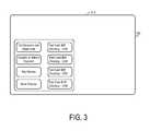
- FIGS. 3-4are display screens with a menu that is presented after the user's touch in FIG. 2 .
- FIG. 5is a menu that is displayed based on the multiple finger touches by the user.
- FIG. 6is a menu that is displayed based on the user's detected position.
- FIG. 7is a process that may be implemented using the system in FIG. 1 .
- FIG. 1shows a system 100 according to an example embodiment.
- the system 100may include a bank computer system 101 that may include, among other systems, account management logic 103 , data storage system 105 and network interface logic 109 .
- the system 100may also include an automated banking machine 110 , such as an automated teller machine (ATM).
- ATMautomated teller machine
- the system 100may be accessed by an account holder 150 who seeks authorization for a financial transaction.
- the bank computer system 101may be provided or controlled by a bank or other financial institution, and the users may be the customers or account holders of the financial institution.
- the usersmay access the system 101 through tellers at retail bank branches, through the Internet, or through an automated banking machine.
- a customer 150is shown accessing system 101 through an automated banking machine 110 .
- account management logic 103may further include stored program logic that performs various tasks in connection with accounts held by account holders at the financial institution, such as account processing (processing of account debits and credits), authentication, statement generation, account status, funds transfers, and so on.
- the bank computer system 101may include server computing systems, for example, comprising one or more networked computer servers having non-transitory machine readable media.
- the logic or logics described hereinmay therefore be implemented as program logic that is stored on the non-transitory machine-readable storage media and that, when executed by the server(s), causes the servers to perform the operations described herein.
- the account management logic 103may store data related to the account in data storage system 105 .
- the data storage system 105may include an account database 107 .
- the account database 107may be configured to store a log of each transaction performed by the account management logic 103 .
- the account database 107may be configured store other information such as account balance and other account holder related information, such as, preferences, profiles, and so on.
- Network interface logic 109may be used to connect the bank computer system 101 to communicate with other systems such as the automated banking machine 110 .
- An embodiment of the network interface logic 109may be configured to communicate with the automated banking machine 110 over a proprietary encrypted network.
- Another embodiment of the network interface logic 109may be configured to communicate with the automated banking machine 110 over a public encrypted network.
- the network interface logic 109may connect to the Internet to permit account holders to access the bank computer system 101 through an on-line banking area of a website of the bank.
- Network interface logic 109may also comprise other logic that is configured to provide an interface for other types of devices such mobile devices that includes cell phones, smart phones, fax machines, and server-based computing systems.
- the automatic banking machine 110may, for example, be an automated teller machine, a point of sale device, or other device.
- automatic banking machine 110may include a currency dispenser 112 , deposit mechanism 114 , card reader/writer 118 , information authentication logic 120 , image capture device 122 , transaction processing logic 124 , user interface logic 132 , touch screen display 130 , sensor 134 , and finger print scanner 138 .
- the automated banking machine 110may include a touch screen display 130 and sensor 134 .
- Other hardwaremay also be included, such as a keypad or buttons for receiving user inputs.
- the point of sale devicemay, for example, be a self checkout system used at a merchant to pay for goods or services that are being purchased.
- a banking transaction at a point of salemay permit, for example, funds to be automatically transferred to the merchant from a checking or credit card account of the account holder to pay for the goods or services.
- the currency dispenser 112may dispense currency notes (“cash”) to an account holder 150 from their financial institution accounts.
- the currency dispenser 112may be configured to dispense currency in various denominations, as specified by the account holder.
- the deposit mechanism 114accepts envelop or envelop-free deposits of cash or checks.
- One example embodiment of the deposit mechanism 114may include a scanner capable of scanning images from a various papers placed in the deposit mechanism 114 .
- the card reader/writer 118scans information from the magnetic stripe (“magstripe”) of a transaction card.
- the card reader/writer 118may be configured to read information from a credit card, debit card, ATM card, stored value card, or the like. While performing the read operation the card reader/writer 118 may be configured to read the account information and the PIN associated with the card and the account. In an example embodiment, the card reader/writer 118 may also be configured to perform write operations.
- the information authentication logic 120may authenticate information received by the automated banking machine 110 to approve or reject a transaction.
- the information authentication logic 120may approve or deny authentication for transaction data received by automated banking machine 110 .
- the information authentication logic 120authenticates a user as being a valid account holder associated with the transaction card and the corresponding account at the financial institution.
- the image capture device 122may capture an image outside the automated banking machine 110 .
- the image capture device 122may be used in part for security purposes, i.e., to capture an image of a person conducting a transaction in case the transaction later turns out to be fraudulent.
- the image capture device 122may include a single camera or multiple cameras.
- the image capture device 122may be configured to identify features of a person who is front of the automated banking machine 110 .
- the image capture device 122may be configured to identify the nose, eyes, mouth and ears and, based on this information, pinpoint the center of an individual's face.
- Another embodiment of the image capture device 122may include two cameras, e.g., to provide depth perception.
- the transaction processing logic 124may be configured to process each transaction requested by the account holder.
- the transaction processing logic 124may cooperate with the account management logic 103 at the bank computer system 101 to ensure that transactions are properly debited/credit to the account of the account holder.
- the touch screen display 130may allow the customer or account holder 150 to interact with the automated banking machine 110 in order to process transactions.
- the touch screenmay utilize resistive, capacitive, surface acoustic wave, infrared, optical imaging, dispersive signal, acoustic pulse recognition, or other touch sensing technology.
- the transactionsmay include withdrawing funds, purchasing one or more goods or services, transferring funds from one account to another account, and so on.
- the touch screen display 130may be used to display various menu options relating to such transactions to the account holder.
- the touch screen display 130may is a screen display that is sufficiently large that the placement of the menu options on the screen display impacts the ability of the user to reach the menu options.
- the screenmay have a diagonal size of about 13, 15, 19, 22, 24, 27, 32, 42, 46 or 52 inches. Other sizes are also possible.
- the user interface logic 132generates a graphical user interface for presentation to a user at the automated banking machine 110 via the touch screen display 130 .
- the user interface logic 132receives information indicating a physical disposition of the user relative to the automated banking machine and, based on this information, adjusts placement of menu options on the touch screen display to accommodate the user's position.
- the information regarding the physical disposition of the user relative to the automated banking machineis sensed by a sensor.
- the sensormay be the touch screen display 130 , the image capture device 122 , and/or a separate sensor 134 .
- the location of the menumay be based on the initial placement of the user's finger as sensed by the touch screen display 130 .
- the location of the menumay be based on a detected position of the user as sensed by the image capture device 122 .
- the location of the menumay be based on a detected position of the user's automobile as detected by the sensor 134 .
- the sensormay comprise one or more proximity sensors located in the path of the drive thru that detects the position of the automobile along the path of the drive thru.
- the user interface logic 132may place the menu based on a plurality of fingers that touched the touch screen display 130 .
- the user interface logic 132may be configured to allow a user to move the entire or portions of the menu choices displayed.
- Other types of sensorsmay also be used, such as infrared, camera, laser or the like.
- the sensor 134may sense the height of the vehicle relative to the automated banking machine 110 and adjust the vertical positioning of the menu accordingly. Other configurations are also possible, some of which are described below.
- the user interface logicis able to accommodate the physical disposition of the user. For example, in the context of a drive thru arrangement in which the account holder remains seated in an automobile during their transaction, the account holder may accidentally pull too far forward to conveniently reach the left side of the screen. Alternatively, an individual sitting in the cab of a truck may have difficulty reaching a bottom portion of the screen. Likewise, a person in a wheel chair or with other physical disabilities may have difficulties reaching certain portions of the screen.
- the user interface logic 132is configured to adjust placement of menu options to accommodate the variations in the ability of account holders to reach the touch screen display.
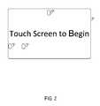
- FIG. 2shows a touch screen display 130 that may be part of an automated banking machine 110 .
- the automated banking machine 110may display a generic welcome message, such as “touch screen to begin,” as shown.
- Other contentsuch as a financial institution logo, advertising, and so on, may also be displayed.
- FIG. 2also shows regions 301 , 401 and 405 , which for example may each be where particular account holders have just touched the display 130 in different examples.
- FIG. 3shows a screen display that includes a menu 310 that is displayed as a result of the user touch 301 in FIG. 2 .
- the menuis positioned in the lower left hand corner, corresponding to the fact that the user touched the screen in the lower left hand corner in FIG. 2 .
- the horizontal and vertical placement of the menu optionsmay one or both be adjusted based upon the horizontal and vertical position, respectively, of the user touch.
- the menumay be centered around the location of the touch or may simply be in the same general region as the touch (as in FIG. 3 ).
- the placement of other contentmay then be adjusted accordingly. For example, advertising content on the touch screen display may be placed in a portion of the touch screen display not occupied by the menu options. Other content such as a financial institution logo, instructions and other information content, and so on, may also be displayed.
- the user interface logic 132may be configured to monitor whether the user the touches the touch screen display within a predetermined period of time. For example, if for some reason the positioning of the menu options was not performed correctly, the user may not be able to reach the menu options. Thus, for example, if the user interface logic 132 determines that the user has not touched the touch screen display within a predetermined period of time then, in response, the user interface logic 132 may readjust placement of menu options on the touch screen display to a default placement.
- FIG. 4shows a screen display that includes a menu 410 that is displayed as a result of the user touch 401 in FIG. 2 .
- the user interface logic 132has made a determination to place the menu options in a vertical column extending along a left side of the touch screen display. Such a determination may have been made, for example, because the user touched a far left portion of the screen.
- the user interface logic 132may make a determination to place the menu options in a horizontal row across a top of the touch screen display.
- the user interface logic 132may make a determination to place the menu options in a vertical column extending along a right side of the touch screen display 130 or in a horizontal row across a bottom of the touch screen display 130 . It may also be noted in FIG. 4 that the overall arrangement of the menu options (including the number of menu options presented) has been adjusted as compared to that shown in FIG. 3 .
- the menumay be selectable and movable or otherwise adjustable by the account holder. For example, once the menu is displayed, the user may place a finger at the center of the menu and (without lifting the finger) drag the menu to another location on the touch screen display 130 .
- the user interface logic 132may adjust the overall arrangement of the menu option to accommodate the new menu position received from the user.
- the draggingmay permit the part of the menu to be placed outside the screen display and thus not visible to the user.
- the usermay be limited in the movement of the menu such that the no part of the menu is outside the screen display.
- FIG. 5shows a menu that is displayed based on the multiple finger touches by the user.
- An embodiment of the touch screen display 130may be sensitive to multiple finger touches.
- a usermay have touched the touch screen display 130 at two different locations, such as, a first touch 501 and a second touch 502 .
- the first touch 501 and second touch 502are in different locations.
- the user interface logic 132may calculate the distance between the first touch 501 and the second touch 502 and determine the vertical and horizontal halfway points between the first touch 501 and the second touch 502 .
- the user interface logic 132may place the center 520 of the menu 510 at an equal distance from both the first touch 501 and the second touch 502 .
- the user interface logic 132may place the center 520 of the menu at one of the touch location instead of the center of both the touch locations.
- FIG. 6shows a menu 620 that is displayed based on the user's detected position.
- the usermay stand or be in an automobile in front of the automated banking machine 110 .
- the user interface logic 132may automatically display the menu 620 at a position determined based on the user's height, e.g., at the detected center of the user's torso 402 .
- the center of the menumay be positioned at or near the center of the user's face.
- the sensors 134may be located in various locations of the automated banking machine 110 .
- the cameras in the sensors 134may detect the user movement and facial features.
- the sensors 134may be configured to locate the users facial features, such as, nose, mouth, eyes and ears.
- the sensors 134may sense the height of the user's automobile and display the menu based on the detected height of the automobile.
- the sensors 134may be infrared sensors, video cameras, lasers or the like.
- the sensor 134may provide the position information about the user to the user interface logic 132 to generate the menu 620 at the appropriate location.
- FIG. 7is a process that may be implemented using the system in FIG. 1 .
- the automated banking machine 110may generate a graphical user interface on a touch screen display.
- the sensors 134may detect the physical disposition of the user relative to the automated banking machine 110 .
- the user interface logic 132may adjust the menu placement on the touch screen display based on the physical disposition of the user.
- the automated banking machine 110may detect the physical attributes of the user's automobile. The physical attributes may include the height and distance from the automated banking machine 110 .
- the menu placementmay be adjusted based on the disposition of the user's automobile.
- machine-readable mediamay be any available media that may be accessed by a general purpose or special purpose computer or other machine with a processor.
- machine-readable mediamay comprise RAM, ROM, EPROM, EEPROM, CD-ROM or other optical disk storage, magnetic disk storage or other magnetic storage devices, or any other medium which may be used to carry or store desired program code in the form of machine-executable instructions or data structures and which may be accessed by a general purpose or special purpose computer or other machine with a processor. Combinations of the above are also included within the scope of machine-readable media.
- Machine-executable instructionscomprise, for example, instructions and data which cause a general purpose computer, special purpose computer, or special purpose processing machines to perform a certain function or group of functions.
- Embodiments of the present inventionhave been described in the general context of method steps which may be implemented in one embodiment by a program product including machine-executable instructions, such as program code, for example in the form of program modules executed by machines in networked environments.
- program modulesinclude routines, programs, objects, components, data structures, etc. that perform particular tasks or implement particular abstract data types.
- Machine-executable instructions, associated data structures, and program modulesrepresent examples of program code for executing steps of the methods disclosed herein.
- the particular sequence of such executable instructions or associated data structuresrepresent examples of corresponding acts for implementing the functions described in such steps.
- embodiments of the present inventionmay be practiced in a networked environment using logical connections to one or more remote computers having processors.
- network computing environmentsmay encompass many types of computers, including personal computers, hand-held devices, multi-processor systems, microprocessor-based or programmable consumer electronics, network PCs, minicomputers, mainframe computers, and so on.
- Embodiments of the inventionmay also be practiced in distributed computing environments where tasks are performed by local and remote processing devices that are linked (either by hardwired links, wireless links, or by a combination of hardwired or wireless links) through a communications network.
- program modulesmay be located in both local and remote memory storage devices.
- An exemplary system for implementing the overall system or portions of the inventionmight include a general purpose computing computers in the form of computers, including a processing unit, a system memory or database, and a system bus that couples various system components including the system memory to the processing unit.
- the database or system memorymay include read only memory (ROM) and random access memory (RAM).
- the databasemay also include a magnetic hard disk drive for reading from and writing to a magnetic hard disk, a magnetic disk drive for reading from or writing to a removable magnetic disk, and an optical disk drive for reading from or writing to a removable optical disk such as a CD ROM or other optical media.
- the drives and their associated machine-readable mediaprovide nonvolatile storage of machine-executable instructions, data structures, program modules and other data for the computer.
- terminalis intended to encompass computer input and output devices.
- User interfacesas described herein may include a computer with monitor, keyboard, a keypad, a mouse, joystick or other input devices performing a similar function.
Landscapes
- Engineering & Computer Science (AREA)
- Physics & Mathematics (AREA)
- General Physics & Mathematics (AREA)
- General Engineering & Computer Science (AREA)
- Theoretical Computer Science (AREA)
- Human Computer Interaction (AREA)
- Business, Economics & Management (AREA)
- Accounting & Taxation (AREA)
- Finance (AREA)
- User Interface Of Digital Computer (AREA)
Abstract
Description
This application claims the benefit of U.S. Provisional Application No. 61/473,101, filed Apr. 7, 2011, which is hereby incorporated by reference herein its entirety.
Transaction cards such as debit, credit or stored value cards are often used by account holders to purchase items or services or to obtain funds. Account holders often prefer the convenience, for example, of visiting an automated teller machine (ATM) or other automated banking machine over walking into a bank branch to obtain cash. Such cards provide account holders with round the clock access to banking services such as withdrawing funds, depositing funds, and transferring funds.
An embodiment of a method for generating an adaptive user interface may include, generating a graphical user interface for presentation to a user at an automated banking machine that includes a touch screen display and a currency note dispenser. The automated banking machine may include a sensor that senses information indicating a physical disposition of the user relative to the automated banking machine. The method may include adjusting the placement of the menu options on the touch screen display based on the information regarding the physical disposition of the user relative to the automated teller machine.
An embodiment of an automated banking machine can include a currency note dispenser, display device and a sensor configured to generate information regarding a physical location of the user relative to the automated banking machine. The automated banking machine can include a user interface logic configured to adjust the placement of the menu options on the display device based on the information regarding the physical disposition of the user relative to the automated banking machine.
An embodiment of an automated banking machine can include a touch screen display configured to sense a user's touch, the touch screen display configured to display menu options to a user. The automated banking machine can include a user interface logic configured to receive information regarding a location of the user touch from the touch screen display and to adjust placement of the menu options on the touch screen display based on the location of the user touch. The user interface logic may adjust the horizontal placement of the menu options being based upon a horizontal position of the user touch and the vertical placement of the menu options based on a vertical position of the user touch.
Referring toFIG. 1 ,FIG. 1 shows asystem 100 according to an example embodiment. Thesystem 100 may include abank computer system 101 that may include, among other systems, account management logic103,data storage system 105 andnetwork interface logic 109. Thesystem 100 may also include anautomated banking machine 110, such as an automated teller machine (ATM). Thesystem 100 may be accessed by anaccount holder 150 who seeks authorization for a financial transaction.
In an example embodiment, thebank computer system 101 may be provided or controlled by a bank or other financial institution, and the users may be the customers or account holders of the financial institution. The users may access thesystem 101 through tellers at retail bank branches, through the Internet, or through an automated banking machine. InFIG. 1 , for example, acustomer 150 is shown accessingsystem 101 through anautomated banking machine 110.
In the example wheresystem 100 is provided by a financial institution, account management logic103 may further include stored program logic that performs various tasks in connection with accounts held by account holders at the financial institution, such as account processing (processing of account debits and credits), authentication, statement generation, account status, funds transfers, and so on. In practice, thebank computer system 101 may include server computing systems, for example, comprising one or more networked computer servers having non-transitory machine readable media. The logic or logics described herein may therefore be implemented as program logic that is stored on the non-transitory machine-readable storage media and that, when executed by the server(s), causes the servers to perform the operations described herein. The account management logic103 may store data related to the account indata storage system 105.
Thedata storage system 105 may include an account database107. The account database107 may be configured to store a log of each transaction performed by the account management logic103. The account database107 may be configured store other information such as account balance and other account holder related information, such as, preferences, profiles, and so on.
Theautomatic banking machine 110 may, for example, be an automated teller machine, a point of sale device, or other device. For example, in the case of an automated teller machine,automatic banking machine 110 may include a currency dispenser112,deposit mechanism 114, card reader/writer 118,information authentication logic 120,image capture device 122,transaction processing logic 124,user interface logic 132,touch screen display 130,sensor 134, andfinger print scanner 138. In the case of a point of sale device, theautomated banking machine 110 may include atouch screen display 130 andsensor 134. Other hardware may also be included, such as a keypad or buttons for receiving user inputs. The point of sale device may, for example, be a self checkout system used at a merchant to pay for goods or services that are being purchased. Such a banking transaction at a point of sale may permit, for example, funds to be automatically transferred to the merchant from a checking or credit card account of the account holder to pay for the goods or services.
The currency dispenser112 may dispense currency notes (“cash”) to anaccount holder 150 from their financial institution accounts. The currency dispenser112 may be configured to dispense currency in various denominations, as specified by the account holder. Thedeposit mechanism 114 accepts envelop or envelop-free deposits of cash or checks. One example embodiment of thedeposit mechanism 114 may include a scanner capable of scanning images from a various papers placed in thedeposit mechanism 114.
The card reader/writer 118 scans information from the magnetic stripe (“magstripe”) of a transaction card. The card reader/writer 118 may be configured to read information from a credit card, debit card, ATM card, stored value card, or the like. While performing the read operation the card reader/writer 118 may be configured to read the account information and the PIN associated with the card and the account. In an example embodiment, the card reader/writer 118 may also be configured to perform write operations.
Theinformation authentication logic 120 may authenticate information received by theautomated banking machine 110 to approve or reject a transaction. Theinformation authentication logic 120 may approve or deny authentication for transaction data received byautomated banking machine 110. Theinformation authentication logic 120 authenticates a user as being a valid account holder associated with the transaction card and the corresponding account at the financial institution.
Theimage capture device 122 may capture an image outside theautomated banking machine 110. For example, theimage capture device 122 may be used in part for security purposes, i.e., to capture an image of a person conducting a transaction in case the transaction later turns out to be fraudulent. Theimage capture device 122 may include a single camera or multiple cameras. In one embodiment, theimage capture device 122 may be configured to identify features of a person who is front of theautomated banking machine 110. For example, theimage capture device 122 may be configured to identify the nose, eyes, mouth and ears and, based on this information, pinpoint the center of an individual's face. Another embodiment of theimage capture device 122 may include two cameras, e.g., to provide depth perception.
Thetransaction processing logic 124 may be configured to process each transaction requested by the account holder. For example, thetransaction processing logic 124 may cooperate with the account management logic103 at thebank computer system 101 to ensure that transactions are properly debited/credit to the account of the account holder.
Thetouch screen display 130 may allow the customer oraccount holder 150 to interact with theautomated banking machine 110 in order to process transactions. The touch screen may utilize resistive, capacitive, surface acoustic wave, infrared, optical imaging, dispersive signal, acoustic pulse recognition, or other touch sensing technology. The transactions may include withdrawing funds, purchasing one or more goods or services, transferring funds from one account to another account, and so on. Thetouch screen display 130 may be used to display various menu options relating to such transactions to the account holder.
In an example embodiment, thetouch screen display 130 may is a screen display that is sufficiently large that the placement of the menu options on the screen display impacts the ability of the user to reach the menu options. For example, the screen may have a diagonal size of about 13, 15, 19, 22, 24, 27, 32, 42, 46 or 52 inches. Other sizes are also possible.
Theuser interface logic 132 generates a graphical user interface for presentation to a user at theautomated banking machine 110 via thetouch screen display 130. As explained in greater detail below in connection withFIGS. 2-6 , theuser interface logic 132 receives information indicating a physical disposition of the user relative to the automated banking machine and, based on this information, adjusts placement of menu options on the touch screen display to accommodate the user's position. The information regarding the physical disposition of the user relative to the automated banking machine is sensed by a sensor. The sensor may be thetouch screen display 130, theimage capture device 122, and/or aseparate sensor 134. For example, the location of the menu may be based on the initial placement of the user's finger as sensed by thetouch screen display 130. As another example, the location of the menu may be based on a detected position of the user as sensed by theimage capture device 122. As another example, the location of the menu may be based on a detected position of the user's automobile as detected by thesensor 134. In this embodiment, for example, the sensor may comprise one or more proximity sensors located in the path of the drive thru that detects the position of the automobile along the path of the drive thru. As another example, theuser interface logic 132 may place the menu based on a plurality of fingers that touched thetouch screen display 130. As another example, theuser interface logic 132 may be configured to allow a user to move the entire or portions of the menu choices displayed. Other types of sensors may also be used, such as infrared, camera, laser or the like. As another example, thesensor 134 may sense the height of the vehicle relative to theautomated banking machine 110 and adjust the vertical positioning of the menu accordingly. Other configurations are also possible, some of which are described below.
By sensing the physical disposition of the user relative to the automated banking machine and adjusting placement of menu options on the touch screen display, the user interface logic is able to accommodate the physical disposition of the user. For example, in the context of a drive thru arrangement in which the account holder remains seated in an automobile during their transaction, the account holder may accidentally pull too far forward to conveniently reach the left side of the screen. Alternatively, an individual sitting in the cab of a truck may have difficulty reaching a bottom portion of the screen. Likewise, a person in a wheel chair or with other physical disabilities may have difficulties reaching certain portions of the screen. Theuser interface logic 132 is configured to adjust placement of menu options to accommodate the variations in the ability of account holders to reach the touch screen display.
Referring toFIG. 2 ,FIG. 2 shows atouch screen display 130 that may be part of anautomated banking machine 110. When theautomated banking machine 110 is not in use by a particular account holder, it may display a generic welcome message, such as “touch screen to begin,” as shown. Other content such as a financial institution logo, advertising, and so on, may also be displayed. For purposes of providing examples,FIG. 2 also showsregions 301,401 and405, which for example may each be where particular account holders have just touched thedisplay 130 in different examples.
Referring toFIG. 3 ,FIG. 3 shows a screen display that includes amenu 310 that is displayed as a result of the user touch301 inFIG. 2 . As shown inFIG. 3 , the menu is positioned in the lower left hand corner, corresponding to the fact that the user touched the screen in the lower left hand corner inFIG. 2 . It is thus seen that the horizontal and vertical placement of the menu options may one or both be adjusted based upon the horizontal and vertical position, respectively, of the user touch. Depending on the location of the touch (and how close it is to the edge of the screen) the menu may be centered around the location of the touch or may simply be in the same general region as the touch (as inFIG. 3 ). The placement of other content may then be adjusted accordingly. For example, advertising content on the touch screen display may be placed in a portion of the touch screen display not occupied by the menu options. Other content such as a financial institution logo, instructions and other information content, and so on, may also be displayed.
After adjusting the placement of menu options on the touch screen display, theuser interface logic 132 may be configured to monitor whether the user the touches the touch screen display within a predetermined period of time. For example, if for some reason the positioning of the menu options was not performed correctly, the user may not be able to reach the menu options. Thus, for example, if theuser interface logic 132 determines that the user has not touched the touch screen display within a predetermined period of time then, in response, theuser interface logic 132 may readjust placement of menu options on the touch screen display to a default placement.
Referring toFIG. 4 ,FIG. 4 shows a screen display that includes amenu 410 that is displayed as a result of the user touch401 inFIG. 2 . InFIG. 4 , theuser interface logic 132 has made a determination to place the menu options in a vertical column extending along a left side of the touch screen display. Such a determination may have been made, for example, because the user touched a far left portion of the screen. Likewise, for theuser touch 405 inFIG. 2 , theuser interface logic 132 may make a determination to place the menu options in a horizontal row across a top of the touch screen display. In other scenarios, theuser interface logic 132 may make a determination to place the menu options in a vertical column extending along a right side of thetouch screen display 130 or in a horizontal row across a bottom of thetouch screen display 130. It may also be noted inFIG. 4 that the overall arrangement of the menu options (including the number of menu options presented) has been adjusted as compared to that shown inFIG. 3 .
In one embodiment, the menu may be selectable and movable or otherwise adjustable by the account holder. For example, once the menu is displayed, the user may place a finger at the center of the menu and (without lifting the finger) drag the menu to another location on thetouch screen display 130. In one embodiment, theuser interface logic 132 may adjust the overall arrangement of the menu option to accommodate the new menu position received from the user. In another embodiment, the dragging may permit the part of the menu to be placed outside the screen display and thus not visible to the user. In another embodiment the user may be limited in the movement of the menu such that the no part of the menu is outside the screen display.
In another embodiment, thesensors 134 may sense the height of the user's automobile and display the menu based on the detected height of the automobile. Thesensors 134 may be infrared sensors, video cameras, lasers or the like. In one embodiment, thesensor 134 may provide the position information about the user to theuser interface logic 132 to generate themenu 620 at the appropriate location.
Referring now toFIG. 7 ,FIG. 7 is a process that may be implemented using the system inFIG. 1 . Atstep 710, theautomated banking machine 110 may generate a graphical user interface on a touch screen display. Atstep 720, thesensors 134 may detect the physical disposition of the user relative to theautomated banking machine 110. Next atstep 730, theuser interface logic 132 may adjust the menu placement on the touch screen display based on the physical disposition of the user. In other embodiments, in order to detect the physical disposition of the user, theautomated banking machine 110 may detect the physical attributes of the user's automobile. The physical attributes may include the height and distance from theautomated banking machine 110. In this embodiment, the menu placement may be adjusted based on the disposition of the user's automobile.
The embodiments of the methods and system have been described with reference to drawings. The drawings illustrate certain details of specific embodiments that implement the systems and methods and programs of the present invention. However, describing the invention with drawings should not be construed as imposing on the invention any limitations that may be present in the drawings. The present invention contemplates methods, systems and program products on any non-transitory machine-readable storage media for accomplishing its operations. The embodiments of the present invention may be implemented using an existing computer processor, or by a special purpose computer processor incorporated for this or another purpose or by a hardwired system.
As noted above, embodiments within the scope of the present invention include program products comprising non-transitory machine-readable storage media for carrying or having machine-executable instructions or data structures stored thereon. Such machine-readable media may be any available media that may be accessed by a general purpose or special purpose computer or other machine with a processor. By way of example, such machine-readable media may comprise RAM, ROM, EPROM, EEPROM, CD-ROM or other optical disk storage, magnetic disk storage or other magnetic storage devices, or any other medium which may be used to carry or store desired program code in the form of machine-executable instructions or data structures and which may be accessed by a general purpose or special purpose computer or other machine with a processor. Combinations of the above are also included within the scope of machine-readable media. Machine-executable instructions comprise, for example, instructions and data which cause a general purpose computer, special purpose computer, or special purpose processing machines to perform a certain function or group of functions.
Embodiments of the present invention have been described in the general context of method steps which may be implemented in one embodiment by a program product including machine-executable instructions, such as program code, for example in the form of program modules executed by machines in networked environments. Generally, program modules include routines, programs, objects, components, data structures, etc. that perform particular tasks or implement particular abstract data types. Machine-executable instructions, associated data structures, and program modules represent examples of program code for executing steps of the methods disclosed herein. The particular sequence of such executable instructions or associated data structures represent examples of corresponding acts for implementing the functions described in such steps.
As previously indicated, embodiments of the present invention may be practiced in a networked environment using logical connections to one or more remote computers having processors. Those skilled in the art will appreciate that such network computing environments may encompass many types of computers, including personal computers, hand-held devices, multi-processor systems, microprocessor-based or programmable consumer electronics, network PCs, minicomputers, mainframe computers, and so on. Embodiments of the invention may also be practiced in distributed computing environments where tasks are performed by local and remote processing devices that are linked (either by hardwired links, wireless links, or by a combination of hardwired or wireless links) through a communications network. In a distributed computing environment, program modules may be located in both local and remote memory storage devices.
An exemplary system for implementing the overall system or portions of the invention might include a general purpose computing computers in the form of computers, including a processing unit, a system memory or database, and a system bus that couples various system components including the system memory to the processing unit. The database or system memory may include read only memory (ROM) and random access memory (RAM). The database may also include a magnetic hard disk drive for reading from and writing to a magnetic hard disk, a magnetic disk drive for reading from or writing to a removable magnetic disk, and an optical disk drive for reading from or writing to a removable optical disk such as a CD ROM or other optical media. The drives and their associated machine-readable media provide nonvolatile storage of machine-executable instructions, data structures, program modules and other data for the computer. It should also be noted that the word “terminal” as used herein is intended to encompass computer input and output devices. User interfaces, as described herein may include a computer with monitor, keyboard, a keypad, a mouse, joystick or other input devices performing a similar function.
It should be noted that although the diagrams herein may show a specific order and composition of method steps, it is understood that the order of these steps may differ from what is depicted. For example, two or more steps may be performed concurrently or with partial concurrence. Also, some method steps that are performed as discrete steps may be combined, steps being performed as a combined step may be separated into discrete steps, the sequence of certain processes may be reversed or otherwise varied, and the nature or number of discrete processes may be altered or varied. The order or sequence of any element or apparatus may be varied or substituted according to alternative embodiments. Accordingly, all such modifications are intended to be included within the scope of the present invention. Such variations will depend on the software and hardware systems chosen and on designer choice. It is understood that all such variations are within the scope of the invention. Likewise, software and web implementations of the present invention could be accomplished with standard programming techniques with rule based logic and other logic to accomplish the various database searching steps, correlation steps, comparison steps and decision steps.
The foregoing description of embodiments of the invention has been presented for purposes of illustration and description. It is not intended to be exhaustive or to limit the invention to the precise form disclosed, and modifications and variations are possible in light of the above teachings or may be acquired from practice of the invention. The embodiments were chosen and described in order to explain the principals of the invention and its practical application to enable one skilled in the art to utilize the invention in various embodiments and with various modifications as are suited to the particular use contemplated. Other substitutions, modifications, changes and omissions may be made in the design, operating conditions and arrangement of the embodiments without departing from the scope of the present invention.
Throughout the specification, numerous advantages of the exemplary embodiments have been identified. It will be understood of course that it is possible to employ the teachings herein without necessarily achieving the same advantages. Additionally, although many features have been described in the context of a particular data processing unit, it will be appreciated that such features could also be implemented in the context of other hardware configurations.
While the exemplary embodiments illustrated in the figures and described above are presently preferred, it should be understood that these embodiments are offered by way of example only. Other embodiments may include, for example, structures with different data mapping or different data. The invention is not limited to a particular embodiment, but extends to various modifications, combinations, and permutations that nevertheless fall within the scope and spirit of the appended claims.
Claims (26)
1. A method comprising:
generating a graphical user interface for presentation to a user at an automated banking machine, the automated banking machine comprising a touch screen display and a currency note dispenser;
sensing, by a sensor, information indicating a physical disposition of the user relative to the automated banking machine, including receiving a user touch by the touch screen display and detecting a facial location of the user;
adjusting placement of a menu including menu options on the touch screen display based on the information indicating the physical disposition of the user relative to the automated banking machine;
wherein the user touch comprises a plurality of touch inputs, the adjusted placement of the menu being based at least in part on each of the plurality of touch inputs, wherein the plurality of touch inputs includes a first touch input and a second touch input;
determining a halfway point between the first touch input and the second touch input;
placing a center of the menu at the halfway point between the first touch input and the second touch input;
wherein the adjusting of the placement of the menu comprises adjusting an arrangement of two or more of the menu options to be placed on a portion of the touch screen display such that the center of the menu is positioned closest to a center of the detected facial location;
displaying the two or more menu options on the touch screen display according to the adjusted placement;
after the two or more menu options are displayed, sensing, by the touch screen display, a second user touch at a second location on the touch screen display; and
re-adjusting the placement of the menu on the touch screen display according to the second user touch, including re-adjusting the arrangement of the two or more menu options based on the second location, while limiting movement of the two or more menu options outside of the touch screen display by adjusting a shape of the arrangement,
wherein the adjusting of the placement of the menu comprises determining, based on the information indicating the physical disposition of the user relative to the automated banking machine, at least one of (i) whether to place the two or more menu options in a horizontal row across a top of the touch screen display, (ii) whether to place the two or more menu options in a horizontal row across a bottom of the touch screen display, (iii) whether to place the two or more menu options in a vertical column extending along a left side of the touch screen display, and (iv) whether to place the two or more menu options in a vertical column extending along a right side of the touch screen display.
2. The method ofclaim 1 , wherein the sensor is the touch screen display;
wherein the sensing further comprises:
presenting a message to the user via the touch screen display, and estimating the location of the user touch on the touch screen display; and
wherein the adjusting the placement of the menu further comprises adjusting horizontal placement of the menu based upon a horizontal position of the user touch or adjusting vertical placement of the menu based upon a vertical position of the user touch or both.
3. The method ofclaim 2 , wherein the horizontal and vertical placement of the menu is adjusted to be centered around the horizontal and vertical position of the user touch on the touch screen display.
4. The method ofclaim 1 , wherein the automated banking machine comprises a camera configured to capture an image of the user during a transaction, wherein the sensor is the camera, and wherein the method further comprises processing image data associated with the image to estimate a position of the user.
5. The method ofclaim 1 , wherein the sensor is configured to sense a height of the user.
6. The method ofclaim 1 , wherein the sensor is configured to sense a height of a vehicle in which the user is located.
7. The method ofclaim 1 , further comprising, after adjusting the placement of the menu on the touch screen display, determining that the user has not touched the touch screen display within a predetermined period of time; and in response
readjusting placement of the menu on the touch screen display to a default placement.
8. The method ofclaim 1 , further comprising adjusting placement of advertising content on the touch screen display based on the information regarding the physical disposition of the user relative to the automated banking machine.
9. The method ofclaim 8 , wherein adjusting the placement of the advertising content comprises placing the advertising content in a portion of the touch screen display not occupied by the menu.
10. The method ofclaim 1 , wherein no portion of the menu is located outside of the touch screen display upon adjusting the placement of the menu.
11. The method ofclaim 1 , wherein the placement of the menu is readjustable to a default position after a condition occurs.
12. The method ofclaim 11 , wherein the condition is the user has not touched the touch screen display for a predetermined period of time.
13. The method ofclaim 1 , wherein the placement of the menu is adjustable before the two or more menu options are displayed to the user.
14. The method ofclaim 1 , wherein the shape of the arrangement of the two or more of the menu options is adjustable based, at least in part, on the physical disposition of the user.
15. The method ofclaim 1 , wherein the number of the two or more menu options presented is adjusted based, at least in part, on the physical disposition of the user.
16. The method ofclaim 1 , wherein the arrangement is re-adjusted according to proximity of the second location of the second user touch to an edge of the touch screen display, including adjusting the shape of the arrangement based on proximity of the second location to the edge of the touch screen display and limiting movement of the menu such that no part of the menu is outside of the touch screen display.
17. The method ofclaim 1 , wherein adjusting the shape of the arrangement includes adjusting the number of the two or more menu options that are presented on the touch screen display.
18. An automated banking machine, comprising:
a currency note dispenser;
a display device, including a touch screen display;
a sensor configured to generate information regarding a physical location of a user relative to the automated banking machine, wherein the sensor includes the touch screen display and is configured to receive a user touch, and wherein the sensor is configured to detect a height of a user automobile; and
a processor executing user interface logic configured to cause the processor to adjust a placement of a menu including menu options on the display device based on the information regarding the physical location of the user relative to the automated banking machine, including placing the menu options on the display device based on the height of the user automobile, and adjusting an arrangement of two or more of the menu options based on a location of the user touch on the touch screen display;
wherein the user touch comprises a plurality of touch inputs, the adjusted placement of the menu being based at least in part on each of the plurality of touch inputs, wherein the plurality of touch inputs includes a first touch input and a second touch input;
wherein the user interface logic is further configured to cause the processor to determine a halfway point between the first touch input and the second touch input;
wherein the user interface logic is further configured to cause the processor to place a center of the menu at the halfway point between the first touch input and the second touch input;
wherein the sensor is configured to detect a facial location of the user, and wherein the display device is configured to adjust the arrangement of the two or more of the menu options on the touch screen display according to the adjusted placement such that the center of the menu is positioned closest to a center the detected facial location;
wherein the sensor is further configured to, after the two or more menu options are displayed according to the adjusted position, sense a second user touch at a second location on the touch screen display;
wherein the user interface logic is further configured to cause the processor to re-adjust the placement of the menu according to the second user touch, including adjusting the arrangement of the two or more menu options based on the second location;
wherein the user interface logic is further configured to cause the processor to determine, based on the information regarding the physical location of the user relative to the automated banking machine, at least one of (i) whether to place the two or more menu options in a horizontal row across a top of the touch screen display, (ii) whether to place the two or more menu options in a horizontal row across a bottom of the touch screen display, (iii) whether to place the two or more menu options in a vertical column extending along a left side of the touch screen display, and (iv) whether to place the two or more menu options in a vertical column extending along a right side of the touch screen display.
19. The automated banking machine ofclaim 18 , wherein the display device is configured to place the two or more menu options on a portion of the display device that is lower than the height of the user automobile.
20. The automated banking machine ofclaim 18 , wherein the touch screen display is configured to display a message to the user;
wherein the touch screen display is configured to estimate a position of the user touch on the touch screen display; and
wherein the user interface logic causes the processor to adjust horizontal placement of the menu based upon a horizontal position of the user touch or vertical placement of the menu based upon a vertical position of the user touch or both.
21. The automated banking machine ofclaim 20 , wherein the touch screen display is configured to adjust the horizontal and vertical placement of the menu to be centered around the horizontal and vertical position of the user touch on the touch screen display.
22. The automated banking machine ofclaim 18 , wherein the automated banking machine comprises a camera configured to capture an image of the user during a transaction, wherein the sensor includes the camera, and wherein the automated banking machine is configured to process image data associated with the image to estimate a position of the user.
23. The automated banking machine ofclaim 18 , wherein the automated banking machine comprises a camera configured to capture an image of the user, wherein the sensor includes the camera, and wherein the automated banking machine is configured to process image data associated with the image to estimate a position of the user.
24. The automated banking machine ofclaim 18 , wherein the sensor is configured to sense a height of a vehicle in which the user is located.
25. The automated banking machine ofclaim 20 , wherein the sensor is configured to allow the user to move the menu by touch input.
26. An automated banking machine, comprising:
a touch screen display configured to sense a user touch, the touch screen display configured to display a menu including menu options to a user;
a processor executing user interface logic configured to cause the processor to receive information indicating a physical disposition of the user relative to the automated banking machine, including a location of the user touch from the touch screen display and a facial location of the user and to adjust placement of the menu and an arrangement of two or more of the menu options on the touch screen display based on the location of the user touch and the user's facial location;
wherein the user touch comprises a plurality of touch inputs, the adjusted placement of the menu being based at least in part on each of the plurality of touch inputs, wherein the plurality of touch inputs includes a first touch input and a second touch input;
wherein the user interface logic is further configured to cause the processor to determine a halfway point between the first touch input and the second touch input;
wherein the user interface logic is further configured to cause the processor to place a center of the menu at the halfway point between the first touch input and the second touch input;
wherein the touch screen display is further configured to:
adjust the arrangement of the two or more of the menu options according to the adjusted placement such that the center of the menu is positioned closest to a center the detected facial location;
display the two or more menu options to the user according to the adjusted placement; and
after the two or more menu options are displayed, sense a second user touch at a second location on the touch screen display; and
wherein the user interface logic is further configured to cause the processor to re-adjust the placement of the menu on the touch screen display according to the second user touch, including re-adjusting the arrangement of the two or more menu options based on the second location, while limiting movement of the two or more menu options outside of the touch screen display by adjusting a shape of the arrangement;
wherein the user interface logic is further configured to cause the processor to determine, based on the information indicating the physical disposition of the user relative to the automated banking machine, at least one of (i) whether to place the two or more menu options in a horizontal row across a top of the touch screen display, (ii) whether to place the two or more menu options in a horizontal row across a bottom of the touch screen display, (iii) whether to place the two or more menu options in a vertical column extending along a left side of the touch screen display, and (iv) whether to place the two or more menu options in a vertical column extending along a right side of the touch screen display.
Priority Applications (4)
| Application Number | Priority Date | Filing Date | Title |
|---|---|---|---|
| US13/441,151US10146423B1 (en) | 2011-04-07 | 2012-04-06 | System and method for generating a position based user interface |
| US16/204,939US11188218B1 (en) | 2011-04-07 | 2018-11-29 | System and method for generating a position based user interface |
| US17/537,261US11934613B1 (en) | 2011-04-07 | 2021-11-29 | Systems and methods for generating a position based user interface |
| US18/608,307US20240221450A1 (en) | 2011-04-07 | 2024-03-18 | Systems and methods for generating a position based user interface |
Applications Claiming Priority (2)
| Application Number | Priority Date | Filing Date | Title |
|---|---|---|---|
| US201161473101P | 2011-04-07 | 2011-04-07 | |
| US13/441,151US10146423B1 (en) | 2011-04-07 | 2012-04-06 | System and method for generating a position based user interface |
Related Child Applications (1)
| Application Number | Title | Priority Date | Filing Date |
|---|---|---|---|
| US16/204,939ContinuationUS11188218B1 (en) | 2011-04-07 | 2018-11-29 | System and method for generating a position based user interface |
Publications (1)
| Publication Number | Publication Date |
|---|---|
| US10146423B1true US10146423B1 (en) | 2018-12-04 |
Family
ID=64451940
Family Applications (4)
| Application Number | Title | Priority Date | Filing Date |
|---|---|---|---|
| US13/441,151Active2032-09-06US10146423B1 (en) | 2011-04-07 | 2012-04-06 | System and method for generating a position based user interface |
| US16/204,939Active2032-04-08US11188218B1 (en) | 2011-04-07 | 2018-11-29 | System and method for generating a position based user interface |
| US17/537,261ActiveUS11934613B1 (en) | 2011-04-07 | 2021-11-29 | Systems and methods for generating a position based user interface |
| US18/608,307PendingUS20240221450A1 (en) | 2011-04-07 | 2024-03-18 | Systems and methods for generating a position based user interface |
Family Applications After (3)
| Application Number | Title | Priority Date | Filing Date |
|---|---|---|---|
| US16/204,939Active2032-04-08US11188218B1 (en) | 2011-04-07 | 2018-11-29 | System and method for generating a position based user interface |
| US17/537,261ActiveUS11934613B1 (en) | 2011-04-07 | 2021-11-29 | Systems and methods for generating a position based user interface |
| US18/608,307PendingUS20240221450A1 (en) | 2011-04-07 | 2024-03-18 | Systems and methods for generating a position based user interface |
Country Status (1)
| Country | Link |
|---|---|
| US (4) | US10146423B1 (en) |
Cited By (167)
| Publication number | Priority date | Publication date | Assignee | Title |
|---|---|---|---|---|
| US20170205987A1 (en)* | 2016-01-15 | 2017-07-20 | Pearson Education, Inc. | Interactive presentation controls |
| US20180153542A1 (en)* | 2013-08-23 | 2018-06-07 | Ethicon Llc | Torque optimization for surgical instruments |
| US20200342706A1 (en)* | 2017-12-29 | 2020-10-29 | Shandong New Beiyang Information Technology Co., Ltd. | Vending machine and method for detecting height of storage column |
| CN113552996A (en)* | 2021-09-22 | 2021-10-26 | 深圳技术大学 | A method and touch screen device for automatically adjusting interface layout according to human body posture |
| US11684434B2 (en) | 2019-06-28 | 2023-06-27 | Cilag Gmbh International | Surgical RFID assemblies for instrument operational setting control |
| US11684361B2 (en) | 2008-09-23 | 2023-06-27 | Cilag Gmbh International | Motor-driven surgical cutting instrument |
| US11696757B2 (en) | 2021-02-26 | 2023-07-11 | Cilag Gmbh International | Monitoring of internal systems to detect and track cartridge motion status |
| US11696759B2 (en) | 2017-06-28 | 2023-07-11 | Cilag Gmbh International | Surgical stapling instruments comprising shortened staple cartridge noses |
| US11696761B2 (en) | 2019-03-25 | 2023-07-11 | Cilag Gmbh International | Firing drive arrangements for surgical systems |
| US11701111B2 (en) | 2019-12-19 | 2023-07-18 | Cilag Gmbh International | Method for operating a surgical stapling instrument |
| US11701113B2 (en) | 2021-02-26 | 2023-07-18 | Cilag Gmbh International | Stapling instrument comprising a separate power antenna and a data transfer antenna |
| US11701115B2 (en) | 2016-12-21 | 2023-07-18 | Cilag Gmbh International | Methods of stapling tissue |
| US11707273B2 (en) | 2012-06-15 | 2023-07-25 | Cilag Gmbh International | Articulatable surgical instrument comprising a firing drive |
| US11712244B2 (en) | 2015-09-30 | 2023-08-01 | Cilag Gmbh International | Implantable layer with spacer fibers |
| US11717297B2 (en) | 2014-09-05 | 2023-08-08 | Cilag Gmbh International | Smart cartridge wake up operation and data retention |
| US11717294B2 (en) | 2014-04-16 | 2023-08-08 | Cilag Gmbh International | End effector arrangements comprising indicators |
| US11717291B2 (en) | 2021-03-22 | 2023-08-08 | Cilag Gmbh International | Staple cartridge comprising staples configured to apply different tissue compression |
| US11723658B2 (en) | 2021-03-22 | 2023-08-15 | Cilag Gmbh International | Staple cartridge comprising a firing lockout |
| US11723662B2 (en) | 2021-05-28 | 2023-08-15 | Cilag Gmbh International | Stapling instrument comprising an articulation control display |
| US11723657B2 (en) | 2021-02-26 | 2023-08-15 | Cilag Gmbh International | Adjustable communication based on available bandwidth and power capacity |
| US11730473B2 (en) | 2021-02-26 | 2023-08-22 | Cilag Gmbh International | Monitoring of manufacturing life-cycle |
| US11730474B2 (en) | 2005-08-31 | 2023-08-22 | Cilag Gmbh International | Fastener cartridge assembly comprising a movable cartridge and a staple driver arrangement |
| US11730471B2 (en) | 2016-02-09 | 2023-08-22 | Cilag Gmbh International | Articulatable surgical instruments with single articulation link arrangements |
| US11730477B2 (en) | 2008-10-10 | 2023-08-22 | Cilag Gmbh International | Powered surgical system with manually retractable firing system |
| US11737751B2 (en) | 2020-12-02 | 2023-08-29 | Cilag Gmbh International | Devices and methods of managing energy dissipated within sterile barriers of surgical instrument housings |
| US11737754B2 (en) | 2010-09-30 | 2023-08-29 | Cilag Gmbh International | Surgical stapler with floating anvil |
| US11737749B2 (en) | 2021-03-22 | 2023-08-29 | Cilag Gmbh International | Surgical stapling instrument comprising a retraction system |
| US11749877B2 (en) | 2021-02-26 | 2023-09-05 | Cilag Gmbh International | Stapling instrument comprising a signal antenna |
| US11744593B2 (en) | 2019-06-28 | 2023-09-05 | Cilag Gmbh International | Method for authenticating the compatibility of a staple cartridge with a surgical instrument |
| US11744583B2 (en) | 2021-02-26 | 2023-09-05 | Cilag Gmbh International | Distal communication array to tune frequency of RF systems |
| US11744588B2 (en) | 2015-02-27 | 2023-09-05 | Cilag Gmbh International | Surgical stapling instrument including a removably attachable battery pack |
| US11744603B2 (en) | 2021-03-24 | 2023-09-05 | Cilag Gmbh International | Multi-axis pivot joints for surgical instruments and methods for manufacturing same |
| US11744581B2 (en) | 2020-12-02 | 2023-09-05 | Cilag Gmbh International | Powered surgical instruments with multi-phase tissue treatment |
| US11751867B2 (en) | 2017-12-21 | 2023-09-12 | Cilag Gmbh International | Surgical instrument comprising sequenced systems |
| US11751869B2 (en) | 2021-02-26 | 2023-09-12 | Cilag Gmbh International | Monitoring of multiple sensors over time to detect moving characteristics of tissue |
| US11759202B2 (en) | 2021-03-22 | 2023-09-19 | Cilag Gmbh International | Staple cartridge comprising an implantable layer |
| US11759208B2 (en) | 2015-12-30 | 2023-09-19 | Cilag Gmbh International | Mechanisms for compensating for battery pack failure in powered surgical instruments |
| EP4246296A1 (en)* | 2022-03-18 | 2023-09-20 | Diebold Nixdorf Systems GmbH | Self-service terminal and method |
| US11771419B2 (en) | 2019-06-28 | 2023-10-03 | Cilag Gmbh International | Packaging for a replaceable component of a surgical stapling system |
| US11771426B2 (en) | 2007-01-10 | 2023-10-03 | Cilag Gmbh International | Surgical instrument with wireless communication |
| US11779420B2 (en) | 2012-06-28 | 2023-10-10 | Cilag Gmbh International | Robotic surgical attachments having manually-actuated retraction assemblies |
| US11779336B2 (en) | 2016-02-12 | 2023-10-10 | Cilag Gmbh International | Mechanisms for compensating for drivetrain failure in powered surgical instruments |
| US11779330B2 (en) | 2020-10-29 | 2023-10-10 | Cilag Gmbh International | Surgical instrument comprising a jaw alignment system |
| US11786239B2 (en) | 2021-03-24 | 2023-10-17 | Cilag Gmbh International | Surgical instrument articulation joint arrangements comprising multiple moving linkage features |
| US11786243B2 (en) | 2021-03-24 | 2023-10-17 | Cilag Gmbh International | Firing members having flexible portions for adapting to a load during a surgical firing stroke |
| US11793509B2 (en) | 2012-03-28 | 2023-10-24 | Cilag Gmbh International | Staple cartridge including an implantable layer |
| US11793514B2 (en) | 2021-02-26 | 2023-10-24 | Cilag Gmbh International | Staple cartridge comprising sensor array which may be embedded in cartridge body |
| US11793518B2 (en) | 2006-01-31 | 2023-10-24 | Cilag Gmbh International | Powered surgical instruments with firing system lockout arrangements |
| US11793513B2 (en) | 2017-06-20 | 2023-10-24 | Cilag Gmbh International | Systems and methods for controlling motor speed according to user input for a surgical instrument |
| US11793512B2 (en) | 2005-08-31 | 2023-10-24 | Cilag Gmbh International | Staple cartridges for forming staples having differing formed staple heights |
| US11793516B2 (en) | 2021-03-24 | 2023-10-24 | Cilag Gmbh International | Surgical staple cartridge comprising longitudinal support beam |
| US11801047B2 (en) | 2008-02-14 | 2023-10-31 | Cilag Gmbh International | Surgical stapling system comprising a control circuit configured to selectively monitor tissue impedance and adjust control of a motor |
| US11811253B2 (en) | 2016-04-18 | 2023-11-07 | Cilag Gmbh International | Surgical robotic system with fault state detection configurations based on motor current draw |
| US11806013B2 (en) | 2012-06-28 | 2023-11-07 | Cilag Gmbh International | Firing system arrangements for surgical instruments |
| US11806011B2 (en) | 2021-03-22 | 2023-11-07 | Cilag Gmbh International | Stapling instrument comprising tissue compression systems |
| US11812965B2 (en) | 2010-09-30 | 2023-11-14 | Cilag Gmbh International | Layer of material for a surgical end effector |
| US11812964B2 (en) | 2021-02-26 | 2023-11-14 | Cilag Gmbh International | Staple cartridge comprising a power management circuit |
| US11812958B2 (en) | 2014-12-18 | 2023-11-14 | Cilag Gmbh International | Locking arrangements for detachable shaft assemblies with articulatable surgical end effectors |
| US11812954B2 (en) | 2008-09-23 | 2023-11-14 | Cilag Gmbh International | Robotically-controlled motorized surgical instrument with an end effector |
| US11826042B2 (en) | 2021-03-22 | 2023-11-28 | Cilag Gmbh International | Surgical instrument comprising a firing drive including a selectable leverage mechanism |
| US11826012B2 (en) | 2021-03-22 | 2023-11-28 | Cilag Gmbh International | Stapling instrument comprising a pulsed motor-driven firing rack |
| US11832816B2 (en) | 2021-03-24 | 2023-12-05 | Cilag Gmbh International | Surgical stapling assembly comprising nonplanar staples and planar staples |
| US11839375B2 (en) | 2005-08-31 | 2023-12-12 | Cilag Gmbh International | Fastener cartridge assembly comprising an anvil and different staple heights |
| US11839352B2 (en) | 2007-01-11 | 2023-12-12 | Cilag Gmbh International | Surgical stapling device with an end effector |
| US11849945B2 (en) | 2021-03-24 | 2023-12-26 | Cilag Gmbh International | Rotary-driven surgical stapling assembly comprising eccentrically driven firing member |
| US11849946B2 (en) | 2015-09-23 | 2023-12-26 | Cilag Gmbh International | Surgical stapler having downstream current-based motor control |
| US11850310B2 (en) | 2010-09-30 | 2023-12-26 | Cilag Gmbh International | Staple cartridge including an adjunct |
| US11849944B2 (en) | 2021-03-24 | 2023-12-26 | Cilag Gmbh International | Drivers for fastener cartridge assemblies having rotary drive screws |
| US11849952B2 (en) | 2010-09-30 | 2023-12-26 | Cilag Gmbh International | Staple cartridge comprising staples positioned within a compressible portion thereof |
| US11849941B2 (en) | 2007-06-29 | 2023-12-26 | Cilag Gmbh International | Staple cartridge having staple cavities extending at a transverse angle relative to a longitudinal cartridge axis |
| US11849943B2 (en) | 2020-12-02 | 2023-12-26 | Cilag Gmbh International | Surgical instrument with cartridge release mechanisms |
| US11857181B2 (en) | 2007-06-04 | 2024-01-02 | Cilag Gmbh International | Robotically-controlled shaft based rotary drive systems for surgical instruments |
| US11857183B2 (en) | 2021-03-24 | 2024-01-02 | Cilag Gmbh International | Stapling assembly components having metal substrates and plastic bodies |
| US11857187B2 (en) | 2010-09-30 | 2024-01-02 | Cilag Gmbh International | Tissue thickness compensator comprising controlled release and expansion |
| US11871925B2 (en) | 2020-07-28 | 2024-01-16 | Cilag Gmbh International | Surgical instruments with dual spherical articulation joint arrangements |
| US11871923B2 (en) | 2008-09-23 | 2024-01-16 | Cilag Gmbh International | Motorized surgical instrument |
| US11871939B2 (en) | 2017-06-20 | 2024-01-16 | Cilag Gmbh International | Method for closed loop control of motor velocity of a surgical stapling and cutting instrument |
| US11877748B2 (en) | 2006-10-03 | 2024-01-23 | Cilag Gmbh International | Robotically-driven surgical instrument with E-beam driver |
| US11883020B2 (en) | 2006-01-31 | 2024-01-30 | Cilag Gmbh International | Surgical instrument having a feedback system |
| US11882987B2 (en) | 2004-07-28 | 2024-01-30 | Cilag Gmbh International | Articulating surgical stapling instrument incorporating a two-piece E-beam firing mechanism |
| USD1013170S1 (en) | 2020-10-29 | 2024-01-30 | Cilag Gmbh International | Surgical instrument assembly |
| US11883026B2 (en) | 2014-04-16 | 2024-01-30 | Cilag Gmbh International | Fastener cartridge assemblies and staple retainer cover arrangements |
| US11883025B2 (en) | 2010-09-30 | 2024-01-30 | Cilag Gmbh International | Tissue thickness compensator comprising a plurality of layers |
| US11890015B2 (en) | 2015-09-30 | 2024-02-06 | Cilag Gmbh International | Compressible adjunct with crossing spacer fibers |
| US11890012B2 (en) | 2004-07-28 | 2024-02-06 | Cilag Gmbh International | Staple cartridge comprising cartridge body and attached support |
| US11890008B2 (en) | 2006-01-31 | 2024-02-06 | Cilag Gmbh International | Surgical instrument with firing lockout |
| US11890010B2 (en) | 2020-12-02 | 2024-02-06 | Cllag GmbH International | Dual-sided reinforced reload for surgical instruments |
| US11890005B2 (en) | 2017-06-29 | 2024-02-06 | Cilag Gmbh International | Methods for closed loop velocity control for robotic surgical instrument |
| US11890029B2 (en) | 2006-01-31 | 2024-02-06 | Cilag Gmbh International | Motor-driven surgical cutting and fastening instrument |
| US11896222B2 (en) | 2017-12-15 | 2024-02-13 | Cilag Gmbh International | Methods of operating surgical end effectors |
| US11896219B2 (en) | 2021-03-24 | 2024-02-13 | Cilag Gmbh International | Mating features between drivers and underside of a cartridge deck |
| US11896217B2 (en) | 2020-10-29 | 2024-02-13 | Cilag Gmbh International | Surgical instrument comprising an articulation lock |
| US11896218B2 (en) | 2021-03-24 | 2024-02-13 | Cilag Gmbh International | Method of using a powered stapling device |
| US11903581B2 (en) | 2019-04-30 | 2024-02-20 | Cilag Gmbh International | Methods for stapling tissue using a surgical instrument |
| US11903582B2 (en) | 2021-03-24 | 2024-02-20 | Cilag Gmbh International | Leveraging surfaces for cartridge installation |
| US11911027B2 (en) | 2010-09-30 | 2024-02-27 | Cilag Gmbh International | Adhesive film laminate |
| US11918208B2 (en) | 2011-05-27 | 2024-03-05 | Cilag Gmbh International | Robotically-controlled shaft based rotary drive systems for surgical instruments |
| US11918215B2 (en) | 2016-12-21 | 2024-03-05 | Cilag Gmbh International | Staple cartridge with array of staple pockets |
| US11918212B2 (en) | 2015-03-31 | 2024-03-05 | Cilag Gmbh International | Surgical instrument with selectively disengageable drive systems |
| US11918222B2 (en) | 2014-04-16 | 2024-03-05 | Cilag Gmbh International | Stapling assembly having firing member viewing windows |
| US11918210B2 (en) | 2014-10-16 | 2024-03-05 | Cilag Gmbh International | Staple cartridge comprising a cartridge body including a plurality of wells |
| US11918220B2 (en) | 2012-03-28 | 2024-03-05 | Cilag Gmbh International | Tissue thickness compensator comprising tissue ingrowth features |
| US11931034B2 (en) | 2016-12-21 | 2024-03-19 | Cilag Gmbh International | Surgical stapling instruments with smart staple cartridges |
| US11931025B2 (en) | 2020-10-29 | 2024-03-19 | Cilag Gmbh International | Surgical instrument comprising a releasable closure drive lock |
| USD1018577S1 (en) | 2017-06-28 | 2024-03-19 | Cilag Gmbh International | Display screen or portion thereof with a graphical user interface for a surgical instrument |
| US11931038B2 (en) | 2014-10-29 | 2024-03-19 | Cilag Gmbh International | Cartridge assemblies for surgical staplers |
| US11931028B2 (en) | 2016-04-15 | 2024-03-19 | Cilag Gmbh International | Surgical instrument with multiple program responses during a firing motion |
| US11937816B2 (en) | 2021-10-28 | 2024-03-26 | Cilag Gmbh International | Electrical lead arrangements for surgical instruments |
| US11944338B2 (en) | 2015-03-06 | 2024-04-02 | Cilag Gmbh International | Multiple level thresholds to modify operation of powered surgical instruments |
| US11944300B2 (en) | 2017-08-03 | 2024-04-02 | Cilag Gmbh International | Method for operating a surgical system bailout |
| US11944296B2 (en) | 2020-12-02 | 2024-04-02 | Cilag Gmbh International | Powered surgical instruments with external connectors |
| US11950777B2 (en) | 2021-02-26 | 2024-04-09 | Cilag Gmbh International | Staple cartridge comprising an information access control system |
| US11957339B2 (en) | 2018-08-20 | 2024-04-16 | Cilag Gmbh International | Method for fabricating surgical stapler anvils |
| US11957345B2 (en) | 2013-03-01 | 2024-04-16 | Cilag Gmbh International | Articulatable surgical instruments with conductive pathways for signal communication |
| US11963680B2 (en) | 2017-10-31 | 2024-04-23 | Cilag Gmbh International | Cartridge body design with force reduction based on firing completion |
| US11974746B2 (en) | 2014-04-16 | 2024-05-07 | Cilag Gmbh International | Anvil for use with a surgical stapling assembly |
| US11974742B2 (en) | 2017-08-03 | 2024-05-07 | Cilag Gmbh International | Surgical system comprising an articulation bailout |
| US11974747B2 (en) | 2011-05-27 | 2024-05-07 | Cilag Gmbh International | Surgical stapling instruments with rotatable staple deployment arrangements |
| US11980362B2 (en) | 2021-02-26 | 2024-05-14 | Cilag Gmbh International | Surgical instrument system comprising a power transfer coil |
| US11980363B2 (en) | 2021-10-18 | 2024-05-14 | Cilag Gmbh International | Row-to-row staple array variations |
| US11980366B2 (en) | 2006-10-03 | 2024-05-14 | Cilag Gmbh International | Surgical instrument |
| US11986183B2 (en) | 2008-02-14 | 2024-05-21 | Cilag Gmbh International | Surgical cutting and fastening instrument comprising a plurality of sensors to measure an electrical parameter |
| US11992214B2 (en) | 2013-03-14 | 2024-05-28 | Cilag Gmbh International | Control systems for surgical instruments |
| US11992213B2 (en) | 2016-12-21 | 2024-05-28 | Cilag Gmbh International | Surgical stapling instruments with replaceable staple cartridges |
| US11998194B2 (en) | 2008-02-15 | 2024-06-04 | Cilag Gmbh International | Surgical stapling assembly comprising an adjunct applicator |
| US11998198B2 (en) | 2004-07-28 | 2024-06-04 | Cilag Gmbh International | Surgical stapling instrument incorporating a two-piece E-beam firing mechanism |
| US11998206B2 (en) | 2008-02-14 | 2024-06-04 | Cilag Gmbh International | Detachable motor powered surgical instrument |
| US12011166B2 (en) | 2016-12-21 | 2024-06-18 | Cilag Gmbh International | Articulatable surgical stapling instruments |
| US12016564B2 (en) | 2014-09-26 | 2024-06-25 | Cilag Gmbh International | Circular fastener cartridges for applying radially expandable fastener lines |
| US12023022B2 (en) | 2014-03-26 | 2024-07-02 | Cilag Gmbh International | Systems and methods for controlling a segmented circuit |
| US12035913B2 (en) | 2019-12-19 | 2024-07-16 | Cilag Gmbh International | Staple cartridge comprising a deployable knife |
| US12053175B2 (en) | 2020-10-29 | 2024-08-06 | Cilag Gmbh International | Surgical instrument comprising a stowed closure actuator stop |
| US12076011B2 (en) | 2017-10-30 | 2024-09-03 | Cilag Gmbh International | Surgical stapler knife motion controls |
| US12076096B2 (en) | 2017-12-19 | 2024-09-03 | Cilag Gmbh International | Method for determining the position of a rotatable jaw of a surgical instrument attachment assembly |
| US12076017B2 (en) | 2014-09-18 | 2024-09-03 | Cilag Gmbh International | Surgical instrument including a deployable knife |
| US12076008B2 (en) | 2018-08-20 | 2024-09-03 | Cilag Gmbh International | Method for operating a powered articulatable surgical instrument |
| US12082806B2 (en) | 2007-01-10 | 2024-09-10 | Cilag Gmbh International | Surgical instrument with wireless communication between control unit and sensor transponders |
| US12089841B2 (en) | 2021-10-28 | 2024-09-17 | Cilag CmbH International | Staple cartridge identification systems |
| US12102323B2 (en) | 2021-03-24 | 2024-10-01 | Cilag Gmbh International | Rotary-driven surgical stapling assembly comprising a floatable component |
| US12108951B2 (en) | 2021-02-26 | 2024-10-08 | Cilag Gmbh International | Staple cartridge comprising a sensing array and a temperature control system |
| US12108950B2 (en) | 2014-12-18 | 2024-10-08 | Cilag Gmbh International | Surgical instrument assembly comprising a flexible articulation system |
| US12114859B2 (en) | 2014-12-10 | 2024-10-15 | Cilag Gmbh International | Articulatable surgical instrument system |
| US12137912B2 (en) | 2015-09-30 | 2024-11-12 | Cilag Gmbh International | Compressible adjunct with attachment regions |
| US12144500B2 (en) | 2016-04-15 | 2024-11-19 | Cilag Gmbh International | Surgical instrument with multiple program responses during a firing motion |
| US12156653B2 (en) | 2015-12-30 | 2024-12-03 | Cilag Gmbh International | Surgical instruments with motor control circuits |
| US12161320B2 (en) | 2013-04-16 | 2024-12-10 | Cilag Gmbh International | Powered surgical stapler |
| US12171507B2 (en) | 2016-08-16 | 2024-12-24 | Cilag Gmbh International | Surgical tool with manual control of end effector jaws |
| US12171508B2 (en) | 2006-03-23 | 2024-12-24 | Cilag Gmbh International | Robotically-controlled surgical instrument with selectively articulatable end effector |
| US12213671B2 (en) | 2008-02-14 | 2025-02-04 | Cilag Gmbh International | Motorized system having a plurality of power sources |
| US12213666B2 (en) | 2010-09-30 | 2025-02-04 | Cilag Gmbh International | Tissue thickness compensator comprising layers |
| US12232723B2 (en) | 2014-03-26 | 2025-02-25 | Cilag Gmbh International | Systems and methods for controlling a segmented circuit |
| US12239316B2 (en) | 2011-05-27 | 2025-03-04 | Cilag Gmbh International | Automated end effector component reloading system for use with a robotic system |
| US12245901B2 (en) | 2015-09-25 | 2025-03-11 | Cilag Gmbh International | Implantable layer comprising boundary indicators |
| US12245764B2 (en) | 2016-12-21 | 2025-03-11 | Cilag Gmbh International | Shaft assembly comprising a lockout |
| US12262888B2 (en) | 2018-08-20 | 2025-04-01 | Cilag Gmbh International | Surgical instruments with progressive jaw closure arrangements |
| US12285166B2 (en) | 2014-03-26 | 2025-04-29 | Cilag Gmbh International | Feedback algorithms for manual bailout systems for surgical instruments |
| US12324580B2 (en) | 2021-02-26 | 2025-06-10 | Cilag Gmbh International | Method of powering and communicating with a staple cartridge |
| US12324581B2 (en) | 2017-06-28 | 2025-06-10 | Cilag Gmbh International | Surgical instrument comprising selectively actuatable rotatable couplers |
| US12329381B2 (en) | 2019-04-30 | 2025-06-17 | Cilag Gmbh International | Stapling instrument comprising a mounted shaft orientation sensor |
| US12336705B2 (en) | 2017-12-21 | 2025-06-24 | Cilag Gmbh International | Continuous use self-propelled stapling instrument |
| US12383267B2 (en) | 2012-06-28 | 2025-08-12 | Cilag Gmbh International | Robotically powered surgical device with manually-actuatable reversing system |
| US12383259B2 (en) | 2014-09-26 | 2025-08-12 | Cilag Gmbh International | Method for creating a flexible staple line |
| US12414768B2 (en) | 2014-09-05 | 2025-09-16 | Cilag Gmbh International | Staple cartridge electrical contacts |
| US12432790B2 (en) | 2021-10-28 | 2025-09-30 | Cilag Gmbh International | Method and device for transmitting UART communications over a security short range wireless communication |
| US12433627B2 (en) | 2013-03-01 | 2025-10-07 | Cilag Gmbh International | Surgical instrument soft stop |
| US12433584B2 (en) | 2006-01-31 | 2025-10-07 | Cilag Gmbh International | Robotically-controlled end effector |
| US12440209B2 (en) | 2023-05-09 | 2025-10-14 | Cilag Gmbh International | Surgical instrument with multiple program responses during a firing motion |
Citations (18)
| Publication number | Priority date | Publication date | Assignee | Title |
|---|---|---|---|---|
| US20020070926A1 (en)* | 2000-12-11 | 2002-06-13 | Xerox Corporation | Touchscreen display calibration using results history |
| US6573884B1 (en)* | 1998-10-16 | 2003-06-03 | Gilbarco Inc. | ADA convertible input display |
| US20050132302A1 (en)* | 2003-12-12 | 2005-06-16 | Miroslav Cina | Refreshing a transaction screen |
| US20070008300A1 (en)* | 2005-07-08 | 2007-01-11 | Samsung Electronics Co., Ltd. | Method and medium for variably arranging content menu and display device using the same |
| US20070257891A1 (en)* | 2006-05-03 | 2007-11-08 | Esenther Alan W | Method and system for emulating a mouse on a multi-touch sensitive surface |
| US20070279485A1 (en)* | 2004-01-30 | 2007-12-06 | Sony Computer Entertainment, Inc. | Image Processor, Image Processing Method, Recording Medium, Computer Program, And Semiconductor Device |
| US7392937B1 (en)* | 1999-12-03 | 2008-07-01 | Diebold, Incorporated | Card reading arrangement involving robotic card handling responsive to card sensing at a drive-up automated banking machine |
| US20080163053A1 (en)* | 2006-12-28 | 2008-07-03 | Samsung Electronics Co., Ltd. | Method to provide menu, using menu set and multimedia device using the same |
| US7419091B1 (en)* | 2004-03-30 | 2008-09-02 | Diebold Self-Service Systems Division Of Diebold, Incorporated | Cash dispensing automated banking machine with disposable cash display |
| US20090295832A1 (en)* | 2008-06-02 | 2009-12-03 | Sony Ericsson Mobile Communications Japan, Inc. | Display processing device, display processing method, display processing program, and mobile terminal device |
| US20090327963A1 (en)* | 2008-06-28 | 2009-12-31 | Mouilleseaux Jean-Pierre M | Radial menu selection |
| US7644039B1 (en)* | 2000-02-10 | 2010-01-05 | Diebold, Incorporated | Automated financial transaction apparatus with interface that adjusts to the user |
| US20100079405A1 (en)* | 2008-09-30 | 2010-04-01 | Jeffrey Traer Bernstein | Touch Screen Device, Method, and Graphical User Interface for Moving On-Screen Objects Without Using a Cursor |
| US20100100849A1 (en)* | 2008-10-22 | 2010-04-22 | Dr Systems, Inc. | User interface systems and methods |
| US20110001762A1 (en)* | 2009-07-02 | 2011-01-06 | Inventec Appliances Corp. | Method for adjusting displayed frame, electronic device, and computer readable medium thereof |
| US20110164063A1 (en)* | 2008-12-04 | 2011-07-07 | Mitsuo Shimotani | Display input device |
| US20120032896A1 (en)* | 2010-08-06 | 2012-02-09 | Jan Vesely | Self-service terminal and configurable screen therefor |
| US20130091464A1 (en)* | 2011-10-11 | 2013-04-11 | Nautilus Hyosung Inc. | Tilting control method and apparatus for automatic teller machine |
Family Cites Families (6)
| Publication number | Priority date | Publication date | Assignee | Title |
|---|---|---|---|---|
| US6473102B1 (en)* | 1998-05-11 | 2002-10-29 | Apple Computer, Inc. | Method and system for automatically resizing and repositioning windows in response to changes in display |
| JP2004212857A (en)* | 2003-01-08 | 2004-07-29 | Pioneer Electronic Corp | Touch panel display device |
| US8077153B2 (en)* | 2006-04-19 | 2011-12-13 | Microsoft Corporation | Precise selection techniques for multi-touch screens |
| JP4605478B2 (en)* | 2007-12-19 | 2011-01-05 | ソニー株式会社 | Information processing apparatus, display control method, and display control program |
| US8356258B2 (en)* | 2008-02-01 | 2013-01-15 | Microsoft Corporation | Arranging display areas utilizing enhanced window states |
| US20100188342A1 (en)* | 2009-01-26 | 2010-07-29 | Manufacturing Resources International, Inc. | Method and System for Positioning a Graphical User Interface |
- 2012
- 2012-04-06USUS13/441,151patent/US10146423B1/enactiveActive
- 2018
- 2018-11-29USUS16/204,939patent/US11188218B1/enactiveActive
- 2021
- 2021-11-29USUS17/537,261patent/US11934613B1/enactiveActive
- 2024
- 2024-03-18USUS18/608,307patent/US20240221450A1/enactivePending
Patent Citations (18)
| Publication number | Priority date | Publication date | Assignee | Title |
|---|---|---|---|---|
| US6573884B1 (en)* | 1998-10-16 | 2003-06-03 | Gilbarco Inc. | ADA convertible input display |
| US7392937B1 (en)* | 1999-12-03 | 2008-07-01 | Diebold, Incorporated | Card reading arrangement involving robotic card handling responsive to card sensing at a drive-up automated banking machine |
| US7644039B1 (en)* | 2000-02-10 | 2010-01-05 | Diebold, Incorporated | Automated financial transaction apparatus with interface that adjusts to the user |
| US20020070926A1 (en)* | 2000-12-11 | 2002-06-13 | Xerox Corporation | Touchscreen display calibration using results history |
| US20050132302A1 (en)* | 2003-12-12 | 2005-06-16 | Miroslav Cina | Refreshing a transaction screen |
| US20070279485A1 (en)* | 2004-01-30 | 2007-12-06 | Sony Computer Entertainment, Inc. | Image Processor, Image Processing Method, Recording Medium, Computer Program, And Semiconductor Device |
| US7419091B1 (en)* | 2004-03-30 | 2008-09-02 | Diebold Self-Service Systems Division Of Diebold, Incorporated | Cash dispensing automated banking machine with disposable cash display |
| US20070008300A1 (en)* | 2005-07-08 | 2007-01-11 | Samsung Electronics Co., Ltd. | Method and medium for variably arranging content menu and display device using the same |
| US20070257891A1 (en)* | 2006-05-03 | 2007-11-08 | Esenther Alan W | Method and system for emulating a mouse on a multi-touch sensitive surface |
| US20080163053A1 (en)* | 2006-12-28 | 2008-07-03 | Samsung Electronics Co., Ltd. | Method to provide menu, using menu set and multimedia device using the same |
| US20090295832A1 (en)* | 2008-06-02 | 2009-12-03 | Sony Ericsson Mobile Communications Japan, Inc. | Display processing device, display processing method, display processing program, and mobile terminal device |
| US20090327963A1 (en)* | 2008-06-28 | 2009-12-31 | Mouilleseaux Jean-Pierre M | Radial menu selection |
| US20100079405A1 (en)* | 2008-09-30 | 2010-04-01 | Jeffrey Traer Bernstein | Touch Screen Device, Method, and Graphical User Interface for Moving On-Screen Objects Without Using a Cursor |
| US20100100849A1 (en)* | 2008-10-22 | 2010-04-22 | Dr Systems, Inc. | User interface systems and methods |
| US20110164063A1 (en)* | 2008-12-04 | 2011-07-07 | Mitsuo Shimotani | Display input device |
| US20110001762A1 (en)* | 2009-07-02 | 2011-01-06 | Inventec Appliances Corp. | Method for adjusting displayed frame, electronic device, and computer readable medium thereof |
| US20120032896A1 (en)* | 2010-08-06 | 2012-02-09 | Jan Vesely | Self-service terminal and configurable screen therefor |
| US20130091464A1 (en)* | 2011-10-11 | 2013-04-11 | Nautilus Hyosung Inc. | Tilting control method and apparatus for automatic teller machine |
Non-Patent Citations (1)
| Title |
|---|
| Migge, B. and Kunz, A. User Model for Predictive Calibration Control on Interactive Screens. 2010 International Conference on Cyberworlds [online] Oct. 20-22, 2010 [retrieved on Oct. 4, 2013] Retrieved from the Internet <http://ieeexplore.ieee.org/xpl/articleDetails.jsp?arnumber=5657197&tag=1>.* |
Cited By (241)
| Publication number | Priority date | Publication date | Assignee | Title |
|---|---|---|---|---|
| US12029423B2 (en) | 2004-07-28 | 2024-07-09 | Cilag Gmbh International | Surgical stapling instrument comprising a staple cartridge |
| US11896225B2 (en) | 2004-07-28 | 2024-02-13 | Cilag Gmbh International | Staple cartridge comprising a pan |
| US11890012B2 (en) | 2004-07-28 | 2024-02-06 | Cilag Gmbh International | Staple cartridge comprising cartridge body and attached support |
| US11882987B2 (en) | 2004-07-28 | 2024-01-30 | Cilag Gmbh International | Articulating surgical stapling instrument incorporating a two-piece E-beam firing mechanism |
| US11963679B2 (en) | 2004-07-28 | 2024-04-23 | Cilag Gmbh International | Articulating surgical stapling instrument incorporating a two-piece E-beam firing mechanism |
| US11998198B2 (en) | 2004-07-28 | 2024-06-04 | Cilag Gmbh International | Surgical stapling instrument incorporating a two-piece E-beam firing mechanism |
| US12011165B2 (en) | 2004-07-28 | 2024-06-18 | Cilag Gmbh International | Surgical stapling instrument comprising replaceable staple cartridge |
| US11839375B2 (en) | 2005-08-31 | 2023-12-12 | Cilag Gmbh International | Fastener cartridge assembly comprising an anvil and different staple heights |
| US11771425B2 (en) | 2005-08-31 | 2023-10-03 | Cilag Gmbh International | Stapling assembly for forming staples to different formed heights |
| US11793512B2 (en) | 2005-08-31 | 2023-10-24 | Cilag Gmbh International | Staple cartridges for forming staples having differing formed staple heights |
| US11730474B2 (en) | 2005-08-31 | 2023-08-22 | Cilag Gmbh International | Fastener cartridge assembly comprising a movable cartridge and a staple driver arrangement |
| US11944299B2 (en) | 2006-01-31 | 2024-04-02 | Cilag Gmbh International | Surgical instrument having force feedback capabilities |
| US11793518B2 (en) | 2006-01-31 | 2023-10-24 | Cilag Gmbh International | Powered surgical instruments with firing system lockout arrangements |
| US11890029B2 (en) | 2006-01-31 | 2024-02-06 | Cilag Gmbh International | Motor-driven surgical cutting and fastening instrument |
| US12161329B2 (en) | 2006-01-31 | 2024-12-10 | Cilag Gmbh International | Surgical systems comprising a control circuit including a timer |
| US12433584B2 (en) | 2006-01-31 | 2025-10-07 | Cilag Gmbh International | Robotically-controlled end effector |
| US11883020B2 (en) | 2006-01-31 | 2024-01-30 | Cilag Gmbh International | Surgical instrument having a feedback system |
| US11890008B2 (en) | 2006-01-31 | 2024-02-06 | Cilag Gmbh International | Surgical instrument with firing lockout |
| US12171508B2 (en) | 2006-03-23 | 2024-12-24 | Cilag Gmbh International | Robotically-controlled surgical instrument with selectively articulatable end effector |
| US11980366B2 (en) | 2006-10-03 | 2024-05-14 | Cilag Gmbh International | Surgical instrument |
| US11877748B2 (en) | 2006-10-03 | 2024-01-23 | Cilag Gmbh International | Robotically-driven surgical instrument with E-beam driver |
| US12178434B2 (en) | 2006-10-03 | 2024-12-31 | Cilag Gmbh International | Surgical stapling system including control circuit to monitor clamping pressure |
| US12004743B2 (en) | 2007-01-10 | 2024-06-11 | Cilag Gmbh International | Staple cartridge comprising a sloped wall |
| US11844521B2 (en) | 2007-01-10 | 2023-12-19 | Cilag Gmbh International | Surgical instrument for use with a robotic system |
| US11937814B2 (en) | 2007-01-10 | 2024-03-26 | Cilag Gmbh International | Surgical instrument for use with a robotic system |
| US11771426B2 (en) | 2007-01-10 | 2023-10-03 | Cilag Gmbh International | Surgical instrument with wireless communication |
| US11849947B2 (en) | 2007-01-10 | 2023-12-26 | Cilag Gmbh International | Surgical system including a control circuit and a passively-powered transponder |
| US11931032B2 (en) | 2007-01-10 | 2024-03-19 | Cilag Gmbh International | Surgical instrument with wireless communication between a control unit of a robotic system and remote sensor |
| US11812961B2 (en) | 2007-01-10 | 2023-11-14 | Cilag Gmbh International | Surgical instrument including a motor control system |
| US11918211B2 (en) | 2007-01-10 | 2024-03-05 | Cilag Gmbh International | Surgical stapling instrument for use with a robotic system |
| US12082806B2 (en) | 2007-01-10 | 2024-09-10 | Cilag Gmbh International | Surgical instrument with wireless communication between control unit and sensor transponders |
| US11839352B2 (en) | 2007-01-11 | 2023-12-12 | Cilag Gmbh International | Surgical stapling device with an end effector |
| US11857181B2 (en) | 2007-06-04 | 2024-01-02 | Cilag Gmbh International | Robotically-controlled shaft based rotary drive systems for surgical instruments |
| US11992208B2 (en) | 2007-06-04 | 2024-05-28 | Cilag Gmbh International | Rotary drive systems for surgical instruments |
| US11911028B2 (en) | 2007-06-04 | 2024-02-27 | Cilag Gmbh International | Surgical instruments for use with a robotic surgical system |
| US12023024B2 (en) | 2007-06-04 | 2024-07-02 | Cilag Gmbh International | Robotically-controlled shaft based rotary drive systems for surgical instruments |
| US12035906B2 (en) | 2007-06-04 | 2024-07-16 | Cilag Gmbh International | Surgical instrument including a handle system for advancing a cutting member |
| US11849941B2 (en) | 2007-06-29 | 2023-12-26 | Cilag Gmbh International | Staple cartridge having staple cavities extending at a transverse angle relative to a longitudinal cartridge axis |
| US12023025B2 (en) | 2007-06-29 | 2024-07-02 | Cilag Gmbh International | Surgical stapling instrument having a releasable buttress material |
| US11986183B2 (en) | 2008-02-14 | 2024-05-21 | Cilag Gmbh International | Surgical cutting and fastening instrument comprising a plurality of sensors to measure an electrical parameter |
| US12213671B2 (en) | 2008-02-14 | 2025-02-04 | Cilag Gmbh International | Motorized system having a plurality of power sources |
| US11801047B2 (en) | 2008-02-14 | 2023-10-31 | Cilag Gmbh International | Surgical stapling system comprising a control circuit configured to selectively monitor tissue impedance and adjust control of a motor |
| US11998206B2 (en) | 2008-02-14 | 2024-06-04 | Cilag Gmbh International | Detachable motor powered surgical instrument |
| US11998194B2 (en) | 2008-02-15 | 2024-06-04 | Cilag Gmbh International | Surgical stapling assembly comprising an adjunct applicator |
| US11812954B2 (en) | 2008-09-23 | 2023-11-14 | Cilag Gmbh International | Robotically-controlled motorized surgical instrument with an end effector |
| US11684361B2 (en) | 2008-09-23 | 2023-06-27 | Cilag Gmbh International | Motor-driven surgical cutting instrument |
| US12029415B2 (en) | 2008-09-23 | 2024-07-09 | Cilag Gmbh International | Motor-driven surgical cutting instrument |
| US11871923B2 (en) | 2008-09-23 | 2024-01-16 | Cilag Gmbh International | Motorized surgical instrument |
| US11730477B2 (en) | 2008-10-10 | 2023-08-22 | Cilag Gmbh International | Powered surgical system with manually retractable firing system |
| US11957795B2 (en) | 2010-09-30 | 2024-04-16 | Cilag Gmbh International | Tissue thickness compensator configured to redistribute compressive forces |
| US11857187B2 (en) | 2010-09-30 | 2024-01-02 | Cilag Gmbh International | Tissue thickness compensator comprising controlled release and expansion |
| US11850310B2 (en) | 2010-09-30 | 2023-12-26 | Cilag Gmbh International | Staple cartridge including an adjunct |
| US11883025B2 (en) | 2010-09-30 | 2024-01-30 | Cilag Gmbh International | Tissue thickness compensator comprising a plurality of layers |
| US11849952B2 (en) | 2010-09-30 | 2023-12-26 | Cilag Gmbh International | Staple cartridge comprising staples positioned within a compressible portion thereof |
| US12213666B2 (en) | 2010-09-30 | 2025-02-04 | Cilag Gmbh International | Tissue thickness compensator comprising layers |
| US11925354B2 (en) | 2010-09-30 | 2024-03-12 | Cilag Gmbh International | Staple cartridge comprising staples positioned within a compressible portion thereof |
| US11944292B2 (en) | 2010-09-30 | 2024-04-02 | Cilag Gmbh International | Anvil layer attached to a proximal end of an end effector |
| US12178432B2 (en) | 2010-09-30 | 2024-12-31 | Cilag Gmbh International | Tissue thickness compensator comprising laterally offset layers |
| US11737754B2 (en) | 2010-09-30 | 2023-08-29 | Cilag Gmbh International | Surgical stapler with floating anvil |
| US11812965B2 (en) | 2010-09-30 | 2023-11-14 | Cilag Gmbh International | Layer of material for a surgical end effector |
| US11911027B2 (en) | 2010-09-30 | 2024-02-27 | Cilag Gmbh International | Adhesive film laminate |
| US12059154B2 (en) | 2011-05-27 | 2024-08-13 | Cilag Gmbh International | Surgical instrument with detachable motor control unit |
| US11974747B2 (en) | 2011-05-27 | 2024-05-07 | Cilag Gmbh International | Surgical stapling instruments with rotatable staple deployment arrangements |
| US11918208B2 (en) | 2011-05-27 | 2024-03-05 | Cilag Gmbh International | Robotically-controlled shaft based rotary drive systems for surgical instruments |
| US12239316B2 (en) | 2011-05-27 | 2025-03-04 | Cilag Gmbh International | Automated end effector component reloading system for use with a robotic system |
| US12256930B2 (en) | 2011-05-27 | 2025-03-25 | Cilag Gmbh International | Robotically-driven surgical instrument with E-beam driver |
| US12290261B2 (en) | 2011-05-27 | 2025-05-06 | Cilag Gmbh International | Robotically-driven surgical instrument with E-beam driver |
| US12121234B2 (en) | 2012-03-28 | 2024-10-22 | Cilag Gmbh International | Staple cartridge assembly comprising a compensator |
| US11918220B2 (en) | 2012-03-28 | 2024-03-05 | Cilag Gmbh International | Tissue thickness compensator comprising tissue ingrowth features |
| US11793509B2 (en) | 2012-03-28 | 2023-10-24 | Cilag Gmbh International | Staple cartridge including an implantable layer |
| US11707273B2 (en) | 2012-06-15 | 2023-07-25 | Cilag Gmbh International | Articulatable surgical instrument comprising a firing drive |
| US11806013B2 (en) | 2012-06-28 | 2023-11-07 | Cilag Gmbh International | Firing system arrangements for surgical instruments |
| US11857189B2 (en) | 2012-06-28 | 2024-01-02 | Cilag Gmbh International | Surgical instrument including first and second articulation joints |
| US11779420B2 (en) | 2012-06-28 | 2023-10-10 | Cilag Gmbh International | Robotic surgical attachments having manually-actuated retraction assemblies |
| US11918213B2 (en) | 2012-06-28 | 2024-03-05 | Cilag Gmbh International | Surgical stapler including couplers for attaching a shaft to an end effector |
| US12383267B2 (en) | 2012-06-28 | 2025-08-12 | Cilag Gmbh International | Robotically powered surgical device with manually-actuatable reversing system |
| US12369911B2 (en) | 2012-06-28 | 2025-07-29 | Cilag Gmbh International | Firing system lockout arrangements for surgical instruments |
| US12343013B2 (en) | 2012-06-28 | 2025-07-01 | Cilag Gmbh International | Interconnected joint segments forming drive tube for stapling assembly |
| US12433627B2 (en) | 2013-03-01 | 2025-10-07 | Cilag Gmbh International | Surgical instrument soft stop |
| US11957345B2 (en) | 2013-03-01 | 2024-04-16 | Cilag Gmbh International | Articulatable surgical instruments with conductive pathways for signal communication |
| US11992214B2 (en) | 2013-03-14 | 2024-05-28 | Cilag Gmbh International | Control systems for surgical instruments |
| US12161320B2 (en) | 2013-04-16 | 2024-12-10 | Cilag Gmbh International | Powered surgical stapler |
| US12178429B2 (en) | 2013-04-16 | 2024-12-31 | Cilag Gmbh International | Surgical instruments having modular end effector selectively coupleable to housing assembly |
| US11701110B2 (en) | 2013-08-23 | 2023-07-18 | Cilag Gmbh International | Surgical instrument including a drive assembly movable in a non-motorized mode of operation |
| US11918209B2 (en)* | 2013-08-23 | 2024-03-05 | Cilag Gmbh International | Torque optimization for surgical instruments |
| US12053176B2 (en) | 2013-08-23 | 2024-08-06 | Cilag Gmbh International | End effector detention systems for surgical instruments |
| US20180153542A1 (en)* | 2013-08-23 | 2018-06-07 | Ethicon Llc | Torque optimization for surgical instruments |
| US12232723B2 (en) | 2014-03-26 | 2025-02-25 | Cilag Gmbh International | Systems and methods for controlling a segmented circuit |
| US12285166B2 (en) | 2014-03-26 | 2025-04-29 | Cilag Gmbh International | Feedback algorithms for manual bailout systems for surgical instruments |
| US12023022B2 (en) | 2014-03-26 | 2024-07-02 | Cilag Gmbh International | Systems and methods for controlling a segmented circuit |
| US11717294B2 (en) | 2014-04-16 | 2023-08-08 | Cilag Gmbh International | End effector arrangements comprising indicators |
| US12274445B2 (en) | 2014-04-16 | 2025-04-15 | Cilag Gmbh International | Fastener cartridges including extensions having different configurations |
| US11918222B2 (en) | 2014-04-16 | 2024-03-05 | Cilag Gmbh International | Stapling assembly having firing member viewing windows |
| US11883026B2 (en) | 2014-04-16 | 2024-01-30 | Cilag Gmbh International | Fastener cartridge assemblies and staple retainer cover arrangements |
| US11925353B2 (en) | 2014-04-16 | 2024-03-12 | Cilag Gmbh International | Surgical stapling instrument comprising internal passage between stapling cartridge and elongate channel |
| US11974746B2 (en) | 2014-04-16 | 2024-05-07 | Cilag Gmbh International | Anvil for use with a surgical stapling assembly |
| US11944307B2 (en) | 2014-04-16 | 2024-04-02 | Cilag Gmbh International | Surgical stapling system including jaw windows |
| US11963678B2 (en) | 2014-04-16 | 2024-04-23 | Cilag Gmbh International | Fastener cartridges including extensions having different configurations |
| US12414768B2 (en) | 2014-09-05 | 2025-09-16 | Cilag Gmbh International | Staple cartridge electrical contacts |
| US12042147B2 (en) | 2014-09-05 | 2024-07-23 | Cllag GmbH International | Smart cartridge wake up operation and data retention |
| US11717297B2 (en) | 2014-09-05 | 2023-08-08 | Cilag Gmbh International | Smart cartridge wake up operation and data retention |
| US12336709B2 (en) | 2014-09-05 | 2025-06-24 | Cilag Gmbh International | Smart cartridge wake up operation and data retention |
| US12076017B2 (en) | 2014-09-18 | 2024-09-03 | Cilag Gmbh International | Surgical instrument including a deployable knife |
| US12016564B2 (en) | 2014-09-26 | 2024-06-25 | Cilag Gmbh International | Circular fastener cartridges for applying radially expandable fastener lines |
| US12383259B2 (en) | 2014-09-26 | 2025-08-12 | Cilag Gmbh International | Method for creating a flexible staple line |
| US12004741B2 (en) | 2014-10-16 | 2024-06-11 | Cilag Gmbh International | Staple cartridge comprising a tissue thickness compensator |
| US11918210B2 (en) | 2014-10-16 | 2024-03-05 | Cilag Gmbh International | Staple cartridge comprising a cartridge body including a plurality of wells |
| US11931038B2 (en) | 2014-10-29 | 2024-03-19 | Cilag Gmbh International | Cartridge assemblies for surgical staplers |
| US12114859B2 (en) | 2014-12-10 | 2024-10-15 | Cilag Gmbh International | Articulatable surgical instrument system |
| US11812958B2 (en) | 2014-12-18 | 2023-11-14 | Cilag Gmbh International | Locking arrangements for detachable shaft assemblies with articulatable surgical end effectors |
| US12108950B2 (en) | 2014-12-18 | 2024-10-08 | Cilag Gmbh International | Surgical instrument assembly comprising a flexible articulation system |
| US12076018B2 (en) | 2015-02-27 | 2024-09-03 | Cilag Gmbh International | Modular stapling assembly |
| US11744588B2 (en) | 2015-02-27 | 2023-09-05 | Cilag Gmbh International | Surgical stapling instrument including a removably attachable battery pack |
| US11944338B2 (en) | 2015-03-06 | 2024-04-02 | Cilag Gmbh International | Multiple level thresholds to modify operation of powered surgical instruments |
| US11918212B2 (en) | 2015-03-31 | 2024-03-05 | Cilag Gmbh International | Surgical instrument with selectively disengageable drive systems |
| US11849946B2 (en) | 2015-09-23 | 2023-12-26 | Cilag Gmbh International | Surgical stapler having downstream current-based motor control |
| US12245901B2 (en) | 2015-09-25 | 2025-03-11 | Cilag Gmbh International | Implantable layer comprising boundary indicators |
| US11944308B2 (en) | 2015-09-30 | 2024-04-02 | Cilag Gmbh International | Compressible adjunct with crossing spacer fibers |
| US11903586B2 (en) | 2015-09-30 | 2024-02-20 | Cilag Gmbh International | Compressible adjunct with crossing spacer fibers |
| US11712244B2 (en) | 2015-09-30 | 2023-08-01 | Cilag Gmbh International | Implantable layer with spacer fibers |
| US12137912B2 (en) | 2015-09-30 | 2024-11-12 | Cilag Gmbh International | Compressible adjunct with attachment regions |
| US11890015B2 (en) | 2015-09-30 | 2024-02-06 | Cilag Gmbh International | Compressible adjunct with crossing spacer fibers |
| US11759208B2 (en) | 2015-12-30 | 2023-09-19 | Cilag Gmbh International | Mechanisms for compensating for battery pack failure in powered surgical instruments |
| US12156653B2 (en) | 2015-12-30 | 2024-12-03 | Cilag Gmbh International | Surgical instruments with motor control circuits |
| US12324579B2 (en) | 2015-12-30 | 2025-06-10 | Cilag Gmbh International | Mechanisms for compensating for battery pack failure in powered surgical instruments |
| US20170205987A1 (en)* | 2016-01-15 | 2017-07-20 | Pearson Education, Inc. | Interactive presentation controls |
| US10795536B2 (en)* | 2016-01-15 | 2020-10-06 | Pearson Education, Inc. | Interactive presentation controls |
| US11730471B2 (en) | 2016-02-09 | 2023-08-22 | Cilag Gmbh International | Articulatable surgical instruments with single articulation link arrangements |
| US11779336B2 (en) | 2016-02-12 | 2023-10-10 | Cilag Gmbh International | Mechanisms for compensating for drivetrain failure in powered surgical instruments |
| US12144500B2 (en) | 2016-04-15 | 2024-11-19 | Cilag Gmbh International | Surgical instrument with multiple program responses during a firing motion |
| US11931028B2 (en) | 2016-04-15 | 2024-03-19 | Cilag Gmbh International | Surgical instrument with multiple program responses during a firing motion |
| US12261471B2 (en) | 2016-04-18 | 2025-03-25 | Cilag Gmbh International | Technologies for detection of drive train failures in a surgical instrument |
| US11811253B2 (en) | 2016-04-18 | 2023-11-07 | Cilag Gmbh International | Surgical robotic system with fault state detection configurations based on motor current draw |
| US12171507B2 (en) | 2016-08-16 | 2024-12-24 | Cilag Gmbh International | Surgical tool with manual control of end effector jaws |
| US11701115B2 (en) | 2016-12-21 | 2023-07-18 | Cilag Gmbh International | Methods of stapling tissue |
| US12011166B2 (en) | 2016-12-21 | 2024-06-18 | Cilag Gmbh International | Articulatable surgical stapling instruments |
| US12185946B2 (en) | 2016-12-21 | 2025-01-07 | Cilag Gmbh International | Articulatable surgical stapling instruments |
| US12245764B2 (en) | 2016-12-21 | 2025-03-11 | Cilag Gmbh International | Shaft assembly comprising a lockout |
| US11931034B2 (en) | 2016-12-21 | 2024-03-19 | Cilag Gmbh International | Surgical stapling instruments with smart staple cartridges |
| US11918215B2 (en) | 2016-12-21 | 2024-03-05 | Cilag Gmbh International | Staple cartridge with array of staple pockets |
| US11992213B2 (en) | 2016-12-21 | 2024-05-28 | Cilag Gmbh International | Surgical stapling instruments with replaceable staple cartridges |
| US11793513B2 (en) | 2017-06-20 | 2023-10-24 | Cilag Gmbh International | Systems and methods for controlling motor speed according to user input for a surgical instrument |
| US11871939B2 (en) | 2017-06-20 | 2024-01-16 | Cilag Gmbh International | Method for closed loop control of motor velocity of a surgical stapling and cutting instrument |
| US12324581B2 (en) | 2017-06-28 | 2025-06-10 | Cilag Gmbh International | Surgical instrument comprising selectively actuatable rotatable couplers |
| US11696759B2 (en) | 2017-06-28 | 2023-07-11 | Cilag Gmbh International | Surgical stapling instruments comprising shortened staple cartridge noses |
| USD1018577S1 (en) | 2017-06-28 | 2024-03-19 | Cilag Gmbh International | Display screen or portion thereof with a graphical user interface for a surgical instrument |
| US11890005B2 (en) | 2017-06-29 | 2024-02-06 | Cilag Gmbh International | Methods for closed loop velocity control for robotic surgical instrument |
| US11944300B2 (en) | 2017-08-03 | 2024-04-02 | Cilag Gmbh International | Method for operating a surgical system bailout |
| US11974742B2 (en) | 2017-08-03 | 2024-05-07 | Cilag Gmbh International | Surgical system comprising an articulation bailout |
| US12076011B2 (en) | 2017-10-30 | 2024-09-03 | Cilag Gmbh International | Surgical stapler knife motion controls |
| US11963680B2 (en) | 2017-10-31 | 2024-04-23 | Cilag Gmbh International | Cartridge body design with force reduction based on firing completion |
| US11896222B2 (en) | 2017-12-15 | 2024-02-13 | Cilag Gmbh International | Methods of operating surgical end effectors |
| US12076096B2 (en) | 2017-12-19 | 2024-09-03 | Cilag Gmbh International | Method for determining the position of a rotatable jaw of a surgical instrument attachment assembly |
| US11751867B2 (en) | 2017-12-21 | 2023-09-12 | Cilag Gmbh International | Surgical instrument comprising sequenced systems |
| US11849939B2 (en) | 2017-12-21 | 2023-12-26 | Cilag Gmbh International | Continuous use self-propelled stapling instrument |
| US12336705B2 (en) | 2017-12-21 | 2025-06-24 | Cilag Gmbh International | Continuous use self-propelled stapling instrument |
| US11488435B2 (en)* | 2017-12-29 | 2022-11-01 | Shandong New Beiyang Information Technology Co., Ltd. | Vending machine and method for detecting height of storage column |
| US20200342706A1 (en)* | 2017-12-29 | 2020-10-29 | Shandong New Beiyang Information Technology Co., Ltd. | Vending machine and method for detecting height of storage column |
| US12262888B2 (en) | 2018-08-20 | 2025-04-01 | Cilag Gmbh International | Surgical instruments with progressive jaw closure arrangements |
| US11957339B2 (en) | 2018-08-20 | 2024-04-16 | Cilag Gmbh International | Method for fabricating surgical stapler anvils |
| US12076008B2 (en) | 2018-08-20 | 2024-09-03 | Cilag Gmbh International | Method for operating a powered articulatable surgical instrument |
| US11696761B2 (en) | 2019-03-25 | 2023-07-11 | Cilag Gmbh International | Firing drive arrangements for surgical systems |
| US12290259B2 (en) | 2019-03-25 | 2025-05-06 | Cilag Gmbh International | Firing drive arrangements for surgical systems |
| US12329381B2 (en) | 2019-04-30 | 2025-06-17 | Cilag Gmbh International | Stapling instrument comprising a mounted shaft orientation sensor |
| US11903581B2 (en) | 2019-04-30 | 2024-02-20 | Cilag Gmbh International | Methods for stapling tissue using a surgical instrument |
| US11744593B2 (en) | 2019-06-28 | 2023-09-05 | Cilag Gmbh International | Method for authenticating the compatibility of a staple cartridge with a surgical instrument |
| US11684434B2 (en) | 2019-06-28 | 2023-06-27 | Cilag Gmbh International | Surgical RFID assemblies for instrument operational setting control |
| US11771419B2 (en) | 2019-06-28 | 2023-10-03 | Cilag Gmbh International | Packaging for a replaceable component of a surgical stapling system |
| US12035913B2 (en) | 2019-12-19 | 2024-07-16 | Cilag Gmbh International | Staple cartridge comprising a deployable knife |
| US11701111B2 (en) | 2019-12-19 | 2023-07-18 | Cilag Gmbh International | Method for operating a surgical stapling instrument |
| US11871925B2 (en) | 2020-07-28 | 2024-01-16 | Cilag Gmbh International | Surgical instruments with dual spherical articulation joint arrangements |
| US12220126B2 (en) | 2020-07-28 | 2025-02-11 | Cilag Gmbh International | Surgical instruments with double pivot articulation joint arrangements |
| US11974741B2 (en) | 2020-07-28 | 2024-05-07 | Cilag Gmbh International | Surgical instruments with differential articulation joint arrangements for accommodating flexible actuators |
| US12161323B2 (en) | 2020-07-28 | 2024-12-10 | Cilag Gmbh International | Surgical instruments with torsion spine drive arrangements |
| US12064107B2 (en) | 2020-07-28 | 2024-08-20 | Cilag Gmbh International | Articulatable surgical instruments with articulation joints comprising flexible exoskeleton arrangements |
| US11896217B2 (en) | 2020-10-29 | 2024-02-13 | Cilag Gmbh International | Surgical instrument comprising an articulation lock |
| US11931025B2 (en) | 2020-10-29 | 2024-03-19 | Cilag Gmbh International | Surgical instrument comprising a releasable closure drive lock |
| US12053175B2 (en) | 2020-10-29 | 2024-08-06 | Cilag Gmbh International | Surgical instrument comprising a stowed closure actuator stop |
| US11779330B2 (en) | 2020-10-29 | 2023-10-10 | Cilag Gmbh International | Surgical instrument comprising a jaw alignment system |
| USD1013170S1 (en) | 2020-10-29 | 2024-01-30 | Cilag Gmbh International | Surgical instrument assembly |
| US11744581B2 (en) | 2020-12-02 | 2023-09-05 | Cilag Gmbh International | Powered surgical instruments with multi-phase tissue treatment |
| US11890010B2 (en) | 2020-12-02 | 2024-02-06 | Cllag GmbH International | Dual-sided reinforced reload for surgical instruments |
| US12133648B2 (en) | 2020-12-02 | 2024-11-05 | Cilag Gmbh International | Surgical instrument with cartridge release mechanisms |
| US11737751B2 (en) | 2020-12-02 | 2023-08-29 | Cilag Gmbh International | Devices and methods of managing energy dissipated within sterile barriers of surgical instrument housings |
| US11849943B2 (en) | 2020-12-02 | 2023-12-26 | Cilag Gmbh International | Surgical instrument with cartridge release mechanisms |
| US11944296B2 (en) | 2020-12-02 | 2024-04-02 | Cilag Gmbh International | Powered surgical instruments with external connectors |
| US11730473B2 (en) | 2021-02-26 | 2023-08-22 | Cilag Gmbh International | Monitoring of manufacturing life-cycle |
| US11751869B2 (en) | 2021-02-26 | 2023-09-12 | Cilag Gmbh International | Monitoring of multiple sensors over time to detect moving characteristics of tissue |
| US12369909B2 (en) | 2021-02-26 | 2025-07-29 | Cilag Gmbh International | Monitoring of multiple sensors over time to detect moving characteristics of tissue |
| US12357309B2 (en) | 2021-02-26 | 2025-07-15 | Cilag Gmbh International | Staple cartridge comprising a power management circuit |
| US12108951B2 (en) | 2021-02-26 | 2024-10-08 | Cilag Gmbh International | Staple cartridge comprising a sensing array and a temperature control system |
| US11950777B2 (en) | 2021-02-26 | 2024-04-09 | Cilag Gmbh International | Staple cartridge comprising an information access control system |
| US11812964B2 (en) | 2021-02-26 | 2023-11-14 | Cilag Gmbh International | Staple cartridge comprising a power management circuit |
| US11701113B2 (en) | 2021-02-26 | 2023-07-18 | Cilag Gmbh International | Stapling instrument comprising a separate power antenna and a data transfer antenna |
| US12035911B2 (en) | 2021-02-26 | 2024-07-16 | Cilag Gmbh International | Stapling instrument comprising a separate power antenna and a data transfer antenna |
| US11744583B2 (en) | 2021-02-26 | 2023-09-05 | Cilag Gmbh International | Distal communication array to tune frequency of RF systems |
| US12144501B2 (en) | 2021-02-26 | 2024-11-19 | Cilag Gmbh International | Monitoring of manufacturing life-cycle |
| US12324580B2 (en) | 2021-02-26 | 2025-06-10 | Cilag Gmbh International | Method of powering and communicating with a staple cartridge |
| US11793514B2 (en) | 2021-02-26 | 2023-10-24 | Cilag Gmbh International | Staple cartridge comprising sensor array which may be embedded in cartridge body |
| US12035910B2 (en) | 2021-02-26 | 2024-07-16 | Cllag GmbH International | Monitoring of internal systems to detect and track cartridge motion status |
| US12035912B2 (en) | 2021-02-26 | 2024-07-16 | Cilag Gmbh International | Adjustable communication based on available bandwidth and power capacity |
| US11980362B2 (en) | 2021-02-26 | 2024-05-14 | Cilag Gmbh International | Surgical instrument system comprising a power transfer coil |
| US11749877B2 (en) | 2021-02-26 | 2023-09-05 | Cilag Gmbh International | Stapling instrument comprising a signal antenna |
| US11723657B2 (en) | 2021-02-26 | 2023-08-15 | Cilag Gmbh International | Adjustable communication based on available bandwidth and power capacity |
| US11696757B2 (en) | 2021-02-26 | 2023-07-11 | Cilag Gmbh International | Monitoring of internal systems to detect and track cartridge motion status |
| US11737749B2 (en) | 2021-03-22 | 2023-08-29 | Cilag Gmbh International | Surgical stapling instrument comprising a retraction system |
| US11826012B2 (en) | 2021-03-22 | 2023-11-28 | Cilag Gmbh International | Stapling instrument comprising a pulsed motor-driven firing rack |
| US11723658B2 (en) | 2021-03-22 | 2023-08-15 | Cilag Gmbh International | Staple cartridge comprising a firing lockout |
| US11826042B2 (en) | 2021-03-22 | 2023-11-28 | Cilag Gmbh International | Surgical instrument comprising a firing drive including a selectable leverage mechanism |
| US12042146B2 (en) | 2021-03-22 | 2024-07-23 | Cilag Gmbh International | Surgical stapling instrument comprising a retraction system |
| US11759202B2 (en) | 2021-03-22 | 2023-09-19 | Cilag Gmbh International | Staple cartridge comprising an implantable layer |
| US11717291B2 (en) | 2021-03-22 | 2023-08-08 | Cilag Gmbh International | Staple cartridge comprising staples configured to apply different tissue compression |
| US11806011B2 (en) | 2021-03-22 | 2023-11-07 | Cilag Gmbh International | Stapling instrument comprising tissue compression systems |
| US12023026B2 (en) | 2021-03-22 | 2024-07-02 | Cilag Gmbh International | Staple cartridge comprising a firing lockout |
| US11832816B2 (en) | 2021-03-24 | 2023-12-05 | Cilag Gmbh International | Surgical stapling assembly comprising nonplanar staples and planar staples |
| US11786239B2 (en) | 2021-03-24 | 2023-10-17 | Cilag Gmbh International | Surgical instrument articulation joint arrangements comprising multiple moving linkage features |
| US11849945B2 (en) | 2021-03-24 | 2023-12-26 | Cilag Gmbh International | Rotary-driven surgical stapling assembly comprising eccentrically driven firing member |
| US11849944B2 (en) | 2021-03-24 | 2023-12-26 | Cilag Gmbh International | Drivers for fastener cartridge assemblies having rotary drive screws |
| US11903582B2 (en) | 2021-03-24 | 2024-02-20 | Cilag Gmbh International | Leveraging surfaces for cartridge installation |
| US11744603B2 (en) | 2021-03-24 | 2023-09-05 | Cilag Gmbh International | Multi-axis pivot joints for surgical instruments and methods for manufacturing same |
| US11896218B2 (en) | 2021-03-24 | 2024-02-13 | Cilag Gmbh International | Method of using a powered stapling device |
| US12102323B2 (en) | 2021-03-24 | 2024-10-01 | Cilag Gmbh International | Rotary-driven surgical stapling assembly comprising a floatable component |
| US11857183B2 (en) | 2021-03-24 | 2024-01-02 | Cilag Gmbh International | Stapling assembly components having metal substrates and plastic bodies |
| US11793516B2 (en) | 2021-03-24 | 2023-10-24 | Cilag Gmbh International | Surgical staple cartridge comprising longitudinal support beam |
| US11896219B2 (en) | 2021-03-24 | 2024-02-13 | Cilag Gmbh International | Mating features between drivers and underside of a cartridge deck |
| US11786243B2 (en) | 2021-03-24 | 2023-10-17 | Cilag Gmbh International | Firing members having flexible portions for adapting to a load during a surgical firing stroke |
| US11826047B2 (en) | 2021-05-28 | 2023-11-28 | Cilag Gmbh International | Stapling instrument comprising jaw mounts |
| US11998201B2 (en) | 2021-05-28 | 2024-06-04 | Cilag CmbH International | Stapling instrument comprising a firing lockout |
| US11918217B2 (en) | 2021-05-28 | 2024-03-05 | Cilag Gmbh International | Stapling instrument comprising a staple cartridge insertion stop |
| US11723662B2 (en) | 2021-05-28 | 2023-08-15 | Cilag Gmbh International | Stapling instrument comprising an articulation control display |
| CN113552996A (en)* | 2021-09-22 | 2021-10-26 | 深圳技术大学 | A method and touch screen device for automatically adjusting interface layout according to human body posture |
| CN113552996B (en)* | 2021-09-22 | 2022-03-25 | 深圳技术大学 | Method for automatically adjusting interface layout according to human body posture and touch screen device |
| US11980363B2 (en) | 2021-10-18 | 2024-05-14 | Cilag Gmbh International | Row-to-row staple array variations |
| US12089841B2 (en) | 2021-10-28 | 2024-09-17 | Cilag CmbH International | Staple cartridge identification systems |
| US11937816B2 (en) | 2021-10-28 | 2024-03-26 | Cilag Gmbh International | Electrical lead arrangements for surgical instruments |
| US12432790B2 (en) | 2021-10-28 | 2025-09-30 | Cilag Gmbh International | Method and device for transmitting UART communications over a security short range wireless communication |
| WO2023175147A1 (en)* | 2022-03-18 | 2023-09-21 | Wincor Nixdorf International Gmbh | Self-service terminal and method |
| EP4246296A1 (en)* | 2022-03-18 | 2023-09-20 | Diebold Nixdorf Systems GmbH | Self-service terminal and method |
| US12440213B2 (en) | 2022-12-05 | 2025-10-14 | Cilag Gmbh International | Surgical instrument having a power control circuit |
| US12440209B2 (en) | 2023-05-09 | 2025-10-14 | Cilag Gmbh International | Surgical instrument with multiple program responses during a firing motion |
| US12440208B2 (en) | 2023-08-23 | 2025-10-14 | Cilag Gmbh International | Powered surgical instrument |
Also Published As
| Publication number | Publication date |
|---|---|
| US11188218B1 (en) | 2021-11-30 |
| US11934613B1 (en) | 2024-03-19 |
| US20240221450A1 (en) | 2024-07-04 |
Similar Documents
| Publication | Publication Date | Title |
|---|---|---|
| US11934613B1 (en) | Systems and methods for generating a position based user interface | |
| US12211019B2 (en) | Smart chaining | |
| US11694523B1 (en) | Service messaging system and method for a transaction machine | |
| US12243043B1 (en) | Cardless ATM authentication | |
| US11200553B2 (en) | Point of sale transactions | |
| US10366375B2 (en) | Automated transaction machine with dual customer interface displays | |
| US12293342B2 (en) | Personalized automatic teller machine | |
| US20140297433A1 (en) | Security system | |
| CA3140141A1 (en) | Obstruction detection of a transaction device display screen | |
| US10181154B1 (en) | Financial services device | |
| CN100504939C (en) | Automatic cash transaction device | |
| US20130338823A1 (en) | Vending system and method of selling commercial products | |
| US20130091464A1 (en) | Tilting control method and apparatus for automatic teller machine | |
| CN1979569A (en) | Automated teller machine | |
| US20170228674A1 (en) | System and Method for Enhancements of Financial Services Device Features | |
| US20240144214A1 (en) | Drive-up banking with windows up | |
| US20210090043A1 (en) | Real-time paper resource distribution restorer system | |
| JP2011118716A (en) | Automated teller machine | |
| US20160140523A1 (en) | Position adaptive atm for customer privacy | |
| JP7277406B2 (en) | Automated transaction device, counterfeit card determination method, and counterfeit card determination program | |
| JP4238627B2 (en) | Automatic transaction equipment | |
| KR20240148252A (en) | Computerized systems and methods for dynamically processing payments associated with a multi-display pos device |
Legal Events
| Date | Code | Title | Description |
|---|---|---|---|
| STCF | Information on status: patent grant | Free format text:PATENTED CASE | |
| MAFP | Maintenance fee payment | Free format text:PAYMENT OF MAINTENANCE FEE, 4TH YEAR, LARGE ENTITY (ORIGINAL EVENT CODE: M1551); ENTITY STATUS OF PATENT OWNER: LARGE ENTITY Year of fee payment:4 |