US10146398B2 - Generating a virtual-room of a virtual room-based user interface - Google Patents
Generating a virtual-room of a virtual room-based user interfaceDownload PDFInfo
- Publication number
- US10146398B2 US10146398B2US14/733,428US201514733428AUS10146398B2US 10146398 B2US10146398 B2US 10146398B2US 201514733428 AUS201514733428 AUS 201514733428AUS 10146398 B2US10146398 B2US 10146398B2
- Authority
- US
- United States
- Prior art keywords
- room
- devices
- virtual room
- images
- physical space
- Prior art date
- Legal status (The legal status is an assumption and is not a legal conclusion. Google has not performed a legal analysis and makes no representation as to the accuracy of the status listed.)
- Active, expires
Links
Images


Classifications
- G—PHYSICS
- G05—CONTROLLING; REGULATING
- G05B—CONTROL OR REGULATING SYSTEMS IN GENERAL; FUNCTIONAL ELEMENTS OF SUCH SYSTEMS; MONITORING OR TESTING ARRANGEMENTS FOR SUCH SYSTEMS OR ELEMENTS
- G05B19/00—Programme-control systems
- G05B19/02—Programme-control systems electric
- G05B19/04—Programme control other than numerical control, i.e. in sequence controllers or logic controllers
- G05B19/042—Programme control other than numerical control, i.e. in sequence controllers or logic controllers using digital processors
- G—PHYSICS
- G06—COMPUTING OR CALCULATING; COUNTING
- G06F—ELECTRIC DIGITAL DATA PROCESSING
- G06F3/00—Input arrangements for transferring data to be processed into a form capable of being handled by the computer; Output arrangements for transferring data from processing unit to output unit, e.g. interface arrangements
- G06F3/01—Input arrangements or combined input and output arrangements for interaction between user and computer
- G06F3/048—Interaction techniques based on graphical user interfaces [GUI]
- G06F3/0481—Interaction techniques based on graphical user interfaces [GUI] based on specific properties of the displayed interaction object or a metaphor-based environment, e.g. interaction with desktop elements like windows or icons, or assisted by a cursor's changing behaviour or appearance
- G06F3/0482—Interaction with lists of selectable items, e.g. menus
- G—PHYSICS
- G06—COMPUTING OR CALCULATING; COUNTING
- G06F—ELECTRIC DIGITAL DATA PROCESSING
- G06F3/00—Input arrangements for transferring data to be processed into a form capable of being handled by the computer; Output arrangements for transferring data from processing unit to output unit, e.g. interface arrangements
- G06F3/01—Input arrangements or combined input and output arrangements for interaction between user and computer
- G06F3/048—Interaction techniques based on graphical user interfaces [GUI]
- G06F3/0484—Interaction techniques based on graphical user interfaces [GUI] for the control of specific functions or operations, e.g. selecting or manipulating an object, an image or a displayed text element, setting a parameter value or selecting a range
- G06F3/04842—Selection of displayed objects or displayed text elements
- G—PHYSICS
- G06—COMPUTING OR CALCULATING; COUNTING
- G06F—ELECTRIC DIGITAL DATA PROCESSING
- G06F3/00—Input arrangements for transferring data to be processed into a form capable of being handled by the computer; Output arrangements for transferring data from processing unit to output unit, e.g. interface arrangements
- G06F3/01—Input arrangements or combined input and output arrangements for interaction between user and computer
- G06F3/048—Interaction techniques based on graphical user interfaces [GUI]
- G06F3/0484—Interaction techniques based on graphical user interfaces [GUI] for the control of specific functions or operations, e.g. selecting or manipulating an object, an image or a displayed text element, setting a parameter value or selecting a range
- G06F3/04845—Interaction techniques based on graphical user interfaces [GUI] for the control of specific functions or operations, e.g. selecting or manipulating an object, an image or a displayed text element, setting a parameter value or selecting a range for image manipulation, e.g. dragging, rotation, expansion or change of colour
- G—PHYSICS
- G06—COMPUTING OR CALCULATING; COUNTING
- G06T—IMAGE DATA PROCESSING OR GENERATION, IN GENERAL
- G06T1/00—General purpose image data processing
- G06T1/20—Processor architectures; Processor configuration, e.g. pipelining
- G—PHYSICS
- G08—SIGNALLING
- G08C—TRANSMISSION SYSTEMS FOR MEASURED VALUES, CONTROL OR SIMILAR SIGNALS
- G08C17/00—Arrangements for transmitting signals characterised by the use of a wireless electrical link
- G08C17/02—Arrangements for transmitting signals characterised by the use of a wireless electrical link using a radio link
- H—ELECTRICITY
- H04—ELECTRIC COMMUNICATION TECHNIQUE
- H04L—TRANSMISSION OF DIGITAL INFORMATION, e.g. TELEGRAPHIC COMMUNICATION
- H04L12/00—Data switching networks
- H04L12/28—Data switching networks characterised by path configuration, e.g. LAN [Local Area Networks] or WAN [Wide Area Networks]
- H04L12/2803—Home automation networks
- H04L12/2816—Controlling appliance services of a home automation network by calling their functionalities
- H05B37/0245—
- H05B37/029—
- H—ELECTRICITY
- H05—ELECTRIC TECHNIQUES NOT OTHERWISE PROVIDED FOR
- H05B—ELECTRIC HEATING; ELECTRIC LIGHT SOURCES NOT OTHERWISE PROVIDED FOR; CIRCUIT ARRANGEMENTS FOR ELECTRIC LIGHT SOURCES, IN GENERAL
- H05B47/00—Circuit arrangements for operating light sources in general, i.e. where the type of light source is not relevant
- H05B47/10—Controlling the light source
- H05B47/155—Coordinated control of two or more light sources
- H—ELECTRICITY
- H05—ELECTRIC TECHNIQUES NOT OTHERWISE PROVIDED FOR
- H05B—ELECTRIC HEATING; ELECTRIC LIGHT SOURCES NOT OTHERWISE PROVIDED FOR; CIRCUIT ARRANGEMENTS FOR ELECTRIC LIGHT SOURCES, IN GENERAL
- H05B47/00—Circuit arrangements for operating light sources in general, i.e. where the type of light source is not relevant
- H05B47/10—Controlling the light source
- H05B47/175—Controlling the light source by remote control
- H05B47/196—Controlling the light source by remote control characterised by user interface arrangements
- H05B47/1965—Controlling the light source by remote control characterised by user interface arrangements using handheld communication devices
- H—ELECTRICITY
- H05—ELECTRIC TECHNIQUES NOT OTHERWISE PROVIDED FOR
- H05B—ELECTRIC HEATING; ELECTRIC LIGHT SOURCES NOT OTHERWISE PROVIDED FOR; CIRCUIT ARRANGEMENTS FOR ELECTRIC LIGHT SOURCES, IN GENERAL
- H05B47/00—Circuit arrangements for operating light sources in general, i.e. where the type of light source is not relevant
- H05B47/10—Controlling the light source
- H05B47/175—Controlling the light source by remote control
- H05B47/196—Controlling the light source by remote control characterised by user interface arrangements
- H05B47/1975—Gesture control
- G—PHYSICS
- G06—COMPUTING OR CALCULATING; COUNTING
- G06F—ELECTRIC DIGITAL DATA PROCESSING
- G06F3/00—Input arrangements for transferring data to be processed into a form capable of being handled by the computer; Output arrangements for transferring data from processing unit to output unit, e.g. interface arrangements
- G06F3/01—Input arrangements or combined input and output arrangements for interaction between user and computer
- G06F3/048—Interaction techniques based on graphical user interfaces [GUI]
- G06F3/0481—Interaction techniques based on graphical user interfaces [GUI] based on specific properties of the displayed interaction object or a metaphor-based environment, e.g. interaction with desktop elements like windows or icons, or assisted by a cursor's changing behaviour or appearance
- G06F3/04815—Interaction with a metaphor-based environment or interaction object displayed as three-dimensional, e.g. changing the user viewpoint with respect to the environment or object
- G—PHYSICS
- G06—COMPUTING OR CALCULATING; COUNTING
- G06T—IMAGE DATA PROCESSING OR GENERATION, IN GENERAL
- G06T2200/00—Indexing scheme for image data processing or generation, in general
- G06T2200/28—Indexing scheme for image data processing or generation, in general involving image processing hardware
Definitions
- the present disclosurerelates generally to light fixture and device control and more specifically to virtual room-based light fixture and device control techniques.
- a single room in a large home or other structuremay include a large number of individual light fixtures.
- a large roommay include several free-standing light fixtures, such as lamps, that provide task lighting; several fixed light fixtures, such as recessed cans and/or wall sconces, that provide general lighting; as well as several special-purpose light fixtures, such as accent spots, that provide illumination on artwork, architectural features or other elements of the room.
- ganged switch panelshave traditionally been employed.
- FIG. 1is a depiction of a conventional 6-gang mechanical switch panel 100 , housing six individual mechanical switches 110 , 120 , 130 , 140 , 150 , 160 , each of which may control one or more light fixtures.
- a large room with many light fixturesmay require several of these panels, located at several locations in the room, for example, near different entrances, to provide adequate means for control of all the light fixtures in the room.
- Such electronic lighting control systemstypically include one or more programmable electronic lighting controllers, which are interconnected via control wiring to relays and/or dimmer units wired inline with each individual light fixture.
- the electronic lighting controllersmay also be connected to a number of wall mounted, table-top, or portable control panels, either by wired, or wireless, links.
- Some electronic lighting control systemssupport a variety of lighting “scenes”, such that a number of lights may be activated, deactivated, and/or dimmed together, in response to a single control section, for example, a single button press. For instance, a particular lighting scene in a room may activate certain task lighting and fixed lighting at high-brightness, appropriate for reading, while another lighting scene in the room may activate only certain accent lighting, at a very low level, creating a setting suitable for movie viewing.
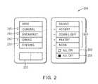
- FIG. 2depicts a conventional wall-mounted control panel 200 for a conventional electronic lighting control system.
- the panel 200includes a plurality of physical push buttons labeled with text labels. Lighting scene selection buttons 205 , 210 , 215 , 220 enable selection of various lighting scenes, while dimmer controls 230 are provided to adjust brightness. Further, the control panel 200 includes buttons 240 for selecting light fixtures in other rooms of the home or structure, as well as “All On” and “All Off” buttons 250 , 255 for global control.
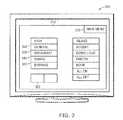
- FIG. 3depicts a conventional touch-based user interface 310 for a conventional electronic lighting control system on touch-screen control unit 300 . Similar to the button-centric control panel 200 discussed above, the user interface 310 displays a plurality of buttons 320 , 330 , 340 , 350 for selecting various lighting scenes. Further, the user interface 310 includes dimmer controls 360 for adjusting brightness, as well as menuing controls 370 for accessing interfaces for other rooms in the home or structure.
- a conventional touch-screen control unit 300is often little change from that provided by a conventional button-centric control panel 200 . Rather utilizing physical buttons, the user is simply utilizing digital buttons. The user still must memorize which buttons operate which light fixtures, or groups of light fixtures, and may still have to resort to trial and error to determine exactly what each button does. Thus, the overall user experience may be just as frustrating as with a conventional button-centric control panel 200 .
- a large room in a home or other structuremay include a number of motor operated devices, such as automatic window shades or ceiling fans, which a user may desire to operate and adjust selectively.
- a large room in a home or other structuremay include a number of audio/video (A/V) components that a user may desire to select and control, as well as other devices that a user may desire to operate in a controlled manner.
- A/Vaudio/video
- a room of a home or other structuremay include various heating, ventilating, and air conditioning and/or energy management devices user may desire to manage.
- a usermay be forced to memorize which mechanical switch, physical push-button, or digital button is associated with each device and/or each function of a device, and may become frustrated when simply turning on or off a device, or otherwise changing the state of a device, becomes a complicated endeavor.
- the virtual room-based user interfaceincludes a plurality of virtual room interface environments (hereinafter “virtual rooms”). Each virtual room corresponds to a different physical room (or portion of a physical room) in a home or other structure. In some cases, several virtual rooms may correspond to different portions of one physical room, e.g., to cover the entire physical room. Each virtual room may include a substantially photo-realistic depiction of the boundaries of the physical room (or portion of the physical room), for example, of the walls, ceiling, floor, etc.
- That define the roommay show at least a portion of furnishings present in the physical room (or portion of the physical room), for example, sofas, chairs, beds, wall-hangings, etc. that are present in the physical room; and may show devices, for example, light fixtures, under control (either directly or indirectly) of the programmable multimedia controller that are present within the physical room (or portion of the physical room).
- Substantially photo-realistic depictions of devices under controlare preferably shown at locations within the virtual room corresponding to the device's actual locations within the physical room.
- the substantially photo-realistic depictions of the room and the devicesare derived from a limited number of prerecorded images, for example, a limited number of still digital photographs of the physical room, captured from a predetermined location and showing the room in differing states.
- a variety of other techniques for creation of the substantially photo-realistic depictions of the room and the devicesare expressly contemplated and described below.
- a usermay select, control, and otherwise interact with the devices, for example, the light fixtures, in the physical room by manipulating the substantially photo-realistic visual depictions of the devices within the virtual room, for example, by selecting the visual depictions of the devices within the virtual room on a touch-screen display.
- the appearance of the virtual roommay be dynamically updated in response to the user's manipulations in the virtual room. Further, the appearance of the virtual room may be dynamically updated in response to data received from devices within the physical room and/or in response to environmental changes.
- a virtual roommay be continuously updated to show a substantially photo-realistic depiction of at least a portion of the corresponding physical room, such that what a user views within the virtual room will mirror, or at least resemble, their experience within the corresponding physical room at a given time.
- FIG. 1is a depiction of a conventional 6-gang mechanical switch panel, housing six individual mechanical switches;
- FIG. 2is a depiction of a conventional wall-mounted control panel for a conventional electronic lighting control system
- FIG. 3is a depiction of a conventional touch user interface for a conventional electronic lighting control system
- FIG. 4is a block diagram of an example programmable multimedia controller interconnected to a number of devices
- FIG. 5is a block diagram of an example hardware architecture of the example programmable multimedia controller of FIG. 4 ;
- FIG. 6is a diagram of an example virtual room-based user interface
- FIG. 7is a diagram of an example virtual room-based user interface in which the virtual room has been updated to show particular light fixtures activated;
- FIG. 8Ais a diagram of an example virtual room-based user interface in which portions of two virtual rooms are shown in mid-advance, for example, in response to a user's swipe;
- FIG. 8Bis a diagram of an alternative example virtual room-based user interface in which portions of two virtual rooms corresponding to the same physical room are shown in mid-advance, for example, in response to a user's swipe;
- FIG. 8Cis a diagram of an alternative example virtual room-based user interface showing a virtual room corresponding to a lower level of a tree structure of virtual rooms;
- FIG. 8Dis a diagram of an alternative example virtual room-based user interface showing a virtual room corresponding to a lower level of a tree structure of virtual rooms that illustrates additional usage of gestures;
- FIG. 8Eis a diagram of an alternative example virtual room-based user interface showing a plurality of virtual rooms, arranged into groups within a tree structure of virtual rooms.
- FIG. 9is a diagram of an example virtual room-based user interface in which a Lighting Tab is selected.
- FIG. 10is a diagram of an example virtual room-based user interface in which an A/V Tab is displayed
- FIG. 11is a flow diagram of an example sequence of steps for controlling devices within a physical room using a virtual room-based user interface.
- FIG. 12is a functional block diagram depicting an example technique for rendering a virtual room based on a limited number of prerecorded images of the physical room in different states.
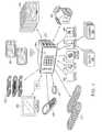
- FIG. 4is a block diagram of an example programmable multimedia controller 400 interconnected to a number of devices.
- the term “programmable multimedia controller”should be interpreted broadly as a device capable of controlling, switching data between, and/or otherwise interoperating with a variety of electrical and electronic devices, such as audio, video, telephony, data, security, motor-operated, relay-operated, heating, ventilation, and air conditioning (HVAC), energy management and/or other types of devices.
- HVACheating, ventilation, and air conditioning
- the programmable multimedia controller 400may be coupled to a variety of A/V devices, including audio source devices 410 , such as compact disk (CD) players, digital video disc (DVD) players, microphones, digital video recorders (DVRs), cable boxes, audio/video receivers, personal media players, and other devices that source audio signals; may be coupled to a variety of video source devices 420 , such as digital video disc (DVD) players, digital video recorders (DVRs), cable boxes, audio/video receivers, personal media players and other devices that source video signals; may be coupled to a variety of audio output devices 430 , such as speakers, devices that incorporate speakers, and other devices that output audio; and may be coupled to a variety of video output devices 440 , such as televisions, monitors, and other devices that output video.
- audio source devices 410such as compact disk (CD) players, digital video disc (DVD) players, microphones, digital video recorders (DVRs), cable boxes, audio/video receivers, personal media players, and other devices that source audio signals
- the programmable multimedia controller 400may be coupled to, control, and otherwise interoperate with a variety of other types of devices, either directly, or through one or more intermediate controllers.
- the programmable multimedia controller 400may be coupled to a closed-circuit television (CCTV) control system 470 that manages a system of cameras positioned about a home or other structure, HVAC control and/or energy management system 475 that manages HVAC devices to regulate environmental functions and/or energy management devices in the home or other structure, and/or a security system 480 that manages a plurality of individual security sensors in the home or other structure.
- CCTVclosed-circuit television
- the CCTV control system 470 , the HVAC control system and/or energy management system 475 , and the security system 480may manage the devices under their respective immediate control.
- the programmable multimedia controller 400may be coupled to, control, and otherwise interoperate with, one or more electronic lighting controllers 490 .
- the one or more electronic lighting controllers 490may be coupled to, for example, via wired or wireless links, a plurality of relays 492 and/or dimmer units 493 distributed throughout the home or other structure, and wired inline with the electrical feed to individual light fixtures located therein.
- the one or more electronic lighting controllers 490may selectively trigger relays 492 and/or adjust dimmer units 493 wired inline to particular light fixtures (not shown), to create a desired level of illumination or darkness in different rooms of the home or other structure.
- the programmable multimedia controller 400may be coupled to, control, and otherwise interoperate with, one or more motor operated device controllers 495 , for example, one or more automatic window shade controllers, or other types of controllers.
- the motor-operated device controllers 495may selectively trigger motor-operated devices (not shown) in various rooms of the home or other structure, to achieve desired effects.
- the programmable multimedia controller 400may receive user-input via one or more control units 450 , for example, wall-mounted control units, table-top control units, hand-held portable control units, and the like, that include a display screen.
- the one or more control units 450may include a touch screen interface, a mouse and pointer interface, or other type of interface.
- the control units 450may be special-purpose units, dedicated to operating with the programmable multimedia controller 400 , or general-purpose devices, for example, laptop computers, desktop computers, etc., configured with software to implement a user interface according to the below described techniques.
- the control units 450may be coupled to the programmable multimedia controller 400 via an intermediate device 453 , such a computer, via a wired or wireless connections or networks. In other cases, the control units 450 may communicate directly to the able multimedia controller 400 .
- the programmable multimedia controller 400may also receive user-input via one or more handheld button-centric remote control units and/or wall mounted button-centric control units 455 , or from one or more handheld remote control units including an annular touch sensor 457 .
- Remote control units including an annular touch sensor 457may be adapted to manipulate, and make control selections using, an on-screen menuing system, displayed on a display device. Further details regarding remote control units including an annular touch sensor may be found in Madonna et al., U.S. patent application Ser. No. 11/520,328, filed Sep. 13, 2006 and titled “Remote Control Unit for a Programmable Multimedia Controller,” the contents of which are incorporated by reference herein in their entirety.
- the programmable multimedia controller 400may also receive user-input via one or more mobile devices 460 .
- the term “mobile device”refers to electronic devices that are adapted to be transported on one's person, including multimedia smartphones, such as the iPhone® multimedia phone available from Apple Inc. and the Blackberry® device available from Research In Motion Limited, multi-purposes tablet computing devices, such as the iPad® tablet available from Apple Inc., portable media players with enhanced capabilities, such as the iPod® touch available from Apple Inc., personal digital assistants (PDAs), electronic book readers, and the like.
- Such mobile devicesmay communicate directly with the programmable multimedia controller 400 , or indirectly through various wireless, cellular, and/or wired networks (not shown).
- the programmable multimedia controller 400may receive user-input via a touch screen or other interface integrated into the programmable controller multimedia 400 itself, for example, a touch screen or other interface presented on a front panel 465 of the programmable multimedia controller 400 .
- the programmable multimedia controller 400may receive user-input via a touch screen integrated into a video output device 440 , such as a television.
- the programmable multimedia controller 400may switch data between, issue control commands to, and/or otherwise interoperate with, the audio source devices 410 , the video source devices 420 , the audio output devices 430 , and/or the video output devices 440 .
- the programmable multimedia controller 400may issue control commands to, and otherwise interoperate with, the CCTV control system 470 , the HVAC control and/or energy management system 475 , the security system 480 , the electronic lighting controllers 490 , as well as the motor operated device controllers 495 .
- the user-input which directs such functionality, at least in part,may be received within a novel virtual room-based user interface, as explained further below.
- the novel virtual room-based user interfaceis displayed on the screen of a control unit 450 , mobile device 460 , front panel display 465 or other device that has a touch screen, and the user makes selections therein by touching selected portions of the interface with their finger, a stylus, or similar implement.
- the virtual room-based user interfaceis displayed on a display screen, that lacks touch recognition capabilities, and a user may interact with the interface using some other type of interface, for example, a mouse.
- the usermay make selections using handheld button-centric remote control units and/or wall mounted button-centric control units 455 , remote control units including an annular touch sensor 457 , or other device.
- the programmable multimedia controller 400may issue specific control commands to the devices coupled to it.
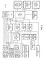
- FIG. 5is a schematic block diagram of an example hardware architecture 500 of the example programmable multimedia controller 400 .
- the various components shownmay be arranged on a “motherboard” of the controller 400 , or on a plurality of circuit cards interconnected by a backplane (not shown).
- a microcontroller 510manages the general operation of the controller 400 .
- the microcontroller 510is coupled to an audio switch 515 and a video switch 520 via a bus 518 .
- the audio switch 515 and the video switch 520are preferably crosspoint switches capable of switching a number of connections simultaneously. However, many other types of switches capable of switching digital signals may be employed, for example Time Division Multiplexing (TDM) switches or other devices. Further, while two separate switches 515 , 520 are shown, audio and video switching may be consolidated into a single switch that supports switching of both types of data.
- TDMTime Division Multiplexing
- a mid plane 535interconnects the audio and video switches 515 , 520 to a variety of input and output modules, for example, one or more Video Input/Output Modules 587 , one or more Audio Input/Output Modules 590 , and/or one or more other modules 595 .
- Such modulesmay include a plural of connection ports that may be coupled to A/V devices.
- Further details regarding the operation of the one or more Video Input/Output Modules 587 , one or more Audio Input/Output Modules 590 , and/or one or more other modules 595may be found in Madonna et al., U.S. patent application Ser. No. 11/314,664, filed Dec. 20, 2005 and titled “System and Method for a Programmable Multimedia Controller”, the contents of which are incorporated by reference herein in their entirety.
- the mid plane 535is further coupled to an Ethernet switch 530 that interconnects Ethernet ports 532 and a processing subsystem 540 to the microcontroller 210 .
- the processing subsystem 540includes one or more “general-purpose computers” 545 .
- a general-purpose computer 545refers to a device that is configured to execute a set of instructions, and depending upon the particular instructions executed, may perform a variety of different functions or tasks.
- a general-purpose computer 545executes a general-purpose operating system, such as the Windows® operating system, available from Microsoft Corporation, the Linux® operating system, available from a variety of vendors, the OSX® operating system, available from Apple Inc., or another operating system.
- the general-purpose computer 545may include a computer-readable medium, for example, a hard drive, a Compact Disc read-only memory (CDROM) drive, a Flash memory, or other type of storage device, and/or may be interconnected to a storage device provided elsewhere in the processing subsystem 540 .
- a computer-readable mediumfor example, a hard drive, a Compact Disc read-only memory (CDROM) drive, a Flash memory, or other type of storage device, and/or may be interconnected to a storage device provided elsewhere in the processing subsystem 540 .
- the processing subsystem 540preferably has one or more graphics outputs 541 , 542 such as analog Video Graphics Array (VGA) connectors, Digital Visual Interface (DVI) connectors, Apple Display Connector (ADC) connectors, or other type of connectors, for supplying graphics.
- graphics outputs 541 , 542may, for example, be supplied directly from the one or more general-purpose computers 545 of the processing subsystem 240 .
- the example programmable multimedia controller 400may also include a memory card interface and a number of Universal Serial Bus (USB) ports 542 interconnected to a USB hub 543 . Such USB ports 542 may be couple to external devices.
- USB switch 544is employed to switch USB signals received at the hub to the processing subsystem 540 .
- IEEE 1394 (FireWireTM) ports 546may be coupled to external devices and pass data to an IEEE 1394 hub 547 and to an IEEE 1394 switch 548 , for switching to the processing subsystem 540 .
- the microcontroller 510is further connected to a Serial Peripheral Interface (SPI) and Inter-Integrated Circuit (I 2 C) distribution circuit 550 , which provides a serial communication interface to relatively low data transfer rate devices.
- SPISerial Peripheral Interface
- I 2 CInter-Integrated Circuit
- the SPI/I 2 C controller 550is connected to the mid plane 535 and thereby provides control commands from the microcontroller 510 to the modules 587 , 590 , 595 of the programmable multimedia controller 300 . Further, connections from the SPI/I 2 C controller 550 are provided to components such as a fan controller 551 , a temperature sensor 552 , and a power manager circuit 553 , which collectively manage the thermal characteristics of the programmable multimedia controller 400 .
- the microcontroller 510is also connected to a device control interface 575 that may communicate with the CCTV control system 470 , the HVAC control and/or energy management system 475 , the security system 480 , the one or more electronic lighting controllers 490 as well as the one or more motor operated device controllers 495 .
- a telephone interface 570may be provided to connect to a telephone network and/or telephone handsets.
- an expansion port 580may be provided for linking several programmable multimedia controllers 100 together, to form an expanded system, while a front panel display 465 , for example, a touch screen display, is provided to display status, configuration, and/or other information to a user, as well as to accept user input.
- Such a programmable multimedia control 400 or other platformmay support a novel virtual room-based user interface.
- the virtual room-based user interfaceincludes a plurality of virtual room interface environments (hereinafter “virtual rooms”). Each virtual room corresponds to a different physical room (or portion of a physical room) in a home or other structure). In some cases, several virtual rooms may correspond to different portions of one physical room, e.g., to cover the entire physical room.
- Each virtual roommay include a substantially photo-realistic depiction of the boundaries of the physical room (or portion of the physical room), for example, of the walls, ceiling, floor, etc.
- That define the roommay show at least a portion of furnishings present in the physical room (or portion of the physical room), for example, sofas, chairs, beds, wall-hangings, etc. that are present in the physical room; and may show devices, for example, light fixtures, under control (either directly or indirectly) of the programmable multimedia controller that are present within the physical room (or portion of the physical room).
- Substantially photo-realistic depictions of devices under controlare preferably shown at locations within the virtual room corresponding to the device's actual locations within the physical room.
- the substantially photo-realistic depictions of the room and the devicesare derived from a limited number of prerecorded images, for example, a limited number of still digital photographs of the physical room, captured from a predetermined location and showing the room in differing states.
- a variety of other techniques for creation of the substantially photo-realistic depictions of the room and the devicesare expressly contemplated and described below.
- a usermay select, control, and otherwise interact with the devices, for example, light fixtures, by manipulating the substantially photo-realistic visual depictions of the devices within the virtual room, for example, by selecting the visual depictions of the devices within the virtual room.
- the appearance of the virtual roommay be dynamically updated in response to the user's manipulations in the virtual room.
- the appearance of the virtual roommay also be dynamically updated in response to data received from devices within the physical room and/or environmental changes, for example, time of day.
- the virtual roommay be continuously updated to show a substantially photo-realistic depiction of at least a portion of the coral responding physical room, such that what a user views within a virtual room will mirror, or at least resemble, their experience within the corresponding physical room at a given time.
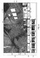
- FIG. 6is a diagram of an example virtual room-based user interface 600 .
- the example virtual room-based user interface 600may include a main portion 610 that provides a virtual room for controlling devices within a corresponding physical room.
- the example virtual room-based user interface 600may further include a menu portion 620 , configured to display selectable menu tabs corresponding to different types of functionality, and a function specific portion 630 , configured to display options specific to a selected menu tab.
- a virtual room corresponding to a portion of a “great room”is shown.
- a substantially photo-realistic depiction of a portion of the “great room”is displayed, including the boundaries of the physical room, its furnishings, and devices under control of the programmable multimedia controller 400 that are within the portion of the room.
- the example virtual roomshows substantially photo-realistic representations of free-standing light fixtures, such as lamps 640 , 642 ; fixed light fixtures, such as wall sconces 645 , 647 , 650 and chandelier 662 ; and special-purpose light fixtures, such as accent lighting 665 , 667 , and 670 .
- the example virtual roomshows substantially photo-realistic visual depictions of a flat-screen television 672 and automatic window shades 675 , which are also under control of the programmable multimedia controller 400 .
- a usermay manipulate the substantially photo-realistic visual depictions of the devices within the virtual room, to select, control, or otherwise interoperate with the devices within the physical room.
- a usermay select particular light fixtures to activate by selecting, e.g., touching or clicking on, the substantially photo-realistic visual depictions of the light fixtures within the virtual room.
- a usermay select, e.g., touch or click on, the substantially photo-realistic visual depiction of a lamp 640 and a chandelier 662 .
- the programmable multimedia controller 400may send control commands to one or more electronic lighting controllers 490 to cause such controllers to activate relays wired inline with the electrical feed to the lamp 640 and the chandelier 662 .
- the programmable multimedia controller 400may update the virtual room, such that it shows a substantially photo-realistic depiction of the physical room with the particular light fixtures illuminated.
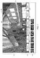
- FIG. 7is a diagram of an example virtual room-based user interface 700 in which the virtual room has been updated to show particular light fixtures activated.
- the substantially photo-realistic visual depictions of the lamp 640 and the chandelier 662have been changed to depict the light fixtures illuminated.
- the effects of such illuminationare depicted in the virtual room, such that the structure and furnishings show the effects of the light provided by the lamp 640 and the chandelier 662 . For instance, realistic reflections are shown on reflective surfaces, appropriate shadows are shown given the direction of the light, etc.
- the updated appearance of the virtual roommay be rendered based upon a limited number of prerecorded images, for example, a limited number of still digital photographs of the physical room, captured from a predetermined location and showing the room in differing states.
- a variety of other techniques for creation of the substantially photo-realistic depictions of the room and devices therein, in differing statesmay be employed.
- a usermay select a device other than a light fixture in the physical room to activate and/or control by selecting, e.g., touching or clicking on, the substantially photo-realistic visual depiction of the device within the virtual room.
- a usermay select, e.g., touch or click on, the substantially photo-realistic visual depiction of the flat-screen television 672 within the virtual room.
- the programmable multimedia controller 400may send control commands to activate the flat-screen television. Further, the programmable multimedia controller 400 may update the virtual room, such that it shows a substantially photo-realistic depiction of the physical room with the television activated.
- a miniature depiction of the programming currently being displayed on the televisionmay be shown on the substantially photo-realistic depiction of the flat-screen television 672 within the virtual room.
- a variety of other types of A/V devices associated with the physical roommay be controlled.
- a usermay select, e.g., touch or click on, the substantially photo-realistic visual depiction of a particular set of window shades 675 within the virtual room.
- the programmable multimedia controller 400may send control commands to one or more motor operated device controllers 495 to raise or lower the selected shades, as appropriate.
- the programmable multimedia controller 400may update the virtual room, such that it shows a substantially photo-realistic depiction of the shades 675 raised or lowered. In such manner, what a user views within the virtual room may mirror, or at least resemble, their experience within the corresponding physical room.
- the virtual room-based user interfacemay support more advanced types of control input. Such more advanced control may be supported via the menu portion 620 of the virtual room-based user interface and the function specific portion 630 of the virtual room-based user interface. It may alternatively be supported by gesture recognition in the main portion 610 of the virtual room-based user interface.
- the menu portion 620 of the interfacemay include a plurality of function tabs, for example, a Security Tab 677 in which certain additional functionality related to a CCTV system and/or security system may be accessed, an A/V Tab 680 in which certain additional audio and video related functionality may be accessed, an HVAC/Shades Tab 682 in which certain additional functionality related to HVAC systems and/or automatic window shades systems may be accessed, a Lighting Tab 685 in which certain additional functionality related to light fixture control may be accessed, a Services Tab 687 in which certain functionality related to programmable services may be accessed, and a Zones Tab 690 in which different virtual rooms may be selected for display in the main portion 610 of the screen.
- a Security Tab 677in which certain additional functionality related to a CCTV system and/or security system may be accessed
- A/V Tab 680in which certain additional audio and video related functionality may be accessed
- an HVAC/Shades Tab 682in which certain additional functionality related to HVAC systems and/or automatic window shades systems may be accessed
- the function specific portion 630 of the user interfacemay show selectable icons, buttons, text and the like related to such functionality.
- the example virtual room-based user 600 of FIG. 6 interfacedepicts the Zones Tab 690 selected, and the function specific portion 630 shows a plurality of selectable images 691 , 692 , 693 , 694 , 695 , 696 corresponding to different available virtual rooms, each virtual room corresponding to a different physical room (or portion of a physical room) in the home or other structure.
- the main portion 610 of the virtual room-based user interfacemay be updated to display the corresponding different virtual room.
- different virtual roomsmay be selected via gestures, for example, touch-based gestures.
- virtual roomsmay be logically arranged in a linear or circular array.
- a usermay “swipe,” for example, with their finger, a stylus, or similar implement on a touch sensitive display, for example in the main portion 610 of the virtual room-based user interface to advance from one virtual room to the next.
- swiperefers to a rapid continuous, substantially linear motion in the user interface.
- the virtual room displayed in the main portion 610 of the virtual room-based user interfacemay be advanced.
- FIG. 8Ais a diagram of an example virtual room-based user interface 800 in which portions of two virtual rooms 810 , 810 corresponding to different physical rooms are shown in mid-advance, for example, in response to a user's swipe. Since virtual rooms may also correspond to a portion of a physical room, swiping may alternatively be used to advance between virtual rooms that correspond to a portion of the same physical room.
- FIG. 8Bis a diagram of an alternative example virtual room-based user interface 830 in which portions of two virtual rooms 835 , 840 corresponding to the same physical room are shown in mid-advance, for example, in response to a user's swipe.
- virtual roomsmay be logically arranged in more complicated arrangements.
- virtual rooms and/or groups of virtual roomsmay be arranged in a tree structure.
- various gesturesmay perform differing functions.
- Such an arrangementmay be used in conjunction with a variety of type of gestures, including “multi-touch” gestures, that is, gestures that involve selection of two or more points in the user interface.
- multi-touch gesturesthat is, gestures that involve selection of two or more points in the user interface.
- such an arrangementmay be used with other types of controls, for example with a pointer and mouse control scheme.
- FIG. 8Cis a diagram of an alternative example virtual room-based user interface 845 showing a virtual room corresponding to a lower level of a tree structure of virtual rooms. While a user is viewing a virtual room at this level, the user may make a multi-touch “contract gesture” 850 .
- the term “contract gesture”refers to a selection of two points in the user interface and a dragging of such points towards one another in a substantially continuous motion. In response, the interface may “zoom in” on a portion of the virtual room about the location the gesture was made. Similarly, the user may make a multi-touch “expand gesture” 855 .
- the term “expand gesture”refers to a selection of two points in the user interface and a dragging of such points away from one another in a substantially continuous motion. In response, the interface may “zoom out” to show a greater portion of the virtual room.
- FIG. 8Dis a diagram of an alternative example virtual room-based user interface 860 showing a virtual room corresponding to a lower level of a tree structure of virtual rooms that illustrates additional usage of gestures.
- the usermay make a “drag gesture” 865 in one of several directions, for example, up, down, left or right.
- drag gesturerefers to a continuous, substantially linear motion in the user interface.
- the interfacemay pan within the virtual room in a corresponding direction, if there are portions of the virtual room that are not presently shown in the viewable area of the interface.
- FIG. 8Eis a diagram of an alternative example virtual room-based user interface 870 showing a plurality of virtual rooms, arranged into groups within a tree structure of virtual rooms.
- a first group 890may correspond to a “1 st Floor” of a structure and include one or more virtual rooms associated with that floor
- a second group 885may correspond to a “2 nd Floor” of a structure and include one or more virtual rooms associated with that floor
- a third group 880may correspond to a “3 rd Floor” of a structure and include virtual rooms associated with that floor
- an additional group 895may correspond to an exterior of a structure and include virtual rooms associated therewith. It should be understood, such grouping is merely an example, and a wide variety of other configurations may be readily implemented. To revist a lower level of the tree structure of virtual rooms, the user may select one of the virtual rooms shown in the interface 870 .
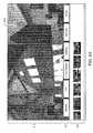
- FIG. 9is a diagram of an example virtual room-based user interface 900 in which the Lighting Tab 685 is selected.
- the function specific portion 630 of the example user interface 900may include a plurality of buttons 910 , 920 , 930 , 940 corresponding to various lighting “scenes,” selection of which will activate, deactivate, and/or permit dimming/brightening of a plurality of light fixtures in the room.
- the function specific portion 630 of the example virtual room-based user interface 900may include one or more dimming sliders 950 , which when operated may cause the programmable multimedia controller 400 to issue commands to one or more electronic lighting controllers 490 , to cause such controllers to adjust dimmer units 493 wired inline with the electrical feed to individual light fixtures, or groups of light fixtures.
- gesturesfor example, touch-based gestures may be used to cause the programmable multimedia controller 400 to issue commands to one or more electronic lighting controllers 490 to cause such controllers to adjust dimmer units 493 wired inline with the electrical feed to individual light fixtures, or groups of light fixtures.
- a usermay make a gesture, for example, a touch-based gesture, on or about a substantially photo-realistic depiction of a particular light fixture or group of light fixtures. Such gesture may be translated into a brightening or dimming control command.
- the usermay make a multi-touch “expand” on or about the substantially photo-realistic depiction of a particular light fixture and dragging such points in opposing directions, to indicate the corresponding light fixture should be brightened.
- the usermay make a multi-touch “contract” gesture on or about the substantially photo-realistic depiction of a particular light fixture to indicate the corresponding light fixture should be dimmed.
- “expand” and “contract” gesturessupport for a variety of other gestures is expressly contemplated to for use with controlling brightness of light fixtures or the settings of other devices.
- the A/V Tab 680may provide access to selectable icons, buttons, text and the like in the function specific portion 630 of the user interface for A/V device control.
- a usermay choose an A/V device under control of the programmable multimedia controller 400 , for example, a television, by selecting, e.g., touching, the substantially photo-realistic representation of the device in the virtual room displayed in the main portion 610 of the virtual-room based user interface. Thereafter, the user may be presented with device-specific control icons, buttons, text and the like, manipulation of which may control the selected device.
- FIG. 10is a diagram of an example virtual room-based user interface 1000 in which the A/V Tab 685 is displayed.
- the function specific portion 630 of the example virtual room-based user interface 1000may include a plurality of A/V related buttons, for example, volume buttons 1010 , 1020 , a mute button 1030 , playback control buttons 1040 , a power button 1050 , and/or channel selection buttons 1060 , 1070 .
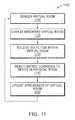
- FIG. 11is a flow diagram of an example sequence of steps 1100 for controlling devices within a physical room using a virtual room-based user interface.
- the programmable multimedia controller 400renders a virtual room, including the substantially photo-realistic depiction of the physical room (or a portion of the physical room) and the substantially photo-realistic depictions of the devices, for example, the light fixtures, within the physical room.
- the rendered virtual roomis displayed on the display screen of a control unit 450 , a mobile device 460 , the front panel display 465 of the programmable multimedia controller 400 , a television 440 or, alternatively, on another device.
- the multimedia controller 400receives a selection, for example, a touch selection, button-press, annular touch sensor input, etc. from a user.
- the selectionindicates a particular substantially photo-realistic visual depiction of a device, for example, of a particular light fixture, within the virtual room.
- the programmable multimedia controller 400sends control commands to the device in the physical room, or to an intermediate controller coupled to the device, to change a state of the device.
- the programmable multimedia controller 400may send control commands to one or more electronic lighting controllers 490 to cause such controllers to activate a relay 492 wired inline with the electrical feed to a selected light fixture.
- the programmable multimedia controller 400updates the appearance of the virtual room, and loops to step 1010 , to render the virtual room and visual depictions of the devices in the virtual room, to show the updated state, for example to show the light fixture activated.
- the virtual roomincluding the substantially photo-realistic depiction of the physical room and the substantially photo-realistic depictions of the devices within the physical room may be rendered in step 1110 of FIG. 11 in any of a variety of different manners.
- an installer during system configurationmay capture images, for example, take still digital photographs, of the physical room from a predetermined location, each image captured of the room while it is in a different potential state.
- a first imagemay be captured of the physical room with no light fixtures activated
- a second imagemay be captured of the physical room with a first light fixture activated
- a third imagemay be captured of the physical room with a second light fixture activated
- a forthimage may be captured of the physical room with the first light fixture and the second light fixture activated, and so forth such that every potential combination is captured.
- the imagesmay be correlated, such that features coincide in location between images, and stored in a library on the programmable multimedia controller 400 , or on another device.
- the rendering step 1110may involve simply accessing the appropriate stored image of the physical room that shows the room with devices in the appropriate states.
- the virtual roomincluding the substantially photo-realistic depiction of the physical room and the substantially photo-realistic depictions of the devices within the physical room, is rendered in step 1110 of FIG. 11 from a limited number of prerecorded images, for example, a limited number of digital still photographs of the physical room.
- an installercaptures from a predetermined location an image of the room with no devices activated, as well as images of the room with each device in the room activated singly (i.e. activated without any other devices in the room activated).
- a first imagemay be captured of the physical room with no light fixtures activated
- a second imagemay be captured of the physical room with just a first light fixture activated (preferably at maximum brightness)
- a third imagemay be captured of the physical room with just a second light fixture activated (preferably at maximum brightness)
- a forth imagemay be captured of the physical room with a just a third light fixture and activated (preferably at maximum brightness)
- n+1 imagesmay be captured.
- the n+1 imagesmay be correlated such that features coincide in location between images, and the images may be stored in a library on the programmable multimedia controller 400 , or another device. Then, according to a novel mixing technique, all of the possible states of the room may be generated at display-time from the n+1 prerecorded images.
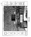
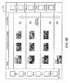
- FIG. 12is a functional block diagram 1200 depicting an example technique for rendering a virtual room based on a limited number of prerecorded images of the physical room in different states.
- the limited number of imagesmay be stored in an image repository, for example, a memory 1202 of the programmable multimedia controller 400 or other device.
- the imagesinclude a first image 1210 of the physical room with no devices, for example, light fixtures, activated, a second image 1230 of the physical room with just a first device activated, for example, a first light fixture activated (preferably at maximum brightness), a third image 1250 of the physical room with just a second device activated, for example, a second light fixture activated (preferably at maximum brightness), a forth image 1270 of the physical room with a just a third device activated, for example, a third light fixture activated (preferably at maximum brightness), up to an n th image 1290 of the room with just an n th device activated, for example, an n th light fixture activated (preferably at maximum brightness).
- a first device activatedfor example, a first light fixture activated (preferably at maximum brightness)
- a third image 1250 of the physical room with just a second device activatedfor example, a second light fixture activated (preferably at maximum brightness)
- the images 1210 , 1230 , 1250 , 1270 , 1290may be accessed by a processor 1204 , for example, of the programmable multimedia controller 400 or another device, that implements binary virtual controls 1232 , 1252 , 1272 , 1292 .
- the binary virtual controlsmay be software routines that, in response to a user's selection of the visual depiction of the device in the virtual room-based user interface, either passes a corresponding image showing the device activated, or blocks the image.
- the imagesare received at a graphical processing unit (GPU) 1206 , for example of the programmable multimedia controller 400 or of another device.
- GPUgraphical processing unit
- the GPU 1206preferably implements a plurality of adjustment routines 1234 , 1254 , 1274 , 1294 that adjust properties of the images 1230 , 1250 , 1270 , 1290 .
- the adjustment routines 1234 , 1254 , 1274 , 1294may be dimmer routines that adjust the brightness of the images 1230 , 1250 , 1270 , 1290 , for instance from between 0% and 100%, in response to dimmer selections made by a user in the virtual room-based user interface.
- the GPU 1206preferably implements a plurality of filter routines 1236 , 1256 , 1276 , 1296 that receive two or more images, and filter the images on a pixel-by-pixel basis, to produce output images 1238 , 1258 , 1278 , 1298 .
- the received imagesmay include adjusted images provided by the adjustment routines 1234 , 1254 , 1274 , 1294 , as well as output images provided by previous filter routines 1236 , 1256 , 1276 via paths 1237 , 1257 , 1277 .
- filter routines 1236 , 1256 , 1276 , 1296may select among corresponding pixels in each received image the pixel having the greatest pixel value (e.g., the greatest brightness), and generate the output image 1238 , 1258 , 1278 , 1298 from such pixels. In such manner, the illumination effects of various light fixtures may be effectively combined. Further, by feeding the output image from a filter routine to the next successive filter routine, accumulated illumination effects from a plurality of different light fixtures activated at once may be approximated.
- a selector 1240 of the GPU 1206selects the appropriate output image 1238 , 1258 , 1278 , 1298 that represents the combination of devices activated in the room. Such output image is then provided for display in the virtual room-based user interface, for example, the image is used in displaying step 1120 of FIG. 11 .
- the devices controlled via the virtual room-based user interfaceare located within a room of a home or other structure, such as a great room or kitchen
- the techniquesmay be used with a variety of other types of rooms found in different types of structures.
- the virtual roommay correspond to (or correspond to a portion of) a conference room, a board room, a show room, a class room, a restaurant or bar dining room, a factory floor, a warehouse space, etc.
- the devicesneed not be located within any type of “room”.
- devices that are located external to the home or structure, such as exterior light fixtures,may also be controlled via the virtual room-based user interface.
- one or more virtual roomsmay be defined for outdoor spaces, each virtual room including a substantially photo-realistic depiction of a particular portion of outdoor space.
- each structuremay include its own programmable multimedia controller 400 coupled to devices and intermediate controllers, for example, to electronic lighting controllers 490 , motor operated device controllers 495 , and the like.
- a networkfor example, a wide area network (WAN) may interconnect the programmable multimedia controllers 400 , and allow control commands to passed there between.
- WANwide area network
- the substantially photo-realistic depictions of the room and devices used to create each virtual roommay be rendered from images, for example, from digital still photographs
- the substantially photo-realistic depictionsmay be rendered in other manners.
- the substantially photo-realistic depictionsmay be rendered from full-motion video, rather than still photographs.
- the full-motion videomay be captured in advance, during system configuration, and stored, or may comprise at least some live full-motion video of the physical room (or portion thereof) of the home or other structure, for example, captured live by one or more cameras coupled to the CCTV control system 470 .
- the substantially photo-realistic depictionsmay be rendered from high-definition three-dimensional (3-D) laser scans or other types of high-definition surveying of the rooms of the home or other structure.
- a high-definition computer aided design (CAD) modelmay be built for each room, based on the data captured in the 3-D laser scans or other types of surveying, and such model used in the rendering.
- CADcomputer aided design
- control units 450button-centric remote control units and/or wall mounted button-centric control units 455 , remote control units including an annular touch sensor 457 , mobile devices 460 , front panel 465 and/or video output devices 440 , coupled to programmable multimedia controller 400 are located within the home or other structure, it should be understood that at least some of these devices may be located remotely, and enable a user to interact with the system remotely, for example, via the Internet.
- the programmable multimedia controller 400may be coupled via a network interface (not shown) to the Internet.
- the virtual room-based user interfacemay be displayed to a user within a web browser or other application, on a device located far remote from the home or structure. User selections may be forwarded over the Internet to the programmable multimedia controller 400 . In such manner, a user may be able to control devices within the home or structure remotely, over great distances, and view the effects of their control selections.
- a computer-readable mediummay take the form of a memory, such as a Random Access Memory (RAM), a disk, such as a CD-ROM, or other tangible storage medium.
- RAMRandom Access Memory
- CD-ROMCompact Disc-ROM
Landscapes
- Engineering & Computer Science (AREA)
- Theoretical Computer Science (AREA)
- General Engineering & Computer Science (AREA)
- Physics & Mathematics (AREA)
- General Physics & Mathematics (AREA)
- Human Computer Interaction (AREA)
- Automation & Control Theory (AREA)
- Computer Networks & Wireless Communication (AREA)
- Signal Processing (AREA)
- User Interface Of Digital Computer (AREA)
- Circuit Arrangement For Electric Light Sources In General (AREA)
- Selective Calling Equipment (AREA)
- Controls And Circuits For Display Device (AREA)
Abstract
Description
Claims (24)
Priority Applications (3)
| Application Number | Priority Date | Filing Date | Title |
|---|---|---|---|
| US14/733,428US10146398B2 (en) | 2009-06-03 | 2015-06-08 | Generating a virtual-room of a virtual room-based user interface |
| US16/123,731US10613704B2 (en) | 2009-06-03 | 2018-09-06 | Small screen virtual room-based user interface |
| US16/821,626US10802668B2 (en) | 2009-06-03 | 2020-03-17 | Small screen virtual room-based user interface |
Applications Claiming Priority (4)
| Application Number | Priority Date | Filing Date | Title |
|---|---|---|---|
| US18382509P | 2009-06-03 | 2009-06-03 | |
| US12/792,236US8296669B2 (en) | 2009-06-03 | 2010-06-02 | Virtual room-based light fixture and device control |
| US13/551,289US9055627B2 (en) | 2009-06-03 | 2012-07-17 | Virtual room-based light fixture and device control |
| US14/733,428US10146398B2 (en) | 2009-06-03 | 2015-06-08 | Generating a virtual-room of a virtual room-based user interface |
Related Parent Applications (1)
| Application Number | Title | Priority Date | Filing Date |
|---|---|---|---|
| US13/551,289ContinuationUS9055627B2 (en) | 2009-06-03 | 2012-07-17 | Virtual room-based light fixture and device control |
Related Child Applications (2)
| Application Number | Title | Priority Date | Filing Date |
|---|---|---|---|
| US12/792,236Continuation-In-PartUS8296669B2 (en) | 2009-06-03 | 2010-06-02 | Virtual room-based light fixture and device control |
| US16/123,731Continuation-In-PartUS10613704B2 (en) | 2009-06-03 | 2018-09-06 | Small screen virtual room-based user interface |
Publications (2)
| Publication Number | Publication Date |
|---|---|
| US20150301716A1 US20150301716A1 (en) | 2015-10-22 |
| US10146398B2true US10146398B2 (en) | 2018-12-04 |
Family
ID=42549347
Family Applications (3)
| Application Number | Title | Priority Date | Filing Date |
|---|---|---|---|
| US12/792,236Active2031-04-21US8296669B2 (en) | 2009-06-03 | 2010-06-02 | Virtual room-based light fixture and device control |
| US13/551,289Active2031-02-13US9055627B2 (en) | 2009-06-03 | 2012-07-17 | Virtual room-based light fixture and device control |
| US14/733,428Active2031-06-28US10146398B2 (en) | 2009-06-03 | 2015-06-08 | Generating a virtual-room of a virtual room-based user interface |
Family Applications Before (2)
| Application Number | Title | Priority Date | Filing Date |
|---|---|---|---|
| US12/792,236Active2031-04-21US8296669B2 (en) | 2009-06-03 | 2010-06-02 | Virtual room-based light fixture and device control |
| US13/551,289Active2031-02-13US9055627B2 (en) | 2009-06-03 | 2012-07-17 | Virtual room-based light fixture and device control |
Country Status (14)
| Country | Link |
|---|---|
| US (3) | US8296669B2 (en) |
| EP (1) | EP2438800B1 (en) |
| JP (1) | JP5782433B2 (en) |
| KR (1) | KR101719842B1 (en) |
| CN (1) | CN102461344B (en) |
| AU (1) | AU2010257154B2 (en) |
| BR (1) | BRPI1011140B1 (en) |
| CA (1) | CA2764240C (en) |
| ES (1) | ES2530679T3 (en) |
| IL (1) | IL216756A0 (en) |
| MX (1) | MX2011012905A (en) |
| NZ (1) | NZ596852A (en) |
| RU (1) | RU2528016C2 (en) |
| WO (1) | WO2010141076A1 (en) |
Cited By (5)
| Publication number | Priority date | Publication date | Assignee | Title |
|---|---|---|---|---|
| US10972360B2 (en) | 2018-05-08 | 2021-04-06 | Lexi Devices, Inc. | Dynamic design of a lighting configuration |
| US11189061B2 (en) | 2019-06-25 | 2021-11-30 | Universal City Studios Llc | Systems and methods for virtual feature development |
| US11688140B2 (en) | 2019-09-11 | 2023-06-27 | Savant Systems, Inc. | Three dimensional virtual room-based user interface for a home automation system |
| US11968268B2 (en) | 2019-07-30 | 2024-04-23 | Dolby Laboratories Licensing Corporation | Coordination of audio devices |
| US12375855B2 (en) | 2019-07-30 | 2025-07-29 | Dolby Laboratories Licensing Corporation | Coordination of audio devices |
Families Citing this family (128)
| Publication number | Priority date | Publication date | Assignee | Title |
|---|---|---|---|---|
| US9126116B2 (en)* | 2007-09-05 | 2015-09-08 | Sony Computer Entertainment America Llc | Ranking of user-generated game play advice |
| US9108108B2 (en)* | 2007-09-05 | 2015-08-18 | Sony Computer Entertainment America Llc | Real-time, contextual display of ranked, user-generated game play advice |
| US8074581B2 (en) | 2007-10-12 | 2011-12-13 | Steelcase Inc. | Conference table assembly |
| US10631632B2 (en) | 2008-10-13 | 2020-04-28 | Steelcase Inc. | Egalitarian control apparatus and method for sharing information in a collaborative workspace |
| US20140361954A1 (en) | 2013-06-07 | 2014-12-11 | Lewis Epstein | Personal control apparatus and method for sharing information in a collaboration workspace |
| US10884607B1 (en) | 2009-05-29 | 2021-01-05 | Steelcase Inc. | Personal control apparatus and method for sharing information in a collaborative workspace |
| MX2011012905A (en) | 2009-06-03 | 2012-03-29 | Savant Systems Llc | Virtual room-based light fixture and device control. |
| US10775960B2 (en) | 2009-06-03 | 2020-09-15 | Savant Systems, Inc. | User generated virtual room-based user interface |
| US10613704B2 (en) | 2009-06-03 | 2020-04-07 | Savant Systems, Llc | Small screen virtual room-based user interface |
| US8955022B2 (en) | 2010-09-15 | 2015-02-10 | Comcast Cable Communications, Llc | Securing property |
| FR2969778B1 (en)* | 2010-12-22 | 2013-01-11 | Somfy Sas | WHEEL MOUSE |
| US20130311146A1 (en)* | 2011-01-28 | 2013-11-21 | Interactive Control Solutions, Llc | Design and authorization system for wireless control |
| KR101069269B1 (en)* | 2011-03-21 | 2011-10-04 | 엘지전자 주식회사 | Central controller and lighting system comprising the same |
| WO2012131544A1 (en)* | 2011-03-29 | 2012-10-04 | Koninklijke Philips Electronics N.V. | Device for communicating light effect possibilities |
| US8914724B2 (en)* | 2011-04-06 | 2014-12-16 | Savant Systems, Llc | Method and apparatus for creating and modifying graphical schedules |
| US9329773B2 (en)* | 2011-05-19 | 2016-05-03 | International Business Machines Corporation | Scalable gesture-based device control |
| US10007341B2 (en)* | 2011-06-21 | 2018-06-26 | Northwestern University | Touch interface device and method for applying lateral forces on a human appendage |
| TW201308933A (en)* | 2011-08-11 | 2013-02-16 | Hon Hai Prec Ind Co Ltd | Electrical appliance remote controlling system and method |
| US20130049633A1 (en)* | 2011-08-24 | 2013-02-28 | Fsp-Powerland Technology Inc. | Illumination system relating to light-emitting-diode lamps |
| US20130076651A1 (en)* | 2011-09-28 | 2013-03-28 | Robert Reimann | Methods and apparatus to change control centexts of controllers |
| US9101003B2 (en)* | 2011-09-29 | 2015-08-04 | Lite-On Electronics (Guangzhou) Limited | Wireless intelligent lamp control method and system, wall switch base, and remote switch handset |
| DE102011054357B4 (en)* | 2011-10-10 | 2014-06-12 | Gira Giersiepen Gmbh & Co. Kg | Control unit in an electrical installation system and electrical installation system comprising at least one power unit and at least one control panel |
| US10465882B2 (en) | 2011-12-14 | 2019-11-05 | Signify Holding B.V. | Methods and apparatus for controlling lighting |
| US9060409B2 (en)* | 2012-02-13 | 2015-06-16 | Lumenetix, Inc. | Mobile device application for remotely controlling an LED-based lamp |
| CN103313460B (en)* | 2012-03-15 | 2017-04-12 | 富泰华工业(深圳)有限公司 | System and method for controlling lighting equipment |
| US9115880B2 (en) | 2012-05-04 | 2015-08-25 | Abl Ip Holding, Llc | Lighting system reconfigurable by gestural control |
| JP6235572B2 (en) | 2012-06-04 | 2017-11-22 | フィリップス ライティング ホールディング ビー ヴィ | Method for providing privacy protection in a network lighting control system |
| CN104335250B (en)* | 2012-06-11 | 2018-08-10 | 飞利浦灯具控股公司 | Method and apparatus for configuring illuminator in virtual environment |
| WO2014027275A1 (en)* | 2012-08-16 | 2014-02-20 | Koninklijke Philips N.V. | Controlling a system comprising one or more controllable device |
| US9833707B2 (en)* | 2012-10-29 | 2017-12-05 | Sony Interactive Entertainment Inc. | Ambient light control and calibration via a console |
| US10078371B1 (en) | 2012-12-07 | 2018-09-18 | American Megatrends, Inc. | Touchless controller with configurable output pins |
| USD734766S1 (en)* | 2013-01-15 | 2015-07-21 | Samsung Electronics Co., Ltd. | Display screen or portion thereof with graphical user interface |
| US9766799B2 (en) | 2013-02-20 | 2017-09-19 | Panasonic Intellectual Property Corporation Of America | Control method for information apparatus and computer-readable recording medium |
| EP2793481B1 (en) | 2013-02-20 | 2016-05-18 | Panasonic Intellectual Property Corporation of America | Program and method for controlling portable information terminal |
| MY171219A (en)* | 2013-02-20 | 2019-10-03 | Panasonic Ip Corp America | Control method for information apparatus and computer-readable recording medium |
| JP5870212B2 (en)* | 2013-02-20 | 2016-02-24 | パナソニック インテレクチュアル プロパティ コーポレーション オブアメリカPanasonic Intellectual Property Corporation of America | Control method and program for portable information terminal |
| MY181880A (en)* | 2013-02-20 | 2021-01-12 | Panasonic Ip Corp America | Method for controlling information apparatus and program |
| CN104126313B (en)* | 2013-02-20 | 2018-12-07 | 松下电器(美国)知识产权公司 | The control method and device of information terminal |
| EP2800459B1 (en)* | 2013-02-20 | 2016-05-25 | Panasonic Intellectual Property Corporation of America | Program and method for controlling portable information terminal |
| US9198259B2 (en) | 2013-02-27 | 2015-11-24 | Nguyen Hoan Hoang | Programmable touchscreen dimmer with interchangeable electronic faceplate |
| US9806712B2 (en)* | 2013-03-14 | 2017-10-31 | Control4 Corporation | Systems and methods for gesture-based lighting control |
| TWI505175B (en)* | 2013-04-29 | 2015-10-21 | Hon Hai Prec Ind Co Ltd | Remote control device possessing three-dimensinal user interface and generation method for user interface |
| KR20140133362A (en)* | 2013-05-10 | 2014-11-19 | 삼성전자주식회사 | display apparatus and user interface screen providing method thereof |
| RU2015153221A (en)* | 2013-05-13 | 2017-06-19 | Конинклейке Филипс Н.В. | DEVICE WITH GRAPHIC USER INTERFACE FOR MANAGING LIGHTING PROPERTIES |
| JP5474238B1 (en)* | 2013-06-05 | 2014-04-16 | 三菱電機株式会社 | Layout generation system, energy management system, terminal device, layout creation method, and program |
| US10568179B2 (en)* | 2013-09-20 | 2020-02-18 | Osram Sylvania Inc. | Techniques and photographical user interface for controlling solid-state luminaire with electronically adjustable light beam distribution |
| US10939155B2 (en) | 2013-11-19 | 2021-03-02 | Comcast Cable Communications, Llc | Premises automation control |
| JP6259368B2 (en)* | 2013-11-28 | 2018-01-10 | パナソニック インテレクチュアル プロパティ コーポレーション オブ アメリカPanasonic Intellectual Property Corporation of America | Control method of mobile terminal |
| KR20150079106A (en)* | 2013-12-31 | 2015-07-08 | 삼성전자주식회사 | Display apparatus, terminal apparatus and controlling method thereof |
| JP2015130168A (en)* | 2013-12-31 | 2015-07-16 | イマージョン コーポレーションImmersion Corporation | Friction augmented control, and method to convert buttons of touch control panels to friction augmented controls |
| US9300647B2 (en) | 2014-01-15 | 2016-03-29 | Sonos, Inc. | Software application and zones |
| CA3158967C (en)* | 2014-02-26 | 2024-06-04 | Savant Systems, Inc. | A user generated virtual room-based user interface |
| US20180285312A1 (en)* | 2014-03-04 | 2018-10-04 | Google Inc. | Methods, systems, and media for providing content based on a level of conversation and shared interests during a social event |
| US10664772B1 (en) | 2014-03-07 | 2020-05-26 | Steelcase Inc. | Method and system for facilitating collaboration sessions |
| US9716861B1 (en) | 2014-03-07 | 2017-07-25 | Steelcase Inc. | Method and system for facilitating collaboration sessions |
| EP2922370B1 (en)* | 2014-03-21 | 2019-09-11 | Osram Sylvania Inc. | Techniques and graphical user interface for controlling solid-state luminaire with electronically adjustable light beam distribution |
| CN105050227B (en)* | 2014-03-21 | 2019-07-26 | 奥斯兰姆施尔凡尼亚公司 | Method and user interface for controlling a solid state floodlight with adjustable beam distribution |
| CN105025611B (en)* | 2014-04-16 | 2018-03-20 | 东林科技股份有限公司 | control interface display method of wireless lamp |
| KR20150123374A (en)* | 2014-04-24 | 2015-11-04 | 한국전자통신연구원 | Apparatus and method for virtual home service |
| US9918180B2 (en) | 2014-04-28 | 2018-03-13 | Johnson Controls Technology Company | Systems and methods for detecting and using occupant location in a building management system |
| US9766079B1 (en) | 2014-10-03 | 2017-09-19 | Steelcase Inc. | Method and system for locating resources and communicating within an enterprise |
| US9955318B1 (en) | 2014-06-05 | 2018-04-24 | Steelcase Inc. | Space guidance and management system and method |
| US9380682B2 (en) | 2014-06-05 | 2016-06-28 | Steelcase Inc. | Environment optimization for space based on presence and activities |
| US10433646B1 (en) | 2014-06-06 | 2019-10-08 | Steelcaase Inc. | Microclimate control systems and methods |
| US11744376B2 (en) | 2014-06-06 | 2023-09-05 | Steelcase Inc. | Microclimate control systems and methods |
| GB2529295B (en)* | 2014-06-13 | 2018-02-28 | Harman Int Ind | Media system controllers |
| KR20160021576A (en)* | 2014-08-18 | 2016-02-26 | 엘지이노텍 주식회사 | Light control unit and method thereof |
| EP3189712A1 (en)* | 2014-09-01 | 2017-07-12 | Philips Lighting Holding B.V. | Lighting system control method, computer program product, wearable computing device and lighting system kit |
| USD783632S1 (en)* | 2014-09-04 | 2017-04-11 | Flir Systems Ab | Display screen or portion thereof with graphical user interface |
| US10042336B2 (en)* | 2014-09-09 | 2018-08-07 | Savant Systems, Llc | User-defined scenes for home automation |
| US10310704B2 (en)* | 2014-09-18 | 2019-06-04 | Ademco Inc. | System and method to have location based personalized UI updates on mobile app for connected users in security, video and home automation applications |
| KR102288777B1 (en) | 2014-09-22 | 2021-08-11 | 엘지이노텍 주식회사 | Apparatus and Method for Controlling Light |
| US9852388B1 (en) | 2014-10-03 | 2017-12-26 | Steelcase, Inc. | Method and system for locating resources and communicating within an enterprise |
| TWD180105S (en)* | 2014-11-14 | 2016-12-11 | 愛斯佩克股份有限公司 | Part of the operating interface of the display panel |
| CN107407913A (en)* | 2015-01-16 | 2017-11-28 | 吉瓦视听技术私人有限公司 | Audio, video and the Optimizing Control System being encapsulated in single housing |
| US10982868B2 (en) | 2015-05-04 | 2021-04-20 | Johnson Controls Technology Company | HVAC equipment having locating systems and methods |
| US10733371B1 (en) | 2015-06-02 | 2020-08-04 | Steelcase Inc. | Template based content preparation system for use with a plurality of space types |
| JP6300112B2 (en)* | 2015-06-05 | 2018-03-28 | 株式会社ダイフク | Touch panel for manual operation of mechanical equipment |
| US20170139582A1 (en)* | 2015-11-13 | 2017-05-18 | General Electric Company | Method and system for controlling an illumination device and related lighting system |
| CN107295502B (en)* | 2016-04-05 | 2020-06-30 | 北京京东尚科信息技术有限公司 | Identification system and method of information transmission device |
| USD823882S1 (en)* | 2016-04-20 | 2018-07-24 | Sorenson Ip Holdings, Llc | Display screen or portion thereof with a graphical user interface |
| US10190792B2 (en) | 2016-04-27 | 2019-01-29 | Crestron Electronics, Inc. | Three-dimensional building management system visualization |
| DE102016005255B4 (en)* | 2016-04-29 | 2023-01-26 | Mercedes-Benz Group AG | Device and method for controlling interior lighting of a vehicle |
| US10481574B2 (en) | 2016-05-04 | 2019-11-19 | Johnson Controls Technology Company | Building alarm management system with mobile device notifications |
| US9921726B1 (en) | 2016-06-03 | 2018-03-20 | Steelcase Inc. | Smart workstation method and system |
| US10701781B2 (en) | 2016-07-08 | 2020-06-30 | Signify Holding B.V. | Programming rules for controlling lighting based on user interactions with one or more actuators in one or more zones |
| US10621836B2 (en) | 2016-09-14 | 2020-04-14 | Lutron Ketra, Llc | Global keypad for linking the control of shows and brightness among multiple zones illuminated by light emitting diodes arranged among a structure |
| US11202354B2 (en) | 2016-09-14 | 2021-12-14 | Lutron Technology Company Llc | Illumination system and method that presents a natural show to emulate daylight conditions with smoothing dimcurve modification thereof |
| WO2018052571A1 (en) | 2016-09-14 | 2018-03-22 | Ketra, Inc. | Illumination device and method for adjusting periodic changes in emulation output |
| US9930742B1 (en) | 2016-09-14 | 2018-03-27 | Ketra, Inc. | Keypad with color temperature control as a function of brightness among scenes and the momentary or persistent override and reprogram of a natural show and method thereof |
| US10582596B2 (en) | 2016-09-14 | 2020-03-03 | Lutron Ketra, Llc | Illumination device, system and method for manually adjusting automated fading of color temperature changes to emulate exterior daylight |
| CN114531764B (en)* | 2016-09-14 | 2024-10-18 | 路创技术有限责任公司 | Lighting system for controlling color temperature as a function of brightness |
| US10237945B2 (en) | 2016-09-14 | 2019-03-19 | Lutron Ketra, Llc | Illumination device, system and method for manually adjusting automated periodic changes in emulation output |
| US9795000B1 (en) | 2016-09-14 | 2017-10-17 | Ketra, Inc. | Illumination device, system and method for manually adjusting automated changes in exterior daylight among select groups of illumination devices placed in various rooms of a structure |
| GB2554914B (en)* | 2016-10-14 | 2022-07-20 | Vr Chitect Ltd | Virtual reality system and method |
| CA3044845A1 (en)* | 2016-11-29 | 2018-06-07 | Walmart Apollo, Llc | Virtual representation of activity within an environment |
| US10264213B1 (en) | 2016-12-15 | 2019-04-16 | Steelcase Inc. | Content amplification system and method |
| GB2559321B (en)* | 2017-01-10 | 2022-09-21 | Hoare Lea Llp | Graphical lighting control system |
| CN106817827A (en)* | 2017-02-13 | 2017-06-09 | 杭州睿者智能工程有限公司 | Outdoor scene feeds back method for controlling lamp and control system |
| CN106982499B (en)* | 2017-03-10 | 2019-04-30 | 北京工业大学 | A somatosensory intelligent lighting system and method based on multi-point light source |
| US20180284953A1 (en)* | 2017-03-28 | 2018-10-04 | Osram Sylvania Inc. | Image-Based Lighting Controller |
| US10561942B2 (en) | 2017-05-15 | 2020-02-18 | Sony Interactive Entertainment America Llc | Metronome for competitive gaming headset |
| USD847174S1 (en)* | 2017-08-04 | 2019-04-30 | Lutron Electronics Co., Inc. | Display screen or portion thereof with graphical user interface |
| ES2972208T3 (en)* | 2017-09-06 | 2024-06-11 | Savant Systems Inc | User interface based on a small screen virtual space |
| US10128914B1 (en) | 2017-09-06 | 2018-11-13 | Sony Interactive Entertainment LLC | Smart tags with multiple interactions |
| US20190215460A1 (en)* | 2018-01-09 | 2019-07-11 | Osram Sylvania Inc. | User Interface for Control of Building System Components |
| CN108846220A (en)* | 2018-06-23 | 2018-11-20 | 广东启源建筑工程设计院有限公司 | A kind of visualization building illumination design method and its system |
| CN109286545A (en)* | 2018-09-11 | 2019-01-29 | 青岛海信智慧家居系统股份有限公司 | A kind of smart home device management method and device |
| US11863343B2 (en) | 2019-02-14 | 2024-01-02 | Savant Systems, Inc. | Multi-role devices for automation environments |
| US11120682B2 (en)* | 2019-02-20 | 2021-09-14 | Robert Bosch Gmbh | System and method for operating physical entities based on a virtual representation of the physical entities |
| US12165495B2 (en)* | 2019-02-28 | 2024-12-10 | Nice North America Llc | Virtual partition of a security system |
| US11626010B2 (en)* | 2019-02-28 | 2023-04-11 | Nortek Security & Control Llc | Dynamic partition of a security system |
| CN110374486A (en)* | 2019-07-08 | 2019-10-25 | 武汉诚信卓远科技发展有限公司 | Curtain control method, equipment and computer readable storage medium |
| CA3153699A1 (en) | 2019-09-11 | 2021-03-18 | Savant Systems, Inc. | Energy management system and methods |
| US12282650B2 (en) | 2019-10-18 | 2025-04-22 | Rockwell Collins, Inc. | Hypercontextual touch-the-plane (TTP) cabin management graphical user interface (GUI) |
| CN111487892B (en)* | 2020-03-31 | 2023-03-21 | 北京中庆现代技术股份有限公司 | Multifunctional programmable integrated control device |
| US12118178B1 (en) | 2020-04-08 | 2024-10-15 | Steelcase Inc. | Wayfinding services method and apparatus |
| US20210358294A1 (en)* | 2020-05-15 | 2021-11-18 | Microsoft Technology Licensing, Llc | Holographic device control |
| WO2022015830A1 (en)* | 2020-07-14 | 2022-01-20 | Lutron Technology Company Llc | Lighting control system with light show overrides |
| CN111818705A (en)* | 2020-07-17 | 2020-10-23 | 广州彩熠灯光股份有限公司 | Lamp selection method and system based on 3D simulation, storage medium and light console |
| US11984739B1 (en) | 2020-07-31 | 2024-05-14 | Steelcase Inc. | Remote power systems, apparatus and methods |
| CN112074056A (en)* | 2020-09-16 | 2020-12-11 | 陈漱文 | Light interaction simulation system |
| CN112732460B (en)* | 2021-01-05 | 2024-08-06 | 卓望数码技术(深圳)有限公司 | Data state management method, system and storage medium |
| USD1021940S1 (en)* | 2021-10-13 | 2024-04-09 | Degussa Bank AG | Display screen with financial institution communication interface |
| USD1021939S1 (en)* | 2021-10-13 | 2024-04-09 | Degussa Bank AG | Display screen with financial institution navigation interface |
| USD1018580S1 (en)* | 2021-10-13 | 2024-03-19 | Degussa Bank AG | Display screen with financial institution graphical user interface |
| US12369242B1 (en) | 2022-01-26 | 2025-07-22 | Haven Lighting, Inc. | Lighting system with distributed programming |
| US20240106899A1 (en)* | 2022-09-22 | 2024-03-28 | Apple Inc. | Techniques for adjusting network-connected device functionality based on modes |
Citations (39)
| Publication number | Priority date | Publication date | Assignee | Title |
|---|---|---|---|---|
| JPH0773978A (en) | 1993-08-31 | 1995-03-17 | Toshiba Lighting & Technol Corp | Lighting production device |
| US6160359A (en) | 1998-01-30 | 2000-12-12 | Hewlett-Packard Company | Apparatus for communicating with a remote computer to control an assigned lighting load |
| DE10012508A1 (en) | 2000-03-15 | 2001-09-20 | Luxmate Controls Gmbh Dornbirn | Actuator control system of electrical devices, has central control unit which tunes parameter of several actuators, displayed on touch screen |
| US20020067355A1 (en)* | 1999-03-12 | 2002-06-06 | Terminal Reality, Inc. | Lighting and shadowing methods and arrangements for use in computer graphic simulations |
| JP2002245102A (en) | 2001-02-14 | 2002-08-30 | Matsushita Electric Works Ltd | Building environment control method and system |
| US6463343B1 (en)* | 1999-08-10 | 2002-10-08 | International Business Machines Corporation | System and method for controlling remote devices from a client computer using digital images |
| WO2002099780A2 (en) | 2001-06-06 | 2002-12-12 | Color Kinetics Incorporated | System and methods of generating control signals |
| WO2002103841A1 (en) | 2001-06-14 | 2002-12-27 | Chan Goo Park | A satellite tracking system using frequency scanning effect and method thereof |
| DE10314134A1 (en) | 2002-03-27 | 2003-10-23 | Siemens Gebaeudeman & Services | Building services centralized control system in which sensors and actuators for control of windows, lights, climate, etc. are controlled via a central computer and database that is linked to them by a bus system |
| US6756998B1 (en) | 2000-10-19 | 2004-06-29 | Destiny Networks, Inc. | User interface and method for home automation system |
| US20040160199A1 (en) | 2001-05-30 | 2004-08-19 | Color Kinetics, Inc. | Controlled lighting methods and apparatus |
| US20040260427A1 (en)* | 2003-04-08 | 2004-12-23 | William Wimsatt | Home automation contextual user interface |
| US20060098112A1 (en) | 2004-11-05 | 2006-05-11 | Kelly Douglas J | Digital camera having system for digital image composition and related method |
| US7167777B2 (en) | 2003-11-04 | 2007-01-23 | Powerweb Technologies | Wireless internet lighting control system |
| US20070265121A1 (en) | 2006-05-09 | 2007-11-15 | Jimmy Gross | Drive chain motion stabilizer |
| US20070288849A1 (en) | 2006-04-20 | 2007-12-13 | Seale Moorer | Touch screen for convergence and automation system |
| US20080127063A1 (en) | 2006-09-13 | 2008-05-29 | Silva Michael C | Programming environment and metadata management for programmable multimedia controller |
| US20080200205A1 (en) | 2006-08-15 | 2008-08-21 | Fuji Xerox Co., Ltd | System and method for interacting with objects via a camera enhanced mobile device |
| EP1986474A2 (en) | 2007-04-26 | 2008-10-29 | Everbright Optech Inc. | Method and system of controlling a color lighting device |
| US20080270937A1 (en) | 2005-03-01 | 2008-10-30 | Olivier Poulet | Control Interface for a Home Automation System and Method for Operating Same |
| WO2009004531A1 (en) | 2007-06-29 | 2009-01-08 | Philips Intellectual Property & Standards Gmbh | Light control system with a user interface for interactively changing settings in a lighting system and method for interactively changing settings in a lighting system with a user interface |
| US20090066534A1 (en) | 2007-09-07 | 2009-03-12 | Verizon Data Services Inc. | Network-based access and control of home automation systems |
| US20090083634A1 (en) | 2007-09-05 | 2009-03-26 | Savant Systems Llc | Multimedia control and distribution architecture |
| US7529838B2 (en) | 2001-01-26 | 2009-05-05 | American Power Conversion Corporation | Method and system for a set of network appliances which can be connected to provide enhanced collaboration, scalability, and reliability |
| WO2009061014A1 (en) | 2007-11-07 | 2009-05-14 | Wiworld Co., Ltd. | Satellite tracking antenna system with improved tracking characteristics and operating method thereof |
| US20090303197A1 (en) | 2008-05-02 | 2009-12-10 | Bonczek Bryan S | Touch sensitive video signal display for a programmable multimedia controller |
| US20100157018A1 (en)* | 2007-06-27 | 2010-06-24 | Samsun Lampotang | Display-Based Interactive Simulation with Dynamic Panorama |
| US7760107B1 (en) | 2007-10-24 | 2010-07-20 | Inteltech Corporation | Method for programming a network of control points |
| US20100211897A1 (en) | 2009-02-19 | 2010-08-19 | Kimberly-Clark Worldwide, Inc. | Virtual Room Use Simulator and Room Planning System |
| US20100277107A1 (en) | 2008-01-16 | 2010-11-04 | Koninklijke Philips Electronics N.V. | User interface for scene setting control with light balance |
| USRE42289E1 (en) | 1995-01-31 | 2011-04-12 | Transcenic, Inc. | Spatial referenced photographic system with navigation arrangement |
| CN102034341A (en) | 2009-09-30 | 2011-04-27 | 金宝电子工业股份有限公司 | Control system and method for generating control screen |
| US8042049B2 (en) | 2003-11-03 | 2011-10-18 | Openpeak Inc. | User interface for multi-device control |
| US20110273114A1 (en) | 2007-05-22 | 2011-11-10 | Koninklijke Philips Electronics N.V. | Remote lighting control |
| US8122131B2 (en) | 2005-03-16 | 2012-02-21 | Icontrol Networks, Inc. | Takeover processes in security network integrated with premise security system |
| US20120084472A1 (en) | 2010-09-22 | 2012-04-05 | Locascio Timothy R | Programmable multimedia controller with flexible user access and shared device configurations |
| US20120284672A1 (en) | 2009-06-03 | 2012-11-08 | Savant Systems, Llc | Virtual room-based light fixture and device control |
| US8352079B2 (en) | 2007-11-06 | 2013-01-08 | Koninklijke Philips Electronics N.V. | Light management system with automatic identification of light effects available for a home entertainment system |
| WO2013137191A1 (en) | 2012-03-12 | 2013-09-19 | 株式会社エヌ・ティ・ティ・ドコモ | Remote control system, remote control method, communication device and program |
Family Cites Families (3)
| Publication number | Priority date | Publication date | Assignee | Title |
|---|---|---|---|---|
| JP2005098043A (en)* | 2003-08-21 | 2005-04-14 | Misawa Homes Co Ltd | Living room environment producing device |
| RU53510U1 (en)* | 2005-10-24 | 2006-05-10 | Сергей Александрович Шестаков | MICROPROCESSOR INFORMATION AND MANAGEMENT SYSTEM "SMART HOUSE" |
| US20070268121A1 (en)* | 2006-05-18 | 2007-11-22 | Daryush Vasefi | On-line portal system and method for management of devices and services |
- 2010
- 2010-06-02MXMX2011012905Apatent/MX2011012905A/enactiveIP Right Grant
- 2010-06-02BRBRPI1011140Apatent/BRPI1011140B1/enactiveIP Right Grant
- 2010-06-02NZNZ596852Apatent/NZ596852A/enunknown
- 2010-06-02WOPCT/US2010/001600patent/WO2010141076A1/enactiveApplication Filing
- 2010-06-02JPJP2012513933Apatent/JP5782433B2/enactiveActive
- 2010-06-02ESES10727992Tpatent/ES2530679T3/enactiveActive
- 2010-06-02CNCN201080034548.8Apatent/CN102461344B/enactiveActive
- 2010-06-02AUAU2010257154Apatent/AU2010257154B2/enactiveActive
- 2010-06-02EPEP10727992.9Apatent/EP2438800B1/enactiveActive
- 2010-06-02RURU2011152270/07Apatent/RU2528016C2/enactive
- 2010-06-02USUS12/792,236patent/US8296669B2/enactiveActive
- 2010-06-02KRKR1020127000059Apatent/KR101719842B1/enactiveActive
- 2010-06-02CACA2764240Apatent/CA2764240C/enactiveActive
- 2011
- 2011-12-04ILIL216756Apatent/IL216756A0/enactiveIP Right Grant
- 2012
- 2012-07-17USUS13/551,289patent/US9055627B2/enactiveActive
- 2015
- 2015-06-08USUS14/733,428patent/US10146398B2/enactiveActive
Patent Citations (42)
| Publication number | Priority date | Publication date | Assignee | Title |
|---|---|---|---|---|
| JPH0773978A (en) | 1993-08-31 | 1995-03-17 | Toshiba Lighting & Technol Corp | Lighting production device |
| USRE42289E1 (en) | 1995-01-31 | 2011-04-12 | Transcenic, Inc. | Spatial referenced photographic system with navigation arrangement |
| US6160359A (en) | 1998-01-30 | 2000-12-12 | Hewlett-Packard Company | Apparatus for communicating with a remote computer to control an assigned lighting load |
| US20020067355A1 (en)* | 1999-03-12 | 2002-06-06 | Terminal Reality, Inc. | Lighting and shadowing methods and arrangements for use in computer graphic simulations |
| US7061488B2 (en) | 1999-03-12 | 2006-06-13 | Terminal Reality, Inc. | Lighting and shadowing methods and arrangements for use in computer graphic simulations |
| US6463343B1 (en)* | 1999-08-10 | 2002-10-08 | International Business Machines Corporation | System and method for controlling remote devices from a client computer using digital images |
| DE10012508A1 (en) | 2000-03-15 | 2001-09-20 | Luxmate Controls Gmbh Dornbirn | Actuator control system of electrical devices, has central control unit which tunes parameter of several actuators, displayed on touch screen |
| US6756998B1 (en) | 2000-10-19 | 2004-06-29 | Destiny Networks, Inc. | User interface and method for home automation system |
| US7529838B2 (en) | 2001-01-26 | 2009-05-05 | American Power Conversion Corporation | Method and system for a set of network appliances which can be connected to provide enhanced collaboration, scalability, and reliability |
| JP2002245102A (en) | 2001-02-14 | 2002-08-30 | Matsushita Electric Works Ltd | Building environment control method and system |
| US20040160199A1 (en) | 2001-05-30 | 2004-08-19 | Color Kinetics, Inc. | Controlled lighting methods and apparatus |
| WO2002099780A2 (en) | 2001-06-06 | 2002-12-12 | Color Kinetics Incorporated | System and methods of generating control signals |
| WO2002103841A1 (en) | 2001-06-14 | 2002-12-27 | Chan Goo Park | A satellite tracking system using frequency scanning effect and method thereof |
| DE10314134A1 (en) | 2002-03-27 | 2003-10-23 | Siemens Gebaeudeman & Services | Building services centralized control system in which sensors and actuators for control of windows, lights, climate, etc. are controlled via a central computer and database that is linked to them by a bus system |
| US20040260427A1 (en)* | 2003-04-08 | 2004-12-23 | William Wimsatt | Home automation contextual user interface |
| US7047092B2 (en) | 2003-04-08 | 2006-05-16 | Coraccess Systems | Home automation contextual user interface |
| US8042049B2 (en) | 2003-11-03 | 2011-10-18 | Openpeak Inc. | User interface for multi-device control |
| US7167777B2 (en) | 2003-11-04 | 2007-01-23 | Powerweb Technologies | Wireless internet lighting control system |
| US20060098112A1 (en) | 2004-11-05 | 2006-05-11 | Kelly Douglas J | Digital camera having system for digital image composition and related method |
| US20080270937A1 (en) | 2005-03-01 | 2008-10-30 | Olivier Poulet | Control Interface for a Home Automation System and Method for Operating Same |
| US8122131B2 (en) | 2005-03-16 | 2012-02-21 | Icontrol Networks, Inc. | Takeover processes in security network integrated with premise security system |
| US20070288849A1 (en) | 2006-04-20 | 2007-12-13 | Seale Moorer | Touch screen for convergence and automation system |
| US20070265121A1 (en) | 2006-05-09 | 2007-11-15 | Jimmy Gross | Drive chain motion stabilizer |
| US20080200205A1 (en) | 2006-08-15 | 2008-08-21 | Fuji Xerox Co., Ltd | System and method for interacting with objects via a camera enhanced mobile device |
| US20080127063A1 (en) | 2006-09-13 | 2008-05-29 | Silva Michael C | Programming environment and metadata management for programmable multimedia controller |
| EP1986474A2 (en) | 2007-04-26 | 2008-10-29 | Everbright Optech Inc. | Method and system of controlling a color lighting device |
| US20110273114A1 (en) | 2007-05-22 | 2011-11-10 | Koninklijke Philips Electronics N.V. | Remote lighting control |
| US20100157018A1 (en)* | 2007-06-27 | 2010-06-24 | Samsun Lampotang | Display-Based Interactive Simulation with Dynamic Panorama |
| WO2009004531A1 (en) | 2007-06-29 | 2009-01-08 | Philips Intellectual Property & Standards Gmbh | Light control system with a user interface for interactively changing settings in a lighting system and method for interactively changing settings in a lighting system with a user interface |
| US20100185969A1 (en) | 2007-06-29 | 2010-07-22 | Koninklijke Philips Electronics N.V. | Light control system with a user interface for interactively changing settings in a lighting system and method for interactively changing settings in a lighting system with a user interface |
| US20090083634A1 (en) | 2007-09-05 | 2009-03-26 | Savant Systems Llc | Multimedia control and distribution architecture |
| US20090066534A1 (en) | 2007-09-07 | 2009-03-12 | Verizon Data Services Inc. | Network-based access and control of home automation systems |
| US7760107B1 (en) | 2007-10-24 | 2010-07-20 | Inteltech Corporation | Method for programming a network of control points |
| US8352079B2 (en) | 2007-11-06 | 2013-01-08 | Koninklijke Philips Electronics N.V. | Light management system with automatic identification of light effects available for a home entertainment system |
| WO2009061014A1 (en) | 2007-11-07 | 2009-05-14 | Wiworld Co., Ltd. | Satellite tracking antenna system with improved tracking characteristics and operating method thereof |
| US20100277107A1 (en) | 2008-01-16 | 2010-11-04 | Koninklijke Philips Electronics N.V. | User interface for scene setting control with light balance |
| US20090303197A1 (en) | 2008-05-02 | 2009-12-10 | Bonczek Bryan S | Touch sensitive video signal display for a programmable multimedia controller |
| US20100211897A1 (en) | 2009-02-19 | 2010-08-19 | Kimberly-Clark Worldwide, Inc. | Virtual Room Use Simulator and Room Planning System |
| US20120284672A1 (en) | 2009-06-03 | 2012-11-08 | Savant Systems, Llc | Virtual room-based light fixture and device control |
| CN102034341A (en) | 2009-09-30 | 2011-04-27 | 金宝电子工业股份有限公司 | Control system and method for generating control screen |
| US20120084472A1 (en) | 2010-09-22 | 2012-04-05 | Locascio Timothy R | Programmable multimedia controller with flexible user access and shared device configurations |
| WO2013137191A1 (en) | 2012-03-12 | 2013-09-19 | 株式会社エヌ・ティ・ティ・ドコモ | Remote control system, remote control method, communication device and program |
Non-Patent Citations (5)
| Title |
|---|
| "HomeRunner: User Manual," JDS Technologies, Feb. 2007, pp. 1-12. |
| "Notification of Transmittal of the International Search Report and the Written Opinion of the International Searching Authority, or the Declaration," International Filing Date: Feb. 12, 2015, International Application No. PCT/US2015/015628, Applicant: Savant Systems, LLC, dated Apr. 29, 2015, pp. 1-9. |
| "Notification of Transmittal of the International Search Report and the Written Opinion of the International Searching Authority, or the Declaration," International Filing Date: Jun. 2, 2010, International Application No. PCT/US2010/001600, Applicant: Savant Systems, LLC. , dated Sep. 3, 2010, pp. 1-14. |
| "Pocket WebX: Installation and Operation Manual," JDS Technologies, Feb. 2004, pp. 1-12. |
| U.S. Appl. No. 13/551,289, filed Jul. 17, 2012 by Robert P. Madonna, et al. for a Virtual Room-Based Light Fixture and Device Control, 1-50. |
Cited By (6)
| Publication number | Priority date | Publication date | Assignee | Title |
|---|---|---|---|---|
| US10972360B2 (en) | 2018-05-08 | 2021-04-06 | Lexi Devices, Inc. | Dynamic design of a lighting configuration |
| US11189061B2 (en) | 2019-06-25 | 2021-11-30 | Universal City Studios Llc | Systems and methods for virtual feature development |
| US11968268B2 (en) | 2019-07-30 | 2024-04-23 | Dolby Laboratories Licensing Corporation | Coordination of audio devices |
| US12375855B2 (en) | 2019-07-30 | 2025-07-29 | Dolby Laboratories Licensing Corporation | Coordination of audio devices |
| US11688140B2 (en) | 2019-09-11 | 2023-06-27 | Savant Systems, Inc. | Three dimensional virtual room-based user interface for a home automation system |
| US12223601B2 (en) | 2019-09-11 | 2025-02-11 | Savant Systems, Inc. | Three dimensional virtual room-based user interface for a home automation system |
Also Published As
| Publication number | Publication date |
|---|---|
| JP5782433B2 (en) | 2015-09-24 |
| US20120284672A1 (en) | 2012-11-08 |
| AU2010257154A1 (en) | 2012-01-12 |
| JP2012529147A (en) | 2012-11-15 |
| EP2438800B1 (en) | 2014-11-19 |
| CA2764240A1 (en) | 2010-12-09 |
| RU2011152270A (en) | 2013-07-20 |
| KR20120027454A (en) | 2012-03-21 |
| US9055627B2 (en) | 2015-06-09 |
| US20100312366A1 (en) | 2010-12-09 |
| RU2528016C2 (en) | 2014-09-10 |
| KR101719842B1 (en) | 2017-03-24 |
| CN102461344A (en) | 2012-05-16 |
| US8296669B2 (en) | 2012-10-23 |
| CA2764240C (en) | 2017-08-22 |
| ES2530679T3 (en) | 2015-03-04 |
| AU2010257154B2 (en) | 2014-02-20 |
| WO2010141076A1 (en) | 2010-12-09 |
| BRPI1011140A2 (en) | 2018-02-14 |
| US20150301716A1 (en) | 2015-10-22 |
| NZ596852A (en) | 2013-03-28 |
| EP2438800A1 (en) | 2012-04-11 |
| MX2011012905A (en) | 2012-03-29 |
| CN102461344B (en) | 2014-12-17 |
| IL216756A0 (en) | 2012-03-01 |
| BRPI1011140B1 (en) | 2020-04-14 |
Similar Documents
| Publication | Publication Date | Title |
|---|---|---|
| US10146398B2 (en) | Generating a virtual-room of a virtual room-based user interface | |
| US10387007B2 (en) | Video tiling | |
| AU2012207616B2 (en) | Remote control interface providing head-up operation and visual feedback | |
| US10802668B2 (en) | Small screen virtual room-based user interface | |
| KR101932786B1 (en) | Method and apparatus for creating and modifying graphical schedules | |
| US8914724B2 (en) | Method and apparatus for creating and modifying graphical schedules | |
| JP7312162B2 (en) | Small-screen virtual room-based user interface | |
| WO2017050576A1 (en) | Expanding slider | |
| NZ616350B2 (en) | Method and apparatus for creating and modifying graphical schedules |
Legal Events
| Date | Code | Title | Description |
|---|---|---|---|
| STCF | Information on status: patent grant | Free format text:PATENTED CASE | |
| CC | Certificate of correction | ||
| FEPP | Fee payment procedure | Free format text:ENTITY STATUS SET TO UNDISCOUNTED (ORIGINAL EVENT CODE: BIG.); ENTITY STATUS OF PATENT OWNER: LARGE ENTITY | |
| AS | Assignment | Owner name:SAVANT SYSTEMS, INC., MASSACHUSETTS Free format text:MERGER AND CHANGE OF NAME;ASSIGNORS:SAVANT SYSTEMS, LLC;SAVANT SYSTEMS, INC.;REEL/FRAME:052906/0812 Effective date:20200524 | |
| AS | Assignment | Owner name:PNC BANK, NATIONAL ASSOCIATION, PENNSYLVANIA Free format text:SECURITY INTEREST;ASSIGNORS:SAVANT SYSTEMS, INC.;CONSUMER LIGHTING (U.S.), LLC;REEL/FRAME:053095/0001 Effective date:20200630 | |
| AS | Assignment | Owner name:RACEPOINT ENERGY, LLC, OHIO Free format text:RELEASE BY SECURED PARTY;ASSIGNOR:PNC BANK, NATIONAL ASSOCIATION;REEL/FRAME:059910/0312 Effective date:20220331 Owner name:SAVANT TECHNOLOGIES LLC, OHIO Free format text:RELEASE BY SECURED PARTY;ASSIGNOR:PNC BANK, NATIONAL ASSOCIATION;REEL/FRAME:059910/0312 Effective date:20220331 Owner name:SAVANT SYSTEMS, INC., MASSACHUSETTS Free format text:RELEASE BY SECURED PARTY;ASSIGNOR:PNC BANK, NATIONAL ASSOCIATION;REEL/FRAME:059910/0312 Effective date:20220331 | |
| MAFP | Maintenance fee payment | Free format text:PAYMENT OF MAINTENANCE FEE, 4TH YEAR, LARGE ENTITY (ORIGINAL EVENT CODE: M1551); ENTITY STATUS OF PATENT OWNER: LARGE ENTITY Year of fee payment:4 |