US10145627B2 - Nanotube-based insulators - Google Patents
Nanotube-based insulatorsDownload PDFInfo
- Publication number
- US10145627B2 US10145627B2US14/230,527US201414230527AUS10145627B2US 10145627 B2US10145627 B2US 10145627B2US 201414230527 AUS201414230527 AUS 201414230527AUS 10145627 B2US10145627 B2US 10145627B2
- Authority
- US
- United States
- Prior art keywords
- nanotubes
- cnt
- insulator
- thermal conductivity
- sheet
- Prior art date
- Legal status (The legal status is an assumption and is not a legal conclusion. Google has not performed a legal analysis and makes no representation as to the accuracy of the status listed.)
- Active, expires
Links
- 239000002071nanotubeSubstances0.000titleclaimsabstractdescription86
- 239000012212insulatorSubstances0.000titleclaimsabstractdescription65
- OKTJSMMVPCPJKN-UHFFFAOYSA-NCarbonChemical compound[C]OKTJSMMVPCPJKN-UHFFFAOYSA-N0.000claimsabstractdescription205
- 239000002041carbon nanotubeSubstances0.000claimsabstractdescription193
- 229910021393carbon nanotubeInorganic materials0.000claimsabstractdescription189
- 125000006850spacer groupChemical group0.000claimsabstractdescription24
- 239000000919ceramicSubstances0.000claimsabstractdescription9
- PNEYBMLMFCGWSK-UHFFFAOYSA-Naluminium oxideInorganic materials[O-2].[O-2].[O-2].[Al+3].[Al+3]PNEYBMLMFCGWSK-UHFFFAOYSA-N0.000claimsabstractdescription6
- 238000000034methodMethods0.000claimsdescription34
- 239000000463materialSubstances0.000claimsdescription23
- ZOXJGFHDIHLPTG-UHFFFAOYSA-NBoronChemical group[B]ZOXJGFHDIHLPTG-UHFFFAOYSA-N0.000claimsdescription18
- 229910052796boronInorganic materials0.000claimsdescription18
- 239000002019doping agentSubstances0.000claimsdescription17
- 238000009413insulationMethods0.000claimsdescription6
- 229910052755nonmetalInorganic materials0.000claimsdescription5
- OKTJSMMVPCPJKN-OUBTZVSYSA-NCarbon-13Chemical compound[13C]OKTJSMMVPCPJKN-OUBTZVSYSA-N0.000claimsdescription4
- 238000012546transferMethods0.000claimsdescription4
- 239000007769metal materialSubstances0.000claimsdescription3
- 230000007797corrosionEffects0.000claimsdescription2
- 238000005260corrosionMethods0.000claimsdescription2
- 238000004804windingMethods0.000claims1
- 239000011229interlayerSubstances0.000abstractdescription4
- 230000015572biosynthetic processEffects0.000description17
- 239000010410layerSubstances0.000description14
- 229920000642polymerPolymers0.000description14
- 238000003786synthesis reactionMethods0.000description13
- 239000007789gasSubstances0.000description11
- 239000002086nanomaterialSubstances0.000description10
- 229910052799carbonInorganic materials0.000description9
- 238000004519manufacturing processMethods0.000description9
- 239000002245particleSubstances0.000description9
- 238000000926separation methodMethods0.000description9
- 230000008569processEffects0.000description8
- -1single wall (SWNT)Chemical compound0.000description8
- 229910052751metalInorganic materials0.000description7
- 239000002184metalSubstances0.000description7
- 238000012986modificationMethods0.000description7
- 230000004048modificationEffects0.000description7
- PXHVJJICTQNCMI-UHFFFAOYSA-NnickelSubstances[Ni]PXHVJJICTQNCMI-UHFFFAOYSA-N0.000description7
- 239000000243solutionSubstances0.000description7
- 239000002904solventSubstances0.000description7
- IJGRMHOSHXDMSA-UHFFFAOYSA-NAtomic nitrogenChemical compoundN#NIJGRMHOSHXDMSA-UHFFFAOYSA-N0.000description6
- LFQSCWFLJHTTHZ-UHFFFAOYSA-NEthanolChemical compoundCCOLFQSCWFLJHTTHZ-UHFFFAOYSA-N0.000description6
- OKKJLVBELUTLKV-UHFFFAOYSA-NMethanolChemical compoundOCOKKJLVBELUTLKV-UHFFFAOYSA-N0.000description6
- ZMXDDKWLCZADIW-UHFFFAOYSA-NN,N-DimethylformamideChemical compoundCN(C)C=OZMXDDKWLCZADIW-UHFFFAOYSA-N0.000description6
- 239000004964aerogelSubstances0.000description6
- 239000011159matrix materialSubstances0.000description6
- UFHFLCQGNIYNRP-UHFFFAOYSA-NHydrogenChemical compound[H][H]UFHFLCQGNIYNRP-UHFFFAOYSA-N0.000description5
- 229910052739hydrogenInorganic materials0.000description5
- 239000001257hydrogenSubstances0.000description5
- 230000008901benefitEffects0.000description4
- 238000005229chemical vapour depositionMethods0.000description4
- 229910052759nickelInorganic materials0.000description4
- 238000012545processingMethods0.000description4
- XQUPVDVFXZDTLT-UHFFFAOYSA-N1-[4-[[4-(2,5-dioxopyrrol-1-yl)phenyl]methyl]phenyl]pyrrole-2,5-dioneChemical compoundO=C1C=CC(=O)N1C(C=C1)=CC=C1CC1=CC=C(N2C(C=CC2=O)=O)C=C1XQUPVDVFXZDTLT-UHFFFAOYSA-N0.000description3
- CSCPPACGZOOCGX-UHFFFAOYSA-NAcetoneChemical compoundCC(C)=OCSCPPACGZOOCGX-UHFFFAOYSA-N0.000description3
- WEVYAHXRMPXWCK-UHFFFAOYSA-NAcetonitrileChemical compoundCC#NWEVYAHXRMPXWCK-UHFFFAOYSA-N0.000description3
- UHOVQNZJYSORNB-UHFFFAOYSA-NBenzeneChemical compoundC1=CC=CC=C1UHOVQNZJYSORNB-UHFFFAOYSA-N0.000description3
- YMWUJEATGCHHMB-UHFFFAOYSA-NDichloromethaneChemical compoundClCClYMWUJEATGCHHMB-UHFFFAOYSA-N0.000description3
- YXFVVABEGXRONW-UHFFFAOYSA-NTolueneChemical compoundCC1=CC=CC=C1YXFVVABEGXRONW-UHFFFAOYSA-N0.000description3
- 150000001340alkali metalsChemical class0.000description3
- 229910052782aluminiumInorganic materials0.000description3
- XAGFODPZIPBFFR-UHFFFAOYSA-NaluminiumChemical compound[Al]XAGFODPZIPBFFR-UHFFFAOYSA-N0.000description3
- 239000003054catalystSubstances0.000description3
- 238000000151depositionMethods0.000description3
- 230000008021depositionEffects0.000description3
- 125000004435hydrogen atomChemical group[H]*0.000description3
- XEEYBQQBJWHFJM-UHFFFAOYSA-NironSubstances[Fe]XEEYBQQBJWHFJM-UHFFFAOYSA-N0.000description3
- 239000007788liquidSubstances0.000description3
- 239000000203mixtureSubstances0.000description3
- 229910052757nitrogenInorganic materials0.000description3
- 229920003192poly(bis maleimide)Polymers0.000description3
- 239000000047productSubstances0.000description3
- 238000011282treatmentMethods0.000description3
- MYRTYDVEIRVNKP-UHFFFAOYSA-N1,2-DivinylbenzeneChemical compoundC=CC1=CC=CC=C1C=CMYRTYDVEIRVNKP-UHFFFAOYSA-N0.000description2
- RYGMFSIKBFXOCR-UHFFFAOYSA-NCopperChemical compound[Cu]RYGMFSIKBFXOCR-UHFFFAOYSA-N0.000description2
- 239000004593EpoxySubstances0.000description2
- UQSXHKLRYXJYBZ-UHFFFAOYSA-NIron oxideChemical compound[Fe]=OUQSXHKLRYXJYBZ-UHFFFAOYSA-N0.000description2
- KFZMGEQAYNKOFK-UHFFFAOYSA-NIsopropanolChemical compoundCC(C)OKFZMGEQAYNKOFK-UHFFFAOYSA-N0.000description2
- BAPJBEWLBFYGME-UHFFFAOYSA-NMethyl acrylateChemical compoundCOC(=O)C=CBAPJBEWLBFYGME-UHFFFAOYSA-N0.000description2
- LRHPLDYGYMQRHN-UHFFFAOYSA-NN-ButanolChemical compoundCCCCOLRHPLDYGYMQRHN-UHFFFAOYSA-N0.000description2
- SECXISVLQFMRJM-UHFFFAOYSA-NN-MethylpyrrolidoneChemical compoundCN1CCCC1=OSECXISVLQFMRJM-UHFFFAOYSA-N0.000description2
- 239000004952PolyamideSubstances0.000description2
- 229920002873PolyethyleniminePolymers0.000description2
- PPBRXRYQALVLMV-UHFFFAOYSA-NStyreneChemical compoundC=CC1=CC=CC=C1PPBRXRYQALVLMV-UHFFFAOYSA-N0.000description2
- WYURNTSHIVDZCO-UHFFFAOYSA-NTetrahydrofuranChemical compoundC1CCOC1WYURNTSHIVDZCO-UHFFFAOYSA-N0.000description2
- XLOMVQKBTHCTTD-UHFFFAOYSA-NZinc monoxideChemical compound[Zn]=OXLOMVQKBTHCTTD-UHFFFAOYSA-N0.000description2
- 238000010521absorption reactionMethods0.000description2
- 229910052783alkali metalInorganic materials0.000description2
- 229910045601alloyInorganic materials0.000description2
- 239000000956alloySubstances0.000description2
- 125000004429atomChemical group0.000description2
- QVGXLLKOCUKJST-UHFFFAOYSA-Natomic oxygenChemical compound[O]QVGXLLKOCUKJST-UHFFFAOYSA-N0.000description2
- WGQKYBSKWIADBV-UHFFFAOYSA-NbenzylamineChemical compoundNCC1=CC=CC=C1WGQKYBSKWIADBV-UHFFFAOYSA-N0.000description2
- 238000006243chemical reactionMethods0.000description2
- 239000003153chemical reaction reagentSubstances0.000description2
- 150000001875compoundsChemical class0.000description2
- 229910052802copperInorganic materials0.000description2
- 239000010949copperSubstances0.000description2
- 230000003247decreasing effectEffects0.000description2
- 230000007547defectEffects0.000description2
- 230000000694effectsEffects0.000description2
- 238000009713electroplatingMethods0.000description2
- 239000006260foamSubstances0.000description2
- 238000003306harvestingMethods0.000description2
- AMWRITDGCCNYAT-UHFFFAOYSA-Lhydroxy(oxo)manganese;manganeseChemical compound[Mn].O[Mn]=O.O[Mn]=OAMWRITDGCCNYAT-UHFFFAOYSA-L0.000description2
- 238000011065in-situ storageMethods0.000description2
- 230000008595infiltrationEffects0.000description2
- 238000001764infiltrationMethods0.000description2
- 229910052742ironInorganic materials0.000description2
- 239000002905metal composite materialSubstances0.000description2
- 229910044991metal oxideInorganic materials0.000description2
- 150000004706metal oxidesChemical class0.000description2
- 239000000178monomerSubstances0.000description2
- VLKZOEOYAKHREP-UHFFFAOYSA-Nn-HexaneChemical classCCCCCCVLKZOEOYAKHREP-UHFFFAOYSA-N0.000description2
- 229910052760oxygenInorganic materials0.000description2
- 239000001301oxygenSubstances0.000description2
- 229920002647polyamidePolymers0.000description2
- 229910052700potassiumInorganic materials0.000description2
- 239000000843powderSubstances0.000description2
- 239000002243precursorSubstances0.000description2
- 230000005855radiationEffects0.000description2
- 150000003839saltsChemical class0.000description2
- NDVLTYZPCACLMA-UHFFFAOYSA-Nsilver oxideChemical compound[O-2].[Ag+].[Ag+]NDVLTYZPCACLMA-UHFFFAOYSA-N0.000description2
- 239000002109single walled nanotubeSubstances0.000description2
- 239000007921spraySubstances0.000description2
- PCCVSPMFGIFTHU-UHFFFAOYSA-NtetracyanoquinodimethaneChemical compoundN#CC(C#N)=C1C=CC(=C(C#N)C#N)C=C1PCCVSPMFGIFTHU-UHFFFAOYSA-N0.000description2
- 239000002470thermal conductorSubstances0.000description2
- 150000003624transition metalsChemical class0.000description2
- GUHFUVLKYSQIOQ-UHFFFAOYSA-N2-(3-amino-6-chloroquinolin-2-yl)propan-2-olChemical compoundC1=C(Cl)C=C2C=C(N)C(C(C)(O)C)=NC2=C1GUHFUVLKYSQIOQ-UHFFFAOYSA-N0.000description1
- 229910015446B(OCH3)3Inorganic materials0.000description1
- 229910015148B2H6Inorganic materials0.000description1
- 229910015844BCl3Inorganic materials0.000description1
- WKBOTKDWSSQWDR-UHFFFAOYSA-NBromine atomChemical compound[Br]WKBOTKDWSSQWDR-UHFFFAOYSA-N0.000description1
- 229910004858CaZn2Inorganic materials0.000description1
- OYPRJOBELJOOCE-UHFFFAOYSA-NCalciumChemical compound[Ca]OYPRJOBELJOOCE-UHFFFAOYSA-N0.000description1
- QPLDLSVMHZLSFG-UHFFFAOYSA-NCopper oxideChemical compound[Cu]=OQPLDLSVMHZLSFG-UHFFFAOYSA-N0.000description1
- 239000005751Copper oxideSubstances0.000description1
- 229910000640Fe alloyInorganic materials0.000description1
- 229910032387LiCoO2Inorganic materials0.000description1
- 229910003005LiNiO2Inorganic materials0.000description1
- 229910013179LiNixCo1-xO2Inorganic materials0.000description1
- 229910013171LiNixCo1−xO2Inorganic materials0.000description1
- 229910002097Lithium manganese(III,IV) oxideInorganic materials0.000description1
- 229920000877Melamine resinPolymers0.000description1
- 229910021586Nickel(II) chlorideInorganic materials0.000description1
- CBENFWSGALASAD-UHFFFAOYSA-NOzoneChemical compound[O-][O+]=OCBENFWSGALASAD-UHFFFAOYSA-N0.000description1
- 239000004696Poly ether ether ketoneSubstances0.000description1
- 239000004698PolyethyleneSubstances0.000description1
- 239000004642PolyimideSubstances0.000description1
- ZLMJMSJWJFRBEC-UHFFFAOYSA-NPotassiumChemical compound[K]ZLMJMSJWJFRBEC-UHFFFAOYSA-N0.000description1
- KWYUFKZDYYNOTN-UHFFFAOYSA-MPotassium hydroxideChemical compound[OH-].[K+]KWYUFKZDYYNOTN-UHFFFAOYSA-M0.000description1
- BQCADISMDOOEFD-UHFFFAOYSA-NSilverChemical compound[Ag]BQCADISMDOOEFD-UHFFFAOYSA-N0.000description1
- ATJFFYVFTNAWJD-UHFFFAOYSA-NTinChemical compound[Sn]ATJFFYVFTNAWJD-UHFFFAOYSA-N0.000description1
- GWEVSGVZZGPLCZ-UHFFFAOYSA-NTitan oxideChemical compoundO=[Ti]=OGWEVSGVZZGPLCZ-UHFFFAOYSA-N0.000description1
- RTAQQCXQSZGOHL-UHFFFAOYSA-NTitaniumChemical compound[Ti]RTAQQCXQSZGOHL-UHFFFAOYSA-N0.000description1
- TZHYBRCGYCPGBQ-UHFFFAOYSA-N[B].[N]Chemical compound[B].[N]TZHYBRCGYCPGBQ-UHFFFAOYSA-N0.000description1
- 239000002253acidSubstances0.000description1
- 229910000272alkali metal oxideInorganic materials0.000description1
- 229910052784alkaline earth metalChemical class0.000description1
- 229910000287alkaline earth metal oxideInorganic materials0.000description1
- 239000012670alkaline solutionSubstances0.000description1
- 238000013459approachMethods0.000description1
- 230000009286beneficial effectEffects0.000description1
- JUPQTSLXMOCDHR-UHFFFAOYSA-Nbenzene-1,4-diol;bis(4-fluorophenyl)methanoneChemical compoundOC1=CC=C(O)C=C1.C1=CC(F)=CC=C1C(=O)C1=CC=C(F)C=C1JUPQTSLXMOCDHR-UHFFFAOYSA-N0.000description1
- 229910002056binary alloyInorganic materials0.000description1
- GDTBXPJZTBHREO-UHFFFAOYSA-NbromineSubstancesBrBrGDTBXPJZTBHREO-UHFFFAOYSA-N0.000description1
- 229910052794bromiumInorganic materials0.000description1
- PLLZRTNVEXYBNA-UHFFFAOYSA-Lcadmium hydroxideChemical compound[OH-].[OH-].[Cd+2]PLLZRTNVEXYBNA-UHFFFAOYSA-L0.000description1
- 229910052791calciumInorganic materials0.000description1
- 239000011575calciumSubstances0.000description1
- 230000003197catalytic effectEffects0.000description1
- 239000012707chemical precursorSubstances0.000description1
- 229910017052cobaltInorganic materials0.000description1
- 239000010941cobaltSubstances0.000description1
- GUTLYIVDDKVIGB-UHFFFAOYSA-Ncobalt atomChemical compound[Co]GUTLYIVDDKVIGB-UHFFFAOYSA-N0.000description1
- 230000001427coherent effectEffects0.000description1
- 238000009694cold isostatic pressingMethods0.000description1
- 239000004020conductorSubstances0.000description1
- 229910000431copper oxideInorganic materials0.000description1
- ORTQZVOHEJQUHG-UHFFFAOYSA-Lcopper(II) chlorideChemical compoundCl[Cu]ClORTQZVOHEJQUHG-UHFFFAOYSA-L0.000description1
- 238000005520cutting processMethods0.000description1
- 238000010891electric arcMethods0.000description1
- 238000005868electrolysis reactionMethods0.000description1
- 125000003700epoxy groupChemical group0.000description1
- 230000001747exhibiting effectEffects0.000description1
- 239000003302ferromagnetic materialSubstances0.000description1
- 239000012467final productSubstances0.000description1
- 239000012530fluidSubstances0.000description1
- PCHJSUWPFVWCPO-UHFFFAOYSA-NgoldChemical compound[Au]PCHJSUWPFVWCPO-UHFFFAOYSA-N0.000description1
- 229910052737goldInorganic materials0.000description1
- 239000010931goldSubstances0.000description1
- 231100001261hazardousToxicity0.000description1
- 238000010438heat treatmentMethods0.000description1
- 238000001513hot isostatic pressingMethods0.000description1
- 238000007731hot pressingMethods0.000description1
- 229910017053inorganic saltInorganic materials0.000description1
- 239000003350keroseneSubstances0.000description1
- 238000000608laser ablationMethods0.000description1
- 231100001231less toxicToxicity0.000description1
- 239000000696magnetic materialSubstances0.000description1
- 230000007246mechanismEffects0.000description1
- 230000001404mediated effectEffects0.000description1
- JDSHMPZPIAZGSV-UHFFFAOYSA-NmelamineChemical compoundNC1=NC(N)=NC(N)=N1JDSHMPZPIAZGSV-UHFFFAOYSA-N0.000description1
- 239000002923metal particleSubstances0.000description1
- 239000003863metallic catalystSubstances0.000description1
- 229910052961molybdeniteInorganic materials0.000description1
- CWQXQMHSOZUFJS-UHFFFAOYSA-Nmolybdenum disulfideChemical compoundS=[Mo]=SCWQXQMHSOZUFJS-UHFFFAOYSA-N0.000description1
- 229910052982molybdenum disulfideInorganic materials0.000description1
- 239000002048multi walled nanotubeSubstances0.000description1
- 239000002105nanoparticleSubstances0.000description1
- QMMRZOWCJAIUJA-UHFFFAOYSA-Lnickel dichlorideChemical compoundCl[Ni]ClQMMRZOWCJAIUJA-UHFFFAOYSA-L0.000description1
- BFDHFSHZJLFAMC-UHFFFAOYSA-Lnickel(ii) hydroxideChemical compound[OH-].[OH-].[Ni+2]BFDHFSHZJLFAMC-UHFFFAOYSA-L0.000description1
- 239000012299nitrogen atmosphereSubstances0.000description1
- 230000003287optical effectEffects0.000description1
- BPUBBGLMJRNUCC-UHFFFAOYSA-Noxygen(2-);tantalum(5+)Chemical compound[O-2].[O-2].[O-2].[O-2].[O-2].[Ta+5].[Ta+5]BPUBBGLMJRNUCC-UHFFFAOYSA-N0.000description1
- RVTZCBVAJQQJTK-UHFFFAOYSA-Noxygen(2-);zirconium(4+)Chemical compound[O-2].[O-2].[Zr+4]RVTZCBVAJQQJTK-UHFFFAOYSA-N0.000description1
- 239000012466permeateSubstances0.000description1
- 238000005268plasma chemical vapour depositionMethods0.000description1
- 239000004033plasticSubstances0.000description1
- 229920003023plasticPolymers0.000description1
- 229920001084poly(chloroprene)Polymers0.000description1
- 239000004417polycarbonateSubstances0.000description1
- 229920000515polycarbonatePolymers0.000description1
- 229920000647polyepoxidePolymers0.000description1
- 229920002530polyetherether ketonePolymers0.000description1
- 229920000573polyethylenePolymers0.000description1
- 229920001721polyimidePolymers0.000description1
- 229920001296polysiloxanePolymers0.000description1
- 229920002635polyurethanePolymers0.000description1
- 239000004814polyurethaneSubstances0.000description1
- 229920002451polyvinyl alcoholPolymers0.000description1
- 239000011591potassiumSubstances0.000description1
- 238000000197pyrolysisMethods0.000description1
- 239000010453quartzSubstances0.000description1
- 230000009467reductionEffects0.000description1
- 238000011160researchMethods0.000description1
- VYPSYNLAJGMNEJ-UHFFFAOYSA-Nsilicon dioxideInorganic materialsO=[Si]=OVYPSYNLAJGMNEJ-UHFFFAOYSA-N0.000description1
- 229910052709silverInorganic materials0.000description1
- 239000004332silverSubstances0.000description1
- 229910001923silver oxideInorganic materials0.000description1
- 239000002356single layerSubstances0.000description1
- 238000005245sinteringMethods0.000description1
- 150000003384small moleculesChemical class0.000description1
- 238000001179sorption measurementMethods0.000description1
- 238000003860storageMethods0.000description1
- 239000000758substrateSubstances0.000description1
- 229910000601superalloyInorganic materials0.000description1
- 239000002887superconductorSubstances0.000description1
- 229910001936tantalum oxideInorganic materials0.000description1
- 229910002058ternary alloyInorganic materials0.000description1
- ISXSCDLOGDJUNJ-UHFFFAOYSA-Ntert-butyl prop-2-enoateChemical compoundCC(C)(C)OC(=O)C=CISXSCDLOGDJUNJ-UHFFFAOYSA-N0.000description1
- YLQBMQCUIZJEEH-UHFFFAOYSA-NtetrahydrofuranNatural productsC=1C=COC=1YLQBMQCUIZJEEH-UHFFFAOYSA-N0.000description1
- 239000004753textileSubstances0.000description1
- 229920001169thermoplasticPolymers0.000description1
- 229920001187thermosetting polymerPolymers0.000description1
- 239000004416thermosoftening plasticSubstances0.000description1
- 229910052718tinInorganic materials0.000description1
- 239000011135tinSubstances0.000description1
- 229910052719titaniumInorganic materials0.000description1
- 239000010936titaniumSubstances0.000description1
- OGIDPMRJRNCKJF-UHFFFAOYSA-Ntitanium oxideInorganic materials[Ti]=OOGIDPMRJRNCKJF-UHFFFAOYSA-N0.000description1
- 229910052723transition metalInorganic materials0.000description1
- 229910000314transition metal oxideInorganic materials0.000description1
- FAQYAMRNWDIXMY-UHFFFAOYSA-NtrichloroboraneChemical compoundClB(Cl)ClFAQYAMRNWDIXMY-UHFFFAOYSA-N0.000description1
- WRECIMRULFAWHA-UHFFFAOYSA-Ntrimethyl borateChemical compoundCOB(OC)OCWRECIMRULFAWHA-UHFFFAOYSA-N0.000description1
- ITRNXVSDJBHYNJ-UHFFFAOYSA-Ntungsten disulfideChemical compoundS=[W]=SITRNXVSDJBHYNJ-UHFFFAOYSA-N0.000description1
- 229920001567vinyl ester resinPolymers0.000description1
- 239000011787zinc oxideSubstances0.000description1
- NWONKYPBYAMBJT-UHFFFAOYSA-Lzinc sulfateChemical compound[Zn+2].[O-]S([O-])(=O)=ONWONKYPBYAMBJT-UHFFFAOYSA-L0.000description1
- 229910001928zirconium oxideInorganic materials0.000description1
Images


Classifications
- F—MECHANICAL ENGINEERING; LIGHTING; HEATING; WEAPONS; BLASTING
- F28—HEAT EXCHANGE IN GENERAL
- F28F—DETAILS OF HEAT-EXCHANGE AND HEAT-TRANSFER APPARATUS, OF GENERAL APPLICATION
- F28F13/00—Arrangements for modifying heat-transfer, e.g. increasing, decreasing
- B—PERFORMING OPERATIONS; TRANSPORTING
- B32—LAYERED PRODUCTS
- B32B—LAYERED PRODUCTS, i.e. PRODUCTS BUILT-UP OF STRATA OF FLAT OR NON-FLAT, e.g. CELLULAR OR HONEYCOMB, FORM
- B32B5/00—Layered products characterised by the non- homogeneity or physical structure, i.e. comprising a fibrous, filamentary, particulate or foam layer; Layered products characterised by having a layer differing constitutionally or physically in different parts
- B32B5/02—Layered products characterised by the non- homogeneity or physical structure, i.e. comprising a fibrous, filamentary, particulate or foam layer; Layered products characterised by having a layer differing constitutionally or physically in different parts characterised by structural features of a fibrous or filamentary layer
- B32B5/022—Non-woven fabric
- B—PERFORMING OPERATIONS; TRANSPORTING
- B82—NANOTECHNOLOGY
- B82Y—SPECIFIC USES OR APPLICATIONS OF NANOSTRUCTURES; MEASUREMENT OR ANALYSIS OF NANOSTRUCTURES; MANUFACTURE OR TREATMENT OF NANOSTRUCTURES
- B82Y30/00—Nanotechnology for materials or surface science, e.g. nanocomposites
- C—CHEMISTRY; METALLURGY
- C01—INORGANIC CHEMISTRY
- C01B—NON-METALLIC ELEMENTS; COMPOUNDS THEREOF; METALLOIDS OR COMPOUNDS THEREOF NOT COVERED BY SUBCLASS C01C
- C01B32/00—Carbon; Compounds thereof
- C01B32/15—Nano-sized carbon materials
- C01B32/158—Carbon nanotubes
- C01B32/168—After-treatment
- B—PERFORMING OPERATIONS; TRANSPORTING
- B32—LAYERED PRODUCTS
- B32B—LAYERED PRODUCTS, i.e. PRODUCTS BUILT-UP OF STRATA OF FLAT OR NON-FLAT, e.g. CELLULAR OR HONEYCOMB, FORM
- B32B2307/00—Properties of the layers or laminate
- B32B2307/30—Properties of the layers or laminate having particular thermal properties
- B32B2307/304—Insulating
- C—CHEMISTRY; METALLURGY
- C01—INORGANIC CHEMISTRY
- C01B—NON-METALLIC ELEMENTS; COMPOUNDS THEREOF; METALLOIDS OR COMPOUNDS THEREOF NOT COVERED BY SUBCLASS C01C
- C01B2202/00—Structure or properties of carbon nanotubes
- C01B2202/20—Nanotubes characterized by their properties
- C01B2202/24—Thermal properties
- Y—GENERAL TAGGING OF NEW TECHNOLOGICAL DEVELOPMENTS; GENERAL TAGGING OF CROSS-SECTIONAL TECHNOLOGIES SPANNING OVER SEVERAL SECTIONS OF THE IPC; TECHNICAL SUBJECTS COVERED BY FORMER USPC CROSS-REFERENCE ART COLLECTIONS [XRACs] AND DIGESTS
- Y10—TECHNICAL SUBJECTS COVERED BY FORMER USPC
- Y10T—TECHNICAL SUBJECTS COVERED BY FORMER US CLASSIFICATION
- Y10T29/00—Metal working
- Y10T29/49—Method of mechanical manufacture
- Y10T29/49002—Electrical device making
- Y10T29/49227—Insulator making
- Y—GENERAL TAGGING OF NEW TECHNOLOGICAL DEVELOPMENTS; GENERAL TAGGING OF CROSS-SECTIONAL TECHNOLOGIES SPANNING OVER SEVERAL SECTIONS OF THE IPC; TECHNICAL SUBJECTS COVERED BY FORMER USPC CROSS-REFERENCE ART COLLECTIONS [XRACs] AND DIGESTS
- Y10—TECHNICAL SUBJECTS COVERED BY FORMER USPC
- Y10T—TECHNICAL SUBJECTS COVERED BY FORMER US CLASSIFICATION
- Y10T428/00—Stock material or miscellaneous articles
- Y10T428/24—Structurally defined web or sheet [e.g., overall dimension, etc.]
- Y10T428/24132—Structurally defined web or sheet [e.g., overall dimension, etc.] including grain, strips, or filamentary elements in different layers or components parallel
- Y—GENERAL TAGGING OF NEW TECHNOLOGICAL DEVELOPMENTS; GENERAL TAGGING OF CROSS-SECTIONAL TECHNOLOGIES SPANNING OVER SEVERAL SECTIONS OF THE IPC; TECHNICAL SUBJECTS COVERED BY FORMER USPC CROSS-REFERENCE ART COLLECTIONS [XRACs] AND DIGESTS
- Y10—TECHNICAL SUBJECTS COVERED BY FORMER USPC
- Y10T—TECHNICAL SUBJECTS COVERED BY FORMER US CLASSIFICATION
- Y10T428/00—Stock material or miscellaneous articles
- Y10T428/24—Structurally defined web or sheet [e.g., overall dimension, etc.]
- Y10T428/24273—Structurally defined web or sheet [e.g., overall dimension, etc.] including aperture
- Y10T428/24322—Composite web or sheet
- Y—GENERAL TAGGING OF NEW TECHNOLOGICAL DEVELOPMENTS; GENERAL TAGGING OF CROSS-SECTIONAL TECHNOLOGIES SPANNING OVER SEVERAL SECTIONS OF THE IPC; TECHNICAL SUBJECTS COVERED BY FORMER USPC CROSS-REFERENCE ART COLLECTIONS [XRACs] AND DIGESTS
- Y10—TECHNICAL SUBJECTS COVERED BY FORMER USPC
- Y10T—TECHNICAL SUBJECTS COVERED BY FORMER US CLASSIFICATION
- Y10T428/00—Stock material or miscellaneous articles
- Y10T428/24—Structurally defined web or sheet [e.g., overall dimension, etc.]
- Y10T428/24355—Continuous and nonuniform or irregular surface on layer or component [e.g., roofing, etc.]
- Y—GENERAL TAGGING OF NEW TECHNOLOGICAL DEVELOPMENTS; GENERAL TAGGING OF CROSS-SECTIONAL TECHNOLOGIES SPANNING OVER SEVERAL SECTIONS OF THE IPC; TECHNICAL SUBJECTS COVERED BY FORMER USPC CROSS-REFERENCE ART COLLECTIONS [XRACs] AND DIGESTS
- Y10—TECHNICAL SUBJECTS COVERED BY FORMER USPC
- Y10T—TECHNICAL SUBJECTS COVERED BY FORMER US CLASSIFICATION
- Y10T428/00—Stock material or miscellaneous articles
- Y10T428/24—Structurally defined web or sheet [e.g., overall dimension, etc.]
- Y10T428/24744—Longitudinal or transverse tubular cavity or cell
- Y—GENERAL TAGGING OF NEW TECHNOLOGICAL DEVELOPMENTS; GENERAL TAGGING OF CROSS-SECTIONAL TECHNOLOGIES SPANNING OVER SEVERAL SECTIONS OF THE IPC; TECHNICAL SUBJECTS COVERED BY FORMER USPC CROSS-REFERENCE ART COLLECTIONS [XRACs] AND DIGESTS
- Y10—TECHNICAL SUBJECTS COVERED BY FORMER USPC
- Y10T—TECHNICAL SUBJECTS COVERED BY FORMER US CLASSIFICATION
- Y10T428/00—Stock material or miscellaneous articles
- Y10T428/249921—Web or sheet containing structurally defined element or component
- Y10T428/249953—Composite having voids in a component [e.g., porous, cellular, etc.]
- Y—GENERAL TAGGING OF NEW TECHNOLOGICAL DEVELOPMENTS; GENERAL TAGGING OF CROSS-SECTIONAL TECHNOLOGIES SPANNING OVER SEVERAL SECTIONS OF THE IPC; TECHNICAL SUBJECTS COVERED BY FORMER USPC CROSS-REFERENCE ART COLLECTIONS [XRACs] AND DIGESTS
- Y10—TECHNICAL SUBJECTS COVERED BY FORMER USPC
- Y10T—TECHNICAL SUBJECTS COVERED BY FORMER US CLASSIFICATION
- Y10T428/00—Stock material or miscellaneous articles
- Y10T428/30—Self-sustaining carbon mass or layer with impregnant or other layer
- Y—GENERAL TAGGING OF NEW TECHNOLOGICAL DEVELOPMENTS; GENERAL TAGGING OF CROSS-SECTIONAL TECHNOLOGIES SPANNING OVER SEVERAL SECTIONS OF THE IPC; TECHNICAL SUBJECTS COVERED BY FORMER USPC CROSS-REFERENCE ART COLLECTIONS [XRACs] AND DIGESTS
- Y10—TECHNICAL SUBJECTS COVERED BY FORMER USPC
- Y10T—TECHNICAL SUBJECTS COVERED BY FORMER US CLASSIFICATION
- Y10T442/00—Fabric [woven, knitted, or nonwoven textile or cloth, etc.]
- Y10T442/60—Nonwoven fabric [i.e., nonwoven strand or fiber material]
- Y10T442/659—Including an additional nonwoven fabric
- Y10T442/67—Multiple nonwoven fabric layers composed of the same inorganic strand or fiber material
Definitions
- the inventionis supported, in whole or in part, by the U.S. Government under contract Number: NRO 000-09-C-0185. The Government may have certain rights in the invention.
- the present inventionrelates to insulators, and more particularly, to insulators made from a plurality of carbon nanotube (CNT) sheets positioned on top of one another, and designed to promote, enhanced thermal insulation properties, among other things.
- CNTcarbon nanotube
- Carbon nanotubesare known to have extraordinary tensile strength, including high strain to failure and relatively high tensile modulus. Carbon nanotubes may also be highly electrically and thermally conductive while being resistant to fatigue, radiation damage, and heat. For example, carbon nanotubes can be good thermal conductors along the tube, where each individual tube can have thermal conductivities potentially in excess of 2000 W/m ⁇ K. However, this conductivity is anisotropic, exhibiting properties with different values when measured in different directions and is dramatically reduced when a large ensemble of tubes are used in a sheet or mat.
- the present inventionfeatures, in one aspect, an insulator made from nanotubes.
- the insulatorincludes a plurality of carbon nanotube (CNT) sheets stacked on top of one another.
- the CNT sheetscan be non-woven CNT sheets or woven from a plurality of CNT yarns.
- each CNT sheetcan be defined by a plurality of non-woven carbon nanotubes, and/or a plurality of layers of carbon nanotubes.
- the carbon nanotubesin an embodiment, can be so configured as to maintain or increase in-plane thermal conductivity while minimizing normal-to-plane thermal conductivity.
- the carbon nanotubescan be substantially aligned in-plane to maintain the in-plane thermal conductivity in one direction.
- Each CNT sheetin an embodiment, can include a dopant to decrease normal-to-plane thermal conductivity.
- the dopantcan be boron (e.g., about 0.5 to about 5% weight percent, or about 2% weight percent), carbon 13, an irradiated CNT material, or a combination thereof.
- a plurality of spacerscan be situated between adjacent CNT sheets in order to reduce interlayer contact of carbon nanotubes, so as to further minimize normal-to-plane thermal conductivity.
- the spacersin some embodiments, can be alumina or ceramic dots sprayed between adjacent CNT sheets, a plurality of holes on each CNT sheet, a porous layer of non-metal material having poor thermal conductivity and positioned between adjacent CNT sheets, a texture in each CNT sheet to define a rough surface having peaks and valleys thereon so as to minimize surface contact between adjacent CNT sheets, or any combination thereof.
- the present inventionprovides a process for making an insulator.
- the processincludes: (1) providing a sheet having a plurality of nanotubes; (2) when desired, processing the nanotube sheet to substantially align the plurality of nanotubes within the sheet, so as to maintain in-plane thermal conductivity while minimizing normal-to-plane thermal conductivity and providing an anisotropy to in plane thermal conductivity; (3) positioning a spacer between adjacent nanotube sheets, so as to further minimize normal-to-plane thermal conductivity.
- the present inventionin yet another aspect, features use of the nanotube material as a thermal insulator possessing multifunctional properties such as EMI shielding, EMP protection, ESD shielding, electrical conduction, impact resistance, and corrosion resistance along with the desired thermal properties.
- FIGS. 1A-1Billustrate a nanotube sheet in accordance with an embodiment of the present invention.
- FIG. 2illustrates a nanotube-based insulator in accordance with one embodiment of the present invention.
- FIG. 3illustrates a system for fabricating nanotubes and nanotube sheets, in accordance with one embodiment of the present invention.
- FIGS. 4A-4Dillustrate a system of the present invention for formation and harvesting of nanotubes.
- FIG. 5illustrates a cross section of a nano-based insulator made in accordance with one embodiment of the present invention.
- FIG. 6illustrates conductivity of the nanotube sheets in relation to temperature in accordance of one embodiment of the present invention.
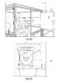
- FIG. 7illustrates a layered insulator in accordance with an embodiment of the present invention.
- FIG. 8illustrates a cross section view of a layered insulator in accordance with an embodiment of the present invention.
- FIG. 9illustrates a cross section view of a layered insulator in accordance with another embodiment of the present invention.
- FIG. 10illustrates a thermal image of a layered insulator in accordance with an embodiment of the present invention.
- the present inventionprovides, in one embodiment, an insulator made from nanotubes.
- the insulatorincludes a plurality of carbon nanotube (CNT) sheets stacked or layered on top of one another.
- CNTcarbon nanotube
- the CNT insulatorpossesses multifunctional properties that can promote thermal insulation, EMI, EMP, EDS shielding, and optical absorption, among other things.
- each CNT sheetis defined by a plurality of carbon nanotubes configured so as to minimize normal-to-plane thermal conductivity through the CNT sheet.
- a spacercan be situated between adjacent CNT sheets to further minimize normal-to-plane thermal conductivity.
- CVDChemical Vapor Deposition
- Arc Dischargea high temperature process that can give rise to tubes having a high degree of perfection
- Laser ablation and forest growth on a substrateAny of these methods can be used for the formation of CNTs that can be post processed into a non-woven sheet or textile (e.g., Bucky Paper or CNT sheets directly fabricated from the CVD reactor).
- the present inventionemploys a CVD process or similar gas phase pyrolysis procedures to generate the appropriate sheet type materials made from carbon-based nanostructures, including carbon nanotubes.
- Carbon nanotubesincluding single wall (SWNT), double wall (DWNT), and multiwall (MWNT) may be grown, in an embodiment of the present invention, by exposing nanoscaled catalyst particles in the presence of reagent carbon-containing gases (i.e., gaseous carbon source at elevated temperatures).
- the nanoscaled catalyst particlesmay be introduced into the reagent carbon-containing gases, either by addition of existing particles or by in situ synthesis of the particles from a metal-organic precursor, or even non-metallic catalysts.
- SWNTAlthough SWNT, DWNT, and MWNT may be grown, in certain instances, SWNT may be selected due to their relatively higher growth rate and tendency to form rope-like structures, which may offer advantages in handling, thermal conductivity, electronic properties, and strength. In other instances, DWNT or MWCNTs may be grown for thermal properties that are advantageous for thermal applications, such as insulators.
- the strength of the nanotubes generated in connection with the present inventionmay be about 30 GPa or more. Strength, as should be noted, is generally sensitive to defects. However, the elastic modulus of the carbon nanotubes fabricated in accordance with an embodiment of the present invention may not be sensitive to defects and can vary from about 1 to about 1.2 TPa. Moreover, the strain to failure, which generally can be a structure sensitive parameter, may range from about 10% to about 25% for carbon nanotubes used in the present invention.
- the nanotubes of the present inventioncan be provided with relatively small diameter.
- the nanotubes fabricated in the present inventioncan be provided with a diameter in a range of from less than 1 nm to about 10 nm.
- materials made from nanotubes of the present inventioncan represent a significant advance over copper and other metallic conducting members, as such materials are isotropic heat conductors.
- CNT sheets made in accordance with an embodiment of the present inventioncan be a good thermal insulator in a direction normal (e.g., transverse) to the plane of the CNT sheet, while being a good thermal conductor in the plane of the CNT sheet. Additional anisotropy can be introduced within the plane by stretching the sheets.
- heat transport for a carbon nanotubemay be predominantly phonon based at certain temperatures. When the carbon nanotubes are formed into a large sheet, phonons need to transport across all the physical contact points or spots between tubes.
- the CNT insulator of the present inventioncan be used as a thermal insulator, while being conductive in plane and substantially immune to mechanical damage.
- the present inventionprovides, in an embodiment, a CNT insulator 10 made from a nanostructured CNT sheet 12 .
- the CNT insulator 10can be so designed to minimize thermal conductivity through the CNT sheet 12 , i.e., in a direction normal to the CNT sheet 12 , while, to the extent desired, permitting thermal conductivity along the length of the CNT sheet 12 , i.e., within the plane of the the CNT sheet 12 .
- the CNT insulator 10may include a substantially planar body in the form of a single CNT sheet 12 .
- the sheet 12may, in one embodiment, be a single layer of non-woven carbon nanotubes 14 , or alternatively be multiple layers 51 of non-woven nanotubes (see FIG. 5 ).
- the CNT insulator 10can include a plurality CNT sheets 12 layered or stacked on top of one another.
- the CNT insulator 10can include spacers and/or texturing designs between adjacent sheets 12 to minimize sheet to sheet contact.
- some or all of the CNT sheets 12 used in the formation of CNT insulator 10may be processed (e.g., doped) to contain a dopant.
- a dopantcan be any material that can cause phonon scattering, so as to decrease thermal transport. Suitable dopants include, for example, boron, carbon 13, irradiated CNT materials, or any combination thereof.
- Other post-production modification and/or layering methodsmay also be applied to modify a thermal conductivity of the CNT insulator.
- the plurality of carbon nanotubes 14can be physically and/or chemically configured to increase in-plane thermal conductivity and to decrease normal-to-plane thermal conductivity.
- a plurality of spacescan be introduced between adjacent CNT sheets 12 so as to reduce interlayer thermal contacts, thereby reducing normal-to-plane thermal conductivity.
- nanotubes synthesized from carbonother compound(s), such as boron, MoS 2 , WS 2 , NS 2 or a combination thereof may be used in the synthesis of nanotubes in connection with the present invention.
- boron nanotubesmay also be grown, but with different chemical precursors.
- boronmay also be used to reduce resistivity in individual carbon nanotubes at higher temperatures.
- other methodssuch as plasma CVD or the like, can also be used to fabricate the nanotubes of the present invention.
- System 30may include a synthesis chamber 31 .
- the synthesis chamber 31in general, includes an entrance end 311 , into which reaction gases (i.e., gaseous carbon source) may be supplied, a hot zone 312 , where synthesis of nanotubes 313 may occur, and an exit end 314 from which the products of the reaction, namely a cloud of nanotubes and exhaust gases, may exit and be collected.
- reaction gasesi.e., gaseous carbon source
- the synthesis chamber 31may include a quartz tube, a ceramic tube or a FeCrAl tube 315 extending through a furnace 316 .
- the nanotubes generated by system 30may be individual single-walled nanotubes, bundles of such nanotubes, and/or intermingled or intertwined single-walled nanotubes, all of which may be referred to hereinafter as “non-woven.”
- System 30may also include a housing 32 designed to be substantially fluid (e.g., gas, air, etc.) tight, so as to minimize the release of potentially hazardous airborne particulates from within the synthesis chamber 31 into the environment.
- the housing 32may also act to prevent oxygen from entering into the system 30 and reaching the synthesis chamber 31 .
- the presence of oxygen within the synthesis chamber 31can affect the integrity and can compromise the production of the nanotubes 313 .
- System 30may also include a moving belt 320 , positioned within housing 32 , designed for collecting synthesized nanotubes 313 generated from within synthesis chamber 31 of system 30 .
- belt 320may be used to permit nanotubes collected thereon to subsequently form a substantially continuous extensible structure 321 , for instance, a CNT sheet.
- a CNT sheetmay be generated from compacted, substantially non-aligned, non-woven nanotubes 313 , with sufficient structural integrity to be handled as a sheet.
- Belt 320in an embodiment, can be designed to translate back and forth in a direction substantially perpendicular to the flow of gas from the exit end 314 , so as to increase the width of the CNT sheet 321 being collected on belt 320 .
- belt 320may be positioned adjacent the exit end 314 of the synthesis chamber 31 to permit the nanotubes to be deposited on to belt 320 .
- belt 320may be positioned substantially parallel to the flow of gas from the exit end 314 , as illustrated in FIG. 3 .
- belt 320may be positioned substantially perpendicular to the flow of gas from the exit end 314 and may be porous in nature to allow the flow of gas carrying the nanomaterials to pass therethrough.
- belt 320can be designed to translate from side to side in a direction substantially perpendicular to the flow of gas from the exit end 314 , so as to generate a sheet that is substantially wider than the exit end 314 .
- Belt 320may also be designed as a continuous loop, similar to a conventional conveyor belt, such that belt 320 can continuously rotate about an axis, whereby multiple layers of CNT can be deposited on belt 320 .
- belt 320in an embodiment, may be looped about opposing rotating elements 322 and may be driven by a mechanical device, such as an electric motor.
- belt 320may be a rigid cylinder, such as the drum shown in FIG. 4B .
- the motor devicemay be controlled through the use of a control system, such as a computer or microprocessor, so that tension and velocity can be optimized.
- the deposition of multiple layers of CNT in formation of sheet 321can result in minimizing interlayer contacts between nanotubes. Specifically, nanotubes in each distinct layer of sheet 321 tend not to extend into an adjacent layer of sheet 321 . As a result, normal-to-plane thermal conductivity can be minimized through sheet 321 .
- system 30may also include a pressure applicator, such as roller (not shown), situated adjacent belt to apply a compacting force (i.e., pressure) onto the collected nanomaterials.
- a pressure applicatorsuch as roller (not shown)
- the nanomaterials on belt 320may be forced to move under and against roller, such that a pressure may be applied to the intermingled nanomaterials while the nanomaterials get compacted between the belt and roller into a coherent substantially-bonded CNT sheet 321 .
- a plate(not shown) may be positioned behind belt 320 to provide a hard surface against which pressure from the roller can be applied. It should be noted that the use of a roller may not be necessary should the collected nanomaterials be ample in amount and sufficiently intermingled, such that an adequate number of contact sites exists to provide the necessary bonding strength to generate the CNT sheet 321 .
- a blade(not shown) may be provided adjacent the roller with its edge against surface of belt 320 . In this manner, as CNT sheet 321 is rotated on belt 320 past the roller, the blade may act to lift the CNT sheet 321 from surface of belt 320 . In an alternate embodiment, a blade does not have to be in use to remove the CNT sheet 321 . Rather, removal of the CNT sheet may be by hand or by other known methods in the art.
- a spool(not shown) may be provided downstream of blade, so that the disengaged CNT sheet 321 may subsequently be directed thereonto and wound about the spool for harvesting.
- a plurality of layers of CNT sheet 321may be formed.
- the spoollike belt 320 , may be driven, in an embodiment, by a mechanical drive, such as an electric motor, so that its axis of rotation may be substantially transverse to the direction of movement of the CNT sheet 321 .
- a separation materialmay be applied onto one side of the CNT sheet 321 prior to the sheet being wound about the spool.
- the separation material for use in connection with the present inventionmay be one of various commercially available metal sheets or polymers that can be supplied in a continuous roll. To that end, the separation material may be pulled along with the CNT sheet 321 onto the spool as sheet is being wound about the spool.
- the polymer comprising the separation materialmay be provided in a sheet, liquid, or any other form, so long as it can be applied to one side of CNT sheet 321 .
- the separation materialin one embodiment, may be a non-magnetic material, e.g., conducting or otherwise, so as to prevent the CNT sheet from sticking strongly to the separation material. In an alternate embodiment, a separation material may not be necessary.
- the CNT sheet 321After the CNT sheet 321 is generated, it may be left as a CNT sheet or it may be cut into smaller segments, such as strips.
- a lasermay be used to cut the CNT sheet 321 into strips as the belt 320 or drum rotates and/or simultaneously translates.
- the laser beammay, in an embodiment, be situated adjacent the housing 32 such that the laser may be directed at the CNT sheet 321 as it exits the housing 32 .
- a computer or programmay be employed to control the operation of the laser beam and also the cutting of the strip.
- any mechanical means or other means known in the artmay be used to cut the CNT sheet 321 into strips.
- FIGS. 4A-4DA system suitable for use in accordance with the present invention is shown in FIGS. 4A-4D .
- the CNT insulator produced by such systemcan be collected as a non-woven sheet on a moving belt 320 or drum.
- Such production methodcan provide, in a CNT sheet, a plurality of carbon nanotubes 14 , which can subsequently be made to be substantially aligned in-plane, as will be discussed below.
- the carbon nanotubes 14in an embodiment, can be deposited in multiple distinct layers 51 to form a multilayered structure or morphology in a single CNT sheet 12 , as shown in FIG. 5 .
- the CNT sheetcan have a low normal-to-plane or through-thickness thermal conductivity, which may result from inter-tube resistance.
- the normal-to-plane or through-thickness thermal conductivitycan be further reduced using various modifications, including (but not limited to) doping, post-production processing and layering sheets. Fabrication of sheets from multiwall CNTs can also reduce thermal conductivity.
- a strategy for reducing through-plane thermal conductivity of the nanotube sheets or yarns of the present inventionincludes introducing an amount of dopant (e.g., foreign atoms) during the nanotube growth process (e.g., in situ doping).
- a trace amount of the dopantmay be used.
- Such dopantmay substitute for carbon used to generate the carbon nanotubes and decrease inter-tube thermal conductivity.
- Any known protocols and devices available in the artcan be employed and incorporated into the CNT growth process of the present invention.
- a dopantcan be dispersed among the nanotubes using known methods.
- Substitutional dopantsmight include C 13 , a larger isotope of carbon, or boron.
- post-growth doping of a collected nanotube sheetcan also be utilized.
- Post-growth dopingin one embodiment, may be achieved by heating a sample of nanotubes in an N 2 environment to about 1500° C. for up to about 4 hours.
- placing the carbon nanotube material over a crucible of B 2 O 3 at these temperaturescan also allow for boron doping of the material, which can be done concurrently with N 2 to create B x N y C z nanotubes.
- dopantswhich may have an effect in reducing conductivity in individual nanotubes include, but are not limited to, boron, nitrogen, boron-nitrogen, carbon 13, irradiated material, or other foreign atoms that can cause phonon scattering. Dopants can also include ozone, potassium and other alkali metals, and bromine.
- boron dopingmay alter characteristics of the nanotubes.
- boron dopingcan introduce p-type behavior into the inherently n-type nanotube.
- boron-mediated growth using BF 3 /MeOH as the boron sourcehas been observed to have an important effect on the electronic properties of the nanotubes.
- Other potential sources useful for boron doping of nanotubesinclude, but are not limited to B(OCH 3 ) 3 , B 2 H 6 , and BCl 3 .
- doping with 2% boroncan decrease the thermal conductivity of CNT sheet, as compared to other treatments such as ethanol condensed, acid treated, polyethyleneimine (PEI) doped, tetracyano-p-quinodimethane (TCNQ) doped, stretched by 20%, and 18.75 ppm C 60 treated.
- Thermal conductivity (W/m ⁇ K, y axis) as a function of temperature (K, x axis)is shown.
- Boron containing CNT sheet insulatorhas a lower thermal conductivity value at various temperature points than the other materials tested.
- Post production modificationsin accordance with an embodiment of the present invention, can focus on decreasing the number of through-plane tube contacts and increasing inter-tube spacing (i.e., spacing between adjacent nanotubes) so as to yield measurably lower normal-to-plane or through-plane thermal conductivities.
- Suitable modificationsinclude, but are not limited to in-plane alignment of CNTs, polymer infiltration, hydrogen evolution, metal composite, or any combination thereof.
- orientation of the nanotubes in the CNT sheetcan be modified to be substantially aligned along the length of the CNT sheet.
- mechanical stretching of the CNT sheet, strip, or textile-like felt materialcan align the carbon nanotubes in the plane of the CNT sheet, to permit in-plane thermal conductivity.
- stretchingcan also reduce the number of conduction paths through-plane by decreasing the number of contact points between nanotubes, so as to reduce normal-to-plane or through-plane thermal conductivity.
- the CNT insulator of the present inventionin an embodiment, can also be infused with polymers.
- an appropriately chosen polymercan permeate within the spaces between individual nanotubes, thereby disrupting inter-tube contacts, so as to minimize normal-to-plane thermal conductivity.
- Examples of a polymer that can be usedinclude a small molecule or polymer matrix (thermoset or thermoplastic) including, but not limited to, polyurethane, polyethylene, poly(styrene butadiene), polychloroprene, poly(vinyl alcohol), poly(vinyl pyrrolidone), poly(acrylonitrile-co-butadiene-co-styrene), epoxy, polyureasilazane, bismaleimide, polyamide, polyimide, polycarbonate, or any monomer including styrene, divinyl benzene, methyl acrylate, and tert-butyl acrylate.
- the polymercan be supplied, in one embodiment, in a liquid form (e.g., in a solvent).
- the polymermay include polymer particles, that may be difficult to obtain in liquid form.
- the CNT sheet, strip, or feltcan be treated in an electroplating solution to evolve hydrogen therewithin, creating voids or separations between adjacent tubes that may lower thermal conductivity in a normal-to-plane direction.
- the sheet of carbon nanotubesin an embodiment, can act as a hydrogen electrode for storage of hydrogen atoms and/or molecules. For example, there can be absorption and/or adsorption of hydrogen atoms or hydrogen molecules onto the carbon nanotubes.
- the electroplating solutioncan be any suitable solution generally known in the art, e.g., any alkaline solution.
- the electrolysis of a potassium hydroxide solutioncan be used to produce hydrogen atoms and/or molecules that can be absorbed by the CNT sheet.
- metalmay be aluminum, nickel, gold, titanium or the like.
- Metal compositecan be made from a salt (any transition metal, alkali metal, or alkali earth metal salt or mixture thereof including, but not limited to, nickel hydroxide, cadmium hydroxide, nickel chloride, copper chloride, calcium zincate (CaZn 2 (OH) 6 )), or metal oxide (any transition metal, alkali metal, or alkali earth metal oxide or mixture thereof, including but not limited to: zinc oxide, iron oxide, silver oxide, copper oxide, manganese oxide, LiCoO 2 , LiNiO 2 , LiNi x Co 1-x O 2 , LiMn 2 O 4 ).
- aluminum or its alloyscan be used to create a foam structure on a surface of the CNT sheet and/or among the nanotubes within the sheet.
- the foam structurein an embodiment, can be combined with other methods for creating voids or separations (such as polymer infiltration and/or hydrogen evolution) to decrease thermal conductivity in a normal-to-plane direction.
- the metalmay include polymers or volatile solvents to create a carbon nanotube metal matrix CNT. Examples of such metal include powdered forms of aluminum or its alloys, nickel, superalloys, copper, silver, tin, cobalt, iron, iron alloys, or any element that can be produced in a powdered form including complex binary and ternary alloys or even superconductors.
- the solution, particles or powder noted above, in an embodiment,may be sprayed on the CNT sheet as it exits the furnace and is collected on the belt.
- Other methods for depositioncan also be used, for instance, the CNT sheet can be dipped into a bath or reservoir of solution, particles or powder.
- the sprayin one embodiment, may contain other compounds that cover the outer surface of the nanotubes in such a manner as to enhance alignment of the carbon nanotubes and reduce the inter-tube contacts.
- the spraymay include a solvent, a polymer, a metal, or a combination thereof.
- the solvent used in connection with the solution of the present inventioncan be used to lubricate the sheet in order to gain better alignment and enhancement in the properties of the carbon nanotubes.
- Examples of a solvent that can be used in connection with the solutioninclude toluene, kerosene, benzene, hexanes, any alcohol including but not limited to ethanol, methanol, butanol, isopropanol, as well as tetrahydrofuran, 1-methyl-2-pyrrolidinone, dimethyl formamide, methylene chloride, acetone or any other solvent as the present invention is not intended to be limited in this manner.
- the solventmay be used as a carrier for a polymer, monomer, inorganic salt, or metal oxide to.
- the treated sheetmay be subject to a heat source for processing of the sheet.
- the sheetmay be subject to sintering, hot isostatic pressing, hot pressing, cold isostatic pressing so as to yield the desired form of the final product.
- Nitrogen dopingmay be done by adding melamine, acetonitrile, benzylamine, or dimethylformamide to the catalyst or carbon source. Carrying out carbon nanotube synthesis in a nitrogen atmosphere can also lead to small amounts of N-doping.
- Each CNT sheetin one embodiment, can be made with varying thicknesses and/or a number of layers of CNT.
- Individual CNT sheetscan be, in an embodiment, about 30 microns in thickness. Of course, individually thicker or thinner CNT sheets can be provided, as desired.
- a plurality of CNT sheetscan be stacked or layered on top of one another to achieve a more substantial thickness.
- the use of an individual CNT sheet or the use of a plurality of stacked or layered CNT sheetscan result in a CNT insulator that has any desired thickness, shape, size, and/or profile.
- the presence of the distinct layers within one CNT sheetcan reduce normal-to-plane. i.e., through-plane, to the extent that stacking of CNT sheets may be employed, such an approach can further reduce inter-sheet contact and can further minimize through-plane thermal conductivity by reducing phonon transport between the stacked layers of CNT sheets.
- a spacercan be provided between adjacent CNT sheets.
- the spacercan be, for example, a plurality of alumina or ceramic dots, a layer of CNT sheet having a plurality of holes thereon, a porous layer of non-metal material, a CNT sheet having a rough surface with peaks and valleys thereon, or any combination thereof.
- a CNT insulatorcan be patterned with spacers 82 , as shown in FIG. 7 , to further increase inter-sheet thermal resistance.
- the spacers 82can be oxide pillars (dots) that can substantially separate each CNT sheet from one another.
- oxide materials having low thermal conductivitysuch as titanium oxide, zirconium oxide, tantalum oxide or the like, can be used as spacers 82 .
- a matrix of alumina or ceramic dotscan be deposited between two adjacent CNT sheets to create a gap therebetween. The alumina or ceramic dots, in one embodiment, can be sprayed onto the CNT sheets though a mask allowing deposition though predetermined holes.
- a plurality of small cylindrical dots or pillars supporting each CNT sheet from an adjacent CNT sheetcan be sprayed through the mask and deposited on each CNT sheet.
- the spacers 82can be other particles deposited on a surface of a CNT sheet creating sufficient spacing between two adjacent sheets, such as other non-metal particles, ceramic spacers, plastic particles, silicone dots, etc. Patterns of spacers 82 can be geometric or random.
- holes, openings, slits, cavities, apertures, or any combination thereofcan be provided (e.g., cut, engraved, punched, etc.) in each CNT sheet.
- the holescan be in a predetermined pattern that is the same or different for different CNT sheets.
- the predetermined patterncan be geometric or random.
- the CNT sheetscan be so aligned that the hole pattern can be, for example, offset between two adjacent sheets, allowing each sheet to contain air pockets.
- a layered CNT insulator 80 having three CNT sheetsis shown in FIG. 8 , where each sheet has a plurality of holes 84 therein.
- the holes 84are not substantially aligned across the layers, rather, they are offset, to the extent desired, between two adjacent CNT sheets.
- Each CNT sheet 80can be designed to have a rough surface with peaks 86 and valleys 88 thereon. It should be appreciated that peaks and valleys are relative to one another. For example, when a sheet is turned upside down, peaks can become valleys and vice versa.
- the CNT sheets 80when stacked on top of one another, can be situated in a way such that the peaks are offset between two sheets and sheet-to-sheet contacts are minimized.
- Thermal conductivity for a CNT sheet of the present invention without further processingcan be about 20 W/m ⁇ K.
- the thermal conductivitycan be increased to about 100 W/m ⁇ K within the plane and along the direction of alignment, while the thermal conductivity normal to the plane of the CNT sheet can be as low as about 1 W/m ⁇ K.
- the resultant CNT insulating structurecan have a thermal conductivity normal to the plane of the stacked CNT sheets less than about 1 W/m ⁇ K.
- the normal-to-plane thermal conductivity of an insulator having such stacked CNT sheetsranges from about 0.01 W/m ⁇ K to about 0.5 W/m ⁇ K.
- An insulator having such stacked CNT sheetscan also have a density of less than about 1 g/cc. In an embodiment, the density may be less than about 0.4 g/cc.
- the insulator with such stacked CNT sheetscan have an areal density of from about 0.01 g/cm 2 to about 0.5 g/cm 2 or from about 0.02 g/cm 2 to about 0.2 g/cm 2 . In a particular embodiment, the areal density may be about 0.078 g/cm 2 . Therefore, the CNT insulator of the present invention, when placed between a heat source and an area to which heat transfer may not be desired, can provide excellent normal-to-plane thermal insulation properties, while being conductive in-plane, and having sufficient structural integrity against damages.
- FIG. 10shows a thermal image of a CNT super-insulator 80 (a CNT insulator having spacers 82 between adjacent sheets, shown on the right), compared with a commercial super-insulator 90 (an aerogel, shown on the left).
- the CNT super-insulator 80 and the aerogel 90have substantially the same thickness.
- the background temperatureis about 100° C. It was observed that the CNT super-insulator 80 displays substantially similar, and in some instances lower temperature than aerogel 90 . Therefore, the CNT super-insulator 80 can have substantially similar, and in some instances superior thermal resistance than aerogel 90 .
- the CNT insulatorcan have thermal properties similar to aerogels, while having much higher strength and fracture toughness than aerogels.
- the CNT insulator of the present inventionmay be incorporated into other structures for additional end use applications, such as sporting goods products, helmets, jackets (such as a fireman's jacket), antenna, morphing applications, aerospace, lightning protection flame proofing, etc.
- the CNT insulatormay further be nickel free, meaning it may be less toxic than standard products. Additionally, the CNT insulator may be repairable to eliminate the need to replace the CNT sheets entirely or in part.
- a CNT insulatormay be formed by impregnating the CNT sheet with a matrix precursor, such as Krayton, vinyl ester, PEEK, bispolyamide, BMI (bismaleimide), epoxies, or polyamides, and subsequently allowing the matrix to polymerize or thermally cure.
- a matrix precursorsuch as Krayton, vinyl ester, PEEK, bispolyamide, BMI (bismaleimide), epoxies, or polyamides
- Examples of specific applications of the CNT insulator of the present inventioncan also include electromagnetic interference shielding (EMI shielding) which may, reflect and absorb EMI radiation and thereby provide excelling shielding while at the same time providing very good insulation characteristics. Shielding may be beneficial to prevent interference from surrounding equipment and may be found in stereo systems, telephones, mobile phones, televisions, medical devices, computers, and many other appliances.
- This conductive layermay also be used as a ground plane or provide a means of creating an electromagnetic mirror.
Landscapes
- Engineering & Computer Science (AREA)
- Chemical & Material Sciences (AREA)
- Nanotechnology (AREA)
- Materials Engineering (AREA)
- Organic Chemistry (AREA)
- Physics & Mathematics (AREA)
- Condensed Matter Physics & Semiconductors (AREA)
- Crystallography & Structural Chemistry (AREA)
- General Physics & Mathematics (AREA)
- Inorganic Chemistry (AREA)
- Composite Materials (AREA)
- Textile Engineering (AREA)
- Thermal Sciences (AREA)
- Mechanical Engineering (AREA)
- General Engineering & Computer Science (AREA)
- Carbon And Carbon Compounds (AREA)
- Laminated Bodies (AREA)
- Nonwoven Fabrics (AREA)
Abstract
Description
Claims (13)
Priority Applications (1)
| Application Number | Priority Date | Filing Date | Title |
|---|---|---|---|
| US14/230,527US10145627B2 (en) | 2011-01-04 | 2014-03-31 | Nanotube-based insulators |
Applications Claiming Priority (3)
| Application Number | Priority Date | Filing Date | Title |
|---|---|---|---|
| US201161429680P | 2011-01-04 | 2011-01-04 | |
| US13/343,366US8722171B2 (en) | 2011-01-04 | 2012-01-04 | Nanotube-based insulators |
| US14/230,527US10145627B2 (en) | 2011-01-04 | 2014-03-31 | Nanotube-based insulators |
Related Parent Applications (1)
| Application Number | Title | Priority Date | Filing Date |
|---|---|---|---|
| US13/343,366DivisionUS8722171B2 (en) | 2011-01-04 | 2012-01-04 | Nanotube-based insulators |
Publications (2)
| Publication Number | Publication Date |
|---|---|
| US20160161196A1 US20160161196A1 (en) | 2016-06-09 |
| US10145627B2true US10145627B2 (en) | 2018-12-04 |
Family
ID=46381000
Family Applications (2)
| Application Number | Title | Priority Date | Filing Date |
|---|---|---|---|
| US13/343,366ActiveUS8722171B2 (en) | 2011-01-04 | 2012-01-04 | Nanotube-based insulators |
| US14/230,527Active2035-06-23US10145627B2 (en) | 2011-01-04 | 2014-03-31 | Nanotube-based insulators |
Family Applications Before (1)
| Application Number | Title | Priority Date | Filing Date |
|---|---|---|---|
| US13/343,366ActiveUS8722171B2 (en) | 2011-01-04 | 2012-01-04 | Nanotube-based insulators |
Country Status (5)
| Country | Link |
|---|---|
| US (2) | US8722171B2 (en) |
| EP (1) | EP2661369B1 (en) |
| JP (1) | JP6014603B2 (en) |
| ES (1) | ES2721377T3 (en) |
| WO (1) | WO2012094398A1 (en) |
Cited By (1)
| Publication number | Priority date | Publication date | Assignee | Title |
|---|---|---|---|---|
| CN112799012A (en)* | 2020-12-28 | 2021-05-14 | 中国气象科学研究院 | A broadband interferometer lightning localization method and system based on pulse matching |
Families Citing this family (23)
| Publication number | Priority date | Publication date | Assignee | Title |
|---|---|---|---|---|
| EP2661369B1 (en) | 2011-01-04 | 2019-04-10 | Nanocomp Technologies, Inc. | Thermal insulators based on nanotubes, their use and method for thermal insulation. |
| EP2837005A4 (en)* | 2012-04-09 | 2015-12-09 | Nanocomp Technologies Inc | Nanotube material having conductive deposits to increase conductivity |
| US9581282B1 (en)* | 2012-05-02 | 2017-02-28 | Lockheed Martin Corporation | Heat management and thermal shielding techniques using compressed carbon nanotube aerogel materials |
| US9291297B2 (en)* | 2012-12-19 | 2016-03-22 | Elwha Llc | Multi-layer phononic crystal thermal insulators |
| CN103360858B (en)* | 2013-08-02 | 2014-12-17 | 深圳市彩虹精细化工股份有限公司 | Thermal insulation slurry, novel water-based carbon nanotube composite thermal insulation coating using the thermal insulation slurry and preparation method thereof |
| WO2016019143A1 (en) | 2014-07-30 | 2016-02-04 | General Nano Llc | Carbon nanotube sheet structure and method for its making |
| US20160040830A1 (en)* | 2014-08-11 | 2016-02-11 | Raytheon Company | Cryogenic assembly including carbon nanotube electrical interconnect |
| US9762779B2 (en)* | 2014-10-10 | 2017-09-12 | Dotworkz | Shock-resistant camera mounting device and methods of forming the same |
| EP3253709A4 (en)* | 2015-02-03 | 2018-10-31 | Nanocomp Technologies, Inc. | Carbon nanotube structures and methods for production thereof |
| JP6704229B2 (en) | 2015-09-14 | 2020-06-03 | リンテック オブ アメリカ インコーポレーテッドLintec of America, Inc. | Flexible sheet, heat conductive member, conductive member, antistatic member, heating element, electromagnetic wave shield, and method for manufacturing flexible sheet |
| CA3002539A1 (en)* | 2015-10-23 | 2017-04-27 | Nanocomp Technologies, Inc. | Directed infrared radiator article |
| JP6799602B2 (en)* | 2016-01-29 | 2020-12-16 | 中国科学院蘇州納米技術与納米▲ファン▼生研究所 | Carbon nanotube aggregates, anti-stick composites and bulletproof composites |
| US11021369B2 (en) | 2016-02-04 | 2021-06-01 | General Nano Llc | Carbon nanotube sheet structure and method for its making |
| JP6845856B2 (en)* | 2016-09-02 | 2021-03-24 | リンテック オブ アメリカ インコーポレーテッドLintec of America, Inc. | Composite nanofiber sheet |
| US10581082B2 (en) | 2016-11-15 | 2020-03-03 | Nanocomp Technologies, Inc. | Systems and methods for making structures defined by CNT pulp networks |
| US10264627B2 (en)* | 2016-12-08 | 2019-04-16 | Goodrich Corporation | Adjusting CNT resistance using perforated CNT sheets |
| US10584418B1 (en)* | 2017-02-23 | 2020-03-10 | Northrop Grumman Systems Corporation | Plasma treatment of carbon nanotube sheet materials to reduce optical reflectance |
| JP2020516494A (en)* | 2017-04-12 | 2020-06-11 | リンテック・オヴ・アメリカ,インコーポレイテッド | Multilayer composite containing heat-shrinkable polymer and nanofiber sheet |
| US10807326B2 (en)* | 2017-05-26 | 2020-10-20 | Goodrich Corporation | Method of making complex carbon nanotube sheets |
| US10908108B2 (en)* | 2017-08-22 | 2021-02-02 | The Board Of Regents Of The University Of Nebraska | Carbon nanostructure based gas sensors and method of making same |
| US11292586B2 (en) | 2018-05-14 | 2022-04-05 | Goodrich Corporation | Carbon nanotube based heat shield |
| GB201912962D0 (en)* | 2019-09-09 | 2019-10-23 | Q Flo Ltd | Electromagnetic waveguide |
| CN110650605A (en)* | 2019-09-18 | 2020-01-03 | Oppo广东移动通信有限公司 | Shell assembly, preparation method thereof and electronic equipment |
Citations (89)
| Publication number | Priority date | Publication date | Assignee | Title |
|---|---|---|---|---|
| US3462289A (en) | 1965-08-05 | 1969-08-19 | Carborundum Co | Process for producing reinforced carbon and graphite bodies |
| JPS5872036A (en) | 1981-10-26 | 1983-04-28 | Satake Eng Co Ltd | Screening device for color screening machine |
| US4583247A (en) | 1982-02-12 | 1986-04-22 | Arthur Larry Fingerhut | Garment including composite insulation material |
| US5648027A (en) | 1993-11-01 | 1997-07-15 | Osaka Gas Company Ltd. | Porous carbonaceous material and a method for producing the same |
| US5747161A (en) | 1991-10-31 | 1998-05-05 | Nec Corporation | Graphite filaments having tubular structure and method of forming the same |
| JP2000058228A (en) | 1998-08-12 | 2000-02-25 | Suzuki Sogyo Co Ltd | Thin film resistance heating element and toner heating/ fixing member using it |
| US6037281A (en) | 1996-12-27 | 2000-03-14 | Kimberly-Clark Worldwide, Inc. | Cloth-like, liquid-impervious, breathable composite barrier fabric |
| EP1160861A2 (en) | 2000-06-01 | 2001-12-05 | Matsushita Electric Industrial Co., Ltd. | Thermally conductive substrate with leadframe and heat radiation plate and manufacturing method thereof |
| US6376971B1 (en) | 1997-02-07 | 2002-04-23 | Sri International | Electroactive polymer electrodes |
| US6426134B1 (en) | 1998-06-30 | 2002-07-30 | E. I. Du Pont De Nemours And Company | Single-wall carbon nanotube-polymer composites |
| US20020113335A1 (en) | 2000-11-03 | 2002-08-22 | Alex Lobovsky | Spinning, processing, and applications of carbon nanotube filaments, ribbons, and yarns |
| US6541744B2 (en) | 2000-08-18 | 2003-04-01 | Watlow Polymer Technologies | Packaging having self-contained heater |
| US20030104156A1 (en) | 2001-11-30 | 2003-06-05 | Tamotsu Osada | Composite material |
| US6611039B2 (en) | 2001-09-28 | 2003-08-26 | Hewlett-Packard Development Company, L.P. | Vertically oriented nano-fuse and nano-resistor circuit elements |
| US20040020681A1 (en) | 2000-03-30 | 2004-02-05 | Olof Hjortstam | Power cable |
| US6706402B2 (en) | 2001-07-25 | 2004-03-16 | Nantero, Inc. | Nanotube films and articles |
| US20040124772A1 (en) | 2002-12-25 | 2004-07-01 | Ga-Lane Chen | Plasma display panel |
| US6784656B2 (en) | 2001-08-30 | 2004-08-31 | Teradyne, Inc. | Hybrid conductor-board for multi-conductor routing |
| JP2004315297A (en) | 2003-04-17 | 2004-11-11 | Misuzu Kogyo:Kk | Nanocarbon composite material and method for producing the same |
| US20040240144A1 (en) | 2003-05-30 | 2004-12-02 | Schott Joachim Hossick | Capacitor and method for producing a capacitor |
| US20040265212A1 (en) | 2002-12-06 | 2004-12-30 | Vijay Varadan | Synthesis of coiled carbon nanotubes by microwave chemical vapor deposition |
| US20040265489A1 (en) | 2003-06-25 | 2004-12-30 | Dubin Valery M. | Methods of fabricating a composite carbon nanotube thermal interface device |
| KR20050007886A (en) | 2003-07-12 | 2005-01-21 | 영 욱 김 | Heating structure using porous carbon fiber activated and Heater having the structure |
| JP2005075672A (en) | 2003-08-29 | 2005-03-24 | Seiko Epson Corp | Compact |
| US20050067406A1 (en) | 2003-09-30 | 2005-03-31 | Shanmugam Rajarajan | Self heating apparatus |
| US20050087222A1 (en) | 2003-09-15 | 2005-04-28 | Bernhard Muller-Werth | Device for producing electric energy |
| US20050095938A1 (en) | 2003-10-29 | 2005-05-05 | Rosenberger Brian T. | Carbon nanotube fabrics |
| CN1614772A (en) | 2003-11-08 | 2005-05-11 | 鸿富锦精密工业(深圳)有限公司 | Radiator and producing method thereof |
| US20050112051A1 (en) | 2003-01-17 | 2005-05-26 | Duke University | Systems and methods for producing single-walled carbon nanotubes (SWNTS) on a substrate |
| US20050124246A1 (en) | 2003-12-03 | 2005-06-09 | Feng Chia University | Method for making carbon fabric and product thereof |
| US6908572B1 (en) | 2000-07-17 | 2005-06-21 | University Of Kentucky Research Foundation | Mixing and dispersion of nanotubes by gas or vapor expansion |
| US6923946B2 (en) | 1999-11-26 | 2005-08-02 | Ut-Battelle, Llc | Condensed phase conversion and growth of nanorods instead of from vapor |
| JP2005281672A (en) | 2004-03-01 | 2005-10-13 | Mitsubishi Rayon Co Ltd | Carbon nanotube-containing composition, composite having coating film made thereof, and method for producing them |
| US6979709B2 (en) | 1997-03-07 | 2005-12-27 | William Marsh Rice University | Continuous fiber of single-wall carbon nanotubes |
| US20060062944A1 (en) | 2004-09-20 | 2006-03-23 | Gardner Slade H | Ballistic fabrics with improved antiballistic properties |
| WO2006069007A2 (en) | 1998-12-07 | 2006-06-29 | Meridian Research And Development | Radiation detectable and protective articles |
| WO2006099156A2 (en) | 2005-03-10 | 2006-09-21 | Tailored Materials Corporation | Thin film production method and apparatus |
| US20060269670A1 (en) | 2005-05-26 | 2006-11-30 | Lashmore David S | Systems and methods for thermal management of electronic components |
| US20060276056A1 (en) | 2005-04-05 | 2006-12-07 | Nantero, Inc. | Nanotube articles with adjustable electrical conductivity and methods of making the same |
| JP2006335604A (en) | 2005-06-02 | 2006-12-14 | Shinshu Univ | Coaxial carbon nanotube sheet and manufacturing method thereof |
| WO2006137893A2 (en) | 2004-10-01 | 2006-12-28 | Board Of Regents Of The University Of Texas System | Polymer-free carbon nanotube assemblies (fibers, ropes, ribbons, films) |
| WO2007003879A1 (en) | 2005-06-30 | 2007-01-11 | Bae Systems Plc | Self-reparing structure |
| US20070009421A1 (en) | 2004-12-01 | 2007-01-11 | William Marsh Rice University | Fibers comprised of epitaxially grown single-wall carbon nanotubes, and a method for added catalyst and continuous growth at the tip |
| WO2007015710A2 (en) | 2004-11-09 | 2007-02-08 | Board Of Regents, The University Of Texas System | The fabrication and application of nanofiber ribbons and sheets and twisted and non-twisted nanofiber yarns |
| US20070029291A1 (en) | 2005-01-28 | 2007-02-08 | Tekna Plasma Systems Inc. | Induction plasma synthesis of nanopowders |
| US20070036709A1 (en) | 2005-07-28 | 2007-02-15 | Lashmore David S | Systems and methods for formation and harvesting of nanofibrous materials |
| US7182929B1 (en) | 2003-08-18 | 2007-02-27 | Nei, Inc. | Nanostructured multi-component and doped oxide powders and method of making same |
| US20070048211A1 (en) | 2005-08-19 | 2007-03-01 | Tsinghua University | Apparatus and method for synthesizing a single-wall carbon nanotube array |
| US20070056855A1 (en) | 2005-09-12 | 2007-03-15 | Industrial Technology Research Institute | Method of making an electroplated interconnection wire of a composite of metal and carbon nanotubes |
| US20070087121A1 (en) | 2005-10-11 | 2007-04-19 | Hon Hai Precision Industry Co., Ltd. | Apparatus and method for synthesizing chiral carbon nanotubes |
| WO2007089118A1 (en) | 2006-02-03 | 2007-08-09 | Exaenc Corp. | Heating element using carbon nano tube |
| DE102006014171A1 (en) | 2006-03-24 | 2007-09-27 | Thüringisches Institut für Textil- und Kunststoff-Forschung e.V. | Panel radiator for use in the field of heating voltage, has electrically conductive cellulose non-woven material that forms electrical resistance required for heating, and two electrical strips, which electrically contacts the material |
| US20070236325A1 (en) | 2004-09-21 | 2007-10-11 | Nantero, Inc. | Resistive elements using carbon nanotubes |
| US20070277866A1 (en) | 2006-05-31 | 2007-12-06 | General Electric Company | Thermoelectric nanotube arrays |
| JP2008108583A (en) | 2006-10-25 | 2008-05-08 | Sumitomo Precision Prod Co Ltd | Conductive wire, conductive coil, and conductive wire manufacturing method |
| WO2008106143A2 (en) | 2007-02-27 | 2008-09-04 | Nanocomp Technologies, Inc. | Materials for thermal protection and methods of manufacturing same |
| US20080238882A1 (en)* | 2007-02-21 | 2008-10-02 | Ramesh Sivarajan | Symmetric touch screen system with carbon nanotube-based transparent conductive electrode pairs |
| US20080254675A1 (en) | 2007-04-11 | 2008-10-16 | Tsinghua University | Coaxial cable |
| US20090044848A1 (en) | 2007-08-14 | 2009-02-19 | Nanocomp Technologies, Inc. | Nanostructured Material-Based Thermoelectric Generators |
| WO2009072478A1 (en) | 2007-12-07 | 2009-06-11 | Daido Corporation | Method for producing carbon nanotube-containing conductor |
| US20090195989A1 (en)* | 2008-02-04 | 2009-08-06 | Shinko Electric Industries Co., Ltd. | Heat sink component and a method of producing a heat sink component |
| US20090237886A1 (en) | 2008-03-18 | 2009-09-24 | Fujitsu Limited | Sheet structure and method of manufacturing sheet structure |
| US20090255706A1 (en) | 2008-04-09 | 2009-10-15 | Tsinghua University | Coaxial cable |
| JP2009242145A (en) | 2008-03-28 | 2009-10-22 | Toray Ind Inc | Production method of carbon nanotube film |
| US7615097B2 (en) | 2005-10-13 | 2009-11-10 | Plasma Processes, Inc. | Nano powders, components and coatings by plasma technique |
| US7615204B2 (en) | 2002-02-22 | 2009-11-10 | Rensselaer Polytechnic Institute | Direct synthesis of long single-walled carbon nanotube strands |
| US20090317710A1 (en) | 2008-06-20 | 2009-12-24 | Mysticmd, Inc. | Anode, cathode, grid and current collector material for reduced weight battery and process for production thereof |
| US20100000754A1 (en) | 2008-05-07 | 2010-01-07 | Nanocomp Technologies, Inc. | Carbon nanotube-based coaxial electrical cables and wiring harness |
| US20100041297A1 (en) | 2008-07-04 | 2010-02-18 | Tsinghua University | Method for making liquid crystal display adopting touch panel |
| US7745498B2 (en) | 2005-04-13 | 2010-06-29 | Nanosys, Inc. | Nanowire dispersion compositions and uses thereof |
| US20100219383A1 (en)* | 2007-03-07 | 2010-09-02 | Eklund Peter C | Boron-Doped Single-Walled Nanotubes(SWCNT) |
| US20100220074A1 (en) | 2006-06-20 | 2010-09-02 | Eastman Kodak Company | Touchscreen with carbon nanotube conductive layers |
| US20100243295A1 (en) | 2006-10-12 | 2010-09-30 | Cambrios Technologies Corporation | Nanowire-based transparent conductors and applications thereof |
| US20100270058A1 (en) | 2007-12-14 | 2010-10-28 | 3M Innovative Properties Company | Methods for making electronic devices |
| US7846414B2 (en) | 2002-11-15 | 2010-12-07 | Mcgill University | Method for producing carbon nanotubes using a DC non-transferred thermal plasma torch |
| WO2010151244A1 (en) | 2009-06-22 | 2010-12-29 | Hewlett-Packard Development Company, L.P. | Transparent conductive material |
| US20100328845A1 (en)* | 2009-06-25 | 2010-12-30 | Nokia Corporation | Nano-structured flexible electrodes, and energy storage devices using the same |
| US20110007477A1 (en) | 2005-08-05 | 2011-01-13 | Purdue Research Foundation | Enhancement of thermal interface conductivities with carbon nanotube arrays |
| US7897248B2 (en) | 1999-12-07 | 2011-03-01 | William Marsh Rice University | Oriented nanofibers embedded in a polymer matrix |
| US20110110843A1 (en) | 2007-10-29 | 2011-05-12 | William March Rice University | Neat carbon nanotube articles processed from super acid solutions and methods for production thereof |
| US8071906B2 (en) | 2002-05-09 | 2011-12-06 | Institut National De La Recherche Scientifique | Apparatus for producing single-wall carbon nanotubes |
| US20120045643A1 (en) | 2010-08-23 | 2012-02-23 | Hon Hai Precision Industry Co., Ltd. | Carbon nanotube wire structure and method for making the same |
| US20120045644A1 (en) | 2010-08-23 | 2012-02-23 | Hon Hai Precision Industry Co., Ltd. | Carbon nanotube wire composite structure and method for making the same |
| US20120045385A1 (en) | 2007-07-25 | 2012-02-23 | Nanocomp Technologies, Inc. | Systems and Methods for Controlling Chirality of Nanotubes |
| US20120118552A1 (en) | 2010-11-12 | 2012-05-17 | Nanocomp Technologies, Inc. | Systems and methods for thermal management of electronic components |
| US20120183770A1 (en) | 2010-06-22 | 2012-07-19 | Bosnyak Clive P | Modified carbon nanotubes, methods for production thereof and products obtained therefrom |
| US8246886B2 (en) | 2007-07-09 | 2012-08-21 | Nanocomp Technologies, Inc. | Chemically-assisted alignment of nanotubes within extensible structures |
| US20130105195A1 (en) | 2011-04-19 | 2013-05-02 | Commscope Inc. | Carbon Nanotube Enhanced Conductors for Communications Cables and Related Communications Cables and Methods |
| US8722171B2 (en) | 2011-01-04 | 2014-05-13 | Nanocomp Technologies, Inc. | Nanotube-based insulators |
- 2012
- 2012-01-04EPEP12732279.0Apatent/EP2661369B1/enactiveActive
- 2012-01-04USUS13/343,366patent/US8722171B2/enactiveActive
- 2012-01-04JPJP2013548480Apatent/JP6014603B2/ennot_activeExpired - Fee Related
- 2012-01-04WOPCT/US2012/020194patent/WO2012094398A1/enactiveApplication Filing
- 2012-01-04ESES12732279Tpatent/ES2721377T3/enactiveActive
- 2014
- 2014-03-31USUS14/230,527patent/US10145627B2/enactiveActive
Patent Citations (102)
| Publication number | Priority date | Publication date | Assignee | Title |
|---|---|---|---|---|
| US3462289A (en) | 1965-08-05 | 1969-08-19 | Carborundum Co | Process for producing reinforced carbon and graphite bodies |
| JPS5872036A (en) | 1981-10-26 | 1983-04-28 | Satake Eng Co Ltd | Screening device for color screening machine |
| US4583247A (en) | 1982-02-12 | 1986-04-22 | Arthur Larry Fingerhut | Garment including composite insulation material |
| US5747161A (en) | 1991-10-31 | 1998-05-05 | Nec Corporation | Graphite filaments having tubular structure and method of forming the same |
| US5648027A (en) | 1993-11-01 | 1997-07-15 | Osaka Gas Company Ltd. | Porous carbonaceous material and a method for producing the same |
| US6037281A (en) | 1996-12-27 | 2000-03-14 | Kimberly-Clark Worldwide, Inc. | Cloth-like, liquid-impervious, breathable composite barrier fabric |
| US6376971B1 (en) | 1997-02-07 | 2002-04-23 | Sri International | Electroactive polymer electrodes |
| US6979709B2 (en) | 1997-03-07 | 2005-12-27 | William Marsh Rice University | Continuous fiber of single-wall carbon nanotubes |
| US6426134B1 (en) | 1998-06-30 | 2002-07-30 | E. I. Du Pont De Nemours And Company | Single-wall carbon nanotube-polymer composites |
| JP2000058228A (en) | 1998-08-12 | 2000-02-25 | Suzuki Sogyo Co Ltd | Thin film resistance heating element and toner heating/ fixing member using it |
| WO2006069007A2 (en) | 1998-12-07 | 2006-06-29 | Meridian Research And Development | Radiation detectable and protective articles |
| US6923946B2 (en) | 1999-11-26 | 2005-08-02 | Ut-Battelle, Llc | Condensed phase conversion and growth of nanorods instead of from vapor |
| US7897248B2 (en) | 1999-12-07 | 2011-03-01 | William Marsh Rice University | Oriented nanofibers embedded in a polymer matrix |
| US20040020681A1 (en) | 2000-03-30 | 2004-02-05 | Olof Hjortstam | Power cable |
| EP1160861A2 (en) | 2000-06-01 | 2001-12-05 | Matsushita Electric Industrial Co., Ltd. | Thermally conductive substrate with leadframe and heat radiation plate and manufacturing method thereof |
| US6908572B1 (en) | 2000-07-17 | 2005-06-21 | University Of Kentucky Research Foundation | Mixing and dispersion of nanotubes by gas or vapor expansion |
| US6541744B2 (en) | 2000-08-18 | 2003-04-01 | Watlow Polymer Technologies | Packaging having self-contained heater |
| US20020113335A1 (en) | 2000-11-03 | 2002-08-22 | Alex Lobovsky | Spinning, processing, and applications of carbon nanotube filaments, ribbons, and yarns |
| US7745810B2 (en) | 2001-07-25 | 2010-06-29 | Nantero, Inc. | Nanotube films and articles |
| US6706402B2 (en) | 2001-07-25 | 2004-03-16 | Nantero, Inc. | Nanotube films and articles |
| US6784656B2 (en) | 2001-08-30 | 2004-08-31 | Teradyne, Inc. | Hybrid conductor-board for multi-conductor routing |
| US6611039B2 (en) | 2001-09-28 | 2003-08-26 | Hewlett-Packard Development Company, L.P. | Vertically oriented nano-fuse and nano-resistor circuit elements |
| US20030104156A1 (en) | 2001-11-30 | 2003-06-05 | Tamotsu Osada | Composite material |
| US7615204B2 (en) | 2002-02-22 | 2009-11-10 | Rensselaer Polytechnic Institute | Direct synthesis of long single-walled carbon nanotube strands |
| US8071906B2 (en) | 2002-05-09 | 2011-12-06 | Institut National De La Recherche Scientifique | Apparatus for producing single-wall carbon nanotubes |
| US7846414B2 (en) | 2002-11-15 | 2010-12-07 | Mcgill University | Method for producing carbon nanotubes using a DC non-transferred thermal plasma torch |
| US20040265212A1 (en) | 2002-12-06 | 2004-12-30 | Vijay Varadan | Synthesis of coiled carbon nanotubes by microwave chemical vapor deposition |
| US20040124772A1 (en) | 2002-12-25 | 2004-07-01 | Ga-Lane Chen | Plasma display panel |
| US20050112051A1 (en) | 2003-01-17 | 2005-05-26 | Duke University | Systems and methods for producing single-walled carbon nanotubes (SWNTS) on a substrate |
| JP2004315297A (en) | 2003-04-17 | 2004-11-11 | Misuzu Kogyo:Kk | Nanocarbon composite material and method for producing the same |
| US20040240144A1 (en) | 2003-05-30 | 2004-12-02 | Schott Joachim Hossick | Capacitor and method for producing a capacitor |
| US20040265489A1 (en) | 2003-06-25 | 2004-12-30 | Dubin Valery M. | Methods of fabricating a composite carbon nanotube thermal interface device |
| KR20050007886A (en) | 2003-07-12 | 2005-01-21 | 영 욱 김 | Heating structure using porous carbon fiber activated and Heater having the structure |
| US7182929B1 (en) | 2003-08-18 | 2007-02-27 | Nei, Inc. | Nanostructured multi-component and doped oxide powders and method of making same |
| JP2005075672A (en) | 2003-08-29 | 2005-03-24 | Seiko Epson Corp | Compact |
| US20050087222A1 (en) | 2003-09-15 | 2005-04-28 | Bernhard Muller-Werth | Device for producing electric energy |
| US20050067406A1 (en) | 2003-09-30 | 2005-03-31 | Shanmugam Rajarajan | Self heating apparatus |
| US20050095938A1 (en) | 2003-10-29 | 2005-05-05 | Rosenberger Brian T. | Carbon nanotube fabrics |
| US7354877B2 (en) | 2003-10-29 | 2008-04-08 | Lockheed Martin Corporation | Carbon nanotube fabrics |
| CN1614772A (en) | 2003-11-08 | 2005-05-11 | 鸿富锦精密工业(深圳)有限公司 | Radiator and producing method thereof |
| US7670970B2 (en) | 2003-12-03 | 2010-03-02 | Feng Chia University | Method for making carbon fabric and product thereof |
| US20050124246A1 (en) | 2003-12-03 | 2005-06-09 | Feng Chia University | Method for making carbon fabric and product thereof |
| JP2005281672A (en) | 2004-03-01 | 2005-10-13 | Mitsubishi Rayon Co Ltd | Carbon nanotube-containing composition, composite having coating film made thereof, and method for producing them |
| US20060062944A1 (en) | 2004-09-20 | 2006-03-23 | Gardner Slade H | Ballistic fabrics with improved antiballistic properties |
| US8080487B2 (en) | 2004-09-20 | 2011-12-20 | Lockheed Martin Corporation | Ballistic fabrics with improved antiballistic properties |
| US20070236325A1 (en) | 2004-09-21 | 2007-10-11 | Nantero, Inc. | Resistive elements using carbon nanotubes |
| WO2006137893A2 (en) | 2004-10-01 | 2006-12-28 | Board Of Regents Of The University Of Texas System | Polymer-free carbon nanotube assemblies (fibers, ropes, ribbons, films) |
| WO2007015710A2 (en) | 2004-11-09 | 2007-02-08 | Board Of Regents, The University Of Texas System | The fabrication and application of nanofiber ribbons and sheets and twisted and non-twisted nanofiber yarns |
| US8926933B2 (en) | 2004-11-09 | 2015-01-06 | The Board Of Regents Of The University Of Texas System | Fabrication of twisted and non-twisted nanofiber yarns |
| JP2008523254A (en) | 2004-11-09 | 2008-07-03 | ボード オブ リージェンツ, ザ ユニバーシティ オブ テキサス システム | Production and application of nanofiber ribbons and sheets and nanofiber twisted and untwisted yarns |
| US20080170982A1 (en) | 2004-11-09 | 2008-07-17 | Board Of Regents, The University Of Texas System | Fabrication and Application of Nanofiber Ribbons and Sheets and Twisted and Non-Twisted Nanofiber Yarns |
| US20070009421A1 (en) | 2004-12-01 | 2007-01-11 | William Marsh Rice University | Fibers comprised of epitaxially grown single-wall carbon nanotubes, and a method for added catalyst and continuous growth at the tip |
| US20070029291A1 (en) | 2005-01-28 | 2007-02-08 | Tekna Plasma Systems Inc. | Induction plasma synthesis of nanopowders |
| WO2006099156A2 (en) | 2005-03-10 | 2006-09-21 | Tailored Materials Corporation | Thin film production method and apparatus |
| US20060276056A1 (en) | 2005-04-05 | 2006-12-07 | Nantero, Inc. | Nanotube articles with adjustable electrical conductivity and methods of making the same |
| US7745498B2 (en) | 2005-04-13 | 2010-06-29 | Nanosys, Inc. | Nanowire dispersion compositions and uses thereof |
| US7898079B2 (en) | 2005-05-26 | 2011-03-01 | Nanocomp Technologies, Inc. | Nanotube materials for thermal management of electronic components |
| US20060269670A1 (en) | 2005-05-26 | 2006-11-30 | Lashmore David S | Systems and methods for thermal management of electronic components |
| JP2006335604A (en) | 2005-06-02 | 2006-12-14 | Shinshu Univ | Coaxial carbon nanotube sheet and manufacturing method thereof |
| WO2007003879A1 (en) | 2005-06-30 | 2007-01-11 | Bae Systems Plc | Self-reparing structure |
| US20070036709A1 (en) | 2005-07-28 | 2007-02-15 | Lashmore David S | Systems and methods for formation and harvesting of nanofibrous materials |
| US20110007477A1 (en) | 2005-08-05 | 2011-01-13 | Purdue Research Foundation | Enhancement of thermal interface conductivities with carbon nanotube arrays |
| US20070048211A1 (en) | 2005-08-19 | 2007-03-01 | Tsinghua University | Apparatus and method for synthesizing a single-wall carbon nanotube array |
| US20070056855A1 (en) | 2005-09-12 | 2007-03-15 | Industrial Technology Research Institute | Method of making an electroplated interconnection wire of a composite of metal and carbon nanotubes |
| US20070087121A1 (en) | 2005-10-11 | 2007-04-19 | Hon Hai Precision Industry Co., Ltd. | Apparatus and method for synthesizing chiral carbon nanotubes |
| US7615097B2 (en) | 2005-10-13 | 2009-11-10 | Plasma Processes, Inc. | Nano powders, components and coatings by plasma technique |
| WO2007089118A1 (en) | 2006-02-03 | 2007-08-09 | Exaenc Corp. | Heating element using carbon nano tube |
| DE102006014171A1 (en) | 2006-03-24 | 2007-09-27 | Thüringisches Institut für Textil- und Kunststoff-Forschung e.V. | Panel radiator for use in the field of heating voltage, has electrically conductive cellulose non-woven material that forms electrical resistance required for heating, and two electrical strips, which electrically contacts the material |
| US20070277866A1 (en) | 2006-05-31 | 2007-12-06 | General Electric Company | Thermoelectric nanotube arrays |
| US20100220074A1 (en) | 2006-06-20 | 2010-09-02 | Eastman Kodak Company | Touchscreen with carbon nanotube conductive layers |
| US20100243295A1 (en) | 2006-10-12 | 2010-09-30 | Cambrios Technologies Corporation | Nanowire-based transparent conductors and applications thereof |
| JP2008108583A (en) | 2006-10-25 | 2008-05-08 | Sumitomo Precision Prod Co Ltd | Conductive wire, conductive coil, and conductive wire manufacturing method |
| US20080238882A1 (en)* | 2007-02-21 | 2008-10-02 | Ramesh Sivarajan | Symmetric touch screen system with carbon nanotube-based transparent conductive electrode pairs |
| WO2008106143A2 (en) | 2007-02-27 | 2008-09-04 | Nanocomp Technologies, Inc. | Materials for thermal protection and methods of manufacturing same |
| US20100219383A1 (en)* | 2007-03-07 | 2010-09-02 | Eklund Peter C | Boron-Doped Single-Walled Nanotubes(SWCNT) |
| US20080254675A1 (en) | 2007-04-11 | 2008-10-16 | Tsinghua University | Coaxial cable |
| US7491883B2 (en) | 2007-04-11 | 2009-02-17 | Tsinghua University | Coaxial cable |
| US8246886B2 (en) | 2007-07-09 | 2012-08-21 | Nanocomp Technologies, Inc. | Chemically-assisted alignment of nanotubes within extensible structures |
| US20120045385A1 (en) | 2007-07-25 | 2012-02-23 | Nanocomp Technologies, Inc. | Systems and Methods for Controlling Chirality of Nanotubes |
| US20090044848A1 (en) | 2007-08-14 | 2009-02-19 | Nanocomp Technologies, Inc. | Nanostructured Material-Based Thermoelectric Generators |
| US20110110843A1 (en) | 2007-10-29 | 2011-05-12 | William March Rice University | Neat carbon nanotube articles processed from super acid solutions and methods for production thereof |
| WO2009072478A1 (en) | 2007-12-07 | 2009-06-11 | Daido Corporation | Method for producing carbon nanotube-containing conductor |
| US20100252184A1 (en) | 2007-12-07 | 2010-10-07 | Meijyo Nano Carbon Co., Ltd. | Method for producing carbon nanotube-containing conductor |
| US20100270058A1 (en) | 2007-12-14 | 2010-10-28 | 3M Innovative Properties Company | Methods for making electronic devices |
| US20090195989A1 (en)* | 2008-02-04 | 2009-08-06 | Shinko Electric Industries Co., Ltd. | Heat sink component and a method of producing a heat sink component |
| US20090237886A1 (en) | 2008-03-18 | 2009-09-24 | Fujitsu Limited | Sheet structure and method of manufacturing sheet structure |
| JP2009242145A (en) | 2008-03-28 | 2009-10-22 | Toray Ind Inc | Production method of carbon nanotube film |
| US20090255706A1 (en) | 2008-04-09 | 2009-10-15 | Tsinghua University | Coaxial cable |
| US8604340B2 (en) | 2008-04-09 | 2013-12-10 | Tsinghua Univeristy | Coaxial cable |
| WO2010036405A1 (en) | 2008-05-07 | 2010-04-01 | Nanocomp Technologies, Inc. | Nanostructure composite sheets and methods of use |
| US20100000754A1 (en) | 2008-05-07 | 2010-01-07 | Nanocomp Technologies, Inc. | Carbon nanotube-based coaxial electrical cables and wiring harness |
| US20090317710A1 (en) | 2008-06-20 | 2009-12-24 | Mysticmd, Inc. | Anode, cathode, grid and current collector material for reduced weight battery and process for production thereof |
| US20100041297A1 (en) | 2008-07-04 | 2010-02-18 | Tsinghua University | Method for making liquid crystal display adopting touch panel |
| WO2010151244A1 (en) | 2009-06-22 | 2010-12-29 | Hewlett-Packard Development Company, L.P. | Transparent conductive material |
| US20100328845A1 (en)* | 2009-06-25 | 2010-12-30 | Nokia Corporation | Nano-structured flexible electrodes, and energy storage devices using the same |
| US20120183770A1 (en) | 2010-06-22 | 2012-07-19 | Bosnyak Clive P | Modified carbon nanotubes, methods for production thereof and products obtained therefrom |
| US20120045643A1 (en) | 2010-08-23 | 2012-02-23 | Hon Hai Precision Industry Co., Ltd. | Carbon nanotube wire structure and method for making the same |
| US20120045644A1 (en) | 2010-08-23 | 2012-02-23 | Hon Hai Precision Industry Co., Ltd. | Carbon nanotube wire composite structure and method for making the same |
| US20120118552A1 (en) | 2010-11-12 | 2012-05-17 | Nanocomp Technologies, Inc. | Systems and methods for thermal management of electronic components |
| US8722171B2 (en) | 2011-01-04 | 2014-05-13 | Nanocomp Technologies, Inc. | Nanotube-based insulators |
| US20130105195A1 (en) | 2011-04-19 | 2013-05-02 | Commscope Inc. | Carbon Nanotube Enhanced Conductors for Communications Cables and Related Communications Cables and Methods |
| US8853540B2 (en) | 2011-04-19 | 2014-10-07 | Commscope, Inc. Of North Carolina | Carbon nanotube enhanced conductors for communications cables and related communications cables and methods |
Non-Patent Citations (19)
| Title |
|---|
| Canadian Search Report for Canadian Patent Application No. 2,609,712 dated Jul. 30, 2012. |
| European Search Report for European Patent Application No. 08726128.5 dated Aug. 10, 2012. |
| European Search Report for European Patent Application No. 10160098.9 dated Mar. 9, 2012. |
| European Search Report for European Patent Application No. 12160856.6 dated May 10, 2012. |
| Extended European Search Report for European Patent Application No. 12732279, dated Aug. 9, 2017. |
| Gou, J.G., "Passage: Nanotube Bucky Papers and Nanocomposites", Ph.D. Dissertation, Marburg An Der Lahn, pp. 93-126, Jan. 1, 2002. |
| International Search Report for International Patent Application No. PCT/US12/20194 dated May 1, 2012. |
| International Search Report for International Patent Application No. PCT/US12/33300 dated Jul. 5, 2012. |
| International Search Report for International Patent Application No. PCT/US2012/020194 dated May 1, 2012. |
| Japanese Office Action issued for Japanese Patent Application No. 2009-551705 dated May 29, 2012. |
| Office Action issued for Australian Patent Application No. 2008311234 dated Feb. 14, 2012. |
| Office Action issued for U.S. Appl. No. 12/038,408 dated Feb. 23, 2012. |
| Office Action issued for U.S. Appl. No. 12/437,535 dated Aug. 22, 2012. |
| Office Action issued for U.S. Appl. No. 12/437,538 dated Mar. 26, 2012. |
| Office Action issued for U.S. Appl. No. 12/566,229 dated May 4, 2012. |
| Office Action issued for U.S. Appl. No. 12/580,994 dated Mar. 12, 2012. |
| Pipes et al., "Helical carbon nanotube arrays: mechanical properties," Composities Science and Technology. 62: 419-428 (2002). |
| VIGOLO BRIGITTE, POULIN PHILIPPE, LUCAS MARCEL, LAUNOIS PASCALE, BERNIER PATRICK: "Improved structure and properties of single-wall carbon nanotube spun fibers", APPLIED PHYSICS LETTERS, A I P PUBLISHING LLC, US, vol. 81, no. 7, 12 August 2002 (2002-08-12), US, pages 1210 - 1212, XP012033229, ISSN: 0003-6951, DOI: 10.1063/1.1497706 |
| Vigolo et al., "Improved Structure and Properties of single-wall carbon nanotube spun fibers", Applied Physics Letters, American Institute of Physics, US, vol. 81, No. 7, Aug. 12, 2002, pp. 1210-1212, XP012033229. |
Cited By (1)
| Publication number | Priority date | Publication date | Assignee | Title |
|---|---|---|---|---|
| CN112799012A (en)* | 2020-12-28 | 2021-05-14 | 中国气象科学研究院 | A broadband interferometer lightning localization method and system based on pulse matching |
Also Published As
| Publication number | Publication date |
|---|---|
| US20120171411A1 (en) | 2012-07-05 |
| EP2661369B1 (en) | 2019-04-10 |
| US8722171B2 (en) | 2014-05-13 |
| ES2721377T3 (en) | 2019-07-31 |
| EP2661369A1 (en) | 2013-11-13 |
| WO2012094398A1 (en) | 2012-07-12 |
| JP6014603B2 (en) | 2016-10-25 |
| JP2014508054A (en) | 2014-04-03 |
| EP2661369A4 (en) | 2017-09-06 |
| US20160161196A1 (en) | 2016-06-09 |
Similar Documents
| Publication | Publication Date | Title |
|---|---|---|
| US10145627B2 (en) | Nanotube-based insulators | |
| JP2014508054A5 (en) | ||
| Liang et al. | Multifunctional magnetic Ti3C2T x MXene/graphene aerogel with superior electromagnetic wave absorption performance | |
| Zhao et al. | Enhanced X-band electromagnetic-interference shielding performance of layer-structured fabric-supported polyaniline/cobalt–nickel coatings | |
| Kumar et al. | Recent advances in polymer and polymer composites for electromagnetic interference shielding: review and future prospects | |
| US9215835B2 (en) | Graphene based structures and methods for shielding electromagnetic radiation | |
| US20120177926A1 (en) | Nanostructure composite sheets and methods of use | |
| Bhattacharjee et al. | Recent trends in multi-layered architectures towards screening electromagnetic radiation: challenges and perspectives | |
| Song et al. | Highly efficient electromagnetic wave absorbing metal-free and carbon-rich ceramics derived from hyperbranched polycarbosilazanes | |
| Prasad et al. | Molybdenum disulfide-wrapped carbon nanotube-reduced graphene oxide (CNT/MoS2-rGO) nanohybrids for excellent and fast removal of electromagnetic interference pollution | |
| Kang et al. | Hybrids of reduced graphene oxide and hexagonal boron nitride: lightweight absorbers with tunable and highly efficient microwave attenuation properties | |
| Yan et al. | MXene/CNTs/aramid aerogels for electromagnetic interference shielding and joule heating | |
| US10543509B2 (en) | Nanotube material having conductive deposits to increase conductivity | |
| Kubozono et al. | Recent progress on carbon-based superconductors | |
| Youn et al. | Synthesis and gas sensing properties of WS2 nanocrystallites assembled hierarchical WS2 fibers by electrospinning | |
| Zhang et al. | Optimizing electromagnetic interference shielding of ultrathin nanoheterostructure textiles through interfacial engineering | |
| Yang et al. | A review of the use of graphene-based materials in electromagnetic-shielding | |
| Liu et al. | Hollow Spheres of Ti3C2T x with a Nanometer-Thick Wall for High-Performance Microwave Absorption | |
| Prasad et al. | Electromagnetic interference shielding properties of hierarchical core-shell palladium-doped MoS2/CNT nanohybrid materials | |
| Huang et al. | Ti3C2T x MXene/Fe3O4/Carbon Fiber Fabric/Water Polyurethane Composite Fabrics for Electromagnetic Interference Shielding and Thermal Management | |
| Ye et al. | Novel nanometer-level uniform amorphous carbon coating for boron powders by direct pyrolysis of coronene without solvent |
Legal Events
| Date | Code | Title | Description |
|---|---|---|---|
| AS | Assignment | Owner name:NANOCOMP TECHNOLOGIES, INC., NEW HAMPSHIRE Free format text:ASSIGNMENT OF ASSIGNORS INTEREST;ASSIGNORS:LASHMORE, DAVID S.;LEWIS, DIANA;REEL/FRAME:037816/0278 Effective date:20120202 | |
| AS | Assignment | Owner name:HORIZON TECHNOLOGY FINANCE CORPORATION, CONNECTICUT Free format text:SECURITY INTEREST;ASSIGNOR:NANOCOMP TECHNOLOGIES, INC.;REEL/FRAME:038231/0798 Effective date:20160331 Owner name:HORIZON TECHNOLOGY FINANCE CORPORATION, CONNECTICU Free format text:SECURITY INTEREST;ASSIGNOR:NANOCOMP TECHNOLOGIES, INC.;REEL/FRAME:038231/0798 Effective date:20160331 | |
| AS | Assignment | Owner name:PIVOTAL CAPITAL FUND, LP, CALIFORNIA Free format text:SECURITY INTEREST;ASSIGNOR:NANOCOMP TECHNOLOGIES, INC.;REEL/FRAME:042364/0279 Effective date:20170512 Owner name:NANOCOMP TECHNOLOGIES, INC., NEW HAMPSHIRE Free format text:RELEASE BY SECURED PARTY;ASSIGNOR:HORIZON TECHNOLOGY FINANCE CORPORATION;REEL/FRAME:042364/0414 Effective date:20170512 | |
| AS | Assignment | Owner name:SECTOR CAPITAL GROUP, LLC, NEW HAMPSHIRE Free format text:SECURITY INTEREST;ASSIGNOR:NANOCOMP TECHNOLOGIES, INC.;REEL/FRAME:044683/0242 Effective date:20180121 | |
| FEPP | Fee payment procedure | Free format text:ENTITY STATUS SET TO UNDISCOUNTED (ORIGINAL EVENT CODE: BIG.); ENTITY STATUS OF PATENT OWNER: LARGE ENTITY | |
| STCF | Information on status: patent grant | Free format text:PATENTED CASE | |
| MAFP | Maintenance fee payment | Free format text:PAYMENT OF MAINTENANCE FEE, 4TH YEAR, LARGE ENTITY (ORIGINAL EVENT CODE: M1551); ENTITY STATUS OF PATENT OWNER: LARGE ENTITY Year of fee payment:4 |