US10145388B2 - Fan with a filter - Google Patents
Fan with a filterDownload PDFInfo
- Publication number
- US10145388B2 US10145388B2US15/420,057US201715420057AUS10145388B2US 10145388 B2US10145388 B2US 10145388B2US 201715420057 AUS201715420057 AUS 201715420057AUS 10145388 B2US10145388 B2US 10145388B2
- Authority
- US
- United States
- Prior art keywords
- nozzle
- fan assembly
- air flow
- filter
- air
- Prior art date
- Legal status (The legal status is an assumption and is not a legal conclusion. Google has not performed a legal analysis and makes no representation as to the accuracy of the status listed.)
- Active, expires
Links
Images


Classifications
- F—MECHANICAL ENGINEERING; LIGHTING; HEATING; WEAPONS; BLASTING
- F04—POSITIVE - DISPLACEMENT MACHINES FOR LIQUIDS; PUMPS FOR LIQUIDS OR ELASTIC FLUIDS
- F04D—NON-POSITIVE-DISPLACEMENT PUMPS
- F04D29/00—Details, component parts, or accessories
- F04D29/70—Suction grids; Strainers; Dust separation; Cleaning
- F04D29/701—Suction grids; Strainers; Dust separation; Cleaning especially adapted for elastic fluid pumps
- F04D29/703—Suction grids; Strainers; Dust separation; Cleaning especially adapted for elastic fluid pumps specially for fans, e.g. fan guards
- F—MECHANICAL ENGINEERING; LIGHTING; HEATING; WEAPONS; BLASTING
- F04—POSITIVE - DISPLACEMENT MACHINES FOR LIQUIDS; PUMPS FOR LIQUIDS OR ELASTIC FLUIDS
- F04D—NON-POSITIVE-DISPLACEMENT PUMPS
- F04D25/00—Pumping installations or systems
- F04D25/02—Units comprising pumps and their driving means
- F04D25/08—Units comprising pumps and their driving means the working fluid being air, e.g. for ventilation
- F—MECHANICAL ENGINEERING; LIGHTING; HEATING; WEAPONS; BLASTING
- F04—POSITIVE - DISPLACEMENT MACHINES FOR LIQUIDS; PUMPS FOR LIQUIDS OR ELASTIC FLUIDS
- F04D—NON-POSITIVE-DISPLACEMENT PUMPS
- F04D29/00—Details, component parts, or accessories
- F04D29/40—Casings; Connections of working fluid
- F04D29/403—Casings; Connections of working fluid especially adapted for elastic fluid pumps
- F—MECHANICAL ENGINEERING; LIGHTING; HEATING; WEAPONS; BLASTING
- F04—POSITIVE - DISPLACEMENT MACHINES FOR LIQUIDS; PUMPS FOR LIQUIDS OR ELASTIC FLUIDS
- F04D—NON-POSITIVE-DISPLACEMENT PUMPS
- F04D29/00—Details, component parts, or accessories
- F04D29/40—Casings; Connections of working fluid
- F04D29/42—Casings; Connections of working fluid for radial or helico-centrifugal pumps
- F04D29/44—Fluid-guiding means, e.g. diffusers
- F04D29/441—Fluid-guiding means, e.g. diffusers especially adapted for elastic fluid pumps
- F—MECHANICAL ENGINEERING; LIGHTING; HEATING; WEAPONS; BLASTING
- F04—POSITIVE - DISPLACEMENT MACHINES FOR LIQUIDS; PUMPS FOR LIQUIDS OR ELASTIC FLUIDS
- F04D—NON-POSITIVE-DISPLACEMENT PUMPS
- F04D29/00—Details, component parts, or accessories
- F04D29/40—Casings; Connections of working fluid
- F04D29/52—Casings; Connections of working fluid for axial pumps
- F04D29/54—Fluid-guiding means, e.g. diffusers
- F04D29/541—Specially adapted for elastic fluid pumps
- F04D29/545—Ducts
- F—MECHANICAL ENGINEERING; LIGHTING; HEATING; WEAPONS; BLASTING
- F04—POSITIVE - DISPLACEMENT MACHINES FOR LIQUIDS; PUMPS FOR LIQUIDS OR ELASTIC FLUIDS
- F04D—NON-POSITIVE-DISPLACEMENT PUMPS
- F04D29/00—Details, component parts, or accessories
- F04D29/70—Suction grids; Strainers; Dust separation; Cleaning
- F—MECHANICAL ENGINEERING; LIGHTING; HEATING; WEAPONS; BLASTING
- F04—POSITIVE - DISPLACEMENT MACHINES FOR LIQUIDS; PUMPS FOR LIQUIDS OR ELASTIC FLUIDS
- F04F—PUMPING OF FLUID BY DIRECT CONTACT OF ANOTHER FLUID OR BY USING INERTIA OF FLUID TO BE PUMPED; SIPHONS
- F04F5/00—Jet pumps, i.e. devices in which flow is induced by pressure drop caused by velocity of another fluid flow
- F04F5/14—Jet pumps, i.e. devices in which flow is induced by pressure drop caused by velocity of another fluid flow the inducing fluid being elastic fluid
- F04F5/16—Jet pumps, i.e. devices in which flow is induced by pressure drop caused by velocity of another fluid flow the inducing fluid being elastic fluid displacing elastic fluids
- F04F5/20—Jet pumps, i.e. devices in which flow is induced by pressure drop caused by velocity of another fluid flow the inducing fluid being elastic fluid displacing elastic fluids for evacuating
- Y—GENERAL TAGGING OF NEW TECHNOLOGICAL DEVELOPMENTS; GENERAL TAGGING OF CROSS-SECTIONAL TECHNOLOGIES SPANNING OVER SEVERAL SECTIONS OF THE IPC; TECHNICAL SUBJECTS COVERED BY FORMER USPC CROSS-REFERENCE ART COLLECTIONS [XRACs] AND DIGESTS
- Y10—TECHNICAL SUBJECTS COVERED BY FORMER USPC
- Y10T—TECHNICAL SUBJECTS COVERED BY FORMER US CLASSIFICATION
- Y10T137/00—Fluid handling
- Y10T137/206—Flow affected by fluid contact, energy field or coanda effect [e.g., pure fluid device or system]
- Y10T137/2224—Structure of body of device
Definitions
- the present inventionrelates to a fan appliance. Particularly, but not exclusively, the present invention relates to a domestic fan, such as a desk fan, for creating air circulation and air current in a room, in an office or other domestic environment.
- a domestic fansuch as a desk fan
- a number of types of domestic fanare known. It is common for a conventional fan to include a single set of blades or vanes mounted for rotation about an axis, and driving apparatus mounted about the axis for rotating the set of blades. Domestic fans are available in a variety of sizes and diameters, for example, a ceiling fan can be at least 1 m in diameter and is usually mounted in a suspended manner from the ceiling and positioned to provide a downward flow of air and cooling throughout a room.
- U.S. Pat. No. 1,767,060describes a desk fan with an oscillating function that aims to provide an air circulation equivalent to two or more prior art fans.
- USD 103,476includes a cage around the blades.
- Other types of fan or circulatorare described in U.S. Pat. Nos. 2,488,467, 2,433,795 and JP 56-167897.
- the fan of U.S. Pat. No. 2,433,795has spiral slots in a rotating shroud instead of fan blades.
- a disadvantage of certain of the prior art arrangementsis that the air flow produced by the fan is not felt uniformly by the user due to variations across the blade surface or across the outward facing surface of the fan. Uneven or ‘choppy’ air flow can be felt as a series of pulses or blasts of air. The uneven air flow may move and disturb dust and debris located in the vicinity of the fan, causing it to be projected towards the user. Furthermore, this type of air flow can cause lightweight items, such as papers or stationery, placed close to the fan to move or become dislodged from their location. This is disruptive in a home or office environment.
- a further disadvantageis that the cooling effect created by the fan diminishes with distance from the user. This means the fan must be placed in close proximity to the user in order for the user to receive the benefit of the fan. Locating fans such as those described above close to a user is not always possible as the bulky shape and structure mean that the fan occupies a significant amount of the user's work space area. In the particular case of a fan placed on, or close to, a desk the fan body reduces the area available for paperwork, a computer or other office equipment.
- the shape and structure of a fan at a desknot only reduces the working area available to a user but can block natural light (or light from artificial sources) from reaching the desk area.
- a well lit desk areais desirable for close work and for reading.
- a well lit areacan reduce eye strain and the related health problems that may result from prolonged periods working in reduced light levels.
- the present inventionseeks to provide an improved fan assembly which obviates disadvantages of the prior art. It is an object of the present invention to provide a fan assembly which, in use, generates air flow at an even rate over the emission output area of the fan. It is another object to provide an improved fan assembly whereby a user at a distance from the fan feels an improved air flow, improved air quality and improved cooling effect in comparison to prior art fans.
- a fan assemblyfor creating an air current
- the fan assemblycomprising a nozzle, means for creating an air flow through the nozzle and a filter for removing particulates from the air flow
- the nozzlecomprising an interior passage, a mouth for receiving the air flow from the interior passage, and a Coanda surface located adjacent the mouth and over which the mouth is arranged to direct the air flow.
- a filtered air flowis generated and can be projected from the fan and delivered to the user.
- the filtermay comprise one or any number of filters or filters assemblies in one or more locations within the fan assembly.
- the filter materialmay comprise filter media such as foam materials, carbon, paper, HEPA (High Efficiency Particle Arrester) filter media, fabric or open cell polyurethane foam, for example.
- the filtermay comprise a mesh or porous material located around a base of the fan assembly, and may form part of, or be mounted to, the outer casing.
- the filtermay be suitable for removal of specific pollutants and particulates from the air flow and may be used for chemical or odor removal.
- Other filtration schemes or processing systemssuch as ionization or UV treatment could be used in any combination within the filter and within the fan assembly.
- the filtermay be located upstream of the means for creating an airflow.
- the benefit of this arrangementis that the means for creating an air flow is reliably protected from debris and dust that may be drawn into the appliance and which may damage the fan assembly.
- the filtermay be located between an air inlet of the fan assembly and the means for creating an air flow.
- the filtermay be located upstream of the air inlet.
- the filtermay surround or otherwise extend about a part of the fan assembly in which the air inlet is located. This part may be a base of the fan assembly to which the nozzle is connected.
- a filtermay be located downstream of the means for creating an airflow through the nozzle.
- a filterin this position it is possible to filter and clean the air drawn through the means for creating an air flow, including any exhaust emissions from said means, prior to progression through the elements of the fan assembly and supply to the user.
- the filtermay be located within the nozzle.
- This arrangementprovides filtration in the air flow path through the nozzle resulting in a reduction in wear on the parts of the fan assembly and thus a reduction in the maintenance costs.
- an additional filteris located upstream of the means for creating an air flow.
- this arrangementprovides a superior level of filtration and cleaning of the air flow in the appliance.
- the additional filterensures that the said means is protected from debris and dust that may be drawn into the appliance.
- the fan assemblyis bladeless.
- an air currentis generated and a cooling effect is created without requiring a bladed fan.
- the bladeless arrangementleads to lower noise emissions due to the absence of the sound of a fan blade moving through the air, and a reduction in moving parts and complexity.
- bladelessis used to describe apparatus in which air flow is emitted or projected forwards from the fan assembly without the use of blades.
- a bladeless fan assemblycan be considered to have an output area or emission zone absent blades or vanes from which the air flow is released or emitted in a direction appropriate for the user.
- a bladeless fan assemblymay be supplied with a primary source of air from a variety of sources or generating means such as pumps, generators, motors or other fluid transfer devices, which include rotating devices such as a motor rotor and a bladed impeller for generating air flow.
- the supply of air generated by the motorcauses a flow of air to pass from the room space or environment outside the fan assembly through the interior passage to the nozzle and then out through the mouth.
- a fan assemblyas bladeless is not intended to extend to the description of the power source and components such as motors that are required for secondary fan functions.
- secondary fan functionscan include lighting, adjustment and oscillation of the fan.
- the fan assemblyachieves the output and cooling effect described above with a nozzle which includes a Coanda surface to provide an amplifying region utilizing the Coanda effect.
- a Coanda surfaceis a known type of surface over which fluid flow exiting an output orifice close to the surface exhibits the Coanda effect. The fluid tends to flow over the surface closely, almost ‘clinging to’ or ‘hugging’ the surface.
- the Coanda effectis already a proven, well documented method of entrainment whereby a primary air flow is directed over the Coanda surface.
- a description of the features of a Coanda surface, and the effect of fluid flow over a Coanda surfacecan be found in articles such as Reba, Scientific American, Volume 214, June 1963 pages 84 to 92.
- the nozzleextends about an axis to define an opening through which air from outside the fan assembly is drawn by the air flow directed over the Coanda surface. Air from the external environment is drawn through the opening by the air flow directed over the Coanda surface.
- the assemblycan be produced and manufactured with a reduced number of parts than those required in prior art fans. This reduces manufacturing cost and complexity.
- an air flowis created through the nozzle of the fan assembly.
- this air flowwill be referred to as primary air flow.
- the primary air flowexits the nozzle via the mouth and passes over the Coanda surface.
- the primary air flowentrains the air surrounding the mouth of the nozzle, which acts as an air amplifier to supply both the primary air flow and the entrained air to the user.
- the entrained airwill be referred to here as a secondary air flow.
- the secondary air flowis drawn from the room space, region or external environment surrounding the mouth of the nozzle and, by displacement, from other regions around the fan assembly.
- the primary air flow directed over the Coanda surface combined with the secondary air flow entrained by the air amplifiergives a total air flow emitted or projected forward to a user from the opening defined by the nozzle.
- the total air flowis sufficient for the fan assembly to create an air current suitable for cooling.
- the air current delivered by the fan assembly to the userhas the benefit of being an air flow with low turbulence and with a more linear air flow profile than that provided by other prior art devices.
- the air flow from the fancan be projected forward from the opening and the area surrounding the mouth of the nozzle with a laminar flow that is experienced by the user as a superior cooling effect to that from a bladed fan.
- the linear or laminar air flow with low turbulencetravels efficiently out from the point of emission and loses less energy and less velocity to turbulence than the air flow generated by prior art fans.
- An advantage for a useris that the cooling effect can be felt even at a distance and the overall efficiency of the fan increases. This means that the user can choose to site the fan some distance from a work area or desk and still be able to feel the cooling benefit of the fan.
- the assemblyresults in the entrainment of air surrounding the mouth of the nozzle such that the primary air flow is amplified by at least 15%, while a smooth overall output is maintained.
- the entrainment and amplification features of the fan assemblyresult in a fan with a higher efficiency than prior art devices.
- the air current emitted from the opening defined by the nozzlehas an approximately flat velocity profile across the diameter of the nozzle. Overall the flow rate and profile can be described as plug flow with some regions having a laminar or partial laminar flow.
- the Coanda surfaceextends symmetrically about the axis. More preferably, the angle subtended between the Coanda surface and the axis is in the range from 7° to 20°, preferably around 15°. This provides an efficient primary air flow over the Coanda surface and leads to maximum air entrainment and secondary air flow.
- the nozzleextends by a distance of at least 5 cm in the direction of the axis, more preferably the nozzle extends about the axis by a distance in the range from 30 cm to 180 cm.
- Thisprovides options for emission of air over a range of different output areas and opening sizes, such as may be suitable for cooling the upper body and face of a user when working at a desk, for example.
- the nozzlecomprises a loop.
- the shape of the nozzleis not constrained by the requirement to include space for a bladed fan.
- the nozzleis substantially annular. By providing an annular nozzle the fan can potentially reach a broad area.
- an illumination source in the room or at the desk fan location or natural lightcan reach the user through the central opening.
- the nozzleis at least partially circular. This arrangement can provide a variety of design options for the fan, increasing the choice available to a user or customer.
- the nozzlecomprises a diffuser located downstream of the Coanda surface.
- An angular arrangement of the diffuser surface and an aerofoil-type shaping of the nozzle and diffuser surfacecan enhance the amplification properties of the fan assembly while minimizing noise and frictional losses.
- the nozzlecomprises at least one wall defining the interior passage and the mouth, and the at least one wall comprises opposing surfaces defining the mouth.
- the mouthhas an outlet, and the spacing between the opposing surfaces at the outlet of the mouth is in the range from 1 mm to 10 mm, more preferably around 5 mm.
- the means for creating an air flow through the nozzlecomprises an impeller driven by a motor.
- This arrangementprovides a fan with efficient air flow generation.
- the means for creating an air flowcomprises a DC brushless motor and a mixed flow impeller.
- This arrangementprovides an efficient motor package.
- the arrangementreduces frictional losses from motor brushes and also reduces carbon debris from the brushes in a traditional motor. Reducing carbon debris and emissions is advantageous in a clean or pollutant sensitive environment such as a hospital or around those with allergies.
- the means for creating an air flow through the nozzleis preferably located in a base of the fan assembly, the nozzle being connected to the base to receive the air flow.
- the nozzlemay be rotatable or pivotable relative to a base portion, or other portion, of the fan assembly. This enables the nozzle to be directed towards or away from a user as required.
- the fan assemblymay be desk, floor, wall or ceiling mountable. This can increase the portion of a room over which the user experiences cooling.
- FIG. 1is a front view of a fan assembly
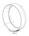
- FIG. 2is a perspective view of a portion of the fan assembly of FIG. 1 ;
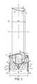
- FIG. 3is a side sectional view taken at line A-A through a portion of the fan assembly of FIG. 1 , illustrating a first filter arrangement
- FIG. 4is an enlarged side sectional detail of a portion of the fan assembly of FIG. 1 ;
- FIG. 5is a sectional view of the fan assembly taken along line B-B of FIG. 3 and viewed from direction F of FIG. 3 ;
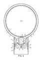
- FIG. 6is a sectional view of the fan assembly of FIG. 1 , illustrating a second filter arrangement
- FIG. 7is a side sectional view taken at line A-A through a portion of the fan assembly of FIG. 1 , illustrating a third filter arrangement
- FIG. 8is an enlarged side sectional detail of a portion of the fan assembly as illustrated in FIG. 7 .
- FIG. 1shows an example of a fan assembly 100 viewed from the front of the device.
- the fan assembly 100comprises an annular nozzle 1 defining a central opening 2 .
- nozzle 1comprises an interior passage 10 , a mouth 12 and a Coanda surface 14 adjacent the mouth 12 .
- the Coanda surface 14is arranged so that a primary air flow exiting the mouth 12 and directed over the Coanda surface 14 is amplified by the Coanda effect.
- the nozzle 1is connected to, and supported by, a base 16 having an outer casing 18 .
- the base 16includes a plurality of selection buttons 20 accessible through the outer casing 18 and through which the fan assembly 100 can be operated.
- FIGS. 3, 4 and 5show further specific details of the fan assembly 100 .
- a motor 22 for creating an air flow through the nozzle 1is located inside the base 16 .
- the base 16further comprises an air inlet 24 a , 24 b formed in the outer casing 18 and through which air is drawn into the base 16 .
- a motor housing 28 for the motor 22is also located inside the base 16 .
- the motor 22is supported by the motor housing 28 and held or fixed in a secure position within the base 16 .
- the motor 22is a DC brushless motor.
- An impeller 30is connected to a rotary shaft extending outwardly from the motor 22 , and a diffuser 32 is positioned downstream of the impeller 30 .
- the diffuser 32comprises a fixed, stationary disc having spiral blades.
- An inlet 34 to the impeller 30communicates with the air inlet 24 a , 24 b formed in the outer casing 18 of the base 16 .
- the outlet 36 of the diffuser 32 and the exhaust from the impeller 30communicate with hollow passageway portions or ducts located inside the base 16 in order to establish air flow from the impeller 30 to the interior passage 10 of the nozzle 1 .
- the motor 22is connected to an electrical connection and power supply and is controlled by a controller (not shown). Communication between the controller and the plurality of selection buttons 20 enable a user to operate the fan assembly 100 .
- the shape of the nozzle 1is annular.
- the nozzle 1has a diameter of around 350 mm, but the nozzle 1 may have any desired diameter, for example around 300 mm.
- the interior passage 10is annular and is formed as a continuous loop or duct within the nozzle 1 .
- the nozzle 1is formed from at least one wall defining the interior passage 10 and the mouth 12 .
- the nozzle 1comprises an inner wall 38 and an outer wall 40 .
- the walls 38 , 40are arranged in a looped or folded shape such that the inner wall 38 and outer wall 40 approach one another.
- the inner wall 38 and the outer wall 40together define the mouth 12 , and the mouth 12 extends about the axis X.
- the mouth 12comprises a tapered region 42 narrowing to an outlet 44 .
- the outlet 44comprises a gap or spacing formed between the inner wall 38 of the nozzle 1 and the outer wall 40 of the nozzle 1 .
- the spacing between the opposing surfaces of the walls 38 , 40 at the outlet 44 of the mouth 12is chosen to be in the range from 1 mm to 10 mm. The choice of spacing will depend on the desired performance characteristics of the fan. In this embodiment the outlet 44 is around 5 mm wide, and the mouth 12 and the outlet 44 are concentric with the interior passage 10 .
- the mouth 12is adjacent the Coanda surface 14 .
- the nozzle 1further comprises a diffuser portion located downstream of the Coanda surface.
- the diffuser portionincludes a diffuser surface 46 to further assist the flow of air current delivered or output from the fan assembly 100 .
- the mouth 12 and the overall arrangement of the nozzle 1is such that the angle subtended between the Coanda surface 14 and the axis X is around 15°. The angle is chosen for efficient air flow over the Coanda surface 14 .
- the base 16 and the nozzle 1have a depth in the direction of the axis X.
- the nozzle 1extends by a distance of around 5 cm in the direction of the axis.
- the diffuser surface 46 and the overall profile of the nozzle 1are based on an aerofoil shape, and in the example shown the diffuser portion extends by a distance of around two thirds the overall depth of the nozzle 1 .
- the fan assembly 100 described aboveoperates in the following manner
- a signal or other communicationis sent to drive the motor 22 .
- the motor 22is thus activated and air is drawn into the fan assembly 100 via the air inlet.
- airis drawn in at a rate of approximately 40 to 100 liters per second, preferably around 80 l/s (liters per second).
- the airpasses through the outer casing 18 and along the route illustrated by arrows F, F′′ of FIGS. 3 and 6 to the inlet 34 of the impeller 30 .
- the air flow leaving the outlet 36 of the diffuser 32 and the exhaust of the impeller 30is divided into two air flows that proceed in opposite directions through the interior passage 10 .
- the air flowis constricted as it enters the mouth 12 and is further constricted at the outlet 44 of the mouth 12 .
- the constrictioncreates pressure in the system.
- the motor 22creates an air flow through the nozzle 1 having a pressure of at least 300 kPa and a pressure of up to 700 kPa may be used.
- the air flow createdovercomes the pressure created by the constriction and the air flow exits through the outlet 44 as a primary air flow.
- the output and emission of the primary air flowcreates a low pressure area at the air inlet with the effect of drawing additional air into the fan assembly 100 .
- the operation of the fan assembly 100induces high air flow through the nozzle 1 and out through the opening 2 .
- the primary air flowis directed over the Coanda surface 14 and the diffuser surface 46 , and is amplified by the Coanda effect.
- a secondary air flowis generated by entrainment of air from the external environment, specifically from the region around the outlet 44 and from around the outer edge of the nozzle 1 .
- a portion of the secondary air flow entrained by the primary air flowmay also be guided over the diffuser surface 46 .
- This secondary air flowpasses through the opening 2 , where it combines with the primary air flow to produce a total air flow projected forward from the nozzle 1 .
- the combination of entrainment and amplificationresults in a total air flow from the opening 2 of the fan assembly 100 that is greater than the air flow output from a fan assembly without such a Coanda or amplification surface adjacent the emission area.
- the amplification and laminar type of air flow producedresults in a sustained flow of air being directed towards a user from the nozzle 1 .
- the mass flow rate of air projected from the fan assembly 100is at least 450 l/s, preferably in the range from 600 l/s to 700 l/s.
- the flow rate at a distance of up to 3 nozzle diameters (i.e. around 1000 to 1200 mm) from a useris around 400 to 500 l/s.
- the total air flowhas a velocity of around 3 to 4 m/s (meters per second). Higher velocities are achievable by reducing the angle subtended between the Coanda surface 14 and the axis X.
- a first filter arrangement for the fan assembly 100is illustrated in FIGS. 3 and 5 .
- the first filter arrangementcomprises a filter 26 , which comprises a filter medium 50 .
- the filter 26is placed upstream of the motor 22 and impeller 30 of the fan assembly 100 , and downstream of the air inlet 24 a , 24 b . Consequently air flow drawn into the base 16 through the air inlet 24 a passes through the filter 26 and the filter medium 50 before entering the motor housing 28 .
- the air flowis constricted as it enters the filter 26 and passes through the filter medium 50 .
- the filter 26provides a pre-motor filter in the fan assembly 100 , and the motor is thereby reliably protected from dirt, dust and debris that may be drawn into the device.
- the filter 26is positioned adjacent the air inlet 24 a , 24 b .
- the filter 26is located such that it extends cylindrically about an axis Y, perpendicular to the axis X.
- the fan assembly 100will include a recess or other shaping into which the filter 26 is received.
- the recessis preferably designed to accommodate snugly the filter 26 .
- the filter 26is preferably mounted and secured within the recess to establish an air-tight seal so that all of the air flow drawn into the air inlet 24 a , 24 b will pass through the filter medium 50 .
- the filter 26is preferably fixedly connected and secured within the fan assembly 100 by suitable fixings such as screw-threaded portions, fasteners, seal members or other equivalent means.
- FIG. 6A second filter arrangement for the fan assembly 100 is illustrated in FIG. 6 .
- the second filter arrangementcomprises a filter 126 , which comprises a filter medium 150 .
- the fan assembly 100 illustrated in FIG. 6differs from that illustrated in FIGS. 3 and 5 in that air inlets 25 a , 25 b are formed in the lower surface of the outer casing 18 , rather than in the cylindrical side wall thereof.
- the filter 126is positioned adjacent the lower air inlets 25 a , 25 b and shaped so as to substantially cover the lower surface of the base 16 .
- the filter 126is preferably mounted and secured in a fixed arrangement within the base 16 to establish an air-tight seal so that all of the air flow drawn into air inlet 25 a , 25 b will pass through the filter medium 150 .
- the filter 126is preferably fixedly connected and secured within the fan assembly 100 by suitable fixings. As described previously, the filter 126 thus provides a pre-motor filter in the fan assembly 100 , and the motor is thereby reliably protected from dirt, dust and debris that may be drawn into the device.
- a third filter arrangement for the fan assembly 100is illustrated in FIGS. 7 and 8 .
- This third arrangementmay be used in combination with, or separately from, any of the first and second filter arrangements.
- the third filter arrangementcomprises a filter 226 , which comprises a filter medium 250 .
- the filter 226is annular and is housed within the interior passage 10 of the nozzle 1 such that the filter 226 extends about the axis X.
- the filter 226has a depth of around 5 cm in the direction of the axis X.
- the dimensions of the filter 226are chosen so that the filter 226 is accommodated snugly within the nozzle 1 .
- the filter 226is preferably fixedly connected and secured within the interior passage 10 of the nozzle 1 by suitable fixings such as screw-threaded portions, fasteners, seal members or other equivalent means.
- the interior passage 10is divided by the filter 226 into an outer air chamber 228 and an inner air chamber 230 .
- Each air chamber 228 , 230comprises a continuous duct or passageway within the nozzle 1 .
- the outer air chamber 228is arranged to receive the airflow from the base 16
- the inner air chamber 230is arranged to convey the air flow to the mouth 12 .
- the filter 226thus provides a post-motor filter in the fan assembly 100 , and can thereby capture dirt and carbon debris that may be generated by motor brushes in a traditional motor or that may be drawn into the nozzle from outside the fan assembly.
- the filtermay comprise one or any number of filters or filters assemblies in one or more locations within the fan assembly.
- the filter materialmay comprise filter media such as foam materials, carbon, paper, HEPA (High Efficiency Particle Arrester) filter media, fabric or open cell polyurethane foam, for example.
- the filter materialcould be material having different density and thickness to that described and illustrated above.
- the filtermay comprise a mesh or porous material located around the base and may form part of, or be mounted to, the outer casing.
- the filtermay be suitable for removal of specific pollutants and particulates from the air flow and may be used for chemical or odor removal.
- Other filtration schemes or processing systemssuch as ionization or UV treatment could be used in any combination within the filter and within the fan assembly.
- the filtermay be positioned in or formed around any part of the fan assembly, it may be located adjacent or in close proximity to the air inlet, it may surround the entire circumference or boundary of the base, the motor or the motor housing.
- the shape and size of the portion of the fan assembly accommodating the filtermay be modified.
- the fancould be of a different height or diameter.
- the performance of the fan assemblymay be modified by increasing the diameter of the nozzle and the area of the mouth opening, the distance that the nozzle extends in the direction of the axis may be greater than 5 cm, and may be up to 20 cm.
- the fanneed not be located on a desk, but could be free standing, wall mounted or ceiling mounted.
- the fan shapecould be adapted to suit any kind of situation or location where a cooling flow of air is desired.
- a portable fancould have a smaller nozzle, say 5 cm in diameter.
- the means for creating an air flow through the nozzlecan be a motor or other air emitting device, such as any air blower or vacuum source that can be used so that the fan assembly can create an air current in a room.
- a motorsuch as an AC induction motor or types of DC brushless motor, but may also comprise any suitable air movement or air transport device such as a pump or other means of providing directed fluid flow to generate and create an air flow.
- a motormay include a diffuser or a secondary diffuser located downstream of the motor to recover some of the static pressure lost in the motor housing and through the motor.
- nozzlecomprising an oval, or ‘racetrack’ shape, a single strip or line, or block shape could be used.
- the fan assemblyprovides access to the central part of the fan as there are no blades. This means that additional features such as lighting or a clock or LCD display could be provided in the opening defined by the nozzle.
- the outlet of the mouthmay be modified.
- the outlet of the mouthmay be widened or narrowed to a variety of spacings to maximize air flow.
- the Coanda effectmay be made to occur over a number of different surfaces, or a number of internal or external designs may be used in combination to achieve the flow and entrainment required.
Landscapes
- Engineering & Computer Science (AREA)
- Mechanical Engineering (AREA)
- General Engineering & Computer Science (AREA)
- Physics & Mathematics (AREA)
- Fluid Mechanics (AREA)
- Structures Of Non-Positive Displacement Pumps (AREA)
- Jet Pumps And Other Pumps (AREA)
Abstract
Description
This application is a continuation of U.S. patent application Ser. No. 13/125,742, filed Jul. 8, 2011, which is a national stage application under 35 USC 371 of International Application No. PCT/GB2009/051401, filed Oct. 19, 2009, which claims the priority of United Kingdom Application No. 0819612.3, filed Oct. 25, 2008, the entire contents of which are incorporated herein by reference.
The present invention relates to a fan appliance. Particularly, but not exclusively, the present invention relates to a domestic fan, such as a desk fan, for creating air circulation and air current in a room, in an office or other domestic environment.
A number of types of domestic fan are known. It is common for a conventional fan to include a single set of blades or vanes mounted for rotation about an axis, and driving apparatus mounted about the axis for rotating the set of blades. Domestic fans are available in a variety of sizes and diameters, for example, a ceiling fan can be at least 1 m in diameter and is usually mounted in a suspended manner from the ceiling and positioned to provide a downward flow of air and cooling throughout a room.
Desk fans, on the other hand, are often around 30 cm in diameter and are usually free standing and portable. In standard desk fan arrangements the single set of blades is positioned close to the user and the rotation of the fan blades provides a forward flow of air current in a room or into a part of a room, and towards the user. Other types of fan can be attached to the floor or mounted on a wall. The movement and circulation of the air creates a so called ‘wind chill’ or breeze and, as a result, the user experiences a cooling effect as heat is dissipated through convection and evaporation. Fans such as that disclosed in USD 103,476 are suitable for standing on a desk or a table. U.S. Pat. No. 2,620,127 discloses a dual purpose fan suitable for use either mounted in a window or as a portable desk fan.
In a domestic environment it is desirable for appliances to be as small and compact as possible. U.S. Pat. No. 1,767,060 describes a desk fan with an oscillating function that aims to provide an air circulation equivalent to two or more prior art fans. In a domestic environment it is undesirable for parts to project from the appliance, or for the user to be able to touch any moving parts of the fan, such as the blades. USD 103,476 includes a cage around the blades. Other types of fan or circulator are described in U.S. Pat. Nos. 2,488,467, 2,433,795 and JP 56-167897. The fan of U.S. Pat. No. 2,433,795 has spiral slots in a rotating shroud instead of fan blades.
Some of the above prior art arrangements have safety features such as a cage or shroud around the blades to protect a user from injuring himself on the moving parts of the fan. However, caged blade parts can be difficult to clean and the movement of blades through air can be noisy and disturbing in a home or office environment.
A disadvantage of certain of the prior art arrangements is that the air flow produced by the fan is not felt uniformly by the user due to variations across the blade surface or across the outward facing surface of the fan. Uneven or ‘choppy’ air flow can be felt as a series of pulses or blasts of air. The uneven air flow may move and disturb dust and debris located in the vicinity of the fan, causing it to be projected towards the user. Furthermore, this type of air flow can cause lightweight items, such as papers or stationery, placed close to the fan to move or become dislodged from their location. This is disruptive in a home or office environment.
A further disadvantage is that the cooling effect created by the fan diminishes with distance from the user. This means the fan must be placed in close proximity to the user in order for the user to receive the benefit of the fan. Locating fans such as those described above close to a user is not always possible as the bulky shape and structure mean that the fan occupies a significant amount of the user's work space area. In the particular case of a fan placed on, or close to, a desk the fan body reduces the area available for paperwork, a computer or other office equipment.
The shape and structure of a fan at a desk not only reduces the working area available to a user but can block natural light (or light from artificial sources) from reaching the desk area. A well lit desk area is desirable for close work and for reading. In addition, a well lit area can reduce eye strain and the related health problems that may result from prolonged periods working in reduced light levels.
The present invention seeks to provide an improved fan assembly which obviates disadvantages of the prior art. It is an object of the present invention to provide a fan assembly which, in use, generates air flow at an even rate over the emission output area of the fan. It is another object to provide an improved fan assembly whereby a user at a distance from the fan feels an improved air flow, improved air quality and improved cooling effect in comparison to prior art fans.
According to the invention, there is provided a fan assembly for creating an air current, the fan assembly comprising a nozzle, means for creating an air flow through the nozzle and a filter for removing particulates from the air flow, the nozzle comprising an interior passage, a mouth for receiving the air flow from the interior passage, and a Coanda surface located adjacent the mouth and over which the mouth is arranged to direct the air flow.
Advantageously, by this arrangement a filtered air flow is generated and can be projected from the fan and delivered to the user.
The filter may comprise one or any number of filters or filters assemblies in one or more locations within the fan assembly. The filter material may comprise filter media such as foam materials, carbon, paper, HEPA (High Efficiency Particle Arrester) filter media, fabric or open cell polyurethane foam, for example. The filter may comprise a mesh or porous material located around a base of the fan assembly, and may form part of, or be mounted to, the outer casing. The filter may be suitable for removal of specific pollutants and particulates from the air flow and may be used for chemical or odor removal. Other filtration schemes or processing systems such as ionization or UV treatment could be used in any combination within the filter and within the fan assembly.
The filter may be located upstream of the means for creating an airflow. The benefit of this arrangement is that the means for creating an air flow is reliably protected from debris and dust that may be drawn into the appliance and which may damage the fan assembly. The filter may be located between an air inlet of the fan assembly and the means for creating an air flow. Alternatively, the filter may be located upstream of the air inlet. For example, the filter may surround or otherwise extend about a part of the fan assembly in which the air inlet is located. This part may be a base of the fan assembly to which the nozzle is connected.
Alternatively, or additionally, a filter may be located downstream of the means for creating an airflow through the nozzle. Advantageously, in this position it is possible to filter and clean the air drawn through the means for creating an air flow, including any exhaust emissions from said means, prior to progression through the elements of the fan assembly and supply to the user.
The filter may be located within the nozzle. This arrangement provides filtration in the air flow path through the nozzle resulting in a reduction in wear on the parts of the fan assembly and thus a reduction in the maintenance costs. Preferably, an additional filter is located upstream of the means for creating an air flow. Advantageously, this arrangement provides a superior level of filtration and cleaning of the air flow in the appliance. As well as filtration of the air flow path through the nozzle, the additional filter ensures that the said means is protected from debris and dust that may be drawn into the appliance.
Preferably the fan assembly is bladeless. By this arrangement an air current is generated and a cooling effect is created without requiring a bladed fan. The bladeless arrangement leads to lower noise emissions due to the absence of the sound of a fan blade moving through the air, and a reduction in moving parts and complexity.
In the following description of fans and, in particular a fan of the preferred embodiment, the term ‘bladeless’ is used to describe apparatus in which air flow is emitted or projected forwards from the fan assembly without the use of blades. By this definition a bladeless fan assembly can be considered to have an output area or emission zone absent blades or vanes from which the air flow is released or emitted in a direction appropriate for the user. A bladeless fan assembly may be supplied with a primary source of air from a variety of sources or generating means such as pumps, generators, motors or other fluid transfer devices, which include rotating devices such as a motor rotor and a bladed impeller for generating air flow. The supply of air generated by the motor causes a flow of air to pass from the room space or environment outside the fan assembly through the interior passage to the nozzle and then out through the mouth.
Hence, the description of a fan assembly as bladeless is not intended to extend to the description of the power source and components such as motors that are required for secondary fan functions. Examples of secondary fan functions can include lighting, adjustment and oscillation of the fan.
The fan assembly achieves the output and cooling effect described above with a nozzle which includes a Coanda surface to provide an amplifying region utilizing the Coanda effect. A Coanda surface is a known type of surface over which fluid flow exiting an output orifice close to the surface exhibits the Coanda effect. The fluid tends to flow over the surface closely, almost ‘clinging to’ or ‘hugging’ the surface. The Coanda effect is already a proven, well documented method of entrainment whereby a primary air flow is directed over the Coanda surface. A description of the features of a Coanda surface, and the effect of fluid flow over a Coanda surface, can be found in articles such as Reba, Scientific American, Volume 214, June 1963 pages 84 to 92.
Preferably the nozzle extends about an axis to define an opening through which air from outside the fan assembly is drawn by the air flow directed over the Coanda surface. Air from the external environment is drawn through the opening by the air flow directed over the Coanda surface. Advantageously, by this arrangement the assembly can be produced and manufactured with a reduced number of parts than those required in prior art fans. This reduces manufacturing cost and complexity.
In the present invention an air flow is created through the nozzle of the fan assembly. In the following description this air flow will be referred to as primary air flow. The primary air flow exits the nozzle via the mouth and passes over the Coanda surface. The primary air flow entrains the air surrounding the mouth of the nozzle, which acts as an air amplifier to supply both the primary air flow and the entrained air to the user. The entrained air will be referred to here as a secondary air flow. The secondary air flow is drawn from the room space, region or external environment surrounding the mouth of the nozzle and, by displacement, from other regions around the fan assembly. The primary air flow directed over the Coanda surface combined with the secondary air flow entrained by the air amplifier gives a total air flow emitted or projected forward to a user from the opening defined by the nozzle. The total air flow is sufficient for the fan assembly to create an air current suitable for cooling.
The air current delivered by the fan assembly to the user has the benefit of being an air flow with low turbulence and with a more linear air flow profile than that provided by other prior art devices. Advantageously, the air flow from the fan can be projected forward from the opening and the area surrounding the mouth of the nozzle with a laminar flow that is experienced by the user as a superior cooling effect to that from a bladed fan. The linear or laminar air flow with low turbulence travels efficiently out from the point of emission and loses less energy and less velocity to turbulence than the air flow generated by prior art fans. An advantage for a user is that the cooling effect can be felt even at a distance and the overall efficiency of the fan increases. This means that the user can choose to site the fan some distance from a work area or desk and still be able to feel the cooling benefit of the fan.
Advantageously, the assembly results in the entrainment of air surrounding the mouth of the nozzle such that the primary air flow is amplified by at least 15%, while a smooth overall output is maintained. The entrainment and amplification features of the fan assembly result in a fan with a higher efficiency than prior art devices. The air current emitted from the opening defined by the nozzle has an approximately flat velocity profile across the diameter of the nozzle. Overall the flow rate and profile can be described as plug flow with some regions having a laminar or partial laminar flow.
Preferably, the Coanda surface extends symmetrically about the axis. More preferably, the angle subtended between the Coanda surface and the axis is in the range from 7° to 20°, preferably around 15°. This provides an efficient primary air flow over the Coanda surface and leads to maximum air entrainment and secondary air flow.
Preferably the nozzle extends by a distance of at least 5 cm in the direction of the axis, more preferably the nozzle extends about the axis by a distance in the range from 30 cm to 180 cm. This provides options for emission of air over a range of different output areas and opening sizes, such as may be suitable for cooling the upper body and face of a user when working at a desk, for example.
Preferably the nozzle comprises a loop. The shape of the nozzle is not constrained by the requirement to include space for a bladed fan. In a preferred embodiment the nozzle is substantially annular. By providing an annular nozzle the fan can potentially reach a broad area. In addition, an illumination source in the room or at the desk fan location or natural light can reach the user through the central opening. In a further preferred embodiment the nozzle is at least partially circular. This arrangement can provide a variety of design options for the fan, increasing the choice available to a user or customer.
In the preferred embodiment the nozzle comprises a diffuser located downstream of the Coanda surface. An angular arrangement of the diffuser surface and an aerofoil-type shaping of the nozzle and diffuser surface can enhance the amplification properties of the fan assembly while minimizing noise and frictional losses.
In a preferred arrangement the nozzle comprises at least one wall defining the interior passage and the mouth, and the at least one wall comprises opposing surfaces defining the mouth. Preferably, the mouth has an outlet, and the spacing between the opposing surfaces at the outlet of the mouth is in the range from 1 mm to 10 mm, more preferably around 5 mm By this arrangement a nozzle can be provided with the desired flow properties to guide the primary air flow over the Coanda surface and provide a relatively uniform, or close to uniform, total air flow reaching the user.
In the preferred fan arrangement the means for creating an air flow through the nozzle comprises an impeller driven by a motor. This arrangement provides a fan with efficient air flow generation. More preferably the means for creating an air flow comprises a DC brushless motor and a mixed flow impeller. This arrangement provides an efficient motor package. In addition the arrangement reduces frictional losses from motor brushes and also reduces carbon debris from the brushes in a traditional motor. Reducing carbon debris and emissions is advantageous in a clean or pollutant sensitive environment such as a hospital or around those with allergies. The means for creating an air flow through the nozzle is preferably located in a base of the fan assembly, the nozzle being connected to the base to receive the air flow.
The nozzle may be rotatable or pivotable relative to a base portion, or other portion, of the fan assembly. This enables the nozzle to be directed towards or away from a user as required. The fan assembly may be desk, floor, wall or ceiling mountable. This can increase the portion of a room over which the user experiences cooling.
Embodiments of the invention will now be described with reference to the accompanying drawings, in which:
In the illustrated embodiment, themotor 22 is a DC brushless motor. Animpeller 30 is connected to a rotary shaft extending outwardly from themotor 22, and adiffuser 32 is positioned downstream of theimpeller 30. Thediffuser 32 comprises a fixed, stationary disc having spiral blades.
Aninlet 34 to theimpeller 30 communicates with theair inlet outer casing 18 of thebase 16. Theoutlet 36 of thediffuser 32 and the exhaust from theimpeller 30 communicate with hollow passageway portions or ducts located inside the base16 in order to establish air flow from theimpeller 30 to theinterior passage 10 of thenozzle 1. Themotor 22 is connected to an electrical connection and power supply and is controlled by a controller (not shown). Communication between the controller and the plurality ofselection buttons 20 enable a user to operate thefan assembly 100.
The features of thenozzle 1 will now be described with reference toFIGS. 3 and 4 . The shape of thenozzle 1 is annular. In this embodiment thenozzle 1 has a diameter of around 350 mm, but thenozzle 1 may have any desired diameter, for example around 300 mm. Theinterior passage 10 is annular and is formed as a continuous loop or duct within thenozzle 1. Thenozzle 1 is formed from at least one wall defining theinterior passage 10 and themouth 12. In this embodiment thenozzle 1 comprises aninner wall 38 and anouter wall 40. In the illustrated embodiment thewalls inner wall 38 andouter wall 40 approach one another. Theinner wall 38 and theouter wall 40 together define themouth 12, and themouth 12 extends about the axis X. Themouth 12 comprises a taperedregion 42 narrowing to anoutlet 44. Theoutlet 44 comprises a gap or spacing formed between theinner wall 38 of thenozzle 1 and theouter wall 40 of thenozzle 1. The spacing between the opposing surfaces of thewalls outlet 44 of themouth 12 is chosen to be in the range from 1 mm to 10 mm. The choice of spacing will depend on the desired performance characteristics of the fan. In this embodiment theoutlet 44 is around 5 mm wide, and themouth 12 and theoutlet 44 are concentric with theinterior passage 10.
Themouth 12 is adjacent theCoanda surface 14. Thenozzle 1 further comprises a diffuser portion located downstream of the Coanda surface. The diffuser portion includes adiffuser surface 46 to further assist the flow of air current delivered or output from thefan assembly 100. In the example illustrated inFIG. 3 themouth 12 and the overall arrangement of thenozzle 1 is such that the angle subtended between theCoanda surface 14 and the axis X is around 15°. The angle is chosen for efficient air flow over theCoanda surface 14. Thebase 16 and thenozzle 1 have a depth in the direction of the axis X. Thenozzle 1 extends by a distance of around 5 cm in the direction of the axis. Thediffuser surface 46 and the overall profile of thenozzle 1 are based on an aerofoil shape, and in the example shown the diffuser portion extends by a distance of around two thirds the overall depth of thenozzle 1.
Thefan assembly 100 described above operates in the following manner When a user makes a suitable selection from the plurality ofbuttons 20 to operate or activate thefan assembly 100, a signal or other communication is sent to drive themotor 22. Themotor 22 is thus activated and air is drawn into thefan assembly 100 via the air inlet. In the preferred embodiment air is drawn in at a rate of approximately 40 to 100 liters per second, preferably around 80 l/s (liters per second). The air passes through theouter casing 18 and along the route illustrated by arrows F, F″ ofFIGS. 3 and 6 to theinlet 34 of theimpeller 30. The air flow leaving theoutlet 36 of thediffuser 32 and the exhaust of theimpeller 30 is divided into two air flows that proceed in opposite directions through theinterior passage 10. The air flow is constricted as it enters themouth 12 and is further constricted at theoutlet 44 of themouth 12. The constriction creates pressure in the system. Themotor 22 creates an air flow through thenozzle 1 having a pressure of at least 300 kPa and a pressure of up to 700 kPa may be used. The air flow created overcomes the pressure created by the constriction and the air flow exits through theoutlet 44 as a primary air flow.
The output and emission of the primary air flow creates a low pressure area at the air inlet with the effect of drawing additional air into thefan assembly 100. The operation of thefan assembly 100 induces high air flow through thenozzle 1 and out through theopening 2. The primary air flow is directed over theCoanda surface 14 and thediffuser surface 46, and is amplified by the Coanda effect. A secondary air flow is generated by entrainment of air from the external environment, specifically from the region around theoutlet 44 and from around the outer edge of thenozzle 1. A portion of the secondary air flow entrained by the primary air flow may also be guided over thediffuser surface 46. This secondary air flow passes through theopening 2, where it combines with the primary air flow to produce a total air flow projected forward from thenozzle 1.
The combination of entrainment and amplification results in a total air flow from theopening 2 of thefan assembly 100 that is greater than the air flow output from a fan assembly without such a Coanda or amplification surface adjacent the emission area.
The amplification and laminar type of air flow produced results in a sustained flow of air being directed towards a user from thenozzle 1. In the preferred embodiment the mass flow rate of air projected from thefan assembly 100 is at least 450 l/s, preferably in the range from 600 l/s to 700 l/s. The flow rate at a distance of up to 3 nozzle diameters (i.e. around 1000 to 1200 mm) from a user is around 400 to 500 l/s. The total air flow has a velocity of around 3 to 4 m/s (meters per second). Higher velocities are achievable by reducing the angle subtended between theCoanda surface 14 and the axis X. A smaller angle results in the total air flow being emitted in a more focussed and directed manner This type of air flow tends to be emitted at a higher velocity but with a reduced mass flow rate. Conversely, greater mass flow can be achieved by increasing the angle between the Coanda surface and the axis. In this case the velocity of the emitted air flow is reduced but the mass flow generated increases. Thus the performance of the fan assembly can be altered by altering the angle subtended between the Coanda surface and the axis X. Performance of the fan assembly
A first filter arrangement for thefan assembly 100 is illustrated inFIGS. 3 and 5 . The first filter arrangement comprises afilter 26, which comprises afilter medium 50. In this filter arrangement thefilter 26 is placed upstream of themotor 22 andimpeller 30 of thefan assembly 100, and downstream of theair inlet air inlet 24apasses through thefilter 26 and thefilter medium 50 before entering themotor housing 28. The air flow is constricted as it enters thefilter 26 and passes through thefilter medium 50. Thefilter 26 provides a pre-motor filter in thefan assembly 100, and the motor is thereby reliably protected from dirt, dust and debris that may be drawn into the device.
In the illustrated arrangement, thefilter 26 is positioned adjacent theair inlet filter 26 is located such that it extends cylindrically about an axis Y, perpendicular to the axis X. Thefan assembly 100 will include a recess or other shaping into which thefilter 26 is received. The recess is preferably designed to accommodate snugly thefilter 26. In addition, thefilter 26 is preferably mounted and secured within the recess to establish an air-tight seal so that all of the air flow drawn into theair inlet filter medium 50. Thefilter 26 is preferably fixedly connected and secured within thefan assembly 100 by suitable fixings such as screw-threaded portions, fasteners, seal members or other equivalent means.
A second filter arrangement for thefan assembly 100 is illustrated inFIG. 6 . The second filter arrangement comprises afilter 126, which comprises afilter medium 150. Thefan assembly 100 illustrated inFIG. 6 differs from that illustrated inFIGS. 3 and 5 in thatair inlets outer casing 18, rather than in the cylindrical side wall thereof. Thefilter 126 is positioned adjacent thelower air inlets base 16. Thefilter 126 is preferably mounted and secured in a fixed arrangement within thebase 16 to establish an air-tight seal so that all of the air flow drawn intoair inlet filter medium 150. Thefilter 126 is preferably fixedly connected and secured within thefan assembly 100 by suitable fixings. As described previously, thefilter 126 thus provides a pre-motor filter in thefan assembly 100, and the motor is thereby reliably protected from dirt, dust and debris that may be drawn into the device.
A third filter arrangement for thefan assembly 100 is illustrated inFIGS. 7 and 8 . This third arrangement may be used in combination with, or separately from, any of the first and second filter arrangements. The third filter arrangement comprises afilter 226, which comprises afilter medium 250. Thefilter 226 is annular and is housed within theinterior passage 10 of thenozzle 1 such that thefilter 226 extends about the axis X. Thefilter 226 has a depth of around 5 cm in the direction of the axis X. The dimensions of thefilter 226 are chosen so that thefilter 226 is accommodated snugly within thenozzle 1. In a similar manner to the first and second filter arrangements, thefilter 226 is preferably fixedly connected and secured within theinterior passage 10 of thenozzle 1 by suitable fixings such as screw-threaded portions, fasteners, seal members or other equivalent means.
Theinterior passage 10 is divided by thefilter 226 into anouter air chamber 228 and aninner air chamber 230. Eachair chamber nozzle 1. Theouter air chamber 228 is arranged to receive the airflow from thebase 16, and theinner air chamber 230 is arranged to convey the air flow to themouth 12.
Thus, all of the air flow drawn into thenozzle 1 will enter theouter air chamber 228, pass through thefilter medium 250 and into theinner air chamber 230 before exiting thenozzle 1 through themouth 12. Thefilter 226 thus provides a post-motor filter in thefan assembly 100, and can thereby capture dirt and carbon debris that may be generated by motor brushes in a traditional motor or that may be drawn into the nozzle from outside the fan assembly.
In any of the above filter arrangements the filter may comprise one or any number of filters or filters assemblies in one or more locations within the fan assembly. For example, the shape and size of the filter and the type of filter material, may be altered. The filter material may comprise filter media such as foam materials, carbon, paper, HEPA (High Efficiency Particle Arrester) filter media, fabric or open cell polyurethane foam, for example. The filter material could be material having different density and thickness to that described and illustrated above. The filter may comprise a mesh or porous material located around the base and may form part of, or be mounted to, the outer casing. The filter may be suitable for removal of specific pollutants and particulates from the air flow and may be used for chemical or odor removal. Other filtration schemes or processing systems such as ionization or UV treatment could be used in any combination within the filter and within the fan assembly.
Also the manner in which the filter arrangement is received and located within the appliance is immaterial to this invention and a skilled reader will appreciate that the location can be formed by the mating of corresponding surfaces, push or snap fittings or other equivalent means. The filter may be positioned in or formed around any part of the fan assembly, it may be located adjacent or in close proximity to the air inlet, it may surround the entire circumference or boundary of the base, the motor or the motor housing. The shape and size of the portion of the fan assembly accommodating the filter may be modified.
The invention is not limited to the detailed description given above. Variations will be apparent to the person skilled in the art. For example, the fan could be of a different height or diameter. The performance of the fan assembly may be modified by increasing the diameter of the nozzle and the area of the mouth opening, the distance that the nozzle extends in the direction of the axis may be greater than 5 cm, and may be up to 20 cm. The fan need not be located on a desk, but could be free standing, wall mounted or ceiling mounted. The fan shape could be adapted to suit any kind of situation or location where a cooling flow of air is desired. A portable fan could have a smaller nozzle, say 5 cm in diameter. The means for creating an air flow through the nozzle can be a motor or other air emitting device, such as any air blower or vacuum source that can be used so that the fan assembly can create an air current in a room. Examples include a motor such as an AC induction motor or types of DC brushless motor, but may also comprise any suitable air movement or air transport device such as a pump or other means of providing directed fluid flow to generate and create an air flow. Features of a motor may include a diffuser or a secondary diffuser located downstream of the motor to recover some of the static pressure lost in the motor housing and through the motor.
Other shapes of nozzle are envisaged. For example, a nozzle comprising an oval, or ‘racetrack’ shape, a single strip or line, or block shape could be used. The fan assembly provides access to the central part of the fan as there are no blades. This means that additional features such as lighting or a clock or LCD display could be provided in the opening defined by the nozzle.
The outlet of the mouth may be modified. The outlet of the mouth may be widened or narrowed to a variety of spacings to maximize air flow. The Coanda effect may be made to occur over a number of different surfaces, or a number of internal or external designs may be used in combination to achieve the flow and entrainment required.
Other features could include a pivotable or tiltable base for ease of movement and adjustment of the position of the nozzle for the user.
Claims (15)
1. A fan assembly for creating an air current, the fan assembly comprising a nozzle that extends about an axis to define an opening through which air from outside the fan assembly is drawn by an air flow, a base connected to the nozzle, the base comprising a system for creating the air flow through the nozzle comprising a single air inlet, at least one base air inlet, and a filter surrounding the base and surrounding the system for creating the air flow for removing particulates from the air flow, the nozzle comprising an interior passage, a mouth for receiving the air flow from the interior passage, wherein the single air inlet to the system for creating the air flow is perpendicular to the at least one base air inlet.
2. The fan assembly ofclaim 1 , wherein the filter is located upstream of the system for creating the air flow.
3. The fan assembly ofclaim 1 , wherein an additional filter is located within the nozzle.
4. The fan assembly ofclaim 2 , comprising an additional filter located downstream of the system for creating the air flow.
5. The fan assembly ofclaim 1 , wherein the nozzle extends by a distance of at least 5 cm in the direction of the axis.
6. The fan assembly ofclaim 1 , wherein the nozzle extends about the axis by a distance in the range from 30 cm to 180 cm.
7. The fan assembly ofclaim 1 , wherein the nozzle comprises a loop.
8. The fan assembly ofclaim 1 , wherein the nozzle is substantially annular.
9. The fan assembly ofclaim 1 , wherein the nozzle is at least partially circular.
10. The fan assembly ofclaim 1 , wherein the nozzle comprises a diffuser.
11. The fan assembly ofclaim 1 , wherein the nozzle comprises at least one wall defining the interior passage and the mouth, and wherein said at least one wall comprises opposing surfaces defining the mouth.
12. The fan assembly ofclaim 11 , wherein the mouth has an outlet, and the spacing between the opposing surfaces at the outlet of the mouth is in the range from 0.5 mm to 10 mm.
13. The fan assembly ofclaim 1 , wherein the system for creating the air flow through the nozzle comprises an impeller driven by a motor.
14. The fan assembly ofclaim 13 , wherein the system for creating the air flow comprises a DC brushless motor and a mixed flow impeller.
15. The fan assembly ofclaim 1 , wherein the base comprises an air inlet and the filter is located upstream of the air inlet.
Priority Applications (1)
| Application Number | Priority Date | Filing Date | Title |
|---|---|---|---|
| US15/420,057US10145388B2 (en) | 2008-10-25 | 2017-01-30 | Fan with a filter |
Applications Claiming Priority (5)
| Application Number | Priority Date | Filing Date | Title |
|---|---|---|---|
| GB0819612AGB2464736A (en) | 2008-10-25 | 2008-10-25 | Fan with a filter |
| GB0819612.3 | 2008-10-25 | ||
| PCT/GB2009/051401WO2010046691A1 (en) | 2008-10-25 | 2009-10-19 | A fan |
| US201113125742A | 2011-07-08 | 2011-07-08 | |
| US15/420,057US10145388B2 (en) | 2008-10-25 | 2017-01-30 | Fan with a filter |
Related Parent Applications (2)
| Application Number | Title | Priority Date | Filing Date |
|---|---|---|---|
| PCT/GB2009/051401ContinuationWO2010046691A1 (en) | 2008-10-25 | 2009-10-19 | A fan |
| US13/125,742ContinuationUS9816531B2 (en) | 2008-10-25 | 2009-10-19 | Fan utilizing coanda surface |
Publications (2)
| Publication Number | Publication Date |
|---|---|
| US20170138374A1 US20170138374A1 (en) | 2017-05-18 |
| US10145388B2true US10145388B2 (en) | 2018-12-04 |
Family
ID=40133834
Family Applications (2)
| Application Number | Title | Priority Date | Filing Date |
|---|---|---|---|
| US13/125,742Active2031-02-06US9816531B2 (en) | 2008-10-25 | 2009-10-19 | Fan utilizing coanda surface |
| US15/420,057Active2030-03-04US10145388B2 (en) | 2008-10-25 | 2017-01-30 | Fan with a filter |
Family Applications Before (1)
| Application Number | Title | Priority Date | Filing Date |
|---|---|---|---|
| US13/125,742Active2031-02-06US9816531B2 (en) | 2008-10-25 | 2009-10-19 | Fan utilizing coanda surface |
Country Status (9)
| Country | Link |
|---|---|
| US (2) | US9816531B2 (en) |
| EP (2) | EP2337957B1 (en) |
| JP (1) | JP5456787B2 (en) |
| CN (1) | CN102197227B (en) |
| AU (2) | AU2009306160B2 (en) |
| DK (1) | DK2337957T3 (en) |
| ES (1) | ES2605467T3 (en) |
| GB (1) | GB2464736A (en) |
| WO (1) | WO2010046691A1 (en) |
Cited By (3)
| Publication number | Priority date | Publication date | Assignee | Title |
|---|---|---|---|---|
| US11007464B1 (en) | 2020-07-31 | 2021-05-18 | Germfree Laboratories INC | Portable air filtration and air dispersion system and method |
| US11384956B2 (en) | 2017-05-22 | 2022-07-12 | Sharkninja Operating Llc | Modular fan assembly with articulating nozzle |
| USD1057918S1 (en) | 2021-06-23 | 2025-01-14 | Sharkninja Operating Llc | Air purifier |
Families Citing this family (132)
| Publication number | Priority date | Publication date | Assignee | Title |
|---|---|---|---|---|
| GB0814835D0 (en) | 2007-09-04 | 2008-09-17 | Dyson Technology Ltd | A Fan |
| GB2463698B (en) | 2008-09-23 | 2010-12-01 | Dyson Technology Ltd | A fan |
| GB2464736A (en) | 2008-10-25 | 2010-04-28 | Dyson Technology Ltd | Fan with a filter |
| CN202056982U (en) | 2009-03-04 | 2011-11-30 | 戴森技术有限公司 | Humidifying device |
| GB2468312A (en) | 2009-03-04 | 2010-09-08 | Dyson Technology Ltd | Fan assembly |
| GB0903682D0 (en) | 2009-03-04 | 2009-04-15 | Dyson Technology Ltd | A fan |
| GB2468326A (en) | 2009-03-04 | 2010-09-08 | Dyson Technology Ltd | Telescopic pedestal fan |
| GB2468317A (en) | 2009-03-04 | 2010-09-08 | Dyson Technology Ltd | Height adjustable and oscillating fan |
| GB2468320C (en) | 2009-03-04 | 2011-06-01 | Dyson Technology Ltd | Tilting fan |
| GB2468331B (en) | 2009-03-04 | 2011-02-16 | Dyson Technology Ltd | A fan |
| KR101395177B1 (en) | 2009-03-04 | 2014-05-15 | 다이슨 테크놀러지 리미티드 | A fan |
| PL2276933T3 (en) | 2009-03-04 | 2011-10-31 | Dyson Technology Ltd | A fan |
| GB2468323A (en) | 2009-03-04 | 2010-09-08 | Dyson Technology Ltd | Fan assembly |
| GB2468322B (en) | 2009-03-04 | 2011-03-16 | Dyson Technology Ltd | Tilting fan stand |
| GB2468329A (en) | 2009-03-04 | 2010-09-08 | Dyson Technology Ltd | Fan assembly |
| GB2468315A (en) | 2009-03-04 | 2010-09-08 | Dyson Technology Ltd | Tilting fan |
| NZ593318A (en) | 2009-03-04 | 2012-11-30 | Dyson Technology Ltd | An annular fan assembly with a silencing member |
| GB0919473D0 (en) | 2009-11-06 | 2009-12-23 | Dyson Technology Ltd | A fan |
| GB2478925A (en) | 2010-03-23 | 2011-09-28 | Dyson Technology Ltd | External filter for a fan |
| GB2478927B (en) | 2010-03-23 | 2016-09-14 | Dyson Technology Ltd | Portable fan with filter unit |
| SG186071A1 (en) | 2010-05-27 | 2013-01-30 | Dyson Technology Ltd | Device for blowing air by means of narrow slit nozzle assembly |
| GB2482548A (en) | 2010-08-06 | 2012-02-08 | Dyson Technology Ltd | A fan assembly with a heater |
| GB2482549A (en) | 2010-08-06 | 2012-02-08 | Dyson Technology Ltd | A fan assembly with a heater |
| GB2482547A (en) | 2010-08-06 | 2012-02-08 | Dyson Technology Ltd | A fan assembly with a heater |
| GB2483448B (en) | 2010-09-07 | 2015-12-02 | Dyson Technology Ltd | A fan |
| WO2012046022A1 (en)* | 2010-10-04 | 2012-04-12 | Dyson Technology Limited | Fan supplied by external dc power source |
| JP5588565B2 (en) | 2010-10-13 | 2014-09-10 | ダイソン テクノロジー リミテッド | Blower assembly |
| GB2484671A (en)* | 2010-10-18 | 2012-04-25 | Dyson Technology Ltd | A fan assembly comprising an adjustable surface for control of air flow |
| EP2630373B1 (en) | 2010-10-18 | 2016-12-28 | Dyson Technology Limited | A fan assembly |
| GB2484669A (en)* | 2010-10-18 | 2012-04-25 | Dyson Technology Ltd | A fan assembly comprising an adjustable nozzle for control of air flow |
| GB2484670B (en) | 2010-10-18 | 2018-04-25 | Dyson Technology Ltd | A fan assembly |
| GB2484696A (en)* | 2010-10-20 | 2012-04-25 | Dyson Technology Ltd | A fan assembly comprising a nozzle with a Coanda surface and masks for directing air flow |
| GB2484695A (en)* | 2010-10-20 | 2012-04-25 | Dyson Technology Ltd | A fan assembly comprising a nozzle and inserts for directing air flow |
| JP5778293B2 (en) | 2010-11-02 | 2015-09-16 | ダイソン テクノロジー リミテッド | Blower assembly |
| GB2486019B (en) | 2010-12-02 | 2013-02-20 | Dyson Technology Ltd | A fan |
| GB2486890B (en) | 2010-12-23 | 2017-09-06 | Dyson Technology Ltd | A fan |
| GB2486889B (en) | 2010-12-23 | 2017-09-06 | Dyson Technology Ltd | A fan |
| GB2486892B (en) | 2010-12-23 | 2017-11-15 | Dyson Technology Ltd | A fan |
| CN102606492B (en)* | 2011-01-25 | 2015-04-22 | 台达电子工业股份有限公司 | Fan assembly |
| CN102398188A (en)* | 2011-06-01 | 2012-04-04 | 兰州理工大学 | Hollow ball-screw gas-liquid binary cooling system |
| GB2492961A (en)* | 2011-07-15 | 2013-01-23 | Dyson Technology Ltd | Fan with impeller and motor inside annular casing |
| GB2492962A (en) | 2011-07-15 | 2013-01-23 | Dyson Technology Ltd | Fan with tangential inlet to casing passage |
| GB2492963A (en)* | 2011-07-15 | 2013-01-23 | Dyson Technology Ltd | Fan with scroll casing decreasing in cross-section |
| BR112014001474A2 (en) | 2011-07-27 | 2017-02-21 | Dyson Technology Ltd | fan assembly |
| GB2493506B (en) | 2011-07-27 | 2013-09-11 | Dyson Technology Ltd | A fan assembly |
| CN102367814A (en)* | 2011-09-30 | 2012-03-07 | 王宁雷 | Nozzle of bladeless fan |
| GB201119500D0 (en) | 2011-11-11 | 2011-12-21 | Dyson Technology Ltd | A fan assembly |
| GB2496877B (en) | 2011-11-24 | 2014-05-07 | Dyson Technology Ltd | A fan assembly |
| GB2498547B (en) | 2012-01-19 | 2015-02-18 | Dyson Technology Ltd | A fan |
| GB2499042A (en)* | 2012-02-06 | 2013-08-07 | Dyson Technology Ltd | A nozzle for a fan assembly |
| GB2499041A (en)* | 2012-02-06 | 2013-08-07 | Dyson Technology Ltd | Bladeless fan including an ionizer |
| GB2499044B (en) | 2012-02-06 | 2014-03-19 | Dyson Technology Ltd | A fan |
| GB2500017B (en) | 2012-03-06 | 2015-07-29 | Dyson Technology Ltd | A Humidifying Apparatus |
| GB2500012B (en) | 2012-03-06 | 2016-07-06 | Dyson Technology Ltd | A Humidifying Apparatus |
| GB2500010B (en) | 2012-03-06 | 2016-08-24 | Dyson Technology Ltd | A humidifying apparatus |
| GB2512192B (en) | 2012-03-06 | 2015-08-05 | Dyson Technology Ltd | A Humidifying Apparatus |
| GB2500011B (en) | 2012-03-06 | 2016-07-06 | Dyson Technology Ltd | A Humidifying Apparatus |
| RU2606194C2 (en) | 2012-03-06 | 2017-01-10 | Дайсон Текнолоджи Лимитед | Fan unit |
| GB2500903B (en) | 2012-04-04 | 2015-06-24 | Dyson Technology Ltd | Heating apparatus |
| GB2501301B (en) | 2012-04-19 | 2016-02-03 | Dyson Technology Ltd | A fan assembly |
| EP2850324A2 (en) | 2012-05-16 | 2015-03-25 | Dyson Technology Limited | A fan |
| GB2518935B (en) | 2012-05-16 | 2016-01-27 | Dyson Technology Ltd | A fan |
| GB2532557B (en) | 2012-05-16 | 2017-01-11 | Dyson Technology Ltd | A fan comprsing means for suppressing noise |
| GB2503907B (en) | 2012-07-11 | 2014-05-28 | Dyson Technology Ltd | A fan assembly |
| AU350181S (en) | 2013-01-18 | 2013-08-15 | Dyson Technology Ltd | Humidifier or fan |
| BR302013003358S1 (en) | 2013-01-18 | 2014-11-25 | Dyson Technology Ltd | CONFIGURATION APPLIED ON HUMIDIFIER |
| AU350140S (en) | 2013-01-18 | 2013-08-13 | Dyson Technology Ltd | Humidifier or fan |
| AU350179S (en) | 2013-01-18 | 2013-08-15 | Dyson Technology Ltd | Humidifier or fan |
| SG11201505665RA (en) | 2013-01-29 | 2015-08-28 | Dyson Technology Ltd | A fan assembly |
| GB2510195B (en) | 2013-01-29 | 2016-04-27 | Dyson Technology Ltd | A fan assembly |
| CA152655S (en) | 2013-03-07 | 2014-05-20 | Dyson Technology Ltd | Fan |
| CA152658S (en) | 2013-03-07 | 2014-05-20 | Dyson Technology Ltd | Fan |
| BR302013004394S1 (en) | 2013-03-07 | 2014-12-02 | Dyson Technology Ltd | CONFIGURATION APPLIED TO FAN |
| CA152656S (en) | 2013-03-07 | 2014-05-20 | Dyson Technology Ltd | Fan |
| CA152657S (en) | 2013-03-07 | 2014-05-20 | Dyson Technology Ltd | Fan |
| USD729372S1 (en) | 2013-03-07 | 2015-05-12 | Dyson Technology Limited | Fan |
| CN103256209B (en)* | 2013-03-22 | 2016-04-06 | 杭州金鱼电器集团有限公司 | A kind of fan component |
| GB2515809B (en) | 2013-07-05 | 2015-08-19 | Dyson Technology Ltd | A handheld appliance |
| GB2515808B (en) | 2013-07-05 | 2015-12-23 | Dyson Technology Ltd | A handheld appliance |
| GB2515811B (en) | 2013-07-05 | 2015-11-11 | Dyson Technology Ltd | A handheld appliance |
| GB2515813B (en) | 2013-07-05 | 2017-07-05 | Dyson Technology Ltd | A handheld appliance |
| RU2635063C2 (en) | 2013-07-05 | 2017-11-08 | Дайсон Текнолоджи Лимитед | Manual household appliance |
| GB2515810B (en)* | 2013-07-05 | 2015-11-11 | Dyson Technology Ltd | A hand held appliance |
| GB2515815B (en) | 2013-07-05 | 2015-12-02 | Dyson Technology Ltd | A hand held appliance |
| GB2516058B (en) | 2013-07-09 | 2016-12-21 | Dyson Technology Ltd | A fan assembly with an oscillation and tilt mechanism |
| CA154723S (en) | 2013-08-01 | 2015-02-16 | Dyson Technology Ltd | Fan |
| TWD172707S (en) | 2013-08-01 | 2015-12-21 | 戴森科技有限公司 | A fan |
| CA154722S (en) | 2013-08-01 | 2015-02-16 | Dyson Technology Ltd | Fan |
| CN103418093B (en)* | 2013-09-01 | 2015-09-02 | 沈志聪 | A kind of dust mask for mine safety |
| GB2518638B (en) | 2013-09-26 | 2016-10-12 | Dyson Technology Ltd | Humidifying apparatus |
| JP1518058S (en) | 2014-01-09 | 2015-02-23 | ||
| JP1518059S (en) | 2014-01-09 | 2015-02-23 | ||
| KR101580248B1 (en)* | 2014-04-03 | 2015-12-24 | 한국기계연구원 | Hair dryer of low-noise and low-power |
| GB2528708B (en) | 2014-07-29 | 2016-06-29 | Dyson Technology Ltd | A fan assembly |
| GB2528709B (en) | 2014-07-29 | 2017-02-08 | Dyson Technology Ltd | Humidifying apparatus |
| GB2528704A (en) | 2014-07-29 | 2016-02-03 | Dyson Technology Ltd | Humidifying apparatus |
| ES2870660T3 (en) | 2014-10-24 | 2021-10-27 | Integrated Surgical LLC | Suction device for surgical instruments |
| CN104315580B (en)* | 2014-11-25 | 2016-08-24 | 济南大学 | A kind of movable kitchen ventilator |
| GB2535225B (en) | 2015-02-13 | 2017-12-20 | Dyson Technology Ltd | A fan |
| GB2537584B (en) | 2015-02-13 | 2019-05-15 | Dyson Technology Ltd | Fan assembly comprising a nozzle releasably retained on a body |
| GB2535224A (en) | 2015-02-13 | 2016-08-17 | Dyson Technology Ltd | A fan |
| GB2535460B (en)* | 2015-02-13 | 2017-11-29 | Dyson Technology Ltd | Fan assembly with removable nozzle and filter |
| WO2016128735A1 (en)* | 2015-02-13 | 2016-08-18 | Dyson Technology Limited | A fan assembly |
| GB2535462B (en) | 2015-02-13 | 2018-08-22 | Dyson Technology Ltd | A fan |
| JP6714700B2 (en) | 2015-07-13 | 2020-06-24 | コンメッド コーポレイション | Surgical suction device using positive pressure gas |
| US10926007B2 (en) | 2015-07-13 | 2021-02-23 | Conmed Corporation | Surgical suction device that uses positive pressure gas |
| US10837659B2 (en) | 2015-12-02 | 2020-11-17 | Coway Co., Ltd. | Air purifier |
| CN105351230B (en)* | 2015-12-10 | 2017-11-28 | 南华大学 | Coanda fin ventilation fan |
| CN105465019A (en)* | 2016-02-14 | 2016-04-06 | 任文华 | Air fan |
| USD831808S1 (en)* | 2016-08-12 | 2018-10-23 | Lg Electronics Inc. | Humidifying fan |
| USD831807S1 (en)* | 2016-08-12 | 2018-10-23 | Lg Electronics Inc. | Humidifying fan |
| USD831816S1 (en)* | 2016-08-12 | 2018-10-23 | Lg Electronics Inc. | Fan |
| CN207064346U (en)* | 2016-08-15 | 2018-03-02 | 杨家宁 | Fan with cooling device |
| TWI599724B (en)* | 2017-02-02 | 2017-09-21 | 楊家寧 | A fan |
| US20180066677A1 (en)* | 2016-08-15 | 2018-03-08 | Chia-Ning Yang | Fan |
| US10111500B2 (en) | 2016-11-08 | 2018-10-30 | Brian Lambert | Self-aligning, quick connect and disconnect magnetic end connectors |
| US12000621B2 (en)* | 2016-12-07 | 2024-06-04 | Coway Co., Ltd. | Wind-direction adjustable air purifier |
| CN107687451A (en)* | 2017-09-30 | 2018-02-13 | 程凌军 | A kind of air purification fan |
| GB2568937B (en) | 2017-12-01 | 2020-08-12 | Dyson Technology Ltd | A fan assembly |
| GB2568938B (en) | 2017-12-01 | 2020-12-30 | Dyson Technology Ltd | A filter assembly |
| GB2571718B (en) | 2018-03-05 | 2020-12-16 | Dyson Technology Ltd | A fan assembly |
| GB2571717B (en) | 2018-03-05 | 2020-12-16 | Dyson Technology Ltd | A fan assembly |
| WO2019191237A1 (en)* | 2018-03-29 | 2019-10-03 | Walmart Apollo, Llc | Aerial vehicle turbine system |
| GB2582796B (en) | 2019-04-03 | 2021-11-03 | Dyson Technology Ltd | Control of a fan assembly |
| WO2021083292A1 (en)* | 2019-10-31 | 2021-05-06 | 应辉 | Fan and filter screen changing method therefor |
| CN111075741B (en)* | 2019-10-31 | 2025-09-30 | 东莞市卓奇峰智能科技有限公司 | Column flow back spray expansion bladeless air purifier fan |
| WO2021083283A1 (en)* | 2019-10-31 | 2021-05-06 | 应辉 | Fan |
| EP4063667B1 (en)* | 2019-11-18 | 2024-08-28 | Ying, Hui | Fan |
| CN110792639B (en)* | 2019-11-18 | 2023-08-25 | 应辉 | Fan and method for replacing filter by fan |
| CN115039296B (en)* | 2020-03-19 | 2025-04-18 | 极光先进雷射株式会社 | Laser device and method for manufacturing electronic device |
| CN114738997A (en)* | 2022-03-10 | 2022-07-12 | 浙江弩牌电器有限公司 | Fan and how to use it |
| GB2630778B (en)* | 2023-06-07 | 2025-05-28 | Ogab Ltd | Disc brake assembly particulate collection system |
Citations (390)
| Publication number | Priority date | Publication date | Assignee | Title |
|---|---|---|---|---|
| BE560119A (en) | 1956-09-13 | |||
| GB191322235A (en) | 1913-10-02 | 1914-06-11 | Sidney George Leach | Improvements in the Construction of Electric Fans. |
| US1357261A (en) | 1918-10-02 | 1920-11-02 | Ladimir H Svoboda | Fan |
| US1767060A (en) | 1928-10-04 | 1930-06-24 | W H Addington | Electric motor-driven desk fan |
| US1819498A (en) | 1929-08-22 | 1931-08-18 | Ai Root Co | Air circulating and clarifying unit |
| GB383498A (en) | 1931-03-03 | 1932-11-17 | Spontan Ab | Improvements in or relating to fans, ventilators, or the like |
| US1896869A (en) | 1931-07-18 | 1933-02-07 | Master Electric Co | Electric fan |
| US2014185A (en) | 1930-06-25 | 1935-09-10 | Martin Brothers Electric Compa | Drier |
| US2035733A (en) | 1935-06-10 | 1936-03-31 | Marathon Electric Mfg | Fan motor mounting |
| US2115883A (en) | 1937-04-21 | 1938-05-03 | Sher Samuel | Lamp |
| US2210458A (en) | 1936-11-16 | 1940-08-06 | Lester S Keilholtz | Method of and apparatus for air conditioning |
| US2258961A (en) | 1939-07-26 | 1941-10-14 | Prat Daniel Corp | Ejector draft control |
| US2336295A (en) | 1940-09-25 | 1943-12-07 | Reimuller Caryl | Air diverter |
| US2362933A (en)* | 1941-03-08 | 1944-11-14 | Harry Alter Co | Air conditioning apparatus |
| US2394923A (en) | 1943-11-03 | 1946-02-12 | William P Little | Dust collector |
| GB593828A (en) | 1945-06-14 | 1947-10-27 | Dorothy Barker | Improvements in or relating to propeller fans |
| US2433795A (en) | 1945-08-18 | 1947-12-30 | Westinghouse Electric Corp | Fan |
| GB601222A (en) | 1944-10-04 | 1948-04-30 | Berkeley & Young Ltd | Improvements in, or relating to, electric fans |
| US2473325A (en) | 1946-09-19 | 1949-06-14 | E A Lab Inc | Combined electric fan and air heating means |
| US2476002A (en) | 1946-01-12 | 1949-07-12 | Edward A Stalker | Rotating wing |
| US2488467A (en) | 1947-09-12 | 1949-11-15 | Lisio Salvatore De | Motor-driven fan |
| GB633273A (en) | 1948-02-12 | 1949-12-12 | Albert Richard Ponting | Improvements in or relating to air circulating apparatus |
| US2510132A (en) | 1948-05-27 | 1950-06-06 | Morrison Hackley | Oscillating fan |
| GB641622A (en) | 1942-05-06 | 1950-08-16 | Fernan Oscar Conill | Improvements in or relating to hair drying |
| US2544379A (en) | 1946-11-15 | 1951-03-06 | Oscar J Davenport | Ventilating apparatus |
| US2547448A (en) | 1946-02-20 | 1951-04-03 | Demuth Charles | Hot-air space heater |
| GB661747A (en) | 1948-12-18 | 1951-11-28 | British Thomson Houston Co Ltd | Improvements in and relating to oscillating fans |
| US2583374A (en) | 1950-10-18 | 1952-01-22 | Hydraulic Supply Mfg Company | Exhaust fan |
| US2620127A (en) | 1950-02-28 | 1952-12-02 | Westinghouse Electric Corp | Air translating apparatus |
| FR1033034A (en) | 1951-02-23 | 1953-07-07 | Articulated stabilizer support for fan with flexible propellers and variable speeds | |
| FR1119439A (en) | 1955-02-18 | 1956-06-20 | Enhancements to portable and wall fans | |
| US2765977A (en) | 1954-10-13 | 1956-10-09 | Morrison Hackley | Electric ventilating fans |
| US2808198A (en) | 1956-04-30 | 1957-10-01 | Morrison Hackley | Oscillating fans |
| US2813673A (en) | 1953-07-09 | 1957-11-19 | Gilbert Co A C | Tiltable oscillating fan |
| US2830779A (en) | 1955-02-21 | 1958-04-15 | Lau Blower Co | Fan stand |
| US2838229A (en) | 1953-10-30 | 1958-06-10 | Roland J Belanger | Electric fan |
| US2922277A (en) | 1955-11-29 | 1960-01-26 | Bertin & Cie | Device for increasing the momentum of a fluid especially applicable as a lifting or propulsion device |
| US2922570A (en) | 1957-12-04 | 1960-01-26 | Burris R Allen | Automatic booster fan and ventilating shield |
| CH346643A (en) | 1955-12-06 | 1960-05-31 | K Tateishi Arthur | Electric fan |
| GB863124A (en) | 1956-09-13 | 1961-03-15 | Sebac Nouvelle Sa | New arrangement for putting gases into movement |
| US3004403A (en) | 1960-07-21 | 1961-10-17 | Francis L Laporte | Refrigerated space humidification |
| US3046732A (en)* | 1956-06-20 | 1962-07-31 | Research Corp | Method of energy exchange and apparatus for carrying out the same |
| FR1387334A (en) | 1963-12-21 | 1965-01-29 | Hair dryer capable of blowing hot and cold air separately | |
| US3270655A (en) | 1964-03-25 | 1966-09-06 | Howard P Guirl | Air curtain door seal |
| US3271936A (en) | 1963-01-30 | 1966-09-13 | Ventola Sa Atel Const | Apparatus for collecting automatically fibrous materials suspended in air |
| GB1067956A (en) | 1963-10-01 | 1967-05-10 | Siemens Elektrogeraete Gmbh | Portable electric hair drier |
| DE1291090B (en) | 1963-01-23 | 1969-03-20 | Schmidt Geb Halm Anneliese | Device for generating an air flow |
| US3503138A (en) | 1969-05-19 | 1970-03-31 | Oster Mfg Co John | Hair dryer |
| US3518776A (en) | 1967-06-03 | 1970-07-07 | Bremshey & Co | Blower,particularly for hair-drying,laundry-drying or the like |
| GB1262131A (en) | 1968-01-15 | 1972-02-02 | Hoover Ltd | Improvements relating to hair dryer assemblies |
| GB1265341A (en) | 1968-02-20 | 1972-03-01 | ||
| GB1278606A (en) | 1969-09-02 | 1972-06-21 | Oberlind Veb Elektroinstall | Improvements in or relating to transverse flow fans |
| GB1304560A (en) | 1970-01-14 | 1973-01-24 | ||
| US3724092A (en) | 1971-07-12 | 1973-04-03 | Westinghouse Electric Corp | Portable hair dryer |
| US3743186A (en) | 1972-03-14 | 1973-07-03 | Src Lab | Air gun |
| US3795367A (en) | 1973-04-05 | 1974-03-05 | Src Lab | Fluid device using coanda effect |
| US3850598A (en) | 1972-02-14 | 1974-11-26 | Braun Ag | Portable ventilating appliances |
| JPS49150403U (en) | 1973-04-23 | 1974-12-26 | ||
| US3871847A (en) | 1974-01-16 | 1975-03-18 | Whirlpool Co | Vacuum cleaner filter |
| US3872916A (en) | 1973-04-05 | 1975-03-25 | Int Harvester Co | Fan shroud exit structure |
| US3875745A (en) | 1973-09-10 | 1975-04-08 | Wagner Minning Equipment Inc | Venturi exhaust cooler |
| US3885891A (en)* | 1972-11-30 | 1975-05-27 | Rockwell International Corp | Compound ejector |
| GB1403188A (en) | 1971-10-22 | 1975-08-28 | Olin Energy Systems Ltd | Fluid flow inducing apparatus |
| JPS517258A (en) | 1974-07-11 | 1976-01-21 | Tsudakoma Ind Co Ltd | YOKOITO CHORYUSOCHI |
| US3937192A (en)* | 1974-09-03 | 1976-02-10 | General Motors Corporation | Ejector fan shroud arrangement |
| US3943329A (en) | 1974-05-17 | 1976-03-09 | Clairol Incorporated | Hair dryer with safety guard air outlet nozzle |
| GB1434226A (en) | 1973-11-02 | 1976-05-05 | Roberts S A | Pumps |
| DE2451557A1 (en) | 1974-10-30 | 1976-05-06 | Arnold Dipl Ing Scheel | Air conditioning by admixture of fresh warm or cool air - annular nozzle mixes fresh and stale air at nozzle outlet, eliminates draughts |
| US4037991A (en) | 1973-07-26 | 1977-07-26 | The Plessey Company Limited | Fluid-flow assisting devices |
| US4046492A (en) | 1976-01-21 | 1977-09-06 | Vortec Corporation | Air flow amplifier |
| US4061188A (en) | 1975-01-24 | 1977-12-06 | International Harvester Company | Fan shroud structure |
| US4073613A (en) | 1974-06-25 | 1978-02-14 | The British Petroleum Company Limited | Flarestack Coanda burners with self-adjusting slot at pressure outlet |
| GB1501473A (en) | 1974-06-11 | 1978-02-15 | Charbonnages De France | Fans |
| DE2748724A1 (en) | 1976-11-01 | 1978-05-03 | Arborg O J M | ADVANCE JET FOR AIRCRAFT OR WATER VEHICLES |
| US4113416A (en) | 1977-02-24 | 1978-09-12 | Ishikawajima-Harima Jukogyo Kabushiki Kaisha | Rotary burner |
| US4136735A (en) | 1975-01-24 | 1979-01-30 | International Harvester Company | Heat exchange apparatus including a toroidal-type radiator |
| CA1055344A (en) | 1974-05-17 | 1979-05-29 | International Harvester Company | Heat transfer system employing a coanda effect producing fan shroud exit |
| US4173995A (en) | 1975-02-24 | 1979-11-13 | International Harvester Company | Recirculation barrier for a heat transfer system |
| US4180130A (en) | 1974-05-22 | 1979-12-25 | International Harvester Company | Heat exchange apparatus including a toroidal-type radiator |
| US4184541A (en) | 1974-05-22 | 1980-01-22 | International Harvester Company | Heat exchange apparatus including a toroidal-type radiator |
| JPS56167897A (en) | 1980-05-28 | 1981-12-23 | Toshiba Corp | Fan |
| EP0044494A1 (en) | 1980-07-17 | 1982-01-27 | General Conveyors Limited | Nozzle for ring jet pump |
| US4332529A (en) | 1975-08-11 | 1982-06-01 | Morton Alperin | Jet diffuser ejector |
| US4336017A (en) | 1977-01-28 | 1982-06-22 | The British Petroleum Company Limited | Flare with inwardly directed Coanda nozzle |
| US4342204A (en) | 1970-07-22 | 1982-08-03 | Melikian Zograb A | Room ejection unit of central air-conditioning |
| GB2094400A (en) | 1981-01-30 | 1982-09-15 | Philips Nv | Electric fan |
| JPS57157097A (en) | 1981-03-20 | 1982-09-28 | Sanyo Electric Co Ltd | Fan |
| US4371322A (en)* | 1980-09-29 | 1983-02-01 | The Bendix Corporation | Combination air pump and air filter |
| GB2107787A (en) | 1981-10-08 | 1983-05-05 | Wright Barry Corp | Vibration-isolating seal for mounting fans and blowers |
| GB2111125A (en) | 1981-10-13 | 1983-06-29 | Beavair Limited | Apparatus for inducing fluid flow by Coanda effect |
| FR2534983A1 (en) | 1982-10-20 | 1984-04-27 | Chacoux Claude | Jet supersonic compressor |
| US4448354A (en) | 1982-07-23 | 1984-05-15 | The United States Of America As Represented By The Secretary Of The Air Force | Axisymmetric thrust augmenting ejector with discrete primary air slot nozzles |
| US4477270A (en)* | 1983-01-07 | 1984-10-16 | Franz Tauch | Air filter |
| US4566852A (en)* | 1982-03-15 | 1986-01-28 | Sueddeutsche Kuehlerfabrik Julius Fr. Behr Gmbh & Co. Kg | Axial fan arrangement |
| US4568243A (en) | 1981-10-08 | 1986-02-04 | Barry Wright Corporation | Vibration isolating seal for mounting fans and blowers |
| JPS6131830A (en) | 1984-07-25 | 1986-02-14 | Sanyo Electric Co Ltd | Ultrasonic humidifier |
| JPS61116093A (en) | 1984-11-12 | 1986-06-03 | Matsushita Electric Ind Co Ltd | Fan |
| EP0186581A1 (en) | 1984-12-17 | 1986-07-02 | ACIERS ET OUTILLAGE PEUGEOT Société dite: | Engine fan, especially for a motor vehicle, fixed to supporting arms integral with the car body |
| JPS61280787A (en) | 1985-05-30 | 1986-12-11 | Sanyo Electric Co Ltd | Fan |
| US4630475A (en) | 1985-03-20 | 1986-12-23 | Sharp Kabushiki Kaisha | Fiber optic level sensor for humidifier |
| GB2178256A (en) | 1985-05-30 | 1987-02-04 | Sanyo Electric Co | Brushless motor control |
| US4643351A (en) | 1984-06-14 | 1987-02-17 | Tokyo Sanyo Electric Co. | Ultrasonic humidifier |
| GB2185531A (en) | 1986-01-20 | 1987-07-22 | Mitsubishi Electric Corp | Oscillating electrician |
| GB2185533A (en) | 1986-01-08 | 1987-07-22 | Rolls Royce | Ejector pumps |
| JPS62223494A (en) | 1986-03-21 | 1987-10-01 | Uingu:Kk | Cold air fan |
| US4703152A (en) | 1985-12-11 | 1987-10-27 | Holmes Products Corp. | Tiltable and adjustably oscillatable portable electric heater/fan |
| US4718870A (en) | 1983-02-15 | 1988-01-12 | Techmet Corporation | Marine propulsion system |
| US4732539A (en) | 1986-02-14 | 1988-03-22 | Holmes Products Corp. | Oscillating fan |
| DE3644567A1 (en) | 1986-12-27 | 1988-07-07 | Ltg Lufttechnische Gmbh | Method for blowing supply air into a room |
| JPS63179198A (en) | 1987-01-20 | 1988-07-23 | Sanyo Electric Co Ltd | Blower |
| US4790133A (en) | 1986-08-29 | 1988-12-13 | General Electric Company | High bypass ratio counterrotating turbofan engine |
| JPS63306340A (en) | 1987-06-06 | 1988-12-14 | Koichi Hidaka | Bacteria preventive ultrasonic humidifier incorporating sterilizing lamp lighting circuit |
| JPS6421300A (en) | 1987-07-15 | 1989-01-24 | Mitsubishi Heavy Ind Ltd | Heat insulating structure of tank bottom surface part and construction method |
| JPS6483884A (en) | 1987-09-28 | 1989-03-29 | Matsushita Seiko Kk | Chargeable electric fan |
| JPH01138399A (en) | 1987-11-24 | 1989-05-31 | Sanyo Electric Co Ltd | Blowing fan |
| US4850804A (en) | 1986-07-07 | 1989-07-25 | Tatung Company Of America, Inc. | Portable electric fan having a universally adjustable mounting |
| JPH01224598A (en) | 1988-03-02 | 1989-09-07 | Sanyo Electric Co Ltd | Turn up angle adjusting device for equipment |
| US4878620A (en) | 1988-05-27 | 1989-11-07 | Tarleton E Russell | Rotary vane nozzle |
| GB2218196A (en) | 1988-04-08 | 1989-11-08 | Kouzo Fukuda | Air circulation devices |
| US4893990A (en) | 1987-10-07 | 1990-01-16 | Matsushita Electric Industrial Co., Ltd. | Mixed flow impeller |
| US4905340A (en) | 1988-08-11 | 1990-03-06 | Alan Gutschmit | Lint control apparatus |
| JPH02146294A (en) | 1988-11-24 | 1990-06-05 | Japan Air Curtain Corp | Air blower |
| FR2640857A1 (en) | 1988-12-27 | 1990-06-29 | Seb Sa | Hairdryer with an air exit flow of modifiable form |
| JPH02218890A (en) | 1989-02-20 | 1990-08-31 | Matsushita Seiko Co Ltd | Oscillating device for fan |
| JPH02248690A (en) | 1989-03-22 | 1990-10-04 | Hitachi Ltd | Fan |
| WO1990013478A1 (en) | 1989-05-12 | 1990-11-15 | Terence Robert Day | Annular body aircraft |
| US4978281A (en) | 1988-08-19 | 1990-12-18 | Conger William W Iv | Vibration dampened blower |
| JPH0352515A (en) | 1989-07-14 | 1991-03-06 | Samsung Electron Co Ltd | Circuit and method for controlling induc- tion motor |
| GB2236804A (en) | 1989-07-26 | 1991-04-17 | Anthony Reginald Robins | Compound nozzle |
| US5022900A (en) | 1988-07-20 | 1991-06-11 | Eagle, Military Gear Overseas Ltd. | Forced ventilation filtration device |
| GB2240268A (en) | 1990-01-29 | 1991-07-31 | Wik Far East Limited | Hair dryer |
| FR2658593A1 (en) | 1990-02-20 | 1991-08-23 | Electricite De France | Air inlet opening |
| CN2085866U (en) | 1991-03-16 | 1991-10-02 | 郭维涛 | Portable electric fan |
| GB2242935A (en) | 1990-03-14 | 1991-10-16 | S & C Thermofluids Ltd | Flue gas extraction |
| US5061405A (en) | 1990-02-12 | 1991-10-29 | Emerson Electric Co. | Constant humidity evaporative wicking filter humidifier |
| JPH03267598A (en) | 1990-03-19 | 1991-11-28 | Hitachi Ltd | Air blower |
| JPH03267597A (en) | 1990-03-19 | 1991-11-28 | Hitachi Ltd | Air blowing device |
| JPH0443895A (en) | 1990-06-08 | 1992-02-13 | Matsushita Seiko Co Ltd | Controller of electric fan |
| US5094676A (en) | 1990-05-03 | 1992-03-10 | Karbacher Michael H | Filter/fan assembly |
| JPH04109095A (en) | 1990-08-28 | 1992-04-10 | Sanyo Electric Co Ltd | Air blower with air cleaning function |
| USD325435S (en) | 1990-09-24 | 1992-04-14 | Vornado Air Circulation Systems, Inc. | Fan support base |
| CN2111392U (en) | 1992-02-26 | 1992-07-29 | 张正光 | Switch device for electric fan |
| US5168722A (en) | 1991-08-16 | 1992-12-08 | Walton Enterprises Ii, L.P. | Off-road evaporative air cooler |
| JPH04366330A (en) | 1991-06-12 | 1992-12-18 | Taikisha Ltd | Induction type blowing device |
| US5176856A (en) | 1991-01-14 | 1993-01-05 | Tdk Corporation | Ultrasonic wave nebulizer |
| US5188508A (en) | 1991-05-09 | 1993-02-23 | Comair Rotron, Inc. | Compact fan and impeller |
| JPH05157093A (en) | 1991-12-03 | 1993-06-22 | Sanyo Electric Co Ltd | Electric fan |
| JPH05164089A (en) | 1991-12-10 | 1993-06-29 | Matsushita Electric Ind Co Ltd | Axial fan motor |
| EP0556435A1 (en) | 1992-02-19 | 1993-08-25 | RBI DISTRIBUTORS Inc. | Inlet filter for hair dryer |
| JPH05263786A (en) | 1992-07-23 | 1993-10-12 | Sanyo Electric Co Ltd | Electric fan |
| US5266004A (en) | 1990-03-19 | 1993-11-30 | Hitachi, Ltd. | Blower |
| US5266090A (en) | 1992-09-21 | 1993-11-30 | Dust Free, Inc. | Multi-sided air filter with wraparound filter media |
| JPH0674190A (en) | 1993-07-30 | 1994-03-15 | Sanyo Electric Co Ltd | Fan |
| US5296769A (en) | 1992-01-24 | 1994-03-22 | Electrolux Corporation | Air guide assembly for an electric motor and methods of making |
| JPH0686898A (en) | 1992-09-09 | 1994-03-29 | Matsushita Electric Ind Co Ltd | Clothes dryer |
| US5310313A (en) | 1992-11-23 | 1994-05-10 | Chen C H | Swinging type of electric fan |
| JPH06147188A (en) | 1992-11-10 | 1994-05-27 | Hitachi Ltd | Electric fan |
| US5317815A (en) | 1993-06-15 | 1994-06-07 | Hwang Shyh Jye | Grille assembly for hair driers |
| JPH06257591A (en) | 1993-03-08 | 1994-09-13 | Hitachi Ltd | Fan |
| JPH06280800A (en) | 1993-03-29 | 1994-10-04 | Matsushita Seiko Co Ltd | Induced blast device |
| US5358443A (en)* | 1993-04-14 | 1994-10-25 | Centercore, Inc. | Dual fan hepa filtration system |
| JPH06336113A (en) | 1993-05-28 | 1994-12-06 | Sawafuji Electric Co Ltd | Automotive humidifier |
| US5402938A (en) | 1993-09-17 | 1995-04-04 | Exair Corporation | Fluid amplifier with improved operating range using tapered shim |
| US5407324A (en) | 1993-12-30 | 1995-04-18 | Compaq Computer Corporation | Side-vented axial fan and associated fabrication methods |
| US5425902A (en) | 1993-11-04 | 1995-06-20 | Tom Miller, Inc. | Method for humidifying air |
| GB2285504A (en) | 1993-12-09 | 1995-07-12 | Alfred Slack | Hot air distribution |
| US5435817A (en) | 1992-12-23 | 1995-07-25 | Honeywell Inc. | Portable room air purifier |
| JPH07190443A (en) | 1993-12-24 | 1995-07-28 | Matsushita Seiko Co Ltd | Blower equipment |
| GB2289087A (en) | 1992-11-23 | 1995-11-08 | Chen Cheng Ho | A swiveling electric fan |
| JPH0821400A (en) | 1994-07-06 | 1996-01-23 | Kamata Bio Eng Kk | Jet stream pump |
| JPH0821648A (en) | 1994-07-06 | 1996-01-23 | Kajima Corp | Filter clogging monitor |
| US5518370A (en) | 1995-04-03 | 1996-05-21 | Duracraft Corporation | Portable electric fan with swivel mount |
| DE19510397A1 (en) | 1995-03-22 | 1996-09-26 | Piller Gmbh | Blower unit for car=wash |
| CA2155482A1 (en) | 1995-03-27 | 1996-09-28 | Honeywell Consumer Products, Inc. | Portable electric fan heater |
| US5588985A (en) | 1990-11-14 | 1996-12-31 | Abatement Technologies, Inc. | Methods of using a portable filtration unit |
| US5609473A (en) | 1996-03-13 | 1997-03-11 | Litvin; Charles | Pivot fan |
| JPH09100800A (en) | 1995-10-04 | 1997-04-15 | Hitachi Ltd | Vehicle ventilation system |
| US5641343A (en) | 1996-01-25 | 1997-06-24 | Hmi Industries, Inc. | Room air cleaner |
| US5645769A (en) | 1994-06-17 | 1997-07-08 | Nippondenso Co., Ltd. | Humidified cool wind system for vehicles |
| US5649370A (en) | 1996-03-22 | 1997-07-22 | Russo; Paul | Delivery system diffuser attachment for a hair dryer |
| JPH09287600A (en) | 1996-04-24 | 1997-11-04 | Kioritz Corp | Blower pipe with silencer |
| US5735683A (en) | 1994-05-24 | 1998-04-07 | E.E.T. Umwelt - & Gastechnik Gmbh | Injector for injecting air into the combustion chamber of a torch burner and a torch burner |
| US5753000A (en) | 1993-08-23 | 1998-05-19 | Honeywell Consumer Products, Inc. | Filter air cleaner |
| US5762034A (en)* | 1996-01-16 | 1998-06-09 | Board Of Trustees Operating Michigan State University | Cooling fan shroud |
| US5762661A (en) | 1992-01-31 | 1998-06-09 | Kleinberger; Itamar C. | Mist-refining humidification system having a multi-direction, mist migration path |
| US5783117A (en) | 1997-01-09 | 1998-07-21 | Hunter Fan Company | Evaporative humidifier |
| USD398983S (en) | 1997-08-08 | 1998-09-29 | Vornado Air Circulation Systems, Inc. | Fan |
| DE19712228A1 (en) | 1997-03-24 | 1998-10-01 | Behr Gmbh & Co | Easily demountable fixing for vehicle fan motor |
| US5837020A (en)* | 1997-06-20 | 1998-11-17 | Hmi Industries, Inc. | Room air cleaner |
| US5843344A (en) | 1995-08-17 | 1998-12-01 | Circulair, Inc. | Portable fan and combination fan and spray misting device |
| US5862037A (en) | 1997-03-03 | 1999-01-19 | Inclose Design, Inc. | PC card for cooling a portable computer |
| US5868197A (en) | 1995-06-22 | 1999-02-09 | Valeo Thermique Moteur | Device for electrically connecting up a motor/fan unit for a motor vehicle heat exchanger |
| JPH11159499A (en) | 1997-11-27 | 1999-06-15 | Chikashi Nomura | Filter for removing dust or waste from fan |
| JPH11227866A (en) | 1998-02-17 | 1999-08-24 | Matsushita Seiko Co Ltd | Fan packing equipment |
| USD415271S (en) | 1998-12-11 | 1999-10-12 | Holmes Products, Corp. | Fan housing |
| US5997619A (en) | 1997-09-04 | 1999-12-07 | Nq Environmental, Inc. | Air purification system |
| US6001145A (en) | 1996-11-01 | 1999-12-14 | Clinix Gmbh | Air purification apparatus |
| US6015274A (en) | 1997-10-24 | 2000-01-18 | Hunter Fan Company | Low profile ceiling fan having a remote control receiver |
| JP2000116179A (en) | 1998-10-06 | 2000-04-21 | Calsonic Corp | Air-conditioning controller with brushless motor |
| US6053968A (en) | 1998-10-14 | 2000-04-25 | Miller; Bob C. | Portable room air purifier |
| US6073881A (en) | 1998-08-18 | 2000-06-13 | Chen; Chung-Ching | Aerodynamic lift apparatus |
| JP2000201723A (en) | 1999-01-11 | 2000-07-25 | Hirokatsu Nakano | Hair dryer with improved hair setting effect |
| USD429808S (en) | 2000-01-14 | 2000-08-22 | The Holmes Group, Inc. | Fan housing |
| US6123618A (en) | 1997-07-31 | 2000-09-26 | Jetfan Australia Pty. Ltd. | Air movement apparatus |
| FR2794195A1 (en) | 1999-05-26 | 2000-12-01 | Moulinex Sa | FAN EQUIPPED WITH AIR HANDLE |
| US6155782A (en) | 1999-02-01 | 2000-12-05 | Hsu; Chin-Tien | Portable fan |
| USD435899S1 (en) | 1999-11-15 | 2001-01-02 | B.K. Rehkatex (H.K.) Ltd. | Electric fan with clamp |
| JP2001017358A (en) | 1999-07-06 | 2001-01-23 | Hitachi Ltd | Electric vacuum cleaner |
| US6197096B1 (en)* | 1998-02-27 | 2001-03-06 | Hmi Industries, Inc. | Filter system |
| DE10000400A1 (en) | 1999-09-10 | 2001-03-15 | Sunonwealth Electr Mach Ind Co | Brushless DC motor for electric fan has driver circuit for stator coil supplied from AC supply network via voltage converter with rectification, filtering and smoothing stages |
| US6217281B1 (en) | 1999-06-30 | 2001-04-17 | Industrial Technology Research Institute | Low-noise fan-filter unit |
| EP1094224A2 (en) | 1999-10-19 | 2001-04-25 | ebm Werke GmbH & Co. KG | Radial fan |
| US6254337B1 (en) | 1995-09-08 | 2001-07-03 | Augustine Medical, Inc. | Low noise air blower unit for inflating thermal blankets |
| US6269549B1 (en) | 1999-01-08 | 2001-08-07 | Conair Corporation | Device for drying hair |
| US6282746B1 (en) | 1999-12-22 | 2001-09-04 | Auto Butler, Inc. | Blower assembly |
| US6293121B1 (en) | 1988-10-13 | 2001-09-25 | Gaudencio A. Labrador | Water-mist blower cooling system and its new applications |
| EP1138954A1 (en) | 2000-03-30 | 2001-10-04 | Technofan | Centrifugal fan |
| US6321034B2 (en) | 1999-12-06 | 2001-11-20 | The Holmes Group, Inc. | Pivotable heater |
| JP2002021797A (en) | 2000-07-10 | 2002-01-23 | Denso Corp | Blower |
| US6386845B1 (en) | 1999-08-24 | 2002-05-14 | Paul Bedard | Air blower apparatus |
| JP2002138829A (en) | 2000-11-06 | 2002-05-17 | Komatsu Zenoah Co | Air duct with sound absorbing material and manufacturing method thereof |
| DE10041805A1 (en) | 2000-08-25 | 2002-06-13 | Conti Temic Microelectronic | Cooling fan for motor vehicle radiator has fan motor attached to support housing by angled support arms |
| JP2002213388A (en) | 2001-01-18 | 2002-07-31 | Mitsubishi Electric Corp | Fan |
| US20020106547A1 (en) | 2001-02-02 | 2002-08-08 | Honda Giken Kogyo Kabushiki Kaisha | Variable flow-rate ejector and fuel cell system having the same |
| WO2002073096A1 (en) | 2001-03-09 | 2002-09-19 | Yann Birot | Mobile multifunctional ventilation device |
| US6480672B1 (en) | 2001-03-07 | 2002-11-12 | Holmes Group, Inc. | Flat panel heater |
| US6511531B1 (en)* | 2001-01-26 | 2003-01-28 | Hmi Industries, Inc. | Room air filtering and freshening device |
| US20030059307A1 (en) | 2001-09-27 | 2003-03-27 | Eleobardo Moreno | Fan assembly with desk organizer |
| GB2383277A (en) | 2000-08-11 | 2003-06-25 | Hamilton Beach Proctor Silex | Evaporative humidifier |
| WO2003058795A2 (en) | 2002-01-12 | 2003-07-17 | Vorwerk & Co. | Rapidly-running electric motor |
| US6599088B2 (en) | 2001-09-27 | 2003-07-29 | Borgwarner, Inc. | Dynamically sealing ring fan shroud assembly |
| CN1437300A (en) | 2002-02-07 | 2003-08-20 | 德昌电机股份有限公司 | Blowing machine motor |
| WO2003069931A1 (en) | 2002-02-13 | 2003-08-21 | Silverbrook Research Pty. Ltd. | A battery and ink charging stand for mobile communication device having an internal printer |
| US6616722B1 (en) | 2000-05-09 | 2003-09-09 | Hmi Industries, Inc. | Room air cleaner |
| US20030171093A1 (en) | 2002-03-11 | 2003-09-11 | Pablo Gumucio Del Pozo | Vertical ventilator for outdoors and/or indoors |
| JP2003329273A (en) | 2002-05-08 | 2003-11-19 | Mind Bank:Kk | Mist cold air blower also serving as humidifier |
| JP2004008275A (en) | 2002-06-04 | 2004-01-15 | Hitachi Home & Life Solutions Inc | Washing and drying machine |
| JP2004016466A (en) | 2002-06-17 | 2004-01-22 | Koken Ltd | Respirator with electric fan |
| USD485895S1 (en) | 2003-04-24 | 2004-01-27 | B.K. Rekhatex (H.K.) Ltd. | Electric fan |
| US20040022631A1 (en) | 2002-08-05 | 2004-02-05 | Birdsell Walter G. | Tower fan |
| US20040049842A1 (en) | 2002-09-13 | 2004-03-18 | Conair Cip, Inc. | Remote control bath mat blower unit |
| US20040118093A1 (en) | 2002-12-23 | 2004-06-24 | Samsung Electronics Co., Ltd. | Air cleaning apparatus |
| JP2004208935A (en) | 2002-12-27 | 2004-07-29 | Matsushita Electric Works Ltd | Hair drier |
| JP2004216221A (en) | 2003-01-10 | 2004-08-05 | Omc:Kk | Atomizing device |
| US20040149881A1 (en) | 2003-01-31 | 2004-08-05 | Allen David S | Adjustable support structure for air conditioner and the like |
| JP2004232954A (en) | 2003-01-30 | 2004-08-19 | Kurimoto Ltd | Air cleaner |
| US6789787B2 (en) | 2001-12-13 | 2004-09-14 | Tommy Stutts | Portable, evaporative cooling unit having a self-contained water supply |
| CN2650005Y (en) | 2003-10-23 | 2004-10-20 | 上海复旦申花净化技术股份有限公司 | Humidity-retaining spray machine with softening function |
| US6834412B2 (en) | 2002-05-07 | 2004-12-28 | D.P.L. Enterprises, Inc. | Mobile air duct vacuum |
| US20050031448A1 (en) | 2002-12-18 | 2005-02-10 | Lasko Holdings Inc. | Portable air moving device |
| US20050053465A1 (en) | 2003-09-04 | 2005-03-10 | Atico International Usa, Inc. | Tower fan assembly with telescopic support column |
| US20050069407A1 (en) | 2003-07-15 | 2005-03-31 | Ebm-Papst St. Georgen Gmbh & Co. Kg | Fan mounting means and method of making the same |
| WO2005050026A1 (en) | 2003-11-18 | 2005-06-02 | Distributed Thermal Systems Ltd. | Heater fan with integrated flow control element |
| US20050128698A1 (en) | 2003-12-10 | 2005-06-16 | Huang Cheng Y. | Cooling fan |
| WO2005057091A1 (en) | 2003-11-19 | 2005-06-23 | Lasko Holdings, Inc. | Portable electric air heater with pedestal |
| CN2713643Y (en) | 2004-08-05 | 2005-07-27 | 大众电脑股份有限公司 | heat sink |
| JP2005201507A (en) | 2004-01-15 | 2005-07-28 | Mitsubishi Electric Corp | Humidifier |
| US20050163670A1 (en) | 2004-01-08 | 2005-07-28 | Stephnie Alleyne | Heat activated air freshener system utilizing auto cigarette lighter |
| US20050173997A1 (en) | 2002-04-19 | 2005-08-11 | Schmid Alexandre C. | Mounting arrangement for a refrigerator fan |
| CN1680727A (en) | 2004-04-05 | 2005-10-12 | 奇鋐科技股份有限公司 | DC fan motor high voltage activates the control circuit for low voltage and high speed operation |
| KR20050102317A (en) | 2004-04-21 | 2005-10-26 | 서울반도체 주식회사 | Humidifier having sterilizing led |
| JP2005307985A (en) | 2005-06-17 | 2005-11-04 | Matsushita Electric Ind Co Ltd | Electric blower for electric vacuum cleaner and electric vacuum cleaner using the same |
| US20050281672A1 (en) | 2002-03-30 | 2005-12-22 | Parker Danny S | High efficiency air conditioner condenser fan |
| WO2006008021A1 (en) | 2004-07-17 | 2006-01-26 | Volkswagen Aktiengesellschaft | Cooling frame comprising at least one electrically driven ventilator |
| WO2006012526A2 (en) | 2004-07-23 | 2006-02-02 | Sharper Image Corporation | Air conditioner device with enhanced germicidal lamp |
| FR2874409A1 (en) | 2004-08-19 | 2006-02-24 | Max Sardou | Air circulator for e.g. tunnel, has wheel that cooperates with nozzle whose bore is near to and slightly larger than bore of rotating ring of blades, and main diffuser provided with sinusoidal trailing edge |
| JP2006089096A (en) | 2004-09-24 | 2006-04-06 | Toshiba Home Technology Corp | Package apparatus |
| US20060096863A1 (en) | 2001-12-20 | 2006-05-11 | Hitachi High-Technologies Corporation | Multi-capillary electrophoresis apparatus |
| US7059826B2 (en) | 2003-07-25 | 2006-06-13 | Lasko Holdings, Inc. | Multi-directional air circulating fan |
| WO2006071503A1 (en) | 2004-12-29 | 2006-07-06 | 3M Innovative Properties Company | Air filter assembly |
| US20060172682A1 (en) | 2005-01-06 | 2006-08-03 | Lasko Holdings, Inc. | Space saving vertically oriented fan |
| US7088913B1 (en) | 2004-06-28 | 2006-08-08 | Jcs/Thg, Llc | Baseboard/upright heater assembly |
| WO2006083849A1 (en) | 2005-02-01 | 2006-08-10 | Zipwall Llc | Filter mounts for a portable fan and method for mounting a filter to a portable fan |
| US20060199515A1 (en) | 2002-12-18 | 2006-09-07 | Lasko Holdings, Inc. | Concealed portable fan |
| US20060201119A1 (en) | 2004-03-02 | 2006-09-14 | Sung-Wook Song | Air cleaner |
| CN2833197Y (en) | 2005-10-11 | 2006-11-01 | 美的集团有限公司 | Foldable fan |
| US20060260282A1 (en) | 2005-05-19 | 2006-11-23 | Oav Equipment & Tools, Inc. | Detachable mobile rack for dust collector |
| JP3127331U (en) | 2005-09-16 | 2006-11-30 | スーティム フォク | Blower mechanism for column type fan |
| US7147336B1 (en) | 2005-07-28 | 2006-12-12 | Ming Shi Chou | Light and fan device combination |
| KR20070007997A (en) | 2005-07-12 | 2007-01-17 | 엘지전자 주식회사 | Air conditioner simultaneous air conditioner and indoor fan control method |
| GB2428569A (en) | 2005-07-30 | 2007-02-07 | Dyson Technology Ltd | Hand Dryer |
| US20070035189A1 (en) | 2001-01-16 | 2007-02-15 | Minebea Co., Ltd. | Axial fan motor and cooling unit |
| US20070041857A1 (en) | 2005-08-19 | 2007-02-22 | Armin Fleig | Fan housing with strain relief |
| WO2007024955A2 (en) | 2005-08-24 | 2007-03-01 | Ric Investments, Llc | Blower mounting assembly |
| USD539414S1 (en) | 2006-03-31 | 2007-03-27 | Kaz, Incorporated | Multi-fan frame |
| EP1779745A1 (en) | 2005-10-25 | 2007-05-02 | Seb Sa | Hair dryer comprising a device allowing the modification of the geometry of the air flow |
| WO2007048205A1 (en) | 2005-10-28 | 2007-05-03 | Resmed Ltd | Blower motor with flexible support sleeve |
| JP2007138763A (en) | 2005-11-16 | 2007-06-07 | Matsushita Electric Ind Co Ltd | Fan |
| JP2007138789A (en) | 2005-11-17 | 2007-06-07 | Matsushita Electric Ind Co Ltd | Fan |
| US20070166160A1 (en) | 2006-01-18 | 2007-07-19 | Kaz, Incorporated | Rotatable pivot mount for fans and other appliances |
| US20070176502A1 (en) | 2006-01-13 | 2007-08-02 | Nidec Copal Corporation | Compact fan motor and electric device comprising a compact fan motor |
| US20070224044A1 (en) | 2006-03-27 | 2007-09-27 | Valeo, Inc. | Cooling fan using coanda effect to reduce recirculation |
| US20070269323A1 (en) | 2006-05-22 | 2007-11-22 | Lei Zhou | Miniature high speed compressor having embedded permanent magnet motor |
| US7320721B2 (en) | 2005-03-17 | 2008-01-22 | Samsung Electronics Co., Ltd. | Chemical filter and fan filter unit having the same |
| US20080020698A1 (en) | 2004-11-30 | 2008-01-24 | Alessandro Spaggiari | Ventilating System For Motor Vehicles |
| WO2008014641A1 (en) | 2006-07-25 | 2008-02-07 | Pao-Chu Wang | Electric fan |
| JP2008039316A (en) | 2006-08-08 | 2008-02-21 | Sharp Corp | Humidifier |
| WO2008024569A2 (en) | 2006-08-25 | 2008-02-28 | Wind Merchants Ip, Llc | Personal or spot area environmental management systems and apparatuses |
| FR2906980A1 (en) | 2006-10-17 | 2008-04-18 | Seb Sa | HAIR DRYER COMPRISING A FLEXIBLE NOZZLE |
| JP2008100204A (en) | 2005-12-06 | 2008-05-01 | Akira Tomono | Mist generating apparatus |
| US20080152482A1 (en) | 2006-12-25 | 2008-06-26 | Amish Patel | Solar Powered Fan |
| EP1939456A2 (en) | 2006-12-27 | 2008-07-02 | Pfannenberg GmbH | Air passage device |
| US20080166224A1 (en) | 2007-01-09 | 2008-07-10 | Steve Craig Giffin | Blower housing for climate controlled systems |
| EP1980432A2 (en) | 2007-04-12 | 2008-10-15 | Halla Climate Control Corporation | Blower for vehicles |
| JP3146538U (en) | 2008-09-09 | 2008-11-20 | 宸維 范 | Atomizing fan |
| US20080286130A1 (en) | 2007-05-17 | 2008-11-20 | Purvines Stephen H | Fan impeller |
| JP2008294243A (en) | 2007-05-25 | 2008-12-04 | Mitsubishi Electric Corp | Cooling fan mounting structure |
| EP2000675A2 (en) | 2007-06-05 | 2008-12-10 | ResMed Limited | Blower With Bearing Tube |
| US20080314250A1 (en) | 2007-06-20 | 2008-12-25 | Cowie Ross L | Electrostatic filter cartridge for a tower air cleaner |
| CN201180678Y (en) | 2008-01-25 | 2009-01-14 | 台达电子工业股份有限公司 | Fan structure adjusted by dynamic balance |
| WO2009010528A1 (en) | 2007-07-16 | 2009-01-22 | Basic Holdings | A fan assisted applicance comprising a biocidal filter |
| US20090026850A1 (en) | 2007-07-25 | 2009-01-29 | King Jih Enterprise Corp. | Cylindrical oscillating fan |
| US20090039805A1 (en) | 2007-08-07 | 2009-02-12 | Tang Yung Yu | Changeover device of pull cord control and wireless remote control for a dc brushless-motor ceiling fan |
| JP2009044568A (en) | 2007-08-09 | 2009-02-26 | Sharp Corp | Storage stand and storage structure |
| US20090060710A1 (en) | 2007-09-04 | 2009-03-05 | Dyson Technology Limited | Fan |
| GB2452490A (en) | 2007-09-04 | 2009-03-11 | Dyson Technology Ltd | Bladeless fan |
| CN201221477Y (en) | 2008-05-06 | 2009-04-15 | 王衡 | Charging type fan |
| US20090097953A1 (en) | 2007-10-12 | 2009-04-16 | R.A. Jones & Co., Inc. | Device for moving packages and methods of using the same |
| US7540474B1 (en) | 2008-01-15 | 2009-06-02 | Chuan-Pan Huang | UV sterilizing humidifier |
| CN201281416Y (en) | 2008-09-26 | 2009-07-29 | 黄志力 | Ultrasonic vibration humidifier |
| US20090188126A1 (en) | 2008-01-25 | 2009-07-30 | Christophe Gaillard | Silencer for Drying Appliance and Silent Hair Dryer |
| US20090191054A1 (en) | 2008-01-25 | 2009-07-30 | Wolfgang Arno Winkler | Fan unit having an axial fan with improved noise damping |
| USD598532S1 (en) | 2008-07-19 | 2009-08-18 | Dyson Limited | Fan |
| US20090205498A1 (en) | 2008-02-14 | 2009-08-20 | Chi-Hsiang Wang | Air cleaner |
| US20090214341A1 (en) | 2008-02-25 | 2009-08-27 | Trevor Craig | Rotatable axial fan |
| USD602143S1 (en) | 2008-06-06 | 2009-10-13 | Dyson Limited | Fan |
| USD602144S1 (en) | 2008-07-19 | 2009-10-13 | Dyson Limited | Fan |
| US20090280007A1 (en) | 2008-05-06 | 2009-11-12 | Jih-I Ou | Multi-functional air circulation system |
| CN201349269Y (en) | 2008-12-22 | 2009-11-18 | 康佳集团股份有限公司 | Couple remote controller |
| USD605748S1 (en) | 2008-06-06 | 2009-12-08 | Dyson Limited | Fan |
| US7664377B2 (en) | 2007-07-19 | 2010-02-16 | Rhine Electronic Co., Ltd. | Driving apparatus for a ceiling fan |
| GB2463698A (en) | 2008-09-23 | 2010-03-24 | Dyson Technology Ltd | Annular fan |
| USD614280S1 (en) | 2008-11-07 | 2010-04-20 | Dyson Limited | Fan |
| GB2464736A (en) | 2008-10-25 | 2010-04-28 | Dyson Technology Ltd | Fan with a filter |
| KR20100055611A (en) | 2008-11-18 | 2010-05-27 | 오휘진 | A hair drier nozzle |
| CN201502549U (en) | 2009-08-19 | 2010-06-09 | 张钜标 | Fan with external storage battery |
| GB2466058A (en) | 2008-12-11 | 2010-06-16 | Dyson Technology Ltd | Fan nozzle |
| JP2010131259A (en) | 2008-12-05 | 2010-06-17 | Panasonic Electric Works Co Ltd | Scalp care apparatus |
| CN101749288A (en) | 2009-12-23 | 2010-06-23 | 李增珍 | Airflow generating method and device |
| US20100162011A1 (en) | 2008-12-22 | 2010-06-24 | Samsung Electronics Co., Ltd. | Method and apparatus for controlling interrupts in portable terminal |
| US20100171465A1 (en) | 2005-06-08 | 2010-07-08 | Belkin International, Inc. | Charging Station Configured To Provide Electrical Power to Electronic Devices And Method Therefor |
| DE102009007037A1 (en) | 2009-02-02 | 2010-08-05 | GM Global Technology Operations, Inc., Detroit | Discharge nozzle for ventilation device or air-conditioning system for vehicle, has horizontal flow lamellas pivoted around upper horizontal axis and/or lower horizontal axis and comprising curved profile |
| US7775848B1 (en) | 2004-07-21 | 2010-08-17 | Candyrific, LLC | Hand-held fan and object holder |
| CN201568337U (en) | 2009-12-15 | 2010-09-01 | 叶建阳 | Electric fan without blade |
| GB2468320A (en) | 2009-03-04 | 2010-09-08 | Dyson Technology Ltd | Tilting Fan |
| GB2468331A (en) | 2009-03-04 | 2010-09-08 | Dyson Technology Ltd | Fan assembly |
| GB2468313A (en) | 2009-03-04 | 2010-09-08 | Dyson Technology Ltd | Fan assembly |
| GB2468319A (en) | 2009-03-04 | 2010-09-08 | Dyson Technology Ltd | Fan assembly |
| GB2468323A (en) | 2009-03-04 | 2010-09-08 | Dyson Technology Ltd | Fan assembly |
| GB2468315A (en) | 2009-03-04 | 2010-09-08 | Dyson Technology Ltd | Tilting fan |
| GB2468328A (en) | 2009-03-04 | 2010-09-08 | Dyson Technology Ltd | Fan assembly with humidifier |
| GB2468369A (en) | 2009-03-04 | 2010-09-08 | Dyson Technology Ltd | Fan assembly with heater |
| GB2468312A (en) | 2009-03-04 | 2010-09-08 | Dyson Technology Ltd | Fan assembly |
| US20100226787A1 (en) | 2009-03-04 | 2010-09-09 | Dyson Technology Limited | Fan assembly |
| US20100226749A1 (en) | 2009-03-04 | 2010-09-09 | Dyson Technology Limited | Fan assembly |
| US20100226764A1 (en) | 2009-03-04 | 2010-09-09 | Dyson Technology Limited | Fan |
| US20100225012A1 (en) | 2009-03-04 | 2010-09-09 | Dyson Technology Limited | Humidifying apparatus |
| US20100226751A1 (en) | 2009-03-04 | 2010-09-09 | Dyson Technology Limited | Fan assembly |
| US20100226754A1 (en) | 2009-03-04 | 2010-09-09 | Dyson Technology Limited | Fan assembly |
| US20100226801A1 (en) | 2009-03-04 | 2010-09-09 | Dyson Technology Limited | Fan assembly |
| US20100226752A1 (en) | 2009-03-04 | 2010-09-09 | Dyson Technology Limited | Fan assembly |
| US20100226758A1 (en) | 2009-03-04 | 2010-09-09 | Dyson Technology Limited | Fan assembly |
| KR100985378B1 (en) | 2010-04-23 | 2010-10-04 | 윤정훈 | A bladeless fan for air circulation |
| US7806388B2 (en) | 2007-03-28 | 2010-10-05 | Eric Junkel | Handheld water misting fan with improved air flow |
| TWM394383U (en) | 2010-02-03 | 2010-12-11 | sheng-zhi Yang | Bladeless fan structure |
| CN101936310A (en) | 2010-10-04 | 2011-01-05 | 任文华 | Fan without fan blades |
| GB2473037A (en) | 2009-08-28 | 2011-03-02 | Dyson Technology Ltd | Humidifying apparatus comprising a fan and a humidifier with a plurality of transducers |
| CN101984299A (en) | 2010-09-07 | 2011-03-09 | 林美利 | Electronic ice fan |
| CN101985948A (en) | 2010-11-27 | 2011-03-16 | 任文华 | Bladeless fan |
| CN201763706U (en) | 2010-09-18 | 2011-03-16 | 任文华 | Non-bladed fan |
| CN201763705U (en) | 2010-09-22 | 2011-03-16 | 任文华 | Fan |
| CN201770513U (en) | 2010-08-04 | 2011-03-23 | 美的集团有限公司 | Sterilizing device for ultrasonic humidifier |
| CN201779080U (en) | 2010-05-21 | 2011-03-30 | 海尔集团公司 | Bladeless fan |
| US20110072770A1 (en)* | 2009-09-28 | 2011-03-31 | Ness Lakdawala | Portable air filter |
| CN201802648U (en) | 2010-08-27 | 2011-04-20 | 海尔集团公司 | Fan without fan blades |
| US20110110805A1 (en) | 2009-11-06 | 2011-05-12 | Dyson Technology Limited | Fan |
| CN102095236A (en) | 2011-02-17 | 2011-06-15 | 曾小颖 | Ventilation device |
| TWM407299U (en) | 2011-01-28 | 2011-07-11 | Zhong Qin Technology Co Ltd | Structural improvement for blade free fan |
| US20110236229A1 (en) | 2010-03-23 | 2011-09-29 | Dyson Technology Limited | Accessory for a fan |
| US20110236228A1 (en) | 2010-03-23 | 2011-09-29 | Dyson Technology Limited | Fan |
| US20110236219A1 (en) | 2010-03-23 | 2011-09-29 | Dyson Technology Limited | Fan |
| GB2479760A (en) | 2010-04-21 | 2011-10-26 | Dyson Technology Ltd | Conditioning air using an electrical influence machine |
| GB2482547A (en) | 2010-08-06 | 2012-02-08 | Dyson Technology Ltd | A fan assembly with a heater |
| US20120034108A1 (en) | 2010-08-06 | 2012-02-09 | Dyson Technology Limited | Fan assembly |
| US20120031509A1 (en) | 2010-08-06 | 2012-02-09 | Dyson Technology Limited | Fan assembly |
| CN102367813A (en) | 2011-09-30 | 2012-03-07 | 王宁雷 | Nozzle of bladeless fan |
| US20120057959A1 (en) | 2010-09-07 | 2012-03-08 | Dyson Technology Limited | Fan |
| US20120093629A1 (en) | 2010-10-18 | 2012-04-19 | Dyson Technology Limited | Fan assembly |
| US20120093630A1 (en) | 2010-10-18 | 2012-04-19 | Dyson Technology Limited | Fan assembly |
| US20140212291A1 (en)* | 2007-04-05 | 2014-07-31 | Jonathan Bradley Stagg | Ring fan and shroud air guide system |
Family Cites Families (3)
| Publication number | Priority date | Publication date | Assignee | Title |
|---|---|---|---|---|
| JPS6421300U (en)* | 1987-07-27 | 1989-02-02 | ||
| CN2072163U (en)* | 1988-07-15 | 1991-02-27 | 单觉民 | Ceiling fan jacket |
| CN1012152B (en)* | 1989-08-03 | 1991-03-27 | 杨松涛 | Centrifugal pressure expanding propeller |
- 2008
- 2008-10-25GBGB0819612Apatent/GB2464736A/ennot_activeWithdrawn
- 2009
- 2009-10-19EPEP09740942.9Apatent/EP2337957B1/enactiveActive
- 2009-10-19AUAU2009306160Apatent/AU2009306160B2/enactiveActive
- 2009-10-19EPEP16184103.6Apatent/EP3130808A1/ennot_activeWithdrawn
- 2009-10-19WOPCT/GB2009/051401patent/WO2010046691A1/enactiveApplication Filing
- 2009-10-19CNCN200980142258.2Apatent/CN102197227B/enactiveActive
- 2009-10-19USUS13/125,742patent/US9816531B2/enactiveActive
- 2009-10-19ESES09740942.9Tpatent/ES2605467T3/enactiveActive
- 2009-10-19DKDK09740942.9Tpatent/DK2337957T3/enactive
- 2009-10-19JPJP2011532719Apatent/JP5456787B2/enactiveActive
- 2010
- 2010-11-18AUAU2010101277Apatent/AU2010101277C4/ennot_activeExpired
- 2017
- 2017-01-30USUS15/420,057patent/US10145388B2/enactiveActive
Patent Citations (438)
| Publication number | Priority date | Publication date | Assignee | Title |
|---|---|---|---|---|
| GB191322235A (en) | 1913-10-02 | 1914-06-11 | Sidney George Leach | Improvements in the Construction of Electric Fans. |
| US1357261A (en) | 1918-10-02 | 1920-11-02 | Ladimir H Svoboda | Fan |
| US1767060A (en) | 1928-10-04 | 1930-06-24 | W H Addington | Electric motor-driven desk fan |
| US1819498A (en) | 1929-08-22 | 1931-08-18 | Ai Root Co | Air circulating and clarifying unit |
| US2014185A (en) | 1930-06-25 | 1935-09-10 | Martin Brothers Electric Compa | Drier |
| GB383498A (en) | 1931-03-03 | 1932-11-17 | Spontan Ab | Improvements in or relating to fans, ventilators, or the like |
| US1896869A (en) | 1931-07-18 | 1933-02-07 | Master Electric Co | Electric fan |
| US2035733A (en) | 1935-06-10 | 1936-03-31 | Marathon Electric Mfg | Fan motor mounting |
| US2210458A (en) | 1936-11-16 | 1940-08-06 | Lester S Keilholtz | Method of and apparatus for air conditioning |
| US2115883A (en) | 1937-04-21 | 1938-05-03 | Sher Samuel | Lamp |
| US2258961A (en) | 1939-07-26 | 1941-10-14 | Prat Daniel Corp | Ejector draft control |
| US2336295A (en) | 1940-09-25 | 1943-12-07 | Reimuller Caryl | Air diverter |
| US2362933A (en)* | 1941-03-08 | 1944-11-14 | Harry Alter Co | Air conditioning apparatus |
| GB641622A (en) | 1942-05-06 | 1950-08-16 | Fernan Oscar Conill | Improvements in or relating to hair drying |
| US2394923A (en) | 1943-11-03 | 1946-02-12 | William P Little | Dust collector |
| GB601222A (en) | 1944-10-04 | 1948-04-30 | Berkeley & Young Ltd | Improvements in, or relating to, electric fans |
| GB593828A (en) | 1945-06-14 | 1947-10-27 | Dorothy Barker | Improvements in or relating to propeller fans |
| US2433795A (en) | 1945-08-18 | 1947-12-30 | Westinghouse Electric Corp | Fan |
| US2476002A (en) | 1946-01-12 | 1949-07-12 | Edward A Stalker | Rotating wing |
| US2547448A (en) | 1946-02-20 | 1951-04-03 | Demuth Charles | Hot-air space heater |
| US2473325A (en) | 1946-09-19 | 1949-06-14 | E A Lab Inc | Combined electric fan and air heating means |
| US2544379A (en) | 1946-11-15 | 1951-03-06 | Oscar J Davenport | Ventilating apparatus |
| US2488467A (en) | 1947-09-12 | 1949-11-15 | Lisio Salvatore De | Motor-driven fan |
| GB633273A (en) | 1948-02-12 | 1949-12-12 | Albert Richard Ponting | Improvements in or relating to air circulating apparatus |
| US2510132A (en) | 1948-05-27 | 1950-06-06 | Morrison Hackley | Oscillating fan |
| GB661747A (en) | 1948-12-18 | 1951-11-28 | British Thomson Houston Co Ltd | Improvements in and relating to oscillating fans |
| US2620127A (en) | 1950-02-28 | 1952-12-02 | Westinghouse Electric Corp | Air translating apparatus |
| US2583374A (en) | 1950-10-18 | 1952-01-22 | Hydraulic Supply Mfg Company | Exhaust fan |
| FR1033034A (en) | 1951-02-23 | 1953-07-07 | Articulated stabilizer support for fan with flexible propellers and variable speeds | |
| US2813673A (en) | 1953-07-09 | 1957-11-19 | Gilbert Co A C | Tiltable oscillating fan |
| US2838229A (en) | 1953-10-30 | 1958-06-10 | Roland J Belanger | Electric fan |
| US2765977A (en) | 1954-10-13 | 1956-10-09 | Morrison Hackley | Electric ventilating fans |
| FR1119439A (en) | 1955-02-18 | 1956-06-20 | Enhancements to portable and wall fans | |
| US2830779A (en) | 1955-02-21 | 1958-04-15 | Lau Blower Co | Fan stand |
| US2922277A (en) | 1955-11-29 | 1960-01-26 | Bertin & Cie | Device for increasing the momentum of a fluid especially applicable as a lifting or propulsion device |
| CH346643A (en) | 1955-12-06 | 1960-05-31 | K Tateishi Arthur | Electric fan |
| US2808198A (en) | 1956-04-30 | 1957-10-01 | Morrison Hackley | Oscillating fans |
| US3046732A (en)* | 1956-06-20 | 1962-07-31 | Research Corp | Method of energy exchange and apparatus for carrying out the same |
| GB863124A (en) | 1956-09-13 | 1961-03-15 | Sebac Nouvelle Sa | New arrangement for putting gases into movement |
| BE560119A (en) | 1956-09-13 | |||
| US3047208A (en) | 1956-09-13 | 1962-07-31 | Sebac Nouvelle Sa | Device for imparting movement to gases |
| US2922570A (en) | 1957-12-04 | 1960-01-26 | Burris R Allen | Automatic booster fan and ventilating shield |
| US3004403A (en) | 1960-07-21 | 1961-10-17 | Francis L Laporte | Refrigerated space humidification |
| DE1291090B (en) | 1963-01-23 | 1969-03-20 | Schmidt Geb Halm Anneliese | Device for generating an air flow |
| US3271936A (en) | 1963-01-30 | 1966-09-13 | Ventola Sa Atel Const | Apparatus for collecting automatically fibrous materials suspended in air |
| GB1067956A (en) | 1963-10-01 | 1967-05-10 | Siemens Elektrogeraete Gmbh | Portable electric hair drier |
| FR1387334A (en) | 1963-12-21 | 1965-01-29 | Hair dryer capable of blowing hot and cold air separately | |
| US3270655A (en) | 1964-03-25 | 1966-09-06 | Howard P Guirl | Air curtain door seal |
| US3518776A (en) | 1967-06-03 | 1970-07-07 | Bremshey & Co | Blower,particularly for hair-drying,laundry-drying or the like |
| GB1262131A (en) | 1968-01-15 | 1972-02-02 | Hoover Ltd | Improvements relating to hair dryer assemblies |
| GB1265341A (en) | 1968-02-20 | 1972-03-01 | ||
| US3503138A (en) | 1969-05-19 | 1970-03-31 | Oster Mfg Co John | Hair dryer |
| GB1278606A (en) | 1969-09-02 | 1972-06-21 | Oberlind Veb Elektroinstall | Improvements in or relating to transverse flow fans |
| GB1304560A (en) | 1970-01-14 | 1973-01-24 | ||
| US4342204A (en) | 1970-07-22 | 1982-08-03 | Melikian Zograb A | Room ejection unit of central air-conditioning |
| US3724092A (en) | 1971-07-12 | 1973-04-03 | Westinghouse Electric Corp | Portable hair dryer |
| GB1403188A (en) | 1971-10-22 | 1975-08-28 | Olin Energy Systems Ltd | Fluid flow inducing apparatus |
| US3850598A (en) | 1972-02-14 | 1974-11-26 | Braun Ag | Portable ventilating appliances |
| US3743186A (en) | 1972-03-14 | 1973-07-03 | Src Lab | Air gun |
| US3885891A (en)* | 1972-11-30 | 1975-05-27 | Rockwell International Corp | Compound ejector |
| US3872916A (en) | 1973-04-05 | 1975-03-25 | Int Harvester Co | Fan shroud exit structure |
| US3795367A (en) | 1973-04-05 | 1974-03-05 | Src Lab | Fluid device using coanda effect |
| JPS49150403U (en) | 1973-04-23 | 1974-12-26 | ||
| US4037991A (en) | 1973-07-26 | 1977-07-26 | The Plessey Company Limited | Fluid-flow assisting devices |
| US3875745A (en) | 1973-09-10 | 1975-04-08 | Wagner Minning Equipment Inc | Venturi exhaust cooler |
| GB1434226A (en) | 1973-11-02 | 1976-05-05 | Roberts S A | Pumps |
| US3871847A (en) | 1974-01-16 | 1975-03-18 | Whirlpool Co | Vacuum cleaner filter |
| US3943329A (en) | 1974-05-17 | 1976-03-09 | Clairol Incorporated | Hair dryer with safety guard air outlet nozzle |
| CA1055344A (en) | 1974-05-17 | 1979-05-29 | International Harvester Company | Heat transfer system employing a coanda effect producing fan shroud exit |
| US4180130A (en) | 1974-05-22 | 1979-12-25 | International Harvester Company | Heat exchange apparatus including a toroidal-type radiator |
| US4184541A (en) | 1974-05-22 | 1980-01-22 | International Harvester Company | Heat exchange apparatus including a toroidal-type radiator |
| GB1501473A (en) | 1974-06-11 | 1978-02-15 | Charbonnages De France | Fans |
| US4073613A (en) | 1974-06-25 | 1978-02-14 | The British Petroleum Company Limited | Flarestack Coanda burners with self-adjusting slot at pressure outlet |
| JPS517258A (en) | 1974-07-11 | 1976-01-21 | Tsudakoma Ind Co Ltd | YOKOITO CHORYUSOCHI |
| US3937192A (en)* | 1974-09-03 | 1976-02-10 | General Motors Corporation | Ejector fan shroud arrangement |
| DE2451557A1 (en) | 1974-10-30 | 1976-05-06 | Arnold Dipl Ing Scheel | Air conditioning by admixture of fresh warm or cool air - annular nozzle mixes fresh and stale air at nozzle outlet, eliminates draughts |
| US4061188A (en) | 1975-01-24 | 1977-12-06 | International Harvester Company | Fan shroud structure |
| US4136735A (en) | 1975-01-24 | 1979-01-30 | International Harvester Company | Heat exchange apparatus including a toroidal-type radiator |
| US4173995A (en) | 1975-02-24 | 1979-11-13 | International Harvester Company | Recirculation barrier for a heat transfer system |
| US4332529A (en) | 1975-08-11 | 1982-06-01 | Morton Alperin | Jet diffuser ejector |
| US4046492A (en) | 1976-01-21 | 1977-09-06 | Vortec Corporation | Air flow amplifier |
| US4192461A (en)* | 1976-11-01 | 1980-03-11 | Arborg Ole J M | Propelling nozzle for means of transport in air or water |
| DE2748724A1 (en) | 1976-11-01 | 1978-05-03 | Arborg O J M | ADVANCE JET FOR AIRCRAFT OR WATER VEHICLES |
| JPS5360100A (en) | 1976-11-01 | 1978-05-30 | Arborg O J M | Propulsion nozzle |
| US4336017A (en) | 1977-01-28 | 1982-06-22 | The British Petroleum Company Limited | Flare with inwardly directed Coanda nozzle |
| US4113416A (en) | 1977-02-24 | 1978-09-12 | Ishikawajima-Harima Jukogyo Kabushiki Kaisha | Rotary burner |
| JPS56167897A (en) | 1980-05-28 | 1981-12-23 | Toshiba Corp | Fan |
| JPS5771000A (en) | 1980-07-17 | 1982-05-01 | Gen Conveyors Ltd | Nozzle for ring jet pump |
| EP0044494A1 (en) | 1980-07-17 | 1982-01-27 | General Conveyors Limited | Nozzle for ring jet pump |
| US4371322A (en)* | 1980-09-29 | 1983-02-01 | The Bendix Corporation | Combination air pump and air filter |
| GB2094400A (en) | 1981-01-30 | 1982-09-15 | Philips Nv | Electric fan |
| JPS57157097A (en) | 1981-03-20 | 1982-09-28 | Sanyo Electric Co Ltd | Fan |
| GB2107787A (en) | 1981-10-08 | 1983-05-05 | Wright Barry Corp | Vibration-isolating seal for mounting fans and blowers |
| US4568243A (en) | 1981-10-08 | 1986-02-04 | Barry Wright Corporation | Vibration isolating seal for mounting fans and blowers |
| GB2111125A (en) | 1981-10-13 | 1983-06-29 | Beavair Limited | Apparatus for inducing fluid flow by Coanda effect |
| US4566852A (en)* | 1982-03-15 | 1986-01-28 | Sueddeutsche Kuehlerfabrik Julius Fr. Behr Gmbh & Co. Kg | Axial fan arrangement |
| US4448354A (en) | 1982-07-23 | 1984-05-15 | The United States Of America As Represented By The Secretary Of The Air Force | Axisymmetric thrust augmenting ejector with discrete primary air slot nozzles |
| FR2534983A1 (en) | 1982-10-20 | 1984-04-27 | Chacoux Claude | Jet supersonic compressor |
| US4477270A (en)* | 1983-01-07 | 1984-10-16 | Franz Tauch | Air filter |
| US4718870A (en) | 1983-02-15 | 1988-01-12 | Techmet Corporation | Marine propulsion system |
| US4643351A (en) | 1984-06-14 | 1987-02-17 | Tokyo Sanyo Electric Co. | Ultrasonic humidifier |
| JPS6131830A (en) | 1984-07-25 | 1986-02-14 | Sanyo Electric Co Ltd | Ultrasonic humidifier |
| JPS61116093A (en) | 1984-11-12 | 1986-06-03 | Matsushita Electric Ind Co Ltd | Fan |
| EP0186581A1 (en) | 1984-12-17 | 1986-07-02 | ACIERS ET OUTILLAGE PEUGEOT Société dite: | Engine fan, especially for a motor vehicle, fixed to supporting arms integral with the car body |
| US4630475A (en) | 1985-03-20 | 1986-12-23 | Sharp Kabushiki Kaisha | Fiber optic level sensor for humidifier |
| JPS61280787A (en) | 1985-05-30 | 1986-12-11 | Sanyo Electric Co Ltd | Fan |
| GB2178256A (en) | 1985-05-30 | 1987-02-04 | Sanyo Electric Co | Brushless motor control |
| US4703152A (en) | 1985-12-11 | 1987-10-27 | Holmes Products Corp. | Tiltable and adjustably oscillatable portable electric heater/fan |
| GB2185533A (en) | 1986-01-08 | 1987-07-22 | Rolls Royce | Ejector pumps |
| GB2185531A (en) | 1986-01-20 | 1987-07-22 | Mitsubishi Electric Corp | Oscillating electrician |
| US4732539A (en) | 1986-02-14 | 1988-03-22 | Holmes Products Corp. | Oscillating fan |
| JPS62223494A (en) | 1986-03-21 | 1987-10-01 | Uingu:Kk | Cold air fan |
| US4850804A (en) | 1986-07-07 | 1989-07-25 | Tatung Company Of America, Inc. | Portable electric fan having a universally adjustable mounting |
| US4790133A (en) | 1986-08-29 | 1988-12-13 | General Electric Company | High bypass ratio counterrotating turbofan engine |
| DE3644567A1 (en) | 1986-12-27 | 1988-07-07 | Ltg Lufttechnische Gmbh | Method for blowing supply air into a room |
| JPS63179198A (en) | 1987-01-20 | 1988-07-23 | Sanyo Electric Co Ltd | Blower |
| JPS63306340A (en) | 1987-06-06 | 1988-12-14 | Koichi Hidaka | Bacteria preventive ultrasonic humidifier incorporating sterilizing lamp lighting circuit |
| JPS6421300A (en) | 1987-07-15 | 1989-01-24 | Mitsubishi Heavy Ind Ltd | Heat insulating structure of tank bottom surface part and construction method |
| JPS6483884A (en) | 1987-09-28 | 1989-03-29 | Matsushita Seiko Kk | Chargeable electric fan |
| US4893990A (en) | 1987-10-07 | 1990-01-16 | Matsushita Electric Industrial Co., Ltd. | Mixed flow impeller |
| JPH01138399A (en) | 1987-11-24 | 1989-05-31 | Sanyo Electric Co Ltd | Blowing fan |
| JPH01224598A (en) | 1988-03-02 | 1989-09-07 | Sanyo Electric Co Ltd | Turn up angle adjusting device for equipment |
| GB2218196A (en) | 1988-04-08 | 1989-11-08 | Kouzo Fukuda | Air circulation devices |
| US4878620A (en) | 1988-05-27 | 1989-11-07 | Tarleton E Russell | Rotary vane nozzle |
| US5022900A (en) | 1988-07-20 | 1991-06-11 | Eagle, Military Gear Overseas Ltd. | Forced ventilation filtration device |
| US4905340A (en) | 1988-08-11 | 1990-03-06 | Alan Gutschmit | Lint control apparatus |
| US4978281A (en) | 1988-08-19 | 1990-12-18 | Conger William W Iv | Vibration dampened blower |
| US6293121B1 (en) | 1988-10-13 | 2001-09-25 | Gaudencio A. Labrador | Water-mist blower cooling system and its new applications |
| JPH02146294A (en) | 1988-11-24 | 1990-06-05 | Japan Air Curtain Corp | Air blower |
| FR2640857A1 (en) | 1988-12-27 | 1990-06-29 | Seb Sa | Hairdryer with an air exit flow of modifiable form |
| JPH02218890A (en) | 1989-02-20 | 1990-08-31 | Matsushita Seiko Co Ltd | Oscillating device for fan |
| JPH02248690A (en) | 1989-03-22 | 1990-10-04 | Hitachi Ltd | Fan |
| WO1990013478A1 (en) | 1989-05-12 | 1990-11-15 | Terence Robert Day | Annular body aircraft |
| JPH0352515A (en) | 1989-07-14 | 1991-03-06 | Samsung Electron Co Ltd | Circuit and method for controlling induc- tion motor |
| GB2236804A (en) | 1989-07-26 | 1991-04-17 | Anthony Reginald Robins | Compound nozzle |
| GB2240268A (en) | 1990-01-29 | 1991-07-31 | Wik Far East Limited | Hair dryer |
| US5061405A (en) | 1990-02-12 | 1991-10-29 | Emerson Electric Co. | Constant humidity evaporative wicking filter humidifier |
| FR2658593A1 (en) | 1990-02-20 | 1991-08-23 | Electricite De France | Air inlet opening |
| GB2242935A (en) | 1990-03-14 | 1991-10-16 | S & C Thermofluids Ltd | Flue gas extraction |
| JPH03267598A (en) | 1990-03-19 | 1991-11-28 | Hitachi Ltd | Air blower |
| JPH03267597A (en) | 1990-03-19 | 1991-11-28 | Hitachi Ltd | Air blowing device |
| US5266004A (en) | 1990-03-19 | 1993-11-30 | Hitachi, Ltd. | Blower |
| US5094676A (en) | 1990-05-03 | 1992-03-10 | Karbacher Michael H | Filter/fan assembly |
| JPH0443895A (en) | 1990-06-08 | 1992-02-13 | Matsushita Seiko Co Ltd | Controller of electric fan |
| JPH04109095A (en) | 1990-08-28 | 1992-04-10 | Sanyo Electric Co Ltd | Air blower with air cleaning function |
| USD325435S (en) | 1990-09-24 | 1992-04-14 | Vornado Air Circulation Systems, Inc. | Fan support base |
| US5588985A (en) | 1990-11-14 | 1996-12-31 | Abatement Technologies, Inc. | Methods of using a portable filtration unit |
| US5176856A (en) | 1991-01-14 | 1993-01-05 | Tdk Corporation | Ultrasonic wave nebulizer |
| CN2085866U (en) | 1991-03-16 | 1991-10-02 | 郭维涛 | Portable electric fan |
| US5188508A (en) | 1991-05-09 | 1993-02-23 | Comair Rotron, Inc. | Compact fan and impeller |
| JPH04366330A (en) | 1991-06-12 | 1992-12-18 | Taikisha Ltd | Induction type blowing device |
| US5168722A (en) | 1991-08-16 | 1992-12-08 | Walton Enterprises Ii, L.P. | Off-road evaporative air cooler |
| JPH05157093A (en) | 1991-12-03 | 1993-06-22 | Sanyo Electric Co Ltd | Electric fan |
| JPH05164089A (en) | 1991-12-10 | 1993-06-29 | Matsushita Electric Ind Co Ltd | Axial fan motor |
| US5296769A (en) | 1992-01-24 | 1994-03-22 | Electrolux Corporation | Air guide assembly for an electric motor and methods of making |
| US5762661A (en) | 1992-01-31 | 1998-06-09 | Kleinberger; Itamar C. | Mist-refining humidification system having a multi-direction, mist migration path |
| EP0556435A1 (en) | 1992-02-19 | 1993-08-25 | RBI DISTRIBUTORS Inc. | Inlet filter for hair dryer |
| CN2111392U (en) | 1992-02-26 | 1992-07-29 | 张正光 | Switch device for electric fan |
| JPH05263786A (en) | 1992-07-23 | 1993-10-12 | Sanyo Electric Co Ltd | Electric fan |
| JPH0686898A (en) | 1992-09-09 | 1994-03-29 | Matsushita Electric Ind Co Ltd | Clothes dryer |
| US5266090A (en) | 1992-09-21 | 1993-11-30 | Dust Free, Inc. | Multi-sided air filter with wraparound filter media |
| JPH06147188A (en) | 1992-11-10 | 1994-05-27 | Hitachi Ltd | Electric fan |
| US5310313A (en) | 1992-11-23 | 1994-05-10 | Chen C H | Swinging type of electric fan |
| GB2289087A (en) | 1992-11-23 | 1995-11-08 | Chen Cheng Ho | A swiveling electric fan |
| US5435817A (en) | 1992-12-23 | 1995-07-25 | Honeywell Inc. | Portable room air purifier |
| JPH06257591A (en) | 1993-03-08 | 1994-09-13 | Hitachi Ltd | Fan |
| JPH06280800A (en) | 1993-03-29 | 1994-10-04 | Matsushita Seiko Co Ltd | Induced blast device |
| US5358443A (en)* | 1993-04-14 | 1994-10-25 | Centercore, Inc. | Dual fan hepa filtration system |
| JPH06336113A (en) | 1993-05-28 | 1994-12-06 | Sawafuji Electric Co Ltd | Automotive humidifier |
| US5317815A (en) | 1993-06-15 | 1994-06-07 | Hwang Shyh Jye | Grille assembly for hair driers |
| JPH0674190A (en) | 1993-07-30 | 1994-03-15 | Sanyo Electric Co Ltd | Fan |
| US5753000A (en) | 1993-08-23 | 1998-05-19 | Honeywell Consumer Products, Inc. | Filter air cleaner |
| US6156085A (en) | 1993-08-23 | 2000-12-05 | Honeywell Consumer Products, Inc. | Filter air cleaner |
| US5402938A (en) | 1993-09-17 | 1995-04-04 | Exair Corporation | Fluid amplifier with improved operating range using tapered shim |
| US5425902A (en) | 1993-11-04 | 1995-06-20 | Tom Miller, Inc. | Method for humidifying air |
| GB2285504A (en) | 1993-12-09 | 1995-07-12 | Alfred Slack | Hot air distribution |
| JPH07190443A (en) | 1993-12-24 | 1995-07-28 | Matsushita Seiko Co Ltd | Blower equipment |
| US5407324A (en) | 1993-12-30 | 1995-04-18 | Compaq Computer Corporation | Side-vented axial fan and associated fabrication methods |
| US5735683A (en) | 1994-05-24 | 1998-04-07 | E.E.T. Umwelt - & Gastechnik Gmbh | Injector for injecting air into the combustion chamber of a torch burner and a torch burner |
| US5645769A (en) | 1994-06-17 | 1997-07-08 | Nippondenso Co., Ltd. | Humidified cool wind system for vehicles |
| JPH0821648A (en) | 1994-07-06 | 1996-01-23 | Kajima Corp | Filter clogging monitor |
| JPH0821400A (en) | 1994-07-06 | 1996-01-23 | Kamata Bio Eng Kk | Jet stream pump |
| DE19510397A1 (en) | 1995-03-22 | 1996-09-26 | Piller Gmbh | Blower unit for car=wash |
| CA2155482A1 (en) | 1995-03-27 | 1996-09-28 | Honeywell Consumer Products, Inc. | Portable electric fan heater |
| US5518370A (en) | 1995-04-03 | 1996-05-21 | Duracraft Corporation | Portable electric fan with swivel mount |
| US5868197A (en) | 1995-06-22 | 1999-02-09 | Valeo Thermique Moteur | Device for electrically connecting up a motor/fan unit for a motor vehicle heat exchanger |
| US5843344A (en) | 1995-08-17 | 1998-12-01 | Circulair, Inc. | Portable fan and combination fan and spray misting device |
| US6254337B1 (en) | 1995-09-08 | 2001-07-03 | Augustine Medical, Inc. | Low noise air blower unit for inflating thermal blankets |
| JPH09100800A (en) | 1995-10-04 | 1997-04-15 | Hitachi Ltd | Vehicle ventilation system |
| US5762034A (en)* | 1996-01-16 | 1998-06-09 | Board Of Trustees Operating Michigan State University | Cooling fan shroud |
| US5881685A (en) | 1996-01-16 | 1999-03-16 | Board Of Trustees Operating Michigan State University | Fan shroud with integral air supply |
| US5641343A (en) | 1996-01-25 | 1997-06-24 | Hmi Industries, Inc. | Room air cleaner |
| US5609473A (en) | 1996-03-13 | 1997-03-11 | Litvin; Charles | Pivot fan |
| US5649370A (en) | 1996-03-22 | 1997-07-22 | Russo; Paul | Delivery system diffuser attachment for a hair dryer |
| US5841080A (en) | 1996-04-24 | 1998-11-24 | Kioritz Corporation | Blower pipe with silencer |
| JPH09287600A (en) | 1996-04-24 | 1997-11-04 | Kioritz Corp | Blower pipe with silencer |
| US6001145A (en) | 1996-11-01 | 1999-12-14 | Clinix Gmbh | Air purification apparatus |
| US5783117A (en) | 1997-01-09 | 1998-07-21 | Hunter Fan Company | Evaporative humidifier |
| US5862037A (en) | 1997-03-03 | 1999-01-19 | Inclose Design, Inc. | PC card for cooling a portable computer |
| DE19712228A1 (en) | 1997-03-24 | 1998-10-01 | Behr Gmbh & Co | Easily demountable fixing for vehicle fan motor |
| US5837020A (en)* | 1997-06-20 | 1998-11-17 | Hmi Industries, Inc. | Room air cleaner |
| US6123618A (en) | 1997-07-31 | 2000-09-26 | Jetfan Australia Pty. Ltd. | Air movement apparatus |
| USD398983S (en) | 1997-08-08 | 1998-09-29 | Vornado Air Circulation Systems, Inc. | Fan |
| US5997619A (en) | 1997-09-04 | 1999-12-07 | Nq Environmental, Inc. | Air purification system |
| US6015274A (en) | 1997-10-24 | 2000-01-18 | Hunter Fan Company | Low profile ceiling fan having a remote control receiver |
| JPH11159499A (en) | 1997-11-27 | 1999-06-15 | Chikashi Nomura | Filter for removing dust or waste from fan |
| JPH11227866A (en) | 1998-02-17 | 1999-08-24 | Matsushita Seiko Co Ltd | Fan packing equipment |
| US6197096B1 (en)* | 1998-02-27 | 2001-03-06 | Hmi Industries, Inc. | Filter system |
| US6073881A (en) | 1998-08-18 | 2000-06-13 | Chen; Chung-Ching | Aerodynamic lift apparatus |
| JP2000116179A (en) | 1998-10-06 | 2000-04-21 | Calsonic Corp | Air-conditioning controller with brushless motor |
| US6053968A (en) | 1998-10-14 | 2000-04-25 | Miller; Bob C. | Portable room air purifier |
| USD415271S (en) | 1998-12-11 | 1999-10-12 | Holmes Products, Corp. | Fan housing |
| US6269549B1 (en) | 1999-01-08 | 2001-08-07 | Conair Corporation | Device for drying hair |
| JP2000201723A (en) | 1999-01-11 | 2000-07-25 | Hirokatsu Nakano | Hair dryer with improved hair setting effect |
| US6155782A (en) | 1999-02-01 | 2000-12-05 | Hsu; Chin-Tien | Portable fan |
| FR2794195A1 (en) | 1999-05-26 | 2000-12-01 | Moulinex Sa | FAN EQUIPPED WITH AIR HANDLE |
| US6217281B1 (en) | 1999-06-30 | 2001-04-17 | Industrial Technology Research Institute | Low-noise fan-filter unit |
| JP2001017358A (en) | 1999-07-06 | 2001-01-23 | Hitachi Ltd | Electric vacuum cleaner |
| US6386845B1 (en) | 1999-08-24 | 2002-05-14 | Paul Bedard | Air blower apparatus |
| US6278248B1 (en) | 1999-09-10 | 2001-08-21 | Sunonwealth Electric Machine Industry Co., Ltd. | Brushless DC motor fan driven by an AC power source |
| DE10000400A1 (en) | 1999-09-10 | 2001-03-15 | Sunonwealth Electr Mach Ind Co | Brushless DC motor for electric fan has driver circuit for stator coil supplied from AC supply network via voltage converter with rectification, filtering and smoothing stages |
| EP1094224A2 (en) | 1999-10-19 | 2001-04-25 | ebm Werke GmbH & Co. KG | Radial fan |
| USD435899S1 (en) | 1999-11-15 | 2001-01-02 | B.K. Rehkatex (H.K.) Ltd. | Electric fan with clamp |
| US6321034B2 (en) | 1999-12-06 | 2001-11-20 | The Holmes Group, Inc. | Pivotable heater |
| US6282746B1 (en) | 1999-12-22 | 2001-09-04 | Auto Butler, Inc. | Blower assembly |
| USD429808S (en) | 2000-01-14 | 2000-08-22 | The Holmes Group, Inc. | Fan housing |
| EP1138954A1 (en) | 2000-03-30 | 2001-10-04 | Technofan | Centrifugal fan |
| US6616722B1 (en) | 2000-05-09 | 2003-09-09 | Hmi Industries, Inc. | Room air cleaner |
| JP2002021797A (en) | 2000-07-10 | 2002-01-23 | Denso Corp | Blower |
| GB2383277A (en) | 2000-08-11 | 2003-06-25 | Hamilton Beach Proctor Silex | Evaporative humidifier |
| DE10041805A1 (en) | 2000-08-25 | 2002-06-13 | Conti Temic Microelectronic | Cooling fan for motor vehicle radiator has fan motor attached to support housing by angled support arms |
| JP2002138829A (en) | 2000-11-06 | 2002-05-17 | Komatsu Zenoah Co | Air duct with sound absorbing material and manufacturing method thereof |
| US20070035189A1 (en) | 2001-01-16 | 2007-02-15 | Minebea Co., Ltd. | Axial fan motor and cooling unit |
| JP2002213388A (en) | 2001-01-18 | 2002-07-31 | Mitsubishi Electric Corp | Fan |
| US6511531B1 (en)* | 2001-01-26 | 2003-01-28 | Hmi Industries, Inc. | Room air filtering and freshening device |
| US20020106547A1 (en) | 2001-02-02 | 2002-08-08 | Honda Giken Kogyo Kabushiki Kaisha | Variable flow-rate ejector and fuel cell system having the same |
| US6480672B1 (en) | 2001-03-07 | 2002-11-12 | Holmes Group, Inc. | Flat panel heater |
| WO2002073096A1 (en) | 2001-03-09 | 2002-09-19 | Yann Birot | Mobile multifunctional ventilation device |
| US20030059307A1 (en) | 2001-09-27 | 2003-03-27 | Eleobardo Moreno | Fan assembly with desk organizer |
| US6599088B2 (en) | 2001-09-27 | 2003-07-29 | Borgwarner, Inc. | Dynamically sealing ring fan shroud assembly |
| US6789787B2 (en) | 2001-12-13 | 2004-09-14 | Tommy Stutts | Portable, evaporative cooling unit having a self-contained water supply |
| US20060096863A1 (en) | 2001-12-20 | 2006-05-11 | Hitachi High-Technologies Corporation | Multi-capillary electrophoresis apparatus |
| WO2003058795A2 (en) | 2002-01-12 | 2003-07-17 | Vorwerk & Co. | Rapidly-running electric motor |
| CN1437300A (en) | 2002-02-07 | 2003-08-20 | 德昌电机股份有限公司 | Blowing machine motor |
| WO2003069931A1 (en) | 2002-02-13 | 2003-08-21 | Silverbrook Research Pty. Ltd. | A battery and ink charging stand for mobile communication device having an internal printer |
| US20030171093A1 (en) | 2002-03-11 | 2003-09-11 | Pablo Gumucio Del Pozo | Vertical ventilator for outdoors and/or indoors |
| US20050281672A1 (en) | 2002-03-30 | 2005-12-22 | Parker Danny S | High efficiency air conditioner condenser fan |
| US20050173997A1 (en) | 2002-04-19 | 2005-08-11 | Schmid Alexandre C. | Mounting arrangement for a refrigerator fan |
| US6834412B2 (en) | 2002-05-07 | 2004-12-28 | D.P.L. Enterprises, Inc. | Mobile air duct vacuum |
| JP2003329273A (en) | 2002-05-08 | 2003-11-19 | Mind Bank:Kk | Mist cold air blower also serving as humidifier |
| JP2004008275A (en) | 2002-06-04 | 2004-01-15 | Hitachi Home & Life Solutions Inc | Washing and drying machine |
| JP2004016466A (en) | 2002-06-17 | 2004-01-22 | Koken Ltd | Respirator with electric fan |
| US20040022631A1 (en) | 2002-08-05 | 2004-02-05 | Birdsell Walter G. | Tower fan |
| US6830433B2 (en) | 2002-08-05 | 2004-12-14 | Kaz, Inc. | Tower fan |
| US20040049842A1 (en) | 2002-09-13 | 2004-03-18 | Conair Cip, Inc. | Remote control bath mat blower unit |
| US20050031448A1 (en) | 2002-12-18 | 2005-02-10 | Lasko Holdings Inc. | Portable air moving device |
| US20060199515A1 (en) | 2002-12-18 | 2006-09-07 | Lasko Holdings, Inc. | Concealed portable fan |
| CN1510354A (en) | 2002-12-23 | 2004-07-07 | ���ǵ�����ʽ���� | air purification device |
| US7112232B2 (en) | 2002-12-23 | 2006-09-26 | Samsung Electronics Co., Ltd. | Air cleaning apparatus |
| US20040118093A1 (en) | 2002-12-23 | 2004-06-24 | Samsung Electronics Co., Ltd. | Air cleaning apparatus |
| JP2004208935A (en) | 2002-12-27 | 2004-07-29 | Matsushita Electric Works Ltd | Hair drier |
| JP2004216221A (en) | 2003-01-10 | 2004-08-05 | Omc:Kk | Atomizing device |
| JP2004232954A (en) | 2003-01-30 | 2004-08-19 | Kurimoto Ltd | Air cleaner |
| US20040149881A1 (en) | 2003-01-31 | 2004-08-05 | Allen David S | Adjustable support structure for air conditioner and the like |
| USD485895S1 (en) | 2003-04-24 | 2004-01-27 | B.K. Rekhatex (H.K.) Ltd. | Electric fan |
| US20050069407A1 (en) | 2003-07-15 | 2005-03-31 | Ebm-Papst St. Georgen Gmbh & Co. Kg | Fan mounting means and method of making the same |
| US7059826B2 (en) | 2003-07-25 | 2006-06-13 | Lasko Holdings, Inc. | Multi-directional air circulating fan |
| US20050053465A1 (en) | 2003-09-04 | 2005-03-10 | Atico International Usa, Inc. | Tower fan assembly with telescopic support column |
| CN2650005Y (en) | 2003-10-23 | 2004-10-20 | 上海复旦申花净化技术股份有限公司 | Humidity-retaining spray machine with softening function |
| WO2005050026A1 (en) | 2003-11-18 | 2005-06-02 | Distributed Thermal Systems Ltd. | Heater fan with integrated flow control element |
| WO2005057091A1 (en) | 2003-11-19 | 2005-06-23 | Lasko Holdings, Inc. | Portable electric air heater with pedestal |
| US20050128698A1 (en) | 2003-12-10 | 2005-06-16 | Huang Cheng Y. | Cooling fan |
| US20050163670A1 (en) | 2004-01-08 | 2005-07-28 | Stephnie Alleyne | Heat activated air freshener system utilizing auto cigarette lighter |
| JP2005201507A (en) | 2004-01-15 | 2005-07-28 | Mitsubishi Electric Corp | Humidifier |
| US20060201119A1 (en) | 2004-03-02 | 2006-09-14 | Sung-Wook Song | Air cleaner |
| CN1680727A (en) | 2004-04-05 | 2005-10-12 | 奇鋐科技股份有限公司 | DC fan motor high voltage activates the control circuit for low voltage and high speed operation |
| KR20050102317A (en) | 2004-04-21 | 2005-10-26 | 서울반도체 주식회사 | Humidifier having sterilizing led |
| US7088913B1 (en) | 2004-06-28 | 2006-08-08 | Jcs/Thg, Llc | Baseboard/upright heater assembly |
| WO2006008021A1 (en) | 2004-07-17 | 2006-01-26 | Volkswagen Aktiengesellschaft | Cooling frame comprising at least one electrically driven ventilator |
| US7775848B1 (en) | 2004-07-21 | 2010-08-17 | Candyrific, LLC | Hand-held fan and object holder |
| WO2006012526A2 (en) | 2004-07-23 | 2006-02-02 | Sharper Image Corporation | Air conditioner device with enhanced germicidal lamp |
| CN2713643Y (en) | 2004-08-05 | 2005-07-27 | 大众电脑股份有限公司 | heat sink |
| FR2874409A1 (en) | 2004-08-19 | 2006-02-24 | Max Sardou | Air circulator for e.g. tunnel, has wheel that cooperates with nozzle whose bore is near to and slightly larger than bore of rotating ring of blades, and main diffuser provided with sinusoidal trailing edge |
| JP2006089096A (en) | 2004-09-24 | 2006-04-06 | Toshiba Home Technology Corp | Package apparatus |
| US20080020698A1 (en) | 2004-11-30 | 2008-01-24 | Alessandro Spaggiari | Ventilating System For Motor Vehicles |
| WO2006071503A1 (en) | 2004-12-29 | 2006-07-06 | 3M Innovative Properties Company | Air filter assembly |
| US20060172682A1 (en) | 2005-01-06 | 2006-08-03 | Lasko Holdings, Inc. | Space saving vertically oriented fan |
| WO2006083849A1 (en) | 2005-02-01 | 2006-08-10 | Zipwall Llc | Filter mounts for a portable fan and method for mounting a filter to a portable fan |
| US7320721B2 (en) | 2005-03-17 | 2008-01-22 | Samsung Electronics Co., Ltd. | Chemical filter and fan filter unit having the same |
| US20060260282A1 (en) | 2005-05-19 | 2006-11-23 | Oav Equipment & Tools, Inc. | Detachable mobile rack for dust collector |
| US20100171465A1 (en) | 2005-06-08 | 2010-07-08 | Belkin International, Inc. | Charging Station Configured To Provide Electrical Power to Electronic Devices And Method Therefor |
| JP2005307985A (en) | 2005-06-17 | 2005-11-04 | Matsushita Electric Ind Co Ltd | Electric blower for electric vacuum cleaner and electric vacuum cleaner using the same |
| KR20070007997A (en) | 2005-07-12 | 2007-01-17 | 엘지전자 주식회사 | Air conditioner simultaneous air conditioner and indoor fan control method |
| US7147336B1 (en) | 2005-07-28 | 2006-12-12 | Ming Shi Chou | Light and fan device combination |
| GB2428569A (en) | 2005-07-30 | 2007-02-07 | Dyson Technology Ltd | Hand Dryer |
| US20070041857A1 (en) | 2005-08-19 | 2007-02-22 | Armin Fleig | Fan housing with strain relief |
| WO2007024955A2 (en) | 2005-08-24 | 2007-03-01 | Ric Investments, Llc | Blower mounting assembly |
| US20070065280A1 (en) | 2005-09-16 | 2007-03-22 | Su-Tim Fok | Blowing mechanism for column type electric fan |
| JP3127331U (en) | 2005-09-16 | 2006-11-30 | スーティム フォク | Blower mechanism for column type fan |
| CN2833197Y (en) | 2005-10-11 | 2006-11-01 | 美的集团有限公司 | Foldable fan |
| EP1779745A1 (en) | 2005-10-25 | 2007-05-02 | Seb Sa | Hair dryer comprising a device allowing the modification of the geometry of the air flow |
| WO2007048205A1 (en) | 2005-10-28 | 2007-05-03 | Resmed Ltd | Blower motor with flexible support sleeve |
| JP2007138763A (en) | 2005-11-16 | 2007-06-07 | Matsushita Electric Ind Co Ltd | Fan |
| JP2007138789A (en) | 2005-11-17 | 2007-06-07 | Matsushita Electric Ind Co Ltd | Fan |
| JP2008100204A (en) | 2005-12-06 | 2008-05-01 | Akira Tomono | Mist generating apparatus |
| US20070176502A1 (en) | 2006-01-13 | 2007-08-02 | Nidec Copal Corporation | Compact fan motor and electric device comprising a compact fan motor |
| US20070166160A1 (en) | 2006-01-18 | 2007-07-19 | Kaz, Incorporated | Rotatable pivot mount for fans and other appliances |
| US20070224044A1 (en) | 2006-03-27 | 2007-09-27 | Valeo, Inc. | Cooling fan using coanda effect to reduce recirculation |
| US7478993B2 (en) | 2006-03-27 | 2009-01-20 | Valeo, Inc. | Cooling fan using Coanda effect to reduce recirculation |
| USD539414S1 (en) | 2006-03-31 | 2007-03-27 | Kaz, Incorporated | Multi-fan frame |
| US20070269323A1 (en) | 2006-05-22 | 2007-11-22 | Lei Zhou | Miniature high speed compressor having embedded permanent magnet motor |
| WO2008014641A1 (en) | 2006-07-25 | 2008-02-07 | Pao-Chu Wang | Electric fan |
| JP2008039316A (en) | 2006-08-08 | 2008-02-21 | Sharp Corp | Humidifier |
| WO2008024569A2 (en) | 2006-08-25 | 2008-02-28 | Wind Merchants Ip, Llc | Personal or spot area environmental management systems and apparatuses |
| FR2906980A1 (en) | 2006-10-17 | 2008-04-18 | Seb Sa | HAIR DRYER COMPRISING A FLEXIBLE NOZZLE |
| US20080152482A1 (en) | 2006-12-25 | 2008-06-26 | Amish Patel | Solar Powered Fan |
| EP1939456A2 (en) | 2006-12-27 | 2008-07-02 | Pfannenberg GmbH | Air passage device |
| US20080166224A1 (en) | 2007-01-09 | 2008-07-10 | Steve Craig Giffin | Blower housing for climate controlled systems |
| US7806388B2 (en) | 2007-03-28 | 2010-10-05 | Eric Junkel | Handheld water misting fan with improved air flow |
| US20140212291A1 (en)* | 2007-04-05 | 2014-07-31 | Jonathan Bradley Stagg | Ring fan and shroud air guide system |
| EP1980432A2 (en) | 2007-04-12 | 2008-10-15 | Halla Climate Control Corporation | Blower for vehicles |
| US20080286130A1 (en) | 2007-05-17 | 2008-11-20 | Purvines Stephen H | Fan impeller |
| JP2008294243A (en) | 2007-05-25 | 2008-12-04 | Mitsubishi Electric Corp | Cooling fan mounting structure |
| EP2000675A2 (en) | 2007-06-05 | 2008-12-10 | ResMed Limited | Blower With Bearing Tube |
| US20080314250A1 (en) | 2007-06-20 | 2008-12-25 | Cowie Ross L | Electrostatic filter cartridge for a tower air cleaner |
| WO2009010528A1 (en) | 2007-07-16 | 2009-01-22 | Basic Holdings | A fan assisted applicance comprising a biocidal filter |
| US7664377B2 (en) | 2007-07-19 | 2010-02-16 | Rhine Electronic Co., Ltd. | Driving apparatus for a ceiling fan |
| US20090026850A1 (en) | 2007-07-25 | 2009-01-29 | King Jih Enterprise Corp. | Cylindrical oscillating fan |
| US20090039805A1 (en) | 2007-08-07 | 2009-02-12 | Tang Yung Yu | Changeover device of pull cord control and wireless remote control for a dc brushless-motor ceiling fan |
| JP2009044568A (en) | 2007-08-09 | 2009-02-26 | Sharp Corp | Storage stand and storage structure |
| US20090060710A1 (en) | 2007-09-04 | 2009-03-05 | Dyson Technology Limited | Fan |
| US8764412B2 (en)* | 2007-09-04 | 2014-07-01 | Dyson Technology Limited | Fan |
| WO2009030879A1 (en) | 2007-09-04 | 2009-03-12 | Dyson Technology Limited | A fan |
| JP2009062987A (en) | 2007-09-04 | 2009-03-26 | Dyson Technology Ltd | Blower |
| EP2191142A1 (en) | 2007-09-04 | 2010-06-02 | Dyson Technology Limited | A fan |
| US20110058935A1 (en) | 2007-09-04 | 2011-03-10 | Dyson Technology Limited | Fan |
| CN101424279A (en) | 2007-09-04 | 2009-05-06 | 戴森技术有限公司 | Fan |
| CN101424278A (en) | 2007-09-04 | 2009-05-06 | 戴森技术有限公司 | Fan |
| GB2452593A (en) | 2007-09-04 | 2009-03-11 | Dyson Technology Ltd | A fan |
| WO2009030881A1 (en) | 2007-09-04 | 2009-03-12 | Dyson Technology Limited | A fan |
| US20110223015A1 (en) | 2007-09-04 | 2011-09-15 | Dyson Technology Limited | Fan |
| US20090060711A1 (en) | 2007-09-04 | 2009-03-05 | Dyson Technology Limited | Fan |
| GB2452490A (en) | 2007-09-04 | 2009-03-11 | Dyson Technology Ltd | Bladeless fan |
| US20090097953A1 (en) | 2007-10-12 | 2009-04-16 | R.A. Jones & Co., Inc. | Device for moving packages and methods of using the same |
| US7540474B1 (en) | 2008-01-15 | 2009-06-02 | Chuan-Pan Huang | UV sterilizing humidifier |
| US20090191054A1 (en) | 2008-01-25 | 2009-07-30 | Wolfgang Arno Winkler | Fan unit having an axial fan with improved noise damping |
| US20090188126A1 (en) | 2008-01-25 | 2009-07-30 | Christophe Gaillard | Silencer for Drying Appliance and Silent Hair Dryer |
| CN201180678Y (en) | 2008-01-25 | 2009-01-14 | 台达电子工业股份有限公司 | Fan structure adjusted by dynamic balance |
| US20090205498A1 (en) | 2008-02-14 | 2009-08-20 | Chi-Hsiang Wang | Air cleaner |
| US20090214341A1 (en) | 2008-02-25 | 2009-08-27 | Trevor Craig | Rotatable axial fan |
| US20090280007A1 (en) | 2008-05-06 | 2009-11-12 | Jih-I Ou | Multi-functional air circulation system |
| CN201221477Y (en) | 2008-05-06 | 2009-04-15 | 王衡 | Charging type fan |
| USD605748S1 (en) | 2008-06-06 | 2009-12-08 | Dyson Limited | Fan |
| USD602143S1 (en) | 2008-06-06 | 2009-10-13 | Dyson Limited | Fan |
| USD602144S1 (en) | 2008-07-19 | 2009-10-13 | Dyson Limited | Fan |
| USD598532S1 (en) | 2008-07-19 | 2009-08-18 | Dyson Limited | Fan |
| JP3146538U (en) | 2008-09-09 | 2008-11-20 | 宸維 范 | Atomizing fan |
| GB2463698A (en) | 2008-09-23 | 2010-03-24 | Dyson Technology Ltd | Annular fan |
| US20110164959A1 (en) | 2008-09-23 | 2011-07-07 | Dyson Technology Limited | Fan |
| US20100254800A1 (en) | 2008-09-23 | 2010-10-07 | Dyson Technology Limited | Fan |
| US7931449B2 (en)* | 2008-09-23 | 2011-04-26 | Dyson Technology Limited | Fan |
| CN201281416Y (en) | 2008-09-26 | 2009-07-29 | 黄志力 | Ultrasonic vibration humidifier |
| GB2464736A (en) | 2008-10-25 | 2010-04-28 | Dyson Technology Ltd | Fan with a filter |
| USD614280S1 (en) | 2008-11-07 | 2010-04-20 | Dyson Limited | Fan |
| KR20100055611A (en) | 2008-11-18 | 2010-05-27 | 오휘진 | A hair drier nozzle |
| JP2010131259A (en) | 2008-12-05 | 2010-06-17 | Panasonic Electric Works Co Ltd | Scalp care apparatus |
| US8092166B2 (en)* | 2008-12-11 | 2012-01-10 | Dyson Technology Limited | Fan |
| GB2466058A (en) | 2008-12-11 | 2010-06-16 | Dyson Technology Ltd | Fan nozzle |
| US20100150699A1 (en) | 2008-12-11 | 2010-06-17 | Dyson Technology Limited | Fan |
| US20100162011A1 (en) | 2008-12-22 | 2010-06-24 | Samsung Electronics Co., Ltd. | Method and apparatus for controlling interrupts in portable terminal |
| CN201349269Y (en) | 2008-12-22 | 2009-11-18 | 康佳集团股份有限公司 | Couple remote controller |
| DE102009007037A1 (en) | 2009-02-02 | 2010-08-05 | GM Global Technology Operations, Inc., Detroit | Discharge nozzle for ventilation device or air-conditioning system for vehicle, has horizontal flow lamellas pivoted around upper horizontal axis and/or lower horizontal axis and comprising curved profile |
| US20100226763A1 (en) | 2009-03-04 | 2010-09-09 | Dyson Technology Limited | Fan assembly |
| GB2468315A (en) | 2009-03-04 | 2010-09-08 | Dyson Technology Ltd | Tilting fan |
| GB2468312A (en) | 2009-03-04 | 2010-09-08 | Dyson Technology Ltd | Fan assembly |
| US20100226787A1 (en) | 2009-03-04 | 2010-09-09 | Dyson Technology Limited | Fan assembly |
| US20100226750A1 (en) | 2009-03-04 | 2010-09-09 | Dyson Technology Limited | Fan assembly |
| US20100226749A1 (en) | 2009-03-04 | 2010-09-09 | Dyson Technology Limited | Fan assembly |
| US20100226764A1 (en) | 2009-03-04 | 2010-09-09 | Dyson Technology Limited | Fan |
| US20100225012A1 (en) | 2009-03-04 | 2010-09-09 | Dyson Technology Limited | Humidifying apparatus |
| US20100226771A1 (en) | 2009-03-04 | 2010-09-09 | Dyson Technology Limited | Fan assembly |
| US20100226751A1 (en) | 2009-03-04 | 2010-09-09 | Dyson Technology Limited | Fan assembly |
| US20100226754A1 (en) | 2009-03-04 | 2010-09-09 | Dyson Technology Limited | Fan assembly |
| GB2468328A (en) | 2009-03-04 | 2010-09-08 | Dyson Technology Ltd | Fan assembly with humidifier |
| US20100226801A1 (en) | 2009-03-04 | 2010-09-09 | Dyson Technology Limited | Fan assembly |
| US20100226752A1 (en) | 2009-03-04 | 2010-09-09 | Dyson Technology Limited | Fan assembly |
| US20100226797A1 (en) | 2009-03-04 | 2010-09-09 | Dyson Technology Limited | Fan assembly |
| US20100226758A1 (en) | 2009-03-04 | 2010-09-09 | Dyson Technology Limited | Fan assembly |
| US20100226753A1 (en) | 2009-03-04 | 2010-09-09 | Dyson Technology Limited | Fan assembly |
| US20100226769A1 (en) | 2009-03-04 | 2010-09-09 | Dyson Technology Limited | Fan assembly |
| WO2010100453A1 (en) | 2009-03-04 | 2010-09-10 | Dyson Technology Limited | A fan assembly |
| WO2010100451A1 (en) | 2009-03-04 | 2010-09-10 | Dyson Technology Limited | A fan assembly |
| WO2010100462A1 (en) | 2009-03-04 | 2010-09-10 | Dyson Technology Limited | Humidifying apparatus |
| WO2010100452A1 (en) | 2009-03-04 | 2010-09-10 | Dyson Technology Limited | A fan assembly |
| GB2468320A (en) | 2009-03-04 | 2010-09-08 | Dyson Technology Ltd | Tilting Fan |
| US20110223014A1 (en) | 2009-03-04 | 2011-09-15 | Dyson Technology Limited | Fan assembly |
| GB2468323A (en) | 2009-03-04 | 2010-09-08 | Dyson Technology Ltd | Fan assembly |
| US20120039705A1 (en) | 2009-03-04 | 2012-02-16 | Dyson Technology Limited | Fan assembly |
| GB2468331A (en) | 2009-03-04 | 2010-09-08 | Dyson Technology Ltd | Fan assembly |
| US20120045316A1 (en) | 2009-03-04 | 2012-02-23 | Dyson Technology Limited | Fan assembly |
| GB2468313A (en) | 2009-03-04 | 2010-09-08 | Dyson Technology Ltd | Fan assembly |
| GB2468319A (en) | 2009-03-04 | 2010-09-08 | Dyson Technology Ltd | Fan assembly |
| US20120045315A1 (en) | 2009-03-04 | 2012-02-23 | Dyson Technology Limited | Fan assembly |
| US20120230658A1 (en) | 2009-03-04 | 2012-09-13 | Dyson Technology Limited | Fan assembly |
| US20120082561A1 (en) | 2009-03-04 | 2012-04-05 | Dyson Technology Limited | Fan assembly |
| GB2468369A (en) | 2009-03-04 | 2010-09-08 | Dyson Technology Ltd | Fan assembly with heater |
| CN201502549U (en) | 2009-08-19 | 2010-06-09 | 张钜标 | Fan with external storage battery |
| GB2473037A (en) | 2009-08-28 | 2011-03-02 | Dyson Technology Ltd | Humidifying apparatus comprising a fan and a humidifier with a plurality of transducers |
| US20110072770A1 (en)* | 2009-09-28 | 2011-03-31 | Ness Lakdawala | Portable air filter |
| US20110110805A1 (en) | 2009-11-06 | 2011-05-12 | Dyson Technology Limited | Fan |
| CN201568337U (en) | 2009-12-15 | 2010-09-01 | 叶建阳 | Electric fan without blade |
| CN101749288A (en) | 2009-12-23 | 2010-06-23 | 李增珍 | Airflow generating method and device |
| TWM394383U (en) | 2010-02-03 | 2010-12-11 | sheng-zhi Yang | Bladeless fan structure |
| US8770946B2 (en)* | 2010-03-23 | 2014-07-08 | Dyson Technology Limited | Accessory for a fan |
| US20110236229A1 (en) | 2010-03-23 | 2011-09-29 | Dyson Technology Limited | Accessory for a fan |
| US20110236228A1 (en) | 2010-03-23 | 2011-09-29 | Dyson Technology Limited | Fan |
| US20110236219A1 (en) | 2010-03-23 | 2011-09-29 | Dyson Technology Limited | Fan |
| GB2479760A (en) | 2010-04-21 | 2011-10-26 | Dyson Technology Ltd | Conditioning air using an electrical influence machine |
| KR100985378B1 (en) | 2010-04-23 | 2010-10-04 | 윤정훈 | A bladeless fan for air circulation |
| CN201779080U (en) | 2010-05-21 | 2011-03-30 | 海尔集团公司 | Bladeless fan |
| CN201770513U (en) | 2010-08-04 | 2011-03-23 | 美的集团有限公司 | Sterilizing device for ultrasonic humidifier |
| US20120034108A1 (en) | 2010-08-06 | 2012-02-09 | Dyson Technology Limited | Fan assembly |
| US20120033952A1 (en) | 2010-08-06 | 2012-02-09 | Dyson Technology Limited | Fan assembly |
| US20120031509A1 (en) | 2010-08-06 | 2012-02-09 | Dyson Technology Limited | Fan assembly |
| US8366403B2 (en)* | 2010-08-06 | 2013-02-05 | Dyson Technology Limited | Fan assembly |
| GB2482547A (en) | 2010-08-06 | 2012-02-08 | Dyson Technology Ltd | A fan assembly with a heater |
| CN201802648U (en) | 2010-08-27 | 2011-04-20 | 海尔集团公司 | Fan without fan blades |
| US20120057959A1 (en) | 2010-09-07 | 2012-03-08 | Dyson Technology Limited | Fan |
| CN101984299A (en) | 2010-09-07 | 2011-03-09 | 林美利 | Electronic ice fan |
| CN201763706U (en) | 2010-09-18 | 2011-03-16 | 任文华 | Non-bladed fan |
| CN201763705U (en) | 2010-09-22 | 2011-03-16 | 任文华 | Fan |
| CN101936310A (en) | 2010-10-04 | 2011-01-05 | 任文华 | Fan without fan blades |
| US20120093629A1 (en) | 2010-10-18 | 2012-04-19 | Dyson Technology Limited | Fan assembly |
| US20120093630A1 (en) | 2010-10-18 | 2012-04-19 | Dyson Technology Limited | Fan assembly |
| CN101985948A (en) | 2010-11-27 | 2011-03-16 | 任文华 | Bladeless fan |
| TWM407299U (en) | 2011-01-28 | 2011-07-11 | Zhong Qin Technology Co Ltd | Structural improvement for blade free fan |
| CN102095236A (en) | 2011-02-17 | 2011-06-15 | 曾小颖 | Ventilation device |
| CN102367813A (en) | 2011-09-30 | 2012-03-07 | 王宁雷 | Nozzle of bladeless fan |
Non-Patent Citations (47)
| Title |
|---|
| European Search Report dated Dec. 7, 2016, directed to EP Application No. 16 18 4103; 8 pages. |
| Fitton et al., U.S. Office Action dated Mar. 30, 2012, directed to U.S. Appl. No. 12/716,707; 7 pages. |
| Fitton et al., U.S. Office Action dated Mar. 8, 2011, directed to U.S. Appl. No. 12/716,780; 12 pages. |
| Fitton et al., U.S. Office Action dated May 14, 2013, directed to U.S. Appl. No. 13/052,832; 15 pages. |
| Fitton et al., U.S. Office Action dated May 15, 2013, directed to U.S. Appl. No. 13/052,830; 11 pages. |
| Fitton et al., U.S. Office Action dated Nov. 15, 2012, directed to U.S. Appl. No. 13/052,830; 10 pages. |
| Fitton et al., U.S. Office Action dated Nov. 30, 2010 directed to U.S. Appl. No. 12/560,232; 9 pages. |
| Fitton et al., U.S. Office Action dated Nov. 6, 2013, directed to U.S. Appl. No. 13/052,846; 29 pages. |
| Fitton et al., U.S. Office Action dated Oct. 26, 2012, directed to U.S. Appl. No. 13/052,832; 13 pages. |
| Fitton et al., U.S. Office Action dated Sep. 13, 2013, directed to U.S. Appl. No. 13/052,830; 10 pages. |
| Fitton et al., U.S. Office Action dated Sep. 13, 2013, directed to U.S. Appl. No. 13/052,832; 13 pages. |
| Fitton et al., U.S. Office Action dated Sep. 6, 2011, directed to U.S. Appl. No. 12/716,780; 16 pages. |
| Gammack et al., U.S. Office Action dated Apr. 12, 2011, directed to U.S. Appl. No. 12/716,749; 8 pages. |
| Gammack et al., U.S. Office Action dated Aug. 20, 2012, directed to U.S. Appl. No. 12/945,558; 15 pages. |
| Gammack et al., U.S. Office Action dated Dec. 10, 2010, directed to U.S. Appl. No. 12/230,613; 12 pages. |
| Gammack et al., U.S. Office Action dated Dec. 9, 2010, directed to U.S. Appl. No. 12/203,698; 10 pages. |
| Gammack et al., U.S. Office Action dated Dec. 9, 2010, directed to U.S. Appl. No. 12/716,781; 17 pages. |
| Gammack et al., U.S. Office Action dated Jun. 15, 2009, directed to U.S. Appl. No. 29/328,939; 5 pages. |
| Gammack et al., U.S. Office Action dated Jun. 21, 2011, directed to U.S. Appl. No. 12/203,698; 11 pages. |
| Gammack et al., U.S. Office Action dated Jun. 24, 2011, directed to U.S. Appl. No. 12/716,781; 19 pages. |
| Gammack et al., U.S. Office Action dated Jun. 25, 2012, directed to U.S. Appl. No. 12/716,749; 11 pages. |
| Gammack et al., U.S. Office Action dated Jun. 8, 2012, directed to U.S. Appl. No. 12/230,613; 15 pages. |
| Gammack et al., U.S. Office Action dated May 13, 2011, directed to U.S. Appl. No. 12/230,613; 13 pages. |
| Gammack et al., U.S. Office Action dated May 24, 2011, directed to U.S. Appl. No. 12/716,613; 9 pages. |
| Gammack et al., U.S. Office Action dated Sep. 1, 2011, directed to U.S. Appl. No. 12/716,749; 9 pages. |
| Gammack et al., U.S. Office Action dated Sep. 17, 2012, directed to U.S. Appl. No. 13/114,707; 12 pages. |
| Gammack et al., U.S. Office Action dated Sep. 7, 2011, directed to U.S. Appl. No. 12/230,613; 15 pages. |
| International Search Report and Written Opinion dated Dec. 17, 2009, directed to International Application No. PCT/GB2009/051401; 14 pages. |
| International Search Report and Written Opinion dated Jul. 13, 2011, directed to International Application No. PCT/GB2011/050429; 11 pages. |
| International Search Report and Written Opinion dated Jul. 15, 2011, directed to International Application No. PCT/GB2011/050428; 13 pages. |
| International Search Report and Written Opinion dated Jun. 1, 2011, directed to International Application No. PCT/GB2011/050427; 11 pages. |
| Nicolas et al., U.S. Office Action dated Mar. 7, 2011, directed to U.S. Appl. No. 12/622,844; 10 pages. |
| Nicolas et al., U.S. Office Action dated Sep. 8, 2011, directed to U.S. Appl. No. 12/622,844; 11 pages. |
| Reba, I. (1966). "Applications of the Coanda Effect," Scientific American 214:84-92. |
| Search Report dated Jan. 20, 2009 directed GB Application No. 0819612.3; 1 page. |
| Search Report dated May 20, 2010 directed to GB Application No. 1004813.0; 1 page. |
| Search Report dated May 20, 2010, directed to GB Application No. 1004812.2; 1 page. |
| Search Report dated May 20, 2010, directed to GB Application No. 1004814.8; 1 page. |
| Simmonds et al., Ex Parte Quayle Action mailed Jun. 27, 2017, directed to U.S. Appl. No. 13/125,742; 4 pages. |
| Simmonds et al., U.S. Office Action dated Apr. 14, 2016, directed to U.S. Appl. No. 13/125,742; 18 pages. |
| Simmonds et al., U.S. Office Action dated Dec. 27, 2013, directed to U.S. Appl. No. 13/125,742; 18 pages. |
| Simmonds et al., U.S. Office Action dated Mar. 26, 2015, directed to U.S. Appl. No. 13/125,742; 16 pages. |
| Simmonds et al., U.S. Office Action dated Oct. 25, 2016, directed to U.S. Appl. No. 13/125,742; 11 pages. |
| Simmonds et al., U.S. Office Action dated Sep. 11, 2015, directed to U.S. Appl. No. 13/125,742; 13 pages. |
| Simmonds et al., U.S. Office Action dated Sep. 16, 2014, directed to U.S. Appl. No. 13/125,742; 18 pages. |
| Third Party Submission Under 37 CFR 1.99 filed Jun. 2, 2011, directed to U.S. Appl. No. 12/203,698; 3 pages. |
| US 6,102,988, 08/2000, Tang et al. (withdrawn) |
Cited By (5)
| Publication number | Priority date | Publication date | Assignee | Title |
|---|---|---|---|---|
| US11384956B2 (en) | 2017-05-22 | 2022-07-12 | Sharkninja Operating Llc | Modular fan assembly with articulating nozzle |
| US11859857B2 (en) | 2017-05-22 | 2024-01-02 | Sharkninja Operating Llc | Modular fan assembly with articulating nozzle |
| US11007464B1 (en) | 2020-07-31 | 2021-05-18 | Germfree Laboratories INC | Portable air filtration and air dispersion system and method |
| US11717783B2 (en) | 2020-07-31 | 2023-08-08 | Germfree Laboratories INC | Portable air filtration and air dispersion system and method |
| USD1057918S1 (en) | 2021-06-23 | 2025-01-14 | Sharkninja Operating Llc | Air purifier |
Also Published As
| Publication number | Publication date |
|---|---|
| US9816531B2 (en) | 2017-11-14 |
| GB2464736A (en) | 2010-04-28 |
| GB0819612D0 (en) | 2008-12-03 |
| CN102197227A (en) | 2011-09-21 |
| US20170138374A1 (en) | 2017-05-18 |
| WO2010046691A1 (en) | 2010-04-29 |
| AU2010101277C4 (en) | 2012-03-22 |
| CN102197227B (en) | 2015-01-21 |
| AU2010101277A4 (en) | 2010-12-16 |
| AU2009306160A1 (en) | 2010-04-29 |
| DK2337957T3 (en) | 2016-12-19 |
| AU2010101277B4 (en) | 2011-03-17 |
| EP3130808A1 (en) | 2017-02-15 |
| EP2337957A1 (en) | 2011-06-29 |
| AU2009306160B2 (en) | 2011-12-08 |
| EP2337957B1 (en) | 2016-09-07 |
| ES2605467T3 (en) | 2017-03-14 |
| JP5456787B2 (en) | 2014-04-02 |
| JP2012506515A (en) | 2012-03-15 |
| US20120114513A1 (en) | 2012-05-10 |
Similar Documents
| Publication | Publication Date | Title |
|---|---|---|
| US10145388B2 (en) | Fan with a filter | |
| CA2698489C (en) | A fan | |
| AU2011101166A4 (en) | A fan | |
| HK1159217A (en) | A fan | |
| HK1143413B (en) | A fan | |
| HK1148802B (en) | A fan |
Legal Events
| Date | Code | Title | Description |
|---|---|---|---|
| STCF | Information on status: patent grant | Free format text:PATENTED CASE | |
| MAFP | Maintenance fee payment | Free format text:PAYMENT OF MAINTENANCE FEE, 4TH YEAR, LARGE ENTITY (ORIGINAL EVENT CODE: M1551); ENTITY STATUS OF PATENT OWNER: LARGE ENTITY Year of fee payment:4 |