US10143574B2 - Monolithic medical devices, methods of making and using the same - Google Patents
Monolithic medical devices, methods of making and using the sameDownload PDFInfo
- Publication number
- US10143574B2 US10143574B2US14/213,974US201414213974AUS10143574B2US 10143574 B2US10143574 B2US 10143574B2US 201414213974 AUS201414213974 AUS 201414213974AUS 10143574 B2US10143574 B2US 10143574B2
- Authority
- US
- United States
- Prior art keywords
- pattern
- members
- intravascular stent
- elliptical section
- circumferential ring
- Prior art date
- Legal status (The legal status is an assumption and is not a legal conclusion. Google has not performed a legal analysis and makes no representation as to the accuracy of the status listed.)
- Active
Links
- 238000000034methodMethods0.000titledescription25
- 210000004027cellAnatomy0.000description32
- 229920002120photoresistant polymerPolymers0.000description18
- 229910052751metalInorganic materials0.000description17
- 239000002184metalSubstances0.000description17
- 239000000463materialSubstances0.000description12
- 238000003754machiningMethods0.000description11
- 238000000151depositionMethods0.000description8
- 229920000642polymerPolymers0.000description7
- 230000017531blood circulationEffects0.000description6
- 230000008021depositionEffects0.000description6
- 239000007943implantSubstances0.000description6
- 230000008901benefitEffects0.000description5
- 229910001000nickel titaniumInorganic materials0.000description5
- HLXZNVUGXRDIFK-UHFFFAOYSA-Nnickel titaniumChemical compound[Ti].[Ti].[Ti].[Ti].[Ti].[Ti].[Ti].[Ti].[Ti].[Ti].[Ti].[Ni].[Ni].[Ni].[Ni].[Ni].[Ni].[Ni].[Ni].[Ni].[Ni].[Ni].[Ni].[Ni].[Ni]HLXZNVUGXRDIFK-UHFFFAOYSA-N0.000description5
- PXHVJJICTQNCMI-UHFFFAOYSA-NNickelChemical compound[Ni]PXHVJJICTQNCMI-UHFFFAOYSA-N0.000description4
- KDLHZDBZIXYQEI-UHFFFAOYSA-NPalladiumChemical compound[Pd]KDLHZDBZIXYQEI-UHFFFAOYSA-N0.000description4
- 238000013461designMethods0.000description4
- 238000011161developmentMethods0.000description4
- 210000003981ectodermAnatomy0.000description4
- 210000001900endodermAnatomy0.000description4
- 210000001654germ layerAnatomy0.000description4
- 210000003716mesodermAnatomy0.000description4
- 238000005192partitionMethods0.000description4
- 238000000059patterningMethods0.000description4
- BASFCYQUMIYNBI-UHFFFAOYSA-NplatinumChemical compound[Pt]BASFCYQUMIYNBI-UHFFFAOYSA-N0.000description4
- 210000001082somatic cellAnatomy0.000description4
- 239000000126substanceSubstances0.000description4
- 229910052715tantalumInorganic materials0.000description4
- GUVRBAGPIYLISA-UHFFFAOYSA-Ntantalum atomChemical compound[Ta]GUVRBAGPIYLISA-UHFFFAOYSA-N0.000description4
- 206010002329AneurysmDiseases0.000description3
- 229910045601alloyInorganic materials0.000description3
- 239000000956alloySubstances0.000description3
- 238000000576coating methodMethods0.000description3
- 239000002131composite materialSubstances0.000description3
- 238000005530etchingMethods0.000description3
- 238000001020plasma etchingMethods0.000description3
- 229910001220stainless steelInorganic materials0.000description3
- VYZAMTAEIAYCRO-UHFFFAOYSA-NChromiumChemical compound[Cr]VYZAMTAEIAYCRO-UHFFFAOYSA-N0.000description2
- FYYHWMGAXLPEAU-UHFFFAOYSA-NMagnesiumChemical compound[Mg]FYYHWMGAXLPEAU-UHFFFAOYSA-N0.000description2
- ZOKXTWBITQBERF-UHFFFAOYSA-NMolybdenumChemical compound[Mo]ZOKXTWBITQBERF-UHFFFAOYSA-N0.000description2
- XUIMIQQOPSSXEZ-UHFFFAOYSA-NSiliconChemical compound[Si]XUIMIQQOPSSXEZ-UHFFFAOYSA-N0.000description2
- BQCADISMDOOEFD-UHFFFAOYSA-NSilverChemical compound[Ag]BQCADISMDOOEFD-UHFFFAOYSA-N0.000description2
- 229910001362Ta alloysInorganic materials0.000description2
- RTAQQCXQSZGOHL-UHFFFAOYSA-NTitaniumChemical compound[Ti]RTAQQCXQSZGOHL-UHFFFAOYSA-N0.000description2
- QCWXUUIWCKQGHC-UHFFFAOYSA-NZirconiumChemical compound[Zr]QCWXUUIWCKQGHC-UHFFFAOYSA-N0.000description2
- 238000007792additionMethods0.000description2
- 229910052782aluminiumInorganic materials0.000description2
- XAGFODPZIPBFFR-UHFFFAOYSA-NaluminiumChemical compound[Al]XAGFODPZIPBFFR-UHFFFAOYSA-N0.000description2
- 230000000259anti-tumor effectEffects0.000description2
- 210000000436anusAnatomy0.000description2
- 238000010009beatingMethods0.000description2
- 230000015572biosynthetic processEffects0.000description2
- 210000000601blood cellAnatomy0.000description2
- 210000004204blood vesselAnatomy0.000description2
- 210000004556brainAnatomy0.000description2
- 230000001413cellular effectEffects0.000description2
- 229910010293ceramic materialInorganic materials0.000description2
- 238000005229chemical vapour depositionMethods0.000description2
- 229910052804chromiumInorganic materials0.000description2
- 239000011651chromiumSubstances0.000description2
- 229910017052cobaltInorganic materials0.000description2
- 239000010941cobaltSubstances0.000description2
- GUTLYIVDDKVIGB-UHFFFAOYSA-Ncobalt atomChemical compound[Co]GUTLYIVDDKVIGB-UHFFFAOYSA-N0.000description2
- 210000003419coelomocyteAnatomy0.000description2
- 210000002808connective tissueAnatomy0.000description2
- 229940124558contraceptive agentDrugs0.000description2
- 239000003433contraceptive agentSubstances0.000description2
- 210000003298dental enamelAnatomy0.000description2
- 238000005137deposition processMethods0.000description2
- 238000010586diagramMethods0.000description2
- 229910003460diamondInorganic materials0.000description2
- 239000010432diamondSubstances0.000description2
- 238000001312dry etchingMethods0.000description2
- 210000003372endocrine glandAnatomy0.000description2
- 210000002615epidermisAnatomy0.000description2
- 210000001035gastrointestinal tractAnatomy0.000description2
- 210000004602germ cellAnatomy0.000description2
- PCHJSUWPFVWCPO-UHFFFAOYSA-NgoldChemical compound[Au]PCHJSUWPFVWCPO-UHFFFAOYSA-N0.000description2
- 229910052737goldInorganic materials0.000description2
- 239000010931goldSubstances0.000description2
- 210000002149gonadAnatomy0.000description2
- 210000004209hairAnatomy0.000description2
- 210000003709heart valveAnatomy0.000description2
- 229910052749magnesiumInorganic materials0.000description2
- 239000011777magnesiumSubstances0.000description2
- WPBNNNQJVZRUHP-UHFFFAOYSA-Lmanganese(2+);methyl n-[[2-(methoxycarbonylcarbamothioylamino)phenyl]carbamothioyl]carbamate;n-[2-(sulfidocarbothioylamino)ethyl]carbamodithioateChemical compound[Mn+2].[S-]C(=S)NCCNC([S-])=S.COC(=O)NC(=S)NC1=CC=CC=C1NC(=S)NC(=O)OCWPBNNNQJVZRUHP-UHFFFAOYSA-L0.000description2
- 238000004519manufacturing processMethods0.000description2
- 210000004379membraneAnatomy0.000description2
- 239000012528membraneSubstances0.000description2
- 210000000713mesenteryAnatomy0.000description2
- 239000000203mixtureSubstances0.000description2
- 229910052750molybdenumInorganic materials0.000description2
- 239000011733molybdenumSubstances0.000description2
- 210000003205muscleAnatomy0.000description2
- 210000004165myocardiumAnatomy0.000description2
- 210000000282nailAnatomy0.000description2
- 210000000653nervous systemAnatomy0.000description2
- 229910052759nickelInorganic materials0.000description2
- 229910052758niobiumInorganic materials0.000description2
- 239000010955niobiumSubstances0.000description2
- GUCVJGMIXFAOAE-UHFFFAOYSA-Nniobium atomChemical compound[Nb]GUCVJGMIXFAOAE-UHFFFAOYSA-N0.000description2
- 210000000056organAnatomy0.000description2
- 229910052763palladiumInorganic materials0.000description2
- 239000008188pelletSubstances0.000description2
- 210000000578peripheral nerveAnatomy0.000description2
- 238000001259photo etchingMethods0.000description2
- 229910052697platinumInorganic materials0.000description2
- 210000002345respiratory systemAnatomy0.000description2
- 229910052706scandiumInorganic materials0.000description2
- SIXSYDAISGFNSX-UHFFFAOYSA-Nscandium atomChemical compound[Sc]SIXSYDAISGFNSX-UHFFFAOYSA-N0.000description2
- 229910052710siliconInorganic materials0.000description2
- 239000010703siliconSubstances0.000description2
- 229910052709silverInorganic materials0.000description2
- 239000004332silverSubstances0.000description2
- 239000010935stainless steelSubstances0.000description2
- 210000000106sweat glandAnatomy0.000description2
- WILOFBYLLUPEHC-UHFFFAOYSA-Ntantalum titanium zirconiumChemical compound[Ti].[Zr].[Ta]WILOFBYLLUPEHC-UHFFFAOYSA-N0.000description2
- 229910052719titaniumInorganic materials0.000description2
- 239000010936titaniumSubstances0.000description2
- 230000002485urinary effectEffects0.000description2
- 238000001771vacuum depositionMethods0.000description2
- 229910052720vanadiumInorganic materials0.000description2
- LEONUFNNVUYDNQ-UHFFFAOYSA-Nvanadium atomChemical compound[V]LEONUFNNVUYDNQ-UHFFFAOYSA-N0.000description2
- 230000002792vascularEffects0.000description2
- 210000002073venous valveAnatomy0.000description2
- 229910052726zirconiumInorganic materials0.000description2
- 229910000684Cobalt-chromeInorganic materials0.000description1
- 229910019026PtCrInorganic materials0.000description1
- 208000007536ThrombosisDiseases0.000description1
- 206010053648Vascular occlusionDiseases0.000description1
- 230000006978adaptationEffects0.000description1
- 125000000129anionic groupChemical group0.000description1
- 238000005452bendingMethods0.000description1
- 125000002091cationic groupChemical group0.000description1
- 230000012292cell migrationEffects0.000description1
- 239000000919ceramicSubstances0.000description1
- 239000011248coating agentSubstances0.000description1
- 239000010952cobalt-chromeSubstances0.000description1
- 238000010276constructionMethods0.000description1
- 238000002788crimpingMethods0.000description1
- 238000007598dipping methodMethods0.000description1
- 230000000694effectsEffects0.000description1
- 230000003073embolic effectEffects0.000description1
- 239000003623enhancerSubstances0.000description1
- 230000035876healingEffects0.000description1
- 239000011261inert gasSubstances0.000description1
- 238000005304joiningMethods0.000description1
- 238000003475laminationMethods0.000description1
- 239000003550markerSubstances0.000description1
- 238000012986modificationMethods0.000description1
- 230000004048modificationEffects0.000description1
- 230000000926neurological effectEffects0.000description1
- 238000002360preparation methodMethods0.000description1
- 238000012545processingMethods0.000description1
- 238000005507sprayingMethods0.000description1
- 229910002058ternary alloyInorganic materials0.000description1
- 210000001519tissueAnatomy0.000description1
- 208000021331vascular occlusion diseaseDiseases0.000description1
Images


Classifications
- A—HUMAN NECESSITIES
- A61—MEDICAL OR VETERINARY SCIENCE; HYGIENE
- A61F—FILTERS IMPLANTABLE INTO BLOOD VESSELS; PROSTHESES; DEVICES PROVIDING PATENCY TO, OR PREVENTING COLLAPSING OF, TUBULAR STRUCTURES OF THE BODY, e.g. STENTS; ORTHOPAEDIC, NURSING OR CONTRACEPTIVE DEVICES; FOMENTATION; TREATMENT OR PROTECTION OF EYES OR EARS; BANDAGES, DRESSINGS OR ABSORBENT PADS; FIRST-AID KITS
- A61F2/00—Filters implantable into blood vessels; Prostheses, i.e. artificial substitutes or replacements for parts of the body; Appliances for connecting them with the body; Devices providing patency to, or preventing collapsing of, tubular structures of the body, e.g. stents
- A61F2/82—Devices providing patency to, or preventing collapsing of, tubular structures of the body, e.g. stents
- A61F2/86—Stents in a form characterised by the wire-like elements; Stents in the form characterised by a net-like or mesh-like structure
- A61F2/90—Stents in a form characterised by the wire-like elements; Stents in the form characterised by a net-like or mesh-like structure characterised by a net-like or mesh-like structure
- A61F2/91—Stents in a form characterised by the wire-like elements; Stents in the form characterised by a net-like or mesh-like structure characterised by a net-like or mesh-like structure made from perforated sheets or tubes, e.g. perforated by laser cuts or etched holes
- A61F2/915—Stents in a form characterised by the wire-like elements; Stents in the form characterised by a net-like or mesh-like structure characterised by a net-like or mesh-like structure made from perforated sheets or tubes, e.g. perforated by laser cuts or etched holes with bands having a meander structure, adjacent bands being connected to each other
- A—HUMAN NECESSITIES
- A61—MEDICAL OR VETERINARY SCIENCE; HYGIENE
- A61F—FILTERS IMPLANTABLE INTO BLOOD VESSELS; PROSTHESES; DEVICES PROVIDING PATENCY TO, OR PREVENTING COLLAPSING OF, TUBULAR STRUCTURES OF THE BODY, e.g. STENTS; ORTHOPAEDIC, NURSING OR CONTRACEPTIVE DEVICES; FOMENTATION; TREATMENT OR PROTECTION OF EYES OR EARS; BANDAGES, DRESSINGS OR ABSORBENT PADS; FIRST-AID KITS
- A61F2/00—Filters implantable into blood vessels; Prostheses, i.e. artificial substitutes or replacements for parts of the body; Appliances for connecting them with the body; Devices providing patency to, or preventing collapsing of, tubular structures of the body, e.g. stents
- A61F2/02—Prostheses implantable into the body
- A61F2/04—Hollow or tubular parts of organs, e.g. bladders, tracheae, bronchi or bile ducts
- A61F2/06—Blood vessels
- A61F2002/068—Modifying the blood flow model, e.g. by diffuser or deflector
- A—HUMAN NECESSITIES
- A61—MEDICAL OR VETERINARY SCIENCE; HYGIENE
- A61F—FILTERS IMPLANTABLE INTO BLOOD VESSELS; PROSTHESES; DEVICES PROVIDING PATENCY TO, OR PREVENTING COLLAPSING OF, TUBULAR STRUCTURES OF THE BODY, e.g. STENTS; ORTHOPAEDIC, NURSING OR CONTRACEPTIVE DEVICES; FOMENTATION; TREATMENT OR PROTECTION OF EYES OR EARS; BANDAGES, DRESSINGS OR ABSORBENT PADS; FIRST-AID KITS
- A61F2/00—Filters implantable into blood vessels; Prostheses, i.e. artificial substitutes or replacements for parts of the body; Appliances for connecting them with the body; Devices providing patency to, or preventing collapsing of, tubular structures of the body, e.g. stents
- A61F2/82—Devices providing patency to, or preventing collapsing of, tubular structures of the body, e.g. stents
- A61F2002/823—Stents, different from stent-grafts, adapted to cover an aneurysm
- A—HUMAN NECESSITIES
- A61—MEDICAL OR VETERINARY SCIENCE; HYGIENE
- A61F—FILTERS IMPLANTABLE INTO BLOOD VESSELS; PROSTHESES; DEVICES PROVIDING PATENCY TO, OR PREVENTING COLLAPSING OF, TUBULAR STRUCTURES OF THE BODY, e.g. STENTS; ORTHOPAEDIC, NURSING OR CONTRACEPTIVE DEVICES; FOMENTATION; TREATMENT OR PROTECTION OF EYES OR EARS; BANDAGES, DRESSINGS OR ABSORBENT PADS; FIRST-AID KITS
- A61F2/00—Filters implantable into blood vessels; Prostheses, i.e. artificial substitutes or replacements for parts of the body; Appliances for connecting them with the body; Devices providing patency to, or preventing collapsing of, tubular structures of the body, e.g. stents
- A61F2/82—Devices providing patency to, or preventing collapsing of, tubular structures of the body, e.g. stents
- A61F2/86—Stents in a form characterised by the wire-like elements; Stents in the form characterised by a net-like or mesh-like structure
- A61F2/90—Stents in a form characterised by the wire-like elements; Stents in the form characterised by a net-like or mesh-like structure characterised by a net-like or mesh-like structure
- A61F2/91—Stents in a form characterised by the wire-like elements; Stents in the form characterised by a net-like or mesh-like structure characterised by a net-like or mesh-like structure made from perforated sheets or tubes, e.g. perforated by laser cuts or etched holes
- A61F2/915—Stents in a form characterised by the wire-like elements; Stents in the form characterised by a net-like or mesh-like structure characterised by a net-like or mesh-like structure made from perforated sheets or tubes, e.g. perforated by laser cuts or etched holes with bands having a meander structure, adjacent bands being connected to each other
- A61F2002/9155—Adjacent bands being connected to each other
- A61F2002/91575—Adjacent bands being connected to each other connected peak to trough
Definitions
- the inventiongenerally relates to medical devices.
- intravascular stentsgenerally refers to a device used for the support of living tissue during the healing phase, including the support of internal structures.
- Intravascular stents, or stents, placed intraluminally, as by use of a catheter device,have been demonstrated to be highly efficacious in initially restoring patency to sites of vascular occlusion.
- Intravascular stents, or stentsmay be of the balloon-expandable type, such as those of U.S. Pat. Nos.
- Prior art stentshave some functional limitations due to their current design. For example, the prior art stent can collapse when it is bent around a sharp angle. What is needed is an improved stent that is more flexible and can be implanted in tightly bent vessels.
- FIG. 1is a diagram of one embodiment of a method to make a monolithic medical device.
- FIG. 2is a diagram of one embodiment of a method to make a monolithic medical device.
- FIG. 3Ais a perspective view of one embodiment of a monolithic medical device.
- FIG. 3Bis an enlarged view of a section of the device of FIG. 3A , showing the scaffolding members and the mesh patterned members.
- FIG. 4Ais a perspective view of one embodiment of a monolithic medical device.
- FIG. 4Bis an enlarged view of a section of FIG. 4A showing the scaffold members and the mesh patterned members.
- FIG. 5Ais a perspective view of one embodiment of the monolithic medical device.
- FIG. 5Bis an enlarged view of a section of FIG. 5A showing the scaffold members and the mesh patterned members.
- FIGS. 6A-6Bare enlarged photographs of the photoresist and the exposed metal from the metal tube 600 is shown after steps 105 through 120 and steps 205 through 220 from FIGS. 1-2 , at 100 ⁇ magnification.
- FIG. 6Cshows an embodiment of the device after steps 125 through 130 and steps 225 through 230 from FIGS. 1-2 , displaying the scaffolding members and mesh surface that can be later patterned by laser machining or chemically machining
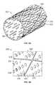
- FIG. 7is a perspective view of one embodiment of a monolithic device preserving flow in a blood vessel while diverting flow from an aneurysm.
- FIG. 8Ais a perspective view of one embodiment the monolithic device.
- FIG. 8Bis an enlarged view of a photograph of the distal end of one embodiment of the monolithic device, in the expanded configuration at 50 ⁇ magnification.
- FIG. 8Cis an enlarged view of a photograph of the embodiment of the monolithic device of FIG. 8B , in the unexpanded configuration at 100 ⁇ magnification.
- FIG. 8Dis an enlarged view of a photograph of the distal end of the embodiment of the monolithic device of FIG. 8B , in the unexpanded configuration at 100 ⁇ magnification.
- FIG. 9is an enlarged view of a photograph of one embodiment of the monolithic device in a bent configuration.
- FIG. 10is an enlarged side view of a photograph of one embodiment of the monolithic device crimped around a guidewire.
- FIG. 11Ais a side view of an enlarged photograph of the distal end of an alternative embodiment of the monolithic device.
- FIG. 11Bis an exploded version of portion 11 B from FIG. 11A of the side view of the distal end of an alternative embodiment of the monolithic device.
- FIG. 11Cis a side view of an enlarged photograph of the distal end of the alternative embodiment of the monolithic device of FIG. 11A .
- the present inventioncomprises a monolithic medical device and a method of making monolithic medical devices.
- the monolithic devicemay comprise a covered stent 300 , as shown in FIG. 3A .
- the monolithic devicecan be used to prevent plaque from embolizing downstream during a stent placement.
- the covered (or webbed) stent 300comprises of a plurality of scaffolding members 310 and a mesh patterned members 320 webbed between the scaffolding members 310 .
- the mesh patterned member 320 webbed between the scaffolding members 310surround a lumen 302 and may generally expand from a contracted state to an expanded state.
- the scaffold members 310may generally for polygonal shapes, including, but not limited to, squares, rectangles, trapezoids, pentagons, diamond-shapes, hexagons, octagons, circles, ellipses, and the like.
- the mesh patterned member 320may general includes a plurality of openings 330 traversing the thickness of the mesh patterned member 320 .
- the mesh patterned members 320includes a surface on which a pattern of openings 330 is formed.
- the covered stent 300can be monolithically constructed out of one starting work-piece tube using subtractive processing.
- the covered stent made monolithicallyis favored due the fact that the tedious and often questionable joining/assembly of the two components as historically achieved could possibly be circumvented, in-turn potentially improving quality and performance while reducing overall costs.
- the monolithically constructed covered stentensures a secure bond between the scaffolding members 310 and the mesh patterned member 320 webbed between the scaffolding members 310 about the entire length and circumference of the device.
- FIG. 1highlights the process flow steps 100 of how the monolithic covered stent may be made according to one embodiment.
- a start tubeis prepared 105 , and then photoresist is applied to the start tube 110 .
- the start tubemay be a wrought metal, polymer, composite, or ceramic tube, or may be vacuum deposited metal or polymer tube.
- the start tubemay be fabricated by a deposition procedure as disclosed in commonly assigned U.S. patent application Ser. No. 13/788,081, filed Mar. 7, 2013 or in U.S. patent application Ser. No. 13/099,980, filed May 3, 2011, herein incorporated by reference in their entireties.
- the monolithic devicemay be produced from drawn metal or polymer tubing, or wrought tubing, provided that fatigue life is adequate.
- Radiopaque markerscould be added as an interdispersed deposited layer or a ternary alloy deposition (e.g., NiTiTa or NiTiNb) if vacuum deposition is used.
- a ternary alloy depositione.g., NiTiTa or NiTiNb
- Different metal layersmay be used to form the monolithic device. The positioning of the layers can be optimized for mechanical, or other reasons.
- ternary additions to binary Nitinolcan be used to strengthen or otherwise alter the material properties, allowing for lower profile devices, enhanced fatigue resistance, etc. These ternary additions can also double as radiopacity enhancers.
- the stent patternis then exposed 115 and the stent pattern's exposed photoresist is developed 120 .
- Methods for UV exposure of the patterncan include using contact mask methods, non-contact methods (e.g., DLP pattern projection), or UV laser writing. Then the stent pattern is chemically machined 125 , and the photoresist is removed 130 . Photoresist is then reapplied 135 , and the mesh pattern is exposed 140 . The exposed photoresist for the mesh pattern members is developed 142 , and the mesh pattern members are chemically machined 144 . The final step is to remove the photoresist 146 . Photo-chemical machining enables the tiered levels of tube wall material from which the stent scaffold and fine mesh patterned members can be made. Steps 105 through 130 shown in FIG.
- Steps 135 through 146highlight methods for machining the fine mesh pattern(s) within the cells of the larger stent struts either by using photo-chemical or laser machining The machining and patterning herewith may use the methods of commonly assigned U.S. patent application Ser. No. 13/801,173, filed Mar. 13, 2013, incorporated by reference herein in its entirety.
- the mesh pattern membersmay include grooved features along with the openings on at least one surface of the monolithic device.
- the patternmay be a plurality of microgrooves imparted onto the luminal and/or abluminal surface of the monolithic device, as is more fully described in U.S. patent application Ser. No. 13/654,923, filed Oct. 18, 2012, which is commonly assigned with the present application and is hereby incorporated by reference in its entirety.
- the plurality of microgroovesmay be formed either as a post-deposition process step, such as by etching, or during deposition, such as by depositing the stent-forming material onto a mandrel which has a microtopography on the surface thereof which causes the metal to deposit with the microgroove pattern as part of the deposited material.
- FIG. 2An alternative process 200 is shown in FIG. 2 , which comprises the preparation of the start tube 205 , and applying a photoresist to the start tube 210 . Then, the stent pattern is exposed 215 and the photoresist is developed for the stent pattern 220 . The stent pattern is then chemically machined 225 , and the photoresist is removed 230 . The last step is to laser machine the mesh pattern 240 .
- the processes 100 and 200 previously mentionedinclude the use of electrophoretically depositable (ED) photoresist, and photochemical machining of a 3D work-piece geometry to make the monolithic medical device.
- ED photoresistallows for pattern designs that encompass different circumferential planes, which is necessary for the monolithic covered stent to resolve the stent and mesh patterns.
- a vast assortment of stent and mesh patternsmay be formed which enable optimal designs.
- the photoresistbe applied to the work-piece tube (or other geometry) electrophoretically using either an anionic or cationic electrophoretic depositable photoresist
- the photoresistmay be applied using other techniques including but not limited to lamination, spraying, dipping, or Chemical Vapor Deposition (CVD).
- CVDChemical Vapor Deposition
- chemical machininghas been initially disclosed as the method for through-resist machining, other selective methods including but not limited to reactive ion etching (RIE), dry etching, electrochemical machining, or photo-activated chemical machining may be used.
- RIEmay utilize Cl or F (or mixtures thereof) based chemistries or others compatible with etching SS, PtCr, Nitinol, SS, CoCr alloys (to include MP35N and L-605). Dry etching may use inert gases such as Ar, Kr, Xe, and the like.
- the device 300includes a plurality of scaffold members 310 and mesh patterned members 320 webbed between the scaffolding members 310 .
- the scaffolding members 310may include a raised surface feature that includes a thickness T above the surface of the mesh patterned members 320 .
- the mesh patterned members 320may form generally polygonal shapes with the scaffolding members 310 forming the borders thereabout.
- a plurality of openings 330may be patterned in a first row 332 , a second row 334 , and/or a third row 336 in the mesh patterned members 320 .
- the scaffolding members 310may intersect at points 312 to form larger hinge regions 312 to allow for the expansion of the scaffolding members 310 .
- the mesh patterned members 320have a length or a width between at least 0.1 to 50.0 microns in length or width, alternatively between at least 10.0 to 100.0 microns in length or width, or alternatively between at least 1.0 to 1000.0 microns in length or width.
- the length and/or width of the mesh patterned members 320may be selected according to the type of pattern and openings employed with the mesh patterned members.
- the monolithic medical device 400comprises a plurality of scaffold members 410 interconnected by a plurality of mesh patterned members 420 .
- the mesh patterned members 420may include a plurality of openings 430 throughout the surface of the mesh patterned members 420 , and exterior borders 422 around the perimeters of the mesh patterned members 420 , as shown in FIG. 4B .
- the plurality of openings 430may generally form a diamond shaped pattern 432 .
- the generally diamond shaped pattern 432may generally include between at least 4 to 16 openings 430 in a mesh patterned member 420 .
- the scaffold members 410include a thickness T that is raised from the surface of the mesh patterned members 420 , and the scaffold members 410 intersect at hinge regions 412 .
- the monolithic medical device 500may comprise a plurality of scaffold members 510 interconnected by a plurality of mesh patterned members 520 .
- the mesh patterned members 520may include a plurality of openings 530 in the corner features of the mesh patterned members 520 , and a plurality of L-shaped openings 532 traversing the width and length of the mesh patterned members 520 .
- each corner opening 530includes at least 2 to 5 L-shaped openings 532 of progressively larger L-shapes.
- corner openings 530 adjacent to scaffold members 510may be a different size.
- the scaffold members 510include a thickness T that is raised from the surface of the mesh patterned members 520 , and the scaffold members 510 intersect at hinge regions 512 .
- FIGS. 6A-6Bthe photoresist and the exposed metal from the metal tube 600 are shown after steps 105 through 120 and steps 205 through 220 .
- the exposed photoresist 610defines the location of the scaffold members and the exposed metal 620 is shown for locations of the mesh pattern members.
- FIG. 6Cshows the result of steps 125 through 130 and steps 225 through 230 , displaying the scaffold members 630 and mesh pattern surface 640 that can be later patterned by laser machining or chemical machining
- the monolithic devicemay be used with any type of cell, which cell has a cellular membrane.
- Most distinct cell typesarise from a single totipotent cell that differentiates into hundreds of different cell types during the course of development.
- Multicellular organismsare composed of cells that fall into two fundamental types: germ cells and somatic cells.
- somatic cellswill become more specialized and form the three primary germ layers: ectoderm, mesoderm, and endoderm. After formation of the three germ layers, cells will continue to specialize until they reach a terminally differentiated state that is much more resistant to changes in cell type than its progenitors.
- the ectodermdifferentiates to form the nervous system (spine, peripheral nerves and brain), tooth enamel and the epidermis (the outer part of integument). It also forms the lining of mouth, anus, nostrils, sweat glands, hair and nails.
- the endodermforms the gastrointestinal tract cells, the respiratory tract cells, the endocrine glands and organ cells, the auditory system cells, and the urinary system cells.
- the mesodermforms mesenchyme (connective tissue), mesothelium, non-epithelial blood cells and coelomocytes.
- the inventive monolithic devicesmay be intravascular stents, stent-grafts, grafts, heart valves, venous valves, filters, occlusion devices, catheters, sheaths, osteal implants, implantable contraceptives, implantable antitumor pellets or rods, shunts and patches, pacemakers, needles, temporary fixation rods, medical wires or medical tubes for any type of medical device, or other implantable medical devices, as will also be hereinafter described.
- a pacemakeror artificial pacemaker, so as not to be confused with the heart's natural pacemaker
- the electrodesmay be covered by tubing or other material that includes a surface that may require endothelialization and grooves thereon. Earrings and other piercings may benefit from the topographical features, as well as any other implant, whether the implant is an organic, inorganic, mechanical, electrical, or biological device.
- the monolithic deviceis formed from a metal, a polymer, a composite, or a ceramic material.
- materials to make the inventive stentsare chosen for their biocompatibility, mechanical properties, i.e., tensile strength, yield strength, and their ease of deposition include the following: elemental titanium, vanadium, aluminum, nickel, tantalum, zirconium, chromium, silver, gold, silicon, magnesium, niobium, scandium, platinum, cobalt, palladium, manganese, molybdenum and alloys thereof, such as zirconium-titanium-tantalum alloys, nitinol, and stainless steel.
- the present inventionmay comprise a monolithic medical device and a method of using the monolithic medical device.
- the monolithic device 700may comprise a low profile stent that promotes thrombosis of an aneurysm 12 by diverting blood flow through the parent vessel 10 , as shown in FIG. 7 .
- the monolithic device 700comprises an ultra-dense stent cell pattern 710 including a plurality of structural members 720 that diverts the majority of blood flow without restricting blood flow completely, thus providing the opportunity for the aneurysm to shrink over time.
- the monolithic deviceincludes an expanded state and a contracted state for delivery.
- the monolithic devicemay include an end ring 730 on the proximal and/or distal ends.
- This monolithic devicemay alternatively be used as an embolic protection stent cover or in any other application where a low profile, high density pattern is desirable.
- the monolithic devicemay be used a liner for a catheter tip, scaffold/indenter for drug-eluting balloons, and vascular stenting, including; vulnerable plaque containment (carotid, coronary), flow diversion, adjunct to coiling (neurological), and vascular perforation.
- the expanded monolithic device 700includes the end ring 730 on either the proximal or distal end or both ends of the device 700 .
- the ultra-dense cell pattern 710includes a first Z-pattern 740 of the structural members 720 and a second Z-pattern 742 of the structural members 720 .
- the first and second Z patterns 740 , 742form a plurality of peaks 744 and a plurality of troughs 746 along the longitudinal axis 702 .
- the first and second Z patterns 740 , 742are interconnected by a plurality of curved interconnecting members 750 that connect a peak 744 of the first Z pattern 740 with a trough 746 of the second Z pattern 742 .
- the curved interconnecting members 750do not connect adjacent peaks 744 of the first Z pattern to adjacent troughs 746 of the second Z pattern.
- the curved interconnecting members 750connect a peak 744 of the first Z pattern with a trough 746 of the second Z pattern that is displaced along the longitudinal axis and at least one trough below the peak 744 along the vertical axis 704 of the monolithic device 700 .
- the curved interconnecting members 750may connect a peak 744 of the first Z pattern 740 with a trough 746 of the second Z pattern 742 that is at least two troughs below the peak 744 along the vertical axis 704 of the monolithic device.
- This connection of the peak 744 of the first Z pattern 740 with a nonadjacent trough 746 of the second Z pattern 742 by the curved interconnecting member 750forms the curved portion of the curved interconnecting member 750 .
- the second Z pattern 742is connected with a second set of curved interconnecting members 752 at the peak 744 that is angled at an opposite angle or non-parallel angle from the first set of the curved interconnecting members 750 .
- the opposite or non-parallel anglemay be between about 10-100 degrees, alternatively, between about 20-90 degrees, alternatively, between about 30-80 degrees.
- the tight first and second Z patterns 740 , 742allow the monolithic device to maintain adequate radial force despite its small size.
- the interior cell structure 710could be modified to optimize performance.
- the end ring 730includes an end Z pattern 732 comprising a plurality of peaks 734 and a plurality of troughs 736 .
- a peak 734 of the end ring 730connects to every other trough 746 of the first Z pattern 740 , such that the peak 734 of each end Z pattern 730 does not connect to adjacent troughs 746 of the first Z pattern 740 .
- This connectionforms a larger end Z pattern 732 .
- the peak 734 of the end Z pattern 732connects to every third trough 746 of the first Z pattern 740 , while in other embodiments the peak 734 may connect to every fourth trough 746 of the first Z pattern 740 .
- the modified end rings of the stent geometrycan prevent cell migration as well as be used for marker placement. Alternatively, the end rings could be modified or eliminated completely from the monolithic device.
- the monolithic device 700may be bent along its longitudinal axis to conform to the shape or curvature of a blood vessel. After being deployment and bending along its longitudinal axis, the monolithic device 700 is retrievable.
- the spacing between the curved interconnecting members 750 and 752is maintained between about least 0.1 and 20 microns, and the spacing between the peaks 744 and the troughs 746 of the first and second Z patterns 740 , 742 is maintained between about at least 0.1 and 20 microns to permit blood flow therebetween.
- the monolithic device 700is able to bend, while the wall thickness of the monolithic device 700 is between about 0.1-100.0 microns.
- the monolithic device 700may be crimped around a guide wire 790 .
- the crimpingmay collapse the first Z pattern 740 , the end ring 730 , and the curved interconnecting members 750 to a diameter between about 0.2 and 2.0 mm.
- the monolithic device 700may expand to a diameter between about 2.0 and 7.0 mm while maintaining adequate radial force and wall apposition.
- the wall thickness of the monolithic device 700is less than about 75 microns.
- the monolithic device 800comprises a dense cell pattern 810 and may include circumferential ring members comprising a first Z pattern 840 , a second Z pattern 842 , and a plurality of looped or generally S-shaped interconnecting members 850 connecting the first Z pattern 840 and the second Z pattern 842 .
- the proximal and/or distal end of the monolithic device 800may include an end ring 830 in an end Z pattern 832 that is connected to the first Z pattern 840 .
- the first and second Z patterns 840 , 842include a plurality of interconnected peaks 844 and troughs 846 . As shown in FIG.
- the peak 844 of the first Z pattern 840is connected to the first end 852 of the looped or S-shaped interconnecting member 850 , whereby the first end 852 of the looped or S-shaped interconnected member 850 forms a generally first loop or first generally elliptical section 854 facing the proximal end of the monolithic device 800 , while the first loop or first generally elliptical section 854 connects to a second loop or second generally elliptical section 856 that faces in the opposite direction of the first loop or first generally elliptical section 854 and towards the distal end of the monolithic device.
- the second loop or second generally elliptical section 856ends at the second end 858 that is connected to the trough 846 of the second Z pattern 842 .
- the first loop or first generally elliptical section 854fits within the peak 844 of the second Z pattern 844
- the second loop or second generally elliptical section 856fits within the trough 846 of the first Z pattern 840 .
- the end ring 830includes an end Z pattern 832 , which includes a plurality of interconnected peaks 834 and troughs 836 .
- the peak 834 of the end Z pattern 832connects with the trough 846 of the first Z pattern 840 , and in one embodiment, the peak 834 of the end Z pattern 832 connects with every other trough 846 of the first Z pattern 840 , or every third trough 846 of the first Z pattern 840 .
- the end Z pattern 832may include additional peaks 834 b and troughs 836 b , whereby the peaks 834 b are to the troughs 836 , as to further extend the distal end.
- a radiopaque layer 860 of Tantalummay be between two layers of metal for the monolithic device 800 . The Tantalum is the white layer 860 that appears as a stripe along the side walls of the stent, as shown in FIG. 11B . Alternatively, radiopaque layer 860 may comprise another biocompatible radiopaque material.
- the monolithic deviceis formed from a material that is a metal, a polymer, a composite, or a ceramic material.
- materials to make the inventive stentsare chosen for their biocompatibility, mechanical properties, i.e., tensile strength, yield strength, and their ease of deposition include the following: elemental titanium, vanadium, aluminum, nickel, tantalum, zirconium, chromium, silver, gold, silicon, magnesium, niobium, scandium, platinum, cobalt, palladium, manganese, molybdenum and alloys thereof, such as zirconium-titanium-tantalum alloys, nitinol, and stainless steel.
- the first generally elliptical section 854has a major axis generally parallel to a longitudinal axis of the intravascular stent device.
- the first generally elliptical sectionfurther comprises a first portion 855 connected to a peak of a first circumferential ring member at a first end of the major axis and to a second portion 857 at a second end of the major axis.
- the second portion 857is further coupled to the second generally elliptical section 856 proximate to the first end of the major axis.
- the second generally elliptical section 856has a second major axis generally parallel to a longitudinal axis of the intravascular stent device and circumferentially off-set from the major axis.
- the second generally elliptical section 856further comprises a third portion 859 coupled to the first generally elliptical section 854 proximate a second end of the second major axis and further coupled to a fourth portion 861 at a first end of the second major axis.
- the fourth portion 861is further connected to a peak of the second circumferential ring member at the second end of the second major axis.
- the intravascular stent devicefurther comprises a curvilinear member 863 connecting the second portion 857 of the first generally elliptical section 854 to the third portion 859 of the second generally elliptical section 856 .
- the curvilinear member 863is oriented generally along a longitudinal axis of the intravascular stent device.
- the intravascular stent devicefurther comprises hinge regions 865 at the junctions of the portions of the generally elliptical sections.
- a hinge region 865interconnects the first portion 855 and the second portion 857 of the first generally elliptical section 854 at the second end of the major axis of the first generally elliptical section 854 and a second hinge region 865 interconnects the third portion 859 and the fourth portion 861 of the second generally elliptical section 856 at the first end of the major axis connect of the second generally elliptical section 856 .
- the monolithic device 700may be fabricated by a procedure, as described in U.S. application Ser. No. 13/788,081, filed Mar. 7, 2013 or in U.S. patent application Ser. No. 13/099,980, filed May 3, 2011, herein incorporated by reference in their entireties.
- a coating of deposited metal film or polymeris about 0.1-100.0 microns in a tube form, which is laser cut using ultra short pulsed femtosecond laser to minimize heat affected zones and recast.
- the final monolithic devicemay be heat treated to optimize spring back effects.
- the stent's one piece constructionallows many advantages over many currently available braided stent designs, such as a lower profile, self-expanding, and ease of manufacturing.
- the monolithic devicemay be produced from drawn metal or polymer tubing, wrought tubing, provided that fatigue life is adequate. Radiopaque markers could be added as an interdispersed deposited layer if vacuum deposition is used. Different metal layers may be used to form the monolithic device.
- the methodfurther comprises the step of patterning at least one surface of the monolithic device.
- the patterningcomprises laser patterning to impart at least one feature on the at least one surface of the monolithic device.
- the patternis a series of grooves on at least one surface of the monolithic device, preferably the surface that will comprise the inner diameter of the finished stent.
- the patternmay be a plurality of microgrooves imparted onto the luminal and/or abluminal surface of the monolithic device, as is more fully described in U.S. patent application Ser. No. 13/654,923, filed Oct. 18, 2012, which is commonly assigned with the present application and is hereby incorporated by reference in its entirety.
- the plurality of microgroovesmay be formed either as a post-deposition process step, such as by etching, or during deposition, such as by depositing the stent-forming material onto a mandrel which has a microtopography on the surface thereof which causes the metal to deposit with the microgroove pattern as part of the deposited material.
- the inventive monolithic devicesmay be intravascular stents, stent-grafts, grafts, heart valves, venous valves, filters, occlusion devices, catheters, sheaths, osteal implants, implantable contraceptives, implantable antitumor pellets or rods, shunts and patches, pacemakers, needles, temporary fixation rods, medical wires or medical tubes for any type of medical device, or other implantable medical devices, as will also be hereinafter described.
- a pacemakeror artificial pacemaker, so as not to be confused with the heart's natural pacemaker
- the electrodesmay be covered by tubing or other material that includes a surface that may require endothelialization and grooves thereon. Earrings and other piercings may benefit from the topographical features, as well as any other implant, whether the implant is an organic, inorganic, mechanical, electrical, or biological device.
- the monolithic devicemay be used with any type of cell, which cell has a cellular membrane.
- Most distinct cell typesarise from a single totipotent cell that differentiates into hundreds of different cell types during the course of development.
- Multicellular organismsare composed of cells that fall into two fundamental types: germ cells and somatic cells.
- somatic cellswill become more specialized and form the three primary germ layers: ectoderm, mesoderm, and endoderm. After formation of the three germ layers, cells will continue to specialize until they reach a terminally differentiated state that is much more resistant to changes in cell type than its progenitors.
- the ectodermdifferentiates to form the nervous system (spine, peripheral nerves and brain), tooth enamel and the epidermis (the outer part of integument). It also forms the lining of mouth, anus, nostrils, sweat glands, hair and nails.
- the endodermforms the gastrointestinal tract cells, the respiratory tract cells, the endocrine glands and organ cells, the auditory system cells, and the urinary system cells.
- the mesodermforms mesenchyme (connective tissue), mesothelium, non-epithelial blood cells and coelomocytes.
- the apparatuscomprises: an ultra-dense stent cell pattern including a plurality of structural members that diverts the majority of blood flow without restricting blood flow completely.
Landscapes
- Health & Medical Sciences (AREA)
- Engineering & Computer Science (AREA)
- Biomedical Technology (AREA)
- General Health & Medical Sciences (AREA)
- Veterinary Medicine (AREA)
- Cardiology (AREA)
- Oral & Maxillofacial Surgery (AREA)
- Transplantation (AREA)
- Heart & Thoracic Surgery (AREA)
- Vascular Medicine (AREA)
- Life Sciences & Earth Sciences (AREA)
- Animal Behavior & Ethology (AREA)
- Physics & Mathematics (AREA)
- Public Health (AREA)
- Optics & Photonics (AREA)
- Prostheses (AREA)
- Media Introduction/Drainage Providing Device (AREA)
- Chemical & Material Sciences (AREA)
- Materials For Medical Uses (AREA)
- Chemical Kinetics & Catalysis (AREA)
- Electrochemistry (AREA)
- Materials Engineering (AREA)
- Metallurgy (AREA)
- Organic Chemistry (AREA)
Abstract
Description
Claims (11)
Priority Applications (3)
| Application Number | Priority Date | Filing Date | Title |
|---|---|---|---|
| US14/213,974US10143574B2 (en) | 2013-03-14 | 2014-03-14 | Monolithic medical devices, methods of making and using the same |
| US16/192,122US11291569B2 (en) | 2013-03-14 | 2018-11-15 | Monolithic medical devices, methods of making and using the same |
| US29/670,317USD888245S1 (en) | 2014-03-14 | 2018-11-15 | Stent device |
Applications Claiming Priority (3)
| Application Number | Priority Date | Filing Date | Title |
|---|---|---|---|
| US201361783330P | 2013-03-14 | 2013-03-14 | |
| US201361788767P | 2013-03-15 | 2013-03-15 | |
| US14/213,974US10143574B2 (en) | 2013-03-14 | 2014-03-14 | Monolithic medical devices, methods of making and using the same |
Related Child Applications (2)
| Application Number | Title | Priority Date | Filing Date |
|---|---|---|---|
| US29/670,317ContinuationUSD888245S1 (en) | 2014-03-14 | 2018-11-15 | Stent device |
| US16/192,122ContinuationUS11291569B2 (en) | 2013-03-14 | 2018-11-15 | Monolithic medical devices, methods of making and using the same |
Publications (2)
| Publication Number | Publication Date |
|---|---|
| US20140296965A1 US20140296965A1 (en) | 2014-10-02 |
| US10143574B2true US10143574B2 (en) | 2018-12-04 |
Family
ID=51581433
Family Applications (2)
| Application Number | Title | Priority Date | Filing Date |
|---|---|---|---|
| US14/213,974ActiveUS10143574B2 (en) | 2013-03-14 | 2014-03-14 | Monolithic medical devices, methods of making and using the same |
| US16/192,122ActiveUS11291569B2 (en) | 2013-03-14 | 2018-11-15 | Monolithic medical devices, methods of making and using the same |
Family Applications After (1)
| Application Number | Title | Priority Date | Filing Date |
|---|---|---|---|
| US16/192,122ActiveUS11291569B2 (en) | 2013-03-14 | 2018-11-15 | Monolithic medical devices, methods of making and using the same |
Country Status (6)
| Country | Link |
|---|---|
| US (2) | US10143574B2 (en) |
| EP (1) | EP2967939A4 (en) |
| JP (2) | JP2016512751A (en) |
| AU (2) | AU2014236249B2 (en) |
| CA (1) | CA2905515C (en) |
| WO (1) | WO2014153162A1 (en) |
Families Citing this family (6)
| Publication number | Priority date | Publication date | Assignee | Title |
|---|---|---|---|---|
| GB2514135B (en)* | 2013-05-14 | 2015-04-15 | Cook Medical Technologies Llc | Implantable flow diverter |
| US10321984B2 (en)* | 2016-02-19 | 2019-06-18 | Cook Medical Technologies Llc | Spiral flow inducing stent and canula cut method of making same |
| US10893869B2 (en)* | 2016-03-24 | 2021-01-19 | Covidien Lp | Thin wall constructions for vascular flow diversion |
| EP3763340B1 (en)* | 2016-03-24 | 2024-08-14 | Covidien LP | Vascular flow diversion |
| US10835398B2 (en) | 2017-11-03 | 2020-11-17 | Covidien Lp | Meshes and devices for treating vascular defects |
| DE102023104170A1 (en)* | 2023-02-20 | 2024-08-22 | Acandis Gmbh | Medical device and treatment system |
Citations (34)
| Publication number | Priority date | Publication date | Assignee | Title |
|---|---|---|---|---|
| US4733665A (en) | 1985-11-07 | 1988-03-29 | Expandable Grafts Partnership | Expandable intraluminal graft, and method and apparatus for implanting an expandable intraluminal graft |
| US5102417A (en) | 1985-11-07 | 1992-04-07 | Expandable Grafts Partnership | Expandable intraluminal graft, and method and apparatus for implanting an expandable intraluminal graft |
| US5195984A (en) | 1988-10-04 | 1993-03-23 | Expandable Grafts Partnership | Expandable intraluminal graft |
| US5800520A (en)* | 1995-03-10 | 1998-09-01 | Medtronic, Inc. | Tubular endoluminar prosthesis having oblique ends |
| US20020095207A1 (en) | 2001-01-15 | 2002-07-18 | Yousuke Moriuchi | Stent |
| US20020193862A1 (en)* | 2001-06-14 | 2002-12-19 | Vladimir Mitelberg | Intravascular stent device |
| US20030218735A1 (en) | 1997-04-08 | 2003-11-27 | Thomas Trozera | Stent manufacturing apparatus |
| US20030225449A1 (en)* | 2002-05-30 | 2003-12-04 | Denison Andy E. | Intravascular stents |
| US20040024445A1 (en)* | 2002-07-31 | 2004-02-05 | Dickson Todd R. | Flexible and conformable stent and method of forming same |
| WO2004010902A1 (en) | 2002-07-31 | 2004-02-05 | Unison Therapeutics, Inc. | Flexible and conformable stent and method of forming same |
| US20040106985A1 (en)* | 1996-04-26 | 2004-06-03 | Jang G. David | Intravascular stent |
| US20040230291A1 (en)* | 2000-03-01 | 2004-11-18 | Jacob Richter | Longitudinally flexible stent |
| US20040236404A1 (en)* | 1996-03-05 | 2004-11-25 | Penn Ian M. | Expandable stent and method for delivery of same |
| US20060086440A1 (en)* | 2000-12-27 | 2006-04-27 | Boylan John F | Nitinol alloy design for improved mechanical stability and broader superelastic operating window |
| US20060224229A1 (en)* | 2005-03-30 | 2006-10-05 | Terumo Kabushiki Kaisha | Stent and stent delivery device |
| US20080132989A1 (en)* | 2004-06-28 | 2008-06-05 | Xtent, Inc. | Devices and methods for controlling expandable prostheses during deployment |
| US20080294239A1 (en)* | 2007-05-23 | 2008-11-27 | Abbott Laboratories Vascular Enterprises Limited | Flexible stent with elevated scaffolding properties |
| US7594927B2 (en) | 2001-03-01 | 2009-09-29 | Cordis Corporation | Flexible stent |
| US20100087913A1 (en)* | 2001-12-03 | 2010-04-08 | Intek Technology L.L.C. | Temporary, Repositionable Or Retrievable Intraluminal Devices |
| US20100249904A1 (en)* | 2007-09-27 | 2010-09-30 | Terumo Kabushiki Kaisha | Stent and living organ dilator |
| WO2010124286A1 (en) | 2009-04-24 | 2010-10-28 | Flexible Stenting Solutions, Inc. | Flexible devices |
| US20110022157A1 (en)* | 2007-10-25 | 2011-01-27 | Jacques Essinger | Stents, Valved-Stents, and Methods and Systems for Delivery Thereof |
| US20120009325A1 (en) | 2010-07-12 | 2012-01-12 | Medtronic Vascular, Inc. | Method of Making a Stent with Hollow Struts |
| US20120136427A1 (en) | 1999-11-19 | 2012-05-31 | Advanced Bio Prosthetic Surfaces, Ltd., A Wholly Owned Subsidiary Of Palmaz Scientific, Inc. | Implantable medical devices having controlled surface properties for improved healing response |
| US20120209366A1 (en)* | 2011-02-15 | 2012-08-16 | Terumo Kabushiki Kaisha | Stent and stent delivery system |
| US20120282391A1 (en) | 2011-05-03 | 2012-11-08 | Palmaz Scientific, Inc. | Endoluminal implantable surfaces, stents, and grafts and method of making same |
| US20120310319A1 (en) | 2010-12-21 | 2012-12-06 | Tieu Tai D | Stent |
| US20130268055A1 (en)* | 2012-03-07 | 2013-10-10 | Orbusneich Medical, Inc. | Medical device for implantation into luminal structures |
| US20140042022A1 (en) | 2012-08-09 | 2014-02-13 | Palmaz Scientific, Inc. | Inverted cylindrical magnetron (icm) system and methods of use |
| US20140114435A1 (en) | 2012-10-18 | 2014-04-24 | Palmaz Scientific, Inc. | Topographical features and patterns on a surface of a medical device and methods of making the same |
| US20140109383A1 (en) | 2011-05-09 | 2014-04-24 | Palmaz Scientific, Inc. | Method for making topographical features on a surface of a medical device |
| US20150112422A1 (en)* | 2013-10-22 | 2015-04-23 | Orbusneich Medical, Inc. | Medical Device for Implantation into Luminal Structures Incorporating Corrugated Structural Elements |
| WO2015070124A2 (en) | 2013-11-08 | 2015-05-14 | Palmaz Scientific, Inc. | Monolithic medical devices and methods of use |
| US20170079816A1 (en)* | 2015-09-18 | 2017-03-23 | Terumo Kabushiki Kaisha | Stent |
Family Cites Families (31)
| Publication number | Priority date | Publication date | Assignee | Title |
|---|---|---|---|---|
| US6241760B1 (en)* | 1996-04-26 | 2001-06-05 | G. David Jang | Intravascular stent |
| JP4636634B2 (en)* | 1996-04-26 | 2011-02-23 | ボストン サイエンティフィック サイムド,インコーポレイテッド | Intravascular stent |
| US5824059A (en)* | 1997-08-05 | 1998-10-20 | Wijay; Bandula | Flexible stent |
| US6059822A (en)* | 1997-08-22 | 2000-05-09 | Uni-Cath Inc. | Stent with different mesh patterns |
| US5948016A (en)* | 1997-09-25 | 1999-09-07 | Jang; G. David | Intravascular stent with non-parallel slots |
| US6096175A (en)* | 1998-07-17 | 2000-08-01 | Micro Therapeutics, Inc. | Thin film stent |
| US5911754A (en)* | 1998-07-24 | 1999-06-15 | Uni-Cath Inc. | Flexible stent with effective strut and connector patterns |
| US6042597A (en)* | 1998-10-23 | 2000-03-28 | Scimed Life Systems, Inc. | Helical stent design |
| JP3654627B2 (en)* | 2000-04-20 | 2005-06-02 | 川澄化学工業株式会社 | Stent |
| US20030176914A1 (en)* | 2003-01-21 | 2003-09-18 | Rabkin Dmitry J. | Multi-segment modular stent and methods for manufacturing stents |
| US6969402B2 (en)* | 2002-07-26 | 2005-11-29 | Syntheon, Llc | Helical stent having flexible transition zone |
| US6878162B2 (en)* | 2002-08-30 | 2005-04-12 | Edwards Lifesciences Ag | Helical stent having improved flexibility and expandability |
| CA2558128C (en)* | 2004-03-02 | 2013-01-08 | Boston Scientific Scimed, Inc. | Medical devices including metallic films and polymer layers |
| EP1604697A1 (en)* | 2004-06-09 | 2005-12-14 | J.A.C.C. GmbH | Implantable device |
| US20060030929A1 (en) | 2004-08-09 | 2006-02-09 | Scimed Life Systems, Inc. | Flap-cover aneurysm stent |
| MX2007005168A (en) | 2004-10-26 | 2007-10-10 | Johnson & Johnson | Stent having phased hoop sections. |
| US8262720B2 (en)* | 2004-12-02 | 2012-09-11 | Nitinol Development Corporation | Prosthesis comprising dual tapered stent |
| JP4846414B2 (en)* | 2005-03-30 | 2011-12-28 | テルモ株式会社 | In vivo indwelling stent and biological organ dilator |
| JP5523700B2 (en) | 2005-04-04 | 2014-06-18 | フレキシブル ステンティング ソリューションズ,インク. | Flexible stent |
| US20070061006A1 (en) | 2005-09-14 | 2007-03-15 | Nathan Desatnik | Methods of making shape memory films by chemical vapor deposition and shape memory devices made thereby |
| US20070088428A1 (en)* | 2005-09-15 | 2007-04-19 | Cappella, Inc. | Intraluminal device with asymmetric cap portion |
| US20070250148A1 (en)* | 2005-09-26 | 2007-10-25 | Perry Kenneth E Jr | Systems, apparatus and methods related to helical, non-helical or removable stents with rectilinear ends |
| US8956400B2 (en) | 2005-10-14 | 2015-02-17 | Flexible Stenting Solutions, Inc. | Helical stent |
| US20100010622A1 (en)* | 2006-03-13 | 2010-01-14 | Abbott Laboratories | Hybrid segmented endoprosthesis |
| JP5061181B2 (en) | 2006-04-07 | 2012-10-31 | ピナンブラ、インク | System and method for occluding an aneurysm |
| US8182890B2 (en)* | 2007-01-19 | 2012-05-22 | Elixir Medical Corporation | Biodegradable endoprostheses and methods for their fabrication |
| US8623070B2 (en)* | 2007-03-08 | 2014-01-07 | Thomas O. Bales | Tapered helical stent and method for manufacturing the stent |
| US10092427B2 (en)* | 2009-11-04 | 2018-10-09 | Confluent Medical Technologies, Inc. | Alternating circumferential bridge stent design and methods for use thereof |
| US9028540B2 (en)* | 2011-03-25 | 2015-05-12 | Covidien Lp | Vascular stent with improved vessel wall apposition |
| US20140031917A1 (en)* | 2012-07-25 | 2014-01-30 | Medtronic Vascular, Inc. | Matched End Stiffness Stent and Method of Manufacture |
| US20140114434A1 (en)* | 2012-10-22 | 2014-04-24 | Orbusneich Medical, Inc. | Medical device for implantation into luminal structures |
- 2014
- 2014-03-14JPJP2016503076Apatent/JP2016512751A/enactivePending
- 2014-03-14WOPCT/US2014/029370patent/WO2014153162A1/enactiveApplication Filing
- 2014-03-14CACA2905515Apatent/CA2905515C/enactiveActive
- 2014-03-14USUS14/213,974patent/US10143574B2/enactiveActive
- 2014-03-14EPEP14768830.3Apatent/EP2967939A4/enactivePending
- 2014-03-14AUAU2014236249Apatent/AU2014236249B2/enactiveActive
- 2018
- 2018-11-15USUS16/192,122patent/US11291569B2/enactiveActive
- 2018-11-16AUAU2018264124Apatent/AU2018264124B2/enactiveActive
- 2018-11-26JPJP2018220280Apatent/JP7038272B2/enactiveActive
Patent Citations (37)
| Publication number | Priority date | Publication date | Assignee | Title |
|---|---|---|---|---|
| US5102417A (en) | 1985-11-07 | 1992-04-07 | Expandable Grafts Partnership | Expandable intraluminal graft, and method and apparatus for implanting an expandable intraluminal graft |
| US4733665B1 (en) | 1985-11-07 | 1994-01-11 | Expandable Grafts Partnership | Expandable intraluminal graft,and method and apparatus for implanting an expandable intraluminal graft |
| US4733665C2 (en) | 1985-11-07 | 2002-01-29 | Expandable Grafts Partnership | Expandable intraluminal graft and method and apparatus for implanting an expandable intraluminal graft |
| US4733665A (en) | 1985-11-07 | 1988-03-29 | Expandable Grafts Partnership | Expandable intraluminal graft, and method and apparatus for implanting an expandable intraluminal graft |
| US5195984A (en) | 1988-10-04 | 1993-03-23 | Expandable Grafts Partnership | Expandable intraluminal graft |
| US5800520A (en)* | 1995-03-10 | 1998-09-01 | Medtronic, Inc. | Tubular endoluminar prosthesis having oblique ends |
| US20040236404A1 (en)* | 1996-03-05 | 2004-11-25 | Penn Ian M. | Expandable stent and method for delivery of same |
| US20040106985A1 (en)* | 1996-04-26 | 2004-06-03 | Jang G. David | Intravascular stent |
| US20030218735A1 (en) | 1997-04-08 | 2003-11-27 | Thomas Trozera | Stent manufacturing apparatus |
| US20120136427A1 (en) | 1999-11-19 | 2012-05-31 | Advanced Bio Prosthetic Surfaces, Ltd., A Wholly Owned Subsidiary Of Palmaz Scientific, Inc. | Implantable medical devices having controlled surface properties for improved healing response |
| US20040230291A1 (en)* | 2000-03-01 | 2004-11-18 | Jacob Richter | Longitudinally flexible stent |
| US20060086440A1 (en)* | 2000-12-27 | 2006-04-27 | Boylan John F | Nitinol alloy design for improved mechanical stability and broader superelastic operating window |
| US20020095207A1 (en) | 2001-01-15 | 2002-07-18 | Yousuke Moriuchi | Stent |
| US7594927B2 (en) | 2001-03-01 | 2009-09-29 | Cordis Corporation | Flexible stent |
| US20020193862A1 (en)* | 2001-06-14 | 2002-12-19 | Vladimir Mitelberg | Intravascular stent device |
| US20100087913A1 (en)* | 2001-12-03 | 2010-04-08 | Intek Technology L.L.C. | Temporary, Repositionable Or Retrievable Intraluminal Devices |
| US20030225449A1 (en)* | 2002-05-30 | 2003-12-04 | Denison Andy E. | Intravascular stents |
| WO2004010902A1 (en) | 2002-07-31 | 2004-02-05 | Unison Therapeutics, Inc. | Flexible and conformable stent and method of forming same |
| US20040024445A1 (en)* | 2002-07-31 | 2004-02-05 | Dickson Todd R. | Flexible and conformable stent and method of forming same |
| US20080132989A1 (en)* | 2004-06-28 | 2008-06-05 | Xtent, Inc. | Devices and methods for controlling expandable prostheses during deployment |
| US20060224229A1 (en)* | 2005-03-30 | 2006-10-05 | Terumo Kabushiki Kaisha | Stent and stent delivery device |
| US20080294239A1 (en)* | 2007-05-23 | 2008-11-27 | Abbott Laboratories Vascular Enterprises Limited | Flexible stent with elevated scaffolding properties |
| US20100249904A1 (en)* | 2007-09-27 | 2010-09-30 | Terumo Kabushiki Kaisha | Stent and living organ dilator |
| US20110022157A1 (en)* | 2007-10-25 | 2011-01-27 | Jacques Essinger | Stents, Valved-Stents, and Methods and Systems for Delivery Thereof |
| WO2010124286A1 (en) | 2009-04-24 | 2010-10-28 | Flexible Stenting Solutions, Inc. | Flexible devices |
| US20120009325A1 (en) | 2010-07-12 | 2012-01-12 | Medtronic Vascular, Inc. | Method of Making a Stent with Hollow Struts |
| US20120310319A1 (en) | 2010-12-21 | 2012-12-06 | Tieu Tai D | Stent |
| US20120209366A1 (en)* | 2011-02-15 | 2012-08-16 | Terumo Kabushiki Kaisha | Stent and stent delivery system |
| US20120282391A1 (en) | 2011-05-03 | 2012-11-08 | Palmaz Scientific, Inc. | Endoluminal implantable surfaces, stents, and grafts and method of making same |
| US20140109383A1 (en) | 2011-05-09 | 2014-04-24 | Palmaz Scientific, Inc. | Method for making topographical features on a surface of a medical device |
| US20130268055A1 (en)* | 2012-03-07 | 2013-10-10 | Orbusneich Medical, Inc. | Medical device for implantation into luminal structures |
| US20140042022A1 (en) | 2012-08-09 | 2014-02-13 | Palmaz Scientific, Inc. | Inverted cylindrical magnetron (icm) system and methods of use |
| US20140114435A1 (en) | 2012-10-18 | 2014-04-24 | Palmaz Scientific, Inc. | Topographical features and patterns on a surface of a medical device and methods of making the same |
| US20150112422A1 (en)* | 2013-10-22 | 2015-04-23 | Orbusneich Medical, Inc. | Medical Device for Implantation into Luminal Structures Incorporating Corrugated Structural Elements |
| WO2015070124A2 (en) | 2013-11-08 | 2015-05-14 | Palmaz Scientific, Inc. | Monolithic medical devices and methods of use |
| US20170035589A1 (en)* | 2013-11-08 | 2017-02-09 | Palmaz Scientific, Inc. | Monolithic medical devices and methods of use |
| US20170079816A1 (en)* | 2015-09-18 | 2017-03-23 | Terumo Kabushiki Kaisha | Stent |
Non-Patent Citations (3)
| Title |
|---|
| European Search Report issued in corresponding foreign application, pp. 1-8 (dated Nov. 11, 2016). |
| PCT International Search Report issued in corresponding foreign application, pp. 1-3 (dated Aug. 6, 2014). |
| PCT Preliminary Report on Patentability issued in corresponding foreign application, pp. 1-12 (dated Sep. 24, 2015). |
Also Published As
| Publication number | Publication date |
|---|---|
| US20140296965A1 (en) | 2014-10-02 |
| AU2014236249A1 (en) | 2015-11-05 |
| JP2019058693A (en) | 2019-04-18 |
| CA2905515A1 (en) | 2014-09-25 |
| CA2905515C (en) | 2020-11-10 |
| AU2018264124A1 (en) | 2018-12-06 |
| US20190083286A1 (en) | 2019-03-21 |
| JP7038272B2 (en) | 2022-03-18 |
| EP2967939A4 (en) | 2016-12-14 |
| US11291569B2 (en) | 2022-04-05 |
| AU2018264124B2 (en) | 2020-03-05 |
| AU2014236249B2 (en) | 2018-11-08 |
| JP2016512751A (en) | 2016-05-09 |
| WO2014153162A1 (en) | 2014-09-25 |
| EP2967939A1 (en) | 2016-01-20 |
Similar Documents
| Publication | Publication Date | Title |
|---|---|---|
| US11291569B2 (en) | Monolithic medical devices, methods of making and using the same | |
| US12290458B2 (en) | Stents having a hybrid pattern and methods of manufacture | |
| US7625398B2 (en) | Endoprosthesis having foot extensions | |
| US10744011B2 (en) | Monolithic medical devices and methods of use | |
| US8075610B2 (en) | Endoprosthesis for controlled contraction and expansion | |
| US7316711B2 (en) | Intralumenal stent device for use in body lumens of various diameters | |
| KR102157676B1 (en) | Uniformly expandable stent | |
| US8545548B2 (en) | Radiopaque markers for implantable stents and methods for manufacturing the same | |
| US20080009935A1 (en) | Stent design with sheath attachment members | |
| CN110267624B (en) | Device for constructing venous valves and associated percutaneous minimally invasive method |
Legal Events
| Date | Code | Title | Description |
|---|---|---|---|
| AS | Assignment | Owner name:PALMAZ SCIENTIFIC, INC., TEXAS Free format text:ASSIGNMENT OF ASSIGNORS INTEREST;ASSIGNORS:POOR, MICHAEL;GARZA, ARMANDO;CARPENTER, SCOTT;AND OTHERS;SIGNING DATES FROM 20140806 TO 20140811;REEL/FRAME:035245/0886 | |
| AS | Assignment | Owner name:SPI DALLAS INVESTMENTS, LP, TEXAS Free format text:SECURITY INTEREST;ASSIGNORS:PALMAZ SCIENTIFIC INC.;ADVANCED BIO PROSTHETIC SURFACES, LTD.;ABPS VENTURE ONE, LTD.;REEL/FRAME:036384/0818 Effective date:20150722 | |
| AS | Assignment | Owner name:SPI DALLAS INVESTMENTS, LP, TEXAS Free format text:SECURITY INTEREST;ASSIGNORS:PALMAZ SCIENTIFIC INC.;ADVANCED BIO PROSTHETIC SURFACES, LTD.;ABPS VENTURE ONE, LTD.;REEL/FRAME:036434/0813 Effective date:20150722 Owner name:LENNOX CAPITAL PARTNERS, LP, TEXAS Free format text:CORRECTIVE ASSIGNMENT TO CORRECT THE NAME OF ASSIGNEE PREVIOUSLY RECORDED AT REEL: 036384 FRAME: 0818. ASSIGNOR(S) HEREBY CONFIRMS THE SECURITY INTEREST;ASSIGNORS:PALMAZ SCIENTIFIC INC.;ADVANCED BIO PROSTHETIC SURFACES, LTD.;ABPS VENTURE ONE, LTD.;REEL/FRAME:036465/0091 Effective date:20150722 | |
| AS | Assignment | Owner name:PALMAZ, JULIO, CALIFORNIA Free format text:SECURITY INTEREST;ASSIGNORS:PALMAZ SCIENTIFIC INC.;ADVANCED BIO PROSTHETIC SURFACES, LTD.;ABPS VENTURE ONE, LTD.;REEL/FRAME:037820/0400 Effective date:20150917 | |
| AS | Assignment | Owner name:OAK COURT PARTNERS, LTD., NEVADA Free format text:SECURITY INTEREST;ASSIGNORS:PALMAZ SCIENTIFIC INC.;ADVANCED BIO PROSTHETIC SURFACES, LTD.;ABPS VENTURE ONE, LTD.;REEL/FRAME:037827/0568 Effective date:20150917 Owner name:OAK COURT PARTNERS, LTD., NEVADA Free format text:SECURITY INTEREST;ASSIGNORS:PALMAZ SCIENTIFIC INC.;ADVANCED BIO PROSTHETIC SURFACES, LTD.;ABPS VENTURE ONE, LTD.;REEL/FRAME:037836/0646 Effective date:20150917 | |
| AS | Assignment | Owner name:OAK COURT PARTNERS, LTD., TEXAS Free format text:SECURITY INTEREST;ASSIGNORS:PALMAZ SCIENTIFIC INC.;ADVANCED BIO PROSTHETIC SURFACES, LTD.;ABPS VENTURE ONE, LTD.;REEL/FRAME:037839/0278 Effective date:20151230 | |
| AS | Assignment | Owner name:VACTRONIX SCIENTIFIC, INC., TEXAS Free format text:ASSIGNMENT OF ASSIGNORS INTEREST;ASSIGNOR:PALMAZ SCIENTIFIC, INC.;REEL/FRAME:045708/0569 Effective date:20180503 | |
| AS | Assignment | Owner name:VACTRONIX SCIENTIFIC, LLC, TEXAS Free format text:ASSIGNMENT OF ASSIGNORS INTEREST;ASSIGNOR:VACTRONIX SCIENTIFIC, INC.;REEL/FRAME:046203/0682 Effective date:20180516 | |
| STCF | Information on status: patent grant | Free format text:PATENTED CASE | |
| MAFP | Maintenance fee payment | Free format text:PAYMENT OF MAINTENANCE FEE, 4TH YR, SMALL ENTITY (ORIGINAL EVENT CODE: M2551); ENTITY STATUS OF PATENT OWNER: SMALL ENTITY Year of fee payment:4 |