US10143485B2 - Debriding dressing for use with negative pressure and fluid instillation - Google Patents
Debriding dressing for use with negative pressure and fluid instillationDownload PDFInfo
- Publication number
- US10143485B2 US10143485B2US14/708,078US201514708078AUS10143485B2US 10143485 B2US10143485 B2US 10143485B2US 201514708078 AUS201514708078 AUS 201514708078AUS 10143485 B2US10143485 B2US 10143485B2
- Authority
- US
- United States
- Prior art keywords
- debridement tool
- holes
- tissue
- tissue site
- debridement
- Prior art date
- Legal status (The legal status is an assumption and is not a legal conclusion. Google has not performed a legal analysis and makes no representation as to the accuracy of the status listed.)
- Active, expires
Links
- 239000012530fluidSubstances0.000titleclaimsdescription59
- 238000001804debridementMethods0.000claimsabstractdescription298
- 238000005520cutting processMethods0.000claimsabstractdescription23
- 230000004044responseEffects0.000claimsabstractdescription10
- 239000006260foamSubstances0.000claimsdescription75
- 239000004433Thermoplastic polyurethaneSubstances0.000claimsdescription8
- 229920002725thermoplastic elastomerPolymers0.000claimsdescription8
- 229920002803thermoplastic polyurethanePolymers0.000claimsdescription8
- 239000004744fabricSubstances0.000claimsdescription3
- 125000006850spacer groupChemical group0.000claimsdescription2
- 238000000034methodMethods0.000abstractdescription22
- 210000001519tissueAnatomy0.000description191
- 238000002560therapeutic procedureMethods0.000description69
- 230000001225therapeutic effectEffects0.000description42
- 239000011800void materialSubstances0.000description30
- 230000008602contractionEffects0.000description21
- 206010051814EscharDiseases0.000description18
- 231100000333escharToxicity0.000description18
- 239000000463materialSubstances0.000description18
- 230000001338necrotic effectEffects0.000description18
- 230000008569processEffects0.000description16
- 208000027418Wounds and injuryDiseases0.000description14
- 239000011148porous materialSubstances0.000description14
- 206010052428WoundDiseases0.000description13
- 239000006261foam materialSubstances0.000description11
- 230000002358autolytic effectEffects0.000description10
- 239000000243solutionSubstances0.000description9
- 108090000790EnzymesProteins0.000description8
- 102000004190EnzymesHuman genes0.000description8
- 230000008901benefitEffects0.000description6
- 229920005830Polyurethane FoamPolymers0.000description5
- 210000000416exudates and transudateAnatomy0.000description5
- 239000011496polyurethane foamSubstances0.000description5
- 230000010261cell growthEffects0.000description4
- 230000007423decreaseEffects0.000description4
- 208000014674injuryDiseases0.000description4
- 239000007788liquidSubstances0.000description4
- 239000000126substanceSubstances0.000description4
- 229920000954PolyglycolidePolymers0.000description3
- 208000025865UlcerDiseases0.000description3
- 230000009471actionEffects0.000description3
- 230000002209hydrophobic effectEffects0.000description3
- 238000010297mechanical methods and processMethods0.000description3
- 230000005226mechanical processes and functionsEffects0.000description3
- 239000000203mixtureSubstances0.000description3
- 230000037361pathwayEffects0.000description3
- 239000004633polyglycolic acidSubstances0.000description3
- 238000007789sealingMethods0.000description3
- 238000003860storageMethods0.000description3
- 230000008733traumaEffects0.000description3
- 231100000397ulcerToxicity0.000description3
- 206010017533Fungal infectionDiseases0.000description2
- 208000031888MycosesDiseases0.000description2
- 229920001247Reticulated foamPolymers0.000description2
- 239000000853adhesiveSubstances0.000description2
- 230000001070adhesive effectEffects0.000description2
- 230000001580bacterial effectEffects0.000description2
- 230000015572biosynthetic processEffects0.000description2
- 230000001413cellular effectEffects0.000description2
- 230000008859changeEffects0.000description2
- 230000006835compressionEffects0.000description2
- 238000007906compressionMethods0.000description2
- 125000004122cyclic groupChemical group0.000description2
- 230000003247decreasing effectEffects0.000description2
- 238000011161developmentMethods0.000description2
- 210000002615epidermisAnatomy0.000description2
- 239000000499gelSubstances0.000description2
- 230000012010growthEffects0.000description2
- 230000000887hydrating effectEffects0.000description2
- WQYVRQLZKVEZGA-UHFFFAOYSA-NhypochloriteChemical compoundCl[O-]WQYVRQLZKVEZGA-UHFFFAOYSA-N0.000description2
- 230000001788irregularEffects0.000description2
- 239000004626polylactic acidSubstances0.000description2
- SQGYOTSLMSWVJD-UHFFFAOYSA-Nsilver(1+) nitrateChemical compound[Ag+].[O-]N(=O)=OSQGYOTSLMSWVJD-UHFFFAOYSA-N0.000description2
- 239000004753textileSubstances0.000description2
- 230000000699topical effectEffects0.000description2
- 238000013022ventingMethods0.000description2
- 238000003466weldingMethods0.000description2
- 241000193738Bacillus anthracisSpecies0.000description1
- 208000035143Bacterial infectionDiseases0.000description1
- 229940123208BiguanideDrugs0.000description1
- 235000014653Carica parvifloraNutrition0.000description1
- 241000243321CnidariaSpecies0.000description1
- 102000008186CollagenHuman genes0.000description1
- 108010035532CollagenProteins0.000description1
- 206010063560Excessive granulation tissueDiseases0.000description1
- 206010017711GangreneDiseases0.000description1
- 239000004721Polyphenylene oxideSubstances0.000description1
- 239000004372Polyvinyl alcoholSubstances0.000description1
- 239000004820Pressure-sensitive adhesiveSubstances0.000description1
- 208000003589Spider BitesDiseases0.000description1
- NINIDFKCEFEMDL-UHFFFAOYSA-NSulfurChemical compound[S]NINIDFKCEFEMDL-UHFFFAOYSA-N0.000description1
- 239000003522acrylic cementSubstances0.000description1
- 230000001154acute effectEffects0.000description1
- 210000000577adipose tissueAnatomy0.000description1
- 208000022362bacterial infectious diseaseDiseases0.000description1
- 230000004888barrier functionEffects0.000description1
- 150000004283biguanidesChemical class0.000description1
- 230000017531blood circulationEffects0.000description1
- 210000000988bone and boneAnatomy0.000description1
- 229910000389calcium phosphateInorganic materials0.000description1
- 239000001506calcium phosphateSubstances0.000description1
- 235000011010calcium phosphatesNutrition0.000description1
- 150000004649carbonic acid derivativesChemical class0.000description1
- 210000000845cartilageAnatomy0.000description1
- 125000002091cationic groupChemical group0.000description1
- 238000012412chemical couplingMethods0.000description1
- 239000003795chemical substances by applicationSubstances0.000description1
- 230000001684chronic effectEffects0.000description1
- 239000011248coating agentSubstances0.000description1
- 238000000576coating methodMethods0.000description1
- 229920001436collagenPolymers0.000description1
- 210000002808connective tissueAnatomy0.000description1
- 229920001577copolymerPolymers0.000description1
- 230000008878couplingEffects0.000description1
- 238000010168coupling processMethods0.000description1
- 238000005859coupling reactionMethods0.000description1
- 230000006378damageEffects0.000description1
- 230000007547defectEffects0.000description1
- 230000002950deficientEffects0.000description1
- 206010012601diabetes mellitusDiseases0.000description1
- 229910003460diamondInorganic materials0.000description1
- 239000010432diamondSubstances0.000description1
- 238000009826distributionMethods0.000description1
- 230000002500effect on skinEffects0.000description1
- 230000000694effectsEffects0.000description1
- 230000002255enzymatic effectEffects0.000description1
- 210000000981epitheliumAnatomy0.000description1
- 238000011010flushing procedureMethods0.000description1
- 210000001126granulation tissueAnatomy0.000description1
- 230000035876healingEffects0.000description1
- 150000004677hydratesChemical class0.000description1
- 239000000416hydrocolloidSubstances0.000description1
- 239000000017hydrogelSubstances0.000description1
- 230000002706hydrostatic effectEffects0.000description1
- 125000002887hydroxy groupChemical group[H]O*0.000description1
- 208000015181infectious diseaseDiseases0.000description1
- 230000028709inflammatory responseEffects0.000description1
- 239000000644isotonic solutionSubstances0.000description1
- 238000003698laser cuttingMethods0.000description1
- 210000003041ligamentAnatomy0.000description1
- 239000003589local anesthetic agentSubstances0.000description1
- 229960005015local anestheticsDrugs0.000description1
- 230000007246mechanismEffects0.000description1
- 230000008018meltingEffects0.000description1
- 238000002844meltingMethods0.000description1
- 239000012528membraneSubstances0.000description1
- 230000005012migrationEffects0.000description1
- 238000013508migrationMethods0.000description1
- 238000012986modificationMethods0.000description1
- 230000004048modificationEffects0.000description1
- 238000012544monitoring processMethods0.000description1
- 238000000465mouldingMethods0.000description1
- 210000003205muscleAnatomy0.000description1
- 238000009581negative-pressure wound therapyMethods0.000description1
- 230000001537neural effectEffects0.000description1
- 206010033675panniculitisDiseases0.000description1
- 239000002245particleSubstances0.000description1
- 239000006072pasteSubstances0.000description1
- 230000002093peripheral effectEffects0.000description1
- 230000002572peristaltic effectEffects0.000description1
- 229940021222peritoneal dialysis isotonic solutionDrugs0.000description1
- 230000035699permeabilityEffects0.000description1
- 229920000747poly(lactic acid)Polymers0.000description1
- 229920000515polycarbonatePolymers0.000description1
- 239000004417polycarbonateSubstances0.000description1
- 229920000728polyesterPolymers0.000description1
- 229920000570polyetherPolymers0.000description1
- 229920000642polymerPolymers0.000description1
- 229920000098polyolefinPolymers0.000description1
- 229920001296polysiloxanePolymers0.000description1
- 229920006264polyurethane filmPolymers0.000description1
- 229920002451polyvinyl alcoholPolymers0.000description1
- 238000012545processingMethods0.000description1
- 229910001961silver nitrateInorganic materials0.000description1
- -1styrene ethylene butylene styreneChemical class0.000description1
- 210000004304subcutaneous tissueAnatomy0.000description1
- 239000011593sulfurSubstances0.000description1
- 229910052717sulfurInorganic materials0.000description1
- 238000001356surgical procedureMethods0.000description1
- 210000002435tendonAnatomy0.000description1
- 238000003856thermoformingMethods0.000description1
- 239000003053toxinSubstances0.000description1
- 231100000765toxinToxicity0.000description1
- 108700012359toxinsProteins0.000description1
- 238000012546transferMethods0.000description1
- 230000000472traumatic effectEffects0.000description1
- QORWJWZARLRLPR-UHFFFAOYSA-Htricalcium bis(phosphate)Chemical compound[Ca+2].[Ca+2].[Ca+2].[O-]P([O-])([O-])=O.[O-]P([O-])([O-])=OQORWJWZARLRLPR-UHFFFAOYSA-H0.000description1
- 238000011144upstream manufacturingMethods0.000description1
- 230000008016vaporizationEffects0.000description1
- 230000002792vascularEffects0.000description1
- 201000002282venous insufficiencyDiseases0.000description1
- 239000002699waste materialSubstances0.000description1
- XLYOFNOQVPJJNP-UHFFFAOYSA-NwaterChemical compoundOXLYOFNOQVPJJNP-UHFFFAOYSA-N0.000description1
Images


Classifications
- A—HUMAN NECESSITIES
- A61—MEDICAL OR VETERINARY SCIENCE; HYGIENE
- A61B—DIAGNOSIS; SURGERY; IDENTIFICATION
- A61B17/00—Surgical instruments, devices or methods
- A61B17/32—Surgical cutting instruments
- A—HUMAN NECESSITIES
- A61—MEDICAL OR VETERINARY SCIENCE; HYGIENE
- A61B—DIAGNOSIS; SURGERY; IDENTIFICATION
- A61B17/00—Surgical instruments, devices or methods
- A61B17/32—Surgical cutting instruments
- A61B17/3205—Excision instruments
- A61F13/00017—
- A61F13/00068—
- A—HUMAN NECESSITIES
- A61—MEDICAL OR VETERINARY SCIENCE; HYGIENE
- A61F—FILTERS IMPLANTABLE INTO BLOOD VESSELS; PROSTHESES; DEVICES PROVIDING PATENCY TO, OR PREVENTING COLLAPSING OF, TUBULAR STRUCTURES OF THE BODY, e.g. STENTS; ORTHOPAEDIC, NURSING OR CONTRACEPTIVE DEVICES; FOMENTATION; TREATMENT OR PROTECTION OF EYES OR EARS; BANDAGES, DRESSINGS OR ABSORBENT PADS; FIRST-AID KITS
- A61F13/00—Bandages or dressings; Absorbent pads
- A61F13/01—Non-adhesive bandages or dressings
- A61F13/01008—Non-adhesive bandages or dressings characterised by the material
- A61F13/01017—Non-adhesive bandages or dressings characterised by the material synthetic, e.g. polymer based
- A61F13/0216—
- A—HUMAN NECESSITIES
- A61—MEDICAL OR VETERINARY SCIENCE; HYGIENE
- A61F—FILTERS IMPLANTABLE INTO BLOOD VESSELS; PROSTHESES; DEVICES PROVIDING PATENCY TO, OR PREVENTING COLLAPSING OF, TUBULAR STRUCTURES OF THE BODY, e.g. STENTS; ORTHOPAEDIC, NURSING OR CONTRACEPTIVE DEVICES; FOMENTATION; TREATMENT OR PROTECTION OF EYES OR EARS; BANDAGES, DRESSINGS OR ABSORBENT PADS; FIRST-AID KITS
- A61F13/00—Bandages or dressings; Absorbent pads
- A61F13/05—Bandages or dressings; Absorbent pads specially adapted for use with sub-pressure or over-pressure therapy, wound drainage or wound irrigation, e.g. for use with negative-pressure wound therapy [NPWT]
- A—HUMAN NECESSITIES
- A61—MEDICAL OR VETERINARY SCIENCE; HYGIENE
- A61L—METHODS OR APPARATUS FOR STERILISING MATERIALS OR OBJECTS IN GENERAL; DISINFECTION, STERILISATION OR DEODORISATION OF AIR; CHEMICAL ASPECTS OF BANDAGES, DRESSINGS, ABSORBENT PADS OR SURGICAL ARTICLES; MATERIALS FOR BANDAGES, DRESSINGS, ABSORBENT PADS OR SURGICAL ARTICLES
- A61L31/00—Materials for other surgical articles, e.g. stents, stent-grafts, shunts, surgical drapes, guide wires, materials for adhesion prevention, occluding devices, surgical gloves, tissue fixation devices
- A61L31/04—Macromolecular materials
- A61L31/06—Macromolecular materials obtained otherwise than by reactions only involving carbon-to-carbon unsaturated bonds
- A—HUMAN NECESSITIES
- A61—MEDICAL OR VETERINARY SCIENCE; HYGIENE
- A61L—METHODS OR APPARATUS FOR STERILISING MATERIALS OR OBJECTS IN GENERAL; DISINFECTION, STERILISATION OR DEODORISATION OF AIR; CHEMICAL ASPECTS OF BANDAGES, DRESSINGS, ABSORBENT PADS OR SURGICAL ARTICLES; MATERIALS FOR BANDAGES, DRESSINGS, ABSORBENT PADS OR SURGICAL ARTICLES
- A61L31/00—Materials for other surgical articles, e.g. stents, stent-grafts, shunts, surgical drapes, guide wires, materials for adhesion prevention, occluding devices, surgical gloves, tissue fixation devices
- A61L31/14—Materials characterised by their function or physical properties, e.g. injectable or lubricating compositions, shape-memory materials, surface modified materials
- A61L31/146—Porous materials, e.g. foams or sponges
- A61M1/0088—
- A—HUMAN NECESSITIES
- A61—MEDICAL OR VETERINARY SCIENCE; HYGIENE
- A61M—DEVICES FOR INTRODUCING MEDIA INTO, OR ONTO, THE BODY; DEVICES FOR TRANSDUCING BODY MEDIA OR FOR TAKING MEDIA FROM THE BODY; DEVICES FOR PRODUCING OR ENDING SLEEP OR STUPOR
- A61M1/00—Suction or pumping devices for medical purposes; Devices for carrying-off, for treatment of, or for carrying-over, body-liquids; Drainage systems
- A61M1/90—Negative pressure wound therapy devices, i.e. devices for applying suction to a wound to promote healing, e.g. including a vacuum dressing
- A61M1/91—Suction aspects of the dressing
- A61M1/915—Constructional details of the pressure distribution manifold
- A—HUMAN NECESSITIES
- A61—MEDICAL OR VETERINARY SCIENCE; HYGIENE
- A61B—DIAGNOSIS; SURGERY; IDENTIFICATION
- A61B17/00—Surgical instruments, devices or methods
- A61B2017/00743—Type of operation; Specification of treatment sites
- A61B2017/00747—Dermatology
- A61B2017/00761—Removing layer of skin tissue, e.g. wrinkles, scars or cancerous tissue
- A—HUMAN NECESSITIES
- A61—MEDICAL OR VETERINARY SCIENCE; HYGIENE
- A61B—DIAGNOSIS; SURGERY; IDENTIFICATION
- A61B17/00—Surgical instruments, devices or methods
- A61B17/32—Surgical cutting instruments
- A61B2017/320004—Surgical cutting instruments abrasive
- A—HUMAN NECESSITIES
- A61—MEDICAL OR VETERINARY SCIENCE; HYGIENE
- A61B—DIAGNOSIS; SURGERY; IDENTIFICATION
- A61B17/00—Surgical instruments, devices or methods
- A61B17/32—Surgical cutting instruments
- A61B2017/320004—Surgical cutting instruments abrasive
- A61B2017/320008—Scrapers
- A—HUMAN NECESSITIES
- A61—MEDICAL OR VETERINARY SCIENCE; HYGIENE
- A61B—DIAGNOSIS; SURGERY; IDENTIFICATION
- A61B17/00—Surgical instruments, devices or methods
- A61B17/32—Surgical cutting instruments
- A61B2017/32006—Surgical cutting instruments with a cutting strip, band or chain, e.g. like a chainsaw
- A—HUMAN NECESSITIES
- A61—MEDICAL OR VETERINARY SCIENCE; HYGIENE
- A61F—FILTERS IMPLANTABLE INTO BLOOD VESSELS; PROSTHESES; DEVICES PROVIDING PATENCY TO, OR PREVENTING COLLAPSING OF, TUBULAR STRUCTURES OF THE BODY, e.g. STENTS; ORTHOPAEDIC, NURSING OR CONTRACEPTIVE DEVICES; FOMENTATION; TREATMENT OR PROTECTION OF EYES OR EARS; BANDAGES, DRESSINGS OR ABSORBENT PADS; FIRST-AID KITS
- A61F13/00—Bandages or dressings; Absorbent pads
- A61F2013/00089—Wound bandages
- A61F2013/0017—Wound bandages possibility of applying fluid
- A61F2013/00174—Wound bandages possibility of applying fluid possibility of applying pressure
- A—HUMAN NECESSITIES
- A61—MEDICAL OR VETERINARY SCIENCE; HYGIENE
- A61F—FILTERS IMPLANTABLE INTO BLOOD VESSELS; PROSTHESES; DEVICES PROVIDING PATENCY TO, OR PREVENTING COLLAPSING OF, TUBULAR STRUCTURES OF THE BODY, e.g. STENTS; ORTHOPAEDIC, NURSING OR CONTRACEPTIVE DEVICES; FOMENTATION; TREATMENT OR PROTECTION OF EYES OR EARS; BANDAGES, DRESSINGS OR ABSORBENT PADS; FIRST-AID KITS
- A61F13/00—Bandages or dressings; Absorbent pads
- A61F2013/00089—Wound bandages
- A61F2013/0028—Wound bandages applying of mechanical pressure; passive massage
- A—HUMAN NECESSITIES
- A61—MEDICAL OR VETERINARY SCIENCE; HYGIENE
- A61K—PREPARATIONS FOR MEDICAL, DENTAL OR TOILETRY PURPOSES
- A61K45/00—Medicinal preparations containing active ingredients not provided for in groups A61K31/00 - A61K41/00
- A61K45/06—Mixtures of active ingredients without chemical characterisation, e.g. antiphlogistics and cardiaca
- A—HUMAN NECESSITIES
- A61—MEDICAL OR VETERINARY SCIENCE; HYGIENE
- A61L—METHODS OR APPARATUS FOR STERILISING MATERIALS OR OBJECTS IN GENERAL; DISINFECTION, STERILISATION OR DEODORISATION OF AIR; CHEMICAL ASPECTS OF BANDAGES, DRESSINGS, ABSORBENT PADS OR SURGICAL ARTICLES; MATERIALS FOR BANDAGES, DRESSINGS, ABSORBENT PADS OR SURGICAL ARTICLES
- A61L2400/00—Materials characterised by their function or physical properties
- A61M1/0037—
- A—HUMAN NECESSITIES
- A61—MEDICAL OR VETERINARY SCIENCE; HYGIENE
- A61M—DEVICES FOR INTRODUCING MEDIA INTO, OR ONTO, THE BODY; DEVICES FOR TRANSDUCING BODY MEDIA OR FOR TAKING MEDIA FROM THE BODY; DEVICES FOR PRODUCING OR ENDING SLEEP OR STUPOR
- A61M1/00—Suction or pumping devices for medical purposes; Devices for carrying-off, for treatment of, or for carrying-over, body-liquids; Drainage systems
- A61M1/71—Suction drainage systems
- A61M1/74—Suction control
- A61M1/75—Intermittent or pulsating suction
- A—HUMAN NECESSITIES
- A61—MEDICAL OR VETERINARY SCIENCE; HYGIENE
- A61M—DEVICES FOR INTRODUCING MEDIA INTO, OR ONTO, THE BODY; DEVICES FOR TRANSDUCING BODY MEDIA OR FOR TAKING MEDIA FROM THE BODY; DEVICES FOR PRODUCING OR ENDING SLEEP OR STUPOR
- A61M1/00—Suction or pumping devices for medical purposes; Devices for carrying-off, for treatment of, or for carrying-over, body-liquids; Drainage systems
- A61M1/90—Negative pressure wound therapy devices, i.e. devices for applying suction to a wound to promote healing, e.g. including a vacuum dressing
- A61M1/91—Suction aspects of the dressing
- A61M1/912—Connectors between dressing and drainage tube
- A—HUMAN NECESSITIES
- A61—MEDICAL OR VETERINARY SCIENCE; HYGIENE
- A61M—DEVICES FOR INTRODUCING MEDIA INTO, OR ONTO, THE BODY; DEVICES FOR TRANSDUCING BODY MEDIA OR FOR TAKING MEDIA FROM THE BODY; DEVICES FOR PRODUCING OR ENDING SLEEP OR STUPOR
- A61M1/00—Suction or pumping devices for medical purposes; Devices for carrying-off, for treatment of, or for carrying-over, body-liquids; Drainage systems
- A61M1/90—Negative pressure wound therapy devices, i.e. devices for applying suction to a wound to promote healing, e.g. including a vacuum dressing
- A61M1/92—Negative pressure wound therapy devices, i.e. devices for applying suction to a wound to promote healing, e.g. including a vacuum dressing with liquid supply means
- A—HUMAN NECESSITIES
- A61—MEDICAL OR VETERINARY SCIENCE; HYGIENE
- A61M—DEVICES FOR INTRODUCING MEDIA INTO, OR ONTO, THE BODY; DEVICES FOR TRANSDUCING BODY MEDIA OR FOR TAKING MEDIA FROM THE BODY; DEVICES FOR PRODUCING OR ENDING SLEEP OR STUPOR
- A61M1/00—Suction or pumping devices for medical purposes; Devices for carrying-off, for treatment of, or for carrying-over, body-liquids; Drainage systems
- A61M1/90—Negative pressure wound therapy devices, i.e. devices for applying suction to a wound to promote healing, e.g. including a vacuum dressing
- A61M1/94—Negative pressure wound therapy devices, i.e. devices for applying suction to a wound to promote healing, e.g. including a vacuum dressing with gas supply means
Definitions
- the invention set forth in the appended claimsrelates generally to tissue treatment systems and more particularly, but without limitation, to a dressing for debriding a tissue site.
- Negative-pressure therapymay provide a number of benefits, including migration of epithelial and subcutaneous tissues, improved blood flow, and micro-deformation of tissue at a wound site. Together, these benefits can increase development of granulation tissue and reduce healing times.
- a systemis described herein that includes a manifold adapted to deliver negative pressure to the tissue site.
- the systemmay also include a cover adapted to form a sealed space over the manifold and the tissue site for receiving a negative pressure from a negative-pressure source.
- the systemcan further include a debridement tool positioned between the manifold and the tissue site.
- the debridement toolmay have a tissue-facing surface and an opposite surface and a plurality of holes extending therebetween.
- the holescan be separated from each other by walls, which may have transverse surfaces extending between the tissue-facing surface and the opposite surface.
- the transverse surfacesmay form cutting edges with the tissue-facing surface.
- the holesmay have a perforation shape factor that allows the holes to collapse from a relaxed position to a contracted position in response to the application and removal of negative pressure to the sealed space.
- the cutting edgescan debride the tissue site in response to movement of the debridement tool between the relaxed position and the contracted position.
- another example embodimentincludes an apparatus debriding a tissue site.
- the apparatusmay include a debridement tool having a tissue-facing surface and an opposite surface including a plurality of holes extending therebetween.
- the holesmay be separated from each other by walls, and the walls may have transverse surfaces extending between the tissue-facing surface and the opposite surface that form cutting edges with the tissue-facing surface.
- the holesmay have a perforation shape factor that allows the holes to collapse from a relaxed position to a contracted position in response to the application and removal of negative pressure.
- the cutting edgescan debride the tissue site in response to movement of the debridement tool between the relaxed position and the contracted position.
- a debridement toolmay be positioned so that a tissue-facing surface of the debridement tool is adjacent to and covering the tissue site.
- the debridement toolmay have a plurality of holes extending between the tissue-facing surface and an opposite surface that are separated from each other by walls.
- the wallsmay have transverse surfaces extending between the tissue-facing surface and the opposite surface that form cutting edges with the tissue-facing surface.
- the holesmay have a perforation shape factor and a strut angle that allows the holes to collapse from a relaxed position to a contracted position generally perpendicular to a line of symmetry of the debridement tool.
- a sealing membermay be positioned over the debridement tool and sealed to tissue surrounding the tissue site to form a sealed space having the debridement tool therein.
- a negative-pressure sourcemay be fluidly coupled to the sealed space and negative pressure may be supplied to the sealed space to contract the debridement tool. Negative pressure may be vented from the sealed space to expand the debridement tool.
- the systemcan include a manifold adapted to deliver negative pressure to the tissue site and having a first firmness factor.
- the systemcan also include a cover adapted to form a sealed space over the manifold and the tissue site for receiving a negative pressure from a negative-pressure source.
- the systemcan include a tissue interface adapted to be positioned between the manifold and the tissue site. The tissue interface can have a second firmness factor that is greater than the first firmness factor and a plurality of holes separated from each other by walls.
- FIG. 1is a sectional section view with a portion shown in elevation, illustrating details that may be associated with some embodiments of a negative-pressure therapy system
- FIG. 1Ais a detail view of a portion of the negative-pressure therapy system of FIG. 1 ;
- FIG. 2is a plan view, illustrating details that may be associated with some embodiments of a debridement tool of the negative-pressure therapy system of FIG. 1 in a first position;
- FIG. 3is a schematic view, illustrating details that may be associated with some embodiments of a hole of the debridement tool of FIG. 2 ;
- FIG. 4is a plan view, illustrating details that may be associated with some embodiments of the holes of the debridement tool of FIG. 2 ;
- FIG. 5is a plan view, illustrating details that may be associated with some embodiments of the debridement tool of FIG. 2 in a second position;
- FIG. 6is a plan view, illustrating details that may be associated with some embodiments of another debridement tool of the negative-pressure therapy system of FIG. 1 ;
- FIG. 7is a schematic view, illustrating details that may be associated with some embodiments of a hole of the debridement tool of FIG. 6 ;
- FIG. 8is a plan view, illustrating details that may be associated with some embodiments of the holes of the debridement tool of FIG. 6 ;
- FIG. 9Ais a plan view, illustrating details that may be associated with some embodiments of another debridement tool of the negative-pressure therapy system of FIG. 1 ;
- FIG. 9Bis a plan view, illustrating details that may be associated with some embodiments of the holes of the debridement tool of FIG. 9A ;
- FIG. 10is a schematic view, illustrating details that may be associated with some embodiments of a hole of the debridement tool of FIG. 9A having a perforation shape factor;
- FIG. 11is a schematic view, illustrating details that may be associated with some embodiments of a hole of the debridement tool of FIG. 9A having another perforation shape factor;
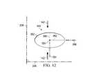
- FIG. 12is a schematic view, illustrating details that may be associated with some embodiments of a hole of the debridement tool of FIG. 9A having another perforation shape factor;
- FIG. 13Ais a plan view, illustrating details that may be associated with some embodiments of another debridement tool of the negative-pressure therapy system of FIG. 1 ;
- FIG. 13Bis a plan view, illustrating details that may be associated with some embodiments of the holes of the debridement tool of FIG. 13A ;
- FIG. 14is a schematic view, illustrating details that may be associated with some embodiments of a hole of the debridement tool of FIG. 13A ;
- FIG. 15is a plan view, illustrating details that may be associated with some embodiments of another debridement tool of the negative-pressure therapy system of FIG. 1 .
- FIG. 1is a sectional view with a portion shown in elevation, of an example embodiment of a therapy system 100 that can provide negative pressure therapy, instillation of topical treatment solutions, and debridement in accordance with this specification.
- the therapy system 100may include a dressing and a negative-pressure source.
- a dressing 102may be fluidly coupled to a negative-pressure source 104 , as illustrated in FIG. 1 .
- FIG. 1Ais a detail view of a portion of the therapy system 100 of FIG. 1 .
- the dressing 102for example, includes a cover 106 , and a tissue interface 107 for positioning adjacent or proximate a tissue site such as, for example, a tissue site 103 .
- the tissue interface 107may be a manifold, for example, a manifold 108 .
- the tissue interface 107may be a tissue removal tool, such as a debridement tool 110 having a tissue-facing surface 111 adapted to face the tissue site 103 and an opposite surface 113 adapted to face, for example, the manifold 108 .
- the tissue interface 107may be both the debridement tool 110 and the manifold 108 .
- the therapy system 100may also include an exudate container, such as a container 112 , coupled to the dressing 102 and to the negative-pressure source 104 ,
- the container 112may be fluidly coupled to the dressing 102 by a connector 114 and a tube 116
- the container 112may be fluidly coupled to the negative-pressure source 104 by a tube 118 .
- the therapy system 100may also include an instillation solution source.
- a fluid source 120may be fluidly coupled to the dressing 102 by a tube 122 and a connector 124 , as illustrated in the example embodiment of FIG. 1 .
- components of the therapy system 100may be coupled directly or indirectly.
- the negative-pressure source 104may be directly coupled to the container 112 and indirectly coupled to the dressing 102 through the container 112 .
- Componentsmay be fluidly coupled to each other to provide a path for transferring fluids (i.e., liquid and/or gas) between the components.
- componentsmay be fluidly coupled through a tube, such as the tube 116 , the tube 118 , and the tube 122 .
- a tubeis an elongated, cylindrical structure with some flexibility, but the geometry and rigidity may vary.
- componentsmay additionally or alternatively be coupled by virtue of physical proximity, being integral to a single structure, or being formed from the same piece of material. Coupling may also include mechanical, thermal, electrical, or chemical coupling (such as a chemical bond) in some contexts.
- a “connector,” such as the connector 114 and the connector 124 ,may be used to fluidly couple a tube to a sealed therapeutic environment.
- the negative pressure developed by a negative-pressure sourcemay be delivered through a tube to a connector.
- a connectormay be a T.R.A.C.® Pad or Sensa T.R.A.C.® Pad available from KCI of San Antonio, Tex.
- the connector 114may allow the negative pressure generated by the negative-pressure source 104 to be delivered to the sealed therapeutic environment 128 .
- a connectormay also be a tube inserted through a drape.
- the connector 124may allow fluid provided by the fluid source 120 to be delivered to the sealed therapeutic environment 128 .
- the tissue interface 107may be placed within, over, on, or otherwise proximate to the tissue site 103 .
- the cover 106may be placed over the tissue interface 107 and sealed to tissue near the tissue site.
- the cover 106may be sealed to undamaged epidermis peripheral to a tissue site, also known as peritissue.
- the dressing 102can provide a sealed therapeutic environment 128 proximate to a tissue site, substantially isolated from the external environment, and the negative-pressure source 104 can reduce the pressure in the sealed therapeutic environment 128 .
- Negative pressure applied across the tissue site 103 through the tissue interface 107 in the sealed therapeutic environment 128can induce macrostrain and microstrain in the tissue site 103 , as well as remove exudates and other fluids from the tissue site 103 , which can be collected in container 112 and disposed of properly.
- the fluid mechanics of using a negative-pressure source to reduce pressure in another component or location, such as within a sealed therapeutic environmentcan be mathematically complex.
- the basic principles of fluid mechanics applicable to negative-pressure therapy and instillationare generally well-known to those skilled in the art.
- downstreamtypically refers to a position in a fluid path that is closer to a source of negative pressure or alternatively further away from a source of positive pressure.
- upstreamrefers to a position in a fluid path further away from a source of negative pressure or closer to a source of positive pressure.
- tissue sitesuch as the tissue site 103
- tissue sitebroadly refers to a wound or defect located on or within tissue, including but not limited to, bone tissue, adipose tissue, muscle tissue, neural tissue, dermal tissue, vascular tissue, connective tissue, cartilage, tendons, or ligaments.
- a woundmay include chronic, acute, traumatic, subacute, and dehisced wounds, partial-thickness bums, ulcers (such as diabetic, pressure, or venous insufficiency ulcers), flaps, and grafts, for example.
- tissue sitemay also refer to areas of tissue that are not necessarily wounded or defective, but are instead areas in which it may be desirable to add or promote the growth of additional tissue. For example, negative pressure may be used in certain tissue areas to grow additional tissue that may be harvested and transplanted to another tissue location.
- Negative pressuregenerally refers to a pressure less than a local ambient pressure, such as the ambient pressure in a local environment external to a sealed therapeutic environment provided by the dressing 102 .
- the local ambient pressuremay also be the atmospheric pressure at which a tissue site is located.
- the pressuremay be less than a hydrostatic pressure associated with tissue at the tissue site. Unless otherwise indicated, values of pressure stated herein are gauge pressures.
- references to increases in negative pressuretypically refer to a decrease in absolute pressure, while decreases in negative pressure typically refer to an increase in absolute pressure.
- a negative-pressure sourcesuch as the negative-pressure source 104
- a negative-pressure sourcemay be housed within or used in conjunction with other components, such as sensors, processing units, alarm indicators, memory, databases, software, display devices, or user interfaces that further facilitate negative-pressure therapy.
- the pressureis generally a low vacuum, also commonly referred to as a rough vacuum, between ⁇ 5 mmHg ( ⁇ 667 Pa) and ⁇ 500 mmHg ( ⁇ 66.7 kPa).
- a rough vacuumbetween ⁇ 5 mmHg ( ⁇ 667 Pa) and ⁇ 500 mmHg ( ⁇ 66.7 kPa).
- Common therapeutic rangesare between ⁇ 75 mmHg ( ⁇ 9.9 kPa) and ⁇ 300 mmHg ( ⁇ 39.9 kPa).
- the tissue interface 107can be generally adapted to contact a tissue site.
- the tissue interface 107may be partially or fully in contact with the tissue site. If the tissue site is a wound, for example, the tissue interface 107 may partially or completely fill the wound, or may be placed over the wound.
- the tissue interface 107may take many forms, and may have many sizes, shapes, or thicknesses depending on a variety of factors, such as the type of treatment being implemented or the nature and size of a tissue site. For example, the size and shape of the tissue interface 107 may be adapted to the contours of deep and irregular shaped tissue sites. In some embodiments, the tissue interface 107 may be provided in a spiral cut sheet. Moreover, any or all of the surfaces of the tissue interface 107 may have an uneven, coarse, or jagged profile that can induce microstrains and stresses at a tissue site.
- the tissue interface 107may be a manifold, such as the manifold 108 .
- a “manifold” in this contextgenerally includes any substance or structure providing a plurality of pathways adapted to collect or distribute fluid across a tissue site under negative pressure.
- a manifoldmay be adapted to receive negative pressure from a source and distribute the negative pressure through multiple apertures across a tissue site, which may have the effect of collecting fluid from across a tissue site and drawing the fluid toward the source.
- the fluid pathmay be reversed or a secondary fluid path may be provided to facilitate delivering fluid across a tissue site.
- the pathways of a manifoldmay be channels interconnected to improve distribution or collection of fluids across a tissue site.
- cellular foam, open-cell foam, reticulated foam, porous tissue collections, and other porous materialsuch as gauze or felted mat generally include pores, edges, and/or walls adapted to form interconnected fluid pathways.
- Liquids, gels, and other foamsmay also include or be cured to include apertures and flow channels.
- a manifoldmay be a porous foam material having interconnected cells or pores adapted to uniformly (or quasi-uniformly) distribute negative pressure to a tissue site.
- the foam materialmay be either hydrophobic or hydrophilic.
- the pore size of a foam materialmay vary according to needs of a prescribed therapy.
- the manifold 108may be a foam having pore sizes in a range of about 400 microns to about 600 microns.
- the tensile strength of the manifold 108may also vary according to needs of a prescribed therapy. For example, the tensile strength of a foam may be increased for instillation of topical treatment solutions.
- the manifold 108may be an open-cell, reticulated polyurethane foam such as GranuFoam® dressing available from Kinetic Concepts, Inc. of San Antonio, Texas; in other embodiments the manifold 108 may be an open-cell, reticulated polyurethane foam such as a VeraFlo® foam, also available from Kinetic Concepts, Inc., of San Antonio, Texas.
- the tissue interface 107may also wick fluid away from a tissue site, while continuing to distribute negative pressure to the tissue site.
- the wicking properties of the tissue interface 107may draw fluid away from a tissue site by capillary flow or other wicking mechanisms.
- An example of a hydrophilic foamis a polyvinyl alcohol, open-cell foam such as V.A.C. WhiteFoam® dressing available from Kinetic Concepts, Inc. of San Antonio, Tex.
- Other hydrophilic foamsmay include those made from polyether.
- Other foams that may exhibit hydrophilic characteristicsinclude hydrophobic foams that have been treated or coated to provide hydrophilicity.
- the tissue interface 107may be constructed from bioresorbable materials. Suitable bioresorbable materials may include, without limitation, a polymeric blend of polylactic acid (PLA) and polyglycolic acid (PGA). The polymeric blend may also include without limitation polycarbonates, polyfumarates, and capralactones.
- the tissue interface 107may further serve as a scaffold for new cell-growth, or a scaffold material may be used in conjunction with the tissue interface 107 to promote cell-growth.
- a scaffoldis generally a substance or structure used to enhance or promote the growth of cells or formation of tissue, such as a three-dimensional porous structure that provides a template for cell growth.
- Illustrative examples of scaffold materialsinclude calcium phosphate, collagen, PLA/PGA, coral hydroxy apatites, carbonates, or processed allograft materials.
- the cover 106may provide a bacterial barrier and protection from physical trauma.
- the cover 106may also be a sealing member constructed from a material that can reduce evaporative losses and provide a fluid seal between two components or two environments, such as between a therapeutic environment and a local external environment.
- the cover 106may be, for example, an elastomeric film or membrane that can provide a seal adequate to maintain a negative pressure at a tissue site for a given negative-pressure source.
- the cover 106may be a polymer drape, such as a polyurethane film, that is permeable to water vapor but impermeable to liquid. Such drapes typically have a thickness in the range of about 25 microns to about 50 microns. For permeable materials, the permeability generally should be low enough that a desired negative pressure may be maintained.
- An attachment devicemay be used to attach the cover 106 to an attachment surface, such as undamaged epidermis, a gasket, or another cover.
- the attachment devicemay take many forms.
- an attachment devicemay be a medically-acceptable, pressure-sensitive adhesive that extends about a periphery, a portion, or an entire sealing member.
- some or all of the cover 106may be coated with an acrylic adhesive having a coating weight between about 25 grams per square meter (gsm) to about 65 gsm. Thicker adhesives, or combinations of adhesives, may be applied in some embodiments to improve the seal and reduce leaks.
- Other example embodiments of an attachment devicemay include a double-sided tape, paste, hydrocolloid, hydrogel, silicone gel, or organogel.
- the container 112is representative of a container, canister, pouch, or other storage component that can be used to manage exudates and other fluids withdrawn from a tissue site.
- a rigid containermay be preferred or required for collecting, storing, and disposing of fluids.
- fluidsmay be properly disposed of without rigid container storage, and a re-usable container could reduce waste and costs associated with negative-pressure therapy.
- the fluid source 120may be representative of a container, canister, pouch, bag, or other storage component that can provide a solution for instillation therapy. Compositions of solutions may vary according to prescribed therapy, but examples of solutions that are suitable for some prescriptions include hypochlorite-based solutions, silver nitrate (0.5%), sulfur-based solutions, biguanides, cationic solutions, and isotonic solutions.
- a fluid sourcesuch as the fluid source 120 , may be a reservoir of fluid at an atmospheric or greater pressure, or may be a manual or electrically-powered device, such as a pump, that can convey fluid to a sealed volume, such as the sealed therapeutic environment 128 , for example.
- a fluid sourcemay include a peristaltic pump.
- necrotic tissuemay be dead tissue resulting from infection, toxins, or trauma that caused the tissue to die faster than the tissue can be removed by the normal body processes that regulate the removal of dead tissue.
- necrotic tissuemay be in the form of slough, which may include a viscous liquid mass of tissue.
- sloughis produced by bacterial and fungal infections that stimulate an inflammatory response in the tissue. Slough may be a creamy yellow color and may also be referred to as pus.
- sloughsuch as slough 130 , may cover all or a portion of the tissue site 103 .
- Necrotic tissuemay also include eschar, such as eschar 132 .
- Eschar 132may be a portion of necrotic tissue that has become dehydrated and hardened.
- Eschar 132may be the result of a burn injury, gangrene, ulcers, fungal infections, spider bites, or anthrax. Eschar may be difficult to move without the use of surgical cutting instruments.
- Necrotic tissuecan also include thick exudate and fibrinous slough.
- a tissue sitedevelops necrotic tissue, the tissue site may be treated with a process called debridement.
- Debridementmay include the removal of dead, damaged, or infected material, such as thick exudate, fibrinous slough, the slough 130 or the eschar 132 , from a tissue site.
- a mechanical processis used to remove necrotic tissue. Mechanical processes may include using scalpels or other cutting tools having a sharp edge to cut away the necrotic tissue from the tissue site.
- mechanical processes of debriding a tissue sitemay be painful and may require the application of local anesthetics.
- An autolytic processmay involve using enzymes and moisture produced by a tissue site to soften and liquefy the necrotic tissue.
- a dressingmay be placed over a tissue site having necrotic tissue so that fluid produced by the tissue site may remain in place, hydrating the necrotic tissue.
- Autolytic processescan be pain-free, but autolytic processes are a slow and can take many days. Because autolytic processes are slow, autolytic processes may also involve many dressing changes.
- Some autolytic processesmay be paired with negative-pressure therapy so that, as necrotic tissue hydrates, negative pressure supplied to a tissue site may draw off the removed necrotic tissue.
- a manifold positioned at a tissue site to distribute negative-pressure across the tissue sitemay become blocked or clogged with necrotic tissue broken down by an autolytic process. If a manifold becomes clogged, negative-pressure may not be able to draw off necrotic tissue, which can slow or stop the autolytic process.
- Debridementmay also be performed by adding enzymes or other agents to the tissue site.
- the enzymesdigest tissue. Often, strict control of the placement of the enzymes and the length of time the enzymes are in contact with a tissue site must be maintained If enzymes are left on the tissue site for longer than needed, the enzymes may remove too much tissue, contaminate the tissue site, or be carried to other areas of a patient. Once carried to other areas of a patient, the enzymes may break down undamaged tissue and cause other complications.
- a negative-pressure sourcemay be fluidly coupled to a tissue site to provide negative pressure to the tissue site for negative-pressure therapy.
- a fluid sourcemay be fluidly coupled to a tissue site to provide therapeutic fluid to the tissue site for instillation therapy.
- the therapy system 100may include a debridement tool positioned adjacent to a tissue site.
- a debridement toolmay be used with negative-pressure therapy and instillation therapy to debride areas of a tissue site having necrotic tissue.
- the therapy system 100may be used on the tissue site 103 having the slough 130 and the eschar 132 .
- the debridement tool 110may be positioned adjacent to the tissue site 103 so that the debridement tool 110 is in contact with the slough 130 and the eschar 132 .
- the manifold 108may be positioned over the debridement tool 110 . In other embodiments, if the tissue site 103 has a depth about a depth of the debridement tool 110 , the manifold 108 may not be used.
- the debridement tool 110may be a substantially flat or substantially planar body.
- the debridement tool 110may have a thickness 134 .
- the thickness 134may be about 15 mm. In other embodiments, the thickness 134 may be thinner or thicker than about 15 mm as needed for the tissue site 103 .
- individual portions of the debridement tool 110may have a minimal tolerance from the thickness 134 . In some embodiments, the thickness 134 may have a tolerance of about 2 mm.
- the debridement tool 110may be flexible so that the debridement tool 110 can be contoured to a surface of the tissue site 103 .
- the debridement tool 110may be formed from thermoplastic elastomers (TPE), such as styrene ethylene butylene styrene (SEBS) copolymers, or thermoplastic polyurethane (TPU).
- TPEthermoplastic elastomers
- SEBSstyrene ethylene butylene styrene
- TPUthermoplastic polyurethane
- the debridement tool 110may be formed by combining sheets of TPE or TPU.
- the sheets of TPE or TPUmay be bonded, welded, adhered, or otherwise coupled to one another.
- the sheets of TPE or TPUmay be welded using radiant heat, radio-frequency welding, or laser welding.
- the debridement tool 110may produce suitable TPE or TPU sheets for the formation of the debridement tool 110 .
- sheets of TPE or TPU having a thickness between about 0.2 mm and about 2.0 mmmay be used to form a structure having the thickness 134 .
- the debridement tool 110may be formed from a 3D textile, also referred to as a spacer fabric. Suitable 3D textiles may be produced by Heathcoat Fabrics, Ltd., Baltex, and Mueller Textil Group.
- the debridement tool 110may be formed from a foam.
- cellular foam, open-cell foam, reticulated foam, or porous tissue collectionsmay be used to form the debridement tool 110 .
- the debridement tool 110may be formed of GranuFoam®, grey foam, or Zotefoam.
- Grey foammay be a polyester polyurethane foam having about 60 pores per inch (ppi).
- Zotefoammay be a closed-cell crosslinked polyolefin foam.
- the debridement tool 110may be an open-cell, reticulated polyurethane foam such as GranuFoam® dressing available from Kinetic Concepts, Inc.
- the debridement tool 110may be an open-cell, reticulated polyurethane foam such as a V.A.C. VeraFlo® foam, also available from Kinetic Concepts, Inc., of San Antonio, Tex.
- the debridement tool 110may be formed from a foam that is mechanically or chemically compressed to increase the density of the foam at ambient pressure.
- a foam that is mechanically or chemically compressedmay be referred to as a compressed foam.
- a compressed foammay be characterized by a firmness factor (FF) that is defined as a ratio of the density of a foam in a compressed state to the density of the same foam in an uncompressed state.
- FFfirmness factor
- 5may refer to a compressed foam having a density that is five times greater than a density of the same foam in an uncompressed state.
- Mechanically or chemically compressing a foammay reduce a thickness of the foam at ambient pressure when compared to the same foam that has not been compressed.
- a compressed foammay be a compressed GranuFoam®.
- GranuFoam®may have a density of about 0.03 grams per centimeter 3 (g/cm 3 ) in its uncompressed state.
- the GranuFoam®may be compressed until the density of the GranuFoam® is about 0.15 g/cm 3 .
- VeraFlo® foammay also be compressed to form a compressed foam having a firmness factor (FF) up to 5.
- the debridement tool 110may have a thickness of about 8 mm, and if the debridement tool 110 is positioned within the sealed therapeutic space 128 and subjected to negative pressure of about ⁇ 125 mmHg, the thickness 134 of the debridement tool 110 may be greater than about 3 mm.
- a compressed foammay also be referred to as a felted foam.
- a felted foamundergoes a thermoforming process to permanently compress the foam to increase the density of the foam.
- a felted foammay also be compared to other felted foams or compressed foams by comparing the firmness factor of the felted foam to the firmness factor of other compressed or uncompressed foams. Generally a compressed or felted foam may have a firmness factor greater than 1.
- the firmness factor (FF)may also be used to compare compressed foam materials with non-foam materials.
- a Supracor® materialmay have a firmness factor (FF) that allows Supracor® to be compared to compressed foams.
- the firmness factor (FF) for a non-foam materialmay represent that the non-foam material has a stiffness that is equivalent to a stiffness of a compressed foam having the same firmness factor.
- a debridement toolis formed from Supracor®, as illustrated in Table 1 below, the debridement tool may have a stiffness that is about the same as the stiffness of a compressed GranuFoam® material having a firmness factor (FF) of 3.
- the compressed foamexhibits less deformation than a similar uncompressed foam.
- the thickness 134 of the debridement tool 110may deform less than if the debridement tool 110 is formed of a comparable uncompressed foam.
- the decrease in deformationmay be caused by the increased stiffness as reflected by the firmness factor (FF).
- FFfirmness factor
- the foam material used to form a compressed foammay be either hydrophobic or hydrophilic
- the pore size of a foam materialmay vary according to needs of the debridement tool 110 and the amount of compression of the foam. For example, in some embodiments, an uncompressed foam may have pore sizes in a range of about 400 microns to about 600 microns. If the same foam is compressed, the pore sizes may be smaller than when the foam is in its uncompressed state.
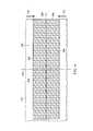
- FIG. 2is a plan view, illustrating additional details that may be associated with some embodiments of the debridement tool 110 .
- the debridement tool 110may include a plurality of holes 140 or perforations extending through the debridement tool 110 to form walls 148 extending through the debridement tool 110 .
- the walls 148may be parallel to the thickness 134 of the debridement tool 110 .
- the walls 148may be generally perpendicular to the tissue-facing surface 111 and the opposite surface 113 of the debridement tool 110 .
- the holes 140may have a hexagonal shape as shown. In other embodiments, the holes 140 may have a circular, oval, triangular, square, irregular, or amorphous shape.
- the debridement tool 110may have a first orientation 136 and a second orientation line 138 that is perpendicular to the first orientation line 136 .
- the first orientation line 136 and the second orientation line 138may be lines of symmetry of the debridement tool 110 .
- a line of symmetrymay be, for example, an imaginary line across the tissue-facing surface 111 or the opposite surface 113 of the debridement tool 110 defining a fold line such that if the debridement tool 110 is folded on the line of symmetry, the holes 140 and walls 148 would be coincidentally aligned.
- the first orientation line 136 and the second orientation line 138aid in the description of the debridement tool 110 .
- the first orientation line 136 and the second orientation line 138may be used to refer to the desired directions of contraction of the debridement tool 110 .
- the desired direction of contractionmay be parallel to the second orientation line 138 and perpendicular to the first orientation line 136 .
- the desired direction of contractionmay be parallel to the first orientation line 136 and perpendicular to the second orientation line 138 .
- the desired direction of contractionmay be at a non-perpendicular angle to both the first orientation line 136 and the second orientation line 138 .
- the debridement tool 110may be placed at the tissue site 103 so that the second orientation line 138 extends across the slough 130 and the eschar 132 of FIG. 1 .
- the debridement tool 110is shown as having a generally rectangular shape including longitudinal edges 144 and latitudinal edges 146 , the debridement tool 110 may have other shapes.
- the debridement tool 110may have a diamond, square, or circular shape.
- the shape of the debridement tool 110may be selected to accommodate the type of tissue site being treated.
- the debridement tool 110may have an oval or circular shape to accommodate an oval or circular tissue site.
- the first orientation line 136may be parallel to the longitudinal edges 144 .
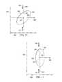
- the hole 140may include a center 150 and a perimeter 152 .
- the hole 140may have a perforation shape factor (PSF).
- the perforation shape factor (PSF)may represent an orientation of the hole 140 relative to the first orientation line 136 and the second orientation line 138 .
- the perforation shape factor (PSF)is a ratio of 1/2 a maximum length of the hole 140 that is parallel to the desired direction of contraction to 1/2 a maximum length of the hole 140 that is perpendicular to the desired direction of contraction.
- the desired direction of contractionis parallel to the second orientation line 138 .
- the desired direction of contractionmay be indicated by a debriding force 142 .
- the hole 140may have an X-axis 156 extending through the center 150 between opposing vertices of the hexagon and parallel to the first orientation line 136 , and a Y-axis 154 extending through the center 150 between opposing sides of the hexagon and parallel to the second orientation line 138 .
- the perforation shape factor (PSF) of the hole 140may be defined as a ratio of a line segment 158 on the Y-axis 154 extending from the center 150 to the perimeter 152 of the hole 140 , to a line segment 160 on the X-axis 156 extending from the center 150 to the perimeter 152 of the hole 140 .
- the perforation shape factor (PSF)would be 2.69/2.5 or about 1.08.
- the hole 140may be oriented relative to the first orientation line 136 and the second orientation line 138 so that the perforation shape factor (PSF) may be about 1.07 or 1.1.
- the debridement tool 110may include the plurality of holes 140 aligned in a pattern of parallel rows.
- the pattern of parallel rowsmay include a first row 162 of the holes 140 , a second row 164 of the holes 140 , and a third row 166 of the holes 140 .
- the centers 150 of the holes 140 in adjacent rowsmay be characterized by being offset from the second orientation line 138 along the first orientation line 136 .
- a line connecting the centers of adjacent rowsmay form a strut angle (SA) with the first orientation line 136 .
- SAstrut angle
- a first hole 140 A in the first row 162may have a center 150 A
- a second hole 140 B in the second row 164may have a center 150 B.
- a strut line 168may connect the center 150 A with the center 150 B.
- the strut line 168may form an angle 170 with the first orientation line 136 .
- the angle 170may be the strut angle (SA) of the debridement tool 110 .
- the strut angle (SA)may be less than about 90°.
- the strut angle (SA)may be between about 30° and about 70° relative to the first orientation line 136 .
- the strut angle (SA)may be about 66° from the first orientation line 136 .
- a stiffness of the debridement tool 110 in a direction parallel to the first orientation line 136may increase. Increasing the stiffness of the debridement tool 110 parallel to the first orientation line 136 may increase the compressibility of the debridement tool 110 perpendicular to the first orientation line 136 . Consequently, if negative pressure is applied to the debridement tool 110 , the debridement tool 110 may be more compliant or compressible in a direction perpendicular to the first orientation line 136 . By increasing the compressibility of the debridement tool 110 in a direction perpendicular to the first orientation line 136 , the debridement tool 110 may collapse to apply the debriding force 142 to the tissue site 103 described in more detail below.
- the centers 150 of the holes 140 in alternating rowsmay be spaced from each other parallel to the second orientation line 138 by a length 172 .
- the length 172may be greater than an effective diameter of the hole 140 . If the centers 150 of holes 140 in alternating rows are separated by the length 172 , walls 148 parallel to the first orientation line 136 may be considered continuous. Generally, the walls 148 may be continuous if the walls 148 do not have any discontinuities or breaks between holes 140 .
- the holes 140 in the debridement tool 110may leave void spaces in the debridement tool 110 and on the tissue-facing surface 111 and the opposite surface 113 of the debridement tool 110 so that only the walls 148 of the debridement tool 110 remain with a surface available to contact the tissue site 103 . It may be desirable to minimize the walls 148 so that the holes 140 may collapse, causing the debridement tool 110 to collapse and generate the debriding force 142 in a direction perpendicular to the first orientation line 136 . However, it may also be desirable not to minimize the walls 148 so much that the debridement tool 110 becomes too fragile for sustaining the application of a negative pressure.
- the void space percentage (VS) of the holes 140may be equal to the percentage of the volume or surface area of the void spaces of the tissue-facing surface 111 created by the holes 140 to the total volume or surface area of the tissue-facing surface 111 of the debridement tool 110 . In some embodiments, the void space percentage (VS) may be between about 40% and about 60%. In other embodiments, the void space percentage (VS) may be about 55%.
- the holes 140may be formed during molding of the debridement tool 110 .
- the holes 140may be formed by cutting, melting, or vaporizing the debridement tool 110 after the debridement tool 110 is formed.
- the holes 140may be formed in the debridement tool 110 by laser cutting the compressed foam of the debridement tool 110 .
- an effective diameter of the holes 140may be selected to permit flow of particulates through the holes 140 .
- An effective diameter of a non-circular areais defined as a diameter of a circular area having the same surface area as the non-circular area, In some embodiments, each hole 140 may have an effective diameter of about 3.5 mm.
- each hole 140may have an effective diameter between about 5 mm and about 20 mm.
- the effective diameter of the holes 140should be distinguished from the porosity of the material forming the walls 148 of the debridement tool 110 .
- an effective diameter of the holes 140is an order of magnitude larger than the effective diameter of the pores of a material forming the debridement tool 110 .
- the effective diameter of the holes 140may be larger than about 1 mm, while the walls 148 may be formed from GranuFoam® material having a pore size less than about 600 microns.
- the pores of the walls 148may not create openings that extend all the way through the material.
- the holes 140may foam a pattern depending on the geometry of the holes 140 and the alignment of the holes 140 between adjacent and alternating rows in the debridement tool 110 with respect to the first orientation line 136 . If the debridement tool 110 is subjected to negative pressure, the holes 140 of the debridement tool 110 may collapse. In some embodiments the void space percentage (VS), the perforation shape factor (PSF), and the strut angle (SA) may cause the debridement tool 110 to contract along the second orientation line 138 perpendicular to the first orientation line 136 as shown in more detail in FIG.
- VSvoid space percentage
- PSFperforation shape factor
- SAstrut angle
- the debridement tool 110may generate the debriding force 142 along the second orientation line 138 , contracting the debridement tool 110 , as shown in more detail in FIG. 5 .
- the debriding force 142may be optimized by adjusting the factors described above as set forth in Table 1 below.
- the holes 140may be hexagonal, have a strut angle (SA) of approximately 66°, a void space percentage (VS) of about 55%, a firmness factor (FF) of about 5, a perforation shape factor (PSF) of about 1.07, and an effective diameter of about 5 mm, If the debridement tool 110 is subjected to a negative pressure of about ⁇ 125 mmHg, the debriding force 142 asserted by the debridement tool 110 is about 13.3 N. If the effective diameter of the holes 140 of the debridement tool 110 is increased to 10 mm, the debriding force 142 is decreased to about 7.5 N.
- SAstrut angle
- VSvoid space percentage
- FFfirmness factor
- PSFperforation shape factor
- the debridement tool 110is in the second position, or contracted position, as indicated by the debriding force 142 .
- negative pressureis supplied to the sealed therapeutic environment 128 with the negative-pressure source 104 .
- the debridement tool 110contracts from the relaxed position illustrated in FIG. 2 to the contracted position illustrated in FIG. 5 , Generally, the thickness 134 of the debridement tool 110 remains substantially the same.
- the debridement tool 110expands back to the relaxed position. If the debridement tool 110 is cycled between the contracted and relaxed positions of FIGS. 5 and FIG.
- the tissue-facing surface 111 of the debridement tool 110debrides the tissue site 103 by cutting away dead or contaminated tissue from the wound, including the slough 130 and the eschar 132 .
- the edges of the holes 140 formed by the tissue-facing surface 111 and transverse surfaces of the walls 148form cutting edges that debride the tissue site 103 , allowing the severed tissue to exit through the holes 140 and the manifold 108 into the container 112 when negative pressure is applied.
- the cutting edgesare defined by the perimeter 152 where each hole 140 intersects the tissue-facing surface 111 .
- the therapy system 100may provide cyclic therapy. Cyclic therapy may alternately apply negative pressure to and vent negative pressure from the sealed therapeutic environment 128 .
- negative pressuremay be supplied to the sealed therapeutic environment 128 until the pressure in the sealed therapeutic environment 128 reaches a predetermined therapy pressure. If negative pressure is supplied to the sealed therapeutic environment 128 , the debridement tool 110 contracts as shown in FIG. 5 .
- the sealed therapeutic environment 128may remain at the therapy pressure for a predetermined therapy period such as, for example, about 10 minutes, In other embodiments, the therapy period may be longer or shorter as needed to supply appropriate negative-pressure therapy to the tissue site 103 .
- the sealed therapeutic environment 128may be vented.
- the negative-pressure source 104may fluidly couple the sealed therapeutic environment 128 to the atmosphere (not shown), allowing the sealed therapeutic environment 128 to return to ambient pressure.
- the negative-pressure source 104may vent the sealed therapeutic environment 128 for about 1 minute. In other embodiments, the negative-pressure source 104 may vent the sealed therapeutic environment 128 for longer or shorter periods.
- the debridement tool 110expands, returning to the relaxed position of FIG. 2 .
- the contraction and expansion of the debridement tool 110causes the cutting edges of the debridement tool 110 to debride the tissue site 103 as described above. Removed portions of the severed tissue, including the slough 130 and the eschar 132 may be drawn out through the holes 140 when negative pressure is applied to the sealed therapeutic environment 128 by the negative-pressure source 104 .
- instillation therapymay be combined with negative-pressure therapy.
- the fluid source 120may operate to provide fluid to the sealed therapeutic environment 128 .
- the fluid source 120may provide fluid while the negative-pressure source 104 vents the sealed therapeutic environment 128 .
- the fluid source 120may include a pump configured to move instillation fluid from the fluid source 120 to the sealed therapeutic environment 128 .
- the negative-pressure source 104may not vent the sealed therapeutic environment 128 . Instead, the negative pressure in the sealed therapeutic environment 128 is used to draw instillation fluid from the fluid source 120 into the sealed therapeutic environment 128 .
- the fluid source 120may provide a volume of fluid to the sealed therapeutic environment 128 .
- the volume of fluidmay be the same as a volume of the sealed therapeutic environment 128 .
- the volume of fluidmay be smaller or larger than the sealed therapeutic environment 128 as needed to appropriately apply instillation therapy.
- the fluid provided by the fluid source 120may remain in the sealed therapeutic environment 128 for a dwell time.
- the dwell timeis about 5 minutes.
- the dwell timemay be longer or shorter as needed to appropriately administer instillation therapy to the tissue site 103 .
- the dwell timemay be referred to as a dwell period of a therapy cycle.
- the negative-pressure source 104may be operated to draw off the instillation fluid into the container 112 , completing a cycle of therapy.
- negative pressuremay also be supplied to the sealed therapeutic environment 128 , starting another cycle of therapy.
- the debridement tool 110may be contracted and expanded. With each cycle of therapy, the tissue-facing surface 111 of the debridement tool 110 is rubbed across a facing surface of the tissue site 103 by the debriding force 142 , The rubbing action of the debridement tool 110 by the debriding force 142 causes the cutting edges of the holes 140 to dislodge portions of the slough 130 and the eschar 132 . With each subsequent cycle of therapy, additional portions of slough 130 and eschar 132 are removed from the tissue site 103 by the debriding force 142 .
- the dislodged portions of the slough 130 and the eschar 132 in particlesmay be sufficiently small to be drawn-off from the tissue site 103 by negative-pressure therapy. If instillation therapy is also provided, the fluid from the fluid source 120 may also aid in the removal of debrided tissue. Instillation therapy may also clean the manifold 108 , preventing blockage of the manifold 108 by removed slough 130 and eschar 132 .
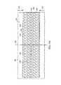
- FIG. 6is a plan view, illustrating additional details that may be associated with some embodiments of a debridement tool 210 .
- the debridement tool 210may be similar to the debridement tool 110 and operate as described above with respect to FIGS. 1-5 . Similar elements may have similar numbers indexed to 200 .
- the debridement tool 210is shown as having a generally rectangular shape including longitudinal edges 244 and latitudinal edges 246 .
- the debridement tool 210may have a first orientation line 236 and a second orientation line 238 that is perpendicular to the first orientation line 236 .
- the first orientation line 236 and the second orientation line 238may be used to refer to the desired directions of contraction for the debridement tool 210 .
- the desired direction of contractionmay be parallel to the second orientation line 238 and perpendicular to the first orientation line 236 , as shown by the debriding force 142 .
- the desired direction of contractionmay be perpendicular to the second orientation line 238 and parallel to the first orientation line 236 .
- the desired direction of contractionmay be at a non-perpendicular to both the second orientation line 238 and the first orientation line 236 .
- the debridement tool 210may be placed at the tissue site 103 so that a tissue-facing surface 211 of the debridement tool 210 may cover portions of the tissue site 103 having slough 130 or eschar 132 .
- the debridement tool 210may include a plurality of holes 240 or perforations extending through the debridement tool 210 to from walls 248 that extend through the debridement tool 210 .
- the walls 248are parallel to the thickness 234 of the debridement tool 210 .
- the walls 248may have transverse surfaces that intersect with the tissue-facing surface 211 to form cutting edges.
- the holes 240may have a circular shape as shown.
- the hole 240may include a center 250 , a perimeter 252 , and a perforation shape factor (PSF).
- the hole 240may have an X-axis 256 extending through the center 250 parallel to the first orientation line 236 , and a Y-axis 254 extending through the center 250 parallel to the second orientation line 238 .
- the perforation shape factor (PSF) of the hole 240may be defined as a ratio of a line segment 258 on the Y-axis 254 extending from the center 250 to the perimeter 252 of the hole 240 , to a line segment 260 on the X-axis 256 extending from the center 250 to the perimeter 252 of the hole 240 . If a length of the line segment 258 is 2.5 mm and the length of the line segment 260 is 2.5 mm, the perforation shape factor (PSF) would be 2.5/2.5 or about 1.
- the debridement tool 210may include the plurality of holes 240 aligned in a pattern of parallel rows.
- the pattern of parallel rowsmay include a first row 262 of the holes 240 , a second row 264 of the holes 240 , and a third row 266 of the holes 240 .
- the X-axis 256 of FIG. 7 of each hole 240may be parallel to the first orientation line 236 of FIG. 8 .
- the centers 250 of the holes 240 in adjacent rows, for example, the first row 262 and the second row 264may be characterized by being offset from the second orientation line 238 along the first orientation line 236 .
- a line connecting the centers of adjacent rowsmay form the strut angle (SA) with the first orientation line 236 .
- SAstrut angle
- a first hole 240 A in the first row 262may have a center 250 A
- a second hole 240 B in the second row 264may have a center 250 B.
- a strut line 268may connect the center 250 A with the center 250 B.
- the strut line 268may form an angle 270 with the first orientation line 236 .
- the angle 270may be the strut angle (SA) of the debridement tool 210 .
- the strut angle (SA)may be less than about 90°.
- the strut angle (SA)may be between about 30° and about 70° relative to the first orientation line 236 .
- the debridement tool 210may be more compliant or compressible in a direction perpendicular to the first orientation line 236 .
- the debridement tool 210may collapse to apply a debriding force to the tissue site 103 as described in more detail below.
- the centers 250 of the holes 240 in alternating rowsmay be spaced from each other parallel to the second orientation line 238 by a length 272 .
- the length 272may be greater than an effective diameter of the hole 240 . If the centers 250 of holes 240 in alternating rows are separated by the length 272 , the walls 248 parallel to the first orientation line 236 may be considered continuous. Generally, the walls 248 may be continuous if the walls 248 do not have any discontinuities or breaks between holes 240 .
- the holes 240 in the debridement tool 210may leave void spaces in the debridement tool 210 and on the tissue-facing surface 211 of the debridement tool 210 so that only walls 248 of the debridement tool 210 remain with a surface available to contact the tissue site 103 . It may be desirable to minimize the walls 248 so that the holes 240 collapse, causing the debridement tool 210 to collapse to generate the debriding force 142 in a direction perpendicular to the first orientation line 236 . However, it may also be desirable not to minimize the walls 248 so much that the debridement tool 210 becomes too fragile for sustaining the application of a negative pressure.
- the void space percentage (VS) of the holes 240may be equal to the percentage of the volume or surface area of the void spaces of the tissue-facing surface 211 created by the holes 240 to the total volume or surface area of the tissue-facing surface 211 of the debridement tool 210 .
- the void space percentage (VS)may be between about 40% and about 60%, In other embodiments, the void space percentage (VS) may be about 54%.
- a diameter of the holes 240may be selected to permit flow of particulates through the holes 240 .
- each hole 240may have a diameter of about 5 mm. In other embodiments, each hole 240 may have an effective diameter between about 3.5 mm and about 20 mm.
- the holes 240may form in a pattern depending on the geometry of the holes 240 and the alignment of the holes 240 between adjacent and alternating rows in the debridement tool 210 with respect to the first orientation line 236 . If the debridement tool 210 is subjected to negative pressure, the holes 240 of the debridement tool 210 may collapse. In some embodiments, the void space percentage (VS), the perforation shape factor (PSF), and the strut angle (SA) may cause the debridement tool 210 to collapse along the second orientation line 238 perpendicular to the first orientation line 236 .
- the debriding force 142may be optimized by adjusting the factors described above as set forth in Table 1 below.
- the holes 240may be circular, have a strut angle (SA) of approximately 37°, a void space percentage (VS) of about 54%, a firmness factor (FF) of about 5, a perforation shape factor (PSF) of about 1, and a diameter of about 5 mm. If the debridement tool 210 is subjected to a negative pressure of about ⁇ 125 mmHg, the debridement tool 210 asserts the debriding force 142 of approximately 11.9 N.
- SAstrut angle
- VSvoid space percentage
- FFfirmness factor
- PSFperforation shape factor
- the debriding force 142is decreased to about 6.5 N.
- FIG. 9Ais a plan view, illustrating additional details that may be associated with some embodiments of a debridement tool 310 .
- the debridement tool 310may be similar to the debridement tool 110 and operate as described above with respect to FIGS. 1-5 , Similar elements may have similar reference numbers indexed to 300 .
- the debridement tool 310may cover the tissue site 103 .
- the debridement tool 310may have a first orientation line 336 and a second orientation line 338 that is perpendicular to the first orientation line 336 .
- the first orientation line 336 and the second orientation line 338may be used to refer to the desired directions of contraction for the debridement tool 310 .
- the desired direction of contractionmay be parallel to the second orientation line 338 and perpendicular to the first orientation line 336 .
- the desired direction of contractionmay be perpendicular to the second orientation line 338 and parallel to the first orientation line 336 .
- the desired direction of contractionmay be at a non-perpendicular angle to both the second orientation line 338 and the first orientation line 336 .
- the debridement tool 310may be placed at the tissue site 103 so that a tissue-facing surface 311 of the debridement tool 310 may cover portions of the tissue site 103 having slough 130 and eschar 132 .
- the debridement tool 310may include a plurality of holes 340 or perforations extending through the debridement tool 310 to form walls 348 that extend through the debridement tool 310 .
- the walls 348are parallel to the thickness 334 of the debridement tool 310 .
- the walls 348may have transverse surfaces that intersect with the tissue-facing surface 311 to form cutting edges.
- the holes 340may have an ovoid shape as shown.
- the hole 340may include a center 350 , a perimeter 352 , and a perforation shape factor (PSF).
- PSFperforation shape factor
- the hole 340may have an X-axis 356 extending through the center 350 parallel to the first orientation line 336 , and a Y-axis 354 extending through the center 350 parallel to the second orientation line 338 .
- the perforation shape factor (PSF) of the hole 340may be defined as a ratio of a line segment 358 on the Y-axis 354 extending from the center 350 to the perimeter 352 of the hole 340 , to a line segment 360 on the X-axis 356 extending from the center 350 to the perimeter 352 of the hole 340 . If a length of the line segment 358 is 2.5 mm and the length of the line segment 360 is 2.5 mm, the perforation shape factor (PSF) would be 2.5/2.5 or about 1.
- the perforation shape factor (PSF)may change.
- the perforation shape factor (PSF)is now the ratio of a line segment 376 on the Y-axis 354 extending from the center 350 to the perimeter 352 of the hole 340 , to a line segment 378 on the X-axis 356 extending from the center 350 to the perimeter 352 of the hole 340 . If a length of the line segment 376 is 5 mm and the length of the line segment 378 is 2.5 mm, the perforation shape factor (PSF) would be 5/2.5 or about 2.
- the perforation shape factor (PSF)may change.
- the perforation shape factor (PSF)is now the ratio of a line segment 380 on the Y-axis 354 extending from the center 350 to the perimeter 352 of the hole 340 , to a line segment 382 on the X-axis 356 extending from the center 350 to the perimeter 352 of the hole 340 . If a length of the line segment 380 is 2.5 nun and the length of the line segment 382 is 5 mm, the perforation shape factor (PSF) would be 2.5/5 or about 1 ⁇ 2.
- the debridement tool 310may include the plurality of holes 340 aligned in a pattern of parallel rows.
- the pattern of parallel rowsmay include a first row 262 of the holes 340 , a second row 364 of the holes 340 , and a third row 366 of the holes 340 .
- the X-axis 356 of each hole 340 of FIGS. 10, 11, and 12may be parallel to the first orientation line 336 of FIG. 9B .
- the centers 350 of the holes 340 in adjacent rowsmay be characterized by being offset from the second orientation line 338 along the first orientation line 336 .
- a line connecting the centers of adjacent rowsmay form a strut angle (SA) with the first orientation line 336 .
- SAstrut angle
- a first hole 340 A in the first row 262may have a center 350 A
- a second hole 340 B in the second row 364may have a center 350 B.
- a strut line 368may connect the center 350 A with the center 350 B.
- the strut line 368may form an angle 370 with the first orientation line 336 .
- the angle 370may be the strut angle (SA) of the debridement tool 310 .
- the strut angle (SA)may be less than about 90°.
- the strut angle (SA)may be between about 30° and about 70° relative to the first orientation line 336 .
- the debridement tool 310may be more compliant or compressible in a direction perpendicular to the first orientation line 336 .
- the debridement tool 310may collapse to apply the debriding force 142 to the tissue site 103 as described in more detail below.
- the centers 350 of the holes 340 in alternating rowsmay be spaced from each other parallel to the second orientation line 338 by a length 372 .
- the length 372may be greater than an effective diameter of the hole 340 . If the centers 350 of holes 340 in alternating rows are separated by the length 372 , the walls 348 parallel to the first orientation line 336 may be considered continuous. Generally, the walls 348 may be continuous if the walls 348 do not have any discontinuities or breaks between holes 340 .
- the holes 340 in the debridement tool 310may leave void spaces in the debridement tool 310 and on the tissue-facing surface 311 of the debridement tool 310 so that only walls 348 of the debridement tool 310 remain with a surface available to contact the tissue site 103 . It may be desirable to minimize the walls 348 so that the holes 340 may collapse, causing the debridement tool 310 to collapse the debriding force 142 in a direction perpendicular to the first orientation line 336 . However, it may also be desirable not to minimize the walls 348 so much that the debridement tool 310 becomes too fragile for sustaining the application of a negative pressure.
- the void space percentage (VS) of the holes 340may be equal to the percentage of the volume or surface area of the void spaces of the tissue-facing surface 311 created by the holes 340 to the total volume or surface area of the tissue-facing surface 311 of the debridement tool 310 .
- the void space percentage (VS)may be between about 40% and about 60%. In other embodiments, the void space percentage (VS) may be about 56%.
- an effective diameter of the holes 340may be selected to permit flow of particulates through the holes 340 .
- each hole 340may have an effective diameter of about 7 mm. In other embodiments, each hole 340 may have an effective diameter between about 2.5 mm and about 20 mm.
- the holes 340may form a pattern depending on the geometry of the holes 340 and the alignment of the holes 340 between adjacent and alternating rows in the debridement tool 310 with respect to the first orientation line 336 . If the debridement tool 310 is subjected to negative pressure, the holes 340 of the debridement tool 310 may collapse, causing the debridement tool 310 to collapse along the second orientation line 338 perpendicular to the first orientation line 336 .
- the debridement tool 310may generate the debriding force 142 along the second orientation line 338 such that the debridement tool 310 is contracted in the same direction to debride the tissue site 103 .
- the debriding force 142may be optimized by adjusting the factors described above as set forth in Table 1 below.
- the holes 340may be ovular, have a strut angle (SA) of approximately 47°, a void space percentage (VS) of about 56%, a firmness factor (FF) of about 5, a perforation shape factor (PSF) of about 1, and an effective diameter of about 7 mm (where the major axis is about 10 mm and the minor axis is about 5 mm). If the debridement tool 310 is subjected to a negative pressure of about ⁇ 125 mmHg, the debridement tool 310 asserts the debriding force 142 of approximately 13.5 N.
- SAstrut angle
- VSvoid space percentage
- FFfirmness factor
- PSFperforation shape factor
- FIG. 13Ais a plan view, illustrating additional details that may be associated with some embodiments of a debridement tool 410 .
- the debridement tool 410may be similar to the debridement tool 110 and operate as described with respect to FIGS. 1-5 . Similar elements may have similar reference numbers indexed to 400 .
- the debridement tool 410is shown as having a generally rectangular shape including longitudinal edges 444 and latitudinal edges 446 .
- the debridement tool 410may cover the tissue site 103 .
- the debridement tool 410may have a first orientation line 436 and a second orientation line 438 that is perpendicular to the first orientation line 436 .
- the first orientation line 436 and the second orientation line 438may be used to refer to the desired directions of contraction for the debridement tool 410 .
- the desired direction of contractionmay be parallel to the second orientation line 438 and perpendicular to the first orientation line 436 .
- the desired direction of contractionmay be perpendicular to the second orientation line 438 and parallel to the first orientation line 436 .
- the desired direction of contractionmay be at a non-perpendicular angle to both the second orientation line 438 and the first orientation line 436 .
- the debridement tool 410may be placed at the tissue site 103 so that a tissue-facing surface 411 of the debridement tool 410 may cover portions of the tissue site 103 having slough 130 or eschar 132 .
- the debridement tool 410may include a plurality of holes 440 or perforations extending through the debridement tool 410 to form walls 448 that extend through the debridement tool 410 .
- the walls 448are parallel to the thickness 434 of the debridement tool 410 .
- the walls 448may have transverse surfaces that intersect with the tissue-facing surface 411 to form cutting edges,
- the holes 440may have a triangular shape as shown,
- the hole 440may include a center 450 , a perimeter 452 , and a perforation shape factor (PSF).
- the hole 440may include a first vertex 484 , a second vertex 486 , and a third vertex 488 .
- the hole 440may have an X-axis 456 extending through the center 450 parallel to the first orientation line 436 , and a Y-axis 454 extending through the center 450 parallel to the second orientation line 438 .
- the perforation shape factor (PSF) of the hole 440may be defined as a ratio of a line segment 458 on the Y-axis 454 extending from the center 450 to the perimeter 452 of the hole 440 , to a line segment 460 on the X-axis 456 extending from the center 450 to the perimeter 452 of the hole 440 . If a length of the line segment 458 is 1.1 mm and the length of the line segment 460 is 1 mm, the perforation shape factor (PSF) would be 1.1/1 or about 1.1.
- the debridement tool 410may include the plurality of holes 440 aligned in a pattern of parallel rows.
- the pattern of parallel rowsmay include a first row 462 of the holes 440 , a second row 464 of the holes 440 , and a third row 466 of the holes 440 .
- the X-axis 456 of FIG. 14 of each hole 440may be parallel to the first orientation line 436 of FIG. 13B .
- a first hole 440 A in the first row 462may be oriented so that the first vertex 484 A may be between the first orientation line 436 and a leg of the first hole 440 A opposite the first vertex 484 A.
- a hole 440 C that is adjacent the first hole 440 A in the first row 462may be oriented so that the first vertex 484 C may be oriented opposite the first hole 440 A.
- the centers 450 of the holes 440 in adjacent rows having the first vertex 484 oriented in a same direction, for example, the first row 462 and the second row 464 ,may be characterized by being offset from the second orientation line 438 along the first orientation line 436 .
- a line connecting the centers 450 of adjacent rowsmay form a strut angle (SA) with the first orientation line 436 .
- SAstrut angle
- a first hole 440 A in the first row 462may have a center 450 A
- a second hole 440 B in the second row 464may have a center 450 B and a first vertex 484 B.
- a strut line 468may connect the center 450 A with the center 450 B.
- the strut line 468may form an angle 470 with the first orientation line 436 .
- the angle 470may be the strut angle (SA) of the debridement tool 410 .
- the strut angle (SA)may be less than about 90°.
- the strut angle (SA)may be between about 40° and about 70° relative to the first orientation line 436 .
- the debridement tool 410may be more compliant or compressible in a direction perpendicular to the first orientation line 436 .
- the debridement tool 410may collapse to apply the debriding force 142 to the tissue site 103 as described in more detail below.
- the holes 440 in the debridement tool 410may leave void spaces in the debridement tool 410 and on the tissue-facing surface 411 of the debridement tool 410 so that only the walls 448 of the debridement tool 410 remain with a surface available to contact the tissue site 103 . It may be desirable to minimize the walls 448 so that the holes 440 may collapse, causing the debridement tool 410 to generate the debriding force 142 in a direction perpendicular to the first orientation line 436 . However, it may also be desirable not to minimize the walls 448 so much that the debridement tool 410 becomes too fragile for sustaining the application of a negative pressure.
- the void space percentage (VS) of the holes 440may be equal to the percentage of the volume or surface area of the void spaces of the tissue-facing surface 411 created by the holes 440 to the total volume or surface area of the tissue-facing surface 411 of the debridement tool 410 .
- the void space percentage (VS)may be between about 40% and about 60%. In other embodiments, the void space percentage (VS) may be about 56%.
- an effective diameter of the holes 440may be selected to permit flow of particulates through the holes 440 .
- each hole 440may have an effective diameter of about 7 mm. In other embodiments, each hole 440 may have an effective diameter between about 2.5 mm and about 20 mm.
- the holes 440may form a pattern depending on the geometry of the holes 440 and the alignment of the holes 440 between adjacent and alternating rows in the debridement tool 410 with respect to the first orientation line 436 . If the debridement tool 410 is subjected to negative pressure, the holes 440 of the debridement tool 410 may collapse. In some embodiments, the void space percentage (VS), the perforation shape factor (PSF), and the strut angle (SA) may cause the debridement tool 410 to collapse along the second orientation line 438 perpendicular to the first orientation line 436 .
- VSvoid space percentage
- PSFperforation shape factor
- SAstrut angle
- the debridement tool 410may generate the debriding force 142 along the second orientation line 438 such that the debridement tool 410 is contracted in the same direction.
- the debriding force 142may be optimized by adjusting the factors described above as set forth in Table 1 below.
- the holes 440may be triangular, have a strut angle (SA) of approximately 63°, a void space percentage (VS) of about 40%, a firmness factor (FF) of 5, a perforation shape factor (PSF) of 1.1, and an effective diameter of about 10 mm. If the debridement tool 410 is subjected to a negative pressure of about ⁇ 125 mmHg, the debridement tool 410 may assert the debriding force 142 of approximately 13.5 N.
- FIG. 15is a plan view, illustrating additional details that may be associated with some embodiments of a debridement tool 510 .
- the debridement tool 510may be similar to the debridement tool 110 described above with respect to FIGS. 1-5 .
- the debridement tool 510may include stripes 516 and stripes 518 .
- the debridement tool 510may be formed from a foam, similar to GranuFoam®.
- the stripes 518may be formed by compressing portions of the foam so that the stripes 516 have a first density and the stripes 518 have a second density. In some embodiments, the second density is greater than the first density, for example.
- the second densitymay be between about 3 times and about 5 times greater than the first density.
- the stripes 516may be an uncompressed foam, and the stripes 518 may be a compressed foam having a firmness factor of about 5.
- the stripes 516may be more compressible than the stripes 518 .
- the stripes 516 and the stripes 518may be vertically oriented relative to a tissue site, and in other embodiments, the stripes 516 and the stripes 518 may be horizontally oriented relative to a tissue site. In still other embodiments, the stripes 516 and the stripes 518 may be oriented at an angle relative to a tissue site.
- the foam material of the debridement tool 510may have cutting edges formed by pores in the foam material that are positioned on a tissue-facing surface 511 of the debridement tool 510 . If the debridement tool 510 is placed under a negative-pressure, the stripes 516 may collapse before the stripes 518 . In some embodiments, if the stripes 516 collapse, the debridement tool 510 contracts perpendicular to the stripes 516 . If the debridement tool 510 is cycled between contracted and relaxed states, as described above, the cutting edges of the pores may debride tissue similar to the cutting edges of the debridement tool 110 , described above.
- a debriding force, such as the debriding force 142 , generated by a debridement tool, such as the debridement tool 110may be related to a compressive force generated by applying negative pressure at a therapy pressure to a sealed therapeutic environment.
- the debriding force 142may be proportional to a product of a therapy pressure (TP) in the sealed therapeutic environment 128 , the compressibility factor (CF) of the debridement tool 110 , and a surface area (A) the tissue-facing surface 111 of the debridement tool 110 .
- TPtherapy pressure
- CFcompressibility factor
- Asurface area
- the therapy pressure TPis measured in N/m 2
- the compressibility factor (CF)is dimensionless
- the area (A)is measured in m 2
- the debriding forceis measured in Newtons (N).
- the compressibility factor (CF) resulting from the application of negative pressure to a debridement toolmay be, for example, a dimensionless number that is proportional to the product of the void space percentage (VS) of a debridement tool, the firmness factor (FF) of the debridement tool, the strut angle (SA) of the holes in the debridement tool, and the perforation shape factor (PSF) of the holes in the debridement tool.
- the relationshipis expressed as follows: Compressibility Factor (CF) ⁇ (VS*FF*sin(SA)*PSF)
- debridement toolsformed from different materials with holes of different shapes were manufactured and tested to determine the debriding force of the debridement tools.
- the therapy pressure TPwas about ⁇ 125 mmHg and the dimensions of the debridement tool were about 200 mm by about 53 mm so that the surface area (A) of the tissue-facing surface of the debridement tool was about 106 cm 2 or 0.0106 m 2 .
- the debriding force for a Supracor® debridement tool 110 having a firmness factor (FF) of 3was about 13.3 where the Supracor® debridement tool 110 had hexagonal holes 140 with a distance between opposite vertices of 5 mm, a perforation shape factor (PSF) of 1.07, a strut angle (SA) of approximately 66°, and a void space percentage (VS) of about 55%.
- a similarly dimensioned GranuFoam® debridement tool 110generated the debriding force 142 of about 9.1 Newtons (N).
- the formulas described abovemay not precisely describe the debriding forces due to losses in force due to the transfer of the force from the debridement tool to the wound.
- the modulus and stretching of the cover 106 , the modulus of the tissue site 103 , slippage of the cover 106 over the tissue site 103 , and friction between the debridement tool 110 and the tissue site 103may cause the actual value of the debriding force 142 to be less than the calculated value of the debriding force 142 .
- the systems, apparatuses, and methods described hereinmay provide significant advantages. For example, Combining the mechanical rubbing action of a debridement tool with the hydrating and flushing action of instillation and negative-pressure therapy may enable low or no pain debridement of a tissue site.
- a debridement tool as described hereinmay also require less monitoring from a clinician or other attendant as compared to other mechanical debridement processes and enzymatic debridement processes.
- debridement tools as described hereinmay not become blocked by removed necrotic tissue as may occur during autolytic debridement of a tissue site.
Landscapes
- Health & Medical Sciences (AREA)
- Life Sciences & Earth Sciences (AREA)
- Heart & Thoracic Surgery (AREA)
- General Health & Medical Sciences (AREA)
- Animal Behavior & Ethology (AREA)
- Public Health (AREA)
- Veterinary Medicine (AREA)
- Biomedical Technology (AREA)
- Engineering & Computer Science (AREA)
- Surgery (AREA)
- Vascular Medicine (AREA)
- Molecular Biology (AREA)
- Nuclear Medicine, Radiotherapy & Molecular Imaging (AREA)
- Medical Informatics (AREA)
- Chemical & Material Sciences (AREA)
- Anesthesiology (AREA)
- Hematology (AREA)
- Epidemiology (AREA)
- Organic Chemistry (AREA)
- Chemical Kinetics & Catalysis (AREA)
- Dispersion Chemistry (AREA)
- Media Introduction/Drainage Providing Device (AREA)
- Virology (AREA)
- AIDS & HIV (AREA)
- Tropical Medicine & Parasitology (AREA)
- Communicable Diseases (AREA)
- Oncology (AREA)
- General Chemical & Material Sciences (AREA)
- Medicinal Chemistry (AREA)
- Pharmacology & Pharmacy (AREA)
- Surgical Instruments (AREA)
Abstract
Description
Debriding force α(TP*CF*A)
Compressibility Factor (CF) α(VS*FF*sin(SA)*PSF)
| TABLE 1 | |||||||
| Material | VS | FF | SA | Hole Shape | PSF | Major diam. (mm) | Debriding force |
| GranuFoam ® | 56 | 5 | 47 | Ovular | 1 | 10 | 13.5 |
| Supracor ® | 55 | 3 | 66 | Hexagon | 1.1 | 5 | 13.3 |
| GranuFoam ® | 40 | 5 | 63 | Triangle | 1.1 | 10 | 12.2 |
| GranuFoam ® | 54 | 5 | 37 | Circular | 1 | 5 | 11.9 |
| GranuFoam ® | 52 | 5 | 37 | Circular | 1 | 20 | 10.3 |
| Grey Foam | N/A | 5 | N/A | Horizontal stripes | N/A | N/A | 9.2 |
| GranuFoam ® | 55 | 5 | 66 | Hexagon | 1.1 | 5 | 9.1 |
| GranuFoam ® | N/A | 5 | N/A | Horizontal stripes | N/A | N/A | 8.8 |
| Zotefoam | 52 | 3 | 37 | Circular | 1 | 10 | 8.4 |
| GranuFoam ® | 52 | 5 | 37 | Circular | 1 | 10 | 8.0 |
| GranuFoam ® | 52 | 5 | 64 | Circular | 1 | 10 | 7.7 |
| GranuFoam ® | 56 | 5 | 66 | Hexagon | 1.1 | 10 | 7.5 |
| Grey Foam | N/A | 3 | N/A | Horizontal stripes | N/A | N/A | 7.2 |
| Zotefoam | 52 | 3 | 52 | Circular | 1 | 20 | 6.8 |
| GranuFoam ® | N/A | 3 | N/A | Horizontal Striping | N/A | N/A | 6.6 |
| GranuFoam ® | 52 | 5 | 52 | Circular | 1 | 20 | 6.5 |
| GranuFoam ® | N/A | 5 | N/A | Vertical Stripes | N/A | N/A | 6.1 |
| GranuFoam ® | N/A | 1 | N/A | None | N/A | N/A | 5.9 |
| GranuFoam ® | N/A | 3 | N/A | Vertical stripes | N/A | N/A | 5.6 |
| GranuFoam ® | 52 | 1 | 37 | None | 1 | 10 | 5.5 |
Claims (22)
Priority Applications (3)
| Application Number | Priority Date | Filing Date | Title |
|---|---|---|---|
| US14/708,078US10143485B2 (en) | 2014-05-09 | 2015-05-08 | Debriding dressing for use with negative pressure and fluid instillation |
| US16/168,446US20190053819A1 (en) | 2014-05-09 | 2018-10-23 | Debriding Dressing For Use With Negative Pressure And Fluid Instillation |
| US18/538,282US20240109849A1 (en) | 2014-05-09 | 2023-12-13 | Debriding dressing for use with negative pressure and fluid instillation |
Applications Claiming Priority (2)
| Application Number | Priority Date | Filing Date | Title |
|---|---|---|---|
| US201461991134P | 2014-05-09 | 2014-05-09 | |
| US14/708,078US10143485B2 (en) | 2014-05-09 | 2015-05-08 | Debriding dressing for use with negative pressure and fluid instillation |
Related Child Applications (2)
| Application Number | Title | Priority Date | Filing Date |
|---|---|---|---|
| US16/158,446DivisionUS10774053B2 (en) | 2017-10-13 | 2018-10-12 | HIV protease inhibitors |
| US16/168,446DivisionUS20190053819A1 (en) | 2014-05-09 | 2018-10-23 | Debriding Dressing For Use With Negative Pressure And Fluid Instillation |
Publications (2)
| Publication Number | Publication Date |
|---|---|
| US20150320603A1 US20150320603A1 (en) | 2015-11-12 |
| US10143485B2true US10143485B2 (en) | 2018-12-04 |
Family
ID=53267627
Family Applications (3)
| Application Number | Title | Priority Date | Filing Date |
|---|---|---|---|
| US14/708,078Active2036-10-10US10143485B2 (en) | 2014-05-09 | 2015-05-08 | Debriding dressing for use with negative pressure and fluid instillation |
| US16/168,446PendingUS20190053819A1 (en) | 2014-05-09 | 2018-10-23 | Debriding Dressing For Use With Negative Pressure And Fluid Instillation |
| US18/538,282PendingUS20240109849A1 (en) | 2014-05-09 | 2023-12-13 | Debriding dressing for use with negative pressure and fluid instillation |
Family Applications After (2)
| Application Number | Title | Priority Date | Filing Date |
|---|---|---|---|
| US16/168,446PendingUS20190053819A1 (en) | 2014-05-09 | 2018-10-23 | Debriding Dressing For Use With Negative Pressure And Fluid Instillation |
| US18/538,282PendingUS20240109849A1 (en) | 2014-05-09 | 2023-12-13 | Debriding dressing for use with negative pressure and fluid instillation |
Country Status (7)
| Country | Link |
|---|---|
| US (3) | US10143485B2 (en) |
| EP (4) | EP3821858B1 (en) |
| JP (2) | JP6728062B2 (en) |
| CN (3) | CN111134779B (en) |
| AU (3) | AU2015255719B2 (en) |
| CA (1) | CA2947298C (en) |
| WO (1) | WO2015172104A1 (en) |
Cited By (19)
| Publication number | Priority date | Publication date | Assignee | Title |
|---|---|---|---|---|
| US11083631B2 (en) | 2012-07-16 | 2021-08-10 | University Of Massachusetts | Negative pressure wound closure device |
| US11096832B2 (en) | 2016-09-27 | 2021-08-24 | Smith & Nephew Plc | Wound closure devices with dissolvable portions |
| US11123476B2 (en) | 2017-06-14 | 2021-09-21 | Smith & Nephew, Inc. | Fluid removal management and control of wound closure in wound therapy |
| US11166726B2 (en) | 2011-02-04 | 2021-11-09 | University Of Massachusetts | Negative pressure wound closure device |
| US11241337B2 (en) | 2012-05-24 | 2022-02-08 | Smith & Nephew, Inc. | Devices and methods for treating and closing wounds with negative pressure |
| US11324876B2 (en) | 2017-06-13 | 2022-05-10 | Smith & Nephew Plc | Collapsible structure and method of use |
| US11375923B2 (en) | 2017-08-29 | 2022-07-05 | Smith & Nephew Plc | Systems and methods for monitoring wound closure |
| US11395873B2 (en) | 2017-06-14 | 2022-07-26 | Smith & Nephew, Inc. | Control of wound closure and fluid removal management in wound therapy |
| US11419767B2 (en) | 2013-03-13 | 2022-08-23 | University Of Massachusetts | Negative pressure wound closure device and systems and methods of use in treating wounds with negative pressure |
| US11439539B2 (en) | 2015-04-29 | 2022-09-13 | University Of Massachusetts | Negative pressure wound closure device |
| US11471586B2 (en) | 2015-12-15 | 2022-10-18 | University Of Massachusetts | Negative pressure wound closure devices and methods |
| WO2022234444A1 (en) | 2021-05-06 | 2022-11-10 | Kci Manufacturing Unlimited Company | Bio-absorbable dispersible rapidly deployable wound interface |
| US11583623B2 (en) | 2017-06-14 | 2023-02-21 | Smith & Nephew Plc | Collapsible structure for wound closure and method of use |
| US11590030B2 (en) | 2017-08-07 | 2023-02-28 | Smith & Nephew Plc | Wound closure device with protective layer and method of use |
| US11607344B2 (en) | 2017-07-27 | 2023-03-21 | Smith & Nephew Plc | Customizable wound closure device and method of use |
| US11617684B2 (en) | 2016-11-02 | 2023-04-04 | Smith & Nephew, Inc. | Wound closure devices |
| US11724020B2 (en) | 2017-06-14 | 2023-08-15 | Smith & Nephew Plc | Collapsible sheet for wound closure and method of use |
| US11872110B2 (en) | 2017-06-13 | 2024-01-16 | Smith & Nephew Plc | Wound closure device and method of use |
| US12133790B2 (en) | 2013-10-21 | 2024-11-05 | Smith & Nephew, Inc. | Negative pressure wound closure device |
Families Citing this family (64)
| Publication number | Priority date | Publication date | Assignee | Title |
|---|---|---|---|---|
| WO2013066426A2 (en) | 2011-06-24 | 2013-05-10 | Kci Licensing, Inc. | Reduced-pressure dressings employing tissue-fixation elements |
| WO2015172111A1 (en)* | 2014-05-09 | 2015-11-12 | Kci Licensing, Inc. | Disruptive dressing for use with negative pressure and fluid instillation |
| US10898217B2 (en) | 2014-05-09 | 2021-01-26 | Kci Licensing, Inc. | Dressing providing apertures with multiple orifice sizes for negative-pressure therapy |
| WO2015172108A1 (en) | 2014-05-09 | 2015-11-12 | Kci Licensing, Inc. | Dressing with contracting layer for linear tissue sites |
| DK3288508T3 (en) | 2015-04-27 | 2020-03-09 | Smith & Nephew | REDUCED PRESSURE DEVICES |
| EP3426206B1 (en) | 2016-03-07 | 2023-05-10 | Smith & Nephew plc | Wound treatment apparatuses and methods with negative pressure source integrated into wound dressing |
| US11167074B2 (en) | 2016-03-17 | 2021-11-09 | Kcl Licensing, Inc. | Systems and methods for treating a tissue site using one manifold and multiple therapy units |
| CA3022184A1 (en) | 2016-04-26 | 2017-11-02 | Smith & Nephew Plc | Wound dressings and methods of use with integrated negative pressure source having a fluid ingress inhibition component |
| CA3038206A1 (en) | 2016-05-03 | 2017-11-09 | Smith & Nephew Plc | Optimizing power transfer to negative pressure sources in negative pressure therapy systems |
| WO2017191158A1 (en) | 2016-05-03 | 2017-11-09 | Smith & Nephew Plc | Systems and methods for driving negative pressure sources in negative pressure therapy systems |
| US11096831B2 (en) | 2016-05-03 | 2021-08-24 | Smith & Nephew Plc | Negative pressure wound therapy device activation and control |
| WO2018037075A1 (en) | 2016-08-25 | 2018-03-01 | Smith & Nephew Plc | Absorbent negative pressure wound therapy dressing |
| EP3519001B1 (en) | 2016-09-30 | 2025-05-21 | Smith & Nephew plc | Negative pressure wound treatment apparatuses and methods with integrated electronics |
| EP3551244A1 (en) | 2016-12-12 | 2019-10-16 | Smith & Nephew PLC | Pressure wound therapy status indication via external device |
| EP3592312B1 (en) | 2017-03-08 | 2024-01-10 | Smith & Nephew plc | Negative pressure wound therapy device control in presence of fault condition |
| JP7121050B2 (en) | 2017-05-09 | 2022-08-17 | スミス アンド ネフュー ピーエルシー | Redundant control of negative pressure wound therapy systems |
| WO2018226650A1 (en) | 2017-06-07 | 2018-12-13 | Kci Licensing, Inc. | Systems, apparatuses, and methods for negative-pressure treatment with reduced tissue in-growth |
| WO2018226691A1 (en) | 2017-06-07 | 2018-12-13 | Kci Licensing, Inc. | Methods for manufacturing and assembling dual material tissue interface for negative-pressure therapy |
| WO2018226707A1 (en) | 2017-06-07 | 2018-12-13 | Kci Licensing, Inc. | Composite dressings for improved granulation reduced maceration with negative-pressure treatment |
| AU2018282159A1 (en) | 2017-06-07 | 2019-12-19 | 3M Innovative Properties Company | Composite dressings for improved granulation and reduced maceration with negative-pressure treatment |
| JP7204685B2 (en) | 2017-06-07 | 2023-01-16 | スリーエム イノベイティブ プロパティズ カンパニー | A composite dressing that promotes granulation formation and reduces maceration in negative pressure therapy |
| WO2018226744A1 (en) | 2017-06-07 | 2018-12-13 | Kci Licensing, Inc. | Peel and place dressing for negative -pressure treatment |
| EP3634334B1 (en) | 2017-06-07 | 2023-05-24 | 3M Innovative Properties Company | Multi-layer wound filler for extended wear time |
| US10695227B2 (en) | 2017-06-07 | 2020-06-30 | Kci Licensing, Inc. | Methods for manufacturing and assembling dual material tissue interface for negative-pressure therapy |
| AU2018282188A1 (en) | 2017-06-07 | 2019-12-19 | 3M Innovative Properties Company | Tissue contact interface |
| GB201718070D0 (en) | 2017-11-01 | 2017-12-13 | Smith & Nephew | Negative pressure wound treatment apparatuses and methods with integrated electronics |
| CA3074780A1 (en) | 2017-09-13 | 2019-03-21 | Smith & Nephew Plc | Negative pressure wound treatment apparatuses and methods with integrated electronics |
| RU2020113361A (en)* | 2017-09-20 | 2021-10-20 | Колопласт А/С | WOUND CARE DEVICE TO REMOVE DEAD TISSUE OF WOUNDS |
| US11432967B2 (en)* | 2017-10-23 | 2022-09-06 | Kci Licensing, Inc. | Fluid bridge for simultaneous application of negative pressure to multiple tissue sites |
| WO2019084006A1 (en) | 2017-10-23 | 2019-05-02 | Kci Licensing, Inc. | Low profile distribution components for wound therapy |
| JP7288901B2 (en)* | 2017-10-24 | 2023-06-08 | スリーエム イノベイティブ プロパティズ カンパニー | Wound dressing for debridement and system using same |
| GB201718054D0 (en) | 2017-11-01 | 2017-12-13 | Smith & Nephew | Sterilization of integrated negative pressure wound treatment apparatuses and sterilization methods |
| GB201718072D0 (en) | 2017-11-01 | 2017-12-13 | Smith & Nephew | Negative pressure wound treatment apparatuses and methods with integrated electronics |
| US11497653B2 (en) | 2017-11-01 | 2022-11-15 | Smith & Nephew Plc | Negative pressure wound treatment apparatuses and methods with integrated electronics |
| US20210077302A1 (en)* | 2018-01-04 | 2021-03-18 | Kci Licensing, Inc. | Peel And Place Dressing For Thick Exudate And Instillation |
| EP3735211B1 (en)* | 2018-01-04 | 2024-03-13 | Solventum Intellectual Properties Company | Peel and place dressing for thick exudate and instillation |
| US10624794B2 (en) | 2018-02-12 | 2020-04-21 | Healyx Labs, Inc. | Negative pressure wound therapy systems, devices, and methods |
| WO2019164618A1 (en)* | 2018-02-23 | 2019-08-29 | Kci Licensing, Inc. | Dressing with bolster for linear tissue sites |
| US11040127B2 (en) | 2018-04-09 | 2021-06-22 | Kci Licensing, Inc. | Abdominal dressing with mechanism for fascial closure |
| USD878609S1 (en) | 2018-04-09 | 2020-03-17 | Kci Licensing, Inc. | Compressive layer for abdominal wound dressing |
| EP3801416B1 (en)* | 2018-05-25 | 2024-07-10 | Solventum Intellectual Properties Company | Method and system for providing active tissue site debridement |
| US12053205B2 (en)* | 2018-05-25 | 2024-08-06 | Solventum Intellectual Properties Company | Method and system for providing active tissue site debridement |
| US12178687B2 (en) | 2018-05-25 | 2024-12-31 | Solventum Intellectual Properties Company | Method and system for providing active tissue site debridement |
| EP3829515A1 (en)* | 2018-08-01 | 2021-06-09 | KCI Licensing, Inc. | Soft-tissue treatment with negative pressure |
| CN112423800B (en) | 2018-08-03 | 2024-05-17 | 3M创新知识产权公司 | Wound treatment system with wound volume estimation |
| EP3840794B1 (en) | 2018-08-21 | 2023-10-11 | 3M Innovative Properties Company | System for utilizing pressure decay to determine available fluid capacity in a negative pressure dressing |
| USD898925S1 (en) | 2018-09-13 | 2020-10-13 | Smith & Nephew Plc | Medical dressing |
| WO2020056014A1 (en)* | 2018-09-14 | 2020-03-19 | Kci Licensing, Inc. | Differential collapse wound dressings |
| USD961782S1 (en) | 2018-10-23 | 2022-08-23 | Kci Licensing, Inc. | Low-profile fluid conductor for tissue therapy |
| JP7566755B2 (en)* | 2019-01-24 | 2024-10-15 | スリーエム イノベイティブ プロパティズ カンパニー | Variable density dressing |
| EP3914308B1 (en)* | 2019-01-25 | 2024-05-15 | Solventum Intellectual Properties Company | Systems for instillation purging |
| GB201903774D0 (en) | 2019-03-20 | 2019-05-01 | Smith & Nephew | Negative pressure wound treatment apparatuses and methods with integrated electronics |
| EP3946502A1 (en) | 2019-03-29 | 2022-02-09 | KCI Licensing, Inc. | Dressing with integrated pump and releasably coupled pump actuator |
| WO2020205445A1 (en)* | 2019-03-29 | 2020-10-08 | Kci Licensing, Inc. | Negative-pressure treatment with area stabilization |
| GB201907716D0 (en) | 2019-05-31 | 2019-07-17 | Smith & Nephew | Systems and methods for extending operational time of negative pressure wound treatment apparatuses |
| CN110338867A (en)* | 2019-06-26 | 2019-10-18 | 万绵水 | Electrostatic spinning Wound dressing and its processing method containing dihydroquercetin |
| WO2020263473A1 (en)* | 2019-06-26 | 2020-12-30 | Kci Licensing, Inc. | Dressing including differential lateral contraction capability |
| EP4007552B1 (en)* | 2019-08-01 | 2025-03-19 | Solventum Intellectual Properties Company | Hand dressing for use with negative pressure wound therapy |
| US12409072B2 (en) | 2019-12-05 | 2025-09-09 | Kci Manufacturing Unlimited Company | Multi-layer negative pressure incisional wound therapy dressing |
| US20220409801A1 (en)* | 2019-12-13 | 2022-12-29 | Kci Licensing, Inc. | Conformable dressing for negative-pressure treatment of large areas |
| JP2023536800A (en)* | 2020-07-09 | 2023-08-30 | ケーシーアイ ライセンシング インコーポレイテッド | Tissue interface for tissue debridement |
| CN116547017A (en)* | 2020-08-21 | 2023-08-04 | 凯希制造无限公司 | Wound interface system with integral contact surface |
| EP4251110A4 (en)* | 2020-11-24 | 2024-10-23 | Aroa Biosurgery Limited | BANDAGE |
| CN114622334B (en)* | 2022-04-29 | 2024-01-23 | 青岛全季服饰有限公司 | Breathable ultraviolet-proof fabric and preparation method thereof |
Citations (131)
| Publication number | Priority date | Publication date | Assignee | Title |
|---|---|---|---|---|
| US1355846A (en) | 1920-02-06 | 1920-10-19 | David A Rannells | Medical appliance |
| US2547758A (en) | 1949-01-05 | 1951-04-03 | Wilmer B Keeling | Instrument for treating the male urethra |
| US2632443A (en) | 1949-04-18 | 1953-03-24 | Eleanor P Lesher | Surgical dressing |
| GB692578A (en) | 1949-09-13 | 1953-06-10 | Minnesota Mining & Mfg | Improvements in or relating to drape sheets for surgical use |
| US2682873A (en) | 1952-07-30 | 1954-07-06 | Johnson & Johnson | General purpose protective dressing |
| US2910763A (en) | 1955-08-17 | 1959-11-03 | Du Pont | Felt-like products |
| US2969057A (en) | 1957-11-04 | 1961-01-24 | Brady Co W H | Nematodic swab |
| US3066672A (en) | 1960-09-27 | 1962-12-04 | Jr William H Crosby | Method and apparatus for serial sampling of intestinal juice |
| US3367332A (en) | 1965-08-27 | 1968-02-06 | Gen Electric | Product and process for establishing a sterile area of skin |
| US3520300A (en) | 1967-03-15 | 1970-07-14 | Amp Inc | Surgical sponge and suction device |
| US3568675A (en) | 1968-08-30 | 1971-03-09 | Clyde B Harvey | Fistula and penetrating wound dressing |
| US3648692A (en) | 1970-12-07 | 1972-03-14 | Parke Davis & Co | Medical-surgical dressing for burns and the like |
| US3682180A (en) | 1970-06-08 | 1972-08-08 | Coilform Co Inc | Drain clip for surgical drain |
| US3826254A (en) | 1973-02-26 | 1974-07-30 | Verco Ind | Needle or catheter retaining appliance |
| DE2640413A1 (en) | 1976-09-08 | 1978-03-09 | Wolf Gmbh Richard | CATHETER MONITORING DEVICE |
| US4080970A (en) | 1976-11-17 | 1978-03-28 | Miller Thomas J | Post-operative combination dressing and internal drain tube with external shield and tube connector |
| US4096853A (en) | 1975-06-21 | 1978-06-27 | Hoechst Aktiengesellschaft | Device for the introduction of contrast medium into an anus praeter |
| US4139004A (en) | 1977-02-17 | 1979-02-13 | Gonzalez Jr Harry | Bandage apparatus for treating burns |
| US4165748A (en) | 1977-11-07 | 1979-08-28 | Johnson Melissa C | Catheter tube holder |
| US4184510A (en) | 1977-03-15 | 1980-01-22 | Fibra-Sonics, Inc. | Valued device for controlling vacuum in surgery |
| WO1980002182A1 (en) | 1979-04-06 | 1980-10-16 | J Moss | Portable suction device for collecting fluids from a closed wound |
| US4233969A (en) | 1976-11-11 | 1980-11-18 | Lock Peter M | Wound dressing materials |
| US4245630A (en) | 1976-10-08 | 1981-01-20 | T. J. Smith & Nephew, Ltd. | Tearable composite strip of materials |
| US4256109A (en) | 1978-07-10 | 1981-03-17 | Nichols Robert L | Shut off valve for medical suction apparatus |
| US4261363A (en) | 1979-11-09 | 1981-04-14 | C. R. Bard, Inc. | Retention clips for body fluid drains |
| US4275721A (en) | 1978-11-28 | 1981-06-30 | Landstingens Inkopscentral Lic, Ekonomisk Forening | Vein catheter bandage |
| US4284079A (en) | 1979-06-28 | 1981-08-18 | Adair Edwin Lloyd | Method for applying a male incontinence device |
| US4297995A (en) | 1980-06-03 | 1981-11-03 | Key Pharmaceuticals, Inc. | Bandage containing attachment post |
| US4333468A (en) | 1980-08-18 | 1982-06-08 | Geist Robert W | Mesentery tube holder apparatus |
| US4373519A (en) | 1981-06-26 | 1983-02-15 | Minnesota Mining And Manufacturing Company | Composite wound dressing |
| US4382441A (en) | 1978-12-06 | 1983-05-10 | Svedman Paul | Device for treating tissues, for example skin |
| US4392853A (en) | 1981-03-16 | 1983-07-12 | Rudolph Muto | Sterile assembly for protecting and fastening an indwelling device |
| US4392858A (en) | 1981-07-16 | 1983-07-12 | Sherwood Medical Company | Wound drainage device |
| US4419097A (en) | 1981-07-31 | 1983-12-06 | Rexar Industries, Inc. | Attachment for catheter tube |
| EP0100148A1 (en) | 1982-07-06 | 1984-02-08 | Dow Corning Limited | Medical-surgical dressing and a process for the production thereof |
| US4465485A (en) | 1981-03-06 | 1984-08-14 | Becton, Dickinson And Company | Suction canister with unitary shut-off valve and filter features |
| EP0117632A2 (en) | 1983-01-27 | 1984-09-05 | Johnson & Johnson Products Inc. | Adhesive film dressing |
| US4475909A (en) | 1982-05-06 | 1984-10-09 | Eisenberg Melvin I | Male urinary device and method for applying the device |
| US4480638A (en) | 1980-03-11 | 1984-11-06 | Eduard Schmid | Cushion for holding an element of grafted skin |
| US4525374A (en) | 1984-02-27 | 1985-06-25 | Manresa, Inc. | Treating hydrophobic filters to render them hydrophilic |
| US4525166A (en) | 1981-11-21 | 1985-06-25 | Intermedicat Gmbh | Rolled flexible medical suction drainage device |
| US4540412A (en) | 1983-07-14 | 1985-09-10 | The Kendall Company | Device for moist heat therapy |
| US4543100A (en) | 1983-11-01 | 1985-09-24 | Brodsky Stuart A | Catheter and drain tube retainer |
| US4548202A (en) | 1983-06-20 | 1985-10-22 | Ethicon, Inc. | Mesh tissue fasteners |
| US4551139A (en) | 1982-02-08 | 1985-11-05 | Marion Laboratories, Inc. | Method and apparatus for burn wound treatment |
| EP0161865A2 (en) | 1984-05-03 | 1985-11-21 | Smith and Nephew Associated Companies p.l.c. | Adhesive wound dressing |
| US4569348A (en) | 1980-02-22 | 1986-02-11 | Velcro Usa Inc. | Catheter tube holder strap |
| AU550575B2 (en) | 1981-08-07 | 1986-03-27 | Richard Christian Wright | Wound drainage device |
| US4605399A (en) | 1984-12-04 | 1986-08-12 | Complex, Inc. | Transdermal infusion device |
| US4608041A (en) | 1981-10-14 | 1986-08-26 | Frese Nielsen | Device for treatment of wounds in body tissue of patients by exposure to jets of gas |
| US4640688A (en) | 1985-08-23 | 1987-02-03 | Mentor Corporation | Urine collection catheter |
| US4655754A (en) | 1984-11-09 | 1987-04-07 | Stryker Corporation | Vacuum wound drainage system and lipids baffle therefor |
| US4664662A (en) | 1984-08-02 | 1987-05-12 | Smith And Nephew Associated Companies Plc | Wound dressing |
| WO1987004626A1 (en) | 1986-01-31 | 1987-08-13 | Osmond, Roger, L., W. | Suction system for wound and gastro-intestinal drainage |
| US4710165A (en) | 1985-09-16 | 1987-12-01 | Mcneil Charles B | Wearable, variable rate suction/collection device |
| US4733659A (en) | 1986-01-17 | 1988-03-29 | Seton Company | Foam bandage |
| GB2195255A (en) | 1986-09-30 | 1988-04-07 | Vacutec Uk Limited | Method and apparatus for vacuum treatment of an epidermal surface |
| US4743232A (en) | 1986-10-06 | 1988-05-10 | The Clinipad Corporation | Package assembly for plastic film bandage |
| GB2197789A (en) | 1986-11-28 | 1988-06-02 | Smiths Industries Plc | Anti-foaming disinfectants used in surgical suction apparatus |
| US4758220A (en) | 1985-09-26 | 1988-07-19 | Alcon Laboratories, Inc. | Surgical cassette proximity sensing and latching apparatus |
| US4787888A (en) | 1987-06-01 | 1988-11-29 | University Of Connecticut | Disposable piezoelectric polymer bandage for percutaneous delivery of drugs and method for such percutaneous delivery (a) |
| US4826494A (en) | 1984-11-09 | 1989-05-02 | Stryker Corporation | Vacuum wound drainage system |
| US4838883A (en) | 1986-03-07 | 1989-06-13 | Nissho Corporation | Urine-collecting device |
| US4840187A (en) | 1986-09-11 | 1989-06-20 | Bard Limited | Sheath applicator |
| US4863449A (en) | 1987-07-06 | 1989-09-05 | Hollister Incorporated | Adhesive-lined elastic condom cathether |
| US4872450A (en) | 1984-08-17 | 1989-10-10 | Austad Eric D | Wound dressing and method of forming same |
| US4878901A (en) | 1986-10-10 | 1989-11-07 | Sachse Hans Ernst | Condom catheter, a urethral catheter for the prevention of ascending infections |
| GB2220357A (en) | 1988-05-28 | 1990-01-10 | Smiths Industries Plc | Medico-surgical containers |
| US4897081A (en) | 1984-05-25 | 1990-01-30 | Thermedics Inc. | Percutaneous access device |
| US4906233A (en) | 1986-05-29 | 1990-03-06 | Terumo Kabushiki Kaisha | Method of securing a catheter body to a human skin surface |
| US4906240A (en) | 1988-02-01 | 1990-03-06 | Matrix Medica, Inc. | Adhesive-faced porous absorbent sheet and method of making same |
| US4919654A (en) | 1988-08-03 | 1990-04-24 | Kalt Medical Corporation | IV clamp with membrane |
| CA2005436A1 (en) | 1988-12-13 | 1990-06-13 | Glenda G. Kalt | Transparent tracheostomy tube dressing |
| US4941882A (en) | 1987-03-14 | 1990-07-17 | Smith And Nephew Associated Companies, P.L.C. | Adhesive dressing for retaining a cannula on the skin |
| US4953565A (en) | 1986-11-26 | 1990-09-04 | Shunro Tachibana | Endermic application kits for external medicines |
| WO1990010424A1 (en) | 1989-03-16 | 1990-09-20 | Smith & Nephew Plc | Absorbent devices and precursors therefor |
| US4969880A (en) | 1989-04-03 | 1990-11-13 | Zamierowski David S | Wound dressing and treatment method |
| US4985019A (en) | 1988-03-11 | 1991-01-15 | Michelson Gary K | X-ray marker |
| GB2235877A (en) | 1989-09-18 | 1991-03-20 | Antonio Talluri | Closed wound suction apparatus |
| US5037397A (en) | 1985-05-03 | 1991-08-06 | Medical Distributors, Inc. | Universal clamp |
| US5086170A (en) | 1989-01-16 | 1992-02-04 | Roussel Uclaf | Process for the preparation of azabicyclo compounds |
| US5092858A (en) | 1990-03-20 | 1992-03-03 | Becton, Dickinson And Company | Liquid gelling agent distributor device |
| US5100396A (en) | 1989-04-03 | 1992-03-31 | Zamierowski David S | Fluidic connection system and method |
| US5134994A (en) | 1990-02-12 | 1992-08-04 | Say Sam L | Field aspirator in a soft pack with externally mounted container |
| US5149331A (en) | 1991-05-03 | 1992-09-22 | Ariel Ferdman | Method and device for wound closure |
| US5167613A (en) | 1992-03-23 | 1992-12-01 | The Kendall Company | Composite vented wound dressing |
| US5176663A (en) | 1987-12-02 | 1993-01-05 | Pal Svedman | Dressing having pad with compressibility limiting elements |
| WO1993009727A1 (en) | 1991-11-14 | 1993-05-27 | Wake Forest University | Method and apparatus for treating tissue damage |
| US5215522A (en) | 1984-07-23 | 1993-06-01 | Ballard Medical Products | Single use medical aspirating device and method |
| US5232453A (en) | 1989-07-14 | 1993-08-03 | E. R. Squibb & Sons, Inc. | Catheter holder |
| US5261893A (en) | 1989-04-03 | 1993-11-16 | Zamierowski David S | Fastening system and method |
| US5278100A (en) | 1991-11-08 | 1994-01-11 | Micron Technology, Inc. | Chemical vapor deposition technique for depositing titanium silicide on semiconductor wafers |
| US5279550A (en) | 1991-12-19 | 1994-01-18 | Gish Biomedical, Inc. | Orthopedic autotransfusion system |
| US5298015A (en) | 1989-07-11 | 1994-03-29 | Nippon Zeon Co., Ltd. | Wound dressing having a porous structure |
| US5342376A (en) | 1993-05-03 | 1994-08-30 | Dermagraphics, Inc. | Inserting device for a barbed tissue connector |
| US5344415A (en) | 1993-06-15 | 1994-09-06 | Deroyal Industries, Inc. | Sterile system for dressing vascular access site |
| DE4306478A1 (en) | 1993-03-02 | 1994-09-08 | Wolfgang Dr Wagner | Drainage device, in particular pleural drainage device, and drainage method |
| WO1994020041A1 (en) | 1993-03-09 | 1994-09-15 | Wake Forest University | Wound treatment employing reduced pressure |
| US5358494A (en) | 1989-07-11 | 1994-10-25 | Svedman Paul | Irrigation dressing |
| US5437651A (en) | 1993-09-01 | 1995-08-01 | Research Medical, Inc. | Medical suction apparatus |
| US5437622A (en) | 1992-04-29 | 1995-08-01 | Laboratoire Hydrex (Sa) | Transparent adhesive dressing with reinforced starter cuts |
| DE29504378U1 (en) | 1995-03-15 | 1995-09-14 | MTG Medizinisch, technische Gerätebau GmbH, 66299 Friedrichsthal | Electronically controlled low-vacuum pump for chest and wound drainage |
| WO1996005873A1 (en) | 1994-08-22 | 1996-02-29 | Kinetic Concepts Inc. | Wound drainage equipment |
| US5527293A (en) | 1989-04-03 | 1996-06-18 | Kinetic Concepts, Inc. | Fastening system and method |
| US5549584A (en) | 1994-02-14 | 1996-08-27 | The Kendall Company | Apparatus for removing fluid from a wound |
| US5556375A (en) | 1994-06-16 | 1996-09-17 | Hercules Incorporated | Wound dressing having a fenestrated base layer |
| US5607388A (en) | 1994-06-16 | 1997-03-04 | Hercules Incorporated | Multi-purpose wound dressing |
| WO1997018007A1 (en) | 1995-11-14 | 1997-05-22 | Kci Medical Limited | Portable wound treatment apparatus |
| GB2329127A (en) | 1997-09-12 | 1999-03-17 | Kci Medical Ltd | Suction head and drape wound treatment assembly |
| US6071267A (en) | 1998-02-06 | 2000-06-06 | Kinetic Concepts, Inc. | Medical patient fluid management interface system and method |
| US6135116A (en) | 1997-07-28 | 2000-10-24 | Kci Licensing, Inc. | Therapeutic method for treating ulcers |
| US6241747B1 (en) | 1993-05-03 | 2001-06-05 | Quill Medical, Inc. | Barbed Bodily tissue connector |
| US6287316B1 (en) | 1999-03-26 | 2001-09-11 | Ethicon, Inc. | Knitted surgical mesh |
| US20010037118A1 (en) | 1999-12-30 | 2001-11-01 | James F. Hann | Instruments and techniques for inducing neocollagenesis in skin treatments |
| US20020077661A1 (en) | 2000-12-20 | 2002-06-20 | Vahid Saadat | Multi-barbed device for retaining tissue in apposition and methods of use |
| US20020115951A1 (en) | 2001-02-22 | 2002-08-22 | Core Products International, Inc. | Ankle brace providing upper and lower ankle adjustment |
| US20020120185A1 (en) | 2000-05-26 | 2002-08-29 | Kci Licensing, Inc. | System for combined transcutaneous blood gas monitoring and vacuum assisted wound closure |
| US20020143286A1 (en) | 2001-03-05 | 2002-10-03 | Kci Licensing, Inc. | Vacuum assisted wound treatment apparatus and infection identification system and method |
| US6488643B1 (en) | 1998-10-08 | 2002-12-03 | Kci Licensing, Inc. | Wound healing foot wrap |
| US6493568B1 (en) | 1994-07-19 | 2002-12-10 | Kci Licensing, Inc. | Patient interface system |
| AU755496B2 (en) | 1997-09-12 | 2002-12-12 | Kci Licensing, Inc. | Surgical drape and suction head for wound treatment |
| WO2008005532A2 (en) | 2006-07-07 | 2008-01-10 | Boehringer Technologies L.P. | Growth stimulating wound dressing with improved contact surfaces |
| JP4129536B2 (en) | 2000-02-24 | 2008-08-06 | ヴェネテック インターナショナル,インコーポレイテッド | Highly compatible catheter anchoring system |
| WO2009021523A1 (en) | 2007-08-14 | 2009-02-19 | Coloplast A/S | Pressure-distributing element of closed cell foam |
| US20090093779A1 (en) | 2006-04-12 | 2009-04-09 | Birgit Riesinger | Primary Dressing |
| US20100063484A1 (en) | 2008-09-05 | 2010-03-11 | Tyco Healthcare Group Lp | Three-Dimensional Porous Film Contact Layer With Improved Wound Healing |
| US20100160871A1 (en)* | 2008-12-24 | 2010-06-24 | Charles Alan Seegert | Reduced-pressure treatment systems and methods employing debridement mechanisms |
| US20100185163A1 (en) | 2009-01-20 | 2010-07-22 | Tyco Healthcare Group Lp | Method and Apparatus for Bridging From a Dressing in Negative Pressure Wound Therapy |
| US20110213319A1 (en) | 2004-04-27 | 2011-09-01 | Patrick Lewis Blott | Wound treatment apparatus and method |
| WO2014014922A1 (en) | 2012-07-16 | 2014-01-23 | Smith & Nephew, Inc. | Negative pressure wound closure device |
| US20140066868A1 (en) | 2011-11-01 | 2014-03-06 | J&M Shuler Medical, Inc. | Mechanical wound therapy for sub-atmospheric wound care system |
Family Cites Families (18)
| Publication number | Priority date | Publication date | Assignee | Title |
|---|---|---|---|---|
| GB0011202D0 (en)* | 2000-05-09 | 2000-06-28 | Kci Licensing Inc | Abdominal wound dressing |
| US6685681B2 (en)* | 2000-11-29 | 2004-02-03 | Hill-Rom Services, Inc. | Vacuum therapy and cleansing dressing for wounds |
| US7247161B2 (en)* | 2002-03-22 | 2007-07-24 | Gyrus Ent L.L.C. | Powered surgical apparatus, method of manufacturing powered surgical apparatus, and method of using powered surgical apparatus |
| GB0224986D0 (en)* | 2002-10-28 | 2002-12-04 | Smith & Nephew | Apparatus |
| US7951124B2 (en)* | 2004-04-13 | 2011-05-31 | Boehringer Technologies, Lp | Growth stimulating wound dressing with improved contact surfaces |
| US20070299369A1 (en)* | 2006-06-26 | 2007-12-27 | Eilaz Babaev | Ultrasound wound care device and method |
| US8057446B2 (en)* | 2007-05-01 | 2011-11-15 | The Brigham And Women's Hospital, Inc. | Wound healing device |
| RU2447878C2 (en)* | 2007-06-29 | 2012-04-20 | КейСиАй Лайсензинг Инк. | Osteogenesis and chondrogenesis activation |
| US9023001B2 (en)* | 2007-09-12 | 2015-05-05 | Heal-Ex, Llc | Systems and methods for providing a debriding wound vacuum |
| US8257326B2 (en)* | 2008-06-30 | 2012-09-04 | Tyco Healthcare Group Lp | Apparatus for enhancing wound healing |
| JP5414098B2 (en)* | 2009-03-30 | 2014-02-12 | ユニ・チャーム株式会社 | Disposable diapers |
| US20110144674A1 (en)* | 2009-10-16 | 2011-06-16 | Keith Patrick Heaton | Debridement cutting heads, methods, and systems employing reduced pressure |
| US8702644B2 (en)* | 2010-05-13 | 2014-04-22 | Ethicon Endo-Surgery, Inc. | Instrument for debriding tissue and applying therapeutic cells |
| WO2012078556A2 (en)* | 2010-12-07 | 2012-06-14 | Kci Licensing, Inc. | Wound healing apparatus for promoting granulation and epithelialisation at a tissue site |
| AU2012212070A1 (en)* | 2011-02-04 | 2013-09-19 | University Of Massachusetts | Negative pressure wound closure device |
| WO2013066426A2 (en)* | 2011-06-24 | 2013-05-10 | Kci Licensing, Inc. | Reduced-pressure dressings employing tissue-fixation elements |
| AU2012301427B2 (en)* | 2011-08-31 | 2017-03-02 | Solventum Intellectual Properties Company | Reduced-pressure treatment and debridement systems and methods |
| EP3096725B1 (en)* | 2014-01-21 | 2023-10-18 | Smith & Nephew plc | Wound treatment apparatuses |
- 2015
- 2015-05-08JPJP2016566815Apatent/JP6728062B2/enactiveActive
- 2015-05-08EPEP20212298.2Apatent/EP3821858B1/enactiveActive
- 2015-05-08EPEP19164841.9Apatent/EP3527180B1/enactiveActive
- 2015-05-08USUS14/708,078patent/US10143485B2/enactiveActive
- 2015-05-08EPEP17186252.7Apatent/EP3263078B1/enactiveActive
- 2015-05-08CNCN202010088181.3Apatent/CN111134779B/enactiveActive
- 2015-05-08CNCN201580026901.0Apatent/CN106456848B/enactiveActive
- 2015-05-08CACA2947298Apatent/CA2947298C/enactiveActive
- 2015-05-08AUAU2015255719Apatent/AU2015255719B2/enactiveActive
- 2015-05-08WOPCT/US2015/030023patent/WO2015172104A1/enactiveApplication Filing
- 2015-05-08EPEP15724880.8Apatent/EP3139879B1/enactiveActive
- 2015-05-08CNCN202310381589.3Apatent/CN116370035A/enactivePending
- 2018
- 2018-10-23USUS16/168,446patent/US20190053819A1/enactivePending
- 2019
- 2019-12-17AUAU2019283817Apatent/AU2019283817B2/enactiveActive
- 2020
- 2020-07-01JPJP2020113823Apatent/JP7090667B2/enactiveActive
- 2021
- 2021-09-14AUAU2021232704Apatent/AU2021232704B2/enactiveActive
- 2023
- 2023-12-13USUS18/538,282patent/US20240109849A1/enactivePending
Patent Citations (141)
| Publication number | Priority date | Publication date | Assignee | Title |
|---|---|---|---|---|
| US1355846A (en) | 1920-02-06 | 1920-10-19 | David A Rannells | Medical appliance |
| US2547758A (en) | 1949-01-05 | 1951-04-03 | Wilmer B Keeling | Instrument for treating the male urethra |
| US2632443A (en) | 1949-04-18 | 1953-03-24 | Eleanor P Lesher | Surgical dressing |
| GB692578A (en) | 1949-09-13 | 1953-06-10 | Minnesota Mining & Mfg | Improvements in or relating to drape sheets for surgical use |
| US2682873A (en) | 1952-07-30 | 1954-07-06 | Johnson & Johnson | General purpose protective dressing |
| US2910763A (en) | 1955-08-17 | 1959-11-03 | Du Pont | Felt-like products |
| US2969057A (en) | 1957-11-04 | 1961-01-24 | Brady Co W H | Nematodic swab |
| US3066672A (en) | 1960-09-27 | 1962-12-04 | Jr William H Crosby | Method and apparatus for serial sampling of intestinal juice |
| US3367332A (en) | 1965-08-27 | 1968-02-06 | Gen Electric | Product and process for establishing a sterile area of skin |
| US3520300A (en) | 1967-03-15 | 1970-07-14 | Amp Inc | Surgical sponge and suction device |
| US3568675A (en) | 1968-08-30 | 1971-03-09 | Clyde B Harvey | Fistula and penetrating wound dressing |
| US3682180A (en) | 1970-06-08 | 1972-08-08 | Coilform Co Inc | Drain clip for surgical drain |
| US3648692A (en) | 1970-12-07 | 1972-03-14 | Parke Davis & Co | Medical-surgical dressing for burns and the like |
| US3826254A (en) | 1973-02-26 | 1974-07-30 | Verco Ind | Needle or catheter retaining appliance |
| US4096853A (en) | 1975-06-21 | 1978-06-27 | Hoechst Aktiengesellschaft | Device for the introduction of contrast medium into an anus praeter |
| DE2640413A1 (en) | 1976-09-08 | 1978-03-09 | Wolf Gmbh Richard | CATHETER MONITORING DEVICE |
| US4245630A (en) | 1976-10-08 | 1981-01-20 | T. J. Smith & Nephew, Ltd. | Tearable composite strip of materials |
| US4233969A (en) | 1976-11-11 | 1980-11-18 | Lock Peter M | Wound dressing materials |
| US4080970A (en) | 1976-11-17 | 1978-03-28 | Miller Thomas J | Post-operative combination dressing and internal drain tube with external shield and tube connector |
| US4139004A (en) | 1977-02-17 | 1979-02-13 | Gonzalez Jr Harry | Bandage apparatus for treating burns |
| US4184510A (en) | 1977-03-15 | 1980-01-22 | Fibra-Sonics, Inc. | Valued device for controlling vacuum in surgery |
| US4165748A (en) | 1977-11-07 | 1979-08-28 | Johnson Melissa C | Catheter tube holder |
| US4256109A (en) | 1978-07-10 | 1981-03-17 | Nichols Robert L | Shut off valve for medical suction apparatus |
| US4275721A (en) | 1978-11-28 | 1981-06-30 | Landstingens Inkopscentral Lic, Ekonomisk Forening | Vein catheter bandage |
| US4382441A (en) | 1978-12-06 | 1983-05-10 | Svedman Paul | Device for treating tissues, for example skin |
| WO1980002182A1 (en) | 1979-04-06 | 1980-10-16 | J Moss | Portable suction device for collecting fluids from a closed wound |
| US4284079A (en) | 1979-06-28 | 1981-08-18 | Adair Edwin Lloyd | Method for applying a male incontinence device |
| US4261363A (en) | 1979-11-09 | 1981-04-14 | C. R. Bard, Inc. | Retention clips for body fluid drains |
| US4569348A (en) | 1980-02-22 | 1986-02-11 | Velcro Usa Inc. | Catheter tube holder strap |
| US4480638A (en) | 1980-03-11 | 1984-11-06 | Eduard Schmid | Cushion for holding an element of grafted skin |
| US4297995A (en) | 1980-06-03 | 1981-11-03 | Key Pharmaceuticals, Inc. | Bandage containing attachment post |
| US4333468A (en) | 1980-08-18 | 1982-06-08 | Geist Robert W | Mesentery tube holder apparatus |
| US4465485A (en) | 1981-03-06 | 1984-08-14 | Becton, Dickinson And Company | Suction canister with unitary shut-off valve and filter features |
| US4392853A (en) | 1981-03-16 | 1983-07-12 | Rudolph Muto | Sterile assembly for protecting and fastening an indwelling device |
| US4373519A (en) | 1981-06-26 | 1983-02-15 | Minnesota Mining And Manufacturing Company | Composite wound dressing |
| US4392858A (en) | 1981-07-16 | 1983-07-12 | Sherwood Medical Company | Wound drainage device |
| US4419097A (en) | 1981-07-31 | 1983-12-06 | Rexar Industries, Inc. | Attachment for catheter tube |
| AU550575B2 (en) | 1981-08-07 | 1986-03-27 | Richard Christian Wright | Wound drainage device |
| US4608041A (en) | 1981-10-14 | 1986-08-26 | Frese Nielsen | Device for treatment of wounds in body tissue of patients by exposure to jets of gas |
| US4525166A (en) | 1981-11-21 | 1985-06-25 | Intermedicat Gmbh | Rolled flexible medical suction drainage device |
| US4551139A (en) | 1982-02-08 | 1985-11-05 | Marion Laboratories, Inc. | Method and apparatus for burn wound treatment |
| US4475909A (en) | 1982-05-06 | 1984-10-09 | Eisenberg Melvin I | Male urinary device and method for applying the device |
| EP0100148A1 (en) | 1982-07-06 | 1984-02-08 | Dow Corning Limited | Medical-surgical dressing and a process for the production thereof |
| EP0117632A2 (en) | 1983-01-27 | 1984-09-05 | Johnson & Johnson Products Inc. | Adhesive film dressing |
| US4548202A (en) | 1983-06-20 | 1985-10-22 | Ethicon, Inc. | Mesh tissue fasteners |
| US4540412A (en) | 1983-07-14 | 1985-09-10 | The Kendall Company | Device for moist heat therapy |
| US4543100A (en) | 1983-11-01 | 1985-09-24 | Brodsky Stuart A | Catheter and drain tube retainer |
| US4525374A (en) | 1984-02-27 | 1985-06-25 | Manresa, Inc. | Treating hydrophobic filters to render them hydrophilic |
| EP0161865A2 (en) | 1984-05-03 | 1985-11-21 | Smith and Nephew Associated Companies p.l.c. | Adhesive wound dressing |
| US4897081A (en) | 1984-05-25 | 1990-01-30 | Thermedics Inc. | Percutaneous access device |
| US5215522A (en) | 1984-07-23 | 1993-06-01 | Ballard Medical Products | Single use medical aspirating device and method |
| US4664662A (en) | 1984-08-02 | 1987-05-12 | Smith And Nephew Associated Companies Plc | Wound dressing |
| US4872450A (en) | 1984-08-17 | 1989-10-10 | Austad Eric D | Wound dressing and method of forming same |
| US4655754A (en) | 1984-11-09 | 1987-04-07 | Stryker Corporation | Vacuum wound drainage system and lipids baffle therefor |
| US4826494A (en) | 1984-11-09 | 1989-05-02 | Stryker Corporation | Vacuum wound drainage system |
| US4605399A (en) | 1984-12-04 | 1986-08-12 | Complex, Inc. | Transdermal infusion device |
| US5037397A (en) | 1985-05-03 | 1991-08-06 | Medical Distributors, Inc. | Universal clamp |
| US4640688A (en) | 1985-08-23 | 1987-02-03 | Mentor Corporation | Urine collection catheter |
| US4710165A (en) | 1985-09-16 | 1987-12-01 | Mcneil Charles B | Wearable, variable rate suction/collection device |
| US4758220A (en) | 1985-09-26 | 1988-07-19 | Alcon Laboratories, Inc. | Surgical cassette proximity sensing and latching apparatus |
| US4733659A (en) | 1986-01-17 | 1988-03-29 | Seton Company | Foam bandage |
| WO1987004626A1 (en) | 1986-01-31 | 1987-08-13 | Osmond, Roger, L., W. | Suction system for wound and gastro-intestinal drainage |
| US4838883A (en) | 1986-03-07 | 1989-06-13 | Nissho Corporation | Urine-collecting device |
| US4906233A (en) | 1986-05-29 | 1990-03-06 | Terumo Kabushiki Kaisha | Method of securing a catheter body to a human skin surface |
| US4840187A (en) | 1986-09-11 | 1989-06-20 | Bard Limited | Sheath applicator |
| GB2195255A (en) | 1986-09-30 | 1988-04-07 | Vacutec Uk Limited | Method and apparatus for vacuum treatment of an epidermal surface |
| US4743232A (en) | 1986-10-06 | 1988-05-10 | The Clinipad Corporation | Package assembly for plastic film bandage |
| US4878901A (en) | 1986-10-10 | 1989-11-07 | Sachse Hans Ernst | Condom catheter, a urethral catheter for the prevention of ascending infections |
| US4953565A (en) | 1986-11-26 | 1990-09-04 | Shunro Tachibana | Endermic application kits for external medicines |
| GB2197789A (en) | 1986-11-28 | 1988-06-02 | Smiths Industries Plc | Anti-foaming disinfectants used in surgical suction apparatus |
| US4941882A (en) | 1987-03-14 | 1990-07-17 | Smith And Nephew Associated Companies, P.L.C. | Adhesive dressing for retaining a cannula on the skin |
| US4787888A (en) | 1987-06-01 | 1988-11-29 | University Of Connecticut | Disposable piezoelectric polymer bandage for percutaneous delivery of drugs and method for such percutaneous delivery (a) |
| US4863449A (en) | 1987-07-06 | 1989-09-05 | Hollister Incorporated | Adhesive-lined elastic condom cathether |
| US5176663A (en) | 1987-12-02 | 1993-01-05 | Pal Svedman | Dressing having pad with compressibility limiting elements |
| US4906240A (en) | 1988-02-01 | 1990-03-06 | Matrix Medica, Inc. | Adhesive-faced porous absorbent sheet and method of making same |
| US4985019A (en) | 1988-03-11 | 1991-01-15 | Michelson Gary K | X-ray marker |
| EP0358302A2 (en) | 1988-05-28 | 1990-03-14 | Smiths Industries Public Limited Company | Medico-surgical suction container |
| GB2220357A (en) | 1988-05-28 | 1990-01-10 | Smiths Industries Plc | Medico-surgical containers |
| US4919654A (en) | 1988-08-03 | 1990-04-24 | Kalt Medical Corporation | IV clamp with membrane |
| CA2005436A1 (en) | 1988-12-13 | 1990-06-13 | Glenda G. Kalt | Transparent tracheostomy tube dressing |
| US5086170A (en) | 1989-01-16 | 1992-02-04 | Roussel Uclaf | Process for the preparation of azabicyclo compounds |
| WO1990010424A1 (en) | 1989-03-16 | 1990-09-20 | Smith & Nephew Plc | Absorbent devices and precursors therefor |
| US5261893A (en) | 1989-04-03 | 1993-11-16 | Zamierowski David S | Fastening system and method |
| US4969880A (en) | 1989-04-03 | 1990-11-13 | Zamierowski David S | Wound dressing and treatment method |
| US5100396A (en) | 1989-04-03 | 1992-03-31 | Zamierowski David S | Fluidic connection system and method |
| US5527293A (en) | 1989-04-03 | 1996-06-18 | Kinetic Concepts, Inc. | Fastening system and method |
| US5358494A (en) | 1989-07-11 | 1994-10-25 | Svedman Paul | Irrigation dressing |
| US5298015A (en) | 1989-07-11 | 1994-03-29 | Nippon Zeon Co., Ltd. | Wound dressing having a porous structure |
| US5232453A (en) | 1989-07-14 | 1993-08-03 | E. R. Squibb & Sons, Inc. | Catheter holder |
| GB2235877A (en) | 1989-09-18 | 1991-03-20 | Antonio Talluri | Closed wound suction apparatus |
| US5134994A (en) | 1990-02-12 | 1992-08-04 | Say Sam L | Field aspirator in a soft pack with externally mounted container |
| US5092858A (en) | 1990-03-20 | 1992-03-03 | Becton, Dickinson And Company | Liquid gelling agent distributor device |
| US5149331A (en) | 1991-05-03 | 1992-09-22 | Ariel Ferdman | Method and device for wound closure |
| US5278100A (en) | 1991-11-08 | 1994-01-11 | Micron Technology, Inc. | Chemical vapor deposition technique for depositing titanium silicide on semiconductor wafers |
| WO1993009727A1 (en) | 1991-11-14 | 1993-05-27 | Wake Forest University | Method and apparatus for treating tissue damage |
| US5636643A (en) | 1991-11-14 | 1997-06-10 | Wake Forest University | Wound treatment employing reduced pressure |
| US5645081A (en) | 1991-11-14 | 1997-07-08 | Wake Forest University | Method of treating tissue damage and apparatus for same |
| US5279550A (en) | 1991-12-19 | 1994-01-18 | Gish Biomedical, Inc. | Orthopedic autotransfusion system |
| US5167613A (en) | 1992-03-23 | 1992-12-01 | The Kendall Company | Composite vented wound dressing |
| US5437622A (en) | 1992-04-29 | 1995-08-01 | Laboratoire Hydrex (Sa) | Transparent adhesive dressing with reinforced starter cuts |
| DE4306478A1 (en) | 1993-03-02 | 1994-09-08 | Wolfgang Dr Wagner | Drainage device, in particular pleural drainage device, and drainage method |
| WO1994020041A1 (en) | 1993-03-09 | 1994-09-15 | Wake Forest University | Wound treatment employing reduced pressure |
| US6241747B1 (en) | 1993-05-03 | 2001-06-05 | Quill Medical, Inc. | Barbed Bodily tissue connector |
| US5342376A (en) | 1993-05-03 | 1994-08-30 | Dermagraphics, Inc. | Inserting device for a barbed tissue connector |
| US5344415A (en) | 1993-06-15 | 1994-09-06 | Deroyal Industries, Inc. | Sterile system for dressing vascular access site |
| US5437651A (en) | 1993-09-01 | 1995-08-01 | Research Medical, Inc. | Medical suction apparatus |
| US5549584A (en) | 1994-02-14 | 1996-08-27 | The Kendall Company | Apparatus for removing fluid from a wound |
| US5607388A (en) | 1994-06-16 | 1997-03-04 | Hercules Incorporated | Multi-purpose wound dressing |
| US5556375A (en) | 1994-06-16 | 1996-09-17 | Hercules Incorporated | Wound dressing having a fenestrated base layer |
| US6493568B1 (en) | 1994-07-19 | 2002-12-10 | Kci Licensing, Inc. | Patient interface system |
| WO1996005873A1 (en) | 1994-08-22 | 1996-02-29 | Kinetic Concepts Inc. | Wound drainage equipment |
| DE29504378U1 (en) | 1995-03-15 | 1995-09-14 | MTG Medizinisch, technische Gerätebau GmbH, 66299 Friedrichsthal | Electronically controlled low-vacuum pump for chest and wound drainage |
| WO1997018007A1 (en) | 1995-11-14 | 1997-05-22 | Kci Medical Limited | Portable wound treatment apparatus |
| US6135116A (en) | 1997-07-28 | 2000-10-24 | Kci Licensing, Inc. | Therapeutic method for treating ulcers |
| WO1999013793A1 (en) | 1997-09-12 | 1999-03-25 | Kci Medical Limited | Surgical drape and suction head for wound treatment |
| EP1018967A1 (en) | 1997-09-12 | 2000-07-19 | KCI Medical Ltd. | Surgical drape and suction head for wound treatment |
| GB2333965A (en) | 1997-09-12 | 1999-08-11 | Kci Medical Ltd | Surgical drape |
| US6345623B1 (en) | 1997-09-12 | 2002-02-12 | Keith Patrick Heaton | Surgical drape and suction head for wound treatment |
| AU745271B2 (en) | 1997-09-12 | 2002-03-14 | Kci Licensing, Inc. | Surgical drape and suction head for wound treatment |
| GB2329127A (en) | 1997-09-12 | 1999-03-17 | Kci Medical Ltd | Suction head and drape wound treatment assembly |
| US6814079B2 (en) | 1997-09-12 | 2004-11-09 | Kci Licensing, Inc. | Surgical drape and suction head for wound treatment |
| US6553998B2 (en) | 1997-09-12 | 2003-04-29 | Kci Licensing, Inc. | Surgical drape and suction head for wound treatment |
| AU755496B2 (en) | 1997-09-12 | 2002-12-12 | Kci Licensing, Inc. | Surgical drape and suction head for wound treatment |
| US6071267A (en) | 1998-02-06 | 2000-06-06 | Kinetic Concepts, Inc. | Medical patient fluid management interface system and method |
| US6488643B1 (en) | 1998-10-08 | 2002-12-03 | Kci Licensing, Inc. | Wound healing foot wrap |
| US6287316B1 (en) | 1999-03-26 | 2001-09-11 | Ethicon, Inc. | Knitted surgical mesh |
| US20010037118A1 (en) | 1999-12-30 | 2001-11-01 | James F. Hann | Instruments and techniques for inducing neocollagenesis in skin treatments |
| JP4129536B2 (en) | 2000-02-24 | 2008-08-06 | ヴェネテック インターナショナル,インコーポレイテッド | Highly compatible catheter anchoring system |
| US20020120185A1 (en) | 2000-05-26 | 2002-08-29 | Kci Licensing, Inc. | System for combined transcutaneous blood gas monitoring and vacuum assisted wound closure |
| US20020077661A1 (en) | 2000-12-20 | 2002-06-20 | Vahid Saadat | Multi-barbed device for retaining tissue in apposition and methods of use |
| US20020115951A1 (en) | 2001-02-22 | 2002-08-22 | Core Products International, Inc. | Ankle brace providing upper and lower ankle adjustment |
| US20020143286A1 (en) | 2001-03-05 | 2002-10-03 | Kci Licensing, Inc. | Vacuum assisted wound treatment apparatus and infection identification system and method |
| US20110213319A1 (en) | 2004-04-27 | 2011-09-01 | Patrick Lewis Blott | Wound treatment apparatus and method |
| US20090093779A1 (en) | 2006-04-12 | 2009-04-09 | Birgit Riesinger | Primary Dressing |
| WO2008005532A2 (en) | 2006-07-07 | 2008-01-10 | Boehringer Technologies L.P. | Growth stimulating wound dressing with improved contact surfaces |
| WO2009021523A1 (en) | 2007-08-14 | 2009-02-19 | Coloplast A/S | Pressure-distributing element of closed cell foam |
| US20100063484A1 (en) | 2008-09-05 | 2010-03-11 | Tyco Healthcare Group Lp | Three-Dimensional Porous Film Contact Layer With Improved Wound Healing |
| US20100160871A1 (en)* | 2008-12-24 | 2010-06-24 | Charles Alan Seegert | Reduced-pressure treatment systems and methods employing debridement mechanisms |
| US20100185163A1 (en) | 2009-01-20 | 2010-07-22 | Tyco Healthcare Group Lp | Method and Apparatus for Bridging From a Dressing in Negative Pressure Wound Therapy |
| US20140066868A1 (en) | 2011-11-01 | 2014-03-06 | J&M Shuler Medical, Inc. | Mechanical wound therapy for sub-atmospheric wound care system |
| WO2014014922A1 (en) | 2012-07-16 | 2014-01-23 | Smith & Nephew, Inc. | Negative pressure wound closure device |
Non-Patent Citations (46)
| Title |
|---|
| "Introduction to Polyurethanes: Thermoplastic Polyurethane", American Chemistry Council, https://polyurethane.americanchemistry.com/polyurethanes/Introduction-to-Polyurethanes/Applications/Thermoplastic-Polyurethane/.* |
| A.A. Safronov, Dissertation Abstract, Vacuum Therapy of Trophic Ulcers of the Lower Leg with Simultaneous Autoplasty of the Skin (Central Scientific Research Institute of Traumatology and Orthopedics, Moscow, U.S.S.R. 1967). |
| Arnljots, Björn et al.: "Irrigation Treatment in Split-Thickness Skin Grafting of Intractable Leg Ulcers", Scand J. Plast Reconstr. Surg., No. 19, 1985, pp. 211-213. |
| C.E. Tennants, "The Use of Hypermia in the Postoperative Treatment of Lesions of the Extremities and Thorax," Journal of the American Medical Association 64 (1915), pp. 1548-1549. |
| Chariker, Mark E., M.D., et al; "Effective Management of incisional and cutaneous fistulae with closed suction wound drainage"; Contemporary Surgery, vol. 34, Jun. 1989, pp. 59-63. |
| Chinn, Steven D. et al.: "Closed Wound Suction Drainage", The Journal of Foot Surgery, vol. 24, No. 1, 1985, pp. 76-81. |
| D.E. Tribble, An Improved Sump Drain-Irrigation Device of Simple Construction, Archives of Surgery 105 (1972) pp. 511-513. |
| Dattilo, Philip P., Jr., et al; "Medical Textiles: Application of an Absorbable Barbed Bi-directional Surgical Suture"; Journal of Textile and Apparel, Technology and Management, vol. 2, Issue 2, Spring 2002, pp. 1-5. |
| Davydov, Yu. A., et al; "Vacuum Therapy in the Treatment of Purulent Lactation Mastitis"; Vestnik Khirurgi, May 14, 1986, pp. 66-70, and 9 page English translation thereof. |
| Davydov, YU.A., et al; "Bacteriological and Cytological Assessment of Vacuum Therapy for Purulent Wounds"; Vestnik Khirugi, Oct. 1988, pp. 48-52, and 8 page English translation thereof. |
| Davydov, YU.A., et al; "Concepts for the Clinical-Biological Management of the Wound Process in the Treatment of Purulent Wounds by Means of Vacuum Therapy"; Vestnik Khirurgi, Jul. 7, 1980, pp. 132-136, and 8 page English translation thereof. |
| Egnell Minor, Instruction Book, First Edition, 300 7502, Feb. 1975, pp. 24. |
| Egnell Minor: Addition to the Users Manual Concerning Overflow Protection-Concerns all Egnell Pumps, Feb. 3, 1983, pp. 2. |
| Egnell Minor: Addition to the Users Manual Concerning Overflow Protection—Concerns all Egnell Pumps, Feb. 3, 1983, pp. 2. |
| Extended European Search Report for corresponding Application No. 171862527, dated Nov. 14, 2017. |
| F.E. Johnson, "An Improved Technique for Skin Graft Placement Using a Suction Drain," Surgery, Gynecology, and Obstetrics 159 (1984), pp. 584-585. |
| G. {hacek over (Z)}ivadinovi?, V. ?uki?, {hacek over (Z)}. Maksimovi?, ?. Radak, and P. Pe{hacek over (s)}ka, "Vacuum Therapy in the Treatment of Peripheral Blood Vessels," Timok Medical Journal 11 (1986), pp. 161-164. |
| George V. Letsou, MD., et al; "Stimulation of Adenylate Cyclase Activity in Cultured Endothelial Cells Subjected to Cyclic Stretch"; Journal of Cardiovascular Surgery, 31, 1990, pp. 634-639. |
| International Search Report and Written Opinion for PCT/US2015/030023 dated Aug. 24, 2015. |
| International Search Report for PCT International Application PCT/GB95/01983; dated Nov. 23, 1995. |
| James H. Blackburn II, MD et al.: Negative-Pressure Dressings as a Bolster for Skin Grafts; Annals of Plastic Surgery, vol. 40, No. 5, May 1998, pp. 453-457; Lippincott Williams & Wilkins, Inc., Philidelphia, PA, USA. |
| John Masters; "Reliable, Inexpensive and Simple Suction Dressings"; Letter to the Editor, British Journal of Plastic Surgery, 198, vol. 51 (3), p. 267; Elsevier Science/The British Association of Plastic Surgeons, UK. |
| K.F. Jeter, T.E. Tintle, and M. Chariker, "Managing Draining Wounds and Fistulae: New and Established Methods," Chronic Wound Care, edited by D. Krasner (Health Management Publications, Inc., King of Prussia, PA 1990), pp. 240-246. |
| Kostyuchenok, B.M., et al; "Vacuum Treatment in the Surgical Management of Purulent Wounds"; Vestnik Khirurgi, Sep. 1986, pp. 18-21 and 6 page English translation thereof. |
| Louis C. Argenta, MD and Michael J. Morykwas, PHD; Vacuum-Assisted Closure: A New Method for Wound Control and Treatment: Clinical Experience; Annals of Plastic Surgery. |
| M. Schein, R. Saadia, J.R. Jamieson, and G.A.G. Decker, "The 'Sandwich Technique' in the Management of the Open Abdomen," British Journal of Surgery 73 (1986), pp. 369-370. |
| M. Schein, R. Saadia, J.R. Jamieson, and G.A.G. Decker, "The ‘Sandwich Technique’ in the Management of the Open Abdomen," British Journal of Surgery 73 (1986), pp. 369-370. |
| M.J. Morykwas, L.C. Argenta, E.I. Shelton-Brown, and W. McGuirt, "Vacuum-Assisted Closure: A New Method for Wound Control and Treatment: Animal Studies and Basic Foundation," Annals of Plastic Surgery 38 (1997), pp. 553-562 (Morykwas I). |
| N.A. Bagautdinov, "Variant of External Vacuum Aspiration in the Treatment of Purulent Diseases of Soft Tissues," Current Problems in Modern Clinical Surgery: Interdepartmental Collection, edited by V. Ye Volkov et al. (Chuvashia State University, Cheboksary, U.S.S.R. 1986); pp. 94-96. |
| Orringer, Jay, et al; "Management of Wounds in Patients with Complex Enterocutaneous Fistulas"; Surgery, Gynecology & Obstetrics, Jul. 1987, vol. 165, pp. 79-80. |
| Partial International Search Report from PCT/US2015/030030 dated Jul. 22, 2015. |
| PCT International Examination and Search Report, PCT International Application PCT/GB96/02802; dated Jan. 15, 1998 & Apr. 29, 1997. |
| PCT International Search Report for PCT International Application PCT/GB98/02713; dated Jan. 8, 1999. |
| PCT Written Opinion, PCT International Application PCT/GB96/02802; dated Sep. 3, 1997. |
| PCT Written Opinion; PCT International Application PCT/GB98/02713; dated Jun. 8, 1999. |
| S.E. Greer, et al. "The Use of Subatmospheric Pressure Dressing Therapy to Close Lymphocutaneous Fistulas of the Groin" British Journal of Plastic Surgery (2000), 53, pp. 484-487. |
| Selections from W. Meyer and V. Schmieden, Bier's Hyperemic Treatment in Surgery, Medicine, and the Specialties: A Manual of Its Practical Application, (W.B. Saunders Co., Philadelphia, PA 1909), pp. 17-25, 44-64, 90-96, 167-170, and 210-211. |
| Susan Mendez-Eatmen, RN; "When wounds Won't Heal" RN Jan. 1998, vol. 61 (1); Medical Economics Company, Inc., Montvale, NJ, USA; pp. 20-24. |
| Svedman, P. et al: "A Dressing System Providing Fluid Supply and Suction Drainage Used for Continuous of Intermittent Irrigation", Annals of Plastic Surgery, vol. 17, No. 2, Aug. 1986, pp. 125-133. |
| Svedman, P.: "A Dressing Allowing Continuous Treatment of a Biosurface", IRCS Medical Science: Biomedical Technology, Clinical Medicine, Surgery and Transplantation, vol. 7, 1979, p. 221. |
| Svedman, P.: "Irrigation Treatment of Leg Ulcers", The Lancet, Sep. 3, 1983, pp. 532-534. |
| V.A. Kuznetsov & N.a. Bagautdinov, "Vacuum and Vacuum-Sorption Treatment of Open Septic Wounds," in II All-Union Conference on Wounds and Wound Infections: Presentation Abstracts, edited by B.M. Kostyuchenok et al. (Moscow, U.S.S.R. Oct. 28-29, 1986) pp. 91-92 ("Bagautdinov II"). |
| V.A. Solovev et al., Guidelines, The Method of Treatment of Immature External Fistulas in the Upper Gastrointestinal Tract, editor-in-chief Prov. V.I. Parahonyak (S.M. Kirov Gorky State Medical Institute, Gorky, U.S.S.R. 1987) ("Solovev Guidelines"). |
| V.A. Solovev, Dissertation Abstract, Treatment and Prevention of Suture Failures after Gastric Resection (S.M. Kirov Gorky State Medical Institute, Gorky, U.S.S.R. 1988) ("Solovev Abstract"). |
| V.A.C.® Clinicians Guidelines; A Reference Source for Clinicians; Jul. 2007. |
| Yusupov. YU.N., et al; "Active Wound Drainage", Vestnki Khirurgi, vol. 138, Issue 4, 1987, and 7 page English translation thereof. |
Cited By (28)
| Publication number | Priority date | Publication date | Assignee | Title |
|---|---|---|---|---|
| US11166726B2 (en) | 2011-02-04 | 2021-11-09 | University Of Massachusetts | Negative pressure wound closure device |
| US11241337B2 (en) | 2012-05-24 | 2022-02-08 | Smith & Nephew, Inc. | Devices and methods for treating and closing wounds with negative pressure |
| US11083631B2 (en) | 2012-07-16 | 2021-08-10 | University Of Massachusetts | Negative pressure wound closure device |
| US11564843B2 (en) | 2012-07-16 | 2023-01-31 | University Of Massachusetts | Negative pressure wound closure device |
| US11419767B2 (en) | 2013-03-13 | 2022-08-23 | University Of Massachusetts | Negative pressure wound closure device and systems and methods of use in treating wounds with negative pressure |
| US12133790B2 (en) | 2013-10-21 | 2024-11-05 | Smith & Nephew, Inc. | Negative pressure wound closure device |
| US12239509B2 (en) | 2013-10-21 | 2025-03-04 | Smith & Nephew, Inc. | Negative pressure wound closure device |
| US11439539B2 (en) | 2015-04-29 | 2022-09-13 | University Of Massachusetts | Negative pressure wound closure device |
| US11471586B2 (en) | 2015-12-15 | 2022-10-18 | University Of Massachusetts | Negative pressure wound closure devices and methods |
| US11096832B2 (en) | 2016-09-27 | 2021-08-24 | Smith & Nephew Plc | Wound closure devices with dissolvable portions |
| US11617684B2 (en) | 2016-11-02 | 2023-04-04 | Smith & Nephew, Inc. | Wound closure devices |
| US12127918B2 (en) | 2017-06-13 | 2024-10-29 | Smith & Nephew Plc | Collapsible structure and method of use |
| US11324876B2 (en) | 2017-06-13 | 2022-05-10 | Smith & Nephew Plc | Collapsible structure and method of use |
| US12082999B2 (en) | 2017-06-13 | 2024-09-10 | Smith & Nephew Plc | Wound closure device and method of use |
| US11872110B2 (en) | 2017-06-13 | 2024-01-16 | Smith & Nephew Plc | Wound closure device and method of use |
| US12005180B2 (en) | 2017-06-14 | 2024-06-11 | Smith & Nephew Plc | Collapsible sheet for wound closure and method of use |
| US11690948B2 (en) | 2017-06-14 | 2023-07-04 | Smith & Nephew, Inc. | Fluid removal management and control of wound closure in wound therapy |
| US11724020B2 (en) | 2017-06-14 | 2023-08-15 | Smith & Nephew Plc | Collapsible sheet for wound closure and method of use |
| US11938002B2 (en) | 2017-06-14 | 2024-03-26 | Smith & Nephew, Inc. | Control of wound closure and fluid removal management in wound therapy |
| US11583623B2 (en) | 2017-06-14 | 2023-02-21 | Smith & Nephew Plc | Collapsible structure for wound closure and method of use |
| US12082998B2 (en) | 2017-06-14 | 2024-09-10 | Smith & Nephew Plc | Collapsible structure for wound closure and method of use |
| US11395873B2 (en) | 2017-06-14 | 2022-07-26 | Smith & Nephew, Inc. | Control of wound closure and fluid removal management in wound therapy |
| US11123476B2 (en) | 2017-06-14 | 2021-09-21 | Smith & Nephew, Inc. | Fluid removal management and control of wound closure in wound therapy |
| US11607344B2 (en) | 2017-07-27 | 2023-03-21 | Smith & Nephew Plc | Customizable wound closure device and method of use |
| US12097096B2 (en) | 2017-07-27 | 2024-09-24 | Smith & Nephew Plc | Customizable wound closure device and method of use |
| US11590030B2 (en) | 2017-08-07 | 2023-02-28 | Smith & Nephew Plc | Wound closure device with protective layer and method of use |
| US11375923B2 (en) | 2017-08-29 | 2022-07-05 | Smith & Nephew Plc | Systems and methods for monitoring wound closure |
| WO2022234444A1 (en) | 2021-05-06 | 2022-11-10 | Kci Manufacturing Unlimited Company | Bio-absorbable dispersible rapidly deployable wound interface |
Also Published As
| Publication number | Publication date |
|---|---|
| EP3263078A1 (en) | 2018-01-03 |
| AU2015255719B2 (en) | 2019-09-19 |
| US20240109849A1 (en) | 2024-04-04 |
| JP7090667B2 (en) | 2022-06-24 |
| JP2017517312A (en) | 2017-06-29 |
| AU2019283817B2 (en) | 2021-06-17 |
| AU2015255719A1 (en) | 2016-11-03 |
| AU2021232704A1 (en) | 2021-10-21 |
| EP3527180B1 (en) | 2021-01-06 |
| CN111134779B (en) | 2023-04-18 |
| CA2947298C (en) | 2023-06-06 |
| EP3527180A1 (en) | 2019-08-21 |
| CN106456848B (en) | 2020-03-06 |
| EP3263078B1 (en) | 2019-05-08 |
| AU2021232704B2 (en) | 2023-03-16 |
| AU2019283817A1 (en) | 2020-01-16 |
| CN111134779A (en) | 2020-05-12 |
| CN116370035A (en) | 2023-07-04 |
| EP3139879B1 (en) | 2017-08-23 |
| EP3821858A1 (en) | 2021-05-19 |
| US20150320603A1 (en) | 2015-11-12 |
| CN106456848A (en) | 2017-02-22 |
| EP3139879A1 (en) | 2017-03-15 |
| US20190053819A1 (en) | 2019-02-21 |
| WO2015172104A1 (en) | 2015-11-12 |
| JP2020168425A (en) | 2020-10-15 |
| EP3821858B1 (en) | 2024-06-26 |
| CA2947298A1 (en) | 2015-11-12 |
| JP6728062B2 (en) | 2020-07-22 |
Similar Documents
| Publication | Publication Date | Title |
|---|---|---|
| US20240109849A1 (en) | Debriding dressing for use with negative pressure and fluid instillation | |
| US12408939B2 (en) | Disruptive dressing for use with negative pressure and fluid instillation | |
| US12409075B2 (en) | Dressing with contracting layer for linear tissue sites | |
| US20200046567A1 (en) | Disruptive dressing for use with negative pressure and fluid instillation |
Legal Events
| Date | Code | Title | Description |
|---|---|---|---|
| AS | Assignment | Owner name:KCI LICENSING, INC., TEXAS Free format text:ASSIGNMENT OF ASSIGNORS INTEREST;ASSIGNORS:ROBINSON, TIMOTHY MARK;LOCKE, CHRISTOPHER BRIAN;ARNOLD, PETER;SIGNING DATES FROM 20150825 TO 20150921;REEL/FRAME:036825/0550 | |
| AS | Assignment | Owner name:WILMINGTON TRUST, NATIONAL ASSOCIATION, AS COLLATERAL AGENT, MINNESOTA Free format text:SECOND LIEN SECURITY AGREEMENT;ASSIGNORS:KCI USA, INC.;LIFECELL CORPORATION;KCI LICENSING, INC.;REEL/FRAME:040098/0268 Effective date:20160920 Owner name:WILMINGTON TRUST, NATIONAL ASSOCIATION, AS COLLATE Free format text:SECOND LIEN SECURITY AGREEMENT;ASSIGNORS:KCI USA, INC.;LIFECELL CORPORATION;KCI LICENSING, INC.;REEL/FRAME:040098/0268 Effective date:20160920 | |
| AS | Assignment | Owner name:WILMINGTON TRUST, NATIONAL ASSOCIATION, AS COLLATERAL AGENT, MINNESOTA Free format text:LIMITED THIRD LIEN INTELLECTUAL PROPERTY SECURITY AGREEMENT;ASSIGNORS:KCI USA, INC.;LIFECELL CORPORATION;KCI LICENSING, INC.;REEL/FRAME:040291/0237 Effective date:20161006 Owner name:WILMINGTON TRUST, NATIONAL ASSOCIATION, AS COLLATE Free format text:LIMITED THIRD LIEN INTELLECTUAL PROPERTY SECURITY AGREEMENT;ASSIGNORS:KCI USA, INC.;LIFECELL CORPORATION;KCI LICENSING, INC.;REEL/FRAME:040291/0237 Effective date:20161006 | |
| AS | Assignment | Owner name:KCI USA, INC., TEXAS Free format text:RELEASE OF SECURITY INTEREST REEL/FRAME 040098/0268;ASSIGNOR:WILMINGTON TRUST;REEL/FRAME:041666/0320 Effective date:20170203 | |
| STCF | Information on status: patent grant | Free format text:PATENTED CASE | |
| AS | Assignment | Owner name:KCI LICENSING, INC., TEXAS Free format text:RELEASE OF SECURITY INTEREST IN PATENTS;ASSIGNOR:WILMINGTON TRUST, NATIONAL ASSOCIATION;REEL/FRAME:050966/0547 Effective date:20191011 Owner name:KCI USA, INC., TEXAS Free format text:RELEASE OF SECURITY INTEREST IN PATENTS;ASSIGNOR:WILMINGTON TRUST, NATIONAL ASSOCIATION;REEL/FRAME:050966/0547 Effective date:20191011 | |
| MAFP | Maintenance fee payment | Free format text:PAYMENT OF MAINTENANCE FEE, 4TH YEAR, LARGE ENTITY (ORIGINAL EVENT CODE: M1551); ENTITY STATUS OF PATENT OWNER: LARGE ENTITY Year of fee payment:4 | |
| AS | Assignment | Owner name:3M INNOVATIVE PROPERTIES COMPANY, MINNESOTA Free format text:ASSIGNMENT OF ASSIGNORS INTEREST;ASSIGNOR:KCI LICENSING, INC.;REEL/FRAME:064730/0636 Effective date:20230824 | |
| AS | Assignment | Owner name:SOLVENTUM INTELLECTUAL PROPERTIES COMPANY, MINNESOTA Free format text:ASSIGNMENT OF ASSIGNORS INTEREST;ASSIGNOR:3M INNOVATIVE PROPERTIES COMPANY;REEL/FRAME:066432/0376 Effective date:20240201 |