US10143452B2 - Fracturing calcifications in heart valves - Google Patents
Fracturing calcifications in heart valvesDownload PDFInfo
- Publication number
- US10143452B2 US10143452B2US14/362,405US201214362405AUS10143452B2US 10143452 B2US10143452 B2US 10143452B2US 201214362405 AUS201214362405 AUS 201214362405AUS 10143452 B2US10143452 B2US 10143452B2
- Authority
- US
- United States
- Prior art keywords
- stabilizer
- impactor
- assembly
- valve
- external
- Prior art date
- Legal status (The legal status is an assumption and is not a legal conclusion. Google has not performed a legal analysis and makes no representation as to the accuracy of the status listed.)
- Active, expires
Links
Images


Classifications
- A—HUMAN NECESSITIES
- A61—MEDICAL OR VETERINARY SCIENCE; HYGIENE
- A61B—DIAGNOSIS; SURGERY; IDENTIFICATION
- A61B17/00—Surgical instruments, devices or methods
- A61B17/00234—Surgical instruments, devices or methods for minimally invasive surgery
- A—HUMAN NECESSITIES
- A61—MEDICAL OR VETERINARY SCIENCE; HYGIENE
- A61B—DIAGNOSIS; SURGERY; IDENTIFICATION
- A61B17/00—Surgical instruments, devices or methods
- A61B17/22—Implements for squeezing-off ulcers or the like on inner organs of the body; Implements for scraping-out cavities of body organs, e.g. bones; for invasive removal or destruction of calculus using mechanical vibrations; for removing obstructions in blood vessels, not otherwise provided for
- A61B17/22031—Gripping instruments, e.g. forceps, for removing or smashing calculi
- A—HUMAN NECESSITIES
- A61—MEDICAL OR VETERINARY SCIENCE; HYGIENE
- A61B—DIAGNOSIS; SURGERY; IDENTIFICATION
- A61B17/00—Surgical instruments, devices or methods
- A61B17/32—Surgical cutting instruments
- A61B17/3205—Excision instruments
- A61B17/3207—Atherectomy devices working by cutting or abrading; Similar devices specially adapted for non-vascular obstructions
- A—HUMAN NECESSITIES
- A61—MEDICAL OR VETERINARY SCIENCE; HYGIENE
- A61B—DIAGNOSIS; SURGERY; IDENTIFICATION
- A61B17/00—Surgical instruments, devices or methods
- A61B17/22—Implements for squeezing-off ulcers or the like on inner organs of the body; Implements for scraping-out cavities of body organs, e.g. bones; for invasive removal or destruction of calculus using mechanical vibrations; for removing obstructions in blood vessels, not otherwise provided for
- A61B2017/22098—Decalcification of valves
Definitions
- the present inventiongenerally relates to devices and methods for fracturing calcifications in heart valves, such as aortic valve leaflets.
- the valveshave either two or three cusps, flaps, or leaflets, which comprise fibrous tissue that attaches to the walls of the heart.
- the cuspsopen when the blood flow is flowing correctly and then close to form a tight seal to prevent backflow.
- the four chambersare known as the right and left atria (upper chambers) and right and left ventricles (lower chambers).
- the four valves that control blood floware known as the tricuspid, mitral, pulmonary, and aortic valves.
- the tricuspid valveallows one-way flow of deoxygenated blood from the right upper chamber (right atrium) to the right lower chamber (right ventricle).
- the pulmonary valveallows blood to flow from the right ventricle to the pulmonary artery, which carries the deoxygenated blood to the lungs.
- the mitral valveallows oxygenated blood, which has returned to the left upper chamber (left atrium), to flow to the left lower chamber (left ventricle).
- the left ventriclecontracts, the oxygenated blood is pumped through the aortic valve to the aorta.
- Heart valve defectssuch as is stenosis or calcification. This involves calcium buildup in the valve which impedes proper valve leaflet movement.
- the inventionconsists of minimally invasive devices and methods that may be used for fracturing calcifications in aortic valve leaflets, in order to increase leaflet pliability and mobility, thereby increasing the cross-sectional area of the open valve in patients with aortic stenosis.
- the devices and methods describedcan be applied as a preparation step for trans-catheter aortic valve implantation, in order to allow valve implantation in heavily calcified or asymmetrically calcified native valves, to increase the cross-sectional area of the implanted valve and to decrease the risk of paravalvular leaks.
- the devices and methodsmay also be used for fracturing calcifications in other valves, such as the mitral valve, for performing angioplasty on calcified plaque, or for fracturing hard deposits such as kidney or bladder stones.
- the present inventionseeks to provide improved devices and methods that may be used for fracturing calcifications in aortic valve leaflets, in order to increase leaflet pliability and mobility, either as standalone treatment, bridge treatment or preparation of the “landing zone” for trans-catheter valve implantation.
- fracturerefers to any kind of reduction in size or any modification in shape or form, such as but not limited to, fracturing, pulverizing, breaking, grinding, chopping and the like.
- a device for fracturing calcifications in heart valvesincluding a catheter including an external shaft in which are disposed an expandable stabilizer, an impactor shaft on which are mounted expandable impactor arms, and an internal shaft, characterised in that the internal shaft is movable to cause the impactor arms to expand outwards and be locked in an expanded shape, and wherein an impacting element is movable to cause the impactor arms, while in the expanded shape, to move towards the tissue with sufficient energy so as to fracture a calcification located in tissue which is fixed by the stabilizer in a certain position vis-à-vis the impactor arms.
- the impacting elementincludes the internal shaft which is connected to a distal portion of the impactor arms and which is operative to move relative to the impactor shaft to expand the impactor arms outwards and to cause the impactor arms, while in the expanded shape, to move towards the stabilizer with the sufficient energy.
- the internal shaftmay be lockable relative to the impactor shaft so that the impactor arms are fixed.
- the impacting elementincludes a weight and a biasing device, wherein the biasing device urges the weight towards the impactor arms with the sufficient energy.
- the weightis mounted on the biasing device which is fixed to a distal tip of the catheter.
- the weightis fixed to the internal shaft of the catheter.
- the biasing deviceincludes a pneumatic energy source connected to a pressurized air source.
- the stabilizerincludes a stabilizer structure that includes one or more elements (of any form or shape, such as rods, loops or more complex structures) optionally covered by a stabilizer cover.
- the stabilizermay include a stabilizer structure covered by a covering balloon.
- An inflate/deflate tubemay be inserted into the covering balloon.
- a first pressure sensormay be located near the stabilizer (in the portion of the catheter that lies in the aorta) and a second pressure sensor may be located near the impactor arms (in the portion of the catheter that lies in the LVOT or left ventricle).
- the devicecan be designed in a “reverse” manner for trans-apical use, so that the impactor is proximal and the stabilizer may be positioned at a distal tip of the device. Stabilizer arms may be expandable outwards from the external shaft.
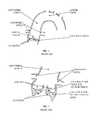
- FIG. 1is a simplified illustration of the anatomy of a calcified aortic valve, ascending aorta and aortic arch.
- FIG. 2is an enlarged view of a calcified aortic valve.
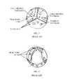
- FIG. 3is a simplified top-view illustration of typical calcification patterns on aortic valve leaflets.
- FIG. 4is a simplified illustration of valve leaflets of FIG. 3 after fractures were obtained, in accordance with an embodiment of the invention.
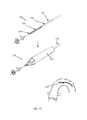
- FIG. 5is a simplified illustration of an impactor catheter delivered over a guidewire through a peripheral artery, over the aortic arch and into the aortic valve, described in PCT Patent Application PCT/US2010/058810 (WO 2011/069025).
- FIG. 6is a simplified illustration of the valve leaflets of FIG. 3 with a footprint of both impactor and stabilizer elements on the leaflets, in accordance with an embodiment of the invention.
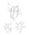
- FIG. 7is a simplified illustration of the “stent-like” impactor design with a footprint similar to the impactor footprint shown in FIG. 6 , in accordance with an embodiment of the invention.
- FIGS. 8-9are top and side views, respectively, of the “stent-like” impactor, in accordance with an embodiment of the invention.
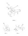
- FIG. 10is a simplified illustration of the “M” stabilizer design with a footprint similar to the stabilizer footprint shown in FIG. 6 , in accordance with an embodiment of the invention.
- FIG. 11-12is a simplified illustration of the top and side view of the “M” stabilizer design, in accordance with an embodiment of the invention.
- FIGS. 13-15are simplified illustrations of the double layer stabilizer design, in accordance with an embodiment of the invention.
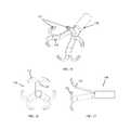
- FIGS. 16-18are simplified illustrations of a “basket” stabilizer, in accordance with an embodiment of the invention.
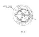
- FIGS. 19-21are simplified illustrations of a “rose” stabilizer assembly, in accordance with another embodiment of the invention.
- FIG. 22is a simplified illustration of the steps of opening and closing the “M” stabilizer of FIG. 10 , in accordance with an embodiment of the invention.
- FIG. 23is a simplified illustration of a method of using various impactor designs for dilating the valve, in accordance with an embodiment of the invention, and of a method of using various impactor designs for measuring the real valve diameter, in accordance with an embodiment of the invention.
- FIGS. 24A-24Bare simplified illustrations of an inner lumen of an impactor and delivery system, and its ability to take pressure measurements from the ventricular and aortic aspects of the aortic valve, in accordance with an embodiment of the invention.
- FIGS. 25-27are simplified illustrations of a stabilizer assembly with cushions or shock absorbers on stabilizing struts, in accordance with an embodiment of the invention.
- FIGS. 28-30are simplified illustrations of a stabilizer assembly with cushions or shock absorbers on stabilizing struts, in accordance with another embodiment of the invention.
- FIG. 31is a simplified illustration of a stabilizer assembly with cushions or shock absorbers on stabilizing struts, which can also be used for embolic capturing, in accordance with yet another embodiment of the invention.
- FIG. 32is a simplified illustration of a “parachute” embolic protection structure, capable of deflecting debris in the blood stream away from the carotid-aortic arch junction, in accordance with an embodiment of the invention.
- FIG. 33is a simplified illustration of transmitting impact across the delivery system to the impactor, in accordance with an embodiment of the invention.
- FIG. 1illustrates the anatomy of a calcified aortic valve, ascending aorta and aortic arch. Calcifications may be embedded and/or superimposed on the valve leaflets, which are connected to the aortic wall just below the coronary ostia. Of course, the invention is not limited to these calcifications.
- FIG. 2illustrates a calcified aortic valve.
- the leafletscreate concave sinuses on their aortic aspect, just below the coronary ostia. Calcification can be either embedded or superimposed on the leaflets, making the leaflets thicker and less pliable. Specifically, calcification that occurs at the leaflet base, i.e. where the leaflet connects to the annulus or aortic wall, can significantly impair the mobility of the leaflet.
- FIG. 3illustrates typical calcification patterns on aortic valve leaflets.
- a “full-bridge” pattern, “half-bridge” pattern and scattered “pebbles”are believed to be common forms of calcification in degenerated aortic stenosis of 3-leaflet valves, although the invention is not limited to any pattern.
- the dashed linesshow the optimal fracture locations that need to be generated in order to maximize the increase in open valve cross sectional area during systole. These locations include the bases of the full-bridge and half-bridge patterns, close to the base of each leaflet, and the centerline of the leaflet in a full-bridge pattern. Leaflets with pebble patterns do not usually obstruct flow that much.
- FIG. 4illustrates the valve leaflets of FIG. 3 after fractures were obtained. Both full-bridge and half-bridge patterns are broken into smaller segments, allowing the leaflets to open during systole, creating a significantly larger aortic valve area.
- FIG. 5illustrates an impactor catheter delivered over a guidewire through a peripheral artery, over the aortic arch and into the aortic valve, described in PCT Patent Application PCT/US2010/058810 (WO 2011/069025), of the inventor (and assigned to the current assignee) of the present invention.
- An impactor elementis opened below the aortic valve leaflets (ventricular aspect) and a stabilizer element is opened above the leaflets. Both elements preferably then “sandwich” the leaflets and the impactor is then pulled rapidly upwards to deliver mechanical impact to the valve leaflets, while the opposing stabilizer holds the leaflets and counteracts the force.
- a catheter 10may be delivered over a guide-wire 11 through a vessel, such as the peripheral artery, using a retrograde approach, through the aortic arch and into the ascending aorta, just above the aortic valve.
- a catheter external shaft 12The external shaft 12 is then retracted so that an expandable (e.g., self-expanding) stabilizer 14 , connected to a stabilizer shaft 16 , opens up.
- Stabilizer 14is used to guide, position and anchor the catheter distal part in the sinuses, just above the valve leaflets.
- catheter 10is just one example of a delivery system used to deliver and manipulate a stabilizer and impactor arms described below to impact calcifications.
- the stabilizer and impactor arms described belowmay be delivered and/or manipulated by other devices other than a catheter, such as a guidewire or system of guidewires and push/pull wires.
- An impactor shaft 18including impactor arms 20 , is then pushed forward (distally) through the center of the valve into the left ventricle. When pushed forward the impactor arms 20 are folded so that they can easily cross the valve.
- An internal shaft 22which is connected to the distal portion of the impactor arms 20 , is then pulled proximally to cause the impactor arms 20 to open (expand) outwards sideways and lock them in the expanded shape.
- Impactor and internal shafts 18 and 22are then pulled back (proximally) a bit in order for the impactor arms 20 to make good contact with the ventricular aspect of the leaflets, so that the leaflets are “sandwiched” between the proximally-located stabilizer 14 (from above in the sense of the drawing) and the distally-located impactor arms 20 (from below in the sense of the drawing).
- impactor arms 20are pulled abruptly towards the leaflet tissue, while the stabilizer 14 holds the relevant portion of the leaflets in place, by pulling impactor and internal shafts 18 and 22 at a speed of at least 1 m/sec, such as without limitation, around 5-20 msec, but with an amplitude of at least 0.5 mm, such as without limitation, about 0.5-3 mm, so that calcification is fractured but soft tissue is unharmed.
- the delivery of the impactor and stabilizer elementscan be done in a reverse manner. In such a case, the impactor first crosses the valve and is opened in order to position and center the device. The stabilizer is then opened in order to sandwich the leaflets, and then impact is delivered.
- the present inventionseeks to provide improved structure over that described in PCT/US2010/058810, both for impact and stabilization.
- FIG. 6illustrates the valve leaflets of FIG. 3 with a preferred footprint (although the invention is not limited to this footprint) of both impactor 70 and stabilizer elements 14 S on the leaflets, in accordance with embodiments of the invention described hereinbelow.
- the impactorwhen in an open position, preferably makes contact with the leaflets from below (the ventricular aspect), along the regions marked as “IF”, short for “impactor-footprint”.
- the stabilizer element(such as a stabilizer 80 ) preferably, but not necessarily, makes contact with the leaflets from above (the aortic aspect) along the regions marked as “SF”, short for “stabilizer-footprint”.
- the impactor and stabilizer elementscan be brought closer together until the leaflets are “sandwiched” by both elements.
- the impactoris then pulled rapidly towards the stabilizer to deliver impact to the valve leaflets, creating a strong and rapid bending force between opposing elements that can generate fractures in the calcifications.
- FIG. 7illustrates an impactor assembly 70 , having a “stent-like” impactor design, in accordance with an embodiment of the invention, with a footprint similar to the impactor footprint presented in FIG. 6 .
- Impactor assembly 70includes one or more impaction struts 72 , which extend between proximal structural struts 74 and distal structural struts 76 .
- the “stent-like” impactorpreferably, but not necessarily, contacts the leaflets from their ventricular aspect using impaction struts 72 .
- Impaction struts 72run along the connection of the leaflet to the aortic wall, creating a footprint on an area that, if not because of calcific deposits, would be flexible enough to allow high mobility of the leaflets.
- the positions of distal structural struts 76are illustrated at about 120° apart, but the invention is not limited to this spacing. Fractures along or near the footprint of the “stent-like” impactor results in a significant increase in aortic valve cross sectional area during systole.
- the “stent-like” impactormay be used in various rotational positions on the valve, preferably, but not necessarily, with proximal structural struts 74 on the ventricular aspect of the commissures, which is the “natural” rotational position of the impactor. Alternatively, the impactor can be rotated so that the proximal structural struts contact the centerline of the valve's leaflets.
- FIGS. 8 and 9illustrate more views of impactor assembly 70 .
- the structure of the “stent-like” impactoris designed to allow active self-positioning of the device on the aortic valve.
- Proximal structural struts 74are located higher than the impaction struts 72 and at an angle relative to the impaction struts 72 , so that the proximal structural struts 74 position themselves just below the commissures when the impactor 70 is pulled towards the valve.
- the positioning of the proximal structural struts 74 below the commissuresis due to stable equilibrium of mechanical forces and therefore cannot be mistakenly altered.
- the impaction struts 72are preferably shaped in accordance with a shape of the desired fracture site, e.g., leaflet bases (close to the annulus) and central folding lines of the native valve.
- the shapes of the impaction struts and of the stabilizermay include portions with a bicuspid shape, a tricuspid shape, or a semilunar shape, and may additionally have a portion with a depression corresponding to the folding lines, depending on the valve to be treated, Due to these predetermined shapes, impactor 70 , by impacting against the stabilizer 14 S, is able to generate fractures along the leaflet bases (close to the annulus) and central folding lines of the valve. This is in contrast with the prior art wherein fractures are not purposely made at these critical places, rather at other places along the leaflets.
- This method of generating fractures along the desired fracture sitecan provide significant improvement in the ability to efficiently fracture calcifications within a relatively short procedure time.
- impactor 70 and stabilizer 14 S( FIG. 6 ) have predetermined shapes that self-position the device with respect to the valve.
- Stabilizer assembly 80may include a shaft 82 , from which extend a plurality of arms 84 (three are shown, spaced 120° apart, in the non-limiting illustrated embodiment). Distal portions of arms 84 include a full bridge section 86 which terminates in a pair of half bridge sections 88 .
- Stabilizer assembly 80may be considered to have an “M” stabilizer design with a footprint similar to the stabilizer footprint presented in FIG. 6 .
- the “M” stabilizerpreferably, but not necessarily, contacts the leaflets from their aortic aspect using full bridge sections 86 and half bridge sections 88 .
- the half bridge section 88is positioned on the bases of the leaflets so as to counteract the impactor (such as impactor 70 of FIG. 7 ) in order to break calcific deposits mainly along the base of the leaflet (its connection to the aortic wall).
- the full bridge section 86is positioned on the centerline of the leaflets in order to break calcific deposits mainly along the central folding line of the leaflets.
- the “M” stabilizercan be positioned in various rotational positions on the valve, preferably, but not necessarily, with its full bridge section 86 along the centerline of the leaflet or with its full bridge section 86 on the commissures so that each half bridge section 88 is touching two leaflets at a time.
- Stabilizer assembly 90may include a double layer stabilizer design, including an external layer 92 which pulls an internal layer 94 and forms a flower shaped stabilizer with two “petals” on each valve leaflet.
- the double layer stabilizermay be operated in various rotational positions and thus can achieve multiple footprints on the valve in order to generate a significant amount of calcium fractures.
- the double layer stabilizeris preferably positioned on the aortic aspect of the valve and is capable of fracturing calcific deposits located in the bases of the leaflets and in the central folding line of the leaflet. The extent of pulling of the external layer determines the stabilizer's diameter.
- Stabilizer assembly 100may include a “basket” stabilizer design, including one stabilizer arm 102 on each valve leaflet.
- Each stabilizer arm 102includes a proximal structural strut 104 from which extends a distal structural strut 106 .
- a rounded stabilizing tip 108is positioned at the junction of proximal structural strut 104 and distal structural strut 106 , and another rounded stabilizing tip 108 is positioned at the junction of all the proximal structural struts 104 .
- the “basket” designcan be rotated to multiple positions and can increase and/or decrease its diameter.
- this stabilizeris capable of touching any point on the valve and to counteract the impact delivered by the impactor at any selected location on the valve.
- the “basket” stabilizing tips 108are fully rounded and have excellent safety properties in addition to high rigidity and counteracting attributes.
- Stabilizer assembly 110may include a “rose” or “rose-petal” stabilizer design, including a plurality of structural struts 112 (for each valve leaflet).
- the structural struts 112extend into curved, twisted, half bridge stabilizing struts 114 , which in turn extend into full bridge stabilizing struts 116 .
- a rounded stabilizing tip 118is positioned at the junction of extensions of the full bridge stabilizing struts 116 .
- the “rose” designcan be rotated to multiple positions and can increase and/or decrease its diameter.
- this stabilizeris capable of touching any point on the valve and to counteract the impact delivered by the impactor at any selected location on the valve.
- the half bridge stabilizing struts 114are fully rounded and have excellent safety properties in addition to high rigidity and counteracting attributes.
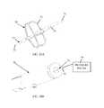
- FIG. 22illustrates use of an external tip 120 of a tube 122 for deploying the stabilizing assemblies of the present invention.
- the external tip 120 of the tube 122initially covers a stabilizer tube T (of any of the embodiments of the invention).
- the external tip 120may have an open distal end and is capable of gradually moving forward (distally) and backwards on the stabilizer and stabilizer tube T. When moving forward the external tip 120 covers more of the stabilizer structure and thus reinforces it and allows a higher counteract force. It may also be pushed forward to decrease the stabilizer diameter or to change the angle in which the stabilizer approaches the valve. All of the mentioned actions can be reversed by pulling the external tip backwards.
- FIG. 23illustrates a method of using various impactor designs for increasing the open cross-sectional area of the valve during systole.
- the impactorsuch as impactor 70
- This methodmay be used before or after impact has been delivered to the leaflets to increase the effect of valve fractures on leaflet pliability, or without delivering impact to the valve.
- Impactor dilation of the valvemay enlarge present fractures, create new fractures, stretch the valve and its immediate surroundings, separate fused commissures and soften calcific deposits within the valve.
- the impactor dilationis designed so as not to obstruct blood flow from the left ventricle towards the aorta, thus making rapid pacing unnecessary in this procedure.
- the method of impactor dilationmay also be designed for dilating other valves, such as the mitral valve, for performing angioplasty on calcified plaque or for increasing the open lumen cross-sectional area in vessels and other lumens in the human anatomy
- FIG. 23also illustrates a method of using various impactor designs for measuring the real valve diameter, in accordance with an embodiment of the invention.
- the impactorsuch as impactor 70
- the impactor diameteris viewed on the operating catheter handle.
- the method of impactor sizinggives a real, in-situ measurement of the valve and may help in determining future prosthesis sizes or in other optional therapies.
- the method of impactor sizingmay also be designed for sizing other valves, such as the mitral valve, for measuring the surroundings of the valve (annulus, aorta), for measuring open lumen cross-sectional areas in healthy or partially obstructed vessels or for measuring the cross-sectional area of other lumens in the human anatomy.
- other valvessuch as the mitral valve, for measuring the surroundings of the valve (annulus, aorta), for measuring open lumen cross-sectional areas in healthy or partially obstructed vessels or for measuring the cross-sectional area of other lumens in the human anatomy.
- FIGS. 24A-24Billustrate the inner lumen of the impactor and delivery system, and demonstrates its ability to take pressure measurements from the ventricular and aortic aspects of the aortic valve.
- the impaction struts 72 of impactor 70may be mounted around an internal sealed shaft 73 .
- the internal sealed shaft 73has a lumen 75 that extends from the proximal to the distal part of the catheter. In the proximal side, lumen 75 continues all the way to a delivery system handle 79 , wherein lumen 75 may terminate in a connection point 81 , which is connected to a pressure gauge 77 that indicates the pressure present in the distal part of lumen 75 .
- the pressure gaugeBy allowing blood to enter the lumen the pressure gauge is affected by the blood pressure and thus can indicate the real-time blood pressure at the distal end of the internal sealed shaft.
- the use of this methodmakes it unnecessary to use a pigtail for left ventricle pressure measurements.
- the method of internal sealed shaft pressure measurementmay also be designed for measuring the pressure across other valves, such as the mitral valve, or for measuring the pressure in other lumens in the human anatomy.
- FIGS. 25-27illustrate a stabilizer assembly 150 with cushions or shock absorbers 152 on stabilizing struts 154 , in accordance with an embodiment of the invention.
- Shock absorbers 152are disposed on the distal portions of half bridge stabilizer sections.
- Shock absorbers 152may be made of any suitably soft material, such as an elastomer or soft plastic, for example.
- FIGS. 28-30illustrate a stabilizer assembly 160 with cushions or shock absorbers 162 on stabilizing struts, in accordance with another embodiment of the invention.
- shock absorbers 162are disposed as full “webs” on the half bridge stabilizer sections and the bridge stabilizer sections.
- shock absorbers 172are constructed from a stretchable material, such as a stretchable plastic, that extends outwards like an umbrella or canopy when deployed out of the stabilizer tube 122 . These absorbers can also be used as capturing means in case embolic debris is created on the aortic aspect of the valve during valve manipulation or impact.
- FIG. 32illustrates a “parachute” embolic protection structure (filter) 150 , capable of deflecting debris in the blood stream away from the carotid-aortic arch junction.
- the “parachute” embolic filter 150includes an external operating tube 152 , a porous sleeve (the “parachute”) 154 and cords 156 that connect the “parachute” 154 at a connection area 156 to the distal part of the external tube 152 .
- the embolic protection filter 150is activated once the operating tube 152 is pulled backwards in the direction of arrow 157 (towards the proximal side); the parachute sleeve 154 then opens due to the blood flow.
- the aortic archis covered by the porous filter 150 and the blood that flows into the carotid arteries is filtered.
- the debrisif present, is thus deflected to the descending aorta, making it impossible for the debris to obstruct blood flow to the brain.
- FIG. 33illustrates the components and methods of transmitting impact across the delivery system to the impactor.
- the internal layer 200consisting of an internal tube 202 and impactor tube 204
- the external layer 206consisting of a stabilizer tube 208 and an external tube 210 .
- Each layeris designed to effectively counteract the other.
- the internal layer 200is preferably constructed of a material with negligible elongation, such as but not limited to, a bundle of stainless steel wires.
- the external layer 206is preferably constructed of a material with negligible compression, such as but not limited to, a braided stainless steel mesh coated with a polymer, such as polyamide 12 (e.g., VESTAMID). Friction between the layers may be minimized by coating the inner surface of the external layer 206 with polytetrafluoroethylene.
- the internal layer 200is initially pre-tensioned against the external layer 206 , with the valve tissue pinched (preferably gently pinched) therebetween. This creates a static pre-loaded mechanical force on both layers. Impact is delivered by a rapid and short deflection of the internal layer 200 towards the external layer 206 . The internal layer 200 is rapidly pulled, such as by mechanical impact, so that the internal layer 200 is further squeezed against the external layer 206 . This causes the impactor to impact the valve which then encounters the external layer's counteracting force. The counteracting forces of the external and internal layers result in fractured calcific deposits along and in proximity the footprints of the impactor and stabilizer.
- the ability to transmit impact across a full catheteris due to, inter alia, the internal layer's negligible elongation, the external layer's negligible compression, both layers' resistance to impact and negligible friction between layers.
- the internal layer's negligible elongationmeans the internal layer transmits the full force of the impact with negligible losses due to strain or stress on the internal layer's material.
- the external layer's negligible compressionmeans the external layer can act as an excellent anvil to bear the brunt of the impact with negligible losses due strain or stress on the external layer's material. Another parameter that helps to achieve efficacious impact is both layers' pre-tensioning towards each other.
Landscapes
- Health & Medical Sciences (AREA)
- Surgery (AREA)
- Life Sciences & Earth Sciences (AREA)
- Medical Informatics (AREA)
- Animal Behavior & Ethology (AREA)
- Engineering & Computer Science (AREA)
- Biomedical Technology (AREA)
- Heart & Thoracic Surgery (AREA)
- Veterinary Medicine (AREA)
- Molecular Biology (AREA)
- Nuclear Medicine, Radiotherapy & Molecular Imaging (AREA)
- General Health & Medical Sciences (AREA)
- Public Health (AREA)
- Vascular Medicine (AREA)
- Orthopedic Medicine & Surgery (AREA)
- Prostheses (AREA)
- Surgical Instruments (AREA)
Abstract
Description
Claims (6)
Priority Applications (1)
| Application Number | Priority Date | Filing Date | Title |
|---|---|---|---|
| US14/362,405US10143452B2 (en) | 2011-12-05 | 2012-12-05 | Fracturing calcifications in heart valves |
Applications Claiming Priority (3)
| Application Number | Priority Date | Filing Date | Title |
|---|---|---|---|
| US201161566766P | 2011-12-05 | 2011-12-05 | |
| US14/362,405US10143452B2 (en) | 2011-12-05 | 2012-12-05 | Fracturing calcifications in heart valves |
| PCT/US2012/067812WO2013085934A1 (en) | 2011-12-05 | 2012-12-05 | Fracturing calcifications in heart valves |
Publications (2)
| Publication Number | Publication Date |
|---|---|
| US20140316428A1 US20140316428A1 (en) | 2014-10-23 |
| US10143452B2true US10143452B2 (en) | 2018-12-04 |
Family
ID=47678984
Family Applications (1)
| Application Number | Title | Priority Date | Filing Date |
|---|---|---|---|
| US14/362,405Active2034-08-23US10143452B2 (en) | 2011-12-05 | 2012-12-05 | Fracturing calcifications in heart valves |
Country Status (5)
| Country | Link |
|---|---|
| US (1) | US10143452B2 (en) |
| EP (1) | EP2787902B1 (en) |
| JP (1) | JP6210236B2 (en) |
| CN (1) | CN104023656B (en) |
| WO (1) | WO2013085934A1 (en) |
Cited By (3)
| Publication number | Priority date | Publication date | Assignee | Title |
|---|---|---|---|---|
| US20180214165A1 (en)* | 2017-01-30 | 2018-08-02 | Pi-Cardia Ltd. | Fracturing calcifications in heart valves |
| US20230056062A1 (en)* | 2016-10-06 | 2023-02-23 | Shockwave Medical, Inc. | Aortic leaflet repair using shock wave applicators |
| US12011184B2 (en) | 2020-02-10 | 2024-06-18 | Elixir Medical Corporation | Methods and apparatus for plaque disruption |
Families Citing this family (56)
| Publication number | Priority date | Publication date | Assignee | Title |
|---|---|---|---|---|
| JPH1049450A (en)* | 1996-07-31 | 1998-02-20 | Kyocera Corp | Recovery method when an error occurs in the remote monitoring system |
| US8652202B2 (en) | 2008-08-22 | 2014-02-18 | Edwards Lifesciences Corporation | Prosthetic heart valve and delivery apparatus |
| US10517719B2 (en) | 2008-12-22 | 2019-12-31 | Valtech Cardio, Ltd. | Implantation of repair devices in the heart |
| US9968452B2 (en) | 2009-05-04 | 2018-05-15 | Valtech Cardio, Ltd. | Annuloplasty ring delivery cathethers |
| US8449599B2 (en) | 2009-12-04 | 2013-05-28 | Edwards Lifesciences Corporation | Prosthetic valve for replacing mitral valve |
| EP3345573B1 (en) | 2011-06-23 | 2020-01-29 | Valtech Cardio, Ltd. | Closure element for use with annuloplasty structure |
| US9554815B2 (en) | 2012-08-08 | 2017-01-31 | Shockwave Medical, Inc. | Shockwave valvuloplasty with multiple balloons |
| DE102012021547A1 (en)* | 2012-11-02 | 2014-05-08 | Johnson & Johnson Medical Gmbh | Surgical implant |
| EP2941210B1 (en)* | 2013-01-07 | 2016-11-16 | Pi-Cardia Ltd. | Stabilizer assembly for fracturing calcifications in heart valves |
| US9439763B2 (en) | 2013-02-04 | 2016-09-13 | Edwards Lifesciences Corporation | Prosthetic valve for replacing mitral valve |
| US9622863B2 (en) | 2013-11-22 | 2017-04-18 | Edwards Lifesciences Corporation | Aortic insufficiency repair device and method |
| WO2016090308A1 (en) | 2014-12-04 | 2016-06-09 | Edwards Lifesciences Corporation | Percutaneous clip for repairing a heart valve |
| EP3294219B1 (en) | 2015-05-14 | 2020-05-13 | Edwards Lifesciences Corporation | Heart valve sealing devices and delivery devices therefor |
| WO2017060851A1 (en)* | 2015-10-07 | 2017-04-13 | Pi-Cardia Ltd. | Impactor for fracturing calcifications in heart valves |
| US10799675B2 (en) | 2016-03-21 | 2020-10-13 | Edwards Lifesciences Corporation | Cam controlled multi-direction steerable handles |
| US10799677B2 (en) | 2016-03-21 | 2020-10-13 | Edwards Lifesciences Corporation | Multi-direction steerable handles for steering catheters |
| US11219746B2 (en) | 2016-03-21 | 2022-01-11 | Edwards Lifesciences Corporation | Multi-direction steerable handles for steering catheters |
| US10799676B2 (en) | 2016-03-21 | 2020-10-13 | Edwards Lifesciences Corporation | Multi-direction steerable handles for steering catheters |
| US10835714B2 (en) | 2016-03-21 | 2020-11-17 | Edwards Lifesciences Corporation | Multi-direction steerable handles for steering catheters |
| WO2017168345A1 (en)* | 2016-03-31 | 2017-10-05 | Pi-Cardia Ltd. | Remodeling of calcified aortic valve leaflets |
| US10973638B2 (en) | 2016-07-07 | 2021-04-13 | Edwards Lifesciences Corporation | Device and method for treating vascular insufficiency |
| US10517708B2 (en) | 2016-10-26 | 2019-12-31 | DePuy Synthes Products, Inc. | Multi-basket clot capturing device |
| US10653862B2 (en) | 2016-11-07 | 2020-05-19 | Edwards Lifesciences Corporation | Apparatus for the introduction and manipulation of multiple telescoping catheters |
| US10905554B2 (en) | 2017-01-05 | 2021-02-02 | Edwards Lifesciences Corporation | Heart valve coaptation device |
| US11224511B2 (en) | 2017-04-18 | 2022-01-18 | Edwards Lifesciences Corporation | Heart valve sealing devices and delivery devices therefor |
| EP4613214A2 (en) | 2017-04-18 | 2025-09-10 | Edwards Lifesciences Corporation | Heart valve sealing devices and delivery devices therefor |
| US10799312B2 (en) | 2017-04-28 | 2020-10-13 | Edwards Lifesciences Corporation | Medical device stabilizing apparatus and method of use |
| US10959846B2 (en) | 2017-05-10 | 2021-03-30 | Edwards Lifesciences Corporation | Mitral valve spacer device |
| US11051940B2 (en) | 2017-09-07 | 2021-07-06 | Edwards Lifesciences Corporation | Prosthetic spacer device for heart valve |
| US11065117B2 (en) | 2017-09-08 | 2021-07-20 | Edwards Lifesciences Corporation | Axisymmetric adjustable device for treating mitral regurgitation |
| US11040174B2 (en) | 2017-09-19 | 2021-06-22 | Edwards Lifesciences Corporation | Multi-direction steerable handles for steering catheters |
| US10624658B2 (en)* | 2017-10-03 | 2020-04-21 | Pi-Cardia Ltd. | Impactor and stabilizer for fracturing calcifications in heart valves |
| CN108175476B (en)* | 2017-12-29 | 2021-01-05 | 杭州安杰思医学科技股份有限公司 | Diameter-variable sleeving and taking device |
| US10076415B1 (en) | 2018-01-09 | 2018-09-18 | Edwards Lifesciences Corporation | Native valve repair devices and procedures |
| US10507109B2 (en) | 2018-01-09 | 2019-12-17 | Edwards Lifesciences Corporation | Native valve repair devices and procedures |
| US10245144B1 (en) | 2018-01-09 | 2019-04-02 | Edwards Lifesciences Corporation | Native valve repair devices and procedures |
| US10231837B1 (en) | 2018-01-09 | 2019-03-19 | Edwards Lifesciences Corporation | Native valve repair devices and procedures |
| FI3964175T3 (en) | 2018-01-09 | 2024-12-03 | Edwards Lifesciences Corp | Native valve repair devices |
| US10136993B1 (en) | 2018-01-09 | 2018-11-27 | Edwards Lifesciences Corporation | Native valve repair devices and procedures |
| US10123873B1 (en) | 2018-01-09 | 2018-11-13 | Edwards Lifesciences Corporation | Native valve repair devices and procedures |
| US10159570B1 (en) | 2018-01-09 | 2018-12-25 | Edwards Lifesciences Corporation | Native valve repair devices and procedures |
| US10238493B1 (en) | 2018-01-09 | 2019-03-26 | Edwards Lifesciences Corporation | Native valve repair devices and procedures |
| US10111751B1 (en) | 2018-01-09 | 2018-10-30 | Edwards Lifesciences Corporation | Native valve repair devices and procedures |
| US10105222B1 (en) | 2018-01-09 | 2018-10-23 | Edwards Lifesciences Corporation | Native valve repair devices and procedures |
| US10973639B2 (en) | 2018-01-09 | 2021-04-13 | Edwards Lifesciences Corporation | Native valve repair devices and procedures |
| US11389297B2 (en) | 2018-04-12 | 2022-07-19 | Edwards Lifesciences Corporation | Mitral valve spacer device |
| US11207181B2 (en) | 2018-04-18 | 2021-12-28 | Edwards Lifesciences Corporation | Heart valve sealing devices and delivery devices therefor |
| US10898216B2 (en) | 2018-06-13 | 2021-01-26 | DePuy Synthes Products, Inc. | Vasculature obstruction capture device |
| US10945844B2 (en) | 2018-10-10 | 2021-03-16 | Edwards Lifesciences Corporation | Heart valve sealing devices and delivery devices therefor |
| CN113226223A (en) | 2018-11-20 | 2021-08-06 | 爱德华兹生命科学公司 | Deployment tools and methods for delivering devices to native heart valves |
| CA3118988A1 (en) | 2018-11-21 | 2020-05-28 | Edwards Lifesciences Corporation | Heart valve sealing devices, delivery devices therefor, and retrieval devices |
| CR20210312A (en) | 2018-11-29 | 2021-09-14 | Edwards Lifesciences Corp | Catheterization method and apparatus |
| ES2969252T3 (en) | 2019-02-14 | 2024-05-17 | Edwards Lifesciences Corp | Heart valve sealing devices and delivery devices therefor |
| CN115768363A (en)* | 2020-07-07 | 2023-03-07 | 皮-卡尔迪亚有限公司 | Heart valve treatment member with variable orientation |
| CN115737061A (en)* | 2022-11-14 | 2023-03-07 | 杭州诺纳生物医疗科技有限公司 | Shock wave device |
| USD1071198S1 (en) | 2023-06-28 | 2025-04-15 | Edwards Lifesciences Corporation | Cradle |
Citations (55)
| Publication number | Priority date | Publication date | Assignee | Title |
|---|---|---|---|---|
| US5846251A (en)* | 1996-07-22 | 1998-12-08 | Hart; Charles C. | Access device with expandable containment member |
| US20010041909A1 (en)* | 1997-05-08 | 2001-11-15 | Embol-X, Inc. | Methods of protecting a patient from embolization during surgery |
| US20020173819A1 (en)* | 2001-05-21 | 2002-11-21 | Bacchus Vascular, Inc. | Apparatus and methods for capturing particulate material within blood vessels |
| US20030004536A1 (en)* | 2001-06-29 | 2003-01-02 | Boylan John F. | Variable thickness embolic filtering devices and method of manufacturing the same |
| US20030023265A1 (en)* | 2001-07-13 | 2003-01-30 | Forber Simon John | Vascular protection system |
| US20030055452A1 (en)* | 2001-09-19 | 2003-03-20 | Joergensen Ib Erling | Methods and apparatus for distal protection during a medical procedure |
| US20030139765A1 (en)* | 2000-10-20 | 2003-07-24 | Patel Nilesh H. | Convertible blood clot filter |
| US20030176884A1 (en)* | 2002-03-12 | 2003-09-18 | Marwane Berrada | Everted filter device |
| US20040093017A1 (en)* | 2002-11-06 | 2004-05-13 | Nmt Medical, Inc. | Medical devices utilizing modified shape memory alloy |
| US20040230220A1 (en)* | 2003-02-11 | 2004-11-18 | Cook Incorporated | Removable vena cava filter |
| US20050015111A1 (en)* | 2001-06-18 | 2005-01-20 | Mcguckin James F. | Vein filter |
| US20050043757A1 (en)* | 2000-06-12 | 2005-02-24 | Michael Arad | Medical devices formed from shape memory alloys displaying a stress-retained martensitic state and method for use thereof |
| US20050075662A1 (en)* | 2003-07-18 | 2005-04-07 | Wesley Pedersen | Valvuloplasty catheter |
| US20050267515A1 (en)* | 2002-11-29 | 2005-12-01 | Vascular Interventional Technologies Inc. | Embolus blood clot filter |
| US20060015137A1 (en)* | 2004-07-19 | 2006-01-19 | Wasdyke Joel M | Retrievable intravascular filter with bendable anchoring members |
| US20060036279A1 (en)* | 2004-08-11 | 2006-02-16 | Eidenschink Tracee E | Single wire intravascular filter |
| US20060095068A1 (en)* | 2004-11-03 | 2006-05-04 | Wasdyke Joel M | Retrievable vena cava filter |
| US20060178695A1 (en)* | 2005-02-04 | 2006-08-10 | Decant Leonard J Jr | Vascular filter with sensing capability |
| US20060287668A1 (en)* | 2005-06-16 | 2006-12-21 | Fawzi Natalie V | Apparatus and methods for intravascular embolic protection |
| US20070032816A1 (en)* | 2005-04-04 | 2007-02-08 | B.Braun Medical | Removable Filter Head |
| US7179275B2 (en)* | 2001-06-18 | 2007-02-20 | Rex Medical, L.P. | Vein filter |
| US20070112374A1 (en)* | 2005-10-18 | 2007-05-17 | Cook Incorporated | Invertible filter for embolic protection |
| US20070112371A1 (en)* | 2005-11-14 | 2007-05-17 | Medtronic Vascular, Inc. | Embolic protection filter having compact collapsed dimensions and method of making same |
| US20070135832A1 (en)* | 2002-03-12 | 2007-06-14 | Wholey Michael H | Vascular catheter with aspiration capabilities and expanded distal tip |
| US20070191878A1 (en)* | 2006-01-20 | 2007-08-16 | Segner Garland L | Body vessel filter |
| US20070198050A1 (en)* | 2006-02-22 | 2007-08-23 | Phase One Medica, Llc | Medical implant device |
| US20070197858A1 (en) | 2004-09-27 | 2007-08-23 | Evalve, Inc. | Methods and devices for tissue grasping and assessment |
| US20070233174A1 (en)* | 2005-04-01 | 2007-10-04 | Gordon Hocking | Trapping Filter for Blood Vessel |
| US20080234722A1 (en)* | 2006-06-14 | 2008-09-25 | Possis Medical, Inc. | Inferior vena cava filter on guidewire |
| US20080275495A1 (en)* | 2007-05-01 | 2008-11-06 | Silver James H | Retrievable medical filter with diverse baskets |
| US20080275492A1 (en)* | 2007-05-01 | 2008-11-06 | Victor Farmiga | Extended duration medical filter with bio-absorbable barbs |
| US20080275487A1 (en)* | 2007-05-01 | 2008-11-06 | Fleming James A | Removable medical filter with stand-off arms |
| US20080275489A1 (en)* | 2007-05-01 | 2008-11-06 | Thomas Frank Kinst | Removable medical filter |
| US20080306499A1 (en)* | 2006-02-13 | 2008-12-11 | Retro Vascular, Inc. | Recanalizing occluded vessels using controlled antegrade and retrograde tracking |
| US20090198270A1 (en)* | 2008-01-11 | 2009-08-06 | Mcguckin Jr James F | Vein Filter |
| WO2010014515A2 (en)* | 2008-07-27 | 2010-02-04 | Klein, David | Fracturing calcifications in heart valves |
| US20100049239A1 (en)* | 2004-01-22 | 2010-02-25 | Rex Medical, Lp | Vein Filter |
| US20100198211A1 (en)* | 2007-05-29 | 2010-08-05 | Kassab Ghassan S | Devices, systems, and methods for valve removal |
| US7803168B2 (en)* | 2004-12-09 | 2010-09-28 | The Foundry, Llc | Aortic valve repair |
| US20100268264A1 (en)* | 2007-10-26 | 2010-10-21 | Medrad, Inc. | Intravascular guidewire filter system for pulmonary embolism protection and embolism removal or maceration |
| US20100312269A1 (en)* | 2004-01-22 | 2010-12-09 | Mcguckin Jr James F | Vein filter |
| US20110060359A1 (en)* | 2006-09-20 | 2011-03-10 | Ralf Hannes | Device for the removal of thrombi from blood vessels |
| US7931659B2 (en)* | 2004-09-10 | 2011-04-26 | Penumbra, Inc. | System and method for treating ischemic stroke |
| WO2011069025A1 (en) | 2009-12-05 | 2011-06-09 | Pi-R-Squared Ltd. | Fracturing calcifications in heart valves |
| US8092470B2 (en)* | 2006-06-08 | 2012-01-10 | Olympus Medical Systems Corp. | Calculus crushing apparatus and medical procedure using endoscope |
| US20120059356A1 (en)* | 2010-09-07 | 2012-03-08 | Di Palma Giorgio | Device and method for removing material from a hollow anatomical structure |
| US20120245607A1 (en)* | 2010-09-21 | 2012-09-27 | Angioscore, Inc. | Method and system for treating valve stenosis |
| US20130035713A1 (en)* | 2011-08-05 | 2013-02-07 | Merit Medical Systems, Inc. | Vascular Filter |
| US20130053882A1 (en)* | 2010-04-13 | 2013-02-28 | Access Point Technologies, Inc. | Embolic material excision trapping device |
| US20130274793A1 (en)* | 2004-01-22 | 2013-10-17 | Rex Medical, L.P. | Vein filter |
| US20140012310A1 (en)* | 2012-07-06 | 2014-01-09 | Cook Medical Technologies Llc | Conical vena cava filter with jugular or femoral retrieval |
| US20150265299A1 (en)* | 2012-10-03 | 2015-09-24 | Christopher J. Cooper | Minimally Invasive Thrombectomy |
| US20160008121A1 (en)* | 2014-07-10 | 2016-01-14 | Ptmc Institute | Medical tool |
| US9364255B2 (en)* | 2011-11-09 | 2016-06-14 | Boston Scientific Scimed, Inc. | Medical cutting devices and methods of use |
| US9510930B2 (en)* | 2008-10-22 | 2016-12-06 | Contego Medical, Llc | Angioplasty device with embolic filter |
Family Cites Families (1)
| Publication number | Priority date | Publication date | Assignee | Title |
|---|---|---|---|---|
| AU2002362442B2 (en)* | 2001-10-01 | 2008-08-07 | Ample Medical, Inc. | Methods and devices for heart valve treatments |
- 2012
- 2012-12-05CNCN201280059535.5Apatent/CN104023656B/enactiveActive
- 2012-12-05EPEP12823063.8Apatent/EP2787902B1/enactiveActive
- 2012-12-05WOPCT/US2012/067812patent/WO2013085934A1/enactiveApplication Filing
- 2012-12-05JPJP2014544996Apatent/JP6210236B2/enactiveActive
- 2012-12-05USUS14/362,405patent/US10143452B2/enactiveActive
Patent Citations (56)
| Publication number | Priority date | Publication date | Assignee | Title |
|---|---|---|---|---|
| US5846251A (en)* | 1996-07-22 | 1998-12-08 | Hart; Charles C. | Access device with expandable containment member |
| US20010041909A1 (en)* | 1997-05-08 | 2001-11-15 | Embol-X, Inc. | Methods of protecting a patient from embolization during surgery |
| US20050043757A1 (en)* | 2000-06-12 | 2005-02-24 | Michael Arad | Medical devices formed from shape memory alloys displaying a stress-retained martensitic state and method for use thereof |
| US20030139765A1 (en)* | 2000-10-20 | 2003-07-24 | Patel Nilesh H. | Convertible blood clot filter |
| US20020173819A1 (en)* | 2001-05-21 | 2002-11-21 | Bacchus Vascular, Inc. | Apparatus and methods for capturing particulate material within blood vessels |
| US20050015111A1 (en)* | 2001-06-18 | 2005-01-20 | Mcguckin James F. | Vein filter |
| US7179275B2 (en)* | 2001-06-18 | 2007-02-20 | Rex Medical, L.P. | Vein filter |
| US20030004536A1 (en)* | 2001-06-29 | 2003-01-02 | Boylan John F. | Variable thickness embolic filtering devices and method of manufacturing the same |
| US20030023265A1 (en)* | 2001-07-13 | 2003-01-30 | Forber Simon John | Vascular protection system |
| US20030055452A1 (en)* | 2001-09-19 | 2003-03-20 | Joergensen Ib Erling | Methods and apparatus for distal protection during a medical procedure |
| US20070135832A1 (en)* | 2002-03-12 | 2007-06-14 | Wholey Michael H | Vascular catheter with aspiration capabilities and expanded distal tip |
| US20030176884A1 (en)* | 2002-03-12 | 2003-09-18 | Marwane Berrada | Everted filter device |
| US20040093017A1 (en)* | 2002-11-06 | 2004-05-13 | Nmt Medical, Inc. | Medical devices utilizing modified shape memory alloy |
| US20050267515A1 (en)* | 2002-11-29 | 2005-12-01 | Vascular Interventional Technologies Inc. | Embolus blood clot filter |
| US20040230220A1 (en)* | 2003-02-11 | 2004-11-18 | Cook Incorporated | Removable vena cava filter |
| US20050075662A1 (en)* | 2003-07-18 | 2005-04-07 | Wesley Pedersen | Valvuloplasty catheter |
| US20100049239A1 (en)* | 2004-01-22 | 2010-02-25 | Rex Medical, Lp | Vein Filter |
| US20100312269A1 (en)* | 2004-01-22 | 2010-12-09 | Mcguckin Jr James F | Vein filter |
| US20130274793A1 (en)* | 2004-01-22 | 2013-10-17 | Rex Medical, L.P. | Vein filter |
| US20060015137A1 (en)* | 2004-07-19 | 2006-01-19 | Wasdyke Joel M | Retrievable intravascular filter with bendable anchoring members |
| US20060036279A1 (en)* | 2004-08-11 | 2006-02-16 | Eidenschink Tracee E | Single wire intravascular filter |
| US7931659B2 (en)* | 2004-09-10 | 2011-04-26 | Penumbra, Inc. | System and method for treating ischemic stroke |
| US20070197858A1 (en) | 2004-09-27 | 2007-08-23 | Evalve, Inc. | Methods and devices for tissue grasping and assessment |
| US20060095068A1 (en)* | 2004-11-03 | 2006-05-04 | Wasdyke Joel M | Retrievable vena cava filter |
| US7803168B2 (en)* | 2004-12-09 | 2010-09-28 | The Foundry, Llc | Aortic valve repair |
| US20060178695A1 (en)* | 2005-02-04 | 2006-08-10 | Decant Leonard J Jr | Vascular filter with sensing capability |
| US20070233174A1 (en)* | 2005-04-01 | 2007-10-04 | Gordon Hocking | Trapping Filter for Blood Vessel |
| US20070032816A1 (en)* | 2005-04-04 | 2007-02-08 | B.Braun Medical | Removable Filter Head |
| US20060287668A1 (en)* | 2005-06-16 | 2006-12-21 | Fawzi Natalie V | Apparatus and methods for intravascular embolic protection |
| US20070112374A1 (en)* | 2005-10-18 | 2007-05-17 | Cook Incorporated | Invertible filter for embolic protection |
| US20070112371A1 (en)* | 2005-11-14 | 2007-05-17 | Medtronic Vascular, Inc. | Embolic protection filter having compact collapsed dimensions and method of making same |
| US20070191878A1 (en)* | 2006-01-20 | 2007-08-16 | Segner Garland L | Body vessel filter |
| US20080306499A1 (en)* | 2006-02-13 | 2008-12-11 | Retro Vascular, Inc. | Recanalizing occluded vessels using controlled antegrade and retrograde tracking |
| US20070198050A1 (en)* | 2006-02-22 | 2007-08-23 | Phase One Medica, Llc | Medical implant device |
| US8092470B2 (en)* | 2006-06-08 | 2012-01-10 | Olympus Medical Systems Corp. | Calculus crushing apparatus and medical procedure using endoscope |
| US20080234722A1 (en)* | 2006-06-14 | 2008-09-25 | Possis Medical, Inc. | Inferior vena cava filter on guidewire |
| US20110060359A1 (en)* | 2006-09-20 | 2011-03-10 | Ralf Hannes | Device for the removal of thrombi from blood vessels |
| US20080275492A1 (en)* | 2007-05-01 | 2008-11-06 | Victor Farmiga | Extended duration medical filter with bio-absorbable barbs |
| US20080275489A1 (en)* | 2007-05-01 | 2008-11-06 | Thomas Frank Kinst | Removable medical filter |
| US20080275487A1 (en)* | 2007-05-01 | 2008-11-06 | Fleming James A | Removable medical filter with stand-off arms |
| US20080275495A1 (en)* | 2007-05-01 | 2008-11-06 | Silver James H | Retrievable medical filter with diverse baskets |
| US20100198211A1 (en)* | 2007-05-29 | 2010-08-05 | Kassab Ghassan S | Devices, systems, and methods for valve removal |
| US20100268264A1 (en)* | 2007-10-26 | 2010-10-21 | Medrad, Inc. | Intravascular guidewire filter system for pulmonary embolism protection and embolism removal or maceration |
| US20090198270A1 (en)* | 2008-01-11 | 2009-08-06 | Mcguckin Jr James F | Vein Filter |
| US20110118634A1 (en)* | 2008-07-27 | 2011-05-19 | Erez Golan | Fracturing calcifications in heart valves |
| WO2010014515A2 (en)* | 2008-07-27 | 2010-02-04 | Klein, David | Fracturing calcifications in heart valves |
| US9510930B2 (en)* | 2008-10-22 | 2016-12-06 | Contego Medical, Llc | Angioplasty device with embolic filter |
| WO2011069025A1 (en) | 2009-12-05 | 2011-06-09 | Pi-R-Squared Ltd. | Fracturing calcifications in heart valves |
| US20130053882A1 (en)* | 2010-04-13 | 2013-02-28 | Access Point Technologies, Inc. | Embolic material excision trapping device |
| US20120059356A1 (en)* | 2010-09-07 | 2012-03-08 | Di Palma Giorgio | Device and method for removing material from a hollow anatomical structure |
| US20120245607A1 (en)* | 2010-09-21 | 2012-09-27 | Angioscore, Inc. | Method and system for treating valve stenosis |
| US20130035713A1 (en)* | 2011-08-05 | 2013-02-07 | Merit Medical Systems, Inc. | Vascular Filter |
| US9364255B2 (en)* | 2011-11-09 | 2016-06-14 | Boston Scientific Scimed, Inc. | Medical cutting devices and methods of use |
| US20140012310A1 (en)* | 2012-07-06 | 2014-01-09 | Cook Medical Technologies Llc | Conical vena cava filter with jugular or femoral retrieval |
| US20150265299A1 (en)* | 2012-10-03 | 2015-09-24 | Christopher J. Cooper | Minimally Invasive Thrombectomy |
| US20160008121A1 (en)* | 2014-07-10 | 2016-01-14 | Ptmc Institute | Medical tool |
Non-Patent Citations (1)
| Title |
|---|
| PCT Written Opinion PCT/2012/067812, dated Apr. 2, 2013. |
Cited By (4)
| Publication number | Priority date | Publication date | Assignee | Title |
|---|---|---|---|---|
| US20230056062A1 (en)* | 2016-10-06 | 2023-02-23 | Shockwave Medical, Inc. | Aortic leaflet repair using shock wave applicators |
| US12144516B2 (en)* | 2016-10-06 | 2024-11-19 | Shockwave Medical, Inc. | Aortic leaflet repair using shock wave applicators |
| US20180214165A1 (en)* | 2017-01-30 | 2018-08-02 | Pi-Cardia Ltd. | Fracturing calcifications in heart valves |
| US12011184B2 (en) | 2020-02-10 | 2024-06-18 | Elixir Medical Corporation | Methods and apparatus for plaque disruption |
Also Published As
| Publication number | Publication date |
|---|---|
| EP2787902A1 (en) | 2014-10-15 |
| EP2787902B1 (en) | 2018-09-19 |
| CN104023656A (en) | 2014-09-03 |
| JP2015502809A (en) | 2015-01-29 |
| CN104023656B (en) | 2017-02-15 |
| US20140316428A1 (en) | 2014-10-23 |
| JP6210236B2 (en) | 2017-10-11 |
| WO2013085934A1 (en) | 2013-06-13 |
Similar Documents
| Publication | Publication Date | Title |
|---|---|---|
| US10143452B2 (en) | Fracturing calcifications in heart valves | |
| US20210393281A1 (en) | Fracturing calcifications in heart valves | |
| US11318014B2 (en) | Prosthetic valve delivery system with multi-planar steering | |
| CN109789017B (en) | Steerable delivery system for replacing a mitral valve and methods of use | |
| EP3407834B1 (en) | Systems for repositioning a fully deployed valve assembly | |
| EP3288499B1 (en) | Replacement mitral valve and delivery system for replacement mitral valve | |
| AU783906B2 (en) | Endoluminal cardiac and venous valve prostheses and methods of manufacture and delivery thereof | |
| EP3572045B1 (en) | Stents for prosthetic heart valves | |
| EP1951166B1 (en) | Transapical heart valve delivery syste | |
| US20090264859A1 (en) | Catheter Having a Selectively Expandable Distal Tip | |
| US9724121B2 (en) | Apparatus and methods for recannalization, valve repair and replacement | |
| US20130131710A1 (en) | Device system and method for reshaping tissue openings | |
| KR20230012397A (en) | artificial heart valve | |
| CN118488814A (en) | Prosthetic valve with wider outflow cell | |
| US20180214165A1 (en) | Fracturing calcifications in heart valves | |
| US20230346401A1 (en) | Fracturing calcifications in heart valves | |
| CN222091911U (en) | Delivery equipment | |
| EP4378420B1 (en) | Stents for prosthetic heart valves | |
| HK1117026B (en) | Transapical heart valve delivery system |
Legal Events
| Date | Code | Title | Description |
|---|---|---|---|
| AS | Assignment | Owner name:PI-CARDIA LTD., ISRAEL Free format text:ASSIGNMENT OF ASSIGNORS INTEREST;ASSIGNOR:GOLAN, EREZ;REEL/FRAME:035977/0908 Effective date:20150705 | |
| STCF | Information on status: patent grant | Free format text:PATENTED CASE | |
| AS | Assignment | Owner name:KREOS CAPITAL VI (EXPERT FUND) L.P., JERSEY Free format text:SECURITY INTEREST;ASSIGNOR:PI-CARDIA LTD.;REEL/FRAME:057888/0869 Effective date:20211021 | |
| FEPP | Fee payment procedure | Free format text:MAINTENANCE FEE REMINDER MAILED (ORIGINAL EVENT CODE: REM.); ENTITY STATUS OF PATENT OWNER: SMALL ENTITY | |
| FEPP | Fee payment procedure | Free format text:SURCHARGE FOR LATE PAYMENT, SMALL ENTITY (ORIGINAL EVENT CODE: M2554); ENTITY STATUS OF PATENT OWNER: SMALL ENTITY | |
| MAFP | Maintenance fee payment | Free format text:PAYMENT OF MAINTENANCE FEE, 4TH YR, SMALL ENTITY (ORIGINAL EVENT CODE: M2551); ENTITY STATUS OF PATENT OWNER: SMALL ENTITY Year of fee payment:4 | |
| AS | Assignment | Owner name:KREOS CAPITAL VI (EXPERT FUND) L.P., JERSEY Free format text:SECURITY INTEREST;ASSIGNOR:PI-CARDIA LTD;REEL/FRAME:066208/0842 Effective date:20231219 | |
| AS | Assignment | Owner name:KREOS CAPITAL VI (EXPERT FUND) LP, JERSEY Free format text:SECURITY INTEREST;ASSIGNOR:PI-CARDIA LTD.;REEL/FRAME:071463/0524 Effective date:20250430 |