US10142988B2 - Base station configured for persistent resource allocation - Google Patents
Base station configured for persistent resource allocationDownload PDFInfo
- Publication number
- US10142988B2 US10142988B2US14/879,632US201514879632AUS10142988B2US 10142988 B2US10142988 B2US 10142988B2US 201514879632 AUS201514879632 AUS 201514879632AUS 10142988 B2US10142988 B2US 10142988B2
- Authority
- US
- United States
- Prior art keywords
- persistent
- base station
- map
- resource allocation
- client station
- Prior art date
- Legal status (The legal status is an assumption and is not a legal conclusion. Google has not performed a legal analysis and makes no representation as to the accuracy of the status listed.)
- Active, expires
Links
Images


Classifications
- H—ELECTRICITY
- H04—ELECTRIC COMMUNICATION TECHNIQUE
- H04W—WIRELESS COMMUNICATION NETWORKS
- H04W72/00—Local resource management
- H04W72/04—Wireless resource allocation
- H04W72/044—Wireless resource allocation based on the type of the allocated resource
- H04W72/0453—Resources in frequency domain, e.g. a carrier in FDMA
- H—ELECTRICITY
- H04—ELECTRIC COMMUNICATION TECHNIQUE
- H04W—WIRELESS COMMUNICATION NETWORKS
- H04W72/00—Local resource management
- H04W72/20—Control channels or signalling for resource management
- H04W72/23—Control channels or signalling for resource management in the downlink direction of a wireless link, i.e. towards a terminal
- H—ELECTRICITY
- H04—ELECTRIC COMMUNICATION TECHNIQUE
- H04L—TRANSMISSION OF DIGITAL INFORMATION, e.g. TELEGRAPHIC COMMUNICATION
- H04L1/00—Arrangements for detecting or preventing errors in the information received
- H04L1/12—Arrangements for detecting or preventing errors in the information received by using return channel
- H04L1/16—Arrangements for detecting or preventing errors in the information received by using return channel in which the return channel carries supervisory signals, e.g. repetition request signals
- H04L1/18—Automatic repetition systems, e.g. Van Duuren systems
- H04L1/1829—Arrangements specially adapted for the receiver end
- H04L1/1861—Physical mapping arrangements
- H—ELECTRICITY
- H04—ELECTRIC COMMUNICATION TECHNIQUE
- H04L—TRANSMISSION OF DIGITAL INFORMATION, e.g. TELEGRAPHIC COMMUNICATION
- H04L1/00—Arrangements for detecting or preventing errors in the information received
- H04L1/12—Arrangements for detecting or preventing errors in the information received by using return channel
- H04L1/16—Arrangements for detecting or preventing errors in the information received by using return channel in which the return channel carries supervisory signals, e.g. repetition request signals
- H04L1/18—Automatic repetition systems, e.g. Van Duuren systems
- H04L1/1867—Arrangements specially adapted for the transmitter end
- H04L1/1887—Scheduling and prioritising arrangements
- H—ELECTRICITY
- H04—ELECTRIC COMMUNICATION TECHNIQUE
- H04L—TRANSMISSION OF DIGITAL INFORMATION, e.g. TELEGRAPHIC COMMUNICATION
- H04L5/00—Arrangements affording multiple use of the transmission path
- H04L5/003—Arrangements for allocating sub-channels of the transmission path
- H04L5/0053—Allocation of signalling, i.e. of overhead other than pilot signals
- H04L5/0055—Physical resource allocation for ACK/NACK
- H—ELECTRICITY
- H04—ELECTRIC COMMUNICATION TECHNIQUE
- H04L—TRANSMISSION OF DIGITAL INFORMATION, e.g. TELEGRAPHIC COMMUNICATION
- H04L5/00—Arrangements affording multiple use of the transmission path
- H04L5/0091—Signalling for the administration of the divided path, e.g. signalling of configuration information
- H04L5/0096—Indication of changes in allocation
- H—ELECTRICITY
- H04—ELECTRIC COMMUNICATION TECHNIQUE
- H04W—WIRELESS COMMUNICATION NETWORKS
- H04W72/00—Local resource management
- H04W72/04—Wireless resource allocation
- H—ELECTRICITY
- H04—ELECTRIC COMMUNICATION TECHNIQUE
- H04W—WIRELESS COMMUNICATION NETWORKS
- H04W72/00—Local resource management
- H04W72/04—Wireless resource allocation
- H04W72/044—Wireless resource allocation based on the type of the allocated resource
- H04W72/0466—Wireless resource allocation based on the type of the allocated resource the resource being a scrambling code
- H—ELECTRICITY
- H04—ELECTRIC COMMUNICATION TECHNIQUE
- H04L—TRANSMISSION OF DIGITAL INFORMATION, e.g. TELEGRAPHIC COMMUNICATION
- H04L1/00—Arrangements for detecting or preventing errors in the information received
- H04L1/0001—Systems modifying transmission characteristics according to link quality, e.g. power backoff
- H04L1/0002—Systems modifying transmission characteristics according to link quality, e.g. power backoff by adapting the transmission rate
- H04L1/0003—Systems modifying transmission characteristics according to link quality, e.g. power backoff by adapting the transmission rate by switching between different modulation schemes
- H04L1/0004—Systems modifying transmission characteristics according to link quality, e.g. power backoff by adapting the transmission rate by switching between different modulation schemes applied to control information
- H—ELECTRICITY
- H04—ELECTRIC COMMUNICATION TECHNIQUE
- H04L—TRANSMISSION OF DIGITAL INFORMATION, e.g. TELEGRAPHIC COMMUNICATION
- H04L1/00—Arrangements for detecting or preventing errors in the information received
- H04L1/0001—Systems modifying transmission characteristics according to link quality, e.g. power backoff
- H04L1/0009—Systems modifying transmission characteristics according to link quality, e.g. power backoff by adapting the channel coding
- H04L1/001—Systems modifying transmission characteristics according to link quality, e.g. power backoff by adapting the channel coding applied to control information
- H—ELECTRICITY
- H04—ELECTRIC COMMUNICATION TECHNIQUE
- H04L—TRANSMISSION OF DIGITAL INFORMATION, e.g. TELEGRAPHIC COMMUNICATION
- H04L5/00—Arrangements affording multiple use of the transmission path
- H04L5/0001—Arrangements for dividing the transmission path
- H04L5/0003—Two-dimensional division
- H04L5/0005—Time-frequency
- H04L5/0007—Time-frequency the frequencies being orthogonal, e.g. OFDM(A) or DMT
- H—ELECTRICITY
- H04—ELECTRIC COMMUNICATION TECHNIQUE
- H04L—TRANSMISSION OF DIGITAL INFORMATION, e.g. TELEGRAPHIC COMMUNICATION
- H04L5/00—Arrangements affording multiple use of the transmission path
- H04L5/003—Arrangements for allocating sub-channels of the transmission path
- H—ELECTRICITY
- H04—ELECTRIC COMMUNICATION TECHNIQUE
- H04W—WIRELESS COMMUNICATION NETWORKS
- H04W88/00—Devices specially adapted for wireless communication networks, e.g. terminals, base stations or access point devices
- H04W88/08—Access point devices
Definitions
- the inventionrelates to the field of wireless communications. More particularly, the invention relates to the field of resource allocation in a wireless communication system.
- Wireless communication systemsmay support discontinuous transmission in which the various parties to a communication link use resources only as needed. Limiting the allocation and consumption of resources to those devices actively engaged in communications increases the efficiency of a wireless communication system. However, each device may need to request an allocation of resources before it is granted the opportunity to communicate. The request and grant of communication resources can itself consume a large amount of resources that otherwise could be used to support additional users or provide increased bandwidth to active users.
- a method of persistent resource allocationin which a base station schedules a candidate client station for a persistent resource allocation, associates the candidate client station with a shared NACK channel, configures a persistent allocation information element indicating the persistent resource allocation and transmits the persistent allocation information element.
- the base stationmay further configure the persistent allocation information element to indicate a pseudo random code which defines the shared NACK channel. It may also receive a NACK message over the shared NACK channel and transmit an indication of a set of recent changes made to persistent allocations corresponding to a set of client stations associated with the shared NACK channel.
- the base stationmay receive a NACK message over the shared NACK channel, determine that no changes have been made to persistent allocation corresponding to a set of client stations associated with the shared NACK channel and transmit a no-changes-made indication to the set of client stations.
- the base stationmay detect little or no energy from the candidate client station on the persistent resource allocation and retransmit the persistent allocation information element.
- the persistent resource allocationmay be configured to carry an HARQ packet stream and the base station may detect a series of failed HARQ packet transfers and retransmit the persistent allocation information element.
- a method of persistent uplink resource allocationin which an element of the communication network communicates a persistent resource allocation information element, receives a NACK on a predetermine shared NACK channel and retransmits at least a portion of the persistent resource allocation information element to a group of client stations associated with the shared NACK channel.
- a method of persistent uplink resource allocationis also disclosed in which a resource map is received. An attempt is made to decode a persistent allocation information element within the resource map. A map NACK is selectively transmitted over a shared map NACK channel if the persistent allocation information element fails to successfully decode. In one aspect, transmission of data is ceased on an uplink channel associated with a most recently received downlink persistent allocation. According to one aspect, a map NACK channel recovery process begins in response to a failure to receive an expected response to transmission of the map NACK. According to another aspect, a second persistent allocation information element is received that indicates that a NACK message was received and no changes were made.
- a base stationwhich executes a method of recovering from an error condition in a system using a shared NACK channel.
- the base stationsends an uplink persistent allocation information element specifying a first persistent allocation for a client station. If the base station detects little or no signal energy from the client station on the first persistent allocation, the base station resends the uplink persistent allocation information element to the client station.
- the base stationmay recover from an error condition by sending an persistent allocation information element specifying a first allocation to a client station for a purpose of carrying HARQ traffic, by detecting a series of failed HARQ packet transfers associated with the first allocation, and resending the persistent allocation information element to the client station.
- a client stationwhich executes a method of recovering from an error condition in a system using a shared map NACK channel by receiving a persistent allocation information element from a base station for a purpose of carrying HARQ traffic over a first allocation, detecting a series of failed HARQ packet transfers associated with the first allocation and by sending a map NACK channel error message to the base station.
- a base stationmay establish a global map NACK channel for persistent allocation assignments, send an uplink persistent allocation information element to a client station indicating an associated shared NACK channel, receive a global NACK message on the global map NACK channel and resend a set of recently changed persistent allocation information elements to a set client stations associated with two or more shared NACK channels.
- a client stationfails to receive a persistent allocation information element while no persistent allocation is currently assigned to the client station.
- the client stationdetermines that no shared map NACK channel assignment is active and sends a global map NACK message on the global map NACK channel.
- a base stationhaving a group scheduler configured to schedule a candidate client station for persistent uplink resource allocation, a persistent DL/UL IE generator configured to associate the candidate client station with a shared map NACK channel and to configure a persistent allocation information element identifying a persistent resource allocation and a transmitter configured to transmit the persistent allocation information element.
- the base stationmay be configured to receive a map NACK message over the shared map NACK channel and the persistent DL/UL IE generator is further configured to determine a set of recent changes made to persistent allocations corresponding to a set of client stations associated with the shared NACK channel for retransmission.
- the client stationhas a receiver configured to receive a resource map, a DL/UL-map module configured to determine whether a persistent allocation information element is within the resource map and to attempt to decode the persistent allocation information element, and a NACK module configured to selectively create a map NACK message for transmission over a shared map NACK channel if the DL/UL module is unable to successfully decode the persistent allocation information element.
- FIG. 1is a simplified functional block diagram of an embodiment of a wireless communication system.
- FIG. 2is a simplified functional block diagram of an embodiment of a base station implementing persistent downlink or uplink resource allocation.
- FIG. 3is a simplified functional block diagram of an embodiment of a client station configured to operate using persistent downlink or uplink resource allocation.
- FIG. 4is a simplified timing diagram of an embodiment of a persistent resource allocation.
- FIG. 5is a simplified timing diagram of an embodiment of map NACK messaging in a system having persistent resource allocation.
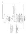
- FIG. 6is a simplified flowchart of an embodiment of a method of persistent downlink or uplink resource allocation.
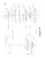
- FIG. 7is a simplified flowchart of an embodiment of a method of resource reallocation in the presence of error correction.
- FIG. 8is a simplified flowchart of an embodiment of a method of error correction signaling in a client station.
- FIG. 9is a flowchart of an embodiment of a method of addressing a persistent allocation map error from the perspective of a base station.
- FIG. 10is a flowchart of an embodiment of a method of addressing a downlink persistent allocation map error from the perspective of a client station.
- DLdownlink
- ULuplink
- the allocationWhen the base station assigns a standard non-persistent downlink or uplink allocation for use by a client station, the allocation is valid for a predetermined frame, such as a frame in which the allocation is granted or the frame following the frame in which the allocation is granted, depending on the allocation relevancy. In contrast, when a base station assigns a persistent downlink or uplink allocation to a client station, the allocation typically remains valid for multiple future downlink or uplink frames. Thus, the client station does not need to repeat a request for uplink resources periodically over a long series of frames. Nor does the base station need to expressly and repeatedly identify a downlink or uplink resource allocation in a series of downlink or uplink map information element (IE) messages when the base station implements persistent resource allocation.
- IEdownlink map information element
- a client stationrequests a persistent downlink or uplink allocation when the client station is producing a data stream which is predictably periodic and in which the packets are generally fixed in size. For example, when a client station has established a voice over Internet protocol (VOIP) connection, a steady stream of voice packets will typically be produced.
- the base stationcan verify that the downlink or uplink resource request meets the criteria for persistent resource allocation and allocate persistent downlink or uplink resources as part of a persistent downlink or uplink map information element (IE) message that is transmitted to the client stations in the system.
- IEmap information element
- the base stationhas the ability to determine that a client station is a candidate for a persistent downlink or uplink resource allocation. For example, the base station can determine that a client station is a candidate for a persistent downlink or uplink resource allocation based on one or more parameters.
- the parameterscan include, for example, repeated requests for uplink resource allocations from the client station, the consistency of the resource allocation requested, stability of characteristics of a wireless channel between the base station and the client station, knowledge of the packet arrival distribution, and the type of connection. As an example, if the connection is in support of VOIP communication, the base station typically knows that the packet arrival pattern is a good candidate for persistent resource allocation.
- the persistent allocationremains dedicated to the client station in future frames until a predetermined terminating event, such as a passage of time, passage of a predetermined number of frames, the base station notifying the client station that the resource has been deallocated, a base station reallocating all or part of resources allocated to another client station, and the like or some combination thereof.
- the base stationmay deallocate a persistent resource by sending a revised persistent downlink or uplink map IE which no longer allocates a persistent resource to the client station or reallocates resources to the client station.
- the base stationsends an express deallocation message.
- the base stationcan group the client station resource request and resource allocation to any one of multiple persistence groups.
- the base stationcan select a persistence group for a particular client station based on such factors as a traffic arrival pattern, a power class of the client station, load balancing at the base station, and the like or some combination thereof.
- the base stationcan allocate uplink resources to the client stations in each of the persistence groups such that members of each persistence group transmit in a frame distinct from any other persistence group. Similarly, the base station can allocate persistent resources to the client stations in each of the persistent groups such that members of each persistence group transmit in a frame distinct from any other persistence group. If the base station allocates both persistent downlink and uplink resources to a particular client station, the persistence groups will coincide. For example, each persistence group can be associated with a group cycle number and a persistent resource allocation can be valid for uplink frames associated with the group cycle index. In one embodiment, the persistence groups can be time cycled in a round-robin schedule in order to provide uniform access and a uniform rate across the multiple persistence groups.
- a simple implementationutilizes the frame number and group cycle index to identify the active persistence group associated with a particular frame.
- the active persistence groupcan be identified by determining the modulo function of the frame number and the total number of persistence groups, typically notated as MOD (frame number, N), and comparing the result against the group cycle index, where N represents the number of persistence groups.
- the modulo operationreturns the remainder of division of one number by another. Given two numbers, a (the dividend) and x (the divisor), mod (a,x) is the remainder, of division of a by x. For instance, the expression MOD (7,3) would evaluate to 1, while MOD (9,3) would evaluate to 0.)
- the client stationneed not have any knowledge of its group cycle index and only needs to know the number of persistence groups, N.
- the client stationcan determine its group cycle index by determining the value of MOD (frame number, N) for the first frame number for which it is allocated persistent downlink or uplink resources.
- Groupsmay also be identified and associated with client stations explicitly by communicating a period parameter in the persistent allocation IE.
- an express indication of the period of the persistent allocationis sent in the UL-MAP information element, thus eliminating the need for the use of a modulo function.
- the base stationcan distinguish data coming from the various client stations according to time (number of symbols) and frequency (number of subcarriers). Of course in other systems, the base station may distinguish data coming from the various client stations according to some other physical layer (PHY) characteristics associated with the system.
- PHYphysical layer
- the base stationtypically does not assign individual physical layer units to the client stations. Instead, the physical layer units are grouped together into “allocation units.” The base station assigns resources to the client stations by specifying allocation units, rather than designating individual physical layer units.
- An allocation unitcan be, for example, a combination of a predetermined number of subcarriers and symbols. In one embodiment, a minimum allocation unit is referred to as a “slot,” and a slot encompasses a predetermined number of subcarriers in one or more OFDMA symbols.
- Each frameincludes a downlink subframe and uplink subframe.
- the downlink subframetypically includes link management transmissions (such as synchronization signals and the like), overhead channels, a number of downlink allocation units for carrying user data from the base station to the client stations as well as other types of overhead and data transmissions.
- the uplink subframeincludes many of these same categories of transmissions, including uplink allocation units for carrying user data from the client station to the base station and control signaling channels for system control, administration and the like.
- Modulationis the process of encoding information onto a signal for transmission.
- Many modulation schemesare well known in the art including binary phased shift keying (BPSK), quadrature phase shift keying (QPSK) and quadrature amplitude modulation (QAM.) Modulation schemes differ from one another according to the amount of data carried by any one symbol. Higher order modulation schemes carry more data per symbol. For example, a 16 QAM symbol carries 4 bits of data per symbol while BPSK modulation carries only one bit of data per symbol.
- error correction codingsuch as forward error correction (FEC)
- FECforward error correction
- the code ratetypically refers to the length of the uncoded information divided by the length of the resulting encoded information.
- the redundancycan be used to correct for errors which are introduced by the wireless channel.
- the effectiveness of a coding schemeis measured in terms of coding gain, which can be expressed as the difference between the signal to noise level required to reach the same bit error rate level for encoded and uncoded data.
- Modern error correction coding techniquesprovide substantial coding gains.
- the use of error correction codingtypically decreases the effective rate at which data is transmitted over the channel. Therefore, transmissions using codes having higher redundancy rates are more robust, but less efficient than transmissions using codes having lower redundancy rates.
- the IEEE 802.16e standard and its progenydefine a variety of modulation and coding scheme (MCS) combinations.
- MCSmodulation and coding scheme
- the MCSspecifies a type of modulation as well as a type of forward error correction which the client station is to use on the uplink transmission.
- the MCS combinationsaccommodate the large variation in performance associated with the client stations scattered throughout the coverage area. Proper selection of an MCS combination is important to both the efficiency and performance of a wireless link.
- the base stationWhen the base station assigns an allocation unit to a specific client station, it also specifies the MCS combination to be used on the allocation. This may be typical for both persistent and nonpersistent resource allocations.
- the base stationsends a persistent resource allocation, generally it need not resend the resource allocation unless a change to the downlink or uplink resource allocations makes it advantageous to resend the resource allocation.
- a new full or partial persistent uplink map IEmay be sent when there is a need to change the size of the allocation. Such a size change may occur if the operating conditions of the client station assigned a persistent allocation are altered or otherwise change to such a degree that a new MCS combination is advantageous. Therefore the base station typically resends the persistent downlink or uplink map IE to identify the new MCS combination and assign the client station fewer or more allocation units as appropriate.
- a new persistent downlink or uplink map IEmay be sent when a voice activity state changes, thus changing the rate of occurrence of the persistent allocation.
- the base stationtypically resends the persistent uplink map IE if requested by the client station to do so, and may alter a persistent downlink map accordingly.
- the base stationcan be configured to periodically resend the persistent downlink or uplink map IE even if no changes have occurred to permit client stations in the base station coverage area to verify the persistent downlink and uplink resource allocations.
- persistent downlink and uplink map IEmay be resent, some of which are discussed below.
- OFDMAOrthogonal Frequency Division Multiple Access
- FIG. 1is a simplified functional block diagram of an embodiment of a wireless communication system 100 .
- the wireless communication system 100includes a plurality of base stations 110 a , 110 b , each supporting a corresponding service or coverage area 112 a , 112 b .
- Each base station 110 a and 110 bcan be coupled to one another and a supporting network (not shown) via a combination of a wired and wireless links.
- the base stationfor example 110 a , can communicate with wireless devices within its coverage area 112 a .
- the first base station 110 acan wirelessly communicate with a first client station 130 a and a second client station 130 b within the coverage area 112 a over a downlink 116 a and an uplink 116 b.
- the base stations 110 a and 110 bcan be configured as cellular base station transceiver subsystems, gateways, access points, radio frequency (RF) repeaters, frame repeaters, nodes or any wireless network entry point.
- RFradio frequency
- the base stations 110 a and 110 balso communicate with each other and a network control module (not shown) over backhaul links (also not shown.)
- the backhaul linksmay include wired and wireless communication links.
- the network control moduleprovides network administration and coordination as well as other overhead, coupling and supervisory functions for the wireless communication system.
- the network control modulealso couples the wireless link system to other communications systems such as the Internet, convention telephone systems and the like.
- client stations 130 a and 130 bcan be mobile, nomadic or stationary units.
- the client stations 130 a and 130 bare often referred to as, for example, mobile stations, mobile units, subscriber stations, wireless terminals or the like.
- a client stationcan be, for example, a wireless handheld device, a vehicle mounted device, a portable device, client premise equipment, a fixed location device, a wireless plug-in accessory or the like.
- a client stationcan take the form of a handheld computer, notebook computer, wireless telephone, personal digital assistant, wireless email device, personal media player, meter reading equipment or the like in may include a display mechanism, microphone, speaker and memory.
- the wireless communication system 100is configured for Orthogonal Frequency Division Multiple Access (OFDMA) communications.
- OFDMAOrthogonal Frequency Division Multiple Access
- the wireless communication system 100can be configured to substantially comply with a standard system specification, such as IEEE 802.16e or some other wireless standard.
- the wireless communication system 100can support the persistent downlink or uplink resource allocation described herein as an extension to the system standard or as part of a system standard.
- the wireless communication system 100is not limited to an OFDMA system, and use of persistent downlink or uplink resource allocation described herein is not limited to application in OFDMA systems.
- the descriptionis offered for the purposes of providing a particular example of the operation of persistent downlink or uplink resource allocation in a wireless communication environment.
- Each base stationcan supervise and control the communications within its respective coverage area 112 a .
- Each active client stationfor example 130 a , registers with the base station 110 a upon entry into the coverage area 112 a .
- the client station 130 acan notify the base station 110 a of its presence upon entry into the coverage area 112 a , and the base station 110 a can interrogate the client station 130 a to determine the capabilities of the client station 130 a.
- the base station 110 aassigns one or more temporary identifiers to each data stream coming from a particular client station 130 a for use in identifying the a data stream to the base station 110 a .
- the temporary identifiercan be referred to as a Connection Identifier (CID).
- the systemcan allocate a predetermined range of numbers or characters for the CID, and reserves a number of bits necessary to support the maximum CID value in each message requiring a CID value. More than one CID may be associated with a particular client station. For example, if a client station is conducting a voice over Internet protocol (VoIP) call while also downloading information from the Internet, the VoIP data stream will be assigned one CID and the Internet data stream will be assigned another CID.
- VoIPvoice over Internet protocol
- a base stationallocates resources for a particular CID, rather than for particular client station.
- the base stationmay allocate a persistent resource for one data connection associated with a client station while continuing to sporadically assign non-persistent allocations to another data connection associated with the same client station on an as needed basis.
- a persistent allocationis typically referred to herein as assigned to a particular client station, and many systems, the persistent allocations are assigned per connection rather than per client station.
- the client stations 130 a and 130 bcommunicate information to the base station 110 a on the uplink.
- the client stationsreport information related to current operating conditions as well as request uplink resources.
- each base stationfor example 110 a , can allocate some resources to support one of more random access channel (RAC), dedicated control channel, media access control layer (MAC) signing, channel quality indication channel (CQICH), out of band signaling, piggy back messaging or other control signaling path used by the client stations 130 a and 130 b for such uplink communications.
- RACrandom access channel
- MACmedia access control layer
- CQICHchannel quality indication channel
- one such a dedicated channel for transmission of allocation requestsis referred to as a fast feedback channel.
- the base station 110 acan periodically allocate resources to support the control signaling channel.
- the base station 110 acan support one or more random access channels, dedicated channels etc. in each uplink frame.
- a base station 110 acan allocate a portion of the uplink resources to one or more random access and/or dedicated channels.
- the base station 110 acan allocate, for example, a time, duration, and number of OFDM subcarriers on the uplink portion for the random access and/or dedicated channels.
- Each of the random access and/or dedicated channel parametersmay be static or may be dynamic.
- the client station 130 amay transmit a bandwidth request to the base station 110 a using the random access channel, dedicated control signaling channel or other channel.
- the base station 110 amay allocate uplink resources to the client station 130 a.
- the wireless communication system 100can reduce the need for a continual request and allocation of resources by utilizing persistent uplink resource allocations.
- a client statione.g. 130 a may request a persistent resource allocation or a base station, e.g. 110 a may determine that a client station 130 a is a candidate for a persistent uplink resource allocation.
- a base station 110 amay determine that a particular client station 130 a is a good candidate for persistent downlink resource allocation, and may allocate persistent downlink resources to eliminate the overhead and resources needed to continually communicate downlink resource allocations to the client station.
- Each of the base station 110 a and client station 130 acan implement one or more processes for detecting and/or communicating an error in the receipt or processing of persistent resource allocation assignments. For example, each client station 130 a can affirmatively acknowledge (ACK) receipt of a persistent downlink or uplink resource allocation IE message. Conversely, each client station 130 a can communicate a negative acknowledgement (NACK) upon determining a failure to receive a persistent downlink or uplink resource allocation IE message or otherwise determining an inability to decode the persistent downlink or uplink resource allocation IE message sent by a serving base station, e.g. 110 a.
- ACKacknowledgment
- NACKnegative acknowledgement
- the base station 110 acan determine the presence of the error condition, either through failure to receive an affirmative acknowledgement, through receipt of a negative acknowledgement, or via some other process.
- the base station 110 acan retransmit the persistent downlink or uplink resource allocation IE message in response to determining the error condition.
- the base station 110 acan retransmit the entire persistent downlink or uplink resource allocation IE message.
- the base station 110 acan retransmit a portion of the persistent downlink or uplink resource allocation IE message that relates to the client station 130 a communicating the error condition.
- FIG. 2is a simplified functional block diagram of an embodiment of a base station 200 implementing persistent downlink and uplink resource allocation and resource allocation retransmission for error correction.
- the base station 200can be, for example, one of the base stations in the wireless communication system of FIG. 1 .
- the base station 200includes an antenna 202 that can be coupled to a receiver 210 and transmitter 280 within the base station 200 .
- FIG. 2illustrates a single antenna 202
- the antenna 202can be one or more antennas configured to support multiple transmit and receive operating bands, multiple input multiple output (MIMO) operation, beam steering, special diversity and the like.
- MIMOmultiple input multiple output
- the base station 200can include a duplexor (not shown) to isolate the transmit signals from the receiver 210 .
- the receiver 210 and transmitter 280can be distinct or can be part of a transceiver.
- the receiver 210is configured to receive the uplink transmissions transmit by a client station (not shown), such as one of the client stations of FIG. 1 . Initially, a client station can synchronize and register with a base station 200 once the client station enters a coverage area of the base station 200 or upon waking up from a sleep or idle state.
- the receiver 210can receive a request for uplink resources in a request from a subscriber transmitted over a random access channel, fast feedback channel, piggyback data channel, MAC signaling, CQICH signaling, in band or out of band messaging, dedicated control channel or any other type of control signaling channel.
- a control signaling channel processor 220is coupled to the receiver 210 and operates to determine the presence of an uplink allocation request.
- the control signaling channel processor 220may also perform associated duties in combination with one or more functional modules to identify the requesting client station and to identify the nature and size of the resource allocation request.
- the control signaling channel processor 220may operate in conjunction with a downlink signal processor 270 to communicate additional information to the client station that enables the client station to communicate the additional bandwidth, nature, and identity information.
- a persistent candidate processor 230can process the downlink and uplink resource allocation request, for example, processed by the control signaling channel processor 220 to determine whether the requesting client station is a good candidate for persistent resource allocation.
- the persistent candidate processor 230can also determine if a client station is a good candidate for persistent downlink resource allocation.
- the persistent candidate processor 230can, for example, determine an express request for a persistent channel or may monitor one or more parameters to determine whether the client station is a candidate for persistent resource allocation in the downlink, uplink, or both.
- the express request for persistent channelis made by another element of the base station or infrastructure.
- the persistent candidate processor 230may also monitor the received signal to determine a channel characteristic associated with the requesting client station. Alternatively, the persistent candidate processor 230 may monitor the received signal for feedback information from the client station characterizing its channel characteristics. Such signaling may be processed by the control signaling channel processor 220 .
- the persistent candidate processor 230can be coupled to a group scheduler 240 and to a downlink/uplink map generator 260 . If the persistent candidate processor 230 determines that the resource request and client station are not candidates for persistent allocation, the persistent candidate processor 230 can signal the DL/UL map generator 260 to generate a non-persistent downlink or uplink resource allocation.
- the persistent candidate processor 230can communicate the information to the group scheduler 240 .
- the group scheduler 240can be configured to schedule the persistent allocation to one or more group from a predetermined number of groups.
- the group scheduler 240can determine the group or groups based on a variety of parameters and metrics. For example, the group scheduler 240 can attempt to balance persistent allocations across each of the groups or may operate to optimize some other constraint or metric.
- the group scheduler 240can communicate the group information to a persistent DL/UL map IE generator 250 that operates to generate the persistent DL/UL allocation IE for the group, including the persistent resource allocation for the requesting client station.
- the persistent DL/UL IE generator 250can communicate the persistent DL/UL allocation IE to the DL/UL map generator 260 for inclusion in the respective DL-MAP or UL-MAP.
- the DL/UL map generator 260can be configured to generate the DL-MAP and UL-MAP including any persistent and non-persistent resource allocations.
- the DL/UL map generator 260couples the UL-MAP information element to the downlink signal processor 270 which creates the final message for transmission over the downlink.
- the downlink informationcan be coupled to the transmitter 280 for transmission in the coverage area supported by the base station 200 .
- the base station 200can determine and communicate persistent resource allocations periodically, in response to an updating event or trigger, or some combination thereof.
- the base station 200can be configured to update and transmit persistent resource allocation IEs each frame, where a frame corresponds to a predetermined number of symbols, packets, or some other measure of information.
- the base station 200can also include a NACK/ACK processing module 290 coupled to the receiver 210 output.
- the NACK/ACK processing module 290can be configured to determine, for example, the presence of a persistent resource allocation map error condition.
- a map erroroccurs when a client station fails to properly receive the persistent downlink or uplink map IE in a frame which may have included a change to its current persistent allocation configuration, for example, such as, an initial grant of a new persistent allocation, a change to a currently active persistent allocation or termination or suspension of a currently active persistent allocation.
- the NACK/ACK processing module 290can be configured to determine the error condition expressly or implicitly.
- the NACK/ACK processing module 290can determine the error condition expressly by monitoring the received signals for ACK and/or NACK messages communicated by the client stations.
- the NACK/ACK processing module 290can determine the error condition implicitly by monitoring the received signals and monitoring for the absence of received signals over persistent resource allocations.
- the NACK/ACK processing module 290can communicate the presence of an error condition to the DL/UL map generator 260 and the persistent DL/UL IE generator 250 .
- the NACK/ACK processing module 290can also determine the identity of a client station or group of client stations associated with the error condition.
- the NACK/ACK processing module 290can communicate the identity information to the DL/UL map generator 260 and the persistent DL/UL IE generator 250 .
- the persistent DL/UL IE generator 250can generate a persistent DL or UL allocation IE that repeats at least a portion of a previously transmitted persistent allocation IE.
- the repeated portion of the persistent allocation IEcan correspond to the identified client station or group of client stations associated with the error condition.
- the DL/UL map generator 260generates the error correction DL-MAP or UL-MAP, as needed, and retransmits at least the portion of a previously transmitted persistent resource allocation IE. In the absence of map error grouping, where the base station is unable to determine which client station or group of client stations transmitted the NACK, the base station may retransmit the entire persistent allocation IE.
- FIG. 3is a simplified functional block diagram of an embodiment of a client station 300 configured to operate using persistent downlink and uplink resource allocation.
- the client station 300can be, for example, one of the client stations illustrated in the wireless system of FIG. 1 .
- the client station 300can include an antenna 302 coupled to a receiver 310 and a transmitter 370 . Although a single antenna 302 is shown as shared between a transmitter 370 and receiver 310 , multiple antennas can be used.
- the receiver 310can be configured to operate to receive the downlink transmissions from a base station such as the base station of FIG. 2 .
- a DL/UL map module 320 coupled to the receiver 310can be configured to extract the DL-MAP information element and the UL-MAP information element from the downlink signal.
- the DL/UL map module 320can be configured to examine the DL-MAP to determine if the client station 300 has been allocated persistent or non-persistent downlink resources and can examine the UL-MAP to determine whether the client station 300 has been granted uplink resources, and if so, whether the allocation is persistent or non-persistent.
- the DL/UL-map module 320can store the persistent DL or UL map IE in a storage device 324 .
- the DL/UL-map module 320can also communicate a persistent allocation to a group cycle index module 340 that is configured to determine the group cycle index associated with the persistent resource allocation.
- the group cycle index module 340can communicate the group cycle index value to a synchronizer 360 to permit the synchronizer 360 to synchronize the UL transmissions to the proper frames.
- the synchronizer 360can communicate the group cycle index value to the receiver 310 to synchronize the receiver 310 to the proper downlink frames.
- the DL/UL-map module 320can also communicate the persistent UL-MAP and DL-MAP information to a resource mapper 330 .
- the resource mapper 330can be configured to compare the current persistent allocation map against the stored persistence map from the storage device 324 to determine the actual resources allocated to the client station 300 .
- the resource mapper 330determines the resources directly from the resource allocation. If neither UL-MAP nor the DL-MAP identifies the client station 300 , but instead relies on an earlier communicated persistent allocation, the resource mapper 330 compares the persistent allocations against the stored version to determine if any allocation has been temporarily deactivated, and whether such temporary deactivation affects the resources allocated to the client station 300 .
- the resource mapper 330maps the uplink information to the proper resources in a channelizer 350 based on the resource allocation.
- the resource mapper 330can be configured to control the subcarriers and symbols that UL information is mapped to in the channelizer 350 .
- the output from the channelizer 350which can specify, for example, a series of OFDM symbols, is coupled to the synchronizer 360 that can be configured to synchronize the symbol timing to the timing of the frames in which the uplink or downlink resource is allocated.
- the output of the synchronizer 360is coupled to a transmitter 370 that uses the information to create a signal that is upconverted to a desired operating frequency before it is transmitted using the antenna 302 .
- the output of the synchronizer 360is also coupled to the receiver 310 to facilitate receipt of the downlink allocation.
- a NACK/ACK generator 332can be coupled to the output of the DL/UL-map module 320 and can be configured to generate an appropriate ACK or NACK message based on the ability of the DL/UL-map module 320 to recover and decode the persistent resource allocation IE in the DL-MAP or the UL-MAP.
- the NACK/ACK generator 332determines and couples the appropriate NACK or ACK message, if any, to the channelizer 350 for transmission to the base station.
- the NACK/ACK generator 332can selectively generate the NACK or ACK message to indicate the successful receipt of a persistent resource allocation IE, the presence or absence of a persistent resource allocation IE error condition and the like.
- a map erroroccurs when a client station fails to properly receive the persistent downlink or uplink map IE in a frame which may have included a change to its persistent allocation. If a client station experiences a map error, it must refrain from using the persistent allocation or risk transmitting on an allocation assigned to another client station, possibly corrupting both transmissions. Similarly, if a client station experiences a map error in a downlink resource allocation, the client station notifies the base station. In order to avoid failed attempts to decode allocations granted to some other client station, the client station may refrain from attempting to decode data according to its most recent downlink persistent allocation until the error condition is corrected.
- the client stationmay continue to decode data according to its most recent downlink persistent allocation until the map error condition is addressed, relying on the physical layer (PHY) and media access (MAC) layer data error detection/correction mechanisms commonly in use on wireless systems to correct any data errors that may occur if its most recent downlink persistent allocation is no longer valid.
- PHYphysical layer
- MACmedia access
- the client stationmay resume the uplink communications on the proper persistent resource allocation or the downlink reception on the proper resource allocation as soon as possible. Therefore, it is advantageous if the persistent allocation method employs an efficient error detection and correction mechanism with very low latency between the occurrence of a map error and the correction of the error condition.
- map errorsmay be addressed by having the client station send an affirmative acknowledgment (ACK) to the base station every time it properly receives a persistent downlink or uplink map IE which includes an update for the client station.
- ACKaffirmative acknowledgment
- each client station with a persistent allocationcan also be assigned a dedicated persistent ACK channel.
- One disadvantage of assigning each client station a dedicated persistent ACK channelis that there is significant overhead associated with allocating and using these dedicated ACK channels. Even if allocation of the dedicated ACK channel is restricted to the client stations having higher probability of experiencing map error, such as client stations operating at the edge of the coverage area, the overhead associated with affirmative acknowledgement is still significant.
- such an embodimentcan be implemented in conjunction with the shared NACK channel described more fully below such that client stations more like to experience a MAP error are assigned either dedicated or sparsely shared NACK channel.
- map errorscan be addressed by implementing NACK based error recovery. If a client station experiences a map error, it sends a negative acknowledgment (NACK) message to the base station indicating the map error.
- NACKnegative acknowledgment
- the base stationcan allocate dedicated NACK channel associated with just one subscriber station.
- using dedicated NACK channelscan require a significant amount of system resources as the number of client stations using the system gets large.
- a limited number of shared NACK channelsare used.
- Each shared NACK channelcan be used by more than one subscriber station to indicate a map error.
- the NACK messagecan include virtually any number of bits and information. However, in order to reduce overhead, the NACK message can have as few as one bit, whose presence indicates the NACK.
- the base stationupon receipt of a message on the shared NACK channel, the base station determines that one or more of the client stations associated with the NACK channel has experienced a map error. However if multiple client stations are using the NACK channel, the base station cannot specifically identify the client station which experienced the map error.
- the base stationcan specify the modulation coding scheme assigned to the NACK channels, for example, in the persistent resource allocation IE.
- the modulation coding scheme associated with the NACK channelscan be fixed to a robust modulation coding scheme and a highly repetitious coding.
- the modulation coding scheme associated with the NACK channelsis BPSK.
- the modulation coding scheme associated with the NACK channelsis QPSK with rate 1/2 coding according to a predetermined encoding scheme.
- the modulation coding schemescan be virtually any type of fixed or dynamically specified schemes.
- the client stationsuse pseudorandom codes to define the MAP NACK channel.
- one common pseudorandom codecan be assigned to, or otherwise used by, more than one client station to indicate a map error.
- the base stationdoes not know which or how many client stations experienced a map error upon receipt of an error indication on the NACK channel.
- the base stationcan determine the group to which the client station is assigned based on the frame in which the map NACK channel message is received and, in some cases, the particular pseudorandom code if more than one is used.
- pseudorandom codesif more than one client station sends a map NACK channel message, the energy from each client station can be combined in a macro-diversity sense, according to the standard operation of the physical layer, thus enhancing the probability of reception.
- FIGS. 4 through 8detail an embodiment of error correction in persistent uplink resource allocation utilizing NACK messaging.
- the embodiments and descriptionare focused on correcting persistent downlink or uplink map errors in a time division multiplex (TDM) OFDMA system.
- TDMtime division multiplex
- the apparatus and methods for error correction in persistent resource allocationsare not limited to pseudorandom NACK messaging nor are they limited to TDM or OFDMA systems.
- FIG. 4is a simplified timing diagram 400 of an embodiment of a persistent resource allocation.
- the persistent resource allocation embodiment illustrated in the timing diagram of FIG. 4supports Time Division Duplex (TDD) operation of downlink and uplink subframes, and multiple persistent resource groups within a persistence period. Additionally, the timing diagram is described in the context of persistent uplink resource allocation with a K+1 allocation relevance (resources allocated in the resource allocation IE message of frame K are active in frame K+1) and persistent downlink resource allocation with a relevance of K.
- the error correction for persistent resource allocation methods and apparatus described hereinare not limited to TDD operation, multiple resource groups, or any particular resource allocation relevance. This error recovery mechanism described herein allows for fast error detection for both DL and UL persistent allocations.
- the timing diagram 400 of FIG. 4illustrates a number of successive frames 420 , e.g. 420 -K through 420 -(K+8), where each frame includes a downlink subframe 412 followed by an uplink subframe 414 .
- the framesare further divided into persistence groups 410 , such as persistent groups 410 -N and 410 -(N+1), with each persistence group 410 including a fixed number of frames 420 .
- the period of one persistence groupis referred to as an allocation period (AP) or persistent period.
- APallocation period
- Each frame 420 in a persistence group 410can be associated with a persistence index, also referred to as a group cycle index, which can be used to identify the position of the frame within the persistence group 410 .
- a persistent downlink or uplink resource allocationmay be associated with a particular group cycle index.
- the allocation periodis four frames.
- a persistent uplink resource allocated to the Kth UL subframe 414 -Kapplies to the UL subframe in the frame 420 -(K+4) of the next persistence group 410 -(N+1).
- a persistent downlink resource allocated to the Kth downlink subframe 412 -Kapplies to the downlink subframe in which it occurs (i.e. DL subframe 412 -K.)
- persistence resource allocationsremain valid for successive frames.
- a persistent resource allocation IE 430 -Kcan specify an uplink or downlink persistent resource allocation or both.
- an uplink persistent resource allocation received in a downlink subframe 412 -Kcan have a relevance of K+1, such that the uplink resources allocated in the Kth DL subframe 412 -K occur in the K+1 uplink subframe.
- the persistent resource allocation IE 430 -K received in a downlink subframe 412 -Kcan have a relevance of K for downlink allocations, such that the downlink persistent resources 434 allocated in the Kth DL subframe 412 -K occur in the Kth downlink subframe.
- the persistence allocation IE 430 -Ktypically allocates the resources using multiple pieces of information.
- the information in the persistence allocation IE 430 -Kcan include a CID or reduced connection identifier (RCID)—indicating the connection for which this persistent allocation is directed.
- RCIDis an abbreviated connection identifier which contains fewer bits than the CID but still completely identifies the connection.
- the informationcan also include an indication of the allocation period, illustrated above as the period of the persistence group 410 . If a client station is allocated a persistent allocation in frame K using the persistent IE, the client station also has an allocation in frames K+N*AP, where N represents the number of persistence groups and AP is the allocation period measured in units of frames.
- a typical IEEE 802.16 allocation periodis 20 ms, corresponding to four 5 ms frames, representing the packet emission rate of most commonly used codecs.
- the information in the persistence allocation IE 430 -Kcan also include an allocation unit offset, which may also be referred to as a slot offset.
- the slot offsetis used to indicate the start of the persistent allocation relative to a known starting point. For example, in HARQ allocation, the slot offset is relative to the beginning of the HARQ region. As another example, in UL non-HARQ allocation, the offset is relative to the start of the UL sub-frame.
- the informationcan also include a number of slots, also referred to as a duration. The duration indicates the number of consecutive slots in the persistent allocation.
- the informationcan also include PHY related information (e.g. modulation and coding, etc.)
- the informationcan include an HARQ ACK channel index (in the case of HARQ allocation) that indicates a specific HARQ ACK channel to use to acknowledge receipt of HARQ packets over the persistent resource allocation.
- the HARQ ACK channelis also allocated persistently with the same period as the data resource assignment so that each HARQ packet received can be properly acknowledged.
- a dedicated map ACK channelcan be defined for each subscriber station.
- the subscriber stationsends a map ACK each time it successfully receives a downlink or uplink map IE.
- this approachrequires the establishment of a great number of map ACK channels as well as the transmission of many responsive acknowledgments.
- the information in the persistence allocation IE 430 -Kcan also include a map NACK channel index.
- the map NACK channel indexidentifies a specific map NACK channel used by the client station to indicate that it was not able to decode a persistent map IE.
- the NACK channelmay be assigned to the individual client station or it may be shared among multiple client stations.
- FIG. 5is a simplified timing diagram 500 of an embodiment of map NACK messaging in a system having persistent resource allocation and multiple map NACK channels.
- UL sub-frame 414 K+1contains the map NACK channels 510 -(K+1), 512 -(K+1) and 514 -(K+1) for Frame K 420 -K.
- the timing diagram 500illustrates three map NACK channel subgroups, indexed a 510 -(K+1), b 512 -(K+1), and c 514 -(K+1). Client stations are assigned to one of these map NACK sub-groups: a, b or c. This allows the base station to narrow the group of possibly affected client stations when a map NACK message is received.
- the base stationallocates one or more fast feedback slots for the purpose of creating one or more map NACK channels.
- the map NACK Channel(MNCH) can be allocated a pseudorandom code to indicate a map error condition, with different codes assigned to the various subgroups.
- the base stationreceives a NACK message from one or more client stations that did not properly decode a persistent downlink or uplink map IE which may carry information for that client station. In other words the base station receives a NACK message from any users who experienced a map error.
- the base stationif the base station receives a map NACK channel message and no changes were made to the persistent allocations in the corresponding frame, the base station sends a short message indicating that there were no changes. In this way the base station avoids resending a full or partial persistent downlink or uplink map information element in favor of a shorter “no changes” message.
- the base stationcan use implicit means to detect map errors.
- the client stationexperiences an uplink map error, it does not transmit in the next frame. Therefore, if the base station detects little or no signal energy was received from a client station over the uplink during its uplink persistent allocation for one or more frames, the base station can infer that the client station experienced a map error.
- This implicit method of map error detectioncan be used alone or in conjunction with a map NACK channel or other error detection mechanisms. This implicit error detection mechanism can be used to recover from a map NACK channel error as discussed below.
- the map NACK channelis specified within the persistent downlink or uplink map information element.
- a problemmay occur if a client station experiences a map error in a persistent allocation information element in which it is either initially assigned a map NACK channel or its map NACK channel is changed. In the first case, the client station does not know what map NACK channel to use. In the second case, the client station uses a map NACK channel that the base station does not associate with this client station. In a third case, the client station properly uses a currently assigned map NACK channel but the message is not properly received by the base station. We refer to this problem as a map NACK channel error or map NACK channel assignment error.
- the base stationuses implicit means to detect map NACK error. For example, if the base station detects little or no signal energy was received from a client station during one or more its uplink persistent allocations, the base station can infer that the client station experienced a map error and a map NACK channel error and can resend the persistent allocation information, including the map NACK channel assignment.
- a map NACK channel errorcan be detected by the client station. If a client station sends a message on the map NACK channel and does not get the expected response from the base station in the next persistent map IE of interest, the client station assumes that the base station did not receive the map NACK channel message. Therefore, according to this aspect, the client station sends another map NACK message. In this case, when a base station receives a map NACK message it does not know whether the NACK message was a first or a second transmission. If this scheme is used, it may be advantageous for the base station to send updates associated with one or more frames worth of updates. For example, in response to each successfully received message on the map NACK channel, the base station can repeat all changes affected within the last two relevant frames.
- FIG. 6is a simplified flowchart of an embodiment of a method 600 of persistent downlink or uplink resource allocation.
- the method 600can be implemented, for example, within a base station of FIG. 1 or FIG. 2 to enable NACK messaging used to perform error correction in persistent resource allocations.
- the persistent resource allocationcan be an initial persistent resource allocation or can be an updated persistent resource allocation.
- the method 600begins at block 610 where the base station determines that a particular client station, or communication link established with the client station, is a candidate for persistent resource allocation.
- the base stationproceeds to block 620 and schedules the client station for persistent resource allocation.
- the persistent resource allocationis valid for more than one frame.
- the persistent resource allocationcan be specified according to a number of time division multiplexed persistence resource groups. Each group may be associated with a persistence slot index that identifies a downlink or uplink frame in each resource allocation period.
- the base stationcan assign the client station to one of the persistence groups, for example, to balance the persistent resource loading across the allocation period.
- the base stationproceeds to block 630 and assigns the client station to a NACK subgroup within its persistence group.
- Each NACK subgroupcan be associated with a distinct map NACK channel assignment.
- the base stationcan utilize NACK subgroups with a plurality of client stations assigned to subgroups in order to reduce the resources needed to support NACK channels.
- a NACK message received by the base station on a map NACK channel associated with a particular subgroupaffects all client stations associated with the group and NACK subgroup.
- the base stationcan base the retransmission on the identified client stations.
- the base stationcan operate to substantially uniformly distribute client stations across the various subgroups.
- the base stationproceeds to block 640 and generates for the client station a persistent resource allocation IE with a map NACK channel assignment.
- the base stationproceeds to block 650 and transmits the persistent resource allocation IE with a map NACK channel assignment, for example, as part of a DL-MAP or UL-MAP message.
- the base stationproceeds to block 660 and is done with the current persistent resource allocation for a client station.
- FIG. 7is a simplified flowchart of an embodiment of a method 700 of resource reallocation in the presence of error correction.
- the method 700 of FIG. 7can be implemented, for example, within a base station of FIG. 1 or FIG. 2 .
- the method 700begins at block 710 where the base station sends a persistent allocation IE with a NACK channel assignment to one or more client stations in its serving area.
- the base stationcan, for example, generate and send the message using the method of FIG. 6 .
- the base stationproceeds to decision block 720 and monitors the received uplink signals to determine whether a NACK message is received during an assigned NACK channel.
- a presence of a NACK messageis an express indication of a map error condition, while absence of a NACK message does not ensure the absence of a map error condition.
- the base stationdetermines, at decision block 720 , that an express NACK message is received, the base station proceeds to block 740 .
- the base stationdetermines, at decision block 730 that no NACK message has been received, the base station proceeds to decision block 730 .
- the base stationdetermine the presence of a map error condition implicitly. That is, the base station, based on one or more parameters implicitly determines the presence of a NACK. For example, the base station may monitor uplink resource allocations and may imply a NACK for any uplink resource allocation for which no transmission is received. If the base station determines that no implicit NACK is present, the base station determines an absence of a map error condition and returns to block 710 . Alternatively, if the base station, at decision block 730 , implicitly determines the presence of a NACK, the base station proceeds to block 740 .
- the base stationidentifies the client station or group of client stations associated with a NACK message or indication. For example, the base station can examine the NACK channel, persistence group, and subgroup associated with a NACK message to identify one or more client stations. Alternatively, the base station can correlate a missing uplink transmission with a client station allocated the uplink resources to determine an identity of a client station.
- the base stationAfter determining the identity of one or more client stations associated with a NACK message or indication, the base station proceeds to block 750 and determines the portion of a previously transmitted uplink resource allocation IE relevant to the identified client stations.
- the base stationcan format an updated persistent resource allocation IE repeating a portion of a previously transmitted uplink resource allocation IE relevant to the identified client stations.
- the base stationcan transmit a “no change” persistent resource allocation IE message.
- the base stationreturns to decision block 720 to determine if the latest resource allocation IE message is a source of map errors.
- FIG. 8is a simplified flowchart of an embodiment of a method 800 of error correction signaling in a client station.
- the method 800can be implemented, for example, in a client station of FIG. 1 or FIG. 3 .
- the method 800begins at block 810 where the client station receives a DL-MAP or an UL-MAP having a persistent resource allocation IE message.
- the client stationproceeds to decision block 820 to determine if it is able to successfully decode the map and, in particular, the persistent resource allocation IE message. If so, the client station proceeds to block 840 to process the map for any resource allocations to the client device.
- the client deviceproceeds to block 850 . Alternatively, if the client station is unable to successfully decode the map message, the client station proceeds from decision block 820 to decision block 830 .
- the client devicedetermines if it is already a recipient of a persistent resource allocation, such as a persistent uplink resource allocation or a persistent downlink resource allocation. If, at decision block 830 , the client station determines that it has no active persistent resource allocation, the client station proceeds to block 832 in which it optionally generates ands send a global NACK to indicate the failure to potentially receive the initial resource allocation. The client station returns from block 832 to block 810 to await the next DL/UL map transmission, which likely includes a retransmission of any missed persistent resource allocation.
- a persistent resource allocationsuch as a persistent uplink resource allocation or a persistent downlink resource allocation.
- the client stationdetermines that it has previously been allocated persistent resources, the client station proceeds to block 834 to temporarily deallocate the client station from the prior persistent resource allocation to prevent potential corruption of another device's transmissions.
- the client deviceproceeds from block 834 to block 860 and determines its associated map NACK channel assignment.
- the client stationproceeds to block 870 and transmits the NACK on the assigned map NACK channel.
- the client stationreturns to block 810 to await the transmission of a subsequence persistent UL allocation IE.
- FIG. 9is a more detailed flowchart of an embodiment of a method 900 of addressing a persistent allocation map error from the perspective of a base station.
- the method 900can be implemented, for example, within a base stations such as the one shown in FIG. 1 or FIG. 2 .
- the method 900begins in block 910 in which the base station determines whether a map NACK message was received in frame K.
- the base station 200may determine whether a map NACK message was received over a shared map NACK channel.
- the map NACK channelis received over the receiver 210 ( FIG. 2 ) over a shared random access channel.
- the map NACK messagemay comprise a pseudorandom sequence the presence of which specifies a map NACK error is being indicated by a client station assigned to the shared map NACK channel.
- the random access channel processor 220determines whether a map NACK message was received.
- the base stationdetermines whether it has a reason to send all persistent allocation assignments. For example, within the base station 200 , the persistent DL/UL IE gyrator 250 determines whether it intends to send all currently active persistent allocation assignments.
- the base station 200determines that it will send all currently active persistent allocation assignments, flow continues to block 916 .
- the base stationcreates a persistent DL_map IE indicating all persistent allocations.
- the persistent DL/UL IE generator 250creates such a message and provides the information to the DL map generator 260 for combination with other allocations.
- the DL map generator 260provides the map information to the downlink processor 270 which formats the message for proper transmission over the wireless link via the transmitter 280 and an antenna 202 (such actions being omitted from FIG. 9 for clarity.)
- the base stationdetermines whether changes to the persistent allocations were made in recent downlink map IE's. For example, if the system is configured such that a client station may send one additional map NACK messages if it does not receive an expected response to a first map NACK message, the persistent DL/UL IE generator determines whether any changes to the persistent allocations were made in the two previous relevant frames. If changes were made, flow continues to block 920 in which the base station creates a DL_map IE indicating the receipt of a map NACK and repeating any persistent allocation changes that were made in the relevant frames. For example, referring again to FIG. 2 , the persistent DL/UL IE generator 250 creates a message indicating receipt of a map NACK message and repeating the relevant persistent allocation changes. This information is sent over the wireless link in the manner just described.
- the base stationdetermines that no changes were made in block 918 , flow continues to block 922 to.
- the base stationcreates a persistent downlink map IE indicating receipt of the map NACK and that no changes have been made.
- the persistent DL UL IE generator 250creates such a “no-changes” message and this information is sent over the wireless link in the manner just described.
- FIG. 10is a more detailed flowchart of an embodiment of a method 1000 of addressing a downlink persistent allocation map error from the perspective of a client station.
- the method 1000can be implemented, for example, within a client station such as the one shown in FIG. 1 or FIG. 3 .
- FIG. 10is described in the context of a downlink map error, a similar process can be used to address an uplink map error.
- the client stationdetermines whether it is expecting a persistent DL_map in frame K. If not, flow continues to block 1004 in which the frame count is incremented. If the client station is expecting a persistent DL_map, flow continues to block 1006 . In block 1006 , the client station determines whether the expected downlink persistent allocation map was properly received. For example, downlink messaging from the base station is received over the downlink 116 a via the antenna 302 and the receiver 310 of the client station 300 , as shown in FIG. 3 . The DL/UL map module 320 determines whether the downlink map was properly received. If the downlink map was properly received, flow continues to block 1004 in which the frame counter is incremented.
- the client stationinterrupts transmissions on any uplink control messaging associated with any active downlink persistent allocation, such as an HARQ ACK channel associated with the downlink persistent allocation.
- the client stationalso stops attempting to decode downlink messaging according to any active persistent allocation in order to avoid failed attempts to decode downlink allocations granted to some other client station.
- the client stationmay continue to decode data according to any active downlink persistent allocation until the map error condition is addressed, relying on the physical (PHY) layer and media access (MAC) layer data error detection/correction mechanisms commonly in use on wireless systems to correct any data errors that may occur if its most recent downlink persistent allocation is no longer valid.
- PHYphysical
- MACmedia access
- the base stationmay re-map the resource associated with a shared NACK channel. For example, the base station may assign a new pseudorandom code to a shared NACK channel. Such a change is typically reported to the client station in an UL-MAP information element. If a client station fails to receive an UL-MAP information element which defined a new shared NACK channel, it may send a NACK message over an incorrect channel. Thus, according to one aspect of the invention not shown in FIG. 10 , the client station determines whether the uplink map is properly received in the relevant frame following a failure to properly receive a downlink map. For example in FIG. 3 , the DL/UL map module 320 determines whether the uplink map in relevant frame was properly received. If not, the client station cannot be sure that its NACK channel information is current and a map NACK channel error recovery procedure may begin without the client station sending a message on the shared NACK channel.
- Flowproceeds to block 1014 in which the client station sends a downlink map NACK message in the proper frame.
- the delay between the occurrence of a map error and the transmission of the NACKis a predetermined value so that the base station can determine the affected persistence group based on the frame in which the map NACK is received.
- the map NACKis sent two frames after the occurrence of the map error.
- the client stationsends a pseudorandom code over a shared DL map NACK channel in which the presence pseudorandom code indicates to the base station that one or more of a set of client stations using the shared DL map NACK channel has experienced an error.
- the DL/UL map module 320passes is information to the NACK/ACK module 332 the NACK/ACK module 332 creates the shared channel pseudorandom code.
- the channelizer 358receives the message which is transmitted over the uplink 116 via the synchronizer 360 , the transmitter 370 and the antenna 302 .
- the frame countis incremented and the client station awaits the arrival of the next frame in which it expects to receive a persistent allocation map.
- the client stationdetermines whether it has received a DL_map IE in a subsequent frame including a persistent downlink allocation expressly addressed to the client station. If so, in block 1018 , the client station uses the newly assigned persistent allocation. Flow continues through block 1004 .
- the client stationdetermines whether it has received a persistent downlink map IE indicating that a NACK message was received but that no downlink map changes were made within the relevant frames. If so, flow continues to block 1020 and the client station resumes use of any persistent allocations which were active at the time of the map error.
- the map NACK error recovery processdoes not commence until the client station has sent more than one map NACK, in which case, after the first pass through block 1024 , the frame counter would increment and flow could continue back to block 1014 .
- the process for addressing a persistent map error for the uplink mapis similar to the one shown in FIG. 9 for the base station and in FIG. 10 for the client station.
- block 1008it would be prudent to refrain from using any active uplink, persistent allocation to avoid the risk of transmitting on an allocation which was assigned to another client station in the missed map, possibly corrupting both transmissions.
- a map NACK channel errorcan occur if the base station fails to receive the map NACK message.
- the client stationbegins a map NACK channel error recovery process due to a map NACK channel error.
- the client stationsends a map NACK channel error indication on a dedicated channel, such as by using an express MAC layer message.
- the base stationuses MAC layer information to implicitly determine a map NACK channel error and the client station need not expressly address a map NACK channel error.
- the channelis established using a Hybrid Automatic Repeat-reQuest (HARQ) error control method, each time the base station sends a downlink data packet to the client station it expects to receive from the client station over the uplink either an acknowledgment (ACK) indicating that the packet was successfully received or a negative acknowledgment (NACK) indicating that the packet was not successfully received, according to well known principles. If the base station fails to receive either a packet ACK or packet NACK for one or more HARQ packets, the base station can infer that a map NACK channel error has occurred.
- HARQHybrid Automatic Repeat-reQuest
- the base stationcan infer that a map NACK error has occurred.
- the base stationresponds to the absence of an HARQ ACK and NACK in the same manner as it was if it received a message over the NACK channel, such as in step 910 of FIG. 9 .
- the base stationknows the identity of the client station and can address the error specifically without regard to the other client stations in the persistence group.
- a map NACK channel errorcan occur when a client station which is not currently assigned a persistent downlink or uplink allocation does not properly decode the persistent map IE which assigns to it a persistent allocation.
- This scenariois referred to as a lost invitation error.
- the client stationmay not been assigned a map NACK channel over which to send an indication of the map error.
- the HARQ error detection method just describedis used only the first time a persistent allocation is made in order to address a lost invitation error. After the initial persistent allocation is made and a series of packet ACKs and packets NACKs are received, the base station can assume that the client station as properly decoded the persistent map information element and has the information it needs to use the map NACK channel.
- the base stationdefines a global map NACK channel in addition to the persistent group map NACK channels discussed above.
- the global map NACK channelis used to address lost invitation errors.
- the base stationadvertises the global map NACK channel information in the Uplink Channel Descriptor (UCD) rather than in the persistent uplink map IE so that all client stations in the system are aware of the global map NACK channel, whether or not they are currently assigned an active persistent allocation.
- This global map NACK channelis used only by users without a persistent resource allocation if they fail to receive a persistent map IE.
- the client stationsends a NACK message over the global map NACK channel rather than a map NACK channel shared by a persistence group or subgroup as shown in block 1014 .
- a client station which has detected a map NACK channel errorcan send a NACK message on the global map NACK channel as part of the recovery process.
- a client station which executed the process shown in FIG. 10may send a global map NACK message as part of the map NACK channel error recovery process of block 1030 .
- the base stationWhen using a global map NACK channel, the base station implements a corresponding process similar to one shown in FIG. 9 with respect to the global map NACK channel.
- the base stationdetermines whether it had a reason to retransmits all persistent allocations. The base station determines: any new persistent allocations were made (similar to block 918 .) If no new persistent allocations were made in the frame of interest, the base station can either send a no-changes message (similar to block 922 ) or simply ignore the global map NACK message.
- the base stationcan repeat either the entire persistent downlink and/or uplink map IE or send a partial persistent map IE including all the newly initiated persistent allocations (similar to blocks 916 and 920 .) Users with persistent resource allocations typically use the map NACK channel index indicated in the persistent allocation IE rather than a global map NACK channel.
- the global map NACK channelcan be used in conjunction with one or more error recovery techniques.
- the base stationdefines one or more universal map NACK channels.
- the universal map NACK channelis used to address lost invitation errors.
- the base stationadvertises one or more universal map NACK channels in the UCD.
- the base stationsends a group cycle index to the client station over an assured delivery service.
- the assured delivery serviceensures that a message is received by the client station. For example such a link requires an acknowledgment from the client station before the message is considered to have been successfully transmitted.
- the base stationmay use a delivery assured dynamic service (DSx) message to send the group cycle index to the client station.
- Client stationmay use the universal map NACK channels only after it has been allocated a map NACK index.
- DSxdelivery assured dynamic service
- the base stationcan either send a “no changes” message or simply ignore the universal map NACK message. If new persistent allocations were made in the frame of interest, the base station can repeat either the entire persistent uplink map IE or just send a partial persistent downlink or uplink map IE.
- the universal map NACK channelis used in addition to the map NACK channel specified in the persistent downlink or uplink map IE as discussed above.
- lost invitation errorsare addressed using a temporary map ACK channel.
- the persistent map IEincludes a map ACK channel for use by the client station only to acknowledge this first allocation. If the base station fails to receive a message on the map ACK channel, the base station acts in the same manner as if it received a message over the map NACK channel. Once the client station has successfully received the persistent map IE, it indicates subsequent map errors in loss using the map NACK channel assigned using the persistent allocation IE.
- coupled or connectedis used to mean an indirect coupling as well as a direct coupling or connection. Where two or more blocks, modules, devices, or apparatus are coupled, there may be one or more intervening blocks between the two coupled blocks.
- the steps of a method, process, or algorithm described in connection with the embodiments disclosed hereinmay be embodied directly in hardware, in a software module executed by a processor, or in a combination of the two.
- the program code or code segments to perform the necessary tasksmay be stored in a machine readable medium such as a storage medium.
- the various steps or acts in a method or processmay be performed in the order shown, or may be performed in another order. Additionally, one or more process or method steps may be omitted or one or more process or method steps may be added to the methods and processes. An additional step, block, or action may be added in the beginning, end, or intervening existing elements of the methods and processes
Landscapes
- Engineering & Computer Science (AREA)
- Signal Processing (AREA)
- Computer Networks & Wireless Communication (AREA)
- Mobile Radio Communication Systems (AREA)
- Quality & Reliability (AREA)
- Detection And Prevention Of Errors In Transmission (AREA)
Abstract
Description
Claims (24)
Priority Applications (5)
| Application Number | Priority Date | Filing Date | Title |
|---|---|---|---|
| US14/879,632US10142988B2 (en) | 2007-09-11 | 2015-10-09 | Base station configured for persistent resource allocation |
| US16/199,348US10932265B2 (en) | 2007-09-11 | 2018-11-26 | Client station configured for operation based on persistent resource allocation information |
| US17/160,028US11212804B2 (en) | 2007-09-11 | 2021-01-27 | Client station configured for operation based on persistent resource allocation information |
| US17/563,756US11611964B2 (en) | 2007-09-11 | 2021-12-28 | Base station configured for operation based on persistent resource allocation information |
| US18/187,247US20230239849A1 (en) | 2007-09-11 | 2023-03-21 | User terminal configured for operation based on persistent resource allocation information |
Applications Claiming Priority (6)
| Application Number | Priority Date | Filing Date | Title |
|---|---|---|---|
| US97152607P | 2007-09-11 | 2007-09-11 | |
| US1362207P | 2007-12-13 | 2007-12-13 | |
| US12/204,719US8423853B2 (en) | 2007-09-11 | 2008-09-04 | Error correction for a persistent resource allocation |
| US13/861,013US8732541B2 (en) | 2007-09-11 | 2013-04-11 | Error correction for a persistent resource allocation |
| US14/271,596US9161341B2 (en) | 2007-09-11 | 2014-05-07 | Error correction for a persistent resource allocation |
| US14/879,632US10142988B2 (en) | 2007-09-11 | 2015-10-09 | Base station configured for persistent resource allocation |
Related Parent Applications (1)
| Application Number | Title | Priority Date | Filing Date |
|---|---|---|---|
| US14/271,596ContinuationUS9161341B2 (en) | 2007-09-11 | 2014-05-07 | Error correction for a persistent resource allocation |
Related Child Applications (1)
| Application Number | Title | Priority Date | Filing Date |
|---|---|---|---|
| US16/199,348ContinuationUS10932265B2 (en) | 2007-09-11 | 2018-11-26 | Client station configured for operation based on persistent resource allocation information |
Publications (2)
| Publication Number | Publication Date |
|---|---|
| US20160037529A1 US20160037529A1 (en) | 2016-02-04 |
| US10142988B2true US10142988B2 (en) | 2018-11-27 |
Family
ID=40433156
Family Applications (10)
| Application Number | Title | Priority Date | Filing Date |
|---|---|---|---|
| US12/204,719Active2031-06-13US8423853B2 (en) | 2007-09-11 | 2008-09-04 | Error correction for a persistent resource allocation |
| US12/205,436Expired - Fee RelatedUS8169960B2 (en) | 2007-09-11 | 2008-09-05 | Persistent resource allocation |
| US13/460,234Expired - Fee RelatedUS8908623B2 (en) | 2007-09-11 | 2012-04-30 | Persistent resource allocation |
| US13/861,013ActiveUS8732541B2 (en) | 2007-09-11 | 2013-04-11 | Error correction for a persistent resource allocation |
| US14/271,596ActiveUS9161341B2 (en) | 2007-09-11 | 2014-05-07 | Error correction for a persistent resource allocation |
| US14/879,632Active2028-10-22US10142988B2 (en) | 2007-09-11 | 2015-10-09 | Base station configured for persistent resource allocation |
| US16/199,348Active2029-01-06US10932265B2 (en) | 2007-09-11 | 2018-11-26 | Client station configured for operation based on persistent resource allocation information |
| US17/160,028ActiveUS11212804B2 (en) | 2007-09-11 | 2021-01-27 | Client station configured for operation based on persistent resource allocation information |
| US17/563,756ActiveUS11611964B2 (en) | 2007-09-11 | 2021-12-28 | Base station configured for operation based on persistent resource allocation information |
| US18/187,247PendingUS20230239849A1 (en) | 2007-09-11 | 2023-03-21 | User terminal configured for operation based on persistent resource allocation information |
Family Applications Before (5)
| Application Number | Title | Priority Date | Filing Date |
|---|---|---|---|
| US12/204,719Active2031-06-13US8423853B2 (en) | 2007-09-11 | 2008-09-04 | Error correction for a persistent resource allocation |
| US12/205,436Expired - Fee RelatedUS8169960B2 (en) | 2007-09-11 | 2008-09-05 | Persistent resource allocation |
| US13/460,234Expired - Fee RelatedUS8908623B2 (en) | 2007-09-11 | 2012-04-30 | Persistent resource allocation |
| US13/861,013ActiveUS8732541B2 (en) | 2007-09-11 | 2013-04-11 | Error correction for a persistent resource allocation |
| US14/271,596ActiveUS9161341B2 (en) | 2007-09-11 | 2014-05-07 | Error correction for a persistent resource allocation |
Family Applications After (4)
| Application Number | Title | Priority Date | Filing Date |
|---|---|---|---|
| US16/199,348Active2029-01-06US10932265B2 (en) | 2007-09-11 | 2018-11-26 | Client station configured for operation based on persistent resource allocation information |
| US17/160,028ActiveUS11212804B2 (en) | 2007-09-11 | 2021-01-27 | Client station configured for operation based on persistent resource allocation information |
| US17/563,756ActiveUS11611964B2 (en) | 2007-09-11 | 2021-12-28 | Base station configured for operation based on persistent resource allocation information |
| US18/187,247PendingUS20230239849A1 (en) | 2007-09-11 | 2023-03-21 | User terminal configured for operation based on persistent resource allocation information |
Country Status (9)
| Country | Link |
|---|---|
| US (10) | US8423853B2 (en) |
| EP (4) | EP3672137B1 (en) |
| JP (5) | JP5362726B2 (en) |
| KR (8) | KR101561812B1 (en) |
| CN (2) | CN101849375B (en) |
| BR (1) | BRPI0815862A2 (en) |
| MX (2) | MX2010002748A (en) |
| RU (2) | RU2471291C2 (en) |
| WO (2) | WO2009035904A2 (en) |
Cited By (1)
| Publication number | Priority date | Publication date | Assignee | Title |
|---|---|---|---|---|
| US20190098630A1 (en)* | 2007-09-11 | 2019-03-28 | Wi-Lan Inc. | Client station configured for operation based on persistent resource allocation information |
Families Citing this family (101)
| Publication number | Priority date | Publication date | Assignee | Title |
|---|---|---|---|---|
| US8687542B2 (en) | 2006-05-18 | 2014-04-01 | Qualcomm Incorporated | Method of improving throughput in a system including sticky assignments |
| KR100965673B1 (en)* | 2006-11-15 | 2010-06-24 | 삼성전자주식회사 | Data transmission method in mobile communication system |
| WO2008105416A1 (en)* | 2007-03-01 | 2008-09-04 | Ntt Docomo, Inc. | Base station device and communication control method |
| WO2008126260A1 (en)* | 2007-03-30 | 2008-10-23 | Fujitsu Limited | Base station device, communication system, and computer program |
| WO2008147150A1 (en)* | 2007-05-30 | 2008-12-04 | Electronics And Telecommunications Research Institute | Radio resource reallocating method for circuit mode |
| US20080310359A1 (en)* | 2007-06-15 | 2008-12-18 | Mcbeath Sean Michael | Method and Apparatus for Sharing Resources in a Wireless System |
| US8130780B2 (en)* | 2007-06-15 | 2012-03-06 | Futurewei Technologies, Inc. | Method and apparatus for assigning resources in a wireless system with multiple regions |
| US8265029B2 (en)* | 2007-06-15 | 2012-09-11 | Futurewei Technologies, Inc. | Method and apparatus for assigning resources in a wireless system |
| US8614985B2 (en)* | 2007-06-15 | 2013-12-24 | Futurewei Technologies, Inc. | Method and apparatus for sharing a group resource in a wireless SDMA system |
| US9544911B2 (en)* | 2007-08-10 | 2017-01-10 | Futurewei Technologies, Inc. | System and method for assigning communications resources in a wireless communications system |
| US9306709B2 (en)* | 2007-09-14 | 2016-04-05 | Futurewei Technologies, Inc. | Method and apparatus for associating a packet with an H-ARQ channel identifier |
| KR20090030562A (en)* | 2007-09-20 | 2009-03-25 | 엘지전자 주식회사 | Packet Transmission Method for Resource Allocation in Broadband Wireless Access System |
| WO2009051445A2 (en)* | 2007-10-18 | 2009-04-23 | Samsung Electronics Co., Ltd. | Method and apparatus for allocating resources in a wireless communication system |
| US9215692B2 (en)* | 2007-10-31 | 2015-12-15 | Nec Corporation | Resource allocation method in communication system, resource allocation system, and base station used for the same |
| EP2760235B1 (en)* | 2007-11-05 | 2018-05-16 | Apple Inc. | Methods and systems for resource allocation |
| KR101366285B1 (en)* | 2007-11-20 | 2014-02-20 | 엘지전자 주식회사 | Method of allocating resource for Mobile Station to support real time service |
| KR101457121B1 (en)* | 2007-11-26 | 2014-11-03 | 삼성전자주식회사 | Fixed allocation apparatus and method capable of self-recovery in a broadband wireless communication system |
| US8254942B2 (en)* | 2007-11-27 | 2012-08-28 | Futurewei Technologies, Inc. | System and method for resource allocation in a wireless communications system |
| KR101516818B1 (en)* | 2008-01-25 | 2015-05-04 | 삼성전자주식회사 | Apparatus and method for transmitting/receiving map in a communication system |
| US8208433B2 (en)* | 2008-02-19 | 2012-06-26 | Broadcom Corporation | Method and apparatus for allocating resources in wireless communication system |
| US8259662B2 (en)* | 2008-02-19 | 2012-09-04 | Futurewei Technologies | Method and apparatus for assigning persistent resources dynamically in a wireless communication system |
| KR101464340B1 (en)* | 2008-02-29 | 2014-11-26 | 삼성전자주식회사 | Apparatus and method for persistent allocation in wireless communication system |
| JP4410837B2 (en)* | 2008-03-28 | 2010-02-03 | 株式会社エヌ・ティ・ティ・ドコモ | Radio resource selection method, mobile station and radio base station |
| US8570958B2 (en)* | 2008-04-04 | 2013-10-29 | Intel Corporation | Method and apparatus for efficient scheduling in broadband wireless access networks |
| WO2009133954A1 (en)* | 2008-05-02 | 2009-11-05 | 株式会社エヌ・ティ・ティ・ドコモ | Radio base station and communication control method |
| US8009620B2 (en)* | 2008-05-09 | 2011-08-30 | Nokia Siemens Networks Oy | Variable header types for persistent resource allocation in a wireless network |
| KR20090128988A (en)* | 2008-06-12 | 2009-12-16 | 삼성전자주식회사 | Device and method for transmitting and receiving map information in broadband wireless communication system |
| US8483041B2 (en)* | 2008-06-12 | 2013-07-09 | Qualcomm Incorporated | Methods and systems for sticky region allocation in OFDMA communication systems |
| US8526390B2 (en)* | 2008-06-12 | 2013-09-03 | Qualcomm Incorporated | Methods and systems for dynamic sticky region allocation in map-based communication systems |
| US8412222B2 (en)* | 2008-06-27 | 2013-04-02 | Qualcomm Incorporated | Broadcast-multicast transmission with rate adaption |
| EP2363010A2 (en)* | 2008-09-03 | 2011-09-07 | Nokia Siemens Networks OY | Resource allocation during silence period for a wireless network |
| KR101036482B1 (en) | 2009-02-03 | 2011-05-24 | 엘지전자 주식회사 | Random access method in wireless communication system |
| KR20100089728A (en) | 2009-02-03 | 2010-08-12 | 엘지전자 주식회사 | Method of transmitting and receiving an acknowledgement in a wireless system |
| US8310921B2 (en) | 2008-09-04 | 2012-11-13 | Lg Electronics Inc. | Method of random access in a wireless system |
| KR101018855B1 (en)* | 2008-12-18 | 2011-03-04 | 삼성전자주식회사 | Method and apparatus for transmitting resource allocation information |
| US8948069B2 (en)* | 2009-01-09 | 2015-02-03 | Qualcomm Incorporated | Methods and systems for improving response message transmission reliability |
| KR101564107B1 (en)* | 2009-03-11 | 2015-10-29 | 삼성전자주식회사 | Method and apparatus for controlling sleep mode operation in a communication system |
| KR101011988B1 (en)* | 2009-03-13 | 2011-01-31 | 한국항공대학교산학협력단 | Method and apparatus for transmitting and receiving feedback information in a communication system including user terminals having various numbers of antennas |
| WO2010117206A2 (en) | 2009-04-07 | 2010-10-14 | 엘지전자 주식회사 | Method for allocating resources in a broadband wireless access system |
| KR101638899B1 (en)* | 2009-04-08 | 2016-07-12 | 엘지전자 주식회사 | Method of transmitting and receiving an acknowledgement in a wireless system |
| CN101867882B (en)* | 2009-04-14 | 2015-10-21 | 中兴通讯股份有限公司 | Message sends and message feedback preprocess method |
| CN101867971B (en)* | 2009-04-14 | 2016-03-02 | 中兴通讯股份有限公司 | The processing method of persistent resource, terminal and base station |
| US8699440B2 (en) | 2009-04-22 | 2014-04-15 | Lg Electronics Inc. | Resource allocation method for broadband wireless connection system, and apparatus for performing same |
| WO2010136069A1 (en)* | 2009-05-28 | 2010-12-02 | Nokia Siemens Networks Oy | Apparatus and method for selecting a user from a group of users sharing a channel |
| WO2010148086A2 (en)* | 2009-06-16 | 2010-12-23 | Interdigital Patent Holdings, Inc. | Method and apparatus for synchronous harq operation and interference avoidance |
| WO2010151091A2 (en)* | 2009-06-26 | 2010-12-29 | 엘지전자 주식회사 | Method for reconfiguring user bitmap in wireless access system |
| WO2011004613A1 (en)* | 2009-07-10 | 2011-01-13 | パナソニック株式会社 | Terminal apparatus, base station apparatus, feedback method and retransmission control method |
| CN101959161B (en)* | 2009-07-16 | 2014-12-10 | 中兴通讯股份有限公司 | Method for sending and receiving uplink fixed resource allocation signaling |
| US8477711B2 (en)* | 2009-12-04 | 2013-07-02 | General Electric Company | Media access control scheme for a multi-frequency TDMA network |
| WO2011074780A2 (en)* | 2009-12-18 | 2011-06-23 | Lg Electronics Inc. | Method and apparatus for transmitting uplink control signal in wireless communication system |
| US8458548B2 (en)* | 2009-12-22 | 2013-06-04 | Intel Corporation | Adaptive H-ARQ using outage capacity optimization |
| US9379867B2 (en) | 2009-12-30 | 2016-06-28 | Samsung Electronics Co., Ltd. | Apparatus and method for efficiently operating fast feedback channel in wireless communication system |
| KR101653637B1 (en)* | 2009-12-30 | 2016-09-02 | 삼성전자주식회사 | Apparatus and method for efficiently operating fast feedback channel in wireless communication system |
| CN102763474B (en)* | 2010-02-23 | 2016-06-15 | Lg电子株式会社 | Group resource allocation method in wireless access system and device |
| KR101864457B1 (en)* | 2010-03-01 | 2018-06-04 | 인터디지탈 패튼 홀딩스, 인크 | Method and apparatus for performing hybrid per station and per flow uplink allocations |
| CA2793065A1 (en)* | 2010-04-15 | 2011-10-20 | Lg Electronics Inc. | Method and apparatus for persistent resource allocation in a wireless access system |
| US20120066396A1 (en)* | 2010-09-10 | 2012-03-15 | Samsung Electronics Co. Ltd. | Apparatus and method for supporting periodic multicast transmission in machine to machine communication system |
| US9531522B2 (en) | 2010-09-28 | 2016-12-27 | Hesham El Gamal | System and method for proactive resource allocation |
| WO2012050913A1 (en) | 2010-09-28 | 2012-04-19 | The Ohio State University | Predictive network system and method |
| CN102651679B (en)* | 2011-02-28 | 2016-02-03 | 华为技术有限公司 | Data transmission method, evolution base station and subscriber equipment |
| KR101948348B1 (en)* | 2011-04-01 | 2019-02-14 | 인터디지탈 패튼 홀딩스, 인크 | Method and apparatus for controlling connectivity to a network |
| CN102789398A (en)* | 2011-05-16 | 2012-11-21 | 中国联合网络通信集团有限公司 | Host resource self-adaptive management method and device |
| KR101191220B1 (en)* | 2011-10-27 | 2012-10-15 | 엘지전자 주식회사 | Apparatus and method for transmitting and receiving persistent scheduling change information in wireless communication system |
| CN104429112B (en)* | 2012-07-04 | 2018-05-25 | 株式会社日立国际电气 | Wireless communication system, channel sharing method, network controller device |
| US10178580B2 (en) | 2012-08-14 | 2019-01-08 | Ohio State Innovation Foundation | System and method for efficient use of network bandwidth based on user profiles and other data |
| CN104781494B (en)* | 2012-11-13 | 2017-04-12 | 埃克森美孚上游研究公司 | Method to detect drilling dysfunctions |
| US9681465B2 (en)* | 2013-01-17 | 2017-06-13 | Qualcomm Incorporated | Methods and apparatus for power efficient operation of LTE based machine type communications |
| CN103973418B (en)* | 2013-01-29 | 2018-10-19 | 中兴通讯股份有限公司 | A kind of transmission method and device based on Channel Activation detection |
| WO2015103746A1 (en)* | 2014-01-08 | 2015-07-16 | Qualcomm Incorporated | Small mbsfn enhancement |
| US11452121B2 (en)* | 2014-05-19 | 2022-09-20 | Qualcomm Incorporated | Apparatus and method for synchronous multiplexing and multiple access for different latency targets utilizing thin control |
| US11153875B2 (en) | 2014-05-19 | 2021-10-19 | Qualcomm Incorporated | Apparatus and method for inter-band pairing of carriers for time division duplex transmit- and receive-switching and its application to multiplexing of different transmission time intervals |
| US11297614B2 (en) | 2014-09-01 | 2022-04-05 | Telefonaktiebolaget Lm Ericsson (Publ) | Collision avoidance for uplink radio resource allocation in reoccurring time intervals |
| US20160128045A1 (en)* | 2014-10-31 | 2016-05-05 | Qualcomm Incorporated | Reliable transmission of information on control channels |
| US10873538B2 (en)* | 2015-05-05 | 2020-12-22 | Avaya Inc. | Automatic cloud capacity adjustment |
| CN107211362B (en)* | 2015-09-10 | 2020-12-04 | 华为技术有限公司 | A data transmission method, terminal and RAN device |
| US10285168B2 (en)* | 2015-09-16 | 2019-05-07 | Intel Corporation | Systems and methods for elimination of PDCCH in resource allocation signaling for MTC devices |
| CN108886433A (en)* | 2016-01-19 | 2018-11-23 | 华为技术有限公司 | A kind of feedback method and device for up channel |
| ES2785647T3 (en)* | 2016-03-11 | 2020-10-07 | Asustek Comp Inc | Procedure and apparatus to aid data transmission in a wireless communication system |
| CN107222825B (en)* | 2016-03-21 | 2021-08-06 | 阿尔卡特朗讯 | Method for a communication device, method for a base station, communication device and base station |
| JP2019165268A (en)* | 2016-07-27 | 2019-09-26 | シャープ株式会社 | Terminal device, base station device, communication method and integrated circuit |
| KR102606781B1 (en)* | 2016-09-02 | 2023-11-27 | 삼성전자 주식회사 | Method and apparatuss for efficient transmission and reception a data in a wireless communication system |
| ES2940908T3 (en)* | 2016-09-30 | 2023-05-12 | Nokia Technologies Oy | Security key update |
| US10142967B2 (en)* | 2017-03-10 | 2018-11-27 | Mediatek Inc. | Method of handling radio resource |
| BR112019019804A2 (en)* | 2017-03-23 | 2020-04-22 | Fraunhofer Ges Forschung | transmission of reliable data packet between entities in a radio access network of a mobile communication network |
| CN108667570A (en)* | 2017-03-27 | 2018-10-16 | 索尼公司 | For the network-control end of wireless communication and the electronic equipment and method of network node |
| WO2019061145A1 (en)* | 2017-09-28 | 2019-04-04 | Qualcomm Incorporated | Techniques and apparatuses for radio resource management with multiple bandwidth parts |
| RU2741633C1 (en)* | 2017-11-16 | 2021-01-28 | Бейджин Сяоми Мобайл Софтвеа Ко., Лтд. | Method and device for displaying physical layer resources, user equipment and base station |
| CN110139237B (en)* | 2018-02-02 | 2022-06-28 | 大唐移动通信设备有限公司 | Resource allocation management method and equipment |
| WO2020013422A1 (en)* | 2018-07-13 | 2020-01-16 | 한국과학기술원 | Mutual coexistence communication method and system for wideband low-power communication |
| US20210306121A1 (en)* | 2018-08-09 | 2021-09-30 | Telefonaktiebolaget Lm Ericsson (Publ) | Contiguous Uplink Frequency Resource Allocation to a Group of Wireless Devices |
| CN110944394B (en)* | 2018-09-25 | 2023-04-21 | 华硕电脑股份有限公司 | Method and device for deriving feedback resources for sidelink transmission in wireless communication |
| CN110972108B (en) | 2018-09-29 | 2021-12-28 | 华为技术有限公司 | Internet of vehicles message interaction method and related device |
| KR102262496B1 (en) | 2018-12-21 | 2021-06-07 | 한화솔루션 주식회사 | A process for producing a ruthenium oxide supported catalyst for chlorine production, and a catalyst thereof |
| CN120018297A (en)* | 2019-01-10 | 2025-05-16 | 松下电器(美国)知识产权公司 | Integrated circuits for communication devices |
| CN111488229B (en)* | 2019-01-29 | 2023-10-13 | 上海原动力通信科技有限公司 | Aging processing method and device for RRU (remote radio unit) of base station |
| JPWO2020166032A1 (en)* | 2019-02-14 | 2021-10-21 | 富士通株式会社 | Communication system and terminal equipment |
| CN118625956A (en)* | 2019-03-01 | 2024-09-10 | 株式会社和冠 | Sensor controller and pen |
| US12200314B2 (en) | 2019-07-19 | 2025-01-14 | Mo-Dv, Inc. | Network arrangement using SNDS and SLANS |
| US12047659B2 (en)* | 2019-07-19 | 2024-07-23 | Mo-Dv, Inc. | Special network device |
| AU2019323043A1 (en)* | 2019-11-13 | 2021-05-27 | Alipay (Hangzhou) Information Technology Co., Ltd. | Blockchain data storage based on error correction code for permissioned blockchain network |
| US11375526B1 (en)* | 2020-12-28 | 2022-06-28 | Charter Communications Operating, Llc | Uplink resource allocation in fixed wireless access systems using WiFi controller |
Citations (45)
| Publication number | Priority date | Publication date | Assignee | Title |
|---|---|---|---|---|
| US20010010687A1 (en) | 2000-01-25 | 2001-08-02 | Hyundai Electronics Industries Co., Ltd. | Method for allocating dedicated channel for transmitting packet in CDMA media access control (MAC) layer control unit |
| US20030095538A1 (en) | 2001-11-22 | 2003-05-22 | Ntt Docomo, Inc. | Base station, radio resource control equipment, mobile station, communication system, and communication method |
| US20030227875A1 (en) | 2002-06-10 | 2003-12-11 | Yongbin Wei | RLP retransmission for CDMA communication systems |
| US20050107036A1 (en) | 2003-11-19 | 2005-05-19 | Samsung Elecronics Co., Ltd | Apparatus and method for transmitting and receiving commmon control information in a wireless communication system |
| US20050286408A1 (en) | 2004-06-25 | 2005-12-29 | Lg Electronics Inc. | Allocation of radio resource in orthogonal frequency division multiplexing system |
| US20060007849A1 (en) | 2004-07-10 | 2006-01-12 | Samsung Electronics Co., Ltd. | Dynamic resource allocation method for an OFDMA system |
| US20060038677A1 (en) | 2004-08-19 | 2006-02-23 | Diener Neil R | System and method for monitoring and enforcing a restricted wireless zone |
| WO2006083077A1 (en) | 2004-12-27 | 2006-08-10 | Lg Electronics Inc. | Allocating data bursts and supporting hybrid auto retransmission request in orthogonal frequency division multiplexing access radio access system |
| WO2006130741A1 (en) | 2005-05-31 | 2006-12-07 | Qualcomm Incorporated | Use of supplemental assignments to decrement resources |
| WO2006130742A1 (en) | 2005-05-31 | 2006-12-07 | Qualcomm Incorporated | Assignment acknowledgement for a wireless communication system |
| US7149200B1 (en) | 1998-09-21 | 2006-12-12 | Fujitsu Limited | Interference reduction in mobile stations for CDMA mobile communications networks |
| US20060293076A1 (en) | 2005-06-16 | 2006-12-28 | Julian David J | OFDMA reverse link scheduling |
| WO2007000696A1 (en) | 2005-06-27 | 2007-01-04 | Koninklijke Philips Electronics N.V. | Method and apparatus for h-arq in a wireless communication system |
| EP1746855A2 (en) | 2005-07-20 | 2007-01-24 | Samsung Electronics Co., Ltd. | System and method for transmitting resource allocation information in a communication system |
| EP1753256A1 (en) | 2005-08-09 | 2007-02-14 | Samsung Electronics Co., Ltd. | Method and apparatus for allocating communication resources using a dedicated channel or a shared channel |
| US20070086422A1 (en) | 2005-09-29 | 2007-04-19 | Soeng-Hun Kim | Method and apparatus for retransmitting packet in a mobile communication system, and system thereof |
| US20070184842A1 (en) | 2006-02-03 | 2007-08-09 | Nokia Corporation | Apparatus, method, and computer program product providing persistent uplink and downlink resource allocation |
| EP1819107A1 (en) | 2006-02-14 | 2007-08-15 | Samsung Electronics Co., Ltd. | System and method for transmitting and receiving resource allocation information in a wireless communication system |
| WO2007095473A1 (en) | 2006-02-10 | 2007-08-23 | Qualcomm Incorporated | Signaling with opaque ue identities |
| US20070263568A1 (en)* | 2006-05-02 | 2007-11-15 | Samsung Electronics Co., Ltd. | Method and apparatus for transmitting/receiving packet in mobile communication system |
| US20070274342A1 (en) | 2006-05-08 | 2007-11-29 | Samsung Electronics Co., Ltd. | Retransmission apparatus and method for high-speed data processing |
| US20070280166A1 (en)* | 2006-05-15 | 2007-12-06 | Samsung Electronics Co., Ltd. | Apparatus and method for allocating resources in an orthogonal frequency division multiple access mobile communication system |
| US20070298822A1 (en) | 2004-10-29 | 2007-12-27 | Telefonaktiebolaget Lm Ericsson (Publ) | Resource Allocation In Communication Networks |
| US20070300120A1 (en) | 2006-05-10 | 2007-12-27 | Samsung Electronics Co., Ltd. | Retransmission apparatus and method for high-speed data processing |
| US20080019327A1 (en) | 2006-04-19 | 2008-01-24 | Samsung Electronics Co., Ltd | Method and apparatus for transmitting/receiving data control channel in a packet data communication system |
| US20080020778A1 (en) | 2006-07-19 | 2008-01-24 | Samsung Electronics Co., Ltd. | Method for efficient persistent resource assignment in communication systems |
| US20080062944A1 (en) | 2006-09-08 | 2008-03-13 | Motorola, Inc. | Apparatus and Method For Automatic Repeat Request Signalling With Reduced Retransmission Indications in a Wireless VoIP Communication System |
| US7359345B2 (en) | 2001-08-24 | 2008-04-15 | Samsung Electronics Co., Ltd | Signaling method between MAC entities in a packet communication system |
| US20080117891A1 (en) | 2006-08-22 | 2008-05-22 | Aleksandar Damnjanovic | Semi-Persistent Scheduling For Traffic Spurts in Wireless Communication |
| US20080130590A1 (en) | 2006-11-06 | 2008-06-05 | Samsung Electronics Co., Ltd. | Method and apparatus for session negotiation in a mobile communication system, and mobile communication system for the same |
| US20080233992A1 (en)* | 2007-03-19 | 2008-09-25 | Freescale Semiconductor, Inc. | Resource allocation in a communication system |
| US20080268850A1 (en) | 2007-04-30 | 2008-10-30 | Motorola, Inc. | Method and apparatus for handover in a wireless communication system |
| US20080311919A1 (en) | 2007-06-18 | 2008-12-18 | Motorola, Inc. | Use of the physical uplink control channel in a 3rd generation partnership project communication system |
| US20080310333A1 (en)* | 2007-06-14 | 2008-12-18 | Telefonaktiebolaget Lm Ericsson (Publ) | Semi-persistent resource allocation method for uplink transmission in wireless packet data systems |
| US7472027B1 (en) | 2002-04-09 | 2008-12-30 | Cisco Technology, Inc. | Method and apparatus of low power energy detection for a WLAN |
| US20090022098A1 (en)* | 2005-10-21 | 2009-01-22 | Robert Novak | Multiplexing schemes for ofdma |
| US20090075677A1 (en) | 2007-09-14 | 2009-03-19 | Sony Ericsson Mobile Communications Ab | Dynamically Updated Proximity Warning |
| US20090138598A1 (en) | 2007-11-27 | 2009-05-28 | Shweta Shrivastava | Avoiding collisions between users if map containing persistent scheduling information is lost |
| US20090137254A1 (en)* | 2007-11-28 | 2009-05-28 | Motorola, Inc. | Techniques for aligning application output and uplink resource allocation in wireless communication systems |
| US7609639B2 (en) | 2002-02-07 | 2009-10-27 | Motorola, Inc. | Negative acknowledgment (NAK) suppression |
| US20100020758A1 (en) | 2007-05-30 | 2010-01-28 | Electronics And Telecommunications Research Institute | Radio resource reallocating method for circuit mode |
| US20100246511A1 (en) | 2007-09-20 | 2010-09-30 | Jeong Ki Kim | Method of allocating resource area in wireless access system |
| US8006158B2 (en) | 2006-03-14 | 2011-08-23 | Samsung Electronics Co., Ltd | Hybrid automatic repeat request method in a mobile communication system and transmission/reception method and apparatus using the same |
| US8423853B2 (en) | 2007-09-11 | 2013-04-16 | Wi-Lan, Inc. | Error correction for a persistent resource allocation |
| US9099410B2 (en) | 2003-10-13 | 2015-08-04 | Joseph H. McCain | Microelectronic device with integrated energy source |
Family Cites Families (13)
| Publication number | Priority date | Publication date | Assignee | Title |
|---|---|---|---|---|
| US6862622B2 (en) | 1998-07-10 | 2005-03-01 | Van Drebbel Mariner Llc | Transmission control protocol/internet protocol (TCP/IP) packet-centric wireless point to multi-point (PTMP) transmission system architecture |
| WO2005096536A1 (en) | 2004-03-12 | 2005-10-13 | Telefonaktiebolaget Lm Ericsson (Publ) | A method and apparatus for received signal quality estimation |
| KR20060056141A (en) | 2004-11-19 | 2006-05-24 | 삼성전자주식회사 | Resource Allocation Method and System in Wireless Communication System of Orthogonal Frequency Multiple Access |
| US8031583B2 (en)* | 2005-03-30 | 2011-10-04 | Motorola Mobility, Inc. | Method and apparatus for reducing round trip latency and overhead within a communication system |
| US20070064665A1 (en) | 2005-08-23 | 2007-03-22 | Interdigital Technology Corporation | Method and apparatus for accessing an uplink random access channel in a single carrier frequency division multiple access system |
| EP1845668A1 (en)* | 2006-04-11 | 2007-10-17 | Samsung Electronics Co., Ltd. | Method and apparatus for discontinuously receiving packet in a mobile communication system |
| KR101426958B1 (en)* | 2007-02-06 | 2014-08-06 | 엘지전자 주식회사 | Method of transmitting and receiving data in wireless communication system |
| US20080232284A1 (en)* | 2007-03-23 | 2008-09-25 | Nokia Corporation | Apparatus, method and computer program product providing semi-dynamic persistent allocation |
| EP2986073B1 (en)* | 2007-08-13 | 2023-04-26 | Optis Cellular Technology, LLC | Method for controlling a scheduling scheme |
| GB2452697A (en)* | 2007-08-14 | 2009-03-18 | Nec Corp | Dynamically allocating new resources to a node provided with persistently allocated resources |
| WO2009021314A1 (en)* | 2007-08-14 | 2009-02-19 | Research In Motion Limited | System and method for handling of large ip packets during voip session |
| WO2018141091A1 (en)* | 2017-02-04 | 2018-08-09 | 华为技术有限公司 | Method for transmitting information, method for receiving information, and device |
| US11044730B2 (en)* | 2018-09-25 | 2021-06-22 | Qualcomm Incorporated | Multiple semi-persistent scheduled transmission control by a single downlink control information message |
- 2008
- 2008-09-04KRKR1020157006632Apatent/KR101561812B1/ennot_activeExpired - Fee Related
- 2008-09-04MXMX2010002748Apatent/MX2010002748A/enactiveIP Right Grant
- 2008-09-04KRKR1020107007944Apatent/KR101548026B1/ennot_activeExpired - Fee Related
- 2008-09-04EPEP20153689.3Apatent/EP3672137B1/enactiveActive
- 2008-09-04BRBRPI0815862Apatent/BRPI0815862A2/ennot_activeIP Right Cessation
- 2008-09-04JPJP2010524930Apatent/JP5362726B2/enactiveActive
- 2008-09-04EPEP20080799181patent/EP2195945A4/ennot_activeWithdrawn
- 2008-09-04KRKR1020107007937Apatent/KR101548392B1/enactiveActive
- 2008-09-04KRKR1020157005722Apatent/KR101606900B1/enactiveActive
- 2008-09-04USUS12/204,719patent/US8423853B2/enactiveActive
- 2008-09-04EPEP23151300.3Apatent/EP4216477A1/enactivePending
- 2008-09-04JPJP2010524929Apatent/JP5408673B2/ennot_activeExpired - Fee Related
- 2008-09-04KRKR1020157002160Apatent/KR101606899B1/enactiveActive
- 2008-09-04EPEP08799186.5Apatent/EP2195946B1/enactiveActive
- 2008-09-04KRKR1020177002359Apatent/KR101725751B1/enactiveActive
- 2008-09-04RURU2010114293/07Apatent/RU2471291C2/ennot_activeIP Right Cessation
- 2008-09-04CNCN200880114884.6Apatent/CN101849375B/enactiveActive
- 2008-09-04RURU2010114250/07Apatent/RU2492577C2/enactive
- 2008-09-04WOPCT/US2008/075279patent/WO2009035904A2/enactiveApplication Filing
- 2008-09-04KRKR1020167007572Apatent/KR101702821B1/enactiveActive
- 2008-09-04KRKR20157009689Apatent/KR20150046388A/ennot_activeCeased
- 2008-09-04WOPCT/US2008/075285patent/WO2009035905A2/enactiveApplication Filing
- 2008-09-04CNCN200880115242.8Apatent/CN101855843B/ennot_activeExpired - Fee Related
- 2008-09-04MXMX2010002747Apatent/MX2010002747A/enactiveIP Right Grant
- 2008-09-05USUS12/205,436patent/US8169960B2/ennot_activeExpired - Fee Related
- 2012
- 2012-04-30USUS13/460,234patent/US8908623B2/ennot_activeExpired - Fee Related
- 2013
- 2013-04-11USUS13/861,013patent/US8732541B2/enactiveActive
- 2013-09-04JPJP2013183438Apatent/JP5801360B2/enactiveActive
- 2014
- 2014-05-07USUS14/271,596patent/US9161341B2/enactiveActive
- 2015
- 2015-08-26JPJP2015166972Apatent/JP6482987B2/enactiveActive
- 2015-10-09USUS14/879,632patent/US10142988B2/enactiveActive
- 2017
- 2017-05-15JPJP2017096325Apatent/JP6466994B2/enactiveActive
- 2018
- 2018-11-26USUS16/199,348patent/US10932265B2/enactiveActive
- 2021
- 2021-01-27USUS17/160,028patent/US11212804B2/enactiveActive
- 2021-12-28USUS17/563,756patent/US11611964B2/enactiveActive
- 2023
- 2023-03-21USUS18/187,247patent/US20230239849A1/enactivePending
Patent Citations (51)
| Publication number | Priority date | Publication date | Assignee | Title |
|---|---|---|---|---|
| US7149200B1 (en) | 1998-09-21 | 2006-12-12 | Fujitsu Limited | Interference reduction in mobile stations for CDMA mobile communications networks |
| US20010010687A1 (en) | 2000-01-25 | 2001-08-02 | Hyundai Electronics Industries Co., Ltd. | Method for allocating dedicated channel for transmitting packet in CDMA media access control (MAC) layer control unit |
| US7359345B2 (en) | 2001-08-24 | 2008-04-15 | Samsung Electronics Co., Ltd | Signaling method between MAC entities in a packet communication system |
| US20030095538A1 (en) | 2001-11-22 | 2003-05-22 | Ntt Docomo, Inc. | Base station, radio resource control equipment, mobile station, communication system, and communication method |
| US7609639B2 (en) | 2002-02-07 | 2009-10-27 | Motorola, Inc. | Negative acknowledgment (NAK) suppression |
| US7472027B1 (en) | 2002-04-09 | 2008-12-30 | Cisco Technology, Inc. | Method and apparatus of low power energy detection for a WLAN |
| US6987780B2 (en)* | 2002-06-10 | 2006-01-17 | Qualcomm, Incorporated | RLP retransmission for CDMA communication systems |
| US20030227875A1 (en) | 2002-06-10 | 2003-12-11 | Yongbin Wei | RLP retransmission for CDMA communication systems |
| US9099410B2 (en) | 2003-10-13 | 2015-08-04 | Joseph H. McCain | Microelectronic device with integrated energy source |
| US20050107036A1 (en) | 2003-11-19 | 2005-05-19 | Samsung Elecronics Co., Ltd | Apparatus and method for transmitting and receiving commmon control information in a wireless communication system |
| US20050286408A1 (en) | 2004-06-25 | 2005-12-29 | Lg Electronics Inc. | Allocation of radio resource in orthogonal frequency division multiplexing system |
| US20060007849A1 (en) | 2004-07-10 | 2006-01-12 | Samsung Electronics Co., Ltd. | Dynamic resource allocation method for an OFDMA system |
| US20060038677A1 (en) | 2004-08-19 | 2006-02-23 | Diener Neil R | System and method for monitoring and enforcing a restricted wireless zone |
| US20070298822A1 (en) | 2004-10-29 | 2007-12-27 | Telefonaktiebolaget Lm Ericsson (Publ) | Resource Allocation In Communication Networks |
| WO2006083077A1 (en) | 2004-12-27 | 2006-08-10 | Lg Electronics Inc. | Allocating data bursts and supporting hybrid auto retransmission request in orthogonal frequency division multiplexing access radio access system |
| WO2006130742A1 (en) | 2005-05-31 | 2006-12-07 | Qualcomm Incorporated | Assignment acknowledgement for a wireless communication system |
| WO2006130741A1 (en) | 2005-05-31 | 2006-12-07 | Qualcomm Incorporated | Use of supplemental assignments to decrement resources |
| US20060293076A1 (en) | 2005-06-16 | 2006-12-28 | Julian David J | OFDMA reverse link scheduling |
| WO2007000696A1 (en) | 2005-06-27 | 2007-01-04 | Koninklijke Philips Electronics N.V. | Method and apparatus for h-arq in a wireless communication system |
| EP1746855A2 (en) | 2005-07-20 | 2007-01-24 | Samsung Electronics Co., Ltd. | System and method for transmitting resource allocation information in a communication system |
| WO2007018406A1 (en) | 2005-08-09 | 2007-02-15 | Samsung Electronics Co., Ltd. | Method and apparatus for allocating communication resources using virtual circuit switching in a wireless communication system and method for transmitting and receiving data in a mobile station using the same |
| EP1753256A1 (en) | 2005-08-09 | 2007-02-14 | Samsung Electronics Co., Ltd. | Method and apparatus for allocating communication resources using a dedicated channel or a shared channel |
| US20080144547A1 (en) | 2005-08-09 | 2008-06-19 | Samsung Electronics Co., Ltd. | Method and apparatus for allocating communication resources using virtual circuit switching in a wireless communication system and method for transmitting and receiving data in a mobile station using the same |
| US20070086422A1 (en) | 2005-09-29 | 2007-04-19 | Soeng-Hun Kim | Method and apparatus for retransmitting packet in a mobile communication system, and system thereof |
| US20090022098A1 (en)* | 2005-10-21 | 2009-01-22 | Robert Novak | Multiplexing schemes for ofdma |
| US20070184842A1 (en) | 2006-02-03 | 2007-08-09 | Nokia Corporation | Apparatus, method, and computer program product providing persistent uplink and downlink resource allocation |
| WO2007095473A1 (en) | 2006-02-10 | 2007-08-23 | Qualcomm Incorporated | Signaling with opaque ue identities |
| EP1819107A1 (en) | 2006-02-14 | 2007-08-15 | Samsung Electronics Co., Ltd. | System and method for transmitting and receiving resource allocation information in a wireless communication system |
| US8006158B2 (en) | 2006-03-14 | 2011-08-23 | Samsung Electronics Co., Ltd | Hybrid automatic repeat request method in a mobile communication system and transmission/reception method and apparatus using the same |
| US20080019327A1 (en) | 2006-04-19 | 2008-01-24 | Samsung Electronics Co., Ltd | Method and apparatus for transmitting/receiving data control channel in a packet data communication system |
| US8059681B2 (en)* | 2006-05-02 | 2011-11-15 | Samsung Electronics Co., Ltd. | Method and apparatus for transmitting/receiving packet in mobile communication system |
| US20070263568A1 (en)* | 2006-05-02 | 2007-11-15 | Samsung Electronics Co., Ltd. | Method and apparatus for transmitting/receiving packet in mobile communication system |
| US20070274342A1 (en) | 2006-05-08 | 2007-11-29 | Samsung Electronics Co., Ltd. | Retransmission apparatus and method for high-speed data processing |
| US20070300120A1 (en) | 2006-05-10 | 2007-12-27 | Samsung Electronics Co., Ltd. | Retransmission apparatus and method for high-speed data processing |
| US20070280166A1 (en)* | 2006-05-15 | 2007-12-06 | Samsung Electronics Co., Ltd. | Apparatus and method for allocating resources in an orthogonal frequency division multiple access mobile communication system |
| US20080020778A1 (en) | 2006-07-19 | 2008-01-24 | Samsung Electronics Co., Ltd. | Method for efficient persistent resource assignment in communication systems |
| US20080117891A1 (en) | 2006-08-22 | 2008-05-22 | Aleksandar Damnjanovic | Semi-Persistent Scheduling For Traffic Spurts in Wireless Communication |
| US20080062944A1 (en) | 2006-09-08 | 2008-03-13 | Motorola, Inc. | Apparatus and Method For Automatic Repeat Request Signalling With Reduced Retransmission Indications in a Wireless VoIP Communication System |
| US20080130590A1 (en) | 2006-11-06 | 2008-06-05 | Samsung Electronics Co., Ltd. | Method and apparatus for session negotiation in a mobile communication system, and mobile communication system for the same |
| US9295003B2 (en)* | 2007-03-19 | 2016-03-22 | Apple Inc. | Resource allocation in a communication system |
| US20080233992A1 (en)* | 2007-03-19 | 2008-09-25 | Freescale Semiconductor, Inc. | Resource allocation in a communication system |
| US20080268850A1 (en) | 2007-04-30 | 2008-10-30 | Motorola, Inc. | Method and apparatus for handover in a wireless communication system |
| US20100020758A1 (en) | 2007-05-30 | 2010-01-28 | Electronics And Telecommunications Research Institute | Radio resource reallocating method for circuit mode |
| US20080310333A1 (en)* | 2007-06-14 | 2008-12-18 | Telefonaktiebolaget Lm Ericsson (Publ) | Semi-persistent resource allocation method for uplink transmission in wireless packet data systems |
| US20080311919A1 (en) | 2007-06-18 | 2008-12-18 | Motorola, Inc. | Use of the physical uplink control channel in a 3rd generation partnership project communication system |
| US8423853B2 (en) | 2007-09-11 | 2013-04-16 | Wi-Lan, Inc. | Error correction for a persistent resource allocation |
| US8732541B2 (en) | 2007-09-11 | 2014-05-20 | Wi-Lan, Inc. | Error correction for a persistent resource allocation |
| US20090075677A1 (en) | 2007-09-14 | 2009-03-19 | Sony Ericsson Mobile Communications Ab | Dynamically Updated Proximity Warning |
| US20100246511A1 (en) | 2007-09-20 | 2010-09-30 | Jeong Ki Kim | Method of allocating resource area in wireless access system |
| US20090138598A1 (en) | 2007-11-27 | 2009-05-28 | Shweta Shrivastava | Avoiding collisions between users if map containing persistent scheduling information is lost |
| US20090137254A1 (en)* | 2007-11-28 | 2009-05-28 | Motorola, Inc. | Techniques for aligning application output and uplink resource allocation in wireless communication systems |
Non-Patent Citations (48)
| Title |
|---|
| Alcatel-Lucent, "DL Control Signaling and Multiplexing for VoIP," 3GPP TSG RAN WG1 Meeting #48bis, R1-071721, St. Julians, Malta (Mar. 26-30, 2007). |
| Ben-Shimol et al., "Efficient Mapping of Voice Calls in Wireless OFDMA Systems," IEEE Communications Letters, vol. 10, No. 9 (Sep. 2006). |
| Bourlas et al., "Persistent Allocation Error Recovery Procedures," EEE 802.16 Broadband Wireless Access Working Group, IEEE C802.16maint-08/030r2 (Jan. 14, 2008). |
| Bourlas et al., "Persistent Allocation Error Recovery Procedures," EEE 802.16 Broadband Wireless Access Working Group, IEEE C802.16maint-08/054r2 (Jan. 16, 2008). |
| Bourlas et al., "Persistent Allocation Error Recovery Procedures," S802.16maint-08/030r2 (Jan. 14, 2008). |
| Bourlas et al., "Persistent Allocation Error Recovery," IEEE 802.16 Broadband Wireless Access Working Group, IEEE C802.16maint.-08/252r3 (Jul. 16, 2008). |
| Ericsson, "Comparison of scheduling methods for LTE," TSG-RAN WG2 Meeting #57, R2-070796, St. Louis, USA (Feb. 12-16, 2007). |
| Harris et al., "MAP NACK Channel for Persistent Allocation," IEEE 802.16 Presentation Submission Template (Rev. 9), IEEE C802.16maint-08/110 (Mar. 10, 2008). |
| Harris et al., "Resource Shifting in Persistent Scheduling," IEEE 802.16 Broadband Wireless Access Working Group, IEEE C802.16maint.-08/111r1 (Mar. 17, 2008). |
| Harris et al., "Resource Shifting in Persistent Scheduling," IEEE 802.16 Broadband Wireless Access Working Group, IEEE C802.16maint.-08/111r2 (Mar. 17, 2008). |
| IEEE Standard for Local and metropolitan area networks; Part 16: Air Interface for Fixed Broadband Wireless Access Systems, IEEE Std. 802.16/2001 (Apr. 2002). |
| IEEE Standard for Local and metropolitan area networks; Part 16: Air Interface for Fixed Broadband Wireless Access Systems-Amendment 2: Physical and Medium Access Control Layers for Combined Fixed and Mobile Operation in Licensed Bands, IEEE Std. 802.16e-2005 (Feb. 2006). |
| IEEE Standard for Local and metropolitan area networks; Part 16: Air Interface for Fixed Broadband Wireless Access Systems—Amendment 2: Physical and Medium Access Control Layers for Combined Fixed and Mobile Operation in Licensed Bands, IEEE Std. 802.16e-2005 (Feb. 2006). |
| Intel Corporation, "Persistent Scheduling," 3GPP TSG RAN WG2 Meeting #54, R2-062113, Tallinn, Estonia (Aug. 28-Sep. 1, 2006). |
| LG Electronics, Inc., "Discussion on Persistent Scheduling," 3GPP TSG-RAN WG2 #59, R2-073510, Athens, Greece (Aug. 20-24, 2007). |
| Motorola, "Resource Allocation Scheme for 802.16m," S802.16m-07/258 (Nov. 2007). |
| Nokia, "Uplink Scheduling for VoIP," 3GPP TSG-RAN WG2 Meeting #57, R2-070476, St Louis, Missouri, USA (Feb. 12-16, 2007). |
| NTT Docomo et al, "Persistent Scheduling in E-UTRA," 3GPP TSG RAN WG1 Meeting #50, R1-073705, Athens, Greece (Aug. 20-24, 2007). |
| NTT Docomo, Inc., "Uplink resource allocation scheme," 3GPP TSG RAN WG2 #54, R2-062164, Tallinn, Estonia (Aug. 28-Sep. 1, 2006). |
| Persson et al., "Voice over IP Realized for the 3GPP Long Term Evolution," IEEE Vehicular Technology Conference, pp. 1436-1440 (Sep. 2007). |
| Philips, "Text Proposal for TR 25.858 for ACK/NACK Signaling," TSG RAN WG1 #22, TSGR(01)1202 (Nov. 19-23, 2001). |
| Samsung, "Discussion on control signalling for persistent scheduling of VoIP," 3GPP TSG-RAN2 Meeting #56, R2-063482, Riga, Latvia (Nov. 6-10, 2006). |
| Third Generation Partnership Project, "3rd Generation Partnership Project; Technical Specification Group Radio Access Network; High Speed Downlink Packet Access (HSDPA); Overall description; Stage 2 (Release 7)," 3GPP TS 25.308 V7.4.0 (Sep. 2007). |
| Third Generation Partnership Project, "Technical Specification Group Radio Access Network; Evolved Universal Terrestrial Radio Access (E-UTRA) and Evolved Universal Terrestrial Radio Access Network (E-UTRAN); Overall description; Stage 2 (Release 8)," 3GPP TS 36.300 V8.1.0 (Jun. 2007). |
| Third Generation Partnership Project, "Technical Specification Group Radio Access Network; Evolved Universal Terrestrial Radio Access (E-UTRA) and Evolved Universal Terrestrial Radio Access Network (E-UTRAN); Overall description; Stage 2 (Release 8)," 3GPP TS 36.300 V8.2.0 (Sep. 2007). |
| Third Generation Partnership Project, "Technical Specification Group Radio Access Network; Evolved Universal Terrestrial Radio Access (E-UTRA) and Evolved Universal Terrestrial Radio Access Network (E-UTRAN); Overall description; Stage 2 (Release 8)," 3GPP TS 36.300 V8.5.0 (May 2008). |
| Third Generation Partnership Project, "Technical Specification Group Radio Access Network; Evolved Universal Terrestrial Radio Access (E-UTRA) Medium Access Control (MAC) protocol specification (Release 8)," 3GPP TS 36.321 V2.0.0 (Nov. 2007). |
| Third Generation Partnership Project, "Technical Specification Group Radio Access Network; Evolved Universal Terrestrial Radio Access (E-UTRA) Medium Access Control (MAC) protocol specification (Release 8)," 3GPP TS 36.321 V8.2.0 (May 2008). |
| Third Generation Partnership Project, "Technical Specification Group Radio Access Network; Evolved Universal Terrestrial Radio Access (E-UTRA) Radio Resource Control (RRC); Protocol Specification (Release 8)," 3GPP TS 36.331 V1.0.0 (Nov. 2007). |
| Third Generation Partnership Project, "Technical Specification Group Radio Access Network; Evolved Universal Terrestrial Radio Access (E-UTRA) Radio Resource Control (RRC); Protocol specification (Release 8)," 3GPP TS 36.331 V8.2.0 (May 2008). |
| Third Generation Partnership Project, "Technical Specification Group Radio Access Network; Evolved Universal Terrestrial Radio Access (E-UTRA); LTE Physical Layer-General Description (Release 8)," 3GPP TS 36.201 V8.1.0 (Nov. 2007). |
| Third Generation Partnership Project, "Technical Specification Group Radio Access Network; Evolved Universal Terrestrial Radio Access (E-UTRA); Physical layer procedures (Release 8)," 3GPP TS 36.213 V8.0.0 (Sep. 2007). |
| Third Generation Partnership Project, "Technical Specification Group Radio Access Network; Evolved Universal Terrestrial Radio Access (E-UTRA); Physical layer procedures (Release 8)," 3GPP TS 36.213 V8.3.0 (May 2008). |
| Third Generation Partnership Project, "Technical Specification Group Radio Access Network; High Speed Downlink Packet Access (HSDPA); Overall description; Stage 2 (Release 5)," 3GPP TS 25.308 V5.7.0 (Dec. 2004). |
| Third Generation Partnership Project, "Technical Specification Group Radio Access Network; High Speed Downlink Packet Access (HSDPA); Overall description; Stage 2 (Release 6)," 3GPP TS 25.308 V6.4.0 (Mar. 2007). |
| Third Generation Partnership Project, "Technical Specification Group Radio Access Network; High Speed Downlink Packet Access (HSDPA); Overall Description; Stage 2 (Release 7)," 3GPP TR 25.308 V7.0.0 (Mar. 2006). |
| Third Generation Partnership Project, "Technical Specification Group Radio Access Network; High Speed Downlink Packet Access (HSDPA); Overall description; Stage 2 (Release 7)," 3GPP TS 25.308 V7.3.0 (Jun. 2007). |
| Third Generation Partnership Project, "Technical Specification Group Radio Access Network; High Speed Downlink Packet Access (HSDPA); Overall description; Stage 2 (Release 7)," 3GPP TS 25.308 V7.7 (May 2008). |
| Third Generation Partnership Project, "Technical Specification Group Radio Access Network; High Speed Downlink Packet Access (HSDPA); Overall description; Stage 2 (Release 8)," 3GPP TS 25.308 V8.2.0 (May 2008). |
| Third Generation Partnership Project, "Technical Specification Group Radio Access Network; High Speed Downlink Packet Access; Physical Layer Aspects (Release 5)," 3GPP TR 25.858 V5.0.0 (Mar. 2002). |
| Third Generation Partnership Project, "Technical Specification Group Radio Access Network; LTE Physical Layer-General Description (Release 8)," 3GPP TS 36.201 V1.2.0 (Jun. 2007). |
| Third Generation Partnership Project, "Technical Specification Group Radio Access Network; Physical layer procedures (Release 8)," 3GPP TS 36.213 V1.2.0 (May 2007). |
| Third Generation Partnership Project, "Technical Specification Group Radio Access Network; Evolved Universal Terrestrial Radio Access (E-UTRA); LTE Physical Layer—General Description (Release 8)," 3GPP TS 36.201 V8.1.0 (Nov. 2007). |
| Third Generation Partnership Project, "Technical Specification Group Radio Access Network; LTE Physical Layer—General Description (Release 8)," 3GPP TS 36.201 V1.2.0 (Jun. 2007). |
| Wei et al., "ACK and NACK Feedback Schemes for HARQ Operation," IEEE 802.16 Broadband Wireless Access Working Group, IEEE C802.16m-08/294r4 (May 5, 2008). |
| WiMax Forum Mobile System Profile-Release 1.0 Approved Specification-(Revision 1.4.0: May 2, 2007). |
| WiMax Forum Mobile System Profile—Release 1.0 Approved Specification—(Revision 1.4.0: May 2, 2007). |
| Yu et al., "RS Downlink HARQ on Dedicated Channel," IEEE 802.16 Broadband Wireless Access Working Group, IEEE C802.16j-07/415, (Jul. 5, 2007). |
Cited By (2)
| Publication number | Priority date | Publication date | Assignee | Title |
|---|---|---|---|---|
| US20190098630A1 (en)* | 2007-09-11 | 2019-03-28 | Wi-Lan Inc. | Client station configured for operation based on persistent resource allocation information |
| US10932265B2 (en)* | 2007-09-11 | 2021-02-23 | Wi-Lan Inc. | Client station configured for operation based on persistent resource allocation information |
Also Published As
Similar Documents
| Publication | Publication Date | Title |
|---|---|---|
| US11611964B2 (en) | Base station configured for operation based on persistent resource allocation information |
Legal Events
| Date | Code | Title | Description |
|---|---|---|---|
| AS | Assignment | Owner name:WI-LAN INC., CANADA Free format text:ASSIGNMENT OF ASSIGNORS INTEREST;ASSIGNOR:NEXTWAVE BROADBAND INC.;REEL/FRAME:036774/0112 Effective date:20090716 Owner name:NEXTWAVE BROADBAND INC., CALIFORNIA Free format text:ASSIGNMENT OF ASSIGNORS INTEREST;ASSIGNORS:BOURLAS, YAIR;ASIRVATHAM, KIRUPAIRAJ;REEL/FRAME:036774/0103 Effective date:20080903 | |
| AS | Assignment | Owner name:MONUMENT BANK OF INTELLECTUAL PROPERTY, LLC, TEXAS Free format text:ASSIGNMENT OF ASSIGNORS INTEREST;ASSIGNOR:WI-LAN INC.;REEL/FRAME:038398/0141 Effective date:20160209 | |
| AS | Assignment | Owner name:WI-LAN INC., CANADA Free format text:ASSIGNMENT OF ASSIGNORS INTEREST;ASSIGNOR:MONUMENT BANK OF INTELLECTUAL PROPERTY, LLC;REEL/FRAME:039035/0317 Effective date:20160623 | |
| AS | Assignment | Owner name:QUARTERHILL INC., CANADA Free format text:MERGER AND CHANGE OF NAME;ASSIGNORS:WI-LAN INC.;QUARTERHILL INC.;REEL/FRAME:042725/0362 Effective date:20170601 | |
| AS | Assignment | Owner name:WI-LAN INC., CANADA Free format text:ASSIGNMENT OF ASSIGNORS INTEREST;ASSIGNOR:QUARTERHILL INC.;REEL/FRAME:042756/0914 Effective date:20170601 | |
| STCF | Information on status: patent grant | Free format text:PATENTED CASE | |
| AS | Assignment | Owner name:MONUMENT BANK OF INTELLECTUAL PROPERTY, LLC, TEXAS Free format text:CORRECTIVE ASSIGNMENT TO CORRECT THE ADDED EXHIBIT PREVIOUSLY RECORDED AT REEL: 38398 FRAME: 414. ASSIGNOR(S) HEREBY CONFIRMS THE ASSIGNMENT;ASSIGNOR:WI-LAN INC.;REEL/FRAME:051486/0400 Effective date:20160209 | |
| MAFP | Maintenance fee payment | Free format text:PAYMENT OF MAINTENANCE FEE, 4TH YEAR, LARGE ENTITY (ORIGINAL EVENT CODE: M1551); ENTITY STATUS OF PATENT OWNER: LARGE ENTITY Year of fee payment:4 | |
| AS | Assignment | Owner name:WI-LAN INC., CANADA Free format text:ASSIGNMENT OF ASSIGNORS INTEREST;ASSIGNOR:QUARTERHILL, INC.;REEL/FRAME:071131/0957 Effective date:20250410 Owner name:WI-LAN INC., CANADA Free format text:ASSIGNMENT OF ASSIGNORS INTEREST;ASSIGNOR:MONUMENT BANK OF INTELLECTUAL PROPERTY LLC;REEL/FRAME:071131/0935 Effective date:20241104 |