US10141594B2 - Systems and methods for assembling redox flow battery reactor cells - Google Patents
Systems and methods for assembling redox flow battery reactor cellsDownload PDFInfo
- Publication number
- US10141594B2 US10141594B2US13/269,362US201113269362AUS10141594B2US 10141594 B2US10141594 B2US 10141594B2US 201113269362 AUS201113269362 AUS 201113269362AUS 10141594 B2US10141594 B2US 10141594B2
- Authority
- US
- United States
- Prior art keywords
- seal
- flow battery
- redox flow
- frames
- reactor assembly
- Prior art date
- Legal status (The legal status is an assumption and is not a legal conclusion. Google has not performed a legal analysis and makes no representation as to the accuracy of the status listed.)
- Active, expires
Links
Images


Classifications
- H—ELECTRICITY
- H01—ELECTRIC ELEMENTS
- H01M—PROCESSES OR MEANS, e.g. BATTERIES, FOR THE DIRECT CONVERSION OF CHEMICAL ENERGY INTO ELECTRICAL ENERGY
- H01M8/00—Fuel cells; Manufacture thereof
- H01M8/18—Regenerative fuel cells, e.g. redox flow batteries or secondary fuel cells
- H01M8/184—Regeneration by electrochemical means
- H01M8/188—Regeneration by electrochemical means by recharging of redox couples containing fluids; Redox flow type batteries
- Y—GENERAL TAGGING OF NEW TECHNOLOGICAL DEVELOPMENTS; GENERAL TAGGING OF CROSS-SECTIONAL TECHNOLOGIES SPANNING OVER SEVERAL SECTIONS OF THE IPC; TECHNICAL SUBJECTS COVERED BY FORMER USPC CROSS-REFERENCE ART COLLECTIONS [XRACs] AND DIGESTS
- Y02—TECHNOLOGIES OR APPLICATIONS FOR MITIGATION OR ADAPTATION AGAINST CLIMATE CHANGE
- Y02E—REDUCTION OF GREENHOUSE GAS [GHG] EMISSIONS, RELATED TO ENERGY GENERATION, TRANSMISSION OR DISTRIBUTION
- Y02E60/00—Enabling technologies; Technologies with a potential or indirect contribution to GHG emissions mitigation
- Y02E60/30—Hydrogen technology
- Y02E60/50—Fuel cells
- Y02E60/528—
- Y—GENERAL TAGGING OF NEW TECHNOLOGICAL DEVELOPMENTS; GENERAL TAGGING OF CROSS-SECTIONAL TECHNOLOGIES SPANNING OVER SEVERAL SECTIONS OF THE IPC; TECHNICAL SUBJECTS COVERED BY FORMER USPC CROSS-REFERENCE ART COLLECTIONS [XRACs] AND DIGESTS
- Y10—TECHNICAL SUBJECTS COVERED BY FORMER USPC
- Y10T—TECHNICAL SUBJECTS COVERED BY FORMER US CLASSIFICATION
- Y10T29/00—Metal working
- Y10T29/49—Method of mechanical manufacture
- Y10T29/49002—Electrical device making
- Y10T29/49108—Electric battery cell making
Definitions
- This disclosurerelates to redox flow battery systems and, more particularly, to a design for a redox flow battery energy storage system reactor cell.
- FIG. 1illustrates a block diagram of a redox battery energy storage system consistent with embodiments disclosed herein.
- FIG. 2illustrates an exploded view of a reactor cell assembly of a redox flow battery energy storage system consistent with embodiments disclosed herein.
- FIG. 3illustrates a plurality of reactor stack cells consistent with embodiments disclosed herein.
- FIG. 4illustrates a block diagram of a multiple seal system consistent with embodiments disclosed herein.
- FIG. 5illustrates a top perspective view of a portion of an outer frame of a reactor stack including integrated seals consistent with embodiments disclosed herein.
- FIG. 6illustrates a cross-sectional view of a plurality of reactor stack cells including integrated seals consistent with embodiments disclosed herein.
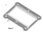
- FIG. 7illustrates a top perspective view of an outer frame of a reactor stack cell including an inner o-ring channel consistent with embodiments disclosed herein.
- FIG. 8illustrates a cross-sectional view of an outer frame of a reactor stack cell including an inner o-ring channel consistent with embodiments disclosed herein.
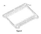
- FIG. 9illustrates a bottom perspective view of an outer frame of a reactor stack cell including an outer o-ring channel consistent with embodiments disclosed herein.
- FIG. 10illustrates a cross-sectional view of an outer frame of a reactor stack cell including an outer o-ring channel consistent with embodiments disclosed herein.
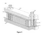
- FIG. 11illustrates a cross-sectional view of an assembled flow cell battery including a plurality of reactor cells consistent with embodiments disclosed herein.
- FIG. 12illustrates a perspective view of an assembled flow cell battery including a plurality of reactor cells consistent with embodiments disclosed herein.
- FIG. 13illustrates a perspective view of the flow of negative electrolyte through a reactor stack cell consistent with embodiments disclosed herein.
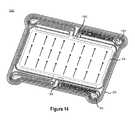
- FIG. 14illustrates a perspective view of the flow of positive electrolyte through a reactor stack cell consistent with embodiments disclosed herein.
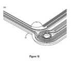
- FIG. 15illustrates an inner frame of a reactor stack cell including flexible corners consistent with embodiments disclosed herein.
- FIG. 16illustrates a cross-sectional view of a membrane securing design for a reactor stack cell consistent with embodiments disclosed herein.
- FIG. 17illustrates a cross-sectional view of an electrode securing design for a reactor stack cell consistent with embodiments disclosed herein.
- FIG. 18illustrates a perspective view of an outer frame of a reactor stack cell including guides for positioning other reactor stack cell components consistent with embodiments disclosed herein.
- FIG. 19illustrates a perspective view of an inner frame of a reactor stack cell including guides for positioning other reactor stack cell components consistent with embodiments disclosed herein.
- FIG. 20illustrates a perspective view of a gasket system for sealing areas of a reactor stack cell consistent with embodiments disclosed herein.
- Energy storage systemssuch as rechargeable batteries are an important part of electrical power systems, particularly electrical power systems supplied by wind turbine generators, photovoltaic cells, or the like. Energy storage systems may also be utilized to enable energy arbitrage for selling and buying power during off peak conditions, as uninterruptible power sources (UPS), in power quality applications, and to provide backup power.
- Redox flow battery energy storage systems and, particularly, vanadium redox flow battery energy storage systems (VRB-ESS)may be used in such electrical power systems.
- a redox flow battery energy storage systemmay respond quickly to changing loads, as is conventionally required in UPS and power quality applications, and may further be configured to have a large capacity, as is conventionally required in energy arbitrage and backup power applications.
- a redox flow battery energy storage systemgenerates electrical power by passing anolyte and catholyte electrolyte solutions through reactor cells.
- Anolyte and catholyte solutionsmay be collectively described herein as reactants or reactant electrolytes.
- a redox flow battery energy storage systemmay include one or more reactor cells depending on the power demands of the system and, consistent with embodiments disclosed herein, may utilize varying amounts of electrolyte solution based on the energy capacity needs of the system.
- the number and cross-sectional area of the reactors cells within the redox flow battery energy storage systemmay determine the amount of instantaneous power the system is capable of producing.
- the volume of anolyte and catholyte electrolytic solutions available to the redox flow battery energy storage systemmay determine its power storage and production capacity.
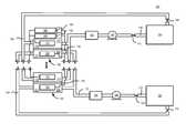
- FIG. 1illustrates a block diagram of a redox flow battery energy storage system 100 and, more specifically, a VRB-ESS, consistent with embodiments disclosed herein.
- the redox flow battery energy storage system 100may include one or more reactor cells 102 each having a negative compartment 104 with a negative electrode 108 and a positive compartment 110 with a positive electrode 112 .
- the negative compartment 104may include an anolyte solution 114 in electrical communication with the negative electrode 108 .
- the anolyte solution 114is an electrolyte containing specified redox ions which are in a reduced state and are to be oxidized during the discharge process of a cell 102 , or are in an oxidized state and are to be reduced during the charging process of a cell 102 , or which are a mixture of these latter reduced ions and ions to be reduced.
- the positive compartment 110contains a catholyte solution 116 in electrical communication with the positive electrode 112 .
- the catholyte solution 116is an electrolyte containing specified redox ions which are in an oxidized state and are to be reduced during the discharge process of a cell 102 , or an in a reduced state and are to be oxidized during the charging process of the cell 102 , or which are a mixture of these oxidized ions and ions to be oxidized.
- the anolyte and catholyte solutions 114 , 116may be prepared consistent with the disclosure of U.S. Pat. Nos. 4,786,567, 6,143,443, 6,468,688, and 6,562,514, which are herein incorporated by reference in their entireties, or by other known techniques. While the redox flow battery energy storage system illustrated in FIG. 1 is described herein for illustrative purposes as being a Vanadium-based system, other reactant solutions may be utilized.
- Each cell 102 of the redox flow battery energy storage system 100may include an ionically conducting separator 118 (e.g., a membrane) disposed between the negative and positive compartments 104 , 110 and in contact with the anolyte and catholyte solutions 114 , 116 to provide ionic communication therebetween.
- the separator 118may serve as a proton exchange membrane.
- additional anolyte solution 114may be held in an anolyte storage reservoir 120 that is in fluid communication with the negative compartment 104 through an anolyte supply line 122 and an anolyte return line 124 .
- the anolyte storage reservoir 120may include a tank, bladder, or any other similar storage container.
- the anolyte supply line 122may communicate with a pump 126 and a heat exchanger 128 .
- the pump 126may enable fluid movement of the anolyte solution 114 through the anolyte reservoir 120 supply line 122 , negative compartment 104 , and return line 124 .
- the pump 126may have a variable speed to allow variance in the generated flow rate.
- the heat exchanger 128may be configured to transfer heat generated from the anolyte solution 114 to a fluid or gas medium.
- the supply line 122may include one or more supply line valves 130 to control the volumetric flow of the anolyte solution 114 .
- the return line 124may communicate with one or more return line valves 132 that control the return volumetric flow.
- additional catholyte solution 116may be held in a catholyte storage reservoir 134 that is in fluid communication with the positive compartment 110 through a catholyte supply line 136 and a catholyte return line 138 .
- the catholyte supply line 136may communicate with a pump 140 and a heat exchanger 142 .
- the pump 140which in some embodiments may be a variable speed pump to allow variance in the generated flow rate, may enable fluid movement of the catholyte solution 116 through the catholyte reservoir 134 , supply line 136 , positive compartment 110 , and return line 138 .
- the heat exchanger 142may be configured to transfer heat generated from the catholyte solution 116 to a fluid or gas medium.
- the supply line 136may include one or more supply line valves 144 to control the volumetric flow of catholyte solution 116 .
- the return line 138may communicate with one or more return line valves 146 that control the return volumetric flow.
- the negative and positive electrodes 108 , 112may be in electrical communication with a power source 148 and a load 150 .
- a power source switch 152may be disposed in series between the power source 148 and each negative electrode 108 .
- a load switch 154may be disposed in series between the load 150 and each negative electrode 108 .
- Alternative configurationsare possible, and the specific configuration of the redox flow battery energy storage system 100 illustrated in FIG. 1 is provided as an exemplary configuration of many possible configurations consistent with embodiments disclosed herein.
- Pump 126may pump the anolyte solution 114 through the negative compartment 104 and anolyte storage reservoir 120 via anolyte supply and return lines 122 , 124 .
- pump 140may pump the catholyte solution 116 through the positive compartment 110 and catholyte storage reservoir 134 via catholyte supply and return lines 136 , 138 .
- Each cell 102 of the redox flow battery energy storage system 100may be charged by delivering electrical energy from the power source 148 to negative and positive electrodes 108 , 112 , by, for example, deriving divalent vanadium ions in the anolyte solution 114 and equivalent pentavalent vanadium ions in the catholyte solution 116 .
- Electricitymay be drawn from each reactor cell 102 of the redox flow battery energy storage system 100 by closing load switch 154 and opening power source switch 152 . This causes the load 150 , which is in electrical communication with negative and positive electrodes 108 , 112 , to withdraw electrical energy when anolyte and catholyte solution is pumped respectively through the cell 102 .
- operation of the various components of the redox flow battery energy storage system 100may be controlled by an electronic control and monitoring system (not shown). Further, power withdrawn from the redox flow battery energy storage system 100 may be conditioned using power conditioning equipment (not shown) prior to being provided to the load 150 .
- a power conversion system(not shown) may also be incorporated to convert DC power output from the reactor cell 102 to AC power required by the load 150 .
- FIG. 2illustrates an exploded view of a reactor cell assembly 200 of a redox flow battery energy storage system consistent with embodiments disclosed herein.
- the reactor stack assembly 200may comprise an outer frame 202 , felt sheets 204 , an ionically conducting separator (e.g., membrane) 206 , an inner frame 208 , and an electrode 210 .
- the components 202 - 210 of the reactor cell assembly 200may be included in a first level bill of materials.
- the reactor cell assembly 200may be assembled without sub-assembly (i.e., no sub-assembly of components prior to final assembly), allowing for fewer components and a more streamlined manufacturing process.
- the reactor cell assembly 200may be assembled in the order shown in FIG. 2 .
- a felt sheet 204may be placed within the outer frame 202 , thereby creating a permeable compartment (e.g., a negative or positive compartment) between a membrane 206 placed on top of the felt sheet 204 and a bipole of another stack assembly (not shown).
- the inner frame 208may then be placed on top of an inside edge of the outer frame 202 and be used to secure the membrane 206 between the outer frame 202 and the inner frame 208 .
- the outer frame 202 and the inner frame 208may be coupled using one or more ribs and channels, as described in detail below.
- a second felt sheet 204may then be placed on the assembly, defining another permeable compartment (e.g., the negative or positive compartment) between the membrane 206 and an electrode 210 (e.g., an anode or a cathode).
- the components 202 - 210may be aligned in the reactor cell assembly 200 using guides or other devices integrated into the outer frame 202 and inner frame 208 , as described below.
- the components 202 - 210 of the reactor cell assembly 200may be configured to be coupled in series with other reactor cell assemblies, thereby creating a multi-cell redox flow battery energy storage system.
- the outer frame 202 and the inner frame 208may be comprised of a plastic and/or other polymer material. In certain embodiments, the outer frame 202 and the inner frame 208 may be comprised of a material that does not significantly degrade under the normal operation of the redox flow battery energy storage system. For example, the outer frame 202 and the inner frame 208 may be comprised of a material that does not significantly degrade over time resulting from contact with electrolyte solution.
- the outer frame 202 and the inner frame 208may be manufactured using an injection molding process. In some embodiments, the outer frame 202 and the inner frame 208 may be constructed such that the material wall thickness of any part of the frames 202 , 208 is substantially similar to enable consistent molding of the frames 202 , 208 . In certain embodiments, ribs and channels integrated in the outer frame 202 and/or the inner frame 208 may be configured to interlock when the outer frame 202 is coupled with the inner frame 208 . By interlocking ribs and channels integrated in the outer frame 202 and/or the inner frame 208 , thicker and/or structural frame portions may be created.
- the outer frame 202 and/or inner frame 208may comprise polypropylene, polyethylene, polyvinyl chloride and/or other like materials. In further embodiments, the outer frame 202 and/or the inner frame 208 may be manufactured using a machining process.
- the felt sheets 204may be configured to define compartments (e.g., negative or positive compartments) in the reactor cell assembly 200 that are permeable by electrolyte solutions (e.g., anolyte and/or catholyte solutions).
- the felt sheets 204may be further configured to provide a conductive path between bipole electrodes (e.g., electrode 210 ) and electrolyte solution.
- the felt sheets 204may comprise a plurality of conductive fibers.
- when saturated with electrolyte solutionthe felt sheets 204 may allow for a uniform flow of electrolyte solution through the cell compartments they define.
- the felt sheets 204may comprise, for examples, materials that include graphite and/or carbon fibers.
- the membrane 206may be an ionically conducting separator configured to provide ionic communication between anolyte and catholyte electrolyte solutions disposed on each side of the membrane 206 .
- the membrane 206may be configured as a proton exchange membrane. Further, in some embodiments, the membrane 206 may be configured to prevent the mixing of electrolyte solutions (e.g., anolyte and catholyte solutions) disposed on either side of the membrane 206 .
- the electrode 210may be configured to provide a conductive path between each cell in a stacked assembly.
- the electrode 210may be comprised of a conductive metallic material. Further, the electrode 210 may be configured to prevent the mixing of electrolyte solutions disposed on either side of the electrode 210 between cells.
- the electrode 210may be comprised of graphite and/or carbon powder, fibers, and/or flakes bonded with a polymer material designed to not degrade significantly when exposed to the electrolyte solution.
- the polymer materialmay comprise ethylene tetrafluoroethylene, polytetrafluoroethylene, polyvinyl chloride, polypropylene, epoxy, and/or other similar materials.
- FIG. 3illustrates a plurality of reactor stack cells 300 consistent with embodiments disclosed herein.
- the components 202 - 210 of the reactor cell assembly 200 illustrated in FIG. 2may be configured to be coupled in series with other reactor cell assemblies.
- individual reactor cell assemblies 200comprising an outer frame 202 , a felt sheet 204 , a membrane 206 , an inner frame 208 , another felt sheet 204 , and an electrode 210 may be stacked in series with any number of other reactor cell assemblies to form a multi-cell stack.
- the outer frames 202 and the inner frames 208may be coupled using one or more rib and channel connections integrated in the frames 202 , 208 , thereby securing other components of the stack assembly (e.g., felt sheets 204 , membranes 206 , and electrodes 210 ) within the frames 202 , 208 .
- Rib and channel connections integrated in the frames 202 , 208may further function to align the components 202 - 210 of the reactor cell assemblies 200 included in the reactor stack cells 300 .
- utilizing rib and channel connectionsmay also allow the reactor stack cells 300 to be securely coupled using a mechanical clamping system (not shown) or other mechanical means rather than using adhesives between the frames 202 , 208 . Utilizing a mechanical clamping system may, in some embodiments, allow for streamlined manufacturing of the reactor stack cells 300 and reduce manufacturing time associated with adhesive curing.
- FIG. 4illustrates a block diagram of a multiple seal system 400 consistent with embodiments disclosed herein.
- the illustrated seal system 400may be integrated into the outer frame 202 and/or the inner frame 208 and be used to substantially confine electrolyte solution within a negative and/or positive compartment of a reactor cell assembly 200 . That is, the illustrated seal system 400 may be utilized to prevent external leaking of electrolyte solution from a reactor cell assembly.
- the seal system 400may include a primary seal 402 enclosing a primary compartment 406 which, consistent with embodiments disclosed herein, may contain electrolyte solution (e.g., anolyte or catholyte solution) and function as a negative or positive compartment of a reactor cell.
- this primary compartment 406may be at a higher pressure than surrounding compartments and/or external atmospheric pressure.
- the primary seal 402may be a high pressure seal configured to contain electrolyte solution at high pressures.
- the higher pressuremay be attributable to electrolyte solution being pumped through the primary compartment 406 during operation of the redox flow battery energy storage system.
- Electrolyte solutionmay be pumped into the primary compartment 406 via one or more electrolyte inlet manifolds (not shown). Similarly, electrolyte solution may be pumped out of the primary compartment 406 via one or more electrolyte solution outlet manifolds (not shown).
- a secondary seal 404may enclose the primary seal 402 , thereby creating a secondary compartment 408 between the primary seal 402 and the secondary seal 404 .
- the secondary seal 404may be configured to capture electrolyte solution that leaks through the primary seal 402 and store the leaked electrolyte solution in the secondary compartment 408 .
- the secondary compartment 408can function as a “drip tray” for any leaks from the primary seal 402 .
- the secondary compartment 408may be configured to capture an amount of electrolyte solution corresponding to several leaked drops of electrolyte solution per day over a long period (e.g., a 12-month period).
- the secondary compartment 408may be at a lower pressure than the primary compartment 406 , thereby reducing the likelihood that electrolyte solution will leak through the secondary seal 404 .
- the secondary compartment 408may be at an ambient or external atmospheric pressure.
- a selectively-closable access port 410may be integrated into the secondary seal 404 providing external access to the secondary compartment 408 .
- the access port 410may allow access to electrolyte solution that has leaked through the primary seal 402 into the secondary compartment 408 via a valve system or the like. Through the access port 410 , this leaked electrolyte solution may be removed (i.e., drained) from the secondary compartment 408 and disposed of. Alternatively, leaked electrolyte solution removed from the secondary compartment 408 via the access port 410 may be recycled and reintroduced to the redox flow battery energy storage system.
- a rib and channel interlock designmay be used to form the primary seal 402 , the secondary seal 404 , and/or other structures included in the reactor cell assembly 200 .
- rib and channel interlocks integrated into the outer frame 202 and the inner frame 208may be used to mechanically couple reactor cell assemblies 200 in conjunction with a mechanical clamping system, to create thicker and/or structural frame portions, and to align the components 202 - 210 of the reactor cell assemblies 200 during assembly.
- a rib and channel interlock systemmay comprise a channel formed by two channel ribs integrated into a first frame portion (e.g., the outer frame 202 and/or the inner frame 208 ) and a sealing rib integrated into a second frame portion (e.g., the outer frame 202 and/or the inner frame 208 ).
- the sealing ribmay be disposed within the channel formed by the two channel ribs and, when force (e.g., 300 KN) is applied to the first frame portion including the sealing rib compressing the first frame portion against the second frame portion including the channel ribs, may be secured within the channel.
- securing the sealing rib between the channel ribsmay support the sealing rib and reduce the likelihood that the sealing rib will buckle when compressed into the channel. Further, the channel ribs may support the sealing rib and prevent the sealing rib from being over-compressed into the channel.
- the sealing ribmay include a tip that, when pressed against the bottom of the channel formed by the channel ribs, forms a seal that may substantially prevent electrolyte solution from passing through the seal.
- FIG. 5illustrates a top perspective view of a portion 500 of an outer frame 202 of a reactor stack including integrated seals 402 , 404 , 502 consistent with embodiments disclosed herein.
- the outer frame 202may include a primary seal 402 configured to enclose a primary compartment (e.g., negative or positive compartment) of a reactor cell containing electrolyte solution (e.g., anolyte or catholyte solution).
- a primary seal 402may be formed when two frame portions are coupled using a rib and channel interlock design.
- Electrolyte solutionmay be pumped into the primary compartment via one or more electrolyte inlet manifolds 504 .
- electrolyte solutionmay be pumped out of the primary compartment via one or more electrolyte solution outlet manifolds (not shown).
- the primary seal 402may be configured to surround and/or isolate the inlet manifolds 504 and/or outlet manifolds. Further, the primary seal 402 may define an inlet channel 508 running from an inlet manifold to the primary compartment, enabling electrolyte solution to be pumped into the primary compartment at one or more specific locations. Similarly, the primary seal 402 may define an outlet channel running from an outlet manifold to the primary compartment, enabling electrolyte solution to be pumped out of the primary compartment at one or more specific locations.
- the outer frame 202may further include a secondary seal 404 configured to enclose the primary seal 402 and create a secondary compartment 408 between the primary seal 402 and the secondary seal 404 .
- a secondary seal 404may be formed when two frame portions are coupled using a rib and channel interlock design.
- the secondary seal 404may be configured to capture electrolyte solution that leaks through the primary seal 402 and store the leaked electrolyte solution in the secondary compartment 408 . Electrolyte solution contained in the secondary compartment 408 may be removed for disposal and/or recycling back into the system via an access port (not shown).
- the secondary compartment 408may be at a lower pressure than the primary compartment, thereby reducing the likelihood that electrolyte solution will leak through the secondary seal 404 .
- a shunt channel 506may be defined by one or more shunt channel seals 502 integrated in the outer frame 202 .
- a shunt channel seal 502may be formed when two frame portions are coupled using a rib and channel interlock design.
- the shunt channel 506may be designed to increase the electrical resistance between cells of the reactor cell assembly by increasing its length and/or decreasing its flow-cross section. In this manner, the shunt channel 506 may reduce shunt electrical currents flowing between reactor cells.
- the integrity of the primary seal 402may be increased.
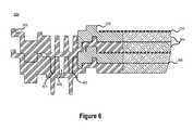
- FIG. 6illustrates a cross-sectional view 600 of a plurality of reactor stack cells including integrated seals 402 , 404 consistent with embodiments disclosed herein.
- individual reactor cell assembliescomprising an outer frame 202 , a felt sheet 204 , a membrane 206 , an inner frame 208 , another felt sheet 204 , and an electrode 210 may be stacked in parallel with any number of other reactor cell assemblies to form a multi-cell stack.
- the outer frame 202may include a primary seal 402 configured to enclose a primary compartment (e.g., negative or positive compartment) that, in some embodiments, may be filed with a permeable felt sheet 204 of a reactor cell containing electrolyte solution (e.g., anolyte or catholyte solution).
- a primary seal 402may be formed when two frame portions are coupled using a rib and channel interlock design.
- the outer frame 202may further include a secondary seal 404 that encloses the primary seal 402 , thereby creating a secondary compartment 408 between the primary seal 402 and the secondary seal 404 .
- the secondary compartment 408may be configured to capture electrolyte solution that leaks through the primary seal 402 . Electrolyte solution contained in the secondary compartment 408 may be removed for disposal and/or recycling back into the system via an access port (not shown).
- a secondary seal 404may be formed when two frame portions are coupled using a rib and channel interlock design.
- FIG. 7illustrates a top perspective view 700 of an outer frame 202 of a reactor stack cell including an inner o-ring channel consistent with embodiments disclosed herein.
- the inner o-ring channelillustrated in more detail in FIG. 8 , may be integrated into the outer frame 202 and used in conjunction with an appropriately sized o-ring (e.g., a rubber o-ring or the like) to seal a terminal outer frame 202 of a multi-cell reactor stack assembly (e.g., reactor stack cells 300 ) against a rigid structural enclosure.
- an appropriately sized o-ringe.g., a rubber o-ring or the like
- the inner o-ring channelmay be used in conjunction with an o-ring to create an external seal against a rigid enclosure placed on the terminal ends of a multi-cell reactor stack assembly included in a redox flow battery energy storage system.
- the inner o-ring channelmay be used in conjunction with an o-ring to seal a terminal frame at an end of a multi-cell reactor stack that receives and/or provides electrolyte solution from/to storage reservoirs (i.e., an inlet/outlet and/or feed end).
- FIG. 8illustrates a cross-sectional view 800 of an outer frame 202 of a reactor stack cell including an inner o-ring channel 702 consistent with embodiments disclosed herein.
- the inner o-ring channel 702may define a channel that encloses the inner periphery of the outer frame 202 configured to retain and/or secure an appropriately sized o-ring.
- the o-ringmay be sized such that when a rigid frame is pressed against the o-ring in the inner o-ring channel 702 , a seal is created that substantially contains electrolyte solution at pumping pressures.
- FIG. 9illustrates a bottom perspective view 900 of an outer frame 202 of a reactor stack cell including an outer o-ring channel consistent with embodiments disclosed herein.
- the outer o-ring channelillustrated in more detail in FIG. 10 , may be integrated into the outer frame 202 and used in conjunction with an appropriately sized o-ring (e.g., a rubber o-ring or the like) to seal a terminal outer frame 202 of a multi-cell reactor stack assembly (e.g., reactor stack cells 300 ) against a rigid structural enclosure.
- an appropriately sized o-ringe.g., a rubber o-ring or the like
- the outer o-ring channel 902may be used in conjunction with an o-ring to create an external seal against a rigid enclosure placed on the terminal ends of a multi-cell reactor stack assembly included in a redox flow battery energy storage system.
- the outer o-ring channel 902may be used in conjunction with an o-ring to seal a terminal frame at an end of a multi-cell reactor stack.
- FIG. 10illustrates a cross-sectional view 1000 of an outer frame 202 of a reactor stack cell including an outer o-ring channel 902 consistent with embodiments disclosed herein.
- the outer o-ring channel 902may define a channel that encloses the outer periphery of the outer frame 202 configured to retain and/or secure an appropriately sized o-ring.
- the o-ringmay be sized such that when a rigid frame is pressed against the o-ring in the outer o-ring channel 902 , a seal is created that substantially contains electrolyte solution at pumping pressures.
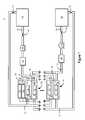
- FIG. 11illustrates a cross-sectional view of an assembled flow cell battery 1100 including a plurality of reactor cells 1102 consistent with embodiments disclosed herein.
- the plurality of reactor cells 1102may include several reactor cell assemblies (i.e., reactor cell assembly 200 illustrated in FIG. 2 ), each including components 202 - 210 , coupled in series.
- reactor cell assembliescomprising an outer frame 202 , a felt sheet 204 , a membrane 206 , an inner frame 208 , another felt sheet 204 , and an electrode 210 may be stacked in series with other reactor cell assemblies to form a multi-cell stack including a plurality of reactor cells 1102 .
- the plurality of reactor cells 1102may be secured together using a mechanical clamping system (not shown) in conjunction with one or more rigid structural end plates 1104 .
- the end plates 1104may be placed on each end of the plurality of reactor cells 1102 and may function to secure, align, and retain the plurality of reactor cells 1102 .
- the end plates 1104may function to create seals and other structural frame portions using rib and channel interlocks integrated into the outer frames 202 and the inner frames 208 in the plurality of reactor cells 1102 .
- Rigid isolators 1106may be included between the rigid structural end plates 1104 and the plurality of reactor cells 1102 in the assembled flow cell battery 1100 .
- the rigid isolators 1106may be configured to provide a planar surface for the end plates 1104 to interface with outer frames 202 and/or the inner frames 208 of the terminal cell assemblies of the plurality of reactor cells 1102 , thereby allowing uniform compression across the outer frames 202 and the inner frames 208 when a mechanical clamping system (not shown) is used to secure the reactor cells 1102 . In this manner, as illustrated in FIG.
- the rigid isolators 1106may utilize channels and/or ribs configured to interface with any ribs and/or channels of the terminal outer frames 202 and/or inner frames 208 of the assembled plurality of reactor cells 1102 . Further, the isolators 1106 may be configured to provide electrical isolation of electrically active components and metallic end plates and/or damping system. Accordingly, the isolators 1106 may comprise a non-conductive material.
- One or more input/output manifold fittings 1108may be configured to interface with electrolyte inlet manifolds 504 or output manifolds of the outer frames 202 of the reactor cells 1102 .
- External pumping mechanismsmay pump electrolyte solution into primary compartments of the reactor cells through the electrolyte inlet manifolds 504 of the outer frames 202 of the reactor cells 1102 via the input manifold fittings 1108 .
- electrolyte solutionmay be pumped from the primary compartments of the reactor cells through the electrolyte outlet manifolds of the outer frames 202 of the reactor cells 1102 via output manifold fittings 1108 .
- an inner o-ring(not shown) may be disposed in an inner o-ring channel 702 included in the outer frame 202 at a terminal end of the stack of reactor cells 1102 .
- the inner o-ringmay be configured to seal the terminal outer frame 202 of the stack of reactor cells 1102 (i.e., the top outer frame 202 of stack of reactor cells 1102 illustrated in FIG. 11 ) against an end plate 1104 and/or rigid isolator 1106 .
- an outer o-ring 1112may be disposed in an outer o-ring channel 902 included in the outer frame 202 at the other terminal end of the stack of reactor cells 1102 .
- the outer o-ring 1112may be configured to seal the other terminal outer frame 202 of the stack of reactor cells 1102 (i.e., the bottom outer frame 202 of the stack of reactor cells 1102 illustrated in FIG. 11 ) against a end plate 1104 and/or rigid isolator 1106 .
- the input/output manifold fittings 1108may be also sealed against an outer frame 202 using an input/output manifold fitting o-ring 1114 as shown.
- FIG. 12illustrates a perspective view of an assembled flow cell battery 1200 including a plurality of reactor cells 1102 consistent with embodiments disclosed herein.
- the plurality of reactor cells 1102may be secured together using a mechanical clamping system 1202 .
- the mechanical clamping system 1202may be configured to apply substantially uniform compression across the plurality of reactor cells 1102 .
- end plates 1104may be used in conjunction with the mechanical clamping system 1202 to apply uniform compression across the plurality of reactor cells 1102 .
- the mechanical clamping system 1202may comprise rigid members disposed in parallel to the end plates 1104 on each side of the plurality of reactor cells 1102 .
- the mechanical clamping system 1202may further comprise cross members extending perpendicular to the plurality of reactor cells 1102 .
- the cross membersmay be coupled to the rigid members disposed in parallel to the end plates 1104 on each side of the plurality of reactor cells 1102 .
- the cross membersmay be utilized to apply a compressive force between the rigid members and/or end plates 1104 .
- the cross membersmay utilize a bolting, jackscrew, or similar mechanism to apply such a compressive force.
- any mechanical system configured to provide a compressive force to the plurality of reactor cells 1102may be utilized in assembled flow cell battery 1200 .
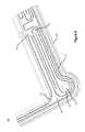
- FIG. 13illustrates a perspective view 1300 of the flow of negative electrolyte through a reactor stack cell consistent with embodiments disclosed herein.
- electrolyte solutionmay be pumped into a primary compartment defined in part by outer frame 202 via an electrolyte inlet manifold 504 .
- the electrolyte solutionmay be pumped into the primary compartment through a shunt channel, as described above in reference to FIG. 5 , and enter the primary compartment via an inlet channel 508 .
- feed channels integrated along the inner periphery of the outer frame 202 and/or the inner frame 208 defining the edges of the primary compartmentmay be configured to provide a more uniform flow of electrolyte solution through the primary compartment after entering from the inlet channel 508 . Accordingly, as illustrated, electrolyte solution may be fed into the primary compartment via the inlet channel 508 and be distributed along an edge of the primary compartment by feed channels, thereby enabling a substantially uniform flow of the electrolyte solution through the primary compartment.
- electrolyte solutionmay tend to flow around the outer edges of the primary compartment rather than uniformly across the primary compartment.
- electrolyte solutionmay tend to flow across the primary compartment through paths of lesser flow resistance such as the interface between the felt sheets 204 and the outer frames 202 and/or inner frames 208 .
- the felts sheets 204may be sized slightly larger than the size of the primary compartment defined by the outer frames 202 and/or inner frames 208 .
- the felt sheets 204may be cut slightly wide to tightly fit into a primary compartment. By compressing the “oversized” felt sheets 204 into the narrower compartment, the flow resistance along the edges of the primary compartment may be increased, thereby decreasing the tendency for electrolyte solution to flow more readily along the edges of the primary compartment.
- Feed channels integrated along the inner periphery of the outer frame 202 and/or the inner frame 208 defining the edges of the primary compartmentmay be configured to collect electrolyte solution flowing through the primary compartment and direct the electrolyte solution to an outlet channel 1302 .
- the electrolyte solutionmay then pass through a shunt channel and out of the reactor cell through an outlet manifold 1304 .
- FIG. 14illustrates a perspective view 1400 of the flow of positive electrolyte through a reactor stack cell consistent with embodiments disclosed herein.
- the flow of positive electrolyte solution through a primary compartmentmay be similar to the flow of negative electrolyte solution through a primary compartment, as described above in reference to FIG. 13 .
- positive electrolyte solutionmay flow through a primary compartment via an inlet manifold 504 , a shunt channel, an inlet channel, feed channels, an outlet channel 1302 , another shunt channel, and an outlet manifold 1304 .
- the frame structures used in directing the flow of positive electrolyte solutionmay be disposed on the opposite side of the outer and/or inner frames 202 , 208 , than the frame structures used in directing the flow of negative electrolyte solution.
- FIG. 15illustrates a perspective view 1500 of an inner frame 208 of a reactor stack cell including flexible corners 1502 consistent with embodiments disclosed herein. Due to minor dimensional variations of the outer frame 202 and/or inner frame 208 introduced during manufacturing, securing the inner frame 208 to the outer frame 202 may be difficult. Accordingly, the corners 1502 of the inner frame 208 may be configured to be flexible (i.e., less rigid than the sides of the inner frame 208 ), allowing the inner frame 208 to adapt to minor manufacturing variations of the inner frame 208 and/or the outer frame 202 when secured in the outer frame 202 .
- flexible corners 1502 of the inner frame 208may be designed by integrating portions at the corners 1502 of the inner frame 208 that are thinner and/or less rigid than the sides of the inner frame 208 .
- the inner frame 208 and/or outer frame 202may be heated to increase the flexibility of the frames 208 , 202 and allow for the frames to be securely coupled despite minor dimensional variations.
- FIG. 16illustrates a cross-sectional view 1600 of a membrane securing design for a reactor stack cell consistent with embodiments disclosed herein.
- the membrane 206may be secured between the outer frame 202 and the inner frame 208 .
- a raised rib 1602 integrated into the inner frame 208 and/or the outer frame 202may be configured to press into the edges of membrane 206 when it is compressed between the outer frame 202 and the inner frame 208 , thereby securing the membrane 206 between the outer frame 202 and the inner frame 208 .
- the raised rib 1602may create a seal between the outer frame 202 , the inner frame 208 , and the edges of the membrane 206 .
- the sealmay be a low pressure seal capable of containing low or sub-kilopascal pressure differentials (e.g., 5 kPa or 15 kPa).
- FIG. 17illustrates a cross-sectional view 1700 of an electrode 210 securing design for a reactor stack cell consistent with embodiments disclosed herein.
- the electrode 210may be secured between the outer frame 202 and the inner frame 208 .
- a raised rib(not shown) integrated into the inner frame 208 and/or the outer frame 202 may be configured to press into the edges of electrode 210 when it is compressed between the outer frame 202 and the inner frame 208 , thereby securing the electrode 210 between the outer frame 202 and the inner frame 208 .
- the raised ribmay create a seal between the outer frame 202 , the inner frame 208 , and the edges of the electrode 210 .
- the sealmay be a low pressure seal capable of containing low or sub-kilopascal pressure differentials.
- a sealantmay be used between the interfaces of the outer frame 202 , the inner frame 208 , and the edges of the electrode 210 to create a seal.
- FIG. 18illustrates a perspective view 1800 of an outer frame 202 of a reactor stack cell including guides 1802 for positioning other reactor stack cell components consistent with embodiments disclosed herein.
- the outer frame 202may include integrated guides 1802 configured to guide, align, and/or position components 202 - 210 of the reactor cell during assembly.
- the illustrated guides 1802may be particularly configured to guide, align, and/or position the membrane 206 during assembly of the reactor cell stack. Utilizing guides 1802 may allow for a more efficient assembly of the reactor cell stack by reducing the likelihood of components 202 - 210 becoming unaligned which may potentially result in disassembly and realignment.
- FIG. 19illustrates a perspective view 1900 of an inner frame 208 of a reactor stack cell including guides 1902 for positioning other reactor stack cell components consistent with embodiments disclosed herein.
- the inner frame 208may include integrated guides 1902 configured to guide, align, and/or position components 202 - 210 of the reactor cell during assembly.
- the illustrated guides 1902may be particularly configured to guide, align, and/or position the electrode 210 during assembly of the reactor cell stack. Utilizing guides 1902 may allow for a more efficient assembly of the reactor cell stack by reducing the likelihood of components 202 - 210 becoming unaligned which may potentially result in disassembly and realignment.
- FIG. 20illustrates a perspective view 2000 of a gasket system 2002 for sealing areas of a reactor stack cell consistent with embodiments disclosed herein.
- the frame structures used in directing the flow of positive electrolyte solutionmay be disposed on the opposite side of the outer and/or inner frames 202 , 208 , than the frame structures used in directing the flow of negative electrolyte solution.
- gaskets 2002e.g., rubber gaskets or the like
- gaskets 2002configured to be secured onto the inner frame 208 and/or outer frame 202 may be utilized to direct the flow of electrolyte solution in conjunction with integrated frame structures.
- gaskets 2002may be utilized to create substantially impermeable seals between a positive electrolyte inlet channel and a negative electrolyte inlet channel defined in the outer frame 202 and/or the inner frame 208 .
- adhesive and/or non-adhesive sealantsmay be utilized to create similar seals without the use of discrete gaskets 2002 .
Landscapes
- Life Sciences & Earth Sciences (AREA)
- Engineering & Computer Science (AREA)
- Manufacturing & Machinery (AREA)
- Sustainable Development (AREA)
- Sustainable Energy (AREA)
- Chemical & Material Sciences (AREA)
- Chemical Kinetics & Catalysis (AREA)
- Electrochemistry (AREA)
- General Chemical & Material Sciences (AREA)
- Fuel Cell (AREA)
Abstract
Description
Claims (20)
Priority Applications (9)
| Application Number | Priority Date | Filing Date | Title |
|---|---|---|---|
| US13/269,362US10141594B2 (en) | 2011-10-07 | 2011-10-07 | Systems and methods for assembling redox flow battery reactor cells |
| CN201280048913.XACN103858264A (en) | 2011-10-07 | 2012-09-14 | System and method for assembling redox flow battery reactor cells |
| EP12839055.6AEP2764571A4 (en) | 2011-10-07 | 2012-09-14 | SYSTEMS AND METHODS FOR ASSEMBLING REACTOR CELLS OF A REDOX STREAMER |
| KR1020147008704AKR102036388B1 (en) | 2011-10-07 | 2012-09-14 | Systems and methods for assembling redox flow battery reactor cells |
| PCT/CA2012/050640WO2013049933A1 (en) | 2011-10-07 | 2012-09-14 | Systems and methods for assembling redox flow battery reactor cells |
| MX2014003414AMX358374B (en) | 2011-10-07 | 2012-09-14 | Systems and methods for assembling redox flow battery reactor cells. |
| AU2012321014AAU2012321014A1 (en) | 2011-10-07 | 2012-09-14 | Systems and methods for assembling redox flow battery reactor cells |
| CA2848115ACA2848115A1 (en) | 2011-10-07 | 2012-09-14 | Systems and methods for assembling redox flow battery reactor cells |
| ZA2014/01814AZA201401814B (en) | 2011-10-07 | 2014-03-12 | Systems and methods for assembling redox flow battery reactor cells |
Applications Claiming Priority (1)
| Application Number | Priority Date | Filing Date | Title |
|---|---|---|---|
| US13/269,362US10141594B2 (en) | 2011-10-07 | 2011-10-07 | Systems and methods for assembling redox flow battery reactor cells |
Publications (2)
| Publication Number | Publication Date |
|---|---|
| US20130089767A1 US20130089767A1 (en) | 2013-04-11 |
| US10141594B2true US10141594B2 (en) | 2018-11-27 |
Family
ID=48042290
Family Applications (1)
| Application Number | Title | Priority Date | Filing Date |
|---|---|---|---|
| US13/269,362Active2033-08-22US10141594B2 (en) | 2011-10-07 | 2011-10-07 | Systems and methods for assembling redox flow battery reactor cells |
Country Status (9)
| Country | Link |
|---|---|
| US (1) | US10141594B2 (en) |
| EP (1) | EP2764571A4 (en) |
| KR (1) | KR102036388B1 (en) |
| CN (1) | CN103858264A (en) |
| AU (1) | AU2012321014A1 (en) |
| CA (1) | CA2848115A1 (en) |
| MX (1) | MX358374B (en) |
| WO (1) | WO2013049933A1 (en) |
| ZA (1) | ZA201401814B (en) |
Families Citing this family (18)
| Publication number | Priority date | Publication date | Assignee | Title |
|---|---|---|---|---|
| US20140060634A1 (en)* | 2012-08-31 | 2014-03-06 | Primestar Solar, Inc. | Use of an inert graphite layer in a back contact of a photovoltaic cell |
| DE102013009629B4 (en) | 2013-06-10 | 2019-09-12 | Carl Freudenberg Kg | Electrode module and arrangement with electrode modules |
| KR101465489B1 (en)* | 2013-07-16 | 2014-11-26 | 주식회사 에이치투 | Stack for Redox Flow Battery with a Sealing to Prevent Shunt Current Loss |
| KR20160040615A (en) | 2013-07-31 | 2016-04-14 | 아쿠아하이드렉스 프로프라이어터리 리미티드 | Modular Electrochemical Cells |
| CN103647090B (en)* | 2013-12-06 | 2016-03-02 | 中国东方电气集团有限公司 | Flow frame component and flow battery |
| KR101377187B1 (en)* | 2014-01-02 | 2014-03-25 | 스탠다드에너지(주) | Fuel cell or redox flow battery with means for recovering reaction substances |
| JP6247590B2 (en)* | 2014-05-07 | 2017-12-13 | 旭化成株式会社 | Cell stack and storage battery |
| US9728791B2 (en)* | 2014-07-30 | 2017-08-08 | Concurrent Technologies Corporation | Self-sealing flow frame for flow battery stack |
| US9362582B2 (en)* | 2014-09-12 | 2016-06-07 | Imergy Power Systems, Inc. | Flow cell stack with single plate cells |
| DE212015000116U1 (en)* | 2015-04-14 | 2016-12-19 | Sumitomo Electric Industries, Ltd. | Frame body, cell frame for a redox flow battery and redox flow battery |
| CN106328969B (en)* | 2015-07-07 | 2019-10-25 | 宁波亘新储能技术有限公司 | A kind of flow battery and its monocell frame, integrated monocell, pile |
| CN110071305A (en)* | 2018-01-22 | 2019-07-30 | 北京普能世纪科技有限公司 | A kind of sealing structure of pile and the non-entry position of pile |
| CN110416584B (en)* | 2018-04-27 | 2021-04-16 | 江苏泛宇能源有限公司 | Stack frame for flow battery |
| WO2020129022A2 (en)* | 2018-12-20 | 2020-06-25 | Visblue Portugal, Unipessoal Lda | Redox flow battery comprising stack of flow frames and redox flow frame thereof |
| JP2022519575A (en) | 2019-02-01 | 2022-03-24 | アクアハイドレックス, インコーポレイテッド | Electrochemical system with confined electrolyte |
| KR102308407B1 (en)* | 2019-11-05 | 2021-10-06 | 주식회사 코리드에너지 | Cell frame structure and redox flow battery using thereof |
| US20210359327A1 (en)* | 2020-05-15 | 2021-11-18 | Ess Tech, Inc. | Redox flow battery and battery system |
| ES3036837A1 (en)* | 2024-03-21 | 2025-09-24 | Consejo Superior Investigacion | REDOX FLOW BATTERIES WITH ELECTROLYTE DISTRIBUTORS WITH INTEGRATED CHANNEL AND MANUFACTURING METHOD THEREOF |
Citations (142)
| Publication number | Priority date | Publication date | Assignee | Title |
|---|---|---|---|---|
| US3279949A (en) | 1961-07-27 | 1966-10-18 | Union Carbide Corp | Fuel cell half-cell containing vanadium redox couple |
| US3530003A (en) | 1967-02-24 | 1970-09-22 | Gen Constr Elect Mec | Compact fuel cell battery |
| FR2034755A1 (en) | 1969-02-10 | 1970-12-18 | Electrocell Ltd | Electrochemical cell using organic reducing - agents |
| US3666561A (en) | 1969-03-01 | 1972-05-30 | Toyoda Chuo Kenkyusho Kk | Electrolyte circulating battery |
| US3996064A (en) | 1975-08-22 | 1976-12-07 | The United States Of America As Represented By The Administrator Of The National Aeronautics And Space Administration | Electrically rechargeable REDOX flow cell |
| US4018508A (en) | 1974-03-15 | 1977-04-19 | Imperial Chemical Industries Limited | Electrochromic device and medium therefor |
| JPS54138502A (en) | 1978-04-17 | 1979-10-27 | Toyo Soda Mfg Co Ltd | Electrolytic reduction of organic and inorganic compounds |
| US4181777A (en) | 1978-09-07 | 1980-01-01 | Diamond Shamrock Technologies S.A. | Rechargeable zinc halogen battery |
| GB2030349A (en) | 1978-07-10 | 1980-04-02 | Oronzio De Nora Impianti | Process and Accumulator, for Storing and Releasing Electrical Energy |
| JPS5642970A (en) | 1979-09-14 | 1981-04-21 | Agency Of Ind Science & Technol | Redox battery |
| US4287465A (en) | 1978-10-09 | 1981-09-01 | Saft-Societe Des Accumulateurs Fixes Et De Traction | Apparatus for regulating the charging of a storage battery |
| JPS579073A (en) | 1980-06-17 | 1982-01-18 | Agency Of Ind Science & Technol | Bedox battery |
| JPS579072A (en) | 1980-06-17 | 1982-01-18 | Agency Of Ind Science & Technol | Redox battery |
| US4312735A (en) | 1979-11-26 | 1982-01-26 | Exxon Research & Engineering Co. | Shunt current elimination |
| GB2085475A (en) | 1980-10-14 | 1982-04-28 | Gen Electric | Reduction of shunt current in bipolar electrochemical cell assemblies |
| US4362791A (en) | 1980-06-17 | 1982-12-07 | Agency Of Industrial Science & Technology | Redox battery |
| US4410606A (en) | 1982-04-21 | 1983-10-18 | Loutfy Raouf O | Low temperature thermally regenerative electrochemical system |
| JPS60225366A (en) | 1984-04-23 | 1985-11-09 | Sumitomo Electric Ind Ltd | Redox flow battery |
| AU5556286A (en) | 1986-02-11 | 1987-08-13 | Pinnacle Vrb Limited | All vanadium redox battery |
| EP0246649A1 (en) | 1986-05-23 | 1987-11-25 | Hitachi, Ltd. | Integrated power plant and method for operating the plant |
| JPS6369151A (en) | 1986-09-09 | 1988-03-29 | Kawasaki Heavy Ind Ltd | redox battery |
| US4786567A (en) | 1986-02-11 | 1988-11-22 | Unisearch Limited | All-vanadium redox battery |
| US4797566A (en) | 1986-02-27 | 1989-01-10 | Agency Of Industrial Science And Technology | Energy storing apparatus |
| WO1989005528A1 (en) | 1987-12-10 | 1989-06-15 | Unisearch Limited | Vanadium charging cell and vanadium dual battery system |
| WO1989005363A1 (en) | 1987-12-10 | 1989-06-15 | Unisearch Limited | Vanadium compound dissolution processes |
| US4908281A (en) | 1987-09-25 | 1990-03-13 | Alcan International Limited | Metal/air battery with recirculating electrolyte |
| WO1990003666A1 (en) | 1988-09-23 | 1990-04-05 | Unisearch Limited | State of charge of redox cell |
| US4927509A (en) | 1986-06-04 | 1990-05-22 | H-D Tech Inc. | Bipolar electrolyzer |
| US4956244A (en) | 1988-06-03 | 1990-09-11 | Sumitomo Electric Industries, Ltd. | Apparatus and method for regenerating electrolyte of a redox flow battery |
| AU8586291A (en) | 1990-10-15 | 1992-04-16 | Director-General Of Agency Of Industrial Science And Technology | Method for producing vanadium electrolytic solution |
| EP0517217A1 (en) | 1991-06-06 | 1992-12-09 | Director-General Of The Agency Of Industrial Science And Technology | Redox battery |
| US5225712A (en) | 1991-02-01 | 1993-07-06 | U.S. Windpower, Inc. | Variable speed wind turbine with reduced power fluctuation and a static VAR mode of operation |
| US5250158A (en) | 1990-10-15 | 1993-10-05 | Director-General, Agency Of Industrial Science And Technology | Method for producing vanadium electrolytic solution |
| EP0566019A1 (en) | 1992-04-09 | 1993-10-20 | Kashima-Kita Electric Power Corporation | Method for producing vanadium electrolytic solution |
| US5308718A (en) | 1993-01-15 | 1994-05-03 | Globe-Union Inc. | End block constructions for batteries |
| JPH0714617A (en) | 1993-06-24 | 1995-01-17 | Meidensha Corp | Current collecting electrode of zinc-bromine battery |
| WO1995012219A1 (en) | 1993-11-17 | 1995-05-04 | Unisearch Limited | Stabilised electrolyte solutions, methods of preparation thereof and redox cells and batteries containing stabilised electrolyte solutions |
| JPH07153477A (en) | 1993-12-01 | 1995-06-16 | Ebara Corp | Electrolyte flow type battery |
| JPH07192776A (en) | 1993-12-27 | 1995-07-28 | Meidensha Corp | Zinc-bromine battery |
| JPH087913A (en) | 1994-06-22 | 1996-01-12 | Kashima Kita Kyodo Hatsuden Kk | Full vanadium redox cell |
| US5484666A (en) | 1994-09-20 | 1996-01-16 | Ballard Power Systems Inc. | Electrochemical fuel cell stack with compression mechanism extending through interior manifold headers |
| JPH0819179A (en) | 1994-06-30 | 1996-01-19 | Hitachi Ltd | System stabilization system using secondary batteries |
| US5486430A (en) | 1994-09-01 | 1996-01-23 | Ballard Power Systems Inc. | Internal fluid manifold assembly for an electrochemical fuel cell stack array |
| US5512787A (en) | 1994-10-19 | 1996-04-30 | Dederick; Robert | Facility for refueling of clean air vehicles/marine craft and power generation |
| US5587132A (en) | 1994-11-17 | 1996-12-24 | Kashima-Kita Electric Power Corporation | Method for producing high purity vanadium electrolytic solution |
| US5601943A (en) | 1995-10-26 | 1997-02-11 | Zbb Technologies, Inc. | Module for an aqueous battery system |
| US5656390A (en) | 1995-02-16 | 1997-08-12 | Kashima-Kita Electric Power Corporation | Redox battery |
| US5665212A (en) | 1992-09-04 | 1997-09-09 | Unisearch Limited Acn 000 263 025 | Flexible, conducting plastic electrode and process for its preparation |
| JPH09283169A (en) | 1996-04-16 | 1997-10-31 | Sumitomo Electric Ind Ltd | Redox flow type secondary battery device and operating method thereof |
| EP0814527A2 (en) | 1996-06-19 | 1997-12-29 | Kashima-Kita Electric Power Corporation | A redox flow type battery |
| US5725967A (en)* | 1995-08-15 | 1998-03-10 | Micron Communications, Inc. | Battery container and method of manufacture |
| US5734255A (en) | 1996-03-13 | 1998-03-31 | Alaska Power Systems Inc. | Control system and circuits for distributed electrical power generating stations |
| US5759711A (en) | 1996-02-19 | 1998-06-02 | Kashima-Kita Electric Power Corporation | Liquid-circulating battery |
| EP0889571A2 (en) | 1997-07-04 | 1999-01-07 | G. BARGELLINI & C. S.p.A. | An auxiliary electric supply apparatus |
| WO1999039397A1 (en) | 1998-01-28 | 1999-08-05 | Chemieco S.R.L. | Redox flow battery system and cell stack |
| WO1999050945A1 (en) | 1998-03-30 | 1999-10-07 | Mita-Teknik A/S | Method and device for limiting making current and excess power from an alternating-current induction generator |
| JPH11299106A (en) | 1998-04-14 | 1999-10-29 | Ishikawajima Harima Heavy Ind Co Ltd | Method and apparatus for stabilizing wind power output |
| US6086643A (en)* | 1995-12-28 | 2000-07-11 | National Power Plc | Method for the fabrication of electrochemical cells |
| US6219623B1 (en) | 1997-11-24 | 2001-04-17 | Plug Power, Inc. | Anti-islanding method and apparatus for distributed power generation |
| US6242125B1 (en) | 1998-05-06 | 2001-06-05 | Zbb Technologies, Inc. | Battery circulation system with improved four-way valve |
| US20010028977A1 (en) | 1995-05-03 | 2001-10-11 | Michael Kazacos | High energy density vanadium electrolyte solutions, methods of preparation thereof and all-vanadium redox cells and batteries containing high energy vanadium electrolyte solutions |
| US6414653B1 (en) | 1997-04-30 | 2002-07-02 | Pioneer Electronic Corporation | Driving system for a plasma display panel |
| US6416653B1 (en) | 2000-07-18 | 2002-07-09 | Barben Analyzer Technology, Llc | Device for separating electrolyte chambers within an electrochemical sensor |
| US6461772B1 (en) | 1998-12-14 | 2002-10-08 | Sumitomo Electric Industries, Ltd. | Battery diaphragm |
| JP2003017763A (en) | 2001-07-02 | 2003-01-17 | Okano Electric Wire Co Ltd | Substrate for thermo-electric module, method of fabricating the same module and thermo-electric module utilizing substrate for thermo-electric module |
| US6519041B1 (en) | 2000-06-29 | 2003-02-11 | J W B C. Llc | Hydrogen sensor for fuel cell applications |
| EP1284513A1 (en) | 1999-07-01 | 2003-02-19 | Squirrel Holdings Ltd. | Porous mat electrodes for electrochemical reactor having electrolyte solution distribution channels |
| US6524452B1 (en) | 1998-09-29 | 2003-02-25 | Regenesys Technologies Limited | Electrochemical cell |
| US6544679B1 (en) | 2000-04-19 | 2003-04-08 | Millennium Cell, Inc. | Electrochemical cell and assembly for same |
| US6555267B1 (en) | 1999-07-01 | 2003-04-29 | Squirrel Holding Ltd. | Membrane-separated, bipolar multicell electrochemical reactor |
| US6558833B2 (en) | 2000-12-18 | 2003-05-06 | Mccoy Reginald F.H. | Recharging batteries by electrolyte transfer |
| US20030087156A1 (en) | 2001-04-12 | 2003-05-08 | Squirrel Holdings Ltd. | Porous mat electrodes for electrochemical reactor having electrolyte solution distribution channels |
| US6563234B2 (en) | 2000-02-03 | 2003-05-13 | Sumitomo Electric Industries, Ltd. | Power system stabilization system and method employing a rechargeable battery system |
| US6609081B1 (en) | 2000-06-02 | 2003-08-19 | Astec International Limited | Automated expansion analyzer for telecommunications power systems |
| US6613298B2 (en) | 2000-07-04 | 2003-09-02 | Kansai Electric Power Co., Inc. | Trivalent and tetravalent mixed vanadium compound producing method and vanadium electrolyte producing method |
| WO2003092109A1 (en) | 2002-04-23 | 2003-11-06 | Sumitomo Electric Industries, Ltd. | Method for operating redox flow battery system |
| US6670721B2 (en) | 2001-07-10 | 2003-12-30 | Abb Ab | System, method, rotating machine and computer program product for enhancing electric power produced by renewable facilities |
| US6680547B1 (en) | 2002-08-01 | 2004-01-20 | Innovations Electrical, Lc | Power sharing system including rechargeable power source |
| EP1385226A1 (en) | 2001-05-01 | 2004-01-28 | Sumitomo Electric Industries, Ltd. | Secondary cell and method of operating the secondary cell |
| US20040036360A1 (en) | 2000-09-01 | 2004-02-26 | Mccombs P. Roger | Battery storage for grid scale power within rights-of-way |
| US20040044442A1 (en) | 2001-12-28 | 2004-03-04 | Bayoumi Deia Salah-Eldin | Optimized dispatch planning of distributed resources in electrical power systems |
| US20040113431A1 (en) | 2001-04-12 | 2004-06-17 | Chienwen Huang | Method of wind-collecting power generation and its equipment |
| WO2004054065A1 (en) | 2002-12-06 | 2004-06-24 | Electric Power Research Institute, Inc. | Uninterruptable power supply and generator system |
| US20040121204A1 (en) | 2001-06-07 | 2004-06-24 | Adelman Marc D. | Fluid electrical connected flow-through electrochemical cells, system and method |
| US6761945B1 (en) | 1999-04-28 | 2004-07-13 | Sumitomo Electric Industries, Ltd. | Electrolyte tank and manufacturing method thereof |
| US6764789B1 (en) | 1999-09-27 | 2004-07-20 | Sumitomo Electric Industries, Ltd. | Redox flow battery |
| US20040151953A1 (en) | 2001-02-01 | 2004-08-05 | Kirk Donald W. | Electrochemical cell stacks |
| US20040158417A1 (en) | 2002-11-06 | 2004-08-12 | Bonet Antonio Trias | System and method for monitoring and managing electrical power transmission and distribution networks |
| US20040172943A1 (en) | 2001-12-10 | 2004-09-09 | Buelow Jason W. | Vehicle Hydrogen fuel system |
| US20040191623A1 (en) | 2001-06-07 | 2004-09-30 | Michiru Kubata | Electrolyte for redox flow battery, and redox flow battery |
| US20040207207A1 (en) | 2002-12-20 | 2004-10-21 | Stahlkopf Karl E. | Power control interface between a wind farm and a power transmission system |
| US6809431B1 (en) | 1998-09-26 | 2004-10-26 | Dewind Ag | Control logic for a wind energy system |
| JP2004319341A (en) | 2003-04-17 | 2004-11-11 | Sumitomo Electric Ind Ltd | Redox flow battery |
| US20040241544A1 (en) | 2001-06-12 | 2004-12-02 | Hiroyuki Nakaishi | Cell stack for flow cell |
| US20050004716A1 (en) | 2003-05-22 | 2005-01-06 | Mark Lillis | Method and apparatus for providing modular communications in a modular power system |
| US6875535B2 (en) | 2002-04-15 | 2005-04-05 | Hydrogenics Corporation | Manifold for a fuel cell system |
| US20050074665A1 (en) | 2001-11-16 | 2005-04-07 | Squirrel Holdings Ltd | System for storing and/or transforming energy from sources at variable voltage and frequency |
| US20050077252A1 (en) | 2003-10-14 | 2005-04-14 | George Shih | Readying cooling circuits for use in fuel cells |
| US6916579B2 (en) | 2002-05-30 | 2005-07-12 | Enerl Battery Company | Cathode material for lithium battery |
| US20050158614A1 (en) | 2004-01-15 | 2005-07-21 | Hennessy Timothy D.J. | System and method for optimizing efficiency and power output from a vanadium redox battery energy storage system |
| US20050158615A1 (en)* | 2002-02-14 | 2005-07-21 | Samuel John M.G. | Redox flow battery |
| US20050156432A1 (en) | 2004-01-15 | 2005-07-21 | Hennessy Timothy D.J. | Power generation system incorporating a vanadium redox battery and a direct current wind turbine generator |
| US7052796B2 (en) | 2003-02-27 | 2006-05-30 | Protonex Technology Corporation | Externally manifolded membrane based electrochemical cell stacks |
| US20060142899A1 (en) | 2001-09-28 | 2006-06-29 | Aloys Wobben | Method of operating a wind park |
| US7083875B2 (en) | 2002-04-22 | 2006-08-01 | Proton Energy Systems, Inc. | Method and apparatus for providing modular power |
| WO2006081514A2 (en) | 2005-01-28 | 2006-08-03 | Premium Power Corporation | Flowing electrolyte battery with electric potential neutralization |
| US20060171086A1 (en) | 2005-02-01 | 2006-08-03 | Vrb Power Systems Inc. | Method for retrofitting wind turbine farms |
| WO2006089415A1 (en) | 2005-02-22 | 2006-08-31 | Hyteon Inc. | Fuel cell system comprising modular design features |
| US20060273595A1 (en) | 2005-06-03 | 2006-12-07 | Avagliano Aaron J | System and method for operating a wind farm under high wind speed conditions |
| WO2006129635A1 (en) | 2005-05-31 | 2006-12-07 | Matsushita Electric Industrial Co., Ltd. | Secondary battery, power supply system using same and usage of power supply system |
| US20070001461A1 (en) | 2005-06-30 | 2007-01-04 | Hopewell Paul D | System and method for controlling effective wind farm power output |
| US20070035135A1 (en) | 2004-05-07 | 2007-02-15 | Mitsubishi Denki Kabushiki Kaisha | Wind power generation evaluation system and predictive control service system for use with wind power generator |
| US7181183B1 (en) | 2006-01-27 | 2007-02-20 | Vrb Power Systems Inc. | Telecommunication system incorporating a vanadium redox battery energy storage system |
| US7184903B1 (en) | 2006-03-16 | 2007-02-27 | Vrb Power Systems Inc. | System and method for a self-healing grid using demand side management techniques and energy storage |
| US20070072067A1 (en) | 2005-09-23 | 2007-03-29 | Vrb Power Systems Inc. | Vanadium redox battery cell stack |
| US7220515B2 (en) | 2000-12-06 | 2007-05-22 | Sumitomo Electric Industries, Ltd. | Pressure fluctuation prevention tank structure, electrolyte circulation type secondary battery, and redox flow type secondary battery |
| US20070202385A1 (en) | 2006-02-28 | 2007-08-30 | Sanyo Electric Co., Ltd. | Fuel cell stack |
| US20070258784A1 (en) | 2006-05-02 | 2007-11-08 | Robert Looker | Air cargo container extension unit |
| US7353083B2 (en) | 2004-01-15 | 2008-04-01 | Vrb Power Systems Inc. | Vanadium redox battery energy storage and power generation system incorporating and optimizing diesel engine generators |
| US20080081247A1 (en) | 2001-06-12 | 2008-04-03 | Sumitomo Electric Industries, Ltd. | Cell frame for redox flow battery, and redox flow battery |
| US7361427B1 (en) | 2005-05-27 | 2008-04-22 | The United States Of America Represented By The Secretary Of The Navy | Manifold for a pile configured battery |
| WO2008053317A1 (en) | 2006-10-30 | 2008-05-08 | Toyota Jidosha Kabushiki Kaisha | Fuel cell and gasket for fuel cell |
| US20080182157A1 (en) | 2005-08-09 | 2008-07-31 | Polyplus Battery Company | Compliant seal structures for protected active metal anodes |
| US20080220318A1 (en) | 2007-03-09 | 2008-09-11 | Vrb Power Systems Inc. | Inherently safe redox flow battery storage system |
| US20080241643A1 (en) | 2007-03-26 | 2008-10-02 | Gary Lepp | Vanadium redox battery incorporating multiple electrolyte reservoirs |
| US20090004536A1 (en) | 2007-05-16 | 2009-01-01 | Paul Knauer | Direct methanol fuel cell process tower |
| US20090047571A1 (en) | 2007-08-17 | 2009-02-19 | Vrb Power Systems Inc. | Electrochemical battery incorporating internal manifolds |
| US20090311559A1 (en) | 2008-06-16 | 2009-12-17 | Levine R Paul | Systems and methods for electrochemical power generation |
| US20100003545A1 (en) | 2008-07-07 | 2010-01-07 | Enervault Corporation | Redox Flow Battery System for Distributed Energy Storage |
| US20100003586A1 (en) | 2008-07-01 | 2010-01-07 | Deeya Energy, Inc. A California C-Corp | Redox flow cell |
| US20100021805A1 (en) | 2007-01-16 | 2010-01-28 | Primus Power Corporation | Electrochemical energy generation system |
| US7704634B2 (en) | 2002-04-23 | 2010-04-27 | Sumitomo Electric Industries, Ltd. | Method for designing redox flow battery system |
| US20100136455A1 (en) | 2008-10-10 | 2010-06-03 | Rick Winter | Common Module Stack Component Design |
| WO2010118060A1 (en) | 2009-04-06 | 2010-10-14 | A123 Systems, Inc. | Fuel system using redox flow battery |
| US20110115425A1 (en) | 2009-11-13 | 2011-05-19 | Dresser, Inc. | Recharging Electric Vehicles |
| WO2011074330A1 (en) | 2009-12-15 | 2011-06-23 | 日本碍子株式会社 | Control device for secondary battery, and control method for secondary battery |
| US20110215645A1 (en) | 2010-03-05 | 2011-09-08 | Active Power, Inc. | Containerized continuous power system and method |
| WO2011114094A1 (en) | 2010-03-19 | 2011-09-22 | Renewable Energy Dynamics Technology Ltd | Electrochemical cell stack |
| US8026013B2 (en) | 2006-08-14 | 2011-09-27 | Modine Manufacturing Company | Annular or ring shaped fuel cell unit |
| AT509888A4 (en) | 2010-06-08 | 2011-12-15 | Younicos Ag | ELECTRICAL ENERGY STORAGE AND METHOD FOR REGULATING SUCH A ENERGY STORAGE |
| US20110311896A1 (en) | 2010-06-22 | 2011-12-22 | Jd Holding Inc. | Integrated system for electrochemical energy storage system |
| US8541138B2 (en) | 2005-06-20 | 2013-09-24 | Newsouth Innovations Pty Limited | Perfluorinated membranes and improved electrolytes for redox cells and batteries |
Family Cites Families (1)
| Publication number | Priority date | Publication date | Assignee | Title |
|---|---|---|---|---|
| US7445869B2 (en)* | 2003-05-09 | 2008-11-04 | Nilar International Ab | Gasket, a bipolar battery and a method for manufacturing a bipolar battery with such a gasket |
- 2011
- 2011-10-07USUS13/269,362patent/US10141594B2/enactiveActive
- 2012
- 2012-09-14WOPCT/CA2012/050640patent/WO2013049933A1/ennot_activeCeased
- 2012-09-14KRKR1020147008704Apatent/KR102036388B1/enactiveActive
- 2012-09-14CACA2848115Apatent/CA2848115A1/ennot_activeAbandoned
- 2012-09-14AUAU2012321014Apatent/AU2012321014A1/ennot_activeAbandoned
- 2012-09-14MXMX2014003414Apatent/MX358374B/enactiveIP Right Grant
- 2012-09-14EPEP12839055.6Apatent/EP2764571A4/ennot_activeWithdrawn
- 2012-09-14CNCN201280048913.XApatent/CN103858264A/enactivePending
- 2014
- 2014-03-12ZAZA2014/01814Apatent/ZA201401814B/enunknown
Patent Citations (176)
| Publication number | Priority date | Publication date | Assignee | Title |
|---|---|---|---|---|
| US3279949A (en) | 1961-07-27 | 1966-10-18 | Union Carbide Corp | Fuel cell half-cell containing vanadium redox couple |
| US3530003A (en) | 1967-02-24 | 1970-09-22 | Gen Constr Elect Mec | Compact fuel cell battery |
| FR2034755A1 (en) | 1969-02-10 | 1970-12-18 | Electrocell Ltd | Electrochemical cell using organic reducing - agents |
| US3666561A (en) | 1969-03-01 | 1972-05-30 | Toyoda Chuo Kenkyusho Kk | Electrolyte circulating battery |
| US4018508A (en) | 1974-03-15 | 1977-04-19 | Imperial Chemical Industries Limited | Electrochromic device and medium therefor |
| US3996064A (en) | 1975-08-22 | 1976-12-07 | The United States Of America As Represented By The Administrator Of The National Aeronautics And Space Administration | Electrically rechargeable REDOX flow cell |
| JPS54138502A (en) | 1978-04-17 | 1979-10-27 | Toyo Soda Mfg Co Ltd | Electrolytic reduction of organic and inorganic compounds |
| GB2030349A (en) | 1978-07-10 | 1980-04-02 | Oronzio De Nora Impianti | Process and Accumulator, for Storing and Releasing Electrical Energy |
| US4181777A (en) | 1978-09-07 | 1980-01-01 | Diamond Shamrock Technologies S.A. | Rechargeable zinc halogen battery |
| US4287465A (en) | 1978-10-09 | 1981-09-01 | Saft-Societe Des Accumulateurs Fixes Et De Traction | Apparatus for regulating the charging of a storage battery |
| JPS5642970A (en) | 1979-09-14 | 1981-04-21 | Agency Of Ind Science & Technol | Redox battery |
| US4312735A (en) | 1979-11-26 | 1982-01-26 | Exxon Research & Engineering Co. | Shunt current elimination |
| JPS579072A (en) | 1980-06-17 | 1982-01-18 | Agency Of Ind Science & Technol | Redox battery |
| JPS579073A (en) | 1980-06-17 | 1982-01-18 | Agency Of Ind Science & Technol | Bedox battery |
| US4362791A (en) | 1980-06-17 | 1982-12-07 | Agency Of Industrial Science & Technology | Redox battery |
| GB2085475A (en) | 1980-10-14 | 1982-04-28 | Gen Electric | Reduction of shunt current in bipolar electrochemical cell assemblies |
| US4371433A (en) | 1980-10-14 | 1983-02-01 | General Electric Company | Apparatus for reduction of shunt current in bipolar electrochemical cell assemblies |
| US4410606A (en) | 1982-04-21 | 1983-10-18 | Loutfy Raouf O | Low temperature thermally regenerative electrochemical system |
| JPS60225366A (en) | 1984-04-23 | 1985-11-09 | Sumitomo Electric Ind Ltd | Redox flow battery |
| AU5556286A (en) | 1986-02-11 | 1987-08-13 | Pinnacle Vrb Limited | All vanadium redox battery |
| US4786567A (en) | 1986-02-11 | 1988-11-22 | Unisearch Limited | All-vanadium redox battery |
| US4797566A (en) | 1986-02-27 | 1989-01-10 | Agency Of Industrial Science And Technology | Energy storing apparatus |
| EP0246649A1 (en) | 1986-05-23 | 1987-11-25 | Hitachi, Ltd. | Integrated power plant and method for operating the plant |
| US4927509A (en) | 1986-06-04 | 1990-05-22 | H-D Tech Inc. | Bipolar electrolyzer |
| JPS6369151A (en) | 1986-09-09 | 1988-03-29 | Kawasaki Heavy Ind Ltd | redox battery |
| US4908281A (en) | 1987-09-25 | 1990-03-13 | Alcan International Limited | Metal/air battery with recirculating electrolyte |
| WO1989005528A1 (en) | 1987-12-10 | 1989-06-15 | Unisearch Limited | Vanadium charging cell and vanadium dual battery system |
| WO1989005363A1 (en) | 1987-12-10 | 1989-06-15 | Unisearch Limited | Vanadium compound dissolution processes |
| US4956244A (en) | 1988-06-03 | 1990-09-11 | Sumitomo Electric Industries, Ltd. | Apparatus and method for regenerating electrolyte of a redox flow battery |
| WO1990003666A1 (en) | 1988-09-23 | 1990-04-05 | Unisearch Limited | State of charge of redox cell |
| AU8586291A (en) | 1990-10-15 | 1992-04-16 | Director-General Of Agency Of Industrial Science And Technology | Method for producing vanadium electrolytic solution |
| US5250158A (en) | 1990-10-15 | 1993-10-05 | Director-General, Agency Of Industrial Science And Technology | Method for producing vanadium electrolytic solution |
| US5225712A (en) | 1991-02-01 | 1993-07-06 | U.S. Windpower, Inc. | Variable speed wind turbine with reduced power fluctuation and a static VAR mode of operation |
| US5318865A (en) | 1991-06-06 | 1994-06-07 | Director-General, Agency Of Industrial Science And Technology | Redox battery |
| EP0517217A1 (en) | 1991-06-06 | 1992-12-09 | Director-General Of The Agency Of Industrial Science And Technology | Redox battery |
| US5368762A (en) | 1992-04-09 | 1994-11-29 | Kashima-Kita Electric Power Corporation | Method for producing vanadium electrolytic solution |
| EP0566019A1 (en) | 1992-04-09 | 1993-10-20 | Kashima-Kita Electric Power Corporation | Method for producing vanadium electrolytic solution |
| US5665212A (en) | 1992-09-04 | 1997-09-09 | Unisearch Limited Acn 000 263 025 | Flexible, conducting plastic electrode and process for its preparation |
| US5308718A (en) | 1993-01-15 | 1994-05-03 | Globe-Union Inc. | End block constructions for batteries |
| JPH0714617A (en) | 1993-06-24 | 1995-01-17 | Meidensha Corp | Current collecting electrode of zinc-bromine battery |
| WO1995012219A1 (en) | 1993-11-17 | 1995-05-04 | Unisearch Limited | Stabilised electrolyte solutions, methods of preparation thereof and redox cells and batteries containing stabilised electrolyte solutions |
| US6143443A (en) | 1993-11-17 | 2000-11-07 | Pinnacle Arb Limited | Stabilized electrolyte solutions, methods of preparation thereof and redox cells and batteries containing stabilized electrolyte solutions |
| US6562514B1 (en) | 1993-11-17 | 2003-05-13 | Pinnacle Vrb Limited | Stabilized vanadium electrolyte solutions for all-vanadium redox cells and batteries |
| JPH07153477A (en) | 1993-12-01 | 1995-06-16 | Ebara Corp | Electrolyte flow type battery |
| JPH07192776A (en) | 1993-12-27 | 1995-07-28 | Meidensha Corp | Zinc-bromine battery |
| JPH087913A (en) | 1994-06-22 | 1996-01-12 | Kashima Kita Kyodo Hatsuden Kk | Full vanadium redox cell |
| JPH0819179A (en) | 1994-06-30 | 1996-01-19 | Hitachi Ltd | System stabilization system using secondary batteries |
| US5486430A (en) | 1994-09-01 | 1996-01-23 | Ballard Power Systems Inc. | Internal fluid manifold assembly for an electrochemical fuel cell stack array |
| US5484666A (en) | 1994-09-20 | 1996-01-16 | Ballard Power Systems Inc. | Electrochemical fuel cell stack with compression mechanism extending through interior manifold headers |
| US5512787A (en) | 1994-10-19 | 1996-04-30 | Dederick; Robert | Facility for refueling of clean air vehicles/marine craft and power generation |
| US5587132A (en) | 1994-11-17 | 1996-12-24 | Kashima-Kita Electric Power Corporation | Method for producing high purity vanadium electrolytic solution |
| US5656390A (en) | 1995-02-16 | 1997-08-12 | Kashima-Kita Electric Power Corporation | Redox battery |
| US20030143456A1 (en) | 1995-05-03 | 2003-07-31 | Michael Kazacos | High energy density vanadium electrolyte solutions, methods of preparation thereof and all-vanadium redox cells and batteries containing high energy vanadium electrolyte solutions |
| US20010028977A1 (en) | 1995-05-03 | 2001-10-11 | Michael Kazacos | High energy density vanadium electrolyte solutions, methods of preparation thereof and all-vanadium redox cells and batteries containing high energy vanadium electrolyte solutions |
| US6468688B2 (en) | 1995-05-03 | 2002-10-22 | Pinnacle Vrb Limited | High energy density vanadium electrolyte solutions, methods of preparation thereof and all-vanadium redox cells and batteries containing high energy vanadium electrolyte solutions |
| US7078123B2 (en) | 1995-05-03 | 2006-07-18 | Vrb Power Systems, Inc. | High energy density vanadium electrolyte solutions, methods of preparation thereof and all-vanadium redox cells and batteries containing high energy vanadium electrolyte solutions |
| US5725967A (en)* | 1995-08-15 | 1998-03-10 | Micron Communications, Inc. | Battery container and method of manufacture |
| US5601943A (en) | 1995-10-26 | 1997-02-11 | Zbb Technologies, Inc. | Module for an aqueous battery system |
| US6086643A (en)* | 1995-12-28 | 2000-07-11 | National Power Plc | Method for the fabrication of electrochemical cells |
| US5759711A (en) | 1996-02-19 | 1998-06-02 | Kashima-Kita Electric Power Corporation | Liquid-circulating battery |
| US5734255A (en) | 1996-03-13 | 1998-03-31 | Alaska Power Systems Inc. | Control system and circuits for distributed electrical power generating stations |
| JPH09283169A (en) | 1996-04-16 | 1997-10-31 | Sumitomo Electric Ind Ltd | Redox flow type secondary battery device and operating method thereof |
| EP0814527A2 (en) | 1996-06-19 | 1997-12-29 | Kashima-Kita Electric Power Corporation | A redox flow type battery |
| US5851694A (en) | 1996-06-19 | 1998-12-22 | Kashima-Kita Electric Power Corporation | Redox flow type battery |
| US6414653B1 (en) | 1997-04-30 | 2002-07-02 | Pioneer Electronic Corporation | Driving system for a plasma display panel |
| EP0889571A2 (en) | 1997-07-04 | 1999-01-07 | G. BARGELLINI & C. S.p.A. | An auxiliary electric supply apparatus |
| US6219623B1 (en) | 1997-11-24 | 2001-04-17 | Plug Power, Inc. | Anti-islanding method and apparatus for distributed power generation |
| WO1999039397A1 (en) | 1998-01-28 | 1999-08-05 | Chemieco S.R.L. | Redox flow battery system and cell stack |
| US6475661B1 (en) | 1998-01-28 | 2002-11-05 | Squirrel Holdings Ltd | Redox flow battery system and cell stack |
| WO1999050945A1 (en) | 1998-03-30 | 1999-10-07 | Mita-Teknik A/S | Method and device for limiting making current and excess power from an alternating-current induction generator |
| JPH11299106A (en) | 1998-04-14 | 1999-10-29 | Ishikawajima Harima Heavy Ind Co Ltd | Method and apparatus for stabilizing wind power output |
| US6261714B1 (en) | 1998-05-06 | 2001-07-17 | Zbb Technologies, Inc. | Spill and leak containment system for zinc-bromine battery |
| US6242125B1 (en) | 1998-05-06 | 2001-06-05 | Zbb Technologies, Inc. | Battery circulation system with improved four-way valve |
| US6809431B1 (en) | 1998-09-26 | 2004-10-26 | Dewind Ag | Control logic for a wind energy system |
| US6524452B1 (en) | 1998-09-29 | 2003-02-25 | Regenesys Technologies Limited | Electrochemical cell |
| US6461772B1 (en) | 1998-12-14 | 2002-10-08 | Sumitomo Electric Industries, Ltd. | Battery diaphragm |
| US6761945B1 (en) | 1999-04-28 | 2004-07-13 | Sumitomo Electric Industries, Ltd. | Electrolyte tank and manufacturing method thereof |
| EP1284513A1 (en) | 1999-07-01 | 2003-02-19 | Squirrel Holdings Ltd. | Porous mat electrodes for electrochemical reactor having electrolyte solution distribution channels |
| US6555267B1 (en) | 1999-07-01 | 2003-04-29 | Squirrel Holding Ltd. | Membrane-separated, bipolar multicell electrochemical reactor |
| US6764789B1 (en) | 1999-09-27 | 2004-07-20 | Sumitomo Electric Industries, Ltd. | Redox flow battery |
| US6563234B2 (en) | 2000-02-03 | 2003-05-13 | Sumitomo Electric Industries, Ltd. | Power system stabilization system and method employing a rechargeable battery system |
| US6544679B1 (en) | 2000-04-19 | 2003-04-08 | Millennium Cell, Inc. | Electrochemical cell and assembly for same |
| US6609081B1 (en) | 2000-06-02 | 2003-08-19 | Astec International Limited | Automated expansion analyzer for telecommunications power systems |
| US6519041B1 (en) | 2000-06-29 | 2003-02-11 | J W B C. Llc | Hydrogen sensor for fuel cell applications |
| US6613298B2 (en) | 2000-07-04 | 2003-09-02 | Kansai Electric Power Co., Inc. | Trivalent and tetravalent mixed vanadium compound producing method and vanadium electrolyte producing method |
| US6416653B1 (en) | 2000-07-18 | 2002-07-09 | Barben Analyzer Technology, Llc | Device for separating electrolyte chambers within an electrochemical sensor |
| US20040036360A1 (en) | 2000-09-01 | 2004-02-26 | Mccombs P. Roger | Battery storage for grid scale power within rights-of-way |
| US7220515B2 (en) | 2000-12-06 | 2007-05-22 | Sumitomo Electric Industries, Ltd. | Pressure fluctuation prevention tank structure, electrolyte circulation type secondary battery, and redox flow type secondary battery |
| US6558833B2 (en) | 2000-12-18 | 2003-05-06 | Mccoy Reginald F.H. | Recharging batteries by electrolyte transfer |
| US20040151953A1 (en) | 2001-02-01 | 2004-08-05 | Kirk Donald W. | Electrochemical cell stacks |
| US20030087156A1 (en) | 2001-04-12 | 2003-05-08 | Squirrel Holdings Ltd. | Porous mat electrodes for electrochemical reactor having electrolyte solution distribution channels |
| US20040113431A1 (en) | 2001-04-12 | 2004-06-17 | Chienwen Huang | Method of wind-collecting power generation and its equipment |
| EP1385226A1 (en) | 2001-05-01 | 2004-01-28 | Sumitomo Electric Industries, Ltd. | Secondary cell and method of operating the secondary cell |
| US7199550B2 (en) | 2001-05-01 | 2007-04-03 | Sumitomo Electric Industries, Ltd. | Method of operating a secondary battery system having first and second tanks for reserving electrolytes |
| US20040169493A1 (en) | 2001-05-01 | 2004-09-02 | Yasumitsu Tsutsui | Secondary cell and method of operating the secondary cell |
| US7258947B2 (en) | 2001-06-07 | 2007-08-21 | Sumitomo Electric Industries, Ltd. | Electrolyte for redox flow battery, and redox flow battery |
| US20040121204A1 (en) | 2001-06-07 | 2004-06-24 | Adelman Marc D. | Fluid electrical connected flow-through electrochemical cells, system and method |
| US20040191623A1 (en) | 2001-06-07 | 2004-09-30 | Michiru Kubata | Electrolyte for redox flow battery, and redox flow battery |
| US20040241544A1 (en) | 2001-06-12 | 2004-12-02 | Hiroyuki Nakaishi | Cell stack for flow cell |
| US20080081247A1 (en) | 2001-06-12 | 2008-04-03 | Sumitomo Electric Industries, Ltd. | Cell frame for redox flow battery, and redox flow battery |
| JP2003017763A (en) | 2001-07-02 | 2003-01-17 | Okano Electric Wire Co Ltd | Substrate for thermo-electric module, method of fabricating the same module and thermo-electric module utilizing substrate for thermo-electric module |
| US6670721B2 (en) | 2001-07-10 | 2003-12-30 | Abb Ab | System, method, rotating machine and computer program product for enhancing electric power produced by renewable facilities |
| US20060142899A1 (en) | 2001-09-28 | 2006-06-29 | Aloys Wobben | Method of operating a wind park |
| US20050074665A1 (en) | 2001-11-16 | 2005-04-07 | Squirrel Holdings Ltd | System for storing and/or transforming energy from sources at variable voltage and frequency |
| US20040172943A1 (en) | 2001-12-10 | 2004-09-09 | Buelow Jason W. | Vehicle Hydrogen fuel system |
| US20040044442A1 (en) | 2001-12-28 | 2004-03-04 | Bayoumi Deia Salah-Eldin | Optimized dispatch planning of distributed resources in electrical power systems |
| US20050158615A1 (en)* | 2002-02-14 | 2005-07-21 | Samuel John M.G. | Redox flow battery |
| US6875535B2 (en) | 2002-04-15 | 2005-04-05 | Hydrogenics Corporation | Manifold for a fuel cell system |
| US7083875B2 (en) | 2002-04-22 | 2006-08-01 | Proton Energy Systems, Inc. | Method and apparatus for providing modular power |
| WO2003092109A1 (en) | 2002-04-23 | 2003-11-06 | Sumitomo Electric Industries, Ltd. | Method for operating redox flow battery system |
| US7061205B2 (en) | 2002-04-23 | 2006-06-13 | Sumitomo Electric Industries, Ltd. | Method for operating redox flow battery system |
| EP1536506A1 (en) | 2002-04-23 | 2005-06-01 | Sumitomo Electric Industries, Ltd. | Method for operating redox flow battery system |
| US20050147871A1 (en) | 2002-04-23 | 2005-07-07 | Toshio Shigematsu | Method for operating redox flow battery system |
| US7704634B2 (en) | 2002-04-23 | 2010-04-27 | Sumitomo Electric Industries, Ltd. | Method for designing redox flow battery system |
| US6916579B2 (en) | 2002-05-30 | 2005-07-12 | Enerl Battery Company | Cathode material for lithium battery |
| US6680547B1 (en) | 2002-08-01 | 2004-01-20 | Innovations Electrical, Lc | Power sharing system including rechargeable power source |
| US20040158417A1 (en) | 2002-11-06 | 2004-08-12 | Bonet Antonio Trias | System and method for monitoring and managing electrical power transmission and distribution networks |
| US20050012395A1 (en) | 2002-12-06 | 2005-01-20 | Steven Eckroad | Integrated closed loop control method and apparatus for combined uninterruptible power supply and generator system |
| WO2004054065A1 (en) | 2002-12-06 | 2004-06-24 | Electric Power Research Institute, Inc. | Uninterruptable power supply and generator system |
| US20040207207A1 (en) | 2002-12-20 | 2004-10-21 | Stahlkopf Karl E. | Power control interface between a wind farm and a power transmission system |
| US6858953B2 (en) | 2002-12-20 | 2005-02-22 | Hawaiian Electric Company, Inc. | Power control interface between a wind farm and a power transmission system |
| US7052796B2 (en) | 2003-02-27 | 2006-05-30 | Protonex Technology Corporation | Externally manifolded membrane based electrochemical cell stacks |
| JP2004319341A (en) | 2003-04-17 | 2004-11-11 | Sumitomo Electric Ind Ltd | Redox flow battery |
| US20050004716A1 (en) | 2003-05-22 | 2005-01-06 | Mark Lillis | Method and apparatus for providing modular communications in a modular power system |
| US20050077252A1 (en) | 2003-10-14 | 2005-04-14 | George Shih | Readying cooling circuits for use in fuel cells |
| US7353083B2 (en) | 2004-01-15 | 2008-04-01 | Vrb Power Systems Inc. | Vanadium redox battery energy storage and power generation system incorporating and optimizing diesel engine generators |
| US8277964B2 (en) | 2004-01-15 | 2012-10-02 | Jd Holding Inc. | System and method for optimizing efficiency and power output from a vanadium redox battery energy storage system |
| US20050158614A1 (en) | 2004-01-15 | 2005-07-21 | Hennessy Timothy D.J. | System and method for optimizing efficiency and power output from a vanadium redox battery energy storage system |
| US7265456B2 (en) | 2004-01-15 | 2007-09-04 | Vrb Bower Systems Inc. | Power generation system incorporating a vanadium redox battery and a direct current wind turbine generator |
| US20050156432A1 (en) | 2004-01-15 | 2005-07-21 | Hennessy Timothy D.J. | Power generation system incorporating a vanadium redox battery and a direct current wind turbine generator |
| US20070035135A1 (en) | 2004-05-07 | 2007-02-15 | Mitsubishi Denki Kabushiki Kaisha | Wind power generation evaluation system and predictive control service system for use with wind power generator |
| US8048555B2 (en) | 2005-01-28 | 2011-11-01 | Premium Power Corporation | Flowing electrolyte battery with electric potential neutralization |
| WO2006081514A2 (en) | 2005-01-28 | 2006-08-03 | Premium Power Corporation | Flowing electrolyte battery with electric potential neutralization |
| US20060171086A1 (en) | 2005-02-01 | 2006-08-03 | Vrb Power Systems Inc. | Method for retrofitting wind turbine farms |
| US7227275B2 (en) | 2005-02-01 | 2007-06-05 | Vrb Power Systems Inc. | Method for retrofitting wind turbine farms |
| WO2006089415A1 (en) | 2005-02-22 | 2006-08-31 | Hyteon Inc. | Fuel cell system comprising modular design features |
| US7361427B1 (en) | 2005-05-27 | 2008-04-22 | The United States Of America Represented By The Secretary Of The Navy | Manifold for a pile configured battery |
| JPWO2006129635A1 (en) | 2005-05-31 | 2009-01-08 | 松下電器産業株式会社 | Secondary battery, power supply system using the same, and method of using the power supply system |
| WO2006129635A1 (en) | 2005-05-31 | 2006-12-07 | Matsushita Electric Industrial Co., Ltd. | Secondary battery, power supply system using same and usage of power supply system |
| US20060273595A1 (en) | 2005-06-03 | 2006-12-07 | Avagliano Aaron J | System and method for operating a wind farm under high wind speed conditions |
| US8541138B2 (en) | 2005-06-20 | 2013-09-24 | Newsouth Innovations Pty Limited | Perfluorinated membranes and improved electrolytes for redox cells and batteries |
| US20070001461A1 (en) | 2005-06-30 | 2007-01-04 | Hopewell Paul D | System and method for controlling effective wind farm power output |
| US20080182157A1 (en) | 2005-08-09 | 2008-07-31 | Polyplus Battery Company | Compliant seal structures for protected active metal anodes |
| US20070072067A1 (en) | 2005-09-23 | 2007-03-29 | Vrb Power Systems Inc. | Vanadium redox battery cell stack |
| US7181183B1 (en) | 2006-01-27 | 2007-02-20 | Vrb Power Systems Inc. | Telecommunication system incorporating a vanadium redox battery energy storage system |
| US20070202385A1 (en) | 2006-02-28 | 2007-08-30 | Sanyo Electric Co., Ltd. | Fuel cell stack |
| US7389189B2 (en) | 2006-03-16 | 2008-06-17 | Vrb Power Systems Inc. | System and method for a self-healing grid using demand side management techniques and energy storage |
| US7184903B1 (en) | 2006-03-16 | 2007-02-27 | Vrb Power Systems Inc. | System and method for a self-healing grid using demand side management techniques and energy storage |
| US20070258784A1 (en) | 2006-05-02 | 2007-11-08 | Robert Looker | Air cargo container extension unit |
| US8026013B2 (en) | 2006-08-14 | 2011-09-27 | Modine Manufacturing Company | Annular or ring shaped fuel cell unit |
| WO2008053317A1 (en) | 2006-10-30 | 2008-05-08 | Toyota Jidosha Kabushiki Kaisha | Fuel cell and gasket for fuel cell |
| US20100021805A1 (en) | 2007-01-16 | 2010-01-28 | Primus Power Corporation | Electrochemical energy generation system |
| US20080220318A1 (en) | 2007-03-09 | 2008-09-11 | Vrb Power Systems Inc. | Inherently safe redox flow battery storage system |
| US7517608B2 (en) | 2007-03-09 | 2009-04-14 | Vrb Power Systems Inc. | Inherently safe redox flow battery storage system |
| US20080241643A1 (en) | 2007-03-26 | 2008-10-02 | Gary Lepp | Vanadium redox battery incorporating multiple electrolyte reservoirs |
| US7740977B2 (en) | 2007-03-26 | 2010-06-22 | Jd Holding Inc. | Vanadium redox battery incorporating multiple electrolyte reservoirs |
| US20090004536A1 (en) | 2007-05-16 | 2009-01-01 | Paul Knauer | Direct methanol fuel cell process tower |
| US7682728B2 (en) | 2007-08-17 | 2010-03-23 | Jd Holding Inc. | Electrochemical battery incorporating internal manifolds |
| US7687193B2 (en) | 2007-08-17 | 2010-03-30 | Jd Holding Inc. | Electrochemical battery incorporating internal manifolds |
| US20090047571A1 (en) | 2007-08-17 | 2009-02-19 | Vrb Power Systems Inc. | Electrochemical battery incorporating internal manifolds |
| US20090047570A1 (en) | 2007-08-17 | 2009-02-19 | Vrb Power Systems Inc. | Electrochemical battery incorporating internal manifolds |
| US20090311559A1 (en) | 2008-06-16 | 2009-12-17 | Levine R Paul | Systems and methods for electrochemical power generation |
| US20100003586A1 (en) | 2008-07-01 | 2010-01-07 | Deeya Energy, Inc. A California C-Corp | Redox flow cell |
| US20100003545A1 (en) | 2008-07-07 | 2010-01-07 | Enervault Corporation | Redox Flow Battery System for Distributed Energy Storage |
| US20100136455A1 (en) | 2008-10-10 | 2010-06-03 | Rick Winter | Common Module Stack Component Design |
| WO2010118060A1 (en) | 2009-04-06 | 2010-10-14 | A123 Systems, Inc. | Fuel system using redox flow battery |
| US20110115425A1 (en) | 2009-11-13 | 2011-05-19 | Dresser, Inc. | Recharging Electric Vehicles |
| WO2011074330A1 (en) | 2009-12-15 | 2011-06-23 | 日本碍子株式会社 | Control device for secondary battery, and control method for secondary battery |
| US20120217933A1 (en) | 2009-12-15 | 2012-08-30 | Ngk Insulators, Ltd. | Control apparatus for secondary battery and control method for secondary battery |
| US20110215645A1 (en) | 2010-03-05 | 2011-09-08 | Active Power, Inc. | Containerized continuous power system and method |
| WO2011114094A1 (en) | 2010-03-19 | 2011-09-22 | Renewable Energy Dynamics Technology Ltd | Electrochemical cell stack |
| AT509888A4 (en) | 2010-06-08 | 2011-12-15 | Younicos Ag | ELECTRICAL ENERGY STORAGE AND METHOD FOR REGULATING SUCH A ENERGY STORAGE |
| WO2011154306A2 (en) | 2010-06-08 | 2011-12-15 | Younicos Ag | Electrical energy store and method for closed-loop control of an energy store such as this |
| WO2011154306A3 (en) | 2010-06-08 | 2012-03-08 | Younicos Ag | Electrical energy store and method for closed-loop control of an energy store such as this |
| US20130127396A1 (en) | 2010-06-08 | 2013-05-23 | Younicos Ag | Electrical Energy Store and Method for Closed-Loop Control of Such Energy Store |
| US20110311896A1 (en) | 2010-06-22 | 2011-12-22 | Jd Holding Inc. | Integrated system for electrochemical energy storage system |
Non-Patent Citations (41)
| Title |
|---|
| "Flow Battery," Flow Battery Solutions, Mar. 15, 2013, <http://www.arbin.com/ products/flow-battery? gclid?CKvNqLXD7bUCFed1Ogod-jcAkQ>. |
| 6001 Chemical Abstract, 1989, No. 22, 111:198495s, printed Feb. 6, 2012, 2 pgs. |
| Bartolozzi, M., "Development of Redox Flow Batteries. A Historical Bibliography," Journal of Power Sources, 27 (1989), pp. 219/234. |
| Barton, John P. and Infield, David G.; Énergy Storage and Its Use with Intermittent Renewable Energy, IEEE Transactions on Energy Conversion, vol. 19, No. 2, Jun. 2004 (8 pgs). |
| Chen et al., "Solution Redox Couples for Electrochemical Energy Storage," Journal of Electrochemical Society Energy Storage (128), downloaded Feb. 6, 2012, pp. 1460/1467. |
| Chen et al., "Solution Redox Couples for Electrochemical Energy Storage," Journal of Electrochemical Society Energy Storage (1982), 129(1), downloaded Feb. 6, 2012, pp. 61/66. |
| Close, Tullis; "Energy storage—a key technology for global energy sustainability", Journal of Power Sources 100, 2-17, 2001 (16 pgs.) |
| Definition of "Electrical Power" retrieved from Dictionary.com on Aug. 12, 2010. |
| Definition of "Load" retrieved from Dictionary.com on Aug. 12, 2010. |
| Hagedorn, Mark, et al., "NASA Redox Cell Stack Shunt Current, Pumping Power, and Cell Performance Tradeoffs," National Aeronautics and Space Administration, Lewis Research Center, Feb. 1982, 30 pgs. |
| Hawkins, J.M, et at., "A field of a Vanadium Energy Storage System," INTELC 2001, Oct. 2001, pp. 652-656, Conference Publication No. 484. |
| International Preliminary Report on Patentability for PCT/CA2012/050640 filed Sep. 14, 2012, and date of issuance from the International Bureau dated Apr. 8, 2014, 5 pgs. |
| International Search Report and Written Opinion for PCT/CA2012/050640 filed Sep. 14, 2012, and dated Dec. 14, 2012, 8 pgs. |
| Kazacos et al., "Vanadium redox cell electrolyte optimization studies," Journal of Applied Electrochemistry, 1990, 20, pgs. 463/467. |
| Kazacos, Michael, "Electrolyte Optimization and Electrode Material Evaluation for the Vanadium Redox Battery," a thesis submitted as part of the requirements for the degree of Master of Science, School of Chemical Engineering and Industrial Chemistry, The University of New South Wales, Feb. 1989, 250 pgs. |
| Liu, Galasco, and Savinell, "Enhancing Performance of the Ti(III)/Ti(IV) Couple for Redox Battery Applications," Journal of Electrochemical Society, 1981, downloaded Feb. 6, 2012, pp. 1755/1757. |
| Murthy et al., "Fe(III)/Fe(II)—Ligand Systems for Use as Negative Half/Cells in Redox/Flow Cells," Journal of Power Sources, 1989, 27(2), pp. 119/126. |
| Nevins, Sheri et al., Article entitled "Flow Battery Solution for Smart Grid Renewable Energy Applications," Ktech Corporation, 2010 DOE Energy Storage Program Review, Nov. 10, 2010 (14 pgs). |
| Nguyen, Trung and Savinell, Robert F.; "Flow Batteries", The Electrochemical Society Interface; Fall 2010 (3 pgs.). |
| Non-final Office Action for U.S. Appl. No. 13/332,002, filed Dec. 20, 2011, and mailed from the USPTO dated Dec. 19, 2014, 15 pgs. |
| Norris, Benjamin L.; Lex, Peter; Ball, Greg J.; and Scaini, Vince; "Grid-Connected Solar Energy Storage Using the Zinc-Bromine Flow Battery"; (4 pgs.). |
| Notice of Allowance and Fee(s) Due for U.S. Appl. No. 12/975,709, filed Dec. 22, 2010 and dated Mar. 3, 2014, 12 pgs. |
| Notice of Allowance and Fee(s) Due for U.S. Appl. No. 13/332,002, filed Dec. 20, 2011, and mailed from the USPTO dated May 21, 2015, 11 pgs. |
| Notice of Allowance and Fee(s) Due for U.S. Appl. No. 13/605,771, filed Sep. 6, 2012, and mailed from the USPTO dated Mar. 5, 2015, 26 pgs. |
| Office Action dated May 10, 2013, for U.S. Appl. No. 12/820,972, filed Jun. 22, 2010. |
| Office Action for U.S. Appl. No. 11/234,778 from USPTO dated Sep. 19, 2007, 16 pgs. |
| Office Action for U.S. Appl. No. 12/820,972, filed Jun. 22, 2010 and mailed from the USPTO dated Dec. 20, 2012, 22 pgs. |
| Office Action for U.S. Appl. No. 12/975,709 filed Dec. 22, 2010, and mailed from the USPTO dated Oct. 8, 2013, 47 pgs. |
| Office Action for U.S. Appl. No. 13/332,002, filed Dec. 20, 2011, and mailed from the USPTO dated Jun. 20, 2014, 34 pgs. |
| Ponce De Leon, C.; Frias-Ferrer, A.; Gonzalez-Garcia, J.; Szanto, D.A.; and Walsh, F.C.; "Redox Flow Cells for Energy Conversion"; Elsevier B.V. ScienceDirect, Journal of Power Sources 160, 716-732; 2006 (17 pgs.). |
| Premium Power Corporation, North Andover, Massachusetts, United States; Powerblock 150 Specifications; (2 pgs.) |
| Premium Power Corporation, North Andover, Massachusetts, United States; Product Brochure, "Zinc-Flow 45 Regenerative fuel cell with DC output power, for uninterrupted operation of mission-critical site infrastructure"; (2 pgs.). |
| Premium Power Corporation, North Reading, Massachusetts, United States; Product Brochure, "TransFlow 2000 Utility-Scale Mobile Energy Storage System"; (2 pgs.). |
| Scamman, Daniel P.; Reade, Gavin W.; and Roberts, Edward P.L.; "Numerical Modelling of a Bromide-Polysulphide Redox Flow Battery Part 1: Modelling Approach and Validation for a Pilot-Scale System"; Elsevier B.V. Journal of Power Sources 189, 1120-1230; 2009 (9 pgs.). |
| Shigematsu, T.; Kumamoto T.; Deguchi, H.; and Hara, T.; "Applications of a Vanadium Redox-Flow Batter to Maintain Power Quality", Sumitomo Electric Industries, Ltd., IEEE 2002 (6 pgs.). |
| Skyllas/Kazacos et al., "Characteristics and performance of 1 kW UNSW vanadium redox battery," Journal of Power Sources, 35 (1991) pp. 399/404. |
| Skyllas/Kazacos et al., "Development of Redox Cell for Remote Area Energy Storage," School of Chemical Engineering & Industrial Chemistry, University of New South Wales, 200 pgs. |
| Skyllas/Kazacos et al., "Vanadium redox battery prototype: design & development," University of New South Wales, Department of Minerals and Energy, Jan. 1991, 254 pgs. |
| Sum, et al., "A Study of the V(II)/V(III) Redox Couple for Redox Flow Cell Applications," Journal of power Sources, 15 (1985), pp. 179/190. |
| Tokuda, Nobuyuki; Kanno, Takashi; Hara, Takushi; Shigematsu, Toshio; Tsutsui, Yasumitsu; Ikeuchi, Atsuo; Itou, Takefumi; and Kumamoto, Takahiro; "Development of a Redox Flow Battery System"; SEI Technical Review, No. 50; Jun. 2000 (7 pgs.). |
| ZBB Energy Corporation, Menomonee Falls, Wisconsin, United States; Product Brochure, "The Focus of Advanced Energy Storage Systems"; (8 pgs.). |
Also Published As
| Publication number | Publication date |
|---|---|
| CN103858264A (en) | 2014-06-11 |
| EP2764571A1 (en) | 2014-08-13 |
| WO2013049933A1 (en) | 2013-04-11 |
| MX358374B (en) | 2018-08-16 |
| ZA201401814B (en) | 2015-02-25 |
| CA2848115A1 (en) | 2013-04-11 |
| AU2012321014A1 (en) | 2014-04-03 |
| US20130089767A1 (en) | 2013-04-11 |
| KR20140084011A (en) | 2014-07-04 |
| EP2764571A4 (en) | 2015-07-15 |
| MX2014003414A (en) | 2014-05-07 |
| KR102036388B1 (en) | 2019-10-24 |
Similar Documents
| Publication | Publication Date | Title |
|---|---|---|
| US10141594B2 (en) | Systems and methods for assembling redox flow battery reactor cells | |
| KR100876262B1 (en) | Solid Polymer Electrolyte Fuel Cell | |
| US20100136455A1 (en) | Common Module Stack Component Design | |
| US10230123B2 (en) | Battery cell and redox flow battery | |
| US9362582B2 (en) | Flow cell stack with single plate cells | |
| CN108183252B (en) | Redox flow battery | |
| JP6607357B2 (en) | Battery cell and redox flow battery | |
| KR101377187B1 (en) | Fuel cell or redox flow battery with means for recovering reaction substances | |
| US11183702B2 (en) | Cell, cell stack, redox flow battery, and redox flow battery system | |
| CN207834459U (en) | Bipolar plates, battery unit frame, battery cell stack and redox flow batteries | |
| CN112928295B (en) | Integrated structure of electrode frame and bipolar plate and application | |
| EP4320666A1 (en) | Systems and methods for electrode assembly for redox flow battery system | |
| KR20130033824A (en) | Fuel cell stack | |
| KR20210111376A (en) | Hydrogen supply apparatus and sealing unit using the same | |
| US10790530B2 (en) | Cell frame and redox flow battery | |
| CN111490280A (en) | Method for thoroughly solving leakage of vanadium cell stack |
Legal Events
| Date | Code | Title | Description |
|---|---|---|---|
| AS | Assignment | Owner name:JD HOLDING INC, CAYMAN ISLANDS Free format text:ASSIGNMENT OF ASSIGNORS INTEREST;ASSIGNORS:BLACKER, RICKY;LEPP, GARY;REEL/FRAME:027033/0051 Effective date:20111004 | |
| AS | Assignment | Owner name:VRB ENERGY INC., CAYMAN ISLANDS Free format text:CHANGE OF NAME;ASSIGNOR:JD HOLDING INC.;REEL/FRAME:046913/0407 Effective date:20180628 | |
| STCF | Information on status: patent grant | Free format text:PATENTED CASE | |
| AS | Assignment | Owner name:VRB ENERGY INC., CAYMAN ISLANDS Free format text:RECORDATION WAS IN ERROR FOR U.S. APPL. NOS. 12/810,950 AND 13/934,046 AND THE CHANGE OF NAME SHOULD BE REMOVED;ASSIGNOR:JD HOLDING INC.;REEL/FRAME:048175/0806 Effective date:20180628 Owner name:VRB ENERGY INC., CAYMAN ISLANDS Free format text:CORRECTIVE ASSIGNMENT TO CORRECT APPLICATION NUMBERS 12/810,950 AND 13/934,046 PREVIOUSLY RECORD ON REEL 048175 FRAME 0806 HEREBY CONFIRMS CHANGE OF NAME;ASSIGNOR:JD HOLDING INC.;REEL/FRAME:048175/0806 Effective date:20180628 | |
| AS | Assignment | Owner name:VRB ENERY INC., CAYMAN ISLANDS Free format text:CORRECTIVE ASSIGNMENT TO CORRECT THE NATURE OF CONVEYANCE PREVIOUSLY RECORDED AT REEL: 048175 FRAME: 0806. ASSIGNOR(S) HEREBY CONFIRMS THE CHANGE OF NAME;ASSIGNOR:JD HOLING INC.;REEL/FRAME:048203/0459 Effective date:20180628 | |
| MAFP | Maintenance fee payment | Free format text:PAYMENT OF MAINTENANCE FEE, 4TH YR, SMALL ENTITY (ORIGINAL EVENT CODE: M2551); ENTITY STATUS OF PATENT OWNER: SMALL ENTITY Year of fee payment:4 |