US10139966B2 - External user interface for head worn computing - Google Patents
External user interface for head worn computingDownload PDFInfo
- Publication number
- US10139966B2 US10139966B2US14/806,410US201514806410AUS10139966B2US 10139966 B2US10139966 B2US 10139966B2US 201514806410 AUS201514806410 AUS 201514806410AUS 10139966 B2US10139966 B2US 10139966B2
- Authority
- US
- United States
- Prior art keywords
- user
- user interface
- hwc
- finger
- pen
- Prior art date
- Legal status (The legal status is an assumption and is not a legal conclusion. Google has not performed a legal analysis and makes no representation as to the accuracy of the status listed.)
- Active, expires
Links
Images


Classifications
- G—PHYSICS
- G06—COMPUTING OR CALCULATING; COUNTING
- G06F—ELECTRIC DIGITAL DATA PROCESSING
- G06F3/00—Input arrangements for transferring data to be processed into a form capable of being handled by the computer; Output arrangements for transferring data from processing unit to output unit, e.g. interface arrangements
- G06F3/01—Input arrangements or combined input and output arrangements for interaction between user and computer
- G06F3/03—Arrangements for converting the position or the displacement of a member into a coded form
- G06F3/041—Digitisers, e.g. for touch screens or touch pads, characterised by the transducing means
- G06F3/044—Digitisers, e.g. for touch screens or touch pads, characterised by the transducing means by capacitive means
- G—PHYSICS
- G06—COMPUTING OR CALCULATING; COUNTING
- G06F—ELECTRIC DIGITAL DATA PROCESSING
- G06F3/00—Input arrangements for transferring data to be processed into a form capable of being handled by the computer; Output arrangements for transferring data from processing unit to output unit, e.g. interface arrangements
- G06F3/01—Input arrangements or combined input and output arrangements for interaction between user and computer
- G06F3/03—Arrangements for converting the position or the displacement of a member into a coded form
- G06F3/033—Pointing devices displaced or positioned by the user, e.g. mice, trackballs, pens or joysticks; Accessories therefor
- G06F3/0346—Pointing devices displaced or positioned by the user, e.g. mice, trackballs, pens or joysticks; Accessories therefor with detection of the device orientation or free movement in a 3D space, e.g. 3D mice, 6-DOF [six degrees of freedom] pointers using gyroscopes, accelerometers or tilt-sensors
- G—PHYSICS
- G06—COMPUTING OR CALCULATING; COUNTING
- G06F—ELECTRIC DIGITAL DATA PROCESSING
- G06F3/00—Input arrangements for transferring data to be processed into a form capable of being handled by the computer; Output arrangements for transferring data from processing unit to output unit, e.g. interface arrangements
- G06F3/01—Input arrangements or combined input and output arrangements for interaction between user and computer
- G06F3/03—Arrangements for converting the position or the displacement of a member into a coded form
- G06F3/033—Pointing devices displaced or positioned by the user, e.g. mice, trackballs, pens or joysticks; Accessories therefor
- G06F3/0354—Pointing devices displaced or positioned by the user, e.g. mice, trackballs, pens or joysticks; Accessories therefor with detection of 2D relative movements between the device, or an operating part thereof, and a plane or surface, e.g. 2D mice, trackballs, pens or pucks
- G06F3/03547—Touch pads, in which fingers can move on a surface
- G—PHYSICS
- G06—COMPUTING OR CALCULATING; COUNTING
- G06F—ELECTRIC DIGITAL DATA PROCESSING
- G06F3/00—Input arrangements for transferring data to be processed into a form capable of being handled by the computer; Output arrangements for transferring data from processing unit to output unit, e.g. interface arrangements
- G06F3/01—Input arrangements or combined input and output arrangements for interaction between user and computer
- G06F3/03—Arrangements for converting the position or the displacement of a member into a coded form
- G06F3/033—Pointing devices displaced or positioned by the user, e.g. mice, trackballs, pens or joysticks; Accessories therefor
- G06F3/038—Control and interface arrangements therefor, e.g. drivers or device-embedded control circuitry
- G06F3/0383—Signal control means within the pointing device
- G—PHYSICS
- G06—COMPUTING OR CALCULATING; COUNTING
- G06F—ELECTRIC DIGITAL DATA PROCESSING
- G06F2203/00—Indexing scheme relating to G06F3/00 - G06F3/048
- G06F2203/033—Indexing scheme relating to G06F3/033
- G06F2203/0331—Finger worn pointing device
Definitions
- This inventionrelates to head worn computing. More particularly, this invention relates to external user interfaces used in connection with to head worn computing.
- aspects of the present inventionrelate to the systems and methods of interacting with a head-worn computer.
- FIG. 1illustrates a head worn computing system in accordance with the principles of the present invention.
- FIG. 2illustrates an external user interface in accordance with the principles of the present invention.
- FIGS. 3 a to 3 cillustrate distance control systems in accordance with the principles of the present invention.
- FIGS. 4 a to 4 cillustrate force interpretation systems in accordance with the principles of the present invention.
- FIGS. 5 a to 5 cillustrate user interface mode selection systems in accordance with the principles of the present invention.
- FIG. 6illustrates interaction systems in accordance with the principles of the present invention.
- FIG. 7illustrates external user interfaces in accordance with the principles of the present invention.
- FIG. 8illustrates a pattern recognition system and process in accordance with the principles of the present invention.
- FIG. 9illustrates a projection system in accordance with the principles of the present invention.
- FIG. 10illustrates an external user interface adapted to be used with a steering wheel, in accordance with the principles of the present invention.
- FIG. 11illustrates a dual screen user interface in accordance with the principles of the present invention.
- FIG. 12illustrates a wireless finger mountable controller in according to the principles of the present invention.
- FIG. 13illustrates a wireless finger mountable controller with a finger contact sensor in according to the principles of the present invention.
- FIG. 14illustrates a wireless finger mountable controller with a finger contact sensor in according to the principles of the present invention.
- FIG. 15illustrates certain components of a wireless finger mountable controller with a finger contact sensor in according to the principles of the present invention.
- HWChead-worn computing
- the glassesmay be a fully developed computing platform, such as including computer displays presented in each of the lenses of the glasses to the eyes of the user.
- the lenses and displaysmay be configured to allow a person wearing the glasses to see the environment through the lenses while also seeing, simultaneously, digital imagery, which forms an overlaid image that is perceived by the person as a digitally augmented image of the environment, or augmented reality (“AR”).
- ARaugmented reality
- HWCinvolves more than just placing a computing system on a person's head.
- the systemmay need to be designed as a lightweight, compact and fully functional computer display, such as wherein the computer display includes a high resolution digital display that provides a high level of emersion comprised of the displayed digital content and the see-through view of the environmental surroundings.
- User interfaces and control systems suited to the HWC devicemay be required that are unlike those used for a more conventional computer such as a laptop.
- the glassesmay be equipped with sensors to determine environmental conditions, geographic location, relative positioning to other points of interest, objects identified by imaging and movement by the user or other users in a connected group, and the like.
- the HWCmay then change the mode of operation to match the conditions, location, positioning, movements, and the like, in a method generally referred to as a contextually aware HWC.
- the glassesalso may need to be connected, wirelessly or otherwise, to other systems either locally or through a network. Controlling the glasses may be achieved through the use of an external device, automatically through contextually gathered information, through user gestures captured by the glasses sensors, and the like. Each technique may be further refined depending on the software application being used in the glasses.
- the glassesmay further be used to control or coordinate with external devices that are associated with the glasses.
- the HWC system 100comprises a HWC 102 , which in this instance is configured as glasses to be worn on the head with sensors such that the HWC 102 is aware of the objects and conditions in the environment 114 .
- the HWC 102also receives and interprets control inputs such as gestures and movements 116 .
- the HWC 102may communicate with external user interfaces 104 .
- the external user interfaces 104may provide a physical user interface to take control instructions from a user of the HWC 102 and the external user interfaces 104 and the HWC 102 may communicate bi-directionally to affect the user's command and provide feedback to the external device 108 .
- the HWC 102may also communicate bi-directionally with externally controlled or coordinated local devices 108 .
- an external user interface 104may be used in connection with the HWC 102 to control an externally controlled or coordinated local device 108 .
- the externally controlled or coordinated local device 108may provide feedback to the HWC 102 and a customized GUI may be presented in the HWC 102 based on the type of device or specifically identified device 108 .
- the HWC 102may also interact with remote devices and information sources 112 through a network connection 110 .
- the external user interface 104may be used in connection with the HWC 102 to control or otherwise interact with any of the remote devices 108 and information sources 112 in a similar way as when the external user interfaces 104 are used to control or otherwise interact with the externally controlled or coordinated local devices 108 .
- HWC 102may interpret gestures 116 (e.g captured from forward, downward, upward, rearward facing sensors such as camera(s), range finders, IR sensors, etc.) or environmental conditions sensed in the environment 114 to control either local or remote devices 108 or 112 .
- the HWC 102is a computing platform intended to be worn on a person's head.
- the HWC 102may take many different forms to fit many different functional requirements.
- the HWC 102will be designed in the form of conventional glasses.
- the glassesmay or may not have active computer graphics displays.
- the displaysmay be configured as see-through displays such that the digital imagery can be overlaid with respect to the user's view of the environment 114 .
- see-through optical designsincluding ones that have a reflective display (e.g. LCoS, DLP), emissive displays (e.g. OLED, LED), hologram, TIR waveguides, and the like.
- the optical configurationmay be monocular or binocular. It may also include vision corrective optical components.
- the opticsmay be packaged as contact lenses.
- the HWC 102may be in the form of a helmet with a see-through shield, sunglasses, safety glasses, goggles, a mask, fire helmet with see-through shield, police helmet with see through shield, military helmet with see-through shield, utility form customized to a certain work task (e.g. inventory control, logistics, repair, maintenance, etc.), and the like.
- the HWC 102may also have a number of integrated computing facilities, such as an integrated processor, integrated power management, communication structures (e.g. cell net, WiFi, Bluetooth, local area connections, mesh connections, remote connections (e.g. client server, etc.)), and the like.
- the HWC 102may also have a number of positional awareness sensors, such as GPS, electronic compass, altimeter, tilt sensor, IMU, and the like. It may also have other sensors such as a camera, rangefinder, hyper-spectral camera, Geiger counter, microphone, spectral illumination detector, temperature sensor, chemical sensor, biologic sensor, moisture sensor, ultrasonic sensor, and the like.
- the HWC 102may also have integrated control technologies.
- the integrated control technologiesmay be contextual based control, passive control, active control, user control, and the like.
- the HWC 102may have an integrated sensor (e.g. camera) that captures user hand or body gestures 116 such that the integrated processing system can interpret the gestures and generate control commands for the HWC 102 .
- the HWC 102may have sensors that detect movement (e.g. a nod, head shake, and the like) including accelerometers, gyros and other inertial measurements, where the integrated processor may interpret the movement and generate a control command in response.
- the HWC 102may also automatically control itself based on measured or perceived environmental conditions.
- the HWC 102may increase the brightness or contrast of the displayed image.
- the integrated control technologiesmay be mounted on the HWC 102 such that a user can interact with it directly.
- the HWC 102may have a button(s), touch capacitive interface, and the like.
- the HWC 102may be in communication with external user interfaces 104 .
- the external user interfacesmay come in many different forms.
- a cell phone screenmay be adapted to take user input for control of an aspect of the HWC 102 .
- the external user interfacemay be a dedicated UI, such as a keyboard, touch surface, button(s), joy stick, and the like.
- the external controllermay be integrated into another device such as a ring, watch, bike, car, and the like.
- the external user interface 104may include sensors (e.g. IMU, accelerometers, compass, altimeter, and the like) to provide additional input for controlling the HWD 104 .
- sensorse.g. IMU, accelerometers, compass, altimeter, and the like
- the HWC 102may control or coordinate with other local devices 108 .
- the external devices 108may be an audio device, visual device, vehicle, cell phone, computer, and the like.
- the local external device 108may be another HWC 102 , where information may then be exchanged between the separate HWCs 108 .
- the HWC 102may control or coordinate with remote devices 112 , such as the HWC 102 communicating with the remote devices 112 through a network 110 .
- the form of the remote device 112may have many forms. Included in these forms is another HWC 102 .
- each HWC 102may communicate its GPS position such that all the HWCs 102 know where all of HWC 102 are located.
- the pen 200is a specially designed external user interface 104 and can operate as a user interface, such as to many different styles of HWC 102 .
- the pen 200generally follows the form of a conventional pen, which is a familiar user handled device and creates an intuitive physical interface for many of the operations to be carried out in the HWC system 100 .
- the pen 200may be one of several user interfaces 104 used in connection with controlling operations within the HWC system 100 .
- the HWC 102may watch for and interpret hand gestures 116 as control signals, where the pen 200 may also be used as a user interface with the same HWC 102 .
- a remote keyboardmay be used as an external user interface 104 in concert with the pen 200 .
- the combination of user interfaces or the use of just one control systemgenerally depends on the operation(s) being executed in the HWC's system 100 .
- the pen 200may follow the general form of a conventional pen, it contains numerous technologies that enable it to function as an external user interface 104 .
- FIG. 2illustrate technologies comprised in the pen 200 .
- the pen 200may include a camera 208 , which is arranged to view through lens 202 . The camera may then be focused, such as through lens 202 , to image a surface upon which a user is writing or making other movements to interact with the HWC 102 .
- the pen 200will also have an ink, graphite, or other system such that what is being written can be seen on the writing surface.
- the pen 200may include a sensor, such as an IMU 212 .
- the IMUcould be included in the pen 200 in its separate parts (e.g. gyro, accelerometer, etc.) or an IMU could be included as a single unit.
- the IMU 212is used to measure and predict the motion of the pen 200 .
- the integrated microprocessor 210would take the IMU information and camera information as inputs and process the information to form a prediction of the pen tip movement.
- the pen 200may also include a pressure monitoring system 204 , such as to measure the pressure exerted on the lens 202 .
- the pressure measurementcan be used to predict the user's intention for changing the weight of a line, type of a line, type of brush, click, double click, and the like.
- the pressure sensormay be constructed using any force or pressure measurement sensor located behind the lens 202 , including for example, a resistive sensor, a current sensor, a capacitive sensor, a voltage sensor such as a piezoelectric sensor, and the like.
- the pen 200may also include a communications module 218 , such as for bi-directional communication with the HWC 102 .
- the communications module 218may be a short distance communication module (e.g. Bluetooth).
- the communications module 218may be security matched to the HWC 102 .
- the communications module 218may be arranged to communicate data and commands to and from the microprocessor 210 of the pen 200 .
- the microprocessor 210may be programmed to interpret data generated from the camera 208 , IMU 212 , and pressure sensor 204 , and the like, and then pass a command onto the HWC 102 through the communications module 218 , for example.
- the data collected from any of the input sourcese.g.
- the microprocessormay be communicated by the communication module 218 to the HWC 102 , and the HWC 102 may perform data processing and prediction of the user's intention when using the pen 200 .
- the datamay be further passed on through a network 110 to a remote device 112 , such as a server, for the data processing and prediction.
- the commandsmay then be communicated back to the HWC 102 for execution (e.g. display writing in the glasses display, make a selection within the UI of the glasses display, control a remote external device 112 , control a local external device 108 ), and the like.
- the penmay also include memory 214 for long or short term uses.
- the pen 200may also include a number of physical user interfaces, such as quick launch buttons 222 , a touch sensor 220 , and the like.
- the quick launch buttons 222may be adapted to provide the user with a fast way of jumping to a software application in the HWC system 100 .
- the usermay be a frequent user of communication software packages (e.g. email, text, Twitter, Instagram, Facebook, Google+, and the like), and the user may program a quick launch button 222 to command the HWC 102 to launch an application.
- the pen 200may be provided with several quick launch buttons 222 , which may be user programmable or factory programmable.
- the quick launch button 222may be programmed to perform an operation.
- buttonsmay be programmed to clear the digital display of the HWC 102 . This would create a fast way for the user to clear the screens on the HWC 102 for any reason, such as for example to better view the environment.
- the quick launch button functionalitywill be discussed in further detail below.
- the touch sensor 220may be used to take gesture style input from the user. For example, the user may be able to take a single finger and run it across the touch sensor 220 to affect a page scroll.
- the pen 200may also include a laser pointer 224 .
- the laser pointer 224may be coordinated with the IMU 212 to coordinate gestures and laser pointing. For example, a user may use the laser 224 in a presentation to help with guiding the audience with the interpretation of graphics and the IMU 212 may, either simultaneously or when the laser 224 is off, interpret the user's gestures as commands or data input.
- FIGS. 3A-Cillustrate several embodiments of lens and camera arrangements 300 for the pen 200 .
- One aspectrelates to maintaining a constant distance between the camera and the writing surface to enable the writing surface to be kept in focus for better tracking of movements of the pen 200 over the writing surface.
- Another aspectrelates to maintaining an angled surface following the circumference of the writing tip of the pen 200 such that the pen 200 can be rolled or partially rolled in the user's hand to create the feel and freedom of a conventional writing instrument.
- FIG. 3Aillustrates an embodiment of the writing lens end of the pen 200 .
- the configurationincludes a ball lens 304 , a camera or image capture surface 302 , and a domed cover lens 308 .
- the cameraviews the writing surface through the ball lens 304 and dome cover lens 308 .
- the ball lens 304causes the camera to focus such that the camera views the writing surface when the pen 200 is held in the hand in a natural writing position, such as with the pen 200 in contact with a writing surface.
- the ball lens 304should be separated from the writing surface to obtain the highest resolution of the writing surface at the camera 302 .
- the ball lens 304is separated by approximately 1 to 3 mm.
- the domed cover lens 308provides a surface that can keep the ball lens 304 separated from the writing surface at a constant distance, such as substantially independent of the angle used to write on the writing surface. For instance, in embodiments the field of view of the camera in this arrangement would be approximately 60 degrees.
- the domed cover lens, or other lens 308 used to physically interact with the writing surfacewill be transparent or transmissive within the active bandwidth of the camera 302 .
- the domed cover lens 308may be spherical or other shape and comprised of glass, plastic, sapphire, diamond, and the like. In other embodiments where low resolution imaging of the surface is acceptable.
- the pen 200can omit the domed cover lens 308 and the ball lens 304 can be in direct contact with the surface.
- FIG. 3Billustrates another structure where the construction is somewhat similar to that described in connection with FIG. 3A ; however this embodiment does not use a dome cover lens 308 , but instead uses a spacer 310 to maintain a predictable distance between the ball lens 304 and the writing surface, wherein the spacer may be spherical, cylindrical, tubular or other shape that provides spacing while allowing for an image to be obtained by the camera 302 through the lens 304 .
- the spacer 310is transparent.
- the spacer 310is shown as spherical, other shapes such a an oval, doughnut shape, half sphere, cone, cylinder or other form may be used.
- FIG. 3Cillustrates yet another embodiment, where the structure includes a post 314 , such as running through the center of the lensed end of the pen 200 .
- the post 314may be an ink deposition system (e.g. ink cartridge), graphite deposition system (e.g. graphite holder), or a dummy post whose purpose is mainly only that of alignment.
- the selection of the post typeis dependent on the pen's use. For instance, in the event the user wants to use the pen 200 as a conventional ink depositing pen as well as a fully functional external user interface 104 , the ink system post would be the best selection. If there is no need for the ‘writing’ to be visible on the writing surface, the selection would be the dummy post.
- the pen 200includes camera(s) 302 and an associated lens 312 , where the camera 302 and lens 312 are positioned to capture the writing surface without substantial interference from the post 314 .
- the pen 200may include multiple cameras 302 and lenses 312 such that more or all of the circumference of the tip 314 can be used as an input system.
- the pen 200includes a contoured grip that keeps the pen aligned in the user's hand so that the camera 302 and lens 312 remains pointed at the surface.
- the force measurementmay be used in a number of ways.
- the force measurementmay be used as a discrete value, or discontinuous event tracking, and compared against a threshold in a process to determine a user's intent.
- the usermay want the force interpreted as a ‘click’ in the selection of an object, for instance.
- the usermay intend multiple force exertions interpreted as multiple clicks. There may be times when the user holds the pen 200 in a certain position or holds a certain portion of the pen 200 (e.g. a button or touch pad) while clicking to affect a certain operation (e.g. a ‘right click’).
- the force measurementmay be used to track force and force trends.
- the force trendsmay be tracked and compared to threshold limits, for example. There may be one such threshold limit, multiple limits, groups of related limits, and the like.
- threshold limitsThere may be one such threshold limit, multiple limits, groups of related limits, and the like.
- the microprocessor 210may interpret the force trend as an indication that the user desires to maintain the current writing style, writing tip type, line weight, brush type, and the like.
- the microprocessormay interpret the action as an indication that the user wants to change the current writing style, writing tip type, line weight, brush type, and the like.
- a change in the current writing style, writing tip type, line weight, brush type, and the like.may be executed.
- the changemay be noted to the user (e.g. in a display of the HWC 102 ), and the user may be presented with an opportunity to accept the change.
- FIG. 4Aillustrates an embodiment of a force sensing surface tip 400 of a pen 200 .
- the force sensing surface tip 400comprises a surface connection tip 402 (e.g. a lens as described herein elsewhere) in connection with a force or pressure monitoring system 204 .
- a force monitoring system 204measures the force or pressure the user applies to the writing surface and the force monitoring system communicates data to the microprocessor 210 for processing.
- the microprocessor 210receives force data from the force monitoring system 204 and processes the data to make predictions of the user's intent in applying the particular force that is currently being applied.
- the processingmay be provided at a location other than on the pen (e.g.
- the microprocessor 210may be programmed with force threshold(s), force signature(s), force signature library and/or other characteristics intended to guide an inference program in determining the user's intentions based on the measured force or pressure.
- the microprocessor 210may be further programmed to make inferences from the force measurements as to whether the user has attempted to initiate a discrete action (e.g. a user interface selection ‘click’) or is performing a constant action (e.g. writing within a particular writing style).
- the inferencing processis important as it causes the pen 200 to act as an intuitive external user interface 104 .
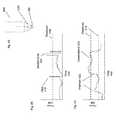
- FIG. 4Billustrates a force 408 versus time 410 trend chart with a single threshold 418 .
- the threshold 418may be set at a level that indicates a discrete force exertion indicative of a user's desire to cause an action (e.g. select an object in a GUI).
- Event 412may be interpreted as a click or selection command because the force quickly increased from below the threshold 418 to above the threshold 418 .
- the event 414may be interpreted as a double click because the force quickly increased above the threshold 418 , decreased below the threshold 418 and then essentially repeated quickly.
- the usermay also cause the force to go above the threshold 418 and hold for a period indicating that the user is intending to select an object in the GUI (e.g. a GUI presented in the display of the HWC 102 ) and ‘hold’ for a further operation (e.g. moving the object).
- a threshold valuemay be used to assist in the interpretation of the user's intention
- a signature force event trendmay also be used.
- the threshold and signaturemay be used in combination or either method may be used alone.
- a single-click signaturemay be represented by a certain force trend signature or set of signatures.
- the single-click signature(s)may require that the trend meet a criteria of a rise time between x any y values, a hold time of between a and b values and a fall time of between c and d values, for example.
- Signaturesmay be stored for a variety of functions such as click, double click, right click, hold, move, etc.
- the microprocessor 210may compare the real-time force or pressure tracking against the signatures from a signature library to make a decision and issue a command to the software application executing in the GUI.
- FIG. 4Cillustrates a force 408 versus time 410 trend chart with multiple thresholds 418 .
- the force trendis plotted on the chart with several pen force or pressure events.
- the two thresholds 418 of FIG. 4Ccreate three zones of force: a lower, middle and higher range.
- the beginning of the trendindicates that the user is placing a lower zone amount of force. This may mean that the user is writing with a given line weight and does not intend to change the weight, the user is writing.
- the trendshows a significant increase 420 in force into the middle force range. This force change appears, from the trend to have been sudden and thereafter it is sustained.
- the microprocessor 210may interpret this as an intentional change and as a result change the operation in accordance with preset rules (e.g. change line width, increase line weight, etc.).
- preset rulese.g. change line width, increase line weight, etc.
- the trendthen continues with a second apparently intentional event 420 into the higher-force range.
- the forcedips below the upper threshold 418 . This may indicate an unintentional force change and the microprocessor may detect the change in range however not affect a change in the operations being coordinated by the pen 200 .
- the trend analysismay be done with thresholds and/or signatures.
- instrument stroke parameter changesmay be referred to as a change in line type, line weight, tip type, brush type, brush width, brush pressure, color, and other forms of writing, coloring, painting, and the like.
- the pen 200may have several operating modes. For instance, the pen 200 may have a writing mode where the user interface(s) of the pen 200 (e.g. the writing surface end, quick launch buttons 222 , touch sensor 220 , motion based gesture, and the like) is optimized or selected for tasks associated with writing. As another example, the pen 200 may have a wand mode where the user interface(s) of the pen is optimized or selected for tasks associated with software or device control (e.g. the HWC 102 , external local device, remote device 112 , and the like).
- software or device controle.g. the HWC 102 , external local device, remote device 112 , and the like.
- the pen 200may have a presentation mode where the user interface(s) is optimized or selected to assist a user with giving a presentation (e.g. pointing with the laser pointer 224 while using the button(s) 222 and/or gestures to control the presentation or applications relating to the presentation).
- the penmay, for example, have a mode that is optimized or selected for a particular device that a user is attempting to control.
- the pen 200may have a number of other modes and an aspect of the present invention relates to selecting such modes.
- FIG. 5Aillustrates an automatic user interface(s) mode selection based on contextual information.
- the microprocessor 210may be programmed with IMU thresholds 514 and 512 .
- the thresholds 514 and 512may be used as indications of upper and lower bounds of an angle 504 and 502 of the pen 200 for certain expected positions during certain predicted modes.
- the microprocessor 210may then institute a writing mode for the pen's user interfaces. Similarly, if the microprocessor 210 determines (e.g.
- the microprocessormay institute a wand mode for the pen's user interface.
- a wand mode for the pen's user interfaceBoth of these examples may be referred to as context based user interface mode selection as the mode selection is based on contextual information (e.g. position) collected automatically and then used through an automatic evaluation process to automatically select the pen's user interface(s) mode.
- the microprocessor 210may monitor the contextual trend (e.g. the angle of the pen over time) in an effort to decide whether to stay in a mode or change modes. For example, through signatures, thresholds, trend analysis, and the like, the microprocessor may determine that a change is an unintentional change and therefore no user interface mode change is desired.
- the contextual trende.g. the angle of the pen over time
- the microprocessormay determine that a change is an unintentional change and therefore no user interface mode change is desired.
- FIG. 5Billustrates an automatic user interface(s) mode selection based on contextual information.
- the pen 200is monitoring (e.g. through its microprocessor) whether or not the camera at the writing surface end 208 is imaging a writing surface in close proximity to the writing surface end of the pen 200 . If the pen 200 determines that a writing surface is within a predetermined relatively short distance, the pen 200 may decide that a writing surface is present 502 and the pen may go into a writing mode user interface(s) mode. In the event that the pen 200 does not detect a relatively close writing surface 504 , the pen may predict that the pen is not currently being used to as a writing instrument and the pen may go into a non-writing user interface(s) mode.
- FIG. 5Cillustrates a manual user interface(s) mode selection.
- the user interface(s) modemay be selected based on a twist of a section 508 of the pen 200 housing, clicking an end button 510 , pressing a quick launch button 222 , interacting with touch sensor 220 , detecting a predetermined action at the pressure monitoring system (e.g. a click), detecting a gesture (e.g. detected by the IMU), etc.
- the manual mode selectionmay involve selecting an item in a GUI associated with the pen 200 (e.g. an image presented in the display of HWC 102 ).
- a confirmation selectionmay be presented to the user in the event a mode is going to change.
- the presentationmay be physical (e.g. a vibration in the pen 200 ), through a GUI, through a light indicator, etc.
- FIG. 6illustrates a couple pen use-scenarios 600 and 601 .
- FIG. 6illustrates a couple pen use-scenarios 600 and 601 .
- the use-scenariosshould be considered illustrative and non-limiting.
- Use scenario 600is a writing scenario where the pen 200 is used as a writing instrument.
- quick launch button 122 Ais pressed to launch a note application 610 in the GUI 608 of the HWC 102 display 604 .
- the HWC 102launches the note program 610 and puts the pen into a writing mode.
- the useruses the pen 200 to scribe symbols 602 on a writing surface, the pen records the scribing and transmits the scribing to the HWC 102 where symbols representing the scribing are displayed 612 within the note application 610 .
- Use scenario 601is a gesture scenario where the pen 200 is used as a gesture capture and command device.
- the quick launch button 122 Bis activated and the pen 200 activates a wand mode such that an application launched on the HWC 102 can be controlled.
- the usersees an application chooser 618 in the display(s) of the HWC 102 where different software applications can be chosen by the user.
- the user gesturese.g. swipes, spins, turns, etc.
- the usermay gesture or click or otherwise interact with the pen 200 such that the identified application is selected and launched.
- the wand modemay be used to scroll, rotate, change applications, select items, initiate processes, and the like, for example.
- the quick launch button 122 Amay be activated and the HWC 102 may launch an application chooser presenting to the user a set of applications.
- the quick launch buttonmay launch a chooser to show all communication programs (e.g. SMS, Twitter, Instagram, Facebook, email, etc.) available for selection such that the user can select the program the user wants and then go into a writing mode.
- the launchermay bring up selections for various other groups that are related or categorized as generally being selected at a given time (e.g. Microsoft Office products, communication products, productivity products, note products, organizational products, and the like)
- FIG. 7illustrates yet another embodiment of the present invention.
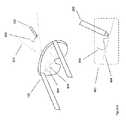
- FIG. 700illustrates a watchband clip on controller 700 .
- the watchband clip on controllermay be a controller used to control the HWC 102 or devices in the HWC system 100 .
- the watchband clip on controller 700has a fastener 718 (e.g. rotatable clip) that is mechanically adapted to attach to a watchband, as illustrated at 704 .
- the watchband controller 700may have quick launch interfaces 708 (e.g. to launch applications and choosers as described herein), a touch pad 714 (e.g. to be used as a touch style mouse for GUI control in a HWC 102 display) and a display 712 .
- the clip 718may be adapted to fit a wide range of watchbands so it can be used in connection with a watch that is independently selected for its function.
- the clipin embodiments, is rotatable such that a user can position it in a desirable manner.
- the clipmay be a flexible strap.
- the flexible strapmay be adapted to be stretched to attach to a hand, wrist, finger, device, weapon, and the like.
- the watchband controllermay be configured as a removable and replaceable watchband.
- the controllermay be incorporated into a band with a certain width, segment spacing's, etc. such that the watchband, with its incorporated controller, can be attached to a watch body.
- the attachmentin embodiments, may be mechanically adapted to attach with a pin upon which the watchband rotates.
- the watchband controllermay be electrically connected to the watch and/or watch body such that the watch, watch body and/or the watchband controller can communicate data between them.
- the watchband controllermay have 3-axis motion monitoring (e.g. through an IMU, accelerometers, magnetometers, gyroscopes, etc.) to capture user motion. The user motion may then be interpreted for gesture control.
- 3-axis motion monitoringe.g. through an IMU, accelerometers, magnetometers, gyroscopes, etc.
- the watchband controllermay comprise fitness sensors and a fitness computer.
- the sensorsmay track heart rate, calories burned, strides, distance covered, and the like. The data may then be compared against performance goals and/or standards for user feedback.
- Another aspect of the present inventionrelates to tracking pen movements with the assistance of a camera and displayed content in a HWC 102 .
- contentis presented in a see-through display of a head-worn computer to provide a virtual guide for the wearer who wants to make motions with a pen, finger, or other interface and have the motions interpreted for pattern recognition.
- an IMU or pen-tip cameramay be used to monitor the motion of a pen in order to predict what patterns are being drawn.
- the IMU and/or pen tip cameramay suffer from electronic or optical drift and the drift may cause inaccuracies in the pattern prediction.
- the virtual guideis provided to compensate for the drift.
- the pen motionsmay be captured by a camera on-board the HWC 102 while the wearer is writing with the guidance of the virtual line. Knowing that the wearer is using the virtual line as a guide, the relative position between the pen tip and virtual line can be used to reduce or eliminate drift issues.
- digital contentis presented to a wearer of the HWC 102 and the wearer moves the pen 200 along a writing surface guided by the digital content for pattern recordation, recognition and presentation assistance.
- a camera in the HWC 102images and tracks the positions of the pen 200 for pattern recordation and recognition assistance.
- both the digital content and the camera capturing the pen positionsare used for pattern recordation and recognition assistance.
- the digital content, camera capture, in-pen camera capture, in-pen IMU, etc.may be used in combination for pattern recordation and recognition assistance.
- the relative positions of the pen strokes to the virtual linemay be presented in the HWC 102 displays in relation to the virtual line.
- the wearer of the HWC 102may be scribing without ink in relation to the virtual line that he perceives and as presented in the HWC 102 display
- the on-board HWC 102 cameramay capture the scribing
- a processormay interpret the imaged scribing in relation to the line such that the scribing can be converted into digital content to be displayed in the HWC 102 display in relation to the virtual line.
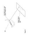
- FIG. 8illustrates a system where a camera in the HWC 102 is used to track pen 200 motions and digital content is presented to the wearer of the HWC 102 to assist the wearer with writing within a structure.
- digital content in the form of a line 804is presented in an FOV 802 of the HWC 102 .
- the wearercan see through the FOV 802 so the line 804 appears to augment the surrounding environment's view for the wearer.
- the linemay be ‘fixed’ to a spot in the environment such that when the wearer turns his head and hence changes the position of the HWC 102 , the line appears to stay in position with respect to the environment.
- the camera in the HWC 102may image the environment and track the relative movement of the HWC 102 with respect to the environment such that the line 804 can be positioned and moved within the FOV in accordance with the imaged movements to maintain visual alignment of the line with a point, object, marker, etc. in the environment.
- This configurationpresents a virtual line in the environment that does not appear to move as the wearer's head moves.
- the virtual linecan provide the wearer with guidance on where to make pen strokes.
- the linecan be thought of as a line on a piece of paper so the wearer can write, or make strokes in a writing pattern, along the virtual line to make prediction of the lines pattern more accurate and overcome drift errors that may otherwise be apparent when attempting to record the movements and predict the patterns.
- the HWC 102 cameracan also be used to track the movements of the pen 200 relative to the position of the virtual line. This may be used to better predict the patterns indicated by the wearer's pen strokes.
- the pen 200may track its motions through a pen tip camera and IMU.
- the pen tip camera and IMUmay track the pen's motion and the camera may be used to track the motion of the pen relative to the virtual line. Each of these inputs may be used to track, record and predict what it being written.
- the camera in the HWC 102captures images of the wearer's pen's motion while the wearer is using the pen to make patterns with the virtual line as a guide.
- the virtual linemay then be overlaid on the captured images of the motion to assist with the pattern analysis.
- once the overlay is madeone can see or analyze how the pen pattern moved with respect to the position of the virtual line as the wearer may be viewed the virtual line.
- the pattern analysismay involve interpreting the IMU motion detection, in-pen motion detection, and/or the pen's motion as captured through the HWC 102 camera relative to the virtual line.
- the portion of IMU data that indicated the shiftmay be discounted in the prediction analysis.
- the virtual line pattern analysismay be done in real-time, after the fact, etc.
- the pattern recognitionmay be done on a processor on-board the HWC 102 , remote from the HWC 102 , or partially on-board and remotely.
- the virtual linemay take any number of forms.
- the virtual linemay be a line, part of a virtual note, part of a virtual message template, etc.
- the linemay also change positions and shapes depending on the wearer's needs. For example, the wearer may want to trace a pattern that is being displayed as digital content and the digital content may be presented as a consolidated image, part of an image, image in a line-by-line presentation format, etc. In embodiments, this system may be used for lessons on writing, painting, drawing, etc.
- Another aspect of the present inventionrelates to the projection of imagery from a head-worn computer, wherein a projector with x-y mirror control and a solid state lighting system are mounted in the head-worn computer and positioned to project a raster style image onto a nearby surface.
- FIG. 9illustrates a projection system according to the principles of the present invention.
- the HWC 102has a micro-mirror projector 902 adapted to project a raster style beam of light to generate an image on a nearby surface.
- the micro-mirror projector 902may include two movable mirrors for the x-y directional control of the light source or a single mirror that has movement on two independently controlled perpendicular axes for x-y directional control.
- the light sourcemay be a monochromatic, multi-chromatic, dual color, tri color, multi-colored, or other arrangement. In the embodiments where multiple colors are used (e.g.
- red, green, and bluethe colors may be sequentially provided, simultaneously provided, or otherwise provided by a solid-state lighting system (e.g. LED, Laser, etc.).
- a solid-state lighting systeme.g. LED, Laser, etc.
- rasteris being used herein as an example of a pattern that may be projected to produce the image on the nearby surface and it should not be considered limited to any one particular pattern unless otherwise stated.
- embodimentsrefer to a “nearby surface” it should be understood that this is also an example for the reader and that it should not be considered limited to any particular distance unless otherwise stated.
- the micro-mirror projector 902may project an image for display (e.g. a map, presentation, etc.), an interactive user interface for the HWC 102 (e.g. an interactive keyboard, cursor control interface, button, touch pad, etc.), an interactive user interface for an external device 108 , interactive content for multiple participants (e.g. a map, game, etc.).
- an image for displaye.g. a map, presentation, etc.
- an interactive user interface for the HWC 102e.g. an interactive keyboard, cursor control interface, button, touch pad, etc.
- an interactive user interface for an external device 108e.g. an interactive content for multiple participants (e.g. a map, game, etc.).
- an interactive user interfacemay be projected by the micro-mirror projector 902 and a sensor system may be included in the HWC 102 to make interpretations related to the intersection of the person with the image.
- the sensor systemmay detect that the person has ‘touched’ the letter “a” on a projected keyboard and provide the detection information to a processor that determines that the person has ‘pressed’ the letter “a.”
- a sensor systemmay be included in the HWC 102 adapted to sense an interference when there is an object between the micro-projector 902 and a nearby surface and the interference information may be used to modify the projected image such that the projected image does not project onto the object.
- the micro-mirror projector 902may project a keyboard onto a nearby surface and when the user places their fingers over the keyboard the sensor system can detect the interference from the fingers and the projection can be modified such that the projection is dark, not emitted, in the area of the interference so the user's finger or hand does not have a projected image on it.
- the micro-projectorcan project the keyboard onto the surface.
- An image of the projected keyboardis captured by the camera in the HWC and this image is used as a baseline for comparison. Images are then captured periodically of the keyboard and compared to the baseline to determine whether fingers are present and where the fingers are located. The image of the projected keyboard is then modified to remove the portions of the keyboard where the fingers have been determined to be located.
- the solid state light used in the micro-mirror projectoris a non-visible laser or LED (e.g. NIR, IR), such that the projector projects an invisible image.
- the invisible imagemay be detected through the use of a matching non-visible light detector or camera. This may be used to prevent others from seeing what the user of the HWC 102 is seeing by providing the HWC 102 with the detector and then displaying visible image content in the see-through display of the HWC 102 that matches the non-visible radiation. This may also be used to project an image for someone else to see if they have a matching non-visible detector system.
- the position of the projected image from the micro-mirror projector 902is controllable through the HWC 102 .
- the positionfor example, may be settable through a user gesture, external control device, HWC 102 mounted interface, etc.
- the positionis locked in place on the nearby surface.
- an adjacent object or a marker on or proximate the nearby surfacemay be used to ‘key’ the projected image to such that the projected image maintains a relative position on the nearby surface.
- the projected imageis stabilized relative to the key, so that as the HWC moves, the projected image is moved within the display field of view to maintain a constant relative position to the key, this is also known as a world-locked image.
- the micro-mirror projector 902has an image stabilization system.
- the image stabilization systemmay move the micro-mirror projector 902 to compensate for sensed vibrations or other movements of the HWC 102 such that the projected image appears stably positioned on the nearby surface even when there are vibrations or movements (e.g. small movements) of the HWC 102 .
- An aspect of the present inventionrelates to a gyro-stabilized image projector with gimbaled mounts to provide a physically stabilized projection platform.
- the projectionis world locked such that the projected image appears in a fixed position relative a surface, surface edge, marker, etc.
- the world locked projectionmaybe gyro-stabilized with a laser rasterized projection where an IMU is used to measure movements of the head-worn computer and then small motors (e.g. piezo electric motors) are used to stabilize the projector/raster mirror(s).
- the projected imagepasses through optics that include optical stabilization wherein the position of optical elements can be laterally moved to change the pointing direction of the projector in response to sensed movements of the HWC.
- the projected user interfacemay also be, or instead be, digitally stabilized.
- the digitally generated image of the projected user interfacecan be digitally shifted laterally across the projected field of view to stabilize the user interface as seen by the user.
- the projected user interfacee.g. the keyboard
- the projected imagecan be digitally stabilized for movements of +/ ⁇ 5 degrees by digitally shifting the image to compensate for detected movements.
- movement detectioncan be accomplished by detecting movements of the HWC or by detecting movements of objects in the camera's field of view or through a combination of both techniques.
- the IMU stabilized laseris arranged such that the user interface image is generated by the diffractive.
- the lasermay be attached to the diffractive and the combined device may be pointed by actuators to align and stabilize the image.
- the diffractiveis removable and replaceable such that the user can change what projected image is to be presented by the projector.
- the HWC 102may be provided with a set of diffractives, one for a keyboard, button, slider, etc. and each one may be removed and replaced in the HWC 102 .
- An aspect of the present inventionrelates to a projected or augmented reality content displayed user interface position and focal plane along with the focal plane for content resulting from an interaction with the user interface.
- a keyboard or other user interfacemay be projected from an HWC 102 onto a surface.
- the usermay interact with the image that appears on the surface and the HWC 102 may have an interaction identification system (e.g. structured invisible wavelength light pattern recognition system, motion and distance sensor system, etc.) such that the interactions produce output (e.g. key strokes relating to keyboard interactions).
- an interaction identification systeme.g. structured invisible wavelength light pattern recognition system, motion and distance sensor system, etc.
- the output, or response to the interactions,may be displayed in the see-through display of the HWC 102 at a position and at a focal plane that is in relation to the position and focal plane of the surface and area where the projected user interface is displayed.
- the positionmay be such that the resultant content does not overlap the user interface from the user's perspective.
- the focal plane for the presentation of the resultant content and the user interface display surfacemay be different to form a workspace where the user can either focus on the user interface or the resultant content, but not both simultaneously.
- the position of the resultant contentmay be world-locked in relation to the projected user interface such that they appear to maintain a constant positional relation to one another from the user's perspective. This can be a useful arrangement for user's that are touch typers where they focus mainly on the resultant content but occasionally want to view the keyboard.
- the resultant contentmay be positioned and locked in a position near the projected or displayed user interface and have the same or similar focal plane as the user interface. This arrangement may be desirable for those users who like to look back and forth between the resultant content and the keys of a keyboard, for example.
- the usermay affirmatively control the position and focal plane of the resultant content relative to the projected or displayed user interface.
- the selectionsmay be set as default settings, temporary settings, contextual settings (e.g. a selection based on the application being used in the HWC 102 , a selection based on the surface in use for the reference projection or display, time of day, sensor feedback (e.g. if a motion sensor identifies motion a certain setting may be used), environmental conditions, etc.
- the resultant contentmay be presented through a display other than the head-worn see-through display.
- the usermay want to display the content to other people, either proximate or remote from the user, so the user may elect to cause the resultant content to be presented on another system display.
- the user interfaceis presented as a world-locked item, meaning it is positioned through a fixed reference to something in the surrounding environment such that it appears to be locked in place even as the user moves his head and eyes.
- the user interfaceis also stabilized such that relatively small movements of the user's head don't cause the user interface to appear to shake or move in an unwanted fashion from the user's perspective.
- the shape of the projected user interfacemay be monitored and adjusted to maintain its intended shape as to be viewed from the user's perspective (e.g. to correct for keystoning).
- the surface or edges of the surfacemay be monitored for shape alignment and when the HWC 102 moves enough to cause the shape to otherwise change with respect to the surface reference, the projected user interface shape may be altered to maintain the properly aligned shape.
- active surface alignmentmay be accomplished through an imaging process where the camera in the HWC 102 is used to image the surface.
- the shape modificationsmay be accomplished based on a predictive system.
- an IMUmay monitor the movements of the HWC 102 and the IMU output may be used to predict the resulting changes in a projected user interface image such that the user interface image can be reshaped based on the movements.
- the shape managementmay involve both surface imaging and motion-based predictions.
- the projected or displayed user interfacemay further be digitally stabilized.
- Another aspect of the present inventionrelates to cutting away a portion or all of a displayed or projected user interface based on movements of the HWC.
- the user interfaceis world locked and either a portion or the whole user interface will be cut off if the HWC 102 moves too much.
- a portion of the projected keyboardmay be eliminated when the user turns his head to the side. This prevents the projector from projecting the image erroneously.
- the projectorwill only have a certain relatively small adjustable range to target the surface and once the end of the range is reached, for example, the projection can stop or the projected image can be altered in such a way that only a portion of the projected user interface still appears.
- the content being projectedmay need to be altered. For example, as the right side of the projection is getting cut off, the digital content may be altered such that the left portion of the content continues to appear clear.
- a user of a HWC 102places a high contrast marker or makes a high contrast mark such that the HWC 102 has a reference for the world-locking of the user interface.
- the marker or markmay be intended to be used multiple times, such as a mark on a table top where the user periodically sits.
- the markermay be intended as a one time or limited time mark, such as a mark in the sand or on some surface that the user does not frequently visit.
- the marker or markmay be used to world-lock the user interface where the mark is directly associated with the placement for a portion of the user interface.
- the marker or markmay be used as a remote reference for which the user interface will be referenced but which the user interface will not overlap. This can be useful in situations where the user wants to move the user interface on the surface. For example, the user interface may be projected in an original position and the HWC 102 may give the user the opportunity to move the user interface on the world-locking surface. The user may then use a gesture, such as touching the user interface projection and dragging it into the preferred position. Then the HWC may continue to use the mark or marker as a reference or if another marker is recognized as being available the new marker may be used.
- the user generated markeris not visible to the human eye but can be detected by the HWC 102 .
- quantum dot ink or other infrared active materialmay be used to make a mark that is invisible to the human eye but is visible when viewed in infrared and the HWC 102 may include an infrared camera capable of detecting the infrared light emitted from the mark.
- the quantum dot ink or other infrared active materialmay fluoresce infrared light in response to visible light or near infrared light.
- the markmay be visible in ultraviolet light but be invisible to the human eye, and the HWC then includes an ultraviolet camera.
- the structured lightis projected through a diffractive to generate a known pattern of light.
- the structured light projectormay be built into the HWC 102 , IMU stabilized and coordinated with the user interface projector to maintain an alignment with the projected user interface image.
- the structured lightwill cover the user interface such that physical interactions with the area involving the user interface can be identified and interpreted.
- the structured lightis typically not visible to the user because it is can be a very busy pattern that would be distracting to the user.
- the HWC 102includes a non-visible capture system (e.g. IR camera) to capture the structured light interference patterns.
- a user's finger positionscan be calibrated into the structured light system or stereo camera 3D imaging system by having the user start with all fingers in contact with the surface.
- a baseline position of the fingertips when in contact with the surfacecan be obtained.
- a fingertip later reaches this baseline positionit can be interpreted as having contacted the surface and a keystroke or other input can be determined on the projected or displayed keyboard or user interface.
- the position and angle of the surface relative to the user interfacecan also be determined by using the structured light system or stereo camera 3D imaging system.
- the position and angle of the surfacecan be used to more accurately determine the baseline position of the fingers over the entire area of the projected or displayed keyboard or user interface so that keystrokes can be more accurately identified.
- a displayed or projected user interfacee.g. a keyboard
- other displayed informationare provided to the user in correspondence with the head pose of the user.
- the head poseis determined by the measured tilt of the HWC as determined by a tilt sensor associated with the HWC.
- the displayed or projected user interfaceis only provided when the user's head pose is at a selected angle or range of angles such as when the user's head is tilted downward by 30 degrees as is typical when using a laptop computer.
- the user interfaceraises their head above this tilt angle, the user interface is not provided and their finger movements are not tracked. If the user then tilts their head down again, the user interface is once again provided and their finger movements are tracked to determine their interactions with the user interface.
- the user interfacecan be provided when the user's head pose is within a selected lateral angle or range of angles and if the user moves their head laterally, the user interface is not provided.
- This method of providing the user interface only when the user's head pose is within a selected positionencourages the user to keep their head still as is typical when a person is typing or interacting with a graphical user interface.
- the methodrelies on tracking the head pose of the user within a selected range of angular movements to determine when a displayed or projected user interface is provided to the user.
- the methodcan also be provided as a mode that is selected by the user of the HWC.
- providing the user interfacecan be combined with the providing of other information that is displayed in the HWC when the user interface is not displayed. For example, when the user has their head tilted downward, the user interface can be displayed or projected and when the user tilts their head upward the other information is provided while the user interface is not provided.
- the user interfaceis projected using non-visible light where the non-visible light is imaged by the user, or other user, and the user interface is then presented as an augmented reality overlay in the head-worn display.
- the structured lightcould be provided at 940 nm (e.g. with an LED or laser diode), which can still be captured by a standard CMOS or CCD camera with the infrared cut filter removed.
- the keyboardcould then be projected with 808 nm light (e.g. with an LED or laser diode) and captured with a standard camera.
- the imagemay be captured with the same camera and the images may be image processed to identify the different wavelength patterns.
- thismay be accomplished with two cameras wherein one camera is used to capture the structured light and the other camera is used to capture the projected image and each camera is blocked from light associated with the other image (e.g. by including a notch filter that transmits certain wavelengths of light while reflecting or absorbing other wavelengths of light).
- the structured light pattern and projected user interfaceare world locked, stabilized, and image shape corrected in a coordinated fashion to maintain proper alignment between the two and such that proper identification of user interactions can be identified as properly aligned with the user interface elements.
- both the structured light projector and user interface projectormay be physically stabilized (e.g. as described herein), digitally stabilized (e.g. as described herein) and shape corrected to compensate for head movements (e.g. as described herein).
- IMU'sare attached to the back of a user's hand, finger, and or knuckles to detect finger movements and surface contact by detecting sharp stops in movement. This can provide a more detectable key contact to go along with detection of finger movements with systems.
- Another aspect of the present inventionrelates to capturing user interactions with a projected or displayed content user interface through 3D imagery of the user's fingers as captured by two separated cameras mounted on a head worn computer.
- a cameramay be mounted on ends of the front facing side of the HWC 102 (e.g. near the glasses lenses) and the two cameras may simultaneously capture video of the user's fingers while the user is interacting with a projected or content displayed user interface (e.g. a projected keyboard or AR content displayed keyboard).
- a projected or content displayed user interfacee.g. a projected keyboard or AR content displayed keyboard
- the images from the separate camerascan be processed to generate a 3D model of the user's movements such that interactions with the projected or display user interface (e.g. virtual interface) can be determined.
- the dual separated camerasmay capture other user body part movements such that they can be interpreted as 3D gesture commands.
- the user interfacemay be activated (e.g. projected or displayed) based on an affirmative user action, contextual information or other information. For example, if the user launches a software application on the head-worn computer that interoperates with a particular type of user interface (e.g. a keyboard, button, mouse, touch pad), the user interface may be presented to the user automatically. In embodiments, the user interface may be presented when appropriate during the experience with the software application. For example, if the user launches an email application, the user may automatically be presented with a ‘reader's’ user interface such as a projected or displayed touch pad.
- a software applicatione.g. a software application on the head-worn computer that interoperates with a particular type of user interface (e.g. a keyboard, button, mouse, touch pad)
- the user interfacemay be presented to the user automatically.
- the user interfacemay be presented when appropriate during the experience with the software application. For example, if the user launches an email application, the user may automatically be presented with a ‘reader's’
- the usermay use the touch pad to interact with the email program to assist in reading, scrolling, moving to another email, etc.
- the usermay also use the touch pad to reply or start a new email, which is an action that may cause the user interface to alter and include a keyboard to facilitate the input of text.
- the usermay use another external user interface to launch the projected or displayed user interface.
- the usermay have a pen or watch interface (as described herein) and the pen or watch may be adapted to launch the projected or displayed user interface.
- the usermay then use the pen or watch for certain interactions and then quick launch an additional user interface (e.g. a projected or displayed keyboard).
- the usermay also use a user interface mounted on the head-worn computer to launch the projected or displayed interface.
- the user interfaceis an infrared fluorescing printed keyboard (e.g. printed with quantum dot ink or infrared active ink) wherein the ink fluoresces in the infrared after being exposed to visible light or near infrared light.
- the light from the infrared fluorescing printed keyboard, or other user interface or imagecan be captured by an infrared camera or hyperspectral camera in the HWC, along with finger movement. Since the printed keyboard is under the user's fingers, the fingers don't interfere with the keyboard image. Stereo cameras or structured light can be used to determine finger movements as has been discussed previously herein.
- suitable infrared inksinclude: http://www.maxmax.com/aXRayIRInks asp IR1 ink absorbs below 793 nm and emits at 840 nm; or http://www.diversifiednano.com/i-series.aspx x-nano IR-783 absorbs in the visible and emits at 783 nm.
- user interactions with the projected or displayed user interface or printed user interfaceare captured with a time of flight camera system that is associated with the HWC.
- the time of flight cameraprojects a short burst of light (e g infrared light) onto the user hands and the associated area of the user interface.
- Light reflected from the user's hands and the associated area of the user interface or keyboardis then captured for a very short period of time by the time of flight camera.
- the relative distance between the time of flight camera and portions of the user's hands and portions of the associated area of the user interfaceis then determined from the relative brightness of the different portions of the image of the scene as captured by the time of flight camera.
- the time of flight cameraprovides a depth map of the user's hands and the associated area of the user interface. Changes in the depth map are used to determine the movements of the user's hands in relation to the user interface.
- the vehicle-specific external (“VSE”) user interface 104includes a mechanical mounting system adapted to mount the VSE interface 104 on the steering wheel of the vehicle.
- the mounting systemmay secure the VSE interface in a position that tends to be near the driver's hands, such as on the wheel portion around the 1:00 to 3:00 position or 9:00 to 11:00 position.
- the VSE interfacemay be secured with a Velcro style system, clip, strap, etc.
- the VSE interfaceis adapted to provide the driver with a system for the interaction with the HWC 102 when driving where the interactions are intended to enhance the driver's driving experience.
- a drivermay preset applications, screens, content sets, etc.
- the VSE interfacemay provide a physical interface for the launching of an application, toggling, switching, or changing applications or screens or content sets, etc.
- the presentation of display content controlled by the VSE interfacemay involve navigation, vehicle systems, point-of-interest information, advertisements, etc. and the driver may be able to switch between the applications very quickly through the interaction of a button or more than one button.
- the preset screens, content sets, or applicationsmay be launched through dedicated quick launch buttons.
- the navigation application buttonmay be in the upper right of the VSE interface.
- a pre-programmed button or set of buttonsmay be set to clear the display of the HWC 102 to be free of content or reduce the amount of content that is otherwise displayed to increase the driver's see-through view of the surroundings.
- the button(s)may be set to switch content display modes between two pre-determined content types relating to the vehicle (e.g. switching between pre-set driving applications).
- the button(s)may be set to change the amount of content-free area in the field-of view of the HWC 102 .
- the button(s)may be set to move content within the field-of-view.
- the button(s)may be set to change the HWC 102 display brightness and contrast or control other aspects of the HWC 102 , such as to change audio volume, sensor settings, etc. While many embodiments refer to the use of “button(s)” it should be understood that this is for simplicity in illustration only and that other forms of user controllable interfaces are envisioned by the present invention, such as, switches, toggles, touch screens, touch pads,
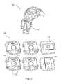
- FIG. 10illustrates several VSE interfaces according to the principles of the present invention.
- the VSE interface 1004is illustrated as being mounted on the steering wheel 1002 and illustrated in various control configurations.
- the VSE interfacemay have hot or launch buttons on the side 1008 , front face 1010 or otherwise such that the driver can touch and interact with them while driving.
- the VSE interfacemay also have a fixed hot button 1012 to perform a dedicated function such as clearing the display of the HWC 102 of content or limiting the type or amount of content that is permitted to be displayed in the display.
- the VSE interfacemay also have one or more touch pads or screens. A touch pad or screen may, for example, be used as a button style interface as well as a cursor control style interface.
- the VSE interfacemay also be virtually modified with a virtual active layer 1014 .
- the virtual active layer 1014may be presented as digital content in the display of the HWC 102 and be locked in position with respect to the physical VSE interface such that the driver perceives the virtual content as augmenting the physical VSE interface.
- virtual button labelsmay be provided as digital content and overlaid or set next to the VSE interface such that the driver perceives the labels as being associated with the buttons.
- the virtual contentmay be used in coordination with a new command set. For example, a new command set relating to navigation may be set on the HWC 102 and a label or image may be set to appear in a position locked to the VSE interface.
- there may not be a physical button and the interaction that causes a control commandmay be initiated when the user virtually interacts with the content by touching a portion of the VSE controller that intersects, from the driver's perspective through the display, with the virtual content.
- An aspect of the present inventionrelates to a user interface with a quick launch interface adapted to quickly launch an application, portion of an application, function, display control command, head-worn computer function, etc.
- an external user interface for a head-worn deviceis provided (e.g. as described herein elsewhere) and the external user interface includes a button, switch, touch pad, etc. that when actuated (e.g. the button pressed), an action is initiated on the head-worn computer (e.g. launching or activating a software application or clearing the see-through display).
- the external user interfacemay be in a form of a pen, pen attachment, watch, watch attachment, application specific device (e.g. steering wheel attachment), programmable device, mouse, wireless finger mounted mouse, phone, music player, etc. (some of which are described herein elsewhere).
- a finger mounted wireless controlleralso generally referred to as a wireless finger mouse, wireless air mouse or WAM
- the WAMmay include a gyro and/or inertial movement detection system (e.g. an IMU) and such system may communicate signals or commands to the head-worn computer based on its movements. This system may be used to interpret gestures, continuously control the movement of a mouse element on the see-through display, control a view of content being displayed on the see-through display, etc.
- the WAMmay also be mechanically adapted to be mounted on a person's finger (e.g. the index finger) such that its buttons and other physical interfaces can be controlled with the person's thumb.
- the quick launch physical interfacee.g. button
- the WAMsuch that the thumb can actuate it. Once actuated, the program, action, function, etc. associated with the interface may be initiated.
- the quick launch system and associated head-worn computermay be configured such that quick launch commands are not acted upon or modified before being executed based on a situation aware system, head-worn computer setting, external user interface setting, etc.
- the head-worn computermay include sensors that collect information that may be interpreted to determine an activity (e.g. a forward speed may be calculated and, in a case where the speed is over 10 mph, it may be determined that the person is driving in a car), and the commands may be ignored or modified based on the activity.
- an activitye.g. a forward speed may be calculated and, in a case where the speed is over 10 mph, it may be determined that the person is driving in a car
- the commandsmay be ignored or modified based on the activity.
- a quick launch command that would otherwise cause content to be presented in the see-through displaymay be ignored or the content displayed may be modified to maintain a high degree of see through.
- a quick launch button's commandsmay be altered or otherwise interpreted to cause a predetermined action based on the situation or setting. For example, irrespective of the command associated with the quick launch interface, activation of the interface may cause the clearing of content from the see-through interface when the situation appears to demand a clear view of the surrounding.
- the quick launch interfacemay be programmed to cause the see-through display to clear or substantially clear (e.g. only displaying content towards an edge of the display such that it is ‘out of the way’ of the surrounding view).
- the quick launch systemmay be adapted to launch an application, function, display control command, etc. when the actuator is interacted with in a particular way and then send a different command when the interaction is terminated.
- the systemmay be adapted to cause content to be displayed in the see-through display only when a button is held. When the button is released, the content may be removed. This system allows the user to only display content when he has activated the interface and he can quickly remove the content, by releasing, when he is done with the content or wants a clear view of the surroundings.
- the systemmay be programmed in reverse (i.e. content is removed with the button is held).
- the quick launch systemmay be programmable and/or pre-programmed to set which actuation system on the external device is used and what the pattern of interaction that causes the action is.
- an actuatormay be programmed to cause the launch command after the actuator is held for a period of time, actuated multiple times (e.g. double click), or other interaction pattern.
- the quick launch systemmay have a ‘hold’ function where a predetermined interaction causes the launch and then a second predetermined action causes a cancellation of the launch or modification of the launch.
- a double click of the actuatormay cause the display of content in the see-through display and a second double click or a single click may cause the removal of the content from the see-through display.
- Another aspect of the present inventionrelates to an auto-adapting graphical user interface presented on an external user interface device 104 adapted for the control of software applications operating on a HWC 102 .
- the auto-adapting graphical user interfacereceives information from the HWC 102 pertaining to one or more applications operating on the HWC 102 and then the graphical user interface is changed to meet the requirements of the application(s) that are running.
- the adaptationis tailored to assist the user in interacting with the application(s). For example, if a text-based application is being presented to the user in the see-through display of the HWC 102 , the auto-adaptable graphical user interface may be changed to a touch based keyboard.
- the auto-adaptable graphical interfacemay change to a game controller.
- feedback from sensor systems in the external user interface device 104may be used differently depending on the application operating on the HWC 102 . For example, when reading on the HWC 102 tilting the angle of the external user interface device 104 may cause the page to scroll, but when the HWC is presenting a game, the tilt feedback may change the way an object in the game is affected.
- FIG. 11illustrates an external user interface device 104 with an auto-adaptable graphic user interface 1102 in bi-directional communication with a HWC 102 .
- a user of the HWC 102can see through to the environment and see the external device 104 with the auto-adaptable graphical user interface at the same time the user is viewing digital content present on the see-through displays of the HWC 102 .
- the field of view of the HWC 102does not have to include any UI elements or the number of elements may be minimized because the user can still see the control elements on the external user interface device 104 .
- the HWC 102does include UI control elements even with the auto-adaptable graphical user interface 1102 . For example, if a cursor or other such element may be needed and the cursor may be presented in the see-through display of the HWC 102 while the adaptable graphical user interface 1102 converts automatically into a touch based or movement based mouse.
- the external user interface device 104may be a hand-held device with a touch screen and a processor, wherein the processor is adapted to present graphical information on the touch screen and interpret user interactions with the touch screen (e.g. a touch screed on a phone, tablet, dedicated device, etc.).
- the hand-held device processorfurther adapted to receive an indication, from the head-worn computer, of an operating program of out of a plurality of computer programs the head-worn computer processor is currently operating and presenting to the user.
- the hand-held device processormay be further adapted to change the graphical information on the touch screen based on the indication of operating program such that the touch screen presents a pre-determined user interface on the touch screen that meets the needs of the operating program.
- the HWChas its own, separate from the processor in the external user control device, processor operating the applications on the HWC.
- the GUI on the external user control devicepresents indications (e.g. icons) of available programs to be operated on the HWC where a selection of the indication initiates the corresponding program on the HWC.
- the GUI on the external user control devicepresents several applications that are already running on the HWC such that one or more may be selected to be interacted with in the HWC.
- the GUI on the external user control deviceprovides a control element adapted to switch the external user control device back into a standalone device that no longer controls the HWC. For example, if the external user control device is a phone or other multi-purpose device (i.e. controller for the HWC and adapted to perform functions unrelated to the HWC) the control element may change the device back into a phone.
- a finger mounted external user interfacei.e. a type of external user interface 104
- a sensorpositioned and adapted to sense the presence of a user's finger.
- the sensorcan provide feedback to an on-board processor of the finger mounted external user interface and the processor can adjust the interface's functionality based on the presence or non-presence of the finger.
- the sensor facilitated systemcan act like a ‘dead man switch’ where the interface stops controlling a related device (e.g. HWC) when no finger is detected. This can prevent unintentional operation.
- a related devicee.g. HWC
- a finger control interfacemay also have a security system such that only authorized user's can properly use the interface to control a related device.
- the finger controllermay have a touch pad and the touch pad may be adapted to image or otherwise read a fingerprint for authorization.
- the usermay have a predetermined period to mount the device after proper authorization. For example, the user may have his finger print authorized and then have ten seconds to mount the device such that the finger sensor senses the presence of a finger.
- a finger mounted user interface devicemay have a housing adapted to be mounted on a finger of a user; a finger touch sensor positioned to touch the finger of the user, when the finger mounted user interface is worn by the user; and the finger touch sensor may be in communication with a processor in the finger mounted user interface, wherein the processor may regulate a function of the finger mounted user interface based on the finger touch sensor's indication of a presence or non-presence of the finger of the user.
- the processormay be further adapted to communicate control commands to a head-worn computer.
- the housingmay include a strap to further secure the housing to the finger of the user.
- the processormay be further adapted to control a head-worn computer when the finger touch sensor's indication is that a finger is present.
- the processormay be further adapted to stop controlling a head-worn computer when the finger touch sensor's indication is that a finger is not present.
- the finger touch sensormay be a capacitively activated sensor, mechanically activated sensor, proximity sensor, etc.
- the function regulated by the processormay control a function based on inertial measurements indicative of movements of the device.
- the function regulated by the processormay control a function based on movements of the device.
- FIG. 12illustrates a wireless finger mounted controller 1202 in accordance with the principles of the present invention.
- the controller 1202has a housing 1212 mechanically adapted to sit on top of a finger (e.g. the index finger).
- the housingincludes a strap 1210 that can be slipped over the finger to secure the housing 1212 on the finger.
- the controller 1202mounted on the user's finger, the user may use his thumb, or other digit, to interact with the various components on the controller (e.g. track pad 1204 , actuators 1208 a and 1208 b or actuators on the front of the device).
- the usermay also interact with the controller 1202 and hence generate control signals for a related device (e.g. HWC 102 ) by moving the controller in 2D or 3D space.
- Gyros, inertial measurement units (IMUs), etc. in the controller 1202may detect user movements to generate the control signals.
- IMUsinertial measurement units
- FIG. 13illustrates a side view of the controller 1202 with internal portions in dashed lines.
- the top of the housing 1212is also removed in this view to expose the circuit board on top and some of the internal components.
- a contact sensor 1302may extend through the housing 1212 into the region where the user's finger fits.
- the contact sensor 1302may be a capacitive touch sensor, mechanical touch sensor, etc.
- the contact sensormay be adapted to sense the presence or non-presence of the user's finger.
- a processor in the controller 1202may be connected to the contact sensor 1304 such that the processor can alter functionality of the controller 1202 based on the presence or non-presence of the user's finger. For example, the controller may be shut off or it's controlling functions may be turned off if no finger is detected.
- FIG. 14illustrates another view of the finger controller 1202 showing the contact sensor 1302 extending through the housing 1212 .
- a proximity sensormay be positioned inside of the housing such that the sensor does not extend through the housing while still sensing a finger within its proximity.
- a finger mounted controllercan provide intuitive control for the user of a head-worn computer.
- a finger mounted controllermay include interactive control elements (e.g. buttons, touch pads, track pads, etc.) to facilitate input of user instructions.
- the finger mounted controllermay also have motion and position sensors (e.g. gyros, inertial measurement units (IMU), etc.) to provide the user with another form of control, which could be based on one, two or three dimensional motion sensing control instructions.
- IMUinertial measurement units
- the movement based control systemmay interfere with a button or other touch based control system.
- a touched based control elemente.g. a button
- the force or motion of touching the buttonmay cause the motion based control system to sense a movement and generate an unintentional control command.
- Thiscan cause, for example, a cursor to move downward, based on a sensed movement, while the user is attempting to select an element in content in the display of the HWC, which can cause the user to not click on the element. This can cause frustration for the user.
- a touch sensoris positioned to detect the user's attempted interaction with the touch based control element and then a processor in the finger mounted control device can turn off or ignore control commands initiated by any movement based control system. So, continuing with the example above, the movement based control system would be removed from consideration when the user interacts with a touch based control element on the housing of the finger mounted controller and the user would be able to properly interact with the element presented in the HWC display.
- a finger mounted user interface devicemay include a housing adapted to be mounted on a finger of a user; one or more user interactive control elements mounted within the housing and accessible by the user when the device is worn by the user; a touch sensor positioned to sense the presence of a thumb or finger of the user in proximity of the user interactive control element, wherein the proximity is indicative that the user is interacting with the interactive control element; and a processor adapted to alter a control schema of the finger mounted user interface device based on the proximity of the thumb or finger.
- the user interactive control elementmay be a button, track pad, etc.
- the touch sensormay be a capacitive touch sensor, mechanical touch sensor, proximity sensor, etc.
- a capacitive touch sensorforms at least a portion of a ring around the interactive control element.
- the processormay alter the control schema by not responding to data indicative of the housing moving.
- the movements of the housingmay be measured by an IMU, gyros, etc.
- FIG. 15illustrates certain components of the wireless finger controller 1202 .
- Trackpad 1204 and actuators 1208 a and 1208 bare interactive control elements mounted within the housing 1212 and positioned to be interacted with by the user.
- the housing 1212is mounted on the index finger of the user and the user uses his thumb to interact with the buttons, actuators, touch pad, track pad, and other interactive control elements.
- this systemalso includes a capacitive touch sensor ring 1502 .
- the capacitive touch sensoris positioned to detect the user's thumb (or finger if a finger is used to interact with the control elements instead of the thumb) in proximity to the interactive control elements as a prediction that the user is going to or is interacting touching the control elements.
- the touching of the capacitive touch sensor 1502can alert the processor to ignore motion based control system when the capacitive touch sensor is indicating the user is interacting with or going to interact with the control elements to improve the user's control experience.
Landscapes
- Engineering & Computer Science (AREA)
- General Engineering & Computer Science (AREA)
- Theoretical Computer Science (AREA)
- Human Computer Interaction (AREA)
- Physics & Mathematics (AREA)
- General Physics & Mathematics (AREA)
- User Interface Of Digital Computer (AREA)
- Position Input By Displaying (AREA)
Abstract
Description
Claims (9)
Priority Applications (6)
| Application Number | Priority Date | Filing Date | Title |
|---|---|---|---|
| US14/806,410US10139966B2 (en) | 2015-07-22 | 2015-07-22 | External user interface for head worn computing |
| PCT/US2016/042440WO2017015093A1 (en) | 2015-07-17 | 2016-07-15 | External user interface for head worn computing |
| US16/160,300US11209939B2 (en) | 2015-07-22 | 2018-10-15 | External user interface for head worn computing |
| US17/529,979US11816296B2 (en) | 2015-07-22 | 2021-11-18 | External user interface for head worn computing |
| US18/482,525US12271560B2 (en) | 2015-07-22 | 2023-10-06 | External user interface for head worn computing |
| US19/063,753US20250199647A1 (en) | 2015-07-22 | 2025-02-26 | External user interface for head worn computing |
Applications Claiming Priority (1)
| Application Number | Priority Date | Filing Date | Title |
|---|---|---|---|
| US14/806,410US10139966B2 (en) | 2015-07-22 | 2015-07-22 | External user interface for head worn computing |
Related Child Applications (1)
| Application Number | Title | Priority Date | Filing Date |
|---|---|---|---|
| US16/160,300ContinuationUS11209939B2 (en) | 2015-07-22 | 2018-10-15 | External user interface for head worn computing |
Publications (2)
| Publication Number | Publication Date |
|---|---|
| US20170024035A1 US20170024035A1 (en) | 2017-01-26 |
| US10139966B2true US10139966B2 (en) | 2018-11-27 |
Family
ID=57837180
Family Applications (5)
| Application Number | Title | Priority Date | Filing Date |
|---|---|---|---|
| US14/806,410Active2035-08-24US10139966B2 (en) | 2015-07-17 | 2015-07-22 | External user interface for head worn computing |
| US16/160,300ActiveUS11209939B2 (en) | 2015-07-22 | 2018-10-15 | External user interface for head worn computing |
| US17/529,979ActiveUS11816296B2 (en) | 2015-07-22 | 2021-11-18 | External user interface for head worn computing |
| US18/482,525ActiveUS12271560B2 (en) | 2015-07-22 | 2023-10-06 | External user interface for head worn computing |
| US19/063,753PendingUS20250199647A1 (en) | 2015-07-22 | 2025-02-26 | External user interface for head worn computing |
Family Applications After (4)
| Application Number | Title | Priority Date | Filing Date |
|---|---|---|---|
| US16/160,300ActiveUS11209939B2 (en) | 2015-07-22 | 2018-10-15 | External user interface for head worn computing |
| US17/529,979ActiveUS11816296B2 (en) | 2015-07-22 | 2021-11-18 | External user interface for head worn computing |
| US18/482,525ActiveUS12271560B2 (en) | 2015-07-22 | 2023-10-06 | External user interface for head worn computing |
| US19/063,753PendingUS20250199647A1 (en) | 2015-07-22 | 2025-02-26 | External user interface for head worn computing |
Country Status (1)
| Country | Link |
|---|---|
| US (5) | US10139966B2 (en) |
Cited By (4)
| Publication number | Priority date | Publication date | Assignee | Title |
|---|---|---|---|---|
| US20200061457A1 (en)* | 2017-04-26 | 2020-02-27 | Facebook Technologies, Llc | Hand-held controller using led tracking ring |
| US10691180B2 (en)* | 2017-12-19 | 2020-06-23 | North Inc. | Wearable electronic devices having a multi-use single switch and methods of use thereof |
| US10912990B2 (en) | 2017-12-29 | 2021-02-09 | Facebook Technologies, Llc | Hand-held controller using sensors for hand disambiguation |
| US11209939B2 (en) | 2015-07-22 | 2021-12-28 | Mentor Acquisition One, Llc | External user interface for head worn computing |
Families Citing this family (29)
| Publication number | Priority date | Publication date | Assignee | Title |
|---|---|---|---|---|
| US9298007B2 (en) | 2014-01-21 | 2016-03-29 | Osterhout Group, Inc. | Eye imaging in head worn computing |
| US9965681B2 (en) | 2008-12-16 | 2018-05-08 | Osterhout Group, Inc. | Eye imaging in head worn computing |
| US9810906B2 (en) | 2014-06-17 | 2017-11-07 | Osterhout Group, Inc. | External user interface for head worn computing |
| US9299194B2 (en) | 2014-02-14 | 2016-03-29 | Osterhout Group, Inc. | Secure sharing in head worn computing |
| US10684687B2 (en) | 2014-12-03 | 2020-06-16 | Mentor Acquisition One, Llc | See-through computer display systems |
| US9841599B2 (en) | 2014-06-05 | 2017-12-12 | Osterhout Group, Inc. | Optical configurations for head-worn see-through displays |
| US9939934B2 (en) | 2014-01-17 | 2018-04-10 | Osterhout Group, Inc. | External user interface for head worn computing |
| US10254856B2 (en) | 2014-01-17 | 2019-04-09 | Osterhout Group, Inc. | External user interface for head worn computing |
| US11487110B2 (en) | 2014-01-21 | 2022-11-01 | Mentor Acquisition One, Llc | Eye imaging in head worn computing |
| US9494800B2 (en) | 2014-01-21 | 2016-11-15 | Osterhout Group, Inc. | See-through computer display systems |
| US9753288B2 (en) | 2014-01-21 | 2017-09-05 | Osterhout Group, Inc. | See-through computer display systems |
| US9740280B2 (en) | 2014-01-21 | 2017-08-22 | Osterhout Group, Inc. | Eye imaging in head worn computing |
| US9766463B2 (en) | 2014-01-21 | 2017-09-19 | Osterhout Group, Inc. | See-through computer display systems |
| US9401540B2 (en) | 2014-02-11 | 2016-07-26 | Osterhout Group, Inc. | Spatial location presentation in head worn computing |
| US20160187651A1 (en) | 2014-03-28 | 2016-06-30 | Osterhout Group, Inc. | Safety for a vehicle operator with an hmd |
| US20160239985A1 (en) | 2015-02-17 | 2016-08-18 | Osterhout Group, Inc. | See-through computer display systems |
| US11003246B2 (en) | 2015-07-22 | 2021-05-11 | Mentor Acquisition One, Llc | External user interface for head worn computing |
| US10466491B2 (en) | 2016-06-01 | 2019-11-05 | Mentor Acquisition One, Llc | Modular systems for head-worn computers |
| US10684478B2 (en) | 2016-05-09 | 2020-06-16 | Mentor Acquisition One, Llc | User interface systems for head-worn computers |
| US10824253B2 (en) | 2016-05-09 | 2020-11-03 | Mentor Acquisition One, Llc | User interface systems for head-worn computers |
| US20180267615A1 (en)* | 2017-03-20 | 2018-09-20 | Daqri, Llc | Gesture-based graphical keyboard for computing devices |
| US10817128B2 (en)* | 2017-07-11 | 2020-10-27 | Logitech Europe S.A. | Input device for VR/AR applications |
| US10152141B1 (en) | 2017-08-18 | 2018-12-11 | Osterhout Group, Inc. | Controller movement tracking with light emitters |
| US11861136B1 (en)* | 2017-09-29 | 2024-01-02 | Apple Inc. | Systems, methods, and graphical user interfaces for interacting with virtual reality environments |
| CN108829271A (en)* | 2018-05-25 | 2018-11-16 | 南通理工学院 | Finger ring mouse |
| US11372518B2 (en) | 2020-06-03 | 2022-06-28 | Capital One Services, Llc | Systems and methods for augmented or mixed reality writing |
| WO2022237958A1 (en)* | 2021-05-10 | 2022-11-17 | Telefonaktiebolaget Lm Ericsson (Publ) | Wearable electronic device, electronic device system and methods thereof |
| US12008160B2 (en) | 2022-03-30 | 2024-06-11 | Apple Inc. | Eye tracking based selection of a user interface (UI) element based on targeting criteria |
| US12248639B1 (en)* | 2023-11-15 | 2025-03-11 | Input Labs Oy | Human operable controller with touch sensor |
Citations (315)
| Publication number | Priority date | Publication date | Assignee | Title |
|---|---|---|---|---|
| US1897833A (en) | 1931-01-26 | 1933-02-14 | William G G Benway | Audiphone |
| EP0368898A1 (en) | 1987-06-12 | 1990-05-23 | Hughes Flight Dynamics, Inc. | Windshield display system for an automobile |
| USD327674S (en) | 1990-02-21 | 1992-07-07 | Primax Electronics Ltd. | Video display control or similar article |
| USD352930S (en) | 1993-10-29 | 1994-11-29 | Hunter Fan Company | Remote control for a ceiling fan |
| USD375748S (en) | 1995-11-03 | 1996-11-19 | Hartman William M | Hand held remote |
| USD376790S (en) | 1995-12-21 | 1996-12-24 | Goulet Matthew G | Computer hand controller |
| US5596451A (en) | 1995-01-30 | 1997-01-21 | Displaytech, Inc. | Miniature image generator including optics arrangement |
| EP0777867A1 (en) | 1994-08-24 | 1997-06-11 | James L. Fergason | Head mounted display and viewing system using a remote retro-reflector and method of displaying and viewing an image |
| US5717422A (en) | 1994-01-25 | 1998-02-10 | Fergason; James L. | Variable intensity high contrast passive display |
| USD392959S (en) | 1997-02-26 | 1998-03-31 | Kensington Microware Limited | Computer pointing device |
| US5767841A (en) | 1995-11-03 | 1998-06-16 | Hartman; William M. | Two-sided trackball |
| US5788195A (en) | 1993-08-09 | 1998-08-04 | Rice; Gregory H. | Ergonomic data entry device |
| US5808800A (en) | 1994-12-22 | 1998-09-15 | Displaytech, Inc. | Optics arrangements including light source arrangements for an active matrix liquid crystal image generator |
| USD410638S (en) | 1998-05-08 | 1999-06-08 | Logitech Incorporated | Optical trackball |
| US20010017614A1 (en) | 2000-02-29 | 2001-08-30 | Alps Electric Co., Ltd. | Input device for moving cursor and scrolling image on screen |
| US6297749B1 (en) | 1998-11-06 | 2001-10-02 | Eric S. Smith | Emergency operating system for piloting an aircraft in a smoke filled cockpit |
| USD451892S1 (en) | 1999-11-19 | 2001-12-11 | Tefal S.A. | Switch with a light |
| US20020021498A1 (en) | 2000-04-28 | 2002-02-21 | Keiji Ohtaka | Image display apparatus and optical system |
| US20020024675A1 (en) | 2000-01-28 | 2002-02-28 | Eric Foxlin | Self-referenced tracking |
| US6369952B1 (en) | 1995-07-14 | 2002-04-09 | I-O Display Systems Llc | Head-mounted personal visual display apparatus with image generator and holder |
| USD460071S1 (en) | 2001-03-01 | 2002-07-09 | Logitech Europe S.A. | Mouse with side gap |
| US6456438B1 (en) | 1999-08-12 | 2002-09-24 | Honeywell Inc. | Variable immersion vignetting display |
| US20020148655A1 (en) | 2001-04-12 | 2002-10-17 | Samsung Electronics Co., Ltd. | Electronic pen input device and coordinate detecting method therefor |
| USD470144S1 (en) | 2002-04-18 | 2003-02-11 | Huixia Li | Computer mouse |
| US6535182B2 (en) | 1998-12-07 | 2003-03-18 | Koninklijke Philips Electronics N.V. | Head-mounted projection display system |
| USD473871S1 (en) | 2002-07-08 | 2003-04-29 | Mar Santos | Desktop/hand-held trackball |
| US20030142065A1 (en)* | 2002-01-28 | 2003-07-31 | Kourosh Pahlavan | Ring pointer device with inertial sensors |
| USD478052S1 (en) | 2002-07-12 | 2003-08-05 | Hunter Fan Company | Ceiling fan remote control |
| US6642945B1 (en) | 2000-05-04 | 2003-11-04 | Microsoft Corporation | Method and system for optimizing a visual display for handheld computer systems |
| US20030234823A1 (en) | 2002-05-17 | 2003-12-25 | Shigemi Sato | Image processing apparatus and image processing method, and image processing program and recording medium of the same |
| US20040003453A1 (en) | 2002-07-02 | 2004-01-08 | Takashi Urakawa | Mounting unit for head mounted apparatus and head mounting apparatus |
| US20040024287A1 (en) | 2002-08-05 | 2004-02-05 | Eastman Kodak Company | System and method for conditioning the psychological state of a subject using an adaptive autostereoscopic display |
| US20040027312A1 (en) | 2002-03-27 | 2004-02-12 | Norio Owada | Portable information device |
| US20040032392A1 (en) | 2002-08-19 | 2004-02-19 | Topseed Technology Corp. | Mouse pen device having remote-control function |
| US6717075B1 (en) | 2003-01-08 | 2004-04-06 | Hewlett-Packard Development Company, L.P. | Method and apparatus for a multi-sided input device |
| US20040080541A1 (en) | 1998-03-20 | 2004-04-29 | Hisashi Saiga | Data displaying device |
| US20040130522A1 (en) | 2003-01-08 | 2004-07-08 | Wen-Po Lin | System and method for presenting real handwriting trace |
| US6771294B1 (en) | 1999-12-29 | 2004-08-03 | Petri Pulli | User interface |
| US20040150631A1 (en) | 2003-01-31 | 2004-08-05 | David Fleck | Method of triggering functions in a computer application using a digitizer having a stylus and a digitizer system |
| US20040224765A1 (en) | 2003-05-09 | 2004-11-11 | Microsoft Corporation | Text input device and adapter mechanism |
| US6847336B1 (en) | 1996-10-02 | 2005-01-25 | Jerome H. Lemelson | Selectively controllable heads-up display system |
| US20050156915A1 (en) | 2004-01-16 | 2005-07-21 | Fisher Edward N. | Handwritten character recording and recognition device |
| US6956558B1 (en) | 1998-03-26 | 2005-10-18 | Immersion Corporation | Rotary force feedback wheels for remote control devices |
| USD512027S1 (en) | 2004-03-15 | 2005-11-29 | Nokia Corporation | Remote control |
| USD513233S1 (en) | 2004-02-28 | 2005-12-27 | Hunter Fan Company | Ceiling fan remote |
| US6987787B1 (en) | 2004-06-28 | 2006-01-17 | Rockwell Collins | LED brightness control system for a wide-range of luminance control |
| US20060017654A1 (en) | 2004-07-23 | 2006-01-26 | Romo Justin R | Virtual reality interactivity system and method |
| USD514525S1 (en) | 2004-02-28 | 2006-02-07 | Hunter Fan Company | Ceiling fan wall controller |
| US20060047339A1 (en) | 2004-08-27 | 2006-03-02 | Brown David C | Intracapsular pseudophakic device |
| US20060132924A1 (en) | 2004-12-18 | 2006-06-22 | Emile Mimran | Portable adaptor and software for use with a heads-up display unit |
| US20060132457A1 (en) | 2004-12-21 | 2006-06-22 | Microsoft Corporation | Pressure sensitive controls |
| US20060170652A1 (en) | 2005-01-31 | 2006-08-03 | Canon Kabushiki Kaisha | System, image processing apparatus, and information processing method |
| US7088234B2 (en) | 2001-11-27 | 2006-08-08 | Matsushita Electric Industrial Co., Ltd. | Wearing information notifying unit |
| US20060178827A1 (en) | 2005-02-10 | 2006-08-10 | Xanavi Informatics Corporation | Map display apparatus, map display method and navigation system |
| USD529467S1 (en) | 2005-06-01 | 2006-10-03 | Research In Motion Limited | Handset |
| US20060279549A1 (en) | 2005-06-08 | 2006-12-14 | Guanglie Zhang | Writing system |
| US20060288233A1 (en) | 2005-04-25 | 2006-12-21 | Douglas Kozlay | Attachable biometric authentication apparatus for watchbands and other personal items |
| US20070003168A1 (en) | 2005-06-29 | 2007-01-04 | Microsoft Corporation | Computer input device |
| US20070004451A1 (en) | 2005-06-30 | 2007-01-04 | C Anderson Eric | Controlling functions of a handheld multifunction device |
| US20070038960A1 (en) | 1998-10-19 | 2007-02-15 | Sony Corporation | Information processing apparatus and method, information processing system, and providing medium |
| US20070058868A1 (en) | 2005-09-14 | 2007-03-15 | Kabushiki Kaisha Toshiba | Character reader, character reading method, and character reading program |
| US7199934B2 (en) | 2004-05-06 | 2007-04-03 | Olympus Corporation | Head-mounted display apparatus |
| US20070075989A1 (en) | 2005-03-18 | 2007-04-05 | Searete Llc, A Limited Liability Corporation Of The State Of Delaware | Electronic acquisition of a hand formed expression and a context of the expression |
| US7206134B2 (en) | 2004-02-04 | 2007-04-17 | Displaytech, Inc. | Compact electronic viewfinder |
| USD541226S1 (en) | 2004-12-21 | 2007-04-24 | Kabushiki Kaisha Toshiba | Controller for forceps for medical robot |
| US20070120836A1 (en) | 2005-11-22 | 2007-05-31 | Sony Corporation | Inputting apparatus, inputting method and fabrication method for inputting apparatus |
| US20070132662A1 (en) | 2004-05-27 | 2007-06-14 | Canon Kabushiki Kaisha | Information processing method, information processing apparatus, and image sensing apparatus |
| US20070156364A1 (en) | 2005-12-29 | 2007-07-05 | Apple Computer, Inc., A California Corporation | Light activated hold switch |
| US20070153639A1 (en) | 2005-12-02 | 2007-07-05 | Ronald Lafever | Flexible band with clip-on watch |
| US20070178950A1 (en) | 2006-01-19 | 2007-08-02 | International Business Machines Corporation | Wearable multimodal computing device with hands-free push to talk |
| US20070229458A1 (en) | 2006-03-31 | 2007-10-04 | Samsung Electronics Co., Ltd. | Wheel input device and method for four-way key stroke in portable terminal |
| US20070236450A1 (en) | 2006-03-24 | 2007-10-11 | Northwestern University | Haptic device with indirect haptic feedback |
| US20080005702A1 (en) | 2006-05-31 | 2008-01-03 | Abb Technology Ltd. | Virtual work place |
| USD559793S1 (en) | 2006-10-25 | 2008-01-15 | Hannspree, Inc. | Remote control |
| US20080066973A1 (en) | 2006-09-19 | 2008-03-20 | Fuji Xerox Co., Ltd. | Writing information processing system, writing information generating device and computer readable storage medium |
| US20080121441A1 (en) | 2006-05-12 | 2008-05-29 | Velosum, Inc. | Systems and methods for mutually exclusive options on a paper form for use with a digital pen |
| US7380936B2 (en) | 2003-10-09 | 2008-06-03 | Ipventure, Inc. | Eyeglasses with a clock or other electrical component |
| USD571816S1 (en) | 2006-06-19 | 2008-06-24 | Logitech Europe S.A. | Computer mouse topcase |
| US7401918B2 (en) | 2003-10-09 | 2008-07-22 | Ipventure, Inc. | Eyeglasses with activity monitoring |
| US20080186255A1 (en) | 2006-12-07 | 2008-08-07 | Cohen Philip R | Systems and methods for data annotation, recordation, and communication |
| US7500747B2 (en) | 2003-10-09 | 2009-03-10 | Ipventure, Inc. | Eyeglasses with electrical components |
| US20090183929A1 (en) | 2005-06-08 | 2009-07-23 | Guanglie Zhang | Writing system with camera |
| US20090251441A1 (en) | 2008-04-03 | 2009-10-08 | Livescribe, Inc. | Multi-Modal Controller |
| US20090279180A1 (en) | 2004-06-17 | 2009-11-12 | Yaakov Amitai | High brightness optical device |
| US20100001572A1 (en) | 2006-11-10 | 2010-01-07 | Hiroshi Masunaga | Chair backrest device |
| US7677723B2 (en) | 2003-10-09 | 2010-03-16 | Ipventure, Inc. | Eyeglasses with a heart rate monitor |
| US20100085325A1 (en) | 2008-10-02 | 2010-04-08 | Wacom Co., Ltd. | Combination touch and transducer input system and method |
| US20100134848A1 (en) | 2007-03-23 | 2010-06-03 | Stefan Lynggaard | Printing of a position-coding pattern |
| US20100182561A1 (en) | 2007-08-08 | 2010-07-22 | Masaki Ikeda | Liquid crystal display device and method of manufacturing same |
| US20100194682A1 (en) | 2009-01-30 | 2010-08-05 | Research In Motion Limited | Method for tap detection and for interacting with a handheld electronic device, and a handheld electronic device configured therefor |
| US7777723B2 (en) | 2006-06-28 | 2010-08-17 | Tosiki Namiki | Mouse |
| US7792552B2 (en) | 2003-04-15 | 2010-09-07 | Ipventure, Inc. | Eyeglasses for wireless communications |
| US7806525B2 (en) | 2003-10-09 | 2010-10-05 | Ipventure, Inc. | Eyeglasses having a camera |
| US7830370B2 (en) | 2000-06-06 | 2010-11-09 | Semiconductor Energy Laboratory Co., Ltd. | Display device and method of manufacturing the same |
| US20100309097A1 (en) | 2009-06-04 | 2010-12-09 | Roni Raviv | Head mounted 3d display |
| US7855743B2 (en) | 2006-09-08 | 2010-12-21 | Sony Corporation | Image capturing and displaying apparatus and image capturing and displaying method |
| USD630213S1 (en) | 2010-07-28 | 2011-01-04 | Senduzy Corp. | Computer mouse |
| US20110006982A1 (en) | 2009-07-07 | 2011-01-13 | Samsung Electronics Co., Ltd. | Pen type input device and input method using the same |
| USD631881S1 (en) | 2006-03-28 | 2011-02-01 | Quinn Bryan C | Computer mouse |
| USD631882S1 (en) | 2010-01-31 | 2011-02-01 | Swiftpoint Limited | Computer interface device |
| US7928926B2 (en) | 2006-06-27 | 2011-04-19 | Panasonic Corporation | Display apparatus and method for hands free operation that selects a function when window is within field of view |
| US20110109587A1 (en)* | 2009-11-06 | 2011-05-12 | Andrew Ferencz | Touch-Based User Interface Corner Conductive Pad |
| US20110199305A1 (en)* | 2008-11-07 | 2011-08-18 | Changsu Suh | Mouse controlled by movements of fingers in the air |
| US8004765B2 (en) | 2002-03-21 | 2011-08-23 | Lumus Ltd. | Light guide optical device |
| US20110213664A1 (en) | 2010-02-28 | 2011-09-01 | Osterhout Group, Inc. | Local advertising content on an interactive head-mounted eyepiece |
| US20110221672A1 (en) | 2010-02-28 | 2011-09-15 | Osterhout Group, Inc. | Hand-worn control device in an augmented reality eyepiece |
| WO2011143655A1 (en) | 2010-05-14 | 2011-11-17 | Advitech, Inc. | System and method for prevention and control of the effects of spatial disorientation |
| US20110285638A1 (en) | 2010-05-21 | 2011-11-24 | Microsoft Corporation | Computing Device Notes |
| US20120026088A1 (en) | 2010-08-01 | 2012-02-02 | T-Mobile Usa, Inc. | Handheld device with projected user interface and interactive image |
| US20120050493A1 (en) | 2010-08-24 | 2012-03-01 | Siemens Corporation | Geometric calibration of head-worn multi-camera eye tracking system |
| US20120049759A1 (en)* | 2009-05-13 | 2012-03-01 | Koninklijke Philips Electronics N.V. | User interface with circular light guided ring with adaptive appearance depending on function |
| US20120062850A1 (en) | 2010-09-15 | 2012-03-15 | Microsoft Corporation | Laser-scanning virtual image display |
| US20120062594A1 (en) | 2010-09-15 | 2012-03-15 | Richard John Campbell | Methods and Systems for Collaborative-Writing-Surface Image Formation |
| US20120068913A1 (en) | 2010-09-21 | 2012-03-22 | Avi Bar-Zeev | Opacity filter for see-through head mounted display |
| US20120075168A1 (en) | 2010-09-14 | 2012-03-29 | Osterhout Group, Inc. | Eyepiece with uniformly illuminated reflective display |
| WO2012058175A1 (en) | 2010-10-28 | 2012-05-03 | Eastman Kodak Company | Method of operating a head-mounted display for prevention of motion sickness |
| US20120113514A1 (en) | 2010-11-08 | 2012-05-10 | Polycom, Inc. | Picoprojector with Image Stabilization [Image-Stabilized Projector] |
| US20120133885A1 (en) | 2003-10-09 | 2012-05-31 | Howell Thomas A | Eyewear supporting electrical components and apparatus therefor |
| US20120139915A1 (en) | 2010-06-07 | 2012-06-07 | Masahiro Muikaichi | Object selecting device, computer-readable recording medium, and object selecting method |
| US8223024B1 (en) | 2011-09-21 | 2012-07-17 | Google Inc. | Locking mechanism based on unnatural movement of head-mounted display |
| US8228315B1 (en) | 2011-07-12 | 2012-07-24 | Google Inc. | Methods and systems for a virtual input device |
| EP2486450A1 (en) | 2008-11-02 | 2012-08-15 | David Chaum | Near to eye display system and appliance |
| US20120212499A1 (en) | 2010-02-28 | 2012-08-23 | Osterhout Group, Inc. | System and method for display content control during glasses movement |
| US20120212593A1 (en) | 2011-02-17 | 2012-08-23 | Orcam Technologies Ltd. | User wearable visual assistance system |
| US20120218301A1 (en) | 2010-02-28 | 2012-08-30 | Osterhout Group, Inc. | See-through display with an optical assembly including a wedge-shaped illumination system |
| US20120223885A1 (en) | 2011-03-02 | 2012-09-06 | Microsoft Corporation | Immersive display experience |
| US20120229248A1 (en) | 2011-03-12 | 2012-09-13 | Uday Parshionikar | Multipurpose controller for electronic devices, facial expressions management and drowsiness detection |
| EP2502410A1 (en) | 2009-11-19 | 2012-09-26 | eSight Corporation | Image magnification on a head mounted display |
| US20120250152A1 (en) | 2011-03-31 | 2012-10-04 | Honeywell International Inc. | Variable focus stereoscopic display system and method |
| US20120249741A1 (en) | 2011-03-29 | 2012-10-04 | Giuliano Maciocci | Anchoring virtual images to real world surfaces in augmented reality systems |
| US20120256944A1 (en) | 2011-04-11 | 2012-10-11 | Apple Inc. | Handwriting Capture Techniques |
| US20120264510A1 (en) | 2011-04-12 | 2012-10-18 | Microsoft Corporation | Integrated virtual environment |
| US20120302347A1 (en) | 2011-05-25 | 2012-11-29 | Sony Computer Entertainment America Llc | Hybrid Separable Motion Controller |
| US20120306850A1 (en) | 2011-06-02 | 2012-12-06 | Microsoft Corporation | Distributed asynchronous localization and mapping for augmented reality |
| US8337013B2 (en) | 2004-07-28 | 2012-12-25 | Ipventure, Inc. | Eyeglasses with RFID tags or with a strap |
| US20120327040A1 (en) | 2011-06-22 | 2012-12-27 | Simon David I | Identifiable stylus |
| US20120327116A1 (en) | 2011-06-23 | 2012-12-27 | Microsoft Corporation | Total field of view classification for head-mounted display |
| US20130002724A1 (en) | 2011-06-30 | 2013-01-03 | Google Inc. | Wearable computer with curved display and navigation tool |
| US20130002545A1 (en) | 2011-06-30 | 2013-01-03 | Google Inc. | Wearable computer with curved display and navigation tool |
| US20130009907A1 (en) | 2009-07-31 | 2013-01-10 | Rosenberg Ilya D | Magnetic Stylus |
| US20130009366A1 (en) | 2007-10-23 | 2013-01-10 | Weatherford/Lamb, Inc. | Low Profile Rotating Control Device |
| US20130027341A1 (en)* | 2010-04-16 | 2013-01-31 | Mastandrea Nicholas J | Wearable motion sensing computing interface |
| US20130038729A1 (en) | 2010-04-29 | 2013-02-14 | Nelson Liang An Chang | Participant Collaboration On A Displayed Version Of An Object |
| US8378924B2 (en) | 2007-01-12 | 2013-02-19 | Kopin Corporation | Monocular display device |
| US20130044042A1 (en) | 2011-08-18 | 2013-02-21 | Google Inc. | Wearable device with input and output structures |
| WO2013050650A1 (en) | 2011-10-06 | 2013-04-11 | Nokia Corporation | Method and apparatus for controlling the visual representation of information upon a see-through display |
| USD680112S1 (en) | 2008-07-25 | 2013-04-16 | Michael J. Monahan | Movement filtered mouse |
| US8427396B1 (en) | 2012-07-16 | 2013-04-23 | Lg Electronics Inc. | Head mounted display and method of outputting a content using the same in which the same identical content is displayed |
| US20130100259A1 (en) | 2011-10-21 | 2013-04-25 | Arun Ramaswamy | Methods and apparatus to identify exposure to 3d media presentations |
| US20130120224A1 (en) | 2011-11-11 | 2013-05-16 | Elmer S. Cajigas | Recalibration of a flexible mixed reality device |
| US20130135244A1 (en) | 2011-11-29 | 2013-05-30 | Apple Inc | Embedded force measurement |
| US20130154913A1 (en) | 2010-12-16 | 2013-06-20 | Siemens Corporation | Systems and methods for a gaze and gesture interface |
| US20130169560A1 (en) | 2012-01-04 | 2013-07-04 | Tobii Technology Ab | System for gaze interaction |
| WO2013103825A1 (en) | 2012-01-05 | 2013-07-11 | Google Inc. | Wearable device assembly with input and output structures |
| US8494215B2 (en) | 2009-03-05 | 2013-07-23 | Microsoft Corporation | Augmenting a field of view in connection with vision-tracking |
| US20130196757A1 (en) | 2012-01-30 | 2013-08-01 | Microsoft Corporation | Multiplayer gaming with head-mounted display |
| WO2013110846A1 (en) | 2012-01-26 | 2013-08-01 | Nokia Corporation | Capacitive eye tracking sensor |
| US20130222270A1 (en) | 2012-02-28 | 2013-08-29 | Motorola Mobility, Inc. | Wearable display device, corresponding systems, and method for presenting output on the same |
| US20130234914A1 (en) | 2012-03-07 | 2013-09-12 | Seiko Epson Corporation | Head-mounted display device and control method for the head-mounted display device |
| USD689862S1 (en) | 2012-08-15 | 2013-09-17 | Kye Systems Corp. | Ring mouse |
| US20130249849A1 (en) | 2012-03-21 | 2013-09-26 | Google Inc. | Don and Doff Sensing Using Capacitive Sensors |
| US20130249946A1 (en) | 2012-03-22 | 2013-09-26 | Seiko Epson Corporation | Head-mounted display device |
| USD690684S1 (en) | 2012-05-30 | 2013-10-01 | Samsung Electronics Co., Ltd. | Remote controller |
| US20130257622A1 (en) | 2012-03-30 | 2013-10-03 | Honeywell International Inc. | Personal protection equipment verification |
| US8564883B2 (en) | 2011-02-04 | 2013-10-22 | Seiko Epson Corporation | Virtual image display device |
| US8570273B1 (en) | 2010-05-20 | 2013-10-29 | Lockheed Martin Corporation | Input device configured to control a computing device |
| US20130288761A1 (en) | 2011-01-04 | 2013-10-31 | Marta Isabel Santos Paiva Ferraz Conceicao | Interactive wearable videogame through the use of wireless electronic sensors and physical objects |
| US8576491B2 (en) | 2011-02-04 | 2013-11-05 | Seiko Epson Corporation | Virtual image display device |
| US8576276B2 (en) | 2010-11-18 | 2013-11-05 | Microsoft Corporation | Head-mounted display device which provides surround video |
| WO2013170073A1 (en) | 2012-05-09 | 2013-11-14 | Nokia Corporation | Method and apparatus for determining representations of displayed information based on focus distance |
| US20130300637A1 (en) | 2010-10-04 | 2013-11-14 | G Dirk Smits | System and method for 3-d projection and enhancements for interactivity |
| US8587869B2 (en) | 2011-02-04 | 2013-11-19 | Seiko Epson Corporation | Virtual image display device |
| US8594467B2 (en) | 2008-12-19 | 2013-11-26 | Microsoft Corporation | Interactive virtual display system for ubiquitous devices |
| US20130336528A1 (en) | 2012-05-25 | 2013-12-19 | Atheer, Inc. | Method and apparatus for identifying input features for later recognition |
| USD696668S1 (en) | 2013-03-18 | 2013-12-31 | Asustek Computer Inc. | Input device |
| USD697914S1 (en) | 2012-10-09 | 2014-01-21 | Logitech Europe S.A. | Wireless input device |
| US20140028704A1 (en) | 2012-07-30 | 2014-01-30 | Lenovo (Beijing) Co., Ltd. | Display Device |
| US20140043682A1 (en) | 2010-10-21 | 2014-02-13 | Patrick Hussey | Flip Up Interchangeable System |
| US8662686B2 (en) | 2010-09-03 | 2014-03-04 | Seiko Epson Corporation | Light guide plate and virtual image display apparatus having the same |
| US20140063473A1 (en) | 2012-08-31 | 2014-03-06 | Stmicroelectronics S.R.L. | Stabilized pico-projector device and related image stabilization method |
| US20140062854A1 (en) | 2012-08-31 | 2014-03-06 | Lg Electronics Inc. | Head mounted display and method of controlling digital device using the same |
| US8670183B2 (en) | 2011-03-07 | 2014-03-11 | Microsoft Corporation | Augmented view of advertisements |
| US20140078043A1 (en) | 2012-09-14 | 2014-03-20 | Lg Electronics Inc. | Apparatus and method of providing user interface on head mounted display and head mounted display thereof |
| US8698157B2 (en) | 2011-10-03 | 2014-04-15 | Seiko Epson Corporation | Electro-optical apparatus and electronic apparatus |
| US20140115520A1 (en) | 2012-10-22 | 2014-04-24 | Atheer, Inc. | Method and apparatus for secure data entry using a virtual interface |
| US20140111838A1 (en) | 2012-10-24 | 2014-04-24 | Samsung Electronics Co., Ltd. | Method for providing virtual image to user in head-mounted display device, machine-readable storage medium, and head-mounted display device |
| US8711487B2 (en) | 2011-09-15 | 2014-04-29 | Seiko Epson Corporation | Virtual image display device and manufacturing method of virtual image display device |
| US20140129328A1 (en) | 2012-11-07 | 2014-05-08 | Microsoft Corporation | Providing augmented purchase schemes |
| US20140147829A1 (en) | 2012-11-29 | 2014-05-29 | Robert Jerauld | Wearable food nutrition feedback system |
| US20140146394A1 (en) | 2012-11-28 | 2014-05-29 | Nigel David Tout | Peripheral display for a near-eye display device |
| US8745058B1 (en) | 2012-02-21 | 2014-06-03 | Google Inc. | Dynamic data item searching |
| US8743052B1 (en) | 2012-11-24 | 2014-06-03 | Eric Jeffrey Keller | Computing interface system |
| US20140152558A1 (en) | 2012-11-30 | 2014-06-05 | Tom Salter | Direct hologram manipulation using imu |
| US20140152676A1 (en) | 2012-11-30 | 2014-06-05 | Dave Rohn | Low latency image display on multi-display device |
| US20140152530A1 (en) | 2012-12-03 | 2014-06-05 | Honeywell International Inc. | Multimedia near to eye display system |
| US8750541B1 (en) | 2012-10-31 | 2014-06-10 | Google Inc. | Parametric array for a head-mountable device |
| US20140159995A1 (en) | 2012-12-12 | 2014-06-12 | Aditha May Adams | Head mounted display having temple arms to provide long axis compression |
| US20140160055A1 (en) | 2012-12-12 | 2014-06-12 | Jeffrey Margolis | Wearable multi-modal input device for augmented reality |
| US20140165000A1 (en)* | 2011-12-29 | 2014-06-12 | Apple Inc. | Device, Method, and Graphical User Interface for Configuring and Implementing Restricted Interactions for Applications |
| US20140160170A1 (en) | 2012-12-06 | 2014-06-12 | Nokia Corporation | Provision of an Image Element on a Display Worn by a User |
| US20140160157A1 (en) | 2012-12-11 | 2014-06-12 | Adam G. Poulos | People-triggered holographic reminders |
| US8752963B2 (en) | 2011-11-04 | 2014-06-17 | Microsoft Corporation | See-through display brightness control |
| US20140168735A1 (en) | 2012-12-19 | 2014-06-19 | Sheng Yuan | Multiplexed hologram tiling in a waveguide display |
| US20140168716A1 (en) | 2004-04-19 | 2014-06-19 | Google Inc. | Handheld device for capturing text from both a document printed on paper and a document displayed on a dynamic display device |
| US20140176603A1 (en) | 2012-12-20 | 2014-06-26 | Sri International | Method and apparatus for mentoring via an augmented reality assistant |
| US20140177023A1 (en) | 2012-04-05 | 2014-06-26 | Augmented Vision Inc. | Apparatus for optical see-through head mounted display with mutual occlusion and opaqueness control capability |
| US8770742B2 (en) | 2004-04-15 | 2014-07-08 | Ingeniospec, Llc | Eyewear with radiation detection system |
| US20140191942A1 (en) | 2013-01-07 | 2014-07-10 | Seiko Epson Corporation | Display device and control method thereof |
| US8787006B2 (en) | 2011-01-31 | 2014-07-22 | Apple Inc. | Wrist-worn electronic device and methods therefor |
| US20140204062A1 (en) | 2013-01-23 | 2014-07-24 | Sony Corporation | Head-mounted display, display apparatus, and input apparatus |
| US8803867B2 (en) | 2011-09-28 | 2014-08-12 | Seiko Epson Corporation | Electro-optical device and electronic apparatus |
| US20140240223A1 (en) | 2013-02-22 | 2014-08-28 | Thalmic Labs Inc. | Method and apparatus for analyzing capacitive emg and imu sensor signals for gesture control |
| US8823071B2 (en) | 2011-09-28 | 2014-09-02 | Seiko Epson Corporation | Electro-optical device and electronic apparatus |
| US8837880B2 (en) | 2010-10-08 | 2014-09-16 | Seiko Epson Corporation | Virtual image display device |
| US20140279528A1 (en) | 2013-03-15 | 2014-09-18 | Motorola Mobility Llc | Wearable Authentication Device |
| US20140266988A1 (en) | 2013-03-15 | 2014-09-18 | Eyecam, LLC | Autonomous computing and telecommunications head-up displays glasses |
| US20140285631A1 (en) | 2013-03-20 | 2014-09-25 | Trimble Navigation Limited | Indoor navigation via multi-beam laser projection |
| US20140306866A1 (en) | 2013-03-11 | 2014-10-16 | Magic Leap, Inc. | System and method for augmented and virtual reality |
| US20140320389A1 (en) | 2013-04-29 | 2014-10-30 | Michael Scavezze | Mixed reality interactions |
| US20140320383A1 (en) | 2011-12-16 | 2014-10-30 | Sony Corporaton | Head-mounted display and information display apparatus |
| USD716813S1 (en) | 2014-07-28 | 2014-11-04 | Jianbo Deng | Computer mouse |
| USD718309S1 (en) | 2012-05-10 | 2014-11-25 | Stealth International, Llc | Stealth 3D mouse |
| US20140363797A1 (en) | 2013-05-28 | 2014-12-11 | Lark Technologies, Inc. | Method for providing wellness-related directives to a user |
| US8922530B2 (en) | 2010-01-06 | 2014-12-30 | Apple Inc. | Communicating stylus |
| US20150012581A1 (en) | 2013-07-02 | 2015-01-08 | Samsung Electronics Co., Ltd. | Method for function control and electronic device thereof |
| US20150016777A1 (en) | 2012-06-11 | 2015-01-15 | Magic Leap, Inc. | Planar waveguide apparatus with diffraction element(s) and system employing same |
| US20150040040A1 (en) | 2013-08-05 | 2015-02-05 | Alexandru Balan | Two-hand interaction with natural user interface |
| US8982471B1 (en) | 2012-01-04 | 2015-03-17 | Google Inc. | HMD image source as dual-purpose projector/near-eye display |
| US20150085333A1 (en) | 2013-09-25 | 2015-03-26 | Logitech Europe Sa | Retinal display projection device |
| USD728573S1 (en) | 2013-09-20 | 2015-05-05 | Jianbo Deng | Computer input device |
| US9024842B1 (en) | 2011-07-08 | 2015-05-05 | Google Inc. | Hand gestures to signify what is important |
| US20150123887A1 (en) | 2013-11-01 | 2015-05-07 | Apple Inc. | Invisible light transmission via a display assembly |
| US20150128251A1 (en) | 2013-11-05 | 2015-05-07 | Lg Electronics Inc. | Mobile terminal and method for controlling the same |
| US20150143297A1 (en) | 2011-11-22 | 2015-05-21 | Google Inc. | Input detection for a head mounted device |
| US9046999B1 (en) | 2010-06-08 | 2015-06-02 | Google Inc. | Dynamic input at a touch-based interface based on pressure |
| US20150156716A1 (en) | 2013-12-03 | 2015-06-04 | Google Inc. | On-head detection for head-mounted display |
| US9063563B1 (en) | 2012-09-25 | 2015-06-23 | Amazon Technologies, Inc. | Gesture actions for interface elements |
| US9064436B1 (en) | 2012-01-06 | 2015-06-23 | Google Inc. | Text input on touch sensitive interface |
| US20150185476A1 (en) | 2013-12-30 | 2015-07-02 | Samsung Display Co., Ltd. | Electronic device and method of operating an electronic device |
| US20150205119A1 (en) | 2014-01-21 | 2015-07-23 | Osterhout Group, Inc. | Optical configurations for head worn computing |
| US20150205402A1 (en) | 2014-01-17 | 2015-07-23 | Osterhout Group, Inc. | External user interface for head worn computing |
| US20150206173A1 (en) | 2014-01-21 | 2015-07-23 | Osterhout Group, Inc. | Eye imaging in head worn computing |
| US20150205388A1 (en) | 2014-01-17 | 2015-07-23 | Osterhout Group, Inc. | External user interface for head worn computing |
| US20150202962A1 (en) | 2014-01-21 | 2015-07-23 | Honda Motor Co., Ltd. | System and method for providing an augmented reality vehicle interface |
| US20150205351A1 (en) | 2014-01-17 | 2015-07-23 | Osterhout Group, Inc. | External user interface for head worn computing |
| US20150205132A1 (en) | 2014-01-21 | 2015-07-23 | Osterhout Group, Inc. | See-through computer display systems |
| US20150212327A1 (en) | 2014-01-24 | 2015-07-30 | Osterhout Group, Inc. | Stray light suppression for head worn computing |
| US20150213584A1 (en) | 2014-01-24 | 2015-07-30 | Ricoh Company, Ltd. | Projection system, image processing apparatus, and correction method |
| US20150212647A1 (en) | 2012-10-10 | 2015-07-30 | Samsung Electronics Co., Ltd. | Head mounted display apparatus and method for displaying a content |
| US20150226967A1 (en) | 2014-02-11 | 2015-08-13 | Osterhout Group, Inc. | Spatial location presentation in head worn computing |
| US20150228099A1 (en) | 2014-02-11 | 2015-08-13 | Osterhout Group, Inc. | Micro doppler presentations in head worn computing |
| US20150229019A1 (en) | 2014-02-11 | 2015-08-13 | Osterhout Group, Inc. | Spatial location presentation in head worn computing |
| US20150228120A1 (en) | 2014-02-11 | 2015-08-13 | Osterhout Group, Inc. | Spatial location presentation in head worn computing |
| US20150241963A1 (en) | 2014-02-11 | 2015-08-27 | Osterhout Group, Inc. | Eye imaging in head worn computing |
| US20150243039A1 (en) | 2012-01-17 | 2015-08-27 | Leap Motion, Inc. | Systems and Methods of Constructing Three-Dimensional (3D) Model of an Object Using Image Cross-Sections |
| US20150260986A1 (en) | 2014-03-17 | 2015-09-17 | Osterhout Group, Inc. | Eye imaging in head worn computing |
| US9141194B1 (en) | 2012-01-04 | 2015-09-22 | Google Inc. | Magnetometer-based gesture sensing with a wearable device |
| US20150277559A1 (en) | 2014-04-01 | 2015-10-01 | Apple Inc. | Devices and Methods for a Ring Computing Device |
| US20150277116A1 (en) | 2014-03-28 | 2015-10-01 | Google Inc. | Lightguide with multiple in-coupling holograms for head wearable display |
| US20150277120A1 (en) | 2014-01-21 | 2015-10-01 | Osterhout Group, Inc. | Optical configurations for head worn computing |
| US9158116B1 (en) | 2014-04-25 | 2015-10-13 | Osterhout Group, Inc. | Temple and ear horn assembly for headworn computer |
| US20150293738A1 (en) | 2014-04-15 | 2015-10-15 | Samsung Display Co., Ltd. | Wearable device |
| US20150302647A1 (en) | 2014-02-11 | 2015-10-22 | Osterhout Group, Inc. | Spatial location presentation in head worn computing |
| US20150309995A1 (en) | 2014-04-25 | 2015-10-29 | Osterhout Group, Inc. | Language translation with head-worn computing |
| US20150309534A1 (en) | 2014-04-25 | 2015-10-29 | Osterhout Group, Inc. | Ear horn assembly for headworn computer |
| US9176582B1 (en) | 2013-04-10 | 2015-11-03 | Google Inc. | Input system |
| USD743963S1 (en) | 2014-12-22 | 2015-11-24 | Osterhout Group, Inc. | Air mouse |
| US20150346496A1 (en) | 2014-04-25 | 2015-12-03 | Osterhout Group, Inc. | Speaker assembly for headworn computer |
| US20150356779A1 (en) | 2014-06-09 | 2015-12-10 | Osterhout Group, Inc. | Content presentation in head worn computing |
| US20150356772A1 (en) | 2014-06-09 | 2015-12-10 | Osterhout Group, Inc. | Content presentation in head worn computing |
| US20150363975A1 (en) | 2014-06-17 | 2015-12-17 | Osterhout Group, Inc. | External user interface for head worn computing |
| US9223136B1 (en) | 2013-02-04 | 2015-12-29 | Google Inc. | Preparation of image capture device in response to pre-image-capture signal |
| US20160021304A1 (en) | 2014-07-15 | 2016-01-21 | Osterhout Group, Inc. | Content presentation in head worn computing |
| US20160018650A1 (en) | 2014-01-24 | 2016-01-21 | Osterhout Group, Inc. | See-through computer display systems |
| US20160018649A1 (en) | 2014-01-21 | 2016-01-21 | Osterhout Group, Inc. | See-through computer display systems |
| US20160027414A1 (en) | 2014-07-22 | 2016-01-28 | Osterhout Group, Inc. | External user interface for head worn computing |
| US20160025979A1 (en) | 2014-08-28 | 2016-01-28 | Osterhout Group, Inc. | External user interface for head worn computing |
| US20160025977A1 (en) | 2014-07-22 | 2016-01-28 | Osterhout Group, Inc. | External user interface for head worn computing |
| US20160056647A1 (en) | 2014-08-25 | 2016-02-25 | Samsung Electronics Co., Ltd. | Cradle for Electronic Device |
| US20160062118A1 (en) | 2014-07-22 | 2016-03-03 | Osterhout Group, Inc. | External user interface for head worn computing |
| US20160078278A1 (en) | 2014-09-17 | 2016-03-17 | Toyota Motor Engineering & Manufacturing North America, Inc. | Wearable eyeglasses for providing social and environmental awareness |
| US20160080897A1 (en) | 2014-09-17 | 2016-03-17 | Toyota Motor Engineering & Manufacturing North America, Inc. | Wearable clip for providing social and environmental awareness |
| US9292082B1 (en) | 2011-11-08 | 2016-03-22 | Google Inc. | Text-entry for a computing device |
| WO2016044035A1 (en) | 2014-09-17 | 2016-03-24 | Microsoft Technology Licensing, Llc | Smart ring |
| US20160085278A1 (en) | 2014-09-18 | 2016-03-24 | Osterhout Group, Inc. | Thermal management for head-worn computer |
| USD753114S1 (en) | 2015-01-05 | 2016-04-05 | Osterhout Group, Inc. | Air mouse |
| US20160098086A1 (en)* | 2014-10-06 | 2016-04-07 | Chien-Wen Li | Wearable smart type input and control device |
| US20160109709A1 (en) | 2014-01-21 | 2016-04-21 | Osterhout Group, Inc. | See-through computer display systems |
| US9324189B2 (en) | 2013-09-27 | 2016-04-26 | Intel Corporation | Ambulatory system to communicate visual projections |
| US20160116745A1 (en) | 2014-01-21 | 2016-04-28 | Osterhout Group, Inc. | See-through computer display systems |
| US20160132082A1 (en) | 2014-11-07 | 2016-05-12 | Osterhout Group, Inc. | Power management for head worn computing |
| USD756363S1 (en) | 2013-08-02 | 2016-05-17 | Sanofi-Aventis Deutschland Gmbh | Display for use with pen-type injection device |
| US20160140766A1 (en) | 2012-12-12 | 2016-05-19 | Sulon Technologies Inc. | Surface projection system and method for augmented reality |
| US20160161747A1 (en) | 2014-01-24 | 2016-06-09 | Osterhout Group, Inc. | Haptic systems for head-worn computers |
| US20160161743A1 (en) | 2014-12-03 | 2016-06-09 | Osterhout Group, Inc. | See-through computer display systems |
| US9374655B1 (en)* | 2012-06-18 | 2016-06-21 | Amazon Technologies, Inc. | Managing a transmission power level |
| US20160246055A1 (en) | 2014-12-03 | 2016-08-25 | Osterhout Group, Inc. | Head worn computer display systems |
| US20160286203A1 (en) | 2015-03-27 | 2016-09-29 | Osterhout Group, Inc. | See-through computer display systems |
| US9529385B2 (en) | 2013-05-23 | 2016-12-27 | Medibotics Llc | Smart watch and human-to-computer interface for monitoring food consumption |
| US20160375306A1 (en) | 2015-06-26 | 2016-12-29 | Samsung Electronics Co., Ltd. | Method and device for providing workout guide information |
| US20170017323A1 (en) | 2015-07-17 | 2017-01-19 | Osterhout Group, Inc. | External user interface for head worn computing |
| US20170024007A1 (en) | 2015-07-22 | 2017-01-26 | Osterhout Group, Inc. | External user interface for head worn computing |
| US20170075155A1 (en) | 2015-09-11 | 2017-03-16 | Semiconductor Energy Laboratory Co., Ltd. | Display device and manufacturing method of the same |
| US20170100664A1 (en) | 2015-10-12 | 2017-04-13 | Osterhout Group, Inc. | External user interface for head worn computing |
| US20170123492A1 (en) | 2014-05-09 | 2017-05-04 | Eyefluence, Inc. | Systems and methods for biomechanically-based eye signals for interacting with real and virtual objects |
| US20170153672A1 (en) | 2015-11-30 | 2017-06-01 | Samsung Electronics Co., Ltd. | Head-mounted display device with detachable device |
| US20170160812A1 (en) | 2015-12-07 | 2017-06-08 | Lg Electronics Inc. | Mobile terminal and method for controlling the same |
| US9682622B2 (en) | 2014-05-15 | 2017-06-20 | Lg Electronics Inc. | Driver monitoring system |
| US9690763B1 (en) | 2013-12-17 | 2017-06-27 | Bryant Christopher Lee | Display of webpage elements on a connected computer |
| US20170187855A1 (en) | 2008-09-30 | 2017-06-29 | Apple Inc. | Head-Mounted Display Apparatus for Retaining a Portable Electronic Device with Display |
| US20170185214A1 (en) | 2015-12-28 | 2017-06-29 | Seiko Epson Corporation | Display apparatus, display system, method for controlling display apparatus, and program |
| US20170293351A1 (en) | 2016-04-07 | 2017-10-12 | Ariadne's Thread (Usa), Inc. (Dba Immerex) | Head mounted display linked to a touch sensitive input device |
| US20170322416A1 (en) | 2016-05-09 | 2017-11-09 | Osterhout Group, Inc. | User interface systems for head-worn computers |
| US20170322627A1 (en) | 2016-05-09 | 2017-11-09 | Osterhout Group, Inc. | User interface systems for head-worn computers |
| US20170324860A1 (en) | 2012-08-31 | 2017-11-09 | Analog Devices, Inc. | Capacitive gesture detection system and methods thereof |
Family Cites Families (39)
| Publication number | Priority date | Publication date | Assignee | Title |
|---|---|---|---|---|
| US4852988A (en) | 1988-09-12 | 1989-08-01 | Applied Science Laboratories | Visor and camera providing a parallax-free field-of-view image for a head-mounted eye movement measurement system |
| US6433760B1 (en) | 1999-01-14 | 2002-08-13 | University Of Central Florida | Head mounted display with eyetracking capability |
| US6491391B1 (en) | 1999-07-02 | 2002-12-10 | E-Vision Llc | System, apparatus, and method for reducing birefringence |
| CA2316473A1 (en) | 1999-07-28 | 2001-01-28 | Steve Mann | Covert headworn information display or data display or viewfinder |
| CA2362895A1 (en) | 2001-06-26 | 2002-12-26 | Steve Mann | Smart sunglasses or computer information display built into eyewear having ordinary appearance, possibly with sight license |
| DE10132872B4 (en) | 2001-07-06 | 2018-10-11 | Volkswagen Ag | Head mounted optical inspection system |
| US20030030597A1 (en) | 2001-08-13 | 2003-02-13 | Geist Richard Edwin | Virtual display apparatus for mobile activities |
| CA2388766A1 (en) | 2002-06-17 | 2003-12-17 | Steve Mann | Eyeglass frames based computer display or eyeglasses with operationally, actually, or computationally, transparent frames |
| US6943754B2 (en) | 2002-09-27 | 2005-09-13 | The Boeing Company | Gaze tracking system, eye-tracking assembly and an associated method of calibration |
| US7347551B2 (en) | 2003-02-13 | 2008-03-25 | Fergason Patent Properties, Llc | Optical system for monitoring eye movement |
| CA2967756C (en) | 2004-04-01 | 2018-08-28 | Google Inc. | Biosensors, communicators, and controllers monitoring eye movement and methods for using them |
| US8696113B2 (en) | 2005-10-07 | 2014-04-15 | Percept Technologies Inc. | Enhanced optical and perceptual digital eyewear |
| US20070081123A1 (en) | 2005-10-07 | 2007-04-12 | Lewis Scott W | Digital eyewear |
| JP4725818B2 (en)* | 2009-02-20 | 2011-07-13 | ソニー株式会社 | INPUT DEVICE AND METHOD, INFORMATION PROCESSING SYSTEM, AND PROGRAM |
| US8890946B2 (en) | 2010-03-01 | 2014-11-18 | Eyefluence, Inc. | Systems and methods for spatially controlled scene illumination |
| US8531355B2 (en) | 2010-07-23 | 2013-09-10 | Gregory A. Maltz | Unitized, vision-controlled, wireless eyeglass transceiver |
| US9292973B2 (en) | 2010-11-08 | 2016-03-22 | Microsoft Technology Licensing, Llc | Automatic variable virtual focus for augmented reality displays |
| KR101788006B1 (en)* | 2011-07-18 | 2017-10-19 | 엘지전자 주식회사 | Remote Controller and Image Display Device Controllable by Remote Controller |
| US9323325B2 (en) | 2011-08-30 | 2016-04-26 | Microsoft Technology Licensing, Llc | Enhancing an object of interest in a see-through, mixed reality display device |
| US20130077147A1 (en) | 2011-09-22 | 2013-03-28 | Los Alamos National Security, Llc | Method for producing a partially coherent beam with fast pattern update rates |
| US8929589B2 (en) | 2011-11-07 | 2015-01-06 | Eyefluence, Inc. | Systems and methods for high-resolution gaze tracking |
| US8611015B2 (en) | 2011-11-22 | 2013-12-17 | Google Inc. | User interface |
| US8235529B1 (en) | 2011-11-30 | 2012-08-07 | Google Inc. | Unlocking a screen using eye tracking information |
| US8638498B2 (en) | 2012-01-04 | 2014-01-28 | David D. Bohn | Eyebox adjustment for interpupillary distance |
| US9274338B2 (en) | 2012-03-21 | 2016-03-01 | Microsoft Technology Licensing, Llc | Increasing field of view of reflective waveguide |
| US8989535B2 (en) | 2012-06-04 | 2015-03-24 | Microsoft Technology Licensing, Llc | Multiple waveguide imaging structure |
| KR102205374B1 (en) | 2012-12-06 | 2021-01-21 | 아이플루언스, 인크. | Eye tracking wearable devices and methods for use |
| JP2016509292A (en) | 2013-01-03 | 2016-03-24 | メタ カンパニー | Extramissive spatial imaging digital eyeglass device or extended intervening vision |
| US20140195918A1 (en) | 2013-01-07 | 2014-07-10 | Steven Friedlander | Eye tracking user interface |
| US9146618B2 (en)* | 2013-06-28 | 2015-09-29 | Google Inc. | Unlocking a head mounted device |
| US20150035743A1 (en)* | 2013-07-31 | 2015-02-05 | Plantronics, Inc. | Wrist Worn Platform for Sensors |
| US9411446B2 (en)* | 2013-11-04 | 2016-08-09 | Google Technology Holdings LLC | Electronic device with a touch sensor and method for operating the same |
| US10139906B1 (en)* | 2014-01-29 | 2018-11-27 | Guiyu Bai | Ring human-machine interface |
| US9817959B2 (en)* | 2014-06-27 | 2017-11-14 | Intel Corporation | Wearable electronic devices |
| KR20160015050A (en)* | 2014-07-30 | 2016-02-12 | 엘지전자 주식회사 | Mobile terminal |
| US10055064B2 (en)* | 2014-10-29 | 2018-08-21 | Sony Corporation | Controlling multiple devices with a wearable input device |
| US9696822B2 (en)* | 2015-06-29 | 2017-07-04 | International Business Machines Corporation | Rotating ring for device control |
| US10166123B2 (en)* | 2015-06-29 | 2019-01-01 | International Business Machines Corporation | Controlling prosthetic devices with smart wearable technology |
| US10139966B2 (en) | 2015-07-22 | 2018-11-27 | Osterhout Group, Inc. | External user interface for head worn computing |
- 2015
- 2015-07-22USUS14/806,410patent/US10139966B2/enactiveActive
- 2018
- 2018-10-15USUS16/160,300patent/US11209939B2/enactiveActive
- 2021
- 2021-11-18USUS17/529,979patent/US11816296B2/enactiveActive
- 2023
- 2023-10-06USUS18/482,525patent/US12271560B2/enactiveActive
- 2025
- 2025-02-26USUS19/063,753patent/US20250199647A1/enactivePending
Patent Citations (395)
| Publication number | Priority date | Publication date | Assignee | Title |
|---|---|---|---|---|
| US1897833A (en) | 1931-01-26 | 1933-02-14 | William G G Benway | Audiphone |
| EP0368898A1 (en) | 1987-06-12 | 1990-05-23 | Hughes Flight Dynamics, Inc. | Windshield display system for an automobile |
| USD327674S (en) | 1990-02-21 | 1992-07-07 | Primax Electronics Ltd. | Video display control or similar article |
| US5788195A (en) | 1993-08-09 | 1998-08-04 | Rice; Gregory H. | Ergonomic data entry device |
| USD352930S (en) | 1993-10-29 | 1994-11-29 | Hunter Fan Company | Remote control for a ceiling fan |
| US5717422A (en) | 1994-01-25 | 1998-02-10 | Fergason; James L. | Variable intensity high contrast passive display |
| EP0777867A1 (en) | 1994-08-24 | 1997-06-11 | James L. Fergason | Head mounted display and viewing system using a remote retro-reflector and method of displaying and viewing an image |
| US5808800A (en) | 1994-12-22 | 1998-09-15 | Displaytech, Inc. | Optics arrangements including light source arrangements for an active matrix liquid crystal image generator |
| US6359723B1 (en) | 1994-12-22 | 2002-03-19 | Displaytech, Inc. | Optics arrangements including light source arrangements for an active matrix liquid crystal image generator |
| US6195136B1 (en) | 1994-12-22 | 2001-02-27 | Displaytech, Inc | Optics arrangement including light source arrangement for an active matrix liquid crystal image generator |
| US5596451A (en) | 1995-01-30 | 1997-01-21 | Displaytech, Inc. | Miniature image generator including optics arrangement |
| US6369952B1 (en) | 1995-07-14 | 2002-04-09 | I-O Display Systems Llc | Head-mounted personal visual display apparatus with image generator and holder |
| US5767841A (en) | 1995-11-03 | 1998-06-16 | Hartman; William M. | Two-sided trackball |
| USD375748S (en) | 1995-11-03 | 1996-11-19 | Hartman William M | Hand held remote |
| USD376790S (en) | 1995-12-21 | 1996-12-24 | Goulet Matthew G | Computer hand controller |
| US6847336B1 (en) | 1996-10-02 | 2005-01-25 | Jerome H. Lemelson | Selectively controllable heads-up display system |
| USD392959S (en) | 1997-02-26 | 1998-03-31 | Kensington Microware Limited | Computer pointing device |
| US20040080541A1 (en) | 1998-03-20 | 2004-04-29 | Hisashi Saiga | Data displaying device |
| US6956558B1 (en) | 1998-03-26 | 2005-10-18 | Immersion Corporation | Rotary force feedback wheels for remote control devices |
| USD410638S (en) | 1998-05-08 | 1999-06-08 | Logitech Incorporated | Optical trackball |
| US20070038960A1 (en) | 1998-10-19 | 2007-02-15 | Sony Corporation | Information processing apparatus and method, information processing system, and providing medium |
| US6297749B1 (en) | 1998-11-06 | 2001-10-02 | Eric S. Smith | Emergency operating system for piloting an aircraft in a smoke filled cockpit |
| US6535182B2 (en) | 1998-12-07 | 2003-03-18 | Koninklijke Philips Electronics N.V. | Head-mounted projection display system |
| US6456438B1 (en) | 1999-08-12 | 2002-09-24 | Honeywell Inc. | Variable immersion vignetting display |
| USD451892S1 (en) | 1999-11-19 | 2001-12-11 | Tefal S.A. | Switch with a light |
| US6771294B1 (en) | 1999-12-29 | 2004-08-03 | Petri Pulli | User interface |
| US20020024675A1 (en) | 2000-01-28 | 2002-02-28 | Eric Foxlin | Self-referenced tracking |
| US20010017614A1 (en) | 2000-02-29 | 2001-08-30 | Alps Electric Co., Ltd. | Input device for moving cursor and scrolling image on screen |
| US20020021498A1 (en) | 2000-04-28 | 2002-02-21 | Keiji Ohtaka | Image display apparatus and optical system |
| US6642945B1 (en) | 2000-05-04 | 2003-11-04 | Microsoft Corporation | Method and system for optimizing a visual display for handheld computer systems |
| US7830370B2 (en) | 2000-06-06 | 2010-11-09 | Semiconductor Energy Laboratory Co., Ltd. | Display device and method of manufacturing the same |
| USD460071S1 (en) | 2001-03-01 | 2002-07-09 | Logitech Europe S.A. | Mouse with side gap |
| US20020148655A1 (en) | 2001-04-12 | 2002-10-17 | Samsung Electronics Co., Ltd. | Electronic pen input device and coordinate detecting method therefor |
| US7088234B2 (en) | 2001-11-27 | 2006-08-08 | Matsushita Electric Industrial Co., Ltd. | Wearing information notifying unit |
| US20030142065A1 (en)* | 2002-01-28 | 2003-07-31 | Kourosh Pahlavan | Ring pointer device with inertial sensors |
| US8004765B2 (en) | 2002-03-21 | 2011-08-23 | Lumus Ltd. | Light guide optical device |
| US20040027312A1 (en) | 2002-03-27 | 2004-02-12 | Norio Owada | Portable information device |
| USD470144S1 (en) | 2002-04-18 | 2003-02-11 | Huixia Li | Computer mouse |
| US20030234823A1 (en) | 2002-05-17 | 2003-12-25 | Shigemi Sato | Image processing apparatus and image processing method, and image processing program and recording medium of the same |
| US20040003453A1 (en) | 2002-07-02 | 2004-01-08 | Takashi Urakawa | Mounting unit for head mounted apparatus and head mounting apparatus |
| USD473871S1 (en) | 2002-07-08 | 2003-04-29 | Mar Santos | Desktop/hand-held trackball |
| USD478052S1 (en) | 2002-07-12 | 2003-08-05 | Hunter Fan Company | Ceiling fan remote control |
| US20040024287A1 (en) | 2002-08-05 | 2004-02-05 | Eastman Kodak Company | System and method for conditioning the psychological state of a subject using an adaptive autostereoscopic display |
| US20040032392A1 (en) | 2002-08-19 | 2004-02-19 | Topseed Technology Corp. | Mouse pen device having remote-control function |
| US6717075B1 (en) | 2003-01-08 | 2004-04-06 | Hewlett-Packard Development Company, L.P. | Method and apparatus for a multi-sided input device |
| US20040130522A1 (en) | 2003-01-08 | 2004-07-08 | Wen-Po Lin | System and method for presenting real handwriting trace |
| US20040150631A1 (en) | 2003-01-31 | 2004-08-05 | David Fleck | Method of triggering functions in a computer application using a digitizer having a stylus and a digitizer system |
| US7792552B2 (en) | 2003-04-15 | 2010-09-07 | Ipventure, Inc. | Eyeglasses for wireless communications |
| US20040224765A1 (en) | 2003-05-09 | 2004-11-11 | Microsoft Corporation | Text input device and adapter mechanism |
| US7771046B2 (en) | 2003-10-09 | 2010-08-10 | I p Venture, Inc. | Eyewear with monitoring capability |
| US7500747B2 (en) | 2003-10-09 | 2009-03-10 | Ipventure, Inc. | Eyeglasses with electrical components |
| US7677723B2 (en) | 2003-10-09 | 2010-03-16 | Ipventure, Inc. | Eyeglasses with a heart rate monitor |
| US20120133885A1 (en) | 2003-10-09 | 2012-05-31 | Howell Thomas A | Eyewear supporting electrical components and apparatus therefor |
| US7481531B2 (en) | 2003-10-09 | 2009-01-27 | Ipventure, Inc. | Eyeglasses with user monitoring |
| US8430507B2 (en) | 2003-10-09 | 2013-04-30 | Thomas A. Howell | Eyewear with touch-sensitive input surface |
| US8434863B2 (en) | 2003-10-09 | 2013-05-07 | Thomas A. Howell | Eyeglasses with a printed circuit board |
| US7401918B2 (en) | 2003-10-09 | 2008-07-22 | Ipventure, Inc. | Eyeglasses with activity monitoring |
| US7380936B2 (en) | 2003-10-09 | 2008-06-03 | Ipventure, Inc. | Eyeglasses with a clock or other electrical component |
| US7806525B2 (en) | 2003-10-09 | 2010-10-05 | Ipventure, Inc. | Eyeglasses having a camera |
| US20050156915A1 (en) | 2004-01-16 | 2005-07-21 | Fisher Edward N. | Handwritten character recording and recognition device |
| US7206134B2 (en) | 2004-02-04 | 2007-04-17 | Displaytech, Inc. | Compact electronic viewfinder |
| USD514525S1 (en) | 2004-02-28 | 2006-02-07 | Hunter Fan Company | Ceiling fan wall controller |
| USD513233S1 (en) | 2004-02-28 | 2005-12-27 | Hunter Fan Company | Ceiling fan remote |
| USD512027S1 (en) | 2004-03-15 | 2005-11-29 | Nokia Corporation | Remote control |
| US8770742B2 (en) | 2004-04-15 | 2014-07-08 | Ingeniospec, Llc | Eyewear with radiation detection system |
| US20140168716A1 (en) | 2004-04-19 | 2014-06-19 | Google Inc. | Handheld device for capturing text from both a document printed on paper and a document displayed on a dynamic display device |
| US7199934B2 (en) | 2004-05-06 | 2007-04-03 | Olympus Corporation | Head-mounted display apparatus |
| US20070132662A1 (en) | 2004-05-27 | 2007-06-14 | Canon Kabushiki Kaisha | Information processing method, information processing apparatus, and image sensing apparatus |
| US20090279180A1 (en) | 2004-06-17 | 2009-11-12 | Yaakov Amitai | High brightness optical device |
| US6987787B1 (en) | 2004-06-28 | 2006-01-17 | Rockwell Collins | LED brightness control system for a wide-range of luminance control |
| US20060017654A1 (en) | 2004-07-23 | 2006-01-26 | Romo Justin R | Virtual reality interactivity system and method |
| US8337013B2 (en) | 2004-07-28 | 2012-12-25 | Ipventure, Inc. | Eyeglasses with RFID tags or with a strap |
| US20060047339A1 (en) | 2004-08-27 | 2006-03-02 | Brown David C | Intracapsular pseudophakic device |
| US20060132924A1 (en) | 2004-12-18 | 2006-06-22 | Emile Mimran | Portable adaptor and software for use with a heads-up display unit |
| USD541226S1 (en) | 2004-12-21 | 2007-04-24 | Kabushiki Kaisha Toshiba | Controller for forceps for medical robot |
| US20060132457A1 (en) | 2004-12-21 | 2006-06-22 | Microsoft Corporation | Pressure sensitive controls |
| US20060170652A1 (en) | 2005-01-31 | 2006-08-03 | Canon Kabushiki Kaisha | System, image processing apparatus, and information processing method |
| US20060178827A1 (en) | 2005-02-10 | 2006-08-10 | Xanavi Informatics Corporation | Map display apparatus, map display method and navigation system |
| US20070075989A1 (en) | 2005-03-18 | 2007-04-05 | Searete Llc, A Limited Liability Corporation Of The State Of Delaware | Electronic acquisition of a hand formed expression and a context of the expression |
| US20060288233A1 (en) | 2005-04-25 | 2006-12-21 | Douglas Kozlay | Attachable biometric authentication apparatus for watchbands and other personal items |
| USD529467S1 (en) | 2005-06-01 | 2006-10-03 | Research In Motion Limited | Handset |
| US20060279549A1 (en) | 2005-06-08 | 2006-12-14 | Guanglie Zhang | Writing system |
| US20090183929A1 (en) | 2005-06-08 | 2009-07-23 | Guanglie Zhang | Writing system with camera |
| US20070003168A1 (en) | 2005-06-29 | 2007-01-04 | Microsoft Corporation | Computer input device |
| US20070004451A1 (en) | 2005-06-30 | 2007-01-04 | C Anderson Eric | Controlling functions of a handheld multifunction device |
| US20070058868A1 (en) | 2005-09-14 | 2007-03-15 | Kabushiki Kaisha Toshiba | Character reader, character reading method, and character reading program |
| US20070120836A1 (en) | 2005-11-22 | 2007-05-31 | Sony Corporation | Inputting apparatus, inputting method and fabrication method for inputting apparatus |
| US20070153639A1 (en) | 2005-12-02 | 2007-07-05 | Ronald Lafever | Flexible band with clip-on watch |
| US20070156364A1 (en) | 2005-12-29 | 2007-07-05 | Apple Computer, Inc., A California Corporation | Light activated hold switch |
| US20070178950A1 (en) | 2006-01-19 | 2007-08-02 | International Business Machines Corporation | Wearable multimodal computing device with hands-free push to talk |
| US20180011571A1 (en) | 2006-03-24 | 2018-01-11 | Northwestern University | Haptic device with indirect haptic feedback |
| US20070236450A1 (en) | 2006-03-24 | 2007-10-11 | Northwestern University | Haptic device with indirect haptic feedback |
| USD631881S1 (en) | 2006-03-28 | 2011-02-01 | Quinn Bryan C | Computer mouse |
| US20070229458A1 (en) | 2006-03-31 | 2007-10-04 | Samsung Electronics Co., Ltd. | Wheel input device and method for four-way key stroke in portable terminal |
| US20080121441A1 (en) | 2006-05-12 | 2008-05-29 | Velosum, Inc. | Systems and methods for mutually exclusive options on a paper form for use with a digital pen |
| US20080005702A1 (en) | 2006-05-31 | 2008-01-03 | Abb Technology Ltd. | Virtual work place |
| USD571816S1 (en) | 2006-06-19 | 2008-06-24 | Logitech Europe S.A. | Computer mouse topcase |
| US7928926B2 (en) | 2006-06-27 | 2011-04-19 | Panasonic Corporation | Display apparatus and method for hands free operation that selects a function when window is within field of view |
| US7777723B2 (en) | 2006-06-28 | 2010-08-17 | Tosiki Namiki | Mouse |
| US7855743B2 (en) | 2006-09-08 | 2010-12-21 | Sony Corporation | Image capturing and displaying apparatus and image capturing and displaying method |
| US20080066973A1 (en) | 2006-09-19 | 2008-03-20 | Fuji Xerox Co., Ltd. | Writing information processing system, writing information generating device and computer readable storage medium |
| USD559793S1 (en) | 2006-10-25 | 2008-01-15 | Hannspree, Inc. | Remote control |
| US20100001572A1 (en) | 2006-11-10 | 2010-01-07 | Hiroshi Masunaga | Chair backrest device |
| US20080186255A1 (en) | 2006-12-07 | 2008-08-07 | Cohen Philip R | Systems and methods for data annotation, recordation, and communication |
| US8378924B2 (en) | 2007-01-12 | 2013-02-19 | Kopin Corporation | Monocular display device |
| US20100134848A1 (en) | 2007-03-23 | 2010-06-03 | Stefan Lynggaard | Printing of a position-coding pattern |
| US20100182561A1 (en) | 2007-08-08 | 2010-07-22 | Masaki Ikeda | Liquid crystal display device and method of manufacturing same |
| US20130009366A1 (en) | 2007-10-23 | 2013-01-10 | Weatherford/Lamb, Inc. | Low Profile Rotating Control Device |
| US20090251441A1 (en) | 2008-04-03 | 2009-10-08 | Livescribe, Inc. | Multi-Modal Controller |
| USD680112S1 (en) | 2008-07-25 | 2013-04-16 | Michael J. Monahan | Movement filtered mouse |
| US20170187855A1 (en) | 2008-09-30 | 2017-06-29 | Apple Inc. | Head-Mounted Display Apparatus for Retaining a Portable Electronic Device with Display |
| US20100085325A1 (en) | 2008-10-02 | 2010-04-08 | Wacom Co., Ltd. | Combination touch and transducer input system and method |
| EP2486450A1 (en) | 2008-11-02 | 2012-08-15 | David Chaum | Near to eye display system and appliance |
| US20110199305A1 (en)* | 2008-11-07 | 2011-08-18 | Changsu Suh | Mouse controlled by movements of fingers in the air |
| US8594467B2 (en) | 2008-12-19 | 2013-11-26 | Microsoft Corporation | Interactive virtual display system for ubiquitous devices |
| US20100194682A1 (en) | 2009-01-30 | 2010-08-05 | Research In Motion Limited | Method for tap detection and for interacting with a handheld electronic device, and a handheld electronic device configured therefor |
| US8494215B2 (en) | 2009-03-05 | 2013-07-23 | Microsoft Corporation | Augmenting a field of view in connection with vision-tracking |
| US20120049759A1 (en)* | 2009-05-13 | 2012-03-01 | Koninklijke Philips Electronics N.V. | User interface with circular light guided ring with adaptive appearance depending on function |
| US20100309097A1 (en) | 2009-06-04 | 2010-12-09 | Roni Raviv | Head mounted 3d display |
| US20110006982A1 (en) | 2009-07-07 | 2011-01-13 | Samsung Electronics Co., Ltd. | Pen type input device and input method using the same |
| US20130009907A1 (en) | 2009-07-31 | 2013-01-10 | Rosenberg Ilya D | Magnetic Stylus |
| US20110109587A1 (en)* | 2009-11-06 | 2011-05-12 | Andrew Ferencz | Touch-Based User Interface Corner Conductive Pad |
| EP2502410A1 (en) | 2009-11-19 | 2012-09-26 | eSight Corporation | Image magnification on a head mounted display |
| US8922530B2 (en) | 2010-01-06 | 2014-12-30 | Apple Inc. | Communicating stylus |
| USD631882S1 (en) | 2010-01-31 | 2011-02-01 | Swiftpoint Limited | Computer interface device |
| US20120212499A1 (en) | 2010-02-28 | 2012-08-23 | Osterhout Group, Inc. | System and method for display content control during glasses movement |
| US20110221672A1 (en) | 2010-02-28 | 2011-09-15 | Osterhout Group, Inc. | Hand-worn control device in an augmented reality eyepiece |
| US20120062445A1 (en) | 2010-02-28 | 2012-03-15 | Osterhout Group, Inc. | Adjustable wrap around extendable arm for a head-mounted display |
| US20110213664A1 (en) | 2010-02-28 | 2011-09-01 | Osterhout Group, Inc. | Local advertising content on an interactive head-mounted eyepiece |
| US20120218301A1 (en) | 2010-02-28 | 2012-08-30 | Osterhout Group, Inc. | See-through display with an optical assembly including a wedge-shaped illumination system |
| US20110221658A1 (en) | 2010-02-28 | 2011-09-15 | Osterhout Group, Inc. | Augmented reality eyepiece with waveguide having a mirrored surface |
| US20110227820A1 (en) | 2010-02-28 | 2011-09-22 | Osterhout Group, Inc. | Lock virtual keyboard position in an augmented reality eyepiece |
| US20130027341A1 (en)* | 2010-04-16 | 2013-01-31 | Mastandrea Nicholas J | Wearable motion sensing computing interface |
| US20130038729A1 (en) | 2010-04-29 | 2013-02-14 | Nelson Liang An Chang | Participant Collaboration On A Displayed Version Of An Object |
| WO2011143655A1 (en) | 2010-05-14 | 2011-11-17 | Advitech, Inc. | System and method for prevention and control of the effects of spatial disorientation |
| US8570273B1 (en) | 2010-05-20 | 2013-10-29 | Lockheed Martin Corporation | Input device configured to control a computing device |
| US20110285638A1 (en) | 2010-05-21 | 2011-11-24 | Microsoft Corporation | Computing Device Notes |
| US20120139915A1 (en) | 2010-06-07 | 2012-06-07 | Masahiro Muikaichi | Object selecting device, computer-readable recording medium, and object selecting method |
| US9046999B1 (en) | 2010-06-08 | 2015-06-02 | Google Inc. | Dynamic input at a touch-based interface based on pressure |
| USD630213S1 (en) | 2010-07-28 | 2011-01-04 | Senduzy Corp. | Computer mouse |
| US20120026088A1 (en) | 2010-08-01 | 2012-02-02 | T-Mobile Usa, Inc. | Handheld device with projected user interface and interactive image |
| US20120050493A1 (en) | 2010-08-24 | 2012-03-01 | Siemens Corporation | Geometric calibration of head-worn multi-camera eye tracking system |
| US8662686B2 (en) | 2010-09-03 | 2014-03-04 | Seiko Epson Corporation | Light guide plate and virtual image display apparatus having the same |
| US20120075168A1 (en) | 2010-09-14 | 2012-03-29 | Osterhout Group, Inc. | Eyepiece with uniformly illuminated reflective display |
| US20120062850A1 (en) | 2010-09-15 | 2012-03-15 | Microsoft Corporation | Laser-scanning virtual image display |
| US20120062594A1 (en) | 2010-09-15 | 2012-03-15 | Richard John Campbell | Methods and Systems for Collaborative-Writing-Surface Image Formation |
| US20120068913A1 (en) | 2010-09-21 | 2012-03-22 | Avi Bar-Zeev | Opacity filter for see-through head mounted display |
| US20130300637A1 (en) | 2010-10-04 | 2013-11-14 | G Dirk Smits | System and method for 3-d projection and enhancements for interactivity |
| US8837880B2 (en) | 2010-10-08 | 2014-09-16 | Seiko Epson Corporation | Virtual image display device |
| US20140043682A1 (en) | 2010-10-21 | 2014-02-13 | Patrick Hussey | Flip Up Interchangeable System |
| WO2012058175A1 (en) | 2010-10-28 | 2012-05-03 | Eastman Kodak Company | Method of operating a head-mounted display for prevention of motion sickness |
| US20120113514A1 (en) | 2010-11-08 | 2012-05-10 | Polycom, Inc. | Picoprojector with Image Stabilization [Image-Stabilized Projector] |
| US8576276B2 (en) | 2010-11-18 | 2013-11-05 | Microsoft Corporation | Head-mounted display device which provides surround video |
| US20130154913A1 (en) | 2010-12-16 | 2013-06-20 | Siemens Corporation | Systems and methods for a gaze and gesture interface |
| US20130288761A1 (en) | 2011-01-04 | 2013-10-31 | Marta Isabel Santos Paiva Ferraz Conceicao | Interactive wearable videogame through the use of wireless electronic sensors and physical objects |
| US8787006B2 (en) | 2011-01-31 | 2014-07-22 | Apple Inc. | Wrist-worn electronic device and methods therefor |
| US8587869B2 (en) | 2011-02-04 | 2013-11-19 | Seiko Epson Corporation | Virtual image display device |
| US8564883B2 (en) | 2011-02-04 | 2013-10-22 | Seiko Epson Corporation | Virtual image display device |
| US8576491B2 (en) | 2011-02-04 | 2013-11-05 | Seiko Epson Corporation | Virtual image display device |
| US20120212593A1 (en) | 2011-02-17 | 2012-08-23 | Orcam Technologies Ltd. | User wearable visual assistance system |
| US20120223885A1 (en) | 2011-03-02 | 2012-09-06 | Microsoft Corporation | Immersive display experience |
| US8670183B2 (en) | 2011-03-07 | 2014-03-11 | Microsoft Corporation | Augmented view of advertisements |
| US20120229248A1 (en) | 2011-03-12 | 2012-09-13 | Uday Parshionikar | Multipurpose controller for electronic devices, facial expressions management and drowsiness detection |
| US20120249741A1 (en) | 2011-03-29 | 2012-10-04 | Giuliano Maciocci | Anchoring virtual images to real world surfaces in augmented reality systems |
| US20120250152A1 (en) | 2011-03-31 | 2012-10-04 | Honeywell International Inc. | Variable focus stereoscopic display system and method |
| US20120256944A1 (en) | 2011-04-11 | 2012-10-11 | Apple Inc. | Handwriting Capture Techniques |
| US20120264510A1 (en) | 2011-04-12 | 2012-10-18 | Microsoft Corporation | Integrated virtual environment |
| US20120302347A1 (en) | 2011-05-25 | 2012-11-29 | Sony Computer Entertainment America Llc | Hybrid Separable Motion Controller |
| US20120306850A1 (en) | 2011-06-02 | 2012-12-06 | Microsoft Corporation | Distributed asynchronous localization and mapping for augmented reality |
| US20120327040A1 (en) | 2011-06-22 | 2012-12-27 | Simon David I | Identifiable stylus |
| US20120327116A1 (en) | 2011-06-23 | 2012-12-27 | Microsoft Corporation | Total field of view classification for head-mounted display |
| US20130002545A1 (en) | 2011-06-30 | 2013-01-03 | Google Inc. | Wearable computer with curved display and navigation tool |
| US20130002724A1 (en) | 2011-06-30 | 2013-01-03 | Google Inc. | Wearable computer with curved display and navigation tool |
| US9024842B1 (en) | 2011-07-08 | 2015-05-05 | Google Inc. | Hand gestures to signify what is important |
| US8228315B1 (en) | 2011-07-12 | 2012-07-24 | Google Inc. | Methods and systems for a virtual input device |
| US20130044042A1 (en) | 2011-08-18 | 2013-02-21 | Google Inc. | Wearable device with input and output structures |
| US8711487B2 (en) | 2011-09-15 | 2014-04-29 | Seiko Epson Corporation | Virtual image display device and manufacturing method of virtual image display device |
| US8223024B1 (en) | 2011-09-21 | 2012-07-17 | Google Inc. | Locking mechanism based on unnatural movement of head-mounted display |
| US8823071B2 (en) | 2011-09-28 | 2014-09-02 | Seiko Epson Corporation | Electro-optical device and electronic apparatus |
| US8803867B2 (en) | 2011-09-28 | 2014-08-12 | Seiko Epson Corporation | Electro-optical device and electronic apparatus |
| US8698157B2 (en) | 2011-10-03 | 2014-04-15 | Seiko Epson Corporation | Electro-optical apparatus and electronic apparatus |
| WO2013050650A1 (en) | 2011-10-06 | 2013-04-11 | Nokia Corporation | Method and apparatus for controlling the visual representation of information upon a see-through display |
| US20130100259A1 (en) | 2011-10-21 | 2013-04-25 | Arun Ramaswamy | Methods and apparatus to identify exposure to 3d media presentations |
| US8752963B2 (en) | 2011-11-04 | 2014-06-17 | Microsoft Corporation | See-through display brightness control |
| US9292082B1 (en) | 2011-11-08 | 2016-03-22 | Google Inc. | Text-entry for a computing device |
| US20130120224A1 (en) | 2011-11-11 | 2013-05-16 | Elmer S. Cajigas | Recalibration of a flexible mixed reality device |
| US20150143297A1 (en) | 2011-11-22 | 2015-05-21 | Google Inc. | Input detection for a head mounted device |
| US20130135244A1 (en) | 2011-11-29 | 2013-05-30 | Apple Inc | Embedded force measurement |
| US20140320383A1 (en) | 2011-12-16 | 2014-10-30 | Sony Corporaton | Head-mounted display and information display apparatus |
| US20140165000A1 (en)* | 2011-12-29 | 2014-06-12 | Apple Inc. | Device, Method, and Graphical User Interface for Configuring and Implementing Restricted Interactions for Applications |
| US20130169560A1 (en) | 2012-01-04 | 2013-07-04 | Tobii Technology Ab | System for gaze interaction |
| US9141194B1 (en) | 2012-01-04 | 2015-09-22 | Google Inc. | Magnetometer-based gesture sensing with a wearable device |
| US8982471B1 (en) | 2012-01-04 | 2015-03-17 | Google Inc. | HMD image source as dual-purpose projector/near-eye display |
| WO2013103825A1 (en) | 2012-01-05 | 2013-07-11 | Google Inc. | Wearable device assembly with input and output structures |
| US9064436B1 (en) | 2012-01-06 | 2015-06-23 | Google Inc. | Text input on touch sensitive interface |
| US20150243039A1 (en) | 2012-01-17 | 2015-08-27 | Leap Motion, Inc. | Systems and Methods of Constructing Three-Dimensional (3D) Model of an Object Using Image Cross-Sections |
| WO2013110846A1 (en) | 2012-01-26 | 2013-08-01 | Nokia Corporation | Capacitive eye tracking sensor |
| US20130196757A1 (en) | 2012-01-30 | 2013-08-01 | Microsoft Corporation | Multiplayer gaming with head-mounted display |
| US8745058B1 (en) | 2012-02-21 | 2014-06-03 | Google Inc. | Dynamic data item searching |
| US20130222270A1 (en) | 2012-02-28 | 2013-08-29 | Motorola Mobility, Inc. | Wearable display device, corresponding systems, and method for presenting output on the same |
| US20130234914A1 (en) | 2012-03-07 | 2013-09-12 | Seiko Epson Corporation | Head-mounted display device and control method for the head-mounted display device |
| US20130249849A1 (en) | 2012-03-21 | 2013-09-26 | Google Inc. | Don and Doff Sensing Using Capacitive Sensors |
| US20130249946A1 (en) | 2012-03-22 | 2013-09-26 | Seiko Epson Corporation | Head-mounted display device |
| US20130257622A1 (en) | 2012-03-30 | 2013-10-03 | Honeywell International Inc. | Personal protection equipment verification |
| US20140177023A1 (en) | 2012-04-05 | 2014-06-26 | Augmented Vision Inc. | Apparatus for optical see-through head mounted display with mutual occlusion and opaqueness control capability |
| WO2013170073A1 (en) | 2012-05-09 | 2013-11-14 | Nokia Corporation | Method and apparatus for determining representations of displayed information based on focus distance |
| USD718309S1 (en) | 2012-05-10 | 2014-11-25 | Stealth International, Llc | Stealth 3D mouse |
| US20130336528A1 (en) | 2012-05-25 | 2013-12-19 | Atheer, Inc. | Method and apparatus for identifying input features for later recognition |
| USD690684S1 (en) | 2012-05-30 | 2013-10-01 | Samsung Electronics Co., Ltd. | Remote controller |
| US20150016777A1 (en) | 2012-06-11 | 2015-01-15 | Magic Leap, Inc. | Planar waveguide apparatus with diffraction element(s) and system employing same |
| US9374655B1 (en)* | 2012-06-18 | 2016-06-21 | Amazon Technologies, Inc. | Managing a transmission power level |
| US8427396B1 (en) | 2012-07-16 | 2013-04-23 | Lg Electronics Inc. | Head mounted display and method of outputting a content using the same in which the same identical content is displayed |
| US20140028704A1 (en) | 2012-07-30 | 2014-01-30 | Lenovo (Beijing) Co., Ltd. | Display Device |
| USD689862S1 (en) | 2012-08-15 | 2013-09-17 | Kye Systems Corp. | Ring mouse |
| US20140063473A1 (en) | 2012-08-31 | 2014-03-06 | Stmicroelectronics S.R.L. | Stabilized pico-projector device and related image stabilization method |
| US20170324860A1 (en) | 2012-08-31 | 2017-11-09 | Analog Devices, Inc. | Capacitive gesture detection system and methods thereof |
| US20140062854A1 (en) | 2012-08-31 | 2014-03-06 | Lg Electronics Inc. | Head mounted display and method of controlling digital device using the same |
| US20140078043A1 (en) | 2012-09-14 | 2014-03-20 | Lg Electronics Inc. | Apparatus and method of providing user interface on head mounted display and head mounted display thereof |
| US9063563B1 (en) | 2012-09-25 | 2015-06-23 | Amazon Technologies, Inc. | Gesture actions for interface elements |
| USD697914S1 (en) | 2012-10-09 | 2014-01-21 | Logitech Europe S.A. | Wireless input device |
| US20150212647A1 (en) | 2012-10-10 | 2015-07-30 | Samsung Electronics Co., Ltd. | Head mounted display apparatus and method for displaying a content |
| US20140115520A1 (en) | 2012-10-22 | 2014-04-24 | Atheer, Inc. | Method and apparatus for secure data entry using a virtual interface |
| US20140111838A1 (en) | 2012-10-24 | 2014-04-24 | Samsung Electronics Co., Ltd. | Method for providing virtual image to user in head-mounted display device, machine-readable storage medium, and head-mounted display device |
| US8750541B1 (en) | 2012-10-31 | 2014-06-10 | Google Inc. | Parametric array for a head-mountable device |
| US20140129328A1 (en) | 2012-11-07 | 2014-05-08 | Microsoft Corporation | Providing augmented purchase schemes |
| US8743052B1 (en) | 2012-11-24 | 2014-06-03 | Eric Jeffrey Keller | Computing interface system |
| US20140146394A1 (en) | 2012-11-28 | 2014-05-29 | Nigel David Tout | Peripheral display for a near-eye display device |
| US20140147829A1 (en) | 2012-11-29 | 2014-05-29 | Robert Jerauld | Wearable food nutrition feedback system |
| US20140152676A1 (en) | 2012-11-30 | 2014-06-05 | Dave Rohn | Low latency image display on multi-display device |
| US20140152558A1 (en) | 2012-11-30 | 2014-06-05 | Tom Salter | Direct hologram manipulation using imu |
| US20140152530A1 (en) | 2012-12-03 | 2014-06-05 | Honeywell International Inc. | Multimedia near to eye display system |
| US20140160170A1 (en) | 2012-12-06 | 2014-06-12 | Nokia Corporation | Provision of an Image Element on a Display Worn by a User |
| US20140160157A1 (en) | 2012-12-11 | 2014-06-12 | Adam G. Poulos | People-triggered holographic reminders |
| US20160140766A1 (en) | 2012-12-12 | 2016-05-19 | Sulon Technologies Inc. | Surface projection system and method for augmented reality |
| US20140160055A1 (en) | 2012-12-12 | 2014-06-12 | Jeffrey Margolis | Wearable multi-modal input device for augmented reality |
| US20140159995A1 (en) | 2012-12-12 | 2014-06-12 | Aditha May Adams | Head mounted display having temple arms to provide long axis compression |
| US20140168735A1 (en) | 2012-12-19 | 2014-06-19 | Sheng Yuan | Multiplexed hologram tiling in a waveguide display |
| US20140176603A1 (en) | 2012-12-20 | 2014-06-26 | Sri International | Method and apparatus for mentoring via an augmented reality assistant |
| US20140191942A1 (en) | 2013-01-07 | 2014-07-10 | Seiko Epson Corporation | Display device and control method thereof |
| US20140204062A1 (en) | 2013-01-23 | 2014-07-24 | Sony Corporation | Head-mounted display, display apparatus, and input apparatus |
| US9223136B1 (en) | 2013-02-04 | 2015-12-29 | Google Inc. | Preparation of image capture device in response to pre-image-capture signal |
| US20140240223A1 (en) | 2013-02-22 | 2014-08-28 | Thalmic Labs Inc. | Method and apparatus for analyzing capacitive emg and imu sensor signals for gesture control |
| US20140240103A1 (en) | 2013-02-22 | 2014-08-28 | Thalmic Labs Inc. | Methods and devices for combining muscle activity sensor signals and inertial sensor signals for gesture-based control |
| US20140306866A1 (en) | 2013-03-11 | 2014-10-16 | Magic Leap, Inc. | System and method for augmented and virtual reality |
| US20140279528A1 (en) | 2013-03-15 | 2014-09-18 | Motorola Mobility Llc | Wearable Authentication Device |
| US20140266988A1 (en) | 2013-03-15 | 2014-09-18 | Eyecam, LLC | Autonomous computing and telecommunications head-up displays glasses |
| US20160299569A1 (en) | 2013-03-15 | 2016-10-13 | Eyecam, LLC | Autonomous computing and telecommunications head-up displays glasses |
| USD696668S1 (en) | 2013-03-18 | 2013-12-31 | Asustek Computer Inc. | Input device |
| US20140285631A1 (en) | 2013-03-20 | 2014-09-25 | Trimble Navigation Limited | Indoor navigation via multi-beam laser projection |
| US9176582B1 (en) | 2013-04-10 | 2015-11-03 | Google Inc. | Input system |
| US20140320389A1 (en) | 2013-04-29 | 2014-10-30 | Michael Scavezze | Mixed reality interactions |
| US9529385B2 (en) | 2013-05-23 | 2016-12-27 | Medibotics Llc | Smart watch and human-to-computer interface for monitoring food consumption |
| US20140363797A1 (en) | 2013-05-28 | 2014-12-11 | Lark Technologies, Inc. | Method for providing wellness-related directives to a user |
| US20150012581A1 (en) | 2013-07-02 | 2015-01-08 | Samsung Electronics Co., Ltd. | Method for function control and electronic device thereof |
| USD756363S1 (en) | 2013-08-02 | 2016-05-17 | Sanofi-Aventis Deutschland Gmbh | Display for use with pen-type injection device |
| US20150040040A1 (en) | 2013-08-05 | 2015-02-05 | Alexandru Balan | Two-hand interaction with natural user interface |
| USD728573S1 (en) | 2013-09-20 | 2015-05-05 | Jianbo Deng | Computer input device |
| US20150085333A1 (en) | 2013-09-25 | 2015-03-26 | Logitech Europe Sa | Retinal display projection device |
| US9324189B2 (en) | 2013-09-27 | 2016-04-26 | Intel Corporation | Ambulatory system to communicate visual projections |
| US20150123887A1 (en) | 2013-11-01 | 2015-05-07 | Apple Inc. | Invisible light transmission via a display assembly |
| US20150128251A1 (en) | 2013-11-05 | 2015-05-07 | Lg Electronics Inc. | Mobile terminal and method for controlling the same |
| US20150156716A1 (en) | 2013-12-03 | 2015-06-04 | Google Inc. | On-head detection for head-mounted display |
| US9690763B1 (en) | 2013-12-17 | 2017-06-27 | Bryant Christopher Lee | Display of webpage elements on a connected computer |
| US20150185476A1 (en) | 2013-12-30 | 2015-07-02 | Samsung Display Co., Ltd. | Electronic device and method of operating an electronic device |
| US20150205351A1 (en) | 2014-01-17 | 2015-07-23 | Osterhout Group, Inc. | External user interface for head worn computing |
| US20150205387A1 (en) | 2014-01-17 | 2015-07-23 | Osterhout Group, Inc. | External user interface for head worn computing |
| US20150205384A1 (en) | 2014-01-17 | 2015-07-23 | Osterhout Group, Inc. | External user interface for head worn computing |
| US20150205566A1 (en) | 2014-01-17 | 2015-07-23 | Osterhout Group, Inc. | External user interface for head worn computing |
| US9939934B2 (en) | 2014-01-17 | 2018-04-10 | Osterhout Group, Inc. | External user interface for head worn computing |
| US20150205385A1 (en) | 2014-01-17 | 2015-07-23 | Osterhout Design Group, Inc. | External user interface for head worn computing |
| US20150205401A1 (en) | 2014-01-17 | 2015-07-23 | Osterhout Group, Inc. | External user interface for head worn computing |
| US20150205373A1 (en) | 2014-01-17 | 2015-07-23 | Osterhout Group, Inc. | External user interface for head worn computing |
| US20150205402A1 (en) | 2014-01-17 | 2015-07-23 | Osterhout Group, Inc. | External user interface for head worn computing |
| US20150205388A1 (en) | 2014-01-17 | 2015-07-23 | Osterhout Group, Inc. | External user interface for head worn computing |
| US20150205378A1 (en) | 2014-01-17 | 2015-07-23 | Osterhout Group, Inc. | External user interface for head worn computing |
| US20150202962A1 (en) | 2014-01-21 | 2015-07-23 | Honda Motor Co., Ltd. | System and method for providing an augmented reality vehicle interface |
| US20160116745A1 (en) | 2014-01-21 | 2016-04-28 | Osterhout Group, Inc. | See-through computer display systems |
| US9523856B2 (en) | 2014-01-21 | 2016-12-20 | Osterhout Group, Inc. | See-through computer display systems |
| US20160187658A1 (en) | 2014-01-21 | 2016-06-30 | Osterhout Group, Inc. | See-through computer display systems |
| US20150241966A1 (en) | 2014-01-21 | 2015-08-27 | Osterhout Group, Inc. | Eye imaging in head worn computing |
| US20150206173A1 (en) | 2014-01-21 | 2015-07-23 | Osterhout Group, Inc. | Eye imaging in head worn computing |
| US9529195B2 (en) | 2014-01-21 | 2016-12-27 | Osterhout Group, Inc. | See-through computer display systems |
| US20150205119A1 (en) | 2014-01-21 | 2015-07-23 | Osterhout Group, Inc. | Optical configurations for head worn computing |
| US9529199B2 (en) | 2014-01-21 | 2016-12-27 | Osterhout Group, Inc. | See-through computer display systems |
| US20160116738A1 (en) | 2014-01-21 | 2016-04-28 | Osterhout Group, Inc. | See-through computer display systems |
| US20150277120A1 (en) | 2014-01-21 | 2015-10-01 | Osterhout Group, Inc. | Optical configurations for head worn computing |
| US20150241965A1 (en) | 2014-01-21 | 2015-08-27 | Osterhout Group, Inc. | Eye imaging in head worn computing |
| US20150205349A1 (en) | 2014-01-21 | 2015-07-23 | Osterhout Group, Inc. | Eye imaging in head worn computing |
| US20160109713A1 (en) | 2014-01-21 | 2016-04-21 | Osterhout Group, Inc. | See-through computer display systems |
| US20160109709A1 (en) | 2014-01-21 | 2016-04-21 | Osterhout Group, Inc. | See-through computer display systems |
| US20150205348A1 (en) | 2014-01-21 | 2015-07-23 | Osterhout Group, Inc. | Eye imaging in head worn computing |
| US20160018647A1 (en) | 2014-01-21 | 2016-01-21 | Osterhout Group, Inc. | See-through computer display systems |
| US20160018646A1 (en) | 2014-01-21 | 2016-01-21 | Osterhout Group, Inc. | See-through computer display systems |
| US20150205132A1 (en) | 2014-01-21 | 2015-07-23 | Osterhout Group, Inc. | See-through computer display systems |
| US20160018648A1 (en) | 2014-01-21 | 2016-01-21 | Osterhout Group, Inc. | See-through computer display systems |
| US20160018649A1 (en) | 2014-01-21 | 2016-01-21 | Osterhout Group, Inc. | See-through computer display systems |
| US20150213584A1 (en) | 2014-01-24 | 2015-07-30 | Ricoh Company, Ltd. | Projection system, image processing apparatus, and correction method |
| US20160018654A1 (en) | 2014-01-24 | 2016-01-21 | Osterhout Group, Inc. | See-through computer display systems |
| US20150212327A1 (en) | 2014-01-24 | 2015-07-30 | Osterhout Group, Inc. | Stray light suppression for head worn computing |
| US20150212324A1 (en) | 2014-01-24 | 2015-07-30 | Osterhout Group, Inc. | Peripheral lighting for head worn computing |
| US9400390B2 (en) | 2014-01-24 | 2016-07-26 | Osterhout Group, Inc. | Peripheral lighting for head worn computing |
| US9122054B2 (en) | 2014-01-24 | 2015-09-01 | Osterhout Group, Inc. | Stray light suppression for head worn computing |
| US20160170207A1 (en) | 2014-01-24 | 2016-06-16 | Osterhout Group, Inc. | See-through computer display systems |
| US20160171769A1 (en) | 2014-01-24 | 2016-06-16 | Osterhout Group, Inc. | See-through computer display systems |
| US20160161747A1 (en) | 2014-01-24 | 2016-06-09 | Osterhout Group, Inc. | Haptic systems for head-worn computers |
| US20160085072A1 (en) | 2014-01-24 | 2016-03-24 | Osterhout Group, Inc. | See-through computer display systems |
| US20160018645A1 (en) | 2014-01-24 | 2016-01-21 | Osterhout Group, Inc. | See-through computer display systems |
| US20160018653A1 (en) | 2014-01-24 | 2016-01-21 | Osterhout Group, Inc. | See-through computer display systems |
| US20160018652A1 (en) | 2014-01-24 | 2016-01-21 | Osterhout Group, Inc. | See-through computer display systems |
| US20150338661A1 (en) | 2014-01-24 | 2015-11-26 | Osterhout Group, Inc. | Stray light suppression for head worn computing |
| US20160018650A1 (en) | 2014-01-24 | 2016-01-21 | Osterhout Group, Inc. | See-through computer display systems |
| US20160018651A1 (en) | 2014-01-24 | 2016-01-21 | Osterhout Group, Inc. | See-through computer display systems |
| US20150226966A1 (en) | 2014-02-11 | 2015-08-13 | Osterhout Group, Inc. | Micro doppler presentations in head worn computing |
| US20150302647A1 (en) | 2014-02-11 | 2015-10-22 | Osterhout Group, Inc. | Spatial location presentation in head worn computing |
| US20150241964A1 (en) | 2014-02-11 | 2015-08-27 | Osterhout Group, Inc. | Eye imaging in head worn computing |
| US20160202946A1 (en) | 2014-02-11 | 2016-07-14 | Osterhout Group, Inc. | Spatial location presentation in head worn computing |
| US20150302646A1 (en) | 2014-02-11 | 2015-10-22 | Osterhout Group, Inc. | Spatial location presentation in head worn computing |
| US9401540B2 (en) | 2014-02-11 | 2016-07-26 | Osterhout Group, Inc. | Spatial location presentation in head worn computing |
| US20150241963A1 (en) | 2014-02-11 | 2015-08-27 | Osterhout Group, Inc. | Eye imaging in head worn computing |
| US20160329634A1 (en) | 2014-02-11 | 2016-11-10 | Osterhout Group, Inc. | Spatial location presentation in head worn computing |
| US20150228119A1 (en) | 2014-02-11 | 2015-08-13 | Osterhout Group, Inc. | Spatial location presentation in head worn computing |
| US20150228120A1 (en) | 2014-02-11 | 2015-08-13 | Osterhout Group, Inc. | Spatial location presentation in head worn computing |
| US9229233B2 (en) | 2014-02-11 | 2016-01-05 | Osterhout Group, Inc. | Micro Doppler presentations in head worn computing |
| US9286728B2 (en) | 2014-02-11 | 2016-03-15 | Osterhout Group, Inc. | Spatial location presentation in head worn computing |
| US20150229019A1 (en) | 2014-02-11 | 2015-08-13 | Osterhout Group, Inc. | Spatial location presentation in head worn computing |
| US20150228099A1 (en) | 2014-02-11 | 2015-08-13 | Osterhout Group, Inc. | Micro doppler presentations in head worn computing |
| US20150226967A1 (en) | 2014-02-11 | 2015-08-13 | Osterhout Group, Inc. | Spatial location presentation in head worn computing |
| US20150260986A1 (en) | 2014-03-17 | 2015-09-17 | Osterhout Group, Inc. | Eye imaging in head worn computing |
| US20150277116A1 (en) | 2014-03-28 | 2015-10-01 | Google Inc. | Lightguide with multiple in-coupling holograms for head wearable display |
| US20150277559A1 (en) | 2014-04-01 | 2015-10-01 | Apple Inc. | Devices and Methods for a Ring Computing Device |
| US20150293738A1 (en) | 2014-04-15 | 2015-10-15 | Samsung Display Co., Ltd. | Wearable device |
| US20150309534A1 (en) | 2014-04-25 | 2015-10-29 | Osterhout Group, Inc. | Ear horn assembly for headworn computer |
| US20150346511A1 (en) | 2014-04-25 | 2015-12-03 | Osterhout Group, Inc. | Temple and ear horn assembly for headworn computer |
| US20150346496A1 (en) | 2014-04-25 | 2015-12-03 | Osterhout Group, Inc. | Speaker assembly for headworn computer |
| US20150309317A1 (en) | 2014-04-25 | 2015-10-29 | Osterhout Group, Inc. | Temple and ear horn assembly for headworn computer |
| US20150309995A1 (en) | 2014-04-25 | 2015-10-29 | Osterhout Group, Inc. | Language translation with head-worn computing |
| US9158116B1 (en) | 2014-04-25 | 2015-10-13 | Osterhout Group, Inc. | Temple and ear horn assembly for headworn computer |
| US20170123492A1 (en) | 2014-05-09 | 2017-05-04 | Eyefluence, Inc. | Systems and methods for biomechanically-based eye signals for interacting with real and virtual objects |
| US9682622B2 (en) | 2014-05-15 | 2017-06-20 | Lg Electronics Inc. | Driver monitoring system |
| US20150356779A1 (en) | 2014-06-09 | 2015-12-10 | Osterhout Group, Inc. | Content presentation in head worn computing |
| US20150356772A1 (en) | 2014-06-09 | 2015-12-10 | Osterhout Group, Inc. | Content presentation in head worn computing |
| US20150356776A1 (en) | 2014-06-09 | 2015-12-10 | Osterhout Group, Inc. | Content presentation in head worn computing |
| US20150355468A1 (en) | 2014-06-09 | 2015-12-10 | Osterhout Group, Inc. | Content presentation in head worn computing |
| US20150356777A1 (en) | 2014-06-09 | 2015-12-10 | Osterhout Group, Inc. | Content presentation in head worn computing |
| US9575321B2 (en) | 2014-06-09 | 2017-02-21 | Osterhout Group, Inc. | Content presentation in head worn computing |
| US20150356775A1 (en) | 2014-06-09 | 2015-12-10 | Osterhout Group, Inc. | Content presentation in head worn computing |
| US20150356778A1 (en) | 2014-06-09 | 2015-12-10 | Osterhout Group, Inc. | Content presentation in head worn computing |
| US9810906B2 (en) | 2014-06-17 | 2017-11-07 | Osterhout Group, Inc. | External user interface for head worn computing |
| US20150363975A1 (en) | 2014-06-17 | 2015-12-17 | Osterhout Group, Inc. | External user interface for head worn computing |
| US20160018641A1 (en) | 2014-07-15 | 2016-01-21 | Osterhout Group, Inc. | Content presentation in head worn computing |
| US20160018640A1 (en) | 2014-07-15 | 2016-01-21 | Osterhout Group, Inc. | Content presentation in head worn computing |
| US20160019715A1 (en) | 2014-07-15 | 2016-01-21 | Osterhout Group, Inc. | Content presentation in head worn computing |
| US20160019719A1 (en) | 2014-07-15 | 2016-01-21 | Osterhout Group, Inc. | Content presentation in head worn computing |
| US20160021304A1 (en) | 2014-07-15 | 2016-01-21 | Osterhout Group, Inc. | Content presentation in head worn computing |
| US20160018642A1 (en) | 2014-07-15 | 2016-01-21 | Osterhout Group, Inc. | Content presentation in head worn computing |
| US20160062118A1 (en) | 2014-07-22 | 2016-03-03 | Osterhout Group, Inc. | External user interface for head worn computing |
| US20160025980A1 (en) | 2014-07-22 | 2016-01-28 | Osterhout Group, Inc. | External user interface for head worn computing |
| US20160025977A1 (en) | 2014-07-22 | 2016-01-28 | Osterhout Group, Inc. | External user interface for head worn computing |
| US20170336872A1 (en) | 2014-07-22 | 2017-11-23 | Osterhout Group, Inc. | External user interface for head worn computing |
| US20160027414A1 (en) | 2014-07-22 | 2016-01-28 | Osterhout Group, Inc. | External user interface for head worn computing |
| US20160025974A1 (en) | 2014-07-22 | 2016-01-28 | Osterhout Group, Inc. | External user interface for head worn computing |
| US20160027211A1 (en) | 2014-07-22 | 2016-01-28 | Osterhout Group, Inc. | External user interface for head worn computing |
| USD716813S1 (en) | 2014-07-28 | 2014-11-04 | Jianbo Deng | Computer mouse |
| US20160056647A1 (en) | 2014-08-25 | 2016-02-25 | Samsung Electronics Co., Ltd. | Cradle for Electronic Device |
| US20160025979A1 (en) | 2014-08-28 | 2016-01-28 | Osterhout Group, Inc. | External user interface for head worn computing |
| US20160026239A1 (en) | 2014-08-28 | 2016-01-28 | Osterhout Group, Inc. | External user interface for head worn computing |
| US20160078278A1 (en) | 2014-09-17 | 2016-03-17 | Toyota Motor Engineering & Manufacturing North America, Inc. | Wearable eyeglasses for providing social and environmental awareness |
| WO2016044035A1 (en) | 2014-09-17 | 2016-03-24 | Microsoft Technology Licensing, Llc | Smart ring |
| US20160080897A1 (en) | 2014-09-17 | 2016-03-17 | Toyota Motor Engineering & Manufacturing North America, Inc. | Wearable clip for providing social and environmental awareness |
| US20170031395A1 (en) | 2014-09-18 | 2017-02-02 | Osterhout Group, Inc. | Thermal management for head-worn computer |
| US9423842B2 (en) | 2014-09-18 | 2016-08-23 | Osterhout Group, Inc. | Thermal management for head-worn computer |
| US20160085278A1 (en) | 2014-09-18 | 2016-03-24 | Osterhout Group, Inc. | Thermal management for head-worn computer |
| US20160098086A1 (en)* | 2014-10-06 | 2016-04-07 | Chien-Wen Li | Wearable smart type input and control device |
| US20160131911A1 (en) | 2014-11-07 | 2016-05-12 | Osterhout Group, Inc. | Power management for head worn computing |
| US20160133201A1 (en) | 2014-11-07 | 2016-05-12 | Osterhout Group, Inc. | Power management for head worn computing |
| US20160132082A1 (en) | 2014-11-07 | 2016-05-12 | Osterhout Group, Inc. | Power management for head worn computing |
| US20160131904A1 (en) | 2014-11-07 | 2016-05-12 | Osterhout Group, Inc. | Power management for head worn computing |
| US20160161743A1 (en) | 2014-12-03 | 2016-06-09 | Osterhout Group, Inc. | See-through computer display systems |
| US20160246055A1 (en) | 2014-12-03 | 2016-08-25 | Osterhout Group, Inc. | Head worn computer display systems |
| USD743963S1 (en) | 2014-12-22 | 2015-11-24 | Osterhout Group, Inc. | Air mouse |
| USD753114S1 (en) | 2015-01-05 | 2016-04-05 | Osterhout Group, Inc. | Air mouse |
| USD794637S1 (en) | 2015-01-05 | 2017-08-15 | Osterhout Group, Inc. | Air mouse |
| US20160286203A1 (en) | 2015-03-27 | 2016-09-29 | Osterhout Group, Inc. | See-through computer display systems |
| US20160375306A1 (en) | 2015-06-26 | 2016-12-29 | Samsung Electronics Co., Ltd. | Method and device for providing workout guide information |
| US20170017323A1 (en) | 2015-07-17 | 2017-01-19 | Osterhout Group, Inc. | External user interface for head worn computing |
| US20170024007A1 (en) | 2015-07-22 | 2017-01-26 | Osterhout Group, Inc. | External user interface for head worn computing |
| US20170075155A1 (en) | 2015-09-11 | 2017-03-16 | Semiconductor Energy Laboratory Co., Ltd. | Display device and manufacturing method of the same |
| US20170100664A1 (en) | 2015-10-12 | 2017-04-13 | Osterhout Group, Inc. | External user interface for head worn computing |
| US20170153672A1 (en) | 2015-11-30 | 2017-06-01 | Samsung Electronics Co., Ltd. | Head-mounted display device with detachable device |
| US20170160812A1 (en) | 2015-12-07 | 2017-06-08 | Lg Electronics Inc. | Mobile terminal and method for controlling the same |
| US20170185214A1 (en) | 2015-12-28 | 2017-06-29 | Seiko Epson Corporation | Display apparatus, display system, method for controlling display apparatus, and program |
| US20170293351A1 (en) | 2016-04-07 | 2017-10-12 | Ariadne's Thread (Usa), Inc. (Dba Immerex) | Head mounted display linked to a touch sensitive input device |
| US20170322416A1 (en) | 2016-05-09 | 2017-11-09 | Osterhout Group, Inc. | User interface systems for head-worn computers |
| US20170322627A1 (en) | 2016-05-09 | 2017-11-09 | Osterhout Group, Inc. | User interface systems for head-worn computers |
| US20170322641A1 (en) | 2016-05-09 | 2017-11-09 | Osterhout Group, Inc. | User interface systems for head-worn computers |
Non-Patent Citations (11)
| Title |
|---|
| "Genius Ring Mice", http://www.geniusnet.com/Genius/wSite/productCompare/comparejsp, Dec. 23, 2014, 1 page. |
| "Meet Nod, the Bluetooth Ring That Wants to Replace Your Mouse", http://www.pcmag.com/article2/0,2817,2457238,00.asp, Apr. 29, 2014, 6 pages. |
| Logbar Inc., "Ring: Shortcut Everything", https://www.kickstarter.com/projects/1761670738/ring-shortcut-everything, Jun. 2012, 22 pages. |
| Mastandrea, Nick, "Mycestro, The Next Generation 3D Mouse", https://www.kickstarter.com/projects/mycestro/mycestrotm-the-next-generation-3d-mouse, Dec. 2014, 22 pages. |
| Schedwill, "Bidirectional OLED Microdisplay", Fraunhofer Research Institution for Organics, Materials and Electronic Device Comedd, Apr. 11, 2014, 2 pages. |
| U.S. Appl. No. 15/680,917, filed Aug. 18, 2017, Allowed. |
| U.S. Appl. No. 15/785,505, filed Oct. 17, 2017, Pending. |
| US 8,743,465, 06/2014, Totani et al. (withdrawn) |
| US 8,792,178, 07/2014, Totani et al. (withdrawn) |
| Vogel, et al., "Data glasses controlled by eye movements", Information and communication, Fraunhofer-Gesellschaft, Sep. 22, 2013, 2 pages. |
| Walton, Zach , "Wear This Smartphone Controller on Your Finger", http://www.webpronews.com/wear-this-smartphone-controller-on-your-finger-2012-06, 5 pages. |
Cited By (8)
| Publication number | Priority date | Publication date | Assignee | Title |
|---|---|---|---|---|
| US11209939B2 (en) | 2015-07-22 | 2021-12-28 | Mentor Acquisition One, Llc | External user interface for head worn computing |
| US11816296B2 (en) | 2015-07-22 | 2023-11-14 | Mentor Acquisition One, Llc | External user interface for head worn computing |
| US12271560B2 (en) | 2015-07-22 | 2025-04-08 | Mentor Acquisition One, Llc | External user interface for head worn computing |
| US20200061457A1 (en)* | 2017-04-26 | 2020-02-27 | Facebook Technologies, Llc | Hand-held controller using led tracking ring |
| US10894208B2 (en)* | 2017-04-26 | 2021-01-19 | Facebook Technologies, Llc | Hand-held controller using LED tracking ring |
| US10691180B2 (en)* | 2017-12-19 | 2020-06-23 | North Inc. | Wearable electronic devices having a multi-use single switch and methods of use thereof |
| US10912990B2 (en) | 2017-12-29 | 2021-02-09 | Facebook Technologies, Llc | Hand-held controller using sensors for hand disambiguation |
| US11511183B2 (en) | 2017-12-29 | 2022-11-29 | Meta Platforms Technologies, Llc | Hand-held controller using sensors for hand disambiguation |
Also Published As
| Publication number | Publication date |
|---|---|
| US11816296B2 (en) | 2023-11-14 |
| US20170024035A1 (en) | 2017-01-26 |
| US12271560B2 (en) | 2025-04-08 |
| US20220075466A1 (en) | 2022-03-10 |
| US20240036686A1 (en) | 2024-02-01 |
| US20190250733A1 (en) | 2019-08-15 |
| US20250199647A1 (en) | 2025-06-19 |
| US11209939B2 (en) | 2021-12-28 |
Similar Documents
| Publication | Publication Date | Title |
|---|---|---|
| US12271560B2 (en) | External user interface for head worn computing | |
| US12216821B2 (en) | External user interface for head worn computing | |
| US12174378B2 (en) | External user interface for head worn computing | |
| US20220027003A1 (en) | External user interface for head worn computing | |
| US20170100664A1 (en) | External user interface for head worn computing | |
| US20170336872A1 (en) | External user interface for head worn computing | |
| US20170017323A1 (en) | External user interface for head worn computing | |
| US20150205351A1 (en) | External user interface for head worn computing | |
| US20160026239A1 (en) | External user interface for head worn computing | |
| US20160027211A1 (en) | External user interface for head worn computing | |
| US20160025977A1 (en) | External user interface for head worn computing | |
| WO2017015093A1 (en) | External user interface for head worn computing | |
| WO2015195444A1 (en) | External user interface for head worn computing | |
| WO2015179877A2 (en) | External user interface for head worn computing |
Legal Events
| Date | Code | Title | Description |
|---|---|---|---|
| AS | Assignment | Owner name:OSTERHOUT GROUP, INC., CALIFORNIA Free format text:ASSIGNMENT OF ASSIGNORS INTEREST;ASSIGNORS:PELIS, NICHOLAS BENJAMIN;O'HARA, SEAN TOMAS MOSTAJO;LOHSE, ROBERT MICHAEL;AND OTHERS;SIGNING DATES FROM 20160624 TO 20160706;REEL/FRAME:043347/0548 | |
| AS | Assignment | Owner name:21ST CENTURY FOX AMERICA, INC., NEW YORK Free format text:SECURITY INTEREST;ASSIGNOR:OSTERHOUT GROUP, INC.;REEL/FRAME:044052/0367 Effective date:20170928 | |
| AS | Assignment | Owner name:O-FILM GLOBAL (HK) TRADING LIMITED, CHINA Free format text:SECURITY INTEREST;ASSIGNOR:OSTERHOUT GROUP, INC.;REEL/FRAME:044127/0501 Effective date:20170929 | |
| AS | Assignment | Owner name:JGB COLLATERAL, LLC, CONNECTICUT Free format text:SECURITY INTEREST;ASSIGNOR:OSTERHOUT GROUP, INC.;REEL/FRAME:045606/0295 Effective date:20180313 | |
| STCF | Information on status: patent grant | Free format text:PATENTED CASE | |
| AS | Assignment | Owner name:MENTOR ACQUISITION ONE, LLC, FLORIDA Free format text:ASSIGNMENT OF PATENTS AND PATENT APPLICATIONS;ASSIGNOR:JGB COLLATERAL, LLC;REEL/FRAME:048945/0939 Effective date:20190118 Owner name:JGB COLLATERAL, LLC, CONNECTICUT Free format text:SECURED PARTY BILL OF SALE;ASSIGNOR:OSTERHOUT GROUP, INC.;REEL/FRAME:051018/0883 Effective date:20190118 | |
| AS | Assignment | Owner name:JP MORGAN CHASE BANK, N.A., NEW YORK Free format text:PATENT SECURITY AGREEMENT;ASSIGNORS:MAGIC LEAP, INC.;MOLECULAR IMPRINTS, INC.;MENTOR ACQUISITION ONE, LLC;REEL/FRAME:050138/0287 Effective date:20190820 | |
| AS | Assignment | Owner name:CITIBANK, N.A., NEW YORK Free format text:ASSIGNMENT OF SECURITY INTEREST IN PATENTS;ASSIGNOR:JPMORGAN CHASE BANK, N.A.;REEL/FRAME:050967/0138 Effective date:20191106 | |
| FEPP | Fee payment procedure | Free format text:ENTITY STATUS SET TO UNDISCOUNTED (ORIGINAL EVENT CODE: BIG.); ENTITY STATUS OF PATENT OWNER: LARGE ENTITY | |
| MAFP | Maintenance fee payment | Free format text:PAYMENT OF MAINTENANCE FEE, 4TH YEAR, LARGE ENTITY (ORIGINAL EVENT CODE: M1551); ENTITY STATUS OF PATENT OWNER: LARGE ENTITY Year of fee payment:4 |