US10136909B2 - Magnetic introducer systems and methods - Google Patents
Magnetic introducer systems and methodsDownload PDFInfo
- Publication number
- US10136909B2 US10136909B2US12/339,331US33933108AUS10136909B2US 10136909 B2US10136909 B2US 10136909B2US 33933108 AUS33933108 AUS 33933108AUS 10136909 B2US10136909 B2US 10136909B2
- Authority
- US
- United States
- Prior art keywords
- introducer
- patient
- magnet
- cap
- ablation
- Prior art date
- Legal status (The legal status is an assumption and is not a legal conclusion. Google has not performed a legal analysis and makes no representation as to the accuracy of the status listed.)
- Active, expires
Links
- 238000000034methodMethods0.000titleabstractdescription43
- 238000012800visualizationMethods0.000claimsabstractdescription142
- 238000011282treatmentMethods0.000claimsabstractdescription90
- 230000008878couplingEffects0.000claimsabstractdescription68
- 238000010168coupling processMethods0.000claimsabstractdescription68
- 238000005859coupling reactionMethods0.000claimsabstractdescription68
- 230000007246mechanismEffects0.000claimsdescription74
- 238000002679ablationMethods0.000claimsdescription59
- 230000003902lesionEffects0.000claimsdescription9
- 210000001519tissueAnatomy0.000description57
- 210000003492pulmonary veinAnatomy0.000description14
- 238000011298ablation treatmentMethods0.000description11
- 230000003213activating effectEffects0.000description10
- 230000002708enhancing effectEffects0.000description9
- 239000000463materialSubstances0.000description9
- 239000000523sampleSubstances0.000description8
- 210000001782transverse sinusAnatomy0.000description6
- 238000012978minimally invasive surgical procedureMethods0.000description5
- 230000000295complement effectEffects0.000description4
- 230000000694effectsEffects0.000description4
- 239000012530fluidSubstances0.000description4
- 210000005003heart tissueAnatomy0.000description4
- 238000007789sealingMethods0.000description4
- 230000001225therapeutic effectEffects0.000description4
- 206010003658Atrial FibrillationDiseases0.000description3
- 238000013459approachMethods0.000description3
- 238000012790confirmationMethods0.000description3
- 238000003780insertionMethods0.000description3
- 230000037431insertionEffects0.000description3
- 230000000007visual effectEffects0.000description3
- 230000008901benefitEffects0.000description2
- 210000005248left atrial appendageAnatomy0.000description2
- 239000012780transparent materialSubstances0.000description2
- 235000001674Agaricus brunnescensNutrition0.000description1
- DVGLPAJVZMVRTP-HJWRWDBZSA-NC(C1)CC1/C=C\C1CCCC1Chemical compoundC(C1)CC1/C=C\C1CCCC1DVGLPAJVZMVRTP-HJWRWDBZSA-N0.000description1
- 230000006978adaptationEffects0.000description1
- 210000003484anatomyAnatomy0.000description1
- 210000000709aortaAnatomy0.000description1
- 206010003119arrhythmiaDiseases0.000description1
- 230000006793arrhythmiaEffects0.000description1
- 238000005452bendingMethods0.000description1
- 230000000747cardiac effectEffects0.000description1
- 238000013153catheter ablationMethods0.000description1
- 229920001971elastomerPolymers0.000description1
- 239000000806elastomerSubstances0.000description1
- 230000007717exclusionEffects0.000description1
- 239000004744fabricSubstances0.000description1
- 238000002594fluoroscopyMethods0.000description1
- 238000003384imaging methodMethods0.000description1
- 230000003601intercostal effectEffects0.000description1
- 210000005246left atriumAnatomy0.000description1
- 239000002184metalSubstances0.000description1
- 238000002324minimally invasive surgeryMethods0.000description1
- 238000012986modificationMethods0.000description1
- 230000004048modificationEffects0.000description1
- 238000012544monitoring processMethods0.000description1
- 230000007935neutral effectEffects0.000description1
- 238000011275oncology therapyMethods0.000description1
- 210000001147pulmonary arteryAnatomy0.000description1
- 230000002685pulmonary effectEffects0.000description1
- 239000003381stabilizerSubstances0.000description1
- 229910001220stainless steelInorganic materials0.000description1
- 239000010935stainless steelSubstances0.000description1
- 238000001356surgical procedureMethods0.000description1
- 238000002560therapeutic procedureMethods0.000description1
- 201000003957thoracic cancerDiseases0.000description1
Images


Classifications
- A—HUMAN NECESSITIES
- A61—MEDICAL OR VETERINARY SCIENCE; HYGIENE
- A61B—DIAGNOSIS; SURGERY; IDENTIFICATION
- A61B17/00—Surgical instruments, devices or methods
- A61B17/28—Surgical forceps
- A61B17/29—Forceps for use in minimally invasive surgery
- A—HUMAN NECESSITIES
- A61—MEDICAL OR VETERINARY SCIENCE; HYGIENE
- A61B—DIAGNOSIS; SURGERY; IDENTIFICATION
- A61B17/00—Surgical instruments, devices or methods
- A61B17/34—Trocars; Puncturing needles
- A61B17/3417—Details of tips or shafts, e.g. grooves, expandable, bendable; Multiple coaxial sliding cannulas, e.g. for dilating
- A61B17/3421—Cannulas
- A—HUMAN NECESSITIES
- A61—MEDICAL OR VETERINARY SCIENCE; HYGIENE
- A61B—DIAGNOSIS; SURGERY; IDENTIFICATION
- A61B5/00—Measuring for diagnostic purposes; Identification of persons
- A61B5/06—Devices, other than using radiation, for detecting or locating foreign bodies ; Determining position of diagnostic devices within or on the body of the patient
- A61B5/061—Determining position of a probe within the body employing means separate from the probe, e.g. sensing internal probe position employing impedance electrodes on the surface of the body
- A61B5/062—Determining position of a probe within the body employing means separate from the probe, e.g. sensing internal probe position employing impedance electrodes on the surface of the body using magnetic field
- A—HUMAN NECESSITIES
- A61—MEDICAL OR VETERINARY SCIENCE; HYGIENE
- A61B—DIAGNOSIS; SURGERY; IDENTIFICATION
- A61B18/00—Surgical instruments, devices or methods for transferring non-mechanical forms of energy to or from the body
- A61B18/04—Surgical instruments, devices or methods for transferring non-mechanical forms of energy to or from the body by heating
- A61B18/12—Surgical instruments, devices or methods for transferring non-mechanical forms of energy to or from the body by heating by passing a current through the tissue to be heated, e.g. high-frequency current
- A61B18/14—Probes or electrodes therefor
- A61B18/1492—Probes or electrodes therefor having a flexible, catheter-like structure, e.g. for heart ablation
- A—HUMAN NECESSITIES
- A61—MEDICAL OR VETERINARY SCIENCE; HYGIENE
- A61B—DIAGNOSIS; SURGERY; IDENTIFICATION
- A61B17/00—Surgical instruments, devices or methods
- A61B17/00234—Surgical instruments, devices or methods for minimally invasive surgery
- A61B2017/00238—Type of minimally invasive operation
- A61B2017/00243—Type of minimally invasive operation cardiac
- A61B2017/00247—Making holes in the wall of the heart, e.g. laser Myocardial revascularization
- A—HUMAN NECESSITIES
- A61—MEDICAL OR VETERINARY SCIENCE; HYGIENE
- A61B—DIAGNOSIS; SURGERY; IDENTIFICATION
- A61B17/00—Surgical instruments, devices or methods
- A61B17/00234—Surgical instruments, devices or methods for minimally invasive surgery
- A61B2017/00292—Surgical instruments, devices or methods for minimally invasive surgery mounted on or guided by flexible, e.g. catheter-like, means
- A61B2017/00296—Surgical instruments, devices or methods for minimally invasive surgery mounted on or guided by flexible, e.g. catheter-like, means mounted on an endoscope
- A—HUMAN NECESSITIES
- A61—MEDICAL OR VETERINARY SCIENCE; HYGIENE
- A61B—DIAGNOSIS; SURGERY; IDENTIFICATION
- A61B17/00—Surgical instruments, devices or methods
- A61B17/00234—Surgical instruments, devices or methods for minimally invasive surgery
- A61B2017/00292—Surgical instruments, devices or methods for minimally invasive surgery mounted on or guided by flexible, e.g. catheter-like, means
- A61B2017/003—Steerable
- A61B2017/00318—Steering mechanisms
- A61B2017/00331—Steering mechanisms with preformed bends
- A—HUMAN NECESSITIES
- A61—MEDICAL OR VETERINARY SCIENCE; HYGIENE
- A61B—DIAGNOSIS; SURGERY; IDENTIFICATION
- A61B17/00—Surgical instruments, devices or methods
- A61B2017/00477—Coupling
- A—HUMAN NECESSITIES
- A61—MEDICAL OR VETERINARY SCIENCE; HYGIENE
- A61B—DIAGNOSIS; SURGERY; IDENTIFICATION
- A61B17/00—Surgical instruments, devices or methods
- A61B2017/00831—Material properties
- A61B2017/00876—Material properties magnetic
- A—HUMAN NECESSITIES
- A61—MEDICAL OR VETERINARY SCIENCE; HYGIENE
- A61B—DIAGNOSIS; SURGERY; IDENTIFICATION
- A61B17/00—Surgical instruments, devices or methods
- A61B17/28—Surgical forceps
- A61B17/29—Forceps for use in minimally invasive surgery
- A61B2017/2926—Details of heads or jaws
- A61B2017/2932—Transmission of forces to jaw members
- A61B2017/2933—Transmission of forces to jaw members camming or guiding means
- A—HUMAN NECESSITIES
- A61—MEDICAL OR VETERINARY SCIENCE; HYGIENE
- A61B—DIAGNOSIS; SURGERY; IDENTIFICATION
- A61B17/00—Surgical instruments, devices or methods
- A61B17/28—Surgical forceps
- A61B17/29—Forceps for use in minimally invasive surgery
- A61B2017/2926—Details of heads or jaws
- A61B2017/2932—Transmission of forces to jaw members
- A61B2017/2944—Translation of jaw members
- A—HUMAN NECESSITIES
- A61—MEDICAL OR VETERINARY SCIENCE; HYGIENE
- A61B—DIAGNOSIS; SURGERY; IDENTIFICATION
- A61B18/00—Surgical instruments, devices or methods for transferring non-mechanical forms of energy to or from the body
- A61B2018/00315—Surgical instruments, devices or methods for transferring non-mechanical forms of energy to or from the body for treatment of particular body parts
- A61B2018/00345—Vascular system
- A61B2018/00351—Heart
- A61B2018/00392—Transmyocardial revascularisation
- A—HUMAN NECESSITIES
- A61—MEDICAL OR VETERINARY SCIENCE; HYGIENE
- A61B—DIAGNOSIS; SURGERY; IDENTIFICATION
- A61B18/00—Surgical instruments, devices or methods for transferring non-mechanical forms of energy to or from the body
- A61B18/04—Surgical instruments, devices or methods for transferring non-mechanical forms of energy to or from the body by heating
- A61B18/12—Surgical instruments, devices or methods for transferring non-mechanical forms of energy to or from the body by heating by passing a current through the tissue to be heated, e.g. high-frequency current
- A61B18/14—Probes or electrodes therefor
- A61B2018/1495—Electrodes being detachable from a support structure
- A—HUMAN NECESSITIES
- A61—MEDICAL OR VETERINARY SCIENCE; HYGIENE
- A61B—DIAGNOSIS; SURGERY; IDENTIFICATION
- A61B90/00—Instruments, implements or accessories specially adapted for surgery or diagnosis and not covered by any of the groups A61B1/00 - A61B50/00, e.g. for luxation treatment or for protecting wound edges
- A61B90/36—Image-producing devices or illumination devices not otherwise provided for
- A61B90/361—Image-producing devices, e.g. surgical cameras
- A61B2090/3614—Image-producing devices, e.g. surgical cameras using optical fibre
- A—HUMAN NECESSITIES
- A61—MEDICAL OR VETERINARY SCIENCE; HYGIENE
- A61B—DIAGNOSIS; SURGERY; IDENTIFICATION
- A61B5/00—Measuring for diagnostic purposes; Identification of persons
- A61B5/06—Devices, other than using radiation, for detecting or locating foreign bodies ; Determining position of diagnostic devices within or on the body of the patient
- A—HUMAN NECESSITIES
- A61—MEDICAL OR VETERINARY SCIENCE; HYGIENE
- A61B—DIAGNOSIS; SURGERY; IDENTIFICATION
- A61B90/00—Instruments, implements or accessories specially adapted for surgery or diagnosis and not covered by any of the groups A61B1/00 - A61B50/00, e.g. for luxation treatment or for protecting wound edges
- A61B90/36—Image-producing devices or illumination devices not otherwise provided for
- A61B90/361—Image-producing devices, e.g. surgical cameras
Definitions
- Embodiments of the present inventionrelate generally to medical devices and methods. More specifically, embodiments relate to devices and methods for positioning a treatment device in a patient.
- Medical treatment and surgical methodstypically involve a surgeon or operator placing a treatment device at a desired location within a patient.
- a surgeoncan position a cardiac ablation device in the vicinity of a patient's heart, and apply an ablative energy to the epicardial tissue to treat atrial fibrillation and other arrhythmias.
- treatment devicesare difficult to accurately position at an effective location within the patient.
- surgeonsmay find it difficult to adequately secure a treatment device at a desired location in the patient.
- Another shortcoming of currently available surgical techniquesis the difficulty of gaining optimal visualization of a surgical or treatment site on the heart or of structures in and around the surgical site.
- devices and methodsfor positioning a treatment device at a desired location in the patient.
- devices and methodswould provide enhanced techniques for viewing within the body of the patient to facilitate placement of the treatment devices, without crowding the surgical site.
- embodimentsmay involve improved techniques for attaching or securing a treatment device at a location within a patient. Further, it would be desirable for such methods and devices to be minimally invasive. At least some of these objectives will be met by embodiments of the present invention.
- Embodiments of the present inventionprovide techniques for placing a treatment device at a location within a patient.
- Such techniquesinvolve the use of introducer devices having coupling mechanisms, and optionally integrated visualization mechanisms, whereby an operator can efficiently and effective manipulate the introducer devices within the patient's body so as to position a treatment device at a desired location.
- Such techniquescan be performed in a minimally invasive procedure without crowding the surgical site.
- An exemplary systemcan include an ablation assembly having a flexible ablation member configured to deliver an ablation energy to a tissue of the patient.
- the systemincludes a placement assembly that can help position and engage the ablation assembly about the patient tissue in a circumferential or semi-circumferential path.
- ablative energycan be administered through the ablation member so as to create a transmural lesion in the cardiac tissue. For example, ablative energy can be applied to form a closed path lesion in the epicardial tissue of the patient.
- embodiments of the present inventionprovide methods for placing a treatment device at a location within a patient.
- a methodmay include, for example, advancing a first introducer into the patient, where the first introducer includes a distal portion and a proximal portion, and the distal portion of the first introducer includes a coupling member.
- the methodmay also include advancing a second introducer into the patient, where the second introducer includes a distal portion and a proximal portion, and the distal portion of the second introducer includes a coupling member.
- the methodmay include coupling the coupling member of the first introducer and the coupling member of the second introducer, and moving the first introducer and the second introducer while the coupling member of the first introducer and the coupling member of the second introducer are coupled, so as to place a treatment device that is coupled with the proximal portion of the first introducer at a location within the patient.
- the coupling member of the first introducerincludes a magnet
- the coupling member of the second introducerincludes a magnet
- the step of coupling the coupling membersincludes coupling the distal portion of the first introducer and the distal portion of the second introducer via an attractive magnetic force between the first introducer magnet and the second introducer magnet.
- the second introducermay include a grasping mechanism
- the step of coupling the coupling membersmay include grasping a distal element of the first introducer with the grasping mechanism of the second introducer.
- methodsmay include visualizing the distal portion of the first introducer and the distal portion of the second introducer with a visualization device.
- a treatment devicecan include an ablation device, and methods may involve creating a transmural lesion in a cardiac tissue of the patient with the ablation device. Some methods include placing an obturator within the patient, and advancing the first introducer along the obturator.
- a systemcan include a first introducer having a distal portion and a proximal portion, where the distal portion includes a coupling member.
- the systemmay also include a second introducer having a distal portion and a proximal portion, where the distal portion includes a coupling member.
- the systemmay also include a treatment device configured to be releasably coupled with the proximal portion of the first introducer.
- the coupling member of the first introducerincludes a magnet
- the coupling member of the second introducerincludes a magnet.
- the coupling member of the second introducerincludes a grasping mechanism
- the coupling member of the first introducerincludes a distal element that can be grasped by the grasping mechanism.
- the treatment devicemay include an ablation device.
- a systemincludes an obturator having a shape, where the obturator is configured to bend the first introducer toward the shape of the obturator.
- An obturatormay include a stiffening rod and a handle.
- embodiments of the present inventionencompass methods for placing a treatment device at a location within a patient that include advancing an introducer and a visualization device into the patient.
- the introducercan include a distal portion and a proximal portion, and the distal portion of the introducer can include a coupling member.
- the visualization devicecan include a distal portion and a proximal portion, and the distal portion of the visualization device can include a coupling member and a visualization member.
- Methodsmay also include visualizing the distal portion of the introducer with the visualization member of the visualization device, coupling the distal portion of the introducer and the distal portion of the visualization device, and moving the introducer and the visualization device while the distal portion of the introducer and the distal portion of the visualization device are coupled, so as to place a treatment device that is coupled with the proximal portion of the introducer at a location within the patient.
- the coupling member of the introducerincludes a magnet
- the coupling member of the visualization deviceincludes a magnet
- the step of coupling the coupling membersincludes coupling the distal portion of the introducer and the distal portion of the visualization device via an attractive magnetic force between the introducer magnet and the visualization device magnet.
- the visualization devicemay include a grasping mechanism, and the step of coupling the coupling members can include grasping a distal element of the introducer with the grasping mechanism of the visualization device.
- the treatment deviceincludes an ablation device, and methods may include creating a transmural lesion in a cardiac tissue of the patient with the ablation device. According to some embodiments, methods may include placing an obturator within the patient, and advancing the introducer along the obturator.
- embodiments of the present inventionencompass systems for providing a treatment to a patient that include an introducer, a visualization device, and a treatment device.
- An introducermay include a distal portion and a proximal portion, and the distal portion may include a coupling member.
- a visualization devicemay include a distal portion and a proximal portion, and the distal portion may include a coupling member and a visualization member.
- the treatment devicemay be configured to be releasably coupled with the proximal portion of the introducer.
- the coupling member of the introducerincludes a magnet
- the coupling member of the visualization deviceincludes a magnet.
- the coupling member of the visualization device introducerincludes a grasping mechanism, and the coupling member of the introducer includes a distal element that can be grasped by the grasping mechanism.
- a treatment devicemay include an ablation device.
- a systemmay include an obturator having a shape, and the obturator can be configured to bend the introducer toward the shape of the obturator.
- an obturatormay include a stiffening rod and a handle.
- FIGS. 1 to 1Eshow aspects of an introducer system according to embodiments of the present invention.
- FIGS. 2A to 2Cshow aspects of an introducer system according to embodiments of the present invention.
- FIGS. 3A to 3Dshow aspects of treatment or ablation introducer devices according to embodiments of the present invention.
- FIGS. 4A to 4Gshow aspects of an obturator treatment or ablation system according to embodiments of the present invention.
- FIGS. 5A to 5Cillustrate aspects of an introducer system according to embodiments of the present invention.
- FIG. 6shows aspects of a visualization system according to embodiments of the present invention.
- FIG. 7shows aspects of a visualization system according to embodiments of the present invention.
- FIG. 8shows aspects of a visualization system according to embodiments of the present invention.
- FIGS. 9A to 9Cshow aspects of a visualization system according to embodiments of the present invention.
- FIGS. 10A and 10Bshow aspects of a visualization system according to embodiments of the present invention.
- FIG. 11shows aspects of a visualization system according to embodiments of the present invention.
- FIGS. 12A to 12Cshow aspects of a visualization system according to embodiments of the present invention.
- FIGS. 13A to 13Dshow aspects of a visualization system according to embodiments of the present invention.
- FIGS. 14A and 14Bshow aspects of a visualization system according to embodiments of the present invention.
- Embodiments of the present inventionprovide systems and methods for placing a treatment device within a patient.
- Exemplary techniquesinvolve advancing a magnetic first introducer into the patient, advancing a magnetic second introducer into the patient, coupling the first introducer with the second introducer via magnetic force, and using the introducer devices to place a treatment device at a desired location within the patient.
- such techniquesmay involve visualization of the introducers or treatment devices during the procedure.
- a system for administering an ablation treatment to a patientmay include an ablation assembly having a flexible ablation member configured to deliver ablative energy to a tissue of the patient.
- the systemmay also include a stabilizer member that helps to hold the ablation member against or near the patient tissue.
- the systemincludes a positioning or cinching assembly or member that can be used to maneuver the ablation assembly into a desired configuration within the patient's body.
- the positioning assemblymay be used to help position the ablation assembly about the patient tissue in a circumferential path.
- the ablation assemblyincludes an ablation electrode for transmitting ablative energy to the patient tissue.
- Such systemsare well suited for delivering ablative energy to the cardiac tissue of a patient, for example to create a transmural lesion in the epicardial tissue.
- transmural lesionsare in the form of a closed path.
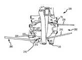
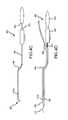
- FIGS. 1 to 1Eshow an introducer system and method of use according to embodiments of the present invention.
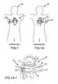
- FIG. 1depicts a front or anterior view of a patient and an introducer system 100 placed at a location 140 within the body of a patient 150 .
- FIG. 1Adepicts a rear or posterior view of patient 150 and introducer system 100 placed at location 140 within the body of patient 150 .
- the introducer system 100is also shown in a disassembled state in FIG. 1A-1 .
- Introducer system 100includes a first introducer device 110 , a second introducer device 120 , and a visualization device 160 . In use, an operator can employ the introducer device and visualization device to position a treatment device 130 at a location 140 in a patient.
- First introducer device 110has a distal section 112 , a proximal portion 114 , and a magnet 116 .
- magnet 116is disposed toward distal section 112 of the first introducer device.
- second introducer device 120has a distal section 122 , a proximal portion 124 , and a magnet 126 .
- magnet 126is disposed toward distal section 122 of the second introducer device.
- FIG. 1Bprovides a posterior anatomical view, and illustrates the positioning of first introducer device 110 within patient 150 . As shown here, an operator can advance distal section 112 of the first introducer device toward location 140 which has been selected for treatment, as indicated by arrow A.
- FIG. 1Bprovides a posterior anatomical view, and illustrates the positioning of first introducer device 110 within patient 150 . As shown here, an operator can advance distal section 112 of the first introducer device toward location 140 which has been selected for treatment, as indicated by arrow A.
- 1Cprovides a posterior anatomical view, and depicts a closer view of the treatment location.
- An operatorcan continue to advance distal section 112 of the first introducer device toward a desired location as indicated by arrow A.
- the operatorcan advance distal section 122 of the second introducer device toward location 140 as indicated by arrow B.
- An operatorcan also view the first and second introducer devices with visualization device 160 .
- the operatorcan view distal sections 112 and 122 as the introducer devices are manipulated within the patient's body. Such visualization can assist the operator in bringing distal sections 112 and 122 into proximity with each other, such that first introducer magnet 116 and second introducer magnet 126 can attach or couple.
- first introducer device 110may be introduced into the patient via one or more incisions placed in any suitable location.
- Incisionsmay include subzyphoid incisions, subcostal incisions, intercostal incisions or any other suitable incision or combination of incisions.
- proximal section 114 of first introducer device 110can be coupled with a distal section 132 of treatment device 130 .
- the operatorcan advance treatment device 130 toward location 140 . This can be accomplished by moving second introducer device 120 away from treatment location 140 as indicated by arrow A.
- the operatormay grasp the second introducer device and pull it in a direction away from the patient.
- treatment device 130can be advanced toward location 140 by moving proximal portion 114 of the first introducer device toward the location as indicated by arrow B.
- FIG. 1Eprovides a posterior anatomical view, and shows the positioning of treatment device 130 at location 140 , as first and second introducer devices 110 , 120 , and treatment device 130 are advanced along a positioning path 190 , as indicated by arrows A, B, and C, respectively. In this way, a surgeon can use the first and second introducer devices of introducer system 100 to effectively place treatment device 130 within the patient's body.
- Visualization device 160may encompass any of a variety of imaging mechanisms for viewing or detecting the location and orientation of the introducer or treatment devices as they may be situated within or relative to the patient, or relative to other system components.
- visualization device 160may include an endoscope, a Transesophageal Echocardiogram (TEE) device, an X-ray fluoroscopy device, or the like.
- TEETransesophageal Echocardiogram
- X-ray fluoroscopy deviceor the like.
- Devicesare often manipulated based on monitoring the device location relative to visualized cardiac structures, such as the left or right pulmonary artery, aorta, or pulmonary veins.
- Transducer inputs from the devicesuch as electrogram recordings, can also be used to refine the location of the introducer or therapeutic device relative to the tissues being targeted.
- Exemplary treatmentsinclude atrial fibrillation (AF) therapy, Left Atrial Appendage (LAA) exclusion or removal, pulmonary lobectomy or other thoracic cancer therapy, or procedures to safely enter
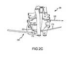
- FIGS. 2A to 2Cillustrate how an introducer system can be used in a tissue environment of a patient, according to embodiments of the present invention.
- An ablation or treatment system 200includes an introducer system 202 having a first introducer device 210 and a second introducer device 220 .
- the treatment systemmay also include a visualization device 260 .
- First and second introducer devicesinclude a magnetically or mechanically attaching mechanism, whereby a distal end or section 212 of the first introducer device can be attached or coupled with a distal end or section 222 of the second introducer device.
- the attaching mechanismmay include a first magnet 216 disposed toward the distal section of the first introducer device, and a second magnet 226 disposed toward the distal section of the second introducer device.
- introducer system 202can be used to move a treatment device about a patient's pulmonary veins (PV).
- PVpulmonary veins
- second introducer device 220can be advanced within a patient, whereby the device enters a first cavity such as a transverse sinus (TS).
- first introducer device 210can be advanced within a patient, whereby the device enters a second cavity such as an oblique sinus (OS).
- OSoblique sinus
- a surgeon or operatormay use visualization device 260 to view or detect introducer devices 210 , 220 as they are placed within the patient's body.
- first introducer device 210can be manipulated so as to couple one with the other.
- an attractive force between first magnet 216 and second magnet 226can effectively couple or attach distal end 212 with distal end 222 .
- the magnetscan have self aligning faces, and the distal ends of first introducer device 210 and second introducer device 220 can have rounded or blunted edges.
- magnetshave a dipolar magnetic field, and therefore opposite ends of magnets are attracted to each other. Due to the self aligning configuration, the magnetic dipole of first magnet 216 tends to align or orient itself with the opposed polarity of the magnetic dipole of second magnet 226 .
- the operatorcan manipulate the introducer system or the treatment or ablation system to a position as desired. In some cases, an operator can determine that the distal ends are coupled by visual confirmation.
- FIG. 2Cdepicts ablation or treatment system 200 disposed within the patient's body, where distal section 212 of first introducer device 210 is coupled with distal section 222 . After the distal ends are coupled, an operator can advance a treatment device toward a desired location within the patient, in a manner similar to that described with reference to FIGS. 1D and 1E .
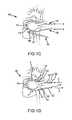
- FIGS. 3A to 3Dshow aspects of visualization systems, scopes, or introducer devices according to embodiments of the present invention.
- FIG. 3Ashows that a magnet or other attachment mechanism 316 a can be disposed at or toward a distal end or portion 312 a of a device introducer 310 a .
- distal end or portion 312 acan include a preformed bend 313 a .
- FIG. 3Bshows that a magnet or other attachment mechanism 316 b can be disposed at or toward a distal end or portion 312 b of a device introducer 310 b , where the device introducer includes a visualization element 318 b .
- the position of magnet or attachment mechanism 316 bmay be offset.
- magnet or attachment mechanism 316 bmay laterally offset from a central longitudinal axis 319 b defined by a shaft 311 b of the introducer device.
- an obturator 320 ccan be inserted into or moved along device introducer 310 a .
- Obturator 320 cmay include a handle 322 c disposed at or toward a proximal end or portion 314 c and a stiffening rod 321 c .
- Device introducer 310 acan include a visualization mechanism 318 a and an attachment mechanism 316 c such as a magnet disposed at or toward a distal end or portion 312 c of introducer device 310 c .
- the obturator 320 c shown hereis partially inserted into device introducer 310 c , such that stiffening rod 321 c , which is less flexible than distal portion 312 c of introducer device 310 c , operates to straighten only a portion of a preformed bend 313 c .
- introducer device 310 cmay be malleable or flexible.
- Obturator 320 ccan optionally include a connector configured to interface with another portion of the system or other devices, at or near the proximal end of obturator 320 c .
- a straight, preformed, bent, or malleable obturatormay be inserted inside a flexible introducer from or near the proximal end of the introducer.
- Introducer device 320 cmay have a preformed bend 313 c at or near the distal end to allow a desired curve to form as a stiffer obturator is withdrawn or inserted during a particular phase of a procedure.
- the obturatormay be fully or partially inserted or withdrawn completely as needed or desired.
- obturator 320 dmay be further or fully inserted into introducer device 310 d , such that the preformed bend of introducer device 310 d is substantially straightened.
- obturator 320 dincludes a handle 322 d and a stiffening rod 321 d .
- Introducer device 310 dincludes a distal section or portion 312 d having a visualization mechanism 318 d and an attachment mechanism 316 d such as a magnet.
- Obturator 320 dmay be flexible, stiff, preformed, or malleable.
- an obturatorincludes one or more stiff wires.
- the position of a magnet or attachment mechanismmay be offset. In some cases, offsetting the position of the magnet or attachment mechanism can provide an operator with an optimized field of view, depending on the geometric configuration of a visualization system.
- the terms “introducer device”, “scope”, and “visualization system”maybe used interchangeably. Such devices may be flexible, or fixed.
- FIGS. 4A to 4Gshow aspects of an obturator treatment or ablation system according to embodiments of the present invention.
- Such positioning systemscan involve an obturator and a probe that when used in conjunction with an ablation system can create a substantially mid-length curved portion that is positionally controlled independently from the axial, longitudinally slidable position of an ablation system and a distal curved sheath or probe portion that is controlled manually and not affected by the position of the obturator.
- FIG. 4Aillustrates an obturator 410 having a handle 412 coupled with a stiffening rod 413 . As shown here, preformed stiffening rod 413 includes a preformed bend 414 .
- a preformed bend 414may be created out of material sufficiently stiff to perform its function, which can include bending a deformable introducer device and optionally a treatment device, yet be springy or elastic enough without excessively yielding when subjected to influences of the introducer device or treatment device.
- Such a configurationallows system insertion through and placement within a patient anatomy, utilizing a material that is sufficiently stiff to perform its function yet malleable enough to be formed into an advantageous or desired curve or shape.
- Exemplary materialsinclude a malleable metal, such as stainless steel.
- FIG. 4Billustrates a steerable sheath or introducer device 420 having a handle 422 and a flexible casing 425 .
- the flexible casingmay include in its distal, steerable portion a preformed curve or bend 426 .
- bend 426may be initially straightened to facilitate insertion into the body by an integral steering mechanism that includes a pull wire, for example, or by the insertion of the obturator 410 .
- an introducer device having an integral steering mechanismmay be referred to as a steerable introducer, a deflectable introducer, or the like.
- Distal curve 426is independent of a curve 424 produced by a mid-length bend 414 in the obturator stiffening rod, as depicted in FIG. 4C .
- an operatorcan construct the obturator assembly 400 by inserting obturator stiffening rod 413 into sheath or introducer device 420 .
- obturator assembly 400can be construed to include obturator 410 and introducer device 420 .
- the obturator stiffening rodis more rigid than the sheath or introducer device casing 424 .
- the shape of casing 425can conform with the shape of the bent stiffening rod, so as to provide a complementary bend 424 in the casing.
- both an obturator and a steerable sheath or introducer devicecan be provided in a pre-assembled configuration.
- the obturator stiffening rod 413can be axially slidable within or along the sheath or introducer device 420 so that the curve 414 of the obturator 410 can be positioned as desired within the sheath or introducer device 420 .
- obturator 410can be inserted into introducer device 420 to a sufficient depth such that bend 426 of introducer device is partially straightened. In this way, the distal portion 413 a of stiffening rod 413 straightens or otherwise deforms part of the introducer device distal curve 426 .
- an ablation or treatment system 440can slide over the combined sheath or introducer device and obturator assembly 400 , so as to create a bend 444 in the ablation or treatment system.
- the ability to independently slide the obturator 410 axially within the sheath or introducer device 420provides placement of the relatively stationary curve 444 desired for the ablation system 440 as the ablation system is advanced over the stationary obturator assembly 400 .
- the curve in the obturator assembly 400which corresponds to obturator curve 414 and introducer device curve 424 may be advanced within a relatively stationary ablation system 440 so as to provide an advantageous or desired placement during the procedure.
- the combined obturator assembly 400 and ablation system 440can be inserted across the left atrium of a patient's heart, for example.
- Obturator 410can remain inserted into introducer device 420 to a sufficient depth such that bend 426 of introducer device remains substantially straightened. [In this way, distal portion 413 a of stiffening rod 413 straightens or otherwise deforms the introducer device distal curve 426 .
- an operatorcan retract obturator 410 from probe 420 to a sufficient depth, such that probe bend 426 recovers or returns toward its original configuration. Consequently, probe bend 426 forces the corresponding section of ablation system 440 to adopt a similar bent or curved shape 445 .
- obturator 410only partially advanced within the sheath 420 , an operator can negotiate the turn at the far side of the heart by flexing the steerable distal portion of the probe at bend 426 along with the distal portion 450 of the ablation assembly 440 , as indicated by arrow E. According to the illustration in FIG.
- distal or grasping element 470includes a string or tape which the operator can grasp with a maneuvering mechanism 480 such as a pair of forceps.
- grasping element 470may include a magnetic element which the operator can engage with a maneuvering mechanism 480 such as a matching magnetic device.
- a maneuvering mechanism 480such as a matching magnetic device.
- FIG. 4Gplacement of ablation system 440 against the pulmonary veins is facilitated by advancing obturator 410 within sheath or introducer device 420 such that bend 444 is disposed at or near the tissue to make or enhance tissue contact.
- the contour of the distal bendsare similar to or conform to the shape of the tissue 460 .
- FIGS. 5A to 5Cillustrate how an introducer system can be used in a tissue environment of a patient, according to embodiments of the present invention.
- An ablation or treatment system 500includes an introducer system 502 having a first introducer device 510 and a second introducer device 520 .
- the treatment systemmay also include a visualization device 560 incorporated into or integrated with either the first introducer device or the second introducer device.
- First and second introducer devicesinclude a magnetically or mechanically attaching mechanism, whereby a distal end or section 512 of the first introducer device can be attached or coupled with a distal end or section 522 of the second introducer device.
- the attaching mechanismmay include a first magnet 516 disposed toward the distal section of the first introducer device, and a second magnet 526 disposed toward the distal section of the second introducer device.
- introducer system 502can be used to move or position a treatment device about a patient's pulmonary veins (PV).
- PVpulmonary veins
- second introducer device 520can be advanced within a patient, whereby the device enters a first cavity such as a transverse sinus (TS).
- TStransverse sinus
- first introducer device 510can be advanced within a patient, whereby the device enters a second cavity such as an oblique sinus (OS).
- a surgeon or operatormay use visualization device 560 to view or detect introducer devices 510 , 520 as they are placed within the patient's body.
- the distal end or section 512 of first introducer device 510 , the distal end or section 522 of second introducer device 520 , or both,can be manipulated so as to couple one with the other. For example, an attractive force between first magnet 516 and second magnet 526 can effectively couple or attach distal end 512 with distal end 522 .
- the magnetscan have self aligning faces, and the distal ends of first introducer device 510 and second introducer device 520 can have rounded or blunted edges.
- a magnethas a dipolar magnetic field, and therefore opposite ends of magnets are attracted to each other. Due to the self aligning configuration, the magnetic dipole of first magnet 516 tends to align or orient itself with the opposed polarity of the magnetic dipole of second magnet 526 .
- the operatorcan manipulate the introducer system or the treatment or ablation system to a position as desired. In some cases, an operator can determine that the distal ends are coupled by visual confirmation.
- distal section 512may include a transparent material 514 that allows the operator to see the surrounding tissue environment with the visualization device.
- an operatorcan use visualization device 560 to determine the location or orientation of second introducer device 520 , for example relative to the location or orientation of first introducer device 510 .
- use of the visualization device 560can assist the operator in maneuvering first magnet 516 and second magnet 526 into close proximity, so as to provide the desired magnetic coupling.
- an operatorcan hear or feel the distal ends snap together.
- FIG. 5Cdepicts ablation or treatment system 500 disposed within the patient's body, where distal section 512 of first introducer device 510 is coupled with distal section 522 of second introducer device 520 .
- an operatorcan advance a treatment device toward a desired location within the patient, in a manner similar to that described with reference to FIGS. 1D and 1E .
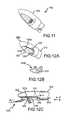
- FIG. 6shows a cross-section of a visualization system 600 which can be used for providing or enhancing device placement visualization.
- Visualization system 600can include a scope 610 and a cap 620 .
- Scope 610includes a distal end 612 , which in some cases is beveled at an angle ⁇ . In some embodiments, angle ⁇ can be within a range from about 30 degrees to about 45 degrees.
- Scope 610can be a straight scope, a rigid scope, or both, for example.
- scope 610includes an endoscope.
- Cap 620can include a tip having a bullet shape, a cone shape, a dome shape, and the like.
- cap 620may present an asymmetric shape.
- a capmay be shaped for optimized visualization of a tissue.
- cap 620includes a clear or transparent portion or material through which a lens of scope 610 can visualize the surrounding environment. In this way, cap 620 can operate to expand the visualization capacity, or the field of view, of scope 610 .
- cap 620can be advanced into or against tissue, and can separate tissue. Accordingly, tissue which presses on cap 620 , or is otherwise near cap 620 , can be visualized.
- Cap 620can allow a user or operator to visualize an increased amount of tissue, or an increased surface area of tissue, as compared to a similar scope which does not include cap 620 .
- an operatorcan use visualization system 600 for orientation purposes, for treatment purposes, for therapeutic purposes, and the like.
- Cap 620allows an operator to gain an enhanced awareness of an operating space within a patient's body. For example, an operator may use visualization system 600 to determine how close a particular instrument or device is to a pulmonary vein. Such techniques can be helpful when applying a treatment to a site that is near, but not on, a pulmonary vein. An operator will also find such approaches useful when connecting or coupling introducer devices together, for example via the magnetic attraction techniques as described herein.
- Cap 620may include a stop 624 .
- stop 624typically contacts distal end 612 of scope 610 when cap 620 is disposed on scope 610 .
- the location or position of stop 624 on cap 620can be selected so as to control or adjust the distance between a distal end, or some other visualization portion, of cap 620 , and a lens of scope 610 .
- Different scopesmay have different focal lengths, and selection of a desired stop 624 configuration can allow cap 620 to provide a particular viewing effect on a patient's tissue.
- stop 624at a certain distance from a distal end or viewing portion of cap 620 , it may be possible to allow an operator to view tissue which contacts the distal end or viewing portion of cap 620 with a maximum clarity or distinctness, so that the tissue is in focus.
- Cap 620can protect a lens of scope 610 from unwanted contact with fluid.
- cap 620may include one or more sealing mechanism 622 .
- sealing mechanism 622may include an o-ring.
- Cap 620may be releasably attached with scope 610 .
- cap 620includes an attachment mechanism 626 , which can be used to attach or couple visualization system 600 with another device or implement. This attachment or coupling can be a releasable attachment.
- cap 620 of visualization system 600allows an operator to visualize an operating space within a patient.
- attachment mechanism 626can include a magnet
- the device or implementcan include a material which is attracted to the magnet. The operator can advance or place the magnet near the device or implement, so as to create a releasable coupling between the magnet and the device or implement.
- FIG. 7shows a cross-section of a visualization system 700 which can be used for providing or enhancing device placement visualization.
- Visualization system 700can include a scope 710 and a cap 720 .
- Scope 710includes a distal end 712 , which in some cases is not beveled at an angle ⁇ . In some embodiments, angle ⁇ can be about 0 degrees.
- Scope 710can also include a flexible zone or portion 714 .
- Scope 710can be a curved scope, a flexible scope, or both, for example.
- scope 710includes an endoscope.
- Cap 720can include a tip having a bullet shape, a cone shape, a dome shape, and the like.
- cap 720may present an asymmetric shape.
- a capmay be shaped for optimized visualization of a tissue.
- cap 720includes a clear or transparent portion or material through which a lens of scope 710 can visualize the surrounding environment. In this way, cap 720 can operate to expand the visualization capacity, or the field of view, of scope 710 .
- cap 720can be advanced into or against tissue, and can separate tissue. Accordingly, tissue which presses on cap 720 , or is otherwise near cap 720 , can be visualized.
- Cap 720can allow a user or operator to visualize an increased amount of tissue, or an increased surface area of tissue, as compared to a similar scope which does not include cap 720 .
- an operatorcan use visualization system 700 for orientation purposes, for treatment purposes, for therapeutic purposes, and the like.
- Cap 720allows an operator to gain an enhanced awareness of an operating space within a patient's body. For example, an operator may use visualization system 700 to determine how close a particular instrument or device is to a pulmonary vein. Such techniques can be helpful when applying a treatment to a site that is near, but not on, a pulmonary vein. An operator will also find such approaches useful when connecting or coupling introducer devices together, for example via the magnetic attraction techniques as described herein.
- Cap 720may include a stop 724 .
- stop 724typically contacts distal end 712 of scope 710 when cap 720 is disposed on scope 710 .
- the location or position of stop 724 on cap 720can be selected so as to control or adjust the distance between a distal end, or some other visualization portion, of cap 720 , and a lens of scope 710 .
- Different scopesmay have different focal lengths, and selection of a desired stop 724 configuration can allow cap 720 to provide a particular viewing effect on a patient's tissue.
- stop 724at a certain distance from a distal end or viewing portion of cap 720 , it may be possible to allow an operator to view tissue which contacts the distal end or viewing portion of cap 720 with a maximum clarity or distinctness, so that the tissue is in focus.
- Cap 720can protect a lens of scope 710 from unwanted contact with fluid.
- cap 720may include one or more sealing mechanism 722 .
- sealing mechanism 722may include an o-ring.
- Cap 720may be releasably attached with scope 710 .
- cap 720includes an attachment mechanism 726 , which can be used to attach or couple visualization system 700 with another device or implement. This attachment or coupling can be a releasable attachment.
- cap 720 of visualization system 700allows an operator to visualize an operating space within a patient.
- attachment mechanism 726can include a magnet
- the device or implementcan include a material which is attracted to the magnet. The operator can advance or place the magnet near the device or implement, so as to create a releasable coupling between the magnet and the device or implement.
- FIG. 8shows a cross-section of a visualization system 800 which can be used for providing or enhancing device placement visualization.
- Visualization system 800can include a scope 810 and a cap 820 .
- Scope 810includes a distal end 812 , which in some cases is not beveled at an angle ⁇ . In some embodiments, angle ⁇ can be about 30 degrees to about 45 degrees.
- Scope 810can be a straight scope, a rigid scope, or both, for example.
- scope 810includes an endoscope.
- Cap 820can include a tip having a bullet shape, a cone shape, a dome shape, and the like. In some embodiments, cap 820 may present an asymmetric shape.
- a capmay be shaped for optimized visualization of a tissue.
- cap 820includes a clear or transparent portion through which a lens of scope 810 can visualize the surrounding environment. In this way, cap 820 can operate to expand the visualization capacity, or the field of view, of scope 810 .
- cap 820can be advanced into or against tissue, and can separate tissue. Accordingly, tissue which presses on cap 820 , or is otherwise near cap 820 , can be visualized.
- Cap 820can allow a user or operator to visualize an increased amount of tissue, or an increased surface area of tissue, as compared to a similar scope which does not include cap 820 .
- an operatorcan use visualization system 800 for orientation purposes, for treatment purposes, for therapeutic purposes, and the like.
- Cap 820allows an operator to gain an enhanced awareness of an operating space within a patient's body. For example, an operator may use visualization system 800 to determine how close a particular instrument or device is to a pulmonary vein. Such techniques can be helpful when applying a treatment to a site that is near, but not on, a pulmonary vein. Cap 820 can be moved relative to scope 810 or relative to body tissue. In some cases, cap 820 can be rotated relative to scope 810 or relative to body tissue. An operator may effect such movement via a handle 828 of cap 820 . An operator will also find such approaches useful when connecting or coupling introducer devices together, for example via the magnetic attraction techniques as described herein.
- Cap 820may include a stop 824 .
- stop 824can contact distal end 812 of scope 810 when cap 820 is disposed on scope 810 .
- the location or position of stop 824 on cap 820can be selected so as to control or adjust the distance between a distal end, or some other visualization portion, of cap 820 , and a lens of scope 810 .
- Different scopesmay have different focal lengths, and selection of a desired stop 824 configuration can allow cap 820 to provide a particular viewing effect on a patient's tissue.
- stop 824at a certain distance from a distal end or viewing portion of cap 820 , it may be possible to allow an operator to view tissue which contacts the distal end or viewing portion of cap 820 with a maximum clarity or distinctness, so that the tissue is in focus.
- Cap 820can protect a lens of scope 810 from unwanted contact with fluid. Toward this end, as shown here the length of cap 820 can be such that fluid is not present at a proximal end 829 of cap 820 .
- Cap 820may be releasably attached with scope 810 . For example, it may be possible to snap together, and to snap apart, cap 820 and scope 810 .
- cap 820includes an attachment mechanism or instrument mount 826 , which can be used to attach or couple visualization system 800 with another device or implement. This attachment or coupling can be a releasable attachment. In use, cap 820 of visualization system 800 allows an operator to visualize an operating space within a patient.
- attachment mechanism 826can include a magnet
- the device or implementcan include a material which is attracted to the magnet. The operator can advance or place the magnet near the device or implement, so as to create a releasable coupling between the magnet and the device or implement.
- all or part of cap 820can be constructed of a flexible material, such as an elastomer.
- cap 820is rigid.
- scope 810may be flexible or rigid. In some embodiments, a distal end of cap 820 is rigid, and a proximal end of cap 820 is flexible.
- FIGS. 9A to 9Cshow aspects of a visualization system 900 which can be used for providing or enhancing device placement visualization.
- Visualization system 900can include a scope 910 and a cap 920 .
- Scope 910 and cap 920can include any feature or component of the scopes and caps discussed herein, for example the scopes and caps depicted in FIGS. 6 to 8 .
- cap 920can include an attachment mechanism channel 921 adapted to receive an attachment mechanism such as a grasping device 940 .
- Grasping device 940can include a pair of spring loaded jaws 942 , 944 . When pushed against a spring force as depicted in FIG.
- grasping device 940can protrude out of channel 921 , and jaws 942 , 944 can open or separate. When retracted as depicted in FIG. 9A , jaws 942 , 944 close together, and grasping device 940 withdraws into channel 921 .
- an operatorcan advance grasping device 940 out of cap 920 and place open jaws 942 , 944 on a desired item to be grasped. The operator can then withdrawn grasping device 940 into cap 920 , thereby clamping jaws 942 , 944 on the item.
- an operatorcan push grasping device 940 against a spring force so that grasping device 940 protrudes out of cap channel 921 , thereby opening the jaws.
- the jawscan be used to grasp a hook, or a fabric, or a component on a device or introducer for a device which the operator wishes to grasp. Often, the operator may grasp a distal end of such a device or introducer.
- visualization system 900can be used in a minimally invasive surgical procedure by an operator to find a device, attach to the device, and then to manipulate or retract the device.
- FIG. 9Cshows how an introducer system 900 c can be used in conjunction with a visualization system 900 according to embodiments of the present invention.
- Ablation or treatment system 900 cincludes an introducer system 902 c having a first introducer device 910 c and a second introducer device 920 c .
- the treatment systemalso includes visualization system 900 incorporated into or integrated with a distal section 912 c of the first introducer device.
- Visualization system 900can be attached or coupled with a string, tape, or other attachment mechanism 923 , which may be attached with distal section 922 c of second introducer device 920 c .
- Such configurationscan be used in a minimally invasive surgical procedure, so as to position or manipulate an ablation mechanism within the body of a patient.
- introducer system 902 ccan be used to move or position a treatment device about a patient's pulmonary veins (PV).
- PVpulmonary veins
- second introducer device 920 ccan be advanced within a patient, whereby the device enters a first cavity such as a transverse sinus (TS).
- first introducer device 910 ccan be advanced within a patient, whereby the device enters a second cavity such as an oblique sinus (OS).
- OSoblique sinus
- a surgeon or operatormay use visualization system 900 to view or detect introducer devices 910 c , 920 c as they are placed within the patient's body.
- the distal end or section 912 c of first introducer device 910 c , the distal end or section 922 c of second introducer device 920 c , or both,can be manipulated so as to couple one with the other.
- first introducer device 910 c and second introducer device 920 care coupled, the operator can manipulate the introducer system or the treatment or ablation system to a position as desired. In some cases, an operator can determine that the distal ends are coupled by visual confirmation. Optionally, the operator can view or detect a coupling between distal sections 912 c , 922 c by using visualization system 900 .
- distal section 912 cmay include a transparent material that allows the operator to see the surrounding tissue environment with the visualization system.
- an operatorcan use visualization system 900 to determine the location or orientation of second introducer device 920 c , for example relative to the location or orientation of first introducer device 910 c .
- use of the visualization system 900can assist the operator in maneuvering the grasping jaws 942 , 944 and the tape or string 923 c into close proximity, whereby the desired coupling may be effected.
- an operatorcan advance a treatment device toward a desired location within the patient, in a manner similar to that described with reference to FIGS. 1D and 1E .
- FIGS. 10A and 10Bshow aspects of a visualization system 1000 which can be used for providing or enhancing device placement visualization.
- Visualization system 1000can include a scope 1010 and a cap 1020 .
- Scope 1010 and cap 1020can include any feature or component of the scopes and caps discussed herein, for example the scopes and caps depicted in FIGS. 6 to 8 .
- the visualization systemcan include a grasping device 1040 , such as a fin or wedge. In use, an operator can place grasping device 1040 near a distal grasping element or introducer tape 1050 , and rotate the grasping device as indicated by arrow A.
- grasping device 1050can securely attach with the distal grasping element.
- grasping device 1050can be rolled to snag tape on a hook or fin of the device, which can then be rolled back to produce a roll of tape.
- grasping device 1050can include a wedging shape that holds the tape under tension. Accordingly, visualization system 1000 can be used in a minimally invasive surgical procedure by an operator to find a device, attach to the device, and then to manipulate or retract the device.
- FIG. 11shows aspects of a visualization system 1100 which can be used for providing or enhancing device placement visualization.
- Visualization system 1100can include a scope 1110 and a cap 1120 .
- Scope 1110 and cap 1120can include any feature or component of the scopes and caps discussed herein, for example the scopes and caps depicted in FIGS. 6 to 8 .
- a concave shape of cap 1120can facilitate use of a working channel of scope 1110 .
- FIGS. 12A to 12Cillustrate aspects of a visualization system 1200 which can be used for providing or enhancing device placement visualization.
- Visualization system 1200can include a scope 1210 and a cap 1220 .
- Scope 1210 and cap 1220can include any feature or component of the scopes and caps discussed herein, for example the scopes and caps depicted in FIGS. 6 to 8 .
- the body of cap 1220includes a grasping portion 1223 a
- a jaw 1225 of cap 1220includes a corresponding or complementary grasping portion 1223 b .
- the body of cap 1220is coupled with jaw 1225 via a hinge or pivot 1227 , as depicted in FIG. 12C .
- a pocket, attachment point, or divot 1229 of jaw 1225can be aligned with a working channel 1219 of scope 1210 , and a push pull mechanism or axial member 1250 can be disposed in working channels 1219 .
- axial member 1250is advanced distally through working channel 1219 , for example, the distal section of axial member 1250 can contact and transmit force to jaw divot 1229 , thereby closing the bringing the grasping portions 1223 a , 1223 b toward each other.
- this configurationmay be well suited for use with an angled scope, as compared to a forward looking scope, due to the desired field of view provided by cap 1220 .
- push pull mechanism 1250can be pulled or retracted as indicated by arrow A so as to open jaw 1225 .
- An operatorcan manipulate jaw 1225 and the body of cap 1220 about a tape or distal end of a device or introducer.
- Push pull mechanism 1250can then be pushed or advanced as indicated by arrow B so as to close jaw 1225 , thereby grasping the tape, device, introducer, or other implement 1224 .
- FIGS. 13A to 13Dillustrate aspects of a visualization system 1300 which can be used for providing or enhancing device placement visualization.
- Visualization system 1300can include a scope 1310 and a cap 1320 .
- Scope 1310 and cap 1320can include any feature or component of the scopes and caps discussed herein, for example the scopes and caps depicted in FIGS. 6 to 8 .
- cap 1320includes a retractable underslung jaw 1325 , shown here in a closed or retracted position.
- FIG. 13Bprovides a cross section side view of visualization system 1300 .
- Jaw 1325can have a push pull mechanism 1350 attached thereto, and disposed within a working channel 1319 of scope 1310 .
- push pull mechanism 1350can be advanced so as to openjaw 1325 , as shown in FIGS. 13C and 13D .
- An operatorcan manipulate jaw 1325 so as to snag a tape or distal end of a device or introducer.
- Push pull mechanism 1350can then be retracted so as to close jaw 1325 , thereby firmly grasping the tape, device, introducer, or other implement.
- visualization system 1300includes an anti-roll guidance rib 1305 .
- the body of cap 1320includes a toothed configuration which is complementary to the toothed configuration of jaw 1325 .
- FIGS. 14A and 14Billustrate aspects of a visualization system 1400 which can be used for providing or enhancing device placement visualization.
- Visualization system 1400can include a scope 1410 and a cap 1420 .
- Scope 1410 and cap 1420can include any feature or component of the scopes and caps discussed herein, for example the scopes and caps depicted in FIGS. 6 to 8 .
- cap 1420includes a pivoting overhung toothed jaw 1425 , shown here in a closed or retracted position. Jaw 1425 can have an activating mechanism 1450 or a similar axial member attached thereto, and disposed within a working channel 1419 of scope 1410 .
- cap 1420includes a pivot 1429 that is configured to provide a neutral jaw position under tension, such that there is no tendency for jaw 1425 to open.
- Activating mechanism 1450can be advanced distally, as shown in FIG. 14B , so as to swing jaw 1425 about pivot 1429 , toward an open configuration.
- jaw 1425is disposed outside of the external cone or dome shaped contour of the cap body.
- An operatorcan manipulate jaw 1425 so as to snag a tape or distal end of a device or introducer.
- Activating mechanism 1450can then be retracted so as to allow jaw 1425 to close, thereby firmly grasping the tape, device, introducer, or other implement.
- the body of cap 1420includes a toothed configuration which is complementary to the toothed configuration of jaw 1425 .
- the visualization systemincludes a cap having a bullet, dome, cone, or similar profile.
- a capmay present a flat top bullet profile, or a truncated cone profile.
- a capmay present a bulged profile or a mushroom profile.
- capincludes a rounded or blunted distal section, so as to avoid cutting tissue when placed within a patient's body.
- a capis integrated with the scope.
- the capcan be releasably attached with the scope.
- a scopeincludes a working channel
- the visualization systemincludes an activating mechanism that can be disposed at least partially within the working channel.
- Activating mechanismscan be operated to manipulate grasping members or mechanisms of the visualization system.
- a cap, a grasping mechanism, an activating mechanism, or any combination thereofcan be configured such that the activating mechanism can be aligned within the working channel when the cap is coupled with the scope.
- any of a variety of other toolsmay be disposed on or coupled with the cap body, and activated or controlled via an activating mechanism housed at least partially within a working channel of the scope.
Landscapes
- Health & Medical Sciences (AREA)
- Life Sciences & Earth Sciences (AREA)
- Surgery (AREA)
- Engineering & Computer Science (AREA)
- Medical Informatics (AREA)
- Public Health (AREA)
- Biomedical Technology (AREA)
- Heart & Thoracic Surgery (AREA)
- Veterinary Medicine (AREA)
- Molecular Biology (AREA)
- Animal Behavior & Ethology (AREA)
- General Health & Medical Sciences (AREA)
- Pathology (AREA)
- Nuclear Medicine, Radiotherapy & Molecular Imaging (AREA)
- Ophthalmology & Optometry (AREA)
- Human Computer Interaction (AREA)
- Physics & Mathematics (AREA)
- Biophysics (AREA)
- Surgical Instruments (AREA)
Abstract
Description
Claims (14)
Priority Applications (2)
| Application Number | Priority Date | Filing Date | Title |
|---|---|---|---|
| US12/339,331US10136909B2 (en) | 2007-12-20 | 2008-12-19 | Magnetic introducer systems and methods |
| US16/169,740US20190150966A1 (en) | 2007-12-20 | 2018-10-24 | Magnetic introducer systems and methods |
Applications Claiming Priority (2)
| Application Number | Priority Date | Filing Date | Title |
|---|---|---|---|
| US1547207P | 2007-12-20 | 2007-12-20 | |
| US12/339,331US10136909B2 (en) | 2007-12-20 | 2008-12-19 | Magnetic introducer systems and methods |
Related Child Applications (1)
| Application Number | Title | Priority Date | Filing Date |
|---|---|---|---|
| US16/169,740ContinuationUS20190150966A1 (en) | 2007-12-20 | 2018-10-24 | Magnetic introducer systems and methods |
Publications (2)
| Publication Number | Publication Date |
|---|---|
| US20090163768A1 US20090163768A1 (en) | 2009-06-25 |
| US10136909B2true US10136909B2 (en) | 2018-11-27 |
Family
ID=40789437
Family Applications (2)
| Application Number | Title | Priority Date | Filing Date |
|---|---|---|---|
| US12/339,331Active2031-12-15US10136909B2 (en) | 2007-12-20 | 2008-12-19 | Magnetic introducer systems and methods |
| US16/169,740AbandonedUS20190150966A1 (en) | 2007-12-20 | 2018-10-24 | Magnetic introducer systems and methods |
Family Applications After (1)
| Application Number | Title | Priority Date | Filing Date |
|---|---|---|---|
| US16/169,740AbandonedUS20190150966A1 (en) | 2007-12-20 | 2018-10-24 | Magnetic introducer systems and methods |
Country Status (1)
| Country | Link |
|---|---|
| US (2) | US10136909B2 (en) |
Cited By (3)
| Publication number | Priority date | Publication date | Assignee | Title |
|---|---|---|---|---|
| US10405919B2 (en) | 2010-04-13 | 2019-09-10 | Sentreheart, Inc. | Methods and devices for treating atrial fibrillation |
| US10799288B2 (en) | 2013-10-31 | 2020-10-13 | Sentreheart Llc | Devices and methods for left atrial appendage closure |
| US11678928B2 (en) | 2019-01-10 | 2023-06-20 | Atricure, Inc. | Surgical clamp |
Families Citing this family (16)
| Publication number | Priority date | Publication date | Assignee | Title |
|---|---|---|---|---|
| US7399300B2 (en)* | 2001-12-04 | 2008-07-15 | Endoscopic Technologies, Inc. | Cardiac ablation devices and methods |
| US7591818B2 (en) | 2001-12-04 | 2009-09-22 | Endoscopic Technologies, Inc. | Cardiac ablation devices and methods |
| US12121289B2 (en)* | 2008-05-09 | 2024-10-22 | Atricure, Inc. | Conduction block systems and methods |
| US7226448B2 (en)* | 2001-12-04 | 2007-06-05 | Estech, Inc. (Endoscopic Technologies, Inc.) | Cardiac treatment devices and methods |
| US9072522B2 (en)* | 2001-12-04 | 2015-07-07 | Atricure, Inc. | Adjustable clamp systems and methods |
| US7749157B2 (en)* | 2001-12-04 | 2010-07-06 | Estech, Inc. (Endoscopic Technologies, Inc.) | Methods and devices for minimally invasive cardiac surgery for atrial fibrillation |
| AU2003296379A1 (en)* | 2002-12-06 | 2004-06-30 | Estech, Inc. (Endoscopic Technologies, Inc.) | Methods and devices for cardiac surgery |
| US8216221B2 (en)* | 2007-05-21 | 2012-07-10 | Estech, Inc. | Cardiac ablation systems and methods |
| US8430875B2 (en) | 2009-05-19 | 2013-04-30 | Estech, Inc. (Endoscopic Technologies, Inc.) | Magnetic navigation systems and methods |
| US20100331838A1 (en)* | 2009-06-25 | 2010-12-30 | Estech, Inc. (Endoscopic Technologies, Inc.) | Transmurality clamp systems and methods |
| US9572624B2 (en) | 2009-08-05 | 2017-02-21 | Atricure, Inc. | Bipolar belt systems and methods |
| US10123821B2 (en)* | 2009-09-10 | 2018-11-13 | Atricure, Inc. | Scope and magnetic introducer systems and methods |
| US11229479B2 (en) | 2009-12-18 | 2022-01-25 | Atricure, Inc. | Adjustable clamp systems and methods |
| DE102011107613A1 (en)* | 2011-06-30 | 2013-01-03 | Siegfried Riek | trocar |
| DE102012203908B3 (en) | 2012-03-13 | 2013-06-06 | Siegfried Riek | Instrument system for minimally invasive surgery in the single-port technique |
| DE102019129811A1 (en)* | 2019-11-05 | 2021-05-06 | Olympus Winter & Ibe Gmbh | Surgical instrument and optical obturator for a surgical instrument |
Citations (94)
| Publication number | Priority date | Publication date | Assignee | Title |
|---|---|---|---|---|
| US2623256A (en)* | 1950-05-19 | 1952-12-30 | Hans J Feibelman | Connector for bracelets and the like |
| US3111736A (en)* | 1961-12-07 | 1963-11-26 | Monarch Tool & Machinery Co | Separable two-part magnetic connector |
| US3129477A (en)* | 1962-06-21 | 1964-04-21 | New Kyoei Inc | Magnetic clasp |
| US3745998A (en) | 1971-01-06 | 1973-07-17 | Bio Medical Syst Inc | Vacuum formed support structures and immobilizer devices |
| US3986493A (en)* | 1975-07-28 | 1976-10-19 | Hendren Iii William Hardy | Electromagnetic bougienage method |
| US4190041A (en)* | 1977-09-12 | 1980-02-26 | Machida Endoscope Co., Ltd. | Cleaning device for wire guide tube in an endoscope |
| US4224929A (en) | 1977-11-08 | 1980-09-30 | Olympus Optical Co., Ltd. | Endoscope with expansible cuff member and operation section |
| US4445892A (en) | 1982-05-06 | 1984-05-01 | Laserscope, Inc. | Dual balloon catheter device |
| US4961738A (en) | 1987-01-28 | 1990-10-09 | Mackin Robert A | Angioplasty catheter with illumination and visualization within angioplasty balloon |
| US4991578A (en) | 1989-04-04 | 1991-02-12 | Siemens-Pacesetter, Inc. | Method and system for implanting self-anchoring epicardial defibrillation electrodes |
| US5025778A (en)* | 1990-03-26 | 1991-06-25 | Opielab, Inc. | Endoscope with potential channels and method of using the same |
| US5122137A (en)* | 1990-04-27 | 1992-06-16 | Boston Scientific Corporation | Temperature controlled rf coagulation |
| US5336252A (en) | 1992-06-22 | 1994-08-09 | Cohen Donald M | System and method for implanting cardiac electrical leads |
| US5409483A (en) | 1993-01-22 | 1995-04-25 | Jeffrey H. Reese | Direct visualization surgical probe |
| US5423805A (en) | 1992-02-05 | 1995-06-13 | Angeion Corporation | Laser catheter with moveable integral fixation wires |
| US5503617A (en) | 1994-07-19 | 1996-04-02 | Jako; Geza J. | Retractor and method for direct access endoscopic surgery |
| US5593405A (en) | 1994-07-16 | 1997-01-14 | Osypka; Peter | Fiber optic endoscope |
| US5672153A (en) | 1992-08-12 | 1997-09-30 | Vidamed, Inc. | Medical probe device and method |
| US5681260A (en)* | 1989-09-22 | 1997-10-28 | Olympus Optical Co., Ltd. | Guiding apparatus for guiding an insertable body within an inspected object |
| US5727569A (en) | 1996-02-20 | 1998-03-17 | Cardiothoracic Systems, Inc. | Surgical devices for imposing a negative pressure to fix the position of cardiac tissue during surgery |
| US5782746A (en) | 1996-02-15 | 1998-07-21 | Wright; John T. M. | Local cardiac immobilization surgical device |
| US5807243A (en) | 1994-08-31 | 1998-09-15 | Heartport, Inc. | Method for isolating a surgical site |
| US5836311A (en) | 1995-09-20 | 1998-11-17 | Medtronic, Inc. | Method and apparatus for temporarily immobilizing a local area of tissue |
| US5865730A (en) | 1997-10-07 | 1999-02-02 | Ethicon Endo-Surgery, Inc. | Tissue stabilization device for use during surgery having remotely actuated feet |
| US5976132A (en) | 1997-10-10 | 1999-11-02 | Morris; James R. | Bipolar surgical shears |
| US6013027A (en) | 1997-10-07 | 2000-01-11 | Ethicon Endo-Surgery, Inc. | Method for using a tissue stabilization device during surgery |
| US6036641A (en) | 1996-02-20 | 2000-03-14 | Cardiothoracic System, Inc. | Surgical instruments for stabilizing the beating heart during coronary artery bypass graft surgery |
| US6036685A (en) | 1996-03-29 | 2000-03-14 | Eclipse Surgical Technologies. Inc. | Lateral- and posterior-aspect method for laser-assisted transmyocardial revascularization and other surgical applications |
| US6039733A (en) | 1995-09-19 | 2000-03-21 | Valleylab, Inc. | Method of vascular tissue sealing pressure control |
| US6071233A (en)* | 1997-10-31 | 2000-06-06 | Olympus Optical Co., Ltd. | Endoscope |
| US6086586A (en) | 1998-09-14 | 2000-07-11 | Enable Medical Corporation | Bipolar tissue grasping apparatus and tissue welding method |
| US6110106A (en) | 1998-06-24 | 2000-08-29 | Biomax Technologies, Inc. | Endoscopes and methods relating to direct viewing of a target tissue |
| US6161543A (en) | 1993-02-22 | 2000-12-19 | Epicor, Inc. | Methods of epicardial ablation for creating a lesion around the pulmonary veins |
| US6237605B1 (en)* | 1996-10-22 | 2001-05-29 | Epicor, Inc. | Methods of epicardial ablation |
| US6251065B1 (en) | 1998-03-17 | 2001-06-26 | Gary S. Kochamba | Methods and apparatus for stabilizing tissue |
| US6277065B1 (en) | 1998-03-20 | 2001-08-21 | Boston Scientific Corporation | Anchoring and positioning device and method for an endoscope |
| US6309349B1 (en) | 1996-04-10 | 2001-10-30 | Endoscopic Technologies, Inc. | Surgical retractor and stabilizing device and method for use |
| US6338712B2 (en) | 1997-09-17 | 2002-01-15 | Origin Medsystems, Inc. | Device to permit offpump beating heart coronary bypass surgery |
| US6338738B1 (en) | 1999-08-31 | 2002-01-15 | Edwards Lifesciences Corp. | Device and method for stabilizing cardiac tissue |
| US6346077B1 (en) | 1996-02-20 | 2002-02-12 | Cardiothoracic Systems, Inc. | Surgical instrument for stabilizing the beating heart during coronary artery bypass graft surgery |
| US20020026094A1 (en) | 1993-02-22 | 2002-02-28 | Roth Alex T. | Devices for less-invasive intracardiac interventions |
| US6352534B1 (en) | 1997-09-30 | 2002-03-05 | Boston Scientific Corporation | Deflectable interstitial ablation device |
| US20020056460A1 (en) | 1993-02-22 | 2002-05-16 | Boyd Stephen W. | Devices and methods for port-access multivessel coronary artery bypass surgery |
| US6390976B1 (en) | 1997-09-17 | 2002-05-21 | Origin Medsystems, Inc. | System to permit offpump beating heart coronary bypass surgery |
| US20020068855A1 (en) | 1993-02-22 | 2002-06-06 | Daniel S. Christopher | Endoscopic retraction system and method |
| US20020099390A1 (en) | 1999-05-20 | 2002-07-25 | Kaplan Aaron V. | Methods and apparatus for transpericardial left atrial appendage closure |
| US6463332B1 (en) | 1999-09-17 | 2002-10-08 | Core Medical, Inc. | Method and system for pericardial enhancement |
| US6484727B1 (en) | 1996-10-22 | 2002-11-26 | Epicor, Inc. | Apparatus and method for diagnosis and therapy of electrophysiological disease |
| US20020177846A1 (en) | 2001-03-06 | 2002-11-28 | Mulier Peter M.J. | Vaporous delivery of thermal energy to tissue sites |
| US20030009080A1 (en) | 1999-09-07 | 2003-01-09 | Steven Peng | Organ manipulator having suction member supported with freedom to move relative to its support |
| US20030010346A1 (en) | 1999-01-21 | 2003-01-16 | Anthony Paolitto | Surgical apparatus and method for performing transabdominal cardiac surgery |
| US6511416B1 (en) | 1999-08-03 | 2003-01-28 | Cardiothoracic Systems, Inc. | Tissue stabilizer and methods of use |
| US6514250B1 (en) | 2000-04-27 | 2003-02-04 | Medtronic, Inc. | Suction stabilized epicardial ablation devices |
| US6522905B2 (en) | 1993-03-11 | 2003-02-18 | Jawahar M. Desai | Apparatus and method for cardiac ablation |
| US6524338B1 (en) | 2000-08-25 | 2003-02-25 | Steven R. Gundry | Method and apparatus for stapling an annuloplasty band in-situ |
| US6527767B2 (en) | 1998-05-20 | 2003-03-04 | New England Medical Center | Cardiac ablation system and method for treatment of cardiac arrhythmias and transmyocardial revascularization |
| US20030060685A1 (en) | 2001-09-06 | 2003-03-27 | Houser Russell A. | Superelastic/shape memory tissue stabilizers and surgical instruments |
| US6544263B2 (en) | 1996-05-11 | 2003-04-08 | C. R. Bard, Inc. | Ablation catheter |
| US6595989B1 (en) | 1999-05-11 | 2003-07-22 | Atrionix, Inc. | Balloon anchor wire |
| US6599237B1 (en) | 2000-01-10 | 2003-07-29 | Errol O. Singh | Instrument and method for facilitating endoscopic examination and surgical procedures |
| US20030158464A1 (en) | 2001-12-04 | 2003-08-21 | Estech, Inc. (Endoscopic Technologies, Inc.) | Methods & devices for minimally invasive cardiac surgery for atrial fibrillation |
| US20030158463A1 (en) | 1999-11-09 | 2003-08-21 | Intuitive Surgical, Inc. | Endoscopic beating-heart stabilizer and vessel occlusion fastener |
| US6645202B1 (en) | 1996-10-22 | 2003-11-11 | Epicor Medical, Inc. | Apparatus and method for ablating tissue |
| US6652518B2 (en) | 2001-09-28 | 2003-11-25 | Ethicon, Inc. | Transmural ablation tool and method |
| US20030229974A1 (en)* | 2002-06-15 | 2003-12-18 | Zemer Jack D. | Concealed secure magnetic clasp |
| US6758809B2 (en) | 2002-06-06 | 2004-07-06 | Medtronic, Inc. | Surgical tool for engagement of body tissue |
| US20040154143A1 (en)* | 2003-02-12 | 2004-08-12 | Harrell Penelope E. | Magnetic clasp |
| US6778846B1 (en)* | 2000-03-30 | 2004-08-17 | Medtronic, Inc. | Method of guiding a medical device and system regarding same |
| US20040186350A1 (en)* | 2003-01-13 | 2004-09-23 | Usgi Medical Corp. | Apparatus and methods for guiding an endoscope via a rigidizable wire guide |
| US20050010179A1 (en) | 2002-03-04 | 2005-01-13 | Dornoch Medical Systems, Inc. | High volume liquid waste collection and disposal system |
| US6849075B2 (en) | 2001-12-04 | 2005-02-01 | Estech, Inc. | Cardiac ablation devices and methods |
| US6878106B1 (en)* | 1999-02-15 | 2005-04-12 | Ingo F. Herrmann | Deformable fiberscope with a displaceable supplementary device |
| US6890295B2 (en) | 2002-10-31 | 2005-05-10 | Medtronic, Inc. | Anatomical space access tools and methods |
| US20050119654A1 (en) | 2003-12-02 | 2005-06-02 | Swanson David K. | Clamp based methods and apparatus for forming lesions in tissue and confirming whether a therapeutic lesion has been formed |
| US20050119653A1 (en) | 2003-12-02 | 2005-06-02 | Swanson David K. | Surgical methods and apparatus for forming lesions in tissue and confirming whether a therapeutic lesion has been formed |
| US20050240175A1 (en) | 2001-12-04 | 2005-10-27 | Estech, Inc. (Endoscopic Technologies, Inc.) | Cardiac treatment devices and methods |
| US20060015165A1 (en) | 2001-12-04 | 2006-01-19 | Bertolero Arthur A | Conduction block verification probe and method of use |
| US20060063973A1 (en)* | 2004-04-21 | 2006-03-23 | Acclarent, Inc. | Methods and apparatus for treating disorders of the ear, nose and throat |
| US7018328B2 (en) | 2000-02-11 | 2006-03-28 | Endoscopic Technologies, Inc. | Tissue stabilizer |
| US20060123845A1 (en)* | 2004-12-15 | 2006-06-15 | Guy Beard | Magnetic jewelry clasp and article of jewelry |
| US20060155272A1 (en) | 2005-01-08 | 2006-07-13 | Boston Scientific Scimed, Inc. | Apparatus and methods for forming lesions in tissue and applying stimulation energy to tissue in which lesions are formed |
| US20060235372A1 (en)* | 2005-04-06 | 2006-10-19 | Ward Jim L | Facilitating tools for cardiac tissue ablation |
| US7204207B2 (en)* | 2004-07-28 | 2007-04-17 | Nite Glow Industries, Inc. | Abrasion resistant omnidirectionally reflective jewelry |
| US7237555B2 (en) | 1998-03-17 | 2007-07-03 | Estech | Tissue stabilization and ablation devices and methods |
| US7282057B2 (en)* | 2004-03-30 | 2007-10-16 | Wilson-Cook Medical, Inc. | Pediatric atresia magnets |
| US7338434B1 (en) | 2002-08-21 | 2008-03-04 | Medtronic, Inc. | Method and system for organ positioning and stabilization |
| US7431694B2 (en)* | 2003-05-16 | 2008-10-07 | Ethicon Endo-Surgery, Inc. | Method of guiding medical devices |
| US7441917B1 (en)* | 2005-05-18 | 2008-10-28 | Will Underdown | Illuminated jewelry |
| US20080294154A1 (en) | 2007-05-21 | 2008-11-27 | Estech, Inc. | Cardiac ablation systems and methods |
| US7566300B2 (en)* | 2004-04-15 | 2009-07-28 | Wilson-Cook Medical, Inc. | Endoscopic surgical access devices and methods of articulating an external accessory channel |
| US7575548B2 (en)* | 2004-09-24 | 2009-08-18 | Olympus Corporation | Endoscopic treatment instrument, endoscopic treatment system and supporting adaptor |
| US7608038B2 (en)* | 2002-05-17 | 2009-10-27 | The Trustees Of The University Of Pennsylvania | Luminal coupling system |
| US20090281541A1 (en) | 2008-05-09 | 2009-11-12 | Estech, Inc. | Conduction block systems and methods |
| US7976458B2 (en)* | 2006-12-05 | 2011-07-12 | Ethicon Endo-Surgery, Inc. | Independent articulating accessory channel |
Family Cites Families (3)
| Publication number | Priority date | Publication date | Assignee | Title |
|---|---|---|---|---|
| US6071281A (en)* | 1998-05-05 | 2000-06-06 | Ep Technologies, Inc. | Surgical method and apparatus for positioning a diagnostic or therapeutic element within the body and remote power control unit for use with same |
| JP2002032590A (en)* | 2000-06-22 | 2002-01-31 | Internatl Business Mach Corp <Ibm> | Method and system for advertisement, method and system for dealing advertisement frame, and recording medium |
| EP1750607A2 (en)* | 2004-06-02 | 2007-02-14 | Medtronic, Inc. | Loop ablation apparatus and method |
- 2008
- 2008-12-19USUS12/339,331patent/US10136909B2/enactiveActive
- 2018
- 2018-10-24USUS16/169,740patent/US20190150966A1/ennot_activeAbandoned
Patent Citations (114)
| Publication number | Priority date | Publication date | Assignee | Title |
|---|---|---|---|---|
| US2623256A (en)* | 1950-05-19 | 1952-12-30 | Hans J Feibelman | Connector for bracelets and the like |
| US3111736A (en)* | 1961-12-07 | 1963-11-26 | Monarch Tool & Machinery Co | Separable two-part magnetic connector |
| US3129477A (en)* | 1962-06-21 | 1964-04-21 | New Kyoei Inc | Magnetic clasp |
| US3745998A (en) | 1971-01-06 | 1973-07-17 | Bio Medical Syst Inc | Vacuum formed support structures and immobilizer devices |
| US3986493A (en)* | 1975-07-28 | 1976-10-19 | Hendren Iii William Hardy | Electromagnetic bougienage method |
| US4190041A (en)* | 1977-09-12 | 1980-02-26 | Machida Endoscope Co., Ltd. | Cleaning device for wire guide tube in an endoscope |
| US4190041B1 (en)* | 1977-09-12 | 1983-05-24 | ||
| US4224929A (en) | 1977-11-08 | 1980-09-30 | Olympus Optical Co., Ltd. | Endoscope with expansible cuff member and operation section |
| US4445892A (en) | 1982-05-06 | 1984-05-01 | Laserscope, Inc. | Dual balloon catheter device |
| US4961738A (en) | 1987-01-28 | 1990-10-09 | Mackin Robert A | Angioplasty catheter with illumination and visualization within angioplasty balloon |
| US4991578A (en) | 1989-04-04 | 1991-02-12 | Siemens-Pacesetter, Inc. | Method and system for implanting self-anchoring epicardial defibrillation electrodes |
| US5681260A (en)* | 1989-09-22 | 1997-10-28 | Olympus Optical Co., Ltd. | Guiding apparatus for guiding an insertable body within an inspected object |
| US5025778A (en)* | 1990-03-26 | 1991-06-25 | Opielab, Inc. | Endoscope with potential channels and method of using the same |
| US5122137A (en)* | 1990-04-27 | 1992-06-16 | Boston Scientific Corporation | Temperature controlled rf coagulation |
| US5423805A (en) | 1992-02-05 | 1995-06-13 | Angeion Corporation | Laser catheter with moveable integral fixation wires |
| US5336252A (en) | 1992-06-22 | 1994-08-09 | Cohen Donald M | System and method for implanting cardiac electrical leads |
| US5672153A (en) | 1992-08-12 | 1997-09-30 | Vidamed, Inc. | Medical probe device and method |
| US5409483A (en) | 1993-01-22 | 1995-04-25 | Jeffrey H. Reese | Direct visualization surgical probe |
| US20020068855A1 (en) | 1993-02-22 | 2002-06-06 | Daniel S. Christopher | Endoscopic retraction system and method |
| US20020056460A1 (en) | 1993-02-22 | 2002-05-16 | Boyd Stephen W. | Devices and methods for port-access multivessel coronary artery bypass surgery |
| US20020026094A1 (en) | 1993-02-22 | 2002-02-28 | Roth Alex T. | Devices for less-invasive intracardiac interventions |
| US6161543A (en) | 1993-02-22 | 2000-12-19 | Epicor, Inc. | Methods of epicardial ablation for creating a lesion around the pulmonary veins |
| US6522905B2 (en) | 1993-03-11 | 2003-02-18 | Jawahar M. Desai | Apparatus and method for cardiac ablation |
| US5593405A (en) | 1994-07-16 | 1997-01-14 | Osypka; Peter | Fiber optic endoscope |
| US5503617A (en) | 1994-07-19 | 1996-04-02 | Jako; Geza J. | Retractor and method for direct access endoscopic surgery |
| US6482151B1 (en) | 1994-08-31 | 2002-11-19 | Heartport, Inc. | Method of performing a procedure on a coronary artery |
| US5807243A (en) | 1994-08-31 | 1998-09-15 | Heartport, Inc. | Method for isolating a surgical site |
| US6039733A (en) | 1995-09-19 | 2000-03-21 | Valleylab, Inc. | Method of vascular tissue sealing pressure control |
| US6371906B1 (en) | 1995-09-20 | 2002-04-16 | Medtronic, Inc. | Method and apparatus for temporarily immobilizing a local area of tissue |
| US6328688B1 (en) | 1995-09-20 | 2001-12-11 | Medtronic, Inc. | Method and apparatus for temporarily immobilizing a local area of tissue |
| US6394948B1 (en) | 1995-09-20 | 2002-05-28 | Medtronic, Inc. | Method and apparatus for temporarily immobilizing a local area of tissue |
| US6015378A (en) | 1995-09-20 | 2000-01-18 | Medtronic, Inc. | Method and apparatus for temporarily immobilizing a local area tissue |
| US5927284A (en) | 1995-09-20 | 1999-07-27 | Medtronic, Inc | Method and apparatus for temporarily immobilizing a local area of tissue |
| US6364826B1 (en) | 1995-09-20 | 2002-04-02 | Medtronic, Inc. | Method and apparatus for temporarily immobilizing a local area of tissue |
| US5836311A (en) | 1995-09-20 | 1998-11-17 | Medtronic, Inc. | Method and apparatus for temporarily immobilizing a local area of tissue |
| US6350229B1 (en) | 1995-09-20 | 2002-02-26 | Medtronic, Inc. | Method and apparatus for temporarily immobilizing a local area of tissue |
| US6464630B1 (en) | 1995-09-20 | 2002-10-15 | Medtronic, Inc. | Method and apparatus for temporarily immobilizing a local area of tissue |
| US6336898B1 (en) | 1995-09-20 | 2002-01-08 | Medtronic, Inc. | Method and apparatus for temporarily immobilizing a local area of tissue |
| US6334843B1 (en) | 1995-09-20 | 2002-01-01 | Medtronic, Inc. | Method and apparatus for temporarily immobilizing a local area of tissue |
| US5782746A (en) | 1996-02-15 | 1998-07-21 | Wright; John T. M. | Local cardiac immobilization surgical device |
| US6036641A (en) | 1996-02-20 | 2000-03-14 | Cardiothoracic System, Inc. | Surgical instruments for stabilizing the beating heart during coronary artery bypass graft surgery |
| US5727569A (en) | 1996-02-20 | 1998-03-17 | Cardiothoracic Systems, Inc. | Surgical devices for imposing a negative pressure to fix the position of cardiac tissue during surgery |
| US6346077B1 (en) | 1996-02-20 | 2002-02-12 | Cardiothoracic Systems, Inc. | Surgical instrument for stabilizing the beating heart during coronary artery bypass graft surgery |
| US20020099270A1 (en) | 1996-02-20 | 2002-07-25 | Taylor Charles S. | Device for sealing a vessel during coronary artery bypass surgery |
| US6036685A (en) | 1996-03-29 | 2000-03-14 | Eclipse Surgical Technologies. Inc. | Lateral- and posterior-aspect method for laser-assisted transmyocardial revascularization and other surgical applications |
| US6309349B1 (en) | 1996-04-10 | 2001-10-30 | Endoscopic Technologies, Inc. | Surgical retractor and stabilizing device and method for use |
| US6544263B2 (en) | 1996-05-11 | 2003-04-08 | C. R. Bard, Inc. | Ablation catheter |
| US6237605B1 (en)* | 1996-10-22 | 2001-05-29 | Epicor, Inc. | Methods of epicardial ablation |
| US6645202B1 (en) | 1996-10-22 | 2003-11-11 | Epicor Medical, Inc. | Apparatus and method for ablating tissue |
| US6484727B1 (en) | 1996-10-22 | 2002-11-26 | Epicor, Inc. | Apparatus and method for diagnosis and therapy of electrophysiological disease |
| US6338712B2 (en) | 1997-09-17 | 2002-01-15 | Origin Medsystems, Inc. | Device to permit offpump beating heart coronary bypass surgery |
| US6390976B1 (en) | 1997-09-17 | 2002-05-21 | Origin Medsystems, Inc. | System to permit offpump beating heart coronary bypass surgery |
| US6352534B1 (en) | 1997-09-30 | 2002-03-05 | Boston Scientific Corporation | Deflectable interstitial ablation device |
| US6013027A (en) | 1997-10-07 | 2000-01-11 | Ethicon Endo-Surgery, Inc. | Method for using a tissue stabilization device during surgery |
| US5865730A (en) | 1997-10-07 | 1999-02-02 | Ethicon Endo-Surgery, Inc. | Tissue stabilization device for use during surgery having remotely actuated feet |
| US5976132A (en) | 1997-10-10 | 1999-11-02 | Morris; James R. | Bipolar surgical shears |
| US6071233A (en)* | 1997-10-31 | 2000-06-06 | Olympus Optical Co., Ltd. | Endoscope |
| US20070233226A1 (en) | 1998-03-17 | 2007-10-04 | Estech | Tissue stabilization and ablation devices and methods |
| US7594915B2 (en) | 1998-03-17 | 2009-09-29 | Endoscopic Technologies, Inc. | Tissue stabilization and ablation devices and methods |
| US6251065B1 (en) | 1998-03-17 | 2001-06-26 | Gary S. Kochamba | Methods and apparatus for stabilizing tissue |
| US7237555B2 (en) | 1998-03-17 | 2007-07-03 | Estech | Tissue stabilization and ablation devices and methods |
| US6277065B1 (en) | 1998-03-20 | 2001-08-21 | Boston Scientific Corporation | Anchoring and positioning device and method for an endoscope |
| US6527767B2 (en) | 1998-05-20 | 2003-03-04 | New England Medical Center | Cardiac ablation system and method for treatment of cardiac arrhythmias and transmyocardial revascularization |
| US6110106A (en) | 1998-06-24 | 2000-08-29 | Biomax Technologies, Inc. | Endoscopes and methods relating to direct viewing of a target tissue |
| US6086586A (en) | 1998-09-14 | 2000-07-11 | Enable Medical Corporation | Bipolar tissue grasping apparatus and tissue welding method |
| US20030010346A1 (en) | 1999-01-21 | 2003-01-16 | Anthony Paolitto | Surgical apparatus and method for performing transabdominal cardiac surgery |
| US6878106B1 (en)* | 1999-02-15 | 2005-04-12 | Ingo F. Herrmann | Deformable fiberscope with a displaceable supplementary device |
| US6595989B1 (en) | 1999-05-11 | 2003-07-22 | Atrionix, Inc. | Balloon anchor wire |
| US20020099390A1 (en) | 1999-05-20 | 2002-07-25 | Kaplan Aaron V. | Methods and apparatus for transpericardial left atrial appendage closure |
| US6511416B1 (en) | 1999-08-03 | 2003-01-28 | Cardiothoracic Systems, Inc. | Tissue stabilizer and methods of use |
| US6338738B1 (en) | 1999-08-31 | 2002-01-15 | Edwards Lifesciences Corp. | Device and method for stabilizing cardiac tissue |
| US20030009080A1 (en) | 1999-09-07 | 2003-01-09 | Steven Peng | Organ manipulator having suction member supported with freedom to move relative to its support |
| US6463332B1 (en) | 1999-09-17 | 2002-10-08 | Core Medical, Inc. | Method and system for pericardial enhancement |
| US20030158463A1 (en) | 1999-11-09 | 2003-08-21 | Intuitive Surgical, Inc. | Endoscopic beating-heart stabilizer and vessel occlusion fastener |
| US6599237B1 (en) | 2000-01-10 | 2003-07-29 | Errol O. Singh | Instrument and method for facilitating endoscopic examination and surgical procedures |
| US7018328B2 (en) | 2000-02-11 | 2006-03-28 | Endoscopic Technologies, Inc. | Tissue stabilizer |
| US6778846B1 (en)* | 2000-03-30 | 2004-08-17 | Medtronic, Inc. | Method of guiding a medical device and system regarding same |
| US6514250B1 (en) | 2000-04-27 | 2003-02-04 | Medtronic, Inc. | Suction stabilized epicardial ablation devices |
| US6524338B1 (en) | 2000-08-25 | 2003-02-25 | Steven R. Gundry | Method and apparatus for stapling an annuloplasty band in-situ |
| US20020177846A1 (en) | 2001-03-06 | 2002-11-28 | Mulier Peter M.J. | Vaporous delivery of thermal energy to tissue sites |
| US20030060685A1 (en) | 2001-09-06 | 2003-03-27 | Houser Russell A. | Superelastic/shape memory tissue stabilizers and surgical instruments |
| US6652518B2 (en) | 2001-09-28 | 2003-11-25 | Ethicon, Inc. | Transmural ablation tool and method |
| US20060015165A1 (en) | 2001-12-04 | 2006-01-19 | Bertolero Arthur A | Conduction block verification probe and method of use |
| US20090076501A1 (en) | 2001-12-04 | 2009-03-19 | Estech, Inc. (Endoscopic Technologies, Inc.) | Cardiac treatment devices and methods |
| US7542807B2 (en) | 2001-12-04 | 2009-06-02 | Endoscopic Technologies, Inc. | Conduction block verification probe and method of use |
| US6849075B2 (en) | 2001-12-04 | 2005-02-01 | Estech, Inc. | Cardiac ablation devices and methods |
| US20050240175A1 (en) | 2001-12-04 | 2005-10-27 | Estech, Inc. (Endoscopic Technologies, Inc.) | Cardiac treatment devices and methods |
| US20090076537A1 (en) | 2001-12-04 | 2009-03-19 | Estech, Inc. (Endoscopic Technologies, Inc. ) | Methods and devices for minimally invasive cardiac surgery for atrial fibrillation |
| US7226448B2 (en) | 2001-12-04 | 2007-06-05 | Estech, Inc. (Endoscopic Technologies, Inc.) | Cardiac treatment devices and methods |
| US20030158464A1 (en) | 2001-12-04 | 2003-08-21 | Estech, Inc. (Endoscopic Technologies, Inc.) | Methods & devices for minimally invasive cardiac surgery for atrial fibrillation |
| US20050010179A1 (en) | 2002-03-04 | 2005-01-13 | Dornoch Medical Systems, Inc. | High volume liquid waste collection and disposal system |
| US7608038B2 (en)* | 2002-05-17 | 2009-10-27 | The Trustees Of The University Of Pennsylvania | Luminal coupling system |
| US6758809B2 (en) | 2002-06-06 | 2004-07-06 | Medtronic, Inc. | Surgical tool for engagement of body tissue |
| US20030229974A1 (en)* | 2002-06-15 | 2003-12-18 | Zemer Jack D. | Concealed secure magnetic clasp |
| US7338434B1 (en) | 2002-08-21 | 2008-03-04 | Medtronic, Inc. | Method and system for organ positioning and stabilization |
| US6890295B2 (en) | 2002-10-31 | 2005-05-10 | Medtronic, Inc. | Anatomical space access tools and methods |
| US20040186350A1 (en)* | 2003-01-13 | 2004-09-23 | Usgi Medical Corp. | Apparatus and methods for guiding an endoscope via a rigidizable wire guide |
| US20040154143A1 (en)* | 2003-02-12 | 2004-08-12 | Harrell Penelope E. | Magnetic clasp |
| US7431694B2 (en)* | 2003-05-16 | 2008-10-07 | Ethicon Endo-Surgery, Inc. | Method of guiding medical devices |
| US20050119653A1 (en) | 2003-12-02 | 2005-06-02 | Swanson David K. | Surgical methods and apparatus for forming lesions in tissue and confirming whether a therapeutic lesion has been formed |
| US20050119654A1 (en) | 2003-12-02 | 2005-06-02 | Swanson David K. | Clamp based methods and apparatus for forming lesions in tissue and confirming whether a therapeutic lesion has been formed |
| US7282057B2 (en)* | 2004-03-30 | 2007-10-16 | Wilson-Cook Medical, Inc. | Pediatric atresia magnets |
| US7566300B2 (en)* | 2004-04-15 | 2009-07-28 | Wilson-Cook Medical, Inc. | Endoscopic surgical access devices and methods of articulating an external accessory channel |
| US20060063973A1 (en)* | 2004-04-21 | 2006-03-23 | Acclarent, Inc. | Methods and apparatus for treating disorders of the ear, nose and throat |
| US7204207B2 (en)* | 2004-07-28 | 2007-04-17 | Nite Glow Industries, Inc. | Abrasion resistant omnidirectionally reflective jewelry |
| US7575548B2 (en)* | 2004-09-24 | 2009-08-18 | Olympus Corporation | Endoscopic treatment instrument, endoscopic treatment system and supporting adaptor |
| US20060123845A1 (en)* | 2004-12-15 | 2006-06-15 | Guy Beard | Magnetic jewelry clasp and article of jewelry |
| US20060155272A1 (en) | 2005-01-08 | 2006-07-13 | Boston Scientific Scimed, Inc. | Apparatus and methods for forming lesions in tissue and applying stimulation energy to tissue in which lesions are formed |
| US20060235372A1 (en)* | 2005-04-06 | 2006-10-19 | Ward Jim L | Facilitating tools for cardiac tissue ablation |
| US7441917B1 (en)* | 2005-05-18 | 2008-10-28 | Will Underdown | Illuminated jewelry |
| US7976458B2 (en)* | 2006-12-05 | 2011-07-12 | Ethicon Endo-Surgery, Inc. | Independent articulating accessory channel |
| US20090048591A1 (en) | 2007-05-21 | 2009-02-19 | Estech, Inc. | Cardiac ablation systems and methods |
| US20080294154A1 (en) | 2007-05-21 | 2008-11-27 | Estech, Inc. | Cardiac ablation systems and methods |
| US20090281541A1 (en) | 2008-05-09 | 2009-11-12 | Estech, Inc. | Conduction block systems and methods |
Non-Patent Citations (2)
| Title |
|---|
| Borst, Cornelius, et al., "Coronary artery bypass grafting without cardiopulmonary bypass and without interruption of native coronary flow using a novel anastomosis site restraining device ("Octopus")," JACC vol. 27, No. 6, May 1996, pp. 1356-1364. |
| Jansen, Erik, et al., "Less Invasive off-pump CABG using a suction device for immobilization: The Octopus method," European Journal of Cardiothoracic surgery 12 (1997) pp. 406-412. |
Cited By (5)
| Publication number | Priority date | Publication date | Assignee | Title |
|---|---|---|---|---|
| US10405919B2 (en) | 2010-04-13 | 2019-09-10 | Sentreheart, Inc. | Methods and devices for treating atrial fibrillation |
| US10799288B2 (en) | 2013-10-31 | 2020-10-13 | Sentreheart Llc | Devices and methods for left atrial appendage closure |
| US11844566B2 (en) | 2013-10-31 | 2023-12-19 | Atricure, Inc. | Devices and methods for left atrial appendage closure |
| US11678928B2 (en) | 2019-01-10 | 2023-06-20 | Atricure, Inc. | Surgical clamp |
| US20230355297A1 (en)* | 2019-01-10 | 2023-11-09 | Atricure, Inc. | Surgical clamp |
Also Published As
| Publication number | Publication date |
|---|---|
| US20190150966A1 (en) | 2019-05-23 |
| US20090163768A1 (en) | 2009-06-25 |
Similar Documents
| Publication | Publication Date | Title |
|---|---|---|
| US20190150966A1 (en) | Magnetic introducer systems and methods | |
| CN109833091B (en) | Ablation needle assembly and ablation system | |
| US10238448B2 (en) | Surgical devices and mechanisms | |
| US10828092B2 (en) | Cardiac ablation systems and methods | |
| US20160100882A1 (en) | Methods and Devices for Articulating Laparoscopic Energy Device | |
| JP6470270B2 (en) | Multi-lumen catheter retractor system for gastrointestinal treatment with minimally invasive surgery | |
| EP2140803A2 (en) | Apparatus for performing minimally-invasive surgical procedures | |
| EP2136714A2 (en) | A delivery system for delivering a medical device to a location within a patient's body | |
| MXPA05012599A (en) | Articulating mechanism for remote manipulation of a surgical or diagnostic tool. | |
| WO2009131912A1 (en) | Articulating cannula access device | |
| US11950805B2 (en) | Sharp turning steerable needle | |
| JP7744964B2 (en) | surgical forceps | |
| EP2309940A1 (en) | A positionable medical system for positioning medical components on or within a body | |
| WO2019202699A1 (en) | Medical device | |
| JPH07213618A (en) | Medical equipment | |
| US8647362B2 (en) | Device with deflectable distal end and related methods of use | |
| US20230165627A1 (en) | Laceration system and device, and methods for laceration | |
| WO2006108106A2 (en) | Facilitating tools for cardiac tissue ablation | |
| US20140200577A1 (en) | Ablation grasper | |
| WO2020014191A1 (en) | Flexible/articulating delivery device for ligation of tissue | |
| JP2004337474A (en) | Medical guiding manipulator |
Legal Events
| Date | Code | Title | Description |
|---|---|---|---|
| AS | Assignment | Owner name:ESTECH, INC. (ENDOSCOPIC TECHNOLOGIES, INC.),CALIF Free format text:ASSIGNMENT OF ASSIGNORS INTEREST;ASSIGNORS:IBRAHIM, TAMER;BANCHIERI, MIKE J.;MOREJOHN, DWIGHT P.;REEL/FRAME:022442/0284 Effective date:20090204 Owner name:ESTECH, INC. (ENDOSCOPIC TECHNOLOGIES, INC.), CALI Free format text:ASSIGNMENT OF ASSIGNORS INTEREST;ASSIGNORS:IBRAHIM, TAMER;BANCHIERI, MIKE J.;MOREJOHN, DWIGHT P.;REEL/FRAME:022442/0284 Effective date:20090204 | |
| AS | Assignment | Owner name:SILICON VALLEY BANK, CALIFORNIA Free format text:SECURITY AGREEMENT;ASSIGNOR:ENDOSCOPIC TECHNOLOGIES, INC.;REEL/FRAME:027464/0898 Effective date:20111229 | |
| AS | Assignment | Owner name:NXT CAPITAL, LLC, ITS SUCCESSORS AND ASSIGNS, ILLINOIS Free format text:SECURITY AGREEMENT;ASSIGNOR:ENDOSCOPIC TECHNOLOGIES, INC.;REEL/FRAME:027468/0759 Effective date:20111230 Owner name:NXT CAPITAL, LLC, ITS SUCCESSORS AND ASSIGNS, ILLI Free format text:SECURITY AGREEMENT;ASSIGNOR:ENDOSCOPIC TECHNOLOGIES, INC.;REEL/FRAME:027468/0759 Effective date:20111230 | |
| AS | Assignment | Owner name:NXT CAPITAL SBIC, LP, ITS SUCCESSORS AND ASSIGNS, ILLINOIS Free format text:ASSIGNMENT OF SECURITY INTEREST;ASSIGNOR:NXT CAPITAL, LLC;REEL/FRAME:027786/0529 Effective date:20120229 Owner name:NXT CAPITAL SBIC, LP, ITS SUCCESSORS AND ASSIGNS, Free format text:ASSIGNMENT OF SECURITY INTEREST;ASSIGNOR:NXT CAPITAL, LLC;REEL/FRAME:027786/0529 Effective date:20120229 | |
| AS | Assignment | Owner name:ENDOSCOPIC TECHNOLOGIES, INC., CALIFORNIA Free format text:RELEASE BY SECURED PARTY;ASSIGNOR:NXT CAPITAL SBIC, LP;REEL/FRAME:030097/0652 Effective date:20130321 | |
| AS | Assignment | Owner name:ENDOSCOPIC TECHNOLOGIES, INC., CALIFORNIA Free format text:RELEASE BY SECURED PARTY;ASSIGNOR:SILICON VALLEY BANK;REEL/FRAME:030127/0554 Effective date:20130321 | |
| AS | Assignment | Owner name:SILICON VALLEY BANK, COLORADO Free format text:SECURITY INTEREST;ASSIGNORS:ATRICURE, INC.;ATRICURE, LLC;ENDOSCOPIC TECHNOLOGIES, LLC;REEL/FRAME:032812/0032 Effective date:20140424 | |
| AS | Assignment | Owner name:ATRICURE, INC., OHIO Free format text:ASSIGNMENT OF ASSIGNORS INTEREST;ASSIGNOR:ENDOSCOPIC TECHNOLOGIES, LLC;REEL/FRAME:038315/0335 Effective date:20160311 | |
| AS | Assignment | Owner name:SILICON VALLEY BANK, CALIFORNIA Free format text:SECOND AMENDED AND RESTATED JOINT INTELLECTUAL PROPERTY SECURITY AGREEMENT;ASSIGNORS:ATRICURE, INC.;ATRICURE, LLC;ENDOSCOPIC TECHNOLOGIES, LLC;AND OTHERS;REEL/FRAME:038520/0062 Effective date:20160425 | |
| FEPP | Fee payment procedure | Free format text:ENTITY STATUS SET TO UNDISCOUNTED (ORIGINAL EVENT CODE: BIG.); ENTITY STATUS OF PATENT OWNER: LARGE ENTITY | |
| STCF | Information on status: patent grant | Free format text:PATENTED CASE | |
| AS | Assignment | Owner name:SILICON VALLEY BANK, CALIFORNIA Free format text:SECURITY INTEREST;ASSIGNORS:ATRICURE, INC.;ATRICURE, LLC;ENDOSCOPIC TECHNOLOGIES, LLC;AND OTHERS;REEL/FRAME:047951/0496 Effective date:20180223 | |
| MAFP | Maintenance fee payment | Free format text:PAYMENT OF MAINTENANCE FEE, 4TH YEAR, LARGE ENTITY (ORIGINAL EVENT CODE: M1551); ENTITY STATUS OF PATENT OWNER: LARGE ENTITY Year of fee payment:4 | |
| AS | Assignment | Owner name:SENTREHEART LLC, OHIO Free format text:RELEASE BY SECURED PARTY;ASSIGNOR:SILICON VALLEY BANK, A DIVISION OF FIRST-CITIZENS BANK & TRUST COMPANY;REEL/FRAME:066256/0797 Effective date:20240105 Owner name:NCONTACT SURGICAL, LLC, OHIO Free format text:RELEASE BY SECURED PARTY;ASSIGNOR:SILICON VALLEY BANK, A DIVISION OF FIRST-CITIZENS BANK & TRUST COMPANY;REEL/FRAME:066256/0797 Effective date:20240105 Owner name:ENDOSCOPIC TECHNOLOGIES, LLC, OHIO Free format text:RELEASE BY SECURED PARTY;ASSIGNOR:SILICON VALLEY BANK, A DIVISION OF FIRST-CITIZENS BANK & TRUST COMPANY;REEL/FRAME:066256/0797 Effective date:20240105 Owner name:ATRICURE, LLC, OHIO Free format text:RELEASE BY SECURED PARTY;ASSIGNOR:SILICON VALLEY BANK, A DIVISION OF FIRST-CITIZENS BANK & TRUST COMPANY;REEL/FRAME:066256/0797 Effective date:20240105 Owner name:ATRICURE, INC., OHIO Free format text:RELEASE BY SECURED PARTY;ASSIGNOR:SILICON VALLEY BANK, A DIVISION OF FIRST-CITIZENS BANK & TRUST COMPANY;REEL/FRAME:066256/0797 Effective date:20240105 Owner name:JPMORGAN CHASE BANK, N.A., AS ADMINISTRATIVE AGENT, ILLINOIS Free format text:SECURITY INTEREST;ASSIGNORS:ATRICURE, INC.;ATRICURE, LLC.;REEL/FRAME:066267/0896 Effective date:20240105 |