US10130858B2 - Composite golf club grip - Google Patents
Composite golf club gripDownload PDFInfo
- Publication number
- US10130858B2 US10130858B2US15/352,327US201615352327AUS10130858B2US 10130858 B2US10130858 B2US 10130858B2US 201615352327 AUS201615352327 AUS 201615352327AUS 10130858 B2US10130858 B2US 10130858B2
- Authority
- US
- United States
- Prior art keywords
- composite shell
- foam layer
- core tube
- grip
- composite
- Prior art date
- Legal status (The legal status is an assumption and is not a legal conclusion. Google has not performed a legal analysis and makes no representation as to the accuracy of the status listed.)
- Active
Links
- 239000002131composite materialSubstances0.000titleclaimsabstractdescription82
- 239000006260foamSubstances0.000claimsabstractdescription54
- 239000002657fibrous materialSubstances0.000claimsabstractdescription4
- 238000000576coating methodMethods0.000claimsdescription11
- 239000011248coating agentSubstances0.000claimsdescription10
- 239000013536elastomeric materialSubstances0.000claimsdescription4
- 239000000835fiberSubstances0.000claimsdescription4
- 229920005830Polyurethane FoamPolymers0.000claimsdescription3
- 239000011496polyurethane foamSubstances0.000claimsdescription3
- 239000000463materialSubstances0.000description12
- 229920001971elastomerPolymers0.000description9
- 239000005060rubberSubstances0.000description9
- 238000010276constructionMethods0.000description5
- 239000011159matrix materialSubstances0.000description5
- 230000002787reinforcementEffects0.000description4
- 239000004918carbon fiber reinforced polymerSubstances0.000description3
- 238000000034methodMethods0.000description3
- 239000004814polyurethaneSubstances0.000description3
- 229920002725thermoplastic elastomerPolymers0.000description3
- OKTJSMMVPCPJKN-UHFFFAOYSA-NCarbonChemical compound[C]OKTJSMMVPCPJKN-UHFFFAOYSA-N0.000description2
- 229920002430Fibre-reinforced plasticPolymers0.000description2
- 208000027418Wounds and injuryDiseases0.000description2
- 229910052799carbonInorganic materials0.000description2
- 230000006378damageEffects0.000description2
- 239000011151fibre-reinforced plasticSubstances0.000description2
- 208000014674injuryDiseases0.000description2
- 238000004519manufacturing processMethods0.000description2
- 239000002952polymeric resinSubstances0.000description2
- 229920003225polyurethane elastomerPolymers0.000description2
- 230000035939shockEffects0.000description2
- 239000008259solid foamSubstances0.000description2
- 229920003002synthetic resinPolymers0.000description2
- ZOXJGFHDIHLPTG-UHFFFAOYSA-NBoronChemical compound[B]ZOXJGFHDIHLPTG-UHFFFAOYSA-N0.000description1
- 229920000049Carbon (fiber)Polymers0.000description1
- 239000004593EpoxySubstances0.000description1
- 229920000271Kevlar®Polymers0.000description1
- 229910052796boronInorganic materials0.000description1
- 239000004917carbon fiberSubstances0.000description1
- 238000000748compression mouldingMethods0.000description1
- 239000011521glassSubstances0.000description1
- 230000003116impacting effectEffects0.000description1
- 238000001746injection mouldingMethods0.000description1
- 238000009434installationMethods0.000description1
- 239000004761kevlarSubstances0.000description1
- 239000010985leatherSubstances0.000description1
- VNWKTOKETHGBQD-UHFFFAOYSA-NmethaneChemical compoundCVNWKTOKETHGBQD-UHFFFAOYSA-N0.000description1
- 238000012986modificationMethods0.000description1
- 230000004048modificationEffects0.000description1
- 229920002635polyurethanePolymers0.000description1
- 239000011527polyurethane coatingSubstances0.000description1
- 239000011359shock absorbing materialSubstances0.000description1
- 239000002904solventSubstances0.000description1
- 229920003051synthetic elastomerPolymers0.000description1
- 239000005061synthetic rubberSubstances0.000description1
- 229920005992thermoplastic resinPolymers0.000description1
- 229920001187thermosetting polymerPolymers0.000description1
Images


Classifications
- A—HUMAN NECESSITIES
- A63—SPORTS; GAMES; AMUSEMENTS
- A63B—APPARATUS FOR PHYSICAL TRAINING, GYMNASTICS, SWIMMING, CLIMBING, OR FENCING; BALL GAMES; TRAINING EQUIPMENT
- A63B60/00—Details or accessories of golf clubs, bats, rackets or the like
- A63B60/06—Handles
- A63B60/14—Coverings specially adapted for handles, e.g. sleeves or ribbons
- A—HUMAN NECESSITIES
- A63—SPORTS; GAMES; AMUSEMENTS
- A63B—APPARATUS FOR PHYSICAL TRAINING, GYMNASTICS, SWIMMING, CLIMBING, OR FENCING; BALL GAMES; TRAINING EQUIPMENT
- A63B53/00—Golf clubs
- A63B53/14—Handles
- A—HUMAN NECESSITIES
- A63—SPORTS; GAMES; AMUSEMENTS
- A63B—APPARATUS FOR PHYSICAL TRAINING, GYMNASTICS, SWIMMING, CLIMBING, OR FENCING; BALL GAMES; TRAINING EQUIPMENT
- A63B60/00—Details or accessories of golf clubs, bats, rackets or the like
- A63B60/06—Handles
- A63B60/10—Handles with means for indicating correct holding positions
- A—HUMAN NECESSITIES
- A63—SPORTS; GAMES; AMUSEMENTS
- A63B—APPARATUS FOR PHYSICAL TRAINING, GYMNASTICS, SWIMMING, CLIMBING, OR FENCING; BALL GAMES; TRAINING EQUIPMENT
- A63B60/00—Details or accessories of golf clubs, bats, rackets or the like
- A63B60/54—Details or accessories of golf clubs, bats, rackets or the like with means for damping vibrations
- A—HUMAN NECESSITIES
- A63—SPORTS; GAMES; AMUSEMENTS
- A63B—APPARATUS FOR PHYSICAL TRAINING, GYMNASTICS, SWIMMING, CLIMBING, OR FENCING; BALL GAMES; TRAINING EQUIPMENT
- A63B2209/00—Characteristics of used materials
Definitions
- the present disclosuregenerally pertains to golf grips, and is also directed toward a golf grip including angled recessed or protruded features.
- Grips for sporting implements such as golf clubshave taken numerous forms over the years.
- Early gripsconsisted of a wrap material, such as leather, in a helical pattern around the handle portion of the golf club.
- gripshave evolved from the wrap type grip to a tapered cylinder of rubber, polyurethane, TPE, or similar elastomeric and shock absorbing materials that slip over an end of a golf club shaft.
- These gripsare generally formed by a compression molding or an injection molding process.
- Rubberis a material that can provide a good coefficient of friction to help the golfer hold the club throughout the swing. Rubber can also dampen vibrations and reduce the magnitude of forces generated by impacting the ball and the ground that reach a golfer's hands, which may prevent injury or reduce the chances of injury.
- Vibration dampening in a putter gripmay not be necessary or desirable.
- dampening vibrationsmay reduce the feedback the golfer feels when the ball is struck by the putter. This feedback may be valuable to help the golfer determine whether the ball was struck at the center of the club face or whether the ball was struck near the heel or toe of the club face and to help the golfer make the proper adjustments to the putting stroke.
- the golf gripincludes a composite shell including an open end, a closed end, a laminate composite fiber material, a foam layer, and a shaft cavity.
- the foam layeris inward of the composite shell.
- the shaft cavityextends from the open end towards the closed end. The shaft cavity is inward from the composite shell and the foam layer.
- the golf gripalso includes a core tube inward of the composite shell and of the foam layer.
- the core tubeforms a shaft cavity for receiving a shaft of the golf club.
- the core tubeincludes a hollow circular cylinder shape.
- the gripalso includes core protrusions extending from the core tube to the composite shell through the foam layer.
- FIG. 1is a perspective view of the grip mounted to a shaft of a golf club.
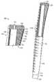
- FIG. 2is a perspective view of an embodiment of the grip of FIG. 1 with a portion of the grip cutaway.
- FIG. 3is a perspective view of another embodiment of the grip of FIG. 1 with a portion of the grip cutaway.
- FIG. 4is a perspective view of a further embodiment of the grip of FIG. 1 with a portion of the grip cutaway.
- FIG. 5is a cross-section of a portion of an embodiment of the grip of FIG. 1 .
- FIG. 6is a perspective view of the grip of FIG. 1 illustrating an texture layer adjacent to the grip.
- FIG. 7is a perspective view of another embodiment of the grip of FIG. 1 with a portion of the grip cutaway.
- FIG. 8is a detailed view of the portion of FIG. 7 enclosed by rectangle VIII in FIG. 7 .
- the apparatus disclosed hereinincludes a composite golf club grip (“grip”).
- the gripincludes a high modulus hybrid construction that has a composite shell and a foam layer within the composite shell.
- the composite shellmay provide a seamless surface for a golfer to grasp that does not deflect inward as the golfer grasps a putter for a putting stroke, while the foam layer may provide a reduction in weight of the overall grip.
- the gripalso includes a core that may dampen or transfer vibration to the composite shell from the shaft, which may provide valuable feedback to the golfer during a putting stroke.
- FIG. 1is a perspective view of the grip 100 mounted to a shaft 50 of a golf club.
- FIG. 2is a perspective view of an embodiment of the grip 100 of FIG. 1 with a portion of the grip 100 cutaway.
- grip 100may be affixed to the end of a shaft 50 opposite a club head of a golf club.
- Grip 100include may include an open end 103 , a closed end 101 , a shaft cavity 109 , and a body 108 .
- the open end 103is opposite the closed end 101 and allows the shaft 50 to be inserted into the shaft cavity 109 .
- the closed end 101may include a cap 102 that is integral to the body 108 .
- the cap 102may be joined to the body 108 , such as molded, glued, or bonded to the body 108 .
- the cap 102may be pre-molded prior to being joined to the body 108 .
- the cap 102may include a vent hole 105 , which can be used to install the grip 100 onto the shaft 50 and allow the displaced air and installation solvent to escape from the grip shaft cavity 109 .
- the shaft cavity 109is the hollow interior of the grip 100 formed by the body 108 .
- the shaft cavity 109may be sized relative to the diameter of the shaft 50 and extends from the open end 103 toward the closed end 101 and may terminate adjacent to the closed end 101 .
- the shaft cavity 109may have a shaft cavity axis 90 .
- the shaft cavity axis 90may be coaxial to the axis of the shaft 50 when the grip 100 is installed onto the shaft 50 . All references to radial, axial, and circumferential directions and measures refer to a shaft cavity axis 90 , unless specified otherwise, and terms such as “inner” and “outer” generally indicate a lesser or greater radial distance from the shaft cavity axis 90 .
- the body 108may include a composite shell 110 and a foam layer 120 .
- the outer surface 111 of the composite shell 110may be smooth as illustrated in FIG. 2 or may include surface texture 112 as illustrated in FIG. 1 .
- the surface texture 112may be, inter alia, from the nature of the material used for the composite shell 110 , may be formed from an texture layer 114 (shown in FIG. 6 ) in the composite shell 110 , such as a decal, or from a combination thereof.
- the composite shell 110is a hard outer shell of the body 108 .
- the composite shell 110may be a composite material that includes a matrix and a reinforcement material.
- the composite shell 110may be a laminate composite fiber outer shell.
- the fibercan be, inter alia, carbon, glass, boron, Kevlar, or a combination thereof.
- the composite shell 110is a fiber reinforced plastic.
- the fiber reinforced plasticmay be carbon fiber reinforced polymer, carbon fiber reinforced plastic or carbon fiber reinforced thermoplastic, where the matrix may be a polymer resin, such as epoxy, and the reinforcement is a carbon or synthetic carbon fiber.
- the polymer resinmay be a thermoset or thermoplastic resin.
- the reinforcement materialmay include multiple layers of sheets that include the fibers.
- the foam layer 120may be inward from the composite shell 110 .
- the composite shell 110may surround the foam layer 120 .
- the foam layer 120may adjoin and be integral to the composite shell 110 .
- the composite shell 110 and the foam layer 120may be bonded together.
- the composite shell 110is formed around the foam layer 120 and bonded to the foam layer 120 during the process of forming the composite shell 110 .
- the shaft cavity 109is located inward from the foam layer 120 .
- the foam layer 120is shaped and constructed to form the shaft cavity 109 .
- the foam layer 120is a light structural portion of the body 108 and may include solid foam.
- the solid foammay include an open or closed cell structure.
- the closed cell foammay be syntactic foam.
- the foam layer 120includes polyurethane foam.
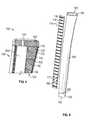
- FIG. 3is a perspective view of another embodiment of the grip 100 of FIG. 1 with a portion of the grip 100 cutaway.
- the body 108may also include a core tube 132 inward from the foam layer 120 .
- the composite shell 110 and the foam layer 120may surround the core tube 132 .
- the core tube 132may adjoin the foam layer 120 .
- the core tube 132may be integral to the foam layer 120 .
- the core tube 132 and the foam layer 120may be bonded or otherwise joined together.
- the core tube 132may form an inner sleeve of the grip 100 for the shaft 50 and may be formed to include the shaft cavity 109 .
- the core tube 132 and the composite shell 110may be in contact adjacent to the open end 103 .
- the cap 102 , the core tube 132 , and the composite shell 110may enclose a volume that is filled by the foam layer 120 .
- the core tube 132may include a right circular cylinder shape.
- the core tube 132may include one or more layers of elastomeric materials, such as rubber, polyurethane, or thermoplastic elastomer. In some embodiments, the core tube 132 can include shock absorbing properties.
- the core tube 132 and the cap 102may be integral, such as bonded together, glued together, or molded as a unitary piece.
- the composite shell 110includes a composite shell end 113 which may not extend completely to the open end 103 .
- the core tube 132may extend to the composite shell end 113 and may extend beyond the composite shell end 113 to form a tip 104 that includes the open end 103 as illustrated in FIGS. 3 and 4 .
- the tip 104may be formed of an elastomeric material.
- FIG. 4is a perspective view of a further embodiment of the grip 100 of FIG. 1 with a portion of the grip 100 cutaway.
- the body 108may also include core protrusions 134 .
- the core protrusions 134may extend from the core tube 132 to the composite shell 110 through the foam layer 120 .
- the core protrusions 134may be interspersed throughout the foam layer 120 .
- the core protrusions 134may be full or partial ribs extending around the circumference of the core tube 132 , along the axis of the core tube 132 and along the shaft cavity axis 90 , or may spiral about the core tube 132 .
- the core protrusions 134 that are full ribsmay subdivide the volume enclosed by the cap 102 , the core tube 132 and the composite shell 110 , and may subdivide the foam layer 120 into foam layer sections 122 .
- the core protrusions 134may also be spokes, such as partial ribs that extend partially around the circumference of the core tube 132 or tubes that extend outward from the core tube 132 to the composite shell 110 .
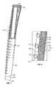
- the core protrusions 134 and the core tube 132are integral and may be joined or molded as a unitary piece as shown in FIG. 5 .
- the core protrusions 134may be formed of the same or similar materials as the core tube 132 .
- the core protrusions 134may include elastomeric materials, such as rubber, polyurethane, or thermoplastic elastomer, and can include shock absorbing properties.
- FIG. 5is a cross-section of a portion of an embodiment of the grip 100 of FIG. 1 .
- the grip 100may also include a surface coating 140 on the outer surface 111 of the composite shell 110 .
- the surface coating 140may improve the durability or the gripping properties of the grip 100 . These properties include inter alia, an increased coefficient of friction at the outer surface 111 , increased surface tack, and increased surface hardness.
- the surface coating 140may include, inter alia, polyurethane coatings and rubber based coatings.
- FIG. 6is a perspective view of the grip of FIG. 1 illustrating a texture layer 114 adjacent to the grip 100 .
- the texture layer 114may be an overlay or an inlay.
- the texture layer 114may be located within the composite material, inward of the composite material or outward from the composite material. During the manufacturing process, the texture layer 114 may be located between layers, such as sheets, of the reinforcement material prior to adding the binding matrix, located under the layers prior to adding the binding matrix, or may be located on the composite material after adding the binding matrix.
- the texture layer 114may include tactile features 115 , alignment features 116 , and graphic features 117 .
- the tactile features 115may be protrusions, depressions, or a combination thereof.
- the alignment features 116may also be protrusions, depressions or graphic in nature, and may be located adjacent the closed end 101 or the open end 103 .
- Graphic features 117may be, inter alia, images, logos, symbols, or a combination thereof.
- FIG. 7is a perspective view of another embodiment of the grip of FIG. 1 with a portion of the grip cutaway.
- FIG. 8is a detailed view of the portion of FIG. 7 enclosed by rectangle VIII in FIG. 7 .
- a portion of the surface coating 140 in FIG. 8is cutaway and not shown for illustrative purposes.
- the texture layer 114is located outward of the composite shell and may be a decal that is adhered to the outside of the composite shell 110 .
- the texture layer 114may be a continuous strip of material as illustrated, may be multiple strips of material that include tactile features 115 , or may be individual tactile features 115 .
- the surface coating 140is located outward of the texture layer 114 , with the texture layer 114 located between the composite shell 110 and the surface coating 140 .
- the texture layer 114may be decals that are applied after the surface coating 140 .
- the tactile features 115may form some or all of the surface texture 112 of the grip 100 .
- the grip 100 as described hereinmay have a high modulus hybrid construction.
- the composite shell 110may have a seamless construction and may not deflect inward when gripped, which can allow a golfer to grasp the grip comfortably and precisely no matter the gripping method the golfer uses.
- the composite shell 110may also improve the durability of the grip 100 .
- the layered construction of the embodiments of the grip 100 described hereinmay allow for the fine tuning of the weight of the grip 100 , such as by adjusting the thickness of each layer and by the foam density.
- the layered constructionalso allows for the fine tuning of the amount of vibration that reaches the golfer's hand. Dampening some of the vibration may filter the noise and allow proper vibrational feedback to reach the golfer's hand. This feedback may help the golfer feel how hard the ball was struck and where on the clubface the ball was struck, which may provide the golfer valuable information about the golfer's putting stroke.
- the vibrational dampening and transference of vibration from the shaft 50 to the composite shell 110may be tuned by, inter alia, the thickness of the core tube 132 and the amount of contact that the composite shell 110 has with the core tube 132 , the core protrusions 134 , and with the cap 102 . While the core protrusions 134 may have some dampening properties, those properties may be less than the dampening properties of the foam layer 120 . Thus, the amount vibrational transference to the composite shell 110 may be controlled by the pattern, shapes, and thicknesses of the core protrusions 134 and the contact area the core protrusions 134 , the core tube 132 , and the cap 102 each have with the composite shell 110 .
Landscapes
- Health & Medical Sciences (AREA)
- General Health & Medical Sciences (AREA)
- Physical Education & Sports Medicine (AREA)
- Golf Clubs (AREA)
Abstract
Description
The present disclosure generally pertains to golf grips, and is also directed toward a golf grip including angled recessed or protruded features.
Grips for sporting implements such as golf clubs have taken numerous forms over the years. Early grips consisted of a wrap material, such as leather, in a helical pattern around the handle portion of the golf club. Over the years grips have evolved from the wrap type grip to a tapered cylinder of rubber, polyurethane, TPE, or similar elastomeric and shock absorbing materials that slip over an end of a golf club shaft. These grips are generally formed by a compression molding or an injection molding process.
The choice of rubber and synthetic rubber materials provides multiple benefits for the swinging golf clubs. Rubber is a material that can provide a good coefficient of friction to help the golfer hold the club throughout the swing. Rubber can also dampen vibrations and reduce the magnitude of forces generated by impacting the ball and the ground that reach a golfer's hands, which may prevent injury or reduce the chances of injury.
Since swinging grips were made of rubber, it was natural that putter grips would also be made of rubber. It was easy for manufacturers to apply the same manufacturing methods to the putter grip. Over the last several years the size and shape of the putter grip has evolved to better accommodate the putting stroke, which is much different than a full golf swing stroke. These shapes are larger and more accommodating to the types of methods golfer's use to grip the putter.
Vibration dampening in a putter grip may not be necessary or desirable. For example, dampening vibrations may reduce the feedback the golfer feels when the ball is struck by the putter. This feedback may be valuable to help the golfer determine whether the ball was struck at the center of the club face or whether the ball was struck near the heel or toe of the club face and to help the golfer make the proper adjustments to the putting stroke.
A golf grip for a golf club is disclosed herein. In embodiments, the golf grip includes a composite shell including an open end, a closed end, a laminate composite fiber material, a foam layer, and a shaft cavity. The foam layer is inward of the composite shell. The shaft cavity extends from the open end towards the closed end. The shaft cavity is inward from the composite shell and the foam layer.
In some embodiments, the golf grip also includes a core tube inward of the composite shell and of the foam layer. The core tube forms a shaft cavity for receiving a shaft of the golf club. In some embodiments, the core tube includes a hollow circular cylinder shape. In embodiments, the grip also includes core protrusions extending from the core tube to the composite shell through the foam layer.
Other features and advantages of the present invention should be apparent from the following description which illustrates, by way of example, aspects of the invention.
The apparatus disclosed herein includes a composite golf club grip (“grip”). In embodiments, the grip includes a high modulus hybrid construction that has a composite shell and a foam layer within the composite shell. The composite shell may provide a seamless surface for a golfer to grasp that does not deflect inward as the golfer grasps a putter for a putting stroke, while the foam layer may provide a reduction in weight of the overall grip. In some embodiments, the grip also includes a core that may dampen or transfer vibration to the composite shell from the shaft, which may provide valuable feedback to the golfer during a putting stroke.
Theshaft cavity 109 is the hollow interior of thegrip 100 formed by thebody 108. Theshaft cavity 109 may be sized relative to the diameter of theshaft 50 and extends from theopen end 103 toward the closedend 101 and may terminate adjacent to the closedend 101. Theshaft cavity 109 may have ashaft cavity axis 90. Theshaft cavity axis 90 may be coaxial to the axis of theshaft 50 when thegrip 100 is installed onto theshaft 50. All references to radial, axial, and circumferential directions and measures refer to ashaft cavity axis 90, unless specified otherwise, and terms such as “inner” and “outer” generally indicate a lesser or greater radial distance from theshaft cavity axis 90.
Thebody 108 may include acomposite shell 110 and afoam layer 120. Theouter surface 111 of thecomposite shell 110 may be smooth as illustrated inFIG. 2 or may includesurface texture 112 as illustrated inFIG. 1 . Thesurface texture 112 may be, inter alia, from the nature of the material used for thecomposite shell 110, may be formed from an texture layer114 (shown inFIG. 6 ) in thecomposite shell 110, such as a decal, or from a combination thereof.
Thecomposite shell 110 is a hard outer shell of thebody 108. Thecomposite shell 110 may be a composite material that includes a matrix and a reinforcement material. Thecomposite shell 110 may be a laminate composite fiber outer shell. The fiber can be, inter alia, carbon, glass, boron, Kevlar, or a combination thereof. In some embodiments, thecomposite shell 110 is a fiber reinforced plastic. The fiber reinforced plastic may be carbon fiber reinforced polymer, carbon fiber reinforced plastic or carbon fiber reinforced thermoplastic, where the matrix may be a polymer resin, such as epoxy, and the reinforcement is a carbon or synthetic carbon fiber. The polymer resin may be a thermoset or thermoplastic resin. The reinforcement material may include multiple layers of sheets that include the fibers.
Thefoam layer 120 may be inward from thecomposite shell 110. Thecomposite shell 110 may surround thefoam layer 120. Thefoam layer 120 may adjoin and be integral to thecomposite shell 110. Thecomposite shell 110 and thefoam layer 120 may be bonded together. In embodiments, thecomposite shell 110 is formed around thefoam layer 120 and bonded to thefoam layer 120 during the process of forming thecomposite shell 110. Theshaft cavity 109 is located inward from thefoam layer 120. In the embodiment illustrated inFIG. 2 , thefoam layer 120 is shaped and constructed to form theshaft cavity 109. Thefoam layer 120 is a light structural portion of thebody 108 and may include solid foam. The solid foam may include an open or closed cell structure. The closed cell foam may be syntactic foam. In some embodiments, thefoam layer 120 includes polyurethane foam.
Thecore tube 132 may include one or more layers of elastomeric materials, such as rubber, polyurethane, or thermoplastic elastomer. In some embodiments, thecore tube 132 can include shock absorbing properties.
Thecore tube 132 and thecap 102 may be integral, such as bonded together, glued together, or molded as a unitary piece.
Thecomposite shell 110 includes acomposite shell end 113 which may not extend completely to theopen end 103. Thecore tube 132 may extend to thecomposite shell end 113 and may extend beyond thecomposite shell end 113 to form atip 104 that includes theopen end 103 as illustrated inFIGS. 3 and 4 . Thetip 104 may be formed of an elastomeric material.
The core protrusions134 may be full or partial ribs extending around the circumference of thecore tube 132, along the axis of thecore tube 132 and along theshaft cavity axis 90, or may spiral about thecore tube 132. The core protrusions134 that are full ribs may subdivide the volume enclosed by thecap 102, thecore tube 132 and thecomposite shell 110, and may subdivide thefoam layer 120 intofoam layer sections 122. The core protrusions134 may also be spokes, such as partial ribs that extend partially around the circumference of thecore tube 132 or tubes that extend outward from thecore tube 132 to thecomposite shell 110.
The core protrusions134 and thecore tube 132 are integral and may be joined or molded as a unitary piece as shown inFIG. 5 . The core protrusions134 may be formed of the same or similar materials as thecore tube 132. The core protrusions134 may include elastomeric materials, such as rubber, polyurethane, or thermoplastic elastomer, and can include shock absorbing properties.
In the embodiment illustrated, thesurface coating 140 is located outward of thetexture layer 114, with thetexture layer 114 located between thecomposite shell 110 and thesurface coating 140. In other embodiments, thetexture layer 114 may be decals that are applied after thesurface coating 140. Thetactile features 115 may form some or all of thesurface texture 112 of thegrip 100.
Thegrip 100 as described herein may have a high modulus hybrid construction. Thecomposite shell 110 may have a seamless construction and may not deflect inward when gripped, which can allow a golfer to grasp the grip comfortably and precisely no matter the gripping method the golfer uses. Thecomposite shell 110 may also improve the durability of thegrip 100.
The layered construction of the embodiments of thegrip 100 described herein may allow for the fine tuning of the weight of thegrip 100, such as by adjusting the thickness of each layer and by the foam density. The layered construction also allows for the fine tuning of the amount of vibration that reaches the golfer's hand. Dampening some of the vibration may filter the noise and allow proper vibrational feedback to reach the golfer's hand. This feedback may help the golfer feel how hard the ball was struck and where on the clubface the ball was struck, which may provide the golfer valuable information about the golfer's putting stroke.
The vibrational dampening and transference of vibration from theshaft 50 to thecomposite shell 110 may be tuned by, inter alia, the thickness of thecore tube 132 and the amount of contact that thecomposite shell 110 has with thecore tube 132, thecore protrusions 134, and with thecap 102. While thecore protrusions 134 may have some dampening properties, those properties may be less than the dampening properties of thefoam layer 120. Thus, the amount vibrational transference to thecomposite shell 110 may be controlled by the pattern, shapes, and thicknesses of thecore protrusions 134 and the contact area thecore protrusions 134, thecore tube 132, and thecap 102 each have with thecomposite shell 110.
The above description of the disclosed embodiments is provided to enable any person skilled in the art to make or use the invention. The described embodiments are not limited to use in conjunction with a particular type of golf club. Hence, although the present disclosure, for convenience of explanation, depicts and describes particular embodiments of the grip for a putter, it will be appreciated that the grip in accordance with this disclosure can be used with various other types of golf clubs, and can be used with other types of implements. Various modifications to these embodiments will be readily apparent to those skilled in the art, and the generic principles described herein can be applied to other embodiments without departing from the spirit or scope of the invention. Thus, any explanation in connection with one embodiment applies to similar features of other embodiments, and elements of multiple embodiments can be combined to form other embodiments. It is to be understood that the description and drawings presented herein represent a presently preferred embodiment of the invention and are therefore representative of the subject matter which is broadly contemplated by the present invention. It is further understood that the scope of the present invention fully encompasses other embodiments that may become obvious to those skilled in the art.
Claims (16)
1. A golf grip for a golf club comprising:
a closed end;
an open end;
a composite shell including a laminate composite fiber material forming a continuous surface from the open end to the closed end;
a foam layer inward of the composite shell;
a shaft cavity inward of the composite shell and the foam layer extending from the open end toward the closed end;
a core tube inward of the foam layer, the core tube forming the shaft cavity; wherein the core tube includes a cap integral to the core tube, the cap forming the closed end, and wherein the core tube extends beyond the composite shell at the open end.
2. The golf grip ofclaim 1 , further comprising core protrusions extending from the core tube to the composite shell through the foam layer.
3. The golf grip ofclaim 2 , wherein the core protrusions include a rib that subdivides the foam layer into foam layer sections.
4. The golf grip ofclaim 1 , a texture layer adjoining the outer surface of the composite shell, the texture layer including tactile features that form surface texture on the grip.
5. The golf grip ofclaim 4 , further comprising a surface coating located outward of the texture layer and the composite shell, wherein the texture layer is located between the composite shell and the surface coating.
6. A golf grip for a golf club comprising:
a body forming a shaft cavity for receiving a shaft of the golf club, the body having
a closed end,
an open end,
a composite shell including a laminate composite fiber material forming a continuous surface from the open end to the closed end, and
a foam layer inward of, adjoining, and integral to the composite shell; and
a cap integral to the body at the closed end of the body, where the shaft cavity extends from the open end to the cap;
a core tube inward of, adjoining, and integral to the foam layer;
core protrusions extending from the core tube to the composite shell through the foam layer.
7. The golf grip ofclaim 6 , wherein the core protrusions include a rib that subdivides the foam layer into foam layer sections.
8. The golf grip ofclaim 6 , wherein the core tube includes an elastomeric material.
9. The golf grip ofclaim 6 , wherein the foam layer includes closed cell polyurethane foam.
10. The golf grip ofclaim 9 , further comprising a surface coating located at an outer surface of the composite shell.
11. A golf grip for a golf club comprising:
a core tube forming a shaft cavity;
a composite shell surrounding the core tube, the composite shell including a laminate fiber composite material, wherein the composite shell forms a hard outer shell having a continuous surface from a first end to a second end, the first end of the composite shell contacting the core tube adjacent an open end of the grip;
a cap adjoining the core tube and the second end of the composite shell to form a closed end of the grip opposite the open end; and
a foam layer filling a volume enclosed by the cap, the composite shell, and the core tube, where the composite shell, the foam layer, the core tube, and the cap are integral.
12. The golf grip ofclaim 11 , further comprising core protrusions extending from the core tube to the composite shell through the foam layer.
13. The golf grip ofclaim 12 , wherein the core protrusions include a rib that subdivides the volume between the cap, the composite shell, and the core tube, and wherein the foam layer is subdivided into foam layer sections.
14. The golf grip ofclaim 12 , wherein the foam layer includes closed cell polyurethane foam, and the core tube and the core protrusions include an elastomeric material.
15. The golf grip ofclaim 11 , wherein the core tube extends beyond the composite shell at the open end forming a tip of elastomeric material.
16. The golf grip ofclaim 11 , further comprising a texture layer that forms tactile features on the grip.
Priority Applications (1)
| Application Number | Priority Date | Filing Date | Title |
|---|---|---|---|
| US15/352,327US10130858B2 (en) | 2016-11-15 | 2016-11-15 | Composite golf club grip |
Applications Claiming Priority (1)
| Application Number | Priority Date | Filing Date | Title |
|---|---|---|---|
| US15/352,327US10130858B2 (en) | 2016-11-15 | 2016-11-15 | Composite golf club grip |
Publications (2)
| Publication Number | Publication Date |
|---|---|
| US20180133571A1 US20180133571A1 (en) | 2018-05-17 |
| US10130858B2true US10130858B2 (en) | 2018-11-20 |
Family
ID=62107061
Family Applications (1)
| Application Number | Title | Priority Date | Filing Date |
|---|---|---|---|
| US15/352,327ActiveUS10130858B2 (en) | 2016-11-15 | 2016-11-15 | Composite golf club grip |
Country Status (1)
| Country | Link |
|---|---|
| US (1) | US10130858B2 (en) |
Cited By (8)
| Publication number | Priority date | Publication date | Assignee | Title |
|---|---|---|---|---|
| US10525315B1 (en) | 2018-07-20 | 2020-01-07 | Harry Matthew Wells | Grip assembly for sports equipment |
| US20200139205A1 (en)* | 2018-11-04 | 2020-05-07 | William R. Diepenbrock, JR. | Putter Type Golf Club |
| US11097172B2 (en)* | 2018-11-04 | 2021-08-24 | William R. Diepenbrock, JR. | Weighting system for putter type golf club |
| US11752410B2 (en) | 2021-09-28 | 2023-09-12 | Bradley R. Mason | Force sensor for alerting golfer when club held too tightly |
| USD1019840S1 (en) | 2022-06-29 | 2024-03-26 | Parsons Xtreme Golf, LLC | Golf club grip |
| USD1022094S1 (en) | 2022-06-29 | 2024-04-09 | Parsons Xtreme Golf, LLC | Golf club grip |
| USD1022095S1 (en) | 2022-07-11 | 2024-04-09 | Parsons Xtreme Golf, LLC | Golf club grip |
| USD1022096S1 (en) | 2022-08-02 | 2024-04-09 | Parsons Xtreme Golf, LLC | Golf club grip |
Citations (33)
| Publication number | Priority date | Publication date | Assignee | Title |
|---|---|---|---|---|
| US1139843A (en)* | 1913-10-16 | 1915-05-18 | Robert B Brown | Handle-grip. |
| US4180264A (en) | 1977-04-25 | 1979-12-25 | Acro, Inc. | Racket handle and method of making same |
| US4676839A (en)* | 1986-09-10 | 1987-06-30 | Osborn Jack S | Golf club grip cleaner |
| US4819939A (en) | 1985-10-30 | 1989-04-11 | Maruman Golf Co., Ltd. | Grip for a golf club shaft |
| US5087042A (en)* | 1990-08-27 | 1992-02-11 | Karsten Manufacturing Corporation | Golf club grip |
| US5160139A (en)* | 1991-10-15 | 1992-11-03 | Soong Tsai C | Handle device for sports equipment shafts |
| US5259614A (en)* | 1992-08-06 | 1993-11-09 | Greer Julian A | Composite seamless filament-wound golf club shaft and method |
| US5398934A (en)* | 1993-10-13 | 1995-03-21 | Soong; Tsai C. | Golf club and grip therefor |
| US5571050A (en) | 1995-09-13 | 1996-11-05 | Huang; Ben | Tubular golf club grip |
| US5575473A (en)* | 1992-11-23 | 1996-11-19 | Turner; Terry S. | Golf club |
| US5692970A (en)* | 1994-02-09 | 1997-12-02 | Radius Engineering | Composite golf club shaft |
| US5743811A (en) | 1996-03-07 | 1998-04-28 | Emhart Inc. | Lightweight shaft |
| US5792551A (en)* | 1994-12-05 | 1998-08-11 | Daiwa Seiko, Inc. | Light-weighted prepreg and grip made therefrom |
| US5846629A (en)* | 1996-05-31 | 1998-12-08 | Lord Corporation | Cushioning handle wrap for isolating vibration |
| US20020077192A1 (en) | 2000-12-18 | 2002-06-20 | Yung-Hsiang Chen | Grip of golf club and its manufacture method |
| US20020142858A1 (en) | 2001-03-29 | 2002-10-03 | Yung-Hsiang Chen | Handle of golf club |
| US6656057B2 (en) | 2001-08-21 | 2003-12-02 | Hong-Sung Chu | Golf club grip |
| US20030224865A1 (en) | 2002-05-29 | 2003-12-04 | Lai Chien Hao | Tubular sport items |
| US6908400B2 (en) | 2002-08-07 | 2005-06-21 | Hong-Sung Chu | Golf club grip with a hem structure |
| US20060011566A1 (en)* | 2004-07-19 | 2006-01-19 | Guy Michael T | Lacrosse stick holder |
| US7374498B2 (en)* | 2000-02-04 | 2008-05-20 | Ben Huang | All-weather golf club grip |
| CN201565059U (en) | 2009-07-09 | 2010-09-01 | 王天武 | Golf club handle with foaming shock-absorbing interlayer |
| WO2010147982A2 (en) | 2009-06-18 | 2010-12-23 | Xene Corporation | Fiber composite and process of manufacture |
| US8006349B2 (en) | 2008-09-29 | 2011-08-30 | Eaton Corporation | Lightweight grip and method of making same |
| US8296907B2 (en) | 2009-05-15 | 2012-10-30 | Eaton Corporation | Light weight grip and method of making same |
| US8480508B2 (en)* | 2011-09-21 | 2013-07-09 | Hong-Sung Chu | Golf club grip and method of making the same |
| US8518505B2 (en)* | 2009-04-10 | 2013-08-27 | Ben Huang | Multi-layered grip |
| US8845448B2 (en)* | 2003-03-18 | 2014-09-30 | Ben Huang | Single panel golf club grip |
| US8858356B2 (en) | 2012-02-07 | 2014-10-14 | Hong-Sung Chu | Golf putter grip |
| US8998753B2 (en)* | 2008-05-07 | 2015-04-07 | Robert Tinti | Hand implement vibration isolation system |
| US20150224370A1 (en) | 2014-02-12 | 2015-08-13 | Dunlop Sports Co. Ltd. | Racket |
| WO2016010853A1 (en) | 2014-07-13 | 2016-01-21 | Giant Project, Inc. | Ergonomic grip sleeve for sport sticks |
| US20160136492A1 (en) | 2014-11-14 | 2016-05-19 | Dunlop Sports Co. Ltd. | Grip for sporting goods and golf club |
- 2016
- 2016-11-15USUS15/352,327patent/US10130858B2/enactiveActive
Patent Citations (35)
| Publication number | Priority date | Publication date | Assignee | Title |
|---|---|---|---|---|
| US1139843A (en)* | 1913-10-16 | 1915-05-18 | Robert B Brown | Handle-grip. |
| US4180264A (en) | 1977-04-25 | 1979-12-25 | Acro, Inc. | Racket handle and method of making same |
| US4819939A (en) | 1985-10-30 | 1989-04-11 | Maruman Golf Co., Ltd. | Grip for a golf club shaft |
| US4676839A (en)* | 1986-09-10 | 1987-06-30 | Osborn Jack S | Golf club grip cleaner |
| US5087042A (en)* | 1990-08-27 | 1992-02-11 | Karsten Manufacturing Corporation | Golf club grip |
| US5160139A (en)* | 1991-10-15 | 1992-11-03 | Soong Tsai C | Handle device for sports equipment shafts |
| USRE34767E (en)* | 1991-10-15 | 1994-10-25 | Soong; Tsai C. | Handle device for sports equipment shafts |
| US5259614A (en)* | 1992-08-06 | 1993-11-09 | Greer Julian A | Composite seamless filament-wound golf club shaft and method |
| US5575473A (en)* | 1992-11-23 | 1996-11-19 | Turner; Terry S. | Golf club |
| US5398934A (en)* | 1993-10-13 | 1995-03-21 | Soong; Tsai C. | Golf club and grip therefor |
| US5692970A (en)* | 1994-02-09 | 1997-12-02 | Radius Engineering | Composite golf club shaft |
| US5792551A (en)* | 1994-12-05 | 1998-08-11 | Daiwa Seiko, Inc. | Light-weighted prepreg and grip made therefrom |
| US5571050A (en) | 1995-09-13 | 1996-11-05 | Huang; Ben | Tubular golf club grip |
| US5743811A (en) | 1996-03-07 | 1998-04-28 | Emhart Inc. | Lightweight shaft |
| US5846629A (en)* | 1996-05-31 | 1998-12-08 | Lord Corporation | Cushioning handle wrap for isolating vibration |
| US7374498B2 (en)* | 2000-02-04 | 2008-05-20 | Ben Huang | All-weather golf club grip |
| US20020077192A1 (en) | 2000-12-18 | 2002-06-20 | Yung-Hsiang Chen | Grip of golf club and its manufacture method |
| US20020142858A1 (en) | 2001-03-29 | 2002-10-03 | Yung-Hsiang Chen | Handle of golf club |
| US6656057B2 (en) | 2001-08-21 | 2003-12-02 | Hong-Sung Chu | Golf club grip |
| US20030224865A1 (en) | 2002-05-29 | 2003-12-04 | Lai Chien Hao | Tubular sport items |
| US6908400B2 (en) | 2002-08-07 | 2005-06-21 | Hong-Sung Chu | Golf club grip with a hem structure |
| US8845448B2 (en)* | 2003-03-18 | 2014-09-30 | Ben Huang | Single panel golf club grip |
| US20060011566A1 (en)* | 2004-07-19 | 2006-01-19 | Guy Michael T | Lacrosse stick holder |
| US8998753B2 (en)* | 2008-05-07 | 2015-04-07 | Robert Tinti | Hand implement vibration isolation system |
| US8006349B2 (en) | 2008-09-29 | 2011-08-30 | Eaton Corporation | Lightweight grip and method of making same |
| US8518505B2 (en)* | 2009-04-10 | 2013-08-27 | Ben Huang | Multi-layered grip |
| US8296907B2 (en) | 2009-05-15 | 2012-10-30 | Eaton Corporation | Light weight grip and method of making same |
| WO2010147982A2 (en) | 2009-06-18 | 2010-12-23 | Xene Corporation | Fiber composite and process of manufacture |
| US20140239531A1 (en) | 2009-06-18 | 2014-08-28 | Xu Jiansheng | Composite member and method of making |
| CN201565059U (en) | 2009-07-09 | 2010-09-01 | 王天武 | Golf club handle with foaming shock-absorbing interlayer |
| US8480508B2 (en)* | 2011-09-21 | 2013-07-09 | Hong-Sung Chu | Golf club grip and method of making the same |
| US8858356B2 (en) | 2012-02-07 | 2014-10-14 | Hong-Sung Chu | Golf putter grip |
| US20150224370A1 (en) | 2014-02-12 | 2015-08-13 | Dunlop Sports Co. Ltd. | Racket |
| WO2016010853A1 (en) | 2014-07-13 | 2016-01-21 | Giant Project, Inc. | Ergonomic grip sleeve for sport sticks |
| US20160136492A1 (en) | 2014-11-14 | 2016-05-19 | Dunlop Sports Co. Ltd. | Grip for sporting goods and golf club |
Cited By (9)
| Publication number | Priority date | Publication date | Assignee | Title |
|---|---|---|---|---|
| US10525315B1 (en) | 2018-07-20 | 2020-01-07 | Harry Matthew Wells | Grip assembly for sports equipment |
| US10751590B1 (en) | 2018-07-20 | 2020-08-25 | Harry Matthew Welsl | Grip assembly for sports equipment |
| US20200139205A1 (en)* | 2018-11-04 | 2020-05-07 | William R. Diepenbrock, JR. | Putter Type Golf Club |
| US11097172B2 (en)* | 2018-11-04 | 2021-08-24 | William R. Diepenbrock, JR. | Weighting system for putter type golf club |
| US11752410B2 (en) | 2021-09-28 | 2023-09-12 | Bradley R. Mason | Force sensor for alerting golfer when club held too tightly |
| USD1019840S1 (en) | 2022-06-29 | 2024-03-26 | Parsons Xtreme Golf, LLC | Golf club grip |
| USD1022094S1 (en) | 2022-06-29 | 2024-04-09 | Parsons Xtreme Golf, LLC | Golf club grip |
| USD1022095S1 (en) | 2022-07-11 | 2024-04-09 | Parsons Xtreme Golf, LLC | Golf club grip |
| USD1022096S1 (en) | 2022-08-02 | 2024-04-09 | Parsons Xtreme Golf, LLC | Golf club grip |
Also Published As
| Publication number | Publication date |
|---|---|
| US20180133571A1 (en) | 2018-05-17 |
Similar Documents
| Publication | Publication Date | Title |
|---|---|---|
| US10130858B2 (en) | Composite golf club grip | |
| KR101501584B1 (en) | Vibration dampening ball bat | |
| US20200384322A1 (en) | Composite golf club grip with foam layer | |
| US7749114B2 (en) | Composite bat | |
| US8029391B2 (en) | Composite bat | |
| US20020198071A1 (en) | Ball bat | |
| US7458903B2 (en) | Hand grip and method of making same | |
| US7510483B2 (en) | Golf club grip | |
| CA3032371C (en) | Double-barrel ball bats | |
| US8296908B2 (en) | Lightweight grip and method of making same | |
| CN102100964A (en) | Lightweight golf grip | |
| US10507367B2 (en) | Bat with barrel pivot joint | |
| US11058934B2 (en) | Ball bat with cantilevered insert | |
| US10384106B2 (en) | Ball bat with shock attenuating handle | |
| US20160184679A1 (en) | Neck cover for a sports paddle and method of manufacture | |
| US20150157909A1 (en) | Vibration damper end knob for baseball and softball bats | |
| US9067638B2 (en) | Handgrip for bicycle handlebars | |
| US10507368B2 (en) | Baseball or softball bat | |
| WO2007012843A1 (en) | Cricket bat | |
| JPH1024134A (en) | Golf club grip | |
| WO2022232874A1 (en) | An improved grip for sporting equipment | |
| JPS5928980A (en) | Bat for baseball and softball | |
| JP2004344470A (en) | Grip |
Legal Events
| Date | Code | Title | Description |
|---|---|---|---|
| AS | Assignment | Owner name:LAMKIN CORPORATION, CALIFORNIA Free format text:ASSIGNMENT OF ASSIGNORS INTEREST;ASSIGNORS:LAMKIN, ROBERT J.;PETTERSEN, CARL W.;SNOW, MICHAEL;REEL/FRAME:040330/0561 Effective date:20161111 | |
| STCF | Information on status: patent grant | Free format text:PATENTED CASE | |
| MAFP | Maintenance fee payment | Free format text:PAYMENT OF MAINTENANCE FEE, 4TH YEAR, LARGE ENTITY (ORIGINAL EVENT CODE: M1551); ENTITY STATUS OF PATENT OWNER: LARGE ENTITY Year of fee payment:4 | |
| AS | Assignment | Owner name:MANUFACTURERS BANK, CALIFORNIA Free format text:SECURITY INTEREST;ASSIGNOR:LAMKIN CORPORATION;REEL/FRAME:062198/0978 Effective date:20221223 | |
| AS | Assignment | Owner name:SUPERSTROKE INTERNATIONAL, LLC, MICHIGAN Free format text:ASSIGNMENT OF ASSIGNORS INTEREST;ASSIGNOR:LAMKIN CORPORATION;REEL/FRAME:068199/0584 Effective date:20240426 |