US10130831B2 - Self-contained breathing system - Google Patents
Self-contained breathing systemDownload PDFInfo
- Publication number
- US10130831B2 US10130831B2US14/600,719US201514600719AUS10130831B2US 10130831 B2US10130831 B2US 10130831B2US 201514600719 AUS201514600719 AUS 201514600719AUS 10130831 B2US10130831 B2US 10130831B2
- Authority
- US
- United States
- Prior art keywords
- breathing
- gas
- air
- chassis
- self
- Prior art date
- Legal status (The legal status is an assumption and is not a legal conclusion. Google has not performed a legal analysis and makes no representation as to the accuracy of the status listed.)
- Active, expires
Links
- 230000029058respiratory gaseous exchangeEffects0.000titleclaimsabstractdescription106
- 239000003570airSubstances0.000claimsabstractdescription87
- 239000012080ambient airSubstances0.000claimsabstractdescription26
- 239000000356contaminantSubstances0.000claimsabstractdescription15
- 238000011045prefiltrationMethods0.000claimsdescription21
- 238000004891communicationMethods0.000claimsdescription13
- 239000000463materialSubstances0.000claimsdescription12
- 238000010926purgeMethods0.000claimsdescription11
- 239000012530fluidSubstances0.000claimsdescription9
- 238000001914filtrationMethods0.000claimsdescription8
- 230000001105regulatory effectEffects0.000claimsdescription8
- 239000000126substanceSubstances0.000claimsdescription7
- 230000008878couplingEffects0.000claimsdescription5
- 238000010168coupling processMethods0.000claimsdescription5
- 238000005859coupling reactionMethods0.000claimsdescription5
- 230000013011matingEffects0.000claimsdescription5
- 239000004677NylonSubstances0.000claimsdescription3
- 229920001778nylonPolymers0.000claimsdescription3
- 239000002245particleSubstances0.000claimsdescription2
- 239000004020conductorSubstances0.000claims4
- 230000000392somatic effectEffects0.000claims2
- 238000011144upstream manufacturingMethods0.000claims1
- 239000007789gasSubstances0.000description43
- 229920000642polymerPolymers0.000description9
- 238000007789sealingMethods0.000description9
- QVGXLLKOCUKJST-UHFFFAOYSA-Natomic oxygenChemical compound[O]QVGXLLKOCUKJST-UHFFFAOYSA-N0.000description7
- 239000001301oxygenSubstances0.000description7
- 229910052760oxygenInorganic materials0.000description7
- -1polypropylenePolymers0.000description6
- 229920001343polytetrafluoroethylenePolymers0.000description6
- 239000004810polytetrafluoroethyleneSubstances0.000description6
- 238000003860storageMethods0.000description6
- 239000010410layerSubstances0.000description5
- 230000001681protective effectEffects0.000description5
- CURLTUGMZLYLDI-UHFFFAOYSA-NCarbon dioxideChemical compoundO=C=OCURLTUGMZLYLDI-UHFFFAOYSA-N0.000description4
- 238000004140cleaningMethods0.000description4
- 230000007613environmental effectEffects0.000description4
- 238000010438heat treatmentMethods0.000description4
- 230000007246mechanismEffects0.000description4
- 230000015556catabolic processEffects0.000description3
- 239000002131composite materialSubstances0.000description3
- 239000000470constituentSubstances0.000description3
- 238000001816coolingMethods0.000description3
- 238000005520cutting processMethods0.000description3
- 238000006731degradation reactionMethods0.000description3
- 230000006870functionEffects0.000description3
- 231100001261hazardousToxicity0.000description3
- 230000001590oxidative effectEffects0.000description3
- 239000004033plasticSubstances0.000description3
- 230000000007visual effectEffects0.000description3
- 239000004743PolypropyleneSubstances0.000description2
- 239000004809TeflonSubstances0.000description2
- 229920006362Teflon®Polymers0.000description2
- 230000004075alterationEffects0.000description2
- 229910052782aluminiumInorganic materials0.000description2
- XAGFODPZIPBFFR-UHFFFAOYSA-NaluminiumChemical compound[Al]XAGFODPZIPBFFR-UHFFFAOYSA-N0.000description2
- 229910002092carbon dioxideInorganic materials0.000description2
- 239000001569carbon dioxideSubstances0.000description2
- 238000011109contaminationMethods0.000description2
- 239000006185dispersionSubstances0.000description2
- 239000000428dustSubstances0.000description2
- 229910052751metalInorganic materials0.000description2
- 239000002184metalSubstances0.000description2
- 238000012986modificationMethods0.000description2
- 230000004048modificationEffects0.000description2
- 239000000178monomerSubstances0.000description2
- 229920001155polypropylenePolymers0.000description2
- 239000002243precursorSubstances0.000description2
- 230000000717retained effectEffects0.000description2
- 238000012360testing methodMethods0.000description2
- XLYOFNOQVPJJNP-UHFFFAOYSA-NwaterSubstancesOXLYOFNOQVPJJNP-UHFFFAOYSA-N0.000description2
- 229920000049Carbon (fiber)Polymers0.000description1
- YCKRFDGAMUMZLT-UHFFFAOYSA-NFluorine atomChemical compound[F]YCKRFDGAMUMZLT-UHFFFAOYSA-N0.000description1
- HBBGRARXTFLTSG-UHFFFAOYSA-NLithium ionChemical compound[Li+]HBBGRARXTFLTSG-UHFFFAOYSA-N0.000description1
- FYYHWMGAXLPEAU-UHFFFAOYSA-NMagnesiumChemical compound[Mg]FYYHWMGAXLPEAU-UHFFFAOYSA-N0.000description1
- 239000000853adhesiveSubstances0.000description1
- 230000001070adhesive effectEffects0.000description1
- 229910045601alloyInorganic materials0.000description1
- 239000000956alloySubstances0.000description1
- 239000012237artificial materialSubstances0.000description1
- 230000008901benefitEffects0.000description1
- 239000003124biologic agentSubstances0.000description1
- 229920005549butyl rubberPolymers0.000description1
- 239000004917carbon fiberSubstances0.000description1
- 239000013043chemical agentSubstances0.000description1
- 239000011248coating agentSubstances0.000description1
- 238000000576coating methodMethods0.000description1
- 230000000295complement effectEffects0.000description1
- 238000007906compressionMethods0.000description1
- 230000006835compressionEffects0.000description1
- 230000001276controlling effectEffects0.000description1
- 239000012809cooling fluidSubstances0.000description1
- 230000007797corrosionEffects0.000description1
- 238000005260corrosionMethods0.000description1
- 239000006071creamSubstances0.000description1
- 230000000881depressing effectEffects0.000description1
- 238000010586diagramMethods0.000description1
- 230000000694effectsEffects0.000description1
- 239000003063flame retardantSubstances0.000description1
- 229910052731fluorineInorganic materials0.000description1
- 239000011737fluorineSubstances0.000description1
- 239000004811fluoropolymerSubstances0.000description1
- 229920002313fluoropolymerPolymers0.000description1
- 239000006260foamSubstances0.000description1
- 238000009472formulationMethods0.000description1
- 239000000499gelSubstances0.000description1
- 230000036571hydrationEffects0.000description1
- 238000006703hydration reactionMethods0.000description1
- 239000007788liquidSubstances0.000description1
- 239000004973liquid crystal related substanceSubstances0.000description1
- 229910001416lithium ionInorganic materials0.000description1
- 229910052749magnesiumInorganic materials0.000description1
- 239000011777magnesiumSubstances0.000description1
- 238000012423maintenanceMethods0.000description1
- 230000007257malfunctionEffects0.000description1
- VNWKTOKETHGBQD-UHFFFAOYSA-NmethaneChemical compoundCVNWKTOKETHGBQD-UHFFFAOYSA-N0.000description1
- 239000000203mixtureSubstances0.000description1
- 229920005615natural polymerPolymers0.000description1
- 238000004806packaging method and processMethods0.000description1
- 239000006072pasteSubstances0.000description1
- 229920006254polymer filmPolymers0.000description1
- 239000002861polymer materialSubstances0.000description1
- LJCNRYVRMXRIQR-OLXYHTOASA-Lpotassium sodium L-tartrateChemical class[Na+].[K+].[O-]C(=O)[C@H](O)[C@@H](O)C([O-])=OLJCNRYVRMXRIQR-OLXYHTOASA-L0.000description1
- 238000012545processingMethods0.000description1
- 239000011241protective layerSubstances0.000description1
- 239000010453quartzSubstances0.000description1
- 230000004044responseEffects0.000description1
- 239000003566sealing materialSubstances0.000description1
- VYPSYNLAJGMNEJ-UHFFFAOYSA-Nsilicon dioxideInorganic materialsO=[Si]=OVYPSYNLAJGMNEJ-UHFFFAOYSA-N0.000description1
- 235000011006sodium potassium tartrateNutrition0.000description1
- 230000006641stabilisationEffects0.000description1
- 238000011105stabilizationMethods0.000description1
- 238000005728strengtheningMethods0.000description1
- 229920001059synthetic polymerPolymers0.000description1
- 231100000331toxicToxicity0.000description1
- 230000002588toxic effectEffects0.000description1
- 238000012549trainingMethods0.000description1
- 238000013519translationMethods0.000description1
Images


Classifications
- A—HUMAN NECESSITIES
- A62—LIFE-SAVING; FIRE-FIGHTING
- A62B—DEVICES, APPARATUS OR METHODS FOR LIFE-SAVING
- A62B7/00—Respiratory apparatus
- A62B7/12—Respiratory apparatus with fresh-air hose
- A—HUMAN NECESSITIES
- A62—LIFE-SAVING; FIRE-FIGHTING
- A62B—DEVICES, APPARATUS OR METHODS FOR LIFE-SAVING
- A62B18/00—Breathing masks or helmets, e.g. affording protection against chemical agents or for use at high altitudes or incorporating a pump or compressor for reducing the inhalation effort
- A62B18/006—Breathing masks or helmets, e.g. affording protection against chemical agents or for use at high altitudes or incorporating a pump or compressor for reducing the inhalation effort with pumps for forced ventilation
- A—HUMAN NECESSITIES
- A62—LIFE-SAVING; FIRE-FIGHTING
- A62B—DEVICES, APPARATUS OR METHODS FOR LIFE-SAVING
- A62B18/00—Breathing masks or helmets, e.g. affording protection against chemical agents or for use at high altitudes or incorporating a pump or compressor for reducing the inhalation effort
- A62B18/02—Masks
- A—HUMAN NECESSITIES
- A62—LIFE-SAVING; FIRE-FIGHTING
- A62B—DEVICES, APPARATUS OR METHODS FOR LIFE-SAVING
- A62B18/00—Breathing masks or helmets, e.g. affording protection against chemical agents or for use at high altitudes or incorporating a pump or compressor for reducing the inhalation effort
- A62B18/08—Component parts for gas-masks or gas-helmets, e.g. windows, straps, speech transmitters, signal-devices
- A62B18/10—Valves
- A—HUMAN NECESSITIES
- A62—LIFE-SAVING; FIRE-FIGHTING
- A62B—DEVICES, APPARATUS OR METHODS FOR LIFE-SAVING
- A62B7/00—Respiratory apparatus
- A62B7/02—Respiratory apparatus with compressed oxygen or air
- A—HUMAN NECESSITIES
- A62—LIFE-SAVING; FIRE-FIGHTING
- A62B—DEVICES, APPARATUS OR METHODS FOR LIFE-SAVING
- A62B7/00—Respiratory apparatus
- A62B7/10—Respiratory apparatus with filter elements
- A—HUMAN NECESSITIES
- A62—LIFE-SAVING; FIRE-FIGHTING
- A62B—DEVICES, APPARATUS OR METHODS FOR LIFE-SAVING
- A62B9/00—Component parts for respiratory or breathing apparatus
- A62B9/006—Indicators or warning devices, e.g. of low pressure, contamination
- A—HUMAN NECESSITIES
- A62—LIFE-SAVING; FIRE-FIGHTING
- A62B—DEVICES, APPARATUS OR METHODS FOR LIFE-SAVING
- A62B9/00—Component parts for respiratory or breathing apparatus
- A62B9/04—Couplings; Supporting frames
- A—HUMAN NECESSITIES
- A61—MEDICAL OR VETERINARY SCIENCE; HYGIENE
- A61M—DEVICES FOR INTRODUCING MEDIA INTO, OR ONTO, THE BODY; DEVICES FOR TRANSDUCING BODY MEDIA OR FOR TAKING MEDIA FROM THE BODY; DEVICES FOR PRODUCING OR ENDING SLEEP OR STUPOR
- A61M16/00—Devices for influencing the respiratory system of patients by gas treatment, e.g. ventilators; Tracheal tubes
- A61M16/10—Preparation of respiratory gases or vapours
- A61M16/105—Filters
Definitions
- the present inventionrelates to a breathing system and, more particularly, a dual-purpose, self-contained breathing system in which the air source is switchable between self-contained air supply and filtered ambient air, as required by the operator.
- the systemfinds utility in connection with all manner of hazardous or contaminated environments in which a self-contained breathing apparatus (SCBA) is required, including, chemical, biological, and radiological environments, burning buildings, and so forth.
- SCBAself-contained breathing apparatus
- the systemallows the user to switch between a self-contained air supply and filtered ambient air without the need to switch hoses, thereby reducing potential exposure to contaminants in a hazardous, contaminated, or toxic environment.
- the inventionmay take form in various components and arrangements of components, and in various steps and arrangements of steps.
- the drawingsare only for purposes of illustrating preferred embodiments and are not to be construed as limiting the invention.
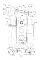
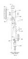
- FIG. 1is a front elevational view of an exemplary breathing apparatus according to the present invention.
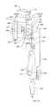
- FIG. 2is a rear elevational view of the breathing apparatus shown in FIG. 1 .
- FIG. 3is an exemplary embodiment of a breathing apparatus according to the present invention adapted to be worn by a user.
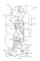
- FIG. 4is a front elevational view of the breathing apparatus shown in FIG. 1 with the housing cover removed.
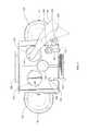
- FIG. 5is a top plan view of the breathing apparatus shown in FIG. 1 .
- FIG. 6is a bottom plan view of the breathing apparatus shown in FIG. 1 .
- FIG. 7is a side elevational view of the breathing apparatus with the tanks removed.
- FIGS. 8-10are side sectional views illustrating the flow of air through the breathing apparatus.
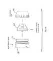
- FIG. 11depicts an exemplary, optional prefilter assembly.
- FIG. 12is an exploded view of the prefilter assembly shown in FIG. 11 .
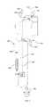
- FIG. 13illustrates an exemplary breathing hose according to a preferred embodiment having a vibrator alarm and purge valve.
- FIG. 14illustrates the purge valve on the mask connector end of the breathing hose shown in FIG. 13 .
- FIG. 15is a schematic functional block diagram of a breathing system according to an exemplary embodiment of the present invention.
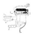
- FIG. 16illustrates the modular nature of the system and some exemplary modules which may be attached in place of one or both of the breathing gas cylinders to expand the functionality of the system.
- FIGS. 17 and 18are assembled and exploded views, respectively, of a one-way check valve for attachment to a port of the user's face mask.
- FIGS. 1-10illustrate a breathing apparatus 110 including a main body or housing section 112 , (also sometimes referred to herein as a chassis), a base manifold section 114 , one or more self-contained air supply tanks 116 , and a breathing hose 118 .
- the hose 118includes a first end 120 which may be attached to an outlet port 122 on the housing 112 .
- a second end 124may be attached to an inlet port 129 of a face mask 126 worn by a user 128 for delivery of breathable air.
- the mask assembly 126may be of a type commonly used in chemical, biological, radiological, or other hazardous environments.
- a plurality of fastenerssuch as connecting pins 133 or other fasteners may be provided on the exterior of the housing 112 to secure the unit 110 to a user wearable garment 131 , such as a ballistic vest, emergency ditch system, or the like (see FIG. 3 ).
- the breathing device 110is switchable between a first, pressurized air mode in which air from the pressurized tanks 116 is delivered to the user 128 via the air hose 118 and a second, filtration mode in which ambient air is filtered via a filtration unit (as described below) and is likewise delivered to the user 128 via the hose 118 .
- the operator 128has the ability to readily select the desired mode of operation, namely, a SCBA mode in which air is delivered from an attached cylinder 116 and powered air-purifying respirator (PAPR) mode of operation in which filtered ambient air is drawn with blower assistance through one or more air filters or purifiers and delivered to the user.
- PAPRpowered air-purifying respirator
- the facile switching between the self-contained air supply 116 and filtered airis particularly advantageous, for example, in the event that the self-contained air supply 116 becomes exhausted or malfunctions, when it is desired to conserve the self-contained air supply, and so forth.
- a user operating on filtered airmay readily switch to the self-contained air supply, for example, in low oxygen conditions or when the ambient air contains dangerous levels of a non-filterable constituent, e.g., as may be detected employing an optional air sampler module, as described in further detail below.
- the main chassis 112defines an internal cavity or compartment 113 , and may be manufactured of plastic, preferably chemically hardened plastic, composite materials, aluminum or other metal and alloys thereof, or the like.
- the main chassis 112provides for mounting of externally mounted components thereon and the internal cavity 113 contains internal components, such as a power supply 218 , a circuit board 214 and associated circuitry, blower 208 , internal filter 222 , and other interior components, for operation of the apparatus 110 .
- the cavity 113also serves as the main breathing reservoir.
- the breathing reservoir 113is in flow communication with the breathing hose 118 .
- the housing 112 and all connectors and access ports thereonare sealed against entry of external environmental contamination, thereby allowing the unit to be employed underwater or in otherwise wet or damp conditions.
- the breathing gas(either gas from tank 116 or purified ambient air) is allowed to fill the chamber 113 and breathing bag 118 to provide additional “next breath” capability and the positive pressure within the breathing chamber 113 , in turn, provides additional resistance against ingress of moisture or other external contaminants.
- the flowis confined to a conduit or more limited passageway within the chassis 112 are also contemplated.
- the circuit board 214may include a microprocessor, microcontroller, or other logic device 217 , which is coupled via an electrical and/or data bus 219 to various system components, whereby various system components and parameters may be monitored and/or controlled (see FIG. 15 ).
- a programming port 221such as a serial or parallel data interface port, may be provided on the chassis 112 for programming, updating, or testing the processing circuitry 217 (including an associated memory thereof) without the need to open the unit.
- a removable housing cover plate or shell 115encloses the internal components within the chassis housing 112 and is provided with an environmental seal or gasket to prevent air leakage out of the chassis and to prevent entry of moisture, debris, or environmental contamination therein.
- a cover plateis fastened to the first shell portion via a plurality of fasteners 117 , such as threaded connectors, spaced about the periphery of the opening.
- breathing gastypically air or oxygen
- the gas storage tanks 116may be of any type suitable for supplying a breathing gas.
- the housing sectionmay be adapted to accommodate tanks 116 of various, interchangeable sizes. For example, it may be desirable to select a tank size commensurate with the scope of an operation or mission, to employ smaller tanks in order to reduce the weight of the system, etc.
- the breathing gaswill be described primarily in reference to compressed air for ease of exposition, it will be recognized that other suitable breathing gasses may be used as well.
- one tankmay contain compressed air while the other tank may contain oxygen.
- the tank containing oxygenwould be designed to prevent oxygen flow into the system, the oxygen being used for an accessory function such as for use with a torch cutting 1117 attachment.
- the tank 116is suitable for high-pressure air/gas storage (e.g., up to about 9,500 PSI, or higher), and may be an aluminum-lined, composite (e.g., carbon fiber composite) wrapped high-pressure storage tank.
- high-pressure air/gas storagee.g., up to about 9,500 PSI, or higher
- aluminum-lined, compositee.g., carbon fiber composite
- a modular systemmay be provided wherein one or more modules for expanding the functionality of the system may be attached to the chassis 112 . Since the apparatus 110 may be operated with one or two tanks 116 , or, in filtered mode, with no tanks 116 , one or more special purpose modules may be provided which are interchangeable with one of the breathing gas cylinders 116 .
- a cutting torch module 1117is contemplated.
- the cutting torch modulemay be of a type employing a burning metal, such as magnesium, a source of oxygen or other oxidizing gas, and a feed line for delivering the oxidizing gas to the surface of the material to be cut.
- the oxidizing gasis contained in a cylinder adapted to replace one of the breathing gas tanks 116 .
- a heating and/or cooling module 119is contemplated, wherein a circulating source of heating and/or cooling fluid, comprising a pump and a cooling source, heating source, or both, are provided in a module, e.g., a generally cylindrical module, adapted to mount in place of one of the breathing gas tanks 116 .
- the heating/cooling moduleis adapted for use in connection with a tube-lined garment through which the fluid is circulated to effect heat exchange with the user's body and, preferably, may be electrically coupled to the power supply of the apparatus 110 .
- a hydration modulemay be provided, including a container adapted to be exchanged with a breathing gas tank 116 for supplying water or other suitable fluid to the user 128 .
- a hydration modulemay be provided, including a container adapted to be exchanged with a breathing gas tank 116 for supplying water or other suitable fluid to the user 128 .
- an alternatively sized cylinder 116 ′may be used in place of the cylinder 116 .
- the base manifold section 114 of the main system body 112provides a platform for mounting the tanks 116 .
- the base portion 114includes a channel or opening 130 .
- the cylinder 116includes a connection assembly 132 having a connection foot 134 adapted to be removably received in the opening 130 .
- the connection footis of complimentary size and shape (e.g., dovetail, tenon, or other geometrical configuration) with respect to the opening 130 .
- a fastener for removably retaining the tank 116 on the base section 114such as a locking pin engaging aligned receiving holes on the base portion 114 and the connection assembly 132 , or the like, may be employed.
- a locking pin 152 passing through a selected receiving hole 154 or 156may be used to secure the cylinder foot 134 within the opening 130 and to prevent inadvertent ejection of the cylinder 116 .
- the manifold connection assembly 132may also include a pressure gauge 148 and a cylinder valve 150 , e.g., a manually operable valve.
- the pressure gauges 148face outward from the operator and may be viewed from the side of the device.
- the cylinder valvesallow the operator to open and close the air flow from the cylinders 116 to an inlet 139 of manifold 140 .
- connection assembly 132may be adapted for either left-side or right-side mounting of the tank 116 .
- a blow-out disk assembly 136may be provided to relieve pressure in the event that cylinder pressure exceeds some prespecified value according to the tank capacity. In the event of excessive pressure, the burst disk will rupture.
- a pressure release cap 137may be provided to retain the disk while pressure is released through the cap.
- the burst assembly 136may include a blowout disk, O-ring and safety cap, providing the main pressure relief for the cylinders 116 . When the disk blows, it opens an air escape path, allowing air to pass through the aerated cap 137 . This prevents accidental damage to equipment and operator. In the depicted preferred embodiment, the burst assembly 136 faces away from the direction of an operator donning the apparatus 110 .
- the connection assembly 132additionally includes a manifold connector 138 for providing an airflow connection to a manifold inlet 139 on the base portion 114 .
- the connector 138is preferably a threaded connector which is removably connected via complimentary threads on the inlet 139 .
- a sealing ring or gaskete.g., formed of a material such as a teflon or other sealing material, is preferably provided to provide a sealing engagement between the connector 138 and the inlet 140 .
- the connectors 138may include holes 141 or other features which provide for engaging a tool or key to provide leverage when rotating the connectors to ensure a tight fit.
- the manifold connection assembly 132additionally includes a fastener for securing the air cylinder 116 to the main body portion 112 .
- the illustrated embodimentincludes a retaining band 142 and one or more retaining nuts 144 , e.g., which may be secured to the main body portion 112 to provide stabilization of the air cylinders on the main chassis.
- a screw-tight fastener 146is provided for tightening of the band 142 .
- a retractable stand 158may also be provided.
- the retractable stand 158pivots about a pivot pin 160 .
- the stand 158rotates between a first, retracted position (see FIG. 1 ) and a second, extended position ( FIG. 6 ) for standing the unit 110 upright, e.g., for service or maintenance.
- a notch 162is provided in the base portion 114 for receiving the stand 158 when fully retracted.
- the standis removably retained in the notch 162 by a captured spring 164 .
- a handle or strap 166is provided on an upper portion of the housing section 112 for carrying the unit 110 when it is not being worn.
- a hardened plastic storage casewhich may include a foam lining, may be provided for storage of the unit 110 and its components when not in use.
- a port valvefor selectively receiving pressurized air or filtered ambient air.
- the port valveis controlled by a snorkel assembly 168 including a snorkel cap 170 , an ambient air inlet 172 , an optional prefilter 174 , and a snorkel tube 176 .
- the snorkel cap 170is movable between a first, closed position (see FIG. 9 ) wherein the inlet 172 is closed to ambient air 178 , and a second, open position (see FIG. 10 ) wherein the inlet may receive ambient air.
- the prefilter assembly 174includes a filter cap 182 and a filter housing 188 , which houses a pre-filter filtration medium 186 .
- the pre-filter medium 186may be, for example, a polymeric material, such as polypropylene, polytetrafluoroethylene, or the like, and may be formed of a mesh material.
- the pre-filter material 186is formed of a monofilament polypropylene mesh material.
- the prefilter 174filters particles which are 10 microns in size or larger.
- the filter cap 182 and filter housing 188include perforations 184 and 190 , respectively, for passage of ambient air therethrough.
- the optional prefilteradvantageously provides filtering of ambient air prior to entry into the system, preventing dust buildup in the filter compartment chamber.
- the filtermay be housed within a hardened housing 182 that has openings 184 formed therein and a connector, such as a threaded connector 189 .
- This hardened coverprotects the snorkel assembly from entanglement and other damage.
- a source of gasmay be provided to unclog or remove dust and debris from the externally facing surface of the prefilter and/or main filter. That is, air or other gas may be passed air from an internal source outwardly therethrough, in the direction opposite to the air flow in normal, breathing operation.
- the source of gasmay be, for example, the air contained in the breathing tanks 116 , e.g., delivered from the first stage gas pressure regulator 244 , via the connector 238 , and so forth.
- the source of the gas used for cleaning the filtermay be a specially provided source, such as a carbon dioxide tank or cartridge.
- a valve and actuating meanssuch as a manual valve actuator may be provided to allow the filter cleaning gas to be forced outwardly through the filter in quick bursts.
- a burst of airmay be forced outwardly through the prefilter each time the snorkel is raised prior to use. The burst of air may be actuated, for example, via a switch or other snorkel position indicator 175 (see FIG.
- the switchmay be, for example, an electrical switch or position indicator providing a signal for actuating or controlling an electrically operated air valve, a mechanical air valve actuator, and so forth.
- the burst of airmay be actuated under preprogrammed control whenever the snorkel is moved from closed to open position.
- the housing 182is adapted to accommodate an additional, external filter 181 .
- the filtercomprises a mesh or woven filtration medium which covers the cap 182 and perforations 184 and is secured at the base 183 with an annular fastener 185 such as a tie, band or the like.
- an annular fastener 185such as a tie, band or the like.
- a groove 187is provided to prevent the flow of air around the external filter 181 and to prevent dislodging of the annular fastener 185 .
- the external snorkel filter 181is formed of a woven nylon material of a type used for nylon hosiery. The external filter 181 is readily cleaned or replaced and prolongs the life of the inner filtration medium 186 .
- the snorkel assemblymay be moved between the open and closed positions by manually lifting or depressing the snorkel cap 170 , respectively.
- a control module 192may be provided for switching between pressurized tank air and filtered air.
- the control moduleincludes a housing 194 , a button or key 196 for toggling between the filtered and self-contained air sources, a visual indication or display 198 indicating the air source currently selected and a display 200 , such as a liquid crystal display (LCD), light emitting diode (LED) display, or the like, indicating the system pressure or pressure remaining in the tank 116 .
- the control module 192may also control and/or display blower motor speed, cylinder pressures, battery life, friend/foe identification system, or the like. It may also contain a backlight for the display 200 .
- control module 192may also be employed.
- a single display combining the pressure display 200 and the source selection indicia 198may be used.
- An electrical cable 202electrically couples the module 192 to the electrical system of the apparatus 110 , e.g., via an electrical connector 204 which may be connected to a mating electrical connector 206 on the housing 112 .
- the connectors 204 and 206may include mating threaded connector housing members.
- the button 196also serves to activate an internal suction source 208 , such as a fan or blower (the terms “fan” and “blower” will be used interchangeably herein unless specifically stated otherwise) via the electrical cable 202 when filtered ambient air is selected as the air source.
- programming or control circuitry in the apparatus 110may be provided to automatically switch from pressurized mode to filtered mode when the remaining air supply in the tank 116 is exhausted or substantially exhausted, or the tank pressure or system pressure otherwise falls below preselected value.
- the main housing portion 112further includes a battery compartment 210 containing a power supply 218 , such as one or more batteries or battery packs for providing power to the electrical components of the apparatus 110 .
- the power supply 218may also electrically coupled to provide power to one or more electrically operated, externally mounted modules which may be provided to expand the functionality of the apparatus 110 .
- a removable cover 212is provided on an exterior surface of the housing portion 112 , and is preferably sealed against moisture and other external contaminants, e.g., via an O-ring or other sealing ring or gasket.
- a power selection switch 216is provided on the battery compartment cover 212 for turning the device 110 on and off. When turned on, the power system powers the blower, control module, and any other electrical components, such as a pressure sensing and alert system (as described in greater detail below), or other optional chassis-mounted components.
- the compartment 210accommodates eight 3-volt batteries, such as lithium ion batteries, in which four chambers each accommodating two batteries in series configuration and the four chambers being electrically connected in parallel.
- the compartmentthus accommodates up to four sets of two batteries to provide a 6-volt output.
- the unitmay be operated on fewer than eight batteries for noncritical applications, such as training, testing, or servicing of the apparatus, whereas a full complement of eight batteries is recommended for a full mission.
- other battery and battery compartment configurationsincluding removable and/or rechargeable batteries or battery packs, and the like can be used.
- an external electrical connectormay also be provided for recharging the internal batteries when a rechargeable power source is used.
- a main filter compartment 220 in the chassis 112houses a main filter 222 , such as a radiological, biological, or chemical filter.
- the filter 222includes an inlet 224 for receiving ambient air 178 , which may be prefiltered in the case wherein an optional prefilter is employed.
- the filter 222further includes an outlet 226 for filtered air.
- the filter 222is preferably secured within the compartment 220 via a connector 228 .
- the connector 228is a threaded connector, most preferably a standard NATO 55-millimeter male threaded connector which removably rotatably engages a complimentary female threaded connector in the compartment 220 .
- An O-ring or other sealing ring or gasket 229is provided in the base of the threaded connector to prevent flow around the filter canister 222 .
- a filter compartment cover 230seals against air leakage and against the entry of moisture or other contaminants.
- the filter covermay be formed of aluminum and include threads which rotatably and removably engage complimentary threads formed in the filter compartment 220 .
- An O-ring 231 or other sealing ring, gasket, or the like,may be provided to provide an environmental seal.
- an extension ring or sleevemay be provided between the compartment 220 and the cover 230 to extend the compartment and accommodate additional filter sizes. Because the filter compartment 220 is not exposed to air when the snorkel is down, the apparatus 110 allows for extended storage of the filter 222 without degradation due to exposure to air. In this manner, the filter may be installed in advance of use, thereby improving response time as compared to a conventional PAPR unit in which the filters must remain in a separate sealed container or packaging and installed just prior to use. Likewise, the apparatus 110 may be used in SCBA mode in rain or other wet conditions, including under water, without affecting the filter.
- An intermediate-pressure “buddy” connector 238may be provided on an exterior surface of the chassis 112 and is preferably of a quick connect/disconnect type as generally know in the art.
- the connector 238is in flow communication with the first stage regulator 244 via conduit 243 and provides an external (e.g., about 80 psi) connection for attaching various second stage regulators. In this manner, use of the air supply of the breathing system 110 may be shared by attaching an external breathing device or mask incorporating a second stage regulator.
- the intermediate pressure connection port 238may be used to operate pneumatically operated tools and devices.
- a connection cap 239may be provided to prevent moisture and debris from contaminating the connection 238 .
- a high-pressure charging valve 240may be provided on an exterior surface of the chassis 112 for connection with an external charging device for charging the tanks 116 with air/breathing gas.
- the valve 240is in flow communication with the manifold 140 via conduit 245 .
- a protective cap 241may be provided to prevent moisture and debris from contaminating the connector 240 .
- the connector 240is preferably of a quick connect/disconnect type as generally known in the art.
- the high pressure port 240may also be used to couple the apparatus 110 to an external source of breathing gas.
- the external sourcemay be, for example, an additional tank or may be a stationary source of breathing gas, e.g., a compressor or a pressurized vessel, in which case the user is tethered to the stationary breathing gas supply by a line connecting the connector port 240 and an outlet of the source.
- a stationary source of breathing gase.g., a compressor or a pressurized vessel
- one or both of the cylinder valves 150may be opened and the connector 240 connected to a source of breathing gas and charged to a desired pressure. The cylinder valves 150 may then be closed and the charging source disconnected from the connector 240 .
- the chassis 112additionally includes at least one connection port ( 122 , 123 ) for connection to the breathing hose 118 .
- connection port122 , 123
- left-side and right-side connection ports 122 and 123are provided to accommodate both left-handed and right-handed operation.
- the left port 122provides a left-side connection for the breathing hose 118 , thereby keeping the right side free for a right-handed marksman.
- the right port 123provides a right-side connection for the breathing hose 118 , thereby keeping the left side free for a left-handed marksman.
- the breathing hose 118is attached to a selected one of the ports 122 and 123 via the hose connecting end 120 .
- a blanking plug or cap 242seals the other one of the ports 122 and 123 to prevent contaminant entry via the unused port.
- the connection between the ports ( 122 , 123 ) and the hose connector end 120 or the plug 242are preferably of a quick connect/disconnect type and preferably incorporates an O-ring or other sealing ring or gasket to seal against entry of moisture or other external contaminants.
- the portreadily accepts the quick-connect end of the breathing hose, and contains a quick-connect electrical appliance for powering the vibrator unit within the mask adaptor and a gas line for coupling to the purge valve line 266 (see FIG. 13 ) in breathing hose 118 .
- the snorkelIn the pressurized mode of operation, the snorkel is in the down or closed position and one or both of the valves 150 are opened. Air exits the cylinders 116 via the respective open valve 150 and passes the pressure gauge 148 and pressure relief assembly and enters the main manifold 140 of the housing 112 .
- the first stage regulator 244may be of a type, for example, including a diaphragm which is acted upon by fluid pressure to reduce the pressure of the air passing through the regulator.
- the pressureis reduced to a first reduced pressure level, which is preferably about 80-100 psi.
- the first stage regulator 244may also include a relief valve for pressure relief for the regulator when the pressure of the gas exiting the first stage regulator exceeds some pre-selected or pre-determined value, e.g., about 100-120 psi.
- the relief valvemay be, for example, of a spring-loaded type which relieves pressure at a first threshold value and returns at a second threshold level.
- the relief valvemay relieve at a pressure of about 100-120 psi and return at a pressure of about 90-110 psi.
- the regulated pressure junction 246may also divert gas at about 80 PSI to additional locations within the breathing apparatus 110 for various pressure actuated services as described herein, such as an optional purge valve, a gas driven piston for selecting between the self-contained and filtered modes of operation, air for prefilter cleaning.
- the second stage regulator 248reduces the air pressure to a level suitable for safe breathing (e.g., about 1-5 psi). Air passing through the second stage regulator 248 is then delivered to the operator via the compartment 113 and the hose 118 to the interior of the mask assembly 126 .
- airpasses from the second stage regulator 248 through a conduit 250 to an internal orifice 252 then into the chassis 112 , the inside of which is a compartment defining an internal breathing air reservoir or chamber 113 .
- An outlet valve 127 on the mask 126includes a one-way check valve placed over the existing breathing exhaust port on the face mask through which gas in the mask 126 may exit in the event the pressure in the mask is above some threshold level.
- the pressure of the gas in the maskeither from the suction source 208 or from the second stage gas pressure regulator 248 , is greater than the ambient, atmospheric pressure, thereby resisting entry of external air, even in the event that the seal between the user's face and the mask is momentarily broken, e.g., due to user movement. This positive pressure in the mask also assists in preventing fogging of the interior of the mask.
- the outlet valve 127is shown in FIGS. 17 and 18 .
- the deviceis placed over the existing breathing exhaust port on a protective mask. It may be fastened in place via an adapter housing 133 with adhesive and a mechanical hook system 135 which mates with the adapter port on the mask.
- the deviceincludes a spring-loaded outlet valve 143 regulates exhaust air flow by use of a calibrated spring that provides compression on the purge valve.
- the purge valveis retained via an annular retaining cap 145 .
- the valve 143may be made of various materials including polymers and may be coated with HSF, PTFE, or the like.
- the outlet valve 127maintains regulated positive pressure in the mask thus eliminating the free flow of air, or other breathable gas, from the mask's standard exhaust port.
- the outlet valve 127is also designed so that it releases gas from inside the mask before the pressure inside the mask is raised to the point where gas is exhausted between the mask's sealing surfaces and the wearer's skin. Breaking the seal between the mask's sealing surface and the wearer is not a desired occurrence because of the probability of introducing a contaminant into the mask thus incapacitating the wearer. In the event that the mask seal is inadvertently breached the positive pressure created by the mask adapter 127 eliminates the possibility of a contaminant entering the mask.
- the second stage regulator 248includes a diaphragm responsive to pressure differentials to provide demand breathing gas to a user in communication with the regulator 248 .
- Air in the chassis 113is held in place until demand is placed on the system, i.e., when the operator inhales. Air then passes through the outlet ( 122 , 123 ) of the internal chamber 113 through the hose 118 connecting the main system body to the mask.
- the exterior facing surface of the diaphragmmay be coated or treated to protect against corrosion or degradation when exposed to chemical or biological agents.
- a protective polymer layeris bonded to or deposited on the outward surface of the diaphragm.
- the polymer layeris preferably a polymer having a high degree of chemical resistance such as a fluorine-containing polymer and, more preferably, polytetrafluoroethylene (PTFE).
- the polymer layermay be applied in the form of a sheet or film bonded to the diaphragm or in the form of a solution or dispersion, e.g., liquid, paste, cream, gel, or similar formulation, containing monomers and/or polymer precursors, which are subsequently cured in place to form the protective layer.
- a removable cover or port 249secured by a retaining ring or clamp 247 may be provided to allow access to or servicing of the second stage regulator diaphragm.
- the entire assembled unitmay be coated with a solution or dispersion of monomers and/or polymer precursors and cured to protective polymer film, preferably of PTFE, over the entire unit prior to use.
- the breathing hose 118may be employed as any known type of breathing hose.
- an inhalation hose assembly providing next breath capabilityis provided.
- the illustrated inhalation hose assembly 118includes an inner perforated hose 254 having perforations 258 along its length, which is contained within a flexible outer bag 260 .
- the outer baginflates to provide a ready volume of air, e.g., up to two liters of air, providing the operator with a “next breath” capability.
- the additional volume of air contained in the bag 260is especially advantageous in that it eliminates the need for employing multiple filters and blowers in that sufficient volume of breathing gas is delivered to the user, even under high exertion.
- the “next breath” capabilityalso provides positive pressure (e.g., about 5 psi) in the user mask 126 .
- the inner hose 254also provided a structural strengthening between the ends of the hose 118 and serves to house the electrical cable 270 and purge line 266 .
- the bag 260may be formed of a woven polymeric material, such as a high strength fluoropolymer (HSF), polytetrafluoroethylene (e.g., Teflon), etc.
- HSFhigh strength fluoropolymer
- Teflonpolytetrafluoroethylene
- an inner lining 262may also be disposed between the perforated hose and the outer bag.
- the inner lining or bag 262may be formed of a natural or synthetic polymer material, such as butyl rubber or the like.
- the optional inner lining 262functions as a bladder and provides an extra level of protection against external contaminant entry into the air stream, e.g., in the event the outer bag 260 is cut or abraded.
- a fire-retardant layer or coatingmay also be provided or applied to the bag 260 .
- the inhalation hose assembly 118is connected to the chassis portion 112 via the connector 120 and to the user mask 126 via a connector at 124 at the proximal end of the hose 118 .
- the connectors 120 and 124which may be the same or different, may be, for example, threaded connectors, quick-connect type connectors (e.g., having one or more resilient protrusions engaging a depression), and the like. Also, one or more sealing rings or gaskets (not shown) may be provided to prevent moisture and other contaminant entry into the system. As described above, the preferred depicted embodiment accommodates connection of the hose 118 on either side of the chassis 112 , according to the user's preference. In another preferred aspect, the connectors 120 and/or 124 may be adapted to swivel or rotate to accommodate user movement, to switch between right and left-handed operation.
- the hose assembly 118includes an optional purge valve 264 that provides the operator with an additional burst of regulated air from the first stage regulator 244 (e.g., about 80-100 psi) when needed.
- the purge valve assembly 264can include a manually controlled actuator and connection hose 266 that is in fluid communication with the first stage regulator 244 in the main body portion 112 for introducing additional air into the user mask.
- the connection hose 266preferably passes through an interior portion of the hose assembly 118 and, more preferably, through an interior portion of the perforated inner hose 254 .
- the hose 266extends through the end 120 of the hose 118 , allowing connection to a mating connector within the selected connection port 122 or 123 .
- Gasis delivered from the first stage regulator 244 via the regulated pressure junction 246 .
- Another optional feature of the systemis to provide a user perceptible alert when the air pressure drops below a pre-selected pressure level (e.g., below 500 PSI).
- a pre-selected pressure levele.g., below 500 PSI
- Such alertmay be a visual or audible alarm or, more preferably, a vibrating mechanism that alerts the user without drawing attention to the user.
- the pressure detectedis system or manifold pressure, although employing tank pressure is also contemplated.
- an electronic pressure gauge or electronic transducer 149may be housed within the manifold 140 .
- the vibrator 268 or other alarm mechanismmay be mounted within the inhalation hose assembly 118 , preferably in or near the mask connection end 124 .
- the vibrator 268may be electrically coupled to the main power source within the main body portion 112 , e.g., by means of an electrical connection 270 passing through the inhalation hose assembly 118 and, preferably, within the perforated hose 254 .
- the electrical coupling 270may include a connector 272 which mates with a corresponding connector allowing connection to a mating connector within the selected connection port 122 or 123 .
- a dedicated power supplysuch as a battery or battery pack, for the vibrator or other alarm 268 is also contemplated.
- the vibrational unit 268may employ any of a number of generally known vibrational elements for producing mechanical vibrations.
- the vibrational elementmay employ an electric motor wherein a pivotally mounted weight is mounted at the end of the shaft thereof.
- other vibrational elementsmay be utilized to produce mechanical vibrations, such as a piezoelectric substance (e.g., quartz, Rochelle salts, or various artificial materials). The application of an electrical signal to the piezoelectric material induces the material to mechanically vibrate.
- the electrical supply 270 passing through the hose 118may also be employed to power one or more additional devices in the mask.
- the power supply cable 270may be employed to provide power to a display device, such as a head up display, indicator lights, a communication system, and so forth, which may be mounted or integrated with the user mask.
- the snorkel assembly 168is moved to the open position, e.g., either electronically or manually, as described above.
- an electronically actuated solenoid valve 274releases pressurized air from the first stage regulator 244 to close the orifice 252 in the snorkel.
- the snorkel assemblyis urged to the open position via a mechanical linkage 281 between a cylinder/piston assembly 280 and the snorkel assembly 168 to open a filtered air valve inlet 276 .
- pressurized air from the first stage regulator 244is in fluid communication with the gas-driven piston/cylinder assembly 280 , which controls the movement of the snorkel using the 80 PSI air that comes from the regulated pressure junction 246 .
- An electronic sensorcontrols the flow of gas to the piston/cylinder assembly 280 when the operator presses the button 196 on the remote control unit 192 .
- the piston/cylinder assembly 280is fluidically coupled to the regulated pressure junction 246 via a conduit 282 when the solenoid valve 274 is opened. The piston assembly 280 is thereby extended and retracted to move the snorkel assembly to the open and closed positions, respectively, by the release of air from the first stage regulator 244 .
- a removable cover 279may be provided to allow access to the piston assembly 280 without the need to remove the entire cover 115 .
- a snorkel position sensor 175such as a switch, position indicator, or the like, may be provided to provide an indication of snorkel position and/or for actuating a prefilter cleaning function as described above.
- the unit 110may be operated with one or both cylinders 116 removed from the main body 112 .
- Cylinder manifold plugsmay be secured over the manifold inlets to seal the manifold intake connections to prevent contaminant entry when the cylinders are not in use.
- the snorkel assembly 170may be manually moved to the open position in order to activate the suction source 208 and allow air to flow through the filter mechanism.
- a dedicated source of gas for operation of the piston assembly 280such as a carbon dioxide tank or cartridge or the like be provided for operating the piston assembly 280 .
- ambient air 178e.g., possibly contaminated air
- the suction source 208draws in by the suction source 208 through the through the inlet 172 , optional prefilter 180 , and main filter 222 as described above.
- Airpasses through the filter and into the breathing reservoir 113 of the chassis housing 112 . From there, the air flows into the user mask 126 , e.g. via the inhalation hose assembly 118 , as previously described.
- a connector 193is provided for electrically coupling an optional air sensor module 195 (see FIG. 15 ) which samples and monitors the ambient air for harmful constituents which are unfilterable by the main filter 222 .
- an optional air sensor module 195see FIG. 15
- the snorkelis moved to the closed position and switched to the self-contained mode of operation under preprogrammed control.
- An audible, visual, or tactual warning signalmay also be provided to the user.
Landscapes
- Health & Medical Sciences (AREA)
- Pulmonology (AREA)
- General Health & Medical Sciences (AREA)
- Business, Economics & Management (AREA)
- Emergency Management (AREA)
- Life Sciences & Earth Sciences (AREA)
- Zoology (AREA)
- Emergency Medicine (AREA)
- Respiratory Apparatuses And Protective Means (AREA)
Abstract
Description
Claims (14)
Priority Applications (1)
| Application Number | Priority Date | Filing Date | Title |
|---|---|---|---|
| US14/600,719US10130831B2 (en) | 2003-08-22 | 2015-01-20 | Self-contained breathing system |
Applications Claiming Priority (6)
| Application Number | Priority Date | Filing Date | Title |
|---|---|---|---|
| US49720603P | 2003-08-22 | 2003-08-22 | |
| US49721503P | 2003-08-23 | 2003-08-23 | |
| US10/924,281US7647927B2 (en) | 2003-08-22 | 2004-08-23 | Self-contained breathing system |
| US12/688,676US8113198B2 (en) | 2003-08-22 | 2010-01-15 | Self-contained breathing system |
| US13/371,744US8950401B2 (en) | 2003-08-22 | 2012-02-13 | Self-contained breathing system |
| US14/600,719US10130831B2 (en) | 2003-08-22 | 2015-01-20 | Self-contained breathing system |
Related Parent Applications (1)
| Application Number | Title | Priority Date | Filing Date |
|---|---|---|---|
| US13/371,744ContinuationUS8950401B2 (en) | 2003-08-22 | 2012-02-13 | Self-contained breathing system |
Publications (2)
| Publication Number | Publication Date |
|---|---|
| US20150128937A1 US20150128937A1 (en) | 2015-05-14 |
| US10130831B2true US10130831B2 (en) | 2018-11-20 |
Family
ID=38573827
Family Applications (4)
| Application Number | Title | Priority Date | Filing Date |
|---|---|---|---|
| US10/924,281Active2026-11-20US7647927B2 (en) | 2003-08-22 | 2004-08-23 | Self-contained breathing system |
| US12/688,676Expired - LifetimeUS8113198B2 (en) | 2003-08-22 | 2010-01-15 | Self-contained breathing system |
| US13/371,744Expired - LifetimeUS8950401B2 (en) | 2003-08-22 | 2012-02-13 | Self-contained breathing system |
| US14/600,719Active2026-10-25US10130831B2 (en) | 2003-08-22 | 2015-01-20 | Self-contained breathing system |
Family Applications Before (3)
| Application Number | Title | Priority Date | Filing Date |
|---|---|---|---|
| US10/924,281Active2026-11-20US7647927B2 (en) | 2003-08-22 | 2004-08-23 | Self-contained breathing system |
| US12/688,676Expired - LifetimeUS8113198B2 (en) | 2003-08-22 | 2010-01-15 | Self-contained breathing system |
| US13/371,744Expired - LifetimeUS8950401B2 (en) | 2003-08-22 | 2012-02-13 | Self-contained breathing system |
Country Status (1)
| Country | Link |
|---|---|
| US (4) | US7647927B2 (en) |
Cited By (4)
| Publication number | Priority date | Publication date | Assignee | Title |
|---|---|---|---|---|
| WO2022079561A1 (en)* | 2020-10-12 | 2022-04-21 | 3M Innovative Properties Company | Scba assembly with integrated apr capability |
| RU212172U1 (en)* | 2021-05-31 | 2022-07-11 | Общество с ограниченной ответственностью "Смоленский завод пластиковых изделий" | AIR VALVE |
| US11992585B2 (en) | 2020-03-13 | 2024-05-28 | Julian HENLEY | Electro-ionic devices for improved protection from airborne biopathogens |
| US12017232B2 (en) | 2020-03-13 | 2024-06-25 | Julian HENLEY | Electro-ionic mask devices for improved protection from airborne biopathogens |
Families Citing this family (80)
| Publication number | Priority date | Publication date | Assignee | Title |
|---|---|---|---|---|
| US7527053B2 (en) | 2003-08-04 | 2009-05-05 | Cardinal Health 203, Inc. | Method and apparatus for attenuating compressor noise |
| US7607437B2 (en) | 2003-08-04 | 2009-10-27 | Cardinal Health 203, Inc. | Compressor control system and method for a portable ventilator |
| US8118024B2 (en) | 2003-08-04 | 2012-02-21 | Carefusion 203, Inc. | Mechanical ventilation system utilizing bias valve |
| US8156937B2 (en) | 2003-08-04 | 2012-04-17 | Carefusion 203, Inc. | Portable ventilator system |
| ES2592262T3 (en) | 2003-08-04 | 2016-11-29 | Carefusion 203, Inc. | Portable respirator system |
| US7647927B2 (en)* | 2003-08-22 | 2010-01-19 | Wilcox Industries Corp. | Self-contained breathing system |
| ES2392173T3 (en)* | 2005-09-09 | 2012-12-05 | Dexwet Usa Llc | Filtering module |
| US20070240719A1 (en)* | 2006-04-18 | 2007-10-18 | Raul Duarte | Portable air-purifying system |
| US20080044299A1 (en)* | 2006-08-18 | 2008-02-21 | Liquid Load Logistics, Llc | Apparatus, system and method for loading and offlloading a bulk fluid tanker |
| US8006877B2 (en)* | 2007-04-18 | 2011-08-30 | Sperian Respiratory Protection Usa, Llc | Backpack for self contained breathing apparatus |
| DK2207715T3 (en)* | 2007-10-29 | 2014-05-19 | Poseidon Diving Systems | Mouthpiece for an oxygen device |
| EP2205323B1 (en)* | 2007-10-29 | 2018-07-25 | Poseidon Diving Systems | Auto calibration / validation of oxygen sensor in breathing apparatus |
| US7997885B2 (en) | 2007-12-03 | 2011-08-16 | Carefusion 303, Inc. | Roots-type blower reduced acoustic signature method and apparatus |
| US9776022B2 (en)* | 2008-03-13 | 2017-10-03 | Honeywell International Inc. | Protective garment usable with gas tank releasibly carried by shoulder straps and waist belt |
| US8888711B2 (en) | 2008-04-08 | 2014-11-18 | Carefusion 203, Inc. | Flow sensor |
| US8061199B2 (en)* | 2008-06-19 | 2011-11-22 | Ametek, Inc. | Measurement systems having seals with pressure relief |
| US8371295B2 (en)* | 2008-07-23 | 2013-02-12 | Rescue Air Systems, Inc. | Breathable air safety system for both emergency and civilian personnel |
| US9032952B2 (en)* | 2008-08-15 | 2015-05-19 | Honeywell International Inc. | Apparatus having cross conditioned breathing air |
| US8251064B2 (en)* | 2010-02-17 | 2012-08-28 | Sanders Stan A | Articulated firefighter breathing pack |
| US9428237B2 (en) | 2010-09-01 | 2016-08-30 | Peer Toftner | Motorcycle with adjustable geometry |
| EP2629875B1 (en)* | 2010-10-19 | 2022-11-30 | Total Safety U.S., Inc. | Breathing air production and filtration system |
| GB2489052A (en)* | 2011-03-18 | 2012-09-19 | Draeger Safety Uk Ltd | Breathing apparatus with cylinders and housings |
| GB2489051A (en)* | 2011-03-18 | 2012-09-19 | Draeger Safety Uk Ltd | Breathing apparatus with two or more gas cylinders |
| GB201106479D0 (en)* | 2011-04-18 | 2011-06-01 | Draeger Safety Uk Ltd | Diaphragm |
| US9004068B2 (en)* | 2011-05-25 | 2015-04-14 | Scott Technologies, Inc. | High pressure air cylinders for use with self-contained breathing apparatus |
| US20130025904A1 (en)* | 2011-07-28 | 2013-01-31 | King Abdullah University Of Science And Technology | Pressurized waterproof case electronic device |
| US9192795B2 (en) | 2011-10-07 | 2015-11-24 | Honeywell International Inc. | System and method of calibration in a powered air purifying respirator |
| US9724484B2 (en)* | 2012-01-05 | 2017-08-08 | Draeger Medical Systems, Inc. | Breathing apparatus and method of use |
| US9808656B2 (en) | 2012-01-09 | 2017-11-07 | Honeywell International Inc. | System and method of oxygen deficiency warning in a powered air purifying respirator |
| US10155275B2 (en) | 2012-02-29 | 2018-12-18 | Special Projects Operations, Inc. | Silent entry torching and oxygen delivery system and configuration |
| WO2013130750A2 (en) | 2012-02-29 | 2013-09-06 | The Osen-Hunter Group, LLC | Silent entry torching and oxygen delivery system and configuration |
| US9446468B2 (en) | 2012-02-29 | 2016-09-20 | The Osen-Hunter Group, LLC | Silent entry torching and oxygen delivery system and configuration |
| US10561863B1 (en)* | 2012-04-06 | 2020-02-18 | Orbital Research Inc. | Biometric and environmental monitoring and control system |
| US8900338B2 (en) | 2012-08-07 | 2014-12-02 | Honeywell International Inc. | Accessory cap for a respiratory filter cartridge |
| US9044625B2 (en)* | 2012-10-29 | 2015-06-02 | Honeywell International Inc. | Piezo driver having low current quiesent operation for use in a personal alert safety system of a self-contained breathing apparatus |
| US9795756B2 (en) | 2012-12-04 | 2017-10-24 | Mallinckrodt Hospital Products IP Limited | Cannula for minimizing dilution of dosing during nitric oxide delivery |
| SMT201700286T1 (en) | 2012-12-04 | 2017-07-18 | Ino Therapeutics Llc | Cannula for minimizing dilution of dosing during nitric oxide delivery |
| US20140166001A1 (en)* | 2012-12-13 | 2014-06-19 | Lincoln Global, Inc. | Powered air-purifying respirator helmet with photovoltaic power source |
| WO2014127138A1 (en) | 2013-02-13 | 2014-08-21 | Johnson Outdoors Inc. | Modular dive computer |
| WO2014132057A2 (en)* | 2013-03-01 | 2014-09-04 | Draeger Safety Uk Limited | Valve assembly |
| US9033616B2 (en)* | 2013-07-13 | 2015-05-19 | Sean Allen Krumhauer | Personal flotation device for a self contained breathing apparatus |
| EP3038716B1 (en)* | 2013-08-27 | 2018-11-14 | Honeywell International Inc. | Fresh air port mechanism for facepiece used on self-contained open-circuit compressed air breathing apparatus |
| US10010956B2 (en)* | 2014-01-07 | 2018-07-03 | Paul A. SOLLIDAY | Firefighter's appliance |
| US9674676B2 (en)* | 2014-01-30 | 2017-06-06 | Wilcox Industries Corp. | Push to talk system with wireless interface |
| US20150283409A1 (en)* | 2014-04-02 | 2015-10-08 | C&B Technology LLC | Oxygen Augmented Powered Air Purifying Respirator |
| US8765050B1 (en)* | 2014-04-11 | 2014-07-01 | Fluid injector Associates | Fluid injector to metal enclosure |
| CN104225746B (en)* | 2014-10-21 | 2016-09-14 | 刘晨熠 | Replacing oxygen bag device automatically based on leaf spring pressure |
| DE102014015909B4 (en)* | 2014-10-29 | 2020-01-02 | Dräger Safety AG & Co. KGaA | Maintenance device and method for servicing a circulatory breathing apparatus |
| US10100871B2 (en) | 2014-10-30 | 2018-10-16 | Knightvision, Lllp | Bridge mount device and system |
| CN107427701A (en)* | 2014-12-05 | 2017-12-01 | 杰弗里·L·戴克斯 | Direction indicators for protective masks |
| EP4186548A1 (en) | 2015-04-02 | 2023-05-31 | Hill-Rom Services PTE. LTD. | Mask leakage detection for a respiratory device |
| US9958667B2 (en) | 2015-06-17 | 2018-05-01 | Robert J. McCreight, Jr. | Apparatus, system, and method for a mounting shoe with locking projection |
| EP3328506B1 (en)* | 2015-09-09 | 2020-08-05 | Avon Protection Systems, Inc. | Cbrn breathing apparatus |
| US10307622B2 (en)* | 2016-04-14 | 2019-06-04 | Special Projects Operations, Inc. | High-pressure passthrough for protective suit |
| US20180021605A1 (en)* | 2016-07-25 | 2018-01-25 | Mark A. Bartkoski | Coal miner personal air filtration system specially adapted for low ceiling mines |
| US10512798B2 (en) | 2016-08-05 | 2019-12-24 | Illinois Tool Works Inc. | Method and apparatus for providing air flow |
| DE102016216117A1 (en)* | 2016-08-26 | 2018-03-01 | Contitech Elastomer-Beschichtungen Gmbh | Protective suit arrangement, protective suit unit and respiratory protection unit |
| US20210048131A1 (en)* | 2017-09-27 | 2021-02-18 | Avon Protection Systems, Inc. | Integrated manifold system |
| CA3076001A1 (en)* | 2017-09-27 | 2019-04-04 | Special Projects Operations, Inc. | Integrated manifold system |
| AU2018369755B2 (en)* | 2017-11-15 | 2025-04-24 | Immediate Response Technologies, Llc | Modular powered air purifying respirator system |
| EP3501610B1 (en)* | 2017-12-19 | 2024-02-07 | Dräger Safety AG & Co. KGaA | Housing of a closed circuit breathing apparatus |
| WO2020013907A1 (en)* | 2018-07-13 | 2020-01-16 | Aok Tooling Ltd. | Super mask respirator system having a face mask and a sub-peak inspiratory flow blower |
| CN109395220A (en)* | 2018-11-28 | 2019-03-01 | 赵金花 | A kind of internal medicine clinic breathing sterilised filtration device |
| CA3123027A1 (en)* | 2018-12-17 | 2020-06-25 | The Trustees Of The University Of Pennsylvania | Improvements on ambulatory respiratory assist device |
| JP7243284B2 (en)* | 2019-02-25 | 2023-03-22 | 株式会社ジェイテクト | Pressure reducing valve |
| CN109847224A (en)* | 2019-04-03 | 2019-06-07 | 贵州大学 | An easy-to-wear anti-smoke high-rise escape device |
| US12239861B2 (en) | 2019-07-26 | 2025-03-04 | 3M Innovative Properties Company | Low pressure alarm for self-contained breathing apparatus |
| CA3147252A1 (en)* | 2019-08-20 | 2021-02-25 | Greg A. Tilley | Modular, integrated powered air purifying respirator system |
| DE102019123813B3 (en)* | 2019-09-05 | 2021-01-14 | Msa Europe Gmbh | Filling element for filling a space between at least one compressed gas cylinder of a breathing apparatus and a support plate |
| US20210178311A1 (en)* | 2019-12-12 | 2021-06-17 | Techtronic Cordless Gp | Air purifier |
| CN211448677U (en)* | 2019-12-27 | 2020-09-08 | 李恒 | Safety device for coal mining |
| WO2021156876A1 (en) | 2020-02-09 | 2021-08-12 | Pureorr Ltd. | Device, system and method for treating air during breathing |
| CN113713283B (en)* | 2020-05-26 | 2022-08-19 | 贵州东方思创应急装备科技有限公司 | Mine self-rescuer and use method thereof |
| CN112138294A (en)* | 2020-10-22 | 2020-12-29 | 轩维技术(北京)有限公司 | Air respirator |
| US20230081989A1 (en)* | 2021-09-13 | 2023-03-16 | Avox Systems Inc. | Oxygen control system with improved pressure regulator |
| US20230087418A1 (en)* | 2021-09-21 | 2023-03-23 | Philip Andrew Topa | Entanglement prevention harness for breathing apparatus |
| GB2614883A (en)* | 2022-01-19 | 2023-07-26 | Draeger Safety Ag & Co Kgaa | Modular support system |
| WO2023164751A1 (en)* | 2022-03-04 | 2023-09-07 | Towers Group Pty Ltd | Apparatus, system and method for resuscitation in hazardous environments |
| US11839780B1 (en)* | 2023-05-25 | 2023-12-12 | Krishan Kumar Singal | Air purifier and method |
| CN119548773B (en)* | 2024-12-30 | 2025-04-29 | 北京安氧特科技有限公司 | A bottom-connected positive pressure fire-fighting oxygen breathing apparatus with improved wearing comfort |
Citations (116)
| Publication number | Priority date | Publication date | Assignee | Title |
|---|---|---|---|---|
| FR814750A (en) | 1935-12-12 | 1937-06-28 | Improvement in the construction of gas masks | |
| US2085249A (en) | 1933-10-02 | 1937-06-29 | Bullard Co | Respirator |
| US2284054A (en) | 1941-09-09 | 1942-05-26 | Hermann Siegwart | Gas mask |
| US2284249A (en) | 1939-06-26 | 1942-05-26 | Chain Belt Co | Boom swing mechanism for concrete mixers |
| FR886782A (en) | 1941-11-04 | 1943-10-25 | Auergesellschaft Ag | Filter respirator |
| US2450446A (en) | 1946-12-12 | 1948-10-05 | Earl V Rupp | Oxygen warning device |
| US2484217A (en) | 1949-10-11 | Gas flow apparatus | ||
| US2787782A (en) | 1955-06-13 | 1957-04-02 | William H Rosenblum | Gas-responsive signal actuator |
| US2817350A (en) | 1955-06-01 | 1957-12-24 | Bradner Hugh | Device for control of oxygen partial pressure |
| US2818860A (en) | 1955-11-17 | 1958-01-07 | Old Dominion Res And Dev Corp | Method of and means for maintaining desired percentages of oxygen in oxygen tents or other spaces |
| US2828741A (en) | 1956-01-06 | 1958-04-01 | Bronzavia Sa | Automatic alarm and emergency device in particular for inhaling and like apparatus |
| US2998009A (en) | 1952-05-23 | 1961-08-29 | Old Dominion Res And Dev Corp | Breathing apparatus |
| US3000805A (en) | 1957-08-30 | 1961-09-19 | Walter G Finch | Electrode measuring device |
| US3092104A (en) | 1958-04-21 | 1963-06-04 | Ling Temco Vought Inc | Safety apparatus for oxygen system |
| US3106205A (en) | 1957-08-23 | 1963-10-08 | Normalair Ltd | Breathing apparatus |
| US3202150A (en) | 1962-06-11 | 1965-08-24 | Scott Aviation Corp | Filter attachment for a pressurized breathing apparatus |
| US3250873A (en) | 1964-03-20 | 1966-05-10 | Marvel Eng Co | Filter signal |
| US3252458A (en) | 1965-02-16 | 1966-05-24 | J H Emerson Co | Oxygen sensing and control device for a breathing apparatus |
| US3410778A (en) | 1965-02-16 | 1968-11-12 | J H Emerson Company | Electrochemical sensing device and method of making same |
| US3456642A (en) | 1966-12-27 | 1969-07-22 | Automatic Sprinkler Corp | Demand actuating means for alternate breathing supply |
| US3508542A (en) | 1967-05-03 | 1970-04-28 | Automatic Sprinkler Corp | Dual source breathing fluid supply system with alarm |
| US3556098A (en) | 1968-12-04 | 1971-01-19 | John W Kanwisher | Apparatus for controlling environmental conditions, suitable for use underwater |
| US3587438A (en) | 1968-05-03 | 1971-06-28 | Space Defense Corp | Gaseous atmosphere control device |
| US3739774A (en) | 1970-05-21 | 1973-06-19 | Ml Aviation Co Ltd | Respirators |
| US3773044A (en) | 1971-03-10 | 1973-11-20 | R Wallace | Chemical breathing apparatus with alarm device |
| US3805590A (en) | 1973-03-09 | 1974-04-23 | Us Navy | Oxygen partial pressure sensor |
| US3896837A (en) | 1972-10-13 | 1975-07-29 | Draegerwerk Ag | Gas mixing apparatus particularly for respirators and medical devices |
| US3911413A (en) | 1974-02-08 | 1975-10-07 | Richard A Wallace | Thermally activated warning system |
| US3957044A (en) | 1974-11-11 | 1976-05-18 | Nasa | Self-contained breathing apparatus |
| US4121578A (en) | 1976-10-04 | 1978-10-24 | The Bendix Corporation | Physiological responsive control for an oxygen regulator |
| US4127122A (en) | 1976-03-26 | 1978-11-28 | Gesellschaft Fur Kernforschung Gmbh | Breathing apparatus |
| US4146887A (en) | 1977-08-05 | 1979-03-27 | American Optical Corporation | Respirator cartridge end-of-service life indicator |
| GB2025316A (en) | 1978-07-05 | 1980-01-23 | Blucher H Von | Compound Material for Protective Clothing |
| US4250876A (en) | 1978-08-10 | 1981-02-17 | Robertshaw Controls Company | Emergency life support system |
| GB1587812A (en) | 1967-03-20 | 1981-04-08 | Secr Defence | Respirators |
| US4273120A (en) | 1978-02-27 | 1981-06-16 | Submarine Products Limited | Underwater breathing apparatus |
| FR2514934A1 (en) | 1981-10-16 | 1983-04-22 | Boye Manufacture Vetements Pau | Garment to counter radioactive dust, biological and fibre hazards - has fireproof outer layer lined with polyurethane foam contg. activated carbon |
| US4392490A (en)* | 1981-02-23 | 1983-07-12 | Mattingly Glen R | Multiple outlet connecting means for self-contained positive pressure or demand regulated breathing apparatus |
| EP0094757A2 (en) | 1982-05-13 | 1983-11-23 | Racal Safety Limited | Respirator |
| US4417575A (en) | 1980-07-03 | 1983-11-29 | Racal Safety Limited | Respirators |
| US4419994A (en) | 1980-07-03 | 1983-12-13 | Racal Safety Limited | Respirators |
| US4423723A (en) | 1981-03-13 | 1984-01-03 | Dragerwerk Aktiengesellschaft | Closed cycle respirator with emergency oxygen supply |
| US4430995A (en)* | 1981-05-29 | 1984-02-14 | Hilton Joseph R | Power assisted air-purifying respirators |
| US4440162A (en) | 1981-06-23 | 1984-04-03 | Her Majesty The Queen In Right Of Canada | Soda lime half life indicator |
| US4463755A (en) | 1981-05-18 | 1984-08-07 | Terumo Corporation | Breathing circuit |
| US4510193A (en) | 1983-02-09 | 1985-04-09 | Bluecher Hubert | Filter sheet material |
| US4567889A (en) | 1982-08-05 | 1986-02-04 | Interspiro Gmbh | Protective breathing aid device for diving or other operation under pressure |
| US4572323A (en) | 1983-03-28 | 1986-02-25 | Racal Safety Limited | Hearing protectors |
| US4590951A (en) | 1983-06-07 | 1986-05-27 | Racal Safety Limited | Breathing apparatus |
| US4612239A (en) | 1983-02-15 | 1986-09-16 | Felix Dimanshteyn | Articles for providing fire protection |
| DE3512644A1 (en) | 1985-04-06 | 1986-10-16 | Bartels & Rieger GmbH & Co, 5000 Köln | Protective breathing equipment |
| US4633868A (en) | 1984-06-04 | 1987-01-06 | Itoh Seiki Kabushiki Kaisha | Closed circuit type respirator |
| US4676236A (en) | 1983-09-09 | 1987-06-30 | Gentex Corporation | Helmet airflow system |
| EP0241188A1 (en) | 1986-04-03 | 1987-10-14 | Racal Safety Limited | Improvements in and relating to breathing apparatus |
| USD295046S (en) | 1985-02-25 | 1988-04-05 | Racal Safety Limited | Pump assembly for supplying air to a respirator, or the like |
| US4741332A (en) | 1984-02-15 | 1988-05-03 | Intertechnique | Equipment for protecting personnel from contamination |
| US4744357A (en)* | 1985-08-05 | 1988-05-17 | Respirator Research Ltd. | Portable emergency breathing apparatus |
| US4873970A (en) | 1986-04-22 | 1989-10-17 | Auergesellschaft Gmbh | Warning device to indicate the state of gases exhaustion of a gas filter retaining dangerous gases |
| US4887638A (en) | 1987-08-11 | 1989-12-19 | Interspiro Ab | Regulator |
| US4899740A (en) | 1989-01-17 | 1990-02-13 | E. D. Bullard Company | Respirator system for use with a hood or face mask |
| US4905683A (en) | 1985-03-22 | 1990-03-06 | Dragerwerk Aktiengesellschaft | Respirator mask for positive pressure respirator equipment |
| US4926855A (en) | 1984-09-21 | 1990-05-22 | Interspiro Ab | Respirator |
| US4971052A (en) | 1988-07-26 | 1990-11-20 | Racal Safety Limited | Breathing apparatus |
| US5018518A (en) | 1988-05-27 | 1991-05-28 | Gesellschaft Fur Geratebau Mbh | Gas work with sensing and alarm means |
| US5035239A (en) | 1988-06-25 | 1991-07-30 | Racal Safety Limited | Powered respirators |
| US5080414A (en) | 1985-07-15 | 1992-01-14 | Interspiro Ab | Locking device for attaching a gas cylinder in a portable cylinder holder |
| US5097826A (en) | 1989-11-13 | 1992-03-24 | Cairns & Brother, Inc. | Pressure monitoring device for self-contained breathing apparatus |
| US5112666A (en) | 1987-06-22 | 1992-05-12 | Charcoal Cloth Limited | Cbw protective clothing |
| US5115804A (en) | 1987-08-05 | 1992-05-26 | Dme Corporation | Protective hood and oral-nasal mask |
| US5133344A (en)* | 1991-06-03 | 1992-07-28 | Environmental Safety First Industries, Inc. | Inflatable protective hood |
| US5221572A (en) | 1990-10-17 | 1993-06-22 | Her Majesty The Queen In Right Of Canada, As Represented By The Minister Of National Defence | Stretchable protective fabric and protective apparel made therefrom |
| US5265592A (en) | 1991-02-28 | 1993-11-30 | Intertechnique | Individual protective breathing equipment |
| US5322058A (en) | 1992-03-10 | 1994-06-21 | Dragerwerk Ag | Gas mask and breathing equipment with respiration air recirculation |
| US5323774A (en) | 1992-04-30 | 1994-06-28 | Dragerwerk Ag | Breathing mask with an indicator signalling penetration of a toxic substance into the mask |
| US5370112A (en) | 1993-07-01 | 1994-12-06 | Devilbiss Health Care, Inc. | Method and means for powering portable oxygen supply systems |
| US5392773A (en) | 1994-04-13 | 1995-02-28 | Bertrand; Archie A. | Respiratory particulate filter |
| US5413097A (en) | 1992-01-25 | 1995-05-09 | Dragerwerk Ag | Fan-supported gas mask and breathing equipment with adjustable fan output |
| DE19503027A1 (en) | 1995-01-31 | 1996-03-07 | Michael Mucha | Breathing mask for use in fires |
| US5562092A (en) | 1993-06-14 | 1996-10-08 | George; Eric W. | Firefighter's emergency smoke filter |
| US5577496A (en) | 1993-04-14 | 1996-11-26 | Mine Safety Appliances Company | Respiratory protective apparatus |
| US5584286A (en) | 1993-01-13 | 1996-12-17 | Kippax; John E. | Integrated breathing system |
| US5626947A (en) | 1992-05-29 | 1997-05-06 | E. I. Du Pont De Nemours And Company | Composite chemical barrier fabric for protective garments |
| US5666949A (en) | 1994-10-24 | 1997-09-16 | Minnesota Mining And Manufacturing Company | Exposure indicator with continuous alarm signal indicating multiple conditions |
| US5685296A (en) | 1993-07-30 | 1997-11-11 | Respironics Inc. | Flow regulating valve and method |
| US5743775A (en) | 1995-05-22 | 1998-04-28 | Akzo Nobel Nv | Laminate for restraining organic vapors, aerosols, and biological agents |
| US5758641A (en) | 1995-11-16 | 1998-06-02 | Karr; Lawrence J. | Continuous-flow oxygen valve for oxygen rebreathers |
| US5832916A (en) | 1996-02-20 | 1998-11-10 | Interspiro Ab | Method and system for checking the operability of electrical-based components in a breathing equipment |
| US5848591A (en) | 1996-07-05 | 1998-12-15 | Dragerwerk Ag | Respirator with oxygen enrichment |
| US5901705A (en) | 1996-10-17 | 1999-05-11 | King Systems Corporation | Sleeved filter for a breathing circuit |
| US5906203A (en) | 1994-08-01 | 1999-05-25 | Safety Equipment Sweden Ab | Breathing apparatus |
| US5915834A (en) | 1997-06-09 | 1999-06-29 | Litton Systems, Inc. | Variable set point oxygen concentration mixer |
| US5950621A (en) | 1995-03-23 | 1999-09-14 | Safety Equipment Sweden Ab | Powered air-purifying respirator management system |
| US5964218A (en) | 1994-08-31 | 1999-10-12 | Lifepro, Inc. | Face mask with back-up smoke inhalation protection and method of operation |
| US6102034A (en) | 1995-07-05 | 2000-08-15 | Interspiro Ab | Breathing equipment |
| US6105632A (en) | 1996-05-21 | 2000-08-22 | Interspiro, Ab | Combined pressure reducing and charging valve |
| WO2000057738A2 (en) | 1999-03-29 | 2000-10-05 | N.V. Bekaert S.A. | Heat-resistant garment |
| US6167882B1 (en) | 1996-02-23 | 2001-01-02 | Interspiro Europe Ab | Delivery conduit for a breathing equipment |
| US6186140B1 (en) | 1997-03-14 | 2001-02-13 | 3M Innovative Properties Company | Respiratory filter element having a storage device for keeping track of filter usage and a system for use therewith |
| WO2001032266A2 (en) | 1999-11-01 | 2001-05-10 | Atlantic Research Corporation | Gas generator deployed protection apparatus |
| US6253767B1 (en)* | 1998-12-10 | 2001-07-03 | Robert F. Mantz | Gas concentrator |
| US6290111B1 (en) | 1996-02-21 | 2001-09-18 | Interspiro Ab | Harness |
| US6328031B1 (en) | 1997-03-20 | 2001-12-11 | Michael Scott Tischer | Firefighting hood and face mask assembly |
| US6349721B1 (en) | 1999-10-04 | 2002-02-26 | Morning Pride Manufacturing, L.L.C. | Protective cover for air filter and for conduit connecting air filter to breathing mask |
| US6360742B1 (en) | 1995-02-22 | 2002-03-26 | Interspiro Ab | Connecting device for a breathing apparatus |
| US6401714B1 (en)* | 1997-04-03 | 2002-06-11 | Scott Technologies, Inc. | Self contained breathing apparatus |
| US20020069876A1 (en) | 2000-12-09 | 2002-06-13 | Ralf-Ernst Loser | Arrangement for supplying a medical apparatus with anesthetic |
| US20020092522A1 (en) | 2001-01-18 | 2002-07-18 | 3M Innovative Properties Company | Modular respirators and a method of conversion thereof |
| US6553989B1 (en) | 2001-07-20 | 2003-04-29 | James M. Richardson | Self-contained breathing apparatus with emergency filtration device |
| US6575165B1 (en) | 2000-08-03 | 2003-06-10 | 3M Innovative Properties Company | Apparatus and method for breathing apparatus component coupling |
| US20040040561A1 (en) | 2002-08-27 | 2004-03-04 | Amad Tayebi | Full face mask |
| US6763835B1 (en)* | 2001-10-01 | 2004-07-20 | The United States Of America As Represented By The Secretary Of The Army | Chemical/biological special operations mask |
| US20040182394A1 (en) | 2003-03-21 | 2004-09-23 | Alvey Jeffrey Arthur | Powered air purifying respirator system and self contained breathing apparatus |
| US6957653B2 (en) | 2000-06-19 | 2005-10-25 | The United States Of America As Represented By The Secretary Of The Department Of Health And Human Services | Flushed-seal respirator |
| US20050279351A1 (en)* | 2004-06-18 | 2005-12-22 | Charles Lewis | Medicine delivery interface system |
| US20060048777A1 (en) | 2003-03-21 | 2006-03-09 | Interspiro, Inc. | Apparatus and method for providing breathable air and bodily protection in a contaminated environment |
| US7647927B2 (en) | 2003-08-22 | 2010-01-19 | Wilcox Industries Corp. | Self-contained breathing system |
Family Cites Families (2)
| Publication number | Priority date | Publication date | Assignee | Title |
|---|---|---|---|---|
| US5964281A (en)* | 1996-07-31 | 1999-10-12 | Modine Manufacturing Company | Heat exchanger with adapter |
| WO2003036473A1 (en)* | 2001-10-24 | 2003-05-01 | Sun Microsystems, Inc. | Native code isolation in a multi-tasking java virtual machine |
- 2004
- 2004-08-23USUS10/924,281patent/US7647927B2/enactiveActive
- 2010
- 2010-01-15USUS12/688,676patent/US8113198B2/ennot_activeExpired - Lifetime
- 2012
- 2012-02-13USUS13/371,744patent/US8950401B2/ennot_activeExpired - Lifetime
- 2015
- 2015-01-20USUS14/600,719patent/US10130831B2/enactiveActive
Patent Citations (128)
| Publication number | Priority date | Publication date | Assignee | Title |
|---|---|---|---|---|
| US2484217A (en) | 1949-10-11 | Gas flow apparatus | ||
| US2085249A (en) | 1933-10-02 | 1937-06-29 | Bullard Co | Respirator |
| FR814750A (en) | 1935-12-12 | 1937-06-28 | Improvement in the construction of gas masks | |
| US2284249A (en) | 1939-06-26 | 1942-05-26 | Chain Belt Co | Boom swing mechanism for concrete mixers |
| US2284054A (en) | 1941-09-09 | 1942-05-26 | Hermann Siegwart | Gas mask |
| FR886782A (en) | 1941-11-04 | 1943-10-25 | Auergesellschaft Ag | Filter respirator |
| US2450446A (en) | 1946-12-12 | 1948-10-05 | Earl V Rupp | Oxygen warning device |
| US2998009A (en) | 1952-05-23 | 1961-08-29 | Old Dominion Res And Dev Corp | Breathing apparatus |
| US2817350A (en) | 1955-06-01 | 1957-12-24 | Bradner Hugh | Device for control of oxygen partial pressure |
| US2787782A (en) | 1955-06-13 | 1957-04-02 | William H Rosenblum | Gas-responsive signal actuator |
| US2818860A (en) | 1955-11-17 | 1958-01-07 | Old Dominion Res And Dev Corp | Method of and means for maintaining desired percentages of oxygen in oxygen tents or other spaces |
| US2828741A (en) | 1956-01-06 | 1958-04-01 | Bronzavia Sa | Automatic alarm and emergency device in particular for inhaling and like apparatus |
| US3106205A (en) | 1957-08-23 | 1963-10-08 | Normalair Ltd | Breathing apparatus |
| US3000805A (en) | 1957-08-30 | 1961-09-19 | Walter G Finch | Electrode measuring device |
| US3092104A (en) | 1958-04-21 | 1963-06-04 | Ling Temco Vought Inc | Safety apparatus for oxygen system |
| US3202150A (en) | 1962-06-11 | 1965-08-24 | Scott Aviation Corp | Filter attachment for a pressurized breathing apparatus |
| US3250873A (en) | 1964-03-20 | 1966-05-10 | Marvel Eng Co | Filter signal |
| US3410778A (en) | 1965-02-16 | 1968-11-12 | J H Emerson Company | Electrochemical sensing device and method of making same |
| US3252458A (en) | 1965-02-16 | 1966-05-24 | J H Emerson Co | Oxygen sensing and control device for a breathing apparatus |
| US3456642A (en) | 1966-12-27 | 1969-07-22 | Automatic Sprinkler Corp | Demand actuating means for alternate breathing supply |
| GB1587812A (en) | 1967-03-20 | 1981-04-08 | Secr Defence | Respirators |
| US3508542A (en) | 1967-05-03 | 1970-04-28 | Automatic Sprinkler Corp | Dual source breathing fluid supply system with alarm |
| US3587438A (en) | 1968-05-03 | 1971-06-28 | Space Defense Corp | Gaseous atmosphere control device |
| US3556098A (en) | 1968-12-04 | 1971-01-19 | John W Kanwisher | Apparatus for controlling environmental conditions, suitable for use underwater |
| US3739774A (en) | 1970-05-21 | 1973-06-19 | Ml Aviation Co Ltd | Respirators |
| US3773044A (en) | 1971-03-10 | 1973-11-20 | R Wallace | Chemical breathing apparatus with alarm device |
| US3896837A (en) | 1972-10-13 | 1975-07-29 | Draegerwerk Ag | Gas mixing apparatus particularly for respirators and medical devices |
| US3805590A (en) | 1973-03-09 | 1974-04-23 | Us Navy | Oxygen partial pressure sensor |
| US3911413A (en) | 1974-02-08 | 1975-10-07 | Richard A Wallace | Thermally activated warning system |
| US3957044A (en) | 1974-11-11 | 1976-05-18 | Nasa | Self-contained breathing apparatus |
| US4127122A (en) | 1976-03-26 | 1978-11-28 | Gesellschaft Fur Kernforschung Gmbh | Breathing apparatus |
| US4121578A (en) | 1976-10-04 | 1978-10-24 | The Bendix Corporation | Physiological responsive control for an oxygen regulator |
| US4146887A (en) | 1977-08-05 | 1979-03-27 | American Optical Corporation | Respirator cartridge end-of-service life indicator |
| US4273120A (en) | 1978-02-27 | 1981-06-16 | Submarine Products Limited | Underwater breathing apparatus |
| GB2025316A (en) | 1978-07-05 | 1980-01-23 | Blucher H Von | Compound Material for Protective Clothing |
| US4250876A (en) | 1978-08-10 | 1981-02-17 | Robertshaw Controls Company | Emergency life support system |
| US4419994A (en) | 1980-07-03 | 1983-12-13 | Racal Safety Limited | Respirators |
| US4417575A (en) | 1980-07-03 | 1983-11-29 | Racal Safety Limited | Respirators |
| US4392490A (en)* | 1981-02-23 | 1983-07-12 | Mattingly Glen R | Multiple outlet connecting means for self-contained positive pressure or demand regulated breathing apparatus |
| US4423723A (en) | 1981-03-13 | 1984-01-03 | Dragerwerk Aktiengesellschaft | Closed cycle respirator with emergency oxygen supply |
| US4463755A (en) | 1981-05-18 | 1984-08-07 | Terumo Corporation | Breathing circuit |
| US4430995A (en)* | 1981-05-29 | 1984-02-14 | Hilton Joseph R | Power assisted air-purifying respirators |
| US4440162A (en) | 1981-06-23 | 1984-04-03 | Her Majesty The Queen In Right Of Canada | Soda lime half life indicator |
| FR2514934A1 (en) | 1981-10-16 | 1983-04-22 | Boye Manufacture Vetements Pau | Garment to counter radioactive dust, biological and fibre hazards - has fireproof outer layer lined with polyurethane foam contg. activated carbon |
| EP0094757A2 (en) | 1982-05-13 | 1983-11-23 | Racal Safety Limited | Respirator |
| US4567889A (en) | 1982-08-05 | 1986-02-04 | Interspiro Gmbh | Protective breathing aid device for diving or other operation under pressure |
| US4510193A (en) | 1983-02-09 | 1985-04-09 | Bluecher Hubert | Filter sheet material |
| US4510193B1 (en) | 1983-02-09 | 1989-10-24 | ||
| US4612239A (en) | 1983-02-15 | 1986-09-16 | Felix Dimanshteyn | Articles for providing fire protection |
| US4572323A (en) | 1983-03-28 | 1986-02-25 | Racal Safety Limited | Hearing protectors |
| US4590951A (en) | 1983-06-07 | 1986-05-27 | Racal Safety Limited | Breathing apparatus |
| US4676236A (en) | 1983-09-09 | 1987-06-30 | Gentex Corporation | Helmet airflow system |
| US4741332A (en) | 1984-02-15 | 1988-05-03 | Intertechnique | Equipment for protecting personnel from contamination |
| US4633868A (en) | 1984-06-04 | 1987-01-06 | Itoh Seiki Kabushiki Kaisha | Closed circuit type respirator |
| US4926855A (en) | 1984-09-21 | 1990-05-22 | Interspiro Ab | Respirator |
| USD295046S (en) | 1985-02-25 | 1988-04-05 | Racal Safety Limited | Pump assembly for supplying air to a respirator, or the like |
| US4905683A (en) | 1985-03-22 | 1990-03-06 | Dragerwerk Aktiengesellschaft | Respirator mask for positive pressure respirator equipment |
| DE3512644A1 (en) | 1985-04-06 | 1986-10-16 | Bartels & Rieger GmbH & Co, 5000 Köln | Protective breathing equipment |
| US5080414A (en) | 1985-07-15 | 1992-01-14 | Interspiro Ab | Locking device for attaching a gas cylinder in a portable cylinder holder |
| US4744357A (en)* | 1985-08-05 | 1988-05-17 | Respirator Research Ltd. | Portable emergency breathing apparatus |
| EP0241188A1 (en) | 1986-04-03 | 1987-10-14 | Racal Safety Limited | Improvements in and relating to breathing apparatus |
| US4873970A (en) | 1986-04-22 | 1989-10-17 | Auergesellschaft Gmbh | Warning device to indicate the state of gases exhaustion of a gas filter retaining dangerous gases |
| US5112666A (en) | 1987-06-22 | 1992-05-12 | Charcoal Cloth Limited | Cbw protective clothing |
| US5115804A (en) | 1987-08-05 | 1992-05-26 | Dme Corporation | Protective hood and oral-nasal mask |
| US4887638A (en) | 1987-08-11 | 1989-12-19 | Interspiro Ab | Regulator |
| US5018518A (en) | 1988-05-27 | 1991-05-28 | Gesellschaft Fur Geratebau Mbh | Gas work with sensing and alarm means |
| US5035239A (en) | 1988-06-25 | 1991-07-30 | Racal Safety Limited | Powered respirators |
| US4971052A (en) | 1988-07-26 | 1990-11-20 | Racal Safety Limited | Breathing apparatus |
| US4899740A (en) | 1989-01-17 | 1990-02-13 | E. D. Bullard Company | Respirator system for use with a hood or face mask |
| US5097826A (en) | 1989-11-13 | 1992-03-24 | Cairns & Brother, Inc. | Pressure monitoring device for self-contained breathing apparatus |
| US5221572A (en) | 1990-10-17 | 1993-06-22 | Her Majesty The Queen In Right Of Canada, As Represented By The Minister Of National Defence | Stretchable protective fabric and protective apparel made therefrom |
| US5265592A (en) | 1991-02-28 | 1993-11-30 | Intertechnique | Individual protective breathing equipment |
| US5133344A (en)* | 1991-06-03 | 1992-07-28 | Environmental Safety First Industries, Inc. | Inflatable protective hood |
| US5413097A (en) | 1992-01-25 | 1995-05-09 | Dragerwerk Ag | Fan-supported gas mask and breathing equipment with adjustable fan output |
| US5322058A (en) | 1992-03-10 | 1994-06-21 | Dragerwerk Ag | Gas mask and breathing equipment with respiration air recirculation |
| US5323774A (en) | 1992-04-30 | 1994-06-28 | Dragerwerk Ag | Breathing mask with an indicator signalling penetration of a toxic substance into the mask |
| US5626947A (en) | 1992-05-29 | 1997-05-06 | E. I. Du Pont De Nemours And Company | Composite chemical barrier fabric for protective garments |
| US5584286A (en) | 1993-01-13 | 1996-12-17 | Kippax; John E. | Integrated breathing system |
| US5577496A (en) | 1993-04-14 | 1996-11-26 | Mine Safety Appliances Company | Respiratory protective apparatus |
| US5562092A (en) | 1993-06-14 | 1996-10-08 | George; Eric W. | Firefighter's emergency smoke filter |
| US5370112A (en) | 1993-07-01 | 1994-12-06 | Devilbiss Health Care, Inc. | Method and means for powering portable oxygen supply systems |
| US5685296A (en) | 1993-07-30 | 1997-11-11 | Respironics Inc. | Flow regulating valve and method |
| US5392773A (en) | 1994-04-13 | 1995-02-28 | Bertrand; Archie A. | Respiratory particulate filter |
| US5906203A (en) | 1994-08-01 | 1999-05-25 | Safety Equipment Sweden Ab | Breathing apparatus |
| US5964218A (en) | 1994-08-31 | 1999-10-12 | Lifepro, Inc. | Face mask with back-up smoke inhalation protection and method of operation |
| US5666949A (en) | 1994-10-24 | 1997-09-16 | Minnesota Mining And Manufacturing Company | Exposure indicator with continuous alarm signal indicating multiple conditions |
| DE19503027A1 (en) | 1995-01-31 | 1996-03-07 | Michael Mucha | Breathing mask for use in fires |
| US6360742B1 (en) | 1995-02-22 | 2002-03-26 | Interspiro Ab | Connecting device for a breathing apparatus |
| US5950621A (en) | 1995-03-23 | 1999-09-14 | Safety Equipment Sweden Ab | Powered air-purifying respirator management system |
| US5743775A (en) | 1995-05-22 | 1998-04-28 | Akzo Nobel Nv | Laminate for restraining organic vapors, aerosols, and biological agents |
| US6102034A (en) | 1995-07-05 | 2000-08-15 | Interspiro Ab | Breathing equipment |
| US5758641A (en) | 1995-11-16 | 1998-06-02 | Karr; Lawrence J. | Continuous-flow oxygen valve for oxygen rebreathers |
| US5832916A (en) | 1996-02-20 | 1998-11-10 | Interspiro Ab | Method and system for checking the operability of electrical-based components in a breathing equipment |
| US6290111B1 (en) | 1996-02-21 | 2001-09-18 | Interspiro Ab | Harness |
| US6167882B1 (en) | 1996-02-23 | 2001-01-02 | Interspiro Europe Ab | Delivery conduit for a breathing equipment |
| US6105632A (en) | 1996-05-21 | 2000-08-22 | Interspiro, Ab | Combined pressure reducing and charging valve |
| US5848591A (en) | 1996-07-05 | 1998-12-15 | Dragerwerk Ag | Respirator with oxygen enrichment |
| US5901705A (en) | 1996-10-17 | 1999-05-11 | King Systems Corporation | Sleeved filter for a breathing circuit |
| US6186140B1 (en) | 1997-03-14 | 2001-02-13 | 3M Innovative Properties Company | Respiratory filter element having a storage device for keeping track of filter usage and a system for use therewith |
| US6328031B1 (en) | 1997-03-20 | 2001-12-11 | Michael Scott Tischer | Firefighting hood and face mask assembly |
| US6401714B1 (en)* | 1997-04-03 | 2002-06-11 | Scott Technologies, Inc. | Self contained breathing apparatus |
| US5915834A (en) | 1997-06-09 | 1999-06-29 | Litton Systems, Inc. | Variable set point oxygen concentration mixer |
| US6253767B1 (en)* | 1998-12-10 | 2001-07-03 | Robert F. Mantz | Gas concentrator |
| WO2000057738A2 (en) | 1999-03-29 | 2000-10-05 | N.V. Bekaert S.A. | Heat-resistant garment |
| US6349721B1 (en) | 1999-10-04 | 2002-02-26 | Morning Pride Manufacturing, L.L.C. | Protective cover for air filter and for conduit connecting air filter to breathing mask |
| WO2001032266A2 (en) | 1999-11-01 | 2001-05-10 | Atlantic Research Corporation | Gas generator deployed protection apparatus |
| US6957653B2 (en) | 2000-06-19 | 2005-10-25 | The United States Of America As Represented By The Secretary Of The Department Of Health And Human Services | Flushed-seal respirator |
| US6575165B1 (en) | 2000-08-03 | 2003-06-10 | 3M Innovative Properties Company | Apparatus and method for breathing apparatus component coupling |
| US20020069876A1 (en) | 2000-12-09 | 2002-06-13 | Ralf-Ernst Loser | Arrangement for supplying a medical apparatus with anesthetic |
| US20020092522A1 (en) | 2001-01-18 | 2002-07-18 | 3M Innovative Properties Company | Modular respirators and a method of conversion thereof |
| US20050103335A1 (en) | 2001-01-18 | 2005-05-19 | 3M Innovative Properties Company | Modular respirators and a method of conversion thereof |
| US6895960B2 (en) | 2001-01-18 | 2005-05-24 | 3M Innovative Properties Company | Modular respirators and a method of conversion thereof |
| US6553989B1 (en) | 2001-07-20 | 2003-04-29 | James M. Richardson | Self-contained breathing apparatus with emergency filtration device |
| US6763835B1 (en)* | 2001-10-01 | 2004-07-20 | The United States Of America As Represented By The Secretary Of The Army | Chemical/biological special operations mask |
| US6978782B2 (en) | 2002-08-27 | 2005-12-27 | Amad Tayebi | Full face mask |
| US20040040561A1 (en) | 2002-08-27 | 2004-03-04 | Amad Tayebi | Full face mask |
| US20060048777A1 (en) | 2003-03-21 | 2006-03-09 | Interspiro, Inc. | Apparatus and method for providing breathable air and bodily protection in a contaminated environment |
| US20050109341A1 (en)* | 2003-03-21 | 2005-05-26 | Alvey Jeffrey A. | Powered air purifying respirator system and self contained breathing apparatus |
| US20040182394A1 (en) | 2003-03-21 | 2004-09-23 | Alvey Jeffrey Arthur | Powered air purifying respirator system and self contained breathing apparatus |
| US20040182395A1 (en) | 2003-03-21 | 2004-09-23 | Brookman Michael J. | Powered air purifying respirator system and breathing apparatus |
| US20050022817A1 (en) | 2003-03-21 | 2005-02-03 | Tvi Corporation | Breathing apparatus |
| US20060191533A1 (en) | 2003-03-21 | 2006-08-31 | Interspiro, Inc. | Powered air purifying respirator system and breathing apparatus |
| US7380551B2 (en) | 2003-03-21 | 2008-06-03 | Tvi Corporation | Breathing apparatus |
| US7543584B2 (en) | 2003-03-21 | 2009-06-09 | Interspiro, Inc. | Powered air purifying respirator system and breathing apparatus |
| US7647927B2 (en) | 2003-08-22 | 2010-01-19 | Wilcox Industries Corp. | Self-contained breathing system |
| US8113198B2 (en) | 2003-08-22 | 2012-02-14 | Wilcox Industries Corp. | Self-contained breathing system |
| US8950401B2 (en) | 2003-08-22 | 2015-02-10 | Wilcox Industries Corp. | Self-contained breathing system |
| US20050279351A1 (en)* | 2004-06-18 | 2005-12-22 | Charles Lewis | Medicine delivery interface system |
Non-Patent Citations (5)
| Title |
|---|
| Facsimile correspondence sent to the U.S. Navel Inventory Control Point, Dave Duval, from Wilcox Industries Corp., Robert F. Guarasi, dated Aug. 23, 2002, 10 pages. |
| Scott Health & Safety, Air-Pak Fifty SCBA, Brochure No. H/S 5807 I (Feb. 2004). |
| Scott Health & Safety, C420 PPR, Brochure No. H/S 6171 B (Aug. 2001). |
| Scout System (Self Contained Operational Utility Tank) brochure, Order No. 20000G01, Wilcox Industries Corp., 2002, 2 pages. |
| Wilcox Industries Corp. Invoice No. 2328-0104-00 and Packing List, dated Dec. 31, 2002, 2 pages. |
Cited By (5)
| Publication number | Priority date | Publication date | Assignee | Title |
|---|---|---|---|---|
| US11992585B2 (en) | 2020-03-13 | 2024-05-28 | Julian HENLEY | Electro-ionic devices for improved protection from airborne biopathogens |
| US12017232B2 (en) | 2020-03-13 | 2024-06-25 | Julian HENLEY | Electro-ionic mask devices for improved protection from airborne biopathogens |
| US12208183B2 (en) | 2020-03-13 | 2025-01-28 | Julian HENLEY | Electro-ionic devices for improved protection from airborne biopathogens |
| WO2022079561A1 (en)* | 2020-10-12 | 2022-04-21 | 3M Innovative Properties Company | Scba assembly with integrated apr capability |
| RU212172U1 (en)* | 2021-05-31 | 2022-07-11 | Общество с ограниченной ответственностью "Смоленский завод пластиковых изделий" | AIR VALVE |
Also Published As
| Publication number | Publication date |
|---|---|
| US20150128937A1 (en) | 2015-05-14 |
| US20070235030A1 (en) | 2007-10-11 |
| US8113198B2 (en) | 2012-02-14 |
| US20100224193A1 (en) | 2010-09-09 |
| US8950401B2 (en) | 2015-02-10 |
| US7647927B2 (en) | 2010-01-19 |
| US20120138059A1 (en) | 2012-06-07 |
Similar Documents
| Publication | Publication Date | Title |
|---|---|---|
| US10130831B2 (en) | Self-contained breathing system | |
| RU2372120C2 (en) | Portable air purifier with filters, covered by casing | |
| EP1786523B1 (en) | Apparatus for providing breathable air and bodily protection in a contaminated environment | |
| US12311205B2 (en) | Modular powered air purifying respirator system | |
| US6796304B2 (en) | Personal containment system with sealed passthrough | |
| CA2706376C (en) | Modular powered air purifying respirator | |
| KR102014513B1 (en) | Re-breathing Apparatus for Disaster | |
| US20060048777A1 (en) | Apparatus and method for providing breathable air and bodily protection in a contaminated environment | |
| US8678000B2 (en) | Portable breathing apparatus | |
| US20030192536A1 (en) | Personal containment system with isolated blower | |
| EP1252914A1 (en) | Purified air pumping unit for protection devices with assisted ventilation | |
| HK1151484B (en) | Portable powered air-purifying respirator | |
| HK1107787B (en) | Portable air-purifying system utilizing enclosed filters |
Legal Events
| Date | Code | Title | Description |
|---|---|---|---|
| AS | Assignment | Owner name:WILCOX INDUSTRIES CORP., NEW HAMPSHIRE Free format text:ASSIGNMENT OF ASSIGNORS INTEREST;ASSIGNORS:TEETZEL, JAMES W.;LEMIRE, GARY M.;DESROSIERS, DANIEL A.;AND OTHERS;SIGNING DATES FROM 20041011 TO 20041012;REEL/FRAME:034776/0960 | |
| AS | Assignment | Owner name:PATRIOT LIFE SUPPORT, INC., NEW HAMPSHIRE Free format text:ASSIGNMENT OF ASSIGNORS INTEREST;ASSIGNOR:WILCOX INDUSTRIES CORP.;REEL/FRAME:043927/0466 Effective date:20171017 | |
| AS | Assignment | Owner name:PEOPLE'S UNITED BANK, NATIONAL ASSOCIATION, NEW HA Free format text:SECURITY INTEREST;ASSIGNOR:PATRIOT LIFE SUPPORT, INC.;REEL/FRAME:044368/0695 Effective date:20171212 | |
| AS | Assignment | Owner name:PEOPLE'S UNITED BANK, NATIONAL ASSOCIATION, NEW HA Free format text:SECURITY INTEREST;ASSIGNOR:PATRIOT LIFE SUPPORT INC.;REEL/FRAME:045395/0939 Effective date:20180116 | |
| STCF | Information on status: patent grant | Free format text:PATENTED CASE | |
| AS | Assignment | Owner name:PATRIOT LIFE SUPPORT, INC., NEW HAMPSHIRE Free format text:RELEASE BY SECURED PARTY;ASSIGNOR:PEOPLE'S UNITED BANK, NATIONAL ASSOCIATION;REEL/FRAME:053719/0677 Effective date:20200805 Owner name:WILCOX INDUSTRIES CORP., NEW HAMPSHIRE Free format text:ASSIGNMENT OF ASSIGNORS INTEREST;ASSIGNOR:PATRIOT LIFE SUPPORT, INC.;REEL/FRAME:053720/0898 Effective date:20200731 Owner name:PEOPLE'S UNITED BANK, NATIONAL ASSOCIATION, NEW HAMPSHIRE Free format text:SECURITY INTEREST;ASSIGNOR:WILCOX INDUSTRIES CORP.;REEL/FRAME:053723/0893 Effective date:20200731 | |
| MAFP | Maintenance fee payment | Free format text:PAYMENT OF MAINTENANCE FEE, 4TH YR, SMALL ENTITY (ORIGINAL EVENT CODE: M2551); ENTITY STATUS OF PATENT OWNER: SMALL ENTITY Year of fee payment:4 | |
| AS | Assignment | Owner name:PEOPLE'S UNITED BANK, NATIONAL ASSOCIATION, NEW HAMPSHIRE Free format text:SECURITY INTEREST;ASSIGNORS:WILCOX INDUSTRIES CORP.;TEETZEL, JAMES W.;REEL/FRAME:058672/0318 Effective date:20211228 |