US10130405B2 - Adjustable devices for treating arthritis of the knee - Google Patents
Adjustable devices for treating arthritis of the kneeDownload PDFInfo
- Publication number
- US10130405B2 US10130405B2US14/379,742US201314379742AUS10130405B2US 10130405 B2US10130405 B2US 10130405B2US 201314379742 AUS201314379742 AUS 201314379742AUS 10130405 B2US10130405 B2US 10130405B2
- Authority
- US
- United States
- Prior art keywords
- tibia
- bone
- outer housing
- wedge osteotomy
- inner shaft
- Prior art date
- Legal status (The legal status is an assumption and is not a legal conclusion. Google has not performed a legal analysis and makes no representation as to the accuracy of the status listed.)
- Active, expires
Links
Images


Classifications
- A—HUMAN NECESSITIES
- A61—MEDICAL OR VETERINARY SCIENCE; HYGIENE
- A61B—DIAGNOSIS; SURGERY; IDENTIFICATION
- A61B17/00—Surgical instruments, devices or methods
- A61B17/56—Surgical instruments or methods for treatment of bones or joints; Devices specially adapted therefor
- A61B17/58—Surgical instruments or methods for treatment of bones or joints; Devices specially adapted therefor for osteosynthesis, e.g. bone plates, screws or setting implements
- A61B17/68—Internal fixation devices, including fasteners and spinal fixators, even if a part thereof projects from the skin
- A61B17/80—Cortical plates, i.e. bone plates; Instruments for holding or positioning cortical plates, or for compressing bones attached to cortical plates
- A61B17/8095—Wedge osteotomy devices
- A—HUMAN NECESSITIES
- A61—MEDICAL OR VETERINARY SCIENCE; HYGIENE
- A61B—DIAGNOSIS; SURGERY; IDENTIFICATION
- A61B17/00—Surgical instruments, devices or methods
- A61B17/16—Instruments for performing osteoclasis; Drills or chisels for bones; Trepans
- A61B17/1662—Instruments for performing osteoclasis; Drills or chisels for bones; Trepans for particular parts of the body
- A61B17/1675—Instruments for performing osteoclasis; Drills or chisels for bones; Trepans for particular parts of the body for the knee
- A—HUMAN NECESSITIES
- A61—MEDICAL OR VETERINARY SCIENCE; HYGIENE
- A61B—DIAGNOSIS; SURGERY; IDENTIFICATION
- A61B17/00—Surgical instruments, devices or methods
- A61B17/56—Surgical instruments or methods for treatment of bones or joints; Devices specially adapted therefor
- A61B17/58—Surgical instruments or methods for treatment of bones or joints; Devices specially adapted therefor for osteosynthesis, e.g. bone plates, screws or setting implements
- A61B17/68—Internal fixation devices, including fasteners and spinal fixators, even if a part thereof projects from the skin
- A61B17/72—Intramedullary devices, e.g. pins or nails
- A61B17/7216—Intramedullary devices, e.g. pins or nails for bone lengthening or compression
- A—HUMAN NECESSITIES
- A61—MEDICAL OR VETERINARY SCIENCE; HYGIENE
- A61B—DIAGNOSIS; SURGERY; IDENTIFICATION
- A61B17/00—Surgical instruments, devices or methods
- A61B17/56—Surgical instruments or methods for treatment of bones or joints; Devices specially adapted therefor
- A61B17/58—Surgical instruments or methods for treatment of bones or joints; Devices specially adapted therefor for osteosynthesis, e.g. bone plates, screws or setting implements
- A61B17/68—Internal fixation devices, including fasteners and spinal fixators, even if a part thereof projects from the skin
- A61B17/80—Cortical plates, i.e. bone plates; Instruments for holding or positioning cortical plates, or for compressing bones attached to cortical plates
- A61B17/8004—Cortical plates, i.e. bone plates; Instruments for holding or positioning cortical plates, or for compressing bones attached to cortical plates with means for distracting or compressing the bone or bones
- A—HUMAN NECESSITIES
- A61—MEDICAL OR VETERINARY SCIENCE; HYGIENE
- A61B—DIAGNOSIS; SURGERY; IDENTIFICATION
- A61B17/00—Surgical instruments, devices or methods
- A61B17/56—Surgical instruments or methods for treatment of bones or joints; Devices specially adapted therefor
- A61B17/58—Surgical instruments or methods for treatment of bones or joints; Devices specially adapted therefor for osteosynthesis, e.g. bone plates, screws or setting implements
- A61B17/68—Internal fixation devices, including fasteners and spinal fixators, even if a part thereof projects from the skin
- A61B17/80—Cortical plates, i.e. bone plates; Instruments for holding or positioning cortical plates, or for compressing bones attached to cortical plates
- A61B17/8023—Variable length plates adjustable in both directions
- A—HUMAN NECESSITIES
- A61—MEDICAL OR VETERINARY SCIENCE; HYGIENE
- A61B—DIAGNOSIS; SURGERY; IDENTIFICATION
- A61B17/00—Surgical instruments, devices or methods
- A61B17/56—Surgical instruments or methods for treatment of bones or joints; Devices specially adapted therefor
- A61B17/58—Surgical instruments or methods for treatment of bones or joints; Devices specially adapted therefor for osteosynthesis, e.g. bone plates, screws or setting implements
- A61B17/68—Internal fixation devices, including fasteners and spinal fixators, even if a part thereof projects from the skin
- A61B17/80—Cortical plates, i.e. bone plates; Instruments for holding or positioning cortical plates, or for compressing bones attached to cortical plates
- A61B17/8061—Cortical plates, i.e. bone plates; Instruments for holding or positioning cortical plates, or for compressing bones attached to cortical plates specially adapted for particular bones
- A—HUMAN NECESSITIES
- A61—MEDICAL OR VETERINARY SCIENCE; HYGIENE
- A61B—DIAGNOSIS; SURGERY; IDENTIFICATION
- A61B17/00—Surgical instruments, devices or methods
- A61B17/56—Surgical instruments or methods for treatment of bones or joints; Devices specially adapted therefor
- A61B17/58—Surgical instruments or methods for treatment of bones or joints; Devices specially adapted therefor for osteosynthesis, e.g. bone plates, screws or setting implements
- A61B17/88—Osteosynthesis instruments; Methods or means for implanting or extracting internal or external fixation devices
- A61B17/885—Tools for expanding or compacting bones or discs or cavities therein
- A61B17/8852—Tools for expanding or compacting bones or discs or cavities therein capable of being assembled or enlarged, or changing shape, inside the bone or disc
- A—HUMAN NECESSITIES
- A61—MEDICAL OR VETERINARY SCIENCE; HYGIENE
- A61B—DIAGNOSIS; SURGERY; IDENTIFICATION
- A61B17/00—Surgical instruments, devices or methods
- A61B17/56—Surgical instruments or methods for treatment of bones or joints; Devices specially adapted therefor
- A61B17/58—Surgical instruments or methods for treatment of bones or joints; Devices specially adapted therefor for osteosynthesis, e.g. bone plates, screws or setting implements
- A61B17/88—Osteosynthesis instruments; Methods or means for implanting or extracting internal or external fixation devices
- A61B17/8872—Instruments for putting said fixation devices against or away from the bone
- A—HUMAN NECESSITIES
- A61—MEDICAL OR VETERINARY SCIENCE; HYGIENE
- A61B—DIAGNOSIS; SURGERY; IDENTIFICATION
- A61B6/00—Apparatus or devices for radiation diagnosis; Apparatus or devices for radiation diagnosis combined with radiation therapy equipment
- A61B6/12—Arrangements for detecting or locating foreign bodies
- A—HUMAN NECESSITIES
- A61—MEDICAL OR VETERINARY SCIENCE; HYGIENE
- A61B—DIAGNOSIS; SURGERY; IDENTIFICATION
- A61B17/00—Surgical instruments, devices or methods
- A61B17/56—Surgical instruments or methods for treatment of bones or joints; Devices specially adapted therefor
- A—HUMAN NECESSITIES
- A61—MEDICAL OR VETERINARY SCIENCE; HYGIENE
- A61B—DIAGNOSIS; SURGERY; IDENTIFICATION
- A61B17/00—Surgical instruments, devices or methods
- A61B17/56—Surgical instruments or methods for treatment of bones or joints; Devices specially adapted therefor
- A61B17/58—Surgical instruments or methods for treatment of bones or joints; Devices specially adapted therefor for osteosynthesis, e.g. bone plates, screws or setting implements
- A61B17/68—Internal fixation devices, including fasteners and spinal fixators, even if a part thereof projects from the skin
- A61B17/70—Spinal positioners or stabilisers, e.g. stabilisers comprising fluid filler in an implant
- A61B17/7001—Screws or hooks combined with longitudinal elements which do not contact vertebrae
- A61B17/7002—Longitudinal elements, e.g. rods
- A61B17/7014—Longitudinal elements, e.g. rods with means for adjusting the distance between two screws or hooks
- A61B17/7016—Longitudinal elements, e.g. rods with means for adjusting the distance between two screws or hooks electric or electromagnetic means
- A—HUMAN NECESSITIES
- A61—MEDICAL OR VETERINARY SCIENCE; HYGIENE
- A61B—DIAGNOSIS; SURGERY; IDENTIFICATION
- A61B17/00—Surgical instruments, devices or methods
- A61B17/56—Surgical instruments or methods for treatment of bones or joints; Devices specially adapted therefor
- A61B17/58—Surgical instruments or methods for treatment of bones or joints; Devices specially adapted therefor for osteosynthesis, e.g. bone plates, screws or setting implements
- A61B17/68—Internal fixation devices, including fasteners and spinal fixators, even if a part thereof projects from the skin
- A61B17/70—Spinal positioners or stabilisers, e.g. stabilisers comprising fluid filler in an implant
- A61B17/7001—Screws or hooks combined with longitudinal elements which do not contact vertebrae
- A61B17/7002—Longitudinal elements, e.g. rods
- A61B17/7014—Longitudinal elements, e.g. rods with means for adjusting the distance between two screws or hooks
- A61B17/7017—Longitudinal elements, e.g. rods with means for adjusting the distance between two screws or hooks pneumatic or hydraulic means
- A—HUMAN NECESSITIES
- A61—MEDICAL OR VETERINARY SCIENCE; HYGIENE
- A61B—DIAGNOSIS; SURGERY; IDENTIFICATION
- A61B17/00—Surgical instruments, devices or methods
- A61B2017/00017—Electrical control of surgical instruments
- A61B2017/00212—Electrical control of surgical instruments using remote controls
- A—HUMAN NECESSITIES
- A61—MEDICAL OR VETERINARY SCIENCE; HYGIENE
- A61B—DIAGNOSIS; SURGERY; IDENTIFICATION
- A61B17/00—Surgical instruments, devices or methods
- A61B2017/00367—Details of actuation of instruments, e.g. relations between pushing buttons, or the like, and activation of the tool, working tip, or the like
- A61B2017/00398—Details of actuation of instruments, e.g. relations between pushing buttons, or the like, and activation of the tool, working tip, or the like using powered actuators, e.g. stepper motors, solenoids
- A61B2017/00402—Piezo electric actuators
- A—HUMAN NECESSITIES
- A61—MEDICAL OR VETERINARY SCIENCE; HYGIENE
- A61B—DIAGNOSIS; SURGERY; IDENTIFICATION
- A61B17/00—Surgical instruments, devices or methods
- A61B2017/00367—Details of actuation of instruments, e.g. relations between pushing buttons, or the like, and activation of the tool, working tip, or the like
- A61B2017/00411—Details of actuation of instruments, e.g. relations between pushing buttons, or the like, and activation of the tool, working tip, or the like actuated by application of energy from an energy source outside the body
- A—HUMAN NECESSITIES
- A61—MEDICAL OR VETERINARY SCIENCE; HYGIENE
- A61B—DIAGNOSIS; SURGERY; IDENTIFICATION
- A61B17/00—Surgical instruments, devices or methods
- A61B2017/00535—Surgical instruments, devices or methods pneumatically or hydraulically operated
- A61B2017/00539—Surgical instruments, devices or methods pneumatically or hydraulically operated hydraulically
- A—HUMAN NECESSITIES
- A61—MEDICAL OR VETERINARY SCIENCE; HYGIENE
- A61B—DIAGNOSIS; SURGERY; IDENTIFICATION
- A61B17/00—Surgical instruments, devices or methods
- A61B2017/00535—Surgical instruments, devices or methods pneumatically or hydraulically operated
- A61B2017/00544—Surgical instruments, devices or methods pneumatically or hydraulically operated pneumatically
- A—HUMAN NECESSITIES
- A61—MEDICAL OR VETERINARY SCIENCE; HYGIENE
- A61B—DIAGNOSIS; SURGERY; IDENTIFICATION
- A61B17/00—Surgical instruments, devices or methods
- A61B2017/00681—Aspects not otherwise provided for
- A61B2017/00734—Aspects not otherwise provided for battery operated
- A—HUMAN NECESSITIES
- A61—MEDICAL OR VETERINARY SCIENCE; HYGIENE
- A61B—DIAGNOSIS; SURGERY; IDENTIFICATION
- A61B17/00—Surgical instruments, devices or methods
- A61B2017/00831—Material properties
- A61B2017/00867—Material properties shape memory effect
- A—HUMAN NECESSITIES
- A61—MEDICAL OR VETERINARY SCIENCE; HYGIENE
- A61B—DIAGNOSIS; SURGERY; IDENTIFICATION
- A61B17/00—Surgical instruments, devices or methods
- A61B2017/00831—Material properties
- A61B2017/00876—Material properties magnetic
- A—HUMAN NECESSITIES
- A61—MEDICAL OR VETERINARY SCIENCE; HYGIENE
- A61B—DIAGNOSIS; SURGERY; IDENTIFICATION
- A61B17/00—Surgical instruments, devices or methods
- A61B2017/00982—General structural features
- A61B2017/00991—Telescopic means
- A—HUMAN NECESSITIES
- A61—MEDICAL OR VETERINARY SCIENCE; HYGIENE
- A61B—DIAGNOSIS; SURGERY; IDENTIFICATION
- A61B17/00—Surgical instruments, devices or methods
- A61B17/56—Surgical instruments or methods for treatment of bones or joints; Devices specially adapted therefor
- A61B2017/564—Methods for bone or joint treatment
- A—HUMAN NECESSITIES
- A61—MEDICAL OR VETERINARY SCIENCE; HYGIENE
- A61B—DIAGNOSIS; SURGERY; IDENTIFICATION
- A61B17/00—Surgical instruments, devices or methods
- A61B17/56—Surgical instruments or methods for treatment of bones or joints; Devices specially adapted therefor
- A61B17/58—Surgical instruments or methods for treatment of bones or joints; Devices specially adapted therefor for osteosynthesis, e.g. bone plates, screws or setting implements
- A61B17/68—Internal fixation devices, including fasteners and spinal fixators, even if a part thereof projects from the skin
- A61B2017/681—Alignment, compression, or distraction mechanisms
- A—HUMAN NECESSITIES
- A61—MEDICAL OR VETERINARY SCIENCE; HYGIENE
- A61F—FILTERS IMPLANTABLE INTO BLOOD VESSELS; PROSTHESES; DEVICES PROVIDING PATENCY TO, OR PREVENTING COLLAPSING OF, TUBULAR STRUCTURES OF THE BODY, e.g. STENTS; ORTHOPAEDIC, NURSING OR CONTRACEPTIVE DEVICES; FOMENTATION; TREATMENT OR PROTECTION OF EYES OR EARS; BANDAGES, DRESSINGS OR ABSORBENT PADS; FIRST-AID KITS
- A61F2/00—Filters implantable into blood vessels; Prostheses, i.e. artificial substitutes or replacements for parts of the body; Appliances for connecting them with the body; Devices providing patency to, or preventing collapsing of, tubular structures of the body, e.g. stents
- A61F2/02—Prostheses implantable into the body
- A61F2/30—Joints
- A61F2/38—Joints for elbows or knees
- A61F2/389—Tibial components
Definitions
- the field of the inventiongenerally relates to medical devices for treating knee osteoarthritis.
- Knee osteoarthritisis a degenerative disease of the knee joint that affects a large number of patients, particularly over the age of 40.
- the prevalence of this diseasehas increased significantly over the last several decades, attributed partially, but not completely, to the rising age of the population as well as the increase in obesity.
- the increasemay also be due to the increase in highly active people within the population.
- Knee osteoarthritisis caused mainly by long term stresses on the knee that degrade the cartilage covering the articulating surfaces of the bones in the knee joint. Oftentimes, the problem becomes worse after a particular trauma event, but it can also be a hereditary process. Symptoms include pain, stiffness, reduced range of motion, swelling, deformity, muscle weakness, and several others.
- Osteoarthritismay include one or more of the three compartments of the knee: the medial compartment of the tibiofemoral joint, the lateral compartment of the tibiofemoral joint, and the patellofemoral joint.
- partial or total replacement of the kneeis performed in order to replace the diseased portions with new weight bearing surfaces for the knee, typically made from implant grade plastics or metals. These operations involve significant post-operative pain and require substantial physical therapy. The recovery period may last weeks or months. Several potential complications of this surgery exist, including deep venous thrombosis, loss of motion, infection and bone fracture. After recovery, surgical patients who have received uni-compartmental or total knee replacement must significantly reduce their activity, removing running and high energy sports completely from their lifestyle.
- Osteotomy surgeriesmay be performed on the femur or tibia, in order to change the angle between the femur and tibia, and thus adjust the stresses on the different portions of the knee joint.
- closed wedge or closing wedge osteotomyan angled wedge of bone is removed, and the remaining surfaces are fused together, creating a new improved bone angle.
- open wedge osteotomya cut is made in the bone and the edges of the cut are opened, creating a new angle.
- Bone graftis often used to fill in the new opened wedge-shaped space, and often, a plate is attached to the bone with bone screws. Obtaining the correct angle during either of these types of osteotomy is almost always suboptimal, and even if the result is close to what was desired, there can be a subsequent loss of the correction angle.
- a system for changing an angle of a bone of a subjectincludes an adjustable actuator having an outer housing and an inner shaft, telescopically disposed in the outer housing, a magnetic assembly configured to adjust the length of the adjustable actuator though axial movement of the inner shaft and outer housing in relation to one another, a first bracket configured for coupling to the outer housing, and a second bracket configured for coupling to the inner shaft, wherein application of a moving magnetic field externally to the subject moves the magnetic assembly such that the inner shaft and the outer housing move in relation to one another.
- a system for changing an angle of a bone of a subjectincludes a magnetic assembly having a radially-poled magnet coupled to a shaft having external threads, and a block having internal threads and coupled to the shaft, wherein rotational movement of the radially-poled magnet causes the shaft to turn and to move axially in relation to the block.
- the systemfurther includes an upper bone interface and a lower bone interface having an adjustable distance, wherein axial movement of the shaft in a first direction causes the distance to increase.
- a system for changing an angle of a bone of a subjectincludes a scissors assembly having first and second scissor arms pivotably coupled via a hinge, the first and second scissor arms coupled, respectively, to upper and lower bone interfaces configured to move relative to one another.
- the systemfurther includes a hollow magnetic assembly containing an axially moveable lead screw disposed therein, wherein the hollow magnetic assembly is configured to rotate in response to a moving magnetic field and wherein said rotation translations into axial movement of the lead screw.
- the systemfurther includes a ratchet assembly coupled at one end to the lead screw and at another end to one of the first and second scissor arms, the ratchet assembly comprising a pawl configured to engage teeth disposed in one of the upper and lower bone interfaces, and wherein axial movement of the lead screw advances the pawl along the teeth and moves the upper and lower bone interfaces away from one another.
- a method of preparing a tibia for implantation of an offset implantincludes making a first incision in the skin of a patient at a location adjacent the tibial plateau of the tibia of the patient, creating a first cavity in the tibia by removing bone material along a first axis extending in a substantially longitudinal direction from a first point at the tibial plateau to a second point, placing an excavation device within the first cavity, the excavation device including a main elongate body and configured to excavate the tibia asymmetrically in relation to the first axis, creating a second cavity in the tibia with the excavation device, wherein the second cavity communicates with the first cavity and extends substantially towards one side of the tibia, and removing the excavation device.
- a method of implanting a non-invasively adjustable system for changing an angle of the tibia of a patientincludes creating an osteotomy between a first portion and a second portion of the tibia, making a first incision in the skin of a patient at a location adjacent the tibial plateau of the tibia of the patient, creating a first cavity in the tibia along a first axis extending in a substantially longitudinal direction from a first point at the tibial plateau to a second point, placing an excavation device within the first cavity, the excavation device configured to excavate the tibia asymmetrically in relation to the first axis, creating a second cavity in the tibia with the excavation device, wherein the second cavity extends substantially towards one side of the tibia, placing a non-invasively adjustable implant through the first cavity and at least partially into the second cavity, the non-invasively adjustable implant comprising an adjustable actuator having an outer housing and an inner shaft, telescopically
- a method of preparing a bone for implantation of an implantincludes making a first incision in the skin of a patient, creating a first cavity in the bone by removing bone material along a first axis extending in a substantially longitudinal direction from a first point at the tibial plateau to a second point, placing an excavation device within the first cavity, the excavation device including a main elongate body and configured to excavate the bone asymmetrically in relation to the first axis, the excavation device further comprising an articulating arm having a first end and a second end, the arm including a compaction surface, creating a second cavity in the bone with the excavation device, wherein the second cavity communicates with the first cavity and extends substantially towards one side of the bone, and removing the excavation device.
- a method of preparing a bone for implantation of an implantincludes making a first incision in the skin of a patient, creating a first cavity in the bone by removing bone material along a first axis extending in a substantially longitudinal direction from a first point at the tibial plateau to a second point, placing an excavation device within the first cavity, the excavation device including a main elongate body and configured to excavate the bone asymmetrically in relation to the first axis, the excavation device further comprising an articulating arm having a first end and a second end, the arm including an abrading surface, creating a second cavity in the bone with the excavation device, wherein the second cavity communicates with the first cavity and extends substantially towards one side of the bone, and removing the excavation device.
- a method of preparing a bone for implantation of an implantincludes making a first incision in the skin of a patient, creating a first cavity in the bone by removing bone material along a first axis extending in a substantially longitudinal direction from a first point at the tibial plateau to a second point, placing an excavation device within the first cavity, the excavation device including a main elongate body and configured to excavate the bone asymmetrically in relation to the first axis, the excavation device further comprising a rotational cutting tool configured to be moved substantially towards one side of the bone while the rotational cutting tool is being rotated, creating a second cavity in the bone with the excavation device, wherein the second cavity communicates with the first cavity and extends substantially towards one side of the bone, and removing the excavation device.
- a system for changing an angle of a bone of a subjectincludes a non-invasively adjustable implant comprising an adjustable actuator having an outer housing and an inner shaft, telescopically disposed in the outer housing, the outer housing configured to couple to a first portion of the bone, and the inner shaft configured to couple to a second portion of the bone, a driving element configured to move the inner shaft in relation to the outer housing, and an excavation device including a main elongate body configured to insert within a first cavity of the bone along a first axis, the excavation device configured to excavate the bone asymmetrically in relation to the first axis to create a second cavity communicating with the first cavity, wherein the adjustable actuator is configured to be coupled to the bone at least partially within the second cavity.
- a method of changing a bone angleincludes creating an osteotomy between a first portion and a second portion of a tibia of a patient; creating a cavity in the tibia by removing bone material along an axis extending in a substantially longitudinal direction from a first point at the tibial plateau to a second point; placing a non-invasively adjustable implant into the cavity, the non-invasively adjustable implant comprising an adjustable actuator having an outer housing and an inner shaft, telescopically disposed in the outer housing, and a driving element configured to be remotely operable to telescopically displace the inner shaft in relation to the outer housing; coupling one of the outer housing or the inner shaft to the first portion of the tibia; coupling the other of the outer housing or the inner shaft to the second portion of the tibia; and remotely operating the driving element to telescopically displace the inner shaft in relation to the outer housing, thus changing an angle between the first portion and second portion of the tibia.
- a system for changing an angle of a tibia of a subject having osteoarthritis of the kneeincludes a non-invasively adjustable implant comprising an adjustable actuator configured to be placed inside a longitudinal cavity within the tibia, and having an outer housing and an inner shaft, telescopically disposed in the outer housing, the outer housing configured to couple to a first portion of the tibia, and the inner shaft configured to couple to a second portion of the tibia, the second portion of the tibia separated at least partially from the first portion of the tibia by an osteotomy; and a driving element comprising a permanent magnet and configured to be remotely operable to telescopically displace the inner shaft in relation to the outer housing.
- a system for changing an angle of a bone of a subjectincludes a non-invasively adjustable implant comprising an adjustable actuator having an outer housing and an inner shaft, telescopically disposed in the outer housing, the outer housing associated with a first anchor hole, and the inner shaft associated with a second anchor hole, the first anchor hole configured to pass a first anchor for coupling the adjustable actuator to a first portion of the bone and the second anchor hole configured to pass a second anchor for coupling the adjustable actuator to a second portion of the bone, the second portion of the bone separated at least partially from the first portion of the bone by an osteotomy; a driving element configured to be remotely operable to telescopically displace the inner shaft in relation to the outer housing; and wherein the non-invasively adjustable implant is configured to be angularly unconstrained in relation to at least one of the first portion of the bone or the second portion of the bone when coupled to both the first portion and second portion of the bone.
- FIG. 1illustrates the desired alignment of a knee joint in relation to a femur and tibia.
- FIG. 2illustrates a knee joint with misalignment and associated medial compartment osteoarthritis.
- FIG. 3illustrates an open wedge technique in a tibia.
- FIG. 4illustrates an open wedge technique with bone graft and a plate attached.
- FIG. 5illustrates a non-invasively adjustable wedge osteotomy device placed in a tibia according to a first embodiment of the present invention placed in a tibia.
- FIG. 6illustrates a view of the non-invasively adjustable wedge osteotomy device of FIG. 5 .
- FIG. 7illustrates a detailed view of the lower clip of the non-invasively adjustable wedge osteotomy device of FIGS. 5 and 6 .
- FIG. 8illustrates an embodiment of a magnetically adjustable implant.
- FIG. 9illustrates a non-invasively adjustable wedge osteotomy device based on a spring element according to a second embodiment of the present invention.
- FIG. 10illustrates a non-invasively adjustable wedge osteotomy device based on a linked lift according to a third embodiment of the present invention.
- FIG. 11illustrates the non-invasively adjustable wedge osteotomy device of FIG. 9 being inserted into a wedge opening in a tibia.
- FIG. 12illustrates a non-invasively adjustable wedge osteotomy device based on a scissor jack according to a fourth embodiment of the present invention.
- FIG. 13illustrates the non-invasively adjustable wedge osteotomy device of FIG. 12 with the upper bone interface removed to show the scissor jack mechanism.
- FIG. 14illustrates a sectional view of the non-invasively adjustable wedge osteotomy device of FIGS. 12 and 13 .
- FIG. 15illustrates a perspective view of an external adjustment device.
- FIG. 16illustrates an exploded view of a magnetic handpiece of the external adjustment device of FIG. 15 .
- FIG. 17illustrates a non-invasively adjustable wedge osteotomy device according to a fifth embodiment of the present invention.
- FIG. 18illustrates a sectional view of the non-invasively adjustable wedge osteotomy device of FIG. 17 .
- FIG. 19illustrates an exploded view of the non-invasively adjustable wedge osteotomy device of FIG. 17 .
- FIGS. 20-27illustrate a method of implanting and operating a non-invasively adjustable wedge osteotomy device for maintaining or adjusting an angle of an opening wedge osteotomy of the tibia of a patient.
- FIG. 28illustrates distraction axes in a tibia.
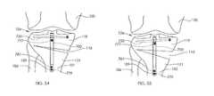
- FIGS. 29-31illustrate a method of implanting and operating a non-invasively adjustable wedge osteotomy device for maintaining or adjusting an angle of a closing wedge osteotomy of the tibia of a patient.
- FIG. 32illustrates a system for excavation of bone material according to a first embodiment of the present invention.
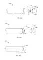
- FIG. 33illustrates a rotational cutting tool of the system of FIG. 32 .
- FIG. 34illustrates a side view of the rotational cutting tool of FIG. 33 .
- FIG. 35illustrates a section view of the rotational cutting tool of FIG. 34 , taken along line 35 - 35 .
- FIG. 36illustrates a drive unit of the system of FIG. 32 with covers removed.
- FIG. 37illustrates the system of FIG. 32 in place within a tibia.
- FIG. 38illustrates the system of FIG. 32 after removing bone material from the tibia.
- FIG. 39illustrates a system for excavation of bone material according to a second embodiment of the present invention in place within the tibia.
- FIG. 40illustrates the system of FIG. 39 in an expanded configuration within the tibia.
- FIG. 41illustrates an end view of an arm having an abrading surface as part of an excavation device of the system of FIG. 39 .
- FIG. 42illustrates a system for excavation of bone material according to a third embodiment of the present invention in place within the tibia.
- FIG. 43illustrates the system of FIG. 42 in an expanded configuration within the tibia.
- FIG. 44illustrates an end view of an arm having a compaction surface as part of an excavation device of the system of FIG. 42 .
- FIG. 45Aillustrates a non-invasively adjustable wedge osteotomy device according to a sixth embodiment of the present invention.
- FIG. 45Billustrates the non-invasively adjustable wedge osteotomy device of FIG. 45A in a perspective view.
- FIG. 46illustrates a detailed view of the non-invasively adjustable wedge osteotomy device of FIG. 45B taken from within circle 46 .
- FIG. 47illustrates the non-invasively adjustable wedge osteotomy device of FIG. 45A in a first distraction position.
- FIG. 48illustrates the non-invasively adjustable wedge osteotomy device of FIG. 45A in a second distraction position.
- FIG. 49illustrates a sectional view of the non-invasively adjustable wedge osteotomy device of FIG. 45A in a first distraction position.
- FIG. 50illustrates a sectional view of the non-invasively adjustable wedge osteotomy device of FIG. 45A in a second distraction position.
- FIG. 51illustrates a bushing of the non-invasively adjustable wedge osteotomy device of FIG. 45A .
- FIGS. 52-55illustrate a method of implanting and operating the non-invasively adjustable wedge osteotomy device of FIG. 45A for maintaining or adjusting an angle of an opening wedge osteotomy of the tibia of a patient.
- FIGS. 56A-56Dillustrate bone screw configurations for the non-invasively adjustable wedge osteotomy device of FIG. 45A .
- FIG. 57illustrates a non-invasively adjustable wedge osteotomy device according to a seventh embodiment of the present invention.
- FIG. 58illustrates a bone anchor for use with the non-invasively adjustable wedge osteotomy device of FIG. 57 .
- FIGS. 59-61illustrate a method of implanting and operating the non-invasively adjustable wedge osteotomy device of FIG. 57 for maintaining or adjusting an angle of an opening wedge osteotomy of the tibia of a patient.
- FIG. 62illustrates a non-invasively adjustable wedge osteotomy device according to an eighth embodiment of the present invention in a first distraction position.
- FIG. 63illustrates the non-invasively adjustable wedge osteotomy device of FIG. 62 in a second distraction position.
- FIG. 64Aillustrates a magnetically adjustable actuator of a non-invasively adjustable wedge osteotomy device according to an embodiment of the present invention during removal of a magnetic assembly.
- FIG. 64Billustrates the magnetically adjustable actuator of FIG. 64A after removal of a magnetic assembly.
- FIG. 64Cillustrates the magnetically adjustable actuator FIG. 64A after replacement of an actuator housing cap.
- FIG. 65Aillustrates a magnetically adjustable actuator of a non-invasively adjustable wedge osteotomy device according to an embodiment of the present invention prior to removal of a radially-poled permanent magnet.
- FIG. 65Billustrates the magnetically adjustable actuator of FIG. 65A during removal of the radially-poled permanent magnet.
- FIG. 65Cillustrates the magnetically adjustable actuator of FIG. 64A after removal of the radially-poled permanent magnet and replacement of a magnetic housing cap.
- FIG. 65Dillustrates the magnetically adjustable actuator of FIG. 64A after replacement of an actuator housing cap.
- FIGS. 66-69schematically illustrate various embodiments of alternate sources of a driving element of a non-invasively adjustable wedge osteotomy device.
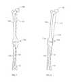
- FIG. 1illustrates a standard alignment of a femur 100 , a tibia 102 and a knee joint 104 , wherein a hip joint (at a femur head 108 ), a knee joint 104 and an ankle joint (at the midline of distal tibia 110 ) are oriented along a single line 112 .
- a fibula 106is shown alongside the tibia 102 .
- the knee joint 104 of FIG. 2is shown in an arthritic state, in which a medial compartment 114 has been compromised, causing the line 112 to pass medially off the center of the knee joint 104 .
- FIG. 3illustrates an open wedge osteotomy 118 formed by making a cut along a cut line 120 , and opening a wedge angle ⁇ .
- FIG. 4illustrates the final setting of this open wedge by the placement of bone graft material 122 within the open wedge osteotomy 118 , and then placement of a plate 124 , which is then secured to the tibia 102 with tibial screws 126 .
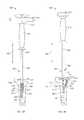
- FIG. 5illustrates a tibia 102 with a non-invasively adjustable wedge osteotomy device 128 implanted.
- the non-invasively adjustable wedge osteotomy device 128is shown without the tibia 102 in FIG. 6 .
- the non-invasively adjustable wedge osteotomy device 128includes an actuator 142 comprising an outer housing 130 and an inner shaft 132 telescopically coupled within the outer housing 130 for non-invasive longitudinal adjustment.
- a hole 138is drilled in the tibia 102 , and then a cut is made along cut line 120 .
- the actuator 142is then inserted, distal end 140 first, into the hole 138 .
- a wedge opening 144is opened enough to be able to insert a lower bracket 136 and an upper bracket 134 .
- the lower bracket 136as seen in FIG. 7 , has an opening 146 and an internal diameter 148 which allow it to be snapped onto a circumferential groove 150 around the outer housing 130 .
- the lower bracket 136is then secured to the tibia 102 at the lower portion 152 of the wedge opening 144 by placing bone screws (not shown) through screw holes 154 .
- Upper bracket 134is then slid into place and secured to a proximal end 156 of the actuator 142 by tightening a tightening screw 158 which threads through a threaded hole in inner shaft 132 of the actuator 142 .
- the upper bracket 134is then secured to the tibia 102 at the upper portion 162 of the wedge opening 144 by placing bone screws (not shown) through screw holes 164 .
- FIG. 8illustrates a magnetically adjustable actuator 142 which can be used in the embodiments of FIGS. 5-7 , or other embodiments described herein.
- An inner shaft 132having an end 160 , is telescopically adjustable within an outer housing 130 by the use of a magnetic assembly 166 contained therein.
- the magnetic assembly 166comprises a radially-poled, cylindrical magnet 168 which engages with one or more planetary gear stages 170 .
- the planetary gear stages 170output to a lead screw 172 .
- the final gear stage 170may be pinned to the lead screw 172 with a high strength pin, for example, a pin constructed from 400 series stainless steel.
- the inner shaft 132contains a cavity 174 into which is bonded a nut 176 having a female thread which interfaces with the male thread of the lead screw 172 .
- a radial bearing 178 and a thrust bearing 180allow the magnetic assembly 166 to operate with relatively low friction.
- An o-ring seal 182is held within a circumferential groove on inside of the wall of the outer housing 130 , and the inner diameter of the o-ring seal 182 dynamically seals the outer diameter of the inner shaft 132 .
- the non-invasively adjustable wedge osteotomy device 128is used to gradually open the wedge opening 144 over time.
- the actuator 142 of FIG. 6can be gradually lengthened (for example about one (1) mm per day), allowing the wedge opening 144 to reach a desired angle, which can be tested by having the patient perform different motion studies (stepping, turning, etc.), until the most comfortable condition is reached.
- Gradual lengtheningcan allow for the possibility of Ilizarov osteogenesis, in which new bone material forms in the wedge opening as it is opened. In such manner, a bone graft may be unnecessary.
- the newly grown bone materialcan be allowed to consolidate. If, during the process, lengthening has been too rapid, or new bone has not consolidated sufficiently, a moving magnetic field may be applied in an opposite direction thereby shortening the actuator 142 to add compression and create a good dimension for callus formation. After confirming that sufficient callus formation has taken place, lengthening may be resumed at the same speed, or at a different speed. Once lengthening is sufficiently completed, and consolidated bone is stable, it may be desired to remove the entire non-invasively adjustable wedge osteotomy device 128 , or simply the magnetic assembly 166 .
- FIG. 9illustrates a non-invasively adjustable wedge osteotomy device 184 comprising magnetic assembly 192 including a magnet, e.g., a radially-poled cylindrical magnet 186 which is coupled to a drive screw 188 .
- a magnete.g., a radially-poled cylindrical magnet 186
- the drive screw 188turns inside a block 190 having a female thread, causing the drive screw 188 and magnetic assembly 192 to be moved in a first axial direction (A).
- Afirst axial direction
- the magnetic assembly 192moves axially it pushes a curved shape memory (e.g., superelastic Nitinol®) plate spring 194 at connection point 196 .
- a curved shape memorye.g., superelastic Nitinol®
- a thrust bearing 198 at the connection point 196allows for continued rotation of the radially-poled cylindrical magnet 186 as the force increases.
- the width (W) of the Nitinol plate spring 194increases.
- a cutout 202 in the Nitinol plate spring 194provides space for the radially-poled cylindrical magnet 186 to turn and to move in the first axial direction (A).
- FIG. 10illustrates a non-invasively adjustable wedge osteotomy device 216 similar to the non-invasively adjustable wedge osteotomy device 184 of FIG. 9 , except that the Nitinol plate spring 194 of FIG. 9 is replaced by a linked lift 204 .
- Linked lift 204comprises a lower plate 206 and an upper plate 208 which are attached to a block 190 by pins 210 which allow each plate 206 and 208 to increase in angulation along arrows (B). Plates 206 and 208 are attached to inner plates 212 and 214 by pins 210 .
- the hinged structure of inner plates 212 , 214is pushed forward in a similar manner as Nitinol plate spring 194 is pushed in the first axial direction (A) in FIG. 9 .
- FIG. 11illustrates the non-invasively adjustable wedge osteotomy device 184 being placed into a wedge opening 144 in a tibia 102 .
- the non-invasively adjustable wedge osteotomy device 216 of FIG. 10can be inserted in the same manner.
- FIGS. 12-14illustrate a non-invasively adjustable wedge osteotomy device 218 based on a scissor jack.
- Non-invasively adjustable wedge osteotomy device 218comprises a main housing 220 having a lower bone interface 222 and an upper bone interface 224 , the upper bone interface 224 which can be adjusted with respect to the main housing 220 and the lower bone interface 222 .
- FIG. 13shows the non-invasively adjustable wedge osteotomy device 218 with the upper bone interface 224 removed to better appreciate the inner components.
- a scissors assembly 225comprises a first scissor 226 and a second scissor 228 that can be coupled by a center pin 230 in a hinged manner.
- Distal arms 234 and 238 of scissors 226 and 228can be coupled to the distal ends of the lower bone interface 222 and the upper bone interface 224 by pins 240 .
- An arm 232 of the second scissor 228is coupled to an interconnect 242 of a magnetic assembly 244 with a pin 240 .
- a hollow magnetic assembly 246has internal threads 247 which engage external threads 249 of a lead screw 248 which is bonded to the interconnect 242 .
- the hollow magnetic assembly 246may comprise a hollow radially-poled magnet.
- the interconnect 242includes a pawl 251 , which is able to engage teeth 253 of a ratchet plate 255 .
- the lead screw 248 and the interconnect 242are moved in a first axial direction (A), causing scissors assembly 225 to open up, and thus increase the distance (D) between the lower bone interface 222 and the upper bone interface 224 .
- An arm 236 of the first scissor 226is able to slide within a channel 257 in the upper bone interface 224 .
- the pawl 251 and the teeth 253 of the ratchet plate 255form a one way ratchet, allowing the distance (D) to be increased but not decreased.
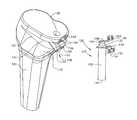
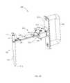
- FIG. 15illustrates an external adjustment device 1180 which is used to non-invasively adjust the devices and systems described herein.
- the external adjustment device 1180comprises a magnetic handpiece 1178 , a control box 1176 and a power supply 1174 .
- the control box 1176includes a control panel 1182 having one or more controls (buttons, switches or tactile, motion, audio or light sensors) and a display 1184 .
- the display 1184may be visual, auditory, tactile, the like or some combination of the aforementioned features.
- the external adjustment device 1180may contain software which allows programming by the physician.
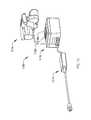
- FIG. 16shows the detail of the magnetic handpiece 1178 of the external adjustment device 1180 .
- the magnets 1186can be made from rare earth magnets, and can in some embodiments be radially poled.
- the magnets 1186are bonded or otherwise secured within magnetic cups 1187 .
- the magnetic cups 1187include a shaft 1198 which is attached to a first magnet gear 1212 and a second magnet gear 1214 , respectively.
- each the two magnets 1186are maintained in relation to each other by means of the gearing system (by use of center gear 1210 , which meshes with both first magnet gear 1212 and second magnet gear 1214 ).
- the north pole of one of the magnets 1186turns synchronously with the south pole of the other magnet 1186 , at matching clock positions throughout a complete rotation.
- the configurationhas been known to provide an improved delivery of torque, for example to cylindrical magnet 168 or magnet 246 . Examples of methods and embodiments of external adjustment devices that may be used to adjust the non-invasively adjustable wedge osteotomy device 218 , or other embodiments of the present invention, are described in U.S. Pat. No.
- the components of the magnetic handpiece 1178are held together between a magnet plate 1190 and a front plate 1192 . Most of the components are protected by a cover 1216 .
- the magnets 1186rotate within a static magnet cover 188 , so that the magnetic handpiece 1178 may be rested directly on the patient, while not imparting any motion to the external surfaces of the patient.
- the operatorPrior to distracting the intramedullary lengthening device 1110 , the operator places the magnetic handpiece 1178 over the patient near the location of the cylindrical magnet 1134 .
- a magnet standoff 1194 that is interposed between the two magnets 1186contains a viewing window 1196 , to aid in the placement.
- a mark made on the patient's skin at the appropriate location with an indelible markermay be viewed through the viewing window 1196 .
- the operatorholds the magnetic handpiece 1178 by its handles 1200 and depresses a distract switch 1228 , causing motor 1202 to drive in a first direction.
- the motor 1202has a gear box 1206 which causes the rotational speed of an output gear 1204 to be different from the rotational speed of the motor 1202 (for example, a slower speed).
- the output gear 1204then turns a reduction gear 1208 which meshes with center gear 1210 , causing it to turn at a different rotational speed than the reduction gear 1208 .
- the center gear 1210meshes with both the first magnet gear 1212 and the second magnet gear 1214 turning them at a rate which is identical to each other.
- this ratebe controlled, to minimize the resulting induced current density imparted by magnet 1186 and cylindrical magnet 1134 though the tissues and fluids of the body.
- a magnet rotational speed of 60 RPM or lessis contemplated although other speeds may be used such as 35 RPM or less.
- the distractionmay be lessened by depressing the retract switch 1230 , which can be desirable if the patient feels significant pain, or numbness in the area holding the device.
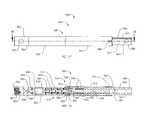
- FIGS. 17-19illustrate a non-invasively adjustable wedge osteotomy device 300 comprising a magnetically adjustable actuator 342 having a first end 326 and a second end 328 .
- An inner shaft 332 having a cavity 374is telescopically coupled within an outer housing 330 , which comprises a distraction housing 312 and a gear housing 306 .
- At least one transverse hole 305passes through an end cap 302 located at the first end 326 of the magnetically adjustable actuator 342 .
- the end cap 302may be sealably secured to the gear housing 306 by a circumferential weld joint 390 .
- a second weld joint 392sealably secures the distraction housing 312 to the gear housing 306 .
- One or more transverse holes 364pass through the inner shaft 332 .
- the one or more transverse holes 364 and the at least one transverse hole 305allow passage of at least one locking screw. Some embodiments use only one transverse hole 364 and one transverse hole 305 in order to better allow rotational play between the magnetically adjustable actuator 342 and the locking screws as the magnetically adjustable actuator 342 is adjusted.
- One or more longitudinal grooves 372 in the outer surface of the inner shaft 332engage in a keyed manner with protrusions 375 in an anti-rotation ring 373 which engages undercuts within end of the distraction housing 312 at a flat edge 384 of the anti-rotation ring 373 .
- One or more guide fins 383 in the anti-rotation ring 373can keep the anti-rotation ring 373 rotationally static within cuts 391 in the distraction housing 312 .
- the contents of the magnetically adjustable actuator 342are protected from body fluids by one or more o-rings 334 which reside within circumferential grooves 382 in the inner shaft 332 , dynamically sealing along the inner surface of the distraction housing 312 .
- the inner shaft 332is driven axially with respect to the outer housing 330 by a lead screw 348 which is turned by a cylindrical radially poled magnet 368 .
- the cylindrical radially poled magnet 368is bonded within a first magnet housing 308 and a second magnet housing 310 and is rotatably held at a pin 336 on one end by a radial bearing 378 , which directly engages the counterbore 304 of the end cap 302 .
- the second magnet housing 310outputs into a first stage 367 of three planetary gear stages 370 .
- the planet gears 387 of the three planetary gear stages 370turn within inner teeth 321 within the gear housing 306 .
- the first stage 367outputs to a second stage 369
- the second stage 369outputs to a third stage 371 .
- the third stage 371is coupled to the lead screw 348 by a locking pin 385 , which passes through holes 352 in both the output of the third stage 371 and in the lead screw 348 .
- a lead screw coupler 339is also held to the lead screw 348 by the pin 385 , which passes through a hole 359 .
- the lead screw 348threadingly engages with a nut 376 which is bonded within the cavity 374 of the inner shaft 332 .
- Each planetary gear stage 370incorporates a 4:1 gear ratio, producing an overall gear ratio of 64:1, so that 64 turns of the cylindrical radially poled magnet 368 cause a single turn of the lead screw 348 .
- a thrust bearing 380is held loosely in the axial direction between ledges in the gear housing 306 .
- the lead screw coupler 339includes a ledge 355 , which is similar to an opposing ledge (not shown) at the base of the lead screw 348 .
- the thrust bearing 380is held between a ledge 393 in the gear housing 306 and an insert 395 at the end of the gear housing 306 .
- the thrust bearing 380serves to protect the cylindrical radially poled magnet 368 , the planetary gear stages 370 , the magnet housings 308 and 310 , and the radial bearing 378 from damage due to compression.
- a maintenance member 346comprising a thin arc of magnetic material, such as ‘400 series’ stainless steel, is bonded within the gear housing 306 , adjacent to the cylindrical radially poled magnet 368 , and can attract a pole of the cylindrical radially poled magnet 368 , in order to minimize the chance of the cylindrical radially poled magnet 368 turning when not being adjusted by the external adjustment device 1180 , for example during patient movement.
- the non-invasively adjustable wedge osteotomy device 300has the capability to increase or decrease its length at least about three millimeters in each direction in one embodiment, and about nine millimeters in each direction in another embodiment.
- the non-invasively adjustable wedge osteotomy device 300can achieve a distraction force of 240 pounds when the magnetic handpiece 1178 of the external adjustment device 1180 is placed so that the magnets 1186 are about one-half inch from the cylindrical radially poled magnet 368 .
- the majority of the components of the non-invasively adjustable wedge osteotomy devicemay be made from Titanium or Titanium alloys such as Titanium-6Al-4V, Cobalt Chromium, Stainless Steel or other alloys.
- the non-invasively adjustable wedge osteotomy device 300When implanted, the non-invasively adjustable wedge osteotomy device 300 may be inserted by hand or may be attached to an insertion tool (for example a drill guide). An interface 366 comprising an internal thread 397 is located in the end cap 302 for reversible engagement with the male threads of an insertion tool. Alternatively, these features may be located on the end 360 of the inner shaft 332 . Additionally a detachable tether may be attached to either end of the non-invasively adjustable wedge osteotomy device 300 , so that it may be easily removed if placed incorrectly.
- an insertion toolfor example a drill guide
- An interface 366comprising an internal thread 397 is located in the end cap 302 for reversible engagement with the male threads of an insertion tool.
- these featuresmay be located on the end 360 of the inner shaft 332 .
- a detachable tethermay be attached to either end of the non-invasively adjustable wedge osteotomy device 300 , so
- FIGS. 20 through 27illustrate a method of implanting and operating a non-invasively adjustable wedge osteotomy device 125 for changing an angle of the tibia of a patient.
- a front view of the right knee joint 104 of a patient with osteoarthritis of the kneeis shown, including the femur 100 , tibia 102 and fibula 106 .
- the non-invasively adjustable wedge osteotomy device 125can be placed towards the medial side of the tibia 102 (away from the fibula 106 ).
- the bone of the tibia 102is thus prepared to allow a non-central placement of the non-invasively adjustable wedge osteotomy device.
- An incisionis made in the skin at a medial side of the tibia 102 and an open wedge osteotomy 118 is made in relation to a hinge point 107 , by creating a first cut 103 , for example with an oscillating saw, and opening the open wedge osteotomy 118 , as seen in FIG. 21 .
- the open wedge osteotomy 118now separates a first portion 119 and second portion 121 of the tibia 102 .
- FIG. 22an incision is made in the skin, a drill 111 is placed at the central tibial plateau 101 and a first cavity 109 having a first axis 117 is drilled from the tibial plateau 101 down the medullary canal of the tibia 102 . It may be desired during this drilling step to place a temporary wedge 123 in the open wedge osteotomy 118 , in order to maintain stability.
- a drill diameter of about 12 mm or less, or more preferably about 10 mm or lessis used to create the first cavity 109 .
- FIGS. 23 and 24illustrate generalized steps for creating a second cavity 115 .
- FIG. 25Several embodiments are represented here by an excavation device 113 , which is inserted into the first cavity 109 through the opening at the tibial plateau 101 .
- the second cavity 115is then formed to one side of the first cavity 109 , in this case the medial side.
- a non-invasively adjustable wedge osteotomy device 125having an outer housing 129 and an inner shaft 127 is inserted into the first cavity 109 .
- the non-invasively adjustable wedge osteotomy device 125is shown with the inner shaft 127 facing superiorly (up) on the patient, but it may desired in some situations to implant the non-invasively adjustable wedge osteotomy device 125 with the inner shaft 127 facing inferiorly (down).
- First transverse hole 135 and second transverse hole 137 in the non-invasively adjustable wedge osteotomy device 125are configured for placement of bone anchors, for example locking screws.
- the non-invasively adjustable wedge osteotomy device 125is then placed into the second cavity 115 and secured with a first anchor 131 through first transverse hole 135 and a second anchor 133 through second transverse hole 137 .
- a wedge angle ⁇ 1is set between the first portion 119 and second portion 121 of the tibia.
- the patientmay return for a dynamic imaging session (for example x-ray) during which the patient stands, and even moves the knee joint 104 , in order to best confirm whether the wedge angle ⁇ 1 is allows for the optimal conformation of the knee joint 104 .
- the magnetic handpiece 1178 of the external adjustment device 1180 of FIG. 15is then placed over the knee joint 104 of the patient and operated so that the inner shaft 127 is distracted from the outer housing 129 , to increase to a larger wedge angle ⁇ 2 ( FIG. 27 ).
- the anchorsfor example second anchor 133
- the transverse holefor example the second transverse hole 137
- the dynamic imaging sessionmay be done at a time following surgery when swelling has decreased, but before bone consolidation is significant. This period may be approximately one to two weeks following surgery. If an adjustment is made (increase or decrease), an additional dynamic imaging session may be performed, for example, a week later.
- the non-invasively adjustable wedge osteotomy device 125is supplied so that it can be either lengthened or shortened, in other words, so that the angle of the open wedge osteotomy 118 may be subsequently increased or decreased, depending on the determination of the desired correction.
- An alternative manner of quantifying the amount of opening of the open wedge osteotomy 118is to measure, for example via radiography, the gap G 1 , G 2 at the medial edge 181 of the open wedge osteotomy 118 .
- the gap G 1 , G 2in millimeters tends to approximate the wedge angle ⁇ 1 , ⁇ 2 in degrees. For example, G 1 (mm) ⁇ 1 (°); G 2 (mm) ⁇ 2 (°). It is expected that, assuming correction is required, productive lengthening will be done at a rate in the range of about 2 mm gap (G) increase per day or less.
- Gap increase ratemay be defined as the change in gap in millimeters per day.
- One consideration in determining the gap increase rate (GIR) to useis the pain tolerance of the patient. Some patients may tolerate a larger amount of pain, for example the pain caused by stretching of soft tissue, and thus a higher gap increase rate (GIR).
- Another considerationis the amount of bone growth that is occurring.
- One method of assessing the amount of bone growthis via radiography.
- the preferred gap increase rate (GIR)is that at which bone growth is occurring within the open wedge osteotomy 118 , but early consolidation of the bone is not occurring (consolidation that would “freeze” the mobility of the open wedge osteotomy 118 , making it unable to be opened more).
- the non-invasively adjustable wedge osteotomy device 125may be desired to purposely implant the non-invasively adjustable wedge osteotomy device 125 with an undersized initial gap (G 0 ), so that an ideal gap (G i ) may be gradually achieved via non-invasive adjustments. It is contemplated that over the adjustment period, a total of one to twenty or more adjustment procedures may be performed, for a total amount of about 1 mm to about 20 mm of gap (G) increase, such as during an adjustment period of one month or less. Typically, the adjustment period may span approximately ten days, involve approximately ten adjustment procedures and involve a total amount of about 5 mm to about 12 mm gap increase.
- a larger momentmay be placed on the first portion 119 and second portion 121 to open the open wedge osteotomy 118 in relation to the hinge point 107 .
- a larger amount of distractionmay be achieved.
- FIG. 28three different distraction axes (A, B, C) are shown, representing three possible positions of the non-invasively adjustable wedge osteotomy device 125 .
- Distraction axis Ais approximately midline in the tibia 102
- distraction axis Bis approximately 11° angled from the midline
- distraction axis Cis approximately 22° angled from the midline.
- the length D B from the hinge point 107 to distraction axis Bcan be approximately 32% greater than the length D A from the hinge point 107 to distraction axis A.
- the length D C from the hinge point 107 to distraction axis Ccan be approximately 60% greater than the length D A from the hinge point 107 to distraction axis A.
- the distraction force of the non-invasively adjustable wedge osteotomy device 125is needed to overcome a series of resistances arrayed along the tibia due to the tethering effect of soft tissue.
- a placement of the non-invasively adjustable wedge osteotomy device 125 along axis C, and thus in second cavity 115 ( FIG. 27 )can allow for a more effective distraction of the open wedge osteotomy 118 .
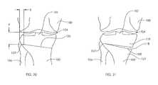
- FIGS. 29 through 31illustrate a method of implanting and operating a non-invasively adjustable wedge osteotomy device 125 for changing an angle of the tibia of a patient, but unlike the open wedge osteotomy 118 shown in FIGS. 20-27 , a closing wedge osteotomy 141 is shown.
- the first cut 103is made, but in FIG. 30 a second cut 105 is made and a wedge of bone is removed.
- the second cut 105purposely removes slightly more bone than is needed to optimize the correction angle, and as shown in FIG. 31 , the closing wedge osteotomy 141 is left with a slight gap, allowing it to be subsequently adjusted in either direction (to increase or decrease then angle).
- the implantation methodcontinues by following the remaining steps described in FIGS. 22-26 , and the angle of the closing wedge osteotomy 141 may be increased or decreased as described in FIG. 27 .
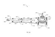
- FIGS. 32 through 36illustrate a first system for excavation of bone material 400 .
- the system for excavation of bone material 400is configured for creating a second cavity 115 as generally described in FIGS. 22 through 24 .
- a drive unit 404is coupled to a rotational cutting tool 402 by means of a flexible drive train 408 .
- the rotational cutting tool 402is an embodiment of the excavation device 113 as introduced in FIG. 23 , but may also serve as the drill 111 of FIG. 22 .
- the rotational cutting tool 402as depicted in FIGS. 32 through 35 , extends between a first end 444 and second end 446 (as shown in FIG. 34 ), and comprises a distal reamer 412 which is coupled to a proximal reamer 410 .
- the distal reamer 412includes a small diameter portion 440 which inserts inside the proximal reamer 410 .
- a circumferential engagement member 434is held axially between the distal reamer 412 and the proximal reamer 410 , and includes several cutouts 435 ( FIG. 34 ) arrayed around its circumference, forming a pulley.
- the distal reamer 412 , proximal reamer 410 and circumferential engagement member 434are held together with pins 437 , which are passed through holes 436 , and which assure that all components rotate in unison.
- a cap screw 438is secured within a female threaded internal surface of the proximal reamer 410 .
- the distal reamer 412further includes a taper 442 and a blunt tip 414 .
- the outer diameter of the rotational cutting tool 402may be about 12 mm or less, and more specifically about 10 mm or less.
- the outer diameter of the proximal reamer 410may be about 9 mm and the outer diameter of the distal reamer may taper from about 9 mm to about 6.35 mm at the blunt tip 414 .
- the drive unit 404as best seen in FIGS. 32 and 36 , comprises a drive housing 416 covered by a pulley cover plate 418 and a drive cover plate 420 .
- a handle 406is coupled by screws 424 to a handle mounting plate 422 which in turn is removably attached to the drive housing 416 (for example by screws or a clip).
- a shaft 428( FIG. 36 ) having a keyed end 430 , is configured for removeably coupling to an electric drill unit 468 ( FIGS. 37 and 38 ).
- a large pulley 450is attached to the shaft 428 with a set screw 451 so that rotation of the shaft 428 by the electric drill unit 468 causes rotation of the large pulley 450 .
- the shaft 428 and large pulley 450are held between two ball bearings 448 (lower ball bearing not visible), and a shim washer 464 and wave washer 466 are located on either side of the large pulley 450 in order to control the amount of axial play.
- a roller wheel 452is rotatably attached to the end of a roller wheel slide 456 with a pin 454 .
- the roller wheel slide 456is able to slide axially within the drive housing 416 and drive cover plate 420 with the loosening of a thumb screw 432 , whose threaded shaft engages with internal threads 462 on the roller wheel slide 456 .
- the roller wheel slide 456may be secured by tightening the thumb screw 432 so that it will not slide during use.
- a longitudinal slit 460 in the roller wheel slide 456controls the total amount of axial sliding by providing a first end 461 and a second end 463 which abut a stop 458 .
- the flexible drive train 408comprises a small timing belt, for example an about 3 mm wide Kevlar® or fiberglass reinforced polyurethane belt having a slippage torque of greater than 10 inch-ounces when used with the large pulley 450 or the circumferential engagement member 434 .
- One potential example slippage torque foris 13 inch-ounces.
- the teeth of the flexible drive trainmay be located at a pitch of two millimeters.
- FIG. 37shows the drive unit 404 of the System for excavation of bone material 400 coupled to the electric drill unit 468 .
- the electric drill unit 468includes a motor housing 476 , a handle 470 and a battery pack 472 .
- the handlemay include any number of interfaces known in the art for turning the electric drill unit 468 on or off, or controlling the speed.
- the electric drill unit 468may plug directly into a standard power source instead of having the battery pack 472 .
- the keyed end 430 of the shaft 428is coupled to a shaft coupler 474 of the
- the flexible drive train 408is inserted through the medial incision and into the open wedge osteotomy 118 , between first portion 119 and second portion 121 of the tibia.
- the rotational cutting tool 402is then placed down the first cavity 109 of the tibia 102 so that the flexible drive train 408 wraps around the circumferential engagement member 434 of the rotational cutting tool 402 .
- the thumb screw 432loose, the desired amount of tension in the flexible drive train 408 is adjusted and then the thumb screw 432 is tightened. At this desired tension, the teeth of the flexible drive train 408 should engage well within the cutouts 435 ( FIG.
- the electric drill unit 468is operated, causing the large pulley 450 of FIG. 36 to rotate the flexible drive train 408 , and thus rotate the rotational cutting tool 402 via engagement with the circumferential engagement member 434 ( FIG. 34 ).
- the large pulley 450can be twice the diameter of the circumferential engagement member 434 , therefore causing the rotational cutting tool 402 to spin at one-half the speed of the output of the electric drill unit 468 . Other ratios are also within the scope of this invention.
- the rotational cutting tool 402may be desired to control the rotational speed of the rotational cutting tool 402 in order to minimize heating of the bone surrounding the bone material being cut, and thus limit damage to the bone that may impede normal growth during the healing process.
- the handle 406is pulled causing the rotational cutting tool 402 to cut a second cavity 115 following path 477 ( FIG. 38 ).
- the proximal reamer 410cuts within first portion 119 of the tibia 102 and the distal reamer 412 cuts within the second portion 121 of the tibia 102 .
- the thumb screw 432is loosened and tension on the flexible drive train 408 is at least partially reduced.
- the rotational cutting tool 402is then removed and the flexible drive train 408 is pulled out of the open wedge osteotomy 118 .
- a tether linemay be attached to the rotational cutting tool 402 , for example via the cap screw 438 , to apply tension and thus aid removal.
- a swivel jointmay further be included between the tether line and the rotational cutting tool 408 in order to keep the tether line from being twisted.
- FIG. 39-41illustrate a second system for excavation of bone material 500 .
- the system for excavation of bone materialcomprises an excavation device 502 having a hollow outer shaft 508 .
- the hollow outer shaft 508has a distal end 507 and a proximal end 509 and is attached to an outer shaft handle 510 which is configured to be held with a single hand to stabilize or to move the excavation device 502 .
- An adjustment member 512 having a threaded end 516is attached to an adjustment handle 514 .
- the threaded end 516threadingly engages internal threads (not shown) within the hollow outer shaft 508 , and turning the adjustment member 512 by manipulation of the adjustment handle 514 moves the adjustment member 512 axially in relation to the hollow outer shaft 508 .
- the hollow outer shaft 508has a cut away section 511 adjacent to an articulatable arm 504 .
- the threaded end 516is coupled to the arm 504 via a link 520 .
- the link 520connects to the arm 504 at a first pivot point 518 , and the link 520 connects to the threaded end 516 of the adjustment member 512 at a second pivot point 521 (as seen in FIG. 40 ).
- Rotating the adjustment handle 514 in a rotational direction R in relation to the hollow outer shaft 508 and outer shaft handle 510causes adjustment member 512 to move in direction D in relation to the hollow outer shaft 508 , and causes the arm 504 to expand in path E in relation to the hollow outer shaft 508 .
- the arm 504comprises an abrading surface 506 for removing bone material.
- the arm 504may be an elongate member having a semi-cylindrical cross-section, and the abrading surface 506 may comprise a rasp, covered with several sharp projections 513 .
- FIG. 39shows the excavation device 502 placed within a first cavity 109 made within a tibia 102 .
- the operatorgrips the outer shaft handle 510 with one hand and the adjustment handle 514 with the other hand, and begins moving the system for excavation of bone material 500 in a back and forth motion 522 , while slowly turning the adjustment handle 514 in rotational direction R.
- the arm 504is able to be expanded more and more along path E ( FIG. 40 ) as the adjustment handle 514 is turned in rotational direction R and the system for excavation of bone material 500 is moved in a back and forth motion 522 .
- the culmination of this stepis seen in FIG. 40 , with the second cavity 115 created in the first portion 119 and the second portion 121 of the tibia 102 .
- the adjustment handleis turned in an opposite rotational direction than rotational direction R, thus allowing the arm 504 to collapse, and the excavation device 502 to be removed from the tibia 102 .
- FIG. 42-44illustrate a third system for excavation of bone material 600 .
- the system for excavation of bone material 600comprises an excavation device 602 having a hollow outer shaft 608 .
- the hollow outer shaft 608has a distal end 607 and a proximal end 609 and is attached to an outer shaft handle 610 which is configured to be held with a single hand to stabilize or to move the excavation device 602 .
- An adjustment member 612 having a threaded end 616is attached to an adjustment handle 614 .
- the threaded end 616threadingly engages internal threads (not shown) within the hollow outer shaft 608 , and turning the adjustment member 612 by manipulation of the adjustment handle 614 moves the adjustment member 612 axially in relation to the hollow outer shaft 608 .
- the hollow outer shaft 608has a cut away section 611 adjacent to an articulatable arm 604 .
- the threaded end 616is coupled to the arm 604 via a link 620 .
- the link 620connects to the arm 604 at a first pivot point 618 , and the link 620 connects to the threaded end 616 of the adjustment member 612 at a second pivot point 621 .
- Rotating the adjustment handle 614 in a rotational direction R in relation to the hollow outer shaft 608 and outer shaft handle 610causes adjustment member 612 to move in direction D in relation to the hollow outer shaft 608 , and causes the arm 604 to expand in path E in relation to the hollow outer shaft 608 , as seen in FIG. 43 .
- the arm 604comprises a compaction surface 606 for compacting cancellous bone.
- the arm 604may be an elongate member having a tubular or partially tubular cross-section, and the compaction surface 606 may include a leading edge 690 for cutting a path through the cancellous bone and a first angled surface 692 extending from the leading edge 690 .
- the first angled surface 692serves to compact the cancellous bone, but also allows some sliding past cancellous bone as the cancellous bone moves out of the way.
- a second angled surface 694having an angle different from that of the first angled surface 692 may be configured as part of the compaction surface 606 .
- FIG. 42shows the excavation device 602 placed within a first cavity 109 made within a tibia 102 .
- the operatorgrips the outer shaft handle 610 with one hand and the adjustment handle 614 with the other hand, and begins slowly turning the adjustment handle 614 in rotational direction R.
- Cancellous boneis compacted as the arm 604 is expanded more and more along path E by turning the adjustment handle 614 in rotational direction R.
- the culmination of this stepis seen in FIG. 43 , with the second cavity 115 created in the second portion 121 of the tibia 102 .
- the excavation device 602may be moved superiorly in the tibia 102 and the compaction may be completed within the first portion 119 of the tibia 102 .
- the adjustment handleis turned in an opposite rotational direction than rotational direction R, thus allowing the arm 604 to collapse, and the excavation device 602 to be removed from the tibia 102 .
- FIGS. 45A through 50illustrate a non-invasively adjustable wedge osteotomy device 700 .
- the non-invasively adjustable wedge osteotomy device 700has a first end 726 and a second end 728 , as shown in FIG. 45A , and is similar in construction to the non-invasively adjustable wedge osteotomy device 300 of FIGS. 17 through 19 .
- the first end 726 of the non-invasively adjustable wedge osteotomy device 700comprises a Herzog bend 780 , in which the first end 726 projects at an angle ⁇ .
- the angle ⁇may range between about 5° and about 20°, or more specifically between about 8° to 12°, or about 10°, in relation to the central axis 782 of the non-invasively adjustable wedge osteotomy device 700 .
- a magnetically adjustable actuator 742comprises an inner shaft 732 , telescopically disposed within an outer housing 730 , the outer housing 730 further comprising a distraction housing 712 and a gear housing 706 .
- First transverse hole 735 , second transverse hole 743 , third transverse hole 737 and fourth transverse hole 739are sized for the passage of bone anchors, for example locking screws having diameters of about 3.0 mm to about 5.5 mm, and more specifically about 4.0 mm to about 5.0 mm.
- the diameter of the outer housing 730is between about 7.0 mm and about 9.5 mm, and more specifically about 8.5 mm.
- the diameter of the inner shaft 732may also taper up to about 8.5 mm at the portion of the inner shaft 732 containing the second transverse hole 743 and third transverse hole 737 . This is larger than the small-diameter portion 784 of the inner shaft 732 , which telescopes within the outer housing 730 , and thus this increase diameter allows the second transverse hole 743 and third transverse hole 737 to in turn be constructed with larger diameters, allowing the use of stronger, larger diameter bone screws. Likewise, the diameter of the first end 726 may taper up to about 10.7 mm in order to allow for even larger bone screws to be used.
- a non-invasively adjustable wedge osteotomy device 700having an outer housing 730 diameter of about 8.5 mm, tapering up to about 10.7 mm at the first end 726 , and with an inner shaft 732 that tapers up to about 8.5 mm, it is contemplated that bone screws having diameter of about 4.0 mm will be placed through the second transverse hole 743 and the third transverse hole 737 , while bone screws having a diameter of about 5.0 mm will be placed through the first transverse hole 735 and the fourth transverse hole 739 .
- An exemplary length of the non-invasively adjustable wedge osteotomy device 700 from the extents of the first end 726 to the second end 728is about 150 mm.
- an interface 766 at the first end 726 of the non-invasively adjustable wedge osteotomy device 700includes internal thread 797 for reversible engagement with the male threads of an insertion tool.
- Examples of methods and embodiments of instruments that may be used to implant the non-invasively adjustable wedge osteotomy device 700 , or other embodiments of the present invention,are described in U.S. Pat. No. 8,449,543, the disclosure of which is hereby incorporated by reference in its entirety.
- the fourth transverse hole 739comprises a dynamic construction that allows some motion between a bone anchor and the non-invasively adjustable wedge osteotomy device 700 when the non-invasively adjustable wedge osteotomy device 700 is implanted and being non-invasively adjusted.
- a bushing 751having substantially cylindrical outer and inner diameters resides within the fourth transverse hole 739 and has an inner diameter 753 configured to smoothly pass the shaft of a locking screw, for example a locking screw having a diameter of about 5.0 mm.
- the bushing 751may be constructed of metallic materials such as Titanium-6Al-4V.
- the bushing 751may be constructed of PEEK.
- the bushing 751can be angularly unconstrained, thus being able to rock or pivot within the fourth transverse hole 739 .
- FIG. 47shows the non-invasively adjustable wedge osteotomy device 700 in a first, non-distracted state.
- the inner shaft 732is substantially retracted within the outer housing 730 .
- FIG. 48shows the non-invasively adjustable wedge osteotomy device 700 in a partially distracted state, with a portion of the inner shaft 732 extending from the outer housing 730 (for example, after having been magnetically distracted).
- FIGS. 47 and 48show two different possible positions for a bone screw 755 , having a head 757 , a shaft 759 and a threaded portion 761 for engaging cortical bone.
- the bone screw 755is depicted rocking or pivoting along a general arcuate pathway 763 .
- the bushing 751may generally rock within the fourth transverse hole 739 , or the bushing 751 may actually pivot upon an axis.
- pinsmay extend transversely from the outer diameter of the bushing 751 at approximately the center point of its length, and attach into holes or recesses formed transversely within the fourth transverse hole 739 .
- rock and rockingare generally intended to denote a motion that does not have a central pivot point.
- Angularly unconstrainedis intended to denote any freedom of motion of the bushing 751 that allows angulation, not necessarily in a single plane, of the bone screw 755 in relation to the non-invasively adjustable wedge osteotomy device 700 .
- Angularly unconstrainedis intended to include both rocking and pivoting.
- FIGS. 49 and 50illustrate sectional views of the bushing 751 moving in an angularly constrained manner within the fourth transverse hole 739 .
- bushing 751comprises two large diameter extensions 765 , 770 and two small diameter extensions 767 , 768 , separated by a transition area 769 .
- a longitudinal slit 771 along one side of the bushing 751may be present, to allow bone screws 755 having a certain amount of outer diameter variance to fit within the inner diameter 753 .
- the bushing 751has not reached its extents against the fourth transverse hole 739 .
- this longitudinal slit 771may fit within matching contours the fourth transverse hole 739 , so that the bushing 751 cannot rotate around its cylindrical axis (in relation to the fourth transverse hole 739 ), but is still able to rock or pivot.
- the sizing of the two large diameter extensions 765 , 770 and two small diameter extensions 767 , 768may be controlled, for example, so that the bushing 751 is able to rock or pivot about 15° in one direction, but about 0° in the other direction. These about 15°, for example, may be chosen to correspond to the total amount of opening of the open wedge osteotomy 118 in a particular patient. The extent of this angulation may be controlled in different models of the bushing 751 . For example about 15° in one direction, about 0° in the other direction; about 10° in one direction, about 5° in the other direction; about 20° in one direction, about 0° in the other direction; and about 10° in one direction, about 10° in the other direction.
- FIGS. 52-55illustrate a method of implanting and operating the non-invasively adjustable wedge osteotomy device 700 of FIGS. 45A-51 for maintaining or adjusting an angle of an opening wedge osteotomy of the tibia of a patient.
- a first cavity 109extending from a first point on the tibia 102 at the tibial plateau 101 , is made.
- the first cavity 109can be made as shown in FIGS. 20-22 .
- the non-invasively adjustable wedge osteotomy device 700is inserted into the first cavity 109 , the inner shaft 732 first, followed by the outer housing 730 .
- the non-invasively adjustable wedge osteotomy device 700is secured to the first portion 119 of the tibia 102 with a first bone screw 755 which is passed through the fourth transverse hole 739 of FIG. 45B , and a second bone screw 777 which is passed through the first transverse hole 735 , of FIG. 45B .
- only the fourth transverse hole 739has the bushing 751 incorporated therein.
- a third bone screw 779 and a fourth bone screw 781are passed through the second transverse hole 743 , in FIG. 45B , and the third transverse hole 737 , in FIG. 45B , respectively, and secured to the second portion 121 of the tibia 102 .
- the non-invasively adjustable wedge osteotomy device 700is secured within the tibia 102 so that the Herzog bend 780 , of FIG. 45A , points anteriorly (e.g. towards the patellar tendon).
- FIG. 55illustrates the non-invasively adjustable wedge osteotomy device 700 after having been distracted over one or more non-invasive distractions, over a period of one or more days.
- the angle of the open wedge osteotomy 118has been increased as the inner shaft 732 was displaced out of the outer housing 730 .
- the bone screw 755has been able to change its angle in relation to the non-invasively adjustable wedge osteotomy device 700 , for example, by rocking or pivoting of the bushing 751 of FIG. 49 within the fourth transverse hole 739 .
- FIGS. 56A through 56Dillustrate four possible bone screw configurations for securing the first end 726 of the non-invasively adjustable wedge osteotomy device 700 to the first portion 119 of the tibia 102 with the first bone screw 755 and the second bone screw 777 .
- the medial 800 , lateral 802 , anterior 804 and posterior 806 portions of the tibia 102are denoted.
- the medial 800 to lateral 802 orientation in FIGS. 56A through 56Dis left to right respectively in each figure, while in FIGS. 52 through 55 , medial was on the right and lateral was on the left.
- FIG. 52 through 55medial was on the right and lateral was on the left.
- the first bone screw 755is secured unicortically (through the cortex of the tibia 102 on one side only) and is at an angle of B ⁇ 10° with the medial-lateral axis 810 .
- the second bone screw 777is secured bicortically (through the cortex of the tibia 102 on both sides) and is at an angle of A ⁇ 20° with the anterior-posterior axis 808 .
- the first bone screw 755is secured unicortically and is at an angle of B ⁇ 10° (in the opposite direction than in FIG. 56A ) with the medial-lateral axis 810 .
- the second bone screw 777is secured bicortically and is at an angle of A ⁇ 20° with the anterior-posterior axis 808 .
- the first bone screw 755 and the second bone screw 777are both secured bicortically.
- First bone screw 755is secured at an angle of D ⁇ 45° with the anterior-posterior axis 808
- second bone screw 777is secured at an angle of A ⁇ 20° with the anterior-posterior axis 808
- the first bone screw 755 and the second bone screw 777are both secured bicortically.
- First bone screw 755is secured at an angle of D ⁇ 45° with the anterior-posterior axis 808
- second bone screw 777is secured at an angle of E ⁇ 45° with the anterior-posterior axis 808 .
- the third bone screw 779 and the fourth bone screw 781may be secured in a number of orientations. Though shown in FIGS. 54 and 55 oriented slightly angled from the anterior-posterior plane, they may also be placed in other orientations, for example angled approximately 35° from the medial-lateral plane.
- FIG. 57illustrates a non-invasively adjustable wedge osteotomy device 900 .
- the non-invasively adjustable wedge osteotomy device 900comprises a magnetically adjustable actuator 942 having a first end 926 and a second end 928 , and is similar in construction to the non-invasively adjustable wedge osteotomy device 300 of FIGS. 17 through 19 .
- the second end 928includes an inner shaft 932 having a small-diameter portion 984 which is telescopically disposed and axially distractable within an outer housing 930 .
- the outer housing 930comprises a distraction housing 912 and a gear housing 906 .
- a first plate 950extends from the outer housing 930 and is configured to be placed in proximity to an external surface of a bone, for example, the second portion 121 of a tibia 102 shown in FIG. 59 .
- One or more anchor holes 952are arrayed on the first plate 950 , and configured for interface with corresponding bone screws.
- a bone screw 954is shown in FIG. 58 , and includes a threaded, tapered head 956 and a threaded shaft 958 .
- a keyed cavity 960couples with a driving instrument (not shown).
- the first plate 950features a bone interface side 962 and a non-bone interface side 964 .
- a second plate 966having a bone interface side 968 and a non-bone interface side 970 , extends from the inner shaft 932 .
- the second plate 966is coupled to the inner shaft 932 by a cap 972 , and secured with a set screw 974 .
- One or more anchor holes 976are arrayed on the second plate 966 , and configured for interface with corresponding bone screws, for example bone screw 954 .
- Anchor hole 978is shown having a threaded taper 980 , for interfacing with the tapered head 956 of the bone screw 954 .
- FIGS. 59-61illustrate a method of implanting and operating the non-invasively adjustable wedge osteotomy device of FIG. 57 for maintaining or adjusting an angle of an opening wedge osteotomy of the tibia of a patient.
- an open wedge osteotomy 118is made in the tibia 102 .
- the non-invasively adjustable wedge osteotomy device 900is placed through an incision and is secured to the tibia 102 by coupling the first plate 950 to the second portion 121 of the tibia 102 and coupling the second plate 966 to the first portion 119 of the tibia, for example with bone screws 954 .
- FIG. 61illustrates the tibia 102 after the non-invasively adjustable wedge osteotomy device 900 has been non-invasively distracted, for example with the external adjustment device 1180 .
- FIGS. 62 and 63illustrate a non-invasively adjustable wedge osteotomy device 1000 .
- the non-invasively adjustable wedge osteotomy device 1000comprises a magnetically adjustable actuator 1042 having a first end 1026 and a second end 1028 , and is similar in construction to the non-invasively adjustable wedge osteotomy device 300 of FIGS. 17 through 19 , and the non-invasively adjustable wedge osteotomy device 900 of FIG. 57 .
- the magnetically adjustable actuator 1042comprises an outer housing 1030 and an inner shaft 1032 telescopically disposed within the outer housing 1030 .
- non-invasively adjustable wedge osteotomy device 1000has a first plate 1050 extending from the outer housing 1030 .
- a second plate 1066is secured to the inner shaft 1032 by a cap 1072 .
- the second plate 1066is rotatably coupled to the cap 1072 at pivot point 1091 , thus allowing the second plate 1066 to rotate from the position in FIG. 62 to the position in FIG. 63 along arrow 1081 , for example as the inner shaft 1032 is distracted from the position in FIG. 62 to the position in FIG. 63 .
- Thisallows the first portion 119 of the tibia 102 to be moved apart from the second portion 121 of the tibia 102 , and thus opening the open wedge osteotomy 118 , but without creating too large of a bending moment (and related frictional force increases) on the movement of the inner shaft 1032 within the outer housing 1030 .
- the rotatability of the second plate 1066 with relation to the rest of the non-invasively adjustable wedge osteotomy device 900is analogous to the angularly unconstrained motion of the bushing 751 and the bone screw 755 in relation to the non-invasively adjustable wedge osteotomy device 700 of FIGS. 45A through 50 .
- non-invasively adjustable wedge osteotomy device 900 or the non-invasively adjustable wedge osteotomy device 1000which do not require any removal of bone at the tibial plateau 101 , may be preferred in certain patients in whom it is desired to maintain the knee joint 104 in as original a condition as possible. This may include younger patients, patients who may be able to avoid later partial or total knee replacement, or patients with deformities at the knee joint 104 . It may also include small patients who have small medullary canal dimensions, in whom intramedullary devices will not fit well.
- FIGS. 64A through 64Cillustrate a magnetically adjustable actuator 1504 which may be used with any of the embodiments of the present invention, and which allows for temporary or permanent removal of a rotatable magnetic assembly 1542 .
- Subjects undergoing magnetic resonance imaging (MRI)may require that the radially-poled permanent magnet 1502 be removed prior to MRI in order to avoid an imaging artifact which may be caused by the radially-poled permanent magnet 1502 . Additionally, there is a risk that an implanted radially-poled permanent magnet 1502 may be demagnetized upon entering an MRI scanner.
- an actuator housing cap 1588has a male thread 1599 which engages with a female thread 1597 of the outer housing 1505 of the magnetically adjustable actuator 1504 .
- a snap/unsnap interfacemay be used.
- a smooth diameter portion 1595 of the actuator housing cap 1588is sealed within an o-ring 1593 , which is held within a circumferential groove in the outer housing 1505 . If at a time subsequent to the implantation of the magnetically adjustable actuator 1504 it desired to remove the rotatable magnetic assembly 1542 while leaving the rest of the implant intact, a small incision may be made in the skin of the subject in proximity to the actuator housing cap 1588 , and the actuator housing cap 1588 may be unscrewed. The rotatable magnetic assembly 1542 may then be removed, as shown in FIG. 64A .
- 64B and 64Cshow the subsequent steps of replacing the actuator housing cap 1588 onto the magnetically adjustable actuator 1504 , once again sealing it with the o-ring 1593 .
- the incisionmay then be closed, and the subject can undergo typical MRI scanning.
- the magnetic assembly 1542may be replaced by following a reverse method.
- FIGS. 65A through 65Dillustrate a magnetically adjustable actuator 1604 which may be used with any of the embodiments of the present invention, and which advantageously allows for temporary or permanent removal of the radially-poled permanent magnet 1602 .
- An actuator housing cap 1688attaches to and detaches from the magnetically adjustable actuator 1604 in the same manner as in the magnetically adjustable actuator 1504 of FIGS. 64A through 64C .
- the radially-poled permanent magnet 1602has two radial portions 1687 and two flat portions 1685 . The two flat portions 1685 fit within flat walls 1683 of a magnetic housing 1640 , which allows rotation of the radially-poled permanent magnet 1602 to directly impart a torque upon the magnetic housing 1640 without the need for any adhesive or epoxy.
- a magnetic housing cap 1681 having an o-ring 1679is attachable to and removable from the magnetic housing 1640 . If an MRI of the subject is desired and it has been determined that the radially-poled permanent magnet 1602 should be removed, an small incision is made in the skin of the subject in proximity to the actuator housing cap 1688 , and the actuator housing cap 1688 is removed. Then magnetic housing cap 1681 is removed from the magnetic housing 1640 .
- a pull rod 1677extends through a longitudinal hole (not shown) in the radially-poled permanent magnet 1602 , extending at one end such that it may be gripped, for example by forceps or hemostats.
- the pull rod 1677may have a flat base 1675 at the opposite end so that when it is pulled, it can drag the radially-poled permanent magnet 1602 with it.
- the radially-poled permanent magnet 1602can be permanently or temporarily removed ( FIG. 65B ) (note removal path 1691 ) and the magnetic housing cap 1681 replaced ( FIG. 65C ).
- the actuator housing cap 1688can then be replaced ( FIG. 65D ).
- the incisionis then closed, and the subject may undergo typical MRI scanning. If desired, after the MRI scanning, the radially-poled permanent magnet 1602 may be replaced by following a reverse method.
- the magnetic housing cap 1681 or the actuator housing cap 1688may be replaced by an alternatively shaped cap which will guide into a keyed structure within the magnet actuator 1604 , thus keeping the internal mechanisms from turning, and keeping the subject's particular amount of adjustment from changing as he subject walks, runs or stretches.
- a radially-poled permanent magnete.g. 168 of FIG. 8
- a magnetic assemblye.g. 166
- FIGS. 66-69schematically show four alternate embodiments, wherein other types of energy transfer are used in place of permanent magnets.
- FIG. 66illustrates a non-invasively adjustable wedge osteotomy device 1300 comprising an implant 1306 having a first implant portion 1302 and a second implant portion 1304 , the second implant portion 1304 non-invasively displaceable with relation to the first implant portion 1302 .
- the first implant portion 1302is secured to a first bone portion 197 and the second implant portion 1304 is secured to a second bone portion 199 within a patient 191 .
- a motor 1308is operable to cause the first implant portion 1302 and the second implant portion 1304 to displace relative to one another.
- An external adjustment device 1310has a control panel 1312 for input by an operator, a display 1314 and a transmitter 1316 .
- the transmitter 1316sends a control signal 1318 through the skin 195 of the patient 191 to an implanted receiver 1320 .
- Implanted receiver 1320communicates with the motor 1308 via a conductor 1322 .
- the motor 1308may be powered by an implantable battery, or may be powered or charged by inductive coupling.
- FIG. 67illustrates a non-invasively adjustable wedge osteotomy device 1400 comprising an implant 1406 having a first implant portion 1402 and a second implant portion 1404 , the second implant portion 1404 non-invasively displaceable with relation to the first implant portion 1402 .
- the first implant portion 1402is secured to a first bone portion 197 and the second implant portion 1404 is secured to a second bone portion 199 within a patient 191 .
- An ultrasonic motor 1408is operable to cause the first implant portion 1402 and the second implant portion 1404 to displace relative to one another.
- An external adjustment device 1410has a control panel 1412 for input by an operator, a display 1414 and an ultrasonic transducer 1416 , which is coupled to the skin 195 of the patient 191 .
- the ultrasonic transducer 1416produces ultrasonic waves 1418 which pass through the skin 195 of the patient 191 and operate the ultrasonic motor 1408 .
- FIG. 68illustrates a non-invasively adjustable wedge osteotomy device 1700 comprising an implant 1706 having a first implant portion 1702 and a second implant portion 1704 , the second implant portion 1704 non-invasively displaceable with relation to the first implant portion 1702 .
- the first implant portion 1702is secured to a first bone portion 197 and the second implant portion 1704 is secured to a second bone portion 199 within a patient 191 .
- a shape memory actuator 1708is operable to cause the first implant portion 1702 and the second implant portion 1704 to displace relative to one another.
- An external adjustment device 1710has a control panel 1712 for input by an operator, a display 1714 and a transmitter 1716 .
- the transmitter 1716sends a control signal 1718 through the skin 195 of the patient 191 to an implanted receiver 1720 .
- Implanted receiver 1720communicates with the shape memory actuator 1708 via a conductor 1722 .
- the shape memory actuator 1708may be powered by an implantable battery, or may be powered or charged by inductive coupling.
- FIG. 69illustrates a non-invasively adjustable wedge osteotomy device 1800 comprising an implant 1806 having a first implant portion 1802 and a second implant portion 1804 , the second implant portion 1804 non-invasively displaceable with relation to the first implant portion 1802 .
- the first implant portion 1802is secured to a first bone portion 197 and the second implant portion 1804 is secured to a second bone portion 199 within a patient 191 .
- a hydraulic pump 1808is operable to cause the first implant portion 1802 and the second implant portion 1804 to displace relative to one another.
- An external adjustment device 1810has a control panel 1812 for input by an operator, a display 1814 and a transmitter 1816 .
- the transmitter 1816sends a control signal 1818 through the skin 195 of the patient 191 to an implanted receiver 1820 .
- Implanted receiver 1820communicates with the hydraulic pump 1808 via a conductor 1822 .
- the hydraulic pump 1808may be powered by an implantable battery, or may be powered or charged by inductive coupling.
- the hydraulic pump 1808may alternatively be replaced by a pneumatic pump.
- a system for changing an angle of a bone of a subjectincludes an adjustable actuator having an outer housing and an inner shaft, telescopically disposed in the outer housing; a magnetic assembly configured to adjust the length of the adjustable actuator though axial movement of the inner shaft and outer housing in relation to one another; a first bracket configured for coupling to the outer housing; a second bracket configured for coupling to the inner shaft; and wherein application of a moving magnetic field externally to the subject moves the magnetic assembly such that the inner shaft and the outer housing move in relation to one another.
- a system for changing an angle of a bone of a subjectincludes a magnetic assembly comprising a radially-poled magnet coupled to a shaft having external threads; a block having internal threads and coupled to the shaft, wherein rotational movement of the radially-poled magnet causes the shaft to turn and to move axially in relation to the block; an upper bone interface and a lower bone interface having an adjustable distance; and wherein axial movement of the shaft in a first direction causes the distance to increase.
- the upper and lower bone interfacesmay be formed as part of a plate spring.
- the upper and lower bone interfacesmay be formed as part of a plurality of interlinked plates.
- a system for changing an angle of a bone of a subjectincludes a scissors assembly comprising first and second scissor arms pivotably coupled via a hinge, the first and second scissor arms coupled, respectively, to upper and lower bone interfaces configured to move relative to one another; a hollow magnetic assembly containing an axially moveable lead screw disposed therein, wherein the hollow magnetic assembly is configured to rotate in response to a moving magnetic field and wherein said rotation translations into axial movement of the lead screw; a ratchet assembly coupled at one end to the lead screw and at another end to one of the first and second scissor arms, the ratchet assembly comprising a pawl configured to engage teeth disposed in one of the upper and lower bone interfaces; and wherein axial movement of the lead screw advances the pawl along the teeth and moves the upper and lower bone interfaces away from one another
- a method of preparing a tibia for implantation of an offset implantincludes making a first incision in the skin of a patient at a location adjacent the tibial plateau of the tibia of the patient; creating a first cavity in the tibia by removing bone material along a first axis extending in a substantially longitudinal direction from a first point at the tibial plateau to a second point; placing an excavation device within the first cavity, the excavation device including a main elongate body and configured to excavate the tibia asymmetrically in relation to the first axis; creating a second cavity in the tibia with the excavation device, wherein the second cavity communicates with the first cavity and extends substantially towards one side of the tibia; and removing the excavation device.
- the second cavitymay extend substantially laterally in the patient.
- the second cavitymay extend substantially medially in the patient.
- the methodmay further include compacting a portion of the cancellous bone of the tibia in the creating a second cavity step.
- the excavation devicemay comprise an articulating arm having a first end and a second end, the arm including a compaction surface.
- the compaction surfacemay include a leading edge and at least one angled surface.
- the armmay be adjustable in relation to the main elongate body.
- the first end of the armmay be pivotally coupled to the main elongate body and the second end of the arm may be adjustable to a plurality of distances from the main elongate body.
- the excavation devicemay be coupled to an adjustment member configured to move the second end of the arm into at least one of the plurality of distances from the main elongate body.
- the creating a second cavity stepmay further comprise adjusting the adjustment member to move the second end of the arm along at least several of the plurality of distances from the main elongate body such that the compaction surface compacts cancellous bone against cortical bone.
- the creating a second cavity stepmay comprise removing bone material from the tibia.
- the excavation devicemay comprise an articulating arm having a first end and a second end, the arm including an abrading surface.
- the abrading surfacemay comprise a rasp.
- the armmay be adjustable in relation to the main elongate body.
- the first end of the armmay be pivotally coupled to the main elongate body and the second end of the arm may be adjustable to a plurality of distances from the main elongate body.
- the excavation devicemay be coupled to an adjustment member configured to move the second end of the arm into at least one of the plurality of distances from the main elongate body.
- the creating a second cavity stepmay further comprise moving the excavation device longitudinally along a bidirectional path approximating the first axis and adjusting the adjustment member to move the second end of the arm to at least one of the plurality of distances from the main elongate body such that the abrading surface removes bone material.
- the main elongate bodymay comprise a rotational cutting tool having a first end, a second end, a cutting region extending at least partially between the first end and second end, and a circumferential engagement member and the excavation device may further comprise a flexible drive train configured to engage the circumferential engagement member.
- the placing an excavation device stepmay further comprise creating a pathway through cortical bone on at least one side of the tibia, inserting the flexible drive train through a the pathway, and coupling the flexible drive train to the rotational cutting tool so that movement of the flexible drive train causes rotation of the rotational cutting tool.
- the creating a second cavity stepmay further comprise moving the circumferential engagement member of the rotational cutting tool substantially towards one side of the tibia while the rotational cutting tool is being rotated by the flexible drive train.
- the flexible drive trainmay be moved by drive unit.
- the rotational cutting toolmay be used to create the first cavity.
- the rotational cutting toolmay comprise a reamer.
- the first end of the rotational cutting toolmay comprise a blunt tip.
- the second end of the rotational cutting toolmay be coupled to a retrieval tether extending from the first incision.
- the retrieval tethermay be coupled to the rotational cutting tool by a swivel joint.
- the removing stepmay comprise removing the rotational cutting tool by applying tension to the retrieval tether from a location external to the patient.
- the methodmay further comprise the step of creating an osteotomy between a first portion and a second portion of the tibia, wherein the flexible drive train extends through the osteotomy.
- a method of implanting a non-invasively adjustable system for changing an angle of the tibia of a patientincludes creating an osteotomy between a first portion and a second portion of the tibia; making a first incision in the skin of the patient at a location adjacent the tibial plateau of the tibia of the patient; creating a first cavity in the tibia along a first axis extending in a substantially longitudinal direction from a first point at the tibial plateau to a second point; placing an excavation device within the first cavity, the excavation device configured to excavate the tibia asymmetrically in relation to the first axis; creating a second cavity in the tibia with the excavation device, wherein the second cavity extends substantially towards one side of the tibia; placing a non-invasively adjustable implant through the first cavity and at least partially into the second cavity, the non-invasively adjustable implant comprising an adjustable actuator having an outer housing and an inner shaft, telescopically disposed in the outer
- the first portionmay be above the osteotomy and the second portion may be below the osteotomy.
- the first portionmay be below the osteotomy and the second portion may be above the osteotomy.
- the second cavitymay communicate with the first cavity.
- the methodmay further comprise the step of non-invasively causing the inner shaft to move in relation to the outer housing.
- the non-invasively adjustable implantmay comprise a driving element configured to move the inner shaft in relation to the outer housing.
- the driving elementmay be selected from the group comprising: a permanent magnet, an inductively coupled motor, an ultrasonically actuated motor, a subcutaneous hydraulic pump, a subcutaneous pneumatic pump, and a shape-memory driven actuator.
- a method of preparing a bone for implantation of an implantincludes making a first incision in the skin of a patient; creating a first cavity in the bone by removing bone material along a first axis extending in a substantially longitudinal direction from a first point at the to a second point; placing an excavation device within the first cavity, the excavation device including a main elongate body and configured to excavate the bone asymmetrically in relation to the first axis, the excavation device further comprising an articulating arm having a first end and a second end, the arm including a compaction surface; creating a second cavity in the bone with the excavation device, wherein the second cavity communicates with the first cavity and extends substantially towards one side of the bone; and removing the excavation device.
- a method of preparing a bone for implantation of an implantincludes making a first incision in the skin of a patient; creating a first cavity in the bone by removing bone material along a first axis extending in a substantially longitudinal direction from a first point at the to a second point; placing an excavation device within the first cavity, the excavation device including a main elongate body and configured to excavate the bone asymmetrically in relation to the first axis, the excavation device further comprising an articulating arm having a first end and a second end, the arm including an abrading surface; creating a second cavity in the bone with the excavation device, wherein the second cavity communicates with the first cavity and extends substantially towards one side of the bone; and removing the excavation device.
- a method of preparing a bone for implantation of an implantincludes making a first incision in the skin of a patient; creating a first cavity in the bone by removing bone material along a first axis extending in a substantially longitudinal direction from a first point at the to a second point; placing an excavation device within the first cavity, the excavation device including a main elongate body and configured to excavate the bone asymmetrically in relation to the first axis, the excavation device further comprising a rotational cutting tool configured to be moved substantially towards one side of the bone while the rotational cutting tool is being rotated; creating a second cavity in the bone with the excavation device, wherein the second cavity communicates with the first cavity and extends substantially towards one side of the bone; and removing the excavation device.
- a system for changing an angle of a bone of a subjectincludes a non-invasively adjustable implant comprising an adjustable actuator having an outer housing and an inner shaft, telescopically disposed in the outer housing, the outer housing configured to couple to a first portion of the bone, and the inner shaft configured to couple to a second portion of the bone; a driving element configured to move the inner shaft in relation to the outer housing; and an excavation device including a main elongate body configured to insert within a first cavity of the bone along a first axis, the excavation device configured to excavate the bone asymmetrically in relation to the first axis to create a second cavity communicating with the first cavity, wherein the adjustable actuator is configured to be coupled to the bone at least partially within the second cavity.
- the driving elementmay be selected from the group comprising: a permanent magnet, an inductively coupled motor, an ultrasonically actuated motor, a subcutaneous hydraulic pump, a subcutaneous pneumatic pump, and a shape-memory driven actuator.
- the excavation devicemay be configured to compact cancellous bone.
- the excavation devicemay comprise an articulating arm having a first end and a second end, the arm including an abrading surface.
- the abrading surfacemay comprise a rasp.
- the excavation devicemay comprise a rotational cutting tool having a first end, a second end, a cutting region extending at least partially between the first end and second end, and a circumferential engagement member, and the excavation device may further comprise a flexible drive train configured to engage the circumferential engagement member.
- a system for changing an angle of a bone of a subjectincludes a non-invasively adjustable implant comprising an adjustable actuator having an outer housing and an inner shaft, telescopically disposed in the outer housing, the outer housing configured to couple to a first portion of the bone, and the inner shaft configured to couple to a second portion of the bone; and a driving element configured to move the inner shaft in relation to the outer housing, wherein the driving element is selected from the group comprising: a permanent magnet, an inductively coupled motor, an ultrasonically actuated motor, a subcutaneous hydraulic pump, a subcutaneous pneumatic pump, and a shape-memory driven actuator.
- the driving elementmay comprise a permanent magnet.
- a system for changing an angle of a tibia of a subject having osteoarthritis of the kneeincludes a non-invasively adjustable implant comprising an adjustable actuator having an outer housing and an inner shaft, telescopically disposed in the outer housing, the outer housing having a first transverse hole, and the inner shaft having a second transverse hole; a driving element configured to move the inner shaft in relation to the outer housing, wherein the driving element is selected from the group comprising: a permanent magnet, an inductively coupled motor, an ultrasonically actuated motor, a subcutaneous hydraulic pump, a subcutaneous pneumatic pump, and a shape-memory driven actuator; a first anchor configured to place through the first transverse hole and to couple to a first portion of the tibia; and a second anchor configured to place through the second transverse hole and to couple to a second portion of the tibia, wherein at least one of the first anchor and second anchor is configured to be pivotable in relation to the non-invasively adjustable implant when coupled to either the
- a method of changing a bone angleincludes creating an osteotomy between a first portion and a second portion of a tibia of a patient; creating a cavity in the tibia by removing bone material along an axis extending in a substantially longitudinal direction from a first point at the tibial plateau to a second point; placing a non-invasively adjustable implant into the cavity, the non-invasively adjustable implant comprising an adjustable actuator having an outer housing and an inner shaft, telescopically disposed in the outer housing, and a driving element configured to be remotely operable to telescopically displace the inner shaft in relation to the outer housing; coupling one of the outer housing or the inner shaft to the first portion of the tibia; coupling the other of the outer housing or the inner shaft to the second portion of the tibia; and remotely operating the driving element to telescopically displace the inner shaft in relation to the outer housing, thus changing an angle between the first portion and second portion of the tibia.
- any of the embodiments of the non-invasively adjustable wedge osteotomy devicemay be used for gradual distraction (Ilizarov osteogenesis) or for acute correction of an incorrect angle.
- the implant itselfmay be used as any one of the elements of the excavation device, for example, the external portion of the implant may have features that allow it to be used as a reamer, rasp or bone compactor.
- remote adjustment described abovemay be replaced by manual control of any implanted part, for example manual pressure by the patient or caregiver on a button placed under the skin.
Landscapes
- Health & Medical Sciences (AREA)
- Orthopedic Medicine & Surgery (AREA)
- Life Sciences & Earth Sciences (AREA)
- Surgery (AREA)
- Engineering & Computer Science (AREA)
- Medical Informatics (AREA)
- General Health & Medical Sciences (AREA)
- Heart & Thoracic Surgery (AREA)
- Nuclear Medicine, Radiotherapy & Molecular Imaging (AREA)
- Molecular Biology (AREA)
- Animal Behavior & Ethology (AREA)
- Public Health (AREA)
- Veterinary Medicine (AREA)
- Biomedical Technology (AREA)
- Neurology (AREA)
- Dentistry (AREA)
- Oral & Maxillofacial Surgery (AREA)
- Physics & Mathematics (AREA)
- Optics & Photonics (AREA)
- Pathology (AREA)
- Radiology & Medical Imaging (AREA)
- High Energy & Nuclear Physics (AREA)
- Biophysics (AREA)
- Surgical Instruments (AREA)
- Prostheses (AREA)
Abstract
Description
Claims (17)
Priority Applications (1)
| Application Number | Priority Date | Filing Date | Title |
|---|---|---|---|
| US14/379,742US10130405B2 (en) | 2012-10-29 | 2013-10-28 | Adjustable devices for treating arthritis of the knee |
Applications Claiming Priority (4)
| Application Number | Priority Date | Filing Date | Title |
|---|---|---|---|
| US201261719887P | 2012-10-29 | 2012-10-29 | |
| US201361868535P | 2013-08-21 | 2013-08-21 | |
| PCT/US2013/067142WO2014070681A1 (en) | 2012-10-29 | 2013-10-28 | Adjustable devices for treating arthritis of the knee |
| US14/379,742US10130405B2 (en) | 2012-10-29 | 2013-10-28 | Adjustable devices for treating arthritis of the knee |
Related Parent Applications (1)
| Application Number | Title | Priority Date | Filing Date |
|---|---|---|---|
| PCT/US2013/067142A-371-Of-InternationalWO2014070681A1 (en) | 2012-10-29 | 2013-10-28 | Adjustable devices for treating arthritis of the knee |
Related Child Applications (1)
| Application Number | Title | Priority Date | Filing Date |
|---|---|---|---|
| US16/159,061ContinuationUS11213330B2 (en) | 2012-10-29 | 2018-10-12 | Adjustable devices for treating arthritis of the knee |
Publications (2)
| Publication Number | Publication Date |
|---|---|
| US20150223854A1 US20150223854A1 (en) | 2015-08-13 |
| US10130405B2true US10130405B2 (en) | 2018-11-20 |
Family
ID=50627977
Family Applications (7)
| Application Number | Title | Priority Date | Filing Date |
|---|---|---|---|
| US14/065,342AbandonedUS20140155946A1 (en) | 2012-10-29 | 2013-10-28 | Adjustable devices for treating arthritis of the knee |
| US14/379,742Active2034-08-02US10130405B2 (en) | 2012-10-29 | 2013-10-28 | Adjustable devices for treating arthritis of the knee |
| US16/159,061Active2033-11-12US11213330B2 (en) | 2012-10-29 | 2018-10-12 | Adjustable devices for treating arthritis of the knee |
| US16/263,333Active2034-06-09US11191579B2 (en) | 2012-10-29 | 2019-01-31 | Adjustable devices for treating arthritis of the knee |
| US17/544,856Active2034-01-27US11871971B2 (en) | 2012-10-29 | 2021-12-07 | Adjustable devices for treating arthritis of the knee |
| US18/410,052ActiveUS12295630B2 (en) | 2012-10-29 | 2024-01-11 | Adjustable devices for treating arthritis of the knee |
| US19/206,518PendingUS20250268635A1 (en) | 2012-10-29 | 2025-05-13 | Adjustable devices for treating arthritis of the knee |
Family Applications Before (1)
| Application Number | Title | Priority Date | Filing Date |
|---|---|---|---|
| US14/065,342AbandonedUS20140155946A1 (en) | 2012-10-29 | 2013-10-28 | Adjustable devices for treating arthritis of the knee |
Family Applications After (5)
| Application Number | Title | Priority Date | Filing Date |
|---|---|---|---|
| US16/159,061Active2033-11-12US11213330B2 (en) | 2012-10-29 | 2018-10-12 | Adjustable devices for treating arthritis of the knee |
| US16/263,333Active2034-06-09US11191579B2 (en) | 2012-10-29 | 2019-01-31 | Adjustable devices for treating arthritis of the knee |
| US17/544,856Active2034-01-27US11871971B2 (en) | 2012-10-29 | 2021-12-07 | Adjustable devices for treating arthritis of the knee |
| US18/410,052ActiveUS12295630B2 (en) | 2012-10-29 | 2024-01-11 | Adjustable devices for treating arthritis of the knee |
| US19/206,518PendingUS20250268635A1 (en) | 2012-10-29 | 2025-05-13 | Adjustable devices for treating arthritis of the knee |
Country Status (9)
| Country | Link |
|---|---|
| US (7) | US20140155946A1 (en) |
| EP (2) | EP2911616B1 (en) |
| CN (1) | CN104902854B (en) |
| AU (1) | AU2013338218B2 (en) |
| BR (1) | BR112015009446B1 (en) |
| CA (1) | CA2889769A1 (en) |
| IN (1) | IN2015DN03762A (en) |
| RU (2) | RU2017126066A (en) |
| WO (1) | WO2014070681A1 (en) |
Cited By (3)
| Publication number | Priority date | Publication date | Assignee | Title |
|---|---|---|---|---|
| US20190350656A1 (en)* | 2015-07-01 | 2019-11-21 | Mako Surgical Corp. | Implant Placement Planning |
| US11871971B2 (en) | 2012-10-29 | 2024-01-16 | Nuvasive Specialized Orthopedics, Inc. | Adjustable devices for treating arthritis of the knee |
| US12433649B2 (en) | 2019-02-13 | 2025-10-07 | The Trustees Of The University Of Pennsylvania | Systems and methods for a smart, implantable cranio-maxillo-facial distractor |
Families Citing this family (22)
| Publication number | Priority date | Publication date | Assignee | Title |
|---|---|---|---|---|
| AU2009310439B2 (en)* | 2008-10-31 | 2016-05-26 | Implantica Patent Ltd. | Device and method for bone adjustment with anchoring function |
| US9179938B2 (en)* | 2013-03-08 | 2015-11-10 | Ellipse Technologies, Inc. | Distraction devices and method of assembling the same |
| EP3102138B1 (en)* | 2014-02-07 | 2019-07-17 | Brainlab AG | Detachable tracking reference array |
| CN106456215B (en) | 2014-04-28 | 2020-04-10 | 诺威适骨科专科公司 | External adjustment device for adjusting a medical implant |
| WO2016175893A1 (en)* | 2015-04-28 | 2016-11-03 | Ellipse Technologies, Inc. | System for informational magnetic feedback in adjustable implants |
| US9931138B2 (en)* | 2014-10-15 | 2018-04-03 | Globus Medical, Inc. | Orthopedic extendable rods |
| ES2908064T3 (en)* | 2014-12-26 | 2022-04-27 | Nuvasive Specialized Orthopedics Inc | distraction systems |
| US11006977B2 (en)* | 2015-10-05 | 2021-05-18 | Global Medical Inc | Growing rod for treating spinal deformities and method for using same |
| BR112018007347A2 (en) | 2015-10-16 | 2018-10-23 | Nuvasive Specialized Orthopedics, Inc. | adjustable devices for the treatment of knee arthritis |
| CN105380734B (en)* | 2015-11-30 | 2017-03-29 | 北京爱康宜诚医疗器材股份有限公司 | Knee-joint prosthesis |
| CN108601611B (en) | 2015-12-10 | 2021-11-02 | 诺威适骨科专科公司 | External adjustment device for stretcher |
| BR112018015504A2 (en) | 2016-01-28 | 2018-12-18 | Nuvasive Specialized Orthopedics, Inc. | bone transport systems |
| WO2017139548A1 (en) | 2016-02-10 | 2017-08-17 | Nuvasive Specialized Orthopedics, Inc. | Systems and methods for controlling multiple surgical variables |
| WO2017172717A1 (en)* | 2016-03-29 | 2017-10-05 | Biomet Manufacturing, Llc | Modular bone model |
| RU2621949C1 (en)* | 2016-06-02 | 2017-06-08 | Общество с ограниченной ответственностью "Медико-инженерный центр сплавов с памятью формы" | Combined implant and instruments for its installation |
| CN108420475A (en)* | 2018-03-20 | 2018-08-21 | 河北医科大学第三医院 | Gradual dilator after a kind of gonitis Tibial osteotomy |
| CN108784814A (en)* | 2018-08-08 | 2018-11-13 | 河北医科大学第三医院 | The padded device of combined type after a kind of gonitis Tibial osteotomy |
| CN110115628B (en)* | 2019-05-14 | 2020-06-19 | 影为医疗科技(上海)有限公司 | Construction method of model of personalized tibia high osteotomy angle matching template |
| US20210186643A1 (en)* | 2019-12-20 | 2021-06-24 | Endotact | Distraction device with reflector |
| WO2022015898A1 (en)* | 2020-07-17 | 2022-01-20 | Nuvasive Specialized Orthopedics, Inc. | Extramedullary device and system |
| US20220304730A1 (en)* | 2021-03-26 | 2022-09-29 | Nuvasive Specialized Orthopedics, Inc. | Intramedullary device for ankle fusion |
| CN114587556B (en)* | 2022-03-28 | 2023-03-10 | 中南大学湘雅医院 | Tibial osteotomy fixation support |
Citations (146)
| Publication number | Priority date | Publication date | Assignee | Title |
|---|---|---|---|---|
| US4501266A (en) | 1983-03-04 | 1985-02-26 | Biomet, Inc. | Knee distraction device |
| DE8515687U1 (en) | 1985-05-29 | 1985-10-24 | Aesculap-Werke Ag Vormals Jetter & Scheerer, 7200 Tuttlingen | Distraction device for extension osteotomy |
| US5156605A (en) | 1990-07-06 | 1992-10-20 | Autogenesis Corporation | Automatic internal compression-distraction-method and apparatus |
| US5356411A (en) | 1993-02-18 | 1994-10-18 | Spievack Alan R | Bone transporter |
| US5575790A (en) | 1995-03-28 | 1996-11-19 | Rensselaer Polytechnic Institute | Shape memory alloy internal linear actuator for use in orthopedic correction |
| US5672177A (en) | 1996-01-31 | 1997-09-30 | The General Hospital Corporation | Implantable bone distraction device |
| US5700263A (en) | 1996-06-17 | 1997-12-23 | Schendel; Stephen A. | Bone distraction apparatus |
| US5762599A (en) | 1994-05-02 | 1998-06-09 | Influence Medical Technologies, Ltd. | Magnetically-coupled implantable medical devices |
| US5827286A (en) | 1997-02-14 | 1998-10-27 | Incavo; Stephen J. | Incrementally adjustable tibial osteotomy fixation device and method |
| US5902304A (en) | 1995-12-01 | 1999-05-11 | Walker; David A. | Telescopic bone plate for use in bone lengthening by distraction osteogenesis |
| WO1999051160A1 (en) | 1998-04-02 | 1999-10-14 | The University Of Birmingham | Distraction device |
| US6033412A (en) | 1997-04-03 | 2000-03-07 | Losken; H. Wolfgang | Automated implantable bone distractor for incremental bone adjustment |
| WO2000061018A1 (en) | 1999-04-09 | 2000-10-19 | Depuy Orthopaedics, Inc. | Intramedullary nail with nonmetal spacers |
| US6162223A (en) | 1999-04-09 | 2000-12-19 | Smith & Nephew, Inc. | Dynamic wrist fixation apparatus for early joint motion in distal radius fractures |
| US6183476B1 (en) | 1998-06-26 | 2001-02-06 | Orto Maquet Gmbh & Co. Kg | Plate arrangement for osteosynthesis |
| US6245075B1 (en) | 1997-01-07 | 2001-06-12 | Wittenstein Motion Control Gmbh | Distraction device for moving apart two bone sections |
| US6375682B1 (en) | 2001-08-06 | 2002-04-23 | Lewis W. Fleischmann | Collapsible, rotatable and expandable spinal hydraulic prosthetic device |
| US6416516B1 (en) | 1999-02-16 | 2002-07-09 | Wittenstein Gmbh & Co. Kg | Active intramedullary nail for the distraction of bone parts |
| US20020164905A1 (en) | 2000-03-14 | 2002-11-07 | Amei Technologies Inc., A Delaware Corporation | Osteotomy guide and method |
| US20020188296A1 (en) | 2001-06-06 | 2002-12-12 | Michelson Gary K. | Dynamic, modular, multilock anterior cervical plate system having detachably fastened assembleable and moveable segments, instrumentation, and method for installation thereof |
| US20030040671A1 (en) | 1996-06-17 | 2003-02-27 | Somogyi Christopher P. | Medical tube for insertion and detection within the body of a patient |
| US20030114856A1 (en) | 2001-12-14 | 2003-06-19 | Nathanson Jeremy J. | Internal osteotomy fixation device |
| US20040023623A1 (en) | 2000-11-09 | 2004-02-05 | Roman Stauch | Device for controlling, regulating and/or putting an active implant into operation |
| US6706042B2 (en) | 2001-03-16 | 2004-03-16 | Finsbury (Development) Limited | Tissue distractor |
| US20050090823A1 (en) | 2003-10-28 | 2005-04-28 | Bartimus Christopher S. | Posterior fixation system |
| US20050159754A1 (en) | 2004-01-21 | 2005-07-21 | Odrich Ronald B. | Periosteal distraction bone growth |
| WO2005092219A1 (en) | 2004-03-26 | 2005-10-06 | Hirotaka Shimizu | Bone connecting tool |
| US20050234448A1 (en) | 2004-03-19 | 2005-10-20 | Mccarthy James | Implantable bone-lengthening device |
| US20050234462A1 (en) | 2004-01-05 | 2005-10-20 | Hershberger Troy W | Method and instrumentation for performing minimally invasive hip arthroplasty |
| US20050251147A1 (en)* | 2004-05-07 | 2005-11-10 | Novak Vincent P | Open wedge osteotomy system and surgical method |
| US20060004459A1 (en) | 2004-06-30 | 2006-01-05 | Hazebrouck Stephen A | Adjustable orthopaedic prosthesis and associated method |
| US20060009767A1 (en) | 2004-07-02 | 2006-01-12 | Kiester P D | Expandable rod system to treat scoliosis and method of using the same |
| US20060069447A1 (en) | 2004-09-30 | 2006-03-30 | Disilvestro Mark R | Adjustable, remote-controllable orthopaedic prosthesis and associated method |
| US7063706B2 (en) | 2001-11-19 | 2006-06-20 | Wittenstein Ag | Distraction device |
| US20060142767A1 (en) | 2004-12-27 | 2006-06-29 | Green Daniel W | Orthopedic device and method for correcting angular bone deformity |
| US20060155279A1 (en) | 2004-10-28 | 2006-07-13 | Axial Biotech, Inc. | Apparatus and method for concave scoliosis expansion |
| US20060235424A1 (en) | 2005-04-01 | 2006-10-19 | Foster-Miller, Inc. | Implantable bone distraction device and method |
| US20060241636A1 (en) | 2005-01-31 | 2006-10-26 | Novak Vincent P | Method and apparatus for forming a wedge-like opening in a bone for an open wedge osteotomy |
| US20060293683A1 (en) | 2003-04-16 | 2006-12-28 | Roman Stauch | Device for lengthening bones or bone parts |
| US20070010814A1 (en) | 2003-08-28 | 2007-01-11 | Roman Stauch | Device for extending bones |
| US20070264605A1 (en) | 2005-05-19 | 2007-11-15 | Theodore Belfor | System and method to bioengineer facial form in adults |
| WO2008003952A1 (en) | 2006-07-04 | 2008-01-10 | The University Of Birmingham | Distraction device |
| US20080015604A1 (en) | 2006-06-30 | 2008-01-17 | Howmedica Osteonics Corp. | Method for performing a high tibial osteotomy |
| US7357635B2 (en) | 2004-05-19 | 2008-04-15 | Orthovisage Inc. | System and method to bioengineer facial form in adults |
| US20080161933A1 (en) | 2005-09-26 | 2008-07-03 | Innvotec Surgical, Inc. | Selectively expanding spine cage, hydraulically controllable in three dimensions for vertebral body replacement |
| US20080167685A1 (en) | 2007-01-05 | 2008-07-10 | Warsaw Orthopedic, Inc. | System and Method For Percutanously Curing An Implantable Device |
| US20080195104A1 (en) | 2007-02-09 | 2008-08-14 | Sidebotham Christopher G | Modular tapered hollow reamer for medical applications |
| US20080228186A1 (en) | 2005-04-01 | 2008-09-18 | The Regents Of The University Of Colorado | Graft Fixation Device |
| US20080255615A1 (en) | 2007-03-27 | 2008-10-16 | Warsaw Orthopedic, Inc. | Treatments for Correcting Spinal Deformities |
| US20080275556A1 (en) | 2007-05-01 | 2008-11-06 | Exploramed Nc4, Inc. | Adjustable absorber designs for implantable device |
| US20080275564A1 (en) | 2007-05-01 | 2008-11-06 | Exploramed Nc4, Inc. | Adjustable absorber designs for implantable device |
| US7458981B2 (en) | 2004-03-09 | 2008-12-02 | The Board Of Trustees Of The Leland Stanford Junior University | Spinal implant and method for restricting spinal flexion |
| US7485149B1 (en) | 2003-10-06 | 2009-02-03 | Biomet Manufacturing Corporation | Method and apparatus for use of a non-invasive expandable implant |
| US20090076597A1 (en) | 2007-09-19 | 2009-03-19 | Jonathan Micheal Dahlgren | System for mechanical adjustment of medical implants |
| US20090088766A1 (en) | 2007-10-01 | 2009-04-02 | Physical Sciences, Inc. | Distraction Osteogenesis Methods and Devices |
| US20090093890A1 (en) | 2007-10-04 | 2009-04-09 | Daniel Gelbart | Precise control of orthopedic actuators |
| US20090112207A1 (en) | 2007-10-30 | 2009-04-30 | Blair Walker | Skeletal manipulation method |
| US7531002B2 (en) | 2004-04-16 | 2009-05-12 | Depuy Spine, Inc. | Intervertebral disc with monitoring and adjusting capabilities |
| US20090171356A1 (en) | 2008-01-02 | 2009-07-02 | International Business Machines Corporation | Bone Repositioning Apparatus and System |
| US20090192514A1 (en) | 2007-10-09 | 2009-07-30 | Feinberg Stephen E | Implantable distraction osteogenesis device and methods of using same |
| US20090222014A1 (en) | 2001-05-25 | 2009-09-03 | Conformis, Inc. | Patient Selectable Joint Arthroplasty Devices and Surgical Tools |
| US7601156B2 (en) | 2001-12-05 | 2009-10-13 | Randolph C. Robinson | Limb lengthener |
| US7611526B2 (en) | 2004-08-03 | 2009-11-03 | K Spine, Inc. | Spinous process reinforcement device and method |
| WO2010017649A1 (en) | 2008-08-15 | 2010-02-18 | Ao Technology Ag | Bone fixation device |
| US7666184B2 (en) | 2003-08-28 | 2010-02-23 | Wittenstein Ag | Planetary roll system, in particular for a device for extending bones |
| US20100087821A1 (en)* | 2007-03-22 | 2010-04-08 | Novalign Orthopaedics, Inc. | Fracture fixation device with support rods and sheath |
| US20100094925A1 (en) | 2008-10-15 | 2010-04-15 | Xerox Corporation | Sharing service applications across multi-function devices in a peer-aware network |
| US20100094306A1 (en)* | 2008-10-13 | 2010-04-15 | Arvin Chang | Spinal distraction system |
| US20100094293A1 (en) | 2008-10-11 | 2010-04-15 | Anthem Orthopaedics Van, Llc | Intramedullary rod with pivotable and fixed fasteners and method for using same |
| US20100100185A1 (en) | 2008-10-22 | 2010-04-22 | Warsaw Orthopedic, Inc. | Intervertebral Disc Prosthesis Having Viscoelastic Properties |
| US20100106248A1 (en) | 2007-05-01 | 2010-04-29 | Moximed, Inc. | Extra-Articular Implantable Mechanical Energy Absorbing Systems |
| WO2010050891A1 (en) | 2008-10-31 | 2010-05-06 | Teslux Holding S.A. | Device and method for bone adjustment operating with wireless transmission energy |
| US20100114322A1 (en) | 2007-05-01 | 2010-05-06 | Moximed, Inc. | Extra-Articular Implantable Mechanical Energy Absorbing Systems and Implantation Method |
| US20100121323A1 (en) | 2008-11-10 | 2010-05-13 | Ellipse Technologies, Inc. | External adjustment device for distraction device |
| US20100137872A1 (en) | 2008-12-03 | 2010-06-03 | Linvatec Corporation | Drill guide for cruciate ligament repair |
| US20100145449A1 (en) | 2007-05-01 | 2010-06-10 | Moximed, Inc. | Adjustable absorber designs for implantable device |
| US7776091B2 (en) | 2004-06-30 | 2010-08-17 | Depuy Spine, Inc. | Adjustable posterior spinal column positioner |
| US7794476B2 (en) | 2003-08-08 | 2010-09-14 | Warsaw Orthopedic, Inc. | Implants formed of shape memory polymeric material for spinal fixation |
| US20100249837A1 (en) | 2009-03-26 | 2010-09-30 | Kspine, Inc. | Semi-constrained anchoring system |
| US20100249847A1 (en) | 2006-06-29 | 2010-09-30 | Searete Llc, A Limited Liability Corporation Of The State Of Delaware | Position augmenting mechanism |
| US7811328B2 (en) | 2005-04-29 | 2010-10-12 | Warsaw Orthopedic, Inc. | System, device and methods for replacing the intervertebral disc with a magnetic or electromagnetic prosthesis |
| US7887566B2 (en) | 2004-09-16 | 2011-02-15 | Hynes Richard A | Intervertebral support device with bias adjustment and related methods |
| US20110060336A1 (en)* | 2009-09-04 | 2011-03-10 | Ellipse Technologies, Inc. | Bone growth device and method |
| US20110202138A1 (en) | 2009-08-27 | 2011-08-18 | The Foundry Llc | Method and Apparatus for Force Redistribution in Articular Joints |
| US20110213371A1 (en) | 2009-12-31 | 2011-09-01 | Anthony Sarah M | Reciprocating rasps for use in an orthopaedic surgical procedure |
| US20110230885A1 (en) | 2010-03-19 | 2011-09-22 | Nextremity Solutions, Llc | Dynamic bone plate |
| US20110257655A1 (en) | 2008-10-02 | 2011-10-20 | Copf Jr Franz | Instrument for measuring the distraction pressure between vertebral bodies |
| US8043299B2 (en) | 2006-11-06 | 2011-10-25 | Janet Conway | Internal bone transport |
| US20110284014A1 (en) | 2010-05-19 | 2011-11-24 | The Board Of Regents Of The University Of Texas System | Medical Devices That Include Removable Magnet Units and Related Methods |
| US20120053633A1 (en) | 2010-08-26 | 2012-03-01 | Wittenstein Ag | Actuator for correcting scoliosis |
| US8147517B2 (en) | 2006-05-23 | 2012-04-03 | Warsaw Orthopedic, Inc. | Systems and methods for adjusting properties of a spinal implant |
| US8147549B2 (en) | 2008-11-24 | 2012-04-03 | Warsaw Orthopedic, Inc. | Orthopedic implant with sensor communications antenna and associated diagnostics measuring, monitoring, and response system |
| US20120088953A1 (en) | 2010-10-08 | 2012-04-12 | Jerry King | Fractured Bone Treatment Methods And Fractured Bone Treatment Assemblies |
| US20120109207A1 (en) | 2010-10-29 | 2012-05-03 | Warsaw Orthopedic, Inc. | Enhanced Interfacial Conformance for a Composite Rod for Spinal Implant Systems with Higher Modulus Core and Lower Modulus Polymeric Sleeve |
| US20120116535A1 (en) | 2010-06-07 | 2012-05-10 | Yves-Alain Ratron | Telescopic prosthesis |
| US20120172883A1 (en) | 2009-10-05 | 2012-07-05 | Sayago Ruben Fernando | Remote-controlled internal hydraulic osseous distractor |
| US8221420B2 (en) | 2009-02-16 | 2012-07-17 | Aoi Medical, Inc. | Trauma nail accumulator |
| US20120197258A1 (en) | 2011-01-28 | 2012-08-02 | Chavarria Jason M | Osscilating rasp for use in an orthopaedic surgical procedure |
| US20120203282A1 (en) | 2007-06-06 | 2012-08-09 | K Spine, Inc. | Medical device and method to correct deformity |
| US8241331B2 (en) | 2007-11-08 | 2012-08-14 | Spine21 Ltd. | Spinal implant having a post-operative adjustable dimension |
| US20120209269A1 (en) | 2011-02-14 | 2012-08-16 | Ellipse Tecnologies, Inc. | Variable length device and method |
| US8252063B2 (en) | 2009-03-04 | 2012-08-28 | Wittenstein Ag | Growing prosthesis |
| US8282671B2 (en) | 2010-10-25 | 2012-10-09 | Orthonex | Smart device for non-invasive skeletal adjustment |
| US8298240B2 (en) | 2006-04-06 | 2012-10-30 | Synthes (Usa) | Remotely adjustable tissue displacement device |
| US20120283781A1 (en) | 2009-11-25 | 2012-11-08 | Uri Arnin | Spinal rod having a post-operative adjustable dimension |
| US20120316568A1 (en) | 2004-01-08 | 2012-12-13 | Spine Wave, Inc. | System for distracting opposing vertebral bodies of a spine |
| US20130013066A1 (en) | 2011-07-06 | 2013-01-10 | Moximed, Inc. | Methods and Devices for Joint Load Control During Healing of Joint Tissue |
| US20130030436A1 (en) | 2010-06-18 | 2013-01-31 | Lecronier David | Easily Implantable And Stable Nail-Fastener For Skeletal Fixation And Method |
| US20130072931A1 (en) | 2011-09-16 | 2013-03-21 | Stryker Trauma Gmbh | Method for tibial nail insertion |
| US20130072932A1 (en)* | 2011-09-15 | 2013-03-21 | Wittenstein Ag | Intramedullary nail |
| US8439915B2 (en) | 2004-09-29 | 2013-05-14 | The Regents Of The University Of California | Apparatus and methods for magnetic alteration of anatomical features |
| US20130138154A1 (en) | 2008-01-04 | 2013-05-30 | Inbone Medical Technologies, Inc. | Devices, systems and methods for re-alignment of bone |
| US20130138112A1 (en) | 2010-04-14 | 2013-05-30 | Depuy (Ireland) | Distractor |
| US8469908B2 (en) | 2007-04-06 | 2013-06-25 | Wilson T. Asfora | Analgesic implant device and system |
| US20130184764A1 (en) | 2006-02-27 | 2013-07-18 | Biomet Manufacturing Corp. | Patient-specific high tibia osteotomy |
| US20130211521A1 (en) | 2009-08-27 | 2013-08-15 | Cotera, Inc. | Method and Apparatus for Altering Biomechanics of the Articular Joints |
| US8529606B2 (en) | 2009-03-10 | 2013-09-10 | Simpirica Spine, Inc. | Surgical tether apparatus and methods of use |
| US20130253344A1 (en) | 2012-03-26 | 2013-09-26 | Medtronic, Inc. | Intravascular implantable medical device introduction |
| US8562653B2 (en) | 2009-03-10 | 2013-10-22 | Simpirica Spine, Inc. | Surgical tether apparatus and methods of use |
| US8568457B2 (en) | 2009-12-01 | 2013-10-29 | DePuy Synthes Products, LLC | Non-fusion scoliosis expandable spinal rod |
| US20130296870A1 (en) | 2009-12-31 | 2013-11-07 | Ryan C. Keefer | Reciprocating rasps for use in an orthopaedic surgical procedure |
| US20130296864A1 (en) | 2012-01-05 | 2013-11-07 | Pivot Medical, Inc. | Flexible drill bit and angled drill guide for use with the same |
| US20130296863A1 (en) | 2010-06-07 | 2013-11-07 | Carbofix Orthopedics Ltd. | Plate with contour |
| US20130296940A1 (en) | 2012-04-17 | 2013-11-07 | Aurora Spine, Llc | Dynamic and non-dynamic interspinous fusion implant and bone growth stimulation system |
| US20130325006A1 (en) | 2012-05-30 | 2013-12-05 | Acumed Llc | Articulated intramedullary nail |
| US20140005788A1 (en) | 2010-05-24 | 2014-01-02 | Aalto University Foundation | Implantable treatment device fixed or interlinked to bone |
| US8632544B2 (en) | 2008-03-19 | 2014-01-21 | Synoste Oy | Internal osteodistraction device |
| US20140025172A1 (en) | 2012-07-17 | 2014-01-23 | Kim John Chillag | Lockable implants and related methods |
| US8641723B2 (en) | 2010-06-03 | 2014-02-04 | Orthonex LLC | Skeletal adjustment device |
| US20140058392A1 (en) | 2011-02-08 | 2014-02-27 | Stryker Trauma Gmbh | Implant system for bone fixation |
| US8663285B2 (en) | 2009-09-03 | 2014-03-04 | Dalmatic Lystrup A/S | Expansion devices |
| WO2014040013A1 (en) | 2012-09-10 | 2014-03-13 | Cotera, Inc. | Method and apparatus for treating canine cruciate ligament disease |
| US20140128920A1 (en) | 2012-11-05 | 2014-05-08 | Sven Kantelhardt | Dynamic Stabilizing Device for Bones |
| US20140155946A1 (en) | 2012-10-29 | 2014-06-05 | Ellipse Technologies, Inc. | Adjustable devices for treating arthritis of the knee |
| US8777947B2 (en) | 2010-03-19 | 2014-07-15 | Smith & Nephew, Inc. | Telescoping IM nail and actuating mechanism |
| US8790409B2 (en) | 2012-12-07 | 2014-07-29 | Cochlear Limited | Securable implantable component |
| US20140277446A1 (en) | 2013-03-15 | 2014-09-18 | Moximed, Inc. | Implantation Approach and Instrumentality for an Energy Absorbing System |
| US20140296918A1 (en) | 2011-12-12 | 2014-10-02 | Stephen D. Fening | Noninvasive device for adjusting fastener |
| US20140303538A1 (en) | 2013-04-08 | 2014-10-09 | Elwha Llc | Apparatus, System, and Method for Controlling Movement of an Orthopedic Joint Prosthesis in a Mammalian Subject |
| US20140303539A1 (en) | 2013-04-08 | 2014-10-09 | Elwha Llc | Apparatus, System, and Method for Controlling Movement of an Orthopedic Joint Prosthesis in a Mammalian Subject |
| US8870959B2 (en) | 2009-11-24 | 2014-10-28 | Spine21 Ltd. | Spinal fusion cage having post-operative adjustable dimensions |
| US20140358150A1 (en) | 2013-05-29 | 2014-12-04 | Children's National Medical Center | Surgical distraction device with external activation |
| US8961567B2 (en) | 2010-11-22 | 2015-02-24 | DePuy Synthes Products, LLC | Non-fusion scoliosis expandable spinal rod |
| US8992527B2 (en) | 2009-06-24 | 2015-03-31 | Jean-Marc Guichet | Elongation nail for long bone or similar |
| US20150105824A1 (en) | 2005-04-12 | 2015-04-16 | Nathan C. Moskowitz | Bi-directional fixating transvertebral body screws, zero-profile horizontal intervertebral miniplates, total intervertebral body fusion devices, and posterior motion-calibrating interarticulating joint stapling device for spinal fusion |
| US9022917B2 (en) | 2012-07-16 | 2015-05-05 | Sophono, Inc. | Magnetic spacer systems, devices, components and methods for bone conduction hearing aids |
Family Cites Families (705)
| Publication number | Priority date | Publication date | Assignee | Title |
|---|---|---|---|---|
| US1599538A (en) | 1919-12-06 | 1926-09-14 | Mintrop Ludger | Geological testing method |
| US2702031A (en) | 1953-09-25 | 1955-02-15 | Wenger Herman Leslie | Method and apparatus for treatment of scoliosis |
| US3111945A (en) | 1961-01-05 | 1963-11-26 | Solbrig Charles R Von | Bone band and process of applying the same |
| US3377576A (en) | 1965-05-03 | 1968-04-09 | Metcom Inc | Gallium-wetted movable electrode switch |
| US3397928A (en) | 1965-11-08 | 1968-08-20 | Edward M. Galle | Seal means for drill bit bearings |
| SE344275B (en) | 1966-02-10 | 1972-04-10 | R Gruenert | |
| US3372476A (en) | 1967-04-05 | 1968-03-12 | Amp Inc | Method of making permanent connections between interfitting parts |
| USRE28907E (en) | 1967-06-05 | 1976-07-20 | Self-tapping threaded bushings | |
| FR1556730A (en) | 1967-06-05 | 1969-02-07 | ||
| US3866510A (en) | 1967-06-05 | 1975-02-18 | Carl B H Eibes | Self-tapping threaded bushings |
| US3512901A (en) | 1967-07-28 | 1970-05-19 | Carrier Corp | Magnetically coupled pump with slip detection means |
| US3527220A (en) | 1968-06-28 | 1970-09-08 | Fairchild Hiller Corp | Implantable drug administrator |
| FR2086747A5 (en) | 1970-04-07 | 1971-12-31 | Cotton De Bennetot M | |
| US3726279A (en) | 1970-10-08 | 1973-04-10 | Carolina Medical Electronics I | Hemostatic vascular cuff |
| US3810259A (en) | 1971-01-25 | 1974-05-14 | Fairchild Industries | Implantable urinary control apparatus |
| US3750194A (en) | 1971-03-16 | 1973-08-07 | Fairchild Industries | Apparatus and method for reversibly closing a natural or implanted body passage |
| US3840018A (en) | 1973-01-31 | 1974-10-08 | M Heifetz | Clamp for occluding tubular conduits in the human body |
| DE2314573C2 (en) | 1973-03-23 | 1986-12-18 | Werner Dipl.-Ing. 8000 München Kraus | Device for promoting healing processes |
| GB1467248A (en) | 1973-07-30 | 1977-03-16 | Horstmann Magnetics Ltd | Electric motors |
| CH581988A5 (en) | 1974-04-09 | 1976-11-30 | Messerschmitt Boelkow Blohm | |
| US3900025A (en) | 1974-04-24 | 1975-08-19 | Jr Walter P Barnes | Apparatus for distracting or compressing longitudinal bone segments |
| FI53062C (en) | 1975-05-30 | 1978-02-10 | Erkki Einari Nissinen | |
| US4010758A (en) | 1975-09-03 | 1977-03-08 | Medtronic, Inc. | Bipolar body tissue electrode |
| US4068821A (en) | 1976-09-13 | 1978-01-17 | Acf Industries, Incorporated | Valve seat ring having a corner groove to receive an elastic seal ring |
| SU715082A1 (en) | 1977-01-24 | 1980-02-15 | Всесоюзный научно-исследовательский и испытательный институт медицинской техники | Surgical suturing apparatus |
| US4118805A (en) | 1977-02-28 | 1978-10-10 | Codman & Shurtleff, Inc. | Artificial sphincter |
| SU707580A1 (en)* | 1977-08-11 | 1980-01-05 | Крымский Государственный Медицинский Институт | Device for fixing bone fragments |
| CH625384B (en) | 1977-12-20 | Ebauches Electroniques Sa | STEP MOTOR NON-ROTATION DETECTION DEVICE FOR CLOCKWORK PART AND LOST STEPS CATCHING UP. | |
| US4286584A (en) | 1978-06-16 | 1981-09-01 | Infusaid Corporation | Septum locating apparatus |
| US4222374A (en) | 1978-06-16 | 1980-09-16 | Metal Bellows Corporation | Septum locating apparatus |
| US4235246A (en) | 1979-02-05 | 1980-11-25 | Arco Medical Products Company | Epicardial heart lead and assembly and method for optimal fixation of same for cardiac pacing |
| US4256094A (en) | 1979-06-18 | 1981-03-17 | Kapp John P | Arterial pressure control system |
| US4357946A (en) | 1980-03-24 | 1982-11-09 | Medtronic, Inc. | Epicardial pacing lead with stylet controlled helical fixation screw |
| DE3035670A1 (en) | 1980-09-22 | 1982-04-29 | Siemens AG, 1000 Berlin und 8000 München | DEVICE FOR INFUSING LIQUIDS IN HUMAN OR ANIMAL BODIES |
| US4386603A (en) | 1981-03-23 | 1983-06-07 | Mayfield Jack K | Distraction device for spinal distraction systems |
| US4448191A (en) | 1981-07-07 | 1984-05-15 | Rodnyansky Lazar I | Implantable correctant of a spinal curvature and a method for treatment of a spinal curvature |
| FR2514250A1 (en) | 1981-10-08 | 1983-04-15 | Artus | HANDPIECE WITH INTEGRATED MOTOR |
| SU1029958A1 (en)* | 1981-10-27 | 1983-07-23 | Крымский Медицинский Институт | Apparatus for lengthening bone |
| FR2523232B1 (en) | 1982-03-09 | 1985-09-20 | Thomson Csf | TELESCOPIC COLUMN WITH CYLINDRICAL TUBES |
| CH648723GA3 (en) | 1982-09-10 | 1985-04-15 | ||
| DE3340596A1 (en) | 1982-11-16 | 1984-05-24 | Tokyo Electric Co., Ltd., Tokyo | MATRIX PRINTER |
| IL67773A (en) | 1983-01-28 | 1985-02-28 | Antebi E | Tie for tying live tissue and an instrument for performing said tying operation |
| DE3306657C2 (en) | 1983-02-25 | 1986-12-11 | Fa. Heinrich C. Ulrich, 7900 Ulm | Spine correction implant with a distraction rod |
| US4595007A (en) | 1983-03-14 | 1986-06-17 | Ethicon, Inc. | Split ring type tissue fastener |
| FR2551350B1 (en) | 1983-09-02 | 1985-10-25 | Buffet Jacques | FLUID INJECTION DEVICE, SUITABLE FOR IMPLANTATION |
| US4522501A (en) | 1984-04-06 | 1985-06-11 | Northern Telecom Limited | Monitoring magnetically permeable particles in admixture with a fluid carrier |
| US4573454A (en) | 1984-05-17 | 1986-03-04 | Hoffman Gregory A | Spinal fixation apparatus |
| SE448812B (en) | 1985-02-01 | 1987-03-23 | Astra Meditec Ab | SURGICAL DEVICE FOR CONNECTING THE TAGS OF A PATIENT |
| US4592339A (en) | 1985-06-12 | 1986-06-03 | Mentor Corporation | Gastric banding device |
| US4642257A (en) | 1985-06-13 | 1987-02-10 | Michael Chase | Magnetic occluding device |
| US4696288A (en) | 1985-08-14 | 1987-09-29 | Kuzmak Lubomyr I | Calibrating apparatus and method of using same for gastric banding surgery |
| US4931055A (en) | 1986-05-30 | 1990-06-05 | John Bumpus | Distraction rods |
| US4700091A (en) | 1986-08-22 | 1987-10-13 | Timex Corporation | Bipolar stepping motor rotor with drive pinion and method of manufacture |
| SE460301B (en) | 1986-10-15 | 1989-09-25 | Sandvik Ab | CUTTING ROD FOR STOCKING DRILLING MACHINE |
| US4760837A (en) | 1987-02-19 | 1988-08-02 | Inamed Development Company | Apparatus for verifying the position of needle tip within the injection reservoir of an implantable medical device |
| DE8704134U1 (en) | 1987-03-19 | 1987-07-16 | Zielke, Klaus, Dr.med., 3590 Bad Wildungen | Implant designed as a distraction and compression rod |
| DE3711091A1 (en) | 1987-04-02 | 1988-10-13 | Kluger Patrick | DEVICE FOR SETTING UP A SPINE WITH A DAMAGED SPINE |
| DE3728686A1 (en) | 1987-08-27 | 1989-03-09 | Draenert Klaus | PREDICTABLE SURGICAL NETWORK |
| WO1989006940A1 (en) | 1988-02-03 | 1989-08-10 | Biomet, Inc. | Variable length fixation device |
| US4940467A (en) | 1988-02-03 | 1990-07-10 | Tronzo Raymond G | Variable length fixation device |
| FR2632514B1 (en) | 1988-06-09 | 1990-10-12 | Medinov Sarl | PROGRESSIVE CENTRO-MEDULAR NAIL |
| US4904861A (en) | 1988-12-27 | 1990-02-27 | Hewlett-Packard Company | Optical encoder using sufficient inactive photodetectors to make leakage current equal throughout |
| US4998013A (en) | 1988-12-27 | 1991-03-05 | Hewlett-Packard Company | Optical encoder with inactive photodetectors |
| US4973331A (en) | 1989-03-08 | 1990-11-27 | Autogenesis Corporation | Automatic compression-distraction-torsion method and apparatus |
| US5180380A (en) | 1989-03-08 | 1993-01-19 | Autogenesis Corporation | Automatic compression-distraction-torsion method and apparatus |
| JPH0620466B2 (en) | 1989-03-31 | 1994-03-23 | 有限会社田中医科器械製作所 | Spinal column correction device |
| US5092889A (en) | 1989-04-14 | 1992-03-03 | Campbell Robert M Jr | Expandable vertical prosthetic rib |
| US5222976A (en) | 1989-05-16 | 1993-06-29 | Inbae Yoon | Suture devices particularly useful in endoscopic surgery |
| US5053047A (en) | 1989-05-16 | 1991-10-01 | Inbae Yoon | Suture devices particularly useful in endoscopic surgery and methods of suturing |
| US5025183A (en)* | 1989-05-17 | 1991-06-18 | The United States Of America As Represented By The Secretary Of The Air Force | Electromagnetic actuator driver apparatus with pivot axis |
| DE3921972C2 (en) | 1989-07-04 | 1994-06-09 | Rainer Dr Med Baumgart | Intramedullary nail |
| US4978323A (en) | 1989-08-10 | 1990-12-18 | George Freedman | System and method for preventing closure of passageways |
| US5176618A (en) | 1989-08-10 | 1993-01-05 | George Freedman | System for preventing closure of passageways |
| IT1236172B (en) | 1989-11-30 | 1993-01-11 | Franco Mingozzi | EXTERNAL FIXER FOR THE TREATMENT OF LONG BONE FRACTURES OF THE LIMBS. |
| US5142407A (en) | 1989-12-22 | 1992-08-25 | Donnelly Corporation | Method of reducing leakage current in electrochemichromic solutions and solutions based thereon |
| SE464558B (en) | 1990-03-22 | 1991-05-13 | Hepar Ab | IMPLANTABLE DEVICE FOR SUSPENSION OF A CHANNEL IN THE BODY OF A LIVE BEING |
| US5030235A (en) | 1990-04-20 | 1991-07-09 | Campbell Robert M Jr | Prosthetic first rib |
| US5290289A (en) | 1990-05-22 | 1994-03-01 | Sanders Albert E | Nitinol spinal instrumentation and method for surgically treating scoliosis |
| US5074868A (en) | 1990-08-03 | 1991-12-24 | Inamed Development Company | Reversible stoma-adjustable gastric band |
| US5133716A (en) | 1990-11-07 | 1992-07-28 | Codespi Corporation | Device for correction of spinal deformities |
| US5226429A (en) | 1991-06-20 | 1993-07-13 | Inamed Development Co. | Laparoscopic gastric band and method |
| US5399168A (en) | 1991-08-29 | 1995-03-21 | C. R. Bard, Inc. | Implantable plural fluid cavity port |
| US5360407A (en) | 1991-08-29 | 1994-11-01 | C. R. Bard, Inc. | Implantable dual access port with tactile ridge for position sensing |
| JP3068683B2 (en) | 1991-10-21 | 2000-07-24 | マグネット製造株式会社 | Non-magnetic metal separator |
| US5433721A (en) | 1992-01-17 | 1995-07-18 | Ethicon, Inc. | Endoscopic instrument having a torsionally stiff drive shaft for applying fasteners to tissue |
| AU4630393A (en) | 1992-06-08 | 1994-01-04 | Robert M. Campbell Jr. | Segmental rib carriage instrumentation and associated methods |
| US5437266A (en) | 1992-07-02 | 1995-08-01 | Mcpherson; William | Coil screw surgical retractor |
| DE4221692A1 (en) | 1992-07-02 | 1994-01-05 | Siemens Ag | Method and device for determining a mixture proportion of a gas mixture |
| US5676651A (en) | 1992-08-06 | 1997-10-14 | Electric Boat Corporation | Surgically implantable pump arrangement and method for pumping body fluids |
| US5381943A (en) | 1992-10-09 | 1995-01-17 | Ethicon, Inc. | Endoscopic surgical stapling instrument with pivotable and rotatable staple cartridge |
| US5601224A (en) | 1992-10-09 | 1997-02-11 | Ethicon, Inc. | Surgical instrument |
| US5466261A (en) | 1992-11-19 | 1995-11-14 | Wright Medical Technology, Inc. | Non-invasive expandable prosthesis for growing children |
| US5306275A (en) | 1992-12-31 | 1994-04-26 | Bryan Donald W | Lumbar spine fixation apparatus and method |
| US5498262A (en) | 1992-12-31 | 1996-03-12 | Bryan; Donald W. | Spinal fixation apparatus and method |
| US5336223A (en) | 1993-02-04 | 1994-08-09 | Rogers Charles L | Telescoping spinal fixator |
| US5356424A (en) | 1993-02-05 | 1994-10-18 | American Cyanamid Co. | Laparoscopic suturing device |
| US5429638A (en) | 1993-02-12 | 1995-07-04 | The Cleveland Clinic Foundation | Bone transport and lengthening system |
| US5626579A (en) | 1993-02-12 | 1997-05-06 | The Cleveland Clinic Foundation | Bone transport and lengthening system |
| US5449368A (en) | 1993-02-18 | 1995-09-12 | Kuzmak; Lubomyr I. | Laparoscopic adjustable gastric banding device and method for implantation and removal thereof |
| US5536269A (en) | 1993-02-18 | 1996-07-16 | Genesis Orthopedics | Bone and tissue lengthening device |
| US5516335A (en) | 1993-03-24 | 1996-05-14 | Hospital For Joint Diseases Orthopaedic Institute | Intramedullary nail for femoral lengthening |
| US5364396A (en) | 1993-03-29 | 1994-11-15 | Robinson Randolph C | Distraction method and apparatus |
| US5334202A (en) | 1993-04-06 | 1994-08-02 | Carter Michael A | Portable bone distraction apparatus |
| US5527309A (en) | 1993-04-21 | 1996-06-18 | The Trustees Of Columbia University In The City Of New York | Pelvo-femoral fixator |
| US5403322A (en) | 1993-07-08 | 1995-04-04 | Smith & Nephew Richards Inc. | Drill guide and method for avoiding intramedullary nails in the placement of bone pins |
| FR2709246B1 (en) | 1993-08-27 | 1995-09-29 | Martin Jean Raymond | Dynamic implanted spinal orthosis. |
| US5468030A (en) | 1994-01-04 | 1995-11-21 | Caterpillar Inc. | Tube clamp and coupling |
| AU1011595A (en) | 1994-01-13 | 1995-07-20 | Ethicon Inc. | Spiral surgical tack |
| WO1998008454A1 (en) | 1994-05-25 | 1998-03-05 | Jackson Roger P | Apparatus and method for spinal fixation and correction of spinal deformities |
| US7255851B2 (en) | 1994-07-01 | 2007-08-14 | The Board Of Trustees Of The Leland Stanford Junior University | Non-invasive localization of a light-emitting conjugate in a mammal |
| US6217847B1 (en) | 1994-07-01 | 2001-04-17 | The Board Of Trustees Of The Leland Stanford Junior University | Non-invasive localization of a light-emitting conjugate in a mammal |
| EP0769928B1 (en) | 1994-07-11 | 1999-02-24 | Dacomed Corporation | Vessel occlusive apparatus |
| US5620445A (en) | 1994-07-15 | 1997-04-15 | Brosnahan; Robert | Modular intramedullary nail |
| US5509888A (en) | 1994-07-26 | 1996-04-23 | Conceptek Corporation | Controller valve device and method |
| IT1268313B1 (en) | 1994-07-28 | 1997-02-27 | Orthofix Srl | MECHANICAL EQUIPMENT FOR CENTERING BLIND HOLES FOR BONE SCREWS OF INTRAMIDOLLAR NAILS |
| US5582616A (en) | 1994-08-05 | 1996-12-10 | Origin Medsystems, Inc. | Surgical helical fastener with applicator |
| US5573012A (en) | 1994-08-09 | 1996-11-12 | The Regents Of The University Of California | Body monitoring and imaging apparatus and method |
| US5549610A (en) | 1994-10-31 | 1996-08-27 | Smith & Nephew Richards Inc. | Femoral intramedullary nail |
| WO1996015377A1 (en) | 1994-11-16 | 1996-05-23 | Soubeiran Arnaud Andre | Device for mutually moving two bodies |
| US5659217A (en) | 1995-02-10 | 1997-08-19 | Petersen; Christian C. | Permanent magnet d.c. motor having a radially-disposed working flux gap |
| US5874796A (en) | 1995-02-10 | 1999-02-23 | Petersen; Christian C. | Permanent magnet D.C. motor having a radially-disposed working flux gap |
| FR2730406B1 (en) | 1995-02-13 | 1997-08-14 | Medinov Sa | IMPROVED LENGTHENING DEVICE FOR LONG BONES |
| US5536296A (en) | 1995-05-03 | 1996-07-16 | Alumax Inc. | Process for treating molten aluminum with chlorine gas and sulfur hexafluoride to remove impurities |
| US5626613A (en) | 1995-05-04 | 1997-05-06 | Arthrex, Inc. | Corkscrew suture anchor and driver |
| US5628888A (en) | 1996-03-28 | 1997-05-13 | Rscecat, Usa, Inc. | Apparatus for electrochemical treatment of water and/or water solutions |
| US5662683A (en) | 1995-08-22 | 1997-09-02 | Ortho Helix Limited | Open helical organic tissue anchor and method of facilitating healing |
| JP3338944B2 (en) | 1995-08-25 | 2002-10-28 | 有限会社田中医科器械製作所 | Spinal deformity correction device |
| US6102922A (en) | 1995-09-22 | 2000-08-15 | Kirk Promotions Limited | Surgical method and device for reducing the food intake of patient |
| EP0769282B1 (en) | 1995-09-22 | 2000-05-03 | Kirk Promotions Limited | Device for reducing the food intake of a patient |
| WO1998050309A1 (en) | 1996-03-27 | 1998-11-12 | Bakhir Vitold M | Apparatus for electrochemical treatment of water and/or water solutions |
| US5704938A (en) | 1996-03-27 | 1998-01-06 | Volunteers For Medical Engineering | Implantable bone lengthening apparatus using a drive gear mechanism |
| US5985110A (en) | 1996-03-28 | 1999-11-16 | Bakhir; Vitold M. | Apparatus for electrochemical treatment of water and/or water solutions |
| US5704939A (en)* | 1996-04-09 | 1998-01-06 | Justin; Daniel F. | Intramedullary skeletal distractor and method |
| US5979456A (en) | 1996-04-22 | 1999-11-09 | Magovern; George J. | Apparatus and method for reversibly reshaping a body part |
| US5954915A (en) | 1996-05-24 | 1999-09-21 | Voorwood Company | Surface finishing apparatus |
| DE19626230A1 (en) | 1996-06-29 | 1998-01-02 | Inst Physikalische Hochtech Ev | Device for determining the position of magnetic marker through Magen-Darm tract |
| US6835207B2 (en) | 1996-07-22 | 2004-12-28 | Fred Zacouto | Skeletal implant |
| US6500110B1 (en) | 1996-08-15 | 2002-12-31 | Neotonus, Inc. | Magnetic nerve stimulation seat device |
| US5830221A (en) | 1996-09-20 | 1998-11-03 | United States Surgical Corporation | Coil fastener applier |
| US5810815A (en) | 1996-09-20 | 1998-09-22 | Morales; Jose A. | Surgical apparatus for use in the treatment of spinal deformities |
| US6058323A (en) | 1996-11-05 | 2000-05-02 | Lemelson; Jerome | System and method for treating select tissue in a living being |
| US5743910A (en) | 1996-11-14 | 1998-04-28 | Xomed Surgical Products, Inc. | Orthopedic prosthesis removal instrument |
| DE19652608C1 (en) | 1996-12-18 | 1998-08-27 | Eska Implants Gmbh & Co | Prophylaxis implant against fractures of osteoporotically affected bone segments |
| NL1004873C2 (en) | 1996-12-23 | 1998-06-24 | Univ Twente | Device for moving two objects together. |
| IT1293934B1 (en) | 1997-01-21 | 1999-03-11 | Orthofix Srl | ENDOMIDOLLAR NAIL FOR THE TREATMENT OF HIP FRACTURES |
| US5997490A (en) | 1997-02-12 | 1999-12-07 | Exogen, Inc. | Method and system for therapeutically treating bone fractures and osteoporosis |
| DE19708279C2 (en) | 1997-02-28 | 1999-10-14 | Rainer Baumgart | Distraction system for a long bone |
| US6034296A (en) | 1997-03-11 | 2000-03-07 | Elvin; Niell | Implantable bone strain telemetry sensing system and method |
| FR2761876B1 (en) | 1997-04-09 | 1999-08-06 | Materiel Orthopedique En Abreg | INSTRUMENTATION OF LUMBAR OSTEOSYNTHESIS FOR CORRECTION OF SPONDYLOLISTHESIS BY POSTERIOR PATHWAY |
| US5938669A (en) | 1997-05-07 | 1999-08-17 | Klasamed S.A. | Adjustable gastric banding device for contracting a patient's stomach |
| DE19751733A1 (en) | 1997-06-09 | 1998-12-10 | Arnold Dipl Ing Dr Med Pier | Gastric band that can be used laparoscopically |
| GB9713018D0 (en) | 1997-06-20 | 1997-08-27 | Secr Defence | Optical fibre bend sensor |
| DE69827680D1 (en) | 1997-07-16 | 2004-12-23 | Syngenta Ltd | Tetrazolinone herbicide compositions and antidotes therefor |
| DE19741757A1 (en) | 1997-09-22 | 1999-03-25 | Sachse Hans E | Implantable hydraulic bone expansion device |
| US6138681A (en) | 1997-10-13 | 2000-10-31 | Light Sciences Limited Partnership | Alignment of external medical device relative to implanted medical device |
| DE19745654A1 (en) | 1997-10-16 | 1999-04-22 | Hans Peter Prof Dr Med Zenner | Port for subcutaneous infusion |
| GB9723194D0 (en) | 1997-11-03 | 1998-01-07 | Isis Innovation | Electromechanical transducer |
| FR2771280B1 (en) | 1997-11-26 | 2001-01-26 | Albert P Alby | RESILIENT VERTEBRAL CONNECTION DEVICE |
| US5935127A (en) | 1997-12-17 | 1999-08-10 | Biomet, Inc. | Apparatus and method for treatment of a fracture in a long bone |
| US6336929B1 (en) | 1998-01-05 | 2002-01-08 | Orthodyne, Inc. | Intramedullary skeletal distractor and method |
| KR20010033867A (en) | 1998-01-05 | 2001-04-25 | 오르토다인 인코포레이티드 | Intramedullary Skeletal Distractor And Method |
| US5945762A (en) | 1998-02-10 | 1999-08-31 | Light Sciences Limited Partnership | Movable magnet transmitter for inducing electrical current in an implanted coil |
| US6331744B1 (en) | 1998-02-10 | 2001-12-18 | Light Sciences Corporation | Contactless energy transfer apparatus |
| US7468060B2 (en) | 1998-02-19 | 2008-12-23 | Respiratory Diagnostic, Inc. | Systems and methods for treating obesity and other gastrointestinal conditions |
| DE19807663A1 (en) | 1998-02-24 | 1999-09-09 | Baur | Connection means for releasably connecting a first component and a second component and method for releasing a connection of a first component and a second component |
| US6343568B1 (en) | 1998-03-25 | 2002-02-05 | Mcclasky David R. | Non-rotating telescoping pole |
| US6009837A (en) | 1998-03-25 | 2000-01-04 | Mcclasky; David R. | Purple martin birdhouse and telescoping pole |
| US6074341A (en) | 1998-06-09 | 2000-06-13 | Timm Medical Technologies, Inc. | Vessel occlusive apparatus and method |
| US6283156B1 (en) | 1998-06-17 | 2001-09-04 | Halliburton Energy Services, Inc. | Expandable O-ring seal, method of sealing and apparatus having such seals |
| DE19829523A1 (en) | 1998-07-02 | 2000-01-05 | Michael Butsch | Distraction device for moving apart a one- or two-part, possibly separate bone |
| US6126660A (en) | 1998-07-29 | 2000-10-03 | Sofamor Danek Holdings, Inc. | Spinal compression and distraction devices and surgical methods |
| US6460543B1 (en) | 1998-08-13 | 2002-10-08 | Obtech Medical Ag | Non-injection port food intake restriction device |
| US6210347B1 (en) | 1998-08-13 | 2001-04-03 | Peter Forsell | Remote control food intake restriction device |
| US6067991A (en) | 1998-08-13 | 2000-05-30 | Forsell; Peter | Mechanical food intake restriction device |
| FR2783153B1 (en) | 1998-09-14 | 2000-12-01 | Jerome Dargent | GASTRIC CONSTRICTION DEVICE |
| US6494879B2 (en) | 1998-10-15 | 2002-12-17 | Scimed Life Systems, Inc. | Treating urinary retention |
| DE19856062A1 (en) | 1998-12-04 | 2000-06-15 | Wittenstein Gmbh & Co Kg | Distraction device |
| US6139316A (en) | 1999-01-26 | 2000-10-31 | Sachdeva; Rohit C. L. | Device for bone distraction and tooth movement |
| US6315784B1 (en) | 1999-02-03 | 2001-11-13 | Zarija Djurovic | Surgical suturing unit |
| IL129032A (en) | 1999-03-17 | 2006-12-31 | Moshe Dudai | Gastric band |
| US6325805B1 (en) | 1999-04-23 | 2001-12-04 | Sdgi Holdings, Inc. | Shape memory alloy staple |
| US6296643B1 (en) | 1999-04-23 | 2001-10-02 | Sdgi Holdings, Inc. | Device for the correction of spinal deformities through vertebral body tethering without fusion |
| US6299613B1 (en) | 1999-04-23 | 2001-10-09 | Sdgi Holdings, Inc. | Method for the correction of spinal deformities through vertebral body tethering without fusion |
| US7008425B2 (en) | 1999-05-27 | 2006-03-07 | Jonathan Phillips | Pediatric intramedullary nail and method |
| FR2794357B1 (en) | 1999-06-01 | 2001-09-14 | Frederic Fortin | DISTRACTION DEVICE FOR BONES OF CHILDREN HAVING HANGING AND ADJUSTMENT MEANS FOR TRACKING GROWTH |
| US6221074B1 (en) | 1999-06-10 | 2001-04-24 | Orthodyne, Inc. | Femoral intramedullary rod system |
| US7018380B2 (en) | 1999-06-10 | 2006-03-28 | Cole J Dean | Femoral intramedullary rod system |
| US6358283B1 (en) | 1999-06-21 | 2002-03-19 | Hoegfors Christian | Implantable device for lengthening and correcting malpositions of skeletal bones |
| JP3962254B2 (en) | 1999-06-21 | 2007-08-22 | フィッシャー アンド ペイケル アプライアンシーズ リミテッド | Linear motor |
| US20050192629A1 (en) | 1999-06-25 | 2005-09-01 | Usgi Medical Inc. | Methods and apparatus for creating and regulating a gastric stoma |
| US6626899B2 (en) | 1999-06-25 | 2003-09-30 | Nidus Medical, Llc | Apparatus and methods for treating tissue |
| US7160312B2 (en) | 1999-06-25 | 2007-01-09 | Usgi Medical, Inc. | Implantable artificial partition and methods of use |
| AU5884400A (en) | 1999-06-25 | 2001-01-31 | Vahid Saadat | Apparatus and methods for treating tissue |
| US6587719B1 (en) | 1999-07-01 | 2003-07-01 | Cyberonics, Inc. | Treatment of obesity by bilateral vagus nerve stimulation |
| US6409175B1 (en) | 1999-07-13 | 2002-06-25 | Grant Prideco, Inc. | Expandable joint connector |
| EP1072282A1 (en) | 1999-07-19 | 2001-01-31 | EndoArt S.A. | Flow control device |
| AUPQ202699A0 (en) | 1999-08-04 | 1999-08-26 | University Of Melbourne, The | Prosthetic device for incontinence |
| FR2797181B1 (en) | 1999-08-05 | 2002-05-03 | Richard Cancel | REMOTE GASTRIC BAND DEVICE FOR FORMING A RESTRICTED STOMA OPENING IN THE ESTOMAC |
| US6234956B1 (en) | 1999-08-11 | 2001-05-22 | Hongping He | Magnetic actuation urethral valve |
| US6471635B1 (en) | 2000-02-10 | 2002-10-29 | Obtech Medical Ag | Anal incontinence disease treatment with controlled wireless energy supply |
| US6454698B1 (en) | 1999-08-12 | 2002-09-24 | Obtech Medical Ag | Anal incontinence treatment with energy transfer device |
| US6464628B1 (en) | 1999-08-12 | 2002-10-15 | Obtech Medical Ag | Mechanical anal incontinence |
| IL147963A0 (en) | 1999-08-12 | 2002-09-12 | Potencia Medical Ag | Medical implant apparatus with wireless energy transmission |
| EP1211988B1 (en) | 1999-08-12 | 2010-02-17 | Potencia Medical AG | Stoma opening forming apparatus |
| US6482145B1 (en) | 2000-02-14 | 2002-11-19 | Obtech Medical Ag | Hydraulic anal incontinence treatment |
| US6450173B1 (en) | 1999-08-12 | 2002-09-17 | Obtech Medical Ag | Heartburn and reflux disease treatment with controlled wireless energy supply |
| US6453907B1 (en) | 1999-08-12 | 2002-09-24 | Obtech Medical Ag | Food intake restriction with energy transfer device |
| US6454701B1 (en) | 1999-08-12 | 2002-09-24 | Obtech Medical Ag | Heartburn and reflux disease treatment apparatus with energy transfer device |
| US6454699B1 (en) | 2000-02-11 | 2002-09-24 | Obtech Medical Ag | Food intake restriction with controlled wireless energy supply |
| US6673079B1 (en) | 1999-08-16 | 2004-01-06 | Washington University | Device for lengthening and reshaping bone by distraction osteogenesis |
| FR2799118B1 (en) | 1999-10-01 | 2002-07-12 | Medical Innovation Dev | ADJUSTABLE GASTRIC IMPLANT |
| WO2001024697A1 (en) | 1999-10-06 | 2001-04-12 | Orthodyne, Inc. | Device and method for measuring skeletal distraction |
| US6926719B2 (en) | 1999-10-21 | 2005-08-09 | Gary W. Sohngen | Modular intramedullary nail |
| US6626917B1 (en) | 1999-10-26 | 2003-09-30 | H. Randall Craig | Helical suture instrument |
| US6583630B2 (en) | 1999-11-18 | 2003-06-24 | Intellijoint Systems Ltd. | Systems and methods for monitoring wear and/or displacement of artificial joint members, vertebrae, segments of fractured bones and dental implants |
| IT1315260B1 (en) | 1999-12-07 | 2003-02-03 | Valerio Cigaina | REMOVABLE GASTRIC BANDAGE |
| US20030208212A1 (en) | 1999-12-07 | 2003-11-06 | Valerio Cigaina | Removable gastric band |
| FR2802407B1 (en) | 1999-12-21 | 2002-12-13 | Rc Medical | DESERRABLE GASTROPLASTY RING |
| FR2802406B1 (en) | 1999-12-21 | 2002-12-13 | Rc Medical | PNEUMATIC CLOSING GASTROPLASTY RING |
| US6702732B1 (en) | 1999-12-22 | 2004-03-09 | Paracor Surgical, Inc. | Expandable cardiac harness for treating congestive heart failure |
| US6386083B1 (en) | 1999-12-23 | 2002-05-14 | Ber-Fong Hwang | Vertically movable foam sponge cutting apparatus |
| US7296577B2 (en) | 2000-01-31 | 2007-11-20 | Edwards Lifescience Ag | Transluminal mitral annuloplasty with active anchoring |
| US6527702B2 (en) | 2000-02-01 | 2003-03-04 | Abbeymoor Medical, Inc. | Urinary flow control device and method |
| WO2001058336A2 (en) | 2000-02-03 | 2001-08-16 | Alphatec Manufacturing, Inc. | Intramedullary interlock screw |
| US6454700B1 (en) | 2000-02-09 | 2002-09-24 | Obtech Medical Ag | Heartburn and reflux disease treatment apparatus with wireless energy supply |
| ATE391468T1 (en) | 2000-02-10 | 2008-04-15 | Potencia Medical Ag | MECHANICAL DEVICE FOR IMPOTENCY TREATMENT |
| DE60136183D1 (en) | 2000-02-10 | 2008-11-27 | Obtech Medical Ag | CONTROLLED DEVICE FOR THE TREATMENT OF SODBRENCES AND ACIDES |
| US6470892B1 (en) | 2000-02-10 | 2002-10-29 | Obtech Medical Ag | Mechanical heartburn and reflux treatment |
| US6463935B1 (en) | 2000-02-10 | 2002-10-15 | Obtech Medical Ag | Controlled heartburn and reflux disease treatment |
| EP1253881B1 (en) | 2000-02-10 | 2005-09-14 | Potencia Medical AG | Anal incontinence treatment with controlled wireless energy supply |
| CN1679453B (en) | 2000-02-10 | 2010-12-01 | 阿布多米卡股份公司 | Anal incontinence treatment apparatus |
| EP1284691B1 (en) | 2000-02-11 | 2006-12-20 | Potencia Medical AG | Urinary incontinence treatment apparatus |
| US6450946B1 (en) | 2000-02-11 | 2002-09-17 | Obtech Medical Ag | Food intake restriction with wireless energy transfer |
| US6475136B1 (en) | 2000-02-14 | 2002-11-05 | Obtech Medical Ag | Hydraulic heartburn and reflux treatment |
| ATE293941T1 (en) | 2000-02-14 | 2005-05-15 | Potencia Medical Ag | HYDRAULIC DEVICE FOR TREATING URINARY INCONTINENCE |
| US7938836B2 (en) | 2003-10-23 | 2011-05-10 | Trans1, Inc. | Driver assembly for simultaneous axial delivery of spinal implants |
| US7776068B2 (en) | 2003-10-23 | 2010-08-17 | Trans1 Inc. | Spinal motion preservation assemblies |
| US20070260270A1 (en) | 2000-02-16 | 2007-11-08 | Trans1 Inc. | Cutter for preparing intervertebral disc space |
| US7601171B2 (en) | 2003-10-23 | 2009-10-13 | Trans1 Inc. | Spinal motion preservation assemblies |
| FR2805451B1 (en) | 2000-02-29 | 2002-04-19 | Arnaud Andre Soubeiran | IMPROVED DEVICE FOR MOVING TWO BODIES IN RELATION TO ONE ANOTHER, PARTICULARLY FOR REALIZING IMPLANTABLE SYSTEMS IN THE HUMAN BODY |
| US20030220644A1 (en) | 2002-05-23 | 2003-11-27 | Thelen Sarah L. | Method and apparatus for reducing femoral fractures |
| WO2001067985A1 (en) | 2000-03-10 | 2001-09-20 | Paracor Surgical, Inc. | Expandable cardiac harness for treating congestive heart failure |
| US6309391B1 (en) | 2000-03-15 | 2001-10-30 | Sdgi Holding, Inc. | Multidirectional pivoting bone screw and fixation system |
| GB0009107D0 (en) | 2000-04-13 | 2000-05-31 | Univ London | Surgical distraction device |
| US6510345B1 (en) | 2000-04-24 | 2003-01-21 | Medtronic, Inc. | System and method of bridging a transreceiver coil of an implantable medical device during non-communication periods |
| US7232449B2 (en) | 2000-04-29 | 2007-06-19 | Medtronic, Inc. | Components, systems and methods for forming anastomoses using magnetism or other coupling means |
| US20020072758A1 (en) | 2000-12-13 | 2002-06-13 | Reo Michael L. | Processes for producing anastomotic components having magnetic properties |
| US7241300B2 (en) | 2000-04-29 | 2007-07-10 | Medtronic, Inc, | Components, systems and methods for forming anastomoses using magnetism or other coupling means |
| US20050080439A1 (en) | 2000-04-29 | 2005-04-14 | Carson Dean F. | Devices and methods for forming magnetic anastomoses and ports in vessels |
| US8518062B2 (en) | 2000-04-29 | 2013-08-27 | Medtronic, Inc. | Devices and methods for forming magnetic anastomoses between vessels |
| US6802847B1 (en) | 2000-04-29 | 2004-10-12 | Ventrica, Inc. | Devices and methods for forming magnetic anastomoses and ports in vessels |
| US6656135B2 (en) | 2000-05-01 | 2003-12-02 | Southwest Research Institute | Passive and wireless displacement measuring device |
| HU223454B1 (en) | 2000-07-21 | 2004-07-28 | László Bodó | Strain-setting device for tendonrekonstruction or replacement and introductionspipe for implant a tension-adjusting device |
| US7114501B2 (en) | 2000-08-14 | 2006-10-03 | Spine Wave, Inc. | Transverse cavity device and method |
| US6554831B1 (en) | 2000-09-01 | 2003-04-29 | Hopital Sainte-Justine | Mobile dynamic system for treating spinal disorder |
| FR2813786B1 (en) | 2000-09-11 | 2003-03-14 | Medical Innovation Dev | METHOD AND DEVICE FOR CONTROLLING THE INFLATION OF AN INFLATABLE PROSTHETIC BODY AND PROSTHESIS USING THE SAME |
| US6432040B1 (en) | 2000-09-14 | 2002-08-13 | Nizam N. Meah | Implantable esophageal sphincter apparatus for gastroesophageal reflux disease and method |
| DE10142544B4 (en) | 2000-09-15 | 2010-05-27 | Heidelberger Druckmaschinen Ag | Gear transmission stage with tensioning moment |
| US7691144B2 (en) | 2003-10-01 | 2010-04-06 | Mvrx, Inc. | Devices, systems, and methods for reshaping a heart valve annulus |
| US7381220B2 (en) | 2000-09-20 | 2008-06-03 | Ample Medical, Inc. | Devices, systems, and methods for supplementing, repairing, or replacing a native heart valve leaflet |
| US8784482B2 (en) | 2000-09-20 | 2014-07-22 | Mvrx, Inc. | Method of reshaping a heart valve annulus using an intravascular device |
| US20080091264A1 (en) | 2002-11-26 | 2008-04-17 | Ample Medical, Inc. | Devices, systems, and methods for reshaping a heart valve annulus, including the use of magnetic tools |
| US8956407B2 (en) | 2000-09-20 | 2015-02-17 | Mvrx, Inc. | Methods for reshaping a heart valve annulus using a tensioning implant |
| US20090287179A1 (en) | 2003-10-01 | 2009-11-19 | Ample Medical, Inc. | Devices, systems, and methods for reshaping a heart valve annulus, including the use of magnetic tools |
| US7011621B2 (en) | 2000-09-29 | 2006-03-14 | Precision Medical Devices, Inc. | Body fluid flow control method and device |
| US6527701B1 (en) | 2000-09-29 | 2003-03-04 | Precision Medical Devices, Inc. | Body fluid flow control device |
| US6537196B1 (en) | 2000-10-24 | 2003-03-25 | Stereotaxis, Inc. | Magnet assembly with variable field directions and methods of magnetically navigating medical objects |
| DE10054236A1 (en) | 2000-11-02 | 2002-07-25 | Okin Ges Fuer Antriebstechnik | telescopic arm |
| US6582313B2 (en) | 2000-12-22 | 2003-06-24 | Delphi Technologies, Inc. | Constant velocity stroking joint having recirculating spline balls |
| US6609025B2 (en) | 2001-01-02 | 2003-08-19 | Cyberonics, Inc. | Treatment of obesity by bilateral sub-diaphragmatic nerve stimulation |
| JP3910020B2 (en) | 2001-03-08 | 2007-04-25 | 敏行 ▲高▼木 | Artificial sphincter |
| US6802844B2 (en) | 2001-03-26 | 2004-10-12 | Nuvasive, Inc | Spinal alignment apparatus and methods |
| SE523852C2 (en) | 2001-04-10 | 2004-05-25 | Azad Al-Najjar | Heart prosthesis |
| US7787958B2 (en) | 2001-04-13 | 2010-08-31 | Greatbatch Ltd. | RFID detection and identification system for implantable medical lead systems |
| US6565573B1 (en) | 2001-04-16 | 2003-05-20 | Smith & Nephew, Inc. | Orthopedic screw and method of use |
| FR2823663B1 (en) | 2001-04-18 | 2004-01-02 | Cousin Biotech | DEVICE FOR TREATING MORBID OBESITY |
| US20040173222A1 (en) | 2001-04-24 | 2004-09-09 | Kim Young D. | Magnetic pellets and external electromagnetic device for assisting left ventricular contraction, method of pellet insertion, and method of ventricular electromagnetic assistance |
| EP1395186A1 (en) | 2001-05-23 | 2004-03-10 | Yona Kosashvili | Magnetically-actuable intramedullary device |
| EP1260188B1 (en) | 2001-05-25 | 2014-09-17 | Zimmer GmbH | Femoral bone nail for implantation in the knee |
| US7083629B2 (en) | 2001-05-30 | 2006-08-01 | Satiety, Inc. | Overtube apparatus for insertion into a body |
| US6558400B2 (en) | 2001-05-30 | 2003-05-06 | Satiety, Inc. | Obesity treatment tools and methods |
| FR2825264B1 (en) | 2001-06-01 | 2004-04-02 | Surgical Diffusion | GASTROPLASTY RING |
| US6511490B2 (en) | 2001-06-22 | 2003-01-28 | Antoine Jean Henri Robert | Gastric banding device and method |
| CA2494237C (en) | 2001-06-28 | 2008-03-25 | Halliburton Energy Services, Inc. | Drill tool shaft-to-housing locking device |
| SE0102313D0 (en) | 2001-06-28 | 2001-06-28 | Obtech Medical Ag | Intestine dysfunction treatment apparatus |
| US6627206B2 (en) | 2001-07-25 | 2003-09-30 | Greg A. Lloyd | Method and apparatus for treating obesity and for delivering time-released medicaments |
| FR2827756B1 (en) | 2001-07-25 | 2005-01-14 | Patrick Rat | IMPROVED LAKES AND ASSOCIATED APPLICATORS USED IN ENDOSCOPIC SURGERY |
| JP2003059558A (en) | 2001-08-09 | 2003-02-28 | Tokai Rika Co Ltd | Connector for printed circuit board |
| EP1435884A1 (en) | 2001-09-05 | 2004-07-14 | Potencia Medical AG | Stoma opening forming apparatus with connection device |
| AU2002349962B2 (en) | 2001-10-19 | 2006-04-06 | Baylor College Of Medicine | Bone compression devices and systems and methods of contouring and using same |
| US20040172040A1 (en) | 2001-10-19 | 2004-09-02 | Heggeness Michael H. | Bone compression devices and systems and methods of contouring and using same |
| US7194297B2 (en) | 2001-11-13 | 2007-03-20 | Boston Scientific Scimed, Inc. | Impedance-matching apparatus and construction for intravascular device |
| US7001346B2 (en) | 2001-11-14 | 2006-02-21 | Michael R. White | Apparatus and methods for making intraoperative orthopedic measurements |
| DE10158545B4 (en) | 2001-11-29 | 2004-05-19 | Gkn Driveline Deutschland Gmbh | Longitudinal displacement unit with hollow profile pin |
| US20030114731A1 (en) | 2001-12-14 | 2003-06-19 | Cadeddu Jeffrey A. | Magnetic positioning system for trocarless laparoscopic instruments |
| FR2834631B1 (en) | 2002-01-15 | 2004-10-22 | Cie Euro Etude Rech Paroscopie | GASTROPLASTY RING IN VARIABLE HARDNESS ELASTOMERIC MATERIAL |
| US9101422B2 (en) | 2002-02-01 | 2015-08-11 | Zimmer Spine, Inc. | Spinal plate system for stabilizing a portion of a spine |
| US20040019353A1 (en) | 2002-02-01 | 2004-01-29 | Freid James M. | Spinal plate system for stabilizing a portion of a spine |
| US7678136B2 (en) | 2002-02-04 | 2010-03-16 | Spinal, Llc | Spinal fixation assembly |
| US7105029B2 (en) | 2002-02-04 | 2006-09-12 | Zimmer Spine, Inc. | Skeletal fixation device with linear connection |
| FR2835734B1 (en) | 2002-02-11 | 2004-10-29 | Scient X | CONNECTION SYSTEM BETWEEN A SPINAL ROD AND A CROSS BAR |
| US20040006342A1 (en) | 2002-02-13 | 2004-01-08 | Moti Altarac | Posterior polyaxial plate system for the spine |
| US7163538B2 (en) | 2002-02-13 | 2007-01-16 | Cross Medical Products, Inc. | Posterior rod system |
| UA75048C2 (en) | 2002-02-18 | 2006-03-15 | Товариство З Обмеженою Відповідальністю "Кримський Центр Травматології І Ортопедії Імені О.І. Блискунова-"Абас" | Blyskunov's device for extending long bones |
| US6607363B1 (en) | 2002-02-20 | 2003-08-19 | Terumo Cardiovascular Systems Corporation | Magnetic detent for rotatable knob |
| US7311690B2 (en) | 2002-02-25 | 2007-12-25 | Novashunt Ag | Implantable fluid management system for the removal of excess fluid |
| US7011658B2 (en) | 2002-03-04 | 2006-03-14 | Sdgi Holdings, Inc. | Devices and methods for spinal compression and distraction |
| EP1343112A1 (en) | 2002-03-08 | 2003-09-10 | EndoArt S.A. | Implantable device |
| US20100168751A1 (en) | 2002-03-19 | 2010-07-01 | Anderson D Greg | Method, Implant & Instruments for Percutaneous Expansion of the Spinal Canal |
| US6774624B2 (en) | 2002-03-27 | 2004-08-10 | Ge Medical Systems Global Technology Company, Llc | Magnetic tracking system |
| US7717959B2 (en) | 2002-03-30 | 2010-05-18 | Lytton William | Intervertebral device and method of use |
| US6761503B2 (en) | 2002-04-24 | 2004-07-13 | Torque-Traction Technologies, Inc. | Splined member for use in a slip joint and method of manufacturing the same |
| US7445010B2 (en) | 2003-01-29 | 2008-11-04 | Torax Medical, Inc. | Use of magnetic implants to treat issue structures |
| US6749556B2 (en) | 2002-05-10 | 2004-06-15 | Scimed Life Systems, Inc. | Electroactive polymer based artificial sphincters and artificial muscle patches |
| US20030220643A1 (en) | 2002-05-24 | 2003-11-27 | Ferree Bret A. | Devices to prevent spinal extension |
| FR2840193B1 (en) | 2002-05-31 | 2005-02-11 | Textile Hi Tec | GASTRIC BAND |
| US20050165440A1 (en) | 2002-06-13 | 2005-07-28 | Richard Cancel | System for treating obesity and implant for a system of this type |
| US7175589B2 (en) | 2002-07-02 | 2007-02-13 | The Foundry Inc. | Methods and devices for luminal and sphincter augmentation |
| WO2004005872A2 (en) | 2002-07-10 | 2004-01-15 | Orthodata Technologies Llc | Strain sensing system |
| US7357037B2 (en) | 2002-07-10 | 2008-04-15 | Orthodata Technologies Llc | Strain sensing system |
| US7060075B2 (en) | 2002-07-18 | 2006-06-13 | Biosense, Inc. | Distal targeting of locking screws in intramedullary nails |
| US20040133219A1 (en) | 2002-07-29 | 2004-07-08 | Peter Forsell | Multi-material constriction device for forming stoma opening |
| ATE551971T1 (en) | 2002-08-13 | 2012-04-15 | Allergan Inc | REMOTELY ADJUSTABLE GASTRIC BANDING DEVICE |
| US7338433B2 (en) | 2002-08-13 | 2008-03-04 | Allergan, Inc. | Remotely adjustable gastric banding method |
| FR2843538B1 (en) | 2002-08-13 | 2005-08-12 | Frederic Fortin | DEVICE FOR DISTRACTING AND DAMPING ADJUSTABLE TO THE GROWTH OF THE RACHIS |
| EP1389453B1 (en) | 2002-08-16 | 2007-03-07 | AMI Agency for Medical Innovations GmbH | Band to produce an artificial reduction in the gastrointestinal tract |
| US6667725B1 (en) | 2002-08-20 | 2003-12-23 | The United States Of America As Represented By The Administrator Of The National Aeronautics And Space Administration | Radio frequency telemetry system for sensors and actuators |
| JP4423197B2 (en) | 2002-08-25 | 2010-03-03 | ザ ユニヴァーシティ オブ ホンコン | Spinal deformity correction device |
| DK1553878T3 (en) | 2002-08-28 | 2010-05-31 | Allergan Inc | Fatigue resistant gastric banding device |
| EP1531762B1 (en) | 2002-08-29 | 2010-04-14 | St. Jude Medical, Cardiology Division, Inc. | Implantable devices for controlling the internal circumference of an anatomic orifice or lumen |
| US8758372B2 (en) | 2002-08-29 | 2014-06-24 | St. Jude Medical, Cardiology Division, Inc. | Implantable devices for controlling the size and shape of an anatomical structure or lumen |
| FR2843875B1 (en) | 2002-08-30 | 2004-10-08 | Arnaud Andre Soubeiran | IMPLANTABLE DEVICE FOR TRANSFORMING ON DEMAND ALTERNATE COUPLES APPLIED BY MUSCLE FORCE BETWEEN TWO WORKPIECES IN A MOVEMENT OF TWO BODIES RELATIVELY TO ONE ANOTHER |
| US7972346B2 (en) | 2002-09-04 | 2011-07-05 | Allergan Medical S.A. | Telemetrically controlled band for regulating functioning of a body organ or duct, and methods of making, implantation and use |
| US7901419B2 (en) | 2002-09-04 | 2011-03-08 | Allergan, Inc. | Telemetrically controlled band for regulating functioning of a body organ or duct, and methods of making, implantation and use |
| ES2291405T3 (en) | 2002-09-04 | 2008-03-01 | Endoart S.A. | SURGICAL RING PROVIDED WITH A REMOTE CONTROL SYSTEM AND REVERSIBLE IN THE VARIATION OF YOUR DIAMETER. |
| ES2295272T3 (en) | 2002-09-04 | 2008-04-16 | Endoart S.A. | CLOSURE SYSTEM FOR SURGICAL RING. |
| US7360542B2 (en) | 2002-09-06 | 2008-04-22 | Apneon, Inc. | Devices, systems, and methods to fixate tissue within the regions of body, such as the pharyngeal conduit |
| US7188627B2 (en) | 2002-09-06 | 2007-03-13 | Apneon, Inc. | Magnetic force devices, systems, and methods for resisting tissue collapse within the pharyngeal conduit |
| US8074654B2 (en) | 2002-09-06 | 2011-12-13 | Koninklijke Philips Electronics N.V. | Implantable devices, systems, and methods for maintaining desired orientations in targeted tissue regions |
| US7441559B2 (en) | 2002-09-06 | 2008-10-28 | Koninklijke Philips Electronics N.V. | Devices, systems, and methods to fixate tissue within the regions of body, such as the pharyngeal conduit |
| US20120312307A1 (en) | 2002-09-06 | 2012-12-13 | Koninklijke Philips Electronics N.V. | Implantable devices, systems, and methods for maintaining desired orientations in targeted tissue regions |
| US20080066764A1 (en) | 2002-09-06 | 2008-03-20 | Apneon, Inc. | Implantable devices, systems, and methods for maintaining desired orientations in targeted tissue regions |
| WO2004021870A2 (en) | 2002-09-06 | 2004-03-18 | Apneon, Inc. | Magnetic force devices, systems, and methods for resisting tissue collapse within the pharyngal conduit |
| US20060289014A1 (en) | 2002-09-06 | 2006-12-28 | Apneon, Inc. | Devices, systems, and methods using magnetic force systems in or on tissue in an airway |
| US8707959B2 (en) | 2002-09-06 | 2014-04-29 | Koninklijke Philips N.V. | Implantable devices, systems, and methods for maintaining desired orientations in targeted tissue regions |
| US7845356B2 (en) | 2002-09-06 | 2010-12-07 | Koninklijke Philips Electronics N.V. | Implantable devices, systems, and methods for maintaining desired orientations in targeted tissue regions |
| US8522790B2 (en) | 2002-09-06 | 2013-09-03 | Koninklijke Philips N.V. | Stabilized magnetic force devices, systems and methods |
| US7216648B2 (en) | 2002-09-06 | 2007-05-15 | Apneon, Inc. | Systems and methods for moving and/or restraining tissue in the upper respiratory system |
| US20070256693A1 (en) | 2002-09-06 | 2007-11-08 | Apneon, Inc. | Devices, systems, and methods using magnetic force systems in or on soft palate tissue |
| DE60319106T2 (en) | 2002-09-20 | 2009-02-05 | Potencia Medical Ag | HARMLESS WIRELESS ENERGY TRANSMISSION TO AN IMPLANT |
| US20040055610A1 (en) | 2002-09-25 | 2004-03-25 | Peter Forsell | Detection of implanted wireless energy receiving device |
| US20040064030A1 (en) | 2002-10-01 | 2004-04-01 | Peter Forsell | Detection of implanted injection port |
| AU2003277118A1 (en) | 2002-10-01 | 2004-04-23 | Ample Medical, Inc. | Devices for retaining native heart valve leaflet |
| CA2500845C (en) | 2002-10-03 | 2012-07-31 | Virginia Tech Intellectual Properties, Inc. | Magnetic targeting device |
| US20100249782A1 (en) | 2002-10-03 | 2010-09-30 | Durham Alfred A | Intramedullary nail targeting device |
| US7837669B2 (en) | 2002-11-01 | 2010-11-23 | Valentx, Inc. | Devices and methods for endolumenal gastrointestinal bypass |
| US7794447B2 (en) | 2002-11-01 | 2010-09-14 | Valentx, Inc. | Gastrointestinal sleeve device and methods for treatment of morbid obesity |
| US9060844B2 (en) | 2002-11-01 | 2015-06-23 | Valentx, Inc. | Apparatus and methods for treatment of morbid obesity |
| US6656194B1 (en) | 2002-11-05 | 2003-12-02 | Satiety, Inc. | Magnetic anchoring devices |
| EP1560525B1 (en) | 2002-11-07 | 2009-01-14 | NMT Medical, Inc. | Patent foramen ovale (pfo) closure with magnetic force |
| US8187324B2 (en) | 2002-11-15 | 2012-05-29 | Advanced Cardiovascular Systems, Inc. | Telescoping apparatus for delivering and adjusting a medical device in a vessel |
| AU2003292221A1 (en) | 2002-12-11 | 2004-06-30 | Christoph Miethke Gmbh And Co Kg | Adjustable hydrocephalus valve |
| US6918910B2 (en) | 2002-12-16 | 2005-07-19 | John T. Smith | Implantable distraction device |
| KR100498951B1 (en) | 2003-01-02 | 2005-07-04 | 삼성전자주식회사 | Method of Motion Estimation for Video Coding in MPEG-4/H.263 Standards |
| US7481224B2 (en) | 2003-01-22 | 2009-01-27 | Koninklijke Philips Electronics N.V. | Magnetic force device, systems, and methods for resisting tissue collapse within the pharyngeal conduit |
| US6752754B1 (en) | 2003-02-04 | 2004-06-22 | Imagine Enterprise, Inc. | Artificial rectum and related method |
| US20040158254A1 (en) | 2003-02-12 | 2004-08-12 | Sdgi Holdings, Inc. | Instrument and method for milling a path into bone |
| US20070043376A1 (en) | 2003-02-21 | 2007-02-22 | Osteobiologics, Inc. | Bone and cartilage implant delivery device |
| US7618435B2 (en) | 2003-03-04 | 2009-11-17 | Nmt Medical, Inc. | Magnetic attachment systems |
| US20040193266A1 (en) | 2003-03-31 | 2004-09-30 | Meyer Rudolf Xaver | Expansible prosthesis and magnetic apparatus |
| IL155222A0 (en) | 2003-04-03 | 2003-11-23 | Hadasit Med Res Service | An implant for treating idiopathic scoliosis and a method for using the same |
| US6961553B2 (en) | 2003-04-11 | 2005-11-01 | Motorola, Inc. | Bidirectional distributed amplifier |
| US20050177164A1 (en) | 2003-05-02 | 2005-08-11 | Carmen Walters | Pedicle screw devices, systems and methods having a preloaded set screw |
| US7635379B2 (en) | 2003-05-02 | 2009-12-22 | Applied Spine Technologies, Inc. | Pedicle screw assembly with bearing surfaces |
| US7713287B2 (en) | 2003-05-02 | 2010-05-11 | Applied Spine Technologies, Inc. | Dynamic spine stabilizer |
| US8652175B2 (en) | 2003-05-02 | 2014-02-18 | Rachiotek, Llc | Surgical implant devices and systems including a sheath member |
| CA2524145A1 (en) | 2003-05-02 | 2004-11-18 | Yale University | Dynamic spine stabilizer |
| US7615068B2 (en) | 2003-05-02 | 2009-11-10 | Applied Spine Technologies, Inc. | Mounting mechanisms for pedicle screws and related assemblies |
| US20050182401A1 (en) | 2003-05-02 | 2005-08-18 | Timm Jens P. | Systems and methods for spine stabilization including a dynamic junction |
| US20050171543A1 (en) | 2003-05-02 | 2005-08-04 | Timm Jens P. | Spine stabilization systems and associated devices, assemblies and methods |
| JP4391762B2 (en) | 2003-05-08 | 2009-12-24 | オリンパス株式会社 | Surgical instrument |
| AT413475B (en) | 2003-06-04 | 2006-03-15 | Ami Gmbh | DEVICE FOR GENERATING ARTIFICIAL FENCING IN THE GASTRO-INTESTINAL TRACT |
| US7862546B2 (en) | 2003-06-16 | 2011-01-04 | Ethicon Endo-Surgery, Inc. | Subcutaneous self attaching injection port with integral moveable retention members |
| US7850660B2 (en) | 2003-12-19 | 2010-12-14 | Ethicon Endo-Surgery, Inc. | Implantable medical device with simultaneous attachment mechanism and method |
| US7374557B2 (en) | 2003-06-16 | 2008-05-20 | Ethicon Endo-Surgery, Inc. | Subcutaneous self attaching injection port with integral fasteners |
| US8715243B2 (en) | 2003-06-16 | 2014-05-06 | Ethicon Endo-Surgery, Inc. | Injection port applier with downward force actuation |
| US7561916B2 (en) | 2005-06-24 | 2009-07-14 | Ethicon Endo-Surgery, Inc. | Implantable medical device with indicator |
| US20050131352A1 (en) | 2003-06-16 | 2005-06-16 | Conlon Sean P. | Subcutaneous injection port for applied fasteners |
| US20060184240A1 (en) | 2003-06-25 | 2006-08-17 | Georgia Tech Research Corporation | Annuloplasty chain |
| US7494459B2 (en) | 2003-06-26 | 2009-02-24 | Biophan Technologies, Inc. | Sensor-equipped and algorithm-controlled direct mechanical ventricular assist device |
| US7951067B2 (en) | 2003-06-27 | 2011-05-31 | Ethicon Endo-Surgery, Inc. | Implantable band having improved attachment mechanism |
| US20050002984A1 (en) | 2003-06-27 | 2005-01-06 | Byrum Randal T. | Implantable band with attachment mechanism having dissimilar material properties |
| US7218232B2 (en) | 2003-07-11 | 2007-05-15 | Depuy Products, Inc. | Orthopaedic components with data storage element |
| EP1646332B1 (en) | 2003-07-18 | 2015-06-17 | Edwards Lifesciences AG | Remotely activated mitral annuloplasty system |
| US9700450B2 (en) | 2003-07-28 | 2017-07-11 | Baronova, Inc. | Devices and methods for gastrointestinal stimulation |
| US20090259236A2 (en) | 2003-07-28 | 2009-10-15 | Baronova, Inc. | Gastric retaining devices and methods |
| US9498366B2 (en) | 2003-07-28 | 2016-11-22 | Baronova, Inc. | Devices and methods for pyloric anchoring |
| US8048169B2 (en) | 2003-07-28 | 2011-11-01 | Baronova, Inc. | Pyloric valve obstructing devices and methods |
| US8037871B2 (en) | 2003-08-12 | 2011-10-18 | Cameron International Corporation | Seal assembly for a pressurized fuel feed system for an internal combustion engine |
| US7371244B2 (en) | 2003-08-25 | 2008-05-13 | Ethicon, Inc. | Deployment apparatus for suture anchoring device |
| CA2537761A1 (en) | 2003-09-04 | 2005-03-17 | Texas Scottish Rite Hospital For Children | Method for the correction of spinal deformities using rod-plates anterior system |
| EP1514518A1 (en) | 2003-09-11 | 2005-03-16 | SDGI Holdings, Inc. | Impulsive percussion instruments for endplate preparation |
| US7901381B2 (en) | 2003-09-15 | 2011-03-08 | Allergan, Inc. | Implantable device fastening system and methods of use |
| JP4722850B2 (en) | 2003-09-15 | 2011-07-13 | アラーガン、インコーポレイテッド | Implantable device clamping system and method of use |
| US8026729B2 (en) | 2003-09-16 | 2011-09-27 | Cardiomems, Inc. | System and apparatus for in-vivo assessment of relative position of an implant |
| US20050070937A1 (en) | 2003-09-30 | 2005-03-31 | Jambor Kristin L. | Segmented gastric band |
| US7255714B2 (en) | 2003-09-30 | 2007-08-14 | Michel H. Malek | Vertically adjustable intervertebral disc prosthesis |
| US20050261779A1 (en) | 2003-11-17 | 2005-11-24 | Meyer Rudolf X | Expansible rod-type prosthesis and external magnetic apparatus |
| WO2005051292A2 (en) | 2003-11-20 | 2005-06-09 | Apneon, Inc. | Devices systems, and methods to fixate tissue within the regions of the body, such as the pharyngeal conduit |
| US7775099B2 (en) | 2003-11-20 | 2010-08-17 | Schlumberger Technology Corporation | Downhole tool sensor system and method |
| US7862586B2 (en) | 2003-11-25 | 2011-01-04 | Life Spine, Inc. | Spinal stabilization systems |
| US7429259B2 (en) | 2003-12-02 | 2008-09-30 | Cadeddu Jeffrey A | Surgical anchor and system |
| AU2004235622A1 (en) | 2003-12-17 | 2005-07-07 | Ethicon Endo-Surgery, Inc. | Mechanically adjustable gastric band |
| US8162897B2 (en) | 2003-12-19 | 2012-04-24 | Ethicon Endo-Surgery, Inc. | Audible and tactile feedback |
| FR2865129B1 (en) | 2004-01-16 | 2006-05-19 | Medical Innovation Dev | GASTRIC BELT |
| US20050159755A1 (en) | 2004-01-21 | 2005-07-21 | Odrich Ronald B. | Bone growth via periosteal distraction |
| JP2007527279A (en) | 2004-01-23 | 2007-09-27 | アラーガン、インコーポレイテッド | One-piece adjustable gastric band that can be fixed removably |
| US7442196B2 (en) | 2004-02-06 | 2008-10-28 | Synvasive Technology, Inc. | Dynamic knee balancer |
| US8758355B2 (en) | 2004-02-06 | 2014-06-24 | Synvasive Technology, Inc. | Dynamic knee balancer with pressure sensing |
| US8002809B2 (en) | 2004-02-10 | 2011-08-23 | Atlas Spine, Inc. | Dynamic cervical plate |
| US8328854B2 (en) | 2004-02-10 | 2012-12-11 | Atlas Spine, Inc. | Cervical plate ratchet pedicle screws |
| US8636802B2 (en) | 2004-03-06 | 2014-01-28 | DePuy Synthes Products, LLC | Dynamized interspinal implant |
| US20050272976A1 (en) | 2004-03-15 | 2005-12-08 | Olympus Corporation | Endoscope insertion aiding device |
| DK1613388T3 (en) | 2004-03-27 | 2008-03-25 | Christoph Miethke Gmbh & Co Kg | Adjustable hydrocephalus valve |
| US7909852B2 (en) | 2004-03-31 | 2011-03-22 | Depuy Spine Sarl | Adjustable-angle spinal fixation element |
| US7993397B2 (en) | 2004-04-05 | 2011-08-09 | Edwards Lifesciences Ag | Remotely adjustable coronary sinus implant |
| US7489495B2 (en) | 2004-04-15 | 2009-02-10 | Greatbatch-Sierra, Inc. | Apparatus and process for reducing the susceptibility of active implantable medical devices to medical procedures such as magnetic resonance imaging |
| US7678139B2 (en) | 2004-04-20 | 2010-03-16 | Allez Spine, Llc | Pedicle screw assembly |
| FR2869218B1 (en) | 2004-04-21 | 2006-06-09 | Europlak Sa | GASTRIC CERCLING DEVICE OR MOTORIZED "GASTRIC RING" HAVING AT LEAST ONE RECEIVED ANTENNA FOR DELIVERY, REMOTE CONTROL AND DATA SENDING BY INDUCTION |
| US7763080B2 (en) | 2004-04-30 | 2010-07-27 | Depuy Products, Inc. | Implant system with migration measurement capacity |
| US7333013B2 (en) | 2004-05-07 | 2008-02-19 | Berger J Lee | Medical implant device with RFID tag and method of identification of device |
| US20080091059A1 (en) | 2004-05-14 | 2008-04-17 | Ample Medical, Inc. | Devices, systems, and methods for reshaping a heart valve annulus, including the use of a bridge implant having an adjustable bridge stop |
| US7909839B2 (en) | 2004-05-26 | 2011-03-22 | Bariatec Corporation | Gastric bypass band and surgical method |
| US7481763B2 (en) | 2004-05-28 | 2009-01-27 | Ethicon Endo-Surgery, Inc. | Metal bellows position feedback for hydraulic control of an adjustable gastric band |
| US7351240B2 (en) | 2004-05-28 | 2008-04-01 | Ethicon Endo—Srugery, Inc. | Thermodynamically driven reversible infuser pump for use as a remotely controlled gastric band |
| US7390294B2 (en) | 2004-05-28 | 2008-06-24 | Ethicon Endo-Surgery, Inc. | Piezo electrically driven bellows infuser for hydraulically controlling an adjustable gastric band |
| US7351198B2 (en) | 2004-06-02 | 2008-04-01 | Ethicon Endo-Surgery, Inc. | Implantable adjustable sphincter system |
| JP4874970B2 (en) | 2004-06-07 | 2012-02-15 | ジンテス ゲゼルシャフト ミット ベシュレンクテル ハフツング | Orthopedic implant with sensor |
| US7243719B2 (en) | 2004-06-07 | 2007-07-17 | Pathfinder Energy Services, Inc. | Control method for downhole steering tool |
| US7191007B2 (en) | 2004-06-24 | 2007-03-13 | Ethicon Endo-Surgery, Inc | Spatially decoupled twin secondary coils for optimizing transcutaneous energy transfer (TET) power transfer characteristics |
| US20070135913A1 (en) | 2004-06-29 | 2007-06-14 | Micardia Corporation | Adjustable annuloplasty ring activation system |
| WO2006010037A2 (en) | 2004-07-08 | 2006-01-26 | Deborah Schenberger | Strain monitoring system and apparatus |
| US7285087B2 (en) | 2004-07-15 | 2007-10-23 | Micardia Corporation | Shape memory devices and methods for reshaping heart anatomy |
| DE602005020304D1 (en) | 2004-07-15 | 2010-05-12 | Micardia Corp | FORM MEMORY DEVICES FOR SHAPING THE HEART ANATOMY |
| US7402134B2 (en) | 2004-07-15 | 2008-07-22 | Micardia Corporation | Magnetic devices and methods for reshaping heart anatomy |
| US7875033B2 (en) | 2004-07-19 | 2011-01-25 | Synthes Usa, Llc | Bone distraction apparatus |
| GB0417005D0 (en) | 2004-07-29 | 2004-09-01 | Finsbury Dev Ltd | Auto-extensible device |
| US7658753B2 (en) | 2004-08-03 | 2010-02-09 | K Spine, Inc. | Device and method for correcting a spinal deformity |
| US20060036259A1 (en) | 2004-08-03 | 2006-02-16 | Carl Allen L | Spine treatment devices and methods |
| US8114158B2 (en) | 2004-08-03 | 2012-02-14 | Kspine, Inc. | Facet device and method |
| US20060036323A1 (en) | 2004-08-03 | 2006-02-16 | Carl Alan L | Facet device and method |
| US8425570B2 (en) | 2004-08-09 | 2013-04-23 | Si-Bone Inc. | Apparatus, systems, and methods for achieving anterior lumbar interbody fusion |
| US20060036251A1 (en) | 2004-08-09 | 2006-02-16 | Reiley Mark A | Systems and methods for the fixation or fusion of bone |
| US8388667B2 (en) | 2004-08-09 | 2013-03-05 | Si-Bone, Inc. | Systems and methods for the fixation or fusion of bone using compressive implants |
| US8444693B2 (en) | 2004-08-09 | 2013-05-21 | Si-Bone Inc. | Apparatus, systems, and methods for achieving lumbar facet fusion |
| US8470004B2 (en) | 2004-08-09 | 2013-06-25 | Si-Bone Inc. | Apparatus, systems, and methods for stabilizing a spondylolisthesis |
| US8414648B2 (en) | 2004-08-09 | 2013-04-09 | Si-Bone Inc. | Apparatus, systems, and methods for achieving trans-iliac lumbar fusion |
| US7763053B2 (en) | 2004-08-30 | 2010-07-27 | Gordon Jeffrey D | Implant for correction of spinal deformity |
| US9717537B2 (en) | 2004-08-30 | 2017-08-01 | Globus Medical, Inc. | Device and method for treatment of spinal deformity |
| US7255682B1 (en) | 2004-09-09 | 2007-08-14 | Bartol Jr Robert J | Spot locator device |
| US7302858B2 (en) | 2004-09-24 | 2007-12-04 | Kevin Walsh | MEMS capacitive cantilever strain sensor, devices, and formation methods |
| US7776061B2 (en) | 2004-09-28 | 2010-08-17 | Garner Dean L | Fluid adjustable band |
| US20060271107A1 (en) | 2004-09-29 | 2006-11-30 | Harrison Michael R | Apparatus and methods for magnetic alteration of anatomical features |
| US8043290B2 (en) | 2004-09-29 | 2011-10-25 | The Regents Of The University Of California, San Francisco | Apparatus and methods for magnetic alteration of deformities |
| US8915915B2 (en) | 2004-09-29 | 2014-12-23 | The Regents Of The University Of California | Apparatus and methods for magnetic alteration of anatomical features |
| US8623036B2 (en) | 2004-09-29 | 2014-01-07 | The Regents Of The University Of California | Magnamosis |
| US8142454B2 (en) | 2004-09-29 | 2012-03-27 | The Regents Of The University Of California, San Francisco | Apparatus and method for magnetic alteration of anatomical features |
| US20060079897A1 (en) | 2004-09-29 | 2006-04-13 | Harrison Michael R | Apparatus and methods for magnetic alteration of anatomical features |
| US20100331883A1 (en) | 2004-10-15 | 2010-12-30 | Schmitz Gregory P | Access and tissue modification systems and methods |
| US20100004654A1 (en) | 2008-07-01 | 2010-01-07 | Schmitz Gregory P | Access and tissue modification systems and methods |
| US8267969B2 (en) | 2004-10-20 | 2012-09-18 | Exactech, Inc. | Screw systems and methods for use in stabilization of bone structures |
| US8226690B2 (en) | 2005-07-22 | 2012-07-24 | The Board Of Trustees Of The Leland Stanford Junior University | Systems and methods for stabilization of bone structures |
| US20070239159A1 (en) | 2005-07-22 | 2007-10-11 | Vertiflex, Inc. | Systems and methods for stabilization of bone structures |
| US7105968B2 (en) | 2004-12-03 | 2006-09-12 | Edward William Nissen | Magnetic transmission |
| US20060136062A1 (en) | 2004-12-17 | 2006-06-22 | Dinello Alexandre | Height-and angle-adjustable motion disc implant |
| US7601162B2 (en) | 2005-01-14 | 2009-10-13 | Ethicon Endo-Surgery, Inc. | Actuator for an implantable band |
| US7927357B2 (en) | 2005-02-02 | 2011-04-19 | Depuy Spine, Inc. | Adjustable length implant |
| US7942908B2 (en) | 2005-02-02 | 2011-05-17 | Depuy Spine, Inc. | Adjustable length implant |
| WO2006086627A2 (en) | 2005-02-11 | 2006-08-17 | Micardia Corporation | Dynamically adjustable gastric implants and methods of treating obesity using dynamically adjustable gastric implants |
| US20060195102A1 (en) | 2005-02-17 | 2006-08-31 | Malandain Hugues F | Apparatus and method for treatment of spinal conditions |
| US8057513B2 (en) | 2005-02-17 | 2011-11-15 | Kyphon Sarl | Percutaneous spinal implants and methods |
| US7927354B2 (en) | 2005-02-17 | 2011-04-19 | Kyphon Sarl | Percutaneous spinal implants and methods |
| US8038698B2 (en) | 2005-02-17 | 2011-10-18 | Kphon Sarl | Percutaneous spinal implants and methods |
| US7988709B2 (en) | 2005-02-17 | 2011-08-02 | Kyphon Sarl | Percutaneous spinal implants and methods |
| WO2006089085A2 (en) | 2005-02-17 | 2006-08-24 | Kyphon Inc. | Percutaneous spinal implants and methods |
| US7993342B2 (en) | 2005-02-17 | 2011-08-09 | Kyphon Sarl | Percutaneous spinal implants and methods |
| US8097018B2 (en) | 2005-02-17 | 2012-01-17 | Kyphon Sarl | Percutaneous spinal implants and methods |
| US7998174B2 (en) | 2005-02-17 | 2011-08-16 | Kyphon Sarl | Percutaneous spinal implants and methods |
| US20070276373A1 (en) | 2005-02-17 | 2007-11-29 | Malandain Hugues F | Percutaneous Spinal Implants and Methods |
| US20060184248A1 (en) | 2005-02-17 | 2006-08-17 | Edidin Avram A | Percutaneous spinal implants and methods |
| US8157841B2 (en) | 2005-02-17 | 2012-04-17 | Kyphon Sarl | Percutaneous spinal implants and methods |
| US8034080B2 (en) | 2005-02-17 | 2011-10-11 | Kyphon Sarl | Percutaneous spinal implants and methods |
| US8100943B2 (en) | 2005-02-17 | 2012-01-24 | Kyphon Sarl | Percutaneous spinal implants and methods |
| US20070055237A1 (en) | 2005-02-17 | 2007-03-08 | Edidin Avram A | Percutaneous spinal implants and methods |
| US8096995B2 (en) | 2005-02-17 | 2012-01-17 | Kyphon Sarl | Percutaneous spinal implants and methods |
| US8092459B2 (en) | 2005-02-17 | 2012-01-10 | Kyphon Sarl | Percutaneous spinal implants and methods |
| US20070276493A1 (en) | 2005-02-17 | 2007-11-29 | Malandain Hugues F | Percutaneous spinal implants and methods |
| US8029567B2 (en) | 2005-02-17 | 2011-10-04 | Kyphon Sarl | Percutaneous spinal implants and methods |
| US7998208B2 (en) | 2005-02-17 | 2011-08-16 | Kyphon Sarl | Percutaneous spinal implants and methods |
| US20070276372A1 (en) | 2005-02-17 | 2007-11-29 | Malandain Hugues F | Percutaneous Spinal Implants and Methods |
| WO2006090380A2 (en) | 2005-02-22 | 2006-08-31 | Orthogon Technologies 2003 Ltd. | Device and method for vertebral column distraction and oscillation |
| WO2008024937A2 (en) | 2006-08-23 | 2008-02-28 | Pioneer Surgical Technology, Inc. | Minimally invasive surgical system |
| US7699770B2 (en) | 2005-02-24 | 2010-04-20 | Ethicon Endo-Surgery, Inc. | Device for non-invasive measurement of fluid pressure in an adjustable restriction device |
| US7775215B2 (en) | 2005-02-24 | 2010-08-17 | Ethicon Endo-Surgery, Inc. | System and method for determining implanted device positioning and obtaining pressure data |
| US20070021644A1 (en) | 2005-03-02 | 2007-01-25 | Woolson Steven T | Noninvasive methods, apparatus, kits, and systems for intraoperative position and length determination |
| JP2006250178A (en) | 2005-03-08 | 2006-09-21 | Nsk Ltd | Wheel support bearing unit and manufacturing method thereof |
| US7189005B2 (en) | 2005-03-14 | 2007-03-13 | Borgwarner Inc. | Bearing system for a turbocharger |
| US8864823B2 (en) | 2005-03-25 | 2014-10-21 | StJude Medical, Cardiology Division, Inc. | Methods and apparatus for controlling the internal circumference of an anatomic orifice or lumen |
| EP2767260B1 (en) | 2005-03-25 | 2019-07-03 | St. Jude Medical, Cardiology Division, Inc. | Apparatus for controlling the internal circumference of an anatomic orifice or lumen |
| JP4647365B2 (en) | 2005-03-31 | 2011-03-09 | 日本シャーウッド株式会社 | Medical connection device |
| DE202005009809U1 (en) | 2005-03-31 | 2005-08-25 | Stryker Trauma Gmbh | Patient data transmission system for use with implant, has downlink between internal transmission and receiving units, and uplink between external transmission and receiving units controlling measurement and internal transmission units |
| US20060276812A1 (en) | 2005-04-04 | 2006-12-07 | Hill James W | Dynamic reinforcement of the lower esophageal sphincter |
| US7708762B2 (en) | 2005-04-08 | 2010-05-04 | Warsaw Orthopedic, Inc. | Systems, devices and methods for stabilization of the spinal column |
| US9848993B2 (en) | 2005-04-12 | 2017-12-26 | Nathan C. Moskowitz | Zero-profile expandable intervertebral spacer devices for distraction and spinal fusion and a universal tool for their placement and expansion |
| US7972363B2 (en) | 2005-04-12 | 2011-07-05 | Moskowitz Ahmnon D | Bi-directional fixating/locking transvertebral body screw/intervertebral cage stand-alone constructs and posterior cervical and lumbar interarticulating joint stapling guns and devices for spinal fusion |
| US7704279B2 (en) | 2005-04-12 | 2010-04-27 | Moskowitz Mosheh T | Bi-directional fixating transvertebral body screws, zero-profile horizontal intervertebral miniplates, expansile intervertebral body fusion devices, and posterior motion-calibrating interarticulating joint stapling device for spinal fusion |
| US7942903B2 (en) | 2005-04-12 | 2011-05-17 | Moskowitz Ahmnon D | Bi-directional fixating transvertebral body screws and posterior cervical and lumbar interarticulating joint calibrated stapling devices for spinal fusion |
| US8257370B2 (en) | 2005-04-12 | 2012-09-04 | Moskowitz Ahmnon D | Posterior cervical and lumbar interarticulating joint staples, stapling guns, and devices for spinal fusion |
| US8251888B2 (en) | 2005-04-13 | 2012-08-28 | Mitchell Steven Roslin | Artificial gastric valve |
| US20060235299A1 (en) | 2005-04-13 | 2006-10-19 | Martinelli Michael A | Apparatus and method for intravascular imaging |
| US20060241746A1 (en) | 2005-04-21 | 2006-10-26 | Emanuel Shaoulian | Magnetic implants and methods for reshaping tissue |
| US7799080B2 (en) | 2005-04-22 | 2010-09-21 | Doty Keith L | Spinal disc prosthesis and methods of use |
| US7361192B2 (en) | 2005-04-22 | 2008-04-22 | Doty Keith L | Spinal disc prosthesis and methods of use |
| US7727141B2 (en) | 2005-05-04 | 2010-06-01 | Ethicon Endo-Surgery, Inc. | Magnetic resonance imaging (MRI) safe remotely adjustable artifical sphincter |
| US20060249914A1 (en) | 2005-05-06 | 2006-11-09 | Dulin Robert D | Enhanced reliability sealing system |
| US7390007B2 (en) | 2005-06-06 | 2008-06-24 | Ibis Tek, Llc | Towbar system |
| WO2006138439A2 (en) | 2005-06-14 | 2006-12-28 | Fell Barry M | System and method for joint restoration by extracapsular means |
| US7918844B2 (en) | 2005-06-24 | 2011-04-05 | Ethicon Endo-Surgery, Inc. | Applier for implantable medical device |
| US7651483B2 (en) | 2005-06-24 | 2010-01-26 | Ethicon Endo-Surgery, Inc. | Injection port |
| US7708737B2 (en) | 2005-07-12 | 2010-05-04 | Intramed Systems Ltd | Intramedullar distraction device with user actuated distraction |
| US7615001B2 (en) | 2005-07-15 | 2009-11-10 | Ethicon Endo-Surgery, Inc. | Precurved gastric band |
| US20070015955A1 (en) | 2005-07-15 | 2007-01-18 | Mark Tsonton | Accordion-like gastric band |
| US7416528B2 (en) | 2005-07-15 | 2008-08-26 | Ethicon Endo-Surgery, Inc. | Latching device for gastric band |
| US7367937B2 (en) | 2005-07-15 | 2008-05-06 | Ethicon Endo-Surgey, Inc. | Gastric band |
| US7364542B2 (en) | 2005-07-15 | 2008-04-29 | Ethicon Endo-Surgery, Inc. | Gastric band suture tab extender |
| US8182411B2 (en) | 2005-07-15 | 2012-05-22 | Ethicon Endo-Surgery, Inc. | Gastric band with mating end profiles |
| US8298133B2 (en) | 2005-07-15 | 2012-10-30 | Ethicon Endo-Surgery, Inc. | Gastric band composed of different hardness materials |
| US8523865B2 (en) | 2005-07-22 | 2013-09-03 | Exactech, Inc. | Tissue splitter |
| AU2006273679B2 (en) | 2005-07-26 | 2012-05-03 | Menachem P. Weiss | Extending intrabody capsule |
| US7353747B2 (en) | 2005-07-28 | 2008-04-08 | Ethicon Endo-Surgery, Inc. | Electroactive polymer-based pump |
| US7766815B2 (en) | 2005-07-28 | 2010-08-03 | Ethicon Endo-Surgery, Inc. | Electroactive polymer actuated gastric band |
| EP1915099A2 (en) | 2005-08-01 | 2008-04-30 | Orthogon Technologies 2003 Ltd. | An implantable magnetically activated actuator |
| US20070031131A1 (en) | 2005-08-04 | 2007-02-08 | Mountain Engineering Ii, Inc. | System for measuring the position of an electric motor |
| JP5258153B2 (en) | 2005-08-17 | 2013-08-07 | 柴田科学株式会社 | Organic synthesizer |
| AU2006282828B2 (en) | 2005-08-23 | 2013-01-31 | Smith & Nephew, Inc | Telemetric orthopaedic implant |
| US20070050030A1 (en) | 2005-08-23 | 2007-03-01 | Kim Richard C | Expandable implant device with interchangeable spacer |
| US20070055368A1 (en) | 2005-09-07 | 2007-03-08 | Richard Rhee | Slotted annuloplasty ring |
| DE102005045070A1 (en) | 2005-09-21 | 2007-04-05 | Siemens Ag | Bone implant, in particular femoral neck prosthesis |
| US9028550B2 (en) | 2005-09-26 | 2015-05-12 | Coalign Innovations, Inc. | Selectively expanding spine cage with enhanced bone graft infusion |
| US7985256B2 (en) | 2005-09-26 | 2011-07-26 | Coalign Innovations, Inc. | Selectively expanding spine cage, hydraulically controllable in three dimensions for enhanced spinal fusion |
| US20070123989A1 (en) | 2005-10-21 | 2007-05-31 | Synthes (U.S.A.) | Method and instruments to treat spondylolisthesis by an anterior minimally invasive approach of the spine |
| FR2892617B1 (en) | 2005-11-02 | 2008-09-26 | Frederic Fortin | DAMPING DISPLACEMENT DEVICE AND CORRECTION ADJUSTABLE TO THE GROWTH OF THE RACHIS |
| JP2007136199A (en) | 2005-11-16 | 2007-06-07 | Micardia Corp | Device with magnetically engaged catheter which can be embedded |
| WO2007061890A2 (en) | 2005-11-17 | 2007-05-31 | Calypso Medical Technologies, Inc. | Apparatus and methods for using an electromagnetic transponder in orthopedic procedures |
| US20070173837A1 (en) | 2005-11-18 | 2007-07-26 | William Marsh Rice University | Bone fixation and dynamization devices and methods |
| US8494805B2 (en) | 2005-11-28 | 2013-07-23 | Orthosensor | Method and system for assessing orthopedic alignment using tracking sensors |
| US7749224B2 (en) | 2005-12-08 | 2010-07-06 | Ebi, Llc | Foot plate fixation |
| US7798954B2 (en) | 2006-01-04 | 2010-09-21 | Allergan, Inc. | Hydraulic gastric band with collapsible reservoir |
| CN101495061A (en) | 2006-01-04 | 2009-07-29 | 阿勒根公司 | Self-interacting stomach belt |
| US8043206B2 (en) | 2006-01-04 | 2011-10-25 | Allergan, Inc. | Self-regulating gastric band with pressure data processing |
| EP1971282A2 (en) | 2006-01-10 | 2008-09-24 | Life Spine, Inc. | Pedicle screw constructs and spinal rod attachment assemblies |
| WO2007084416A2 (en) | 2006-01-13 | 2007-07-26 | Kim Richard C | Magnetic spinal implant device |
| US20070185374A1 (en) | 2006-01-17 | 2007-08-09 | Ellipse Technologies, Inc. | Two-way adjustable implant |
| EP1983917B1 (en) | 2006-01-27 | 2014-06-25 | Spinal Ventures, LLC | Low pressure delivery system for delivering a solid and liquid mixture into a target site for medical treatment |
| US7776075B2 (en) | 2006-01-31 | 2010-08-17 | Warsaw Orthopedic, Inc. | Expandable spinal rods and methods of use |
| US9173661B2 (en) | 2006-02-27 | 2015-11-03 | Biomet Manufacturing, Llc | Patient specific alignment guide with cutting surface and laser indicator |
| US8323290B2 (en) | 2006-03-03 | 2012-12-04 | Biomet Manufacturing Corp. | Tensor for use in surgical navigation |
| US7431692B2 (en) | 2006-03-09 | 2008-10-07 | Edwards Lifesciences Corporation | Apparatus, system, and method for applying and adjusting a tensioning element to a hollow body organ |
| US20070213751A1 (en) | 2006-03-13 | 2007-09-13 | Scirica Paul A | Transdermal magnetic coupling gastric banding |
| US8016837B2 (en) | 2006-04-06 | 2011-09-13 | Synthes Usa, Llc | Remotely adjustable tissue displacement device |
| US20070255088A1 (en) | 2006-04-11 | 2007-11-01 | Jacobson Andrew D | Implantable, magnetic actuator |
| WO2007121320A2 (en) | 2006-04-12 | 2007-10-25 | Spinalmotion, Inc. | Posterior spinal device and method |
| JP2009535161A (en) | 2006-04-29 | 2009-10-01 | ボード・オブ・リージエンツ,ザ・ユニバーシテイ・オブ・テキサス・システム | Device for use in transmural and intraluminal surgery |
| US7708779B2 (en) | 2006-05-01 | 2010-05-04 | Warsaw Orthopedic, Inc. | Expandable intervertebral spacers and methods of use |
| FR2900563B1 (en) | 2006-05-05 | 2008-08-08 | Frederic Fortin | ADJUSTABLE SCOLIOSIS RECTIFIER DEVICE |
| US20070276369A1 (en) | 2006-05-26 | 2007-11-29 | Sdgi Holdings, Inc. | In vivo-customizable implant |
| US7727143B2 (en) | 2006-05-31 | 2010-06-01 | Allergan, Inc. | Locator system for implanted access port with RFID tag |
| US7780590B2 (en) | 2006-05-31 | 2010-08-24 | Allergan, Inc. | Method for locating an implanted fluid access port |
| US20070288024A1 (en) | 2006-06-06 | 2007-12-13 | Sohrab Gollogly | Bone fixation |
| WO2007146075A2 (en) | 2006-06-07 | 2007-12-21 | Cherik Bulkes | Analog signal transition detector |
| FR2901991B1 (en) | 2006-06-13 | 2021-07-09 | Arnaud Andre Soubeiran | INTRACORPAL EXTENSION DEVICE MOUNTED IN TENSILE SCREW |
| CA2654294C (en) | 2006-06-22 | 2016-09-20 | Ams Research Corporation | Adjustable tension incontinence sling assemblies |
| US20100179601A1 (en) | 2006-06-29 | 2010-07-15 | Jung Edward K Y | Threadless position augmenting mechanism |
| US20080015577A1 (en) | 2006-07-11 | 2008-01-17 | Alexander Loeb | Spinal Correction Device |
| US8475499B2 (en) | 2006-07-14 | 2013-07-02 | DePuy Synthes Products, LLC. | Rod to rod connectors and methods of adjusting the length of a spinal rod construct |
| US20080021454A1 (en) | 2006-07-21 | 2008-01-24 | Depuy Spine, Inc. | Sacral or iliac connector |
| US20080021455A1 (en) | 2006-07-21 | 2008-01-24 | Depuy Spine, Inc. | Articulating Sacral or Iliac Connector |
| US20080021456A1 (en) | 2006-07-21 | 2008-01-24 | Depuy Spine, Inc. | Sacral or iliac cross connector |
| US20080051784A1 (en) | 2006-08-03 | 2008-02-28 | Sohrab Gollogly | Bone repositioning apparatus and methodology |
| WO2008015679A2 (en) | 2006-08-03 | 2008-02-07 | Intellimedi Ltd. | System and method for monitoring displacements of in vivo objects |
| US8403958B2 (en) | 2006-08-21 | 2013-03-26 | Warsaw Orthopedic, Inc. | System and method for correcting spinal deformity |
| US20080086128A1 (en) | 2006-09-07 | 2008-04-10 | David Warren Lewis | Method and apparatus for treatment of scoliosis |
| US8685091B2 (en) | 2006-09-29 | 2014-04-01 | DePuy Synthes Products, LLC | System, method, and device for monitoring orthopaedic implant data over a cellular network |
| FR2906453B1 (en) | 2006-10-03 | 2009-03-06 | Arnaud Andre Soubeiran | INTRA-BODY LIFTING DEVICE WITH PERMANENT MAGNET. |
| US7862502B2 (en) | 2006-10-20 | 2011-01-04 | Ellipse Technologies, Inc. | Method and apparatus for adjusting a gastrointestinal restriction device |
| US8246533B2 (en) | 2006-10-20 | 2012-08-21 | Ellipse Technologies, Inc. | Implant system with resonant-driven actuator |
| US20100145462A1 (en) | 2006-10-24 | 2010-06-10 | Trans1 Inc. | Preformed membranes for use in intervertebral disc spaces |
| US20080108995A1 (en) | 2006-11-06 | 2008-05-08 | Janet Conway | Internal bone transport |
| CA2568078C (en) | 2006-11-14 | 2014-03-18 | Unifor S.P.A. | Telescopic table support |
| US20100286791A1 (en) | 2006-11-21 | 2010-11-11 | Goldsmith David S | Integrated system for the ballistic and nonballistic infixion and retrieval of implants |
| US20140163664A1 (en) | 2006-11-21 | 2014-06-12 | David S. Goldsmith | Integrated system for the ballistic and nonballistic infixion and retrieval of implants with or without drug targeting |
| US7793583B2 (en) | 2006-12-06 | 2010-09-14 | Schaeffler Kg | Mechanical tappet in particular for a fuel pump of an internal combustion engine |
| US20080177319A1 (en) | 2006-12-09 | 2008-07-24 | Helmut Schwab | Expansion Rod, Self-Adjusting |
| DE102006059225A1 (en) | 2006-12-13 | 2008-06-26 | Wittenstein Ag | Medical device for determining the position of intracorporeal implants |
| US20080177326A1 (en) | 2007-01-19 | 2008-07-24 | Matthew Thompson | Orthosis to correct spinal deformities |
| US8435268B2 (en) | 2007-01-19 | 2013-05-07 | Reduction Technologies, Inc. | Systems, devices and methods for the correction of spinal deformities |
| US8709090B2 (en) | 2007-05-01 | 2014-04-29 | Moximed, Inc. | Adjustable absorber designs for implantable device |
| US20080272928A1 (en) | 2007-05-03 | 2008-11-06 | Shuster Gary S | Signaling light with motion-sensing light control circuit |
| WO2008140756A2 (en) | 2007-05-09 | 2008-11-20 | Vertiflex, Inc. | Systems and methods for posterior dynamic stabilization of the spine |
| FR2916622B1 (en) | 2007-05-28 | 2009-09-04 | Arnaud Andre Soubeiran | IMPLANTABLE DISTRACTOR WITH MODIFIABLE LENGTH WITHOUT REOPERATION IN J-SHAPE |
| US8366628B2 (en) | 2007-06-07 | 2013-02-05 | Kenergy, Inc. | Signal sensing in an implanted apparatus with an internal reference |
| US7753915B1 (en) | 2007-06-14 | 2010-07-13 | August Eksler | Bi-directional bone length adjustment system |
| US8790380B2 (en) | 2007-07-26 | 2014-07-29 | Dynamic Spine, Llc | Segmental orthopaedic device for spinal elongation and for treatment of scoliosis |
| US9204908B2 (en) | 2007-07-26 | 2015-12-08 | Dynamic Spine, Llc | Segmental orthopedic device for spinal elongation and for treatment of scoliosis |
| US20090082815A1 (en) | 2007-09-20 | 2009-03-26 | Zimmer Gmbh | Spinal stabilization system with transition member |
| WO2009042721A1 (en) | 2007-09-25 | 2009-04-02 | Neosync, Inc. | Systems and methods for neuro-eeg synchronization therapy |
| US20090088803A1 (en) | 2007-10-01 | 2009-04-02 | Warsaw Orthopedic, Inc. | Flexible members for correcting spinal deformities |
| US20090093820A1 (en) | 2007-10-09 | 2009-04-09 | Warsaw Orthopedic, Inc. | Adjustable spinal stabilization systems |
| AU2008318535B2 (en) | 2007-10-31 | 2014-06-19 | Wright Medical Technology, Inc. | Orthopedic device |
| DE102007053362B4 (en) | 2007-11-06 | 2014-06-05 | Universität Rostock | Magnetically stored artificial joint |
| US7983763B2 (en) | 2007-11-20 | 2011-07-19 | Greatbatch Ltd. | Implanted lead sleeve having RFID tag |
| JP5366974B2 (en) | 2007-12-21 | 2013-12-11 | マイクロベンション インコーポレイテッド | System and method for determining the position of a separation zone of a separable implant |
| US8092499B1 (en) | 2008-01-11 | 2012-01-10 | Roth Herbert J | Skeletal flexible/rigid rod for treating skeletal curvature |
| US8425608B2 (en) | 2008-01-18 | 2013-04-23 | Warsaw Orthopedic, Inc. | Lordotic expanding vertebral body spacer |
| CN101981821B (en) | 2008-02-01 | 2015-06-03 | 史密夫和内修有限公司 | System and method for communicating with an implant |
| JP2011511676A (en) | 2008-02-07 | 2011-04-14 | ケー2エム, インコーポレイテッド | Automatic expansion bone fixation device |
| WO2009146089A2 (en) | 2008-04-01 | 2009-12-03 | Cardiomems, Inc. | System and apparatus for in-vivo assessment of relative position of an implant |
| KR101045933B1 (en) | 2008-05-02 | 2011-07-01 | 김가브리엘민 | Calibration device |
| US8211149B2 (en) | 2008-05-12 | 2012-07-03 | Warsaw Orthopedic | Elongated members with expansion chambers for treating bony members |
| EP2293727A1 (en) | 2008-05-28 | 2011-03-16 | Kerflin Orthopedic Innovations, Llc | Fluid-powered elongation instrumentation for correcting orthopedic deformities |
| US8414584B2 (en) | 2008-07-09 | 2013-04-09 | Icon Orthopaedic Concepts, Llc | Ankle arthrodesis nail and outrigger assembly |
| EP2339976B1 (en) | 2008-07-09 | 2016-03-16 | Icon Orthopaedic Concepts, LLC | Ankle arthrodesis nail and outrigger assembly |
| EP2304445B1 (en) | 2008-07-09 | 2020-06-10 | Micropoint Bioscience Inc | Analytical cartridge with fluid flow control |
| US20100057127A1 (en) | 2008-08-26 | 2010-03-04 | Mcguire Brian | Expandable Laminoplasty Fixation System |
| ES2557496T3 (en) | 2008-09-02 | 2016-01-26 | Innovative In Vivo Sensing, Llc | Microelectromechanical system sensor used in the biological field (BIOMEMS) and related devices and procedures |
| US8095317B2 (en) | 2008-10-22 | 2012-01-10 | Gyrodata, Incorporated | Downhole surveying utilizing multiple measurements |
| WO2010048396A2 (en) | 2008-10-23 | 2010-04-29 | Linares Maedical Devices, Llc | Support insert associated with spinal vertebrae |
| US20100106192A1 (en) | 2008-10-27 | 2010-04-29 | Barry Mark A | System and method for aligning vertebrae in the amelioration of aberrant spinal column deviation condition in patients requiring the accomodation of spinal column growth or elongation |
| US20100106193A1 (en) | 2008-10-27 | 2010-04-29 | Barry Mark A | System and method for aligning vertebrae in the amelioration of aberrant spinal column deviation conditions in patients requiring the accomodation of spinal column growth or elongation |
| US20100114103A1 (en) | 2008-11-06 | 2010-05-06 | The Regents Of The University Of California | Apparatus and methods for alteration of anatomical features |
| US8828058B2 (en) | 2008-11-11 | 2014-09-09 | Kspine, Inc. | Growth directed vertebral fixation system with distractible connector(s) and apical control |
| EG25692A (en) | 2008-11-11 | 2012-05-20 | Hazem Bayoumi Elsebaie | Self expandable vertebral instrumentation system with apical deformity control |
| US8043338B2 (en) | 2008-12-03 | 2011-10-25 | Zimmer Spine, Inc. | Adjustable assembly for correcting spinal abnormalities |
| US8133280B2 (en) | 2008-12-19 | 2012-03-13 | Depuy Spine, Inc. | Methods and devices for expanding a spinal canal |
| US8556911B2 (en) | 2009-01-27 | 2013-10-15 | Vishal M. Mehta | Arthroscopic tunnel guide for rotator cuff repair |
| WO2010088621A1 (en) | 2009-02-02 | 2010-08-05 | Simpirica Spine, Inc. | Sacral tether anchor and methods of use |
| US8197490B2 (en) | 2009-02-23 | 2012-06-12 | Ellipse Technologies, Inc. | Non-invasive adjustable distraction system |
| EP2405840B1 (en) | 2009-03-10 | 2024-02-21 | Empirical Spine, Inc. | Surgical tether apparatus |
| US8668719B2 (en) | 2009-03-30 | 2014-03-11 | Simpirica Spine, Inc. | Methods and apparatus for improving shear loading capacity of a spinal segment |
| EP2413832A1 (en) | 2009-04-02 | 2012-02-08 | Avedro, INC. | Eye therapy system |
| US8211154B2 (en)* | 2009-04-06 | 2012-07-03 | Lanx, Inc. | Bone plate assemblies with backout protection and visual indicator |
| WO2010117572A2 (en) | 2009-04-08 | 2010-10-14 | Virginia Commonwealth University | Combining predictive capabilities of transcranial doppler (tcd) with electrocardiogram (ecg) to predict hemorrhagic shock |
| US9095436B2 (en) | 2009-04-14 | 2015-08-04 | The Invention Science Fund I, Llc | Adjustable orthopedic implant and method for treating an orthopedic condition in a subject |
| US20100318129A1 (en) | 2009-06-16 | 2010-12-16 | Kspine, Inc. | Deformity alignment system with reactive force balancing |
| US8394124B2 (en) | 2009-06-18 | 2013-03-12 | The University Of Toledo | Unidirectional rotatory pedicle screw and spinal deformity correction device for correction of spinal deformity in growing children |
| US8105360B1 (en) | 2009-07-16 | 2012-01-31 | Orthonex LLC | Device for dynamic stabilization of the spine |
| US8915917B2 (en) | 2009-08-13 | 2014-12-23 | Cork Institute Of Technology | Intramedullary nails for long bone fracture setting |
| US9668868B2 (en) | 2009-08-27 | 2017-06-06 | Cotera, Inc. | Apparatus and methods for treatment of patellofemoral conditions |
| US8657856B2 (en) | 2009-08-28 | 2014-02-25 | Pioneer Surgical Technology, Inc. | Size transition spinal rod |
| US20110057756A1 (en) | 2009-09-04 | 2011-03-10 | Electron Energy Corporation | Rare Earth Composite Magnets with Increased Resistivity |
| FR2949662B1 (en) | 2009-09-09 | 2011-09-30 | Arnaud Soubeiran | INTRA-BODY DEVICE FOR MOVING TISSUE |
| US9168071B2 (en) | 2009-09-15 | 2015-10-27 | K2M, Inc. | Growth modulation system |
| PL215752B1 (en) | 2009-09-28 | 2014-01-31 | Lfc Spolka Z Ograniczona Odpowiedzialnoscia | Equipment for surgical vertebra movement |
| US20110098748A1 (en) | 2009-10-26 | 2011-04-28 | Warsaw Orthopedic, Inc. | Adjustable vertebral rod system and methods of use |
| US8470003B2 (en) | 2009-10-30 | 2013-06-25 | DePuy Synthes Products, LLC | Laminoplasty plates and methods of expanding the spinal canal |
| US8211151B2 (en) | 2009-10-30 | 2012-07-03 | Warsaw Orthopedic | Devices and methods for dynamic spinal stabilization and correction of spinal deformities |
| US8585740B1 (en) | 2010-01-12 | 2013-11-19 | AMB Surgical, LLC | Automated growing rod device |
| US8632547B2 (en) | 2010-02-26 | 2014-01-21 | Biomet Sports Medicine, Llc | Patient-specific osteotomy devices and methods |
| CN102917659B (en) | 2010-03-19 | 2016-04-20 | 史密夫和内修有限公司 | Telescoping Intramedullary Nails and Actuation Mechanisms |
| FR2957776B1 (en) | 2010-03-23 | 2013-02-15 | Arnaud Andre Soubeiran | DEVICE FOR MOVING TISSUES INSIDE THE ORGANISM, ESPECIALLY BONE TISSUES, WITH FIXED TRACTION SCREWS AND ROTATING NUT |
| US20130138017A1 (en) | 2010-03-24 | 2013-05-30 | Jonathon Jundt | Ultrasound guided automated wireless distraction osteogenesis |
| US8287540B2 (en) | 2010-06-18 | 2012-10-16 | Kettering University | Easily implantable and stable nail-fastener for skeletal fixation and method |
| FR2961386B1 (en) | 2010-06-21 | 2012-07-27 | Arnaud Soubeiran | INTRA-MEDALLIC DEVICE FOR THE RELATIVE MOVEMENT OF TWO LOCKED BONE PORTIONS BY THE MEDULLARY CHANNEL. |
| US9248043B2 (en) | 2010-06-30 | 2016-02-02 | Ellipse Technologies, Inc. | External adjustment device for distraction device |
| US20120019342A1 (en) | 2010-07-21 | 2012-01-26 | Alexander Gabay | Magnets made from nanoflake precursors |
| US20120019341A1 (en) | 2010-07-21 | 2012-01-26 | Alexandr Gabay | Composite permanent magnets made from nanoflakes and powders |
| US20120271353A1 (en) | 2010-08-16 | 2012-10-25 | Mark Barry | System and method for aligning vertebrae in the amelioration of aberrant spinal column deviation conditions in patients requiring the accomodation of spinal column growth or elongation |
| RU2452426C1 (en)* | 2010-09-30 | 2012-06-10 | Михаил Михайлович Криштал | Rod for fixation of position and shape of tubular bones |
| US8636771B2 (en) | 2010-11-29 | 2014-01-28 | Life Spine, Inc. | Spinal implants for lumbar vertebra to sacrum fixation |
| DE102010055431B4 (en) | 2010-12-10 | 2014-09-11 | Celgen Ag | Distraction device for bone regeneration in the jaw area |
| WO2012083101A1 (en) | 2010-12-17 | 2012-06-21 | Synthes Usa, Llc | Methods and systems for minimally invasive posterior arch expansion |
| US9168076B2 (en) | 2011-01-25 | 2015-10-27 | Bridging Medical, Llc | Bone compression screw |
| US8585595B2 (en) | 2011-01-27 | 2013-11-19 | Biomet Manufacturing, Llc | Method and apparatus for aligning bone screw holes |
| US8591549B2 (en) | 2011-04-08 | 2013-11-26 | Warsaw Orthopedic, Inc. | Variable durometer lumbar-sacral implant |
| PL218347B1 (en) | 2011-05-12 | 2014-11-28 | Lfc Spółka Z Ograniczoną Odpowiedzialnością | Intervertebral implant for positioning of adjacent vertebrae |
| BR112013029376A2 (en) | 2011-05-16 | 2017-01-31 | Smith & Nephew Inc | skeleton extension measurement |
| US9572910B2 (en) | 2011-05-19 | 2017-02-21 | Northwestern University | pH responsive self-healing hydrogels formed by boronate-catechol complexation |
| JP6158176B2 (en) | 2011-06-03 | 2017-07-05 | ケイツーエム インコーポレイテッドK2M,Inc. | Spine correction system |
| US9173715B2 (en) | 2011-06-22 | 2015-11-03 | DePuy Synthes Products, Inc. | Ultrasound CT registration for positioning |
| US9308089B2 (en) | 2011-06-27 | 2016-04-12 | University Of Cape Town | Endoprosthesis |
| US20130178903A1 (en) | 2011-07-07 | 2013-07-11 | Samy Abdou | Devices and methods to prevent or limit spondlylolisthesis and other aberrant movements of the vertebral bones |
| US8636770B2 (en) | 2011-08-08 | 2014-01-28 | Zimmer Spine, Inc. | Bone anchoring device |
| US8968402B2 (en) | 2011-10-18 | 2015-03-03 | Arthrocare Corporation | ACL implants, instruments, and methods |
| ES2676696T3 (en) | 2011-10-21 | 2018-07-24 | Innovative Surgical Designs Inc. | Surgical implants for percutaneous lengthening of the spinal pedicles to correct spinal stenosis |
| US9949761B2 (en) | 2011-12-12 | 2018-04-24 | Children's Hospital Medical Center Of Akron | Noninvasive device for adjusting fastener |
| US8617220B2 (en) | 2012-01-04 | 2013-12-31 | Warsaw Orthopedic, Inc. | System and method for correction of a spinal disorder |
| WO2013119528A1 (en) | 2012-02-07 | 2013-08-15 | Io Surgical, Llc | Sensor system, implantable sensor and method for remote sensing of a stimulus in vivo |
| US20140052134A1 (en) | 2012-02-08 | 2014-02-20 | Bruce Orisek | Limb lengthening apparatus and methods |
| US9561062B2 (en) | 2012-03-19 | 2017-02-07 | Alphatec Spine, Inc. | Spondylolisthesis reduction system |
| US20130253587A1 (en) | 2012-03-20 | 2013-09-26 | Warsaw Orthopedic, Inc. | Spinal systems and methods for correction of spinal disorders |
| US8945188B2 (en) | 2012-04-06 | 2015-02-03 | William Alan Rezach | Spinal correction system and method |
| US8870881B2 (en) | 2012-04-06 | 2014-10-28 | Warsaw Orthopedic, Inc. | Spinal correction system and method |
| US20130325071A1 (en) | 2012-05-30 | 2013-12-05 | Marcin Niemiec | Aligning Vertebral Bodies |
| US20140058450A1 (en) | 2012-08-22 | 2014-02-27 | Warsaw Orthopedic, Inc. | Spinal correction system and method |
| WO2015057814A1 (en) | 2013-10-15 | 2015-04-23 | XpandOrtho, Inc. | Actuated positioning device for arthroplasty and methods of use |
- 2013
- 2013-10-28EPEP13850787.6Apatent/EP2911616B1/enactiveActive
- 2013-10-28AUAU2013338218Apatent/AU2013338218B2/enactiveActive
- 2013-10-28CNCN201380068926.8Apatent/CN104902854B/enactiveActive
- 2013-10-28WOPCT/US2013/067142patent/WO2014070681A1/enactiveApplication Filing
- 2013-10-28USUS14/065,342patent/US20140155946A1/ennot_activeAbandoned
- 2013-10-28ININ3762DEN2015patent/IN2015DN03762A/enunknown
- 2013-10-28EPEP20191872.9Apatent/EP3760147B1/enactiveActive
- 2013-10-28USUS14/379,742patent/US10130405B2/enactiveActive
- 2013-10-28CACA2889769Apatent/CA2889769A1/ennot_activeAbandoned
- 2013-10-28BRBR112015009446-5Apatent/BR112015009446B1/enactiveIP Right Grant
- 2013-10-28RURU2017126066Apatent/RU2017126066A/ennot_activeApplication Discontinuation
- 2013-10-28RURU2015120291Apatent/RU2626961C2/ennot_activeIP Right Cessation
- 2018
- 2018-10-12USUS16/159,061patent/US11213330B2/enactiveActive
- 2019
- 2019-01-31USUS16/263,333patent/US11191579B2/enactiveActive
- 2021
- 2021-12-07USUS17/544,856patent/US11871971B2/enactiveActive
- 2024
- 2024-01-11USUS18/410,052patent/US12295630B2/enactiveActive
- 2025
- 2025-05-13USUS19/206,518patent/US20250268635A1/enactivePending
Patent Citations (178)
| Publication number | Priority date | Publication date | Assignee | Title |
|---|---|---|---|---|
| US4501266A (en) | 1983-03-04 | 1985-02-26 | Biomet, Inc. | Knee distraction device |
| DE8515687U1 (en) | 1985-05-29 | 1985-10-24 | Aesculap-Werke Ag Vormals Jetter & Scheerer, 7200 Tuttlingen | Distraction device for extension osteotomy |
| US5156605A (en) | 1990-07-06 | 1992-10-20 | Autogenesis Corporation | Automatic internal compression-distraction-method and apparatus |
| US5356411A (en) | 1993-02-18 | 1994-10-18 | Spievack Alan R | Bone transporter |
| US5762599A (en) | 1994-05-02 | 1998-06-09 | Influence Medical Technologies, Ltd. | Magnetically-coupled implantable medical devices |
| US5575790A (en) | 1995-03-28 | 1996-11-19 | Rensselaer Polytechnic Institute | Shape memory alloy internal linear actuator for use in orthopedic correction |
| US5902304A (en) | 1995-12-01 | 1999-05-11 | Walker; David A. | Telescopic bone plate for use in bone lengthening by distraction osteogenesis |
| US5672177A (en) | 1996-01-31 | 1997-09-30 | The General Hospital Corporation | Implantable bone distraction device |
| US5700263A (en) | 1996-06-17 | 1997-12-23 | Schendel; Stephen A. | Bone distraction apparatus |
| US20030040671A1 (en) | 1996-06-17 | 2003-02-27 | Somogyi Christopher P. | Medical tube for insertion and detection within the body of a patient |
| US6245075B1 (en) | 1997-01-07 | 2001-06-12 | Wittenstein Motion Control Gmbh | Distraction device for moving apart two bone sections |
| US5827286A (en) | 1997-02-14 | 1998-10-27 | Incavo; Stephen J. | Incrementally adjustable tibial osteotomy fixation device and method |
| US6033412A (en) | 1997-04-03 | 2000-03-07 | Losken; H. Wolfgang | Automated implantable bone distractor for incremental bone adjustment |
| WO1999051160A1 (en) | 1998-04-02 | 1999-10-14 | The University Of Birmingham | Distraction device |
| US6183476B1 (en) | 1998-06-26 | 2001-02-06 | Orto Maquet Gmbh & Co. Kg | Plate arrangement for osteosynthesis |
| US6416516B1 (en) | 1999-02-16 | 2002-07-09 | Wittenstein Gmbh & Co. Kg | Active intramedullary nail for the distraction of bone parts |
| WO2000061018A1 (en) | 1999-04-09 | 2000-10-19 | Depuy Orthopaedics, Inc. | Intramedullary nail with nonmetal spacers |
| US6162223A (en) | 1999-04-09 | 2000-12-19 | Smith & Nephew, Inc. | Dynamic wrist fixation apparatus for early joint motion in distal radius fractures |
| US20020164905A1 (en) | 2000-03-14 | 2002-11-07 | Amei Technologies Inc., A Delaware Corporation | Osteotomy guide and method |
| US20040023623A1 (en) | 2000-11-09 | 2004-02-05 | Roman Stauch | Device for controlling, regulating and/or putting an active implant into operation |
| US6706042B2 (en) | 2001-03-16 | 2004-03-16 | Finsbury (Development) Limited | Tissue distractor |
| US20090222014A1 (en) | 2001-05-25 | 2009-09-03 | Conformis, Inc. | Patient Selectable Joint Arthroplasty Devices and Surgical Tools |
| US20020188296A1 (en) | 2001-06-06 | 2002-12-12 | Michelson Gary K. | Dynamic, modular, multilock anterior cervical plate system having detachably fastened assembleable and moveable segments, instrumentation, and method for installation thereof |
| US6375682B1 (en) | 2001-08-06 | 2002-04-23 | Lewis W. Fleischmann | Collapsible, rotatable and expandable spinal hydraulic prosthetic device |
| US7063706B2 (en) | 2001-11-19 | 2006-06-20 | Wittenstein Ag | Distraction device |
| US7601156B2 (en) | 2001-12-05 | 2009-10-13 | Randolph C. Robinson | Limb lengthener |
| US6852113B2 (en) | 2001-12-14 | 2005-02-08 | Orthopaedic Designs, Llc | Internal osteotomy fixation device |
| US20030114856A1 (en) | 2001-12-14 | 2003-06-19 | Nathanson Jeremy J. | Internal osteotomy fixation device |
| US20060293683A1 (en) | 2003-04-16 | 2006-12-28 | Roman Stauch | Device for lengthening bones or bone parts |
| US7794476B2 (en) | 2003-08-08 | 2010-09-14 | Warsaw Orthopedic, Inc. | Implants formed of shape memory polymeric material for spinal fixation |
| US7666184B2 (en) | 2003-08-28 | 2010-02-23 | Wittenstein Ag | Planetary roll system, in particular for a device for extending bones |
| US20070010814A1 (en) | 2003-08-28 | 2007-01-11 | Roman Stauch | Device for extending bones |
| US7485149B1 (en) | 2003-10-06 | 2009-02-03 | Biomet Manufacturing Corporation | Method and apparatus for use of a non-invasive expandable implant |
| US20050090823A1 (en) | 2003-10-28 | 2005-04-28 | Bartimus Christopher S. | Posterior fixation system |
| US20050234462A1 (en) | 2004-01-05 | 2005-10-20 | Hershberger Troy W | Method and instrumentation for performing minimally invasive hip arthroplasty |
| US20120316568A1 (en) | 2004-01-08 | 2012-12-13 | Spine Wave, Inc. | System for distracting opposing vertebral bodies of a spine |
| US20050159754A1 (en) | 2004-01-21 | 2005-07-21 | Odrich Ronald B. | Periosteal distraction bone growth |
| US8486110B2 (en) | 2004-03-09 | 2013-07-16 | The Board Of Trustees Of The Leland Stanford Junior University | Spinal implant and method for restricting spinal flexion |
| US8105363B2 (en) | 2004-03-09 | 2012-01-31 | The Board Of Trustees Of The Leland Stanford Junior University | Spinal implant and method for restricting spinal flexion |
| US8216275B2 (en) | 2004-03-09 | 2012-07-10 | The Board Of Trustees Of The Leland Stanford Junior University | Spinal implant and method for restricting spinal flexion |
| US7458981B2 (en) | 2004-03-09 | 2008-12-02 | The Board Of Trustees Of The Leland Stanford Junior University | Spinal implant and method for restricting spinal flexion |
| US20050234448A1 (en) | 2004-03-19 | 2005-10-20 | Mccarthy James | Implantable bone-lengthening device |
| WO2005092219A1 (en) | 2004-03-26 | 2005-10-06 | Hirotaka Shimizu | Bone connecting tool |
| US7531002B2 (en) | 2004-04-16 | 2009-05-12 | Depuy Spine, Inc. | Intervertebral disc with monitoring and adjusting capabilities |
| US20050251147A1 (en)* | 2004-05-07 | 2005-11-10 | Novak Vincent P | Open wedge osteotomy system and surgical method |
| US7357635B2 (en) | 2004-05-19 | 2008-04-15 | Orthovisage Inc. | System and method to bioengineer facial form in adults |
| US7776091B2 (en) | 2004-06-30 | 2010-08-17 | Depuy Spine, Inc. | Adjustable posterior spinal column positioner |
| US20060004459A1 (en) | 2004-06-30 | 2006-01-05 | Hazebrouck Stephen A | Adjustable orthopaedic prosthesis and associated method |
| US20060009767A1 (en) | 2004-07-02 | 2006-01-12 | Kiester P D | Expandable rod system to treat scoliosis and method of using the same |
| US7611526B2 (en) | 2004-08-03 | 2009-11-03 | K Spine, Inc. | Spinous process reinforcement device and method |
| US7887566B2 (en) | 2004-09-16 | 2011-02-15 | Hynes Richard A | Intervertebral support device with bias adjustment and related methods |
| US8439915B2 (en) | 2004-09-29 | 2013-05-14 | The Regents Of The University Of California | Apparatus and methods for magnetic alteration of anatomical features |
| US8419801B2 (en) | 2004-09-30 | 2013-04-16 | DePuy Synthes Products, LLC | Adjustable, remote-controllable orthopaedic prosthesis and associated method |
| US20060069447A1 (en) | 2004-09-30 | 2006-03-30 | Disilvestro Mark R | Adjustable, remote-controllable orthopaedic prosthesis and associated method |
| US20060155279A1 (en) | 2004-10-28 | 2006-07-13 | Axial Biotech, Inc. | Apparatus and method for concave scoliosis expansion |
| US20060142767A1 (en) | 2004-12-27 | 2006-06-29 | Green Daniel W | Orthopedic device and method for correcting angular bone deformity |
| US20060241636A1 (en) | 2005-01-31 | 2006-10-26 | Novak Vincent P | Method and apparatus for forming a wedge-like opening in a bone for an open wedge osteotomy |
| US20060235424A1 (en) | 2005-04-01 | 2006-10-19 | Foster-Miller, Inc. | Implantable bone distraction device and method |
| US20080228186A1 (en) | 2005-04-01 | 2008-09-18 | The Regents Of The University Of Colorado | Graft Fixation Device |
| US20150105824A1 (en) | 2005-04-12 | 2015-04-16 | Nathan C. Moskowitz | Bi-directional fixating transvertebral body screws, zero-profile horizontal intervertebral miniplates, total intervertebral body fusion devices, and posterior motion-calibrating interarticulating joint stapling device for spinal fusion |
| US7811328B2 (en) | 2005-04-29 | 2010-10-12 | Warsaw Orthopedic, Inc. | System, device and methods for replacing the intervertebral disc with a magnetic or electromagnetic prosthesis |
| US8211179B2 (en) | 2005-04-29 | 2012-07-03 | Warsaw Orthopedic | System, device and methods for replacing the intervertebral disc with a magnetic or electromagnetic prosthesis |
| US20070264605A1 (en) | 2005-05-19 | 2007-11-15 | Theodore Belfor | System and method to bioengineer facial form in adults |
| US20080161933A1 (en) | 2005-09-26 | 2008-07-03 | Innvotec Surgical, Inc. | Selectively expanding spine cage, hydraulically controllable in three dimensions for vertebral body replacement |
| US20130184764A1 (en) | 2006-02-27 | 2013-07-18 | Biomet Manufacturing Corp. | Patient-specific high tibia osteotomy |
| US8298240B2 (en) | 2006-04-06 | 2012-10-30 | Synthes (Usa) | Remotely adjustable tissue displacement device |
| US8894663B2 (en) | 2006-04-06 | 2014-11-25 | DePuy Synthes Products, LLC | Remotely adjustable tissue displacement device |
| US8147517B2 (en) | 2006-05-23 | 2012-04-03 | Warsaw Orthopedic, Inc. | Systems and methods for adjusting properties of a spinal implant |
| US20100249847A1 (en) | 2006-06-29 | 2010-09-30 | Searete Llc, A Limited Liability Corporation Of The State Of Delaware | Position augmenting mechanism |
| US20080015604A1 (en) | 2006-06-30 | 2008-01-17 | Howmedica Osteonics Corp. | Method for performing a high tibial osteotomy |
| WO2008003952A1 (en) | 2006-07-04 | 2008-01-10 | The University Of Birmingham | Distraction device |
| US8043299B2 (en) | 2006-11-06 | 2011-10-25 | Janet Conway | Internal bone transport |
| US20080167685A1 (en) | 2007-01-05 | 2008-07-10 | Warsaw Orthopedic, Inc. | System and Method For Percutanously Curing An Implantable Device |
| US20080195104A1 (en) | 2007-02-09 | 2008-08-14 | Sidebotham Christopher G | Modular tapered hollow reamer for medical applications |
| US20100087821A1 (en)* | 2007-03-22 | 2010-04-08 | Novalign Orthopaedics, Inc. | Fracture fixation device with support rods and sheath |
| US20080255615A1 (en) | 2007-03-27 | 2008-10-16 | Warsaw Orthopedic, Inc. | Treatments for Correcting Spinal Deformities |
| US8469908B2 (en) | 2007-04-06 | 2013-06-25 | Wilson T. Asfora | Analgesic implant device and system |
| US20100121457A1 (en) | 2007-05-01 | 2010-05-13 | Moximed, Inc. | Extra-articular implantable mechanical energy absorbing systems and implantation method |
| US20120136449A1 (en) | 2007-05-01 | 2012-05-31 | Moximed, Inc. | Adjustable Absorber Designs For Implantable Device |
| US20100145449A1 (en) | 2007-05-01 | 2010-06-10 | Moximed, Inc. | Adjustable absorber designs for implantable device |
| US20120179273A1 (en) | 2007-05-01 | 2012-07-12 | Moximed, Inc. | Extra-articular implantable mechanical energy absorbing systems and implantation method |
| US20100114322A1 (en) | 2007-05-01 | 2010-05-06 | Moximed, Inc. | Extra-Articular Implantable Mechanical Energy Absorbing Systems and Implantation Method |
| US20140172097A1 (en) | 2007-05-01 | 2014-06-19 | Moximed, Inc. | Extra-Articular Implantable Mechanical Energy Absorbing Systems and Implantation Method |
| US20130197639A1 (en) | 2007-05-01 | 2013-08-01 | Moximed, Inc. | Extra-articular implantable mechanical energy absorbing systems and implantation method |
| US20100106247A1 (en) | 2007-05-01 | 2010-04-29 | Moximed, Inc. | Extra-Articular Implantable Mechanical Energy Absorbing Systems |
| US20100106248A1 (en) | 2007-05-01 | 2010-04-29 | Moximed, Inc. | Extra-Articular Implantable Mechanical Energy Absorbing Systems |
| US20120221106A1 (en) | 2007-05-01 | 2012-08-30 | Moximed, Inc. | Extra-Articular Implantable Load Sharing Systems |
| US20110060422A1 (en) | 2007-05-01 | 2011-03-10 | Moximed, Inc. | Adjustable Absorber Designs for Implantable Device |
| US20110137415A1 (en) | 2007-05-01 | 2011-06-09 | Moximed, Inc. | Extra-Articular Implantable Mechanical Energy Absorbing Systems and Implantation Method |
| US20120116522A1 (en) | 2007-05-01 | 2012-05-10 | Moximed, Inc. | Adjustable absorber designs for implantable device |
| US20080275556A1 (en) | 2007-05-01 | 2008-11-06 | Exploramed Nc4, Inc. | Adjustable absorber designs for implantable device |
| US20140067075A1 (en) | 2007-05-01 | 2014-03-06 | Moximed, Inc. | Extra-Articular Implantable Mechanical Energy Absorbing Systems |
| US20080275564A1 (en) | 2007-05-01 | 2008-11-06 | Exploramed Nc4, Inc. | Adjustable absorber designs for implantable device |
| US20120203282A1 (en) | 2007-06-06 | 2012-08-09 | K Spine, Inc. | Medical device and method to correct deformity |
| US20090076597A1 (en) | 2007-09-19 | 2009-03-19 | Jonathan Micheal Dahlgren | System for mechanical adjustment of medical implants |
| US8177789B2 (en) | 2007-10-01 | 2012-05-15 | The General Hospital Corporation | Distraction osteogenesis methods and devices |
| US20090088766A1 (en) | 2007-10-01 | 2009-04-02 | Physical Sciences, Inc. | Distraction Osteogenesis Methods and Devices |
| US20090093890A1 (en) | 2007-10-04 | 2009-04-09 | Daniel Gelbart | Precise control of orthopedic actuators |
| US20090192514A1 (en) | 2007-10-09 | 2009-07-30 | Feinberg Stephen E | Implantable distraction osteogenesis device and methods of using same |
| US20120157996A1 (en) | 2007-10-30 | 2012-06-21 | Ellipse Technologies, Inc. | Skeletal manipulation method |
| US20090112207A1 (en) | 2007-10-30 | 2009-04-30 | Blair Walker | Skeletal manipulation method |
| US20090112262A1 (en) | 2007-10-30 | 2009-04-30 | Scott Pool | Skeletal manipulation system |
| US8968406B2 (en) | 2007-11-08 | 2015-03-03 | Spine21 Ltd. | Spinal implant having a post-operative adjustable dimension |
| US8241331B2 (en) | 2007-11-08 | 2012-08-14 | Spine21 Ltd. | Spinal implant having a post-operative adjustable dimension |
| US20090171356A1 (en) | 2008-01-02 | 2009-07-02 | International Business Machines Corporation | Bone Repositioning Apparatus and System |
| US20130138154A1 (en) | 2008-01-04 | 2013-05-30 | Inbone Medical Technologies, Inc. | Devices, systems and methods for re-alignment of bone |
| US8632544B2 (en) | 2008-03-19 | 2014-01-21 | Synoste Oy | Internal osteodistraction device |
| WO2010017649A1 (en) | 2008-08-15 | 2010-02-18 | Ao Technology Ag | Bone fixation device |
| US20110257655A1 (en) | 2008-10-02 | 2011-10-20 | Copf Jr Franz | Instrument for measuring the distraction pressure between vertebral bodies |
| US20100094293A1 (en) | 2008-10-11 | 2010-04-15 | Anthem Orthopaedics Van, Llc | Intramedullary rod with pivotable and fixed fasteners and method for using same |
| US20100094306A1 (en)* | 2008-10-13 | 2010-04-15 | Arvin Chang | Spinal distraction system |
| US20100094925A1 (en) | 2008-10-15 | 2010-04-15 | Xerox Corporation | Sharing service applications across multi-function devices in a peer-aware network |
| US20100100185A1 (en) | 2008-10-22 | 2010-04-22 | Warsaw Orthopedic, Inc. | Intervertebral Disc Prosthesis Having Viscoelastic Properties |
| US20110196371A1 (en) | 2008-10-31 | 2011-08-11 | Milux Holdings SA | Device and method for bone adjustment with anchoring function |
| WO2010050891A1 (en) | 2008-10-31 | 2010-05-06 | Teslux Holding S.A. | Device and method for bone adjustment operating with wireless transmission energy |
| US20110196435A1 (en)* | 2008-10-31 | 2011-08-11 | Milux Holding Sa | Device and method for bone adjustment operating with wireless transmission energy |
| US20100121323A1 (en) | 2008-11-10 | 2010-05-13 | Ellipse Technologies, Inc. | External adjustment device for distraction device |
| US8147549B2 (en) | 2008-11-24 | 2012-04-03 | Warsaw Orthopedic, Inc. | Orthopedic implant with sensor communications antenna and associated diagnostics measuring, monitoring, and response system |
| US20100137872A1 (en) | 2008-12-03 | 2010-06-03 | Linvatec Corporation | Drill guide for cruciate ligament repair |
| US8221420B2 (en) | 2009-02-16 | 2012-07-17 | Aoi Medical, Inc. | Trauma nail accumulator |
| US8252063B2 (en) | 2009-03-04 | 2012-08-28 | Wittenstein Ag | Growing prosthesis |
| US8562653B2 (en) | 2009-03-10 | 2013-10-22 | Simpirica Spine, Inc. | Surgical tether apparatus and methods of use |
| US8529606B2 (en) | 2009-03-10 | 2013-09-10 | Simpirica Spine, Inc. | Surgical tether apparatus and methods of use |
| US20100249837A1 (en) | 2009-03-26 | 2010-09-30 | Kspine, Inc. | Semi-constrained anchoring system |
| US8992527B2 (en) | 2009-06-24 | 2015-03-31 | Jean-Marc Guichet | Elongation nail for long bone or similar |
| US20140156004A1 (en) | 2009-08-27 | 2014-06-05 | Cotera, Inc. | Method and Apparatus for Altering Biomechanics of the Articular Joints |
| US8845724B2 (en) | 2009-08-27 | 2014-09-30 | Cotera, Inc. | Method and apparatus for altering biomechanics of the articular joints |
| US20130211521A1 (en) | 2009-08-27 | 2013-08-15 | Cotera, Inc. | Method and Apparatus for Altering Biomechanics of the Articular Joints |
| US20110202138A1 (en) | 2009-08-27 | 2011-08-18 | The Foundry Llc | Method and Apparatus for Force Redistribution in Articular Joints |
| US20140156005A1 (en) | 2009-08-27 | 2014-06-05 | Cotera, Inc. | Method and Apparatus for Altering Biomechanics of the Articular Joints |
| US8597362B2 (en) | 2009-08-27 | 2013-12-03 | Cotera, Inc. | Method and apparatus for force redistribution in articular joints |
| US8663285B2 (en) | 2009-09-03 | 2014-03-04 | Dalmatic Lystrup A/S | Expansion devices |
| US20110060336A1 (en)* | 2009-09-04 | 2011-03-10 | Ellipse Technologies, Inc. | Bone growth device and method |
| US20120172883A1 (en) | 2009-10-05 | 2012-07-05 | Sayago Ruben Fernando | Remote-controlled internal hydraulic osseous distractor |
| US8870959B2 (en) | 2009-11-24 | 2014-10-28 | Spine21 Ltd. | Spinal fusion cage having post-operative adjustable dimensions |
| US20120283781A1 (en) | 2009-11-25 | 2012-11-08 | Uri Arnin | Spinal rod having a post-operative adjustable dimension |
| US8568457B2 (en) | 2009-12-01 | 2013-10-29 | DePuy Synthes Products, LLC | Non-fusion scoliosis expandable spinal rod |
| US20140142631A1 (en) | 2009-12-01 | 2014-05-22 | DePuy Synthes Products, LLC | Non-fusion scoliosis expandable spinal rod |
| US20130296870A1 (en) | 2009-12-31 | 2013-11-07 | Ryan C. Keefer | Reciprocating rasps for use in an orthopaedic surgical procedure |
| US20110213371A1 (en) | 2009-12-31 | 2011-09-01 | Anthony Sarah M | Reciprocating rasps for use in an orthopaedic surgical procedure |
| US8777947B2 (en) | 2010-03-19 | 2014-07-15 | Smith & Nephew, Inc. | Telescoping IM nail and actuating mechanism |
| US20140324047A1 (en) | 2010-03-19 | 2014-10-30 | Smith & Nephew, Inc. | Telescoping im nail and actuating mechanism |
| US20110230885A1 (en) | 2010-03-19 | 2011-09-22 | Nextremity Solutions, Llc | Dynamic bone plate |
| US20130138112A1 (en) | 2010-04-14 | 2013-05-30 | Depuy (Ireland) | Distractor |
| US20110284014A1 (en) | 2010-05-19 | 2011-11-24 | The Board Of Regents Of The University Of Texas System | Medical Devices That Include Removable Magnet Units and Related Methods |
| US20140005788A1 (en) | 2010-05-24 | 2014-01-02 | Aalto University Foundation | Implantable treatment device fixed or interlinked to bone |
| US8641723B2 (en) | 2010-06-03 | 2014-02-04 | Orthonex LLC | Skeletal adjustment device |
| US20130296863A1 (en) | 2010-06-07 | 2013-11-07 | Carbofix Orthopedics Ltd. | Plate with contour |
| US20120116535A1 (en) | 2010-06-07 | 2012-05-10 | Yves-Alain Ratron | Telescopic prosthesis |
| US20130030436A1 (en) | 2010-06-18 | 2013-01-31 | Lecronier David | Easily Implantable And Stable Nail-Fastener For Skeletal Fixation And Method |
| US20120053633A1 (en) | 2010-08-26 | 2012-03-01 | Wittenstein Ag | Actuator for correcting scoliosis |
| US20120088953A1 (en) | 2010-10-08 | 2012-04-12 | Jerry King | Fractured Bone Treatment Methods And Fractured Bone Treatment Assemblies |
| US8282671B2 (en) | 2010-10-25 | 2012-10-09 | Orthonex | Smart device for non-invasive skeletal adjustment |
| US20120109207A1 (en) | 2010-10-29 | 2012-05-03 | Warsaw Orthopedic, Inc. | Enhanced Interfacial Conformance for a Composite Rod for Spinal Implant Systems with Higher Modulus Core and Lower Modulus Polymeric Sleeve |
| US8961567B2 (en) | 2010-11-22 | 2015-02-24 | DePuy Synthes Products, LLC | Non-fusion scoliosis expandable spinal rod |
| US20120197258A1 (en) | 2011-01-28 | 2012-08-02 | Chavarria Jason M | Osscilating rasp for use in an orthopaedic surgical procedure |
| US20140058392A1 (en) | 2011-02-08 | 2014-02-27 | Stryker Trauma Gmbh | Implant system for bone fixation |
| US20120209269A1 (en) | 2011-02-14 | 2012-08-16 | Ellipse Tecnologies, Inc. | Variable length device and method |
| US20120209265A1 (en) | 2011-02-14 | 2012-08-16 | Ellipse Tecnologies, Inc. | System and method for altering rotational alignment of bone sections |
| US20140142698A1 (en) | 2011-07-06 | 2014-05-22 | Moximed, Inc. | Methods and devices for joint load control during healing of joint tissue |
| US20130013066A1 (en) | 2011-07-06 | 2013-01-10 | Moximed, Inc. | Methods and Devices for Joint Load Control During Healing of Joint Tissue |
| US20130072932A1 (en)* | 2011-09-15 | 2013-03-21 | Wittenstein Ag | Intramedullary nail |
| US20130072931A1 (en) | 2011-09-16 | 2013-03-21 | Stryker Trauma Gmbh | Method for tibial nail insertion |
| US20140296918A1 (en) | 2011-12-12 | 2014-10-02 | Stephen D. Fening | Noninvasive device for adjusting fastener |
| US20130296864A1 (en) | 2012-01-05 | 2013-11-07 | Pivot Medical, Inc. | Flexible drill bit and angled drill guide for use with the same |
| US20130253344A1 (en) | 2012-03-26 | 2013-09-26 | Medtronic, Inc. | Intravascular implantable medical device introduction |
| US20130296940A1 (en) | 2012-04-17 | 2013-11-07 | Aurora Spine, Llc | Dynamic and non-dynamic interspinous fusion implant and bone growth stimulation system |
| US20130325006A1 (en) | 2012-05-30 | 2013-12-05 | Acumed Llc | Articulated intramedullary nail |
| US9022917B2 (en) | 2012-07-16 | 2015-05-05 | Sophono, Inc. | Magnetic spacer systems, devices, components and methods for bone conduction hearing aids |
| US20140025172A1 (en) | 2012-07-17 | 2014-01-23 | Kim John Chillag | Lockable implants and related methods |
| WO2014040013A1 (en) | 2012-09-10 | 2014-03-13 | Cotera, Inc. | Method and apparatus for treating canine cruciate ligament disease |
| US20140155946A1 (en) | 2012-10-29 | 2014-06-05 | Ellipse Technologies, Inc. | Adjustable devices for treating arthritis of the knee |
| US20140128920A1 (en) | 2012-11-05 | 2014-05-08 | Sven Kantelhardt | Dynamic Stabilizing Device for Bones |
| US8790409B2 (en) | 2012-12-07 | 2014-07-29 | Cochlear Limited | Securable implantable component |
| US20140277446A1 (en) | 2013-03-15 | 2014-09-18 | Moximed, Inc. | Implantation Approach and Instrumentality for an Energy Absorbing System |
| US20140303538A1 (en) | 2013-04-08 | 2014-10-09 | Elwha Llc | Apparatus, System, and Method for Controlling Movement of an Orthopedic Joint Prosthesis in a Mammalian Subject |
| US20140303539A1 (en) | 2013-04-08 | 2014-10-09 | Elwha Llc | Apparatus, System, and Method for Controlling Movement of an Orthopedic Joint Prosthesis in a Mammalian Subject |
| US20140358150A1 (en) | 2013-05-29 | 2014-12-04 | Children's National Medical Center | Surgical distraction device with external activation |
Non-Patent Citations (8)
| Title |
|---|
| Amer, A., Khanfour, A., "Evaluation of treatment of late-onset tibia vara using gradual angulation translation high tibial osteotomy", ACTA Orthopaedica Belgica, 2010, vol. 76, No. 3, pp. 360-366. ACTA Medica Belgica, Brussels, Belgium. |
| Dorsey, W., Miller, B., Tadje, J., Bryant, C. "The Stability of Three Commercially Available Implants Used in Medical Opening Wedge High Tibial Osteotomy", Journal of Knee Surgery, 2006, vol. 19, No. 2, pp. 95-98, Thieme Medical Publishers, New York, United States. |
| European Search Report for Application No. 13850787.6. |
| Hennig, a., Incavo, S., Beynnon, B., Abate, J., Urse, L., Kelly, S. "The Safety and Efficiency of a New Adjustable Plate Used for Proximal Tibial Opening Wedge Osteotomy in the Treatment of Unicompartmental Knee Osteoarthritis", Journal of Knee Surgery, 2007, vol. 20, No. 1, pp. 6-14, Thieme Medical Publishers, New York, United States. |
| International Preliminary Report on Patentability for International Patent Application No. PCT/US2013/067142 in 9 pages dated Oct. 3, 2014. |
| International Search Report and Written Opinion for PCT/US13/67142 in 13 pages dated Jan. 10, 2014. |
| Shia, A., Ei-Deen, M., Khalifa, A., Kenawey, M. "Ilizarov Gradual Correction of Genu Varum Deformity in Adults". ACTA Orthopaedica Belgica, 2009, vol. 75, No. 6, pp. 784-791. ACTA Medica Belgica, Brussels, Belgium. |
| U.S. Appl. No. 61/113,086, filed Nov. 10, 2008, Pool. |
Cited By (4)
| Publication number | Priority date | Publication date | Assignee | Title |
|---|---|---|---|---|
| US11871971B2 (en) | 2012-10-29 | 2024-01-16 | Nuvasive Specialized Orthopedics, Inc. | Adjustable devices for treating arthritis of the knee |
| US20190350656A1 (en)* | 2015-07-01 | 2019-11-21 | Mako Surgical Corp. | Implant Placement Planning |
| US10828111B2 (en)* | 2015-07-01 | 2020-11-10 | Mako Surgical Corp. | Implant placement planning |
| US12433649B2 (en) | 2019-02-13 | 2025-10-07 | The Trustees Of The University Of Pennsylvania | Systems and methods for a smart, implantable cranio-maxillo-facial distractor |
Also Published As
| Publication number | Publication date |
|---|---|
| BR112015009446A2 (en) | 2017-07-04 |
| RU2626961C2 (en) | 2017-08-02 |
| US12295630B2 (en) | 2025-05-13 |
| US11191579B2 (en) | 2021-12-07 |
| CA2889769A1 (en) | 2014-05-08 |
| EP3760147A1 (en) | 2021-01-06 |
| US20240180599A1 (en) | 2024-06-06 |
| IN2015DN03762A (en) | 2015-10-02 |
| EP3760147B1 (en) | 2022-11-30 |
| AU2013338218B2 (en) | 2017-05-04 |
| WO2014070681A1 (en) | 2014-05-08 |
| US20220096136A1 (en) | 2022-03-31 |
| US20150223854A1 (en) | 2015-08-13 |
| AU2013338218A1 (en) | 2015-05-21 |
| US20140155946A1 (en) | 2014-06-05 |
| EP2911616A1 (en) | 2015-09-02 |
| US11213330B2 (en) | 2022-01-04 |
| US20190159817A1 (en) | 2019-05-30 |
| WO2014070681A8 (en) | 2014-06-26 |
| BR112015009446B1 (en) | 2021-07-20 |
| US20250268635A1 (en) | 2025-08-28 |
| RU2015120291A (en) | 2016-12-27 |
| CN104902854B (en) | 2017-10-03 |
| US20190046252A1 (en) | 2019-02-14 |
| EP2911616A4 (en) | 2016-07-13 |
| EP2911616B1 (en) | 2020-10-07 |
| CN104902854A (en) | 2015-09-09 |
| US11871971B2 (en) | 2024-01-16 |
| RU2017126066A (en) | 2019-01-31 |
Similar Documents
| Publication | Publication Date | Title |
|---|---|---|
| US11871971B2 (en) | Adjustable devices for treating arthritis of the knee | |
| US12357352B2 (en) | Adjustable devices for treating arthritis of the knee | |
| US20240238024A1 (en) | Systems and methods for distraction |
Legal Events
| Date | Code | Title | Description |
|---|---|---|---|
| AS | Assignment | Owner name:ELLIPSE TECHNOLOGIES, INC., CALIFORNIA Free format text:ASSIGNMENT OF ASSIGNORS INTEREST;ASSIGNORS:SKINLO, DAVID;BUFORD, THOMAS B;AKYUZ, EPHRAIM;AND OTHERS;SIGNING DATES FROM 20140225 TO 20140409;REEL/FRAME:034140/0765 | |
| AS | Assignment | Owner name:NUVASIVE, INC., CALIFORNIA Free format text:ASSIGNMENT OF ASSIGNORS INTEREST;ASSIGNOR:ELLIPSE TECHNOLOGIES, INC.;REEL/FRAME:038269/0278 Effective date:20160104 | |
| AS | Assignment | Owner name:NUVASIVE SPECIALIZED ORTHOPEDICS, INC., CALIFORNIA Free format text:CORRECTIVE ASSIGNMENT TO CORRECT THE NATURE OF CONVEYANCE PREVIOUSLY RECORDED AT REEL: 038269 FRAME: 0278. ASSIGNOR(S) HEREBY CONFIRMS THE MERGER;ASSIGNOR:ELLIPSE TECHNOLOGIES, INC.;REEL/FRAME:039941/0856 Effective date:20160104 | |
| AS | Assignment | Owner name:BANK OF AMERICA, N.A., AS ADMINISTRATIVE AGENT, CALIFORNIA Free format text:NOTICE OF GRANT OF SECURITY INTEREST IN PATENTS;ASSIGNORS:NUVASIVE, INC.;IMPULSE MONITORING, INC.;REEL/FRAME:040634/0404 Effective date:20160208 Owner name:BANK OF AMERICA, N.A., AS ADMINISTRATIVE AGENT, CA Free format text:NOTICE OF GRANT OF SECURITY INTEREST IN PATENTS;ASSIGNORS:NUVASIVE, INC.;IMPULSE MONITORING, INC.;REEL/FRAME:040634/0404 Effective date:20160208 | |
| AS | Assignment | Owner name:NUVASIVE SPECIALIZED ORTHOPEDICS, INC., CALIFORNIA Free format text:ASSIGNMENT OF ASSIGNORS INTEREST;ASSIGNOR:DAHL, MARK T.;REEL/FRAME:042078/0515 Effective date:20170314 | |
| FEPP | Fee payment procedure | Free format text:ENTITY STATUS SET TO UNDISCOUNTED (ORIGINAL EVENT CODE: BIG.); ENTITY STATUS OF PATENT OWNER: LARGE ENTITY | |
| STCF | Information on status: patent grant | Free format text:PATENTED CASE | |
| AS | Assignment | Owner name:BANK OF AMERICA, N.A., AS ADMINISTRATIVE AGENT, NORTH CAROLINA Free format text:SECURITY INTEREST;ASSIGNORS:NUVASIVE, INC.;NUVASIVE CLINICAL SERVICES MONITORING, INC.;NUVASIVE CLINICAL SERVICES, INC.;AND OTHERS;REEL/FRAME:052918/0595 Effective date:20200224 | |
| MAFP | Maintenance fee payment | Free format text:PAYMENT OF MAINTENANCE FEE, 4TH YEAR, LARGE ENTITY (ORIGINAL EVENT CODE: M1551); ENTITY STATUS OF PATENT OWNER: LARGE ENTITY Year of fee payment:4 |