US10130373B2 - Automatic surgical ligation clip applier - Google Patents
Automatic surgical ligation clip applierDownload PDFInfo
- Publication number
- US10130373B2 US10130373B2US15/018,565US201615018565AUS10130373B2US 10130373 B2US10130373 B2US 10130373B2US 201615018565 AUS201615018565 AUS 201615018565AUS 10130373 B2US10130373 B2US 10130373B2
- Authority
- US
- United States
- Prior art keywords
- clip
- jaws
- applier
- tube
- outer tube
- Prior art date
- Legal status (The legal status is an assumption and is not a legal conclusion. Google has not performed a legal analysis and makes no representation as to the accuracy of the status listed.)
- Active, expires
Links
- 238000000034methodMethods0.000claimsabstractdescription36
- 239000011800void materialSubstances0.000claimsdescription16
- 230000005540biological transmissionEffects0.000description56
- 230000007246mechanismEffects0.000description22
- 230000033001locomotionEffects0.000description19
- 229910052751metalInorganic materials0.000description11
- 239000002184metalSubstances0.000description11
- 210000004204blood vesselAnatomy0.000description10
- 238000001356surgical procedureMethods0.000description9
- 230000009471actionEffects0.000description8
- 238000002224dissectionMethods0.000description5
- 230000000295complement effectEffects0.000description4
- 230000002439hemostatic effectEffects0.000description4
- 239000000463materialSubstances0.000description4
- 230000013011matingEffects0.000description4
- 238000010276constructionMethods0.000description3
- 210000005069earsAnatomy0.000description3
- 238000012976endoscopic surgical procedureMethods0.000description3
- 230000014759maintenance of locationEffects0.000description3
- 230000008569processEffects0.000description3
- 230000000712assemblyEffects0.000description2
- 238000000429assemblyMethods0.000description2
- 238000007373indentationMethods0.000description2
- 238000005304joiningMethods0.000description2
- 238000002357laparoscopic surgeryMethods0.000description2
- 150000002739metalsChemical class0.000description2
- 238000012986modificationMethods0.000description2
- 230000004048modificationEffects0.000description2
- 230000000149penetrating effectEffects0.000description2
- KJLPSBMDOIVXSN-UHFFFAOYSA-N4-[4-[2-[4-(3,4-dicarboxyphenoxy)phenyl]propan-2-yl]phenoxy]phthalic acidChemical compoundC=1C=C(OC=2C=C(C(C(O)=O)=CC=2)C(O)=O)C=CC=1C(C)(C)C(C=C1)=CC=C1OC1=CC=C(C(O)=O)C(C(O)=O)=C1KJLPSBMDOIVXSN-UHFFFAOYSA-N0.000description1
- 206010002329AneurysmDiseases0.000description1
- 0C1*=NC2=C=CC12Chemical compoundC1*=NC2=C=CC120.000description1
- 102100027350Cysteine-rich secretory protein 2Human genes0.000description1
- 101000726255Homo sapiens Cysteine-rich secretory protein 2Proteins0.000description1
- RTAQQCXQSZGOHL-UHFFFAOYSA-NTitaniumChemical compound[Ti]RTAQQCXQSZGOHL-UHFFFAOYSA-N0.000description1
- 125000000218acetic acid groupChemical groupC(C)(=O)*0.000description1
- 229910045601alloyInorganic materials0.000description1
- 239000000956alloySubstances0.000description1
- 238000013459approachMethods0.000description1
- 210000001367arteryAnatomy0.000description1
- 230000009286beneficial effectEffects0.000description1
- 229920000249biocompatible polymerPolymers0.000description1
- 230000000740bleeding effectEffects0.000description1
- 239000008280bloodSubstances0.000description1
- 210000004369bloodAnatomy0.000description1
- 230000017531blood circulationEffects0.000description1
- 238000004140cleaningMethods0.000description1
- 238000002591computed tomographyMethods0.000description1
- 238000005520cutting processMethods0.000description1
- 238000012631diagnostic techniqueMethods0.000description1
- 230000009977dual effectEffects0.000description1
- 238000005516engineering processMethods0.000description1
- 239000012530fluidSubstances0.000description1
- 230000023597hemostasisEffects0.000description1
- 229920001519homopolymerPolymers0.000description1
- 238000003384imaging methodMethods0.000description1
- 230000006872improvementEffects0.000description1
- 238000003780insertionMethods0.000description1
- 230000037431insertionEffects0.000description1
- 238000002595magnetic resonance imagingMethods0.000description1
- 238000002355open surgical procedureMethods0.000description1
- 230000035515penetrationEffects0.000description1
- 229920000642polymerPolymers0.000description1
- 239000002861polymer materialSubstances0.000description1
- 238000003825pressingMethods0.000description1
- 239000010935stainless steelSubstances0.000description1
- 229910001220stainless steelInorganic materials0.000description1
- 238000012414sterilization procedureMethods0.000description1
- 239000003356suture materialSubstances0.000description1
- 229910052715tantalumInorganic materials0.000description1
- GUVRBAGPIYLISA-UHFFFAOYSA-Ntantalum atomChemical compound[Ta]GUVRBAGPIYLISA-UHFFFAOYSA-N0.000description1
- 229910052719titaniumInorganic materials0.000description1
- 239000010936titaniumSubstances0.000description1
- 210000003462veinAnatomy0.000description1
Images


Classifications
- A—HUMAN NECESSITIES
- A61—MEDICAL OR VETERINARY SCIENCE; HYGIENE
- A61B—DIAGNOSIS; SURGERY; IDENTIFICATION
- A61B17/00—Surgical instruments, devices or methods
- A61B17/12—Surgical instruments, devices or methods for ligaturing or otherwise compressing tubular parts of the body, e.g. blood vessels or umbilical cord
- A61B17/128—Surgical instruments, devices or methods for ligaturing or otherwise compressing tubular parts of the body, e.g. blood vessels or umbilical cord for applying or removing clamps or clips
- A61B17/1285—Surgical instruments, devices or methods for ligaturing or otherwise compressing tubular parts of the body, e.g. blood vessels or umbilical cord for applying or removing clamps or clips for minimally invasive surgery
- A—HUMAN NECESSITIES
- A61—MEDICAL OR VETERINARY SCIENCE; HYGIENE
- A61B—DIAGNOSIS; SURGERY; IDENTIFICATION
- A61B17/00—Surgical instruments, devices or methods
- A61B17/12—Surgical instruments, devices or methods for ligaturing or otherwise compressing tubular parts of the body, e.g. blood vessels or umbilical cord
- A61B17/122—Clamps or clips, e.g. for the umbilical cord
- A—HUMAN NECESSITIES
- A61—MEDICAL OR VETERINARY SCIENCE; HYGIENE
- A61B—DIAGNOSIS; SURGERY; IDENTIFICATION
- A61B17/00—Surgical instruments, devices or methods
- A61B17/12—Surgical instruments, devices or methods for ligaturing or otherwise compressing tubular parts of the body, e.g. blood vessels or umbilical cord
- A61B17/128—Surgical instruments, devices or methods for ligaturing or otherwise compressing tubular parts of the body, e.g. blood vessels or umbilical cord for applying or removing clamps or clips
- A—HUMAN NECESSITIES
- A61—MEDICAL OR VETERINARY SCIENCE; HYGIENE
- A61B—DIAGNOSIS; SURGERY; IDENTIFICATION
- A61B17/00—Surgical instruments, devices or methods
- A61B17/064—Surgical staples, i.e. penetrating the tissue
- A61B17/0643—Surgical staples, i.e. penetrating the tissue with separate closing member, e.g. for interlocking with staple
- A—HUMAN NECESSITIES
- A61—MEDICAL OR VETERINARY SCIENCE; HYGIENE
- A61B—DIAGNOSIS; SURGERY; IDENTIFICATION
- A61B17/00—Surgical instruments, devices or methods
- A61B17/28—Surgical forceps
- A61B17/2812—Surgical forceps with a single pivotal connection
- A61B17/2841—Handles
- A61B2017/2845—Handles with a spring pushing the handle back
- A—HUMAN NECESSITIES
- A61—MEDICAL OR VETERINARY SCIENCE; HYGIENE
- A61B—DIAGNOSIS; SURGERY; IDENTIFICATION
- A61B17/00—Surgical instruments, devices or methods
- A61B17/28—Surgical forceps
- A61B17/29—Forceps for use in minimally invasive surgery
- A61B17/2909—Handles
- A61B2017/2912—Handles transmission of forces to actuating rod or piston
- A—HUMAN NECESSITIES
- A61—MEDICAL OR VETERINARY SCIENCE; HYGIENE
- A61B—DIAGNOSIS; SURGERY; IDENTIFICATION
- A61B17/00—Surgical instruments, devices or methods
- A61B17/28—Surgical forceps
- A61B17/29—Forceps for use in minimally invasive surgery
- A61B2017/2926—Details of heads or jaws
- A61B2017/2927—Details of heads or jaws the angular position of the head being adjustable with respect to the shaft
- A61B2017/2929—Details of heads or jaws the angular position of the head being adjustable with respect to the shaft with a head rotatable about the longitudinal axis of the shaft
- A—HUMAN NECESSITIES
- A61—MEDICAL OR VETERINARY SCIENCE; HYGIENE
- A61B—DIAGNOSIS; SURGERY; IDENTIFICATION
- A61B17/00—Surgical instruments, devices or methods
- A61B17/28—Surgical forceps
- A61B17/29—Forceps for use in minimally invasive surgery
- A61B2017/2926—Details of heads or jaws
- A61B2017/2932—Transmission of forces to jaw members
- A61B2017/2933—Transmission of forces to jaw members camming or guiding means
- A61B2017/2936—Pins in guiding slots
- A—HUMAN NECESSITIES
- A61—MEDICAL OR VETERINARY SCIENCE; HYGIENE
- A61B—DIAGNOSIS; SURGERY; IDENTIFICATION
- A61B17/00—Surgical instruments, devices or methods
- A61B17/28—Surgical forceps
- A61B17/29—Forceps for use in minimally invasive surgery
- A61B2017/2926—Details of heads or jaws
- A61B2017/2932—Transmission of forces to jaw members
- A61B2017/2933—Transmission of forces to jaw members camming or guiding means
- A61B2017/2937—Transmission of forces to jaw members camming or guiding means with flexible part
Definitions
- the present inventionrelates to medical devices and, in particular, a device for applying surgical clips for ligation of vessels or tissue.
- vessels or other fluid ducts or tissue conduits and structuresto be ligated during the surgical process, such as, for example, veins or arteries in the human body.
- many surgical proceduresrequire cutting blood vessels, and these blood vessels may require ligation to reduce bleeding.
- a surgeonmay wish to ligate the vessel temporarily to reduce blood flow to the surgical site during the surgical procedure.
- a surgeonmay wish to permanently ligate a vessel.
- Ligation of vessels or other tissuescan be performed by closing the vessel with a ligating clip, or by suturing the vessel with surgical thread.
- the use of surgical thread for ligationrequires complex manipulations of the needle and suture material to form the knots required to secure the vessel.
- ligating clipsare relatively easy and quick to apply. Accordingly, the use of ligating clips in endoscopic as well as open surgical procedures has grown dramatically.
- hemostatic and aneurysm clipsare used in surgery for ligating blood vessels or other tissues to stop the flow of blood. Such clips have also been used for interrupting or occluding ducts and vessels in particular surgeries such as sterilization procedures.
- a clipis applied to the vessel or other tissue by using a dedicated mechanical instrument commonly referred to as a surgical clip applier, ligating clip applier, or hemostatic clip applier.
- the clipis left in place after application to the tissue until hemostasis or occlusion occurs.
- Ligating clipscan be classified according to their geometric configuration (e.g., symmetric clips or asymmetric clips), and according to the material from which they are manufactured (e.g., metal clips or polymeric clips).
- Symmetric clipsare generally “U” or “V” shaped and thus are substantially symmetrical about a central, longitudinal axis extending between the legs of the clip.
- Symmetric clipsare usually constructed from metals such as stainless steel, titanium, tantalum, or alloys thereof.
- CASCANcomputer tomography
- MRImagnetic resonance imaging
- a clipmay also be desirable to allow for a clip to be opened again after initial closure, which is especially a problem with known surgical clips, such as metal hemostatic clips.
- prior art polymeric clipsinvolve locking the distal ends of their legs together in order to clamp down on the vessel or structure being ligated.
- Such closure of a clip having locking parts at its distal endgenerally causes or requires dissection, removal, or clearance of additional surrounding tissue, in order to allow the clip's locking features to come together, and/or due to actuation of an applier tool surrounding or applied against the distal clip ends, requiring additional time during a surgical procedure and damage to tissue.
- the usermay choose not to prepare a path for the locking features and rely on the locking features penetrating through the tissue.
- the locking featuremay have difficulty penetrating the tissue or may have difficulty locking after it has penetrated the tissue. This technique may also result in unintended penetration of tissue or vessels.
- the inventionprovides, in one or more embodiments, a surgical ligation clip and a device and/or a method of applying the clip to a vessel or tissue.
- the devicemay contain a plurality of clips and may apply a first clip to a vessel or tissue and advance a second clip contained in the applier to an applying position.
- a method of applying a surgical ligation clipincludes positioning the clip in an open position proximate an inner anatomical body vessel, the clip having first and second legs each extending along a longitudinal axis of the clip and having proximal and distal end portions with respect to said longitudinal axis, a clip hinge means joining the first and second legs at a point on their respective proximal end portions, the first and second legs each having inner clamping surface means between the clip hinge and the distal end portions of said first and second legs, the clamping surface means being apposed when the clip is in a fully closed position, and a locking means for biasing the legs closed extending proximal to the clip hinge means.
- An external forceis applied substantially along the longitudinal axis to a proximal end portion of one of the legs which forms a portion of the locking means, to move a body formed as a first part of said locking means from a first position to a second position to provide an abutment force between a curved planar segment abutment portion of said body and a curved surface formed on a second part of said locking means disposed on the first leg to bias the clip in a closed position.
- the methodmay further include moving the clip through an instrument prior to positioning the clip proximate the vessel, and may also further include that a portion of the instrument opens the clip from a closed position to an open position.
- the applieris an instrument used to deploy multiple proximal locking polymeric ligation clips, the number of clips within the applier is proportional to the length the distal end of the applier and the length of the clip.
- the automatic applierapplies a single clip at a time with the ability to repeat the application multiple times without moving from the surgical site.
- the applieris an endoscopic instrument suitable for use in laparoscopic surgery applications.
- the jaws of the applierwill be able to actuate without disturbing the loaded clip. This allows the jaws to be used in the dissection and grasping of tissue around the vessel being ligated if necessary.
- the jaws of the applierwill clamp over the vessel to flatten the section to be ligated.
- the clipis opened internally in the applier by a set of wedges.
- the clipis then positioned over the vessel and subsequently closed with actuation of the wedges and final pusher mechanisms.
- the clipis then closed with the wedges and a second clip, proximal to the first clip, engages the locking feature on the first clip and locks the clip to maintain the clamping pressure of the clip.
- the jawsthen open allowing the ligated vessel and clip to clear the applier jaws.
- the internal components of the applierreturn to their start positions and the second clip becomes the first clip. This repeats until the applier is out of clips.
- the last clipis locked with a false clip that stays internal to the applier. When all clips have been delivered the false clip assists with the handle lockout which prevents the user from being able to use the ligation portion of the applier.
- the jawscontinue to actuate.
- the jaws of the applierwill clamp over the vessel to flatten the section to be ligated.
- the clipis pushed through a channel and into a set of doors with features on the underside that opens the clip.
- the clipis then positioned partially over the vessel with forward movement of the channel and clip advancers.
- the movement stops and the clipis advanced fully over the vessel with the clip advancers, at this time the clip is pushed out of the doors.
- the doorsswing together and become the surface that is used to latch the clip. With the doors closed the channel continues forward and latches the clip.
- the jawsthen open allowing the ligated vessel and clip to clear the applier jaws.
- the internal components of the applierreturn to their start positions and the second clip becomes the first clip. This repeats until the applier is out of clips.
- Each of the distal end actuationsare accomplished through the use of a proximal handle.
- the handleis made of a housing and rotation knob, which allow for a 360° continuous rotation of the distal end, separate triggers for jaw actuation and clip functions, and a multi-stage transmission that allows the distal end to be actuated in the proper sequence for effective clip delivery.
- the applierhas a transmission that has at least two inputs.
- the inputsare manipulated by a jaw actuation trigger and a clip function or ligate trigger.
- the transmissionis connected to clip advancers and the jaws of the applier and transform the trigger positions to articulations of the jaws and/or the clip advancers.
- a method of moving clips through an applier, attaching a clip to a vessel or tissueis provided.
- an applier for ligation clipincludes: an outer tube having mounting bosses; a pair of jaws pivotally connected to the mounting bosses, the jaws having actuating projections; a feed tube located in the outer tube and configured to move axially within the outer tube, the feed tube having actuating slots in which the actuating projections are located; a clip lock arm located in the outer tube and configured to move axially within the outer tube; and a clip advance arm located in the outer tube and configured to move axially within the outer tube, the clip advance arm having flexible pinchers at one end of the clip advance arm.
- a method of applying a ligation clipincludes: sliding a feed tube forward thereby camming a projection on a jaw to move the jaw to an open position; sliding a clip arm forward thereby pushing a clip into the jaws;
- an applier for ligation clipmay include: an outer tube having mounting bosses; means for clamping pivotally connected to the mounting bosses, the means for clamping having actuating projections; means for opening and closing the means for clamping located in the outer tube and configured to move axially within the outer tube, the means for opening and closing the means for clamping having actuating slots in which the actuating projections are located; means for locking a clip in closed position located in the outer tube and configured to move axially within the outer tube; and means for advancing a clip located in the outer tube and configured to move axially within the outer tube.
- FIG. 1shows a view of a first embodiment of a surgical ligation clip of the present invention
- FIGS. 2 a , 2 b , and 2 cshow side, top, and bottom views respectively, of the clip shown in FIG. 1 ;
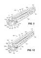
- FIGS. 3 and 4show perspective views of the clip shown in FIG. 1 from a first side
- FIG. 5shows a perspective view of the clip shown in FIG. 1 from the side opposite to that shown in FIGS. 3 and 4 ;
- FIG. 6is another side view of the clip shown in FIG. 1 ;
- FIG. 6 ais a close-up detail view of the portion of the clip shown in FIG. 6 in region “ 6 a ” therein;
- FIG. 6 bis a sectional view of the clip shown in FIG. 6 taken along section B-B in the direction shown in FIG. 6 ;
- FIG. 7is another side view of the clip shown in FIG. 1 from the opposite side to that shown in FIG. 6 ;
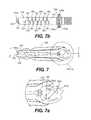
- FIG. 7 ais a close-up detail view of the portion of the clip shown in FIG. 7 in region “ 7 a ” therein;
- FIG. 7 bis a sectional view of the clip shown in FIG. 7 taken along section C-C in the direction shown in FIG. 7 ;
- FIGS. 8 a , 8 b , and 8 care side, top, and bottom views, respectively, of the clip shown in FIG. 1 in an open position;
- FIG. 9is a perspective view from the bottom of the clip shown in FIG. 8 a in the open position
- FIG. 10is a perspective side view from the top of the clip shown in FIG. 8 a in the open position
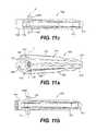
- FIGS. 11 a , 11 b , and 11 cshow side, top, and bottom views respectively, of the clip shown in FIG. 1 , with the proximal locking components in locked position;
- FIG. 12is a perspective view from the top of the clip shown in FIG. 11 a;
- FIG. 13is a side view of the clip shown in FIG. 11 a;
- FIG. 13 ais a close-up detail view of the portion of the clip shown in FIG. 13 in region “ 13 a ” therein;
- FIG. 14is a side view of the clip shown in FIG. 11 a from the side opposite to that shown in FIG. 13 ;
- FIG. 14 ais a close-up detail view of the portion of the clip shown in FIG. 14 in region “ 14 a ” therein;
- FIG. 15is a view of the clip shown in FIG. 1 ;
- FIG. 15 ais a close-up detail view of the portion of the clip shown in FIG. 15 in region “ 15 a ” therein;
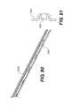
- FIG. 16shows a side view of an applier
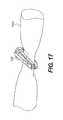
- FIG. 17shows a isometric view of clip latched on vessel
- FIG. 18shows a clip latched on vessel
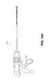
- FIG. 19shows an applier approach to vessel
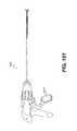
- FIG. 20shows an applier clamped on vessel
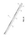
- FIG. 21shows a feed rail
- FIG. 22shows a wedge
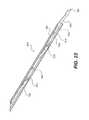
- FIG. 23shows a primary pusher
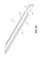
- FIG. 24shows a final pusher
- FIG. 25shows an inner tube
- FIG. 26shows an outer tube
- FIG. 27shows a jaw/inner tube camming
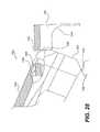
- FIG. 28shows a jaw/inner tube cam points
- FIGS. 29-31shows jaws
- FIG. 32shows inner and outer tubes cut away to see interior of distal end
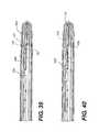
- FIG. 33shows a top feed rail cut away to see clip and wedge
- FIG. 34shows a final pusher cut away to show primary pusher
- FIG. 35shows jaws clamped on vessel
- FIG. 36shows a start of ligation—wedges, primary & final pushers begin to move
- FIG. 37shows an open clip advanced into jaws over vessel
- FIG. 38shows wedges advance to close clip legs down on vessel
- FIG. 39shows a second clip advanced into first clip rotating buttress and locking first clip
- FIG. 40shows wedges begin to retract, feeder rails are together keeping the second from retracting
- FIG. 41wedges continue to retract primary pusher and second clip retract
- FIG. 42shows second clip stops in notch on feeder rails, wedges and primary pushers continue to retract final pusher begins to retract;
- FIG. 43shows all moving parts return to start position, first clip on vessel is released when jaws are opened;
- FIG. 44shows a last clip in stack is locked with a false clip
- FIG. 45shows a false clip
- FIG. 46shows a dual trigger handle
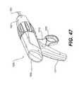
- FIG. 47show an isometric view of handle
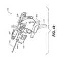
- FIG. 48shows a handle with shell and knobs exploded showing actuation mechanisms
- FIG. 49shows internal handle components
- FIG. 50shows triggers and mechanisms
- FIGS. 51-58show a pawl mechanism
- FIG. 59shows transmission parts
- FIG. 60shows a multi stage transmission
- FIG. 61shows a outer shell of transmission removed
- FIG. 62show a jaw actuation links removed
- FIG. 63shows a back outer shell removed
- FIG. 64shows a final pusher latches and dowels removed
- FIG. 65shows a primary pusher latches removed
- FIG. 66shows center spindles removed distal end connection points shown
- FIG. 67shows input positions when the jaws are open
- FIG. 68shows input positions when the jaws are clamped on vessel
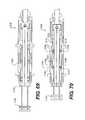
- FIG. 69shows input positions at a start of clip advance
- FIG. 70shows input positions for a first clip advanced over vessel by final pushers and wedges advance second clip advances by primary pushers
- FIG. 71shows input positions for wedges to advance to close first clip
- FIG. 72shows input positions for a clip latch—primary pushers advance second clip to lock first clip
- FIG. 73shows input positions for wedges to begin to retract
- FIG. 74shows input positions for primary pushers to retract and wedges continue to retract
- FIG. 75shows input positions for final pusher to retract other parts continue to retract
- FIG. 76shows input positions when everything returns to start position-second clip is now the first clip
- FIG. 77shows a walking beam
- FIG. 78shows a walking beam
- FIG. 79shows a walking beam
- FIG. 80shows a walking beam pusher
- FIG. 81shows a walking beam pusher
- FIG. 82shows a punch ring
- FIG. 83shows a punch door
- FIG. 84shows a door wedge
- FIG. 85shows a clip advancer
- FIG. 86shows a start position
- FIG. 87shows a clip advancer pushes first clip through doors
- FIG. 88shows a walking beam and clip advancers move forward to partially advance clip over vessel in jaws.
- the walking beam pusherstays stationary;
- FIG. 89shows the walking beam stops and the clip advancers push the clip the final distance
- FIG. 90shows punch doors fully closed against punch ring
- FIG. 91shows once the doors are closed the walking beam advances again and latches the clip
- FIG. 92shows the walking beam and clip advancers return to their start position
- FIG. 93shows a start of clip advance and latch
- FIG. 94shows a clip pushed through punch doors
- FIG. 95shows a clip opened by wedges on punch doors
- FIG. 96shows a clip pushed out of wedge/punch doors
- FIG. 97shows a clip latched
- FIG. 98shows a cross section end view with punch doors opened
- FIGS. 99-108shows a side view of an applier
- FIG. 109illustrates a side view of the clip according to another embodiment
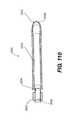
- FIG. 110illustrates a top view of the clip shown in FIG. 109 ;
- FIG. 111illustrates an isometric view of the clip shown in FIG. 109 ;
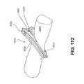
- FIG. 112illustrates an isometric view of a clip engaging a blood vessel
- FIG. 113illustrates a side view of a clip engaging a blood vessel.
- FIG. 114is an isometric view of an applier records of in accordance with an embodiment of the invention.
- FIG. 115is a partial isometric view of a distal end of an applier
- FIG. 116is a partial isometric view of the jaws on applier engaging a blood vessel
- FIG. 117is a isometric, partial, exploded view of a distal end of an applier
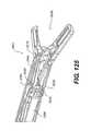
- FIG. 118is a partial cross-sectional view of a midsection of an applier
- FIGS. 119-126are isometric, cutaway views of the distal end of an applier
- FIG. 127is an isometric view of a clip stick pusher
- FIG. 128is a side view of a clip stack pusher
- FIGS. 129A and 129Bare front and rear views of a clip stick pusher
- FIG. 130is a partial cutaway distal view of an applier
- FIG. 131is a partial, perspective view of the distal end of a cam finger assembly
- FIG. 132is a partial, exploded view of a cam finger assembly
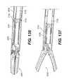
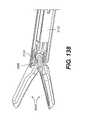
- FIGS. 133-138are partial cutaway isometric views of the distal end of an applier
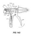
- FIG. 139is an exploded view of a handle portion of an applier
- FIGS. 140-145are partial cutaway views of the handle portion of the applier
- FIG. 146is a side view of another clip that may be used in accordance with invention.
- FIG. 147is a side view of the clip shown FIG. 146 and a closed position; and;
- FIG. 148is a isometric view of the clip illustrated in FIG. 146 .
- FIG. 1shows a view of a first embodiment of a surgical ligation clip 100 in accordance with present invention.
- the clip 100defines a longitudinal axis “L” along its longest dimension and includes a first leg 101 and a second leg 102 each extending along the longitudinal axis L and having proximal 111 , 112 and distal 121 , 122 end portions with respect to said longitudinal axis.
- proximalshall refer to the portion of the clip referenced herein which is away from the tips of the clip which open
- distalshall refer to the portion of the clip at the tips which open, in accordance with the convention that the clip is inserted distal tip first through an instrument towards an anatomical body to be ligated, such that distal generally refers to the direction away from the user or applier of the surgical clip and proximal refers to the direction opposite to distal.
- a clip hinge 130joins the first and second legs 101 , 102 at a point on their respective proximal end portions 111 , 112 , the first and second legs each having respective inner clamping surfaces 131 , 132 between the clip hinge 130 and the distal ends 123 , 124 of said first and second legs, the clamping surfaces being apposed when the clip is in a fully closed position.
- the term “apposed” when used with regard to the inner clamping surfaces 131 , 132shall mean close to, or nearly in contact with each other, allowing for some small spacing therebetween or a concave radius of curvature for the clamping surfaces, such to allow for a clipped vessel to reside between such apposed surfaces, as is more fully illustrated herein and with respect to the drawing figures.
- the clip hinge 130can include a bar or cylindrically shaped body or tube which defines a lateral pivot axis “P” (shown in FIGS. 2 b and 2 c ) about which the legs 101 and 102 pivot as the clip moves from open to closed position and vice versa.
- a first jaw structure 141 on the first leg 101extends proximal to a transverse axis “T” which is perpendicular to both the longitudinal axis L and lateral pivot axis P, all intersecting at a point “X” centered on the clip hinge 130 , as shown in FIG. 1 .
- the term “lateral”shall directionally mean orthogonal to both the directions of the longitudinal axis L and transverse axis T, and parallel to pivot axis P as shown in the figures.
- the first jaw structure 141includes a first curved inner surface 143 extending from the clip hinge 130 , the first curved inner surface 143 having a complex surface which is oriented at changing angles with respect to, but is generally facing towards, the longitudinal axis L, as shown in FIG. 1 .
- the curved inner surface 143is therefore substantially concave when viewed from the longitudinal axis (or plane spanning the longitudinal axis and pivot axis).
- substantially concaveshall mean a surface which is concave in overall curvature, but which may include one or more component areas which may have convex segments or protrusions, such as a notch surface or recess for mating thereto.
- a second jaw structure 142is on the second leg 102 extending proximal to the transverse axis T and has a second curved inner surface 144 extending from the clip hinge 130 .
- the “curved inner surface”can include either a single smoothly curved surface segment, or a series of connected curved or straight planar segments, which, taken together, form an overall generally curving surface.
- the surgical clip of the present inventionprovides that the jaws 141 and 142 are each substantially proximal to a transverse plane extending through transverse axis T and lateral pivot axis P, thus behind the clip hinge 130 , thereby providing a means for actuating the clip legs 101 and 102 and biasing or locking the clip and its mating faces 131 , 132 in a closed position, which biasing or locking means can be actuated and/or applied by acting only on the proximal end portions of the clip 100 , without having to lock the distal ends 123 , 124 to each other or use a clip applier tool which acts on said distal ends 123 , 124 , thereby obviating the need to dissect tissue around the distal end of the clip as in previously known surgical ligation clips.
- the means for biasing or locking the clip closedincludes a wedge or buttress body 150 which extends from and is connected to the second jaw structure 142 by a first living hinge 160 at a proximal end of said second jaw structure 142 , the buttress body 150 having an outer surface 151 at a proximal first end portion thereof, which is also disposed approximately as the proximal end of the clip 100 overall.
- the first and second jaw structures 141 , 142are spaced on opposite sides of the longitudinal axis L and define a locking space 170 there between.
- the wedge or buttress body 150is pivotable about the living hinge 160 to move into the locking space 170 such that the outer surface 151 of the proximal first end portion of the buttress body 150 abuts against a proximal portion 145 of the curved inner surface 143 of the first jaw structure 141 to bias the clip in a closed position (as best shown in FIGS. 11 a , and 12 - 14 ).
- the clip 100is shown in FIG. 1 in a closed position, this is with the locking means of the first and second jaws 141 , 142 and buttress body 150 being in the “unlocked” position as shown in FIGS. 1, 2 a , and 3 - 7 .
- the buttress bodyis in the “locked” position as shown in FIGS.
- the first and second jaws 141 , 142are urged or spread apart (shown, as an example, by arrows “J 1 ” and “J 2 ” in FIGS. 13 a and 14 a ) by action of surfaces of the wedge/buttress body 150 acting on portions of curved inner surfaces 143 , 144 , which act as moments about the clip hinge 130 and lateral pivot axis P to urge the legs 101 , 102 and its inner clamping surfaces 131 , 132 to become more closely apposed to each other, thereby providing additional clamping and closing force over a vessel around which the clip is applied.
- a variety of meansmay be used to actuate the wedge or buttress body 150 from the unlocked position in FIG. 1 to the locked position shown in FIGS. 11 a , 12 - 14 .
- an external forceshown, for example, as arrow “F” in FIG. 1
- the external force appliedmay be at a small angle to the longitudinal axis L, such as, for example, a force shown by arrow “F*” shown in FIG. 1 .
- the applied external forcewill create a moment about living hinge 160 to pivot the buttress body 150 into the locking space 170 .
- the external forcemay be applied by an actuating rod or other structural means in an applier instrument, or may be another clip as fed through a multi-clip applier.
- the clip 100may be inserted through an instrument having a bore or channel for receiving the clip 100 , through which the clip 100 may travel distally for positioning near a vessel during a surgical procedure.
- the clipmay be inserted in a legs closed position, but with the proximal locking means including buttress body 150 in open, unlocked position.
- the clip 100can be inserted in such fashion in closed form, the clip forms a narrow profile and can fit in smaller sized surgical instruments, thereby allowing for smaller incisions and tissue dissection or damage during surgery.
- a rod or other actuating mechanism translating or moveable on the instrument inserting the clip, or a second instrument or second clip used in conjunction with the instrument used for inserting and positioning the clip in place,maybe used to lock the clip by application of an external force on the proximal end portion of the clip as discussed above.
- a method of applying a surgical ligation clip on a vesselincludes positioning a clip, such as, for example, clip 100 , in an open position proximate a vessel, the clip having first and second legs each extending along a longitudinal axis of the clip and having proximal and distal end portions with respect to said longitudinal axis, a clip hinge means joining the first and second legs at a point on their respective proximal end portions, the first and second legs each having inner clamping surface means between the clip hinge and the distal end portions of said first and second legs, the clamping surface means being apposed when the clip is in a fully closed position.
- a clipsuch as, for example, clip 100
- a locking means for biasing the legs closedmay extend proximal to a transverse axis perpendicular to the longitudinal axis intersecting at a point centered on the clip hinge.
- the methodincludes applying an external force to a proximal end portion of the clip or of one of the legs which forms a portion of the locking means, to move a body formed as a first part of said locking means from a first position to a second position to provide an abutment force between said body and a surface formed on a second part of said locking means to bias the clip in a closed position.
- an instrumentin the method, may be used, wherein, in moving the clip through the instrument prior to positioning the clip proximate a vessel, a portion of the instrument opens the clip from a closed position to an open position, such that the legs of the clip open for placement of the clip around a vessel.
- the locking meansmay then be applied to the proximal end portion of the clip to move and bias the legs closed and clamp the clip more fully over the vessel.
- the clamping surfacesappear substantially parallel to each other, oriented, in the clip closed position, substantially or very close to parallel to a plane extending through the longitudinal axis L and lateral pivot axis P.
- the inner clamping surfaces 131 , 132may be slightly curved concave when facing said surfaces, such that the surfaces bow away from the longitudinal axis L and straighten slightly when clamping force is applied by action of the locking mechanism of the buttress body 150 acting against jaws 141 , 142 . This allows for enhanced grasping and occlusion of vessels around which the clip 100 is applied, wherein the clamping force is spread more evenly across the clamping surface.
- the living hinge 160 connecting the wedge or buttress body 150 to the second jaw 142can be integral to the second jaw 142 such that the clip body of second leg 102 proximal to transverse axis T extends as a single unitary structure including the second jaw 142 and entire wedge or buttress body 150 .
- a lateral beam or curved body 152connects the living hinge 160 to the rest of the buttress body 150 , which beam 152 curves from the living hinge 160 (which is separated by a distance from the longitudinal axis L) towards the longitudinal axis L.
- portions of wedge of buttress body 150can be oriented on both sides of longitudinal axis L.
- the pivot axis of living hinge 160extends in a lateral direction parallel the lateral pivot axis P of the main clip hinge 130 .
- the present inventionprovides, in various embodiments, a locking mechanism cooperating between the buttress body 150 and another portion of the clip.
- the proximal end portion 145 of the curved inner surface 143 of the first jaw structure 141defines a notch 147 recessed from said curved inner surface 143
- the buttress body 150defines a detent 157 formed on the outer surface thereof, the detent 157 mating with the notch 147 when the buttress body 150 is pivoted into the locking space 170 to bias the clip in the closed position, as best shown in FIGS. 11 a , 12 , and 14 .
- FIGS. 2 a , 2 b , and 2 cshow side, top, and bottom views respectively, of the clip shown in FIG. 1 .
- the wedge or buttress body 150can be divided into two lateral sections or portions 150 a and 150 b , each on opposite sides of the longitudinal axis L as shown, and can form approximate lateral halves of the buttress body 150 , with a possible space or small channel in-between.
- Lateral portion 150 b of the buttress body 150can have a width in a plane spanning the transverse and longitudinal axes sufficient to exceed a complementary width formed by the locking space 170 to create an interference fit between the proximal end portion 145 of the curved inner surface 143 of the first jaw structure 141 and the outer surfaces 151 a , 151 b on the proximal first end portion outer surface 151 of the buttress body 150 , to bias the clip in a closed position.
- An example of the transverse width of said lateral portion 150 bis shown as distance “TW 1 ” in FIG.
- the buttress body 150once locked into place as shown in FIG. 12 , is prevented from moving laterally from side to side since the notch 147 and detent 157 interlock only extends laterally partially across the clip, the detent 157 being limited in lateral movement by a shoulder 187 formed by a termination of the notch 147 laterally into the first jaw structure 141 , as shown in FIG. 9 .
- the lateral slice of buttress body 150only extends for a lateral width LW 1 which includes detent 157 , which the lateral slice LW 2 of buttress body 150 on the other side of the clip does not include the detent 157 .
- the proximal locking mechanism of the clip 100is more stable in lateral directions, which is also useful for keeping all parts of the clip together in the event the living hinge 160 may break.
- the outer surface 151 on proximal first end portion of buttress body 150 on a proximal end of the clip 100defines one or more surfaces which form a curved planar segment abutment portion, which in the embodiment as shown includes curved planar segment abutment portions 151 a and 151 b .
- the “curved planar segment abutment portion” formed by a surfacemay include a single curved surface segment or a series of curved or straight planar surface segments connected to one another which form an overall generally curved surface, each of the surface segments extending as a surface at least laterally. In the embodiment shown in FIG.
- curved planar segment abutment portion 151 aincluded planar and curved surface segments formed by the notch 157 and extends laterally for about one-half of the lateral width of clip 100
- curved planar segment abutment portion 151 bincludes planar and curved surface segments which also extend laterally for about one-half of the lateral width of clip 100 .
- Each of the curved planar segment abutment portions 151 a and 151 b on outer surface 151forms a substantial abutment surface that pushes against complementary curved inner surfaces of jaw 141 to provide a stronger and more stable locking mechanism for clip 100 .
- the second curved inner surface 144 on the second jaw structure 142forms a first laterally spanning recessed groove 146 separated from the clip hinge 130 and a first laterally spanning ball-shaped or rounded protruding surface 148 proximal to said recessed groove 146
- a distal second end portion of the buttress body 150forms a second laterally spanning recessed groove 158 and a second laterally spanning ball-shaped or rounded protruding surface 156 distal to said second recessed groove which are shaped complementary to the first rounded surface 148 and first recessed groove 146 , respectively, so as to mate in abutment when the buttress body 150 is pivoted into the locking space 170 to further stabilize and bias the clip in a closed position.
- the first recessed groove 146 , first rounded surface 148 , second recessed groove 158 , and second rounded surface 156may extend laterally all the way across the lateral width of the buttress body 150 , such that the first rounded surface 148 and second rounded surface 156 are not spherically shaped but rather form an extended, laterally-spanning, rounded, semi-cylindrical surface which can mate in corresponding semi-cylindrical shaped grooves formed by first recessed groove 146 and second recessed groove 158 .
- the buttress body 150can further define a second living hinge 162 extending laterally between the proximal first end portion 150 c of buttress body 150 and a distal second end portion 150 d , wherein the proximal first end portion 150 c including outer surface 151 further pivots about said second living hinge 162 when the buttress body 150 moves into the locking space 170 , allowing the outer surface 151 of the proximal first end portion 150 c of the buttress body to flex towards the longitudinal axis L prior to abutment against the curved inner surface 143 of the first jaw structure 141 .
- the outer surface of the proximal end of the buttress body 150 , or clip 100 itself,defines a V- or L-shaped laterally spanning notch 150 x on the proximal end of the clip 100 and further defines a laterally spanning flange 150 y extending from said notch 150 x adjacent to the curved planar segment abutment portions 151 a and 151 b .
- Each of notch 150 x and flange 150 ymay be divided into two lateral sections or components divided by a small space or channel there between as they are disposed on the lateral sectional halves 150 a and 150 b of the buttress body 150 .
- the notch 150 xprovides a receiving space for the tip of an instrument, pushing or actuating rod, or another clip, so as to enable a more stable actuation of the buttress body 150 into locking space 170 to lock the clip 100 .
- the flange 150 ymay act to limit the movement of buttress body 150 once fully inserted into locked position inside space 170 , and also further stabilizes the locking mechanism for the clip 100 .
- the buttress bodymay occupy a majority of a volume defined by locking space 170 when it is moved into clip locked position so as to bias the legs 101 , 102 in a closed position.
- the volume defined by the locking spaceis limited by the lateral width of the clip legs 101 , 102 near the hinge 130 and the jaws 141 and 142 .
- the remaining locking space 170 ′ between jaws 141 and 142once the clip is locked by movement of the buttress body 150 into space 170 , is less than half the volume of the locking space 170 as shown in FIG. 6 a .
- the presence of a bulky body like buttress body 150which occupies the majority of the volume or space between proximal extending jaws 141 and 142 when the clip 100 is in the locked position further provides a greater strength and stability to the locking of said clip.
- the buttress body 150can be characterized in one way as having a core mass which has, in a transverse plane spanning the longitudinal and transverse axes, a cross-section which approximately spans a trapezoidal shape, having rounded curved sides extending from the sides TP 1 , TP 2 , TP 3 , TP 4 of the trapezoid.
- Side TP 1defines the longest side and one of the parallel sides of the trapezoid, while side TP 2 defines the shorter parallel side.
- Side TP 3defines the longer and more distal of the non-parallel sides, while side TP 4 defines the shorter and more proximal non-parallel side.
- Side TP 1is therefore connected to sides TP 3 and TP 4 .
- the vertex TPX 1 of sides TP 1 and TP 4lies approximately on or near the longitudinal axis L, and side TP 1 makes an angle ⁇ below the longitudinal axis, towards proximal jaw 142 , such angle ⁇ being, in one embodiment, approximately 30 degrees.
- the rounded laterally-spanning protuberance 156extends substantially from side TP 3 .
- the clip hinge 130can also be a resilient hinge providing additional biasing force to maintain the inner clamping surfaces 131 , 132 of the legs towards a closed position.
- a span of each leg extending from the clip hinge 130 to its respective distal tip 123 , 124can be, in one embodiment of the present invention, at least 75% to 80% of an overall length of the clip.
- the clip hinge 130can define lateral bosses which extend laterally from the side surfaces of the clip legs, defining a bossed width or span which is greater than the clip width.
- the clip hinge 130is formed as a laterally extending bar 130 x integrally formed with the first and second legs 101 , 102 , each leg being resiliently coupled to first and second transverse sides of said bar, the bar 130 x further defining laterally spanning grooves 130 a and 130 b on longitudinally distal and proximal sides of the bar, respectively.
- These grooves 130 a and 130 bfurther enable the clip 100 to flex as pivoting about the lateral axis of hinge 130 , and further provide a resilient pivoting moment or force about said hinge.
- flanges 191 and 192extend longitudinally across respective outer surfaces of each of the first and second legs 101 , 102 which are on opposite sides to the inner clamping surfaces 131 , 132 of each respective leg, the flange 191 of the first leg 101 extending from the first jaw structure 141 to the distal end portion 121 of the first leg 101 , the flange 192 of the second leg 102 extending from the second jaw structure 142 to the distal end portion 122 of the second leg 102 .
- Each of the flanges 191 , 192defines a transverse indentation 191 a , 192 a proximate the distal end portions 121 , 122 of the legs 101 , 102 .
- the flanges 191 and 192provide a rigidity to legs 101 and 102 , respectively, such that said legs do not easily bend.
- Transverse indentations 191 a and 192 aprovide a means for a clip applier to better actuate or grip the legs 101 , 102 .
- the clip 100further includes serrations, ridges, or teeth 181 , 182 on the inner clamping surfaces 131 and 132 , respectively, as shown in FIGS. 6 b and 7 b , and 9 , 10 , and 15 a .
- the teeth or ridges 181 , 182provide additional grasping means to better attach and clamp the clip 100 onto a vessel when closed.
- the teeth or ridges 181 , 182are disposed to fit into complementarily arranged grooves 183 and 184 on the clamping surfaces 131 and 132 , respectively.
- the teeth 181 , 182may have a slanted orientation, extending proximally, so as to better grip tissue. As best shown in FIGS.
- a pair of distal hook elements 194 and 195may be disposed on the absolute distal tips of legs 101 and 102 , respectively, each hook 194 and 195 offset laterally with respect to each other to form a scissor-like configuration, such that each hook 194 and 195 fit into corresponding recesses 195 a and 194 a , respectively, on the distal tips of legs 102 and 101 , respectively.
- This mechanismprovides means to further grip and contain tissue with the space between the clamping surfaces 131 , 132 when the clip 100 is applied to body vessel, as illustrated in FIGS. 19 and 20 .
- the clip 100may be in a range of sizes. As shown in FIG. 15 , an overall length “S 1 ” of the clip 100 may be approximately 0.50 inches; the length “S 2 ”, between the intersection of transverse axis T and longitudinal axis L centered at clip hinge 130 and the distal tip of the clip, may be approximately 0.40 inches, and the radius of curvature of the inner mating or clamping surfaces 131 , 132 of the legs 101 , 102 may be approximately 3.0 inches. Such sizes and dimensions are given as an example, and it is understood that the clip may, in one or more embodiments of the invention, vary in size ranging from approximately 0.15 to 0.80 inches in overall longitudinal length, and from approximately 0.03 to 0.15 inches in lateral width. As one embodiment of the invention, the illustration of clip 100 in FIG. 15 is shown as a scaled magnification of actual size, and shows all the parts of the clip 100 in actual proportion to each other.
- the instrumentation used to deploy the clips discussed hereinmay include a manually loaded device that can apply a single clip at a time, or an automatically fed, multi-clip applier.
- Both applierscan be endoscopic instruments suitable for use in laparoscopic surgery applications. In both cases the applier will clamp over the vessel to flatten the section to be ligated. The clip will then be opened, positioned over the vessel and closed. Once closed, a mechanism will engage the locking feature on the proximal end of the clips disclosed herein, to the to maintain the clamping pressure of the clip.
- a manual applierwill load/apply a single clip at a time.
- An automatic applierwill be able to load/apply multiple clips before the instrument has to be removed from the surgical site.
- the sequence of clip applicationis as follows:
- the various embodiments of the clips disclosed hereintherefore can start in an as-molded state; can be opened further to better encapsulate the vessel; and can then be closed further (into a 3rd state). This process of opening and closing the clip can be repeated as needed, prior to locking.
- the clipWhen closed and locked, the clip provides an active clamping force which can also squeeze the vessel, which is beneficial if the vessel necroses and/or shrinks over time.
- the various embodiments of the surgical clips of the present inventionare preferably made of one or more polymer materials, such as, by example, acetyl homopolymer, but could also be made of a variety of other materials, including one or more metals, or a combination of metal and polymer or plastic.
- the radiopacity of the clipcan be “tuned” to a desirable level, or can be tuned to be radiopaque.
- the various embodiments of surgical clips of the present inventionare an improvement over the known polymeric surgical ligation clips, as well as standard metal clips.
- the resulting advantages of the surgical clip of the invention as disclosed hereinare: the ability to deliver a larger clip through a smaller endoscopic instrument; the ability to place a clip on a vessel just like a prior art malleable and deformable metal clip, with no need for added dissection or cleaning around the vessel, but with greater retention force than metal clips, which results in a reduced risk of clips slipping off the vessels.
- the greater clip locking stability and clip retention forceis accomplished by the locking feature applying an active biasing or clamping force as discussed above, versus the passive clamping action created by plastic deformation of malleable metal clips.
- the litigation clip appliercan be split into three main sections for discussion. They are the distal end or shaft, the multistage transmission, and the handle.
- One embodiment of the distal portion of the applieris made up of 12 parts.
- Two feeder railssee FIG. 21 , two wedges, see FIG. 22 , two primary pushers see FIG. 23 , two final pushers, see FIG. 24 , inner and outer tubes, see FIGS. 25 and 26 , and two jaws, see FIG. 31 .
- the outer tubehas tabs with holes that the jaws fit into and rotate about.
- the inner tubeconnects to the jaws in a pocket that provides the cam surface to open and close the jaws, see FIGS. 27 and 28 .
- the inner tubeacts as a push pull link to actuate the jaws, see FIGS. 19 and 20 for jaw actuation.
- the two feeder railsare assembled so that they make pockets to hold the clips, the number of clips to be held is determined by the ratio of the overall length of the applier and the size of the clip.
- the railsare spring loaded together and spread apart when the bosses on the clips pass through to the next pocket.
- the primary pushersride on the sides of the feeder rails, the primary pusher has spring fingers that are spaced equidistant to match the pockets in the feed rail. When advanced they push the entire stack of clips forward to the next pocket in the feed rails. They also provide the push that allows the second clip to lock the first clip.
- the final pushersride outside of the primary pushers and are what advanced the first clip over a vessel in the jaws of the applier.
- the final pushersalso hold the first clip in place while the wedges retract.
- the wedgesare just inside the feeder rails and are spring loaded together at the ends to open the first clip as it is advanced forward.
- the wedgesalso move forward into the jaws to cam the legs of the clip closed after it has fully advanced.
- the spring load for the wedgesis provided by spring tabs in the outer tube that push down on the wedges.
- the false clipis advanced down the distal portion of the applier the same way the stack of clips is advanced. For actuation of the parts and clip advance/lock, see FIGS. 32-44 .
- the proximal end of the applier, or applier handleis made up of many parts that provide a user interface portion of the applier. Each of the distal end actuations are accomplished through the use of the proximal handle.
- the handlehas a two piece outer shell which stages the internal actuating components and provides a bearing surface for a multi stage transmission to allow 360° continuous rotation of the distal end.
- both triggersrotate around the same center point, see FIG. 50 .
- the lower triggeractuates the jaws and the upper trigger actuates the clip delivery sequence.
- the lower triggeris attached to the multistage transmission through two mirrored linkages which have features that allow the trigger to lock down when the jaws are closed. This feature is an over center cam.
- the linkagesalso have an inner profile which allows them to drive the section of the multistage transmission that actuates the jaws while allowing the 360° continuous rotation.
- the return stroke of the lower triggeris accomplished through a return spring attached to a cable that wraps around the front of the trigger and based on a pin at the proximal side of the handle.
- the upper triggeris attached to the multistage transmission through a linkage which has and inner profile that drives the section of the multistage transmission that actuates the clip delivery mechanisms and also allows the 360° continuous rotation.
- the return stoke of the upper triggeris accomplished through a return spring attached to the back side of the trigger and based on a pin at the proximal side of the handle. For both the actuation and return strokes there is a one way pawl that limits the direction of the upper trigger until a full stroke is completed. There is also a low clip indication/last clip lockout that is actuated when the false clip moves down shaft.
- a crimped on ballthat starts to pull on the lockout latch which begins to move the lockout lever.
- the top of the lockout leverhas an indicator that shows through a window in the handle outer shells indicating low clips in one color and then indicates no clips left in another. When there are no clips left the lockout lever engages the ligate trigger and locks the trigger in place.
- the jaw triggerstill functions see FIG. 50 for triggers and actuating components.
- the trigger functionsare reversed so that the upper trigger actuates the jaws and the lower trigger actuates the clip delivery mechanisms.
- the distal portion of the applieris connected to the handle through the multi stage transmission, see FIGS. 49 and 50 .
- One embodiment of the transmissionis made up of a two piece outer shell which acts as the bearing to allow the rotation of the distal end. Internal to the shell are features that guide the internal components during the actuation sequences of the applier.
- the jaw linkssnap together and ride on the internal surface of the transmission shell.
- the area between the jaw linksis open to allow for additional transmission pails.
- the final pusher latch and the primary pusher latchmove over the center spindles and are guided in slots on the outer shell of the transmission.
- Small pinsmove in and out of groves in the two pieces and the outer shell to achieve the appropriate timing for the clip delivery mechanisms in the shaft, see FIGS. 59-66 for the transmission assembly and FIGS. 67-76 for actuation sequence.
- Another embodiment of the distal portion of the applieris made up of 10 parts.
- the outer tubehas tabs with holes that the jaws fit into and rotate about.
- the inner tubeconnects to the jaws in a pocket that provides the cam surface to open and close the jaws.
- the inner tubeacts as a push pull link to actuate the jaws.
- the walking beam pusherrides in grooves on the walking beam.
- the punch ringis permanently fixed to the distal end of the walking beam and provides the attachment point for the punch doors.
- the punch doorsare attached to the punch ring via a rivet or tabs that allow the doors to rotate.
- the doorsare forced closed by a torsion spring or may be a plastic part that has spring like characteristics that keep the doors closed.
- On the underside of the punch doorsare wedges that force the clip to open when the clip is pushed through the doors.
- the clipis pushed forward by a pair of clip advancers that ride on the outside of the walking beam and walking beam pusher.
- FIG. 86-97A cross-section of the distal end is shown in FIG. 98 for assembly reference.
- the distal portion of the applierwould be attached to a proximal handle with components that achieve the proper sequence to successfully apply a ligation clip.
- the following discussionrefers to the FIGS. and specific reference characters.
- FIG. 16shows an applier 1000 in accordance with an embodiment of the invention.
- the applier 1000is shown about to clamp a blood vessel or tissue 1002 .
- the applier 1000includes jaws 1004 , a shaft 1003 , and a clamshell transmission housing 1007 .
- the applier 1000also includes a clamshell housing 1009 , a handle 1011 , a ligate trigger 1013 , and a jaw actuating trigger 1015 .
- FIGS. 17 and 18shows a clip 100 after it has clamped a vessel or tissue 1002 via the applier 1000 .
- the clip 100has the first 101 and second legs 102 locked in a clamping position over the vessel or tissue 1002 .
- the buttress body 150 on the clip 100has moved forward and locked the legs 101 and 102 by interlocking the detent 157 into the notch 147 .
- FIG. 19shows the applier 1000 about to clamp a vessel or tissue 1002 .
- the upper jaw 1006 and the lower jaw 1008are positioned to be above the vessel or tissue 1002 .
- FIG. 20shows the jaws 1004 of the applier 1000 shut and thereby clamping the vessel or tissue 1002 with the jaws 1004 .
- FIGS. 21-31show various parts of the applier 1000 .
- FIG. 21shows a feed rail 1010 .
- the feed rail 1010has end projections 1014 and cut out slots 1012 .
- the cut out slots 1012form slots that will be discussed in more detail later.
- FIG. 22shows a wedge 1016 . While only one is shown in FIG. 22 in the applier 1000 , there are two wedges 1016 and they are identical or mirror images of each other.
- the wedges 1016include a thicker portion 1018 , a slanted surface 1020 and define a U-shaped channel 1022 .
- FIG. 23shows a primary pusher 1024 . While only one primary pusher 1024 is shown in FIG. 23 there are two primary pusher 1024 that are identical or mirror images of each other in the applier 1000 .
- the primary pusher 1024includes a flat portion 1026 , two rails 1028 , and several forked engagers 1030 .
- the forked engagers 1030connect to the flat portion 1026 via a engager connector 1032 .
- the number of forked engagers 1030may vary depending upon the length of the shaft 1003 (See FIG. 16 ) and how many clips 100 are loaded in the applier 1000 .
- the forked engagers 1030are used to move the clips 100 forward and will be discussed further below.
- FIG. 24shows a final pusher 1036 .
- the final pusher 1036includes a pusher backing 1037 , two sets of pusher rails 1038 , a pusher engager connector 1040 and a final pusher forked engager 1042 .
- the final pusher forked engager 1042will engage and push a clip 100 (not shown in FIG. 24 ) as will be discussed later.
- FIG. 25shows an inner tube 1044 .
- the inner tube 1044has T-shaped connecting structure 1046 , U-shaped channels 1048 , a top slot 1050 and guides 1052 in the top slot 1050 .
- FIG. 26shows a outer tube 1054 .
- the outer tube 1054provides the outer housing for the shaft 1003 .
- the outer tube 1054has eye brackets 1056 defining holes 1058 .
- the outer tube 1054also has leaf spring limbs 1060 . The leaf spring limbs 1060 extend into the interior of the outer tube 1054 .
- FIG. 27shows the jaws 1004 connected to the inner tube 1044 .
- the jaws 1004have T-shaped structure holes 1064 .
- the T-shaped connecting structure 1046 of the inner tube 1044fit into the T-shaped structure holes 1064 of the jaws 1004 and allow the jaws 1004 to pivot on the T-shaped structure 1046 .
- the jaws 1004have jaw grooves 1062 for assisting in the engagement of the jaws 1004 with a vessel or tissue 1002 .
- the jaws 1004also have pushing surfaces 1072 . When an object pushes against the pushing surfaces 1072 the jaws 1004 will pivot on the T-shaped structure 1046 to an opened position.
- FIG. 28is an enlarged partial view of the jaws 1004 and the inner tube 1044 .
- the top jaw 1006has a press point 1070 with the lower jaw 1008 .
- the cam surface 1066 on the inner tube 1044is seen as well as the cam surface 1068 on the jaw 1006 .
- the cam surfaces 1066 and 1068urge against each other as the jaws 1004 open.
- the cam surfaces 1066 and 1068also urge against each other as the jaws 1004 close.
- FIG. 29-31show various views of the top jaw 1006 .
- the top jaw 1006is the same as or a mirror image of the low jaw 1008 .
- the top jaw 1006has T-shaped structure holes 1064 , jaw hinge pins 1074 and hinge pin caps 1076 .
- the hinge pin caps 1076have been removed from one of the jaw hinge pins 1074 for clarity, usually there are hinge pin caps 1076 on each hinge pin 1074 .
- the top 1078 and the bottom 1080 of the top jaw 1006are shown.
- FIG. 32is a side isometric view of a part of the applier 1000 .
- the inner 1044 and outer tubes 1054are cut away to better show interior parts.
- the jaws 1004are clamped on a vessel or tissue 1002 .
- the clip 100has not yet moved forward into the jaws 1004 so that it can clamp the vessel or tissue 1002 .
- the end projections 1014 of the feed rail 1010are visible.
- the slot cut outs 1012make a space for the jaw hinge pin 1074 to reside.
- the final pusher forked engager 1042is spaced from the hinge pin 1074 on the clip 100 .
- the final pusher engager connector 1040connects the final pusher forked engager 1042 to the final pusher back 1037 .
- the clip 100is in a somewhat open position and the leaf spring limbs 1060 are not engaging the clip 100 .
- the wedges 1016can also be seen.
- FIG. 33is similar to FIG. 32 but shows the top feed rail 1010 cut away.
- the clip 100 and the top wedge 1016can be seen along with the final pusher 1036 .
- FIG. 34a similar view of the applier 1000 is shown but the top of the final pusher 1036 is cut away.
- the clip 100can be seen.
- a second clip 1252can be seen in position behind the first clip 100 .
- the primary pusher 1024can be seen. Once the first clip 100 is applied, the second clip 1084 will move forward and become the first clip 100 (from the point of view of position) as will be explained later.
- FIGS. 35-44will illustrate in cross section views the application sequence and forward movement of the clips 100 , 1084 in the applier 1000 .
- the jaws 1004are clamped on the vessel or tissue 1002 .
- the end projections 1014are visible forward the clip 100 .
- the top wedge 1016is also visible.
- the final pusher 1036is cut in half for clarity.
- a second clip 1084may also be seen with the primary pusher 1024 behind the second clip 1084 .
- FIG. 35shows an initial condition of the various parts of the applier 1000 when the jaws 1004 are first clamped on the vessel or tissue 1002 .
- FIG. 36shows the start of ligation.
- the wedges 1016 , the primary pushers 1024 and the final pusher 1036begin to move.
- the feeder rails 1010spread apart to allow the boss 1082 on the clip 100 to pass through.
- the primary pusher 1024engages the second clip 1084 .
- the wedges 1016open the clip 100 and by a camming action between the thicker portion 1018 of the wedge and the clip 100 .
- the final pusher 1036advances the open clip 100 into the jaws 1004 and over the vessel or tissue 1002 .
- the primary pusher 1024advances the second clip 1084 (and any other clips that may be located behind the initial clip 100 ).
- FIG. 38shows the wedges 1084 advancing by action of the primary pusher 1024 .
- the wedges 1016advance to close the clip 100 onto the vessel or tissue 1002 .
- the second clip 1084advances by action of the primary pusher 1024 into buttress 150 of the first clip 100 (sometimes referred to as the initial clip 100 ).
- the buttress 150is moved by the second clip 1084 to the point that the detent 157 fits into the notch 147 thereby locking the first clip 100 onto the vessel or tissue 1002 .
- the wedges 1016retract, however, the feeder rails 1010 (partially cut away in FIG. 40 and are better shown in FIG. 35 ) stay together and thus keep the second clip 1084 from retracting.
- the final pusher 1036stays in place to keep the initial clip 100 in a forward position.
- FIG. 41the wedges 1016 , the primary pusher 1024 and the second clip 1084 (and any other clips behind the initial clip retract).
- FIG. 42the second clip 1084 stops in the slot 1012 (best shown in FIG. 32 ) in the feeder rails 1010 .
- the wedges 1016 , primary pushers 1024 and the final pusher 1036begin to retract.
- FIG. 43shows the parts returning to an initial or start condition.
- the thicker portion 1018 of the wedges 1016open top 101 and bottom 102 legs of the second clip 1084 .
- the first clip 100was released and exited the applier 1000 when the jaws 1004 were opened.
- the second clip 1084now becomes the first clip 100 and the cycle starts over.
- FIG. 44shows how that final clip 1086 is applied.
- the cycleis substantially the same as described above for applying a clip 100 but a false clip 1088 performs the function of locking the last clip 1086 .
- FIG. 45shows the false clip 1088 .
- the false clip 1088includes longitudinal ridges 1090 , a butting face 1092 , a boss 1094 . These features perform similar functions as the similar features found on the actual clip 100 .
- the false clip 1088also has a hole 1096 .
- FIGS. 46-58show and describe how the applier receives inputs from a user and provides those inputs to the transmission 1098 .
- the transmission 1098receives the inputs and converts them to motions to the parts that act on the clips 100 , 1084 , 1086 .
- FIGS. 46 and 47show a part of an applier 1000 having a shaft 1003 , a transmission housing 1007 , a clam shell housing 1009 , and handle 1011 , a ligate trigger 1013 and a jaw trigger 1015 . While claim shell housings may be described herein, other types of housings may be used.
- FIG. 48shows and exploded view of part of the applier and some of the internal mechanisms.
- FIGS. 49 and 50shows many of the internal components in more detail.
- the transmission 1098has a jaw link input 1110 having a jaw link input groove 1112 , a center spindle 1114 and a second input 1116 having a second input groove 1118 .
- An upper grasper lever pin 1102fits into the jaw link input groove 1112 and moves to provide an input to the transmission 1098 .
- the upper grasper lever pin 1102also fits into grasper lever holes 1106 and is controlled by the grasper levers 1100 .
- the grasper levers 1100have grasper lever slots 1108 in which the lower grasper lever pin 1104 rides.
- the lower grasper lever pin 1104fits into the jaw trigger pin holes 1154 on the jaw trigger 1015 .
- the grasper levers 1100 and thus the input 1110is controlled by the grasper/jaw trigger 1015 .
- the ligate lever 1120has ligate lever slots 1122 in which the ratchet plate pin 1160 resides.
- the ratchet plate pin 1160also fits in the ratchet plate pin holes 1162 on the ratchet plates 1158 .
- the ligate lever 1120is controlled by the ratchet plates 1158 .
- the ligate lever 1120has ligate lever trunnions 1124 which fit into the second input groove 1118 in the second input 1116 .
- the ligate lever 1120controls the second input 1116 .
- the ratchet plates 1158have ratchet teeth 1166 and disengaging cams 1168 that interact with forward 1126 and rearward 1128 facing pawls.
- the pawls 1126 , 1128ride on a pawl shaft 1130 that is connected by a pawl spring 1132 connected to a spring anchor 1134 .
- the inputs 1110 and 1116are circular and the features (i.e. pins) that control the inputs may be rotated 360° about the inputs 1110 and 1116 so that a user can manipulate the triggers 1013 and 1015 from a rotated position with respect to the transmission 1098 and jaws 1004 .
- FIGS. 51-58show the pawl mechanism and its accompanying discussion will explain how the pawl mechanism works.
- Springs 1146 and 1148are used to bias the triggers 1013 and 1015 to a position against the handle 1011 .
- the triggers 1013 and 1015 and the ratchet plates 1158all pivot about the same hole 1156 .
- a pivot pinmay be provided or trunnion on the housing 1009 may provide a pivot.
- a spring extension 1150may be used to connect either or both of the springs 1148 and 1146 to a desired feature.
- the spring extension 1150may attach to the pin 1152 which may fit in holes 1164 in the ratchet plates 1158 .
- a low clip indicator spring 1136may fit around a low clip indictor anchor 1138 .
- the low clip indicator 1136is connected to the low clip indicator 1140 , which in turn is connected to the last clip lock out 1142 and grommets 1144 .
- the low clip indicator 1140may help a user to know that the amount of clips in the applier are low.
- the last clip lockout 1142may prevent the user from using the applier 1000 when there are no more clips in the applier 1000 .
- FIG. 50shows a trigger lock 1170 .
- the trigger lock 1170has a trigger lock groove 1172 .
- a trigger release 1178has a detent 1174 that fits into the trigger lock groove 1172 .
- a trigger lock spring 1176urges the trigger release 1178 toward the trigger 1013 .
- FIG. 51shows an initial condition where the triggers 1013 and 1015 (not well shown in FIG. 51 ) are in a position against the handle 1011 (see FIG. 16 )
- the triggers 1013 and 1015 and the ratchet plates 1158will move as shown and described.
- the teeth 1166 on ratchet plates 1158are not engaged with either the forward facing 1126 or the rearward facing 1128 pawl.
- the pawl anchoris attached to the housing 1009 (a front housing piece has been removed to the pawl mechanism may be seen).
- the disengaging cam 1168has disengaged the reward facing pawl 1128 from the teeth 1166 .
- FIG. 52shows that the rearward facing pawl 1128 is disengaged with the teeth 1166 and the forward facing pawl 1126 is engaged with the teeth 1166 during the pull of the ligate trigger 1013 .
- the forward facing pawl 1126is engaged with the teeth 1166 the rearward facing pawl 1128 is engaged.
- the disengaging cam 1168disengages the pawl 1126 and engages the pawl 1128 with the teeth 1166 .
- FIG. 55shows the pawl 1126 disengaged by the disengaging cam 1168 and the cam 1168 engaged.
- FIG. 56shows that during the return of the trigger, the rearward facing pawl 1128 stays engaged with the teeth 1166 while the forward facing cam 1126 remains disengaged with the teeth 1166 on the ratchet plates 1158 .
- FIG. 57is similar to FIG. 51 as the triggers 1013 and 1015 return to the initial position proximate to the handle 1011 .
- FIG. 58is a side view of the pawl 1126 and ratchet plate 1158 in the position shown in FIGS. 51 and 57 .
- FIGS. 59-66show the parts and the layout of the parts of the transmission 1098 various parts will be removed from the FIGS. to show interior parts.
- FIG. 59is an exploded view of the transmission 1098 .
- FIG. 59shows the outer rotating housing 1180 , 1182 of the transmission.
- the outer rotating housing 1180 , 1182may be a clamshell housing.
- Jaw link actuators 1184 and 1186define the jaw link input 1110 and jaw link input groove 1112 .
- the jaw link actuators 1184 and 1186have attaching structure 1188 for attaching to parts that will be described later.
- Within the jaw link actuators 1184 , 1186are final pusher latches 1190 , 1192 .
- the final pusher latches 1190 , 1192also have attaching structure 1194 for attaching to other parts as will be described later.
- a primary pusher latch 1202(or latches, many of the parts may be referred to in the singular or plural form as many are made of two pieces. However multiple piece are not required to be referred to in the plural form) may have attaching structure 1200 for attaching to other parts as will be described later.
- the primary pusher latch 1202may include attaching pin grooves 1198 for attaching pins 1196 .
- the center spindle 1114is attached to the second input 1116 which defines the second input groove 1118 .
- the center spindle 1114has pin grooves 1218 .
- FIG. 60shows the transmission 1098 with the outer rotation housing 1180 in place and the center spindle 1114 extending from the housing 1182 .
- FIG. 61one of the housing members 1182 has been removed. The housing 1180 is still present. The jaw link actuators 1184 , 1186 are visible.
- FIG. 62shows the transmission 1098 with the jaw link actuators 1184 , 1186 removed.
- the final pusher latches 1190 , 1192 and the primary pusher latches 1202are visible along with the attaching pins 1196 .
- FIG. 63has the housing 1180 removed.
- the final pusher latches 1190 , 1192 and the primary pusher latches 1202are visible along with the attaching pins 1196 in the attaching pin grooves 1198 .
- FIG. 64shows the transmission 1098 with the final pusher latches 1202 and pins 1196 removed.
- the primary pusher latch 1202is visible.
- the final pusher latch 1202is removed.
- FIG. 66shows the transmission 1098 with the center spindle 1114 removed.
- the wedges 1016are shown with wedge connection brackets 1204 where the wedges 1016 connect to the transmission 1098 via the center spindle 1114 .
- the connection point 1206where the primary pusher 1024 connects to the transmission 1098 .
- the connection points 1208 , 1210 , and 1212are shown for connecting the transmission 1098 to the final pusher 1036 , the inner tube 1044 , and the feed rail 1010 respectively are shown.
- the outer tube 1054can also be shown.
- the connections between the transmission 1098 and the various elementsare not limited to what is shown. Any suitable means may be used. One of ordinary skill in the art may, after reviewing this disclosure, conceive of various ways to connect these features to the transmission 1098 .
- FIGS. 67-76are cross sectional views of the transmission 1098 at various positions.
- the movement of the transmission componentswill cause the components they are connected to move the clip 100 (not shown in these FIGS.) to various positions and/or orientations within the applier 1000 .
- the components the transmission is manipulatingare generally not shown in FIGS. 67-76 but they are shown and described with respect to other FIGS.
- transmission 1098is in a position to cause the jaws 1004 to be in an open position.
- the second input 1116is extended away from the transmission 1098 .
- the jaw link input 1110is spaced away from the outer housing 1180 of the transmission 1098 .
- the final pusher latch 1190 and the primary pusher latch 1202may be seen.
- the jaw link input 1110has moved toward, and contacts the housing 1180 .
- the jaws 1004are in a clamped position.
- the center spindle 1114 and second input 1116are still extended.
- the clip 100is starting to advance.
- the second input 1116is moved slightly toward the jaw link input 1110 .
- the first clip 100is advanced to be over the vessel or tissue 1002 by the final pushers 1036 and the wedges 1016 advance.
- the second clip(s) 1084are advanced by the primary pushers 1024 .
- the final pusher latch 1190has moved such that the attaching pins 1196 are aligned with pin notches 1214 in the outer housing 1180 .
- the attaching pins 1196can move out of the pin grooves 1218 in the center spindle 1114 (see FIG. 59 ) and into the into the pin notches 1214 and thus unlock the final pusher latch 1190 with the center spindle 1114 .
- the primary pusher latch 1202has moved so that the attaching pins 1196 are aligned with the pin slot 1216 in the outer housing 1180 .
- the pins 1196can move out of the pin grooves 1218 in the center spindle 1114 and into the pin slot 1216 and thus unlock the primary pusher latch 1202 from the center spindle 1114 .
- the primary pusher latchmay move along the center spindle the length of the pin slot 1216 .
- FIG. 71the transmission 1098 is shown where the wedges advance to close the first clip 100 .
- the second input 1116moves inward causing the center spindle 1114 to move inward.
- the pins 1196are moved to the pin notches 1214 and pin slots 1216 in the housing 1180 .
- FIG. 72the clip 100 is latched.
- the primary pushers 1036advance the second clip 1084 (or false clip 1088 ) to lock the first clip 100 . This is accomplished by moving the second input 1116 /center spindle 1114 further into the transmission 1098 .
- the pins 1196stay in the pin notches 1214 and pin slot 1216 .
- FIG. 73the transmission 1098 is shown where the wedges 1016 begin to retract.
- the center spindle 114moves out of the transmission 1098 .
- the pins 1196are still in the pin notches 1214 and pin slots 1216 .
- the final pusher latch 1190 and the primary pusher latch 1202are unchanged from FIG. 72 .
- the center spindle 1114continues to move out of the transmission 1098 .
- the pins 1196still in the pin notches 1214 and slots 1216 .
- the final pusher latch 1190is unchanged from FIG. 72 , but the primary pusher latch 1202 has moved back.
- FIG. 75the position of the transmission 1098 is shown where the final pusher 1036 retracts and other parts also retract.
- the pins 1196are once again aligned with the pin grooves 1218 and the final pusher latch 1190 and the primary pusher latch 1202 have moved back taking the pins 1196 out of alignment with the pin notches 1214 and pin slot 1216 .
- FIG. 76shows the transmission 1098 back in the start position.
- the final pusher latch 1190 and the primary pusher latch 1202are move back and the center spindle 1114 is full extracted.
- the transmission 1098 shown in FIG. 76is similar to the transmission 1098 shown in FIG. 67 .
- FIGS. 77-98A second embodiment is shown in FIGS. 77-98 this embodiment is similar to the applier 1000 described above, but it uses a slightly different system to move the clips 100 , 1084 along. Where the description of the second embodiment is silent, as to specific parts, the second embodiment may be assumed to be similar to the first embodiment with respect to the not described features.
- FIGS. 77-85show individual elements. How these elements fit together and operate are shown and described with respect to FIGS. 86-98 .
- FIGS. 77-79show a walking beam 1220 .
- the walking beam 1220includes pusher arms 1222 mounted to a side 1224 of the walking beam 1220 .
- the walking beam 1220also has brackets 1226 mounted to one side.
- FIGS. 80-81show a walking beam pusher 1228 which includes pusher arms 1230 .
- FIG. 82shows a punch ring 1231 .
- the punch ring 1231includes U-shaped protrusions 1232 and connecting holes 1234 .
- FIG. 83shows a punch door 1236 that mounts to the punch ring 1231 .
- the punch door 1236includes eye brackets 1238 , holes 1240 in the eye brackets 1238 and slots 1242 .
- FIG. 84shows a door wedge 1244 .
- FIG. 85shows a clip advancer 1246 having a pushing member 1248 .
- FIG. 86shows the elements of the second embodiment fit in an outer tube 1054 .
- the position of the elementis an initial or start position.
- the jaws 1004are fit onto the outer tube in a similar manner as described with respect to the first embodiment.
- Door pins 1250are shown connecting the punch doors 1236 with the punch ring 1231 .
- a clip 100is shown behind the punch doors 1236 .
- FIG. 87shows the clip advancer 1246 pushing the first clip 100 through the punch ring 1231 and punch doors 1236 .
- the clipopens by virtue of a camming action between the wedges 1244 and the clip 100 passing by the wedges 1244 .
- FIG. 88shows the walking beam 1220 and clip advancers 1246 moving forward toward the jaws 1004 to partially advance the clip 100 over the vessel or tissue 1002 (not shown in FIG. 87 .).
- the walking beam 1229has stopped.
- the clip advancers 1246push the clip 100 the final distance into the jaws 1004 .
- the clip 100is pushed through the punch doors 1236 and wedges 1244 .
- the punch doors 1236closed as they are spring loaded to do so.
- FIG. 87shows the clip advancer 1246 pushing the first clip 100 through the punch ring 1231 and punch doors 1236 .
- the clipopens by virtue of a camming action between the wedges 1244 and the clip 100 passing by the wedges 1244 .
- the clip 100is fully in the jaws 1004 and the punch doors 1236 are closed behind the clip 100 .
- the walking beam 1220advances to lock the clip 100 .
- the walking beam 1220has moved forward and presses the punch doors 1236 against the buttress body 150 of the clip 100 causing the detent 157 to fit and lock into the notch 147 .
- the walking beam 1220 , the clip advancers 1246have returned to the start positions.
- the second clip 1084 and any other clipshave advanced one position by the stationary walking beam pusher 1228 .
- the clip 100may be released when the jaws 1004 are opened.
- FIGS. 93-97illustrate the process described above but with some of the components removed for clarity.
- clip 100starts to advance by the pusher arm 1230 of the walking beam pusher 1228 pushing against the second clip 1084 .
- the brackets 1226 on the walking beam 1220are shown.
- the brackets 1226allow the walking beam pusher 1228 to slidably connect to the walking beam 1220 .
- the punch ring 1231is visible and the punch doors 1236 are shown on the punch ring 1231 .
- the punch doors 1236connect to the punch ring 1231 by hinge pins 1250 in the holes 1234 in the punch ring 1231 and holes 1240 in the eye brackets 1238 on the punch doors 1236 .
- FIG. 94shows the clip 100 partially extending through the punch doors 1236 .
- the pusher arm 1230 of the walking beam pusher 1228is advancing the clip 100 .
- the clip 100is opened by the wedges 1244 as the clip 100 passes through the doors 1236 .
- the pusher arm 1230passes though the U-shaped protrusion 1232 of the punch ring 1231 .
- FIG. 96The clip 100 has extended through the punch doors 1236 .
- the pusher arm 1230passes though the U-shaped protrusion 1232 of the punch ring 1231 .
- the walking beam 1220moves forward, but the walking beam pusher 1228 remains stationary.
- the forward movement of the walking beam 1220causes the punch doors 1236 to press against the buttress body 150 and rotate the buttress body 150 to lock as the detent 157 interlocks with the notch 147 .
- the clip 100is locked in the closed position.
- FIG. 98is an end view of the applier 1000 where the punch doors 1236 are opened.
- the outer tube 1054may be seen.
- the door wedges 1244are shown in the punch ring 1231 .
- the U-shaped protrusions 1232are also visible.
- the brackets 1226 on the walking beam 1220 holding the walking beam pusher 1228are also visible.
- FIGS. 99-108show various trigger 1013 and 1015 positions that may occur while the applier 1000 is performing various steps.
- FIG. 109shows a side view of the clip 2000 .
- the clip 2000includes an upper leg 2002 and a lower leg 2004 . Both legs 2002 and 2004 include teeth 2006 and grooves 2007 .
- the upper leg 2002includes an upper front end 2008 the lower leg 2004 includes a lower front end 2010 .
- the upper front end 2008includes an upper slanted edge 2012 and the lower front end 2010 includes a lower slanted edge 2014 .
- the upper leg 2002 and the lower leg 2004pivot about a hinge portion 2016 which is part of a body portion 2018 .
- the body portion 2018includes a locking void 2020 .
- the clip 2000is locked by moving a buttress 2022 into the locking void 2020 .
- the buttress 2022includes a buttress void 2024 .
- the body portion 2018includes locking wings 2026 .
- the locking wings 2026help retain the buttress 2022 into the locking void 2020 when the clip 2000 is in a locking position.
- the buttress void 2024includes locking interior surfaces 2030 .
- the buttress 2022includes locking exterior surfaces 2032 . When the buttress 2022 is in the buttress void 2024 , the locking interior surfaces 2030 and the locking exterior surfaces 2032 will be in contact with each other.
- the buttress 2022is attached to the body portion 2018 and the connectors 2034 .
- the connectors 2034are resilient and will flex to permit the movement of the buttress 2022 with respect to the body portion 2018 .
- the connectors 2034are equipped with projections 2036 .
- the projections 2036are useful when the clips 2000 are arranged in an automatic applier in a nose to tail fashion. In such an instance, the upper front end 2008 and lower front end 2010 of a clip 2000 behind a first clip 2000 will engage the projections 2036 of the clip 2000 in front.
- FIG. 110illustrates a top view of the clip 2000 .
- the upper leg 2002 and the upper front end 2008are visible.
- the connector 2034 connecting the buttress 2022 and having the projection 2036is also shown in FIG. 110 .
- FIG. 111illustrates an isometric view of the clip 2000 .
- the upper leg 2002 , the lower leg 2004 , the grooves 2007 , and teeth 2006are visible.
- the lower slanted edge 2014can also be seen.
- the hinge portion 2016 , the buttress void 2024 , and the buttress 2022are also visible in the isometric view shown in FIG. 111 .
- FIGS. 112 and 113illustrate the clip 2000 clamping onto a vessel 2038 .
- the grooves and teethare not shown and are removed for clarity in FIGS. 112 and 113 .
- the vessel 2038is clamped between the upper leg 2002 and the lower leg 2004 .
- the buttress 2022has been moved into the buttress avoid 2024 causing the locking interior surfaces 2030 and a locking exterior surfaces 2032 to be in contact with each other. Movement of the buttress 2022 into the buttress avoid 2024 has caused the upper leg 2002 and the lower leg 2004 to be locked in a closed position.
- closing of the clip 2000will cause the hinge portion 2016 to rotate thereby enlarging the buttress avoid 2024 and allowing the buttress 2022 to be pushed or moved into the buttress void 2024 thereby locking the clip 2000 in the closed position. Once the clip 2000 is in the closed position the vessel 2028 is clamped.
- FIG. 114illustrates an automatic applier 2040 .
- the automatic applier 2040includes jaws 2042 .
- the jaws 2042including upper jaw 2044 and a lower jaw 2046 an outer tube assembly 2048 is located between the jaws 2042 and a handle assembly 2050 .
- the handle assembly 2050includes a handle 2052 and actuator 2054 .
- the actuator 2054functions and acts similar to a trigger and is pivotally connected to the handle assembly 2050 .
- the handle assembly 2050also includes a body 2056 and a rotator 2058 .
- the rotator 2058is configured to allow a user to rotate the rotator 2058 which will thereby rotate the outer tube assembly 2048 and the jaws 2042 .
- the jaws 2042can be oriented or rotated 360° to any orientation desired by a user.
- the automatic applier 2040includes a distal end 2060 which includes the jaws 2042 and a proximal end 2061 which includes the handle assembly 2050 .
- FIG. 115illustrates a portion of the distal end 2060 .
- the outer tube assembly 2048includes bosses 2062 .
- the bosses 2062define holes 2064 .
- Jaw projections 2066extend from the jaws 2044 and 2046 outwardly through the holes 2064 .
- the jaws 2044 and 2046pivot about the jaw projections 2066 which pivotally connected jaws 2044 and 2046 to the outer tube assembly 2048 .
- the jaws 2042are shown in an open condition and contain a clip 2000 .
- the jaws 2042have approached flesh or a blood vessel 2038 but have not yet contacted it.
- FIG. 116illustrates the distal end 2060 and shows the jaws 2042 , 2044 , 2046 clamped on the flesh or vessel 2038 .
- a portion of the clip 2000can be seen within the jaws 2042 . Closing the jaws 2042 is caused the clip 2000 to also be closed.
- FIG. 117is an exploded isometric view of the distal end 2060 .
- the outer tube assembly 2048is shown along with the top jaw 2044 and lower jaw 2046 .
- Both of the jaws 2042are identical parts and some embodiments of the invention. In other embodiments they can be slightly different or mirror images of each other.
- Each jaw 2044 and 2046includes a jaw projection 2066 that extends outward and away from the jaws 2044 and 2046 .
- the jaw projections 2066extend into the holes 2064 defined by the bosses 2062 and the outer tube assembly 2048 .
- the jaws 2044 and 2046also include a jaw arm 2068 .
- the jaw arm 2068defines an inward projecting a projection 2070 .
- the inward pointing projection 2070that fits within the actuation slots 2082 found on the feed tube 2076 .
- the inward projections 2070 on the jaws 2046 and 2044pivot and cam within the slots 2082 to open and close the jaws 2042 .
- the feed tube 2076further contain slots 2078 and spring fingers 2080 fit within the slots 2078 .
- the spring fingers 2080are useful in preventing clips 2000 (not shown in FIG. 117 ) from moving in a proximal direction at undesired times.
- the feed tube 2076stores a stack of clips 2000 which will be discussed further below.
- the clip lock arm 2072includes a clip engaging portion 2074 .
- the clip engaging portion 2074fits through one of the slots 2078 in the feed tube 2076 .
- the clip engaging portion 2074is configured to move axially so that the clip engaging portion 2074 will engage and lock a clip 2000 as will be discussed further below.
- a clip advance arm 2084is equipped with pinchers 2086 .
- the clip advance arm 2084also is configured to move axially and performs several functions. For example, it moves a clip 2000 forward into the jaws 2042 and also opens and closes the clip 2000 by action of the pinchers 2086 acting upon either the legs 2002 , 2004 (to close the clip 2000 ) or on the locking wings 2026 and/or connectors 2034 to open the clip 2000 .
- the feed tube 2076 , the clip locked arm 2072 , and the clip advance arm 2084are all fit with in the outer tube assembly 2048 .
- FIG. 118is a partial cutaway view of the outer tube assembly 2048 and feed tube 2076 containing a stack of clips 2000 .
- Each clip 2000has its upper and lower legs 2002 , 2004 pushing on the projections 2036 of the clip 2000 in front of it.
- a clip stack pusher 2088pushes on the projections 2036 of the last clip 2000 of the clip stack.
- This clip stack pusher 2088is spring-loaded and has a clip advance rod 2090 surrounded by a spring 2092 .
- the spring 2092urges the clip stack pusher 2088 in a distal direction thus urging the clips 2000 also in a distal direction.
- Spring 2092may urge against an internal portion of the handle assembly 2050 as can be appreciated by one of ordinary skill the art after viewing this disclosure.
- FIG. 119shows the distal portion 2060 including the upper jaw 2044 and the lower jaw 2046 .
- the jaws 2044 and 2046are open and about to close over a tissue or blood vessel 2038 .
- a clip 2000is shown to be in the jaws 2044 and 2046 and is also in the open position.
- the pinchers 2086 of the clip advance arm 2084have moved forward and are contacting the locking wings 2026 and connectors 2034 of the clip 2000 .
- the pinching pressure placed on the connectors 2034biases the jaws 2044 and 2046 to be open.
- the outer tube assembly 2048is partially cutaway to expose internal components.
- the clips 2000 contained within the outer tube assembly 2048are also shown.
- FIG. 120the distal portion 2060 is illustrated again in a cutaway view.
- the jaws 2044 and 2046are now in a closed position clamping the tissue or blood vessel 2038 .
- the feed tube 2076has moved to a proximate position.
- the feed tube 2076is not shown in FIG. 120 .
- the clip 2000 and is also in the clamp position and the connectors 2034 of the clampare flexing the pinchers 2086 of the clip advance arm 2084 .
- the flex marks 2096 on the pinchers 2086illustrates this.
- the broken line region 2094 of the pinchers 2086also illustrates the interference between the clip 2000 and the pinchers 2086 . As a result of this interference, the clip 2000 and the pinchers 2086 will flex.
- FIG. 121shows the advance arm 2084 moving back to a proximal position to engage a second clip 2000 .
- the broken line region 2094represents the interference fit between the clip 2000 and the pinchers 2086 of the clip advance arm 2084 . Both the clip 2000 and the pinchers 2086 will flex to accommodate the interference.
- the second clip 2000is prevented from moving back in a proximal direction by the rearward movement of the pinchers 2086 by the spring fingers 2080 (best shown in FIG. 117 ) on the feed tube 2076 .
- the clip locked arm 2072starts to advance toward the clip 2000 in the jaws 2042 .
- the clip 2000 and the jaws 2042are clamped onto the vessel 2038 , however the clip 2000 is not yet locked in the clamping or closed position.
- FIG. 122illustrates the distal end 2060 cutaway view.
- the clip advance arm 2084has moved fully back or in the full proximal position and is now pinching the connectors 2034 and/or locking wings 2026 thereby urging the clip 2002 to move to an open position.
- Broken line region 2094 on the pinchers 2086illustrates interference fit between the pinchers 2086 and the clip 2000 and the flex portion 2096 of the pinchers 2086 also illustrates stress on the pinchers 2086 to open.
- the clip lock arm 2072has moved distally forward and has engaged and moved the buttress 2022 to push the buttress 2022 into the locking void 2020 to lock the clip 2000 onto the vessel 2038 .
- FIG. 123illustrates the distal portion 2060 in a cutaway view.
- the feed tube 2076pushes forward or distally thereby opening the jaws 2042 , 2044 , 2046 to release the locked clip 2000 and vessel 2038 .
- the clip lock arm 2072returns to its initial position.
- the clip advance arm 2084remains in its pulled back or proximal position.
- the pinchers 2086 and the locking wings 2026 of the second clip 2000are in an interference fit as indicated by the broken line section 2094 .
- the buttress 2022is still in the locking void 2020 causing the clip 2000 now exiting the jaws 2042 to remain locked on the vessel 2038 .
- FIG. 124illustrates the distal portion 2060 in a cutaway view.
- the clip 2000 and vessel 2038are now clear of the jaws 2042 and are therefore not shown in FIG. 124 .
- the clip advance arm 2084now pushes the next clip 2000 distally or forward into the jaws 2042 .
- the jaw projection 2066 of jaw 2046is shown, as well as part of the feed tube 2076 and the actuation slots 2082 containing the actuation projection 2070 attached to jaw 2044 .
- FIG. 125illustrates the distal portion 2060 in a cutaway view.
- the clip advance arm 2084moves forward or distally to push the clip 2000 into the jaws 2042 .
- the pinchers 2086apply force on to the locking wings 2026 and connectors 2034 to cause the clip 2000 to open as it enters the jaws 2042 .
- the clips 2000 and the clip stackmove forward under the spring tension from the clip stack pusher 2088 (best shown in FIG. 118 ).
- FIG. 126illustrates the distal portion 2060 in a cutaway view.
- the second clip 2000and is fully advanced into the jaws 2042 by the pinchers 2086 of the clip advance arm 2084 .
- the connectors 2034are under pinching pressure from the pinchers 2086 causing the clip 2000 to be an open position.
- the upper slanted edge 2012 of the clip 2000is fit into a void or pocket that is defined at least in part by the slanted edge 2098 of the upper jaw 2044 .
- the lower slanted edge 2014 of the clip 2000has fit into a void or pocket defined at least in part by the slanted edge 2098 of lower jaw 2046 .
- FIG. 127is an isometric view
- FIG. 128is a side view
- FIGS. 129A and 129Bare front and rear views of a clip pusher 2100 in accordance with another embodiment of the invention.
- FIGS. 127-138illustrate a variation of the embodiments described above. The embodiment shown in FIGS. 127-138 is very similar to the embodiments described above and differ in geometry and in operation as described below. Where features are not described it may be assumed that the embodiment operates in a manner similar to that described above unless the FIGS. show otherwise.
- the clip pusher 2100includes a spring arms 2102 and projections 2104 which may aid in moving the clip pusher 2100 through the feed tube 2076 .
- the projections 2104may include pushing surfaces 2106 , which may be configured to push a clip 2000 forward.
- the clip pusher 2100includes spring fingers 2108 terminated with projections 2110 .
- the projections 2110aid in limiting the movement of the clip pusher 2100 when it is desired for the clip pusher 2100 to remain stationary. In some embodiments of the invention, at certain times, the projections 2110 will be moved inward by flexing the spring fingers 2108 when it is desired to move the clip pusher 2100 .
- the body 2112 , the projections 2110 , the spring fingers 2108 , the projections 2104 , and the spring arms 2102may be made of a single material and are unified. In other embodiments, they may be made of separate parts.
- FIG. 129Billustrates a hole 2114 located in the body 2112 for receiving a clip advance rod 2090 (best shown in FIG. 118 ).
- FIG. 130is an isometric, cutaway view of the distal end 2060 according to another embodiment.
- the feed tube 2076is shown having slots 2078 .
- the projection 2110 on the spring finger 2108has stopped the clip pusher 2100 from further moving distally or forward.
- the clip advance rod 2090can be seen attached to the clip pusher 2100 .
- the springis not shown in order to avoid overcrowding figure.
- the jaw boss 2116is shown with the jaw projection 2118 in the jaw boss 2116 providing a camming projection for the jaws 2042 when the projection 2118 moves through the actuation slot 2082 .
- FIG. 131is a perspective view of a cam finger assembly 2122 .
- the cam finger assembly 2122includes cam fingers 2124 and cam surfaces 2126 . The cam surfaces contact the clip 2000 to push it forward.
- FIG. 132is an isometric, exploded view of the cam finger assembly 2122 .
- the cam finger assembly 2122includes the cam fingers 2124 , and the unified portion 2128 .
- the unified portion 2128has holes 2129 to accept fasteners 2134 .
- a cam finger base 2130attaches to the unified portion 2128 and contacts the clip advance arm 2136 .
- the clip advance arm 2136has a notch 2138 for interfacing with the cam finger base 2130 .
- the cam finger base 2130has a slot 2132 including to larger diameter portions 2133 .
- the fasteners 2134attach the cam finger base 2130 to the unified portion 2128 while still being able to slide within the slot 2132 .
- the larger diameter portions 2133may align with the holes 2129 in the unified portion 2128 .
- a cam finger shim 2140is also shown.
- FIG. 133illustrates the jaws 2042 in an open position.
- the cam fingers 2124have moved forward and would engage a clip 2000 just behind the hinge portion 2016 and in front of the connectors 2034 to bias the clip 2000 and an open position. However, the majority of the clip 2000 itself is not visible from the view shown in FIG. 133 .
- FIG. 134illustrates the jaws 2042 and a closed position. The cam finger base 2130 has moved back or proximately as the jaws 2042 closed releasing the cam fingers 2124 from the clip 2000 thereby releasing the clip 2000 in the jaws 2042 .
- FIG. 135shows the jaws 2042 in a closed position.
- the cam finger base 2130has moved back pulling the cam fingers 2124 over the clip 2000 just inside the outer tube 2048 and sets into the tabs 2142 in the outer tube 2048 .
- FIG. 136illustrates the jaws 2042 just beginning to open as the cam finger base 2130 moves forward camming the cam fingers 2124 to pinch the clip 2000 open.
- the cam fingers 2124are held in place by the tabs 2142 in the outer tube assembly 2048 until the clip 2000 is fully pinched.
- the jaws 2042are in an open position that shown in FIG. 137 . Once the jaws 2042 have opened, the cam finger assembly 2122 moves forward. The cam fingers 2124 push the clip 2000 forward or distally. At the same time the clip 2000 is pushed into the jaws 2042 and opens as it advances into the jaws 2042 and out of the outer tube assembly 2048 .
- the clip 2000is fully advanced into the jaws 2042 by the forward or distal movement of the cam fingers 2124 of the cam finger assembly 2122 .
- FIGS. 139 through 144illustrate a handle assembly 2050 that may be used in accordance with some embodiments of the invention.
- the handle assembly 2050is meant to be exemplary only and is in no way limiting.
- the distal end 2060 (See FIG. 114 ) of the applier 2040can be used with a variety of different handle assemblies are not limited to those shown herein.
- a manually operated handlemay be used as well as electro/mechanically operated handles, robotically controlled interfaces and other suitable interfaces may also be used.
- Mechanical handles that may be usedinclude not only the various mechanical handles illustrated and described in the various embodiments described herein but other mechanical handles may also be used.
- FIGS. 139 through 145show the handle assembly 2050 with one of the clamshell housings 2144 removed in order to better show internal parts.
- FIG. 139is an exploded view of a handle assembly 2050 .
- the handle assembly 2050includes a handle clamshell 2144 . It will be appreciated that although only one handle clamshell 2144 is illustrated, two handle clamshells are used and are substantially mirror images of each other with minor variations to facilitate attaching the two handle shells 2144 together or to accommodate interior parts contained in the handle shells 2144 .
- the handle assembly 2050also includes a pivotal trigger 2146 .
- the pivotal trigger 2146may include a pivot hole 2166 and connecting ears 2164 .
- the handle assembly 2050may also include a jaw link 2148 and the trigger link 2150 .
- the handle assembly 2050may also include a clip lock arm connector 2152 and an advance arm connector 2154 .
- the advance arm connector 2154may be made of several parts including an arm cap 2156 , and arm shaft 2158 and a connector arm housing 2160 .
- the arm cap 2156may include a slot 2157 into which the jaw link 2148 may fit.
- the arm shaft 2158is fit into the connector arm housing 2160 and both are capped by the arm cap 2156 .
- the handle assembly 2050may also include a pawl 2162 .
- FIG. 140illustrates the start or default position of the components in the handle assembly 2050 .
- the rotator 2058allows a user to rotate the outer tube assembly 2048 and thereby the jaws to a desired angular rotation by merely twisting the rotator 2058 .
- the trigger 2146is shown along with its pivot point 2168 .
- the trigger 2146is equipped with connecting ears 2164 which connect to a clip lock arm connector 2152 which is operatively connected to the clip lock arm 2072 (not shown in FIG. 140 ).
- the trigger 2146has a second pivot point 2170 .
- the second pivot point 2170is connected to a spring 2172 for biasing the trigger 2146 and a trigger link 2150 .
- the trigger link 2150is connected to the jaw link 2148 within the advance arm connector 2154 .
- the advance arm connector 2154is operatively connected to the feed tube 2076 (not shown in FIG. 140 ).
- the advance arm connector 2154is capped by the arm cap 2156 .
- the spring 2172urges against the handle shell 2144 on one end and the advance arm connector 2154 and the clip lock arm connector 2152 at the other end.
- the spring 2174urges against the feed tube 2076 on one end and the jaw link 2148 on the other end.
- the springs 2174 and 2176bias the components of the handle assembly 2054 to the position shown in FIG. 140 .
- the pawl 2162is shown in a disengaged position.
- FIG. 141illustrates the handle assembly where the trigger 2146 is moved slightly the direction indicated by arrow B. The movement of the trigger 2146 has caused the jaws 2042 (not shown in FIG. 141 ) to close. The jaw link 2148 has moved back in the direction illustrated by arrow A to advance the clip advance arm connectors 2152 . The jaw link 2148 pulls back the feed tube (not shown in FIG. 141 ) through a spring.
- FIG. 143shows the trigger 2146 returning to its initial position in the direction of arrow D.
- the trigger 2146returns as result of the biasing from spring 2172 . While FIG. 143 does not show the lower end of the spring 2172 to anchored, one of ordinary skill the art will understand when the second clamshell housing 2244 is installed, the spring 2172 will be anchored similar to that shown in FIGS. 144 and 145 .
- the return movement of the trigger 2146causes connecting ears 2164 to move the clip lock arm 2152 in the direction of arrow A.
- the clip advance arm 2154is locked in place by the pawl 2162 .
- the jaw link 2148 and trigger link 2150are moved in the direction of arrow B through the slot 2178 in the connector housing 2160 .
- the jaws 2042(not shown in FIG. 144 ) open, the pawl 2162 is tripped and the advance arm 2154 moves forward as illustrated by arrow B.
- FIG. 145shows the components at their initial conditions.
- the trigger 2146is at its full forward position the clip 2000 and loaded into the jaws 2042 (not shown in FIG. 145 ) the advance arm connector 2154 is in its initial condition along with the trigger link 2150 .
- FIGS. 146-148illustrate another clip 2000 that may be used in some embodiments of the invention.
- the clip 2000 shown in FIGS. 146-148is similar to the clip illustrated in FIGS. 108-113 . Differences between the clip 2000 shown in FIGS. 146-148 include the buttress 2022 having a different exterior geometry.
- the buttress 2022is attached the connectors 2034 which, in turn, are connected to the locking wings 2026 of the clip 2000 .
- the locking wings 2026have a slightly different geometry as the clips 2000 shown earlier figures but is shaped to correspond to the exterior geometry of the buttress 2022 .
- the different exterior geometry of the buttress 2022provides desired locking and unlocking characteristics for facilitating insertion or removal of the buttress 2022 from the locking void 2020 .
- the clip 2000also has bulges 2180 mounted on the upper leg 2002 and the rear bottom leg 2004 .
- the bulges 2180assist in the retention and removal of the clip 2000 in the jaws 2042 of the applier 2040 .
- appliers 2040can be used with various shaped clips and are not limited to the various clips described herein.
- other clipsare shown and described in the application titled “Narrow Profile Surgical Ligation Clip” filed Sep. 14, 2012 and identified as U.S. patent application Ser. No. 13/616,120 which is incorporated by reference in its entirety herein.
Landscapes
- Health & Medical Sciences (AREA)
- Surgery (AREA)
- Life Sciences & Earth Sciences (AREA)
- Heart & Thoracic Surgery (AREA)
- Nuclear Medicine, Radiotherapy & Molecular Imaging (AREA)
- Vascular Medicine (AREA)
- Engineering & Computer Science (AREA)
- Biomedical Technology (AREA)
- Reproductive Health (AREA)
- Medical Informatics (AREA)
- Molecular Biology (AREA)
- Animal Behavior & Ethology (AREA)
- General Health & Medical Sciences (AREA)
- Public Health (AREA)
- Veterinary Medicine (AREA)
- Surgical Instruments (AREA)
Abstract
Description
- 1. The clip is presented in the partially closed condition.
- 2. A device, such as a set of applier jaws clamps down on the vessel or tissue to be ligated or clamped. The applier jaws have a channel down the center that is just large enough to allow the clip to fit in the channel.
- 3. The clip is opened by pressing the proximal legs together lightly.
- 4. The clip is advanced over the vessel or tissue that is clamped within the jaws of the applier (the clip traveling in the channel area of the applier jaws).
- 5. Once fully advanced, the proximal legs are released and the clip springs back to the partially closed condition.
- 6. The proximal locking mechanisms discussed for the clip embodiments disclosed herein are actuated or pressed, causing the legs or ‘clamping section’ of the clips to close tightly on the vessel or tissue.
Claims (19)
Priority Applications (1)
| Application Number | Priority Date | Filing Date | Title |
|---|---|---|---|
| US15/018,565US10130373B2 (en) | 2011-09-15 | 2016-02-08 | Automatic surgical ligation clip applier |
Applications Claiming Priority (3)
| Application Number | Priority Date | Filing Date | Title |
|---|---|---|---|
| US201161535166P | 2011-09-15 | 2011-09-15 | |
| US13/618,215US9271737B2 (en) | 2011-09-15 | 2012-09-14 | Automatic surgical ligation clip applier |
| US15/018,565US10130373B2 (en) | 2011-09-15 | 2016-02-08 | Automatic surgical ligation clip applier |
Related Parent Applications (1)
| Application Number | Title | Priority Date | Filing Date |
|---|---|---|---|
| US13/618,215ContinuationUS9271737B2 (en) | 2011-09-15 | 2012-09-14 | Automatic surgical ligation clip applier |
Publications (2)
| Publication Number | Publication Date |
|---|---|
| US20160151073A1 US20160151073A1 (en) | 2016-06-02 |
| US10130373B2true US10130373B2 (en) | 2018-11-20 |
Family
ID=46888717
Family Applications (2)
| Application Number | Title | Priority Date | Filing Date |
|---|---|---|---|
| US13/618,215Active2033-06-14US9271737B2 (en) | 2011-09-15 | 2012-09-14 | Automatic surgical ligation clip applier |
| US15/018,565Active2033-04-13US10130373B2 (en) | 2011-09-15 | 2016-02-08 | Automatic surgical ligation clip applier |
Family Applications Before (1)
| Application Number | Title | Priority Date | Filing Date |
|---|---|---|---|
| US13/618,215Active2033-06-14US9271737B2 (en) | 2011-09-15 | 2012-09-14 | Automatic surgical ligation clip applier |
Country Status (5)
| Country | Link |
|---|---|
| US (2) | US9271737B2 (en) |
| EP (1) | EP2755576B1 (en) |
| JP (1) | JP2014531248A (en) |
| CN (1) | CN103930054A (en) |
| WO (1) | WO2013040378A1 (en) |
Cited By (65)
| Publication number | Priority date | Publication date | Assignee | Title |
|---|---|---|---|---|
| USD907203S1 (en) | 2019-08-02 | 2021-01-05 | Covidien Lp | Ligation clip |
| USD907200S1 (en) | 2019-08-05 | 2021-01-05 | Covidien Lp | Ligation clip |
| USD907204S1 (en) | 2019-08-02 | 2021-01-05 | Covidien Lp | Ligation clip |
| US10932789B2 (en) | 2018-04-11 | 2021-03-02 | Covidien Lp | Ligation clip with latching and retention features |
| US10932788B2 (en) | 2018-04-11 | 2021-03-02 | Covidien Lp | Ligation clip with latching and retention features |
| US11033279B2 (en) | 2018-04-24 | 2021-06-15 | Covidien Lp | Ligation clip with retention features |
| US11304703B2 (en) | 2018-05-25 | 2022-04-19 | Covidien Lp | Ligation clip removal device |
| US11304704B2 (en) | 2018-08-22 | 2022-04-19 | Covidien Lp | Surgical clip applier and ligation clips |
| US11317923B2 (en) | 2018-08-13 | 2022-05-03 | Covidien Lp | Ligation clip with improved hinge |
| US11395660B2 (en) | 2019-08-05 | 2022-07-26 | Covidien Lp | Stackable ligation clip |
| US11471165B2 (en) | 2019-05-08 | 2022-10-18 | Covidien Lp | Ligation clip cartridge |
| US11648014B2 (en) | 2017-11-14 | 2023-05-16 | Teleflex Medical Incorporated | Surgical clip |
| US11696764B2 (en) | 2020-01-31 | 2023-07-11 | Covidien Lp | Ligation clip with controlled tissue compression |
| USD993411S1 (en) | 2017-11-03 | 2023-07-25 | Covidien Lp | Ligation clip with controlled tissue compression |
| US11707282B2 (en) | 2019-07-02 | 2023-07-25 | Covidien Lp | Multi-piece ligation clip |
| US11771487B2 (en) | 2017-12-28 | 2023-10-03 | Cilag Gmbh International | Mechanisms for controlling different electromechanical systems of an electrosurgical instrument |
| US11775682B2 (en) | 2017-12-28 | 2023-10-03 | Cilag Gmbh International | Data stripping method to interrogate patient records and create anonymized record |
| US11779337B2 (en) | 2017-12-28 | 2023-10-10 | Cilag Gmbh International | Method of using reinforced flexible circuits with multiple sensors to optimize performance of radio frequency devices |
| US11793537B2 (en) | 2017-10-30 | 2023-10-24 | Cilag Gmbh International | Surgical instrument comprising an adaptive electrical system |
| US11801098B2 (en) | 2017-10-30 | 2023-10-31 | Cilag Gmbh International | Method of hub communication with surgical instrument systems |
| US11818052B2 (en) | 2017-12-28 | 2023-11-14 | Cilag Gmbh International | Surgical network determination of prioritization of communication, interaction, or processing based on system or device needs |
| US11832899B2 (en) | 2017-12-28 | 2023-12-05 | Cilag Gmbh International | Surgical systems with autonomously adjustable control programs |
| US11844545B2 (en) | 2018-03-08 | 2023-12-19 | Cilag Gmbh International | Calcified vessel identification |
| US11844579B2 (en) | 2017-12-28 | 2023-12-19 | Cilag Gmbh International | Adjustments based on airborne particle properties |
| US11857152B2 (en) | 2017-12-28 | 2024-01-02 | Cilag Gmbh International | Surgical hub spatial awareness to determine devices in operating theater |
| US11864845B2 (en) | 2017-12-28 | 2024-01-09 | Cilag Gmbh International | Sterile field interactive control displays |
| US11864728B2 (en) | 2017-12-28 | 2024-01-09 | Cilag Gmbh International | Characterization of tissue irregularities through the use of mono-chromatic light refractivity |
| US11871901B2 (en) | 2012-05-20 | 2024-01-16 | Cilag Gmbh International | Method for situational awareness for surgical network or surgical network connected device capable of adjusting function based on a sensed situation or usage |
| US11890065B2 (en) | 2017-12-28 | 2024-02-06 | Cilag Gmbh International | Surgical system to limit displacement |
| US11896322B2 (en) | 2017-12-28 | 2024-02-13 | Cilag Gmbh International | Sensing the patient position and contact utilizing the mono-polar return pad electrode to provide situational awareness to the hub |
| US11896443B2 (en) | 2017-12-28 | 2024-02-13 | Cilag Gmbh International | Control of a surgical system through a surgical barrier |
| US11903587B2 (en) | 2017-12-28 | 2024-02-20 | Cilag Gmbh International | Adjustment to the surgical stapling control based on situational awareness |
| US11911045B2 (en) | 2017-10-30 | 2024-02-27 | Cllag GmbH International | Method for operating a powered articulating multi-clip applier |
| US11911043B2 (en) | 2017-06-22 | 2024-02-27 | Teleflex Medical Incorporated | Surgical clip |
| US11925350B2 (en) | 2019-02-19 | 2024-03-12 | Cilag Gmbh International | Method for providing an authentication lockout in a surgical stapler with a replaceable cartridge |
| US11931027B2 (en) | 2018-03-28 | 2024-03-19 | Cilag Gmbh Interntional | Surgical instrument comprising an adaptive control system |
| US11969216B2 (en) | 2017-12-28 | 2024-04-30 | Cilag Gmbh International | Surgical network recommendations from real time analysis of procedure variables against a baseline highlighting differences from the optimal solution |
| US11969142B2 (en) | 2017-12-28 | 2024-04-30 | Cilag Gmbh International | Method of compressing tissue within a stapling device and simultaneously displaying the location of the tissue within the jaws |
| US11986233B2 (en) | 2018-03-08 | 2024-05-21 | Cilag Gmbh International | Adjustment of complex impedance to compensate for lost power in an articulating ultrasonic device |
| US11992222B2 (en) | 2019-12-19 | 2024-05-28 | Teleflex Medical Incorporated | Surgical clip |
| US11998193B2 (en) | 2017-12-28 | 2024-06-04 | Cilag Gmbh International | Method for usage of the shroud as an aspect of sensing or controlling a powered surgical device, and a control algorithm to adjust its default operation |
| US12009095B2 (en) | 2017-12-28 | 2024-06-11 | Cilag Gmbh International | Real-time analysis of comprehensive cost of all instrumentation used in surgery utilizing data fluidity to track instruments through stocking and in-house processes |
| US12029506B2 (en) | 2017-12-28 | 2024-07-09 | Cilag Gmbh International | Method of cloud based data analytics for use with the hub |
| US12035983B2 (en) | 2017-10-30 | 2024-07-16 | Cilag Gmbh International | Method for producing a surgical instrument comprising a smart electrical system |
| US12035890B2 (en) | 2017-12-28 | 2024-07-16 | Cilag Gmbh International | Method of sensing particulate from smoke evacuated from a patient, adjusting the pump speed based on the sensed information, and communicating the functional parameters of the system to the hub |
| US12042207B2 (en) | 2017-12-28 | 2024-07-23 | Cilag Gmbh International | Estimating state of ultrasonic end effector and control system therefor |
| US12048496B2 (en) | 2017-12-28 | 2024-07-30 | Cilag Gmbh International | Adaptive control program updates for surgical hubs |
| US12059218B2 (en) | 2017-10-30 | 2024-08-13 | Cilag Gmbh International | Method of hub communication with surgical instrument systems |
| US12062442B2 (en) | 2017-12-28 | 2024-08-13 | Cilag Gmbh International | Method for operating surgical instrument systems |
| US12059169B2 (en) | 2017-12-28 | 2024-08-13 | Cilag Gmbh International | Controlling an ultrasonic surgical instrument according to tissue location |
| US12076010B2 (en) | 2017-12-28 | 2024-09-03 | Cilag Gmbh International | Surgical instrument cartridge sensor assemblies |
| US12114866B2 (en) | 2020-03-26 | 2024-10-15 | Covidien Lp | Interoperative clip loading device |
| US12121256B2 (en) | 2018-03-08 | 2024-10-22 | Cilag Gmbh International | Methods for controlling temperature in ultrasonic device |
| US12127729B2 (en) | 2017-12-28 | 2024-10-29 | Cilag Gmbh International | Method for smoke evacuation for surgical hub |
| US12133773B2 (en) | 2017-12-28 | 2024-11-05 | Cilag Gmbh International | Surgical hub and modular device response adjustment based on situational awareness |
| US12133709B2 (en) | 2017-12-28 | 2024-11-05 | Cilag Gmbh International | Communication hub and storage device for storing parameters and status of a surgical device to be shared with cloud based analytics systems |
| US12144518B2 (en) | 2017-12-28 | 2024-11-19 | Cilag Gmbh International | Surgical systems for detecting end effector tissue distribution irregularities |
| US12207817B2 (en) | 2017-12-28 | 2025-01-28 | Cilag Gmbh International | Safety systems for smart powered surgical stapling |
| US12226166B2 (en) | 2017-12-28 | 2025-02-18 | Cilag Gmbh International | Surgical instrument with a sensing array |
| US12226151B2 (en) | 2017-12-28 | 2025-02-18 | Cilag Gmbh International | Capacitive coupled return path pad with separable array elements |
| US12295674B2 (en) | 2017-12-28 | 2025-05-13 | Cilag Gmbh International | Usage and technique analysis of surgeon / staff performance against a baseline to optimize device utilization and performance for both current and future procedures |
| US12310586B2 (en) | 2017-12-28 | 2025-05-27 | Cilag Gmbh International | Method for adaptive control schemes for surgical network control and interaction |
| US12318152B2 (en) | 2017-12-28 | 2025-06-03 | Cilag Gmbh International | Computer implemented interactive surgical systems |
| US12329467B2 (en) | 2017-10-30 | 2025-06-17 | Cilag Gmbh International | Method of hub communication with surgical instrument systems |
| US12396806B2 (en) | 2017-12-28 | 2025-08-26 | Cilag Gmbh International | Adjustment of a surgical device function based on situational awareness |
Families Citing this family (96)
| Publication number | Priority date | Publication date | Assignee | Title |
|---|---|---|---|---|
| CA2809110A1 (en) | 2004-10-08 | 2006-04-20 | Tyco Healthcare Group Lp | Apparatus for applying surgical clips |
| EP2157920B1 (en) | 2007-03-26 | 2017-09-27 | Covidien LP | Endoscopic surgical clip applier |
| US8465502B2 (en) | 2008-08-25 | 2013-06-18 | Covidien Lp | Surgical clip applier and method of assembly |
| US9186136B2 (en) | 2009-12-09 | 2015-11-17 | Covidien Lp | Surgical clip applier |
| US8545486B2 (en) | 2009-12-15 | 2013-10-01 | Covidien Lp | Surgical clip applier |
| US8403945B2 (en) | 2010-02-25 | 2013-03-26 | Covidien Lp | Articulating endoscopic surgical clip applier |
| US8409246B2 (en)* | 2010-06-02 | 2013-04-02 | Covidien Lp | Apparatus for performing an electrosurgical procedure |
| US8968337B2 (en) | 2010-07-28 | 2015-03-03 | Covidien Lp | Articulating clip applier |
| US20130131697A1 (en) | 2011-11-21 | 2013-05-23 | Covidien Lp | Surgical clip applier |
| US9364216B2 (en) | 2011-12-29 | 2016-06-14 | Covidien Lp | Surgical clip applier with integrated clip counter |
| US9532787B2 (en) | 2012-05-31 | 2017-01-03 | Covidien Lp | Endoscopic clip applier |
| US9113892B2 (en) | 2013-01-08 | 2015-08-25 | Covidien Lp | Surgical clip applier |
| US9750500B2 (en) | 2013-01-18 | 2017-09-05 | Covidien Lp | Surgical clip applier |
| US9775624B2 (en) | 2013-08-27 | 2017-10-03 | Covidien Lp | Surgical clip applier |
| US10779838B1 (en) | 2013-11-13 | 2020-09-22 | Joseph W Blake, III | Instrument for serially applying clips to a surgical site |
| US10098641B1 (en) | 2014-08-21 | 2018-10-16 | Joseph W Blake, III | Jaws and cams for clip applying instruments |
| US9968363B2 (en) | 2014-10-20 | 2018-05-15 | Joseph W. Blake, III | Multi-clip applier |
| US11071848B2 (en)* | 2014-11-24 | 2021-07-27 | Kirn Medical Design, Llc | Nasal bridle clip applier and related method |
| US9931124B2 (en) | 2015-01-07 | 2018-04-03 | Covidien Lp | Reposable clip applier |
| CN107205747B (en) | 2015-01-15 | 2020-09-08 | 柯惠有限合伙公司 | Reusable endoscopic surgical clip applier |
| US10159491B2 (en) | 2015-03-10 | 2018-12-25 | Covidien Lp | Endoscopic reposable surgical clip applier |
| US9782877B2 (en) | 2015-03-11 | 2017-10-10 | Robert Paul Marquis | Panel fastener tool for quickly, safely, and easily removing and inserting panel fasteners |
| US10463360B2 (en)* | 2015-07-17 | 2019-11-05 | Suturegard Medical, Inc. | Suture locks |
| US10660652B2 (en) | 2015-10-10 | 2020-05-26 | Covidien Lp | Endoscopic surgical clip applier |
| CN108348259B (en) | 2015-11-03 | 2020-12-11 | 柯惠有限合伙公司 | Endoscopic Surgical Fixture Applicator |
| US10905425B2 (en) | 2015-11-10 | 2021-02-02 | Covidien Lp | Endoscopic reposable surgical clip applier |
| US10702280B2 (en) | 2015-11-10 | 2020-07-07 | Covidien Lp | Endoscopic reposable surgical clip applier |
| CN108472044B (en) | 2016-01-11 | 2021-04-16 | 柯惠有限合伙公司 | endoscope-reserved surgical clip applier |
| AU2016388454A1 (en) | 2016-01-18 | 2018-07-19 | Covidien Lp | Endoscopic surgical clip applier |
| CA2958160A1 (en) | 2016-02-24 | 2017-08-24 | Covidien Lp | Endoscopic reposable surgical clip applier |
| WO2018027788A1 (en) | 2016-08-11 | 2018-02-15 | Covidien Lp | Endoscopic surgical clip applier and clip applying systems |
| CN109640844B (en) | 2016-08-25 | 2021-08-06 | 柯惠Lp公司 | Endoscopic Surgical Clip Appliers and Applicator Systems |
| US10639044B2 (en) | 2016-10-31 | 2020-05-05 | Covidien Lp | Ligation clip module and clip applier |
| US10660651B2 (en) | 2016-10-31 | 2020-05-26 | Covidien Lp | Endoscopic reposable surgical clip applier |
| US10426489B2 (en) | 2016-11-01 | 2019-10-01 | Covidien Lp | Endoscopic reposable surgical clip applier |
| US10610236B2 (en) | 2016-11-01 | 2020-04-07 | Covidien Lp | Endoscopic reposable surgical clip applier |
| US10709455B2 (en) | 2017-02-02 | 2020-07-14 | Covidien Lp | Endoscopic surgical clip applier |
| US11116514B2 (en) | 2017-02-06 | 2021-09-14 | Covidien Lp | Surgical clip applier with user feedback feature |
| US10758244B2 (en) | 2017-02-06 | 2020-09-01 | Covidien Lp | Endoscopic surgical clip applier |
| US10660725B2 (en) | 2017-02-14 | 2020-05-26 | Covidien Lp | Endoscopic surgical clip applier including counter assembly |
| US10603038B2 (en) | 2017-02-22 | 2020-03-31 | Covidien Lp | Surgical clip applier including inserts for jaw assembly |
| US11583291B2 (en) | 2017-02-23 | 2023-02-21 | Covidien Lp | Endoscopic surgical clip applier |
| US10548602B2 (en) | 2017-02-23 | 2020-02-04 | Covidien Lp | Endoscopic surgical clip applier |
| JP6873267B2 (en) | 2017-03-21 | 2021-05-19 | テレフレックス メディカル インコーポレイテッド | Clip applier with stabilizer |
| CN116784923A (en) | 2017-03-21 | 2023-09-22 | 泰利福医疗公司 | Clip applier with stabilizing member |
| WO2018175610A1 (en) | 2017-03-21 | 2018-09-27 | Teleflex Medical Incorporated | Surgical clip and clip applier |
| CN110740694B (en) | 2017-03-21 | 2023-03-28 | 泰利福医疗公司 | Clip applier with replaceable tip |
| JP7159189B2 (en) | 2017-03-21 | 2022-10-24 | テレフレックス メディカル インコーポレイテッド | Flexible stabilizing member for clip applier |
| US12023041B2 (en) | 2017-03-21 | 2024-07-02 | Teleflex Medical Incorporated | Clip applier |
| CN108721759B (en)* | 2017-04-20 | 2024-08-20 | 易生科技(北京)有限公司 | Clamp |
| US10675043B2 (en) | 2017-05-04 | 2020-06-09 | Covidien Lp | Reposable multi-fire surgical clip applier |
| US10722235B2 (en) | 2017-05-11 | 2020-07-28 | Covidien Lp | Spring-release surgical clip |
| US10639032B2 (en) | 2017-06-30 | 2020-05-05 | Covidien Lp | Endoscopic surgical clip applier including counter assembly |
| US10660723B2 (en) | 2017-06-30 | 2020-05-26 | Covidien Lp | Endoscopic reposable surgical clip applier |
| US10675112B2 (en) | 2017-08-07 | 2020-06-09 | Covidien Lp | Endoscopic surgical clip applier including counter assembly |
| US10863992B2 (en) | 2017-08-08 | 2020-12-15 | Covidien Lp | Endoscopic surgical clip applier |
| US10932790B2 (en) | 2017-08-08 | 2021-03-02 | Covidien Lp | Geared actuation mechanism and surgical clip applier including the same |
| US10786262B2 (en) | 2017-08-09 | 2020-09-29 | Covidien Lp | Endoscopic reposable surgical clip applier |
| US10786263B2 (en) | 2017-08-15 | 2020-09-29 | Covidien Lp | Endoscopic reposable surgical clip applier |
| US10835341B2 (en) | 2017-09-12 | 2020-11-17 | Covidien Lp | Endoscopic surgical clip applier and handle assemblies for use therewith |
| US10653429B2 (en) | 2017-09-13 | 2020-05-19 | Covidien Lp | Endoscopic surgical clip applier |
| US10758245B2 (en) | 2017-09-13 | 2020-09-01 | Covidien Lp | Clip counting mechanism for surgical clip applier |
| US10835260B2 (en) | 2017-09-13 | 2020-11-17 | Covidien Lp | Endoscopic surgical clip applier and handle assemblies for use therewith |
| WO2019089305A1 (en)* | 2017-10-30 | 2019-05-09 | Ethicon Llc | Surgical suturing instrument configured to manipulate tissue using mechanical and electrical power |
| US11116513B2 (en) | 2017-11-03 | 2021-09-14 | Covidien Lp | Modular surgical clip cartridge |
| US10932791B2 (en) | 2017-11-03 | 2021-03-02 | Covidien Lp | Reposable multi-fire surgical clip applier |
| US10945734B2 (en) | 2017-11-03 | 2021-03-16 | Covidien Lp | Rotation knob assemblies and surgical instruments including the same |
| US11376015B2 (en) | 2017-11-03 | 2022-07-05 | Covidien Lp | Endoscopic surgical clip applier and handle assemblies for use therewith |
| US10828036B2 (en) | 2017-11-03 | 2020-11-10 | Covidien Lp | Endoscopic surgical clip applier and handle assemblies for use therewith |
| US10722236B2 (en) | 2017-12-12 | 2020-07-28 | Covidien Lp | Endoscopic reposable surgical clip applier |
| US10959737B2 (en) | 2017-12-13 | 2021-03-30 | Covidien Lp | Reposable multi-fire surgical clip applier |
| US10849630B2 (en) | 2017-12-13 | 2020-12-01 | Covidien Lp | Reposable multi-fire surgical clip applier |
| US10743887B2 (en) | 2017-12-13 | 2020-08-18 | Covidien Lp | Reposable multi-fire surgical clip applier |
| US11051827B2 (en) | 2018-01-16 | 2021-07-06 | Covidien Lp | Endoscopic surgical instrument and handle assemblies for use therewith |
| US11129623B2 (en) | 2018-01-25 | 2021-09-28 | Boston Scientific Scimed, Inc. | Dual support jaw design |
| EP3745966B1 (en) | 2018-01-29 | 2025-09-10 | Boston Scientific Scimed, Inc. | Hemostasis clip |
| CN108433786B (en)* | 2018-04-04 | 2024-04-26 | 微尔创(武汉)医疗科技有限公司 | Automatic elastic thread binding mechanism of self-tightening elastic thread ligation device |
| US10993721B2 (en) | 2018-04-25 | 2021-05-04 | Covidien Lp | Surgical clip applier |
| US10786273B2 (en) | 2018-07-13 | 2020-09-29 | Covidien Lp | Rotation knob assemblies for handle assemblies |
| US11246601B2 (en)* | 2018-08-13 | 2022-02-15 | Covidien Lp | Elongated assemblies for surgical clip appliers and surgical clip appliers incorporating the same |
| US11278267B2 (en) | 2018-08-13 | 2022-03-22 | Covidien Lp | Latch assemblies and surgical instruments including the same |
| US11219463B2 (en) | 2018-08-13 | 2022-01-11 | Covidien Lp | Bilateral spring for surgical instruments and surgical instruments including the same |
| US11051828B2 (en) | 2018-08-13 | 2021-07-06 | Covidien Lp | Rotation knob assemblies and surgical instruments including same |
| US11344316B2 (en) | 2018-08-13 | 2022-05-31 | Covidien Lp | Elongated assemblies for surgical clip appliers and surgical clip appliers incorporating the same |
| JP7247330B2 (en) | 2018-09-26 | 2023-03-28 | テレフレックス メディカル インコーポレイテッド | Clip applier with stabilizing member |
| US11147566B2 (en) | 2018-10-01 | 2021-10-19 | Covidien Lp | Endoscopic surgical clip applier |
| US11524398B2 (en) | 2019-03-19 | 2022-12-13 | Covidien Lp | Gear drive mechanisms for surgical instruments |
| CN109793550A (en)* | 2019-03-27 | 2019-05-24 | 江苏百纳医疗科技有限公司 | A kind of split type binding clip |
| CN110037765B (en)* | 2019-05-24 | 2023-12-08 | 杭州圣石科技股份有限公司 | Continuous clip applier |
| WO2021062170A1 (en) | 2019-09-26 | 2021-04-01 | Teleflex Medical Incorporated | Clip applier |
| US11779340B2 (en) | 2020-01-02 | 2023-10-10 | Covidien Lp | Ligation clip loading device |
| US11723669B2 (en) | 2020-01-08 | 2023-08-15 | Covidien Lp | Clip applier with clip cartridge interface |
| CN111134737B (en)* | 2020-03-06 | 2020-11-27 | 李四桥 | Tissue forceps for digestive surgery |
| WO2022270639A1 (en)* | 2021-06-24 | 2022-12-29 | Olympus Corporation | Jaw apparatus to maintain tissue engagement |
| US12419648B2 (en) | 2022-09-26 | 2025-09-23 | Covidien Lp | Two-part fasteners for surgical clip appliers and surgical clip appliers for deploying the same |
| CN116474952A (en)* | 2023-05-12 | 2023-07-25 | 无锡知妍生物科技有限公司 | Low-temperature centrifuge and centrifugation method |
Citations (101)
| Publication number | Priority date | Publication date | Assignee | Title |
|---|---|---|---|---|
| US2277139A (en) | 1939-12-15 | 1942-03-24 | Frederick G Niemand | Surgical instrument |
| US2968041A (en) | 1958-09-25 | 1961-01-17 | John F Skold | Applicator for surgical clamps |
| US3234636A (en)* | 1962-03-19 | 1966-02-15 | Ernest C Wood | Clip applicator |
| US4296751A (en) | 1979-08-02 | 1981-10-27 | Blake Joseph W Iii | Surgical device |
| US4372316A (en) | 1979-08-02 | 1983-02-08 | Blake Joseph W Iii | Surgical device |
| US4408603A (en) | 1980-10-24 | 1983-10-11 | Blake Joseph W Iii | Surgical device |
| US4638804A (en)* | 1980-02-25 | 1987-01-27 | Ethicon, Inc. | Double-latched non-metallic, bio-compatible hemostatic clip |
| US4671281A (en) | 1982-09-13 | 1987-06-09 | Ethicon, Inc. | Non-metallic, bio-compatible hemostatic clips (one piece wedge clip) |
| US4722466A (en) | 1987-05-14 | 1988-02-02 | Walter Hsu | Tack puncher for an assembly of tacks |
| WO1991009569A1 (en) | 1989-12-26 | 1991-07-11 | Naomi Nakao | Endoscopic stapling device and method |
| US5084057A (en) | 1989-07-18 | 1992-01-28 | United States Surgical Corporation | Apparatus and method for applying surgical clips in laparoscopic or endoscopic procedures |
| US5100420A (en) | 1989-07-18 | 1992-03-31 | United States Surgical Corporation | Apparatus and method for applying surgical clips in laparoscopic or endoscopic procedures |
| US5100418A (en) | 1987-05-14 | 1992-03-31 | Inbae Yoon | Suture tie device system and applicator therefor |
| US5171250A (en) | 1987-05-14 | 1992-12-15 | Inbae Yoon | Surgical clips and surgical clip applicator and cutting and transection device |
| US5171247A (en) | 1991-04-04 | 1992-12-15 | Ethicon, Inc. | Endoscopic multiple ligating clip applier with rotating shaft |
| US5171249A (en) | 1991-04-04 | 1992-12-15 | Ethicon, Inc. | Endoscopic multiple ligating clip applier |
| US5289963A (en) | 1991-10-18 | 1994-03-01 | United States Surgical Corporation | Apparatus and method for applying surgical staples to attach an object to body tissue |
| US5300081A (en) | 1992-10-09 | 1994-04-05 | United States Surgical Corporation | Surgical clip applier having clip advancement control |
| US5356064A (en) | 1991-10-18 | 1994-10-18 | United States Surgical Corporation | Apparatus and method for applying surgical staples to attach an object to body tissue |
| US5366458A (en) | 1990-12-13 | 1994-11-22 | United States Surgical Corporation | Latchless surgical clip |
| US5366459A (en) | 1987-05-14 | 1994-11-22 | Inbae Yoon | Surgical clip and clip application procedures |
| US5431668A (en) | 1993-04-29 | 1995-07-11 | Ethicon, Inc. | Ligating clip applier |
| US5437680A (en) | 1987-05-14 | 1995-08-01 | Yoon; Inbae | Suturing method, apparatus and system for use in endoscopic procedures |
| US5447513A (en) | 1992-05-06 | 1995-09-05 | Ethicon, Inc. | Endoscopic ligation and division instrument |
| US5456401A (en) | 1991-10-18 | 1995-10-10 | United States Surgical Corporation | Surgical apparatus having articulation mechanism |
| US5462558A (en) | 1994-08-29 | 1995-10-31 | United States Surgical Corporation | Suture clip applier |
| US5474567A (en) | 1992-09-14 | 1995-12-12 | Ethicon, Inc. | Sterile clips and instrument for their placement |
| US5478353A (en) | 1987-05-14 | 1995-12-26 | Yoon; Inbae | Suture tie device system and method for suturing anatomical tissue proximate an opening |
| US5478003A (en) | 1991-10-18 | 1995-12-26 | United States Surgical Corporation | Surgical apparatus |
| US5527319A (en) | 1992-02-13 | 1996-06-18 | United States Surgical Corporation | Surgical fastener applying instrument for ligating and dividing tissue |
| US5527318A (en) | 1988-01-15 | 1996-06-18 | United States Surgical Corportion | Surgical clip advancing system |
| US5542949A (en) | 1987-05-14 | 1996-08-06 | Yoon; Inbae | Multifunctional clip applier instrument |
| US5545167A (en) | 1995-04-11 | 1996-08-13 | Lin; Chih-I | Retaining mechanism of vertebral fixation rod |
| US5591178A (en) | 1992-10-09 | 1997-01-07 | United States Surgical Corporation | Surgical clip applier |
| US5593414A (en) | 1993-08-25 | 1997-01-14 | Apollo Camera, L.L.C. | Method of applying a surgical ligation clip |
| US5601573A (en) | 1994-03-02 | 1997-02-11 | Ethicon Endo-Surgery, Inc. | Sterile occlusion fasteners and instruments and method for their placement |
| US5607436A (en) | 1993-10-08 | 1997-03-04 | United States Surgical Corporation | Apparatus for applying surgical clips |
| US5643291A (en) | 1994-09-29 | 1997-07-01 | United States Surgical Corporation | Surgical clip applicator |
| US5681330A (en) | 1994-03-02 | 1997-10-28 | Ethicon Endo-Surgery, Inc. | Sterile occlusion fasteners and instrument and method for their placement |
| US5700271A (en) | 1995-10-20 | 1997-12-23 | United States Surgical Corporation | Apparatus for applying surgical clips |
| US5700270A (en) | 1995-10-20 | 1997-12-23 | United States Surgical Corporation | Surgical clip applier |
| US5720756A (en) | 1992-10-09 | 1998-02-24 | United States Surgical Corporation | Surgical clip applier |
| US5725538A (en) | 1992-10-09 | 1998-03-10 | United States Surgical Corporation | Surgical clip applier |
| US5769857A (en) | 1996-06-11 | 1998-06-23 | Mgf Group Inc. | Ligating clip applier |
| US5772673A (en) | 1996-03-07 | 1998-06-30 | United States Surgical Corporation | Apparatus for applying surgical clips |
| US5833700A (en) | 1995-03-15 | 1998-11-10 | Ethicon Endo-Surgery, Inc. | Sterile occlusion fasteners and instrument and method for their placement |
| US5833696A (en) | 1996-10-03 | 1998-11-10 | United States Surgical Corporation | Apparatus for applying surgical clips |
| US5843097A (en) | 1996-02-03 | 1998-12-01 | Aesculap Ag | Surgical applicator |
| US5951574A (en) | 1998-10-23 | 1999-09-14 | Ethicon Endo-Surgery, Inc. | Multiple clip applier having a split feeding mechanism |
| USRE36720E (en) | 1990-12-13 | 2000-05-30 | United States Surgical Corporation | Apparatus and method for applying latchless surgical clips |
| US6258105B1 (en) | 1996-04-18 | 2001-07-10 | Charles C. Hart | Malleable clip applier and method |
| US6273253B1 (en) | 2000-07-07 | 2001-08-14 | Vitalitec International, Inc. | Cartridge and system for holding and applying clips |
| US6273898B1 (en) | 1997-11-26 | 2001-08-14 | Aesculap Ag & Co. Kg | Clip applicator |
| US6277131B1 (en) | 2000-02-15 | 2001-08-21 | Microline, Inc | Ladder-type medical clip feeding mechanism |
| US6350269B1 (en) | 1999-03-01 | 2002-02-26 | Apollo Camera, L.L.C. | Ligation clip and clip applier |
| US20020068946A1 (en) | 2000-12-06 | 2002-06-06 | Kortenbach Juergen A. | Apparatus for the endoluminal treatment of gastroesophageal reflux disease (GERD) |
| US20020068945A1 (en)* | 2000-12-06 | 2002-06-06 | Robert Sixto | Surgical clips particularly useful in the endoluminal treatment of gastroesophageal reflux disease (GERD) |
| US20020198537A1 (en) | 2001-06-25 | 2002-12-26 | Smith Kevin W. | Method of applying surgical clips to tissue |
| US20030014060A1 (en) | 2001-07-13 | 2003-01-16 | Don Wilson | Endoscopic clip applier and method |
| US6599298B1 (en) | 2000-10-23 | 2003-07-29 | Vitalitec International, S.A. | Automatic surgical clip applier |
| JP2004500190A (en) | 2000-02-04 | 2004-01-08 | コンメド コーポレイション | Surgical clip application device |
| US20040097971A1 (en) | 2002-11-19 | 2004-05-20 | Hughett J. David | Automated-feed surgical clip applier and related methods |
| US20040193186A1 (en) | 2003-03-25 | 2004-09-30 | Kortenbach Juergen A. | Flexible housing element for a surgical tool |
| US20040193185A1 (en) | 2003-03-25 | 2004-09-30 | Inscope Development, Llc | Surgical jaw assembly with increased mechanical advantage |
| JP2005021587A (en) | 2003-07-02 | 2005-01-27 | Olympus Corp | Ligation apparatus |
| US20050049616A1 (en) | 2001-12-06 | 2005-03-03 | Carlos Rivera | Clip ejector for endoscopic clip applier |
| US6911033B2 (en) | 2001-08-21 | 2005-06-28 | Microline Pentax Inc. | Medical clip applying device |
| US20050277954A1 (en) | 2004-06-14 | 2005-12-15 | Smith Kevin W | Endoscopic clip applier actuator |
| US20060064117A1 (en) | 2004-09-23 | 2006-03-23 | Ernest Aranyi | Clip applying apparatus and ligation clip |
| US7090685B2 (en) | 2001-06-25 | 2006-08-15 | Ethicon Endo-Surgery, Inc. | Surgical tool having a distal ratchet mechanism |
| US20060235444A1 (en) | 2005-04-14 | 2006-10-19 | Ethicon Endo-Surgery, Inc. | Clip advancer mechanism with alignment features |
| US7131977B2 (en) | 2002-08-27 | 2006-11-07 | Pilling Weck Incorporated | Apparatus and method for removing a clip |
| US7179265B2 (en) | 2001-08-21 | 2007-02-20 | Microline Pentax, Inc. | Reduced diameter clip applying arrangement |
| US7182775B2 (en) | 2003-02-27 | 2007-02-27 | Microline Pentax, Inc. | Super atraumatic grasper apparatus |
| US20070049951A1 (en) | 2005-08-25 | 2007-03-01 | Microline Pentax Inc. | Apparatus alignment device |
| US7261724B2 (en) | 2005-04-14 | 2007-08-28 | Ethicon Endo-Surgery, Inc. | Surgical clip advancement mechanism |
| US7288098B2 (en) | 2005-04-14 | 2007-10-30 | Ethicon Endo-Surgery, Inc. | Force limiting mechanism for medical instrument |
| US7297149B2 (en) | 2005-04-14 | 2007-11-20 | Ethicon Endo-Surgery, Inc. | Surgical clip applier methods |
| JP2008100071A (en) | 2006-10-17 | 2008-05-01 | Tyco Healthcare Group Lp | Device for applying surgical operation clip |
| US20080207995A1 (en) | 2000-12-06 | 2008-08-28 | Ethicon Endo-Surgery, Inc. | Surgical clip application assembly |
| US20080234703A1 (en) | 2007-03-23 | 2008-09-25 | Ethicon Endo-Surgery, Inc. | Tissue approximation system |
| US20080243145A1 (en) | 2007-03-26 | 2008-10-02 | Whitfield Kenneth H | Endoscopic surgical clip applier |
| US7431724B2 (en) | 2001-02-28 | 2008-10-07 | Microline Pentax Inc. | Medical clip applier safety arrangement |
| US7572266B2 (en) | 2003-10-21 | 2009-08-11 | Young Wayne P | Clip applier tool having a discharge configuration |
| US7582095B2 (en) | 1993-08-25 | 2009-09-01 | Apollo Camera, L.L.C. | Surgical ligation clip and method for use thereof |
| US7585304B2 (en) | 2004-02-02 | 2009-09-08 | Teleflex Medical Incorporated | Endoscopic clip applying apparatus with improved aperture for clip release and related method |
| US7637917B2 (en) | 2004-10-08 | 2009-12-29 | Tyco Healthcare Group Lp | Endoscopic surgical clip applier |
| US20100057106A1 (en) | 2008-08-29 | 2010-03-04 | Gregory Sorrentino | Endoscopic surgical clip applier with connector plate |
| US7686820B2 (en) | 2005-04-14 | 2010-03-30 | Ethicon Endo-Surgery, Inc. | Surgical clip applier ratchet mechanism |
| US7731724B2 (en) | 2005-04-14 | 2010-06-08 | Ethicon Endo-Surgery, Inc. | Surgical clip advancement and alignment mechanism |
| US7740641B2 (en) | 2005-04-14 | 2010-06-22 | Ethicon Endo-Surgery, Inc. | Clip applier with migrational resistance features |
| US7819886B2 (en) | 2004-10-08 | 2010-10-26 | Tyco Healthcare Group Lp | Endoscopic surgical clip applier |
| WO2011044039A1 (en) | 2009-10-09 | 2011-04-14 | Ethicon Endo-Surgery, Inc. | Clip advancer with lockout mechanism |
| EP2361560A2 (en) | 2010-02-19 | 2011-08-31 | Tyco Healthcare Group LP | Surgical clip applier |
| US20110224700A1 (en)* | 2010-03-09 | 2011-09-15 | Teleflex Medical Incorporated | Narrow Profile Surgical Ligation Clip |
| US8038686B2 (en) | 2005-04-14 | 2011-10-18 | Ethicon Endo-Surgery, Inc. | Clip applier configured to prevent clip fallout |
| US8097004B2 (en) | 2004-09-14 | 2012-01-17 | Teresa Kathleen Wild | Apparatus for dispensing surgical clips |
| US8114098B2 (en) | 2004-12-07 | 2012-02-14 | Olympus Corporation | Insertion apparatus for endoscope |
| US8262679B2 (en) | 2009-10-09 | 2012-09-11 | Ethicon Endo-Surgery, Inc. | Clip advancer |
| US8267944B2 (en) | 2008-08-29 | 2012-09-18 | Tyco Healthcare Group Lp | Endoscopic surgical clip applier with lock out |
| US8403945B2 (en) | 2010-02-25 | 2013-03-26 | Covidien Lp | Articulating endoscopic surgical clip applier |
Family Cites Families (4)
| Publication number | Priority date | Publication date | Assignee | Title |
|---|---|---|---|---|
| US3326216A (en) | 1964-03-30 | 1967-06-20 | Peter B Samuels | Hemostatic clip constructions |
| US4834096A (en) | 1987-10-26 | 1989-05-30 | Edward Weck Incorporated | Plastic ligating clips |
| US5062846A (en) | 1989-03-28 | 1991-11-05 | Edward Weck Incorporated | Penetrating plastic ligating clip |
| US5908430A (en) | 1995-06-07 | 1999-06-01 | Appleby; Timothy | Easy loading hemostatic clip and cartridge |
- 2012
- 2012-09-14EPEP12762181.1Apatent/EP2755576B1/ennot_activeNot-in-force
- 2012-09-14WOPCT/US2012/055455patent/WO2013040378A1/enunknown
- 2012-09-14CNCN201280056301.5Apatent/CN103930054A/enactivePending
- 2012-09-14USUS13/618,215patent/US9271737B2/enactiveActive
- 2012-09-14JPJP2014530864Apatent/JP2014531248A/ennot_activeCeased
- 2016
- 2016-02-08USUS15/018,565patent/US10130373B2/enactiveActive
Patent Citations (152)
| Publication number | Priority date | Publication date | Assignee | Title |
|---|---|---|---|---|
| US2277139A (en) | 1939-12-15 | 1942-03-24 | Frederick G Niemand | Surgical instrument |
| US2968041A (en) | 1958-09-25 | 1961-01-17 | John F Skold | Applicator for surgical clamps |
| US3234636A (en)* | 1962-03-19 | 1966-02-15 | Ernest C Wood | Clip applicator |
| US4296751A (en) | 1979-08-02 | 1981-10-27 | Blake Joseph W Iii | Surgical device |
| US4372316A (en) | 1979-08-02 | 1983-02-08 | Blake Joseph W Iii | Surgical device |
| US4638804A (en)* | 1980-02-25 | 1987-01-27 | Ethicon, Inc. | Double-latched non-metallic, bio-compatible hemostatic clip |
| US4408603A (en) | 1980-10-24 | 1983-10-11 | Blake Joseph W Iii | Surgical device |
| US4671281A (en) | 1982-09-13 | 1987-06-09 | Ethicon, Inc. | Non-metallic, bio-compatible hemostatic clips (one piece wedge clip) |
| US5480405A (en) | 1987-05-14 | 1996-01-02 | Yoon; Inbae | Anchor applier instrument for use in suturing tissue |
| US5100418A (en) | 1987-05-14 | 1992-03-31 | Inbae Yoon | Suture tie device system and applicator therefor |
| US5171250A (en) | 1987-05-14 | 1992-12-15 | Inbae Yoon | Surgical clips and surgical clip applicator and cutting and transection device |
| US5478353A (en) | 1987-05-14 | 1995-12-26 | Yoon; Inbae | Suture tie device system and method for suturing anatomical tissue proximate an opening |
| US5437680A (en) | 1987-05-14 | 1995-08-01 | Yoon; Inbae | Suturing method, apparatus and system for use in endoscopic procedures |
| US4722466A (en) | 1987-05-14 | 1988-02-02 | Walter Hsu | Tack puncher for an assembly of tacks |
| US5542949A (en) | 1987-05-14 | 1996-08-06 | Yoon; Inbae | Multifunctional clip applier instrument |
| US5366459A (en) | 1987-05-14 | 1994-11-22 | Inbae Yoon | Surgical clip and clip application procedures |
| US5527318A (en) | 1988-01-15 | 1996-06-18 | United States Surgical Corportion | Surgical clip advancing system |
| US5084057A (en) | 1989-07-18 | 1992-01-28 | United States Surgical Corporation | Apparatus and method for applying surgical clips in laparoscopic or endoscopic procedures |
| US5100420A (en) | 1989-07-18 | 1992-03-31 | United States Surgical Corporation | Apparatus and method for applying surgical clips in laparoscopic or endoscopic procedures |
| US5645551A (en) | 1989-07-18 | 1997-07-08 | United States Surgical Corporation | Apparatus and method for applying surgical clips |
| WO1991009569A1 (en) | 1989-12-26 | 1991-07-11 | Naomi Nakao | Endoscopic stapling device and method |
| US5395381A (en) | 1990-12-13 | 1995-03-07 | United States Surgical Corporation | Apparatus and method for applying latchless surgical clips |
| US5474732A (en) | 1990-12-13 | 1995-12-12 | United States Surgical Corporation | Forming latchless surgical clip and fixture for use therein |
| US5366458A (en) | 1990-12-13 | 1994-11-22 | United States Surgical Corporation | Latchless surgical clip |
| USRE36720E (en) | 1990-12-13 | 2000-05-30 | United States Surgical Corporation | Apparatus and method for applying latchless surgical clips |
| USRE35525E (en) | 1991-04-04 | 1997-06-03 | Ethicon Endo-Surgery, Inc. | Endoscopic multiple ligating clip applier |
| US5171249A (en) | 1991-04-04 | 1992-12-15 | Ethicon, Inc. | Endoscopic multiple ligating clip applier |
| US5171247A (en) | 1991-04-04 | 1992-12-15 | Ethicon, Inc. | Endoscopic multiple ligating clip applier with rotating shaft |
| US5356064A (en) | 1991-10-18 | 1994-10-18 | United States Surgical Corporation | Apparatus and method for applying surgical staples to attach an object to body tissue |
| US5478003A (en) | 1991-10-18 | 1995-12-26 | United States Surgical Corporation | Surgical apparatus |
| US5289963A (en) | 1991-10-18 | 1994-03-01 | United States Surgical Corporation | Apparatus and method for applying surgical staples to attach an object to body tissue |
| US5456401A (en) | 1991-10-18 | 1995-10-10 | United States Surgical Corporation | Surgical apparatus having articulation mechanism |
| US5527319A (en) | 1992-02-13 | 1996-06-18 | United States Surgical Corporation | Surgical fastener applying instrument for ligating and dividing tissue |
| US5447513A (en) | 1992-05-06 | 1995-09-05 | Ethicon, Inc. | Endoscopic ligation and division instrument |
| US5601574A (en) | 1992-09-14 | 1997-02-11 | Ethicon, Inc. | Sterile clips and instrument for their placement |
| US5474567A (en) | 1992-09-14 | 1995-12-12 | Ethicon, Inc. | Sterile clips and instrument for their placement |
| US5725537A (en) | 1992-10-09 | 1998-03-10 | United States Surgical Corporation | Method of performing a vessel anastomosis using a surgical clip applier |
| US5591178A (en) | 1992-10-09 | 1997-01-07 | United States Surgical Corporation | Surgical clip applier |
| US5725538A (en) | 1992-10-09 | 1998-03-10 | United States Surgical Corporation | Surgical clip applier |
| US5300081A (en) | 1992-10-09 | 1994-04-05 | United States Surgical Corporation | Surgical clip applier having clip advancement control |
| US5779718A (en) | 1992-10-09 | 1998-07-14 | United States Surgical Corporation | Method of anastomosing a vessel using a surgical clip applier |
| US5720756A (en) | 1992-10-09 | 1998-02-24 | United States Surgical Corporation | Surgical clip applier |
| US5431668A (en) | 1993-04-29 | 1995-07-11 | Ethicon, Inc. | Ligating clip applier |
| US5593414A (en) | 1993-08-25 | 1997-01-14 | Apollo Camera, L.L.C. | Method of applying a surgical ligation clip |
| US7582095B2 (en) | 1993-08-25 | 2009-09-01 | Apollo Camera, L.L.C. | Surgical ligation clip and method for use thereof |
| US5792150A (en) | 1993-10-08 | 1998-08-11 | United States Surgical Corporation | Apparatus for applying surgical clips with improved jaw and closure mechanisms |
| US5607436A (en) | 1993-10-08 | 1997-03-04 | United States Surgical Corporation | Apparatus for applying surgical clips |
| US5755726A (en) | 1993-10-08 | 1998-05-26 | United States Surgical Corporation | Apparatus for applying surgical clips |
| US5601573A (en) | 1994-03-02 | 1997-02-11 | Ethicon Endo-Surgery, Inc. | Sterile occlusion fasteners and instruments and method for their placement |
| US5681330A (en) | 1994-03-02 | 1997-10-28 | Ethicon Endo-Surgery, Inc. | Sterile occlusion fasteners and instrument and method for their placement |
| US5921997A (en) | 1994-03-02 | 1999-07-13 | Ethicon Endo-Surgery, Inc. | Sterile occlusion fasteners and instrument and method for their placement |
| US5462558A (en) | 1994-08-29 | 1995-10-31 | United States Surgical Corporation | Suture clip applier |
| US5645553A (en) | 1994-08-29 | 1997-07-08 | United States Surgical Corporation | Suture clip applier |
| US5695502A (en) | 1994-09-29 | 1997-12-09 | United States Surgical Corporation | Surgical clip applicator |
| US5643291A (en) | 1994-09-29 | 1997-07-01 | United States Surgical Corporation | Surgical clip applicator |
| US5833700A (en) | 1995-03-15 | 1998-11-10 | Ethicon Endo-Surgery, Inc. | Sterile occlusion fasteners and instrument and method for their placement |
| US5545167A (en) | 1995-04-11 | 1996-08-13 | Lin; Chih-I | Retaining mechanism of vertebral fixation rod |
| US5700270A (en) | 1995-10-20 | 1997-12-23 | United States Surgical Corporation | Surgical clip applier |
| US5700271A (en) | 1995-10-20 | 1997-12-23 | United States Surgical Corporation | Apparatus for applying surgical clips |
| US5843097A (en) | 1996-02-03 | 1998-12-01 | Aesculap Ag | Surgical applicator |
| US5772673A (en) | 1996-03-07 | 1998-06-30 | United States Surgical Corporation | Apparatus for applying surgical clips |
| US6258105B1 (en) | 1996-04-18 | 2001-07-10 | Charles C. Hart | Malleable clip applier and method |
| US5769857A (en) | 1996-06-11 | 1998-06-23 | Mgf Group Inc. | Ligating clip applier |
| US5833696A (en) | 1996-10-03 | 1998-11-10 | United States Surgical Corporation | Apparatus for applying surgical clips |
| US6273898B1 (en) | 1997-11-26 | 2001-08-14 | Aesculap Ag & Co. Kg | Clip applicator |
| US5951574A (en) | 1998-10-23 | 1999-09-14 | Ethicon Endo-Surgery, Inc. | Multiple clip applier having a split feeding mechanism |
| US6652539B2 (en) | 1999-03-01 | 2003-11-25 | Surgicon, Inc. | Method for applying a ligation clip |
| US7207997B2 (en) | 1999-03-01 | 2007-04-24 | Shipp John I | Ligation clip and clip applier |
| US6350269B1 (en) | 1999-03-01 | 2002-02-26 | Apollo Camera, L.L.C. | Ligation clip and clip applier |
| US6652545B2 (en) | 1999-03-01 | 2003-11-25 | Surgicon, Inc. | Ligation clip and clip applier |
| JP2004500190A (en) | 2000-02-04 | 2004-01-08 | コンメド コーポレイション | Surgical clip application device |
| US6277131B1 (en) | 2000-02-15 | 2001-08-21 | Microline, Inc | Ladder-type medical clip feeding mechanism |
| US6273253B1 (en) | 2000-07-07 | 2001-08-14 | Vitalitec International, Inc. | Cartridge and system for holding and applying clips |
| US6599298B1 (en) | 2000-10-23 | 2003-07-29 | Vitalitec International, S.A. | Automatic surgical clip applier |
| US20080207995A1 (en) | 2000-12-06 | 2008-08-28 | Ethicon Endo-Surgery, Inc. | Surgical clip application assembly |
| US20020068945A1 (en)* | 2000-12-06 | 2002-06-06 | Robert Sixto | Surgical clips particularly useful in the endoluminal treatment of gastroesophageal reflux disease (GERD) |
| US20020068946A1 (en) | 2000-12-06 | 2002-06-06 | Kortenbach Juergen A. | Apparatus for the endoluminal treatment of gastroesophageal reflux disease (GERD) |
| US7431724B2 (en) | 2001-02-28 | 2008-10-07 | Microline Pentax Inc. | Medical clip applier safety arrangement |
| US6843794B2 (en) | 2001-06-25 | 2005-01-18 | Ethicon Endo-Surgery, Inc. | Surgical clip applier having jaws adapted to guide and deform a clip |
| US20020198537A1 (en) | 2001-06-25 | 2002-12-26 | Smith Kevin W. | Method of applying surgical clips to tissue |
| US7090685B2 (en) | 2001-06-25 | 2006-08-15 | Ethicon Endo-Surgery, Inc. | Surgical tool having a distal ratchet mechanism |
| US6824548B2 (en) | 2001-06-25 | 2004-11-30 | Ethicon Endo-Surgery, Inc. | Flexible surgical clip applier |
| US6743240B2 (en) | 2001-06-25 | 2004-06-01 | Ethicon Endo-Surgery, Inc. | Flexible surgical device having a rotatable end effector assembly |
| US7070602B2 (en) | 2001-06-25 | 2006-07-04 | Ethicon Endo-Surgery, Inc. | Method of applying surgical clips to tissue |
| US20020198539A1 (en)* | 2001-06-25 | 2002-12-26 | Robert Sixto | Surgical clip applier having jaws adapted to guide and deform a clip |
| US20050125010A1 (en)* | 2001-06-25 | 2005-06-09 | Smith Kevin W. | Flexible surgical clip applier |
| US7615058B2 (en) | 2001-06-25 | 2009-11-10 | Ethicon Endo-Surgery, Inc | Surgical clip applier having jaws adapted to guide and deform a clip |
| US20030014060A1 (en) | 2001-07-13 | 2003-01-16 | Don Wilson | Endoscopic clip applier and method |
| US6911033B2 (en) | 2001-08-21 | 2005-06-28 | Microline Pentax Inc. | Medical clip applying device |
| US7179265B2 (en) | 2001-08-21 | 2007-02-20 | Microline Pentax, Inc. | Reduced diameter clip applying arrangement |
| US20050049616A1 (en) | 2001-12-06 | 2005-03-03 | Carlos Rivera | Clip ejector for endoscopic clip applier |
| US7131977B2 (en) | 2002-08-27 | 2006-11-07 | Pilling Weck Incorporated | Apparatus and method for removing a clip |
| US20040097971A1 (en) | 2002-11-19 | 2004-05-20 | Hughett J. David | Automated-feed surgical clip applier and related methods |
| US7211092B2 (en) | 2002-11-19 | 2007-05-01 | Pilling Weck Incorporated | Automated-feed surgical clip applier and related methods |
| US7182775B2 (en) | 2003-02-27 | 2007-02-27 | Microline Pentax, Inc. | Super atraumatic grasper apparatus |
| US20040193186A1 (en) | 2003-03-25 | 2004-09-30 | Kortenbach Juergen A. | Flexible housing element for a surgical tool |
| US20040193185A1 (en) | 2003-03-25 | 2004-09-30 | Inscope Development, Llc | Surgical jaw assembly with increased mechanical advantage |
| JP2005021587A (en) | 2003-07-02 | 2005-01-27 | Olympus Corp | Ligation apparatus |
| US7572266B2 (en) | 2003-10-21 | 2009-08-11 | Young Wayne P | Clip applier tool having a discharge configuration |
| US7585304B2 (en) | 2004-02-02 | 2009-09-08 | Teleflex Medical Incorporated | Endoscopic clip applying apparatus with improved aperture for clip release and related method |
| US20050277953A1 (en) | 2004-06-14 | 2005-12-15 | Francese Jose L | Endoscopic clip applier with hermaphroditic jaws mounted on non-collinear axes |
| US20050277951A1 (en) | 2004-06-14 | 2005-12-15 | Smith Kevin W | Rotational, translational and torqueing control members for an endoscopic instrument |
| US20050277952A1 (en) | 2004-06-14 | 2005-12-15 | Scott Arp | Endoscopic clip applier with threaded clip |
| US20050277956A1 (en) | 2004-06-14 | 2005-12-15 | Francese Jose L | Clip storage for endoscopic clip applier |
| US7223272B2 (en) | 2004-06-14 | 2007-05-29 | Ethicon Endo-Surgery, Inc. | Endoscopic clip applier with hermaphroditic jaws mounted on non-collinear axes |
| US20050277954A1 (en) | 2004-06-14 | 2005-12-15 | Smith Kevin W | Endoscopic clip applier actuator |
| US20050277955A1 (en) | 2004-06-14 | 2005-12-15 | Palmer Matthew A | Endoscopic surgical instrument having a rotational actuator with an energy storage element |
| US8097004B2 (en) | 2004-09-14 | 2012-01-17 | Teresa Kathleen Wild | Apparatus for dispensing surgical clips |
| US20060064117A1 (en) | 2004-09-23 | 2006-03-23 | Ernest Aranyi | Clip applying apparatus and ligation clip |
| US8357171B2 (en) | 2004-10-08 | 2013-01-22 | Covidien Lp | Endoscopic surgical clip applier |
| US7637917B2 (en) | 2004-10-08 | 2009-12-29 | Tyco Healthcare Group Lp | Endoscopic surgical clip applier |
| US7717926B2 (en) | 2004-10-08 | 2010-05-18 | Tyco Healthcare Group Lp | Endoscopic surgical clip applier |
| US7819886B2 (en) | 2004-10-08 | 2010-10-26 | Tyco Healthcare Group Lp | Endoscopic surgical clip applier |
| US7905890B2 (en) | 2004-10-08 | 2011-03-15 | Tyco Healthcare Group Lp | Endoscopic surgical clip applier |
| US8267946B2 (en) | 2004-10-08 | 2012-09-18 | Tyco Healthcare Group Lp | Endoscopic surgical clip applier |
| US8282655B2 (en) | 2004-10-08 | 2012-10-09 | Tyco Healthcare Group Lp | Endoscopic surgical clip applier |
| US8114098B2 (en) | 2004-12-07 | 2012-02-14 | Olympus Corporation | Insertion apparatus for endoscope |
| US20080004639A1 (en) | 2005-04-14 | 2008-01-03 | Ethicon Endo-Surgery, Inc. | Force limiting mechanism for medical instrument |
| US8246634B2 (en) | 2005-04-14 | 2012-08-21 | Ethicon Endo-Surgery, Inc. | Surgical clip applier ratchet mechanism |
| US20060235444A1 (en) | 2005-04-14 | 2006-10-19 | Ethicon Endo-Surgery, Inc. | Clip advancer mechanism with alignment features |
| US8328822B2 (en) | 2005-04-14 | 2012-12-11 | Ethicon Endo-Surgery, Inc. | Surgical clip applier ratchet mechanism |
| US20080027465A1 (en) | 2005-04-14 | 2008-01-31 | Ethicon Endo-Surgery, Inc. | Surgical clip applier methods |
| US7297149B2 (en) | 2005-04-14 | 2007-11-20 | Ethicon Endo-Surgery, Inc. | Surgical clip applier methods |
| US8246635B2 (en) | 2005-04-14 | 2012-08-21 | Ethicon Endo-Surgery, Inc. | Clip applier with migrational resistance features |
| US7686820B2 (en) | 2005-04-14 | 2010-03-30 | Ethicon Endo-Surgery, Inc. | Surgical clip applier ratchet mechanism |
| US7288098B2 (en) | 2005-04-14 | 2007-10-30 | Ethicon Endo-Surgery, Inc. | Force limiting mechanism for medical instrument |
| US7731724B2 (en) | 2005-04-14 | 2010-06-08 | Ethicon Endo-Surgery, Inc. | Surgical clip advancement and alignment mechanism |
| US7740641B2 (en) | 2005-04-14 | 2010-06-22 | Ethicon Endo-Surgery, Inc. | Clip applier with migrational resistance features |
| US7261724B2 (en) | 2005-04-14 | 2007-08-28 | Ethicon Endo-Surgery, Inc. | Surgical clip advancement mechanism |
| US8236012B2 (en) | 2005-04-14 | 2012-08-07 | Ethicon Endo-Surgery, Inc. | Surgical clip advancement mechanism |
| US8216257B2 (en) | 2005-04-14 | 2012-07-10 | Ethicon Endo-Surgery, Inc. | Clip applier configured to prevent clip fallout |
| US8075571B2 (en) | 2005-04-14 | 2011-12-13 | Ethicon Endo-Surgery, Inc. | Surgical clip applier methods |
| US20110218555A1 (en) | 2005-04-14 | 2011-09-08 | Ethicon Endo-Surgery, Inc. | Clip applier with migrational resistance features |
| US8038686B2 (en) | 2005-04-14 | 2011-10-18 | Ethicon Endo-Surgery, Inc. | Clip applier configured to prevent clip fallout |
| US20070191868A1 (en) | 2005-08-25 | 2007-08-16 | Microline Pentax Inc. | Indicating system for clip applying device |
| US20070049948A1 (en) | 2005-08-25 | 2007-03-01 | Microline Pentax Inc, | Trigger lockout device for clip applying instrument |
| US20070049949A1 (en) | 2005-08-25 | 2007-03-01 | Microline Pentax Inc | Clip feeder mechanism for clip applying device |
| US20070049951A1 (en) | 2005-08-25 | 2007-03-01 | Microline Pentax Inc. | Apparatus alignment device |
| US20070049950A1 (en) | 2005-08-25 | 2007-03-01 | Microline Pentax Inc. | Medical clip applying device |
| JP2008100071A (en) | 2006-10-17 | 2008-05-01 | Tyco Healthcare Group Lp | Device for applying surgical operation clip |
| US20080234703A1 (en) | 2007-03-23 | 2008-09-25 | Ethicon Endo-Surgery, Inc. | Tissue approximation system |
| US20080243145A1 (en) | 2007-03-26 | 2008-10-02 | Whitfield Kenneth H | Endoscopic surgical clip applier |
| US20100057106A1 (en) | 2008-08-29 | 2010-03-04 | Gregory Sorrentino | Endoscopic surgical clip applier with connector plate |
| US8267944B2 (en) | 2008-08-29 | 2012-09-18 | Tyco Healthcare Group Lp | Endoscopic surgical clip applier with lock out |
| US20120116420A1 (en) | 2008-08-29 | 2012-05-10 | Tyco Healthcare Group Lp | Endoscopic surgical clip applier with connector plate |
| US8262679B2 (en) | 2009-10-09 | 2012-09-11 | Ethicon Endo-Surgery, Inc. | Clip advancer |
| US8267945B2 (en) | 2009-10-09 | 2012-09-18 | Ethicon Endo-Surgery, Inc. | Clip advancer with lockout mechanism |
| WO2011044039A1 (en) | 2009-10-09 | 2011-04-14 | Ethicon Endo-Surgery, Inc. | Clip advancer with lockout mechanism |
| US20110218556A1 (en) | 2009-10-09 | 2011-09-08 | Ethicon Endo-Surgery, Inc. | Clip advancer with lockout mechanism |
| EP2361560A2 (en) | 2010-02-19 | 2011-08-31 | Tyco Healthcare Group LP | Surgical clip applier |
| US8403945B2 (en) | 2010-02-25 | 2013-03-26 | Covidien Lp | Articulating endoscopic surgical clip applier |
| US20110224700A1 (en)* | 2010-03-09 | 2011-09-15 | Teleflex Medical Incorporated | Narrow Profile Surgical Ligation Clip |
Non-Patent Citations (5)
| Title |
|---|
| English translation of Japanese Office Action dated Sep. 16, 2015. |
| International Search Report and The Written Opinion dated Jan. 15, 2013 for PCT/US2012/055455. |
| Japanese Office Action dated Mar. 25, 2015, with English translation. |
| U.S. Notice of Allowance in U.S. Appl. No. 13/618,215 dated Jul. 27, 2015. |
| U.S. Office Action in U.S. Appl. No. 13/618,215 dated Dec. 12, 2014. |
Cited By (79)
| Publication number | Priority date | Publication date | Assignee | Title |
|---|---|---|---|---|
| US11871901B2 (en) | 2012-05-20 | 2024-01-16 | Cilag Gmbh International | Method for situational awareness for surgical network or surgical network connected device capable of adjusting function based on a sensed situation or usage |
| US11911043B2 (en) | 2017-06-22 | 2024-02-27 | Teleflex Medical Incorporated | Surgical clip |
| US11911045B2 (en) | 2017-10-30 | 2024-02-27 | Cllag GmbH International | Method for operating a powered articulating multi-clip applier |
| US12121255B2 (en) | 2017-10-30 | 2024-10-22 | Cilag Gmbh International | Electrical power output control based on mechanical forces |
| US12059218B2 (en) | 2017-10-30 | 2024-08-13 | Cilag Gmbh International | Method of hub communication with surgical instrument systems |
| US12035983B2 (en) | 2017-10-30 | 2024-07-16 | Cilag Gmbh International | Method for producing a surgical instrument comprising a smart electrical system |
| US11925373B2 (en) | 2017-10-30 | 2024-03-12 | Cilag Gmbh International | Surgical suturing instrument comprising a non-circular needle |
| US12329467B2 (en) | 2017-10-30 | 2025-06-17 | Cilag Gmbh International | Method of hub communication with surgical instrument systems |
| US11793537B2 (en) | 2017-10-30 | 2023-10-24 | Cilag Gmbh International | Surgical instrument comprising an adaptive electrical system |
| US11819231B2 (en) | 2017-10-30 | 2023-11-21 | Cilag Gmbh International | Adaptive control programs for a surgical system comprising more than one type of cartridge |
| US11801098B2 (en) | 2017-10-30 | 2023-10-31 | Cilag Gmbh International | Method of hub communication with surgical instrument systems |
| USD993411S1 (en) | 2017-11-03 | 2023-07-25 | Covidien Lp | Ligation clip with controlled tissue compression |
| US11998215B2 (en) | 2017-11-14 | 2024-06-04 | Teleflex Medical Incorporated | Surgical clip |
| US12426889B2 (en) | 2017-11-14 | 2025-09-30 | Teleflex Medical Incorporated | Surgical clip |
| US11648014B2 (en) | 2017-11-14 | 2023-05-16 | Teleflex Medical Incorporated | Surgical clip |
| US11969216B2 (en) | 2017-12-28 | 2024-04-30 | Cilag Gmbh International | Surgical network recommendations from real time analysis of procedure variables against a baseline highlighting differences from the optimal solution |
| US12029506B2 (en) | 2017-12-28 | 2024-07-09 | Cilag Gmbh International | Method of cloud based data analytics for use with the hub |
| US11779337B2 (en) | 2017-12-28 | 2023-10-10 | Cilag Gmbh International | Method of using reinforced flexible circuits with multiple sensors to optimize performance of radio frequency devices |
| US11771487B2 (en) | 2017-12-28 | 2023-10-03 | Cilag Gmbh International | Mechanisms for controlling different electromechanical systems of an electrosurgical instrument |
| US12396806B2 (en) | 2017-12-28 | 2025-08-26 | Cilag Gmbh International | Adjustment of a surgical device function based on situational awareness |
| US11818052B2 (en) | 2017-12-28 | 2023-11-14 | Cilag Gmbh International | Surgical network determination of prioritization of communication, interaction, or processing based on system or device needs |
| US12318152B2 (en) | 2017-12-28 | 2025-06-03 | Cilag Gmbh International | Computer implemented interactive surgical systems |
| US11832899B2 (en) | 2017-12-28 | 2023-12-05 | Cilag Gmbh International | Surgical systems with autonomously adjustable control programs |
| US12310586B2 (en) | 2017-12-28 | 2025-05-27 | Cilag Gmbh International | Method for adaptive control schemes for surgical network control and interaction |
| US11844579B2 (en) | 2017-12-28 | 2023-12-19 | Cilag Gmbh International | Adjustments based on airborne particle properties |
| US11857152B2 (en) | 2017-12-28 | 2024-01-02 | Cilag Gmbh International | Surgical hub spatial awareness to determine devices in operating theater |
| US11864845B2 (en) | 2017-12-28 | 2024-01-09 | Cilag Gmbh International | Sterile field interactive control displays |
| US11864728B2 (en) | 2017-12-28 | 2024-01-09 | Cilag Gmbh International | Characterization of tissue irregularities through the use of mono-chromatic light refractivity |
| US12295674B2 (en) | 2017-12-28 | 2025-05-13 | Cilag Gmbh International | Usage and technique analysis of surgeon / staff performance against a baseline to optimize device utilization and performance for both current and future procedures |
| US11890065B2 (en) | 2017-12-28 | 2024-02-06 | Cilag Gmbh International | Surgical system to limit displacement |
| US11896322B2 (en) | 2017-12-28 | 2024-02-13 | Cilag Gmbh International | Sensing the patient position and contact utilizing the mono-polar return pad electrode to provide situational awareness to the hub |
| US11896443B2 (en) | 2017-12-28 | 2024-02-13 | Cilag Gmbh International | Control of a surgical system through a surgical barrier |
| US11903587B2 (en) | 2017-12-28 | 2024-02-20 | Cilag Gmbh International | Adjustment to the surgical stapling control based on situational awareness |
| US12256995B2 (en) | 2017-12-28 | 2025-03-25 | Cilag Gmbh International | Surgical network recommendations from real time analysis of procedure variables against a baseline highlighting differences from the optimal solution |
| US12239320B2 (en) | 2017-12-28 | 2025-03-04 | Cilag Gmbh International | Method of using reinforced flexible circuits with multiple sensors to optimize performance of radio frequency devices |
| US11918302B2 (en) | 2017-12-28 | 2024-03-05 | Cilag Gmbh International | Sterile field interactive control displays |
| US12226151B2 (en) | 2017-12-28 | 2025-02-18 | Cilag Gmbh International | Capacitive coupled return path pad with separable array elements |
| US12226166B2 (en) | 2017-12-28 | 2025-02-18 | Cilag Gmbh International | Surgical instrument with a sensing array |
| US12207817B2 (en) | 2017-12-28 | 2025-01-28 | Cilag Gmbh International | Safety systems for smart powered surgical stapling |
| US12193636B2 (en) | 2017-12-28 | 2025-01-14 | Cilag Gmbh International | Characterization of tissue irregularities through the use of mono-chromatic light refractivity |
| US11969142B2 (en) | 2017-12-28 | 2024-04-30 | Cilag Gmbh International | Method of compressing tissue within a stapling device and simultaneously displaying the location of the tissue within the jaws |
| US12144518B2 (en) | 2017-12-28 | 2024-11-19 | Cilag Gmbh International | Surgical systems for detecting end effector tissue distribution irregularities |
| US12133709B2 (en) | 2017-12-28 | 2024-11-05 | Cilag Gmbh International | Communication hub and storage device for storing parameters and status of a surgical device to be shared with cloud based analytics systems |
| US12133773B2 (en) | 2017-12-28 | 2024-11-05 | Cilag Gmbh International | Surgical hub and modular device response adjustment based on situational awareness |
| US11998193B2 (en) | 2017-12-28 | 2024-06-04 | Cilag Gmbh International | Method for usage of the shroud as an aspect of sensing or controlling a powered surgical device, and a control algorithm to adjust its default operation |
| US12009095B2 (en) | 2017-12-28 | 2024-06-11 | Cilag Gmbh International | Real-time analysis of comprehensive cost of all instrumentation used in surgery utilizing data fluidity to track instruments through stocking and in-house processes |
| US11775682B2 (en) | 2017-12-28 | 2023-10-03 | Cilag Gmbh International | Data stripping method to interrogate patient records and create anonymized record |
| US12127729B2 (en) | 2017-12-28 | 2024-10-29 | Cilag Gmbh International | Method for smoke evacuation for surgical hub |
| US12035890B2 (en) | 2017-12-28 | 2024-07-16 | Cilag Gmbh International | Method of sensing particulate from smoke evacuated from a patient, adjusting the pump speed based on the sensed information, and communicating the functional parameters of the system to the hub |
| US12042207B2 (en) | 2017-12-28 | 2024-07-23 | Cilag Gmbh International | Estimating state of ultrasonic end effector and control system therefor |
| US12048496B2 (en) | 2017-12-28 | 2024-07-30 | Cilag Gmbh International | Adaptive control program updates for surgical hubs |
| US12053159B2 (en) | 2017-12-28 | 2024-08-06 | Cilag Gmbh International | Method of sensing particulate from smoke evacuated from a patient, adjusting the pump speed based on the sensed information, and communicating the functional parameters of the system to the hub |
| US12096985B2 (en) | 2017-12-28 | 2024-09-24 | Cilag Gmbh International | Surgical network recommendations from real time analysis of procedure variables against a baseline highlighting differences from the optimal solution |
| US12059124B2 (en) | 2017-12-28 | 2024-08-13 | Cilag Gmbh International | Surgical hub spatial awareness to determine devices in operating theater |
| US12062442B2 (en) | 2017-12-28 | 2024-08-13 | Cilag Gmbh International | Method for operating surgical instrument systems |
| US12059169B2 (en) | 2017-12-28 | 2024-08-13 | Cilag Gmbh International | Controlling an ultrasonic surgical instrument according to tissue location |
| US12076010B2 (en) | 2017-12-28 | 2024-09-03 | Cilag Gmbh International | Surgical instrument cartridge sensor assemblies |
| US12096916B2 (en) | 2017-12-28 | 2024-09-24 | Cilag Gmbh International | Method of sensing particulate from smoke evacuated from a patient, adjusting the pump speed based on the sensed information, and communicating the functional parameters of the system to the hub |
| US11844545B2 (en) | 2018-03-08 | 2023-12-19 | Cilag Gmbh International | Calcified vessel identification |
| US12121256B2 (en) | 2018-03-08 | 2024-10-22 | Cilag Gmbh International | Methods for controlling temperature in ultrasonic device |
| US11986233B2 (en) | 2018-03-08 | 2024-05-21 | Cilag Gmbh International | Adjustment of complex impedance to compensate for lost power in an articulating ultrasonic device |
| US11931027B2 (en) | 2018-03-28 | 2024-03-19 | Cilag Gmbh Interntional | Surgical instrument comprising an adaptive control system |
| US10932789B2 (en) | 2018-04-11 | 2021-03-02 | Covidien Lp | Ligation clip with latching and retention features |
| US10932788B2 (en) | 2018-04-11 | 2021-03-02 | Covidien Lp | Ligation clip with latching and retention features |
| US11033279B2 (en) | 2018-04-24 | 2021-06-15 | Covidien Lp | Ligation clip with retention features |
| US11304703B2 (en) | 2018-05-25 | 2022-04-19 | Covidien Lp | Ligation clip removal device |
| US11317923B2 (en) | 2018-08-13 | 2022-05-03 | Covidien Lp | Ligation clip with improved hinge |
| US11304704B2 (en) | 2018-08-22 | 2022-04-19 | Covidien Lp | Surgical clip applier and ligation clips |
| US11925350B2 (en) | 2019-02-19 | 2024-03-12 | Cilag Gmbh International | Method for providing an authentication lockout in a surgical stapler with a replaceable cartridge |
| US11471165B2 (en) | 2019-05-08 | 2022-10-18 | Covidien Lp | Ligation clip cartridge |
| US12285176B2 (en) | 2019-07-02 | 2025-04-29 | Covidien Lp | Multi-piece ligation clip |
| US11707282B2 (en) | 2019-07-02 | 2023-07-25 | Covidien Lp | Multi-piece ligation clip |
| USD907203S1 (en) | 2019-08-02 | 2021-01-05 | Covidien Lp | Ligation clip |
| USD907204S1 (en) | 2019-08-02 | 2021-01-05 | Covidien Lp | Ligation clip |
| US11395660B2 (en) | 2019-08-05 | 2022-07-26 | Covidien Lp | Stackable ligation clip |
| USD907200S1 (en) | 2019-08-05 | 2021-01-05 | Covidien Lp | Ligation clip |
| US11992222B2 (en) | 2019-12-19 | 2024-05-28 | Teleflex Medical Incorporated | Surgical clip |
| US11696764B2 (en) | 2020-01-31 | 2023-07-11 | Covidien Lp | Ligation clip with controlled tissue compression |
| US12114866B2 (en) | 2020-03-26 | 2024-10-15 | Covidien Lp | Interoperative clip loading device |
Also Published As
| Publication number | Publication date |
|---|---|
| US20160151073A1 (en) | 2016-06-02 |
| EP2755576A1 (en) | 2014-07-23 |
| EP2755576B1 (en) | 2019-05-22 |
| WO2013040378A1 (en) | 2013-03-21 |
| JP2014531248A (en) | 2014-11-27 |
| US9271737B2 (en) | 2016-03-01 |
| US20130253540A1 (en) | 2013-09-26 |
| WO2013040378A4 (en) | 2013-05-23 |
| CN103930054A (en) | 2014-07-16 |
Similar Documents
| Publication | Publication Date | Title |
|---|---|---|
| US10130373B2 (en) | Automatic surgical ligation clip applier | |
| US10307166B2 (en) | Manual surgical ligation clip applier | |
| US12053178B2 (en) | End effectors, surgical stapling devices, and methods of using same | |
| US6824547B2 (en) | Endoscopic clip applier and method | |
| EP3520713B1 (en) | Clamping mechanism for linear surgical stapler | |
| JP5628348B2 (en) | Narrow contour surgical ligation clip | |
| US7211092B2 (en) | Automated-feed surgical clip applier and related methods | |
| US7052504B2 (en) | Automated-feed surgical clip applier and related methods | |
| US7585304B2 (en) | Endoscopic clip applying apparatus with improved aperture for clip release and related method | |
| CA2777040A1 (en) | Clip advancer with lockout mechanism | |
| MXPA06010632A (en) | Clip applier with migrational resistance features. | |
| EP2755575B1 (en) | Narrow profile surgical ligation clip | |
| CN114727748A (en) | Clip applier | |
| CN222426116U (en) | Hemostatic clip for endoscope | |
| CN222917571U (en) | Continuous Clip Applier | |
| CN222942392U (en) | Clip applier | |
| US12336716B2 (en) | Surgical clip applier | |
| CN222968609U (en) | Bendable clip applier | |
| US20250318841A1 (en) | Surgical Clip Applier | |
| HK1177671A (en) | Endoscopic clip applier |
Legal Events
| Date | Code | Title | Description |
|---|---|---|---|
| AS | Assignment | Owner name:TELEFLEX MEDICAL INCORPORATED, NORTH CAROLINA Free format text:ASSIGNMENT OF ASSIGNORS INTEREST;ASSIGNORS:CASTRO, SALVATORE;THORNTON, CURTIS;WILLETT, LYNN;AND OTHERS;SIGNING DATES FROM 20130102 TO 20130301;REEL/FRAME:041190/0201 | |
| AS | Assignment | Owner name:JPMORGAN CHASE BANK, N.A., AS ADMINISTRATIVE AGENT, ILLINOIS Free format text:SECURITY INTEREST;ASSIGNOR:TELEFLEX MEDICAL INCORPORATED;REEL/FRAME:041761/0470 Effective date:20170217 Owner name:JPMORGAN CHASE BANK, N.A., AS ADMINISTRATIVE AGENT Free format text:SECURITY INTEREST;ASSIGNOR:TELEFLEX MEDICAL INCORPORATED;REEL/FRAME:041761/0470 Effective date:20170217 | |
| STCF | Information on status: patent grant | Free format text:PATENTED CASE | |
| AS | Assignment | Owner name:JPMORGAN CHASE BANK, N.A., AS ADMINISTRATIVE AGENT Free format text:SECURITY INTEREST;ASSIGNOR:TELEFLEX MEDICAL INCORPORATED;REEL/FRAME:050620/0904 Effective date:20190925 Owner name:JPMORGAN CHASE BANK, N.A., AS ADMINISTRATIVE AGENT, ILLINOIS Free format text:SECURITY INTEREST;ASSIGNOR:TELEFLEX MEDICAL INCORPORATED;REEL/FRAME:050620/0904 Effective date:20190925 | |
| MAFP | Maintenance fee payment | Free format text:PAYMENT OF MAINTENANCE FEE, 4TH YEAR, LARGE ENTITY (ORIGINAL EVENT CODE: M1551); ENTITY STATUS OF PATENT OWNER: LARGE ENTITY Year of fee payment:4 |