US10128893B2 - Method and system for planar, multi-function, multi-power sourced, long battery life radio communication appliance - Google Patents
Method and system for planar, multi-function, multi-power sourced, long battery life radio communication applianceDownload PDFInfo
- Publication number
- US10128893B2 US10128893B2US15/473,224US201715473224AUS10128893B2US 10128893 B2US10128893 B2US 10128893B2US 201715473224 AUS201715473224 AUS 201715473224AUS 10128893 B2US10128893 B2US 10128893B2
- Authority
- US
- United States
- Prior art keywords
- ekey
- electronic key
- printed circuit
- circuit board
- transducer
- Prior art date
- Legal status (The legal status is an assumption and is not a legal conclusion. Google has not performed a legal analysis and makes no representation as to the accuracy of the status listed.)
- Active
Links
Images


Classifications
- H—ELECTRICITY
- H04—ELECTRIC COMMUNICATION TECHNIQUE
- H04B—TRANSMISSION
- H04B5/00—Near-field transmission systems, e.g. inductive or capacitive transmission systems
- H04B5/70—Near-field transmission systems, e.g. inductive or capacitive transmission systems specially adapted for specific purposes
- H04B5/77—Near-field transmission systems, e.g. inductive or capacitive transmission systems specially adapted for specific purposes for interrogation
- H—ELECTRICITY
- H04—ELECTRIC COMMUNICATION TECHNIQUE
- H04B—TRANSMISSION
- H04B1/00—Details of transmission systems, not covered by a single one of groups H04B3/00 - H04B13/00; Details of transmission systems not characterised by the medium used for transmission
- H04B1/38—Transceivers, i.e. devices in which transmitter and receiver form a structural unit and in which at least one part is used for functions of transmitting and receiving
- H04B1/40—Circuits
- H04B1/401—Circuits for selecting or indicating operating mode
- H—ELECTRICITY
- H04—ELECTRIC COMMUNICATION TECHNIQUE
- H04B—TRANSMISSION
- H04B1/00—Details of transmission systems, not covered by a single one of groups H04B3/00 - H04B13/00; Details of transmission systems not characterised by the medium used for transmission
- H04B1/06—Receivers
- H04B1/16—Circuits
- H04B5/0062—
- H—ELECTRICITY
- H04—ELECTRIC COMMUNICATION TECHNIQUE
- H04W—WIRELESS COMMUNICATION NETWORKS
- H04W52/00—Power management, e.g. Transmission Power Control [TPC] or power classes
- H04W52/02—Power saving arrangements
- H—ELECTRICITY
- H04—ELECTRIC COMMUNICATION TECHNIQUE
- H04W—WIRELESS COMMUNICATION NETWORKS
- H04W52/00—Power management, e.g. Transmission Power Control [TPC] or power classes
- H04W52/02—Power saving arrangements
- H04W52/0209—Power saving arrangements in terminal devices
- H04W52/0225—Power saving arrangements in terminal devices using monitoring of external events, e.g. the presence of a signal
- H04W52/0229—Power saving arrangements in terminal devices using monitoring of external events, e.g. the presence of a signal where the received signal is a wanted signal
- H04W52/0235—Power saving arrangements in terminal devices using monitoring of external events, e.g. the presence of a signal where the received signal is a wanted signal where the received signal is a power saving command
- Y—GENERAL TAGGING OF NEW TECHNOLOGICAL DEVELOPMENTS; GENERAL TAGGING OF CROSS-SECTIONAL TECHNOLOGIES SPANNING OVER SEVERAL SECTIONS OF THE IPC; TECHNICAL SUBJECTS COVERED BY FORMER USPC CROSS-REFERENCE ART COLLECTIONS [XRACs] AND DIGESTS
- Y02—TECHNOLOGIES OR APPLICATIONS FOR MITIGATION OR ADAPTATION AGAINST CLIMATE CHANGE
- Y02D—CLIMATE CHANGE MITIGATION TECHNOLOGIES IN INFORMATION AND COMMUNICATION TECHNOLOGIES [ICT], I.E. INFORMATION AND COMMUNICATION TECHNOLOGIES AIMING AT THE REDUCTION OF THEIR OWN ENERGY USE
- Y02D30/00—Reducing energy consumption in communication networks
- Y02D30/70—Reducing energy consumption in communication networks in wireless communication networks
- Y02D70/00—
Definitions
- This inventionrelates to realization of a multi-function portable wireless device.
- Some embodimentshave an extremely low profile (meaning the thickness is a small fraction of width or height of the device).
- the deviceis powered by multiple types of energy sources and energy storing methods.
- An energy sourcecan be solar power, vibration energy harvesting, Peltier thermo-electric array, dry cell, and/or some other source; rechargeable energy storage may include a rechargeable battery and/or super capacitor and/or some other type).
- Some embodimentsrelate to long battery endurance electronic devices, wireless communication systems, RFID and tracking systems. Some embodiments are suitable for systems with devices where one or more of them are mobile.
- a Ukey device available from SecureALL Corporation of Californiahas been in use for the last few years, and has many breakthrough technologies that enable a hand-free key to provide door access. Namely the extremely long battery life due to ELP (extreme-low-power) technology, omni-directional (isotropic) antenna, low energy intensive cryptography (see US Pre-Grant Patent Publication 2012/0170751, incorporated herein by reference) and communication protocol (see US Pre-Grant Patent Publication 2013/0247153, incorporated herein by reference), which enable Access control information communication, efficient information synchronization etc.
- ELPextreme-low-power
- omni-directional antennaomni-directional antenna
- low energy intensive cryptographysee US Pre-Grant Patent Publication 2012/0170751, incorporated herein by reference
- communication protocolsee US Pre-Grant Patent Publication 2013/0247153, incorporated herein by reference
- This documentdiscloses methods to further increase battery life of an exemplary embodiment shown below as Ekey 240 (using CR2450 cell) from currently 4.5 years by a few times, or eliminate the need for a battery altogether. It also discloses methods to change the form factor to make it very thin (of the order of the thickness of current RFID access cards).
- Prior art semi-active RFID tags technologyrequires a battery, and communicates over a longer range (typically 1-30 m) compared to passive RFID tags.
- the onboard batteryis used only to provide power for telemetry and backscatter enabling circuits on the tag, not to generate RF energy directly. These systems have a low data rate and small-medium data payload.
- the RFID readercan be as power hungry as passive RFID reader.
- the prior art active RFID systemshave comparatively longer operating range (10-80 m) but require larger batteries for a reasonable battery change frequency. They provide high data rates and support larger data payloads. Its RFID reader is much less power hungry compared to passive RFID reader. Exemplary active-RFID products are available from AeroScout, WhereNet and PanGo.
- the conventional active RFID devicesDue to battery and antenna considerations the conventional active RFID devices have a rather tall profile that makes it uncomfortable to carry them in a pocket or wallet. There is a user demand for low profile electronic devices that can easily be carried in a pocket or a wallet.
- the present disclosureteaches methods to realize low profile electronic devices/appliances (appliances that are smart, multi-functional and that require no battery replacement).
- the batteryis sealed in the case, or the device may not even have a primary battery (non-rechargeable battery).
- An embodiment of this disclosureteaches the combined use of Time of flight (to get distance estimate) and a steerable beam (get directional estimate) to estimate the location of the tag. This method is much more cost effective as a standalone reader can provide positioning without requiring complex cabling or communication between multiple readers.
- Some embodimentsprovide a multi-function Ekey 240 that is planar and low-profile like conventional passive RFID cards: the size of about a credit card and about 1 to 4 mm thickness. A preferred embodiment is about 60'30 ⁇ 2.5 mm.
- Ekeys(Model-UKN), the current product functionality and form factor; however, some users want it in a format like an employee badge that can be imprinted with a photo and other information.
- Ekeys(Model-UKN)
- Such a form factorfinds easy user acceptance because most already wear their employee badge (a pouch contains the employee badge, along with RFID proximity card in a transparent plastic pouch that has a clip attached to attach to a person's dress). After work they put the card in the wallet or along the wallet in their pockets.
- This disclosureteaches methods to use energy harvesting methods that significantly increase battery life exploiting the way the users typically use the Ekey at work and off-work.
- FIG. 1illustrates a typical Ekey (disclosed in patent application U.S. Pat. No. 13/340,520) exemplified with those Ekeys that use Omni directional antenna
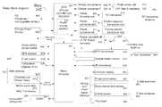
- FIG. 2shows an embodiment system block diagram of Access Control System of the present disclosure.
- FIGS. 3A, 3B, 3C, 3D, 3E, 4A, 4B, 4C, 5A, 5B, 6A, 6B, 7A and 7Bshow various embodiments of the disclosure that reduces the form factor of the multi-functional Ekey.
- FIG. 3Fshows an embodiment of E-field sensor electrode placement.
- FIG. 8shows the electronic block diagram of the Ekey.
- FIG. 9Ashows an example of multiple feed points on an antenna.
- FIGS. 9B, 9C, 9Dshows methods to connect various elements of electronic function block for RF energy harvesting.
- FIGS. 9E, 9F, 9Gshows methods to mount energy harvesting mechanical transducers on a badge style Ekey, and corresponding electronic function blocks.
- FIGS. 10A, 10B, 10Cshow tracker layout and its antenna beams.
- FIGS. 11A, 11B, 11Cshows energy harvesting and charge controller bock diagram for various energy sources.
- FIG. 12shows an exemplary flow chart logic for energy source selection
- FIGS. 13A, 13Billustrates a typical Ekey packaging.
- FIGS. 13C, 13Dillustrates a typical (disclosed in patent application Ser. No. 13/340,520) Ekey exemplified with those Ekeys that use Omni directional antenna
- FIGS. 14A, 14B, 14Cshows previously disclosed antenna methods to implement multiple antennas in a device that operate at different frequencies.
- SecureALL's Ekeyconsumes very low power and energy such that with a CR2450 battery it can typically last many years of operation before requiring battery change.
- the market requirementis to use smaller batteries so that the thickness of the Ekey can be reduced to be similar to a proximity RFID card. And to add more functionality to the Ekey.
- this disclosureteaches methods to make an even smaller form factor Ekey 240 with more functionality and almost indefinite battery life.
- FIGS. 21A, 21B, 21C, 21Dshow various components of the previously disclosed SecureALL Corporation's “UKN” model (UKeyTM) which is a type of E-Key.
- UKeyTMSecureALL Corporation's “UKN” model
- E-Keys from other vendorshave some aspects that are similar to SecureALL's “UKN” model.
- FIGS. 13A, 13B, 13Cshow the typical dimensions of the E-Key.
- the thicknessis typically defined by packaging constraints of the electronics. At 13 mm thickness it is rather uncomfortable to put that in a wallet.
- FIGS. 13A and 13Bshow the end view and side view. 13 C is the plan view.
- the circuitis realized by soldering the circuit components 101 on a Printed Circuit Board (PCB) 102 . Most components are reflow soldered using contemporary surface mount technology (SMT). Other circuit components (E.g. large value energy storage (ES) capacitor 105 ) could be manually soldered or press-fitted.
- the PCBcould employ a rigid dielectric substrate (E.g. FR4) or a flexible substrate (E.g. Flexible Printed Circuit (FPC)).
- a battery 103is typically connected and secured to the PCB via a battery holder/clip. For example SecureALL's UKN employs coin-cell CR2450 battery (3 Volt/640 mAH rating and measuring 24.5 ⁇ 5 mm)).
- the plastic enclosure ( 104 )provides physical protection to the electronics.
- FIG. 13Cshows the top view. It also shows SecureALL's “UKN” with integrated PCB and antenna (as taught in SecureALL's US patent application US 20120169543, True omni-directional antenna).
- the conducting ground plane 107 of the PCB 102is shaped to have a flared aperture 106 that only has PCB substrate dielectric, forming a wideband, pseudo-isotropic antenna.
- FIG. 13Dshows an image of the PCB Gerber file where the ground plane 107 is also used for circuit interconnection to connect various components on both sides of the PCB.
- Top layer 110 and bottom layer 109provide conventional PCB traces and pads to allow soldering of components and interconnect them. Double-sided SMT assembly is a well known prior art.
- FIG. 1is a perspective view of the SecureALL's “UKN”, (as taught in SecureALL's US patent application US 20120169543) where one can see that the thickness of the E-Key is due to battery and/or antenna packaging constraints.
- FIGS. 14A, 14B, 14Cshow an embodiment with a planar structure with multiple antennas operating on different frequencies (annotation numerals described in US pre-grant patent publication no. 2012/0169543, incorporated herein by reference), that some embodiments of the present disclosure can use to realize an E-key with transceiver(s) and RF energy harvesting circuit(s) operating on different frequencies/bands.
- FIG. 8depicts an embodiment 240 of the present disclosure.
- Micro-computer 801is an energy efficient variant known to those skilled in the art that has a CPU, memory (volatile and/or non-volatile), various types of Input/output peripherals and runs a program to perform computations, respond to events and coordinate various electronic circuits.
- Main transceiver 802provides primary RF communication with other devices (Non limiting examples are router 250 , door-lock 210 , locator 260 , and tracker 260 ).
- the use of the license free ISM frequency bandis desirable because of popularity, cost, interoperability and parts availability.
- classical transceivers based on the use of a local oscillator and the heterodyning principle and/or digital radioscould be used using various kinds of modulations and protocols.
- UWB (Ultra-wide-band) radioscould also be used.
- a previously disclosed SecureALL UKey(UKN Model) includes the following elements of the FIG. 8 block diagram:
- Main transceiver 802comprising
- Ekey 240may include such elements (which may or may not be identical to those of the UKN model) and may further include more transceivers to allow communication with various other systems.
- Transceiver 838provides the ability to communicate with other devices using a different set of frequency, modulation or protocol. (e.g. IEEE802.15.4, Zigbee, Bluetooth Classic, Bluetooth Low Energy or Bluetooth High Speed). This could enable secondary authentication of the Ekey's owner with the owner's Smartphone or other items that may have a compatible transceiver and protocol.
- Transceiver 838may share antenna 833 with the main transceiver 802 or have a separate antenna 837 .
- a NFC (Near Field Communication) or RFID transceiver 818may also be present to allow communication transactions with compatible devices in proximity. Typically they operate at frequencies of 13.56 MHz and 125 KHz respectively, and use inductive loop antenna 817 using magnetic field coupling.
- the inductive loop antenna 817could also be used for non-galvanic charging when the device is placed in close proximity to a charging station that generates appreciable short range magnetic coupling to transfer a few watts of charging power.
- the systemswitches (using switch 839 ) the inductive loop antenna 817 between the NFC transceiver 818 and the Inductive power harvester 812 depending on use case, via sensor input and/or periodic checking of the signal on inductive loop antenna 817 .
- the Ekeymay further comprise more transceivers to allow communication with various other systems.
- Transceiver 820provides the ability to communicate with other devices using optical radiation. Amongst other uses this could allow the Ekey user to send IR (Infra Red) beam based commands to a home entertainment system.
- IRInfra Red
- ES 805stores energy from various energy harvesting sources.
- ES 805could be realized by many means including but not limited to electronic components such as capacitor, supercapacitor, and rechargeable lithium-ion cell.
- EScan be implemented by employing both Supercapacitor and rechargeable cell.
- PPSPrimary power source
- itis configured to work with Primary power source (PPS) 806 to increase the ability to handle short term higher power demand (compared to peak power capability of individual ES 805 or PPS 806 ).
- PPSPrimary power source
- PPS 806provides electric power when electric power from harvested energy source(s) and/or ES is inadequate to meet the instantaneous electrical power demand.
- itis a non-rechargeable battery.
- itcould be a rechargeable battery with low self discharge rate.
- Some embodiments of the present disclosureharvest energy from the environment to partially or fully provide operating power to the Ekey. Energy could be harvested from one or more sources from a group comprising:
- QCR 807Charge controller and regulator 807 that uses it to charge an energy storing device (ES) 805 and/or supply full or part of the operating power load of the Ekey/appliance.
- ESis implemented using a Supercapacitor.
- QCR 807 circuitscan be implemented by a variety of electronic methods known to those skilled in the art.
- Power source selector 834provides the function of selecting one or more available energy sources to meet temporal power load.
- FIG. 12shows an exemplary flow chart logic 1200 that is evaluated by PPS 834 periodically and/or when the operating state of the Ekey or EHVD changes.
- the flowchart element 1201first evaluates if the available power from all EVHD sources is enough to meet the temporal power load demand of the operative circuit (all circuit of the Ekey/appliance except the power circuit responsible for power generation, conditioning, regulation and distribution), in which case 1204 it conveys and convert EHVD power to a voltage level suitable to power the operative circuit.
- the available power from all EVHD sources and ES 805is enough to meet the temporal power load demand of the operative circuit in which case 1205 it combines power from EHVDs and ES 805 and convert it to a voltage level suitable to power the operative circuit.
- 1203it combines power available from PPS 806 , EHVDs and ES 805 and converts it to a voltage level suitable to power the operative circuit.
- operation 1205uses power from only ES 805 .
- operation 1203combines power available from PPS 806 and ES 805 .
- 1203uses power from only PPS 806 .
- Photovoltaic (PV) array 813generates electric power when light falls on it.
- the power converter (PC-pv) 808efficiently converts the energy to a voltage level (3V typical) that the Charge controller and regulator (QCR) 807 can employ to power the Ekey.
- An exemplary block diagram in FIG. 11Ashows an embodiment where sufficient power generated by PV array EHVD is detected by a threshold comparator 1104 that turns on converter controller 1105 and signals it to convert the input power to a voltage level suitable for QCR 807 .
- QCR 807provides a path to connect the PC-pv 808 output to the ES 805 .
- Capacitor 1103is the typical input capacitance required for proper operation of power converter 1102 .
- FIG. 11Cshows a method where QCR 807 allows power controllers from various EHVDs to directly transfer energy to ES 805 .
- One or more load power converter 1111is employed to convert energy from ES 805 and/or PPS 806 to a suitable voltage level to meet the load needs of the Ekey's operative circuit.
- ES 805is realized by a rechargeable cell whose operating voltage range is close to the PPS's 806 nominal output voltage, enabling the use of a simpler and more power efficient load power converter 1111 .
- Supercapacitoris used to realize ES 805 and the power output from PC-pv (or PV-rf, PC-pzt, PC-emt, PC-tet etc.) is used to transfer charge to raise ES 805 's voltage. (I.e. No effort is made to regulate the voltage across ES 805 , instead it is allowed to vary from zero to its maximum rated operating voltage) and QCR 807 's load power converter 1111 is used to convert a widely varying input voltage from ES 805 to a regulated output voltage. This arrangement allows optimal use of the supercapacitor's energy storage capacity.
- the PC-pv 808is designed to automatically find the maximum available power at given moment (as the power from PV is a functiona of the temporal illumination flux density on its surface, and some other parameters like temperature) and adapt its operating mode to most efficiently convert/transform it to charge the ES 805 .
- optimizationis done by a model that use a switching converter's operating mode parameters that are well known to those skilled in the art (E.g. Load line, cycle charge, cycle energy, Buck/boost-period, -duty cycle, peak current, etc)
- the present disclosurefurther teaches energy harvesting from ambient radio-frequency (RF) field that could be used by Ekey 240 that has extremely low average operating power.
- RFradio-frequency
- SecueALL's Extreme Low Power based Radio transceiver (2.45 GHz ISM band)that is always operating while consuming only 10 microWatt power, or radios using heterodyne based transceivers operating at extremely low average duty cycles.
- Ekey 240can be designed with a wideband antenna, or multiple antennas that open doors to operating off energetic RF power density in ambient environment for a large fraction of the operating time, thus reducing battery size and/or considerably increasing battery life.
- the small (33 ⁇ 65 ⁇ 13 mm size) SecureALL's Ukeyalready employs a wideband isotropic antenna (500 MHz bandwidth at center frequency of 2.44 GHz) that operates well with linear and circularly polarization RF power source.
- the antenna of a 2.4 GHz based Ekey/Ukey worn by a user who is using a hand held devicewill experience a strong 2.4 GHz band RF field.
- Such handheld devicesperiodically transmit +15 to +30 dBm power.
- the Ekey's isotropic antennawill receive ⁇ 6 to 21 dBm power (I.e. 250 ⁇ W to 10 ⁇ W power, which is considerably much more than prior art) which can be harvested and used to supplement device operating at 10 ⁇ Watt. It is important to note that the Ekey's physical size 33 ⁇ 65 ⁇ 13 mm make for a very small antenna aperture, yet using this scheme at 2.4 GHz it could harvest so much RF energy from other hand held wireless devices that it can provide a substantial portion of the average power need of the Ekey.
- the 5 GHz ISM band in USApermits use of even higher radiation levels, thus allowing some embodiments of this invention to harvest even more power from devices using WiFi or other appliances commonly found at home, offices and civic places.
- the 200 MHz frequency band below and 200 MHz band above the 2.4 GHz ISM bandis a heavily used licensed band, used by commercial users including mobile phone service providers.
- a wideband antennacan thus additionally capture and harvest energy from nearby phone towers and people using cell phones.
- Cell phonescould transmit as much as +36 dBm power (4 Watt) that is many times more than WiFi routers, thus the living environment is a rich source of ambient RF power intensity.
- the 5 GHz ISM bandis even wider than the 2.4 GHZ ISM band thus will permit even richer RF channels, devices and transmitter population.
- Ekey 240 using wideband antennas, and/or multiple antennascan leverage RF energy harvesting.
- Such antennasare taught in SecureALL patent US20120169543 and used in SecureALLs Ukey/Ekey. See FIGS. 1, 13A, 13B, 13C, 13D, 14A, 14B, 14C .
- Ekey 240has a separate antenna 833 dedicated to the main transceiver, and a separate RF harvesting antenna 840 (generally operating on a different frequency) connected to a suitable RF filter and matching circuit 836 to transform the RF impedance suitable for RF energy rectification into DC power by power converter-rf 835 .
- FIG. 9Bshows an embodiment to harvest energy using a broadband antenna that is also used by the main transceiver 802 .
- the main transceiverhas access to the main antenna 833 via a filter 903 that implements a band pass filter function to allow exclusive access to the frequency band of interest to the main transceiver 802 .
- the RF filter and matching 836 for energy harvesting circuitalso has access to the main antenna 833 via the filter 903 that implements a band pass filter function on a separate port that allows exclusive access to the frequency band of interest to the RF energy harvesting circuit.
- FIG. 9Cshows another embodiment to harvest energy using a common antenna.
- Both main transceiver 802 and RF filter and matching 836 for energy harvestingare connected to the antenna.
- the main transceiver 802is connected to a feed point 902 whose feed point impedance matches the transceiver's electronics (typically 50 ohm), and RF filter and matching 836 for energy harvesting is connected to a feed point 901 whose feed point impedance matches its electronics (typically an impedance much higher than 50 ohm to make available higher RF voltage that can later be easily rectified by a RF diode).
- RF filter and matching 836comprise a RF matching and isolation circuit 904 that feeds the RF energy to a RF rectifier and voltage multiplier 905 , which in turn generates a DC output voltage; when signal is too weak the diodes (in RF rectifier and voltage multiplier 905 ) are in high impedance state and the circuit 836 does not load the antenna feed point 901 .
- Power converter-rf 835is similar to PC-pv 808 , comprising a suitable power converter 1102 and controller 1105 . Most of the time the main transceiver 802 is in receive mode where the expected signal is ⁇ 50 to ⁇ 100 dBm, a level too weak for the energy harvesting circuit to operate.
- the RF filter and matching 836 for energy harvestingwill start operating and absorb incident power (In some embodiment the main transceiver 802 could optionally be designed with an attenuator switch that RF filter and matching 836 can activate to reduce antenna loading by the main transceiver 802 , thus allowing maximum energy harvesting).
- the transceivercontinues to get access to the incident signal, albeit somewhat attenuated due to energy absorption by 836 (which in most cases is beneficial helping the Automatic Gain Control AGC function).
- the RF matching and isolation circuit 904is switched to isolation state to ensure transmitted power is fully available for antenna radiation.
- main antenna 833is a broadband antenna, allowing energy harvesting across the whole antenna bandwidth and the main transceiver 802 to operate normally in the intended narrower band.
- main transceiver 802may have a filter to prevent unwanted signals from saturating the RF front end electronics.
- FIG. 9Ashows an embodiment Ekey 240 with feed point 902 to connect to main transceiver 802 , and a higher impendence feed point 901 to connect to the RF energy harvester circuit.
- Ekey 240can also harvest RF energy from the environment by using the RF energy impinging on inductive loop antenna 817 via Power Converter-rflf 812 that has the necessary frequency tuning, scanning, impedance matching and RF power rectification circuit. It harvests ambient RF energy for example as a users walks by NFC security readers in super-stores entrance, RFID readers, or a local radio/TV broadcast transmitter.
- An embodiment of the RF harvesting systemperiodically sweeps the RF energy harvesting band to seek out the most energetic operating frequency and optimize the circuit for optimal performance (E.g. tuning elements and/or impedance matching circuit). This is particularly useful for energy harvesting circuit elements in 836 , 812 that have narrower bandwidth than the antenna it is connected to. It is also useful for situation when the antenna is small compared to operating wavelength, and for better performance it needs to be tuned to a specific frequency, and the tuning range spans a wider band. E.g. Ekey wanting to harvest energy from LF, MF, VHF, and UHF band sources.
- a further embodiment of the disclosurehas the RF harvesting system periodically scan the RF energy harvesting band to seek out the best operating frequency suitable for energy harvesting, failing which it uses a back-off algorithm to reduce the scanning period and conserve energy.
- This back off algorithmfurther could modify the behavior taking into consideration instantaneous energy available from other EHVD sources.
- PV array 813is currently generating 1-mW energy it doesn't help much to bother harvesting 20 ⁇ W from RF sources.
- an EHVDuses Thermoelectric transducer 816 .
- Power converter-tet 811conditions and converts the harvested power suitable to be accepted by QCR 807 .
- An embodiment of thisteaches an EHVD that uses electro-magnetic transducer 815 .
- One embodimentis shown in FIGS. 5 and 6 .
- a non-limiting exampleis a coil in a magnetic field loaded with a mass that vibrates and generated EMF as a person wearing Ekey moves about during daily activity, a dynamic loudspeaker).
- Power converter-emt 810conditions and converts the harvested power suitable to be accepted by QCR 807 .
- An embodiment of thisteaches an EHVD that uses Piezoelectric and/or electrostrictive (PE) transducer 814 mounted in the Ekey that generates EMF due to strain by a person wearing the Ekey moving about during daily activity.
- Power converter-pe 809conditions and converts the harvested power suitable to be accepted by QCR 807 .
- an embodiment of the present inventionis to orient the PE EHVD along the length of the thin Ekey device (see 814 orientation in FIGS. 5B, 6B ), as in normal use the bending strain would be larger compared to the width of the thin Ekey device.
- the electrostrictive elastomer membraneshould be pre-stressed along the direction of the strain as any compressive stress in the planar directions will lead to the formation of wrinkles, which may disrupt the function of the transducer.
- Providing for multiple PE EHVDsallows redundancy, power scalability and layout options to focus on an area that sees compatible range of strain with respect to efficiency and maximum strain specification.
- PE EHVD 814is often low frequency (E.g. 0.1-10 Hz) that use of transformer to step up the voltage before the energy can be harvested becomes impractical due to size and cost.
- FIG. 11Bshows a PE harvester 814 and power converter 809 . It accepts input voltage from PE EHVD 814 and if the signal is strong (E.g. >2 volt) it routes it to QCR 807 by using a diode 1105 (to explain the concept only one diode is shown, however it is not limiting to that but one can use other circuits like a bridge rectifier etc.). However when the voltage input is not strong enough, the input is sensed by power level sensor 1110 , and rectified by an active bridge 1112 using MOSFET switches. The slowly varying input voltage waveform is converted to higher output voltage across output capacitor 1109 by either:
- FIG. 9Fshows a way to harvest energy for using PE EHVD transducer.
- the Ekey 240 in the form of a badgehangs off a means to clip a badge hook clip 906 affixed to apparel worn by a person that connects to a badge hook 907 .
- the badgecan be configured to be worn in portrait or landscape orientation; or any other orientation.
- the badge hook 907is connected to a PE element comprising an electrostrictive Elastomer 909 connected in series with a Piezo-electric transducer 910 (meaning the weight force is serially transferred from Piezo element to the electrostrictive elastomer), which in turn is mechanically affixed to badge body 909 .
- FIG. 9Eshows a block diagram arrangement of using high voltage from Pzt to bias the electrostrictive Elastomers element with necessary high voltage so that it can generate the maximum harvested energy. It should be noted that one could also use some embodiments of this invention by using only one class of transducers like PZT or electrostrictive Elastomer based transducers and other transducers based on intrinsic material property that convert mechanical stress to electricity.
- FIG. 9Gshows another scheme of arranging the transducer to harvest mechanical energy that is particularly advantageous for thin profile and uses cheaper to fabricate thin sheets of PE EHVD.
- the force due to the weight of the badgegenerates shear and bending strain on the PE EHVD.
- the top member 911is connected to the badge hook 907
- bottom member 912is connected to badge body 909 .
- the top member and bottom memberare bound together with an interface 913 .
- the desired range of strain on the top 911 and bottom member 912is adjusted by choosing an appropriate thickness of the interface 913 .
- one of the strained members( 911 or 912 ) is a Piezo-electric transducer and the other member is an electrostrictive transducer.
- the 913 interfacecould be made of compliant material to provide strain to be spread out over a larger area on the top and bottom members, thus improving reliability and robustness.
- the interface 913could have the PE EHVD mounted on its two faces that touch top 911 and bottom 912 member respectively. This allows easy wiring of PE EHVD as well as placement of PE EHVD electronic circuitry in proximity.
- the PE transducer 814could also double up as audio speaker and microphone 832 by switching it to connect to codec 831 .
- An embodiment of the present inventionis to use the Piezo-electric EHVD transducer in multiple ways such that it is used as audio speaker, audio microphone as well as shock sensor and energy harvester when the audio function is not in use.
- the quiescent modeis to function as energy harvester.
- To serve as a speakerthe Piezo element is switched and connected to be driven by an audio amplifier's output.
- To serve as microphoneits terminals are connected to an amplifier input.
- the audio functionis not needed it is connected to the energy harvesting circuit. Necessary operating electronics and protection circuits are turned on and off as the usage mode changes; in particular high voltage safety when the Piezo element is in high strain.
- Electrostrictive transducercan be alternatively used as energy harvester and audio speaker/microphone. This saves space and cost.
- Another embodimentis to use in a series arrangement the Piezo-electric and Electrostrictive transducer (similar to FIG. 9D arrangement) where they are sandwiched together and work in unison to function as microphone, audio speaker, energy harvester or shock sensor.
- a combination of various power control functions( 834 , 807 , 808 , 835 , 836 , 809 , 810 , 811 and 812 ) could be merged into a common function block for better performance and cost optimization.
- the Ekey 240comprises sensors that measure various environmental parameters and user inputs.
- a usercan press the Ecall switch 830 that signals to the micro-computer 801 various user commands (E.g. Emergency/distress call, Lockdown command to nearby door(s) etc).
- Gross motion sensor switch 828sends a digital signal pattern to the microcomputer 801 when the Ekey 240 is mechanically moved. The signal could then be used by Ekey 240 to operate other electronic sensors (E.g. Spatial motion sensor 819 , E-field sensor 824 etc.) or functions (E.g. transition for various level of sleep condition or operating mode, etc.).
- Representative non limiting examples of Gross motion switch 828are: mercury switch, mechanical vibration switch using a metal ball or spring mass that roll on to nearby electrical contacts when disturbed (E.g. SENSOLUTE GmbH part #‘MVS0608.02’—Micro vibration sensor) and Piezo sensor. Also some types of accelerometers have low enough operating power to act as gross motion sensor without significantly impacting quiescent operating power of the multi-function Ekey.
- the spatial motion sensor 819comprises
- the accelerometer and rate-gyroWhen powered by microcomputer 801 the accelerometer and rate-gyro provide linear and angular acceleration measurement to the microcomputer 801 respectively. That information is integrated to obtain change of velocity, and then integrated again to obtain displacement.
- Ekey 240can establish initial inertial reference frame upon power up and thereafter accurately measure spatial motion.
- Three axis accelerometersallow determination of local horizon and magnetic compass provides angular position of north direction allowing quick establishment of absolute orientation of the Ekey. Even if a magnetic compass is not present spatial motion can be determined assuming an arbitrary initial azimuthal orientation. A somewhat less accurate spatial position can be determined by only using accelerometers.
- Spatial sensor 819allows Ekey 240 to sense user gestures as the user manipulates her hand while holding the Ekey, or manipulates the Ekey 240 by hand or other means.
- Sharp gesturecan be easily determined (E.g. vertical tapping of Ekey 240 on wall or table top, flat orientation tapping, rotational flip etc.) along with the intensity of the gesture.
- Spatial sensor 819can also measure subtle user body movement when a user is wearing the Ekey. It allows easy measurement of user's physical activity level, mobility and as well as immobility. Reliability is further increased when Ekey 240 can determine that the user is indeed wearing Ekey 240 by using the information from body electric field sensor 822 (that in turn uses E-field sensor electrode 825 ) (providing capacitance information due to skin proximity) and E-field perturbation.
- the ambient light intensityis sensed by measuring the current generated by the photo voltaic cell 813 ( FIG. 8 ).
- the relative light intensity from the separate PV cellsis used to determine which side is exposed to the environment and which side is facing the skin/body of the person wearing the UKey.
- Some embodimentcould use a dedicated photo cell for light measurement instead of using PV used for EHVD, yet in another embodiment the IR transceiver's 820 optical sensor is used to get a measure of ambient light.
- the ambient light sensorcould be used to obtain information as to amount of time a person has been exposed to sunlight (health care aspect), daytime spent outdoors, physical activity, when the Ekey was removed from a wallet and worn (and later put back into the wallet), time (and duration) when wearer got up from bed at night.
- the Ekeymonitors user activity in an old age home to ensure and the user has not suddenly gone inactive/incapacitated due to a medical issue.
- the Ekeycan be programmed to generate an inactivity alarm message based on criterions derived from sensor information coming from Accelerometers, rate gyros, Gross motion sensor switch 828 and E-field sensors.
- the criterioncomprising some or all of the following: a) A user is wearing the Ekey device b) sudden stoppage of a user's activity as seen from drop of dynamic signal from accelerometer, rate gyro, mechanical motion switch, ambient light sensor and E-field sensors c) the user's activity not matching the user's daily activity pattern d) sudden stopping of activity preceded by strong dynamic signal that is generally associated with fall, d) Lack of activity for a period exceeding a user-defined limit.
- E-field Sensor 824measures the electric field generated by an intentional (external) electric field generator, the environment as well as the perturbation caused by movement of people and things. It measures the electric field by measuring the voltage on E-field electrode(s) 825 in single ended or differential mode. In some embodiments it demodulates and recovers the data transmitted by an intentional electric field generator. In some embodiments the center frequency and bandwidth of the E-field Sensor 824 is dynamically changed per data communication protocol. In yet another embodiment the E-field sensor may comprise many detectors measuring electric field intensity at specific frequencies.
- the E-field sensorinterfaces with analog and mixed signal interface block 827 , provides suitable interface to micro-computer 801 . In some embodiments, the analog and mixed signal interface block's 827 functionality may be subsumed by the microcomputer 801 or the sensor 824 , obviating its need.
- Body E-field sensor 822is similar to E-field sensor 824 , except that it operates at a much lower frequency band (typically few Hz to few KHz) such that it can capture the electric field generated by biological aspects of human body (E.g. nerves, muscles, tissues) as well as electric field perturbation caused by the human body. It measures electric field by measuring the voltage on E-field electrode(s) 825 in single ended or differential mode.
- the center frequency and bandwidth of the E-field Sensor 824is dynamically changed to tune into dominant ambient radiation (E.g. from mains power line, VLF, ULF, SLF, ELF radio transmitters) so that contributory change due to physical changes in nearby environment can be measured.
- a method to measure capacitanceis where one of the electrodes is used to generate an electric field stimulus and the response on the E-field electrode is used to determine the capacitance and capacitance dissipation factor.
- Dissipation factoris an important parameter that allows distinguishing the proximate material is biological tissue or in-animate physical parts (E.g. metal pieces).
- E-field sensor 824 and Body E-field sensor 822may use common circuit elements and e-field electrodes.
- Ekey 240comprises a GPS receiver 829 (with integrated GPS antenna) that can be turned on by the microcomputer to provide its GPS position. This function allows Ekey 240 to provide this information when requested by the application software server or when Locator (e.g. tracker) asks for positioning information.
- Locatore.g. tracker
- Ekey 240provides audio communication capability to the user by employing Codec (Coder Decoder) 831 to provide audio compression and a loudspeaker 832 that could also serve as microphone in half duplex operating mode.
- CodecCoder Decoder
- Loudspeaker/Microphone 832 function and PE transducer 814 functioncould be merged by using a shared PE transducer that can be switched between the two functions depending on need.
- Ekey 240comprises a finger print sensor 821 so that when needed the microcomputer can read and verify finger print of an authorized user. This additional authentication increases system integrity, so that if a person other than the intended Ekey user tries to use the Ekey obtained by error or fraud, the Ekey 240 can be made to operate in a mode different from normal operating mode for an authorized user.
- Ekey 240may further comprise a touchpad 826 allowing availability of many more keys/buttons towards greater ease of use and functionality.
- FIG. 2shows an exemplary Access Control System 200 in the context of which the Ekey 240 may be used.
- Access Control System nameis typical name but the system could perform many other functions (non-limiting examples like security system, tracking, activity management, public announcement, emergency management, emergency marshalling area auditing, wandering protection in senior care, patient monitoring, asset tracking, etc. apart from just traditional Access Control functionalities).
- the Application Software Server (AS) 270can be a typical server computer with CPU ( 292 ), volatile and non-volatile memory ( 294 , 296 ) and data communication devices such as network cards ( 298 ).
- the Application Software Server (AS) 270also runs an operating system 220 and on top of that the Application Software 230 .
- the ASS 270is connected over computer network 290 to the other components of the system. Connected to this network are client application GUI computers 274 that can be used by users 275 U to monitor and configure the system, such as to define access rights to doors, to query the state of the system, use and control devices connected via a communication interface or to get notified about exceptions and alarms.
- the connectioncould be wired or wireless.
- Also connected to the computer network 290are one or more of the following:
- Locator 260 devicesdiscover Ekeys that are within communication range and determine its gross location based on signal strength or ToF. In some embodiment a Locator also takes on the function of a Wireless Router 250 .
- Tracker 1002(described later in this disclosure) is a specialized locator 260 that provides distance and azimuth information about the Ekey location.
- EDLs 210are mounted on doors 211 and are configured to unlock the door when an Ekey 240 carried by an authorized user 242 U is within a configurable range.
- EDL 210is connected over a wireless link 254 to routers. Over this link the EDLs 210 can receive access control information and other commands from the ASS 270 or report events to the ASS 270 .
- EDL 210also implements the functionality of a locator 260 .
- a UKeycommunicates with the AS via wireless network 254 connection with the wireless router 250 or locator 260 .
- Server to device(device meaning UKey, EDL, Wireless router, Locator etc.) communication is encrypted.
- An EDL 210periodically scans its environment to find nearby Ekeys 240 and, when found, determines whether the associated user has permission to access the door at the given time.
- the usermay be required to hold one or more additional tokens at the same time.
- the userwear an Ekey 240 in the form of a badge and also carry a second Ekey 240 somewhere else on the body at the same time.
- the Tokensare independent of each other, thus EDL 210 performs check to ensure both tokens have valid access permissions to unlock and present at the same time.
- the Ekey 240validates itself by checking that the specific additional token(s) is in communication range.
- This conceptcan be modified to require a first Ekey 240 and a cell phone 241 to be carried by user 242 U, whereby the nearby presence of the cell phone 241 is verified by the Ekey 240 using a Bluetooth connection or similar connection, either every time it is used to gain access to a resource, or after a configurable maximum interval since the last verification.
- the Ekey 240would have to be paired with the cell phone first using a method that is similar to the pairing of a Bluetooth headset; there could however be other methods.
- Another method to limit damage with lost or stolen Ekeyis to require users to periodically authenticate themselves to the Ekey (for higher security more than one authentication may be called for). This may be required every time a restricted resource is accessed (or operated upon) or in certain configurable time intervals.
- the Ekey 240may indicate the need for renewed authentication to the user by flashing an LED (Indicator display 841 ) or by emitting a sound. Alternatively the EDL could also indicate that access cannot be granted because renewed authentication is required.
- Said user authenticationcan be done in several ways, but is not limited to these methods:
- Ekey 240may be equipped with an Ecall switch (button) 830 that can be used to send out distress signal messages via wireless network 254 .
- Ecall switchbutton 830 that can be used to send out distress signal messages via wireless network 254 .
- the Ekey 240makes an attempt to find devices, such as Locators 260 , EDLs 240 , or Routers 250 , that can relay the distress message to the ASS 270 .
- the Ekey 240has any location information (for example if it has a built-in GPS receiver 829 , or if it is paired with a cell phone 241 with GPS receiver, list of EDLs that most recently communicated with the Ekey) it can include that information in the distress message.
- the Locators 260 , EDLs 240 , or Routers 250will send a notification to the ASS 270 .
- the ASS 270can optionally then instruct Locators 260 in the vicinity of the Ekey 240 to determine the current location and travel direction of the Ekey 240 , and then the ASS 270 will notify users 275 U whose role is to respond to such Ecalls.
- Ecall button 830To prevent an accidental transmission of the Ecall due to inadvertent pressing of the Ecall button 830 , the user has to the press the Ecall switch 830 in a certain pattern to tell Ekey 240 it is indeed a intentional Ecall initiation (E.g. pressing the Ecall button 5 times within 3 seconds, rapidly pressing the Ecall button 3 times followed by keeping it pressed for at least 3 seconds).
- the Access Control System 200contains cameras 268 and after receiving an Ecall notification with the location of the originating Ekey 240 the ASS 270 can activate the cameras 268 that are in the vicinity of the Ekey 240 and set them to photograph, record or put their live video feed onto the screen of the user 275 U who responds to the Ecall.
- an Ekey 240has voice capabilities the system can establish a direct voice channel between the responder 275 U and the user 242 U in distress.
- the voice callcan be routed using the existing infrastructure from the client computer 274 , via ASS 270 , the computer network 290 and a locator 260 or router 250 device to the Ekey 240 .
- a call to the user's cell phone 241could be placed automatically.
- the Ekey 240 via its Bluetooth connectioncould be configured to automatically pick up the call and use its built-in speaker and microphone as a hands-free device.
- the Ekey 240can instruct the cell phone 241 to send a text message or email to a preconfigured destination, possibly also including GPS coordinates, or place a phone call where the Ekey 240 can act as a hands-free device.
- Recent shootings at school and university campuseshave demonstrated the importance of protecting staff and students from harm in the event of a shooter on campus.
- One component of the protection strategyinvolves preventing the shooter from entering buildings and rooms that may be populated by potential victims.
- Lockdownwhere entrance through doors is limited to a smaller set of people, such as emergency responders.
- the Ecall button 830(or alternately a separate switch button) can be used to send out a “lockdown command” to immediately put in lockdown state a configured set of ELDs 210 .
- a “lockdown command”is activated by the user the Ekey 240 makes an attempt to find devices, such as Locators 260 , EDLs 210 , or Routers 250 , that can relay the distress message to the ASS 270 . If the Ekey 240 has any location information (for example if it has a built-in GPS receiver 839 , or if it is paired with a cell phone 241 with GPS receiver, list of EDLs that most recent communicated with the Ekey) it can include that information in the distress message.
- the Locator 260 , EDL 210 , or Router 250will send a notification to the ASS 270 .
- the ASS 270can then instruct EDLs 210 for the configured set of doors to go into “Lockdown” state.
- ASS 270will also notify users 275 U whose role is to respond to such “lockdown command” events.
- E-Field sensingUnlike magnetic field based near field communication that consumes enormous power and requires a large coil size to generate it, this disclosure teaches using E-field that takes far less power to generate an electric-field, and can be generated by compact electrodes.
- Part of the Access Control System 200can be an E-Field Locator (Generator) 265 that generates an alternating E-field (in one or two polarization) to be picked up by nearby Ekeys 240 that are equipped with E-field sensors 824 .
- E-Field LocatorBy modulating the signal, data, such as an ID of the E-Field Locator, can be transmitted to the Ekey 240 .
- the E-field Locator 265may use cryptographic means to broadcast a temporal parameter along with generator ID.
- the Ekeywhen first receiving the signature (ID) of on E-Field Locator 265 can attempt to contact a Router 250 or Locator 260 in order to transmit a message with the Ekey's ID and the ID of E-Field Locator 265 to the ASS 270 .
- This systemcan be used to implement choke points where the presence or passage of Ekeys in a certain location (the location that is covered by the E-field Locator) produces a record of that event.
- Such a systemwould be useful in an asset-tracking application where an Ekey ( 240 b ) that is affixed to an asset ( 266 ) that needs to be tracked as it enters or leaves certain areas.
- E-field locator 265may have the capability to communicate with a Wireless router 250 so that ASS 270 can monitor and configure it.
- an Ekey 240can be configured to expect to be within the reception range of an E-Field Locator 265 at all times and to send an alarm message when a signal from the E-Field Locator can no longer be received.
- An embodiment of the Ekey devicehas a dosimeter 842 that measures ionizing radiation. This is very convenient and useful for office workers who work in an environment that has various degrees of ionizing radiation. Such users anyway need to carry Ekeys for access to rooms, work areas and equipment.
- the AS and a multipurpose Ekeycan thus monitor and relate the radiation dose experienced by the Ekey user as she moves about various rooms and work locations (Ekey, Locator and EDL determine when a user entered a room and for how long) as part of the work schedule.
- a Pareto chart detailing radiation dose versus roomcan be a powerful tool to adjust work process and improve personal safety and workplace safety.
- FIGS. 3A, 3B, 3C, 3D, 3E, 4A, 4B, 4C, 5A, 5B, 6A, 6B, 7A and 7Bshow various embodiments of the disclosure that tremendously reduces the thickness form factor of the Ekey 240 by using a battery that is extremely thin, yet one that does not interfere with the performance of the ODA (Omni directional antenna.
- FIGS. 14A, 14B, 14Cshow various embodiments of the disclosure that tremendously reduces the thickness form factor of the Ekey 240 by using a battery that is extremely thin, yet one that does not interfere with the performance of the ODA (Omni directional antenna.
- FIGS. 14A, 14B, 14CIt should be noted that while this specification refers to use of an ODA in an Ekey 240 design, but those skilled in the art will understand that the teachings can be applied when using other types of antennas. One skilled in art can mix and match the teachings of this layout and packaging methods taught in this patent specification.
- FIG. 3Adepicts the cross section view of one way to realize planar (low profile) Ekey 240 comprising some or all functional blocks of FIG. 8 .
- FIG. 3Bis an exploded view of FIG. 3A teaching high density packaging layout.
- the packaging schemeallows flexing of the Ekey 240 .
- the electronic components 101are preferably assembled on one or both sides of the flexible printed circuit (FPC) 304 (I.e. one can use FPC 304 instead of a rigid substrate PCB 102 ).
- a custom low thickness battery 806is packed on one side of the FPC 304 suitably insulated with an insulating film in between. In this embodiment the battery is of uniform thickness and thus easier to fabricate.
- FPCflexible printed circuit
- the other side of the FPC 304is covered with an insulating material that also acts as a protective stiffener cover 303 that has custom pockets to allow relatively snug fit with electronic components 101 , thus providing strength against mechanical impact force from the flat side of the Ekey as all the force bypasses the electronic components. It provides mechanical protection to the FPC assembly with minimal addition to overall thickness.
- Protective stiffener cover 303could be realized by various methods known to those skilled in art, including molding, lamination etc. whereby a plastic raw material is easily shaped into desired matrix to form the solid part.
- Another protective stiffener cover 303 on the side of the batteryenvelops the FPC 304 , electronic components 101 (if any) and battery 806 .
- the FPC assemblyis not tightly encapsulated with protective stiffener cover 303 and battery 806 , instead it is allowed to slip along the contact surface, so that when the Ekey 240 flexes it does not stress the FPC assembly. Similarly the battery 806 is not stressed by flexing of the Ekey.
- the battery 806is packaged in narrow sections (see FIGS. 5A, 5B ) that are aligned along the width of Ekey 240 to minimize stress due to flexing of Ekey. This method (in FIGS.
- FPVC 302puts least stress on FPC 304 as the FPC is located almost along the neutral stress plane of flexing, with thick protective stiffener cover on one side and an almost same thickness of battery 806 and protective stiffener cover on the other side.
- the flexible photovoltaic cell(s) (FPVC) 302are stuck to the exposed outer surface of protective stiffener cover 303 to harvest ambient light energy.
- FPVC 302is electrically connected to the circuit in the FPC assembly to charge an electronic store 805 in the device (not shown in this figure to avoid clutter). Further FPVC 302 is preferably chosen with a protective film to protect it from scratching from hard objects during normal use.
- FIGS. 3C, 3D and 3Eshows another embodiment of planar Ekey 240 using an ODA (Omni directional antenna).
- a multi-layered FPC 304uses one layer that acts as a power layer (I.e. Ground or V dd supply) and is shaped to be an ODA.
- a power layerI.e. Ground or V dd supply
- the area of the batterymust increase.
- increasing the battery to the shape of the Ekey's PCB 102 (or FPC 304 )may compromise the operation of the ODA. So some embodiments of this invention accomplish the objective by using a battery that is very thin (E.g.
- this disclosureteaches the battery shaped to follow the contour of the ODA ground plane but be shorter (smaller) than the ODA contour to ensure that portions of the ODA that carry large RF current largely stay confined to well defined copper substrate (part of the electronic printed circuit board) and also portions of the ODA that contribute to E field have capacitance defined by ODA copper structure.
- Those skilled in the artwould know that instead of the ODA other types of antennas could be formed by etching suitable PCB trace pattern on the PCB's conducting layer(s).
- the PCB's conducting layer(s)Non-limiting examples in FIGS. 14A, 15B, 14C ) of different antenna types (E.g. bow-tie UWB antenna, loop, spiral UWB) and operating in the same or different frequency bands.
- the battery 306instead of non-rechargeable battery, it could as well be a rechargeable battery is made to conform to the surface presented by a FPC 304 that is loaded with components 101 , this allows most efficient use of the overall available volume to maximize the energy capacity of the battery.
- the battery 306instead of non-rechargeable battery, it could as well be a rechargeable battery
- the conformal battery 306is packaged on the component side of the FPC assembly, thereby most efficiently using the available volume for maximum battery capacity.
- the outer surface of the batteryis protected by a thin protective stiffener cover 303 , which in turn has place to mount the FPVC 302 , as well E-field electrode 825 .
- the bottom surfaceis protected by another protective stiffener cover 303 that is welded to the top protective stiffener cover 303 , thus protecting the electronics from mechanical damage.
- the bottom protective stiffener cover 303also has a FPVC 302 to harvest light energy, and both the top and bottom surfaces are further protected by a transparent protective film 305 that is abrasion resistant yet allows easy transfer of ambient light to the underlying FPVC 303 .
- the area not covered by FPVC 302may further be used to imprint relevant information that is usually printed on an employee badge.
- FIG. 3Fshows a detailed example of the cross section view of an embodiment of E-Field electrode 825 where each side of the PCB 304 has an E-Field probe electrode 825 to sense the voltage difference between the electrode 825 and the circuit ground realized on one of the PCB copper layers.
- This E-field sensor arrangementis advantageous in reliably measuring the E-field on and around the human body by ensuring that at least one E-field sensor electrode is unaffected by shielding effects and interference due to proximity to conducting material on one side of the multi-functional Ekey device.
- Thin profile E-field sensors with height constraintssuffer from poor sensitivity due to proximity to ground potential in the PCB as dense electronic packaging prevents allocating large conductor free area under the E-Field probe electrode.
- this embodimentteaches the use of active guarding on the PCB surface under the E-Field probe, whereby a large piece of conducting surface under the probe electrodes is driven close to probe potential (i.e. is buffered) by a buffer amplifier.
- FIGS. 4A, 4B and 4Cshows another embodiment of planar Ekey 240 that additionally packages ES 805 .
- the ES 805may or may not require conformal shape.
- the FPVC 302is nested in a recessed pocket carved on the outer surface of protective stiffener cover 303 , such that the transparent protective film 305 is almost flat across the whole surface.
- the PPS battery 806 and/or ES 805are RF connected to the flex circuit at select locations to reduce effect of the conformal battery on antenna radiation pattern, resonance frequency or gain.
- FIGS. 5A and 5Bshow another embodiment of a planar Ekey 240 that packages a conformal ES 805 on the bottom side of the FPC assembly and a conformal PPS battery 806 on the other side, an EM transducer 815 is nested to one end so that it does not interfere with ODA function and FPC assembly.
- the space indicated for the EM transducercould instead be used to house Thermoelectric transducer 816 as it presents an efficient thermal path that is essential for a thermoelectric transducer.
- the battery 306is packaged in narrow (spliced) sections that are aligned along the width of Ekey 240 to minimize stress due to flexing of the Ekey.
- the FPC assemblyis again located near the midpoint of thickness in the plane of least flexural stress, thus it sees little stress corresponding to improved reliability.
- a PE transducer 814is located on one surface of the Ekey 240 to serve as EHVD that could be switched to also act as an acoustic transducer functioning as a loudspeaker and/or microphone.
- FIGS. 6A and 6Bshow another embodiment of a planar Ekey 240 shown in FIGS. 5A and 5B that packages a conformal ES 805 and a conformal battery 306 on a side of the FPC assembly. It has the advantage of being very thin.
- FIGS. 7A and 7Bshow another embodiment of a planar Ekey, that has a more generous area availability (E.g. a traditional employee badge size form factor).
- the additional areais used to more optimally place the E-field sensor electrode 825 .
- E-field sensor electrode 825 Ais at an ideal location for E-field sensor electrode placed near an antenna whereby the wire connecting the Efield electrode passes along the symmetry line between the ends of antenna poles, thus not disturbing the antenna.
- the available spaceis also used to form a loop antenna 817 .
- the loopis broken into small segments that are interconnected by a microwave block 702 that appears as open circuit to 2.4 GHz (in this example at the center frequency of the ODA) and short circuit for the intended low frequency (preferably the small segments length is shorter than 1 ⁇ 4 wavelength).
- An exemplary microwave block 702comprises a parallel tank circuit tuned at 2.4 GHz.
- the available areacould additionally be used to place parasitic antenna element 701 (the example in the figure shows a multipurpose structure that is E-field sensor plus meandered dipole director antenna element) to supplement the main antenna 833 (in this example the main antenna is ODA 107 ).
- an E-field sensor electrode 825is placed above the PCB and another E-field sensor electrode placed below the PCB ( FIG. 3F ); when the device is worn on the human body one large flat side of the device will be close to the body skin while the other flat side will face the free space, in such a situation this E-field sensor arrangement is advantageous in reliably measuring the E-field on or around the human body, particularly mitigating the loss of sensitivity on the sensor facing the human skin.
- An embodiment of this inventionteaches combined use of Time of flight (to get distance estimate) and steerable beam (to get azimuth direction estimate) to position the location of the tag. This method is much more cost effective as a standalone reader can provide positioning without requiring complex cabling or communication between multiple readers. Unlike prior art methods (E.g. Aviation navigation aids do not have low battery energy constraints like an Ekey.
- this disclosureteaches a method where Ekey 240 and Tracker 1002 have to first discover each other and then establish communication (for example using methods taught in US 20100040120 Low power radio communication system, US 20130136046 Establishment of wireless communications), authenticate each other, and then distance is estimated by the stationary Tracker 1002 (using an RSSI-based method or a Time of Flight measurement protocol), and bearing determined by Tracker.
- the Ekey 240is also informed by Tracker 1002 of its estimated position.
- this disclosurediscloses a method that is different from Ground control Precision Approach using Precision approach radar (PAR), as in a PAR system all the transmission and measurement is done by radar without any co-operation by the target (aircraft).
- PARGround control Precision Approach using Precision approach radar
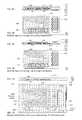
- FIG. 10Ashows a system to track the location the Ekey.
- the tracker 1002is a specialized variant of locator 260 with high power radio and directional antennas with orthogonal polarization capability so that it can communicate with an Ekey's antenna (including those Ekeys that use ODAs) irrespective of the relative orientation of the Ekey 240 (I.e. user is not required to ensure the Ekey is in a particular orientation).
- the trackerperiodically scans for presence of an Ekey (typically 15 second period).
- the Ekeyhas a coarse clock but it does not have a chronometer or a precise clock due to cost, power, energy and space considerations.
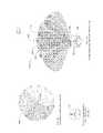
- An exemplary tracker 1002is enclosed in a Radome 1001 and has multiple directional antennas.
- Tracker's 1002 full 360° coverageis provided by 15 antenna beams 1000 .
- Ekey's azimuthal positionis resolved by comparing its communication signal strength from multiple antenna beams.
- the tracker 1002polls for presence of Ekey 240 in its coverage area using different antenna beams to establish communication (for example by using methods taught in US 20100040120 Low power radio communication system, US 20130136046 Establishment of wireless communications).
- the Ekey 240 and tracker 1002estimate mutual distance by an RSSI-based method; communicating using a calibrated transmitter power (plus antenna gain) and measuring receiver signal strength measurement (RSSI).
- RSSIcalibrated transmitter power
- RSSIreceiver signal strength measurement
- itcan use a ToF (Time of flight) measurement for distance ranging.
- ituses both RSSI and ToF technique for accurate azimuth and range estimation, respectively (particularly in an environment that has significant RF reflection due to buildings etc).
- the omni-directional response of the ODA in an Ekey 240enables distance estimation using an RSSI-based method (as per SecureALL patent application: US20120169543) when the Ekey 240 is located within an uniformly illuminated solid angle of the tracker's antenna (say 1.5 dB beam-width of the antenna).
- FIG. 10Ashows the beam pattern from a set of directional antennas whose azimuthal beam width is 30° with overlapping coverage. Instead of using 15 immobile antennas, one could alternatively use a tracker with a physically steered antenna. (See FIG. 10C , Cylindrical shaped steerable beam antenna array formed by triangularly arranged antenna array that revolves inside the Radome 1001 ).
- FIG. 10Bis an embodiment of the system in FIG. 10A , where the 15 beams of 24° width are realized by three antennas arrays (Ant 1 1003 , Ant 2 1004 and Ant 3 1005 ).
- the antennais a phase steered antenna with beam width of 24° where beam 1008 can be phased steered 1006 on either side by ⁇ 24° (B, D) and ⁇ 48° (A, E) from its normal broadside direction)(0°).
- Phase steered antenna with greater beam steering resolutioncan be realized that easily yields finer azimuth position estimation.
- An embodiment of this inventionuses a steerable antenna beam using an active electronically scanned array (AESA) or a passive electronically scanned array (PESA) that allows greatly improved azimuth position.
- AESAactive electronically scanned array
- PESApassive electronically scanned array
- An embodiment of this inventionteaches the combined use of Time of flight (E.g whereby the Ekey 240 responds to Tracker 1002 communication with a known delay, and the tracker factors in that delay in when it times the response from Ekey.
- This methodis well known in art such as receiver correlation, pulse compression, Ultra Wide Band communication etc.). This method is much more cost effective as a standalone reader can provide positioning without requiring complex cabling or communication between multiple trackers that are based on a triangulation method (angular, distance or a combination). This method also allows use of a power and energy constrained Ekey 240 to realize a position tracking system.
- Tracker 1002can additionally communicate with the Ekey 240 , and ask for temporary activation of GPS electronics 829 to get its coordinates, and send the coordinate information to the tracker. This is particular suitable for trackers that provide outdoor coverage.
Landscapes
- Engineering & Computer Science (AREA)
- Computer Networks & Wireless Communication (AREA)
- Signal Processing (AREA)
- Charge And Discharge Circuits For Batteries Or The Like (AREA)
Abstract
Description
- 1. ASIC: Application specific integrated circuit
- 2. ASS: Application Software Server
- 3. EDL: Electronic Door Lock
- 4. EHVD: Energy HarVesting device (E.g. Photo voltaic cell, Piezo-electric transducer, voice coil, peltier pile)
- 5. Ecall: Emergency Call, Distress Call
- 6. Ekey/E-Key: Electronic Key (for door access control, authorized access to resources/computer/lab equipment)
- 7. EM: Electro-Mechanical transducer
- 8. ES: Energy storing device (E.g. Super capacitor, rechargeable battery)
- 9. EST: Electrostrictive transducer
- 10. FPC: Flexible printed circuits, a type of PCB.
- 11. FPVC: Flexible Photo Voltaic Cell
- 12. Locator: A devices that discovers Ekeys and determine its gross location.
- 13. NFC: Near Field communication
- 14. ODA/OD Antenna: An Isotropic antenna disclosed in US20120169543
- 15. PPS: Primary Power Source
- 16. PCB: Printed circuit board.
- 17. PVC/PV cell: Photo voltaic cell, solar cell
- 18. PE: Piezoelectric and/or electrostrictive transducer
- 19. PE EHVD: Piezoelectric and/or electrostrictive transducer based Energy HarVesting device
- 20. PZT: Piezo Electric Transducer
- 21. RFID: Radio frequency identification
- 22. RF: Radio Frequency
- 23. RSSI: Received Signal Strength Indicator
- 24. TOF: Time of Flight
- 25. Tracker: Tracker is type of Locator.
- 26. UKey/Ukey: A type of Ekey made by SecureALL that works in hand free manner.
- 1. Direction Triangulation: Requires the space to be covered by two or more readers with direction finding capability.
- 2. Distance triangulation: Requires readers that can measure distance with the tag (time of flight measurement) and the desired space to be covered by two or more readers.
- 1) OP: Figure number where it was first specified and defined. “O” is optional when Figure number is single digit.
- 2) XX: Last two numerals
- a.
Main antenna 833 - b. Tier-1 Extreme
Low Power Radio 803, and Tier-2Heterodyne radio 804. - c. A secondary antenna (not shown in this block diagram)
- a.
- a) Converting the input power to high frequency (say 200 KHz) AC by using a
chopper switch 1106 and then stepping up the voltage by a small sizehigh frequency transformer 1107 followed by arectifier 1108. One could also use a voltage multiplier circuit for stepping up. - b) Alternatively one can use a boost switching converter
- a) Converting the input power to high frequency (say 200 KHz) AC by using a
- a) announce messages to the user based on commands from the application software server,
- b) allow a remote person using the application software server to speak the user
- c) Allow two-way communication between the Ekey user and a remote person that is using the application software server.
- a)
Locator devices 260, used to determine the location ofEkeys 240, - b)
Wireless routers 250, a type of locator device that also provide wireless connectivity to various other components of the system, such asEDL 210 andEkeys 240. - c) Camera (Video or still)268 that can capture optical images depending on configuration or command from
ASS 270. The camera may additionally comprise mechanical actuators to change to desired spatial orientation the camera's field of view.
- a)
- a. If the
Ekey 240 has motion sensing capabilities (spatial motion sensor819) the authentication can be based in gestures where the user moves theEkey 240 in certain ways or taps it in a specific timed sequence against a hard surface. - b. If the
Ekey 240 has a key pad (touchpad826) the user may have to enter a PIN or password. - c. If the
Ekey 240 is paired with acell phone 241 the user may use an application on the cell phone to authenticate himself using one of many possible authentication methods that are commonly in use on cell phones. - d. If the
Ekey 240 has amicrophone 832 the user may have to speak a passphrase that theEkey 240 compares to a previously recorded voice sample. - e. If the
Ekey 240 has afingerprint sensor 821 the user may have to scan her finger which theEkey 240 compares to a previously stored fingerprint.
- a. If the
- a)
Tracker 1002 communicates with anEkey 240 using Antenna beam C. - b)
Tracker 1002 tries to communicate with theEkey 240 using beam A, E and neighboring beam B and D measuring the RSSI in the process (let us say it manages to communicate using beam B, C and A) call it as RSSIb, RSSIc, RSSId). - c) Finer azimuthal position of Ekey is estimated by following logic:
- i. When (RSSIc>RSSIb+3) and (RSSIc>RSSId+3) its azimuth position is dead on (bore-sight) and within a fraction of the antenna beam width (
FIG. 10B , area marked B′.C.D′1009). - ii. When (RSSIc≈RSSId) its azimuth position is on the beam overlapping region of the antenna beam C and D (
FIG. 10B , area marked C.D1010). - iii. When (RSSIc≈RSSIb) its azimuth position is on the beam overlapping region of the antenna beam C and B (
FIG. 10B , area marked B.C1007).
- i. When (RSSIc>RSSIb+3) and (RSSIc>RSSId+3) its azimuth position is dead on (bore-sight) and within a fraction of the antenna beam width (
- a)
Claims (15)
Priority Applications (4)
| Application Number | Priority Date | Filing Date | Title |
|---|---|---|---|
| US15/473,224US10128893B2 (en) | 2008-07-09 | 2017-03-29 | Method and system for planar, multi-function, multi-power sourced, long battery life radio communication appliance |
| US16/019,503US10447334B2 (en) | 2008-07-09 | 2018-06-26 | Methods and systems for comprehensive security-lockdown |
| US16/601,304US11469789B2 (en) | 2008-07-09 | 2019-10-14 | Methods and systems for comprehensive security-lockdown |
| US17/944,992US20230016625A1 (en) | 2012-03-16 | 2022-09-14 | Methods and Systems for Comprehensive Security-Lockdown |
Applications Claiming Priority (14)
| Application Number | Priority Date | Filing Date | Title |
|---|---|---|---|
| US7943508P | 2008-07-09 | 2008-07-09 | |
| US12/500,587US8472507B2 (en) | 2008-07-09 | 2009-07-09 | Low power radio communication system |
| US201061428155P | 2010-12-29 | 2010-12-29 | |
| US201161565450P | 2011-11-30 | 2011-11-30 | |
| US13/340,520US8912968B2 (en) | 2010-12-29 | 2011-12-29 | True omni-directional antenna |
| US201261611577P | 2012-03-16 | 2012-03-16 | |
| US201261611575P | 2012-03-16 | 2012-03-16 | |
| US13/691,626US9414300B2 (en) | 2011-11-30 | 2012-11-30 | Establishment of wireless communications |
| US13/747,362US8861576B2 (en) | 2008-07-09 | 2013-01-22 | Low power radio communication system |
| US13/843,757US20130241694A1 (en) | 2012-03-16 | 2013-03-15 | Non-contact electronic door locks having specialized radio frequency beam formation |
| US13/841,079US20130247153A1 (en) | 2012-03-16 | 2013-03-15 | Electronic apparatuses and methods for access control and for data integrity verification |
| US201361858821P | 2013-07-26 | 2013-07-26 | |
| US14/444,949US9642089B2 (en) | 2008-07-09 | 2014-07-28 | Method and system for planar, multi-function, multi-power sourced, long battery life radio communication appliance |
| US15/473,224US10128893B2 (en) | 2008-07-09 | 2017-03-29 | Method and system for planar, multi-function, multi-power sourced, long battery life radio communication appliance |
Related Parent Applications (1)
| Application Number | Title | Priority Date | Filing Date |
|---|---|---|---|
| US14/444,949Continuation-In-PartUS9642089B2 (en) | 2008-07-09 | 2014-07-28 | Method and system for planar, multi-function, multi-power sourced, long battery life radio communication appliance |
Related Child Applications (1)
| Application Number | Title | Priority Date | Filing Date |
|---|---|---|---|
| US16/019,503Continuation-In-PartUS10447334B2 (en) | 2008-07-09 | 2018-06-26 | Methods and systems for comprehensive security-lockdown |
Publications (2)
| Publication Number | Publication Date |
|---|---|
| US20170338848A1 US20170338848A1 (en) | 2017-11-23 |
| US10128893B2true US10128893B2 (en) | 2018-11-13 |
Family
ID=60329162
Family Applications (1)
| Application Number | Title | Priority Date | Filing Date |
|---|---|---|---|
| US15/473,224ActiveUS10128893B2 (en) | 2008-07-09 | 2017-03-29 | Method and system for planar, multi-function, multi-power sourced, long battery life radio communication appliance |
Country Status (1)
| Country | Link |
|---|---|
| US (1) | US10128893B2 (en) |
Cited By (2)
| Publication number | Priority date | Publication date | Assignee | Title |
|---|---|---|---|---|
| US11582621B2 (en)* | 2019-10-30 | 2023-02-14 | Zebra Technologies Corporation | Sensor-assisted technique for RF power normalization in locationing applications |
| US12100976B2 (en) | 2022-11-22 | 2024-09-24 | The Adt Security Corporation | Premises security system with wireless energy harvesting |
Families Citing this family (8)
| Publication number | Priority date | Publication date | Assignee | Title |
|---|---|---|---|---|
| US10462651B1 (en)* | 2010-05-18 | 2019-10-29 | Electric Mirror, Llc | Apparatuses and methods for streaming audio and video |
| US10475267B2 (en)* | 2017-10-24 | 2019-11-12 | Ford Global Technologies, Llc | Vehicle finder card with a thin film battery |
| US10714839B2 (en)* | 2018-09-21 | 2020-07-14 | Hrl Laboratories, Llc | Active wideband antenna |
| US11183760B2 (en) | 2018-09-21 | 2021-11-23 | Hrl Laboratories, Llc | Active Vivaldi antenna |
| US11566443B2 (en) | 2019-09-13 | 2023-01-31 | Ford Global Technologies, Llc | Folding backup key |
| US11027699B2 (en)* | 2019-09-13 | 2021-06-08 | Ford Global Technologies, Llc | Backup key with wireless capabilities |
| US11371688B1 (en)* | 2021-11-16 | 2022-06-28 | Putco, Inc. | Automobile accessory light fixture mitigating RF emissions |
| ES2944606B2 (en)* | 2021-12-22 | 2024-04-17 | Ojmar Sa | METHOD AND MECHATRONIC CASCADE ACTIVATION SYSTEM |
Citations (220)
| Publication number | Priority date | Publication date | Assignee | Title |
|---|---|---|---|---|
| US3097301A (en) | 1960-09-12 | 1963-07-09 | Gen Dynamics Corp | Radiation detecting apparatus of the ionization chamber and scintillation type |
| US4036178A (en) | 1974-01-31 | 1977-07-19 | Barry Thomas Lee | Electronic lock and key system |
| US4071713A (en) | 1976-12-27 | 1978-01-31 | Northern Telecom Limited | Telephone speech network |
| US4200871A (en) | 1977-06-29 | 1980-04-29 | Sperry Corporation | Acquisition system for continuous-wave frequency modulation object detector |
| US4839640A (en) | 1984-09-24 | 1989-06-13 | Adt Inc. | Access control system having centralized/distributed control |
| US4853704A (en) | 1988-05-23 | 1989-08-01 | Ball Corporation | Notch antenna with microstrip feed |
| US4855749A (en) | 1988-02-26 | 1989-08-08 | The United States Of America As Represented By The Secretary Of The Air Force | Opto-electronic vivaldi transceiver |
| US4898010A (en) | 1987-10-28 | 1990-02-06 | Nissan Motor Company, Limited | Keyless entry system for automotive vehicles |
| US4936316A (en) | 1988-08-03 | 1990-06-26 | Sonodyne America Limited | Method and apparatus for indicating parturition |
| US4978965A (en) | 1989-04-11 | 1990-12-18 | Itt Corporation | Broadband dual-polarized frameless radiating element |
| US5023597A (en) | 1990-02-28 | 1991-06-11 | Richard Salisbury | Detection apparatus for safety eyewear |
| US5036335A (en) | 1989-06-09 | 1991-07-30 | The Marconi Company Limited | Tapered slot antenna with balun slot line and stripline feed |
| US5187489A (en) | 1991-08-26 | 1993-02-16 | Hughes Aircraft Company | Asymmetrically flared notch radiator |
| US5252960A (en) | 1991-08-26 | 1993-10-12 | Stanley Home Automation | Secure keyless entry system for automatic garage door operator |
| US5293087A (en) | 1991-10-17 | 1994-03-08 | Fujitsu Limited | Filter circuit and filter integrated circuit |
| US5387993A (en) | 1993-06-25 | 1995-02-07 | Precision Tracking Fm, Inc. | Method for receiving and transmitting optical data and control information to and from remotely located receivers and transmitters in an optical locator system |
| US5473318A (en) | 1992-01-10 | 1995-12-05 | Active Control Technology Inc. | Secure remote control system with receiver controlled to add and delete identity codes |
| US5485577A (en) | 1994-12-16 | 1996-01-16 | General Instrument Corporation Of Delaware | Method and apparatus for incremental delivery of access rights |
| US5515036A (en) | 1988-05-27 | 1996-05-07 | Lectron Products, Inc. | Passive keyless entry system |
| US5519408A (en) | 1991-01-22 | 1996-05-21 | Us Air Force | Tapered notch antenna using coplanar waveguide |
| US5530839A (en) | 1991-09-05 | 1996-06-25 | Nec Corporation | Apparatus for checking access rights |
| US5557291A (en) | 1995-05-25 | 1996-09-17 | Hughes Aircraft Company | Multiband, phased-array antenna with interleaved tapered-element and waveguide radiators |
| US5586121A (en) | 1995-04-21 | 1996-12-17 | Hybrid Networks, Inc. | Asymmetric hybrid access system and method |
| US5602535A (en) | 1994-07-15 | 1997-02-11 | The Friedkin Corporation | Vehicle security system based on two step communication range between transmitter and receiver |
| US5649099A (en) | 1993-06-04 | 1997-07-15 | Xerox Corporation | Method for delegating access rights through executable access control program without delegating access rights not in a specification to any intermediary nor comprising server security |
| DE19614362C1 (en) | 1996-04-11 | 1997-07-31 | Siemens Ag | Antenna, esp. for vehicle theft protection system |
| EP0808971A2 (en) | 1996-05-24 | 1997-11-26 | Trw Inc. | Keyless vehicle entry system employing portable transceiver having low power consumption |
| US5719564A (en) | 1996-05-10 | 1998-02-17 | Sears; Lawrence M. | Utility meter reading system |
| US5774064A (en) | 1987-05-21 | 1998-06-30 | Trw Inc. | Remote control system for door locks |
| US5815811A (en) | 1989-06-29 | 1998-09-29 | Symbol Technologies, Inc. | Preemptive roaming in a cellular local area wireless network |
| US5878134A (en) | 1994-10-03 | 1999-03-02 | News Data Com Ltd. | Secure access systems utilizing more than one IC card |
| US5922049A (en) | 1996-12-09 | 1999-07-13 | Sun Microsystems, Inc. | Method for using DHCP and marking to override learned IP addesseses in a network |
| US5933074A (en) | 1998-06-23 | 1999-08-03 | Ut Automotive Dearborn, Inc. | Remote control transmitter broadcasting RF signals conveying plural information components |
| US5940510A (en) | 1996-01-31 | 1999-08-17 | Dallas Semiconductor Corporation | Transfer of valuable information between a secure module and another module |
| US5973611A (en) | 1995-03-27 | 1999-10-26 | Ut Automotive Dearborn, Inc. | Hands-free remote entry system |
| US6002332A (en) | 1998-06-17 | 1999-12-14 | Lear Corporation | Passive garage door operator system |
| US6008727A (en) | 1998-09-10 | 1999-12-28 | Xerox Corporation | Selectively enabled electronic tags |
| US6007338A (en) | 1997-11-17 | 1999-12-28 | Disney Enterprises, Inc. | Roller coaster simulator |
| US6020733A (en) | 1994-12-22 | 2000-02-01 | Anritsu Company | Two port handheld vector network analyzer with frequency monitor mode |
| US6041411A (en) | 1997-03-28 | 2000-03-21 | Wyatt; Stuart Alan | Method for defining and verifying user access rights to a computer information |
| US6043785A (en) | 1998-11-30 | 2000-03-28 | Radio Frequency Systems, Inc. | Broadband fixed-radius slot antenna arrangement |
| US6064309A (en) | 1998-09-28 | 2000-05-16 | Sellers; Scott D. | Swimming pool drowning prevention system |
| US6097301A (en) | 1996-04-04 | 2000-08-01 | Micron Communications, Inc. | RF identification system with restricted range |
| US6107934A (en) | 1991-09-19 | 2000-08-22 | Schlage Lock Company | Remotely operated self-contained electronic lock security system assembly |
| US6111977A (en) | 1997-04-17 | 2000-08-29 | Cross Match Technologies, Inc. | Hand-held fingerprint recognition and transmission device |
| US6219439B1 (en) | 1998-07-09 | 2001-04-17 | Paul M. Burger | Biometric authentication system |
| US6225950B1 (en) | 1998-11-20 | 2001-05-01 | Telefonaktiebolaget L M Ericsson (Publ) | Polarization isolation in antennas |
| US6236335B1 (en) | 1996-09-17 | 2001-05-22 | Ncr Corporation | System and method of tracking short range transmitters |
| US6304226B1 (en) | 1999-08-27 | 2001-10-16 | Raytheon Company | Folded cavity-backed slot antenna |
| US6304168B1 (en) | 1997-04-21 | 2001-10-16 | Aisin Seiki Kabushiki Kaisha | Door approach communication apparatus and door lock control apparatus |
| US6308181B1 (en) | 1998-12-19 | 2001-10-23 | Novell, Inc. | Access control with delayed binding of object identifiers |
| US6329909B1 (en) | 1997-02-07 | 2001-12-11 | Siemens Aktiengesellschaft | Code signal generator, in particular for an anti-theft protection system of a motor vehicle |
| US6337628B2 (en) | 1995-02-22 | 2002-01-08 | Ntp, Incorporated | Omnidirectional and directional antenna assembly |
| US20020013909A1 (en) | 2000-04-29 | 2002-01-31 | Markus Baumeister | Method of dynamic determination of access rights |
| EP1184236A2 (en) | 2000-08-30 | 2002-03-06 | Omron Corporation | Radio system |
| US20020034321A1 (en) | 1997-12-26 | 2002-03-21 | Yoshihiro Saito | Lock and switch using pressure-type fingerprint sensor |
| US20020099945A1 (en) | 2000-10-26 | 2002-07-25 | Mclintock Gavin A. | Door access control and key management system and the method thereof |
| US20020111919A1 (en) | 2000-04-24 | 2002-08-15 | Visa International Service Association | Online payer authentication service |
| US6518882B2 (en) | 1999-06-14 | 2003-02-11 | Siemens Vdo Automotive Corporation | Key fob with valet and car locator feature |
| US20030034877A1 (en) | 2001-08-14 | 2003-02-20 | Miller Brett E. | Proximity detection for access control |
| US20030046578A1 (en) | 2001-09-05 | 2003-03-06 | International Business Machines Incorporation | Apparatus and method for providing access rights information in metadata of a file |
| US6570487B1 (en) | 1997-01-24 | 2003-05-27 | Axcess Inc. | Distributed tag reader system and method |
| US20030119568A1 (en) | 2000-06-08 | 2003-06-26 | Menard Raymond J. | Device with passive receiver |
| US20030142737A1 (en) | 2002-01-29 | 2003-07-31 | Tony Tarng | Fast bit-error-rate (BER) test |
| US20030174095A1 (en) | 2001-04-10 | 2003-09-18 | Hrl Laboratories, Llc | Low-profile slot antenna for vehicular communications and methods of making and designing same |
| US20030214450A1 (en) | 2002-05-14 | 2003-11-20 | Hrl Laboratories, Llc | Wideband antenna array |
| US6690259B2 (en) | 2000-03-15 | 2004-02-10 | Texas Instruments Incorporated | Security system to enable authenticated access of an individual to a protected area |
| US6713895B1 (en) | 2000-10-06 | 2004-03-30 | Lear Corporation | Key fob for vehicular remote keyless entry systems |
| EP1450312A2 (en) | 2003-02-18 | 2004-08-25 | Computerized Security Systems, Inc. | Electronic access control system |
| US20040174271A1 (en) | 1997-08-15 | 2004-09-09 | Welles Kenneth Brakeley | Automatic meter reading system using locally communicating utility meters |
| US20040192222A1 (en) | 2003-03-26 | 2004-09-30 | Nokia Corporation | System and method for semi-simultaneously coupling an antenna to transceivers |
| US6816083B2 (en) | 2002-02-04 | 2004-11-09 | Nokia Corporation | Electronic device with cover including a radio frequency indentification module |
| US20040227656A1 (en) | 1999-08-09 | 2004-11-18 | Honda Giken Kogyo Kabushiki Kaisha | Remote control system for a vehicle |
| US20040229560A1 (en) | 2002-10-10 | 2004-11-18 | Maloney William C. | Methods of tracking and verifying human assets |
| US20040259544A1 (en) | 2003-06-20 | 2004-12-23 | Amos James A. | Hybrid wireless IP phone system and method for using the same |
| US6837427B2 (en) | 2001-11-21 | 2005-01-04 | Goliath Solutions, Llc. | Advertising compliance monitoring system |
| US20050040933A1 (en) | 2003-08-19 | 2005-02-24 | Huntzicker Fred W. | Keyless entry module and method |
| US20050063348A1 (en) | 2003-09-19 | 2005-03-24 | Marvell International Ltd. | Wireless local area network ad-hoc mode for reducing power consumption |
| US6873703B1 (en) | 2000-10-11 | 2005-03-29 | Intersil Corporation | Precision, low-power current-sense transmission channel for subscriber line interface circuit, programmable with single ended impedances and capable of exhibiting a voltage sense response |
| US6876334B2 (en) | 2003-02-28 | 2005-04-05 | Hong Kong Applied Science And Technology Research Institute Co., Ltd. | Wideband shorted tapered strip antenna |
| US6888459B2 (en) | 2003-02-03 | 2005-05-03 | Louis A. Stilp | RFID based security system |
| US20050138046A1 (en) | 2003-12-18 | 2005-06-23 | Nokia Corporation | Method for ensuring the integrity of a data record set |
| US20050215274A1 (en) | 2004-03-26 | 2005-09-29 | Broadcom Corporation | MAC controlled sleep mode/wake-up mode with staged wake-up for power management |
| US6967587B2 (en) | 2003-09-22 | 2005-11-22 | Sanidoor, Llc | Hands-free door opener and method |
| US6972660B1 (en) | 2002-05-15 | 2005-12-06 | Lifecardid, Inc. | System and method for using biometric data for providing identification, security, access and access records |
| US20060008085A1 (en) | 2003-04-18 | 2006-01-12 | Matsushita Electrical Industrial Co., Ltd. | Transmission device and reception device |
| US6989732B2 (en) | 2002-06-14 | 2006-01-24 | Sentrilock, Inc. | Electronic lock system and method for its use with card only mode |
| US20060018139A1 (en) | 2004-07-22 | 2006-01-26 | Valeo Electrical System, Inc. | Zero-crossing correction in sinusoidally commutated motors |
| US20060030373A1 (en) | 2004-08-05 | 2006-02-09 | Lg Electronics Inc. | Power saving method in a mobile communication terminal |
| US7012503B2 (en) | 1999-11-30 | 2006-03-14 | Bording Data A/S | Electronic key device a system and a method of managing electronic key information |
| US7019617B2 (en) | 2002-10-02 | 2006-03-28 | Battelle Memorial Institute | Radio frequency identification devices, backscatter communication device wake-up methods, communication device wake-up methods and a radio frequency identification device wake-up method |
| US20060100000A1 (en) | 2004-11-05 | 2006-05-11 | Motorola, Inc. | System and method for dynamic power savings for short range wireless systems |
| US20060129847A1 (en) | 2002-09-17 | 2006-06-15 | Errikos Pitsos | Methods and systems for providing a secure data distribution via public networks |
| US20060136390A1 (en) | 2004-12-22 | 2006-06-22 | International Business Machines Corporation | Method and system for matching of complex nested objects by multilevel hashing |
| US20060132284A1 (en) | 2004-12-16 | 2006-06-22 | Overhead Door Corporation | Remote control and monitoring of barrier operators with radio frequency transceivers |
| US20060154708A1 (en) | 2005-01-13 | 2006-07-13 | Brehn Corporation | Personal portable external cell phone antenna |
| US20060156018A1 (en) | 2004-12-30 | 2006-07-13 | Craig Lauer | Template access control lists |
| US20060164208A1 (en) | 2005-01-14 | 2006-07-27 | Secureall Corporation | Universal hands free key and lock system and method |
| US7106246B1 (en) | 2003-02-05 | 2006-09-12 | Kevin W Lindell | Oscillator coupled to an antenna and an application |
| US20060222118A1 (en) | 2005-03-11 | 2006-10-05 | Quancomm Incorporated | Automatic gain control for a wireless receiver |
| US7142838B2 (en) | 1993-07-15 | 2006-11-28 | Micron Technology, Inc. | Wake up device for a communications system |
| US7149849B2 (en) | 2003-05-07 | 2006-12-12 | Microsoft Corporation | Caching based on access rights in connection with a content management server system or the like |
| US20070001816A1 (en) | 2005-06-30 | 2007-01-04 | Farpointe Data, Inc., A California Corporation | Power consumption management for an RFID reader |
| US20070038344A1 (en)* | 2005-08-11 | 2007-02-15 | Fujitsu Ten Limited | In-vehicle communication system, on-board terminal, portable device and in-vehicle communication method |
| US7183897B2 (en) | 2004-11-19 | 2007-02-27 | Lear Corporation | Key fob deactivation system and method |
| US20070073694A1 (en) | 2005-09-26 | 2007-03-29 | Jerome Picault | Method and apparatus of determining access rights to content items |
| US7199634B2 (en) | 2003-12-09 | 2007-04-03 | Samsung Electronics Co., Ltd. | Duty cycle correction circuits suitable for use in delay-locked loops and methods of correcting duty cycles of periodic signals |
| US20070105548A1 (en) | 2003-11-13 | 2007-05-10 | Thomason Licensing S.A. | Integrated cellular/pcs-pots communication system |
| US20070103367A1 (en) | 2005-11-09 | 2007-05-10 | Chih-Ming Wang | Slot and multi-inverted-F coupling wideband antenna and electronic device thereof |
| US20070111746A1 (en) | 2005-11-16 | 2007-05-17 | Anderson Robert J | Transmit-power control for wireless mobile services |
| US7227506B1 (en) | 1999-07-08 | 2007-06-05 | Lewis Jr Donald Ray | Low profile dual frequency magnetic radiator for little low earth orbit satellite communication system |
| US20070149257A1 (en) | 2005-12-27 | 2007-06-28 | Matthew Cheresh | Novel design for a wireless network device |
| US20070176739A1 (en) | 2006-01-19 | 2007-08-02 | Fonekey, Inc. | Multifunction keyless and cardless method and system of securely operating and managing housing facilities with electronic door locks |
| US20070183449A1 (en) | 2005-09-07 | 2007-08-09 | Vantage Controls, Inc. | Radio frequency multiple protocol bridge |
| US20070188305A1 (en) | 2006-02-01 | 2007-08-16 | Vitaly Drucker | RFID Interrogator With Improved Symbol Decoding And Systems Based Thereon |
| US7301437B2 (en) | 2001-06-06 | 2007-11-27 | Fujitsu Ten Limited | Key-less entry system |
| US20070273478A1 (en) | 2006-05-26 | 2007-11-29 | John Phillip Chevalier | Automotive latch and RF system interfacing |
| US20070286136A1 (en) | 2006-06-08 | 2007-12-13 | Motorola, Inc. | Method for energy efficient prospective peer discovery in an ad hoc network |
| US20070296545A1 (en) | 2005-12-14 | 2007-12-27 | Checkpoint Systems, Inc. | System for management of ubiquitously deployed intelligent locks |
| US20080031208A1 (en) | 2006-08-04 | 2008-02-07 | Microsoft Corporation | Synchronization between wireless devices while saving power |
| US20080062120A1 (en)* | 2006-09-11 | 2008-03-13 | Lorraine Wheeler | Location tracking system |
| US20080084836A1 (en) | 2006-10-04 | 2008-04-10 | Bluewave Security, Inc. | Low power wireless communication method |
| US20080088514A1 (en) | 2006-10-11 | 2008-04-17 | Saou-Wen Su | Wideband omnidirectional antenna for plug and play device |
| US7366812B2 (en) | 2004-11-13 | 2008-04-29 | International Business Machines Corporation | Determination of access rights to information technology resources |
| US20080129448A1 (en) | 2006-12-01 | 2008-06-05 | Reichling Anita L | Key rf fob |
| US20080129446A1 (en) | 2006-12-04 | 2008-06-05 | Vader Scott J | Vehicle with hands-free door |
| US20080191009A1 (en) | 2004-09-16 | 2008-08-14 | Fortress Gb Ltd. | System and Methods for Accelerated Recognition and Processing of Personal Privilege Operative for Controlling Large Closed Group Environments |
| US20080231522A1 (en) | 2007-03-25 | 2008-09-25 | Mark Montgomery | Slot antenna |
| US20080252432A1 (en)* | 2007-04-11 | 2008-10-16 | Lear Corporation | Remote control with energy harvesting |
| US7463134B1 (en) | 2005-04-01 | 2008-12-09 | Stilley Russell L | Dual key fob |
| US20080303601A1 (en) | 2007-06-01 | 2008-12-11 | Nemerix Sa | Reference oscillator and its use |
| US20080316128A1 (en) | 2007-06-25 | 2008-12-25 | Bae Systems Information Electronic Systems Integration, Inc. | Orientation-independent antenna (orian) |
| US20090007274A1 (en) | 2007-06-28 | 2009-01-01 | Yahoo! Inc. | Rights Engine Including Access Rights Enforcement |
| US7487538B2 (en) | 2001-11-19 | 2009-02-03 | Steven Siong Cheak Mok | Security system |
| US7499283B2 (en) | 2004-07-29 | 2009-03-03 | Delphi Technologies, Inc. | Key fob for an automobile |
| US20090110035A1 (en) | 2007-10-24 | 2009-04-30 | Sutton Brian P | Radio communications system designed for a low-power receiver |
| US7526934B2 (en) | 2001-09-30 | 2009-05-05 | Harrow Products Llc | Door wireless access control system including reader, lock, and wireless access control electronics including wireless transceiver |
| US7577496B2 (en) | 2000-08-22 | 2009-08-18 | Walker Digital, Llc | System for vending physical and information items |
| US20090238308A1 (en) | 2008-03-19 | 2009-09-24 | Crane Co. | Ultra low-power transmission system |
| US20090262036A1 (en) | 2008-01-11 | 2009-10-22 | Julian Thevenard | To planar antennas comprising at least one radiating element of the longitudinal radiation slot type |
| US20090267734A1 (en) | 2008-04-28 | 2009-10-29 | Hyundai Motor Company | Monitoring system and method of smart key |
| US20090267747A1 (en) | 2003-03-31 | 2009-10-29 | Rivest Ronald L | Security and Data Collision Systems and Related Techniques for Use With Radio Frequency Identification Systems |
| US7617522B2 (en) | 2001-12-21 | 2009-11-10 | Microsoft Corporation | Authentication and authorization across autonomous network systems |
| US20090287827A1 (en) | 2008-05-19 | 2009-11-19 | Qualcomm Incorporated | Managing discovery in a wireless peer-to-peer network |
| US20090305628A1 (en) | 2000-03-01 | 2009-12-10 | Geir Monsen Vavik | Method of obtaining single wire transmission line |
| US20090303131A1 (en) | 2005-11-21 | 2009-12-10 | Thomas Schano | Multiband Omnidirectional Antenna |
| US7652632B2 (en) | 2004-08-18 | 2010-01-26 | Ruckus Wireless, Inc. | Multiband omnidirectional planar antenna apparatus with selectable elements |
| US20100036861A1 (en) | 2008-08-08 | 2010-02-11 | Oracle International Corporation | Method and System for Implementing Parallel Transformations of Records |
| US20100035539A1 (en) | 2007-03-30 | 2010-02-11 | Takahiko Yoshida | Wireless communication-improving sheet member, wireless ic tag, antenna, and wireless communication system using the same |
| US20100040120A1 (en) | 2008-07-09 | 2010-02-18 | Arun Kumar Sharma | Low power radio communication system |
| US7668830B2 (en) | 2004-11-29 | 2010-02-23 | Nokia Corporation | Access rights |
| US20100052931A1 (en) | 2008-08-26 | 2010-03-04 | Gm Global Technology Operations, Inc. | Gesture control key fob |
| US20100075655A1 (en)* | 2008-09-24 | 2010-03-25 | Embarq Holdings Company,Llc | System and method for controlling vehicle systems from a cell phone |
| US20100077474A1 (en) | 2008-09-25 | 2010-03-25 | Yacoub Khalil W | Physical access control system with smartcard and methods of operating |
| US7688179B2 (en) | 2005-12-12 | 2010-03-30 | Denso International America, Inc. | Hands-free vehicle door opener |
| US7689196B2 (en) | 2002-06-26 | 2010-03-30 | Qualcomm Incorporated | Timer-based sleep for terminals in wireless communication systems |
| US20100141381A1 (en) | 2006-12-20 | 2010-06-10 | Olle Bliding | Access control system, lock device, administration device, and associated methods and computer program products |
| US20100164683A1 (en) | 2006-09-12 | 2010-07-01 | Tyco Safety Products Canada Ltd. | Method and apparatus for automatically disarming a security system |
| US20100167783A1 (en) | 2008-12-31 | 2010-07-01 | Motorola, Inc. | Portable Electronic Device Having Directional Proximity Sensors Based on Device Orientation |
| US7755482B2 (en) | 2006-08-29 | 2010-07-13 | Electronic Inventory Solutions, Inc. | Method and apparatus for toolbox inventory |
| US7792861B2 (en) | 2000-09-08 | 2010-09-07 | International Business Machines Corporation | Access control system and methods |
| US7805169B2 (en) | 2004-09-08 | 2010-09-28 | At&T Intellectual Property I, L.P. | Methods, systems, and key fob apparatuses for facilitating hands free mobile communications from within an automotive vehicle |
| US20100260114A1 (en) | 2009-04-10 | 2010-10-14 | Qualcomm Incorporated | Acknowledgement resource allocation and scheduling for wlans |
| US20100283579A1 (en) | 2007-12-31 | 2010-11-11 | Schlage Lock Company | Method and system for remotely controlling access to an access point |
| US7856448B2 (en) | 2008-02-14 | 2010-12-21 | International Business Machines Corporation | Access control decision method and system |
| US20110001606A1 (en) | 2009-07-02 | 2011-01-06 | Mountain Pass Systems, Llc | Access control system and method using radio-frequency identification and imaging |
| US7894810B2 (en) | 2005-08-03 | 2011-02-22 | Kamilo Feher | Automobile wireless door opener and ignition starter by cellular device |
| US7898382B2 (en) | 2006-05-11 | 2011-03-01 | International Business Machines Corporation | Key fob and system for indicating the lock status of a door lock |
| US20110069649A1 (en) | 2009-09-22 | 2011-03-24 | Sameh Gobriel | Adaptive power control in a wireless device |
| US7933835B2 (en) | 2007-01-17 | 2011-04-26 | The Western Union Company | Secure money transfer systems and methods using biometric keys associated therewith |
| US7933925B2 (en) | 2006-06-01 | 2011-04-26 | International Business Machines Corporation | System and method for role based analysis and access control |
| US20110102164A1 (en)* | 2004-06-25 | 2011-05-05 | Lear Corporation | Remote fob integrated in a personal convenience device |
| US7953823B2 (en) | 2002-08-07 | 2011-05-31 | International Business Machines Corporation | Controlling access rights to network resources |
| US20110161697A1 (en) | 2009-12-24 | 2011-06-30 | Qi Emily H | Method and system for discoverability of power saving p2p devices |
| US8005777B1 (en) | 1999-11-08 | 2011-08-23 | Aloft Media, Llc | System, method and computer program product for a collaborative decision platform |
| US20110221565A1 (en) | 2007-11-05 | 2011-09-15 | Nelson Ludlow | Dynamic access control in response to flexible rules |
| US8031725B2 (en) | 2004-02-17 | 2011-10-04 | Alcatel Lucent | Methods and devices for obtaining and forwarding domain access rights for nodes moving as a group |
| US8044797B2 (en) | 2009-01-27 | 2011-10-25 | Bae Systems Information And Electronic Systems Integration Inc. | System for locating items |
| US8059628B2 (en) | 2008-04-07 | 2011-11-15 | Medtronic, Inc. | Low power multiple channel mixing architecture for detecting wake-up signals and related falsing protection algorithm |
| US8102239B2 (en) | 2007-12-17 | 2012-01-24 | Hyundai Motor Company | Smart key for vehicles and telematics system using the same |
| US20120030733A1 (en) | 2010-07-27 | 2012-02-02 | Raytheon Company | Accessing resources of a secure computing network |
| US20120045989A1 (en) | 2010-08-18 | 2012-02-23 | Nokia Corporation | Device discovery in near-field communication |
| US8141296B2 (en) | 2008-06-09 | 2012-03-27 | Branko Bem | Apparatus for automatically opening and closing, locking and unlocking bathroom stall door |
| US8149087B2 (en) | 2006-04-25 | 2012-04-03 | Continental Automotive France | Hands-free device for locking/unlocking doors/windows of a vehicle |
| US20120096564A1 (en) | 2010-10-13 | 2012-04-19 | Sony Corporation | Data integrity protecting and verifying methods, apparatuses and systems |
| US8194571B2 (en) | 2002-01-10 | 2012-06-05 | Robert Bosch Gmbh | Protocol for reliable, self-organizing, low-power wireless network for security and building automation systems |
| US20120170751A1 (en) | 2010-12-29 | 2012-07-05 | Secureall Corporation | Cryptographic communication with mobile devices |
| US8228165B2 (en) | 2006-03-07 | 2012-07-24 | Nice S.P.A. | Radio receiver and transmitter apparatus for radio-controlled automation systems for opening/closure |
| US8233420B2 (en) | 2009-09-23 | 2012-07-31 | Sungkyunkwan University Foundation For Corporate Collaboration | Method for wireless multi-hop network using synchronous MAC protocol |
| US8244762B2 (en) | 2006-06-29 | 2012-08-14 | Incard S.A. | Method for configuring an IC card in order to receive personalization commands |
| US8245291B2 (en) | 2008-11-18 | 2012-08-14 | Oracle International Corporation | Techniques for enforcing access rights during directory access |
| US8249910B2 (en) | 2006-12-13 | 2012-08-21 | Crown Equipment Corporation | Fleet management system |
| US8251287B2 (en) | 2003-06-26 | 2012-08-28 | Copper Range, Inc. | Site-specific access management |
| US20120221189A1 (en) | 2011-02-28 | 2012-08-30 | Nissan North America, Inc. | Vehicle user distance measuring system |
| US8258920B2 (en) | 2009-05-13 | 2012-09-04 | Crucs Holdings, Llc | Systems, methods, and kits for automatically activating a garage door opener by reading an RFID tag associated with a garage |
| US8271336B2 (en) | 1999-11-22 | 2012-09-18 | Accenture Global Services Gmbh | Increased visibility during order management in a network-based supply chain environment |
| US8279077B1 (en) | 2008-11-03 | 2012-10-02 | Avid Technologies, Inc. | Radio frequency-based proximity detection system |
| US20120274444A1 (en) | 2002-04-08 | 2012-11-01 | Silvio Micali | Physical access control |
| US8310340B2 (en) | 2007-06-22 | 2012-11-13 | Feig Electronic Gmbh | Radio method for doors |
| US20120296685A1 (en) | 2010-09-30 | 2012-11-22 | International Business Machines Corporation | Method of Managing Access Right, and System for Computer Program for the Same |
| US8319605B2 (en) | 2007-06-19 | 2012-11-27 | Magna Electronics, Inc. | Remote vehicle control system utilizing multiple antennas |
| US20120305340A1 (en) | 2011-05-31 | 2012-12-06 | Ming-Yuan Wu | Elevator, floor, and door access control system and method |
| US8340975B1 (en) | 2011-10-04 | 2012-12-25 | Theodore Alfred Rosenberger | Interactive speech recognition device and system for hands-free building control |
| US20130006680A1 (en) | 2011-06-29 | 2013-01-03 | International Business Machines Corporation | Evaluating Computing Resources Utilization in Accordance with Computing Environment Entitlement Contracts |
| US20130028293A1 (en) | 2011-02-01 | 2013-01-31 | Qualcomm Incorporated | Time-shared and concurrent multi-protocol beacon transmission design |
| US20130054976A1 (en) | 2011-08-23 | 2013-02-28 | International Business Machines Corporation | Lightweight document access control using access control lists in the cloud storage or on the local file system |
| US8391260B1 (en) | 2009-06-22 | 2013-03-05 | Marvell International Ltd | Power management systems and methods for peer-to-peer network devices |
| US8428079B1 (en) | 2008-09-24 | 2013-04-23 | Marvell International, Ltd | Systems and methods for discovering a wireless network in a peer-to-peer network |
| US20130109313A1 (en) | 2011-10-27 | 2013-05-02 | Nokia Corporation | Method, apparatus, and computer program product for discovery of wireless networks |
| US20130109314A1 (en) | 2011-10-27 | 2013-05-02 | Nokia Corporation | Method, apparatus, and computer program product for stopping reception of discovery responses in wireless networks |
| US20130155925A1 (en) | 2011-12-15 | 2013-06-20 | Microsoft Corporation | Mobile Node Group Formation And Management |
| US8473192B2 (en) | 2005-03-18 | 2013-06-25 | Gatekeeper Systems, Inc. | Antenna-based zone creation for controlling movement of vehicles |
| US20130237193A1 (en) | 2011-03-17 | 2013-09-12 | Unikey Technologies, Inc. | Wireless access control system and related methods |
| US8682347B2 (en) | 2010-08-18 | 2014-03-25 | Sauli Hepo-Oja | Active positioning system |
| US8717923B2 (en) | 2010-11-03 | 2014-05-06 | Texas Instruments Incorporated | System and method for soft access point power reduction |
| US20140281566A1 (en) | 2013-03-15 | 2014-09-18 | Tyfone, Inc. | Personal digital identity device with motion sensor |
| US9007173B2 (en) | 2011-06-17 | 2015-04-14 | Yikes Llc | System and method for accessing a structure using directional antennas and a wireless token |
| US20150102904A1 (en) | 2013-10-11 | 2015-04-16 | Nexkey, Inc. | Electronic circuitry for contactless lock |
| US20150135310A1 (en) | 2013-10-04 | 2015-05-14 | Salutron, Inc. | Persistent authentication using sensors of a user-wearable device |
| US20150263663A1 (en) | 2014-03-11 | 2015-09-17 | Rock-Tenn Shared Services, Llc | Light-Harvesting Power Supply With Power Management and Load Identification Capability |
- 2017
- 2017-03-29USUS15/473,224patent/US10128893B2/enactiveActive
Patent Citations (230)
| Publication number | Priority date | Publication date | Assignee | Title |
|---|---|---|---|---|
| US3097301A (en) | 1960-09-12 | 1963-07-09 | Gen Dynamics Corp | Radiation detecting apparatus of the ionization chamber and scintillation type |
| US4036178A (en) | 1974-01-31 | 1977-07-19 | Barry Thomas Lee | Electronic lock and key system |
| US4071713A (en) | 1976-12-27 | 1978-01-31 | Northern Telecom Limited | Telephone speech network |
| US4200871A (en) | 1977-06-29 | 1980-04-29 | Sperry Corporation | Acquisition system for continuous-wave frequency modulation object detector |
| US4839640A (en) | 1984-09-24 | 1989-06-13 | Adt Inc. | Access control system having centralized/distributed control |
| US5774064A (en) | 1987-05-21 | 1998-06-30 | Trw Inc. | Remote control system for door locks |
| US4898010A (en) | 1987-10-28 | 1990-02-06 | Nissan Motor Company, Limited | Keyless entry system for automotive vehicles |
| US4855749A (en) | 1988-02-26 | 1989-08-08 | The United States Of America As Represented By The Secretary Of The Air Force | Opto-electronic vivaldi transceiver |
| US4853704A (en) | 1988-05-23 | 1989-08-01 | Ball Corporation | Notch antenna with microstrip feed |
| US5515036A (en) | 1988-05-27 | 1996-05-07 | Lectron Products, Inc. | Passive keyless entry system |
| US4936316A (en) | 1988-08-03 | 1990-06-26 | Sonodyne America Limited | Method and apparatus for indicating parturition |
| US4978965A (en) | 1989-04-11 | 1990-12-18 | Itt Corporation | Broadband dual-polarized frameless radiating element |
| US5036335A (en) | 1989-06-09 | 1991-07-30 | The Marconi Company Limited | Tapered slot antenna with balun slot line and stripline feed |
| US5815811A (en) | 1989-06-29 | 1998-09-29 | Symbol Technologies, Inc. | Preemptive roaming in a cellular local area wireless network |
| US5023597A (en) | 1990-02-28 | 1991-06-11 | Richard Salisbury | Detection apparatus for safety eyewear |
| US5519408A (en) | 1991-01-22 | 1996-05-21 | Us Air Force | Tapered notch antenna using coplanar waveguide |
| US5252960A (en) | 1991-08-26 | 1993-10-12 | Stanley Home Automation | Secure keyless entry system for automatic garage door operator |
| US5187489A (en) | 1991-08-26 | 1993-02-16 | Hughes Aircraft Company | Asymmetrically flared notch radiator |
| US5530839A (en) | 1991-09-05 | 1996-06-25 | Nec Corporation | Apparatus for checking access rights |
| US6107934A (en) | 1991-09-19 | 2000-08-22 | Schlage Lock Company | Remotely operated self-contained electronic lock security system assembly |
| US5293087A (en) | 1991-10-17 | 1994-03-08 | Fujitsu Limited | Filter circuit and filter integrated circuit |
| US5473318A (en) | 1992-01-10 | 1995-12-05 | Active Control Technology Inc. | Secure remote control system with receiver controlled to add and delete identity codes |
| US5649099A (en) | 1993-06-04 | 1997-07-15 | Xerox Corporation | Method for delegating access rights through executable access control program without delegating access rights not in a specification to any intermediary nor comprising server security |
| US5387993A (en) | 1993-06-25 | 1995-02-07 | Precision Tracking Fm, Inc. | Method for receiving and transmitting optical data and control information to and from remotely located receivers and transmitters in an optical locator system |
| US7142838B2 (en) | 1993-07-15 | 2006-11-28 | Micron Technology, Inc. | Wake up device for a communications system |
| US5602535A (en) | 1994-07-15 | 1997-02-11 | The Friedkin Corporation | Vehicle security system based on two step communication range between transmitter and receiver |
| US5878134A (en) | 1994-10-03 | 1999-03-02 | News Data Com Ltd. | Secure access systems utilizing more than one IC card |
| US5485577A (en) | 1994-12-16 | 1996-01-16 | General Instrument Corporation Of Delaware | Method and apparatus for incremental delivery of access rights |
| US6020733A (en) | 1994-12-22 | 2000-02-01 | Anritsu Company | Two port handheld vector network analyzer with frequency monitor mode |
| US6337628B2 (en) | 1995-02-22 | 2002-01-08 | Ntp, Incorporated | Omnidirectional and directional antenna assembly |
| US5973611A (en) | 1995-03-27 | 1999-10-26 | Ut Automotive Dearborn, Inc. | Hands-free remote entry system |
| US5586121A (en) | 1995-04-21 | 1996-12-17 | Hybrid Networks, Inc. | Asymmetric hybrid access system and method |
| US5557291A (en) | 1995-05-25 | 1996-09-17 | Hughes Aircraft Company | Multiband, phased-array antenna with interleaved tapered-element and waveguide radiators |
| US5940510A (en) | 1996-01-31 | 1999-08-17 | Dallas Semiconductor Corporation | Transfer of valuable information between a secure module and another module |
| US6097301A (en) | 1996-04-04 | 2000-08-01 | Micron Communications, Inc. | RF identification system with restricted range |
| DE19614362C1 (en) | 1996-04-11 | 1997-07-31 | Siemens Ag | Antenna, esp. for vehicle theft protection system |
| US5719564A (en) | 1996-05-10 | 1998-02-17 | Sears; Lawrence M. | Utility meter reading system |
| EP0808971A2 (en) | 1996-05-24 | 1997-11-26 | Trw Inc. | Keyless vehicle entry system employing portable transceiver having low power consumption |
| US6236335B1 (en) | 1996-09-17 | 2001-05-22 | Ncr Corporation | System and method of tracking short range transmitters |
| US5922049A (en) | 1996-12-09 | 1999-07-13 | Sun Microsystems, Inc. | Method for using DHCP and marking to override learned IP addesseses in a network |
| US6570487B1 (en) | 1997-01-24 | 2003-05-27 | Axcess Inc. | Distributed tag reader system and method |
| US6329909B1 (en) | 1997-02-07 | 2001-12-11 | Siemens Aktiengesellschaft | Code signal generator, in particular for an anti-theft protection system of a motor vehicle |
| US6041411A (en) | 1997-03-28 | 2000-03-21 | Wyatt; Stuart Alan | Method for defining and verifying user access rights to a computer information |
| US6111977A (en) | 1997-04-17 | 2000-08-29 | Cross Match Technologies, Inc. | Hand-held fingerprint recognition and transmission device |
| US6304168B1 (en) | 1997-04-21 | 2001-10-16 | Aisin Seiki Kabushiki Kaisha | Door approach communication apparatus and door lock control apparatus |
| US20040174271A1 (en) | 1997-08-15 | 2004-09-09 | Welles Kenneth Brakeley | Automatic meter reading system using locally communicating utility meters |
| US6007338A (en) | 1997-11-17 | 1999-12-28 | Disney Enterprises, Inc. | Roller coaster simulator |
| US20020034321A1 (en) | 1997-12-26 | 2002-03-21 | Yoshihiro Saito | Lock and switch using pressure-type fingerprint sensor |
| US6002332A (en) | 1998-06-17 | 1999-12-14 | Lear Corporation | Passive garage door operator system |
| US5933074A (en) | 1998-06-23 | 1999-08-03 | Ut Automotive Dearborn, Inc. | Remote control transmitter broadcasting RF signals conveying plural information components |
| US6219439B1 (en) | 1998-07-09 | 2001-04-17 | Paul M. Burger | Biometric authentication system |
| US6008727A (en) | 1998-09-10 | 1999-12-28 | Xerox Corporation | Selectively enabled electronic tags |
| US6064309A (en) | 1998-09-28 | 2000-05-16 | Sellers; Scott D. | Swimming pool drowning prevention system |
| US6225950B1 (en) | 1998-11-20 | 2001-05-01 | Telefonaktiebolaget L M Ericsson (Publ) | Polarization isolation in antennas |
| US6043785A (en) | 1998-11-30 | 2000-03-28 | Radio Frequency Systems, Inc. | Broadband fixed-radius slot antenna arrangement |
| US6308181B1 (en) | 1998-12-19 | 2001-10-23 | Novell, Inc. | Access control with delayed binding of object identifiers |
| US6518882B2 (en) | 1999-06-14 | 2003-02-11 | Siemens Vdo Automotive Corporation | Key fob with valet and car locator feature |
| US7227506B1 (en) | 1999-07-08 | 2007-06-05 | Lewis Jr Donald Ray | Low profile dual frequency magnetic radiator for little low earth orbit satellite communication system |
| US20040227656A1 (en) | 1999-08-09 | 2004-11-18 | Honda Giken Kogyo Kabushiki Kaisha | Remote control system for a vehicle |
| US6304226B1 (en) | 1999-08-27 | 2001-10-16 | Raytheon Company | Folded cavity-backed slot antenna |
| US8005777B1 (en) | 1999-11-08 | 2011-08-23 | Aloft Media, Llc | System, method and computer program product for a collaborative decision platform |
| US8271336B2 (en) | 1999-11-22 | 2012-09-18 | Accenture Global Services Gmbh | Increased visibility during order management in a network-based supply chain environment |
| US7012503B2 (en) | 1999-11-30 | 2006-03-14 | Bording Data A/S | Electronic key device a system and a method of managing electronic key information |
| US20090305628A1 (en) | 2000-03-01 | 2009-12-10 | Geir Monsen Vavik | Method of obtaining single wire transmission line |
| US6690259B2 (en) | 2000-03-15 | 2004-02-10 | Texas Instruments Incorporated | Security system to enable authenticated access of an individual to a protected area |
| US20020111919A1 (en) | 2000-04-24 | 2002-08-15 | Visa International Service Association | Online payer authentication service |
| US20020013909A1 (en) | 2000-04-29 | 2002-01-31 | Markus Baumeister | Method of dynamic determination of access rights |
| US20030119568A1 (en) | 2000-06-08 | 2003-06-26 | Menard Raymond J. | Device with passive receiver |
| US7577496B2 (en) | 2000-08-22 | 2009-08-18 | Walker Digital, Llc | System for vending physical and information items |
| EP1184236A2 (en) | 2000-08-30 | 2002-03-06 | Omron Corporation | Radio system |
| US7792861B2 (en) | 2000-09-08 | 2010-09-07 | International Business Machines Corporation | Access control system and methods |
| US6713895B1 (en) | 2000-10-06 | 2004-03-30 | Lear Corporation | Key fob for vehicular remote keyless entry systems |
| US6873703B1 (en) | 2000-10-11 | 2005-03-29 | Intersil Corporation | Precision, low-power current-sense transmission channel for subscriber line interface circuit, programmable with single ended impedances and capable of exhibiting a voltage sense response |
| US20020099945A1 (en) | 2000-10-26 | 2002-07-25 | Mclintock Gavin A. | Door access control and key management system and the method thereof |
| US20030174095A1 (en) | 2001-04-10 | 2003-09-18 | Hrl Laboratories, Llc | Low-profile slot antenna for vehicular communications and methods of making and designing same |
| US7301437B2 (en) | 2001-06-06 | 2007-11-27 | Fujitsu Ten Limited | Key-less entry system |
| US20030034877A1 (en) | 2001-08-14 | 2003-02-20 | Miller Brett E. | Proximity detection for access control |
| US20030046578A1 (en) | 2001-09-05 | 2003-03-06 | International Business Machines Incorporation | Apparatus and method for providing access rights information in metadata of a file |
| US7526934B2 (en) | 2001-09-30 | 2009-05-05 | Harrow Products Llc | Door wireless access control system including reader, lock, and wireless access control electronics including wireless transceiver |
| US7487538B2 (en) | 2001-11-19 | 2009-02-03 | Steven Siong Cheak Mok | Security system |
| US6837427B2 (en) | 2001-11-21 | 2005-01-04 | Goliath Solutions, Llc. | Advertising compliance monitoring system |
| US7617522B2 (en) | 2001-12-21 | 2009-11-10 | Microsoft Corporation | Authentication and authorization across autonomous network systems |
| US8194571B2 (en) | 2002-01-10 | 2012-06-05 | Robert Bosch Gmbh | Protocol for reliable, self-organizing, low-power wireless network for security and building automation systems |
| US20030142737A1 (en) | 2002-01-29 | 2003-07-31 | Tony Tarng | Fast bit-error-rate (BER) test |
| US6816083B2 (en) | 2002-02-04 | 2004-11-09 | Nokia Corporation | Electronic device with cover including a radio frequency indentification module |
| US20120274444A1 (en) | 2002-04-08 | 2012-11-01 | Silvio Micali | Physical access control |
| US20030214450A1 (en) | 2002-05-14 | 2003-11-20 | Hrl Laboratories, Llc | Wideband antenna array |
| US6972660B1 (en) | 2002-05-15 | 2005-12-06 | Lifecardid, Inc. | System and method for using biometric data for providing identification, security, access and access records |
| US6989732B2 (en) | 2002-06-14 | 2006-01-24 | Sentrilock, Inc. | Electronic lock system and method for its use with card only mode |
| US7689196B2 (en) | 2002-06-26 | 2010-03-30 | Qualcomm Incorporated | Timer-based sleep for terminals in wireless communication systems |
| US7953823B2 (en) | 2002-08-07 | 2011-05-31 | International Business Machines Corporation | Controlling access rights to network resources |
| US20060129847A1 (en) | 2002-09-17 | 2006-06-15 | Errikos Pitsos | Methods and systems for providing a secure data distribution via public networks |
| US7019617B2 (en) | 2002-10-02 | 2006-03-28 | Battelle Memorial Institute | Radio frequency identification devices, backscatter communication device wake-up methods, communication device wake-up methods and a radio frequency identification device wake-up method |
| US20040229560A1 (en) | 2002-10-10 | 2004-11-18 | Maloney William C. | Methods of tracking and verifying human assets |
| US6888459B2 (en) | 2003-02-03 | 2005-05-03 | Louis A. Stilp | RFID based security system |
| US7106246B1 (en) | 2003-02-05 | 2006-09-12 | Kevin W Lindell | Oscillator coupled to an antenna and an application |
| EP1450312A2 (en) | 2003-02-18 | 2004-08-25 | Computerized Security Systems, Inc. | Electronic access control system |
| US6876334B2 (en) | 2003-02-28 | 2005-04-05 | Hong Kong Applied Science And Technology Research Institute Co., Ltd. | Wideband shorted tapered strip antenna |
| US20040192222A1 (en) | 2003-03-26 | 2004-09-30 | Nokia Corporation | System and method for semi-simultaneously coupling an antenna to transceivers |
| US20090267747A1 (en) | 2003-03-31 | 2009-10-29 | Rivest Ronald L | Security and Data Collision Systems and Related Techniques for Use With Radio Frequency Identification Systems |
| US20060008085A1 (en) | 2003-04-18 | 2006-01-12 | Matsushita Electrical Industrial Co., Ltd. | Transmission device and reception device |
| US7149849B2 (en) | 2003-05-07 | 2006-12-12 | Microsoft Corporation | Caching based on access rights in connection with a content management server system or the like |
| US20040259544A1 (en) | 2003-06-20 | 2004-12-23 | Amos James A. | Hybrid wireless IP phone system and method for using the same |
| US8251287B2 (en) | 2003-06-26 | 2012-08-28 | Copper Range, Inc. | Site-specific access management |
| US20050040933A1 (en) | 2003-08-19 | 2005-02-24 | Huntzicker Fred W. | Keyless entry module and method |
| US20050063348A1 (en) | 2003-09-19 | 2005-03-24 | Marvell International Ltd. | Wireless local area network ad-hoc mode for reducing power consumption |
| US6967587B2 (en) | 2003-09-22 | 2005-11-22 | Sanidoor, Llc | Hands-free door opener and method |
| US20070105548A1 (en) | 2003-11-13 | 2007-05-10 | Thomason Licensing S.A. | Integrated cellular/pcs-pots communication system |
| US7199634B2 (en) | 2003-12-09 | 2007-04-03 | Samsung Electronics Co., Ltd. | Duty cycle correction circuits suitable for use in delay-locked loops and methods of correcting duty cycles of periodic signals |
| US20050138046A1 (en) | 2003-12-18 | 2005-06-23 | Nokia Corporation | Method for ensuring the integrity of a data record set |
| WO2005059752A1 (en) | 2003-12-18 | 2005-06-30 | Nokia Corporation | Method for ensuring the integrity of a data record set |
| US8031725B2 (en) | 2004-02-17 | 2011-10-04 | Alcatel Lucent | Methods and devices for obtaining and forwarding domain access rights for nodes moving as a group |
| US20050215274A1 (en) | 2004-03-26 | 2005-09-29 | Broadcom Corporation | MAC controlled sleep mode/wake-up mode with staged wake-up for power management |
| US20110102164A1 (en)* | 2004-06-25 | 2011-05-05 | Lear Corporation | Remote fob integrated in a personal convenience device |
| US20060018139A1 (en) | 2004-07-22 | 2006-01-26 | Valeo Electrical System, Inc. | Zero-crossing correction in sinusoidally commutated motors |
| US7499283B2 (en) | 2004-07-29 | 2009-03-03 | Delphi Technologies, Inc. | Key fob for an automobile |
| US20060030373A1 (en) | 2004-08-05 | 2006-02-09 | Lg Electronics Inc. | Power saving method in a mobile communication terminal |
| US7652632B2 (en) | 2004-08-18 | 2010-01-26 | Ruckus Wireless, Inc. | Multiband omnidirectional planar antenna apparatus with selectable elements |
| US7805169B2 (en) | 2004-09-08 | 2010-09-28 | At&T Intellectual Property I, L.P. | Methods, systems, and key fob apparatuses for facilitating hands free mobile communications from within an automotive vehicle |
| US20080191009A1 (en) | 2004-09-16 | 2008-08-14 | Fortress Gb Ltd. | System and Methods for Accelerated Recognition and Processing of Personal Privilege Operative for Controlling Large Closed Group Environments |
| US20060100000A1 (en) | 2004-11-05 | 2006-05-11 | Motorola, Inc. | System and method for dynamic power savings for short range wireless systems |
| US7366812B2 (en) | 2004-11-13 | 2008-04-29 | International Business Machines Corporation | Determination of access rights to information technology resources |
| US7183897B2 (en) | 2004-11-19 | 2007-02-27 | Lear Corporation | Key fob deactivation system and method |
| US7668830B2 (en) | 2004-11-29 | 2010-02-23 | Nokia Corporation | Access rights |
| US20060132284A1 (en) | 2004-12-16 | 2006-06-22 | Overhead Door Corporation | Remote control and monitoring of barrier operators with radio frequency transceivers |
| US20060136390A1 (en) | 2004-12-22 | 2006-06-22 | International Business Machines Corporation | Method and system for matching of complex nested objects by multilevel hashing |
| US20060156018A1 (en) | 2004-12-30 | 2006-07-13 | Craig Lauer | Template access control lists |
| US20060154708A1 (en) | 2005-01-13 | 2006-07-13 | Brehn Corporation | Personal portable external cell phone antenna |
| TW200626782A (en) | 2005-01-14 | 2006-08-01 | Secureall Corp | Universal hands free key and lock system and method |
| CA2597684A1 (en) | 2005-01-14 | 2006-07-27 | Secureall Corporation | Universal hands free key and lock system and method |
| EP1841630A2 (en) | 2005-01-14 | 2007-10-10 | Secureall Corporation | Universal hands free key and lock system and method |
| KR20070100361A (en) | 2005-01-14 | 2007-10-10 | 시큐어올 코포레이션 | Universal hands-free key and lock system and method |
| WO2006078362A2 (en) | 2005-01-14 | 2006-07-27 | Secureall Corporation | Universal hands free key and lock system and method |
| US7446644B2 (en) | 2005-01-14 | 2008-11-04 | Secureall Corporation | Universal hands free key and lock system |
| US20080290990A1 (en) | 2005-01-14 | 2008-11-27 | Schaffzin Richard A | Universal hands free key and lock system and method |
| US20060164208A1 (en) | 2005-01-14 | 2006-07-27 | Secureall Corporation | Universal hands free key and lock system and method |
| US20060222118A1 (en) | 2005-03-11 | 2006-10-05 | Quancomm Incorporated | Automatic gain control for a wireless receiver |
| US8473192B2 (en) | 2005-03-18 | 2013-06-25 | Gatekeeper Systems, Inc. | Antenna-based zone creation for controlling movement of vehicles |
| US7463134B1 (en) | 2005-04-01 | 2008-12-09 | Stilley Russell L | Dual key fob |
| US20070001816A1 (en) | 2005-06-30 | 2007-01-04 | Farpointe Data, Inc., A California Corporation | Power consumption management for an RFID reader |
| US7894810B2 (en) | 2005-08-03 | 2011-02-22 | Kamilo Feher | Automobile wireless door opener and ignition starter by cellular device |
| US20070038344A1 (en)* | 2005-08-11 | 2007-02-15 | Fujitsu Ten Limited | In-vehicle communication system, on-board terminal, portable device and in-vehicle communication method |
| US20070183449A1 (en) | 2005-09-07 | 2007-08-09 | Vantage Controls, Inc. | Radio frequency multiple protocol bridge |
| US20070073694A1 (en) | 2005-09-26 | 2007-03-29 | Jerome Picault | Method and apparatus of determining access rights to content items |
| US20070103367A1 (en) | 2005-11-09 | 2007-05-10 | Chih-Ming Wang | Slot and multi-inverted-F coupling wideband antenna and electronic device thereof |
| US20070111746A1 (en) | 2005-11-16 | 2007-05-17 | Anderson Robert J | Transmit-power control for wireless mobile services |
| US20090303131A1 (en) | 2005-11-21 | 2009-12-10 | Thomas Schano | Multiband Omnidirectional Antenna |
| US7688179B2 (en) | 2005-12-12 | 2010-03-30 | Denso International America, Inc. | Hands-free vehicle door opener |
| US20070296545A1 (en) | 2005-12-14 | 2007-12-27 | Checkpoint Systems, Inc. | System for management of ubiquitously deployed intelligent locks |
| US20070149257A1 (en) | 2005-12-27 | 2007-06-28 | Matthew Cheresh | Novel design for a wireless network device |
| US20070176739A1 (en) | 2006-01-19 | 2007-08-02 | Fonekey, Inc. | Multifunction keyless and cardless method and system of securely operating and managing housing facilities with electronic door locks |
| US20070188305A1 (en) | 2006-02-01 | 2007-08-16 | Vitaly Drucker | RFID Interrogator With Improved Symbol Decoding And Systems Based Thereon |
| US8228165B2 (en) | 2006-03-07 | 2012-07-24 | Nice S.P.A. | Radio receiver and transmitter apparatus for radio-controlled automation systems for opening/closure |
| US8149087B2 (en) | 2006-04-25 | 2012-04-03 | Continental Automotive France | Hands-free device for locking/unlocking doors/windows of a vehicle |
| US7898382B2 (en) | 2006-05-11 | 2011-03-01 | International Business Machines Corporation | Key fob and system for indicating the lock status of a door lock |
| US20070273478A1 (en) | 2006-05-26 | 2007-11-29 | John Phillip Chevalier | Automotive latch and RF system interfacing |
| US7933925B2 (en) | 2006-06-01 | 2011-04-26 | International Business Machines Corporation | System and method for role based analysis and access control |
| US20070286136A1 (en) | 2006-06-08 | 2007-12-13 | Motorola, Inc. | Method for energy efficient prospective peer discovery in an ad hoc network |
| US8244762B2 (en) | 2006-06-29 | 2012-08-14 | Incard S.A. | Method for configuring an IC card in order to receive personalization commands |
| US20080031208A1 (en) | 2006-08-04 | 2008-02-07 | Microsoft Corporation | Synchronization between wireless devices while saving power |
| US7755482B2 (en) | 2006-08-29 | 2010-07-13 | Electronic Inventory Solutions, Inc. | Method and apparatus for toolbox inventory |
| US20080062120A1 (en)* | 2006-09-11 | 2008-03-13 | Lorraine Wheeler | Location tracking system |
| US20100164683A1 (en) | 2006-09-12 | 2010-07-01 | Tyco Safety Products Canada Ltd. | Method and apparatus for automatically disarming a security system |
| US20080084836A1 (en) | 2006-10-04 | 2008-04-10 | Bluewave Security, Inc. | Low power wireless communication method |
| US20080088514A1 (en) | 2006-10-11 | 2008-04-17 | Saou-Wen Su | Wideband omnidirectional antenna for plug and play device |
| US20080129448A1 (en) | 2006-12-01 | 2008-06-05 | Reichling Anita L | Key rf fob |
| US20080129446A1 (en) | 2006-12-04 | 2008-06-05 | Vader Scott J | Vehicle with hands-free door |
| US8249910B2 (en) | 2006-12-13 | 2012-08-21 | Crown Equipment Corporation | Fleet management system |
| US20100141381A1 (en) | 2006-12-20 | 2010-06-10 | Olle Bliding | Access control system, lock device, administration device, and associated methods and computer program products |
| US7933835B2 (en) | 2007-01-17 | 2011-04-26 | The Western Union Company | Secure money transfer systems and methods using biometric keys associated therewith |
| US20080231522A1 (en) | 2007-03-25 | 2008-09-25 | Mark Montgomery | Slot antenna |
| US7804458B2 (en) | 2007-03-25 | 2010-09-28 | Skycross, Inc. | Slot antenna |
| US20100035539A1 (en) | 2007-03-30 | 2010-02-11 | Takahiko Yoshida | Wireless communication-improving sheet member, wireless ic tag, antenna, and wireless communication system using the same |
| US20080252432A1 (en)* | 2007-04-11 | 2008-10-16 | Lear Corporation | Remote control with energy harvesting |
| US20080303601A1 (en) | 2007-06-01 | 2008-12-11 | Nemerix Sa | Reference oscillator and its use |
| US8319605B2 (en) | 2007-06-19 | 2012-11-27 | Magna Electronics, Inc. | Remote vehicle control system utilizing multiple antennas |
| US8310340B2 (en) | 2007-06-22 | 2012-11-13 | Feig Electronic Gmbh | Radio method for doors |
| US20080316128A1 (en) | 2007-06-25 | 2008-12-25 | Bae Systems Information Electronic Systems Integration, Inc. | Orientation-independent antenna (orian) |
| US20090007274A1 (en) | 2007-06-28 | 2009-01-01 | Yahoo! Inc. | Rights Engine Including Access Rights Enforcement |
| US20090110035A1 (en) | 2007-10-24 | 2009-04-30 | Sutton Brian P | Radio communications system designed for a low-power receiver |
| US20110221565A1 (en) | 2007-11-05 | 2011-09-15 | Nelson Ludlow | Dynamic access control in response to flexible rules |
| US8102239B2 (en) | 2007-12-17 | 2012-01-24 | Hyundai Motor Company | Smart key for vehicles and telematics system using the same |
| US20100283579A1 (en) | 2007-12-31 | 2010-11-11 | Schlage Lock Company | Method and system for remotely controlling access to an access point |
| US20090262036A1 (en) | 2008-01-11 | 2009-10-22 | Julian Thevenard | To planar antennas comprising at least one radiating element of the longitudinal radiation slot type |
| US7856448B2 (en) | 2008-02-14 | 2010-12-21 | International Business Machines Corporation | Access control decision method and system |
| US20090238308A1 (en) | 2008-03-19 | 2009-09-24 | Crane Co. | Ultra low-power transmission system |
| US8059628B2 (en) | 2008-04-07 | 2011-11-15 | Medtronic, Inc. | Low power multiple channel mixing architecture for detecting wake-up signals and related falsing protection algorithm |
| US20090267734A1 (en) | 2008-04-28 | 2009-10-29 | Hyundai Motor Company | Monitoring system and method of smart key |
| US20090287827A1 (en) | 2008-05-19 | 2009-11-19 | Qualcomm Incorporated | Managing discovery in a wireless peer-to-peer network |
| US8141296B2 (en) | 2008-06-09 | 2012-03-27 | Branko Bem | Apparatus for automatically opening and closing, locking and unlocking bathroom stall door |
| US20100040120A1 (en) | 2008-07-09 | 2010-02-18 | Arun Kumar Sharma | Low power radio communication system |
| US20100036861A1 (en) | 2008-08-08 | 2010-02-11 | Oracle International Corporation | Method and System for Implementing Parallel Transformations of Records |
| US20100052931A1 (en) | 2008-08-26 | 2010-03-04 | Gm Global Technology Operations, Inc. | Gesture control key fob |
| US8428079B1 (en) | 2008-09-24 | 2013-04-23 | Marvell International, Ltd | Systems and methods for discovering a wireless network in a peer-to-peer network |
| US20100075655A1 (en)* | 2008-09-24 | 2010-03-25 | Embarq Holdings Company,Llc | System and method for controlling vehicle systems from a cell phone |
| US20100077474A1 (en) | 2008-09-25 | 2010-03-25 | Yacoub Khalil W | Physical access control system with smartcard and methods of operating |
| US8279077B1 (en) | 2008-11-03 | 2012-10-02 | Avid Technologies, Inc. | Radio frequency-based proximity detection system |
| US8245291B2 (en) | 2008-11-18 | 2012-08-14 | Oracle International Corporation | Techniques for enforcing access rights during directory access |
| US20100167783A1 (en) | 2008-12-31 | 2010-07-01 | Motorola, Inc. | Portable Electronic Device Having Directional Proximity Sensors Based on Device Orientation |
| US8044797B2 (en) | 2009-01-27 | 2011-10-25 | Bae Systems Information And Electronic Systems Integration Inc. | System for locating items |
| US20100260114A1 (en) | 2009-04-10 | 2010-10-14 | Qualcomm Incorporated | Acknowledgement resource allocation and scheduling for wlans |
| US8258920B2 (en) | 2009-05-13 | 2012-09-04 | Crucs Holdings, Llc | Systems, methods, and kits for automatically activating a garage door opener by reading an RFID tag associated with a garage |
| US8391260B1 (en) | 2009-06-22 | 2013-03-05 | Marvell International Ltd | Power management systems and methods for peer-to-peer network devices |
| US20110001606A1 (en) | 2009-07-02 | 2011-01-06 | Mountain Pass Systems, Llc | Access control system and method using radio-frequency identification and imaging |
| US20110069649A1 (en) | 2009-09-22 | 2011-03-24 | Sameh Gobriel | Adaptive power control in a wireless device |
| US8233420B2 (en) | 2009-09-23 | 2012-07-31 | Sungkyunkwan University Foundation For Corporate Collaboration | Method for wireless multi-hop network using synchronous MAC protocol |
| US20110161697A1 (en) | 2009-12-24 | 2011-06-30 | Qi Emily H | Method and system for discoverability of power saving p2p devices |
| US20120030733A1 (en) | 2010-07-27 | 2012-02-02 | Raytheon Company | Accessing resources of a secure computing network |
| US20120045989A1 (en) | 2010-08-18 | 2012-02-23 | Nokia Corporation | Device discovery in near-field communication |
| US8682347B2 (en) | 2010-08-18 | 2014-03-25 | Sauli Hepo-Oja | Active positioning system |
| US20120296685A1 (en) | 2010-09-30 | 2012-11-22 | International Business Machines Corporation | Method of Managing Access Right, and System for Computer Program for the Same |
| US20120096564A1 (en) | 2010-10-13 | 2012-04-19 | Sony Corporation | Data integrity protecting and verifying methods, apparatuses and systems |
| US8717923B2 (en) | 2010-11-03 | 2014-05-06 | Texas Instruments Incorporated | System and method for soft access point power reduction |
| US20120170751A1 (en) | 2010-12-29 | 2012-07-05 | Secureall Corporation | Cryptographic communication with mobile devices |
| US20130028293A1 (en) | 2011-02-01 | 2013-01-31 | Qualcomm Incorporated | Time-shared and concurrent multi-protocol beacon transmission design |
| US20120221189A1 (en) | 2011-02-28 | 2012-08-30 | Nissan North America, Inc. | Vehicle user distance measuring system |
| US20130237193A1 (en) | 2011-03-17 | 2013-09-12 | Unikey Technologies, Inc. | Wireless access control system and related methods |
| US20120305340A1 (en) | 2011-05-31 | 2012-12-06 | Ming-Yuan Wu | Elevator, floor, and door access control system and method |
| US9007173B2 (en) | 2011-06-17 | 2015-04-14 | Yikes Llc | System and method for accessing a structure using directional antennas and a wireless token |
| US20130006680A1 (en) | 2011-06-29 | 2013-01-03 | International Business Machines Corporation | Evaluating Computing Resources Utilization in Accordance with Computing Environment Entitlement Contracts |
| US20130054976A1 (en) | 2011-08-23 | 2013-02-28 | International Business Machines Corporation | Lightweight document access control using access control lists in the cloud storage or on the local file system |
| US8340975B1 (en) | 2011-10-04 | 2012-12-25 | Theodore Alfred Rosenberger | Interactive speech recognition device and system for hands-free building control |
| US20130109314A1 (en) | 2011-10-27 | 2013-05-02 | Nokia Corporation | Method, apparatus, and computer program product for stopping reception of discovery responses in wireless networks |
| US20130109313A1 (en) | 2011-10-27 | 2013-05-02 | Nokia Corporation | Method, apparatus, and computer program product for discovery of wireless networks |
| US20130155925A1 (en) | 2011-12-15 | 2013-06-20 | Microsoft Corporation | Mobile Node Group Formation And Management |
| US8693453B2 (en) | 2011-12-15 | 2014-04-08 | Microsoft Corporation | Mobile node group formation and management |
| US20140281566A1 (en) | 2013-03-15 | 2014-09-18 | Tyfone, Inc. | Personal digital identity device with motion sensor |
| US20150135310A1 (en) | 2013-10-04 | 2015-05-14 | Salutron, Inc. | Persistent authentication using sensors of a user-wearable device |
| US20150102904A1 (en) | 2013-10-11 | 2015-04-16 | Nexkey, Inc. | Electronic circuitry for contactless lock |
| US20150263663A1 (en) | 2014-03-11 | 2015-09-17 | Rock-Tenn Shared Services, Llc | Light-Harvesting Power Supply With Power Management and Load Identification Capability |
Non-Patent Citations (29)
| Title |
|---|
| A. El-Hoiydi et al., titled Low Power MAC Protocols for Infrastructure Wireless Sensor Networks. Nov. 15, 2012. |
| Barry, John R., titled Carrier Synchronization for Homodyne and Heterodyne Detection of Optical Quadriphase-Shift Keying. Department of EECS, University of California, issued Jul. 2, 1992. 36 pages. |
| Buettner, Michael et al., titled X-MAC: A Short Preamble MAC Protocol for Duty-Cycled Wireless Sensor Networks. SenSys '06, Nov. 1-3, 2006. |
| Chao, Chih-Min et al., titled A Quorum-Based Energy-Saving MAC Protocol Design for Wireless Sensor Networks. IEEE Transactions on Vehicular Technology, vol. 59, No. 2, Feb. 2010. |
| CMPE 25: Wireless and Mobile Networking SET 3p: Medium Access Control Protocols, 2004. |
| Dutta, Prabal et al., titled Practical Asynchronous Neighbor Discovery and Rendezvous for Mobile Sensing Applications. SenSys '08, Nov. 5-7, 2008, Raleigh, NC, USA (ACM). |
| English Translation of Office Action dated Jul. 2, 2013 in Japanese patent application No. 2011-517638. |
| European Search Report dated Feb. 9, 2010, in European Application No. 05849475.8. |
| Fischetti, M. titled Keyless Entry, Scientific American, 3 pages, (Jan. 2005). |
| International Preliminary Report on Patentability, International Application No. PCT/US05/044250, dated Sep. 18, 2007, 2 pages. |
| International Search Report and Written Opinion issued by the International Searching Authority dated Jul. 8, 2013 for PCT application No. PCT/US2013/032620. 16 pages. |
| International Search Report and Written Opinion issued by the International Searching Authority, dated Feb. 19, 2010 for PCT application. No. PCT/US2009/050180. |
| International Search Report and Written Opinion issued by the International Searching Authority, dated Mar. 14, 2013 for PCT application No. PCT/US2012/067478. 7 pages. |
| International Search Report and Writtenn Opinion issued by the International Searching Authority dated Feb. 19, 2010 for PCT application No. PCT/US2011/067981. 10 pages. |
| International Search Report issued by the International Searching Authority for PCT application No. PCT/US05/044250, dated Nov. 14, 2007, 2 pages. |
| John Long titled SiGe Radio Frequency ICs for Low-Power Portable communication; Proceedings of the IEEE, vol. 93, No. 9, Sep. 2005. 26 pages. |
| Kandhalu, Arvind et al., titled U-Connect: A Low-Latency Energy-Efficient Asynchronous Neighbor Discovery Protocol. IPSN '10, Apr. 12-16, 2010, Stockholm, Sweden (ACM). |
| Lai, Shouwen, titled Heterogeneous Quorum-Based Wakeup Scheduling for Duty-Cycled Wireless Sensor Networks, Dissertation. May 5, 2009, 71 pages. |
| Li, Yuan et al., titled Energy and Latency Control in Low Duty Cycle MAC Protocols. USC/ISI Technical Report ISI-TR-595, Aug. 2004. |
| Liapine, A., titled Resonant Cavities as Beam Position Monitors, Part 3. Analog Signal Processing. Accelerator Physicist, Department of Physics, University of London, UK. Received Apr. 10, 2012. http://www.hep.ucl.ac.uk/˜liapine. 6 pages. |
| Meier, Andreas titled Analyzing MAC Protocols for Low Data-Rate Applications. May 16, 2006. Computer Engineering and Networks Laboratory. 16 pages. |
| Mirabbasi, Shahriar et al. titled Classical and Modern Receiver Architectures. IEEE Communications Magazines issued Nov. 2008. 8 pages. |
| Notification of Transmittal of International Search Report and Written Opinion by the International Searching Authority, International Search Report, Written Opinion, in PCT application PCT/US2013/032669; dated Jul. 10, 2013. |
| Office Action dated Jul. 2, 2013 in Japanese patent application No. 2011-517638 based on PCT application No. PCT/US2009/050180. |
| Partial English Translation of Japanese application No. 2005-286745. |
| Polastre, Joseph et al. titled Versatile Low Power Media Access for Wireless Sensor Networks. SenSys '04, Nov. 3-5, 2004. Baltimore, Maryland. |
| Tseng, Yu-Ghee et al., titled Power-Saving Protocols for IEEE 802.1 1-Based Multi-Hop Ad Hoc Networks. IEEE INFOCOM 2002. |
| Written Opinion of the International Searching Authority, International Application No. PCT/US05/044250, dated Aug. 24, 2007, 5 pages. |
| Ye, Wei et al., titled An Energy-Efficient MAC Protocol for Wireless Sensor Networks, (2002), 7 pages. |
Cited By (2)
| Publication number | Priority date | Publication date | Assignee | Title |
|---|---|---|---|---|
| US11582621B2 (en)* | 2019-10-30 | 2023-02-14 | Zebra Technologies Corporation | Sensor-assisted technique for RF power normalization in locationing applications |
| US12100976B2 (en) | 2022-11-22 | 2024-09-24 | The Adt Security Corporation | Premises security system with wireless energy harvesting |
Also Published As
| Publication number | Publication date |
|---|---|
| US20170338848A1 (en) | 2017-11-23 |
Similar Documents
| Publication | Publication Date | Title |
|---|---|---|
| US9642089B2 (en) | Method and system for planar, multi-function, multi-power sourced, long battery life radio communication appliance | |
| US10128893B2 (en) | Method and system for planar, multi-function, multi-power sourced, long battery life radio communication appliance | |
| US12166363B2 (en) | System and methods of using electromagnetic waves to wirelessly deliver power to security cameras and adjusting wireless delivery of power to the security cameras as they move | |
| US11063476B2 (en) | Microstrip antennas for wireless power transmitters | |
| US10992185B2 (en) | Systems and methods of using electromagnetic waves to wirelessly deliver power to game controllers | |
| US10211680B2 (en) | Method for 3 dimensional pocket-forming | |
| CN107017707B (en) | Wireless charging method and system | |
| US20180048178A1 (en) | System and methods of using electromagnetic waves to wirelessly deliver power to electronic devices | |
| Lemey et al. | Wearable flexible lightweight modular RFID tag with integrated energy harvester | |
| Olgun et al. | Design of an efficient ambient WiFi energy harvesting system | |
| US10128699B2 (en) | Systems and methods of providing wireless power using receiver device sensor inputs | |
| US10103552B1 (en) | Protocols for authenticated wireless power transmission | |
| CN106849384A (en) | System and method for recognizing the allergen in wireless charging transmission field | |
| TW201728035A (en) | Receiver devices configured to determine location within a transmission field | |
| US20160099756A1 (en) | Systems and methods for wireless power transmission | |
| US20160099602A1 (en) | Tracking Surface for Determining Optimal Charging Position | |
| US20160099757A1 (en) | Systems and methods for wireless power transmission | |
| TW201732311A (en) | Systems and methods for generating and transmitting wireless power transmission waves | |
| CN107070002A (en) | For by the system and method for power emission to receiver | |
| TW201728051A (en) | Systems and methods for nullifying energy levels for wireless power transmission waves | |
| JP2017532689A (en) | A system for locating remote objects | |
| Tran et al. | Wiwear: Wearable sensing via directional wifi energy harvesting | |
| KR101545212B1 (en) | A wearable device for energy harvesting and a method for controlling thereof | |
| WO2017119947A1 (en) | Tracking devices, systems and methods using patch packages with embedded electronic circuits | |
| US20170347892A1 (en) | Information processing device, information processing system, information processing method, and program |
Legal Events
| Date | Code | Title | Description |
|---|---|---|---|
| AS | Assignment | Owner name:SECUREALL CORPORATION, CALIFORNIA Free format text:ASSIGNMENT OF ASSIGNORS INTEREST;ASSIGNORS:SCHAFFZIN, RICHARD;WURM, MICHAEL;SIGNING DATES FROM 20171010 TO 20171018;REEL/FRAME:044080/0913 | |
| AS | Assignment | Owner name:SECUREALL CORPORATION, CALIFORNIA Free format text:ASSIGNMENT OF ASSIGNORS INTEREST;ASSIGNOR:SHARMA, ARUN KUMAR;REEL/FRAME:047136/0546 Effective date:20171015 | |
| AS | Assignment | Owner name:SECUREALL CORPORATION, CALIFORNIA Free format text:ASSIGNMENT OF ASSIGNORS INTEREST;ASSIGNOR:SETTY, PRAJAKTA;REEL/FRAME:047263/0553 Effective date:20171015 | |
| STCF | Information on status: patent grant | Free format text:PATENTED CASE | |
| AS | Assignment | Owner name:SECUREALL CORPORATION, CALIFORNIA Free format text:CORRECTIVE ASSIGNMENT TO CORRECT THE CONVEYING PARTY PREVIOUSLY RECORDED AT REEL: 044080 FRAME: 0913. ASSIGNOR(S) HEREBY CONFIRMS THE ASSIGNMENT;ASSIGNORS:SCHAFFZIN, RICHARD;WURM, MICHAEL;REEL/FRAME:048475/0454 Effective date:20180626 Owner name:SECUREALL CORPORATION, CALIFORNIA Free format text:CORRECTIVE ASSIGNMENT TO CORRECT THE ASSIGNEE STATE OF IN ICORPORATION PREVIOUSLY RECORDED AT REEL: 04263 FRAME: 0553. ASSIGNOR(S) HEREBY CONFIRMS THE ASSIGNMENT;ASSIGNOR:SETTY, PRAJAKTA;REEL/FRAME:047377/0535 Effective date:20171015 Owner name:SECUREALL CORPORATION, CALIFORNIA Free format text:CORRECTIVE ASSIGNMENT TO CORRECT THE STATE OF CORPORATION OF THE ASSIGNEE PREVIOUSLY RECORDED AT REEL: 047136 FRAME: 0546. ASSIGNOR(S) HEREBY CONFIRMS THE ASSIGNMENT;ASSIGNOR:SHARMA, ARUN KUMAR;REEL/FRAME:047377/0435 Effective date:20171015 | |
| MAFP | Maintenance fee payment | Free format text:PAYMENT OF MAINTENANCE FEE, 4TH YR, SMALL ENTITY (ORIGINAL EVENT CODE: M2551); ENTITY STATUS OF PATENT OWNER: SMALL ENTITY Year of fee payment:4 |