US10127952B2 - Power control module using protection circuit for regulating backup voltage to power load during power fault - Google Patents
Power control module using protection circuit for regulating backup voltage to power load during power faultDownload PDFInfo
- Publication number
- US10127952B2 US10127952B2US15/896,596US201815896596AUS10127952B2US 10127952 B2US10127952 B2US 10127952B2US 201815896596 AUS201815896596 AUS 201815896596AUS 10127952 B2US10127952 B2US 10127952B2
- Authority
- US
- United States
- Prior art keywords
- voltage
- power
- low
- control module
- mode
- Prior art date
- Legal status (The legal status is an assumption and is not a legal conclusion. Google has not performed a legal analysis and makes no representation as to the accuracy of the status listed.)
- Active
Links
- 230000001105regulatory effectEffects0.000titledescription7
- 238000002955isolationMethods0.000claimsdescription73
- 238000013500data storageMethods0.000claimsdescription23
- 238000000034methodMethods0.000claimsdescription15
- 230000004044responseEffects0.000claimsdescription14
- 230000003071parasitic effectEffects0.000description36
- QZZYPHBVOQMBAT-JTQLQIEISA-N(2s)-2-amino-3-[4-(2-fluoroethoxy)phenyl]propanoic acidChemical compoundOC(=O)[C@@H](N)CC1=CC=C(OCCF)C=C1QZZYPHBVOQMBAT-JTQLQIEISA-N0.000description34
- 239000003990capacitorSubstances0.000description7
- 238000012544monitoring processMethods0.000description5
- 238000010586diagramMethods0.000description4
- 239000004065semiconductorSubstances0.000description4
- 239000007787solidSubstances0.000description2
- 238000006467substitution reactionMethods0.000description2
- 238000004804windingMethods0.000description2
- 230000000903blocking effectEffects0.000description1
- 230000001276controlling effectEffects0.000description1
- 238000001514detection methodMethods0.000description1
- 230000000694effectsEffects0.000description1
- 230000010354integrationEffects0.000description1
- 230000007246mechanismEffects0.000description1
Images


Classifications
- G—PHYSICS
- G11—INFORMATION STORAGE
- G11C—STATIC STORES
- G11C5/00—Details of stores covered by group G11C11/00
- G11C5/14—Power supply arrangements, e.g. power down, chip selection or deselection, layout of wirings or power grids, or multiple supply levels
- G11C5/141—Battery and back-up supplies
- G—PHYSICS
- G11—INFORMATION STORAGE
- G11C—STATIC STORES
- G11C5/00—Details of stores covered by group G11C11/00
- G11C5/14—Power supply arrangements, e.g. power down, chip selection or deselection, layout of wirings or power grids, or multiple supply levels
- G11C5/143—Detection of memory cassette insertion or removal; Continuity checks of supply or ground lines; Detection of supply variations, interruptions or levels ; Switching between alternative supplies
- G—PHYSICS
- G11—INFORMATION STORAGE
- G11C—STATIC STORES
- G11C5/00—Details of stores covered by group G11C11/00
- G11C5/14—Power supply arrangements, e.g. power down, chip selection or deselection, layout of wirings or power grids, or multiple supply levels
- G11C5/147—Voltage reference generators, voltage or current regulators; Internally lowered supply levels; Compensation for voltage drops
- H—ELECTRICITY
- H02—GENERATION; CONVERSION OR DISTRIBUTION OF ELECTRIC POWER
- H02J—CIRCUIT ARRANGEMENTS OR SYSTEMS FOR SUPPLYING OR DISTRIBUTING ELECTRIC POWER; SYSTEMS FOR STORING ELECTRIC ENERGY
- H02J1/00—Circuit arrangements for DC mains or DC distribution networks
- H—ELECTRICITY
- H02—GENERATION; CONVERSION OR DISTRIBUTION OF ELECTRIC POWER
- H02J—CIRCUIT ARRANGEMENTS OR SYSTEMS FOR SUPPLYING OR DISTRIBUTING ELECTRIC POWER; SYSTEMS FOR STORING ELECTRIC ENERGY
- H02J1/00—Circuit arrangements for DC mains or DC distribution networks
- H02J1/08—Three-wire systems; Systems having more than three wires
- H02J1/082—Plural DC voltage, e.g. DC supply voltage with at least two different DC voltage levels
- H—ELECTRICITY
- H02—GENERATION; CONVERSION OR DISTRIBUTION OF ELECTRIC POWER
- H02J—CIRCUIT ARRANGEMENTS OR SYSTEMS FOR SUPPLYING OR DISTRIBUTING ELECTRIC POWER; SYSTEMS FOR STORING ELECTRIC ENERGY
- H02J1/00—Circuit arrangements for DC mains or DC distribution networks
- H02J1/10—Parallel operation of DC sources
- H02J1/102—Parallel operation of DC sources being switching converters
- H—ELECTRICITY
- H02—GENERATION; CONVERSION OR DISTRIBUTION OF ELECTRIC POWER
- H02J—CIRCUIT ARRANGEMENTS OR SYSTEMS FOR SUPPLYING OR DISTRIBUTING ELECTRIC POWER; SYSTEMS FOR STORING ELECTRIC ENERGY
- H02J9/00—Circuit arrangements for emergency or stand-by power supply, e.g. for emergency lighting
- H02J9/04—Circuit arrangements for emergency or stand-by power supply, e.g. for emergency lighting in which the distribution system is disconnected from the normal source and connected to a standby source
- H02J9/06—Circuit arrangements for emergency or stand-by power supply, e.g. for emergency lighting in which the distribution system is disconnected from the normal source and connected to a standby source with automatic change-over, e.g. UPS systems
- H02J9/066—Circuit arrangements for emergency or stand-by power supply, e.g. for emergency lighting in which the distribution system is disconnected from the normal source and connected to a standby source with automatic change-over, e.g. UPS systems characterised by the use of dynamo-electric machines
- H—ELECTRICITY
- H02—GENERATION; CONVERSION OR DISTRIBUTION OF ELECTRIC POWER
- H02P—CONTROL OR REGULATION OF ELECTRIC MOTORS, ELECTRIC GENERATORS OR DYNAMO-ELECTRIC CONVERTERS; CONTROLLING TRANSFORMERS, REACTORS OR CHOKE COILS
- H02P3/00—Arrangements for stopping or slowing electric motors, generators, or dynamo-electric converters
- H02P3/06—Arrangements for stopping or slowing electric motors, generators, or dynamo-electric converters for stopping or slowing an individual dynamo-electric motor or dynamo-electric converter
- H02P3/08—Arrangements for stopping or slowing electric motors, generators, or dynamo-electric converters for stopping or slowing an individual dynamo-electric motor or dynamo-electric converter for stopping or slowing a DC motor
- H02P3/14—Arrangements for stopping or slowing electric motors, generators, or dynamo-electric converters for stopping or slowing an individual dynamo-electric motor or dynamo-electric converter for stopping or slowing a DC motor by regenerative braking
- H—ELECTRICITY
- H02—GENERATION; CONVERSION OR DISTRIBUTION OF ELECTRIC POWER
- H02P—CONTROL OR REGULATION OF ELECTRIC MOTORS, ELECTRIC GENERATORS OR DYNAMO-ELECTRIC CONVERTERS; CONTROLLING TRANSFORMERS, REACTORS OR CHOKE COILS
- H02P3/00—Arrangements for stopping or slowing electric motors, generators, or dynamo-electric converters
- H02P3/06—Arrangements for stopping or slowing electric motors, generators, or dynamo-electric converters for stopping or slowing an individual dynamo-electric motor or dynamo-electric converter
- H02P3/18—Arrangements for stopping or slowing electric motors, generators, or dynamo-electric converters for stopping or slowing an individual dynamo-electric motor or dynamo-electric converter for stopping or slowing an AC motor
- H02J2001/008—
- H02J2009/068—
- H—ELECTRICITY
- H02—GENERATION; CONVERSION OR DISTRIBUTION OF ELECTRIC POWER
- H02J—CIRCUIT ARRANGEMENTS OR SYSTEMS FOR SUPPLYING OR DISTRIBUTING ELECTRIC POWER; SYSTEMS FOR STORING ELECTRIC ENERGY
- H02J9/00—Circuit arrangements for emergency or stand-by power supply, e.g. for emergency lighting
- H02J9/04—Circuit arrangements for emergency or stand-by power supply, e.g. for emergency lighting in which the distribution system is disconnected from the normal source and connected to a standby source
- H02J9/06—Circuit arrangements for emergency or stand-by power supply, e.g. for emergency lighting in which the distribution system is disconnected from the normal source and connected to a standby source with automatic change-over, e.g. UPS systems
- H02J9/068—Electronic means for switching from one power supply to another power supply, e.g. to avoid parallel connection
Definitions
- Backup poweris commonly provided to a load (e.g., components of a data storage device, such as a hard disk drive (HDD), solid state hybrid drive (SSHD), or solid state drive (SSD)) in case power from a host power supply is interrupted to the load.
- a loade.g., components of a data storage device, such as a hard disk drive (HDD), solid state hybrid drive (SSHD), or solid state drive (SSD)
- a backup power sourceincluding one or more charge storage elements (e.g., capacitors or batteries) that are charged to a required backup voltage.
- backup powermay be provided by energy generated from the windings of a spindle motor.
- Backup poweris generally provided to a load that includes components of an HDD, SSHD, or SSHD to ensure that user data is fully protected when an interruption of power from a host power supply to the load is detected.
- a loadthat includes components of an HDD, SSHD, or SSHD to ensure that user data is fully protected when an interruption of power from a host power supply to the load is detected.
- backup power generated from the windings of a spindle motormay be used to enable the controller to finish any on-going writing of data to a sector on the disk, thereby preventing loss of user data.
- FIG. 1Ais a block diagram showing a power control module coupled to an external power supply, a backup power source, and low voltage (LV) and high voltage (HV) loads, wherein, when a power fault is detected on either an LV or an HV line from the external power supply, a backup voltage from the backup power source is coupled, via a bypass circuit, to an LV protection circuit to provide power to the LV load, in accordance with one embodiment of the invention.
- LVlow voltage
- HVhigh voltage
- FIG. 1Bis a table showing various operating modes of the power control module shown in FIG. 1A , in accordance with one embodiment of the invention.
- FIG. 2Ais a block diagram showing a power control module coupled to an external power supply, a backup power source, and LV and HV loads, wherein, when a power fault is detected on either an LV or an HV line from the external power supply, a backup voltage from the backup power source is coupled, via a bypass circuit, to an LV protection circuit to provide power to the LV load, in accordance with one embodiment of the invention.
- FIG. 2Bis a table showing various operating modes of the power control module shown in FIG. 2A , in accordance with one embodiment of the invention.
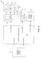
- FIG. 3is a flow diagram showing a process in which, after a power fault is detected on either an external LV or HV supply line, a backup voltage provided to an LV protection circuit via a bypass circuit and linearly regulated by the LV protection circuit to maintain a low output voltage at an LV output port, in accordance with one embodiment of the invention.
- FIG. 4is a block diagram of a data storage device comprising a power control module (e.g., the power control module in the embodiment shown in FIG. 1A or 2A ), in accordance with one embodiment of the invention.
- a power control modulee.g., the power control module in the embodiment shown in FIG. 1A or 2A
- Various embodiments of the inventionare directed to providing a power control module comprising control circuitry configured to detect a power fault (e.g., an undervoltage condition) on a low or high voltage supply line from an external power supply, isolate the low and high supply lines from the power control module, provide a backup voltage to an high voltage (HV) node, provide the backup voltage to a low voltage (LV) node via a bypass circuit coupled between the HV and LV nodes, and cause an LV protection circuit coupled between the LV node and an LV output (LVOUT) port to regulate the backup voltage at the LV node to maintain a low output voltage at the LVOUT port to within a predetermined operating range.
- the predetermined operating rangemay be an operating range as specified for proper operation of an LV load coupled to the LVOUT port.
- the control circuitryis configured to cause the LV protection circuit to operate in an ohmic state to linearly regulate the backup voltage at the LV node and provide backup power to an LV load coupled to the LVOUT port when the power fault is detected.
- the LV loadcomprises one or more low voltage components of a data storage device in which the power control module resides.
- the power control modulefurther comprises an HVOUT port coupled to an HV load.
- the HV loadcomprises one or more components of a data storage device in which the power control module resides.
- the power control modulefurther comprises LV and HV isolations circuits that are used to isolate the respective LV and HV nodes from the external power supply LV and HV supply lines when the power fault is detected.
- the bypass circuit and the LV protection circuitprovide switched back-gate biasing to provide switchable reverse or forward (inrush) current protection.
- a backup power source coupled to multiple I/O ports of the power control modulecomprises a spindle motor that provides backup energy to the power control module when the power fault is detected.
- FIG. 1Ashows a power control module 100 coupled to an external power supply 102 , a backup power source 104 , an LV load 106 , and an HV load 108 , in accordance with one embodiment of the invention.
- the power control module 100comprises an LVIN port for receiving a low supply voltage from the external power supply 102 (which may be, in one embodiment, a host power supply residing in a computing device such as a desktop, laptop or tablet computer or be a standalone power supply) via LV supply line 110 , and an LVOUT port for providing power to the LV load 106 via an LV output power rail 107 .
- the external power supply 102which may be, in one embodiment, a host power supply residing in a computing device such as a desktop, laptop or tablet computer or be a standalone power supply
- LVOUT portfor providing power to the LV load 106 via an LV output power rail 107 .
- the LV load 106may comprise one or more LV components of a data storage device (e.g., an HDD, SSHD, or SSD).
- the LV components of the data store devicemay include a preamp and a regulator bank, which may provide power to a System On a Chip (SOC) (which can comprise a controller), volatile memory, an I/O interface, and non-volatile semiconductor memory, for example.
- SOCSystem On a Chip
- the power control module 100further comprises an HVIN port for receiving a high supply voltage from the external power supply 102 via HV supply line 112 , and an HVOUT port for providing power to the HV load 108 via an HV output power rail 109 .
- the HV load 108may comprise one or more HV components of the data storage device.
- the HV components of the data storage devicemay include a spindle motor and a voice coil motor (VCM).
- the low supply voltagemay be approximately 5V and the high supply voltage may be approximately 12V. In other embodiments, the low supply voltage may be less than or greater than 5V and the high supply voltage may be less than or greater than 12V.
- the high supply voltageis higher than the low supply voltage when there is no power fault on either the LV or HV supply line 110 , 112 , such as when the power control module 100 is operating such that the low output voltage at the LVOUT port and the high output voltage at the HVOUT port are within a predetermined operating range as specified for proper operation of the respective LV and HV loads 106 , 108 .
- power control module 100also comprises control circuitry 114 , an LV isolation circuit 116 , an HV isolation circuit 118 , an LV protection circuit 120 , an HV protection circuit 122 , a bypass circuit 124 , a backup power generator 126 , a supply voltage monitor 128 , and a power supply 130 .
- all of the components of the power control module 100reside on the same integrated circuit (IC).
- the power control module 100resides in a power system (e.g., a Power Large Scale Integration (PLSI) or a power Application Specific Integrated Circuit (ASIC)) in a data storage device.
- PLSIPower Large Scale Integration
- ASICpower Application Specific Integrated Circuit
- control circuitry 114may comprise, for example, a microprocessor or combinatory logic and is configured to control the operation of the LV and HV isolation circuits 116 , 118 , the LV and HV protection circuits 120 , 122 , the bypass circuit 124 , and the backup power generator 126 .
- control circuitry 114may comprise a state machine.
- the LV isolation circuit 116is coupled between the LVIN port and LV node and the HV isolation circuit 118 is coupled between the HVIN port and HV node.
- the LV and HV isolation circuits 116 and 118each comprise a FET (e.g., an ISOFET) that includes an intrinsic body diode (i.e., parasitic diode) (as shown in FIG. 1A ).
- the parasitic diodeprovides reverse current blocking in the LV and HV isolation circuits.
- LV and HV isolation circuits 116 and 118may each comprise, for example, an eFuse, load switch or other type of semiconductor device or devices configured to operate as a switch.
- LV isolation circuit 116 and/or HV isolation circuit 118may be situated external to an IC on which the other components of power control module 100 reside. In the embodiment in FIG.
- the LV isolation circuit 116is configured to operate in either an ON state (i.e., a closed state) or an OFF state (i.e., an open state) in response to a control signal 132 from the control circuitry 114
- HV isolation circuit 118is configured to operate in either an ON state or an OFF state in response to a control signal 134 from the control circuitry 114 .
- the LV protection circuit 120is coupled between the LV node and the LVOUT port and comprises a FET that can be linearly driven and a parasitic diode that provides forward (inrush) current protection.
- the LV protection circuit 120comprises an eFuse (an integrated FET).
- the LV protection circuit 120may comprise a different type of transistor device or circuit that can be linearly driven.
- the LV protection circuitis configured to operate in an ON state, an OFF state, or an ohmic state in response to a control signal 144 from the control circuitry 114 .
- the LV protection circuitcan be controlled by the control circuitry 114 to regulate (e.g., linearly regulate) a backup voltage at the LV node to safely drive the LVOUT port to maintain the low output voltage at the LVOUT port within a predetermined operating range, which may be determined to be within operating specifications of the LV load 106 .
- the LV protection circuit 120further comprises a temperature sensor 136 , a current sensor 138 , and comparators 140 and 142 .
- the temperature sensor 136is situated sufficiently close to the FET in the LV protection circuit 120 so as to enable it to receive thermal energy from the FET.
- a temperature sensor signal provided by the temperature sensor 136is coupled to the positive input of comparator 140
- an over-temperature reference (OT REF)e.g., an OT reference voltage
- OTPover-temperature reference
- comparator 140is configured to compare the temperature sensor signal outputted by the temperature sensor 136 to the OT reference and to provide an indication of an OT condition to the control circuitry 114 when the temperature sensor signal exceeds the OT reference.
- the current sensor 138is coupled between the FET in the LV protection circuit 120 and the LVOUT port and situated in a current path extending from the LVIN port to the LVOUT port, the output of the current sensor 138 is coupled to the positive input of comparator 142 , an over-current reference (OC REF) (e.g., an OC reference voltage) is coupled to the negative input of comparator 142 , and the output of comparator 142 is coupled to the OC input of the control circuitry 114 .
- Comparator 142is configured to compare a current sensor signal outputted by the current sensor 138 to the OC reference and to provide an indication of an OC condition to the control circuitry 114 when the current sensor signal exceeds the OC reference.
- the HV protection circuit 122is coupled between the HV node and the HVOUT port and comprises a FET that can be linearly driven and a parasitic diode, and is configured to provide forward (inrush) current protection and overvoltage protection.
- the HV protection circuit 122comprises an eFuse.
- the HV protection circuit 122may comprise a different type of transistor device or circuit that can be linearly driven.
- the HV protection circuitis configured to operate in an ON state, an OFF state, or an ohmic state in response to a control signal 146 from the control circuitry 114 .
- the HV protection circuitcan be controlled by the control circuitry 114 to regulate (e.g., linearly regulate) a high supply voltage at the HVIN port to safely drive the LVOUT port to maintain the high output voltage at the LVOUT port within a predetermined operating range, which may be determined to be within operating specifications of the HV load 108 .
- the bypass circuit 124is coupled between the LV node and the HV node.
- the bypass circuit 124comprises a FET that includes a parasitic diode.
- the bypass circuit 124may comprise, for example, an eFuse, load switch or other type of semiconductor device or devices configured to operate as a switch.
- the bypass circuit 124is configured to operate in either an ON state (i.e., a closed state) or an OFF state (i.e., an open state) in response to a control signal 147 from the control circuitry 114 .
- the backup power generator 126is coupled to backup power source 104 via I/O ports 148 , 150 , and 152 , coupled to the HVOUT port, and coupled to the HV node via the HV protection circuit 122 .
- the backup power source 104comprises a spindle motor 154 to provide backup energy.
- the backup power source 104may comprise one or more capacitors, one or more batteries, or other type of charge storage element(s).
- the backup power generator 126is controlled by the control circuitry 114 via control line 158 and comprises a spindle driver circuit 156 .
- the spindle driver circuit 156is configured to operate in a power good mode, in which the low supply voltage at the LVIN port is within a predetermined LV range and the high supply voltage at the LVIN port is within a predetermined HV range, and extract energy from the HVOUT port to provide power to the spindle motor 154 via I/O ports 148 , 150 , and 152 , or operate in a power fault detection (hold-up) mode, in which a power fault has been detected on either the LV supply line 110 or the high voltage supply line 112 , and provide a backup voltage (also referred to as backup power in the patent application) to the HV node via the HV protection circuit 122 .
- a power fault detectionhold-up
- the supply voltage monitor 128is coupled to the LVIN and HVIN ports and is configured to monitor the low and high supply voltages on the respective LV and HV supply lines 110 , 112 from the external power supply 102 , and notify the control circuitry 114 via output line 160 when a power fault is detected on either the LV supply line 110 or the HV supply line 112 .
- a power faultmay be detected when the low supply voltage on the LV supply line 110 falls below a predetermined minimum voltage level or the high supply voltage on the HV supply line 112 falls below a predetermined minimum voltage level.
- the supply voltage monitor 128may comprise an ADC channel for monitoring the LV supply line 110 and an ADC channel for monitoring the HV supply line 112 .
- the supply voltage monitor 128may comprise other monitoring mechanisms or circuits for voltage monitoring.
- the power supply 130is coupled to the HV node and is configured to provide operating power to components (e.g., the LV and HV isolation circuits 116 , 118 , the LV and HV protection circuits 120 , 122 , the bypass circuit 124 , the backup power generator 126 , and the supply voltage monitor 128 ) of the power control module 100 .
- the power supply 130is configured to provide the operating voltages (such as bias voltages) each of the aforementioned components of the power control module 100 require for proper operation.
- the power control module 100 in the embodiment in FIG. 1Acan operate in a power good mode, a hold-up mode, an undervoltage (UV) lockout mode, and a power on ramp mode.
- the control circuitry 114places the power control module 100 in the power good mode when the low supply voltage (from the external power supply 102 ) at the LVIN port is within a predetermined low voltage operating range and the high supply voltage (from the external power supply 102 ) at the HVIN port is within a predetermined high voltage operating range.
- control circuitry 114sets the isolation circuit 116 and the LV protection circuit 120 to the ON state (i.e., a closed state), which opens the current path between the LVIN port and the LVOUT port to cause the low supply voltage at the LVIN port to be provided at the LVOUT port to provide power to the LV load 106 .
- control circuitry 114In the power good mode, the control circuitry 114 also sets the HV isolation circuit 118 and the HV protection circuit 122 to the ON state, thereby opening the current path between the HVIN port and the HVOUT port to cause the high supply voltage at the HVIN port to be provided at the HVOUT port to power the HV load 108 . In the power good mode, the control circuitry 114 further sets the bypass circuit 124 to the OFF state (i.e., an open state), which isolates the HV node from the LV node by preventing current to flow from the HV node to the LV node or vice versa. Also, in the embodiment shown in FIG.
- the backup power source 104comprises one or more capacitors
- the backup power generator 126may comprise circuitry, such as a boost switching regulator (BSR), to charge the one or more capacitors in the power good mode.
- the backup power source 104may comprise one or more batteries and circuitry to charge the batteries in the power good mode.
- the control circuitry 114When the control circuitry 114 detects a power fault on either the LV or HV supply line 110 , 112 via a power fault indication from the supply voltage monitor 128 on output line 160 , the control circuitry 114 places the power control module 100 in the hold-up mode.
- the power faultmay be an undervoltage condition on either the LV or HV supply line 110 , 112 .
- the control circuitry 114sets the LV and HV isolation circuits 116 , 118 to the OFF state, which isolates the LV and HV supply lines 110 , 112 of the external power supply 102 from the respective LV and HV nodes.
- the control circuitry 114In the hold-up mode, the control circuitry 114 also sets the bypass circuit 124 to the ON state, the LV protection circuit 120 to an ohmic state, the HV protection circuit 122 to the ON state, as shown in table 175 in FIG. 1B , and causes the backup power generator 126 to provide a backup voltage to the HV node via the HV protection circuit 122 .
- the backup voltageis higher than the high supply voltage provided at the HVOUT port in the power good mode.
- the backup voltageis higher than the low supply voltage provided at the LVOUT port in the power good mode but lower than the high supply voltage provided at the HVOUT port in the power good mode.
- the spindle driver circuit 156 in the backup power generator 126is configured in the hold-up mode to receive motor energy from the spindle motor 154 in the backup power source 104 via I/O ports 148 , 150 , and 152 , and convert the motor energy into the backup voltage.
- the spindle driver circuit 156comprises a boost circuit (not shown in FIG. 1A ) to provide a backup voltage having a higher voltage level than the high output voltage provided at the HVOUT port in the power good mode.
- the motor energymay be rectified or synchronously rectified by the spindle driver circuit 156 to provide a backup voltage that is higher than the low output voltage at the LVOUT port in the power good mode but lower than the high output voltage at the HVOUT port in the power good mode, which reduces thermal dissipation in the LV protection circuit 120 in the hold-up mode.
- the backup voltage at the HV nodeis provided to the LV node via the bypass circuit 124 , and regulated (e.g., linearly regulated) by the LV protection circuit 120 to maintain the low output voltage at the LVOUT port to within a predetermined operating range.
- the predetermined operating rangemay be determined by the operating specifications of the LV load 106 .
- the control circuitry 114appropriately drives the LV protection circuit 120 to set the low output voltage at the LVOUT port to be higher than a mid-point of the predetermined operating range to reduce thermal dissipation in the LV protection circuit 120 .
- the LV and HV isolation circuits 116 , 118When the LV and HV isolation circuits 116 , 118 are set to the OFF state in the hold-up mode, they provide reverse current protection by preventing current from flowing from the respective LV and HV nodes to the external power supply 102 via the LV and HV supply lines 110 , 112 .
- the control circuitry 114places the power control module 100 in the UV lockout mode by setting the bypass circuit 124 and the LV and HV protection circuits 120 , 122 to the OFF state.
- the LV and HV isolation circuits 116 , 118remain set to the OFF state.
- the power control module 100is effectively turned off (i.e., in shutdown).
- the control circuitry 114places the power control module 100 in the power on ramp mode to ramp up the low output voltage on the LVOUT port and the high output voltage on the HVOUT port.
- the control circuitry 114sets the LV and HV isolation circuits 116 , 118 to the ON state, the bypass circuit 124 to the OFF state, and the LV and HV protection circuits 120 , 122 to the ohmic state, as shown in table 175 in FIG. 1B .
- the bypass circuit 124When the bypass circuit 124 is set to the OFF state and the LV and HV isolation circuits 116 , 118 are set to the ON state, the high supply voltage from the HV supply line 112 on the HV node is isolated from the low supply voltage from the LV supply line 110 on the LV node.
- the LV protection circuit 120In the ohmic state, the LV protection circuit 120 is controlled by the control circuitry 114 via control signal 144 to control the slew rate of the low output voltage at the LVOUT port.
- the HV protection circuit 122is controlled by the control circuitry 114 via control signal 146 to control the rate of the high output voltage ramp up at the HVOUT port.
- the control circuitry 114sets the LV and HV protection circuits 120 , 122 to the ON state to end the power on ramp mode.
- FIG. 2Ashows a power control module 200 coupled to an external power supply 102 , a backup power source 104 , an LV load 106 , and an HV load 108 , in accordance with one embodiment of the invention.
- a power control module 200coupled to an external power supply 102 , a backup power source 104 , an LV load 106 , and an HV load 108 , in accordance with one embodiment of the invention.
- FIG. 2Ashows a power control module 200 coupled to an external power supply 102 , a backup power source 104 , an LV load 106 , and an HV load 108 , in accordance with one embodiment of the invention.
- FIG. 2Ashows a power control module 200 coupled to an external power supply 102 , a backup power source 104 , an LV load 106 , and an HV load 108 , in accordance with one embodiment of the invention.
- power control module 200comprises control circuitry 214 , an LV isolation circuit 116 , an HV isolation circuit 218 , an LV protection circuit 220 , a bypass circuit 224 , a backup power generator 126 , a supply voltage monitor 128 , a power supply 230 , LVIN, LVOUT, HVIN, and HVOUT ports, and I/O ports 148 , 150 , and 152 .
- all of the components of power control module 200 shown within solid line 203are situated on the same IC (e.g., a PLSI or ASIC), and the LV isolation circuit 116 is situated external to the IC.
- LV isolation circuit 116may be coupled between the LVIN port and the LV node and situated on the same IC with the other components of power control module 200 shown within the solid line 203 .
- control circuitry 214may comprise, for example, a microprocessor or combinatory logic and is configured to control the operation of the LV and HV isolation circuits 116 , 218 , the LV protection circuit 120 , the bypass circuit 224 , and the backup power generator 126 .
- control circuitry 214may comprise a state machine.
- the LV isolation circuit 116is coupled between the external power supply 102 and the LVIN port and the HV isolation circuit 218 is coupled between the HVIN port and the HV node.
- the HV isolation circuit 218comprises a FET 263 that can be linearly driven, two intrinsic body diodes (i.e., parasitic diodes), and a switch 262 .
- the switch 262may comprise, for example, two or more transistors (e.g., FETs) configured to operate as a switch.
- the HV isolation circuit 218may comprise a switched back-gate device.
- the HV isolation circuit 218may comprise an eFuse or a different type of transistor device or circuit that may be linearly driven, in addition to the parasitic diodes and the switch 262 .
- the anodes of the parasitic diodes in the HV isolation circuit 218are coupled to a body node 265 of the FET 263 , the cathode of one of the parasitic diodes is coupled to the source (S) of the FET 263 , and the cathode of the other parasitic diode is coupled to the drain (D) of the FET 263 .
- Ssource
- Ddrain
- the FET 263 in the HV isolation circuit 218is configured to operate in an ON state, an OFF state, or an ohmic state in response to a control signal 234 from the control circuitry 214 applied to the gate (G) of the FET 263 , and the switch 262 in the HV isolation circuit 218 is configured to operate in an “A” or “B” position in response to a control signal 268 from the control circuitry 214 .
- the switch 262 in the HV isolation circuit 218when the switch 262 in the HV isolation circuit 218 is in the “A” position, the anode of one of the parasitic diodes is coupled to the source of the FET 263 , its cathode is coupled to the drain of the FET 263 , and the anode and cathode of the other parasitic diode are shorted together.
- the switchwhen the switch is in the “A” position, the selected parasitic diode points from the source to the drain of the FET 263 (i.e., the cathode of the selected parasitic diode is coupled to the drain of the FET 263 and its anode is coupled to the source of the FET 263 ).
- the selected parasitic diodepoints from the drain to the source of the FET 263 (i.e., the cathode of the selected parasitic diode is coupled to the source of the FET 263 and its anode is coupled to the drain of the FET 263 ).
- the “state” the HV isolation circuit 218 is configured to operate inis indicated using a format that combines the state of the FET 263 and the position of the switch 262 in the HV isolation circuit 218 .
- a formatthat combines the state of the FET 263 and the position of the switch 262 in the HV isolation circuit 218 .
- the HV isolation circuit 218is configured to operate in an ON-A state, in which the FET 263 is set to the ON state and the switch 262 is set to the “A” position, an OFF-A state, in which the FET 263 is set to the OFF state and the switch 262 is set to the “A” position, and an ohmic-B state, in which the FET 263 is set to the ohmic state and the switch 262 is set to the “B” position.
- the switch 262provides switchable reverse or forward current protection to the HV isolation circuit 218 by appropriately switching the orientation of the selected parasitic diode.
- the same format as described aboveis also used to indicate the operating states of the bypass circuit 224 and the LV protection circuit 220 .
- the LV protection circuit 220is coupled between the LVIN port and the LVOUT port and comprises a FET 267 that can be linearly driven, two parasitic diodes, and a switch 264 .
- the switch 264may comprise, for example, two or more transistors (e.g., FETs) configured to operate as a switch.
- the LV protection circuit 220may comprise a switched back-gate device.
- the LV protection circuit 220may comprise an eFuse or a different type of transistor device or circuit that can be linearly driven, in addition to the parasitic diodes and the switch 264 .
- the FET 267 in the LV protection circuit 220is configure to operate in an ON state, an OFF state, or an ohmic state in response to a control signal 244 from control circuitry 214 applied to the gate of the FET 267
- the switch 264 in the LV protection circuit 220is configured to operate in an “A” or “B” position in response to a control signal 270 from the control circuitry 214 .
- the switch 264is in the “A” position, the selected parasitic diode points from the source to the drain of the FET 267
- the switch 264is in the “B” position, the selected parasitic diode points from the drain to the source of the FET 267 .
- the LV protection circuit 220is configured to operate in an ON-A state (i.e., when the FET 267 is in the ON state and the switch 264 in the “A” position), an OFF-B state (i.e., when the FET 267 is in the OFF state and the switch 264 is in the “B” position), and an ohmic-B state (i.e., when the FET 267 is in the ohmic state and the switch 264 is in the “B” position).
- ON-A statei.e., when the FET 267 is in the ON state and the switch 264 in the “A” position
- an OFF-B statei.e., when the FET 267 is in the OFF state and the switch 264 is in the “B” position
- an ohmic-B statei.e., when the FET 267 is in the ohmic state and the switch 264 is in the “B” position.
- the bypass circuit 224is coupled between the HV node and the LV node and comprises a FET 269 that can be linearly driven, two parasitic diodes, and a switch 266 .
- the switch 266may comprise, for example, two or more transistors (e.g., FETs) configured to operate as a switch.
- the bypass circuit 224may comprise a switched back-gate device.
- the bypass circuit 224may comprise an eFuse or a different type of transistor device or circuit that can be linearly driven, in addition to the parasitic diodes and the switch 266 .
- the FET 269 in the bypass circuit 224is configure to operate in the ON state or the OFF state in response to a control signal 247 from control circuitry 214 applied to the gate of the FET 269
- the switch 266 in the bypass circuit 224is configured to operate in an “A” or “B” position in response to a control signal 272 from the control circuitry 214 .
- the switch 266is in the “A” position, the selected parasitic diode points from the source to the drain of the FET 269
- the switch 266is in the “B” position, the selected parasitic diode points from the drain to the source of the FET 269 .
- the bypass circuit 224is configured to operate in an ON-A state (i.e., when the FET 269 is in the ON state and the switch 266 in the “A” position), an OFF-A state (i.e., when the FET 269 is in the OFF state and the switch 266 is in the “A” position), and an OFF-B state (i.e., when the FET 269 is in the OFF state and the switch 266 is in the “B” position).
- ON-A statei.e., when the FET 269 is in the ON state and the switch 266 in the “A” position
- an OFF-A statei.e., when the FET 269 is in the OFF state and the switch 266 is in the “A” position
- an OFF-B statei.e., when the FET 269 is in the OFF state and the switch 266 is in the “B” position.
- the power supply 230is coupled to the HV node and is configured to provide operating power to components (e.g., the LV and HV isolation circuits 116 , 218 , the LV protection circuit 220 , the bypass circuit 224 , the backup power generator 126 , and the supply voltage monitor 128 ) of the power control module 200 .
- the power supply 230is configured to provide the operating voltages (such as bias voltages) that each of the aforementioned components of the power control module 200 require for proper operation.
- the power control module 200 in the embodiment in FIG. 2Acan operate in a power good mode, a hold-up mode, a UV lockout mode, a power on ramp stage 1 mode, and a power on ramp stage 2 mode.
- the control circuitry 214places the power control module 200 in the power good mode when the low supply voltage (from the external power supply 102 ) at the LVIN port is within a predetermined low voltage operating range and the high supply voltage (from the external power supply 102 ) at the HVIN port is within a predetermined high voltage operating range.
- the control circuitry 214sets the isolation circuit 116 to the ON state and the LV protection circuit 220 to the ON-A state, which opens the current path between the low voltage supply line 110 and the LVOUT port to cause the low supply voltage from the external power supply 102 to be provided at the LVOUT port to provide power to the LV load 106 .
- the switch 264 in the LV protection circuit 220in the “A” position, the selected parasitic diode in the LV protection circuit 220 provides reverse current protection (i.e., it prevents current from flowing back from the LVOUT port to the LVIN port and the external power supply 102 ) while allowing forward current flow from the LVIN port to the LVOUT port.
- the control circuitry 214sets the HV isolation circuit 218 to an ON-A state, which opens the current path between the HVIN port and the HVOUT port to cause the high supply voltage from the external power supply 102 at the HVIN port to be provided at the HVOUT port to provide power to the HV load 108 .
- the switch 262 in the HV isolation circuit 218in the “A” position, the selected parasitic diode in the HV isolation circuit 218 provides reverse current protection (i.e., it prevents current from flowing back from the HVOUT port to the HVIN port and the external power supply 102 ) while allowing forward current flow from the HVIN port to the HVOUT port.
- the control circuitry 214further sets the bypass circuit 224 to the OFF-B state, which isolates the HV node from the LV node.
- the selected parasitic diode in the bypass circuit 224provides reverse current protection (i.e., it prevents current from flowing from the HV node to the LV node).
- poweris applied to the spindle driver circuit 156 , as discussed above with respect to the power good mode in the power control module 100 in the embodiment shown in FIG. 1A .
- the control circuitry 214When the control circuitry 214 detects a power fault on either the LV or HV supply line 110 , 112 via a power fault indication from the supply voltage monitor 128 on output line 160 , the control circuitry 214 places the power control module 200 in the hold-up mode.
- the power faultmay be an undervoltage condition on either the LV or HV supply line 110 , 112 .
- the control circuitry 214sets the LV isolation circuit 116 to the OFF state and the HV isolation circuit 218 to the OFF-A state, which isolates the LV and HV supply lines 110 , 112 of the external power supply 102 from the respective LV and HV nodes.
- the selected parasitic diode in the HV isolation circuit 218provides reverse current protection (i.e., it prevents current from flowing from the HV node to the HVIN port and the external power supply 102 via the high voltage supply line 112 ).
- the control circuitry 214also sets the bypass circuit 224 to the ON-A state, the LV protection circuit 220 to the ohmic-B state, and causes the backup power generator 126 to provide a backup voltage to the HV node.
- the backup voltageis higher than the high supply voltage provided at the HVOUT port in the power good mode.
- the backup voltageis higher than the low supply voltage provided at the LVOUT port in the power good mode but lower than the high supply voltage provided at the HVOUT port in the power good mode.
- the selected parasitic diode in the bypass circuit 224provides forward current flow from the HV node to the LV node. Also, by setting the switch 264 in the LV protection circuit 220 to the “B” position, the selected parasitic diode in the LV protection circuit 220 provide reverse current protection by preventing current flow from the LVOUT port to the LVIN port.
- the spindle driver circuit 156 in the backup power generator 126is configured in the hold-up mode to receive motor energy from the spindle motor 154 in the backup power source 104 via I/O ports 148 , 150 , and 152 , and convert the motor energy into the backup voltage, as described above with respect to the hold-up mode in the power control module 100 in the embodiment shown in FIG. 1A .
- the methods described above for reducing thermal dissipation in the LV protection circuit 120 in the hold-up mode in the embodiment in FIG. 1Aalso apply to the LV protection circuit 220 in the hold-up mode in the embodiment in FIG. 2A .
- the backup voltage at the HV nodeis provided to the LV node via the bypass circuit 224 , and regulated (e.g., linearly regulated) by the LV protection circuit 220 to maintain the low output voltage at the LVOUT port to within a predetermined operating range.
- the predetermined operating rangemay be determined by the operating specifications of the LV load 106 .
- the control circuitry 214appropriately drives the LV protection circuit 220 to set the low output voltage at the LVOUT port to be higher than a mid-point of the predetermined operating range to reduce thermal dissipation in the LV protection circuit 220 .
- the LV and HV isolation circuits 116 , 218When the LV and HV isolation circuits 116 , 218 are turned to the OFF state in the hold-up mode, they provide reverse current protection by preventing current from flowing from the respective LV and HV nodes to the external power supply 102 via the LV and HV supply lines 110 , 112 .
- the control circuitry 214places the power control module 200 in the UV lockout mode by setting the bypass circuit 224 and the LV protection circuit 220 to the OFF state.
- the LV and HV isolation circuits 116 , 218remain set to the OFF state (as they were in the hold-up state).
- the power control module 200is effectively turned off (i.e., in shutdown).
- the control circuitry 214monitors the LV and HV supply lines 110 , 112 at the respective LVIN and HVIN ports via the supply voltage monitor 128 to determine whether to place the power control module 200 in the power on ramp stage 1 or the power on ramp stage 2 operating mode to ramp up the low and high output voltages on the respective LVOUT and HVOUT ports. Since the parasitic diode in the LV isolation circuit 116 allows current to flow from the external power supply to the LVIN port, the LV isolation 116 does not have to be in the ON state for the above determination to be made. However, in one embodiment, the LV isolation circuit 116 is set to the ON state prior to determining whether to place the power control module 200 in the power on ramp stage 1 or stage 2 operating mode.
- the control circuitry 214determines that the low supply voltage starts to ramp up at the LVIN port before the high supply voltage starts to ramp up at the HVIN port, the control circuitry 214 places the power control module 200 in the power on ramp stage 1 operating mode. On the other hand, if the control circuitry 214 determines that the high supply voltage starts to ramp up at the HVIN port before the low supply voltage starts to ramp up at the LVIN port, the control circuitry 214 places the power control module 200 in the power on ramp stage 2 operating mode.
- the power control circuitry 214sets LV isolation circuit 116 to the ON state, the HV isolation circuit 218 to the ohmic-B state, and the LV protection circuit 220 to the ohmic-B state, as shown in the table 275 in FIG. 2B .
- the control circuitry 214sets the bypass circuit 224 to the OFF-A state to prevent current flow from the LV node to the HV node when the voltage at the LV node is initially higher than the voltage at the HV node.
- the control circuitry 214sets the bypass circuit 224 to the OFF-B state to prevent current flow from the HV node to the LV node when the voltage at the HV node is higher than the voltage at the LV node.
- control circuitry 214if the control circuitry 214 places the power control module 200 in the power on ramp stage 1 operating mode, when the high supply voltage at the HVIN port begins to ramp up to a level that is higher than the low supply voltage at the LVIN port, the control circuitry 214 switches the power control module 200 to the power on ramp stage 2 operating mode to prevent current flow from the HV node to the LV node.
- the LV isolation circuit 116is set to the ON state to enable full current flow from the external power supply 102 to the LVIN port
- the LV protection circuit 220is set to the ohmic-B state to control the slew rate of the low output voltage at the LVOUT port and provide forward (i.e., inrush) current protection via the orientation of the parasitic diode that is selected by switch 264
- the HV isolation circuit 218is set to the ohmic-B state to control the slew rate of the high output voltage at the HVOUT port and provide forward current protection via the orientation of the parasitic diode selected by switch 262 .
- control circuitry 214sets the LV protection circuit 220 and the HV isolation circuit 218 to the ON-A state to end the power on ramp mode.
- FIG. 3shows a process 300 for detecting a power fault on either an LV supply line 110 or an HV supply 112 of an external power supply 102 ( FIG. 1A, 2A ), supplying a backup voltage from an HV node to an LV node via a bypass circuit 124 ( FIG. 1A ), 224 ( FIG. 2B ) of a power control module 100 ( FIG. 1A ), 200 ( FIG. 2A ), and regulating the backup voltage at the LV node via an LV protection circuit 120 ( FIG. 1A ), 220 ( FIG. 2A ) of the power control module 100 , 200 to maintain a low output voltage at the LV output port of the power control module 100 , 200 , in accordance with one embodiment of the invention.
- the process 300can be implemented by control circuitry 114 ( FIG. 1A ), 214 ( FIG. 2A ) of the power control module 100 , 200 .
- the power control module 100 , 200may be situated in a data storage device (e.g., an HDD or an SSHD).
- the process 300starts in block 302 , where a power fault (e.g., an undervoltage condition) is detected on either an LV or an HV supply line of an external power supply.
- a power faulte.g., an undervoltage condition
- the power faultmay be detected at an LVIN or HVIN port of the power control module via a supply voltage monitor 128 ( FIG. 1A, 2A ), which may comprise, for example, an ADC channel for monitoring the LV supply line and the HV supply line.
- the process 300isolates the respective LV and NV nodes from the external power supply LV and HV supply lines.
- LV and HV isolation circuitsare set to the OFF state to isolate the respective LV and HV nodes from the external power supply LV and HV supply lines.
- the process 300provides a backup voltage from a backup power source to the HV node.
- the backup voltageis generated by a backup power generator 126 coupled to the backup power source 104 and provided to the HV node via an HV protection circuit 122 , which is set to the ON state to allow current to flow from the backup power generator to the HV node.
- the backup power source 104comprises a spindle motor 154 , which generates backup energy that is used to provide the backup voltage.
- the process 300provides the backup voltage from the HV node to the LV node.
- the backup voltageis provided from the HV node to the LV node by setting to the ON state the bypass circuit 124 , which is coupled between the HV node and the LV node.
- the process 300causes an LV protection circuit to regulate the backup voltage to maintain a low output voltage at an LV output (LVOUT) port to within a predetermined operating range.
- the LV protection circuit 120is coupled between the LV node and the LVOUT port and is set to an ohmic state to enable it to linearly regulate the backup voltage.
- the predetermined operating rangemay be determined to be within operating specifications of an LV load that is coupled to the LVOUT port.
- the LV loadmay comprise low voltage components of a data storage device (e.g., an HDD or an SSHD).
- FIG. 4shows a data storage device 400 coupled to an external power supply and comprising a power control module, in accordance with one embodiment of the invention.
- Data storage device 400can be, for example, an HDD, an SSHD (a data store device comprising both rotating magnetic media and non-volatile semiconductor memory (NVSM, e.g., flash memory), or an SSD, and receives low and high supply voltages from the external power supply 402 , which, in one embodiment, may be a host power supply residing in a computing device such as a desktop, laptop or tablet computer or be a standalone power supply.
- the data storage device 400comprises a power control module 404 , which can be, for example, power control module 100 or 200 shown in FIGS. 1A and 2A , respectively.
- the power control module 404can reside in a PLSI or an ASIC, for example.
- an embodiment of the invention's power control module 404may be integrated in a PLSI in a data storage device, and be used to hold up the LV (e.g., 5V) power rail in the data storage device using either motor energy or one or more capacitors or batteries during a power fault on either a LV or HV supply line.
- the bypass circuitcan short the HV node to the LV node to provide a backup voltage at the HV node to an LV protection circuit in the power control module 404 , and rely on the LV protection circuit to linearly regulate the backup voltage to maintain a low output voltage on the LV power rail in the data storage device.
- An embodiment of the invention's power control module 404can therefore provide a cost effective solution for using a backup power source (e.g., motor energy or one or more capacitors or batteries) to effect an emergency transfer of data from a volatile memory to a non-volatile memory (e.g., a disk or NAND flash memory) during a hold-up time that may be of short duration.
- a backup power sourcee.g., motor energy or one or more capacitors or batteries
- the data storage device 400also comprises an LV load 406 , which comprises low voltage components, such as a regulator block 408 , an SOC 410 (which can comprise, for example, a controller), NVM 412 , and volatile memory 414 .
- the data storage device 400further comprises an HV load 416 , which comprises one or more high voltage components, such as a VCM 418 .
- the data storage devicecomprises a backup power source 420 , which may comprise, for example, a spindle motor or one or more capacitors or batteries for providing backup power. It is noted that data storage device 400 also includes other components known to one of ordinary skill in the art but not shown in FIG. 4 so as not to obscure the various described embodiments of the invention.
- the power control module 404is configured to receive a low supply voltage from the external power supply 402 at an LVIN port, receive a high supply voltage from the external power supply 402 at an HVIN port, provide low output voltage at an LVOUT port, provide a high output voltage at an HVOUT port, and communicate with the backup power source 420 via one or more I/O ports.
Landscapes
- Engineering & Computer Science (AREA)
- Power Engineering (AREA)
- Business, Economics & Management (AREA)
- Emergency Management (AREA)
- Charge And Discharge Circuits For Batteries Or The Like (AREA)
Abstract
Description
Claims (21)
Priority Applications (1)
| Application Number | Priority Date | Filing Date | Title |
|---|---|---|---|
| US15/896,596US10127952B2 (en) | 2015-11-18 | 2018-02-14 | Power control module using protection circuit for regulating backup voltage to power load during power fault |
Applications Claiming Priority (2)
| Application Number | Priority Date | Filing Date | Title |
|---|---|---|---|
| US14/944,664US9899834B1 (en) | 2015-11-18 | 2015-11-18 | Power control module using protection circuit for regulating backup voltage to power load during power fault |
| US15/896,596US10127952B2 (en) | 2015-11-18 | 2018-02-14 | Power control module using protection circuit for regulating backup voltage to power load during power fault |
Related Parent Applications (1)
| Application Number | Title | Priority Date | Filing Date |
|---|---|---|---|
| US14/944,664ContinuationUS9899834B1 (en) | 2015-11-18 | 2015-11-18 | Power control module using protection circuit for regulating backup voltage to power load during power fault |
Publications (2)
| Publication Number | Publication Date |
|---|---|
| US20180175619A1 US20180175619A1 (en) | 2018-06-21 |
| US10127952B2true US10127952B2 (en) | 2018-11-13 |
Family
ID=61189125
Family Applications (2)
| Application Number | Title | Priority Date | Filing Date |
|---|---|---|---|
| US14/944,664Active2036-08-02US9899834B1 (en) | 2015-11-18 | 2015-11-18 | Power control module using protection circuit for regulating backup voltage to power load during power fault |
| US15/896,596ActiveUS10127952B2 (en) | 2015-11-18 | 2018-02-14 | Power control module using protection circuit for regulating backup voltage to power load during power fault |
Family Applications Before (1)
| Application Number | Title | Priority Date | Filing Date |
|---|---|---|---|
| US14/944,664Active2036-08-02US9899834B1 (en) | 2015-11-18 | 2015-11-18 | Power control module using protection circuit for regulating backup voltage to power load during power fault |
Country Status (1)
| Country | Link |
|---|---|
| US (2) | US9899834B1 (en) |
Cited By (1)
| Publication number | Priority date | Publication date | Assignee | Title |
|---|---|---|---|---|
| WO2021073050A1 (en)* | 2019-10-16 | 2021-04-22 | 美的威灵电机技术(上海)有限公司 | Switch circuit, motor control system, and vacuum cleaner |
Families Citing this family (16)
| Publication number | Priority date | Publication date | Assignee | Title |
|---|---|---|---|---|
| FR3069388B1 (en)* | 2017-07-24 | 2020-01-17 | STMicroelectronics (Alps) SAS | METHOD FOR CONTROLLING INTERIOR CURRENTS THAT MAY BE CIRCULATED IN A CHARGE SWITCH, AND CORRESPONDING ELECTRONIC CIRCUIT |
| US10855174B2 (en) | 2018-02-16 | 2020-12-01 | Monolithic Power Systems, Inc. | Power supply and power supply method with power sharing and overshoot preventing |
| US10523048B2 (en)* | 2018-02-16 | 2019-12-31 | Monolithic Power Systems, Inc. | Power supply and power supplying method with power backup and power sharing |
| US10892637B2 (en) | 2018-02-16 | 2021-01-12 | Monolithic Power Systems, Inc. | Power supply and power supplying method with power backup |
| US10804691B2 (en)* | 2018-03-06 | 2020-10-13 | Texas Instruments Incorporated | Circuit providing reverse current protection for high-side driver |
| US10872644B2 (en)* | 2018-07-13 | 2020-12-22 | Taiwan Semiconductor Manufacturing Co., Ltd. | Boost bypass circuitry in a memory storage device |
| US11249117B2 (en)* | 2018-08-02 | 2022-02-15 | Jetperch Llc | Autoranging ammeter with fast dynamic response |
| JP7255249B2 (en)* | 2019-03-12 | 2023-04-11 | 富士通株式会社 | Power supply circuit and electronic device |
| CN112751325B (en) | 2019-10-30 | 2024-05-10 | 台达电子企业管理(上海)有限公司 | DC power supply system and method |
| CN112751328A (en) | 2019-10-30 | 2021-05-04 | 台达电子企业管理(上海)有限公司 | DC power supply system |
| US11397623B2 (en)* | 2020-03-19 | 2022-07-26 | Seagate Technology Llc | Data storage device load sharing |
| JP7449805B2 (en)* | 2020-07-27 | 2024-03-14 | ミネベアミツミ株式会社 | Motor drive control device and motor unit |
| JP7352524B2 (en)* | 2020-07-29 | 2023-09-28 | 株式会社東芝 | driver circuit |
| US11813995B2 (en)* | 2022-03-15 | 2023-11-14 | Ree Automotive Ltd. | Redundant power distribution system based on single power source |
| US11862202B2 (en) | 2022-05-09 | 2024-01-02 | Western Digital Technologies, Inc. | Data storage device with smart ISOFET threshold voltage automatic tuning |
| CN120642161A (en)* | 2022-12-27 | 2025-09-12 | 泰达电子股份有限公司 | Power supply unit for communication power supply system |
Citations (316)
| Publication number | Priority date | Publication date | Assignee | Title |
|---|---|---|---|---|
| US6014283A (en) | 1997-05-15 | 2000-01-11 | Western Digital Corporation | Non-quadrature servo burst pattern for micro-jogging a magnetoresistive head in a magnetic disk drive |
| US6052076A (en) | 1998-10-14 | 2000-04-18 | Western Digital Corporation | Digital-to-analog converter having high resolution and high bandwidth |
| US6052250A (en) | 1997-08-25 | 2000-04-18 | Western Digital Corporation | Disk drive with separately determined servo and data track pitch |
| US6067206A (en) | 1997-11-18 | 2000-05-23 | Western Digital Corporation | Method and apparatus to compensate for servo wedge rotational offset after a head switch |
| US6078453A (en) | 1997-11-12 | 2000-06-20 | Western Digital Corporation | Method and apparatus for optimizing the servo read channel of a hard disk drive |
| US6091564A (en) | 1998-04-30 | 2000-07-18 | Western Digital Corporation | Disk drive with calibration bursts that are recorded on a spiral and method of recording the same |
| US6094020A (en) | 1998-11-18 | 2000-07-25 | Western Digital Corporation | Disk drive utilizing Bemf of spindle motor to increase VCM voltage during seeks |
| US6101065A (en) | 1998-03-30 | 2000-08-08 | Western Digital Corporation | Disk drive with seek profile selection based on read/write operation |
| US6104153A (en) | 1999-02-23 | 2000-08-15 | Western Digital Corporation | Disk drive employing method of spinning down its spindle motor to reduce the time required for spinning it down and subsequently spinning it up |
| US6122135A (en) | 1997-12-19 | 2000-09-19 | Western Digital Corporation | Disk drive with voice coil motor rise time manager |
| US6122133A (en) | 1998-06-17 | 2000-09-19 | Western Digital Corporation | Hybrid method of determining a fractional track position of a read transducer in a hard disk drive |
| US6141175A (en) | 1997-10-08 | 2000-10-31 | Western Digital Corporation | Repeatable runout cancellation in sectored servo disk drive positioning system |
| US6160368A (en) | 1998-06-22 | 2000-12-12 | Western Digital Corporation | Faster spin-down operation in a disk drive by utilizing pulsed braking |
| US6181502B1 (en) | 1998-07-01 | 2001-01-30 | Western Digital Corporation | Faster access time in a disk drive by utilizing increased VCM potential voltage |
| US6195222B1 (en) | 1998-11-04 | 2001-02-27 | Western Digital Corporation | Disk drive with seek profile selection based on a queued vs. non-queued environment |
| US6198584B1 (en) | 1998-04-30 | 2001-03-06 | Western Digital Corporation | Disk drive with staggered calibration bursts that are disposably located in data regions and method of using the same for calibrating a read head |
| US6198590B1 (en) | 1998-07-21 | 2001-03-06 | Western Digital Corporation | Disk drive employing method of spinning down its spindle motor to reduce the time required for subsequently spinning it up |
| US6204988B1 (en) | 1998-08-24 | 2001-03-20 | Western Digital Corporation | Disk drive capable of autonomously evaluating and adapting the frequency response of its servo control system |
| US6243223B1 (en) | 1998-01-15 | 2001-06-05 | Western Digital Corporation | Disk drive with servo burst phasing for improved linearity and off-track performance with a wide reading transducer |
| US6281652B1 (en) | 2000-03-24 | 2001-08-28 | Western Digital Corporation | Method of using two low-resolution DACS for converting high-resolution digital demands into analog output signals that monotonically drive an actuator motor in a disk drive |
| US6285521B1 (en) | 1999-03-25 | 2001-09-04 | Western Digital Technologies, Inc. | Disk drive employing power source modulation for reducing power consumption |
| US6292320B1 (en) | 1998-03-23 | 2001-09-18 | Western Digital Technologies, Inc. | Disk drive with dual stage actuator radial offset calibration |
| US6320718B1 (en) | 1999-01-07 | 2001-11-20 | Western Digital Technologies, Inc. | Disk drive with zero read offset in reserved area and method of making same |
| US6342984B1 (en) | 1998-07-01 | 2002-01-29 | Western Digital Technologies, Inc | Disk drive including DC to DC voltage converter for increasing voltage to its spindle motor and VCM |
| US6347018B1 (en) | 1990-09-18 | 2002-02-12 | Rodime Plc | Digital servo control system for use in disk drives |
| US6369974B1 (en) | 1999-02-09 | 2002-04-09 | Western Digital Technologies, Inc. | Disk drive with method of constructing a continuous position signal and constrained method of linearizing such position signal while maintaining continuity |
| US6369972B1 (en) | 1999-05-14 | 2002-04-09 | Western Digital Technologies, Inc. | Temperature monitoring method of a disk drive voice coil motor from a traveled distance |
| US6462896B1 (en) | 2000-11-30 | 2002-10-08 | Western Digital Technologies, Inc. | Method for minimizing adjacent track data loss during a write operation in a disk drive |
| US6476996B1 (en) | 2000-02-15 | 2002-11-05 | Western Digital Technologies, Inc. | Disk drive comprising an actuator driver circuit for retracting a head independent of a servo microprocessor when a spindle speed fault mode is detected |
| US6484577B1 (en) | 2001-10-31 | 2002-11-26 | Western Digital Technologies, Inc. | Accelerometer signal processor comprising variable oscillators and counters |
| US6493169B1 (en) | 2000-04-19 | 2002-12-10 | Western Digital Technologies, Inc. | Disk drive employing spindle motor commutation time variation for reducing acoustic noise |
| US6496324B1 (en) | 1999-06-29 | 2002-12-17 | Western Digital Technologies, Inc. | Disk drive employing method of unlatching actuator arm using VCM voltage limiting circuit to limit actuator arm velocity |
| US6498698B1 (en) | 1999-06-29 | 2002-12-24 | Western Digital Technologies, Inc. | Servowriter employing method of unlatching actuator arm using VCM voltage limiting circuit to limit actuator arm velocity |
| US6507450B1 (en) | 1999-06-11 | 2003-01-14 | Western Digital Technologies, Inc. | Method of continuously recording servo bursts along one continuous, single helix spiral |
| US6534936B2 (en) | 2000-04-28 | 2003-03-18 | Western Digital Technologies, Inc. | Disk drive employing method of spinning up spindle motor including detecting BEMF polarity change for selecting initial commutation state |
| US6538839B1 (en) | 2001-01-31 | 2003-03-25 | Western Digital Technologies, Inc. | Disk drive employing adaptive feed-forward vibration compensation to enhance a retry operation |
| US6545835B1 (en) | 2000-08-31 | 2003-04-08 | Western Digital Technologies, Inc. | Method and apparatus for RRO learning before and after shipping to cancel RRO in a disk drive |
| US6549361B1 (en) | 2000-04-19 | 2003-04-15 | Western Digital Technologies, Inc. | Disk drive comprising spin down circuitry having a power clamp circuit for enhancing power and braking control |
| US6560056B1 (en) | 2001-01-31 | 2003-05-06 | Western Digital Technologies, Inc. | Disk drive comprising a motor driver IC employing a serial interface for initiating the transmission of real-time status data to a controller IC |
| US6574062B1 (en) | 2000-04-19 | 2003-06-03 | Western Digital Technologies, Inc. | Disk drive comprising a demand limit circuit for enhancing power management during spin down |
| US6614618B1 (en) | 2000-03-31 | 2003-09-02 | Western Digital Technologies, Inc. | Disk drive with feed-forward control path that receives a reference position signal to apply a feed-forward command effort at a rate greater than a servo sampling rate |
| US6614615B1 (en) | 2000-03-31 | 2003-09-02 | Western Digital Technologies, Inc. | Disk drive with adaptive control path that produces an adaptive control effort based on a characterized deviation between actual and modeled plant response |
| US6636377B1 (en) | 2000-06-30 | 2003-10-21 | Western Digital Technologies, Inc. | Method of tuning feed-forward control in a disk drive |
| US6690536B1 (en) | 2000-10-31 | 2004-02-10 | Western Digital Technologies, Inc. | Disk drive employing VCM demand current to calibrate VCM IR voltage for velocity control of an actuator arm |
| US6693764B1 (en) | 2001-01-31 | 2004-02-17 | Western Digital Technologies, Inc. | Method and disk drive for improving head position accuracy during track following through real-time identification of external vibration |
| US6707635B1 (en) | 2000-10-05 | 2004-03-16 | Western Digital Technologies, Inc. | Method and apparatus for RRO learning on alternate tracks before and after shipping to cancel RRO in a disk drive |
| US6710953B1 (en) | 2001-03-30 | 2004-03-23 | Western Digital Technologies, Inc. | Method and disk drive for improving data storage capacity of data tracks using push-down wedges |
| US6710966B1 (en) | 2001-10-23 | 2004-03-23 | Western Digital Technologies, Inc. | Method for reducing an effect of vibration on a disk drive during a track following operation by adjusting an adaptive-filter gain applied to an acceleration sensor signal |
| US6714371B1 (en) | 2001-08-31 | 2004-03-30 | Western Digital Technologies, Inc. | Method and disk drive for shock estimation and write termination control |
| US6714372B1 (en) | 2001-09-28 | 2004-03-30 | Western Digital Technologies, Inc. | Method of manufacturing a disk drive by measuring the read width in the servo-writer to set the write unsafe limit |
| US6724564B1 (en) | 2000-11-30 | 2004-04-20 | Western Digital Technologies, Inc. | Seek distance dependent variable max VCM seek current to control thermal rise in VCM's |
| US6731450B1 (en) | 2000-11-30 | 2004-05-04 | Western Digital Technologies, Inc. | Disk drive control system and method for determining the temperature of an actuator coil |
| US6735041B1 (en) | 2002-03-29 | 2004-05-11 | Western Digital Technologies, Inc. | Method for seeking in a magnetic disk drive having a spiral track |
| US6738220B1 (en) | 2001-09-28 | 2004-05-18 | Western Digital Technologies, Inc. | Servo settling by utilization of a bias torque offset value which depends on the memory of previous seek operations |
| US6747837B1 (en) | 2001-08-31 | 2004-06-08 | Western Digital Technologies, Inc. | Disk drive comprising an integrator for controlling a VCM actuator and transformer for controlling a piezoelectric actuator |
| US6760186B1 (en) | 2000-11-30 | 2004-07-06 | Western Digital Technologies, Inc. | Disk drive having first-written servo wedge marked and method for forming marked servo wedges |
| US6788483B1 (en) | 2001-08-31 | 2004-09-07 | Western Digital Technologies, Inc. | Disk drive comprising a programmable inverting voltage regulator configured relative to the disk drive's mode of operation |
| US6791785B1 (en) | 2001-02-28 | 2004-09-14 | Western Digital Technologies, Inc. | Disk drive with efficient coil temperature estimation |
| US6795268B1 (en) | 2000-10-31 | 2004-09-21 | Western Digital Technologies, Inc. | Disk drive employing seek time vcm ir voltage calibration for velocity control of an actuator arm |
| US6819518B1 (en) | 2002-10-24 | 2004-11-16 | Western Digital Technologies, Inc. | Method and apparatus for self servowriting of tracks of a disk drive using a servo control loop having a two-dimensional digital state compensator |
| US6826007B1 (en) | 2002-08-30 | 2004-11-30 | Western Digital Technologies, Inc. | Disk drive using dual slope integrator to extract velocity of an actuator arm from a back EMF voltage |
| US6826006B1 (en) | 2002-09-30 | 2004-11-30 | Western Digital Technologies, Inc. | Method for recursively determining repeatable runout cancellation values in a magnetic disk drive |
| US6847502B1 (en) | 2002-06-28 | 2005-01-25 | Western Digital Technologies, Inc. | Repeatable runout determination within a rotating media storage device |
| US6850383B1 (en) | 2003-02-28 | 2005-02-01 | Western Digital Technologies, Inc. | Disk drive comprising current sense circuitry for a voice coil motor |
| US6850384B1 (en) | 2003-02-28 | 2005-02-01 | Western Digital Technologies, Inc. | Disk drive comprising oscillators and counters for sensing current in a voice coil motor |
| US6867944B1 (en) | 2000-10-31 | 2005-03-15 | Western Digital Technologies, Inc. | Disk drive comprising VCM stall detector for velocity control of an actuator arm |
| US6876508B1 (en) | 2002-07-31 | 2005-04-05 | Western Digital Technologies, Inc. | Disk drive comprising control circuitry powered by a secondary voltage supplied by a center tap of a spindle motor during a normal operating mode |
| US6882496B1 (en) | 2003-05-30 | 2005-04-19 | Western Digital Technologies, Inc. | Method for adaptively allocating data storage tracks in a disk drive to improve seek performance |
| US6885514B1 (en) | 2001-07-31 | 2005-04-26 | Western Digital Technologies, Inc. | Method of manufacturing and disk drive produced by measuring the read and write widths and varying the track pitch in the servo-writer |
| US6900958B1 (en) | 2003-07-31 | 2005-05-31 | Western Digital Technologies, Inc. | Method and disk drive for improving head position accuracy during track following through real-time identification of external vibration and monitoring of write-unsafe occurrences |
| US6900959B1 (en) | 2003-03-31 | 2005-05-31 | Western Digital Technologies, Inc. | Disk drive comprising an offset-nulling amplifier for detecting a back EMF voltage of a voice coil motor |
| US6903897B1 (en) | 2003-06-27 | 2005-06-07 | Western Digital Technologies, Inc. | Performance of a rotary actuator in a disk drive |
| US6914740B1 (en) | 2003-11-26 | 2005-07-05 | Western Digital Technologies, Inc. | Disk drive employing BEMF spindle speed control or wedge spindle speed control |
| US6914743B1 (en) | 2000-11-30 | 2005-07-05 | Western Digital Technologies, Inc. | Vibration cancellation in a disk drive by using an acceleration sensor and adaptively adjusting its gain to minimize external acceleration effects |
| US6920004B1 (en) | 2002-03-29 | 2005-07-19 | Western Digital Technologies, Inc. | Method for adjusting a delay time for opening a servo sector detection window in a disk drive having a spiral track |
| US6924961B1 (en) | 2002-08-30 | 2005-08-02 | Western Digital Technologies, Inc. | Method and apparatus for self servowriting of tracks of a disk drive using an observer based on an equivalent one-dimensional state model |
| US6924960B1 (en) | 2003-07-31 | 2005-08-02 | Western Digital Technologies, Inc. | Timing compensation in a self-servowriting system |
| US6924959B1 (en) | 2003-08-29 | 2005-08-02 | Western Digital Technologies, Inc. | Reducing estimation period for repeatable runout errors in a disk drive |
| US6934114B1 (en) | 2002-10-24 | 2005-08-23 | Western Digital Technologies, Inc. | Reduced bit number wedge identification techniques within a rotating media storage device |
| US6934135B1 (en) | 2003-02-28 | 2005-08-23 | Western Digital Technologies, Inc. | Disk drive monitoring a supply current to protect motor driver circuits |
| US6937420B1 (en) | 2004-05-28 | 2005-08-30 | Western Digital Technologies, Inc. | Determining repeatable runout cancellation information using PES information generated during self servo-writing operations |
| US6937423B1 (en) | 2004-02-06 | 2005-08-30 | Western Digital Technologies, Inc. | Reducing effects of rotational vibration in disk drive |
| US6952322B1 (en) | 2002-11-27 | 2005-10-04 | Western Digital Technologies, Inc. | Disk drive reading servo sectors recorded at a relative offset on multiple disk surfaces to increase the servo sample rate |
| US6954324B1 (en) | 2003-11-26 | 2005-10-11 | Western Digital Technologies, Inc. | Disk drive disabling BEMF detection window to reduce acoustic noise while using wedge spindle speed control |
| US6958881B1 (en) | 2003-11-26 | 2005-10-25 | Western Digital Technologies, Inc. | Disk drive control system having a servo processing accelerator circuit |
| US6963465B1 (en) | 2004-06-29 | 2005-11-08 | Western Digital Technologies, Inc. | Method for preventing radial error propagation during self-servowriting of tracks in a magnetic disk drive |
| US6965488B1 (en) | 2003-06-27 | 2005-11-15 | Western Digital Technologies, Inc. | Disk drive controlling ripple current of a voice coil motor when driven by a PWM driver |
| US6967458B1 (en) | 2002-07-31 | 2005-11-22 | Western Digital Technologies, Inc. | Decreasing spin up time in a disk drive by adjusting a duty cycle of a spindle motor PWM signal to maintain constant average input current |
| US6967811B1 (en) | 2004-07-02 | 2005-11-22 | Western Digital Technologies, Inc. | Disk drive having first and second seek operating modes for controlling voice coil motor temperature rise |
| US6970319B1 (en) | 2003-05-27 | 2005-11-29 | Western Digital Technologies, Inc. | Disk drive comprising a pulse width modulated demand limit circuit for enhancing power management during spin-down |
| US6972539B1 (en) | 2003-04-30 | 2005-12-06 | Western Digital Technologies, Inc. | Disk drive employing commutation phase modulation and current modulation of a spindle motor |
| US6972540B1 (en) | 2004-11-19 | 2005-12-06 | Western Digital Technologies, Inc. | Disk drive employing wedge spindle speed control with eccentricity compensation |
| US6972922B1 (en) | 2003-02-07 | 2005-12-06 | Western Digital Technologies, Inc. | Disk drive having internal data structures for efficiently storing repeatable runout cancellation information |
| US6975480B1 (en) | 2002-04-17 | 2005-12-13 | Western Digital Technologies, Inc. | Method for determining repeatable runout cancellation values in a magnetic disk drive using filtering |
| US6977789B1 (en) | 2002-01-31 | 2005-12-20 | Western Digital Technologies, Inc. | Disk drive for circular self servo writing and spiral self servo writing using prewritten reference servo bursts |
| US6980389B1 (en) | 2004-02-27 | 2005-12-27 | Western Digital Technologies, Inc. | Disk drive having a disk including a servo burst pattern having a normal servo burst field and a quadrature servo burst field |
| US6987636B1 (en) | 2004-09-17 | 2006-01-17 | Western Digital Technologies, Inc. | Adjusting track density over disk radius by changing slope of spiral tracks used to servo write a disk drive |
| US6987639B1 (en) | 2003-09-30 | 2006-01-17 | Western Digital Technologies, Inc. | Disk drive modifying a rotational position optimization algorithm based on motor capability of a VCM |
| US6989954B1 (en) | 2004-01-31 | 2006-01-24 | Western Digital Technologies, Inc. | Demodulating servo sectors and spiral tracks using common circuitry |
| US6992852B1 (en) | 2004-10-15 | 2006-01-31 | Western Digital Technologies, Inc. | Method for reducing disk thermal expansion effects while writing reference spiral servo patterns to a disk of a disk drive |
| US6992848B1 (en) | 2002-03-29 | 2006-01-31 | Western Digital Technologies, Inc. | Using an external spiral servo writer to write spiral reference patterns to a disk to facilitate writing product servo bursts to the disk |
| US6992851B1 (en) | 2004-06-30 | 2006-01-31 | Western Digital Technologies, Inc. | Method for nonsequentially writing reference spiral servo patterns to a disk to compensate for disk expansion |
| US6995941B1 (en) | 2005-01-07 | 2006-02-07 | Western Digital Technologies, Inc. | Method for improving head position determination in a disk drive |
| US6999263B1 (en) | 2003-10-24 | 2006-02-14 | Western Digital Technologies, Inc. | Method and apparatus for self servowriting of tracks of a disk drive using a servo control loop having a two-dimensional weighted digital state compensator |
| US6999267B1 (en) | 2004-04-28 | 2006-02-14 | Western Digital Technologies, Inc. | Method for iteratively determining repeatable runout cancellation values in a magnetic disk drive |
| US7006320B1 (en) | 2002-07-31 | 2006-02-28 | Western Digital Technologies, Inc. | Disk drive comprising a multi-phase spindle motor having a center tap connectable to a secondary supply voltage |
| US7016134B1 (en) | 2004-01-31 | 2006-03-21 | Western Digital Technologies, Inc. | Using an external spiral servo writer to write spiral tracks to a disk to facilitate writing product servo sectors to the disk |
| US7023640B1 (en) | 2004-05-27 | 2006-04-04 | Western Digital Technologies, Inc. | Acceleration disturbance detection subsystem for use with disk drives |
| US7023637B1 (en) | 2004-06-01 | 2006-04-04 | Western Digital Technologies, Inc. | Disk drive having a disk including a servo burst pattern that improves the signal to noise ratio during track following for writing |
| US7027257B1 (en) | 2004-04-01 | 2006-04-11 | Western Digital Technologies, Inc. | Disk drive having a disk including a servo burst pattern in which a phase difference between radially adjacent servo bursts is less than 180 degrees |
| US7027256B1 (en) | 2003-02-28 | 2006-04-11 | Western Digital Technologies, Inc. | Disk drive having servo sectors that store repeatable runout correction values and related error correction code data |
| US7050254B1 (en) | 2005-02-11 | 2006-05-23 | Western Digital Technologies, Inc. | Internal disk drive temperature estimation |
| US7050258B1 (en) | 2002-12-24 | 2006-05-23 | Western Digital Technologies, Inc. | Disk drive and method for improved disk rotation control |
| US7050249B1 (en) | 2002-12-24 | 2006-05-23 | Western Digital Technologies, Inc. | System and method for processing track identification data in a disk drive |
| US7054098B1 (en) | 2004-06-01 | 2006-05-30 | Western Digital Technologies, Inc. | Disk drive employing asymmetric acceleration/deceleration pulses for acoustic noise reduction during unlatch |
| US7061714B1 (en) | 2003-12-19 | 2006-06-13 | Western Digital Technologies, Inc. | Disk drive modifying estimated seek times for a rotational position optimization algorithm based on change in estimated seek time parameter |
| US7064918B1 (en) | 2003-10-31 | 2006-06-20 | Western Digital Technologies, Inc. | Reducing head gain calibration time in a disk drive |
| US7068451B1 (en) | 2004-11-16 | 2006-06-27 | Western Digital Technologies, Inc. | Disk drive estimating a sinusoidal error in a wedge time period due to eccentricity in disk rotation |
| US7068459B1 (en) | 2004-09-20 | 2006-06-27 | Western Digital Technologies, Inc. | Adjusting track density by changing PES algorithm when servo writing a disk drive from spiral tracks |
| US7068461B1 (en) | 2004-11-29 | 2006-06-27 | Western Digital Technologies, Inc. | Servo writing a disk drive by overwriting a harmonic frequency fill pattern in the servo burst area |
| US7068463B1 (en) | 2004-06-14 | 2006-06-27 | Western Digital Technologies, Inc. | Disk drive employing a velocity profile and back EMF feedback to control a voice coil motor |
| US7088547B1 (en) | 2005-07-25 | 2006-08-08 | Western Digital Technologies, Inc. | Disk drive recursively estimating repeatable runout |
| US7095579B1 (en) | 2005-06-02 | 2006-08-22 | Western Digital Technologies, Inc. | Disk drive employing momentum based unload during power failure |
| US7110214B1 (en) | 2005-01-18 | 2006-09-19 | Western Digital Technologies, Inc. | Disk drive to implement a seek operation utilizing a deceleration velocity profile that mathematically models BEMFs |
| US7110208B1 (en) | 2004-07-30 | 2006-09-19 | Western Digital Technologies, Inc. | Method for improving servo performance in a disk drive having tracks with mini servo wedges |
| US7113365B1 (en) | 2002-12-24 | 2006-09-26 | Western Digital Technologies, Inc. | Disk drive comprising a spindle motor having a windings shield for reduced disk voltage coupling |
| US7116505B1 (en) | 2003-09-30 | 2006-10-03 | Western Digital Technologies, Inc. | Reducing the length of servo-wedges in a disk drive |
| US7126781B1 (en) | 2003-02-28 | 2006-10-24 | Western Digital Technologies, Inc. | Disk drive employing a multi-stage pulse width modulated voice coil motor driver |
| US7158329B1 (en) | 2005-05-23 | 2007-01-02 | Western Digital Technologies, Inc. | Disk drive employing active braking using inductive sense |
| US7180703B1 (en) | 2004-05-15 | 2007-02-20 | Western Digital Technologies, Inc. | Disk drive comprising a spindle motor employing anionic/cationic lubricant to reduce disk surface potential |
| US7184230B1 (en) | 2002-06-01 | 2007-02-27 | Western Digital Technologies, Inc. | System and method for processing track identifier errors to mitigate head instability in data storage devices |
| US7196864B1 (en) | 2005-06-15 | 2007-03-27 | Western Digital Technologies, Inc. | Disk drive having a servo control system optimized for faster determination of repeatable runout correction values and related method |
| US7199966B1 (en) | 2005-06-28 | 2007-04-03 | Western Digital Technologies, Inc. | Disk drive adjusting seek profile for variable seek times to reduce power dissipation |
| US7203021B1 (en) | 2005-11-15 | 2007-04-10 | Western Digital Technologies, Inc. | Self-heating disk drive |
| US7209321B1 (en) | 2003-07-31 | 2007-04-24 | Western Digital Technologies, Inc. | Disk drive pulse width modulating a voice coil motor using model reference current feedback |
| US7212364B1 (en) | 2004-01-31 | 2007-05-01 | Western Digital Technologies, Inc. | Servo writing a disk drive by synchronizing a servo write clock in response to a sync mark reliability metric |
| US7212374B1 (en) | 2005-10-14 | 2007-05-01 | Western Digital Technologies, Inc. | Disk drive to characterize misaligned servo wedges |
| US7215504B1 (en) | 2005-10-19 | 2007-05-08 | Western Digital Technologies, Inc. | Disk drive using an optical sensor to detect a position of an actuator arm |
| US7224546B1 (en) | 2004-01-31 | 2007-05-29 | Western Digital Technologies, Inc. | Disk drive employing a calibrated brake pulse to reduce acoustic noise when latching an actuator arm |
| US7248426B1 (en) | 2004-07-30 | 2007-07-24 | Western Digital Technologies, Inc. | Servo writing a disk drive from spiral tracks by shifting a demodulation window an integer number of sync mark intervals |
| US7251098B1 (en) | 2004-11-19 | 2007-07-31 | Western Digital Technologies, Inc. | Disk drive adjusting write clock frequency to compensate for eccentricity in disk rotation |
| US7253582B1 (en) | 2004-05-28 | 2007-08-07 | Western Digital Technologies, Inc. | Disk drive estimating angular position of spindle motor during spin-up by computing differences in winding current rise times |
| US7253989B1 (en) | 2005-03-21 | 2007-08-07 | Western Digital Technologies, Inc. | Disk drive compensation of bias imparted by a flex circuit cable utilizing a dual bias curve estimation scheme |
| US7265933B1 (en) | 2005-06-14 | 2007-09-04 | Western Digital Technologies, Inc. | Disk drive computing repeatable run out while actuator arm is pressed against crash stop |
| US7289288B1 (en) | 2006-03-23 | 2007-10-30 | Western Digital Technologies, Inc. | Disk drive having hybrid spindle speed control and related method |
| US7298574B1 (en) | 2006-05-10 | 2007-11-20 | Western Digital Technologies, Inc. | Servo writing a disk drive using correction values that attenuate phase error propagation |
| US7304819B1 (en) | 2005-06-23 | 2007-12-04 | Western Digital Technologies, Inc. | Method for writing repeatable runout correction values to a magnetic disk of a disk drive |
| US7330019B1 (en) | 2006-10-31 | 2008-02-12 | Western Digital Technologies, Inc. | Adjusting on-time for a discontinuous switching voltage regulator |
| US7330327B1 (en) | 2004-06-23 | 2008-02-12 | Western Digital Technologies, Inc. | Servo writing a disk drive by writing discontinuous spiral tracks to prevent overheating |
| US7333290B1 (en) | 2006-08-03 | 2008-02-19 | Western Digital Technologies, Inc. | Magnetic disk in a disk drive and method having improved null servo burst phasing |
| US7333280B1 (en) | 2004-08-03 | 2008-02-19 | Western Digital Technologies, Inc. | Servo writing a disk drive by synchronizing a servo write clock to a reference pattern on the disk and compensating for repeatable phase error |
| US7339761B1 (en) | 2006-04-18 | 2008-03-04 | Western Digital Technologies, Inc. | Method for wedge time shift calibration in a disk drive |
| US7365932B1 (en) | 2005-12-30 | 2008-04-29 | Western Digital Technologies, Inc. | Disk drive comprising an optical sensor for vibration mode compensation |
| US7388728B1 (en) | 2006-09-22 | 2008-06-17 | Western Digital Technologies, Inc. | System and method for writing servo sectors in a perpendicular media recording environment |
| US7391584B1 (en) | 2006-11-07 | 2008-06-24 | Western Digital Technologies, Inc. | Compensating for repeatable phase error when servo writing a disk drive from spiral tracks |
| US7391583B1 (en) | 2006-07-27 | 2008-06-24 | Western Digital Technologies, Inc. | Fault tolerant sync mark detection while servo writing a disk drive from spiral tracks |
| US7433143B1 (en) | 2004-09-17 | 2008-10-07 | Western Digital Technologies, Inc. | Adjusting track density by changing slope of spiral tracks used to servo write a disk drive |
| US7440210B1 (en) | 2004-06-23 | 2008-10-21 | Western Digital Technologies, Inc. | Servo writing a disk drive by writing multi-bit sync marks in spiral tracks for improved servo writing |
| US7440225B1 (en) | 2006-08-21 | 2008-10-21 | Western Digital Technologies, Inc. | Disk drive employing pivot friction compensation |
| US7450334B1 (en) | 2007-06-28 | 2008-11-11 | Western Digital Technologies, Inc. | Disk drive adjusting predictive caching based on temperature of voice coil motor |
| US7450336B1 (en) | 2006-10-31 | 2008-11-11 | Western Digital Technologies, Inc. | Method for improved repeatable run out learning in a disk drive |
| US7453661B1 (en) | 2006-03-23 | 2008-11-18 | Western Digital Technologies, Inc. | Servo writing a disk drive with a controlled overlap near the middle diameter of the disk |
| US7457071B1 (en) | 2006-08-08 | 2008-11-25 | Western Digital Technologies, Inc. | Locating an initial servo track in order to servo write a disk drive from spiral tracks |
| US7466509B1 (en) | 2006-09-22 | 2008-12-16 | Western Digital Technologies, Inc. | Disk drive operable with first and second servo patterns in a perpendicular media recording environment |
| US7468855B1 (en) | 2007-02-09 | 2008-12-23 | Western Digital Technologies, Inc. | Servo writing a disk drive from a number of spiral tracks equal to a non-integer multiple of product servo wedges |
| US7477471B1 (en) | 2007-04-20 | 2009-01-13 | Western Digital Technologies, Inc. | Disk drive employing offset compensation for velocity control of a voice coil motor |
| US7480116B1 (en) | 2006-01-20 | 2009-01-20 | Western Digital Technologies, Inc. | Disk drive employing coarse position feedback from mechanical position sensor to improve format efficiency |
| US7489464B1 (en) | 2005-02-02 | 2009-02-10 | Western Digital Technologies, Inc. | Servo writing a disk drive using a secondary actuator to control skew angle |
| US7492546B1 (en) | 2007-06-13 | 2009-02-17 | Western Digital Technologies, Inc. | Providing pre-determined servo position correction values for use during disk drive initialization |
| US7495857B1 (en) | 2005-12-30 | 2009-02-24 | Western Digital Technologies, Inc. | Servo writing a disk drive by writing spiral tracks using a mechanical position sensor |
| US7499236B1 (en) | 2004-01-31 | 2009-03-03 | Western Digital Technologies, Inc. | Calibrating correlation between PES and off-track displacement by processing high frequency signal in spiral track |
| US7502197B1 (en) | 2007-02-06 | 2009-03-10 | Western Digital Technologies, Inc. | Disk drive demodulating a time-based servo pattern |
| US7502195B1 (en) | 2007-02-09 | 2009-03-10 | Western Digital Technologies, Inc. | Compensating for thermal expansion when writing spiral tracks to a disk of a disk drive |
| US7502192B1 (en) | 2006-07-11 | 2009-03-10 | Western Digital Technologies, Inc. | Magnetic disk drive and method for efficiently determining and storing RRO compensation values using a secondary micro-actuator |
| US7505223B1 (en) | 2007-09-05 | 2009-03-17 | Western Digital Technologies, Inc. | Compensating for non-linear thermal expansion when writing spiral tracks to a disk of a disk drive |
| US7542225B1 (en) | 2006-11-17 | 2009-06-02 | Western Digital Technologies, Inc. | Disk drive idle mode responsive to flex circuit cable bias changes |
| US7548392B1 (en) | 2007-05-21 | 2009-06-16 | Western Digital Technologies, Inc. | Disk drive controlling a voice coil motor during an emergency unload |
| US7551390B1 (en) | 2007-08-21 | 2009-06-23 | Western Digital Technologies, Inc. | Disk drive to characterize misaligned servo wedges |
| US7558016B1 (en) | 2007-04-20 | 2009-07-07 | Western Digital Technologies, Inc. | Disk drive servo control techniques for predicting an off-track condition utilizing an estimation filter |
| US7573670B1 (en) | 2007-09-27 | 2009-08-11 | Western Digital Technologies, Inc. | Disk drive seeking to OD track and then ramping velocity to implement fast unload |
| US7576941B1 (en) | 2007-10-26 | 2009-08-18 | Western Digital Technologies, Inc. | Disk drive writing wedge RRO values in a butterfly pattern |
| US7580212B1 (en) | 2006-03-30 | 2009-08-25 | Western Digital Technologies, Inc. | Magnetic disk having efficiently stored WRRO compensation value redundancy information and method for using the redundancy information |
| US7583470B1 (en) | 2007-08-29 | 2009-09-01 | Western Digital Technologies, Inc. | Disk drive writing wedge RRO data along a sinusoidal path to compensate for reader/writer offset |
| US7595954B1 (en) | 2006-04-18 | 2009-09-29 | Western Digital Technologies, Inc. | Disk drive to estimate repeatable runout (RRO) based upon on an optimal mean square estimation (MSE) learning method |
| US7602575B1 (en) | 2008-05-14 | 2009-10-13 | Western Digital Technologies, Inc. | Disk drive adjusting estimated reader/writer offset to achieve target burst crossing signal amplitude when propagating servo sectors |
| US7616399B1 (en) | 2006-12-07 | 2009-11-10 | Western Digital Technologies, Inc. | Disk drive servo control techniques to preserve PES continuity |
| US7619844B1 (en) | 2005-12-30 | 2009-11-17 | Western Digital Technologies, Inc. | Disk drive comprising a mechanical position sensor to prevent a runaway condition |
| US7626782B1 (en) | 2008-07-23 | 2009-12-01 | Western Digital Technologies, Inc. | Disk drive employing iterative learning control for tuning seek servo loop |
| US7630162B2 (en) | 2008-02-04 | 2009-12-08 | Western Digital Technologies, Inc. | Disk drive servoing off of first head while determining fly height for second head |
| US7639447B1 (en) | 2008-02-18 | 2009-12-29 | Western Digital Technologies, Inc. | Servo track squeeze compensation in a disk drive |
| US7656607B1 (en) | 2008-10-21 | 2010-02-02 | Western Digital Technologies, Inc. | Disk drive comprising a servo accelerator employing a dual state variable memory |
| US7656604B1 (en) | 2007-12-10 | 2010-02-02 | Western Digital Technologies, Inc. | Disk drive demodulating a spiral track by finding a maximum correlation between a spiral track crossing signal and a time-shifted nominal spiral track crossing signal |
| US7660067B1 (en) | 2007-09-19 | 2010-02-09 | Western Digital Technologies, Inc. | Disk drive initializing a coil temperature estimation algorithm using a resistance of the coil estimated during a load operation |
| US20100035085A1 (en) | 2007-02-03 | 2010-02-11 | Wd Media, Inc. | Perpendicular magnetic recording medium with improved magnetic anisotropy field |
| US7663835B1 (en) | 2007-06-28 | 2010-02-16 | Western Digital Technologies, Inc. | System and method for identifying track squeeze errors (TSEs) of a disk of a disk drive |
| US7675707B1 (en) | 2008-11-21 | 2010-03-09 | Western Digital Technologies, Inc. | Disk drive employing repeatable disturbance compensation for fly height control |
| US7679854B1 (en) | 2008-10-29 | 2010-03-16 | Western Digital Technologies, Inc. | Head switch operation for a disk drive |
| US7688538B1 (en) | 2007-11-16 | 2010-03-30 | Western Digital Technologies, Inc. | Disk drive comprising a disk surface having track addresses of varying width |
| US7688534B1 (en) | 2008-12-11 | 2010-03-30 | Western Digital Technologies, Inc. | Extracting repeatable phase error from a spindle motor back EMF signal to generate a servo write clock |
| US7688539B1 (en) | 2008-05-14 | 2010-03-30 | Western Digital Technologies, Inc. | Disk drive self servo writing spiral tracks by propagating bursts |
| US7697233B1 (en) | 2008-10-21 | 2010-04-13 | Western Digital Technologies, Inc. | Disk drive comprising a servo accelerator implementing state space equations for a plurality of task objects |
| US7710676B1 (en) | 2008-03-27 | 2010-05-04 | Western Digital Technologies, Inc. | Disk drive comprising gray code implemented with servo bursts |
| US7715138B1 (en) | 2007-11-20 | 2010-05-11 | Western Digital Technologies, Inc. | Disk drive estimating a servo zone after synchronously detecting a servo sync mark |
| US7729079B1 (en) | 2009-01-21 | 2010-06-01 | Western Digital Technologies, Inc. | Disk drive estimating fly height using a PLL tuned by a fly height capacitance |
| US7733189B1 (en) | 2007-09-14 | 2010-06-08 | Western Digital Technologies, Inc. | Oscillator comprising foldover detection |
| US7746594B1 (en) | 2008-09-29 | 2010-06-29 | Western Digital Technologies, Inc. | Disk drive comprising slanted line servo burst sets offset radially |
| US7746592B1 (en) | 2009-02-13 | 2010-06-29 | Western Digital Technologies, Inc. | Disk drive detecting defective spiral servo track |
| US7746595B1 (en) | 2008-09-29 | 2010-06-29 | Western Digital Technologies, Inc. | Disk drive comprising slanted line servo bursts having reverse polarity segments |
| US7800857B1 (en) | 2009-04-30 | 2010-09-21 | Western Digital Technologies, Inc. | Disk drive calibrating voice coil resistance for velocity control of voice coil motor |
| US7800853B1 (en) | 2008-12-03 | 2010-09-21 | Western Digital Technologies, Inc. | Correcting servo sectors in a disk drive |
| US7800856B1 (en) | 2009-03-24 | 2010-09-21 | Western Digital Technologies, Inc. | Disk drive flushing write cache to a nearest set of reserved tracks during a power failure |
| US7839600B1 (en) | 2009-05-04 | 2010-11-23 | Western Digital Technologies, Inc. | Disk drive employing data-based basis function expansion for tuning seek servo loop |
| US7839595B1 (en) | 2008-01-25 | 2010-11-23 | Western Digital Technologies, Inc. | Feed forward compensation for fly height control in a disk drive |
| US7839591B1 (en) | 2008-02-11 | 2010-11-23 | Western Digital Technologies, Inc. | Disk drive comprising index spiral track identified by change in sync mark |
| US7843662B1 (en) | 2008-06-10 | 2010-11-30 | Western Digital Technologies, Inc. | Servoing on concentric servo sectors of a first disk surface to write a spiral servo track to a second disk surface |
| US7852592B1 (en) | 2008-01-29 | 2010-12-14 | Western Digital Technologies, Inc. | Spiral slope approximation of spiral patterns written to a disk of a disk drive |
| US7852588B1 (en) | 2008-06-23 | 2010-12-14 | Western Digital Technologies, Inc. | Disk drive adjusting gain of shock detector relative to resonant frequency amplitude |
| US7864481B1 (en) | 2009-01-26 | 2011-01-04 | Western Digital Technologies, Inc. | Evaluating distribution of peak signals representing reference track crossings to compensate for thermal expansion when writing spiral tracks to a disk |
| US7864482B1 (en) | 2009-02-27 | 2011-01-04 | Western Digital Technologies, Inc. | Disk drive calibrating VCM notch filter by increasing the width and/or the depth of the notch |
| US7863845B2 (en) | 2005-07-06 | 2011-01-04 | Toyota Jidosha Kabushiki Kaisha | Electric power steering system apparatus |
| US7869155B1 (en) | 2007-06-08 | 2011-01-11 | Western Digital Technologies, Inc. | Ramp detection during servo-writing of a disk for a disk drive |
| US7876523B1 (en) | 2009-08-07 | 2011-01-25 | Western Digital Technologies, Inc. | Disk drive initializing position feedforward compensation with velocity feedforward compensation |
| US7876522B1 (en) | 2008-09-30 | 2011-01-25 | Western Digital Technologies, Inc. | Disk drive updating estimate of voice coil resistance to account for resistance change prior to unload operation |
| US7916416B1 (en) | 2008-09-29 | 2011-03-29 | Western Digital Technologies, Inc. | Disk drive comprising slanted line servo bursts having a varying tilt angle |
| US7916422B1 (en) | 2010-05-28 | 2011-03-29 | Western Digital Technologies, Inc. | Disk drive rotating phase based servo bursts based on radial location of head |
| US7916415B1 (en) | 2008-03-27 | 2011-03-29 | Western Digital Technologies, Inc. | Disk drive decoding binary sequence from phases of servo bursts |
| US7916420B1 (en) | 2010-05-14 | 2011-03-29 | Western Digital Technologies, Inc. | Disk drive employing comb filter for repeatable fly height compensation |
| US7929238B1 (en) | 2008-10-14 | 2011-04-19 | Western Digital Technologies, Inc. | Disk drive seeking with a fixed rate clock when crossing servo zones to facilitate zoned servo sectors |
| US7961422B1 (en) | 2009-02-19 | 2011-06-14 | Western Digital Technologies, Inc. | Disk drive computing data center off-track from repeatable runout of write servo track and read servo track |
| US8000053B1 (en) | 2008-12-23 | 2011-08-16 | Western Digital Technologies, Inc. | Write jog value determination for a disk drive |
| US8031423B1 (en) | 2009-06-26 | 2011-10-04 | Western Digital Technologies, Inc. | Disk drive generating actual data TPI profile by combining segments of predetermined data TPI profiles |
| US8054022B1 (en) | 2008-06-26 | 2011-11-08 | Western Digital Technologies, Inc. | Reduced acoustic noise during spin-up by driving a spindle motor open loop using sinusoidal signals |
| US8059357B1 (en) | 2010-03-18 | 2011-11-15 | Western Digital Technologies, Inc. | Disk drive adjusting fly height when calibrating head/disk contact |
| US8059360B1 (en) | 2010-06-22 | 2011-11-15 | Western Digital Technologies, Inc. | Disk drive compensating for radial phase change of repeatable position error due to servo writing from spiral tracks |
| US8072703B1 (en) | 2010-06-23 | 2011-12-06 | Western Digital Technologies, Inc. | Disk drive detecting when head is parked on ramp |
| US8077428B1 (en) | 2010-06-23 | 2011-12-13 | Western Digital Technologies, Inc. | Disk drive correcting position error signal based on velocity of head |
| US8078901B1 (en) | 2008-06-16 | 2011-12-13 | Western Digital Technologies, Inc. | Method for increasing a processor operating frequency when other subsystem demands are low |
| US8081395B1 (en) | 2009-12-15 | 2011-12-20 | Western Digital Technologies, Inc. | Continuous digital offset cancellation |
| US8085020B1 (en) | 2008-06-13 | 2011-12-27 | Western Digital Technologies, Inc. | Switching voltage regulator employing dynamic voltage scaling with hysteretic comparator |
| US8116023B1 (en) | 2008-12-15 | 2012-02-14 | Western Digital Technologies, Inc. | Disk drive comprising preamble aligned zoned servo sectors |
| US8145934B1 (en) | 2009-07-31 | 2012-03-27 | Western Digital Technologies, Inc. | Soft start sequencer for starting multiple voltage regulators |
| US8179626B1 (en) | 2009-12-04 | 2012-05-15 | Western Digital Technologies, Inc. | Adaptive shock detection |
| US8189286B1 (en) | 2010-05-21 | 2012-05-29 | Western Digital Technologies, Inc. | Disk drive employing velocity insensitive servo burst pattern |
| US8213106B1 (en) | 2009-03-10 | 2012-07-03 | Western Digital Technologies, Inc. | Zoned servo system |
| US8254222B1 (en) | 2011-03-21 | 2012-08-28 | Western Digital Technologies, Inc. | Disk drive tuning dual stage actuator servo loop gains from open loop response at target frequency |
| US8300348B1 (en) | 2010-06-25 | 2012-10-30 | Western Digital Technologies, Inc. | Disk drive detecting disk boundaries using microactuator |
| US20120284493A1 (en) | 2011-05-03 | 2012-11-08 | Western Digital Technologies, Inc. | Booting from a secondary storage device in order to accumulate disk drive performance data |
| US8315005B1 (en) | 2009-11-06 | 2012-11-20 | Western Digital Technologies, Inc. | Ramp detection by profile sweep method utilizing integrator values |
| US8320069B1 (en) | 2010-03-18 | 2012-11-27 | Western Digital Technologies, Inc. | Disk drive detecting positive correlation in fly height measurements |
| US8351174B1 (en) | 2009-10-29 | 2013-01-08 | Western Digital Technologies, Inc. | Apparatus comprising a brown-out protection circuit for memory devices |
| US8358145B1 (en) | 2009-06-19 | 2013-01-22 | Western Digital Technologies, Inc. | Self-heating integrated circuit |
| US8358114B1 (en) | 2009-04-28 | 2013-01-22 | Western Digital Technologies, Inc. | Output capacitor current as feedback to control a hysteretic voltage regulator |
| US8390367B1 (en) | 2011-02-15 | 2013-03-05 | Western Digital Technologies, Inc. | Ensuring minimum gate speed during startup of gate speed regulator |
| US8432031B1 (en) | 2009-12-22 | 2013-04-30 | Western Digital Technologies, Inc. | Semiconductor die including a current routing line having non-metallic slots |
| US8432629B1 (en) | 2011-05-23 | 2013-04-30 | Western Digital Technologies, Inc. | Disk drive centering sync frames on sync marks of a spiral track |
| US20130120870A1 (en) | 2011-11-16 | 2013-05-16 | Western Digital Technologies, Inc. | Disk drive selecting disturbance signal for feed-forward compensation |
| US8451697B1 (en) | 2011-05-23 | 2013-05-28 | Western Digital Technologies, Inc. | Disk drive centering demodulation windows on spiral tracks during a seek operation |
| US20130148240A1 (en) | 2011-12-09 | 2013-06-13 | Western Digital Technologies, Inc. | Disk drive charging capacitor using motor supply voltage during power failure |
| US8482873B1 (en) | 2008-02-18 | 2013-07-09 | Western Digital Technologies, Inc. | Disk drive employing pulse width modulation of head control signal |
| US8498172B1 (en) | 2010-08-31 | 2013-07-30 | Western Digital Technologies, Inc. | Data storage device evaluating frequency range of supply voltage to detect power failure |
| US8498076B1 (en) | 2010-04-22 | 2013-07-30 | Western Digital Technologies, Inc. | Disk drive biasing timing recovery measurements for spiral tracks based on radial location of head |
| US8508881B1 (en) | 2011-05-26 | 2013-08-13 | Western Digital Technologies, Inc. | Disk drive employing system inversion for tuning seek to settle servo loop |
| US8531798B1 (en) | 2010-12-13 | 2013-09-10 | Western Digital Technologies, Inc. | Disk drive adjusting servo burst signals to compensate for radial velocity of the head |
| US8537486B2 (en) | 2011-08-10 | 2013-09-17 | Western Digital Technologies, Inc. | Disk drive writing spiral tracks on a slave surface using repeatable runout compensation for a master surface |
| US8542455B2 (en) | 2011-11-16 | 2013-09-24 | Western Digital Technologies, Inc. | Disk drive upsampling servo control signal |
| US8553351B1 (en) | 2011-10-06 | 2013-10-08 | Western Digital Technologies, Inc. | Disk drive correcting track ID in response to an estimated radial location and a burst PES |
| US8564899B2 (en) | 2011-08-09 | 2013-10-22 | Western Digital Technologies, Inc. | Disk drive decreasing a settle delay based on speed that a settle parameter adapts |
| US8576506B1 (en) | 2012-06-21 | 2013-11-05 | Western Digital Technologies, Inc. | Disk drive estimating reader/writer gap across servo zones |
| US8605384B1 (en) | 2012-11-06 | 2013-12-10 | Western Digital Technologies, Inc. | Disk drive performing lifetime logging of microactuator sensitivity |
| US8605382B1 (en) | 2011-06-08 | 2013-12-10 | Western Digital Technologies, Inc. | Disk drive to load a head to a load/unload (LUL) zone of a disk |
| US8611040B1 (en) | 2012-09-27 | 2013-12-17 | Western Digital Technologies, Inc. | Disk drive adjusting microactuator gain by injecting a sinusoid into a servo control system |
| US8610391B1 (en) | 2011-06-29 | 2013-12-17 | Western Digital Technologies, Inc. | Disk drive optimizing spindle motor torque by adjusting leading phase angle during spin-up |
| US8619385B1 (en) | 2011-01-28 | 2013-12-31 | Western Digital Technologies, Inc. | Disk drive biasing sync pattern of an extended sync mark |
| US8630059B1 (en) | 2012-02-29 | 2014-01-14 | Western Digital Technologies, Inc. | Methods for closed-loop compensation of ultra-high frequency disturbances in hard disk drives and hard disk drives utilizing same |
| US8630054B2 (en) | 2011-09-21 | 2014-01-14 | Western Digital Technologies, Inc. | Systems and methods for data throttling during disk drive power down |
| US8634283B1 (en) | 2011-08-08 | 2014-01-21 | Western Digital Technologies, Inc. | Disk drive performing in-drive spiral track writing |
| US8634154B1 (en) | 2011-08-08 | 2014-01-21 | Western Digital Technologies, Inc. | Disk drive writing a sync mark seam in a bootstrap spiral track |
| US8643976B1 (en) | 2007-01-31 | 2014-02-04 | Western Digital Technologies, Inc. | Method for improved repeatable runout learning in a disk drive |
| US8649121B1 (en) | 2012-03-28 | 2014-02-11 | Western Digital Technologies, Inc. | Disk drive tuning speed control loop for a spindle motor |
| US8654466B1 (en) | 2011-11-21 | 2014-02-18 | Western Digital Technologies, Inc. | Calculation of head media separation (HMS) from servo preamble in a hard disk drive |
| US8654467B1 (en) | 2012-04-16 | 2014-02-18 | Western Digital Technologies, Inc. | Disk drive increasing bandwidth of cutoff filter while reading servo sector preamble |
| US8665546B1 (en) | 2010-01-07 | 2014-03-04 | Western Digital Technologies, Inc. | Adaptive threshold for detecting touchdown or contamination |
| US8665551B1 (en) | 2011-12-22 | 2014-03-04 | Western Digital Technologies, Inc. | Disk drive adjusting gain and offset of BEMF velocity sensor during self writing of spiral tracks |
| US8670206B1 (en) | 2012-03-27 | 2014-03-11 | Western Digital Technologies, Inc. | Disk drive estimating repeatable runout of reference pattern based on repeatable runout of phase error |
| US8687312B1 (en) | 2010-11-30 | 2014-04-01 | Western Digital Technologies, Inc. | Edge detection for disk drives |
| US8693134B1 (en) | 2011-06-23 | 2014-04-08 | Western Digital Technologies, Inc. | Alternating wedge repeatable runout (WRRO) pattern |
| US8693123B1 (en) | 2011-06-27 | 2014-04-08 | Western Digital Technologies, Inc. | Disk drive correcting high order gray code using track estimator and decoding low order track code separately |
| US8699173B1 (en) | 2011-09-01 | 2014-04-15 | Western Digital Technologies, Inc. | Disk drive detecting touchdown event by evaluating frequency response of a touchdown metric |
| US8711027B1 (en) | 2012-11-19 | 2014-04-29 | Western Digital Technologies, Inc. | Analog-to-digital converter with input voltage biasing DC level of resonant oscillator |
| US8717704B1 (en) | 2012-02-28 | 2014-05-06 | Western Digital Technologies, Inc. | Disk drive defining non-circular data tracks relative to a rotation axis of the disk |
| US8717696B1 (en) | 2012-12-04 | 2014-05-06 | Western Digital Technologies, Inc. | Disk drive adjusting noise spectrum to reduce resonance excitation of shock detector |
| US8717699B1 (en) | 2012-01-10 | 2014-05-06 | Western Digital Technologies, Inc. | Voltage quadrupler comprising a second charging capacitor charged using a first charging capacitor |
| US8724524B2 (en) | 2005-06-10 | 2014-05-13 | Panasonic Corporation | Wireless communication apparatus and wireless communication method |
| US8724253B1 (en) | 2012-03-27 | 2014-05-13 | Western Digital Technologies, Inc. | Disk drive adjusting demodulation window for spiral track using timing feed-forward compensation |
| US8724245B1 (en) | 2012-06-21 | 2014-05-13 | Western Digital Technologies, Inc. | Disk drive employing overlapping servo zones to facilitate servo zone crossing |
| US8737008B1 (en) | 2011-05-12 | 2014-05-27 | Western Digital Technologies, Inc. | Disk drive adjusting gain of spindle motor compensator based on a ratio of spin speeds |
| US8743504B1 (en) | 2012-07-25 | 2014-06-03 | Western Digital Technologies, Inc. | Servoing on zoned concentric servo sectors of a first disk surface to write a spiral servo track to a second disk surface |
| US8743503B1 (en) | 2013-03-11 | 2014-06-03 | Western Digital Technologies, Inc. | Disk drive updating compensation values for multiple servo sectors based on PES generated for current servo sector |
| US8743495B1 (en) | 2011-06-03 | 2014-06-03 | Western Digital Technologies, Inc. | Disk drive detecting track squeeze when circular tracks are defined from non-circular servo tracks |
| US8749904B1 (en) | 2012-02-28 | 2014-06-10 | Western Digital Technologies, Inc. | Disk drive compensating for track squeeze by writing non-circular servo tracks |
| US8760796B1 (en) | 2011-06-03 | 2014-06-24 | Western Digital Technologies, Inc. | Reducing acoustic noise in a disk drive when exiting idle mode |
| US8767343B1 (en) | 2012-04-24 | 2014-07-01 | Western Digital Technologies, Inc. | Disk drive increasing integrator output range to complete seek operation |
| US8767354B1 (en) | 2011-12-08 | 2014-07-01 | Western Digital Technologies, Inc. | Data storage device employing cascaded voltage regulators during power failure |
| US8767332B1 (en) | 2013-04-03 | 2014-07-01 | Western Digital Technologies, Inc. | Disk drive predicting off-track error due to disturbances occurring over different frequency ranges |
| US8773787B1 (en) | 2012-03-29 | 2014-07-08 | Western Digital Technologies, Inc. | Changing the performance level of a disk drive |
| US8780479B1 (en) | 2013-05-17 | 2014-07-15 | Western Digital Technologies, Inc. | Disk drive executing jerk seeks to rotate pivot ball bearings relative to races |
| US8780477B1 (en) | 2012-06-21 | 2014-07-15 | Western Digital Technologies, Inc. | Disk drive adjusting servo timing to compensate for transient when crossing a servo zone boundary |
| US8780489B1 (en) | 2012-11-20 | 2014-07-15 | Western Digital Technologies, Inc. | Disk drive estimating microactuator gain by injecting a sinusoid into a closed loop servo system |
| US8792202B1 (en) | 2013-08-29 | 2014-07-29 | Western Digital Technologies, Inc. | Disk drive adjusting rotation speed of disk to compensate for blind area when measuring frequency response of servo control system |
| US8797664B1 (en) | 2012-12-22 | 2014-08-05 | Western Digital Technologies, Inc. | Polarity detection of piezoelectric actuator in disk drive |
| US8804267B2 (en) | 2012-11-07 | 2014-08-12 | Western Digital Technologies, Inc. | Disk drive predicting spindle motor failure by evaluating current draw relative to temperature |
| US8824081B1 (en) | 2012-03-13 | 2014-09-02 | Western Digital Technologies, Inc. | Disk drive employing radially coherent reference pattern for servo burst demodulation and fly height measurement |
| US8824262B1 (en) | 2013-08-19 | 2014-09-02 | Western Digital Technologies, Inc. | Disk drive accounting for sinusoidal offset between heads when executing a rotational position optimization algorithm |
| US8868938B2 (en) | 2011-05-31 | 2014-10-21 | Hong Fu Jin Precision (Shenzhen) Co., Ltd. | Power circuit for data storage device to prevent data loss |
| US20160211700A1 (en) | 2014-12-11 | 2016-07-21 | Huawei Technologies Co., Ltd. | Uninterruptible Power System |
| US9484733B1 (en) | 2013-09-11 | 2016-11-01 | Western Digital Technologies, Inc. | Power control module for data storage device |
Family Cites Families (1)
| Publication number | Priority date | Publication date | Assignee | Title |
|---|---|---|---|---|
| US8710820B2 (en) | 2010-03-31 | 2014-04-29 | Crane Electronics, Inc. | Switched capacitor hold-up scheme for constant boost output voltage |
- 2015
- 2015-11-18USUS14/944,664patent/US9899834B1/enactiveActive
- 2018
- 2018-02-14USUS15/896,596patent/US10127952B2/enactiveActive
Patent Citations (329)
| Publication number | Priority date | Publication date | Assignee | Title |
|---|---|---|---|---|
| US6347018B1 (en) | 1990-09-18 | 2002-02-12 | Rodime Plc | Digital servo control system for use in disk drives |
| US6014283A (en) | 1997-05-15 | 2000-01-11 | Western Digital Corporation | Non-quadrature servo burst pattern for micro-jogging a magnetoresistive head in a magnetic disk drive |
| US6052250A (en) | 1997-08-25 | 2000-04-18 | Western Digital Corporation | Disk drive with separately determined servo and data track pitch |
| US6310742B1 (en) | 1997-10-08 | 2001-10-30 | Western Digital Technologies, Inc. | Repeatable runout cancellation in sectored servo disk drive positioning system |
| US6141175A (en) | 1997-10-08 | 2000-10-31 | Western Digital Corporation | Repeatable runout cancellation in sectored servo disk drive positioning system |
| US6078453A (en) | 1997-11-12 | 2000-06-20 | Western Digital Corporation | Method and apparatus for optimizing the servo read channel of a hard disk drive |
| US6067206A (en) | 1997-11-18 | 2000-05-23 | Western Digital Corporation | Method and apparatus to compensate for servo wedge rotational offset after a head switch |
| US6122135A (en) | 1997-12-19 | 2000-09-19 | Western Digital Corporation | Disk drive with voice coil motor rise time manager |
| US6243223B1 (en) | 1998-01-15 | 2001-06-05 | Western Digital Corporation | Disk drive with servo burst phasing for improved linearity and off-track performance with a wide reading transducer |
| US6292320B1 (en) | 1998-03-23 | 2001-09-18 | Western Digital Technologies, Inc. | Disk drive with dual stage actuator radial offset calibration |
| US6101065A (en) | 1998-03-30 | 2000-08-08 | Western Digital Corporation | Disk drive with seek profile selection based on read/write operation |
| US6091564A (en) | 1998-04-30 | 2000-07-18 | Western Digital Corporation | Disk drive with calibration bursts that are recorded on a spiral and method of recording the same |
| US6198584B1 (en) | 1998-04-30 | 2001-03-06 | Western Digital Corporation | Disk drive with staggered calibration bursts that are disposably located in data regions and method of using the same for calibrating a read head |
| US6122133A (en) | 1998-06-17 | 2000-09-19 | Western Digital Corporation | Hybrid method of determining a fractional track position of a read transducer in a hard disk drive |
| US6160368A (en) | 1998-06-22 | 2000-12-12 | Western Digital Corporation | Faster spin-down operation in a disk drive by utilizing pulsed braking |
| US6181502B1 (en) | 1998-07-01 | 2001-01-30 | Western Digital Corporation | Faster access time in a disk drive by utilizing increased VCM potential voltage |
| US6342984B1 (en) | 1998-07-01 | 2002-01-29 | Western Digital Technologies, Inc | Disk drive including DC to DC voltage converter for increasing voltage to its spindle motor and VCM |
| US6198590B1 (en) | 1998-07-21 | 2001-03-06 | Western Digital Corporation | Disk drive employing method of spinning down its spindle motor to reduce the time required for subsequently spinning it up |
| US6204988B1 (en) | 1998-08-24 | 2001-03-20 | Western Digital Corporation | Disk drive capable of autonomously evaluating and adapting the frequency response of its servo control system |
| US6052076A (en) | 1998-10-14 | 2000-04-18 | Western Digital Corporation | Digital-to-analog converter having high resolution and high bandwidth |
| US6195222B1 (en) | 1998-11-04 | 2001-02-27 | Western Digital Corporation | Disk drive with seek profile selection based on a queued vs. non-queued environment |
| US6094020A (en) | 1998-11-18 | 2000-07-25 | Western Digital Corporation | Disk drive utilizing Bemf of spindle motor to increase VCM voltage during seeks |
| US6320718B1 (en) | 1999-01-07 | 2001-11-20 | Western Digital Technologies, Inc. | Disk drive with zero read offset in reserved area and method of making same |
| US6369974B1 (en) | 1999-02-09 | 2002-04-09 | Western Digital Technologies, Inc. | Disk drive with method of constructing a continuous position signal and constrained method of linearizing such position signal while maintaining continuity |
| US6104153A (en) | 1999-02-23 | 2000-08-15 | Western Digital Corporation | Disk drive employing method of spinning down its spindle motor to reduce the time required for spinning it down and subsequently spinning it up |
| US6285521B1 (en) | 1999-03-25 | 2001-09-04 | Western Digital Technologies, Inc. | Disk drive employing power source modulation for reducing power consumption |
| US6369972B1 (en) | 1999-05-14 | 2002-04-09 | Western Digital Technologies, Inc. | Temperature monitoring method of a disk drive voice coil motor from a traveled distance |
| US6507450B1 (en) | 1999-06-11 | 2003-01-14 | Western Digital Technologies, Inc. | Method of continuously recording servo bursts along one continuous, single helix spiral |
| US6496324B1 (en) | 1999-06-29 | 2002-12-17 | Western Digital Technologies, Inc. | Disk drive employing method of unlatching actuator arm using VCM voltage limiting circuit to limit actuator arm velocity |
| US6498698B1 (en) | 1999-06-29 | 2002-12-24 | Western Digital Technologies, Inc. | Servowriter employing method of unlatching actuator arm using VCM voltage limiting circuit to limit actuator arm velocity |
| US6476996B1 (en) | 2000-02-15 | 2002-11-05 | Western Digital Technologies, Inc. | Disk drive comprising an actuator driver circuit for retracting a head independent of a servo microprocessor when a spindle speed fault mode is detected |
| US6281652B1 (en) | 2000-03-24 | 2001-08-28 | Western Digital Corporation | Method of using two low-resolution DACS for converting high-resolution digital demands into analog output signals that monotonically drive an actuator motor in a disk drive |
| US6614615B1 (en) | 2000-03-31 | 2003-09-02 | Western Digital Technologies, Inc. | Disk drive with adaptive control path that produces an adaptive control effort based on a characterized deviation between actual and modeled plant response |
| US6614618B1 (en) | 2000-03-31 | 2003-09-02 | Western Digital Technologies, Inc. | Disk drive with feed-forward control path that receives a reference position signal to apply a feed-forward command effort at a rate greater than a servo sampling rate |
| US6577465B1 (en) | 2000-04-19 | 2003-06-10 | Western Digital Technologies, Inc. | Disk drive comprising spin down circuitry having a programmable signal generator for enhancing power and braking control |
| US6493169B1 (en) | 2000-04-19 | 2002-12-10 | Western Digital Technologies, Inc. | Disk drive employing spindle motor commutation time variation for reducing acoustic noise |
| US6549361B1 (en) | 2000-04-19 | 2003-04-15 | Western Digital Technologies, Inc. | Disk drive comprising spin down circuitry having a power clamp circuit for enhancing power and braking control |
| US6549359B1 (en) | 2000-04-19 | 2003-04-15 | Western Digital Technologies, Inc. | Disk drive comprising spin down circuitry having a current limit circuit for enhancing power and braking control |
| US6574062B1 (en) | 2000-04-19 | 2003-06-03 | Western Digital Technologies, Inc. | Disk drive comprising a demand limit circuit for enhancing power management during spin down |
| US6534936B2 (en) | 2000-04-28 | 2003-03-18 | Western Digital Technologies, Inc. | Disk drive employing method of spinning up spindle motor including detecting BEMF polarity change for selecting initial commutation state |
| US6636377B1 (en) | 2000-06-30 | 2003-10-21 | Western Digital Technologies, Inc. | Method of tuning feed-forward control in a disk drive |
| US6545835B1 (en) | 2000-08-31 | 2003-04-08 | Western Digital Technologies, Inc. | Method and apparatus for RRO learning before and after shipping to cancel RRO in a disk drive |
| US6707635B1 (en) | 2000-10-05 | 2004-03-16 | Western Digital Technologies, Inc. | Method and apparatus for RRO learning on alternate tracks before and after shipping to cancel RRO in a disk drive |
| US6690536B1 (en) | 2000-10-31 | 2004-02-10 | Western Digital Technologies, Inc. | Disk drive employing VCM demand current to calibrate VCM IR voltage for velocity control of an actuator arm |
| US6867944B1 (en) | 2000-10-31 | 2005-03-15 | Western Digital Technologies, Inc. | Disk drive comprising VCM stall detector for velocity control of an actuator arm |
| US6795268B1 (en) | 2000-10-31 | 2004-09-21 | Western Digital Technologies, Inc. | Disk drive employing seek time vcm ir voltage calibration for velocity control of an actuator arm |
| US6914743B1 (en) | 2000-11-30 | 2005-07-05 | Western Digital Technologies, Inc. | Vibration cancellation in a disk drive by using an acceleration sensor and adaptively adjusting its gain to minimize external acceleration effects |
| US6462896B1 (en) | 2000-11-30 | 2002-10-08 | Western Digital Technologies, Inc. | Method for minimizing adjacent track data loss during a write operation in a disk drive |
| US6724564B1 (en) | 2000-11-30 | 2004-04-20 | Western Digital Technologies, Inc. | Seek distance dependent variable max VCM seek current to control thermal rise in VCM's |
| US6760186B1 (en) | 2000-11-30 | 2004-07-06 | Western Digital Technologies, Inc. | Disk drive having first-written servo wedge marked and method for forming marked servo wedges |
| US6731450B1 (en) | 2000-11-30 | 2004-05-04 | Western Digital Technologies, Inc. | Disk drive control system and method for determining the temperature of an actuator coil |
| US6693764B1 (en) | 2001-01-31 | 2004-02-17 | Western Digital Technologies, Inc. | Method and disk drive for improving head position accuracy during track following through real-time identification of external vibration |
| US6560056B1 (en) | 2001-01-31 | 2003-05-06 | Western Digital Technologies, Inc. | Disk drive comprising a motor driver IC employing a serial interface for initiating the transmission of real-time status data to a controller IC |
| US6538839B1 (en) | 2001-01-31 | 2003-03-25 | Western Digital Technologies, Inc. | Disk drive employing adaptive feed-forward vibration compensation to enhance a retry operation |
| US6791785B1 (en) | 2001-02-28 | 2004-09-14 | Western Digital Technologies, Inc. | Disk drive with efficient coil temperature estimation |
| US6710953B1 (en) | 2001-03-30 | 2004-03-23 | Western Digital Technologies, Inc. | Method and disk drive for improving data storage capacity of data tracks using push-down wedges |
| US6885514B1 (en) | 2001-07-31 | 2005-04-26 | Western Digital Technologies, Inc. | Method of manufacturing and disk drive produced by measuring the read and write widths and varying the track pitch in the servo-writer |
| US7035026B2 (en) | 2001-07-31 | 2006-04-25 | Western Digital Technologies, Inc. | Method of manufacturing and disk drive produced by measuring the read and write widths and varying the track pitch in the servo-writer |
| US6747837B1 (en) | 2001-08-31 | 2004-06-08 | Western Digital Technologies, Inc. | Disk drive comprising an integrator for controlling a VCM actuator and transformer for controlling a piezoelectric actuator |
| US6714371B1 (en) | 2001-08-31 | 2004-03-30 | Western Digital Technologies, Inc. | Method and disk drive for shock estimation and write termination control |
| US6788483B1 (en) | 2001-08-31 | 2004-09-07 | Western Digital Technologies, Inc. | Disk drive comprising a programmable inverting voltage regulator configured relative to the disk drive's mode of operation |
| US6738220B1 (en) | 2001-09-28 | 2004-05-18 | Western Digital Technologies, Inc. | Servo settling by utilization of a bias torque offset value which depends on the memory of previous seek operations |
| US6714372B1 (en) | 2001-09-28 | 2004-03-30 | Western Digital Technologies, Inc. | Method of manufacturing a disk drive by measuring the read width in the servo-writer to set the write unsafe limit |
| US6710966B1 (en) | 2001-10-23 | 2004-03-23 | Western Digital Technologies, Inc. | Method for reducing an effect of vibration on a disk drive during a track following operation by adjusting an adaptive-filter gain applied to an acceleration sensor signal |
| US6568268B1 (en) | 2001-10-31 | 2003-05-27 | Western Digital Technologies, Inc. | Multi-axis accelerometer comprising a mass suspended by springs above an optical sensor |
| US6484577B1 (en) | 2001-10-31 | 2002-11-26 | Western Digital Technologies, Inc. | Accelerometer signal processor comprising variable oscillators and counters |
| US6977789B1 (en) | 2002-01-31 | 2005-12-20 | Western Digital Technologies, Inc. | Disk drive for circular self servo writing and spiral self servo writing using prewritten reference servo bursts |
| US6920004B1 (en) | 2002-03-29 | 2005-07-19 | Western Digital Technologies, Inc. | Method for adjusting a delay time for opening a servo sector detection window in a disk drive having a spiral track |
| US6735041B1 (en) | 2002-03-29 | 2004-05-11 | Western Digital Technologies, Inc. | Method for seeking in a magnetic disk drive having a spiral track |
| US6992848B1 (en) | 2002-03-29 | 2006-01-31 | Western Digital Technologies, Inc. | Using an external spiral servo writer to write spiral reference patterns to a disk to facilitate writing product servo bursts to the disk |
| US6975480B1 (en) | 2002-04-17 | 2005-12-13 | Western Digital Technologies, Inc. | Method for determining repeatable runout cancellation values in a magnetic disk drive using filtering |
| US7184230B1 (en) | 2002-06-01 | 2007-02-27 | Western Digital Technologies, Inc. | System and method for processing track identifier errors to mitigate head instability in data storage devices |
| US6847502B1 (en) | 2002-06-28 | 2005-01-25 | Western Digital Technologies, Inc. | Repeatable runout determination within a rotating media storage device |
| US6876508B1 (en) | 2002-07-31 | 2005-04-05 | Western Digital Technologies, Inc. | Disk drive comprising control circuitry powered by a secondary voltage supplied by a center tap of a spindle motor during a normal operating mode |
| US7006320B1 (en) | 2002-07-31 | 2006-02-28 | Western Digital Technologies, Inc. | Disk drive comprising a multi-phase spindle motor having a center tap connectable to a secondary supply voltage |
| US6967458B1 (en) | 2002-07-31 | 2005-11-22 | Western Digital Technologies, Inc. | Decreasing spin up time in a disk drive by adjusting a duty cycle of a spindle motor PWM signal to maintain constant average input current |
| US6826007B1 (en) | 2002-08-30 | 2004-11-30 | Western Digital Technologies, Inc. | Disk drive using dual slope integrator to extract velocity of an actuator arm from a back EMF voltage |
| US7046472B1 (en) | 2002-08-30 | 2006-05-16 | Western Digital Technologies, Inc. | Method and apparatus for self servowriting of tracks of a disk drive using an observer based on an equivalent one-dimensional state model |
| US6924961B1 (en) | 2002-08-30 | 2005-08-02 | Western Digital Technologies, Inc. | Method and apparatus for self servowriting of tracks of a disk drive using an observer based on an equivalent one-dimensional state model |
| US6826006B1 (en) | 2002-09-30 | 2004-11-30 | Western Digital Technologies, Inc. | Method for recursively determining repeatable runout cancellation values in a magnetic disk drive |
| US6819518B1 (en) | 2002-10-24 | 2004-11-16 | Western Digital Technologies, Inc. | Method and apparatus for self servowriting of tracks of a disk drive using a servo control loop having a two-dimensional digital state compensator |
| US6934114B1 (en) | 2002-10-24 | 2005-08-23 | Western Digital Technologies, Inc. | Reduced bit number wedge identification techniques within a rotating media storage device |
| US6952322B1 (en) | 2002-11-27 | 2005-10-04 | Western Digital Technologies, Inc. | Disk drive reading servo sectors recorded at a relative offset on multiple disk surfaces to increase the servo sample rate |
| US7050258B1 (en) | 2002-12-24 | 2006-05-23 | Western Digital Technologies, Inc. | Disk drive and method for improved disk rotation control |
| US7050249B1 (en) | 2002-12-24 | 2006-05-23 | Western Digital Technologies, Inc. | System and method for processing track identification data in a disk drive |
| US7113365B1 (en) | 2002-12-24 | 2006-09-26 | Western Digital Technologies, Inc. | Disk drive comprising a spindle motor having a windings shield for reduced disk voltage coupling |
| US6972922B1 (en) | 2003-02-07 | 2005-12-06 | Western Digital Technologies, Inc. | Disk drive having internal data structures for efficiently storing repeatable runout cancellation information |
| US6850383B1 (en) | 2003-02-28 | 2005-02-01 | Western Digital Technologies, Inc. | Disk drive comprising current sense circuitry for a voice coil motor |
| US7027256B1 (en) | 2003-02-28 | 2006-04-11 | Western Digital Technologies, Inc. | Disk drive having servo sectors that store repeatable runout correction values and related error correction code data |
| US6850384B1 (en) | 2003-02-28 | 2005-02-01 | Western Digital Technologies, Inc. | Disk drive comprising oscillators and counters for sensing current in a voice coil motor |
| US7126781B1 (en) | 2003-02-28 | 2006-10-24 | Western Digital Technologies, Inc. | Disk drive employing a multi-stage pulse width modulated voice coil motor driver |
| US6934135B1 (en) | 2003-02-28 | 2005-08-23 | Western Digital Technologies, Inc. | Disk drive monitoring a supply current to protect motor driver circuits |
| US6900959B1 (en) | 2003-03-31 | 2005-05-31 | Western Digital Technologies, Inc. | Disk drive comprising an offset-nulling amplifier for detecting a back EMF voltage of a voice coil motor |
| US6972539B1 (en) | 2003-04-30 | 2005-12-06 | Western Digital Technologies, Inc. | Disk drive employing commutation phase modulation and current modulation of a spindle motor |
| US6970319B1 (en) | 2003-05-27 | 2005-11-29 | Western Digital Technologies, Inc. | Disk drive comprising a pulse width modulated demand limit circuit for enhancing power management during spin-down |
| US6882496B1 (en) | 2003-05-30 | 2005-04-19 | Western Digital Technologies, Inc. | Method for adaptively allocating data storage tracks in a disk drive to improve seek performance |
| US6903897B1 (en) | 2003-06-27 | 2005-06-07 | Western Digital Technologies, Inc. | Performance of a rotary actuator in a disk drive |
| US6965488B1 (en) | 2003-06-27 | 2005-11-15 | Western Digital Technologies, Inc. | Disk drive controlling ripple current of a voice coil motor when driven by a PWM driver |
| US6900958B1 (en) | 2003-07-31 | 2005-05-31 | Western Digital Technologies, Inc. | Method and disk drive for improving head position accuracy during track following through real-time identification of external vibration and monitoring of write-unsafe occurrences |
| US7209321B1 (en) | 2003-07-31 | 2007-04-24 | Western Digital Technologies, Inc. | Disk drive pulse width modulating a voice coil motor using model reference current feedback |
| US6924960B1 (en) | 2003-07-31 | 2005-08-02 | Western Digital Technologies, Inc. | Timing compensation in a self-servowriting system |
| US6924959B1 (en) | 2003-08-29 | 2005-08-02 | Western Digital Technologies, Inc. | Reducing estimation period for repeatable runout errors in a disk drive |
| US6987639B1 (en) | 2003-09-30 | 2006-01-17 | Western Digital Technologies, Inc. | Disk drive modifying a rotational position optimization algorithm based on motor capability of a VCM |
| US7116505B1 (en) | 2003-09-30 | 2006-10-03 | Western Digital Technologies, Inc. | Reducing the length of servo-wedges in a disk drive |
| US6999263B1 (en) | 2003-10-24 | 2006-02-14 | Western Digital Technologies, Inc. | Method and apparatus for self servowriting of tracks of a disk drive using a servo control loop having a two-dimensional weighted digital state compensator |
| US7064918B1 (en) | 2003-10-31 | 2006-06-20 | Western Digital Technologies, Inc. | Reducing head gain calibration time in a disk drive |
| US6954324B1 (en) | 2003-11-26 | 2005-10-11 | Western Digital Technologies, Inc. | Disk drive disabling BEMF detection window to reduce acoustic noise while using wedge spindle speed control |
| US6958881B1 (en) | 2003-11-26 | 2005-10-25 | Western Digital Technologies, Inc. | Disk drive control system having a servo processing accelerator circuit |
| US6914740B1 (en) | 2003-11-26 | 2005-07-05 | Western Digital Technologies, Inc. | Disk drive employing BEMF spindle speed control or wedge spindle speed control |
| US7061714B1 (en) | 2003-12-19 | 2006-06-13 | Western Digital Technologies, Inc. | Disk drive modifying estimated seek times for a rotational position optimization algorithm based on change in estimated seek time parameter |
| US7113362B1 (en) | 2004-01-31 | 2006-09-26 | Western Digital Technologies, Inc. | Servo writing a disk drive by processing spiral tracks in an interleaved manner |
| US7016134B1 (en) | 2004-01-31 | 2006-03-21 | Western Digital Technologies, Inc. | Using an external spiral servo writer to write spiral tracks to a disk to facilitate writing product servo sectors to the disk |
| US7224546B1 (en) | 2004-01-31 | 2007-05-29 | Western Digital Technologies, Inc. | Disk drive employing a calibrated brake pulse to reduce acoustic noise when latching an actuator arm |
| US7499236B1 (en) | 2004-01-31 | 2009-03-03 | Western Digital Technologies, Inc. | Calibrating correlation between PES and off-track displacement by processing high frequency signal in spiral track |
| US7212364B1 (en) | 2004-01-31 | 2007-05-01 | Western Digital Technologies, Inc. | Servo writing a disk drive by synchronizing a servo write clock in response to a sync mark reliability metric |
| US6989954B1 (en) | 2004-01-31 | 2006-01-24 | Western Digital Technologies, Inc. | Demodulating servo sectors and spiral tracks using common circuitry |
| US6937423B1 (en) | 2004-02-06 | 2005-08-30 | Western Digital Technologies, Inc. | Reducing effects of rotational vibration in disk drive |
| US6980389B1 (en) | 2004-02-27 | 2005-12-27 | Western Digital Technologies, Inc. | Disk drive having a disk including a servo burst pattern having a normal servo burst field and a quadrature servo burst field |
| US7027257B1 (en) | 2004-04-01 | 2006-04-11 | Western Digital Technologies, Inc. | Disk drive having a disk including a servo burst pattern in which a phase difference between radially adjacent servo bursts is less than 180 degrees |
| US6999267B1 (en) | 2004-04-28 | 2006-02-14 | Western Digital Technologies, Inc. | Method for iteratively determining repeatable runout cancellation values in a magnetic disk drive |
| US7180703B1 (en) | 2004-05-15 | 2007-02-20 | Western Digital Technologies, Inc. | Disk drive comprising a spindle motor employing anionic/cationic lubricant to reduce disk surface potential |
| US7023640B1 (en) | 2004-05-27 | 2006-04-04 | Western Digital Technologies, Inc. | Acceleration disturbance detection subsystem for use with disk drives |
| US6937420B1 (en) | 2004-05-28 | 2005-08-30 | Western Digital Technologies, Inc. | Determining repeatable runout cancellation information using PES information generated during self servo-writing operations |
| US7253582B1 (en) | 2004-05-28 | 2007-08-07 | Western Digital Technologies, Inc. | Disk drive estimating angular position of spindle motor during spin-up by computing differences in winding current rise times |
| US7023637B1 (en) | 2004-06-01 | 2006-04-04 | Western Digital Technologies, Inc. | Disk drive having a disk including a servo burst pattern that improves the signal to noise ratio during track following for writing |
| US7054098B1 (en) | 2004-06-01 | 2006-05-30 | Western Digital Technologies, Inc. | Disk drive employing asymmetric acceleration/deceleration pulses for acoustic noise reduction during unlatch |
| US7068463B1 (en) | 2004-06-14 | 2006-06-27 | Western Digital Technologies, Inc. | Disk drive employing a velocity profile and back EMF feedback to control a voice coil motor |
| US7330327B1 (en) | 2004-06-23 | 2008-02-12 | Western Digital Technologies, Inc. | Servo writing a disk drive by writing discontinuous spiral tracks to prevent overheating |
| US7440210B1 (en) | 2004-06-23 | 2008-10-21 | Western Digital Technologies, Inc. | Servo writing a disk drive by writing multi-bit sync marks in spiral tracks for improved servo writing |
| US6963465B1 (en) | 2004-06-29 | 2005-11-08 | Western Digital Technologies, Inc. | Method for preventing radial error propagation during self-servowriting of tracks in a magnetic disk drive |
| US6992851B1 (en) | 2004-06-30 | 2006-01-31 | Western Digital Technologies, Inc. | Method for nonsequentially writing reference spiral servo patterns to a disk to compensate for disk expansion |
| US6967811B1 (en) | 2004-07-02 | 2005-11-22 | Western Digital Technologies, Inc. | Disk drive having first and second seek operating modes for controlling voice coil motor temperature rise |
| US7248426B1 (en) | 2004-07-30 | 2007-07-24 | Western Digital Technologies, Inc. | Servo writing a disk drive from spiral tracks by shifting a demodulation window an integer number of sync mark intervals |
| US7301717B1 (en) | 2004-07-30 | 2007-11-27 | Western Digital Technologies, Inc. | Servo writing a disk drive by integrating a spiral track read signal |
| US7110208B1 (en) | 2004-07-30 | 2006-09-19 | Western Digital Technologies, Inc. | Method for improving servo performance in a disk drive having tracks with mini servo wedges |
| US7333280B1 (en) | 2004-08-03 | 2008-02-19 | Western Digital Technologies, Inc. | Servo writing a disk drive by synchronizing a servo write clock to a reference pattern on the disk and compensating for repeatable phase error |
| US7433143B1 (en) | 2004-09-17 | 2008-10-07 | Western Digital Technologies, Inc. | Adjusting track density by changing slope of spiral tracks used to servo write a disk drive |
| US6987636B1 (en) | 2004-09-17 | 2006-01-17 | Western Digital Technologies, Inc. | Adjusting track density over disk radius by changing slope of spiral tracks used to servo write a disk drive |
| US7068459B1 (en) | 2004-09-20 | 2006-06-27 | Western Digital Technologies, Inc. | Adjusting track density by changing PES algorithm when servo writing a disk drive from spiral tracks |
| US6992852B1 (en) | 2004-10-15 | 2006-01-31 | Western Digital Technologies, Inc. | Method for reducing disk thermal expansion effects while writing reference spiral servo patterns to a disk of a disk drive |
| US7068451B1 (en) | 2004-11-16 | 2006-06-27 | Western Digital Technologies, Inc. | Disk drive estimating a sinusoidal error in a wedge time period due to eccentricity in disk rotation |
| US6972540B1 (en) | 2004-11-19 | 2005-12-06 | Western Digital Technologies, Inc. | Disk drive employing wedge spindle speed control with eccentricity compensation |
| US7251098B1 (en) | 2004-11-19 | 2007-07-31 | Western Digital Technologies, Inc. | Disk drive adjusting write clock frequency to compensate for eccentricity in disk rotation |
| US7068461B1 (en) | 2004-11-29 | 2006-06-27 | Western Digital Technologies, Inc. | Servo writing a disk drive by overwriting a harmonic frequency fill pattern in the servo burst area |
| US6995941B1 (en) | 2005-01-07 | 2006-02-07 | Western Digital Technologies, Inc. | Method for improving head position determination in a disk drive |
| US7110214B1 (en) | 2005-01-18 | 2006-09-19 | Western Digital Technologies, Inc. | Disk drive to implement a seek operation utilizing a deceleration velocity profile that mathematically models BEMFs |
| US7489464B1 (en) | 2005-02-02 | 2009-02-10 | Western Digital Technologies, Inc. | Servo writing a disk drive using a secondary actuator to control skew angle |
| US7050254B1 (en) | 2005-02-11 | 2006-05-23 | Western Digital Technologies, Inc. | Internal disk drive temperature estimation |
| US7253989B1 (en) | 2005-03-21 | 2007-08-07 | Western Digital Technologies, Inc. | Disk drive compensation of bias imparted by a flex circuit cable utilizing a dual bias curve estimation scheme |
| US7158329B1 (en) | 2005-05-23 | 2007-01-02 | Western Digital Technologies, Inc. | Disk drive employing active braking using inductive sense |
| US7095579B1 (en) | 2005-06-02 | 2006-08-22 | Western Digital Technologies, Inc. | Disk drive employing momentum based unload during power failure |
| US8724524B2 (en) | 2005-06-10 | 2014-05-13 | Panasonic Corporation | Wireless communication apparatus and wireless communication method |
| US7265933B1 (en) | 2005-06-14 | 2007-09-04 | Western Digital Technologies, Inc. | Disk drive computing repeatable run out while actuator arm is pressed against crash stop |
| US7196864B1 (en) | 2005-06-15 | 2007-03-27 | Western Digital Technologies, Inc. | Disk drive having a servo control system optimized for faster determination of repeatable runout correction values and related method |
| US7304819B1 (en) | 2005-06-23 | 2007-12-04 | Western Digital Technologies, Inc. | Method for writing repeatable runout correction values to a magnetic disk of a disk drive |
| US7199966B1 (en) | 2005-06-28 | 2007-04-03 | Western Digital Technologies, Inc. | Disk drive adjusting seek profile for variable seek times to reduce power dissipation |
| US7863845B2 (en) | 2005-07-06 | 2011-01-04 | Toyota Jidosha Kabushiki Kaisha | Electric power steering system apparatus |
| US7088547B1 (en) | 2005-07-25 | 2006-08-08 | Western Digital Technologies, Inc. | Disk drive recursively estimating repeatable runout |
| US7212374B1 (en) | 2005-10-14 | 2007-05-01 | Western Digital Technologies, Inc. | Disk drive to characterize misaligned servo wedges |
| US7215504B1 (en) | 2005-10-19 | 2007-05-08 | Western Digital Technologies, Inc. | Disk drive using an optical sensor to detect a position of an actuator arm |
| US7203021B1 (en) | 2005-11-15 | 2007-04-10 | Western Digital Technologies, Inc. | Self-heating disk drive |
| US7365932B1 (en) | 2005-12-30 | 2008-04-29 | Western Digital Technologies, Inc. | Disk drive comprising an optical sensor for vibration mode compensation |
| US7495857B1 (en) | 2005-12-30 | 2009-02-24 | Western Digital Technologies, Inc. | Servo writing a disk drive by writing spiral tracks using a mechanical position sensor |
| US7619844B1 (en) | 2005-12-30 | 2009-11-17 | Western Digital Technologies, Inc. | Disk drive comprising a mechanical position sensor to prevent a runaway condition |
| US7701661B1 (en) | 2006-01-20 | 2010-04-20 | Western Digital Technologies, Inc. | Disk drive employing coarse position feedback from mechanical position sensor to improve format efficiency |
| US7760461B1 (en) | 2006-01-20 | 2010-07-20 | Western Digital Technologies, Inc. | Disk drive employing coarse position feedback from mechanical position sensor to improve format efficiency |
| US7480116B1 (en) | 2006-01-20 | 2009-01-20 | Western Digital Technologies, Inc. | Disk drive employing coarse position feedback from mechanical position sensor to improve format efficiency |
| US7289288B1 (en) | 2006-03-23 | 2007-10-30 | Western Digital Technologies, Inc. | Disk drive having hybrid spindle speed control and related method |
| US7453661B1 (en) | 2006-03-23 | 2008-11-18 | Western Digital Technologies, Inc. | Servo writing a disk drive with a controlled overlap near the middle diameter of the disk |
| US7580212B1 (en) | 2006-03-30 | 2009-08-25 | Western Digital Technologies, Inc. | Magnetic disk having efficiently stored WRRO compensation value redundancy information and method for using the redundancy information |
| US7339761B1 (en) | 2006-04-18 | 2008-03-04 | Western Digital Technologies, Inc. | Method for wedge time shift calibration in a disk drive |
| US7595954B1 (en) | 2006-04-18 | 2009-09-29 | Western Digital Technologies, Inc. | Disk drive to estimate repeatable runout (RRO) based upon on an optimal mean square estimation (MSE) learning method |
| US7298574B1 (en) | 2006-05-10 | 2007-11-20 | Western Digital Technologies, Inc. | Servo writing a disk drive using correction values that attenuate phase error propagation |
| US7502192B1 (en) | 2006-07-11 | 2009-03-10 | Western Digital Technologies, Inc. | Magnetic disk drive and method for efficiently determining and storing RRO compensation values using a secondary micro-actuator |
| US7391583B1 (en) | 2006-07-27 | 2008-06-24 | Western Digital Technologies, Inc. | Fault tolerant sync mark detection while servo writing a disk drive from spiral tracks |
| US7333290B1 (en) | 2006-08-03 | 2008-02-19 | Western Digital Technologies, Inc. | Magnetic disk in a disk drive and method having improved null servo burst phasing |
| US7457071B1 (en) | 2006-08-08 | 2008-11-25 | Western Digital Technologies, Inc. | Locating an initial servo track in order to servo write a disk drive from spiral tracks |
| US7440225B1 (en) | 2006-08-21 | 2008-10-21 | Western Digital Technologies, Inc. | Disk drive employing pivot friction compensation |
| US7388728B1 (en) | 2006-09-22 | 2008-06-17 | Western Digital Technologies, Inc. | System and method for writing servo sectors in a perpendicular media recording environment |
| US7466509B1 (en) | 2006-09-22 | 2008-12-16 | Western Digital Technologies, Inc. | Disk drive operable with first and second servo patterns in a perpendicular media recording environment |
| US7330019B1 (en) | 2006-10-31 | 2008-02-12 | Western Digital Technologies, Inc. | Adjusting on-time for a discontinuous switching voltage regulator |
| US7450336B1 (en) | 2006-10-31 | 2008-11-11 | Western Digital Technologies, Inc. | Method for improved repeatable run out learning in a disk drive |
| US7391584B1 (en) | 2006-11-07 | 2008-06-24 | Western Digital Technologies, Inc. | Compensating for repeatable phase error when servo writing a disk drive from spiral tracks |
| US7542225B1 (en) | 2006-11-17 | 2009-06-02 | Western Digital Technologies, Inc. | Disk drive idle mode responsive to flex circuit cable bias changes |
| US7616399B1 (en) | 2006-12-07 | 2009-11-10 | Western Digital Technologies, Inc. | Disk drive servo control techniques to preserve PES continuity |
| US8643976B1 (en) | 2007-01-31 | 2014-02-04 | Western Digital Technologies, Inc. | Method for improved repeatable runout learning in a disk drive |
| US20100035085A1 (en) | 2007-02-03 | 2010-02-11 | Wd Media, Inc. | Perpendicular magnetic recording medium with improved magnetic anisotropy field |
| US7502197B1 (en) | 2007-02-06 | 2009-03-10 | Western Digital Technologies, Inc. | Disk drive demodulating a time-based servo pattern |
| US7468855B1 (en) | 2007-02-09 | 2008-12-23 | Western Digital Technologies, Inc. | Servo writing a disk drive from a number of spiral tracks equal to a non-integer multiple of product servo wedges |
| US7502195B1 (en) | 2007-02-09 | 2009-03-10 | Western Digital Technologies, Inc. | Compensating for thermal expansion when writing spiral tracks to a disk of a disk drive |
| US7477471B1 (en) | 2007-04-20 | 2009-01-13 | Western Digital Technologies, Inc. | Disk drive employing offset compensation for velocity control of a voice coil motor |
| US7558016B1 (en) | 2007-04-20 | 2009-07-07 | Western Digital Technologies, Inc. | Disk drive servo control techniques for predicting an off-track condition utilizing an estimation filter |
| US7548392B1 (en) | 2007-05-21 | 2009-06-16 | Western Digital Technologies, Inc. | Disk drive controlling a voice coil motor during an emergency unload |
| US7869155B1 (en) | 2007-06-08 | 2011-01-11 | Western Digital Technologies, Inc. | Ramp detection during servo-writing of a disk for a disk drive |
| US7492546B1 (en) | 2007-06-13 | 2009-02-17 | Western Digital Technologies, Inc. | Providing pre-determined servo position correction values for use during disk drive initialization |
| US7450334B1 (en) | 2007-06-28 | 2008-11-11 | Western Digital Technologies, Inc. | Disk drive adjusting predictive caching based on temperature of voice coil motor |
| US7663835B1 (en) | 2007-06-28 | 2010-02-16 | Western Digital Technologies, Inc. | System and method for identifying track squeeze errors (TSEs) of a disk of a disk drive |
| US7551390B1 (en) | 2007-08-21 | 2009-06-23 | Western Digital Technologies, Inc. | Disk drive to characterize misaligned servo wedges |
| US7583470B1 (en) | 2007-08-29 | 2009-09-01 | Western Digital Technologies, Inc. | Disk drive writing wedge RRO data along a sinusoidal path to compensate for reader/writer offset |
| US7505223B1 (en) | 2007-09-05 | 2009-03-17 | Western Digital Technologies, Inc. | Compensating for non-linear thermal expansion when writing spiral tracks to a disk of a disk drive |
| US7733189B1 (en) | 2007-09-14 | 2010-06-08 | Western Digital Technologies, Inc. | Oscillator comprising foldover detection |
| US7660067B1 (en) | 2007-09-19 | 2010-02-09 | Western Digital Technologies, Inc. | Disk drive initializing a coil temperature estimation algorithm using a resistance of the coil estimated during a load operation |
| US7573670B1 (en) | 2007-09-27 | 2009-08-11 | Western Digital Technologies, Inc. | Disk drive seeking to OD track and then ramping velocity to implement fast unload |
| US7576941B1 (en) | 2007-10-26 | 2009-08-18 | Western Digital Technologies, Inc. | Disk drive writing wedge RRO values in a butterfly pattern |
| US7688538B1 (en) | 2007-11-16 | 2010-03-30 | Western Digital Technologies, Inc. | Disk drive comprising a disk surface having track addresses of varying width |
| US7715138B1 (en) | 2007-11-20 | 2010-05-11 | Western Digital Technologies, Inc. | Disk drive estimating a servo zone after synchronously detecting a servo sync mark |
| US7656604B1 (en) | 2007-12-10 | 2010-02-02 | Western Digital Technologies, Inc. | Disk drive demodulating a spiral track by finding a maximum correlation between a spiral track crossing signal and a time-shifted nominal spiral track crossing signal |
| US7839595B1 (en) | 2008-01-25 | 2010-11-23 | Western Digital Technologies, Inc. | Feed forward compensation for fly height control in a disk drive |
| US7852592B1 (en) | 2008-01-29 | 2010-12-14 | Western Digital Technologies, Inc. | Spiral slope approximation of spiral patterns written to a disk of a disk drive |
| US8780473B1 (en) | 2008-02-04 | 2014-07-15 | Western Digital Technologies, Inc. | Disk drive selecting a global digital-to-analog setting for a plurality of heads |
| US7630162B2 (en) | 2008-02-04 | 2009-12-08 | Western Digital Technologies, Inc. | Disk drive servoing off of first head while determining fly height for second head |
| US7839591B1 (en) | 2008-02-11 | 2010-11-23 | Western Digital Technologies, Inc. | Disk drive comprising index spiral track identified by change in sync mark |
| US8482873B1 (en) | 2008-02-18 | 2013-07-09 | Western Digital Technologies, Inc. | Disk drive employing pulse width modulation of head control signal |
| US7639447B1 (en) | 2008-02-18 | 2009-12-29 | Western Digital Technologies, Inc. | Servo track squeeze compensation in a disk drive |
| US7710676B1 (en) | 2008-03-27 | 2010-05-04 | Western Digital Technologies, Inc. | Disk drive comprising gray code implemented with servo bursts |
| US7916415B1 (en) | 2008-03-27 | 2011-03-29 | Western Digital Technologies, Inc. | Disk drive decoding binary sequence from phases of servo bursts |
| US7602575B1 (en) | 2008-05-14 | 2009-10-13 | Western Digital Technologies, Inc. | Disk drive adjusting estimated reader/writer offset to achieve target burst crossing signal amplitude when propagating servo sectors |
| US7688539B1 (en) | 2008-05-14 | 2010-03-30 | Western Digital Technologies, Inc. | Disk drive self servo writing spiral tracks by propagating bursts |
| US7843662B1 (en) | 2008-06-10 | 2010-11-30 | Western Digital Technologies, Inc. | Servoing on concentric servo sectors of a first disk surface to write a spiral servo track to a second disk surface |
| US8085020B1 (en) | 2008-06-13 | 2011-12-27 | Western Digital Technologies, Inc. | Switching voltage regulator employing dynamic voltage scaling with hysteretic comparator |
| US8078901B1 (en) | 2008-06-16 | 2011-12-13 | Western Digital Technologies, Inc. | Method for increasing a processor operating frequency when other subsystem demands are low |
| US7852588B1 (en) | 2008-06-23 | 2010-12-14 | Western Digital Technologies, Inc. | Disk drive adjusting gain of shock detector relative to resonant frequency amplitude |
| US8054022B1 (en) | 2008-06-26 | 2011-11-08 | Western Digital Technologies, Inc. | Reduced acoustic noise during spin-up by driving a spindle motor open loop using sinusoidal signals |
| US7626782B1 (en) | 2008-07-23 | 2009-12-01 | Western Digital Technologies, Inc. | Disk drive employing iterative learning control for tuning seek servo loop |
| US7746595B1 (en) | 2008-09-29 | 2010-06-29 | Western Digital Technologies, Inc. | Disk drive comprising slanted line servo bursts having reverse polarity segments |
| US7916416B1 (en) | 2008-09-29 | 2011-03-29 | Western Digital Technologies, Inc. | Disk drive comprising slanted line servo bursts having a varying tilt angle |
| US7746594B1 (en) | 2008-09-29 | 2010-06-29 | Western Digital Technologies, Inc. | Disk drive comprising slanted line servo burst sets offset radially |
| US7876522B1 (en) | 2008-09-30 | 2011-01-25 | Western Digital Technologies, Inc. | Disk drive updating estimate of voice coil resistance to account for resistance change prior to unload operation |
| US7929238B1 (en) | 2008-10-14 | 2011-04-19 | Western Digital Technologies, Inc. | Disk drive seeking with a fixed rate clock when crossing servo zones to facilitate zoned servo sectors |
| US7656607B1 (en) | 2008-10-21 | 2010-02-02 | Western Digital Technologies, Inc. | Disk drive comprising a servo accelerator employing a dual state variable memory |
| US7697233B1 (en) | 2008-10-21 | 2010-04-13 | Western Digital Technologies, Inc. | Disk drive comprising a servo accelerator implementing state space equations for a plurality of task objects |
| US7679854B1 (en) | 2008-10-29 | 2010-03-16 | Western Digital Technologies, Inc. | Head switch operation for a disk drive |
| US7675707B1 (en) | 2008-11-21 | 2010-03-09 | Western Digital Technologies, Inc. | Disk drive employing repeatable disturbance compensation for fly height control |
| US7800853B1 (en) | 2008-12-03 | 2010-09-21 | Western Digital Technologies, Inc. | Correcting servo sectors in a disk drive |
| US7688534B1 (en) | 2008-12-11 | 2010-03-30 | Western Digital Technologies, Inc. | Extracting repeatable phase error from a spindle motor back EMF signal to generate a servo write clock |
| US8116023B1 (en) | 2008-12-15 | 2012-02-14 | Western Digital Technologies, Inc. | Disk drive comprising preamble aligned zoned servo sectors |
| US8000053B1 (en) | 2008-12-23 | 2011-08-16 | Western Digital Technologies, Inc. | Write jog value determination for a disk drive |
| US7729079B1 (en) | 2009-01-21 | 2010-06-01 | Western Digital Technologies, Inc. | Disk drive estimating fly height using a PLL tuned by a fly height capacitance |
| US7864481B1 (en) | 2009-01-26 | 2011-01-04 | Western Digital Technologies, Inc. | Evaluating distribution of peak signals representing reference track crossings to compensate for thermal expansion when writing spiral tracks to a disk |
| US7746592B1 (en) | 2009-02-13 | 2010-06-29 | Western Digital Technologies, Inc. | Disk drive detecting defective spiral servo track |
| US7961422B1 (en) | 2009-02-19 | 2011-06-14 | Western Digital Technologies, Inc. | Disk drive computing data center off-track from repeatable runout of write servo track and read servo track |
| US7864482B1 (en) | 2009-02-27 | 2011-01-04 | Western Digital Technologies, Inc. | Disk drive calibrating VCM notch filter by increasing the width and/or the depth of the notch |
| US8213106B1 (en) | 2009-03-10 | 2012-07-03 | Western Digital Technologies, Inc. | Zoned servo system |
| US7800856B1 (en) | 2009-03-24 | 2010-09-21 | Western Digital Technologies, Inc. | Disk drive flushing write cache to a nearest set of reserved tracks during a power failure |
| US8358114B1 (en) | 2009-04-28 | 2013-01-22 | Western Digital Technologies, Inc. | Output capacitor current as feedback to control a hysteretic voltage regulator |
| US7800857B1 (en) | 2009-04-30 | 2010-09-21 | Western Digital Technologies, Inc. | Disk drive calibrating voice coil resistance for velocity control of voice coil motor |
| US7839600B1 (en) | 2009-05-04 | 2010-11-23 | Western Digital Technologies, Inc. | Disk drive employing data-based basis function expansion for tuning seek servo loop |
| US8358145B1 (en) | 2009-06-19 | 2013-01-22 | Western Digital Technologies, Inc. | Self-heating integrated circuit |
| US8031423B1 (en) | 2009-06-26 | 2011-10-04 | Western Digital Technologies, Inc. | Disk drive generating actual data TPI profile by combining segments of predetermined data TPI profiles |
| US8145934B1 (en) | 2009-07-31 | 2012-03-27 | Western Digital Technologies, Inc. | Soft start sequencer for starting multiple voltage regulators |
| US7876523B1 (en) | 2009-08-07 | 2011-01-25 | Western Digital Technologies, Inc. | Disk drive initializing position feedforward compensation with velocity feedforward compensation |
| US8351174B1 (en) | 2009-10-29 | 2013-01-08 | Western Digital Technologies, Inc. | Apparatus comprising a brown-out protection circuit for memory devices |
| US8315005B1 (en) | 2009-11-06 | 2012-11-20 | Western Digital Technologies, Inc. | Ramp detection by profile sweep method utilizing integrator values |
| US8179626B1 (en) | 2009-12-04 | 2012-05-15 | Western Digital Technologies, Inc. | Adaptive shock detection |
| US8081395B1 (en) | 2009-12-15 | 2011-12-20 | Western Digital Technologies, Inc. | Continuous digital offset cancellation |
| US8779574B1 (en) | 2009-12-22 | 2014-07-15 | Western Digital Technologies, Inc. | Semiconductor die including a current routing line having non-metallic slots |
| US8432031B1 (en) | 2009-12-22 | 2013-04-30 | Western Digital Technologies, Inc. | Semiconductor die including a current routing line having non-metallic slots |
| US8665546B1 (en) | 2010-01-07 | 2014-03-04 | Western Digital Technologies, Inc. | Adaptive threshold for detecting touchdown or contamination |
| US8320069B1 (en) | 2010-03-18 | 2012-11-27 | Western Digital Technologies, Inc. | Disk drive detecting positive correlation in fly height measurements |
| US8059357B1 (en) | 2010-03-18 | 2011-11-15 | Western Digital Technologies, Inc. | Disk drive adjusting fly height when calibrating head/disk contact |
| US8498076B1 (en) | 2010-04-22 | 2013-07-30 | Western Digital Technologies, Inc. | Disk drive biasing timing recovery measurements for spiral tracks based on radial location of head |
| US7916420B1 (en) | 2010-05-14 | 2011-03-29 | Western Digital Technologies, Inc. | Disk drive employing comb filter for repeatable fly height compensation |
| US8189286B1 (en) | 2010-05-21 | 2012-05-29 | Western Digital Technologies, Inc. | Disk drive employing velocity insensitive servo burst pattern |
| US7916422B1 (en) | 2010-05-28 | 2011-03-29 | Western Digital Technologies, Inc. | Disk drive rotating phase based servo bursts based on radial location of head |
| US8059360B1 (en) | 2010-06-22 | 2011-11-15 | Western Digital Technologies, Inc. | Disk drive compensating for radial phase change of repeatable position error due to servo writing from spiral tracks |
| US8077428B1 (en) | 2010-06-23 | 2011-12-13 | Western Digital Technologies, Inc. | Disk drive correcting position error signal based on velocity of head |
| US8072703B1 (en) | 2010-06-23 | 2011-12-06 | Western Digital Technologies, Inc. | Disk drive detecting when head is parked on ramp |
| US8300348B1 (en) | 2010-06-25 | 2012-10-30 | Western Digital Technologies, Inc. | Disk drive detecting disk boundaries using microactuator |
| US8498172B1 (en) | 2010-08-31 | 2013-07-30 | Western Digital Technologies, Inc. | Data storage device evaluating frequency range of supply voltage to detect power failure |
| US8687312B1 (en) | 2010-11-30 | 2014-04-01 | Western Digital Technologies, Inc. | Edge detection for disk drives |
| US8531798B1 (en) | 2010-12-13 | 2013-09-10 | Western Digital Technologies, Inc. | Disk drive adjusting servo burst signals to compensate for radial velocity of the head |
| US8619385B1 (en) | 2011-01-28 | 2013-12-31 | Western Digital Technologies, Inc. | Disk drive biasing sync pattern of an extended sync mark |
| US8390367B1 (en) | 2011-02-15 | 2013-03-05 | Western Digital Technologies, Inc. | Ensuring minimum gate speed during startup of gate speed regulator |
| US8254222B1 (en) | 2011-03-21 | 2012-08-28 | Western Digital Technologies, Inc. | Disk drive tuning dual stage actuator servo loop gains from open loop response at target frequency |
| US20120284493A1 (en) | 2011-05-03 | 2012-11-08 | Western Digital Technologies, Inc. | Booting from a secondary storage device in order to accumulate disk drive performance data |
| US8737008B1 (en) | 2011-05-12 | 2014-05-27 | Western Digital Technologies, Inc. | Disk drive adjusting gain of spindle motor compensator based on a ratio of spin speeds |
| US8451697B1 (en) | 2011-05-23 | 2013-05-28 | Western Digital Technologies, Inc. | Disk drive centering demodulation windows on spiral tracks during a seek operation |
| US8432629B1 (en) | 2011-05-23 | 2013-04-30 | Western Digital Technologies, Inc. | Disk drive centering sync frames on sync marks of a spiral track |
| US8508881B1 (en) | 2011-05-26 | 2013-08-13 | Western Digital Technologies, Inc. | Disk drive employing system inversion for tuning seek to settle servo loop |
| US8868938B2 (en) | 2011-05-31 | 2014-10-21 | Hong Fu Jin Precision (Shenzhen) Co., Ltd. | Power circuit for data storage device to prevent data loss |
| US8760796B1 (en) | 2011-06-03 | 2014-06-24 | Western Digital Technologies, Inc. | Reducing acoustic noise in a disk drive when exiting idle mode |
| US8743495B1 (en) | 2011-06-03 | 2014-06-03 | Western Digital Technologies, Inc. | Disk drive detecting track squeeze when circular tracks are defined from non-circular servo tracks |
| US8605382B1 (en) | 2011-06-08 | 2013-12-10 | Western Digital Technologies, Inc. | Disk drive to load a head to a load/unload (LUL) zone of a disk |
| US8693134B1 (en) | 2011-06-23 | 2014-04-08 | Western Digital Technologies, Inc. | Alternating wedge repeatable runout (WRRO) pattern |
| US8693123B1 (en) | 2011-06-27 | 2014-04-08 | Western Digital Technologies, Inc. | Disk drive correcting high order gray code using track estimator and decoding low order track code separately |
| US8610391B1 (en) | 2011-06-29 | 2013-12-17 | Western Digital Technologies, Inc. | Disk drive optimizing spindle motor torque by adjusting leading phase angle during spin-up |
| US8634154B1 (en) | 2011-08-08 | 2014-01-21 | Western Digital Technologies, Inc. | Disk drive writing a sync mark seam in a bootstrap spiral track |
| US8634283B1 (en) | 2011-08-08 | 2014-01-21 | Western Digital Technologies, Inc. | Disk drive performing in-drive spiral track writing |
| US8564899B2 (en) | 2011-08-09 | 2013-10-22 | Western Digital Technologies, Inc. | Disk drive decreasing a settle delay based on speed that a settle parameter adapts |
| US8537486B2 (en) | 2011-08-10 | 2013-09-17 | Western Digital Technologies, Inc. | Disk drive writing spiral tracks on a slave surface using repeatable runout compensation for a master surface |
| US8699173B1 (en) | 2011-09-01 | 2014-04-15 | Western Digital Technologies, Inc. | Disk drive detecting touchdown event by evaluating frequency response of a touchdown metric |
| US8630054B2 (en) | 2011-09-21 | 2014-01-14 | Western Digital Technologies, Inc. | Systems and methods for data throttling during disk drive power down |
| US8553351B1 (en) | 2011-10-06 | 2013-10-08 | Western Digital Technologies, Inc. | Disk drive correcting track ID in response to an estimated radial location and a burst PES |
| US8542455B2 (en) | 2011-11-16 | 2013-09-24 | Western Digital Technologies, Inc. | Disk drive upsampling servo control signal |
| US20130120870A1 (en) | 2011-11-16 | 2013-05-16 | Western Digital Technologies, Inc. | Disk drive selecting disturbance signal for feed-forward compensation |
| US8737013B2 (en) | 2011-11-16 | 2014-05-27 | Western Digital Technologies, Inc. | Disk drive selecting disturbance signal for feed-forward compensation |
| US8654466B1 (en) | 2011-11-21 | 2014-02-18 | Western Digital Technologies, Inc. | Calculation of head media separation (HMS) from servo preamble in a hard disk drive |
| US8767354B1 (en) | 2011-12-08 | 2014-07-01 | Western Digital Technologies, Inc. | Data storage device employing cascaded voltage regulators during power failure |
| US20130148240A1 (en) | 2011-12-09 | 2013-06-13 | Western Digital Technologies, Inc. | Disk drive charging capacitor using motor supply voltage during power failure |
| US8665551B1 (en) | 2011-12-22 | 2014-03-04 | Western Digital Technologies, Inc. | Disk drive adjusting gain and offset of BEMF velocity sensor during self writing of spiral tracks |
| US8717699B1 (en) | 2012-01-10 | 2014-05-06 | Western Digital Technologies, Inc. | Voltage quadrupler comprising a second charging capacitor charged using a first charging capacitor |
| US8717704B1 (en) | 2012-02-28 | 2014-05-06 | Western Digital Technologies, Inc. | Disk drive defining non-circular data tracks relative to a rotation axis of the disk |
| US8749904B1 (en) | 2012-02-28 | 2014-06-10 | Western Digital Technologies, Inc. | Disk drive compensating for track squeeze by writing non-circular servo tracks |
| US8630059B1 (en) | 2012-02-29 | 2014-01-14 | Western Digital Technologies, Inc. | Methods for closed-loop compensation of ultra-high frequency disturbances in hard disk drives and hard disk drives utilizing same |
| US8824081B1 (en) | 2012-03-13 | 2014-09-02 | Western Digital Technologies, Inc. | Disk drive employing radially coherent reference pattern for servo burst demodulation and fly height measurement |
| US8724253B1 (en) | 2012-03-27 | 2014-05-13 | Western Digital Technologies, Inc. | Disk drive adjusting demodulation window for spiral track using timing feed-forward compensation |
| US8670206B1 (en) | 2012-03-27 | 2014-03-11 | Western Digital Technologies, Inc. | Disk drive estimating repeatable runout of reference pattern based on repeatable runout of phase error |
| US8649121B1 (en) | 2012-03-28 | 2014-02-11 | Western Digital Technologies, Inc. | Disk drive tuning speed control loop for a spindle motor |
| US8773787B1 (en) | 2012-03-29 | 2014-07-08 | Western Digital Technologies, Inc. | Changing the performance level of a disk drive |
| US8654467B1 (en) | 2012-04-16 | 2014-02-18 | Western Digital Technologies, Inc. | Disk drive increasing bandwidth of cutoff filter while reading servo sector preamble |
| US8767343B1 (en) | 2012-04-24 | 2014-07-01 | Western Digital Technologies, Inc. | Disk drive increasing integrator output range to complete seek operation |
| US8576506B1 (en) | 2012-06-21 | 2013-11-05 | Western Digital Technologies, Inc. | Disk drive estimating reader/writer gap across servo zones |
| US8780477B1 (en) | 2012-06-21 | 2014-07-15 | Western Digital Technologies, Inc. | Disk drive adjusting servo timing to compensate for transient when crossing a servo zone boundary |
| US8724245B1 (en) | 2012-06-21 | 2014-05-13 | Western Digital Technologies, Inc. | Disk drive employing overlapping servo zones to facilitate servo zone crossing |
| US8743504B1 (en) | 2012-07-25 | 2014-06-03 | Western Digital Technologies, Inc. | Servoing on zoned concentric servo sectors of a first disk surface to write a spiral servo track to a second disk surface |
| US8611040B1 (en) | 2012-09-27 | 2013-12-17 | Western Digital Technologies, Inc. | Disk drive adjusting microactuator gain by injecting a sinusoid into a servo control system |
| US8605384B1 (en) | 2012-11-06 | 2013-12-10 | Western Digital Technologies, Inc. | Disk drive performing lifetime logging of microactuator sensitivity |
| US8804267B2 (en) | 2012-11-07 | 2014-08-12 | Western Digital Technologies, Inc. | Disk drive predicting spindle motor failure by evaluating current draw relative to temperature |
| US8711027B1 (en) | 2012-11-19 | 2014-04-29 | Western Digital Technologies, Inc. | Analog-to-digital converter with input voltage biasing DC level of resonant oscillator |
| US8780489B1 (en) | 2012-11-20 | 2014-07-15 | Western Digital Technologies, Inc. | Disk drive estimating microactuator gain by injecting a sinusoid into a closed loop servo system |
| US8717696B1 (en) | 2012-12-04 | 2014-05-06 | Western Digital Technologies, Inc. | Disk drive adjusting noise spectrum to reduce resonance excitation of shock detector |
| US8797664B1 (en) | 2012-12-22 | 2014-08-05 | Western Digital Technologies, Inc. | Polarity detection of piezoelectric actuator in disk drive |
| US8743503B1 (en) | 2013-03-11 | 2014-06-03 | Western Digital Technologies, Inc. | Disk drive updating compensation values for multiple servo sectors based on PES generated for current servo sector |
| US8767332B1 (en) | 2013-04-03 | 2014-07-01 | Western Digital Technologies, Inc. | Disk drive predicting off-track error due to disturbances occurring over different frequency ranges |
| US8780479B1 (en) | 2013-05-17 | 2014-07-15 | Western Digital Technologies, Inc. | Disk drive executing jerk seeks to rotate pivot ball bearings relative to races |
| US8824262B1 (en) | 2013-08-19 | 2014-09-02 | Western Digital Technologies, Inc. | Disk drive accounting for sinusoidal offset between heads when executing a rotational position optimization algorithm |
| US8792202B1 (en) | 2013-08-29 | 2014-07-29 | Western Digital Technologies, Inc. | Disk drive adjusting rotation speed of disk to compensate for blind area when measuring frequency response of servo control system |
| US9484733B1 (en) | 2013-09-11 | 2016-11-01 | Western Digital Technologies, Inc. | Power control module for data storage device |
| US20160211700A1 (en) | 2014-12-11 | 2016-07-21 | Huawei Technologies Co., Ltd. | Uninterruptible Power System |
Non-Patent Citations (1)
| Title |
|---|
| Notice of Allowance in U.S. Appl. No. 14/944,664 dated Oct. 18, 2017 (8 pages). |
Cited By (1)
| Publication number | Priority date | Publication date | Assignee | Title |
|---|---|---|---|---|
| WO2021073050A1 (en)* | 2019-10-16 | 2021-04-22 | 美的威灵电机技术(上海)有限公司 | Switch circuit, motor control system, and vacuum cleaner |
Also Published As
| Publication number | Publication date |
|---|---|
| US9899834B1 (en) | 2018-02-20 |
| US20180175619A1 (en) | 2018-06-21 |
Similar Documents
| Publication | Publication Date | Title |
|---|---|---|
| US10127952B2 (en) | Power control module using protection circuit for regulating backup voltage to power load during power fault | |
| US9811062B2 (en) | Power supply switching circuit, electronic device, and control method of power supply switching circuit | |
| JP5911502B2 (en) | Battery power path management apparatus and method | |
| US9166423B2 (en) | Battery leakage current elimination in UPS units | |
| US9052728B2 (en) | Start-up circuit and method thereof | |
| US10348101B2 (en) | Systems and methods for controlling battery current | |
| US8450976B2 (en) | Power topology with battery charging and discharge current protection capabilities | |
| US20070229149A1 (en) | Voltage regulator having high voltage protection | |
| US20140229748A1 (en) | Apparatus and method for optimizing use of nvdc chargers | |
| US10079498B2 (en) | Charging circuit, power management circuit, and electronic device using the same | |
| US10797490B2 (en) | Battery charge system with transition control that protects adapter components when transitioning from battery mode to adapter mode | |
| US20090015977A1 (en) | Line Protection Load Switch For Portable Device | |
| JP2005160169A (en) | Battery protection circuit | |
| CN101185139A (en) | Voltage Regulators with Bypass Mode | |
| US8804451B2 (en) | Power source and power source control circuit | |
| US8054125B2 (en) | Charge pump with low power, high voltage protection circuitry | |
| US11387667B2 (en) | Combo buck boost battery charger architecture with reverse boost mode | |
| US9984762B1 (en) | Cascaded E-fuse switch circuits to control data backup in a storage device | |
| CN107210296A (en) | Self-inductance measurement reverse-current protection is switched | |
| CN109428484A (en) | Power supply conversion circuit | |
| US9484733B1 (en) | Power control module for data storage device | |
| WO2023106146A1 (en) | Charging system, backup power source system, and moving object | |
| US8552878B2 (en) | Voltage drop cancellation | |
| US9793706B2 (en) | Current limiting systems and methods | |
| US20090189450A1 (en) | Dual-channel load switch circuits, devices including a dual-channel load switch circuit and methods of switching load channels |
Legal Events
| Date | Code | Title | Description |
|---|---|---|---|
| FEPP | Fee payment procedure | Free format text:ENTITY STATUS SET TO UNDISCOUNTED (ORIGINAL EVENT CODE: BIG.); ENTITY STATUS OF PATENT OWNER: LARGE ENTITY | |
| AS | Assignment | Owner name:WESTERN DIGITAL TECHNOLOGIES, INC., CALIFORNIA Free format text:ASSIGNMENT OF ASSIGNORS INTEREST;ASSIGNOR:MAYO, RYAN P.;REEL/FRAME:047012/0186 Effective date:20151113 | |
| STCF | Information on status: patent grant | Free format text:PATENTED CASE | |
| AS | Assignment | Owner name:JPMORGAN CHASE BANK, N.A., AS AGENT, ILLINOIS Free format text:SECURITY INTEREST;ASSIGNOR:WESTERN DIGITAL TECHNOLOGIES, INC.;REEL/FRAME:052915/0566 Effective date:20200113 | |
| AS | Assignment | Owner name:WESTERN DIGITAL TECHNOLOGIES, INC., CALIFORNIA Free format text:RELEASE OF SECURITY INTEREST AT REEL 052915 FRAME 0566;ASSIGNOR:JPMORGAN CHASE BANK, N.A.;REEL/FRAME:059127/0001 Effective date:20220203 | |
| MAFP | Maintenance fee payment | Free format text:PAYMENT OF MAINTENANCE FEE, 4TH YEAR, LARGE ENTITY (ORIGINAL EVENT CODE: M1551); ENTITY STATUS OF PATENT OWNER: LARGE ENTITY Year of fee payment:4 | |
| AS | Assignment | Owner name:JPMORGAN CHASE BANK, N.A., ILLINOIS Free format text:PATENT COLLATERAL AGREEMENT - A&R LOAN AGREEMENT;ASSIGNOR:WESTERN DIGITAL TECHNOLOGIES, INC.;REEL/FRAME:064715/0001 Effective date:20230818 Owner name:JPMORGAN CHASE BANK, N.A., ILLINOIS Free format text:PATENT COLLATERAL AGREEMENT - DDTL LOAN AGREEMENT;ASSIGNOR:WESTERN DIGITAL TECHNOLOGIES, INC.;REEL/FRAME:067045/0156 Effective date:20230818 |