US10126552B2 - Micro collimator system and method for a head up display (HUD) - Google Patents
Micro collimator system and method for a head up display (HUD)Download PDFInfo
- Publication number
- US10126552B2 US10126552B2US15/439,597US201715439597AUS10126552B2US 10126552 B2US10126552 B2US 10126552B2US 201715439597 AUS201715439597 AUS 201715439597AUS 10126552 B2US10126552 B2US 10126552B2
- Authority
- US
- United States
- Prior art keywords
- light
- face
- beam splitter
- display
- head
- Prior art date
- Legal status (The legal status is an assumption and is not a legal conclusion. Google has not performed a legal analysis and makes no representation as to the accuracy of the status listed.)
- Active, expires
Links
Images


Classifications
- G—PHYSICS
- G02—OPTICS
- G02B—OPTICAL ELEMENTS, SYSTEMS OR APPARATUS
- G02B27/00—Optical systems or apparatus not provided for by any of the groups G02B1/00 - G02B26/00, G02B30/00
- G02B27/01—Head-up displays
- G02B27/0101—Head-up displays characterised by optical features
- G—PHYSICS
- G02—OPTICS
- G02B—OPTICAL ELEMENTS, SYSTEMS OR APPARATUS
- G02B17/00—Systems with reflecting surfaces, with or without refracting elements
- G02B17/08—Catadioptric systems
- G02B17/0852—Catadioptric systems having a field corrector only
- G—PHYSICS
- G02—OPTICS
- G02B—OPTICAL ELEMENTS, SYSTEMS OR APPARATUS
- G02B27/00—Optical systems or apparatus not provided for by any of the groups G02B1/00 - G02B26/00, G02B30/00
- G02B27/0025—Optical systems or apparatus not provided for by any of the groups G02B1/00 - G02B26/00, G02B30/00 for optical correction, e.g. distorsion, aberration
- G02B27/005—Optical systems or apparatus not provided for by any of the groups G02B1/00 - G02B26/00, G02B30/00 for optical correction, e.g. distorsion, aberration for correction of secondary colour or higher-order chromatic aberrations
- G02B27/0056—Optical systems or apparatus not provided for by any of the groups G02B1/00 - G02B26/00, G02B30/00 for optical correction, e.g. distorsion, aberration for correction of secondary colour or higher-order chromatic aberrations by using a diffractive optical element
- G—PHYSICS
- G02—OPTICS
- G02B—OPTICAL ELEMENTS, SYSTEMS OR APPARATUS
- G02B27/00—Optical systems or apparatus not provided for by any of the groups G02B1/00 - G02B26/00, G02B30/00
- G02B27/0081—Optical systems or apparatus not provided for by any of the groups G02B1/00 - G02B26/00, G02B30/00 with means for altering, e.g. enlarging, the entrance or exit pupil
- G—PHYSICS
- G02—OPTICS
- G02B—OPTICAL ELEMENTS, SYSTEMS OR APPARATUS
- G02B27/00—Optical systems or apparatus not provided for by any of the groups G02B1/00 - G02B26/00, G02B30/00
- G02B27/01—Head-up displays
- G02B27/0101—Head-up displays characterised by optical features
- G02B27/0103—Head-up displays characterised by optical features comprising holographic elements
- G—PHYSICS
- G02—OPTICS
- G02B—OPTICAL ELEMENTS, SYSTEMS OR APPARATUS
- G02B27/00—Optical systems or apparatus not provided for by any of the groups G02B1/00 - G02B26/00, G02B30/00
- G02B27/01—Head-up displays
- G02B27/017—Head mounted
- G02B27/0172—Head mounted characterised by optical features
- G—PHYSICS
- G02—OPTICS
- G02B—OPTICAL ELEMENTS, SYSTEMS OR APPARATUS
- G02B27/00—Optical systems or apparatus not provided for by any of the groups G02B1/00 - G02B26/00, G02B30/00
- G02B27/28—Optical systems or apparatus not provided for by any of the groups G02B1/00 - G02B26/00, G02B30/00 for polarising
- G02B27/283—Optical systems or apparatus not provided for by any of the groups G02B1/00 - G02B26/00, G02B30/00 for polarising used for beam splitting or combining
- G—PHYSICS
- G02—OPTICS
- G02B—OPTICAL ELEMENTS, SYSTEMS OR APPARATUS
- G02B27/00—Optical systems or apparatus not provided for by any of the groups G02B1/00 - G02B26/00, G02B30/00
- G02B27/30—Collimators
- G—PHYSICS
- G02—OPTICS
- G02B—OPTICAL ELEMENTS, SYSTEMS OR APPARATUS
- G02B27/00—Optical systems or apparatus not provided for by any of the groups G02B1/00 - G02B26/00, G02B30/00
- G02B27/42—Diffraction optics, i.e. systems including a diffractive element being designed for providing a diffractive effect
- G02B27/4205—Diffraction optics, i.e. systems including a diffractive element being designed for providing a diffractive effect having a diffractive optical element [DOE] contributing to image formation, e.g. whereby modulation transfer function MTF or optical aberrations are relevant
- G02B27/4211—Diffraction optics, i.e. systems including a diffractive element being designed for providing a diffractive effect having a diffractive optical element [DOE] contributing to image formation, e.g. whereby modulation transfer function MTF or optical aberrations are relevant correcting chromatic aberrations
- G—PHYSICS
- G02—OPTICS
- G02B—OPTICAL ELEMENTS, SYSTEMS OR APPARATUS
- G02B5/00—Optical elements other than lenses
- G02B5/30—Polarising elements
- G02B5/3083—Birefringent or phase retarding elements
- G—PHYSICS
- G02—OPTICS
- G02B—OPTICAL ELEMENTS, SYSTEMS OR APPARATUS
- G02B6/00—Light guides; Structural details of arrangements comprising light guides and other optical elements, e.g. couplings
- G02B6/0001—Light guides; Structural details of arrangements comprising light guides and other optical elements, e.g. couplings specially adapted for lighting devices or systems
- G02B6/0096—Light guides; Structural details of arrangements comprising light guides and other optical elements, e.g. couplings specially adapted for lighting devices or systems the lights guides being of the hollow type
- G—PHYSICS
- G02—OPTICS
- G02B—OPTICAL ELEMENTS, SYSTEMS OR APPARATUS
- G02B27/00—Optical systems or apparatus not provided for by any of the groups G02B1/00 - G02B26/00, G02B30/00
- G02B27/01—Head-up displays
- G02B27/0101—Head-up displays characterised by optical features
- G02B2027/0112—Head-up displays characterised by optical features comprising device for genereting colour display
- G02B2027/0116—Head-up displays characterised by optical features comprising device for genereting colour display comprising devices for correcting chromatic aberration
- G—PHYSICS
- G02—OPTICS
- G02B—OPTICAL ELEMENTS, SYSTEMS OR APPARATUS
- G02B27/00—Optical systems or apparatus not provided for by any of the groups G02B1/00 - G02B26/00, G02B30/00
- G02B27/01—Head-up displays
- G02B27/0101—Head-up displays characterised by optical features
- G02B2027/0127—Head-up displays characterised by optical features comprising devices increasing the depth of field
- G—PHYSICS
- G02—OPTICS
- G02B—OPTICAL ELEMENTS, SYSTEMS OR APPARATUS
- G02B27/00—Optical systems or apparatus not provided for by any of the groups G02B1/00 - G02B26/00, G02B30/00
- G02B27/01—Head-up displays
- G02B27/0101—Head-up displays characterised by optical features
- G02B2027/0141—Head-up displays characterised by optical features characterised by the informative content of the display
- G—PHYSICS
- G02—OPTICS
- G02B—OPTICAL ELEMENTS, SYSTEMS OR APPARATUS
- G02B27/00—Optical systems or apparatus not provided for by any of the groups G02B1/00 - G02B26/00, G02B30/00
- G02B27/01—Head-up displays
- G02B27/0149—Head-up displays characterised by mechanical features
- G02B2027/015—Head-up displays characterised by mechanical features involving arrangement aiming to get less bulky devices
Definitions
- HUDshead up displays
- worn displayse.g., head worn displays, helmet mounted displays, virtual glasses, etc.
- HUDsprovide significant safety and operational benefits including precise energy management and conformal flight paths. These safety and operational benefits are enjoyed by operators of air transport aircraft, military aircraft, regional aircraft and high end business jets where HUDs are generally employed. These safety and operational benefits are also desirable in smaller aircraft.
- Conventional HUDsare generally large, expensive and difficult to fit into smaller aircraft, such as, business and regional jets as well as general aviation airplanes.
- conventional HUDsrely on large optical components to form adequate field of view and viewing eye box.
- the large optical componentsare often associated with collimating or non-collimating projectors and include lens, prisms, mirrors, etc.
- the volume of the packages including the optical components of the HUDis too large to fit within the constrained space in the cockpit of smaller aircraft.
- conventional HUDsrely upon optical components which are generally too expensive for the cost requirements of smaller aircraft and worn displays.
- Substrate guided HUDshave been proposed which use waveguide technology with diffraction gratings to preserve eye box size while reducing size of the HUD.
- U.S. Pat. No. 4,309,070 issued St. Leger Searle and U.S. Pat. No. 4,711,512 issued to Upatnieksdisclose substrate waveguide HUDs.
- U.S. Pat. No. 8,634,139discloses a catadioptric collimator for HUDs.
- the patents and patent applications listed in the Cross Reference to Related Applicationsdiscuss collimators for HUDs and are incorporated herein by reference in their entireties.
- inventions of the inventive concepts disclosed hereinrelate to a head up display.
- the head up displayis for use with an image source.
- the head up displayincludes a collimating mirror and a polarizing beam splitter. Light from the image source enters the beam splitter and is reflected toward the collimating mirror. The light striking the collimating mirror is reflected through the polarizing beam splitter toward a combiner.
- inventions of the inventive concepts disclosed hereinrelate to a head up display.
- the head up displayincludes a field lens disposed to receive light directly from the image source.
- the field lenshas a diffractive surface for increasing power of the field lens and providing color correction.
- the head up displayalso includes a polarizing beam splitter having a first face, a second face, and a third face.
- the field lensis disposed to provide light to the first face, and the polarizing beam splitter is configured to reflect light of a first polarization toward the second face.
- the light from the image sourcehas the first polarization.
- the head up display systemalso includes a retarder disposed to receive light from the second face, and a curved reflector disposed to receive light from the retarder and provide the light from the retarder to the second face.
- the light entering the second facehas a second polarization state and the polarizing beam splitter is configured so that the light entering the second face travels from the second face to the third face.
- inventions of the inventive concepts disclosed hereinrelate to a head up display.
- the head up displayincludes an image source, an illuminator, a field lens arranged to receive light directly from the image source, a polarizing beam splitter having a first face, a second face, a third face, and a fourth face, a retarder disposed to receive the light provided through the second face, and a curved reflector.
- the field lenshas a diffractive surface for providing color correction and having a higher order of aberration control, and the illuminator is arranged to illuminate the image source through the polarizing beam splitter through the fourth face and the first face.
- the light from the illuminator entering the fourth facehas a second polarization state
- the field lensis disposed to provide the light from the image source to the first face.
- the polarizing beam splitteris configured to reflect light of a first polarization state through the second face, wherein the light from the image source has the first polarization state.
- the curved reflectoris disposed to receive light from the retarder and to provide the light from the retarder back through the retarder to the second face.
- the light entering the second facehas a second polarization state, and the polarizing beam splitter is configured so that the light entering the second face travels from the second face to the third face.
- the light at the third faceis provided for display on the head up display.
- inventions of the inventive concepts disclosed hereinrelate to a method of providing information to a pilot.
- the methodincludes providing light from a light source to an image source through a polarizing beam splitter, providing light from the image source to the polarizing beam splitter and reflecting the light from the image source within the polarizing beam splitter to a curved reflective surface.
- the methodalso includes providing light from the curved reflective surface through the polarizing beam splitter to a corrector lens, and providing the light from the corrector lens as collimated light to a wave guide combiner.
- inventive concepts disclosed hereinrelated to a catadioptric optical system for a head up display.
- the catadioptric optical systemincludes a polarizing beam splitter, a light source disposed on a first side of the polarizing beam splitter, an image source disposed on a second side of the polarizing beam splitter opposite the first side of the polarizing beam splitter, and a first lens disposed between the image source and the second side.
- the catadioptric optical systemalso includes a reflective surface disposed on a third side of the polarizing beam splitter, and a second element disposed on a fourth side of the polarizing beam splitter.
- embodiments of inventive concepts disclosed hereinrelate to a head up display.
- the head up displayincludes an image source, an illuminator, a fold element configured to receive light from the image source, a field lens configured to receive light from the fold element, and a polarizing beam splitter.
- the polarizing beam splitterhas a first face, a second face, a third face, and a fourth face.
- the illuminatoris configured to illuminate the image source through the fold element
- the field lensis configured to provide the light from the fold element to the first face.
- the polarizing beam splitteris configured to reflect light of a first polarization state through the second face, wherein the light from the image source has the first polarization state and the first polarization state and the second polarization state are not the same.
- the head up displayalso includes a retarder disposed to receive the light provided through the second face, and a curved reflector disposed to receive light from the retarder and to provide the light from the retarder back through the retarder to the second face.
- the light entering the second facehas a second polarization state, and the polarizing beam splitter is configured so that the light entering the second face travels from the second face to the third face.
- the light at the third faceis provided for display on the head up display.
- the fourth faceis opposite the first face, and the second face is opposite the third face.
- the head up displayincludes at least one light pipe and a waveguide.
- the at least one light pipeincludes a turning grating or mirror array for providing light into the waveguide from the light pipe.
- FIG. 1is a general block diagram of a head up display (HUD) display system in accordance with some exemplary embodiments of the inventive concepts disclosed herein;
- HUDhead up display
- FIG. 2is a general block diagram of a HUD system in accordance with some exemplary embodiments of the inventive concepts disclosed herein;
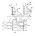
- FIG. 3is a side view schematic drawing of collimating optics for the HUD systems illustrated in FIGS. 1 and 2 in accordance with some exemplary embodiments of the inventive concepts disclosed herein;
- FIG. 4is a top view schematic drawing of the collimating optics illustrated in FIG. 3 ;
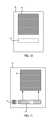
- FIG. 5is a side view schematic drawing of collimating optics for the HUD systems illustrated in FIGS. 1 and 2 in accordance with some exemplary embodiments of the inventive concepts disclosed herein;
- FIG. 6is a top view schematic drawing of the collimating optics illustrated in FIG. 5 ;
- FIG. 7Ais a side view schematic drawing of collimating optics for the HUD systems illustrated in FIGS. 1 and 2 in accordance with some exemplary embodiments of the inventive concepts disclosed herein;
- FIG. 7Bis a side view schematic drawing of collimating optics for the HUD systems, illustrated in FIGS. 1 and 2 in accordance with exemplary embodiments of the inventive concepts disclosed herein;
- FIG. 7Cis a side view schematic drawing of collimating optics including a folded path before the field lens
- FIG. 7Dis a side view schematic drawing of collimating optics including a micro electro mechanical (MEMS) image source;
- MEMSmicro electro mechanical
- FIG. 7Eis a side schematic drawing of collimating optics including an OLED or AMLCD image source
- FIG. 8is a chart showing resolution of a projector
- FIG. 9is a chart showing resolution of the projector illustrated in FIG. 7A in accordance with some embodiments of the inventive concepts disclosed herein;
- FIG. 10is a front view schematic drawing of a waveguide for the HUD systems illustrated in FIGS. 1 and 2 in accordance with some exemplary embodiments of the inventive concepts disclosed herein;
- FIG. 11is a front view schematic drawing of a waveguide for the HUD systems illustrated in FIGS. 1 and 2 in accordance with some exemplary embodiments of the inventive concepts disclosed herein;
- FIG. 12is a planar front view schematic drawing of a waveguide for the HUD systems illustrated in FIGS. 1 and 2 in accordance with some exemplary embodiments of the inventive concepts disclosed herein;
- FIG. 13is a perspective view schematic drawing of a waveguide for the HUD systems illustrated in FIGS. 1 and 2 in accordance with some exemplary embodiments of the inventive concepts disclosed herein;
- FIG. 14is a perspective view schematic drawing of a waveguide for the HUD systems illustrated in FIGS. 1 and 2 in accordance with some exemplary embodiments of the inventive concepts disclosed herein.
- inventive concepts disclosed hereininclude, but are not limited to, a novel structural combination of optical components and not in the particular detailed configurations thereof. Accordingly, the structure, methods, functions, control and arrangement of components have been illustrated in the drawings by readily understandable block representations and schematic drawings, in order not to obscure the disclosure with structural details which will be readily apparent to those skilled in the art, having the benefit of the description herein. Further, the inventive concepts disclosed herein are not limited to the particular embodiments depicted in the exemplary diagrams, but should be construed in accordance with the language in the claims.
- a collimatoradvantageously includes a field lens and a reflector mounted onto a cube, thereby allowing easy mechanical alignment of the field lens and the reflector under very tight tolerances.
- a diffractive surfaceis added to the field lens to provide full color correction and to flatten the corrector lens so that the corrector lens becomes unnecessary.
- the collimatoris provided without a prism or other fold optics, thereby shortening the back focal length and improving performance while advantageously reducing size and weight.
- a liquid crystal on silicon (LCOS) deviceis illuminated through an assembly of collimating optics to make the projector smaller.
- LCOSliquid crystal on silicon
- Careful polarization managementcan be provided through the use of a clean-up polarizer in the exit pupil when illuminating a LCOS device through the assembly in some embodiments.
- the design of the collimating opticscan be scaled to fields of view in excess of 40 degrees and to sizes smaller than 1 cm 3 .
- the collimating optics designis also compatible with organic light emitting diode (OLED) displays, active matrix liquid crystal display (AMLCDs), microelectromechanical systems (MEMS) displays, and other micro displays.
- OLEDorganic light emitting diode
- AMLCDsactive matrix liquid crystal display
- MEMSmicroelectromechanical systems
- a head up display (HUD) system 10can be utilized in various applications, including aviation, medical, naval, targeting, ground based, military, etc.
- HUDas used herein refers to a fixed HUD, a near eye display, a worn display, a helmet mounted display or any type of display using a combiner for overlaying images from an image source over a real world scene.
- the HUD system 10is configured for use in smaller cockpit environments and in worn display applications and yet provides an appropriate field of view and eye box for avionic applications in some embodiments.
- the HUD system 10can be configured for use with worn components, such as, glasses, goggles, hats, helmets, etc. or be a HUD system with a fixed combiner in some embodiments.
- the HUD system 10includes a projector 30 and a substrate waveguide 40 .
- the projector 30provides light (an image) to the substrate waveguide 40 which operates as a combiner.
- the projector 30includes an image source 20 and collimating optics 32 .
- the projector 30provides an image from the image source 20 and collimates the image via collimating optics 32 for display on the substrate waveguide 40 .
- the substrate waveguide 40can be a reflective combiner or holographic combiner.
- the image source 20can be any device for providing an image including but not limited to a CRT display, a light emitting diode (LED) display, an organic light emitting diode (OLED) display, an active matrix liquid crystal display (AMLCD), a liquid crystal on silicon (LCOS) display, etc.
- the image source 20is a micro display and provides linearly polarized light (e.g., S or P polarized).
- the collimating optics 32are disposed between the substrate waveguide 40 and the image source 20 .
- the collimating optics 32can be a single optical component, such as a lens, or include multiple optical components.
- the collimating optics 32are configured as a catadioptric collimator as described with reference to FIGS. 3-7 .
- the collimating optics 32are integrated with or spaced apart from image source 20 and/or substrate waveguide 40 in some embodiments.
- the HUD system 10provides images from the image source 20 via the collimating optics 32 to a pilot or other operator so that the pilot or other operator simultaneously views the images and a real world scene in some embodiments.
- the imagescan include graphic and/or text information (e.g., flight path vector, etc.) related to avionic information in some embodiments.
- the imagescan include synthetic or enhanced vision images.
- collimated light representing the image from the image source 20is provided on the substrate waveguide 40 so that the pilot can view the image conformally on the real world scene through the substrate waveguide 40 .
- the substrate waveguide 40is a translucent or transparent combiner for viewing the real world scene through main surfaces or sides 84 and 88 in some embodiments.
- the input coupler 42 and the output coupler 44are disposed on respective opposing sides 84 and 88 of substrate waveguide 40 in some embodiments.
- the input coupler 42 and the output coupler 44can also be formed on the same side 84 of the substrate waveguide 40 in some embodiments.
- the projector 30includes an assembly of the collimating optics 32 disposed adjacent to or in the proximity of the image source 20 in some embodiments.
- the collimating optics 32provide a catadioptric collimator system and include a field lens 102 , a beam splitter 104 , a curved mirror 108 , a corrector lens 106 , a polarizer 116 , and a film 118 .
- the corrector lens 106is disposed to provide collimated light to the input coupler 42 ( FIG. 1 ) in some embodiments.
- the field lens 102receives polarized light (e.g., an image) from the image source 20 .
- the beam splitter 104is a polarizing beam splitter in a prismatic form in some embodiments.
- the beam splitter 104includes a face 115 , a face 117 , a face 119 , a face 121 , and a polarization selective reflective surface 122 in some embodiments.
- the field lens 102is disposed on the face 117 , and the curved mirror 108 is provided on the face 119 (or is provided on the film 118 which is provided on the face 119 ) in some embodiments.
- the beam splitter 104provides an internal folded optical path and includes the polarizer 116 provided on the face 121 in some embodiments.
- the film 118is a quarter wave retarder film in some embodiments.
- the film 118controls the polarization states for efficient light transmission through the polarization selective reflective surface 122 of the beam splitter 104 in some embodiments.
- the polarizer 116cleans up stray light in some embodiments.
- the beam splitter 104is a rectangular prism in single axis pupil expansion implementations of the HUD system 10 with elongated sides extending into and out of the page in FIG. 3 .
- the field lens 102includes a diffractive surface 114 and is configured as a plano-convex aspherical lens in some embodiments.
- the diffractive surface 114is an aspheric surface processed by diamond grinding, etching, lithography, molding or other process to form diffractive grooves in some embodiments.
- the diffractive surface 114provides color correction and higher order aberration control for the collimating optics 32 in some embodiments.
- the field lens 102is manufactured from optical glass or plastic material in some embodiments.
- the curved mirror 108includes a curved reflective surface 110 .
- the curved reflective surface 110is a dichroic surface, a silvered, a metallic, or other reflecting surface and is curved to assist the collimation of light through the collimating optics 32 .
- the curved mirror 108provides an aspheric medium for reflective surface 110 and is manufactured from optical glass or plastic material in some embodiments.
- the combination of the field lens 102 , the curved mirror 108 , the beam splitter 104 and the corrector lens 106serve to collimate light in some embodiments.
- the corrector lens 106is provided on the face 121 or on the polarizer 116 in some embodiments.
- the corrector lens 106is manufactured from optical glass or plastic material in some embodiments.
- a retarder plate(e.g., similar to film 118 ) can be provided before or after the field lens 102 to effect a polarization change in some embodiments.
- the light received at the face 115 of the beam splitter 104 from the image source 20is reflected off the polarization selective reflective surface 122 within the beam splitter 104 to the face 117 .
- Lighttravels from the face 117 through the film 118 to the curved mirror 108 .
- the curved mirror 108provides a catoptric element which in conjunction with a refractive (dioptric) element, such as, corrector lens 106 , provides a catadioptric system in some embodiments.
- Reflective surface 110can be modeled as an aspheric lens in some embodiments.
- collimating optics 32Light reflecting from the curved reflective surface 110 is provided through the film 118 , the polarization selective reflective surface 122 , and the polarizer 116 to the face 115 .
- a combination of elements in the collimating optics 32collimates light at an exit pupil 142 associated with the face 121 or the corrector lens 106 .
- the collimating optics 32 embodied as a catadioptric systemadvantageously assists in making the design of the HUD system 10 nearly 10 times smaller in volume than conventional designs in one embodiment.
- the assemblyin some embodiments has a volume of less than 20 cubic centimeter.
- the elements of the collimating optics 32can be cemented together around beam splitter 104 to form a small, compact package. Mounting the field lens 102 and the curved mirror 108 directly to the beam splitter 104 or the film 118 provided on the beam splitter 104 provides mechanical alignment in very tight tolerances.
- the corrector lens 106can have dimensions identical to dimensions associated with the face 115 of the beam splitter 104 such that easy alignment is obtained.
- the field lens 102 and the curved mirror 108can match the sizes of the respective faces 115 and 117 .
- the collimating optics 32 in FIGS. 3 and 4are configured for use with single axis pupil expansion such as with the substrate waveguide 40 as shown in FIG. 10 in some embodiments.
- the collimating optics 32 discussed with reference to FIG. 3-4can also be used in dual axis expansion implementations in some embodiments.
- the collimating optics 32 aare similar to the collimating optics 32 discussed with reference to FIGS. 3 and 4 .
- the collimating optics 32 ainclude a field lens 202 , a curved mirror 208 , polarizing beam splitter 204 and a corrector lens 206 .
- the corrector lens 206is optional in some embodiments.
- the polarizing beam splitter 204includes a polarization selective reflective surface 222 similar to a polarization selective reflective surface 122 ( FIGS. 3 and 4 ).
- a film 218is provided between the curved mirror 208 and the polarizing beam splitter 204 and is similar to the film 118 .
- the collimating optics 32 a illustrated in FIGS. 5 and 6are suitable for dual axis expansion such as dual axis expansion utilizing the substrate waveguide 40 illustrated in FIG. 11 .
- the cone angles for the field lens 202are smaller than the cone angles for the field lens 102 and are more suitable for use of the diffractive optical surface in some embodiments.
- a cleanup polarizer 216is provided between the corrector lens 206 and the polarizing beam splitter 204 (e.g., on a face 219 ).
- the corrector lens 206is a flat cover glass for protecting polarizer 116 or beam splitter 104 in some embodiments. In some embodiments, the corrector lens 206 is not necessary due to the power of the curved reflective surface 110 and the field lens 102 with the diffractive surface 114 .
- the components associated with the collimating optics 32 acan be cemented together similar to collimating optics 32 discussed with reference to FIG. 3-4 . Mounting the field lens 202 and the curved mirror 208 directly to the polarizing beam splitter 204 or the film 218 provided on the polarizing beam splitter 204 provides mechanical alignment in very tight tolerances.
- the projector 30includes collimating optics 32 b , a LCOS display 302 and an illuminator 304 in some embodiments.
- the illuminator 304includes a Fresnel lens 306 , a convex lens 308 , a dome lens 310 , and a LED 316 in some embodiments. Light is provided from the LED 316 through the dome lens 310 , the convex lens 308 , and the Fresnel lens 306 to the collimating optics 32 .
- Using the image source 20 and the illuminator 304provides an even smaller package for the projector 30 in some embodiments.
- the collimating optics 32 b shown in FIG. 7Aare similar to the collimating optics 32 and 32 a discussed with reference to FIGS. 3-6 .
- the collimating optics 32 binclude a field lens 402 a (similar to the field lens 202 ), a beam splitter 404 (similar to the beam splitter 204 ), a curved mirror 408 a (similar to the curved mirror 208 ), a corrector lens 406 (similar to the corrector lens 206 ), and a pre-polarizer 417 .
- the beam splitter 404is a polarizing beam splitter disposed between the illuminator 304 and the LCOS micro display 302 in some embodiments.
- the pre-polarizer 417is provided on a face 432 of the beam splitter 404 .
- Light from the Fresnel lens 306is polarized in a particular state (e.g., S or P polarized light) by the pre-polarizer 417 and provided to the LCOS micro display 302 .
- the beam splitter 404includes a polarization selective reflective surface 422 between the face 432 and a face 434 . Polarized light of a first state is provided through the polarization selective reflective surface 422 to the LCOS micro display 302 .
- the LCOS micro display 302provides an image to the field lens 402 a .
- the field lens 402 aincludes a diffractive surface 414 similar to the diffractive surface 214 ( FIG. 3 ).
- the LCOS micro display 302changes the polarization of the light received from the face 434 of beam splitter 404 to a second state (e.g., S or P polarized light).
- a second statee.g., S or P polarized light.
- Lightpasses through the face 434 and strikes the polarization selective reflective surface 422 and is reflected toward a curved reflective surface 410 of the curved mirror 408 a .
- a retarder film 418As light travels through a retarder film 418 , the polarization of the light is changed.
- As light is reflected from the curved reflective surface 410it passes back through the retarder film 418 and becomes polarized back to the first state and passes through the polarization selective reflective surface 422 .
- the lightexits a face 436 of the beam splitter 404 and passes through the corrector lens 406 which is optional.
- a clean up polarizer 416is provided between the corrector lens 406 and the beam splitter 404 at the face 4
- the projector 30includes the image source 20 and the collimating optics 32 c in some embodiments.
- the image source 20includes the LCOS micro display 302 and the illuminator 304 .
- the collimating optics 32 c shown in FIG. 7Bare similar to the collimating optics 32 , 32 a and 32 b discussed with reference to FIGS. 3-7A .
- the collimating optics 32 cinclude a field lens 402 b (similar to the field lens 102 ), the beam splitter 404 (similar to the beam splitter 104 ), a curved mirror 408 b (similar to the curved mirror 108 ), the corrector lens 406 (similar to the corrector lens 106 ), and the pre-polarizer 417 .
- the assembly of the collimating optics 32 , 32 a , 32 b and 32 c as embodied in FIGS. 3, 5, 7A and 7Badvantageously provides a relatively low optical element count with a short focal length in some embodiments.
- the F ratio(the ratio of pupil diameter to focal length) is kept very low in some embodiments.
- the assembly of the collimating optics 32 , 32 a , 32 b , and 32 c as embodied in FIGS. 3, 5 and 7A and 7Befficiently handles polarized light and provides a compact high performance collimating solution.
- the collimating optics 32 , 32 a , 32 b , and 32 cuses a combination of low focal-ratio reflective optics in an on-axis arrangement with the beam splitters 104 , 204 , and 404 and the exit pupil 142 being truncated in some embodiments.
- the low focal-ratio opticsprovides the advantage of achieving a high optical efficiency in a small volume in some embodiments.
- the on-axis arrangementallows excellent aberration correction and low element count in some embodiments.
- the reflective opticsprovide low chromatic dispersion and the beam splitter 104 allows the collimating optics 32 , 32 a , 32 b , and 32 c to be used on axis (no tilted or de-centered elements) in some embodiments.
- Fold optical elementsare advantageously not required by the collimating optics 32 , 32 a , 32 b , and 32 c which simultaneously provide both collimation and efficient handling of polarization states in in some embodiments.
- the collimating optics 32 , 32 a , 32 b , and 32 cprovide a 30 degree field of view from the image source 20 embodied as a 9.4 millimeters diagonal LCOS display which translates into a focal length of approximately 13 millimeters. Eliminating the use of a folded prism path shortens back focal length and improves the performance while reducing size and weight in some embodiments. Fields of view in excess of 40 degrees using the collimating optics 32 , 32 a , 32 b , and 32 c having a size of less than 1 cubic centimeter are possible in some embodiments.
- the design of the collimating optics 32 , 32 a , 32 b , and 32 cis also compatible with OLED, AMLCD, or other micro displays.
- a projector 500includes collimating optics 501 , a LCOS display 502 , and an illuminator 504 .
- This configurationfeatures the advantage of improved contrast.
- the illuminator 504includes a Fresnel lens 506 , a convex lens 508 , dome lens 510 , and a LED 516 .
- the illuminator 504also includes a beam splitter 514 having a polarization sensitive reflective coating 515 , a polarizer 518 , and a retarder 519 .
- the polarizer 518is disposed between the lens 506 and the polarizing beam splitter 514 .
- the polarizing beam splitter 514is a fold element in some embodiments.
- the collimating optics 501include a field lens 602 , a polarizing beam splitter 604 , a curved reflective element 608 , a quarter wave retarder film 618 , and a correcting lens 606 .
- a half wave retarder film 610is provided between correcting lens 606 and polarizing beam splitter 604 .
- the field lens 602is generally spatially separate from the polarizing beam splitter 604 and is larger than the field lenses 102 , 202 , 402 A, and 402 B ( FIGS. 3-7B ).
- the projector 500is provided in a 10 mm ⁇ 10 mm ⁇ 20 mm package.
- a projector 700includes collimating optics 701 , a micro electro mechanical system (MEMS) display 702 , and an illuminator 704 .
- the illuminator 504includes a Fresnel lens 706 , a convex lens 708 , dome lens 710 , an a LED 716 , and a lens 718 .
- the illuminator 704also includes a prism 714 having a border 715 .
- the collimating optics 701includes a polarizing beam splitter 725 , a polarizer 721 , and a field lens 719 .
- the polarizing beam splitter 725is similar to the polarizing beam splitter 604 discussed with reference to FIG. 7C .
- the polarizer 721is disposed between the field lens 719 and the prism 714 .
- the prism 714is a fold element in some embodiments.
- Light from the LED 716is provided through the dome lens 710 , the convex lens 708 , the lens 706 , and the lens 718 to the prism 714 .
- the light in the prism 714bounces off of the border 715 using total internal reflection to the MEMS display 702 .
- the border 715can be a selectively reflective surface.
- the MEMS display 702is a digital light projector display in some embodiments.
- the light from the MEMS display 702is provided across the border 715 to the polarizer 721 and the field lens 719 to the polarizing beam splitter 725 .
- the image reflected off the MEMS display 702is collimated by the collimating optics 701 .
- Lightis provided to the polarizing beam splitter 725 and the light has a polarization such that the light that is reflected by a polarization sensitive reflective coating 735 of the polarizing beam splitter 725 .
- the collimating optics 701include the field lens 719 , the polarizing beam splitter 725 , a curved reflective element 738 , a quarter wave retarder film 740 , and a correcting lens 742 .
- a half wave retarder film 744is provided between correcting lens 742 and the polarizing beam splitter 725 in some embodiments.
- the field lens 719is generally spatially separate from the polarizing beam splitter 735 and the prism 714 and is larger than the field lenses 102 , 202 , 402 A, and 402 B ( FIGS. 3-7B ).
- a projector 750is similar to the projector 500 ( FIG. 7C ) with a prism 752 replacing the polarizing beam splitter 514 .
- the projector 750includes an image source 760 .
- the prism 752is a fold element in some embodiments.
- the image source 760is a back lit or other emissive display. In some embodiments, the image source 760 is a backlit LCD, or an organic light emitting diode (OLED) display.
- Collimating optics 701can be designed in accordance with the projector optics described in U.S. Pat. No. 8,634,139 or collimating optics 701 in FIG. 7D .
- the projectors 30 , 500 , 700 , and 750are used with the waveguide systems described in Exhibit A of the provisional application incorporated herein by reference in its entireties.
- the projectors 30 , 500 , 700 , and 750are configured to provide an exit pupil between 10 mm and 25 mm in diameter and have a cubic beam splitter in the collimating optics with a physical size of 15 mm to 40 mm per side for fixed HUDs.
- the projectors 30 , 500 , 700 , and 750are configured to provide an exit pupil between 3 mm and 5 mm in diameter and have a cubic beam splitter in the collimating optics with a physical size of 4.5 mm to 15 mm per side for HWDs.
- the projectors 30 , 500 , 700 , and 750are provided in a package having a volume of 2.0 cubic centimeters or less.
- the projectors 30 , 500 , 700 , and 750are configured to provide an exit pupil between 2 mm and 25 mm in diameter.
- an X axis 804represents focus in inches and a Y axis 802 represents the modulation transfer function weighted across LED spectral weights which is an indication of the resolving power of the collimator.
- a set of curves 806 at various anglesdemonstrates resolution for the collimating optics 501 of FIG. 7C .
- a Y axis 902represents the modulation transfer function weighted across LED spectral weights which is an indication of contrast and an X axis 904 represents focus in millimeters.
- a set of curves 906 at various anglesshows better resolution for the collimating optics 32 b of FIG.
- the projector 500 including fold optics (the beam splitter 514 ) before the field lens 602provides a polychromatic modulation transfer function of 20 cycles per millimeter while the polychromatic modulation transfer function for the projector 30 including the collimating optics 32 b of FIG. 7A is 78 cycles per millimeter in some embodiments.
- the substrate waveguide 40includes an input coupler (e.g., a diffraction grating) 42 and an output coupler (e.g. a diffraction grating) 44 .
- the input coupler 42 and the output coupler 44are comprised of surface relief gratings, volume gratings (e.g. holographic gratings), reflective arrays, etc.
- the substrate waveguide 40 of FIG. 10effects the single axis pupil expansion.
- the substrate waveguide 40is configured for dual axis pupil expansion and includes the input coupler 42 , a fold grating 50 , and the output coupler 44 in some embodiments.
- the fold grating 50expands the pupil in a first direction (e.g., vertically) and the output coupler 44 expands the pupil in a second direction (e.g., horizontally) in some embodiments.
- the input coupler 42 , fold grating 50 and output coupler 44are comprised of surface relief gratings, volume gratings (e.g. holographic gratings), reflective arrays, etc.
- the input coupler 42is a surface relief grating and the fold grating 50 and the output coupler 44 are volume holograms.
- two layers of waveguidesare used to provide dual axis expansion utilizing cross gratings. Each layer expands in the pupil in one direction. Dual axis expansion using waveguides is discussed in U.S. Pat. No. 8,736,963, incorporated herein by reference in its entirety.
- a head worn waveguide system 1200can be used as the substrate waveguide 40 ( FIG. 1 ).
- a projectorsuch as the projector 30 , can be used with the head worn waveguide system 1200 or the head worn waveguide systems discussed in U.S. patent application Ser. No. 14/715,332 invented by Brown et al. and filed May 18, 2015 and incorporated herein by reference in its entirety.
- the head worn waveguide system 1200is similar to the waveguides discussed in U.S. patent application Ser. No. 14/715,332.
- the head worn waveguide system 1200provides dual axis pupil expansion in some embodiments.
- the head worn waveguide system 1200includes an input block 1202 , a light pipe 1204 and a waveguide 1206 .
- the input block 1202includes an input coupler or input grating 1222 and a turn grating 1223 (e.g., a fold grating).
- the input grating 1222is disposed on a top portion of the XY face of input block 1302 in some embodiments.
- the light pipe 1204includes a turn grating 1226 .
- the turn grating 1223is provided on the light pipe 1204 or between the light pipe 1204 and the input block 1202 .
- the waveguide 1206includes an output grating 1224 which is placed on an XY face (or its parallel) of the waveguide 1206 in some embodiments.
- the input grating 1222couples light from the projector 30 ( FIG. 1 ) into the input block 1202 (e.g., light provided to an XY face of the input block 1202 is turned along the Y direction with only one axis of rotation and in total internal reflection with the XY surfaces of the input block 1202 ).
- the turn grating 1223is configured to turn the light for entry into the light pipe 1204 (e.g., cause the light to travel along the X direction only and maintaining total internal reflection on the XZ faces of the light pipe 1202 ).
- the lightpropagates down the light pipe 1204 by total internal reflection on the XZ faces until it reaches the turn grating 1226 on an XZ face of the light pipe 1204 where the light is turned toward the waveguide 1206 (e.g., breaks total internal reflection conditions in the XZ plane at the turn grating 1226 and propagates in the Y direction).
- the turn grating 1226is a reciprocal turn grating (e.g., kx2 with grating lines parallel to Z) to the input grating 1222 (e.g., ky1 with grating lines parallel to X) and disposed along the expansion path in some embodiments.
- the turn grating 1226is a gradient turn grating in some embodiments.
- the turn grating 1223is a reciprocal turn grating (e.g., kx2 with grating lines parallel to Z) to the input grating 1222 (e.g., ky1 with grating lines parallel to X) in some embodiments.
- the lightis expanded down the waveguide 1206 and is extracted along the XZ face by the output grating 1224 in some embodiments.
- the output grating 1224is a reciprocal grating (e.g., ky1 with grating lines parallel to X) to the turn grating 1226 and diffracts light out of the waveguide 1206 with no dispersion in some embodiments.
- the light pipe 1204provides pupil expansion in the horizontal direction and the output grating 1224 provides pupil expansion in the vertical direction (the axes of expansion are at 90 a degree angle in some embodiments).
- the input grating 1222 , the turn grating 1223 , the turn grating 1224 , and the output grating 1226can be placed on or within the local planes of the light pipe 1204 and the waveguide 1206 . In some embodiments, there is an air gap or low index of refraction material between the light pipe 1204 and the waveguide 1206 .
- the input grating 1222 , the fold grating 1224 , and the output grating 1226can be any type of light couplers including but not limited to volume holograms, switchable Bragg gratings, replicated gratings or surface relief gratings.
- the input grating 1222is a reflection type grating in some embodiments.
- the input grating 1222is a transmission type grating.
- the light pipe 1204injects light into waveguide 1206 along a top edge 1232 of the waveguide 1206 via a bottom edge 1234 of the light pipe 1204 .
- Any of the gratings 1222 , 1224 , and 1226can be replaced with a properly designed mirror or mirror arrays. The dispersion compensation can be lost depending on specific arrangement.
- the light pipe discussed in U.S. patent application Ser. No. 14/715,332does not necessarily provide pupil expansion in the waveguide (e.g., along the second direction) at an angle of 90 degrees with respect to the first direction of pupil expansion which can lead to a vignetted view in the monocular eye box in some embodiments.
- the pupil expansion technique discussed in U.S. patent application Ser. No. 14/715,332does not address dispersion compensation because light is being expanded along two axes but only dispersed along one axis in some embodiments. This produces a banding structure in the eye box of the display, similar to a narrow band source single axis expansion, such as using laser illumination, in some embodiments.
- the head worn waveguide system 1200achieves close to a 90 degree angle between the two directions of pupil expansion therefore providing a compact and high efficiency system with large unvignetted eye box with dispersion compensation.
- a gradient beam splitter and a high efficiency turn gratingis provided in a plane parallel to the XZ plan and in the light pipe 1204 instead of the turn grating 1226 .
- an input portis provided on the light pipe 1204 instead of the input block 1202 .
- the input portis an input grating on the XZ surface of the light pipe 1204 and works in reflection mode in some embodiments.
- the input portis a kinoform mirror or a mirror array (without dispersion property) in some embodiments.
- the turning grating 1226is replaced by a mirror array in parallel or mirrored orientation.
- the mirrorsare partial reflectors with angular dependent coating to avoid ghost reflections from the un-intended group in some embodiments.
- the mirror array for the inputis removed and the input grating is rotated in-plane to send the spiral ray down the light pipe 1204 .
- the gratings at the input of the light pipe 1204 and at the output in the waveguide 1206are matched in pitch and mirrored by the turning mirror array.
- the turning grating/mirrorsis made gradient to allow controlled light output from the light pipe 1204 into the waveguide 1206 .
- a head worn waveguide system 1300can be used as the substrate waveguide 40 ( FIG. 1 ).
- a projectorsuch as the projector 30 , can be used with the head worn waveguide system 1300 .
- the head worn waveguide system 1300is similar to the head worn waveguide 1200 ( FIG. 12 ) and provides dual axis pupil expansion in some embodiments.
- the head worn waveguide system 1300includes a light pipe 1304 and a waveguide 1306 .
- the light pipe 1304includes an input coupler or input grating 1322 , and a pair of mirror symmetric turn gratings 1326 and 1328 (e.g., on XY faces (or their parallel) of the light pipe 1304 ). In some embodiments, only one of the mirror symmetric turn gratings 1326 and 1328 is utilized.
- the input grating 1322is on the XY face of the light pipe 1302 in some embodiments.
- the waveguide 1306includes an output grating 1424 which is disposed on an XY face (or its parallel) of the waveguide 1306 in some embodiments.
- the input grating 1322has both x and y k-vector orientation.
- the turn gratings 1326 and 1328have both components, such that the rotation angle of the k-vector will diffract the ray along the local Y direction.
- the turn gratings 1326 and 1328can be used to pick up the mirror-symmetric ray if desired.
- the output grating 1324has a k-vector that is oriented so that the sum rotation angle is zero in some embodiments.
- the input and output gratings 1322 and 1324are on either side of the light pipe 1302 and the waveguide 1306 in the XY plane.
- the turning gratings 1326 and 1328can be on any of the four surfaces of the light pipe 1404 (e.g., in both the XY and XZ planes.
- the gratings 1322 , 1324 , 1326 , and 1328are either surface mounted or imbedded in some embodiments.
- a head worn waveguide system 1400can be used as the substrate waveguide 40 ( FIG. 1 ).
- a projectorsuch as the projector 30 , can be used with the head worn waveguide system 1500 .
- the head worn waveguide system 1400is similar to the head worn waveguide 1200 ( FIG. 12 ) and provides dual axis pupil expansion in some embodiments.
- the head worn waveguide system 1400includes a light pipe 1402 , a light pipe 1404 and a waveguide 1406 .
- the light pipe 1402includes an input coupler or input grating 1422
- the light pipe 1404includes a turning grating 1426 (e.g., on an XY face (or its parallel) of the light pipe 1404 ).
- the input grating 1422is on the XY face of the light pipe 1502 in some embodiments.
- the waveguide 1406includes an output grating 1424 which is placed on an XY face (or its parallel) of the waveguide 1406 in some embodiments.
- a gradient reflection coatingis provided at an interface of the light pipes 1402 and 1404 in some embodiments.
- the turn grating 1426is one or two highly efficient mirror symmetric gratings on one or two of the XY faces of the light pipe 1404 that diffract and turn the light to break total internal reflection on the XZ face of the light pipe 1404 .
- the input and output gratings 1422 and 1424are on either side of the light pipe 1404 and the waveguide 1406 in the XY plane.
- the turning gratings 1426 and 1428can be on any of the four surfaces of the light pipe 1404 (e.g., in both the XY and XZ planes).
- the gratings 1422 , 1424 , 1426 , and 1428are either surface mounted or imbedded in some embodiments.
Landscapes
- Physics & Mathematics (AREA)
- General Physics & Mathematics (AREA)
- Optics & Photonics (AREA)
- Instrument Panels (AREA)
Abstract
Description
The present application claims the benefit of and priority to U.S. Provisional Patent Application Ser. No. 62/451,041, incorporated herein by reference in its entirety, and is a continuation-in-part of U.S. patent application Ser. No. 14/820,237 and U.S. patent application Ser. No. 15/136,841, which is a continuation in part of U.S. patent application Ser. Nos. 14/715,332 and 14/814,020 (now U.S. Pat. No. 9,523,852), all of which are incorporated herein by reference in their entireties and assigned to the assignee of the present application.
The present application is related to U.S. patent application Ser. No. 13/432,662 filed on Mar. 28, 2012 entitled “System For And Method of Catadioptric Collimation In A Compact Head Up Display (HUD),” incorporated herein by reference in its entirety and assigned to the assignee of the present application which a continuation-in-part application of: U.S. Pat. No. 8,634,139 filed on Sep. 30, 2011 entitled “System For And Method of Catadioptric Collimation In A Compact Head Up Display (HUD),” incorporated herein by reference in its entirety and assigned to the assignee of the present application; U.S. patent application Ser. No. 13/250,940, entitled, “Head Up Display (HUD) Utilizing Diffractive Gratings Having Optimized Efficiency,” filed on Sep. 30, 2011, incorporated herein by reference in its entirety, and assigned to the assignee of the present application; U.S. patent application Ser. No. 13/250,858, entitled, “Ultra-Compact HUD Utilizing Waveguide Pupil Expander With Surface Relief Gratings In High Refractive Index Materials,” filed on Sep. 30, 2011, incorporated herein by reference in its entirety, and assigned to the assignee of the present application; U.S. Pat. No. 8,903,207, entitled, “System for and Method of Extending Vertical Field of View in Head Up Display Utilizing a Waveguide Combiner,” filed on Sep. 30, 2011, incorporated herein by reference in its entirety, and assigned to the assignee of the present application; U.S. Pat. No. 8,937,772, entitled, “System For and Method of Stowing HUD Combiners,” filed on Sep. 30, 2011 and assigned to the assignee of the present application, incorporated herein by reference in its entirety; and U.S. Pat. No. 8,749,890, entitled, “Compact Head Up Display (HUD) for Cockpits with Constrained Space Envelopes,” filed on Sep. 30, 2011, incorporated herein by reference herein in its entirety and assigned to the assignee of the present application.
The inventive concepts disclosed herein relate to projectors. More particularly, embodiments of the inventive concepts disclosed herein relate to projectors for head up displays (HUDs), such as, fixed HUDs and worn displays (e.g., head worn displays, helmet mounted displays, virtual glasses, etc.).
HUDs provide significant safety and operational benefits including precise energy management and conformal flight paths. These safety and operational benefits are enjoyed by operators of air transport aircraft, military aircraft, regional aircraft and high end business jets where HUDs are generally employed. These safety and operational benefits are also desirable in smaller aircraft.
Conventional HUDs are generally large, expensive and difficult to fit into smaller aircraft, such as, business and regional jets as well as general aviation airplanes. Often, conventional HUDs rely on large optical components to form adequate field of view and viewing eye box. The large optical components are often associated with collimating or non-collimating projectors and include lens, prisms, mirrors, etc. The volume of the packages including the optical components of the HUD is too large to fit within the constrained space in the cockpit of smaller aircraft. Further, conventional HUDs rely upon optical components which are generally too expensive for the cost requirements of smaller aircraft and worn displays.
Substrate guided HUDs have been proposed which use waveguide technology with diffraction gratings to preserve eye box size while reducing size of the HUD. U.S. Pat. No. 4,309,070 issued St. Leger Searle and U.S. Pat. No. 4,711,512 issued to Upatnieks disclose substrate waveguide HUDs. U.S. Pat. No. 8,634,139 discloses a catadioptric collimator for HUDs. The patents and patent applications listed in the Cross Reference to Related Applications discuss collimators for HUDs and are incorporated herein by reference in their entireties.
It is desirous to make the projector for waveguide HUDs in a compact arrangement. Aligning optical components in small projector implementations can be difficult especially as sizes are minimized. Folded paths used in conventional projectors can require optical components that add to the package size for the projector. Projectors also often require a corrector lens which can be expensive and add to size of the collimator.
Therefore, there is a need for a compact, low cost projector for HUD systems. Further, there is a need for a compact HUD which uses collimating optics optimized for constrained spaces associated with smaller aircraft and/or worn displays. Yet further, there is also a need for small volume, lightweight, lower cost collimating optics. Yet further still, there is a need for a low parts count collimating system for a substrate waveguide HUD. Still further, there is a need for collimating optics with a short focal length and a low F ratio. Yet further still, there is a need for a compact projector with increased resolution.
In one aspect, embodiments of the inventive concepts disclosed herein relate to a head up display. The head up display is for use with an image source. The head up display includes a collimating mirror and a polarizing beam splitter. Light from the image source enters the beam splitter and is reflected toward the collimating mirror. The light striking the collimating mirror is reflected through the polarizing beam splitter toward a combiner.
In a further aspect, embodiments of the inventive concepts disclosed herein relate to a head up display. The head up display includes a field lens disposed to receive light directly from the image source. The field lens has a diffractive surface for increasing power of the field lens and providing color correction. The head up display also includes a polarizing beam splitter having a first face, a second face, and a third face. The field lens is disposed to provide light to the first face, and the polarizing beam splitter is configured to reflect light of a first polarization toward the second face. The light from the image source has the first polarization. The head up display system also includes a retarder disposed to receive light from the second face, and a curved reflector disposed to receive light from the retarder and provide the light from the retarder to the second face. The light entering the second face has a second polarization state and the polarizing beam splitter is configured so that the light entering the second face travels from the second face to the third face.
In a further aspect, embodiments of the inventive concepts disclosed herein relate to a head up display. The head up display includes an image source, an illuminator, a field lens arranged to receive light directly from the image source, a polarizing beam splitter having a first face, a second face, a third face, and a fourth face, a retarder disposed to receive the light provided through the second face, and a curved reflector. The field lens has a diffractive surface for providing color correction and having a higher order of aberration control, and the illuminator is arranged to illuminate the image source through the polarizing beam splitter through the fourth face and the first face. The light from the illuminator entering the fourth face has a second polarization state, and the field lens is disposed to provide the light from the image source to the first face. The polarizing beam splitter is configured to reflect light of a first polarization state through the second face, wherein the light from the image source has the first polarization state. The curved reflector is disposed to receive light from the retarder and to provide the light from the retarder back through the retarder to the second face. The light entering the second face has a second polarization state, and the polarizing beam splitter is configured so that the light entering the second face travels from the second face to the third face. The light at the third face is provided for display on the head up display.
In a further aspect, embodiments of the inventive concepts disclosed herein relate to a method of providing information to a pilot. The method includes providing light from a light source to an image source through a polarizing beam splitter, providing light from the image source to the polarizing beam splitter and reflecting the light from the image source within the polarizing beam splitter to a curved reflective surface. The method also includes providing light from the curved reflective surface through the polarizing beam splitter to a corrector lens, and providing the light from the corrector lens as collimated light to a wave guide combiner.
In still further aspect, the inventive concepts disclosed herein related to a catadioptric optical system for a head up display. The catadioptric optical system includes a polarizing beam splitter, a light source disposed on a first side of the polarizing beam splitter, an image source disposed on a second side of the polarizing beam splitter opposite the first side of the polarizing beam splitter, and a first lens disposed between the image source and the second side. The catadioptric optical system also includes a reflective surface disposed on a third side of the polarizing beam splitter, and a second element disposed on a fourth side of the polarizing beam splitter. In yet a further aspect, embodiments of inventive concepts disclosed herein relate to a head up display. The head up display includes an image source, an illuminator, a fold element configured to receive light from the image source, a field lens configured to receive light from the fold element, and a polarizing beam splitter. The polarizing beam splitter has a first face, a second face, a third face, and a fourth face. The illuminator is configured to illuminate the image source through the fold element, and the field lens is configured to provide the light from the fold element to the first face. The polarizing beam splitter is configured to reflect light of a first polarization state through the second face, wherein the light from the image source has the first polarization state and the first polarization state and the second polarization state are not the same. The head up display also includes a retarder disposed to receive the light provided through the second face, and a curved reflector disposed to receive light from the retarder and to provide the light from the retarder back through the retarder to the second face. The light entering the second face has a second polarization state, and the polarizing beam splitter is configured so that the light entering the second face travels from the second face to the third face. The light at the third face is provided for display on the head up display. The fourth face is opposite the first face, and the second face is opposite the third face.
In still further aspect, embodiments of the inventive concepts disclosed herein related to a head up display. The head up display includes at least one light pipe and a waveguide. The at least one light pipe includes a turning grating or mirror array for providing light into the waveguide from the light pipe.
Exemplary embodiments of the inventive concepts disclosed herein are hereafter described with reference to the accompanying drawings, wherein like numerals denote like elements; and:
Before describing in detail the particular improved system and method, it should be observed that the inventive concepts disclosed herein include, but are not limited to, a novel structural combination of optical components and not in the particular detailed configurations thereof. Accordingly, the structure, methods, functions, control and arrangement of components have been illustrated in the drawings by readily understandable block representations and schematic drawings, in order not to obscure the disclosure with structural details which will be readily apparent to those skilled in the art, having the benefit of the description herein. Further, the inventive concepts disclosed herein are not limited to the particular embodiments depicted in the exemplary diagrams, but should be construed in accordance with the language in the claims.
In some embodiments, a collimator advantageously includes a field lens and a reflector mounted onto a cube, thereby allowing easy mechanical alignment of the field lens and the reflector under very tight tolerances. In some embodiments, a diffractive surface is added to the field lens to provide full color correction and to flatten the corrector lens so that the corrector lens becomes unnecessary. In some embodiments, the collimator is provided without a prism or other fold optics, thereby shortening the back focal length and improving performance while advantageously reducing size and weight. In some embodiments, a liquid crystal on silicon (LCOS) device is illuminated through an assembly of collimating optics to make the projector smaller. Careful polarization management can be provided through the use of a clean-up polarizer in the exit pupil when illuminating a LCOS device through the assembly in some embodiments. In some embodiments, the design of the collimating optics can be scaled to fields of view in excess of 40 degrees and to sizes smaller than 1 cm3. The collimating optics design is also compatible with organic light emitting diode (OLED) displays, active matrix liquid crystal display (AMLCDs), microelectromechanical systems (MEMS) displays, and other micro displays.
With reference toFIG. 1 , a head up display (HUD)system 10 can be utilized in various applications, including aviation, medical, naval, targeting, ground based, military, etc. The term HUD as used herein refers to a fixed HUD, a near eye display, a worn display, a helmet mounted display or any type of display using a combiner for overlaying images from an image source over a real world scene. TheHUD system 10 is configured for use in smaller cockpit environments and in worn display applications and yet provides an appropriate field of view and eye box for avionic applications in some embodiments. TheHUD system 10 can be configured for use with worn components, such as, glasses, goggles, hats, helmets, etc. or be a HUD system with a fixed combiner in some embodiments.
TheHUD system 10 includes aprojector 30 and asubstrate waveguide 40. Theprojector 30 provides light (an image) to thesubstrate waveguide 40 which operates as a combiner. Theprojector 30 includes animage source 20 andcollimating optics 32. Theprojector 30 provides an image from theimage source 20 and collimates the image via collimatingoptics 32 for display on thesubstrate waveguide 40. In some embodiments, thesubstrate waveguide 40 can be a reflective combiner or holographic combiner.
Theimage source 20 can be any device for providing an image including but not limited to a CRT display, a light emitting diode (LED) display, an organic light emitting diode (OLED) display, an active matrix liquid crystal display (AMLCD), a liquid crystal on silicon (LCOS) display, etc. In some embodiments, theimage source 20 is a micro display and provides linearly polarized light (e.g., S or P polarized).
The collimatingoptics 32 are disposed between thesubstrate waveguide 40 and theimage source 20. The collimatingoptics 32 can be a single optical component, such as a lens, or include multiple optical components. In one embodiment, the collimatingoptics 32 are configured as a catadioptric collimator as described with reference toFIGS. 3-7 . The collimatingoptics 32 are integrated with or spaced apart fromimage source 20 and/orsubstrate waveguide 40 in some embodiments.
In operation, theHUD system 10 provides images from theimage source 20 via thecollimating optics 32 to a pilot or other operator so that the pilot or other operator simultaneously views the images and a real world scene in some embodiments. The images can include graphic and/or text information (e.g., flight path vector, etc.) related to avionic information in some embodiments. In addition, the images can include synthetic or enhanced vision images. In some embodiments, collimated light representing the image from theimage source 20 is provided on thesubstrate waveguide 40 so that the pilot can view the image conformally on the real world scene through thesubstrate waveguide 40. Thesubstrate waveguide 40 is a translucent or transparent combiner for viewing the real world scene through main surfaces orsides
With reference toFIG. 1 , theinput coupler 42 and theoutput coupler 44 are disposed on respective opposingsides substrate waveguide 40 in some embodiments. With reference toFIG. 2 , theinput coupler 42 and theoutput coupler 44 can also be formed on thesame side 84 of thesubstrate waveguide 40 in some embodiments.
With reference toFIGS. 3 and 4 , theprojector 30 includes an assembly of the collimatingoptics 32 disposed adjacent to or in the proximity of theimage source 20 in some embodiments. In some embodiments, the collimatingoptics 32 provide a catadioptric collimator system and include afield lens 102, abeam splitter 104, acurved mirror 108, acorrector lens 106, apolarizer 116, and afilm 118. Thecorrector lens 106 is disposed to provide collimated light to the input coupler42 (FIG. 1 ) in some embodiments. Thefield lens 102 receives polarized light (e.g., an image) from theimage source 20.
Thebeam splitter 104 is a polarizing beam splitter in a prismatic form in some embodiments. Thebeam splitter 104 includes aface 115, aface 117, aface 119, aface 121, and a polarization selectivereflective surface 122 in some embodiments. Thefield lens 102 is disposed on theface 117, and thecurved mirror 108 is provided on the face119 (or is provided on thefilm 118 which is provided on the face119) in some embodiments. Thebeam splitter 104 provides an internal folded optical path and includes thepolarizer 116 provided on theface 121 in some embodiments.
Thefilm 118 is a quarter wave retarder film in some embodiments. Thefilm 118 controls the polarization states for efficient light transmission through the polarization selectivereflective surface 122 of thebeam splitter 104 in some embodiments. Thepolarizer 116 cleans up stray light in some embodiments.
Thebeam splitter 104 is a rectangular prism in single axis pupil expansion implementations of theHUD system 10 with elongated sides extending into and out of the page inFIG. 3 .
Thefield lens 102 includes adiffractive surface 114 and is configured as a plano-convex aspherical lens in some embodiments. Thediffractive surface 114 is an aspheric surface processed by diamond grinding, etching, lithography, molding or other process to form diffractive grooves in some embodiments. Thediffractive surface 114 provides color correction and higher order aberration control for thecollimating optics 32 in some embodiments. Thefield lens 102 is manufactured from optical glass or plastic material in some embodiments.
Thecurved mirror 108 includes a curvedreflective surface 110. The curvedreflective surface 110 is a dichroic surface, a silvered, a metallic, or other reflecting surface and is curved to assist the collimation of light through the collimatingoptics 32. Thecurved mirror 108 provides an aspheric medium forreflective surface 110 and is manufactured from optical glass or plastic material in some embodiments. The combination of thefield lens 102, thecurved mirror 108, thebeam splitter 104 and thecorrector lens 106 serve to collimate light in some embodiments.
Thecorrector lens 106 is provided on theface 121 or on thepolarizer 116 in some embodiments. Thecorrector lens 106 is manufactured from optical glass or plastic material in some embodiments. A retarder plate (e.g., similar to film118) can be provided before or after thefield lens 102 to effect a polarization change in some embodiments.
The light received at theface 115 of thebeam splitter 104 from theimage source 20 is reflected off the polarization selectivereflective surface 122 within thebeam splitter 104 to theface 117. Light travels from theface 117 through thefilm 118 to thecurved mirror 108. Thecurved mirror 108 provides a catoptric element which in conjunction with a refractive (dioptric) element, such as,corrector lens 106, provides a catadioptric system in some embodiments.Reflective surface 110 can be modeled as an aspheric lens in some embodiments.
Light reflecting from the curvedreflective surface 110 is provided through thefilm 118, the polarization selectivereflective surface 122, and thepolarizer 116 to theface 115. A combination of elements in thecollimating optics 32 collimates light at anexit pupil 142 associated with theface 121 or thecorrector lens 106. Applicants believe that the collimatingoptics 32 embodied as a catadioptric system advantageously assists in making the design of theHUD system 10 nearly 10 times smaller in volume than conventional designs in one embodiment. The assembly in some embodiments has a volume of less than 20 cubic centimeter.
The elements of the collimatingoptics 32 can be cemented together aroundbeam splitter 104 to form a small, compact package. Mounting thefield lens 102 and thecurved mirror 108 directly to thebeam splitter 104 or thefilm 118 provided on thebeam splitter 104 provides mechanical alignment in very tight tolerances. Advantageously, thecorrector lens 106 can have dimensions identical to dimensions associated with theface 115 of thebeam splitter 104 such that easy alignment is obtained. Similarly, thefield lens 102 and thecurved mirror 108 can match the sizes of the respective faces115 and117.
The collimatingoptics 32 inFIGS. 3 and 4 are configured for use with single axis pupil expansion such as with thesubstrate waveguide 40 as shown inFIG. 10 in some embodiments. The collimatingoptics 32 discussed with reference toFIG. 3-4 can also be used in dual axis expansion implementations in some embodiments.
With reference toFIGS. 5 and 6 , the collimatingoptics 32aare similar to thecollimating optics 32 discussed with reference toFIGS. 3 and 4 . Thecollimating optics 32ainclude afield lens 202, acurved mirror 208,polarizing beam splitter 204 and acorrector lens 206. Thecorrector lens 206 is optional in some embodiments. Thepolarizing beam splitter 204 includes a polarization selectivereflective surface 222 similar to a polarization selective reflective surface122 (FIGS. 3 and 4 ). Afilm 218 is provided between thecurved mirror 208 and thepolarizing beam splitter 204 and is similar to thefilm 118.
Thecollimating optics 32aillustrated inFIGS. 5 and 6 are suitable for dual axis expansion such as dual axis expansion utilizing thesubstrate waveguide 40 illustrated inFIG. 11 . The cone angles for thefield lens 202 are smaller than the cone angles for thefield lens 102 and are more suitable for use of the diffractive optical surface in some embodiments.
Acleanup polarizer 216 is provided between thecorrector lens 206 and the polarizing beam splitter204 (e.g., on a face219). Thecorrector lens 206 is a flat cover glass for protectingpolarizer 116 orbeam splitter 104 in some embodiments. In some embodiments, thecorrector lens 206 is not necessary due to the power of the curvedreflective surface 110 and thefield lens 102 with thediffractive surface 114. The components associated with thecollimating optics 32acan be cemented together similar tocollimating optics 32 discussed with reference toFIG. 3-4 . Mounting thefield lens 202 and thecurved mirror 208 directly to thepolarizing beam splitter 204 or thefilm 218 provided on thepolarizing beam splitter 204 provides mechanical alignment in very tight tolerances.
With reference toFIG. 7A , theprojector 30 includescollimating optics 32b, aLCOS display 302 and anilluminator 304 in some embodiments. Theilluminator 304 includes aFresnel lens 306, aconvex lens 308, adome lens 310, and aLED 316 in some embodiments. Light is provided from theLED 316 through thedome lens 310, theconvex lens 308, and theFresnel lens 306 to thecollimating optics 32. Using theimage source 20 and theilluminator 304 provides an even smaller package for theprojector 30 in some embodiments.
The collimatingoptics 32bshown inFIG. 7A are similar to thecollimating optics FIGS. 3-6 . The collimatingoptics 32binclude afield lens 402a(similar to the field lens202), a beam splitter404 (similar to the beam splitter204), acurved mirror 408a(similar to the curved mirror208), a corrector lens406 (similar to the corrector lens206), and a pre-polarizer417. Thebeam splitter 404 is a polarizing beam splitter disposed between the illuminator304 and the LCOSmicro display 302 in some embodiments.
The pre-polarizer417 is provided on aface 432 of thebeam splitter 404. Light from theFresnel lens 306 is polarized in a particular state (e.g., S or P polarized light) by the pre-polarizer417 and provided to theLCOS micro display 302. Thebeam splitter 404 includes a polarization selectivereflective surface 422 between theface 432 and aface 434. Polarized light of a first state is provided through the polarization selectivereflective surface 422 to theLCOS micro display 302. TheLCOS micro display 302 provides an image to thefield lens 402a. Thefield lens 402aincludes adiffractive surface 414 similar to the diffractive surface214 (FIG. 3 ). TheLCOS micro display 302 changes the polarization of the light received from theface 434 ofbeam splitter 404 to a second state (e.g., S or P polarized light). Light passes through theface 434 and strikes the polarization selectivereflective surface 422 and is reflected toward a curvedreflective surface 410 of thecurved mirror 408a. As light travels through a retarder film418, the polarization of the light is changed. As light is reflected from the curvedreflective surface 410, it passes back through the retarder film418 and becomes polarized back to the first state and passes through the polarization selectivereflective surface 422. The light exits aface 436 of thebeam splitter 404 and passes through the corrector lens406 which is optional. A clean uppolarizer 416 is provided between the corrector lens406 and thebeam splitter 404 at theface 436 of thebeam splitter 44 in some embodiments. Collimatingoptics 32bis suitable for dual pupil expansion designs in some embodiments.
With reference toFIG. 7B , theprojector 30 includes theimage source 20 and thecollimating optics 32cin some embodiments. Theimage source 20 includes theLCOS micro display 302 and theilluminator 304.
The collimatingoptics 32cshown inFIG. 7B are similar to thecollimating optics FIGS. 3-7A . The collimatingoptics 32cinclude afield lens 402b(similar to the field lens102), the beam splitter404 (similar to the beam splitter104), acurved mirror 408b(similar to the curved mirror108), the corrector lens406 (similar to the corrector lens106), and the pre-polarizer417.
The assembly of the collimatingoptics FIGS. 3, 5, 7A and 7B advantageously provides a relatively low optical element count with a short focal length in some embodiments. The F ratio (the ratio of pupil diameter to focal length) is kept very low in some embodiments. In addition, the assembly of the collimatingoptics FIGS. 3, 5 and 7A and 7B efficiently handles polarized light and provides a compact high performance collimating solution.
As shown inFIGS. 3-7B , the collimatingoptics beam splitters exit pupil 142 being truncated in some embodiments. The low focal-ratio optics provides the advantage of achieving a high optical efficiency in a small volume in some embodiments. The on-axis arrangement allows excellent aberration correction and low element count in some embodiments. The reflective optics provide low chromatic dispersion and thebeam splitter 104 allows the collimatingoptics optics
In some embodiments, the collimatingoptics image source 20 embodied as a 9.4 millimeters diagonal LCOS display which translates into a focal length of approximately 13 millimeters. Eliminating the use of a folded prism path shortens back focal length and improves the performance while reducing size and weight in some embodiments. Fields of view in excess of 40 degrees using thecollimating optics optics
With reference toFIG. 7C , aprojector 500 includescollimating optics 501, aLCOS display 502, and anilluminator 504. This configuration features the advantage of improved contrast. Theilluminator 504 includes aFresnel lens 506, aconvex lens 508,dome lens 510, and aLED 516. Theilluminator 504 also includes abeam splitter 514 having a polarization sensitivereflective coating 515, apolarizer 518, and aretarder 519. Thepolarizer 518 is disposed between thelens 506 and thepolarizing beam splitter 514. Light from theLED 516 is provided through, thedome lens 510, theconvex lens 508, thelens 506, thepolarizer 518, thepolarizing beam splitter 514 including the polarization sensitivereflective coating 515, and theretarder 519 to theLCOS micro display 502. Thepolarizing beam splitter 514 is a fold element in some embodiments.
An image reflected off theLCOS micro display 502 is provided through theretarder 519 and the light has a polarization such that the light that is reflected by polarization sensitivereflective coating 515 to thecollimating optics 501. Thecollimating optics 501 include afield lens 602, apolarizing beam splitter 604, a curvedreflective element 608, a quarterwave retarder film 618, and a correctinglens 606. A halfwave retarder film 610 is provided between correctinglens 606 andpolarizing beam splitter 604. Thefield lens 602 is generally spatially separate from thepolarizing beam splitter 604 and is larger than thefield lenses FIGS. 3-7B ). In some embodiments, theprojector 500 is provided in a 10 mm×10 mm×20 mm package.
With reference toFIG. 7D , aprojector 700 includescollimating optics 701, a micro electro mechanical system (MEMS)display 702, and anilluminator 704. Theilluminator 504 includes aFresnel lens 706, aconvex lens 708,dome lens 710, an aLED 716, and alens 718. Theilluminator 704 also includes aprism 714 having aborder 715. Thecollimating optics 701 includes apolarizing beam splitter 725, apolarizer 721, and afield lens 719. Thepolarizing beam splitter 725 is similar to thepolarizing beam splitter 604 discussed with reference toFIG. 7C . Thepolarizer 721 is disposed between thefield lens 719 and theprism 714. Theprism 714 is a fold element in some embodiments.
Light from theLED 716 is provided through thedome lens 710, theconvex lens 708, thelens 706, and thelens 718 to theprism 714. The light in theprism 714 bounces off of theborder 715 using total internal reflection to theMEMS display 702. Alternatively, theborder 715 can be a selectively reflective surface. TheMEMS display 702 is a digital light projector display in some embodiments. The light from theMEMS display 702 is provided across theborder 715 to thepolarizer 721 and thefield lens 719 to thepolarizing beam splitter 725.
The image reflected off theMEMS display 702 is collimated by thecollimating optics 701. Light is provided to thepolarizing beam splitter 725 and the light has a polarization such that the light that is reflected by a polarization sensitivereflective coating 735 of thepolarizing beam splitter 725. Thecollimating optics 701 include thefield lens 719, thepolarizing beam splitter 725, a curvedreflective element 738, a quarterwave retarder film 740, and a correctinglens 742. A halfwave retarder film 744 is provided between correctinglens 742 and thepolarizing beam splitter 725 in some embodiments. Thefield lens 719 is generally spatially separate from thepolarizing beam splitter 735 and theprism 714 and is larger than thefield lenses FIGS. 3-7B ).
With reference toFIG. 7E , aprojector 750 is similar to the projector500 (FIG. 7C ) with aprism 752 replacing thepolarizing beam splitter 514. Theprojector 750 includes animage source 760. Theprism 752 is a fold element in some embodiments. Theimage source 760 is a back lit or other emissive display. In some embodiments, theimage source 760 is a backlit LCD, or an organic light emitting diode (OLED) display. Collimatingoptics 701 can be designed in accordance with the projector optics described in U.S. Pat. No. 8,634,139 orcollimating optics 701 inFIG. 7D . In some embodiments, theprojectors projectors projectors projectors projectors
With reference toFIG. 8 , anX axis 804 represents focus in inches and aY axis 802 represents the modulation transfer function weighted across LED spectral weights which is an indication of the resolving power of the collimator. A set ofcurves 806 at various angles demonstrates resolution for thecollimating optics 501 ofFIG. 7C . With reference toFIG. 9 , aY axis 902 represents the modulation transfer function weighted across LED spectral weights which is an indication of contrast and anX axis 904 represents focus in millimeters. A set ofcurves 906 at various angles shows better resolution for thecollimating optics 32bofFIG. 7A at the same effective aperture as thecollimating optics 501 ofFIG. 7C . Theprojector 500 including fold optics (the beam splitter514) before thefield lens 602 provides a polychromatic modulation transfer function of 20 cycles per millimeter while the polychromatic modulation transfer function for theprojector 30 including thecollimating optics 32bofFIG. 7A is 78 cycles per millimeter in some embodiments.
With reference toFIGS. 1 and 10 , thesubstrate waveguide 40 includes an input coupler (e.g., a diffraction grating)42 and an output coupler (e.g. a diffraction grating)44. In some embodiments, theinput coupler 42 and theoutput coupler 44 are comprised of surface relief gratings, volume gratings (e.g. holographic gratings), reflective arrays, etc. In some embodiments, thesubstrate waveguide 40 ofFIG. 10 effects the single axis pupil expansion.
With reference toFIG. 11 , thesubstrate waveguide 40 is configured for dual axis pupil expansion and includes theinput coupler 42, a fold grating50, and theoutput coupler 44 in some embodiments. The fold grating50 expands the pupil in a first direction (e.g., vertically) and theoutput coupler 44 expands the pupil in a second direction (e.g., horizontally) in some embodiments. In some embodiments, theinput coupler 42, fold grating50 andoutput coupler 44 are comprised of surface relief gratings, volume gratings (e.g. holographic gratings), reflective arrays, etc. In some embodiments, theinput coupler 42 is a surface relief grating and the fold grating50 and theoutput coupler 44 are volume holograms.
In some embodiments, two layers of waveguides are used to provide dual axis expansion utilizing cross gratings. Each layer expands in the pupil in one direction. Dual axis expansion using waveguides is discussed in U.S. Pat. No. 8,736,963, incorporated herein by reference in its entirety.
With reference toFIG. 12 , a head wornwaveguide system 1200 can be used as the substrate waveguide40 (FIG. 1 ). A projector, such as theprojector 30, can be used with the head wornwaveguide system 1200 or the head worn waveguide systems discussed in U.S. patent application Ser. No. 14/715,332 invented by Brown et al. and filed May 18, 2015 and incorporated herein by reference in its entirety. The head wornwaveguide system 1200 is similar to the waveguides discussed in U.S. patent application Ser. No. 14/715,332. The head wornwaveguide system 1200 provides dual axis pupil expansion in some embodiments.
In some embodiments, the head wornwaveguide system 1200 includes aninput block 1202, alight pipe 1204 and awaveguide 1206. Theinput block 1202 includes an input coupler or input grating1222 and a turn grating1223 (e.g., a fold grating). The input grating1222 is disposed on a top portion of the XY face ofinput block 1302 in some embodiments. Thelight pipe 1204 includes a turn grating1226. In some embodiments, the turn grating1223 is provided on thelight pipe 1204 or between thelight pipe 1204 and theinput block 1202. Thewaveguide 1206 includes anoutput grating 1224 which is placed on an XY face (or its parallel) of thewaveguide 1206 in some embodiments.
In some embodiments, the input grating1222 couples light from the projector30 (FIG. 1 ) into the input block1202 (e.g., light provided to an XY face of theinput block 1202 is turned along the Y direction with only one axis of rotation and in total internal reflection with the XY surfaces of the input block1202). The turn grating1223 is configured to turn the light for entry into the light pipe1204 (e.g., cause the light to travel along the X direction only and maintaining total internal reflection on the XZ faces of the light pipe1202). The light propagates down thelight pipe 1204 by total internal reflection on the XZ faces until it reaches the turn grating1226 on an XZ face of thelight pipe 1204 where the light is turned toward the waveguide1206 (e.g., breaks total internal reflection conditions in the XZ plane at the turn grating1226 and propagates in the Y direction).
The turn grating1226 is a reciprocal turn grating (e.g., kx2 with grating lines parallel to Z) to the input grating1222 (e.g., ky1 with grating lines parallel to X) and disposed along the expansion path in some embodiments. The turn grating1226 is a gradient turn grating in some embodiments. The turn grating1223 is a reciprocal turn grating (e.g., kx2 with grating lines parallel to Z) to the input grating1222 (e.g., ky1 with grating lines parallel to X) in some embodiments.
The light is expanded down thewaveguide 1206 and is extracted along the XZ face by theoutput grating 1224 in some embodiments. Theoutput grating 1224 is a reciprocal grating (e.g., ky1 with grating lines parallel to X) to the turn grating1226 and diffracts light out of thewaveguide 1206 with no dispersion in some embodiments. Thelight pipe 1204 provides pupil expansion in the horizontal direction and theoutput grating 1224 provides pupil expansion in the vertical direction (the axes of expansion are at 90 a degree angle in some embodiments).
The input grating1222, the turn grating1223, the turn grating1224, and theoutput grating 1226 can be placed on or within the local planes of thelight pipe 1204 and thewaveguide 1206. In some embodiments, there is an air gap or low index of refraction material between thelight pipe 1204 and thewaveguide 1206. The input grating1222, the fold grating1224, and theoutput grating 1226 can be any type of light couplers including but not limited to volume holograms, switchable Bragg gratings, replicated gratings or surface relief gratings. The input grating1222 is a reflection type grating in some embodiments. In some embodiments, the input grating1222 is a transmission type grating. In some embodiments, thelight pipe 1204 injects light intowaveguide 1206 along atop edge 1232 of thewaveguide 1206 via abottom edge 1234 of thelight pipe 1204. Any of thegratings
The light pipe discussed in U.S. patent application Ser. No. 14/715,332 does not necessarily provide pupil expansion in the waveguide (e.g., along the second direction) at an angle of 90 degrees with respect to the first direction of pupil expansion which can lead to a vignetted view in the monocular eye box in some embodiments. The pupil expansion technique discussed in U.S. patent application Ser. No. 14/715,332 does not address dispersion compensation because light is being expanded along two axes but only dispersed along one axis in some embodiments. This produces a banding structure in the eye box of the display, similar to a narrow band source single axis expansion, such as using laser illumination, in some embodiments. The head wornwaveguide system 1200 achieves close to a 90 degree angle between the two directions of pupil expansion therefore providing a compact and high efficiency system with large unvignetted eye box with dispersion compensation.
In some embodiments, a gradient beam splitter and a high efficiency turn grating is provided in a plane parallel to the XZ plan and in thelight pipe 1204 instead of the turn grating1226. In some embodiments, an input port is provided on thelight pipe 1204 instead of theinput block 1202. The input port is an input grating on the XZ surface of thelight pipe 1204 and works in reflection mode in some embodiments. The input port is a kinoform mirror or a mirror array (without dispersion property) in some embodiments. In some embodiments, the turning grating1226 is replaced by a mirror array in parallel or mirrored orientation. The mirrors are partial reflectors with angular dependent coating to avoid ghost reflections from the un-intended group in some embodiments. In some embodiments, the mirror array for the input is removed and the input grating is rotated in-plane to send the spiral ray down thelight pipe 1204. In some embodiments, for dispersion compensation, the gratings at the input of thelight pipe 1204 and at the output in thewaveguide 1206 are matched in pitch and mirrored by the turning mirror array. In some embodiments, the turning grating/mirrors is made gradient to allow controlled light output from thelight pipe 1204 into thewaveguide 1206.
With reference toFIG. 13 , a head wornwaveguide system 1300 can be used as the substrate waveguide40 (FIG. 1 ). A projector, such as theprojector 30, can be used with the head wornwaveguide system 1300. The head wornwaveguide system 1300 is similar to the head worn waveguide1200 (FIG. 12 ) and provides dual axis pupil expansion in some embodiments.
In some embodiments, the head wornwaveguide system 1300 includes alight pipe 1304 and a waveguide1306. Thelight pipe 1304 includes an input coupler or input grating1322, and a pair of mirrorsymmetric turn gratings 1326 and1328 (e.g., on XY faces (or their parallel) of the light pipe1304). In some embodiments, only one of the mirrorsymmetric turn gratings light pipe 1302 in some embodiments. The waveguide1306 includes anoutput grating 1424 which is disposed on an XY face (or its parallel) of the waveguide1306 in some embodiments.
In some embodiments, the input grating1322 has both x and y k-vector orientation. Theturn gratings turn gratings output grating 1324 has a k-vector that is oriented so that the sum rotation angle is zero in some embodiments.
In some embodiments, the input andoutput gratings light pipe 1302 and the waveguide1306 in the XY plane. In some embodiments, the turninggratings gratings
With reference toFIG. 14 , a head wornwaveguide system 1400 can be used as the substrate waveguide40 (FIG. 1 ). A projector, such as theprojector 30, can be used with the head worn waveguide system1500. The head wornwaveguide system 1400 is similar to the head worn waveguide1200 (FIG. 12 ) and provides dual axis pupil expansion in some embodiments.
In some embodiments, the head wornwaveguide system 1400 includes alight pipe 1402, alight pipe 1404 and awaveguide 1406. Thelight pipe 1402 includes an input coupler or input grating1422, and thelight pipe 1404 includes a turning grating1426 (e.g., on an XY face (or its parallel) of the light pipe1404). The input grating1422 is on the XY face of the light pipe1502 in some embodiments. Thewaveguide 1406 includes anoutput grating 1424 which is placed on an XY face (or its parallel) of thewaveguide 1406 in some embodiments.
A gradient reflection coating is provided at an interface of thelight pipes light pipe 1404 that diffract and turn the light to break total internal reflection on the XZ face of thelight pipe 1404.
In some embodiments, the input andoutput gratings light pipe 1404 and thewaveguide 1406 in the XY plane. In some embodiments, the turninggratings 1426 and1428 can be on any of the four surfaces of the light pipe1404 (e.g., in both the XY and XZ planes). Thegratings
It is understood that while the detailed drawings, specific examples, material types, thicknesses, dimensions, and particular values given provide a preferred exemplary embodiment of the present invention, the preferred exemplary embodiment is for the purpose of illustration only. The method and apparatus of the invention is not limited to the precise details and conditions disclosed. For example, although specific types of optical component, shapes, dimensions and angles are mentioned, other components, dimensions and angles can be utilized. Various changes may be made to the details disclosed without departing from the spirit of the invention which is defined by the following claim.
Claims (20)
1. A head up display, comprising:
an image source;
an illuminator;
a fold element configured to receive light from the image source;
a field lens configured to receive light from the fold element;
a polarizing beam splitter having a first face, a second face, a third face, and a fourth face, wherein the illuminator is configured to illuminate the image source through the fold element, the field lens is configured to provide the light from the fold element to the first face, the polarizing beam splitter being configured to reflect light of a first polarization state through the second face, wherein the light from the image source has the first polarization state, wherein the first polarization state and a second polarization state are not the same;
a retarder disposed to receive the light provided through the second face; and
a curved reflector disposed to receive light from the retarder and to provide the light from the retarder back through the retarder to the second face, wherein light entering the second face has the second polarization state and wherein the polarizing beam splitter is configured so that the light entering the second face travels from the second face to the third face, wherein the light at the third face is provided for display on the head up display, wherein the fourth face is opposite the first face and the second face is opposite the third face.
2. The head up display ofclaim 1 , further comprising:
a corrector lens disposed to receive light exiting the third face, wherein light leaving the corrector lens is collimated light and wherein the field lens has a diffractive surface for providing color correction and having a higher order of aberration control.
3. The head up display ofclaim 2 , further comprising a waveguide combiner configured to provide vertical, horizontal pupil expansion, or both.
4. The head up display ofclaim 3 , wherein the corrector lens, the field lens, the curved reflector, and the polarizing beam splitter are provided in a package with a volume of less than 1 cubic centimeter.
5. The head up display ofclaim 3 , further comprising a polarizer disposed between the corrector lens and the third face.
6. The head up display ofclaim 1 , wherein the polarizing beam splitter is cubic and the curved reflector and the retarder are attached to the polarizing beam splitter.
7. The head up display ofclaim 1 , wherein the illuminator is an LED.
8. The head up display ofclaim 1 , further comprising a LCOS micro display wherein the image source is a digital light projector.
9. The head up display ofclaim 1 further comprising:
a combiner; and
wherein the field lens, the polarizing beam splitter and the curved reflector are part of a catadioptric optical system.
10. A method of providing information to a pilot, the method comprising:
providing light from a light source through a fold element to an image source;
folding the light from the image source using the fold element;
providing the light from the fold element through a field lens to a polarizing beam splitter;
reflecting the light from the image source within the polarizing beam splitter to a curved reflective surface;
providing the light from the curved reflective surface through the polarizing beam splitter to a corrector lens; and
providing the light from the corrector lens as collimated light to a wave guide combiner.
11. The method ofclaim 10 , wherein the field lens includes a diffractive surface.
12. The method ofclaim 10 , further comprising:
diffracting the collimated light into the wave guide combiner.
13. The method ofclaim 12 , further comprising:
diffracting light out of the wave guide combiner.
14. The method ofclaim 11 , wherein the fold element is a polarizing beam splitter element.
15. A head up display system, comprising:
at least one light pipe; and
a catadioptric collimator, comprising:
a fold element;
an image source;
an illuminator configured to provide light through the fold element to the image source, the fold element being configured to receive light from the image source;
a field lens arranged to receive light from the fold element;
a polarizing beam splitter having a first face, a second face, a third face, and a fourth face, wherein the illuminator is arranged to illuminate the image source through the fold element, the field lens configured to provide the light from the fold element to the first face, the polarizing beam splitter being configured to reflect light of a first polarization state through the second face, wherein the light from the image source has the first polarization state, wherein the first polarization state and a second polarization state are not the same;
a retarder disposed to receive the light provided through the second face; and
a curved reflector disposed to receive light from the retarder and to provide the light from the retarder back through the retarder to the second face, wherein light entering the second face has the second polarization state and wherein the polarizing beam splitter is configured so that the light entering the second face travels from the second face to the third face, wherein the light at the third face is provided for display on the head up display system, wherein the fourth face is opposite the first face and the second face is opposite the third face.
16. The head up display system ofclaim 15 , wherein the fold element is a polarizing beam splitter element.
17. The head up display system ofclaim 16 , wherein the fold element is a prism.
18. The head up display system ofclaim 16 , wherein the catadioptric collimator is on axis arrangement.
19. The head up display system ofclaim 16 , wherein an exit pupil for the catadioptric collimator is at least three inches wide.
20. The head up display system ofclaim 15 , wherein the light pipe comprises an input grating.
Priority Applications (2)
| Application Number | Priority Date | Filing Date | Title |
|---|---|---|---|
| US15/439,597US10126552B2 (en) | 2015-05-18 | 2017-02-22 | Micro collimator system and method for a head up display (HUD) |
| US16/126,618US10746989B2 (en) | 2015-05-18 | 2018-09-10 | Micro collimator system and method for a head up display (HUD) |
Applications Claiming Priority (6)
| Application Number | Priority Date | Filing Date | Title |
|---|---|---|---|
| US14/715,332US10088675B1 (en) | 2015-05-18 | 2015-05-18 | Turning light pipe for a pupil expansion system and method |
| US14/814,020US9523852B1 (en) | 2012-03-28 | 2015-07-30 | Micro collimator system and method for a head up display (HUD) |
| US14/820,237US9715110B1 (en) | 2014-09-25 | 2015-08-06 | Automotive head up display (HUD) |
| US15/136,841US10247943B1 (en) | 2015-05-18 | 2016-04-22 | Head up display (HUD) using a light pipe |
| US201762451041P | 2017-01-26 | 2017-01-26 | |
| US15/439,597US10126552B2 (en) | 2015-05-18 | 2017-02-22 | Micro collimator system and method for a head up display (HUD) |
Related Parent Applications (2)
| Application Number | Title | Priority Date | Filing Date |
|---|---|---|---|
| US14/820,237Continuation-In-PartUS9715110B1 (en) | 2014-09-25 | 2015-08-06 | Automotive head up display (HUD) |
| US15/136,841Continuation-In-PartUS10247943B1 (en) | 2015-05-18 | 2016-04-22 | Head up display (HUD) using a light pipe |
Related Child Applications (1)
| Application Number | Title | Priority Date | Filing Date |
|---|---|---|---|
| US16/126,618ContinuationUS10746989B2 (en) | 2015-05-18 | 2018-09-10 | Micro collimator system and method for a head up display (HUD) |
Publications (2)
| Publication Number | Publication Date |
|---|---|
| US20180088325A1 US20180088325A1 (en) | 2018-03-29 |
| US10126552B2true US10126552B2 (en) | 2018-11-13 |
Family
ID=61686052
Family Applications (2)
| Application Number | Title | Priority Date | Filing Date |
|---|---|---|---|
| US15/439,597Active2035-05-22US10126552B2 (en) | 2015-05-18 | 2017-02-22 | Micro collimator system and method for a head up display (HUD) |
| US16/126,618Active2035-06-07US10746989B2 (en) | 2015-05-18 | 2018-09-10 | Micro collimator system and method for a head up display (HUD) |
Family Applications After (1)
| Application Number | Title | Priority Date | Filing Date |
|---|---|---|---|
| US16/126,618Active2035-06-07US10746989B2 (en) | 2015-05-18 | 2018-09-10 | Micro collimator system and method for a head up display (HUD) |
Country Status (1)
| Country | Link |
|---|---|
| US (2) | US10126552B2 (en) |
Cited By (14)
| Publication number | Priority date | Publication date | Assignee | Title |
|---|---|---|---|---|
| US11300795B1 (en)* | 2009-09-30 | 2022-04-12 | Digilens Inc. | Systems for and methods of using fold gratings coordinated with output couplers for dual axis expansion |
| US11726332B2 (en) | 2009-04-27 | 2023-08-15 | Digilens Inc. | Diffractive projection apparatus |
| US11747719B2 (en) | 2009-10-09 | 2023-09-05 | Digilens Inc. | Diffractive waveguide providing structured illumination for object detection |
| US12140764B2 (en) | 2019-02-15 | 2024-11-12 | Digilens Inc. | Wide angle waveguide display |
| US12210153B2 (en) | 2019-01-14 | 2025-01-28 | Digilens Inc. | Holographic waveguide display with light control layer |
| US12248150B2 (en) | 2017-01-05 | 2025-03-11 | Digilens Inc. | Wearable heads up displays |
| US12271035B2 (en) | 2019-06-07 | 2025-04-08 | Digilens Inc. | Waveguides incorporating transmissive and reflective gratings and related methods of manufacturing |
| US12298513B2 (en) | 2016-12-02 | 2025-05-13 | Digilens Inc. | Waveguide device with uniform output illumination |
| US12306585B2 (en) | 2018-01-08 | 2025-05-20 | Digilens Inc. | Methods for fabricating optical waveguides |
| US12366823B2 (en) | 2018-01-08 | 2025-07-22 | Digilens Inc. | Systems and methods for high-throughput recording of holographic gratings in waveguide cells |
| US12379547B2 (en) | 2015-02-12 | 2025-08-05 | Digilens Inc. | Waveguide grating device |
| US12397477B2 (en) | 2019-02-05 | 2025-08-26 | Digilens Inc. | Methods for compensating for optical surface nonuniformity |
| US12405507B2 (en) | 2012-11-16 | 2025-09-02 | Digilens Inc. | Transparent waveguide display with grating lamina that both couple and extract modulated light |
| US12405471B2 (en) | 2015-10-05 | 2025-09-02 | Digilens Inc. | Apparatus for providing waveguide displays with two-dimensional pupil expansion |
Families Citing this family (29)
| Publication number | Priority date | Publication date | Assignee | Title |
|---|---|---|---|---|
| WO2016146963A1 (en)* | 2015-03-16 | 2016-09-22 | Popovich, Milan, Momcilo | Waveguide device incorporating a light pipe |
| JP6608065B2 (en)* | 2016-01-06 | 2019-11-20 | ビュージックス コーポレーション | Double-sided imaging light guide with embedded dichroic filter |
| CA3056787A1 (en) | 2017-03-21 | 2018-09-27 | Magic Leap, Inc. | Method and system for fiber scanning projector |
| US10295723B1 (en)* | 2018-05-01 | 2019-05-21 | Facebook Technologies, Llc | 2D pupil expander using holographic Bragg grating |
| US11009709B2 (en)* | 2019-04-04 | 2021-05-18 | Yutou Technology (Hangzhou) Co., Ltd. | Compact LCOS projector for wearable AR devices |
| GB2584537B (en)* | 2019-04-18 | 2022-11-16 | Bae Systems Plc | Optical arrangements for displays |
| EP3733139A1 (en)* | 2019-05-02 | 2020-11-04 | Gensight Biologics | Viewing apparatus and method for projecting a light signal |
| US11307347B2 (en) | 2019-05-20 | 2022-04-19 | Facebook Technologies, Llc | Display illumination using a wedge waveguide |
| US11709308B2 (en) | 2019-05-20 | 2023-07-25 | Meta Platforms Technologies, Llc | Optical waveguide beam splitter for directional illumination of display |
| JP7366156B2 (en)* | 2019-06-06 | 2023-10-20 | スリーエム イノベイティブ プロパティズ カンパニー | small heads up display |
| GB201909179D0 (en)* | 2019-06-26 | 2019-08-07 | Wave Optics Ltd | Pupil relay system |
| US11467332B2 (en) | 2019-09-10 | 2022-10-11 | Meta Platforms Technologies, Llc | Display with switchable retarder array |
| US11391948B2 (en) | 2019-09-10 | 2022-07-19 | Facebook Technologies, Llc | Display illumination using a grating |
| US11726336B2 (en) | 2019-09-10 | 2023-08-15 | Meta Platforms Technologies, Llc | Active zonal display illumination using a chopped lightguide |
| CN111141492B (en)* | 2019-12-13 | 2021-11-02 | 中国航空工业集团公司洛阳电光设备研究所 | Head-up display system ray apparatus calibration stand |
| EP4078275A4 (en)* | 2020-01-22 | 2022-12-21 | Huawei Technologies Co., Ltd. | Virtual image display optical architectures |
| CN111290126A (en)* | 2020-03-31 | 2020-06-16 | 优奈柯恩(北京)科技有限公司 | Optical imaging device |
| US12181671B2 (en)* | 2020-04-01 | 2024-12-31 | Google Llc | Systems, devices, and methods for inputting light from a scanning projector into a waveguide |
| US20230161163A1 (en)* | 2020-04-07 | 2023-05-25 | Snap Inc. | Optical device |
| US11726326B1 (en)* | 2020-06-11 | 2023-08-15 | Meta Platforms Technologies, Llc | Wedge light guide |
| US11604352B2 (en)* | 2020-07-29 | 2023-03-14 | Meta Platforms Technologies LLC | Waveguide-based projector |
| KR20220049398A (en)* | 2020-10-14 | 2022-04-21 | 삼성전자주식회사 | Waveguide structure, back light unit including the same, display apparatus including the same |
| US12313855B2 (en) | 2021-01-22 | 2025-05-27 | Google Llc | Systems and methods to separate scanning mirror input and output light |
| US11841503B2 (en) | 2021-02-19 | 2023-12-12 | Rockwell Collins, Inc. | Efficiency of catadioptric system by means of recycling polarized light |
| US11733522B2 (en)* | 2021-04-02 | 2023-08-22 | Rockwell Collins, Inc. | Advanced monitoring solution of displays |
| CN113219671A (en)* | 2021-05-25 | 2021-08-06 | 深圳市光舟半导体技术有限公司 | Optical device and display apparatus |
| US11940627B2 (en) | 2021-07-09 | 2024-03-26 | Realwear, Inc. | Opaque waveguide optical engine assembly for head-mounted device |
| US11852822B2 (en)* | 2021-07-09 | 2023-12-26 | Realwear, Inc. | Convertible waveguide optical engine assembly for head-mounted device |
| WO2024038458A1 (en)* | 2022-08-18 | 2024-02-22 | Lumus Ltd. | Image projector with polarizing catadioptric collimator |
Citations (523)
| Publication number | Priority date | Publication date | Assignee | Title |
|---|---|---|---|---|
| US2141884A (en) | 1936-11-12 | 1938-12-27 | Zeiss Carl Fa | Photographic objective |
| US3620601A (en) | 1969-10-24 | 1971-11-16 | Leonard Cyril Waghorn | Head-up display apparatus |
| US3851303A (en) | 1972-11-17 | 1974-11-26 | Sundstrand Data Control | Head up display and pitch generator |
| US3885095A (en) | 1973-04-30 | 1975-05-20 | Hughes Aircraft Co | Combined head-up multisensor display |
| US3940204A (en) | 1975-01-23 | 1976-02-24 | Hughes Aircraft Company | Optical display systems utilizing holographic lenses |
| US4082432A (en) | 1975-01-09 | 1978-04-04 | Sundstrand Data Control, Inc. | Head-up visual display system using on-axis optics with image window at the focal plane of the collimating mirror |
| US4099841A (en) | 1976-06-30 | 1978-07-11 | Elliott Brothers (London) Limited | Head up displays using optical combiner with three or more partially reflective films |
| US4178074A (en) | 1977-03-28 | 1979-12-11 | Elliott Brothers (London) Limited | Head-up displays |
| US4218111A (en) | 1978-07-10 | 1980-08-19 | Hughes Aircraft Company | Holographic head-up displays |
| US4232943A (en) | 1975-09-13 | 1980-11-11 | Pilkington P. E. Limited | Modified Petzval lens |
| US4309070A (en) | 1979-01-19 | 1982-01-05 | Smiths Industries Limited | Display apparatus |
| GB2115178A (en) | 1978-12-21 | 1983-09-01 | Redifon Simulation Ltd | Projection screen for display apparatus |
| US4647967A (en) | 1986-01-28 | 1987-03-03 | Sundstrand Data Control, Inc. | Head-up display independent test site |
| US4711512A (en) | 1985-07-12 | 1987-12-08 | Environmental Research Institute Of Michigan | Compact head-up display |
| US4714320A (en) | 1980-08-21 | 1987-12-22 | The Secretary Of State For Defence In Her Britannic Majesty's Government Of The United Kingdom Of Great Britain And Northern Ireland | Display systems |
| US4743083A (en) | 1985-12-30 | 1988-05-10 | Schimpe Robert M | Cylindrical diffraction grating couplers and distributed feedback resonators for guided wave devices |
| US4749256A (en) | 1987-02-13 | 1988-06-07 | Gec Avionics, Inc. | Mounting apparatus for head-up display |
| US4775218A (en) | 1987-04-17 | 1988-10-04 | Flight Dynamics, Inc. | Combiner alignment detector for head up display system |
| US4799765A (en) | 1986-03-31 | 1989-01-24 | Hughes Aircraft Company | Integrated head-up and panel display unit |
| US4854688A (en) | 1988-04-14 | 1989-08-08 | Honeywell Inc. | Optical arrangement |
| US4928301A (en) | 1988-12-30 | 1990-05-22 | Bell Communications Research, Inc. | Teleconferencing terminal with camera behind display screen |
| US4946245A (en) | 1987-10-01 | 1990-08-07 | British Telecommunications Public Limited Company | Optical filters |
| US5007711A (en) | 1988-11-30 | 1991-04-16 | Flight Dynamics, Inc. | Compact arrangement for head-up display components |
| US5035734A (en) | 1989-04-13 | 1991-07-30 | Oy Nokia Ab | Method of producing optical waveguides |
| US5076664A (en) | 1989-05-23 | 1991-12-31 | Thomson-Csf | Optical device enabling the introduction of a collimated image in an observer's field of vision |
| US5079416A (en) | 1987-10-27 | 1992-01-07 | Night Vision General Partnership | Compact see-through night vision goggles |
| US5117285A (en) | 1991-01-15 | 1992-05-26 | Bell Communications Research | Eye contact apparatus for video conferencing |
| US5124821A (en) | 1987-03-31 | 1992-06-23 | Thomson Csf | Large-field holographic binocular helmet visor |
| US5148302A (en) | 1986-04-10 | 1992-09-15 | Akihiko Nagano | Optical modulation element having two-dimensional phase type diffraction grating |
| US5151958A (en) | 1990-08-23 | 1992-09-29 | Oy Nokia Ab | Adaptor device for coupling together optical waveguides produced by k-na ion exchange with optical waveguides produced by ag-na ion exchange |
| US5153751A (en) | 1990-04-27 | 1992-10-06 | Central Glass Company, Limited | Holographic display element |
| US5159445A (en) | 1990-12-31 | 1992-10-27 | At&T Bell Laboratories | Teleconferencing video display system for improving eye contact |
| US5160523A (en) | 1990-07-10 | 1992-11-03 | Oy Nokia Ab | Method of producing optical waveguides by an ion exchange technique on a glass substrate |
| FR2677463A1 (en) | 1991-06-04 | 1992-12-11 | Thomson Csf | Collimated display having wide horizontal and vertical fields, in particular for simulators |
| US5183545A (en) | 1989-04-28 | 1993-02-02 | Branca Phillip A | Electrolytic cell with composite, porous diaphragm |
| US5187597A (en) | 1990-06-29 | 1993-02-16 | Fujitsu Limited | Display unit |
| US5210624A (en) | 1989-09-19 | 1993-05-11 | Fujitsu Limited | Heads-up display |
| US5218360A (en) | 1991-05-23 | 1993-06-08 | Trw Inc. | Millimeter-wave aircraft landing and taxing system |
| US5243413A (en) | 1992-09-02 | 1993-09-07 | At&T Bell Laboratories | Color parallax-free camera and display |
| US5289315A (en) | 1991-05-29 | 1994-02-22 | Central Glass Company, Limited | Head-up display system including a uniformly reflecting layer and a selectively reflecting layer |
| US5295208A (en) | 1992-02-26 | 1994-03-15 | The University Of Alabama In Huntsville | Multimode waveguide holograms capable of using non-coherent light |
| US5303085A (en) | 1992-02-07 | 1994-04-12 | Rallison Richard D | Optically corrected helmet mounted display |
| US5317405A (en) | 1991-03-08 | 1994-05-31 | Nippon Telegraph And Telephone Corporation | Display and image capture apparatus which enables eye contact |
| US5341230A (en) | 1992-12-22 | 1994-08-23 | Hughes Aircraft Company | Waveguide holographic telltale display |
| US5351151A (en) | 1993-02-01 | 1994-09-27 | Levy George S | Optical filter using microlens arrays |
| US5359362A (en) | 1993-03-30 | 1994-10-25 | Nec Usa, Inc. | Videoconference system using a virtual camera image |
| US5363220A (en) | 1988-06-03 | 1994-11-08 | Canon Kabushiki Kaisha | Diffraction device |
| US5369511A (en) | 1989-08-21 | 1994-11-29 | Amos; Carl R. | Methods of and apparatus for manipulating electromagnetic phenomenon |
| US5400069A (en) | 1993-06-16 | 1995-03-21 | Bell Communications Research, Inc. | Eye contact video-conferencing system and screen |
| US5408346A (en) | 1993-10-20 | 1995-04-18 | Kaiser Electro-Optics, Inc. | Optical collimating device employing cholesteric liquid crystal and a non-transmissive reflector |
| US5418584A (en) | 1992-12-31 | 1995-05-23 | Honeywell Inc. | Retroreflective array virtual image projection screen |
| US5438357A (en) | 1993-11-23 | 1995-08-01 | Mcnelley; Steve H. | Image manipulating teleconferencing system |
| US5455693A (en) | 1992-09-24 | 1995-10-03 | Hughes Aircraft Company | Display hologram |
| US5471326A (en) | 1993-04-30 | 1995-11-28 | Northrop Grumman Corporation | Holographic laser scanner and rangefinder |
| US5473222A (en) | 1994-07-05 | 1995-12-05 | Delco Electronics Corporation | Active matrix vacuum fluorescent display with microprocessor integration |
| US5496621A (en) | 1993-04-16 | 1996-03-05 | Central Glass Company, Limited | Glass pane with reflectance reducing coating and combiner of head-up display system |
| US5500671A (en) | 1994-10-25 | 1996-03-19 | At&T Corp. | Video conference system and method of providing parallax correction and a sense of presence |
| US5510913A (en) | 1992-07-23 | 1996-04-23 | Central Glass Company, Limited | Head-up display system where polarized light from a display impinges on a glass plate containing twisted nematic liquid crystal at the plate's Brewsters angle |
| US5515184A (en) | 1991-11-12 | 1996-05-07 | The University Of Alabama In Huntsville | Waveguide hologram illuminators |
| US5524272A (en) | 1993-12-22 | 1996-06-04 | Gte Airfone Incorporated | Method and apparatus for distributing program material |
| US5532736A (en) | 1992-07-31 | 1996-07-02 | Nippon Telegraph And Telephone Corporation | Display and image capture apparatus |
| US5537232A (en) | 1993-10-05 | 1996-07-16 | In Focus Systems, Inc. | Reflection hologram multiple-color filter array formed by sequential exposure to a light source |
| US5572248A (en) | 1994-09-19 | 1996-11-05 | Teleport Corporation | Teleconferencing method and system for providing face-to-face, non-animated teleconference environment |
| US5579026A (en) | 1993-05-14 | 1996-11-26 | Olympus Optical Co., Ltd. | Image display apparatus of head mounted type |
| US5583795A (en) | 1995-03-17 | 1996-12-10 | The United States Of America As Represented By The Secretary Of The Army | Apparatus for measuring eye gaze and fixation duration, and method therefor |
| US5604611A (en) | 1991-10-09 | 1997-02-18 | Nippondenso Co., Ltd. | Hologram |
| US5606433A (en) | 1994-08-31 | 1997-02-25 | Hughes Electronics | Lamination of multilayer photopolymer holograms |
| US5612734A (en) | 1995-11-13 | 1997-03-18 | Bell Communications Research, Inc. | Eye contact apparatus employing a directionally transmissive layer for video conferencing |
| US5612733A (en) | 1994-07-18 | 1997-03-18 | C-Phone Corporation | Optics orienting arrangement for videoconferencing system |
| US5619254A (en) | 1995-04-11 | 1997-04-08 | Mcnelley; Steve H. | Compact teleconferencing eye contact terminal |
| US5629259A (en) | 1986-04-11 | 1997-05-13 | Dai Nippon Insatsu Kabushiki Kaisha | Image formation on objective bodies |
| US5631107A (en) | 1994-02-18 | 1997-05-20 | Nippondenso Co., Ltd. | Method for producing optical member |
| US5633100A (en) | 1991-11-27 | 1997-05-27 | E. I. Du Pont De Nemours And Company | Holographic imaging using filters |
| US5646785A (en) | 1993-11-04 | 1997-07-08 | Elbit Ltd. | Helmet with wind resistant visor |
| US5648857A (en) | 1994-02-18 | 1997-07-15 | Nippondenso Co., Ltd. | Manufacturing method for hologram which can prevent the formation of ghant holograms due to noise light |
| US5661603A (en) | 1994-09-05 | 1997-08-26 | Olympus Optical Co., Ltd. | Image display apparatus including a first and second prism array |
| US5661577A (en) | 1990-04-06 | 1997-08-26 | University Of Southern California | Incoherent/coherent double angularly multiplexed volume holographic optical elements |
| US5665494A (en) | 1991-04-17 | 1997-09-09 | Nippon Paint Company, Ltd. | Photosensitive composition for volume hologram recording |
| US5668907A (en) | 1996-01-11 | 1997-09-16 | Associated Universities, Inc. | Thin optical display panel |
| US5682255A (en) | 1993-02-26 | 1997-10-28 | Yeda Research & Development Co. Ltd. | Holographic optical devices for the transmission of optical signals of a plurality of channels |
| US5694230A (en) | 1995-06-07 | 1997-12-02 | Digital Optics Corp. | Diffractive optical elements as combiners |
| US5701132A (en) | 1996-03-29 | 1997-12-23 | University Of Washington | Virtual retinal display with expanded exit pupil |
| US5706108A (en) | 1995-07-20 | 1998-01-06 | Nippondenso Co., Ltd. | Hologram display apparatus including a curved surface of constant curvature |
| US5707925A (en) | 1986-04-11 | 1998-01-13 | Dai Nippon Insatsu Kabushiki Kaisha | Image formation on objective bodies |
| EP0822441A2 (en) | 1996-08-01 | 1998-02-04 | Sharp Kabushiki Kaisha | Optical device and directional display |
| US5724189A (en) | 1995-12-15 | 1998-03-03 | Mcdonnell Douglas Corporation | Methods and apparatus for creating an aspheric optical element and the aspheric optical elements formed thereby |
| US5726782A (en) | 1991-10-09 | 1998-03-10 | Nippondenso Co., Ltd. | Hologram and method of fabricating |
| US5727098A (en) | 1994-09-07 | 1998-03-10 | Jacobson; Joseph M. | Oscillating fiber optic display and imager |
| US5729242A (en) | 1996-05-08 | 1998-03-17 | Hughes Electronics | Dual PDLC-projection head-up display |
| US5731060A (en) | 1994-03-31 | 1998-03-24 | Central Glass Company, Limited | Holographic laminate |
| US5731853A (en) | 1995-02-24 | 1998-03-24 | Matsushita Electric Industrial Co., Ltd. | Display device |
| US5742262A (en) | 1993-06-23 | 1998-04-21 | Olympus Optical Co., Ltd. | Image display apparatus |
| US5751452A (en) | 1993-02-22 | 1998-05-12 | Nippon Telegraph And Telephone Corporation | Optical devices with high polymer material and method of forming the same |
| US5760931A (en) | 1992-12-14 | 1998-06-02 | Nippondenso Co., Ltd. | Image display unit |
| US5764414A (en) | 1991-08-19 | 1998-06-09 | Hughes Aircraft Company | Biocular display system using binary optics |
| US5790288A (en) | 1994-04-15 | 1998-08-04 | Nokia Telecommunications Oy | Transport network with high transmission capacity for telecommunications |
| US5812608A (en) | 1995-05-05 | 1998-09-22 | Nokia Technology Gmbh | Method and circuit arrangement for processing received signal |
| US5822127A (en) | 1995-05-15 | 1998-10-13 | Hughes Electronics | Low-cost light-weight head-mounted virtual-image projection display with low moments of inertia and low center of gravity |
| US5841507A (en) | 1995-06-07 | 1998-11-24 | Barnes; Elwood E. | Light intensity reduction apparatus and method |
| US5856842A (en) | 1996-08-26 | 1999-01-05 | Kaiser Optical Systems Corporation | Apparatus facilitating eye-contact video communications |
| US5868951A (en) | 1997-05-09 | 1999-02-09 | University Technology Corporation | Electro-optical device and method |
| US5886822A (en) | 1996-10-08 | 1999-03-23 | The Microoptical Corporation | Image combining system for eyeglasses and face masks |
| US5892598A (en) | 1994-07-15 | 1999-04-06 | Matsushita Electric Industrial Co., Ltd. | Head up display unit, liquid crystal display panel, and method of fabricating the liquid crystal display panel |
| US5898511A (en) | 1992-09-03 | 1999-04-27 | Nippondenso Co., Ltd. | Process for making holograms and holography device |
| US5903395A (en) | 1994-08-31 | 1999-05-11 | I-O Display Systems Llc | Personal visual display system |
| US5907416A (en) | 1997-01-27 | 1999-05-25 | Raytheon Company | Wide FOV simulator heads-up display with selective holographic reflector combined |
| US5907436A (en) | 1995-09-29 | 1999-05-25 | The Regents Of The University Of California | Multilayer dielectric diffraction gratings |
| US5917459A (en) | 1996-09-07 | 1999-06-29 | Korea Institute Of Science And Technology | Holographic head up display |
| US5926147A (en) | 1995-08-25 | 1999-07-20 | Nokia Telecommunications Oy | Planar antenna design |
| US5929946A (en) | 1995-05-23 | 1999-07-27 | Colorlink, Inc. | Retarder stack for preconditioning light for a modulator having modulation and isotropic states of polarization |
| US5937115A (en) | 1997-02-12 | 1999-08-10 | Foster-Miller, Inc. | Switchable optical components/structures and methods for the fabrication thereof |
| US5942157A (en) | 1996-07-12 | 1999-08-24 | Science Applications International Corporation | Switchable volume hologram materials and devices |
| US5945893A (en) | 1996-03-29 | 1999-08-31 | Nokia Moile Phones Limited | Acoustic wave impedance element ladder filter having a reflector integral with a busbar |
| US5949302A (en) | 1994-09-15 | 1999-09-07 | Nokia Telecommunications Oy | Method for tuning a summing network of a base station, and a bandpass filter |
| US5966223A (en) | 1993-02-26 | 1999-10-12 | Yeda Research & Development Co., Ltd. | Planar holographic optical device |
| WO1999052002A1 (en) | 1998-04-02 | 1999-10-14 | Elop Electro-Optics Industries Ltd. | Holographic optical devices |
| US5985422A (en) | 1996-08-08 | 1999-11-16 | Pelikan Produktions Ag | Thermo-transfer color ribbon for luminescent lettering |
| US5991087A (en) | 1993-11-12 | 1999-11-23 | I-O Display System Llc | Non-orthogonal plate in a virtual reality or heads up display |
| US5999314A (en) | 1996-11-20 | 1999-12-07 | Central Glass Company Limited | Optical display system having a Brewster's angle regulating film |
| US6043585A (en) | 1996-03-29 | 2000-03-28 | Nokia Mobile Phones Limited | Acoustic wave filter |
| US6042947A (en) | 1995-12-25 | 2000-03-28 | Central Glass Company, Limited | Laminate including optically functioning film |
| WO2000028369A2 (en) | 1998-11-12 | 2000-05-18 | Digilens, Inc. | Head mounted apparatus for viewing an image |
| US6075626A (en) | 1997-06-25 | 2000-06-13 | Denso Corporation | Hologram |
| US6078427A (en) | 1998-12-01 | 2000-06-20 | Kaiser Electro-Optics, Inc. | Smooth transition device for area of interest head-mounted display |
| US6115152A (en) | 1998-09-14 | 2000-09-05 | Digilens, Inc. | Holographic illumination system |
| US6127066A (en) | 1992-11-27 | 2000-10-03 | Dai Nippon Printing Co., Ltd. | Hologram recording sheet, holographic optical element using said sheet, and its production process |
| US6137630A (en) | 1998-07-13 | 2000-10-24 | Industrial Technology Research Institute | Thin-film multilayer systems for use in a head-up display |
| US6176837B1 (en) | 1998-04-17 | 2001-01-23 | Massachusetts Institute Of Technology | Motion tracking system |
| US6195206B1 (en) | 1998-01-13 | 2001-02-27 | Elbit Systems Ltd. | Optical system for day and night use |
| US6222675B1 (en) | 1998-12-01 | 2001-04-24 | Kaiser Electro-Optics, Inc. | Area of interest head-mounted display using low resolution, wide angle; high resolution, narrow angle; and see-through views |
| US6222971B1 (en) | 1998-07-17 | 2001-04-24 | David Slobodin | Small inlet optical panel and a method of making a small inlet optical panel |
| US6249386B1 (en) | 1998-07-28 | 2001-06-19 | Elbit Systems Ltd. | Non-adjustable helmet mounted optical systems |
| US6259559B1 (en) | 1995-03-28 | 2001-07-10 | Central Glass Company, Limited | Glass arrangement including an outside glass plate, a polarization direction changing film and an adhesive layer therebetween, and an inside glass layer |
| US6259423B1 (en) | 1997-08-26 | 2001-07-10 | Kabushiki Kaisha Toyoto Chuo Kenkyusho | Display device using organic electroluminescent elements |
| US6285813B1 (en) | 1997-10-03 | 2001-09-04 | Georgia Tech Research Corporation | Diffractive grating coupler and method |
| US6317083B1 (en) | 1998-05-29 | 2001-11-13 | Nokia Mobile Phones Limited | Antenna having a feed and a shorting post connected between reference plane and planar conductor interacting to form a transmission line |
| US6321069B1 (en) | 1997-04-30 | 2001-11-20 | Nokia Telecommunications Oy | Arrangement for reducing intermodulation distortion of radio frequency signals |
| US6327089B1 (en) | 1998-09-30 | 2001-12-04 | Central Glass Company, Limited | Laminated transparent structure for reflective display |
| US6333819B1 (en) | 1999-05-26 | 2001-12-25 | Telefonaktiebolaget Lm Ericsson (Publ) | Display for head mounting |
| US20020012064A1 (en) | 2000-03-17 | 2002-01-31 | Hiroshi Yamaguchi | Photographing device |
| US20020021461A1 (en) | 1999-05-10 | 2002-02-21 | Asahi Glass Company, Limited | Holographic display device and method for producing a transmission diffusion hologram suitable for it |
| US6351333B2 (en) | 1997-09-16 | 2002-02-26 | Canon Kabushiki Kaisha | Optical element and optical system having the same |
| US6356172B1 (en) | 1999-12-29 | 2002-03-12 | Nokia Networks Oy | Resonator structure embedded in mechanical structure |
| US6359730B2 (en) | 1998-10-21 | 2002-03-19 | Nokia Network Oy | Amplification of an optical WDM signal |
| US6359737B1 (en) | 2000-07-28 | 2002-03-19 | Generals Motors Corporation | Combined head-up display |
| US6366378B1 (en) | 1997-05-26 | 2002-04-02 | Nokia Networks Oy | Optical multiplexing and demultiplexing |
| US6392812B1 (en) | 1999-09-29 | 2002-05-21 | Bae Systems Electronics Limited | Head up displays |
| US20020131175A1 (en) | 2001-03-14 | 2002-09-19 | Fuji Photo Optical Co., Ltd. | Diffraction type optical pickup lens and optical pickup apparatus using the same |
| US6470132B1 (en) | 2000-09-05 | 2002-10-22 | Nokia Mobile Phones Ltd. | Optical hinge apparatus |
| US6486997B1 (en) | 1997-10-28 | 2002-11-26 | 3M Innovative Properties Company | Reflective LCD projection system using wide-angle Cartesian polarizing beam splitter |
| US6504518B1 (en) | 1996-10-09 | 2003-01-07 | Shimadzu Corporation | Head-up display |
| US20030030912A1 (en) | 2000-10-20 | 2003-02-13 | Gleckman Philip Landon | Compact wide field of view imaging system |
| US6524771B2 (en) | 1992-06-30 | 2003-02-25 | Nippon Sheet Glass Co., Ltd. | Optical recording film and process for production thereof |
| US20030039442A1 (en) | 2001-08-24 | 2003-02-27 | Aaron Bond | Grating dispersion compensator and method of manufacture |
| US20030063042A1 (en) | 1999-07-29 | 2003-04-03 | Asher A. Friesem | Electronic utility devices incorporating a compact virtual image display |
| US6550949B1 (en) | 1996-06-13 | 2003-04-22 | Gentex Corporation | Systems and components for enhancing rear vision from a vehicle |
| US6557413B2 (en) | 2000-10-02 | 2003-05-06 | Nokia Mobile Phones Ltd. | Micromechanical structure |
| US6583873B1 (en) | 2000-09-25 | 2003-06-24 | The Carnegie Institution Of Washington | Optical devices having a wavelength-tunable dispersion assembly that has a volume dispersive diffraction grating |
| US6587619B1 (en) | 1998-08-04 | 2003-07-01 | Kabushiki Kaisha Toshiba | Optical functional devices their manufacturing method and optical communication system |
| US6598987B1 (en) | 2000-06-15 | 2003-07-29 | Nokia Mobile Phones Limited | Method and apparatus for distributing light to the user interface of an electronic device |
| US20030149346A1 (en) | 2000-03-03 | 2003-08-07 | Arnone Donald Dominic | Imaging apparatus and method |
| US6608720B1 (en) | 1997-06-02 | 2003-08-19 | Robin John Freeman | Optical instrument and optical element thereof |
| US6611253B1 (en) | 2000-09-19 | 2003-08-26 | Harel Cohen | Virtual input environment |
| WO2003081320A1 (en) | 2002-03-21 | 2003-10-02 | Lumus Ltd. | Light guide optical device |
| US6646810B2 (en) | 2001-09-04 | 2003-11-11 | Delphi Technologies, Inc. | Display backlighting apparatus |
| US6661578B2 (en) | 2001-03-02 | 2003-12-09 | Innovative Solutions & Support, Inc. | Image display generator for a head-up display |
| US20030228019A1 (en) | 2002-06-11 | 2003-12-11 | Elbit Systems Ltd. | Method and system for reducing noise |
| US6674578B2 (en) | 2001-05-31 | 2004-01-06 | Yazaki Corporation | Display device for motor vehicle |
| US6686815B1 (en) | 1999-08-11 | 2004-02-03 | Nokia Corporation | Microwave filter |
| US6690516B2 (en) | 2000-01-31 | 2004-02-10 | Fujitsu Limited | Head mount type display device |
| US6741189B1 (en) | 1999-10-06 | 2004-05-25 | Microsoft Corporation | Keypad having optical waveguides |
| US6744478B1 (en) | 1998-12-28 | 2004-06-01 | Central Glass Company, Limited | Heads-up display system with optical rotation layers |
| JP2004157245A (en) | 2002-11-05 | 2004-06-03 | Nippon Telegr & Teleph Corp <Ntt> | Hologram drawing method and hologram |
| US6748342B1 (en) | 1999-04-20 | 2004-06-08 | Nokia Corporation | Method and monitoring device for monitoring the quality of data transmission over analog lines |
| US6750941B2 (en) | 1999-09-27 | 2004-06-15 | Nippon Mitsubishi Oil Corporation | Complex diffraction device |
| US6750995B2 (en) | 2001-07-09 | 2004-06-15 | Dickson Leroy David | Enhanced volume phase grating with high dispersion, high diffraction efficiency and low polarization sensitivity |
| US6757105B2 (en) | 2002-04-25 | 2004-06-29 | Planop Planar Optics Ltd. | Optical device having a wide field-of-view for multicolor images |
| US20040130797A1 (en) | 2001-04-07 | 2004-07-08 | Leigh Travis Adrian Robert | Far-field display |
| US6771403B1 (en) | 2003-01-22 | 2004-08-03 | Minolta Co., Ltd. | Image display apparatus |
| US6776339B2 (en) | 2002-09-27 | 2004-08-17 | Nokia Corporation | Wireless communication device providing a contactless interface for a smart card reader |
| US6781701B1 (en) | 2001-04-10 | 2004-08-24 | Intel Corporation | Method and apparatus for measuring optical phase and amplitude |
| US20040188617A1 (en) | 2002-11-08 | 2004-09-30 | Devitt John W. | Methods and apparatuses for selectively limiting undesired radiation |
| US6805490B2 (en) | 2002-09-30 | 2004-10-19 | Nokia Corporation | Method and system for beam expansion in a display device |
| US20040208466A1 (en) | 2000-03-16 | 2004-10-21 | Mossberg Thomas W. | Multimode planar waveguide spectral filter |
| US6825987B2 (en) | 2002-07-17 | 2004-11-30 | C.R.F. Societa Consortile Per Azioni | Light guide for display devices of the head-mounted or head-up type |
| US6829095B2 (en) | 2000-06-05 | 2004-12-07 | Lumus, Ltd. | Substrate-guided optical beam expander |
| US6833955B2 (en) | 2001-10-09 | 2004-12-21 | Planop Planar Optics Ltd. | Compact two-plane optical device |
| US6836369B2 (en) | 2002-03-08 | 2004-12-28 | Denso Corporation | Head-up display |
| US6844980B2 (en) | 2001-04-23 | 2005-01-18 | Reveo, Inc. | Image display system and electrically actuatable image combiner therefor |
| US6847274B2 (en) | 2000-06-09 | 2005-01-25 | Nokia Corporation | Multilayer coaxial structures and resonator formed therefrom |
| US6853491B1 (en) | 2003-11-26 | 2005-02-08 | Frank Ruhle | Collimating optical member for real world simulation |
| US6864927B1 (en) | 1996-12-31 | 2005-03-08 | Micron Technology, Inc. | Head up display with adjustable transparency screen |
| US6864861B2 (en) | 1997-12-31 | 2005-03-08 | Brillian Corporation | Image generator having a miniature display device |
| US6885483B2 (en) | 1998-07-07 | 2005-04-26 | Denso Corporation | Hologram screen and a method of producing the same |
| US6903872B2 (en) | 2001-05-03 | 2005-06-07 | Nokia Corporation | Electrically reconfigurable optical devices |
| US6909345B1 (en) | 1999-07-09 | 2005-06-21 | Nokia Corporation | Method for creating waveguides in multilayer ceramic structures and a waveguide having a core bounded by air channels |
| US20050135747A1 (en) | 2000-03-16 | 2005-06-23 | Greiner Christoph M. | Multiple distributed optical structures in a single optical element |
| US20050136260A1 (en) | 2003-12-18 | 2005-06-23 | Lintec Corporation | Photochromic film material |
| US6922267B2 (en) | 2001-03-21 | 2005-07-26 | Minolta Co., Ltd. | Image display apparatus |
| US6926429B2 (en) | 2002-01-30 | 2005-08-09 | Delphi Technologies, Inc. | Eye tracking/HUD system |
| US6940361B1 (en) | 2000-10-06 | 2005-09-06 | Nokia Corporation | Self-aligned transition between a transmission line and a module |
| US6950227B2 (en) | 2001-05-03 | 2005-09-27 | Nokia Corporation | Electrically controlled variable thickness plate |
| US6950173B1 (en) | 2003-04-08 | 2005-09-27 | Science Applications International Corporation | Optimizing performance parameters for switchable polymer dispersed liquid crystal optical elements |
| US6952312B2 (en) | 2002-12-31 | 2005-10-04 | 3M Innovative Properties Company | Head-up display with polarized light source and wide-angle p-polarization reflective polarizer |
| US6951393B2 (en) | 2002-07-31 | 2005-10-04 | Canon Kabushiki Kaisha | Projection type image display apparatus and image display system |
| US6958662B1 (en) | 2000-10-18 | 2005-10-25 | Nokia Corporation | Waveguide to stripline transition with via forming an impedance matching fence |
| US20050259302A9 (en) | 1987-09-11 | 2005-11-24 | Metz Michael H | Holographic light panels and flat panel display systems and method and apparatus for making same |
| US20050269481A1 (en) | 2002-08-05 | 2005-12-08 | Elbit Systems Ltd. | Vehicle mounted night vision imaging system and method |
| WO2006002870A1 (en) | 2004-06-29 | 2006-01-12 | Fraunhofer-Gesellschaft zur Förderung der angewandten Forschung e.V. | Method for the preparation of high-efficient, tuneable and switchable optical elements based on polymer-liquid crystal composites |
| US7003187B2 (en) | 2000-08-07 | 2006-02-21 | Rosemount Inc. | Optical switch with moveable holographic optical element |
| US7018744B2 (en) | 2001-08-27 | 2006-03-28 | Dai Nippon Printing Co, Ltd | Volume type hologram recording photosensitive composition, volume type hologram recording medium using the same and method of producing volume type hologram |
| US7021777B2 (en) | 2003-09-10 | 2006-04-04 | Lumus Ltd. | Optical devices particularly for remote viewing applications |
| US7027671B2 (en) | 2002-03-18 | 2006-04-11 | Koninklijke Philips Electronics N.V. | Polarized-light-emitting waveguide, illumination arrangement and display device comprising such |
| US7026892B2 (en) | 2003-12-17 | 2006-04-11 | Microsoft Corporation | Transmission line phase shifter with controllable high permittivity dielectric element |
| US20060093793A1 (en) | 2003-06-19 | 2006-05-04 | Nikon Corporation | Optical element |
| US20060114564A1 (en) | 1996-07-12 | 2006-06-01 | Science Applications International Corporation | Switchable polymer-dispersed liquid crystal optical elements |
| US7058434B2 (en) | 2002-12-19 | 2006-06-06 | Nokia Corporation | Mobile communication |
| US20060119916A1 (en) | 1996-07-12 | 2006-06-08 | Science Applications International Corporation | Switchable polymer-dispersed liquid crystal optical elements |
| US20060132914A1 (en) | 2003-06-10 | 2006-06-22 | Victor Weiss | Method and system for displaying an informative image against a background image |
| US7095562B1 (en) | 2004-09-27 | 2006-08-22 | Rockwell Collins, Inc. | Advanced compact head up display |
| US7101048B2 (en) | 2001-09-25 | 2006-09-05 | Cambridge Flat Protection Displays Limited | Flat-panel projection display |
| US7110184B1 (en) | 2004-07-19 | 2006-09-19 | Elbit Systems Ltd. | Method and apparatus for combining an induced image with a scene image |
| US20060215244A1 (en) | 2003-12-02 | 2006-09-28 | Jacob Yosha | Vehicle display system |
| US20060221448A1 (en) | 2005-04-04 | 2006-10-05 | Mirage Innovations Ltd. | Multi-plane optical apparatus |
| US20060228073A1 (en) | 2004-03-29 | 2006-10-12 | Hiroshi Mukawa | Optical device and virtual image display device |
| US7126583B1 (en) | 1999-12-15 | 2006-10-24 | Automotive Technologies International, Inc. | Interactive vehicle display system |
| US7126418B2 (en) | 2002-12-18 | 2006-10-24 | Powerwave Technologies, Inc. | Delay mismatched feed forward amplifier system using penalties and floors for control |
| US7149385B2 (en) | 2001-04-12 | 2006-12-12 | Nokia Corporation | Optical coupling arrangement |
| US20060279662A1 (en) | 2003-03-16 | 2006-12-14 | Explay Ltd. | Projection system and method |
| US7151246B2 (en) | 2001-07-06 | 2006-12-19 | Palantyr Research, Llc | Imaging system and methodology |
| US20060291021A1 (en) | 2005-06-17 | 2006-12-28 | Hiroshi Mukawa | Optical device, and virtual image display |
| US7158095B2 (en) | 2003-07-17 | 2007-01-02 | Big Buddy Performance, Inc. | Visual display system for displaying virtual images onto a field of vision |
| JP2007011057A (en) | 2005-06-30 | 2007-01-18 | Sony Corp | Optical device and virtual image display device |
| US20070019297A1 (en) | 2005-07-25 | 2007-01-25 | Stewart Robert J | Universal vehicle head display (HUD) device and method for using the same |
| US20070019152A1 (en) | 2003-07-09 | 2007-01-25 | Robert Caputo | Holographic diffraction grating, process for its preparation and opto-electronic devices incorporating it |
| US7181108B2 (en) | 2003-05-13 | 2007-02-20 | Nokia Corporation | Method and optical system for coupling light into a waveguide |
| US7181105B2 (en) | 2003-03-25 | 2007-02-20 | Fuji Photo Film Co., Ltd. | Method for adjusting alignment of laser beams in combined-laser-light source where the laser beams are incident on restricted area of light-emission end face of optical fiber |
| US20070041684A1 (en) | 2003-05-09 | 2007-02-22 | Sbg Labs Inc. A Delaware Corporation | Switchable viewfinder display |
| US7184615B2 (en) | 2002-09-19 | 2007-02-27 | Nokia Corporation | Electrically tunable diffractive grating element |
| US20070045596A1 (en) | 2005-08-31 | 2007-03-01 | King Eric M | Photochromic article |
| US20070052929A1 (en) | 2005-09-06 | 2007-03-08 | Stuart Allman | Light coupling system and method |
| US7190849B2 (en) | 2004-02-03 | 2007-03-13 | Seiko Epson Corporation | Display device |
| US7199934B2 (en) | 2004-05-06 | 2007-04-03 | Olympus Corporation | Head-mounted display apparatus |
| US7205964B1 (en) | 1998-09-02 | 2007-04-17 | Seiko Epson Corporation | Light source and display device |
| US7205960B2 (en) | 2003-02-19 | 2007-04-17 | Mirage Innovations Ltd. | Chromatic planar optic display system |
| US7206107B2 (en) | 2004-12-13 | 2007-04-17 | Nokia Corporation | Method and system for beam expansion in a display device |
| US20070089625A1 (en) | 2005-10-20 | 2007-04-26 | Elbit Vision Systems Ltd. | Method and system for detecting defects during the fabrication of a printing cylinder |
| US7230767B2 (en) | 2001-01-16 | 2007-06-12 | Ppg Industries, Inc. | Image display system utilizing light emitting material |
| US20070133920A1 (en) | 2005-12-08 | 2007-06-14 | Lee Myung H | Optical device having optical waveguide including organic bragg grating sheet |
| US20070133983A1 (en) | 2005-12-14 | 2007-06-14 | Matilda Traff | Light-controlling element for a camera |
| US7242527B2 (en) | 2005-03-22 | 2007-07-10 | The Microoptical Corporation | Optical system using total internal reflection images |
| US7248128B2 (en) | 2004-02-03 | 2007-07-24 | Nokia Corporation | Reference oscillator frequency stabilization |
| DE102006003785A1 (en) | 2006-01-25 | 2007-07-26 | Adc Automotive Distance Control Systems Gmbh | Sensor with a controllable dimming device |
| US20070188837A1 (en) | 2006-02-16 | 2007-08-16 | Konica Minolta Holdings, Inc. | Beam expanding optical element, beam expansion method, image display apparatus, and head-mounted display |
| US7259906B1 (en) | 2002-09-03 | 2007-08-21 | Cheetah Omni, Llc | System and method for voice control of medical devices |
| CN200944140Y (en) | 2006-09-08 | 2007-09-05 | 李伯伦 | Straight waveguide display panel |
| US7268946B2 (en) | 2003-02-10 | 2007-09-11 | Jian Wang | Universal broadband polarizer, devices incorporating same, and method of making same |
| US20070211164A1 (en) | 2004-08-25 | 2007-09-13 | Olsen Richard I | Imager module optical focus and assembly method |
| US7285903B2 (en) | 2004-07-15 | 2007-10-23 | Honeywell International, Inc. | Display with bright backlight |
| US7286272B2 (en) | 2002-04-25 | 2007-10-23 | Sony Corporation | Image display unit |
| US7289069B2 (en) | 2005-01-04 | 2007-10-30 | Nokia Corporation | Wireless device antenna |
| WO2007130130A2 (en) | 2006-04-06 | 2007-11-15 | Sbg Labs Inc. | Method and apparatus for providing a transparent display |
| US7313291B2 (en) | 2002-04-26 | 2007-12-25 | Nokia Corporation | Optical modulator |
| US7319573B2 (en) | 2003-06-16 | 2008-01-15 | Hitachi Global Storage Technologies Japan, Ltd. | Magnetic disk drive having a suspension mounted transmission line including read and write conductors and a lower conductor |
| US7320534B2 (en) | 2004-07-23 | 2008-01-22 | Murakami Corporation | Display device |
| US7323275B2 (en) | 2001-02-09 | 2008-01-29 | Dai Nippon Printing Co., Ltd | Photosensitive composition for volume hologram recording and photosensitive medium for volume hologram recording |
| US20080043334A1 (en) | 2006-08-18 | 2008-02-21 | Mirage Innovations Ltd. | Diffractive optical relay and method for manufacturing the same |
| US7336271B2 (en) | 2002-09-03 | 2008-02-26 | Optrex Corporation | Image display system |
| US7339737B2 (en) | 2004-04-23 | 2008-03-04 | Microvision, Inc. | Beam multiplier that can be used as an exit-pupil expander and related system and method |
| US7339742B2 (en) | 2003-09-10 | 2008-03-04 | Lumas Ltd. | High brightness optical device |
| US7375870B2 (en) | 2002-06-13 | 2008-05-20 | Nokia Corporation | Enhancement electrode configuration for electrically controlled light modulators |
| US20080136923A1 (en) | 2004-11-14 | 2008-06-12 | Elbit Systems, Ltd. | System And Method For Stabilizing An Image |
| US7391573B2 (en) | 2003-09-10 | 2008-06-24 | Lumus Ltd. | Substrate-guided optical devices |
| US20080151379A1 (en) | 2005-02-10 | 2008-06-26 | Lumus Ltd. | Substrate-Guide Optical Device Utilizing Polarization Beam Splitters |
| US7394865B2 (en) | 2003-06-25 | 2008-07-01 | Nokia Corporation | Signal constellations for multi-carrier systems |
| US7397606B1 (en) | 2005-08-04 | 2008-07-08 | Rockwell Collins, Inc. | Meniscus head up display combiner |
| US7401920B1 (en) | 2003-05-20 | 2008-07-22 | Elbit Systems Ltd. | Head mounted eye tracking and display system |
| US7404644B2 (en) | 2004-05-12 | 2008-07-29 | Sharp Kabushiki Kaisha | Time-sequential colour projection |
| US20080186604A1 (en) | 2005-02-10 | 2008-08-07 | Lumus Ltd | Substrate-Guided Optical Device Particularly for Vision Enhanced Optical Systems |
| US7411637B2 (en) | 2002-02-15 | 2008-08-12 | Elop Electro-Optics Industries Ltd. | System and method for varying the reflectance or transmittance of light |
| US7410286B2 (en) | 2001-08-02 | 2008-08-12 | Microsoft Corporation | Flat-panel display using tapered waveguide |
| US7415173B2 (en) | 2006-06-13 | 2008-08-19 | Nokia Corporation | Position sensor |
| US20080198471A1 (en) | 2004-06-17 | 2008-08-21 | Lumus Ltd. | Substrate-Guided Optical Device with Wide Aperture |
| CN101263412A (en) | 2005-09-14 | 2008-09-10 | 米拉茨创新有限公司 | Diffractive optical device and system |
| US7436568B1 (en) | 2004-08-17 | 2008-10-14 | Kuykendall Jr Jacob L | Head mountable video display |
| US20080278812A1 (en) | 2005-11-08 | 2008-11-13 | Lumus Ltd. | Polarizing Optical System |
| US7454103B2 (en) | 2004-04-23 | 2008-11-18 | Parriaux Olivier M | High efficiency optical diffraction device |
| US7466994B2 (en) | 2004-12-31 | 2008-12-16 | Nokia Corporation | Sub-display of a mobile device |
| US20080309586A1 (en) | 2007-06-13 | 2008-12-18 | Anthony Vitale | Viewing System for Augmented Reality Head Mounted Display |
| US20090010135A1 (en) | 2004-07-28 | 2009-01-08 | Sumitomo Electric Industries, Ltd. | Optical Information Recording Medium, and Recording Method and Manufacturing Method Thereof |
| US20090019222A1 (en) | 2007-01-11 | 2009-01-15 | International Business Machines Corporation | Method and system for placement of logical data stores to minimize request response time |
| US20090017424A1 (en) | 2005-05-30 | 2009-01-15 | Elbit Systems Ltd. | Combined head up display |
| US7480215B2 (en) | 2002-11-27 | 2009-01-20 | Nokia Corporation | Read write device for optical memory and method therefore |
| US7482996B2 (en) | 2004-06-28 | 2009-01-27 | Honeywell International Inc. | Head-up display |
| US7483604B2 (en) | 2002-12-16 | 2009-01-27 | Nokia Corporation | Diffractive grating element for balancing diffraction efficiency |
| WO2009013597A2 (en) | 2007-07-26 | 2009-01-29 | Milan Momcilo Popovich | Laser illumination device |
| US7492512B2 (en) | 2004-07-23 | 2009-02-17 | Mirage International Ltd. | Wide field-of-view binocular device, system and kit |
| US7496293B2 (en) | 2004-01-14 | 2009-02-24 | Elbit Systems Ltd. | Versatile camera for various visibility conditions |
| US20090052047A1 (en) | 2006-02-14 | 2009-02-26 | Lumus Ltd. | Substrate-guided imaging lens |
| US7500104B2 (en) | 2001-06-15 | 2009-03-03 | Microsoft Corporation | Networked device branding for secure interaction in trust webs on open networks |
| US20090067774A1 (en) | 2004-07-30 | 2009-03-12 | Robert Magnusson | Tunable resonant leaky-mode N/MEMS elements and uses in optical devices |
| US20090097122A1 (en) | 2005-09-14 | 2009-04-16 | Mirage Innovations Ltd | Diffractive Optical Device and System |
| US7528385B2 (en) | 2002-03-15 | 2009-05-05 | Pd-Ld, Inc. | Fiber optic devices having volume Bragg grating elements |
| US20090122414A1 (en) | 2005-02-10 | 2009-05-14 | Lumus Ltd. | Substrate-Guided Optical Device Utilzing Thin Transparent Layer |
| US20090122413A1 (en) | 2007-02-28 | 2009-05-14 | Joe Hoffman | Systems and methods for aiding situational awareness |
| US20090121301A1 (en) | 2007-11-09 | 2009-05-14 | Hon Hai Precision Industry Co., Ltd. | Image capture module |
| US20090128902A1 (en) | 2005-11-03 | 2009-05-21 | Yehuda Niv | Binocular Optical Relay Device |
| US7545429B2 (en) | 2000-11-30 | 2009-06-09 | Microsoft Corporation | Flat-panel camera |
| US20090153437A1 (en) | 2006-03-08 | 2009-06-18 | Lumus Ltd. | Device and method for alignment of binocular personal display |
| JP2009133999A (en) | 2007-11-29 | 2009-06-18 | Sony Corp | Image display apparatus |
| WO2009077802A1 (en) | 2007-12-18 | 2009-06-25 | Nokia Corporation | Exit pupil expanders with wide field-of-view |
| US7567372B2 (en) | 2003-08-29 | 2009-07-28 | Nokia Corporation | Electrical device utilizing charge recycling within a cell |
| US20090190222A1 (en) | 2005-09-07 | 2009-07-30 | Bae Systems Plc | Projection Display |
| US7570429B2 (en) | 2005-11-10 | 2009-08-04 | Elbit Systems Electro-Optics Elop Ltd. | Head up display mechanism |
| US7572555B2 (en) | 2004-09-30 | 2009-08-11 | Fujifilm Corporation | Hologram recording material, hologram recording method and optical recording medium |
| US7577326B2 (en) | 2004-08-05 | 2009-08-18 | Lumus Ltd. | Optical device for light coupling |
| US20090213208A1 (en) | 2008-02-21 | 2009-08-27 | Otto Glatt | Panoramic camera |
| US7588863B2 (en) | 2003-08-25 | 2009-09-15 | Fujifilm Corporation | Hologram recording method and hologram recording material |
| US7589901B2 (en) | 2007-07-10 | 2009-09-15 | Microvision, Inc. | Substrate-guided relays for use with scanned beam light sources |
| US7589900B1 (en) | 2008-03-11 | 2009-09-15 | Microvision, Inc. | Eyebox shaping through virtual vignetting |
| US7592988B2 (en) | 2004-02-03 | 2009-09-22 | Seiko Epson Corporation | Display device having optical waveguides and light-emitting units |
| US7593575B2 (en) | 2002-03-15 | 2009-09-22 | Computer Sciences Corporation | Systems and methods of capturing information using association of text representations |
| US7599012B2 (en) | 2005-12-08 | 2009-10-06 | Yazaki Corporation | Luminous display device |
| US7597447B2 (en) | 2004-07-14 | 2009-10-06 | Honeywell International Inc. | Color correcting contrast enhancement of displays |
| US7600893B2 (en) | 2007-05-01 | 2009-10-13 | Exalos Ag | Display apparatus, method and light source |
| US7602552B1 (en) | 2005-05-15 | 2009-10-13 | Elbit Systems Electro-Optics Elop Ltd. | Head-up display system |
| EP2110701A1 (en) | 2008-04-14 | 2009-10-21 | BAE Systems PLC | Improvements in or relating to waveguides |
| US7616270B2 (en) | 2006-02-21 | 2009-11-10 | Seiko Epson Corporation | Electro-optical device, and projector and electronic apparatus including the same |
| US20090303599A1 (en) | 2005-06-03 | 2009-12-10 | Nokia Corporation | General diffractive optics method for expanding an exit pupil |
| US20090316246A1 (en) | 2006-06-30 | 2009-12-24 | Hoya Corporation | Photochromic film, photochromic lens comprising the same, and method of manufacturing photochromic lens |
| US7656585B1 (en) | 2008-08-19 | 2010-02-02 | Microvision, Inc. | Embedded relay lens for head-up displays or the like |
| US7660047B1 (en) | 2008-09-03 | 2010-02-09 | Microsoft Corporation | Flat panel lens |
| US20100039796A1 (en) | 2008-08-18 | 2010-02-18 | Sony Corporation | Image display apparatus |
| US20100060551A1 (en) | 2007-09-26 | 2010-03-11 | Keiji Sugiyama | Beam scanning-type display device, method, program and integrated circuit |
| US20100060990A1 (en) | 2008-08-07 | 2010-03-11 | Elbit Systems Ltd | Wide field of view coverage head-up display system |
| US20100079865A1 (en) | 2008-09-26 | 2010-04-01 | Nokia Corporation | Near-to-eye scanning display with exit-pupil expansion |
| US20100092124A1 (en) | 2004-07-30 | 2010-04-15 | University Of Connecticut | Resonant Leaky-Mode Photonic Elements and Methods for Spectral and Polarization Control |
| US20100096562A1 (en) | 2006-12-21 | 2010-04-22 | Koninklijke Philips Electronics N.V. | Wiregrid waveguide |
| US20100103078A1 (en) | 2008-10-23 | 2010-04-29 | Sony Corporation | Head-mounted display apparatus |
| US7710654B2 (en) | 2003-05-12 | 2010-05-04 | Elbit Systems Ltd. | Method and system for improving audiovisual communication |
| US20100136319A1 (en) | 2008-12-03 | 2010-06-03 | Keio University | Method for forming mesoporous silica layer, its porous coating, anti-reflection coating, and optical member |
| US7733572B1 (en) | 2008-06-09 | 2010-06-08 | Rockwell Collins, Inc. | Catadioptric system, apparatus, and method for producing images on a universal, head-up display |
| US20100141555A1 (en) | 2005-12-25 | 2010-06-10 | Elbit Systems Ltd. | Real-time image scanning and processing |
| WO2010067117A1 (en) | 2008-12-12 | 2010-06-17 | Bae Systems Plc | Improvements in or relating to waveguides |
| WO2010067114A1 (en) | 2008-12-12 | 2010-06-17 | Bae Systems Plc | Improvements in or relating to waveguides |
| US20100165465A1 (en) | 2006-06-02 | 2010-07-01 | Tapani Levola | Color Distribution in Exit Pupil Expanders |
| US20100171680A1 (en) | 2007-06-04 | 2010-07-08 | Lumus Ltd. | Distributed head-mounted display system |
| US20100177388A1 (en) | 2006-08-23 | 2010-07-15 | Mirage Innovations Ltd. | Diffractive optical relay device with improved color uniformity |
| US7764413B2 (en) | 2004-12-13 | 2010-07-27 | Nokia Corporation | General diffractive optics method for expanding an exit pupil |
| US7778305B2 (en) | 2005-12-22 | 2010-08-17 | Université Jean-Monnet | Mirror structure and laser device comprising such a mirror structure |
| US7777819B2 (en) | 2005-11-10 | 2010-08-17 | Bae Systems Plc | Display source |
| US7778508B2 (en) | 2004-12-06 | 2010-08-17 | Nikon Corporation | Image display optical system, image display unit, illuminating optical system, and liquid crystal display unit |
| US20100214659A1 (en) | 2007-06-04 | 2010-08-26 | Tapani Levola | Diffractive beam expander and a virtual display based on a diffractive beam expander |
| US20100232003A1 (en) | 2009-03-13 | 2010-09-16 | Transitions Optical, Inc. | Vision enhancing optical articles |
| US20100231705A1 (en) | 2007-07-18 | 2010-09-16 | Elbit Systems Ltd. | Aircraft landing assistance |
| US20100231693A1 (en) | 2006-06-02 | 2010-09-16 | Tapani Levola | Stereoscopic Exit Pupil Expander Display |
| US20100246003A1 (en) | 2007-12-18 | 2010-09-30 | Bae Systems Plc | projection displays |
| US20100246004A1 (en) | 2007-12-18 | 2010-09-30 | Bae Systems Plc | display projectors |
| US20100246993A1 (en) | 2008-12-12 | 2010-09-30 | Fei Company | Method for determining distortions in a particle-optical apparatus |
| US20100265117A1 (en) | 2007-10-24 | 2010-10-21 | Elta Systems Ltd. | System and method for imaging objects |
| WO2010125337A2 (en) | 2009-04-27 | 2010-11-04 | Milan Momcilo Popovich | Compact holographic edge illuminated wearable display |
| US20100277803A1 (en) | 2006-12-14 | 2010-11-04 | Nokia Corporation | Display Device Having Two Operating Modes |
| CN101881936A (en) | 2010-06-04 | 2010-11-10 | 谈顺毅 | Holographical wave guide display and generation method of holographical image thereof |
| US20100284085A1 (en) | 2006-09-28 | 2010-11-11 | Nokia Corporation | Beam expansion with three-dimensional diffractive elements |
| US20100284180A1 (en) | 2005-11-11 | 2010-11-11 | Sbg Labs Inc. | Compact holographic illumination device |
| US7847235B2 (en) | 2005-01-20 | 2010-12-07 | Elbit Systems Electro-Optics Elop Ltd. | Laser obstacle ranging and display |
| US20100315719A1 (en) | 2007-12-17 | 2010-12-16 | Pasi Saarikko | Exit Pupil Expanders with Spherical and Aspheric Substrates |
| US20100321781A1 (en) | 2006-12-28 | 2010-12-23 | Nokia Corporation | Device for expanding an exit pupil in two dimensions |
| US7865080B2 (en) | 2005-01-26 | 2011-01-04 | Nokia Siemens Networks Gmbh & Co. Kg | Methods for the optical transmission of polarization multiplex signals |
| US7864427B2 (en) | 2005-08-29 | 2011-01-04 | Panasonic Corporation | Diffractive optical element and method for manufacturing the same, and imaging apparatus using the diffractive optical element |
| US20110002143A1 (en) | 2006-12-28 | 2011-01-06 | Nokia Corporation | Light guide plate and a method of manufacturing thereof |
| US7872804B2 (en) | 2002-08-20 | 2011-01-18 | Illumina, Inc. | Encoded particle having a grating with variations in the refractive index |
| US20110013423A1 (en) | 2007-12-03 | 2011-01-20 | Selbrede Martin G | Light injection system and method for uniform luminosity of waveguide-based displays |
| US20110019250A1 (en) | 2009-07-22 | 2011-01-27 | Sony Corporation | Image displaying apparatus and optical Apparatus |
| US20110019874A1 (en) | 2008-02-14 | 2011-01-27 | Nokia Corporation | Device and method for determining gaze direction |
| US20110026128A1 (en) | 2008-04-14 | 2011-02-03 | Bae Systems Plc | waveguides |
| US20110026774A1 (en) | 2009-02-05 | 2011-02-03 | Elbit Systems Ltd. | Controlling an imaging apparatus over a delayed communication link |
| WO2011012825A1 (en) | 2009-07-31 | 2011-02-03 | Horiba Jobin Yvon Sas | Planar optical system for wide field-of-view polychromatic imaging |
| US7887186B2 (en) | 2004-09-29 | 2011-02-15 | Brother Kogyo Kabushiki Kaisha | Retinal scanning display with exit pupil expanded by optics offset from intermediate image plane |
| US20110038024A1 (en) | 2009-08-13 | 2011-02-17 | Darwin Optical Co., Ltd. | Photochromic optical article |
| US20110050548A1 (en) | 2008-03-04 | 2011-03-03 | Elbit Systems Electro Optics Elop Ltd. | Head up display utilizing an lcd and a diffuser |
| US7903921B2 (en) | 2005-07-07 | 2011-03-08 | Nokia Corporation | Manufacturing of optical waveguides |
| US7907342B2 (en) | 2005-09-07 | 2011-03-15 | Bae Systems Plc | Projection display |
| US7920787B2 (en) | 2002-04-12 | 2011-04-05 | Nokia Siemens Networks Gmbh & Co. Kg | Method for detecting a check-back signal in an optical transmission system |
| US20110096401A1 (en) | 2006-06-02 | 2011-04-28 | Tapani Levola | Split Exit Pupil Expander |
| WO2011051660A1 (en) | 2009-10-27 | 2011-05-05 | Milan Momcilo Popovich | Compact holographic edge illuminated eyeglass display |
| WO2011055109A2 (en) | 2009-11-03 | 2011-05-12 | Milan Momcilo Popovich | Apparatus for reducing laser speckle |
| US7944428B2 (en) | 2003-06-06 | 2011-05-17 | Microsoft Corporation | Scanning backlight for flat-panel display |
| US7969644B2 (en) | 2008-09-02 | 2011-06-28 | Elbit Systems Of America, Llc | System and method for despeckling an image illuminated by a coherent light source |
| US7970246B2 (en) | 2009-08-21 | 2011-06-28 | Microsoft Corporation | Efficient collimation of light with optical wedge |
| US20110157707A1 (en) | 2009-12-29 | 2011-06-30 | Elbit Systems Of America, Llc | System and Method for Adjusting a Projected Image |
| US20110164221A1 (en) | 2010-01-04 | 2011-07-07 | Elbit Systems Of America, Llc | System and Method for Efficiently Delivering Rays from a Light Source to Create an Image |
| US7976208B2 (en) | 2005-02-05 | 2011-07-12 | Microsoft Corporation | Flat panel lens |
| US7999982B2 (en) | 2007-05-31 | 2011-08-16 | Konica Minolta Holdings, Inc. | Hologram optical element, fabrication method thereof, and image display apparatus |
| US8000491B2 (en) | 2006-10-24 | 2011-08-16 | Nokia Corporation | Transducer device and assembly |
| WO2011107831A1 (en) | 2010-03-04 | 2011-09-09 | Nokia Corporation | Optical apparatus and method for expanding an exit pupil |
| US8016475B2 (en) | 2006-10-10 | 2011-09-13 | Microsoft Corporation | Prismatic film backlight |
| US8022942B2 (en) | 2007-01-25 | 2011-09-20 | Microsoft Corporation | Dynamic projected user interface |
| US20110235179A1 (en) | 2008-12-12 | 2011-09-29 | Bae Systems Plc | waveguides |
| US20110232211A1 (en) | 2010-03-24 | 2011-09-29 | Faramarz Farahi | Waveguide assisted solar energy harvesting |
| US20110238399A1 (en) | 2008-11-19 | 2011-09-29 | Elbit Systems Ltd. | System and a method for mapping a magnetic field |
| US20110235365A1 (en) | 2007-12-03 | 2011-09-29 | Mccollum Timothy A | Light injection system and method for uniform luminosity of waveguide-based displays |
| US20110242349A1 (en) | 2010-03-31 | 2011-10-06 | Sony Corporation | Solid-state image capturing device and electronic device |
| EP2381290A1 (en) | 2010-04-23 | 2011-10-26 | BAE Systems PLC | Optical waveguide and display device |
| US8079713B2 (en) | 2005-09-12 | 2011-12-20 | Elbit Systems Ltd. | Near eye display system |
| US8082222B2 (en) | 2009-01-14 | 2011-12-20 | Bmc Software, Inc. | CMDB federation method and management system |
| US20110310356A1 (en) | 2009-02-27 | 2011-12-22 | Epicrystals Oy | Image projector and an illuminating unit suitable for use in an image projector |
| US8086030B2 (en) | 2005-07-19 | 2011-12-27 | Elbit Systems Electro-Optics Elop Ltd. | Method and system for visually presenting a high dynamic range image |
| US8089568B1 (en)* | 2009-10-02 | 2012-01-03 | Rockwell Collins, Inc. | Method of and system for providing a head up display (HUD) |
| US20120007979A1 (en) | 2008-04-16 | 2012-01-12 | Elbit Systems Ltd. Advanced Technology Center | Multispectral enhanced vision system and method for aircraft landing in inclement weather conditions |
| US20120033306A1 (en) | 2009-04-14 | 2012-02-09 | Bae Systems Plc | Optical waveguide and display device |
| US20120044572A1 (en) | 2009-04-20 | 2012-02-23 | Bae Systems Plc | Optical waveguides |
| US20120044573A1 (en) | 2009-04-29 | 2012-02-23 | Bae Systems Plc | Head mounted display |
| US8132948B2 (en) | 2008-10-17 | 2012-03-13 | Microsoft Corporation | Method and apparatus for directing light around an obstacle using an optical waveguide for uniform lighting of a cylindrical cavity |
| US8132976B2 (en) | 2007-12-05 | 2012-03-13 | Microsoft Corporation | Reduced impact keyboard with cushioned keys |
| US20120062850A1 (en) | 2010-09-15 | 2012-03-15 | Microsoft Corporation | Laser-scanning virtual image display |
| US8137981B2 (en) | 2010-02-02 | 2012-03-20 | Nokia Corporation | Apparatus and associated methods |
| US8136690B2 (en) | 2009-04-14 | 2012-03-20 | Microsoft Corporation | Sensing the amount of liquid in a vessel |
| US8149086B2 (en) | 2004-06-29 | 2012-04-03 | Elbit Systems Ltd. | Security systems and methods relating to travelling vehicles |
| US8155489B2 (en) | 2006-11-02 | 2012-04-10 | Nokia Corporation | Method for coupling light into a thin planar waveguide |
| US8152315B2 (en) | 2006-10-02 | 2012-04-10 | Microsoft Corporation | Flat-panel optical projection apparatus with reduced distortion |
| US8160409B2 (en) | 2006-09-29 | 2012-04-17 | Microsoft Corporation | Flat-panel optical projection apparatus |
| US20120099203A1 (en) | 2009-03-05 | 2012-04-26 | Elbit Systems Electro-Optics Elop Ltd. | Optical device and method for correcting chromatic aberrations |
| US20120105634A1 (en) | 2009-07-08 | 2012-05-03 | Elbit Systems Ltd. | Automatic video surveillance system and method |
| US20120120493A1 (en) | 2009-04-20 | 2012-05-17 | Bae Systems Plc | Optical waveguides |
| US8186874B2 (en) | 2007-08-08 | 2012-05-29 | Semi-Conductor Devices—An Elbit Systems-Rafael Partnership | Thermally based system and method for detecting counterfeit drugs |
| US8188925B2 (en) | 2008-11-07 | 2012-05-29 | Microsoft Corporation | Bent monopole antenna with shared segments |
| US8189263B1 (en) | 2011-04-01 | 2012-05-29 | Google Inc. | Image waveguide with mirror arrays |
| US8199803B2 (en) | 2006-07-14 | 2012-06-12 | Nokia Siemens Neworks GmbH & Co. KG | Receiver structure and method for the demodulation of a quadrature-modulated signal |
| US8213065B2 (en) | 2007-11-29 | 2012-07-03 | Sony Corporation | Image display device |
| US8233204B1 (en) | 2009-09-30 | 2012-07-31 | Rockwell Collins, Inc. | Optical displays |
| US8253914B2 (en) | 2010-06-23 | 2012-08-28 | Microsoft Corporation | Liquid crystal display (LCD) |
| US20120224062A1 (en) | 2009-08-07 | 2012-09-06 | Light Blue Optics Ltd | Head up displays |
| US20120235900A1 (en) | 2010-02-28 | 2012-09-20 | Osterhout Group, Inc. | See-through near-eye display glasses with a fast response photochromic film system for quick transition from dark to clear |
| US20120235884A1 (en) | 2010-02-28 | 2012-09-20 | Osterhout Group, Inc. | Optical imperfections in a light transmissive illumination system for see-through near-eye display glasses |
| US20120242661A1 (en) | 2008-09-24 | 2012-09-27 | Kabushiki Kaisha Toshiba | Stereoscopic image display apparatus |
| US8295710B2 (en) | 2008-07-04 | 2012-10-23 | Nokia Siemens Networks Oy | Optical I-Q-modulator |
| US8301031B2 (en) | 2006-06-13 | 2012-10-30 | Nokia Siemens Networks Gmbh & Co. Kg | Method and arrangement for switching a Raman pump laser on and/or off |
| US8306423B2 (en) | 2008-12-08 | 2012-11-06 | Nokia Siemens Networks Oy | Method and optical network component for signal processing in an optical network and communication system |
| US8305577B2 (en) | 2010-11-04 | 2012-11-06 | Nokia Corporation | Method and apparatus for spectrometry |
| US20120280956A1 (en) | 2007-11-21 | 2012-11-08 | Kakuya Yamamoto | Display apparatus |
| US8314819B2 (en) | 2007-06-14 | 2012-11-20 | Nokia Corporation | Displays with integrated backlighting |
| US20120294037A1 (en) | 2008-01-30 | 2012-11-22 | Qualcomm Mems Technologies, Inc. | Illumination device |
| US8321810B2 (en) | 2009-04-30 | 2012-11-27 | Microsoft Corporation | Configuring an adaptive input device with selected graphical images |
| US20120300311A1 (en) | 2010-01-25 | 2012-11-29 | Bae Systems Plc | Projection display |
| US8355610B2 (en) | 2007-10-18 | 2013-01-15 | Bae Systems Plc | Display systems |
| US8354806B2 (en) | 2009-08-21 | 2013-01-15 | Microsoft Corporation | Scanning collimation of light via flat panel lamp |
| US8384694B2 (en) | 2009-11-17 | 2013-02-26 | Microsoft Corporation | Infrared vision with liquid crystal display device |
| WO2013027006A1 (en) | 2011-08-24 | 2013-02-28 | Milan Momcilo Popovich | Improvements to holographic polymer dispersed liquid crystal materials and devices |
| WO2013033274A1 (en) | 2011-08-29 | 2013-03-07 | Vuzix Corporation | Controllable waveguide for near-eye display applications |
| US20130093893A1 (en) | 2004-04-15 | 2013-04-18 | Donnelly Corporation | Imaging system for vehicle |
| US8427439B2 (en) | 2009-04-13 | 2013-04-23 | Microsoft Corporation | Avoiding optical effects of touch on liquid crystal display |
| US20130101253A1 (en) | 2011-10-19 | 2013-04-25 | Milan Momcilo Popovich | Compact wearable display |
| US8432372B2 (en) | 2007-11-30 | 2013-04-30 | Microsoft Corporation | User input using proximity sensing |
| US8432363B2 (en) | 2007-02-23 | 2013-04-30 | Nokia Corporation | Optical actuators in keypads |
| US8447365B1 (en) | 2009-08-11 | 2013-05-21 | Howard M. Imanuel | Vehicle communication system |
| US20130138275A1 (en) | 2010-03-03 | 2013-05-30 | Elbit Systems Ltd. | System for guiding an aircraft to a reference point in low visibility conditions |
| US20130141937A1 (en) | 2010-08-10 | 2013-06-06 | Sharp Kabushiki Kaisha | Light-controlling element, display device and illumination device |
| US8472120B2 (en)* | 2010-02-28 | 2013-06-25 | Osterhout Group, Inc. | See-through near-eye display glasses with a small scale image source |
| US8472119B1 (en) | 2011-08-12 | 2013-06-25 | Google Inc. | Image waveguide having a bend |
| US8477261B2 (en) | 2010-05-26 | 2013-07-02 | Microsoft Corporation | Shadow elimination in the backlight for a 3-D display |
| US20130170031A1 (en) | 2012-01-04 | 2013-07-04 | David D. Bohn | Eyebox adjustment for interpupillary distance |
| US20130184904A1 (en) | 2012-01-18 | 2013-07-18 | John Gadzinski | Vehicle operator display and assistive mechanisms |
| US8493662B2 (en) | 2008-09-16 | 2013-07-23 | Bae Systems Plc | Waveguides |
| US8491121B2 (en) | 2007-10-09 | 2013-07-23 | Elbit Systems Of America, Llc | Pupil scan apparatus |
| US20130200710A1 (en) | 2012-02-04 | 2013-08-08 | Steven Andrew Robbins | Solar Power Module with Safety Features and Related Method of Operation |
| US20130250207A1 (en) | 2012-03-21 | 2013-09-26 | David D. Bohn | Freeform-prism eyepiece with illumination waveguide |
| US20130249895A1 (en) | 2012-03-23 | 2013-09-26 | Microsoft Corporation | Light guide display and field of view |
| US20130257848A1 (en) | 2012-03-28 | 2013-10-03 | Microsoft Corporation | Augmented Reality Light Guide Display |
| US20130258701A1 (en) | 2012-03-28 | 2013-10-03 | Microsoft Corporation | Mobile Device Light Guide Display |
| WO2013163347A1 (en) | 2012-04-25 | 2013-10-31 | Rockwell Collins, Inc. | Holographic wide angle display |
| US8578038B2 (en) | 2009-11-30 | 2013-11-05 | Nokia Corporation | Method and apparatus for providing access to social content |
| US20130314793A1 (en) | 2012-05-22 | 2013-11-28 | Steven John Robbins | Waveguide optics focus elements |
| US20130322810A1 (en) | 2012-06-04 | 2013-12-05 | Steven John Robbins | Multiple waveguide imaging structure |
| US20130328948A1 (en) | 2012-06-06 | 2013-12-12 | Dolby Laboratories Licensing Corporation | Combined Emissive and Reflective Dual Modulation Display System |
| US8619062B2 (en) | 2011-02-03 | 2013-12-31 | Microsoft Corporation | Touch-pressure sensing in a display panel |
| US8633786B2 (en) | 2010-09-27 | 2014-01-21 | Nokia Corporation | Apparatus and associated methods |
| US8634139B1 (en) | 2011-09-30 | 2014-01-21 | Rockwell Collins, Inc. | System for and method of catadioptric collimation in a compact head up display (HUD) |
| US8643691B2 (en) | 2008-05-12 | 2014-02-04 | Microsoft Corporation | Gaze accurate video conferencing |
| US8649099B2 (en) | 2010-09-13 | 2014-02-11 | Vuzix Corporation | Prismatic multiple waveguide for near-eye display |
| US20140043689A1 (en) | 2011-04-18 | 2014-02-13 | Stephen Paul Mason | Projection display |
| US8659826B1 (en) | 2010-02-04 | 2014-02-25 | Rockwell Collins, Inc. | Worn display system and method without requiring real time tracking for boresight precision |
| US8670029B2 (en) | 2010-06-16 | 2014-03-11 | Microsoft Corporation | Depth camera illuminator with superluminescent light-emitting diode |
| US8693087B2 (en) | 2011-06-30 | 2014-04-08 | Microsoft Corporation | Passive matrix quantum dot display |
| EP2733517A1 (en) | 2012-11-16 | 2014-05-21 | Rockwell Collins, Inc. | Transparent waveguide display |
| US20140140653A1 (en) | 2012-11-16 | 2014-05-22 | Rockwell Collins, Inc. | Transparent waveguide display |
| US8736963B2 (en) | 2012-03-21 | 2014-05-27 | Microsoft Corporation | Two-dimensional exit-pupil expansion |
| US20140146394A1 (en) | 2012-11-28 | 2014-05-29 | Nigel David Tout | Peripheral display for a near-eye display device |
| US20140152778A1 (en) | 2011-07-26 | 2014-06-05 | Magna Electronics Inc. | Imaging system for vehicle |
| US8749890B1 (en) | 2011-09-30 | 2014-06-10 | Rockwell Collins, Inc. | Compact head up display (HUD) for cockpits with constrained space envelopes |
| US8749886B2 (en) | 2012-03-21 | 2014-06-10 | Google Inc. | Wide-angle wide band polarizing beam splitter |
| WO2014091200A1 (en) | 2012-12-10 | 2014-06-19 | Bae Systems Plc | Display comprising an optical waveguide and switchable diffraction gratings and method of producing the same |
| US20140172296A1 (en) | 2012-07-30 | 2014-06-19 | Aleksandr Shtukater | Systems and methods for navigation |
| US20140168260A1 (en) | 2012-12-13 | 2014-06-19 | Paul M. O'Brien | Waveguide spacers within an ned device |
| US20140168055A1 (en) | 2012-12-17 | 2014-06-19 | Clinton B. Smith | Method and system for the display of virtual image edits |
| US20140168735A1 (en) | 2012-12-19 | 2014-06-19 | Sheng Yuan | Multiplexed hologram tiling in a waveguide display |
| US20140176528A1 (en) | 2012-12-20 | 2014-06-26 | Microsoft Corporation | Auto-stereoscopic augmented reality display |
| US8767294B2 (en) | 2011-07-05 | 2014-07-01 | Microsoft Corporation | Optic with extruded conic profile |
| US20140204455A1 (en) | 2011-08-24 | 2014-07-24 | Milan Momcilo Popovich | Wearable data display |
| US20140211322A1 (en) | 2013-01-28 | 2014-07-31 | David D. Bohn | Projection optical system for coupling image light to a near-eye display |
| US20140218801A1 (en) | 2011-08-17 | 2014-08-07 | Bae Systems Plc | Projection display |
| US8810600B2 (en) | 2012-01-23 | 2014-08-19 | Microsoft Corporation | Wearable display device calibration |
| US8814691B2 (en) | 2010-02-28 | 2014-08-26 | Microsoft Corporation | System and method for social networking gaming with an augmented reality |
| US8830588B1 (en) | 2012-03-28 | 2014-09-09 | Rockwell Collins, Inc. | Reflector and cover glass for substrate guided HUD |
| US8903207B1 (en) | 2011-09-30 | 2014-12-02 | Rockwell Collins, Inc. | System for and method of extending vertical field of view in head up display utilizing a waveguide combiner |
| US8913324B2 (en) | 2012-08-07 | 2014-12-16 | Nokia Corporation | Display illumination light guide |
| US20150010265A1 (en) | 2012-01-06 | 2015-01-08 | Milan, Momcilo POPOVICH | Contact image sensor using switchable bragg gratings |
| US8937772B1 (en) | 2011-09-30 | 2015-01-20 | Rockwell Collins, Inc. | System for and method of stowing HUD combiners |
| US8964298B2 (en) | 2010-02-28 | 2015-02-24 | Microsoft Corporation | Video display modification based on sensor input for a see-through near-to-eye display |
| US20150167868A1 (en) | 2013-12-17 | 2015-06-18 | Scott Boncha | Maple sap vacuum collection systems with chew proof tubing |
| US20150177688A1 (en) | 2012-06-18 | 2015-06-25 | Milan Momcilo Popovich | Apparatus for copying a hologram |
| US9097890B2 (en) | 2010-02-28 | 2015-08-04 | Microsoft Technology Licensing, Llc | Grating in a light transmissive illumination system for see-through near-eye display glasses |
| US20150277375A1 (en) | 2014-03-27 | 2015-10-01 | Microsoft Corporation | Optical waveguide including spatially-varying volume hologram |
| US20150289762A1 (en) | 2012-05-11 | 2015-10-15 | Milan Momcilo Popovich | Apparatus for eye tracking |
| US20150316768A1 (en) | 2012-12-10 | 2015-11-05 | Bae Systems Plc | Improvements in and relating to displays |
| US9244280B1 (en) | 2014-03-25 | 2016-01-26 | Rockwell Collins, Inc. | Near eye display system and method for display enhancement or redundancy |
| JP2016030503A (en) | 2014-07-29 | 2016-03-07 | 日本精機株式会社 | Head-up display device |
| WO2016044193A1 (en) | 2014-09-16 | 2016-03-24 | Microsoft Technology Licensing, Llc | Compact projection light engine for a diffractive waveguide display |
| US20160178901A1 (en) | 2013-08-06 | 2016-06-23 | Denso Corporation | Vehicle head-up display device |
| US20160209657A1 (en) | 2013-05-20 | 2016-07-21 | Digilens, Inc. | Holographic waveguide eye tracker |
| US20160238772A1 (en) | 2015-02-12 | 2016-08-18 | Digilens Inc. | Waveguide grating device |
| US9523852B1 (en) | 2012-03-28 | 2016-12-20 | Rockwell Collins, Inc. | Micro collimator system and method for a head up display (HUD) |
| US20180052277A1 (en) | 2016-08-22 | 2018-02-22 | Magic Leap, Inc. | Multi-layer diffractive eyepiece |
Family Cites Families (27)
| Publication number | Priority date | Publication date | Assignee | Title |
|---|---|---|---|---|
| DE3881252D1 (en) | 1987-03-30 | 1993-07-01 | Siemens Ag | INTEGRATED-OPTICAL ARRANGEMENT FOR BIDIRECTIONAL OPTICAL MESSAGE OR SIGNAL TRANSMISSION. |
| FR2684805B1 (en) | 1991-12-04 | 1998-08-14 | France Telecom | VERY LOW RESISTANCE OPTOELECTRONIC DEVICE. |
| FR2706079B1 (en) | 1993-06-02 | 1995-07-21 | France Telecom | Integrated laser-modulator monolithic component with quantum multi-well structure. |
| CA2207226C (en) | 1996-06-10 | 2005-06-21 | Sumitomo Electric Industries, Ltd. | Optical fiber grating and method of manufacturing the same |
| US6156243A (en) | 1997-04-25 | 2000-12-05 | Hoya Corporation | Mold and method of producing the same |
| JP3472103B2 (en) | 1997-09-10 | 2003-12-02 | キヤノン株式会社 | Diffractive optical element and optical system using the same |
| US6560019B2 (en) | 1998-02-05 | 2003-05-06 | Canon Kabushiki Kaisha | Diffractive optical element and optical system having the same |
| US20020127497A1 (en) | 1998-09-10 | 2002-09-12 | Brown Daniel J. W. | Large diffraction grating for gas discharge laser |
| US6317528B1 (en) | 1999-08-23 | 2001-11-13 | Corning Incorporated | Temperature compensated integrated planar bragg grating, and method of formation |
| US6522795B1 (en) | 2000-05-17 | 2003-02-18 | Rebecca Jordan | Tunable etched grating for WDM optical communication systems |
| JP4772204B2 (en) | 2001-04-13 | 2011-09-14 | オリンパス株式会社 | Observation optical system |
| JP3958134B2 (en) | 2002-07-12 | 2007-08-15 | キヤノン株式会社 | measuring device |
| US7376307B2 (en) | 2004-10-29 | 2008-05-20 | Matsushita Electric Industrial Co., Ltd | Multimode long period fiber bragg grating machined by ultrafast laser direct writing |
| US7587110B2 (en) | 2005-03-22 | 2009-09-08 | Panasonic Corporation | Multicore optical fiber with integral diffractive elements machined by ultrafast laser direct writing |
| JP4810949B2 (en) | 2005-09-29 | 2011-11-09 | ソニー株式会社 | Optical device and image display device |
| US7675684B1 (en) | 2007-07-09 | 2010-03-09 | NVIS Inc. | Compact optical system |
| EP2240808A4 (en) | 2008-01-08 | 2012-06-06 | Lucent Technologies Inc | Eye piece and tunable chromatic dispersion compensator using the same |
| EP2196729A1 (en) | 2008-12-12 | 2010-06-16 | BAE Systems PLC | Improvements in or relating to waveguides |
| JP2010256631A (en) | 2009-04-24 | 2010-11-11 | Konica Minolta Opto Inc | Hologram optical element |
| CA2776235C (en) | 2009-10-01 | 2018-03-13 | Tornado Medical Systems, Inc. | Optical slicer for improving the spectral resolution of a dispersive spectrograph |
| DE102012213685B4 (en) | 2012-08-02 | 2020-12-24 | tooz technologies GmbH | Display device |
| ES2913103T3 (en) | 2013-06-26 | 2022-05-31 | Bae Systems Plc | Display comprising an optical waveguide for displaying an image |
| CN113759555B (en) | 2015-10-05 | 2024-09-20 | 迪吉伦斯公司 | Waveguide Display |
| CN108780224B (en) | 2016-03-24 | 2021-08-03 | 迪吉伦斯公司 | Method and apparatus for providing a polarization selective holographic waveguide device |
| WO2018102834A2 (en) | 2016-12-02 | 2018-06-07 | Digilens, Inc. | Waveguide device with uniform output illumination |
| CN106848835B (en) | 2016-12-22 | 2020-04-28 | 华中科技大学 | A DFB Laser Based on Surface Grating |
| EP3710894B1 (en) | 2018-01-08 | 2025-07-30 | Digilens Inc. | Methods for fabricating optical waveguides |
- 2017
- 2017-02-22USUS15/439,597patent/US10126552B2/enactiveActive
- 2018
- 2018-09-10USUS16/126,618patent/US10746989B2/enactiveActive
Patent Citations (615)
| Publication number | Priority date | Publication date | Assignee | Title |
|---|---|---|---|---|
| US6545778B2 (en) | 1909-05-10 | 2003-04-08 | Asahi Glass Company, Limited | Holographic display device and method for producing a transmission diffusion hologram suitable for it |
| US2141884A (en) | 1936-11-12 | 1938-12-27 | Zeiss Carl Fa | Photographic objective |
| US3620601A (en) | 1969-10-24 | 1971-11-16 | Leonard Cyril Waghorn | Head-up display apparatus |
| US3851303A (en) | 1972-11-17 | 1974-11-26 | Sundstrand Data Control | Head up display and pitch generator |
| US3885095A (en) | 1973-04-30 | 1975-05-20 | Hughes Aircraft Co | Combined head-up multisensor display |
| US4082432A (en) | 1975-01-09 | 1978-04-04 | Sundstrand Data Control, Inc. | Head-up visual display system using on-axis optics with image window at the focal plane of the collimating mirror |
| US3940204A (en) | 1975-01-23 | 1976-02-24 | Hughes Aircraft Company | Optical display systems utilizing holographic lenses |
| US4232943A (en) | 1975-09-13 | 1980-11-11 | Pilkington P. E. Limited | Modified Petzval lens |
| US4099841A (en) | 1976-06-30 | 1978-07-11 | Elliott Brothers (London) Limited | Head up displays using optical combiner with three or more partially reflective films |
| US4178074A (en) | 1977-03-28 | 1979-12-11 | Elliott Brothers (London) Limited | Head-up displays |
| US4218111A (en) | 1978-07-10 | 1980-08-19 | Hughes Aircraft Company | Holographic head-up displays |
| GB2115178A (en) | 1978-12-21 | 1983-09-01 | Redifon Simulation Ltd | Projection screen for display apparatus |
| US4309070A (en) | 1979-01-19 | 1982-01-05 | Smiths Industries Limited | Display apparatus |
| US4714320A (en) | 1980-08-21 | 1987-12-22 | The Secretary Of State For Defence In Her Britannic Majesty's Government Of The United Kingdom Of Great Britain And Northern Ireland | Display systems |
| US4711512A (en) | 1985-07-12 | 1987-12-08 | Environmental Research Institute Of Michigan | Compact head-up display |
| US4743083A (en) | 1985-12-30 | 1988-05-10 | Schimpe Robert M | Cylindrical diffraction grating couplers and distributed feedback resonators for guided wave devices |
| US4647967A (en) | 1986-01-28 | 1987-03-03 | Sundstrand Data Control, Inc. | Head-up display independent test site |
| US4799765A (en) | 1986-03-31 | 1989-01-24 | Hughes Aircraft Company | Integrated head-up and panel display unit |
| US5148302A (en) | 1986-04-10 | 1992-09-15 | Akihiko Nagano | Optical modulation element having two-dimensional phase type diffraction grating |
| US6917375B2 (en) | 1986-04-11 | 2005-07-12 | Dai Nippon Insatsu Kabushiki Kaisha | Image formation on objective bodies |
| US5707925A (en) | 1986-04-11 | 1998-01-13 | Dai Nippon Insatsu Kabushiki Kaisha | Image formation on objective bodies |
| US5629259A (en) | 1986-04-11 | 1997-05-13 | Dai Nippon Insatsu Kabushiki Kaisha | Image formation on objective bodies |
| US4749256A (en) | 1987-02-13 | 1988-06-07 | Gec Avionics, Inc. | Mounting apparatus for head-up display |
| US5124821A (en) | 1987-03-31 | 1992-06-23 | Thomson Csf | Large-field holographic binocular helmet visor |
| US4775218A (en) | 1987-04-17 | 1988-10-04 | Flight Dynamics, Inc. | Combiner alignment detector for head up display system |
| US20050259302A9 (en) | 1987-09-11 | 2005-11-24 | Metz Michael H | Holographic light panels and flat panel display systems and method and apparatus for making same |
| US4946245A (en) | 1987-10-01 | 1990-08-07 | British Telecommunications Public Limited Company | Optical filters |
| US5079416A (en) | 1987-10-27 | 1992-01-07 | Night Vision General Partnership | Compact see-through night vision goggles |
| US4854688A (en) | 1988-04-14 | 1989-08-08 | Honeywell Inc. | Optical arrangement |
| US5363220A (en) | 1988-06-03 | 1994-11-08 | Canon Kabushiki Kaisha | Diffraction device |
| US5007711A (en) | 1988-11-30 | 1991-04-16 | Flight Dynamics, Inc. | Compact arrangement for head-up display components |
| US4928301A (en) | 1988-12-30 | 1990-05-22 | Bell Communications Research, Inc. | Teleconferencing terminal with camera behind display screen |
| US5035734A (en) | 1989-04-13 | 1991-07-30 | Oy Nokia Ab | Method of producing optical waveguides |
| US5183545A (en) | 1989-04-28 | 1993-02-02 | Branca Phillip A | Electrolytic cell with composite, porous diaphragm |
| US5076664A (en) | 1989-05-23 | 1991-12-31 | Thomson-Csf | Optical device enabling the introduction of a collimated image in an observer's field of vision |
| US5369511A (en) | 1989-08-21 | 1994-11-29 | Amos; Carl R. | Methods of and apparatus for manipulating electromagnetic phenomenon |
| US5210624A (en) | 1989-09-19 | 1993-05-11 | Fujitsu Limited | Heads-up display |
| US5661577A (en) | 1990-04-06 | 1997-08-26 | University Of Southern California | Incoherent/coherent double angularly multiplexed volume holographic optical elements |
| US5153751A (en) | 1990-04-27 | 1992-10-06 | Central Glass Company, Limited | Holographic display element |
| US5187597A (en) | 1990-06-29 | 1993-02-16 | Fujitsu Limited | Display unit |
| US5187597B1 (en) | 1990-06-29 | 1996-05-14 | Fujitsu Ltd | Display unit |
| US5160523A (en) | 1990-07-10 | 1992-11-03 | Oy Nokia Ab | Method of producing optical waveguides by an ion exchange technique on a glass substrate |
| US5151958A (en) | 1990-08-23 | 1992-09-29 | Oy Nokia Ab | Adaptor device for coupling together optical waveguides produced by k-na ion exchange with optical waveguides produced by ag-na ion exchange |
| US5159445A (en) | 1990-12-31 | 1992-10-27 | At&T Bell Laboratories | Teleconferencing video display system for improving eye contact |
| US5117285A (en) | 1991-01-15 | 1992-05-26 | Bell Communications Research | Eye contact apparatus for video conferencing |
| US5317405A (en) | 1991-03-08 | 1994-05-31 | Nippon Telegraph And Telephone Corporation | Display and image capture apparatus which enables eye contact |
| US5665494A (en) | 1991-04-17 | 1997-09-09 | Nippon Paint Company, Ltd. | Photosensitive composition for volume hologram recording |
| US5218360A (en) | 1991-05-23 | 1993-06-08 | Trw Inc. | Millimeter-wave aircraft landing and taxing system |
| US5289315A (en) | 1991-05-29 | 1994-02-22 | Central Glass Company, Limited | Head-up display system including a uniformly reflecting layer and a selectively reflecting layer |
| FR2677463A1 (en) | 1991-06-04 | 1992-12-11 | Thomson Csf | Collimated display having wide horizontal and vertical fields, in particular for simulators |
| US5764414A (en) | 1991-08-19 | 1998-06-09 | Hughes Aircraft Company | Biocular display system using binary optics |
| US5726782A (en) | 1991-10-09 | 1998-03-10 | Nippondenso Co., Ltd. | Hologram and method of fabricating |
| US5604611A (en) | 1991-10-09 | 1997-02-18 | Nippondenso Co., Ltd. | Hologram |
| US5515184A (en) | 1991-11-12 | 1996-05-07 | The University Of Alabama In Huntsville | Waveguide hologram illuminators |
| US5633100A (en) | 1991-11-27 | 1997-05-27 | E. I. Du Pont De Nemours And Company | Holographic imaging using filters |
| US5303085A (en) | 1992-02-07 | 1994-04-12 | Rallison Richard D | Optically corrected helmet mounted display |
| US5295208A (en) | 1992-02-26 | 1994-03-15 | The University Of Alabama In Huntsville | Multimode waveguide holograms capable of using non-coherent light |
| US6524771B2 (en) | 1992-06-30 | 2003-02-25 | Nippon Sheet Glass Co., Ltd. | Optical recording film and process for production thereof |
| US5510913A (en) | 1992-07-23 | 1996-04-23 | Central Glass Company, Limited | Head-up display system where polarized light from a display impinges on a glass plate containing twisted nematic liquid crystal at the plate's Brewsters angle |
| US5532736A (en) | 1992-07-31 | 1996-07-02 | Nippon Telegraph And Telephone Corporation | Display and image capture apparatus |
| US5243413A (en) | 1992-09-02 | 1993-09-07 | At&T Bell Laboratories | Color parallax-free camera and display |
| US5898511A (en) | 1992-09-03 | 1999-04-27 | Nippondenso Co., Ltd. | Process for making holograms and holography device |
| US5455693A (en) | 1992-09-24 | 1995-10-03 | Hughes Aircraft Company | Display hologram |
| US7618750B2 (en) | 1992-11-27 | 2009-11-17 | Dai Nippon Printing Co., Ltd. | Hologram recording sheet, holographic optical element using said sheet, and its production process |
| US6127066A (en) | 1992-11-27 | 2000-10-03 | Dai Nippon Printing Co., Ltd. | Hologram recording sheet, holographic optical element using said sheet, and its production process |
| US7579119B2 (en) | 1992-11-27 | 2009-08-25 | Dai Nippon Printing Co., Ltd. | Hologram recording sheet, holographic optical element using said sheet, and its production process |
| US7132200B1 (en) | 1992-11-27 | 2006-11-07 | Dai Nippon Printing Co., Ltd. | Hologram recording sheet, holographic optical element using said sheet, and its production process |
| US7479354B2 (en) | 1992-11-27 | 2009-01-20 | Dai Nippon Printing Co., Ltd. | Hologram recording sheet, holographic optical element using said sheet, and its production process |
| US6340540B1 (en) | 1992-11-27 | 2002-01-22 | Dai Nippon Printing Co., Ltd. | Hologram recording sheet holographic optical element using said sheet and its production process |
| US5760931A (en) | 1992-12-14 | 1998-06-02 | Nippondenso Co., Ltd. | Image display unit |
| US5341230A (en) | 1992-12-22 | 1994-08-23 | Hughes Aircraft Company | Waveguide holographic telltale display |
| US5418584A (en) | 1992-12-31 | 1995-05-23 | Honeywell Inc. | Retroreflective array virtual image projection screen |
| US5351151A (en) | 1993-02-01 | 1994-09-27 | Levy George S | Optical filter using microlens arrays |
| US5751452A (en) | 1993-02-22 | 1998-05-12 | Nippon Telegraph And Telephone Corporation | Optical devices with high polymer material and method of forming the same |
| US5966223A (en) | 1993-02-26 | 1999-10-12 | Yeda Research & Development Co., Ltd. | Planar holographic optical device |
| US6169613B1 (en) | 1993-02-26 | 2001-01-02 | Yeda Research & Devel Co., Ltd. | Planar holographic optical device for beam expansion and display |
| US5682255A (en) | 1993-02-26 | 1997-10-28 | Yeda Research & Development Co. Ltd. | Holographic optical devices for the transmission of optical signals of a plurality of channels |
| US5359362A (en) | 1993-03-30 | 1994-10-25 | Nec Usa, Inc. | Videoconference system using a virtual camera image |
| US5496621A (en) | 1993-04-16 | 1996-03-05 | Central Glass Company, Limited | Glass pane with reflectance reducing coating and combiner of head-up display system |
| US5471326A (en) | 1993-04-30 | 1995-11-28 | Northrop Grumman Corporation | Holographic laser scanner and rangefinder |
| US5579026A (en) | 1993-05-14 | 1996-11-26 | Olympus Optical Co., Ltd. | Image display apparatus of head mounted type |
| US5400069A (en) | 1993-06-16 | 1995-03-21 | Bell Communications Research, Inc. | Eye contact video-conferencing system and screen |
| US5742262A (en) | 1993-06-23 | 1998-04-21 | Olympus Optical Co., Ltd. | Image display apparatus |
| US5537232A (en) | 1993-10-05 | 1996-07-16 | In Focus Systems, Inc. | Reflection hologram multiple-color filter array formed by sequential exposure to a light source |
| US5408346A (en) | 1993-10-20 | 1995-04-18 | Kaiser Electro-Optics, Inc. | Optical collimating device employing cholesteric liquid crystal and a non-transmissive reflector |
| US5646785A (en) | 1993-11-04 | 1997-07-08 | Elbit Ltd. | Helmet with wind resistant visor |
| US5991087A (en) | 1993-11-12 | 1999-11-23 | I-O Display System Llc | Non-orthogonal plate in a virtual reality or heads up display |
| US5438357A (en) | 1993-11-23 | 1995-08-01 | Mcnelley; Steve H. | Image manipulating teleconferencing system |
| US5524272A (en) | 1993-12-22 | 1996-06-04 | Gte Airfone Incorporated | Method and apparatus for distributing program material |
| US5631107A (en) | 1994-02-18 | 1997-05-20 | Nippondenso Co., Ltd. | Method for producing optical member |
| US5648857A (en) | 1994-02-18 | 1997-07-15 | Nippondenso Co., Ltd. | Manufacturing method for hologram which can prevent the formation of ghant holograms due to noise light |
| US5731060A (en) | 1994-03-31 | 1998-03-24 | Central Glass Company, Limited | Holographic laminate |
| US5790288A (en) | 1994-04-15 | 1998-08-04 | Nokia Telecommunications Oy | Transport network with high transmission capacity for telecommunications |
| US5473222A (en) | 1994-07-05 | 1995-12-05 | Delco Electronics Corporation | Active matrix vacuum fluorescent display with microprocessor integration |
| US5892598A (en) | 1994-07-15 | 1999-04-06 | Matsushita Electric Industrial Co., Ltd. | Head up display unit, liquid crystal display panel, and method of fabricating the liquid crystal display panel |
| US5612733A (en) | 1994-07-18 | 1997-03-18 | C-Phone Corporation | Optics orienting arrangement for videoconferencing system |
| US5606433A (en) | 1994-08-31 | 1997-02-25 | Hughes Electronics | Lamination of multilayer photopolymer holograms |
| US5903395A (en) | 1994-08-31 | 1999-05-11 | I-O Display Systems Llc | Personal visual display system |
| US5661603A (en) | 1994-09-05 | 1997-08-26 | Olympus Optical Co., Ltd. | Image display apparatus including a first and second prism array |
| US5727098A (en) | 1994-09-07 | 1998-03-10 | Jacobson; Joseph M. | Oscillating fiber optic display and imager |
| US5949302A (en) | 1994-09-15 | 1999-09-07 | Nokia Telecommunications Oy | Method for tuning a summing network of a base station, and a bandpass filter |
| US5572248A (en) | 1994-09-19 | 1996-11-05 | Teleport Corporation | Teleconferencing method and system for providing face-to-face, non-animated teleconference environment |
| US5500671A (en) | 1994-10-25 | 1996-03-19 | At&T Corp. | Video conference system and method of providing parallax correction and a sense of presence |
| US5731853A (en) | 1995-02-24 | 1998-03-24 | Matsushita Electric Industrial Co., Ltd. | Display device |
| US5583795A (en) | 1995-03-17 | 1996-12-10 | The United States Of America As Represented By The Secretary Of The Army | Apparatus for measuring eye gaze and fixation duration, and method therefor |
| US6259559B1 (en) | 1995-03-28 | 2001-07-10 | Central Glass Company, Limited | Glass arrangement including an outside glass plate, a polarization direction changing film and an adhesive layer therebetween, and an inside glass layer |
| US5619254A (en) | 1995-04-11 | 1997-04-08 | Mcnelley; Steve H. | Compact teleconferencing eye contact terminal |
| US5812608A (en) | 1995-05-05 | 1998-09-22 | Nokia Technology Gmbh | Method and circuit arrangement for processing received signal |
| US5822127A (en) | 1995-05-15 | 1998-10-13 | Hughes Electronics | Low-cost light-weight head-mounted virtual-image projection display with low moments of inertia and low center of gravity |
| US5929946A (en) | 1995-05-23 | 1999-07-27 | Colorlink, Inc. | Retarder stack for preconditioning light for a modulator having modulation and isotropic states of polarization |
| US5841507A (en) | 1995-06-07 | 1998-11-24 | Barnes; Elwood E. | Light intensity reduction apparatus and method |
| US5694230A (en) | 1995-06-07 | 1997-12-02 | Digital Optics Corp. | Diffractive optical elements as combiners |
| US5706108A (en) | 1995-07-20 | 1998-01-06 | Nippondenso Co., Ltd. | Hologram display apparatus including a curved surface of constant curvature |
| US5926147A (en) | 1995-08-25 | 1999-07-20 | Nokia Telecommunications Oy | Planar antenna design |
| US5907436A (en) | 1995-09-29 | 1999-05-25 | The Regents Of The University Of California | Multilayer dielectric diffraction gratings |
| US5612734A (en) | 1995-11-13 | 1997-03-18 | Bell Communications Research, Inc. | Eye contact apparatus employing a directionally transmissive layer for video conferencing |
| US5724189A (en) | 1995-12-15 | 1998-03-03 | Mcdonnell Douglas Corporation | Methods and apparatus for creating an aspheric optical element and the aspheric optical elements formed thereby |
| US6042947A (en) | 1995-12-25 | 2000-03-28 | Central Glass Company, Limited | Laminate including optically functioning film |
| US5668907A (en) | 1996-01-11 | 1997-09-16 | Associated Universities, Inc. | Thin optical display panel |
| US5945893A (en) | 1996-03-29 | 1999-08-31 | Nokia Moile Phones Limited | Acoustic wave impedance element ladder filter having a reflector integral with a busbar |
| US6043585A (en) | 1996-03-29 | 2000-03-28 | Nokia Mobile Phones Limited | Acoustic wave filter |
| US5701132A (en) | 1996-03-29 | 1997-12-23 | University Of Washington | Virtual retinal display with expanded exit pupil |
| US5729242A (en) | 1996-05-08 | 1998-03-17 | Hughes Electronics | Dual PDLC-projection head-up display |
| US6550949B1 (en) | 1996-06-13 | 2003-04-22 | Gentex Corporation | Systems and components for enhancing rear vision from a vehicle |
| US20060119916A1 (en) | 1996-07-12 | 2006-06-08 | Science Applications International Corporation | Switchable polymer-dispersed liquid crystal optical elements |
| US20060114564A1 (en) | 1996-07-12 | 2006-06-01 | Science Applications International Corporation | Switchable polymer-dispersed liquid crystal optical elements |
| US5942157A (en) | 1996-07-12 | 1999-08-24 | Science Applications International Corporation | Switchable volume hologram materials and devices |
| US20040089842A1 (en) | 1996-07-12 | 2004-05-13 | Sutehrland Richard L. | Switchable volume hologram materials and devices |
| EP0822441A2 (en) | 1996-08-01 | 1998-02-04 | Sharp Kabushiki Kaisha | Optical device and directional display |
| US5985422A (en) | 1996-08-08 | 1999-11-16 | Pelikan Produktions Ag | Thermo-transfer color ribbon for luminescent lettering |
| US5856842A (en) | 1996-08-26 | 1999-01-05 | Kaiser Optical Systems Corporation | Apparatus facilitating eye-contact video communications |
| US5917459A (en) | 1996-09-07 | 1999-06-29 | Korea Institute Of Science And Technology | Holographic head up display |
| US5886822A (en) | 1996-10-08 | 1999-03-23 | The Microoptical Corporation | Image combining system for eyeglasses and face masks |
| US6504518B1 (en) | 1996-10-09 | 2003-01-07 | Shimadzu Corporation | Head-up display |
| US5999314A (en) | 1996-11-20 | 1999-12-07 | Central Glass Company Limited | Optical display system having a Brewster's angle regulating film |
| US6864927B1 (en) | 1996-12-31 | 2005-03-08 | Micron Technology, Inc. | Head up display with adjustable transparency screen |
| US5907416A (en) | 1997-01-27 | 1999-05-25 | Raytheon Company | Wide FOV simulator heads-up display with selective holographic reflector combined |
| US5937115A (en) | 1997-02-12 | 1999-08-10 | Foster-Miller, Inc. | Switchable optical components/structures and methods for the fabrication thereof |
| US6321069B1 (en) | 1997-04-30 | 2001-11-20 | Nokia Telecommunications Oy | Arrangement for reducing intermodulation distortion of radio frequency signals |
| US5868951A (en) | 1997-05-09 | 1999-02-09 | University Technology Corporation | Electro-optical device and method |
| US6366378B1 (en) | 1997-05-26 | 2002-04-02 | Nokia Networks Oy | Optical multiplexing and demultiplexing |
| US6608720B1 (en) | 1997-06-02 | 2003-08-19 | Robin John Freeman | Optical instrument and optical element thereof |
| US6317227B1 (en) | 1997-06-25 | 2001-11-13 | Denso Corporation | Hologram |
| US6075626A (en) | 1997-06-25 | 2000-06-13 | Denso Corporation | Hologram |
| US6259423B1 (en) | 1997-08-26 | 2001-07-10 | Kabushiki Kaisha Toyoto Chuo Kenkyusho | Display device using organic electroluminescent elements |
| US6351333B2 (en) | 1997-09-16 | 2002-02-26 | Canon Kabushiki Kaisha | Optical element and optical system having the same |
| US6285813B1 (en) | 1997-10-03 | 2001-09-04 | Georgia Tech Research Corporation | Diffractive grating coupler and method |
| US6721096B2 (en) | 1997-10-28 | 2004-04-13 | 3M Innovative Properties Company | Polarizing beam splitter |
| US6486997B1 (en) | 1997-10-28 | 2002-11-26 | 3M Innovative Properties Company | Reflective LCD projection system using wide-angle Cartesian polarizing beam splitter |
| US6864861B2 (en) | 1997-12-31 | 2005-03-08 | Brillian Corporation | Image generator having a miniature display device |
| US6195206B1 (en) | 1998-01-13 | 2001-02-27 | Elbit Systems Ltd. | Optical system for day and night use |
| US6580529B1 (en) | 1998-04-02 | 2003-06-17 | Elop Electro -Optics Industries Ltd. | Holographic optical devices |
| WO1999052002A1 (en) | 1998-04-02 | 1999-10-14 | Elop Electro-Optics Industries Ltd. | Holographic optical devices |
| US7395181B2 (en) | 1998-04-17 | 2008-07-01 | Massachusetts Institute Of Technology | Motion tracking system |
| US6409687B1 (en) | 1998-04-17 | 2002-06-25 | Massachusetts Institute Of Technology | Motion tracking system |
| US6176837B1 (en) | 1998-04-17 | 2001-01-23 | Massachusetts Institute Of Technology | Motion tracking system |
| US6317083B1 (en) | 1998-05-29 | 2001-11-13 | Nokia Mobile Phones Limited | Antenna having a feed and a shorting post connected between reference plane and planar conductor interacting to form a transmission line |
| US6885483B2 (en) | 1998-07-07 | 2005-04-26 | Denso Corporation | Hologram screen and a method of producing the same |
| US6137630A (en) | 1998-07-13 | 2000-10-24 | Industrial Technology Research Institute | Thin-film multilayer systems for use in a head-up display |
| US6222971B1 (en) | 1998-07-17 | 2001-04-24 | David Slobodin | Small inlet optical panel and a method of making a small inlet optical panel |
| US6249386B1 (en) | 1998-07-28 | 2001-06-19 | Elbit Systems Ltd. | Non-adjustable helmet mounted optical systems |
| US6587619B1 (en) | 1998-08-04 | 2003-07-01 | Kabushiki Kaisha Toshiba | Optical functional devices their manufacturing method and optical communication system |
| US7205964B1 (en) | 1998-09-02 | 2007-04-17 | Seiko Epson Corporation | Light source and display device |
| US6115152A (en) | 1998-09-14 | 2000-09-05 | Digilens, Inc. | Holographic illumination system |
| US6327089B1 (en) | 1998-09-30 | 2001-12-04 | Central Glass Company, Limited | Laminated transparent structure for reflective display |
| US6359730B2 (en) | 1998-10-21 | 2002-03-19 | Nokia Network Oy | Amplification of an optical WDM signal |
| WO2000028369A2 (en) | 1998-11-12 | 2000-05-18 | Digilens, Inc. | Head mounted apparatus for viewing an image |
| JP2002529790A (en) | 1998-11-12 | 2002-09-10 | デジレンズ・インコーポレイテッド | Head-mounted display device for viewing images |
| US6078427A (en) | 1998-12-01 | 2000-06-20 | Kaiser Electro-Optics, Inc. | Smooth transition device for area of interest head-mounted display |
| US6222675B1 (en) | 1998-12-01 | 2001-04-24 | Kaiser Electro-Optics, Inc. | Area of interest head-mounted display using low resolution, wide angle; high resolution, narrow angle; and see-through views |
| US6744478B1 (en) | 1998-12-28 | 2004-06-01 | Central Glass Company, Limited | Heads-up display system with optical rotation layers |
| US6748342B1 (en) | 1999-04-20 | 2004-06-08 | Nokia Corporation | Method and monitoring device for monitoring the quality of data transmission over analog lines |
| US20020021461A1 (en) | 1999-05-10 | 2002-02-21 | Asahi Glass Company, Limited | Holographic display device and method for producing a transmission diffusion hologram suitable for it |
| US6333819B1 (en) | 1999-05-26 | 2001-12-25 | Telefonaktiebolaget Lm Ericsson (Publ) | Display for head mounting |
| US6909345B1 (en) | 1999-07-09 | 2005-06-21 | Nokia Corporation | Method for creating waveguides in multilayer ceramic structures and a waveguide having a core bounded by air channels |
| US20030063042A1 (en) | 1999-07-29 | 2003-04-03 | Asher A. Friesem | Electronic utility devices incorporating a compact virtual image display |
| US6686815B1 (en) | 1999-08-11 | 2004-02-03 | Nokia Corporation | Microwave filter |
| US6750941B2 (en) | 1999-09-27 | 2004-06-15 | Nippon Mitsubishi Oil Corporation | Complex diffraction device |
| US6392812B1 (en) | 1999-09-29 | 2002-05-21 | Bae Systems Electronics Limited | Head up displays |
| US6741189B1 (en) | 1999-10-06 | 2004-05-25 | Microsoft Corporation | Keypad having optical waveguides |
| US7126583B1 (en) | 1999-12-15 | 2006-10-24 | Automotive Technologies International, Inc. | Interactive vehicle display system |
| US6356172B1 (en) | 1999-12-29 | 2002-03-12 | Nokia Networks Oy | Resonator structure embedded in mechanical structure |
| US6690516B2 (en) | 2000-01-31 | 2004-02-10 | Fujitsu Limited | Head mount type display device |
| US20030149346A1 (en) | 2000-03-03 | 2003-08-07 | Arnone Donald Dominic | Imaging apparatus and method |
| US20040208466A1 (en) | 2000-03-16 | 2004-10-21 | Mossberg Thomas W. | Multimode planar waveguide spectral filter |
| US20050135747A1 (en) | 2000-03-16 | 2005-06-23 | Greiner Christoph M. | Multiple distributed optical structures in a single optical element |
| US20020012064A1 (en) | 2000-03-17 | 2002-01-31 | Hiroshi Yamaguchi | Photographing device |
| US6829095B2 (en) | 2000-06-05 | 2004-12-07 | Lumus, Ltd. | Substrate-guided optical beam expander |
| US6847274B2 (en) | 2000-06-09 | 2005-01-25 | Nokia Corporation | Multilayer coaxial structures and resonator formed therefrom |
| US7053735B2 (en) | 2000-06-09 | 2006-05-30 | Nokia Corporation | Waveguide in multilayer structures and resonator formed therefrom |
| US6598987B1 (en) | 2000-06-15 | 2003-07-29 | Nokia Mobile Phones Limited | Method and apparatus for distributing light to the user interface of an electronic device |
| US6359737B1 (en) | 2000-07-28 | 2002-03-19 | Generals Motors Corporation | Combined head-up display |
| US7003187B2 (en) | 2000-08-07 | 2006-02-21 | Rosemount Inc. | Optical switch with moveable holographic optical element |
| US6470132B1 (en) | 2000-09-05 | 2002-10-22 | Nokia Mobile Phones Ltd. | Optical hinge apparatus |
| US6611253B1 (en) | 2000-09-19 | 2003-08-26 | Harel Cohen | Virtual input environment |
| US6583873B1 (en) | 2000-09-25 | 2003-06-24 | The Carnegie Institution Of Washington | Optical devices having a wavelength-tunable dispersion assembly that has a volume dispersive diffraction grating |
| US6557413B2 (en) | 2000-10-02 | 2003-05-06 | Nokia Mobile Phones Ltd. | Micromechanical structure |
| US6940361B1 (en) | 2000-10-06 | 2005-09-06 | Nokia Corporation | Self-aligned transition between a transmission line and a module |
| US6958662B1 (en) | 2000-10-18 | 2005-10-25 | Nokia Corporation | Waveguide to stripline transition with via forming an impedance matching fence |
| US20030030912A1 (en) | 2000-10-20 | 2003-02-13 | Gleckman Philip Landon | Compact wide field of view imaging system |
| US6563648B2 (en) | 2000-10-20 | 2003-05-13 | Three-Five Systems, Inc. | Compact wide field of view imaging system |
| US7545429B2 (en) | 2000-11-30 | 2009-06-09 | Microsoft Corporation | Flat-panel camera |
| US7230767B2 (en) | 2001-01-16 | 2007-06-12 | Ppg Industries, Inc. | Image display system utilizing light emitting material |
| US7323275B2 (en) | 2001-02-09 | 2008-01-29 | Dai Nippon Printing Co., Ltd | Photosensitive composition for volume hologram recording and photosensitive medium for volume hologram recording |
| US7629086B2 (en) | 2001-02-09 | 2009-12-08 | Dai Nippon Printing Co., Ltd. | Photosensitive composition for volume hologram recording and photosensitive medium for volume hologram recording |
| US7550234B2 (en) | 2001-02-09 | 2009-06-23 | Dai Nippon Printing Co., Ltd. | Photosensitive composition for volume hologram recording and photosensitive medium for volume hologram recording |
| US6661578B2 (en) | 2001-03-02 | 2003-12-09 | Innovative Solutions & Support, Inc. | Image display generator for a head-up display |
| US20020131175A1 (en) | 2001-03-14 | 2002-09-19 | Fuji Photo Optical Co., Ltd. | Diffraction type optical pickup lens and optical pickup apparatus using the same |
| US6922267B2 (en) | 2001-03-21 | 2005-07-26 | Minolta Co., Ltd. | Image display apparatus |
| US20040130797A1 (en) | 2001-04-07 | 2004-07-08 | Leigh Travis Adrian Robert | Far-field display |
| US6847488B2 (en) | 2001-04-07 | 2005-01-25 | Cambridge Flat Projection Displays Limited | Far-field display |
| US6781701B1 (en) | 2001-04-10 | 2004-08-24 | Intel Corporation | Method and apparatus for measuring optical phase and amplitude |
| US7149385B2 (en) | 2001-04-12 | 2006-12-12 | Nokia Corporation | Optical coupling arrangement |
| US6844980B2 (en) | 2001-04-23 | 2005-01-18 | Reveo, Inc. | Image display system and electrically actuatable image combiner therefor |
| US6903872B2 (en) | 2001-05-03 | 2005-06-07 | Nokia Corporation | Electrically reconfigurable optical devices |
| US6950227B2 (en) | 2001-05-03 | 2005-09-27 | Nokia Corporation | Electrically controlled variable thickness plate |
| US6674578B2 (en) | 2001-05-31 | 2004-01-06 | Yazaki Corporation | Display device for motor vehicle |
| US7500104B2 (en) | 2001-06-15 | 2009-03-03 | Microsoft Corporation | Networked device branding for secure interaction in trust webs on open networks |
| US7151246B2 (en) | 2001-07-06 | 2006-12-19 | Palantyr Research, Llc | Imaging system and methodology |
| US6750995B2 (en) | 2001-07-09 | 2004-06-15 | Dickson Leroy David | Enhanced volume phase grating with high dispersion, high diffraction efficiency and low polarization sensitivity |
| US7410286B2 (en) | 2001-08-02 | 2008-08-12 | Microsoft Corporation | Flat-panel display using tapered waveguide |
| US20030039442A1 (en) | 2001-08-24 | 2003-02-27 | Aaron Bond | Grating dispersion compensator and method of manufacture |
| US6987908B2 (en) | 2001-08-24 | 2006-01-17 | T-Networks, Inc. | Grating dispersion compensator and method of manufacture |
| US6844212B2 (en) | 2001-08-24 | 2005-01-18 | T-Networks, Inc. | Grating dispersion compensator and method of manufacture |
| US20040208446A1 (en) | 2001-08-24 | 2004-10-21 | Aaron Bond | Grating dispersion compensator and method of manufacture |
| US7018744B2 (en) | 2001-08-27 | 2006-03-28 | Dai Nippon Printing Co, Ltd | Volume type hologram recording photosensitive composition, volume type hologram recording medium using the same and method of producing volume type hologram |
| US6646810B2 (en) | 2001-09-04 | 2003-11-11 | Delphi Technologies, Inc. | Display backlighting apparatus |
| US7101048B2 (en) | 2001-09-25 | 2006-09-05 | Cambridge Flat Protection Displays Limited | Flat-panel projection display |
| US6833955B2 (en) | 2001-10-09 | 2004-12-21 | Planop Planar Optics Ltd. | Compact two-plane optical device |
| US6926429B2 (en) | 2002-01-30 | 2005-08-09 | Delphi Technologies, Inc. | Eye tracking/HUD system |
| US7411637B2 (en) | 2002-02-15 | 2008-08-12 | Elop Electro-Optics Industries Ltd. | System and method for varying the reflectance or transmittance of light |
| US6836369B2 (en) | 2002-03-08 | 2004-12-28 | Denso Corporation | Head-up display |
| US7593575B2 (en) | 2002-03-15 | 2009-09-22 | Computer Sciences Corporation | Systems and methods of capturing information using association of text representations |
| US7528385B2 (en) | 2002-03-15 | 2009-05-05 | Pd-Ld, Inc. | Fiber optic devices having volume Bragg grating elements |
| US7027671B2 (en) | 2002-03-18 | 2006-04-11 | Koninklijke Philips Electronics N.V. | Polarized-light-emitting waveguide, illumination arrangement and display device comprising such |
| WO2003081320A1 (en) | 2002-03-21 | 2003-10-02 | Lumus Ltd. | Light guide optical device |
| US7457040B2 (en) | 2002-03-21 | 2008-11-25 | Lumus Ltd. | Light guide optical device |
| US20090052046A1 (en) | 2002-03-21 | 2009-02-26 | Lumus Ltd. | Light guide optical device |
| US7576916B2 (en) | 2002-03-21 | 2009-08-18 | Lumus Ltd. | Light guide optical device |
| US8004765B2 (en) | 2002-03-21 | 2011-08-23 | Lumus Ltd. | Light guide optical device |
| US20090097127A1 (en) | 2002-03-21 | 2009-04-16 | Lumus Ltd. | Light guide optical device |
| US7724441B2 (en) | 2002-03-21 | 2010-05-25 | Lumus Ltd. | Light guide optical device |
| US7920787B2 (en) | 2002-04-12 | 2011-04-05 | Nokia Siemens Networks Gmbh & Co. Kg | Method for detecting a check-back signal in an optical transmission system |
| US7286272B2 (en) | 2002-04-25 | 2007-10-23 | Sony Corporation | Image display unit |
| US6757105B2 (en) | 2002-04-25 | 2004-06-29 | Planop Planar Optics Ltd. | Optical device having a wide field-of-view for multicolor images |
| US7313291B2 (en) | 2002-04-26 | 2007-12-25 | Nokia Corporation | Optical modulator |
| US20030228019A1 (en) | 2002-06-11 | 2003-12-11 | Elbit Systems Ltd. | Method and system for reducing noise |
| US7375870B2 (en) | 2002-06-13 | 2008-05-20 | Nokia Corporation | Enhancement electrode configuration for electrically controlled light modulators |
| US6825987B2 (en) | 2002-07-17 | 2004-11-30 | C.R.F. Societa Consortile Per Azioni | Light guide for display devices of the head-mounted or head-up type |
| US6951393B2 (en) | 2002-07-31 | 2005-10-04 | Canon Kabushiki Kaisha | Projection type image display apparatus and image display system |
| US20050269481A1 (en) | 2002-08-05 | 2005-12-08 | Elbit Systems Ltd. | Vehicle mounted night vision imaging system and method |
| US7872804B2 (en) | 2002-08-20 | 2011-01-18 | Illumina, Inc. | Encoded particle having a grating with variations in the refractive index |
| US7336271B2 (en) | 2002-09-03 | 2008-02-26 | Optrex Corporation | Image display system |
| US7259906B1 (en) | 2002-09-03 | 2007-08-21 | Cheetah Omni, Llc | System and method for voice control of medical devices |
| US7433116B1 (en) | 2002-09-03 | 2008-10-07 | Cheetah Omni, Llc | Infra-red light source including a raman shifter |
| US7184615B2 (en) | 2002-09-19 | 2007-02-27 | Nokia Corporation | Electrically tunable diffractive grating element |
| US7299983B2 (en) | 2002-09-27 | 2007-11-27 | Nokia Corporation | Wireless communication device providing a contactless interface for a smart card reader |
| US6776339B2 (en) | 2002-09-27 | 2004-08-17 | Nokia Corporation | Wireless communication device providing a contactless interface for a smart card reader |
| US6805490B2 (en) | 2002-09-30 | 2004-10-19 | Nokia Corporation | Method and system for beam expansion in a display device |
| JP2004157245A (en) | 2002-11-05 | 2004-06-03 | Nippon Telegr & Teleph Corp <Ntt> | Hologram drawing method and hologram |
| US20040188617A1 (en) | 2002-11-08 | 2004-09-30 | Devitt John W. | Methods and apparatuses for selectively limiting undesired radiation |
| US7480215B2 (en) | 2002-11-27 | 2009-01-20 | Nokia Corporation | Read write device for optical memory and method therefore |
| US7483604B2 (en) | 2002-12-16 | 2009-01-27 | Nokia Corporation | Diffractive grating element for balancing diffraction efficiency |
| US7126418B2 (en) | 2002-12-18 | 2006-10-24 | Powerwave Technologies, Inc. | Delay mismatched feed forward amplifier system using penalties and floors for control |
| US7058434B2 (en) | 2002-12-19 | 2006-06-06 | Nokia Corporation | Mobile communication |
| US7123418B2 (en) | 2002-12-31 | 2006-10-17 | 3M Innovative Properties Company | Head-up display with narrow band reflective polarizer |
| US6952312B2 (en) | 2002-12-31 | 2005-10-04 | 3M Innovative Properties Company | Head-up display with polarized light source and wide-angle p-polarization reflective polarizer |
| US6771403B1 (en) | 2003-01-22 | 2004-08-03 | Minolta Co., Ltd. | Image display apparatus |
| US7268946B2 (en) | 2003-02-10 | 2007-09-11 | Jian Wang | Universal broadband polarizer, devices incorporating same, and method of making same |
| USRE42992E1 (en) | 2003-02-19 | 2011-12-06 | Mirage Innovations Ltd. | Chromatic planar optic display system |
| US7205960B2 (en) | 2003-02-19 | 2007-04-17 | Mirage Innovations Ltd. | Chromatic planar optic display system |
| US20060279662A1 (en) | 2003-03-16 | 2006-12-14 | Explay Ltd. | Projection system and method |
| US7181105B2 (en) | 2003-03-25 | 2007-02-20 | Fuji Photo Film Co., Ltd. | Method for adjusting alignment of laser beams in combined-laser-light source where the laser beams are incident on restricted area of light-emission end face of optical fiber |
| US6950173B1 (en) | 2003-04-08 | 2005-09-27 | Science Applications International Corporation | Optimizing performance parameters for switchable polymer dispersed liquid crystal optical elements |
| US20070041684A1 (en) | 2003-05-09 | 2007-02-22 | Sbg Labs Inc. A Delaware Corporation | Switchable viewfinder display |
| US7710654B2 (en) | 2003-05-12 | 2010-05-04 | Elbit Systems Ltd. | Method and system for improving audiovisual communication |
| US7181108B2 (en) | 2003-05-13 | 2007-02-20 | Nokia Corporation | Method and optical system for coupling light into a waveguide |
| US7401920B1 (en) | 2003-05-20 | 2008-07-22 | Elbit Systems Ltd. | Head mounted eye tracking and display system |
| US7944428B2 (en) | 2003-06-06 | 2011-05-17 | Microsoft Corporation | Scanning backlight for flat-panel display |
| US8581831B2 (en) | 2003-06-06 | 2013-11-12 | Microsoft Corporation | Scanning backlight for flat-panel display |
| US20060132914A1 (en) | 2003-06-10 | 2006-06-22 | Victor Weiss | Method and system for displaying an informative image against a background image |
| US7319573B2 (en) | 2003-06-16 | 2008-01-15 | Hitachi Global Storage Technologies Japan, Ltd. | Magnetic disk drive having a suspension mounted transmission line including read and write conductors and a lower conductor |
| US20060093793A1 (en) | 2003-06-19 | 2006-05-04 | Nikon Corporation | Optical element |
| US7394865B2 (en) | 2003-06-25 | 2008-07-01 | Nokia Corporation | Signal constellations for multi-carrier systems |
| US20070019152A1 (en) | 2003-07-09 | 2007-01-25 | Robert Caputo | Holographic diffraction grating, process for its preparation and opto-electronic devices incorporating it |
| US7158095B2 (en) | 2003-07-17 | 2007-01-02 | Big Buddy Performance, Inc. | Visual display system for displaying virtual images onto a field of vision |
| US7588863B2 (en) | 2003-08-25 | 2009-09-15 | Fujifilm Corporation | Hologram recording method and hologram recording material |
| US7567372B2 (en) | 2003-08-29 | 2009-07-28 | Nokia Corporation | Electrical device utilizing charge recycling within a cell |
| US20080285140A1 (en) | 2003-09-10 | 2008-11-20 | Lumus Ltd. | Substrate-guided optical devices |
| US7724442B2 (en) | 2003-09-10 | 2010-05-25 | Lumus Ltd. | Substrate-guided optical devices |
| US7884985B2 (en) | 2003-09-10 | 2011-02-08 | Lumus Ltd. | High brightness optical device |
| US7021777B2 (en) | 2003-09-10 | 2006-04-04 | Lumus Ltd. | Optical devices particularly for remote viewing applications |
| US7339742B2 (en) | 2003-09-10 | 2008-03-04 | Lumas Ltd. | High brightness optical device |
| US20080106775A1 (en) | 2003-09-10 | 2008-05-08 | Lumus Ltd. | High brightness optical device |
| US20090237804A1 (en) | 2003-09-10 | 2009-09-24 | Lumus Ltd. | High brightness optical device |
| US7672055B2 (en) | 2003-09-10 | 2010-03-02 | Lumus Ltd. | Substrate-guided optical devices |
| US7391573B2 (en) | 2003-09-10 | 2008-06-24 | Lumus Ltd. | Substrate-guided optical devices |
| US6853491B1 (en) | 2003-11-26 | 2005-02-08 | Frank Ruhle | Collimating optical member for real world simulation |
| US20060215244A1 (en) | 2003-12-02 | 2006-09-28 | Jacob Yosha | Vehicle display system |
| US7026892B2 (en) | 2003-12-17 | 2006-04-11 | Microsoft Corporation | Transmission line phase shifter with controllable high permittivity dielectric element |
| US7034748B2 (en) | 2003-12-17 | 2006-04-25 | Microsoft Corporation | Low-cost, steerable, phased array antenna with controllable high permittivity phase shifters |
| US20050136260A1 (en) | 2003-12-18 | 2005-06-23 | Lintec Corporation | Photochromic film material |
| US7496293B2 (en) | 2004-01-14 | 2009-02-24 | Elbit Systems Ltd. | Versatile camera for various visibility conditions |
| US7592988B2 (en) | 2004-02-03 | 2009-09-22 | Seiko Epson Corporation | Display device having optical waveguides and light-emitting units |
| US7190849B2 (en) | 2004-02-03 | 2007-03-13 | Seiko Epson Corporation | Display device |
| US7248128B2 (en) | 2004-02-03 | 2007-07-24 | Nokia Corporation | Reference oscillator frequency stabilization |
| US20060228073A1 (en) | 2004-03-29 | 2006-10-12 | Hiroshi Mukawa | Optical device and virtual image display device |
| US20110211239A1 (en) | 2004-03-29 | 2011-09-01 | Sony Corporation | Optical device, and virtual image display device |
| US7418170B2 (en) | 2004-03-29 | 2008-08-26 | Sony Corporation | Optical device and virtual image display device |
| US7747113B2 (en) | 2004-03-29 | 2010-06-29 | Sony Corporation | Optical device and virtual image display device |
| US20130093893A1 (en) | 2004-04-15 | 2013-04-18 | Donnelly Corporation | Imaging system for vehicle |
| US7339737B2 (en) | 2004-04-23 | 2008-03-04 | Microvision, Inc. | Beam multiplier that can be used as an exit-pupil expander and related system and method |
| US7454103B2 (en) | 2004-04-23 | 2008-11-18 | Parriaux Olivier M | High efficiency optical diffraction device |
| US7199934B2 (en) | 2004-05-06 | 2007-04-03 | Olympus Corporation | Head-mounted display apparatus |
| US7404644B2 (en) | 2004-05-12 | 2008-07-29 | Sharp Kabushiki Kaisha | Time-sequential colour projection |
| US20080198471A1 (en) | 2004-06-17 | 2008-08-21 | Lumus Ltd. | Substrate-Guided Optical Device with Wide Aperture |
| US7643214B2 (en) | 2004-06-17 | 2010-01-05 | Lumus Ltd. | Substrate-guided optical device with wide aperture |
| US7482996B2 (en) | 2004-06-28 | 2009-01-27 | Honeywell International Inc. | Head-up display |
| WO2006002870A1 (en) | 2004-06-29 | 2006-01-12 | Fraunhofer-Gesellschaft zur Förderung der angewandten Forschung e.V. | Method for the preparation of high-efficient, tuneable and switchable optical elements based on polymer-liquid crystal composites |
| US8149086B2 (en) | 2004-06-29 | 2012-04-03 | Elbit Systems Ltd. | Security systems and methods relating to travelling vehicles |
| US7597447B2 (en) | 2004-07-14 | 2009-10-06 | Honeywell International Inc. | Color correcting contrast enhancement of displays |
| US7285903B2 (en) | 2004-07-15 | 2007-10-23 | Honeywell International, Inc. | Display with bright backlight |
| US7110184B1 (en) | 2004-07-19 | 2006-09-19 | Elbit Systems Ltd. | Method and apparatus for combining an induced image with a scene image |
| US7492512B2 (en) | 2004-07-23 | 2009-02-17 | Mirage International Ltd. | Wide field-of-view binocular device, system and kit |
| US7320534B2 (en) | 2004-07-23 | 2008-01-22 | Murakami Corporation | Display device |
| US20090010135A1 (en) | 2004-07-28 | 2009-01-08 | Sumitomo Electric Industries, Ltd. | Optical Information Recording Medium, and Recording Method and Manufacturing Method Thereof |
| US8938141B2 (en) | 2004-07-30 | 2015-01-20 | University Of Connecticut | Tunable resonant leaky-mode N/MEMS elements and uses in optical devices |
| US20100092124A1 (en) | 2004-07-30 | 2010-04-15 | University Of Connecticut | Resonant Leaky-Mode Photonic Elements and Methods for Spectral and Polarization Control |
| US20090067774A1 (en) | 2004-07-30 | 2009-03-12 | Robert Magnusson | Tunable resonant leaky-mode N/MEMS elements and uses in optical devices |
| US7577326B2 (en) | 2004-08-05 | 2009-08-18 | Lumus Ltd. | Optical device for light coupling |
| US7436568B1 (en) | 2004-08-17 | 2008-10-14 | Kuykendall Jr Jacob L | Head mountable video display |
| US20070211164A1 (en) | 2004-08-25 | 2007-09-13 | Olsen Richard I | Imager module optical focus and assembly method |
| US7095562B1 (en) | 2004-09-27 | 2006-08-22 | Rockwell Collins, Inc. | Advanced compact head up display |
| US7887186B2 (en) | 2004-09-29 | 2011-02-15 | Brother Kogyo Kabushiki Kaisha | Retinal scanning display with exit pupil expanded by optics offset from intermediate image plane |
| US7572555B2 (en) | 2004-09-30 | 2009-08-11 | Fujifilm Corporation | Hologram recording material, hologram recording method and optical recording medium |
| US20080136923A1 (en) | 2004-11-14 | 2008-06-12 | Elbit Systems, Ltd. | System And Method For Stabilizing An Image |
| US7778508B2 (en) | 2004-12-06 | 2010-08-17 | Nikon Corporation | Image display optical system, image display unit, illuminating optical system, and liquid crystal display unit |
| US7206107B2 (en) | 2004-12-13 | 2007-04-17 | Nokia Corporation | Method and system for beam expansion in a display device |
| US7764413B2 (en) | 2004-12-13 | 2010-07-27 | Nokia Corporation | General diffractive optics method for expanding an exit pupil |
| US7466994B2 (en) | 2004-12-31 | 2008-12-16 | Nokia Corporation | Sub-display of a mobile device |
| US7289069B2 (en) | 2005-01-04 | 2007-10-30 | Nokia Corporation | Wireless device antenna |
| US7847235B2 (en) | 2005-01-20 | 2010-12-07 | Elbit Systems Electro-Optics Elop Ltd. | Laser obstacle ranging and display |
| US7865080B2 (en) | 2005-01-26 | 2011-01-04 | Nokia Siemens Networks Gmbh & Co. Kg | Methods for the optical transmission of polarization multiplex signals |
| US7976208B2 (en) | 2005-02-05 | 2011-07-12 | Microsoft Corporation | Flat panel lens |
| US20080186604A1 (en) | 2005-02-10 | 2008-08-07 | Lumus Ltd | Substrate-Guided Optical Device Particularly for Vision Enhanced Optical Systems |
| US7751122B2 (en) | 2005-02-10 | 2010-07-06 | Lumus Ltd. | Substrate-guided optical device particularly for vision enhanced optical systems |
| US20080151379A1 (en) | 2005-02-10 | 2008-06-26 | Lumus Ltd. | Substrate-Guide Optical Device Utilizing Polarization Beam Splitters |
| US20090122414A1 (en) | 2005-02-10 | 2009-05-14 | Lumus Ltd. | Substrate-Guided Optical Device Utilzing Thin Transparent Layer |
| US7724443B2 (en) | 2005-02-10 | 2010-05-25 | Lumus Ltd. | Substrate-guided optical device utilizing thin transparent layer |
| US7242527B2 (en) | 2005-03-22 | 2007-07-10 | The Microoptical Corporation | Optical system using total internal reflection images |
| US7573640B2 (en) | 2005-04-04 | 2009-08-11 | Mirage Innovations Ltd. | Multi-plane optical apparatus |
| US20060221448A1 (en) | 2005-04-04 | 2006-10-05 | Mirage Innovations Ltd. | Multi-plane optical apparatus |
| US7602552B1 (en) | 2005-05-15 | 2009-10-13 | Elbit Systems Electro-Optics Elop Ltd. | Head-up display system |
| US20090017424A1 (en) | 2005-05-30 | 2009-01-15 | Elbit Systems Ltd. | Combined head up display |
| US20090303599A1 (en) | 2005-06-03 | 2009-12-10 | Nokia Corporation | General diffractive optics method for expanding an exit pupil |
| US20060291021A1 (en) | 2005-06-17 | 2006-12-28 | Hiroshi Mukawa | Optical device, and virtual image display |
| JP2006350129A (en) | 2005-06-17 | 2006-12-28 | Sony Corp | Optical apparatus and virtual image display apparatus |
| JP2007011057A (en) | 2005-06-30 | 2007-01-18 | Sony Corp | Optical device and virtual image display device |
| US7903921B2 (en) | 2005-07-07 | 2011-03-08 | Nokia Corporation | Manufacturing of optical waveguides |
| US8086030B2 (en) | 2005-07-19 | 2011-12-27 | Elbit Systems Electro-Optics Elop Ltd. | Method and system for visually presenting a high dynamic range image |
| US20070019297A1 (en) | 2005-07-25 | 2007-01-25 | Stewart Robert J | Universal vehicle head display (HUD) device and method for using the same |
| US7397606B1 (en) | 2005-08-04 | 2008-07-08 | Rockwell Collins, Inc. | Meniscus head up display combiner |
| US7864427B2 (en) | 2005-08-29 | 2011-01-04 | Panasonic Corporation | Diffractive optical element and method for manufacturing the same, and imaging apparatus using the diffractive optical element |
| US20070045596A1 (en) | 2005-08-31 | 2007-03-01 | King Eric M | Photochromic article |
| US20070052929A1 (en) | 2005-09-06 | 2007-03-08 | Stuart Allman | Light coupling system and method |
| US7907342B2 (en) | 2005-09-07 | 2011-03-15 | Bae Systems Plc | Projection display |
| US20090190222A1 (en) | 2005-09-07 | 2009-07-30 | Bae Systems Plc | Projection Display |
| US8079713B2 (en) | 2005-09-12 | 2011-12-20 | Elbit Systems Ltd. | Near eye display system |
| US20090097122A1 (en) | 2005-09-14 | 2009-04-16 | Mirage Innovations Ltd | Diffractive Optical Device and System |
| CN101263412A (en) | 2005-09-14 | 2008-09-10 | 米拉茨创新有限公司 | Diffractive optical device and system |
| US20090128911A1 (en) | 2005-09-14 | 2009-05-21 | Moti Itzkovitch | Diffraction Grating With a Spatially Varying Duty-Cycle |
| US20070089625A1 (en) | 2005-10-20 | 2007-04-26 | Elbit Vision Systems Ltd. | Method and system for detecting defects during the fabrication of a printing cylinder |
| US20090128902A1 (en) | 2005-11-03 | 2009-05-21 | Yehuda Niv | Binocular Optical Relay Device |
| US20080278812A1 (en) | 2005-11-08 | 2008-11-13 | Lumus Ltd. | Polarizing Optical System |
| US7777819B2 (en) | 2005-11-10 | 2010-08-17 | Bae Systems Plc | Display source |
| US7570429B2 (en) | 2005-11-10 | 2009-08-04 | Elbit Systems Electro-Optics Elop Ltd. | Head up display mechanism |
| US20100284180A1 (en) | 2005-11-11 | 2010-11-11 | Sbg Labs Inc. | Compact holographic illumination device |
| US7639911B2 (en) | 2005-12-08 | 2009-12-29 | Electronics And Telecommunications Research Institute | Optical device having optical waveguide including organic Bragg grating sheet |
| US7599012B2 (en) | 2005-12-08 | 2009-10-06 | Yazaki Corporation | Luminous display device |
| US20070133920A1 (en) | 2005-12-08 | 2007-06-14 | Lee Myung H | Optical device having optical waveguide including organic bragg grating sheet |
| US20070133983A1 (en) | 2005-12-14 | 2007-06-14 | Matilda Traff | Light-controlling element for a camera |
| US7778305B2 (en) | 2005-12-22 | 2010-08-17 | Université Jean-Monnet | Mirror structure and laser device comprising such a mirror structure |
| US20100141555A1 (en) | 2005-12-25 | 2010-06-10 | Elbit Systems Ltd. | Real-time image scanning and processing |
| DE102006003785A1 (en) | 2006-01-25 | 2007-07-26 | Adc Automotive Distance Control Systems Gmbh | Sensor with a controllable dimming device |
| US20090052047A1 (en) | 2006-02-14 | 2009-02-26 | Lumus Ltd. | Substrate-guided imaging lens |
| JP2007219106A (en) | 2006-02-16 | 2007-08-30 | Konica Minolta Holdings Inc | Optical device for expanding diameter of luminous flux, video display device and head mount display |
| US20070188837A1 (en) | 2006-02-16 | 2007-08-16 | Konica Minolta Holdings, Inc. | Beam expanding optical element, beam expansion method, image display apparatus, and head-mounted display |
| US7616270B2 (en) | 2006-02-21 | 2009-11-10 | Seiko Epson Corporation | Electro-optical device, and projector and electronic apparatus including the same |
| US20090153437A1 (en) | 2006-03-08 | 2009-06-18 | Lumus Ltd. | Device and method for alignment of binocular personal display |
| WO2007130130A2 (en) | 2006-04-06 | 2007-11-15 | Sbg Labs Inc. | Method and apparatus for providing a transparent display |
| WO2007130130A3 (en) | 2006-04-06 | 2009-09-03 | Sbg Labs Inc. | Method and apparatus for providing a transparent display |
| US8547638B2 (en) | 2006-06-02 | 2013-10-01 | Nokia Corporation | Color distribution in exit pupil expanders |
| US20110096401A1 (en) | 2006-06-02 | 2011-04-28 | Tapani Levola | Split Exit Pupil Expander |
| US20100165465A1 (en) | 2006-06-02 | 2010-07-01 | Tapani Levola | Color Distribution in Exit Pupil Expanders |
| US8254031B2 (en) | 2006-06-02 | 2012-08-28 | Nokia Corporation | Color distribution in exit pupil expanders |
| US20120320460A1 (en) | 2006-06-02 | 2012-12-20 | Nokia Corporation | Color distribution in exit pupil expanders |
| US20100231693A1 (en) | 2006-06-02 | 2010-09-16 | Tapani Levola | Stereoscopic Exit Pupil Expander Display |
| US7415173B2 (en) | 2006-06-13 | 2008-08-19 | Nokia Corporation | Position sensor |
| US8301031B2 (en) | 2006-06-13 | 2012-10-30 | Nokia Siemens Networks Gmbh & Co. Kg | Method and arrangement for switching a Raman pump laser on and/or off |
| US20090316246A1 (en) | 2006-06-30 | 2009-12-24 | Hoya Corporation | Photochromic film, photochromic lens comprising the same, and method of manufacturing photochromic lens |
| US8199803B2 (en) | 2006-07-14 | 2012-06-12 | Nokia Siemens Neworks GmbH & Co. KG | Receiver structure and method for the demodulation of a quadrature-modulated signal |
| US20080043334A1 (en) | 2006-08-18 | 2008-02-21 | Mirage Innovations Ltd. | Diffractive optical relay and method for manufacturing the same |
| US20100177388A1 (en) | 2006-08-23 | 2010-07-15 | Mirage Innovations Ltd. | Diffractive optical relay device with improved color uniformity |
| CN200944140Y (en) | 2006-09-08 | 2007-09-05 | 李伯伦 | Straight waveguide display panel |
| US8593734B2 (en) | 2006-09-28 | 2013-11-26 | Nokia Corporation | Beam expansion with three-dimensional diffractive elements |
| US20100284085A1 (en) | 2006-09-28 | 2010-11-11 | Nokia Corporation | Beam expansion with three-dimensional diffractive elements |
| US8160409B2 (en) | 2006-09-29 | 2012-04-17 | Microsoft Corporation | Flat-panel optical projection apparatus |
| US8422840B2 (en) | 2006-09-29 | 2013-04-16 | Microsoft Corporation | Flat-panel optical projection apparatus |
| US8491136B2 (en) | 2006-10-02 | 2013-07-23 | Microsoft Corporation | Flat-panel optical projection apparatus with reduced distortion |
| US8152315B2 (en) | 2006-10-02 | 2012-04-10 | Microsoft Corporation | Flat-panel optical projection apparatus with reduced distortion |
| US8016475B2 (en) | 2006-10-10 | 2011-09-13 | Microsoft Corporation | Prismatic film backlight |
| US8000491B2 (en) | 2006-10-24 | 2011-08-16 | Nokia Corporation | Transducer device and assembly |
| US8155489B2 (en) | 2006-11-02 | 2012-04-10 | Nokia Corporation | Method for coupling light into a thin planar waveguide |
| US20100277803A1 (en) | 2006-12-14 | 2010-11-04 | Nokia Corporation | Display Device Having Two Operating Modes |
| US20100096562A1 (en) | 2006-12-21 | 2010-04-22 | Koninklijke Philips Electronics N.V. | Wiregrid waveguide |
| US20110002143A1 (en) | 2006-12-28 | 2011-01-06 | Nokia Corporation | Light guide plate and a method of manufacturing thereof |
| US20100321781A1 (en) | 2006-12-28 | 2010-12-23 | Nokia Corporation | Device for expanding an exit pupil in two dimensions |
| US8160411B2 (en) | 2006-12-28 | 2012-04-17 | Nokia Corporation | Device for expanding an exit pupil in two dimensions |
| US20090019222A1 (en) | 2007-01-11 | 2009-01-15 | International Business Machines Corporation | Method and system for placement of logical data stores to minimize request response time |
| US8022942B2 (en) | 2007-01-25 | 2011-09-20 | Microsoft Corporation | Dynamic projected user interface |
| US8493366B2 (en) | 2007-01-25 | 2013-07-23 | Microsoft Corporation | Dynamic projected user interface |
| US8432363B2 (en) | 2007-02-23 | 2013-04-30 | Nokia Corporation | Optical actuators in keypads |
| US20090122413A1 (en) | 2007-02-28 | 2009-05-14 | Joe Hoffman | Systems and methods for aiding situational awareness |
| US7600893B2 (en) | 2007-05-01 | 2009-10-13 | Exalos Ag | Display apparatus, method and light source |
| US7999982B2 (en) | 2007-05-31 | 2011-08-16 | Konica Minolta Holdings, Inc. | Hologram optical element, fabrication method thereof, and image display apparatus |
| US20100171680A1 (en) | 2007-06-04 | 2010-07-08 | Lumus Ltd. | Distributed head-mounted display system |
| US20100214659A1 (en) | 2007-06-04 | 2010-08-26 | Tapani Levola | Diffractive beam expander and a virtual display based on a diffractive beam expander |
| US20080309586A1 (en) | 2007-06-13 | 2008-12-18 | Anthony Vitale | Viewing System for Augmented Reality Head Mounted Display |
| US8314819B2 (en) | 2007-06-14 | 2012-11-20 | Nokia Corporation | Displays with integrated backlighting |
| US7589901B2 (en) | 2007-07-10 | 2009-09-15 | Microvision, Inc. | Substrate-guided relays for use with scanned beam light sources |
| US20100231705A1 (en) | 2007-07-18 | 2010-09-16 | Elbit Systems Ltd. | Aircraft landing assistance |
| WO2009013597A2 (en) | 2007-07-26 | 2009-01-29 | Milan Momcilo Popovich | Laser illumination device |
| US8186874B2 (en) | 2007-08-08 | 2012-05-29 | Semi-Conductor Devices—An Elbit Systems-Rafael Partnership | Thermally based system and method for detecting counterfeit drugs |
| US8403490B2 (en) | 2007-09-26 | 2013-03-26 | Panasonic Corporation | Beam scanning-type display device, method, program and integrated circuit |
| US20100060551A1 (en) | 2007-09-26 | 2010-03-11 | Keiji Sugiyama | Beam scanning-type display device, method, program and integrated circuit |
| US8491121B2 (en) | 2007-10-09 | 2013-07-23 | Elbit Systems Of America, Llc | Pupil scan apparatus |
| US8355610B2 (en) | 2007-10-18 | 2013-01-15 | Bae Systems Plc | Display systems |
| US20100265117A1 (en) | 2007-10-24 | 2010-10-21 | Elta Systems Ltd. | System and method for imaging objects |
| US20090121301A1 (en) | 2007-11-09 | 2009-05-14 | Hon Hai Precision Industry Co., Ltd. | Image capture module |
| US20120280956A1 (en) | 2007-11-21 | 2012-11-08 | Kakuya Yamamoto | Display apparatus |
| US8398242B2 (en) | 2007-11-21 | 2013-03-19 | Panasonic Corporation | Display apparatus |
| US8213065B2 (en) | 2007-11-29 | 2012-07-03 | Sony Corporation | Image display device |
| JP2009133999A (en) | 2007-11-29 | 2009-06-18 | Sony Corp | Image display apparatus |
| US8432372B2 (en) | 2007-11-30 | 2013-04-30 | Microsoft Corporation | User input using proximity sensing |
| US20110013423A1 (en) | 2007-12-03 | 2011-01-20 | Selbrede Martin G | Light injection system and method for uniform luminosity of waveguide-based displays |
| US20110235365A1 (en) | 2007-12-03 | 2011-09-29 | Mccollum Timothy A | Light injection system and method for uniform luminosity of waveguide-based displays |
| US8132976B2 (en) | 2007-12-05 | 2012-03-13 | Microsoft Corporation | Reduced impact keyboard with cushioned keys |
| US20100315719A1 (en) | 2007-12-17 | 2010-12-16 | Pasi Saarikko | Exit Pupil Expanders with Spherical and Aspheric Substrates |
| US8830584B2 (en) | 2007-12-17 | 2014-09-09 | Nokia Corporation | Exit pupil expanders with spherical and aspheric substrates |
| US20100296163A1 (en) | 2007-12-18 | 2010-11-25 | Pasi Saarikko | Exit Pupil Expanders with Wide Field-of-View |
| US8107780B2 (en) | 2007-12-18 | 2012-01-31 | Bae Systems Plc | Display projectors |
| US8107023B2 (en) | 2007-12-18 | 2012-01-31 | Bae Systems Plc | Projection displays |
| US20100246004A1 (en) | 2007-12-18 | 2010-09-30 | Bae Systems Plc | display projectors |
| US20100246003A1 (en) | 2007-12-18 | 2010-09-30 | Bae Systems Plc | projection displays |
| US8508848B2 (en) | 2007-12-18 | 2013-08-13 | Nokia Corporation | Exit pupil expanders with wide field-of-view |
| WO2009077802A1 (en) | 2007-12-18 | 2009-06-25 | Nokia Corporation | Exit pupil expanders with wide field-of-view |
| US20120294037A1 (en) | 2008-01-30 | 2012-11-22 | Qualcomm Mems Technologies, Inc. | Illumination device |
| US20110019874A1 (en) | 2008-02-14 | 2011-01-27 | Nokia Corporation | Device and method for determining gaze direction |
| US20090213208A1 (en) | 2008-02-21 | 2009-08-27 | Otto Glatt | Panoramic camera |
| US20110050548A1 (en) | 2008-03-04 | 2011-03-03 | Elbit Systems Electro Optics Elop Ltd. | Head up display utilizing an lcd and a diffuser |
| US7589900B1 (en) | 2008-03-11 | 2009-09-15 | Microvision, Inc. | Eyebox shaping through virtual vignetting |
| US20110026128A1 (en) | 2008-04-14 | 2011-02-03 | Bae Systems Plc | waveguides |
| US8369019B2 (en) | 2008-04-14 | 2013-02-05 | Bae Systems Plc | Waveguides |
| EP2110701A1 (en) | 2008-04-14 | 2009-10-21 | BAE Systems PLC | Improvements in or relating to waveguides |
| US20120007979A1 (en) | 2008-04-16 | 2012-01-12 | Elbit Systems Ltd. Advanced Technology Center | Multispectral enhanced vision system and method for aircraft landing in inclement weather conditions |
| US8643691B2 (en) | 2008-05-12 | 2014-02-04 | Microsoft Corporation | Gaze accurate video conferencing |
| US7733572B1 (en) | 2008-06-09 | 2010-06-08 | Rockwell Collins, Inc. | Catadioptric system, apparatus, and method for producing images on a universal, head-up display |
| US8295710B2 (en) | 2008-07-04 | 2012-10-23 | Nokia Siemens Networks Oy | Optical I-Q-modulator |
| US8159752B2 (en) | 2008-08-07 | 2012-04-17 | Elbit Systems Ltd. | Wide field of view coverage head-up display system |
| US20100060990A1 (en) | 2008-08-07 | 2010-03-11 | Elbit Systems Ltd | Wide field of view coverage head-up display system |
| US20100039796A1 (en) | 2008-08-18 | 2010-02-18 | Sony Corporation | Image display apparatus |
| US7656585B1 (en) | 2008-08-19 | 2010-02-02 | Microvision, Inc. | Embedded relay lens for head-up displays or the like |
| US7969644B2 (en) | 2008-09-02 | 2011-06-28 | Elbit Systems Of America, Llc | System and method for despeckling an image illuminated by a coherent light source |
| US7660047B1 (en) | 2008-09-03 | 2010-02-09 | Microsoft Corporation | Flat panel lens |
| US8493662B2 (en) | 2008-09-16 | 2013-07-23 | Bae Systems Plc | Waveguides |
| US20120242661A1 (en) | 2008-09-24 | 2012-09-27 | Kabushiki Kaisha Toshiba | Stereoscopic image display apparatus |
| US20100079865A1 (en) | 2008-09-26 | 2010-04-01 | Nokia Corporation | Near-to-eye scanning display with exit-pupil expansion |
| US8132948B2 (en) | 2008-10-17 | 2012-03-13 | Microsoft Corporation | Method and apparatus for directing light around an obstacle using an optical waveguide for uniform lighting of a cylindrical cavity |
| US8335040B2 (en) | 2008-10-23 | 2012-12-18 | Sony Corporation | Head-mounted display apparatus |
| US20130069850A1 (en) | 2008-10-23 | 2013-03-21 | Sony Corporation | Head-mounted display apparatus |
| US20100103078A1 (en) | 2008-10-23 | 2010-04-29 | Sony Corporation | Head-mounted display apparatus |
| US8188925B2 (en) | 2008-11-07 | 2012-05-29 | Microsoft Corporation | Bent monopole antenna with shared segments |
| US20110238399A1 (en) | 2008-11-19 | 2011-09-29 | Elbit Systems Ltd. | System and a method for mapping a magnetic field |
| US20100136319A1 (en) | 2008-12-03 | 2010-06-03 | Keio University | Method for forming mesoporous silica layer, its porous coating, anti-reflection coating, and optical member |
| US8306423B2 (en) | 2008-12-08 | 2012-11-06 | Nokia Siemens Networks Oy | Method and optical network component for signal processing in an optical network and communication system |
| WO2010067117A1 (en) | 2008-12-12 | 2010-06-17 | Bae Systems Plc | Improvements in or relating to waveguides |
| US20110235179A1 (en) | 2008-12-12 | 2011-09-29 | Bae Systems Plc | waveguides |
| US8654420B2 (en) | 2008-12-12 | 2014-02-18 | Bae Systems Plc | Waveguides |
| US20110242670A1 (en) | 2008-12-12 | 2011-10-06 | Bae Systems Plc | Waveguides |
| WO2010067114A1 (en) | 2008-12-12 | 2010-06-17 | Bae Systems Plc | Improvements in or relating to waveguides |
| US20110242661A1 (en) | 2008-12-12 | 2011-10-06 | Bae Systems Plc | waveguides |
| US20100246993A1 (en) | 2008-12-12 | 2010-09-30 | Fei Company | Method for determining distortions in a particle-optical apparatus |
| US8082222B2 (en) | 2009-01-14 | 2011-12-20 | Bmc Software, Inc. | CMDB federation method and management system |
| US20110026774A1 (en) | 2009-02-05 | 2011-02-03 | Elbit Systems Ltd. | Controlling an imaging apparatus over a delayed communication link |
| US20110310356A1 (en) | 2009-02-27 | 2011-12-22 | Epicrystals Oy | Image projector and an illuminating unit suitable for use in an image projector |
| US20120099203A1 (en) | 2009-03-05 | 2012-04-26 | Elbit Systems Electro-Optics Elop Ltd. | Optical device and method for correcting chromatic aberrations |
| US20100232003A1 (en) | 2009-03-13 | 2010-09-16 | Transitions Optical, Inc. | Vision enhancing optical articles |
| US8427439B2 (en) | 2009-04-13 | 2013-04-23 | Microsoft Corporation | Avoiding optical effects of touch on liquid crystal display |
| US8611014B2 (en) | 2009-04-14 | 2013-12-17 | Bae Systems Plc | Optical waveguide and display device |
| US20120033306A1 (en) | 2009-04-14 | 2012-02-09 | Bae Systems Plc | Optical waveguide and display device |
| US8136690B2 (en) | 2009-04-14 | 2012-03-20 | Microsoft Corporation | Sensing the amount of liquid in a vessel |
| US20120044572A1 (en) | 2009-04-20 | 2012-02-23 | Bae Systems Plc | Optical waveguides |
| US20120120493A1 (en) | 2009-04-20 | 2012-05-17 | Bae Systems Plc | Optical waveguides |
| WO2010125337A3 (en) | 2009-04-27 | 2010-12-23 | Milan Momcilo Popovich | Compact holographic edge illuminated wearable display |
| WO2010125337A2 (en) | 2009-04-27 | 2010-11-04 | Milan Momcilo Popovich | Compact holographic edge illuminated wearable display |
| US20120044573A1 (en) | 2009-04-29 | 2012-02-23 | Bae Systems Plc | Head mounted display |
| US8321810B2 (en) | 2009-04-30 | 2012-11-27 | Microsoft Corporation | Configuring an adaptive input device with selected graphical images |
| US20120105634A1 (en) | 2009-07-08 | 2012-05-03 | Elbit Systems Ltd. | Automatic video surveillance system and method |
| US20110019250A1 (en) | 2009-07-22 | 2011-01-27 | Sony Corporation | Image displaying apparatus and optical Apparatus |
| WO2011012825A1 (en) | 2009-07-31 | 2011-02-03 | Horiba Jobin Yvon Sas | Planar optical system for wide field-of-view polychromatic imaging |
| US20120127577A1 (en) | 2009-07-31 | 2012-05-24 | Horiba Jobin Yvon Sas | Planar optical system for wide field-of-view polychromatic imaging |
| US20120224062A1 (en) | 2009-08-07 | 2012-09-06 | Light Blue Optics Ltd | Head up displays |
| US8447365B1 (en) | 2009-08-11 | 2013-05-21 | Howard M. Imanuel | Vehicle communication system |
| US20110038024A1 (en) | 2009-08-13 | 2011-02-17 | Darwin Optical Co., Ltd. | Photochromic optical article |
| US8354806B2 (en) | 2009-08-21 | 2013-01-15 | Microsoft Corporation | Scanning collimation of light via flat panel lamp |
| US8351744B2 (en) | 2009-08-21 | 2013-01-08 | Microsoft Corporation | Efficient collimation of light with optical wedge |
| US8189973B2 (en) | 2009-08-21 | 2012-05-29 | Microsoft Corporation | Efficient collimation of light with optical wedge |
| US7970246B2 (en) | 2009-08-21 | 2011-06-28 | Microsoft Corporation | Efficient collimation of light with optical wedge |
| US8233204B1 (en) | 2009-09-30 | 2012-07-31 | Rockwell Collins, Inc. | Optical displays |
| US8089568B1 (en)* | 2009-10-02 | 2012-01-03 | Rockwell Collins, Inc. | Method of and system for providing a head up display (HUD) |
| WO2011051660A1 (en) | 2009-10-27 | 2011-05-05 | Milan Momcilo Popovich | Compact holographic edge illuminated eyeglass display |
| WO2011055109A2 (en) | 2009-11-03 | 2011-05-12 | Milan Momcilo Popovich | Apparatus for reducing laser speckle |
| US8384694B2 (en) | 2009-11-17 | 2013-02-26 | Microsoft Corporation | Infrared vision with liquid crystal display device |
| US8578038B2 (en) | 2009-11-30 | 2013-11-05 | Nokia Corporation | Method and apparatus for providing access to social content |
| US20110157707A1 (en) | 2009-12-29 | 2011-06-30 | Elbit Systems Of America, Llc | System and Method for Adjusting a Projected Image |
| US20110164221A1 (en) | 2010-01-04 | 2011-07-07 | Elbit Systems Of America, Llc | System and Method for Efficiently Delivering Rays from a Light Source to Create an Image |
| US20120300311A1 (en) | 2010-01-25 | 2012-11-29 | Bae Systems Plc | Projection display |
| US8137981B2 (en) | 2010-02-02 | 2012-03-20 | Nokia Corporation | Apparatus and associated methods |
| US8659826B1 (en) | 2010-02-04 | 2014-02-25 | Rockwell Collins, Inc. | Worn display system and method without requiring real time tracking for boresight precision |
| US20120235884A1 (en) | 2010-02-28 | 2012-09-20 | Osterhout Group, Inc. | Optical imperfections in a light transmissive illumination system for see-through near-eye display glasses |
| US20120235900A1 (en) | 2010-02-28 | 2012-09-20 | Osterhout Group, Inc. | See-through near-eye display glasses with a fast response photochromic film system for quick transition from dark to clear |
| US9097890B2 (en) | 2010-02-28 | 2015-08-04 | Microsoft Technology Licensing, Llc | Grating in a light transmissive illumination system for see-through near-eye display glasses |
| US8472120B2 (en)* | 2010-02-28 | 2013-06-25 | Osterhout Group, Inc. | See-through near-eye display glasses with a small scale image source |
| US8964298B2 (en) | 2010-02-28 | 2015-02-24 | Microsoft Corporation | Video display modification based on sensor input for a see-through near-to-eye display |
| US8814691B2 (en) | 2010-02-28 | 2014-08-26 | Microsoft Corporation | System and method for social networking gaming with an augmented reality |
| US20130138275A1 (en) | 2010-03-03 | 2013-05-30 | Elbit Systems Ltd. | System for guiding an aircraft to a reference point in low visibility conditions |
| WO2011107831A1 (en) | 2010-03-04 | 2011-09-09 | Nokia Corporation | Optical apparatus and method for expanding an exit pupil |
| US20110232211A1 (en) | 2010-03-24 | 2011-09-29 | Faramarz Farahi | Waveguide assisted solar energy harvesting |
| US20110242349A1 (en) | 2010-03-31 | 2011-10-06 | Sony Corporation | Solid-state image capturing device and electronic device |
| EP2381290A1 (en) | 2010-04-23 | 2011-10-26 | BAE Systems PLC | Optical waveguide and display device |
| US8477261B2 (en) | 2010-05-26 | 2013-07-02 | Microsoft Corporation | Shadow elimination in the backlight for a 3-D display |
| CN101881936A (en) | 2010-06-04 | 2010-11-10 | 谈顺毅 | Holographical wave guide display and generation method of holographical image thereof |
| US8670029B2 (en) | 2010-06-16 | 2014-03-11 | Microsoft Corporation | Depth camera illuminator with superluminescent light-emitting diode |
| US8736802B2 (en) | 2010-06-23 | 2014-05-27 | Microsoft Corporation | Liquid crystal display (LCD) |
| US8253914B2 (en) | 2010-06-23 | 2012-08-28 | Microsoft Corporation | Liquid crystal display (LCD) |
| US20130141937A1 (en) | 2010-08-10 | 2013-06-06 | Sharp Kabushiki Kaisha | Light-controlling element, display device and illumination device |
| US8649099B2 (en) | 2010-09-13 | 2014-02-11 | Vuzix Corporation | Prismatic multiple waveguide for near-eye display |
| US8582206B2 (en) | 2010-09-15 | 2013-11-12 | Microsoft Corporation | Laser-scanning virtual image display |
| US20120062850A1 (en) | 2010-09-15 | 2012-03-15 | Microsoft Corporation | Laser-scanning virtual image display |
| US8633786B2 (en) | 2010-09-27 | 2014-01-21 | Nokia Corporation | Apparatus and associated methods |
| US8305577B2 (en) | 2010-11-04 | 2012-11-06 | Nokia Corporation | Method and apparatus for spectrometry |
| US8619062B2 (en) | 2011-02-03 | 2013-12-31 | Microsoft Corporation | Touch-pressure sensing in a display panel |
| US8189263B1 (en) | 2011-04-01 | 2012-05-29 | Google Inc. | Image waveguide with mirror arrays |
| US20140043689A1 (en) | 2011-04-18 | 2014-02-13 | Stephen Paul Mason | Projection display |
| US8693087B2 (en) | 2011-06-30 | 2014-04-08 | Microsoft Corporation | Passive matrix quantum dot display |
| US8767294B2 (en) | 2011-07-05 | 2014-07-01 | Microsoft Corporation | Optic with extruded conic profile |
| US20140152778A1 (en) | 2011-07-26 | 2014-06-05 | Magna Electronics Inc. | Imaging system for vehicle |
| US8472119B1 (en) | 2011-08-12 | 2013-06-25 | Google Inc. | Image waveguide having a bend |
| US20140218801A1 (en) | 2011-08-17 | 2014-08-07 | Bae Systems Plc | Projection display |
| US20140204455A1 (en) | 2011-08-24 | 2014-07-24 | Milan Momcilo Popovich | Wearable data display |
| WO2013027006A1 (en) | 2011-08-24 | 2013-02-28 | Milan Momcilo Popovich | Improvements to holographic polymer dispersed liquid crystal materials and devices |
| WO2013033274A1 (en) | 2011-08-29 | 2013-03-07 | Vuzix Corporation | Controllable waveguide for near-eye display applications |
| US20140300966A1 (en) | 2011-08-29 | 2014-10-09 | Vuzix Corporation | Controllable waveguide for near-eye display applications |
| US8937772B1 (en) | 2011-09-30 | 2015-01-20 | Rockwell Collins, Inc. | System for and method of stowing HUD combiners |
| US8634139B1 (en) | 2011-09-30 | 2014-01-21 | Rockwell Collins, Inc. | System for and method of catadioptric collimation in a compact head up display (HUD) |
| US8749890B1 (en) | 2011-09-30 | 2014-06-10 | Rockwell Collins, Inc. | Compact head up display (HUD) for cockpits with constrained space envelopes |
| US8903207B1 (en) | 2011-09-30 | 2014-12-02 | Rockwell Collins, Inc. | System for and method of extending vertical field of view in head up display utilizing a waveguide combiner |
| US20130101253A1 (en) | 2011-10-19 | 2013-04-25 | Milan Momcilo Popovich | Compact wearable display |
| US8639072B2 (en) | 2011-10-19 | 2014-01-28 | Milan Momcilo Popovich | Compact wearable display |
| US20140104685A1 (en) | 2012-01-04 | 2014-04-17 | David D. Bohn | Eyebox adjustment for interpupillary distance |
| US20130170031A1 (en) | 2012-01-04 | 2013-07-04 | David D. Bohn | Eyebox adjustment for interpupillary distance |
| US20150010265A1 (en) | 2012-01-06 | 2015-01-08 | Milan, Momcilo POPOVICH | Contact image sensor using switchable bragg gratings |
| US20130184904A1 (en) | 2012-01-18 | 2013-07-18 | John Gadzinski | Vehicle operator display and assistive mechanisms |
| US8810600B2 (en) | 2012-01-23 | 2014-08-19 | Microsoft Corporation | Wearable display device calibration |
| US20130200710A1 (en) | 2012-02-04 | 2013-08-08 | Steven Andrew Robbins | Solar Power Module with Safety Features and Related Method of Operation |
| US8736963B2 (en) | 2012-03-21 | 2014-05-27 | Microsoft Corporation | Two-dimensional exit-pupil expansion |
| US20130250207A1 (en) | 2012-03-21 | 2013-09-26 | David D. Bohn | Freeform-prism eyepiece with illumination waveguide |
| US8749886B2 (en) | 2012-03-21 | 2014-06-10 | Google Inc. | Wide-angle wide band polarizing beam splitter |
| US20130249895A1 (en) | 2012-03-23 | 2013-09-26 | Microsoft Corporation | Light guide display and field of view |
| US20130258701A1 (en) | 2012-03-28 | 2013-10-03 | Microsoft Corporation | Mobile Device Light Guide Display |
| US20130257848A1 (en) | 2012-03-28 | 2013-10-03 | Microsoft Corporation | Augmented Reality Light Guide Display |
| US9523852B1 (en) | 2012-03-28 | 2016-12-20 | Rockwell Collins, Inc. | Micro collimator system and method for a head up display (HUD) |
| US8830588B1 (en) | 2012-03-28 | 2014-09-09 | Rockwell Collins, Inc. | Reflector and cover glass for substrate guided HUD |
| US20140104665A1 (en) | 2012-04-25 | 2014-04-17 | Milan Momcilo Popovich | Holographic wide angle display |
| WO2013163347A1 (en) | 2012-04-25 | 2013-10-31 | Rockwell Collins, Inc. | Holographic wide angle display |
| US20170031160A1 (en) | 2012-05-11 | 2017-02-02 | Digilens, Inc. | Apparatus for eye tracking |
| US20150289762A1 (en) | 2012-05-11 | 2015-10-15 | Milan Momcilo Popovich | Apparatus for eye tracking |
| US9456744B2 (en) | 2012-05-11 | 2016-10-04 | Digilens, Inc. | Apparatus for eye tracking |
| US20130314793A1 (en) | 2012-05-22 | 2013-11-28 | Steven John Robbins | Waveguide optics focus elements |
| US20130322810A1 (en) | 2012-06-04 | 2013-12-05 | Steven John Robbins | Multiple waveguide imaging structure |
| US20130328948A1 (en) | 2012-06-06 | 2013-12-12 | Dolby Laboratories Licensing Corporation | Combined Emissive and Reflective Dual Modulation Display System |
| US20150177688A1 (en) | 2012-06-18 | 2015-06-25 | Milan Momcilo Popovich | Apparatus for copying a hologram |
| US20140172296A1 (en) | 2012-07-30 | 2014-06-19 | Aleksandr Shtukater | Systems and methods for navigation |
| US8913324B2 (en) | 2012-08-07 | 2014-12-16 | Nokia Corporation | Display illumination light guide |
| EP2733517A1 (en) | 2012-11-16 | 2014-05-21 | Rockwell Collins, Inc. | Transparent waveguide display |
| US20140140653A1 (en) | 2012-11-16 | 2014-05-22 | Rockwell Collins, Inc. | Transparent waveguide display |
| US20140140654A1 (en) | 2012-11-16 | 2014-05-22 | Sbg Labs, Inc. | Transparent waveguide display |
| US20140146394A1 (en) | 2012-11-28 | 2014-05-29 | Nigel David Tout | Peripheral display for a near-eye display device |
| US20150316768A1 (en) | 2012-12-10 | 2015-11-05 | Bae Systems Plc | Improvements in and relating to displays |
| WO2014091200A1 (en) | 2012-12-10 | 2014-06-19 | Bae Systems Plc | Display comprising an optical waveguide and switchable diffraction gratings and method of producing the same |
| US20140168260A1 (en) | 2012-12-13 | 2014-06-19 | Paul M. O'Brien | Waveguide spacers within an ned device |
| US20140168055A1 (en) | 2012-12-17 | 2014-06-19 | Clinton B. Smith | Method and system for the display of virtual image edits |
| US20140168735A1 (en) | 2012-12-19 | 2014-06-19 | Sheng Yuan | Multiplexed hologram tiling in a waveguide display |
| US20140176528A1 (en) | 2012-12-20 | 2014-06-26 | Microsoft Corporation | Auto-stereoscopic augmented reality display |
| US20140211322A1 (en) | 2013-01-28 | 2014-07-31 | David D. Bohn | Projection optical system for coupling image light to a near-eye display |
| US20160209657A1 (en) | 2013-05-20 | 2016-07-21 | Digilens, Inc. | Holographic waveguide eye tracker |
| US20160178901A1 (en) | 2013-08-06 | 2016-06-23 | Denso Corporation | Vehicle head-up display device |
| US20150167868A1 (en) | 2013-12-17 | 2015-06-18 | Scott Boncha | Maple sap vacuum collection systems with chew proof tubing |
| US9244280B1 (en) | 2014-03-25 | 2016-01-26 | Rockwell Collins, Inc. | Near eye display system and method for display enhancement or redundancy |
| US20150277375A1 (en) | 2014-03-27 | 2015-10-01 | Microsoft Corporation | Optical waveguide including spatially-varying volume hologram |
| JP2016030503A (en) | 2014-07-29 | 2016-03-07 | 日本精機株式会社 | Head-up display device |
| WO2016044193A1 (en) | 2014-09-16 | 2016-03-24 | Microsoft Technology Licensing, Llc | Compact projection light engine for a diffractive waveguide display |
| US20160238772A1 (en) | 2015-02-12 | 2016-08-18 | Digilens Inc. | Waveguide grating device |
| US9632226B2 (en) | 2015-02-12 | 2017-04-25 | Digilens Inc. | Waveguide grating device |
| US20180052277A1 (en) | 2016-08-22 | 2018-02-22 | Magic Leap, Inc. | Multi-layer diffractive eyepiece |
Non-Patent Citations (150)
| Title |
|---|
| Amitai, Y., et al. "Visor-display design based on planar holographic optics," Applied Optics, vol. 34, No. 8, Mar. 10, 1995, pp. 1352-1356. |
| Ayras, et al., "Exit pupil expander with a large field of view based on diffractive optics", Journal of the Society for Information Display, 17/8, 2009, pp. 659-664. |
| Cameron, A., The Application of Holograhpic Optical Waveguide Technology to Q-Sight Family of Helmet Mounted Displays, Proc. of SPIE, vol. 7326, 73260H-1, 2009, 11 pages. |
| Caputo, R. et al., POLICRYPS Switchable Holographic Grating: A Promising Grating Electro-Optical Pixel for High Resolution Display Application; Journal of Display Technology, vol. 2, No. 1, Mar. 2006, pp. 38-51, 14 pages. |
| Chinese First Office Action for Chinese Patent Application No. 201610512319.1 dated Aug. 11, 2017. 16 pages. |
| Chinese Office Action issued in corresponding application No. 201310557623, dated Jan. 17, 2017, 13 pages. |
| Corrected Notice of Allowance for U.S. Appl. No. 14/044,676 dated Feb. 1, 2018. 2 pages. |
| Corrected Notice of Allowance for U.S. Appl. No. 14/044,676 dated Jan. 3, 2018. 2 pages. |
| Crawford, "Switchable Bragg Gratings", Optics & Photonics News, Apr. 2003, pp. 54-59. |
| European Office Action for European Patent Application No. 13192383.1 dated Oct. 16, 2017. 5 pages. |
| Extended European Search Report for EP Application No. 13192383, dated Apr. 2, 2014, 7 pages. |
| Extended European Search Report for European Application No. 13765610.4 dated Feb. 16, 2016, 6 pages. |
| Extract of US 2010/0296163 (Saarikko), Figure 2 as marked up by Examiner in Final Office Action for U.S. Appl. No. 14/044,676 dated Oct. 20, 2015, 1 page. |
| Final Notice of Reasons for Rejection on Japanese Application No. JP2015-509120, dated Mar. 7, 2017, English Translation, 2 pages. |
| Final Office Action for U.S. Appl. No. 13/844,456 dated Apr. 19, 2018. 24 pages. |
| Final Office Action for U.S. Appl. No. 14/465,763 dated Jun. 28, 2018. 4 pages. |
| Final Office Action for U.S. Appl. No. 15/136,841 dated Oct. 27, 2017. 15 pages. |
| Final Office Action in U.S. Appl. No. 13/864,991, dated Apr. 2, 2015, 16 pages. |
| Final Office Action on U.S. Appl. No. 13/250,858 dated Feb. 4, 2015, 18 pages. |
| Final Office Action on U.S. Appl. No. 13/250,858, dated Jul. 11, 2016, 21 pages. |
| Final Office Action on U.S. Appl. No. 13/250,858, dated Oct. 7, 2015, 20 pages. |
| Final Office Action on U.S. Appl. No. 13/250,940 dated Oct. 17, 2014, 15 pages. |
| Final Office Action on U.S. Appl. No. 13/432,662, dated Oct. 29, 2015, 9 pages. |
| Final Office Action on U.S. Appl. No. 13/844,456, 19 pages (dated Jul. 10, 2017). |
| Final Office Action on U.S. Appl. No. 13/864,991, dated Jun. 27, 2016, 16 pages. |
| Final Office Action on U.S. Appl. No. 13/869,866 dated Oct. 3, 2014, 17 pages. |
| Final Office Action on U.S. Appl. No. 13/892,026 dated Apr. 3, 2015, 17 pages. |
| Final Office Action on U.S. Appl. No. 13/892,026 dated Nov. 20, 2015, 25 pages. |
| Final Office Action on U.S. Appl. No. 13/892,057 dated Mar. 5, 2015, 21 pages. |
| Final Office Action on U.S. Appl. No. 13/892,057 dated Nov. 20, 2015, 30 pages. |
| Final Office Action on U.S. Appl. No. 14/038,400 dated Aug. 10, 2015, 32 pages. |
| Final Office Action on U.S. Appl. No. 14/044,676, dated Aug. 12, 2016, 23 pages. |
| Final Office Action on U.S. Appl. No. 14/044,676, dated Jul. 13, 2017, 30 pages. |
| Final Office Action on U.S. Appl. No. 14/044,676, dated Oct. 20, 2015, 18 pages. |
| Final Office Action on U.S. Appl. No. 14/152,756, dated Dec. 21, 2015, 15 pages. |
| Final Office Action on U.S. Appl. No. 14/152,756, dated Jun. 7, 2017, 16 pages. |
| Final Office Action on U.S. Appl. No. 14/152,756, dated Oct. 12, 2016, 18 pages. |
| Final Office Action on U.S. Appl. No. 14/168,173, dated Nov. 4, 2015, 10 pages. |
| Final Office Action on U.S. Appl. No. 14/260,943, dated Jul. 19, 2016, 23 pages. |
| Final Office Action on U.S. Appl. No. 14/497,280, dated Mar. 10, 2017, 17 pages. |
| Final Office Action on U.S. Appl. No. 14/715,332, dated Aug. 11, 2017, 14 pages. |
| First Office Action on EPO Application No. 13765610.4, dated Apr. 18, 2017, 4 pages. |
| First Office Action on Japanese Application No. 2013-231450, dated Aug. 8, 2017, 5 pages. |
| First office action received in Chinese patent application No. 201380001530.1, dated Jun. 30, 2015, 9 pages with English translation. |
| International Preliminary Report on Patentability for PCT Application No. PCT/US2013/038070, dated Oct. 28, 2014, 6 pages. |
| International Search Report and Written Opinion for PCT/US18/12227, dated Mar. 14, 2018. 9 pages. |
| International Search Report and Written Opinion regarding PCT/US2013/038070, dated Aug. 14, 2013, 14 pages. |
| Irie, Masahiro, Photochromic diarylethenes for photonic devices, Pure and Applied Chemistry, 1996, pp. 1367-1371, vol. 68, No. 7, IUPAC. |
| Levola, et al., "Replicated slanted gratings with a high refractive index material for in and outcoupling of light" Optics Express, vol. 15, Issue 5, pp. 2067-2074 (2007). |
| Moffitt, "Head-Mounted Display Image Configurations", retrieved from the internet at http://www.kirkmoffitt.com/hmd_image_configurations.pdf on Dec. 19, 2014, dated May 2008, 25 pages. |
| Non-Final Office Action for U.S. Appl. No. 13/844,456 dated Oct. 6, 2017. 23 pages. |
| Non-Final Office Action for U.S. Appl. No. 14/152,756 dated Feb. 13, 2018. 17 pages. |
| Non-Final Office Action for U.S. Appl. No. 14/497,280 dated Mar. 19, 2018. 19 pages. |
| Non-Final Office Action for U.S. Appl. No. 14/715,332 dated Dec. 26, 2017. 8 pages. |
| Non-Final Office Action for U.S. Appl. No. 15/048,954 dated Jul. 26, 2018. 24 pages. |
| Non-Final Office Action for U.S. Appl. No. 15/136,841 dated Mar. 12, 2018. 12 pages. |
| Non-Final Office Action for U.S. Appl. No. 15/460,076 dated Jul. 10, 2018. 15 pages. |
| Non-Final Office Action on U.S. Appl. No. 13/250,858 dated Jun. 12, 2015, 20 pages. |
| Non-Final Office Action on U.S. Appl. No. 13/250,858 dated Sep. 15, 2014, 16 pages. |
| Non-Final Office Action on U.S. Appl. No. 13/250,858, dated Mar. 18, 2016, 20 pages. |
| Non-final Office Action on U.S. Appl. No. 13/250,858, dated Nov. 14, 2016, 18 pages. |
| Non-Final Office Action on U.S. Appl. No. 13/250,940 dated Mar. 18, 2015, 17 pages. |
| Non-Final Office Action on U.S. Appl. No. 13/432,662 dated May 27, 2015, 15 pages. |
| Non-Final Office Action on U.S. Appl. No. 13/844,456 dated Apr. 1, 2015, 16 pages. |
| Non-Final Office Action on U.S. Appl. No. 13/844,456, dated Aug. 16, 2016, 18 pages. |
| Non-Final Office Action on U.S. Appl. No. 13/844,456, dated Dec. 29, 2016, 24 pages. |
| Non-Final Office Action on U.S. Appl. No. 13/844,456, dated Jan. 15, 2016, 16 pages. |
| Non-Final Office Action on U.S. Appl. No. 13/864,991 dated Nov. 30, 2015, 18 pages. |
| Non-Final Office Action on U.S. Appl. No. 13/864,991 dated Oct. 22, 2014, 16 pages. |
| Non-Final Office Action on U.S. Appl. No. 13/869,866 dated Jul. 22, 2015, 28 page. |
| Non-Final Office Action on U.S. Appl. No. 13/869,866 dated May 28, 2014, 16 pages. |
| Non-Final Office Action on U.S. Appl. No. 13/892,026 dated Aug. 6, 2015, 22 pages. |
| Non-Final Office Action on U.S. Appl. No. 13/892,026 dated Mar. 22, 2016, 16 pages. |
| Non-Final Office Action on U.S. Appl. No. 13/892,057 dated Jul. 30, 2015, 29 pages. |
| Non-Final Office Action on U.S. Appl. No. 13/892,057, dated May 16, 2016, 23 pages. |
| Non-Final Office Action on U.S. Appl. No. 14/038,400 dated Feb. 5, 2015, 18 pages. |
| Non-Final Office Action on U.S. Appl. No. 14/044,676 dated Apr. 9, 2015, 13 pages. |
| Non-Final Office Action on U.S. Appl. No. 14/044,676, dated Dec. 29, 2016, 26 pages. |
| Non-Final Office Action on U.S. Appl. No. 14/044,676, dated Jan. 20, 2016, 21 pages. |
| Non-Final Office Action on U.S. Appl. No. 14/109,551 dated Jul. 14, 2015, 32 pages. |
| Non-Final Office Action on U.S. Appl. No. 14/152,756, dated Apr. 26, 2016, 17 pages. |
| Non-Final Office Action on U.S. Appl. No. 14/152,756, dated Aug. 25, 2015, 39 pages. |
| Non-Final Office Action on U.S. Appl. No. 14/152,756, dated Feb. 21, 2017, 18 pages. |
| Non-Final Office Action on U.S. Appl. No. 14/168,173 dated Jun. 22, 2015, 14 pages. |
| Non-Final Office Action on U.S. Appl. No. 14/168,173 dated Mar. 10, 2016, 9 pages. |
| Non-Final Office Action on U.S. Appl. No. 14/225,062 dated May 21, 2015, 11 pages. |
| Non-Final Office Action on U.S. Appl. No. 14/260,943 dated Feb. 3, 2016, 19 pages. |
| Non-Final Office Action on U.S. Appl. No. 14/465,763, dated Nov. 19, 2015, 4 pages. |
| Non-Final Office Action on U.S. Appl. No. 14/465,763, dated Sep. 29, 2016, 4 pages. |
| Non-Final Office Action on U.S. Appl. No. 14/497,280, dated Sep. 22, 2016, 15 pages. |
| Non-Final Office Action on U.S. Appl. No. 14/715,332, dated Mar. 9, 2017, 14 pages. |
| Non-Final Office Action on U.S. Appl. No. 14/754,368, dated May 8, 2017, 12 pages. |
| Non-Final Office Action on U.S. Appl. No. 14/820,237, dated Aug. 5, 2016, 14 pages. |
| Non-Final Office Action on U.S. Appl. No. 15/005,507, dated Nov. 22, 2016, 7 pages. |
| Non-Final Office Action on U.S. Appl. No. 15/136,841, 12 pages (dated Jul. 13, 2017). |
| Non-Final Office Action on U.S. Appl. No. 15/178,521, dated Aug. 24, 2017, 10 pages. |
| Nordin, G., et al., "Diffraction properties of stratified volume holographic optical elements," Journal of the Optical Society of America A., vol. 9, No. 12, Dec. 1992, pp. 2206-2217, 12 pages. |
| Notice of Allowance for U.S. Appl. No. 12/700,557, dated Oct. 22, 2013, 9 pages. |
| Notice of Allowance for U.S. Appl. No. 14/044,676 dated Nov. 24, 2017. 18 pages. |
| Notice of Allowance for U.S. Appl. No. 14/109,551, dated Nov. 20, 2015, 8 pages. |
| Notice of Allowance for U.S. Appl. No. 14/715,332 dated May 14, 2018. 9 pages. |
| Notice of Allowance for U.S. Appl. No. 15/005,507 dated May 23, 2017. 8 pages. |
| Notice of Allowance for U.S. Appl. No. 15/178,521 dated Jan. 31, 2018. 9 pages. |
| Notice of Allowance on U.S. Appl. No. 13/250,970 dated Sep. 16, 2014, 7 pages. |
| Notice of Allowance on U.S. Appl. No. 13/251,087 dated Jul. 17, 2014, 8 pages. |
| Notice of Allowance on U.S. Appl. No. 13/355,360 dated Apr. 10, 2014, 7 pages. |
| Notice of Allowance on U.S. Appl. No. 13/432,662, dated Feb. 18, 2016, 10 pages. |
| Notice of Allowance on U.S. Appl. No. 13/864,991, dated Feb. 2, 2017, 10 pages. |
| Notice of Allowance on U.S. Appl. No. 13/892,026, dated Jul. 18, 2016, 10 pages. |
| Notice of Allowance on U.S. Appl. No. 13/892,057, dated Nov. 8, 2016, 10 pages. |
| Notice of Allowance on U.S. Appl. No. 14/038,400, dated Oct. 30, 2015, 9 pages. |
| Notice of Allowance on U.S. Appl. No. 14/168,173, dated Aug. 8, 2016, 8 pages. |
| Notice of Allowance on U.S. Appl. No. 14/225,062, dated Dec. 2, 2015, 10 pages. |
| Notice of Allowance on U.S. Appl. No. 14/814,020, dated Aug. 12, 2016, 15 pages. |
| Notice of Allowance on U.S. Appl. No. 14/820,237, dated Jan. 23, 2017, 10 pages. |
| Notice of Reasons for Rejection for Japanese Application No. 2015-509120, dated Nov. 1, 2016, 4 pages. |
| Office Action for U.S. Appl. No. 12/571,262, dated Sep. 28, 2011, 5 pages. |
| Office Action for U.S. Appl. No. 12/700,557, dated Aug. 9, 2013, 12 pages. |
| Office Action for U.S. Appl. No. 12/700,557, dated Feb. 4, 2013, 11 pages. |
| Office Action for U.S. Appl. No. 13/250,621, dated May 21, 2013, 10 pages. |
| Office Action for U.S. Appl. No. 13/250,858 dated Feb. 19, 2014, 13 pages. |
| Office Action for U.S. Appl. No. 13/250,858, dated Oct. 28, 2013, 9 pages. |
| Office Action for U.S. Appl. No. 13/250,940, dated Aug. 28, 2013, 15 pages. |
| Office Action for U.S. Appl. No. 13/250,940, dated Mar. 12, 2013, 11 pages. |
| Office Action for U.S. Appl. No. 13/250,970, dated Jul. 30, 2013, 4 pages. |
| Office Action for U.S. Appl. No. 13/250,994, dated Sep. 16, 2013, 11 pages. |
| Office Action for U.S. Appl. No. 13/355,360, dated Sep. 12, 2013, 7 pages. |
| Office Action on U.S. Appl. No. 13/250,940 dated Mar. 25, 2014, 12 pages. |
| Office Action on U.S. Appl. No. 13/251,087 dated Mar. 28, 2014, 12 pages. |
| Office Action on U.S. Appl. No. 13/892,026 dated Dec. 8, 2014, 19 pages. |
| Office Action on U.S. Appl. No. 13/892,057 dated Nov. 28, 2014, 17 pages. |
| Office Action, USPTO, U.S. Appl. No. 10/696,507, dated Nov. 13, 2008, 15 pages. |
| Plastic has replaced glass in photochromic lens, www.plastemart.com, 2003, 1 page. |
| Press Release, "USAF Awards SBG Labs an SBIR Contract for Wide Field of View HUD", SBG Labs—DigiLens, Apr. 2013, 1 page. |
| Press Release: "Navy awards SGB Labs a contract for HMDs for simulation and training", Press releases, DigiLens, Oct. 2012, pp. 1-2, retrieved from the internat at http://www.digilens.com/pr10-2012.2.php. 2 pages. |
| Requirement for Restriction/Election on U.S. Appl. No. 13/844,456 dated Sep. 12, 2014, 23 pages. |
| Restriction Requirement for U.S. Appl. No. 12/700,557, dated Oct. 17, 2012, 5 pages. |
| Schechter, et al., "Compact beam expander with linear gratings", Applied Optics, vol. 41, No. 7, Mar. 1, 2002, pp. 1236-1240. |
| Second Office Action for Chinese Patent Application No. 201310557623.4 dated Dec. 1, 2017. 21 pages. |
| Second office action received in Chinese patent application No. 201380001530.1, dated Oct. 12, 2015, 5 pages with English translation. |
| Third Office Action for Chinese Patent Application No. 20130557623.4 dated May 22, 2018. 16 pages. |
| U.S. Appl. No. 13/250,858, filed Sep. 30, 2011, Brown et al. |
| U.S. Appl. No. 13/250,940, filed Sep. 30, 2011, Stahl et al. |
| U.S. Appl. No. 13/432,662, filed Mar. 28, 2012, Brown et al. |
| U.S. Appl. No. 14/497,280, filed Sep. 25, 2014, Stanley et al. |
| U.S. Appl. No. 14/715,332, filed May 18, 2015, Brown et al. |
| U.S. Appl. No. 14/814,020, filed Jul. 30, 2015, Brown et al. |
| Urey, "Diffractive exit pupil expander for display applications" Applied Optics, vol. 40, Issue 32, pp. 5840-5851 (2001). |
| Webster's Third New International Dictionary 433 (1986), 3 pages. |
| Wisely, P.L., Head up and head mounted display performance improvements through advanced techniques in the manipulation of light, Proc. of SPIE vol. 7327, 732706-1, 2009, 10 pages. |
Cited By (14)
| Publication number | Priority date | Publication date | Assignee | Title |
|---|---|---|---|---|
| US11726332B2 (en) | 2009-04-27 | 2023-08-15 | Digilens Inc. | Diffractive projection apparatus |
| US11300795B1 (en)* | 2009-09-30 | 2022-04-12 | Digilens Inc. | Systems for and methods of using fold gratings coordinated with output couplers for dual axis expansion |
| US11747719B2 (en) | 2009-10-09 | 2023-09-05 | Digilens Inc. | Diffractive waveguide providing structured illumination for object detection |
| US12405507B2 (en) | 2012-11-16 | 2025-09-02 | Digilens Inc. | Transparent waveguide display with grating lamina that both couple and extract modulated light |
| US12379547B2 (en) | 2015-02-12 | 2025-08-05 | Digilens Inc. | Waveguide grating device |
| US12405471B2 (en) | 2015-10-05 | 2025-09-02 | Digilens Inc. | Apparatus for providing waveguide displays with two-dimensional pupil expansion |
| US12298513B2 (en) | 2016-12-02 | 2025-05-13 | Digilens Inc. | Waveguide device with uniform output illumination |
| US12248150B2 (en) | 2017-01-05 | 2025-03-11 | Digilens Inc. | Wearable heads up displays |
| US12306585B2 (en) | 2018-01-08 | 2025-05-20 | Digilens Inc. | Methods for fabricating optical waveguides |
| US12366823B2 (en) | 2018-01-08 | 2025-07-22 | Digilens Inc. | Systems and methods for high-throughput recording of holographic gratings in waveguide cells |
| US12210153B2 (en) | 2019-01-14 | 2025-01-28 | Digilens Inc. | Holographic waveguide display with light control layer |
| US12397477B2 (en) | 2019-02-05 | 2025-08-26 | Digilens Inc. | Methods for compensating for optical surface nonuniformity |
| US12140764B2 (en) | 2019-02-15 | 2024-11-12 | Digilens Inc. | Wide angle waveguide display |
| US12271035B2 (en) | 2019-06-07 | 2025-04-08 | Digilens Inc. | Waveguides incorporating transmissive and reflective gratings and related methods of manufacturing |
Also Published As
| Publication number | Publication date |
|---|---|
| US20200026072A1 (en) | 2020-01-23 |
| US20180088325A1 (en) | 2018-03-29 |
| US10746989B2 (en) | 2020-08-18 |
Similar Documents
| Publication | Publication Date | Title |
|---|---|---|
| US10746989B2 (en) | Micro collimator system and method for a head up display (HUD) | |
| US11366316B2 (en) | Head up display (HUD) using a light pipe | |
| US9523852B1 (en) | Micro collimator system and method for a head up display (HUD) | |
| US10247943B1 (en) | Head up display (HUD) using a light pipe | |
| US10705337B2 (en) | Head up display with an angled light pipe | |
| US8634139B1 (en) | System for and method of catadioptric collimation in a compact head up display (HUD) | |
| US9977247B1 (en) | System for and method of displaying information without need for a combiner alignment detector | |
| US9733475B1 (en) | Curved waveguide combiner for head-mounted and helmet-mounted displays (HMDS), a collimated virtual window, or a head up display (HUD) | |
| US9740013B2 (en) | Collimating optical device and system | |
| US9715067B1 (en) | Ultra-compact HUD utilizing waveguide pupil expander with surface relief gratings in high refractive index materials | |
| EP3754408A1 (en) | Wearable ar system, and ar display device and projection source module thereof | |
| US9507150B1 (en) | Head up display (HUD) using a bent waveguide assembly | |
| US8294994B1 (en) | Image waveguide having non-parallel surfaces | |
| EP2124087A1 (en) | Substrate-guided imaging lens with first and second substrate | |
| CN117706769B (en) | Optical system with cylindrical waveguide | |
| EP4457560A1 (en) | Curved light guide image combiner and system including the same | |
| US11194157B1 (en) | Head up display (HUD) with increased field of view | |
| WO2023129547A1 (en) | Curved light guide image combiner and system including the same |
Legal Events
| Date | Code | Title | Description |
|---|---|---|---|
| AS | Assignment | Owner name:ROCKWELL COLLINS, INC., IOWA Free format text:ASSIGNMENT OF ASSIGNORS INTEREST;ASSIGNORS:BROWN, ROBERT D.;STRATTON, ERIC P.;REEL/FRAME:041367/0300 Effective date:20170221 | |
| STCF | Information on status: patent grant | Free format text:PATENTED CASE | |
| MAFP | Maintenance fee payment | Free format text:PAYMENT OF MAINTENANCE FEE, 4TH YEAR, LARGE ENTITY (ORIGINAL EVENT CODE: M1551); ENTITY STATUS OF PATENT OWNER: LARGE ENTITY Year of fee payment:4 |