US10126516B1 - Telecommunications assembly - Google Patents
Telecommunications assemblyDownload PDFInfo
- Publication number
- US10126516B1 US10126516B1US15/945,891US201815945891AUS10126516B1US 10126516 B1US10126516 B1US 10126516B1US 201815945891 AUS201815945891 AUS 201815945891AUS 10126516 B1US10126516 B1US 10126516B1
- Authority
- US
- United States
- Prior art keywords
- fiber optic
- spool
- cable
- optic cable
- housing
- Prior art date
- Legal status (The legal status is an assumption and is not a legal conclusion. Google has not performed a legal analysis and makes no representation as to the accuracy of the status listed.)
- Active
Links
Images


Classifications
- G—PHYSICS
- G02—OPTICS
- G02B—OPTICAL ELEMENTS, SYSTEMS OR APPARATUS
- G02B6/00—Light guides; Structural details of arrangements comprising light guides and other optical elements, e.g. couplings
- G02B6/44—Mechanical structures for providing tensile strength and external protection for fibres, e.g. optical transmission cables
- G02B6/4439—Auxiliary devices
- G02B6/4457—Bobbins; Reels
- G—PHYSICS
- G02—OPTICS
- G02B—OPTICAL ELEMENTS, SYSTEMS OR APPARATUS
- G02B6/00—Light guides; Structural details of arrangements comprising light guides and other optical elements, e.g. couplings
- G02B6/44—Mechanical structures for providing tensile strength and external protection for fibres, e.g. optical transmission cables
- G02B6/4439—Auxiliary devices
- G02B6/444—Systems or boxes with surplus lengths
- G02B6/4452—Distribution frames
- G02B6/44526—Panels or rackmounts covering a whole width of the frame or rack
- G—PHYSICS
- G02—OPTICS
- G02B—OPTICAL ELEMENTS, SYSTEMS OR APPARATUS
- G02B6/00—Light guides; Structural details of arrangements comprising light guides and other optical elements, e.g. couplings
- G02B6/44—Mechanical structures for providing tensile strength and external protection for fibres, e.g. optical transmission cables
- G02B6/4439—Auxiliary devices
- G02B6/444—Systems or boxes with surplus lengths
- G02B6/4453—Cassettes
- G02B6/4455—Cassettes characterised by the way of extraction or insertion of the cassette in the distribution frame, e.g. pivoting, sliding, rotating or gliding
- G—PHYSICS
- G02—OPTICS
- G02B—OPTICAL ELEMENTS, SYSTEMS OR APPARATUS
- G02B6/00—Light guides; Structural details of arrangements comprising light guides and other optical elements, e.g. couplings
- G02B6/44—Mechanical structures for providing tensile strength and external protection for fibres, e.g. optical transmission cables
- G02B6/4439—Auxiliary devices
- G02B6/444—Systems or boxes with surplus lengths
- G02B6/4441—Boxes
- G02B6/4446—Cable boxes, e.g. splicing boxes with two or more multi fibre cables
- G—PHYSICS
- G02—OPTICS
- G02B—OPTICAL ELEMENTS, SYSTEMS OR APPARATUS
- G02B6/00—Light guides; Structural details of arrangements comprising light guides and other optical elements, e.g. couplings
- G02B6/44—Mechanical structures for providing tensile strength and external protection for fibres, e.g. optical transmission cables
- G02B6/4439—Auxiliary devices
- G02B6/444—Systems or boxes with surplus lengths
- G02B6/4441—Boxes
- G02B6/4448—Electro-optic
- G—PHYSICS
- G02—OPTICS
- G02B—OPTICAL ELEMENTS, SYSTEMS OR APPARATUS
- G02B6/00—Light guides; Structural details of arrangements comprising light guides and other optical elements, e.g. couplings
- G02B6/44—Mechanical structures for providing tensile strength and external protection for fibres, e.g. optical transmission cables
- G02B6/4439—Auxiliary devices
- G02B6/444—Systems or boxes with surplus lengths
- G02B6/4453—Cassettes
- G—PHYSICS
- G02—OPTICS
- G02B—OPTICAL ELEMENTS, SYSTEMS OR APPARATUS
- G02B6/00—Light guides; Structural details of arrangements comprising light guides and other optical elements, e.g. couplings
- G02B6/46—Processes or apparatus adapted for installing or repairing optical fibres or optical cables
Definitions
- inventive aspects of this disclosurepertain to devices and methods for deploying, routing, housing, storing, shipping, connecting, and managing telecommunications cable and connections.
- Telecommunication cabling systemstypically include cabinets that house terminations and connections/interconnections of telecommunication cables.
- the telecommunication cablescan include electrical cable, fiber optic cable, and/or hybrid cable that includes both electrical and optical conductors.
- the cabinetstypically allow terminations of the various cables to be connected, disconnected, and/or reconnected to other terminations of the various cables. In this way, the routing of signals across a telecommunications network can be configured and reconfigured as desired. For example, a trunk cable from a main office of a telecommunications provider or a data center may be branched to various branch cables at the cabinet. Each of the branch cables may then be routed to an end-user or to another cabinet.
- the telecommunications cablecan be stored on, delivered on, and deployed by spools.
- the cableis typically wound on the spool at a factory that produced the cable. Upon delivery to an installation site, the cable can be unwound from the spool and deployed.
- the cabinetcan hold terminations/connectors of the cables that are routed to it.
- An aspect of the present disclosurerelates to a telecommunications assembly having a chassis defining an interior region and a tray assembly disposed in the interior region.
- the tray assemblyincludes a tray and a cable spool assembly.
- the cable spool assemblyis engaged to a base panel of the tray.
- the cable spool assemblyis adapted to rotate relative to the tray.
- the cable spool assemblyincludes a hub, a flange engaged to the hub and an adapter module.
- the flangedefines a termination area.
- the adapter moduleis engaged to the termination module of the flange.
- the adapter moduleis adapted to slide relative to the flange in a direction that is generally parallel to the flange between an extended position and a retracted position.
- the telecommunications assemblyincludes a chassis that is adapted for connection to a rack.
- a tray assemblyis removably mounted in the chassis.
- the tray assemblyincludes a tray, a cable spool rotatably mounted to the tray and a plurality of adapters mounted to the tray.
- the tray assemblycan be inserted into and removed from the chassis as a unit without requiring the cable spool or the plurality of adapters to be detached from the tray.
- the traycarries the cable spool and the plurality of adapters during insertion and removal.
- the cable assemblyincludes a first cable spool.
- the first cable spoolincludes a drum having a first axial end and an oppositely disposed second axial end.
- a first flangeis engaged to the first axial end of the drum while a second flange is engaged to the second axial end of the drum.
- a tray assemblyis mounted to an outer surface of the first flange of the cable spool.
- the tray assemblyincludes a tray that defines a lateral direction and a front-to-back direction that is generally perpendicular to the lateral direction.
- a second cable spoolis rotatably mounted to the tray.
- a plurality of adaptersis slidably mounted to the second cable spool of the tray assembly. The plurality of adapters is adapted to slide relative to the tray in a direction that is generally parallel to the front-to-back direction.
- the telecommunications apparatusincludes a tray, a first spool, a plurality of fiber optic adapters, a second spool, and a fiber optic cable assembly.
- the trayis configured to mount within a housing.
- the housingis adapted for connection to a telecommunications rack.
- the trayincludes a base having a top side and a bottom side.
- the first spoolis mounted to the tray at a location above the top side of the base.
- the first spoolis rotatable relative to the tray.
- the fiber optic adaptersare carried by the first spool when the first spool is rotated relative to the tray.
- the second spoolis mounted to the tray at a location below the bottom side of the base.
- the fiber optic cable assemblyincludes a main cable portion that is spooled about the first spool and is also spooled about the second spool.
- the main cable portionincludes a jacket containing a plurality of optical fibers.
- the fiber optic cable assemblyalso includes a broken-out portion where the optical fibers are broken-out from the jacket and incorporated into separate pigtails having connectorized ends that are received within the fiber optic adapters.
- the connectorized pigtailsextend at least partially along a fiber routing path that extends along the top side of the base of the tray from the first spool to the fiber optic adapters.
- the second spoolis mounted to the tray such that the tray rotates in concert with the second spool when the main cable portion of the fiber optic cable assembly is paid out from the second spool.
- the first spoolrotates relative to the tray when the main cable portion of the fiber optic cable assembly is paid out from the first spool.
- the telecommunications apparatusincludes a tray, a first spool, at least one fiber optic adapter, a second spool, and a fiber optic cable.
- the trayis configured to mount within a housing that is adapted for connection to a telecommunications rack.
- the trayincludes a base having a top side and a bottom side.
- the first spoolis mounted to the tray at a location above the top side of the base.
- the first spoolis rotatable relative to the tray.
- the at least one fiber optic adapteris carried by the first spool when the first spool is rotated relative to the tray.
- the second spoolis mounted to the tray at a location below the bottom side of the base.
- the fiber optic cableis spooled about the first spool and is also spooled about the second spool.
- the second spoolis mounted to the tray such that the tray rotates in concert with the second spool when the fiber optic cable is paid out from the second spool.
- the first spoolrotates relative to the tray when the fiber optic cable is paid out from the first spool.
- the telecommunications apparatusincludes a housing, a tray, a first spool, and a fiber optic cable.
- the housingis adapted for connection to a telecommunications rack.
- the housingincludes a housing body that defines a cross-dimension, a height, and a depth. The cross-dimension is measured in a direction perpendicular relative to the height and the depth.
- the housingalso including flanges for fastening the housing body to the telecommunications rack. The flanges are separated from one another by the cross-dimension of the housing.
- the traycan be inserted into the housing and removed from the housing.
- the first spoolis mounted to the tray.
- the first spoolis rotatable relative to the tray about an axis of rotation.
- the first spoolincludes first and second flanges that are spaced apart along the axis of rotation.
- the first spoolalso includes a core aligned along the axis of rotation and positioned between the first and second flanges.
- the coredefines an elongated spooling path that defines a major dimension and a minor dimension.
- the fiber optic cableis spooled about the elongated spooling path of the core.
- the first spoolrotates about the axis of rotation relative to the tray when the fiber optic cable is paid out from the first spool.
- the telecommunications apparatusincludes a housing and a tray.
- the housingis adapted for connection to a telecommunications rack.
- the housingincludes a housing body that defines a cross-dimension, a height, and a depth. The cross-dimension is measured in a direction perpendicular relative to the height and the depth.
- the housingalso includes flanges for fastening the housing body to the telecommunications rack. The flanges are separated from one another by the cross-dimension of the housing body.
- the housing bodyincludes front and back ends that are separated by the depth of the housing body.
- the traycan be mounted in the housing body.
- the traycarries at least one fiber optic adapter.
- the housing body and the trayare configured such that: a) the tray can be inserted into the housing body and removed from the housing body through the front end of the housing body; and b) the tray can be inserted into the housing body and removed from the housing body through the back end of the housing body.
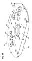
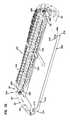
- FIG. 1is a perspective view of a telecommunications assembly having exemplary features of aspects in accordance with the principles of the present disclosure
- FIG. 2is a perspective view of the telecommunications assembly of FIG. 1 ;
- FIG. 3is an exploded perspective view of the telecommunications assembly of FIG. 2 ;
- FIG. 4is a rear perspective view of the telecommunications assembly of FIG. 2 ;
- FIG. 5is a side view of the telecommunications assembly of FIG. 2 ;
- FIG. 6is an exploded perspective view of the telecommunications assembly of FIG. 2 ;
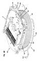
- FIG. 7is a perspective view of a tray assembly suitable for use with the telecommunications assembly of FIG. 2 ;
- FIG. 8is an exploded perspective view of the tray assembly of FIG. 7 ;
- FIG. 9is a perspective view of a bend radius protector suitable for use with the tray assembly of FIG. 7 ;
- FIG. 10is a front view of the bend radius protector of FIG. 9 ;
- FIG. 11is a side view of the bend radius protector of FIG. 9 ;
- FIG. 12is a bottom view of the bend radius protector of FIG. 9 ;
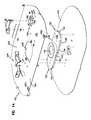
- FIG. 13is a perspective view of a cable spool assembly suitable for use with the tray assembly of FIG. 7 ;
- FIG. 14is an exploded view of the cable spool assembly of FIG. 13 ;
- FIG. 15is a perspective view of a fan-out clip suitable for use with the tray assembly of FIG. 7 ;
- FIG. 16is a front view of the fan-out clip of FIG. 15 ;
- FIG. 17is a side view of the fan-out clip of FIG. 15 ;
- FIG. 18is a top view of the fan-out clip of FIG. 15 ;
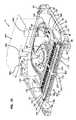
- FIG. 19is a perspective view of the tray assembly of FIG. 7 showing an adapter module
- FIG. 20is a perspective view of the tray assembly of FIG. 7 with the adapter module in an extended position
- FIG. 21is a perspective view of a bushing suitable for use with the tray assembly
- FIG. 22is a cross-sectional view of the tray assembly taken through the bushing
- FIG. 23is a perspective view of a locking mechanism suitable for use with the tray assembly of FIG. 7 ;
- FIG. 24is a view of the locking mechanism of FIG. 23 ;
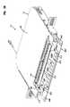
- FIG. 25is an alternate embodiment of a telecommunications assembly having exemplary features of aspects in accordance with the principles of the present disclosure
- FIG. 26is an exploded perspective view of the telecommunications assembly of FIG. 25 ;
- FIG. 27is a perspective view of the telecommunications assembly of FIG. 25 with a tray removed;
- FIG. 28is a perspective view of a cable assembly
- FIG. 29is an exploded perspective view of the cable assembly of FIG. 28 ;
- FIG. 30is a partial perspective view of a tray assembly suitable for use with the telecommunications assembly of FIG. 2 ;
- FIG. 31is an exploded perspective view of the tray assembly of FIG. 30 ;
- FIG. 32is an exploded partial perspective view of the tray assembly of FIG. 30 ;
- FIG. 33is a perspective view of an adapter module of the tray assembly of FIG. 30 ;
- FIG. 34is an enlarged portion of the perspective view of FIG. 33 ;
- FIG. 35is an exploded perspective view of a cable assembly
- FIG. 36is a side view of the cable assembly of FIG. 35 ;
- FIG. 37is an enlarged portion of the side view of FIG. 36 ;
- FIG. 38is an exploded perspective view of a telecommunications assembly having exemplary features of aspects in accordance with the principles of the present disclosure
- FIG. 39is a perspective view of the telecommunications assembly of FIG. 38 ;
- FIG. 40is a perspective view of a telecommunications assembly having exemplary features of aspects in accordance with the principles of the present disclosure.
- the telecommunications assembly 10includes a chassis 12 (e.g., an enclosure, a case, etc.) and a tray assembly 14 (e.g., a shelf assembly, a drawer assembly, etc.) that removably mounts in the chassis 12 .
- the telecommunications assembly 10is adapted for mounting to a telecommunications rack 15 .
- the chassis 12is adapted for connection to the rack 15 .
- the chassis 12is generally rectangular in shape.
- the chassis 12includes a base 16 , a first sidewall 18 , an oppositely disposed second sidewall 20 and a cover 22 .
- the base 16includes a first end 24 , an oppositely disposed second end 26 , a first side 28 that extends between the first and second ends 24 , 26 and an oppositely disposed second side 30 .
- the first end 24is a front end of the base 16 while the second end 26 is a back end.
- the chassis 12includes a major dimension W, which is measured from the first side 28 to the second side 30 , and a minor dimension D, which is measured from the first end 24 to the second end 26 .
- the major dimension Wis greater than the minor dimension D.
- the first and second sidewalls 18 , 20extend outwardly from the base 16 .
- the first and second sidewalls 18 , 20extend outwardly in a direction that is generally perpendicular to the base 16 .
- the first and second sidewalls 18 , 20extend outwardly from the base 16 at an oblique angle.
- the first sidewall 18is disposed at the first side 28 of the base 16 while the second sidewall 20 is disposed at the second side 30 of the base 16 .
- the first sidewall 18includes a first end 32 a , an oppositely disposed second end 32 b , a first side 34 a that extends between the first and second ends 32 a , 32 b of the first sidewall 18 and an oppositely disposed second side 34 b .
- the second sidewall 20includes a first end 36 a , an oppositely disposed second end 36 b , a first side 38 a that extends between the first and second ends 36 a , 36 b of the second sidewall 20 and an oppositely disposed second side 38 b.
- the first side 34 a of the first sidewall 18is engaged to the first side 28 of the base 16 so that the first end 32 a of the first sidewall 18 is adjacent to the first end 24 of the base 16 .
- the first side 38 a of the second sidewall 20is engaged to the second side 30 of the base 16 so that the first end 36 a of the second sidewall 20 is adjacent to the first end 24 of the base 16 .
- the first sides 34 a , 38 a of the first and second sidewalls 18 , 20are integral with the base 16 .
- first sides 34 a , 38 a of the first and second sidewalls 18 , 20are fastened (e.g., welded, pop riveted, bolted, screwed, glued, etc.) to the base 16 .
- the second sides 34 b , 38 b of the first and second sidewalls 18 , 20are engaged to the cover 22 .
- the second sides 34 b , 38 binclude tabs 40 that are engaged to the cover 22 by fasteners (e.g., screws, bolts, rivets, welds, adhesive, etc.).
- Each of the first and second sidewalls 18 , 20includes a mounting bracket 42 .
- the mounting bracket 42is generally L-shaped.
- the mounting bracket 42includes a first end portion 44 that mounts to one of the first and second sidewalls 18 , 20 and a second end portion 46 that is adapted for engagement with the rack 15 .
- the first end portion 44is engaged to the first and second sidewalls 18 , 20 by a plurality of fasteners (e.g., screws, bolts, rivets, welds, adhesive, etc.).
- Each of the first and second sidewalls 18 , 20define a plurality of holes 48 .
- the holes 48are disposed adjacent to the first sides 34 a , 38 a of the first and second sidewalls 18 , 20 .
- the holes 48are generally rectangular in shape.
- the base 16 , the first and second sidewalls 18 , 20 and the cover 22cooperatively define an interior region 50 .
- the interior region 50is adapted to receive the tray assembly 14 .
- the first ends 32 a , 36 a of the first and second sidewalls 18 , 20 and the first end 24 of the base 16cooperatively define a first opening 52 .
- the first opening 52provides access to the interior region 50 .
- the first opening 52is a front opening to the interior region 50 .
- the second ends 32 b , 36 b of the first and second sidewalls 18 , 20 and the second end 26 of the base 16cooperatively define a second opening 54 .
- the second opening 54provides access to the interior region 50 .
- the second opening 54is oppositely disposed from the first opening 52 .
- the second opening 54is a back opening.
- the tray assembly 14includes a tray 60 (e.g., a shelf, a drawer, etc.) and a cable spool assembly 62 rotatably mounted to the tray 60 .
- the tray assembly 14is adapted for insertion and removal from the chassis 12 as a unit without requiring the cable spool assembly 62 to be detached from the tray 60 .
- the tray 60includes a base panel 64 having a first end portion 66 (e.g., a front end portion), an oppositely disposed second end portion 68 (e.g., a back end portion), a first side portion 70 that extends at least partially between the first and second end portions 66 , 68 and an oppositely disposed second side portion 72 that extends at least partially between the first and second end portions 66 , 68 .
- the first and second side portions 70 , 72extend outwardly from the base panel 64 in a generally perpendicular direction.
- the tray 60defines a lateral direction L and a front-to-back direction F-B.
- the lateral direction Lextends between the first and second side portions 70 , 72 .
- the lateral direction Lis generally perpendicular to the first and second side portions 70 , 72 .
- the front-to-back direction F-Bextends between the first and second end portions 66 , 68 .
- the front-to-back direction F-Bis generally perpendicular to the lateral direction L.
- the tray 60includes a plurality of resilient latches 74 .
- the tray 60includes a first resilient latch 74 a engaged to the first side portion 70 and a second resilient latch 74 b engaged to the second side portion 72 .
- the resilient latch 74includes a first axial end portion 76 and an oppositely disposed second axial end portion 78 .
- the first axial end portion 76includes a first protrusion 80 while the second axial end portion 78 includes a second protrusion 82 .
- Each of the first and second protrusions 80 , 82includes a lip 84 and an angled surface 86 .
- the first and second protrusions 80 , 82are oppositely disposed on the resilient latch 74 so that the lip 84 of the first protrusion 80 faces the first end portion 66 of the base panel 64 while the lip 84 of the second protrusion 82 faces the second end portion 68 of the base panel 64 .
- the angled surface 86 of the first protrusion 80flares outwardly toward the first axial end portion 76 while the angled surface 86 of the second protrusion 82 flares outwardly toward the second axial end portion 78 .
- the first resilient latch 74 ais secured to the first side portion 70 by a plurality of fasteners (e.g., screws, bolts, rivets, welds, adhesive, etc.).
- the first resilient latch 74 ais secured to the first side portion 70 at a location disposed between the first and second axial end portions 76 , 78 of the first resilient latch 74 a .
- the first resilient latch 74 ais secured to the first side portion 70 at a location disposed between the first and second protrusions 80 , 82 .
- the second resilient latch 74 bis secured to the second side portion 72 by a plurality of fasteners (e.g., screws, bolts, rivets, welds, adhesive, etc.).
- the second resilient latch 74 bis secured to the second side portion 72 at a location disposed between the first and second axial ends 76 , 78 of the second resilient latch 74 b .
- the second resilient latch 74 bis secured to the second side portion 72 at a location disposed between the first and second protrusions 80 , 82 of the second resilient latch 74 b.
- the first and second side portions 70 , 72 of the base panel 64include a plurality of openings 88 through which the first and second protrusions 80 , 82 extend.
- Each of the first and second axial ends 76 , 78 of the first and second resilient latches 74 a , 74 bis adapted to flex inwardly toward the tray 60 .
- the distance that the first protrusion 80 extends outwardly through the openings 88decreases.
- the tray 60includes a plurality of bend radius protectors 90 .
- a first plurality of bend radius protectors 90 ais disposed adjacent to the first end portion 66 of the base panel 64 .
- a second plurality of bend radius protectors 90 bis disposed adjacent to the second end 68 of the base panel 64 .
- the bend radius protector 90includes a body 92 having a first end surface 94 and an oppositely disposed second end surface 96 .
- the body 92defines a passage 98 that extends through the first and second end surfaces 94 , 96 .
- the passage 98is generally oblong in shape.
- the passage 98includes a first arcuate edge 100 at the first end surface 94 and a second arcuate edge 102 at the second end surface 96 .
- Each of the first and second arcuate edges 100 , 102includes a radius that is greater than the minimum bend radius of a fiber optic cable that passes through passage 98 so as to reduce the risk of attenuation damage to the fiber optic cable.
- the body 92encloses the passage 98 .
- a slot 104is defined by a side 106 of the body 92 .
- the slot 104extends through the side 106 of the body 92 and into the passage 98 .
- the slot 104extends through the first and second end surface 94 , 96 .
- the slot 104is adapted to allow a fiber optic cable to be inserted laterally into the passage 98 rather than threading the fiber optic cable through the passage 98 .
- the slot 104is disposed at an angle relative to a central axis 108 that extends through the passage 98 .
- the slot 104angles as it extends from the first end surface 94 to the second end surface 96 . In one embodiment, the angle is an oblique angle.
- the first and second pluralities of bend radius protectors 90are fastened to the base panel 64 of the tray 60 .
- the bend radius protectors 90include a pin 99 that is adapted for receipt in a hole in the base panel 64 of the tray 60 of the tray assembly 14 .
- the pin 99 and the fastenercooperatively secure the bend radius protectors to the base panel 64 .
- the first plurality of bend radius protectors 90is disposed at the first end portion 66 of the base panel 64 so that the central axes 108 that extend through the passages 98 of the first plurality of bend radius protectors 90 are aligned.
- the central axes 108 of the first plurality of bend radius protectors 90are generally parallel to the lateral direction L.
- the second plurality of bend radius protectors 90is disposed at the second end portion 68 of the base panel 64 so that the central axes 108 of the bend radius protectors 90 are angled outwardly.
- the central axes 108 of the second plurality of bend radius protectors 90are disposed at an oblique angle relative to the lateral direction L and the front-to-back direction F-B.
- the first end portion 66 of the tray 60defines a recess 110 .
- a tab 112extends from the base panel 64 into the recess 110 and separates the recess 110 into a first recess 110 a and a second recess 110 b .
- the tab 112is generally coplanar with the base panel 64 .
- the tab 112includes a free end 114 that extends in a direction that is generally perpendicular to the base panel 64 .
- the first and second recesses 110 a , 110 bare generally equal in size.
- the cable spool assembly 62is adapted to rotate relative to the tray 60 .
- the cable spool assembly 62is rotatably engaged to the base panel 64 of the tray 60 .
- the cable spool assembly 62includes a stored position (shown in FIG. 7 ).
- the cable spool assembly 62can be releasably secured in the stored position.
- the cable spool assembly 62is adapted to be rotated from the stored position to deploy fiber optic cable wrapped about the cable spool assembly 62 .
- the cable spool assembly 62includes a hub 120 , a first flange 122 engaged to the hub 120 and a second flange 124 engaged to the hub 120 opposite the first flange 122 .
- the hub 120includes a body 126 having a first surface 128 and an oppositely disposed second surface 130 .
- the distance between the first and second surfaces 128 , 130is less than or equal to about 0.75 inches.
- the distance between the first and second surfaces 128 , 130is less than or equal to about 0.5 inches.
- the distance between the first and second surface 128 , 130is in a range of about 0.25 inches to about 0.5 inches.
- the body 126 of the hub 120is generally oval in shape.
- the oval shape of the body 126 of the hub 120allows for a greater length of fiber optic cable to be coiled around the body 126 for a given depth and width of the cable spool assembly 62 .
- the body 126 of the hub 120includes a major dimension, as measured along a major axis of the body 126 , and a minor dimension, as measured along a minor axis. In the depicted embodiment, the major dimension is greater than the minor dimension. When in the stored position, the major axis is generally parallel to the lateral direction L.
- the major axisis generally parallel to a plane that extends through the first opening 52 of the chassis 12 when the cable spool assembly 62 is in the stored position.
- the body 126 of the hub 120has been described as being oval in shape, it will be understood that the scope of the present disclosure is not limited to the body 126 of the hub 120 being oval in shape.
- the body 126 of the hub 120can have various geometric shapes (e.g., circular, obround, etc.).
- the depth of the cable spool assembly 62is less than or equal to about 16 inches. In another embodiment, the depth of the cable spool assembly 62 is less than or equal to about 15 inches. In another embodiment, the width of the cable spool assembly 62 is less than or equal to about 18 inches. In another embodiment, the width of the cable spool assembly 62 is less than or equal to about 17 inches. In one embodiment, the body 126 is configured to receive at least about 500 feet of 3 mm fiber optic cable. In another embodiment, the body 126 is configured to receive at least about 400 feet of 3 mm fiber optic cable. In another embodiment, the body 126 is configured to receive at least about 200 feet of 3 mm fiber optic cable.
- the body 126is configured to receive at least about 250 feet of dual-zip 3 mm fiber optic cable. In another embodiment, the body 126 is configured to receive at least about 200 feet of dual-zip 3 mm fiber optic cable. In another embodiment, the body 126 is configured to receive at least about 100 feet of dual-zip 3 mm fiber optic cable.
- the body 126 of the hub 120includes a first longitudinal end 132 , an oppositely disposed second longitudinal end 134 , a first longitudinal side 136 that extends between the first and second longitudinal ends 132 , 134 and an oppositely disposed second longitudinal side 138 that extends between the first and second longitudinal ends 132 , 134 .
- the first and second longitudinal ends 132 , 134are generally arcuate in shape. In the depicted embodiment, the first and second longitudinal ends 132 , 134 are generally semi-circular in shape.
- the hub 120further includes a strain relief protrusion 140 that extends outwardly from the second surface 130 of the hub 120 .
- the strain relief protrusion 140is generally cylindrical in shape.
- the strain relief protrusion 140has an outer diameter that is less than a distance between the first and second longitudinal sides 136 , 138 .
- the hub 120defines a cable transition notch 142 disposed in the first longitudinal side 136 of the body 126 .
- the cable transition notch 142extends inward into the body 126 from the first longitudinal end 132 to the strain relief protrusion 140 .
- the cable transition notch 142angles inwardly from the first longitudinal end 132 of the body 126 to the strain relief protrusion 140 .
- the cable transition notch 142is adapted to provide a location at which fiber optic cable coiled about the body 126 of the hub 120 can pass to the strain relief protrusion 140 .
- the hub 120further defines a central bore 144 .
- the central bore 144extends through the first and second surfaces 128 , 130 and through the strain relief protrusion 140 .
- the first flange 122is engaged to the hub 120 .
- the first flange 122is fastened (e.g., screwed, bolted, riveted, welded, bonded, etc.) to the first surface 128 of the hub 120 .
- the first flange 122is generally planar and oval in shape.
- the first flange 122defines a bore 146 that is adapted for alignment with the central bore 144 of the hub 120 when the first flange 122 is engaged to the hub 120 .
- the second flange 124is engaged to the hub 120 .
- the second flange 124is fastened (e.g., screwed, bolted, riveted, welded, bonded, etc.) to the second surface 130 of the hub 120 .
- the second flange 124includes a central opening 148 that extends through the second flange 124 .
- the central opening 148is adapted to receive the strain relief protrusion 140 of the hub 120 when the second flange 124 is engaged to the hub 120 so that the strain relief protrusion 140 extends outwardly from the second flange 124 of the cable spool assembly 62 .
- the central opening 148is oversized to allow the fiber optic cable which passes through the cable transition notch 142 to pass through the central opening 148 .
- the second flange 124includes an outer surface 150 .
- the outer surface 150includes a cable management area 152 and a termination area 154 disposed adjacent to the cable management area 152 .
- the cable management area 152includes a plurality of fan-out mounting brackets 156 .
- the fan-out mounting brackets 156are spaced apart to receive a fan-out 158 (shown in FIG. 8 ), which separates optical fibers of a fiber optic cable, between the fan-out mounting brackets 156 .
- the fan-out mounting brackets 156extend outwardly from the outer surface 150 of the second flange 124 . In the depicted embodiment, the fan-out mounting brackets 156 extend outwardly in a generally perpendicular direction.
- Each of the fan-out mounting brackets 156includes at least one receptacle 160 . In the depicted embodiment, each of the fan-out mounting brackets 156 includes two receptacles 160 .
- the fan-out 158is retained in the fan-out mounting bracket 156 by a fan-out clip 162 .
- the fan-out clip 162includes a cover plate 164 and a plurality of latches 166 that extend outwardly from the cover plate 164 .
- the cover plate 164is similar in shape to the outline of the fan-out 158 .
- the cover plate 164includes a first end 168 and an oppositely disposed second end 170 .
- the second end 170includes a width that is less than a width of the first end 168 so that the cover plate 164 tapers from the first end 168 to the second end 170 .
- the latches 166extend outwardly from the first end 168 of the cover plate 164 in a direction that is generally perpendicular to the cover plate 164 .
- Each of the latches 166includes a base end 172 and a free end 174 .
- the base end 172is engage to the cover plate 164 .
- the free end 174includes a latch protrusion 176 that is adapted for receipt in the receptacle 160 of the fan-out mounting bracket 156 .
- An alignment pin 178extends outwardly from the second end 170 of the cover plate 164 of the fan-out clip 162 .
- the alignment pin 178extends in a direction that is generally parallel to the latches 166 .
- the alignment pin 178is sized to fit within a first alignment opening 180 a in the fan-out 158 .
- the outer surface 150 of the second flange 124includes a protrusion that is adapted to fit with a second alignment opening 180 b of the fan-out 158 .
- the alignment pin 178 of the fan-out clip 162is aligned with the first alignment opening 180 a of the fan-out 158 .
- the fan-out clip 162is pressed down toward the outer surface 150 of the second flange 124 until the latch protrusion 176 engages the receptacle 160 of the fan-out mounting bracket 156 .
- the mounting brackets 156are adapted to hold multiple fan-outs 158 .
- Each of the fan-out mounting brackets 156includes one receptacle 160 per fan-out 158 that the fan-out mounting brackets 156 can hold.
- the fan-out mounting brackets 156can hold two fan-outs 158 . So, in the depicted embodiment, each of the fan-out mounting brackets 156 defines two receptacles 160 . If only one fan-out 158 is disposed in the fan-out mounting brackets 156 , the fan-out clip 162 is pressed down until the latch protrusions 176 engage the receptacles 160 closest to the outer surface 150 of the second flange 124 .
- the fan-out clip 162is pressed down until the latch protrusions 176 engage the receptacles 160 adjacent to the receptacles 160 closest to the outer surface 150 of the second flange 124 .
- the cable management area 152includes a plurality of bend radius protectors 182 .
- the bend radius protectors 182are disposed on the outer surface 150 of the second flange 124 .
- the bend radius protectors 182are adapted to prevent damage to the optical fibers that are routed from the fan-out 158 to the termination area 154 .
- each of the bend radius protectors 182is arcuate in shape and includes a retention projection 184 that extends outwardly from a convex surface 186 of the bend radius protector 182 .
- the termination area 154includes an adapter module 190 (e.g., a termination unit, etc.).
- the adapter module 190is adapted to rotate in unison with the cable spool assembly 62 and to slide relative to the second flange 124 .
- the adapter module 190is adapted to slide relative to the second flange 124 in a direction that is generally parallel to the second flange 124 between a retracted position (shown in FIG. 7 ) and an extended position (shown in FIG. 20 ).
- the adapter module 190is adapted to slide in a direction that is generally parallel to the front-to-back direction F-B.
- the adapter module 190includes a carrier 192 and a plurality of adapters 194 disposed in the carrier 192 .
- the carrier 192includes a first rail 196 a and a second rail 196 b .
- Each of the first and second rails 196 a , 196 bincludes a first axial end 198 and a second axial end 200 .
- the carrier 192further includes a cross-support 202 that extends between the first and second rails 196 a , 196 b at a location between the first and second axial ends 198 , 200 .
- An adapter mounting bracket 204is engaged with the first axial ends 198 of the first and second rails 196 a , 196 b .
- the adapter mounting bracket 204defines a plurality of adapter openings 205 that is adapted to receive the plurality of adapters 194 .
- the adapter openings 205are arranged in a line that is generally perpendicular to the direction of slide movement of the adapter module 190 so that the direction of slide movement of the adapter module 190 is generally perpendicular to the line of adapters 194 mounted in the adapter mounting bracket 204 .
- the adapter mounting bracket 204is adapted to receive twenty-four adapters 194 . In another embodiment, the adapter mounting bracket 204 is adapted to receive twelve adapters 194 . In another embodiment, the adapter mounting bracket 204 is adapted to receive forty-eight adapters 194 .
- the first and second rails 196 a , 196 b of the adapter module 190are slidably engaged to the outer surface 150 of the second flange 124 by a plurality of guides 206 .
- the guides 206extend outwardly from the outer surface 150 and define channels 208 in which the first and second rails 196 a , 196 b are slidably disposed.
- the second flange 124defines a plurality of mounting tabs 210 that extend outwardly from a perimeter of the outer surface 150 .
- the mounting tabs 210are adapted to abut mounts 212 that extend outwardly from the first axial ends 198 of the first and second rails 196 a , 196 b when the adapter module 190 is in the retracted position.
- fasteners 214e.g., screws, bolts, rivets, etc.
- the fasteners 214are captive thumb screws.
- the adapter module 190can be translated outwardly from the second flange 124 of the cable spool assembly 62 in a direction that is generally parallel to the front-to-back direction F-B to the extended position.
- the adapter module 190has a range of travel of at least two inches.
- the adapter module 190is adapted to slide a distance that provides access to inward facing ports of the adapters 194 when the tray assembly 14 is engaged to the chassis 12 . By providing access to the inward facing ports of the adapters 194 , connectorized ends of fiber optic cables that are plugged into the inward facing ports of the adapters 194 can be removed and cleaned while the tray assembly 14 is engaged to the chassis 12 .
- a catch 216abuts the cross-support 202 and prevents the adapter module 190 from moving farther outward from the second flange 124 .
- the catch 216extends outwardly from a perimeter of the second flange 124 .
- the adapter module 190includes a plurality of resilient latches 220 that is engaged with the first axial ends 198 of the first and second rails 196 a , 196 b .
- the resilient latches 220are disposed between the first and second rails 196 a , 196 b and the mounting tabs 212 .
- the resilient latchesare adapted to engage the mounting tabs 212 to prevent the adapter module 190 from being moved inwardly toward the second flange 124 .
- the engagement of the resilient latches 220 and the mounting tabs 212prevents the adapter module 190 from moving toward the retracted position as connectorized ends of fiber optic cables are inserted into outward facing ports of the adapters 194 .
- the cable spool assembly 62is rotatably engaged to the tray 60 by a bushing 222 .
- the bushing 222provides the engagement between the cable spool assembly 62 and the base panel 64 of the tray 60 .
- the bushing 222is generally cylindrical in shape.
- the bushing 222includes a first axial end 224 and a second axial end 226 .
- the first axial end 224 of the bushing 222includes an end surface 228 .
- the end surface 228is adapted for abutment with the base panel 64 of the tray 60 .
- the end surface 228defines a hole 229 that extends through the end surface 228 .
- the hole 229is adapted to receive a fastener 230 (e.g., screw, bolt, etc.) that is used to secure or anchor the bushing 222 to the tray 60 .
- the end surface 228includes a peg 231 that extends outwardly from the end surface 228 .
- the peg 231is adapted for receipt in an opening in the base panel 64 of the tray 60 .
- the peg 231is adapted to prevent the bushing 222 from rotating relative to the tray 60 .
- the first axial end 224has an outer diameter that is less than the inner diameter of the central bore 144 of the hub 120 so that the first axial end 224 of the bushing 222 can be inserted into the central bore 144 of the hub 120 .
- the second axial end 226has an outer diameter that is greater than the inner diameter of the central bore 144 of the hub 120 .
- the second axial end 226abuts an end surface of the strain relief protrusion 140 of the hub 120 and captures the cable spool assembly 62 between the base panel 64 of the tray 60 and the second axial end 226 of the bushing 222 .
- the cable spool assembly 62can rotate about the bushing 222 .
- the bushing 222is keyed to the base panel 64 so that the bushing 222 is stationary relative to the tray 60 .
- the fiber optic cable 232includes a first end and a second end.
- the fiber optic cable 232is coiled about the body 126 of the hub 120 of the cable spool assembly 62 between the first and second flanges 122 , 124 .
- the first end of the fiber optic cable 232is disposed closest to the hub 120 .
- a portion of the first endpasses through the cable transition notch 142 in the hub 120 and through the central opening 148 of the second flange 124 .
- the portion of the first end of the fiber optic cable 232is coiled at least once around the strain relief protrusion 140 of the hub 120 .
- the first endis anchored to the second flange 124 (e.g., with a cable tie) after being wrapped at least once around the strain relief protrusion 140 .
- the first endis routed from the strain relief protrusion 140 to the fan-out 158 .
- Optical fibers 233are separated from the fiber optic cable 232 at the fan-out 158 .
- Each of the optical fibers 233includes a connectorized end. The connectorized ends of the optical fibers 233 are routed to the adapters 194 and engaged to inward facing ports of the adapters 194 .
- the second end of the fiber optic cable 232has a multi-fiber connector 353 c .
- the second endcan be routed outside of the tray assembly 14 at a location adjacent to the first end portion 66 of the base panel 64 of the tray 60 or at an opposite location adjacent to the second end portion 68 of the base panel 64 of the tray 60 .
- the second endis routed through the passage 98 of any one of the bend radius protectors 90 disposed on the tray 60 .
- the tray assembly 14is adapted for insertion into the chassis 12 through either the first opening 52 or the second opening 54 of the chassis 12 .
- the second axial ends 78 of the first and second resilient latches 74 a , 74 b of the tray assembly 14are flexed inwardly.
- the second end portion 68 of the base panel 64 of the tray 60is inserted through the first opening 52 of the chassis 12 .
- the tray assembly 14is then pushed into the interior region 50 of the chassis 12 until the first and second protrusions 80 , 82 on each of the first and second resilient latches 74 a , 74 b are engaged in the holes 48 of the first and second sidewalls 18 , 20 of the chassis 12 .
- the first and second protrusions 80 , 82 on each of the first and second resilient latches 74 a , 74 bprovide four-point contact between the tray assembly 14 and the chassis 12 .
- the first protrusions 80 of the first and second resilient latches 74 a , 74 bprevent the tray assembly 14 from being removed through the first opening 52 of the chassis 12 by abutting the holes 48 in the chassis 12 but allow the tray assembly to be removed through the second opening 54 of the chassis 12 .
- the second protrusions 82 of the first and second resilient latches 74 a , 74 bprevent the tray assembly 14 from being removed through the second opening 54 of the chassis 12 but allow the tray assembly 14 to be removed through the first opening 52 of the chassis 12 .
- the first axial end portions 76 of the resilient latches 74 a , 74 b of the tray assembly 14are flexed inwardly until the lips 84 of the first protrusions 80 are no longer disposed in the holes 48 of the chassis 12 .
- the tray assembly 14is pulled out of the first opening 52 of the chassis 12 .
- the angled surfaces 86 of the second protrusions 82contact an edge of the hole 48 that causes the second axial end portions 78 of the resilient latches 74 a , 74 b to flex inwardly.
- the first axial end portions 76 of the first and second resilient latches 74 a , 74 b of the tray assembly 14are flexed inwardly.
- the first end portion 66 of the base panel 64 of the tray 60is inserted through the second opening 54 of the chassis 12 .
- the tray assembly 14is pushed into the interior region 50 of the chassis 12 until the first and second protrusion of the first and second resilient latches are engaged in the holes 48 of the first and second sidewalls 18 , 20 of the chassis 12 .
- the second axial end portions 78 of the resilient latches 74 a , 74 b of the tray assembly 14are flexed inwardly until the lips 84 of the second protrusions 82 are no longer disposed in the holes 48 of the chassis 12 .
- the tray assembly 14is pulled out of the second opening 54 of the chassis 12 .
- the angled surfaces 86 of the first protrusions 80contact an edge of the hole 48 that causes the first axial end portions 76 of the resilient latches 74 a , 74 b to flex inwardly.
- the fiber optic cable 232can be deployed by pulling the second end of the fiber optic cable 232 through one of the first and second openings 52 , 54 of the chassis 12 .
- the cable spool assembly 62rotates about the bushing 222 .
- the adapter module 190rotates in unison. Since the adapter module 190 rotates in unison with the cable spool assembly 62 , the connectorized ends of the first end of the fiber optic cable 232 can be engaged in the inwardly facing ports of the adapters 194 .
- the second end of the fiber optic cable 232is pulled until a desired length of fiber optic cable 232 has been deployed.
- the locking mechanism 240is adapted to prevent the cable spool assembly 62 from rotating relative to the tray 60 .
- the locking mechanism 240provides an electrical connection between the tray 60 and the cable spool assembly 62 so as to serve as a ground.
- a separate groundis provided between the tray 60 and the chassis 12 .
- the locking mechanism 240includes an arm 242 that pivots about a location on the tray 60 .
- the arm 242pivots about a location disposed at the second end portion 68 of the base panel 64 of the tray 60 .
- the arm 242is pivoted toward the second flange 124 of the cable spool assembly 62 .
- the second flange 124includes a lock mount 244 (best shown in FIG. 13 ) that extends outwardly from the outer surface 150 of the second flange 124 and is disposed at an outer perimeter of the second flange 124 .
- the arm 242 of the locking mechanism 240is pivoted until a fastener 246 (e.g., thumbscrew) that extends through the arm 242 is aligned with an opening 248 in the lock mount 244 .
- the fastener 246is then engaged with the opening 248 to secure the cable spool assembly 62 in position relative to the tray 60 .
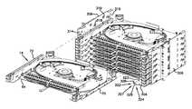
- the telecommunications assembly 300includes a chassis 302 and multiple tray assemblies 14 .
- the chassis 302is similar to the chassis 12 previously described except that the chassis 302 is adapted to receive multiple tray assemblies 14 . Therefore, it will be understood that the features described with regard to the chassis 12 may be incorporated in the chassis 302 .
- the chassis 302includes a base wall 304 , a first sidewall 306 that extends outwardly from the base wall 304 , an oppositely disposed second sidewall 308 and a cover 310 .
- the base wall 304 , the first and second sidewalls 306 , 308 and the cover 310cooperatively define an interior region 312 that is adapted to receive the plurality of tray assemblies 14 .
- the base wall 304 , the first and second sidewalls 306 , 308 and the cover 310further define a first opening 314 to the interior region 312 and an oppositely disposed second opening 316 to the interior region 312 .
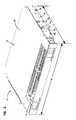
- the first and second sidewalls 306 , 308 of the chassis 302include a plurality of first tray guides 318 (best shown in FIG. 27 ).
- the first tray guides 318extend into the interior region 312 of the chassis 302 .
- the first tray guides 318are adapted to abut the base panel 64 of the tray assembly 14 and to support the tray assembly 14 in the interior region 312 of the chassis 302 .
- the first and second sidewalls 306 , 308 of the chassis 302further include a plurality of second tray guides 319 .
- the second tray guides 319define a channel through which the first and second side portions 70 , 72 of the base panel 64 of the tray assembly 14 pass.
- the tray assemblies 14can be installed into the chassis 302 in a manner that is similar to the installation of the tray assembly 14 in the chassis 12 , which was previously described. In the depicted embodiment, the tray assemblies 14 are disposed in a vertical orientation in the interior region 312 of the chassis 302 .
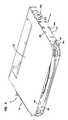
- the telecommunications assembly 300includes a front cover plate 320 .
- the front cover plate 320is engaged to the base wall 304 by a hinge 322 .
- the hinge 322is integral with a first end 323 of the base wall 304 .
- the hinge 322includes a first arm 324 having a first curved portion 326 that opens in a first direction and a second arm 327 having a second curved portion 328 that opens in an opposite second direction.
- the first and second curved portions 326 , 328are adapted to capture a bar 330 of the front cover plate 320 that is disposed between an opening 332 through the front cover plate 320 and an adjacent edge 334 of the front cover plate 320 .
- the front cover plate 320is adapted to pivot between an open position and a closed position (shown in FIG. 23 ).
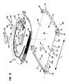
- the cable assembly 350includes the tray assembly 14 mounted to a cable spool 352 .
- the cable assembly 350is adapted to provide a length of fiber optic cable 353 that is greater than the length that can fit around the cable spool assembly 62 of the tray assembly 14 .
- the cable spool 352can hold a length of the fiber optic cable 353 that is greater than or equal to 500 feet of 3 mm fiber optic cable.
- the cable spool 352can hold a length of the fiber optic cable 353 that is greater than or equal to 1,000 feet of 3 mm fiber optic cable.
- the cable spool 352including a drum 354 and/or flanges 356 , 358 , can be manufactured of a plastic material, a paper board material (e.g., cardboard or like material) or a recycled material. In one embodiment, the cable spool 352 is recyclable or disposable after use.
- the cable spool 352includes the drum 354 , the first flange 356 , and the second flange 358 .
- the drum 354is adapted to receive the fiber optic cable 353 coiled around the drum 354 .
- the drum 354includes a first axial end 360 and an oppositely disposed second axial end 362 .
- the first flange 356is engaged to the first axial end 360 of the drum 354 .
- the second flange 358is engaged to the second axial end 362 of the drum 354 .
- the tray assembly 14is mounted to an outer surface 364 of the first flange 356 of the cable spool 352 .
- the tray assembly 14is tied down to the first flange 356 so that the base panel 64 of the tray 60 abuts the outer surface 364 of the first flange 356 .
- a first end of a length of the fiber optic cable 353is coiled around the cable spool assembly 62 of the tray assembly 14 .
- the fiber optic cable 353is routed from the cable spool assembly 62 of the tray assembly 14 through one of the bend radius protectors 90 and through a notch 366 in the first flange 356 and around the drum 354 .
- the notch 366 in the first flange 356extends inwardly from an outer edge of the first flange 356 to the drum 354 .
- the notch 366allows the fiber optic cable 353 to pass to the drum 354 of the cable spool 352 from an off-drum location.
- the cable assembly 350is positioned in front of or behind a telecommunications mount (e.g., rack 15 , frame, etc.), which is adapted to receive the telecommunications assembly 10 , 300 , depending on whether the telecommunications assembly 10 , 300 is to installed from the front or back of the telecommunications mount.
- the fiber optic cable 353is deployed from the cable spool 352 of the cable assembly 350 .
- the cable spool 352 with tray assembly 14 attached theretois mounted to a spindle/rotation structure 370 (see FIG. 35 ).
- the fiber optic cable 353is pulled from the cable spool 352 , which causes rotation of the cable spool 352 and concurrent rotation of the tray assembly 14 carried by the cable spool 352 .
- the cable spool assembly 62 of the tray assembly 14is rotated relative to the tray 60 and the cable spool 352 to pay off additional fiber optic cable 353 disposed about the cable spool assembly 62 .
- the multi-fiber connector 353 c of the second end of the fiber optic cable 353is plugged into a component.
- the cable spool 352is then removed from the tray assembly 14 .
- the cable spool 352is discarded (e.g., disposed of or recycled).
- the tray assembly 14is moved toward the rack 15 (shown in FIG. 1 ).
- the cable spool assembly 62rotates relative to the tray 60 to provide additional length of the fiber optic cable 353 .
- the tray assembly 14is then installed into the chassis 12 , 302 , which, in one embodiment, is pre-mounted in the rack 15 . If it is desired to route the fiber optic cable 353 out the front of the chassis 12 or the front of the rack 15 , the tray assembly 14 is inserted into the rack 15 from the front.
- the tray assembly 14is inserted into the rack 15 from the back. With the tray assembly 14 engaged to the chassis 12 , the telecommunications assembly 10 , 300 is installed in the telecommunications mount.
- the cable assembly 350is depicted at FIGS. 28 and 29 including the cable spool 352 .
- other spool assembliesmay be used.
- the spool assemblies disclosed at U.S. provisional patent application Ser. No. 61/370,070, filed Aug. 2, 2010, hereby incorporated by reference in its entiretycan be included in certain embodiments.
- a cable spool 352 ′, described below,can be included.
- the tray assembly 14 ′is similar to the tray assembly 14 , disclosed above.
- the tray assembly 14 ′includes a tray 60 ′ (e.g., a shelf, a drawer, etc.) and a cable spool assembly 62 ′ rotatably mounted to the tray 60 ′.
- the tray 60 ′is similar to the tray 60
- the cable spool assembly 62 ′is similar to the cable spool assembly 62 .
- the tray assembly 14 ′is adapted for insertion and removal from the chassis 12 and 302 as a unit, without requiring the cable spool assembly 62 ′ to be detached from the tray 60 ′.
- the tray 60 ′includes a base panel 64 ′ having a first end portion 66 ′ (e.g., a front end portion), an oppositely disposed second end portion 68 ′ (e.g., a back end portion), a first side portion 70 ′ that extends at least partially between the first and second end portions 66 ′, 68 ′ and an oppositely disposed second side portion 72 ′ that extends at least partially between the first and second end portions 66 ′, 68 ′.
- the first and second side portions 70 ′, 72 ′extend outwardly from the base panel 64 ′ in a generally perpendicular direction.
- the first end portion 66 ′ of the tray 60 ′defines a recess 110 ′.
- a tab 112 ′extends from the base panel 64 ′ into the recess 110 ′ and separates the recess 110 ′ into a first recess 110 a ′ and a second recess 110 b ′.
- the tab 112 ′is generally coplanar with the base panel 64 ′.
- the tab 112 ′includes a free end 114 ′ that extends in a direction that is generally perpendicular to the base panel 64 ′.
- the first and second recesses 110 a ′, 110 b ′are generally equal in size.
- the cable spool assembly 62 ′is adapted to rotate relative to the tray 60 ′.
- the cable spool assembly 62 ′is rotatably engaged to the base panel 64 ′ of the tray 60 ′.
- the cable spool assembly 62 ′includes a stored position (shown in FIGS. 30-31 ).
- the cable spool assembly 62 ′can be releasably secured in the stored position.
- the cable spool assembly 62 ′is adapted to be rotated from the stored position to deploy fiber optic cable wrapped about the cable spool assembly 62 ′.
- the cable spool assembly 62 ′can include the hub 120 , a first flange 122 ′ engaged to the hub 120 and a second flange 124 ′ engaged to the hub 120 opposite the first flange 122 ′.
- the first flange 122 ′is fastened (e.g., screwed, bolted, riveted, welded, bonded, etc.) to the first surface 128 of the hub 120 .
- the first flange 122 ′is generally planar and oval in shape.
- the second flange 124 ′is fastened (e.g., screwed, bolted, riveted, welded, bonded, etc.) to the second surface 130 of the hub 120 .
- the second flange 124 ′includes a central opening 148 ′ that extends through the second flange 124 ′.
- the central opening 148 ′is adapted to receive the strain relief protrusion 140 of the hub 120 when the second flange 124 ′ is engaged to the hub 120 so that the strain relief protrusion 140 extends outwardly from the second flange 124 ′ of the cable spool assembly 62 ′.
- the central opening 148 ′is oversized to allow the fiber optic cable which passes through the cable transition notch 142 to pass through the central opening 148 ′.
- the second flange 124 ′includes an outer surface 150 ′.
- the outer surface 150 ′includes a cable management area 152 ′ and a termination area 154 ′ disposed adjacent to the cable management area 152 ′.
- the cable management area 152 ′includes a plurality of fan-out mounting features 156 ′.
- the fan-out mounting features 156 ′are spaced apart to receive one or more fan-outs 158 ′, similar to the fan-out 158 , which separates optical fibers of a fiber optic cable.
- the fan-out mounting features 156 ′extend outwardly from the outer surface 150 ′ of the second flange 124 ′.
- the fan-out mounting features 156 ′extend outwardly in a generally perpendicular direction.
- the fan-out mounting features 156 ′can include a post and a fastening arrangement (e.g., a stud and a nut).
- the fan-out 158 ′is retained by the fan-out mounting feature 156 ′ and a nut.
- the fan-out 158 ′includes at least one mounting hole.
- the fan-out 158 ′includes two mounting holes with one mounting hole mounted over the post and the other mounting hole mounted over the stud of the mounting feature 156 ′.
- the termination area 154 ′includes an adapter module 190 ′ (e.g., a termination unit, etc.).
- the adapter module 190 ′is adapted to rotate in unison with the cable spool assembly 62 ′ and to slide relative to the second flange 124 ′.
- the adapter module 190 ′is adapted to slide relative to the second flange 124 ′ in a direction that is generally parallel to the second flange 124 ′ between a retracted position (shown in FIGS. 30-32 ) and an extended position (similar to that shown in FIG. 20 ).
- the adapter module 190 ′is adapted to slide in a direction that is generally parallel to a front-to-back direction F-B′.
- the cable spool assembly 62 ′will not be able to rotate 360 degrees (i.e., rotate through a full revolution) with the adapter module 190 ′ in the extended position.
- the adapter module 190 ′, and particularly corners of the adapter module 190 ′may interfere with the first and second side portions 70 ′, 72 ′ of the base panel 64 ′ and/or interfere with the chassis 12 .
- the adapter module 190 ′includes a carrier 192 ′ and a plurality of adapters 194 disposed in the carrier 192 ′.
- the carrier 192 ′includes a first rail 196 a ′ and a second rail 196 b ′.
- Each of the first and second rails 196 a ′, 196 b ′includes a first axial end 198 ′ and a second axial end 200 ′.
- the carrier 192 ′further includes a cross-support 202 ′ that extends between the first and second rails 196 a ′, 196 b ′ at a location between the first and second axial ends 198 ′, 200 ′.
- the first and second rails 196 a ′, 196 b ′ of the carrier 192 ′each include a slot 197 that extends in the front-to-back direction F-B′.
- Fasteners 199attach the adapter module 190 ′ via the slots 197 to the cable spool assembly 62 ′. As depicted, the fasteners 199 attach the carrier 192 ′ to the second flange 124 ′ at fastening holes in the second flange 124 ′.
- the fasteners 199allow the adapter module 190 ′ to travel between the retracted position and the extended position with the fasteners 199 loosened and can provide stops at the retracted position and the extended position.
- the adapter module 190 ′may be secured at the retracted position, the extended position, or an intermediate position by tightening the fasteners 199 .
- an attachment location 201can be included at the second axial end 200 ′ of either or both of the first and second rails 196 a ′, 196 b ′ of the carrier 192 ′.
- the attachment location 201is a stud at the second axial end 200 ′ of the second rail 196 b ′.
- the attachment location 201is attached to a first end 203 a of a tether 203 .
- a second end 203 b of the tether 203is attached to the second flange 124 ′ by one of the fasteners 199 .
- the second end 203 bis attached by one of the fasteners 199 closest to an adapter mounting bracket 204 ′ of the carrier 192 ′.
- the tether 203provides electrical grounding to the adapter module 190 ′ from the cable spool assembly 62 ′.
- the cable spool assembly 62 ′can be grounded to the tray 60 ′ by the locking mechanism 240 in a manner similar to the grounding of the cable spool assembly 62 to the tray 60 , described above.
- a separate groundcan be provided between the tray 60 ′ and the chassis 12 , the chassis 12 and the rack 15 , and/or the tray 60 ′ and the rack 15 .
- the adapter module 190 ′, the cable spool assembly 62 ′, the tray 60 ′, the chassis 12 , and the rack 15may all be electrically connected.
- the adapter mounting bracket 204 ′is engaged with the first axial ends 198 ′ of the first and second rails 196 a ′, 196 b ′.
- the adapter mounting bracket 204 ′defines a plurality of adapter openings 205 ′ that is adapted to receive the plurality of adapters 194 .
- the adapter openings 205 ′are arranged in a line that is generally perpendicular to the direction of slide movement of the adapter module 190 ′ so that the direction of slide movement of the adapter module 190 ′ is generally perpendicular to the line of adapters 194 mounted in the adapter mounting bracket 204 ′.
- the adapter mounting bracket 204 ′is adapted to receive twenty-four adapters 194 . In another embodiment, the adapter mounting bracket 204 ′ is adapted to receive twelve adapters 194 . In another embodiment, the adapter mounting bracket 204 ′ is adapted to receive forty-eight adapters 194 .
- the second flange 124 ′defines a plurality of mounting tabs 210 ′ (see FIG. 30 ) that extend outwardly from a perimeter of the outer surface 150 ′.
- the mounting tabs 210 ′are adapted to abut mounts 212 ′ that extend outwardly from the first axial ends 198 ′ of the first and second rails 196 a ′, 196 b ′ when the adapter module 190 ′ is in the retracted position.
- fasteners 214 ′e.g., screws, bolts, rivets, thumb screws, etc.
- the fasteners 214 ′are captive thumb screws.
- the adapter module 190 ′can be translated outwardly from the second flange 124 ′ of the cable spool assembly 62 ′ in a direction that is generally parallel to the front-to-back direction F-B′ to the extended position.
- the adapter module 190 ′has a range of travel of at least two inches.
- the adapter module 190 ′is adapted to slide a distance that provides access to inward facing ports of the adapters 194 when the tray assembly 14 ′ is engaged to the chassis 12 . By providing access to the inward facing ports of the adapters 194 , connectorized ends of fiber optic cables that are plugged into the inward facing ports of the adapters 194 can be removed and cleaned while the tray assembly 14 ′ is engaged to the chassis 12 .
- a catch 216 ′abuts the cross-support 202 ′ and prevents the adapter module 190 ′ from moving farther outward from the second flange 124 ′. As depicted, the catch 216 ′ extends outwardly from a perimeter of the second flange 124 ′.
- guiding tabs 207are provided on the adapter module 190 ′ to facilitate the rotation of the cable spool assembly 62 ′ within and/or about the chassis 12 .
- the depicted embodimentincludes a pair of the guiding tabs 207 at opposite ends of the adapter mounting bracket 204 ′.
- the guiding tabs 207are angled downwardly and positioned adjacent corners 209 of the cable spool assembly 62 ′.
- the guiding tabs 207prevent or reduce the potential of the corners 209 of the cable spool assembly 62 ′ getting snagged and/or caught on various features, including the openings 52 , 54 , of the chassis 12 .
- the guiding tabs 207may be functional in both rotational directions of the cable spool assembly 62 ′.
- a cover 250can be provided over the cable management area 152 ′.
- the cover 250can cover or partially cover the optical fibers 233 , the fan-outs 158 ′, and other components and features in the cable management area 152 ′.
- the optical fibers 233are prevented or held back from becoming entangled as the tray assembly 14 ′ is rotated within the chassis 12 , 302 or inserted into the chassis 12 , 302 .
- the fan-outs 158 ′ and other components and features in the cable management area 152 ′are prevented from bumping against features and components of the chassis 12 , 302 as the tray assembly 14 ′ is rotated within the chassis 12 , 302 or inserted into the chassis 12 , 302 .
- the cover 250can serve as a guide to the optical fibers 233 and other optical fiber cables within and near the cable management area 152 ′.
- the optical fibers 233 and other optical fiber cables within and near the cable management area 152 ′can be sandwiched between the cover 250 and the outer surface 150 ′ of the second flange 124 ′.
- An edge 266 of the cover 250may be spaced from the adapter module 190 ′ to allow connectors 252 of fiber optic cables 254 to be inserted and withdrawn from the adapter module 190 ′ without removing the cover 250 .
- the cover 250 and the adapter module 190 ′may effectively keep uncovered portions 256 of the fiber optic cables 254 in position and prevent their tangling.
- the cover 250can include a clearance relief 258 (e.g., a hole, a recess, a slot) around or near the hub 120 .
- the cover 250can include a clearance relief 260 (e.g., a hole, a recess, a slot) around or near the fan-outs 158 ′.
- the cover 250can include a plurality of fastener holes 262 for attaching the cover 250 to the second flange 124 ′.
- the second flange 124 ′can include standoffs 264 for attaching the cover 250 to the second flange 124 ′. The standoffs 264 can space the cover 250 from the second flange 124 ′.
- the standoffs 264can prevent the cover 250 from clamping the optical fibers 233 , 254 , the fan-outs 158 ′, and other components and features in the cable management area 152 ′ against the outer surface 150 ′ of the second flange 124 ′.
- the standoffs 264can be threaded standoffs. Fasteners (not shown) can be inserted through the fasteners holes 262 and into the standoffs 264 and thereby attach the cover 250 to the second flange 124 ′.
- a panel 268can be provided on the adapter module 190 ′.
- FIGS. 30 and 31show the panel 268 assembled and broken away to reveal the fiber optic cable 232 within the cable spool assembly 62 ′.
- FIG. 32shows the panel 268 separated from the adapter module 190 ′.
- the panel 268can serve as a place to affix labels 270 that relate to the adapter module 190 ′.
- indices that relate to or number individual fiber optic adapters 194can be appropriately positioned on the panel 268 .
- the labels 270can be pre-applied to or stamped on the panel 268 at a factory and/or can be applied by a service technician (e.g. as stickers).
- the panel 268is positioned below the fiber optic adapters 194 and covers a front portion of the cable spool assembly 62 ′ and thereby covers a front portion of the fiber optic cable 232 that is within the cable spool assembly 62 ′.
- the panel 268can thereby give the adapter module 190 ′ and the tray assembly 14 ′ a cleaner appearance by hiding or obscuring the fiber optic cable 232 .
- the panel 268can also protect the fiber optic cable 232 .
- the panel 268includes a first tab 272 at a first end portion 274 and a second tab 276 at a second end portion 278 .
- Each of the tabs 272 , 276includes a fastening feature 280 (e.g., a hole).
- the adapter module 190 ′includes a first tab 282 with a fastening feature 284 (e.g., a hole) and also includes a second tab 286 with a fastening feature 288 (e.g., a hole).
- a push-in fastener 290is mounted in each of the holes 280 of the tabs 272 , 276 .
- the panel 268can be removably mounted to the adapter module 190 ′ by inserting the push-in fasteners 290 of each of the tabs 272 , 276 into their corresponding holes 284 , 288 .
- the push-in fasteners 290may snap in and snap out of their corresponding holes 284 , 288 .
- the push-in fasteners 290may be retained by the hole 280 .
- the cable assembly 350 ′includes the tray assembly 14 , 14 ′, or 14 ′′ mounted to a first cable spool 352 1 ′.
- the first cable spool 352 1 ′may be mounted to a second cable spool 352 2 ′. Additional cable spools 352 ′ can be added in like manner, as needed.
- the cable assembly 350 ′is adapted to provide a length of fiber optic cable 353 ′ that is greater than the length that can fit around the cable spool assembly 62 , 62 ′ of the tray assembly 14 , 14 ′, 14 ′′.
- the cable spool 352 ′can hold a length of the fiber optic cable 353 ′ that is generally equal to the lengths or range of lengths held by the cable spool 352 , described above.
- the cable spool 352 ′can be manufactured of materials similar to the materials used in the cable spool 352 , described above.
- the cable spool 352 ′includes a drum 354 ′, a first flange 356 ′, and a second flange 358 ′.
- the flanges 356 ′, 358 ′can be made of cardboard.
- the drum 354 ′, the first flange 356 ′, and the second flange 358 ′are generally respectively similar in form and function to the drum 354 , the first flange 356 , and the second flange 358 , described above.
- the second flange 358 ′ of the first cable spool 352 1 ′may attach to the first flange 356 ′ of the second cable spool 352 2 ′.
- the tray assembly 14 , 14 ′, 14 ′′ and the first cable spool 352 1 ′ of the cable assembly 350 ′are assembled similarly to the tray assembly 14 and the cable spool 352 of the cable assembly 350 , described above.
- the flanges 356 ′, 358 ′each include a notch 366 ′ similar to the notch 366 , described above.
- the notch 366 ′allows the fiber optic cable 353 ′ to pass from the drum 354 1 ′ to the drum 354 2 ′.
- a transition in cable radiusis made.
- the cable radius on the drum 354 1 ′is at or near a large radius or a maximum radius
- the cable radius on the drum 354 2 ′is at or near a small radius or a minimum radius. Guiding features 371 of the notch 366 ′ keep the transition snag-free.
- the cable assembly 350 ′can be positioned relative to the telecommunications mount similar to the positioning of the cable assembly 350 , described above.
- the fiber optic cable 353 ′is first paid out from the second cable spool 352 2 ′ (or the last cable spool 352 ′).
- the fiber optic cable 353 ′is pulled from the cable spool 352 2 ′, which causes rotation of the cable assembly 350 ′, including the tray assembly 14 , 14 ′, 14 ′′, carried by the cable spool 352 1 ′.
- the cable 353 ′ corresponding to the transitionis paid out, over/through the guiding features 371 , followed by the cable 353 ′ wrapped about the first cable spool 352 1 ′.
- the details of paying out the cable 353 ′ from the first cable spool 352 1 ′ and the cable spool assembly 62 , 62 ′are similar to the paying out of cable 353 from the cable spool 352 and the cable spool assembly 62 , described above.
- the spindle/rotation structure 370may be employed (see FIG. 35 ).
- the spindle structure 370includes a base 372 and a rotation mount 374 .
- the rotation mount 374is a shaft.
- the cable assembly 350 ′preferably includes a bushing or bearing 376 adapted to rotatably mount over the shaft 374 .
- the bearing 376is positioned on the second flange 358 ′.
- the spindle structure 370is positioned opposite the tray assembly 14 , 14 ′, 14 ′′ about the cable assembly 350 ′.
- the spindle structure 370is positioned adjacent the tray assembly 14 , 14 ′, 14 ′′.
- the rotation mount 374can mount to the bushing 222 of the tray assembly 14 , 14 ′, 14 ′′ (e.g., within an inside diameter of the bushing 222 , as shown at FIG. 22 ).
- anti-friction features 378can be included on the second flange 358 ′.
- the anti-friction features 378may be made from Teflon® or other suitable material with a sufficiently low coefficient of friction. As depicted, the anti-friction features 378 may ride/glide on the base 372 .
- the anti-friction features 378may provide stability to the cable assembly 350 ′.
- the anti-friction features 378may act as thrust bushings. Other thrust bushings (e.g. flange type) can also or alternatively be used.
- the spindle/rotation structure 370may be set on a floor, a cabinet, or other suitable structure when unwinding or winding the cable 353 ′ from the cable spool 352 ′.
- the spindle/rotation structure 370may be reused.
- the cable spools 352 ′are removed from the tray assembly 14 , 14 ′, 14 ′′ after the cable 353 ′ has been removed from them.
- the cable spools 352 ′ and the tray assembly 14 , 14 ′, 14 ′′are respectively disposed of and installed similar to the cable spool 352 and the tray assembly 14 , discussed above.
- the cable assembly 350 ′provides advantages in stocking, shipping, storing, and deploying the fiber optic cable 353 ′.
- the cable assembly 350 ′can be factory pre-built and stocked in several discrete configurations of varying length.
- the pre-buildingcan include applying terminations 353 c (e.g., connectors) to the fiber optic cable 353 ′.
- terminations 353 ce.g., connectors
- Each of the pre-built cable assemblies 350 ′can be deployed to a range of installations with a range of length requirements for the fiber optic cable 353 ′.
- the minimum cable length installation that the cable assembly 350 ′ could servicewould include a deployed cable length about equal to the length of the cable 353 ′ initially wound on the cable spool(s) 352 ′.
- the maximum cable length installation that the cable assembly 350 ′ could servicewould include a deployed cable length about equal to the length of the cable 353 ′ initially wound on the cable spool(s) 352 ′ plus the length of the cable 353 ′ initially wound on the cable spool assembly 62 , 62 ′. Installation lengths between the minimum and the maximum cable length installation could be serviced without applying the fiber optic terminations 353 c in the field.
- the cable assembly 350 ′can be factory pre-built. A few discrete cable assemblies 350 ′ of different deployed cable length ranges can therefor service a wide variety of installations.
- the cable assembly 350 ′allows post-installation flexibility. In particular, if a telecommunications component needs to be moved or the deployed cable 353 ′ of the cable assembly 350 ′ needs to be connected at a substantially different location, within the range of the cable 353 ′ initially wound on the cable spool assembly 62 , 62 ′, the fiber optic cable 353 ′ can be taken in or paid out from the cable spool assembly 62 , 62 ′.
- a discrete length of the cable 353 ′is stored and deployed from the cable spool(s) 352 ′. This discrete length can be roughly matched to a given installation. Preferably, the discrete length of the cable 353 ′ from the cable spool(s) 352 ′ is somewhat shorter than the total length of deployed cable 353 ′ required at the given installation.
- a discrete length of the cable 353 ′is stored on the cable spool assembly 62 , 62 ′. However, a variable length of this cable 353 ′ can be deployed to exactly match (i.e., fine tune) the total length of the deployed cable 353 ′ to the requirements of the given installation.
- the cable assembly 350 ′is depicted at FIGS. 35-37 including the cable spool 352 ′.
- other spool assembliesmay be used.
- the spool assemblies disclosed at U.S. provisional patent application Ser. No. 61/370,070, filed Aug. 2, 2010, incorporated by reference abovecan be included in certain embodiments.
- the cable spool 352described above, can be included.
- the telecommunications assembly 10 ′is adapted for mounting to the telecommunications rack 15 (see FIG. 1 ).
- the telecommunications assembly 10 ′is similar to the telecommunications assembly 10 , described above, and includes a chassis 12 ′, similar to the chassis 12 , and a tray assembly 14 ′′, similar to the tray assemblies 14 , 14 ′, that removably mounts in the chassis 12 ′.
- the chassis 12 ′includes a first opening 52 ′ and a second opening 54 ′ (see FIG. 40 ).
- a cover 22 ′ of the chassis 12 ′ and a base 16 ′ of the chassis 12 ′are adjacent the first opening 52 ′ and the second opening 54 ′ and are also adjacent an interior region 50 ′ of the chassis 12 ′.
- the cover 22 ′is positioned opposite the base 16 ′ about the interior region 50 ′.
- the tray assembly 14 ′′is adapted for insertion into the chassis 12 ′ through either the first opening 52 ′ or the second opening 54 ′ of the chassis 12 ′ and into the interior region 50 ′.
- the first opening 52 ′is a front opening
- the second opening 54 ′is a back opening.
- the second opening 54 ′is oppositely disposed from the first opening 52 ′.
- an access opening 404is formed by the cover 22 ′, and an access opening 406 is formed by the base 16 ′.
- the access opening 406can include a first region 406 a and a second region 406 b .
- the access openings 404 , 406can be adjacent the first opening 52 ′. In other embodiments, the access openings 404 , 406 can be separated from the first opening 52 ′.
- the access opening 404provides access to an adapter module 190 ′′ of a termination area 154 ′′.
- the adapter module 190 ′′is similar to the adapter modules 190 and 190 ′, described above, and the termination area 154 ′′ is similar to the termination areas 154 and 154 ′, also described above.
- the access openings 404 , 406allow fiber optic cables to be routed to the adapter module 190 ′′ and thereby allow the fiber optic cables to be connected to the fiber optic adapters 194 mounted in the adapter module 190 ′′.
- the access opening 404allows the fiber optic cables to be routed adjacent and/or through the cover 22 ′, and the access opening 406 allows the fiber optic cables to be routed adjacent and/or through the base 16 ′.
- the fiber optic cablescan thereby be routed to other areas about the telecommunications rack 15 .
- fiber optic cablescan be routed to the adapter module 190 ′′ from above and/or below the telecommunications assembly 10 ′.
- the telecommunications assembly 10 ′includes a front cover plate 320 ′.
- the front cover plate 320 ′is engaged to a hinge 322 ′.
- the hinge 322 ′is connected between the front cover plate 320 ′ the base 16 ′.
- the hinge 322 ′can be similar in form and function to the hinge 322 , described above.
- the front cover plate 320 ′is adapted to pivot between an open position (shown at FIGS. 38 and 39 ) and a closed position (shown at FIG. 40 ).
- the front cover plate 320 ′when in the closed position, extends between the cover 22 ′ and the base 16 ′ and substantially covers the interior region 50 ′ from a front side. As depicted, when in the closed position, the front cover plate 320 ′ substantially covers the first opening 52 ′ from the front side.
- the front cover plate 320 ′can be held in the closed position by latches 408 . As depicted, the latches 408 can engages tabs 410 of the cover 22 ′.
- the front cover plate 320 ′can include labels 270 ′.
- the labels 270 ′can be similar in form and function to the labels 270 , described above.
- the labels 270 ′can be associated with individual fiber optic adapters 194 .
- the labels 270 ′can be viewed when the front cover plate 320 ′ is in the open position.
- the front cover plate 320 ′does not cover the access openings 404 , 406 .
- a clip 412 of the front cover plate 320 ′can be used to hold the labels 270 ′.
- the telecommunications assembly 10 ′includes a panel 380 (i.e., a bracket and/or a cover).
- the panel 380includes a first fastening location 382 and a second fastening location 384 .
- the first fastening location 382is adjacent a first end portion 386 of the panel 380
- the second fastening location 384is at or near a center portion 388 .
- the center portion 388is positioned between the first end portion 386 and a second end portion 390 .
- the panel 380can be mounted to the telecommunications assembly 10 ′.
- first fastening location 382is joined to an attachment location 392 of the tray assembly 14 ′′
- second fastening location 384is joined to an attachment location 394 of the tray assembly 14 ′′.
- attachment location 394is located on the adapter module 190 ′′ of the termination area 154 ′′.
- fasteners 214 ′described above, are used at the fastening locations 382 , 384 .
- the mounting of the panel 380 to the telecommunications assembly 10 ′can achieve one or more functions.
- a first functionis providing a locking mechanism adapted to prevent a cable spool assembly 62 ′′ of the tray assembly 14 ′′, with the attachment location 394 , and a tray 60 ′′ of the tray assembly 14 ′′, with the attachment location 392 , from rotating relative to each other.
- a second functionis providing an electrical connection between the attachment location 392 of the tray 60 ′′ and the attachment location 394 of the cable spool assembly 62 ′′, and thus electrically ground the cable spool assembly 62 ′′ and/or the adapter module 190 ′′.
- a third functionis to provide stops 396 , 398 that are adapted to prevent the cable spool assembly 62 ′′ and the tray 60 ′′ from rotating relative to each other.
- a fourth functionis to provide a mounting area 400 for mounting labels 270 ′′.
- the labels 270 ′′can be similar in form and function to the labels 270 , 270 ′ described above.
- a fifth functionis to provide a cover 402 that covers the fiber optic cable 232 or a portion of the fiber optic cable 232 within the cable spool assembly 62 ′′.
- the panel 380has an “L” shaped configuration extending from the first end portion 386 to the second end portion 390 .
- the first fastening location 382 , the second fastening location 384 , and the stops 396 , 398can be formed from tabs that extend from the “L” shaped extrusion.
- the panel 380may be used in applications with restricted access to the rear of the telecommunications assembly 10 ′ (e.g., in outdoor applications). For example, in applications where access to the second opening 54 ′ is restricted and/or blocked, the panel 380 , which can be mounted through the first opening 52 ′, can be used to lock and/or ground the cable spool assembly 62 ′′ and thereby avoid using a lock and/or a grounding member at or near the second opening 54 ′.
- a telecommunications assembly 10 ′′is shown. As depicted, the telecommunications assembly 10 ′′ is a reconfiguration of the telecommunications assembly 10 ′.
- a locking mechanism 240 ′is included.
- the locking mechanism 240 ′is similar to the locking mechanism 240 , described above.
- the locking mechanism 240 ′is adapted to prevent the cable spool assembly 62 ′′ from rotating relative to the tray 60 ′′.
- the locking mechanism 240 ′provides an electrical connection between the tray 60 ′′ and the cable spool assembly 62 ′′ so as to serve as a ground.
- the locking mechanism 240 ′may be used in applications with access to the second opening 54 ′ and/or the rear of the telecommunications assembly 10 ′′ (e.g., in indoor applications).
- the telecommunications assembly 10 ′′may or may not include the panel 380 .
Landscapes
- Physics & Mathematics (AREA)
- General Physics & Mathematics (AREA)
- Optics & Photonics (AREA)
- Light Guides In General And Applications Therefor (AREA)
- Storage Of Web-Like Or Filamentary Materials (AREA)
- Structure Of Telephone Exchanges (AREA)
- Mechanical Coupling Of Light Guides (AREA)
Abstract
Description
Claims (20)
Priority Applications (8)
| Application Number | Priority Date | Filing Date | Title |
|---|---|---|---|
| US15/945,891US10126516B1 (en) | 2010-06-23 | 2018-04-05 | Telecommunications assembly |
| US16/153,493US10268014B2 (en) | 2010-06-23 | 2018-10-05 | Telecommunications assembly |
| US16/257,522US10627593B2 (en) | 2010-06-23 | 2019-01-25 | Telecommunications assembly |
| US16/852,088US10884211B2 (en) | 2010-06-23 | 2020-04-17 | Telecommunications assembly |
| US17/136,556US11402595B2 (en) | 2010-06-23 | 2020-12-29 | Telecommunications assembly |
| US17/808,435US11789226B2 (en) | 2010-06-23 | 2022-06-23 | Telecommunications assembly |
| US18/462,664US12235504B2 (en) | 2010-06-23 | 2023-09-07 | Telecommunications assembly |
| US19/016,687US20250147255A1 (en) | 2010-06-23 | 2025-01-10 | Telecommunications assembly |
Applications Claiming Priority (10)
| Application Number | Priority Date | Filing Date | Title |
|---|---|---|---|
| US35789810P | 2010-06-23 | 2010-06-23 | |
| US37871010P | 2010-08-31 | 2010-08-31 | |
| US201161487542P | 2011-05-18 | 2011-05-18 | |
| US13/167,550US8565572B2 (en) | 2010-06-23 | 2011-06-23 | Telecommunications assembly |
| US14/060,223US8938147B2 (en) | 2010-06-23 | 2013-10-22 | Telecommunications assembly |
| US14/597,936US9170392B2 (en) | 2010-06-23 | 2015-01-15 | Telecommunications assembly |
| US14/855,971US9341802B2 (en) | 2010-06-23 | 2015-09-16 | Telecommunications assembly |
| US15/096,707US9678296B2 (en) | 2010-06-23 | 2016-04-12 | Telecommunications assembly |
| US15/589,582US9995898B2 (en) | 2010-06-23 | 2017-05-08 | Telecommunications assembly |
| US15/945,891US10126516B1 (en) | 2010-06-23 | 2018-04-05 | Telecommunications assembly |
Related Parent Applications (1)
| Application Number | Title | Priority Date | Filing Date |
|---|---|---|---|
| US15/589,582ContinuationUS9995898B2 (en) | 2010-06-23 | 2017-05-08 | Telecommunications assembly |
Related Child Applications (1)
| Application Number | Title | Priority Date | Filing Date |
|---|---|---|---|
| US16/153,493ContinuationUS10268014B2 (en) | 2010-06-23 | 2018-10-05 | Telecommunications assembly |
Publications (2)
| Publication Number | Publication Date |
|---|---|
| US10126516B1true US10126516B1 (en) | 2018-11-13 |
| US20180329166A1 US20180329166A1 (en) | 2018-11-15 |
Family
ID=45352638
Family Applications (14)
| Application Number | Title | Priority Date | Filing Date |
|---|---|---|---|
| US13/167,550Active2032-03-16US8565572B2 (en) | 2010-06-23 | 2011-06-23 | Telecommunications assembly |
| US14/060,223ActiveUS8938147B2 (en) | 2010-06-23 | 2013-10-22 | Telecommunications assembly |
| US14/597,936ActiveUS9170392B2 (en) | 2010-06-23 | 2015-01-15 | Telecommunications assembly |
| US14/855,971Expired - Fee RelatedUS9341802B2 (en) | 2010-06-23 | 2015-09-16 | Telecommunications assembly |
| US15/096,707ActiveUS9678296B2 (en) | 2010-06-23 | 2016-04-12 | Telecommunications assembly |
| US15/589,582ActiveUS9995898B2 (en) | 2010-06-23 | 2017-05-08 | Telecommunications assembly |
| US15/945,891ActiveUS10126516B1 (en) | 2010-06-23 | 2018-04-05 | Telecommunications assembly |
| US16/153,493ActiveUS10268014B2 (en) | 2010-06-23 | 2018-10-05 | Telecommunications assembly |
| US16/257,522ActiveUS10627593B2 (en) | 2010-06-23 | 2019-01-25 | Telecommunications assembly |
| US16/852,088ActiveUS10884211B2 (en) | 2010-06-23 | 2020-04-17 | Telecommunications assembly |
| US17/136,556ActiveUS11402595B2 (en) | 2010-06-23 | 2020-12-29 | Telecommunications assembly |
| US17/808,435ActiveUS11789226B2 (en) | 2010-06-23 | 2022-06-23 | Telecommunications assembly |
| US18/462,664ActiveUS12235504B2 (en) | 2010-06-23 | 2023-09-07 | Telecommunications assembly |
| US19/016,687PendingUS20250147255A1 (en) | 2010-06-23 | 2025-01-10 | Telecommunications assembly |
Family Applications Before (6)
| Application Number | Title | Priority Date | Filing Date |
|---|---|---|---|
| US13/167,550Active2032-03-16US8565572B2 (en) | 2010-06-23 | 2011-06-23 | Telecommunications assembly |
| US14/060,223ActiveUS8938147B2 (en) | 2010-06-23 | 2013-10-22 | Telecommunications assembly |
| US14/597,936ActiveUS9170392B2 (en) | 2010-06-23 | 2015-01-15 | Telecommunications assembly |
| US14/855,971Expired - Fee RelatedUS9341802B2 (en) | 2010-06-23 | 2015-09-16 | Telecommunications assembly |
| US15/096,707ActiveUS9678296B2 (en) | 2010-06-23 | 2016-04-12 | Telecommunications assembly |
| US15/589,582ActiveUS9995898B2 (en) | 2010-06-23 | 2017-05-08 | Telecommunications assembly |
Family Applications After (7)
| Application Number | Title | Priority Date | Filing Date |
|---|---|---|---|
| US16/153,493ActiveUS10268014B2 (en) | 2010-06-23 | 2018-10-05 | Telecommunications assembly |
| US16/257,522ActiveUS10627593B2 (en) | 2010-06-23 | 2019-01-25 | Telecommunications assembly |
| US16/852,088ActiveUS10884211B2 (en) | 2010-06-23 | 2020-04-17 | Telecommunications assembly |
| US17/136,556ActiveUS11402595B2 (en) | 2010-06-23 | 2020-12-29 | Telecommunications assembly |
| US17/808,435ActiveUS11789226B2 (en) | 2010-06-23 | 2022-06-23 | Telecommunications assembly |
| US18/462,664ActiveUS12235504B2 (en) | 2010-06-23 | 2023-09-07 | Telecommunications assembly |
| US19/016,687PendingUS20250147255A1 (en) | 2010-06-23 | 2025-01-10 | Telecommunications assembly |
Country Status (8)
| Country | Link |
|---|---|
| US (14) | US8565572B2 (en) |
| EP (2) | EP3435496A1 (en) |
| CN (3) | CN110174737A (en) |
| AU (1) | AU2011270834B2 (en) |
| BR (1) | BR112012032724A2 (en) |
| DK (1) | DK2586211T3 (en) |
| RU (2) | RU2569671C2 (en) |
| WO (1) | WO2011163464A2 (en) |
Cited By (3)
| Publication number | Priority date | Publication date | Assignee | Title |
|---|---|---|---|---|
| CN111137749A (en)* | 2019-11-21 | 2020-05-12 | 湖南容大之光通信设备有限责任公司 | A pigtail winding device |
| US11402595B2 (en) | 2010-06-23 | 2022-08-02 | Commscope Technologies Llc | Telecommunications assembly |
| US12010810B2 (en) | 2020-12-29 | 2024-06-11 | Legrand DPC, LLC | Extendable cable enclosure |
Families Citing this family (120)
| Publication number | Priority date | Publication date | Assignee | Title |
|---|---|---|---|---|
| US7570860B2 (en) | 2007-01-19 | 2009-08-04 | Adc Telecommunications, Inc. | Adapter panel with lateral sliding adapter arrays |
| US7570861B2 (en) | 2007-01-19 | 2009-08-04 | Adc Telecommunications, Inc. | Adapter panel with lateral sliding adapter arrays |
| US7715679B2 (en) | 2007-05-07 | 2010-05-11 | Adc Telecommunications, Inc. | Fiber optic enclosure with external cable spool |
| US7756379B2 (en) | 2007-08-06 | 2010-07-13 | Adc Telecommunications, Inc. | Fiber optic enclosure with internal cable spool |
| KR101820175B1 (en) | 2009-07-21 | 2018-01-18 | 콤스코프 커넥티비티 엘엘씨 | Rapid universal rack mount enclosure |
| AU2010355632B2 (en)* | 2010-06-18 | 2014-09-18 | Adc Communications (Shanghai) Co., Ltd. | Fiber optic distribution terminal and method of deploying fiber distribution cable |
| WO2012059127A1 (en)* | 2010-11-03 | 2012-05-10 | Telefonaktiebolaget L M Ericsson (Publ) | Rack module |
| US8861919B2 (en) | 2011-02-16 | 2014-10-14 | Tyco Electronics Corporation | Fiber optic closure |
| US8737796B2 (en) | 2011-05-20 | 2014-05-27 | Adc Telecommunications, Inc. | Rapid universal rack mount enclosure |
| CA2877896C (en) | 2011-06-24 | 2020-07-21 | Adc Telecommunications, Inc. | Fiber termination enclosure with modular plate assemblies |
| WO2013039783A2 (en) | 2011-09-16 | 2013-03-21 | Adc Telecommunciations, Inc. | Fiber optic cable packaging management |
| CN103975264B (en)* | 2011-10-07 | 2015-09-16 | Adc电信公司 | Slidable fiber optic connection module with cable slack management |
| US9170391B2 (en) | 2011-10-07 | 2015-10-27 | Adc Telecommunications, Inc. | Slidable fiber optic connection module with cable slack management |
| US9002166B2 (en) | 2011-10-07 | 2015-04-07 | Adc Telecommunications, Inc. | Slidable fiber optic connection module with cable slack management |
| US8831395B2 (en) | 2011-11-14 | 2014-09-09 | Adc Telecommunications, Inc. | Cable pulling arrangement |
| US9075203B2 (en) | 2012-01-17 | 2015-07-07 | Adc Telecommunications, Inc. | Fiber optic adapter block |
| WO2013108140A2 (en)* | 2012-01-18 | 2013-07-25 | Opterna Technology Limiited | Splitter modules and optical component module mounting assemblies |
| US9036974B2 (en) | 2012-01-19 | 2015-05-19 | Adc Telecommunications, Inc. | Fiber optic enclosure with tear-away spool |
| US9494757B2 (en) | 2012-02-29 | 2016-11-15 | Commscope Technologies Llc | Fiber optic cable packaging arrangement |
| US9348096B2 (en)* | 2012-03-30 | 2016-05-24 | Commscope Technologies Llc | Passive distribution system using fiber indexing |
| CN103634703A (en)* | 2012-08-24 | 2014-03-12 | 四川联友电讯技术有限公司 | High-heat dissipation digital distribution frame |
| US10082636B2 (en)* | 2012-09-21 | 2018-09-25 | Commscope Technologies Llc | Slidable fiber optic connection module with cable slack management |
| US9195021B2 (en)* | 2012-09-21 | 2015-11-24 | Adc Telecommunications, Inc. | Slidable fiber optic connection module with cable slack management |
| EP3591444A1 (en)* | 2012-09-28 | 2020-01-08 | AFL Telecommunications LLC | Field installable optical module with configurable cable attachment and internal cable management features |
| US10718919B2 (en) | 2012-09-28 | 2020-07-21 | Afl Telecommunications Llc | Field-installable optical module with configurable cable attachment and internal cable management features |
| WO2014072368A1 (en)* | 2012-11-07 | 2014-05-15 | Tyco Electronics Raychem Bvba | Rapid distribution terminal |
| EP2917775B1 (en) | 2012-11-07 | 2019-06-05 | CommScope Connectivity Belgium BVBA | Cable over-length storage system |
| US9348104B2 (en)* | 2012-12-11 | 2016-05-24 | CommScope Connectivity Belgium BVBA | Universal cable management system for telecommunications rack |
| ES1141660Y (en) | 2012-12-19 | 2015-10-14 | Tyco Electronics Raychem Bvba | Distribution device with incrementally added dividers |
| CN105074525A (en) | 2013-01-29 | 2015-11-18 | 泰科电子瑞侃有限公司 | Fiber Distribution System |
| US20140247541A1 (en)* | 2013-02-26 | 2014-09-04 | Realm Communications Group, Inc. | Telecom cabinet dual tray slider |
| WO2014133943A1 (en) | 2013-02-27 | 2014-09-04 | Adc Telecommunications, Inc. | Slidable fiber optic connection module with cable slack management |
| US10276990B2 (en) | 2013-03-13 | 2019-04-30 | Commscope Technologies Llc | Telecommunications assembly with patch cord storage |
| US9435975B2 (en) | 2013-03-15 | 2016-09-06 | Commscope Technologies Llc | Modular high density telecommunications frame and chassis system |
| AP2015008820A0 (en) | 2013-04-24 | 2015-10-31 | Adc Czech Republic Sro | Optical fiber distribution system |
| EP2989496B1 (en) | 2013-04-24 | 2019-06-12 | CommScope Connectivity Belgium BVBA | Universal mounting mechanism for mounting a telecommunications chassis to a telecommunications fixture |
| US9344776B2 (en) | 2013-05-29 | 2016-05-17 | Go!Foton Holdings, Inc. | Patch panel tray assembly |
| CN105705976A (en) | 2013-09-23 | 2016-06-22 | 泰科电子英国有限公司 | Telecommunications chassis |
| US20150093088A1 (en)* | 2013-09-30 | 2015-04-02 | Optema Technology Limited | Fiber Optic Terminal Assemblies |
| EP3063577A4 (en) | 2013-10-30 | 2017-10-18 | TE Connectivity Corporation | Two-sided optical fiber management tray and method of use |
| US9891399B2 (en) | 2013-11-12 | 2018-02-13 | Commscope Technologies Llc | Packaging assembly for telecommunications components |
| US9151920B2 (en)* | 2014-03-07 | 2015-10-06 | Go!Foton Holdings, Inc. | High density optics and electronics enclosure housing system with cable management |
| US10203465B2 (en) | 2014-04-25 | 2019-02-12 | Commscope Technologies Llc | Managed connectivity in cable spool assemblies |
| CN106575024B (en)* | 2014-06-23 | 2019-07-09 | Adc电信公司 | Undercarriage system with blades |
| WO2016012550A2 (en)* | 2014-07-25 | 2016-01-28 | Tyco Electronics Raychem Bvba | Telecommunications distribution elements |
| US9690065B2 (en) | 2014-09-12 | 2017-06-27 | Panduit Corp. | High density fiber enclosure and method |
| EP4016156B1 (en)* | 2014-09-16 | 2024-05-01 | CommScope Connectivity Belgium BVBA | Telecommunications tray assembly |
| US9882362B2 (en) | 2014-09-23 | 2018-01-30 | Ppc Broadband, Inc. | Enclosure for controling access to different telecommunication components |
| WO2016049242A1 (en) | 2014-09-23 | 2016-03-31 | Ppc Broadband, Inc. | Universal multi-purpose compartmentalized telecommunications box |
| US10509187B2 (en) | 2014-09-23 | 2019-12-17 | Ppc Broadband, Inc. | Universal multi-purpose compartmentalized telecommunications box |
| US10976512B2 (en) | 2014-09-23 | 2021-04-13 | Ppc Broadband, Inc. | House box with mounting surface for mounted access |
| WO2016094331A1 (en) | 2014-12-10 | 2016-06-16 | Commscope Technologies Llc | Fiber optic cable slack management module |
| US9516781B2 (en)* | 2015-02-19 | 2016-12-06 | All Systems Broadband, Inc. | Fiber optic shelf with a removable roof panel |
| US10031306B2 (en)* | 2015-02-27 | 2018-07-24 | Opterna Technology Limited | Fiber distribution assemblies |
| US9543720B2 (en)* | 2015-03-11 | 2017-01-10 | Liang Light Chen | Power distributor mounting device |
| AU2016239875C1 (en) | 2015-04-03 | 2021-06-24 | CommScope Connectivity Belgium BVBA | Telecommunications distribution elements |
| US10754115B2 (en) | 2015-04-22 | 2020-08-25 | CommScope Connectivity Belgium BVBA | Deploying optical fibers within a multi-dwelling unit |
| US10122157B1 (en) | 2015-05-14 | 2018-11-06 | Sticnstac, LLC | Panel wire support brackets |
| EP3329346A4 (en) | 2015-07-29 | 2019-06-12 | Commscope Technologies LLC | CHASSIS SYSTEMS FOR BLADE SERVERS |
| US9851523B2 (en) | 2015-09-22 | 2017-12-26 | Go!Foton Holdings, Inc. | Apparatus for cable routing |
| US9664871B1 (en) | 2015-11-19 | 2017-05-30 | Corning Optical Communications LLC | Fiber optic drawer tray having rotatable spool for deployment of fiber optic cable, and related components, systems, and methods |
| US9720199B2 (en)* | 2016-01-06 | 2017-08-01 | FiberOne LLC | Optical fiber cassette with bend limiting and connector shield |
| US10094997B2 (en) | 2016-02-08 | 2018-10-09 | CommScope Technologies, LLC | Fiber demarcation point and slack storage |
| AU2017217511A1 (en) | 2016-02-08 | 2018-07-05 | Commscope Technologies Llc | Cable slack storage system for terminal |
| BR112018013502A2 (en)* | 2016-02-08 | 2018-12-04 | Commscope Technologies Llc | fiber demarcation point and clearance storage |
| US10359590B2 (en) | 2016-04-04 | 2019-07-23 | Opterna Technology Limited | Fiber optic cable deployment assemblies, systems, and methods |
| ES2851948T3 (en) | 2016-04-19 | 2021-09-09 | Commscope Inc North Carolina | Telecom rack with slide out trays |
| WO2017184501A1 (en) | 2016-04-19 | 2017-10-26 | Commscope, Inc. Of North Carolina | Door assembly for a telecommunications chassis with a combination hinge structure |
| US10880622B2 (en)* | 2016-04-20 | 2020-12-29 | Telefonaktiebolaget Lm Ericsson (Publ) | Assembly for high-speed interconnection of digital electrical components |
| US10215944B2 (en) | 2016-06-30 | 2019-02-26 | Panduit Corp. | Modular fiber optic tray |
| CA3238554A1 (en)* | 2016-07-08 | 2018-01-08 | Belden Canada Ulc | Standalone adapter plate for fiber optic cassette |
| US10488612B2 (en)* | 2016-11-07 | 2019-11-26 | Corning Optical Communications LLC | Fiber optic spool drawer with translatable and/or removable drawer for deployment of fiber optic cable |
| US10291969B2 (en) | 2017-02-14 | 2019-05-14 | Go!Foton Holdings, Inc. | Rear cable management |
| US10310206B2 (en) | 2017-05-22 | 2019-06-04 | Go!Foton Holdings, Inc. | Apparatus for cable routing |
| WO2018226959A1 (en) | 2017-06-07 | 2018-12-13 | Commscope Technologies Llc | Fiber optic adapter and cassette |
| US10670822B2 (en) | 2017-06-28 | 2020-06-02 | Afl Telecommunications Llc | High density patch panel with modular cassettes |
| USD941821S1 (en)* | 2017-10-03 | 2022-01-25 | Corning Research & Development Corporation | Multiport for making optical connections |
| USD941295S1 (en)* | 2017-10-03 | 2022-01-18 | Corning Research & Development Corporation | Multiport for making optical connections |
| USD941296S1 (en)* | 2017-10-03 | 2022-01-18 | Corning Research & Development Corporation | Multiport for making optical connections |
| US11385429B2 (en)* | 2017-10-18 | 2022-07-12 | Commscope Technologies Llc | Fiber optic connection cassette |
| US11852882B2 (en) | 2018-02-28 | 2023-12-26 | Commscope Technologies Llc | Packaging assembly for telecommunications equipment |
| US10416406B1 (en)* | 2018-03-01 | 2019-09-17 | Afl Telecommunications Llc | Communications module housing |
| USD1092479S1 (en) | 2018-03-29 | 2025-09-09 | Corning Research & Development Corporation | Double stack multiport for making optical connections |
| CA183730S (en) | 2018-03-29 | 2020-05-26 | Corning Res And Development Corporation | Multiport for making optical connections |
| USD951954S1 (en)* | 2018-03-29 | 2022-05-17 | Corning Research & Development Corporation | Double stack multiport for making optical connections |
| WO2019204317A1 (en) | 2018-04-16 | 2019-10-24 | Commscope Technologies Llc | Adapter structure |
| US11635578B2 (en) | 2018-04-17 | 2023-04-25 | CommScope Connectivity Belgium BVBA | Telecommunications distribution elements |
| EP3845044B1 (en) | 2018-08-31 | 2023-02-15 | CommScope Connectivity Belgium BVBA | Frame assemblies for optical fiber distribution elements |
| WO2020043914A1 (en) | 2018-08-31 | 2020-03-05 | CommScope Connectivity Belgium BVBA | Frame assemblies for optical fiber distribution elements |
| EP3844547A1 (en) | 2018-08-31 | 2021-07-07 | CommScope Connectivity Belgium BVBA | Frame assemblies for optical fiber distribution elements |
| EP3844546A1 (en) | 2018-08-31 | 2021-07-07 | CommScope Connectivity Belgium BVBA | Frame assemblies for optical fiber distribution elements |
| PL3844973T3 (en) | 2018-08-31 | 2025-03-03 | CommScope Connectivity Belgium BVBA | Frame assemblies for optical fiber distribution elements |
| WO2020058355A1 (en)* | 2018-09-18 | 2020-03-26 | CommScope Connectivity Belgium BVBA | Telecommunications cable management component housing |
| WO2020084012A1 (en) | 2018-10-23 | 2020-04-30 | CommScope Connectivity Belgium BVBA | Frame assemblies for optical fiber distribution elements |
| EP3914947A1 (en) | 2019-01-25 | 2021-12-01 | CommScope Connectivity Belgium BVBA | Frame assemblies for optical fiber distribution elements |
| TWI853904B (en) | 2019-03-21 | 2024-09-01 | 美商Ppc寬頻股份有限公司 | Multi-fiber reel and adapter assembly |
| CN109799586B (en)* | 2019-04-03 | 2020-09-15 | 杭州奥克光电设备有限公司 | Wall-mounted optical cable fiber distribution box with wire arrangement structure |
| WO2020209982A1 (en)* | 2019-04-08 | 2020-10-15 | Corning Research & Development Corporation | Fiber optic hardware assembly having a panel locking feature |
| EP4236343B1 (en) | 2019-04-17 | 2025-03-12 | Afl Ig Llc | Patch panel with lifting cassette removal |
| WO2020214817A1 (en)* | 2019-04-17 | 2020-10-22 | Commscope Technologies Llc | Telecommunications cable guide |
| US11160187B1 (en)* | 2019-04-30 | 2021-10-26 | Facebook, Inc. | Container caddy for computer network transceivers |
| US12360327B2 (en) | 2019-10-17 | 2025-07-15 | Commscope Technologies Llc | Rack mounted enclosure |
| CA3159108A1 (en) | 2019-10-28 | 2021-12-23 | Opterna Am, Inc. | Terminal system assemblies with breakout/adapter modules |
| WO2021148544A1 (en) | 2020-01-22 | 2021-07-29 | CommScope Connectivity Belgium BVBA | Cable termination units for optical fiber distribution elements |
| US11567280B2 (en)* | 2020-01-23 | 2023-01-31 | Optical Cable Corporation | Splice sleeve holder nest |
| US12099246B2 (en) | 2020-01-24 | 2024-09-24 | CommScope Connectivity Belgium BVBA | Telecommunications distribution elements |
| US10998703B1 (en)* | 2020-02-26 | 2021-05-04 | International Business Machines Corporation | Cable routing and bend radius defining tool |
| JP7416661B2 (en)* | 2020-04-16 | 2024-01-17 | 株式会社フジクラ | fixed structure |
| JP7479949B2 (en) | 2020-06-12 | 2024-05-09 | 日本通信電材株式会社 | Optical component storage box |
| US11228819B1 (en)* | 2020-06-30 | 2022-01-18 | Go!Foton Holdings, Inc. | Easy access patch panel |
| CN113885138A (en)* | 2020-07-01 | 2022-01-04 | 罗森伯格高频技术有限及两合公司 | Fiber Optic Modules, Fiber Optic Module Kits, and Optical Distribution Frames |
| EP3971622A1 (en) | 2020-07-02 | 2022-03-23 | Go!Foton Holdings, Inc. | Intelligent optical switch |
| US11947178B2 (en) | 2020-09-17 | 2024-04-02 | Panduit Corp. | Optical distribution and splice frame including cassettes |
| DE102021105665C5 (en)* | 2021-03-09 | 2024-04-25 | Huber+Suhner Ag | Optical connection module and frame |
| US20230073414A1 (en)* | 2021-09-03 | 2023-03-09 | Panduit Corp. | High density fiber cassette and enclosure |
| WO2023114254A1 (en)* | 2021-12-14 | 2023-06-22 | Afl Telecommunications Llc | Adaptor assembly for telecommunications module |
| WO2023200967A1 (en)* | 2022-04-13 | 2023-10-19 | Go!Foton Holdings, Incorporated | Patch panel with extension cable storage |
| CN116132839B (en)* | 2023-02-18 | 2023-12-08 | 福建一缕光智能设备有限公司 | Live broadcast system |
| WO2025137401A1 (en)* | 2023-12-19 | 2025-06-26 | Ppc Broadband, Inc. | Fiber management portion that is structurally configured to provide a modular fiber cable patching system and enhance installation |
| WO2025188800A1 (en)* | 2024-03-04 | 2025-09-12 | Commscope Technologies Llc | Telecommunications panel with sliding modules |
Citations (267)
| Publication number | Priority date | Publication date | Assignee | Title |
|---|---|---|---|---|
| US1276825A (en) | 1916-07-21 | 1918-08-27 | David Swope | Automatic take-up attachment for portable-telephone conductors. |
| US1442999A (en) | 1921-03-03 | 1923-01-23 | Boyle Rudolph Boardman | Automatic reel for electric devices |
| US1446410A (en) | 1922-03-31 | 1923-02-20 | Bennett Sandy Boyd | Winding reel |
| US1474580A (en) | 1923-02-19 | 1923-11-20 | George L Clark | Electric-wiring machine |
| USRE20995E (en) | 1939-02-07 | beasley | ||
| US2502496A (en) | 1944-09-30 | 1950-04-04 | George D Wickman | Equalizer for ground conductors |
| US2521226A (en) | 1946-09-07 | 1950-09-05 | Hugo F Keller | Electric cord reel |
| US2727703A (en) | 1952-11-15 | 1955-12-20 | Robert N Bonnett | Insert for coreless roll of wire |
| US3131729A (en) | 1959-12-04 | 1964-05-05 | Sulzer Ag | Weft thread supply system for looms for weaving |
| US3657491A (en) | 1970-05-28 | 1972-04-18 | Illinois Tool Works | Cord reel |
| US3667417A (en) | 1970-04-24 | 1972-06-06 | Us Navy | Messenger buoy recovery device |
| US3920308A (en) | 1974-04-01 | 1975-11-18 | Harry C Murray | Ready stored power cord |
| US3940086A (en) | 1973-11-23 | 1976-02-24 | Stoquelet Michel R A | Reel for a cable |
| US4053118A (en) | 1976-05-21 | 1977-10-11 | Swing-Shift Mfg. Co. | Reversible reel unit |
| US4081258A (en) | 1976-05-12 | 1978-03-28 | International Telephone And Telegraph Corporation | Method for using on line optic fiber loss monitor |
| US4201278A (en) | 1978-08-02 | 1980-05-06 | db Systems Ltd. | Portable electrical cable interconnection assembly |
| US4384688A (en) | 1981-05-26 | 1983-05-24 | Warren F. B. Lindsley | Self-storing cord and hose reel assemblies |
| FR2566997A1 (en) | 1984-07-03 | 1986-01-10 | Reden Karl | Fishing line reel with external spool |
| US4587801A (en) | 1984-05-30 | 1986-05-13 | Societe Anonyme De Telecommunications | System for rotationally slaving an optical fiber feeding and dispensing device in a cabling line |
| US4635875A (en) | 1984-01-19 | 1987-01-13 | Apple Merrill K | Cable pulling device |
| US4657140A (en) | 1985-12-18 | 1987-04-14 | The United States Of America As Represented By The Secretary Of The Air Force | Fiber optic cable storage device |
| US4666237A (en) | 1983-01-27 | 1987-05-19 | British Telecommunications Public Limited Company | Optical fibre terminations and methods of and apparatus for making optical fibre terminations |
| US4767073A (en) | 1984-09-10 | 1988-08-30 | Malzacher Fred H | Cable spooling system |
| US4869437A (en) | 1987-07-16 | 1989-09-26 | Sms Schloemann-Siemag Aktiengesellschaft | Wire coiling apparatus with a recovery device for a coiled wire reel |
| US4883337A (en) | 1988-08-29 | 1989-11-28 | The Charles Stark Draper Laboratory, Inc. | Low strain optical fiber coil |
| US4913369A (en) | 1989-06-02 | 1990-04-03 | Welch Allyn, Inc. | Reel for borescope insertion tube |
| US4940859A (en) | 1989-07-24 | 1990-07-10 | Daniel Peterson | Telephone cord take-up reel assembly |
| US4939798A (en) | 1988-10-17 | 1990-07-10 | Last Harry J | Leading edge and track slider system for an automatic swimming pool cover |
| US4953194A (en) | 1989-09-22 | 1990-08-28 | Network Devices, Incorporated | Automated documentation system for a communications network |
| US4968929A (en) | 1987-04-18 | 1990-11-06 | Heidelberger Druckmaschinen Ag | Plug connector coding system for electric cables |
| US4978310A (en) | 1989-01-17 | 1990-12-18 | Hosiden Electronics Co., Ltd. | Electrical jack connector |
| GB2236398A (en) | 1989-09-29 | 1991-04-03 | James Alexander Carter | Self documenting patch panel |
| US5016554A (en) | 1990-03-29 | 1991-05-21 | Romar Technologies, Inc. | Line storage reel for boat fenders, respectively, boat fenders equipped with line storage reels |
| US5052940A (en) | 1990-05-11 | 1991-10-01 | Rit-Rad Interconnection Technologies Ltd. | Hermaphroditic self-shorting electrical connector |
| US5066256A (en) | 1989-02-17 | 1991-11-19 | Ward Sr Robert B | Buoy and releasing system for ships in distress |
| US5066149A (en) | 1990-09-11 | 1991-11-19 | Adc Telecommunications, Inc. | Splice tray with slack take-up |
| US5071211A (en) | 1988-12-20 | 1991-12-10 | Northern Telecom Limited | Connector holders and distribution frame and connector holder assemblies for optical cable |
| US5074863A (en) | 1990-10-12 | 1991-12-24 | Dines Lenna V | Disposable retractable surgical instrument |
| US5100221A (en) | 1990-01-22 | 1992-03-31 | Porta Systems Corp. | Optical fiber cable distribution frame and support |
| US5107532A (en) | 1989-09-22 | 1992-04-21 | Cable Management International, Inc. | Automated documentation system for a communications network |
| US5161988A (en) | 1991-02-13 | 1992-11-10 | Rit Technologies Ltd. | Patching panel |
| US5166970A (en) | 1991-06-10 | 1992-11-24 | Ward Timothy K | Multi-conductor identifier with voice communication capability |
| US5167001A (en) | 1991-09-03 | 1992-11-24 | Northern Telecom Limited | Optical fiber storage and connector tray and shelf and tray assembly |
| US5185843A (en) | 1992-01-28 | 1993-02-09 | At&T Bell Laboratories | Restoration kit for communications cable |
| US5222164A (en) | 1992-08-27 | 1993-06-22 | International Business Machines Corporation | Electrically isolated optical connector identification system |
| US5265187A (en) | 1992-10-28 | 1993-11-23 | Northern Telecom Limited | Distribution frame and optical connector holder combination |
| US5265815A (en) | 1992-06-17 | 1993-11-30 | The United States Of America As Represented By The Secretary Of The Army | Multi-cable storage and retrieval device |
| US5280861A (en) | 1992-11-25 | 1994-01-25 | Lippert Pintlepin Mfg. Inc. | Spool assembly for pintle |
| DE4226368A1 (en) | 1992-08-09 | 1994-02-10 | Suhner Elektronik Gmbh | Transmission path for systems equipped with fiber optic cables |
| US5305405A (en) | 1993-02-25 | 1994-04-19 | Adc Telecommunications, Inc. | Patch cord |
| US5317663A (en) | 1993-05-20 | 1994-05-31 | Adc Telecommunications, Inc. | One-piece SC adapter |
| US5326040A (en) | 1993-04-23 | 1994-07-05 | Fairchild Space And Defense Corporation | Sphere and cable deployer |
| US5335874A (en) | 1992-11-20 | 1994-08-09 | Siecor Corporation | Connectorized optical fiber cable reel |
| US5353367A (en) | 1993-11-29 | 1994-10-04 | Northern Telecom Limited | Distribution frame and optical connector holder combination |
| US5394503A (en) | 1993-10-08 | 1995-02-28 | Data Switch Corporation | Optical fiber connection monitoring apparatus, patch panel control system and method of using same |
| US5393249A (en) | 1993-06-30 | 1995-02-28 | Adc Telecommunications, Inc. | Rear cross connect DSX system |
| US5413494A (en) | 1992-10-05 | 1995-05-09 | Adc Telecommunications, Inc. | Jack module assembly |
| US5418334A (en) | 1993-08-04 | 1995-05-23 | Williams; Kenyon D. | Relative position tracer lamp indicator |
| US5419717A (en) | 1994-08-15 | 1995-05-30 | The Whitaker Corporation | Hybrid connector between optics and edge card |
| US5434944A (en) | 1991-06-18 | 1995-07-18 | British Telecommunications Public Limited Company | Optical fibre connection equipment |
| US5448015A (en) | 1991-12-30 | 1995-09-05 | Societe Anonyme Dite Alcatel Cit | Support and Guide device for cables carrying elcetrical or light signals |
| US5448675A (en) | 1994-06-09 | 1995-09-05 | At&T Ipm Corp. | Telecommunications distribution frame with tracing |
| US5467062A (en) | 1992-04-02 | 1995-11-14 | Adc Telecommunications, Inc. | Miniature coax jack module |
| US5473715A (en) | 1994-05-03 | 1995-12-05 | Methode Electronics, Inc. | Hybrid fiber optic/electrical connector |
| US5483467A (en) | 1992-06-10 | 1996-01-09 | Rit Technologies, Ltd. | Patching panel scanner |
| US5490229A (en) | 1993-12-08 | 1996-02-06 | At&T Ipm Corp. | Slidably mounted optical fiber distribution tray |
| US5494234A (en) | 1994-02-08 | 1996-02-27 | Fairchild Space And Defense Corporation | Multiple spheres and cable deployer |
| US5494446A (en) | 1994-01-05 | 1996-02-27 | Delucia; Eugene | Receptacle mounted, retractable, extension cord |
| US5497444A (en) | 1994-01-21 | 1996-03-05 | Adc Telecommunications, Inc. | High-density fiber distribution frame |
| US5519275A (en) | 1994-03-18 | 1996-05-21 | Coleman Powermate, Inc. | Electric machine with a transformer having a rotating component |
| US5522561A (en) | 1992-06-03 | 1996-06-04 | The United States Of America As Represented By The Secretary Of The Navy | Fiber optic cable payout system |
| US5544836A (en) | 1994-06-03 | 1996-08-13 | Lloyds International Trust | Extensible and self-retractable cable device |
| US5551545A (en) | 1994-03-18 | 1996-09-03 | Gelfman; Stanley | Automatic deployment and retrieval tethering system |
| US5613030A (en) | 1995-05-15 | 1997-03-18 | The Whitaker Corporation | High density fiber optic interconnection enclosure |
| US5638481A (en) | 1995-09-26 | 1997-06-10 | Lucent Technologies Inc. | Flush mounted outlet |
| US5657412A (en) | 1995-02-02 | 1997-08-12 | France Telecom, Establissement Autonome De Droit Public | Splice case for fibre optic cables |
| JPH09236709A (en) | 1996-02-28 | 1997-09-09 | Fujikura Ltd | Optical branch module |
| US5685741A (en) | 1996-06-27 | 1997-11-11 | Adc Telecommunications, Inc. | On demand plug-in jack card and monitor frame |
| US5703990A (en) | 1996-03-14 | 1997-12-30 | Lucent Technologies Inc. | Apparatus for housing a linearized optical fiber amplifier |
| US5709347A (en) | 1995-07-24 | 1998-01-20 | Alcatel Kabel Ag & Co | Device for electromagnetically braking and clutching a spool |
| US5712942A (en) | 1996-05-13 | 1998-01-27 | Lucent Technologies Inc. | Optical communications system having distributed intelligence |
| US5718397A (en) | 1996-12-23 | 1998-02-17 | Sonoco Products Company, Inc. | Reel having concentric flange supports |
| US5734774A (en) | 1995-11-30 | 1998-03-31 | Lucent Technologies Inc. | Outdoor electronics cabinet |
| US5749148A (en) | 1993-12-22 | 1998-05-12 | The Toro Company | Filament trimmer head |
| US5787219A (en) | 1996-03-20 | 1998-07-28 | Siemens Aktiengesellschaft | Cable closure |
| US5821510A (en) | 1994-12-22 | 1998-10-13 | Lucent Technologies Inc. | Labeling and tracing system for jumper used in an exchange |
| US5854824A (en) | 1994-09-04 | 1998-12-29 | Rit Technologies Ltd. | Connectivity scanner |
| US5915640A (en) | 1996-02-14 | 1999-06-29 | Innoessentials International B.V. | Reel for storing surplus cable |
| US5987207A (en) | 1997-06-27 | 1999-11-16 | Siecor Corporation | Fiber organizer |
| US5987203A (en) | 1997-10-09 | 1999-11-16 | Lucent Technologies Inc. | Distribution module for optical couplings |
| US5992787A (en) | 1997-02-06 | 1999-11-30 | Burke; Donald D. | Cord reel and storage device |
| US6002331A (en) | 1998-07-20 | 1999-12-14 | Laor; Herzel | Method and apparatus for identifying and tracking connections of communication lines |
| JPH11349230A (en) | 1998-06-09 | 1999-12-21 | Hitachi Cable Ltd | Optical cable reel and optical cable temporary mounting method using the same |
| US6077108A (en) | 1997-12-31 | 2000-06-20 | Krone Gmbh | Patch panel with retractable patch cord |
| US6095837A (en) | 1996-08-30 | 2000-08-01 | Berg Technology, Inc. | Electrical connector with integral sensor device |
| US6116961A (en) | 1998-11-12 | 2000-09-12 | Adc Telecommunications, Inc. | Jack assembly |
| US6215938B1 (en) | 1998-09-21 | 2001-04-10 | Adc Telecommunications, Inc. | Fiber optic cabinet and tray |
| US6222908B1 (en) | 1999-09-23 | 2001-04-24 | Avaya Technology Corp. | Method and device for identifying a specific patch cord connector as it is introduced into, or removed from, a telecommunications patch system |
| US6220413B1 (en) | 1999-10-19 | 2001-04-24 | Siecor Operations, Llc | Retractable cable reel |
| US6222975B1 (en) | 1998-12-11 | 2001-04-24 | Lucent Technologies, Inc. | System and method for detecting and reporting the use of optical fibers in fiber optic cables |
| US6234830B1 (en) | 1999-02-10 | 2001-05-22 | Avaya Technology Corp. | Tracing interface module for patch cords in a telecommunications system |
| US6238235B1 (en) | 1999-05-10 | 2001-05-29 | Rit Technologies Ltd. | Cable organizer |
| EP1107031A1 (en) | 1999-12-07 | 2001-06-13 | Molex Incorporated | Alignment system for mating connectors |
| US6285293B1 (en) | 1999-02-10 | 2001-09-04 | Avaya Technology Corp. | System and method for addressing and tracing patch cords in a dedicated telecommunications system |
| US6300877B1 (en) | 2000-03-10 | 2001-10-09 | Adc Telecommunications, Inc. | DSX baytracer illuminator |
| US6315598B1 (en) | 2000-02-01 | 2001-11-13 | Adc Telecommunications, Inc. | Outlet box with cable management spool |
| US20010048044A1 (en) | 2000-05-30 | 2001-12-06 | Sumitomo Wiring Systems, Ltd. | Cable reel structure |
| US6330307B1 (en) | 1999-02-10 | 2001-12-11 | Avaya Technology Corp. | Display panel overlay structure and method for tracing interface modules in a telecommunications patch system |
| US6330148B1 (en) | 1999-01-13 | 2001-12-11 | Lg. Philips Lcd Co., Ltd. | Flat panel display module for computer |
| US20020003186A1 (en) | 2000-07-06 | 2002-01-10 | Hinds Cecil R. | Cable unwinding system and method |
| US6350148B1 (en) | 1999-02-10 | 2002-02-26 | Avaya Technology Corp. | Method and device for detecting the presence of a patch cord connector in a telecommunications patch system |
| US20020023814A1 (en) | 2000-02-29 | 2002-02-28 | Andrew Poutiatine | Daul retractable cord device with sliding electrical connector |
| US6367347B1 (en) | 1998-08-04 | 2002-04-09 | Sram Deutschland Gmbh | Switch for bicycle speed-changing gear |
| US6421322B1 (en) | 1997-11-17 | 2002-07-16 | Adc Telecommunications, Inc. | System and method for electronically identifying connections of a cross-connect system |
| US6424710B1 (en) | 1999-02-10 | 2002-07-23 | Avaya Technology Corp. | Method and device for detecting the presence of a patch cord connector in a telecommunications patch system using passive detection sensors |
| US20020126980A1 (en) | 2000-09-21 | 2002-09-12 | Adc Telecommunications, Inc. | Cable storage cartridge |
| US6456768B1 (en) | 2000-10-18 | 2002-09-24 | Fitel Usa Corp. | Optical fiber cable tracing system |
| US20020164121A1 (en) | 2001-03-15 | 2002-11-07 | 3M Innovative Properties Company | Wide-bandwidth chirped fiber bragg gratings with low delay ripple amplitude |
| US20020171002A1 (en) | 2001-05-21 | 2002-11-21 | Lake Restoration, Inc. | Retractable fence having a line dispenser |
| USD466479S1 (en) | 2000-05-25 | 2002-12-03 | Krone Gmbh | RJ style plug |
| US6499861B1 (en) | 1999-09-23 | 2002-12-31 | Avaya Technology Corp. | Illuminated patch cord connector ports for use in a telecommunications patch closet having patch cord tracing capabilities |
| US6511231B2 (en) | 2000-12-27 | 2003-01-28 | Fitel Usa Corp. | Optical connector receptacle having switching capability |
| US6522737B1 (en) | 1999-02-10 | 2003-02-18 | Avaya Technology Corp. | System and method of operation for a telecommunications patch system |
| US6522826B2 (en) | 2001-05-11 | 2003-02-18 | Fibersense Technology Corporation | System and method of winding a fog coil |
| US20030037480A1 (en) | 2001-08-22 | 2003-02-27 | Davis Scott B. | Method and apparatus for dispensing filament such as tippet fishing line |
| US6533216B1 (en) | 1998-12-30 | 2003-03-18 | Corning Incorporated | System and methods for providing under-wrap access to optical fiber wound onto spools |
| JP2003114339A (en) | 2001-10-04 | 2003-04-18 | Mitsubishi Electric Corp | Fiber take-up storage reel and fiber take-up storage method |
| US6554484B2 (en) | 2000-12-27 | 2003-04-29 | Fitel Usa Corp. | Optical connector receptacle having switching capability |
| US6574586B1 (en) | 1999-04-06 | 2003-06-03 | Itracs Corporation | System for monitoring connection pattern of data ports |
| US6591051B2 (en) | 2001-11-16 | 2003-07-08 | Adc Telecommunications, Inc. | Fiber termination block with angled slide |
| US6616080B1 (en) | 1999-04-28 | 2003-09-09 | Speculative Product Design, Inc. | Retractable cord device |
| US6626697B1 (en) | 2002-11-07 | 2003-09-30 | Tyco Electronics Corp. | Network connection sensing assembly |
| US6669129B1 (en) | 2001-08-31 | 2003-12-30 | Stocker Yale, Inc. | Fiber optic cable winding tool |
| US6684179B1 (en) | 1999-04-06 | 2004-01-27 | Itracs Corporation | System for monitoring connection pattern of data ports |
| DE10244304B3 (en) | 2002-09-23 | 2004-03-18 | Data-Complex E.K. | Arrangement for monitoring patch panels at distributor points in data networks has patch cables that can be plugged into connections in patch fields with plugs, each fitted with a transponder |
| US6711339B2 (en) | 2002-05-31 | 2004-03-23 | Adc Telecommunications, Inc. | Fiber management module with cable storage |
| US6715619B2 (en) | 2002-07-22 | 2004-04-06 | Adc Telecommunications, Inc. | Fiber management drawer and patch panel |
| US6743044B2 (en) | 2002-08-14 | 2004-06-01 | Adc Telecommunications, Inc. | Cross-connect jumper assembly having tracer lamp |
| US6745971B1 (en) | 2000-09-20 | 2004-06-08 | Toby K. Renzoni | Spooling device for an optical fiber jumper cable |
| US6760530B1 (en) | 2000-06-09 | 2004-07-06 | Cisco Technology, Inc. | Fiber cable connector clip |
| US20040170369A1 (en) | 2003-02-28 | 2004-09-02 | Pons Sean M. | Retractable optical fiber assembly |
| US6793408B2 (en) | 2002-12-31 | 2004-09-21 | Intel Corporation | Module interface with optical and electrical interconnects |
| US6802735B2 (en) | 2002-06-18 | 2004-10-12 | Tyco Electronics Corporation | Receptacle and plug interconnect module with integral sensor contacts |
| US6808116B1 (en) | 2002-05-29 | 2004-10-26 | At&T Corp. | Fiber jumpers with data storage method and apparatus |
| US6814624B2 (en) | 2002-11-22 | 2004-11-09 | Adc Telecommunications, Inc. | Telecommunications jack assembly |
| US20040240807A1 (en) | 2001-05-30 | 2004-12-02 | Franz-Friedrich Frohlich | Optical distribution device and light waveguide connector cable |
| US20040244430A1 (en) | 2003-06-05 | 2004-12-09 | Sheehy James J. | Yarn feeding system |
| US20040258384A1 (en) | 2000-01-24 | 2004-12-23 | Adc Telecommunications, Inc. | Cable management panel with sliding drawer |
| US6845207B2 (en) | 2001-02-12 | 2005-01-18 | Fiber Optic Network Solutions Corp. | Optical fiber enclosure system |
| US6850685B2 (en) | 2002-03-27 | 2005-02-01 | Adc Telecommunications, Inc. | Termination panel with pivoting bulkhead and cable management |
| US6856748B1 (en) | 2003-09-30 | 2005-02-15 | Corning Cable Systems Llc | Interconnection enclosure having a connector port and preterminated optical connector |
| JP2005073365A (en) | 2003-08-22 | 2005-03-17 | Matsushita Electric Works Ltd | Floor wiring device |
| US6885799B2 (en) | 2002-12-17 | 2005-04-26 | Samsung Electronics Co. Ltd. | Optical ribbon fiber including strength members |
| US20050103515A1 (en) | 2003-11-14 | 2005-05-19 | Fuller Denise E. | Fiber optic cable enclosure |
| US6898368B2 (en) | 2002-09-13 | 2005-05-24 | Fitel Usa Corp. | Adapter systems for dynamically updating information related to a network and methods for developing the adapter systems |
| US6901200B2 (en) | 2000-12-22 | 2005-05-31 | Fiber Optic Network Solutions, Inc. | Module and housing for optical fiber distribution and DWDM equipment |
| US20050145522A1 (en) | 2003-12-24 | 2005-07-07 | Bloodworth Stephen G. | Fiber optic drop cable slack storage receptacle |
| US6932517B2 (en) | 2000-10-27 | 2005-08-23 | Ethicon Endo-Surgery, Inc. | Connector incorporating a contact pad surface on a plane parallel to a longitudinal axis |
| US20050184186A1 (en) | 2004-02-20 | 2005-08-25 | Chung Haap Tsoi | Retractable cable winder |
| US6937725B2 (en) | 2001-12-07 | 2005-08-30 | Sheng Hsin Liao | Short wire length wire-winding box |
| US6944387B2 (en) | 2001-04-30 | 2005-09-13 | Telect, Inc. | Fiber optic connector tray system |
| JP2005249858A (en) | 2004-03-01 | 2005-09-15 | Oki Electric Ind Co Ltd | Cable support |
| USD510068S1 (en) | 2002-03-11 | 2005-09-27 | Rit Technologies Ltd | Patch panel for communication equipment |
| US20050213920A1 (en) | 2004-02-20 | 2005-09-29 | Matsushita Electric Works, Ltd. | Wiring device for optical fiber |
| US6961675B2 (en) | 2000-03-14 | 2005-11-01 | Itracs Corporation | System for monitoring connection pattern of data ports |
| US20050247136A1 (en) | 2004-05-07 | 2005-11-10 | Cross Joseph A | Wireline extensometer |
| US20050258411A1 (en) | 2002-07-09 | 2005-11-24 | Markus Zeitler | Appliance for introducing flex into a cable sheath for the subsequent introduction of an electric cable |
| US6971895B2 (en) | 2002-11-15 | 2005-12-06 | Tokyo Communication Equipment Mfg Co., Ltd. | Connector adapter with memory function unit |
| US6976867B2 (en) | 2002-11-07 | 2005-12-20 | Tyco Electronics Amp Espana, S.A. | Network connection sensing assembly |
| US6997410B1 (en) | 2004-09-08 | 2006-02-14 | Kui-Hsien Huang | Positioning device for a reel |
| US7000863B2 (en) | 2003-09-29 | 2006-02-21 | Lucent Technologies Inc. | Method and apparatus for operational low-stress optical fiber storage |
| US20060045458A1 (en) | 2004-08-26 | 2006-03-02 | Koji Sasaki | Holder and structure for organizing excess length |
| US7011538B2 (en) | 2004-06-02 | 2006-03-14 | Elementech International Co., Ltd. | Dual input charger with cable storing mechanism |
| US7017721B1 (en) | 2004-09-29 | 2006-03-28 | Plantronics, Inc. | Cable winding device with clocked keycap and revolving electrical switch |
| CN1799296A (en) | 2003-05-30 | 2006-07-05 | Adc电信股份有限公司 | Fiber optic distribution frame with rotating tray |
| US20060148279A1 (en) | 2004-12-06 | 2006-07-06 | Commscope Solutions Properties, Llc | Telecommunications patching system that utilizes RFID tags to detect and identify patch cord interconnections |
| US7077710B2 (en) | 2001-03-21 | 2006-07-18 | Rit Technologies Ltd. | Patch panel |
| US20060160395A1 (en) | 2004-12-21 | 2006-07-20 | Commscope Solutions Properties, Llc | Methods, systems and computer program products for connecting and monitoring network equipment in a telecommunications system |
| US7081808B2 (en) | 2002-09-13 | 2006-07-25 | Fitel Usa Corp. | Self-registration systems and methods for dynamically updating information related to a network |
| US20060163403A1 (en) | 2005-01-04 | 2006-07-27 | Dickson Richard M | Spincast fishing reel with top-mounted quick-change line spool |
| US20060183362A1 (en) | 2006-04-07 | 2006-08-17 | Julian Mullaney | Coiled cable products and methods of forming the same |
| US20060210230A1 (en) | 2005-03-16 | 2006-09-21 | Fiber Optic Cable Storage, Inc. | Fiber optic storing and dispensing apparatus |
| US7112090B2 (en) | 2003-05-14 | 2006-09-26 | Panduit Corp. | High density keystone jack patch panel |
| US7123810B2 (en) | 2004-05-04 | 2006-10-17 | Bellsouth Intellectual Property Corporation | Optical fiber connectors with identification circuits and distribution terminals that communicate therewith |
| US7139461B2 (en) | 1999-03-01 | 2006-11-21 | Adc Telecommunications, Inc. | Optical fiber distribution frame with outside plant enclosure |
| US7142764B2 (en) | 2003-03-20 | 2006-11-28 | Tyco Electronics Corporation | Optical fiber interconnect cabinets, termination modules and fiber connectivity management for the same |
| US20060280418A1 (en) | 2005-06-13 | 2006-12-14 | William Mahoney | Fiber optic cable enclosure assembly with slide out tray |
| US7153142B2 (en) | 2002-11-11 | 2006-12-26 | Rit Technologies Ltd. | Retrofit kit for interconnect cabling system |
| US7165728B2 (en) | 2004-04-02 | 2007-01-23 | Stratos International, Inc. | Radio frequency identification for transfer of component information in fiber optic testing |
| US20070025675A1 (en) | 2005-07-27 | 2007-02-01 | Anne Kramer | Fiber optic adapter module |
| US7193422B2 (en) | 2004-01-20 | 2007-03-20 | The Siemon Company | Patch panel system |
| US7210858B2 (en) | 2002-01-15 | 2007-05-01 | Tokyo Communications Equipment Co., Ltd. | Optical connector with memory function |
| JP2007121609A (en) | 2005-10-27 | 2007-05-17 | Japan Recom Ltd | Termination board in optical cable connection closure |
| US7220144B1 (en) | 2000-02-01 | 2007-05-22 | Adc Telecommunications, Inc. | Multimedia outlet box |
| US7226217B1 (en) | 2005-11-18 | 2007-06-05 | Stratos International, Inc. | Transceiver/fiber optic connector adaptor with patch cord ID reading capability |
| US7234944B2 (en) | 2005-08-26 | 2007-06-26 | Panduit Corp. | Patch field documentation and revision systems |
| US20070165995A1 (en) | 2005-08-30 | 2007-07-19 | Randy Reagan | Fiber distribution hub with modular termination blocks |
| US20070189691A1 (en) | 2006-02-13 | 2007-08-16 | Michael Barth | Fiber distribution hub with swing frame and modular termination panels |
| US20070237470A1 (en) | 2006-04-10 | 2007-10-11 | Aronson Lewis B | Active optical cable with electrical connector |
| US7297018B2 (en) | 2004-11-03 | 2007-11-20 | Panduit Corp. | Method and apparatus for patch panel patch cord documentation and revision |
| US7312715B2 (en) | 2003-07-31 | 2007-12-25 | Rit Technologies Ltd. | Management of large scale cabling systems |
| US7315681B2 (en) | 2004-08-09 | 2008-01-01 | Anthony Kewitsch | Fiber optic rotary coupling and devices |
| US7315224B2 (en) | 2001-08-23 | 2008-01-01 | Rit Technologies Ltd. | High data rate interconnecting device |
| USD559186S1 (en) | 2004-09-20 | 2008-01-08 | Rit Technologies Ltd. | High-density patch panel |
| US20080013909A1 (en) | 2006-07-14 | 2008-01-17 | Tenvera, Inc. | Modular Optical Fiber Network Interface |
| US20080037945A1 (en) | 2006-08-09 | 2008-02-14 | Jeff Gniadek | Cable payout systems and methods |
| US20080035778A1 (en) | 2006-08-14 | 2008-02-14 | Alpha Security Products, Inc. | Swivel recoiler |
| US7352289B1 (en) | 2003-09-11 | 2008-04-01 | Sun Microsystems, Inc. | System and method for detecting the connection state of a network cable connector |
| US7364108B2 (en) | 2004-05-14 | 2008-04-29 | Mu-Joong Kim | Connection structure and reel |
| US20080100467A1 (en) | 2006-10-31 | 2008-05-01 | Downie John D | Radio frequency identification of component connections |
| US7370106B2 (en) | 2000-11-22 | 2008-05-06 | Panduit Corp. | Network revision system with local system ports |
| US7369739B2 (en) | 2005-08-08 | 2008-05-06 | Fiber Optic Protection Systems, Inc. | Fiber optic cable protective apparatus |
| US7397997B2 (en) | 2004-03-08 | 2008-07-08 | Adc Telecommunications, Inc. | Fiber access terminal |
| US7400814B1 (en) | 2007-01-13 | 2008-07-15 | Furukawa Electric North America, Inc. | Wall-mountable optical fiber and cable management apparatus |
| US7406242B1 (en) | 2007-11-16 | 2008-07-29 | Tyco Electronics Co., Ltd. | Interconnect enclosures for optical fibers including cross-connect modules and methods for using the same |
| US20080218947A1 (en) | 2007-03-08 | 2008-09-11 | Tellabs Vienna, Inc. | Method and apparatus of integration for primary and secondary power with addition of fiber storage for use in FTTx deployments |
| US20080236209A1 (en) | 2007-03-28 | 2008-10-02 | Checkpoint Systems, Inc. | Cable wrap security device |
| US20080292261A1 (en) | 2007-05-07 | 2008-11-27 | Kowalczyk Scott C | Fiber optic enclosure with external cable spool |
| US20080315030A1 (en) | 2007-06-22 | 2008-12-25 | Furukawa Electric North America, Inc. | Fiber optic rapid spooling tool |
| US7477829B2 (en) | 2006-04-27 | 2009-01-13 | Multilink, Inc. | Slack cable storage box |
| US7479032B2 (en) | 2006-10-10 | 2009-01-20 | Adc Gmbh | Upgradeable telecommunications patch panel and method of upgrading same |
| US20090060441A1 (en) | 2007-09-05 | 2009-03-05 | Kowalczyk Scott C | Fiber optic enclosure with tear-away spool |
| US20090074370A1 (en) | 2007-08-06 | 2009-03-19 | Adc Telecommunications, Inc. | Fiber optic enclosure with internal cable spool |
| US7519000B2 (en) | 2002-01-30 | 2009-04-14 | Panduit Corp. | Systems and methods for managing a network |
| US20090098763A1 (en) | 2007-10-08 | 2009-04-16 | The Siemon Company | Contacts For Use In Monitoring Connection Patterns In Data Ports |
| US20090097846A1 (en) | 2006-12-14 | 2009-04-16 | David Robert Kozischek | RFID Systems and Methods for Optical Fiber Network Deployment and Maintenance |
| US7534137B2 (en) | 2006-02-14 | 2009-05-19 | Panduit Corp. | Method and apparatus for patch panel patch cord documentation and revision |
| US7533841B1 (en) | 2000-06-09 | 2009-05-19 | Cisco Technology, Inc. | Fiber optic cable spool |
| US7546018B2 (en) | 2007-01-13 | 2009-06-09 | Ofs Fitel, Llc | Fiber optic cabling for multi-dwelling unit (MDU) and commercial building deployments |
| US7552872B2 (en) | 2006-06-21 | 2009-06-30 | Opnext Japan, Inc. | Reader/writer, optical transceiver module, and cable system |
| US20090166404A1 (en) | 2008-01-02 | 2009-07-02 | Commscope, Inc. Of North Carolina | Intelligent MPO-to-MPO Patch Panels Having Connectivity Tracking Capabilities and Related Methods |
| US20090190894A1 (en) | 2007-11-16 | 2009-07-30 | Adc Telecommunications, Inc. | Edge Protector for Fiber Optic Cable Routing |
| US7570861B2 (en) | 2007-01-19 | 2009-08-04 | Adc Telecommunications, Inc. | Adapter panel with lateral sliding adapter arrays |
| US7591667B2 (en) | 2005-03-04 | 2009-09-22 | Tyco Electronics Amp Espana Sa | Network connection sensing assembly |
| US20090257726A1 (en) | 2008-04-11 | 2009-10-15 | Tim Redmann | Fiber management panel |
| US20090310929A1 (en) | 2007-10-10 | 2009-12-17 | Adc Telecommunications, Inc. | Optical fiber interconnection apparatus |
| WO2010001400A1 (en) | 2008-07-02 | 2010-01-07 | Rit Technologies Ltd. | System and method for monitoring physical layer connectivity |
| US20100054680A1 (en) | 2008-08-27 | 2010-03-04 | Lochkovic Gregory A | Optical fiber assemblies for fiber to the subscriber applications |
| US20100054684A1 (en) | 2008-08-29 | 2010-03-04 | Cooke Terry L | Rear-Slidable Extension in a Fiber Optic Equipment Tray |
| US20100054682A1 (en) | 2008-08-29 | 2010-03-04 | Cooke Terry L | Independently Translatable Modules and Fiber Optic Equipment Trays in Fiber Optic Equipment |
| US7676136B2 (en) | 2008-06-26 | 2010-03-09 | Emerson Network Power, Energy Systems, North America, Inc. | Fiber distribution hubs with patch and splice enclosures |
| US20100074587A1 (en) | 2008-09-16 | 2010-03-25 | Todd Loeffelholz | Modular fiber optic enclosure with external cable spool |
| US7697811B2 (en) | 2008-09-08 | 2010-04-13 | Ortronics, Inc. | Horizontal fiber optic patching assembly |
| US20100166376A1 (en) | 2008-12-31 | 2010-07-01 | Nair K R Suresh | System for an internal rotating storage spool combined with top and bottom cable access in a fiber distribution terminal |
| US7751672B2 (en) | 2007-10-31 | 2010-07-06 | Adc Telecommunications, Inc. | Low profile fiber distribution hub |
| WO2010081186A1 (en) | 2009-01-19 | 2010-07-22 | Adc Gmbh | Telecommunications connector |
| US20100211697A1 (en) | 2009-02-13 | 2010-08-19 | Adc Telecommunications, Inc. | Managed connectivity devices, systems, and methods |
| US7809234B2 (en) | 2004-06-18 | 2010-10-05 | Adc Telecommunications, Inc. | Telecommunications cabinet with connector storage |
| US7811119B2 (en) | 2005-11-18 | 2010-10-12 | Panduit Corp. | Smart cable provisioning for a patch cord management system |
| WO2010121639A1 (en) | 2009-04-22 | 2010-10-28 | Adc Gmbh | Method and arrangement for identifying at least one object |
| US20100322583A1 (en) | 2009-06-19 | 2010-12-23 | Cooke Terry L | High Density and Bandwidth Fiber Optic Apparatuses and Related Equipment and Methods |
| US7869426B2 (en) | 2006-03-22 | 2011-01-11 | Adc Gmbh | Intelligent patching system and method |
| US7872738B2 (en) | 2005-08-22 | 2011-01-18 | Tyco Electronics Subsea Communications Llc | System and method for monitoring an optical communication system |
| US7885505B2 (en) | 2007-10-22 | 2011-02-08 | Adc Telecommunications, Inc. | Wavelength division multiplexing module |
| US20110044599A1 (en) | 2009-07-21 | 2011-02-24 | Adc Telecommunications, Inc. | Rapid universal rack mount enclosure |
| US20110092100A1 (en) | 2009-10-16 | 2011-04-21 | Adc Telecommunications, Inc. | Managed connectivity in electrical systems and methods thereof |
| US20110103761A1 (en) | 2009-09-23 | 2011-05-05 | Adc Telecommunications, Inc. | Fiber Distribution Hub with Internal Cable Spool |
| US20110158598A1 (en) | 2009-11-25 | 2011-06-30 | Adc Telecommunications, Inc. | Methods, Systems and Devices for Providing Fiber-to-the-Desktop |
| US8157582B2 (en) | 2009-04-02 | 2012-04-17 | The Siemon Company | Telecommunications patch panel |
| US8254740B2 (en) | 2008-06-19 | 2012-08-28 | Adc Telecommunications, Inc. | Methods and systems for distributing fiber optic telecommunications services to local area |
| US20130094828A1 (en) | 2010-06-18 | 2013-04-18 | Adc Communications (Shanghai) Co., Ltd. | Fiber optic distribution terminal and method of deploying fiber distribution cable |
| US20130170810A1 (en) | 2011-08-24 | 2013-07-04 | Timothy G. Badar | Fiber Management Panel |
| US20130242866A1 (en) | 2012-03-19 | 2013-09-19 | Industrial Technology Research Institute | Method for device to device communication and base station and user equipment using the same |
| US8565572B2 (en) | 2010-06-23 | 2013-10-22 | Adc Telecommunications, Inc. | Telecommunications assembly |
| US8929706B2 (en) | 2009-08-31 | 2015-01-06 | Cisco Technology, Inc. | Fiber optic cable storage enclosure |
| US20150063770A1 (en) | 2011-09-16 | 2015-03-05 | Adc Telecommunications, Inc. | Fiber optic cable packaging management |
| US20150093088A1 (en) | 2013-09-30 | 2015-04-02 | Optema Technology Limited | Fiber Optic Terminal Assemblies |
Family Cites Families (6)
| Publication number | Priority date | Publication date | Assignee | Title |
|---|---|---|---|---|
| GB9318633D0 (en)* | 1993-09-08 | 1993-10-27 | Raychem Sa Nv | Organization of optical fibres |
| US7391952B1 (en)* | 2006-08-31 | 2008-06-24 | Corning Cable Systems Llc | Pre-connectorized fiber optic cable network interconnection apparatus |
| CN101583256A (en) | 2008-05-12 | 2009-11-18 | 爱德龙通讯系统(上海)有限公司 | Cable management panel |
| US8712206B2 (en)* | 2009-06-19 | 2014-04-29 | Corning Cable Systems Llc | High-density fiber optic modules and module housings and related equipment |
| US8938497B1 (en) | 2009-10-03 | 2015-01-20 | Frank C. Wang | Content delivery system and method spanning multiple data processing systems |
| WO2012018787A2 (en)* | 2010-08-02 | 2012-02-09 | Adc Telecommunications, Inc. | Cable spool assembly |
- 2011
- 2011-06-23CNCN201910437491.9Apatent/CN110174737A/enactivePending
- 2011-06-23RURU2013102860/07Apatent/RU2569671C2/ennot_activeIP Right Cessation
- 2011-06-23BRBR112012032724Apatent/BR112012032724A2/ennot_activeApplication Discontinuation
- 2011-06-23USUS13/167,550patent/US8565572B2/enactiveActive
- 2011-06-23AUAU2011270834Apatent/AU2011270834B2/ennot_activeCeased
- 2011-06-23DKDK11798913.7Tpatent/DK2586211T3/enactive
- 2011-06-23EPEP18195465.2Apatent/EP3435496A1/ennot_activeWithdrawn
- 2011-06-23RURU2015145345Apatent/RU2015145345A/ennot_activeApplication Discontinuation
- 2011-06-23EPEP11798913.7Apatent/EP2586211B1/enactiveActive
- 2011-06-23CNCN201180040418.XApatent/CN103069836B/ennot_activeExpired - Fee Related
- 2011-06-23WOPCT/US2011/041605patent/WO2011163464A2/enactiveApplication Filing
- 2011-06-23CNCN201610301018.4Apatent/CN105807379B/ennot_activeExpired - Fee Related
- 2013
- 2013-10-22USUS14/060,223patent/US8938147B2/enactiveActive
- 2015
- 2015-01-15USUS14/597,936patent/US9170392B2/enactiveActive
- 2015-09-16USUS14/855,971patent/US9341802B2/ennot_activeExpired - Fee Related
- 2016
- 2016-04-12USUS15/096,707patent/US9678296B2/enactiveActive
- 2017
- 2017-05-08USUS15/589,582patent/US9995898B2/enactiveActive
- 2018
- 2018-04-05USUS15/945,891patent/US10126516B1/enactiveActive
- 2018-10-05USUS16/153,493patent/US10268014B2/enactiveActive
- 2019
- 2019-01-25USUS16/257,522patent/US10627593B2/enactiveActive
- 2020
- 2020-04-17USUS16/852,088patent/US10884211B2/enactiveActive
- 2020-12-29USUS17/136,556patent/US11402595B2/enactiveActive
- 2022
- 2022-06-23USUS17/808,435patent/US11789226B2/enactiveActive
- 2023
- 2023-09-07USUS18/462,664patent/US12235504B2/enactiveActive
- 2025
- 2025-01-10USUS19/016,687patent/US20250147255A1/enactivePending
Patent Citations (315)
| Publication number | Priority date | Publication date | Assignee | Title |
|---|---|---|---|---|
| USRE20995E (en) | 1939-02-07 | beasley | ||
| US1276825A (en) | 1916-07-21 | 1918-08-27 | David Swope | Automatic take-up attachment for portable-telephone conductors. |
| US1442999A (en) | 1921-03-03 | 1923-01-23 | Boyle Rudolph Boardman | Automatic reel for electric devices |
| US1446410A (en) | 1922-03-31 | 1923-02-20 | Bennett Sandy Boyd | Winding reel |
| US1474580A (en) | 1923-02-19 | 1923-11-20 | George L Clark | Electric-wiring machine |
| US2502496A (en) | 1944-09-30 | 1950-04-04 | George D Wickman | Equalizer for ground conductors |
| US2521226A (en) | 1946-09-07 | 1950-09-05 | Hugo F Keller | Electric cord reel |
| US2727703A (en) | 1952-11-15 | 1955-12-20 | Robert N Bonnett | Insert for coreless roll of wire |
| US3131729A (en) | 1959-12-04 | 1964-05-05 | Sulzer Ag | Weft thread supply system for looms for weaving |
| US3667417A (en) | 1970-04-24 | 1972-06-06 | Us Navy | Messenger buoy recovery device |
| US3657491A (en) | 1970-05-28 | 1972-04-18 | Illinois Tool Works | Cord reel |
| US3940086A (en) | 1973-11-23 | 1976-02-24 | Stoquelet Michel R A | Reel for a cable |
| US3920308A (en) | 1974-04-01 | 1975-11-18 | Harry C Murray | Ready stored power cord |
| US4081258A (en) | 1976-05-12 | 1978-03-28 | International Telephone And Telegraph Corporation | Method for using on line optic fiber loss monitor |
| US4053118A (en) | 1976-05-21 | 1977-10-11 | Swing-Shift Mfg. Co. | Reversible reel unit |
| US4201278A (en) | 1978-08-02 | 1980-05-06 | db Systems Ltd. | Portable electrical cable interconnection assembly |
| US4384688A (en) | 1981-05-26 | 1983-05-24 | Warren F. B. Lindsley | Self-storing cord and hose reel assemblies |
| US4666237A (en) | 1983-01-27 | 1987-05-19 | British Telecommunications Public Limited Company | Optical fibre terminations and methods of and apparatus for making optical fibre terminations |
| US4635875A (en) | 1984-01-19 | 1987-01-13 | Apple Merrill K | Cable pulling device |
| US4587801A (en) | 1984-05-30 | 1986-05-13 | Societe Anonyme De Telecommunications | System for rotationally slaving an optical fiber feeding and dispensing device in a cabling line |
| FR2566997A1 (en) | 1984-07-03 | 1986-01-10 | Reden Karl | Fishing line reel with external spool |
| US4767073A (en) | 1984-09-10 | 1988-08-30 | Malzacher Fred H | Cable spooling system |
| US4657140A (en) | 1985-12-18 | 1987-04-14 | The United States Of America As Represented By The Secretary Of The Air Force | Fiber optic cable storage device |
| US4968929A (en) | 1987-04-18 | 1990-11-06 | Heidelberger Druckmaschinen Ag | Plug connector coding system for electric cables |
| US4869437A (en) | 1987-07-16 | 1989-09-26 | Sms Schloemann-Siemag Aktiengesellschaft | Wire coiling apparatus with a recovery device for a coiled wire reel |
| US4883337A (en) | 1988-08-29 | 1989-11-28 | The Charles Stark Draper Laboratory, Inc. | Low strain optical fiber coil |
| US4939798A (en) | 1988-10-17 | 1990-07-10 | Last Harry J | Leading edge and track slider system for an automatic swimming pool cover |
| US5071211A (en) | 1988-12-20 | 1991-12-10 | Northern Telecom Limited | Connector holders and distribution frame and connector holder assemblies for optical cable |
| US4978310A (en) | 1989-01-17 | 1990-12-18 | Hosiden Electronics Co., Ltd. | Electrical jack connector |
| US5066256A (en) | 1989-02-17 | 1991-11-19 | Ward Sr Robert B | Buoy and releasing system for ships in distress |
| US4913369A (en) | 1989-06-02 | 1990-04-03 | Welch Allyn, Inc. | Reel for borescope insertion tube |
| US4940859A (en) | 1989-07-24 | 1990-07-10 | Daniel Peterson | Telephone cord take-up reel assembly |
| US4953194A (en) | 1989-09-22 | 1990-08-28 | Network Devices, Incorporated | Automated documentation system for a communications network |
| US5107532A (en) | 1989-09-22 | 1992-04-21 | Cable Management International, Inc. | Automated documentation system for a communications network |
| GB2236398A (en) | 1989-09-29 | 1991-04-03 | James Alexander Carter | Self documenting patch panel |
| US5100221A (en) | 1990-01-22 | 1992-03-31 | Porta Systems Corp. | Optical fiber cable distribution frame and support |
| US5016554A (en) | 1990-03-29 | 1991-05-21 | Romar Technologies, Inc. | Line storage reel for boat fenders, respectively, boat fenders equipped with line storage reels |
| US5052940A (en) | 1990-05-11 | 1991-10-01 | Rit-Rad Interconnection Technologies Ltd. | Hermaphroditic self-shorting electrical connector |
| US5066149A (en) | 1990-09-11 | 1991-11-19 | Adc Telecommunications, Inc. | Splice tray with slack take-up |
| US5074863A (en) | 1990-10-12 | 1991-12-24 | Dines Lenna V | Disposable retractable surgical instrument |
| US5161988A (en) | 1991-02-13 | 1992-11-10 | Rit Technologies Ltd. | Patching panel |
| US5166970A (en) | 1991-06-10 | 1992-11-24 | Ward Timothy K | Multi-conductor identifier with voice communication capability |
| US5434944A (en) | 1991-06-18 | 1995-07-18 | British Telecommunications Public Limited Company | Optical fibre connection equipment |
| US5167001A (en) | 1991-09-03 | 1992-11-24 | Northern Telecom Limited | Optical fiber storage and connector tray and shelf and tray assembly |
| US5448015A (en) | 1991-12-30 | 1995-09-05 | Societe Anonyme Dite Alcatel Cit | Support and Guide device for cables carrying elcetrical or light signals |
| US5185843A (en) | 1992-01-28 | 1993-02-09 | At&T Bell Laboratories | Restoration kit for communications cable |
| US5467062A (en) | 1992-04-02 | 1995-11-14 | Adc Telecommunications, Inc. | Miniature coax jack module |
| US5522561A (en) | 1992-06-03 | 1996-06-04 | The United States Of America As Represented By The Secretary Of The Navy | Fiber optic cable payout system |
| US5483467A (en) | 1992-06-10 | 1996-01-09 | Rit Technologies, Ltd. | Patching panel scanner |
| US5265815A (en) | 1992-06-17 | 1993-11-30 | The United States Of America As Represented By The Secretary Of The Army | Multi-cable storage and retrieval device |
| DE4226368A1 (en) | 1992-08-09 | 1994-02-10 | Suhner Elektronik Gmbh | Transmission path for systems equipped with fiber optic cables |
| US5222164A (en) | 1992-08-27 | 1993-06-22 | International Business Machines Corporation | Electrically isolated optical connector identification system |
| US5413494A (en) | 1992-10-05 | 1995-05-09 | Adc Telecommunications, Inc. | Jack module assembly |
| US5265187A (en) | 1992-10-28 | 1993-11-23 | Northern Telecom Limited | Distribution frame and optical connector holder combination |
| US5335874A (en) | 1992-11-20 | 1994-08-09 | Siecor Corporation | Connectorized optical fiber cable reel |
| US5280861A (en) | 1992-11-25 | 1994-01-25 | Lippert Pintlepin Mfg. Inc. | Spool assembly for pintle |
| US5305405A (en) | 1993-02-25 | 1994-04-19 | Adc Telecommunications, Inc. | Patch cord |
| US5326040A (en) | 1993-04-23 | 1994-07-05 | Fairchild Space And Defense Corporation | Sphere and cable deployer |
| US5317663A (en) | 1993-05-20 | 1994-05-31 | Adc Telecommunications, Inc. | One-piece SC adapter |
| US5393249A (en) | 1993-06-30 | 1995-02-28 | Adc Telecommunications, Inc. | Rear cross connect DSX system |
| US5418334A (en) | 1993-08-04 | 1995-05-23 | Williams; Kenyon D. | Relative position tracer lamp indicator |
| US5394503A (en) | 1993-10-08 | 1995-02-28 | Data Switch Corporation | Optical fiber connection monitoring apparatus, patch panel control system and method of using same |
| US5353367A (en) | 1993-11-29 | 1994-10-04 | Northern Telecom Limited | Distribution frame and optical connector holder combination |
| US5490229A (en) | 1993-12-08 | 1996-02-06 | At&T Ipm Corp. | Slidably mounted optical fiber distribution tray |
| US5749148A (en) | 1993-12-22 | 1998-05-12 | The Toro Company | Filament trimmer head |
| US5494446A (en) | 1994-01-05 | 1996-02-27 | Delucia; Eugene | Receptacle mounted, retractable, extension cord |
| US5717810A (en) | 1994-01-21 | 1998-02-10 | Adc Telecommunications, Inc. | High-density fiber distribution frame |
| US5497444A (en) | 1994-01-21 | 1996-03-05 | Adc Telecommunications, Inc. | High-density fiber distribution frame |
| US5494234A (en) | 1994-02-08 | 1996-02-27 | Fairchild Space And Defense Corporation | Multiple spheres and cable deployer |
| US5519275A (en) | 1994-03-18 | 1996-05-21 | Coleman Powermate, Inc. | Electric machine with a transformer having a rotating component |
| US5551545A (en) | 1994-03-18 | 1996-09-03 | Gelfman; Stanley | Automatic deployment and retrieval tethering system |
| US5473715A (en) | 1994-05-03 | 1995-12-05 | Methode Electronics, Inc. | Hybrid fiber optic/electrical connector |
| US5544836A (en) | 1994-06-03 | 1996-08-13 | Lloyds International Trust | Extensible and self-retractable cable device |
| US5448675A (en) | 1994-06-09 | 1995-09-05 | At&T Ipm Corp. | Telecommunications distribution frame with tracing |
| US5419717A (en) | 1994-08-15 | 1995-05-30 | The Whitaker Corporation | Hybrid connector between optics and edge card |
| US5854824A (en) | 1994-09-04 | 1998-12-29 | Rit Technologies Ltd. | Connectivity scanner |
| US5821510A (en) | 1994-12-22 | 1998-10-13 | Lucent Technologies Inc. | Labeling and tracing system for jumper used in an exchange |
| US5657412A (en) | 1995-02-02 | 1997-08-12 | France Telecom, Establissement Autonome De Droit Public | Splice case for fibre optic cables |
| US5613030A (en) | 1995-05-15 | 1997-03-18 | The Whitaker Corporation | High density fiber optic interconnection enclosure |
| US5709347A (en) | 1995-07-24 | 1998-01-20 | Alcatel Kabel Ag & Co | Device for electromagnetically braking and clutching a spool |
| US5638481A (en) | 1995-09-26 | 1997-06-10 | Lucent Technologies Inc. | Flush mounted outlet |
| US5734774A (en) | 1995-11-30 | 1998-03-31 | Lucent Technologies Inc. | Outdoor electronics cabinet |
| US5915640A (en) | 1996-02-14 | 1999-06-29 | Innoessentials International B.V. | Reel for storing surplus cable |
| JPH09236709A (en) | 1996-02-28 | 1997-09-09 | Fujikura Ltd | Optical branch module |
| US5703990A (en) | 1996-03-14 | 1997-12-30 | Lucent Technologies Inc. | Apparatus for housing a linearized optical fiber amplifier |
| US5787219A (en) | 1996-03-20 | 1998-07-28 | Siemens Aktiengesellschaft | Cable closure |
| US5712942A (en) | 1996-05-13 | 1998-01-27 | Lucent Technologies Inc. | Optical communications system having distributed intelligence |
| US5685741A (en) | 1996-06-27 | 1997-11-11 | Adc Telecommunications, Inc. | On demand plug-in jack card and monitor frame |
| US6095837A (en) | 1996-08-30 | 2000-08-01 | Berg Technology, Inc. | Electrical connector with integral sensor device |
| US5718397A (en) | 1996-12-23 | 1998-02-17 | Sonoco Products Company, Inc. | Reel having concentric flange supports |
| US5992787A (en) | 1997-02-06 | 1999-11-30 | Burke; Donald D. | Cord reel and storage device |
| US5987207A (en) | 1997-06-27 | 1999-11-16 | Siecor Corporation | Fiber organizer |
| US5987203A (en) | 1997-10-09 | 1999-11-16 | Lucent Technologies Inc. | Distribution module for optical couplings |
| US6421322B1 (en) | 1997-11-17 | 2002-07-16 | Adc Telecommunications, Inc. | System and method for electronically identifying connections of a cross-connect system |
| US6077108A (en) | 1997-12-31 | 2000-06-20 | Krone Gmbh | Patch panel with retractable patch cord |
| JPH11349230A (en) | 1998-06-09 | 1999-12-21 | Hitachi Cable Ltd | Optical cable reel and optical cable temporary mounting method using the same |
| US6002331A (en) | 1998-07-20 | 1999-12-14 | Laor; Herzel | Method and apparatus for identifying and tracking connections of communication lines |
| US6367347B1 (en) | 1998-08-04 | 2002-04-09 | Sram Deutschland Gmbh | Switch for bicycle speed-changing gear |
| US6215938B1 (en) | 1998-09-21 | 2001-04-10 | Adc Telecommunications, Inc. | Fiber optic cabinet and tray |
| US6116961A (en) | 1998-11-12 | 2000-09-12 | Adc Telecommunications, Inc. | Jack assembly |
| US6222975B1 (en) | 1998-12-11 | 2001-04-24 | Lucent Technologies, Inc. | System and method for detecting and reporting the use of optical fibers in fiber optic cables |
| US6533216B1 (en) | 1998-12-30 | 2003-03-18 | Corning Incorporated | System and methods for providing under-wrap access to optical fiber wound onto spools |
| US6330148B1 (en) | 1999-01-13 | 2001-12-11 | Lg. Philips Lcd Co., Ltd. | Flat panel display module for computer |
| US6522737B1 (en) | 1999-02-10 | 2003-02-18 | Avaya Technology Corp. | System and method of operation for a telecommunications patch system |
| US6285293B1 (en) | 1999-02-10 | 2001-09-04 | Avaya Technology Corp. | System and method for addressing and tracing patch cords in a dedicated telecommunications system |
| US6424710B1 (en) | 1999-02-10 | 2002-07-23 | Avaya Technology Corp. | Method and device for detecting the presence of a patch cord connector in a telecommunications patch system using passive detection sensors |
| US6350148B1 (en) | 1999-02-10 | 2002-02-26 | Avaya Technology Corp. | Method and device for detecting the presence of a patch cord connector in a telecommunications patch system |
| US6234830B1 (en) | 1999-02-10 | 2001-05-22 | Avaya Technology Corp. | Tracing interface module for patch cords in a telecommunications system |
| US6330307B1 (en) | 1999-02-10 | 2001-12-11 | Avaya Technology Corp. | Display panel overlay structure and method for tracing interface modules in a telecommunications patch system |
| US7139461B2 (en) | 1999-03-01 | 2006-11-21 | Adc Telecommunications, Inc. | Optical fiber distribution frame with outside plant enclosure |
| US6574586B1 (en) | 1999-04-06 | 2003-06-03 | Itracs Corporation | System for monitoring connection pattern of data ports |
| US6725177B2 (en) | 1999-04-06 | 2004-04-20 | Itracs Corporation | System for monitoring connection pattern of data ports |
| US6684179B1 (en) | 1999-04-06 | 2004-01-27 | Itracs Corporation | System for monitoring connection pattern of data ports |
| US6616080B1 (en) | 1999-04-28 | 2003-09-09 | Speculative Product Design, Inc. | Retractable cord device |
| US6238235B1 (en) | 1999-05-10 | 2001-05-29 | Rit Technologies Ltd. | Cable organizer |
| US6499861B1 (en) | 1999-09-23 | 2002-12-31 | Avaya Technology Corp. | Illuminated patch cord connector ports for use in a telecommunications patch closet having patch cord tracing capabilities |
| US6222908B1 (en) | 1999-09-23 | 2001-04-24 | Avaya Technology Corp. | Method and device for identifying a specific patch cord connector as it is introduced into, or removed from, a telecommunications patch system |
| US6220413B1 (en) | 1999-10-19 | 2001-04-24 | Siecor Operations, Llc | Retractable cable reel |
| US20010019002A1 (en) | 1999-10-19 | 2001-09-06 | Walters Mark D. | Retractable cable reel |
| EP1107031A1 (en) | 1999-12-07 | 2001-06-13 | Molex Incorporated | Alignment system for mating connectors |
| US20040258384A1 (en) | 2000-01-24 | 2004-12-23 | Adc Telecommunications, Inc. | Cable management panel with sliding drawer |
| US6315598B1 (en) | 2000-02-01 | 2001-11-13 | Adc Telecommunications, Inc. | Outlet box with cable management spool |
| US7220144B1 (en) | 2000-02-01 | 2007-05-22 | Adc Telecommunications, Inc. | Multimedia outlet box |
| US20020023814A1 (en) | 2000-02-29 | 2002-02-28 | Andrew Poutiatine | Daul retractable cord device with sliding electrical connector |
| US6636152B2 (en) | 2000-03-10 | 2003-10-21 | Adc Telecommunications, Inc. | DSX illuminator |
| US6300877B1 (en) | 2000-03-10 | 2001-10-09 | Adc Telecommunications, Inc. | DSX baytracer illuminator |
| US6961675B2 (en) | 2000-03-14 | 2005-11-01 | Itracs Corporation | System for monitoring connection pattern of data ports |
| USD466479S1 (en) | 2000-05-25 | 2002-12-03 | Krone Gmbh | RJ style plug |
| US20010048044A1 (en) | 2000-05-30 | 2001-12-06 | Sumitomo Wiring Systems, Ltd. | Cable reel structure |
| US6494396B2 (en) | 2000-05-30 | 2002-12-17 | Sumitomo Wiring Systems, Ltd. | Cable reel structure |
| US7533841B1 (en) | 2000-06-09 | 2009-05-19 | Cisco Technology, Inc. | Fiber optic cable spool |
| US6760530B1 (en) | 2000-06-09 | 2004-07-06 | Cisco Technology, Inc. | Fiber cable connector clip |
| US6554221B2 (en) | 2000-07-06 | 2003-04-29 | Cecil R. Hinds | Cable unwinding system and method |
| US20020003186A1 (en) | 2000-07-06 | 2002-01-10 | Hinds Cecil R. | Cable unwinding system and method |
| US6745971B1 (en) | 2000-09-20 | 2004-06-08 | Toby K. Renzoni | Spooling device for an optical fiber jumper cable |
| US20020126980A1 (en) | 2000-09-21 | 2002-09-12 | Adc Telecommunications, Inc. | Cable storage cartridge |
| US6643443B2 (en) | 2000-09-21 | 2003-11-04 | Adc Telecommunications, Inc. | Cable storage cartridge |
| US6456768B1 (en) | 2000-10-18 | 2002-09-24 | Fitel Usa Corp. | Optical fiber cable tracing system |
| US6932517B2 (en) | 2000-10-27 | 2005-08-23 | Ethicon Endo-Surgery, Inc. | Connector incorporating a contact pad surface on a plane parallel to a longitudinal axis |
| US7370106B2 (en) | 2000-11-22 | 2008-05-06 | Panduit Corp. | Network revision system with local system ports |
| US6901200B2 (en) | 2000-12-22 | 2005-05-31 | Fiber Optic Network Solutions, Inc. | Module and housing for optical fiber distribution and DWDM equipment |
| US6554484B2 (en) | 2000-12-27 | 2003-04-29 | Fitel Usa Corp. | Optical connector receptacle having switching capability |
| US6511231B2 (en) | 2000-12-27 | 2003-01-28 | Fitel Usa Corp. | Optical connector receptacle having switching capability |
| US6845207B2 (en) | 2001-02-12 | 2005-01-18 | Fiber Optic Network Solutions Corp. | Optical fiber enclosure system |
| US20020164121A1 (en) | 2001-03-15 | 2002-11-07 | 3M Innovative Properties Company | Wide-bandwidth chirped fiber bragg gratings with low delay ripple amplitude |
| US7077710B2 (en) | 2001-03-21 | 2006-07-18 | Rit Technologies Ltd. | Patch panel |
| US6944387B2 (en) | 2001-04-30 | 2005-09-13 | Telect, Inc. | Fiber optic connector tray system |
| US6522826B2 (en) | 2001-05-11 | 2003-02-18 | Fibersense Technology Corporation | System and method of winding a fog coil |
| US20020171002A1 (en) | 2001-05-21 | 2002-11-21 | Lake Restoration, Inc. | Retractable fence having a line dispenser |
| US7027704B2 (en) | 2001-05-30 | 2006-04-11 | Ccs Technology, Inc. | Optical distribution device and light waveguide connector cable |
| US20040240807A1 (en) | 2001-05-30 | 2004-12-02 | Franz-Friedrich Frohlich | Optical distribution device and light waveguide connector cable |
| US20030037480A1 (en) | 2001-08-22 | 2003-02-27 | Davis Scott B. | Method and apparatus for dispensing filament such as tippet fishing line |
| US7315224B2 (en) | 2001-08-23 | 2008-01-01 | Rit Technologies Ltd. | High data rate interconnecting device |
| US6669129B1 (en) | 2001-08-31 | 2003-12-30 | Stocker Yale, Inc. | Fiber optic cable winding tool |
| JP2003114339A (en) | 2001-10-04 | 2003-04-18 | Mitsubishi Electric Corp | Fiber take-up storage reel and fiber take-up storage method |
| US6591051B2 (en) | 2001-11-16 | 2003-07-08 | Adc Telecommunications, Inc. | Fiber termination block with angled slide |
| US6937725B2 (en) | 2001-12-07 | 2005-08-30 | Sheng Hsin Liao | Short wire length wire-winding box |
| US7210858B2 (en) | 2002-01-15 | 2007-05-01 | Tokyo Communications Equipment Co., Ltd. | Optical connector with memory function |
| US7519000B2 (en) | 2002-01-30 | 2009-04-14 | Panduit Corp. | Systems and methods for managing a network |
| USD510068S1 (en) | 2002-03-11 | 2005-09-27 | Rit Technologies Ltd | Patch panel for communication equipment |
| US6850685B2 (en) | 2002-03-27 | 2005-02-01 | Adc Telecommunications, Inc. | Termination panel with pivoting bulkhead and cable management |
| US6808116B1 (en) | 2002-05-29 | 2004-10-26 | At&T Corp. | Fiber jumpers with data storage method and apparatus |
| US6711339B2 (en) | 2002-05-31 | 2004-03-23 | Adc Telecommunications, Inc. | Fiber management module with cable storage |
| US6802735B2 (en) | 2002-06-18 | 2004-10-12 | Tyco Electronics Corporation | Receptacle and plug interconnect module with integral sensor contacts |
| US20050258411A1 (en) | 2002-07-09 | 2005-11-24 | Markus Zeitler | Appliance for introducing flex into a cable sheath for the subsequent introduction of an electric cable |
| US6715619B2 (en) | 2002-07-22 | 2004-04-06 | Adc Telecommunications, Inc. | Fiber management drawer and patch panel |
| US6905363B2 (en) | 2002-08-14 | 2005-06-14 | Adc Telecommunications, Inc. | Cross-connect jumper assembly having tracer lamp |
| US6743044B2 (en) | 2002-08-14 | 2004-06-01 | Adc Telecommunications, Inc. | Cross-connect jumper assembly having tracer lamp |
| US7081808B2 (en) | 2002-09-13 | 2006-07-25 | Fitel Usa Corp. | Self-registration systems and methods for dynamically updating information related to a network |
| US6898368B2 (en) | 2002-09-13 | 2005-05-24 | Fitel Usa Corp. | Adapter systems for dynamically updating information related to a network and methods for developing the adapter systems |
| DE10244304B3 (en) | 2002-09-23 | 2004-03-18 | Data-Complex E.K. | Arrangement for monitoring patch panels at distributor points in data networks has patch cables that can be plugged into connections in patch fields with plugs, each fitted with a transponder |
| US6626697B1 (en) | 2002-11-07 | 2003-09-30 | Tyco Electronics Corp. | Network connection sensing assembly |
| US6976867B2 (en) | 2002-11-07 | 2005-12-20 | Tyco Electronics Amp Espana, S.A. | Network connection sensing assembly |
| US7153142B2 (en) | 2002-11-11 | 2006-12-26 | Rit Technologies Ltd. | Retrofit kit for interconnect cabling system |
| US6971895B2 (en) | 2002-11-15 | 2005-12-06 | Tokyo Communication Equipment Mfg Co., Ltd. | Connector adapter with memory function unit |
| US6814624B2 (en) | 2002-11-22 | 2004-11-09 | Adc Telecommunications, Inc. | Telecommunications jack assembly |
| US6885799B2 (en) | 2002-12-17 | 2005-04-26 | Samsung Electronics Co. Ltd. | Optical ribbon fiber including strength members |
| US6793408B2 (en) | 2002-12-31 | 2004-09-21 | Intel Corporation | Module interface with optical and electrical interconnects |
| US20040170369A1 (en) | 2003-02-28 | 2004-09-02 | Pons Sean M. | Retractable optical fiber assembly |
| US6915058B2 (en) | 2003-02-28 | 2005-07-05 | Corning Cable Systems Llc | Retractable optical fiber assembly |
| US7142764B2 (en) | 2003-03-20 | 2006-11-28 | Tyco Electronics Corporation | Optical fiber interconnect cabinets, termination modules and fiber connectivity management for the same |
| US7112090B2 (en) | 2003-05-14 | 2006-09-26 | Panduit Corp. | High density keystone jack patch panel |
| CN1799296A (en) | 2003-05-30 | 2006-07-05 | Adc电信股份有限公司 | Fiber optic distribution frame with rotating tray |
| US20070127201A1 (en) | 2003-05-30 | 2007-06-07 | Adc Telecommunications, Inc. | Fiber containment system |
| US20040244430A1 (en) | 2003-06-05 | 2004-12-09 | Sheehy James J. | Yarn feeding system |
| US6834517B1 (en) | 2003-06-05 | 2004-12-28 | Precision Products Co. Inc. | Yarn feeding system |
| US7312715B2 (en) | 2003-07-31 | 2007-12-25 | Rit Technologies Ltd. | Management of large scale cabling systems |
| JP2005073365A (en) | 2003-08-22 | 2005-03-17 | Matsushita Electric Works Ltd | Floor wiring device |
| US7352289B1 (en) | 2003-09-11 | 2008-04-01 | Sun Microsystems, Inc. | System and method for detecting the connection state of a network cable connector |
| US7000863B2 (en) | 2003-09-29 | 2006-02-21 | Lucent Technologies Inc. | Method and apparatus for operational low-stress optical fiber storage |
| US6856748B1 (en) | 2003-09-30 | 2005-02-15 | Corning Cable Systems Llc | Interconnection enclosure having a connector port and preterminated optical connector |
| US20050103515A1 (en) | 2003-11-14 | 2005-05-19 | Fuller Denise E. | Fiber optic cable enclosure |
| US6933441B2 (en) | 2003-11-14 | 2005-08-23 | Denise E. Fuller | Fiber optic cable enclosure |
| US7346253B2 (en) | 2003-12-24 | 2008-03-18 | Corning Cable Systems Llc | Fiber optic drop cable slack storage receptacle |
| US20050145522A1 (en) | 2003-12-24 | 2005-07-07 | Bloodworth Stephen G. | Fiber optic drop cable slack storage receptacle |
| US7193422B2 (en) | 2004-01-20 | 2007-03-20 | The Siemon Company | Patch panel system |
| US20050213920A1 (en) | 2004-02-20 | 2005-09-29 | Matsushita Electric Works, Ltd. | Wiring device for optical fiber |
| US20050184186A1 (en) | 2004-02-20 | 2005-08-25 | Chung Haap Tsoi | Retractable cable winder |
| US7016590B2 (en) | 2004-02-20 | 2006-03-21 | Matsushita Electric Works, Ltd. | Wiring device for optical fiber |
| JP2005249858A (en) | 2004-03-01 | 2005-09-15 | Oki Electric Ind Co Ltd | Cable support |
| US7397997B2 (en) | 2004-03-08 | 2008-07-08 | Adc Telecommunications, Inc. | Fiber access terminal |
| US7165728B2 (en) | 2004-04-02 | 2007-01-23 | Stratos International, Inc. | Radio frequency identification for transfer of component information in fiber optic testing |
| US7123810B2 (en) | 2004-05-04 | 2006-10-17 | Bellsouth Intellectual Property Corporation | Optical fiber connectors with identification circuits and distribution terminals that communicate therewith |
| US20050247136A1 (en) | 2004-05-07 | 2005-11-10 | Cross Joseph A | Wireline extensometer |
| US7364108B2 (en) | 2004-05-14 | 2008-04-29 | Mu-Joong Kim | Connection structure and reel |
| US7011538B2 (en) | 2004-06-02 | 2006-03-14 | Elementech International Co., Ltd. | Dual input charger with cable storing mechanism |
| US7809234B2 (en) | 2004-06-18 | 2010-10-05 | Adc Telecommunications, Inc. | Telecommunications cabinet with connector storage |
| US7315681B2 (en) | 2004-08-09 | 2008-01-01 | Anthony Kewitsch | Fiber optic rotary coupling and devices |
| US20060045458A1 (en) | 2004-08-26 | 2006-03-02 | Koji Sasaki | Holder and structure for organizing excess length |
| US6997410B1 (en) | 2004-09-08 | 2006-02-14 | Kui-Hsien Huang | Positioning device for a reel |
| USD559186S1 (en) | 2004-09-20 | 2008-01-08 | Rit Technologies Ltd. | High-density patch panel |
| US7017721B1 (en) | 2004-09-29 | 2006-03-28 | Plantronics, Inc. | Cable winding device with clocked keycap and revolving electrical switch |
| US7297018B2 (en) | 2004-11-03 | 2007-11-20 | Panduit Corp. | Method and apparatus for patch panel patch cord documentation and revision |
| US20060148279A1 (en) | 2004-12-06 | 2006-07-06 | Commscope Solutions Properties, Llc | Telecommunications patching system that utilizes RFID tags to detect and identify patch cord interconnections |
| US20060160395A1 (en) | 2004-12-21 | 2006-07-20 | Commscope Solutions Properties, Llc | Methods, systems and computer program products for connecting and monitoring network equipment in a telecommunications system |
| US20060163403A1 (en) | 2005-01-04 | 2006-07-27 | Dickson Richard M | Spincast fishing reel with top-mounted quick-change line spool |
| US7591667B2 (en) | 2005-03-04 | 2009-09-22 | Tyco Electronics Amp Espana Sa | Network connection sensing assembly |
| US20060210230A1 (en) | 2005-03-16 | 2006-09-21 | Fiber Optic Cable Storage, Inc. | Fiber optic storing and dispensing apparatus |
| US20060280418A1 (en) | 2005-06-13 | 2006-12-14 | William Mahoney | Fiber optic cable enclosure assembly with slide out tray |
| US7711233B2 (en) | 2005-06-13 | 2010-05-04 | Scientific-Atlanta, Inc. | Fiber optic cable enclosure assembly with slide out tray |
| US20070025675A1 (en) | 2005-07-27 | 2007-02-01 | Anne Kramer | Fiber optic adapter module |
| US7369739B2 (en) | 2005-08-08 | 2008-05-06 | Fiber Optic Protection Systems, Inc. | Fiber optic cable protective apparatus |
| US7872738B2 (en) | 2005-08-22 | 2011-01-18 | Tyco Electronics Subsea Communications Llc | System and method for monitoring an optical communication system |
| US7234944B2 (en) | 2005-08-26 | 2007-06-26 | Panduit Corp. | Patch field documentation and revision systems |
| US20070165995A1 (en) | 2005-08-30 | 2007-07-19 | Randy Reagan | Fiber distribution hub with modular termination blocks |
| JP2007121609A (en) | 2005-10-27 | 2007-05-17 | Japan Recom Ltd | Termination board in optical cable connection closure |
| US7226217B1 (en) | 2005-11-18 | 2007-06-05 | Stratos International, Inc. | Transceiver/fiber optic connector adaptor with patch cord ID reading capability |
| US7811119B2 (en) | 2005-11-18 | 2010-10-12 | Panduit Corp. | Smart cable provisioning for a patch cord management system |
| US20070189691A1 (en) | 2006-02-13 | 2007-08-16 | Michael Barth | Fiber distribution hub with swing frame and modular termination panels |
| US7534137B2 (en) | 2006-02-14 | 2009-05-19 | Panduit Corp. | Method and apparatus for patch panel patch cord documentation and revision |
| US7869426B2 (en) | 2006-03-22 | 2011-01-11 | Adc Gmbh | Intelligent patching system and method |
| US20060183362A1 (en) | 2006-04-07 | 2006-08-17 | Julian Mullaney | Coiled cable products and methods of forming the same |
| US20070237470A1 (en) | 2006-04-10 | 2007-10-11 | Aronson Lewis B | Active optical cable with electrical connector |
| US7477829B2 (en) | 2006-04-27 | 2009-01-13 | Multilink, Inc. | Slack cable storage box |
| US7552872B2 (en) | 2006-06-21 | 2009-06-30 | Opnext Japan, Inc. | Reader/writer, optical transceiver module, and cable system |
| US20080013909A1 (en) | 2006-07-14 | 2008-01-17 | Tenvera, Inc. | Modular Optical Fiber Network Interface |
| US20080037945A1 (en) | 2006-08-09 | 2008-02-14 | Jeff Gniadek | Cable payout systems and methods |
| US20080035778A1 (en) | 2006-08-14 | 2008-02-14 | Alpha Security Products, Inc. | Swivel recoiler |
| US7479032B2 (en) | 2006-10-10 | 2009-01-20 | Adc Gmbh | Upgradeable telecommunications patch panel and method of upgrading same |
| US20090215310A1 (en) | 2006-10-10 | 2009-08-27 | Adc Gmbh | Upgradeable telecommunications patch panel and method of upgrading same |
| US20080100467A1 (en) | 2006-10-31 | 2008-05-01 | Downie John D | Radio frequency identification of component connections |
| US20090097846A1 (en) | 2006-12-14 | 2009-04-16 | David Robert Kozischek | RFID Systems and Methods for Optical Fiber Network Deployment and Maintenance |
| US7400814B1 (en) | 2007-01-13 | 2008-07-15 | Furukawa Electric North America, Inc. | Wall-mountable optical fiber and cable management apparatus |
| US7546018B2 (en) | 2007-01-13 | 2009-06-09 | Ofs Fitel, Llc | Fiber optic cabling for multi-dwelling unit (MDU) and commercial building deployments |
| US7522806B2 (en) | 2007-01-13 | 2009-04-21 | Ofs Fitel, Llc | Fiber optic cable distribution box |
| US7570861B2 (en) | 2007-01-19 | 2009-08-04 | Adc Telecommunications, Inc. | Adapter panel with lateral sliding adapter arrays |
| US20080218947A1 (en) | 2007-03-08 | 2008-09-11 | Tellabs Vienna, Inc. | Method and apparatus of integration for primary and secondary power with addition of fiber storage for use in FTTx deployments |
| US20080236209A1 (en) | 2007-03-28 | 2008-10-02 | Checkpoint Systems, Inc. | Cable wrap security device |
| US20100090830A1 (en) | 2007-03-28 | 2010-04-15 | Checkpoint Systems, Inc. | Cable wrap security device |
| US20110094274A1 (en) | 2007-03-28 | 2011-04-28 | Checkpoint Systems, Inc. | Cable wrap security device |
| US8380035B2 (en) | 2007-05-07 | 2013-02-19 | Adc Telecommunications, Inc. | Fiber optic enclosure with external cable spool |
| US20080292261A1 (en) | 2007-05-07 | 2008-11-27 | Kowalczyk Scott C | Fiber optic enclosure with external cable spool |
| US8131126B2 (en) | 2007-05-07 | 2012-03-06 | Adc Telecommunications, Inc. | Fiber optic enclosure with external cable spool |
| US20130170811A1 (en) | 2007-05-07 | 2013-07-04 | Adc Telecommunications, Inc. | Fiber optic enclosure with external cable spool |
| US7715679B2 (en) | 2007-05-07 | 2010-05-11 | Adc Telecommunications, Inc. | Fiber optic enclosure with external cable spool |
| US20080315030A1 (en) | 2007-06-22 | 2008-12-25 | Furukawa Electric North America, Inc. | Fiber optic rapid spooling tool |
| US20090074370A1 (en) | 2007-08-06 | 2009-03-19 | Adc Telecommunications, Inc. | Fiber optic enclosure with internal cable spool |
| EP2618195A2 (en) | 2007-08-06 | 2013-07-24 | ADC Telecommunications, Inc. | Method of paying out a fiber optic cable from a fiber optic enclosure with internal cable spool |
| US8705929B2 (en) | 2007-08-06 | 2014-04-22 | Adc Telecommunications, Inc. | Fiber optic enclosure with internal cable spool |
| US8189984B2 (en) | 2007-08-06 | 2012-05-29 | Adc Telecommunications, Inc. | Fiber optic enclosure with internal cable spool |
| US8891931B2 (en) | 2007-08-06 | 2014-11-18 | Adc Telecommunications, Inc. | Fiber optic enclosure with internal cable spool |
| WO2009048680A1 (en) | 2007-08-06 | 2009-04-16 | Adc Telecommunications, Inc. | Fiber optic enclosure with internal cable spool |
| US9261666B2 (en) | 2007-08-06 | 2016-02-16 | Commscope Technologies Llc | Fiber optic enclosure with internal cable spool |
| US7894701B2 (en) | 2007-08-06 | 2011-02-22 | Adc Telecommunications, Inc. | Fiber optic enclosure with internal cable spool |
| US8494333B2 (en) | 2007-08-06 | 2013-07-23 | Adc Telecommunications, Inc. | Dispensing cable from an internal cable spool of a fiber optic enclosure |
| US20140010513A1 (en) | 2007-08-06 | 2014-01-09 | Adc Telecommunications, Inc. | Fiber optic enclosure with internal cable spool |
| US7756379B2 (en) | 2007-08-06 | 2010-07-13 | Adc Telecommunications, Inc. | Fiber optic enclosure with internal cable spool |
| US8494334B2 (en) | 2007-09-05 | 2013-07-23 | Adc Telecommunications, Inc. | Fiber optic enclosure with tear-away spool |
| US20090060441A1 (en) | 2007-09-05 | 2009-03-05 | Kowalczyk Scott C | Fiber optic enclosure with tear-away spool |
| US8229267B2 (en) | 2007-09-05 | 2012-07-24 | Adc Telecommunications, Inc. | Fiber optic enclosure with tear-away spool |
| US7869682B2 (en) | 2007-09-05 | 2011-01-11 | Adc Telecommunications, Inc. | Fiber optic enclosure with tear-away spool |
| US20140010512A1 (en) | 2007-09-05 | 2014-01-09 | Adc Telecommunications, Inc. | Fiber optic enclosure with tear-away spool |
| US20090098763A1 (en) | 2007-10-08 | 2009-04-16 | The Siemon Company | Contacts For Use In Monitoring Connection Patterns In Data Ports |
| US20090310929A1 (en) | 2007-10-10 | 2009-12-17 | Adc Telecommunications, Inc. | Optical fiber interconnection apparatus |
| US7885505B2 (en) | 2007-10-22 | 2011-02-08 | Adc Telecommunications, Inc. | Wavelength division multiplexing module |
| US7751672B2 (en) | 2007-10-31 | 2010-07-06 | Adc Telecommunications, Inc. | Low profile fiber distribution hub |
| US7406242B1 (en) | 2007-11-16 | 2008-07-29 | Tyco Electronics Co., Ltd. | Interconnect enclosures for optical fibers including cross-connect modules and methods for using the same |
| US20090190894A1 (en) | 2007-11-16 | 2009-07-30 | Adc Telecommunications, Inc. | Edge Protector for Fiber Optic Cable Routing |
| US20090166404A1 (en) | 2008-01-02 | 2009-07-02 | Commscope, Inc. Of North Carolina | Intelligent MPO-to-MPO Patch Panels Having Connectivity Tracking Capabilities and Related Methods |
| US20090257726A1 (en) | 2008-04-11 | 2009-10-15 | Tim Redmann | Fiber management panel |
| US8254740B2 (en) | 2008-06-19 | 2012-08-28 | Adc Telecommunications, Inc. | Methods and systems for distributing fiber optic telecommunications services to local area |
| US7676136B2 (en) | 2008-06-26 | 2010-03-09 | Emerson Network Power, Energy Systems, North America, Inc. | Fiber distribution hubs with patch and splice enclosures |
| WO2010001400A1 (en) | 2008-07-02 | 2010-01-07 | Rit Technologies Ltd. | System and method for monitoring physical layer connectivity |
| US20100054680A1 (en) | 2008-08-27 | 2010-03-04 | Lochkovic Gregory A | Optical fiber assemblies for fiber to the subscriber applications |
| US20100054684A1 (en) | 2008-08-29 | 2010-03-04 | Cooke Terry L | Rear-Slidable Extension in a Fiber Optic Equipment Tray |
| US20100054682A1 (en) | 2008-08-29 | 2010-03-04 | Cooke Terry L | Independently Translatable Modules and Fiber Optic Equipment Trays in Fiber Optic Equipment |
| US8326107B2 (en) | 2008-08-29 | 2012-12-04 | Corning Cable Systems Llc | Rear-slidable extension in a fiber optic equipment tray |
| US7697811B2 (en) | 2008-09-08 | 2010-04-13 | Ortronics, Inc. | Horizontal fiber optic patching assembly |
| US20100074587A1 (en) | 2008-09-16 | 2010-03-25 | Todd Loeffelholz | Modular fiber optic enclosure with external cable spool |
| US8081857B2 (en) | 2008-12-31 | 2011-12-20 | Opterna Am, Inc. | System for an internal rotating storage spool combined with top and bottom cable access in a fiber distribution terminal |
| US20100166376A1 (en) | 2008-12-31 | 2010-07-01 | Nair K R Suresh | System for an internal rotating storage spool combined with top and bottom cable access in a fiber distribution terminal |
| WO2010081186A1 (en) | 2009-01-19 | 2010-07-22 | Adc Gmbh | Telecommunications connector |
| US20100211664A1 (en) | 2009-02-13 | 2010-08-19 | Adc Telecommunications, Inc. | Aggregation of physical layer information related to a network |
| US20100211697A1 (en) | 2009-02-13 | 2010-08-19 | Adc Telecommunications, Inc. | Managed connectivity devices, systems, and methods |
| US20100211665A1 (en) | 2009-02-13 | 2010-08-19 | Adc Telecommunications, Inc. | Network management systems for use with physical layer information |
| US20100215049A1 (en) | 2009-02-13 | 2010-08-26 | Adc Telecommunications, Inc. | Inter-networking devices for use with physical layer information |
| US8157582B2 (en) | 2009-04-02 | 2012-04-17 | The Siemon Company | Telecommunications patch panel |
| WO2010121639A1 (en) | 2009-04-22 | 2010-10-28 | Adc Gmbh | Method and arrangement for identifying at least one object |
| US20100322583A1 (en) | 2009-06-19 | 2010-12-23 | Cooke Terry L | High Density and Bandwidth Fiber Optic Apparatuses and Related Equipment and Methods |
| US8422847B2 (en) | 2009-07-21 | 2013-04-16 | Adc Telecommunications, Inc. | Rapid universal rack mount enclosure |
| US20110044599A1 (en) | 2009-07-21 | 2011-02-24 | Adc Telecommunications, Inc. | Rapid universal rack mount enclosure |
| US8929706B2 (en) | 2009-08-31 | 2015-01-06 | Cisco Technology, Inc. | Fiber optic cable storage enclosure |
| US20110103761A1 (en) | 2009-09-23 | 2011-05-05 | Adc Telecommunications, Inc. | Fiber Distribution Hub with Internal Cable Spool |
| US20110092100A1 (en) | 2009-10-16 | 2011-04-21 | Adc Telecommunications, Inc. | Managed connectivity in electrical systems and methods thereof |
| US20110158598A1 (en) | 2009-11-25 | 2011-06-30 | Adc Telecommunications, Inc. | Methods, Systems and Devices for Providing Fiber-to-the-Desktop |
| US9261663B2 (en) | 2010-06-18 | 2016-02-16 | Adc Communications (Shanghai) Co., Ltd. | Fiber optic distribution terminal and method of deploying fiber distribution cable |
| US20130094828A1 (en) | 2010-06-18 | 2013-04-18 | Adc Communications (Shanghai) Co., Ltd. | Fiber optic distribution terminal and method of deploying fiber distribution cable |
| US8565572B2 (en) | 2010-06-23 | 2013-10-22 | Adc Telecommunications, Inc. | Telecommunications assembly |
| US8938147B2 (en) | 2010-06-23 | 2015-01-20 | Adc Telecommunications, Inc. | Telecommunications assembly |
| US9170392B2 (en) | 2010-06-23 | 2015-10-27 | Tyco Electronics Services Gmbh | Telecommunications assembly |
| US9341802B2 (en) | 2010-06-23 | 2016-05-17 | Commscope Technologies Llc | Telecommunications assembly |
| US20130170810A1 (en) | 2011-08-24 | 2013-07-04 | Timothy G. Badar | Fiber Management Panel |
| US20150063770A1 (en) | 2011-09-16 | 2015-03-05 | Adc Telecommunications, Inc. | Fiber optic cable packaging management |
| US20130242866A1 (en) | 2012-03-19 | 2013-09-19 | Industrial Technology Research Institute | Method for device to device communication and base station and user equipment using the same |
| US20150093088A1 (en) | 2013-09-30 | 2015-04-02 | Optema Technology Limited | Fiber Optic Terminal Assemblies |
Non-Patent Citations (72)
| Title |
|---|
| Answer, CommScope Technologies LLC v. Clearfield, Inc., Case No. 0:17-cv-00307-PJS-BRT, 27 pages (Apr. 24, 2017). |
| Australian Office Action (Appln. No. 2008247361), dated Nov. 8, 2013. |
| Avaya's Enhanced SYSTIMAX® iPatch System Enables IT Managers to Optimise Network Efficiency and Cut Downtime, Press Release, May 20, 2003, obtained from http://www.avaya.com/usa/about-avaya/newsroom/news-releases/2003/pr-030520 on Jan. 7, 2009. |
| Avaya's Enhanced SYSTIMAX® iPatch System Enables IT Managers to Optimise Network Efficiency and Cut Downtime, Press Release, May 9, 2003, obtained from http://www.avaya.com/usa/about-avaya/newsroom/news-releases/2003/pr-030509 on Jan. 7, 2009. |
| Commscope's Response to Clearfield's Second Revised Invalidity Claim Charts and Disclosure, Civil Action No. 17-cv-00307-PJS-BRT, 105 pages (Jan. 19, 2018). |
| Complaint Exhibit G, CommScope Technologies LLC v. Clearfield, Inc., Case No. 0:17-cv-00307-PJS-BRT, 3 pages (Jan. 31, 2017). |
| Complaint Exhibit H, CommScope Technologies LLC v. Clearfield, Inc., Case No. 0:17-cv-00307-PJS-BRT, 3 pages (Jan. 31, 2017). |
| Complaint relating to Civil Action No. 1:11cv-735 (GBL-IDD), ADC Telecommunications, Inc v. Opterna Am, Inc. filed Jul. 12, 2011 (5 pages). |
| Complaint relating to Civil Action No. 5:11-cv-02509-JS, ADC Telecommunications, Inc v. Opterna Am, Inc. filed Apr. 11, 2011 (14 pages). |
| Complaint, CommScope Technologies LLC v. Clearfield, Inc., Case No. 0:17-cv-00307, 2017) 77 pages (Jan. 31, 2017). |
| Defendant Clearfield Inc.'s Invalidity Claim Chart Exhibit 10, CommScope Technologies LLC v. Clearfield, Inc., Case No. 0:17-cv-00307-PJS-BRT, 36 pages (Oct. 6, 2017). |
| Defendant Clearfield Inc.'s Invalidity Claim Chart Exhibit 11, CommScope Technologies LLC v. Clearfield, Inc., Case No. 0:17-cv-00307-PJS-BRT, 60 pages (Oct. 6, 2017). |
| Defendant Clearfield Inc.'s Invalidity Claim Chart Table D, CommScope Technologies LLC v. Clearfield, Inc., Case No. 0:17-cv-00307-PJS-BRT, 7 pages (Oct. 6, 2017). |
| Defendant Clearfield Inc.'s Invalidity Claim Chart Table E, CommScope Technologies LLC v. Clearfield, Inc., Case No. 0:17-cv-00307-PJS-BRT, 7 pages (Oct. 6, 2017). |
| Defendant Clearfield Inc.'s Preliminary Invalidity Claim Charts and Disclosures, CommScope Technologies LLC v. Clearfield, Inc., Case No. 0:17-cv-00307-PJS-BRT, 62 pages (Oct. 6, 2017). |
| Defendant Clearfield Inc.'s Revised Invalidity Claim Chart Exhibit 10, CommScope Technologies LLC v. Clearfield, Inc., Case No. 0:17-cv-00307-PJS-BRT, 38 pages (Dec. 11, 2017). |
| Defendant Clearfield Inc.'s Revised Invalidity Claim Chart Exhibit 11, CommScope Technologies LLC v. Clearfield, Inc., Case No. 0:17-cv-00307-PJS-BRT, 39 pages (Dec. 11, 2017). |
| Defendant Clearfield Inc.'s Revised Invalidity Claim Chart Table D, CommScope Technologies LLC v. Clearfield, Inc., Case No. 0:17-cv-00307-PJS-BRT, 7 pages (Dec. 11, 2017). |
| Defendant Clearfield Inc.'s Revised Invalidity Claim Chart Table E, CommScope Technologies LLC v. Clearfield, Inc., Case No. 0:17-cv-00307-PJS-BRT, 6 pages (Dec. 11, 2017). |
| Defendant Clearfield Inc.'s Revised Preliminary Invalidity Claim Charts and Disclosures, Civil Action No. 17-cv-00307-PJS-BRT, 51 pages (Dec. 11, 2017). |
| Defendant Clearfield Inc.'s Second Revised Preliminary Invalidity Claim Charts and Disclosures, Civil Action No. 17-cv-00307-PJS-BRT, 65 pages (Jan. 12, 2018). |
| Description of Admitted Prior Art, 30 pages. |
| European Search Report for Application No. 13163032.9 dated Jul. 4, 2013. |
| European Search Report for Application No. 15182271.5 dated Dec. 2, 2015. |
| Exhibit 10 to Second Revised Preliminary Invalidity Claim Charts and Disclosures, Civil Action No. 17-cv-00307-PJS-BRT, 43 pages (Jan. 12, 2018). |
| Exhibit 11 to Second Revised Preliminary Invalidity Claim Charts and Disclosures, Civil Action No. 17-cv-00307-PJS-BRT, 47 pages (Jan. 12, 2018). |
| Exhibit J to Second Revised Preliminary Invalidity Claim Charts and Disclosures, Civil Action No. 17-cv-00307-PJS-BRT, 21 pages (Jan. 19, 2018). |
| Exhibit K to Second Revised Preliminary Invalidity Claim Charts and Disclosures, Civil Action No. 17-cv-00307-PJS-BRT, 19 pages (Jan. 19, 2018). |
| Extended European Search Report for Application No. 11798913.7 dated Sep. 26, 2017. |
| F3DF Modules, ADC Telecommunications, Inc. © 1995, "Individual 12-Pack Assemblies", pp. 90. |
| Fiber Cable Management Products, Third Edition, ADC Telecommunications, Inc., © 1995, 1998. |
| Fiber Distribution Frame, Pre-Terminated Rear Load Connector Module, Installation Instructions, ADC Telecommunications, Inc., © 2000. |
| Fiber Main Distribution Frame (FMDF), Fiber Terminal Block, Installation Instructions, ADC Telecommunications, Inc., © 2001. |
| Fiber Panel Products, Second Edition, ADC Telecommunications, Inc., © 1994, 1996. |
| Fiber Panel Products—Cable Management Tray Panels, ADC Telecommunications, Inc., © 1994, 1996 "72 Fiber Distribution Module (FDM) with Intrafacility Fiber Cable", pp. 56. |
| FL2000 Products, ADC Telecommunications, Inc., © 1994, 1996, "Rack Mount Panel with Intrafacility Fiber Cable", pp. 16. |
| FL2000 Products, ADC Telecommunications, Inc., © 1994, 1996. |
| FL2000 Products—Preconfigured Panels, ADC Telecommunications, Inc., © 2000 "Rack or Cabinet Mount Termination Panel with Multifiber Cable", pp. 13. |
| IFC Style Frame Modules, ADC Telecommunications, Inc., © 1995, "Connector Module Equipped with IFC", pp. 27. |
| Intelligent patching systems carving out a ‘large’ niche, Cabling Installation & Maintenance, vol. 12, Issue 7, Jul. 2004 (5 pages). |
| IntelliMAC: The intelligent way to make Moves, Adds or Changes! NORDX/CDT © 2003 (6 pages). |
| Inter Partes Review Case No. IPR2017-02122, Ex. 1003—Declaration of Dr. Michael Lebby, 141 pages (Sep. 15, 2017). |
| Inter Partes Review Case No. IPR2017-02122, Ex. 1007—Prosecution History of U.S. Appl. No. 12/182,705, filed Jul. 30, 2008., 332 pages. |
| Inter Partes Review Case No. IPR2017-02122, Ex. 1008—PCT Patent No. WO 2009/048680 A1. |
| Inter Partes Review Case No. IPR2017-02122, Ex. 1009—European Patent No. 2 618 195 A2. |
| Inter Partes Review Case No. IPR2017-02122, Ex. 1010—File Wrapper of EP App. No. 13163032.9, downloaded from European Patent Office on Aug. 10, 2017, 222 pages. |
| Inter Partes Review Case No. IPR2017-02122, Ex. 1011—U.S. Pat. No. 4,657,140. |
| Inter Partes Review Case No. IPR2017-02122, Ex. 1012—USConec MTP® Brand Connectors Data Sheet (© 2014), 2 pages. |
| Inter Partes Review Case No. IPR2017-02122, Ex. 1013—Katsuki Suematsu et al., "Super Low-Loss, Super High-Density Multi-Fiber Optical Connectors," Furukawa Review (n. 23), 2003 ("Suematsu"). |
| International Search Report and Written Opinion for PCT/US2008/062764 dated Aug. 8, 2008. |
| International Search Report and Written Opinion for PCT/US2008/072218 dated Mar. 18, 2009. |
| International Search Report and Written Opinion for PCT/US2008/075196 dated Nov. 18, 2008. |
| International Search Report and Written Opinion for PCT/US2010/052872 dated Jan. 12, 2011. |
| International Search Report and Written Opinion for PCT/US2011/041605 dated Feb. 24, 2012. |
| Joint Status Report Exhibit A, CommScope Technologies LLC v. Clearfield, Inc., Case No. 0:17-cv-00307-PJS-BRT, 33 pages (Feb. 9, 2018). |
| Joint Status Report Exhibit B, CommScope Technologies LLC v. Clearfield, Inc., Case No. 0:17-cv-00307-PJS-BRT, 21 pages (Feb. 9, 2018). |
| Joint Status Report, CommScope Technologies LLC v. Clearfield, Inc., Case No. 0:17-cv-00307-PJS-BRT, 11 pages (Feb. 9, 2018. |
| Meredith, L., "Managers missing point of intelligent patching," Daa Center News, Jun. 21, 2005, obtained Dec. 2, 2008 from http://searchdatacenter.techtarget.com/news/article/0,289142,sid80_gcil099991,00.html. |
| Next Generation Frame (NGF), Product Family Ordering Guide, ADC Telecommunications, Inc., © 1996, 1999, 2000, "Fiber Termination Blocks (FTB) Preterminated", pp. 8. |
| Next Generation Frame (NGF), Product Family Ordering Guide, ADC Telecommunications, Inc., © 1996, 1999, 2000. |
| Next Generation Frames—Fiber Termination Blocks, ADC Telecommunication, Inc., © 1998, "Fiber Termination Blocks (FTB) Preterminated" pp. 6. |
| Ohtsuki, F. et al., "Design of Optical Connectors with ID Modules," Electronics and Communications in Japan, Part 1, vol. 77, No. 2, pp. 94-105 (Feb. 1994). |
| Order of Dismissal, CommScope Technologies LLC v. Clearfield, Inc., Case No. 0:17-cv-00307-PJS-BRT, 1 page (Feb. 20, 2018). |
| Petition for Inter Partes Review of U.S. Pat. No. 8,705,929, Clearfield Inc. v. CommScope Technologies LLC, Case No. IPR2017-02122, 67 pages (Sep. 15, 2017). |
| Plaintiff CommScope Technologies LLC's Memorandum in Support of Motion to Compel Discovery, CommScope Technologies LLC v. Clearfield, Inc., Case No. 0:17-cv-00307-PJS-BRT, 21 pages (Oct. 9, 2017). |
| Plaintiff CommScope Technologies LLC's Response to Defendant's First Set of Interrogatories to Plaintiff (Nos.1-15), CommScope Technologies LLC v. Clearfield, Inc., Case No. 0:17-cv-00307-PJS-BRT, 26 pages (Oct. 9, 2017). |
| Plaintiff CommScope Technologies LLC's Supplemental Response to Defendant's Interrogatory No. 2, CommScope Technologies LLC v. Clearfield, Inc., Case No. 0:17-cv-00307-PJS-BRT, 5 pages (Oct. 9, 2017). |
| Plaintiff CommScope's Initial Claim Charts including Exhibits J and K, CommScope Technologies LLC v. Clearfield, Inc., Case No. 0:17-cv-00307-PJS-BRT, 28 pages (Oct. 9, 2017). |
| Preliminary Response by Patent Owner Under 37 C.F.R. § 42.107, Paper No. 6, Case No. IPR2017-02122, 71 pages (Dec. 22, 2017)). |
| Stipulation of Dismissal, CommScope Technologies LLC v. Clearfield, Inc., Case No. 0:17-cv-00307-PJS-BRT, 2 pages (Feb. 19, 2018). |
| SYSTIMAX® iPatch System Wins Platinum Network of the Year Award, Press Release, Jan. 30, 2003, obtained from http://www.avaya.com/usa/about-avaya/newsroom/news-releases/2003/pr-030130a on Jan. 7, 2009. |
| TrueNet; TFP Series Rack Mount Fiber Panels, Spec Sheet; May 2008; 8 pages. |
Cited By (5)
| Publication number | Priority date | Publication date | Assignee | Title |
|---|---|---|---|---|
| US11402595B2 (en) | 2010-06-23 | 2022-08-02 | Commscope Technologies Llc | Telecommunications assembly |
| US11789226B2 (en) | 2010-06-23 | 2023-10-17 | Commscope Technologies Llc | Telecommunications assembly |
| US12235504B2 (en) | 2010-06-23 | 2025-02-25 | Commscope Technologies Llc | Telecommunications assembly |
| CN111137749A (en)* | 2019-11-21 | 2020-05-12 | 湖南容大之光通信设备有限责任公司 | A pigtail winding device |
| US12010810B2 (en) | 2020-12-29 | 2024-06-11 | Legrand DPC, LLC | Extendable cable enclosure |
Also Published As
Similar Documents
| Publication | Publication Date | Title |
|---|---|---|
| US11789226B2 (en) | Telecommunications assembly | |
| US12253734B2 (en) | Fiber optic enclosure with internal cable spool | |
| US10276990B2 (en) | Telecommunications assembly with patch cord storage | |
| AU2015202664B2 (en) | Telecommunications assembly |
Legal Events
| Date | Code | Title | Description |
|---|---|---|---|
| FEPP | Fee payment procedure | Free format text:ENTITY STATUS SET TO UNDISCOUNTED (ORIGINAL EVENT CODE: BIG.); ENTITY STATUS OF PATENT OWNER: LARGE ENTITY | |
| STCF | Information on status: patent grant | Free format text:PATENTED CASE | |
| AS | Assignment | Owner name:JPMORGAN CHASE BANK, N.A., NEW YORK Free format text:TERM LOAN SECURITY AGREEMENT;ASSIGNORS:COMMSCOPE, INC. OF NORTH CAROLINA;COMMSCOPE TECHNOLOGIES LLC;ARRIS ENTERPRISES LLC;AND OTHERS;REEL/FRAME:049905/0504 Effective date:20190404 Owner name:JPMORGAN CHASE BANK, N.A., NEW YORK Free format text:ABL SECURITY AGREEMENT;ASSIGNORS:COMMSCOPE, INC. OF NORTH CAROLINA;COMMSCOPE TECHNOLOGIES LLC;ARRIS ENTERPRISES LLC;AND OTHERS;REEL/FRAME:049892/0396 Effective date:20190404 Owner name:WILMINGTON TRUST, NATIONAL ASSOCIATION, AS COLLATE Free format text:PATENT SECURITY AGREEMENT;ASSIGNOR:COMMSCOPE TECHNOLOGIES LLC;REEL/FRAME:049892/0051 Effective date:20190404 Owner name:WILMINGTON TRUST, NATIONAL ASSOCIATION, AS COLLATERAL AGENT, CONNECTICUT Free format text:PATENT SECURITY AGREEMENT;ASSIGNOR:COMMSCOPE TECHNOLOGIES LLC;REEL/FRAME:049892/0051 Effective date:20190404 | |
| AS | Assignment | Owner name:WILMINGTON TRUST, DELAWARE Free format text:SECURITY INTEREST;ASSIGNORS:ARRIS SOLUTIONS, INC.;ARRIS ENTERPRISES LLC;COMMSCOPE TECHNOLOGIES LLC;AND OTHERS;REEL/FRAME:060752/0001 Effective date:20211115 | |
| MAFP | Maintenance fee payment | Free format text:PAYMENT OF MAINTENANCE FEE, 4TH YEAR, LARGE ENTITY (ORIGINAL EVENT CODE: M1551); ENTITY STATUS OF PATENT OWNER: LARGE ENTITY Year of fee payment:4 | |
| AS | Assignment | Owner name:APOLLO ADMINISTRATIVE AGENCY LLC, NEW YORK Free format text:SECURITY INTEREST;ASSIGNORS:ARRIS ENTERPRISES LLC;COMMSCOPE TECHNOLOGIES LLC;COMMSCOPE INC., OF NORTH CAROLINA;AND OTHERS;REEL/FRAME:069889/0114 Effective date:20241217 | |
| AS | Assignment | Owner name:RUCKUS WIRELESS, LLC (F/K/A RUCKUS WIRELESS, INC.), NORTH CAROLINA Free format text:RELEASE OF SECURITY INTEREST AT REEL/FRAME 049905/0504;ASSIGNOR:JPMORGAN CHASE BANK, N.A., AS COLLATERAL AGENT;REEL/FRAME:071477/0255 Effective date:20241217 Owner name:COMMSCOPE TECHNOLOGIES LLC, NORTH CAROLINA Free format text:RELEASE OF SECURITY INTEREST AT REEL/FRAME 049905/0504;ASSIGNOR:JPMORGAN CHASE BANK, N.A., AS COLLATERAL AGENT;REEL/FRAME:071477/0255 Effective date:20241217 Owner name:COMMSCOPE, INC. OF NORTH CAROLINA, NORTH CAROLINA Free format text:RELEASE OF SECURITY INTEREST AT REEL/FRAME 049905/0504;ASSIGNOR:JPMORGAN CHASE BANK, N.A., AS COLLATERAL AGENT;REEL/FRAME:071477/0255 Effective date:20241217 Owner name:ARRIS SOLUTIONS, INC., NORTH CAROLINA Free format text:RELEASE OF SECURITY INTEREST AT REEL/FRAME 049905/0504;ASSIGNOR:JPMORGAN CHASE BANK, N.A., AS COLLATERAL AGENT;REEL/FRAME:071477/0255 Effective date:20241217 Owner name:ARRIS TECHNOLOGY, INC., NORTH CAROLINA Free format text:RELEASE OF SECURITY INTEREST AT REEL/FRAME 049905/0504;ASSIGNOR:JPMORGAN CHASE BANK, N.A., AS COLLATERAL AGENT;REEL/FRAME:071477/0255 Effective date:20241217 Owner name:ARRIS ENTERPRISES LLC (F/K/A ARRIS ENTERPRISES, INC.), NORTH CAROLINA Free format text:RELEASE OF SECURITY INTEREST AT REEL/FRAME 049905/0504;ASSIGNOR:JPMORGAN CHASE BANK, N.A., AS COLLATERAL AGENT;REEL/FRAME:071477/0255 Effective date:20241217 |