US10126047B2 - Power-consumption output device - Google Patents
Power-consumption output deviceDownload PDFInfo
- Publication number
- US10126047B2 US10126047B2US15/053,520US201615053520AUS10126047B2US 10126047 B2US10126047 B2US 10126047B2US 201615053520 AUS201615053520 AUS 201615053520AUS 10126047 B2US10126047 B2US 10126047B2
- Authority
- US
- United States
- Prior art keywords
- power consumption
- reference value
- output device
- refrigerator
- operational status
- Prior art date
- Legal status (The legal status is an assumption and is not a legal conclusion. Google has not performed a legal analysis and makes no representation as to the accuracy of the status listed.)
- Expired - Fee Related, expires
Links
Images


Classifications
- F—MECHANICAL ENGINEERING; LIGHTING; HEATING; WEAPONS; BLASTING
- F25—REFRIGERATION OR COOLING; COMBINED HEATING AND REFRIGERATION SYSTEMS; HEAT PUMP SYSTEMS; MANUFACTURE OR STORAGE OF ICE; LIQUEFACTION SOLIDIFICATION OF GASES
- F25D—REFRIGERATORS; COLD ROOMS; ICE-BOXES; COOLING OR FREEZING APPARATUS NOT OTHERWISE PROVIDED FOR
- F25D29/00—Arrangement or mounting of control or safety devices
- G—PHYSICS
- G05—CONTROLLING; REGULATING
- G05B—CONTROL OR REGULATING SYSTEMS IN GENERAL; FUNCTIONAL ELEMENTS OF SUCH SYSTEMS; MONITORING OR TESTING ARRANGEMENTS FOR SUCH SYSTEMS OR ELEMENTS
- G05B15/00—Systems controlled by a computer
- G05B15/02—Systems controlled by a computer electric
- G—PHYSICS
- G05—CONTROLLING; REGULATING
- G05F—SYSTEMS FOR REGULATING ELECTRIC OR MAGNETIC VARIABLES
- G05F1/00—Automatic systems in which deviations of an electric quantity from one or more predetermined values are detected at the output of the system and fed back to a device within the system to restore the detected quantity to its predetermined value or values, i.e. retroactive systems
- G05F1/66—Regulating electric power
- H—ELECTRICITY
- H02—GENERATION; CONVERSION OR DISTRIBUTION OF ELECTRIC POWER
- H02J—CIRCUIT ARRANGEMENTS OR SYSTEMS FOR SUPPLYING OR DISTRIBUTING ELECTRIC POWER; SYSTEMS FOR STORING ELECTRIC ENERGY
- H02J13/00—Circuit arrangements for providing remote indication of network conditions, e.g. an instantaneous record of the open or closed condition of each circuitbreaker in the network; Circuit arrangements for providing remote control of switching means in a power distribution network, e.g. switching in and out of current consumers by using a pulse code signal carried by the network
- H02J13/00002—Circuit arrangements for providing remote indication of network conditions, e.g. an instantaneous record of the open or closed condition of each circuitbreaker in the network; Circuit arrangements for providing remote control of switching means in a power distribution network, e.g. switching in and out of current consumers by using a pulse code signal carried by the network characterised by monitoring
- H—ELECTRICITY
- H02—GENERATION; CONVERSION OR DISTRIBUTION OF ELECTRIC POWER
- H02J—CIRCUIT ARRANGEMENTS OR SYSTEMS FOR SUPPLYING OR DISTRIBUTING ELECTRIC POWER; SYSTEMS FOR STORING ELECTRIC ENERGY
- H02J13/00—Circuit arrangements for providing remote indication of network conditions, e.g. an instantaneous record of the open or closed condition of each circuitbreaker in the network; Circuit arrangements for providing remote control of switching means in a power distribution network, e.g. switching in and out of current consumers by using a pulse code signal carried by the network
- H02J13/00004—Circuit arrangements for providing remote indication of network conditions, e.g. an instantaneous record of the open or closed condition of each circuitbreaker in the network; Circuit arrangements for providing remote control of switching means in a power distribution network, e.g. switching in and out of current consumers by using a pulse code signal carried by the network characterised by the power network being locally controlled
- F—MECHANICAL ENGINEERING; LIGHTING; HEATING; WEAPONS; BLASTING
- F25—REFRIGERATION OR COOLING; COMBINED HEATING AND REFRIGERATION SYSTEMS; HEAT PUMP SYSTEMS; MANUFACTURE OR STORAGE OF ICE; LIQUEFACTION SOLIDIFICATION OF GASES
- F25B—REFRIGERATION MACHINES, PLANTS OR SYSTEMS; COMBINED HEATING AND REFRIGERATION SYSTEMS; HEAT PUMP SYSTEMS
- F25B2600/00—Control issues
- F25B2600/07—Remote controls
- F—MECHANICAL ENGINEERING; LIGHTING; HEATING; WEAPONS; BLASTING
- F25—REFRIGERATION OR COOLING; COMBINED HEATING AND REFRIGERATION SYSTEMS; HEAT PUMP SYSTEMS; MANUFACTURE OR STORAGE OF ICE; LIQUEFACTION SOLIDIFICATION OF GASES
- F25B—REFRIGERATION MACHINES, PLANTS OR SYSTEMS; COMBINED HEATING AND REFRIGERATION SYSTEMS; HEAT PUMP SYSTEMS
- F25B2700/00—Sensing or detecting of parameters; Sensors therefor
- F25B2700/15—Power, e.g. by voltage or current
- F—MECHANICAL ENGINEERING; LIGHTING; HEATING; WEAPONS; BLASTING
- F25—REFRIGERATION OR COOLING; COMBINED HEATING AND REFRIGERATION SYSTEMS; HEAT PUMP SYSTEMS; MANUFACTURE OR STORAGE OF ICE; LIQUEFACTION SOLIDIFICATION OF GASES
- F25D—REFRIGERATORS; COLD ROOMS; ICE-BOXES; COOLING OR FREEZING APPARATUS NOT OTHERWISE PROVIDED FOR
- F25D2700/00—Means for sensing or measuring; Sensors therefor
- F25D2700/02—Sensors detecting door opening
- F—MECHANICAL ENGINEERING; LIGHTING; HEATING; WEAPONS; BLASTING
- F25—REFRIGERATION OR COOLING; COMBINED HEATING AND REFRIGERATION SYSTEMS; HEAT PUMP SYSTEMS; MANUFACTURE OR STORAGE OF ICE; LIQUEFACTION SOLIDIFICATION OF GASES
- F25D—REFRIGERATORS; COLD ROOMS; ICE-BOXES; COOLING OR FREEZING APPARATUS NOT OTHERWISE PROVIDED FOR
- F25D2700/00—Means for sensing or measuring; Sensors therefor
- F25D2700/06—Sensors detecting the presence of a product
- F—MECHANICAL ENGINEERING; LIGHTING; HEATING; WEAPONS; BLASTING
- F25—REFRIGERATION OR COOLING; COMBINED HEATING AND REFRIGERATION SYSTEMS; HEAT PUMP SYSTEMS; MANUFACTURE OR STORAGE OF ICE; LIQUEFACTION SOLIDIFICATION OF GASES
- F25D—REFRIGERATORS; COLD ROOMS; ICE-BOXES; COOLING OR FREEZING APPARATUS NOT OTHERWISE PROVIDED FOR
- F25D2700/00—Means for sensing or measuring; Sensors therefor
- F25D2700/14—Sensors measuring the temperature outside the refrigerator or freezer
- G—PHYSICS
- G01—MEASURING; TESTING
- G01D—MEASURING NOT SPECIALLY ADAPTED FOR A SPECIFIC VARIABLE; ARRANGEMENTS FOR MEASURING TWO OR MORE VARIABLES NOT COVERED IN A SINGLE OTHER SUBCLASS; TARIFF METERING APPARATUS; MEASURING OR TESTING NOT OTHERWISE PROVIDED FOR
- G01D2204/00—Indexing scheme relating to details of tariff-metering apparatus
- G01D2204/10—Analysing; Displaying
- G01D2204/14—Displaying of utility usage with respect to time, e.g. for monitoring evolution of usage or with respect to weather conditions
- G—PHYSICS
- G01—MEASURING; TESTING
- G01D—MEASURING NOT SPECIALLY ADAPTED FOR A SPECIFIC VARIABLE; ARRANGEMENTS FOR MEASURING TWO OR MORE VARIABLES NOT COVERED IN A SINGLE OTHER SUBCLASS; TARIFF METERING APPARATUS; MEASURING OR TESTING NOT OTHERWISE PROVIDED FOR
- G01D4/00—Tariff metering apparatus
- G01D4/02—Details
- H—ELECTRICITY
- H02—GENERATION; CONVERSION OR DISTRIBUTION OF ELECTRIC POWER
- H02J—CIRCUIT ARRANGEMENTS OR SYSTEMS FOR SUPPLYING OR DISTRIBUTING ELECTRIC POWER; SYSTEMS FOR STORING ELECTRIC ENERGY
- H02J13/00—Circuit arrangements for providing remote indication of network conditions, e.g. an instantaneous record of the open or closed condition of each circuitbreaker in the network; Circuit arrangements for providing remote control of switching means in a power distribution network, e.g. switching in and out of current consumers by using a pulse code signal carried by the network
- H02J13/00006—Circuit arrangements for providing remote indication of network conditions, e.g. an instantaneous record of the open or closed condition of each circuitbreaker in the network; Circuit arrangements for providing remote control of switching means in a power distribution network, e.g. switching in and out of current consumers by using a pulse code signal carried by the network characterised by information or instructions transport means between the monitoring, controlling or managing units and monitored, controlled or operated power network element or electrical equipment
- H02J13/00022—Circuit arrangements for providing remote indication of network conditions, e.g. an instantaneous record of the open or closed condition of each circuitbreaker in the network; Circuit arrangements for providing remote control of switching means in a power distribution network, e.g. switching in and out of current consumers by using a pulse code signal carried by the network characterised by information or instructions transport means between the monitoring, controlling or managing units and monitored, controlled or operated power network element or electrical equipment using wireless data transmission
- H02J13/00024—Circuit arrangements for providing remote indication of network conditions, e.g. an instantaneous record of the open or closed condition of each circuitbreaker in the network; Circuit arrangements for providing remote control of switching means in a power distribution network, e.g. switching in and out of current consumers by using a pulse code signal carried by the network characterised by information or instructions transport means between the monitoring, controlling or managing units and monitored, controlled or operated power network element or electrical equipment using wireless data transmission by means of mobile telephony
- H—ELECTRICITY
- H02—GENERATION; CONVERSION OR DISTRIBUTION OF ELECTRIC POWER
- H02J—CIRCUIT ARRANGEMENTS OR SYSTEMS FOR SUPPLYING OR DISTRIBUTING ELECTRIC POWER; SYSTEMS FOR STORING ELECTRIC ENERGY
- H02J13/00—Circuit arrangements for providing remote indication of network conditions, e.g. an instantaneous record of the open or closed condition of each circuitbreaker in the network; Circuit arrangements for providing remote control of switching means in a power distribution network, e.g. switching in and out of current consumers by using a pulse code signal carried by the network
- H02J13/00006—Circuit arrangements for providing remote indication of network conditions, e.g. an instantaneous record of the open or closed condition of each circuitbreaker in the network; Circuit arrangements for providing remote control of switching means in a power distribution network, e.g. switching in and out of current consumers by using a pulse code signal carried by the network characterised by information or instructions transport means between the monitoring, controlling or managing units and monitored, controlled or operated power network element or electrical equipment
- H02J13/00022—Circuit arrangements for providing remote indication of network conditions, e.g. an instantaneous record of the open or closed condition of each circuitbreaker in the network; Circuit arrangements for providing remote control of switching means in a power distribution network, e.g. switching in and out of current consumers by using a pulse code signal carried by the network characterised by information or instructions transport means between the monitoring, controlling or managing units and monitored, controlled or operated power network element or electrical equipment using wireless data transmission
- H02J13/00026—Circuit arrangements for providing remote indication of network conditions, e.g. an instantaneous record of the open or closed condition of each circuitbreaker in the network; Circuit arrangements for providing remote control of switching means in a power distribution network, e.g. switching in and out of current consumers by using a pulse code signal carried by the network characterised by information or instructions transport means between the monitoring, controlling or managing units and monitored, controlled or operated power network element or electrical equipment using wireless data transmission involving a local wireless network, e.g. Wi-Fi, ZigBee or Bluetooth
- H02J13/0075—
- H—ELECTRICITY
- H02—GENERATION; CONVERSION OR DISTRIBUTION OF ELECTRIC POWER
- H02J—CIRCUIT ARRANGEMENTS OR SYSTEMS FOR SUPPLYING OR DISTRIBUTING ELECTRIC POWER; SYSTEMS FOR STORING ELECTRIC ENERGY
- H02J2310/00—The network for supplying or distributing electric power characterised by its spatial reach or by the load
- H02J2310/10—The network having a local or delimited stationary reach
- H02J2310/12—The local stationary network supplying a household or a building
- Y—GENERAL TAGGING OF NEW TECHNOLOGICAL DEVELOPMENTS; GENERAL TAGGING OF CROSS-SECTIONAL TECHNOLOGIES SPANNING OVER SEVERAL SECTIONS OF THE IPC; TECHNICAL SUBJECTS COVERED BY FORMER USPC CROSS-REFERENCE ART COLLECTIONS [XRACs] AND DIGESTS
- Y02—TECHNOLOGIES OR APPLICATIONS FOR MITIGATION OR ADAPTATION AGAINST CLIMATE CHANGE
- Y02B—CLIMATE CHANGE MITIGATION TECHNOLOGIES RELATED TO BUILDINGS, e.g. HOUSING, HOUSE APPLIANCES OR RELATED END-USER APPLICATIONS
- Y02B30/00—Energy efficient heating, ventilation or air conditioning [HVAC]
- Y02B30/70—Efficient control or regulation technologies, e.g. for control of refrigerant flow, motor or heating
- Y02B30/765—
- Y—GENERAL TAGGING OF NEW TECHNOLOGICAL DEVELOPMENTS; GENERAL TAGGING OF CROSS-SECTIONAL TECHNOLOGIES SPANNING OVER SEVERAL SECTIONS OF THE IPC; TECHNICAL SUBJECTS COVERED BY FORMER USPC CROSS-REFERENCE ART COLLECTIONS [XRACs] AND DIGESTS
- Y02—TECHNOLOGIES OR APPLICATIONS FOR MITIGATION OR ADAPTATION AGAINST CLIMATE CHANGE
- Y02B—CLIMATE CHANGE MITIGATION TECHNOLOGIES RELATED TO BUILDINGS, e.g. HOUSING, HOUSE APPLIANCES OR RELATED END-USER APPLICATIONS
- Y02B70/00—Technologies for an efficient end-user side electric power management and consumption
- Y02B70/30—Systems integrating technologies related to power network operation and communication or information technologies for improving the carbon footprint of the management of residential or tertiary loads, i.e. smart grids as climate change mitigation technology in the buildings sector, including also the last stages of power distribution and the control, monitoring or operating management systems at local level
- Y02B70/3266—
- Y02B70/3275—
- Y—GENERAL TAGGING OF NEW TECHNOLOGICAL DEVELOPMENTS; GENERAL TAGGING OF CROSS-SECTIONAL TECHNOLOGIES SPANNING OVER SEVERAL SECTIONS OF THE IPC; TECHNICAL SUBJECTS COVERED BY FORMER USPC CROSS-REFERENCE ART COLLECTIONS [XRACs] AND DIGESTS
- Y02—TECHNOLOGIES OR APPLICATIONS FOR MITIGATION OR ADAPTATION AGAINST CLIMATE CHANGE
- Y02B—CLIMATE CHANGE MITIGATION TECHNOLOGIES RELATED TO BUILDINGS, e.g. HOUSING, HOUSE APPLIANCES OR RELATED END-USER APPLICATIONS
- Y02B90/00—Enabling technologies or technologies with a potential or indirect contribution to GHG emissions mitigation
- Y02B90/20—Smart grids as enabling technology in buildings sector
- Y02B90/245—
- Y02B90/2653—
- Y—GENERAL TAGGING OF NEW TECHNOLOGICAL DEVELOPMENTS; GENERAL TAGGING OF CROSS-SECTIONAL TECHNOLOGIES SPANNING OVER SEVERAL SECTIONS OF THE IPC; TECHNICAL SUBJECTS COVERED BY FORMER USPC CROSS-REFERENCE ART COLLECTIONS [XRACs] AND DIGESTS
- Y02—TECHNOLOGIES OR APPLICATIONS FOR MITIGATION OR ADAPTATION AGAINST CLIMATE CHANGE
- Y02E—REDUCTION OF GREENHOUSE GAS [GHG] EMISSIONS, RELATED TO ENERGY GENERATION, TRANSMISSION OR DISTRIBUTION
- Y02E60/00—Enabling technologies; Technologies with a potential or indirect contribution to GHG emissions mitigation
- Y—GENERAL TAGGING OF NEW TECHNOLOGICAL DEVELOPMENTS; GENERAL TAGGING OF CROSS-SECTIONAL TECHNOLOGIES SPANNING OVER SEVERAL SECTIONS OF THE IPC; TECHNICAL SUBJECTS COVERED BY FORMER USPC CROSS-REFERENCE ART COLLECTIONS [XRACs] AND DIGESTS
- Y04—INFORMATION OR COMMUNICATION TECHNOLOGIES HAVING AN IMPACT ON OTHER TECHNOLOGY AREAS
- Y04S—SYSTEMS INTEGRATING TECHNOLOGIES RELATED TO POWER NETWORK OPERATION, COMMUNICATION OR INFORMATION TECHNOLOGIES FOR IMPROVING THE ELECTRICAL POWER GENERATION, TRANSMISSION, DISTRIBUTION, MANAGEMENT OR USAGE, i.e. SMART GRIDS
- Y04S20/00—Management or operation of end-user stationary applications or the last stages of power distribution; Controlling, monitoring or operating thereof
- Y04S20/20—End-user application control systems
- Y04S20/221—General power management systems
- Y—GENERAL TAGGING OF NEW TECHNOLOGICAL DEVELOPMENTS; GENERAL TAGGING OF CROSS-SECTIONAL TECHNOLOGIES SPANNING OVER SEVERAL SECTIONS OF THE IPC; TECHNICAL SUBJECTS COVERED BY FORMER USPC CROSS-REFERENCE ART COLLECTIONS [XRACs] AND DIGESTS
- Y04—INFORMATION OR COMMUNICATION TECHNOLOGIES HAVING AN IMPACT ON OTHER TECHNOLOGY AREAS
- Y04S—SYSTEMS INTEGRATING TECHNOLOGIES RELATED TO POWER NETWORK OPERATION, COMMUNICATION OR INFORMATION TECHNOLOGIES FOR IMPROVING THE ELECTRICAL POWER GENERATION, TRANSMISSION, DISTRIBUTION, MANAGEMENT OR USAGE, i.e. SMART GRIDS
- Y04S20/00—Management or operation of end-user stationary applications or the last stages of power distribution; Controlling, monitoring or operating thereof
- Y04S20/20—End-user application control systems
- Y04S20/242—Home appliances
- Y04S20/244—Home appliances the home appliances being or involving heating ventilating and air conditioning [HVAC] units
- Y—GENERAL TAGGING OF NEW TECHNOLOGICAL DEVELOPMENTS; GENERAL TAGGING OF CROSS-SECTIONAL TECHNOLOGIES SPANNING OVER SEVERAL SECTIONS OF THE IPC; TECHNICAL SUBJECTS COVERED BY FORMER USPC CROSS-REFERENCE ART COLLECTIONS [XRACs] AND DIGESTS
- Y04—INFORMATION OR COMMUNICATION TECHNOLOGIES HAVING AN IMPACT ON OTHER TECHNOLOGY AREAS
- Y04S—SYSTEMS INTEGRATING TECHNOLOGIES RELATED TO POWER NETWORK OPERATION, COMMUNICATION OR INFORMATION TECHNOLOGIES FOR IMPROVING THE ELECTRICAL POWER GENERATION, TRANSMISSION, DISTRIBUTION, MANAGEMENT OR USAGE, i.e. SMART GRIDS
- Y04S20/00—Management or operation of end-user stationary applications or the last stages of power distribution; Controlling, monitoring or operating thereof
- Y04S20/30—Smart metering, e.g. specially adapted for remote reading
- Y04S20/40—
- Y—GENERAL TAGGING OF NEW TECHNOLOGICAL DEVELOPMENTS; GENERAL TAGGING OF CROSS-SECTIONAL TECHNOLOGIES SPANNING OVER SEVERAL SECTIONS OF THE IPC; TECHNICAL SUBJECTS COVERED BY FORMER USPC CROSS-REFERENCE ART COLLECTIONS [XRACs] AND DIGESTS
- Y04—INFORMATION OR COMMUNICATION TECHNOLOGIES HAVING AN IMPACT ON OTHER TECHNOLOGY AREAS
- Y04S—SYSTEMS INTEGRATING TECHNOLOGIES RELATED TO POWER NETWORK OPERATION, COMMUNICATION OR INFORMATION TECHNOLOGIES FOR IMPROVING THE ELECTRICAL POWER GENERATION, TRANSMISSION, DISTRIBUTION, MANAGEMENT OR USAGE, i.e. SMART GRIDS
- Y04S40/00—Systems for electrical power generation, transmission, distribution or end-user application management characterised by the use of communication or information technologies, or communication or information technology specific aspects supporting them
- Y04S40/12—Systems for electrical power generation, transmission, distribution or end-user application management characterised by the use of communication or information technologies, or communication or information technology specific aspects supporting them characterised by data transport means between the monitoring, controlling or managing units and monitored, controlled or operated electrical equipment
- Y04S40/126—Systems for electrical power generation, transmission, distribution or end-user application management characterised by the use of communication or information technologies, or communication or information technology specific aspects supporting them characterised by data transport means between the monitoring, controlling or managing units and monitored, controlled or operated electrical equipment using wireless data transmission
Definitions
- Embodiments disclosed hereinrelate to a power consumption output device.
- a refrigeratorwhich is one example of a home appliance
- its electric power consumptionmay vary significantly depending upon usage.
- Embodiments disclosed hereinprovide a power consumption output device capable of effectively improving the user's energy saving mindset.
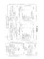
- FIG. 1pertains to one embodiment and schematically illustrates a system including a power consumption output device.
- FIG. 2schematically illustrates the structure of a refrigerator which is one example of a home appliance.
- FIG. 3schematically illustrates one example of a structure of the power consumption output device.
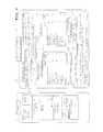
- FIG. 4illustrates one example of an output screen of the power consumption output device.
- FIG. 5illustrates one example of an output screen of the power consumption output device.
- FIG. 6illustrates one example of an output screen of the power consumption output device.
- FIG. 7illustrates one example of an output screen of the power consumption output device.
- a power consumption output deviceis provided with a power consumption information acquiring unit and an output unit.
- the power consumption information acquiring unitis configured to acquire power consumption information indicating power consumption of a home appliance.
- the output unitis configured to output the power consumption of the home appliance along with a reference value. The power consumption of the home appliance is obtained based on the power consumption information acquired by the power consumption information acquiring unit.
- a refrigerator 1being one example of a home appliance, is installed in a residence 2 .
- the refrigerator 1is configured to be capable of communicating with an information output device 4 and a mobile terminal 5 .
- the information output device 4is one example of the power consumption output device.
- a wireless communicationis exchanged between the refrigerator 1 and the access point 3 through a communication adaptor 18 provided at the upper portion of the refrigerator 1 .
- the refrigerator 1is further capable of communicating with the mobile terminal 5 and a server 7 , etc. connected to an external network 6 .
- the information output device 4is configured by a personal computer for example and establishes wire/wireless connection with the access point 3 .
- Examples of the mobile terminal 5 envisaged in the present embodimentinclude a highly functional mobile phone known as a smart phone and a tablet PC.
- the mobile terminal 5When the mobile terminal 5 is located inside a residence 2 , the mobile terminal 5 is communicably connected to the access point 3 by a close-range wireless communication.
- the mobile terminal 5When the mobile terminal 5 is located outside the residence 2 , the mobile terminal 5 is communicably connected to the access point 3 by a wide-range wireless communication byway of external network 6 .
- the mobile terminal 5is further capable of connecting to the access point 3 byway of the external network 6 through wide-range communication even when located inside of the residence 2 .
- the mobile terminal 5 located inside the residence 2is further capable of communicating directly with the refrigerator 1 without the intervention of the access point 3 .
- a wireless LAN communication, a Bluetooth (registered trademark in Japan) wireless communication, etc.are exchanged between the mobile terminal 5 and the refrigerator 1 , between the mobile terminal 5 and the access point 3 , and between the refrigerator 1 and the access point 3 .
- the server 7is configured by a computer system known in the art.
- the server 7stores various information for accessing the refrigerator 1 and is configured to be capable of delivering such information. Examples of information for accessing the refrigerator 1 include an IP address.
- the refrigerator 1is provided with multiple storage chambers such as a refrigeration chamber, a vegetable chamber, an ice maker chamber, and a freezer chamber.
- a controller 10responsible for controlling the overall operation of the refrigerator 1 based on a control program is provided inside the refrigerator 1 .
- the controller 10is connected to a control panel 11 , a peripheral temperature sensor 12 , a door opening sensor 13 , a refrigeration cooling mechanism 14 , a freeze cooler mechanism 15 , a defrost mechanism 16 , an ice maker device 17 , a communication adaptor 18 , a storage amount detection device 19 , etc.
- the controller 10is responsible for the overall control of the refrigerator 1 based on operation signals inputted from the control panel 11 in response to user operation.
- the controller 10is further configured to detect the temperature of the periphery of the refrigerator 1 through the peripheral temperature sensor 12 which is one example of a peripheral temperature detecting unit.
- the controller 10is further capable of detecting the opened/closed status of the door by the door opening sensor 13 based on which is turned ON/OFF when the doors of the storage chambers such as the refrigeration chamber, vegetable chamber, ice maker chamber, and the freezer chamber are opened/closed. It is further possible to detect the time period in which the door is opened or closed through a timer not illustrated by counting the time period in which the door opening sensor 13 is turned ON or OFF.
- the refrigeration cooler mechanism 14is provided with a refrigeration cycle known in the art including the refrigeration cooler, etc. not illustrated.
- the refrigeration cooler mechanism 14is configured to feed cool air into the storage chambers specified to the refrigeration temperature zone depending upon the drive signal inputted from the controller 10 .
- the freeze cooling mechanism 15is provided with a refrigeration cycle known in the art including the freeze cooler, etc. not illustrated.
- the freeze cooler mechanism 15is configured to feed cool air into the storage chambers specified to the freeze temperature zone depending upon the drive signal inputted from the controller 10 .
- a storage amount detector 19is one example of a storage amount detecting unit and is configured to detect the amount of food, etc. stored in the storage chamber.
- the storage amount detector 19is provided with an optical sensor known in the art which is disposed inside the storage chamber.
- the storage amount detector 19makes a judgement that amount of storage inside the chamber is small when illuminance inside the chamber detected by the optical sensor is high and a judgement that amount of storage inside the chamber is large when illuminance inside the chamber detected by the optical sensor is low.
- the storage amount detector 19is configured to judge the level of storage amount of food, etc. inside the fridge in the scale of ten levels ranging from 10% to 100% depending upon the illuminance inside the chamber detected by the optical sensor.
- the refrigerator 1is capable of specifying location information for identifying the location where it is installed.
- the controller 10is configured to store and retain the location information specified when installing the refrigerator 1 into a recording medium such as a memory not illustrated. It is possible to specify such location information by, for example, inputting the address of the location, the coordinate information such as longitude and latitude of the location, or the name of the district of the location.
- a defroster 16is provided to melt away the frost developed on the coolers of the refrigeration cooling mechanism 14 and the freeze cooling mechanism 15 .
- the defroster 16is provided with a heater that produces heat by a supply of electricity. Power consumption increases compared to normal operation when defrost operation of the defroster 16 is started as electricity is supplied to the heater.
- Ice maker 17is configured to supply water to the ice maker carton not illustrated.
- the ice maker 17is configured to detect the water temperature indirectly by detecting the temperature of the ice maker carton.
- the ice maker cartonoperates in the refrigeration cycle in the ice making mode until a judgement is made that water has frozen. When judging that water has frozen, the ice maker carton is turned to store the ice inside the ice box.
- the operation of the refrigeration cycleis switched to the ice making mode and components such as a water feed motor not illustrated are driven and thus, increases power consumption compared to normal operation.
- the communication adaptor 18is capable of communicating with the information output device 4 , the mobile terminal 5 , and the like located inside the residence 2 through the access point 3 .
- the communication adaptor 18is further capable of communicating with the mobile terminal 5 , the server 7 , and the like located outside the residence 2 through the access point 3 and the internet 6 .
- the controller 10is capable of transmitting information such as various information pertaining to the refrigerator 1 to external devices such as the information output device 4 and the server 7 through the communication adaptor 18 .
- Information being provided to the information output device 4 from the refrigerator 1include, for example, power consumption information indicating the power consumption of the refrigerator 1 ; model information identifying the model of the refrigerator 1 ; operational status information indicating the operational status of the refrigerator 1 ; setting information indicating the current settings applied to the refrigerator 1 ; and the location information described earlier.
- the operational status informationinclude, for example, defrost history information indicating the presence/absence of defrost operation of the cooler by the defroster 16 ; door opening-closing count information indicating the count of door opening-closing; peripheral temperature information indicating the peripheral temperature of the refrigerator 1 ; storage amount information indicating the storage amount inside the chamber detected by the storage amount detector 19 , and the like that provide various information pertaining to the operational status of the refrigerator 1 .
- a controller 30is provided inside the information output device 4 as illustrated in FIG. 3 .
- the controller 30is configured to control the overall operation of the information output device 4 based on a control program.
- the controller 30is connected to an operation input portion 31 , a display output portion 32 , and a communication adaptor 33 .
- the operation input portion 31is configured by, for example, a touch panel switch provided on the screen of the display output portion 32 and mechanical operation switches provided around the display output portion 32 .
- the display output portion 32is configured, for example, by a liquid crystal display panel.
- the communication adaptor 33is capable of communicating with the refrigerator 1 and mobile terminal 5 located inside the residence 2 through the access point 3 .
- the communication adaptor 33is further capable of communicating with the mobile terminal 5 and the server 7 located outside the residence 2 through the access point 3 and the internet 6 .
- the controller 30virtually implements power consumption information acquiring portion 41 , power consumption output portion 42 , reference value setting portion 43 , ambient temperature detecting portion 44 , reference value modifying portion 45 , operational status information acquiring portion 46 , and analyzing portion 47 through execution of a control program by the CPU.
- These processing portions 41 to 47maybe implemented by hardware such as an integrated circuit.
- the power consumption information acquiring portion 41is one example of a power consumption information acquiring unit and acquires power consumption information from the refrigerator 1 through the adaptor 33 when required.
- the power consumption informationindicates the amount of electric power currently being consumed by the refrigerator 1 .
- the controller 30stores the acquired power consumption information with acquisition time information identifying the time when the information was acquired.
- the acquisition time informationis produced by time information given by a timer not illustrated provided at the information output device 4 .
- the acquisition time informationcarries enough detail to, for example, identify the year, month, and date of acquisition. Power consumption information obtained from time to time from the refrigerator 1 is thus, stored in the information output device 4 .
- the controller 30is thus, capable of identifying the power consumption of the refrigerator 1 at a first prescribed time period from the present such as 1 week, 1 month, and 1 year based on the stored power consumption information.
- the first prescribed time periodmay be modified as required.
- the power consumption information acquiring portion 41is capable of acquiring and storing power consumption of refrigerators not illustrated besides refrigerator 1 .
- the power consumption output portion 42is one example of an output unit and is configured to display, to the display output portion 32 , power consumption of the refrigerator 1 along with a reference value providing a standard based on the power consumption information acquired by the power consumption information acquiring portion 41 .
- the power consumption output portion 42is further capable of displaying, to the display output portion 32 , cumulative power consumption along with a reference value.
- the cumulative power consumptionis an accumulation of power consumption indicated in the power consumption information obtained by the power consumption information acquiring portion 41 from time to time in a second prescribed time period from the present. That is, the power consumption output portion 42 is capable of displaying a cumulative amount of electric power consumed by the refrigerator 1 in a second prescribed time period from the present.
- the second prescribed time periodbeing variable, is basically shorter than the first prescribed time period. For example, settings may be made so that the power consumption output portion 42 is capable of displaying cumulative power consumption of the refrigerator 1 in the past day, that is, within 24 hours.
- the power consumption output portion 42is further capable of displaying, to the display output portion 32 , cumulative power consumption of the day before along with a reference value.
- the cumulative power consumptionis an accumulation of power consumption indicated in the power consumption information obtained by the power consumption information acquiring portion 41 from time to time. That is, the power consumption output portion 42 is capable of displaying a cumulative amount of electric power consumed by the refrigerator 1 in the day before. For example, settings may be made so that the power consumption output portion 42 is capable of displaying the cumulative power consumption of the refrigerator 1 within 1 day, i.e. 24 hours or less from the present.
- the power consumption output portion 42is capable of displaying the cumulative power consumption of the refrigerator 1 in the range of 0:00 to 24:00 in 1 calendar day before the present day.
- a reference value setting portion 43is one example of a reference value setting unit and is configured to set a reference amount of electric power consumed by the refrigerator 1 on the display output portion 32 along with the actual cumulative amount of electric power consumed.
- the reference valuemay be set in various ways.
- the reference value setting portion 43is capable of calculating an average power consumption of the multiple refrigerators based on the multiple pieces of power consumption information and set the average value as the reference value.
- the reference value setting portion 43is capable of identifying the model of each refrigerator based on the model information and providing an average value for the refrigerators of the same type.
- the reference value setting portion 43may be configured to calculate an average value of only a group of refrigerators of the same model as the refrigerator 1 .
- the reference value setting portion 43is capable of identifying the refrigerators located in the prescribed region based on the location information and providing an average value for the refrigerators located in the prescribed regions.
- the reference value setting portion 43may be configured to calculate an average value of only a group of refrigerators located in the same region as the refrigerator 1 .
- the reference value setting portion 43is further capable of setting, as the reference value, the power consumption indicated in the power consumption information acquired by the power consumption information acquiring portion 41 at first prescribed period ago from the present.
- the ambient temperature detecting portion 44is one example of an ambient temperature detecting unit and is configured to detect ambient temperature by a temperature sensor not illustrated provided to the information output device 4 .
- the ambient temperature detecting portion 44is configured to output ambient temperature information indicating the detected temperature to the controller 30 .
- the “ambient temperature”denotes the temperature outside the information output device 4 and may indicate the temperature inside or outside the residence 2 as long as the temperature pertains to the outside of the information output device 4 . It is possible to detect temperatures of various locations outside the information output device 4 by changing the location where the temperature sensor not illustrated is installed inside or outside the residence 2 .
- a reference value modifying portion 45is one example of a reference value modifying unit and is configured to modify the reference value set by the reference value setting portion 43 based on the ambient temperature detected by the ambient temperature detecting portion 44 .
- the reference value modifying portion 45increases the reference value by a prescribed amount when the ambient temperature is higher than a prescribed value.
- the reference value modifying portion 45reduces the reference value by a prescribed amount when the ambient temperature is lower than a prescribed value.
- the prescribed value and the prescribed amount used in the modificationare variable.
- An operational state information acquiring portion 46is one example of an operational state information acquiring unit and is configured to acquire operational status information indicating the operational status of the refrigerator 1 through the communication adaptor 33 .
- the power consumption output portion 42is capable of displaying the operational status indicated in the operational status information to the display output portion 32 along with power consumption and reference value when the operational status information has been obtained by the operational state information acquiring portion 46 .
- the operational status information acquiring portion 46is capable of acquiring operational status information indicating the operational status of the refrigerator from refrigerators other than the refrigerator 1 .
- An analyzing portion 47is one example of an analyzing unit 47 and is configured to analyze the cause of change encountered in the power consumption outputted by the power consumption output portion 42 .
- the analyzing portion 47is configured to analyze the cause of change in the power consumption outputted by the power consumption output portion 42 when abnormal change is observed in the power consumption such as a significant increase in a short period of time and significant increase compared to similar time of year in the year before. For example, when the present power consumption is greater than the power consumption in the similar time of year of the year before by a prescribed amount of 0.2 kWh or more, the analyzing portion 47 verifies the operational state of the refrigerator 1 based on the operational status information obtained from the refrigerator 1 .
- the analyzing portion 47is configured to produce message data reading, for example, “The fridge interior is not cooled well because of excessive storage. Try organizing the stored items in the fridge. Stay alert on the count of door opening-closing”.
- the information output device 4is capable of outputting power consumption of the refrigerator 1 , being one example of a home appliance, along with a reference value. Different modes for outputting power consumption will be described through examples given herein.
- FIG. 4illustrates one example of a power consumption output screen.
- the power consumption output screenis provided with a power consumption display section 100 and applied settings display section 200 .
- the power consumption display section 100displays current amount of power consumption of the refrigerator 1 and a reference value.
- the applied settings display section 200displays the settings currently being applied to the refrigerator 1 .
- the power consumption display section 100displays variety of information pertaining to the refrigerator 1 based on various information such as power consumption information and operational status information obtained from the refrigerator 1 .
- the power consumption display section 100 illustrated in FIG. 4is provided with: a model block 101 for displaying the name of the model of the refrigerator 1 ; a power consumption block 102 for displaying the power consumption of the refrigerator 1 ; an operational status block 103 for displaying the operational status of the refrigerator 1 ; and ambient temperature block 104 for displaying the ambient temperature of the refrigerator 1 .
- the power consumption block 102displays cumulative power consumption within 1 day from the present, that is, within 24 hours, meaning that cumulative power consumption of the refrigerator 1 of the past 1 day is displayed.
- the power consumption displayed in the power consumption block 102is displayed in the unit of “kWh”.
- the power consumption display section 100is further provided with an average power consumption block 105 , an average operational status block 106 , and an average ambient temperature block 107 .
- the average power consumption block 105displays the average power consumption of a group of multiple refrigerators located in region A where the refrigerator 1 is located which serves as a reference value.
- the average operational status block 106displays the average operational status of a group of multiple refrigerators located in region A where the refrigerator 1 is located.
- the average ambient temperature block 107displays the average ambient temperature of a group of multiple refrigerators located in region A where the refrigerator 1 is located.
- the average power consumption block 105displays average cumulative power consumption within 1 day or 24 hours from the present for a group of multiple refrigerators including refrigerator 1 in region A. That is, an average cumulative power consumption of the past 1 day in region A for a group of multiple refrigerators is displayed as a reference value.
- the power consumption displayed in the average power consumption block 105is displayed in the unit of “kWh”.
- the power consumption display section 100is further provided with power consumption difference block 108 and a defrost operation block 109 , etc.
- the power consumption difference block 108displays the difference between power consumption of the refrigerator 1 displayed in the power consumption block 102 and the average power consumption displayed in the average power consumption block 105 .
- the defrost operation block 109displays the presence/absence of defrost operation in the refrigerator 1 .
- the power consumption displayed in the power consumption difference block 108is displayed in the unit of “kWh”. Character information which may read “defrosted” is displayed in the defrost operation block 109 when there is a history of performing the defrost operation within a prescribed period from the present, for example, in the past 1 day. Character information which may read “undefrosted” is displayed in the defrost operation block 109 when there is no history of performing the defrost operation within a prescribed period from the present.
- the applied settings display section 200displays the settings currently applied to the refrigerator 1 based on the settings information obtained from the refrigerator 1 . As illustrated in FIG. 4 for example, the applied settings display section 200 is provided with a power save block 201 and refrigerator block 202 , etc.
- the power save block 201displays whether or not the refrigerator 1 is set to the power save mode. When the refrigerator 1 is set to the power save mode, character information that may read “ON” is displayed to the power save block 201 . When the refrigerator 1 is not set to the power save mode, on the other hand, character information that may read “OFF” is displayed to the power save block 201 .
- the refrigerator block 202displays items such as the cooling level set to each of the storage chambers of the refrigerator 1 and whether or not any of the settings made to each of the chambers are locked.
- symbols S 1 , S 2 , and S 3are displayed where: symbol S 1 indicates that the cooling level of the refrigeration chamber is set to medium; symbol S 2 indicates that the cooling level of the lower freezer chamber is set to low; and symbol S 3 indicates that settings pertaining to the refrigeration chamber are locked.
- the power consumption display section 100is provided with a past power consumption block 110 instead of the average power consumption block 105 described above.
- the past power consumption block 110displays power consumption of the refrigerator 1 at a prescribed period prior to the present as a reference value. For example, the power consumption of the refrigerator 1 at 1 year from the present is displayed in the unit of “kWh” to the past power consumption block 111 to provide information in the same time of year in the past year.
- the power consumption display section 100is provided with a past operational status block 111 instead of the average operational status block 106 .
- the past operational status block 111displays the operational status of the refrigerator 1 at a prescribed period prior to the present. In this example, the operational status of the refrigerator 1 at 1 year from the present is displayed to the past operational status block 111 to provide information in the same time of year in the past year.
- the power consumption display section 100is provided with a past ambient temperature block 112 instead of the average ambient temperature block 107 .
- the past ambient temperature block 112displays the ambient temperature of the refrigerator 1 at a prescribed period prior to the present. For example, the ambient temperature of the refrigerator 1 at 1 year from the present is displayed to the past ambient temperature block 112 to provide information in the same time of year in the past year.
- the power consumption display section 100is further provided with a storage amount display block 113 which displays the current amount of storage of the refrigerator 1 .
- the power consumption display section 100is further provided with a past storage amount display block 114 which displays the amount of storage of at a prescribed period prior to the present. For example, the amount of storage of the refrigerator 1 at 1 year from the present is displayed to the past storage amount display block 114 to provide information in the same time of year in the past year.
- the power consumption display section 100is further provided with an analysis block 115 .
- the analysis block 115displays insights on the cause of change in power consumption and tips on measures to be taken based on the message data produced depending upon the analysis provided by the analyzing portion.
- the power consumption display section 100is provided with the model block 101 , the power consumption block 102 , and the average power consumption block 105 .
- the current power consumption of the refrigerator 1is displayed with the reference value.
- the power consumption output screen of the information output device 4may be modified as required from the examples given above. For example, the layout of the power consumption output screen of the information output device 4 maybe switched by user operation made through the operation input portion 31 .
- the power consumption output device 4 of one embodimentis configured to acquire power consumption information indicating the current power consumption of the home appliance which, in this example, is refrigerator 1 when required.
- the power consumption output device 4further displays the power consumption of the refrigerator 1 along with a reference value obtained based on the acquired power consumption information. It is thus, possible for the user to readily judge the appropriateness of the current power consumption of the refrigerator 1 through comparison with the reference value. This effectively improves the energy saving mindset of the user.
- the power consumption output device 4is further configured to accumulate the power consumption indicated in the power consumption information acquired from the refrigerator 1 from time to time within the prescribed time period from the present and output the cumulative power consumption along with a reference value. It is thus, possible for the user to readily judge the appropriateness of the current power consumption of the refrigerator 1 through comparison with the cumulative power consumption of the refrigerator 1 within the prescribed time period prior to the present.
- the power consumption output device 4is further configured to accumulate the power consumption indicated in the power consumption information acquired from the refrigerator 1 in the day before and output the cumulative power consumption along with a reference value. It is thus, possible for the user to readily judge the appropriateness of the current power consumption of the refrigerator 1 through comparison with the cumulative power consumption of the refrigerator 1 in the day before.
- the power consumption output device 4is further configured to acquire power consumption information from multiple refrigerators.
- the power consumption output device 4sets the average power consumption of the group of multiple refrigerators, obtained from the acquired multiple pieces of power consumption information, as a reference value. It is thus, possible for the user to readily judge the appropriateness of the cumulative power consumption of the refrigerator 1 through comparison with the average power consumption level.
- the power consumption output device 4is further configured to acquire power consumption information from multiple refrigerators and calculate the average power consumption for each of multiple groups of refrigerators classified by model. It is thus, possible for the user to readily judge the appropriateness of the cumulative power consumption of the refrigerator 1 through comparison with the power consumption of the group of refrigerators of the same model as the refrigerator 1 since good basis of judgement is provided through comparison with refrigerators having the same performance level.
- the power consumption output device 4is further configured to calculate an average value for multiple home appliances located in the same region as the refrigerator 1 . It is thus, possible for the user to readily judge the appropriateness of the cumulative power consumption of the refrigerator 1 through comparison with the power consumption of refrigerators located in the same region where the environment is substantially the same, since good basis of judgement is provided through comparison with refrigerators being subjected to similar environment.
- the power consumption output device 4is further configured to set the power consumption indicated in the power consumption information acquired from the refrigerator 1 at a predetermined time period of, for example, 1 year from the present as the reference value. It is thus, possible for the user to readily judge the appropriateness of the cumulative power consumption of the refrigerator 1 through comparison with the power consumption of the refrigerator 1 in the same time of year in the year before, since good basis of judgement is provided through comparison with power consumption resulting from similar climate.
- the power consumption output device 4is further configured to be capable of modifying the reference value based on the ambient temperature. It is thus, possible to set a more appropriate reference value.
- the power consumption output device 4is further configured to output the operational status of the refrigerator 1 based on the operational status information acquired from the refrigerator 1 along with the power consumption and the reference value. It is thus, possible for the user to judge the appropriateness of the cumulative power consumption of the refrigerator 1 taking the operational status into consideration.
- the operational status of the refrigerator 1includes various operational status of the refrigerator such as the presence/absence of defrost operation of the cooler, count of door opening-closing, time of door opening-closing, temperature around the refrigerator 1 , and amount of food stored in the fridge.
- the power consumption output device 4is further configured to display the power consumption in the unit of “kWh”. It is possible to make the level of power consumption to be more noticeable to the user by displaying the power consumption in a unit which is familiar to the user.
- the power consumption output device 4is further configured to analyze the cause of change in power consumption to be displayed and display the analysis. It is thus, possible for the user to readily be aware of the cause of the change in power consumption and easily cope with such change.
- the power consumption output device 4may be provided with a sound output device such as a speaker and output power consumption and reference value by sound instead of or with visual display.
- the information output device 4may be configured to indicate power consumption and reference value by a rating of levels represented by number of marks such as stars and light bulbs.
- the information output device 4maybe further configured to indicate power consumption and reference value by converting them into electricity bills.
- the refrigerator 1may be provided with a deodorizer configured to deodorize the room by applying high voltage and electrostatic atomizer configured to produce water vapor into the vegetable chamber in addition to the defroster 16 and the ice maker 17 .
- the home applianceincludes various types such as a washing machine and a heat cooker besides a refrigerator given above as an example.
- a power consumption output device of one embodimentis provided with a power consumption information acquiring unit and an output unit.
- the power consumption information acquiring unitis configured to acquire power consumption information indicating power consumption of a home appliance.
- the output unitis configured to output power consumption of the home appliance acquired based on the power consumption information acquired by the power consumption information acquiring unit along with a reference value. It is thus, possible for the user to readily judge the appropriateness of the power consumption of the home appliance through comparison with the reference value and thereby effectively improve the user's energy saving mindset.
Landscapes
- Engineering & Computer Science (AREA)
- Power Engineering (AREA)
- Physics & Mathematics (AREA)
- General Engineering & Computer Science (AREA)
- General Physics & Mathematics (AREA)
- Automation & Control Theory (AREA)
- Chemical & Material Sciences (AREA)
- Combustion & Propulsion (AREA)
- Mechanical Engineering (AREA)
- Thermal Sciences (AREA)
- Electromagnetism (AREA)
- Radar, Positioning & Navigation (AREA)
- Cold Air Circulating Systems And Constructional Details In Refrigerators (AREA)
- Devices That Are Associated With Refrigeration Equipment (AREA)
- User Interface Of Digital Computer (AREA)
- Theoretical Computer Science (AREA)
Abstract
Description
Claims (16)
Applications Claiming Priority (3)
| Application Number | Priority Date | Filing Date | Title |
|---|---|---|---|
| JP2013174493AJP6430106B2 (en) | 2013-08-26 | 2013-08-26 | Power consumption output device |
| JP2013-174493 | 2013-08-26 | ||
| PCT/JP2014/068052WO2015029600A1 (en) | 2013-08-26 | 2014-07-07 | Power-consumption output device |
Related Parent Applications (1)
| Application Number | Title | Priority Date | Filing Date |
|---|---|---|---|
| PCT/JP2014/068052ContinuationWO2015029600A1 (en) | 2013-08-26 | 2014-07-07 | Power-consumption output device |
Publications (2)
| Publication Number | Publication Date |
|---|---|
| US20160169577A1 US20160169577A1 (en) | 2016-06-16 |
| US10126047B2true US10126047B2 (en) | 2018-11-13 |
Family
ID=52586177
Family Applications (1)
| Application Number | Title | Priority Date | Filing Date |
|---|---|---|---|
| US15/053,520Expired - Fee RelatedUS10126047B2 (en) | 2013-08-26 | 2016-02-25 | Power-consumption output device |
Country Status (7)
| Country | Link |
|---|---|
| US (1) | US10126047B2 (en) |
| EP (1) | EP3040658B1 (en) |
| JP (1) | JP6430106B2 (en) |
| KR (1) | KR20160035016A (en) |
| CN (1) | CN105492844B (en) |
| TW (1) | TWI639081B (en) |
| WO (1) | WO2015029600A1 (en) |
Cited By (1)
| Publication number | Priority date | Publication date | Assignee | Title |
|---|---|---|---|---|
| US11270244B2 (en) | 2018-06-26 | 2022-03-08 | Luxon Data Holdings Pte. Ltd. | Monitoring device and system |
Families Citing this family (8)
| Publication number | Priority date | Publication date | Assignee | Title |
|---|---|---|---|---|
| US10337962B2 (en)* | 2013-03-15 | 2019-07-02 | Fluke Corporation | Visible audiovisual annotation of infrared images using a separate wireless mobile device |
| JP6080655B2 (en)* | 2013-04-03 | 2017-02-15 | 三菱電機株式会社 | refrigerator |
| JP2020046093A (en)* | 2018-09-18 | 2020-03-26 | パナソニックIpマネジメント株式会社 | Refrigerator and system |
| JPWO2022102633A1 (en)* | 2020-11-16 | 2022-05-19 | ||
| KR20220111672A (en)* | 2021-02-02 | 2022-08-09 | 트루 매뉴팩쳐링 코., 인크. | Systems, methods, and appliances that enable regional control of refrigeration appliances |
| JP7387694B2 (en)* | 2021-11-16 | 2023-11-28 | 東芝ライフスタイル株式会社 | Program and refrigerator |
| CN114739090B (en)* | 2022-04-13 | 2024-06-18 | 海信冰箱有限公司 | Refrigerator and power consumption monitoring method thereof |
| KR20250056038A (en)* | 2023-10-18 | 2025-04-25 | 삼성전자주식회사 | Inspection apparatus and method for controlling the same |
Citations (32)
| Publication number | Priority date | Publication date | Assignee | Title |
|---|---|---|---|---|
| JPH10123185A (en) | 1996-10-22 | 1998-05-15 | Kajima Corp | Power consumption monitor |
| JPH11337252A (en) | 1998-05-21 | 1999-12-10 | Matsushita Electric Ind Co Ltd | Refrigerator usage comparison system |
| JP2002147932A (en) | 2000-11-06 | 2002-05-22 | Matsushita Refrig Co Ltd | Display apparatus and container chamber |
| US20060090482A1 (en) | 2004-11-02 | 2006-05-04 | Dawes Dennis K | Blood products freezer with event log |
| US20060123807A1 (en) | 2004-12-14 | 2006-06-15 | Sullivan C B | Apparatus and method for monitoring and displaying power usage |
| JP2006190145A (en) | 2005-01-07 | 2006-07-20 | Omron Corp | Store management system, store controller, store control method, management server, management method and program |
| CN1874105A (en) | 2005-06-01 | 2006-12-06 | 三洋电机株式会社 | Request control device and power consumption prediction method and program |
| JP2007014179A (en) | 2004-08-12 | 2007-01-18 | Sanyo Electric Co Ltd | Demand control unit, predicting method and program of consumed electric power |
| US7409258B2 (en)* | 2006-04-28 | 2008-08-05 | Taiwan Semiconductor Manufacturing Company, Ltd. | Method and system for measuring customer delivery service |
| JP2009020721A (en) | 2007-07-12 | 2009-01-29 | Daikin Ind Ltd | Air conditioner deterioration determination device, air conditioning system, deterioration determination method, and deterioration determination program |
| CN101368985A (en) | 2007-08-14 | 2009-02-18 | 通用电气公司 | Cognitive electric power meter |
| TWM360365U (en) | 2009-01-23 | 2009-07-01 | Josephtec Co Ltd | Electric power meter and its corresponding display device with varieties of input and output wire sleeve configuration |
| JP2010014323A (en) | 2008-07-03 | 2010-01-21 | Hitachi Ltd | Deterioration diagnosing device, deterioration diagnosing method, and deterioration diagnosing system for cold supply system |
| US20100070434A1 (en) | 2008-09-15 | 2010-03-18 | Cooper Anthony A | Appliance with real time energy cost displayed based on usage |
| TW201019562A (en) | 2008-11-06 | 2010-05-16 | Ind Tech Res Inst | Socket with power management ability |
| TW201033559A (en) | 2008-12-24 | 2010-09-16 | Panasonic Corp | Refrigerator and compressor |
| US20110098869A1 (en)* | 2009-10-26 | 2011-04-28 | Lg Electronics Inc. | Electric appliance and a control method thereof |
| TWM408027U (en) | 2011-01-18 | 2011-07-21 | Univ Far East | intelligent refrigerator |
| US20110175742A1 (en)* | 2010-01-20 | 2011-07-21 | Lg Electronics Inc. | Refrigerator and control method thereof |
| TW201135169A (en) | 2010-01-14 | 2011-10-16 | Panasonic Corp | Refrigerator |
| US20120004871A1 (en)* | 2010-07-02 | 2012-01-05 | National Chiao Tung University | Power monitoring device for identifying state of electric appliance and power monitoring method thereof |
| US20120017630A1 (en) | 2009-03-27 | 2012-01-26 | Mitsubishi Electric Corporation | Electrostatic atomizing apparatus, appliance, air conditioner, and refrigerator |
| WO2012093903A2 (en) | 2011-01-06 | 2012-07-12 | 엘지전자 주식회사 | Refrigerator and remote controller |
| JP2012133763A (en) | 2010-12-22 | 2012-07-12 | Chi Mei Electronics Corp | Touch panel |
| US20120176252A1 (en) | 2011-01-12 | 2012-07-12 | Emerson Electric Co. | Apparatus and Method for Determining Load of Energy Consuming Appliances Within a Premises |
| US20120316693A1 (en) | 2009-09-09 | 2012-12-13 | Panasonic Corporation | Power control system |
| USD672666S1 (en) | 2011-01-12 | 2012-12-18 | Emerson Electric Co. | Thermostat |
| US20130067375A1 (en) | 2010-02-23 | 2013-03-14 | Lg Electronics Inc. | Refrigerator including a terminal, and method for controlling same |
| TW201322579A (en) | 2011-11-25 | 2013-06-01 | Chunghwa Telecom Co Ltd | Cloud energy monitoring system and method |
| US20130162024A1 (en)* | 2010-07-01 | 2013-06-27 | Stefan Tumback | Method for operating a temperature-limiting device, temperature-limiting device and electrical apparatus |
| TW201333869A (en) | 2012-01-23 | 2013-08-16 | 日本特科諾能源管理咨詢有限公司 | Alarm output device and alarm output method |
| US20130274944A1 (en)* | 2010-12-24 | 2013-10-17 | Lg Electronics Inc. | Electricity management apparatus and electricity management method |
Family Cites Families (5)
| Publication number | Priority date | Publication date | Assignee | Title |
|---|---|---|---|---|
| US6668240B2 (en)* | 2001-05-03 | 2003-12-23 | Emerson Retail Services Inc. | Food quality and safety model for refrigerated food |
| JP2007060848A (en)* | 2005-08-26 | 2007-03-08 | Sanyo Electric Co Ltd | Apparatus and method for controlling electric energy and its program |
| JP2012133764A (en) | 2010-12-02 | 2012-07-12 | Sharp Corp | Controller, network system, and information processing method |
| JP5085751B2 (en)* | 2011-02-28 | 2012-11-28 | 株式会社東芝 | Electronic device and information output method |
| WO2013088584A1 (en)* | 2011-12-14 | 2013-06-20 | 京セラ株式会社 | Display terminal, power control system, and display method |
- 2013
- 2013-08-26JPJP2013174493Apatent/JP6430106B2/ennot_activeExpired - Fee Related
- 2014
- 2014-07-07KRKR1020167004650Apatent/KR20160035016A/ennot_activeCeased
- 2014-07-07EPEP14839818.3Apatent/EP3040658B1/enactiveActive
- 2014-07-07CNCN201480047757.4Apatent/CN105492844B/ennot_activeExpired - Fee Related
- 2014-07-07WOPCT/JP2014/068052patent/WO2015029600A1/ennot_activeCeased
- 2014-07-18TWTW103124652Apatent/TWI639081B/ennot_activeIP Right Cessation
- 2016
- 2016-02-25USUS15/053,520patent/US10126047B2/ennot_activeExpired - Fee Related
Patent Citations (56)
| Publication number | Priority date | Publication date | Assignee | Title |
|---|---|---|---|---|
| JPH10123185A (en) | 1996-10-22 | 1998-05-15 | Kajima Corp | Power consumption monitor |
| JPH11337252A (en) | 1998-05-21 | 1999-12-10 | Matsushita Electric Ind Co Ltd | Refrigerator usage comparison system |
| JP2002147932A (en) | 2000-11-06 | 2002-05-22 | Matsushita Refrig Co Ltd | Display apparatus and container chamber |
| JP4682414B2 (en) | 2000-11-06 | 2011-05-11 | パナソニック株式会社 | Storage |
| JP4346584B2 (en) | 2004-08-12 | 2009-10-21 | 三洋電機株式会社 | Demand control apparatus and program |
| JP2007014179A (en) | 2004-08-12 | 2007-01-18 | Sanyo Electric Co Ltd | Demand control unit, predicting method and program of consumed electric power |
| US20060090482A1 (en) | 2004-11-02 | 2006-05-04 | Dawes Dennis K | Blood products freezer with event log |
| US20060123807A1 (en) | 2004-12-14 | 2006-06-15 | Sullivan C B | Apparatus and method for monitoring and displaying power usage |
| JP2006190145A (en) | 2005-01-07 | 2006-07-20 | Omron Corp | Store management system, store controller, store control method, management server, management method and program |
| US20080195237A1 (en) | 2005-01-07 | 2008-08-14 | Omron Corporation | Store Management System, Stone Control Device, Store Control Method, Management Server, Management Method and Program |
| CN1874105A (en) | 2005-06-01 | 2006-12-06 | 三洋电机株式会社 | Request control device and power consumption prediction method and program |
| US7409258B2 (en)* | 2006-04-28 | 2008-08-05 | Taiwan Semiconductor Manufacturing Company, Ltd. | Method and system for measuring customer delivery service |
| JP2009020721A (en) | 2007-07-12 | 2009-01-29 | Daikin Ind Ltd | Air conditioner deterioration determination device, air conditioning system, deterioration determination method, and deterioration determination program |
| CN101368985B (en) | 2007-08-14 | 2012-10-10 | 通用电气公司 | Cognitive electric power meter |
| CN101368985A (en) | 2007-08-14 | 2009-02-18 | 通用电气公司 | Cognitive electric power meter |
| JP2010014323A (en) | 2008-07-03 | 2010-01-21 | Hitachi Ltd | Deterioration diagnosing device, deterioration diagnosing method, and deterioration diagnosing system for cold supply system |
| US20100179708A1 (en) | 2008-09-15 | 2010-07-15 | General Electric Company | Energy management of household appliances |
| US20100146712A1 (en) | 2008-09-15 | 2010-06-17 | General Electric Company | Energy management of clothes washer appliance |
| US20100092625A1 (en) | 2008-09-15 | 2010-04-15 | General Electric Company | Energy management of household appliances |
| US20100094470A1 (en) | 2008-09-15 | 2010-04-15 | General Electric Company | Demand side management of household appliances beyond electrical |
| US20100090806A1 (en) | 2008-09-15 | 2010-04-15 | General Electric Company | Management control of household appliances using rfid communication |
| US20100089909A1 (en) | 2008-09-15 | 2010-04-15 | General Electric Company | Energy management of household appliances |
| US20100101254A1 (en) | 2008-09-15 | 2010-04-29 | General Electric Company | Energy management of household appliances |
| US20100121499A1 (en) | 2008-09-15 | 2010-05-13 | General Electric Company | Management control of household appliances using continuous tone-coded dsm signalling |
| US20100070434A1 (en) | 2008-09-15 | 2010-03-18 | Cooper Anthony A | Appliance with real time energy cost displayed based on usage |
| US20100070091A1 (en) | 2008-09-15 | 2010-03-18 | General Electric Company | Energy management of household appliances |
| US20100174668A1 (en) | 2008-09-15 | 2010-07-08 | General Electric Company | Energy management of clothes dryer appliance |
| US20100175719A1 (en) | 2008-09-15 | 2010-07-15 | General Electric Company | Energy management of dishwasher appliance |
| US20100070099A1 (en) | 2008-09-15 | 2010-03-18 | General Electric Company | Demand side management module |
| US20100187219A1 (en) | 2008-09-15 | 2010-07-29 | General Electric Company | Energy management of household appliances |
| US20130103222A1 (en) | 2008-09-15 | 2013-04-25 | General Electric Company | Demand side management module |
| TW201019562A (en) | 2008-11-06 | 2010-05-16 | Ind Tech Res Inst | Socket with power management ability |
| TW201033559A (en) | 2008-12-24 | 2010-09-16 | Panasonic Corp | Refrigerator and compressor |
| TWM360365U (en) | 2009-01-23 | 2009-07-01 | Josephtec Co Ltd | Electric power meter and its corresponding display device with varieties of input and output wire sleeve configuration |
| US20120017630A1 (en) | 2009-03-27 | 2012-01-26 | Mitsubishi Electric Corporation | Electrostatic atomizing apparatus, appliance, air conditioner, and refrigerator |
| US20120017628A1 (en) | 2009-03-27 | 2012-01-26 | Mitsubishi Electric Corporation | Electrostatic atomizing apparatus, appliance, air conditioner, and refrigerator |
| JP2012052793A (en) | 2009-03-27 | 2012-03-15 | Mitsubishi Electric Corp | Air conditioner |
| US20120316693A1 (en) | 2009-09-09 | 2012-12-13 | Panasonic Corporation | Power control system |
| US20110098869A1 (en)* | 2009-10-26 | 2011-04-28 | Lg Electronics Inc. | Electric appliance and a control method thereof |
| TW201135169A (en) | 2010-01-14 | 2011-10-16 | Panasonic Corp | Refrigerator |
| US20110175742A1 (en)* | 2010-01-20 | 2011-07-21 | Lg Electronics Inc. | Refrigerator and control method thereof |
| US20130067375A1 (en) | 2010-02-23 | 2013-03-14 | Lg Electronics Inc. | Refrigerator including a terminal, and method for controlling same |
| US20160239179A1 (en) | 2010-02-23 | 2016-08-18 | Lg Electronics Inc. | Refrigerator including a terminal, and method for controlling same |
| US20130162024A1 (en)* | 2010-07-01 | 2013-06-27 | Stefan Tumback | Method for operating a temperature-limiting device, temperature-limiting device and electrical apparatus |
| US20120004871A1 (en)* | 2010-07-02 | 2012-01-05 | National Chiao Tung University | Power monitoring device for identifying state of electric appliance and power monitoring method thereof |
| TW201203770A (en) | 2010-07-02 | 2012-01-16 | Univ Nat Chiao Tung | Power monitoring device for identifying state of electric equipment and power monitoring method thereof |
| JP2012133763A (en) | 2010-12-22 | 2012-07-12 | Chi Mei Electronics Corp | Touch panel |
| US20130274944A1 (en)* | 2010-12-24 | 2013-10-17 | Lg Electronics Inc. | Electricity management apparatus and electricity management method |
| US20130307698A1 (en) | 2011-01-06 | 2013-11-21 | Hyoungjun Park | Refrigerator and remote controller |
| WO2012093903A2 (en) | 2011-01-06 | 2012-07-12 | 엘지전자 주식회사 | Refrigerator and remote controller |
| USD672666S1 (en) | 2011-01-12 | 2012-12-18 | Emerson Electric Co. | Thermostat |
| US20120176252A1 (en) | 2011-01-12 | 2012-07-12 | Emerson Electric Co. | Apparatus and Method for Determining Load of Energy Consuming Appliances Within a Premises |
| USD699130S1 (en) | 2011-01-12 | 2014-02-11 | Emerson Electric Co. | Thermostat |
| TWM408027U (en) | 2011-01-18 | 2011-07-21 | Univ Far East | intelligent refrigerator |
| TW201322579A (en) | 2011-11-25 | 2013-06-01 | Chunghwa Telecom Co Ltd | Cloud energy monitoring system and method |
| TW201333869A (en) | 2012-01-23 | 2013-08-16 | 日本特科諾能源管理咨詢有限公司 | Alarm output device and alarm output method |
Non-Patent Citations (33)
| Title |
|---|
| Chinese Office Action (with English Translation) issued in CN Application No. 201480047757.4 dated Dec. 2, 2016. |
| Chinese Office Action issued in CN Application No. 201480047757.4 dated Aug. 3, 2017. |
| English language Abstract and machine translation of CN 101368985 A published Feb. 18, 2009. |
| English language Abstract and machine translation of CN 101368985 B published Oct. 10, 2012. |
| English language abstract and machine translation of CN 1874105 published Dec. 6, 2006. |
| English language abstract and machine translation of JP 2002-147932 published May 22, 2002. |
| English language Abstract and machine Translation of JP 2006-190145 published on Jul. 20, 2006. |
| English language Abstract and machine Translation of JP 2007-014179 published on Jan. 18, 2007. |
| English language Abstract and machine Translation of JP 2009-020721 published on Jan. 29, 2009. |
| English language Abstract and machine Translation of JP 2010-014323 published on Jan. 21, 2010. |
| English language Abstract and machine Translation of JP 2012-052793 published on Mar. 15, 2012. |
| English language Abstract and machine translation of JP 2012-133763 published on Jul. 12, 2012. |
| English language abstract and machine translation of JP 4346584 published Oct. 21, 2009. |
| English language abstract and machine translation of JP 4682414 published May 11, 2011. |
| English language Abstract and machine Translation of JP H10-123185 published on May 15, 1998. |
| English language Abstract and machine Translation of JP H11-337252 published Dec. 10, 1999. |
| English language Abstract and machine translation of TW 201019562 published on May 16, 2010. |
| English language Abstract and machine translation of TW 201033559 published on Sep. 16, 2010. |
| English language Abstract and machine translation of TW 201135169 published on Oct. 16, 2011. |
| English language Abstract and machine Translation of TW 201203770 published on Jan. 16, 2012. |
| English language Abstract and machine Translation of TW 201333869 published on Aug. 16, 2013. |
| English language Abstract and machine translation of TW M408027 published on Jul. 21, 2011. |
| English language abstract and machine translation of WO 2012/093903 published Jul. 12, 2012. |
| English language Abstract of TW 201322579 published Jun. 1, 2013. |
| English machine translation of M360365 published on Jul. 1, 2009. |
| Extended European Search Report issued in EP 14839818.3 dated Apr. 28, 2017. |
| International Search Report issued in PCT/JP2014/068052 dated Sep. 9, 2014. |
| Japanese Office Action (with English Language Translation) issued in JP 2013-174493 dated May 30, 2017. |
| Japanese Office Action issued in JP 2013-174493 dated Oct. 4, 2016 with English language translation. |
| Korean Office Action (with English Translation) issued in KR 10-2016-7004650 dated Apr. 13, 2017. |
| Taiwanese Office Action issued in TW 103124652 dated Apr. 27, 2017. |
| Taiwanese Office Action issued in TW 103124652 dated Mar. 25, 2016 with English language translation. |
| Taiwanese Office Action issued in TW 103124652 dated Sep. 12, 2016 with English language translation. |
Cited By (1)
| Publication number | Priority date | Publication date | Assignee | Title |
|---|---|---|---|---|
| US11270244B2 (en) | 2018-06-26 | 2022-03-08 | Luxon Data Holdings Pte. Ltd. | Monitoring device and system |
Also Published As
| Publication number | Publication date |
|---|---|
| CN105492844B (en) | 2019-05-03 |
| CN105492844A (en) | 2016-04-13 |
| EP3040658B1 (en) | 2020-08-19 |
| US20160169577A1 (en) | 2016-06-16 |
| KR20160035016A (en) | 2016-03-30 |
| TW201516641A (en) | 2015-05-01 |
| TWI639081B (en) | 2018-10-21 |
| WO2015029600A1 (en) | 2015-03-05 |
| EP3040658A4 (en) | 2017-05-31 |
| JP2015042927A (en) | 2015-03-05 |
| JP6430106B2 (en) | 2018-11-28 |
| EP3040658A1 (en) | 2016-07-06 |
Similar Documents
| Publication | Publication Date | Title |
|---|---|---|
| US10126047B2 (en) | Power-consumption output device | |
| KR101779728B1 (en) | Home electrical appliance and network system | |
| US20190137169A1 (en) | Information terminal device, operating information provision system, and operating information provision program | |
| JP6080655B2 (en) | refrigerator | |
| JP6905869B2 (en) | Home appliance systems, home appliance diagnostic methods, and terminal devices | |
| US20130098083A1 (en) | Refrigerator | |
| US20160201980A1 (en) | Refrigerator and control method therefor | |
| US20160299038A1 (en) | System and method for remotely inferring characteristics of thermostat-controlled appliances | |
| JP2010078198A (en) | Cooling system | |
| CN113280551A (en) | Commercial refrigerator | |
| KR20140099594A (en) | Method for controlling refrigerator | |
| US20140056723A1 (en) | Refrigerator with energy consumption optimization using adaptive fan delay | |
| JP7653251B2 (en) | Home Appliance Systems | |
| CN103438660B (en) | A kind of refrigerator and control method thereof with sabbath day function | |
| EP4127580B1 (en) | Refrigerator with dynamic multi-zone anti-sweat heating system | |
| JP2023073773A (en) | program and refrigerator | |
| KR102013452B1 (en) | Method for controlling refrigerator | |
| JP5589882B2 (en) | Refrigerator, defrost control device and defrost control method | |
| JP2010014379A (en) | Refrigerator | |
| JP2012097970A (en) | Refrigerator, defrosting control device, and defrosting control method | |
| JP2012167870A (en) | Power loss amount notification device |
Legal Events
| Date | Code | Title | Description |
|---|---|---|---|
| AS | Assignment | Owner name:TOSHIBA LIFESTYLE PRODUCTS & SERVICES CORPORATION, Free format text:ASSIGNMENT OF ASSIGNORS INTEREST;ASSIGNORS:WATANABE, KOTA;FURUTA, KAZUHIRO;TAKAHASHI, YUKI;AND OTHERS;REEL/FRAME:039065/0261 Effective date:20160324 Owner name:KABUSHIKI KAISHA TOSHIBA, JAPAN Free format text:ASSIGNMENT OF ASSIGNORS INTEREST;ASSIGNORS:WATANABE, KOTA;FURUTA, KAZUHIRO;TAKAHASHI, YUKI;AND OTHERS;REEL/FRAME:039065/0261 Effective date:20160324 | |
| AS | Assignment | Owner name:TOSHIBA LIFESTYLE PRODUCTS & SERVICES CORPORATION, JAPAN Free format text:ASSIGNMENT OF ASSIGNORS INTEREST;ASSIGNOR:KABUSHIKI KAISHA TOSHIBA;REEL/FRAME:039893/0787 Effective date:20160607 Owner name:TOSHIBA LIFESTYLE PRODUCTS & SERVICES CORPORATION, Free format text:ASSIGNMENT OF ASSIGNORS INTEREST;ASSIGNOR:KABUSHIKI KAISHA TOSHIBA;REEL/FRAME:039893/0787 Effective date:20160607 | |
| STCF | Information on status: patent grant | Free format text:PATENTED CASE | |
| FEPP | Fee payment procedure | Free format text:MAINTENANCE FEE REMINDER MAILED (ORIGINAL EVENT CODE: REM.); ENTITY STATUS OF PATENT OWNER: LARGE ENTITY | |
| LAPS | Lapse for failure to pay maintenance fees | Free format text:PATENT EXPIRED FOR FAILURE TO PAY MAINTENANCE FEES (ORIGINAL EVENT CODE: EXP.); ENTITY STATUS OF PATENT OWNER: LARGE ENTITY | |
| STCH | Information on status: patent discontinuation | Free format text:PATENT EXPIRED DUE TO NONPAYMENT OF MAINTENANCE FEES UNDER 37 CFR 1.362 | |
| FP | Lapsed due to failure to pay maintenance fee | Effective date:20221113 |