US10119917B2 - Apparatus and method for bidirectional Raman spectroscopy - Google Patents
Apparatus and method for bidirectional Raman spectroscopyDownload PDFInfo
- Publication number
- US10119917B2 US10119917B2US15/653,636US201715653636AUS10119917B2US 10119917 B2US10119917 B2US 10119917B2US 201715653636 AUS201715653636 AUS 201715653636AUS 10119917 B2US10119917 B2US 10119917B2
- Authority
- US
- United States
- Prior art keywords
- subject
- raman
- aperture
- reflective cavity
- light
- Prior art date
- Legal status (The legal status is an assumption and is not a legal conclusion. Google has not performed a legal analysis and makes no representation as to the accuracy of the status listed.)
- Active
Links
- 238000001069Raman spectroscopyMethods0.000titleclaimsabstractdescription91
- 238000000034methodMethods0.000titleclaimsabstractdescription25
- 230000002457bidirectional effectEffects0.000titleabstractdescription10
- 230000003287optical effectEffects0.000claimsabstractdescription47
- 230000005284excitationEffects0.000claimsabstractdescription35
- 238000001237Raman spectrumMethods0.000claimsdescription31
- 238000004929transmission Raman spectroscopyMethods0.000abstractdescription18
- 238000001228spectrumMethods0.000abstractdescription17
- 239000000203mixtureSubstances0.000abstractdescription7
- 239000000523sampleSubstances0.000description92
- 239000010410layerSubstances0.000description25
- 230000008901benefitEffects0.000description6
- 239000011248coating agentSubstances0.000description6
- 239000011247coating layerSubstances0.000description6
- 238000000576coating methodMethods0.000description6
- 239000000463materialSubstances0.000description6
- 239000002344surface layerSubstances0.000description6
- BSYNRYMUTXBXSQ-UHFFFAOYSA-NAspirinChemical compoundCC(=O)OC1=CC=CC=C1C(O)=OBSYNRYMUTXBXSQ-UHFFFAOYSA-N0.000description5
- 229960001138acetylsalicylic acidDrugs0.000description5
- 238000005259measurementMethods0.000description5
- RZVAJINKPMORJF-UHFFFAOYSA-NAcetaminophenChemical compoundCC(=O)NC1=CC=C(O)C=C1RZVAJINKPMORJF-UHFFFAOYSA-N0.000description4
- 238000010521absorption reactionMethods0.000description4
- 229940072651tylenolDrugs0.000description4
- 239000002131composite materialSubstances0.000description3
- 239000013307optical fiberSubstances0.000description3
- 238000010183spectrum analysisMethods0.000description3
- 238000012986modificationMethods0.000description2
- 230000004048modificationEffects0.000description2
- 238000002310reflectometryMethods0.000description2
- 238000004611spectroscopical analysisMethods0.000description2
- RYGMFSIKBFXOCR-UHFFFAOYSA-NCopperChemical compound[Cu]RYGMFSIKBFXOCR-UHFFFAOYSA-N0.000description1
- BQCADISMDOOEFD-UHFFFAOYSA-NSilverChemical compound[Ag]BQCADISMDOOEFD-UHFFFAOYSA-N0.000description1
- 229910052782aluminiumInorganic materials0.000description1
- XAGFODPZIPBFFR-UHFFFAOYSA-NaluminiumChemical compound[Al]XAGFODPZIPBFFR-UHFFFAOYSA-N0.000description1
- 230000002238attenuated effectEffects0.000description1
- 230000005540biological transmissionEffects0.000description1
- 238000012512characterization methodMethods0.000description1
- 229910052802copperInorganic materials0.000description1
- 239000010949copperSubstances0.000description1
- 230000007423decreaseEffects0.000description1
- 230000001419dependent effectEffects0.000description1
- 239000003814drugSubstances0.000description1
- 230000009977dual effectEffects0.000description1
- 238000005516engineering processMethods0.000description1
- PCHJSUWPFVWCPO-UHFFFAOYSA-NgoldChemical compound[Au]PCHJSUWPFVWCPO-UHFFFAOYSA-N0.000description1
- 229910052737goldInorganic materials0.000description1
- 239000010931goldSubstances0.000description1
- 238000005286illuminationMethods0.000description1
- 239000004615ingredientSubstances0.000description1
- 229910052751metalInorganic materials0.000description1
- 239000002184metalSubstances0.000description1
- 239000007769metal materialSubstances0.000description1
- 230000000149penetrating effectEffects0.000description1
- 239000000825pharmaceutical preparationSubstances0.000description1
- 229940127557pharmaceutical productDrugs0.000description1
- 239000000843powderSubstances0.000description1
- 229910052709silverInorganic materials0.000description1
- 239000004332silverSubstances0.000description1
- 238000000411transmission spectrumMethods0.000description1
Images


Classifications
- G—PHYSICS
- G01—MEASURING; TESTING
- G01N—INVESTIGATING OR ANALYSING MATERIALS BY DETERMINING THEIR CHEMICAL OR PHYSICAL PROPERTIES
- G01N21/00—Investigating or analysing materials by the use of optical means, i.e. using sub-millimetre waves, infrared, visible or ultraviolet light
- G01N21/62—Systems in which the material investigated is excited whereby it emits light or causes a change in wavelength of the incident light
- G01N21/63—Systems in which the material investigated is excited whereby it emits light or causes a change in wavelength of the incident light optically excited
- G01N21/65—Raman scattering
- G01N21/658—Raman scattering enhancement Raman, e.g. surface plasmons
- G—PHYSICS
- G01—MEASURING; TESTING
- G01J—MEASUREMENT OF INTENSITY, VELOCITY, SPECTRAL CONTENT, POLARISATION, PHASE OR PULSE CHARACTERISTICS OF INFRARED, VISIBLE OR ULTRAVIOLET LIGHT; COLORIMETRY; RADIATION PYROMETRY
- G01J3/00—Spectrometry; Spectrophotometry; Monochromators; Measuring colours
- G01J3/02—Details
- G01J3/0205—Optical elements not provided otherwise, e.g. optical manifolds, diffusers, windows
- G01J3/0208—Optical elements not provided otherwise, e.g. optical manifolds, diffusers, windows using focussing or collimating elements, e.g. lenses or mirrors; performing aberration correction
- G—PHYSICS
- G01—MEASURING; TESTING
- G01J—MEASUREMENT OF INTENSITY, VELOCITY, SPECTRAL CONTENT, POLARISATION, PHASE OR PULSE CHARACTERISTICS OF INFRARED, VISIBLE OR ULTRAVIOLET LIGHT; COLORIMETRY; RADIATION PYROMETRY
- G01J3/00—Spectrometry; Spectrophotometry; Monochromators; Measuring colours
- G01J3/02—Details
- G01J3/0205—Optical elements not provided otherwise, e.g. optical manifolds, diffusers, windows
- G01J3/021—Optical elements not provided otherwise, e.g. optical manifolds, diffusers, windows using plane or convex mirrors, parallel phase plates, or particular reflectors
- G—PHYSICS
- G01—MEASURING; TESTING
- G01J—MEASUREMENT OF INTENSITY, VELOCITY, SPECTRAL CONTENT, POLARISATION, PHASE OR PULSE CHARACTERISTICS OF INFRARED, VISIBLE OR ULTRAVIOLET LIGHT; COLORIMETRY; RADIATION PYROMETRY
- G01J3/00—Spectrometry; Spectrophotometry; Monochromators; Measuring colours
- G01J3/02—Details
- G01J3/0205—Optical elements not provided otherwise, e.g. optical manifolds, diffusers, windows
- G01J3/0229—Optical elements not provided otherwise, e.g. optical manifolds, diffusers, windows using masks, aperture plates, spatial light modulators or spatial filters, e.g. reflective filters
- G—PHYSICS
- G01—MEASURING; TESTING
- G01J—MEASUREMENT OF INTENSITY, VELOCITY, SPECTRAL CONTENT, POLARISATION, PHASE OR PULSE CHARACTERISTICS OF INFRARED, VISIBLE OR ULTRAVIOLET LIGHT; COLORIMETRY; RADIATION PYROMETRY
- G01J3/00—Spectrometry; Spectrophotometry; Monochromators; Measuring colours
- G01J3/02—Details
- G01J3/10—Arrangements of light sources specially adapted for spectrometry or colorimetry
- G—PHYSICS
- G01—MEASURING; TESTING
- G01J—MEASUREMENT OF INTENSITY, VELOCITY, SPECTRAL CONTENT, POLARISATION, PHASE OR PULSE CHARACTERISTICS OF INFRARED, VISIBLE OR ULTRAVIOLET LIGHT; COLORIMETRY; RADIATION PYROMETRY
- G01J3/00—Spectrometry; Spectrophotometry; Monochromators; Measuring colours
- G01J3/28—Investigating the spectrum
- G01J3/44—Raman spectrometry; Scattering spectrometry ; Fluorescence spectrometry
- G01J3/4412—Scattering spectrometry
- G—PHYSICS
- G01—MEASURING; TESTING
- G01N—INVESTIGATING OR ANALYSING MATERIALS BY DETERMINING THEIR CHEMICAL OR PHYSICAL PROPERTIES
- G01N33/00—Investigating or analysing materials by specific methods not covered by groups G01N1/00 - G01N31/00
- G01N33/15—Medicinal preparations ; Physical properties thereof, e.g. dissolubility
- G—PHYSICS
- G01—MEASURING; TESTING
- G01J—MEASUREMENT OF INTENSITY, VELOCITY, SPECTRAL CONTENT, POLARISATION, PHASE OR PULSE CHARACTERISTICS OF INFRARED, VISIBLE OR ULTRAVIOLET LIGHT; COLORIMETRY; RADIATION PYROMETRY
- G01J3/00—Spectrometry; Spectrophotometry; Monochromators; Measuring colours
- G01J3/02—Details
- G01J3/10—Arrangements of light sources specially adapted for spectrometry or colorimetry
- G01J2003/102—Plural sources
- G—PHYSICS
- G01—MEASURING; TESTING
- G01N—INVESTIGATING OR ANALYSING MATERIALS BY DETERMINING THEIR CHEMICAL OR PHYSICAL PROPERTIES
- G01N21/00—Investigating or analysing materials by the use of optical means, i.e. using sub-millimetre waves, infrared, visible or ultraviolet light
- G01N21/62—Systems in which the material investigated is excited whereby it emits light or causes a change in wavelength of the incident light
- G01N21/63—Systems in which the material investigated is excited whereby it emits light or causes a change in wavelength of the incident light optically excited
- G01N21/65—Raman scattering
Definitions
- This inventiongenerally relates to apparatus and method for Raman spectroscopy, and more specifically to apparatus and method for bidirectional Raman spectroscopy.
- Raman spectroscopyis an optical spectroscopy technique, which measures the inelastic scattering, i.e. Raman scattering of monochromatic light by a material to produce a spectrum characteristic of the material.
- Raman spectroscopyhas been demonstrated to be a powerful non-invasive analytical technology for material characterization and identification.
- Conventional Raman spectroscopygenerally utilizes a focused laser beam to produce Raman scattering signal from the sample, where the back scattered Raman light is collected and measured with a spectrometer device.
- forward scattered Raman signalcan be measured provided it is not completely blocked by the sample, it is not the favored approach in most situations.
- the excitation lightis much stronger in the forward scattered beam than in the back scattered beam, which makes it harder to be filtered out.
- the Raman signalis attenuated much more strongly in the forward scattered beam than in the back scattered beam, which makes the measurement more time consuming.
- Transmission Ramanmeasures the forward scattered Raman signal. As the light travels from the front surface to the back of the sample, the scattering path length increases for the excitation light but decreases for the Raman scattered light, such that the difference in contribution from different depths toward the total detected signal is much reduced. For this reason, transmission Raman is the preferred method in content uniformity measurements of pharmaceutical products despite its lower signal throughput. However, due to the complex nature of samples and the unpredictable scattering behavior of the excitation and Raman scattered light, even transmission Raman does not necessarily measure different depths with equal weights. Often, the sample orientation is changed and one or more additional measurements are made, and their average provides a better representation of the sample as a whole. This adds complexity to the measurement.
- the Raman scattering signal which transmits through the sampleare collected by two optical devices each positioned on the opposite side of the sample to obtain two transmission Raman spectra of the sample, which enables the accurate determination of the composition of the whole sample.
- FIG. 1illustrates a first exemplary embodiment of the bidirectional Raman spectroscopy apparatus
- FIG. 2illustrates a second exemplary embodiment of the bidirectional Raman spectroscopy apparatus
- FIGS. 3A and 3Bshow a comparison of the transmission Raman spectra of a composite pharmaceutical tablet sample measured from two opposite directions.
- FIG. 1illustrates a first exemplary embodiment of the bidirectional Raman spectroscopy apparatus, which is utilized to measure the transmission Raman spectrum of a diffusely scattering sample 130 , such as a multilayered pharmaceutical tablet.
- the Raman spectroscopy apparatuscomprises two light sources 102 and 104 , each positioned on the opposite side of the sample 130 .
- the light sourcesare preferably laser light sources, and more preferably laser diode light sources with their output spectrum narrowed and stabilized by volume Bragg gratings (VBGs).
- VBGsvolume Bragg gratings
- the laser beams 150 and 154 produced by the two light sources 102 and 104are first collimated by optical lenses 106 and 108 and then transmit through dichroic beam splitters 110 and 112 , respectively to illuminate the sample 130 from two opposite directions.
- the laser beam 150excites Raman scattered light 152 from the sample 130 which transmits through the sample 130 .
- the Raman scattered light 152is then reflected by the dichroic beam splitters 112 and optical mirror 116 and focused by optical lens 120 into an optical spectrometer 124 for spectral analysis.
- the laser beam 154excites Raman scattered light 156 from the sample 130 , which transmits through the sample 130 and is then reflected by the dichroic beam splitters 110 and optical mirror 114 and focused by optical lens 118 into an optical spectrometer 122 for spectral analysis.
- the collimated laser beamhas a relatively large beam diameter such that it excites Raman scattered light from a large area of the sample to make the measured Raman spectrum more representative.
- the intensity of the laser beam on the sampleis reduced in comparison to a focused laser beam to avoid sample damage.
- the sample 130is a multilayered diffusely scattering sample, e.g. a pharmaceutical tablet having two coating layers 136 and 138 and a middle layer 140 sandwiched between two inner layers 132 and 134 .
- the middle layer 140there exists an optical path length difference in the excitation and transmission of the Raman signal from the middle layer 140 when the sample 130 is illuminated from the two opposite directions.
- the laser beam 150first transmits through the coating layer 136 and the inner layer 132 and then excites Raman scattered light from the middle layer 140 .
- the Raman scattered light from the middle layer 140then transmits through the inner layer 134 and the coating layer 138 to be measured with the optical spectrometer 124 .
- the laser beam 154first transmits through the coating layer 138 and the inner layer 134 and then excites Raman scattered light from the middle layer 140 .
- the Raman scattered light from the middle layer 140then transmits through the inner layer 132 and the coating layer 136 to be measured with the optical spectrometer 122 . Due to the wavelength difference between the laser light and the Raman scattered light, the coating layers 136 and 138 and the inner layers 132 and 134 may have different absorption and scattering coefficients for the laser light and the Raman scattered light.
- the above mentioned optical path length differencewill result in a difference in the measured Raman signal intensity for the middle layer 140 when the sample 130 is illuminated from the two opposite directions.
- This signal intensity differenceis dependent on the location of the middle layer 140 in the sample 130 . The more the middle layer 140 deviates from the center of the sample, the larger the intensity difference will be. In extreme cases, the signal intensity difference may become very large such that the Raman feature from the middle layer 140 is hard to be observed when the sample is measured from one specific direction.
- the dual illumination scheme as disclosed in the present inventionwill overcome this issue.
- the absorption and scattering coefficients of the sampleare known at the laser and Raman signal wavelength, it is possible to infer the location of the middle layer 140 inside the sample from the difference in its Raman signal intensity when measured from the two opposite directions.
- One possible way to obtain the absorption and scattering coefficient of the sampleis to measure a transmission spectrum and a reflection spectrum of the sample at the wavelengths of interest.
- the two optical spectrometers 122 and 124may be configured to work simultaneously such that when the laser source 102 is turned on, the optical spectrometer 122 collects the back-scattered Raman light from the sample 130 and the optical spectrometer 124 collects the transmitted Raman light from the sample 130 to obtain a reflection Raman spectrum and a transmission Raman spectrum simultaneously, where the reflection Raman spectrum mainly contains the Raman features of the surface layer on the left-hand side of the sample (e.g. layer 136 and 132 of the sample 130 ) and the transmission Raman spectrum contains the Raman features of all layers of the sample.
- the optical spectrometer 124collects the back-scattered Raman light from the sample 130 and the optical spectrometer 122 collects the transmitted Raman light from the sample 130 to obtain a reflection Raman spectrum and a transmission Raman spectrum simultaneously, where the reflection Raman spectrum mainly contains the Raman features of the surface layer on the right-hand side of the sample (e.g. layer 138 and 134 of the sample 130 ) and the transmission Raman spectrum contains the Raman features of all layers of the sample.
- These four Raman spectramay be analyzed simultaneously by a processor unit to investigate the composition of the surface layer and inner layer of the sample.
- the composition of the surface layersmay be inferred from the two reflection Raman spectra and the composition of the inner layers may be inferred from the difference of the two transmission Raman spectra in relation to the two reflection Raman spectra.
- the two optical spectrometers 122 and 124may be replaced with two separate channels of a single multichannel spectrometer or a single optical spectrometer switched sequentially using an optical switch to measure the transmitted Raman signals in the two opposite directions.
- the two laser beamsmay be from two separate lasers sources, or from a single laser source split by means of an optical beam splitter and separately switched on or off with an optical shutter.
- the two laser beamsmay be from the same laser source switched to illuminate the sample 130 in two opposite directions by an optical switch.
- FIG. 2illustrates a second exemplary embodiment of the bidirectional Raman spectroscopy apparatus, in which the intensity of the transmission Raman signal is enhanced by a reflective cavity based light delivery and collection device.
- the light delivery and collection deviceis disclosed in U.S. patent application Ser. No. 15/461,613, U.S. patent application Ser. No. 15/378,156, and U.S. patent application Ser. No. 15/349,510, which are hereby incorporated herein by reference.
- the bidirectional transmission Raman spectroscopy apparatuscomprises two of such light delivery and collection devices 202 and 204 , each positioned on the opposite side of a diffusely scattering sample 260 .
- the light delivery and collection devices 202 and 204each comprises a reflective cavity 206 and 208 , which are made of a material having high reflectivity to the laser light and the Raman scattered light.
- a material having high reflectivity to the laser light and the Raman scattered lightcan be metal materials, e.g. gold, silver, copper, and aluminum, etc.
- the surface of the reflective cavityis preferably polished to produce specular reflection to the laser light and the Raman scattered light.
- the reflective cavity 206 and 208may have a surface coating with high reflectivity to the laser light and the Raman scattered light.
- Such surface coatingcan be a metal coating which exhibits high reflection in a broad range of wavelengths. Or it can be a dielectric coating, which has a customized reflection wavelength range.
- the surface coatingis preferably a smooth coating to produce specular reflection to the laser light and the Raman scattered light.
- the light delivery and collection device 202 and 204each comprises a receptacle 218 and 222 to receive a Raman probe 220 and 224 , respectively.
- Each of the Raman probes 220 and 224further comprises input optical fiber 226 and 240 for receiving excitation light 280 and 284 from a laser light source (not shown) as well as output optical fiber 238 and 252 for delivering the collected Raman light 286 and 282 into an optical spectrometer (not shown) for spectral analysis.
- optical components in the Raman probes 220 and 224include optical lenses 228 and 242 , 236 and 250 , dichroic beam splitters 230 and 244 , optical mirrors 234 and 248 , which function in a similar way as the corresponding optical components shown in FIG. 1 .
- the excitation light 280 and 284 from the optical fiber 226 and 240is focused by optical lens 232 and 246 at a first aperture 210 and 214 of the reflective cavity 206 and 208 and thereby enters the reflective cavity 206 and 208 , respectively.
- the aperture 210 and 214preferably has a size as small as possible, but large enough to pass unobstructed the excitation light and the Raman light.
- the excitation light 280 and 284diverges and projects onto a second aperture 212 and 216 of the reflective cavity 206 and 208 , respectively, which preferably has a size much larger than the first aperture 210 and 214 , and more preferably, at least two times as large as the first aperture 210 and 214 in area and covers an area of at least a few square millimeters.
- the second aperture 212 and 216 of the reflective cavity 206 and 208is configured to be applied close to the sample 260 such that the reflective cavity 206 and 208 substantially forms an enclosure covering a large area of the sample 260 , where the excitation light 280 and 284 enters and produces Raman scattered light 282 and 286 from the covered area of the sample 260 , respectively.
- the sample 260can be diffusely scattering samples, such as pharmaceuticals, powders, biological tissues, etc. or even samples having multiple layers of different materials.
- the sample 260reflects and/or scatters the excitation light 280 and 284 , either through elastic scattering or inelastic scattering (i.e. Raman scattering and Brillouin scattering) back into the reflective cavity 206 and 208 , respectively.
- the reflective cavity 206 and 208reflects the excitation light that is reflected and/or back-scattered from the sample and redirects it towards the sample.
- the reflective cavity 206 and 208reflects the Raman scattered light from the sample unless the Raman scattered light either emits from the first aperture 210 and 214 to be collected by the Raman probe 220 and 224 , or re-enters the sample 260 and be re-scattered by the sample 260 at the second aperture 212 and 216 . This multi-reflection process improves the collection efficiency of the Raman scattered light from the sample.
- the Raman spectroscopy apparatus of FIG. 2may work in a similar manner as the Raman spectroscopy apparatus of FIG. 1 to collect four Raman spectra of the sample 260 , i.e. a reflection and a transmission Raman spectrum when the sample is illuminated from the left-hand side of the sample and a reflection and a transmission Raman spectrum when the sample is illuminated from the right-hand side of the sample.
- the four Raman spectramay be analyzed simultaneously by a processor unit to investigate the composition of the surface layer and inner layer of the sample.
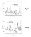
- FIGS. 3A and 3Bshow a comparison of the transmission Raman spectra of a composite pharmaceutical tablet sample measured from two opposite directions.
- the composite tablet sampleis composed of a Tylenol tablet on one side and an Aspirin tablet on the other side.
- the Raman spectrum in dashed lineis measured when the laser light illuminates the sample from the Aspirin side and the Raman spectrum in solid line is measured when the laser light illuminates the sample from the Tylenol side.
- Checking the Raman bands of Aspirin(the circled Raman bands as shown in FIGS. 3A and 3B ), it can be seen that when the Raman shift is small (as shown in FIG. 3A ), the two spectra show almost the same intensity.
- the Aspirin bandshows higher intensity when the laser light illuminates the sample from the Tylenol side.
- the laser lighthas lower absorption and scattering loss than the Raman light when their wavelength difference is large enough.
- the transmission Raman spectra measured in two opposite directionsnot only provides the composition information of the tablet sample but also reveals the relative location of its ingredients (i.e. Tylenol and Aspirin in this example).
Landscapes
- Physics & Mathematics (AREA)
- Spectroscopy & Molecular Physics (AREA)
- General Physics & Mathematics (AREA)
- Health & Medical Sciences (AREA)
- Life Sciences & Earth Sciences (AREA)
- Chemical & Material Sciences (AREA)
- Engineering & Computer Science (AREA)
- Pathology (AREA)
- General Health & Medical Sciences (AREA)
- Immunology (AREA)
- Biochemistry (AREA)
- Analytical Chemistry (AREA)
- Bioinformatics & Cheminformatics (AREA)
- Biophysics (AREA)
- Molecular Biology (AREA)
- Pharmacology & Pharmacy (AREA)
- Food Science & Technology (AREA)
- Medicinal Chemistry (AREA)
- Nuclear Medicine, Radiotherapy & Molecular Imaging (AREA)
- Investigating, Analyzing Materials By Fluorescence Or Luminescence (AREA)
Abstract
Description
Claims (14)
Priority Applications (1)
| Application Number | Priority Date | Filing Date | Title |
|---|---|---|---|
| US15/653,636US10119917B2 (en) | 2016-11-11 | 2017-07-19 | Apparatus and method for bidirectional Raman spectroscopy |
Applications Claiming Priority (4)
| Application Number | Priority Date | Filing Date | Title |
|---|---|---|---|
| US15/349,510US10113969B2 (en) | 2016-11-11 | 2016-11-11 | Methods and devices for measuring Raman scattering of a sample |
| US15/378,156US10119916B2 (en) | 2016-11-11 | 2016-12-14 | Light delivery and collection device for measuring Raman scattering of a sample |
| US15/461,613US10126244B2 (en) | 2016-11-11 | 2017-03-17 | Apparatuses and methods for performing spectroscopic analysis of a subject |
| US15/653,636US10119917B2 (en) | 2016-11-11 | 2017-07-19 | Apparatus and method for bidirectional Raman spectroscopy |
Related Parent Applications (1)
| Application Number | Title | Priority Date | Filing Date |
|---|---|---|---|
| US15/461,613Continuation-In-PartUS10126244B2 (en) | 2016-11-11 | 2017-03-17 | Apparatuses and methods for performing spectroscopic analysis of a subject |
Publications (2)
| Publication Number | Publication Date |
|---|---|
| US20180136138A1 US20180136138A1 (en) | 2018-05-17 |
| US10119917B2true US10119917B2 (en) | 2018-11-06 |
Family
ID=62107106
Family Applications (1)
| Application Number | Title | Priority Date | Filing Date |
|---|---|---|---|
| US15/653,636ActiveUS10119917B2 (en) | 2016-11-11 | 2017-07-19 | Apparatus and method for bidirectional Raman spectroscopy |
Country Status (1)
| Country | Link |
|---|---|
| US (1) | US10119917B2 (en) |
Cited By (1)
| Publication number | Priority date | Publication date | Assignee | Title |
|---|---|---|---|---|
| US11318323B2 (en) | 2018-02-23 | 2022-05-03 | GlobaLaseReach, LLC | Device for delivering precision phototherapy |
Families Citing this family (2)
| Publication number | Priority date | Publication date | Assignee | Title |
|---|---|---|---|---|
| IL254803B2 (en)* | 2017-09-29 | 2023-09-01 | Prisma Photonics Ltd | Tailor distributed amplification for fiber sensing |
| TWI709732B (en)* | 2019-05-22 | 2020-11-11 | 佐信科技有限公司 | Spectrum measurement system |
Citations (47)
| Publication number | Priority date | Publication date | Assignee | Title |
|---|---|---|---|---|
| US4076421A (en) | 1976-03-23 | 1978-02-28 | Kollmorgen Technologies Corporation | Spectrophotometer with parallel sensing |
| DE2606675B2 (en) | 1976-02-19 | 1978-06-22 | Vladimir Dipl.-Ing. 5100 Aachen Blazek | Arrangement for the spectral analysis of the reflectivity of a sample |
| US4378159A (en) | 1981-03-30 | 1983-03-29 | Tencor Instruments | Scanning contaminant and defect detector |
| DE3311954A1 (en) | 1982-08-30 | 1984-03-01 | Shimadzu Corp., Kyoto | TWO-RAY SPECTRAL PHOTOMETER |
| DE3223876C2 (en) | 1981-06-25 | 1985-10-31 | Shimadzu Corp., Kyoto | Device for measuring the color of a brilliant cut diamond |
| US4645340A (en) | 1983-06-01 | 1987-02-24 | Boston University | Optically reflective sphere for efficient collection of Raman scattered light |
| US4853542A (en) | 1987-06-08 | 1989-08-01 | Nicolas J. Harrick | Collecting hemispherical attachment for spectrophotometry |
| US4988205A (en) | 1987-10-09 | 1991-01-29 | The United States Of America As Represented By The Secretary Of The Navy | Reflectometers |
| US5112127A (en) | 1989-11-28 | 1992-05-12 | Eic Laboratories, Inc. | Apparatus for measuring Raman spectra over optical fibers |
| US5199431A (en) | 1985-03-22 | 1993-04-06 | Massachusetts Institute Of Technology | Optical needle for spectroscopic diagnosis |
| US5280788A (en) | 1991-02-26 | 1994-01-25 | Massachusetts Institute Of Technology | Devices and methods for optical diagnosis of tissue |
| US5517315A (en) | 1993-10-29 | 1996-05-14 | The United States Of America As Represented By The Secretary Of The Navy | Reflectometer employing an integrating sphere and lens-mirror concentrator |
| US5615673A (en)* | 1995-03-27 | 1997-04-01 | Massachusetts Institute Of Technology | Apparatus and methods of raman spectroscopy for analysis of blood gases and analytes |
| US5625458A (en)* | 1994-11-10 | 1997-04-29 | Research Foundation Of City College Of New York | Method and system for imaging objects in turbid media using diffusive fermat photons |
| US5659397A (en) | 1995-06-08 | 1997-08-19 | Az Technology | Method and apparatus for measuring total specular and diffuse optical properties from the surface of an object |
| DE69313633T2 (en) | 1992-05-21 | 1998-04-02 | Biobalance As | DEVICE AND METHOD FOR INDUCING AND DETECTING FLUORESCENCE |
| WO1998022802A1 (en) | 1996-11-15 | 1998-05-28 | Optosens Optische Spektroskopie Und Sensortechnik Gmbh | Method and device for combined absorption and reflectance spectroscopy |
| US5864397A (en) | 1997-09-15 | 1999-01-26 | Lockheed Martin Energy Research Corporation | Surface-enhanced raman medical probes and system for disease diagnosis and drug testing |
| US5946090A (en)* | 1996-11-19 | 1999-08-31 | The Institute Of Physical And Chemical Research | Spectrometric method and apparatus for spectrometry |
| US6370406B1 (en) | 1995-11-20 | 2002-04-09 | Cirrex Corp. | Method and apparatus for analyzing a test material by inducing and detecting light-matter interactions |
| US20030120137A1 (en)* | 2001-12-21 | 2003-06-26 | Romuald Pawluczyk | Raman spectroscopic system with integrating cavity |
| WO2004031749A2 (en) | 2002-09-30 | 2004-04-15 | Intel Corporation | Spectroscopic analysis system and method |
| US6781697B1 (en) | 2002-01-16 | 2004-08-24 | Lockheed Martin Corporation | Portable system and method for determining one or more reflectance properties of a surface |
| US20040263842A1 (en) | 2001-06-12 | 2004-12-30 | Puppels Gerwin Jan | Spectrometer for measuring inelastically scattered light |
| US20060238745A1 (en)* | 2004-07-06 | 2006-10-26 | Olympus Corporation | Microscope |
| US7148963B2 (en) | 2003-12-10 | 2006-12-12 | Kaiser Optical Systems | Large-collection-area optical probe |
| US20070121119A1 (en)* | 2005-10-21 | 2007-05-31 | Southwest Research Institute | Spatial Heterodyne Wide-Field Coherent Anti-Stokes Raman Spectromicroscopy |
| US20080259345A1 (en)* | 2007-04-04 | 2008-10-23 | Nikon Corporation | Three-dimensional microscope and method for obtaining three-dimensional image |
| US20090231578A1 (en)* | 2007-05-17 | 2009-09-17 | Jian Ling | Multi-channel fiber optic spectroscopy systems employing integrated optics modules |
| US20090244533A1 (en)* | 2006-04-05 | 2009-10-01 | Pavel Matousek | Raman Analysis |
| US7652763B2 (en) | 2004-12-09 | 2010-01-26 | The Science And Technology Facilities Council | Apparatus for depth-selective Raman spectroscopy |
| US7671985B1 (en) | 2006-03-13 | 2010-03-02 | Milan Milosevic | Device for small spot analysis using fiber optic interfaced spectrometers |
| US20100079754A1 (en)* | 2008-09-30 | 2010-04-01 | Huei Pei Kuo | Systems for performing raman spectroscopy |
| US20110080580A1 (en)* | 2006-03-10 | 2011-04-07 | Imra America, Inc. | Optical signal processing with modelocked lasers |
| US20120089030A1 (en) | 2009-01-16 | 2012-04-12 | President And Fellows Of Harvard College | System and method for characterization of oral, systemic and mucosal tissue utilizing raman spectroscopy |
| US8248600B2 (en) | 2006-11-24 | 2012-08-21 | The Science And Technology Facilities Council | Raman detection of container contents |
| DE112006000273T5 (en) | 2005-01-27 | 2013-01-03 | Hewlett-Packard Development Co., L.P. | Monolithic system and method for enhanced Raman spectroscopy |
| US20130022250A1 (en)* | 2011-05-17 | 2013-01-24 | Gii Acquisition, Llc Dba General Inspection, Llc | Method and system for inspecting dosage forms having code imprints using chemical imaging and sorting the inspected dosage forms |
| US20130038869A1 (en) | 2011-08-12 | 2013-02-14 | Savannah River Nuclear Solutions, Llc | Surface enhanced Raman scattering spectroscopic waveguide |
| DE102012101744A1 (en) | 2012-03-01 | 2013-09-05 | BAM Bundesanstalt für Materialforschung und -prüfung | Method for determining the brightness of a luminescent particle |
| US20130258877A1 (en)* | 2012-03-28 | 2013-10-03 | Zhu Ji | Adaptive Generation of Channel Quality Indicators (CQIs) Based on a Current Communication Scenario |
| US20140009826A1 (en)* | 2011-03-07 | 2014-01-09 | Nikon Corporation | Non-linear microscopy and non-linear observation method |
| US20140103224A1 (en)* | 2011-04-21 | 2014-04-17 | Massachusetts Institute Of Technology | Highly compact multi-optical-junction optical flowcell and flexibly deployable optical sensing assemblies and systems for in-situ real-time spectroscopic measurements |
| US20140226158A1 (en)* | 2004-03-06 | 2014-08-14 | Michael Trainer | Methods and apparatus for determining particle characteristics |
| US20140354989A1 (en)* | 2011-12-16 | 2014-12-04 | Glaxo Group Limited | Apparatus for testing samples using raman radiation |
| WO2015114379A1 (en) | 2014-01-31 | 2015-08-06 | The University Of Bristol | A low background raman probe for optical biopsy of brain tissue |
| US20160209388A1 (en) | 2015-01-16 | 2016-07-21 | The Texas A&M University System | High reflectivity integrating cavity and optical amplification device |
- 2017
- 2017-07-19USUS15/653,636patent/US10119917B2/enactiveActive
Patent Citations (49)
| Publication number | Priority date | Publication date | Assignee | Title |
|---|---|---|---|---|
| DE2606675B2 (en) | 1976-02-19 | 1978-06-22 | Vladimir Dipl.-Ing. 5100 Aachen Blazek | Arrangement for the spectral analysis of the reflectivity of a sample |
| US4076421A (en) | 1976-03-23 | 1978-02-28 | Kollmorgen Technologies Corporation | Spectrophotometer with parallel sensing |
| US4378159A (en) | 1981-03-30 | 1983-03-29 | Tencor Instruments | Scanning contaminant and defect detector |
| DE3223876C2 (en) | 1981-06-25 | 1985-10-31 | Shimadzu Corp., Kyoto | Device for measuring the color of a brilliant cut diamond |
| DE3311954A1 (en) | 1982-08-30 | 1984-03-01 | Shimadzu Corp., Kyoto | TWO-RAY SPECTRAL PHOTOMETER |
| US4645340A (en) | 1983-06-01 | 1987-02-24 | Boston University | Optically reflective sphere for efficient collection of Raman scattered light |
| US5199431A (en) | 1985-03-22 | 1993-04-06 | Massachusetts Institute Of Technology | Optical needle for spectroscopic diagnosis |
| US4853542A (en) | 1987-06-08 | 1989-08-01 | Nicolas J. Harrick | Collecting hemispherical attachment for spectrophotometry |
| US4988205A (en) | 1987-10-09 | 1991-01-29 | The United States Of America As Represented By The Secretary Of The Navy | Reflectometers |
| US5112127A (en) | 1989-11-28 | 1992-05-12 | Eic Laboratories, Inc. | Apparatus for measuring Raman spectra over optical fibers |
| US5280788A (en) | 1991-02-26 | 1994-01-25 | Massachusetts Institute Of Technology | Devices and methods for optical diagnosis of tissue |
| DE69313633T2 (en) | 1992-05-21 | 1998-04-02 | Biobalance As | DEVICE AND METHOD FOR INDUCING AND DETECTING FLUORESCENCE |
| US5517315A (en) | 1993-10-29 | 1996-05-14 | The United States Of America As Represented By The Secretary Of The Navy | Reflectometer employing an integrating sphere and lens-mirror concentrator |
| US5625458A (en)* | 1994-11-10 | 1997-04-29 | Research Foundation Of City College Of New York | Method and system for imaging objects in turbid media using diffusive fermat photons |
| US5615673A (en)* | 1995-03-27 | 1997-04-01 | Massachusetts Institute Of Technology | Apparatus and methods of raman spectroscopy for analysis of blood gases and analytes |
| US5659397A (en) | 1995-06-08 | 1997-08-19 | Az Technology | Method and apparatus for measuring total specular and diffuse optical properties from the surface of an object |
| US6370406B1 (en) | 1995-11-20 | 2002-04-09 | Cirrex Corp. | Method and apparatus for analyzing a test material by inducing and detecting light-matter interactions |
| WO1998022802A1 (en) | 1996-11-15 | 1998-05-28 | Optosens Optische Spektroskopie Und Sensortechnik Gmbh | Method and device for combined absorption and reflectance spectroscopy |
| US5946090A (en)* | 1996-11-19 | 1999-08-31 | The Institute Of Physical And Chemical Research | Spectrometric method and apparatus for spectrometry |
| US5864397A (en) | 1997-09-15 | 1999-01-26 | Lockheed Martin Energy Research Corporation | Surface-enhanced raman medical probes and system for disease diagnosis and drug testing |
| US20040263842A1 (en) | 2001-06-12 | 2004-12-30 | Puppels Gerwin Jan | Spectrometer for measuring inelastically scattered light |
| US20030120137A1 (en)* | 2001-12-21 | 2003-06-26 | Romuald Pawluczyk | Raman spectroscopic system with integrating cavity |
| US6781697B1 (en) | 2002-01-16 | 2004-08-24 | Lockheed Martin Corporation | Portable system and method for determining one or more reflectance properties of a surface |
| WO2004031749A3 (en) | 2002-09-30 | 2004-06-24 | Intel Corp | Spectroscopic analysis system and method |
| WO2004031749A2 (en) | 2002-09-30 | 2004-04-15 | Intel Corporation | Spectroscopic analysis system and method |
| US7148963B2 (en) | 2003-12-10 | 2006-12-12 | Kaiser Optical Systems | Large-collection-area optical probe |
| US20140226158A1 (en)* | 2004-03-06 | 2014-08-14 | Michael Trainer | Methods and apparatus for determining particle characteristics |
| US20060238745A1 (en)* | 2004-07-06 | 2006-10-26 | Olympus Corporation | Microscope |
| US7652763B2 (en) | 2004-12-09 | 2010-01-26 | The Science And Technology Facilities Council | Apparatus for depth-selective Raman spectroscopy |
| DE112006000273T5 (en) | 2005-01-27 | 2013-01-03 | Hewlett-Packard Development Co., L.P. | Monolithic system and method for enhanced Raman spectroscopy |
| US20070121119A1 (en)* | 2005-10-21 | 2007-05-31 | Southwest Research Institute | Spatial Heterodyne Wide-Field Coherent Anti-Stokes Raman Spectromicroscopy |
| US20110080580A1 (en)* | 2006-03-10 | 2011-04-07 | Imra America, Inc. | Optical signal processing with modelocked lasers |
| US7671985B1 (en) | 2006-03-13 | 2010-03-02 | Milan Milosevic | Device for small spot analysis using fiber optic interfaced spectrometers |
| US20090244533A1 (en)* | 2006-04-05 | 2009-10-01 | Pavel Matousek | Raman Analysis |
| US8085396B2 (en) | 2006-04-05 | 2011-12-27 | The Science And Technology Facilities Council | Raman analysis |
| US8248600B2 (en) | 2006-11-24 | 2012-08-21 | The Science And Technology Facilities Council | Raman detection of container contents |
| US20080259345A1 (en)* | 2007-04-04 | 2008-10-23 | Nikon Corporation | Three-dimensional microscope and method for obtaining three-dimensional image |
| US20090231578A1 (en)* | 2007-05-17 | 2009-09-17 | Jian Ling | Multi-channel fiber optic spectroscopy systems employing integrated optics modules |
| US20100079754A1 (en)* | 2008-09-30 | 2010-04-01 | Huei Pei Kuo | Systems for performing raman spectroscopy |
| US20120089030A1 (en) | 2009-01-16 | 2012-04-12 | President And Fellows Of Harvard College | System and method for characterization of oral, systemic and mucosal tissue utilizing raman spectroscopy |
| US20140009826A1 (en)* | 2011-03-07 | 2014-01-09 | Nikon Corporation | Non-linear microscopy and non-linear observation method |
| US20140103224A1 (en)* | 2011-04-21 | 2014-04-17 | Massachusetts Institute Of Technology | Highly compact multi-optical-junction optical flowcell and flexibly deployable optical sensing assemblies and systems for in-situ real-time spectroscopic measurements |
| US20130022250A1 (en)* | 2011-05-17 | 2013-01-24 | Gii Acquisition, Llc Dba General Inspection, Llc | Method and system for inspecting dosage forms having code imprints using chemical imaging and sorting the inspected dosage forms |
| US20130038869A1 (en) | 2011-08-12 | 2013-02-14 | Savannah River Nuclear Solutions, Llc | Surface enhanced Raman scattering spectroscopic waveguide |
| US20140354989A1 (en)* | 2011-12-16 | 2014-12-04 | Glaxo Group Limited | Apparatus for testing samples using raman radiation |
| DE102012101744A1 (en) | 2012-03-01 | 2013-09-05 | BAM Bundesanstalt für Materialforschung und -prüfung | Method for determining the brightness of a luminescent particle |
| US20130258877A1 (en)* | 2012-03-28 | 2013-10-03 | Zhu Ji | Adaptive Generation of Channel Quality Indicators (CQIs) Based on a Current Communication Scenario |
| WO2015114379A1 (en) | 2014-01-31 | 2015-08-06 | The University Of Bristol | A low background raman probe for optical biopsy of brain tissue |
| US20160209388A1 (en) | 2015-01-16 | 2016-07-21 | The Texas A&M University System | High reflectivity integrating cavity and optical amplification device |
Non-Patent Citations (1)
| Title |
|---|
| English language translation of German Office Action of German Applicaton No. 102016225808.7, dated Nov. 24, 2017. |
Cited By (2)
| Publication number | Priority date | Publication date | Assignee | Title |
|---|---|---|---|---|
| US11318323B2 (en) | 2018-02-23 | 2022-05-03 | GlobaLaseReach, LLC | Device for delivering precision phototherapy |
| US12144999B2 (en) | 2018-02-23 | 2024-11-19 | GlobaLaseReach, LLC | Device for delivering precision phototherapy |
Also Published As
| Publication number | Publication date |
|---|---|
| US20180136138A1 (en) | 2018-05-17 |
Similar Documents
| Publication | Publication Date | Title |
|---|---|---|
| US11096608B2 (en) | Device and method for non-invasive measuring of analytes | |
| US8692990B2 (en) | Illumination of diffusely scattering media | |
| Matousek | Raman signal enhancement in deep spectroscopy of turbid media | |
| US12013347B2 (en) | Product inspection method and product inspection apparatus | |
| US20160061660A1 (en) | Miniature spectrometer and apparatus employing same | |
| CN106442401B (en) | A kind of detection device and detection method of combination Raman spectrum and near infrared spectrum | |
| US10119917B2 (en) | Apparatus and method for bidirectional Raman spectroscopy | |
| CN110763671A (en) | Small Frequency Shift Excited Raman Detection Device | |
| JP7159378B2 (en) | Apparatus and method for spectroscopic analysis of object | |
| WO2019092772A1 (en) | Accessory for infrared spectrophotometer | |
| TWI603067B (en) | Optical measurement device and method | |
| JP2018084539A (en) | System and method for measuring characteristic with light | |
| CN108072642B (en) | Optical probe for measuring Raman scattering and measuring method thereof | |
| KR102592510B1 (en) | Raman probe and spectroscopic analysis apparatus using the Raman probe for in vivo biological components | |
| US20180136133A1 (en) | Light Delivery and Collection Device for Performing Spectroscopic Analysis of a Subject | |
| US10481000B2 (en) | Apparatus and method for evaluation of spectral properties of a measurement object | |
| US11540722B2 (en) | Etalon mid-infrared probe for spectroscopic tissue discrimination | |
| US9976950B2 (en) | Optical detector module, measurement system and method of detecting presence of a substance in a test material | |
| JP5480055B2 (en) | Diffuse reflection measuring device | |
| RU2352920C2 (en) | Method for determination of quantitative content of components in mixture | |
| CN201773070U (en) | bias probe | |
| JPH1151927A (en) | Fruit and vegetable quality measuring device |
Legal Events
| Date | Code | Title | Description |
|---|---|---|---|
| AS | Assignment | Owner name:BWT PROPERTY, INC., DELAWARE Free format text:ASSIGNMENT OF ASSIGNORS INTEREST;ASSIGNORS:ZHAO, JUN;ZHOU, XIN JACK;WANG, SEAN XIAOLU;REEL/FRAME:043091/0107 Effective date:20170719 | |
| AS | Assignment | Owner name:B&W TEK LLC C/O BLANK ROME LLP, DISTRICT OF COLUMBIA Free format text:ASSIGNMENT OF ASSIGNORS INTEREST;ASSIGNORS:BWT PROPERTY INC.;B&W TEK PROPERTY, INC.;BWT PROPERTY, INC.;AND OTHERS;REEL/FRAME:046468/0447 Effective date:20180702 Owner name:B&W TEK LLC C/O BLANK ROME LLP, DISTRICT OF COLUMB Free format text:ASSIGNMENT OF ASSIGNORS INTEREST;ASSIGNORS:BWT PROPERTY INC.;B&W TEK PROPERTY, INC.;BWT PROPERTY, INC.;AND OTHERS;REEL/FRAME:046468/0447 Effective date:20180702 | |
| FEPP | Fee payment procedure | Free format text:ENTITY STATUS SET TO UNDISCOUNTED (ORIGINAL EVENT CODE: BIG.); ENTITY STATUS OF PATENT OWNER: LARGE ENTITY | |
| STCF | Information on status: patent grant | Free format text:PATENTED CASE | |
| MAFP | Maintenance fee payment | Free format text:PAYMENT OF MAINTENANCE FEE, 4TH YEAR, LARGE ENTITY (ORIGINAL EVENT CODE: M1551); ENTITY STATUS OF PATENT OWNER: LARGE ENTITY Year of fee payment:4 | |
| AS | Assignment | Owner name:METROHM SPECTRO, INC., NEW JERSEY Free format text:MERGER;ASSIGNOR:B&W TEK LLC;REEL/FRAME:061560/0803 Effective date:20211216 |