US10119901B2 - Geological scanner - Google Patents
Geological scannerDownload PDFInfo
- Publication number
- US10119901B2 US10119901B2US15/036,501US201415036501AUS10119901B2US 10119901 B2US10119901 B2US 10119901B2US 201415036501 AUS201415036501 AUS 201415036501AUS 10119901 B2US10119901 B2US 10119901B2
- Authority
- US
- United States
- Prior art keywords
- specimen
- resolution
- image
- image data
- polarizer
- Prior art date
- Legal status (The legal status is an assumption and is not a legal conclusion. Google has not performed a legal analysis and makes no representation as to the accuracy of the status listed.)
- Active
Links
Images


Classifications
- G—PHYSICS
- G01—MEASURING; TESTING
- G01N—INVESTIGATING OR ANALYSING MATERIALS BY DETERMINING THEIR CHEMICAL OR PHYSICAL PROPERTIES
- G01N21/00—Investigating or analysing materials by the use of optical means, i.e. using sub-millimetre waves, infrared, visible or ultraviolet light
- G01N21/17—Systems in which incident light is modified in accordance with the properties of the material investigated
- G01N21/21—Polarisation-affecting properties
- G—PHYSICS
- G01—MEASURING; TESTING
- G01N—INVESTIGATING OR ANALYSING MATERIALS BY DETERMINING THEIR CHEMICAL OR PHYSICAL PROPERTIES
- G01N33/00—Investigating or analysing materials by specific methods not covered by groups G01N1/00 - G01N31/00
- G01N33/24—Earth materials
- G—PHYSICS
- G02—OPTICS
- G02B—OPTICAL ELEMENTS, SYSTEMS OR APPARATUS
- G02B21/00—Microscopes
- G02B21/0004—Microscopes specially adapted for specific applications
- G02B21/0016—Technical microscopes, e.g. for inspection or measuring in industrial production processes
- G—PHYSICS
- G02—OPTICS
- G02B—OPTICAL ELEMENTS, SYSTEMS OR APPARATUS
- G02B21/00—Microscopes
- G02B21/0004—Microscopes specially adapted for specific applications
- G02B21/0092—Polarisation microscopes
- G—PHYSICS
- G02—OPTICS
- G02B—OPTICAL ELEMENTS, SYSTEMS OR APPARATUS
- G02B21/00—Microscopes
- G02B21/06—Means for illuminating specimens
- G02B21/08—Condensers
- G02B21/12—Condensers affording bright-field illumination
- G02B21/125—Condensers affording bright-field illumination affording both dark- and bright-field illumination
- G—PHYSICS
- G02—OPTICS
- G02B—OPTICAL ELEMENTS, SYSTEMS OR APPARATUS
- G02B21/00—Microscopes
- G02B21/36—Microscopes arranged for photographic purposes or projection purposes or digital imaging or video purposes including associated control and data processing arrangements
- G02B21/365—Control or image processing arrangements for digital or video microscopes
- G02B21/367—Control or image processing arrangements for digital or video microscopes providing an output produced by processing a plurality of individual source images, e.g. image tiling, montage, composite images, depth sectioning, image comparison
- G—PHYSICS
- G02—OPTICS
- G02B—OPTICAL ELEMENTS, SYSTEMS OR APPARATUS
- G02B27/00—Optical systems or apparatus not provided for by any of the groups G02B1/00 - G02B26/00, G02B30/00
- G02B27/28—Optical systems or apparatus not provided for by any of the groups G02B1/00 - G02B26/00, G02B30/00 for polarising
- G02B27/283—Optical systems or apparatus not provided for by any of the groups G02B1/00 - G02B26/00, G02B30/00 for polarising used for beam splitting or combining
- H—ELECTRICITY
- H04—ELECTRIC COMMUNICATION TECHNIQUE
- H04N—PICTORIAL COMMUNICATION, e.g. TELEVISION
- H04N1/00—Scanning, transmission or reproduction of documents or the like, e.g. facsimile transmission; Details thereof
- H04N1/21—Intermediate information storage
- H04N1/2166—Intermediate information storage for mass storage, e.g. in document filing systems
- H04N1/2179—Interfaces allowing access to a plurality of users, e.g. connection to electronic image libraries
- H04N1/2191—Interfaces allowing access to a plurality of users, e.g. connection to electronic image libraries for simultaneous, independent access by a plurality of different users
Definitions
- the followingrelates to material science and engineering, petrography, geological microscopy, material structure scanning, including industrial materials, microscopy training, geology education, research, and microscopy of crystalline structures.
- a microscope for studying materialsis a type of optical microscope used in material science, petrology and optical mineralogy to identify materials, rocks and minerals in thin sections.
- the microscopeis used in material sciences, material engineering, optical mineralogy, and petrography.
- the methodis called polarized light microscopy (PLM).
- a substrate or slideis placed upon an imaging device with a motorized stage, and a digital imaging device (e.g., camera or line scanner), and all parts of the specimen are imaged and reassembled to display the entire substrate or slide as a single image, displayable on a monitor and transmittable across local and wide area networks and the Internet.
- the displayed imageis used for facilitating the acquisition of multiple whole slide or substrate images of the slide or substrate under crossed polarizers rotated at different angles, with each image displayed to the viewer at the angle of polarization.
- methodsare disclosed of visualizing a specimen, the methods comprising the steps of: a) placing a specimen on a substrate, the specimen occupying an area of the substrate; b) placing the substrate on a stage and imaging the area of the substrate with the specimen using a high power magnification objective lens and crossed polarizer to obtain a single scan of the specimen at high magnification and high resolution, wherein the crossed polarizer is set in a single direction to provide data for a high resolution image of the specimen; c) repeating the imaging process of step (b) with the angle of the crossed polarizer changed at various angled increments, further comprising obtaining a continuous sequence of successive images by advancing a field of view of the high power objective lens of the microscope stepwise across the specimen and acquiring successive images of each field of view for the specimen, once at each angle of polarization; and d) uploading and storing the high resolution image data in a database for remote viewing.
- microscopy devicescomprising a device provided with at least one objective lens, a motorized turret, a digital imaging system and a motorized stage, a polarizer and an analyzer, the polarizer and analyzer forming a crossed polarizer capable of rotating about an axis, wherein the microscopy apparatus is controllable to obtain, a single scan of a specimen at a high magnification and high resolution to provide high resolution digital image data of the specimen occupying an area of a substrate placed upon the motorized stage, comprising a continuous sequence of successive images by advancing the field of view of a high power objective lens stepwise across the specimen thereby acquiring successive images of the entire field of view for the specimen, and taking successive scans at different angles of polarization; image processing means to process the high resolution digital image data to obtain a low resolution copy of the image data; a storage means to store the high resolution image data and the low resolution copy of the image data thereby obtained; a means for transferring the low resolution copy of the image data
- a scannercapable of acquiring one or more images of a specimen.
- Specimensinclude samples which are not usually processed for traditional microscopy viewing on slides.
- the term “specimens” or “samples”may be used interchangeably in the various embodiments disclosed herein. Examples of such specimens include, without limitation, rocks of various sizes, metal based samples, and samples, e.g., opaque samples, which require differential illumination over traditional microscopy where light cannot be delivered through the specimen.
- the specimensmay be whole, cross-sections or any portion of a whole specimen. In many implementations, a specimen is scanned without destruction of the specimen, allowing a user to replace the specimen to the location from which it was derived.
- a scannermay be portable, wherein a specimen is scanned at the sampling location or a remote location.
- a scannercomprises an illuminator with light source for illuminating a specimen, wherein the light is then reflected off of the specimen and onto an imaging device.
- the imaging devicesuch as a camera, is a component of the scanner.
- an illuminatorwhich provides coaxial illumination through an illumination light path (light path from a light source to a specimen) to a semi-silvered mirror (50% reflection beamsplitter) which is placed at a 45 degree angle from a primary objective path to the illumination path, allowing 50% of the light to be directed through an objective lens.
- the objective lensfunctions as a condensing lens of the same numerical aperture as the light collecting power of the same objective.
- crossed polarizing filtersare placed in the illumination light path to allow for polarized reflected light.
- an imaging deviceIn one aspect, provided herein is an imaging device.
- light reflected off of a specimenis collected, for example, through an objective lens, by an imaging device.
- imaging devicesinclude, without limitation, CCD, CMOS, line scan camera or line scanner, and other image sensing devices.
- a platform for holding one or more specimensis a stage.
- the stagein various implementations comprises a motorized stage.
- a motorized stageallows for a specimen to be moved relative to an illuminator (light source) and/or imaging device of a scanner.
- the platformis a mat.
- a matin certain circumstances, serves as both a platform and as a display. For example, a specimen is placed on the mat and an image of the specimen is acquired using a scanner. The specimen may subsequently be removed from the mat, and the acquired image is then displayed on the mat.
- the matfunctions as a touchpad. A touchpad is useful for annotating an acquired image.
- a touchpadmay also include a control panel, whereby subsequent specimen acquisition image details, e.g., resolution, selection of specimen area for imaging, are controlled.
- subsequent specimen acquisition image detailse.g., resolution, selection of specimen area for imaging
- the macro image using the matis used for determining the scan area at higher magnification of a large sample.
- a displayallows a user to view image data from a specimen as well as corresponding information regarding the specimen.
- Specimen informationincludes analysis of one or more images of the specimen.
- Specimen informationmay further include mineral content of the specimen.
- information regarding the specimenincludes coordinates for identifying the location from which a specimen was acquired.
- a displayis a geomap.
- a geomapis an interactive map which allows a user to view specimen images and corresponding data (e.g., specimen analysis such as mineral content) along with specimen coordinates.
- the geomapin various embodiments, comprises specimen images and corresponding data from a plurality of user provided data.
- image data from a scanned specimenis stored with specimen coordinate data, which identifies the location of the retrieved specimen.
- the scannermay be a 2D or 3D scanner configured to obtain low resolution, high resolution, or both low and high resolution images of the specimen.
- the scannercomprises polarizing filters.
- one scannerhas polarizing means.
- Each scanneracquires one or more images of a sample and stores the images on a server or computer for display.
- a user of a scannerinputs global position system coordinates for inclusion with image data.
- the methodsmay include the use of a scanner as described herein or other commercially available scanners.
- a scannermay capture one or more images of a specimen in two- or three-dimensions.
- a method for scanning a specimencomprises placing a specimen on a platform such as a stage or mat.
- the stage or matmay be movable by manual or electronic means.
- a scanneracquires one or more images of the entire specimen, or an area of interest of the specimen. If more than one image is acquired, the images are reassembled for display as a single image. Data for the acquired images and reassembled images are transmittable across local and wide area networks and/or the Internet for display at any location.
- the viewed imagesare annotated. In other or additional embodiments, the viewed images are used as guide to control the subsequent acquisition of additional images of the specimen, for example, high resolution images.
- a userinteracts with a display using software to acquire additional images of the specimen and/or to annotate and/or analyze the specimen.
- the displaymay facilitate the acquisition of multiple images of the specimen under crossed polarizers rotated at different angles, with each image displayed at the angle of polarization.
- multiple z-planesare acquired and reassembled to provide an extended depth of field image.
- one or more images of a specimenare acquired using a two-dimensional scanner without polarizing means.
- the imagesare viewed on a display and used as a template for a user to subsequently scan the specimen using a polarized scanner.
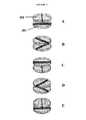
- FIG. 1depicts a non-limiting exemplary embodiment of a geologic scanner, wherein two polarizers (polarizer and an analyzer) are crossed relative to each other.
- the polarizersare rotated in synchrony in 45 degree increments.
- an imageis captured at each of five increments of rotation.
- the stage and samplethat is normally positioned between the two polarizers.
- FIG. 2depicts an exemplary scanner comprising a polarizing beam splitter cube.
- FIG. 3depicts embodiments of darkfield mirror block in a reflected light system.
- FIG. 4depicts embodiments where light travels through darkfield mirror blocks.
- FIG. 5depicts embodiments for mirror blocks in light reflected microscopy.
- FIG. 6depicts embodiments of imaging apparatus comprising a Kohler illumination in reflected light microscopy.
- FIG. 7depicts embodiments of contrast mechanisms in reflected light microscopy.
- Digital pathologyor the digitizing of entire slides of biological tissue, has been used and shown to be a useful method of storing and sharing microscope slides across great distances or cataloguing libraries of tissues, diseases, etc. Because of technical hurdles, such as the need to rotate slides and the inability to tile rectangular images across a slanted image, this technique has not been extended to include industrial, petrographic, geological, metallic or crystalline microscopy samples.
- a polarization scanning deviceis useful for viewing samples comprising anisotropic material, where color is an important property useful for mineral identification.
- the methods and systems provided hereinallow for the acquisition of an image of a geological sample using a scanner with polarizing means, where the images may be digitally stored, viewed and/or analyzed for grain size and shape, crystallinity and/or morphology, which aids in the identification and analysis of the sample.
- characteristics of a sample investigated using a polarizing scannerinclude, without limitation, pleochroism, refractive index, mineral content, birefringence, twinning, inclusions and cleavage characteristics.
- additional materialsmay be scanned using the systems and methods provided herein including, but not limited to, natural and industrial minerals, cement composites, ceramics, metals, minerals, mineral fibers, rocks, polymers, starch, wood, biological samples having anisotropic materials, finished materials, industrial parts and components with an opaque yet reflective nature, metals embedded into a medium and polished or ground for viewing and documentation, crystalline samples and other samples having anisotropic materials.
- Crystalline structures such as rock and crystals and many forms of acidrequire, to be viewed under a microscope, for that microscope to be fitted with two polarizing filters termed the polarizer and analyzer, and the specimen rotated at small increments to view the effect of polarized light upon the crystalline substances to identify and label them properly.
- the methods, systems and apparatus described hereinprovide two polarizing filters, a polarizer and an analyzer, as components of a microscope for use in digital microscopy.
- the microscopemay comprise or be operably connected to, e.g., in a scanner, an imaging device for acquiring images of a specimen.
- the polarizeris positioned beneath a specimen stage with the polarizer vibration azimuth starting in the left-to-right, or East-West direction, although these elements are capable of being rotated through 360 degrees and may be motorized.
- the analyzerstarts aligned with a vibration direction oriented North-South, but again capable of being rotated with, for example, a corresponding motor, is placed above the objectives of the microscope, wherein the analyzer and polarizer vibration azimuths are positioned at right angles to each other. In this configuration, the polarizer and analyzer are said to be crossed, with no light passing through the system and a dark view field present to the imaging device.
- the specimenWhen a specimen is placed into the system, the specimen is scanned by taking digitized images of each field comprising a substrate holding said specimen, such a substrate includes a microscope slide, and reassembling the images as a single image.
- the imagesmay be uploaded and reassembled through a web based program, for example a program similar to Qumulus, optionally with described modifications.
- the systemthen rotates the polarizer and analyzer 45 degrees at the same time, so that the polarizing filters are still crossed, and another scan is acquired. This may occur a total of 5 times so that each stop along a 180 degree arc of crossed polarization is covered.
- Each assembled imageis labeled with the name of the image plus a degree mark (for instance ABC0, ABC45, ABC90, ABC135, ABC180), and the image collected is saved and uploaded to a server.
- a degree markfor instance ABC0, ABC45, ABC90, ABC135, ABC180
- two polarizing filtersare positioned on the same side of a platform holding a specimen.
- the polarizing filters, polarizer and analyzerare crossed in a beamsplitter cube disposed along both a path between a light source and the specimen (illumination path) and a path between the specimen and an imaging device (reflective path).
- the light source and imaging devicein many implementations, are components of a digital scanner.
- a specimenis placed on a platform and scanned.
- the scannerrotates the polarizer and analyzer 45 degrees at the same time, maintaining a crossed configuration, and an image is acquired using the imaging device each time the polarizers are rotated.
- the acquired imagesare then reassembled as a single image using software or a web based program such as Qumulus.
- Each assembled imageis labeled as previously described, with an image name and a degree mark. Images are saved and optionally uploaded to a server.
- the serverhosts a web viewer which displays the primary image (for example, ABC0) for viewing. Since the image consists of multiple tiled or scanned images, the image can be zoomed in and/or panned about, displaying a magnified view of the entire specimen and/or microscope slide, only processing that which is viewed at one time.
- the primary imagefor example, ABC0
- the imagecan be displayed in the “Tiled Pyramidal Files” format, so that a full, high resolution image is viewed which contains all of the folders, however when backing off and obtaining lower magnification views, a new image of a lower resolution would be loaded in its place.
- the viewerallows the person or user viewing the images to “rotate” the image, at 45 degree increments.
- the corresponding imageloads with the precise field being viewed in place at an angle corresponding to the degrees at which the polarizer was rotated when the image was taken, at the same zoom factor as the current image is being viewed.
- a useracquires five images of a specimen using a system described herein, and uploads the images.
- the userzooms in on an image so that the object or area the user is interested in takes up most of the screen of the viewer.
- the userthen “rotates 45 degrees” and a new image loads with the same object, however it loads at a 45 degree angle from the original image. This way it feels to the user as though they are rotating the specimen, which is what they would be doing on a petrographic microscope.
- the systemcomprises (a) a scanner, (b) an image acquisition system controlled by a user, (c) a server workflow and viewing system to display the images post-acquisition, and (d) a display for an end user to view the acquired images.
- the scannercomprises a G2 scanner.
- the acquisition systemis a computer comprising software or a web based program to control the scanner for image acquisition.
- the serverresides at the specimen acquisition site.
- the serverresides at a location remote from the specimen acquisition site.
- the serveris a cloud based server, capable of residing at the acquisition site or in a remote datacenter.
- the displayis a device such as a computer, tablet, television (e.g., smart TV), smartphone or any network enabled device capable of viewing images.
- the imaging system/apparatusdoes not comprise a rotation of polarizers or analyzer in the beamsplitter cube on reflected specimens. In some embodiments, specimen rotation is not required or desired in reflected light.
- a polarizing filteris positioned above the stage and sample and another polarizing filter is positioned below the stage and sample.
- the two polarizing filters, the polarizer 202 and analyzer 203are crossed relative to each other and rotated in synchrony in five 45 degree increments.
- an imageis captured at each of five increments of rotation (A-E). The images are optionally reassembled at a later time point to emulate rotation of the sample.
- a systemcomprising two polarizing filters which are both located above or below a stage holding a specimen.
- the two polarizing filtersare components of a scanner useful for acquiring images of the specimen.
- An exemplary scanner, 200is shown in FIG. 2 .
- the scannerincludes a light source, 204 , for illuminating a specimen, 210 .
- the illuminating lighttravels through a light path (illumination path) comprising a beamsplitter cube, 201 , wherein the beamsplitter cube comprises two polarizing filters: a crossed polarizer, 202 , and an analyzer, 203 .
- the light path in this examplefurther comprises a diaphragm (aperture, 206 , and field, 207 ).
- the scanner of FIG. 2is operably connected to, and/or comprises an imaging device, 208 , for receiving and capturing light reflect off of the specimen. The reflected light travels from the specimen to the imaging device along a reflection path.
- the reflection pathcomprises an objective lens, 205 .
- the specimen in FIG. 2is held by a stage, 211 .
- a scannercomprising a light source for illuminating a specimen.
- the intensity of light directed to a specimen from the light sourceis adjustable.
- a light sourceincludes, without limitation, a light-emitting diode (LED). LEDs include white light, red light, green light and blue light LED.
- the systemcomprises a mirror which reflects light from an external source to a specimen to be scanned.
- the light sourceis a cold cathode fluorescent lamp (CCFL).
- the light sourceis guided to the specimen via optical components disposed along a light path (illumination path) between the light source and the specimen. Optical components include mirrors, filters and lenses.
- the scannercomprises or is operably connected to an imaging device.
- the imaging devicemay comprise a CCD (charge-coupled device) imager, CMOS, line scanner or other imaging device.
- a light path between the scanner light source and the specimen or samplecomprises a diaphragm.
- a diaphragmis an aperture diaphragm.
- An aperture diaphragmis useful for inhibiting the passage of light, except for light which may pass through an aperture of the diaphragm, wherein the size of the aperture regulates the amount of light which may pass through the diaphragm.
- a diaphragmis a field diaphragm.
- a light path between the scanner light source and the specimencomprises two polarizing filters, a polarizer and an analyzer.
- the polarizing filtersmay be located on one side of the specimen, for example, as in FIG. 2 .
- the specimenis located between the polarizing filters, for example, as in FIG. 1 .
- the polarizing filtersare crossed in a polarizing cube beamsplitter.
- An exemplary beamsplitter cube having a polarizer and analyzeris shown in FIG. 2 .
- a polarizeris an optical filter that passes light of a specific polarization while blocking light of other polarizations.
- the polarizeris useful for converting a beam of light of undefined or mixed polarization into defined polarized light.
- the polarizermay be a linear or circular polarizer.
- Linear polarizersinclude absorptive and beam-splitting polarizers.
- a second polarizing filter of a systemcan be generally referred to as an analyzer.
- a light path between the specimen and the imaging devicecomprises an objective lens.
- the objective lensacquires light reflected and/or transmitted from the specimen and projects said light to the imaging device.
- the systemcomprises a plurality of objective lenses, wherein at least two of the plurality of objective lenses have different optical powers.
- a systemcomprises a 4 ⁇ , 10 ⁇ , 40 ⁇ or 100 ⁇ objective lens, or a combination thereof.
- a view of the specimenis focused by moving the objective lens relative to the specimen.
- a scannercomprises a lens changing device, wherein the lens changing device may be motorized. In some instances, the lens changing device is manually or automatically controlled with the use of a software program.
- an objective lens of the systemis a high powered objective lens suitable to obtain a single scan of the entire specimen at high magnification and high resolution.
- the objective lens of the systemis a low powered objective lens suitable to obtain a plurality of images of the entire specimen at low resolution, wherein the plurality of images may then be assembled into a single, low resolution image.
- the imaging deviceacquires a continuous sequence of successive images by advancing a field of view of a high powered objective lens stepwise across the entire sample.
- high resolution image data obtainedis processed to generate data for a relatively low resolution copy of the images.
- the high resolution image data and the low resolution copy of the image datais saved in a metadata file.
- the imaging deviceoptically captures low resolution data from a low magnification image of the sample.
- a scannercomprising an imaging device, wherein light emitted from the light source and reflected from and/or transmitted through the specimen, depending on the scanner type (e.g., polarized or non-polarized) and/or specimen (e.g., microscopy specimen or geological specimen), is directed to an imaging device.
- An imaging devicetransforms optical signals to corresponding electric signals to become digital signals recognizable by a computer. Digital signals are transferable to a computer by interfaces including, but not limited to, the Internet, enhanced parallel port (EPP), bluetooth, universal serial bus (USB) and small computer system interface (SCSI).
- EPPenhanced parallel port
- USBuniversal serial bus
- SCSIsmall computer system interface
- an imaging devicecomprises a surface photoelectric device fabricated to perform photoelectric transformation, for example, a charge-coupled device (CCD).
- the imaging devicecomprises a CMOS, line scan camera or other image sensing device.
- a platformfor holding a specimen for scanning
- a platformis a stage.
- the specimenis prepared on a substrate, such as slide, for placement on a stage.
- the stageis movable, wherein the position of the stage, and thus the specimen, is controlled manually or automatically, optionally with the use of a software program.
- a platformis a mat.
- a matis configured to hold specimens which are not traditionally prepared on a slide, for example, geological specimens.
- the apparatus disclosed hereincomprises a reflected light system, or use of the same; referring to FIG. 3 .
- the reflected light system disclosed hereinallows a user to choose in advance an area, and/or to scan the entire area.
- the reflected light systemis able to reassemble the images and upload them to a web based viewer hosted either on a local server or on a remote, cloud based server.
- a reflected light systemwhich acquires and assembles images as a single image.
- the reflected light systemacquires and assembles images manually; the system operator moves the stage and adds each picture as he/she moves the stage, followed by saving the picture(s) in a single image format (e.g., a single bitmap rather than a pyramidal tiled file viewable via web browser).
- the system and apparatus disclosed hereincomprises a darkfield illumination, or use of the same.
- the reflected darkfield illumination polarizing microscopecomprises an opaque occluding disk placed in the path of the light traveling through the vertical illuminator so that only the peripheral rays of light reach the deflecting mirror.
- these raysare reflected by the mirror and pass through a hollow collar surrounding the objective to illuminate the specimen at oblique angles, including highly oblique angles.
- Light entering the mirror blockis reflected by a special mirror positioned within a tube inside the block. This mirror is oriented at a 45-degree angle to the incident beam and has an elliptically shaped opening surrounded by a fully silvered front surface mirror.
- peripheral rays of light reflected from the elliptical mirrorare deflected downward, exiting at the bottom of the vertical illuminator.
- the cylinder of lightthen travels through the nosepiece before passing into customized darkfield objectives. These objectives are typically designed with optical corrections necessary for use on specimens lacking a cover slip.
- light from a darkfield mirror blocktravels down the 360-degree hollow chamber surrounding the centrally located lens elements of the specially constructed BD reflected light objectives, as illustrated in FIG. 4 .
- This lightis directed at the specimen from every azimuth in oblique rays to form a hollow cone of illumination by means of circular mirrors or prisms located at the bottom of the objective's hollow chamber.
- the objectiveserves as two separate optical systems coupled coaxially such that the outer system functions as a darkfield “condenser” and the inner system as a typical objective.
- the imageis then passed through the objective and tube lens, and collected on the CCD, CMOS, Line Scanner, or other imaging devices.
- FIG. 5presents embodiments where mirror blocks are used for reflected light microscopy.
- a half mirroris used and a side of the cube is open.
- an elliptical mirroris used, and a side of the cube is installed as a darkfield light stop.
- the imaging apparatuscomprises a Kohler illumination system in reflected light microscopy.
- the Kohler illumination systemcomprises a lamp filament which generates light which passes through a collector lens, an aperture, and field lens.
- the beamsplitterdeflects the light onto the specimen.
- the light reflected by the specimenis further passed through the beamsplitter and projected on an image plane.
- the imaging apparatusin some implementations comprises contrast mechanisms in reflected light microscopy.
- the light from an illumination sourceis shed on a beamsplitter which directs the light onto the specimen.
- the light from an illumination sourceis passed by a sequence of mirrors (e.g., oval mirror, concave mirror) to the specimen; the reflected light from the specimen eventually reaches the tube lens and forms an image.
- the light from an illumination sourcetravels through a polarizer and is deflected by the beamsplitter onto the specimen; the reflected light from the specimen then travels back through the objective, beamsplitter, analyzer, and tube lens.
- an image acquisition system or digital processing devicefor controlling the acquisition of an image of a specimen using a scanner.
- the image acquisition systemmay include a computer comprising software or a web based program for remote viewing of the image.
- a server and viewing systemfor the display of acquired images.
- the apparatuses, platforms, devices, systems, methods, media, and software described hereininclude a digital processing device 212 , or use of the same.
- the digital processing device 212includes one or more hardware central processing units (CPU) that carry out the device's functions.
- the digital processing devicefurther comprises an operating system configured to perform executable instructions.
- the digital processing deviceis optionally connected to a computer network.
- the digital processing deviceis optionally connected to the Internet such that it accesses the World Wide Web.
- the digital processing deviceis optionally connected to a cloud computing infrastructure.
- the digital processing deviceis optionally connected to an intranet.
- the digital processing deviceis optionally connected to a data storage device.
- suitable digital processing devicesinclude, by way of non-limiting examples, server computers, desktop computers, laptop computers, notebook computers, sub-notebook computers, netbook computers, netpad computers, set-top computers, handheld computers, Internet appliances, mobile smartphones, tablet computers, personal digital assistants, video game consoles, and vehicles.
- server computersdesktop computers, laptop computers, notebook computers, sub-notebook computers, netbook computers, netpad computers, set-top computers, handheld computers, Internet appliances, mobile smartphones, tablet computers, personal digital assistants, video game consoles, and vehicles.
- smartphonesare suitable for use in the system described herein.
- Suitable tablet computersinclude those with booklet, slate, and convertible configurations, known to those of skill in the art.
- the digital processing deviceincludes an operating system configured to perform executable instructions.
- the operating systemis, for example, software, including programs and data, which manages the device's hardware and provides services for execution of applications.
- suitable server operating systemsinclude, by way of non-limiting examples, FreeBSD, OpenBSD, NetBSD®, Linux, Apple® Mac OS X Server®, Oracle® Solaris®, Windows Server®, and Novell® NetWare®.
- suitable personal computer operating systemsinclude, by way of non-limiting examples, Microsoft® Windows®, Apple® Mac OS X®, UNIX®, and UNIX-like operating systems such as GNU/Linux®.
- the operating systemis provided by cloud computing.
- suitable mobile smart phone operating systemsinclude, by way of non-limiting examples, Nokia® Symbian® OS, Apple® iOS®, Research In Motion® BlackBerry OS®, Google® Android®, Microsoft® Windows Phone® OS, Microsoft® Windows Mobile® OS, Linux®, and Palm® WebOS®.
- the deviceincludes a storage and/or memory device.
- the storage and/or memory deviceis one or more physical apparatuses used to store data or programs on a temporary or permanent basis.
- the deviceis volatile memory and requires power to maintain stored information.
- the deviceis non-volatile memory and retains stored information when the digital processing device is not powered.
- the non-volatile memorycomprises flash memory.
- the non-volatile memorycomprises dynamic random-access memory (DRAM).
- the non-volatile memorycomprises ferroelectric random access memory (FRAM).
- the non-volatile memorycomprises phase-change random access memory (PRAM).
- the deviceis a storage device including, by way of non-limiting examples, CD-ROMs, DVDs, flash memory devices, magnetic disk drives, magnetic tapes drives, optical disk drives, and cloud computing based storage.
- the storage and/or memory deviceis a combination of devices such as those disclosed herein.
- the digital processing deviceincludes a display to send visual information to a user.
- the displayis a cathode ray tube (CRT).
- the displayis a liquid crystal display (LCD).
- the displayis a thin film transistor liquid crystal display (TFT-LCD).
- the displayis an organic light emitting diode (OLED) display.
- OLEDorganic light emitting diode
- on OLED displayis a passive-matrix OLED (PMOLED) or active-matrix OLED (AMOLED) display.
- the displayis a plasma display.
- the displayis a video projector.
- the displayis a combination of devices such as those disclosed herein.
- the digital processing deviceincludes an input device to receive information from a user.
- the input deviceis a keyboard.
- the input deviceis a pointing device including, by way of non-limiting examples, a mouse, trackball, track pad, joystick, game controller, or stylus.
- the input deviceis a touch screen or a multi-touch screen.
- the input deviceis a microphone to capture voice or other sound input.
- the input deviceis a video camera to capture motion or visual input.
- the input deviceis a combination of devices such as those disclosed herein.
- the apparatuses, platforms, devices, systems, methods, media, and software disclosed hereininclude one or more non-transitory computer readable storage media 213 encoded with a program 214 including instructions executable by the operating system of an optionally networked digital processing device 212 .
- a computer readable storage mediumis a tangible component of a digital processing device 212 .
- a computer readable storage mediumis optionally removable from a digital processing device.
- a computer readable storage mediumincludes, by way of non-limiting examples, CD-ROMs, DVDs, flash memory devices, solid state memory, magnetic disk drives, magnetic tape drives, optical disk drives, cloud computing systems and services, and the like.
- the program and instructionsare permanently, substantially permanently, semi-permanently, or non-transitorily encoded on the media.
- the apparatuses, platforms, devices, systems, methods, media, and software disclosed hereininclude at least one computer program 214 , or use of the same.
- a computer programincludes a sequence of instructions, executable in the digital processing device's CPU, written to perform a specified task.
- Computer readable instructionsmay be implemented as program modules, such as functions, objects, Application Programming Interfaces (APIs), data structures, and the like, that perform particular tasks or implement particular abstract data types.
- APIsApplication Programming Interfaces
- a computer programcomprises one sequence of instructions. In some embodiments, a computer program comprises a plurality of sequences of instructions. In some embodiments, a computer program is provided from one location. In other embodiments, a computer program is provided from a plurality of locations. In various embodiments, a computer program includes one or more software modules. In various embodiments, a computer program includes, in part or in whole, one or more web applications, one or more mobile applications, one or more standalone applications, one or more web browser plug-ins, extensions, add-ins, or add-ons, or combinations thereof.
- a computer programincludes a web application.
- a web applicationin various embodiments, utilizes one or more software frameworks and one or more database systems.
- a web applicationis created upon a software framework such as Microsoft® NET or Ruby on Rails (RoR).
- a web applicationutilizes one or more database systems including, by way of non-limiting examples, relational, non-relational, object oriented, associative, and XML database systems.
- suitable relational database systemsinclude, by way of non-limiting examples, Microsoft® SQL Server, mySQLTM, and Oracle®.
- a web applicationin various embodiments, is written in one or more versions of one or more languages.
- a web applicationmay be written in one or more markup languages, presentation definition languages, client-side scripting languages, server-side coding languages, database query languages, or combinations thereof.
- a web applicationis written to some extent in a markup language such as Hypertext Markup Language (HTML), Extensible Hypertext Markup Language (XHTML), or eXtensible Markup Language (XML).
- a web applicationis written to some extent in a presentation definition language such as Cascading Style Sheets (CSS).
- CSSCascading Style Sheets
- a web applicationis written to some extent in a client-side scripting language such as Asynchronous Javascript and XML (AJAX), Flash® Actionscript, Javascript, or Silverlight®.
- AJAXAsynchronous Javascript and XML
- Flash® ActionscriptJavascript
- Javascriptor Silverlight®
- a web applicationis written to some extent in a server-side coding language such as Active Server Pages (ASP), ColdFusion®, Perl, JavaTM, JavaServer Pages (JSP), Hypertext Preprocessor (PHP), PythonTM, Ruby, Tcl, Smalltalk, WebDNA®, or Groovy.
- a web applicationis written to some extent in a database query language such as Structured Query Language (SQL).
- SQLStructured Query Language
- a web applicationintegrates enterprise server products such as IBM® Lotus Domino®.
- a web applicationincludes a media player element.
- a media player elementutilizes one or more of many suitable multimedia technologies including, by way of non-limiting examples, Adobe® Flash®, HTML 5, Apple® QuickTime®, Microsoft® Silverlight®, JavaTM, and Unity®.
- a computer programincludes a mobile application provided to a mobile digital processing device.
- the mobile applicationis provided to a mobile digital processing device at the time it is manufactured.
- the mobile applicationis provided to a mobile digital processing device via the computer network described herein.
- a mobile applicationis created by techniques known to those of skill in the art using hardware, languages, and development environments known to the art. Those of skill in the art will recognize that mobile applications are written in several languages. Suitable programming languages include, by way of non-limiting examples, C, C++, C#, Objective-C, JavaTM, Javascript, Pascal, Object Pascal, PythonTM, Ruby, VB. NET, WML, and XHTML/HTML with or without CSS, or combinations thereof.
- Suitable mobile application development environmentsare available from several sources.
- Commercially available development environmentsinclude, by way of non-limiting examples, AirplaySDK, alcheMo, Appcelerator®, Celsius, Bedrock, Flash Lite, .NET Compact Framework, Rhomobile, and WorkLight Mobile Platform.
- Other development environmentsare available without cost including, by way of non-limiting examples, Lazarus, MobiFlex, MoSync, and Phonegap.
- mobile device manufacturersdistribute software developer kits including, by way of non-limiting examples, iPhone and iPad (iOS) SDK, AndroidTM SDK, BlackBerry® SDK, BREW SDK, Palm® OS SDK, Symbian SDK, webOS SDK, and Windows® Mobile SDK.
- a computer programincludes a standalone application, which is a program that is run as an independent computer process, not an add-on to an existing process, e.g., not a plug-in.
- standalone applicationsare often compiled.
- a compileris a computer program(s) that transforms source code written in a programming language into binary object code such as assembly language or machine code. Suitable compiled programming languages include, by way of non-limiting examples, C, C++, Objective-C, COBOL, Delphi, Eiffel, JavaTM, Lisp, PythonTM, Visual Basic, and VB. NET, or combinations thereof. Compilation is often performed, at least in part, to create an executable program.
- a computer programincludes one or more executable complied applications.
- the computer programincludes a web browser plug-in.
- a plug-inis one or more software components that add specific functionality to a larger software application. Makers of software applications support plug-ins to enable third-party developers to create abilities which extend an application, to support easily adding new features, and to reduce the size of an application. When supported, plug-ins enable customizing the functionality of a software application. For example, plug-ins are commonly used in web browsers to play video, generate interactivity, scan for viruses, and display particular file types. Those of skill in the art will be familiar with several web browser plug-ins including, Adobe® Flash® Player, Microsoft® Silverlight®, and Apple® QuickTime®.
- the toolbarcomprises one or more web browser extensions, add-ins, or add-ons. In some embodiments, the toolbar comprises one or more explorer bars, tool bands, or desk bands.
- plug-in frameworksare available that enable development of plug-ins in various programming languages, including, by way of non-limiting examples, C++, Delphi, JavaTM, PHP, PythonTM, and VB .NET, or combinations thereof.
- Web browsersare software applications, designed for use with network-connected digital processing devices, for retrieving, presenting, and traversing information resources on the World Wide Web. Suitable web browsers include, by way of non-limiting examples, Microsoft® Internet Explorer®, Mozilla® Firefox®, Google® Chrome, Apple® Safari®, Opera Software® Opera®, and KDE Konqueror. In some embodiments, the web browser is a mobile web browser. Mobile web browsers (also called mircrobrowsers, mini-browsers, and wireless browsers) are designed for use on mobile digital processing devices including, by way of non-limiting examples, handheld computers, tablet computers, netbook computers, subnotebook computers, smartphones, music players, personal digital assistants (PDAs), and handheld video game systems.
- PDAspersonal digital assistants
- Suitable mobile web browsersinclude, by way of non-limiting examples, Google® Android® browser, RIM BlackBerry® Browser, Apple® Safari®, Palm® Blazer, Palm® WebOS® Browser, Mozilla® Firefox® for mobile, Microsoft® Internet Explorer® Mobile, Amazon® Kindle® Basic Web, Nokia® Browser, Opera Software® Opera® Mobile, and Sony® PSPTM browser.
- the apparatuses, platforms, devices, systems, methods, media, and software disclosed hereininclude software, server, and/or database modules, or use of the same.
- software modulesare created by techniques known to those of skill in the art using machines, software, and languages known to the art.
- the software modules disclosed hereinare implemented in a multitude of ways.
- a software modulecomprises a file, a section of code, a programming object, a programming structure, or combinations thereof.
- a software modulecomprises a plurality of files, a plurality of sections of code, a plurality of programming objects, a plurality of programming structures, or combinations thereof.
- the one or more software modulescomprise, by way of non-limiting examples, a web application, a mobile application, and a standalone application.
- software modulesare in one computer program or application. In other embodiments, software modules are in more than one computer program or application. In some embodiments, software modules are hosted on one machine. In other embodiments, software modules are hosted on more than one machine. In further embodiments, software modules are hosted on cloud computing platforms. In some embodiments, software modules are hosted on one or more machines in one location. In other embodiments, software modules are hosted on one or more machines in more than one location.
- the apparatuses, platforms, devices, systems, methods, media, and software disclosed hereininclude one or more databases, or use of the same.
- suitable databasesinclude, by way of non-limiting examples, relational databases, non-relational databases, object oriented databases, object databases, entity-relationship model databases, associative databases, and XML databases.
- a databaseis internet-based.
- a databaseis web-based.
- a databaseis cloud computing-based.
- a databaseis based on one or more local computer storage devices.
- the apparatuses, platforms, devices, systems, methods, media, and software described hereininclude one or more networking modules, or use of the same.
- the network moduleis part of the apparatus/platform/system/device, or is coupled with the apparatus/platform/system/device.
- the network moduleis wired, or wireless, or a combination of wired and wireless.
- the wired modulecomprises one or more of the following: twisted electrical wires, telephony lines, printed electrical/electronic wires, coaxial cables, and optical fibers.
- the wireless modulecomprises a cellular interface, or a non-cellular interface, or a combination of cellular interface and non-cellular interface.
- the networking moduleoperates on satellite communication and/or global positioning system (GPS). People with skills in the art can easily recognize various protocols running on the network; non-limiting examples include: the Internet protocol, TCP protocol, FTP, UDP, XML, and data binding scheme like XSD.
- GPSglobal positioning system
- the networking moduleis an electronic logic specifically designed for transmitting the data (e.g., material, structural, mineralogical, petrographical and/or petrological images/information).
- the networking moduleis a portable digital processing device (e.g., smartphones, tablets, portable computers, laptops, desktops, all-in-one computers, palm computers, etc) coupled with the imaging apparatus/platform/system/device for data transmission.
- an end user displayfor displaying acquired images.
- the end user displayprovides information for the displayed acquired images.
- Informationincludes specimen coordinates and image annotations and/or analyses.
- Image analysesinclude specimen mineral content and descriptions of acquired images. Specimen coordinates are useful for generating a geomap.
- An end displayin various embodiments, is a geomap comprising specimen images and corresponding specimen information which are connected to the coordinates from where the specimen originated.
- An end displayis viewable by a plurality of users.
- a displayis any network enabled device capable of viewing images, including, but not limited to, a computer, tablet, smartphone and television.
- the apparatuses, platforms, devices, systems, methods, media, and software described hereininclude one or more geographic maps, or use of the same.
- the geographic mapis stored locally and/or remotely in a computing device (e.g., a server).
- the range of the geographic mapcovers one or more of the following: a building, a street, a town, a region, a site, a city, a state, a nation, and the globe.
- the mapis associated with the mineralogical, petrographical and/or petrological images/information.
- the geographic mapcomprises an interface with a user, wherein the user is a local user or/and a remote user.
- the usercan click a location to obtain the mineralogical, petrographical and/or petrological images/information associated with the location.
- a method of acquiring an image of a specimen for further analysis and/or geotaggingcomprising (a) obtaining a specimen from a given location, (b) optionally recording the coordinates of said location, wherein the coordinates are identified using a global positioning system, (c) positioning the specimen on a platform, wherein the platform is a stage or mat, (d) imaging an area of the specimen using an objective lens and crossed polarizer to obtain a single scan of the specimen, (e) repeating the imaging process of step (d) with the angle of the crossed polarizer changed at various increments one or more times to acquire successive images of each field of view of the specimen at each angle of polarization, and (e) storing the image data and optional coordinate data in a database.
- the specimenis imaged using a high power magnification objective lens to obtain scans of the specimen at high resolution and high magnification.
- the high resolution image datais optionally processed to obtain a relatively low resolution copy of a composite image of the specimen.
- the methodfurther comprises optically capturing a low resolution and/or low magnification image of the specimen and storing said image data.
- a method for acquiring images of a specimen using two or more scannerswherein one scanner is a polarizing scanner.
- a traditional scanneris used to scan one or more images of a sample provided to a system on a mat, wherein the images are two- or three-dimensional.
- a second scanner with polarizing filtersare additionally utilized to obtain images of a specimen for metallurgical analysis. Image data from both scans are uploaded onto a server for viewing and further analysis.
- a non-polarizing scanis completed and the resulting image is used as a template to guide a user to obtain additional images using a polarizing scanner.
- a specimenmay be placed on a mat and scanned.
- the scanned specimenis removed from the mat and the mat serves as a display for viewing the scanned image.
- the image of the specimen on the mapis an interactive image, which can be rotated and zoomed using the map as a control panel.
- the imagemay be analyzed for mineral or metallic content and annotated.
- the imagemay be annotated with specimen coordinate information.
- an acquired imageis stored to a network and viewed on a display.
- a live display of the specimenis simultaneously viewed on a display.
- One or more images of the live specimenare acquired using the stored image as a guide.
- the live imagesmay be high or low resolution and use any scanner described herein.
- the imaging apparatus disclosed hereinincludes specimens and/or samples, or use of the same.
- Non-limiting examples suitable for any kinds of imaging apparatusesinclude industrial, petrographic, geological, metallic or crystalline microscopy samples, including geological rocks, stones, sands, solid objects, minerals, natural composites, and/or compounds.
- non-limiting examplesinclude non-geological metals, parts, components, composites, etc that are opaque and have a reflective nature but are not necessarily geological by nature.
- non-limiting examplesinclude industrial objects, any human-made objects, such as industry devices, semiconductors, conductors, insulators, plastic, nonplastic, aerospace, and/or manufacturing.
- An area of geological interestis identified for petrographic analysis.
- the areacomprises a variety of specimens for which mineral analysis is to be performed.
- a specimenis obtained from the area of interest, and a macro image of the specimen is taken with a mobile device.
- the coordinates of the obtained specimenare saved along with the macro picture and uploaded to the server, or are manually placed upon the specimen via a label.
- the coordinatesare labeled on either the surface of the specimen, which may be viewed on acquired images of the specimen at a later date, or the coordinates are digitally recorded to a database. If the specimens are labeled without a macro photograph taken, then the specimen is placed on a platform or mat of a macro scanning system.
- the high magnification scanning systemcomprises a digital polarizing scanner having at least the following optical components: a polarizing beam splitting cube comprising crossed polarizer and analyzer, an LED light source, a CCD camera and an objective lens.
- the LED lightis directed along an illumination light path having the beamsplitter cube to the platform comprising the specimen.
- the lightis reflected from the specimen through a reflective light path comprising an objective lens to the camera.
- the cameraobtains an image of the specimen, and moves the specimen in an x, y, and z axis, continuing to take pictures until the entirety of the selected area is taken at high magnification.
- the acquired imagesare uploaded onto a server where they are viewed remotely for analysis.
- a remote usermanipulates various views of the images and determines areas of interest for further analysis.
- the area of interest of the specimenis either collected for further analysis or subsequently imaged using the scanning system.
- the subsequent imagesare high resolution images of the area of interest of the specimen. These high resolution images provide important information on the mineral content of the specimen.
- the specimenmay be collected or returned to the environment.
- the analysis of mineral content as well as coordinate informationare uploaded onto a database with corresponding image data. The data is stored by geolocation coordinate information so that it may be retrieved and displayed by any user using a geographic map.
- a metallurgical testing labwants to provide to their clients a high magnification view of an entire specimen for reporting on failure analysis, metal fatigue, ferrite composition, coating analysis, grain size and grain flow, conditions after heat treating, material defects, spray coating coverage, porosity, and/or other indicators of the nature of a metallurgical sample. To this point, they have only been able to provide to their customers a single field of view, which could exclude important contextual data pertaining to the specimen, or multiple failure points.
- a team of California university researcherscarry out a project of studying the geological formation of the Grand Canyon. The study is based on investigating rocks on the site of the Grand Canyon. However, the entire research team involves more than 10 people, and not all of them could go to the site together.
- the research teamutilized the imaging apparatus disclosed in this application. The graduate students are sent out to the Grand Canyon for field study, while professors stayed in the university to conduct their daily teaching duties.
- the graduate studentstravel to the south rim of the Grand Canyon.
- the imaging apparatusis connected in a motor home with a wireless network connected to the internet.
- Upon identifying rocks of interestthey use the imaging system to scan the rocks.
- the studentsare also able to scan rocks with a low resolution imaging setting, including rocks that are unknown to them.
- the low resolution imagesare then sent via a networking system to a server, optionally together with annotations taken by the graduate students.
- the studentsuse their portable devices to take pictures, which coupled with a GPS system, allow the geolocation of the rocks to be recorded along with a photograph of the specimen, and sent to the server as well.
- the professorscan view the information (e.g., textures, colors, granularity, etc) of the rocks. Upon viewing the images, the professors are able to identify some rocks as useless and a few rocks as valuable. The professors further instruct the students to take detailed, high resolution images of the valuable rocks. The students again utilize the imaging apparatus to scan the high resolution images, which are sent to the server. The professors are able to evaluate the rocks based on the high resolution images.
- the informatione.g., textures, colors, granularity, etc
- the above research stepsare repeated at various sites (e.g., west rim and north rim) throughout the Grand Canyon.
- the imaging apparatusautomatically documents the locations of their rock studies, and further constructs a map of rocks found in the Grand Canyon.
- the mapsenable the professors to real-time monitor/study the research findings.
- the virtual field trip that is assisted by the scannerdramatically increases the efficiency and effectiveness of the study.
Landscapes
- Physics & Mathematics (AREA)
- Chemical & Material Sciences (AREA)
- General Physics & Mathematics (AREA)
- Engineering & Computer Science (AREA)
- Analytical Chemistry (AREA)
- Optics & Photonics (AREA)
- Life Sciences & Earth Sciences (AREA)
- Health & Medical Sciences (AREA)
- Multimedia (AREA)
- Biochemistry (AREA)
- Pathology (AREA)
- Immunology (AREA)
- General Health & Medical Sciences (AREA)
- Food Science & Technology (AREA)
- Medicinal Chemistry (AREA)
- Remote Sensing (AREA)
- Geology (AREA)
- General Life Sciences & Earth Sciences (AREA)
- Environmental & Geological Engineering (AREA)
- Library & Information Science (AREA)
- Signal Processing (AREA)
- Computer Vision & Pattern Recognition (AREA)
- Microscoopes, Condenser (AREA)
- Investigating Or Analysing Materials By Optical Means (AREA)
- Automatic Focus Adjustment (AREA)
- Studio Devices (AREA)
Abstract
Description
Claims (18)
Priority Applications (1)
| Application Number | Priority Date | Filing Date | Title |
|---|---|---|---|
| US15/036,501US10119901B2 (en) | 2013-11-15 | 2014-11-14 | Geological scanner |
Applications Claiming Priority (3)
| Application Number | Priority Date | Filing Date | Title |
|---|---|---|---|
| US201361905036P | 2013-11-15 | 2013-11-15 | |
| PCT/US2014/065806WO2015073897A2 (en) | 2013-11-15 | 2014-11-14 | Geological scanner |
| US15/036,501US10119901B2 (en) | 2013-11-15 | 2014-11-14 | Geological scanner |
Publications (2)
| Publication Number | Publication Date |
|---|---|
| US20160299057A1 US20160299057A1 (en) | 2016-10-13 |
| US10119901B2true US10119901B2 (en) | 2018-11-06 |
Family
ID=53058272
Family Applications (1)
| Application Number | Title | Priority Date | Filing Date |
|---|---|---|---|
| US15/036,501ActiveUS10119901B2 (en) | 2013-11-15 | 2014-11-14 | Geological scanner |
Country Status (7)
| Country | Link |
|---|---|
| US (1) | US10119901B2 (en) |
| EP (1) | EP3069183A4 (en) |
| JP (1) | JP2017506367A (en) |
| CN (1) | CN105899992B (en) |
| AU (1) | AU2014348371B2 (en) |
| CA (1) | CA2930411C (en) |
| WO (1) | WO2015073897A2 (en) |
Cited By (5)
| Publication number | Priority date | Publication date | Assignee | Title |
|---|---|---|---|---|
| US10444486B2 (en) | 2017-09-04 | 2019-10-15 | Microscopes International, Llc | Systems and methods for detection of blank fields in digital microscopes |
| US10534107B2 (en)* | 2016-05-13 | 2020-01-14 | Gas Sensing Technology Corp. | Gross mineralogy and petrology using Raman spectroscopy |
| US10712548B2 (en) | 2017-06-08 | 2020-07-14 | Microscope International, LLC | Systems and methods for rapid scanning of images in digital microscopes |
| US11112952B2 (en) | 2018-03-26 | 2021-09-07 | Microscopes International, Llc | Interface for display of multi-layer images in digital microscopy |
| US11169134B2 (en) | 2019-11-01 | 2021-11-09 | Terry Kwao Bruce-Rockson | Geology material organizer and method of use |
Families Citing this family (18)
| Publication number | Priority date | Publication date | Assignee | Title |
|---|---|---|---|---|
| AU2014348371B2 (en) | 2013-11-15 | 2019-11-07 | Mikroscan Technologies, Inc. | Geological scanner |
| CN105570819A (en)* | 2014-10-15 | 2016-05-11 | 富泰华工业(深圳)有限公司 | Backlight source |
| US10162166B2 (en) | 2014-10-28 | 2018-12-25 | Mikroscan Technologies, Inc. | Microdissection viewing system |
| EP3268710A4 (en)* | 2015-03-12 | 2018-11-07 | Purdue Research Foundation | Biodynamic microscopes and methods of use thereof |
| JP2017009905A (en)* | 2015-06-25 | 2017-01-12 | オリンパス株式会社 | Microscope illumination device and microscope |
| US11217009B2 (en) | 2015-11-30 | 2022-01-04 | Photopotech LLC | Methods for collecting and processing image information to produce digital assets |
| US10778877B2 (en) | 2015-11-30 | 2020-09-15 | Photopotech LLC | Image-capture device |
| US10306156B2 (en) | 2015-11-30 | 2019-05-28 | Photopotech LLC | Image-capture device |
| US10706621B2 (en)* | 2015-11-30 | 2020-07-07 | Photopotech LLC | Systems and methods for processing image information |
| US20190137932A1 (en)* | 2016-05-25 | 2019-05-09 | The Regents Of The University Of California | Wide-field imaging of birefringent crystals and other materials using lens-free polarized microscope |
| WO2018126138A1 (en)* | 2016-12-30 | 2018-07-05 | Leica Biosystems Imaging, Inc. | Low resolution slide imaging and slide label imaging and high resolution slide imaging using dual optical paths and a single imaging sensor |
| CA3003118A1 (en) | 2017-04-28 | 2018-10-28 | The Royal Institution For The Advancement Of Learning/Mcgill University | Apparatus for analyzing a sample of granular material |
| US20200154988A1 (en)* | 2017-05-12 | 2020-05-21 | Sony Corporation | Imaging device and imaging method |
| CN112888935A (en)* | 2018-08-07 | 2021-06-01 | 布莱特扫描有限公司 | Portable scanning device for ascertaining properties of sample material |
| KR102116232B1 (en)* | 2019-11-12 | 2020-05-28 | (주)로고스바이오시스템스 | Sample detection device and sample detection method by using the same |
| CN111737388B (en)* | 2020-06-11 | 2024-01-30 | 中国石油天然气股份有限公司 | Geological map data storage processing method |
| CN113435456B (en)* | 2021-02-08 | 2025-04-01 | 中国石油化工股份有限公司 | Rock thin section component identification method, device and medium based on machine learning |
| CN117214170B (en)* | 2023-11-07 | 2024-01-05 | 北京建工环境修复股份有限公司 | Geological information collection device for soil remediation |
Citations (76)
| Publication number | Priority date | Publication date | Assignee | Title |
|---|---|---|---|---|
| US4700298A (en) | 1984-09-14 | 1987-10-13 | Branko Palcic | Dynamic microscope image processing scanner |
| US5018029A (en) | 1989-06-23 | 1991-05-21 | Ekhoff Donald L | Shock start for memory disk motor drives |
| US5216596A (en) | 1987-04-30 | 1993-06-01 | Corabi International Telemetrics, Inc. | Telepathology diagnostic network |
| US5216500A (en) | 1991-07-15 | 1993-06-01 | Rj Lee Group, Inc. | Simultaneously recording of video image and microscope stage position data |
| US5333052A (en)* | 1990-11-27 | 1994-07-26 | Orbotech Ltd. | Method and apparatus for automatic optical inspection |
| US5432871A (en)* | 1993-08-04 | 1995-07-11 | Universal Systems & Technology, Inc. | Systems and methods for interactive image data acquisition and compression |
| US5450201A (en)* | 1993-02-12 | 1995-09-12 | Orbotech Ltd. | Apparatus and method for optical inspection of articles |
| US5828500A (en)* | 1995-10-11 | 1998-10-27 | Asahi Kogaku Kogyo Kabushiki Kaisha | Optical element inspecting apparatus |
| WO1999030264A1 (en) | 1997-12-11 | 1999-06-17 | Bellsouth Intellectual Property Corporation | Digital telepathology imaging system programmed for identifying image regions of potential interest and anticipating sequence of image acquisition |
| US6020966A (en)* | 1998-09-23 | 2000-02-01 | International Business Machines Corporation | Enhanced optical detection of minimum features using depolarization |
| US6101265A (en) | 1996-08-23 | 2000-08-08 | Bacus Research Laboratories, Inc. | Method and apparatus for acquiring and reconstructing magnified specimen images from a computer-controlled microscope |
| US6208374B1 (en) | 1996-07-10 | 2001-03-27 | Second Opinion Solutions As | Video display systems |
| US6272235B1 (en) | 1997-03-03 | 2001-08-07 | Bacus Research Laboratories, Inc. | Method and apparatus for creating a virtual microscope slide |
| US20020061127A1 (en) | 1996-08-23 | 2002-05-23 | Bacus Research Laboratories, Inc. | Apparatus for remote control of a microscope |
| US6400395B1 (en)* | 1999-09-08 | 2002-06-04 | Rex A. Hoover | Computerized video microscopy system |
| US20020091548A1 (en) | 2000-11-17 | 2002-07-11 | Auer John E. | System and method for annotating patient medical information |
| US6452625B1 (en) | 1996-09-03 | 2002-09-17 | Leica Microsystems Wetzlar Gmbh | Compact video microscope |
| WO2002073246A2 (en) | 2001-03-09 | 2002-09-19 | Lucid, Inc. | System and method for macroscopic and confocal imaging of tissue |
| US6606413B1 (en) | 1998-06-01 | 2003-08-12 | Trestle Acquisition Corp. | Compression packaged image transmission for telemicroscopy |
| US6674881B2 (en) | 1996-08-23 | 2004-01-06 | Bacus Laboratories, Inc. | Method and apparatus for internet, intranet, and local viewing of virtual microscope slides |
| US6711283B1 (en) | 2000-05-03 | 2004-03-23 | Aperio Technologies, Inc. | Fully automatic rapid microscope slide scanner |
| US20040066960A1 (en) | 1995-11-30 | 2004-04-08 | Chromavision Medical Systems, Inc., A California Corporation | Automated detection of objects in a biological sample |
| US20040085443A1 (en) | 2000-12-13 | 2004-05-06 | Kallioniemi Olli P | Method and system for processing regions of interest for objects comprising biological material |
| US6847729B1 (en)* | 1999-04-21 | 2005-01-25 | Fairfield Imaging Limited | Microscopy |
| US6905300B1 (en) | 2004-01-16 | 2005-06-14 | Dmetrix, Inc. | Slide feeder with air bearing conveyor |
| US20050134687A1 (en) | 2003-10-17 | 2005-06-23 | The University Of Washington | Circular extinction contrast imaging microscope |
| US20060023201A1 (en) | 2003-11-07 | 2006-02-02 | Ashi Malekafzali | Laser microdissection on inverted polymer films |
| US7028075B2 (en) | 2002-04-23 | 2006-04-11 | Flashpoint Technology, Inc. | Method and system for sharing digital images over a network |
| US20060104499A1 (en) | 1999-10-29 | 2006-05-18 | Cytyc Corporation | Apparatus and methods for verifying the location of areas of interest within a sample in an imaging system |
| US20060159367A1 (en) | 2005-01-18 | 2006-07-20 | Trestle Corporation | System and method for creating variable quality images of a slide |
| US7116437B2 (en) | 2001-09-14 | 2006-10-03 | Dmetrix Inc. | Inter-objective baffle system |
| US7116440B2 (en) | 2003-02-28 | 2006-10-03 | Aperio Technologies, Inc. | Image processing and analysis framework |
| US7215467B2 (en) | 2001-03-01 | 2007-05-08 | Olympus Corporation | System and method for controlling microscope |
| US20070103739A1 (en) | 2005-11-09 | 2007-05-10 | Anderson Thomas P Jr | Apparatus and methods for remote viewing and scanning of microfilm |
| US7257268B2 (en) | 2003-02-28 | 2007-08-14 | Aperio Technologies, Inc. | Systems and methods for image pattern recognition |
| US7292251B1 (en)* | 2000-10-06 | 2007-11-06 | The Research Foundation Of State University Of New York | Virtual telemicroscope |
| US20070279735A1 (en) | 2004-06-12 | 2007-12-06 | Leica Microsystems Cms Gmbh | Specimen slide unit for holding a specimen that is to be examined under a microscope or analyzed with a laboratory analysis system |
| US7319540B2 (en) | 1998-12-23 | 2008-01-15 | Stryker Corporation | Systems and methods for remote viewing of patient images |
| WO2008028944A1 (en) | 2006-09-06 | 2008-03-13 | Leica Microsystems Cms Gmbh | Method and microscopic system for scanning a sample |
| US7432486B2 (en) | 2003-03-03 | 2008-10-07 | Nikon Corporation | Microscope image acquiring system with separate microscope and imaging instrument controllers that operate cooperatively |
| US20090076368A1 (en) | 2007-04-11 | 2009-03-19 | Forth Photonics Ltd. | Integrated imaging workstation and a method for improving, objectifying and documenting in vivo examinations of the uterus |
| US7518652B2 (en) | 2000-05-03 | 2009-04-14 | Aperio Technologies, Inc. | Method and apparatus for pre-focus in a linear array based slide scanner |
| US20090098534A1 (en) | 2005-02-25 | 2009-04-16 | The Regents Of The University Of California | Full Karyotype Single Cell Chromosome Analysis |
| CN101430272A (en) | 2008-12-22 | 2009-05-13 | 浙江大学 | Electro-optical polarization spectrometry microscope |
| US20090238435A1 (en) | 2008-03-21 | 2009-09-24 | Applied Imaging Corp. | Multi-Exposure Imaging for Automated Fluorescent Microscope Slide Scanning |
| US20090272186A1 (en)* | 2008-05-05 | 2009-11-05 | Core Laboratories Lp | Enhanced process for preparing core sample thin sections |
| US20100020299A1 (en) | 2007-11-29 | 2010-01-28 | Syntrix Biosystems, Inc. | Instrumentation and method for maskless photolithography |
| US7668362B2 (en) | 2000-05-03 | 2010-02-23 | Aperio Technologies, Inc. | System and method for assessing virtual slide image quality |
| US7738688B2 (en) | 2000-05-03 | 2010-06-15 | Aperio Technologies, Inc. | System and method for viewing virtual slides |
| US7755841B2 (en) | 2007-01-30 | 2010-07-13 | Dmetrix, Inc. | Liquid-lens variable-control optics in array microscope |
| US20100194681A1 (en) | 2007-06-21 | 2010-08-05 | The Johns Hopkins University | Manipulation device for navigating virtual microscopy slides/digital images and methods related thereto |
| US7801352B2 (en) | 2006-03-01 | 2010-09-21 | Hamamatsu Photonics K.K. | Image acquiring apparatus, image acquiring method, and image acquiring program |
| US20100315502A1 (en) | 2009-06-16 | 2010-12-16 | Ikonisys, Inc. | System and method for remote control of a microscope |
| US20110048142A1 (en) | 2009-09-01 | 2011-03-03 | Leica Microsystems Cms Gmbh | Holder for a capture device |
| US20110090327A1 (en) | 2009-10-15 | 2011-04-21 | General Electric Company | System and method for imaging with enhanced depth of field |
| US7941275B2 (en) | 2003-09-10 | 2011-05-10 | Ventana Medical Systems, Inc. | Method and system for automated detection of immunohistochemical (IHC) patterns |
| US8010555B2 (en) | 2006-06-30 | 2011-08-30 | Aperio Technologies, Inc. | System and method for managing images over a network |
| US20110217238A1 (en) | 2008-09-01 | 2011-09-08 | Carl Arne Krister Borrebaeck | Method of Diagnosing or Prognosing Epithelial Ovarian Cancer |
| US8023714B2 (en) | 2007-06-06 | 2011-09-20 | Aperio Technologies, Inc. | System and method for assessing image interpretability in anatomic pathology |
| US8086077B2 (en) | 2006-06-30 | 2011-12-27 | Aperio Technologies, Inc. | Method for storing and retrieving large images via DICOM |
| US20120038979A1 (en) | 2009-03-11 | 2012-02-16 | Paul Hing | Autofocus method and autofocus device |
| US8126250B2 (en)* | 2006-03-01 | 2012-02-28 | Hamamatsu Photonics K.K. | Image acquiring apparatus, image acquiring method, and image acquiring program |
| US20120072452A1 (en) | 2010-09-16 | 2012-03-22 | Omnyx, LLC | Histology workflow management system |
| US8189897B2 (en) | 2004-06-16 | 2012-05-29 | Carl Zeiss Microimaging Gmbh | Program-controlled microscope and method for externally controlling microscopes |
| US8200767B2 (en)* | 2008-03-31 | 2012-06-12 | Olympus Corporation | Microscope image taking system |
| US8325150B1 (en) | 2011-01-18 | 2012-12-04 | Sprint Communications Company L.P. | Integrated overlay system for mobile devices |
| WO2013013117A1 (en) | 2011-07-20 | 2013-01-24 | Mikroscan Technologies, Inc. | Network-based pathology system with desktop slide scanner |
| CN102035834B (en) | 2010-12-11 | 2013-06-05 | 常州达奇医疗科技有限公司 | Remote picture reading system for performing remote network operation of microscope |
| US20130182922A1 (en) | 2002-09-13 | 2013-07-18 | Life Technologies Corporation | Interactive and automated tissue image analysis with global training database and variable-abstraction processing in cytological specimen classification and laser capture microdissection applications |
| US20130265576A1 (en)* | 2010-07-19 | 2013-10-10 | Horiba Jobin Yvon Sas | Device and method for polarimetric measurement with microscopic resolution, polarimetry accessory for a microscope, ellipsomicroscope and ellipsometric contrast microscope |
| US20140098209A1 (en) | 2012-10-04 | 2014-04-10 | Siemens Medical Solutions Usa, Inc. | Mobile Processing Device System for Patient Monitoring Data Acquisition |
| US20140193839A1 (en) | 2013-01-04 | 2014-07-10 | The Board Of Trustees Of The University Of Illinois | Smartphone Biosensor |
| WO2015073897A2 (en) | 2013-11-15 | 2015-05-21 | Mikroscan Technologies, Inc. | Geological scanner |
| US20150374276A1 (en)* | 2013-02-01 | 2015-12-31 | Daniel Farkas | Method and system for characterizing tissue in three dimensions using multimode optical measurements |
| US20160116729A1 (en) | 2014-10-28 | 2016-04-28 | Mikroscan Technologies, Inc. | Microdissection viewing system |
| WO2017066635A1 (en) | 2015-10-16 | 2017-04-20 | Mikroscan Technologies, Inc. | Systems, media, methods, and apparatus for enhanced digital microscopy |
Family Cites Families (3)
| Publication number | Priority date | Publication date | Assignee | Title |
|---|---|---|---|---|
| JP2003255233A (en)* | 2002-03-04 | 2003-09-10 | Nippon Signal Co Ltd:The | Laser scan image forming method and laser scan image device |
| JP2007298668A (en)* | 2006-04-28 | 2007-11-15 | Shimadzu Corp | Irradiation optics |
| JP5875812B2 (en)* | 2011-09-27 | 2016-03-02 | オリンパス株式会社 | Microscope system and illumination intensity adjustment method |
- 2014
- 2014-11-14AUAU2014348371Apatent/AU2014348371B2/enactiveActive
- 2014-11-14CACA2930411Apatent/CA2930411C/enactiveActive
- 2014-11-14JPJP2016554528Apatent/JP2017506367A/enactivePending
- 2014-11-14CNCN201480073153.7Apatent/CN105899992B/enactiveActive
- 2014-11-14USUS15/036,501patent/US10119901B2/enactiveActive
- 2014-11-14EPEP14861516.4Apatent/EP3069183A4/ennot_activeCeased
- 2014-11-14WOPCT/US2014/065806patent/WO2015073897A2/enactiveApplication Filing
Patent Citations (112)
| Publication number | Priority date | Publication date | Assignee | Title |
|---|---|---|---|---|
| US4700298A (en) | 1984-09-14 | 1987-10-13 | Branko Palcic | Dynamic microscope image processing scanner |
| US5216596A (en) | 1987-04-30 | 1993-06-01 | Corabi International Telemetrics, Inc. | Telepathology diagnostic network |
| US5297034A (en) | 1987-04-30 | 1994-03-22 | Corabi International Telemetrics, Inc. | Telepathology diagnostic network |
| US5018029A (en) | 1989-06-23 | 1991-05-21 | Ekhoff Donald L | Shock start for memory disk motor drives |
| US5333052A (en)* | 1990-11-27 | 1994-07-26 | Orbotech Ltd. | Method and apparatus for automatic optical inspection |
| US5216500A (en) | 1991-07-15 | 1993-06-01 | Rj Lee Group, Inc. | Simultaneously recording of video image and microscope stage position data |
| US5450201A (en)* | 1993-02-12 | 1995-09-12 | Orbotech Ltd. | Apparatus and method for optical inspection of articles |
| US5432871A (en)* | 1993-08-04 | 1995-07-11 | Universal Systems & Technology, Inc. | Systems and methods for interactive image data acquisition and compression |
| US5828500A (en)* | 1995-10-11 | 1998-10-27 | Asahi Kogaku Kogyo Kabushiki Kaisha | Optical element inspecting apparatus |
| US20040066960A1 (en) | 1995-11-30 | 2004-04-08 | Chromavision Medical Systems, Inc., A California Corporation | Automated detection of objects in a biological sample |
| US6208374B1 (en) | 1996-07-10 | 2001-03-27 | Second Opinion Solutions As | Video display systems |
| US7542596B2 (en) | 1996-08-23 | 2009-06-02 | Olympus America Inc. | Method and apparatus for internet, intranet, and local viewing of virtual microscope slides |
| US6101265A (en) | 1996-08-23 | 2000-08-08 | Bacus Research Laboratories, Inc. | Method and apparatus for acquiring and reconstructing magnified specimen images from a computer-controlled microscope |
| US20020061127A1 (en) | 1996-08-23 | 2002-05-23 | Bacus Research Laboratories, Inc. | Apparatus for remote control of a microscope |
| US7856131B2 (en) | 1996-08-23 | 2010-12-21 | Olympus America Inc. | Method and apparatus for internet, intranet, and local viewing of virtual microscope slides |
| US7149332B2 (en) | 1996-08-23 | 2006-12-12 | Bacus Laboratories, Inc. | Method and apparatus for internet, intranet, and local viewing of virtual microscope slides |
| US20040136582A1 (en) | 1996-08-23 | 2004-07-15 | Bacus Laboratories, Inc. | Apparatus for remote control of a microscope |
| US6674881B2 (en) | 1996-08-23 | 2004-01-06 | Bacus Laboratories, Inc. | Method and apparatus for internet, intranet, and local viewing of virtual microscope slides |
| US6452625B1 (en) | 1996-09-03 | 2002-09-17 | Leica Microsystems Wetzlar Gmbh | Compact video microscope |
| US6272235B1 (en) | 1997-03-03 | 2001-08-07 | Bacus Research Laboratories, Inc. | Method and apparatus for creating a virtual microscope slide |
| US20030123717A1 (en) | 1997-03-03 | 2003-07-03 | Bacus Research Laboratories, Inc. | Method and apparatus for creating a virtual microscope slide |
| WO1999030264A1 (en) | 1997-12-11 | 1999-06-17 | Bellsouth Intellectual Property Corporation | Digital telepathology imaging system programmed for identifying image regions of potential interest and anticipating sequence of image acquisition |
| US7224839B2 (en) | 1998-06-01 | 2007-05-29 | Clarient, Inc. | Compression packaged image transmission for telemicroscopy |
| US20100067759A1 (en) | 1998-06-01 | 2010-03-18 | Zeineh Jack A | System and Method for Remote Navigation of a Specimen |
| US7391894B2 (en) | 1998-06-01 | 2008-06-24 | Carl Zeiss Microimaging Ais, Inc. | System and method for remote navigation of a specimen |
| US6606413B1 (en) | 1998-06-01 | 2003-08-12 | Trestle Acquisition Corp. | Compression packaged image transmission for telemicroscopy |
| US7916916B2 (en) | 1998-06-01 | 2011-03-29 | Carl Zeiss Microimaging Gmbh | System and method for remote navigation of a specimen |
| US6020966A (en)* | 1998-09-23 | 2000-02-01 | International Business Machines Corporation | Enhanced optical detection of minimum features using depolarization |
| US7319540B2 (en) | 1998-12-23 | 2008-01-15 | Stryker Corporation | Systems and methods for remote viewing of patient images |
| US6847729B1 (en)* | 1999-04-21 | 2005-01-25 | Fairfield Imaging Limited | Microscopy |
| USRE42220E1 (en)* | 1999-04-21 | 2011-03-15 | Hamamatsu Photonics K.K. | Microscopy |
| US6400395B1 (en)* | 1999-09-08 | 2002-06-04 | Rex A. Hoover | Computerized video microscopy system |
| US20060104499A1 (en) | 1999-10-29 | 2006-05-18 | Cytyc Corporation | Apparatus and methods for verifying the location of areas of interest within a sample in an imaging system |
| US7949168B2 (en) | 2000-05-03 | 2011-05-24 | Aperio Technologies, Inc. | Data management in a linear-array-based microscope slide scanner |
| US7646495B2 (en) | 2000-05-03 | 2010-01-12 | Aperio Technologies, Inc. | System and computer readable medium for pre-focus of digital slides |
| US8094902B2 (en) | 2000-05-03 | 2012-01-10 | Aperio Technologies, Inc. | Data management in a linear-array-based microscope slide scanner |
| US7518652B2 (en) | 2000-05-03 | 2009-04-14 | Aperio Technologies, Inc. | Method and apparatus for pre-focus in a linear array based slide scanner |
| US6711283B1 (en) | 2000-05-03 | 2004-03-23 | Aperio Technologies, Inc. | Fully automatic rapid microscope slide scanner |
| US7035478B2 (en) | 2000-05-03 | 2006-04-25 | Aperio Technologies, Inc. | System and method for data management in a linear-array-based microscope slide scanner |
| US7738688B2 (en) | 2000-05-03 | 2010-06-15 | Aperio Technologies, Inc. | System and method for viewing virtual slides |
| US7668362B2 (en) | 2000-05-03 | 2010-02-23 | Aperio Technologies, Inc. | System and method for assessing virtual slide image quality |
| US20090028414A1 (en) | 2000-05-03 | 2009-01-29 | Aperio Technologies, Inc. | Data Management in a Linear-Array-Based Microscope Slide Scanner |
| US7893988B2 (en) | 2000-05-03 | 2011-02-22 | Aperio Technologies, Inc. | Method for pre-focus of digital slides |
| US8103082B2 (en) | 2000-05-03 | 2012-01-24 | Aperio Technologies, Inc. | Optimizing virtual slide image quality |
| US8456522B2 (en) | 2000-05-03 | 2013-06-04 | Aperio Technologies, Inc. | Achieving focus in a digital pathology system |
| US7826649B2 (en) | 2000-05-03 | 2010-11-02 | Aperio Technologies, Inc. | Data management in a linear-array-based microscope slide scanner |
| US7292251B1 (en)* | 2000-10-06 | 2007-11-06 | The Research Foundation Of State University Of New York | Virtual telemicroscope |
| US20020091548A1 (en) | 2000-11-17 | 2002-07-11 | Auer John E. | System and method for annotating patient medical information |
| US20040085443A1 (en) | 2000-12-13 | 2004-05-06 | Kallioniemi Olli P | Method and system for processing regions of interest for objects comprising biological material |
| US7215467B2 (en) | 2001-03-01 | 2007-05-08 | Olympus Corporation | System and method for controlling microscope |
| WO2002073246A2 (en) | 2001-03-09 | 2002-09-19 | Lucid, Inc. | System and method for macroscopic and confocal imaging of tissue |
| US7116437B2 (en) | 2001-09-14 | 2006-10-03 | Dmetrix Inc. | Inter-objective baffle system |
| US7028075B2 (en) | 2002-04-23 | 2006-04-11 | Flashpoint Technology, Inc. | Method and system for sharing digital images over a network |
| US20130182922A1 (en) | 2002-09-13 | 2013-07-18 | Life Technologies Corporation | Interactive and automated tissue image analysis with global training database and variable-abstraction processing in cytological specimen classification and laser capture microdissection applications |
| US7602524B2 (en) | 2003-02-28 | 2009-10-13 | Aperio Technologies, Inc. | Image processing and analysis framework |
| US7257268B2 (en) | 2003-02-28 | 2007-08-14 | Aperio Technologies, Inc. | Systems and methods for image pattern recognition |
| US7116440B2 (en) | 2003-02-28 | 2006-10-03 | Aperio Technologies, Inc. | Image processing and analysis framework |
| US7502519B2 (en) | 2003-02-28 | 2009-03-10 | Aperio Technologies, Inc. | Systems and methods for image pattern recognition |
| US7844125B2 (en) | 2003-02-28 | 2010-11-30 | Aperio Technologies, Inc. | Systems and methods for image pattern recognition |
| US7432486B2 (en) | 2003-03-03 | 2008-10-07 | Nikon Corporation | Microscope image acquiring system with separate microscope and imaging instrument controllers that operate cooperatively |
| US8515683B2 (en) | 2003-09-10 | 2013-08-20 | Ventana Medical Systems, Inc. | Method and system for automated detection of immunohistochemical (IHC) patterns |
| US7979212B2 (en) | 2003-09-10 | 2011-07-12 | Ventana Medical Systems, Inc. | Method and system for morphology based mitosis identification and classification of digital images |
| US20110311123A1 (en) | 2003-09-10 | 2011-12-22 | Ventana Medical Systems, Inc., a Delaware Corporation | Method and System for Automated Detection of Immunohistochemical (IHC) Patterns |
| US7941275B2 (en) | 2003-09-10 | 2011-05-10 | Ventana Medical Systems, Inc. | Method and system for automated detection of immunohistochemical (IHC) patterns |
| US20050134687A1 (en) | 2003-10-17 | 2005-06-23 | The University Of Washington | Circular extinction contrast imaging microscope |
| US20060023201A1 (en) | 2003-11-07 | 2006-02-02 | Ashi Malekafzali | Laser microdissection on inverted polymer films |
| US6905300B1 (en) | 2004-01-16 | 2005-06-14 | Dmetrix, Inc. | Slide feeder with air bearing conveyor |
| US20070279735A1 (en) | 2004-06-12 | 2007-12-06 | Leica Microsystems Cms Gmbh | Specimen slide unit for holding a specimen that is to be examined under a microscope or analyzed with a laboratory analysis system |
| US8189897B2 (en) | 2004-06-16 | 2012-05-29 | Carl Zeiss Microimaging Gmbh | Program-controlled microscope and method for externally controlling microscopes |
| US20060159367A1 (en) | 2005-01-18 | 2006-07-20 | Trestle Corporation | System and method for creating variable quality images of a slide |
| US20090098534A1 (en) | 2005-02-25 | 2009-04-16 | The Regents Of The University Of California | Full Karyotype Single Cell Chromosome Analysis |
| US20070103739A1 (en) | 2005-11-09 | 2007-05-10 | Anderson Thomas P Jr | Apparatus and methods for remote viewing and scanning of microfilm |
| US7801352B2 (en) | 2006-03-01 | 2010-09-21 | Hamamatsu Photonics K.K. | Image acquiring apparatus, image acquiring method, and image acquiring program |
| US8126250B2 (en)* | 2006-03-01 | 2012-02-28 | Hamamatsu Photonics K.K. | Image acquiring apparatus, image acquiring method, and image acquiring program |
| US8086077B2 (en) | 2006-06-30 | 2011-12-27 | Aperio Technologies, Inc. | Method for storing and retrieving large images via DICOM |
| US8805791B2 (en) | 2006-06-30 | 2014-08-12 | Leica Biosystems Imaging, Inc. | System and method for managing images over a network |
| US8781261B2 (en) | 2006-06-30 | 2014-07-15 | Leica Biosystems Imaging, Inc. | Storing and retrieving large images via DICOM |
| US20120099769A1 (en) | 2006-06-30 | 2012-04-26 | Aperio Technologies, Inc. | Storing and retrieving large images via dicom |
| US8010555B2 (en) | 2006-06-30 | 2011-08-30 | Aperio Technologies, Inc. | System and method for managing images over a network |
| US20120011151A1 (en) | 2006-06-30 | 2012-01-12 | Aperio Technologies, Inc. | System and Method for Managing Images Over a Network |
| US20100103253A1 (en) | 2006-09-06 | 2010-04-29 | Leica Microsystems Cms Gmbh | Method and microscopic system for scanning a sample |
| WO2008028944A1 (en) | 2006-09-06 | 2008-03-13 | Leica Microsystems Cms Gmbh | Method and microscopic system for scanning a sample |
| US7755841B2 (en) | 2007-01-30 | 2010-07-13 | Dmetrix, Inc. | Liquid-lens variable-control optics in array microscope |
| US20090076368A1 (en) | 2007-04-11 | 2009-03-19 | Forth Photonics Ltd. | Integrated imaging workstation and a method for improving, objectifying and documenting in vivo examinations of the uterus |
| US8023714B2 (en) | 2007-06-06 | 2011-09-20 | Aperio Technologies, Inc. | System and method for assessing image interpretability in anatomic pathology |
| US20100194681A1 (en) | 2007-06-21 | 2010-08-05 | The Johns Hopkins University | Manipulation device for navigating virtual microscopy slides/digital images and methods related thereto |
| US20100020299A1 (en) | 2007-11-29 | 2010-01-28 | Syntrix Biosystems, Inc. | Instrumentation and method for maskless photolithography |
| US20090238435A1 (en) | 2008-03-21 | 2009-09-24 | Applied Imaging Corp. | Multi-Exposure Imaging for Automated Fluorescent Microscope Slide Scanning |
| US8200767B2 (en)* | 2008-03-31 | 2012-06-12 | Olympus Corporation | Microscope image taking system |
| US20090272186A1 (en)* | 2008-05-05 | 2009-11-05 | Core Laboratories Lp | Enhanced process for preparing core sample thin sections |
| US20110217238A1 (en) | 2008-09-01 | 2011-09-08 | Carl Arne Krister Borrebaeck | Method of Diagnosing or Prognosing Epithelial Ovarian Cancer |
| CN101430272A (en) | 2008-12-22 | 2009-05-13 | 浙江大学 | Electro-optical polarization spectrometry microscope |
| US20120038979A1 (en) | 2009-03-11 | 2012-02-16 | Paul Hing | Autofocus method and autofocus device |
| US20100315502A1 (en) | 2009-06-16 | 2010-12-16 | Ikonisys, Inc. | System and method for remote control of a microscope |
| US20110048142A1 (en) | 2009-09-01 | 2011-03-03 | Leica Microsystems Cms Gmbh | Holder for a capture device |
| US20110090327A1 (en) | 2009-10-15 | 2011-04-21 | General Electric Company | System and method for imaging with enhanced depth of field |
| US20130265576A1 (en)* | 2010-07-19 | 2013-10-10 | Horiba Jobin Yvon Sas | Device and method for polarimetric measurement with microscopic resolution, polarimetry accessory for a microscope, ellipsomicroscope and ellipsometric contrast microscope |
| US20120072452A1 (en) | 2010-09-16 | 2012-03-22 | Omnyx, LLC | Histology workflow management system |
| US8996570B2 (en) | 2010-09-16 | 2015-03-31 | Omnyx, LLC | Histology workflow management system |
| CN102035834B (en) | 2010-12-11 | 2013-06-05 | 常州达奇医疗科技有限公司 | Remote picture reading system for performing remote network operation of microscope |
| US8325150B1 (en) | 2011-01-18 | 2012-12-04 | Sprint Communications Company L.P. | Integrated overlay system for mobile devices |
| US9230153B2 (en) | 2011-07-20 | 2016-01-05 | Mikroscan Technologies, Inc. | Networkbased pathology system with desktop slide scanner |
| WO2013013117A1 (en) | 2011-07-20 | 2013-01-24 | Mikroscan Technologies, Inc. | Network-based pathology system with desktop slide scanner |
| US20150379328A1 (en) | 2011-07-20 | 2015-12-31 | Mikroscan Technologies, Inc. | Network-based pathology system with desktop slide scanner |
| US20160004902A1 (en) | 2011-07-20 | 2016-01-07 | Mikroscan Technologies, Inc. | Network-based pathology system with desktop slide scanner |
| US20140098209A1 (en) | 2012-10-04 | 2014-04-10 | Siemens Medical Solutions Usa, Inc. | Mobile Processing Device System for Patient Monitoring Data Acquisition |
| US20140193839A1 (en) | 2013-01-04 | 2014-07-10 | The Board Of Trustees Of The University Of Illinois | Smartphone Biosensor |
| US20150374276A1 (en)* | 2013-02-01 | 2015-12-31 | Daniel Farkas | Method and system for characterizing tissue in three dimensions using multimode optical measurements |
| WO2015073897A2 (en) | 2013-11-15 | 2015-05-21 | Mikroscan Technologies, Inc. | Geological scanner |
| US20160116729A1 (en) | 2014-10-28 | 2016-04-28 | Mikroscan Technologies, Inc. | Microdissection viewing system |
| WO2016069794A1 (en) | 2014-10-28 | 2016-05-06 | Mikroscan Technologies, Inc. | Microdissection viewing system |
| WO2017066635A1 (en) | 2015-10-16 | 2017-04-20 | Mikroscan Technologies, Inc. | Systems, media, methods, and apparatus for enhanced digital microscopy |
Non-Patent Citations (22)
| Title |
|---|
| Battmann et al. Telemedicine: Application of Telephathology-Remote miscroscopy for intraoperative diagnoses on frozen sections. Telemedicine pp. 1127-1130 (2000). |
| Co-pending U.S. Appl. No. 15/294,541, filed Oct. 14, 2016. |
| Co-pending U.S. Appl. No. 15/351,889, filed Nov. 15, 2016. |
| Fueten. A computer-controlled rotating polarizer stage for the petrographic microscope. Computers & Geosciences 23(2):203-208 (1997). |
| Parvin et al. DeepView: A Channel for Distributed Microscopy and Informatics. Supercomputing, ACM/IEEE 1999 Conference, Nov. 13-18, 1999 (15 pgs.). |
| PCT/US2012/047527 International Preliminary Report on Patentability dated Jan. 21, 2014. |
| PCT/US2012/047527 International Search Report dated Oct. 1, 2012. |
| PCT/US2014/065806 International Preliminary Report on Patentability dated May 26, 2016. |
| PCT/US2014/065806 International Search Report and Written Opinion dated Feb. 19, 2015. |
| PCT/US2015/057890 International Preliminary Report on Patentability dated May 11, 2017. |
| PCT/US2015/057890 International Search Report and Written Opinion dated Feb. 5, 2016. |
| PCT/US2016/057137 International Search Report and Written Opinion dated Mar. 3, 2017. |
| PCT/US2016/057137 Invitation to Pay Additional Fees dated Dec. 27, 2016. |
| U.S. Appl. No. 14/234,013 office Action dated Jan. 30, 2015. |
| U.S. Appl. No. 14/848,235 Office Action dated Aug. 9, 2016. |
| U.S. Appl. No. 14/848,235 Office Action dated Jun. 30, 2017. |
| U.S. Appl. No. 14/848,235 Office Action dated Mar. 21, 2017. |
| U.S. Appl. No. 14/848,235 Office Action dated Nov. 3, 2016. |
| U.S. Appl. No. 14/848,235 Office Action dated Oct. 29, 2015. |
| U.S. Appl. No. 14/853,763 Office Action dated Dec. 3, 2015. |
| U.S. Appl. No. 14/853,763 Office Action dated May 16, 2016. |
| U.S. Appl. No. 15/351,889 Office Action dated Mar. 24, 2017. |
Cited By (7)
| Publication number | Priority date | Publication date | Assignee | Title |
|---|---|---|---|---|
| US10534107B2 (en)* | 2016-05-13 | 2020-01-14 | Gas Sensing Technology Corp. | Gross mineralogy and petrology using Raman spectroscopy |
| US20200150307A1 (en)* | 2016-05-13 | 2020-05-14 | Gas Sensing Technology Corp. | Gross mineralogy and petrology using raman spectroscopy |
| US11585958B2 (en)* | 2016-05-13 | 2023-02-21 | Gas Sensing Tech Corp | Gross mineralogy and petrology using Raman spectroscopy |
| US10712548B2 (en) | 2017-06-08 | 2020-07-14 | Microscope International, LLC | Systems and methods for rapid scanning of images in digital microscopes |
| US10444486B2 (en) | 2017-09-04 | 2019-10-15 | Microscopes International, Llc | Systems and methods for detection of blank fields in digital microscopes |
| US11112952B2 (en) | 2018-03-26 | 2021-09-07 | Microscopes International, Llc | Interface for display of multi-layer images in digital microscopy |
| US11169134B2 (en) | 2019-11-01 | 2021-11-09 | Terry Kwao Bruce-Rockson | Geology material organizer and method of use |
Also Published As
| Publication number | Publication date |
|---|---|
| JP2017506367A (en) | 2017-03-02 |
| EP3069183A4 (en) | 2017-06-28 |
| AU2014348371A1 (en) | 2016-06-16 |
| WO2015073897A3 (en) | 2015-10-29 |
| CN105899992A (en) | 2016-08-24 |
| AU2014348371B2 (en) | 2019-11-07 |
| CA2930411C (en) | 2022-05-03 |
| US20160299057A1 (en) | 2016-10-13 |
| WO2015073897A2 (en) | 2015-05-21 |
| CN105899992B (en) | 2019-11-08 |
| EP3069183A2 (en) | 2016-09-21 |
| CA2930411A1 (en) | 2015-05-21 |
| HK1226145A1 (en) | 2017-09-22 |
Similar Documents
| Publication | Publication Date | Title |
|---|---|---|
| US10119901B2 (en) | Geological scanner | |
| JP6348504B2 (en) | Biological sample split screen display and system and method for capturing the records | |
| CN104981798B (en) | The selection and display of biological marker expression | |
| EP3009989A1 (en) | System and method for distributed augmented reality | |
| Ahmed et al. | Sustainable archaeology through progressive assembly 3D digitization | |
| AU2022202624A1 (en) | Systems, media, methods, and apparatus for enhanced digital microscopy | |
| US10162166B2 (en) | Microdissection viewing system | |
| JP2016515698A (en) | Visual audiovisual annotation on infrared images using a separate wireless mobile device | |
| Camba et al. | From reality to augmented reality: Rapid strategies for developing marker-based AR content using image capturing and authoring tools | |
| US10115237B2 (en) | Virtual reality display of pipe inspection data | |
| Lin | Application of integration of HBIM and VR technology to 3D immersive digital management—take Han Type traditional architecture as an example | |
| Cabrelles et al. | From multispectral 3D recording and documentation to development of mobile apps for dissemination of cultural heritage | |
| JPWO2018158810A1 (en) | Cell observation device | |
| HK1226145B (en) | Methods and systems for three-dimensional analysis of a specimen | |
| Kaseb et al. | An interactive web-based system using cloud for large-scale visual analytics | |
| Inocencio et al. | 3-D reconstruction of rock samples via structure-from-motion for virtual reality applications: A methodological proposal | |
| Silva et al. | PaleoScan: Low-Cost Easy-to-use High-Volume Fossil Scanning | |
| Vyas et al. | A workflow for Web3D interactive outdoor scene visualisation | |
| M'Darhri et al. | Share-Publish-Store-Preserve. Methodologies, Tools and Challenges for 3D Use in Social Sciences and Humanities | |
| Qin et al. | An image-capturing system to generate 3D borehole models using multiple fiberscope cameras | |
| Nagakura et al. | Capturing with Community: An Online Collaboration Platform for Cultural Heritage Practice | |
| Gede et al. | Digital archiving and on-line publishing of old relief models | |
| Vastenhoud et al. | Pixel+ Universal Web Interface for Interactive Pixel-Based File Formats | |
| Ibrahim et al. | As-built documentation of construction sequence by integrating virtual reality with time-lapse movies | |
| Miles et al. | A Web community for digitising cultural heritage assets |
Legal Events
| Date | Code | Title | Description |
|---|---|---|---|
| AS | Assignment | Owner name:MIKROSCAN TECHNOLOGIES, INC., CALIFORNIA Free format text:ASSIGNMENT OF ASSIGNORS INTEREST;ASSIGNOR:CASAS, VICTOR;REEL/FRAME:039323/0622 Effective date:20160603 | |
| STCF | Information on status: patent grant | Free format text:PATENTED CASE | |
| AS | Assignment | Owner name:PRAIRIE VENTURES, L.L.C., NEBRASKA Free format text:SECURITY INTEREST;ASSIGNOR:MIKROSCAN TECHNOLOGIES, INC.;REEL/FRAME:047803/0485 Effective date:20181128 Owner name:PACE TRUST DATED 1/24/2013, CALIFORNIA Free format text:SECURITY INTEREST;ASSIGNOR:MIKROSCAN TECHNOLOGIES, INC.;REEL/FRAME:047803/0485 Effective date:20181128 Owner name:STUART FAMILY TRUST U/D/T OCTOBER 16 2014, CALIFOR Free format text:SECURITY INTEREST;ASSIGNOR:MIKROSCAN TECHNOLOGIES, INC.;REEL/FRAME:047803/0485 Effective date:20181128 Owner name:PETER C. FARRELL TRUST U/A DTD 4/05/2000, CALIFORN Free format text:SECURITY INTEREST;ASSIGNOR:MIKROSCAN TECHNOLOGIES, INC.;REEL/FRAME:047803/0485 Effective date:20181128 | |
| MAFP | Maintenance fee payment | Free format text:PAYMENT OF MAINTENANCE FEE, 4TH YR, SMALL ENTITY (ORIGINAL EVENT CODE: M2551); ENTITY STATUS OF PATENT OWNER: SMALL ENTITY Year of fee payment:4 |