US10119662B2 - Lens with controlled light refraction - Google Patents
Lens with controlled light refractionDownload PDFInfo
- Publication number
- US10119662B2 US10119662B2US15/236,612US201615236612AUS10119662B2US 10119662 B2US10119662 B2US 10119662B2US 201615236612 AUS201615236612 AUS 201615236612AUS 10119662 B2US10119662 B2US 10119662B2
- Authority
- US
- United States
- Prior art keywords
- light
- lens
- emitter
- adjacent
- region
- Prior art date
- Legal status (The legal status is an assumption and is not a legal conclusion. Google has not performed a legal analysis and makes no representation as to the accuracy of the status listed.)
- Active, expires
Links
- 230000007704transitionEffects0.000claims2
- 239000000463materialSubstances0.000description17
- 230000003287optical effectEffects0.000description17
- 230000002093peripheral effectEffects0.000description16
- 238000005286illuminationMethods0.000description15
- NIXOWILDQLNWCW-UHFFFAOYSA-Nacrylic acid groupChemical groupC(C=C)(=O)ONIXOWILDQLNWCW-UHFFFAOYSA-N0.000description3
- 238000005452bendingMethods0.000description3
- 238000001746injection mouldingMethods0.000description3
- 229920000515polycarbonatePolymers0.000description3
- 239000004417polycarbonateSubstances0.000description3
- 230000007423decreaseEffects0.000description2
- 229920000297RayonPolymers0.000description1
- 229920006397acrylic thermoplasticPolymers0.000description1
- 230000009286beneficial effectEffects0.000description1
- 230000000903blocking effectEffects0.000description1
- 230000003247decreasing effectEffects0.000description1
- 238000009792diffusion processMethods0.000description1
- 239000006185dispersionSubstances0.000description1
- 230000000694effectsEffects0.000description1
- 239000012634fragmentSubstances0.000description1
- 229910052736halogenInorganic materials0.000description1
- 150000002367halogensChemical class0.000description1
- 238000002347injectionMethods0.000description1
- 239000007924injectionSubstances0.000description1
- 229920003229poly(methyl methacrylate)Polymers0.000description1
- 239000002964rayonSubstances0.000description1
- ISXSCDLOGDJUNJ-UHFFFAOYSA-Ntert-butyl prop-2-enoateChemical compoundCC(C)(C)OC(=O)C=CISXSCDLOGDJUNJ-UHFFFAOYSA-N0.000description1
Images


Classifications
- F—MECHANICAL ENGINEERING; LIGHTING; HEATING; WEAPONS; BLASTING
- F21—LIGHTING
- F21K—NON-ELECTRIC LIGHT SOURCES USING LUMINESCENCE; LIGHT SOURCES USING ELECTROCHEMILUMINESCENCE; LIGHT SOURCES USING CHARGES OF COMBUSTIBLE MATERIAL; LIGHT SOURCES USING SEMICONDUCTOR DEVICES AS LIGHT-GENERATING ELEMENTS; LIGHT SOURCES NOT OTHERWISE PROVIDED FOR
- F21K9/00—Light sources using semiconductor devices as light-generating elements, e.g. using light-emitting diodes [LED] or lasers
- F21K9/60—Optical arrangements integrated in the light source, e.g. for improving the colour rendering index or the light extraction
- F21K9/69—Details of refractors forming part of the light source
- F—MECHANICAL ENGINEERING; LIGHTING; HEATING; WEAPONS; BLASTING
- F21—LIGHTING
- F21V—FUNCTIONAL FEATURES OR DETAILS OF LIGHTING DEVICES OR SYSTEMS THEREOF; STRUCTURAL COMBINATIONS OF LIGHTING DEVICES WITH OTHER ARTICLES, NOT OTHERWISE PROVIDED FOR
- F21V5/00—Refractors for light sources
- F21V5/007—Array of lenses or refractors for a cluster of light sources, e.g. for arrangement of multiple light sources in one plane
- F—MECHANICAL ENGINEERING; LIGHTING; HEATING; WEAPONS; BLASTING
- F21—LIGHTING
- F21V—FUNCTIONAL FEATURES OR DETAILS OF LIGHTING DEVICES OR SYSTEMS THEREOF; STRUCTURAL COMBINATIONS OF LIGHTING DEVICES WITH OTHER ARTICLES, NOT OTHERWISE PROVIDED FOR
- F21V5/00—Refractors for light sources
- F21V5/04—Refractors for light sources of lens shape
- F—MECHANICAL ENGINEERING; LIGHTING; HEATING; WEAPONS; BLASTING
- F21—LIGHTING
- F21V—FUNCTIONAL FEATURES OR DETAILS OF LIGHTING DEVICES OR SYSTEMS THEREOF; STRUCTURAL COMBINATIONS OF LIGHTING DEVICES WITH OTHER ARTICLES, NOT OTHERWISE PROVIDED FOR
- F21V7/00—Reflectors for light sources
- F21V7/0091—Reflectors for light sources using total internal reflection
- G—PHYSICS
- G02—OPTICS
- G02B—OPTICAL ELEMENTS, SYSTEMS OR APPARATUS
- G02B19/00—Condensers, e.g. light collectors or similar non-imaging optics
- G02B19/0004—Condensers, e.g. light collectors or similar non-imaging optics characterised by the optical means employed
- G02B19/0009—Condensers, e.g. light collectors or similar non-imaging optics characterised by the optical means employed having refractive surfaces only
- G02B19/0014—Condensers, e.g. light collectors or similar non-imaging optics characterised by the optical means employed having refractive surfaces only at least one surface having optical power
- G—PHYSICS
- G02—OPTICS
- G02B—OPTICAL ELEMENTS, SYSTEMS OR APPARATUS
- G02B19/00—Condensers, e.g. light collectors or similar non-imaging optics
- G02B19/0033—Condensers, e.g. light collectors or similar non-imaging optics characterised by the use
- G02B19/0047—Condensers, e.g. light collectors or similar non-imaging optics characterised by the use for use with a light source
- G02B19/0061—Condensers, e.g. light collectors or similar non-imaging optics characterised by the use for use with a light source the light source comprising a LED
- F—MECHANICAL ENGINEERING; LIGHTING; HEATING; WEAPONS; BLASTING
- F21—LIGHTING
- F21Y—INDEXING SCHEME ASSOCIATED WITH SUBCLASSES F21K, F21L, F21S and F21V, RELATING TO THE FORM OR THE KIND OF THE LIGHT SOURCES OR OF THE COLOUR OF THE LIGHT EMITTED
- F21Y2115/00—Light-generating elements of semiconductor light sources
- F21Y2115/10—Light-emitting diodes [LED]
- G—PHYSICS
- G02—OPTICS
- G02B—OPTICAL ELEMENTS, SYSTEMS OR APPARATUS
- G02B3/00—Simple or compound lenses
- G02B2003/0093—Simple or compound lenses characterised by the shape
Definitions
- This inventionrelates to lighting fixtures and, more particularly, to optics designed for desired LED light distribution. This invention also relates to the field of LED optics.
- LEDslight-emitting diodes
- LED-array bearing devicesoften referred to as “LED modules.”
- LEDslight-emitting diodes
- HIDhigh-intensity discharge
- CFLcompact florescent light
- LED-emitted light raysare oriented at angles that previously would result in illumination of undesirable areas and thus produce less than fully efficient illumination patterns.
- Prior lenseswould typically be arranged to either prevent these undesirable light rays from exiting the lens or to block these rays immediately upon their exiting the lens. Even though these steps were deemed necessary to achieve desired illumination patterns and to prevent so-called lighting “trespass,” they resulted in lost light and decreased efficiency of LED illuminators. It would be highly desirable to improve efficiency of output of light emitted by LEDs.
- Typical LED illuminatorsemit light at a wide range of angles such that light rays reach the same area of the output surface of a lens at different angles. This has made it very difficult to control refraction of such light. As a result, only a portion of light being refracted is refracted in a desired direction, while the reminded exited the lens with very little control. It would be desirable to provide improved control of the direction of light exiting a lens.
- Trespass lightingcan be evaluated by more than just the amount of light emitted toward an undesirable direction; also to be considered is how far from the desired direction such light is directed. It would be highly beneficial to provide a lighting apparatus which produces a desired illumination pattern with a maximum amount of light emitted toward an area intended to be illuminated.
- Another object of the inventionis to provide an LED lens with improved light-output efficiency.
- Another object of the inventionis to provide an LED lens with improved control of the direction of light exiting the optic.
- This inventionis a lens with improved efficiency of output of light from a light emitter which has an emitter axis and defines an emitter plane. It is preferred that the light emitter is an LED package which is free of a surrounding reflective surface. Such improved efficiency of light output from a light emitter is achieved with the inventive lens positioned over the emitter and specifically designed for controlled refraction of light at a lens output surface.
- the inventive lensprovides useful output of almost all of the emitted light, including light emitted at angles which previously resulted in the loss of such light.
- the inventive lensincludes an emitter-adjacent base end forming an opening to an inner cavity surrounding the emitter.
- An inner-cavity surfacepreferably includes an axis-adjacent first inner region, a second inner region spaced from the first inner region, and a middle inner region which joins the first and second regions.
- the axis-adjacent first inner regionis configured for refracting emitter light rays away from the axis.
- the second inner regionis configured for refracting emitter light rays toward the axis.
- the middle inner regionis substantially cross-sectionally asymptotical to the axis-adjacent and base-adjacent regions. It is preferred that the middle inner region is positioned with respect to the emitter to refract light away from the axis by progressively lesser amounts at positions progressively closer to the base-adjacent inner region.
- the lensfurther has an outer surface which includes output regions each configured for refracting the light from a corresponding one of the inner regions such that at the outer surface light from each inner region is refracted substantially without overlapping light rays from the other inner regions.
- the outer surface output regionsinclude an axis-adjacent first output region, a second output region spaced from the first output region, and a middle output region joining the first and second output regions.
- the axis-adjacent first output regionis configured for receiving emitter light rays from the axis-adjacent first inner region and preferably refracting them away from the axis.
- the second output regionis configured for receiving emitter light rays from the second inner region and preferably refracting them substantially away from the axis.
- the middle output regionis configured for receiving emitter light rays from the middle inner region and preferably refracting them substantially away from the axis.
- the outer surfacefurther includes a base-adjacent outer-surface region which extends from the second output region and is substantially free from receiving any emitter light.
- the base-adjacent outer-surface regionis preferably substantially orthogonal to the emitter plane.
- the second inner regionterminates before reaching the emitter plane.
- the inner-cavity surfacefurther preferably includes a base-adjacent inner region extending from the second inner region.
- the base-adjacent inner regionis preferably substantially orthogonal to the emitter plane.
- the light rays emitted between the second inner region and the emitter planepreferably pass through the base-adjacent inner region substantially free of refraction.
- the lenspreferably further includes a peripheral inner surface receiving light from the base-adjacent inner region. It is highly preferred that the peripheral inner surface is configured for total internal reflection (TIR) of such light toward the emitter axis.
- the peripheral inner surfaceis preferably formed by a peripheral cavity extending from the base end. It is preferred that the peripheral inner surface is configured for TIR of the light rays before they enter the peripheral cavity.
- the axis-adjacent first inner regionis substantially cross-sectionally concave and the second inner region is substantially cross-sectionally convex. It is further preferred that the middle inner region is substantially cross-sectionally linear. In other words, the middle inner region is preferably of substantially truncated conical shape.
- the inner-cavity surfacemay be substantially rotationally symmetrical.
- the outer surfacemay also be substantially rotationally symmetrical such that the lens has a substantially annular cross-section made substantially parallel to the emitter plane.
- Another aspect of this inventionis an optical member having a plurality of lenses of the type described above. Each lens is for distribution of light from a corresponding one of spaced light emitters.
- each of the lenseshas at least one layer of a polymeric material extending into the lens flange of such material and is spaced from the lens flanges that surround adjacent lenses.
- the optical membermay be a one-piece member which includes a polymeric carrier portion surrounding the lenses, overlapping with and molded onto the lens flanges across such overlapping, and extending laterally therefrom.
- the at least one lens layeris of a first polymeric material and the carrier is of a second polymeric material.
- the first polymeric materialis an acrylic and the second polymeric material is a polycarbonate.
- the at least one lens layer and the carrierare of the same polymeric material.
- Another aspect of this inventionis an LED light fixture including a heat-sink structure having a mounting surface, a plurality of spaced LED light sources at the mounting surface, and a plurality of the lenses described above, each lens in alignment with a corresponding one of the light sources.
- the LED light fixtureincludes the optical member as described above.
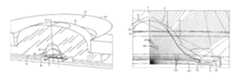
- FIG. 1is an enlarged perspective cross-sectional view of the inventive lens.
- FIG. 2is a greatly enlarged fragmentary cross-sectional side view of the lens of FIG. 1 showing refraction of the emitter light by inner-cavity surface regions and a peripheral inner cavity surface.
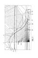
- FIG. 3is an enlarged fragmentary cross-sectional side view of the lens of FIG. 1 showing refraction of light emitted by the emitter at about the emitter axis and including a primary lens.
- FIG. 4is an enlarged fragmentary cross-sectional side view of the lens of FIG. 1 showing refraction of light emitted at the emitter axis.
- FIG. 5is an enlarged fragmentary cross-sectional side view showing non-refracted light direction of light emitted as in FIG. 3 .
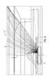
- FIG. 6is an enlarged fragmentary cross-sectional view of the lens of FIG. 1 showing refraction of light emitted from one site of the emitter axis.
- FIG. 7is an enlarged fragmentary cross-sectional view of the lens of FIG. 1 showing refraction of light emitted from another side of the emitter axis.
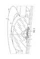
- FIG. 8is a perspective view of an LED light fixture having two optical members with a plurality of lenses in accordance with this invention.
- FIG. 9is a perspective view of the optical member of the LED lighting fixture of FIG. 8 .
- FIG. 10is an enlarged cross-sectional perspective view of one portion of the one-piece optical member of FIG. 9 , illustrating one of the lenses.
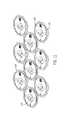
- FIG. 11is a perspective view illustrating the plurality of the lenses.
- FIG. 12is a perspective view of another embodiment of an optical member according to the present invention, shown from the light-output side.
- FIG. 13is a perspective view of the optical member of FIG. 12 , but showing its light-input side.
- FIG. 14is a plan view of the optical member of FIG. 12 .
- FIG. 15is a side sectional view taken along section 15 - 15 as indicated in FIG. 14 .
- FIG. 16is an end sectional view taken along section 16 - 16 as indicated in FIG. 14 .
- FIG. 17is an enlarged perspective view of the lenses arranged as in the optical member of FIG. 12 showing its light-input side.
- FIG. 18is a side elevation of yet another embodiment of a lens according to the present invention, schematically shown with rays representing the direction of light by the lens surfaces seen in a front-to-back plane extending through the emitter axis.
- FIG. 19is a side elevation of still another embodiment of the lens according to the present invention.
- FIG. 20is another side elevation of the lens of FIG. 19 schematically showing rays representing the direction of light by the lens surfaces seen in a side-to-side plane extending through the emitter axis.
- FIG. 21is a side elevation of yet another embodiment of the lens according to the present invention.
- FIGS. 22 and 22Bare another side elevation of the lens of FIG. 21 schematically showing rays representing the direction of light by the lens surfaces seen in a side-to-side plane extending through the emitter axis.
- FIG. 22Ais a fragment of the side elevation of FIG. 22 schematically showing rays representing the direction of axis-adjacent light by the lens surfaces.
- FIG. 23is a side elevation of another embodiment of the lens according to the present invention.
- FIGS. 24 and 25are another side elevation of the lens of FIG. 23 schematically showing rays representing the direction of light by the lens surfaces seen in a side-to-side plane extending through the emitter axis.
- FIG. 26is a perspective view from light output side of the lens of FIG. 23 illustrating an outer-surface feature receiving axial light from the inner surface and further directing such light away from the axis to facilitate diffusion of high-intensity axial light.
- FIG. 27is a plan view of the lens of FIG. 23 showing its light-output side.
- FIGS. 1-7illustrate lens 10 which is a preferred embodiment of the invention.
- Lens 10is for directing light from a light emitter 1 which has an emitter axis 2 and defines an emitter plane 3 .
- Lens 10includes an emitter-adjacent base end 12 forming an opening to an inner cavity 14 surrounding emitter 1 .
- Cavity 14defines a space between emitter 1 and an inner-cavity surface 20 such that emitter light goes through air to enter lens material at inner-cavity surface 20 . Because air and the lens material, which may be acrylic or other suitable material, have different refraction indexes resulting in bending of the light at inner-cavity surface 20 .
- FIG. 2best shows configuration of inner-cavity surface 20 which includes an axis-adjacent first inner region 21 , a second inner region 22 spaced from first inner region 21 , and a middle inner region 23 which joins first and second regions 21 and 22 and is substantially asymptotical to first and second inner regions 21 and 22 .
- FIGS. 1 and 3best show that lens 10 further has an outer surface 30 which includes an axis-adjacent first output region 31 , a second output region 32 spaced from axis-adjacent first output region 31 , and a middle output region 33 joining first and second output regions 31 and 32 .
- Each of output regions 31 , 32 and 33is configured for refracting the light from a corresponding one of inner regions 21 , 22 and 23 . Therefore, at outer surface 30 light from each inner region 21 , 22 or 23 is refracted substantially without overlapping light rays from the other inner regions.
- outer surface 30further includes a base-adjacent outer-surface region 34 which extends from second output region 32 and is substantially free from receiving any emitter light.
- Base-adjacent outer-surface region 34is substantially orthogonal to emitter plane 3 . It should be appreciated that, since the base-adjacent outer-surface substantially does not participate in distribution of emitter light, it may have any configuration dictated by positioning and mounting of the lens or other factors such as material or space conservation.
- FIG. 2best illustrates that axis-adjacent first inner region 21 is configured for refracting emitter light rays 210 which pass through axis-adjacent first inner region 21 away from axis 2 .
- Thisprovides a broader distribution of the light emitted about axis and allows to enlarge the size of first output region 31 to achieve better refraction of light 210 outside lens 10 .
- Light 210 received by the axis-adjacent first inner region 21has the highest intensity. This is because typically the highest illumination intensity of the emitter light is concentrated about axis 2 .
- axis-adjacent inner region 21allows for dispersion of such light 210 over a larger area. This improves uniformity of illumination intensity and substantially decreases a so-called “hot-spot” effect in a plot of illumination intensity distribution.
- FIG. 2further illustrates that axis-adjacent first inner region 21 is substantially cross-sectionally concave.
- second inner region 22is configured for refracting emitter light rays toward the axis. It is seen in FIG. 2 that second inner region 22 is substantially cross-sectionally convex. Second inner region moves light 220 , which mostly includes light emitted within about 30° from emitter plane 3 , away from base-adjacent outer-surface region 34 .
- base-adjacent outer-surface region 34is surrounded by structures 50 which may serve to secure lens 10 with respect to emitter 1 or to be a shield blocking emitter light from going in an undesirable direction. As a result, any light that would arrive at the base-adjacent region 34 would be blocked by such structures 50 and would be eventually lost.
- each one output region of outer surface 30receives light which arrives at substantially narrow sector of angles. This, coupled with improved efficiency which eliminates the need for bending axis-adjacent light for side illumination, simplifies the configuration of that output region of outer surface 30 for refraction of such light in a desired direction and, therefore, decreases a probability of an irregularity impact on the light-output direction.
- middle inner region 23is positioned with respect to emitter 1 to refract light away from axis 2 by progressively lesser amounts at positions progressively closer to the base-adjacent inner region.
- middle region 23may be configured and positioned to allow emitter light to pass therethrough with substantially no refraction.
- middle inner region 23is substantially cross-sectionally linear. In other words, middle inner region 23 is of substantially truncated conical shape.
- axis-adjacent first output region 31is configured for receiving emitter light rays 210 from axis-adjacent first inner region 21 and further refracting them away from axis 2 .
- Second output region 32is configured for receiving emitter light rays 220 from second inner region 22 and refracting them substantially away from axis 22 .
- Middle output region 33is configured for receiving emitter light rays 230 from middle inner region 23 and refracting them substantially away from axis 2 .
- outer surface 30is just an exemplary configuration. Outer surface 30 can have other configurations which would be dictated by an intended illumination pattern.
- Inner-cavity surface 20further includes a base-adjacent inner region 24 extending from second inner region 22 .
- Base-adjacent inner region 24is substantially orthogonal to emitter plane 3 and is oriented for substantially non-refracted passing through of light 240 emitted between second inner region 22 and emitter plane 3 .
- Lens 10further includes a peripheral inner surface 40 which receives light 240 from base-adjacent inner region 24 .
- Peripheral inner surface 40is configured for total internal reflection (TIR) of light 240 toward emitter axis 2 .
- TIRtotal internal reflection
- Peripheral inner surface 40is formed by a peripheral cavity 41 extending from base end 12 .
- peripheral inner surface 41is configured for TIR of light rays 240 before they enter peripheral cavity 41 .
- FIG. 1shows inner-cavity surface 20 substantially rotationally symmetrical.
- Peripheral cavity 41 and peripheral inner surface 40are also substantially rotationally symmetrical.
- the embodiment illustrated in FIG. 1further shows outer surface 30 as substantially rotationally symmetrical such that lens 10 has a substantially annular cross-section in a plane substantially parallel to emitter plane 3 .
- the inner and outer surfacescan have shapes that result in substantially oval or ovoid cross-section made in a plane substantially parallel to the emitter plane. In other words, these surfaces may have symmetries other than rotational.
- the inventive lensmay be shaped without a symmetry and have asymmetrical surfaces.
- FIGS. 8-17illustrate an LED lighting fixture 110 in accordance with the present invention.
- LED light fixture 110includes a heat-sink structure 112 that has a mounting surface 112 A on which a circuit board 114 is mounted.
- Circuit board 114has a plurality of LED light sources 114 A spaced thereon.
- a one-piece optical member 116is positioned over circuit board 114 and has a plurality of secondary lenses 120 thereon, each in alignment with a corresponding one of light sources 114 A.
- FIG. 10best illustrates that each of lenses 120 of one-piece optical member 116 has a layer 122 of polymeric material which extends into a lens flange 124 of such material and is spaced from lens flanges 124 that surround adjacent lenses 120 .
- FIG. 9shows that one-piece optical member 116 also has a polymeric carrier portion 126 surrounding lenses 120 .
- carrier portion 126overlaps with and is molded onto to lens flanges 124 across such overlapping, and carrier portion 126 extends laterally therefrom to a peripheral edge portion 128 .
- the polymeric material of lens 120i.e., the material of layer 122 and flange 124 , is an acrylic, while the polymeric material of carrier portion 126 is a polycarbonate.
- a wide variety of optical-grade acrylicscan be used, and are available from various sources, including: Mitsubishi Rayon America, Inc.; Arkema Group; and Evonik Cyro LLC.
- a wide variety of polycarbonate materialscan be used, and are available from various sources, such as Bayer and Sabic.
- FIG. 11illustrates the positioning of secondary lenses 120 as placed in injection-molding apparatus (not shown). After such placement, carrier portion 126 is injection molded onto lens flanges 124 to form one-piece optical member 116 . As already indicated, carrier portion 126 surrounds lenses 120 and overlaps and is molded onto to lens flanges 124 .
- FIGS. 12-17illustrate aspects of an alternative one-piece optical member 116 A which has three lenses 120 and a carrier portion 126 A. The only significant difference between one-piece optical members 116 and 116 A is the number of lenses.
- FIG. 17like FIG. 11 , illustrates the positioning of secondary lenses 120 as placed in injection-molding apparatus. Accurate placement into the injection-molding apparatus is facilitated by indexing features in the form of posts 130 (see FIGS. 12, 14 and 15 ) which extend from lens flange 124 and mate with corresponding recesses in the mold. ( FIGS. 9 and 10 also show such indexing feature.)
- FIGS. 18-24shows lenses 120 A, 120 B, 120 C and 120 D which are exemplary embodiments of the lens according to the present invention.
- Each of these lenseshas inner surface 20 A-D which defines inner cavity 14 A-D and includes a substantially cross-sectionally convex inner region 22 A-D along an open end of inner cavity 14 A-D.
- convex region 22 A-Dis configured for refracting emitter light rays toward emitter axis 2 .
- lens flange 60 A-Dsurrounding lens 120 A-D and having an outer flange surface 61 A-D extending radially outwardly from lens outer surface 30 A-D at positions axially spaced from light emitter 1 . It is seen in FIGS. 18, 20, 22 and 24 that convex inner region 22 A-D is configured to refract emitter light to the outer surface such that outer flange surface 61 A-D is substantially free from receiving any emitter light.
- FIGS. 18-24also show that inner surface 20 A-D has a substantially cross-sectionally linear inner region 23 A-D which joins substantially cross-sectionally convex inner region 22 A-D and extends therefrom toward emitter axis 1 .
- FIGS. 23 and 24show that, in lens 120 D, substantially cross-sectionally linear inner region 23 D forms a cone-shaped inner surface portion at the closed end of inner cavity 14 D. It is further seen in FIG. 24 that such cone-shaped inner surface portion serves to refract axis-adjacent emitter light away from the axis.
Landscapes
- Physics & Mathematics (AREA)
- Engineering & Computer Science (AREA)
- General Engineering & Computer Science (AREA)
- Optics & Photonics (AREA)
- General Physics & Mathematics (AREA)
- Microelectronics & Electronic Packaging (AREA)
- Non-Portable Lighting Devices Or Systems Thereof (AREA)
- Led Device Packages (AREA)
Abstract
Description
Claims (18)
Priority Applications (1)
| Application Number | Priority Date | Filing Date | Title |
|---|---|---|---|
| US15/236,612US10119662B2 (en) | 2009-04-28 | 2016-08-15 | Lens with controlled light refraction |
Applications Claiming Priority (5)
| Application Number | Priority Date | Filing Date | Title |
|---|---|---|---|
| US12/431,308US9217854B2 (en) | 2009-04-28 | 2009-04-28 | Lens with controlled light refraction |
| US13/843,649US10422503B2 (en) | 2009-10-30 | 2013-03-15 | One-piece multi-lens optical member and method of manufacture |
| US14/155,061US9416926B2 (en) | 2009-04-28 | 2014-01-14 | Lens with inner-cavity surface shaped for controlled light refraction |
| US14/625,712US9915409B2 (en) | 2015-02-19 | 2015-02-19 | Lens with textured surface facilitating light diffusion |
| US15/236,612US10119662B2 (en) | 2009-04-28 | 2016-08-15 | Lens with controlled light refraction |
Related Parent Applications (2)
| Application Number | Title | Priority Date | Filing Date |
|---|---|---|---|
| US12/431,308Continuation-In-PartUS9217854B2 (en) | 2009-04-28 | 2009-04-28 | Lens with controlled light refraction |
| US14/625,712ContinuationUS9915409B2 (en) | 2009-04-28 | 2015-02-19 | Lens with textured surface facilitating light diffusion |
Publications (2)
| Publication Number | Publication Date |
|---|---|
| US20160348858A1 US20160348858A1 (en) | 2016-12-01 |
| US10119662B2true US10119662B2 (en) | 2018-11-06 |
Family
ID=57398239
Family Applications (1)
| Application Number | Title | Priority Date | Filing Date |
|---|---|---|---|
| US15/236,612Active2029-09-06US10119662B2 (en) | 2009-04-28 | 2016-08-15 | Lens with controlled light refraction |
Country Status (1)
| Country | Link |
|---|---|
| US (1) | US10119662B2 (en) |
Cited By (5)
| Publication number | Priority date | Publication date | Assignee | Title |
|---|---|---|---|---|
| US20190338915A1 (en)* | 2018-05-02 | 2019-11-07 | Filament Lighting LLC | Light distribution for planar photonic component |
| US10801696B2 (en) | 2015-02-09 | 2020-10-13 | Ecosense Lighting Inc. | Lighting systems generating partially-collimated light emissions |
| US11306897B2 (en) | 2015-02-09 | 2022-04-19 | Ecosense Lighting Inc. | Lighting systems generating partially-collimated light emissions |
| US11435071B1 (en)* | 2021-03-18 | 2022-09-06 | Bjb Gmbh & Co. Kg | Cover for illuminant and lamp with cover |
| US20230175669A1 (en)* | 2020-11-30 | 2023-06-08 | Hgci, Inc. | Lens cover having lens element |
Citations (66)
| Publication number | Priority date | Publication date | Assignee | Title |
|---|---|---|---|---|
| US1004585A (en) | 1910-08-15 | 1911-10-03 | Multicolor Sign Co | Illuminated sign. |
| US1024695A (en) | 1911-03-24 | 1912-04-30 | Hugh Mulholland | Illuminated sign. |
| US2212876A (en) | 1938-11-05 | 1940-08-27 | Albert L Chauvet | Nonglare headlight |
| US2254961A (en) | 1937-08-21 | 1941-09-02 | George M Cressaty | Unitary lens system |
| US2544413A (en) | 1942-09-05 | 1951-03-06 | Optische Ind De Oude Deift Nv | Optical lens system comprising one or more aspherical refracting surfaces |
| US4186995A (en) | 1978-03-30 | 1980-02-05 | Amp Incorporated | Light device, lens, and fiber optic package |
| US4474437A (en) | 1982-04-12 | 1984-10-02 | Gorenstein Marc V | Teaching aid for simulating gravitational bending of light |
| US4537474A (en) | 1980-07-30 | 1985-08-27 | Optik Innovation Ab Oiab | Optical system for projection |
| US4561736A (en) | 1982-08-07 | 1985-12-31 | Carl-Zeiss-Stiftung | Eyeglass lenses for persons suffering from severe ametropia |
| US4738516A (en) | 1984-01-18 | 1988-04-19 | U.S. Philips Corp. | Optical element having an aspheric surface |
| US5302778A (en) | 1992-08-28 | 1994-04-12 | Eastman Kodak Company | Semiconductor insulation for optical devices |
| US5494615A (en) | 1994-09-28 | 1996-02-27 | Wang Lee; Min-Young | Method and apparatus for manufacturing eyeglasses by forming integrally a frame unit on a lens unit |
| US6033087A (en) | 1996-12-26 | 2000-03-07 | Patlite Corporation | LED illuminating device for providing a uniform light spot |
| US6273596B1 (en) | 1997-09-23 | 2001-08-14 | Teledyne Lighting And Display Products, Inc. | Illuminating lens designed by extrinsic differential geometry |
| US6356395B1 (en) | 1998-09-14 | 2002-03-12 | Fujitsu Limited | Light intensity distribution converting device and optical data storage apparatus |
| US6395201B1 (en) | 2000-02-03 | 2002-05-28 | Visteon Global Technologies, Inc. | Method and manufacturing an automotive reflector |
| US6499870B1 (en) | 1998-11-06 | 2002-12-31 | Reitter & Schefenacker Gmbh & Co. Kg | Tail light for a motor vehicle |
| US6502956B1 (en) | 1999-03-25 | 2003-01-07 | Leotek Electronics Corporation | Light emitting diode lamp with individual LED lenses |
| US6547423B2 (en) | 2000-12-22 | 2003-04-15 | Koninklijke Phillips Electronics N.V. | LED collimation optics with improved performance and reduced size |
| US6598998B2 (en) | 2001-05-04 | 2003-07-29 | Lumileds Lighting, U.S., Llc | Side emitting light emitting device |
| US6616299B2 (en) | 2001-02-02 | 2003-09-09 | Gelcore Llc | Single optical element LED signal |
| US20030235050A1 (en) | 2002-06-24 | 2003-12-25 | West Robert S. | Side emitting led and lens |
| US20040246606A1 (en) | 2002-10-11 | 2004-12-09 | Pablo Benitez | Compact folded-optics illumination lens |
| US6837605B2 (en) | 2001-11-28 | 2005-01-04 | Osram Opto Semiconductors Gmbh | Led illumination system |
| US20050086032A1 (en) | 2003-07-28 | 2005-04-21 | Light Prescriptions Innovators, Llc | Three-dimensional simultaneous multiple-surface method and free-form illumination-optics designed therefrom |
| US20060034082A1 (en) | 2004-08-12 | 2006-02-16 | Samsung Electro-Mechanics Co., Ltd. | Multi-lens light emitting diode |
| US20060232881A1 (en) | 2005-04-18 | 2006-10-19 | Hitachi Global Storage Technologies Netherlands B.V. | Magnetic disk drive and fixing clamp |
| US20060252169A1 (en) | 2004-10-07 | 2006-11-09 | Takeshi Ashida | Transparent member, optical device using transparent member and method of manufacturing optical device |
| US7153002B2 (en) | 2004-10-15 | 2006-12-26 | Samsung Electro-Mechanics Co., Ltd. | Lens for LED light sources |
| US20070058369A1 (en) | 2005-01-26 | 2007-03-15 | Parkyn William A | Linear lenses for LEDs |
| US20070070530A1 (en) | 2005-09-27 | 2007-03-29 | Seo Jung H | Light emitting device package and backlight unit using the same |
| US7227703B2 (en) | 2004-07-02 | 2007-06-05 | Hon Hai Precision Industry Co., Ltd. | Aspheric lens and method for making same |
| US7246931B2 (en) | 2004-12-15 | 2007-07-24 | Epistar Corporation | LED light source |
| US7352011B2 (en) | 2004-11-15 | 2008-04-01 | Philips Lumileds Lighting Company, Llc | Wide emitting lens for LED useful for backlighting |
| US20080084693A1 (en) | 2006-10-10 | 2008-04-10 | Yanchers Corporation | Lighting system |
| US20080089210A1 (en) | 2006-04-24 | 2008-04-17 | Sony Corporation | Solid immersion lens, and condenser lens, optical pickup device, and optical recording/reproducing apparatus including the solid immersion lens |
| US7365916B2 (en) | 2004-09-30 | 2008-04-29 | Nikon Corporation | Aspherical lens and optical instrument using the same |
| US7391580B2 (en) | 2005-11-14 | 2008-06-24 | Zeev Maresse | Ultra compact mono-bloc catadioptric imaging lens |
| US20080151550A1 (en) | 2006-12-22 | 2008-06-26 | Hong Kong Applied Science And Technology Research Institute Co. Ltd. | Light-emitting devices and lens therefor |
| US7411742B1 (en) | 2007-02-20 | 2008-08-12 | Sekonix Co., Ltd. | Focusing lens for LED |
| US20080198604A1 (en) | 2007-02-20 | 2008-08-21 | Sekonix Co., Ltd. | Lighting apparatus using filter and condenser for led illumination |
| US20080203415A1 (en) | 2007-02-13 | 2008-08-28 | 3M Innovative Properties Company | Led devices having lenses and methods of making same |
| US7422347B2 (en) | 2005-03-07 | 2008-09-09 | Nichia Corporation | Planar light source and planar lighting apparatus |
| US20080239722A1 (en) | 2007-04-02 | 2008-10-02 | Ruud Lighting, Inc. | Light-Directing LED Apparatus |
| US20080285136A1 (en) | 2005-08-02 | 2008-11-20 | International Business Machines Corporation | Injection molded microoptics |
| WO2008144672A1 (en) | 2007-05-21 | 2008-11-27 | Illumination Management Solutions, Inc. | An improved led device for wide beam generation and method of making the same |
| US20080294254A1 (en) | 2005-12-06 | 2008-11-27 | Cumming J Stuart | Intraocular lens |
| US20080297020A1 (en) | 2005-09-30 | 2008-12-04 | Osram Opto Semiconductors Gmbh | Illuminiation Arrangement |
| US20080298056A1 (en) | 2007-05-29 | 2008-12-04 | Martin Professional A/S | Light fixture with replaceable optics |
| US20090052192A1 (en) | 2007-08-09 | 2009-02-26 | Sharp Kabushiki Kaisha | Light emitting device and lighting device having the same |
| US7514722B2 (en) | 2005-11-18 | 2009-04-07 | Stanley Electric Co., Ltd. | White LED illumination device |
| US7549769B2 (en) | 2005-08-30 | 2009-06-23 | Samsung Electro-Mechanics Co., Ltd. | LED lens for backlight |
| US20090159915A1 (en) | 2007-12-19 | 2009-06-25 | Shaul Branchevsky | Led insert module and multi-layer lens |
| US20100039810A1 (en) | 2008-08-14 | 2010-02-18 | Cooper Technologies Company | LED Devices for Offset Wide Beam Generation |
| US7722196B2 (en) | 2006-07-14 | 2010-05-25 | Dbm Reflex Enterprises Inc. | Plastic injection of lenses with optical elements and/or retroreflecting prisms that are separated from each other |
| US7766509B1 (en) | 2008-06-13 | 2010-08-03 | Lumec Inc. | Orientable lens for an LED fixture |
| US7766530B2 (en) | 2006-10-31 | 2010-08-03 | Samsung Electronics Co., Ltd. | Backlight, a lens for a backlight, and a backlight assembly having the same |
| US20100271708A1 (en) | 2009-04-28 | 2010-10-28 | Ruud Lighting, Inc. | Lens with controlled light refraction |
| US7874703B2 (en) | 2008-08-28 | 2011-01-25 | Dialight Corporation | Total internal reflection lens with base |
| US7922370B2 (en) | 2009-07-31 | 2011-04-12 | Fu Zhun Precision Industry (Shen Zhen) Co., Ltd. | LED module |
| US20110103051A1 (en) | 2009-10-30 | 2011-05-05 | Ruud Lighting, Inc. | Led apparatus and method for accurate lens alignment |
| WO2012132597A1 (en) | 2011-03-31 | 2012-10-04 | 南部化成株式会社 | Die device for multilayer molding and multilayer molded article |
| US8339716B2 (en) | 2008-12-03 | 2012-12-25 | Philip Premysler | Illumination lenses including light redistributing surfaces |
| US8348475B2 (en) | 2008-05-23 | 2013-01-08 | Ruud Lighting, Inc. | Lens with controlled backlight management |
| US8545049B2 (en) | 2009-11-25 | 2013-10-01 | Cooper Technologies Company | Systems, methods, and devices for sealing LED light sources in a light module |
| US8773616B2 (en) | 2009-10-19 | 2014-07-08 | Panasonic Corporation | Illuminating lens, lighting device, surface light source, and liquid crystal display apparatus |
- 2016
- 2016-08-15USUS15/236,612patent/US10119662B2/enactiveActive
Patent Citations (73)
| Publication number | Priority date | Publication date | Assignee | Title |
|---|---|---|---|---|
| US1004585A (en) | 1910-08-15 | 1911-10-03 | Multicolor Sign Co | Illuminated sign. |
| US1024695A (en) | 1911-03-24 | 1912-04-30 | Hugh Mulholland | Illuminated sign. |
| US2254961A (en) | 1937-08-21 | 1941-09-02 | George M Cressaty | Unitary lens system |
| US2212876A (en) | 1938-11-05 | 1940-08-27 | Albert L Chauvet | Nonglare headlight |
| US2544413A (en) | 1942-09-05 | 1951-03-06 | Optische Ind De Oude Deift Nv | Optical lens system comprising one or more aspherical refracting surfaces |
| US4186995A (en) | 1978-03-30 | 1980-02-05 | Amp Incorporated | Light device, lens, and fiber optic package |
| US4537474A (en) | 1980-07-30 | 1985-08-27 | Optik Innovation Ab Oiab | Optical system for projection |
| US4474437A (en) | 1982-04-12 | 1984-10-02 | Gorenstein Marc V | Teaching aid for simulating gravitational bending of light |
| US4561736A (en) | 1982-08-07 | 1985-12-31 | Carl-Zeiss-Stiftung | Eyeglass lenses for persons suffering from severe ametropia |
| US4738516A (en) | 1984-01-18 | 1988-04-19 | U.S. Philips Corp. | Optical element having an aspheric surface |
| US5302778A (en) | 1992-08-28 | 1994-04-12 | Eastman Kodak Company | Semiconductor insulation for optical devices |
| US5494615A (en) | 1994-09-28 | 1996-02-27 | Wang Lee; Min-Young | Method and apparatus for manufacturing eyeglasses by forming integrally a frame unit on a lens unit |
| US6033087A (en) | 1996-12-26 | 2000-03-07 | Patlite Corporation | LED illuminating device for providing a uniform light spot |
| US6273596B1 (en) | 1997-09-23 | 2001-08-14 | Teledyne Lighting And Display Products, Inc. | Illuminating lens designed by extrinsic differential geometry |
| US6356395B1 (en) | 1998-09-14 | 2002-03-12 | Fujitsu Limited | Light intensity distribution converting device and optical data storage apparatus |
| US20020067549A1 (en) | 1998-09-14 | 2002-06-06 | Fujitsu Limited | Light intensity distribution converting device and optical data storage apparatus |
| US6499870B1 (en) | 1998-11-06 | 2002-12-31 | Reitter & Schefenacker Gmbh & Co. Kg | Tail light for a motor vehicle |
| US6502956B1 (en) | 1999-03-25 | 2003-01-07 | Leotek Electronics Corporation | Light emitting diode lamp with individual LED lenses |
| US6395201B1 (en) | 2000-02-03 | 2002-05-28 | Visteon Global Technologies, Inc. | Method and manufacturing an automotive reflector |
| US6547423B2 (en) | 2000-12-22 | 2003-04-15 | Koninklijke Phillips Electronics N.V. | LED collimation optics with improved performance and reduced size |
| US6616299B2 (en) | 2001-02-02 | 2003-09-09 | Gelcore Llc | Single optical element LED signal |
| US6598998B2 (en) | 2001-05-04 | 2003-07-29 | Lumileds Lighting, U.S., Llc | Side emitting light emitting device |
| US6837605B2 (en) | 2001-11-28 | 2005-01-04 | Osram Opto Semiconductors Gmbh | Led illumination system |
| US20030235050A1 (en) | 2002-06-24 | 2003-12-25 | West Robert S. | Side emitting led and lens |
| US6679621B2 (en) | 2002-06-24 | 2004-01-20 | Lumileds Lighting U.S., Llc | Side emitting LED and lens |
| US7181378B2 (en) | 2002-10-11 | 2007-02-20 | Light Prescriptions Innovators, Llc | Compact folded-optics illumination lens |
| US20040246606A1 (en) | 2002-10-11 | 2004-12-09 | Pablo Benitez | Compact folded-optics illumination lens |
| US6896381B2 (en) | 2002-10-11 | 2005-05-24 | Light Prescriptions Innovators, Llc | Compact folded-optics illumination lens |
| US20050086032A1 (en) | 2003-07-28 | 2005-04-21 | Light Prescriptions Innovators, Llc | Three-dimensional simultaneous multiple-surface method and free-form illumination-optics designed therefrom |
| US7227703B2 (en) | 2004-07-02 | 2007-06-05 | Hon Hai Precision Industry Co., Ltd. | Aspheric lens and method for making same |
| US7153000B2 (en) | 2004-08-12 | 2006-12-26 | Samsung Electro-Mechanics Co., Ltd. | Multi-lens light emitting diode |
| US20060034082A1 (en) | 2004-08-12 | 2006-02-16 | Samsung Electro-Mechanics Co., Ltd. | Multi-lens light emitting diode |
| US7365916B2 (en) | 2004-09-30 | 2008-04-29 | Nikon Corporation | Aspherical lens and optical instrument using the same |
| US20060252169A1 (en) | 2004-10-07 | 2006-11-09 | Takeshi Ashida | Transparent member, optical device using transparent member and method of manufacturing optical device |
| US7153002B2 (en) | 2004-10-15 | 2006-12-26 | Samsung Electro-Mechanics Co., Ltd. | Lens for LED light sources |
| US7352011B2 (en) | 2004-11-15 | 2008-04-01 | Philips Lumileds Lighting Company, Llc | Wide emitting lens for LED useful for backlighting |
| US7246931B2 (en) | 2004-12-15 | 2007-07-24 | Epistar Corporation | LED light source |
| US20070058369A1 (en) | 2005-01-26 | 2007-03-15 | Parkyn William A | Linear lenses for LEDs |
| US7422347B2 (en) | 2005-03-07 | 2008-09-09 | Nichia Corporation | Planar light source and planar lighting apparatus |
| US20060232881A1 (en) | 2005-04-18 | 2006-10-19 | Hitachi Global Storage Technologies Netherlands B.V. | Magnetic disk drive and fixing clamp |
| US20080285136A1 (en) | 2005-08-02 | 2008-11-20 | International Business Machines Corporation | Injection molded microoptics |
| US7549769B2 (en) | 2005-08-30 | 2009-06-23 | Samsung Electro-Mechanics Co., Ltd. | LED lens for backlight |
| US20070070530A1 (en) | 2005-09-27 | 2007-03-29 | Seo Jung H | Light emitting device package and backlight unit using the same |
| US20080297020A1 (en) | 2005-09-30 | 2008-12-04 | Osram Opto Semiconductors Gmbh | Illuminiation Arrangement |
| US7391580B2 (en) | 2005-11-14 | 2008-06-24 | Zeev Maresse | Ultra compact mono-bloc catadioptric imaging lens |
| US7514722B2 (en) | 2005-11-18 | 2009-04-07 | Stanley Electric Co., Ltd. | White LED illumination device |
| US20080294254A1 (en) | 2005-12-06 | 2008-11-27 | Cumming J Stuart | Intraocular lens |
| US20080089210A1 (en) | 2006-04-24 | 2008-04-17 | Sony Corporation | Solid immersion lens, and condenser lens, optical pickup device, and optical recording/reproducing apparatus including the solid immersion lens |
| US7722196B2 (en) | 2006-07-14 | 2010-05-25 | Dbm Reflex Enterprises Inc. | Plastic injection of lenses with optical elements and/or retroreflecting prisms that are separated from each other |
| US20080084693A1 (en) | 2006-10-10 | 2008-04-10 | Yanchers Corporation | Lighting system |
| US7766530B2 (en) | 2006-10-31 | 2010-08-03 | Samsung Electronics Co., Ltd. | Backlight, a lens for a backlight, and a backlight assembly having the same |
| US20080151550A1 (en) | 2006-12-22 | 2008-06-26 | Hong Kong Applied Science And Technology Research Institute Co. Ltd. | Light-emitting devices and lens therefor |
| US20080203415A1 (en) | 2007-02-13 | 2008-08-28 | 3M Innovative Properties Company | Led devices having lenses and methods of making same |
| US20080198604A1 (en) | 2007-02-20 | 2008-08-21 | Sekonix Co., Ltd. | Lighting apparatus using filter and condenser for led illumination |
| US7411742B1 (en) | 2007-02-20 | 2008-08-12 | Sekonix Co., Ltd. | Focusing lens for LED |
| US20080239722A1 (en) | 2007-04-02 | 2008-10-02 | Ruud Lighting, Inc. | Light-Directing LED Apparatus |
| WO2008144672A1 (en) | 2007-05-21 | 2008-11-27 | Illumination Management Solutions, Inc. | An improved led device for wide beam generation and method of making the same |
| US20100238669A1 (en) | 2007-05-21 | 2010-09-23 | Illumination Management Solutions, Inc. | LED Device for Wide Beam Generation and Method of Making the Same |
| US8430538B2 (en) | 2007-05-21 | 2013-04-30 | Illumination Management Solutions, Inc. | LED device for wide beam generation and method of making the same |
| US20080298056A1 (en) | 2007-05-29 | 2008-12-04 | Martin Professional A/S | Light fixture with replaceable optics |
| US20090052192A1 (en) | 2007-08-09 | 2009-02-26 | Sharp Kabushiki Kaisha | Light emitting device and lighting device having the same |
| US20090159915A1 (en) | 2007-12-19 | 2009-06-25 | Shaul Branchevsky | Led insert module and multi-layer lens |
| US8348475B2 (en) | 2008-05-23 | 2013-01-08 | Ruud Lighting, Inc. | Lens with controlled backlight management |
| US7766509B1 (en) | 2008-06-13 | 2010-08-03 | Lumec Inc. | Orientable lens for an LED fixture |
| US20100039810A1 (en) | 2008-08-14 | 2010-02-18 | Cooper Technologies Company | LED Devices for Offset Wide Beam Generation |
| US7874703B2 (en) | 2008-08-28 | 2011-01-25 | Dialight Corporation | Total internal reflection lens with base |
| US8339716B2 (en) | 2008-12-03 | 2012-12-25 | Philip Premysler | Illumination lenses including light redistributing surfaces |
| US20100271708A1 (en) | 2009-04-28 | 2010-10-28 | Ruud Lighting, Inc. | Lens with controlled light refraction |
| US7922370B2 (en) | 2009-07-31 | 2011-04-12 | Fu Zhun Precision Industry (Shen Zhen) Co., Ltd. | LED module |
| US8773616B2 (en) | 2009-10-19 | 2014-07-08 | Panasonic Corporation | Illuminating lens, lighting device, surface light source, and liquid crystal display apparatus |
| US20110103051A1 (en) | 2009-10-30 | 2011-05-05 | Ruud Lighting, Inc. | Led apparatus and method for accurate lens alignment |
| US8545049B2 (en) | 2009-11-25 | 2013-10-01 | Cooper Technologies Company | Systems, methods, and devices for sealing LED light sources in a light module |
| WO2012132597A1 (en) | 2011-03-31 | 2012-10-04 | 南部化成株式会社 | Die device for multilayer molding and multilayer molded article |
Cited By (9)
| Publication number | Priority date | Publication date | Assignee | Title |
|---|---|---|---|---|
| US10801696B2 (en) | 2015-02-09 | 2020-10-13 | Ecosense Lighting Inc. | Lighting systems generating partially-collimated light emissions |
| US11306897B2 (en) | 2015-02-09 | 2022-04-19 | Ecosense Lighting Inc. | Lighting systems generating partially-collimated light emissions |
| US11614217B2 (en) | 2015-02-09 | 2023-03-28 | Korrus, Inc. | Lighting systems generating partially-collimated light emissions |
| US20190338915A1 (en)* | 2018-05-02 | 2019-11-07 | Filament Lighting LLC | Light distribution for planar photonic component |
| US10697612B2 (en)* | 2018-05-02 | 2020-06-30 | Frank Shum | Light distribution for planar photonic component |
| US20230175669A1 (en)* | 2020-11-30 | 2023-06-08 | Hgci, Inc. | Lens cover having lens element |
| US12298000B2 (en)* | 2020-11-30 | 2025-05-13 | Hgci, Inc. | Lens cover having lens element |
| US11435071B1 (en)* | 2021-03-18 | 2022-09-06 | Bjb Gmbh & Co. Kg | Cover for illuminant and lamp with cover |
| US20220299197A1 (en)* | 2021-03-18 | 2022-09-22 | Bjb Gmbh & Co. Kg | Cover for illuminant and lamp with cover |
Also Published As
| Publication number | Publication date |
|---|---|
| US20160348858A1 (en) | 2016-12-01 |
Similar Documents
| Publication | Publication Date | Title |
|---|---|---|
| US9416926B2 (en) | Lens with inner-cavity surface shaped for controlled light refraction | |
| US9217854B2 (en) | Lens with controlled light refraction | |
| EP2435756B1 (en) | Lens with controlled backlight management | |
| US9689552B2 (en) | Multi-lens LED-array optic system | |
| US10119662B2 (en) | Lens with controlled light refraction | |
| JP5785551B2 (en) | Lighting equipment and optical components | |
| CN115597015A (en) | Total internal reflection lens for reducing glare while maintaining color mixing and beam steering of LED light sources | |
| AU2013204682B2 (en) | Lens with controlled backlight management | |
| EP2971946B1 (en) | Lens with controlled light refraction | |
| EP4500077A1 (en) | Lens to produce high angle off-axis light with narrow beam width | |
| JP2011181429A (en) | Led lighting device and method of manufacturing the same | |
| EP2834556A1 (en) | Multi-lens led-array optic system | |
| HK1164979B (en) | Lens with controlled backlight management | |
| HK1164421A (en) | Lens with controlled light refraction | |
| HK40026517B (en) | Total internal reflection lens for lessening glare while maintaining color mixing and beam control of an led light source | |
| HK40026517A (en) | Total internal reflection lens for lessening glare while maintaining color mixing and beam control of an led light source |
Legal Events
| Date | Code | Title | Description |
|---|---|---|---|
| AS | Assignment | Owner name:CREE, INC., NORTH CAROLINA Free format text:ASSIGNMENT OF ASSIGNORS INTEREST;ASSIGNORS:WILCOX, KURT S.;RALEIGH, CRAIG;SIGNING DATES FROM 20140123 TO 20140124;REEL/FRAME:039431/0846 | |
| AS | Assignment | Owner name:CREE, INC., NORTH CAROLINA Free format text:ASSIGNMENT OF ASSIGNORS INTEREST;ASSIGNOR:GOLDSTEIN, COREY;REEL/FRAME:043189/0357 Effective date:20170803 | |
| STCF | Information on status: patent grant | Free format text:PATENTED CASE | |
| AS | Assignment | Owner name:IDEAL INDUSTRIES LIGHTING LLC, ILLINOIS Free format text:ASSIGNMENT OF ASSIGNORS INTEREST;ASSIGNOR:CREE, INC.;REEL/FRAME:049880/0524 Effective date:20190513 | |
| MAFP | Maintenance fee payment | Free format text:PAYMENT OF MAINTENANCE FEE, 4TH YEAR, LARGE ENTITY (ORIGINAL EVENT CODE: M1551); ENTITY STATUS OF PATENT OWNER: LARGE ENTITY Year of fee payment:4 | |
| AS | Assignment | Owner name:FGI WORLDWIDE LLC, NEW YORK Free format text:SECURITY INTEREST;ASSIGNOR:IDEAL INDUSTRIES LIGHTING LLC;REEL/FRAME:064897/0413 Effective date:20230908 |