US10117703B2 - Method of, and device for, marking a patients eye for reference during a toric lens implantation procedure - Google Patents
Method of, and device for, marking a patients eye for reference during a toric lens implantation procedureDownload PDFInfo
- Publication number
- US10117703B2 US10117703B2US13/653,828US201213653828AUS10117703B2US 10117703 B2US10117703 B2US 10117703B2US 201213653828 AUS201213653828 AUS 201213653828AUS 10117703 B2US10117703 B2US 10117703B2
- Authority
- US
- United States
- Prior art keywords
- shaft
- tip
- eye
- marking
- toric lens
- Prior art date
- Legal status (The legal status is an assumption and is not a legal conclusion. Google has not performed a legal analysis and makes no representation as to the accuracy of the status listed.)
- Active, expires
Links
- 238000000034methodMethods0.000titleabstractdescription18
- 238000002513implantationMethods0.000titleabstractdescription8
- 238000009413insulationMethods0.000claimsdescription2
- 210000001508eyeAnatomy0.000description11
- 230000001154acute effectEffects0.000description3
- 201000009310astigmatismDiseases0.000description3
- 230000005611electricityEffects0.000description3
- 230000015572biosynthetic processEffects0.000description2
- 238000005562fadingMethods0.000description2
- 230000023597hemostasisEffects0.000description2
- 239000003550markerSubstances0.000description2
- 208000002177CataractDiseases0.000description1
- 210000005252bulbus oculiAnatomy0.000description1
- 230000008878couplingEffects0.000description1
- 238000010168coupling processMethods0.000description1
- 238000005859coupling reactionMethods0.000description1
- 239000000463materialSubstances0.000description1
- 238000001356surgical procedureMethods0.000description1
Images

Classifications
- A—HUMAN NECESSITIES
- A61—MEDICAL OR VETERINARY SCIENCE; HYGIENE
- A61B—DIAGNOSIS; SURGERY; IDENTIFICATION
- A61B18/00—Surgical instruments, devices or methods for transferring non-mechanical forms of energy to or from the body
- A61B18/04—Surgical instruments, devices or methods for transferring non-mechanical forms of energy to or from the body by heating
- A61B18/12—Surgical instruments, devices or methods for transferring non-mechanical forms of energy to or from the body by heating by passing a current through the tissue to be heated, e.g. high-frequency current
- A61B18/14—Probes or electrodes therefor
- A61B18/1402—Probes for open surgery
- A—HUMAN NECESSITIES
- A61—MEDICAL OR VETERINARY SCIENCE; HYGIENE
- A61B—DIAGNOSIS; SURGERY; IDENTIFICATION
- A61B18/00—Surgical instruments, devices or methods for transferring non-mechanical forms of energy to or from the body
- A61B18/04—Surgical instruments, devices or methods for transferring non-mechanical forms of energy to or from the body by heating
- A61B18/12—Surgical instruments, devices or methods for transferring non-mechanical forms of energy to or from the body by heating by passing a current through the tissue to be heated, e.g. high-frequency current
- A61B18/14—Probes or electrodes therefor
- A61B18/1477—Needle-like probes
- A—HUMAN NECESSITIES
- A61—MEDICAL OR VETERINARY SCIENCE; HYGIENE
- A61F—FILTERS IMPLANTABLE INTO BLOOD VESSELS; PROSTHESES; DEVICES PROVIDING PATENCY TO, OR PREVENTING COLLAPSING OF, TUBULAR STRUCTURES OF THE BODY, e.g. STENTS; ORTHOPAEDIC, NURSING OR CONTRACEPTIVE DEVICES; FOMENTATION; TREATMENT OR PROTECTION OF EYES OR EARS; BANDAGES, DRESSINGS OR ABSORBENT PADS; FIRST-AID KITS
- A61F9/00—Methods or devices for treatment of the eyes; Devices for putting in contact-lenses; Devices to correct squinting; Apparatus to guide the blind; Protective devices for the eyes, carried on the body or in the hand
- A61F9/007—Methods or devices for eye surgery
- A—HUMAN NECESSITIES
- A61—MEDICAL OR VETERINARY SCIENCE; HYGIENE
- A61B—DIAGNOSIS; SURGERY; IDENTIFICATION
- A61B18/00—Surgical instruments, devices or methods for transferring non-mechanical forms of energy to or from the body
- A61B18/04—Surgical instruments, devices or methods for transferring non-mechanical forms of energy to or from the body by heating
- A61B18/12—Surgical instruments, devices or methods for transferring non-mechanical forms of energy to or from the body by heating by passing a current through the tissue to be heated, e.g. high-frequency current
- A61B18/14—Probes or electrodes therefor
- A61B2018/1405—Electrodes having a specific shape
- A61B2018/1422—Hook
- A—HUMAN NECESSITIES
- A61—MEDICAL OR VETERINARY SCIENCE; HYGIENE
- A61B—DIAGNOSIS; SURGERY; IDENTIFICATION
- A61B18/00—Surgical instruments, devices or methods for transferring non-mechanical forms of energy to or from the body
- A61B18/04—Surgical instruments, devices or methods for transferring non-mechanical forms of energy to or from the body by heating
- A61B18/12—Surgical instruments, devices or methods for transferring non-mechanical forms of energy to or from the body by heating by passing a current through the tissue to be heated, e.g. high-frequency current
- A61B18/14—Probes or electrodes therefor
- A61B2018/1405—Electrodes having a specific shape
- A61B2018/1425—Needle
- A61B2018/1432—Needle curved
- A—HUMAN NECESSITIES
- A61—MEDICAL OR VETERINARY SCIENCE; HYGIENE
- A61F—FILTERS IMPLANTABLE INTO BLOOD VESSELS; PROSTHESES; DEVICES PROVIDING PATENCY TO, OR PREVENTING COLLAPSING OF, TUBULAR STRUCTURES OF THE BODY, e.g. STENTS; ORTHOPAEDIC, NURSING OR CONTRACEPTIVE DEVICES; FOMENTATION; TREATMENT OR PROTECTION OF EYES OR EARS; BANDAGES, DRESSINGS OR ABSORBENT PADS; FIRST-AID KITS
- A61F2/00—Filters implantable into blood vessels; Prostheses, i.e. artificial substitutes or replacements for parts of the body; Appliances for connecting them with the body; Devices providing patency to, or preventing collapsing of, tubular structures of the body, e.g. stents
- A61F2/02—Prostheses implantable into the body
- A61F2/14—Eye parts, e.g. lenses or corneal implants; Artificial eyes
- A61F2/16—Intraocular lenses
- A61F2/1613—Intraocular lenses having special lens configurations, e.g. multipart lenses; having particular optical properties, e.g. pseudo-accommodative lenses, lenses having aberration corrections, diffractive lenses, lenses for variably absorbing electromagnetic radiation, lenses having variable focus
- A61F2/1637—Correcting aberrations caused by inhomogeneities; correcting intrinsic aberrations, e.g. of the cornea, of the surface of the natural lens, aspheric, cylindrical, toric lenses
- A61F2/1645—Toric lenses
Definitions
- a method, and device,are provided herein useable for marking a patient's eye for reference during a toric lens implantation procedure.
- Toric lens implantationis known in the art to replace the natural lens of the eye.
- a toric lensis a replacement intraocular lens (TOL) used for cataract patients with pre-existing astigmatism.
- TOLintraocular lens
- the correct angular position of a toric lensis a critical component in order to maximize the amount of astigmatic correction.
- at least one reference markis made on the eye, preferably on or near the limbus, to define a horizontal reference axis.
- alignment mark(s)are subsequently prepared to properly align the toric lens.
- an astigmatic degree gaugee.g., Mendez-style astigmatic degree gauge
- the steep axismay be marked using a marker that combines an astigmatic degree gauge with an inner bezel that marks the steep axis.
- a surgical marking penis used to make the reference marks.
- the thickness of the markeradds error and the ink of the mark is likely to diffuse, fade or disappear as it mixes with the tears from the patient's eye.
- Every degree of inaccuracy in the placement of a toric lensreduces the amount of cylindrical correction by approximately three percent.
- inaccurate or fading reference marksmay present difficulties in achieving the most accurate placement of the toric lens.
- One of the inventors hereinhas utilized a technique in which an electrocautery device, with a straight shaft and an included tip angle of 30°, has been utilized to cauterize one or more reference marks during a toric lens implantation procedure.
- the points of cauterizationprovide fixed reference marks which are not susceptible to fading or other dissipation by the patient's tears.
- the straightness of the shaft of the electrocautery devicemay be cumbersome for some due to the roundness of the patient's eye. With cauterization, sufficiently good contact must be generated between the device and the target location. The angle of inclination of the device relative to the patient's eye is thus critical. Because of the straightness of the shaft, the device may be difficult to handle during marking.
- a methodis provided herein of marking a patient's eye for reference during a toric lens implantation procedure.
- the methodincludes providing an electrocautery device having a handle, a shaft extending from the handle, and a tip defined at the terminus of the shaft.
- the handleis elongated and extends along a longitudinal axis with the shaft being bent or curved such that the tip is spaced from, and not aligned with, the longitudinal axis.
- the methodfurther includes using the electrocautery device to cauterize one or more points on the patient's eye, the points being located as reference marks for placement of the toric lens.
- a deviceis used having a bent or curved shaft which may better accommodate the curvature of a patient's eye while marking.
- the subject inventionalso covers the device useable in the method described herein.
- an electrocautery devicehaving a shaft gauge in the range of 23-27 with an included tip angle in the range of 60°-180°, more preferably, 60°-150°, and more preferably 60°-120°, Forming an included tip angle in accordance with the subject invention allows for smaller, minimally eccentric reference marks to be made during a procedure.
- the included tip angle range of the subject inventionprovides an advantage for both straight-shaft and bent/curved shaft electrocautery devices.
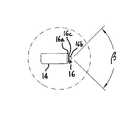
- FIG. 1is a top plan view of a device formed in accordance with the subject invention
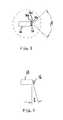
- FIG. 2is a side elevational view of a device formed in accordance with the subject invention.
- FIG. 3is an enlarged view of Section 3 of FIG. 1 ;
- FIG. 4shows a tip useable with the subject invention
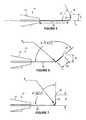
- FIGS. 5-7show different shaft configurations useable with the subject invention
- FIG. 8is a schematic showing a device formed in accordance with the subject invention in use.
- FIG. 9is a schematic showing reference mails performed by the subject invention.
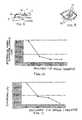
- FIGS. 10-11are plots showing reference mark diameter and eccentricity achievable with the subject invention.
- an electrocautery device 10which generally includes a handle 12 , a shaft 14 extending from the handle 12 , and a tip 16 defined at the terminus of the shaft 14 .
- the device 10is particularly well-suited for use during a toric lens implantation procedure, as described herein, but may have application elsewhere, as will be appreciated by those skilled in the art.
- the device 10is configured to cauterize tissue upon sufficient contact with the tip 16 .
- Various electrocautery devicesare known in the art including devices sold under the tradename “WET-FIELD® ERASER®” by Beaver-Visitec International, Inc. of Waltham, Mass.
- the device 10may, be provided with bipolar diathermy capability, or other features.
- the shaft 14including the tip 16 , may be provided in various gauges, but preferably a smaller-diameter gauge is provided, such as a 20-27 gauge, more preferably, a 23-25 gauge, and even more preferably, a 25 gauge design is provided.
- the tip 16may be tapered to include tip angle ⁇ so as to further reduce the diameter thereabout.
- the device 10may include one or more electrical contacts 18 for electrically coupling to a source of electricity.
- the device 10is configured such that electrical flow is delivered to the tip 16 such that upon contact with the tissue, energy is generated for hemostasis.
- the tip 16may be comprised of three layers (these layers being exposed at the tip 16 ): an outer the 16 a ; an inner conductive wire 16 b ; and, an insulation layer 16 c between the outer tube 16 a and the inner conductive wire 16 b .
- electricityis caused to flow between the inner conductive wire 16 b and the outer the 16 a through tissue in contact with the tip 16 .
- Any known configuration for generating energy for hemostasismay be used.
- the handle 12is formed of an insulative material so as to protect a user from exposure to electrical flow through the device 10 .
- the exposed portions of the shaft 14are also electrically insulated from the flow of electricity.
- the handle 12is elongated and formed to extend along a longitudinal axis X.
- a portion of the shaft 14coincides with the longitudinal axis X.
- the shaft 14is bent or curved such that the tip 16 is spaced from, and not aligned with, the longitudinal axis X.
- Thisprovides the shaft 14 with a length 20 extending between the longitudinal axis X and the tip 16 .
- the length 20is arcuate between the tip 16 and the longitudinal axis X, as shown in FIGS. 2 and 5 . With the length 20 being arcuate, the length 20 may be formed about a radius R. Alternatively, FIGS. 6 and 7 show the length 20 being generally straight.
- the length 20With the length 20 being generally straight, it is preferred that the length 20 extend from the shaft 14 about a joint having a joint radius R J ( FIGS. 6 and 7 ).
- the length 20may be composed of a combination of arcuate and straight portions. It is preferred that the shaft 14 have a length L between the handle 12 and the length 20 in the range of 0.5-1.5 inches.
- the junction between the shaft 14 and the tip 16is disposed along junction angle ⁇ , which may be in the range of 0° to 15° relative to a reference axis perpendicular to the longitudinal axis X.
- the tip 16be located a distance D away from the longitudinal axis X which is preferably in the range of 0.125-0.25 inches. Depending on the configuration of the length 20 , the length 20 may equal the distance D. Further, it is preferred that the length 20 , as oriented at the tip 16 , subtend an approximately right or greater angle ⁇ relative to the longitudinal axis X as measured between the length 20 and the rest of the shaft 14 . It is preferred that the angle ⁇ be in the range of 90°-140°, it is most preferred for the angle ⁇ to be approximately 90 degrees. The angle ⁇ may be acute, but, if acute, preferably, the angle ⁇ is a large acute angle (60 degrees or greater).
- the bent or curved portion of the shaft 14allows for the shaft 14 to extend across a curved portion of a patient's eye without interference therefrom with the tip 16 in contact with a target location.
- the tip 16is in full point contact at the target location.
- one or more points of cauterization 22may be formed on the eye with the device 10 to define one or more reference marks, particularly for defining a reference axis for alignment of a toric lens. It is preferred that the points of cauterization 22 be formed on or near the limbus.
- the tip angle ⁇be in the range of 60°-180°, more preferably in the range of 60°-150°, and more preferably in the range of 60°-120°
- the shaft 14may be bent or curved as described above, or may be straight (i.e., the angle ⁇ being 180°).
- a device as described heremay be used in applications other than toric lens implantation.
- FIGS. 10 and 11tests were conducted using porcine eyeballs to evaluate the performance of the tip angle ⁇ relative to the prior art. With these tests, electrocautery devices (having a 25 gauge) were prepared having all the same characteristics (gauge, electrical input, etc.) except for the included tip angle. As shown in FIG. 10 , it has been found that the tip angle ⁇ formed in accordance with the subject invention provides for formation of a smaller reference mark ( FIG. 10 ), as measured by the diameter of the reference mark, than achievable with a prior art tip design (tip angle of 30°). Also, as shown in FIG.
- the tip angle ⁇ formed in accordance with the subject inventionprovides for less eccentricity in a generated reference mark as compared with reference marks generated by a prior art tip design (tip angle of 30°). Less eccentricity indicates greater circularity (eccentricity of 0.000 indicates complete circularity (no eccentricity)).
- the formation of visible, smaller, minimally-eccentric reference marksis highly desirable and achievable with the subject invention. Such reference marks provide clearer indication of location. Greater variability in surgery exists with larger, eccentric reference marks with a tip angle of 30°. Variation in the reference marks may undesirably result in improper location of the marking of the steep axis of astigmatism.
Landscapes
- Health & Medical Sciences (AREA)
- Engineering & Computer Science (AREA)
- Life Sciences & Earth Sciences (AREA)
- Surgery (AREA)
- General Health & Medical Sciences (AREA)
- Public Health (AREA)
- Heart & Thoracic Surgery (AREA)
- Biomedical Technology (AREA)
- Veterinary Medicine (AREA)
- Animal Behavior & Ethology (AREA)
- Nuclear Medicine, Radiotherapy & Molecular Imaging (AREA)
- Physics & Mathematics (AREA)
- Ophthalmology & Optometry (AREA)
- Plasma & Fusion (AREA)
- Otolaryngology (AREA)
- Medical Informatics (AREA)
- Molecular Biology (AREA)
- Vascular Medicine (AREA)
- Surgical Instruments (AREA)
- Eyeglasses (AREA)
- Prostheses (AREA)
Abstract
Description
Claims (2)
Priority Applications (1)
| Application Number | Priority Date | Filing Date | Title |
|---|---|---|---|
| US13/653,828US10117703B2 (en) | 2011-10-17 | 2012-10-17 | Method of, and device for, marking a patients eye for reference during a toric lens implantation procedure |
Applications Claiming Priority (2)
| Application Number | Priority Date | Filing Date | Title |
|---|---|---|---|
| US201161547877P | 2011-10-17 | 2011-10-17 | |
| US13/653,828US10117703B2 (en) | 2011-10-17 | 2012-10-17 | Method of, and device for, marking a patients eye for reference during a toric lens implantation procedure |
Publications (2)
| Publication Number | Publication Date |
|---|---|
| US20130096547A1 US20130096547A1 (en) | 2013-04-18 |
| US10117703B2true US10117703B2 (en) | 2018-11-06 |
Family
ID=47226398
Family Applications (1)
| Application Number | Title | Priority Date | Filing Date |
|---|---|---|---|
| US13/653,828Active2033-08-29US10117703B2 (en) | 2011-10-17 | 2012-10-17 | Method of, and device for, marking a patients eye for reference during a toric lens implantation procedure |
Country Status (2)
| Country | Link |
|---|---|
| US (1) | US10117703B2 (en) |
| WO (1) | WO2013059289A1 (en) |
Families Citing this family (1)
| Publication number | Priority date | Publication date | Assignee | Title |
|---|---|---|---|---|
| EP3402449A1 (en)* | 2016-01-14 | 2018-11-21 | Beaver-Visitec International, Inc. | Ophthalmic marking device and method of using same |
Citations (15)
| Publication number | Priority date | Publication date | Assignee | Title |
|---|---|---|---|---|
| US4911161A (en)* | 1987-04-29 | 1990-03-27 | Noetix, Inc. | Capsulectomy cutting apparatus |
| US5342357A (en)* | 1992-11-13 | 1994-08-30 | American Cardiac Ablation Co., Inc. | Fluid cooled electrosurgical cauterization system |
| US5445142A (en)* | 1994-03-15 | 1995-08-29 | Ethicon Endo-Surgery, Inc. | Surgical trocars having optical tips defining one or more viewing ports |
| US5951546A (en)* | 1994-12-13 | 1999-09-14 | Lorentzen; Torben | Electrosurgical instrument for tissue ablation, an apparatus, and a method for providing a lesion in damaged and diseased tissue from a mammal |
| US6017340A (en)* | 1994-10-03 | 2000-01-25 | Wiltek Medical Inc. | Pre-curved wire guided papillotome having a shape memory tip for controlled bending and orientation |
| WO2002056805A2 (en) | 2001-01-18 | 2002-07-25 | The Regents Of The University Of California | Minimally invasive glaucoma surgical instrument and method |
| US6428502B1 (en)* | 1999-06-25 | 2002-08-06 | Alcon Manufacturing, Ltd. | Punctal cannula |
| US6920883B2 (en)* | 2001-11-08 | 2005-07-26 | Arthrocare Corporation | Methods and apparatus for skin treatment |
| US6925333B2 (en)* | 2001-05-22 | 2005-08-02 | Peter Krebs | Combination needle for peripheral nerve block |
| US7070596B1 (en)* | 2000-08-09 | 2006-07-04 | Arthrocare Corporation | Electrosurgical apparatus having a curved distal section |
| US20070088352A1 (en) | 2005-10-14 | 2007-04-19 | Rosen Robert S | Method and system for radio frequency ophthalmological presbyopia surgery |
| US20080015565A1 (en)* | 1998-11-20 | 2008-01-17 | Arthrocare Corporation | Electrosurgical apparatus and methods for ablating tissue |
| US20080086160A1 (en)* | 2006-10-06 | 2008-04-10 | Surgiquest, Incorporated | Visualization trocar |
| US20100076428A1 (en)* | 1998-04-15 | 2010-03-25 | Boston Scientific Scimed, Inc. | Electro-cautery catheter |
| US7862563B1 (en)* | 2005-02-18 | 2011-01-04 | Cosman Eric R | Integral high frequency electrode |
- 2012
- 2012-10-17USUS13/653,828patent/US10117703B2/enactiveActive
- 2012-10-17WOPCT/US2012/060572patent/WO2013059289A1/enactiveApplication Filing
Patent Citations (16)
| Publication number | Priority date | Publication date | Assignee | Title |
|---|---|---|---|---|
| US4911161A (en)* | 1987-04-29 | 1990-03-27 | Noetix, Inc. | Capsulectomy cutting apparatus |
| US5342357A (en)* | 1992-11-13 | 1994-08-30 | American Cardiac Ablation Co., Inc. | Fluid cooled electrosurgical cauterization system |
| US5445142A (en)* | 1994-03-15 | 1995-08-29 | Ethicon Endo-Surgery, Inc. | Surgical trocars having optical tips defining one or more viewing ports |
| US6017340A (en)* | 1994-10-03 | 2000-01-25 | Wiltek Medical Inc. | Pre-curved wire guided papillotome having a shape memory tip for controlled bending and orientation |
| US5951546A (en)* | 1994-12-13 | 1999-09-14 | Lorentzen; Torben | Electrosurgical instrument for tissue ablation, an apparatus, and a method for providing a lesion in damaged and diseased tissue from a mammal |
| US20100076428A1 (en)* | 1998-04-15 | 2010-03-25 | Boston Scientific Scimed, Inc. | Electro-cautery catheter |
| US20080015565A1 (en)* | 1998-11-20 | 2008-01-17 | Arthrocare Corporation | Electrosurgical apparatus and methods for ablating tissue |
| US6428502B1 (en)* | 1999-06-25 | 2002-08-06 | Alcon Manufacturing, Ltd. | Punctal cannula |
| US7070596B1 (en)* | 2000-08-09 | 2006-07-04 | Arthrocare Corporation | Electrosurgical apparatus having a curved distal section |
| US20020111608A1 (en)* | 2001-01-18 | 2002-08-15 | George Baerveldt | Minimally invasive glaucoma surgical instrument and method |
| WO2002056805A2 (en) | 2001-01-18 | 2002-07-25 | The Regents Of The University Of California | Minimally invasive glaucoma surgical instrument and method |
| US6925333B2 (en)* | 2001-05-22 | 2005-08-02 | Peter Krebs | Combination needle for peripheral nerve block |
| US6920883B2 (en)* | 2001-11-08 | 2005-07-26 | Arthrocare Corporation | Methods and apparatus for skin treatment |
| US7862563B1 (en)* | 2005-02-18 | 2011-01-04 | Cosman Eric R | Integral high frequency electrode |
| US20070088352A1 (en) | 2005-10-14 | 2007-04-19 | Rosen Robert S | Method and system for radio frequency ophthalmological presbyopia surgery |
| US20080086160A1 (en)* | 2006-10-06 | 2008-04-10 | Surgiquest, Incorporated | Visualization trocar |
Non-Patent Citations (4)
| Title |
|---|
| Beaver-Visitec International Inc., Wet-Field Eraser Precise Targeted Coagulation, 2010, p. 2.* |
| Beaver-Visitec International; XP-055049674; "Wet-Field Eraser"; Nov. 1, 2010; pp. 1-4; Waltham, MA, USA. |
| Robert H. Osher, MD. et al.; "Marking the Axis for a Toric IOL"; Mar. 2009; pp. 37-38. USA. |
| Robert H. Osher, MD.; "Iris fingerprinting: New method of improving accuracy in toric lens orientation"; Cataract Refractive Surgery Today; vol. 36, Feb. 2010, pp. 351-352; USA. |
Also Published As
| Publication number | Publication date |
|---|---|
| US20130096547A1 (en) | 2013-04-18 |
| WO2013059289A1 (en) | 2013-04-25 |
Similar Documents
| Publication | Publication Date | Title |
|---|---|---|
| CN1281182C (en) | Thermokeratoplasty system with power supply that can determine wet or dry cornea | |
| US20220287728A1 (en) | Glenoid anchor guide | |
| US9216053B2 (en) | Elongate member providing a variation in radiopacity | |
| US7593778B2 (en) | Electrosurgical device with improved visibility | |
| CA2778997A1 (en) | Methods and systems for radio frequency neurotomy | |
| CN102821703B (en) | shoulder replacement device | |
| US20160038205A1 (en) | Pedicle screw with electro-conductive coating or portion | |
| US10117703B2 (en) | Method of, and device for, marking a patients eye for reference during a toric lens implantation procedure | |
| US20230082615A1 (en) | Radio frequency surgical instrument | |
| CN106693163B (en) | A kind of directionality DBS electrode and its localization method with cue mark | |
| CN201441526U (en) | Transparent Astigmatic Axial Markers | |
| US20070038276A1 (en) | Instrument for conductive keratoplasty | |
| KR102006907B1 (en) | Surgicalunit for ophthalmology | |
| George et al. | Axis measurement strip for Haag-Streit BM900 series slitlamp | |
| CN209136772U (en) | A kind of open wedge osteotomy device | |
| KR101893926B1 (en) | Marking tool for smile surgery | |
| CN110742685A (en) | Novel nanosecond pulse safety electrode | |
| WO2021056149A1 (en) | Anatomical endpoint positioning method for medial patellofemoral ligament | |
| US20190038340A1 (en) | Radiofrequency cannula with fenestrated active tip | |
| US20210386548A1 (en) | Valve cusp sizer | |
| JP4495045B2 (en) | Corneal marker | |
| US5578049A (en) | Optical zone marker for refractive surgery | |
| CN210843483U (en) | Corneal astigmatism axial marker, marker compass and marker system including them | |
| Yang et al. | Using the arcuate eminence–trigeminal notch line to localize the anterior wall of the internal auditory canal in a subtemporal approach: an anatomical study | |
| US20070038210A1 (en) | Method and system for conductive keratoplasty |
Legal Events
| Date | Code | Title | Description |
|---|---|---|---|
| AS | Assignment | Owner name:GENERAL ELECTRIC CAPITAL CORPORATION, AS AGENT, MA Free format text:SECURITY INTEREST;ASSIGNOR:BEAVER-VISITEC INTERNATIONAL (US), INC.;REEL/FRAME:032738/0320 Effective date:20140422 | |
| AS | Assignment | Owner name:BEAVER-VISITEC INTERNATIONAL (US), INC., ILLINOIS Free format text:ASSIGNMENT OF ASSIGNORS INTEREST;ASSIGNORS:OSHER, ROBERT H.;MURRAY, COLLIN ALEXANDER;SIGNING DATES FROM 20121212 TO 20140522;REEL/FRAME:033054/0980 | |
| AS | Assignment | Owner name:HEALTHCARE FINANCIAL SOLUTIONS, LLC, AS SUCCESSOR Free format text:ASSIGNMENT OF INTELLECTUAL PROPERTY SECURITY AGREEMENT;ASSIGNOR:GENERAL ELECTRIC CAPITAL CORPORATION, AS RETIRING AGENT;REEL/FRAME:037145/0503 Effective date:20151116 | |
| AS | Assignment | Owner name:TURNER ACQUISITION, LLC, MASSACHUSETTS Free format text:RELEASE BY SECURED PARTY;ASSIGNOR:HEALTHCARE FINANCIAL SOLUTIONS, LLC;REEL/FRAME:039771/0931 Effective date:20160819 Owner name:BECTON DICKINSON ACUTECARE, INC., ILLINOIS Free format text:RELEASE BY SECURED PARTY;ASSIGNOR:HEALTHCARE FINANCIAL SOLUTIONS, LLC;REEL/FRAME:039771/0931 Effective date:20160819 Owner name:BEAVER-VISTEC INTERNATIONAL (US), INC., ILLINOIS Free format text:RELEASE BY SECURED PARTY;ASSIGNOR:HEALTHCARE FINANCIAL SOLUTIONS, LLC;REEL/FRAME:039771/0931 Effective date:20160819 Owner name:ULTRACELL MEDICAL TECHNOLOGIES, INC., CONNECTICUT Free format text:RELEASE BY SECURED PARTY;ASSIGNOR:HEALTHCARE FINANCIAL SOLUTIONS, LLC;REEL/FRAME:039771/0931 Effective date:20160819 | |
| AS | Assignment | Owner name:UBS AG, STAMFORD BRANCH, AS COLLATERAL AGENT, CONN Free format text:FIRST LIEN SECURITY AGREEMENT;ASSIGNOR:BEAVER-VISITEC INTERNATIONAL (US), INC.;REEL/FRAME:039781/0437 Effective date:20160819 | |
| AS | Assignment | Owner name:CORTLAND CAPITAL MARKET SERVICES, LLC, ILLINOIS Free format text:SECURITY INTEREST;ASSIGNOR:BEAVER-VISITEC INTERNATIONAL (US), INC.;REEL/FRAME:039808/0810 Effective date:20160819 | |
| AS | Assignment | Owner name:BEAVER-VISITEC INTERNATIONAL (US), INC., ILLINOIS Free format text:RELEASE BY SECURED PARTY;ASSIGNOR:CORTLAND CAPITAL MARKET SERVICES LLC, AS COLLATERAL AGENT;REEL/FRAME:043648/0696 Effective date:20170821 | |
| STCF | Information on status: patent grant | Free format text:PATENTED CASE | |
| AS | Assignment | Owner name:BEAVER-VISITEC INTERNATIONAL (US), INC., ILLINOIS Free format text:RELEASE BY SECURED PARTY;ASSIGNOR:UBS AG, STAMFORD BRANCH;REEL/FRAME:048490/0020 Effective date:20190228 Owner name:GOLDMAN SACHS BANK USA, AS FIRST LIEN COLLATERAL A Free format text:FIRST LIEN PATENT SECURITY AGREEMENT;ASSIGNORS:BEAVER-VISITEC INTERNATIONAL (US), INC.;BEAVER-VISITEC INTERNATIONAL, INC.;REEL/FRAME:048473/0367 Effective date:20190228 Owner name:WILMINGTON TRUST, NATIONAL ASSOCIATION, AS SECOND Free format text:SECOND LIEN PATENT SECURITY AGREEMENT;ASSIGNORS:BEAVER-VISITEC INTERNATIONAL (US), INC.;BEAVER-VISITEC INTERNATIONAL, INC.;REEL/FRAME:048478/0301 Effective date:20190228 Owner name:GOLDMAN SACHS BANK USA, AS FIRST LIEN COLLATERAL AGENT, NEW YORK Free format text:FIRST LIEN PATENT SECURITY AGREEMENT;ASSIGNORS:BEAVER-VISITEC INTERNATIONAL (US), INC.;BEAVER-VISITEC INTERNATIONAL, INC.;REEL/FRAME:048473/0367 Effective date:20190228 Owner name:WILMINGTON TRUST, NATIONAL ASSOCIATION, AS SECOND LIEN COLLATERAL AGENT, DELAWARE Free format text:SECOND LIEN PATENT SECURITY AGREEMENT;ASSIGNORS:BEAVER-VISITEC INTERNATIONAL (US), INC.;BEAVER-VISITEC INTERNATIONAL, INC.;REEL/FRAME:048478/0301 Effective date:20190228 | |
| FEPP | Fee payment procedure | Free format text:ENTITY STATUS SET TO UNDISCOUNTED (ORIGINAL EVENT CODE: BIG.); ENTITY STATUS OF PATENT OWNER: LARGE ENTITY | |
| MAFP | Maintenance fee payment | Free format text:PAYMENT OF MAINTENANCE FEE, 4TH YEAR, LARGE ENTITY (ORIGINAL EVENT CODE: M1551); ENTITY STATUS OF PATENT OWNER: LARGE ENTITY Year of fee payment:4 | |
| AS | Assignment | Owner name:SANNE AGENSYND, S.L.U., SPAIN Free format text:SECOND LIEN PATENT SECURITY AGREEMENT;ASSIGNORS:BEAVER-VISITEC INTERNATIONAL (US), INC.;BEAVER-VISITEC INTERNATIONAL, INC.;REEL/FRAME:060541/0858 Effective date:20220629 | |
| AS | Assignment | Owner name:ARES CAPITAL CORPORATION, AS COLLATERAL AGENT, NEW YORK Free format text:SECURITY INTEREST;ASSIGNORS:BEAVER-VISITEC INTERNATIONAL (US), INC.;BEAVER-VISITEC INTERNATIONAL, INC.;BENZ RESEARCH AND DEVELOPMENT, LLC;AND OTHERS;REEL/FRAME:070442/0001 Effective date:20250307 Owner name:BEAVER-VISITEC INTERNATIONAL, INC., MASSACHUSETTS Free format text:RELEASE BY SECURED PARTY;ASSIGNOR:APEX FINANCIAL SERVICES SPAIN, S.L.U. (FORMERLY SANNE AGENSYND, S.L.U.), AS COLLATERAL AGENT;REEL/FRAME:070442/0729 Effective date:20250307 Owner name:BEAVER-VISITEC INTERNATIONAL (US), INC., MASSACHUSETTS Free format text:RELEASE BY SECURED PARTY;ASSIGNOR:APEX FINANCIAL SERVICES SPAIN, S.L.U. (FORMERLY SANNE AGENSYND, S.L.U.), AS COLLATERAL AGENT;REEL/FRAME:070442/0729 Effective date:20250307 Owner name:BEAVER-VISITEC INTERNATIONAL, INC., MASSACHUSETTS Free format text:RELEASE BY SECURED PARTY;ASSIGNOR:GOLDMAN SACHS BANK USA, AS COLLATERAL AGENT;REEL/FRAME:070442/0705 Effective date:20250307 Owner name:BEAVER-VISITEC INTERNATIONAL (US), INC., MASSACHUSETTS Free format text:RELEASE BY SECURED PARTY;ASSIGNOR:GOLDMAN SACHS BANK USA, AS COLLATERAL AGENT;REEL/FRAME:070442/0705 Effective date:20250307 |