US10113399B2 - Downhole turbine assembly - Google Patents
Downhole turbine assemblyDownload PDFInfo
- Publication number
- US10113399B2 US10113399B2US15/152,189US201615152189AUS10113399B2US 10113399 B2US10113399 B2US 10113399B2US 201615152189 AUS201615152189 AUS 201615152189AUS 10113399 B2US10113399 B2US 10113399B2
- Authority
- US
- United States
- Prior art keywords
- turbine
- downhole
- drill pipe
- fluid flow
- assembly
- Prior art date
- Legal status (The legal status is an assumption and is not a legal conclusion. Google has not performed a legal analysis and makes no representation as to the accuracy of the status listed.)
- Active, expires
Links
- 239000012530fluidSubstances0.000claimsabstractdescription46
- 229910003460diamondInorganic materials0.000claimsdescription7
- 239000010432diamondSubstances0.000claimsdescription7
- 238000007599dischargingMethods0.000claimsdescription4
- 230000000903blocking effectEffects0.000claimsdescription3
- 238000005553drillingMethods0.000description21
- 230000000694effectsEffects0.000description2
- 230000015572biosynthetic processEffects0.000description1
- 238000000605extractionMethods0.000description1
- 238000012423maintenanceMethods0.000description1
- 238000012986modificationMethods0.000description1
- 230000004048modificationEffects0.000description1
Images

Classifications
- E—FIXED CONSTRUCTIONS
- E21—EARTH OR ROCK DRILLING; MINING
- E21B—EARTH OR ROCK DRILLING; OBTAINING OIL, GAS, WATER, SOLUBLE OR MELTABLE MATERIALS OR A SLURRY OF MINERALS FROM WELLS
- E21B41/00—Equipment or details not covered by groups E21B15/00 - E21B40/00
- E21B41/0085—Adaptations of electric power generating means for use in boreholes
Definitions
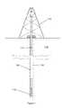
- a specialized drill bit 112may be suspended from a derrick 113 by a drill string 114 as shown in FIG. 1 .
- This drill string 114may be formed from a plurality of drill pipe sections 115 fastened together end-to-end.
- the drill bit 112As the drill bit 112 is rotated, either at the derrick 113 or by a downhole motor, it may engage and degrade a subterranean formation 116 to form a borehole 111 therethrough.
- Drilling fluidmay be passed along the drill string 114 , through each of the drill pipe sections 115 , and expelled at the drill bit 112 to cool and lubricate the drill bit 112 as well as carry loose debris to a surface of the borehole 111 through an annulus surrounding the drill string 114 .
- Various electronic devicessuch as sensors, receivers, communicators or other tools, may be disposed along the drill string or at the drill bit.
- a generatorTo power such devices, it is known to generate electrical power downhole by converting kinetic energy from the flowing drilling fluid by means of a generator.
- a downhole generatoris described in U.S. Pat. No. 8,957,538 to Inman et al. as comprising a turbine located on the axis of a drill pipe, which has outwardly projecting rotor vanes, mounted on a mud-lubricated bearing system to extract energy from the flow.
- the turbinetransmits its mechanical energy via a central shaft to an on-axis electrical generator which houses magnets and coils.
- the turbine described by Inmanis known as an axial turbine because the fluid turning the turbine flows parallel to the turbine's axis of rotation.
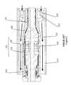
- An example of an axial turbine 220is shown in FIG. 2 connected to a rotor 221 portion of a generator 222 .
- Both axial turbine 220 and rotor 221may be disposed within and coaxial with a section of a drill pipe 215 .
- Drilling fluid 223 flowing through the drill pipe 215may engage a plurality of vanes 224 disposed about the axial turbine 220 causing both axial turbine 220 and rotor 221 to rotate on a fluid-lubricated bearing system 225 .
- the rotor 221comprises a plurality of magnets 226 disposed about the rotor 221 . Movement of the magnets 226 may induce electrical current in coils of wire 227 wound around poles 228 of a stator 229 .
- a downhole turbine assemblymay comprise a tangential turbine disposed within a section of drill pipe.
- a portion of a fluid flowing through the drill pipemay be diverted to the tangential turbine generally perpendicular to the turbine's axis of rotation. After rotating the tangential turbine, the diverted portion may be discharged to an exterior of the drill pipe.
- the pressure difference between fluid inside the drill pipe and fluid outside the drill pipemay be substantial, it may be possible to produce a substantially similar amount of energy from a tangential turbine, as compared to an axial turbine, while utilizing substantially less drilling fluid.
- a substantially similar amount of energyfrom a tangential turbine, as compared to an axial turbine, while utilizing substantially less drilling fluid.
- FIG. 1is an orthogonal view of an embodiment of a drilling operation comprising a drill bit secured to an end of a drill string suspended from a derrick.
- FIG. 2is a schematic representation of an embodiment of an axial turbine of the prior art disposed within a portion of a drill pipe with fluid flowing therethrough.
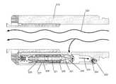
- FIG. 3is a schematic representation of an embodiment of a tangential turbine disposed within a portion of a drill pipe with fluid flowing therethrough.
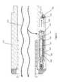
- FIG. 4is a perspective view of an embodiment of a downhole turbine device (shown partially transparent for clarity).
- FIG. 3shows one embodiment of a tangential turbine 320 disposed within a section of a drill pipe 315 .
- a portion of drilling fluid 333 flowing through the drill pipe 315may be diverted away from a primary drilling fluid 323 flow and discharged to an annulus surrounding the drill pipe 315 .
- the diverted portion of drilling fluid 333may be directed toward the tangential turbine 320 within a plane generally perpendicular to an axis of rotation of the tangential turbine 320 .
- the diverted portion of drilling fluid 333may cause the tangential turbine 320 and a rotor 321 connected thereto to rotate.
- the rotor 321may comprise a plurality of magnets 326 disposed about the rotor 321 .
- Movement of the magnets 326may induce electrical current in coils of wire 327 wound around poles 328 of a stator 329 in a generator.
- a plurality of magnets and coils of wiremay be disposed opposite each other on either the rotor or the stator and have the same effect.
- a plurality of magnetsmay be permanent magnets or electromagnets and have the same effect.
- the tangential turbine 320is disposed within a sidewall of the drill pipe 315 .
- a rotational axis of the tangential turbine 320may be parallel to the central axis of the drill pipe while also being offset from the central axis.
- the primary drilling fluid 323 passing through the drill pipe 315is not obstructed by the tangential turbine 320 , allowing for objects to be passed through the drill pipe 315 generally unhindered.
- An outlet 332 for discharging the diverted portion of drilling fluid 333 to an exterior of the drill pipe 315may be disposed on a sidewall of the drill pipe 315 .
- a check valve 334is further disposed within the outlet to allow fluid to exit the drill pipe 315 but not enter.
- PCD bearings 331may support the tangential turbine 320 and rotor 321 allowing them to rotate. It is believed that PCD bearings may require less force to overcome friction than traditional mud-lubricated bearing systems described in the prior art. It is further believed that PDC bearings may be shaped to comprise a gap therebetween sufficient to allow an amount of fluid to pass through while blocking particulate. Allowing fluid to pass while blocking particulate may be desirable to transport heat away from a generator or balance fluid pressures.
- FIG. 4discloses a possible embodiment of a tangential turbine device (part of which is transparent for clarity).
- the devicecomprises a housing 441 with a chamber 442 disposed therein.
- a tangential turbine 420such as an impulse turbine, may be disposed within the chamber 442 and attached to an axle 443 leading to a rotor (not shown).
- the housing 441may comprise at least one inlet 444 , wherein drilling fluid may pass through the housing 441 into the chamber 442 .
- the inlet 444is disposed on a plane perpendicular to a rotational axis of the tangential turbine 420 .
- the inlet 444is also shown offset from the rotational axis of the tangential turbine 420 such that fluid entering the chamber 442 through the inlet 444 may impact a plurality of blades 445 forming part of the tangential turbine 420 to rotate the tangential turbine 420 .
- Each of the plurality of blades 445may comprise a concave surface 446 thereon, disposed on a surface generally parallel to the rotational axis of the tangential turbine 420 , to help catch fluid entering the chamber 442 and convert as much energy therefrom into rotational energy of the tangential turbine 420 .
- three inletsare shown. However, more or less inlets may be preferable.
- at least one outlet 447may allow fluid that enters the chamber 442 to escape.
- the tangential turbine 420may comprise PCD to reduce wear from the fluid entering the chamber 442 .
- the tangential turbine 420may be formed entirely of PCD.
Landscapes
- Life Sciences & Earth Sciences (AREA)
- Engineering & Computer Science (AREA)
- Geology (AREA)
- Mining & Mineral Resources (AREA)
- Physics & Mathematics (AREA)
- Environmental & Geological Engineering (AREA)
- Fluid Mechanics (AREA)
- General Life Sciences & Earth Sciences (AREA)
- Geochemistry & Mineralogy (AREA)
- Earth Drilling (AREA)
- Connection Of Motors, Electrical Generators, Mechanical Devices, And The Like (AREA)
Abstract
Description
This patent application claims priority to U.S. Provisional Pat. App. No. 62/164,933 filed on May 21, 2015 and entitled “Downhole Power Generator”, which is incorporated herein by reference for all that it contains.
In endeavors such as the exploration or extraction of subterranean resources such as oil, gas, and geothermal energy, it is common to form boreholes in the earth. To form such aborehole 111, aspecialized drill bit 112 may be suspended from aderrick 113 by adrill string 114 as shown inFIG. 1 . Thisdrill string 114 may be formed from a plurality ofdrill pipe sections 115 fastened together end-to-end. As thedrill bit 112 is rotated, either at thederrick 113 or by a downhole motor, it may engage and degrade asubterranean formation 116 to form aborehole 111 therethrough. Drilling fluid may be passed along thedrill string 114, through each of thedrill pipe sections 115, and expelled at thedrill bit 112 to cool and lubricate thedrill bit 112 as well as carry loose debris to a surface of theborehole 111 through an annulus surrounding thedrill string 114.
Various electronic devices, such as sensors, receivers, communicators or other tools, may be disposed along the drill string or at the drill bit. To power such devices, it is known to generate electrical power downhole by converting kinetic energy from the flowing drilling fluid by means of a generator. One example of such a downhole generator is described in U.S. Pat. No. 8,957,538 to Inman et al. as comprising a turbine located on the axis of a drill pipe, which has outwardly projecting rotor vanes, mounted on a mud-lubricated bearing system to extract energy from the flow. The turbine transmits its mechanical energy via a central shaft to an on-axis electrical generator which houses magnets and coils.
One limitation of this on-axis arrangement, as identified by Inman, is the difficulty of passing devices through the drill string past the generator. Passing devices through the drill string may be desirable when performing surveys, maintenance and/or fishing operations. To address this problem, Inman provides a detachable section that can be retrieved from the downhole drilling environment to leave an axially-located through bore without removing the entire drill string.
The turbine described by Inman is known as an axial turbine because the fluid turning the turbine flows parallel to the turbine's axis of rotation. An example of anaxial turbine 220 is shown inFIG. 2 connected to arotor 221 portion of agenerator 222. Bothaxial turbine 220 androtor 221 may be disposed within and coaxial with a section of adrill pipe 215. Drillingfluid 223 flowing through thedrill pipe 215 may engage a plurality ofvanes 224 disposed about theaxial turbine 220 causing bothaxial turbine 220 androtor 221 to rotate on a fluid-lubricatedbearing system 225. In the embodiment shown, therotor 221 comprises a plurality ofmagnets 226 disposed about therotor 221. Movement of themagnets 226 may induce electrical current in coils ofwire 227 wound aroundpoles 228 of astator 229.
It may be typical in downhole applications employing an axial turbine to pass around 800 gallons/minute (3.028 m3/min) of drilling fluid past such a turbine. As the drilling fluid rotates the axial turbine, it may experience a pressure drop of approximately 5 pounds/square inch (34.47 kPa). Requiring such a large amount of drilling fluid to rotate a downhole turbine may limit a drilling operator's ability to control other drilling operations that may also require a certain amount of drilling fluid.
A need therefore exists for a downhole turbine that requires less fluid flow to operate. An additional need exists for a downhole turbine that does not require retrieving a detachable section in order to pass devices through a drill string.
A downhole turbine assembly may comprise a tangential turbine disposed within a section of drill pipe. A portion of a fluid flowing through the drill pipe may be diverted to the tangential turbine generally perpendicular to the turbine's axis of rotation. After rotating the tangential turbine, the diverted portion may be discharged to an exterior of the drill pipe.
As the pressure difference between fluid inside the drill pipe and fluid outside the drill pipe may be substantial, it may be possible to produce a substantially similar amount of energy from a tangential turbine, as compared to an axial turbine, while utilizing substantially less drilling fluid. For example, while it may be typical in downhole applications to pass around 800 gallons/minute (3.028 m3/min) of drilling fluid past an axial turbine of the prior art, as discussed previously, which then may experience a pressure drop of around 5 pounds/square inch (34.47 kPa), diverting around 1-10 gallons/minute (0.003785-0.03785 m3/min) of drilling fluid past a tangential turbine and then discharging it to an annulus surrounding a drill pipe may allow that fluid to experience a pressure drop of around 500-1000 pounds/square inch (3,447-6,895 kPa) capable of producing substantially similar energy.
In the embodiment shown, thetangential turbine 320 is disposed within a sidewall of thedrill pipe 315. A rotational axis of thetangential turbine 320 may be parallel to the central axis of the drill pipe while also being offset from the central axis. In this configuration, theprimary drilling fluid 323 passing through thedrill pipe 315 is not obstructed by thetangential turbine 320, allowing for objects to be passed through thedrill pipe 315 generally unhindered.
Anoutlet 332 for discharging the diverted portion ofdrilling fluid 333 to an exterior of thedrill pipe 315 may be disposed on a sidewall of thedrill pipe 315. In the embodiment shown, acheck valve 334 is further disposed within the outlet to allow fluid to exit thedrill pipe 315 but not enter.
Polycrystalline diamond (PCD)bearings 331 may support thetangential turbine 320 androtor 321 allowing them to rotate. It is believed that PCD bearings may require less force to overcome friction than traditional mud-lubricated bearing systems described in the prior art. It is further believed that PDC bearings may be shaped to comprise a gap therebetween sufficient to allow an amount of fluid to pass through while blocking particulate. Allowing fluid to pass while blocking particulate may be desirable to transport heat away from a generator or balance fluid pressures.
Thetangential turbine 420 may comprise PCD to reduce wear from the fluid entering thechamber 442. In some embodiments, thetangential turbine 420 may be formed entirely of PCD.
Whereas the present invention has been described in particular relation to the drawings attached hereto, it should be understood that other and further modifications apart from those shown or suggested herein, may be made within the scope and spirit of the present invention.
Claims (19)
1. A downhole turbine assembly, comprising:
a drill pipe capable of passing a fluid flow there through;
a turbine disposed within a sidewall of the drill pipe, the turbine including a plurality of blades having flat surfaces, at least one blade of the turbine including polycrystalline diamond;
a course capable of diverting a portion of the fluid flow to the turbine; and
an outlet capable of discharging the diverted portion of the fluid flow from within the drill pipe to an exterior of the drill pipe.
2. The downhole turbine assembly ofclaim 1 , wherein the outlet is disposed on a sidewall of the drill pipe.
3. The downhole turbine assembly ofclaim 1 , wherein the course is disposed on a plane perpendicular to a rotational axis of the turbine.
4. The downhole turbine assembly ofclaim 3 , wherein the course is disposed offset from the rotational axis of the turbine.
5. The downhole turbine assembly ofclaim 1 , further comprising a generator connected to the turbine.
6. The downhole turbine assembly ofclaim 1 , wherein the turbine comprises a tangential turbine.
7. The downhole turbine assembly ofclaim 1 , wherein the turbine comprises an impulse turbine.
8. The downhole turbine assembly ofclaim 1 , wherein a housing of the turbine comprises polycrystalline diamond.
9. The downhole turbine assembly ofclaim 8 , wherein the turbine is formed entirely of polycrystalline diamond.
10. The downhole turbine assembly ofclaim 1 , further comprising polycrystalline diamond bearings supporting the turbine.
11. The downhole turbine assembly ofclaim 10 , wherein the polycrystalline diamond bearings supporting the turbine comprise a gap therebetween sufficient to allow an amount of fluid to pass through while blocking particulate.
12. The downhole turbine assembly ofclaim 1 the diverted portion of the fluid flow comprises 1-10 gallons/minute (0.003785-0.03785 m3/min).
13. The downhole turbine assembly ofclaim 1 , wherein the diverted portion of the fluid flow experiences a pressure drop of 500-1000 pounds/square inch (3,447-6,895 kPa) over the turbine.
14. The downhole turbine assembly ofclaim 1 , wherein the turbine comprises a plurality of blades and each of the plurality of blades comprises a concave surface thereon.
15. The downhole turbine assembly ofclaim 14 , wherein each concave surface on each of the plurality of blades is disposed on a surface generally parallel to a rotational axis of the turbine.
16. The downhole turbine assembly ofclaim 1 , wherein the turbine comprises a rotational axis parallel to but offset from a central axis of the drill pipe.
17. The downhole turbine assembly ofclaim 1 , wherein the turbine does not obstruct the fluid flow passing through the drill pipe.
18. The downhole turbine assembly ofclaim 1 , wherein the outlet comprises a check valve.
19. A downhole turbine assembly, comprising:
a drill pipe capable of passing a fluid flow there through, the drill pipe including a sidewall;
a turbine disposed within the sidewall of the drill pipe, the turbine including a plurality of blades having flat surfaces, the turbine formed entirely of polycrystalline diamond such that the turbine can operate when a diverted portion of the fluid flow comprises 1-10 gallons/minute (0.003785-0.03785 m3/min) and when the diverted portion of the fluid flow experiences a pressure drop of 500-1000 pounds/square inch (3,447-6,895 kPa) over the turbine;
a generator connected to the turbine;
a course capable of diverting the diverted portion of the fluid flow to a turbine, the course disposed on a plane perpendicular to a rotational axis of the turbine, and the course is disposed offset from the rotational axis of the turbine; and
an outlet capable of discharging the diverted portion of the fluid flow from within the drill pipe to an exterior of the drill pipe, the outlet disposed on the sidewall of the drill pipe, and the outlet comprises a check valve.
Priority Applications (4)
| Application Number | Priority Date | Filing Date | Title |
|---|---|---|---|
| US15/152,189US10113399B2 (en) | 2015-05-21 | 2016-05-11 | Downhole turbine assembly |
| US15/590,882US10472934B2 (en) | 2015-05-21 | 2017-05-09 | Downhole transducer assembly |
| US16/163,627US10907448B2 (en) | 2015-05-21 | 2018-10-18 | Downhole turbine assembly |
| US17/152,086US11639648B2 (en) | 2015-05-21 | 2021-01-19 | Downhole turbine assembly |
Applications Claiming Priority (2)
| Application Number | Priority Date | Filing Date | Title |
|---|---|---|---|
| US201562164933P | 2015-05-21 | 2015-05-21 | |
| US15/152,189US10113399B2 (en) | 2015-05-21 | 2016-05-11 | Downhole turbine assembly |
Related Child Applications (2)
| Application Number | Title | Priority Date | Filing Date |
|---|---|---|---|
| US15/590,882Continuation-In-PartUS10472934B2 (en) | 2015-05-21 | 2017-05-09 | Downhole transducer assembly |
| US16/163,627ContinuationUS10907448B2 (en) | 2015-05-21 | 2018-10-18 | Downhole turbine assembly |
Publications (2)
| Publication Number | Publication Date |
|---|---|
| US20160341013A1 US20160341013A1 (en) | 2016-11-24 |
| US10113399B2true US10113399B2 (en) | 2018-10-30 |
Family
ID=57325216
Family Applications (3)
| Application Number | Title | Priority Date | Filing Date |
|---|---|---|---|
| US15/152,189Active2036-11-18US10113399B2 (en) | 2015-05-21 | 2016-05-11 | Downhole turbine assembly |
| US16/163,627Active2036-08-09US10907448B2 (en) | 2015-05-21 | 2018-10-18 | Downhole turbine assembly |
| US17/152,086Active2036-06-20US11639648B2 (en) | 2015-05-21 | 2021-01-19 | Downhole turbine assembly |
Family Applications After (2)
| Application Number | Title | Priority Date | Filing Date |
|---|---|---|---|
| US16/163,627Active2036-08-09US10907448B2 (en) | 2015-05-21 | 2018-10-18 | Downhole turbine assembly |
| US17/152,086Active2036-06-20US11639648B2 (en) | 2015-05-21 | 2021-01-19 | Downhole turbine assembly |
Country Status (1)
| Country | Link |
|---|---|
| US (3) | US10113399B2 (en) |
Cited By (5)
| Publication number | Priority date | Publication date | Assignee | Title |
|---|---|---|---|---|
| US20170241242A1 (en)* | 2015-05-21 | 2017-08-24 | Novatek Ip, Llc | Downhole Transducer Assembly |
| US20190048691A1 (en)* | 2015-05-21 | 2019-02-14 | Novatek Ip, Llc | Downhole turbine assembly |
| US10439474B2 (en) | 2016-11-16 | 2019-10-08 | Schlumberger Technology Corporation | Turbines and methods of generating electricity |
| US10927647B2 (en) | 2016-11-15 | 2021-02-23 | Schlumberger Technology Corporation | Systems and methods for directing fluid flow |
| US11454095B1 (en)* | 2021-08-31 | 2022-09-27 | Bosko Gajic | Downhole power and communications system(s) and method(s) of using same |
Families Citing this family (18)
| Publication number | Priority date | Publication date | Assignee | Title |
|---|---|---|---|---|
| US10914138B2 (en)* | 2016-05-20 | 2021-02-09 | Tubel Llc | Downhole power generator and pressure pulser communications module on a side pocket |
| WO2018125048A1 (en)* | 2016-12-27 | 2018-07-05 | Halliburton Energy Services, Inc. | Flow control devices with pressure-balanced pistons |
| GB202218825D0 (en)* | 2018-07-19 | 2023-01-25 | Halliburton Energy Services Inc | Electronic flow control node to aid gravel pack & eliminate wash pipe |
| US11054000B2 (en) | 2018-07-30 | 2021-07-06 | Pi Tech Innovations Llc | Polycrystalline diamond power transmission surfaces |
| US11286985B2 (en) | 2018-07-30 | 2022-03-29 | Xr Downhole Llc | Polycrystalline diamond bearings for rotating machinery with compliance |
| US11187040B2 (en) | 2018-07-30 | 2021-11-30 | XR Downhole, LLC | Downhole drilling tool with a polycrystalline diamond bearing |
| US11371556B2 (en) | 2018-07-30 | 2022-06-28 | Xr Reserve Llc | Polycrystalline diamond linear bearings |
| US10465775B1 (en) | 2018-07-30 | 2019-11-05 | XR Downhole, LLC | Cam follower with polycrystalline diamond engagement element |
| US11035407B2 (en) | 2018-07-30 | 2021-06-15 | XR Downhole, LLC | Material treatments for diamond-on-diamond reactive material bearing engagements |
| US11014759B2 (en) | 2018-07-30 | 2021-05-25 | XR Downhole, LLC | Roller ball assembly with superhard elements |
| US10738821B2 (en) | 2018-07-30 | 2020-08-11 | XR Downhole, LLC | Polycrystalline diamond radial bearing |
| WO2020028674A1 (en) | 2018-08-02 | 2020-02-06 | XR Downhole, LLC | Polycrystalline diamond tubular protection |
| US11603715B2 (en) | 2018-08-02 | 2023-03-14 | Xr Reserve Llc | Sucker rod couplings and tool joints with polycrystalline diamond elements |
| US11236587B2 (en)* | 2018-10-17 | 2022-02-01 | Halliburton Energy Services, Inc. | Magnetic braking system and method for downhole turbine assemblies |
| US12228177B2 (en) | 2020-05-29 | 2025-02-18 | Pi Tech Innovations Llc | Driveline with double conical bearing joints having polycrystalline diamond power transmission surfaces |
| US11614126B2 (en) | 2020-05-29 | 2023-03-28 | Pi Tech Innovations Llc | Joints with diamond bearing surfaces |
| WO2022099186A1 (en) | 2020-11-09 | 2022-05-12 | Gregory Prevost | Diamond surface bearings for sliding engagement with metal surfaces |
| WO2022099184A1 (en) | 2020-11-09 | 2022-05-12 | Gregory Prevost | Continuous diamond surface bearings for sliding engagement with metal surfaces |
Citations (62)
| Publication number | Priority date | Publication date | Assignee | Title |
|---|---|---|---|---|
| US2266355A (en)* | 1940-10-29 | 1941-12-16 | Lane Wells Co | Electrical generator for gun perforators |
| US4132269A (en) | 1978-01-16 | 1979-01-02 | Union Oil Company Of California | Generation of electricity during the injection of a dense fluid into a subterranean formation |
| US4155022A (en) | 1977-06-03 | 1979-05-15 | Otis Engineering Corporation | Line flow electric power generator |
| US4491738A (en) | 1981-11-24 | 1985-01-01 | Shell Internationale Research Maatschappij, B.V. | Means for generating electricity during drilling of a borehole |
| US4532614A (en) | 1981-06-01 | 1985-07-30 | Peppers James M | Wall bore electrical generator |
| US4628995A (en) | 1985-08-12 | 1986-12-16 | Panex Corporation | Gauge carrier |
| US4671735A (en) | 1984-01-19 | 1987-06-09 | Mtu-Motoren-Und Turbinen-Union Munchen Gmbh | Rotor of a compressor, more particularly of an axial-flow compressor |
| US5248896A (en) | 1991-09-05 | 1993-09-28 | Drilex Systems, Inc. | Power generation from a multi-lobed drilling motor |
| US5265682A (en) | 1991-06-25 | 1993-11-30 | Camco Drilling Group Limited | Steerable rotary drilling systems |
| US5285204A (en) | 1992-07-23 | 1994-02-08 | Conoco Inc. | Coil tubing string and downhole generator |
| US5517464A (en) | 1994-05-04 | 1996-05-14 | Schlumberger Technology Corporation | Integrated modulator and turbine-generator for a measurement while drilling tool |
| US5803185A (en) | 1995-02-25 | 1998-09-08 | Camco Drilling Group Limited Of Hycalog | Steerable rotary drilling systems and method of operating such systems |
| US5839508A (en) | 1995-02-09 | 1998-11-24 | Baker Hughes Incorporated | Downhole apparatus for generating electrical power in a well |
| US6386302B1 (en) | 1999-09-09 | 2002-05-14 | Smith International, Inc. | Polycrystaline diamond compact insert reaming tool |
| US20020162654A1 (en) | 1998-12-15 | 2002-11-07 | Bauer William H | Fluid-driven alternator having an internal impeller |
| US6554074B2 (en) | 2001-03-05 | 2003-04-29 | Halliburton Energy Services, Inc. | Lift fluid driven downhole electrical generator and method for use of the same |
| US20030116969A1 (en) | 2001-12-20 | 2003-06-26 | Skinner Neal G. | Annulus pressure operated electric power generator |
| US6672409B1 (en) | 2000-10-24 | 2004-01-06 | The Charles Machine Works, Inc. | Downhole generator for horizontal directional drilling |
| US20050012340A1 (en) | 2003-07-15 | 2005-01-20 | Cousins Edward Thomas | Downhole electrical submersible power generator |
| US6848503B2 (en) | 2002-01-17 | 2005-02-01 | Halliburton Energy Services, Inc. | Wellbore power generating system for downhole operation |
| US6851481B2 (en) | 2000-03-02 | 2005-02-08 | Shell Oil Company | Electro-hydraulically pressurized downhole valve actuator and method of use |
| US20050139393A1 (en) | 2003-12-29 | 2005-06-30 | Noble Drilling Corporation | Turbine generator system and method |
| US20060016606A1 (en) | 2004-07-22 | 2006-01-26 | Tubel Paulo S | Methods and apparatus for in situ generation of power for devices deployed in a tubular |
| US20060100968A1 (en)* | 2004-11-05 | 2006-05-11 | Hall David R | Method for distributing electrical power to downhole tools |
| US20060175838A1 (en) | 2005-02-08 | 2006-08-10 | Tips Timothy R | Downhole electrical power generator |
| US7133325B2 (en) | 2004-03-09 | 2006-11-07 | Schlumberger Technology Corporation | Apparatus and method for generating electrical power in a borehole |
| US7190084B2 (en) | 2004-11-05 | 2007-03-13 | Hall David R | Method and apparatus for generating electrical energy downhole |
| US20070175032A1 (en) | 2006-01-31 | 2007-08-02 | Rolls-Royce Plc | Aerofoil assembly and a method of manufacturing an aerofoil assembly |
| US20070194948A1 (en)* | 2005-05-21 | 2007-08-23 | Hall David R | System and Method for Providing Electrical Power Downhole |
| US20070272410A1 (en) | 2006-05-23 | 2007-11-29 | Schlumberger Technology Corporation | Flow Control System For Use In A Wellbore |
| US20080047753A1 (en) | 2004-11-05 | 2008-02-28 | Hall David R | Downhole Electric Power Generator |
| US20080047754A1 (en) | 2006-08-25 | 2008-02-28 | Smith International, Inc. | Passive vertical drilling motor stabilization |
| US7348893B2 (en) | 2004-12-22 | 2008-03-25 | Schlumberger Technology Corporation | Borehole communication and measurement system |
| US20080226460A1 (en) | 2006-11-24 | 2008-09-18 | Ihi Corporation | Compressor rotor |
| US7434634B1 (en) | 2007-11-14 | 2008-10-14 | Hall David R | Downhole turbine |
| US20080284174A1 (en) | 2005-09-30 | 2008-11-20 | Hydro-Industries Tynat Ltd. | Pipeline Deployed Hydroelectric Generator |
| US20080298962A1 (en) | 2007-05-29 | 2008-12-04 | Sliwa John W | Method and apparatus for reducing bird and fish injuries and deaths at wind and water-turbine power-generation sites |
| US7484576B2 (en) | 2006-03-23 | 2009-02-03 | Hall David R | Jack element in communication with an electric motor and or generator |
| US7537051B1 (en) | 2008-01-29 | 2009-05-26 | Hall David R | Downhole power generation assembly |
| US20100065334A1 (en) | 2005-11-21 | 2010-03-18 | Hall David R | Turbine Driven Hammer that Oscillates at a Constant Frequency |
| US7814993B2 (en) | 2008-07-02 | 2010-10-19 | Robbins & Myers Energy Systems L.P. | Downhole power generator and method |
| US20110273147A1 (en) | 2010-05-04 | 2011-11-10 | Hall David R | Electric Tap in a Voltage Regulator Circuit |
| US20110280105A1 (en) | 2010-05-12 | 2011-11-17 | Hall David R | Downhole Turbine Communication |
| US8092147B2 (en) | 2007-10-17 | 2012-01-10 | Weatherford Energy Services Gmbh | Turbine for power generation in a drill string |
| US8297375B2 (en) | 2005-11-21 | 2012-10-30 | Schlumberger Technology Corporation | Downhole turbine |
| US8596368B2 (en) | 2011-02-04 | 2013-12-03 | Halliburton Energy Services, Inc. | Resettable pressure cycle-operated production valve and method |
| US20140014413A1 (en) | 2012-07-11 | 2014-01-16 | Nobuyoshi Niina | Drilling system with flow control valve |
| US20140174733A1 (en) | 2012-12-20 | 2014-06-26 | Schlumberger Technology Corporation | Power Generation Via Drillstring Pipe Reciprocation |
| US8792304B2 (en) | 2010-05-24 | 2014-07-29 | Schlumberger Technology Corporation | Downlinking communication system and method using signal transition detection |
| US8957538B2 (en) | 2009-08-18 | 2015-02-17 | Halliburton Energy Services, Inc. | Apparatus for downhole power generation |
| US9013957B2 (en) | 2011-08-31 | 2015-04-21 | Teledrill, Inc. | Full flow pulser for measurement while drilling (MWD) device |
| US20150107244A1 (en) | 2007-06-28 | 2015-04-23 | Nikola Lakic | Self-contained in-ground geothermal generator and heat exchanger with in-line pump and several alternative applications |
| US9035788B2 (en) | 2007-10-02 | 2015-05-19 | Schlumberger Technology Corporation | Real time telemetry |
| US9038735B2 (en) | 2010-04-23 | 2015-05-26 | Bench Tree Group LLC | Electromechanical actuator apparatus and method for down-hole tools |
| US20150194860A1 (en)* | 2014-01-09 | 2015-07-09 | Intevep, S.A. | Microgenerator for hydrocarbon producing systems |
| US20160017693A1 (en) | 2012-06-20 | 2016-01-21 | Halliburton Energy Services, Inc. | Fluid-Driven Power Generation Unit for a Drill String Assembly |
| US9312557B2 (en) | 2005-05-11 | 2016-04-12 | Schlumberger Technology Corporation | Fuel cell apparatus and method for downhole power systems |
| US9356497B2 (en) | 2012-08-30 | 2016-05-31 | Halliburton Energy Services, Inc. | Variable-output generator for downhole power production |
| US20160265315A1 (en) | 2014-09-19 | 2016-09-15 | Halliburton Energy Services, Inc. | Transverse flow downhole power generator |
| US20160341012A1 (en)* | 2014-12-09 | 2016-11-24 | Halliburton Energy Services, Inc. | Downhole turbine assembly |
| US9546539B2 (en) | 2008-06-25 | 2017-01-17 | Expro North Sea Limited | Downhole power generation |
| US9598937B2 (en) | 2011-08-30 | 2017-03-21 | China Petroleum & Chemical Corporation | Rotating magnetic field downhole power generation device |
Family Cites Families (12)
| Publication number | Priority date | Publication date | Assignee | Title |
|---|---|---|---|---|
| US3534822A (en)* | 1967-10-02 | 1970-10-20 | Walker Neer Mfg Co | Well circulating device |
| EP0520566B1 (en) | 1991-06-24 | 1996-03-13 | NORSK HYDRO a.s. | Valve device having stationary and movable or turnable valve bodies |
| US6668935B1 (en) | 1999-09-24 | 2003-12-30 | Schlumberger Technology Corporation | Valve for use in wells |
| NO20110958A1 (en) | 2011-07-01 | 2013-01-02 | Aker Solutions As | Port valve |
| US9863238B2 (en)* | 2013-07-30 | 2018-01-09 | Schlumberger Technology Corporation | Submersible electrical machine and method |
| US20150090444A1 (en)* | 2013-09-30 | 2015-04-02 | Schlumberger Technology Corporation | Power systems for wireline well service using wired pipe string |
| FR3014994B1 (en) | 2013-12-18 | 2016-08-05 | Commissariat Energie Atomique | VALVE FOR FLUID CIRCULATION |
| CN104265168B (en) | 2014-07-28 | 2016-08-17 | 西南石油大学 | Drill-bit type rotary guiding device is pointed in interior a kind of biasing |
| US10472934B2 (en) | 2015-05-21 | 2019-11-12 | Novatek Ip, Llc | Downhole transducer assembly |
| US10113399B2 (en) | 2015-05-21 | 2018-10-30 | Novatek Ip, Llc | Downhole turbine assembly |
| WO2018093355A1 (en) | 2016-11-15 | 2018-05-24 | Schlumberger Technology Corporation | Systems and methods for directing fluid flow |
| US10439474B2 (en) | 2016-11-16 | 2019-10-08 | Schlumberger Technology Corporation | Turbines and methods of generating electricity |
- 2016
- 2016-05-11USUS15/152,189patent/US10113399B2/enactiveActive
- 2018
- 2018-10-18USUS16/163,627patent/US10907448B2/enactiveActive
- 2021
- 2021-01-19USUS17/152,086patent/US11639648B2/enactiveActive
Patent Citations (80)
| Publication number | Priority date | Publication date | Assignee | Title |
|---|---|---|---|---|
| US2266355A (en)* | 1940-10-29 | 1941-12-16 | Lane Wells Co | Electrical generator for gun perforators |
| US4155022A (en) | 1977-06-03 | 1979-05-15 | Otis Engineering Corporation | Line flow electric power generator |
| US4132269A (en) | 1978-01-16 | 1979-01-02 | Union Oil Company Of California | Generation of electricity during the injection of a dense fluid into a subterranean formation |
| US4532614A (en) | 1981-06-01 | 1985-07-30 | Peppers James M | Wall bore electrical generator |
| US4491738A (en) | 1981-11-24 | 1985-01-01 | Shell Internationale Research Maatschappij, B.V. | Means for generating electricity during drilling of a borehole |
| US4671735A (en) | 1984-01-19 | 1987-06-09 | Mtu-Motoren-Und Turbinen-Union Munchen Gmbh | Rotor of a compressor, more particularly of an axial-flow compressor |
| US4628995A (en) | 1985-08-12 | 1986-12-16 | Panex Corporation | Gauge carrier |
| US5265682A (en) | 1991-06-25 | 1993-11-30 | Camco Drilling Group Limited | Steerable rotary drilling systems |
| US5248896A (en) | 1991-09-05 | 1993-09-28 | Drilex Systems, Inc. | Power generation from a multi-lobed drilling motor |
| US5285204A (en) | 1992-07-23 | 1994-02-08 | Conoco Inc. | Coil tubing string and downhole generator |
| US5517464A (en) | 1994-05-04 | 1996-05-14 | Schlumberger Technology Corporation | Integrated modulator and turbine-generator for a measurement while drilling tool |
| US5839508A (en) | 1995-02-09 | 1998-11-24 | Baker Hughes Incorporated | Downhole apparatus for generating electrical power in a well |
| US6089332A (en) | 1995-02-25 | 2000-07-18 | Camco International (Uk) Limited | Steerable rotary drilling systems |
| US5803185A (en) | 1995-02-25 | 1998-09-08 | Camco Drilling Group Limited Of Hycalog | Steerable rotary drilling systems and method of operating such systems |
| US20020162654A1 (en) | 1998-12-15 | 2002-11-07 | Bauer William H | Fluid-driven alternator having an internal impeller |
| US6607030B2 (en) | 1998-12-15 | 2003-08-19 | Reuter-Stokes, Inc. | Fluid-driven alternator having an internal impeller |
| US20020125047A1 (en) | 1999-09-09 | 2002-09-12 | Beaton Timothy P. | Polycrystaline diamond compact insert reaming tool |
| US7293617B2 (en) | 1999-09-09 | 2007-11-13 | Smith International, Inc. | Polycrystaline diamond compact insert reaming tool |
| US6386302B1 (en) | 1999-09-09 | 2002-05-14 | Smith International, Inc. | Polycrystaline diamond compact insert reaming tool |
| US20040206552A1 (en) | 1999-09-09 | 2004-10-21 | Beaton Timothy P. | Polycrystaline diamond compact insert reaming tool |
| US20070029115A1 (en) | 1999-09-09 | 2007-02-08 | Smith International, Inc. | Polycrystaline diamond compact insert reaming tool |
| US7137463B2 (en) | 1999-09-09 | 2006-11-21 | Smith International, Inc. | Polycrystaline diamond compact insert reaming tool |
| US6851481B2 (en) | 2000-03-02 | 2005-02-08 | Shell Oil Company | Electro-hydraulically pressurized downhole valve actuator and method of use |
| US6672409B1 (en) | 2000-10-24 | 2004-01-06 | The Charles Machine Works, Inc. | Downhole generator for horizontal directional drilling |
| US6554074B2 (en) | 2001-03-05 | 2003-04-29 | Halliburton Energy Services, Inc. | Lift fluid driven downhole electrical generator and method for use of the same |
| US20030116969A1 (en) | 2001-12-20 | 2003-06-26 | Skinner Neal G. | Annulus pressure operated electric power generator |
| US6717283B2 (en) | 2001-12-20 | 2004-04-06 | Halliburton Energy Services, Inc. | Annulus pressure operated electric power generator |
| US6848503B2 (en) | 2002-01-17 | 2005-02-01 | Halliburton Energy Services, Inc. | Wellbore power generating system for downhole operation |
| US7002261B2 (en) | 2003-07-15 | 2006-02-21 | Conocophillips Company | Downhole electrical submersible power generator |
| US20050012340A1 (en) | 2003-07-15 | 2005-01-20 | Cousins Edward Thomas | Downhole electrical submersible power generator |
| US20050139393A1 (en) | 2003-12-29 | 2005-06-30 | Noble Drilling Corporation | Turbine generator system and method |
| US7133325B2 (en) | 2004-03-09 | 2006-11-07 | Schlumberger Technology Corporation | Apparatus and method for generating electrical power in a borehole |
| US20060016606A1 (en) | 2004-07-22 | 2006-01-26 | Tubel Paulo S | Methods and apparatus for in situ generation of power for devices deployed in a tubular |
| US20060100968A1 (en)* | 2004-11-05 | 2006-05-11 | Hall David R | Method for distributing electrical power to downhole tools |
| US8033328B2 (en) | 2004-11-05 | 2011-10-11 | Schlumberger Technology Corporation | Downhole electric power generator |
| US7190084B2 (en) | 2004-11-05 | 2007-03-13 | Hall David R | Method and apparatus for generating electrical energy downhole |
| US20080047753A1 (en) | 2004-11-05 | 2008-02-28 | Hall David R | Downhole Electric Power Generator |
| US7348893B2 (en) | 2004-12-22 | 2008-03-25 | Schlumberger Technology Corporation | Borehole communication and measurement system |
| US20060175838A1 (en) | 2005-02-08 | 2006-08-10 | Tips Timothy R | Downhole electrical power generator |
| US9312557B2 (en) | 2005-05-11 | 2016-04-12 | Schlumberger Technology Corporation | Fuel cell apparatus and method for downhole power systems |
| US20070194948A1 (en)* | 2005-05-21 | 2007-08-23 | Hall David R | System and Method for Providing Electrical Power Downhole |
| US20080284174A1 (en) | 2005-09-30 | 2008-11-20 | Hydro-Industries Tynat Ltd. | Pipeline Deployed Hydroelectric Generator |
| US20100065334A1 (en) | 2005-11-21 | 2010-03-18 | Hall David R | Turbine Driven Hammer that Oscillates at a Constant Frequency |
| US8297378B2 (en) | 2005-11-21 | 2012-10-30 | Schlumberger Technology Corporation | Turbine driven hammer that oscillates at a constant frequency |
| US8297375B2 (en) | 2005-11-21 | 2012-10-30 | Schlumberger Technology Corporation | Downhole turbine |
| US20070175032A1 (en) | 2006-01-31 | 2007-08-02 | Rolls-Royce Plc | Aerofoil assembly and a method of manufacturing an aerofoil assembly |
| US8656589B2 (en) | 2006-01-31 | 2014-02-25 | Rolls-Royce Plc | Aerofoil assembly and a method of manufacturing an aerofoil assembly |
| US7484576B2 (en) | 2006-03-23 | 2009-02-03 | Hall David R | Jack element in communication with an electric motor and or generator |
| US20070272410A1 (en) | 2006-05-23 | 2007-11-29 | Schlumberger Technology Corporation | Flow Control System For Use In A Wellbore |
| US7650952B2 (en) | 2006-08-25 | 2010-01-26 | Smith International, Inc. | Passive vertical drilling motor stabilization |
| US20080047754A1 (en) | 2006-08-25 | 2008-02-28 | Smith International, Inc. | Passive vertical drilling motor stabilization |
| US8366400B2 (en) | 2006-11-24 | 2013-02-05 | Ihi Corporation | Compressor rotor |
| US20080226460A1 (en) | 2006-11-24 | 2008-09-18 | Ihi Corporation | Compressor rotor |
| US9046080B2 (en) | 2007-05-29 | 2015-06-02 | John W. Sliwa | Method and apparatus for reducing bird and fish injuries and deaths at wind and water-turbine power-generation sites |
| US20080298962A1 (en) | 2007-05-29 | 2008-12-04 | Sliwa John W | Method and apparatus for reducing bird and fish injuries and deaths at wind and water-turbine power-generation sites |
| US20150107244A1 (en) | 2007-06-28 | 2015-04-23 | Nikola Lakic | Self-contained in-ground geothermal generator and heat exchanger with in-line pump and several alternative applications |
| US9035788B2 (en) | 2007-10-02 | 2015-05-19 | Schlumberger Technology Corporation | Real time telemetry |
| US8092147B2 (en) | 2007-10-17 | 2012-01-10 | Weatherford Energy Services Gmbh | Turbine for power generation in a drill string |
| US7451835B1 (en) | 2007-11-14 | 2008-11-18 | Hall David R | Downhole turbine |
| US7434634B1 (en) | 2007-11-14 | 2008-10-14 | Hall David R | Downhole turbine |
| US7537051B1 (en) | 2008-01-29 | 2009-05-26 | Hall David R | Downhole power generation assembly |
| US9546539B2 (en) | 2008-06-25 | 2017-01-17 | Expro North Sea Limited | Downhole power generation |
| US7814993B2 (en) | 2008-07-02 | 2010-10-19 | Robbins & Myers Energy Systems L.P. | Downhole power generator and method |
| US9534577B2 (en) | 2009-08-18 | 2017-01-03 | Halliburton Energy Services, Inc. | Apparatus for downhole power generation |
| US8957538B2 (en) | 2009-08-18 | 2015-02-17 | Halliburton Energy Services, Inc. | Apparatus for downhole power generation |
| US9038735B2 (en) | 2010-04-23 | 2015-05-26 | Bench Tree Group LLC | Electromechanical actuator apparatus and method for down-hole tools |
| US20110273147A1 (en) | 2010-05-04 | 2011-11-10 | Hall David R | Electric Tap in a Voltage Regulator Circuit |
| US20110280105A1 (en) | 2010-05-12 | 2011-11-17 | Hall David R | Downhole Turbine Communication |
| US8792304B2 (en) | 2010-05-24 | 2014-07-29 | Schlumberger Technology Corporation | Downlinking communication system and method using signal transition detection |
| US8596368B2 (en) | 2011-02-04 | 2013-12-03 | Halliburton Energy Services, Inc. | Resettable pressure cycle-operated production valve and method |
| US9598937B2 (en) | 2011-08-30 | 2017-03-21 | China Petroleum & Chemical Corporation | Rotating magnetic field downhole power generation device |
| US9013957B2 (en) | 2011-08-31 | 2015-04-21 | Teledrill, Inc. | Full flow pulser for measurement while drilling (MWD) device |
| US20160017693A1 (en) | 2012-06-20 | 2016-01-21 | Halliburton Energy Services, Inc. | Fluid-Driven Power Generation Unit for a Drill String Assembly |
| US20140014413A1 (en) | 2012-07-11 | 2014-01-16 | Nobuyoshi Niina | Drilling system with flow control valve |
| US9356497B2 (en) | 2012-08-30 | 2016-05-31 | Halliburton Energy Services, Inc. | Variable-output generator for downhole power production |
| US9309748B2 (en) | 2012-12-20 | 2016-04-12 | Schlumberger Technology Corporation | Power generation via drillstring pipe reciprocation |
| US20140174733A1 (en) | 2012-12-20 | 2014-06-26 | Schlumberger Technology Corporation | Power Generation Via Drillstring Pipe Reciprocation |
| US20150194860A1 (en)* | 2014-01-09 | 2015-07-09 | Intevep, S.A. | Microgenerator for hydrocarbon producing systems |
| US20160265315A1 (en) | 2014-09-19 | 2016-09-15 | Halliburton Energy Services, Inc. | Transverse flow downhole power generator |
| US20160341012A1 (en)* | 2014-12-09 | 2016-11-24 | Halliburton Energy Services, Inc. | Downhole turbine assembly |
Non-Patent Citations (2)
| Title |
|---|
| International Search Report and Written Opinion issued in International Patent Application PCT/US2016/062116, dated Sep. 26, 2017. 23 pages. |
| Office Action Issued in U.S. Appl. No. 15/352,620 dated Dec. 27, 2017. 10 pages. |
Cited By (10)
| Publication number | Priority date | Publication date | Assignee | Title |
|---|---|---|---|---|
| US20170241242A1 (en)* | 2015-05-21 | 2017-08-24 | Novatek Ip, Llc | Downhole Transducer Assembly |
| US20190048691A1 (en)* | 2015-05-21 | 2019-02-14 | Novatek Ip, Llc | Downhole turbine assembly |
| US10472934B2 (en)* | 2015-05-21 | 2019-11-12 | Novatek Ip, Llc | Downhole transducer assembly |
| US10907448B2 (en)* | 2015-05-21 | 2021-02-02 | Novatek Ip, Llc | Downhole turbine assembly |
| US11639648B2 (en) | 2015-05-21 | 2023-05-02 | Schlumberger Technology Corporation | Downhole turbine assembly |
| US10927647B2 (en) | 2016-11-15 | 2021-02-23 | Schlumberger Technology Corporation | Systems and methods for directing fluid flow |
| US11608719B2 (en) | 2016-11-15 | 2023-03-21 | Schlumberger Technology Corporation | Controlling fluid flow through a valve |
| US10439474B2 (en) | 2016-11-16 | 2019-10-08 | Schlumberger Technology Corporation | Turbines and methods of generating electricity |
| US11454095B1 (en)* | 2021-08-31 | 2022-09-27 | Bosko Gajic | Downhole power and communications system(s) and method(s) of using same |
| US12385361B2 (en) | 2021-08-31 | 2025-08-12 | Bosko Gajic | Downhole power and communications system(s) and method(s) of using same |
Also Published As
| Publication number | Publication date |
|---|---|
| US20210140277A1 (en) | 2021-05-13 |
| US20160341013A1 (en) | 2016-11-24 |
| US10907448B2 (en) | 2021-02-02 |
| US11639648B2 (en) | 2023-05-02 |
| US20190048691A1 (en) | 2019-02-14 |
Similar Documents
| Publication | Publication Date | Title |
|---|---|---|
| US11639648B2 (en) | Downhole turbine assembly | |
| US10287853B2 (en) | Well debris handling system | |
| US8957538B2 (en) | Apparatus for downhole power generation | |
| US9366100B1 (en) | Hydraulic pipe string vibrator | |
| EP3204597B1 (en) | Apparatus for power generation in a fluid system | |
| US10280717B2 (en) | Downhole turbine assembly | |
| US10472934B2 (en) | Downhole transducer assembly | |
| US20120091732A1 (en) | Power generating apparatus with an annular turbine | |
| US20150027781A1 (en) | Mud lift pump for dual drill string | |
| RU2616198C2 (en) | System of downhole electric generator, system of bore hole, containing the system of downhole electric generator, and method of electrical power generation by the system of bore hole | |
| US10480522B2 (en) | Abrasion-resistant thrust ring for use with a downhole electrical submersible pump | |
| CN110088424A (en) | Pit shaft clast processor for electric submersible pump | |
| US10450849B2 (en) | System and method for system and method for a turbomachine multiphase hyrdrocarbon pump having an auger coupling | |
| US11692551B2 (en) | Particle guard ring for mixed flow pump | |
| RU2265720C1 (en) | Electric generator to supply power to bottomhole telemetering system | |
| RU2325519C1 (en) | Borehole birotatory electric generator | |
| US6361280B1 (en) | System and method for locking parts to a rotatable shaft | |
| RU2337240C1 (en) | Downhole electric generator | |
| RU2326238C1 (en) | Birotatory borehole electric generator | |
| Mokaramian et al. | CFD Simulation of Turbodrill Performance with Asymmetric Stator and Rotor Blades Configuration | |
| RU2321742C1 (en) | Electric generator | |
| AU2014280874A1 (en) | Apparatus for downhole power generation | |
| Kizaki et al. | Development of low speed self-rotating nozzle system for drilling |
Legal Events
| Date | Code | Title | Description |
|---|---|---|---|
| AS | Assignment | Owner name:NOVATEK IP, LLC, UTAH Free format text:ASSIGNMENT OF ASSIGNORS INTEREST;ASSIGNORS:HALL, DAVID R.;MARSHALL, JONATHAN;ENGLUND, JORDAN D.;REEL/FRAME:038717/0035 Effective date:20160509 | |
| AS | Assignment | Owner name:NOVATEK IP, LLC, UTAH Free format text:ASSIGNMENT OF ASSIGNORS INTEREST;ASSIGNORS:HALL, DAVID R.;MARSHALL, JONATHAN;ENGLUND, JORDAN D.;SIGNING DATES FROM 20180417 TO 20180423;REEL/FRAME:045609/0970 | |
| STCF | Information on status: patent grant | Free format text:PATENTED CASE | |
| MAFP | Maintenance fee payment | Free format text:PAYMENT OF MAINTENANCE FEE, 4TH YEAR, LARGE ENTITY (ORIGINAL EVENT CODE: M1551); ENTITY STATUS OF PATENT OWNER: LARGE ENTITY Year of fee payment:4 | |
| AS | Assignment | Owner name:SCHLUMBERGER TECHNOLOGY CORPORATION, TEXAS Free format text:MERGER;ASSIGNOR:NOVATEK IP, LLC;REEL/FRAME:060722/0014 Effective date:20211027 |