US10111760B2 - Bone fusion system, device and method including a measuring mechanism - Google Patents
Bone fusion system, device and method including a measuring mechanismDownload PDFInfo
- Publication number
- US10111760B2 US10111760B2US15/409,407US201715409407AUS10111760B2US 10111760 B2US10111760 B2US 10111760B2US 201715409407 AUS201715409407 AUS 201715409407AUS 10111760 B2US10111760 B2US 10111760B2
- Authority
- US
- United States
- Prior art keywords
- screw
- gear
- bone fusion
- fusion device
- insertion instrument
- Prior art date
- Legal status (The legal status is an assumption and is not a legal conclusion. Google has not performed a legal analysis and makes no representation as to the accuracy of the status listed.)
- Active
Links
- UMWXVJNTXXGODU-WNBHMGEASA-NNC(CC1)[C@H]2C1C1C2C1Chemical compoundNC(CC1)[C@H]2C1C1C2C1UMWXVJNTXXGODU-WNBHMGEASA-N0.000description1
- OUZASHVVEDBRCT-JXVYRKNUSA-NO=NC/C=C/C/C(/C=C1)=C/C=C\C=C/CC/C=C2\C1=C2Chemical compoundO=NC/C=C/C/C(/C=C1)=C/C=C\C=C/CC/C=C2\C1=C2OUZASHVVEDBRCT-JXVYRKNUSA-N0.000description1
Images


Classifications
- A—HUMAN NECESSITIES
- A61—MEDICAL OR VETERINARY SCIENCE; HYGIENE
- A61F—FILTERS IMPLANTABLE INTO BLOOD VESSELS; PROSTHESES; DEVICES PROVIDING PATENCY TO, OR PREVENTING COLLAPSING OF, TUBULAR STRUCTURES OF THE BODY, e.g. STENTS; ORTHOPAEDIC, NURSING OR CONTRACEPTIVE DEVICES; FOMENTATION; TREATMENT OR PROTECTION OF EYES OR EARS; BANDAGES, DRESSINGS OR ABSORBENT PADS; FIRST-AID KITS
- A61F2/00—Filters implantable into blood vessels; Prostheses, i.e. artificial substitutes or replacements for parts of the body; Appliances for connecting them with the body; Devices providing patency to, or preventing collapsing of, tubular structures of the body, e.g. stents
- A61F2/02—Prostheses implantable into the body
- A61F2/30—Joints
- A61F2/46—Special tools for implanting artificial joints
- A61F2/4603—Special tools for implanting artificial joints for insertion or extraction of endoprosthetic joints or of accessories thereof
- A61F2/4611—Special tools for implanting artificial joints for insertion or extraction of endoprosthetic joints or of accessories thereof of spinal prostheses
- A—HUMAN NECESSITIES
- A61—MEDICAL OR VETERINARY SCIENCE; HYGIENE
- A61F—FILTERS IMPLANTABLE INTO BLOOD VESSELS; PROSTHESES; DEVICES PROVIDING PATENCY TO, OR PREVENTING COLLAPSING OF, TUBULAR STRUCTURES OF THE BODY, e.g. STENTS; ORTHOPAEDIC, NURSING OR CONTRACEPTIVE DEVICES; FOMENTATION; TREATMENT OR PROTECTION OF EYES OR EARS; BANDAGES, DRESSINGS OR ABSORBENT PADS; FIRST-AID KITS
- A61F2/00—Filters implantable into blood vessels; Prostheses, i.e. artificial substitutes or replacements for parts of the body; Appliances for connecting them with the body; Devices providing patency to, or preventing collapsing of, tubular structures of the body, e.g. stents
- A61F2/02—Prostheses implantable into the body
- A61F2/30—Joints
- A61F2/44—Joints for the spine, e.g. vertebrae, spinal discs
- A61F2/4455—Joints for the spine, e.g. vertebrae, spinal discs for the fusion of spinal bodies, e.g. intervertebral fusion of adjacent spinal bodies, e.g. fusion cages
- A61F2/447—Joints for the spine, e.g. vertebrae, spinal discs for the fusion of spinal bodies, e.g. intervertebral fusion of adjacent spinal bodies, e.g. fusion cages substantially parallelepipedal, e.g. having a rectangular or trapezoidal cross-section
- A—HUMAN NECESSITIES
- A61—MEDICAL OR VETERINARY SCIENCE; HYGIENE
- A61F—FILTERS IMPLANTABLE INTO BLOOD VESSELS; PROSTHESES; DEVICES PROVIDING PATENCY TO, OR PREVENTING COLLAPSING OF, TUBULAR STRUCTURES OF THE BODY, e.g. STENTS; ORTHOPAEDIC, NURSING OR CONTRACEPTIVE DEVICES; FOMENTATION; TREATMENT OR PROTECTION OF EYES OR EARS; BANDAGES, DRESSINGS OR ABSORBENT PADS; FIRST-AID KITS
- A61F2/00—Filters implantable into blood vessels; Prostheses, i.e. artificial substitutes or replacements for parts of the body; Appliances for connecting them with the body; Devices providing patency to, or preventing collapsing of, tubular structures of the body, e.g. stents
- A61F2/02—Prostheses implantable into the body
- A61F2/30—Joints
- A61F2/46—Special tools for implanting artificial joints
- A61F2/4657—Measuring instruments used for implanting artificial joints
- A—HUMAN NECESSITIES
- A61—MEDICAL OR VETERINARY SCIENCE; HYGIENE
- A61F—FILTERS IMPLANTABLE INTO BLOOD VESSELS; PROSTHESES; DEVICES PROVIDING PATENCY TO, OR PREVENTING COLLAPSING OF, TUBULAR STRUCTURES OF THE BODY, e.g. STENTS; ORTHOPAEDIC, NURSING OR CONTRACEPTIVE DEVICES; FOMENTATION; TREATMENT OR PROTECTION OF EYES OR EARS; BANDAGES, DRESSINGS OR ABSORBENT PADS; FIRST-AID KITS
- A61F2/00—Filters implantable into blood vessels; Prostheses, i.e. artificial substitutes or replacements for parts of the body; Appliances for connecting them with the body; Devices providing patency to, or preventing collapsing of, tubular structures of the body, e.g. stents
- A61F2/02—Prostheses implantable into the body
- A61F2/30—Joints
- A61F2/46—Special tools for implanting artificial joints
- A61F2/4603—Special tools for implanting artificial joints for insertion or extraction of endoprosthetic joints or of accessories thereof
- A—HUMAN NECESSITIES
- A61—MEDICAL OR VETERINARY SCIENCE; HYGIENE
- A61F—FILTERS IMPLANTABLE INTO BLOOD VESSELS; PROSTHESES; DEVICES PROVIDING PATENCY TO, OR PREVENTING COLLAPSING OF, TUBULAR STRUCTURES OF THE BODY, e.g. STENTS; ORTHOPAEDIC, NURSING OR CONTRACEPTIVE DEVICES; FOMENTATION; TREATMENT OR PROTECTION OF EYES OR EARS; BANDAGES, DRESSINGS OR ABSORBENT PADS; FIRST-AID KITS
- A61F2/00—Filters implantable into blood vessels; Prostheses, i.e. artificial substitutes or replacements for parts of the body; Appliances for connecting them with the body; Devices providing patency to, or preventing collapsing of, tubular structures of the body, e.g. stents
- A61F2/02—Prostheses implantable into the body
- A61F2/30—Joints
- A61F2002/30001—Additional features of subject-matter classified in A61F2/28, A61F2/30 and subgroups thereof
- A61F2002/30108—Shapes
- A61F2002/3011—Cross-sections or two-dimensional shapes
- A61F2002/30112—Rounded shapes, e.g. with rounded corners
- A61F2002/30131—Rounded shapes, e.g. with rounded corners horseshoe- or crescent- or C-shaped or U-shaped
- A—HUMAN NECESSITIES
- A61—MEDICAL OR VETERINARY SCIENCE; HYGIENE
- A61F—FILTERS IMPLANTABLE INTO BLOOD VESSELS; PROSTHESES; DEVICES PROVIDING PATENCY TO, OR PREVENTING COLLAPSING OF, TUBULAR STRUCTURES OF THE BODY, e.g. STENTS; ORTHOPAEDIC, NURSING OR CONTRACEPTIVE DEVICES; FOMENTATION; TREATMENT OR PROTECTION OF EYES OR EARS; BANDAGES, DRESSINGS OR ABSORBENT PADS; FIRST-AID KITS
- A61F2/00—Filters implantable into blood vessels; Prostheses, i.e. artificial substitutes or replacements for parts of the body; Appliances for connecting them with the body; Devices providing patency to, or preventing collapsing of, tubular structures of the body, e.g. stents
- A61F2/02—Prostheses implantable into the body
- A61F2/30—Joints
- A61F2002/30001—Additional features of subject-matter classified in A61F2/28, A61F2/30 and subgroups thereof
- A61F2002/30108—Shapes
- A61F2002/3011—Cross-sections or two-dimensional shapes
- A61F2002/30138—Convex polygonal shapes
- A61F2002/30153—Convex polygonal shapes rectangular
- A—HUMAN NECESSITIES
- A61—MEDICAL OR VETERINARY SCIENCE; HYGIENE
- A61F—FILTERS IMPLANTABLE INTO BLOOD VESSELS; PROSTHESES; DEVICES PROVIDING PATENCY TO, OR PREVENTING COLLAPSING OF, TUBULAR STRUCTURES OF THE BODY, e.g. STENTS; ORTHOPAEDIC, NURSING OR CONTRACEPTIVE DEVICES; FOMENTATION; TREATMENT OR PROTECTION OF EYES OR EARS; BANDAGES, DRESSINGS OR ABSORBENT PADS; FIRST-AID KITS
- A61F2/00—Filters implantable into blood vessels; Prostheses, i.e. artificial substitutes or replacements for parts of the body; Appliances for connecting them with the body; Devices providing patency to, or preventing collapsing of, tubular structures of the body, e.g. stents
- A61F2/02—Prostheses implantable into the body
- A61F2/30—Joints
- A61F2002/30001—Additional features of subject-matter classified in A61F2/28, A61F2/30 and subgroups thereof
- A61F2002/30316—The prosthesis having different structural features at different locations within the same prosthesis; Connections between prosthetic parts; Special structural features of bone or joint prostheses not otherwise provided for
- A61F2002/30329—Connections or couplings between prosthetic parts, e.g. between modular parts; Connecting elements
- A61F2002/30405—Connections or couplings between prosthetic parts, e.g. between modular parts; Connecting elements made by screwing complementary threads machined on the parts themselves
- A61F2002/30411—Connections or couplings between prosthetic parts, e.g. between modular parts; Connecting elements made by screwing complementary threads machined on the parts themselves having two threaded end parts connected by a threaded central part with opposite threads at its opposite ends, i.e. for adjusting the distance between both end parts by rotating the central part
- A—HUMAN NECESSITIES
- A61—MEDICAL OR VETERINARY SCIENCE; HYGIENE
- A61F—FILTERS IMPLANTABLE INTO BLOOD VESSELS; PROSTHESES; DEVICES PROVIDING PATENCY TO, OR PREVENTING COLLAPSING OF, TUBULAR STRUCTURES OF THE BODY, e.g. STENTS; ORTHOPAEDIC, NURSING OR CONTRACEPTIVE DEVICES; FOMENTATION; TREATMENT OR PROTECTION OF EYES OR EARS; BANDAGES, DRESSINGS OR ABSORBENT PADS; FIRST-AID KITS
- A61F2/00—Filters implantable into blood vessels; Prostheses, i.e. artificial substitutes or replacements for parts of the body; Appliances for connecting them with the body; Devices providing patency to, or preventing collapsing of, tubular structures of the body, e.g. stents
- A61F2/02—Prostheses implantable into the body
- A61F2/30—Joints
- A61F2002/30001—Additional features of subject-matter classified in A61F2/28, A61F2/30 and subgroups thereof
- A61F2002/30316—The prosthesis having different structural features at different locations within the same prosthesis; Connections between prosthetic parts; Special structural features of bone or joint prostheses not otherwise provided for
- A61F2002/30329—Connections or couplings between prosthetic parts, e.g. between modular parts; Connecting elements
- A61F2002/30476—Connections or couplings between prosthetic parts, e.g. between modular parts; Connecting elements locked by an additional locking mechanism
- A61F2002/30507—Connections or couplings between prosthetic parts, e.g. between modular parts; Connecting elements locked by an additional locking mechanism using a threaded locking member, e.g. a locking screw or a set screw
- A—HUMAN NECESSITIES
- A61—MEDICAL OR VETERINARY SCIENCE; HYGIENE
- A61F—FILTERS IMPLANTABLE INTO BLOOD VESSELS; PROSTHESES; DEVICES PROVIDING PATENCY TO, OR PREVENTING COLLAPSING OF, TUBULAR STRUCTURES OF THE BODY, e.g. STENTS; ORTHOPAEDIC, NURSING OR CONTRACEPTIVE DEVICES; FOMENTATION; TREATMENT OR PROTECTION OF EYES OR EARS; BANDAGES, DRESSINGS OR ABSORBENT PADS; FIRST-AID KITS
- A61F2/00—Filters implantable into blood vessels; Prostheses, i.e. artificial substitutes or replacements for parts of the body; Appliances for connecting them with the body; Devices providing patency to, or preventing collapsing of, tubular structures of the body, e.g. stents
- A61F2/02—Prostheses implantable into the body
- A61F2/30—Joints
- A61F2002/30001—Additional features of subject-matter classified in A61F2/28, A61F2/30 and subgroups thereof
- A61F2002/30316—The prosthesis having different structural features at different locations within the same prosthesis; Connections between prosthetic parts; Special structural features of bone or joint prostheses not otherwise provided for
- A61F2002/30329—Connections or couplings between prosthetic parts, e.g. between modular parts; Connecting elements
- A61F2002/30476—Connections or couplings between prosthetic parts, e.g. between modular parts; Connecting elements locked by an additional locking mechanism
- A61F2002/30515—Connections or couplings between prosthetic parts, e.g. between modular parts; Connecting elements locked by an additional locking mechanism using a locking wedge or block
- A—HUMAN NECESSITIES
- A61—MEDICAL OR VETERINARY SCIENCE; HYGIENE
- A61F—FILTERS IMPLANTABLE INTO BLOOD VESSELS; PROSTHESES; DEVICES PROVIDING PATENCY TO, OR PREVENTING COLLAPSING OF, TUBULAR STRUCTURES OF THE BODY, e.g. STENTS; ORTHOPAEDIC, NURSING OR CONTRACEPTIVE DEVICES; FOMENTATION; TREATMENT OR PROTECTION OF EYES OR EARS; BANDAGES, DRESSINGS OR ABSORBENT PADS; FIRST-AID KITS
- A61F2/00—Filters implantable into blood vessels; Prostheses, i.e. artificial substitutes or replacements for parts of the body; Appliances for connecting them with the body; Devices providing patency to, or preventing collapsing of, tubular structures of the body, e.g. stents
- A61F2/02—Prostheses implantable into the body
- A61F2/30—Joints
- A61F2002/30001—Additional features of subject-matter classified in A61F2/28, A61F2/30 and subgroups thereof
- A61F2002/30316—The prosthesis having different structural features at different locations within the same prosthesis; Connections between prosthetic parts; Special structural features of bone or joint prostheses not otherwise provided for
- A61F2002/30329—Connections or couplings between prosthetic parts, e.g. between modular parts; Connecting elements
- A61F2002/30518—Connections or couplings between prosthetic parts, e.g. between modular parts; Connecting elements with possibility of relative movement between the prosthetic parts
- A61F2002/30523—Connections or couplings between prosthetic parts, e.g. between modular parts; Connecting elements with possibility of relative movement between the prosthetic parts by means of meshing gear teeth
- A—HUMAN NECESSITIES
- A61—MEDICAL OR VETERINARY SCIENCE; HYGIENE
- A61F—FILTERS IMPLANTABLE INTO BLOOD VESSELS; PROSTHESES; DEVICES PROVIDING PATENCY TO, OR PREVENTING COLLAPSING OF, TUBULAR STRUCTURES OF THE BODY, e.g. STENTS; ORTHOPAEDIC, NURSING OR CONTRACEPTIVE DEVICES; FOMENTATION; TREATMENT OR PROTECTION OF EYES OR EARS; BANDAGES, DRESSINGS OR ABSORBENT PADS; FIRST-AID KITS
- A61F2/00—Filters implantable into blood vessels; Prostheses, i.e. artificial substitutes or replacements for parts of the body; Appliances for connecting them with the body; Devices providing patency to, or preventing collapsing of, tubular structures of the body, e.g. stents
- A61F2/02—Prostheses implantable into the body
- A61F2/30—Joints
- A61F2002/30001—Additional features of subject-matter classified in A61F2/28, A61F2/30 and subgroups thereof
- A61F2002/30316—The prosthesis having different structural features at different locations within the same prosthesis; Connections between prosthetic parts; Special structural features of bone or joint prostheses not otherwise provided for
- A61F2002/30535—Special structural features of bone or joint prostheses not otherwise provided for
- A61F2002/30537—Special structural features of bone or joint prostheses not otherwise provided for adjustable
- A61F2002/30556—Special structural features of bone or joint prostheses not otherwise provided for adjustable for adjusting thickness
- A—HUMAN NECESSITIES
- A61—MEDICAL OR VETERINARY SCIENCE; HYGIENE
- A61F—FILTERS IMPLANTABLE INTO BLOOD VESSELS; PROSTHESES; DEVICES PROVIDING PATENCY TO, OR PREVENTING COLLAPSING OF, TUBULAR STRUCTURES OF THE BODY, e.g. STENTS; ORTHOPAEDIC, NURSING OR CONTRACEPTIVE DEVICES; FOMENTATION; TREATMENT OR PROTECTION OF EYES OR EARS; BANDAGES, DRESSINGS OR ABSORBENT PADS; FIRST-AID KITS
- A61F2/00—Filters implantable into blood vessels; Prostheses, i.e. artificial substitutes or replacements for parts of the body; Appliances for connecting them with the body; Devices providing patency to, or preventing collapsing of, tubular structures of the body, e.g. stents
- A61F2/02—Prostheses implantable into the body
- A61F2/30—Joints
- A61F2002/30001—Additional features of subject-matter classified in A61F2/28, A61F2/30 and subgroups thereof
- A61F2002/30316—The prosthesis having different structural features at different locations within the same prosthesis; Connections between prosthetic parts; Special structural features of bone or joint prostheses not otherwise provided for
- A61F2002/30535—Special structural features of bone or joint prostheses not otherwise provided for
- A61F2002/30593—Special structural features of bone or joint prostheses not otherwise provided for hollow
- A61F2002/4475—
- A—HUMAN NECESSITIES
- A61—MEDICAL OR VETERINARY SCIENCE; HYGIENE
- A61F—FILTERS IMPLANTABLE INTO BLOOD VESSELS; PROSTHESES; DEVICES PROVIDING PATENCY TO, OR PREVENTING COLLAPSING OF, TUBULAR STRUCTURES OF THE BODY, e.g. STENTS; ORTHOPAEDIC, NURSING OR CONTRACEPTIVE DEVICES; FOMENTATION; TREATMENT OR PROTECTION OF EYES OR EARS; BANDAGES, DRESSINGS OR ABSORBENT PADS; FIRST-AID KITS
- A61F2/00—Filters implantable into blood vessels; Prostheses, i.e. artificial substitutes or replacements for parts of the body; Appliances for connecting them with the body; Devices providing patency to, or preventing collapsing of, tubular structures of the body, e.g. stents
- A61F2/02—Prostheses implantable into the body
- A61F2/30—Joints
- A61F2/46—Special tools for implanting artificial joints
- A61F2/4603—Special tools for implanting artificial joints for insertion or extraction of endoprosthetic joints or of accessories thereof
- A61F2002/4622—Special tools for implanting artificial joints for insertion or extraction of endoprosthetic joints or of accessories thereof having the shape of a forceps or a clamp
- A—HUMAN NECESSITIES
- A61—MEDICAL OR VETERINARY SCIENCE; HYGIENE
- A61F—FILTERS IMPLANTABLE INTO BLOOD VESSELS; PROSTHESES; DEVICES PROVIDING PATENCY TO, OR PREVENTING COLLAPSING OF, TUBULAR STRUCTURES OF THE BODY, e.g. STENTS; ORTHOPAEDIC, NURSING OR CONTRACEPTIVE DEVICES; FOMENTATION; TREATMENT OR PROTECTION OF EYES OR EARS; BANDAGES, DRESSINGS OR ABSORBENT PADS; FIRST-AID KITS
- A61F2/00—Filters implantable into blood vessels; Prostheses, i.e. artificial substitutes or replacements for parts of the body; Appliances for connecting them with the body; Devices providing patency to, or preventing collapsing of, tubular structures of the body, e.g. stents
- A61F2/02—Prostheses implantable into the body
- A61F2/30—Joints
- A61F2/46—Special tools for implanting artificial joints
- A61F2/4603—Special tools for implanting artificial joints for insertion or extraction of endoprosthetic joints or of accessories thereof
- A61F2002/4625—Special tools for implanting artificial joints for insertion or extraction of endoprosthetic joints or of accessories thereof with relative movement between parts of the instrument during use
- A61F2002/4627—Special tools for implanting artificial joints for insertion or extraction of endoprosthetic joints or of accessories thereof with relative movement between parts of the instrument during use with linear motion along or rotating motion about the instrument axis or the implantation direction, e.g. telescopic, along a guiding rod, screwing inside the instrument
- A—HUMAN NECESSITIES
- A61—MEDICAL OR VETERINARY SCIENCE; HYGIENE
- A61F—FILTERS IMPLANTABLE INTO BLOOD VESSELS; PROSTHESES; DEVICES PROVIDING PATENCY TO, OR PREVENTING COLLAPSING OF, TUBULAR STRUCTURES OF THE BODY, e.g. STENTS; ORTHOPAEDIC, NURSING OR CONTRACEPTIVE DEVICES; FOMENTATION; TREATMENT OR PROTECTION OF EYES OR EARS; BANDAGES, DRESSINGS OR ABSORBENT PADS; FIRST-AID KITS
- A61F2/00—Filters implantable into blood vessels; Prostheses, i.e. artificial substitutes or replacements for parts of the body; Appliances for connecting them with the body; Devices providing patency to, or preventing collapsing of, tubular structures of the body, e.g. stents
- A61F2/02—Prostheses implantable into the body
- A61F2/30—Joints
- A61F2/46—Special tools for implanting artificial joints
- A61F2/4603—Special tools for implanting artificial joints for insertion or extraction of endoprosthetic joints or of accessories thereof
- A61F2002/4625—Special tools for implanting artificial joints for insertion or extraction of endoprosthetic joints or of accessories thereof with relative movement between parts of the instrument during use
- A61F2002/4628—Special tools for implanting artificial joints for insertion or extraction of endoprosthetic joints or of accessories thereof with relative movement between parts of the instrument during use with linear motion along or rotating motion about an axis transverse to the instrument axis or to the implantation direction, e.g. clamping
- A—HUMAN NECESSITIES
- A61—MEDICAL OR VETERINARY SCIENCE; HYGIENE
- A61F—FILTERS IMPLANTABLE INTO BLOOD VESSELS; PROSTHESES; DEVICES PROVIDING PATENCY TO, OR PREVENTING COLLAPSING OF, TUBULAR STRUCTURES OF THE BODY, e.g. STENTS; ORTHOPAEDIC, NURSING OR CONTRACEPTIVE DEVICES; FOMENTATION; TREATMENT OR PROTECTION OF EYES OR EARS; BANDAGES, DRESSINGS OR ABSORBENT PADS; FIRST-AID KITS
- A61F2/00—Filters implantable into blood vessels; Prostheses, i.e. artificial substitutes or replacements for parts of the body; Appliances for connecting them with the body; Devices providing patency to, or preventing collapsing of, tubular structures of the body, e.g. stents
- A61F2/02—Prostheses implantable into the body
- A61F2/30—Joints
- A61F2/46—Special tools for implanting artificial joints
- A61F2002/4635—Special tools for implanting artificial joints using minimally invasive surgery
- A—HUMAN NECESSITIES
- A61—MEDICAL OR VETERINARY SCIENCE; HYGIENE
- A61F—FILTERS IMPLANTABLE INTO BLOOD VESSELS; PROSTHESES; DEVICES PROVIDING PATENCY TO, OR PREVENTING COLLAPSING OF, TUBULAR STRUCTURES OF THE BODY, e.g. STENTS; ORTHOPAEDIC, NURSING OR CONTRACEPTIVE DEVICES; FOMENTATION; TREATMENT OR PROTECTION OF EYES OR EARS; BANDAGES, DRESSINGS OR ABSORBENT PADS; FIRST-AID KITS
- A61F2/00—Filters implantable into blood vessels; Prostheses, i.e. artificial substitutes or replacements for parts of the body; Appliances for connecting them with the body; Devices providing patency to, or preventing collapsing of, tubular structures of the body, e.g. stents
- A61F2/02—Prostheses implantable into the body
- A61F2/30—Joints
- A61F2/46—Special tools for implanting artificial joints
- A61F2/4657—Measuring instruments used for implanting artificial joints
- A61F2002/4658—Measuring instruments used for implanting artificial joints for measuring dimensions, e.g. length
- A—HUMAN NECESSITIES
- A61—MEDICAL OR VETERINARY SCIENCE; HYGIENE
- A61F—FILTERS IMPLANTABLE INTO BLOOD VESSELS; PROSTHESES; DEVICES PROVIDING PATENCY TO, OR PREVENTING COLLAPSING OF, TUBULAR STRUCTURES OF THE BODY, e.g. STENTS; ORTHOPAEDIC, NURSING OR CONTRACEPTIVE DEVICES; FOMENTATION; TREATMENT OR PROTECTION OF EYES OR EARS; BANDAGES, DRESSINGS OR ABSORBENT PADS; FIRST-AID KITS
- A61F2250/00—Special features of prostheses classified in groups A61F2/00 - A61F2/26 or A61F2/82 or A61F9/00 or A61F11/00 or subgroups thereof
- A61F2250/0004—Special features of prostheses classified in groups A61F2/00 - A61F2/26 or A61F2/82 or A61F9/00 or A61F11/00 or subgroups thereof adjustable
- A61F2250/0009—Special features of prostheses classified in groups A61F2/00 - A61F2/26 or A61F2/82 or A61F9/00 or A61F11/00 or subgroups thereof adjustable for adjusting thickness
Definitions
- This inventionrelates generally to bone fusion systems. More specifically, the present invention relates to systems for fusing vertebrae of the spine or other bones.
- the spinal columnis made up of vertebrae stacked on top of one another. Between the vertebrae are discs which are gel-like cushions that act as shock-absorbers and keep the spine flexible. Injury, disease, or excessive pressure on the discs can cause degenerative disc disease or other disorders where the disc becomes thinner and allows the vertebrae to move closer together or become misaligned. Similarly, vertebrae are able to weaken due to impact or disease reducing their ability to properly distribute forces on the spine. As a result, nerves may become pinched, causing pain that radiates into other parts of the body, or instability of the vertebrae may ensue.
- One method for correcting disc and/or vertebrae-related disordersis to insert a fusion cage as a replacement for and/or in between the vertebrae to act as a structural replacement for the deteriorated disc and/or vertebrae.
- the fusion cageis typically a hollow metal device usually made of titanium. Once inserted, the fusion cage maintains the proper separation between the vertebrae to prevent nerves from being pinched and provides structural stability to the spine. Also, the inside of the cage is filled with bone graft material which eventually fuses permanently with the adjacent vertebrae into a single unit. However, it is difficult to retain this bone graft material in the cage and in the proper positions to stimulate bone growth.
- U.S. Pat. No. 4,961,740 to Ray, et al. entitled, “V-Thread Fusion Cage and Method of Fusing a Bone Joint,”discloses a fusion cage with a threaded outer surface, where the crown of the thread is sharp and cuts into the bone. Perforations are provided in valleys between adjacent turns of the thread.
- the cagecan be screwed into a threaded bore provided in the bone structure at the surgical site and then packed with bone chips which promote fusion.
- U.S. Pat. No. 5,015,247 to Michelson entitled, “Threaded Spinal Implant,”discloses a fusion implant comprising a cylindrical member having a series of threads on the exterior of the cylindrical member for engaging the vertebrae to maintain the implant in place and a plurality of openings in the cylindrical surface.
- U.S. Pat. No. 6,342,074 to Simpson entitled, “Anterior Lumbar Underbody Fusion Implant and Method For Fusing Adjacent Vertebrae,”discloses a one-piece spinal fusion implant comprising a hollow body having an access passage for insertion of bone graft material into the intervertebral space after the implant has been affixed to adjacent vertebrae.
- the implantprovides a pair of screw-receiving passages that are oppositely inclined relative to a central plane.
- the screw-receiving passagesenable the head of an orthopaedic screw to be retained entirely within the access passage.
- U.S. Pat. No. 5,885,287 to Bagby entitled, “Self-tapping Interbody Bone Implant,”discloses a bone joining implant with a rigid, implantable base body having an outer surface with at least one bone bed engaging portion configured for engaging between a pair of bone bodies to be joined, wherein at least one spline is provided by the bone bed engaging portion, the spline being constructed and arranged to extend outwardly of the body and having an undercut portion.
- U.S. Pat. No. 6,582,467 to Teitelbaum et al. entitled, “Expandable Fusion Cage,”discloses an expandable fusion cage where the surfaces of the cage have multiple portions cut out of the metal to form sharp barbs. As the cage is expanded, the sharp barbs protrude into the subcortical bone of the vertebrae to secure the cage in place.
- the cageis filled with bone or bone matrix material.
- U.S. Pat. No. 5,800,550 to Sertich entitled, “Interbody Fusion Cage,”discloses a prosthetic device which includes an inert generally rectangularly shaped support body adapted to be seated on hard end plates of vertebrae.
- the support bodyhas top and bottom faces.
- a first pegis movably mounted in a first aperture located in the support body, and the first aperture terminates at one of the top and bottom faces of the support body. Further, the first peg projects away from the one of the top and bottom faces and into an adjacent vertebra to secure the support body in place relative to the vertebra.
- U.S. Pat. No. 6,436,140 to Liu et al. entitled, “Expandable Interbody Fusion Cage and Method for Insertion,”discloses an expandable hollow interbody fusion device, wherein the body is divided into a number of branches connected to one another at a fixed end and separated at an expandable end.
- the expandable cagemay be inserted in its substantially cylindrical form and may be expanded by movement of an expansion member to establish lordosis of the spine.
- An expansion memberinteracts with the interior surfaces of the device to maintain the cage in the expanded condition and provide a large internal chamber for receiving bone in-growth material.
- the present applicationis directed to a bone fusion system, method and device for insertion of a bone fusion device between bones that are to be fused together and/or in place of one or more of the bones, such as, for example, the vertebrae of a spinal column.
- the bone fusion devicecomprises one or more extendable plates having a central rib.
- the bone fusion deviceis able to be inserted between or replace the vertebrae by using an minimally invasive procedure.
- the bone fusion devicecomprises one or more support channels configured to receive an insertion instrument that is then secured to the bone fusion device via a coupling mechanism.
- the coupled deviceis able to be securely positioned between vertebrae using the insertion instrument with minimal risk of slippage.
- the screwis rotated by the control mechanism to deliver the bone graft material and extend the plates.
- Two tabs or platesare extended upon rotating a rotating means wherein extending blocks travel up the screw pushing out the angled plates as the extending blocks approach the ends of the bone fusion device.
- the central rib of the tabsprovides increased support against torsional forces creating more stable contact with the bones.
- a single tabis extended.
- the tabsare able to be advantageously positioned in the confined space between the vertebrae to help brace the device until the bone has fused.
- the present applicationis directed to a bone fusion system for inserting a bone fusion device into a desired location.
- the systemcomprises an insertion instrument comprising a first end, a second end opposite the first end, a coupling mechanism having a control shaft and a plurality of fingers configured to move between a closed position wherein the fingers are close together to a spread position wherein the fingers are farther apart based on manipulation of the control shaft, a bone fusion device having a body and one or more extendable tabs, wherein the body of the bone fusion device is detachably coupled to the first end of the insertion instrument by the coupling mechanism and a measuring tool detachably coupled to the second end of the insertion instrument, the measuring tool comprising an indicating mechanism that indicates a variable tab extension value.
- the systemfurther comprises an engaging tool comprising a handle, an elongated member having a contoured tip and an interface gear, wherein the member and the interface gear are both coupled to a base of the handle with the interface gear being centered around the member.
- the control shafthas a hollow axial cavity that extends from the first end to the second end, and further wherein the engaging tool detachably couples with the insertion instrument by sliding into the hollow axial cavity such that the base of the handle is adjacent to the second end.
- the indicating mechanismcomprises an indicating screw, a screw gear coupled to the indicating screw, a ring threaded onto the indicating screw and an offset gear operably coupled to a screw gear such that rotation of the offset gear causes rotation of the indicating screw via the screw gear thereby causing the ring to move up or down the indicating screw.
- the offset gearcomprises a first set of teeth and a second set of teeth, wherein the first set of teeth are operably coupled with the screw gear and, when coupled to the insertion instrument, the interface gear of the engaging tool is operably coupled with the second set of teeth such that rotation of the engaging tool causes rotation of the offset gear via the interface gear.
- the bone fusion devicecomprises a positioning screw having a positioning aperture and operably coupled with the tabs such that rotation of the screw causes the tabs to extend from or retract into the body of the bone fusion device.
- the tip of the engaging toolslides into the positioning aperture of the positioning screw such that rotation of the engaging tool causes the positioning screw to rotate thereby extending or retracting the tabs.
- the measuring toolcouples to the insertion instrument by sliding the second end of the insertion instrument into a coupling aperture of the measuring tool and the engaging tool couples to the insertion instrument by sliding through the coupling aperture and the second end of the insertion instrument into the hollow axial cavity.
- the measuring toolfurther comprises a compatibility marker that indicates a type of bone fusion device whose tab extension or retraction rate is proportional to a distance the ring moves up or down the indicating screw when the indicating screw is rotated with the positioning screw by the engaging tool.
- a second aspectis directed to a method of operation of a bone fusion system.
- the methodcomprises providing an insertion instrument comprising a first end, a second end opposite the first end, a coupling mechanism having a control shaft and a plurality of fingers configured to move between a closed position wherein the fingers are close together to a spread position wherein the fingers are farther apart based on manipulation of the control shaft, detachably coupling a bone fusion device to the first end of the insertion instrument using the coupling mechanism, wherein the bone fusion device comprises a body and one or more extendable tabs and detachably coupling a measuring tool to the second end of the insertion instrument, the measuring tool comprising an indicating mechanism that indicates a variable tab extension value.
- the methodfurther comprises detachably coupling an engaging tool to the second end of the insertion instrument, the engaging tool comprising a handle, an elongated member having a contoured tip and an interface gear, wherein the member and the interface gear are both coupled to a base of the handle with the interface gear being centered around the member.
- the control shafthas a hollow axial cavity that extends from the first end to the second end.
- the indicating mechanismcomprises an indicating screw, a screw gear coupled to the indicating screw, a ring threaded onto the indicating screw and an offset gear operably coupled to a screw gear, further comprising rotating the offset gear thereby causing rotation of the indicating screw via the screw gear which causes the ring to move up or down the indicating screw.
- the offset gearcomprises a first set of teeth and a second set of teeth, wherein the first set of teeth are operably coupled with the screw gear and, when coupled to the insertion instrument, the interface gear of the engaging tool is operably coupled with the second set of teeth such that rotation of the engaging tool causes rotation of the offset gear via the interface gear, wherein rotating the offset gear comprises rotating the handle of the engaging tool.
- the bone fusion devicecomprises a positioning screw having a positioning aperture and operably coupled with the tabs such that rotation of the screw causes the tabs to extend from or retract into the body of the bone fusion device.
- coupling the engaging tool to the second end of the insertion instrumentcomprises sliding the tip of the engaging tool into the positioning aperture of the positioning screw when the bone fusion device is coupled to the insertion instrument such that rotation of the engaging tool causes the positioning screw to rotate thereby extending or retracting the tabs.
- coupling the measuring tool to the insertion instrumentcomprises sliding the second end of the insertion instrument into a coupling aperture of the measuring tool, and wherein the engaging tool couples to the insertion instrument by sliding through the coupling aperture and the second end of the insertion instrument into the hollow axial cavity.
- the measuring toolfurther comprises a compatibility marker that indicates a type of bone fusion device whose tab extension or retraction rate is proportional to a distance the ring moves up or down the indicating screw when the indicating screw is rotated with the positioning screw by the engaging tool.
- the detachably coupling of the bone fusion device to the insertion instrumentcomprises spreading a plurality of fingers of an insertion instrument with a control shaft of the insertion instrument, sliding the fingers of the insertion instrument into one or more surface channels of a bone fusion device and contracting the fingers with the control shaft such that the fingers move into the surface channels and the insertion instrument is detachably coupled with the bone fusion device.
- a third aspectis directed to a measuring tool for use in the bone fusion device insertion system.
- the measuring toolcomprises a housing including a gear chamber and a screw chamber, a screw that extends through the screw chamber and is rotatably coupled within the housing such that the screw is able to rotate about a screw axis within the screw chamber, an indicator ring threaded onto the screw within the screw chamber such that rotation of the screw causes the ring to move up or down the screw a distance along the screw axis, a screw gear positioned within the gear chamber and coupled to an end of the screw and centered around the screw axis such that rotation of the screw gear causes rotation of the screw and an offset gear positioned within the gear chamber offset from the screw axis and operably coupled with the screw gear such that rotation of the gear wheel causes the screw gear to correspondingly rotate, wherein a number of rotations of the screw gear in a direction is proportional to the distance moved by the ring caused by the rotation of the screw gear.
- the gear chambercomprises a coupling aperture that extends through the gear chamber in a direction and is non-circular in a plane orthogonal to that direction.
- the offset gearhas a gear aperture that extends through the gear and aligns with the coupling aperture.
- the offset gearcomprises a first set of teeth and a second set of teeth, wherein the first set of teeth are operably coupled with the screw gear and the second set of teeth are accessible from outside the gear chamber via the coupling aperture.
- the screw chambercomprises a viewing aperture that extends along a length of the screw such that the length of the screw and the ring are visible from outside the screw chamber via the viewing aperture.
- the ringat least partially protrudes into the viewing aperture such that the inner walls of the screw chamber defining the viewing aperture prevent the ring from rotating with the screw when the screw rotates within the screw chamber.
- the housingcomprises a plurality of height lines positioned on an outer surface of the housing along the perimeter of the viewing aperture, wherein the height lines are all orthogonal to the screw axis within the screw chamber.
- the outer surface of the housingfurther comprises a compatibility marker that indicates a type of a bone fusion device whose tab extension or retraction rate is proportional to a distance the ring moves up or down the screw when the screw is rotated.
- a fourth aspectis directed to a engaging tool for use in the bone fusion device insertion system.
- the engaging toolcomprises a handle having a base, an elongated member having a first end with a contoured tip and a second end opposite the first end and coupled to the base of the handle and an interface gear having a set of teeth and coupled to the base of the handle such that the set of teeth are centered around the elongated member.
- the elongated memberhas a central axis and the contoured tip is non-circular in a plane orthogonal to the central axis.
- the set of teethprotrude away from the base of the handle.
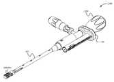
- FIG. 1Aillustrates a top perspective view of the bone fusion device according to some embodiments.
- FIG. 1Billustrates a top cutout view of the bone fusion device according to some embodiments.
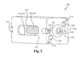
- FIG. 2illustrates a side perspective view of the bone fusion device according to some embodiments.
- FIG. 3illustrates a cross-sectional view of components of the bone fusion device according to some embodiments.
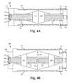
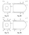
- FIG. 4Aillustrates a cross sectional view of the bone fusion device with the tabs compacted according to some embodiments.
- FIG. 4Billustrates a cross sectional view of the bone fusion device with the tabs extended according to some embodiments.
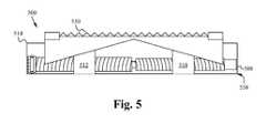
- FIG. 5illustrates a profile view of a bone fusion device having a single tab extension/retraction mechanism according to some embodiments.
- FIGS. 6A and 6Billustrate a front and a side view of a bone fusion device having one or more protruding tabs according to some embodiments.
- FIGS. 7A-7Cillustrate a front, side and top view of a bone fusion device having one or more protruding rails according to some embodiments.
- FIG. 8illustrates a bone fusion apparatus according to some embodiments.
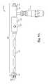
- FIG. 9Aillustrates a side view of the insertion instrument according to some embodiments.
- FIG. 9Billustrates a side cross-sectional view of the insertion instrument according to some embodiments.
- FIG. 9Cillustrates a perspective exploded view of the insertion instrument according to some embodiments.
- FIG. 10Aillustrates an insertion instrument having fingers in a spread position according to some embodiments.
- FIG. 10Billustrates an insertion instrument having fingers in a closed position according to some embodiments.
- FIG. 10Cillustrates an insertion instrument having fingers in a spread position according to some embodiments.
- FIG. 10Dillustrates an insertion instrument having fingers in a closed position according to some embodiments.
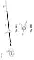
- FIGS. 11A-11Dillustrate perspective, top, front and back views, respectively, of a measuring tool according to some embodiments.
- FIGS. 11E-11Hillustrate perspective, top, front and back views, respectively, of a measuring tool according to some embodiments.
- FIG. 12illustrates a bone fusion device engaging tool according to some embodiments.
- FIG. 13illustrates a bone fusion device insertion and measuring system according to some embodiments.
- FIG. 14illustrates a flow chart of a method of operation of the bone fusion system according to some embodiments.
- FIG. 15illustrates a bone fusion device system according to some embodiments.
- FIGS. 16A-Dillustrate a top, side cross-sectional, perspective and front view, respectively, of the delivery member according to some embodiments.
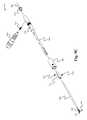
- FIG. 17illustrates the docking rod according to some embodiments.
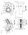
- FIGS. 18A-Dillustrate an exploded perspective view, a side view, a side cross-sectional view and a frontal view, respectively, of a short rigid plunger of the plungers according to some embodiments.
- FIGS. 19A and 19Billustrate an exploded perspective view and a frontal view, respectively, of a long rigid plunger of the plungers according to some embodiments.
- FIGS. 20A-Cillustrate an exploded perspective view, a side view and a frontal view, respectively, of a flexible plunger of the plungers according to some embodiments.
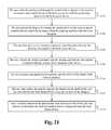
- FIG. 21illustrates a method of operation of the bone fusion system according to some embodiments.
- FIG. 22illustrates a redocking tool according to some embodiments.
- FIG. 23illustrates a method of redocking with a bone fusion device according to some embodiments.
- FIGS. 24A and 24Billustrate a rescue hook according to some embodiments.
- FIG. 25illustrates a method of using a rescue hook according to some embodiments.
- FIGS. 1A and 1Billustrate a top perspective and cutout view of the bone fusion device 100 according to some embodiments.
- the bone fusion device 100has a substantially rectangular shape and has two end faces.
- the bone fusion device 100is able to be constructed from a high strength biocompatible material, such as titanium, which has the strength to withstand forces in the spine that are generated by a patient's body weight and daily movements.
- part of all of the bone fusion device 100is able to be constructed from one or more of the group consisting of high strength biocompatible material or a polymer such as PEEK, PEKK, and other polymeric materials know to be biocompatible and having sufficient strength.
- the materials used to construct the bone fusion deviceinclude using additives, such as carbon fibers for better performance of the materials under various circumstances.
- the base biocompatible materialis often textured or coated with a porous material conducive to the growth of new bone cells on the bone fusion device 100 .
- the porous material or coatingis able to be a three-dimensional open-celled titanium scaffold for bone and tissue growth (e.g. an OsteoSync structure).
- the coatingis able to be a osteosync structure having a mean porosity of 50-70%, pore sizes ranging from 400-700 ⁇ m, and/or a mean pore interconnectivity of 200-300 ⁇ m.
- the porous materialis able to be integrated into the frame and component of the bone fusion device 100 .
- the bone fusion device 100is able to have several conduits or holes 120 (also see FIG. 2 ) which permit the bone graft material to be inserted into the device 100 and to contact the vertebral bone before or after the device 100 has been inserted between the vertebrae of the patient.
- the bone graft material and the surface texturing (e.g. porous material coating) of the device 100encourage the growth and fusion of bone from the neighboring vertebrae.
- the fusion and healing processwill result in the bone fusion device 100 aiding in the bridging of the bone between the two adjacent vertebral bodies of the spine which eventually fuse together during the healing period.
- tabs 130are located on opposing sides of the bone fusion device 100 .
- the tabs 130are shaped so that their outer surface is substantially flush with the frame 114 of the bone fusion device 100 in a nonextended position.
- the tabs 130have a full or partial central rib 124 and an angled inner surface.
- the central rib 124is configured to provide further outer surface area and structural support to the tabs 130 .
- each tab 130is shaped such that one or more angled surfaces 123 of the tab 130 for extending the tab 130 have end thicknesses that are larger than their middle thicknesses such that the thickness of the angled surfaces 123 gradually increases while going from the middle to the ends of the tab 130 .
- a positioning component 108 within the frame 114 of the bone fusion device 100comprises a positioning aperture 134 , a first screw 102 and a second screw 104 coupled together (see FIGS. 4A and 4B ).
- the positioning aperture 134is configured to receive a drive/engaging mechanism of a tool such that the tool is able to rotate or otherwise manipulate the positioning component 108 .
- the positioning aperture 134is able to comprise numerous shapes and sizes as are well known in the art.
- the first screw 102is threaded opposite of the second screw 104 . For example, if the first screw 102 is left threaded, the second screw 104 is right threaded or vice-versa. Furthermore, the first screw 102 (see FIG.
- the positioning component 108is coupled to a first extending block 110 and a second extending block 112 , each having a pair of rib slots 126 configured to receive the central ribs 124 of the tabs 130 (see FIG. 1B ).
- the rib slots 126are sized such that they permit the central ribs 124 to slide into and out of the slots 126 (depending on the position of the blocks 110 , 112 ) such that when positioned within the slots 126 , the blocks 110 , 112 are able to support the tabs 130 against torsional forces by holding and supporting the central ribs 124 .
- first extending block 110is coupled to the first screw 102 and the second extending block 112 is coupled to the second screw 104 , and the first extending block 110 and the second extending block 112 are positioned in the middle of the bone fusion device 100 in the compact position.
- the positioning component 108is turned appropriately, the extending blocks 110 and 112 each travel outwardly on their respective screws 102 and 104 .
- the extending blocks 110 and 112travel outwardly, they push the tabs 130 outward and the central ribs 124 slide within the rib slots 126 .
- the inner tab surface 123when in contact with the extending blocks 110 , 112 act in such a manner so as to push the respective tabs 130 apart.
- each extending block 110 , 112are able to be in contact with the tab surfaces 123 and the center rib surface 121 is in contact with the extending block slot surface 125 .
- the tabs 130will be fully extended when the extending blocks 110 and 112 reach the opposite ends of the screws 102 , 104 .
- the positioning device 108is turned in the opposite direction and the extending blocks 110 and 112 will each travel back to the middle on their respective screws 102 and 104 with the central ribs 124 within the rib slots 126 enabling the tabs 130 to move into the retracted position due to gravity or another downward force.
- the tabs 130are compact and are within the frame 114 of the bone fusion device 100 .
- the extending blocks 110 and 112are coupled to the tabs 130 such that they apply the needed downward force to retract the tabs.
- the tabs 130are able to be biased with a biasing mechanism that applies the downward force needed to cause the tabs 130 to retract when enabled by the position of the extending blocks 110 , 112 .
- one or more springsare able to be coupled to the tabs 130 , wherein the springs apply a retraction biasing force to the tabs 130 that causing the tabs to retract when enabled by the extending blocks 110 , 112 .
- the operation of the device 100is able to be reversed such that the tabs 130 , extending blocks 110 , 112 , and positioning components 108 are configured such that the extending blocks 110 , 112 travel inwardly to extend the tabs 130 into the extended position and travel outwardly to retract the tabs 130 into the compact position.
- the positioning component 108is able to be a non-rotational or other type of force generating mechanism that is able to move the extending blocks 110 , 112 .
- the positioning component 108is able to be a mechanism where a non-rotational movement (e.g. in/out of the device 100 ) causes the movement of the extending blocks 110 , 112 .
- the nonextended tabs 130 of the bone fusion device 100provide a compact assembly that is suitable for insertion into the patient's body through a open, or minimally invasive surgical procedure.
- an open or a minimally invasive procedurecomprises a procedure wherein a smaller surgical incision is employed as compared to the size of the incision required for conventional invasive surgery, for example, arthroscopic procedures.
- minimally invasive proceduresminimize or eliminate the need for excessive retraction of a patient's tissues such as muscles and nerves, thereby minimizing trauma and injury to the muscles and nerves and further reducing the patient's recovery time.
- the positioning component 108As the positioning component 108 is rotated causing the extending blocks 110 and 112 to move closer to the ends of the respective screws 102 and 104 , the extending blocks 110 and 112 push the tabs 130 outward causing the tabs 130 to assert pressure against surrounding bones and securing the bone fusion device 100 in place.
- the extending blocks 110 and 112reach as close to the end of the positioning components 108 as allowed, the tabs 130 are fully extended. Furthermore, since the extending blocks 110 and 112 travel along the positioning components 108 , along the threads of the screws 102 and 104 , very precise positions of the tabs 130 are able to be achieved.
- the tabs 130are able to have serrated edges or teeth 136 to further increase the bone fusion device's gripping ability and therefore ability to be secured in place between the bones for both a long-term purchase and a short-term purchase.
- the serrated edges or teeth 136are able to be in a triangular or form a triangular wave formation as shown in FIG. 3 .
- the serrated edges or teeth 136are able to be filleted, chamfered, or comprise other teeth shapes or edge waves as are well known in the art.
- the device 100is able to comprise a position locking mechanism that helps prevent the positioning component 108 from slipping.
- the locking mechanismis able to be substantially similar to those described in U.S.
- the locking mechanismis able to be positioned within a side wall of the frame 114 around the around the positioning aperture 134 instead of being within a support panel of the device 100 .
- a usergenerally utilizes an insertion instrument such as a screw driver to turn the positioning components 108 .
- Screw driversunfortunately have the ability to slip out of place.
- channels 122 having gripping apertures 128are implemented to receive gripping fingers of a tool/insertion instrument (not shown) such that the tool cannot slip out of place during operation.
- the channels 122are sized to receive the fingers to prevent the tool from moving laterally with respect to the head of the positioning components 108 and the gripping apertures 128 are sized to receive the fingertips of the fingers of the tool such that the fingers (and tool) are unable to unintentionally be pulled out of the channels 122 (and positioning components 108 ).
- the channels 122are aligned such that they are at the same height on opposite sides of the frame 114 of the device 100 .
- the channels 122are able to be offset (e.g. not at the same height).
- the channels 122are able to positioned on other portions of the frame 114 .
- a surgeoncauses the fingers of the tool to spread as the are inserted into the channels 122 , and then the surgeon causes the fingers to clamp together inserting the fingertips of the fingers into the gripping apertures 128 and fully securing the tool onto the device 100 .
- the toolis unable to slip out of place and is only able to be removed upon the spreading of the fingers such that the fingertips are removed from the apertures 128 and the fingers are removed from the channels 122 .
- the device 100is next to relatively immovable tissue (e.g. bone, ligament or tendon under load), then this device 100 will still be able to disengage, whereas one that relies on clamping by bending two rods together will not work if one of the rods is restricted by the relatively immovable tissue.
- FIG. 2illustrates a side perspective view of the bone fusion device 100 according to some embodiments.
- the bone fusion device 100utilizes the positioning components 108 comprising the first screw 102 and the second screw 104 to move the first extending block 110 and the second extending block 112 outwardly from the middle of the bone fusion device 100 towards its ends.
- the positioning component 108is held in place but permitted to turn utilizing one or more first pins 116 .
- the one or more first pins 116are secured within a retaining groove 106 ( FIG. 3 ) of the positioning component 108 .
- the extending blocks 110 and 112force the tabs 130 to either extend or retract depending on where the extending blocks 110 and 112 are positioned.
- the tabs 130are able to have serrated edges or teeth 136 to further increase gripping ability.
- the tabs 130are each coupled to the frame 114 of the bone fusion device 100 by one or more pin slots 132 ( FIGS. 3 and 4A ) and one or more second pins 118 wherein the one or more second pins 118 fit within the one or more pin slots 132 and are able to travel along the interior of the one or more pin slots 132 .
- each tab 130is secured with a single second pin 118 and pin slot 132 .
- one or more of the tabs 130are able to have multiple second pins 118 and pin slots 132 .
- the multiple pin slots 132are able to be positioned at the corners of the tabs 130 similar to the single pin slot 132 shown in FIG. 3 .
- the multiple pin slots 132 of tabs 130are symmetric such that any tab 130 is able to be placed on the top or bottom of the bone fusion device 100 .
- the pin slots 132 of the tabs 130are able to be positioned anywhere on the tab 130 and/or be positioned asymmetrically.
- the pins/pin slots 118 / 132are able to be replaced by or supplemented with one or more biasing elements positioned within biasing channels within the tabs 130 and/or frame 114 and thereby biasing the tabs 130 in the retracted position.
- channels and/or biasing elementsare able to be substantially similar to those described in U.S. patent application Ser. No. 14/210,094, filed on Mar. 13, 2014 and entitled “BODILESS BONE FUSION DEVICE, APPARATUS AND METHOD.”
- the holes/conduits 120 within the tabs 130allow the bone graft material to contact the vertebral bone after the device 100 has been inserted between the vertebrae of the patient.
- a set of holes/conduits 120 within the frame 114also allow bone graft material to be inserted within the bone fusion device 100 after the bone fusion device 100 has been placed.
- the side of the frame 114has an elongated hole 120 exposing the positioning component 108 and extending blocks 112 / 110 . This elongated hole 120 is able to serve as a channel for pushing bone graft material into the frame 114 once it is in position.
- the channels 122have gripping apertures 128 implemented to receive a tool. Alternatively, the gripping apertures 128 are able to be omitted.
- FIG. 3illustrates a cross-sectional view of components of the bone fusion device 100 according to some embodiments.
- the positioning component 108comprises a first screw 102 and a second screw 104 wherein the first screw 102 is threaded differently than that of the second screw 104 .
- the first screw 102is of a slightly different size than the second screw 104 .
- the first screw 102is an 8-32 screw and the second screw is a 6-32 screw.
- a retaining groove 106is utilized to secure the positioning component 108 in place.
- the retaining groove 106is positioned opposite the end of the positioning component 108 having the positioning aperture 134 .
- the channels 122 having fingertip gripping apertures 128are utilized to secure the tool as described above.
- the fingertip gripping apertures 128are able to be omitted and the channels 122 are able to secure the tool as described above.
- a first extending block 110 and a second extending block 112are utilized with the positioning component 108 to extend and compact one or more of tabs 130 .
- the first extending block 110has an internal opening and threading to fit around the first screw 102 .
- the second extending block 112has an internal opening and threading to fit around the second screw 104 .
- the frame 114 of the bone fusion device 100contains a set of holes/conduits 120 within the frame 114 for allowing bone graft material to be inserted. Furthermore, one or more first pins 116 secure the positioning component within the frame 114 . One or more second pins 116 in conjunction with one or more pin slots 132 secure the tabs 130 to the frame 114 .
- FIG. 4Aillustrates a cross sectional view of the bone fusion device 100 with the tabs retracted according to some embodiments.
- the tabs 130are positioned within the frame 114 of the bone fusion device 100 with the central ribs 124 slid within the rib slots 126 .
- the retaining groove 106holds the positioning component 108 in place with one or more first pins 116 .
- the tabs 130are coupled to the frame 114 of the bone fusion device 100 using the one or more slots 132 and the one or more second pins 118 wherein the one or more second pins 118 fit within the one or more slots 132 and are able to travel/slide along the interior of the one or more slots 132 .
- FIG. 4Billustrates a cross sectional view of the bone fusion device 100 with the tabs extended according to some embodiments.
- the bone fusion device 100is compressed/contracted when the extending blocks 110 and 112 are in the middle of the bone fusion device 100 .
- the extending blocks 110 and 112gradually move outward from the middle. If the user turns the positioning component 108 in the opposite direction, the extending blocks move back towards the middle.
- the central ribs 124slide out of the rib slots 126 and the extending blocks 110 , 112 push on the tabs 130 .
- the central ribs 124 and/or rib slots 126are able to be configured such that the central ribs 124 are fully within the rib slots 126 , fully removed from the rib slots 126 , or somewhere in between at any point along the path of the extending blocks 110 , 112 from the center of the device to the ends of the device.
- the tabs 130extend because the extending blocks 110 and 112 exert force against the angled tabs 130 outwardly as shown by the arrows 140 . When the extending blocks 110 and 112 are positioned near the ends of the bone fusion device 100 , the tabs 130 extend beyond the frame 114 of the bone fusion device 100 and ultimately secure the bone fusion device 100 between two bones.
- the tabs 130are able to extend beyond the frame 114 of the bone fusion device 100 as the one or more second pins 118 travel within the interior of the one or more slots 132 .
- the bone fusion device 100is initially configured in a compact position such that the extending blocks 110 , 112 are located in the middle of the bone fusion device 100 thereby allowing the tabs 130 to rest within the frame 114 of the bone fusion device 100 .
- the compact bone fusion device 100is then inserted into position within the patient.
- the surgeonis able to then the expand the bone fusion device 100 by rotating the positioning component 108 which moves the extending blocks 110 , 112 towards the opposing ends of the bone fusion device 100 —one near the head of the positioning component 108 and the other towards the tail of the positioning component.
- the tabs 130are pushed outwardly from the pressure of the extending blocks 110 , 112 against the angled tabs 130 .
- the central ribs 124 of the tabs 130remain at least partially within the rib slots 126 of the extending blocks 110 , 112 such that the blocks 110 , 112 are able to resist torsional forces on the tabs 130 and/or device 100 .
- the central ribs 124slide out of the rib slots 126 as the extending blocks 110 , 112 approach the ends of the positioning component 108 .
- the central ribs 124are able to be configured such that they remain at least partially within the rib slots 126 as the extending blocks 110 , 112 approach the ends of the positioning component 108 .
- the extending blocks 110 , 112exert a satisfactory force between the extended tabs 130 and the bones to be fused.
- the bone fusion device 100is able to remain in place.
- material for fusing the bones togethere.g. bone graft material
- the insertion of the material for fusing the bones togetheris able to be omitted.
- FIG. 5illustrates a bone fusion device 500 having a single tab extension/retraction mechanism according to some embodiments.
- the bone fusion device 500 shown in FIG. 5is substantially similar to the bone fusion device 100 except for the differences described herein.
- the bone fusion device 500comprises a half frame 514 , one or more half extending blocks 510 , 512 , a tab 530 and positioning component 508 .
- the half extending blocks 510 , 512are coupled around the positioning component 508 such that when the positioning components 508 are turned, the blocks 510 , 512 move outwards causing the tab 530 to move to the extended position.
- the half frame 514comprises a tab aperture (see FIG.
- the floor 538is able to have one or more floor holes/conduits for receiving/distributing grafting material into and out of the device 500 .
- the device 500is sized such that when the tab 530 is in the compact/retracted position the distance between the top of the tab 530 and the floor 538 is less than or equal to 5 mm, and when the tab 530 is in the extended position the distance between the top of the tab 530 and the floor 538 is less than or equal to 7 mm.
- the device 500is sized such that when the tab 530 is in the compact/retracted position the distance between the top of the tab 530 and the floor 538 is in the range of 5 mm to 13 mm and when the tab 530 is in the extended position the distance between the top of the tab 530 and the floor 538 is in the range of 7 mm to 22 mm.
- other sizes of the device 500are contemplated as are well known in the art.
- the height of the device 500is able to be minimized.
- the bone fusion device 500enables surgeons to use smaller incisions as well as to fit the bone fusion device 500 into smaller places and increasing the versatility of the device 500 .
- the single tab extension/retraction mechanism described in FIG. 5is able to replace each of the dual or multiple tab extension/retraction mechanisms described herein wherein the devices having dual tab extension/retraction mechanisms are essentially halved (except for the positioning component) such that only one tab is remaining.
- FIGS. 6A and 6Billustrate a front and a side view of a bone fusion device 600 having one or more protruding tabs according to some embodiments.
- the bone fusion device 600 shown in FIGS. 6A and 6Bis substantially similar to the bone fusion device 100 except for the differences described herein.
- the bone fusion device 600comprises one or more tabs 630 having a height such that even when fully retracted an outer end or surface 602 of the tabs 630 extends beyond the plane or face of the frame 614 .
- the outer end or surface 602is able to comprise the outwardly pointing teeth 636 and/or other most outward portions of the tabs 630 .
- two bonese.g.
- the teeth 636 or other portions of the surface 602 of the bottom facing tab 630are able to provide traction with the bone surface such that the device 600 does not slip out of place when the tabs 630 are being extended.
- only one of the tabs 630extends beyond the face of the frame 614 in the fully retracted position.
- two or more of the tabs 630extend beyond the face of the frame 614 in the fully retracted position.
- only a portion (not the full length) of the outward face or end 602 of the tabs 630extend beyond the face of the frame 614 in the fully retracted position.
- the full length of the outward face or end 602 of the tabs 630is able to extend beyond the face of the frame 614 in the fully retracted position.
- the tabs 630extend 0.25 millimeters beyond the face of the frame 614 in the fully retracted position.
- one or more of the tabs 630are able to extend more or less than 0.25 millimeters (e.g. 0.1 mm) beyond the face of the frame 614 in the fully retracted position.
- the device 600comprises two tabs 630 and all of the tabs 630 have ends 602 that extend beyond the face of the frame 614 in the fully retracted position
- the device 600is able to comprise any number of tabs 630 (e.g. one or more) wherein one or any combination of a plurality of the tabs 630 are able to have ends 602 that extend beyond the face of the frame 614 in the fully retracted position.
- one or more of the components of the bone fusion device 600are able to be incorporated into one or more of the other embodiments of bone fusion devices described herein.
- FIGS. 7A-7Cillustrate a front, side and top view of a bone fusion device 700 having one or more protruding rails according to some embodiments.
- the bone fusion device 700 shown in FIGS. 7A-7Cis substantially similar to the one or more of the other embodiments of bone fusion devices (e.g. bone fusion device 100 ) except for the differences described herein.
- the bone fusion device 700comprises one or more rails 702 adjacent to one or more of the tabs 730 that protrude above the plane or face of the frame 714 .
- two rails 702are positioned next to opposite sides/edges of each of the tabs 730 .
- the rails 702provide the advantage of preventing a protruding portion of one or more of the tabs 730 or other parts of the device 700 from catching on anything during insertion of the device 700 into position.
- the rails 702are utilized in conjunction with protruding tabs 630 as shown in FIGS. 6A and 6B .
- the rails 702are able to be used in conjunction with protruding tabs, non-protruding tabs, other types of tabs described herein and/or any combination thereof.
- the rails 702only extend along a portion (not the entire length) of an edge of the perimeter of one or more of the tabs 730 .
- one or more of the rails 702are able to have length such that they extend the full length of a side or sides of the perimeter of one of the tabs 730 .
- a rail 702is able to form a ring such that it extends the entire perimeter of one of the tabs 730 .
- one or more rails 702are able to extend around the corners created by two or more of the sides of the perimeter of one of the tabs 730 .
- the rails 702are able to make perpendicular and/or rounded turns in order to wrap around the multiple sides.
- one or more of the rails 702are able to have length such that they do not extend the full length of a side or sides of the perimeter of one of the tabs 730 and/or one or more of the rails 702 are able to be discontinuous such that there are gaps between one or more portions of the one or more of the rails 702 .
- a plurality of rails 702are able to be next to the same side of the perimeter of one of the tabs 730 .
- two or more rails 702 next to the same sideare able to be the same or different lengths and/or be aligned or otherwise overlap in the portions of the perimeter of the tab 730 that they are next to.
- the positioning of the rails 702 next to the tabs 730is biased toward the front of the device 700 (e.g. away from the side where the positioning component is accessible).
- the rails 702start at the front leading edge of the tabs 730 such that when the device 700 is inserted frontwards the rails will guard the front leading edge of the tabs 730 from getting caught during the insertion.
- a portion or all of one or more of the rails 702are able to directly abut the edge of the tabs 730 .
- a portion or all of one or more of the rails 702is able to be spaced away from the edges of the tab 702 somewhere along the side of the frame 714 from which the tab 702 is able to extend.
- one or more of the rails 702form lines that are parallel or non-parallel with the closest edge of the tab 730 .
- one or more of the rails 702are able to be partially or wholly non-linear (e.g curved).
- the rails 702are positioned in matching or mirroring pairs around one or more of the tabs 730 .
- each of the tabs 730have a pair of matching rails 702 that straddle the tab 730 along a portion of the longer edges of the perimeter of the tab 702 , wherein the portion is the part of the longer edges closest to the front of the device 700 .
- the one or more rails 702 next to a tab 730are able to be asymmetric.
- one or more of the rails 702are coupled to the sides of the frame 714 next to the tabs 730 .
- one or more of the rails 702are able to be integrated into the frame 714 itself (e.g a protrusion of the frame 714 itself).
- one or more of the rails 702extend 0.25 millimeters beyond the face of the frame 714 in the fully retracted position.
- one or more of the rails 702are able to extend more or less than 0.25 millimeters (e.g. 0.1 mm) beyond the face of the frame 714 in the fully retracted position.
- one or more of the rails 702are able to be positioned anywhere along the perimeter of one or more of the tabs 730 , wherein the perimeter includes the side, plane or face of the frame 714 that surrounds the outwardly facing face of the tabs 730 .
- one or more of the components of the bone fusion device 700are able to be incorporated into one or more of the other embodiments of bone fusion devices described herein.
- FIG. 8illustrates a bone fusion device insertion apparatus 800 according to some embodiments.
- the bone fusion apparatus 800comprises a bone fusion insertion instrument 802 detachably coupled to a bone fusion device 804 via a coupling mechanism 806 .
- the bone fusion device 804is substantially similar to the bone fusion device 100 described in FIGS. 1-7 .
- the bone fusion device 804is able to be other embodiments of bone fusion devices described herein or other types of bone fusion devices as are well known in the art.
- the other types of bone fusion devicesare able to be formed by one or more of polymers, bone, synthetic bone, metal or other biocompatible materials as are well known in the art.
- the coupling mechanism 806comprises a clamping mechanism.
- the coupling mechanism 806is able to comprise any combination of a clamps, screws, locks, adhesives or other attachment elements as are well known in the art.
- the insertion instrument 802is able to detachably couple to a plurality of bone fusion devices 804 simultaneously such that the plurality of devices 804 are able to be simultaneously controlled (e.g. extension/contraction of the tabs) by the single insertion instrument 802 .
- FIG. 9Aillustrates a side view of the insertion instrument 802 according to some embodiments.
- FIG. 9Billustrates a side cross-sectional view of the insertion instrument 802 according to some embodiments.
- FIG. 9Cillustrates a perspective exploded view of the insertion instrument 802 according to some embodiments.
- the insertion instrument 802comprises a body portion 904 including a housing tube 906 , a clamping sleeve 908 , one or more channel knobs 910 , a handle 916 and an end cap 914 , and a head portion 902 including a plurality of clamping fingers 903 and a spreading rod 901 operably coupled within the head portion 902 of the housing tube 906 .
- the head portion 902is sized such that the cross-section of the head 902 is smaller than the cross section of the bone fusion device 100 .
- the spreading rod 901is positioned within the head portion 902 of the housing tube 906 between the clamping fingers 903 , which extend from a finger tube 905 that is positioned within a hollow cavity of the body portion 904 of the housing tube 906 .
- the spreading rod 901is fixed in position relative to the housing tube 906 .
- the fingers 903are forced further apart by the rod 901 until they are in a spread position as shown in FIG.
- the fingers 903are able to move closer together to a closed position as shown in FIG. 10B .
- the fingers 903are separated by a distance greater than the distance between the surface of the gripping apertures 128 and/or the channels 122 having the gripping apertures 128 .
- the fingers 903are separated by a distance equal to or less than the distance between the surface of the gripping apertures 128 and/or the channels 122 having the gripping apertures 128 .
- the fingers 903when in the closed position, the fingers 903 are able to enter the gripping apertures 128 and secure the coupling mechanism 806 to the bone fusion device 804 , and when in the spread position, the fingers 903 are able to be removed from the gripping apertures 128 thereby releasing the coupling mechanism 806 from the device 804 .
- the fingers 903are biased toward the closed position such that when not forced apart by the rod 901 the fingers 903 automatically spring back to the closed position.
- the fingers 903are able to not be biased and the walls of the head portion 902 of the housing tube 906 are able to push the fingers 903 back into the closed position as they are pulled back into the head 902 .
- the fingers 903are able to be biased in the spread position such that when not forced together by the walls of the head 902 of the housing tube 906 the fingers 903 automatically spring to the spread position.
- the spreading rod 901is able to be omitted. As also shown in FIG.
- the end cap 914is threaded or screwed into the end of the housing tube 906 and the handle 916 is threaded or screwed into the side of the housing tube 906 via a threaded connection member 917 such that the handle is perpendicular or substantially perpendicular to a central axis 900 of the instrument 802 (as shown in FIG. 9C ).
- the end cap 914is able to be tubular with a round or circular exterior surface to facilitate the screwing and threadable coupling.
- a back end of the end cap 914is able to have one or more cutouts such that instead of being circular, a cross section of the back end of the end cap 914 that is perpendicular to the central axis 900 will be non-circular.
- the top and bottom of the back endare cutout such that the cross-section is a partial circle minus portions above a top secant line and a bottom secant line.
- any other cutoutsare able to be used that produce non-circular cross-sections.
- the non-circular cross-sectionenables a measuring tool 1100 to slide onto the back end of the end cap 914 , wherein the non-circular cross-section prevents the measuring tool 1100 from being able to rotate about the back end when coupled.
- an end tube 912 and the channel knobs 910are able to be coupled to the end of the finger tube 905 .
- the end tube 912 and/or channel knobs 910are able to be integrated into the finger tube 904 .
- the end tube 912is able to be omitted.
- the control sleeve 908is threaded or screwed onto the outside of the housing tube 906 such that, when rotated in a first direction about the threading, the control sleeve 908 moves toward the head 902 and, when rotated in the opposite direction about the threading, the control sleeve 908 moves toward the opposite end of the instrument 802 near the end cap 914 .
- the inner surface of the sleeve 908has an annular channel 909 configured for receiving the ends of the channel knobs 910 through one or more corresponding sliding apertures 918 within the housing tube 906 .
- the channel knobs 910are able to extend from the end tube 912 and/or finger tube 905 through the sliding apertures 918 and at least partially into the channel 909 of the sleeve 908 .
- the position of the knobs 910 in the channel 909causes the knobs 910 to be pushed/pulled by the sleeve 908 and thereby correspondingly move the finger tube 905 toward or away from the head 902 which, as described above, causes the fingers 903 to move between the spread and closed positions.
- the edges of the sliding apertures 918are able to limit the extent to which the knobs 910 are able to slide and thereby prevent the fingers 903 from being spread too far apart or pulled too far into the tube 906 .
- a useris able to controllably move the fingers 903 between the spread and closed positions by selectively rotating the sleeve 908 between a closed and open (or spread) position.
- the instrument 802includes two knobs 910 positioned through two separate apertures 918 , more or less knobs 910 and/or apertures 918 are able to be used.
- the instrument 802further comprises a central hollow channel that extends through the length of the instrument 802 along an axis 900 from the end of the head 902 to the end of the body 904 at the end cap 914 as shown in FIG. 9C .
- each of the components of the instrument 802 that cross the axis 900e.g. finger tube 905 , end cap 914 , spreading rod 901
- a docking rod 1506 and/or a bone fusion device engaging tool 1200is able to be selectively removed or positioned through the central hollow channel in order to access the positioning aperture 134 of a bone fusion device 100 coupled to the instrument 802 by the fingers 903 .
- FIGS. 11A-11Dillustrate perspective, top, front and back views, respectively, of a measuring tool 1100 according to some embodiments.
- the measuring tool 1100comprises an indicator body 1102 and a coupling cap 1104 .
- the indicator body 1102comprises a screw 1110 , a viewing aperture 1113 , an indicator ring 114 , a height line 1115 , height markings 116 and a support bridge 1118 .
- the coupling cap 1104comprises a coupling aperture 1106 , aperture bracers 1107 , a gear wheel 1108 having perimeter teeth 1109 , a screw gear 1111 and a compatibility marker 1112 .
- one or more of the components of the cap 1104 and/or the body 1102are able to be omitted.
- the indicator ring 1114is threaded and screwed onto the screw 1110 and both are positioned within the body 1102 .
- the ring 1114protrudes at least partially into the viewing aperture 1113 .
- the height markings 1116are positioned along the perimeter of at least a portion of the viewing aperture 1113 , which extends vertically along a side of the body 1102 . As a result, the ring 1114 is exposed or visible within the body 1102 when it is positioned on the screw 1110 adjacent to one or more of the height markings 1116 .
- the screw 1110is pivotably or rotatably coupled within the body 1102 and the ring 1114 is slidably coupled within the body 1102 such that the screw 1110 is able to rotate about its axis within the body 1102 causing the ring 1114 to slide up or down the screw 1110 along the viewing aperture 1113 depending on the direction of rotation.
- the ring 1114is prevented from rotating with the screw 1110 due to its protrusion into the viewing aperture 1113 .
- the rotation of the screw 1110causes the ring 1114 and its height line 1115 to move with respect to height markings 1116 (along the axis of the screw 1110 ) and thus sometimes align with the height markings 1116 .
- the compatibility marker 1112indicates one or more bone fusion devices 804 with which the measuring instrument 802 is compatible.
- compatiblemeans that the markings 1116 and/or the screw 1110 /ring 1114 threading granularity are proportional to the rate of extension of the tabs of the indicated compatible bone fusion devices 804 indicated by the marker 1112 .
- the instrument 1100is compatible with a bone fusion device 802 if the amount of the extension of the tabs of the device 804 is accurately indicated by the alignment of the markings 1116 and the height line 1115 of the ring 1114 when the instrument 1100 is used in concert with the extension/retraction of the tabs as described in detail below.
- the gear wheel 1108is rotatably coupled about the coupling aperture 1106 and has both inner gear teeth 1109 a and outer gear teeth 1109 b , wherein at least the inner gear teeth 1109 a are exposed/accessible from the exterior of the cap 1104 about the aperture 1106 .
- the screw gear 1111is fixedly coupled to the screw 1110 , but rotatably coupled within the cap 1104 about the axis of the screw 1111 such that the screw 1110 and the screw gear 1111 together are able to rotate within the cap 1102 and body 1104 about the axis of the screw 1110 .
- the outer gear teeth 1109 b of the gear wheel 1108are engaged with the gear teeth of the screw gear 1111 .
- the rotation of the screw 1110is able to be caused by rotating the gear wheel 1108 (e.g. via the inner gear teeth 1109 a ) which in turn rotates the screw gear 1111 coupled to the screw 1110 . Therefore, movement of the ring 1114 with respect to the markings 1116 , the screw 1110 and/or the aperture 1113 is proportional to and based on the rotation of gear wheel 1108 and/or the corresponding rotation of the screw/screw gear 1110 , 1111 .
- the coupling aperture 1106is defined by the aperture bracers 1107 such that the back end of the end cap 914 of the insertion instrument 802 is able to fit in between the bracers 1107 within the aperture 1106 .
- the aperture 1106 as defined by the bracers 1107is able to have a non-circular cross-section that matches the cross-section of the back end of the end cap 914 in order to enable the end cap 914 to slide into the aperture 1106 but not rotate within the aperture 1106 .
- the coupling aperture 1106enables the measuring tool 1100 to detachably couple to the insertion instrument 802 .
- the aperture 1106 and/or the gear wheel 1108are centered about the central axis 900 and/or the central hollow channel of the insertion instrument 802 .
- thisenables the engaging tool 1200 ( FIG. 12 ) to align with the aperture 1106 and/or the gear wheel 1108 when slid through the aperture 1106 into the central hollow channel of the insertion instrument 802 for engaging the bone fusion device 804 .
- the support bridge 1118is sized and contoured to match and contact the outer surface of the insertion instrument 802 when the measuring tool 1100 and the insertion instrument 802 are coupled together in order to prevent the body 1102 from bending the cap 1104 toward the instrument 802 .
- the support bridge 1118is able to be omitted.
- FIGS. 11E-11Hillustrate perspective, top, front and back views, respectively, of an alternate embodiment of the measuring tool 1100 ′ according to some embodiments.
- the measuring tool 1100 ′ shown in FIGS. 11E-11His able to be the substantially same as the measuring tool 1100 shown in FIGS. 11A-11D except for the differences described herein.
- the measuring tool 1100 ′comprises an indicator body 1102 having a protruding neck 1101 that provides further support for the cap 914 when inserted into the coupling aperture 1116 , wherein the support bridge 1118 is omitted.
- the body 1102is able to include a plurality of viewing apertures 1113 . In some embodiments, there are three viewing apertures 1113 .
- One aperture 1113 on the end of the body 1102as shown in FIG. 11F , and two on either side of the body 1102 (one is shown in FIG. 11E and the other is hidden on the opposite side).
- the tool 1100 ′is able to be read from any of the three sides.
- each viewing aperture 1113is able to have a corresponding set of markings 1116 and/or two or more of the viewing apertures 1113 are able to share a set of markings 1116 .
- a set of markings 1116is able to be positioned in between two of the apertures 1113 such that the lines of the markings are able to be read (e.g. extend to) both of the apertures 1113 .
- FIG. 12illustrates a bone fusion device engaging tool 1200 according to some embodiments.
- the tool 1200comprises a handle 1202 coupled to an elongated member or rod 1204 having an engaging tip 1206 and an interface gear 1208 coupled to the base of the handle 1202 centered around the member 1204 .
- the elongated member 1204is able to be tubular and/or sized to slide and rotate within the central hollow channel of the insertion instrument 802 along the axis 900 .
- the tip 1206is able to be configured (e.g.
- the tip 1206is able to have a hexagonal shape, a star-shape, a flat-head shape, a phillips head shape or other types of bit shapes as are known in the art.
- the teeth of the interface gear 1208are able to be configured to operably engage with the inner teeth 1109 a of the gear wheel 1108 . Further, as shown in FIG. 13 , when fully slid into the central hollow channel of the insertion instrument 802 after the measuring tool 1100 is positioned on the end of the end cap 914 (e.g.
- the teeth of the interface gear 1208operably engage with the inner teeth 1109 a of the wheel gear 1108 .
- rotation of the engaging tool 1200causes the wheel gear 1108 to correspondingly rotate, which as described above moves the indicator ring 1114 up and down the screw 1110 .
- the elongated member 1204is able to have a length such that when fully slid into the central hollow channel of the insertion instrument 802 , the tip 1206 extends into the positioning aperture 134 when the device 100 / 804 is coupled to the insertion instrument 802 . Accordingly, when operably coupled, rotation of the engaging tool 1200 simultaneously extends/retracts the tabs 130 of the coupled device 100 / 804 and moves the indicator ring 1114 with respect to the markings 1116 .
- FIG. 13illustrates a bone fusion device insertion and measuring system 1300 according to some embodiments.
- the system 1300has the engaging tool 1200 and the measuring tool 1100 both operably coupled with the insertion instrument 802 , with the bone fusion device 100 / 804 also being coupled to the instrument 802 .
- the tabs 130are able to be selectively extended or retracted by rotating the engaging tool 1200 with respect to the instrument 802 and/or device 100 / 804 as the tip 1206 is engaged within the positioning aperture 134 .
- the rotation of the engaging tool 1200is able to move the indicator ring 1114 of the measuring tool 1100 with respect to the markings 1116 via the engagement of the interface gear 1208 and the gear wheel 1108 , wherein the movement of the indicator ring 1114 is proportional to the amount of extension of the tabs 130 such that its alignment with the markings 1116 indicates the current amount of extension of the tabs 130 .
- the engaging tool 1200 , measuring tool 1100 , device 100 / 804 and/or insertion instrument 802provide the advantage of enabling a user to control and determine a current amount that the tabs 130 are extended by observing the alignment of the height line 1115 with the markings 1116 .
- the removability of the engaging tool 1200 from the insertion instrument 802beneficially enables the insertion instrument 802 to be used in concert with other tools or rods by simply removing the engaging tool 1200 when no longer needed.
- the removability of the measuring tool 1100enables different devices 100 / 804 having different sizes and/or rates of tab 130 extension to be used with the same insertion instrument 802 by simply replacing current measuring tool 1100 (having a first compatibilty marker 1112 that does not correspond to the desired device 100 / 804 ) with a different measuring tool 1100 having a compatibility marker 1112 that corresponds to the desired device 100 / 804 .
- step 1402comprises selecting the measuring tool 1100 from a plurality of measuring tools 1100 each having a compatibility marker 1112 based on which of the tools 1100 has compatibility markers 1112 that corresponds to the desired bone fusion device 100 / 804 .
- step 1402is able to occur after the device 100 / 804 has been coupled to the insertion instrument 802 as described in step 1408 .
- a usercauses the fingers 903 of the insertion instrument 802 to spread by rotating the control sleeve 908 to an open or spread position at the step 1406 .
- the userslides the fingers 903 into the channels 122 of the bone fusion device 100 / 804 at the step 1408 .
- the usercauses the fingers 903 to close by rotating the control sleeve 908 in the opposite direction to a closed position such that the fingers 903 (or the tips of the fingers) slide into the gripping apertures 128 of the channels 122 thereby detachably coupling the insertion instrument 802 to the bone fusion device 100 / 804 at the step 1410 .
- the usermoves the bone fusion device 100 / 804 into the desired position within the patient with the insertion instrument 802 at the step 1412 .
- the inner cavity of the bone fusion device 100 / 804is packed with a bone graft material prior to being positioned within the patient.
- the desired positioncomprises replacing a spinal disc with the bone fusion device 804 in between two vertebrae.
- the desired positionis able to comprise replacing a degenerated vertebrae with the bone fusion device 100 / 804 in between the two adjacent vertebrae and/or spinal discs.
- the insertion instrument 802is able to be used to position other types of spinal devices such as a dynamic device, a total/partial artificial disc, a nucleus pulposus or other medical devices as are well known in the art.
- the bone fusion device 100 / 804is inserted anteriorly.
- the bone fusion device 100 / 804is able to be inserted posteriorly, laterally or transforaminaly.
- the userrotates the engaging tool 1200 within the insertion instrument 802 as it is engaged in the positioning aperture 134 in order to extend the tabs 130 of the device 100 / 804 as desired at the step 1414 .
- the userobserves the alignment of the height line 1115 of the indicator ring 1114 with the height markings 1116 and stops rotating the engaging tool 1200 when the height line 1115 is aligned with the height marking 1116 indicating the desired height at the step 1416 .
- the userremoves the engaging tool 1200 from within the insertion instrument 802 at the step 1416 .
- the userdecouples the measurement tool 1100 from the end cap 914 at the step 1418 . Alternatively, the measurement tool 1100 is able to remain on the end cap 914 .
- the method of operating the bone fusion system 1300enables the surgeon to securely position the bone fusion device 804 and extend the tabs 130 as needed with minimal possibility of the drive mechanism slipping out of the positioning aperture 134 .
- the insertion instrument 802is prevented from being pulled, pushed or twisted away from the bone fusion device 804 .
- the procedureis made both safer and more efficient.
- the measurement tool 1100is able to be omitted and the engaging tool 1200 is able to be used with the insertion instrument 802 without also coupling with the measurement tool 1100 .
- FIG. 15illustrates a bone fusion device system 1500 according to some embodiments.
- the bone fusion system 1500comprises a bone fusion device 1504 and bone fusion delivery apparatus including a delivery member 1502 , a docking rod 1506 and one or more plungers 1508 .
- the docking rod 1502is able to detachably couple with the bone fusion device 1504 and thereby facilitate the coupling or interfacing of the delivery member 1502 and the bone fusion device 1504 for delivery of the autograft or other material to the inside of the device 1504 via the delivery member 1502 .
- the delivery member 1502is able to slide onto and/or otherwise couple with the docking rod 1506 , wherein the member 1502 and rod 1506 are configured such that, when the docking rod 1506 is coupled with the device 1504 , coupling of the docking rod 1506 and the delivery member 1502 results in an coupling or interface alignment of the delivery member 1502 and the device 1504 (e.g. a channel 120 on the side of the device).
- the plungers 1508are then able to detachably coupled to and/or used with the delivery member 1502 to force desired material through the delivery member 1502 into the bone fusion device 1504 .
- the system 1500is able to be combined with one or more of the components of the system 800 described above in order to create an insertion, measurement and/or delivery system.
- the bone fusion device 1504is able to be substantially similar to the bone fusion devices 100 , 804 described above.
- the bone fusion device 1504is able to be other embodiments of bone fusion devices described herein or other types of bone fusion devices as are well known in the art.
- the other types of bone fusion devicesare able to be formed by one or more of polymers, bone, synthetic bone, metal or other biocompatible materials as are well known in the art.
- FIGS. 16A-Dillustrate a top, side cross-sectional, perspective and front view, respectively, of the delivery member 1502 according to some embodiments.
- the delivery member 1502comprises a delivery shaft 1602 , a handle 1604 and a funnel 1606 .
- the funnel 1606is able to be at least partially coupled within a back end of the handle 1604 via one or more locking pins 1608 .
- funnel 1606is able to be integrated with the handle 1604 to form a single component or the funnel 1606 is able to be coupled with the handle 1604 via other coupling mechanisms as are well known in the art that replace or supplement the pins 1608 .
- the a portion of the delivery shaft 1602is able to be coupled within or through a front end of the handle 1604 such that a tip of the funnel 1606 aligns with, couples to and/or abuts an entrance aperture of the delivery shaft 1602 .
- the remainder of the delivery shaft 1602extends out from the front end of the handle 1604 and ends at a exit aperture 1610 .
- the back end of the funnel 1606is able to have a threaded outer or inner surface and/or have a tubular or circular shape such that one or more of the plungers 1508 are able to threadably couple with the funnel 1606 via the threading.
- the exit aperture 1610is able to be defined by an L-shaped cutout of the tip of the delivery shaft 1602 .
- this L-shapeenables exit aperture 1610 to fit against or contour to a left or right front corner of the bone fusion device 1504 wherein the corner of the L-cutout meets the left or right front corner of the device 1504 and the scoop-like portion of the exit aperture 1610 extends along the corresponding left or right side of the bone fusion device 1504 (in order to align with one or more side channels 120 ).
- the exit aperture 1610is able to comprise any other shapes that enable material to exit the tip of the shaft 1602 .
- the system 1500is able to comprise two delivery members 1502 , wherein the first member 1502 has an L-shaped exit aperture 1610 and the second member 1502 has a differently shaped exit aperture 1610 (e.g. an aperture created by a cross-section cut of the shaft 1602 orthogonal to the axis of the shaft 1602 ).
- the delivery shaft 1602is able to further comprise one or more coupling hoops 1612 that extend from the outer surface of the delivery shaft 1602 .
- each of the coupling hoops 1612are able to be aligned such that their respective through-holes are aligned along a single axis.
- the coupling hoops 1612enable the shaft 1602 to couple with the docking rod 1506 by sliding the docking rod 1506 through the through holes of the coupling hoops 1612 along the axis.
- one or more of the coupling hoops 1612are able to be only partial hoops or C-shaped such that they do not form a full loop.
- the hoops 1612are able to still have greater than fifty percent of the loop as a part of the C-shape in order to hold the docking rod 1506 within the C-shape.
- the shaft 1602has two hoops 1612 , more or less hoops 1612 are able to be used.
- the handle 1604is able to comprise a docking channel 1614 configured for receiving a portion of the docking rod 1506 .
- the docking channel 1614is able to be aligned with the single axis of the hoops 1612 such that the handle 1604 is able to couple with the docking rod 1506 at the same time as the shaft 1602 by sliding the docking rod 1506 along the axis through the coupling loops 1612 and into the docking channel 1614 .
- the docking channel 1614is sized such that when the docking rod 1506 is fully slid into the channel 1614 (and through the hoops 1612 ) the exit aperture 1610 is aligned with one of the channels 120 of the bone fusion device 1504 .
- the docking channel 1614is able to be sloped to become shallower toward the back end of the handle 1604 such that the docking rod 1506 is guided away from the delivery member 1502 as the docking rod 1506 extends beyond the back of the docking channel 1614 .
- FIG. 17illustrates the docking rod 1506 according to some embodiments.
- the docking rod 1506is able to have a long tubular body 1702 and a tapered tip 1704 at one or both ends of the body 1702 .
- the tip 1704is able to be sized and flexible such that it is able to slid into and thereby detachably couple to the positioning aperture 134 of the bone fusion device 1504 (e.g. via a friction fit).
- the body 1702 and/or tips 1704 of the docking rod 1506are able to be made of nitinol.
- the body 1702 and/or tips 1704 of the docking rod 1506are able to be made of other materials and/or a combination of other materials and nitinol.
- the docking rod 1506is able to be flexible.
- FIGS. 18A-Dillustrate an exploded perspective view, a side view, a side cross-sectional view and a frontal view, respectively, of a short rigid plunger 1800 of the plungers 1508 according to some embodiments.
- the short rigid plunger 1800comprises a handle 1802 , a screw 1804 , a screw cap 1806 and a plunger head 1808 .
- the handle 1802 and plunger head 1808are coupled to opposite ends of the screw 1804 by screwing onto threading on either end of the screw 1804 .
- other fastening methodsare able to be used to couple the handle 1802 and head 1808 to the screw 1804 and the threading on the ends of the screw 1804 is able to be omitted.
- the head 1808is able to have a diameter or circumference that is equal to or slightly smaller than the diameter and/or circumference of the inner surface of the funnel 1606 of the delivery member 1502 . As a result, the head 1808 is able to slide into the funnel 1606 (e.g. adjacent to or contacting the inner walls of the funnel) and thereby push material down through the funnel into the shaft 1602 without the material escaping around the head 1808 between the head 1808 and the side walls of the funnel 1606 . Additionally, the tapering portion of the head 1808 that points away from the screw 1804 is able to substantially match the contours of the bottom or funneling portion of the inner surface of the funnel 1606 . As a result, the head 1808 is able to extend to the bottom of the funnel 1606 and push any remaining material out of the hole at the tip of the funnel 1606 .
- the cap 1806has a hollow tubular body having a threaded inner surface that surrounds an inner cavity 1810 .
- the cavity 1810is bounded by a wall 1812 having a central screw aperture 1814 with a threaded inner aperture surface.
- the cavity 1810is exposed to the exterior of the body of the cap 1806 .
- the sizee.g.
- cap 1806is able to thread onto (and thereby couple to) a middle threaded portion of the screw 1804 in between the base of the handle 1802 and the base of the head 1806 when they are coupled to the ends of the screw 1804 .
- head 1808and/or the screw 1804 and handle 1802 ) are able to move with respect to the cap 1806 by rotating the cap 1806 and the screw 1804 with respect to each other such that the threaded engagement between the two causes the cap 1806 to move up or down the screw 1804 depending on the direction of rotation.
- the size (e.g. diameter, radius, circumference), shape and threading of the inner cavity surface of the inner cavity 1810is configured such that the cap 1806 is able to thread onto (and thereby couple to) the threaded outer surface of the back end of the funnel 1606 of the delivery member 1502 .
- a useris able to closely control the plunging of the head 1808 into the funnel 1606 by controlling the rotation of the screw 1804 via the handle 1802 (which controls how much the screw 1804 pushes the head 1808 into or out of the funnel 1606 .
- the short rigid plunger 1800is sized such that when the head 1808 is fully extended away from the cap 1806 (e.g. the cap 1806 has reached the base of the handle 1802 and/or the end of the central threading of the screw 1804 near the handle 1802 ) while the cap 1806 is coupled to the funnel 1606 , the tapered end of the head 1808 abuts or contacts the bottom/funneling inner surface of the funnel 1606 .
- FIGS. 19A and 19Billustrate an exploded perspective view and a frontal view, respectively, of a long rigid plunger 1900 of the plungers 1508 according to some embodiments.
- the long rigid plunger 1900is able to be substantially similar to the short rigid plunger 1800 except for the differences described herein.
- the long rigid plunger 1900comprises a handle 1902 , a screw 1904 , a screw cap 1906 and a plunger head 1908 .
- both the head 1908 and a portion of the screw 1904 coupled to the head 1908are able to have diameters or circumferences that are equal to or slightly smaller than the diameter and/or circumference of the inner surface of the shaft 1602 of the delivery member 1502 .
- the head 1908 and the portion of the screw 1904are able to slide into the shaft 1602 (e.g. entering through the funnel 1606 and then sliding adjacent to or contacting the inner walls of the shaft) and thereby push material down through the shaft 1602 to and out of the exit aperture 1610 without the material escaping around the head 1908 between the head 1908 and the side walls of the shaft 1602 .
- the long plunger 1900is able to push the material out the exit aperture 1610 into the bone fusion device 1504 .
- the tapering portion of the head 1908 that points away from the screw 1904is able to substantially match the contours of the end portion of the inner surface of the shaft 1602 /exit aperture 1610 .
- the long rigid plunger 1900is coupled to the funnel 1606 (via threading the cap 1906 onto the back end of the funnel 1606 ), a user is able to closely control the plunging of the head 1908 into the funnel 1606 and through the shaft 1602 by controlling the rotation of the screw 1904 via the handle 1902 (which controls how much the screw 1904 pushes the head 1908 into or out of the funnel 1606 /shaft 1602 .
- the long rigid plunger 1900is sized such that when the head 1908 is fully extended away from the cap 1906 (e.g.
- the cap 1906has reached the base of the handle 1902 and/or the end of the central threading of the screw 1904 near the handle 1902 ) while the cap 1806 is coupled to the funnel 1606 , the tapered end of the head 1908 abuts or contacts the end inner surface of the shaft 1602 at the exit aperture 1610 .
- FIGS. 20A-Cillustrate an exploded perspective view, a side view and a frontal view, respectively, of a flexible plunger 2000 of the plungers 1508 according to some embodiments.
- the flexible plunger 2000comprises a handle 2002 , a coupling collar 2004 , a crimp tube 2006 and one or more flexible rods 2008 a , 2008 b .
- the handle 2002is threadably coupled onto a first end of the coupling collar 2004 and the crimp tube 2006 is threadably coupled into the second end of the coupling collar 2004 with the flexible rods 2008 a , 2008 b fixedly held within the channel through the crimp tube 2006 .
- the handle 2002 and/or the crimp tube 2006are able to be coupled to the coupling collar 2004 via different or additional fasteners as are known in the art.
- two or all three of the crimp tube 2006 , the coupling collar 2004 and the handle 2002are able to be formed as a single integrated component.
- the flexible rods 2008 and/or the crimp tube 2004are able to have diameters or circumferences that are smaller than the diameter and/or circumference of the inner surface of the shaft 1602 of the delivery member 1502 .
- flexible rods 2008 and/or the crimp tube 2006are able to slide into the shaft 1602 (e.g. entering through the funnel 1606 ) and thereby break up blockages and push material down through the shaft 1602 to and out of the exit aperture 1610 .
- the flexible plunger 2000is able to be sized to have a length such that when the flexible plunger 2000 is fully inserted into the delivery member 1502 (e.g.
- the crimp tube 2006comprises a single channel such that all of the flexible rods 2008 fit within the single channel.
- the crimp tube 2006is able to comprise a plurality is isolated channels such that each rod 2008 is able to be fixedly held in a separate channel.
- the rods 2008are able to offset within the crimp tube 2006 such that the tip of one of the rods 2008 a extends further from the end of the crimp tube 2006 than the tip of the other of the rods 2008 b . Specifically, this aids the rods in clearing out material stuck within the shaft 1602 .
- the rods 2008are able to be not offset within the crimp tube 2006 , but have different lengths such that their tips are still offset.
- the tips of the rods 2008are able to be not offset either via the rods 2008 themselves not being offset in the crimp tube 2006 (and the same length) or being offset in the crimp tube 2006 but having lengths such that the tips are still aligned (i.e. the portion of the rods 2008 extending out from the crimp tube 2006 is of an equal length).
- the plunger 2000comprises two flexible rods 2008 , more or less flexible rods 2008 are able to be used.
- some or all of the flexible rods 2008are coupled together lengthwise along the entire portion that they are adjacent (e.g. lengthwise) such that the rods 2008 must flex together at that portion.
- the rods 2008are able to be formed as a single multi-rod.
- the rods 2008are able to be uncoupled at some or all of the entire portion that the rods 2008 are adjacent.
- the entirety of the portion of the rods 2008 that extend out from the crimp tube 2006e.g. the exposed portion
- the flexible rods 2008are made of nitinol.
- the flexible rods 2008are able to be made of other flexible materials or combinations of other flexible materials and/or nitinol as are known in the art.
- FIG. 21A method of operation of the bone fusion system 1500 according to some embodiments will now be discussed in conjunction with the flow chart shown in FIG. 21 .
- the method described in FIG. 21is able to be combined with the method described in FIG. 14 .
- the userslides the docking rod 1506 through the central hollow channel of the insertion instrument 802 and couples the tip 1704 of the docking rod 1506 into/with the positioning aperture 134 of the bone fusion device 1504 at the step 2102 .
- the userspreads the fingers 903 by rotating the control sleeve 908 to the open or spread position thereby removing the fingers 903 from the gripping apertures 128 and out of the channels 122 at the step 2104 .
- the userthen removes the insertion instrument 802 from the patient leaving the docking rod 1506 coupled to the bone fusion device 1504 at the step 2106 .
- the usercouples the delivery member 1502 onto the docking rod 1506 until the exit aperture 1610 is aligned with one or more of the channels 120 of the device 1504 at the step 2108 .
- the couplingcomprises sliding the docking rod 1506 through one or more of the coupling hoops 1612 and/or into the docking channel 1614 .
- the couplingcomprises abutting the corner of an L-shape of the exit aperture 1610 with a side corner of the bone fusion device 1504 such that the L-shape is substantially aligned with the two sides of the device 1504 that meet to create the side corner.
- the userprepares and inserts desired material into the cavity of the funnel 1606 of the delivery member 1502 at the step 2110 .
- the userthen pushes the material through the funnel 1606 and the shaft 1602 out the exit aperture 1610 and into the bone fusion device 1504 using one or more of the plungers 1508 at the step 2112 .
- this useis able to comprise coupling the short rigid plunger 1800 to the end of the funnel 1606 and turning the handle 1802 such that the head 1808 pushes further into the funnel 1606 (e.g. until all of the material has been pushed into the shaft 1602 or the head 1808 contacts the bottom of the funnel 1606 ).
- the couplingis able to be omitted.
- this useis able to comprise coupling the long rigid plunger 1900 to the end of the funnel 1606 and turning the handle 1902 such that the head 1908 pushes further into the shaft 1602 (e.g. until all of the material has been pushed through the shaft 1602 and/or out of the exit aperture 1610 or the head 1908 contacts the bottom of the shaft 1602 defining the exit aperture 1610 ).
- the couplingis able to be omitted.
- the use of the plungers 1508comprises using the flexible plunger 2000
- this useis able to comprise sliding the plunger 2000 into and/or out of the shaft 1602 and/or the funnel 1606 in order to break up any stuck or blocking portion of the material.
- the delivery member 1502is able to be rotated 180 degrees about the docking rod 1502 such that the exit aperture 1610 aligns with a channel 120 on the opposite side of the device 1504 in order to provide material through both the first channel 120 and the other channel 120 .
- the userremoves or decouples the delivery member 1502 and/or docking rod 1506 from the bone fusion device 1504 at the step 2114 .
- the userdecouples the delivery member 1502 from the docking rod 1506 before decoupling the docking rod 1506 from the device 1504 .
- the userdecouples the docking rod 1506 from the device 1504 while the delivery member 1502 is still coupled to the docking rod 1506 .
- decoupling the delivery member 1502 from the docking rod 1506comprises sliding the delivery member 1502 off the docking rod 1506 until the docking rod 1506 slides out of the docking channel 1614 and/or out of the coupling hoops 1612 .
- desired materiale.g. bone graft material
- the methodprovides the advantage of enabling desired material (e.g. bone graft material) to easily be delivered to the bone fusion device 1504 after it is already positioned within a patient and/or with the plates 130 already expanded to the desired height (which increased the empty volume within the body of the device 1504 .
- one or more of the steps of the methods 1300 and/or 2100are able to be omitted.
- the steps involving one or both of the toolsare able to be omitted or performed without that aspect.
- the steps involving the packing of the bone graft material using the delivery apparatus 1502is able to be omitted.
- FIG. 22illustrates a redocking tool 2200 according to some embodiments.
- the redocking tool 2200comprises base 2202 coupled to an elongated arm or rod 2204 having a redocking tip 2206 .
- the elongated arm 2204is able to be tubular and/or sized to slide and rotate within the central hollow channel of the insertion instrument 802 along the axis 900 .
- the tip 2206is able to be configured (e.g. contoured) to operably fit within or otherwise interface with the positioning aperture 134 of the device 804 such that when positioned within the aperture 134 , rotation of the tip 2206 causes the positioning component 108 to correspondingly rotate.
- the tip 2206is able to have a hexagonal shape, a star-shape, a flat-head shape, a phillips head shape or other types of bit shapes as are known in the art.
- the tip 2206is able to be shaped and/or couple to the positioning aperture 134 in the same manner as the tapered tip 1704 of the docking rod 1506 .
- the length of the longest dimension of the redocking tool 2200is able to be greater than the length of the longest dimension of the insertion instrument 802 such that when inserted into the central hollow channel the tool 2200 protrudes from one or both ends of the instrument 802 .
- the tip 2206 of the redocking tool 2200is able to be coupled to the positioning aperture 134 of the device 804 and then the insertion instrument 802 slid down on the redocking tool 2200 thereby guiding the insertion instrument 802 to align with the device 804 in order to re-couple to the device 804 (as described above).
- the redocking tool 2200is slid into the insertion instrument 802 before the tip 2206 is coupled to the positioning aperture 134 .
- the insertion instrument 802is able to slid onto the redocking tool 2200 after the tip 2206 is coupled to the positioning aperture 134 .
- FIG. 23illustrates a method of redocking with a bone fusion device according to some embodiments.
- a usercouples the redocking tool 2200 to the bone fusion device 804 by sliding the tip 2206 into the positioning aperture 134 of the device 804 at the step 2302 .
- the userslides the insertion instrument 802 onto the redocking tool 2200 through the central hollow channel at the step 2304 .
- the insertion instrument 802is able to be slid onto the redocking tool 2200 before the redocking tool 2200 is coupled to the device 804 .
- the userslides the insertion instrument 802 to the end of the redocking tool 2200 where the redocking tool 2200 meets the device 804 such that the fingers of the insertion instrument 802 are aligned with the channels 120 of the device 804 at the step 2306 .
- the userthen detachably couples the insertion instrument 802 to the device 804 at the step 2308 .
- the coupling of step 2208is able to be substantially similar to steps 1406 - 1410 described above with reference to FIG. 14 .
- the userremoves or repositions the device 804 with the insertion instrument 802 at the step 2310 .
- the removal/repositioningcomprises retracting the tabs/plates 130 using the engaging tool 1200 as described above.
- the redocking tool 2200is able to be removed from the central hollow channel to make room for the engaging tool 1200 .
- the redocking tool 2200is able to be rotated while coupled with the positioning aperture 134 in order to retract the tabs/plates 130 .
- the methodprovides the advantage of enabling a device 804 to be removed or repositioned by safely guiding the insertion instrument 802 such that it is able to re-couple with the device 804 .
- FIGS. 24A and 24Billustrate a rescue hook 2400 according to some embodiments.
- the rescue hook 2400comprises a base 2402 having a hook orientation indicator 2403 and coupled to an elongated arm or rod 2404 having a rescue hook 2406 .
- the indicator 2403is able to have an orientation that matches the rescue hook 2406 such that viewing the indicator 2403 is able to indicate the orientation of the rescue hook 2406 .
- the elongated arm 2404is able to be tubular.
- the hook 2406is able to be sized such that the hooking portion is able to fit within one or more of the channels 120 of the device 804 .
- the well created by the hook 2406is able to be sized and/or contoured such that it is able to wrap around a side wall of the device 802 while being inserted into one of the channels 120 of the device 802 (thereby “hooking” the device 802 ).
- the hook 2406is able to be inserted into any apertures on any sides of the device 802 .
- the well of the hook 2406is rounded.
- the well of the hook 2406is able to be squared (e.g. having two 90 degree turns) or otherwise be non-curved (e.g. coming to one or more concave points/edges) in order to form the U or hook shape.
- the indicator 2403is positioned on both sides of the base 2402 .
- the indicator 2403is able to be positioned on a single side of the base 2402 .
- two or more rescue hooks 2400are able to be used simultaneously or concurrently to retrieve a device 802 .
- two hooks 2406are able to be inserted into channels 120 on opposite sides of the device 802 at the same time to provide more stability in retrieving the device 802 with the rescue hooks 2400 .
- FIG. 25illustrates a method of using a rescue hook 2400 according to some embodiments.
- a userpositions the hook 2406 of the rescue hook 2400 proximate the bone fusion device 804 at the step 2502 .
- the userrotates the rescue hook 2400 such that the hook tip 2406 extends toward a channel 120 of the device 804 at the step 2504 .
- the userdetermines the orientation of the hook tip 2406 based on the indicator 2403 (e.g. the orientation of a hook marking of the indicator).
- the userdetachably couples the rescue hook 2400 to the device 804 at the step 2506 .
- the couplingcomprises inserting the rescue hook 2406 into the channel 120 of the bone fusion device 804 .
- the insertioncomprises moving the hook 2400 such that a portion of the side wall of the device 804 defining the channel 120 slides into the well of the hook tip 2406 .
- the userremoves or repositions the device 804 by manipulating the rescue hook 2400 while the rescue hook 2400 is coupled to the device 804 at the step 2508 .
- step 2506is able to be repeated with one or more additional hooks 2400 such that step 2508 is able to include the manipulating of each of the rescue hooks 2400 coupled to the device 804 in step 2506 .
- the rescue hook 2400provides the advantage of enabling a bone fusion device 804 to be removed or repositioned if necessary even if the device 804 cannot be re-docked with due to its position within the patient.
- the redocking tool 2200 and/or rescue hook 2400are able to be a part of one or both of the systems.
- the redocking tool method and/or rescue hook methodare able to be combined with one or both of the methods.
- the bone fusion device, apparatus and method described hereinhas numerous advantages. Specifically, the system and method provide the advantage of enabling the bone fusion device to be safely positioned and expanded using the insertion instrument. Further, they provide the advantage of enabling the precise measurement of the expansion level of the tabs of the bone fusion device using the measurement system. Moreover, they provide the advantage of enabling desired material to be safely delivered to the bone fusion device while positioned within a patent using the bone graft delivery apparatus and docking rod and in the desired quantity. They provide the advantage of enabling redocking with the device after in position using the redocking rod and/or recovering or moving a bone fusion device that cannot be accessed by the redocking rod using the rescue hook rod.
- the fingers and fingertips coupled to the channels having gripping aperturesensure the non-slippage of the driving mechanism during the operation of the bone fusion apparatus.
- the method of userequires only a small incision and minimally invasive surgical procedure advantageously promoting health and rapid recovery by the patient. Indeed, bone growth occurs around the bone fusion device and particularly at the locations of the extended tabs, such that the bone fusion device is further secured by the bone growth, which further promotes a superior, robust bone fusion result.
- the insertion instrumenthas a hollow central channel that enables the drive mechanism and/or a docking rod to be selectively removed or inserted into the positioning aperture as desired.
- the hollow central channel of the delivery apparatusenables multiple different types of plungers to be used in concert to precisely deliver material to and/or within the bone fusion device.
- each tabis shaped such that the ends are larger than the middle, and the size of the tab gradually increases while going from the middle to the ends
- the use of a single extending block in the above embodimentsis contemplated.
- the positioning meanswould comprise a single screw that when engaged would cause the single extending block to move from one end of the screw to the other end thereby exerting a force against the tabs such that they move into the extended position.
- each tabis shaped such that one end is larger than the opposite end, and the size of the tab gradually increases going from the smaller end to the larger end.
Landscapes
- Health & Medical Sciences (AREA)
- Engineering & Computer Science (AREA)
- Biomedical Technology (AREA)
- Orthopedic Medicine & Surgery (AREA)
- Transplantation (AREA)
- Life Sciences & Earth Sciences (AREA)
- Veterinary Medicine (AREA)
- General Health & Medical Sciences (AREA)
- Oral & Maxillofacial Surgery (AREA)
- Heart & Thoracic Surgery (AREA)
- Vascular Medicine (AREA)
- Neurology (AREA)
- Animal Behavior & Ethology (AREA)
- Cardiology (AREA)
- Public Health (AREA)
- Physical Education & Sports Medicine (AREA)
- Biophysics (AREA)
- Nuclear Medicine, Radiotherapy & Molecular Imaging (AREA)
- Surgery (AREA)
- Surgical Instruments (AREA)
- Prostheses (AREA)
Abstract
Description
Claims (28)
Priority Applications (4)
| Application Number | Priority Date | Filing Date | Title |
|---|---|---|---|
| US15/409,407US10111760B2 (en) | 2017-01-18 | 2017-01-18 | Bone fusion system, device and method including a measuring mechanism |
| PCT/US2018/013715WO2018136358A1 (en) | 2017-01-18 | 2018-01-15 | Bone fusion system, device and method including a measuring mechanism |
| US16/121,301US10729562B2 (en) | 2017-01-18 | 2018-09-04 | Bone fusion system, device and method including a measuring mechanism |
| US16/983,766US11458029B2 (en) | 2017-01-18 | 2020-08-03 | Bone fusion system, device and method including a measuring mechanism |
Applications Claiming Priority (1)
| Application Number | Priority Date | Filing Date | Title |
|---|---|---|---|
| US15/409,407US10111760B2 (en) | 2017-01-18 | 2017-01-18 | Bone fusion system, device and method including a measuring mechanism |
Related Child Applications (1)
| Application Number | Title | Priority Date | Filing Date |
|---|---|---|---|
| US16/121,301ContinuationUS10729562B2 (en) | 2017-01-18 | 2018-09-04 | Bone fusion system, device and method including a measuring mechanism |
Publications (2)
| Publication Number | Publication Date |
|---|---|
| US20180200076A1 US20180200076A1 (en) | 2018-07-19 |
| US10111760B2true US10111760B2 (en) | 2018-10-30 |
Family
ID=62838753
Family Applications (3)
| Application Number | Title | Priority Date | Filing Date |
|---|---|---|---|
| US15/409,407ActiveUS10111760B2 (en) | 2017-01-18 | 2017-01-18 | Bone fusion system, device and method including a measuring mechanism |
| US16/121,301ActiveUS10729562B2 (en) | 2017-01-18 | 2018-09-04 | Bone fusion system, device and method including a measuring mechanism |
| US16/983,766Active2037-05-25US11458029B2 (en) | 2017-01-18 | 2020-08-03 | Bone fusion system, device and method including a measuring mechanism |
Family Applications After (2)
| Application Number | Title | Priority Date | Filing Date |
|---|---|---|---|
| US16/121,301ActiveUS10729562B2 (en) | 2017-01-18 | 2018-09-04 | Bone fusion system, device and method including a measuring mechanism |
| US16/983,766Active2037-05-25US11458029B2 (en) | 2017-01-18 | 2020-08-03 | Bone fusion system, device and method including a measuring mechanism |
Country Status (2)
| Country | Link |
|---|---|
| US (3) | US10111760B2 (en) |
| WO (1) | WO2018136358A1 (en) |
Cited By (24)
| Publication number | Priority date | Publication date | Assignee | Title |
|---|---|---|---|---|
| US20190192307A1 (en)* | 2014-10-28 | 2019-06-27 | Spectrum Spine Ip Holdings, Llc | Expandable, adjustable inter-body fusion devices and methods |
| US10575966B2 (en) | 2013-03-15 | 2020-03-03 | Neuropro Technologies, Inc. | Bodiless bone fusion device, apparatus and method |
| US10729562B2 (en) | 2017-01-18 | 2020-08-04 | Neuropro Technologies, Inc. | Bone fusion system, device and method including a measuring mechanism |
| US10736754B2 (en) | 2011-08-09 | 2020-08-11 | Neuropro Spinal Jaxx, Inc. | Bone fusion device, apparatus and method |
| US10888431B1 (en) | 2014-10-28 | 2021-01-12 | Spectrum Spine Ip Holdings, Llc | Expandable, adjustable inter-body fusion devices and methods |
| US11051951B2 (en) | 2013-03-15 | 2021-07-06 | Spectrum Spine Ip Holdings, Llc | Expandable inter-body fusion devices and methods |
| US11141289B2 (en) | 2017-01-18 | 2021-10-12 | Neuropro Technologies, Inc. | Bone fusion system, device and method including delivery apparatus |
| US11304818B2 (en) | 2013-03-13 | 2022-04-19 | Life Spine, Inc. | Expandable spinal interbody assembly |
| US11382764B2 (en) | 2019-06-10 | 2022-07-12 | Life Spine, Inc. | Expandable implant assembly with compression features |
| US11432940B2 (en) | 2011-08-09 | 2022-09-06 | Neuropro Technologies, Inc. | Bone fusion device, system and method |
| US11439517B2 (en) | 2012-04-13 | 2022-09-13 | Neuropro Technologies, Inc. | Bone fusion device |
| US11497623B2 (en) | 2017-01-18 | 2022-11-15 | Neuropro Technologies, Inc. | Bone fusion system, device and method including an insertion instrument |
| US11554020B2 (en) | 2020-09-08 | 2023-01-17 | Life Spine, Inc. | Expandable implant with pivoting control assembly |
| US11583414B2 (en) | 2004-11-03 | 2023-02-21 | Neuropro Technologies, Inc. | Bone fusion device |
| US11602439B2 (en) | 2020-04-16 | 2023-03-14 | Life Spine, Inc. | Expandable implant assembly |
| US11602440B2 (en) | 2020-06-25 | 2023-03-14 | Life Spine, Inc. | Expandable implant assembly |
| US11857432B2 (en) | 2020-04-13 | 2024-01-02 | Life Spine, Inc. | Expandable implant assembly |
| US11896494B2 (en) | 2017-07-10 | 2024-02-13 | Life Spine, Inc. | Expandable implant assembly |
| US11986398B2 (en) | 2013-03-13 | 2024-05-21 | Life Spine, Inc. | Expandable implant assembly |
| US12011196B2 (en) | 2011-09-28 | 2024-06-18 | Life Spine Inc. | Adjustable spine distraction implant |
| US12042395B2 (en) | 2019-06-11 | 2024-07-23 | Life Spine, Inc. | Expandable implant assembly |
| US12193948B2 (en) | 2013-03-13 | 2025-01-14 | Life Spine, Inc. | Expandable implant assembly |
| US12336917B2 (en) | 2020-05-15 | 2025-06-24 | Life Spine, Inc. | Steerable implant assembly |
| US12350173B2 (en) | 2017-01-18 | 2025-07-08 | Neuropro Technologies, Inc. | Bone fusion surgical system and method |
Families Citing this family (4)
| Publication number | Priority date | Publication date | Assignee | Title |
|---|---|---|---|---|
| AU2017228529B2 (en)* | 2016-09-12 | 2022-03-10 | Vb Spine Us Opco Llc | Interbody implant with independent control of expansion at multiple locations |
| KR102395447B1 (en)* | 2020-10-30 | 2022-05-10 | (주)엘앤케이바이오메드 | Expandable Cage Holder for Spinal Fusion Cage |
| KR102416664B1 (en)* | 2020-10-30 | 2022-07-05 | (주)엘앤케이바이오메드 | Cage Holder for Spinal Fusion Cage |
| WO2023285675A1 (en) | 2021-07-16 | 2023-01-19 | Blue Ocean Spine Gmbh | Adjustable intervertebral cage, associated instrument and manufacturing process therefor |
Citations (388)
| Publication number | Priority date | Publication date | Assignee | Title |
|---|---|---|---|---|
| US4309777A (en) | 1980-11-13 | 1982-01-12 | Patil Arun A | Artificial intervertebral disc |
| US4863476A (en) | 1986-08-29 | 1989-09-05 | Shepperd John A N | Spinal implant |
| US4961740A (en) | 1988-10-17 | 1990-10-09 | Surgical Dynamics, Inc. | V-thread fusion cage and method of fusing a bone joint |
| US5015247A (en) | 1988-06-13 | 1991-05-14 | Michelson Gary K | Threaded spinal implant |
| US5059193A (en) | 1989-11-20 | 1991-10-22 | Spine-Tech, Inc. | Expandable spinal implant and surgical method |
| US5123926A (en) | 1991-02-22 | 1992-06-23 | Madhavan Pisharodi | Artificial spinal prosthesis |
| US5171278A (en) | 1991-02-22 | 1992-12-15 | Madhavan Pisharodi | Middle expandable intervertebral disk implants |
| US5443514A (en) | 1993-10-01 | 1995-08-22 | Acromed Corporation | Method for using spinal implants |
| US5458642A (en) | 1994-01-18 | 1995-10-17 | Beer; John C. | Synthetic intervertebral disc |
| US5489307A (en) | 1993-02-10 | 1996-02-06 | Spine-Tech, Inc. | Spinal stabilization surgical method |
| US5522899A (en) | 1988-06-28 | 1996-06-04 | Sofamor Danek Properties, Inc. | Artificial spinal fusion implants |
| US5653763A (en) | 1996-03-29 | 1997-08-05 | Fastenetix, L.L.C. | Intervertebral space shape conforming cage device |
| US5658335A (en) | 1995-03-09 | 1997-08-19 | Cohort Medical Products Group, Inc. | Spinal fixator |
| US5665122A (en) | 1995-01-31 | 1997-09-09 | Kambin; Parviz | Expandable intervertebral cage and surgical method |
| US5693100A (en) | 1991-02-22 | 1997-12-02 | Pisharodi; Madhavan | Middle expandable intervertebral disk implant |
| US5702391A (en) | 1995-05-16 | 1997-12-30 | Lin; Chih-I | Intervertebral fusion device |
| US5716415A (en) | 1993-10-01 | 1998-02-10 | Acromed Corporation | Spinal implant |
| US5782832A (en) | 1996-10-01 | 1998-07-21 | Surgical Dynamics, Inc. | Spinal fusion implant and method of insertion thereof |
| US5800547A (en) | 1994-08-20 | 1998-09-01 | Schafer Micomed Gmbh | Ventral intervertebral implant |
| US5800550A (en) | 1996-03-13 | 1998-09-01 | Sertich; Mario M. | Interbody fusion cage |
| US5827328A (en) | 1996-11-22 | 1998-10-27 | Buttermann; Glenn R. | Intervertebral prosthetic device |
| US5865848A (en) | 1997-09-12 | 1999-02-02 | Artifex, Ltd. | Dynamic intervertebral spacer and method of use |
| US5885287A (en) | 1995-12-19 | 1999-03-23 | Spine-Tech, Inc. | Self-tapping interbody bone implant |
| US5928284A (en) | 1998-07-09 | 1999-07-27 | Mehdizadeh; Hamid M. | Disc replacement prosthesis |
| DE29911382U1 (en) | 1999-06-30 | 1999-08-26 | Aesculap AG & Co. KG, 78532 Tuttlingen | Surgical measuring instrument |
| US5980522A (en) | 1994-07-22 | 1999-11-09 | Koros; Tibor | Expandable spinal implants |
| US6045579A (en) | 1997-05-01 | 2000-04-04 | Spinal Concepts, Inc. | Adjustable height fusion device |
| US6080158A (en) | 1999-08-23 | 2000-06-27 | Lin; Chih-I | Intervertebral fusion device |
| US6102950A (en) | 1999-01-19 | 2000-08-15 | Vaccaro; Alex | Intervertebral body fusion device |
| US6102949A (en) | 1997-12-03 | 2000-08-15 | Biedermann Motech Gmbh | Intervertebrae implant |
| US6117174A (en) | 1998-09-16 | 2000-09-12 | Nolan; Wesley A. | Spinal implant device |
| US6129763A (en) | 1996-09-13 | 2000-10-10 | Chauvin; Jean-Luc | Expandable osteosynthesis cage |
| US6156067A (en) | 1994-11-14 | 2000-12-05 | Spinal Dynamics Corporation | Human spinal disc prosthesis |
| US6159244A (en) | 1999-07-30 | 2000-12-12 | Suddaby; Loubert | Expandable variable angle intervertebral fusion implant |
| US6174334B1 (en) | 1998-12-16 | 2001-01-16 | Loubert Suddaby | Expandable intervertebral fusion implant and applicator |
| US6176881B1 (en) | 1997-04-15 | 2001-01-23 | Synthes | Telescopic vertebral prosthesis |
| US6176882B1 (en) | 1998-02-20 | 2001-01-23 | Biedermann Motech Gmbh | Intervertebral implant |
| US6179873B1 (en) | 1995-08-11 | 2001-01-30 | Bernhard Zientek | Intervertebral implant, process for widening and instruments for implanting an intervertebral implant |
| US6190414B1 (en) | 1996-10-31 | 2001-02-20 | Surgical Dynamics Inc. | Apparatus for fusion of adjacent bone structures |
| US6231609B1 (en) | 1998-07-09 | 2001-05-15 | Hamid M. Mehdizadeh | Disc replacement prosthesis |
| US6319257B1 (en) | 1999-12-20 | 2001-11-20 | Kinamed, Inc. | Inserter assembly |
| US6342074B1 (en) | 1999-04-30 | 2002-01-29 | Nathan S. Simpson | Anterior lumbar interbody fusion implant and method for fusing adjacent vertebrae |
| US6371968B1 (en) | 1996-05-09 | 2002-04-16 | Olympus Optical Co., Ltd. | Cavity retaining tool for bone surgery, a cavity retaining tool for general surgery, an endoscopic surgery system involving the use of a cavity retaining tool, and a procedure for surgery |
| US6371987B1 (en) | 1998-04-23 | 2002-04-16 | Medinorm Ag Medizintechnische Produkte | Device for connecting vertebrae of the vertebral column |
| US6375655B1 (en) | 1995-03-27 | 2002-04-23 | Sdgi Holdings, Inc. | Interbody fusion device and method for restoration of normal spinal anatomy |
| US6375683B1 (en) | 1997-05-02 | 2002-04-23 | Stryker France S.A. | Implant in particular for replacing a vertebral body in surgery of the spine |
| US6409766B1 (en) | 1998-07-30 | 2002-06-25 | Expanding Concepts, Llc | Collapsible and expandable interbody fusion device |
| US6419705B1 (en) | 1999-06-23 | 2002-07-16 | Sulzer Spine-Tech Inc. | Expandable fusion device and method |
| US6436140B1 (en) | 1998-08-28 | 2002-08-20 | Sofamor S.N.C. | Expandable interbody fusion cage and method for insertion |
| US6443989B1 (en) | 2000-12-04 | 2002-09-03 | Roger P. Jackson | Posterior expandable fusion cage |
| US20020128713A1 (en) | 1999-08-13 | 2002-09-12 | Bret Ferree | Spinal fusion cage with lordosis correction |
| US20020128716A1 (en) | 1999-07-26 | 2002-09-12 | Howard Cohen | Spinal surgical prosthesis |
| US6454806B1 (en) | 1999-07-26 | 2002-09-24 | Advanced Prosthetic Technologies, Inc. | Spinal surgical prosthesis |
| US6454807B1 (en) | 2000-11-30 | 2002-09-24 | Roger P. Jackson | Articulated expandable spinal fusion cage system |
| US6464727B1 (en) | 1999-09-01 | 2002-10-15 | Hugh R. Sharkey | Intervertebral spacer implant |
| US20020165613A1 (en) | 2001-05-04 | 2002-11-07 | Chih-I Lin | Intervertebral fixation device having one or more bracing elements |
| US6488710B2 (en) | 1999-07-02 | 2002-12-03 | Petrus Besselink | Reinforced expandable cage and method of deploying |
| US6491695B1 (en) | 1999-11-05 | 2002-12-10 | Carl Roggenbuck | Apparatus and method for aligning vertebrae |
| US6527803B1 (en) | 1998-06-23 | 2003-03-04 | Dimso (Distribution Medicale Du Sud-Ouest) | Intersomatic spine implant having anchoring elements |
| US6562041B1 (en) | 1997-08-29 | 2003-05-13 | Sulzer Spine-Tech Inc. | Apparatus and method for spinal stabilization |
| US6572619B2 (en) | 2001-02-23 | 2003-06-03 | Albert N. Santilli | Cage plate for spinal fusion and method of operation |
| US6572653B1 (en) | 2001-12-07 | 2003-06-03 | Rush E. Simonson | Vertebral implant adapted for posterior insertion |
| US6575042B1 (en) | 2002-02-13 | 2003-06-10 | Beere Precision Medical Instruments, Inc. | Beam-type torsion applying and measuring tool |
| US20030109932A1 (en) | 2000-01-03 | 2003-06-12 | Ory Keynan | Intramedullary support strut |
| US6582451B1 (en) | 1999-03-16 | 2003-06-24 | The University Of Sydney | Device for use in surgery |
| US6582431B1 (en) | 1997-02-06 | 2003-06-24 | Howmedica Osteonics Corp. | Expandable non-threaded spinal fusion device |
| US6582467B1 (en) | 2000-10-31 | 2003-06-24 | Vertelink Corporation | Expandable fusion cage |
| US6595995B2 (en) | 1995-03-27 | 2003-07-22 | Sdgi Holdings, Inc. | Methods and instruments for interbody fusion |
| US6613091B1 (en) | 1995-03-27 | 2003-09-02 | Sdgi Holdings, Inc. | Spinal fusion implants and tools for insertion and revision |
| US6645249B2 (en) | 2001-10-18 | 2003-11-11 | Spinecore, Inc. | Intervertebral spacer device having a multi-pronged domed spring |
| US6652584B2 (en) | 2000-02-04 | 2003-11-25 | Gary K. Michelson | Expandable threaded arcuate interbody spinal fusion implant with lordotic configuration during insertion |
| US20030229355A1 (en) | 2002-06-10 | 2003-12-11 | Link Spine Group, Inc. | Surgical instrument for inserting intervertebral prosthesis |
| US6666888B1 (en) | 2000-08-23 | 2003-12-23 | Roger P. Jackson | Threaded fusion cage with enhanced anterior support |
| US20030236520A1 (en) | 2002-06-25 | 2003-12-25 | Roy Lim | Minimally invasive expanding spacer and method |
| US6685742B1 (en) | 2002-11-12 | 2004-02-03 | Roger P. Jackson | Articulated anterior expandable spinal fusion cage system |
| US20040024461A1 (en) | 2002-05-10 | 2004-02-05 | Ferree Bret A. | Spring and spherical joint artificial disc replacements |
| US20040039448A1 (en) | 2000-07-28 | 2004-02-26 | Madhavan Pisharodi | Method and apparatus for stabilizing adjacent vertebrae |
| US6706070B1 (en) | 1997-05-01 | 2004-03-16 | Spinal Concepts, Inc. | Multi-variable-height fusion device |
| US6709458B2 (en) | 2000-02-04 | 2004-03-23 | Gary Karlin Michelson | Expandable push-in arcuate interbody spinal fusion implant with tapered configuration during insertion |
| US6723128B2 (en) | 2000-10-17 | 2004-04-20 | Chang Jong Uk | Prosthetic device for correcting deformity of spine |
| US6723126B1 (en) | 2002-11-01 | 2004-04-20 | Sdgi Holdings, Inc. | Laterally expandable cage |
| US20040087947A1 (en) | 2002-08-28 | 2004-05-06 | Roy Lim | Minimally invasive expanding spacer and method |
| US20040087949A1 (en) | 2002-10-31 | 2004-05-06 | Bono Frank S. | Snap-in washers and assemblies thereof |
| US20040102077A1 (en) | 2002-11-19 | 2004-05-27 | Sumitomo Wiring Systems, Ltd. | Connector and a method of assembling it |
| US20040102774A1 (en) | 2002-11-21 | 2004-05-27 | Trieu Hai H. | Systems and techniques for intravertebral spinal stabilization with expandable devices |
| US20040106998A1 (en) | 2002-10-04 | 2004-06-03 | Ferree Bret A. | Multiaxial artificial disc replacements |
| US6746454B2 (en) | 2000-11-07 | 2004-06-08 | Osteotech, Inc. | Implant insertion tool |
| US20040127993A1 (en) | 2002-10-16 | 2004-07-01 | Erich Kast | Spreader implant for placement between vertebrae |
| US20040138750A1 (en) | 2002-10-29 | 2004-07-15 | St. Francis Medical Technologies, Inc. | Artificial vertebral disk replacement implant with a spacer and method |
| US6767367B1 (en) | 2002-02-02 | 2004-07-27 | Gary K. Michelson | Spinal fusion implant having deployable bone engaging projections |
| US20040148027A1 (en) | 2001-07-16 | 2004-07-29 | Errico Joseph P. | Intervertebral spacer device having an engagement hole for manipulation using a surgical tool |
| US6770095B2 (en) | 2002-06-18 | 2004-08-03 | Depuy Acroned, Inc. | Intervertebral disc |
| US6770096B2 (en) | 1999-07-01 | 2004-08-03 | Spinevision S.A. | Interbody spinal stabilization cage and spinal stabilization method |
| US20040153065A1 (en) | 2003-02-03 | 2004-08-05 | Lim Roy K. | Expanding interbody implant and articulating inserter and method |
| US20040181285A1 (en) | 2001-12-07 | 2004-09-16 | Simonson Rush E. | Vertebral implants adapted for posterior insertion |
| US20040204762A1 (en) | 2001-10-01 | 2004-10-14 | Ralph James D. | Intervertebral spacer device utilizing a spirally slotted belleville washer having radially spaced concentric grooves |
| US6808537B2 (en) | 2000-07-07 | 2004-10-26 | Gary Karlin Michelson | Expandable implant with interlocking walls |
| US20040230309A1 (en) | 2003-02-14 | 2004-11-18 | Depuy Spine, Inc. | In-situ formed intervertebral fusion device and method |
| US6821298B1 (en) | 2000-04-18 | 2004-11-23 | Roger P. Jackson | Anterior expandable spinal fusion cage system |
| US20040243238A1 (en) | 2003-06-02 | 2004-12-02 | Uri Arnin | Spinal disc prosthesis |
| US20050015149A1 (en) | 2001-02-04 | 2005-01-20 | Michelson Gary K. | Instrumentation with inwardly moveable extensions for inserting an expandable interbody spinal fusion implant |
| US20050021042A1 (en) | 2003-07-21 | 2005-01-27 | Theirry Marnay | Instruments and method for inserting an intervertebral implant |
| US20050027360A1 (en) | 2003-08-01 | 2005-02-03 | Webb Scott A. | Spinal implant |
| US20050033305A1 (en) | 2003-07-08 | 2005-02-10 | Robert Schultz | Surgical instrument for handling an implant |
| US20050038515A1 (en) | 2003-06-20 | 2005-02-17 | Sdgi Holdings, Inc. | Lumbar composite nucleus |
| US20050065610A1 (en) | 1994-03-18 | 2005-03-24 | Madhavan Pisharodi | Rotating, locking, spring-loaded artificial disk |
| US20050107878A1 (en) | 2000-12-05 | 2005-05-19 | Stryker Spine | Spinal intervertebral implant adjustable in situ |
| US6902568B2 (en) | 2002-03-19 | 2005-06-07 | Hassan Serhan | Vertebral endplate milling device |
| US20050182416A1 (en) | 2004-02-13 | 2005-08-18 | Roy Lim | Spacer with height and angle adjustments for spacing vertebral members |
| US6962606B2 (en) | 2000-02-04 | 2005-11-08 | Gary Karlin Michelson | Expandable push-in interbody spinal fusion implant |
| US20050278036A1 (en) | 2004-06-09 | 2005-12-15 | Ceravic | Method for restoration of human or animal bone anatomy, and expansible prosthetic implant allowing implementation of this method |
| US20050283236A1 (en) | 2002-11-12 | 2005-12-22 | Hassan Razian | Intervertebral cage with medial fixing plate |
| US6979353B2 (en) | 2001-12-03 | 2005-12-27 | Howmedica Osteonics Corp. | Apparatus for fusing adjacent bone structures |
| US6989011B2 (en) | 2003-05-23 | 2006-01-24 | Globus Medical, Inc. | Spine stabilization system |
| US20060052872A1 (en) | 2003-03-24 | 2006-03-09 | Armin Studer | Intervertebral disc prosthesis |
| US7018415B1 (en) | 2002-09-23 | 2006-03-28 | Sdgi Holdings, Inc. | Expandable spinal fusion device and methods of promoting spinal fusion |
| US20060069436A1 (en) | 2004-09-30 | 2006-03-30 | Depuy Spine, Inc. | Trial disk implant |
| US20060074431A1 (en)* | 2004-09-28 | 2006-04-06 | Depuy Spine, Inc. | Disc distraction instrument and measuring device |
| US20060095136A1 (en) | 2004-11-03 | 2006-05-04 | Mcluen Design, Inc. | Bone fusion device |
| US7041309B2 (en) | 2002-06-13 | 2006-05-09 | Neuropro Technologies, Inc. | Spinal fusion using an HMG-CoA reductase inhibitor |
| US7048763B2 (en) | 2001-10-01 | 2006-05-23 | Spinecore, Inc. | Intervertebral spacer device having a radially thinning belleville spring |
| US20060116769A1 (en) | 2004-11-26 | 2006-06-01 | Theirry Marnay | Intervertebral implant |
| US20060122701A1 (en) | 2004-11-23 | 2006-06-08 | Kiester P D | Posterior lumbar interbody fusion expandable cage with lordosis and method of deploying the same |
| US20060129244A1 (en) | 2004-10-25 | 2006-06-15 | Alphaspine, Inc. | Expandable intervertebral spacer method and apparatus |
| US20060149381A1 (en) | 2004-12-30 | 2006-07-06 | Kim Chong C | Prosthetic spinal discs |
| US20060155295A1 (en) | 2002-07-05 | 2006-07-13 | Walter Supper | Ligament tensing device with displaceable lug |
| US7094257B2 (en) | 2003-02-14 | 2006-08-22 | Zimmer Spine, Inc. | Expandable intervertebral implant cage |
| US20060190084A1 (en) | 2005-02-23 | 2006-08-24 | Joint Synergy Llc | Interior insert ball and dual socket joint |
| US7097648B1 (en) | 1999-01-27 | 2006-08-29 | Disc-O-Tech Medical Technologies Ltd. | Expandable element delivery system |
| US20060200244A1 (en)* | 2003-02-05 | 2006-09-07 | Richard Assaker | Vertebral replacement and distraction device for placing said implant |
| US20060200243A1 (en) | 2005-03-03 | 2006-09-07 | Accin Corporation | Cervical intervertebral stabilizer |
| US20060235426A1 (en) | 2005-04-15 | 2006-10-19 | Sdgi Holdings, Inc. | Instruments, implants and methods for positioning implants into a spinal disc space |
| US20060241643A1 (en) | 2002-06-25 | 2006-10-26 | Roy Lim | Minimally invasive expanding spacer and method |
| US20060241767A1 (en) | 2005-04-22 | 2006-10-26 | Doty Keith L | Spinal disc prosthesis and methods of use |
| US20060241766A1 (en) | 2005-04-20 | 2006-10-26 | Sdgi Holdings, Inc. | Method and apparatus for preventing articulation in an artificial joint |
| US20060241770A1 (en) | 2005-04-21 | 2006-10-26 | Rhoda William S | Expandable vertebral prosthesis |
| US7128760B2 (en) | 2001-03-27 | 2006-10-31 | Warsaw Orthopedic, Inc. | Radially expanding interbody spinal fusion implants, instrumentation, and methods of insertion |
| US20060247679A1 (en)* | 2005-04-29 | 2006-11-02 | Sdgi Holdings, Inc. | Compression device and method for shape memory alloy implants |
| US20060276899A1 (en) | 2005-06-03 | 2006-12-07 | Zipnick Richard I | Minimally invasive apparatus to manipulate and revitalize spinal column disc |
| WO2006134262A1 (en) | 2005-06-15 | 2006-12-21 | Hassan Razian | Device insertable between two successive vertebras |
| US20060293752A1 (en) | 2005-06-27 | 2006-12-28 | Missoum Moumene | Intervertebral disc prosthesis and associated methods |
| US20060293753A1 (en) | 2002-08-19 | 2006-12-28 | Lanx, Llc | Corrective artificial disc |
| US7166130B2 (en) | 2002-06-27 | 2007-01-23 | Ferree Bret A | Artificial disc replacements with deployable fixation components |
| US7172561B2 (en) | 2002-09-20 | 2007-02-06 | Depuy Acromed | Spreader tensiometer for measuring tension in an intervertebral disc space |
| US20070050030A1 (en) | 2005-08-23 | 2007-03-01 | Kim Richard C | Expandable implant device with interchangeable spacer |
| US20070067038A1 (en) | 2004-04-02 | 2007-03-22 | Armin Studer | Intervertebral disk prosthesis or artificial vertebral body |
| US20070093901A1 (en) | 2005-09-26 | 2007-04-26 | Thomas Grotz | Selectively Expanding Spine Cage, Hydraulically Controllable in Three Dimensions for Enhanced Spinal Fusion |
| US20070093897A1 (en) | 2005-10-21 | 2007-04-26 | Stryker Spine (In France) | System and method for fusion cage implantation |
| US7211112B2 (en) | 2004-02-10 | 2007-05-01 | Atlas Spine | Spinal fusion device |
| US7217293B2 (en) | 2003-11-21 | 2007-05-15 | Warsaw Orthopedic, Inc. | Expandable spinal implant |
| US7217291B2 (en) | 2003-12-08 | 2007-05-15 | St. Francis Medical Technologies, Inc. | System and method for replacing degenerated spinal disks |
| US7220280B2 (en) | 2002-10-16 | 2007-05-22 | Advanced Medical Technologies Ag | Spreader implant for placement between vertebrae |
| US7235103B2 (en) | 2004-01-13 | 2007-06-26 | Rivin Evgeny I | Artificial intervertebral disc |
| US20070191954A1 (en) | 2005-04-21 | 2007-08-16 | Noah Hansell | Expandable Vertebral Prosthesis |
| US20070213641A1 (en) | 2006-02-08 | 2007-09-13 | Sdgi Holdings, Inc. | Constrained balloon disc sizer |
| US20070209222A1 (en)* | 2004-09-08 | 2007-09-13 | Kay Fischer | Surgical instrument |
| US20070233254A1 (en) | 2005-09-26 | 2007-10-04 | Thomas Grotz | Selectively expanding spine cage, hydraulically controllable in three dimensions for vertebral body replacement |
| US20070255407A1 (en) | 2006-04-27 | 2007-11-01 | Sdgi Holdings, Inc. | Self-contained expandable implant and method |
| US20070255413A1 (en) | 2006-04-27 | 2007-11-01 | Sdgi Holdings, Inc. | Expandable intervertebral spacers and methods of use |
| US20070255415A1 (en) | 2006-05-01 | 2007-11-01 | Sdgi Holdings, Inc. | Expandable intervertebral spacers and methods of use |
| US20070260260A1 (en)* | 2006-03-29 | 2007-11-08 | Hahn Michael R | Sizing instrument for a bodily joint such as an intervertebral disc space |
| US20070270954A1 (en) | 2006-04-05 | 2007-11-22 | Shing-Sheng Wu | Human bone substitutional implant |
| US20070270968A1 (en) | 2004-02-10 | 2007-11-22 | Baynham Bret O | Plif opposing wedge ramp |
| US20070282372A1 (en) | 2006-06-01 | 2007-12-06 | Yedlicka Joseph W | Guide forceps device for use with vertebral treatment device, system and methods of use |
| US20080009868A1 (en) | 2006-07-07 | 2008-01-10 | Bruce Gotfried | Device and method for treating compression fractures |
| US20080009880A1 (en) | 2006-03-22 | 2008-01-10 | Warnick David R | Pivotable Vetrebral Spacer |
| US20080015701A1 (en) | 2001-11-09 | 2008-01-17 | Javier Garcia | Spinal implant |
| US20080021559A1 (en) | 2006-07-06 | 2008-01-24 | Lanx, Llc | Expandable spinal fusion cage |
| US20080021558A1 (en) | 2006-07-06 | 2008-01-24 | Lanx, Llc. | Expandable spinal fusion cage |
| US20080021555A1 (en)* | 2006-07-19 | 2008-01-24 | John White | Expandable vertebral body implants and methods of use |
| US7331996B2 (en) | 2002-08-20 | 2008-02-19 | Showa Ika Kohgyo Co., Ltd. | Intervertebral spacer |
| US7331994B2 (en) | 1999-05-17 | 2008-02-19 | Vanderbilt University | Intervertebral disc replacement prosthesis |
| US20080046083A1 (en) | 2006-08-15 | 2008-02-21 | Motionback Llc | Spinal implant |
| US20080051902A1 (en) | 2006-08-10 | 2008-02-28 | James Dwyer | Modular intervertebral disc prosthesis and method of replacing an intervertebral disc |
| US20080077153A1 (en) | 2006-09-22 | 2008-03-27 | Pioneer Surgical Technology, Inc. | System and methods for inserting a spinal disc device into an intervertebral space |
| WO2008035849A1 (en) | 2006-09-23 | 2008-03-27 | Nam Soo Song | Expandable jacking curette for bone fusion surgery |
| US20080097435A1 (en) | 2006-09-19 | 2008-04-24 | Warsaw Orthopedic Inc. | Instruments and methods for spinal implant revision |
| US20080114367A1 (en) | 2006-11-10 | 2008-05-15 | Syberspine Limited | Method and relaxable distracters for in-situ formation of intervertebral disc prosthesis |
| US20080125778A1 (en) | 2004-10-05 | 2008-05-29 | Kung-Chia Li | Method for fixing an augmenter for vertebral body reconstruction |
| US20080132949A1 (en) | 2005-12-29 | 2008-06-05 | Joseph Aferzon | Apparatus and method for anterior intervertebral spinal fixation and fusion |
| WO2008070863A2 (en) | 2006-12-07 | 2008-06-12 | Interventional Spine, Inc. | Intervertebral implant |
| US20080147193A1 (en) | 2006-11-23 | 2008-06-19 | Wilfried Matthis | Expandable intervertebral implant |
| US20080154381A1 (en) | 2006-12-21 | 2008-06-26 | Rob Gene Parrish | Intervertebral disc spacer |
| US20080161817A1 (en) | 2006-09-28 | 2008-07-03 | Depuy Spine, Inc. | Intervertebral distraction device |
| WO2008086276A2 (en) | 2007-01-05 | 2008-07-17 | Universtiy Of Virginia Patent Foundation | Expandable intervertebral prosthesis device for posterior implantation and related method thereof |
| US20080177275A1 (en) | 2006-12-01 | 2008-07-24 | Charles Wing | Interbody distractor |
| US20080208264A1 (en) | 2007-02-01 | 2008-08-28 | Sargon Lazarof | Securing mechanism with dual expandable ends |
| US20080269756A1 (en) | 2007-04-27 | 2008-10-30 | Spinemedica, Inc. | Surgical instruments for spinal disc implants and related methods |
| US20080269905A1 (en) | 2003-10-20 | 2008-10-30 | Cervitech, Inc. | Cervical intervertebral prosthesis system |
| US20080288073A1 (en) | 2007-05-17 | 2008-11-20 | Depuy Spine, Inc. | Self-Distracting Cage |
| US20080287995A1 (en) | 2007-05-17 | 2008-11-20 | Gauthier Michael T | Compressor Distractor Tool |
| US20080288076A1 (en) | 2006-09-27 | 2008-11-20 | Teck Soo | Spinal interbody spacer |
| US20080306489A1 (en) | 2007-06-07 | 2008-12-11 | Moti Altarac | Inserter for a spinal implant |
| US7479160B2 (en) | 1998-10-28 | 2009-01-20 | Warsaw Orthopedic, Inc. | Interbody fusion grafts and instrumentation |
| US20090030422A1 (en) | 2007-07-23 | 2009-01-29 | Depuy Spine, Inc. | Implant insertion device and method |
| US20090099601A1 (en) | 2007-10-11 | 2009-04-16 | International Spinal Innovations, Llc | Minimally invasive lateral intervertbral fixation system, device and method |
| US20090105828A1 (en) | 2007-10-22 | 2009-04-23 | Gimbel Jonathan A | Posterior stabilization system with isolated, dual dampener systems |
| US20090112217A1 (en) | 2007-10-31 | 2009-04-30 | Douglas Hester | Implant insertion device |
| US20090112220A1 (en)* | 2007-10-30 | 2009-04-30 | Kilian Kraus | Manipulating Tool for a Medical Implant, Medical Implant and Kit of Parts Comprising a Manipulating Tool and Implant |
| US20090164020A1 (en) | 2007-11-28 | 2009-06-25 | Pioneer Surgical Technology, Inc. | Device for Securing an Implant to Tissue |
| US20090164018A1 (en)* | 2007-12-19 | 2009-06-25 | Robert Sommerich | Instruments For Expandable Corpectomy Spinal Fusion Cage |
| US20090182343A1 (en)* | 2006-08-10 | 2009-07-16 | Trudeau Jeffrey L | Intervertebral disc space sizing tools and methods |
| US20090198338A1 (en) | 2008-02-04 | 2009-08-06 | Phan Christopher U | Medical implants and methods |
| US20090198241A1 (en) | 2008-02-04 | 2009-08-06 | Phan Christopher U | Spine distraction tools and methods of use |
| US20090210061A1 (en) | 2008-02-14 | 2009-08-20 | U. S. Spinal Technologies, L.L.C. | Anterior lumbar interbody fusion cage device and associated method |
| US7578849B2 (en) | 2006-01-27 | 2009-08-25 | Warsaw Orthopedic, Inc. | Intervertebral implants and methods of use |
| US20090222101A1 (en) | 2003-05-27 | 2009-09-03 | Spinalmotion, Inc. | Prosthetic Disc for Intervertebral Insertion |
| US20090222100A1 (en) | 2008-02-28 | 2009-09-03 | Stryker Spine | Tool for implanting expandable intervertebral implant |
| US7584682B2 (en) | 2007-08-07 | 2009-09-08 | Chern Shing Top Co., Ltd. | Adjustment device with a dual-guiding structure |
| US20090228110A1 (en)* | 2008-03-07 | 2009-09-10 | K2M, Inc. | Intervertebral instrument, implant, and method |
| US7588573B2 (en) | 2002-09-23 | 2009-09-15 | Warsaw Orthopedic, Inc. | Expansion tool for adjustable spinal implant |
| US20090265008A1 (en) | 2008-03-31 | 2009-10-22 | Stryker Spine | Spinal implant apparatus and methods |
| US7621956B2 (en) | 2003-07-31 | 2009-11-24 | Globus Medical, Inc. | Prosthetic spinal disc replacement |
| US20090292361A1 (en) | 2008-05-26 | 2009-11-26 | Rudolf Morgenstern Lopez | Intervertebral implant and installation tool |
| US20090299478A1 (en) | 2008-06-03 | 2009-12-03 | Warsaw Orthopedic, Inc. | Lordotic Implant for Posterior Approach |
| US20090306672A1 (en) | 2008-06-05 | 2009-12-10 | Alphatec Spine,Inc. | Alif inserter/distractor |
| US20100010494A1 (en) | 2008-07-11 | 2010-01-14 | Q-Spine, Llc | Spinal measuring device and distractor |
| US20100015747A1 (en) | 2006-08-10 | 2010-01-21 | Samsung Electronics Co., Ltd. | Methods of fabricating image sensors including impurity layer isolation regions |
| US20100023057A1 (en) | 2006-09-20 | 2010-01-28 | Woodwelding Ag | Device to be implanted in human or animal tissue and method for implanting and assembling the device |
| US20100024487A1 (en) | 2008-07-31 | 2010-02-04 | Abbott Spine Inc. | Surgical Instrument With Integrated Reduction And Distraction Mechanisms |
| US20100057204A1 (en) | 2008-02-22 | 2010-03-04 | Murali Kadaba | Hydraulically Actuated Expanding Spine Cage With Extendable Locking Anchor |
| US7678148B2 (en) | 2004-07-23 | 2010-03-16 | Warsaw Orthopedic, Inc. | Expandable spinal implant having interlocking geometry for structural support |
| US7682376B2 (en) | 2006-01-27 | 2010-03-23 | Warsaw Orthopedic, Inc. | Interspinous devices and methods of use |
| US7691147B2 (en) | 2002-12-06 | 2010-04-06 | Synthes Usa, Llc | Intervertebral implant |
| US20100100100A1 (en) | 2008-10-16 | 2010-04-22 | Daniel Refai | Surgical instrument and method of use for inserting an implant between two bones |
| US7703727B2 (en) | 2004-07-21 | 2010-04-27 | Selness Jerry N | Universal adjustable spacer assembly |
| US20100114183A1 (en) | 2008-10-31 | 2010-05-06 | K2M, Inc. | Implant insertion tool |
| US20100114106A1 (en)* | 2008-04-21 | 2010-05-06 | Helmut Weber | Surgical instrument to measure an intervertebral space |
| US7749252B2 (en) | 2005-03-21 | 2010-07-06 | Kyphon Sarl | Interspinous process implant having deployable wing and method of implantation |
| US7753958B2 (en) | 2003-08-05 | 2010-07-13 | Gordon Charles R | Expandable intervertebral implant |
| US7758617B2 (en) | 2005-04-27 | 2010-07-20 | Globus Medical, Inc. | Percutaneous vertebral stabilization system |
| US20100204795A1 (en) | 2008-11-12 | 2010-08-12 | Stout Medical Group, L.P. | Fixation device and method |
| US20100211119A1 (en)* | 2009-02-19 | 2010-08-19 | Daniel Refai | Multi-functional surgical instrument and method of use for inserting an implant between two bones |
| US20100211176A1 (en) | 2008-11-12 | 2010-08-19 | Stout Medical Group, L.P. | Fixation device and method |
| US20100234956A1 (en) | 2007-03-28 | 2010-09-16 | David Attia | Expanding cage for vertebral surgery |
| US7799081B2 (en) | 2004-09-14 | 2010-09-21 | Aeolin, Llc | System and method for spinal fusion |
| US20100241231A1 (en) | 2009-02-20 | 2010-09-23 | Marino James F | Intervertebral fixation device |
| US20100262247A1 (en) | 2007-11-08 | 2010-10-14 | Uri Arnin | Spinal implant having a post-operative adjustable dimension |
| WO2010121030A2 (en) | 2009-04-16 | 2010-10-21 | Coalign Innovations, Inc. | Insertion handle for surgical implants |
| US20100286779A1 (en) | 2009-05-06 | 2010-11-11 | Thibodeau Lee L | Expandable spinal implant apparatus and method of use |
| US20100286780A1 (en) | 2005-01-20 | 2010-11-11 | Dryer Randall F | Expandable spinal fusion cage and associated instrumentation |
| US20100292796A1 (en) | 2009-05-14 | 2010-11-18 | Stout Medical Group, L.P. | Expandable support device and method of use |
| US7837688B2 (en) | 2005-06-13 | 2010-11-23 | Globus Medical | Spinous process spacer |
| US20100298939A1 (en) | 2005-06-03 | 2010-11-25 | Mathys Ag Bettlach | Intervertebral Disc Implant |
| US20100324606A1 (en) | 2005-08-23 | 2010-12-23 | Nathan Moskowitz | Bi-directional fixating transvertebral body screws, zero-profile horizontal intervertebral miniplates, total intervertebral body fusion devices, and posterior motion-calibrating interarticulating joint stapling device for spinal fusion |
| US20110015741A1 (en)* | 2009-07-16 | 2011-01-20 | Warsaw Orthopedic, Inc. | Spinal implant configured to apply radiation treatment and method |
| US20110015747A1 (en) | 2008-03-07 | 2011-01-20 | Mcmanus Joshua | Expandable interbody spacer device |
| US20110015742A1 (en) | 2009-07-20 | 2011-01-20 | Wei-Chen Hong | Spine fusion cage |
| US20110015638A1 (en) | 2009-07-17 | 2011-01-20 | Pischl Susanne | Spinal-column distractor |
| US20110035011A1 (en) | 2008-04-05 | 2011-02-10 | Synthes Usa, Llc | Expandable intervertebral implant |
| US20110077738A1 (en) | 2009-09-28 | 2011-03-31 | Lfc Sp. Z.O.O. | Device for surgical displacement of vertebrae |
| US20110087329A1 (en) | 2009-10-13 | 2011-04-14 | Nicholas Poulos | Lumbar implant |
| US7932825B2 (en) | 2004-05-07 | 2011-04-26 | Berger J Lee | Medical implant device with RFID tag and method of identification of device |
| US7931688B2 (en) | 2004-08-25 | 2011-04-26 | Spine Wave, Inc. | Expandable interbody fusion device |
| US7935117B2 (en) | 2007-05-02 | 2011-05-03 | Depuy Products, Inc. | Expandable proximal reamer |
| US20110112587A1 (en) | 2009-11-11 | 2011-05-12 | Nirali Patel | Instrument for insertion and deployment of features on an implant |
| US20110130835A1 (en)* | 2008-12-10 | 2011-06-02 | Innvotec Surgical, Inc. | Adjustable Distraction Cage With Linked Locking Mechanisms |
| US20110138948A1 (en) | 2009-07-22 | 2011-06-16 | Jimenez Omar F | Coaxial screw gear sleeve mechanism |
| US20110172716A1 (en) | 2010-01-12 | 2011-07-14 | Chad Glerum | Expandable Spacer and Method For Use Thereof |
| US20110172774A1 (en) | 2010-01-11 | 2011-07-14 | Armando Varela | Expandable intervertebral implant and associated surgical method |
| US7985231B2 (en) | 2007-12-31 | 2011-07-26 | Kyphon Sarl | Bone fusion device and methods |
| US20110202135A1 (en)* | 2008-03-24 | 2011-08-18 | Lanx, Inc. | Expandable spinal interbody cage and methods |
| US8002834B2 (en) | 2004-07-30 | 2011-08-23 | Spinalmotion, Inc. | Intervertebral prosthetic disc with metallic core |
| US20110218627A1 (en) | 2010-03-03 | 2011-09-08 | Warsaw Orthopedic, Inc. | System and method for replacing at least a portion of a vertebral body |
| US20110230970A1 (en) | 2010-03-16 | 2011-09-22 | Pinnacle Spine Group, Llc | Intervertebral implants and graft delivery systems and methods |
| US20110238184A1 (en) | 1995-03-27 | 2011-09-29 | Thomas Zdeblick | Methods and instruments for interbody fusion |
| US20110251692A1 (en)* | 2010-04-12 | 2011-10-13 | Mclaughlin Colm | Expandable Vertebral Implant |
| US8043295B2 (en)* | 2004-10-27 | 2011-10-25 | Brainlab Ag | Vertebral spreading instrument comprising markers |
| US20110282453A1 (en) | 2010-05-13 | 2011-11-17 | Stout Medical Group, L.P. | Fixation device and method |
| US8062375B2 (en) | 2009-10-15 | 2011-11-22 | Globus Medical, Inc. | Expandable fusion device and method of installation thereof |
| US20110301712A1 (en) | 2010-06-02 | 2011-12-08 | Warsaw Orthopedic, Inc. | System and methods for a laterally expanding implant |
| US20110319997A1 (en)* | 2010-06-25 | 2011-12-29 | Chad Glerum | Expandable Fusion Device and Method of Installation Thereof |
| US8110004B2 (en) | 2008-08-21 | 2012-02-07 | The Trustees Of The Stevens Institute Of Technology | Expandable interbody fusion cage with rotational insert |
| US8114092B2 (en)* | 2007-06-07 | 2012-02-14 | Exactech, Inc. | Inserter for a spinal implant |
| US20120059481A1 (en) | 2005-03-16 | 2012-03-08 | Dennis Lee Abernathie | Spinal Fusion Cage, Method of Design, and Method of Use |
| US20120059470A1 (en) | 2010-09-03 | 2012-03-08 | Mark Weiman | Expandable Fusion Device and Method of Installation Thereof |
| US20120059472A1 (en) | 2010-09-03 | 2012-03-08 | Mark Weiman | Expandable Fusion Device and Method of Installation Thereof |
| US20120059475A1 (en) | 2010-09-03 | 2012-03-08 | Mark Weiman | Expandable Fusion Device and Method of Installation Thereof |
| US20120059473A1 (en) | 2010-09-03 | 2012-03-08 | Mark Weiman | Expandable Fusion Device and Method of Installation Thereof |
| US20120059474A1 (en) | 2010-09-03 | 2012-03-08 | Mark Weiman | Expandable Fusion Device and Method of Installation Thereof |
| US20120071979A1 (en) | 2005-06-03 | 2012-03-22 | Zipnick Richard I | Minimally invasive apparatus to manipulate and revitalize spinal column disk |
| US20120089228A1 (en) | 2010-10-07 | 2012-04-12 | Nicholas Poulos | Lordotic expandable interbody implant and method |
| US20120130494A1 (en) | 2006-09-13 | 2012-05-24 | Synthes Usa, Llc | Allograft intervertebral implant and method of manufacturing the same |
| US20120136448A1 (en) | 2008-08-29 | 2012-05-31 | Jody L Seifert | Devices and Methods for Treating Bone |
| US20120158071A1 (en)* | 2009-12-31 | 2012-06-21 | Jimenez Omar F | Methods and apparatus for insertion of vertebral body distraction and fusion devices |
| US20120197403A1 (en)* | 2011-01-27 | 2012-08-02 | Warsaw Orthopedic. Inc. | Expandable medical implant |
| US20120197404A1 (en) | 2011-02-02 | 2012-08-02 | Philipp Brun | Intervertebral implant having extendable bone fixation members |
| US20120209386A1 (en)* | 2011-02-14 | 2012-08-16 | Medicinelodge, Inc. Dba Imds Co-Innovation | Expandable intervertebral implants and instruments |
| US20120209384A1 (en) | 2009-03-12 | 2012-08-16 | Nu Vasive Inc. | Vertebral body replacement |
| US20120226357A1 (en) | 2010-01-11 | 2012-09-06 | Innova Spinal Technologies, Llc | Expandable intervertebral implant and associated surgical method |
| US8262666B2 (en) | 2007-04-27 | 2012-09-11 | Atlas Spine, Inc. | Implantable distractor |
| US20120232601A1 (en) | 2011-03-11 | 2012-09-13 | Kyphon Sarl | Surgical tool for adjusting a spinal implant |
| US20120232659A1 (en)* | 2010-04-12 | 2012-09-13 | James Himmelberger | Angling Inserter Tool For Expandable Vertebral Implant |
| US20120232660A1 (en)* | 2010-04-12 | 2012-09-13 | Daniel Davenport | Expandable Trial Assembly For Expandable Vertebral Implant |
| US8273129B2 (en) | 2004-02-10 | 2012-09-25 | Atlas Spine, Inc. | PLIF opposing wedge ramp |
| US20120245691A1 (en) | 2011-03-23 | 2012-09-27 | Alphatec Spine, Inc. | Expandable interbody spacer |
| US20120253412A1 (en)* | 2011-04-04 | 2012-10-04 | K2M, Inc. | Adjustable apparatus and methods for inserting an implant |
| US8282683B2 (en) | 2010-04-12 | 2012-10-09 | Globus Medical, Inc. | Expandable vertebral implant |
| US8292963B2 (en) | 2009-04-23 | 2012-10-23 | Warsaw Orthopedic, Inc. | Expandable implant for supporting skeletal structures |
| US20120271422A1 (en) | 2011-04-19 | 2012-10-25 | Warsaw Orthopedic, Inc. | Expandable implant system and methods of use |
| US20120277875A1 (en) | 2009-11-24 | 2012-11-01 | Spine21 Ltd. | Spinal fusion cage having post-operative adjustable dimensions |
| US20120277810A1 (en) | 2011-04-29 | 2012-11-01 | Medacta International Sa | Instrument for positioning an intervertebral implant for the fusion between two vertebral bodies of a vertebral column |
| US8303601B2 (en) | 2006-06-07 | 2012-11-06 | Stryker Spine | Collet-activated distraction wedge inserter |
| US8308804B2 (en) | 2008-11-14 | 2012-11-13 | David Krueger | Spinal fusion device |
| US8308801B2 (en) | 2007-02-12 | 2012-11-13 | Brigham Young University | Spinal implant |
| US20120290090A1 (en) | 2009-10-15 | 2012-11-15 | Chad Glerum | Expandable Fusion Device and Method of Installation Thereof |
| US8317025B1 (en) | 2007-03-01 | 2012-11-27 | San Diego Composites, Inc. | Self-adjusting wedge bumper |
| US20120300124A1 (en) | 2011-05-26 | 2012-11-29 | Shigeyuki Yamashita | Signal transmission apparatus, signal transmission method, signal reception apparatus, signal reception method, and signal transmission system |
| US20120303124A1 (en) | 2004-11-03 | 2012-11-29 | Mcluen Gary R | Bone fusion device |
| US20120310350A1 (en) | 2011-06-03 | 2012-12-06 | Biospine, Llc | Unidirectional dynamic interbody fusion device and method of use |
| US8328962B2 (en) | 2005-09-30 | 2012-12-11 | Acandis Gmbh & Co. Kg | Damping apparatus, use of a shape memory alloy and method for changing damping characteristics |
| US20120323328A1 (en) | 2010-09-03 | 2012-12-20 | Mark Weiman | Expandable Fusion Device and Method of Installation Thereof |
| US20120323327A1 (en) | 2011-06-17 | 2012-12-20 | Mcafee Paul C | Expandable Spinal Implant and Flexible Driver |
| US20120330422A1 (en) | 2010-09-03 | 2012-12-27 | Mark Weiman | Expandable Fusion Device and Method of Installation Thereof |
| US20120330421A1 (en) | 2010-09-03 | 2012-12-27 | Mark Weiman | Expandable Fusion Device and Method of Installation Thereof |
| US8343222B2 (en) | 2005-04-28 | 2013-01-01 | Aiden Cope | Spinal disc prosthesis and instruments |
| US20130006359A1 (en)* | 2011-06-30 | 2013-01-03 | Blackstone Medical, Inc. | Posterior insertion instrument for an expandable support device |
| US20130006361A1 (en) | 2009-10-15 | 2013-01-03 | Chad Glerum | Expandable Fusion Device and Method of Installation Thereof |
| US20130006364A1 (en) | 2008-06-06 | 2013-01-03 | Providence Medical Technology, Inc. | Facet joint implants and delivery tools |
| US20130018470A1 (en) | 2005-04-12 | 2013-01-17 | Moskowitz Nathan C | Bi-directional fixating/locking transvertebral body screw/intervertebral cage stand-alone constructs with vertical hemi-bracket screw locking mechanism |
| US20130018469A1 (en) | 2005-04-12 | 2013-01-17 | Moskowitz Ahmnon D | Bi-directional fixating transvertebral body screws and posterior cervical and lumbar interarticulating joint calibrated stapling devices for spinal fusion |
| US20130023993A1 (en) | 2010-09-03 | 2013-01-24 | Mark Weiman | Expandable Fusion Device and Method of Installation Thereof |
| US20130023992A1 (en) | 2005-04-12 | 2013-01-24 | Moskowitz Nathan C | Bi-directional fixating/locking transvertebral body screw/intervertebral cage stand-alone constructs |
| US20130023994A1 (en)* | 2009-10-15 | 2013-01-24 | Chad Glerum | Expandable Fusion Device and Method of Installation Thereof |
| US8361152B2 (en) | 2008-06-06 | 2013-01-29 | Providence Medical Technology, Inc. | Facet joint implants and delivery tools |
| US20130035724A1 (en) | 2010-04-23 | 2013-02-07 | Fitzbionics Limited | Spinal Implants and Spinal Fixings |
| WO2013023098A1 (en) | 2011-08-09 | 2013-02-14 | Neuropro Spinal Jaxx Inc. | Bone fusion device, apparatus and method |
| WO2013023096A1 (en) | 2011-08-09 | 2013-02-14 | Neuropro Technologies, Inc. | Bone fusion device, system and method |
| WO2013025876A1 (en) | 2011-08-16 | 2013-02-21 | Stryker Spine | Expandable implant |
| US20130085572A1 (en) | 2011-09-30 | 2013-04-04 | Chad Glerum | Expandable Fusion Device and Method of Installation Thereof |
| US20130103156A1 (en) | 2011-10-19 | 2013-04-25 | Evan PACKER | Laterally expandable spinal prosthesis |
| US20130103153A1 (en) | 2011-10-24 | 2013-04-25 | Warsaw Orthopedic, Inc. | Interbody implant system and methods of use |
| US20130110248A1 (en) | 2011-11-02 | 2013-05-02 | Arthrodisc, L.L.C. | Lockable implant members |
| US8444696B2 (en) | 1995-06-07 | 2013-05-21 | Warsaw Orthopedic, Inc. | Anatomic spinal implant having anatomic bearing surfaces |
| US8444697B1 (en) | 2010-11-18 | 2013-05-21 | Daniel Butler | Spinal fusion implant and methods of use thereof |
| US20130158668A1 (en) | 2011-12-14 | 2013-06-20 | Biospine, Llc | Unilateral moveable interbody fusion device and method of use |
| US20130158663A1 (en) | 2011-12-19 | 2013-06-20 | Warsaw Orthopedic, Inc | Expandable interbody implant and methods of use |
| US20130158669A1 (en) | 2012-02-13 | 2013-06-20 | Arno Sungarian | Expandable Self-Anchoring Interbody Cage for Orthopedic Applications |
| US20130158664A1 (en) | 2011-12-19 | 2013-06-20 | Warsaw Orthopedic, Inc. | Expandable interbody implant and methods of use |
| US8485075B1 (en) | 2010-05-18 | 2013-07-16 | Gauthier Biomedical, Inc. | Electronic torque wrench |
| US20130197642A1 (en) | 2012-01-28 | 2013-08-01 | Mark J. Ernst | Expandable implant for mammalian bony segment stabilization |
| US20130253650A1 (en)* | 2008-12-10 | 2013-09-26 | Coalign Innovations, Inc. | Adjustable Distraction Cage With Linked Locking Mechanisms |
| US20130274883A1 (en) | 2012-04-13 | 2013-10-17 | Gary R. McLuen | Bone fusion device |
| US8585763B2 (en) | 2011-06-30 | 2013-11-19 | Blackstone Medical, Inc. | Spring device for locking an expandable support device |
| US20130310938A1 (en) | 2011-02-03 | 2013-11-21 | Medicrea International | Corporectomy implant |
| US8591587B2 (en) | 2007-10-30 | 2013-11-26 | Aesculap Implant Systems, Llc | Vertebral body replacement device and method for use to maintain a space between two vertebral bodies within a spine |
| US20140012383A1 (en)* | 2011-02-14 | 2014-01-09 | Imds Corporation | Expandable intervertebral implants and instruments |
| US20140066941A1 (en)* | 2007-07-06 | 2014-03-06 | Luis Antonio Mignucci | Anterior spinal interbody fusion delivery system |
| US20140088708A1 (en) | 2010-04-12 | 2014-03-27 | Colm McLaughlin | Expandable Vertebral Implant |
| US20140121774A1 (en)* | 2009-10-15 | 2014-05-01 | Chad Glerum | Expandable Fusion Device and Method of Installation Thereof |
| US8734337B2 (en) | 2012-04-12 | 2014-05-27 | Coloplast A/S | Surgical device for internally manipulating an organ |
| US20140148902A1 (en)* | 2006-04-27 | 2014-05-29 | Warsaw Orthopedic, Inc. | Expandable implant, instrument, and method |
| US20140156008A1 (en) | 2012-12-03 | 2014-06-05 | Meditech Spine, Llc | Spinal implant alignment guide systems |
| US20140156006A1 (en)* | 2009-03-12 | 2014-06-05 | Nuvasive, Inc. | Vertebral Body Replacement |
| US20140236296A1 (en) | 2013-02-20 | 2014-08-21 | Erik Wagner | Expandable fusion device for positioning between adjacent vertebral bodies |
| US20140249629A1 (en) | 2005-04-12 | 2014-09-04 | Ahmnon D. Moskowitz | Zero-profile expandable intervertebral spacer devices for distraction and spinal fusion and a universal tool for their placement and expansion |
| US20140277470A1 (en) | 2013-03-14 | 2014-09-18 | Atlas Spine, Inc. | Expandable corpectomy device |
| US20140277490A1 (en)* | 2012-05-30 | 2014-09-18 | Jonathan Perloff | Expandable Interbody Spacer |
| US20140277500A1 (en) | 2013-03-15 | 2014-09-18 | Neuropro Technologies, INC | Bodiless bone fusion device, apparatus and method |
| US20140277510A1 (en)* | 2013-03-15 | 2014-09-18 | Spectrum Spine Ip Holdings, Llc | Expandable vertebral body replacement device, system, and methods |
| US20140277509A1 (en)* | 2013-03-15 | 2014-09-18 | Spectrum Spine Ip Holdings, Llc | Expandable vertebral body replacement and methods |
| US20140288652A1 (en) | 2013-03-12 | 2014-09-25 | Heinrich Boehm | Expandable implant for the spinal column |
| US20140343678A1 (en) | 2013-05-20 | 2014-11-20 | K2M, Inc. | Adjustable Implant and Insertion Tool |
| US20140343677A1 (en) | 2013-05-14 | 2014-11-20 | Spine View, Inc. | Intervertebral devices and related methods |
| US20150018954A1 (en) | 2013-07-09 | 2015-01-15 | Nlt Spine Ltd. | Orthopedic Implant with Adjustable Angle between Tissue Contact Surfaces |
| US20150094814A1 (en) | 2012-04-16 | 2015-04-02 | Biomet Spine, Llc | Multiple spindle adjustable interbody fusion devices and methods of use |
| US20150238327A1 (en)* | 2014-02-27 | 2015-08-27 | Alphatec Spine, Inc. | Spinal Implants and Insertion Instruments |
| US9119725B2 (en)* | 2008-12-22 | 2015-09-01 | DePuy Synthes Products, Inc. | Expandable vertebral body replacement system and method |
| US20150250609A1 (en)* | 2014-03-06 | 2015-09-10 | Spine Wave, Inc. | Expandable spinal interbody fusion device and inserter |
| US20150250606A1 (en)* | 2014-03-06 | 2015-09-10 | Spine Wave, Inc. | Method of expanding a spinal interbody fusion device |
| US20150282797A1 (en)* | 2014-04-08 | 2015-10-08 | Michael J. O'Neil | Methods and devices for spinal correction |
| US20150374509A1 (en) | 2014-06-25 | 2015-12-31 | Spine Wave, Inc. | Expandable interbody fusion device with nested correction surface |
| US9308098B2 (en) | 2010-10-11 | 2016-04-12 | Heinrich Boehm | Implant for the spinal column and actuating instrument |
| US9358672B2 (en) | 2010-05-18 | 2016-06-07 | Gauthier Biomedical, Inc. | Electronic torque wrench |
| US20160256291A1 (en)* | 2015-03-06 | 2016-09-08 | DePuy Synthes Products, Inc. | Expandable intervertebral implant, system, kit and method |
| US20160354211A1 (en)* | 2011-10-19 | 2016-12-08 | P&H Medical Products, Llc | Laterally expandable spinal prosthesis |
| US9545283B2 (en) | 2013-12-23 | 2017-01-17 | Jmea Corporation | Devices and methods for preparation of vertebral members |
| US20170071753A1 (en)* | 2015-09-14 | 2017-03-16 | Warsaw Orthopedic, Inc. | Spinal implant system and method |
| US20170100260A1 (en)* | 2015-10-12 | 2017-04-13 | Institute for Musculoskeletal Science and Education, Ltd. | Insertion tool for implant and methods of use |
| US20170119542A1 (en) | 2011-08-09 | 2017-05-04 | Neuropro Technologies , INC | Bone fusion device, system and method |
| US9655740B1 (en) | 2016-04-28 | 2017-05-23 | Spine Wave, Inc. | Expandable sizer instrument for spacing vertebral bodies |
| US9737316B2 (en)* | 2006-02-17 | 2017-08-22 | Paradigm Spine, Llc | Method and system for performing interspinous space preparation for receiving an implant |
| US20170245997A1 (en)* | 2014-11-12 | 2017-08-31 | Medivest, Llc | Spinal spacing implant, spinal spacer assembly, expander and insertion instrument, kit and methods of assembly and use |
| US9757111B2 (en) | 2012-08-16 | 2017-09-12 | Fehling Instruments Middle East Fcz | Surgical instrument |
| US9757249B2 (en)* | 2013-12-19 | 2017-09-12 | Amendia, Inc. | Expandable spinal implant |
| US20170273804A1 (en)* | 2012-06-06 | 2017-09-28 | Medivest, Llc | Expandable tissue spacer implant and method of use |
| US20170304066A1 (en)* | 2011-03-20 | 2017-10-26 | Nuvasive, Inc. | Vertebral Body Replacement and Insertion Methods |
| US9931224B2 (en) | 2009-11-05 | 2018-04-03 | DePuy Synthes Products, Inc. | Self-pivoting spinal implant and associated instrumentation |
Family Cites Families (120)
| Publication number | Priority date | Publication date | Assignee | Title |
|---|---|---|---|---|
| CH645264A5 (en)* | 1980-05-28 | 1984-09-28 | Straumann Inst Ag | FITTING WITH A PLATE AND SCREWS THAT FIX IT TO A BONE. |
| US5066296A (en) | 1989-02-02 | 1991-11-19 | Pfizer Hopsital Products Group, Inc. | Apparatus for treating a fracture |
| GB9010980D0 (en) | 1990-05-16 | 1990-07-04 | Thackray C F Ltd | Dummy device for moulding bone cavity form |
| FR2715293B1 (en) | 1994-01-26 | 1996-03-22 | Biomat | Vertebral interbody fusion cage. |
| US6267968B1 (en) | 1995-04-07 | 2001-07-31 | Vacsyn S.A. | MDP derivatives and conjugates having haematipoietic function stimulating activity, and compositions containing same |
| AUPN455695A0 (en) | 1995-08-01 | 1995-08-24 | Canon Kabushiki Kaisha | Qam spread spectrum demodulation system |
| WO1999049819A1 (en) | 1998-04-01 | 1999-10-07 | Parallax Medical, Inc. | Pressure applicator for hard tissue implant placement |
| US6019765A (en) | 1998-05-06 | 2000-02-01 | Johnson & Johnson Professional, Inc. | Morsellized bone allograft applicator device |
| US6435298B1 (en) | 1998-12-22 | 2002-08-20 | Nissan Motor Co., Ltd. | Vehicle rear underside structure |
| US6454623B1 (en) | 1999-10-25 | 2002-09-24 | Abraham Flatau | Ring wing toy |
| US6645209B2 (en)* | 2000-04-04 | 2003-11-11 | Synthes (Usa) | Device for rotational stabilization of bone segments |
| US6565572B2 (en) | 2000-04-10 | 2003-05-20 | Sdgi Holdings, Inc. | Fenestrated surgical screw and method |
| JP4454818B2 (en) | 2000-09-20 | 2010-04-21 | 株式会社日立製作所 | Positive displacement fluid machine |
| CA2413665C (en) | 2001-02-12 | 2010-12-21 | Avery J. Evans | Multi-use surgical cement dispenser apparatus and kit for same |
| US6368351B1 (en) | 2001-03-27 | 2002-04-09 | Bradley J. Glenn | Intervertebral space implant for use in spinal fusion procedures |
| US6793660B2 (en) | 2001-08-20 | 2004-09-21 | Synthes (U.S.A.) | Threaded syringe for delivery of a bone substitute material |
| EP1482877B1 (en) | 2002-03-11 | 2007-05-30 | Spinal Concepts Inc. | Instrumentation for implanting spinal implant devices |
| US6860889B2 (en) | 2002-10-07 | 2005-03-01 | Alfred O. Bonati | Clamping screw extractor |
| US7326251B2 (en) | 2003-04-01 | 2008-02-05 | Sdgi Holdings, Inc. | Interbody fusion device |
| US7354442B2 (en) | 2003-05-05 | 2008-04-08 | Warsaw Orthopedic, Inc. | Bone anchor and methods of using the same |
| US6940049B2 (en) | 2003-07-23 | 2005-09-06 | Maytag Corporation | Heating element temperature control for a cooking appliance |
| US8372152B2 (en)* | 2003-09-30 | 2013-02-12 | X-Spine Systems, Inc. | Spinal fusion system utilizing an implant plate having at least one integral lock and ratchet lock |
| CN100401862C (en) | 2004-11-15 | 2008-07-09 | 华晶科技股份有限公司 | Buckle spring plate |
| US9801733B2 (en)* | 2005-03-31 | 2017-10-31 | Life Spine, Inc. | Expandable spinal interbody and intravertebral body devices |
| US7914581B2 (en) | 2006-04-27 | 2011-03-29 | Warsaw Orthopedic, Inc. | Expandable implant, instrument, and method |
| US8002837B2 (en) | 2006-05-19 | 2011-08-23 | Pioneer Surgical Technology | Spinal stabilization device and methods |
| US9526525B2 (en) | 2006-08-22 | 2016-12-27 | Neuropro Technologies, Inc. | Percutaneous system for dynamic spinal stabilization |
| US20090112325A1 (en)* | 2007-10-30 | 2009-04-30 | Biospine, Llc | Footplate member and a method for use in a vertebral body replacement device |
| US8182537B2 (en)* | 2007-10-30 | 2012-05-22 | Aesculap Implant Systems, Llc | Vertebral body replacement device and method for use to maintain a space between two vertebral bodies within a spine |
| DE102008006491B4 (en)* | 2008-01-29 | 2015-06-11 | Aesculap Ag | Vertebral body replacement implant and tool for handling the vertebral body replacement implant |
| CN201194047Y (en) | 2008-04-03 | 2009-02-11 | 施静蓉 | Spectacle frame with temple interchangable |
| US8163022B2 (en) | 2008-10-14 | 2012-04-24 | Anulex Technologies, Inc. | Method and apparatus for the treatment of the intervertebral disc annulus |
| US8252054B2 (en)* | 2009-01-14 | 2012-08-28 | Stout Medical Group, L.P. | Expandable support device and method of use |
| US8267968B2 (en) | 2009-06-24 | 2012-09-18 | Neuropro Technologies, Inc. | Percutaneous system for dynamic spinal stabilization |
| US9259255B2 (en)* | 2009-07-15 | 2016-02-16 | Orthohelix Surgical Designs, Inc. | Variable axis locking mechanism for use in orthopedic implants |
| US8328870B2 (en)* | 2009-08-06 | 2012-12-11 | Alphatec Spine, Inc. | Stand-alone interbody fixation system |
| US9629729B2 (en) | 2009-09-18 | 2017-04-25 | Spinal Surgical Strategies, Llc | Biological delivery system with adaptable fusion cage interface |
| US9186193B2 (en) | 2009-09-18 | 2015-11-17 | Spinal Surgical Strategies, Llc | Fusion cage with combined biological delivery system |
| US10098758B2 (en)* | 2009-10-15 | 2018-10-16 | Globus Medical, Inc. | Expandable fusion device and method of installation thereof |
| US9155628B2 (en)* | 2009-10-15 | 2015-10-13 | Globus Medical, Inc. | Expandable fusion device and method of installation thereof |
| US10806596B2 (en)* | 2009-10-15 | 2020-10-20 | Globus Medical, Inc. | Expandable fusion device and method installation thereof |
| US9301853B2 (en) | 2010-04-09 | 2016-04-05 | DePuy Synthes Products, Inc. | Holder for implantation and extraction of prosthesis |
| US9301850B2 (en)* | 2010-04-12 | 2016-04-05 | Globus Medical, Inc. | Expandable vertebral implant |
| US9597200B2 (en)* | 2010-06-25 | 2017-03-21 | Globus Medical, Inc | Expandable fusion device and method of installation thereof |
| EP3017793A3 (en)* | 2010-07-15 | 2016-08-17 | Spine Wave, Inc. | A plastically deformable inter-osseous device |
| US9351848B2 (en)* | 2010-09-03 | 2016-05-31 | Globus Medical, Inc. | Expandable fusion device and method of installation thereof |
| US10758367B2 (en)* | 2010-09-03 | 2020-09-01 | Globus Medical Inc. | Expandable fusion device and method of installation thereof |
| US8518087B2 (en) | 2011-03-10 | 2013-08-27 | Interventional Spine, Inc. | Method and apparatus for minimally invasive insertion of intervertebral implants |
| CN202165357U (en) | 2011-06-02 | 2012-03-14 | 延锋伟世通汽车电子有限公司 | Buckle structure with location and constraint functions |
| US10098760B2 (en)* | 2011-09-16 | 2018-10-16 | Globus Medical, Inc. | Low profile plate |
| US9770340B2 (en) | 2011-09-16 | 2017-09-26 | Globus Medical, Inc. | Multi-piece intervertebral implants |
| US8690888B2 (en)* | 2011-09-23 | 2014-04-08 | Orthosensor Inc. | Modular active spine tool for measuring vertebral load and position of load |
| US9414940B2 (en)* | 2011-09-23 | 2016-08-16 | Orthosensor Inc. | Sensored head for a measurement tool for the muscular-skeletal system |
| CN102429805A (en) | 2011-12-09 | 2012-05-02 | 宁波康福特健身器械有限公司 | Massager |
| KR101572403B1 (en) | 2011-12-22 | 2015-11-26 | 인텔 코포레이션 | Power conservation by way of memory channel shutdown |
| US9572678B2 (en)* | 2012-02-07 | 2017-02-21 | Medivest, Llc | Tissue spacer implants, insertion and adjustment tools, and method of use |
| PL219189B1 (en) | 2012-03-06 | 2015-03-31 | Lfc Spółka Z Ograniczoną Odpowiedzialnością | Interbody distance device for entering the biomaterial to the vertebral body and the application of the device |
| US10159583B2 (en)* | 2012-04-13 | 2018-12-25 | Neuropro Technologies, Inc. | Bone fusion device |
| US20130317554A1 (en)* | 2012-05-23 | 2013-11-28 | Thomas Purcell | Locking mechanism for an implantable medical device |
| US20140094917A1 (en)* | 2012-10-02 | 2014-04-03 | Anthony A. Salerni | Expandable fusion cage with cam adjuster |
| US9320617B2 (en)* | 2012-10-22 | 2016-04-26 | Cogent Spine, LLC | Devices and methods for spinal stabilization and instrumentation |
| US9351851B2 (en)* | 2012-11-09 | 2016-05-31 | Bevenue Medical, Inc. | Disc space sizing devices and methods for using the same |
| DE102012023042B3 (en)* | 2012-11-26 | 2013-11-28 | Spontech Spine Intelligence Group Ag | Expandable cage for interbody fusion of lumbar vertebrae |
| EP2948106B1 (en)* | 2013-01-24 | 2021-05-26 | BioSpine, LLC | Adjustable interbody fusion device |
| US9572680B2 (en)* | 2013-01-25 | 2017-02-21 | K2M, Inc. | Spinal implants, spinal implant kits, and surgical methods |
| US20140214167A1 (en)* | 2013-01-25 | 2014-07-31 | K2M, Inc. | Spinal implants, spinal implant kits, and surgical methods |
| US9717601B2 (en)* | 2013-02-28 | 2017-08-01 | DePuy Synthes Products, Inc. | Expandable intervertebral implant, system, kit and method |
| US9277928B2 (en)* | 2013-03-11 | 2016-03-08 | Interventional Spine, Inc. | Method and apparatus for minimally invasive insertion of intervertebral implants |
| US11304818B2 (en)* | 2013-03-13 | 2022-04-19 | Life Spine, Inc. | Expandable spinal interbody assembly |
| US20140277493A1 (en)* | 2013-03-14 | 2014-09-18 | Osteomed Llc | Implant Instrument Interconnection |
| US10292832B2 (en)* | 2013-03-14 | 2019-05-21 | Ohio State Innovation Foundation | Spinal fixation device |
| EP3711715B1 (en)* | 2013-03-15 | 2024-04-24 | Spine Forward, Llc | Expandable fusion cage system |
| US9463099B2 (en) | 2013-03-15 | 2016-10-11 | Expanding Orthopedics Inc. | Orthopedic expandable devices |
| US9980825B2 (en) | 2013-05-13 | 2018-05-29 | Biospine, Llc | Adjustable interbody fusion devices |
| US9603717B2 (en)* | 2013-07-03 | 2017-03-28 | Spinefrontier, Inc | System and method for an expandable intervertebral implant |
| US9801734B1 (en)* | 2013-08-09 | 2017-10-31 | Nuvasive, Inc. | Lordotic expandable interbody implant |
| JP6664324B2 (en) | 2013-08-29 | 2020-03-13 | スパインイーエックス・インコーポレーテッド | Expandable and adjustable lordosis interbody fusion system |
| US9186259B2 (en)* | 2013-09-09 | 2015-11-17 | Ouroboros Medical, Inc. | Expandable trials |
| JP2016538086A (en)* | 2013-11-26 | 2016-12-08 | キセンコ メディカル,エルエルシー | Fixed and released implant delivery system |
| WO2015081240A1 (en)* | 2013-11-27 | 2015-06-04 | Coalign Innovations, Inc. | Structurally supporting insert for spinal fusion cage |
| US9668876B2 (en)* | 2013-12-05 | 2017-06-06 | Spinal Elements, Inc. | Expandable interbody device |
| US9662224B2 (en)* | 2014-02-07 | 2017-05-30 | Globus Medical, Inc. | Variable lordosis spacer and related methods of use |
| US9798359B2 (en) | 2014-02-21 | 2017-10-24 | Samsung Electronics Co., Ltd. | Foldable device |
| US8940049B1 (en) | 2014-04-01 | 2015-01-27 | Ex Technology, Llc | Expandable intervertebral cage |
| US9486328B2 (en)* | 2014-04-01 | 2016-11-08 | Ex Technology, Llc | Expandable intervertebral cage |
| US9445920B2 (en)* | 2014-06-03 | 2016-09-20 | Atlas Spine, Inc. | Spinal implant device |
| US9993352B2 (en)* | 2014-07-16 | 2018-06-12 | Amedica Corporation | Intervertebral spacers and related methods and instruments |
| US9681961B2 (en)* | 2014-08-01 | 2017-06-20 | Warsaw Orthopedic, Inc. | Surgical instrument system and method |
| US20160045326A1 (en)* | 2014-08-18 | 2016-02-18 | Eric Hansen | Interbody spacer system |
| US20180042735A1 (en)* | 2014-10-04 | 2018-02-15 | Mis Ip Holdings Llc | System and method for spinal surgery utilizing a low-diameter sheathed portal shielding an oblique lateral approach through kambin's triangle |
| WO2016069796A1 (en)* | 2014-10-28 | 2016-05-06 | Spectrum Spine Ip Holdings, Llc | Expandable, adjustable inter-body fusion devices and methods |
| US10575964B2 (en)* | 2014-10-28 | 2020-03-03 | Spectrum Spine Ip Holdings, Llc | Expandable, adjustable inter-body fusion devices and methods |
| US9889018B2 (en)* | 2015-03-23 | 2018-02-13 | Musc Foundation For Research Development | Expandable vertebral body replacement device and method |
| US9775719B2 (en)* | 2015-03-23 | 2017-10-03 | Musc Foundation For Research Development | Expandable vertebral body replacement device and method |
| TWI547259B (en)* | 2015-04-28 | 2016-09-01 | 鐿鈦科技股份有限公司 | Spinal fusion surgery instrument for implanting and intervertebral cage thereof |
| US9744654B2 (en)* | 2015-06-23 | 2017-08-29 | Medos International Sarl | Surgical devices and methods for driving an implant and applying counter torque |
| US11369483B2 (en)* | 2015-07-17 | 2022-06-28 | Expanding Innovations, Inc. | Intervertebral devices and related methods |
| US10137009B2 (en)* | 2015-09-02 | 2018-11-27 | Globus Medical, Inc. | Expandable intervertebral fusion devices and methods of installation thereof |
| KR101609581B1 (en)* | 2015-10-19 | 2016-04-06 | (주)엘앤케이바이오메드 | Surgical screw and fusion device using thereof |
| CN108472143B (en)* | 2015-12-30 | 2021-03-16 | 纽文思公司 | Deployable fusion implant for lordosis |
| EP3195833B1 (en)* | 2016-01-19 | 2022-01-12 | K2M, Inc. | Surgical instrument |
| US10531816B2 (en)* | 2016-02-01 | 2020-01-14 | Zimmer Biomet Spine, Inc. | Expandable paddle distractor |
| US10543106B2 (en)* | 2016-04-05 | 2020-01-28 | Alphatec Spine, Inc. | Inserter with impact and rotational drive advancement and implant holder with implant auto release |
| US10548738B2 (en)* | 2016-04-07 | 2020-02-04 | Howmedica Osteonics Corp. | Expandable interbody implant |
| US10433981B2 (en) | 2016-05-13 | 2019-10-08 | Spine Wave, Inc. | Graft delivery apparatus |
| US10052215B2 (en) | 2016-06-29 | 2018-08-21 | Globus Medical, Inc. | Expandable fusion device and method of installation thereof |
| US10231846B2 (en) | 2016-08-19 | 2019-03-19 | Stryker European Holdings I, Llc | Bone graft delivery loading assembly |
| US10238503B2 (en)* | 2016-11-01 | 2019-03-26 | Warsaw Orthopedic, Inc. | Expandable spinal implant system with a biased tip and method of using same |
| US9750618B1 (en) | 2016-11-29 | 2017-09-05 | Amendia, Inc. | Intervertebral implant device with independent distal-proximal expansion |
| US20180161175A1 (en)* | 2016-12-14 | 2018-06-14 | DePuy Synthes Products, Inc. | Intervertebral implant inserter and related methods |
| US10973657B2 (en)* | 2017-01-18 | 2021-04-13 | Neuropro Technologies, Inc. | Bone fusion surgical system and method |
| US10213321B2 (en)* | 2017-01-18 | 2019-02-26 | Neuropro Technologies, Inc. | Bone fusion system, device and method including delivery apparatus |
| US10729560B2 (en)* | 2017-01-18 | 2020-08-04 | Neuropro Technologies, Inc. | Bone fusion system, device and method including an insertion instrument |
| US10111760B2 (en)* | 2017-01-18 | 2018-10-30 | Neuropro Technologies, Inc. | Bone fusion system, device and method including a measuring mechanism |
| KR101877731B1 (en)* | 2017-01-31 | 2018-07-13 | 주식회사 솔고 바이오메디칼 | Cage for disc space between vertebrae |
| US10758365B2 (en)* | 2017-05-08 | 2020-09-01 | Zavation Medical Products, Llc | Expandable spinal cage assemblies for supporting bone structures |
| US10398563B2 (en) | 2017-05-08 | 2019-09-03 | Medos International Sarl | Expandable cage |
| EP3456297B1 (en)* | 2017-09-15 | 2023-10-04 | Howmedica Osteonics Corp. | Instruments for expandable interbody implants |
| US10888435B2 (en)* | 2017-10-05 | 2021-01-12 | Spine Wave, Inc. | Modular inserter for anterior cervical cage |
| US11273047B2 (en)* | 2017-12-18 | 2022-03-15 | Nuvasive, Inc. | Expandable implant device |
- 2017
- 2017-01-18USUS15/409,407patent/US10111760B2/enactiveActive
- 2018
- 2018-01-15WOPCT/US2018/013715patent/WO2018136358A1/ennot_activeCeased
- 2018-09-04USUS16/121,301patent/US10729562B2/enactiveActive
- 2020
- 2020-08-03USUS16/983,766patent/US11458029B2/enactiveActive
Patent Citations (476)
| Publication number | Priority date | Publication date | Assignee | Title |
|---|---|---|---|---|
| US4309777A (en) | 1980-11-13 | 1982-01-12 | Patil Arun A | Artificial intervertebral disc |
| US4863476A (en) | 1986-08-29 | 1989-09-05 | Shepperd John A N | Spinal implant |
| US5015247A (en) | 1988-06-13 | 1991-05-14 | Michelson Gary K | Threaded spinal implant |
| US5522899A (en) | 1988-06-28 | 1996-06-04 | Sofamor Danek Properties, Inc. | Artificial spinal fusion implants |
| US20060241764A1 (en) | 1988-06-28 | 2006-10-26 | Michelson Gary K | Spinal implant |
| US4961740A (en) | 1988-10-17 | 1990-10-09 | Surgical Dynamics, Inc. | V-thread fusion cage and method of fusing a bone joint |
| US4961740B1 (en) | 1988-10-17 | 1997-01-14 | Surgical Dynamics Inc | V-thread fusion cage and method of fusing a bone joint |
| US5059193A (en) | 1989-11-20 | 1991-10-22 | Spine-Tech, Inc. | Expandable spinal implant and surgical method |
| US5123926A (en) | 1991-02-22 | 1992-06-23 | Madhavan Pisharodi | Artificial spinal prosthesis |
| US5693100A (en) | 1991-02-22 | 1997-12-02 | Pisharodi; Madhavan | Middle expandable intervertebral disk implant |
| US5171278A (en) | 1991-02-22 | 1992-12-15 | Madhavan Pisharodi | Middle expandable intervertebral disk implants |
| US5489307A (en) | 1993-02-10 | 1996-02-06 | Spine-Tech, Inc. | Spinal stabilization surgical method |
| US5443514A (en) | 1993-10-01 | 1995-08-22 | Acromed Corporation | Method for using spinal implants |
| US5716415A (en) | 1993-10-01 | 1998-02-10 | Acromed Corporation | Spinal implant |
| US5458642A (en) | 1994-01-18 | 1995-10-17 | Beer; John C. | Synthetic intervertebral disc |
| US20050065610A1 (en) | 1994-03-18 | 2005-03-24 | Madhavan Pisharodi | Rotating, locking, spring-loaded artificial disk |
| US5980522A (en) | 1994-07-22 | 1999-11-09 | Koros; Tibor | Expandable spinal implants |
| US5800547A (en) | 1994-08-20 | 1998-09-01 | Schafer Micomed Gmbh | Ventral intervertebral implant |
| US6156067A (en) | 1994-11-14 | 2000-12-05 | Spinal Dynamics Corporation | Human spinal disc prosthesis |
| USRE42480E1 (en) | 1994-11-14 | 2011-06-21 | Warsaw Orthopedic, Inc. | Human spinal disc prothesis with hinges |
| US5665122A (en) | 1995-01-31 | 1997-09-09 | Kambin; Parviz | Expandable intervertebral cage and surgical method |
| US5658335A (en) | 1995-03-09 | 1997-08-19 | Cohort Medical Products Group, Inc. | Spinal fixator |
| US6613091B1 (en) | 1995-03-27 | 2003-09-02 | Sdgi Holdings, Inc. | Spinal fusion implants and tools for insertion and revision |
| US20110238184A1 (en) | 1995-03-27 | 2011-09-29 | Thomas Zdeblick | Methods and instruments for interbody fusion |
| US6595995B2 (en) | 1995-03-27 | 2003-07-22 | Sdgi Holdings, Inc. | Methods and instruments for interbody fusion |
| US6375655B1 (en) | 1995-03-27 | 2002-04-23 | Sdgi Holdings, Inc. | Interbody fusion device and method for restoration of normal spinal anatomy |
| US7238186B2 (en) | 1995-03-27 | 2007-07-03 | Warsaw Orthopedic, Inc. | Interbody fusion device and method for restoration of normal spinal anatomy |
| US5702391A (en) | 1995-05-16 | 1997-12-30 | Lin; Chih-I | Intervertebral fusion device |
| US8444696B2 (en) | 1995-06-07 | 2013-05-21 | Warsaw Orthopedic, Inc. | Anatomic spinal implant having anatomic bearing surfaces |
| US6179873B1 (en) | 1995-08-11 | 2001-01-30 | Bernhard Zientek | Intervertebral implant, process for widening and instruments for implanting an intervertebral implant |
| US5885287A (en) | 1995-12-19 | 1999-03-23 | Spine-Tech, Inc. | Self-tapping interbody bone implant |
| US5800550A (en) | 1996-03-13 | 1998-09-01 | Sertich; Mario M. | Interbody fusion cage |
| US5653763A (en) | 1996-03-29 | 1997-08-05 | Fastenetix, L.L.C. | Intervertebral space shape conforming cage device |
| US6371968B1 (en) | 1996-05-09 | 2002-04-16 | Olympus Optical Co., Ltd. | Cavity retaining tool for bone surgery, a cavity retaining tool for general surgery, an endoscopic surgery system involving the use of a cavity retaining tool, and a procedure for surgery |
| US20060241774A1 (en) | 1996-09-13 | 2006-10-26 | David Attali | Apparatus for providing proper vertebral spacing |
| US6129763A (en) | 1996-09-13 | 2000-10-10 | Chauvin; Jean-Luc | Expandable osteosynthesis cage |
| US5782832A (en) | 1996-10-01 | 1998-07-21 | Surgical Dynamics, Inc. | Spinal fusion implant and method of insertion thereof |
| US6190414B1 (en) | 1996-10-31 | 2001-02-20 | Surgical Dynamics Inc. | Apparatus for fusion of adjacent bone structures |
| US5827328A (en) | 1996-11-22 | 1998-10-27 | Buttermann; Glenn R. | Intervertebral prosthetic device |
| US6582431B1 (en) | 1997-02-06 | 2003-06-24 | Howmedica Osteonics Corp. | Expandable non-threaded spinal fusion device |
| US6176881B1 (en) | 1997-04-15 | 2001-01-23 | Synthes | Telescopic vertebral prosthesis |
| US6706070B1 (en) | 1997-05-01 | 2004-03-16 | Spinal Concepts, Inc. | Multi-variable-height fusion device |
| US6045579A (en) | 1997-05-01 | 2000-04-04 | Spinal Concepts, Inc. | Adjustable height fusion device |
| US6080193A (en) | 1997-05-01 | 2000-06-27 | Spinal Concepts, Inc. | Adjustable height fusion device |
| US6576016B1 (en) | 1997-05-01 | 2003-06-10 | Spinal Concepts, Inc. | Adjustable height fusion device |
| US6375683B1 (en) | 1997-05-02 | 2002-04-23 | Stryker France S.A. | Implant in particular for replacing a vertebral body in surgery of the spine |
| US6562041B1 (en) | 1997-08-29 | 2003-05-13 | Sulzer Spine-Tech Inc. | Apparatus and method for spinal stabilization |
| US5865848A (en) | 1997-09-12 | 1999-02-02 | Artifex, Ltd. | Dynamic intervertebral spacer and method of use |
| US6102949A (en) | 1997-12-03 | 2000-08-15 | Biedermann Motech Gmbh | Intervertebrae implant |
| US6176882B1 (en) | 1998-02-20 | 2001-01-23 | Biedermann Motech Gmbh | Intervertebral implant |
| US6371987B1 (en) | 1998-04-23 | 2002-04-16 | Medinorm Ag Medizintechnische Produkte | Device for connecting vertebrae of the vertebral column |
| US6527803B1 (en) | 1998-06-23 | 2003-03-04 | Dimso (Distribution Medicale Du Sud-Ouest) | Intersomatic spine implant having anchoring elements |
| US5928284A (en) | 1998-07-09 | 1999-07-27 | Mehdizadeh; Hamid M. | Disc replacement prosthesis |
| US6231609B1 (en) | 1998-07-09 | 2001-05-15 | Hamid M. Mehdizadeh | Disc replacement prosthesis |
| US6409766B1 (en) | 1998-07-30 | 2002-06-25 | Expanding Concepts, Llc | Collapsible and expandable interbody fusion device |
| US7431735B2 (en) | 1998-08-28 | 2008-10-07 | Sofamor S.N.C. | Expandable interbody fusion cage |
| US6436140B1 (en) | 1998-08-28 | 2002-08-20 | Sofamor S.N.C. | Expandable interbody fusion cage and method for insertion |
| US6117174A (en) | 1998-09-16 | 2000-09-12 | Nolan; Wesley A. | Spinal implant device |
| US7479160B2 (en) | 1998-10-28 | 2009-01-20 | Warsaw Orthopedic, Inc. | Interbody fusion grafts and instrumentation |
| US6183517B1 (en) | 1998-12-16 | 2001-02-06 | Loubert Suddaby | Expandable intervertebral fusion implant and applicator |
| US6174334B1 (en) | 1998-12-16 | 2001-01-16 | Loubert Suddaby | Expandable intervertebral fusion implant and applicator |
| US6102950A (en) | 1999-01-19 | 2000-08-15 | Vaccaro; Alex | Intervertebral body fusion device |
| US7097648B1 (en) | 1999-01-27 | 2006-08-29 | Disc-O-Tech Medical Technologies Ltd. | Expandable element delivery system |
| US6582451B1 (en) | 1999-03-16 | 2003-06-24 | The University Of Sydney | Device for use in surgery |
| US6342074B1 (en) | 1999-04-30 | 2002-01-29 | Nathan S. Simpson | Anterior lumbar interbody fusion implant and method for fusing adjacent vertebrae |
| US7331994B2 (en) | 1999-05-17 | 2008-02-19 | Vanderbilt University | Intervertebral disc replacement prosthesis |
| US6830589B2 (en) | 1999-06-23 | 2004-12-14 | Zimmer Spine, Inc. | Expandable fusion device and method |
| US6419705B1 (en) | 1999-06-23 | 2002-07-16 | Sulzer Spine-Tech Inc. | Expandable fusion device and method |
| DE29911382U1 (en) | 1999-06-30 | 1999-08-26 | Aesculap AG & Co. KG, 78532 Tuttlingen | Surgical measuring instrument |
| US6770096B2 (en) | 1999-07-01 | 2004-08-03 | Spinevision S.A. | Interbody spinal stabilization cage and spinal stabilization method |
| US6488710B2 (en) | 1999-07-02 | 2002-12-03 | Petrus Besselink | Reinforced expandable cage and method of deploying |
| US20020128716A1 (en) | 1999-07-26 | 2002-09-12 | Howard Cohen | Spinal surgical prosthesis |
| US6454806B1 (en) | 1999-07-26 | 2002-09-24 | Advanced Prosthetic Technologies, Inc. | Spinal surgical prosthesis |
| US6159244A (en) | 1999-07-30 | 2000-12-12 | Suddaby; Loubert | Expandable variable angle intervertebral fusion implant |
| US20020128713A1 (en) | 1999-08-13 | 2002-09-12 | Bret Ferree | Spinal fusion cage with lordosis correction |
| US6080158A (en) | 1999-08-23 | 2000-06-27 | Lin; Chih-I | Intervertebral fusion device |
| US6464727B1 (en) | 1999-09-01 | 2002-10-15 | Hugh R. Sharkey | Intervertebral spacer implant |
| US6491695B1 (en) | 1999-11-05 | 2002-12-10 | Carl Roggenbuck | Apparatus and method for aligning vertebrae |
| US6319257B1 (en) | 1999-12-20 | 2001-11-20 | Kinamed, Inc. | Inserter assembly |
| US20030109932A1 (en) | 2000-01-03 | 2003-06-12 | Ory Keynan | Intramedullary support strut |
| US6709458B2 (en) | 2000-02-04 | 2004-03-23 | Gary Karlin Michelson | Expandable push-in arcuate interbody spinal fusion implant with tapered configuration during insertion |
| US6962606B2 (en) | 2000-02-04 | 2005-11-08 | Gary Karlin Michelson | Expandable push-in interbody spinal fusion implant |
| US6652584B2 (en) | 2000-02-04 | 2003-11-25 | Gary K. Michelson | Expandable threaded arcuate interbody spinal fusion implant with lordotic configuration during insertion |
| US7118598B2 (en) | 2000-02-04 | 2006-10-10 | Sdgi Holdings, Inc. | Expandable push-in arcuate interbody spinal fusion implant with cylindrical configuration during insertion |
| US7008453B1 (en) | 2000-02-04 | 2006-03-07 | Sdgi Holdings, Inc. | Expandable push-in arcuate interbody spinal fusion implant with cylindrical configuration during insertion |
| US6835206B2 (en) | 2000-04-18 | 2004-12-28 | Roger P. Jackson | Anterior expandable spinal fusion cage system |
| US6821298B1 (en) | 2000-04-18 | 2004-11-23 | Roger P. Jackson | Anterior expandable spinal fusion cage system |
| US6808537B2 (en) | 2000-07-07 | 2004-10-26 | Gary Karlin Michelson | Expandable implant with interlocking walls |
| US7608107B2 (en) | 2000-07-07 | 2009-10-27 | Warsaw Orthopedic, Inc. | Expandable implant with interlocking walls and method for use thereof |
| US20040039448A1 (en) | 2000-07-28 | 2004-02-26 | Madhavan Pisharodi | Method and apparatus for stabilizing adjacent vertebrae |
| US6666888B1 (en) | 2000-08-23 | 2003-12-23 | Roger P. Jackson | Threaded fusion cage with enhanced anterior support |
| US6723128B2 (en) | 2000-10-17 | 2004-04-20 | Chang Jong Uk | Prosthetic device for correcting deformity of spine |
| US6582467B1 (en) | 2000-10-31 | 2003-06-24 | Vertelink Corporation | Expandable fusion cage |
| US6746454B2 (en) | 2000-11-07 | 2004-06-08 | Osteotech, Inc. | Implant insertion tool |
| US6454807B1 (en) | 2000-11-30 | 2002-09-24 | Roger P. Jackson | Articulated expandable spinal fusion cage system |
| US6443989B1 (en) | 2000-12-04 | 2002-09-03 | Roger P. Jackson | Posterior expandable fusion cage |
| US20050107878A1 (en) | 2000-12-05 | 2005-05-19 | Stryker Spine | Spinal intervertebral implant adjustable in situ |
| US20050015149A1 (en) | 2001-02-04 | 2005-01-20 | Michelson Gary K. | Instrumentation with inwardly moveable extensions for inserting an expandable interbody spinal fusion implant |
| US6572619B2 (en) | 2001-02-23 | 2003-06-03 | Albert N. Santilli | Cage plate for spinal fusion and method of operation |
| US8262736B2 (en) | 2001-03-27 | 2012-09-11 | Warsaw Orthopedic, Inc. | Radially expanding implants |
| US7128760B2 (en) | 2001-03-27 | 2006-10-31 | Warsaw Orthopedic, Inc. | Radially expanding interbody spinal fusion implants, instrumentation, and methods of insertion |
| US7445636B2 (en) | 2001-03-27 | 2008-11-04 | Warsaw Orthopedic, Inc. | Instrumentation for use with radially expanding interbody spinal fusion implant |
| US20020165613A1 (en) | 2001-05-04 | 2002-11-07 | Chih-I Lin | Intervertebral fixation device having one or more bracing elements |
| US20040148027A1 (en) | 2001-07-16 | 2004-07-29 | Errico Joseph P. | Intervertebral spacer device having an engagement hole for manipulation using a surgical tool |
| US7811287B2 (en) | 2001-07-16 | 2010-10-12 | Spinecore, Inc. | Intervertebral spacer device having an engagement hole for a tool with an extendable post |
| US20040204762A1 (en) | 2001-10-01 | 2004-10-14 | Ralph James D. | Intervertebral spacer device utilizing a spirally slotted belleville washer having radially spaced concentric grooves |
| US7048763B2 (en) | 2001-10-01 | 2006-05-23 | Spinecore, Inc. | Intervertebral spacer device having a radially thinning belleville spring |
| US6645249B2 (en) | 2001-10-18 | 2003-11-11 | Spinecore, Inc. | Intervertebral spacer device having a multi-pronged domed spring |
| US20080015701A1 (en) | 2001-11-09 | 2008-01-17 | Javier Garcia | Spinal implant |
| US6979353B2 (en) | 2001-12-03 | 2005-12-27 | Howmedica Osteonics Corp. | Apparatus for fusing adjacent bone structures |
| US6572653B1 (en) | 2001-12-07 | 2003-06-03 | Rush E. Simonson | Vertebral implant adapted for posterior insertion |
| US20040181285A1 (en) | 2001-12-07 | 2004-09-16 | Simonson Rush E. | Vertebral implants adapted for posterior insertion |
| US6923830B2 (en) | 2002-02-02 | 2005-08-02 | Gary K. Michelson | Spinal fusion implant having deployable bone engaging projections |
| US6767367B1 (en) | 2002-02-02 | 2004-07-27 | Gary K. Michelson | Spinal fusion implant having deployable bone engaging projections |
| US6575042B1 (en) | 2002-02-13 | 2003-06-10 | Beere Precision Medical Instruments, Inc. | Beam-type torsion applying and measuring tool |
| US6902568B2 (en) | 2002-03-19 | 2005-06-07 | Hassan Serhan | Vertebral endplate milling device |
| US20040024461A1 (en) | 2002-05-10 | 2004-02-05 | Ferree Bret A. | Spring and spherical joint artificial disc replacements |
| US20030229355A1 (en) | 2002-06-10 | 2003-12-11 | Link Spine Group, Inc. | Surgical instrument for inserting intervertebral prosthesis |
| US7041309B2 (en) | 2002-06-13 | 2006-05-09 | Neuropro Technologies, Inc. | Spinal fusion using an HMG-CoA reductase inhibitor |
| US7108862B2 (en) | 2002-06-13 | 2006-09-19 | Neuropro Technologies, Inc. | Bone growth compositions and methods |
| US6770095B2 (en) | 2002-06-18 | 2004-08-03 | Depuy Acroned, Inc. | Intervertebral disc |
| US20060241643A1 (en) | 2002-06-25 | 2006-10-26 | Roy Lim | Minimally invasive expanding spacer and method |
| US8317798B2 (en) | 2002-06-25 | 2012-11-27 | Warsaw Orthopedic | Minimally invasive expanding spacer and method |
| US20030236520A1 (en) | 2002-06-25 | 2003-12-25 | Roy Lim | Minimally invasive expanding spacer and method |
| US7166130B2 (en) | 2002-06-27 | 2007-01-23 | Ferree Bret A | Artificial disc replacements with deployable fixation components |
| US20060155295A1 (en) | 2002-07-05 | 2006-07-13 | Walter Supper | Ligament tensing device with displaceable lug |
| US20060293753A1 (en) | 2002-08-19 | 2006-12-28 | Lanx, Llc | Corrective artificial disc |
| US7331996B2 (en) | 2002-08-20 | 2008-02-19 | Showa Ika Kohgyo Co., Ltd. | Intervertebral spacer |
| US20040087947A1 (en) | 2002-08-28 | 2004-05-06 | Roy Lim | Minimally invasive expanding spacer and method |
| US7172561B2 (en) | 2002-09-20 | 2007-02-06 | Depuy Acromed | Spreader tensiometer for measuring tension in an intervertebral disc space |
| US7018415B1 (en) | 2002-09-23 | 2006-03-28 | Sdgi Holdings, Inc. | Expandable spinal fusion device and methods of promoting spinal fusion |
| US7588573B2 (en) | 2002-09-23 | 2009-09-15 | Warsaw Orthopedic, Inc. | Expansion tool for adjustable spinal implant |
| US20040106998A1 (en) | 2002-10-04 | 2004-06-03 | Ferree Bret A. | Multiaxial artificial disc replacements |
| US7220280B2 (en) | 2002-10-16 | 2007-05-22 | Advanced Medical Technologies Ag | Spreader implant for placement between vertebrae |
| US20040127993A1 (en) | 2002-10-16 | 2004-07-01 | Erich Kast | Spreader implant for placement between vertebrae |
| US20040138750A1 (en) | 2002-10-29 | 2004-07-15 | St. Francis Medical Technologies, Inc. | Artificial vertebral disk replacement implant with a spacer and method |
| US20040087949A1 (en) | 2002-10-31 | 2004-05-06 | Bono Frank S. | Snap-in washers and assemblies thereof |
| US6723126B1 (en) | 2002-11-01 | 2004-04-20 | Sdgi Holdings, Inc. | Laterally expandable cage |
| US20050283236A1 (en) | 2002-11-12 | 2005-12-22 | Hassan Razian | Intervertebral cage with medial fixing plate |
| US6685742B1 (en) | 2002-11-12 | 2004-02-03 | Roger P. Jackson | Articulated anterior expandable spinal fusion cage system |
| US20040102077A1 (en) | 2002-11-19 | 2004-05-27 | Sumitomo Wiring Systems, Ltd. | Connector and a method of assembling it |
| US20040102774A1 (en) | 2002-11-21 | 2004-05-27 | Trieu Hai H. | Systems and techniques for intravertebral spinal stabilization with expandable devices |
| US7691147B2 (en) | 2002-12-06 | 2010-04-06 | Synthes Usa, Llc | Intervertebral implant |
| US20110054621A1 (en) | 2003-02-03 | 2011-03-03 | Warsaw Orthopedic, Inc. | Expanding interbody implant and articulating inserter and method |
| US20040153065A1 (en) | 2003-02-03 | 2004-08-05 | Lim Roy K. | Expanding interbody implant and articulating inserter and method |
| US9750617B2 (en)* | 2003-02-03 | 2017-09-05 | Warsaw Orthopedic, Inc. | Expanding interbody implant and articulating inserter and method |
| US7828849B2 (en) | 2003-02-03 | 2010-11-09 | Warsaw Orthopedic, Inc. | Expanding interbody implant and articulating inserter and method |
| US20060200244A1 (en)* | 2003-02-05 | 2006-09-07 | Richard Assaker | Vertebral replacement and distraction device for placing said implant |
| US20040230309A1 (en) | 2003-02-14 | 2004-11-18 | Depuy Spine, Inc. | In-situ formed intervertebral fusion device and method |
| US7094257B2 (en) | 2003-02-14 | 2006-08-22 | Zimmer Spine, Inc. | Expandable intervertebral implant cage |
| US20060052872A1 (en) | 2003-03-24 | 2006-03-09 | Armin Studer | Intervertebral disc prosthesis |
| US6989011B2 (en) | 2003-05-23 | 2006-01-24 | Globus Medical, Inc. | Spine stabilization system |
| US20090222101A1 (en) | 2003-05-27 | 2009-09-03 | Spinalmotion, Inc. | Prosthetic Disc for Intervertebral Insertion |
| US20040243238A1 (en) | 2003-06-02 | 2004-12-02 | Uri Arnin | Spinal disc prosthesis |
| US7537612B2 (en) | 2003-06-20 | 2009-05-26 | Warsaw Orthopedic, Inc. | Lumbar composite nucleus |
| US20050038515A1 (en) | 2003-06-20 | 2005-02-17 | Sdgi Holdings, Inc. | Lumbar composite nucleus |
| US20050033305A1 (en) | 2003-07-08 | 2005-02-10 | Robert Schultz | Surgical instrument for handling an implant |
| US20050021042A1 (en) | 2003-07-21 | 2005-01-27 | Theirry Marnay | Instruments and method for inserting an intervertebral implant |
| US7621956B2 (en) | 2003-07-31 | 2009-11-24 | Globus Medical, Inc. | Prosthetic spinal disc replacement |
| US20050027360A1 (en) | 2003-08-01 | 2005-02-03 | Webb Scott A. | Spinal implant |
| US7753958B2 (en) | 2003-08-05 | 2010-07-13 | Gordon Charles R | Expandable intervertebral implant |
| US20080269905A1 (en) | 2003-10-20 | 2008-10-30 | Cervitech, Inc. | Cervical intervertebral prosthesis system |
| US7217293B2 (en) | 2003-11-21 | 2007-05-15 | Warsaw Orthopedic, Inc. | Expandable spinal implant |
| US8221502B2 (en) | 2003-11-21 | 2012-07-17 | Wasaw Orthopedic, Inc. | Expandable spinal implant |
| US7217291B2 (en) | 2003-12-08 | 2007-05-15 | St. Francis Medical Technologies, Inc. | System and method for replacing degenerated spinal disks |
| US7837734B2 (en) | 2003-12-08 | 2010-11-23 | Warsaw Orthopedic, Inc. | System and method for replacing degenerated spinal disks |
| US7235103B2 (en) | 2004-01-13 | 2007-06-26 | Rivin Evgeny I | Artificial intervertebral disc |
| US8273129B2 (en) | 2004-02-10 | 2012-09-25 | Atlas Spine, Inc. | PLIF opposing wedge ramp |
| US7211112B2 (en) | 2004-02-10 | 2007-05-01 | Atlas Spine | Spinal fusion device |
| US7850733B2 (en) | 2004-02-10 | 2010-12-14 | Atlas Spine, Inc. | PLIF opposing wedge ramp |
| US20070270968A1 (en) | 2004-02-10 | 2007-11-22 | Baynham Bret O | Plif opposing wedge ramp |
| US20100256768A1 (en) | 2004-02-13 | 2010-10-07 | Warsaw Orthopedic Inc. | Spacer with Height and Angle Adjustments for Spacing Vertebral Members |
| US20050182416A1 (en) | 2004-02-13 | 2005-08-18 | Roy Lim | Spacer with height and angle adjustments for spacing vertebral members |
| US20110307066A1 (en) | 2004-02-13 | 2011-12-15 | Warsaw Orthopedic, Inc. | Spacer with Height and Angle Adjustments for Spacing Vertebral Members |
| US20070067038A1 (en) | 2004-04-02 | 2007-03-22 | Armin Studer | Intervertebral disk prosthesis or artificial vertebral body |
| US7932825B2 (en) | 2004-05-07 | 2011-04-26 | Berger J Lee | Medical implant device with RFID tag and method of identification of device |
| US20050278036A1 (en) | 2004-06-09 | 2005-12-15 | Ceravic | Method for restoration of human or animal bone anatomy, and expansible prosthetic implant allowing implementation of this method |
| US7703727B2 (en) | 2004-07-21 | 2010-04-27 | Selness Jerry N | Universal adjustable spacer assembly |
| US8303658B2 (en) | 2004-07-23 | 2012-11-06 | Warsaw Orthopedic, Inc. | Expandable spinal implant having interlocking geometry for structural support |
| US7678148B2 (en) | 2004-07-23 | 2010-03-16 | Warsaw Orthopedic, Inc. | Expandable spinal implant having interlocking geometry for structural support |
| US8002834B2 (en) | 2004-07-30 | 2011-08-23 | Spinalmotion, Inc. | Intervertebral prosthetic disc with metallic core |
| US20110213465A1 (en) | 2004-08-25 | 2011-09-01 | Spine Wave, Inc. | Expandable interbody fusion device |
| US8337562B2 (en) | 2004-08-25 | 2012-12-25 | Spine Wave, Inc. | Device for distracting body tissue |
| US7931688B2 (en) | 2004-08-25 | 2011-04-26 | Spine Wave, Inc. | Expandable interbody fusion device |
| US20070209222A1 (en)* | 2004-09-08 | 2007-09-13 | Kay Fischer | Surgical instrument |
| US20100280622A1 (en) | 2004-09-14 | 2010-11-04 | Aeolin, Llc | System and method for spinal fusion |
| US7799081B2 (en) | 2004-09-14 | 2010-09-21 | Aeolin, Llc | System and method for spinal fusion |
| US20060074431A1 (en)* | 2004-09-28 | 2006-04-06 | Depuy Spine, Inc. | Disc distraction instrument and measuring device |
| US20060069436A1 (en) | 2004-09-30 | 2006-03-30 | Depuy Spine, Inc. | Trial disk implant |
| US7500992B2 (en) | 2004-10-05 | 2009-03-10 | Kung-Chia Li | Distractable body augmenter capable of being planted through a pedicle for vertebral body reconstruction |
| US20080125778A1 (en) | 2004-10-05 | 2008-05-29 | Kung-Chia Li | Method for fixing an augmenter for vertebral body reconstruction |
| US20060129244A1 (en) | 2004-10-25 | 2006-06-15 | Alphaspine, Inc. | Expandable intervertebral spacer method and apparatus |
| US8043295B2 (en)* | 2004-10-27 | 2011-10-25 | Brainlab Ag | Vertebral spreading instrument comprising markers |
| US20060095136A1 (en) | 2004-11-03 | 2006-05-04 | Mcluen Design, Inc. | Bone fusion device |
| US8187332B2 (en) | 2004-11-03 | 2012-05-29 | Mcluen Design, Inc. | Bone fusion device |
| US8597360B2 (en) | 2004-11-03 | 2013-12-03 | Neuropro Technologies, Inc. | Bone fusion device |
| US7727280B2 (en) | 2004-11-03 | 2010-06-01 | Mcluen Design, Inc. | Bone fusion device |
| US20060253201A1 (en) | 2004-11-03 | 2006-11-09 | Mcluen Design, Inc. | Bone fusion device |
| US20120303124A1 (en) | 2004-11-03 | 2012-11-29 | Mcluen Gary R | Bone fusion device |
| US20060122701A1 (en) | 2004-11-23 | 2006-06-08 | Kiester P D | Posterior lumbar interbody fusion expandable cage with lordosis and method of deploying the same |
| US20060116769A1 (en) | 2004-11-26 | 2006-06-01 | Theirry Marnay | Intervertebral implant |
| US20060149381A1 (en) | 2004-12-30 | 2006-07-06 | Kim Chong C | Prosthetic spinal discs |
| US20100286780A1 (en) | 2005-01-20 | 2010-11-11 | Dryer Randall F | Expandable spinal fusion cage and associated instrumentation |
| US8403990B2 (en) | 2005-01-20 | 2013-03-26 | Warsaw Orthopedic, Inc. | Expandable spinal fusion cage and associated instrumentation |
| US20060190084A1 (en) | 2005-02-23 | 2006-08-24 | Joint Synergy Llc | Interior insert ball and dual socket joint |
| US20060200243A1 (en) | 2005-03-03 | 2006-09-07 | Accin Corporation | Cervical intervertebral stabilizer |
| US20120059481A1 (en) | 2005-03-16 | 2012-03-08 | Dennis Lee Abernathie | Spinal Fusion Cage, Method of Design, and Method of Use |
| US7749252B2 (en) | 2005-03-21 | 2010-07-06 | Kyphon Sarl | Interspinous process implant having deployable wing and method of implantation |
| US20130023992A1 (en) | 2005-04-12 | 2013-01-24 | Moskowitz Nathan C | Bi-directional fixating/locking transvertebral body screw/intervertebral cage stand-alone constructs |
| US20130053962A1 (en) | 2005-04-12 | 2013-02-28 | Ahmnon D. Moskowitz | Bi-directional fixating transvertebral body screws and posterior cervical and lumbar interarticulating joint calibrated stapling devices for spinal fusion |
| US20130018470A1 (en) | 2005-04-12 | 2013-01-17 | Moskowitz Nathan C | Bi-directional fixating/locking transvertebral body screw/intervertebral cage stand-alone constructs with vertical hemi-bracket screw locking mechanism |
| US20140249629A1 (en) | 2005-04-12 | 2014-09-04 | Ahmnon D. Moskowitz | Zero-profile expandable intervertebral spacer devices for distraction and spinal fusion and a universal tool for their placement and expansion |
| US20130023991A1 (en) | 2005-04-12 | 2013-01-24 | Moskowitz Ahmnon D | Bi-directional fixating transvertebral body screws and posterior cervical and lumbar interarticulating joint calibrated stapling devices for spinal fusion |
| US20130018468A1 (en) | 2005-04-12 | 2013-01-17 | Moskowitz Ahmnon D | Bi-directional fixating transvertebral body screws and posterior cervical and lumbar interarticulating joint calibrated stapling devices for spinal fusion |
| US20130018469A1 (en) | 2005-04-12 | 2013-01-17 | Moskowitz Ahmnon D | Bi-directional fixating transvertebral body screws and posterior cervical and lumbar interarticulating joint calibrated stapling devices for spinal fusion |
| US20060235426A1 (en) | 2005-04-15 | 2006-10-19 | Sdgi Holdings, Inc. | Instruments, implants and methods for positioning implants into a spinal disc space |
| US20060241766A1 (en) | 2005-04-20 | 2006-10-26 | Sdgi Holdings, Inc. | Method and apparatus for preventing articulation in an artificial joint |
| US7811327B2 (en) | 2005-04-21 | 2010-10-12 | Globus Medical Inc. | Expandable vertebral prosthesis |
| US20060241770A1 (en) | 2005-04-21 | 2006-10-26 | Rhoda William S | Expandable vertebral prosthesis |
| US20070191954A1 (en) | 2005-04-21 | 2007-08-16 | Noah Hansell | Expandable Vertebral Prosthesis |
| US7674296B2 (en) | 2005-04-21 | 2010-03-09 | Globus Medical, Inc. | Expandable vertebral prosthesis |
| US20060241767A1 (en) | 2005-04-22 | 2006-10-26 | Doty Keith L | Spinal disc prosthesis and methods of use |
| US7758617B2 (en) | 2005-04-27 | 2010-07-20 | Globus Medical, Inc. | Percutaneous vertebral stabilization system |
| US8343222B2 (en) | 2005-04-28 | 2013-01-01 | Aiden Cope | Spinal disc prosthesis and instruments |
| US20060247679A1 (en)* | 2005-04-29 | 2006-11-02 | Sdgi Holdings, Inc. | Compression device and method for shape memory alloy implants |
| US20060276899A1 (en) | 2005-06-03 | 2006-12-07 | Zipnick Richard I | Minimally invasive apparatus to manipulate and revitalize spinal column disc |
| US20100298939A1 (en) | 2005-06-03 | 2010-11-25 | Mathys Ag Bettlach | Intervertebral Disc Implant |
| US20120071979A1 (en) | 2005-06-03 | 2012-03-22 | Zipnick Richard I | Minimally invasive apparatus to manipulate and revitalize spinal column disk |
| US7837688B2 (en) | 2005-06-13 | 2010-11-23 | Globus Medical | Spinous process spacer |
| WO2006134262A1 (en) | 2005-06-15 | 2006-12-21 | Hassan Razian | Device insertable between two successive vertebras |
| US20060293752A1 (en) | 2005-06-27 | 2006-12-28 | Missoum Moumene | Intervertebral disc prosthesis and associated methods |
| US20070050030A1 (en) | 2005-08-23 | 2007-03-01 | Kim Richard C | Expandable implant device with interchangeable spacer |
| US20100324606A1 (en) | 2005-08-23 | 2010-12-23 | Nathan Moskowitz | Bi-directional fixating transvertebral body screws, zero-profile horizontal intervertebral miniplates, total intervertebral body fusion devices, and posterior motion-calibrating interarticulating joint stapling device for spinal fusion |
| US20070093901A1 (en) | 2005-09-26 | 2007-04-26 | Thomas Grotz | Selectively Expanding Spine Cage, Hydraulically Controllable in Three Dimensions for Enhanced Spinal Fusion |
| US20070233254A1 (en) | 2005-09-26 | 2007-10-04 | Thomas Grotz | Selectively expanding spine cage, hydraulically controllable in three dimensions for vertebral body replacement |
| US8070813B2 (en) | 2005-09-26 | 2011-12-06 | Coalign Innovations, Inc. | Selectively expanding spine cage, hydraulically controllable in three dimensions for vertebral body replacement |
| US8328962B2 (en) | 2005-09-30 | 2012-12-11 | Acandis Gmbh & Co. Kg | Damping apparatus, use of a shape memory alloy and method for changing damping characteristics |
| US20070093897A1 (en) | 2005-10-21 | 2007-04-26 | Stryker Spine (In France) | System and method for fusion cage implantation |
| US20080132949A1 (en) | 2005-12-29 | 2008-06-05 | Joseph Aferzon | Apparatus and method for anterior intervertebral spinal fixation and fusion |
| US7682376B2 (en) | 2006-01-27 | 2010-03-23 | Warsaw Orthopedic, Inc. | Interspinous devices and methods of use |
| US7578849B2 (en) | 2006-01-27 | 2009-08-25 | Warsaw Orthopedic, Inc. | Intervertebral implants and methods of use |
| US20070213641A1 (en) | 2006-02-08 | 2007-09-13 | Sdgi Holdings, Inc. | Constrained balloon disc sizer |
| US9737316B2 (en)* | 2006-02-17 | 2017-08-22 | Paradigm Spine, Llc | Method and system for performing interspinous space preparation for receiving an implant |
| US20080009880A1 (en) | 2006-03-22 | 2008-01-10 | Warnick David R | Pivotable Vetrebral Spacer |
| US20070260260A1 (en)* | 2006-03-29 | 2007-11-08 | Hahn Michael R | Sizing instrument for a bodily joint such as an intervertebral disc space |
| US20070270954A1 (en) | 2006-04-05 | 2007-11-22 | Shing-Sheng Wu | Human bone substitutional implant |
| US7794501B2 (en) | 2006-04-27 | 2010-09-14 | Wasaw Orthopedic, Inc. | Expandable intervertebral spacers and methods of use |
| US20070255413A1 (en) | 2006-04-27 | 2007-11-01 | Sdgi Holdings, Inc. | Expandable intervertebral spacers and methods of use |
| US20140148902A1 (en)* | 2006-04-27 | 2014-05-29 | Warsaw Orthopedic, Inc. | Expandable implant, instrument, and method |
| US20070255407A1 (en) | 2006-04-27 | 2007-11-01 | Sdgi Holdings, Inc. | Self-contained expandable implant and method |
| US20070255415A1 (en) | 2006-05-01 | 2007-11-01 | Sdgi Holdings, Inc. | Expandable intervertebral spacers and methods of use |
| US20100168862A1 (en)* | 2006-05-01 | 2010-07-01 | Warsaw Orthopedic, Inc. | Expandable Intervertebral Spacers and Methods of Use |
| US20070282372A1 (en) | 2006-06-01 | 2007-12-06 | Yedlicka Joseph W | Guide forceps device for use with vertebral treatment device, system and methods of use |
| US8303601B2 (en) | 2006-06-07 | 2012-11-06 | Stryker Spine | Collet-activated distraction wedge inserter |
| US20080021558A1 (en) | 2006-07-06 | 2008-01-24 | Lanx, Llc. | Expandable spinal fusion cage |
| US20080021559A1 (en) | 2006-07-06 | 2008-01-24 | Lanx, Llc | Expandable spinal fusion cage |
| US20080009868A1 (en) | 2006-07-07 | 2008-01-10 | Bruce Gotfried | Device and method for treating compression fractures |
| US20080021555A1 (en)* | 2006-07-19 | 2008-01-24 | John White | Expandable vertebral body implants and methods of use |
| US20090182343A1 (en)* | 2006-08-10 | 2009-07-16 | Trudeau Jeffrey L | Intervertebral disc space sizing tools and methods |
| US9216098B2 (en) | 2006-08-10 | 2015-12-22 | Pioneer Surgical Technology, Inc. | Intervertebral disc space sizing tools and methods |
| US20080051902A1 (en) | 2006-08-10 | 2008-02-28 | James Dwyer | Modular intervertebral disc prosthesis and method of replacing an intervertebral disc |
| US20100015747A1 (en) | 2006-08-10 | 2010-01-21 | Samsung Electronics Co., Ltd. | Methods of fabricating image sensors including impurity layer isolation regions |
| US20080046083A1 (en) | 2006-08-15 | 2008-02-21 | Motionback Llc | Spinal implant |
| US20120130494A1 (en) | 2006-09-13 | 2012-05-24 | Synthes Usa, Llc | Allograft intervertebral implant and method of manufacturing the same |
| US20130030534A1 (en) | 2006-09-13 | 2013-01-31 | Musculoskeletal Transplant Foundation | Allograft intervertebral implant and method of manufacturing the same |
| US20080097435A1 (en) | 2006-09-19 | 2008-04-24 | Warsaw Orthopedic Inc. | Instruments and methods for spinal implant revision |
| US20100023057A1 (en) | 2006-09-20 | 2010-01-28 | Woodwelding Ag | Device to be implanted in human or animal tissue and method for implanting and assembling the device |
| US20080077153A1 (en) | 2006-09-22 | 2008-03-27 | Pioneer Surgical Technology, Inc. | System and methods for inserting a spinal disc device into an intervertebral space |
| WO2008035849A1 (en) | 2006-09-23 | 2008-03-27 | Nam Soo Song | Expandable jacking curette for bone fusion surgery |
| US20080288076A1 (en) | 2006-09-27 | 2008-11-20 | Teck Soo | Spinal interbody spacer |
| US20080161817A1 (en) | 2006-09-28 | 2008-07-03 | Depuy Spine, Inc. | Intervertebral distraction device |
| US20080114367A1 (en) | 2006-11-10 | 2008-05-15 | Syberspine Limited | Method and relaxable distracters for in-situ formation of intervertebral disc prosthesis |
| US20080147193A1 (en) | 2006-11-23 | 2008-06-19 | Wilfried Matthis | Expandable intervertebral implant |
| US20140257485A1 (en) | 2006-11-23 | 2014-09-11 | Biedermann Technologies Gmbh & Co. Kg | Expandable intervertebral implant |
| US8366777B2 (en) | 2006-11-23 | 2013-02-05 | Biedermann Technologies Gmbh & Co. Kg | Expandable intervertebral implant |
| US20080177275A1 (en) | 2006-12-01 | 2008-07-24 | Charles Wing | Interbody distractor |
| US20120191194A1 (en) | 2006-12-07 | 2012-07-26 | Interventional Spine, Inc. | Intervertebral implant |
| US8105382B2 (en) | 2006-12-07 | 2012-01-31 | Interventional Spine, Inc. | Intervertebral implant |
| WO2008070863A2 (en) | 2006-12-07 | 2008-06-12 | Interventional Spine, Inc. | Intervertebral implant |
| US20080140207A1 (en) | 2006-12-07 | 2008-06-12 | Interventional Spine, Inc. | Intervertebral implant |
| US20080154381A1 (en) | 2006-12-21 | 2008-06-26 | Rob Gene Parrish | Intervertebral disc spacer |
| WO2008086276A2 (en) | 2007-01-05 | 2008-07-17 | Universtiy Of Virginia Patent Foundation | Expandable intervertebral prosthesis device for posterior implantation and related method thereof |
| US20120064488A1 (en) | 2007-02-01 | 2012-03-15 | Sargon Lazarof | Dental abutment with cover |
| US20120058451A1 (en) | 2007-02-01 | 2012-03-08 | Sargon Lazarof | Dental securing mechanism with taper seal |
| US20080208264A1 (en) | 2007-02-01 | 2008-08-28 | Sargon Lazarof | Securing mechanism with dual expandable ends |
| US20120064487A1 (en) | 2007-02-01 | 2012-03-15 | Sargon Lazarof | Dental securing mechanism with varying thread size |
| US8308801B2 (en) | 2007-02-12 | 2012-11-13 | Brigham Young University | Spinal implant |
| US8317025B1 (en) | 2007-03-01 | 2012-11-27 | San Diego Composites, Inc. | Self-adjusting wedge bumper |
| US20100234956A1 (en) | 2007-03-28 | 2010-09-16 | David Attia | Expanding cage for vertebral surgery |
| US8262666B2 (en) | 2007-04-27 | 2012-09-11 | Atlas Spine, Inc. | Implantable distractor |
| US20080269756A1 (en) | 2007-04-27 | 2008-10-30 | Spinemedica, Inc. | Surgical instruments for spinal disc implants and related methods |
| US7935117B2 (en) | 2007-05-02 | 2011-05-03 | Depuy Products, Inc. | Expandable proximal reamer |
| US20080288073A1 (en) | 2007-05-17 | 2008-11-20 | Depuy Spine, Inc. | Self-Distracting Cage |
| US20080287995A1 (en) | 2007-05-17 | 2008-11-20 | Gauthier Michael T | Compressor Distractor Tool |
| US20080306489A1 (en) | 2007-06-07 | 2008-12-11 | Moti Altarac | Inserter for a spinal implant |
| US8114092B2 (en)* | 2007-06-07 | 2012-02-14 | Exactech, Inc. | Inserter for a spinal implant |
| US20140066941A1 (en)* | 2007-07-06 | 2014-03-06 | Luis Antonio Mignucci | Anterior spinal interbody fusion delivery system |
| US20090030422A1 (en) | 2007-07-23 | 2009-01-29 | Depuy Spine, Inc. | Implant insertion device and method |
| US7584682B2 (en) | 2007-08-07 | 2009-09-08 | Chern Shing Top Co., Ltd. | Adjustment device with a dual-guiding structure |
| US20090099601A1 (en) | 2007-10-11 | 2009-04-16 | International Spinal Innovations, Llc | Minimally invasive lateral intervertbral fixation system, device and method |
| US20090105828A1 (en) | 2007-10-22 | 2009-04-23 | Gimbel Jonathan A | Posterior stabilization system with isolated, dual dampener systems |
| US20090112220A1 (en)* | 2007-10-30 | 2009-04-30 | Kilian Kraus | Manipulating Tool for a Medical Implant, Medical Implant and Kit of Parts Comprising a Manipulating Tool and Implant |
| US8591587B2 (en) | 2007-10-30 | 2013-11-26 | Aesculap Implant Systems, Llc | Vertebral body replacement device and method for use to maintain a space between two vertebral bodies within a spine |
| US20090112217A1 (en) | 2007-10-31 | 2009-04-30 | Douglas Hester | Implant insertion device |
| US20100262247A1 (en) | 2007-11-08 | 2010-10-14 | Uri Arnin | Spinal implant having a post-operative adjustable dimension |
| US20090164020A1 (en) | 2007-11-28 | 2009-06-25 | Pioneer Surgical Technology, Inc. | Device for Securing an Implant to Tissue |
| US20090164018A1 (en)* | 2007-12-19 | 2009-06-25 | Robert Sommerich | Instruments For Expandable Corpectomy Spinal Fusion Cage |
| US7985231B2 (en) | 2007-12-31 | 2011-07-26 | Kyphon Sarl | Bone fusion device and methods |
| US20090198338A1 (en) | 2008-02-04 | 2009-08-06 | Phan Christopher U | Medical implants and methods |
| US20090198241A1 (en) | 2008-02-04 | 2009-08-06 | Phan Christopher U | Spine distraction tools and methods of use |
| US20090198245A1 (en)* | 2008-02-04 | 2009-08-06 | Phan Christopher U | Tools and methods for insertion and removal of medical implants |
| US20090210061A1 (en) | 2008-02-14 | 2009-08-20 | U. S. Spinal Technologies, L.L.C. | Anterior lumbar interbody fusion cage device and associated method |
| US20100057204A1 (en) | 2008-02-22 | 2010-03-04 | Murali Kadaba | Hydraulically Actuated Expanding Spine Cage With Extendable Locking Anchor |
| US20090222100A1 (en) | 2008-02-28 | 2009-09-03 | Stryker Spine | Tool for implanting expandable intervertebral implant |
| US9782271B2 (en)* | 2008-02-28 | 2017-10-10 | Stryker European Holdings I, Llc | Expandable intervertebral implant |
| USD626233S1 (en) | 2008-02-28 | 2010-10-26 | Stryker Spine | Expandable intervertebral implant |
| US20090228110A1 (en)* | 2008-03-07 | 2009-09-10 | K2M, Inc. | Intervertebral instrument, implant, and method |
| US20110015747A1 (en) | 2008-03-07 | 2011-01-20 | Mcmanus Joshua | Expandable interbody spacer device |
| US20110202135A1 (en)* | 2008-03-24 | 2011-08-18 | Lanx, Inc. | Expandable spinal interbody cage and methods |
| US20090265008A1 (en) | 2008-03-31 | 2009-10-22 | Stryker Spine | Spinal implant apparatus and methods |
| US20110035011A1 (en) | 2008-04-05 | 2011-02-10 | Synthes Usa, Llc | Expandable intervertebral implant |
| US20100114106A1 (en)* | 2008-04-21 | 2010-05-06 | Helmut Weber | Surgical instrument to measure an intervertebral space |
| US20090292361A1 (en) | 2008-05-26 | 2009-11-26 | Rudolf Morgenstern Lopez | Intervertebral implant and installation tool |
| US20110130838A1 (en) | 2008-05-26 | 2011-06-02 | Interventional Spine, Inc. | Intervertebral implant and installation tool |
| US20090299478A1 (en) | 2008-06-03 | 2009-12-03 | Warsaw Orthopedic, Inc. | Lordotic Implant for Posterior Approach |
| US20090306672A1 (en) | 2008-06-05 | 2009-12-10 | Alphatec Spine,Inc. | Alif inserter/distractor |
| US8361152B2 (en) | 2008-06-06 | 2013-01-29 | Providence Medical Technology, Inc. | Facet joint implants and delivery tools |
| US20130006364A1 (en) | 2008-06-06 | 2013-01-03 | Providence Medical Technology, Inc. | Facet joint implants and delivery tools |
| US20100010494A1 (en) | 2008-07-11 | 2010-01-14 | Q-Spine, Llc | Spinal measuring device and distractor |
| WO2010006258A1 (en)* | 2008-07-11 | 2010-01-14 | Q-Spine, Llc | Spinal measuring device and distractor |
| US20100024487A1 (en) | 2008-07-31 | 2010-02-04 | Abbott Spine Inc. | Surgical Instrument With Integrated Reduction And Distraction Mechanisms |
| US8110004B2 (en) | 2008-08-21 | 2012-02-07 | The Trustees Of The Stevens Institute Of Technology | Expandable interbody fusion cage with rotational insert |
| US20120143194A1 (en) | 2008-08-29 | 2012-06-07 | Jody L Seifert | Devices and Methods for Treating Bone |
| US20120136448A1 (en) | 2008-08-29 | 2012-05-31 | Jody L Seifert | Devices and Methods for Treating Bone |
| US20120143201A1 (en) | 2008-08-29 | 2012-06-07 | Jody L Seifert | Devices and Methods for Treating Bone |
| WO2010045301A1 (en) | 2008-10-16 | 2010-04-22 | Aesculap Implant Systems, Llc | A surgical instrument and method of use for inserting an implant between two bones |
| US20100100100A1 (en) | 2008-10-16 | 2010-04-22 | Daniel Refai | Surgical instrument and method of use for inserting an implant between two bones |
| US20100114183A1 (en) | 2008-10-31 | 2010-05-06 | K2M, Inc. | Implant insertion tool |
| US20100204795A1 (en) | 2008-11-12 | 2010-08-12 | Stout Medical Group, L.P. | Fixation device and method |
| US20100211176A1 (en) | 2008-11-12 | 2010-08-19 | Stout Medical Group, L.P. | Fixation device and method |
| US20100222884A1 (en) | 2008-11-12 | 2010-09-02 | Stout Medical Group, L.P. | Fixation device and method |
| US20130035763A1 (en) | 2008-11-14 | 2013-02-07 | David Krueger | Spinal fusion device |
| US8308804B2 (en) | 2008-11-14 | 2012-11-13 | David Krueger | Spinal fusion device |
| US20110130835A1 (en)* | 2008-12-10 | 2011-06-02 | Innvotec Surgical, Inc. | Adjustable Distraction Cage With Linked Locking Mechanisms |
| US8894710B2 (en) | 2008-12-10 | 2014-11-25 | Coalign Innovations, Inc. | Lockable spinal implant |
| US20130253650A1 (en)* | 2008-12-10 | 2013-09-26 | Coalign Innovations, Inc. | Adjustable Distraction Cage With Linked Locking Mechanisms |
| US20100145456A1 (en) | 2008-12-10 | 2010-06-10 | Simpson Philip J | Lockable spinal implant |
| US9782267B2 (en)* | 2008-12-22 | 2017-10-10 | DePuy Synthes Products, Inc. | Expandable vertebral body replacement system and method |
| US9119725B2 (en)* | 2008-12-22 | 2015-09-01 | DePuy Synthes Products, Inc. | Expandable vertebral body replacement system and method |
| US20100211119A1 (en)* | 2009-02-19 | 2010-08-19 | Daniel Refai | Multi-functional surgical instrument and method of use for inserting an implant between two bones |
| US20100241231A1 (en) | 2009-02-20 | 2010-09-23 | Marino James F | Intervertebral fixation device |
| US20140156006A1 (en)* | 2009-03-12 | 2014-06-05 | Nuvasive, Inc. | Vertebral Body Replacement |
| US20120209384A1 (en) | 2009-03-12 | 2012-08-16 | Nu Vasive Inc. | Vertebral body replacement |
| WO2010121030A2 (en) | 2009-04-16 | 2010-10-21 | Coalign Innovations, Inc. | Insertion handle for surgical implants |
| US8292963B2 (en) | 2009-04-23 | 2012-10-23 | Warsaw Orthopedic, Inc. | Expandable implant for supporting skeletal structures |
| US20100286779A1 (en) | 2009-05-06 | 2010-11-11 | Thibodeau Lee L | Expandable spinal implant apparatus and method of use |
| US20100292796A1 (en) | 2009-05-14 | 2010-11-18 | Stout Medical Group, L.P. | Expandable support device and method of use |
| US20110015741A1 (en)* | 2009-07-16 | 2011-01-20 | Warsaw Orthopedic, Inc. | Spinal implant configured to apply radiation treatment and method |
| US20110015638A1 (en) | 2009-07-17 | 2011-01-20 | Pischl Susanne | Spinal-column distractor |
| US20110015742A1 (en) | 2009-07-20 | 2011-01-20 | Wei-Chen Hong | Spine fusion cage |
| US20110138948A1 (en) | 2009-07-22 | 2011-06-16 | Jimenez Omar F | Coaxial screw gear sleeve mechanism |
| US20110160861A1 (en)* | 2009-07-22 | 2011-06-30 | Jimenez Omar F | Methods and apparatuses for vertebral body distraction and fusion employing a coaxial screw gear sleeve mechanism |
| US20110077738A1 (en) | 2009-09-28 | 2011-03-31 | Lfc Sp. Z.O.O. | Device for surgical displacement of vertebrae |
| US20110087329A1 (en) | 2009-10-13 | 2011-04-14 | Nicholas Poulos | Lumbar implant |
| US20130006361A1 (en) | 2009-10-15 | 2013-01-03 | Chad Glerum | Expandable Fusion Device and Method of Installation Thereof |
| US20120158146A1 (en) | 2009-10-15 | 2012-06-21 | Chad Glerum | Expandable Fusion Device and Method of Installation Thereof |
| US20120150305A1 (en) | 2009-10-15 | 2012-06-14 | Chad Glerum | Expandable Fusion Device and Method of Installation Thereof |
| US20120035729A1 (en) | 2009-10-15 | 2012-02-09 | Chad Glerum | Expandable Fusion Device and Method of Installation Thereof |
| US20120290090A1 (en) | 2009-10-15 | 2012-11-15 | Chad Glerum | Expandable Fusion Device and Method of Installation Thereof |
| US20130023994A1 (en)* | 2009-10-15 | 2013-01-24 | Chad Glerum | Expandable Fusion Device and Method of Installation Thereof |
| US20120158148A1 (en) | 2009-10-15 | 2012-06-21 | Chad Glerum | Expandable Fusion Device and Method of Installation Thereof |
| US20120150304A1 (en) | 2009-10-15 | 2012-06-14 | Chad Glerum | Expandable Fusion Device and Method of Installation Thereof |
| US20120203347A1 (en)* | 2009-10-15 | 2012-08-09 | Chad Glerum | Expandable Fusion Device and Method of Installation Thereof |
| US20120158147A1 (en) | 2009-10-15 | 2012-06-21 | Chad Glerum | Expandable Fusion Device and Method of Installation Thereof |
| US8062375B2 (en) | 2009-10-15 | 2011-11-22 | Globus Medical, Inc. | Expandable fusion device and method of installation thereof |
| US20140121774A1 (en)* | 2009-10-15 | 2014-05-01 | Chad Glerum | Expandable Fusion Device and Method of Installation Thereof |
| US9931224B2 (en) | 2009-11-05 | 2018-04-03 | DePuy Synthes Products, Inc. | Self-pivoting spinal implant and associated instrumentation |
| US20110112587A1 (en) | 2009-11-11 | 2011-05-12 | Nirali Patel | Instrument for insertion and deployment of features on an implant |
| US20120277875A1 (en) | 2009-11-24 | 2012-11-01 | Spine21 Ltd. | Spinal fusion cage having post-operative adjustable dimensions |
| US20120158071A1 (en)* | 2009-12-31 | 2012-06-21 | Jimenez Omar F | Methods and apparatus for insertion of vertebral body distraction and fusion devices |
| US20120226357A1 (en) | 2010-01-11 | 2012-09-06 | Innova Spinal Technologies, Llc | Expandable intervertebral implant and associated surgical method |
| US20110172774A1 (en) | 2010-01-11 | 2011-07-14 | Armando Varela | Expandable intervertebral implant and associated surgical method |
| US20110172716A1 (en) | 2010-01-12 | 2011-07-14 | Chad Glerum | Expandable Spacer and Method For Use Thereof |
| US20110218627A1 (en) | 2010-03-03 | 2011-09-08 | Warsaw Orthopedic, Inc. | System and method for replacing at least a portion of a vertebral body |
| US8308805B2 (en) | 2010-03-16 | 2012-11-13 | Pinnacle Spine Group, Llc | Methods of delivering an implant to an intervertebral space |
| US20110230970A1 (en) | 2010-03-16 | 2011-09-22 | Pinnacle Spine Group, Llc | Intervertebral implants and graft delivery systems and methods |
| US20120232660A1 (en)* | 2010-04-12 | 2012-09-13 | Daniel Davenport | Expandable Trial Assembly For Expandable Vertebral Implant |
| US8282683B2 (en) | 2010-04-12 | 2012-10-09 | Globus Medical, Inc. | Expandable vertebral implant |
| US20140088708A1 (en) | 2010-04-12 | 2014-03-27 | Colm McLaughlin | Expandable Vertebral Implant |
| US20110251692A1 (en)* | 2010-04-12 | 2011-10-13 | Mclaughlin Colm | Expandable Vertebral Implant |
| US20120232659A1 (en)* | 2010-04-12 | 2012-09-13 | James Himmelberger | Angling Inserter Tool For Expandable Vertebral Implant |
| US20130035724A1 (en) | 2010-04-23 | 2013-02-07 | Fitzbionics Limited | Spinal Implants and Spinal Fixings |
| US20110282453A1 (en) | 2010-05-13 | 2011-11-17 | Stout Medical Group, L.P. | Fixation device and method |
| US8485075B1 (en) | 2010-05-18 | 2013-07-16 | Gauthier Biomedical, Inc. | Electronic torque wrench |
| US9358672B2 (en) | 2010-05-18 | 2016-06-07 | Gauthier Biomedical, Inc. | Electronic torque wrench |
| US20110301712A1 (en) | 2010-06-02 | 2011-12-08 | Warsaw Orthopedic, Inc. | System and methods for a laterally expanding implant |
| US20110319997A1 (en)* | 2010-06-25 | 2011-12-29 | Chad Glerum | Expandable Fusion Device and Method of Installation Thereof |
| US20120330422A1 (en) | 2010-09-03 | 2012-12-27 | Mark Weiman | Expandable Fusion Device and Method of Installation Thereof |
| US20120059470A1 (en) | 2010-09-03 | 2012-03-08 | Mark Weiman | Expandable Fusion Device and Method of Installation Thereof |
| US20120059473A1 (en) | 2010-09-03 | 2012-03-08 | Mark Weiman | Expandable Fusion Device and Method of Installation Thereof |
| US20120059474A1 (en) | 2010-09-03 | 2012-03-08 | Mark Weiman | Expandable Fusion Device and Method of Installation Thereof |
| US20130023993A1 (en) | 2010-09-03 | 2013-01-24 | Mark Weiman | Expandable Fusion Device and Method of Installation Thereof |
| US20120059472A1 (en) | 2010-09-03 | 2012-03-08 | Mark Weiman | Expandable Fusion Device and Method of Installation Thereof |
| US20120323328A1 (en) | 2010-09-03 | 2012-12-20 | Mark Weiman | Expandable Fusion Device and Method of Installation Thereof |
| US20120059475A1 (en) | 2010-09-03 | 2012-03-08 | Mark Weiman | Expandable Fusion Device and Method of Installation Thereof |
| US20120330421A1 (en) | 2010-09-03 | 2012-12-27 | Mark Weiman | Expandable Fusion Device and Method of Installation Thereof |
| US20120089228A1 (en) | 2010-10-07 | 2012-04-12 | Nicholas Poulos | Lordotic expandable interbody implant and method |
| US9308098B2 (en) | 2010-10-11 | 2016-04-12 | Heinrich Boehm | Implant for the spinal column and actuating instrument |
| US8444697B1 (en) | 2010-11-18 | 2013-05-21 | Daniel Butler | Spinal fusion implant and methods of use thereof |
| US20120197403A1 (en)* | 2011-01-27 | 2012-08-02 | Warsaw Orthopedic. Inc. | Expandable medical implant |
| US8740980B2 (en) | 2011-01-27 | 2014-06-03 | Warsaw Orthopedic, Inc. | Expandable medical implant |
| US20120197404A1 (en) | 2011-02-02 | 2012-08-02 | Philipp Brun | Intervertebral implant having extendable bone fixation members |
| US20130310938A1 (en) | 2011-02-03 | 2013-11-21 | Medicrea International | Corporectomy implant |
| US20120209386A1 (en)* | 2011-02-14 | 2012-08-16 | Medicinelodge, Inc. Dba Imds Co-Innovation | Expandable intervertebral implants and instruments |
| US20140012383A1 (en)* | 2011-02-14 | 2014-01-09 | Imds Corporation | Expandable intervertebral implants and instruments |
| US20120232601A1 (en) | 2011-03-11 | 2012-09-13 | Kyphon Sarl | Surgical tool for adjusting a spinal implant |
| US20170304066A1 (en)* | 2011-03-20 | 2017-10-26 | Nuvasive, Inc. | Vertebral Body Replacement and Insertion Methods |
| US20120245691A1 (en) | 2011-03-23 | 2012-09-27 | Alphatec Spine, Inc. | Expandable interbody spacer |
| US20120253412A1 (en)* | 2011-04-04 | 2012-10-04 | K2M, Inc. | Adjustable apparatus and methods for inserting an implant |
| US20120271422A1 (en) | 2011-04-19 | 2012-10-25 | Warsaw Orthopedic, Inc. | Expandable implant system and methods of use |
| US20120277810A1 (en) | 2011-04-29 | 2012-11-01 | Medacta International Sa | Instrument for positioning an intervertebral implant for the fusion between two vertebral bodies of a vertebral column |
| US8579904B2 (en) | 2011-04-29 | 2013-11-12 | Medacta International Sa | Instrument for positioning an intervertebral implant for the fusion between two vertebral bodies of a vertebral column |
| US20120300124A1 (en) | 2011-05-26 | 2012-11-29 | Shigeyuki Yamashita | Signal transmission apparatus, signal transmission method, signal reception apparatus, signal reception method, and signal transmission system |
| US20120310350A1 (en) | 2011-06-03 | 2012-12-06 | Biospine, Llc | Unidirectional dynamic interbody fusion device and method of use |
| US20120323327A1 (en) | 2011-06-17 | 2012-12-20 | Mcafee Paul C | Expandable Spinal Implant and Flexible Driver |
| US20130006359A1 (en)* | 2011-06-30 | 2013-01-03 | Blackstone Medical, Inc. | Posterior insertion instrument for an expandable support device |
| US8690886B2 (en) | 2011-06-30 | 2014-04-08 | Blackston Medical, Inc. | Posterior insertion instrument for an expandable support device |
| US8585763B2 (en) | 2011-06-30 | 2013-11-19 | Blackstone Medical, Inc. | Spring device for locking an expandable support device |
| US20170119542A1 (en) | 2011-08-09 | 2017-05-04 | Neuropro Technologies , INC | Bone fusion device, system and method |
| WO2013023096A1 (en) | 2011-08-09 | 2013-02-14 | Neuropro Technologies, Inc. | Bone fusion device, system and method |
| WO2013023098A1 (en) | 2011-08-09 | 2013-02-14 | Neuropro Spinal Jaxx Inc. | Bone fusion device, apparatus and method |
| US20130204371A1 (en) | 2011-08-09 | 2013-08-08 | Gary R. McLuen | Bone fusion device, system and method |
| US20130211525A1 (en) | 2011-08-09 | 2013-08-15 | Gary R. McLuen | Bone fusion device, apparatus and method |
| WO2013025876A1 (en) | 2011-08-16 | 2013-02-21 | Stryker Spine | Expandable implant |
| US9320610B2 (en) | 2011-08-16 | 2016-04-26 | Stryker European Holdings I, Llc | Expandable implant |
| US20130085572A1 (en) | 2011-09-30 | 2013-04-04 | Chad Glerum | Expandable Fusion Device and Method of Installation Thereof |
| US20160354211A1 (en)* | 2011-10-19 | 2016-12-08 | P&H Medical Products, Llc | Laterally expandable spinal prosthesis |
| US20130103156A1 (en) | 2011-10-19 | 2013-04-25 | Evan PACKER | Laterally expandable spinal prosthesis |
| US20130103153A1 (en) | 2011-10-24 | 2013-04-25 | Warsaw Orthopedic, Inc. | Interbody implant system and methods of use |
| US20130110248A1 (en) | 2011-11-02 | 2013-05-02 | Arthrodisc, L.L.C. | Lockable implant members |
| US20130158668A1 (en) | 2011-12-14 | 2013-06-20 | Biospine, Llc | Unilateral moveable interbody fusion device and method of use |
| US20130158663A1 (en) | 2011-12-19 | 2013-06-20 | Warsaw Orthopedic, Inc | Expandable interbody implant and methods of use |
| US20130158664A1 (en) | 2011-12-19 | 2013-06-20 | Warsaw Orthopedic, Inc. | Expandable interbody implant and methods of use |
| US20130197642A1 (en) | 2012-01-28 | 2013-08-01 | Mark J. Ernst | Expandable implant for mammalian bony segment stabilization |
| US20130158669A1 (en) | 2012-02-13 | 2013-06-20 | Arno Sungarian | Expandable Self-Anchoring Interbody Cage for Orthopedic Applications |
| US8734337B2 (en) | 2012-04-12 | 2014-05-27 | Coloplast A/S | Surgical device for internally manipulating an organ |
| US20130274883A1 (en) | 2012-04-13 | 2013-10-17 | Gary R. McLuen | Bone fusion device |
| US20150094814A1 (en) | 2012-04-16 | 2015-04-02 | Biomet Spine, Llc | Multiple spindle adjustable interbody fusion devices and methods of use |
| US20170224500A1 (en)* | 2012-05-30 | 2017-08-10 | Globus Medical, Inc. | Expandable interbody spacer |
| US20140277490A1 (en)* | 2012-05-30 | 2014-09-18 | Jonathan Perloff | Expandable Interbody Spacer |
| US20170273804A1 (en)* | 2012-06-06 | 2017-09-28 | Medivest, Llc | Expandable tissue spacer implant and method of use |
| US9757111B2 (en) | 2012-08-16 | 2017-09-12 | Fehling Instruments Middle East Fcz | Surgical instrument |
| US20140156008A1 (en) | 2012-12-03 | 2014-06-05 | Meditech Spine, Llc | Spinal implant alignment guide systems |
| US20140236296A1 (en) | 2013-02-20 | 2014-08-21 | Erik Wagner | Expandable fusion device for positioning between adjacent vertebral bodies |
| US20140288652A1 (en) | 2013-03-12 | 2014-09-25 | Heinrich Boehm | Expandable implant for the spinal column |
| US20140277470A1 (en) | 2013-03-14 | 2014-09-18 | Atlas Spine, Inc. | Expandable corpectomy device |
| US9724208B2 (en)* | 2013-03-15 | 2017-08-08 | Spectrum Spine Ip Holdings, Llc | Expandable vertebral body replacement device, system, and methods |
| US20140277509A1 (en)* | 2013-03-15 | 2014-09-18 | Spectrum Spine Ip Holdings, Llc | Expandable vertebral body replacement and methods |
| US20140277510A1 (en)* | 2013-03-15 | 2014-09-18 | Spectrum Spine Ip Holdings, Llc | Expandable vertebral body replacement device, system, and methods |
| US20140277500A1 (en) | 2013-03-15 | 2014-09-18 | Neuropro Technologies, INC | Bodiless bone fusion device, apparatus and method |
| US20140343677A1 (en) | 2013-05-14 | 2014-11-20 | Spine View, Inc. | Intervertebral devices and related methods |
| US20140343678A1 (en) | 2013-05-20 | 2014-11-20 | K2M, Inc. | Adjustable Implant and Insertion Tool |
| US20150018954A1 (en) | 2013-07-09 | 2015-01-15 | Nlt Spine Ltd. | Orthopedic Implant with Adjustable Angle between Tissue Contact Surfaces |
| US9757249B2 (en)* | 2013-12-19 | 2017-09-12 | Amendia, Inc. | Expandable spinal implant |
| US9545283B2 (en) | 2013-12-23 | 2017-01-17 | Jmea Corporation | Devices and methods for preparation of vertebral members |
| US20150238327A1 (en)* | 2014-02-27 | 2015-08-27 | Alphatec Spine, Inc. | Spinal Implants and Insertion Instruments |
| US20150250606A1 (en)* | 2014-03-06 | 2015-09-10 | Spine Wave, Inc. | Method of expanding a spinal interbody fusion device |
| US20150250609A1 (en)* | 2014-03-06 | 2015-09-10 | Spine Wave, Inc. | Expandable spinal interbody fusion device and inserter |
| US20150282797A1 (en)* | 2014-04-08 | 2015-10-08 | Michael J. O'Neil | Methods and devices for spinal correction |
| US20150374509A1 (en) | 2014-06-25 | 2015-12-31 | Spine Wave, Inc. | Expandable interbody fusion device with nested correction surface |
| US20170245997A1 (en)* | 2014-11-12 | 2017-08-31 | Medivest, Llc | Spinal spacing implant, spinal spacer assembly, expander and insertion instrument, kit and methods of assembly and use |
| US20160256291A1 (en)* | 2015-03-06 | 2016-09-08 | DePuy Synthes Products, Inc. | Expandable intervertebral implant, system, kit and method |
| US9757250B2 (en)* | 2015-09-14 | 2017-09-12 | Warsaw Orthopedic, Inc. | Spinal implant system and method |
| US20170071753A1 (en)* | 2015-09-14 | 2017-03-16 | Warsaw Orthopedic, Inc. | Spinal implant system and method |
| US20170100260A1 (en)* | 2015-10-12 | 2017-04-13 | Institute for Musculoskeletal Science and Education, Ltd. | Insertion tool for implant and methods of use |
| US9655740B1 (en) | 2016-04-28 | 2017-05-23 | Spine Wave, Inc. | Expandable sizer instrument for spacing vertebral bodies |
Non-Patent Citations (7)
| Title |
|---|
| Australian Examination Report No. 1, from Australian Patent Application No. 2014236698. |
| International Search Report and Written Opinion from International Application No. PCT/US18/13644. |
| International Search Report and Written Opinion from International Application No. PCT/US18/13681. |
| International Search Report and Written Opinion from International Application No. PCT/US18/13715. |
| International Search Report and Written Opinion from International Application No. PCT/US2018/013394. |
| International Search Report and Written Opinion from International Application No. PCT/US2018/013851 dated May 17, 2018. |
| Search Report from European Application No. EP13797446. |
Cited By (39)
| Publication number | Priority date | Publication date | Assignee | Title |
|---|---|---|---|---|
| US11583414B2 (en) | 2004-11-03 | 2023-02-21 | Neuropro Technologies, Inc. | Bone fusion device |
| US11432940B2 (en) | 2011-08-09 | 2022-09-06 | Neuropro Technologies, Inc. | Bone fusion device, system and method |
| US11452616B2 (en) | 2011-08-09 | 2022-09-27 | Neuropro Spinal Jaxx, Inc. | Bone fusion device, apparatus and method |
| US10736754B2 (en) | 2011-08-09 | 2020-08-11 | Neuropro Spinal Jaxx, Inc. | Bone fusion device, apparatus and method |
| US12011196B2 (en) | 2011-09-28 | 2024-06-18 | Life Spine Inc. | Adjustable spine distraction implant |
| US11439517B2 (en) | 2012-04-13 | 2022-09-13 | Neuropro Technologies, Inc. | Bone fusion device |
| US11986398B2 (en) | 2013-03-13 | 2024-05-21 | Life Spine, Inc. | Expandable implant assembly |
| US11304818B2 (en) | 2013-03-13 | 2022-04-19 | Life Spine, Inc. | Expandable spinal interbody assembly |
| US12193948B2 (en) | 2013-03-13 | 2025-01-14 | Life Spine, Inc. | Expandable implant assembly |
| US11963884B2 (en) | 2013-03-15 | 2024-04-23 | Neuropro Technologies, Inc. | Bodiless bone fusion device, apparatus and method |
| US12409050B2 (en) | 2013-03-15 | 2025-09-09 | Neuropro Technologies, Inc. | Bone fusion device, apparatus and method |
| US11399956B2 (en) | 2013-03-15 | 2022-08-02 | Neuropro Technologies, Inc. | Bodiless bone fusion device, apparatus and method |
| US11051951B2 (en) | 2013-03-15 | 2021-07-06 | Spectrum Spine Ip Holdings, Llc | Expandable inter-body fusion devices and methods |
| US10575966B2 (en) | 2013-03-15 | 2020-03-03 | Neuropro Technologies, Inc. | Bodiless bone fusion device, apparatus and method |
| US10888431B1 (en) | 2014-10-28 | 2021-01-12 | Spectrum Spine Ip Holdings, Llc | Expandable, adjustable inter-body fusion devices and methods |
| US11083595B2 (en) | 2014-10-28 | 2021-08-10 | Spectrum Spine Ip Holdings, Llc | Expandable, adjustable inter-body fusion devices and methods |
| US20190192307A1 (en)* | 2014-10-28 | 2019-06-27 | Spectrum Spine Ip Holdings, Llc | Expandable, adjustable inter-body fusion devices and methods |
| US11523915B2 (en) | 2014-10-28 | 2022-12-13 | Spectrum Spine Ip Holdings, Llc | Expandable, adjustable inter-body fusion devices and methods |
| US10500064B2 (en)* | 2014-10-28 | 2019-12-10 | Spectrum Spine Ip Holdings, Llc | Expandable, adjustable inter-body fusion devices and methods |
| US11617657B2 (en) | 2014-10-28 | 2023-04-04 | Spectrum Spine Ip Holdings, Llc | Expandable, adjustable inter-body fusion devices and methods |
| US11590000B2 (en) | 2014-10-28 | 2023-02-28 | Spectrum Spine Ip Holdings, Llc | Expandable, adjustable inter-body fusion devices and methods |
| US11458029B2 (en) | 2017-01-18 | 2022-10-04 | Neuropro Technologies, Inc. | Bone fusion system, device and method including a measuring mechanism |
| US11141289B2 (en) | 2017-01-18 | 2021-10-12 | Neuropro Technologies, Inc. | Bone fusion system, device and method including delivery apparatus |
| US12357472B2 (en) | 2017-01-18 | 2025-07-15 | Neuropro Technologies, Inc. | Bone fusion system, device and method including an insertion instrument |
| US11497623B2 (en) | 2017-01-18 | 2022-11-15 | Neuropro Technologies, Inc. | Bone fusion system, device and method including an insertion instrument |
| US10729562B2 (en) | 2017-01-18 | 2020-08-04 | Neuropro Technologies, Inc. | Bone fusion system, device and method including a measuring mechanism |
| US12350173B2 (en) | 2017-01-18 | 2025-07-08 | Neuropro Technologies, Inc. | Bone fusion surgical system and method |
| US11896494B2 (en) | 2017-07-10 | 2024-02-13 | Life Spine, Inc. | Expandable implant assembly |
| US11382764B2 (en) | 2019-06-10 | 2022-07-12 | Life Spine, Inc. | Expandable implant assembly with compression features |
| US12138179B2 (en) | 2019-06-10 | 2024-11-12 | Life Spine, Inc. | Expandable implant assembly with compression features |
| US12042395B2 (en) | 2019-06-11 | 2024-07-23 | Life Spine, Inc. | Expandable implant assembly |
| US11857432B2 (en) | 2020-04-13 | 2024-01-02 | Life Spine, Inc. | Expandable implant assembly |
| US12138178B2 (en) | 2020-04-16 | 2024-11-12 | Life Spine, Inc. | Expandable implant assembly |
| US11602439B2 (en) | 2020-04-16 | 2023-03-14 | Life Spine, Inc. | Expandable implant assembly |
| US12336917B2 (en) | 2020-05-15 | 2025-06-24 | Life Spine, Inc. | Steerable implant assembly |
| US11602440B2 (en) | 2020-06-25 | 2023-03-14 | Life Spine, Inc. | Expandable implant assembly |
| US12427033B2 (en) | 2020-06-25 | 2025-09-30 | Life Spine, Inc. | Expandable implant assembly |
| US11554020B2 (en) | 2020-09-08 | 2023-01-17 | Life Spine, Inc. | Expandable implant with pivoting control assembly |
| US12364610B2 (en) | 2020-09-08 | 2025-07-22 | Life Spine, Inc. | Expandable implant with pivoting control assembly |
Also Published As
| Publication number | Publication date |
|---|---|
| US20190008658A1 (en) | 2019-01-10 |
| US10729562B2 (en) | 2020-08-04 |
| WO2018136358A1 (en) | 2018-07-26 |
| US11458029B2 (en) | 2022-10-04 |
| US20200360156A1 (en) | 2020-11-19 |
| US20180200076A1 (en) | 2018-07-19 |
Similar Documents
| Publication | Publication Date | Title |
|---|---|---|
| US11458029B2 (en) | Bone fusion system, device and method including a measuring mechanism | |
| US12357472B2 (en) | Bone fusion system, device and method including an insertion instrument | |
| US20220008223A1 (en) | Bone fusion system, device and method including delivery apparatus | |
| US12350173B2 (en) | Bone fusion surgical system and method | |
| US11452616B2 (en) | Bone fusion device, apparatus and method | |
| US12213890B2 (en) | Intervertebral spacer and plate | |
| US20230157844A1 (en) | Method and apparatus for minimally invasive insertion of intervertebral implants | |
| US10376377B2 (en) | Intervertebral spacer and plate | |
| US6575981B1 (en) | Methods and instrumentation for vertebral interbody fusion | |
| US6083225A (en) | Method and instrumentation for implant insertion | |
| WO2014026017A1 (en) | Percutaneuos cage delivery systems, devices and methods | |
| AU765839B2 (en) | Method and instrumentation for implant insertion | |
| AU2003234872A1 (en) | Methods and Instrumentation for Vertebral Interbody Fusion |
Legal Events
| Date | Code | Title | Description |
|---|---|---|---|
| AS | Assignment | Owner name:NEUROPRO TECHNOLOGIES, INC., CALIFORNIA Free format text:ASSIGNMENT OF ASSIGNORS INTEREST;ASSIGNORS:KNAPP, TROY D.;STALCUP, GREGORY C.;WILLIAMS, KREIGH R.;AND OTHERS;REEL/FRAME:041327/0445 Effective date:20170216 | |
| STCF | Information on status: patent grant | Free format text:PATENTED CASE | |
| AS | Assignment | Owner name:U.S. EAGLE FEDERAL CREDIT UNION, NEW MEXICO Free format text:SECURITY INTEREST;ASSIGNOR:NEUROPRO TECHNOLOGIES INC;REEL/FRAME:048572/0847 Effective date:20190226 Owner name:U.S. EAGLE FEDERAL CREDIT UNION, NEW MEXICO Free format text:SECURITY INTEREST;ASSIGNOR:NEUROPRO TECHNOLOGIES INC;REEL/FRAME:048576/0281 Effective date:20190226 | |
| MAFP | Maintenance fee payment | Free format text:PAYMENT OF MAINTENANCE FEE, 4TH YR, SMALL ENTITY (ORIGINAL EVENT CODE: M2551); ENTITY STATUS OF PATENT OWNER: SMALL ENTITY Year of fee payment:4 | |
| AS | Assignment | Owner name:U.S. EAGLE FEDERAL CREDIT UNION, NEW MEXICO Free format text:SECURITY INTEREST;ASSIGNOR:NEUROPRO TECHNOLOGIES, INC.;REEL/FRAME:070560/0047 Effective date:20190226 | |
| AS | Assignment | Owner name:U.S. EAGLE FEDERAL CREDIT UNION, NEW MEXICO Free format text:CORRECTIVE ASSIGNMENT TO CORRECT THE THE PUNCTUATION IN THE NAME OF THE CONVEYING PARTY, ADD "RD NE" TO ADDRESS OF RECEIVING PARTY AND REMOVE PATENT NUMBER 10092422 PREVIOUSLY RECORDED ON REEL 48576 FRAME 281. ASSIGNOR(S) HEREBY CONFIRMS THE SECURITY INTEREST;ASSIGNOR:NEUROPRO TECHNOLOGIES, INC.;REEL/FRAME:071218/0855 Effective date:20190226 Owner name:U.S. EAGLE FEDERAL CREDIT UNION, NEW MEXICO Free format text:CORRECTIVE ASSIGNMENT TO CORRECT THE PUNCTUATION IN THE NAME OF THE CONVEYING PARTY, ADD "RD NE" TO ADDRESS OF RECEIVING PARTY AND REMOVE PATENT NUMBER 10092422 PREVIOUSLY RECORDED ON REEL 48572 FRAME 847. ASSIGNOR(S) HEREBY CONFIRMS THE SECURITY INTEREST;ASSIGNOR:NEUROPRO TECHNOLOGIES, INC.;REEL/FRAME:071218/0812 Effective date:20190226 | |
| AS | Assignment | Owner name:NEUROPRO SPINAL JAXX INC., CALIFORNIA Free format text:RELEASE BY SECURED PARTY;ASSIGNOR:U.S. EAGLE FEDERAL CREDIT UNION;REEL/FRAME:071922/0846 Effective date:20250801 Owner name:NEUROPRO TECHNOLOGIES, INC., CALIFORNIA Free format text:RELEASE BY SECURED PARTY;ASSIGNOR:U.S. EAGLE FEDERAL CREDIT UNION;REEL/FRAME:071922/0846 Effective date:20250801 |