US10111669B2 - Fluoroscopy-independent, endovascular aortic occlusion system - Google Patents
Fluoroscopy-independent, endovascular aortic occlusion systemDownload PDFInfo
- Publication number
- US10111669B2 US10111669B2US14/853,604US201514853604AUS10111669B2US 10111669 B2US10111669 B2US 10111669B2US 201514853604 AUS201514853604 AUS 201514853604AUS 10111669 B2US10111669 B2US 10111669B2
- Authority
- US
- United States
- Prior art keywords
- balloon
- distance
- wire
- patient
- port
- Prior art date
- Legal status (The legal status is an assumption and is not a legal conclusion. Google has not performed a legal analysis and makes no representation as to the accuracy of the status listed.)
- Active, expires
Links
Images


Classifications
- A—HUMAN NECESSITIES
- A61—MEDICAL OR VETERINARY SCIENCE; HYGIENE
- A61B—DIAGNOSIS; SURGERY; IDENTIFICATION
- A61B17/00—Surgical instruments, devices or methods
- A61B17/12—Surgical instruments, devices or methods for ligaturing or otherwise compressing tubular parts of the body, e.g. blood vessels or umbilical cord
- A61B17/12022—Occluding by internal devices, e.g. balloons or releasable wires
- A61B17/12027—Type of occlusion
- A61B17/12031—Type of occlusion complete occlusion
- A—HUMAN NECESSITIES
- A61—MEDICAL OR VETERINARY SCIENCE; HYGIENE
- A61B—DIAGNOSIS; SURGERY; IDENTIFICATION
- A61B17/00—Surgical instruments, devices or methods
- A61B17/12—Surgical instruments, devices or methods for ligaturing or otherwise compressing tubular parts of the body, e.g. blood vessels or umbilical cord
- A61B17/12022—Occluding by internal devices, e.g. balloons or releasable wires
- A61B17/12099—Occluding by internal devices, e.g. balloons or releasable wires characterised by the location of the occluder
- A61B17/12109—Occluding by internal devices, e.g. balloons or releasable wires characterised by the location of the occluder in a blood vessel
- A—HUMAN NECESSITIES
- A61—MEDICAL OR VETERINARY SCIENCE; HYGIENE
- A61B—DIAGNOSIS; SURGERY; IDENTIFICATION
- A61B5/00—Measuring for diagnostic purposes; Identification of persons
- A61B5/103—Measuring devices for testing the shape, pattern, colour, size or movement of the body or parts thereof, for diagnostic purposes
- A61B5/107—Measuring physical dimensions, e.g. size of the entire body or parts thereof
- A61B5/1076—Measuring physical dimensions, e.g. size of the entire body or parts thereof for measuring dimensions inside body cavities, e.g. using catheters
- A—HUMAN NECESSITIES
- A61—MEDICAL OR VETERINARY SCIENCE; HYGIENE
- A61B—DIAGNOSIS; SURGERY; IDENTIFICATION
- A61B5/00—Measuring for diagnostic purposes; Identification of persons
- A61B5/68—Arrangements of detecting, measuring or recording means, e.g. sensors, in relation to patient
- A61B5/6846—Arrangements of detecting, measuring or recording means, e.g. sensors, in relation to patient specially adapted to be brought in contact with an internal body part, i.e. invasive
- A61B5/6847—Arrangements of detecting, measuring or recording means, e.g. sensors, in relation to patient specially adapted to be brought in contact with an internal body part, i.e. invasive mounted on an invasive device
- A61B5/6851—Guide wires
- A—HUMAN NECESSITIES
- A61—MEDICAL OR VETERINARY SCIENCE; HYGIENE
- A61B—DIAGNOSIS; SURGERY; IDENTIFICATION
- A61B90/00—Instruments, implements or accessories specially adapted for surgery or diagnosis and not covered by any of the groups A61B1/00 - A61B50/00, e.g. for luxation treatment or for protecting wound edges
- A61B90/39—Markers, e.g. radio-opaque or breast lesions markers
- A—HUMAN NECESSITIES
- A61—MEDICAL OR VETERINARY SCIENCE; HYGIENE
- A61M—DEVICES FOR INTRODUCING MEDIA INTO, OR ONTO, THE BODY; DEVICES FOR TRANSDUCING BODY MEDIA OR FOR TAKING MEDIA FROM THE BODY; DEVICES FOR PRODUCING OR ENDING SLEEP OR STUPOR
- A61M25/00—Catheters; Hollow probes
- A61M25/01—Introducing, guiding, advancing, emplacing or holding catheters
- A61M25/02—Holding devices, e.g. on the body
- A61M25/04—Holding devices, e.g. on the body in the body, e.g. expansible
- A—HUMAN NECESSITIES
- A61—MEDICAL OR VETERINARY SCIENCE; HYGIENE
- A61M—DEVICES FOR INTRODUCING MEDIA INTO, OR ONTO, THE BODY; DEVICES FOR TRANSDUCING BODY MEDIA OR FOR TAKING MEDIA FROM THE BODY; DEVICES FOR PRODUCING OR ENDING SLEEP OR STUPOR
- A61M25/00—Catheters; Hollow probes
- A61M25/01—Introducing, guiding, advancing, emplacing or holding catheters
- A61M25/09—Guide wires
- A—HUMAN NECESSITIES
- A61—MEDICAL OR VETERINARY SCIENCE; HYGIENE
- A61B—DIAGNOSIS; SURGERY; IDENTIFICATION
- A61B90/00—Instruments, implements or accessories specially adapted for surgery or diagnosis and not covered by any of the groups A61B1/00 - A61B50/00, e.g. for luxation treatment or for protecting wound edges
- A61B90/39—Markers, e.g. radio-opaque or breast lesions markers
- A61B2090/3937—Visible markers
- A—HUMAN NECESSITIES
- A61—MEDICAL OR VETERINARY SCIENCE; HYGIENE
- A61B—DIAGNOSIS; SURGERY; IDENTIFICATION
- A61B5/00—Measuring for diagnostic purposes; Identification of persons
- A61B5/103—Measuring devices for testing the shape, pattern, colour, size or movement of the body or parts thereof, for diagnostic purposes
- A61B5/107—Measuring physical dimensions, e.g. size of the entire body or parts thereof
- A61B5/1072—Measuring physical dimensions, e.g. size of the entire body or parts thereof measuring distances on the body, e.g. measuring length, height or thickness
- A—HUMAN NECESSITIES
- A61—MEDICAL OR VETERINARY SCIENCE; HYGIENE
- A61B—DIAGNOSIS; SURGERY; IDENTIFICATION
- A61B5/00—Measuring for diagnostic purposes; Identification of persons
- A61B5/103—Measuring devices for testing the shape, pattern, colour, size or movement of the body or parts thereof, for diagnostic purposes
- A61B5/107—Measuring physical dimensions, e.g. size of the entire body or parts thereof
- A61B5/1075—Measuring physical dimensions, e.g. size of the entire body or parts thereof for measuring dimensions by non-invasive methods, e.g. for determining thickness of tissue layer
- A—HUMAN NECESSITIES
- A61—MEDICAL OR VETERINARY SCIENCE; HYGIENE
- A61M—DEVICES FOR INTRODUCING MEDIA INTO, OR ONTO, THE BODY; DEVICES FOR TRANSDUCING BODY MEDIA OR FOR TAKING MEDIA FROM THE BODY; DEVICES FOR PRODUCING OR ENDING SLEEP OR STUPOR
- A61M25/00—Catheters; Hollow probes
- A61M2025/0008—Catheters; Hollow probes having visible markings on its surface, i.e. visible to the naked eye, for any purpose, e.g. insertion depth markers, rotational markers or identification of type
- A—HUMAN NECESSITIES
- A61—MEDICAL OR VETERINARY SCIENCE; HYGIENE
- A61M—DEVICES FOR INTRODUCING MEDIA INTO, OR ONTO, THE BODY; DEVICES FOR TRANSDUCING BODY MEDIA OR FOR TAKING MEDIA FROM THE BODY; DEVICES FOR PRODUCING OR ENDING SLEEP OR STUPOR
- A61M25/00—Catheters; Hollow probes
- A61M25/0067—Catheters; Hollow probes characterised by the distal end, e.g. tips
- A61M25/008—Strength or flexibility characteristics of the catheter tip
- A61M2025/0081—Soft tip
- A—HUMAN NECESSITIES
- A61—MEDICAL OR VETERINARY SCIENCE; HYGIENE
- A61M—DEVICES FOR INTRODUCING MEDIA INTO, OR ONTO, THE BODY; DEVICES FOR TRANSDUCING BODY MEDIA OR FOR TAKING MEDIA FROM THE BODY; DEVICES FOR PRODUCING OR ENDING SLEEP OR STUPOR
- A61M25/00—Catheters; Hollow probes
- A61M25/01—Introducing, guiding, advancing, emplacing or holding catheters
- A61M25/09—Guide wires
- A61M2025/09175—Guide wires having specific characteristics at the distal tip
- A61M2025/09183—Guide wires having specific characteristics at the distal tip having tools at the distal tip
- A—HUMAN NECESSITIES
- A61—MEDICAL OR VETERINARY SCIENCE; HYGIENE
- A61M—DEVICES FOR INTRODUCING MEDIA INTO, OR ONTO, THE BODY; DEVICES FOR TRANSDUCING BODY MEDIA OR FOR TAKING MEDIA FROM THE BODY; DEVICES FOR PRODUCING OR ENDING SLEEP OR STUPOR
- A61M25/00—Catheters; Hollow probes
- A61M25/10—Balloon catheters
- A61M2025/1043—Balloon catheters with special features or adapted for special applications
- A61M2025/1052—Balloon catheters with special features or adapted for special applications for temporarily occluding a vessel for isolating a sector
- B—PERFORMING OPERATIONS; TRANSPORTING
- B42—BOOKBINDING; ALBUMS; FILES; SPECIAL PRINTED MATTER
- B42D—BOOKS; BOOK COVERS; LOOSE LEAVES; PRINTED MATTER CHARACTERISED BY IDENTIFICATION OR SECURITY FEATURES; PRINTED MATTER OF SPECIAL FORMAT OR STYLE NOT OTHERWISE PROVIDED FOR; DEVICES FOR USE THEREWITH AND NOT OTHERWISE PROVIDED FOR; MOVABLE-STRIP WRITING OR READING APPARATUS
- B42D15/00—Printed matter of special format or style not otherwise provided for
- B42D15/0006—Paper provided with guiding marks, e.g. ruled, squared or scaled paper
- B—PERFORMING OPERATIONS; TRANSPORTING
- B42—BOOKBINDING; ALBUMS; FILES; SPECIAL PRINTED MATTER
- B42D—BOOKS; BOOK COVERS; LOOSE LEAVES; PRINTED MATTER CHARACTERISED BY IDENTIFICATION OR SECURITY FEATURES; PRINTED MATTER OF SPECIAL FORMAT OR STYLE NOT OTHERWISE PROVIDED FOR; DEVICES FOR USE THEREWITH AND NOT OTHERWISE PROVIDED FOR; MOVABLE-STRIP WRITING OR READING APPARATUS
- B42D15/00—Printed matter of special format or style not otherwise provided for
- B42D15/0073—Printed matter of special format or style not otherwise provided for characterised by shape or material of the sheets
- B42D15/0086—Sheets combined with other articles
- G—PHYSICS
- G01—MEASURING; TESTING
- G01B—MEASURING LENGTH, THICKNESS OR SIMILAR LINEAR DIMENSIONS; MEASURING ANGLES; MEASURING AREAS; MEASURING IRREGULARITIES OF SURFACES OR CONTOURS
- G01B3/00—Measuring instruments characterised by the use of mechanical techniques
- G01B3/10—Measuring tapes
- G01B3/1084—Tapes combined with arrangements for functions other than measuring lengths
Definitions
- This disclosurerelates generally to aortic occlusion systems deployed within the aorta, i.e. endovascular, used for resuscitation in the setting of profound shock from hemorrhage or cardiac or neurogenic causes resulting in severe central aortic hypotension and pending cardiovascular collapse.
- the injury patterns and scenario to which this system most applies, but to which this system is not limited,is torso or junctional hemorrhage not controllable with manual pressure or a tourniquet device, i.e. non-compressible hemorrhage.
- This disclosurerelates further to endovascular resuscitative aortic occlusion systems that are applied rapidly in settings in which fluoroscopy is not available, i.e. fluoroscopy-independent, as a method of occluding the aorta and increasing central perfusion pressure to the heart and brain while controlling hemorrhage distal to the occlusion site.
- Non-compressible sites of torso vascular injuryremain one of the leading causes of potentially preventable death in both active duty troops during wartime conflict and in civilian trauma centers.
- An example of this type of torso vascular injuryis a gunshot wound to the abdomen with a central site of bleeding and a patient in shock.
- vascular injuries to the torsorequire surgical exposure followed by the often difficult application of vascular clamps for hemorrhage control.
- the time it takes to achieve such exposure and controlmay mean the difference between life and death.
- the end stages of shock from hemorrhage or cardiac or neurologic causesare accompanied by critically low blood pressure and circulation to the brain and heart, which eventually lead to neurological death, cardiac arrest, or both.
- one currently acceptable method of managing non-compressible torso hemorrhagei.e., open resuscitative thoracotomy with clamping of the thoracic aorta
- the performance of an emergency or resuscitative thoracotomyis maximally invasive as it involves a large opening of the left chest with retraction of the left lung and other vital structures to expose the thoracic aorta for clamping.
- resuscitative thoracotomyrequires specialized surgical instruments and lighting, and can only be performed by a select group of highly trained medical professionals. Patients undergoing this surgical maneuver require general anesthesia with endotracheal tube insertion and mechanical ventilation. If a thoracotomy with aortic cross-clamp placement is successful, the patient will have the added morbidity of an additional, large, cavitary wound from which to recover.
- Thoracotomiesare considered one of the most difficult surgical incisions to manage post-operatively, as they are extremely painful and frequently lead to lung complications. Chest wall pain and manipulation of the left lung from the procedure can prevent the patient from breathing effectively, and may lead to pneumonia. Notwithstanding these drawbacks, resuscitative thoracotomy is the only known and widely accepted method to control bleeding and support central blood pressure (i.e., perfusion to the heart and brain) in this setting. Acknowledged as an effort of last resort, this complex surgical maneuver is maintained as standard, despite the absence of significant tangible advances in the technique for the last four decades.
- occlusion balloonsrequire large diameter sheaths (12-14 French) which must be placed inside of the femoral and external iliac artery, and have not been designed for use specifically in the setting of non-compressible torso hemorrhage.
- the occlusion balloonshave a large diameter design made for use in elderly individuals affected by aneurysm disease, and not for the normal aorta of young adult civilian trauma victims or injured military troops.
- the delivery shafts of currently available balloonsare too flexible to remain in position without a supporting sheath. As such, available occlusion balloons required very large and extended length sheaths in order to be delivered to and maintained or fixed at the desired position in the thoracic aorta.
- U.S. Pat. No. 5,738,652discloses a catheter for use with inducing cardioplegic arrest in a patient that includes at its distal end a balloon “configured to occlude the coronary sinus of a patient's heart, and has a length and flexibility which allow the distal end to be positioned in the coronary sinus with the proximal end extending transluminally to a peripheral vein . . .
- fluoroscopyaffords visualization of endovascular procedures, the need for this modality carries a significant burden. Specifically, fluoroscopic imaging is costly and its requirement severely limits where catheter-based endovascular procedures can be performed and who can perform them. The requirement for fluoroscopy means that valuable and potentially lifesaving interventions can only be performed by a select number of trained providers in adequately equipped facilities often hours from a point of injury. Even routine or elective endovascular procedures may be delayed as they compete in a resource limited environment among a pool of procedures to be completed using fluoroscopic equipment in the intensive care unit, operating room or endovascular imaging suite.
- fluoroscopyis often not readily available or the environments in which the patients are positioned, e.g., an intensive care unit (ICU) bed or operating room (OR) table, are not specifically made for imaging, thereby impeding the use of fluoroscopy.
- ICUintensive care unit
- ORoperating room
- U.S. Pat. No. 4,713,888 to Broselowdiscloses a pediatric emergency tape that informs a physician of equipment lengths and sizes to perform emergency resuscitation on a child.
- the tapealso provides references at each weight zone on the tape corresponding to pre-calculated medication dosages.
- existing and related technologiesdiffer from the system and method of the present disclosure in function and form.
- current technologieswere designed and approved for use in the temporary occlusion of large blood vessels, or to expand vascular prostheses (e.g., endovascular stent grafts in the elderly).
- vascular prosthesese.g., endovascular stent grafts in the elderly.
- current related technologieswere designed and approved for use with fluoroscopy, for both device positioning and device inflation.
- the system and method of the present disclosureare designed specifically for use in a young adult population exposed to non-compressible torso hemorrhage from trauma or other forms of cardiogenic or neurogenic shock, who have normal aortic diameters, and importantly, without dependence on fluoroscopy.
- a correlationi.e., nomogram
- nomogramincludes one or more tables, charts, graphs, or other visual depiction of a correlation of data. More specifically, it is possible to define, using this easily discernable and consistently located external measure of torso extent, the anticipated lengths or distances of arterial anatomy, i.e. arterial morphometry, between functionally important locations within the torso.
- This mathematical correlation or nomogramwill allow determination of the appropriate distance with which to insert an endovascular wire and aortic occlusion balloon into the torso aorta without the need for fluoroscopy (x-ray).
- the nomogramwill allow a rapid measure of external torso extent in an injured individual or in an individual suffering from cardiogenic or neurogenic shock which will then provide the correlating distance to which the endovascular wire and resuscitative aortic occlusion balloon should be inserted.
- the endovascular wire and resuscitative aortic occlusion balloonare inserted through a puncture in the femoral artery to the standard location below the left subclavian artery at which point inflation of the balloon and occlusion of the aorta can be accomplished.
- the system of the present disclosureemploys such data and provides a self-centering endovascular wire having a J tip sheath, introduced through a transdermal or percutaneous sheath (bridging the skin and subcutaneous tissue) to the torso arterial tree at the femoral artery, to deliver a sufficiently compliant aortic occlusion balloon to a location within the thoracic aorta below the left subclavian artery at the aortic arch.
- This technologyenables aortic occlusion to augment heart and brain perfusion in response to non-compressible torso hemorrhage or other forms of shock, even in semi-austere treatment settings that lack access to fluoroscopy.
- This technologyalso offers a much less invasive and viable alternative to current procedures for arresting hemorrhage, such as thoracotomy. Once the arterial occlusion balloon is inflated, blood pressure to the lower extremities and less critical organs is reduced, while blood pressure to the brain and heart is increased, thereby supporting the vital functions of life while corrective actions can be taken.
- proximal and distalare from the perspective of the physician or other medical professional, such that proximal describes a direction away from a patient, while distal describes a direction toward the patient.
- the self-centering endovascular wire of the present disclosureis biocompatible and is provided with calibration indicia, such as major length markers in 5 cm increments and minor length markers in 1 cm increments along the shaft.
- the J tipis provided at a leading (distal) end of the self-centering endovascular wire to prevent vessel perforation as the wire is advanced along the torso arterial tree toward the thoracic aorta.
- four self-expanding nitenol wire projectionsare provided encircling the endovascular wire, which can move along the endovascular wire as they expand or contract.
- Two beadsare provided to anchor the four self-expanding projections relative to the endovascular wire, with one of the beads at a leading or distal end of the four self-expanding projections, and the other of the beads at the trailing or proximate end of the four self-expanding nitenol wire projections.
- the beadsare of a diameter sufficiently small to pass through the transdermal or percutaneous sheath, yet large enough to prevent movement of an arterial occlusion balloon, delivered on the endovascular wire, past the four self-expanding nitenol wire projections.
- the transdermal or percutaneous sheathmay be a 6 French sheath having a length of about 10 cm.
- the distal outlet end of the sheathis open to an interior of the external iliac artery.
- the four self-expanding nitenol wire projections of the self-centering endovascular wireare in their unexpanded state.
- Each of the nitenol wireshas a diameter of approximately 0.014 inch.
- each of the four nitenol wire projectionsreacts to human body temperature and expands, until the strut portion (between the anchoring beads) reaches an overall cross-sectional dimension within a range of about 5 mm to as much as about 25 mm, with the wire projections opposing the arterial wall in all directions.
- the expanded state of the wire projectionscauses the shaft of the lead portion of the endovascular wire to be centered in the arterial lumen, helping prevent the endovascular wire from inadvertently diverting into an undesired arterial branch, such as the kidney arteries arising from the abdominal aorta, along the course of its travel toward the thoracic aorta inferior to the left subclavian artery.
- the thermal expansion of the four nitenol wire projections, or strutsis a reversible process, such that when it is desired to remove the endovascular wire from the patient, the four nitenol wire projections can be re-constrained or collapsed as they re-enter the transdermal sheath.
- the aortic occlusion balloonincludes a 2-lumen hollow balloon shaft.
- the distal lumenextends the length of the catheter, including a tapered tip to prevent the balloon from passing over the proximal bead anchor of the self-centering nitenol wire strut mechanism on the self-centering endovascular wire.
- the balloon shaftmay include pre-calibrated length markers.
- the other lumencommunicates with the balloon and is used to expand and deflate the balloon.
- a terminating port with a one-way valvemay be provided to be engaged by a fluid source, such as a syringe, for selective inflation and deflation of the arterial occlusion balloon.
- a pressure gaugemay be provided in communication with the valve at the terminating port, which may be calibrated to alert the physician when sufficient pressure has been attained to adequately inflate the aortic occlusion balloon.
- the self-centering wire and occlusion balloonmay be inserted as a single unit or device.
- an apparatus and method of determining endovascular insertion lengths and diameters based upon external torso anatomy without the use of fluoroscopyis provided.
- the apparatus and methodare particularly useful in emergency, intensive care unit, or surgical environments where apparatus insertion into the vascular tree, be it arterial or venous, has been dependent upon fluoroscopy that is now not readily available.
- vascular lengthsmay be estimated based on carefully prescribed algorithms that correlate these average vascular lengths and diameters for men and women to external torso extent, e.g., the distance between the sternal notch to the symphisis pubis. This distance can be easily measured by drawing an extendible tool, such as a tape or telescoping measuring device, across a patient's body and holding the tool between these two external points of torso measurement.
- an extendible toolsuch as a tape or telescoping measuring device
- FIG. 1is an anatomical representation of a human body, illustrating the arterial path from the common femoral artery to the thoracic aorta, inferior to the left subclavian artery at the aortic arch;
- FIG. 1Ais an anatomical representation of a human body, illustrating consistently identifiable external boney landmarks of the torso;
- FIG. 2embedded within FIG. 1 , illustrates hollow needle entry into the left common femoral artery at the femoral head to allow first placement of a wire through the hollow needle into the common femoral artery in the direction of the external iliac artery or torso, and then, after removal of the needle from over the wire, placement of a transdermal sheath over the wire and into the artery, establishing a working port within the lumen of the blood vessel;
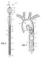
- FIG. 3is an enlarged plan view of a self-centering endovascular wire of the present disclosure
- FIG. 4is a perspective view of the self-centering endovascular wire of FIG. 3 as it is extended in its constrained or collapsed form through a transdermal sheath from the femoral artery into the external iliac artery;
- FIG. 5is a perspective view of the thermally-activated self-centering endovascular wire and transdermal sheath similar to FIG. 4 , illustrating the self-centering nitenol wire struts on the endovascular wire in an expanded condition or form after exiting the transdermal sheath within the external iliac artery;
- FIG. 6is a perspective view of the self-centering endovascular wire with an arterial occlusion balloon disposed proximally of the self-centering nitenol wire struts, illustrating the arterial occlusion balloon in an uninflated condition;
- FIG. 7is a plan view of the self-centering endovascular wire and arterial occlusion balloon of FIG. 6 in an implanted and inflated condition within the thoracic aorta, inferior to the left subclavian artery;
- FIG. 8is a cross-sectional view, taken along lines 8 - 8 of FIG. 4 ;
- FIG. 9is a cross-sectional view, taken along lines 9 - 9 of FIG. 5 ;
- FIG. 10is a perspective view of a multi-way port affixed to a balloon shaft of the arterial occlusion balloon of FIG. 6 , illustrating a one-way valve associated with a main port of the multi-way port in a closed position, preventing fluid communication between a fluid source, such as a syringe, and the balloon shaft and preventing the passage of an inflation medium through the port;
- a fluid sourcesuch as a syringe
- FIG. 11is a perspective view of the multi-way port of FIG. 10 , illustrating the one-way valve in an open position, permitting fluid communication between a fluid source, such as a syringe, and the balloon shaft to achieve inflation or deflation of the arterial occlusion balloon and an inflation medium through the port and into the balloon shaft;
- a fluid sourcesuch as a syringe
- FIG. 12is a flow chart illustrating endovascular procedure categories in large axial vessels of a human torso
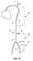
- FIG. 13is an anatomical representation of the human body, illustrating arterial torso vascular anatomy
- FIG. 14is another anatomical representation of the human body, illustrating venous torso vascular anatomy
- FIG. 15is a front perspective view of an exemplary torso vascular insertion tool
- FIG. 16is a back perspective view of the exemplary torso vascular insertion tool
- FIG. 17is a front perspective view of a second embodiment of an exemplary torso vascular insertion tool.
- FIG. 18is a front perspective view of the second embodiment of the exemplary torso vascular insertion tool having a cover disposed thereon.
- FIG. 6A thoracic aortic occlusion system 10 of the present disclosure is illustrated in FIG. 6 .
- This thoracic occlusion system 10employs correlation data extracted from a statistically reliable pool of human patients.
- even reference numeralsdenote structural features of the thoracic aortic occlusion system 10
- odd reference numeralsdenote anatomic locations of a human.
- the system 10relies upon this data to predict the arterial measurement of a normal torso arterial tree 11 from the femoral artery 13 at the level of the femoral head 15 to a level just below 21 the left subclavian artery 17 at the aortic arch 19 (or other relevant locations), each of which is illustrated in FIG.
- a trained medical professionalcan derive the distance to which a calibrated, self-centering endovascular wire 12 of the present disclosure should be advanced from the femoral artery 13 into the descending thoracic aorta 29 to a level just below 21 the left subclavian artery 17 and the aortic arch 19 before deploying an occlusion balloon 14 ( FIG. 6 ) over this endovascular wire 12 to the same position.
- the occlusion balloon 14is deployed at a location 21 inferior of the left subclavian artery 17 at the aortic arch 19 , in an effort to augment or support heart and brain profusion in the setting of end-stage shock resulting from non-compressible torso hemorrhage.
- the prediction model or nomogrammay be developed from, by way of example, a population of male and female trauma patients between the ages of 18-45 years. Computed tomographic measurements are made from the pool of patients to develop statistical associations between distances separating consistently located, external anatomical or boney landmarks and measurements (namely length and diameter data) within the central vascular anatomy.
- a first anatomical landmark distance measured for each patientis a torso extent (in cm), from the symphysis pubis 23 to the sternal notch 25 , as illustrated in FIG. 1A .
- Center-line measurementsare also taken (in cm) from the femoral artery 13 at the level of the femoral head 15 to the left subclavian artery 17 .
- center-line measurements(in cm) from the femoral artery 13 at the level of the femoral head 15 to seven additional key points of anatomical interest, including: (a) the left subclavian artery origin 27 ; (b) the artery of Adamkiewics origin 29 ; (c) the celiac artery origin 31 ; (d) the left renal artery origin 33 ; (e) the right renal artery origin 35 ; (f) the aortic bifurcation 37 ; and (g) the iliac artery bifurcation 39 .
- cross-sectional diameter (in mm) and cross-sectional area (in mm 2 ) measurementsare also determined for each respective vessel.
- a measurementis also taken of the distance (in mm) a hollow tip access needle would traverse at a 45° insertion angle from the epidermis layer of the skin 41 to an initial entry point of the femoral artery 13 , which may be referred to as a percutaneous access length measurement.
- the systemincludes a self-centering endovascular wire 12 , preferably made of a biocompatible wire having calibration indicia thereon, such as pre-calibrated minor length markers 16 provided at 1 cm intervals, and major length markers 18 provided at 5 cm intervals along the length of the self-centering endovascular wire 12 .
- the overall length of the self-centering endovascular wire 12may be 180 cm and have a diameter of approximately 0.035 inch.
- the self-centering endovascular wire 12includes a J tip 20 at a distal end thereof.
- the J tip 20is used to minimize trauma to or perforation of the arterial vessels as the endovascular wire 12 is advanced along the torso arterial tree 11 .
- the J tip 20is also sufficiently flexible to unfold in the event the J tip 20 was to hook onto an arterial branch, such as during withdrawal of the endovascular wire 12 .
- the wire struts 22extend between a leading securement bead 24 and a trailing securement bead 26 , both of which secure the wire struts 22 to the endovascular wire 12 .
- the self-expanding wire struts 22are made of a material that expands upon exposure to fluid at body temperature, such as nitenol, and are disposed at sufficient intervals about the endovascular wire 12 , such as four self-expanding wire struts 22 at 90° intervals.
- struts 22when in their collapsed state such as during insertion through a transdermal sheath 28 , will span the length of the securement beads 24 and 26 . However, the struts 22 will shorten in the length as they extend over the endovascular wire 12 when in their expanded state, such as within the descending thoracic aorta 21 , and as such the wire struts 22 will be movable to some extent axially relative to the endovascular wire 12 , but between the securement beads 24 and 26 .
- the self-expanding wire struts 22serve a self-centering function, keeping the tip or leading end of the endovascular wire 12 away from the sidewalls of the arterial vessels, helping to prevent the endovascular wire 12 from turning down an unintended branch.
- the left renal artery origin 33 ( FIG. 1 ), the right renal artery origin 35 ( FIG. 1 ), and the celiac artery origin 31 ( FIG. 1 )each can branch off from the abdominal aorta 43 at a 90° angle thereto.
- the nitenol self-expanding wire struts 22serve to maintain the endovascular wire 12 within the abdominal aorta 43 ( FIG. 1 ).
- a transdermal or percutaneous sheath 28preferably 6 French, and by way of example having a length of approximately 10 cm with an inner diameter of approximately 0.087 inches is illustrated.
- the sheath 28is inserted into the femoral artery 13 through a puncture in the skin 41 ( FIG. 2 ) with a hollow tip needle to provide an access port by way of first a wire and then the sheath 28 .
- the distal end 30 of the sheath 28is positioned within the external iliac artery 45 ( FIG. 1 ).
- the endovascular wire 12 , the J tip 20 , the leading securement bead 24 , the trailing securement bead 26 , and the unexpanded occlusion balloon 14(which is disposed proximate to the trailing securement bead 26 and illustrated in FIG. 6 ) are all of sufficiently small cross-sectional dimensions to pass through the sheath 28 .
- the leading securement bead 24 and the trailing securement bead 26are also of a sufficient diameter so as to prevent the occlusion balloon 14 from migrating distally over the wire struts 22 and past the J tip 20 .
- the aortic occlusion balloon 14is carried on a balloon shaft 32 having pre-calibrated length indicia 34 thereon.
- the pre-calibrated length indicia 34may include minor length markers 34 a in 1 cm increments, and major length markers 34 b in 5 cm increments.
- the balloon shaft 32preferably has a length of approximately 90 cm (35.43 inches) and an outer diameter less than approximately 1.98 mm (0.087 inches), so as to fit through the sheath 28 .
- the balloon shaft 32includes a lumen 42 (see also FIGS. 10 and 11 ), permitting the balloon shaft 32 to pass over the endovascular wire 12 .
- a tapered distal end portion 44 of the balloon shaft 32prevents the balloon shaft 32 from being inserted past the trailing securement bead 26 .
- the balloon shaft 32will remain over the self-centering endovascular wire 12 during occlusion balloon inflation to provide a rigidity that is sufficient to permit the balloon to be manually maintained at a desired location within the thoracic aorta 47 ( FIG. 1 ), resisting distal or caudal migration, such as might otherwise result from aortic pulsation.
- the aortic occlusion balloon 14has a length of approximately 3 cm, and is affixed to the end of the balloon shaft 32 less than 1 cm below (proximally of) the tapered distal end portion of the balloon shaft 44 . As indicated above, the aortic occlusion balloon 14 is inserted (in a collapsed state) through the transdermal or percutaneous sheath 28 with the endovascular wire 12 and the balloon shaft 32 .
- an inflation fluidis introduced through the balloon shaft 32 to the aortic occlusion balloon 14 , causing the aortic occlusion balloon 14 to inflate, as illustrated in FIG. 7 .
- the aortic occlusion balloon 14may, upon inflation to approximately 1 atm, expand to a maximum diameter of approximately 26 mm, conforming to the shape of the thoracic aorta 47 , thereby obstructing blood flow through the thoracic aorta 47 inferiorly of the inflated aortic occlusion balloon 14 and promptly augmenting heart and brain profusion.
- the inflation fluidis a sterile biocompatible fluid introduced to the multi-port and valve assembly 36 ( FIGS. 10 and 11 ) using a fluid source, such as a syringe 48 .
- a fluid sourcesuch as a syringe 48 .
- the aortic occlusion balloon 14deflates, permitting withdrawal thereof through the transdermal or percutaneous sheath 28 .
- the aortic occlusion balloon 14is inflated and deflated via a multi-port and valve assembly 36 .
- the multi-port and valve assembly 36includes a one-way valve, which is preferably pressure gauge calibrated so as to alert a physician when the aortic occlusion balloon 14 has reached its desired inflation pressure.
- the multi-port and valve assembly 36further includes a terminating port 38 , with a diaphragm 40 .
- the endovascular wire 12can extend through the diaphragm 40 , while maintaining fluid-tight communication between the multi-port and valve assembly 36 and the aortic occlusion balloon 14 .
- the multi-way port and valve assembly 36further includes an elongate tubular barrel section 50 affixed to a proximal end 52 of the balloon shaft 32 .
- the elongate tubular barrel section 50may have a length of approximately 10 to 15 cm.
- the elongate tubular barrel section 50does not pass through the transdermal sheath 28 or enter the body of the patient.
- the multi-way port and valve assembly 36includes a second port 56 at a distal end.
- the multi-way port and valve assembly 36further includes a diaphragm 40 , which is disposed at a proximal end of the elongate tubular barrel section 50 .
- the diaphragm 40permits the endovascular wire 12 to pass through and extend externally of the first port 38 , while maintaining a fluid-tight connection, thereby avoiding leakage of bodily fluid through the first port 38 .
- a one-way valve 60is actuable between an open condition (permitting passage of inflation fluid therethrough), as illustrated in FIG. 11 , and a closed condition (preventing passage of inflation fluid), as illustrated in FIG. 10 .
- the one-way valve 60is in an open condition when oriented parallel to the branch 54 off the elongate tubular barrel section 50 ( FIG. 11 ), and is in a closed condition when rotated to a position perpendicular to the branch 54 .
- An additional port 62provided intermediate the one-way valve and the proximal end 52 of the balloon shaft 32 to which the multi-way port and valve assembly 36 is affixed, is provided with a pressure monitoring device 64 .
- a physicianmay monitor the pressure monitoring device 64 during inflation, enabling the physician to determine when the pressure within the occlusion balloon 14 and the balloon shaft 32 has reached a pressure of, for example, 2 atm, so as to avoid over-inflation and potential injury to the thoracic aorta 47 .
- the physiciancalculates the proper distance to which the endovascular wire 12 and balloon shaft 32 are to be inserted into the transdermal sheath 28 through a puncture in the skin 41 and into the femoral artery 13 at the location of the femoral head 15 , thereby positioning the aortic occlusion balloon 14 at the desired location 21 within the thoracic aorta 47 , inferiorly of the left subclavian artery 17 without the aid of fluoroscopy (i.e. fluoroscopy-independent).
- the major length markers 18 along the endovascular wire 12may be annotated with length-identifying numbers to facilitate determination of the length to which the self-centering endovascular wire 12 has been advanced within the torso arterial tree 11 .
- the physicianactuates a piston of the syringe 48 , thereby introducing inflation fluid through the balloon shaft 32 and into the occlusion balloon 14 , inflating the occlusion balloon 14 to a volume sufficient to block the thoracic aorta 47 .
- the endovascular, fluoroscopy-independent resuscitative thoracic aortic occlusion system 10 of the present disclosuremay be provided to users in the form of a kit, enabling assembly of the same at, by way of example only, a forward surgical hospital close to a battlefield in a civilian trauma setting either outside of a hospital or in a resuscitation room of an emergency department.
- the system 10may be applied in clinical scenarios other than traumas addressed in such urgent care settings, such as cardiac arrest, neurogenic shock, or post-partum hemorrhage that may occur in operating or delivery rooms.
- the kitmay include the endovascular wire 12 having the J tip 20 and at least one wire strut 22 disposed proximally to the J tip 20 .
- the kitmay further include the occlusion balloon 14 that may be disposed proximally on the balloon shaft 32 , and advanced over the endovascular wire 12 until it reaches the trailing securement bead 26 .
- the transdermal sheath 28may also be a part of the kit, such that the transdermal or percutaneous sheath 28 is able to receive each of the endovascular wire 12 , the occlusion balloon 14 when in an uninflated condition, and the balloon shaft 32 , as described above.
- the occlusion balloon 14When assembled with the endovascular wire 12 , the balloon shaft 32 , and the transdermal sheath 28 , the occlusion balloon 14 may be selectively inflated and deflated at a desired location within the thoracic aorta 47 of a patient to treat vascular injury without the aid of fluoroscopy.
- the kitmay further include the multi-port and valve assembly 36 in fluid communication with both the proximal end of the balloon shaft 32 and a fluid source, such as the syringe 48 , as also described above.
- a fluid sourcesuch as the syringe 48
- One of a table, a nomogram, a chart or a graph correlating distances between at least readily externally identifiable anatomical landmarks of a pool of humans to distances from the femoral artery 13 to a location within the thoracic aorta 47 to which the endovascular wire 12 and the balloon shaft 32 are to be insertedmay also be included in the kit.
- endovascular procedures in large axial vessels of the human torsomay be considered as narrow margin procedures 110 or wide margin procedures 112 .
- narrow margin procedures 110require standard fluoroscopy to effectively and accurately direct the procedure.
- narrow margin procedures 110include: (1) placement of stent grafts to treat age-related aneurysms near major branch vessels of the thoracic or abdominal aorta; or (2) treatment of local or localized disease processes such as arterial stenoses caused by atherosclerosis with balloon angioplasty and bare metal stents. Because these procedures entail placing devices at the exact location, i.e., within millimeters, of vital branch or vein locations, they require real time visualization using contrast agents and fluoroscopy.
- wide margin procedures 112include positioning of occlusion balloons to control torso hemorrhage, vena cava filter devices to prevent pulmonary embolus, and stent grafts to treat vessel disruptions localized by computed tomography (CT).
- CTcomputed tomography
- the goalis to temporarily halt flow beyond a certain point in the vena cava or aorta to aid with hemorrhage control.
- life-preserving blood pressure above, or proximal to the balloon occlusionis maintained or supported.
- the balloonmay be positioned anywhere over a much longer length of vessel, e.g., within several centimeters, prior to inflation.
- positioning and placement of thromboembolic filter devices in the vena cavamay occur over a relatively wide distance of vessel, e.g., between the iliac vein confluence and the renal veins.
- fluoroscopyis not required.
- CTcomputer tomography
- 64-panel detectors64-panel detectors
- special measuring softwareallows for such detailed characterization.
- software programs placed in or alongside CT unitsallow precise centerline measurements within the axial vessels as well as determination of their diameter.
- Application of centerline measurementsallows definition of clinically relevant distances between a standard vascular entry point, i.e., femoral vessels and major branch artery points within the vessels.
- the major branch artery pointsinclude a left femoral artery 13 , an external iliac artery 45 , and a left subclavian artery 17 .
- Center-line measurementsare taken (in cm), for example, from the femoral artery 13 at the level of the femoral head 15 to the left subclavian artery 17 , as the left femoral artery 13 is a common vascular entry point.
- FIG. 1the normal torso arterial tree 11 with major branch artery points.
- the major branch artery pointsinclude a left femoral artery 13 , an external iliac artery 45 , and a left subclavian artery 17 .
- Center-line measurementsare taken (in cm), for example, from the femoral artery 13 at the level of the femoral head 15 to the left subclavian artery 17 , as the left femoral artery 13 is a common vascular entry point.
- other major branch artery pointsinclude the artery of Adamkiewics origin 21 , the celiac artery origin 31 , the left renal artery origin 33 , the right renal artery origin 35 , the aortic bifurcation 37 , and the iliac artery bifurcation 39 .
- cross-sectional diametere.g., in mm
- cross-sectional areae.g., in mm2
- arterial torso vascular anatomyis illustrated with various landing zones within the thoracic aorta 47 for wide margin procedures 112 .
- a thoracic aortic zone 137is disposed below a region adjacent to the left subclavian artery 17 along a descending thoracic aorta 47 .
- An infrarenal aortic zone 139is disposed between left renal artery 25 and the iliac artery 45
- a common iliac artery zone 141is disposed between the aortic bifurcation 37 and a distal end of the femoral artery 13 .
- venous torso vascular anatomyis illustrated with various landing zones within the vena cava for wide margin procedures.
- a retro-hepatic inferior vena cava zone 143is disposed along a descending thoracic aorta 47 .
- An infrarenal IVC zone 145is disposed below the retro-hepatic inferior vena cava zone 143
- a common iliac vein zone 147is disposed below the infrarenal IVC zone 145 .
- torso vascular morphometryTo further characterize torso vascular morphometry, it is necessary to account for the relationship between vascular lengths and diameters and an individual's length or height. Because patient height is not consistently available, especially in the context of emergencies or trauma, an external measure of torso extent is needed.
- an external measure of torso extentis illustrated. This measure extends from a sternal notch 25 to the symphisis pubis 23 and can be readily palpated and recorded, even in emergency and trauma settings. Not only is the external measure of torso extent readily available, but it provides a measure which is specific to the torso that houses vascular anatomy of interest.
- the nomogramdefines, with a predetermined confidence interval, the relationship between the external measure of torso extent and distances within the axial vessels of the torso, as well as the specific vessel diameters. If considered from the perspective of a common vascular entry point such as the femoral vessels, to clinically important branch points or landing zones 137 - 147 within the aorta or vena cava, the nomogram is relevant to the performance of wide margin endovascular procedures.
- the nomogramallows a provider to quickly estimate from a basic external measure, e.g., the distance between the sternal notch 25 and the symphysis pubis 23 ( FIG. 1A ), the distance from the femoral vessels to landing zones in the descending thoracic aorta 47 or the inferior vena cava.
- a basic external measuree.g., the distance between the sternal notch 25 and the symphysis pubis 23 ( FIG. 1A ), the distance from the femoral vessels to landing zones in the descending thoracic aorta 47 or the inferior vena cava.
- FIGS. 15 and 16an exemplary torso vascular insertion tool 200 is illustrated.
- the tool 200translates data from the above-described correlation and nomogram, making such information useful in a clinical setting. More specifically, and referring now to FIG. 15 , a first side 210 of the tool 200 is illustrated.
- the first side 210includes an edge 214 and a calibrated ruler 218 disposed on the edge 214 of the first side 210 for use in measuring a torso extent length, i.e., the length between the sternal notch 25 and the symphisis pubis 23 ( FIG. 1A ), on a patient.
- Adjacent to the calibrated ruler 218 on the first side 210 of the tool 200is a first chart 220 providing a listing, by way of example, of male safe zone arterial insertion lengths from the femoral artery 13 vessels to relevant landing zones within the aorta. Such landing zones include the thoracic aortic zone 137 , the infrarenal aortic zone 139 , and the common iliac artery (CIA) zone 141 .
- Adjacent to the first chart 220 disposed on the first side 210 of the tool 200is a second chart 222 .
- the second chart 222provides a listing, by way of example, of male safe zone venuous insertion lengths from the femoral artery 13 vessels to relevant landing zones within the vena cava.
- landing zonesinclude the retro-hepatic inferior vena cava (IVC) zone 143 , the infrarenal IVC zone 145 , and the common iliac vein (CIV) zone 147 .
- the tool 200provides distances from the femoral artery 13 to the aortic bifurcation 37 , the lowest renal artery 33 , the celiac artery 31 , and the left subclavian artery 17 (see FIGS. 1 and 13 ).
- Venous insertion distancesare provided from the femoral vein 153 to the bifurcation of the vena cava 155 , the lowest renal vein 157 , and the hepatic vein 159 (see FIG. 14 ).
- the second side 212includes an edge 216 and a calibrated ruler 218 disposed on the edge 216 also for use in measuring on a patient the external torso extent between the sternal notch 25 and the symphisis pubis 23 ( FIG. 1A ), but this time for a female patient.
- a third chart 224is disposed adjacent to the calibrated ruler 218 on the second side 212 of the tool 200 .
- the third chart 224provides, by way of example, a listing of female safe zone arterial insertion lengths from the femoral artery 13 vessels to relevant landing zones within the aorta.
- Such landing zonesalso include the thoracic aortic zone 137 , the infrarenal aortic zone 139 , and the common iliac artery (CIA) zone 141 .
- Adjacent the third chart 224is a fourth chart 226 .
- the fourth chart 226provides, by way of example, a listing of female safe zone venuous insertion lengths from the femoral artery 13 vessels to relevant landing zones within the vena cava.
- Such landing zonesinclude the retro-hepatic inferior vena cava (IVC) zone 143 , the infrarenal IVC zone 145 , and the common iliac vein (CIV) zone 147 .
- IVCretro-hepatic inferior vena cava
- CIVcommon iliac vein
- the second side 212may also include a listing of the diameter of the torso axial vessels at clinically important locations. More specifically, the back side 212 of the tool 200 provides the diameter of the iliac artery 39 , the thoracic aorta 47 , for the torso axial vessels.
- the venous diametersinclude the iliac vein and infrarenal and suprarenal vena cava.
- the second side 212may also include clinically relevant specifications for endovascular devices commonly used in wide margin endovascular procedures 112 , such as compliant balloons, basic stent grafts, and vena cava filters.
- the torso vascular insertion tool 300includes a data-wheel 310 having a first side 312 and a second side 314 (not shown) and a tape 316 wound between the first and second sides 312 , 314 of the data-wheel 310 , a portion of the tape 316 extending along one side of the data-wheel 310 .
- the tape 316is used to measure on a patient the external measure of torso extent between the sternal notch 25 and the symphisis pubis 23 ( FIG. 1A ).
- the first side 312 of the data-wheel 310provides listings of male safe zone arterial insertion lengths from the femoral artery 13 vessels to relevant landing zones within the aorta corresponding to a circular listing of measured torso extent lengths. More specifically, the first side 312 of the data-wheel 310 includes an inner row 318 , a middle row 320 , and an outer row 322 . The inner row 318 provides a circular listing of male torso extent lengths, e.g., in centimeters.
- the middle row 320provides a circular listing of the thoracic aortic zone 137 lengths corresponding to the circular listing of male torso extent lengths; and the outer row 322 provides a circular listing of the infrarenal aortic zone 139 lengths also corresponding to the circular listing of male torso extent lengths.
- the first side 312 of the data-wheel 310may alternatively provide listings of male safe zone venuous insertion lengths, for example.
- many other variations or combinations of correlation data between the measured torso extent length and new devices, different landing zones, and vessel sizes, for example,may also be provided on the data-wheel 310 .
- the second embodiment of the exemplary torso vascular insertion tool 300is also illustrated, here with a cover 324 over the first side 312 of the data-wheel 310 of the tool 300 .
- the cover 324 of the data-wheel 310rotates to a value of the measured torso extent length displayed on the inner row 318 of the data-wheel 310 .
- the useris then able to compare the torso extent length measured or shown on the inner row 318 of the data-wheel to one or more of corresponding safe zones displayed on the middle row 320 , e.g., the thoracic aortic zone 137 insertion length, or the outer row 322 , e.g., the infrarenal aortic zone 139 insertion length of the data-wheel 310 to calculate a length to which the endovascular device is to be inserted.
- a second side 314 (not shown) of the data-wheel 310may include a circular listing of female safe zone arterial insertion lengths from the femoral artery 13 vessels to relevant landing zones within the aorta. Such landing zones also include the thoracic aortic zone 137 , the infrarenal aortic zone 139 , and the common iliac artery (CIA) zone 141 .
- the second side 314 of the data-wheel 310may alternatively include a circular listing of female safe zone venous insertion lengths from the femoral artery 13 vessels to relevant landing zones within the vena cava.
- Such landing zonesinclude the retro-hepatic inferior vena cava (IVC) zone 143 , the infrarenal IVC zone 145 , and the common iliac vein (CIV) zone 147 .
- the second side 314 of the data-wheel 310 and tape 316 combination of the second embodiment of the torso vascular insertion tool 300may be easily expanded or changed to alternatively include various other correlation data between the measured torso extent length and new devices and vessels sizes, for example.
- the tool 300is also but one example; actual devices could use different numerical indices and zones than those provided in the exemplary tool 300 and still be within the scope of the appended claims.
- Both embodiments of the torso vascular insertion tool 200 , 300may also include calipers or rods to facilitate measuring depending upon a patient's shape. More specifically, in patients having larger abdominal areas, the calipers or rods are needed to provide an accurate linear measurement of the patient's torso extent length because the larger abdominal areas would otherwise impede an accurate measurement.
- the calipers or rodsmay be disposed on one or both ends of the tape.
- the calipers or rodsmay also be retractable and extendible to help facilitate more accurate locating of externally-identifiable anatomic landmarks and measuring of the torso extent length in such patients.
Landscapes
- Health & Medical Sciences (AREA)
- Life Sciences & Earth Sciences (AREA)
- Surgery (AREA)
- Veterinary Medicine (AREA)
- General Health & Medical Sciences (AREA)
- Engineering & Computer Science (AREA)
- Biomedical Technology (AREA)
- Heart & Thoracic Surgery (AREA)
- Public Health (AREA)
- Animal Behavior & Ethology (AREA)
- Molecular Biology (AREA)
- Medical Informatics (AREA)
- Biophysics (AREA)
- Pathology (AREA)
- Nuclear Medicine, Radiotherapy & Molecular Imaging (AREA)
- Hematology (AREA)
- Pulmonology (AREA)
- Anesthesiology (AREA)
- Oral & Maxillofacial Surgery (AREA)
- Physics & Mathematics (AREA)
- Reproductive Health (AREA)
- Vascular Medicine (AREA)
- Dentistry (AREA)
- Media Introduction/Drainage Providing Device (AREA)
- Surgical Instruments (AREA)
- Prostheses (AREA)
Abstract
Description
Claims (19)
Priority Applications (1)
| Application Number | Priority Date | Filing Date | Title |
|---|---|---|---|
| US14/853,604US10111669B2 (en) | 2010-04-21 | 2015-09-14 | Fluoroscopy-independent, endovascular aortic occlusion system |
Applications Claiming Priority (4)
| Application Number | Priority Date | Filing Date | Title |
|---|---|---|---|
| US32647810P | 2010-04-21 | 2010-04-21 | |
| PCT/US2011/033368WO2011133736A2 (en) | 2010-04-21 | 2011-04-21 | Fluoroscopy-independent, endovascular aortic occlusion system |
| US201313642465A | 2013-01-07 | 2013-01-07 | |
| US14/853,604US10111669B2 (en) | 2010-04-21 | 2015-09-14 | Fluoroscopy-independent, endovascular aortic occlusion system |
Related Parent Applications (2)
| Application Number | Title | Priority Date | Filing Date |
|---|---|---|---|
| PCT/US2011/033368ContinuationWO2011133736A2 (en) | 2010-04-21 | 2011-04-21 | Fluoroscopy-independent, endovascular aortic occlusion system |
| US13/642,465ContinuationUS9131874B2 (en) | 2010-04-21 | 2011-04-21 | Fluoroscopy-independent, endovascular aortic occlusion system |
Publications (2)
| Publication Number | Publication Date |
|---|---|
| US20160000446A1 US20160000446A1 (en) | 2016-01-07 |
| US10111669B2true US10111669B2 (en) | 2018-10-30 |
Family
ID=44121017
Family Applications (2)
| Application Number | Title | Priority Date | Filing Date |
|---|---|---|---|
| US13/642,465Active2032-02-25US9131874B2 (en) | 2010-04-21 | 2011-04-21 | Fluoroscopy-independent, endovascular aortic occlusion system |
| US14/853,604Active2032-03-04US10111669B2 (en) | 2010-04-21 | 2015-09-14 | Fluoroscopy-independent, endovascular aortic occlusion system |
Family Applications Before (1)
| Application Number | Title | Priority Date | Filing Date |
|---|---|---|---|
| US13/642,465Active2032-02-25US9131874B2 (en) | 2010-04-21 | 2011-04-21 | Fluoroscopy-independent, endovascular aortic occlusion system |
Country Status (5)
| Country | Link |
|---|---|
| US (2) | US9131874B2 (en) |
| EP (1) | EP2560722A2 (en) |
| AU (1) | AU2011242697B2 (en) |
| CA (1) | CA2797237C (en) |
| WO (1) | WO2011133736A2 (en) |
Cited By (4)
| Publication number | Priority date | Publication date | Assignee | Title |
|---|---|---|---|---|
| US11596411B2 (en) | 2017-04-21 | 2023-03-07 | The Regents Of The University Of California | Aortic flow meter and pump for partial-aortic occlusion |
| US11602592B2 (en) | 2017-01-12 | 2023-03-14 | The Regents Of The University Of California | Endovascular perfusion augmentation for critical care |
| US11633192B2 (en) | 2020-03-16 | 2023-04-25 | Certus Critical Care, Inc. | Blood flow control devices, systems, and methods |
| US11857737B2 (en) | 2015-03-19 | 2024-01-02 | Prytime Medical Devices, Inc. | System and method for low-profile occlusion balloon catheter |
Families Citing this family (27)
| Publication number | Priority date | Publication date | Assignee | Title |
|---|---|---|---|---|
| EP2560722A2 (en) | 2010-04-21 | 2013-02-27 | The Regents of the University of Michigan | Fluoroscopy-independent, endovascular aortic occlusion system |
| US9248262B2 (en)* | 2010-08-31 | 2016-02-02 | Vibha Agarwal | Vascular dilator for controlling blood flow in a blood vessel |
| US10661056B1 (en)* | 2012-02-24 | 2020-05-26 | Christian M. Heesch | Guide catheter support instrument |
| US9474882B2 (en)* | 2013-02-26 | 2016-10-25 | Prytime Medical Devices, Inc. | Fluoroscopy-independent balloon guided occlusion catheter and methods |
| WO2015013238A2 (en) | 2013-07-22 | 2015-01-29 | Mayo Foundation For Medical Education And Research | Device and methods for self-centering a guide catheter |
| US10569062B2 (en) | 2013-09-09 | 2020-02-25 | Prytime Medical Devices, Inc. | Low profile occlusion catheter |
| EP3338826B1 (en)* | 2014-05-26 | 2023-08-23 | Neurescue ApS | A device for providing cardiac output redistribution in emergency medical conditions |
| US10232142B2 (en) | 2014-06-10 | 2019-03-19 | Prytime Medical Devices, Inc. | Conduit guiding tip |
| US10315007B2 (en) | 2014-07-15 | 2019-06-11 | Stryker Corporation | Vascular access system and method of use |
| US20160175569A1 (en)* | 2014-12-22 | 2016-06-23 | Richard R. Heuser | Device for treating vascular occlusion |
| US10279094B2 (en) | 2015-01-21 | 2019-05-07 | United States Of America As Represented By The Secretary Of The Air Force | Endovascular variable aortic control catheter |
| US10820908B2 (en) | 2015-08-19 | 2020-11-03 | Hays, Inc. | Adjustable flow narrow profile balloon for use with a catheter and methods of use |
| US9808254B2 (en) | 2015-08-19 | 2017-11-07 | Hays, Inc. | Selective aortic balloon occlusion device, methods of use, and uses thereof |
| US10154847B2 (en) | 2015-08-19 | 2018-12-18 | Hays, Inc. | Narrow profile balloon for use with an occlusion device, methods of use, and uses thereof |
| WO2017143436A1 (en)* | 2016-02-22 | 2017-08-31 | Uti Limited Partnership | An apparatus, system and method for treating hemorrhage |
| US10368872B2 (en) | 2016-06-02 | 2019-08-06 | Prytime Medical Devices, Inc. | System and method for low profile occlusion balloon catheter |
| US10433852B2 (en) | 2017-05-08 | 2019-10-08 | William Z. H'Doubler | Aortic occlusion balloon apparatus, system and method of making |
| CN107510527A (en)* | 2017-09-29 | 2017-12-26 | 中山大学附属第医院 | Trunk support expansion shaping device |
| US10813648B2 (en) | 2017-10-06 | 2020-10-27 | Boehringer Technologies, Lp | Systems and methods for effecting the total and partial occlusion of the aorta of a living being |
| CA3082315A1 (en) | 2017-11-22 | 2019-05-31 | Front Line Medical Technologies Inc. | Devices and method for blood vessel occlusion |
| EP3833273A4 (en) | 2018-08-06 | 2022-06-29 | Prytime Medical Devices, Inc. | System and method for low profile occlusion balloon catheter |
| US11376011B2 (en)* | 2019-10-03 | 2022-07-05 | José E. Herrera | Catheter balloon for reducing total cardiac burden |
| US11523875B2 (en)* | 2020-04-06 | 2022-12-13 | Biosense Webster (Israel) Ltd. | Enhanced catheter navigation methods and apparatus |
| CN113893444B (en)* | 2020-06-22 | 2025-02-07 | 上海微创心脉医疗科技(集团)股份有限公司 | A medical device |
| WO2022197895A1 (en) | 2021-03-18 | 2022-09-22 | Prytime Medical Devices, Inc. | Vascular occlusion catheter |
| CN116612673B (en)* | 2023-05-16 | 2025-08-08 | 中国人民解放军总医院第五医学中心 | Simulation system for omnibearing monitoring type aortic balloon occlusion training |
| WO2025090636A1 (en)* | 2023-10-27 | 2025-05-01 | The Government Of The United States, As Represented By The Secretary Of The Army | Ultrasound and machine learning based junctional tourniquet |
Citations (152)
| Publication number | Priority date | Publication date | Assignee | Title |
|---|---|---|---|---|
| US2156289A (en) | 1937-04-13 | 1939-05-02 | Permochart Corp | Record chart for automatic recording instruments |
| US4464172A (en) | 1979-04-30 | 1984-08-07 | Lichtenstein Eric Stefan | Computer-control medical care system |
| US4713888A (en) | 1985-10-21 | 1987-12-22 | Broselow James B | Measuring tape for directly determining physical treatment and physiological values |
| US4777951A (en) | 1986-09-19 | 1988-10-18 | Mansfield Scientific, Inc. | Procedure and catheter instrument for treating patients for aortic stenosis |
| US4823469A (en) | 1986-09-23 | 1989-04-25 | Broselow James B | Measuring tape for directly determining physical treatment and physiological values and procedures |
| US4865549A (en) | 1988-04-14 | 1989-09-12 | Kristicare, Inc. | Medical documentation and assessment apparatus |
| US4926885A (en) | 1988-02-22 | 1990-05-22 | Hinkle Allen J | Method of selecting medication and medical equipment |
| US4983166A (en) | 1987-12-28 | 1991-01-08 | Yoshiharu Yamawaki | Balloon catheter and method of use of the same |
| JPH03198868A (en) | 1989-12-27 | 1991-08-30 | Terumo Corp | Catheter for angiography |
| US5135494A (en) | 1988-08-01 | 1992-08-04 | Target Therapeutics | Valved catheter device and method |
| WO1992020398A1 (en) | 1991-05-23 | 1992-11-26 | Leocor, Inc. | Perfusion catheter |
| US5169386A (en) | 1989-09-11 | 1992-12-08 | Bruce B. Becker | Method and catheter for dilatation of the lacrimal system |
| US5282479A (en) | 1992-10-13 | 1994-02-01 | Boc Health Care, Inc. | Guidewire introducer with guidewire grasp and release means |
| US5320605A (en) | 1993-01-22 | 1994-06-14 | Harvinder Sahota | Multi-wire multi-balloon catheter |
| US5383856A (en) | 1993-03-19 | 1995-01-24 | Bersin; Robert M. | Helical spiral balloon catheter |
| US5447503A (en) | 1991-08-14 | 1995-09-05 | Cordis Corporation | Guiding catheter tip having a tapered tip with an expandable lumen |
| US5505702A (en) | 1992-04-09 | 1996-04-09 | Scimed Life Systems, Inc. | Balloon catheter for dilatation and perfusion |
| US5522400A (en) | 1994-11-23 | 1996-06-04 | Uresil Corp | Locking catheter system |
| GB2297259A (en) | 1995-01-25 | 1996-07-31 | Len Edwards Scrymgeour Carrie | Epidural catheter |
| US5571093A (en) | 1994-09-21 | 1996-11-05 | Cruz; Cosme | Multiple-lumen catheter |
| WO1997013542A1 (en) | 1995-10-10 | 1997-04-17 | Cardiac Pathways Corporation | Shape control of catheters by use of movable inner tube |
| JPH09164208A (en) | 1995-11-08 | 1997-06-24 | Pacesetter Ab | Stylet unit |
| US5718678A (en) | 1996-06-26 | 1998-02-17 | Medical Components, Inc. | Multi-lumen coaxial catheter and method for making same |
| US5738652A (en) | 1991-07-16 | 1998-04-14 | Heartport, Inc. | Retrograde delivery catheter and method for inducing cardioplegic arrest |
| WO1998034670A2 (en) | 1997-02-07 | 1998-08-13 | Advanced Cardiovascular Systems, Inc. | Perfusion catheter with high flow distal tip |
| WO1999024105A2 (en) | 1997-11-07 | 1999-05-20 | John Howard | Method and apparatus for treating stenosis of the carotid artery |
| US5911702A (en) | 1997-11-06 | 1999-06-15 | Heartport, Inc. | Methods and devices for cannulating a patient's blood vessel |
| WO1999044666A2 (en) | 1998-03-04 | 1999-09-10 | Scimed Life Systems, Inc. | Catheter tip designs and methods for improved stent crossing |
| US6011988A (en) | 1987-10-28 | 2000-01-04 | Arrow International Investment | Guidewire advancement system |
| US6013019A (en) | 1998-04-06 | 2000-01-11 | Isostent, Inc. | Temporary radioisotope stent |
| US6102930A (en) | 1997-05-16 | 2000-08-15 | Simmons, Jr.; Edward D. | Volumetric measurement device and method in lateral recess and foraminal spinal stenosis |
| US6113579A (en) | 1998-03-04 | 2000-09-05 | Scimed Life Systems, Inc. | Catheter tip designs and methods for improved stent crossing |
| US6146370A (en) | 1999-04-07 | 2000-11-14 | Coaxia, Inc. | Devices and methods for preventing distal embolization from the internal carotid artery using flow reversal by partial occlusion of the external carotid artery |
| US6161547A (en) | 1999-01-15 | 2000-12-19 | Coaxia, Inc. | Medical device for flow augmentation in patients with occlusive cerebrovascular disease and methods of use |
| US6165199A (en) | 1999-01-12 | 2000-12-26 | Coaxia, Inc. | Medical device for removing thromboembolic material from cerebral arteries and methods of use |
| US6190356B1 (en) | 1997-10-20 | 2001-02-20 | Robert M. Bersin | Helical spiral balloon catheter |
| US6248121B1 (en) | 1998-02-18 | 2001-06-19 | Cardio Medical Solutions, Inc. | Blood vessel occlusion device |
| US6280434B1 (en) | 1997-01-31 | 2001-08-28 | Terumo Kabushiki Kaisha | Angiographic catheter |
| WO2001097743A2 (en) | 2000-06-16 | 2001-12-27 | Abbott Laboratories | Balloon occlusion device having a proximal valve |
| US6423031B1 (en) | 1997-04-01 | 2002-07-23 | Brian S. Donlon | Methods and devices for occluding a patient's ascending aorta |
| US6453572B2 (en) | 2000-02-22 | 2002-09-24 | Cross-Tek, Llc | Floor covering estimating device |
| US20020193735A1 (en) | 2001-06-19 | 2002-12-19 | Medtronic Ave, Inc. | Intraluminal therapy catheter with inflatable helical member and methods of use |
| US20030032974A1 (en) | 2001-08-13 | 2003-02-13 | Boris Leschinsky | Reduced size intra-aortic balloon catheter |
| US6575932B1 (en) | 1999-12-02 | 2003-06-10 | Ottawa Heart Institute | Adjustable multi-balloon local delivery device |
| US6579221B1 (en) | 2001-05-31 | 2003-06-17 | Advanced Cardiovascular Systems, Inc. | Proximal catheter shaft design and catheters incorporating the proximal shaft design |
| US20030167038A1 (en) | 1999-10-04 | 2003-09-04 | Ryohei Yozu | Occlusion catheter for the ascending aorta |
| US6656153B1 (en) | 1997-09-12 | 2003-12-02 | Nippon Zeon Co., Ltd | Balloon catheter |
| US6666814B2 (en) | 1999-07-13 | 2003-12-23 | Polycomp Services, Inc. | Enhanced intra-aortic balloon assist device |
| US6669679B1 (en) | 2000-01-07 | 2003-12-30 | Acist Medical Systems, Inc. | Anti-recoil catheter |
| US6695811B2 (en) | 1998-08-06 | 2004-02-24 | Cardeon Corporation | Aortic catheter with porous aortic arch balloon |
| US6719720B1 (en) | 1997-09-06 | 2004-04-13 | Wolfram Voelker | Balloon catheter |
| US20040073162A1 (en) | 2002-05-29 | 2004-04-15 | Bleam Jefferey C. | Balloon construction for occlusion device |
| US20040082935A1 (en) | 1999-12-22 | 2004-04-29 | Lee Jeong Soo | Catheter having a reinforcing mandrel |
| US6733513B2 (en) | 1999-11-04 | 2004-05-11 | Advanced Bioprosthetic Surfaces, Ltd. | Balloon catheter having metal balloon and method of making same |
| US6735532B2 (en) | 1998-09-30 | 2004-05-11 | L. Vad Technology, Inc. | Cardiovascular support control system |
| US6736790B2 (en) | 1998-02-25 | 2004-05-18 | Denise R. Barbut | Method and system for selective or isolated integrate cerebral perfusion and cooling |
| US6746462B1 (en) | 1997-02-28 | 2004-06-08 | Lumend, Inc. | Methods and apparatus for treating vascular occlusions |
| WO2004049970A2 (en) | 2002-12-04 | 2004-06-17 | Lake Region Manufacturing, Inc. | Marked guidewires |
| US6796959B2 (en) | 2001-03-19 | 2004-09-28 | Atrion Medical Products, Inc. | Actuating mechanism for fluid displacement and pressurizing device |
| US20040254528A1 (en) | 2003-06-12 | 2004-12-16 | Adams Daniel O. | Catheter with removable wire lumen segment |
| US20050059931A1 (en) | 2003-09-16 | 2005-03-17 | Venomatrix | Methods and apparatus for localized and semi-localized drug delivery |
| US20050148812A1 (en) | 2003-08-29 | 2005-07-07 | Datascope Investment Corp. | Timing of intra-aortic balloon pump therapy |
| US6936056B2 (en) | 1996-07-26 | 2005-08-30 | Kensey Nash Corporation | Intravascular system for occluded blood vessels and guidewire for use therein |
| US6979318B1 (en) | 2002-10-07 | 2005-12-27 | Lemaitre Vascular, Inc. | Catheter introducer |
| EP1658808A1 (en) | 1994-09-02 | 2006-05-24 | Volcano Corporation | Microminiature pressure sensor and guidewire using the same |
| WO2006135853A2 (en) | 2005-06-10 | 2006-12-21 | Acclarent, Inc. | Devices, systems and methods useable for treating sinusitis |
| WO2007001701A1 (en) | 2005-06-23 | 2007-01-04 | Medtronic Vascular, Inc. | Catheter-based, dual balloon photopolymerization system |
| US20070043409A1 (en)* | 2005-06-29 | 2007-02-22 | Radiant Medical, Inc. | Devices, systems and methods for rapid endovascular cooling |
| US20070043307A1 (en) | 2005-02-02 | 2007-02-22 | Medical Components, Inc. | Guide wire advancer assembly and methods for advancing a guide wire |
| WO2007022592A1 (en) | 2005-08-25 | 2007-03-01 | Baker Medical Research Institute | Devices and methods for perfusing an organ |
| US20070129466A1 (en) | 2004-08-03 | 2007-06-07 | Ichiro Kagawa | Resin composition for sealing medical instruments and medical instrument for endoscope |
| US20070135830A1 (en) | 2004-10-06 | 2007-06-14 | Cook Incorporated | Flexible tip |
| US20070219466A1 (en) | 2006-01-06 | 2007-09-20 | Tremulis W S | Atraumatic Catheter Tip |
| US20070219488A1 (en) | 2005-12-16 | 2007-09-20 | Darius Francescatti | Active drainage system for use in defined natural or surgically created body cavities or lumina |
| WO2008013441A1 (en) | 2006-07-26 | 2008-01-31 | Johan Willem Pieter Marsman | Facilitation of antegrade insertion of a guidewire into the superficial femoral artery |
| US20080027356A1 (en) | 2005-06-02 | 2008-01-31 | David Chen | Anatomical visualization and measurement system |
| US7341571B1 (en) | 2004-09-02 | 2008-03-11 | Advanced Cardiovascular Systems, Inc. | Balloon catheter having a multilayered distal tip |
| US20080082046A1 (en) | 2006-09-29 | 2008-04-03 | Asahi Intecc Co., Ltd. | Balloon catheter, an assembly of the balloon catheter and a method of inserting the assembly into a guiding catheter |
| US20080082119A1 (en) | 2006-10-03 | 2008-04-03 | Vitullo Jeffrey M | Method of determining an appropriate catheter length |
| EP1911484A2 (en) | 2000-12-12 | 2008-04-16 | Datascope Investment Corp. | Intra-aortic balloon catheter having a fiberoptic sensor |
| US20080243067A1 (en) | 2007-03-29 | 2008-10-02 | Dan Rottenberg | Lumen reentry devices and methods |
| US7434326B2 (en) | 2005-05-25 | 2008-10-14 | Edward Gifford | Precision box jig |
| US20080262477A1 (en) | 2007-04-20 | 2008-10-23 | Dr. Hooman Djaladat | Hand made catheter to be used in suprapubic prostatectomy |
| US20090026595A1 (en) | 2007-07-27 | 2009-01-29 | Kiyoaki Kadoi | Semiconductor device package |
| US20090062666A1 (en) | 2003-12-05 | 2009-03-05 | Edwards Lifesciences Corporation | Arterial pressure-based, automatic determination of a cardiovascular parameter |
| US7503904B2 (en) | 2002-04-25 | 2009-03-17 | Cardiac Pacemakers, Inc. | Dual balloon telescoping guiding catheter |
| US7503909B2 (en) | 2001-10-31 | 2009-03-17 | Santen Pharmaceutical Co., Ltd. | Instillation container with level-difference portion |
| US20090171293A1 (en)* | 2007-12-28 | 2009-07-02 | Wilson-Cook Medical Inc. | Self expanding wire guide |
| US20090265951A1 (en) | 2008-04-28 | 2009-10-29 | Bryan Joseph Black | Reference chart apparatus |
| US20090287079A1 (en) | 2008-05-16 | 2009-11-19 | Shriver Edgar L | Hemostatic guiding catheter |
| US20090312807A1 (en) | 2008-06-13 | 2009-12-17 | The Foundry, Llc | Methods and apparatus for joint distraction |
| US20100016735A1 (en) | 2006-08-31 | 2010-01-21 | Atcor Medical Pty Ltd | Method for determination of cardiac output |
| US20100041984A1 (en) | 2008-08-12 | 2010-02-18 | James Edward Shapland | Impedance sensing device and catheter system |
| WO2010070685A1 (en) | 2008-12-18 | 2010-06-24 | Invatec S.P.A. | Guide catheter |
| US7763043B2 (en) | 2003-01-09 | 2010-07-27 | Boston Scientific Scimed, Inc. | Dilatation catheter with enhanced distal end for crossing occluded lesions |
| US20100234915A1 (en) | 2009-03-11 | 2010-09-16 | Herlich Michael B | Non-bioelectrical pressure-based sensing for temporary pacemakers |
| US20100262076A1 (en) | 2006-03-03 | 2010-10-14 | Boston Scientific Scimed, Inc. | Balloon Catheter |
| US20100268017A1 (en) | 2003-08-08 | 2010-10-21 | Thorsten Siess | Intracardiac Pumping Device |
| US20100280451A1 (en) | 2008-11-03 | 2010-11-04 | Atlanta Catheter Therapies, Inc. | Occlusion Perfusion Catheter |
| US7892469B2 (en) | 1998-04-21 | 2011-02-22 | Advanced Cardiovascular Systems, Inc. | Method of making a non-compliant balloon for a catheter |
| US7909810B2 (en) | 2005-04-21 | 2011-03-22 | Medtronic Vascular, Inc | Guiding catheter with resiliently compressible occluder |
| US7951819B2 (en) | 2006-04-26 | 2011-05-31 | Cancer Research Technology Limited | Imidazo[4, 5-B]pyridin-2-one and oxazolo[4, 5-B] pyridin-2-one compounds and analogs thereof as cancer therapeutic compounds |
| US7951186B2 (en) | 2006-04-25 | 2011-05-31 | Boston Scientific Scimed, Inc. | Embedded electroactive polymer structures for use in medical devices |
| US20110196412A1 (en) | 2007-10-22 | 2011-08-11 | Endocross Ltd. | Balloons and balloon catheter systems for treating vascular occlusions |
| WO2011133736A2 (en) | 2010-04-21 | 2011-10-27 | The Regents Of The University Of Michigan | Fluoroscopy-independent, endovascular aortic occlusion system |
| EP2389974A1 (en) | 2010-05-25 | 2011-11-30 | Miracor Medical Systems GmbH | A balloon catheter for introduction into a body vessel, in particular the coronary sinus |
| US20110295302A1 (en) | 2010-05-25 | 2011-12-01 | Miracor Medical Systems Gmbh | Treating Heart Tissue |
| US20110295301A1 (en) | 2010-05-25 | 2011-12-01 | Miracor Medical Systems Gmbh | Catheter System and Method For Occluding A Body Vessel |
| US20110301630A1 (en) | 2010-06-02 | 2011-12-08 | Cook Incorporated | Occlusion device |
| US8162879B2 (en) | 2008-09-22 | 2012-04-24 | Tyco Healthcare Group Lp | Double balloon catheter and methods for homogeneous drug delivery using the same |
| US20120101413A1 (en) | 2010-10-20 | 2012-04-26 | Medtronic Ardian Luxembourg S.a.r.I. | Catheter apparatuses having expandable mesh structures for renal neuromodulation and associated systems and methods |
| US20120109057A1 (en) | 2009-02-18 | 2012-05-03 | Hotspur Technologies, Inc. | Apparatus and methods for treating obstructions within body lumens |
| US20120108979A1 (en) | 2010-10-27 | 2012-05-03 | Gore Enterprise Holdings, Inc. | Imaging catheter with rotatable array |
| US20120116352A1 (en) | 2009-03-31 | 2012-05-10 | Rangi Permjit | Balloon assisted occlusion of aneurysms |
| US20120130359A1 (en) | 2010-10-26 | 2012-05-24 | Medtronic Ardian Luxembourg S.A.R.L. | Neuromodulation cryotherapeutic devices and associated systems and methods |
| US20120172911A1 (en) | 2010-12-30 | 2012-07-05 | Cook Medical Technologies Llc | Occlusion device |
| US8241241B2 (en) | 2000-01-25 | 2012-08-14 | Tyco Healthcare Group Lp | Apparatus and methods for clot dissolution |
| US20120215166A1 (en) | 2011-01-25 | 2012-08-23 | Gerard Barki | Balloon Catheter With Metal Shaft |
| US20120271231A1 (en) | 2011-04-25 | 2012-10-25 | Sony Agrawal | Aspiration thrombectomy device |
| US20120302994A1 (en) | 2011-05-26 | 2012-11-29 | Abbott Cardiovascular Systems Inc. | Through tip for catheter |
| US20130102929A1 (en) | 2011-10-24 | 2013-04-25 | Synvasive Technology, Inc. | Knee balancing devices, systems and methods |
| US8430899B2 (en) | 2001-10-26 | 2013-04-30 | Zoll Circulation, Inc. | Intra-aortic balloon counterpulsation with concurrent hypothermia |
| US20130190619A1 (en) | 2011-12-06 | 2013-07-25 | Ron Nudel | Angiography Catheter |
| US8499681B2 (en) | 2008-11-13 | 2013-08-06 | Atrion Medical Products, Inc. | Actuating mechanism for fluid displacement and pressurizing device |
| US8545382B2 (en) | 2003-06-11 | 2013-10-01 | Senko Medical Instrument Mfg. Co., Ltd. | Method of balloon pumping and a balloon pump driving apparatus |
| US20130281869A1 (en) | 2001-04-24 | 2013-10-24 | Zoll Circulation, Inc. | Partial aortic occlusion devices and methods for cerebral perfusion augmentation |
| US20130289607A1 (en) | 2003-07-18 | 2013-10-31 | Intervalve, Inc. | Valvuloplasty Catheter |
| WO2014003809A1 (en) | 2012-06-29 | 2014-01-03 | University Of Washington Through Its Center For Commercialization | Catheters for emergency endovascular surgery and associated devices, systems, and methods |
| US8655798B2 (en) | 2005-02-16 | 2014-02-18 | University Of Virginia Patent Foundation | Blood flow bypass catheters and methods for the delivery of medium to the vasculature and body ducts |
| US8672868B2 (en) | 2007-02-09 | 2014-03-18 | Maquet Cardiopulmonary Ag | Method and apparatus for monitoring and optimizing blood circulation generated by a pump |
| EP2716323A1 (en) | 2009-03-09 | 2014-04-09 | Flip Technologies Limited | Apparatus for monitoring the internal transverse cross-section of a stoma in a stomach |
| US8747358B2 (en) | 2000-10-18 | 2014-06-10 | Bayer Medical Care Inc. | Injector system with a manual control device |
| US20140221898A1 (en) | 2013-02-01 | 2014-08-07 | Cook Medical Technologies Llc | Curved tip hemodialysis catheter |
| US8814900B2 (en) | 2003-01-31 | 2014-08-26 | Cordis Corporation | Filter retrieval catheter system, and methods |
| US20140243873A1 (en) | 2013-02-26 | 2014-08-28 | Pryor Medical Devices, Inc. | Fluoroscopy-independent balloon guided occlusion catheter and methods |
| US20140249504A1 (en) | 2013-02-26 | 2014-09-04 | Pryor Medical Devices, Inc. | Vascular access systems and methods of use |
| WO2014152191A1 (en) | 2013-03-15 | 2014-09-25 | Qxmedical, Llc | Boosting catheter and related systems and methods |
| US20140316012A1 (en) | 2013-03-15 | 2014-10-23 | Toby Freyman | In-Situ Forming Foams for Embolizing or Occluding a Cavity |
| US8900214B2 (en) | 2007-03-30 | 2014-12-02 | Onset Medical Corporation | Expandable trans-septal sheath |
| US20140378869A1 (en) | 2008-01-23 | 2014-12-25 | MediGuide, Ltd. | Guidewire interconnecting apparatus |
| US20150012031A1 (en) | 2011-08-12 | 2015-01-08 | Adam Rago | Intra-abdominal pressure to promote hemostasis and survival |
| WO2015006828A1 (en) | 2013-07-17 | 2015-01-22 | Hts Therapeutics Pty Ltd | A method for treating haemorrhage, shock and brain injury |
| US8948848B2 (en) | 2011-01-07 | 2015-02-03 | Innovative Cardiovascular Solutions, Llc | Angiography catheter |
| US20150039012A1 (en) | 2006-05-11 | 2015-02-05 | Y-Med, Inc. | Systems and methods for treating a vessel using focused force |
| US8951565B2 (en) | 2003-12-23 | 2015-02-10 | Hemcon Medical Technologies, Inc. | Hemostatic compositions, assemblies, systems, and methods employing particulate hemostatic agents formed from hydrophilic polymer foam such as chitosan |
| WO2015035393A1 (en) | 2013-09-09 | 2015-03-12 | Pryor Medical Devices, Inc. | Low-profile occlusion catheter |
| WO2015191685A1 (en) | 2014-06-10 | 2015-12-17 | Pryor Medical Devices, Inc. | Conduit guiding tip |
| US20150367098A1 (en) | 2014-06-23 | 2015-12-24 | Cook Medical Technologies, LLC | Catheter or sheath assembly |
| USD748257S1 (en) | 2014-10-24 | 2016-01-26 | Pryor Medical Devices, Inc. | Guiding catheter tip |
| US9414843B2 (en) | 2003-11-28 | 2016-08-16 | Cook Medical Technologies Llc | Vascular occlusion methods, systems and devices |
| WO2016149653A2 (en) | 2015-03-19 | 2016-09-22 | Prytime Medical Devices, Inc. | System and method for low-profile occlusion balloon catheter |
| US9687333B2 (en) | 2007-08-31 | 2017-06-27 | BiO2 Medical, Inc. | Reduced profile central venous access catheter with vena cava filter and method |
- 2011
- 2011-04-21EPEP11721151Apatent/EP2560722A2/ennot_activeWithdrawn
- 2011-04-21USUS13/642,465patent/US9131874B2/enactiveActive
- 2011-04-21CACA2797237Apatent/CA2797237C/ennot_activeExpired - Fee Related
- 2011-04-21WOPCT/US2011/033368patent/WO2011133736A2/enactiveApplication Filing
- 2011-04-21AUAU2011242697Apatent/AU2011242697B2/ennot_activeCeased
- 2015
- 2015-09-14USUS14/853,604patent/US10111669B2/enactiveActive
Patent Citations (172)
| Publication number | Priority date | Publication date | Assignee | Title |
|---|---|---|---|---|
| US2156289A (en) | 1937-04-13 | 1939-05-02 | Permochart Corp | Record chart for automatic recording instruments |
| US4464172A (en) | 1979-04-30 | 1984-08-07 | Lichtenstein Eric Stefan | Computer-control medical care system |
| US4713888A (en) | 1985-10-21 | 1987-12-22 | Broselow James B | Measuring tape for directly determining physical treatment and physiological values |
| US4777951A (en) | 1986-09-19 | 1988-10-18 | Mansfield Scientific, Inc. | Procedure and catheter instrument for treating patients for aortic stenosis |
| US4823469A (en) | 1986-09-23 | 1989-04-25 | Broselow James B | Measuring tape for directly determining physical treatment and physiological values and procedures |
| US6011988A (en) | 1987-10-28 | 2000-01-04 | Arrow International Investment | Guidewire advancement system |
| US4983166A (en) | 1987-12-28 | 1991-01-08 | Yoshiharu Yamawaki | Balloon catheter and method of use of the same |
| US4926885A (en) | 1988-02-22 | 1990-05-22 | Hinkle Allen J | Method of selecting medication and medical equipment |
| US4865549A (en) | 1988-04-14 | 1989-09-12 | Kristicare, Inc. | Medical documentation and assessment apparatus |
| US5135494A (en) | 1988-08-01 | 1992-08-04 | Target Therapeutics | Valved catheter device and method |
| US5169386A (en) | 1989-09-11 | 1992-12-08 | Bruce B. Becker | Method and catheter for dilatation of the lacrimal system |
| JPH03198868A (en) | 1989-12-27 | 1991-08-30 | Terumo Corp | Catheter for angiography |
| WO1992020398A1 (en) | 1991-05-23 | 1992-11-26 | Leocor, Inc. | Perfusion catheter |
| US5738652A (en) | 1991-07-16 | 1998-04-14 | Heartport, Inc. | Retrograde delivery catheter and method for inducing cardioplegic arrest |
| US5447503A (en) | 1991-08-14 | 1995-09-05 | Cordis Corporation | Guiding catheter tip having a tapered tip with an expandable lumen |
| US5505702A (en) | 1992-04-09 | 1996-04-09 | Scimed Life Systems, Inc. | Balloon catheter for dilatation and perfusion |
| US5282479A (en) | 1992-10-13 | 1994-02-01 | Boc Health Care, Inc. | Guidewire introducer with guidewire grasp and release means |
| US5320605A (en) | 1993-01-22 | 1994-06-14 | Harvinder Sahota | Multi-wire multi-balloon catheter |
| US5383856A (en) | 1993-03-19 | 1995-01-24 | Bersin; Robert M. | Helical spiral balloon catheter |
| US8419648B2 (en) | 1994-09-02 | 2013-04-16 | Volcano Corporation | Ultra miniature pressure sensor |
| EP1658808A1 (en) | 1994-09-02 | 2006-05-24 | Volcano Corporation | Microminiature pressure sensor and guidewire using the same |
| US5571093A (en) | 1994-09-21 | 1996-11-05 | Cruz; Cosme | Multiple-lumen catheter |
| US5522400A (en) | 1994-11-23 | 1996-06-04 | Uresil Corp | Locking catheter system |
| GB2297259A (en) | 1995-01-25 | 1996-07-31 | Len Edwards Scrymgeour Carrie | Epidural catheter |
| WO1997013542A1 (en) | 1995-10-10 | 1997-04-17 | Cardiac Pathways Corporation | Shape control of catheters by use of movable inner tube |
| JPH09164208A (en) | 1995-11-08 | 1997-06-24 | Pacesetter Ab | Stylet unit |
| US5718678A (en) | 1996-06-26 | 1998-02-17 | Medical Components, Inc. | Multi-lumen coaxial catheter and method for making same |
| US6936056B2 (en) | 1996-07-26 | 2005-08-30 | Kensey Nash Corporation | Intravascular system for occluded blood vessels and guidewire for use therein |
| US6280434B1 (en) | 1997-01-31 | 2001-08-28 | Terumo Kabushiki Kaisha | Angiographic catheter |
| WO1998034670A2 (en) | 1997-02-07 | 1998-08-13 | Advanced Cardiovascular Systems, Inc. | Perfusion catheter with high flow distal tip |
| US6746462B1 (en) | 1997-02-28 | 2004-06-08 | Lumend, Inc. | Methods and apparatus for treating vascular occlusions |
| US6423031B1 (en) | 1997-04-01 | 2002-07-23 | Brian S. Donlon | Methods and devices for occluding a patient's ascending aorta |
| US6102930A (en) | 1997-05-16 | 2000-08-15 | Simmons, Jr.; Edward D. | Volumetric measurement device and method in lateral recess and foraminal spinal stenosis |
| US6719720B1 (en) | 1997-09-06 | 2004-04-13 | Wolfram Voelker | Balloon catheter |
| US6656153B1 (en) | 1997-09-12 | 2003-12-02 | Nippon Zeon Co., Ltd | Balloon catheter |
| US6190356B1 (en) | 1997-10-20 | 2001-02-20 | Robert M. Bersin | Helical spiral balloon catheter |
| US5911702A (en) | 1997-11-06 | 1999-06-15 | Heartport, Inc. | Methods and devices for cannulating a patient's blood vessel |
| WO1999024105A2 (en) | 1997-11-07 | 1999-05-20 | John Howard | Method and apparatus for treating stenosis of the carotid artery |
| US6248121B1 (en) | 1998-02-18 | 2001-06-19 | Cardio Medical Solutions, Inc. | Blood vessel occlusion device |
| US6736790B2 (en) | 1998-02-25 | 2004-05-18 | Denise R. Barbut | Method and system for selective or isolated integrate cerebral perfusion and cooling |
| WO1999044666A2 (en) | 1998-03-04 | 1999-09-10 | Scimed Life Systems, Inc. | Catheter tip designs and methods for improved stent crossing |
| JP2002505165A (en) | 1998-03-04 | 2002-02-19 | ボストン サイエンティフィック リミテッド | Method for improving penetration of catheter tip and stent |
| US6113579A (en) | 1998-03-04 | 2000-09-05 | Scimed Life Systems, Inc. | Catheter tip designs and methods for improved stent crossing |
| EP1094861B1 (en) | 1998-03-04 | 2005-04-06 | Boston Scientific Limited | Catheter tip designs for improved stent crossing |
| US6013019A (en) | 1998-04-06 | 2000-01-11 | Isostent, Inc. | Temporary radioisotope stent |
| US7892469B2 (en) | 1998-04-21 | 2011-02-22 | Advanced Cardiovascular Systems, Inc. | Method of making a non-compliant balloon for a catheter |
| US6695811B2 (en) | 1998-08-06 | 2004-02-24 | Cardeon Corporation | Aortic catheter with porous aortic arch balloon |
| US6735532B2 (en) | 1998-09-30 | 2004-05-11 | L. Vad Technology, Inc. | Cardiovascular support control system |
| US6165199A (en) | 1999-01-12 | 2000-12-26 | Coaxia, Inc. | Medical device for removing thromboembolic material from cerebral arteries and methods of use |
| US6161547A (en) | 1999-01-15 | 2000-12-19 | Coaxia, Inc. | Medical device for flow augmentation in patients with occlusive cerebrovascular disease and methods of use |
| US6146370A (en) | 1999-04-07 | 2000-11-14 | Coaxia, Inc. | Devices and methods for preventing distal embolization from the internal carotid artery using flow reversal by partial occlusion of the external carotid artery |
| US6666814B2 (en) | 1999-07-13 | 2003-12-23 | Polycomp Services, Inc. | Enhanced intra-aortic balloon assist device |
| US20030167038A1 (en) | 1999-10-04 | 2003-09-04 | Ryohei Yozu | Occlusion catheter for the ascending aorta |
| US6733513B2 (en) | 1999-11-04 | 2004-05-11 | Advanced Bioprosthetic Surfaces, Ltd. | Balloon catheter having metal balloon and method of making same |
| US6575932B1 (en) | 1999-12-02 | 2003-06-10 | Ottawa Heart Institute | Adjustable multi-balloon local delivery device |
| US20040082935A1 (en) | 1999-12-22 | 2004-04-29 | Lee Jeong Soo | Catheter having a reinforcing mandrel |
| JP2007014820A (en) | 1999-12-22 | 2007-01-25 | Advanced Cardeovascular Syst Inc | Catheter having reinforcing mandrel |
| US6669679B1 (en) | 2000-01-07 | 2003-12-30 | Acist Medical Systems, Inc. | Anti-recoil catheter |
| US8241241B2 (en) | 2000-01-25 | 2012-08-14 | Tyco Healthcare Group Lp | Apparatus and methods for clot dissolution |
| US6453572B2 (en) | 2000-02-22 | 2002-09-24 | Cross-Tek, Llc | Floor covering estimating device |
| JP2003535652A (en) | 2000-06-16 | 2003-12-02 | アボット・ラボラトリーズ | Balloon occluding device having a proximal end valve |
| WO2001097743A2 (en) | 2000-06-16 | 2001-12-27 | Abbott Laboratories | Balloon occlusion device having a proximal valve |
| US20050261725A1 (en) | 2000-06-16 | 2005-11-24 | Crawford Lynn D | Balloon occlusion device having a proximal valve |
| US8747358B2 (en) | 2000-10-18 | 2014-06-10 | Bayer Medical Care Inc. | Injector system with a manual control device |
| EP1911484A2 (en) | 2000-12-12 | 2008-04-16 | Datascope Investment Corp. | Intra-aortic balloon catheter having a fiberoptic sensor |
| US6796959B2 (en) | 2001-03-19 | 2004-09-28 | Atrion Medical Products, Inc. | Actuating mechanism for fluid displacement and pressurizing device |
| US20130281869A1 (en) | 2001-04-24 | 2013-10-24 | Zoll Circulation, Inc. | Partial aortic occlusion devices and methods for cerebral perfusion augmentation |
| US6579221B1 (en) | 2001-05-31 | 2003-06-17 | Advanced Cardiovascular Systems, Inc. | Proximal catheter shaft design and catheters incorporating the proximal shaft design |
| US6679860B2 (en) | 2001-06-19 | 2004-01-20 | Medtronic Ave, Inc. | Intraluminal therapy catheter with inflatable helical member and methods of use |
| US20020193735A1 (en) | 2001-06-19 | 2002-12-19 | Medtronic Ave, Inc. | Intraluminal therapy catheter with inflatable helical member and methods of use |
| US6602270B2 (en) | 2001-08-13 | 2003-08-05 | Datascope Investment Corp. | Reduced size intra-aortic balloon catheter |
| US20030032974A1 (en) | 2001-08-13 | 2003-02-13 | Boris Leschinsky | Reduced size intra-aortic balloon catheter |
| US8430899B2 (en) | 2001-10-26 | 2013-04-30 | Zoll Circulation, Inc. | Intra-aortic balloon counterpulsation with concurrent hypothermia |
| US7503909B2 (en) | 2001-10-31 | 2009-03-17 | Santen Pharmaceutical Co., Ltd. | Instillation container with level-difference portion |
| US7503904B2 (en) | 2002-04-25 | 2009-03-17 | Cardiac Pacemakers, Inc. | Dual balloon telescoping guiding catheter |
| US20040073162A1 (en) | 2002-05-29 | 2004-04-15 | Bleam Jefferey C. | Balloon construction for occlusion device |
| US6979318B1 (en) | 2002-10-07 | 2005-12-27 | Lemaitre Vascular, Inc. | Catheter introducer |
| WO2004049970A3 (en) | 2002-12-04 | 2004-08-19 | Lake Region Mfg Inc | Marked guidewires |
| WO2004049970A2 (en) | 2002-12-04 | 2004-06-17 | Lake Region Manufacturing, Inc. | Marked guidewires |
| US7763043B2 (en) | 2003-01-09 | 2010-07-27 | Boston Scientific Scimed, Inc. | Dilatation catheter with enhanced distal end for crossing occluded lesions |
| US8814900B2 (en) | 2003-01-31 | 2014-08-26 | Cordis Corporation | Filter retrieval catheter system, and methods |
| US8545382B2 (en) | 2003-06-11 | 2013-10-01 | Senko Medical Instrument Mfg. Co., Ltd. | Method of balloon pumping and a balloon pump driving apparatus |
| US20040254528A1 (en) | 2003-06-12 | 2004-12-16 | Adams Daniel O. | Catheter with removable wire lumen segment |
| US20130289607A1 (en) | 2003-07-18 | 2013-10-31 | Intervalve, Inc. | Valvuloplasty Catheter |
| US20100268017A1 (en) | 2003-08-08 | 2010-10-21 | Thorsten Siess | Intracardiac Pumping Device |
| US20050148812A1 (en) | 2003-08-29 | 2005-07-07 | Datascope Investment Corp. | Timing of intra-aortic balloon pump therapy |
| US20050059931A1 (en) | 2003-09-16 | 2005-03-17 | Venomatrix | Methods and apparatus for localized and semi-localized drug delivery |
| US9414843B2 (en) | 2003-11-28 | 2016-08-16 | Cook Medical Technologies Llc | Vascular occlusion methods, systems and devices |
| US20090062666A1 (en) | 2003-12-05 | 2009-03-05 | Edwards Lifesciences Corporation | Arterial pressure-based, automatic determination of a cardiovascular parameter |
| US8951565B2 (en) | 2003-12-23 | 2015-02-10 | Hemcon Medical Technologies, Inc. | Hemostatic compositions, assemblies, systems, and methods employing particulate hemostatic agents formed from hydrophilic polymer foam such as chitosan |
| US20070129466A1 (en) | 2004-08-03 | 2007-06-07 | Ichiro Kagawa | Resin composition for sealing medical instruments and medical instrument for endoscope |
| US7341571B1 (en) | 2004-09-02 | 2008-03-11 | Advanced Cardiovascular Systems, Inc. | Balloon catheter having a multilayered distal tip |
| US20070135830A1 (en) | 2004-10-06 | 2007-06-14 | Cook Incorporated | Flexible tip |
| US20070043307A1 (en) | 2005-02-02 | 2007-02-22 | Medical Components, Inc. | Guide wire advancer assembly and methods for advancing a guide wire |
| US8655798B2 (en) | 2005-02-16 | 2014-02-18 | University Of Virginia Patent Foundation | Blood flow bypass catheters and methods for the delivery of medium to the vasculature and body ducts |
| US7909810B2 (en) | 2005-04-21 | 2011-03-22 | Medtronic Vascular, Inc | Guiding catheter with resiliently compressible occluder |
| US7434326B2 (en) | 2005-05-25 | 2008-10-14 | Edward Gifford | Precision box jig |
| US20080027356A1 (en) | 2005-06-02 | 2008-01-31 | David Chen | Anatomical visualization and measurement system |
| WO2006135853A2 (en) | 2005-06-10 | 2006-12-21 | Acclarent, Inc. | Devices, systems and methods useable for treating sinusitis |
| WO2006135853A3 (en) | 2005-06-10 | 2009-04-23 | Acclarent Inc | Devices, systems and methods useable for treating sinusitis |
| JP2008546471A (en) | 2005-06-23 | 2008-12-25 | メドトロニック ヴァスキュラー インコーポレイテッド | Catheter-based double balloon photopolymerization system |
| WO2007001701A1 (en) | 2005-06-23 | 2007-01-04 | Medtronic Vascular, Inc. | Catheter-based, dual balloon photopolymerization system |
| US20070043409A1 (en)* | 2005-06-29 | 2007-02-22 | Radiant Medical, Inc. | Devices, systems and methods for rapid endovascular cooling |
| WO2007022592A1 (en) | 2005-08-25 | 2007-03-01 | Baker Medical Research Institute | Devices and methods for perfusing an organ |
| US20070219488A1 (en) | 2005-12-16 | 2007-09-20 | Darius Francescatti | Active drainage system for use in defined natural or surgically created body cavities or lumina |
| US20070219466A1 (en) | 2006-01-06 | 2007-09-20 | Tremulis W S | Atraumatic Catheter Tip |
| US20100262076A1 (en) | 2006-03-03 | 2010-10-14 | Boston Scientific Scimed, Inc. | Balloon Catheter |
| US7951186B2 (en) | 2006-04-25 | 2011-05-31 | Boston Scientific Scimed, Inc. | Embedded electroactive polymer structures for use in medical devices |
| US7951819B2 (en) | 2006-04-26 | 2011-05-31 | Cancer Research Technology Limited | Imidazo[4, 5-B]pyridin-2-one and oxazolo[4, 5-B] pyridin-2-one compounds and analogs thereof as cancer therapeutic compounds |
| US20150039012A1 (en) | 2006-05-11 | 2015-02-05 | Y-Med, Inc. | Systems and methods for treating a vessel using focused force |
| WO2008013441A1 (en) | 2006-07-26 | 2008-01-31 | Johan Willem Pieter Marsman | Facilitation of antegrade insertion of a guidewire into the superficial femoral artery |
| US20100016735A1 (en) | 2006-08-31 | 2010-01-21 | Atcor Medical Pty Ltd | Method for determination of cardiac output |
| US20080082046A1 (en) | 2006-09-29 | 2008-04-03 | Asahi Intecc Co., Ltd. | Balloon catheter, an assembly of the balloon catheter and a method of inserting the assembly into a guiding catheter |
| US20080082119A1 (en) | 2006-10-03 | 2008-04-03 | Vitullo Jeffrey M | Method of determining an appropriate catheter length |
| US8672868B2 (en) | 2007-02-09 | 2014-03-18 | Maquet Cardiopulmonary Ag | Method and apparatus for monitoring and optimizing blood circulation generated by a pump |
| US20080243067A1 (en) | 2007-03-29 | 2008-10-02 | Dan Rottenberg | Lumen reentry devices and methods |
| US8900214B2 (en) | 2007-03-30 | 2014-12-02 | Onset Medical Corporation | Expandable trans-septal sheath |
| US20080262477A1 (en) | 2007-04-20 | 2008-10-23 | Dr. Hooman Djaladat | Hand made catheter to be used in suprapubic prostatectomy |
| US20090026595A1 (en) | 2007-07-27 | 2009-01-29 | Kiyoaki Kadoi | Semiconductor device package |
| US9687333B2 (en) | 2007-08-31 | 2017-06-27 | BiO2 Medical, Inc. | Reduced profile central venous access catheter with vena cava filter and method |
| US20110196412A1 (en) | 2007-10-22 | 2011-08-11 | Endocross Ltd. | Balloons and balloon catheter systems for treating vascular occlusions |
| US20090171293A1 (en)* | 2007-12-28 | 2009-07-02 | Wilson-Cook Medical Inc. | Self expanding wire guide |
| US20140378869A1 (en) | 2008-01-23 | 2014-12-25 | MediGuide, Ltd. | Guidewire interconnecting apparatus |
| US20090265951A1 (en) | 2008-04-28 | 2009-10-29 | Bryan Joseph Black | Reference chart apparatus |
| US7959644B2 (en) | 2008-05-16 | 2011-06-14 | Edgar L Shriver | Hemostatic guiding catheter |
| US20090287079A1 (en) | 2008-05-16 | 2009-11-19 | Shriver Edgar L | Hemostatic guiding catheter |
| US20090312807A1 (en) | 2008-06-13 | 2009-12-17 | The Foundry, Llc | Methods and apparatus for joint distraction |
| US20100041984A1 (en) | 2008-08-12 | 2010-02-18 | James Edward Shapland | Impedance sensing device and catheter system |
| US8162879B2 (en) | 2008-09-22 | 2012-04-24 | Tyco Healthcare Group Lp | Double balloon catheter and methods for homogeneous drug delivery using the same |
| US8088103B2 (en) | 2008-11-03 | 2012-01-03 | Advanced Catheter Therapies, Inc. | Occlusion perfusion catheter |
| US8262611B2 (en) | 2008-11-03 | 2012-09-11 | Advanced Catheter Therapies, Inc | Occlusion perfusion catheter |
| US20100280451A1 (en) | 2008-11-03 | 2010-11-04 | Atlanta Catheter Therapies, Inc. | Occlusion Perfusion Catheter |
| US8499681B2 (en) | 2008-11-13 | 2013-08-06 | Atrion Medical Products, Inc. | Actuating mechanism for fluid displacement and pressurizing device |
| WO2010070685A1 (en) | 2008-12-18 | 2010-06-24 | Invatec S.P.A. | Guide catheter |
| US20120109057A1 (en) | 2009-02-18 | 2012-05-03 | Hotspur Technologies, Inc. | Apparatus and methods for treating obstructions within body lumens |
| EP2716323A1 (en) | 2009-03-09 | 2014-04-09 | Flip Technologies Limited | Apparatus for monitoring the internal transverse cross-section of a stoma in a stomach |
| US20100234915A1 (en) | 2009-03-11 | 2010-09-16 | Herlich Michael B | Non-bioelectrical pressure-based sensing for temporary pacemakers |
| US20120116352A1 (en) | 2009-03-31 | 2012-05-10 | Rangi Permjit | Balloon assisted occlusion of aneurysms |
| US20160000446A1 (en) | 2010-04-21 | 2016-01-07 | The Regents Of The University Of Michigan | Fluoroscopy-independent, endovascular aortic occlusion system |
| US9131874B2 (en) | 2010-04-21 | 2015-09-15 | The Regents Of The University Of Michigan | Fluoroscopy-independent, endovascular aortic occlusion system |
| US20130102926A1 (en) | 2010-04-21 | 2013-04-25 | Government of the United States c/o Secretary of the Air Force | Fluoroscopy-independent, endovascular aortic occlusion system |
| WO2011133736A2 (en) | 2010-04-21 | 2011-10-27 | The Regents Of The University Of Michigan | Fluoroscopy-independent, endovascular aortic occlusion system |
| US20110295301A1 (en) | 2010-05-25 | 2011-12-01 | Miracor Medical Systems Gmbh | Catheter System and Method For Occluding A Body Vessel |
| US20110295302A1 (en) | 2010-05-25 | 2011-12-01 | Miracor Medical Systems Gmbh | Treating Heart Tissue |
| JP2011245300A (en) | 2010-05-25 | 2011-12-08 | Miracor Medical Systems Gmbh | Balloon catheter for introduction into body vessel, in particular coronary sinus |
| EP2389974A1 (en) | 2010-05-25 | 2011-11-30 | Miracor Medical Systems GmbH | A balloon catheter for introduction into a body vessel, in particular the coronary sinus |
| US20110301630A1 (en) | 2010-06-02 | 2011-12-08 | Cook Incorporated | Occlusion device |
| US20120101413A1 (en) | 2010-10-20 | 2012-04-26 | Medtronic Ardian Luxembourg S.a.r.I. | Catheter apparatuses having expandable mesh structures for renal neuromodulation and associated systems and methods |
| US20120130359A1 (en) | 2010-10-26 | 2012-05-24 | Medtronic Ardian Luxembourg S.A.R.L. | Neuromodulation cryotherapeutic devices and associated systems and methods |
| US20120108979A1 (en) | 2010-10-27 | 2012-05-03 | Gore Enterprise Holdings, Inc. | Imaging catheter with rotatable array |
| US20120172911A1 (en) | 2010-12-30 | 2012-07-05 | Cook Medical Technologies Llc | Occlusion device |
| US8948848B2 (en) | 2011-01-07 | 2015-02-03 | Innovative Cardiovascular Solutions, Llc | Angiography catheter |
| US20120215166A1 (en) | 2011-01-25 | 2012-08-23 | Gerard Barki | Balloon Catheter With Metal Shaft |
| US20120271231A1 (en) | 2011-04-25 | 2012-10-25 | Sony Agrawal | Aspiration thrombectomy device |
| US20120302994A1 (en) | 2011-05-26 | 2012-11-29 | Abbott Cardiovascular Systems Inc. | Through tip for catheter |
| US20150012031A1 (en) | 2011-08-12 | 2015-01-08 | Adam Rago | Intra-abdominal pressure to promote hemostasis and survival |
| US20130102929A1 (en) | 2011-10-24 | 2013-04-25 | Synvasive Technology, Inc. | Knee balancing devices, systems and methods |
| US20130190619A1 (en) | 2011-12-06 | 2013-07-25 | Ron Nudel | Angiography Catheter |
| WO2014003809A1 (en) | 2012-06-29 | 2014-01-03 | University Of Washington Through Its Center For Commercialization | Catheters for emergency endovascular surgery and associated devices, systems, and methods |
| US20140221898A1 (en) | 2013-02-01 | 2014-08-07 | Cook Medical Technologies Llc | Curved tip hemodialysis catheter |
| US20140243873A1 (en) | 2013-02-26 | 2014-08-28 | Pryor Medical Devices, Inc. | Fluoroscopy-independent balloon guided occlusion catheter and methods |
| US20140249504A1 (en) | 2013-02-26 | 2014-09-04 | Pryor Medical Devices, Inc. | Vascular access systems and methods of use |
| US9474882B2 (en)* | 2013-02-26 | 2016-10-25 | Prytime Medical Devices, Inc. | Fluoroscopy-independent balloon guided occlusion catheter and methods |
| WO2014134215A1 (en) | 2013-02-26 | 2014-09-04 | Pryor Medical Devices, Inc. | Fluoroscopy-independent balloon guided occlusion catheter and methods |
| US20140316012A1 (en) | 2013-03-15 | 2014-10-23 | Toby Freyman | In-Situ Forming Foams for Embolizing or Occluding a Cavity |
| WO2014152191A1 (en) | 2013-03-15 | 2014-09-25 | Qxmedical, Llc | Boosting catheter and related systems and methods |
| WO2015006828A1 (en) | 2013-07-17 | 2015-01-22 | Hts Therapeutics Pty Ltd | A method for treating haemorrhage, shock and brain injury |
| WO2015035393A1 (en) | 2013-09-09 | 2015-03-12 | Pryor Medical Devices, Inc. | Low-profile occlusion catheter |
| WO2015191685A1 (en) | 2014-06-10 | 2015-12-17 | Pryor Medical Devices, Inc. | Conduit guiding tip |
| US20150367098A1 (en) | 2014-06-23 | 2015-12-24 | Cook Medical Technologies, LLC | Catheter or sheath assembly |
| USD748257S1 (en) | 2014-10-24 | 2016-01-26 | Pryor Medical Devices, Inc. | Guiding catheter tip |
| WO2016149653A2 (en) | 2015-03-19 | 2016-09-22 | Prytime Medical Devices, Inc. | System and method for low-profile occlusion balloon catheter |
Non-Patent Citations (39)
| Title |
|---|
| Chen, John J., et al. "The renal length nomogram: multivariable approach." The Journal of urology 168.5 (2002): 2149-2152.* |
| Detrano et al. "Bayesian Probability Analysis: a Prospective Demonstration of its Clinical Utility in Diagnosing Coronary Disease," Circulation, vol. 69, No. 3, pp. 541-547 (1984). |
| Extended European Search Report dated Jun. 26, 2017 in EP Application No. 14842370. |
| Extended European Search Report dated Oct. 5, 2016 in Europe Application No. EP 14 75 6640. |
| Extended Search Report dated Mar. 21, 2017 in EP Application No. 15806534. |
| Extended Search Report dated Mar. 24, 2017 in EP Application No. 14842370. |
| Fenton et al., "Comparing risks of alternative medical diagnosis using Bayesian arguments," J. Biomed. Inf., vol. 43, pp. 485-495 (2010). |
| Guidance for the Use of Bayesian Statistics in Medical Device Clinical Trials, U.S. Department of Health and Human Services, Food and Drug Administration, Center for Devices and Radiological Health, Division of Biostatistics, Office of Surveillance and Biometrics, Feb. 5, 2010. |
| Holcomb et al., "Causes of death in US Special Operations Forces in the global war on terrorism: 2001-2004," Annals of Surgery, vol. 245, No. 6, pp. 986-991 (2007). |
| Hughes et al., "Use of an Intra-Aortic Balloon Catheter Tamponade for Controlling Intra-Abdominal Hemorrhage in Man," Surgery, vol. 36, pp. 65-68 (1954). |
| International Search Report and Written Opinion for PCT/US2011/033368 dated Oct. 14, 2011. |
| Int'l Preliminary Report dated Dec. 22, 2016 in Int'l Application No. PCT/US2015/035061. |
| Int'l Preliminary Report dated Jul. 17, 2017 in Int'l Application No. PCT/US2016/023223. |
| Int'l Preliminary Report on Patentability dated Mar. 24, 2016 in Int'l Application No. PCT/US2014/054802. |
| Int'l Preliminary Report on Patentability dated Nov. 1, 2012 in Int'l Application No. PCT/US2011/033368. |
| Int'l Preliminary Report on Patentability dated Sep. 11, 2015 in Int'l Application No. PCT/US2014/018779. |
| Int'l Search Report and Written Opinion dated Apr. 21, 2017 in Int'l Application No. PCT/US2016/023223. |
| Int'l Search Report and Written Opinion dated Jan. 28, 2015 in Int'l Application No. PCT/US2014/054802. |
| Int'l Search Report and Written Opinion dated Jun. 8, 2014 in Int'l Application No. PCT/US2014/018779. |
| Int'l Search Report and Written Opinion dated Sep. 28, 2017 in Int'l Application No. PCT/US2017/035729. |
| Int'l Search Report and Written Opinion dated Sep. 4, 2015 in Int'l Application No. PCT/US2014/035061. |
| Langewouters et al. "The static elastic properties of 45 human thoracic and 20 abdominal aortas in vitro and the parameter of a new model." J. Biomechanics 17.6 (1984):425-435. Retrieved form http://dspace.library.uu.nl/bitstream/hjandle/1874/25204/wesseling_84_the%20static%20elastic%20properties%20of%2045%20human.pdf> on Mar. 31, 2015. |
| Ledgerwood et al., "The Role of Thoracic Aortic Occlusion for Massive Hemoperitoneum," J Trauma, vol. 16, No. 8, pp. 610-615 (1976). |
| Office Action dated Apr. 11, 2017 in JP Application No. 2016-546035. |
| Office Action dated Apr. 6, 2014 in U.S. Appl. No. 13/642,465. |
| Office Action dated Aug. 23, 2016 in AU Application No. 2015274743. |
| Office Action dated Mar. 20, 2017 in CA Application No. 2,797,237. |
| Office Action dated Oct. 12, 2017 in CA Application No. 2,980,018. |
| Office Action dated Oct. 28, 2014 in U.S. Appl. No. 13/642,465. |
| Office Action dated Sep. 12, 2017 in JP Application No. 2016-546035. |
| Office Action dated Sep. 19, 2017 in JP Application No. 2015-559309. |
| Patel et al., "Bayesian Designs for Device Clinical Trials," MDG Forum, Waltham, MA., Nov. 3, 2010, downloaded from web page: <http://www.cytel.com/pdfs/Patel Bayes Devices Slides 11.18.10. pdf>. |
| Peterson, et al. "Percutaneous endovascular repair of blunt thoracic aortic transection." Journal of Trauma-Injury, Infection, and Critical Care 59.5 (2005): 1062-1065. Retrieved from <http://www.clubdelpercutaneo.org/pdf/Percutaneous%20Endovascular%20Repari%20Blunt%Thoracid%20Aortic.pdf> on Oct. 14, 2014. |
| Sam II, et al. "Blunt traumatic aortic transection: endoluminal repair with commercially availble aortic cuffs." Journal of vascular surgery 38.5 (2003): 1132-1135. Retieved from <http:www.sciencedirect.com/science/article/pii/S0741521403007171. on Oct. 14, 2014. |
| Sandgren, et al. "The diameter of the common femoral artery in heathy human: influence of sex, age, and body size." Journal of vascular surgery 29.3 (1999): 503-510. Retrieved form <http://www.sciencedirect.com/science/article/pii/S074152149970279X> on Oct. 14, 2014. |
| Sohn et al., "Demographics, Treatment, and Early Outcomes in Penetrating Vascular Combat Trauma," Arch Surg, vol. 143, No. 8, pp. 783-787 (2008). |
| Stannard et al., "Resuscitative Endovascular Balloon Occlusion of the Aorta (REBOA) as an Adjunct for Hemorrhagic Shock," J. Trauma, vol. 71, pp. 1869-1872 (2011). |
| Supplemental Search Report dated Dec. 19, 2016 in EP Application No. 15806534. |
| White et al., "The Epidemiology of Vascular Injury in the Wars in Iraq and Afghanistan," Annals of Surgery, vol. 253, No. 6, pp. 1184-1189. |
Cited By (8)
| Publication number | Priority date | Publication date | Assignee | Title |
|---|---|---|---|---|
| US11857737B2 (en) | 2015-03-19 | 2024-01-02 | Prytime Medical Devices, Inc. | System and method for low-profile occlusion balloon catheter |
| US11602592B2 (en) | 2017-01-12 | 2023-03-14 | The Regents Of The University Of California | Endovascular perfusion augmentation for critical care |
| US12290659B2 (en) | 2017-01-12 | 2025-05-06 | The Regents Of The University Of California | Endovascular perfusion augmentation for critical care |
| US11596411B2 (en) | 2017-04-21 | 2023-03-07 | The Regents Of The University Of California | Aortic flow meter and pump for partial-aortic occlusion |
| US12318090B2 (en) | 2017-04-21 | 2025-06-03 | The Regents Of The University Of California | Aortic flow meter and pump for partial-aortic occlusion |
| US11633192B2 (en) | 2020-03-16 | 2023-04-25 | Certus Critical Care, Inc. | Blood flow control devices, systems, and methods |
| US12251111B2 (en) | 2020-03-16 | 2025-03-18 | Certus Critical Care, Inc. | Blood flow control devices, systems, and methods |
| US12419644B2 (en) | 2020-03-16 | 2025-09-23 | Certus Critical Care, Inc. | Blood flow control devices, systems, and methods and error detection thereof |
Also Published As
| Publication number | Publication date |
|---|---|
| US9131874B2 (en) | 2015-09-15 |
| AU2011242697B2 (en) | 2015-01-22 |
| AU2011242697A1 (en) | 2012-12-13 |
| US20160000446A1 (en) | 2016-01-07 |
| WO2011133736A2 (en) | 2011-10-27 |
| CA2797237C (en) | 2018-05-22 |
| WO2011133736A3 (en) | 2011-12-29 |
| EP2560722A2 (en) | 2013-02-27 |
| US20130102926A1 (en) | 2013-04-25 |
| CA2797237A1 (en) | 2011-10-27 |
Similar Documents
| Publication | Publication Date | Title |
|---|---|---|
| US10111669B2 (en) | Fluoroscopy-independent, endovascular aortic occlusion system | |
| US9474882B2 (en) | Fluoroscopy-independent balloon guided occlusion catheter and methods | |
| US11857737B2 (en) | System and method for low-profile occlusion balloon catheter | |
| US20200329995A1 (en) | Endovascular occlusion device and method of use | |
| US20090054922A1 (en) | Apparatus and Method for the Intravascular Control of Trauma | |
| AU2015201978B2 (en) | Fluoroscopy-independent, endovascular aortic occlusion system | |
| CN217723595U (en) | Aortic blood vessel blocking balloon catheter for controlling traumatic bleeding | |
| RU112046U1 (en) | CORONARY STENT DELIVERY | |
| Hill et al. | Aortoscopy: a guidance system for endoluminal aortic surgery |
Legal Events
| Date | Code | Title | Description |
|---|---|---|---|
| AS | Assignment | Owner name:THE REGENTS OF THE UNIVERSITY OF MICHIGAN, MICHIGA Free format text:ASSIGNMENT OF ASSIGNORS INTEREST;ASSIGNOR:ELIASON, JONATHAN L.;REEL/FRAME:036860/0597 Effective date:20110419 Owner name:GOVERNMENT OF THE UNITED STATES C/O SECRETARY OF T Free format text:ASSIGNMENT OF ASSIGNORS INTEREST;ASSIGNOR:RASMUSSEN, TODD E.;REEL/FRAME:036860/0650 Effective date:20110411 | |
| STCF | Information on status: patent grant | Free format text:PATENTED CASE | |
| MAFP | Maintenance fee payment | Free format text:PAYMENT OF MAINTENANCE FEE, 4TH YEAR, LARGE ENTITY (ORIGINAL EVENT CODE: M1551); ENTITY STATUS OF PATENT OWNER: LARGE ENTITY Year of fee payment:4 | |
| AS | Assignment | Owner name:THE GOVERNMENT OF THE UNITED STATES AS REPRESENTED BY THE DIRECTOR OF THE DEFENSE HEALTH AGENCY, MARYLAND Free format text:ASSIGNMENT OF ASSIGNORS INTEREST;ASSIGNOR:THE GOVERNMENT OF THE UNITED STATES AS REPRESENTED BY THE SECRETARY OF THE AIR FORCE;REEL/FRAME:065779/0620 Effective date:20231109 | |
| AS | Assignment | Owner name:THE UNITED STATES GOVERNMENT AS REPRESENTED BY THE DEPARTMENT OF VETERAN AFFAIRS, DISTRICT OF COLUMBIA Free format text:ASSIGNMENT OF ASSIGNORS INTEREST;ASSIGNOR:REGENTS OF THE UNIVERSITY OF MICHIGAN;REEL/FRAME:068553/0880 Effective date:20240911 Owner name:REGENTS OF THE UNIVERSITY OF MICHIGAN, MICHIGAN Free format text:ASSIGNMENT OF ASSIGNORS INTEREST;ASSIGNOR:REGENTS OF THE UNIVERSITY OF MICHIGAN;REEL/FRAME:068553/0880 Effective date:20240911 |