US10111588B2 - Analyte sensor transceiver configured to provide tactile, visual, and/or aural feedback - Google Patents
Analyte sensor transceiver configured to provide tactile, visual, and/or aural feedbackDownload PDFInfo
- Publication number
- US10111588B2 US10111588B2US14/453,078US201414453078AUS10111588B2US 10111588 B2US10111588 B2US 10111588B2US 201414453078 AUS201414453078 AUS 201414453078AUS 10111588 B2US10111588 B2US 10111588B2
- Authority
- US
- United States
- Prior art keywords
- transceiver
- analyte
- sensor
- analyte sensor
- notification device
- Prior art date
- Legal status (The legal status is an assumption and is not a legal conclusion. Google has not performed a legal analysis and makes no representation as to the accuracy of the status listed.)
- Active
Links
- 239000012491analyteSubstances0.000titleclaimsabstractdescription89
- 230000000007visual effectEffects0.000titleclaimsabstractdescription33
- 238000004891communicationMethods0.000claimsdescription29
- 238000005259measurementMethods0.000claimsdescription7
- 238000012544monitoring processMethods0.000description15
- 230000033001locomotionEffects0.000description9
- WQZGKKKJIJFFOK-GASJEMHNSA-NGlucoseNatural productsOC[C@H]1OC(O)[C@H](O)[C@@H](O)[C@@H]1OWQZGKKKJIJFFOK-GASJEMHNSA-N0.000description7
- 239000008103glucoseSubstances0.000description7
- NOESYZHRGYRDHS-UHFFFAOYSA-NinsulinChemical compoundN1C(=O)C(NC(=O)C(CCC(N)=O)NC(=O)C(CCC(O)=O)NC(=O)C(C(C)C)NC(=O)C(NC(=O)CN)C(C)CC)CSSCC(C(NC(CO)C(=O)NC(CC(C)C)C(=O)NC(CC=2C=CC(O)=CC=2)C(=O)NC(CCC(N)=O)C(=O)NC(CC(C)C)C(=O)NC(CCC(O)=O)C(=O)NC(CC(N)=O)C(=O)NC(CC=2C=CC(O)=CC=2)C(=O)NC(CSSCC(NC(=O)C(C(C)C)NC(=O)C(CC(C)C)NC(=O)C(CC=2C=CC(O)=CC=2)NC(=O)C(CC(C)C)NC(=O)C(C)NC(=O)C(CCC(O)=O)NC(=O)C(C(C)C)NC(=O)C(CC(C)C)NC(=O)C(CC=2NC=NC=2)NC(=O)C(CO)NC(=O)CNC2=O)C(=O)NCC(=O)NC(CCC(O)=O)C(=O)NC(CCCNC(N)=N)C(=O)NCC(=O)NC(CC=3C=CC=CC=3)C(=O)NC(CC=3C=CC=CC=3)C(=O)NC(CC=3C=CC(O)=CC=3)C(=O)NC(C(C)O)C(=O)N3C(CCC3)C(=O)NC(CCCCN)C(=O)NC(C)C(O)=O)C(=O)NC(CC(N)=O)C(O)=O)=O)NC(=O)C(C(C)CC)NC(=O)C(CO)NC(=O)C(C(C)O)NC(=O)C1CSSCC2NC(=O)C(CC(C)C)NC(=O)C(NC(=O)C(CCC(N)=O)NC(=O)C(CC(N)=O)NC(=O)C(NC(=O)C(N)CC=1C=CC=CC=1)C(C)C)CC1=CN=CN1NOESYZHRGYRDHS-UHFFFAOYSA-N0.000description6
- 230000008878couplingEffects0.000description4
- 238000010168coupling processMethods0.000description4
- 238000005859coupling reactionMethods0.000description4
- 102000004877InsulinHuman genes0.000description3
- 108090001061InsulinProteins0.000description3
- 241001465754MetazoaSpecies0.000description3
- 238000004364calculation methodMethods0.000description3
- 230000001413cellular effectEffects0.000description3
- 230000000694effectsEffects0.000description3
- 229940125396insulinDrugs0.000description3
- 206010040576Shock hypoglycaemicDiseases0.000description2
- 230000001133accelerationEffects0.000description2
- QVGXLLKOCUKJST-UHFFFAOYSA-Natomic oxygenChemical compound[O]QVGXLLKOCUKJST-UHFFFAOYSA-N0.000description2
- 230000008901benefitEffects0.000description2
- 239000003086colorantSubstances0.000description2
- 230000009977dual effectEffects0.000description2
- 230000002641glycemic effectEffects0.000description2
- 238000003306harvestingMethods0.000description2
- 230000002218hypoglycaemic effectEffects0.000description2
- 230000007246mechanismEffects0.000description2
- 210000004379membraneAnatomy0.000description2
- 239000012528membraneSubstances0.000description2
- 238000000034methodMethods0.000description2
- 229910052760oxygenInorganic materials0.000description2
- 239000001301oxygenSubstances0.000description2
- 238000003909pattern recognitionMethods0.000description2
- 230000002093peripheral effectEffects0.000description2
- 230000033764rhythmic processEffects0.000description2
- 208000013016HypoglycemiaDiseases0.000description1
- 210000001015abdomenAnatomy0.000description1
- 239000000853adhesiveSubstances0.000description1
- 230000001070adhesive effectEffects0.000description1
- WQZGKKKJIJFFOK-VFUOTHLCSA-Nbeta-D-glucoseChemical compoundOC[C@H]1O[C@@H](O)[C@H](O)[C@@H](O)[C@@H]1OWQZGKKKJIJFFOK-VFUOTHLCSA-N0.000description1
- 230000005540biological transmissionEffects0.000description1
- 230000004397blinkingEffects0.000description1
- 210000004369bloodAnatomy0.000description1
- 239000008280bloodSubstances0.000description1
- 230000036760body temperatureEffects0.000description1
- 238000010276constructionMethods0.000description1
- 238000013461designMethods0.000description1
- 210000003722extracellular fluidAnatomy0.000description1
- 239000012530fluidSubstances0.000description1
- 230000006870functionEffects0.000description1
- 125000002791glucosyl groupChemical groupC1([C@H](O)[C@@H](O)[C@H](O)[C@H](O1)CO)*0.000description1
- 230000003345hyperglycaemic effectEffects0.000description1
- 201000001421hyperglycemiaDiseases0.000description1
- 230000001771impaired effectEffects0.000description1
- 238000002513implantationMethods0.000description1
- 238000001727in vivoMethods0.000description1
- 230000001939inductive effectEffects0.000description1
- 230000000977initiatory effectEffects0.000description1
- 238000007912intraperitoneal administrationMethods0.000description1
- 210000002414legAnatomy0.000description1
- 239000004973liquid crystal related substanceSubstances0.000description1
- 238000012986modificationMethods0.000description1
- 230000004048modificationEffects0.000description1
- 230000003287optical effectEffects0.000description1
- 206010033675panniculitisDiseases0.000description1
- 238000000059patterningMethods0.000description1
- 210000004303peritoneumAnatomy0.000description1
- 230000035790physiological processes and functionsEffects0.000description1
- 230000008569processEffects0.000description1
- 230000000276sedentary effectEffects0.000description1
- 238000012163sequencing techniqueMethods0.000description1
- 229910000679solderInorganic materials0.000description1
- 238000007920subcutaneous administrationMethods0.000description1
- 210000004304subcutaneous tissueAnatomy0.000description1
- 230000002459sustained effectEffects0.000description1
- 210000004243sweatAnatomy0.000description1
- 238000003466weldingMethods0.000description1
- 210000000707wristAnatomy0.000description1
Images


Classifications
- A—HUMAN NECESSITIES
- A61—MEDICAL OR VETERINARY SCIENCE; HYGIENE
- A61B—DIAGNOSIS; SURGERY; IDENTIFICATION
- A61B5/00—Measuring for diagnostic purposes; Identification of persons
- A61B5/0002—Remote monitoring of patients using telemetry, e.g. transmission of vital signals via a communication network
- A—HUMAN NECESSITIES
- A61—MEDICAL OR VETERINARY SCIENCE; HYGIENE
- A61B—DIAGNOSIS; SURGERY; IDENTIFICATION
- A61B5/00—Measuring for diagnostic purposes; Identification of persons
- A61B5/01—Measuring temperature of body parts ; Diagnostic temperature sensing, e.g. for malignant or inflamed tissue
- A—HUMAN NECESSITIES
- A61—MEDICAL OR VETERINARY SCIENCE; HYGIENE
- A61B—DIAGNOSIS; SURGERY; IDENTIFICATION
- A61B5/00—Measuring for diagnostic purposes; Identification of persons
- A61B5/103—Measuring devices for testing the shape, pattern, colour, size or movement of the body or parts thereof, for diagnostic purposes
- A61B5/11—Measuring movement of the entire body or parts thereof, e.g. head or hand tremor or mobility of a limb
- A61B5/1112—Global tracking of patients, e.g. by using GPS
- A—HUMAN NECESSITIES
- A61—MEDICAL OR VETERINARY SCIENCE; HYGIENE
- A61B—DIAGNOSIS; SURGERY; IDENTIFICATION
- A61B5/00—Measuring for diagnostic purposes; Identification of persons
- A61B5/145—Measuring characteristics of blood in vivo, e.g. gas concentration or pH-value ; Measuring characteristics of body fluids or tissues, e.g. interstitial fluid or cerebral tissue
- A61B5/14532—Measuring characteristics of blood in vivo, e.g. gas concentration or pH-value ; Measuring characteristics of body fluids or tissues, e.g. interstitial fluid or cerebral tissue for measuring glucose, e.g. by tissue impedance measurement
- A—HUMAN NECESSITIES
- A61—MEDICAL OR VETERINARY SCIENCE; HYGIENE
- A61B—DIAGNOSIS; SURGERY; IDENTIFICATION
- A61B5/00—Measuring for diagnostic purposes; Identification of persons
- A61B5/145—Measuring characteristics of blood in vivo, e.g. gas concentration or pH-value ; Measuring characteristics of body fluids or tissues, e.g. interstitial fluid or cerebral tissue
- A61B5/1455—Measuring characteristics of blood in vivo, e.g. gas concentration or pH-value ; Measuring characteristics of body fluids or tissues, e.g. interstitial fluid or cerebral tissue using optical sensors, e.g. spectral photometrical oximeters
- A61B5/1459—Measuring characteristics of blood in vivo, e.g. gas concentration or pH-value ; Measuring characteristics of body fluids or tissues, e.g. interstitial fluid or cerebral tissue using optical sensors, e.g. spectral photometrical oximeters invasive, e.g. introduced into the body by a catheter
- A—HUMAN NECESSITIES
- A61—MEDICAL OR VETERINARY SCIENCE; HYGIENE
- A61B—DIAGNOSIS; SURGERY; IDENTIFICATION
- A61B5/00—Measuring for diagnostic purposes; Identification of persons
- A61B5/72—Signal processing specially adapted for physiological signals or for diagnostic purposes
- A61B5/7271—Specific aspects of physiological measurement analysis
- A61B5/7282—Event detection, e.g. detecting unique waveforms indicative of a medical condition
- A—HUMAN NECESSITIES
- A61—MEDICAL OR VETERINARY SCIENCE; HYGIENE
- A61B—DIAGNOSIS; SURGERY; IDENTIFICATION
- A61B5/00—Measuring for diagnostic purposes; Identification of persons
- A61B5/74—Details of notification to user or communication with user or patient; User input means
- A61B5/7405—Details of notification to user or communication with user or patient; User input means using sound
- A—HUMAN NECESSITIES
- A61—MEDICAL OR VETERINARY SCIENCE; HYGIENE
- A61B—DIAGNOSIS; SURGERY; IDENTIFICATION
- A61B5/00—Measuring for diagnostic purposes; Identification of persons
- A61B5/74—Details of notification to user or communication with user or patient; User input means
- A61B5/742—Details of notification to user or communication with user or patient; User input means using visual displays
- A—HUMAN NECESSITIES
- A61—MEDICAL OR VETERINARY SCIENCE; HYGIENE
- A61B—DIAGNOSIS; SURGERY; IDENTIFICATION
- A61B5/00—Measuring for diagnostic purposes; Identification of persons
- A61B5/74—Details of notification to user or communication with user or patient; User input means
- A61B5/7455—Details of notification to user or communication with user or patient; User input means characterised by tactile indication, e.g. vibration or electrical stimulation
- A—HUMAN NECESSITIES
- A61—MEDICAL OR VETERINARY SCIENCE; HYGIENE
- A61B—DIAGNOSIS; SURGERY; IDENTIFICATION
- A61B5/00—Measuring for diagnostic purposes; Identification of persons
- A61B5/145—Measuring characteristics of blood in vivo, e.g. gas concentration or pH-value ; Measuring characteristics of body fluids or tissues, e.g. interstitial fluid or cerebral tissue
- A61B5/14503—Measuring characteristics of blood in vivo, e.g. gas concentration or pH-value ; Measuring characteristics of body fluids or tissues, e.g. interstitial fluid or cerebral tissue invasive, e.g. introduced into the body by a catheter or needle or using implanted sensors
- A—HUMAN NECESSITIES
- A61—MEDICAL OR VETERINARY SCIENCE; HYGIENE
- A61B—DIAGNOSIS; SURGERY; IDENTIFICATION
- A61B5/00—Measuring for diagnostic purposes; Identification of persons
- A61B5/72—Signal processing specially adapted for physiological signals or for diagnostic purposes
- A61B5/7203—Signal processing specially adapted for physiological signals or for diagnostic purposes for noise prevention, reduction or removal
Definitions
- the inventionis directed to an on-body, wearable transceiver for communication with an analyte sensor, where the sensor is implanted subcutaneously, intravenously, or intraperitoneally.
- the transceivermay provide visual, vibratory/tactile, and/or aural notifications/feedback to the user.
- the transceivermay also provide wireless communication to and exchange data with a smartphone or other device, which may also have visual, vibratory/tactile, and/or aural notifications/feedback.
- Conventional continuous analyte (e.g., glucose) monitoring systemsinclude a sensor, a transceiver worn on the user and configured for communication with the sensor, and a receiver, separate from the transceiver and configured to receive data transmissions from the transceiver and to provide notifications and feedback to the user.
- a sensore.g., a Bosch Sensortec BMA150 senor
- a transceiver worn on the usere.g., glucose
- a receiverseparate from the transceiver and configured to receive data transmissions from the transceiver and to provide notifications and feedback to the user.
- all alarms and/or other aural, visual or vibratory notificationsare provided by the receiver.
- the receivershows the user both passive and actionable information and provides visual/aural/vibratory alarms.
- the transceiveris also connected (either by wire or wirelessly) to either to an insulin pump or a personal communication device, such as a smartphone, in which case the visual and/or aural and/or vibratory alarm/notification systems are incorporated into either the insulin pump or the communication device.
- a disadvantage of conventional analyte monitoring systemsis that in order for a user to receive any visual, aural or vibratory alarms and/or information related to the analyte measurements, the user is required to be within close proximity of the receiver in order to see, hear, or feel the alarm. Thus, improvements in analyte monitoring systems are desired.
- An analyte monitoring system embodying aspects of the present inventionmay comprise an analyte sensor and an externally-worn transceiver configured for communication with the sensor which includes the capabilities of having the transceiver vibrate and/or generate an aural or visual signal to prompt the user about sensor and/or transceiver information, in addition to having these capabilities reside on the smartphone application.
- the transceivermay include an interface device and a notification device.
- the interface devicemay be configured to convey a power signal to the analyte sensor and to receive data signals from the analyte sensor.
- the notification devicemay be configured to generate one or more of a vibrational, aural, and visual signal based on one or more data signals received from the analyte sensor.
- the interface devicemay be an antenna configured to wirelessly convey the power signal to an antenna of the analyte sensor and to wirelessly receive the data signals from the antenna of the analyte sensor.
- the notification devicemay be configured to generate one or more of a vibrational, aural, and visual signal if the transceiver is placed for optimal signal exchange between the analyte sensor and the transceiver.
- the interface device of the transceivermay receive analyte data from the analyte sensor, and the transceiver may comprise a processor configured to calculate an analyte concentration value based on the received analyte data.
- the transceivermay include a wireless communication circuit configured to wirelessly transmit the analyte concentration to a smartphone or other device.
- the notification devicemay be configured to emit an aural alarm when the calculated analyte concentration value exceeds or falls below a threshold value.
- the notification devicemay include a vibration motor configured to generate a vibrational signal when the calculated analyte concentration value exceeds or falls below a threshold value.
- the notification devicemay include one or more LEDs configured to generate one or more visual signals.
- the transceivermay include a battery, and the notification device may be configured to generate one or more of a vibrational, aural, and visual signal if the power level of the battery falls below a threshold.
- the transceivermay be an on-body, wearable transceiver.
- the systemmay include an analyte sensor and a transceiver.
- the analyte sensormay be configured to detect the analyte within the living organism.
- the analyte sensormay include indicator elements, sensor elements, and an interface device.
- the indicator elementsmay be configured to exhibit a detectable property based on the amount or concentration of the analyte in proximity to the indicator elements.
- the sensor elementsmay be configured to generate a data signal based on the detectable property exhibited by said indicator elements.
- the interface devicemay be configured to receive signals and generate power for powering the sensor elements and to convey data signals generated by the sensor elements.
- the transceivermay include an interface device and a notification device.
- the interface devicemay be configured to convey a power signal to the interface device of the analyte sensor and to receive data signals conveyed by the interface device of the analyte sensor.
- the notification devicemay be configured to generate one or more of a vibrational, aural, and visual signal based on a data signal received from the interface device of the analyte sensor.
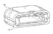
- FIG. 1is cross-sectional, perspective view of a transceiver embodying aspects of the invention.
- FIG. 2is an exploded, perspective view of a transceiver embodying aspects of the invention.
- FIG. 3is a schematic view of an analyte monitoring system embodying aspects of the invention.
- FIG. 3is a schematic view of an analyte monitoring system 300 embodying aspects of the present invention.
- the analyte monitoring system 300may include a sensor 324 and an external transceiver 100 configured for communication with the sensor 324 .
- the sensor 324may be an implantable sensor configured to be implanted in a living animal (e.g., a living human).
- the sensor 324may be an implantable sensor configured to be implanted, for example, in a living animal's arm, wrist, leg, abdomen, peritoneum, or other region of the living animal suitable for sensor implantation.
- the senor 324may be implanted beneath the skin (e.g., in the subcutaneous tissues).
- the sensor 324may be an analyte sensor configured to detect an analyte (e.g., glucose or oxygen) in a patient's interstitial fluid, blood, or intraperitoneal fluid.
- the sensor 324may include indicator elements 326 and sensor elements 328 to detect analyte data and convey/communicate the analyte data to the external transceiver 100 .
- the transceiver 100may be a handheld device or an on-body/wearable device.
- the transceiver 100may be held in place by a band (e.g., an armband, wristband, leg band, or belt) and/or adhesive, and the transceiver 100 may convey (e.g., periodically, such as every two minutes, and/or upon user initiation) measurement commands (i.e., requests for measurement information) to the sensor 324 .
- a bande.g., an armband, wristband, leg band, or belt
- measurement commandsi.e., requests for measurement information
- the transceiver 100may receive analyte data from the sensor 324 and calculate an analyte concentration based on the received analyte data.
- the transceiver 100may include a processor 332 that performs the analyte concentration calculation.
- the analyte concentration calculationmay include one or more features described in U.S. Patent Application Publication No. 2014/0018644, which is incorporated by reference in its entirety.
- the transceiver 100may also include memory 333 (e.g., Flash memory), which may be non-volatile and/or capable of being electronically erased and/or rewritten.
- the memory 333may store analyte data received from the sensor 324 and/or calculated analyte concentrations.
- the senor 324may include an antenna 330 , and the sensor 324 may wirelessly convey the analyte data to the external transceiver 100 .
- the transceiver 100may include an antenna 216 that is capable of coupling with the antenna 330 of the sensor 324 .
- the antenna 216may wirelessly receive analyte data and/or other data (e.g., temperature data) from the sensor 324 and/or may wirelessly convey power and/or data (e.g., commands) to the sensor 324 .
- the system 300may include a transdermal needle tip that provides a wired connection between the external transceiver 100 and the sensor 324 .
- the sensor 324may convey the analyte data to the transceiver 100 via the wired connection provided by the transdermal needle tip, and the transceiver 100 may convey power and/or data (e.g., commands) to the sensor 324 via the wired connection provided by the transdermal needle tip.
- the transceiver 100may have a wired communication circuit 334 that enables wired connection to an external device, such as a smartphone 338 or personal computer (PC) 340 .
- the wired communication circuit 334may include a connector, such as, for example, a Micro-Universal Serial Bus (USB) connector.
- USBMicro-Universal Serial Bus
- the transceiver 100may exchange data to and from the external device through the wired communication circuit 334 and/or may receive power through the wired communication circuit 334 .
- the transceiver 100may wirelessly transmit the calculated analyte concentration to a smartphone 338 or other external device.
- the transceiver 100may include a wireless communication circuit 336 to wirelessly transmit the analyte concentration.
- the wireless communication circuit 336may employ one or more wireless communication standards to wirelessly transmit the data.
- the wireless communication standard(s) employedmay include any suitable wireless communication standard, such as, for example, an ANT standard, a Bluetooth standard, or a Bluetooth Low Energy (BLE) standard (e.g., BLE 4.0).
- FIGS. 1 and 2are cross-sectional and exploded views, respectively, of a non-limiting embodiment of the transceiver 100 , which may be included in the analyte monitoring system 300 .
- the transceiver 100may include a graphic overlay 204 , front housing 206 , button 208 , printed circuit board (PCB) assembly 210 , battery 212 , gaskets 214 , antenna 216 , frame 218 , back housing 220 , ID label 222 , and/or vibration motor 102 .
- the transceiver electronicsmay be assembled using standard surface mount device (SMD) reflow and solder techniques.
- SMDsurface mount device
- the electronics and peripheralsmay be put into a snap together housing design in which the front housing 206 and back housing 220 may be snapped together.
- the front housing 206 and back housing 220in another manner (e.g., ultrasonic welding).
- the full assembly processmay be performed at a single external electronics house.
- the transceiver 100may be performed at one or more electronics houses, which may be internal, external, or a combination thereof.
- the assembled transceivermay be programmed and functionally tested.
- assembled transceivers 100may be packaged into their final shipping containers and be ready for sale.
- the transceiver 100may provide on-body alerts to the user in a visual, aural, and/or vibratory manner, regardless of proximity to a smartphone.
- the transceiver 100may include a notification device 342 that generates visual, aural, and/or vibratory alerts.
- the notification device 342may include one or more of a display 344 , a vibration motor 102 , and a speaker 346 , which respectively generate the visual, aural, and/or vibratory alerts.
- the transceiver 100may be configured to vibrate and/or generate an audio or visual signal to prompt the user about analyte readings outside an acceptable limit, such as hypo/hyper glycemic alerts and alarms in the case where the analyte is glucose.
- the vibrational, visual, and/or aural tone feedback provided by the transceiver 100can enable the use of different patterns/rhythms/melodies that have various meanings corresponding to the status of the transceiver 100 or the inserted sensor 324 , or the analyte concentration.
- the transceiver 100might be calibrated to provide a long, repeatable vibration, with or without an aural or visual alarm, when a user's glucose concentration becomes too low or too high.
- a vibration motor 102 of the transceiver 100may communicate various messages/alerts to the user through Morse code like patterning and sequencing (e.g., long-long-short-short) and/or different vibration speeds and intensities.
- a circuitsuch a supply voltage controller, may control the vibration speed and intensity.
- different patterns of audio feedbackwhich may include different volumes, frequencies, time on-off (duty cycle), melodies, and/or rhythms may be used to communicate various messages/alerts to the user.
- the vibration motorcould also be set via an interface to wake up the subject with various vibration patterns.
- the display 344may be any suitable display such as, for example and without limitation, a display that includes one or more light emitting diodes (LEDs), one or more liquid crystal displays (LCDs), and/or one or more organic light emitting devices (OLEDs).
- the transceiver 100might be calibrated to provide a visual alert (e.g., one or more LEDs or other light sources may turn on and off in a specific pattern and/or emit light of different intensities and/or frequencies/colors) when a user's glucose concentration becomes too low or too high.
- the display 344 of the notification device 342may be capable of displaying more than one color.
- the display 344may include dual LED (e.g., yellow/green) or a tri-color LED (i.e., blue/yellow/green).
- a display 344 providing different colorsmay enhance communication modes by adding color as variable. For instance, by using more than one LED (e.g., the dual LED or the tri-color LED) or other light source, the display 344 may generate a blinking yellow-green-yellow-etc. visual signal and/or a long yellow-short yellow-short green-short green-etc. visual signal to communicate various messages/alerts to the user.
- the combination of visual, aural, and/or vibratory patternsmay communicate different messages/alerts than if the visual, aural, and/or vibratory patterns were communicated alone.
- the transceiver 100may provide certain patterns of a vibratory and/or aural and/or visual alert to prompt the user when a calibration point is needed or is going to be needed, and/or when the battery (e.g., battery 212 ) has low power (e.g., a power level below a threshold) and needs to be recharged.
- the smartphone 338 or other device communicating with the transceivermay also have visual, aural, or vibratory alarms and notifications.
- the vibrational, visual, and/or aural feedback of the transceiver 100can also alert the user regarding the status of the telemetry system with the sensor 324 .
- the visual, aural, and/or vibratory feedbackcan prompt the subject regarding how well the two systems are coupled.
- the vibrational and/or aural feedback of the transceiver 100can assist the user in adjusting the relative position of the transceiver 100 and optimize coupling between the transceiver 100 and the sensor 324 without having visual feedback.
- the transceiver 100may be used to alert the user to an optimal location of the transceiver 100 over the implanted sensor (e.g., a location in which the transceiver 100 and sensor 324 are inductively coupled), which allows the user to adjust the transceiver 100 .
- Embodiments of the present inventionalso include novel ways for building in the vibration motor 102 to the transceiver PCB assembly 210 and housing 206 and 220 .
- the assembly of the vibration motor 102 in the housingenables the coupling of force to the subject.
- the axis of vibrationmay be perpendicular with the body contacting surface of the transceiver 100 to efficiently couple the force of the vibration to the subject.
- the vibration motor 102may be attached to the transceiver housing, frame, or other components within the transceiver 100 .
- attachment of the vibration motor 102 to the transceiver housingenables an aural alert out of the vibration motor 102 , by creating an audible sound as the vibration motor 102 vibrates against the internal surface of the transceiver 100 .
- the vibration motor 102may be attached to a special membrane, which may amplify the audio aspect of the vibration and act as a speaker cone membrane.
- the vibrational and/or aural feedback of the transceiver 100can be combined with a variable vibration speed system by controlling the supply voltage to vibration motor 102 . This would enable both tactile/audio feedback intensity to be varied and enhance communication modes.
- the transceiver 100may include an accelerometer and temperature sensor unit 346 .
- the accelerometer and temperature sensor unit 346may include an accelerometer that monitors motion.
- the accelerometermay improve analyte monitoring by providing motion information that can be used to help determine movement-related artifacts or noise that may be present within the monitoring signal.
- the transceiver 100may additionally or alternatively use information from the accelerometer to provide feedback to the user of the device in order to aid the user in, for example, moving the sensor 324 to the correct position or orientation.
- the accelerometermay be used for sleep monitoring.
- the analyte monitoring systemmay include different analyte pattern recognition parameters (e.g., different glycemic pattern recognition parameters) for different states, such as, for example, awake/active, awake/sedentary, and/or asleep. This further information may be translated into different alarm types for the subject.
- the transceiver 100may have a settable alarm clock functionality, and the transceiver 100 may alert the user following sleep pattern and activity levels.
- the accelerometermay act as a button like interface. This would alleviate the need to have a mechanical button, or the button like interface of the accelerometer could be used in addition to one or more mechanical buttons.
- the transceiver 100may notify a smartphone (e.g., smartphone 338 ) of an emergency condition.
- the transceiver 100may detect an emergency condition if the accelerometer detects a period of low acceleration followed by high acceleration (e.g., a fall event).
- the transceiver 100may detect an emergency condition if alarms are ignored (e.g., no receipt of user input) for a period of sustained hypoglycemia or hyperglycemia.
- notifying the smartphone of an emergency conditionmay cause the cause the smartphone to contact (e.g., via email or text) one or more emergency contacts. In this manner, the transceiver 100 may enable automatic emergency contact for emergency conditions such as, for example, hypoglycemic shock.
- the transceiver 100may include functionality to act as the hub for body worn or local proximity sensors. These sensors could include, for example, oxygen levels or pulse oximeters, sweat detectors, heart rate monitors, and/or gyroscopes. Inclusion of one or more temperature sensors enable the ability to track core, subcutaneous and skin temperature, which could provide feedback on physiological states as well. These body worn or local proximity sensors could communicate using a wireless communication standard (e.g., BLE) or be directly wired to the transceiver 100 . The transceiver 100 may log data received from the body worn or local proximity sensors and transmit the data (e.g., using a wireless communication standard) to a paired smartphone 338 or PC 340 , cellular or Wi-Fi.
- a wireless communication standarde.g., BLE
- the transceiver 100may have a direct interface to an insulin pump to control dosing of bolus or basal rates depending on glycemic or other measurements.
- the sensor hubmay provide an interface for feedback of body movements and physiological signals (e.g., for use with a gaming system that interacts with movements of the human body).
- the transceiver 100may have various forms of energy harvesting mechanisms to slowly charge the battery 212 in order to increase uninterrupted run time.
- the transceiver 100may include a solar panel on the transceiver enclosure (e.g., on front housing 206 ).
- the transceiver 100may additionally or alternatively include one or more of thermo-, magneto-, piezo-, vibration, and/or movement mechanisms, etc. as a source of energy.
- the electromagnetic waves from cellular telephony, Bluetooth, GPS, Wi-Fi, or other frequency bandscan be used for harvesting energy.
- the transceiver 100may include splash-proof or waterproof features. This would enable the user to use the transceiver 100 according to appropriate splash-proof or waterproof guidelines. For example, in embodiments where the transceiver 100 is waterproof, a user could take as shower while wearing the waterproof transceiver 100 .
- the transceiver 100may include a secondary processor.
- the secondary processormay be part of the wireless communication circuit 336 and may perform the functionality of communicating according to a wireless communication standard (e.g., BLE).
- the secondary processormay help processor 332 handle some peripherals.
- the secondary processormay help to handle interrupts from buttons, drive LEDs (e.g., in display 344 ), control vibration motor 102 , buzzer or speaker 346 , etc. This way transceiver 100 could potentially save energy by using the secondary processor instead of processor 332 .
- Use of the secondary processormay also enable use of a smaller package for processor 332 with less pins.
- the secondary processor and processor 332may be connected through an I/O internal interface exchanging data and commands.
- the secondary processor and processor 332may wake up each other and perform certain tasks. This way, one or both of the secondary processor and processor 332 may “sleep” until activity is needed.
- the secondary processore.g., when part of the wireless communication circuit
- the transceiver 100may incorporate a headset (e.g., a BLE headset).
- the headsetmay be suitable for blind and/or visually impaired people.
- the headsetmay inform the user about analyte levels, alerts, coupling issues, reminders, etc.
- the headsetmay have microphone so the user can issue voice command to a smartphone 338 and/or transceiver 100 .
- using the headsetthe user may be able to issue voice commands such as, for example, measure analyte now, battery level, tell me the glucose trend, time, etc.
- the headsetmay use the wireless communication circuit 336 of the transceiver 100 (e.g., internal transceiver BLE) for issuing voice commands, or the headset may request and use iPod/iPhone/smartphone/etc. for that purpose.
- the transceiver 100may have an internal microphone and speaker so that a headset would not be needed, and the transceiver 100 may instead perform the functionally of the headset described above.
- the transceiver 100may have a display 344 .
- the display 344may provide information about one or more of, for example, time, date, analyte values, trends, activities log, alerts/alarms, battery level, sensor signal, BLE signal, etc.
- the display 344may be a color display and/or may be a high resolution display or an organic light emitting device (OLED) display.
- OLEDorganic light emitting device
- all useful information(or at least vital information) may be available through the display 344 so that the patient does not have to rely on a smartphone (e.g., smartphone 338 ).
- the transceiver 100may have embedded (web) radio, video, and mp3 player capabilities.
- the display 344may enable WWW, chat, social games, and services like competing with fellow users in calories/steps counts, etc.
- the WWW capabilitymay be achieved by using Wi-Fi enabled ICs.
- the transceiver 100may have a battery 212 .
- the battery 212may be a disposable or rechargeable battery.
- the battery 212may be a replaceable battery. With the ability to swap replaceable batteries, one transceiver 100 could be used with a plurality of swappable batteries for longer periods between charging, which would be useful during times when recharging is not possible (e.g., camping, traveling, etc.).
- transceiver 100may be compatible with bigger, swappable batteries so the user could use transceiver 100 for longer time while accepting increased transceiver size.
- the accelerometer and temperature sensor unit 346may include a temperature sensor (e.g., a thermistor, thermocouple, or resistance temperature detector).
- the temperature sensormay be used monitor body temperature.
- the accelerometer and temperature sensormay be part of a single unit 346 . However, this is not required, and, in some alternative embodiments, the accelerometer and temperature sensor may be provided as separate units, or the transceiver 100 may include only one of the accelerometer and the temperature sensor.
- the transceiver 100may include a Global Positioning System (GPS) unit having the functionality to acquire a GPS signal.
- GPSGlobal Positioning System
- the GPS unitmay implement hardware and/or software functionality that enables monitoring of motion.
- the GPS unitmay improve glucose monitoring by providing motion information that can be used to help determine movement-related artifacts or noise that may be present within the monitoring signal.
- the GPS unitmay provide the transceiver 100 with the ability to communicate exact positions for patients that may go into hypoglycemic shock and would need emergency personal notified of their location for treatment. For example, the location of the patient may be communicated through the transceiver's wireless capabilities and/or through a cellular or Wi-Fi handset.
- the transceiver 100may include an ambient light sensor (e.g., photodiodes, phototransistors, photoresistors or other photosensitive elements).
- the ambient light sensormay be used to predict potential ambient light issues. For instance, in embodiments where the sensor 324 is an optical sensor, ambient light could interfere with the sensor's analyte measurements, the ambient light sensor could be used to flag or indicate analyte measurements that may not be reliable due to ambient light (e.g., when ambient light exceeds one or more thresholds).
- transceiver 100may incorporate the measured intensity of ambient light into the calculation of analyte concentration.
- circuitry of the sensor and transceivermay be implemented in hardware, software, or a combination of hardware and software.
- the softwaremay be implemented as computer executable instructions that, when executed by a processor, cause the processor to perform one or more functions.
- the vibration motor 102is illustrated in FIGS. 1 and 2 as having a cylindrical shape, this is not required, and, in alternative embodiments, vibration motors having other shapes may be used.
Landscapes
- Health & Medical Sciences (AREA)
- Life Sciences & Earth Sciences (AREA)
- Engineering & Computer Science (AREA)
- Physics & Mathematics (AREA)
- Veterinary Medicine (AREA)
- Pathology (AREA)
- Biomedical Technology (AREA)
- Heart & Thoracic Surgery (AREA)
- Medical Informatics (AREA)
- Molecular Biology (AREA)
- Surgery (AREA)
- Animal Behavior & Ethology (AREA)
- General Health & Medical Sciences (AREA)
- Public Health (AREA)
- Biophysics (AREA)
- Physiology (AREA)
- Optics & Photonics (AREA)
- Radar, Positioning & Navigation (AREA)
- Computer Networks & Wireless Communication (AREA)
- Dentistry (AREA)
- Oral & Maxillofacial Surgery (AREA)
- Artificial Intelligence (AREA)
- Computer Vision & Pattern Recognition (AREA)
- Psychiatry (AREA)
- Signal Processing (AREA)
- Emergency Medicine (AREA)
- Spectroscopy & Molecular Physics (AREA)
- Measuring And Recording Apparatus For Diagnosis (AREA)
- Measurement Of The Respiration, Hearing Ability, Form, And Blood Characteristics Of Living Organisms (AREA)
Abstract
Description
Claims (15)
Priority Applications (8)
| Application Number | Priority Date | Filing Date | Title |
|---|---|---|---|
| US14/453,078US10111588B2 (en) | 2012-03-29 | 2014-08-06 | Analyte sensor transceiver configured to provide tactile, visual, and/or aural feedback |
| US14/559,238US10327714B2 (en) | 2012-03-29 | 2014-12-03 | Analyte concentration alert function for analyte sensor system |
| US15/485,410US10575793B2 (en) | 2012-03-29 | 2017-04-12 | Analyte concentration alert function for analyte sensor system |
| US16/173,502US11116399B2 (en) | 2012-03-29 | 2018-10-29 | Analyte sensor transceiver configured to provide tactile, visual, and/or aural feedback |
| US16/173,508US11116400B2 (en) | 2012-03-29 | 2018-10-29 | Analyte sensor transceiver configured to provide tactile, visual, and/or aural feedback |
| US16/189,173US11109755B2 (en) | 2012-03-29 | 2018-11-13 | Analyte sensor transceiver configured to provide tactile, visual, and/or aural feedback |
| US16/791,713US11857350B2 (en) | 2012-03-29 | 2020-02-14 | Analyte concentration alert function for analyte sensor system |
| US17/462,640US12310693B2 (en) | 2012-03-29 | 2021-08-31 | Analyte sensor transceiver configured to provide tactile, visual, and/or aural feedback |
Applications Claiming Priority (7)
| Application Number | Priority Date | Filing Date | Title |
|---|---|---|---|
| US201261617414P | 2012-03-29 | 2012-03-29 | |
| US13/853,095US9345426B2 (en) | 2012-03-29 | 2013-03-29 | Purification of glucose concentration signal in an implantable fluorescence based glucose sensor |
| US13/937,871US9414775B2 (en) | 2012-03-29 | 2013-07-09 | Purification of glucose concentration signal in an implantable fluorescence based glucose sensor |
| US201361864174P | 2013-08-09 | 2013-08-09 | |
| US201361865373P | 2013-08-13 | 2013-08-13 | |
| US201361881679P | 2013-09-24 | 2013-09-24 | |
| US14/453,078US10111588B2 (en) | 2012-03-29 | 2014-08-06 | Analyte sensor transceiver configured to provide tactile, visual, and/or aural feedback |
Related Parent Applications (2)
| Application Number | Title | Priority Date | Filing Date |
|---|---|---|---|
| US13/853,095Continuation-In-PartUS9345426B2 (en) | 2012-03-29 | 2013-03-29 | Purification of glucose concentration signal in an implantable fluorescence based glucose sensor |
| US13/937,871Continuation-In-PartUS9414775B2 (en) | 2012-03-29 | 2013-07-09 | Purification of glucose concentration signal in an implantable fluorescence based glucose sensor |
Related Child Applications (3)
| Application Number | Title | Priority Date | Filing Date |
|---|---|---|---|
| US14/559,238Continuation-In-PartUS10327714B2 (en) | 2012-03-29 | 2014-12-03 | Analyte concentration alert function for analyte sensor system |
| US16/173,508ContinuationUS11116400B2 (en) | 2012-03-29 | 2018-10-29 | Analyte sensor transceiver configured to provide tactile, visual, and/or aural feedback |
| US16/173,502DivisionUS11116399B2 (en) | 2012-03-29 | 2018-10-29 | Analyte sensor transceiver configured to provide tactile, visual, and/or aural feedback |
Publications (2)
| Publication Number | Publication Date |
|---|---|
| US20140350359A1 US20140350359A1 (en) | 2014-11-27 |
| US10111588B2true US10111588B2 (en) | 2018-10-30 |
Family
ID=51935802
Family Applications (5)
| Application Number | Title | Priority Date | Filing Date |
|---|---|---|---|
| US14/453,078ActiveUS10111588B2 (en) | 2012-03-29 | 2014-08-06 | Analyte sensor transceiver configured to provide tactile, visual, and/or aural feedback |
| US16/173,508Active2033-09-06US11116400B2 (en) | 2012-03-29 | 2018-10-29 | Analyte sensor transceiver configured to provide tactile, visual, and/or aural feedback |
| US16/173,502Active2033-09-06US11116399B2 (en) | 2012-03-29 | 2018-10-29 | Analyte sensor transceiver configured to provide tactile, visual, and/or aural feedback |
| US16/189,173Active2033-09-18US11109755B2 (en) | 2012-03-29 | 2018-11-13 | Analyte sensor transceiver configured to provide tactile, visual, and/or aural feedback |
| US17/462,640Active2035-10-25US12310693B2 (en) | 2012-03-29 | 2021-08-31 | Analyte sensor transceiver configured to provide tactile, visual, and/or aural feedback |
Family Applications After (4)
| Application Number | Title | Priority Date | Filing Date |
|---|---|---|---|
| US16/173,508Active2033-09-06US11116400B2 (en) | 2012-03-29 | 2018-10-29 | Analyte sensor transceiver configured to provide tactile, visual, and/or aural feedback |
| US16/173,502Active2033-09-06US11116399B2 (en) | 2012-03-29 | 2018-10-29 | Analyte sensor transceiver configured to provide tactile, visual, and/or aural feedback |
| US16/189,173Active2033-09-18US11109755B2 (en) | 2012-03-29 | 2018-11-13 | Analyte sensor transceiver configured to provide tactile, visual, and/or aural feedback |
| US17/462,640Active2035-10-25US12310693B2 (en) | 2012-03-29 | 2021-08-31 | Analyte sensor transceiver configured to provide tactile, visual, and/or aural feedback |
Country Status (1)
| Country | Link |
|---|---|
| US (5) | US10111588B2 (en) |
Cited By (3)
| Publication number | Priority date | Publication date | Assignee | Title |
|---|---|---|---|---|
| US10660521B2 (en) | 2015-06-03 | 2020-05-26 | Roche Diabetes Care, Inc | Measurement system for measuring the concentration of an analyte with a subcutaneous analyte sensor |
| US11484652B2 (en) | 2017-08-02 | 2022-11-01 | Diabeloop | Closed-loop blood glucose control systems and methods |
| US11951186B2 (en) | 2019-10-25 | 2024-04-09 | Willow Laboratories, Inc. | Indicator compounds, devices comprising indicator compounds, and methods of making and using the same |
Families Citing this family (14)
| Publication number | Priority date | Publication date | Assignee | Title |
|---|---|---|---|---|
| WO2010135646A1 (en) | 2009-05-22 | 2010-11-25 | Abbott Diabetes Care Inc. | Usability features for integrated insulin delivery system |
| LT4147999T (en) | 2009-08-31 | 2024-10-10 | Abbott Diabetes Care, Inc. | MEDICAL DEVICE DISPLAYS |
| US10327714B2 (en) | 2012-03-29 | 2019-06-25 | Senseonics, Incorporated | Analyte concentration alert function for analyte sensor system |
| US10111588B2 (en) | 2012-03-29 | 2018-10-30 | Senseonics, Incorporated | Analyte sensor transceiver configured to provide tactile, visual, and/or aural feedback |
| WO2014085602A1 (en) | 2012-11-29 | 2014-06-05 | Abbott Diabetes Care Inc. | Methods, devices, and systems related to analyte monitoring |
| DE102017213589A1 (en)* | 2017-08-04 | 2019-02-07 | Skf Lubrication Systems Germany Gmbh | Lubrication system with a signal transmission element |
| DE102017213588A1 (en)* | 2017-08-04 | 2019-02-07 | Skf Lubrication Systems Germany Gmbh | Lubricating system with a power generating element |
| US10545578B2 (en)* | 2017-12-22 | 2020-01-28 | International Business Machines Corporation | Recommending activity sensor usage by image processing |
| JP2021508548A (en)* | 2017-12-28 | 2021-03-11 | プロフサ,インコーポレイテッド | Systems and methods for analyzing biochemical sensor data |
| WO2020092890A1 (en) | 2018-11-02 | 2020-05-07 | Senseonics, Incorporated | Environmental detection and/or temperature compensation in an analyte monitoring system |
| IL273038B (en) | 2020-03-03 | 2022-02-01 | Ben Zion Karmon | Bone implant |
| GB2592694B (en)* | 2020-06-18 | 2022-04-06 | Prevayl Innovations Ltd | Electronics module |
| WO2023043797A1 (en) | 2021-09-15 | 2023-03-23 | Abbott Diabetes Care Inc. | Systems, devices, and methods for applications for communication with ketone sensors |
| JP2025524533A (en) | 2022-07-05 | 2025-07-30 | バイオリンク インコーポレイテッド | Sensor assembly for a microneedle array-based continuous analyte monitoring device |
Citations (33)
| Publication number | Priority date | Publication date | Assignee | Title |
|---|---|---|---|---|
| US20020019586A1 (en) | 2000-06-16 | 2002-02-14 | Eric Teller | Apparatus for monitoring health, wellness and fitness |
| US6422066B1 (en) | 1998-10-31 | 2002-07-23 | Yellow Spring Optical Sensor Co. Pll | Sensor capsule for CO2 sensor |
| US20020128546A1 (en) | 2000-05-15 | 2002-09-12 | Silver James H. | Implantable sensor |
| US20030208113A1 (en) | 2001-07-18 | 2003-11-06 | Mault James R | Closed loop glycemic index system |
| US6790178B1 (en) | 1999-09-24 | 2004-09-14 | Healthetech, Inc. | Physiological monitor and associated computation, display and communication unit |
| US20040186390A1 (en)* | 2002-08-01 | 2004-09-23 | Lynette Ross | Respiratory analyzer for exercise use |
| US20050236580A1 (en) | 2004-04-26 | 2005-10-27 | Sensors For Medicine And Science, Inc. | Systems and methods for extending the useful life of optical sensors |
| US20070014726A1 (en) | 2005-07-18 | 2007-01-18 | Sensors For Medicine And Science | Oxidation-resistant indicator macromolecule |
| US20070163880A1 (en) | 2004-07-13 | 2007-07-19 | Dexcom, Inc. | Analyte sensor |
| US20080108885A1 (en) | 1998-08-26 | 2008-05-08 | Sensors For Medicine And Science | Optical-based sensing devices |
| US20090240120A1 (en) | 2008-02-21 | 2009-09-24 | Dexcom, Inc. | Systems and methods for processing, transmitting and displaying sensor data |
| US20100024526A1 (en) | 2008-07-28 | 2010-02-04 | Sensors For Medicine & Science, Inc. | Systems and methods for optical measurement of analyte concentration |
| WO2010141888A1 (en) | 2009-06-05 | 2010-12-09 | Glumetrics, Inc. | Algorithms for calibrating an analyte sensor |
| WO2011003035A2 (en) | 2009-07-02 | 2011-01-06 | Dexcom, Inc. | Analyte sensor |
| US20110050428A1 (en)* | 2009-09-02 | 2011-03-03 | Medtronic Minimed, Inc. | Medical device having an intelligent alerting scheme, and related operating methods |
| WO2011091336A1 (en) | 2010-01-22 | 2011-07-28 | Abbott Diabetes Care Inc. | Method and apparatus for providing notification in analyte monitoring systems |
| US20110193704A1 (en) | 2009-08-31 | 2011-08-11 | Abbott Diabetes Care Inc. | Displays for a medical device |
| US20120029327A1 (en) | 2008-04-22 | 2012-02-02 | Kimon Angelides | Controlling Diabetes with a Cellular GPRS-Linked Glucometer-Pedometer |
| US20120053427A1 (en) | 2010-08-31 | 2012-03-01 | Glumetrics, Inc. | Optical sensor configuration and methods for monitoring glucose activity in interstitial fluid |
| US20120130203A1 (en) | 2010-11-24 | 2012-05-24 | Fujitsu Limited | Inductively-Powered Ring-Based Sensor |
| US20120223251A1 (en) | 2011-03-01 | 2012-09-06 | Gauge Scientific, Llc | Analyte Detector and Method |
| WO2012123765A1 (en) | 2011-03-17 | 2012-09-20 | University Of Newcastle Upon Tyne | System for the self-monitoring and regulation of blood glucose |
| US20120245444A1 (en) | 2007-11-07 | 2012-09-27 | University Of Washington | Wireless powered contact lens with glucose sensor |
| WO2013086564A1 (en) | 2011-12-12 | 2013-06-20 | Medvet Science Pty Ltd | Method and apparatus for detecting the onset of hypoglycaemia |
| WO2013090731A1 (en) | 2011-12-15 | 2013-06-20 | Becton, Dickinson And Company | System for improved interpretation of physiological data and presentation of physiological condition management information |
| US20130211213A1 (en) | 2012-02-10 | 2013-08-15 | Senseonics, Incorporated | Digital asic sensor platform |
| US20130241745A1 (en)* | 2011-10-11 | 2013-09-19 | Senseonics, Incorporated | Electrodynamic field strength triggering system |
| WO2013149129A1 (en) | 2012-03-29 | 2013-10-03 | Senseonics, Incorporated | Purification of glucose concentration signal in an implantable fluorescence based glucose sensor |
| US20140012118A1 (en) | 2012-07-09 | 2014-01-09 | Dexcom, Inc. | Systems and methods for leveraging smartphone features in continuous glucose monitoring |
| US20140018644A1 (en) | 2012-03-29 | 2014-01-16 | Senseonics, Incorporated | Purification of glucose concentration signal in an implantable fluorescence based glucose sensor |
| US20140350359A1 (en) | 2012-03-29 | 2014-11-27 | Senseonics, Incorporated | Analyte sensor transceiver configured to provide tactile, visual, and/or aural feedback |
| WO2015103022A1 (en) | 2013-12-31 | 2015-07-09 | Senseonics, Incorporated | Continuous analyte monitoring system |
| US20170215815A1 (en) | 2012-03-29 | 2017-08-03 | Senseonics, Incorporated | Analyte concentration alert function for analyte sensor system |
Family Cites Families (8)
| Publication number | Priority date | Publication date | Assignee | Title |
|---|---|---|---|---|
| US5846188A (en)* | 1997-01-17 | 1998-12-08 | Palti; Yoram | Sensor utilizing living muscle cells |
| US6304766B1 (en) | 1998-08-26 | 2001-10-16 | Sensors For Medicine And Science | Optical-based sensing devices, especially for in-situ sensing in humans |
| US6694158B2 (en) | 2001-04-11 | 2004-02-17 | Motorola, Inc. | System using a portable detection device for detection of an analyte through body tissue |
| US20090312621A1 (en) | 2006-08-08 | 2009-12-17 | Koninklijke Philips Electronics N.V. | Method and device for monitoring a physiological parameter |
| JP5090013B2 (en) | 2007-02-23 | 2012-12-05 | 株式会社日立製作所 | Information management system and server |
| WO2010022387A1 (en) | 2008-08-22 | 2010-02-25 | Eastern Virginia Medical School | Method and apparatus for chronic disease control |
| US8614630B2 (en) | 2011-11-14 | 2013-12-24 | Vital Connect, Inc. | Fall detection using sensor fusion |
| WO2014035836A1 (en) | 2012-08-25 | 2014-03-06 | Owlet Protection Enterprises Llc | Wireless infant health monitor |
- 2014
- 2014-08-06USUS14/453,078patent/US10111588B2/enactiveActive
- 2018
- 2018-10-29USUS16/173,508patent/US11116400B2/enactiveActive
- 2018-10-29USUS16/173,502patent/US11116399B2/enactiveActive
- 2018-11-13USUS16/189,173patent/US11109755B2/enactiveActive
- 2021
- 2021-08-31USUS17/462,640patent/US12310693B2/enactiveActive
Patent Citations (35)
| Publication number | Priority date | Publication date | Assignee | Title |
|---|---|---|---|---|
| US20080108885A1 (en) | 1998-08-26 | 2008-05-08 | Sensors For Medicine And Science | Optical-based sensing devices |
| US6422066B1 (en) | 1998-10-31 | 2002-07-23 | Yellow Spring Optical Sensor Co. Pll | Sensor capsule for CO2 sensor |
| US6790178B1 (en) | 1999-09-24 | 2004-09-14 | Healthetech, Inc. | Physiological monitor and associated computation, display and communication unit |
| US20020128546A1 (en) | 2000-05-15 | 2002-09-12 | Silver James H. | Implantable sensor |
| US20020019586A1 (en) | 2000-06-16 | 2002-02-14 | Eric Teller | Apparatus for monitoring health, wellness and fitness |
| US20030208113A1 (en) | 2001-07-18 | 2003-11-06 | Mault James R | Closed loop glycemic index system |
| US20040186390A1 (en)* | 2002-08-01 | 2004-09-23 | Lynette Ross | Respiratory analyzer for exercise use |
| US20050236580A1 (en) | 2004-04-26 | 2005-10-27 | Sensors For Medicine And Science, Inc. | Systems and methods for extending the useful life of optical sensors |
| US20070163880A1 (en) | 2004-07-13 | 2007-07-19 | Dexcom, Inc. | Analyte sensor |
| US20070014726A1 (en) | 2005-07-18 | 2007-01-18 | Sensors For Medicine And Science | Oxidation-resistant indicator macromolecule |
| US20120245444A1 (en) | 2007-11-07 | 2012-09-27 | University Of Washington | Wireless powered contact lens with glucose sensor |
| US20090240120A1 (en) | 2008-02-21 | 2009-09-24 | Dexcom, Inc. | Systems and methods for processing, transmitting and displaying sensor data |
| US20120029327A1 (en) | 2008-04-22 | 2012-02-02 | Kimon Angelides | Controlling Diabetes with a Cellular GPRS-Linked Glucometer-Pedometer |
| US20100024526A1 (en) | 2008-07-28 | 2010-02-04 | Sensors For Medicine & Science, Inc. | Systems and methods for optical measurement of analyte concentration |
| WO2010141888A1 (en) | 2009-06-05 | 2010-12-09 | Glumetrics, Inc. | Algorithms for calibrating an analyte sensor |
| WO2011003035A2 (en) | 2009-07-02 | 2011-01-06 | Dexcom, Inc. | Analyte sensor |
| US20110193704A1 (en) | 2009-08-31 | 2011-08-11 | Abbott Diabetes Care Inc. | Displays for a medical device |
| US20110050428A1 (en)* | 2009-09-02 | 2011-03-03 | Medtronic Minimed, Inc. | Medical device having an intelligent alerting scheme, and related operating methods |
| WO2011091336A1 (en) | 2010-01-22 | 2011-07-28 | Abbott Diabetes Care Inc. | Method and apparatus for providing notification in analyte monitoring systems |
| US20120053427A1 (en) | 2010-08-31 | 2012-03-01 | Glumetrics, Inc. | Optical sensor configuration and methods for monitoring glucose activity in interstitial fluid |
| US20120130203A1 (en) | 2010-11-24 | 2012-05-24 | Fujitsu Limited | Inductively-Powered Ring-Based Sensor |
| US20120223251A1 (en) | 2011-03-01 | 2012-09-06 | Gauge Scientific, Llc | Analyte Detector and Method |
| WO2012123765A1 (en) | 2011-03-17 | 2012-09-20 | University Of Newcastle Upon Tyne | System for the self-monitoring and regulation of blood glucose |
| US20130241745A1 (en)* | 2011-10-11 | 2013-09-19 | Senseonics, Incorporated | Electrodynamic field strength triggering system |
| WO2013086564A1 (en) | 2011-12-12 | 2013-06-20 | Medvet Science Pty Ltd | Method and apparatus for detecting the onset of hypoglycaemia |
| WO2013090731A1 (en) | 2011-12-15 | 2013-06-20 | Becton, Dickinson And Company | System for improved interpretation of physiological data and presentation of physiological condition management information |
| US20130211213A1 (en) | 2012-02-10 | 2013-08-15 | Senseonics, Incorporated | Digital asic sensor platform |
| WO2013149129A1 (en) | 2012-03-29 | 2013-10-03 | Senseonics, Incorporated | Purification of glucose concentration signal in an implantable fluorescence based glucose sensor |
| US20140018644A1 (en) | 2012-03-29 | 2014-01-16 | Senseonics, Incorporated | Purification of glucose concentration signal in an implantable fluorescence based glucose sensor |
| US20140350359A1 (en) | 2012-03-29 | 2014-11-27 | Senseonics, Incorporated | Analyte sensor transceiver configured to provide tactile, visual, and/or aural feedback |
| US20170215815A1 (en) | 2012-03-29 | 2017-08-03 | Senseonics, Incorporated | Analyte concentration alert function for analyte sensor system |
| US20140012118A1 (en) | 2012-07-09 | 2014-01-09 | Dexcom, Inc. | Systems and methods for leveraging smartphone features in continuous glucose monitoring |
| US20140012510A1 (en) | 2012-07-09 | 2014-01-09 | Dexcom, Inc | Systems and methods for leveraging smartphone features in continuous glucose monitoring |
| US20140012117A1 (en) | 2012-07-09 | 2014-01-09 | Dexcom, Inc. | Systems and methods for leveraging smartphone features in continuous glucose monitoring |
| WO2015103022A1 (en) | 2013-12-31 | 2015-07-09 | Senseonics, Incorporated | Continuous analyte monitoring system |
Cited By (3)
| Publication number | Priority date | Publication date | Assignee | Title |
|---|---|---|---|---|
| US10660521B2 (en) | 2015-06-03 | 2020-05-26 | Roche Diabetes Care, Inc | Measurement system for measuring the concentration of an analyte with a subcutaneous analyte sensor |
| US11484652B2 (en) | 2017-08-02 | 2022-11-01 | Diabeloop | Closed-loop blood glucose control systems and methods |
| US11951186B2 (en) | 2019-10-25 | 2024-04-09 | Willow Laboratories, Inc. | Indicator compounds, devices comprising indicator compounds, and methods of making and using the same |
Also Published As
| Publication number | Publication date |
|---|---|
| US11109755B2 (en) | 2021-09-07 |
| US11116399B2 (en) | 2021-09-14 |
| US20190059726A1 (en) | 2019-02-28 |
| US20140350359A1 (en) | 2014-11-27 |
| US20210393127A1 (en) | 2021-12-23 |
| US11116400B2 (en) | 2021-09-14 |
| US20190059727A1 (en) | 2019-02-28 |
| US20190076022A1 (en) | 2019-03-14 |
| US12310693B2 (en) | 2025-05-27 |
Similar Documents
| Publication | Publication Date | Title |
|---|---|---|
| US12310693B2 (en) | Analyte sensor transceiver configured to provide tactile, visual, and/or aural feedback | |
| US12023126B2 (en) | Continuous analyte monitoring system | |
| US12336796B2 (en) | Wearable device with physiological parameters monitoring | |
| JP7733660B2 (en) | Wearable devices with physiological parameter monitoring | |
| US20220264674A1 (en) | Patient-worn wireless physiological sensor with pairing functionality | |
| CA2669294C (en) | Analyte sensing apparatus for hospital use | |
| EP3030150B1 (en) | Analyte sensor transceiver configured to provide tactile, and optionally visual and / or aural, feedback | |
| EP3600038B1 (en) | Methods and systems for correcting blood analyte measurements | |
| US20190159704A1 (en) | Extending battery life | |
| JP7085866B2 (en) | Medical device system | |
| CN106647931A (en) | Wearable device assembly and accessory thereof | |
| US20200178799A1 (en) | Multiple modes of transceiver operation in analyte monitoring system |
Legal Events
| Date | Code | Title | Description |
|---|---|---|---|
| AS | Assignment | Owner name:SENSEONICS, INCORPORATED, MARYLAND Free format text:ASSIGNMENT OF ASSIGNORS INTEREST;ASSIGNORS:TANKIEWICZ, SZYMON;EMKEN, JEREMY;DEHENNIS, ANDREW;AND OTHERS;SIGNING DATES FROM 20140820 TO 20140821;REEL/FRAME:033951/0820 | |
| AS | Assignment | Owner name:OXFORD FINANCE LLC, AS COLLATERAL AGENT AND AS LENDER, VIRGINIA Free format text:SECURITY INTEREST;ASSIGNOR:SENSEONICS, INCORPORATED;REEL/FRAME:045164/0154 Effective date:20180125 Owner name:OXFORD FINANCE LLC, AS COLLATERAL AGENT AND AS LEN Free format text:SECURITY INTEREST;ASSIGNOR:SENSEONICS, INCORPORATED;REEL/FRAME:045164/0154 Effective date:20180125 | |
| STCF | Information on status: patent grant | Free format text:PATENTED CASE | |
| AS | Assignment | Owner name:SENSEONICS, INCORPORATED, MARYLAND Free format text:RELEASE BY SECURED PARTY;ASSIGNOR:OXFORD FINANCE LLC, AS COLLATERAL AGENT AND AS LENDER;REEL/FRAME:049873/0713 Effective date:20190725 | |
| AS | Assignment | Owner name:SOLAR CAPITAL LTD., AS AGENT, NEW YORK Free format text:INTELLECTUAL PROPERTY SECURITY AGREEMENT;ASSIGNOR:SENSEONICS, INCORPORATED;REEL/FRAME:049926/0827 Effective date:20190725 | |
| AS | Assignment | Owner name:SENSEONICS, INCORPORATED, MARYLAND Free format text:RELEASE BY SECURED PARTY;ASSIGNOR:SOLAR CAPITAL LTD., AS AGENT;REEL/FRAME:052207/0242 Effective date:20200323 | |
| AS | Assignment | Owner name:WILMINGTON SAVINGS FUND SOCIETY, FSB, AS COLLATERAL AGENT, DELAWARE Free format text:INTELLECTUAL PROPERTY SECURITY AGREEMENT -SECOND LIEN;ASSIGNORS:SENSEONICS, INCORPORATED;SENSEONICS HOLDINGS, INC.;REEL/FRAME:052490/0160 Effective date:20200424 Owner name:WILMINGTON SAVINGS FUND SOCIETY, FSB, AS COLLATERAL AGENT, DELAWARE Free format text:INTELLECTUAL PROPERTY SECURITY AGREEMENT - FIRST LIEN;ASSIGNORS:SENSEONICS, INCORPORATED;SENSEONICS HOLDINGS, INC.;REEL/FRAME:052492/0109 Effective date:20200424 | |
| AS | Assignment | Owner name:ALTER DOMUS (US) LLC, AS COLLATERAL AGENT, ILLINOIS Free format text:INTELLECTUAL PROPERTY SECURITY AGREEMENT;ASSIGNOR:SENSEONICS, INCORPORATED;REEL/FRAME:053496/0292 Effective date:20200814 Owner name:SENSEONICS, INCORPORATED, MARYLAND Free format text:RELEASE OF SECURITY INTEREST IN PATENTS AND TRADEMARKS;ASSIGNOR:WILMINGTON SAVINGS FUND SOCIETY, FSB, COLLATERAL AGENT;REEL/FRAME:053498/0275 Effective date:20200814 Owner name:SENSEONICS HOLDINGS, INC., MARYLAND Free format text:RELEASE OF SECURITY INTEREST IN PATENTS AND TRADEMARKS;ASSIGNOR:WILMINGTON SAVINGS FUND SOCIETY, FSB, COLLATERAL AGENT;REEL/FRAME:053498/0275 Effective date:20200814 | |
| MAFP | Maintenance fee payment | Free format text:PAYMENT OF MAINTENANCE FEE, 4TH YR, SMALL ENTITY (ORIGINAL EVENT CODE: M2551); ENTITY STATUS OF PATENT OWNER: SMALL ENTITY Year of fee payment:4 | |
| AS | Assignment | Owner name:SENSEONICS, INCORPORATED, MARYLAND Free format text:RELEASE BY SECURED PARTY;ASSIGNOR:ALTER DOMUS (US) LLC, AS COLLATERAL AGENT;REEL/FRAME:063338/0890 Effective date:20230412 Owner name:SENSEONICS HOLDINGS, INC., MARYLAND Free format text:RELEASE BY SECURED PARTY;ASSIGNOR:ALTER DOMUS (US) LLC, AS COLLATERAL AGENT;REEL/FRAME:063338/0890 Effective date:20230412 | |
| AS | Assignment | Owner name:SENSEONICS HOLDINGS, INC., MARYLAND Free format text:RELEASE BY SECURED PARTY;ASSIGNOR:WILMINGTON SAVINGS FUND SOCIETY, FSB, AS COLLATERAL AGENT;REEL/FRAME:064834/0962 Effective date:20230907 Owner name:SENSEONICS, INCORPORATED, MARYLAND Free format text:RELEASE BY SECURED PARTY;ASSIGNOR:WILMINGTON SAVINGS FUND SOCIETY, FSB, AS COLLATERAL AGENT;REEL/FRAME:064834/0962 Effective date:20230907 | |
| AS | Assignment | Owner name:HERCULES CAPITAL, INC., CALIFORNIA Free format text:SECURITY INTEREST;ASSIGNOR:SENSEONICS, INCORPORATED;REEL/FRAME:064866/0963 Effective date:20230908 |