US10111552B2 - Combination cooker with sous vide functionality - Google Patents
Combination cooker with sous vide functionalityDownload PDFInfo
- Publication number
- US10111552B2 US10111552B2US14/727,444US201514727444AUS10111552B2US 10111552 B2US10111552 B2US 10111552B2US 201514727444 AUS201514727444 AUS 201514727444AUS 10111552 B2US10111552 B2US 10111552B2
- Authority
- US
- United States
- Prior art keywords
- control device
- temperature control
- fluidic
- cooking range
- burners
- Prior art date
- Legal status (The legal status is an assumption and is not a legal conclusion. Google has not performed a legal analysis and makes no representation as to the accuracy of the status listed.)
- Active
Links
Images


Classifications
- A—HUMAN NECESSITIES
- A47—FURNITURE; DOMESTIC ARTICLES OR APPLIANCES; COFFEE MILLS; SPICE MILLS; SUCTION CLEANERS IN GENERAL
- A47J—KITCHEN EQUIPMENT; COFFEE MILLS; SPICE MILLS; APPARATUS FOR MAKING BEVERAGES
- A47J27/00—Cooking-vessels
- A47J27/56—Preventing boiling over, e.g. of milk
- A47J27/62—Preventing boiling over, e.g. of milk by devices for automatically controlling the heat supply by switching off heaters or for automatically lifting the cooking-vessels
- A—HUMAN NECESSITIES
- A47—FURNITURE; DOMESTIC ARTICLES OR APPLIANCES; COFFEE MILLS; SPICE MILLS; SUCTION CLEANERS IN GENERAL
- A47J—KITCHEN EQUIPMENT; COFFEE MILLS; SPICE MILLS; APPARATUS FOR MAKING BEVERAGES
- A47J27/00—Cooking-vessels
- A47J27/10—Cooking-vessels with water-bath arrangements for domestic use
- A—HUMAN NECESSITIES
- A21—BAKING; EDIBLE DOUGHS
- A21B—BAKERS' OVENS; MACHINES OR EQUIPMENT FOR BAKING
- A21B7/00—Baking plants
- A21B7/005—Baking plants in combination with mixing or kneading devices
- A—HUMAN NECESSITIES
- A23—FOODS OR FOODSTUFFS; TREATMENT THEREOF, NOT COVERED BY OTHER CLASSES
- A23L—FOODS, FOODSTUFFS OR NON-ALCOHOLIC BEVERAGES, NOT OTHERWISE PROVIDED FOR; PREPARATION OR TREATMENT THEREOF
- A23L5/00—Preparation or treatment of foods or foodstuffs, in general; Food or foodstuffs obtained thereby; Materials therefor
- A23L5/10—General methods of cooking foods, e.g. by roasting or frying
- A23L5/13—General methods of cooking foods, e.g. by roasting or frying using water or steam
- A—HUMAN NECESSITIES
- A47—FURNITURE; DOMESTIC ARTICLES OR APPLIANCES; COFFEE MILLS; SPICE MILLS; SUCTION CLEANERS IN GENERAL
- A47J—KITCHEN EQUIPMENT; COFFEE MILLS; SPICE MILLS; APPARATUS FOR MAKING BEVERAGES
- A47J36/00—Parts, details or accessories of cooking-vessels
- A47J36/16—Inserts
- A47J36/165—Stirring devices operatively connected to cooking vessels when being removably inserted inside
- A—HUMAN NECESSITIES
- A47—FURNITURE; DOMESTIC ARTICLES OR APPLIANCES; COFFEE MILLS; SPICE MILLS; SUCTION CLEANERS IN GENERAL
- A47J—KITCHEN EQUIPMENT; COFFEE MILLS; SPICE MILLS; APPARATUS FOR MAKING BEVERAGES
- A47J37/00—Baking; Roasting; Grilling; Frying
- A47J37/12—Deep fat fryers, e.g. for frying fish or chips
- A47J37/1257—Deep fat fryers, e.g. for frying fish or chips electrically heated
- A—HUMAN NECESSITIES
- A47—FURNITURE; DOMESTIC ARTICLES OR APPLIANCES; COFFEE MILLS; SPICE MILLS; SUCTION CLEANERS IN GENERAL
- A47J—KITCHEN EQUIPMENT; COFFEE MILLS; SPICE MILLS; APPARATUS FOR MAKING BEVERAGES
- A47J37/00—Baking; Roasting; Grilling; Frying
- A47J37/12—Deep fat fryers, e.g. for frying fish or chips
- A47J37/1266—Control devices, e.g. to control temperature, level or quality of the frying liquid
- A—HUMAN NECESSITIES
- A47—FURNITURE; DOMESTIC ARTICLES OR APPLIANCES; COFFEE MILLS; SPICE MILLS; SUCTION CLEANERS IN GENERAL
- A47J—KITCHEN EQUIPMENT; COFFEE MILLS; SPICE MILLS; APPARATUS FOR MAKING BEVERAGES
- A47J43/00—Implements for preparing or holding food, not provided for in other groups of this subclass
- A47J43/04—Machines for domestic use not covered elsewhere, e.g. for grinding, mixing, stirring, kneading, emulsifying, whipping or beating foodstuffs, e.g. power-driven
- A47J43/044—Machines for domestic use not covered elsewhere, e.g. for grinding, mixing, stirring, kneading, emulsifying, whipping or beating foodstuffs, e.g. power-driven with tools driven from the top side
- B—PERFORMING OPERATIONS; TRANSPORTING
- B01—PHYSICAL OR CHEMICAL PROCESSES OR APPARATUS IN GENERAL
- B01F—MIXING, e.g. DISSOLVING, EMULSIFYING OR DISPERSING
- B01F33/00—Other mixers; Mixing plants; Combinations of mixers
- B01F33/50—Movable or transportable mixing devices or plants
- B01F33/501—Movable mixing devices, i.e. readily shifted or displaced from one place to another, e.g. portable during use
- B01F33/5012—Movable mixing devices, i.e. readily shifted or displaced from one place to another, e.g. portable during use adapted to be mounted during use on a standard, base or support
- F—MECHANICAL ENGINEERING; LIGHTING; HEATING; WEAPONS; BLASTING
- F24—HEATING; RANGES; VENTILATING
- F24C—DOMESTIC STOVES OR RANGES ; DETAILS OF DOMESTIC STOVES OR RANGES, OF GENERAL APPLICATION
- F24C3/00—Stoves or ranges for gaseous fuels
- F24C3/08—Arrangement or mounting of burners
- F24C3/085—Arrangement or mounting of burners on ranges
- G—PHYSICS
- G05—CONTROLLING; REGULATING
- G05B—CONTROL OR REGULATING SYSTEMS IN GENERAL; FUNCTIONAL ELEMENTS OF SUCH SYSTEMS; MONITORING OR TESTING ARRANGEMENTS FOR SUCH SYSTEMS OR ELEMENTS
- G05B15/00—Systems controlled by a computer
- G05B15/02—Systems controlled by a computer electric
- G—PHYSICS
- G05—CONTROLLING; REGULATING
- G05D—SYSTEMS FOR CONTROLLING OR REGULATING NON-ELECTRIC VARIABLES
- G05D23/00—Control of temperature
- G05D23/19—Control of temperature characterised by the use of electric means
- G05D23/1917—Control of temperature characterised by the use of electric means using digital means
- H—ELECTRICITY
- H05—ELECTRIC TECHNIQUES NOT OTHERWISE PROVIDED FOR
- H05B—ELECTRIC HEATING; ELECTRIC LIGHT SOURCES NOT OTHERWISE PROVIDED FOR; CIRCUIT ARRANGEMENTS FOR ELECTRIC LIGHT SOURCES, IN GENERAL
- H05B3/00—Ohmic-resistance heating
- H05B3/68—Heating arrangements specially adapted for cooking plates or analogous hot-plates
- H—ELECTRICITY
- H05—ELECTRIC TECHNIQUES NOT OTHERWISE PROVIDED FOR
- H05B—ELECTRIC HEATING; ELECTRIC LIGHT SOURCES NOT OTHERWISE PROVIDED FOR; CIRCUIT ARRANGEMENTS FOR ELECTRIC LIGHT SOURCES, IN GENERAL
- H05B6/00—Heating by electric, magnetic or electromagnetic fields
- H05B6/02—Induction heating
- H05B6/10—Induction heating apparatus, other than furnaces, for specific applications
- H05B6/12—Cooking devices
- H05B6/1209—Cooking devices induction cooking plates or the like and devices to be used in combination with them
- A—HUMAN NECESSITIES
- A47—FURNITURE; DOMESTIC ARTICLES OR APPLIANCES; COFFEE MILLS; SPICE MILLS; SUCTION CLEANERS IN GENERAL
- A47J—KITCHEN EQUIPMENT; COFFEE MILLS; SPICE MILLS; APPARATUS FOR MAKING BEVERAGES
- A47J43/00—Implements for preparing or holding food, not provided for in other groups of this subclass
- A47J43/04—Machines for domestic use not covered elsewhere, e.g. for grinding, mixing, stirring, kneading, emulsifying, whipping or beating foodstuffs, e.g. power-driven
- A47J43/07—Parts or details, e.g. mixing tools, whipping tools
- A47J43/08—Driving mechanisms
- A47J43/082—Driving mechanisms for machines with tools driven from the upper side
- B—PERFORMING OPERATIONS; TRANSPORTING
- B01—PHYSICAL OR CHEMICAL PROCESSES OR APPARATUS IN GENERAL
- B01F—MIXING, e.g. DISSOLVING, EMULSIFYING OR DISPERSING
- B01F33/00—Other mixers; Mixing plants; Combinations of mixers
- B01F33/50—Movable or transportable mixing devices or plants
- B01F33/501—Movable mixing devices, i.e. readily shifted or displaced from one place to another, e.g. portable during use
- B01F33/5011—Movable mixing devices, i.e. readily shifted or displaced from one place to another, e.g. portable during use portable during use, e.g. hand-held
Definitions
- the present disclosurerelates generally to food cooking devices, and more specifically, to controlled cooking ranges for both domestic and commercial applications with sous vide functionality.
- Sous-videis a method of cooking food sealed in airtight plastic bags in a water bath for longer than normal cooking times at an accurately regulated temperature much lower than normally used for cooking, typically around 55° C. (131° F.) to 60° C. (140° F.) for meats and higher for vegetables.
- Current sous-vide equipmentare built with singular sous vide functionality such as a thermal circulator or a temperature controlled water bath and cannot be used for conventional cooking.
- FIG. 1illustrates a fluidic temperature control device in accordance with an example embodiment
- FIG. 2illustrates a fluidic temperature control device in accordance with an example embodiment
- FIG. 3illustrates a fluidic temperature control device in accordance with an example embodiment
- FIG. 4is a cross-sectional view illustrating a fluidic temperature control device in accordance with an example embodiment
- FIG. 5 and FIG. 6illustrates a clamping mechanism for a fluidic temperature control device in accordance with an example embodiment
- FIG. 7is a cross-sectional view illustrating a fluidic temperature control device in accordance with an example embodiment
- FIG. 8illustrates a combination cooking range in accordance with an example embodiment
- FIGS. 9A and 9Billustrate a combination cooking range in accordance with an example embodiment
- FIGS. 10A and 10Billustrates a fluidic temperature control device in accordance with an example embodiment
- FIGS. 11A and 11Billustrates a fluidic temperature control device in accordance with an example embodiment
- FIGS. 12A and 12Billustrates a fluidic temperature control device in accordance with an example embodiment
- FIGS. 13A and 13Billustrate a combination cooking range in accordance with an example embodiment.
- “Circulating”means agitating, blending or mixing of one or more fluids.
- a “circulator”is a device which can be configured to agitate, pump, air pump, blend or mix a fluid. Fluids will be understood to comprise liquids.
- Coupledis defined as connected, whether directly or indirectly through intervening components and is not necessarily limited to physical connections. Coupled devices are devices which are in signal communication with one another. “Connected” means directly connected or indirectly connected. “Sealed” can mean hermetically sealed, mechanically sealed or to make imperious to air and fluid.
- this disclosurerelates to sous-vide circulator cookers and cooking ranges for home sous-vide cooking.
- the disclosed devicesare particularly suited for use in home kitchens, however, the devices are not limited to home kitchens and can be used in commercial environments.
- Aspects of this disclosureare directed to coupling sous vide cooking and the technique to the most common cooking device in the home, the cooking range. By modulating range power with a high precision controller, temperature sensor and a pump, sous vide cooking results can be achieved while utilizing the users own pots and range and the significant power output advantages the cooking range has leads to shorter heat up times.
- sous-vide, circulator, circulator cooker, fluidic temperature control device, and cookerare used interchangeably throughout this specification and each refers to a device configured to cook food in temperature controlled water bath.
- a fluidic temperature control devicecan have one or more turn-able or rotatable information displays.
- the displaycan be located on the top the cooker and can be configured to keep electronics housed therein away from steam, water and heat and to enable easy viewing from a plurality of different angles.
- a fluidic temperature control devicecan include a detachable skirt which enables cleaning of the skirt and cleaning of a heater, air pump, and/or water pump covered by the skirt.
- the removable skirtcan also expose the water pump impellers enabling a user to clean out food and debris.
- the skirtcan be removed without tools.
- the skirtcan be stainless steel, aluminum and/or plastic.
- a fluidic temperature control devicecan have a water proof submersible pump in which the motor can be located under water, at the water line, or above water, with inflow and outflow lines.
- the submersible pumpcan also be opened and/or accessed without tools for cleaning.
- the fluidic temperature control devicecan be configured such that one or more motors of the device can be easily removed for cleaning or replacement.
- the entire circulator systemcan be sealed and can be submersed into water whether purposely or by accident, without damaging any components of the circulator system.
- a fluidic temperature control devicecan include a housing that defines the shape or form of the device.
- the housingcan internally enclose and support various electrical components (for example, motors, fans, and/or electronics).
- the housingcan be cylindrical.
- the housingcan be a shape other than cylindrical, for example, rectangular, circular, square, or oval.
- a fluidic temperature control device for sous-vide cookingcan include an upper portion including a controller, a display device and an input device coupled to the controller; a middle portion connected to the upper portion, the middle portion housing a motor coupled to the controller; a lower portion connected to the middle portion, the lower portion housing a fluid agitation device coupled to the motor, a heating element coupled to the controller, and the lower portion configured for at least partial immersion in a fluid.
- the controllercan be located in a cooking range.
- the heating elementis located in a cooking range.
- a fluidic temperature control devicecan include a clamp that enables an operator to secure the fluidic temperature control device to a container.
- the clamp or other securement devicecan be configured to enable the height of the cooker to be adjusted with respect to the water bath or the chamber containing the bath, (for example, a cooking pot).
- the sous-vide cookercan have a ring clamp that enables an operator to turn the entire system to vector the pump output or to turn the system for better display viewing angle.
- components of a fluidic temperature control devicecan be controlled by a remote device, for example, a phone, a server, a tablet, a Personal Computer (PC) or other electronic device.
- the remote devicecan be wirelessly and communicatively coupled to the cooker, for example, by Wi-fi, Bluetooth, Near Field Communication (NFC), short-range wireless or other similar system capable of sending and receiving data.
- the fluidic temperature control device or the remote device controlling the fluidic temperature control devicecan be configured to wirelessly transmit information about cooking operations, such as a warning that additional water is required in the chamber cooking the food, or an alert indicating that cooking has been completed.
- a fluidic temperature control devicecan receive recipe specifications from the remote device. The specifications can then direct the cook time, water pump speed, and cook temperature of the device.
- the fluidic temperature control devicecan include a memory storage unit.
- the memory storage unitcan be used to store information such as favorite recipes and cooking parameters for certain foods.
- a fluidic temperature control devicecan store a plurality of recipe specifications and user generated data files. Users of the device can recall recipe specifications from an internal recipe book.
- the sous-vide circulator cookercan categorize stored recipe specifications and generated data files which can be searchable.
- a fluidic temperature control devicecan be configured to communicate with a wireless thermometer which can be placed in a bag or other suitable container containing food being cooked by the cooker, proximate the food.
- a thermometer located proximate the foodcan enable the cooker to have extremely accurate information about the temperature of the food being cooked. Accurate information regarding food temperature can enhance the quality of the cooked food and can aid in ensuring the food is properly and thoroughly cooked (thereby ensuring food safety).
- the wireless thermometercan be inductively rechargeable.
- fluidic temperature control devicecan be constructed to protect electronic components of the device from environmental factors associated with cooking, for example, high temperatures, water, and steam.
- one or more portions of the fluidic temperature control devicecan dynamically change color depending on operational state of the device.
- the portions of the sealed housingare configured to change color and to provide information regarding an operational state of the device.
- the upper portion of the fluidic temperature control devicecan be configured to protect the controller, display device and input device from steam during use.
- the agitation devicecan be an impeller, a propeller, a rotatable blade, a water pump or an air pump.
- the lower portion of the fluidic temperature control device or housingcan be composed of at least stainless steel, aluminum or plastic, and is removable without tools.
- the lower portioncan contain slits or openings running along at least a portion of a length of the lower portion.
- the lower portioncan be removable from the middle portion and removal of the middle portion exposes the agitation device.
- the upper portion of the fluidic temperature control devicecan be rotatable with respect to the middle portion.
- the heating elementcan be proximate the agitation device. Additionally, the heating element can be housed substantially within the agitation device. In at least one embodiment, the heating element can be located in a cooking range. In at least one embodiment, the controller can be configurable to control the temperature of the heating element. In at least one embodiment, the controller can be configurable to receive data inputted via the input device, the data comprising control commands to control the temperature of the heating element. In at least one embodiment, the controller can be located in the fluidic temperature control device. In at least one embodiment, the controller can be located in the cooking range.
- At least one embodiment of a fluidic temperature control device for sous-vide cookingcan include an upper portion including a turn-able display and an input device coupled to the microprocessor controller; a middle portion connected to the upper portion, the middle portion housing a temperature controller controlled by the microprocessor; and a lower portion connected to the middle portion.
- the lower portioncan house or encase a submersible fluid agitation device including impellers and motor, and a heating element coupled to the temperature controller, the lower portion configured for at least partial immersion in a fluid.
- the upper portion and middle portioncan be sealed, thereby preventing water entry, thereby protecting electronics, the display and other electrical devices within the fluidic temperature control device.
- the agitation devicecan be wholly or partially submersible.
- the agitation devicecan include a pump system having a motor and an impeller.
- the agitation devicecan also comprise a rotatable impeller blade.
- the agitation devicecan also comprise a submersible pump.
- the lower portioncan be configured to be removable from the middle portion such that removal of the lower portion exposes the agitation device and heaters.
- the middle portioncan have two adjustable electrodes that can sense the water level.
- the lengths of the electrodescan be adjustable to enable detection of different water levels.
- the electrodescan be configurable with attachments that enable adjustment of a length of the electrodes.
- the controllercan be configurable to receive data inputted via the input device, the data comprising control commands to control the temperature of the heating element.
- the temperature controlleris configurable to control the temperature of the heating element.
- the heating elementis located proximate the agitation device. In at least one embodiment, the heating element is located in a cooking range.
- At least one embodiment of a fluidic temperature control devicecan comprise a controller located in a sealed housing; a submersible pump connected to the sealed controller; adjustable electrodes to detect water level; and a ring clamp enabling the device to be turned.
- the entire devicecan be submersed in water without negatively impacting the operation of the system.
- the submersible pumpcan be opened without tools to expose the impeller blades.
- the submersible pumpcan include a barb located on the pump outlet containing a tube receiver.
- a combination cooking range device for both conventional and sous-vide precision cookingcan include one or more heating burners or griddles located on the range, a high precision temperature controller including a heater controller for modulating heating power of the one or more heating burners or griddles, a display device and an input device coupled to the heater controller, a wired or wireless temperature sensor coupled to the heater controller and a fluid agitation device coupled to a motor.
- the combination cooking range devicecan be configured to operate both as a sous-vide precision cooker and a conventional stove top burner when the sous-vide attachment is not connected.
- the combination cooking rangecan be standalone or can be imbedded into a counter.
- the heater controllercan control one or more heating burners.
- the heater controllerincludes a wireless radio transmitter/receiver that can communicate with a computing device.
- the computing devicecan include a cellphone, computer, tablet, or any other computer device enabled to receive and transmit date.
- the one or more heating burners or griddlescan include at least one of electric element, inductive element or gas element.
- the heater controlleris connected to the wired or wireless temperature sensor and can modulate a temperature and heat output of the plurality of heating burners or griddles.
- the fluid agitation devicecan include at least one of motorized stirrer, pump, air pump or immersion pump. In at least one embodiment, the fluid agitation device and the motor can be designed for partial or full submersion into fluid.
- the combination cooking range devicecan include a releasably attached fluidic temperature control device which consists of a thermometer with a water pump that clips or clamps onto the side of a cooking container.
- a thermometer with a water pumpthat clips or clamps onto the side of a cooking container.
- the provision of the thermometer with a water pumpcan ensure that water temperature is measured inside the cooking container and can ensure adequate circulation for homogenous temperature distribution for sous vide cooking.
- the releasably attached fluidic temperature control devicecan be detached from the combination cooking range enabling the range to be controlled as a standard burner cooking surface.
- the display devicecan be configured to change between sous-vide temperature read and/or standard cooking readouts of heat intensity.
- a combination cooking rangecan comprise one or more burners, a fluidic temperature control device including, a heater controller, a temperature sensor and a fluid agitation device, wherein the fluidic temperature control device is releasably attached to a container, the temperature sensor configured to control the heater controller to modulate a heat output of the one or more burners and configured to actuate the fluid agitation device.
- the combination cooking rangecan further comprising a display device and an input device coupled to the heater controller, wherein the display device can be configured to render a display of the temperature fluidic temperature control device or render a display of the heat output of the one or more burners.
- the one or more burners of the combination cooking rangecan include at least one of electric element, inductive element or gas element.
- the fluid agitation device the combination cooking rangecan include at least one of a motorized stirrer, a pump, an air pump or an immersion pump.
- the fluid temperature control deviceis configured for partial or full submersion into a fluid of the container.
- the fluidic temperature control deviceincludes a wireless radio transmitter/receiver that can communicate with a computing device.
- the fluidic temperature control deviceincludes a clamp enabling attachment and removal from the container.
- the combination cooking rangecan be standalone or can be imbedded into a counter.
- the heater controllercan be used for controlling the one or more burners to increase heat output in response to the temperature sensor detecting a predefined temperature.
- the heater controllercan be used to control the one or more burners to decrease heat output in response to the temperature sensor detecting a predefined temperature.
- a fluidic temperature control devicecan be releasably attachable to a container, and can include a heater controller, a temperature sensor which is coupled to the heater controller, a fluid agitation device which is coupled to the heater controller and a first heating element.
- the temperature sensorcan be configured to control the heater controller to modulate heat output of the heating element, and to actuate the fluid agitation device.
- the heater controllercan also be configurable to control the heater controller to modulate heat output of a heating element external to the fluidic temperature control device.
- the fluid agitation deviceconfigured to increase actuation speed in response to the temperature sensor detecting a predefined temperature. In at least one embodiment, the fluid agitation device configured to decrease actuation speed in response to the temperature sensor detecting a predefined temperature.
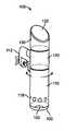
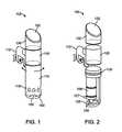
- FIGS. 1 and 2illustrate an example embodiment of a fluidic temperature control device 105 .
- the temperature control device 105comprises a upper portion 130 , a middle portion 120 and a lower portion 110 .
- a fluidic temperature control devicecan include two portions: an upper and a lower.
- a fluidic temperature control devicecan include one portion.
- a fluidic temperature control devicecan include one or more portions.
- the upper portion 130can include a display device 132 which can display information, for example, the temperature of the fluid in which the lower portion 110 is at least partially immersed, the throughput at which intake and ejection ports are operating, or the speed at which an impeller housed within the lower portion is spinning.
- the upper portion 130can also include an input device (not shown), for example, one or more buttons or controls which can enable a user to select a temperature for the water in which the lower portion is at least partially immersed.
- the input devicecan include physical buttons and/or virtual buttons rendered on display device 132 .
- the buttons or input controlscan include capacitive sensor pads.
- the middle portion 120can comprise a ring clamp 112 enabling attachment of control device 105 to a container, or the like.
- Middle portion 120can include housing 124 for motor and heater base (not shown).
- Lower portion 110can be configured with a cap 100 configured with one or more openings 102 .
- Lower portion 110can enclose submersible pump 109 with one or more liquid intake ports 107 and ejection ports 108 .
- ports 108can be fluid ejection ports and ports 107 can be fluid intake ports.
- the lower portion 110can be configured with liquid intake (flow-in) openings 118 through which the heated water can be drawn by submersible pump 109 , an impeller or other agitation device located within the lower portion 110 and ejected out of lower portion 110 through liquid ejection (flow-out) openings 102 .
- openings 118can be liquid output (flow-out) openings and openings 102 can be liquid intake (flow-in) openings.
- the lower portion 110can included a thermometer device for taking the temperature of the fluid in which it is immersed. In another embodiment the thermometer can be separate device 105 and in wireless communication with device 105 .
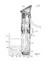
- FIG. 3illustrates components of at least one embodiment of a fluidic temperature control device 105 .
- the devicecan include a lower portion 110 .
- the lower portion 110can be a removable, tool-less screw or clamp-on circulator pump other agitation device housing.
- Lower portion 110can include heaters 125 , drive shaft 101 and impeller 104 .
- the lower portion 110can be composed of stainless steel or other suitable materials.
- the lower portion 110can be a removable clamp-on on skirt.
- the lower portion 110can be configured with one or more liquid intake (flow-in) openings 118 .
- openings 118can be liquid output (flow-out) openings.
- the device 105can also include a liquid ejection (flow-out) cap 100 with one or more openings 102 on the side or bottom at the through which fluid can pass (as liquid intake (flow-in) or liquid output (flow-out)).
- Middle portion 120can enclose motor and heater base 123 connected to electric heaters 125 .
- Middle portion 120can also comprise a fan (not shown) to blow out any steam that may be present.
- Middle portion 120can include collar 124 including one or more openings to provide ventilation to motor and heater base 123 .
- Device 105can include an upper portion 130 .
- the upper portion 130can include a LCD display 132 with touch controls.
- Device 105can be sealed against water/air and can be fully submersed for periods of time in the cooking vessel containing the fluid being heated by the device.
- the clamp 112can further have a moveable engagement portion 116 configured to engage an outer portion of the pot thereby securing the fluidic temperature control device 105 to the pot.
- the collar 117can be positioned at any point along the fluidic temperature control device 105 to enable adjustment in the length of the lower portion 110 that is immersed in fluid of container 114 .
- FIG. 5 and FIG. 6illustrate an exploded view and assembled view of an example clamp 112 respectively.
- Clamp 112can include a collar 117 to engage with a temperature control device (not shown). Collar 117 can be engaged by actuating attachment portion 111 . Attachment portion 111 can be spring-loaded. When attachment portion 111 is actuated, collar 117 can be engaged with the temperature control device preventing movement of collar 117 .
- Clamp 112can also include a stationary engagement portion 113 . Stationary engagement portion 113 can be configured to engage the inside wall of a container.
- Clamp 112can also include a moveable engagement portion 116 . Moveable engagement portion 116 can be configured to engage the outside wall of a container. Moveable engagement portion 116 can be actuated by a screw mechanism. In another embodiment, moveable engagement portion 116 can be spring-loaded.
- FIG. 7illustrates an example fluidic temperature control device in communication with a wireless temperature sensor.
- Device 105is adjustably attached to container 114 containing fluid 150 (for example water).
- the temperature of fluid 150can be regulated by device 105 , as previously described.
- the wireless temperature sensor 156can be placed proximate (or within) the food 154 within a sealed container 152 (for example, a plastic bag or plastic envelope) located in fluid 150 .
- the temperature sensorcan be wired to and located at fluidic temperature control device 105 .
- FIG. 8illustrates an example combination cooking range.
- Combination cooking range 170can include a fluidic temperature control device 105 and one or more burners 172 .
- the one or more burnerscan be an electric range, an electric cooktop, a gas range, a gas stove top, an electric hot plate, an induction cooktop, modular cooktop, or any other type of cooking surface where conventional cookware can be used.
- the fluidic temperature control device 105can be in communication with the one or more burners 172 by cable 171 . In at least one embodiment the communication between fluidic temperature control device 105 and the one or more burners 172 can be wireless.
- the one or more burners 172can be connected to controllers 173 A and 173 B.
- controller 173 Acan be a primary controller and controller 173 B can be a backup controller.
- controller 173 Bcan be a primary controller and controller 173 A can be a backup controller.
- only one controlleris configured for use.
- the one or more burners 172 and fluidic temperature control device 105can be communicatively coupled to Controllers 173 A and 173 B. In response to receiving a temperature reading a controller can modulate the heat output of burners 172 .
- device 105can be set to a specific temperature, if a controller receives a temperature reading of less than the specific temperature, the controller can modulate the one or more burners 172 to increase the heat output. If a controller receives a temperature reading of more than the specific temperature, the controller can modulate the one or more burners 172 to decrease the heat output.
- a controllercan be connected to fluidic temperature control device 105 and the command to modulate the heat output of the one or more burners 172 can be received at the more or more burners by cable 171 or wirelessly.
- device 105 and the one or more burners 172can each have a controller.
- device 105can include a controller.
- one or more burners 172can include a controller.
- fluidic temperature control device 105can receive a temperature reading from a thermometer device (as previously disclosed). In response to receiving a temperature reading, device 105 can actuate the agitation device. For example, device 105 can be set to a specific temperature, if a temperature reading of less than the specific temperature is determined, device 105 can actuate (at a higher speed) the agitation device to aid in increasing temperature of the fluid. If a temperature reading of more than the specific temperature is determined, device 105 can de-actuate (at a lower speed) the agitation device to aid in decreasing temperature of the fluid. In at least one embodiment the temperature of the heater of device 105 can be used to aid in increasing or decreasing the temperature of the fluid.
- modulating the one or more burners and actuating the agitation devicecan be configured in unison to increase or decrease the temperature to the specified temperature of the fluid in a more timely fashion.
- FIG. 9Aillustrates an example combination cooking range where the controller is located in a fluidic temperature control device.
- Fluidic temperature control device 105can include a controller 173 A for configuring an agitation device located in fluidic temperature control device 105 and configured to modulate the one or more burners 172 .
- Controller 173 Acan receive user input, for example of a temperature setting, and in response to the user input can actuate an agitation device of fluidic temperature control device 105 and modulate the burners 172 .
- Controller 173 Acan transmit and receive temperature and control data through cables 171 A and 171 B.
- FIG. 9Billustrates an example combination cooking range where the controller is located in a burner.
- Burner 172can include a controller 173 B for configuring an agitation device located in fluidic temperature control device 105 and configured to modulate the one or more burners 172 .
- Controller 173 Bcan receive user input, for example of a temperature setting, and in response to the user input actuate an agitation device of fluidic temperature control device 105 and modulate the burners 172 .
- Controller 173 Bcan transmit and receive temperature and control data through cables 171 A and 171 B.
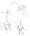
- FIGS. 10A and 10Billustrate example agitation devices of a fluidic temperature control device.
- fluidic temperature control device 105can be configured without any heating elements as shown in FIG. 10A and FIG. 10B .
- fluidic temperature control device 105can include a heating element with or without the use of one or more burners.
- device 105can include cap 100 with one or more openings 102 .
- device 105cannot include a cap and can be open-ended enabling full flow of liquid.
- an agitation devicecan include impeller 104 providing directional control of liquid, heated by one or more burners.
- impeller 104can draw liquid in to one or more openings 118 and expel liquid out of one or more openings 102 .
- an agitation devicecan include a propeller for drawing liquid in openings 118 and out the open-end of device 105 .
- FIG. 11Aillustrates an internal view of an example submersible pump agitation device of a fluidic temperature control device.
- FIG. 11Billustrates an internal view and housing of an example submersible pump agitation device of a fluidic temperature control device.
- fluidic temperature control device 105can be configured without any heating elements as shown in FIG. 11A and FIG. 11B .
- fluidic temperature control device 105can include a heating element with or without the use of one or more burners.
- Submersible pump 109can draw liquid, heated by one or more burners, in with one or more liquid intake ports 107 and expel liquid out through one or more ejection ports 108 .
- device 105can include multiple input openings 118 and output openings 102 .
- FIG. 12Aillustrates an internal view of an example air pump agitation device of a fluidic temperature control device.
- FIG. 12Billustrates an internal view and housing of an example air pump agitation device of a fluidic temperature control device.
- fluidic temperature control device 105can be configured without any heating elements as shown in FIG. 12A and FIG. 12B .
- fluidic temperature control device 105can include a heating element with or without the use of one or more burners.
- fluidic temperature control device 105can include an air pump 115 .
- Air pump 115can include an air inlet 126 and an air outlet 127 .
- Air outlet 127can be U-shaped and include one or more openings 128 .
- Air outlet 127can be a circle, a semi-circle, one or more horizontal bars, one or more downward angled bars, or any other shape to promote agitation of a liquid.
- air pump 115can draw air through air inlet 126 and can agitate a liquid by forcing the air drawn in through the air inlet 126 , out through openings 128 in air outlet 127 .
- FIG. 13Aillustrates an example combination cooking range with a controller included in a fluidic temperature control device.
- FIG. 13Billustrates an example combination cooking range with a controller included in a cooking range 175 .
- fluidic temperature control device 105can be configured without any heating elements.
- fluidic temperature control device 105can be configured with a heating element.
- Combination cooking range 170can include a cooking range 175 with one or more burners 172 .
- Container 114can be configured for use with one or more burners 172 .
- Fluidic temperature control device 105can be releasably attached to container 114 . In at least one embodiment shown in FIG.
- fluidic temperature control device 105can include a controller 173 A.
- Controller 173 Acan connect to one or more burners 172 through one or more connectors 174 by cables 171 A and 171 B.
- Controller 173 Acan transmit and receive temperature and control data through cables 171 A and 171 B.
- Controller 173 Acan be configured to actuate an agitator of device 105 and modulate the one or more burners 172 .
- cooking range 175can include a controller 173 B.
- Controller 173 Bcan connect to device 105 through one or more connectors 174 by cables 171 A and 171 B.
- Controller 173 Bcan transmit and receive temperature and control data through cables 171 A and 171 B.
- Controller 173 Bcan be configured to actuate an agitator of device 105 and modulate the one or more burners 172 .
- device 105 and cooking range 175can each include one or more heating elements.
- the one or more heating elementscan work in unison or independently.
- burner 172can independently heat liquid in container 114 .
- Container 114can be removed from burner 172 and a heating element in device 105 can continue to heat the liquid in container 114 .
- a controllercan modulate burner 172 and a heating element in device 105 to work in unison for precision heating of the liquid in container 114 .
- burner 172can be used to rapidly increase liquid temperature. When a high temperature is reached, burner 172 can be lowered and heating element of device 105 can be modulated to bring the water to a precise temperature.
- the various embodimentscan be implemented in a wide variety of operating environments, which in some cases can include one or more user computers, computing devices, or processing devices which can be used to operate any of a number of applications.
- User or client devicescan include any of a number of general purpose personal computers, such as desktop or laptop computers running a standard operating system, as well as cellular, wireless, and handheld devices running mobile software and capable of supporting a number of networking and messaging protocols.
- Such a systemalso can include a number of workstations running any of a variety of commercially-available operating systems and other known applications for purposes such as development and database management.
- These devicesalso can include other electronic devices, such as dummy terminals, thin-clients, gaming systems, and other devices capable of communicating via a network.
- Services such as Web servicescan communicate using any appropriate type of messaging, such as by using messages in extensible markup language (XML) format and exchanged using an appropriate protocol such as SOAP (derived from the “Simple Object Access Protocol”).
- SOAPderived from the “Simple Object Access Protocol”
- Processes provided or executed by such servicescan be written in any appropriate language, such as the Web Services Description Language (WSDL).
- WSDLWeb Services Description Language
- Most embodimentsutilize at least one network that would be familiar to those skilled in the art for supporting communications using any of a variety of commercially-available protocols, such as TCP/IP, OSI, FTP, UPnP, NFS, CIFS, and AppleTalkTM.
- the networkcan be, for example, a local area network, a wide-area network, a virtual private network, the Internet, an intranet, an extranet, a public switched telephone network, an infrared network, a wireless network, and any suitable combination thereof.
- the Web servercan run any of a variety of server or mid-tier applications, including HTTP servers, FTP servers, CGI servers, data servers, Java servers, and business application servers.
- the server(s)also can be capable of executing programs or scripts in response requests from user devices, such as by executing one or more Web applications that can be implemented as one or more scripts or programs written in any programming language, such as Java®, C, C# or C++, or any scripting language, such as Perl, Python, or TCL, as well as combinations thereof.
- the server(s)can also include database servers, including without limitation those commercially available from Oracle®, Microsoft®, Sybase®, and IBM®.
- the environmentcan include a variety of data stores and other memory and storage media as discussed above. These can reside in a variety of locations, such as on a storage medium local to (and/or resident in) one or more of the computers or remote from any or all of the computers across the network. In a particular set of embodiments, the information can reside in a storage-area network (“SAN”) familiar to those skilled in the art. Similarly, any necessary files for performing the functions attributed to the computers, servers, or other network devices can be stored locally and/or remotely, as appropriate.
- SANstorage-area network
- each such devicecan include hardware elements that can be electrically coupled via a bus, the elements including, for example, at least one central processing unit (CPU), at least one input device (e.g., a mouse, keyboard, controller, touch screen, or keypad), and at least one output device (e.g., a display device, printer, or speaker).
- CPUcentral processing unit
- input devicee.g., a mouse, keyboard, controller, touch screen, or keypad
- at least one output devicee.g., a display device, printer, or speaker
- Such a systemcan also include one or more storage devices, such as disk drives, optical storage devices, and solid-state storage devices such as random access memory (“RAM”) or read-only memory (“ROM”), as well as removable media devices, memory cards, flash cards, etc.
- ROMread-only memory
- Such devicescan include a computer-readable storage media reader, a communications device (e.g., a modem, a network card (wireless or wired), an infrared communication device, etc.), and working memory as described above.
- the computer-readable storage media readercan be connected with, or configured to receive, a computer-readable storage medium, representing remote, local, fixed, and/or removable storage devices as well as storage media for temporarily and/or more permanently containing, storing, transmitting, and retrieving computer-readable information.
- the system and various devicesalso typically will include a number of software applications, modules, services, or other elements located within at least one working memory device, including an operating system and application programs, such as a client application or Web browser. It should be appreciated that alternate embodiments can have numerous variations from that described above. For example, customized hardware might also be used and/or particular elements might be implemented in hardware, software (including portable software, such as applets), or both. Further, connection to other computing devices such as network input/output devices can be employed.
- Storage media and computer readable media for containing code, or portions of codecan include any appropriate media known or used in the art, including storage media and communication media, such as but not limited to volatile and non-volatile, removable and non-removable media implemented in any method or technology for storage and/or transmission of information such as computer readable instructions, data structures, program modules, or other data, including RAM, ROM, EEPROM, flash memory or other memory technology, CD-ROM, digital versatile disk (DVD) or other optical storage, magnetic cassettes, magnetic tape, magnetic disk storage or other magnetic storage devices, or any other medium which can be used to store the desired information and which can be accessed by a system device.
- storage media and communication mediasuch as but not limited to volatile and non-volatile, removable and non-removable media implemented in any method or technology for storage and/or transmission of information such as computer readable instructions, data structures, program modules, or other data, including RAM, ROM, EEPROM, flash memory or other memory technology, CD-ROM, digital versatile disk (DVD) or other optical storage
- Embodiments of the present disclosurecan be provided as a computer program product including a nontransitory machine-readable storage medium having stored thereon instructions (in compressed or uncompressed form) that can be used to program a computer (or other electronic device) to perform processes or methods described herein.
- the machine-readable storage mediumcan include, but is not limited to, hard drives, floppy diskettes, optical disks, CD-ROMs, DVDs, read-only memories (ROMs), random access memories (RAMs), EPROMs, EEPROMs, flash memory, magnetic or optical cards, solid-state memory devices, or other types of media/machine-readable medium suitable for storing electronic instructions.
- embodimentscan also be provided as a computer program product including a transitory machine-readable signal (in compressed or uncompressed form).
- machine-readable signalswhether modulated using a carrier or not, include, but are not limited to, signals that a computer system or machine hosting or running a computer program can be configured to access, including signals downloaded through the Internet or other networks. For example, distribution of software can be via Internet download.
Landscapes
- Engineering & Computer Science (AREA)
- Food Science & Technology (AREA)
- Physics & Mathematics (AREA)
- Chemical & Material Sciences (AREA)
- General Engineering & Computer Science (AREA)
- Mechanical Engineering (AREA)
- General Physics & Mathematics (AREA)
- Automation & Control Theory (AREA)
- Life Sciences & Earth Sciences (AREA)
- Combustion & Propulsion (AREA)
- Electromagnetism (AREA)
- Health & Medical Sciences (AREA)
- Nutrition Science (AREA)
- Polymers & Plastics (AREA)
- Chemical Kinetics & Catalysis (AREA)
- Cookers (AREA)
- Structures Of Non-Positive Displacement Pumps (AREA)
Abstract
Description
Claims (14)
Priority Applications (1)
| Application Number | Priority Date | Filing Date | Title |
|---|---|---|---|
| US14/727,444US10111552B2 (en) | 2013-09-20 | 2015-06-01 | Combination cooker with sous vide functionality |
Applications Claiming Priority (4)
| Application Number | Priority Date | Filing Date | Title |
|---|---|---|---|
| US201361880714P | 2013-09-20 | 2013-09-20 | |
| US201462005885P | 2014-05-30 | 2014-05-30 | |
| US14/491,961US20150082996A1 (en) | 2013-09-20 | 2014-09-19 | Submersable circulator cooker |
| US14/727,444US10111552B2 (en) | 2013-09-20 | 2015-06-01 | Combination cooker with sous vide functionality |
Related Parent Applications (2)
| Application Number | Title | Priority Date | Filing Date |
|---|---|---|---|
| US14/491,961ContinuationUS20150082996A1 (en) | 2013-02-14 | 2014-09-19 | Submersable circulator cooker |
| US14/491,961Continuation-In-PartUS20150082996A1 (en) | 2013-02-14 | 2014-09-19 | Submersable circulator cooker |
Publications (4)
| Publication Number | Publication Date |
|---|---|
| US20150342392A1 US20150342392A1 (en) | 2015-12-03 |
| US20180078075A9 US20180078075A9 (en) | 2018-03-22 |
| US20180199749A9 US20180199749A9 (en) | 2018-07-19 |
| US10111552B2true US10111552B2 (en) | 2018-10-30 |
Family
ID=52689804
Family Applications (5)
| Application Number | Title | Priority Date | Filing Date |
|---|---|---|---|
| US14/491,961GrantedUS20150082996A1 (en) | 2013-02-14 | 2014-09-19 | Submersable circulator cooker |
| US14/727,431Active2034-09-30US10117538B2 (en) | 2013-09-20 | 2015-06-01 | Sous-vide cooker with image translation functionality |
| US14/727,402ActiveUS10136752B2 (en) | 2013-09-20 | 2015-06-01 | Code translation program for precision sous vide cooker device |
| US14/727,444ActiveUS10111552B2 (en) | 2013-09-20 | 2015-06-01 | Combination cooker with sous vide functionality |
| US14/727,369AbandonedUS20150342388A1 (en) | 2013-09-20 | 2015-06-01 | Event tracking precision sous vide cooker device |
Family Applications Before (3)
| Application Number | Title | Priority Date | Filing Date |
|---|---|---|---|
| US14/491,961GrantedUS20150082996A1 (en) | 2013-02-14 | 2014-09-19 | Submersable circulator cooker |
| US14/727,431Active2034-09-30US10117538B2 (en) | 2013-09-20 | 2015-06-01 | Sous-vide cooker with image translation functionality |
| US14/727,402ActiveUS10136752B2 (en) | 2013-09-20 | 2015-06-01 | Code translation program for precision sous vide cooker device |
Family Applications After (1)
| Application Number | Title | Priority Date | Filing Date |
|---|---|---|---|
| US14/727,369AbandonedUS20150342388A1 (en) | 2013-09-20 | 2015-06-01 | Event tracking precision sous vide cooker device |
Country Status (1)
| Country | Link |
|---|---|
| US (5) | US20150082996A1 (en) |
Cited By (1)
| Publication number | Priority date | Publication date | Assignee | Title |
|---|---|---|---|---|
| US11210081B2 (en) | 2019-03-15 | 2021-12-28 | Carrier Corporation | Configuring firmware for a target device |
Families Citing this family (55)
| Publication number | Priority date | Publication date | Assignee | Title |
|---|---|---|---|---|
| GB2525011B (en)* | 2014-04-09 | 2016-06-08 | MELLOW Inc | Cooking system |
| CA2892115C (en) | 2014-05-20 | 2018-07-24 | Sunbeam Products, Inc. | Food cooking system |
| CA2985455C (en) | 2015-05-11 | 2019-06-11 | Intropack. Co., Ltd. | Vacuum low-temperature cooker |
| KR101626414B1 (en)* | 2015-05-11 | 2016-06-03 | 주식회사 인트로팩 | Vacuum heating cooking utensils |
| US10299505B2 (en)* | 2015-06-03 | 2019-05-28 | Calico Cottage, Inc. | Method of cleaning a roaster bowl employing electronic techniques for detecting boiling of water during steam cleaning operation |
| US20160353923A1 (en) | 2015-06-03 | 2016-12-08 | Calico Cottage, Inc. | Roasting and glazing apparatus |
| US11311144B2 (en) | 2015-06-03 | 2022-04-26 | Calico Cottage, Inc. | Roasting and glazing apparatus |
| US10429251B2 (en)* | 2015-09-30 | 2019-10-01 | Anova Applied Electronics, Inc. | Wireless temperature sensor for sous vide cooking |
| CN108370616B (en) | 2015-10-16 | 2021-10-12 | 布瑞威利美国公司 | Thermal immersion circulator |
| USD853785S1 (en)* | 2015-10-16 | 2019-07-16 | ChefSteps, Inc. | Thermal immersion circulator |
| FR3044534B1 (en)* | 2015-12-03 | 2018-05-18 | Enodis Productions | WATER BATHING DEVICE COMPRISING MEANS FOR HOMOGENIZING THE TEMPERATURE OF THE WATER BATH |
| CN106859286A (en)* | 2015-12-14 | 2017-06-20 | 北京奈思膳品科技有限公司 | A kind of low temperature cooking machine and low temperature cooking methods |
| KR102488774B1 (en)* | 2016-03-28 | 2023-01-13 | 엘지전자 주식회사 | Hanger-type cooking information provision device |
| US10598549B2 (en) | 2016-08-04 | 2020-03-24 | The Vollrath Company, L.L.C. | Wireless temperature probe |
| US11134321B2 (en) | 2016-08-04 | 2021-09-28 | The Vollrath Company, L.L.C. | Wireless temperature probe |
| US20180143086A1 (en)* | 2016-11-22 | 2018-05-24 | Electrolux Home Products, Inc. | Cooking temperature sensor with submersed probe |
| USD853173S1 (en) | 2017-02-01 | 2019-07-09 | Columbia Insurance Company | Slow cooker kitchen appliance |
| USD836967S1 (en)* | 2017-02-13 | 2019-01-01 | Bin Lin | Sous vide cooker |
| CN108851964B (en)* | 2017-05-08 | 2020-10-02 | 佛山市顺德区美的电热电器制造有限公司 | Control method and device |
| US10917944B2 (en)* | 2017-06-13 | 2021-02-09 | Rennie R. West | Portable food and beverage heating device |
| USD862154S1 (en) | 2017-07-20 | 2019-10-08 | Anova Applied Electronics, Inc. | Circulator cooker |
| US10827872B2 (en) | 2017-09-29 | 2020-11-10 | Midea Group Co., Ltd. | Fully submergible sous vide device |
| USD853776S1 (en)* | 2017-10-19 | 2019-07-16 | Shenzhen Green Electrical Appliance Co., Ltd. | Sous vide cooker |
| USD874210S1 (en) | 2018-01-03 | 2020-02-04 | Anova Applied Electronics, Inc. | Circulator cooker |
| USD869234S1 (en) | 2018-01-03 | 2019-12-10 | Anova Applied Electronics, Inc. | Circulator cooker display |
| USD853777S1 (en) | 2018-01-03 | 2019-07-16 | Anova Applied Electronics, Inc. | Circulator cooker |
| EP3737268A4 (en)* | 2018-01-10 | 2021-09-29 | Michael R. Eades | PORTABLE SOUS VIDE COOKING APPLIANCE |
| USD850844S1 (en)* | 2018-01-16 | 2019-06-11 | Lin Yang | Sous vide cooking stick |
| CN109343394A (en)* | 2018-10-16 | 2019-02-15 | 珠海格力电器股份有限公司 | Cooking appliance control method and cooking appliance |
| ES2980382T3 (en) | 2018-10-22 | 2024-10-01 | Meyer Intellectual Properties Ltd | Cookware handle for housing electronic components |
| TWI706693B (en)* | 2018-11-06 | 2020-10-01 | 龍華科技大學 | Minimized low temperature cooker |
| CN212261147U (en)* | 2018-12-19 | 2021-01-01 | 布瑞威利私人有限公司 | Improvements to Immersion Circulator Cooking Units |
| USD914435S1 (en)* | 2019-02-04 | 2021-03-30 | Breville Pty Limited | Cooking appliance |
| CN109798983B (en)* | 2019-03-12 | 2020-10-27 | 上海达显智能科技有限公司 | Method and system for measuring temperature of food in cooking facility and cooking facility |
| US11375843B2 (en) | 2019-04-12 | 2022-07-05 | Anova Applied Electronics, Inc. | Sous vide cooker |
| EP3955787B1 (en)* | 2019-04-19 | 2025-06-25 | Cargill, Incorporated | Frying oil maintenance |
| US20200397177A1 (en)* | 2019-06-20 | 2020-12-24 | Midea Group Co., Ltd. | Container including agitator for microwave sous vide function |
| USD937034S1 (en)* | 2019-07-29 | 2021-11-30 | Seb | Induction hub |
| CN112568694B (en)* | 2019-09-30 | 2021-11-02 | 佛山市顺德区美的电热电器制造有限公司 | Cooking control method, cooking control device, cooking appliance and computer readable storage medium |
| KR102311419B1 (en)* | 2020-01-31 | 2021-10-12 | 전지은 | Cooking apparatus capable of cooking under vacuum-low temperature |
| CN113273906A (en)* | 2020-02-20 | 2021-08-20 | 九阳股份有限公司 | Food processing machine |
| US20210289973A1 (en)* | 2020-03-20 | 2021-09-23 | Marvin Gaye Bowen | The core cooker |
| US20210353090A1 (en)* | 2020-05-16 | 2021-11-18 | John McDevitt | System and method for a process to provide improved preparation of consumables |
| CN111513562B (en)* | 2020-05-27 | 2022-02-01 | 成都探寻家科技有限公司 | Power control method and electric water boiling cup |
| CN112294108A (en)* | 2020-10-21 | 2021-02-02 | 许克芝 | Multi-mode modular combined convenient cooking pot |
| USD964797S1 (en)* | 2020-10-29 | 2022-09-27 | Breville Pty Limited | Cooking appliance |
| USD962695S1 (en)* | 2021-02-21 | 2022-09-06 | Shenzhen Yingboweiye Technology Co., Ltd. | Sous vide cooker |
| USD962694S1 (en)* | 2021-02-21 | 2022-09-06 | Shenzhen Yingboweiye Technology Co., Ltd. | Sous vide cooker |
| CN113599227B (en)* | 2021-08-10 | 2023-08-15 | 南通大学附属医院 | Burn and scald rehabilitation is with soaking bath self-service and automatic nursing equipment based on image processing |
| CN113647830B (en)* | 2021-08-16 | 2022-08-12 | 珠海格力电器股份有限公司 | Cooking equipment and heating control method and equipment after power failure recovery |
| CA210742S (en)* | 2021-09-29 | 2023-06-20 | Midea Group Co Ltd | Slow cooking stick |
| USD1054246S1 (en)* | 2022-10-10 | 2024-12-17 | Shenzhen Typhur Technology Co., Ltd | Heating equipment for cooking appliance |
| USD1045486S1 (en)* | 2023-06-12 | 2024-10-08 | Shenzhen Yingboweiye Technology Co., Ltd. | Sous vide cooker |
| USD1059932S1 (en)* | 2023-08-09 | 2025-02-04 | Shenzhen Yisi Technology Co., Ltd. | Circulator cooker |
| USD1044385S1 (en)* | 2023-11-13 | 2024-10-01 | Shenzhen Yingboweiye Technology Co., Ltd. | Sous vide cooker housing |
Citations (81)
| Publication number | Priority date | Publication date | Assignee | Title |
|---|---|---|---|---|
| US1703099A (en) | 1923-07-31 | 1929-02-26 | Frederick L Craddock | Mixing device |
| US1864149A (en) | 1929-08-24 | 1932-06-21 | Stanley P Rockwell Company | Agitator for hardening baths |
| US2140315A (en) | 1936-07-27 | 1938-12-13 | Lewis L Dollinger | Mixing apparatus |
| US3114154A (en) | 1961-10-25 | 1963-12-17 | Myron P Laughlin | Bath safety stanchion |
| US3270661A (en) | 1965-06-07 | 1966-09-06 | Juvan Alois | Egg cooking device |
| US3273717A (en) | 1966-09-20 | Combination filter and aerator | ||
| US4045606A (en) | 1974-11-25 | 1977-08-30 | Kurt Ulrich Kalkowski | Protective cover for an electric range |
| US4099406A (en) | 1975-11-10 | 1978-07-11 | Hammer Industries Inc. | Device for automatically testing fluid absorption rates of soil |
| US4612949A (en) | 1985-02-11 | 1986-09-23 | Henson James H | Apparatus for controlling water level |
| JPS63196984U (en) | 1987-06-05 | 1988-12-19 | ||
| US4817217A (en) | 1985-02-20 | 1989-04-04 | Lively Olin A | Swimming pool control system |
| US4933527A (en) | 1988-02-19 | 1990-06-12 | Sharp Kabushiki Kaisha | Oven and detachable function unit |
| US4993593A (en) | 1989-07-21 | 1991-02-19 | Ralph Fabiano | Apparatus and methods for dispensing a flowable medium |
| US5146840A (en) | 1989-11-22 | 1992-09-15 | Heden-Team Ag | Automatic baking apparatus and mixbag therefore |
| GB2260002A (en) | 1991-09-25 | 1993-03-31 | Sharp Kk | Microwave oven with external memory |
| US5321229A (en) | 1993-04-05 | 1994-06-14 | Whirlpool Corporation | Remote control for a domestic appliance |
| US5336401A (en) | 1993-05-14 | 1994-08-09 | Tu Chih Yao | Water filtration and aeration system for aquariums |
| US5368384A (en) | 1993-08-20 | 1994-11-29 | Duncan; J. Kenneth | Hand-held mixing device with heating element |
| US5372422A (en) | 1993-11-29 | 1994-12-13 | Dubroy; Gary P. | Apparatus for automatically stirring food during cooking |
| US5401401A (en) | 1993-01-13 | 1995-03-28 | Aquaria Inc. | Hang on tank canister filter |
| US5412171A (en) | 1990-04-23 | 1995-05-02 | Lancet S.A. | Cooking device having stirrer movable about two mutually perpendicular axes |
| US5516208A (en) | 1995-03-27 | 1996-05-14 | Givant; Madeline F. | Adjustable pot stirrer |
| US5542344A (en) | 1993-03-30 | 1996-08-06 | Technology Licensing Corporation | Sous vide rethermalizer |
| US6079486A (en) | 1997-02-27 | 2000-06-27 | Aavid Thermal Technologies, Inc. | Spring clip for attaching an electronic component to a heat sink and an assembly utilizing the same |
| US6113258A (en) | 1999-06-29 | 2000-09-05 | Ardent; John Craig | Battery powered food stirrer with pivotally mounted spring biased arms |
| WO2001052478A2 (en) | 2000-01-07 | 2001-07-19 | Invensys Controls Plc | Building control |
| US6286990B1 (en) | 1997-11-04 | 2001-09-11 | Pedro Luis De Zuazo Torres | Battery powered apparatus for stirring a product in any one of a plurality of vessels of different diameter and depth |
| US6539842B1 (en) | 2002-07-19 | 2003-04-01 | Maverick Industries, Inc. | Rotisserie system having a remote temperature monitor |
| US6604917B2 (en) | 2000-10-06 | 2003-08-12 | Torrington Research Company | Light-weight electric motor driven fluid pump assembly |
| WO2004008923A2 (en) | 2002-07-24 | 2004-01-29 | Richard Sharpe | Electronic cooking pan systems and methods |
| US6763879B1 (en) | 2002-07-01 | 2004-07-20 | Hayes Lemmerz International, Inc. | Mold temperature control for casting system |
| US6796220B2 (en) | 2003-01-22 | 2004-09-28 | Jane Lee | Automatic bean curd manufacturing apparatus |
| US20040223404A1 (en) | 2002-03-28 | 2004-11-11 | Hughes Product Designs | Mixer |
| US20040221736A1 (en) | 2003-05-07 | 2004-11-11 | Samsung Electronics Co., Ltd. | Bread maker and method of controlling the same |
| US20050223910A1 (en) | 2004-04-13 | 2005-10-13 | Hankinson Dan L | Food roasting apparatus |
| US6962290B2 (en) | 2002-07-19 | 2005-11-08 | Samsung Electronics Co., Ltd. | Bread maker and control method thereof |
| US7026929B1 (en) | 2002-05-10 | 2006-04-11 | A La Cart, Inc. | Food information monitoring system |
| US20060239113A1 (en) | 2002-04-16 | 2006-10-26 | Harris Mark B | Homogeniser |
| JP2006334208A (en) | 2005-06-03 | 2006-12-14 | Matsushita Electric Ind Co Ltd | Multi-function processor |
| JP2008043502A (en) | 2006-08-14 | 2008-02-28 | Media Price Co Ltd | Crushing cooker |
| US20080066624A1 (en) | 2006-04-06 | 2008-03-20 | Alex Taylor | Sous vide cooker with integrated immersion circulator |
| US20080136581A1 (en) | 2005-06-09 | 2008-06-12 | Whirlpool Corporation | smart current attenuator for energy conservation in appliances |
| US20080218493A1 (en) | 2003-09-03 | 2008-09-11 | Vantage Controls, Inc. | Display With Motion Sensor |
| US20080260557A1 (en) | 2007-04-23 | 2008-10-23 | Austin Timothy L | Floating pump for irrigation and other applications |
| US20090087534A1 (en) | 2002-08-14 | 2009-04-02 | Mclemore John D | Cooking apparatus |
| US20090093983A1 (en) | 2007-10-01 | 2009-04-09 | Mark Trafford | Method and system for measuring the fill level of a material |
| US20090120301A1 (en) | 2007-11-12 | 2009-05-14 | Severnak Teri L | Cooking Device |
| US20090153490A1 (en) | 2007-12-12 | 2009-06-18 | Nokia Corporation | Signal adaptation in response to orientation or movement of a mobile electronic device |
| US20100090656A1 (en) | 2005-06-08 | 2010-04-15 | Shearer John G | Powering devices using rf energy harvesting |
| US20100154656A1 (en) | 2005-07-29 | 2010-06-24 | Yoshikazu Yamamoto | Heating cooker |
| US20100199854A1 (en) | 2007-08-27 | 2010-08-12 | Regina Homme | Method For Adjusting An Operating Program By Means Of Visualized Parameters Relating To The Product To Be Cooked, And A Cooking Appliance Therefor |
| US20110070340A1 (en) | 2008-02-18 | 2011-03-24 | Rational Ag | Method for Controlling at Least Two Cooking Devices, Cooking Device, and System Including at Least Two Cooking Devices |
| US20110088564A1 (en) | 2009-10-21 | 2011-04-21 | Stuart Bonsell | Egg Cooker Device |
| US20110117259A1 (en) | 2009-11-15 | 2011-05-19 | David Storek | Liquid movement and control within a container for food preparation |
| US20110185915A1 (en) | 2009-09-08 | 2011-08-04 | Eades Michael R | Sous-vide cooker |
| US20110186283A1 (en) | 2010-02-03 | 2011-08-04 | Preston Industries, Inc. | Constant Temperature Circulator |
| US20110217439A1 (en) | 2010-03-05 | 2011-09-08 | Whirlpool Corporation | Steam oven for "sous-vide" cooking and method for using such oven |
| US8087822B2 (en) | 2009-03-03 | 2012-01-03 | Wei-Lun Peng | Liquid container capable of self-generating power and showing temprature |
| EP2407703A2 (en) | 2010-07-15 | 2012-01-18 | Preston Industries, Inc. | Movable constant temperature circulator assembly |
| US8122815B2 (en) | 2007-04-20 | 2012-02-28 | Amy Wolfe | Device for stirring and cooking food |
| US20120053747A1 (en) | 2010-08-27 | 2012-03-01 | Yamatake Corporation | Total energy limiting and controlling device, and total electric power limiting and controlling device and method |
| US8172451B2 (en) | 2007-10-16 | 2012-05-08 | Arcfl Technology Limited | Programmable electronic hand mixer |
| KR20120049118A (en) | 2010-11-08 | 2012-05-16 | 주식회사 지엘바이오 | Removable microorganism fermentation equipment |
| US8218402B2 (en) | 2009-01-29 | 2012-07-10 | Bradly Joel Lewis | Multi device programmable cooking timer and method of use |
| WO2012156890A2 (en) | 2011-05-19 | 2012-11-22 | Koninklijke Philips Electronics N.V. | Device and method for producing a beverage |
| US20130091883A1 (en) | 2011-09-26 | 2013-04-18 | Lennox Industries Inc. | Controller, method of operating a water source heat pump and a water source heat pump |
| US20130112683A1 (en)* | 2010-07-15 | 2013-05-09 | Breville Pty Limited | Multi Cooker |
| CN103211494A (en) | 2012-01-18 | 2013-07-24 | 于淼 | Multipurpose water-bath pot (cup) for warming milk |
| US20130220143A1 (en)* | 2012-02-29 | 2013-08-29 | Nomiku Inc. | Apparatus and system for low-temperature cooking |
| US20130302483A1 (en) | 2012-05-09 | 2013-11-14 | Convotherm Elektrogeraete Gmbh | Optical quality control system |
| US20140026762A1 (en) | 2010-11-12 | 2014-01-30 | Convotherm Elekktrogeraete GmbH | Cooking device and procedure for cooking food |
| WO2014019018A1 (en) | 2012-07-31 | 2014-02-06 | Breville Pty Limited | Sous vide device |
| US20140208957A1 (en) | 2012-02-14 | 2014-07-31 | Panasonic Corporation | Electronic device |
| US20140260998A1 (en) | 2013-03-15 | 2014-09-18 | Carl P. Pearson | Cooking apparatus using liquid bath |
| US20140373723A1 (en) | 2011-05-26 | 2014-12-25 | Nestec S.A | Beverage preparation system |
| US20150064314A1 (en) | 2013-08-27 | 2015-03-05 | David Briden Manuel | System and method of monitoring and adjusting a temperature of an object |
| US20150265090A1 (en) | 2012-10-10 | 2015-09-24 | Nutresia Sa | Regeneration household machine for regenerating packaged cooked and subsequently cooled to chilled, ambient or frozen temperatures portions of food and method carried out by said machine |
| US20150289544A1 (en) | 2014-04-09 | 2015-10-15 | FNV Labs Ltd. | Sous vide cooking |
| US20150335192A1 (en) | 2014-05-20 | 2015-11-26 | Sunbeam Products, Inc. | Food Cooking System |
| US20160083048A1 (en) | 2014-09-18 | 2016-03-24 | Donald T. Munsch | Umbrella support for use in a kayak |
| US20160198883A1 (en) | 2013-10-09 | 2016-07-14 | Double Insight Inc. | Apparatus for cooking a food item |
Family Cites Families (1)
| Publication number | Priority date | Publication date | Assignee | Title |
|---|---|---|---|---|
| US20080000357A1 (en) | 2006-06-30 | 2008-01-03 | Frank Yang | Hot beverage brewing device |
- 2014
- 2014-09-19USUS14/491,961patent/US20150082996A1/enactiveGranted
- 2015
- 2015-06-01USUS14/727,431patent/US10117538B2/enactiveActive
- 2015-06-01USUS14/727,402patent/US10136752B2/enactiveActive
- 2015-06-01USUS14/727,444patent/US10111552B2/enactiveActive
- 2015-06-01USUS14/727,369patent/US20150342388A1/ennot_activeAbandoned
Patent Citations (86)
| Publication number | Priority date | Publication date | Assignee | Title |
|---|---|---|---|---|
| US3273717A (en) | 1966-09-20 | Combination filter and aerator | ||
| US1703099A (en) | 1923-07-31 | 1929-02-26 | Frederick L Craddock | Mixing device |
| US1864149A (en) | 1929-08-24 | 1932-06-21 | Stanley P Rockwell Company | Agitator for hardening baths |
| US2140315A (en) | 1936-07-27 | 1938-12-13 | Lewis L Dollinger | Mixing apparatus |
| US3114154A (en) | 1961-10-25 | 1963-12-17 | Myron P Laughlin | Bath safety stanchion |
| US3270661A (en) | 1965-06-07 | 1966-09-06 | Juvan Alois | Egg cooking device |
| US4045606A (en) | 1974-11-25 | 1977-08-30 | Kurt Ulrich Kalkowski | Protective cover for an electric range |
| US4099406A (en) | 1975-11-10 | 1978-07-11 | Hammer Industries Inc. | Device for automatically testing fluid absorption rates of soil |
| US4612949A (en) | 1985-02-11 | 1986-09-23 | Henson James H | Apparatus for controlling water level |
| US4817217A (en) | 1985-02-20 | 1989-04-04 | Lively Olin A | Swimming pool control system |
| JPS63196984U (en) | 1987-06-05 | 1988-12-19 | ||
| US4933527A (en) | 1988-02-19 | 1990-06-12 | Sharp Kabushiki Kaisha | Oven and detachable function unit |
| US4993593A (en) | 1989-07-21 | 1991-02-19 | Ralph Fabiano | Apparatus and methods for dispensing a flowable medium |
| US5146840A (en) | 1989-11-22 | 1992-09-15 | Heden-Team Ag | Automatic baking apparatus and mixbag therefore |
| US5412171A (en) | 1990-04-23 | 1995-05-02 | Lancet S.A. | Cooking device having stirrer movable about two mutually perpendicular axes |
| GB2260002A (en) | 1991-09-25 | 1993-03-31 | Sharp Kk | Microwave oven with external memory |
| US5317134A (en) | 1991-09-25 | 1994-05-31 | Sharp Kabushiki Kaisha | Microwave oven having preparation of menu assisting function |
| US5401401A (en) | 1993-01-13 | 1995-03-28 | Aquaria Inc. | Hang on tank canister filter |
| US5542344A (en) | 1993-03-30 | 1996-08-06 | Technology Licensing Corporation | Sous vide rethermalizer |
| US5321229A (en) | 1993-04-05 | 1994-06-14 | Whirlpool Corporation | Remote control for a domestic appliance |
| US5336401A (en) | 1993-05-14 | 1994-08-09 | Tu Chih Yao | Water filtration and aeration system for aquariums |
| US5368384A (en) | 1993-08-20 | 1994-11-29 | Duncan; J. Kenneth | Hand-held mixing device with heating element |
| US5372422A (en) | 1993-11-29 | 1994-12-13 | Dubroy; Gary P. | Apparatus for automatically stirring food during cooking |
| US5516208A (en) | 1995-03-27 | 1996-05-14 | Givant; Madeline F. | Adjustable pot stirrer |
| US6079486A (en) | 1997-02-27 | 2000-06-27 | Aavid Thermal Technologies, Inc. | Spring clip for attaching an electronic component to a heat sink and an assembly utilizing the same |
| US6286990B1 (en) | 1997-11-04 | 2001-09-11 | Pedro Luis De Zuazo Torres | Battery powered apparatus for stirring a product in any one of a plurality of vessels of different diameter and depth |
| US6113258A (en) | 1999-06-29 | 2000-09-05 | Ardent; John Craig | Battery powered food stirrer with pivotally mounted spring biased arms |
| WO2001052478A2 (en) | 2000-01-07 | 2001-07-19 | Invensys Controls Plc | Building control |
| US6604917B2 (en) | 2000-10-06 | 2003-08-12 | Torrington Research Company | Light-weight electric motor driven fluid pump assembly |
| US20040223404A1 (en) | 2002-03-28 | 2004-11-11 | Hughes Product Designs | Mixer |
| US20060239113A1 (en) | 2002-04-16 | 2006-10-26 | Harris Mark B | Homogeniser |
| US7026929B1 (en) | 2002-05-10 | 2006-04-11 | A La Cart, Inc. | Food information monitoring system |
| US6763879B1 (en) | 2002-07-01 | 2004-07-20 | Hayes Lemmerz International, Inc. | Mold temperature control for casting system |
| US6962290B2 (en) | 2002-07-19 | 2005-11-08 | Samsung Electronics Co., Ltd. | Bread maker and control method thereof |
| US6539842B1 (en) | 2002-07-19 | 2003-04-01 | Maverick Industries, Inc. | Rotisserie system having a remote temperature monitor |
| WO2004008923A2 (en) | 2002-07-24 | 2004-01-29 | Richard Sharpe | Electronic cooking pan systems and methods |
| US20090087534A1 (en) | 2002-08-14 | 2009-04-02 | Mclemore John D | Cooking apparatus |
| US6796220B2 (en) | 2003-01-22 | 2004-09-28 | Jane Lee | Automatic bean curd manufacturing apparatus |
| US20040221736A1 (en) | 2003-05-07 | 2004-11-11 | Samsung Electronics Co., Ltd. | Bread maker and method of controlling the same |
| US20080218493A1 (en) | 2003-09-03 | 2008-09-11 | Vantage Controls, Inc. | Display With Motion Sensor |
| US20050223910A1 (en) | 2004-04-13 | 2005-10-13 | Hankinson Dan L | Food roasting apparatus |
| JP2006334208A (en) | 2005-06-03 | 2006-12-14 | Matsushita Electric Ind Co Ltd | Multi-function processor |
| US20100090656A1 (en) | 2005-06-08 | 2010-04-15 | Shearer John G | Powering devices using rf energy harvesting |
| US20080136581A1 (en) | 2005-06-09 | 2008-06-12 | Whirlpool Corporation | smart current attenuator for energy conservation in appliances |
| US20100154656A1 (en) | 2005-07-29 | 2010-06-24 | Yoshikazu Yamamoto | Heating cooker |
| US20080066624A1 (en) | 2006-04-06 | 2008-03-20 | Alex Taylor | Sous vide cooker with integrated immersion circulator |
| JP2008043502A (en) | 2006-08-14 | 2008-02-28 | Media Price Co Ltd | Crushing cooker |
| US8122815B2 (en) | 2007-04-20 | 2012-02-28 | Amy Wolfe | Device for stirring and cooking food |
| US20080260557A1 (en) | 2007-04-23 | 2008-10-23 | Austin Timothy L | Floating pump for irrigation and other applications |
| US20100199854A1 (en) | 2007-08-27 | 2010-08-12 | Regina Homme | Method For Adjusting An Operating Program By Means Of Visualized Parameters Relating To The Product To Be Cooked, And A Cooking Appliance Therefor |
| US20090093983A1 (en) | 2007-10-01 | 2009-04-09 | Mark Trafford | Method and system for measuring the fill level of a material |
| US8172451B2 (en) | 2007-10-16 | 2012-05-08 | Arcfl Technology Limited | Programmable electronic hand mixer |
| US20090120301A1 (en) | 2007-11-12 | 2009-05-14 | Severnak Teri L | Cooking Device |
| US20090153490A1 (en) | 2007-12-12 | 2009-06-18 | Nokia Corporation | Signal adaptation in response to orientation or movement of a mobile electronic device |
| US20110070340A1 (en) | 2008-02-18 | 2011-03-24 | Rational Ag | Method for Controlling at Least Two Cooking Devices, Cooking Device, and System Including at Least Two Cooking Devices |
| US8218402B2 (en) | 2009-01-29 | 2012-07-10 | Bradly Joel Lewis | Multi device programmable cooking timer and method of use |
| US8087822B2 (en) | 2009-03-03 | 2012-01-03 | Wei-Lun Peng | Liquid container capable of self-generating power and showing temprature |
| US20110185915A1 (en) | 2009-09-08 | 2011-08-04 | Eades Michael R | Sous-vide cooker |
| US20110088564A1 (en) | 2009-10-21 | 2011-04-21 | Stuart Bonsell | Egg Cooker Device |
| US20110117259A1 (en) | 2009-11-15 | 2011-05-19 | David Storek | Liquid movement and control within a container for food preparation |
| EP2354738A2 (en) | 2010-02-03 | 2011-08-10 | Preston Industries, Inc. | Constant temperature circulator |
| US20110186283A1 (en) | 2010-02-03 | 2011-08-04 | Preston Industries, Inc. | Constant Temperature Circulator |
| CN102192597A (en) | 2010-02-03 | 2011-09-21 | 普雷斯顿工业股份有限公司 | Constant temperature circulator |
| US8469678B2 (en) | 2010-02-03 | 2013-06-25 | Preston Industries, Inc. | Constant temperature circulator |
| US20110217439A1 (en) | 2010-03-05 | 2011-09-08 | Whirlpool Corporation | Steam oven for "sous-vide" cooking and method for using such oven |
| EP2407703A2 (en) | 2010-07-15 | 2012-01-18 | Preston Industries, Inc. | Movable constant temperature circulator assembly |
| US20130112683A1 (en)* | 2010-07-15 | 2013-05-09 | Breville Pty Limited | Multi Cooker |
| US20120053747A1 (en) | 2010-08-27 | 2012-03-01 | Yamatake Corporation | Total energy limiting and controlling device, and total electric power limiting and controlling device and method |
| KR20120049118A (en) | 2010-11-08 | 2012-05-16 | 주식회사 지엘바이오 | Removable microorganism fermentation equipment |
| US20140026762A1 (en) | 2010-11-12 | 2014-01-30 | Convotherm Elekktrogeraete GmbH | Cooking device and procedure for cooking food |
| WO2012156890A2 (en) | 2011-05-19 | 2012-11-22 | Koninklijke Philips Electronics N.V. | Device and method for producing a beverage |
| US20140373723A1 (en) | 2011-05-26 | 2014-12-25 | Nestec S.A | Beverage preparation system |
| US20130091883A1 (en) | 2011-09-26 | 2013-04-18 | Lennox Industries Inc. | Controller, method of operating a water source heat pump and a water source heat pump |
| CN103211494A (en) | 2012-01-18 | 2013-07-24 | 于淼 | Multipurpose water-bath pot (cup) for warming milk |
| US20140208957A1 (en) | 2012-02-14 | 2014-07-31 | Panasonic Corporation | Electronic device |
| US20130220143A1 (en)* | 2012-02-29 | 2013-08-29 | Nomiku Inc. | Apparatus and system for low-temperature cooking |
| US20130302483A1 (en) | 2012-05-09 | 2013-11-14 | Convotherm Elektrogeraete Gmbh | Optical quality control system |
| WO2014019018A1 (en) | 2012-07-31 | 2014-02-06 | Breville Pty Limited | Sous vide device |
| US20150257574A1 (en) | 2012-07-31 | 2015-09-17 | Breville Pty Limited | Sous Vide Device |
| US20150265090A1 (en) | 2012-10-10 | 2015-09-24 | Nutresia Sa | Regeneration household machine for regenerating packaged cooked and subsequently cooled to chilled, ambient or frozen temperatures portions of food and method carried out by said machine |
| US20140260998A1 (en) | 2013-03-15 | 2014-09-18 | Carl P. Pearson | Cooking apparatus using liquid bath |
| US20150064314A1 (en) | 2013-08-27 | 2015-03-05 | David Briden Manuel | System and method of monitoring and adjusting a temperature of an object |
| US20160198883A1 (en) | 2013-10-09 | 2016-07-14 | Double Insight Inc. | Apparatus for cooking a food item |
| US20150289544A1 (en) | 2014-04-09 | 2015-10-15 | FNV Labs Ltd. | Sous vide cooking |
| US20150335192A1 (en) | 2014-05-20 | 2015-11-26 | Sunbeam Products, Inc. | Food Cooking System |
| US20160083048A1 (en) | 2014-09-18 | 2016-03-24 | Donald T. Munsch | Umbrella support for use in a kayak |
Non-Patent Citations (32)
| Title |
|---|
| Austalian Examination Report for Australian Application No. 2014200334, dated Mar. 20, 2018, 4 pages. |
| Australian Examination Report, dated Oct. 4, 2017, Application No. 2014293183, entitled "Heating Circulator", 3 pages. |
| Chinese Office Action for Chinese Application No. 201510293958.9, dated Apr. 25, 2018, including English translation, 10 pages. |
| English abstract for JP2006334208; published Dec. 14, 2006. |
| English abstract for JP2008043502; published Feb. 28, 2008. |
| European Communication for European Application No. 15192763.9, dated Mar. 23, 2018, 4 pages. |
| European Communication Pursuant to Article 94(3) EPC for European Application No. 15170175.2, dated Jun. 8, 2018, 6 pages. |
| European Patent Office Extended Search Report dated May 14, 2014, for European Patent Application No. EP 14154528.2, 8 pages. |
| Extended European Communication for European Application No. 15170176.0, dated Sep. 21, 2015, 5 pages. |
| Extended European Search Report dated Sep. 24, 2015, European Application No. 15170165.3, 5 pages. |
| Extended European Search Report for European Application No. 15170175.2, dated Sep. 21, 2015. |
| Extended European Search Report; European Application No. 15170168.7; dated Sep. 23, 2015. |
| Final Office Action for U.S. Appl. No. 14/491,961, dated Jul. 16, 2018, 8 pages. |
| Final Office Action for U.S. Appl. No. 14/727,402, dated Apr. 20, 2017, 8 pages. |
| Final Office Action for U.S. Appl. No. 14/727,402, dated Apr. 20, 2018, 15 pages. |
| Final Office Action for U.S. Appl. No. 14/885,845, dated Aug. 16, 2017, 10 pages. |
| International Search Report and Written Opinion of the International Searching Authority for International Application No. PCT/US2014/047838, dated Jan. 21, 2015. |
| J. Kenji Lopez-Alt: "Is The Nomiku Portable Sopus-Vide Cooker The Solution We're Looking For?", Serious Eats, Jun. 28, 2012; 2 pages, downloaded at http://www/seriouseats.com/2012/06/is-the-nomiku-portable-sous-vide-cooker-the-s.html. |
| News Anova INc. Water Bath Company, May 7, 2014, 1 page, downloaded at http://www.waterbaths.com/news.html. |
| Non Final Office Action for U.S. Appl. No. 14/491,961, dated Apr. 10, 2018, 8 pages. |
| Non Final Office Action for U.S. Appl. No. 14/727,402, dated Dec. 14, 2017, 12 pages. |
| Non Final Office Action for U.S. Appl. No. 14/907,533, dated Aug. 9, 2018, 24 pages. |
| Non Final Office Action for U.S. Appl. No. 15/890,439, dated Aug. 9, 2018, 12 pages. |
| Non-Final Office Action, U.S. Appl. No. 141491,961, filed Jun. 1, 2015, entitled "Submersable Circulator Cooker", 10 pages. |
| Notice of Allowance for U.S. Appl. No. 14/491,961, dated Jan. 22, 2018, 10 pages. |
| Notice of Allowance for U.S. Appl. No. 14/727,402, dated Jul. 2, 2018, 6 pages. |
| Notice of Allowance for U.S. Appl. No. 14/727,431, dated Feb. 14, 2018, 9 pages. |
| Notice of Allowance for U.S. Appl. No. 14/727,431, dated Jun. 1, 2018, 8 pages. |
| Notice of Allowance, U.S. Appl. No. 14/727,431, filed Jun. 1, 2015, entitled "Sous-Vide Cooker with Image Translation Functionality", 8 pages. |
| Notification of Reason for Refusal dated Mar. 31, 2015; in Japanese patent application No. 2014-025539. |
| Studio Kitchen; "Anova Immersion Circulator", May 8, 2014, 8 pp, downloaded at http//www.studiokitchen.com/studio-kitchen/anova-immersion-circulator. |
| The Second Chinese Office Action, dated Sep. 25, 2017, Application No. 201480051964.7, entitled "Heating Circulator", 3 pages. |
Cited By (1)
| Publication number | Priority date | Publication date | Assignee | Title |
|---|---|---|---|---|
| US11210081B2 (en) | 2019-03-15 | 2021-12-28 | Carrier Corporation | Configuring firmware for a target device |
Also Published As
| Publication number | Publication date |
|---|---|
| US20150342392A1 (en) | 2015-12-03 |
| US20150342388A1 (en) | 2015-12-03 |
| US10117538B2 (en) | 2018-11-06 |
| US20180199749A9 (en) | 2018-07-19 |
| US20180078075A9 (en) | 2018-03-22 |
| US20150342389A1 (en) | 2015-12-03 |
| US20150082996A1 (en) | 2015-03-26 |
| US20180125283A9 (en) | 2018-05-10 |
| US20150342390A1 (en) | 2015-12-03 |
| US10136752B2 (en) | 2018-11-27 |
Similar Documents
| Publication | Publication Date | Title |
|---|---|---|
| US10111552B2 (en) | Combination cooker with sous vide functionality | |
| EP2950610B1 (en) | Combination cooker with sous vide functionality | |
| AU2015202983B2 (en) | Sous-vide cooker with image translation functionality | |
| EP2950611B1 (en) | Code translation method for precision sous-vide cooker device | |
| EP3005868B1 (en) | Circulator cooker | |
| US10455967B2 (en) | Circulator cooker | |
| US9826855B2 (en) | Circulator cooker with alarm system | |
| EP2950609B1 (en) | Event tracking precision sous vide cooker device | |
| USRE49267E1 (en) | Circulator cooker with alarm system |
Legal Events
| Date | Code | Title | Description |
|---|---|---|---|
| AS | Assignment | Owner name:ANOVA APPLIED ELECTRONICS, INC., CALIFORNIA Free format text:ASSIGNMENT OF ASSIGNORS INTEREST;ASSIGNOR:ANOVA INDUSTRIES INC.;REEL/FRAME:038555/0148 Effective date:20150731 Owner name:SVAJIAN, STEPHEN, CALIFORNIA Free format text:SECURITY INTEREST;ASSIGNOR:ANOVA APPLIED ELECTRONICS, INC.;REEL/FRAME:038687/0882 Effective date:20150731 Owner name:SVAJIAN HOLDINGS, LLC, CALIFORNIA Free format text:SECURITY INTEREST;ASSIGNOR:ANOVA APPLIED ELECTRONICS, INC.;REEL/FRAME:038687/0882 Effective date:20150731 | |
| AS | Assignment | Owner name:ANOVA INDUSTRIES, INC., TEXAS Free format text:NUNC PRO TUNC ASSIGNMENT;ASSIGNOR:WU, JEFF;REEL/FRAME:040637/0611 Effective date:20161018 Owner name:ANOVA APPLIED ELECTRONICS, INC., CALIFORNIA Free format text:NUNC PRO TUNC ASSIGNMENT;ASSIGNOR:ANOVA INDUSTRIES, INC.;REEL/FRAME:040637/0751 Effective date:20161025 | |
| AS | Assignment | Owner name:ANOVA APPLIED ELECTRONICS, INC., CALIFORNIA Free format text:CORRECTIVE ASSIGNMENT TO CORRECT THE APPLICATION NO. 61946731 PREVIOUSLY RECORDED ON REEL 040637 FRAME 0751. ASSIGNOR(S) HEREBY CONFIRMS THE ASSIGNMENT;ASSIGNOR:ANOVA INDUSTRIES, INC.;REEL/FRAME:041809/0075 Effective date:20161025 | |
| AS | Assignment | Owner name:ANOVA APPLIED ELECTRONICS, INC., CALIFORNIA Free format text:RELEASE BY SECURED PARTY;ASSIGNORS:SVAJIAN, STEPHEN;SVAJIAN HOLDINGS, LLC;REEL/FRAME:041849/0389 Effective date:20170327 | |
| FEPP | Fee payment procedure | Free format text:ENTITY STATUS SET TO UNDISCOUNTED (ORIGINAL EVENT CODE: BIG.); ENTITY STATUS OF PATENT OWNER: LARGE ENTITY | |
| FEPP | Fee payment procedure | Free format text:PETITION RELATED TO MAINTENANCE FEES GRANTED (ORIGINAL EVENT CODE: PTGR); ENTITY STATUS OF PATENT OWNER: LARGE ENTITY | |
| FEPP | Fee payment procedure | Free format text:PETITION RELATED TO MAINTENANCE FEES GRANTED (ORIGINAL EVENT CODE: PTGR); ENTITY STATUS OF PATENT OWNER: LARGE ENTITY | |
| STCF | Information on status: patent grant | Free format text:PATENTED CASE | |
| MAFP | Maintenance fee payment | Free format text:PAYMENT OF MAINTENANCE FEE, 4TH YEAR, LARGE ENTITY (ORIGINAL EVENT CODE: M1551); ENTITY STATUS OF PATENT OWNER: LARGE ENTITY Year of fee payment:4 |