US10105769B2 - Machining tool and method for manufacturing a machining tool - Google Patents
Machining tool and method for manufacturing a machining toolDownload PDFInfo
- Publication number
- US10105769B2 US10105769B2US14/687,189US201514687189AUS10105769B2US 10105769 B2US10105769 B2US 10105769B2US 201514687189 AUS201514687189 AUS 201514687189AUS 10105769 B2US10105769 B2US 10105769B2
- Authority
- US
- United States
- Prior art keywords
- core structure
- machining tool
- base body
- tool
- solid
- Prior art date
- Legal status (The legal status is an assumption and is not a legal conclusion. Google has not performed a legal analysis and makes no representation as to the accuracy of the status listed.)
- Active, expires
Links
Images


Classifications
- B—PERFORMING OPERATIONS; TRANSPORTING
- B23—MACHINE TOOLS; METAL-WORKING NOT OTHERWISE PROVIDED FOR
- B23B—TURNING; BORING
- B23B51/00—Tools for drilling machines
- B23B51/06—Drills with lubricating or cooling equipment
- B—PERFORMING OPERATIONS; TRANSPORTING
- B23—MACHINE TOOLS; METAL-WORKING NOT OTHERWISE PROVIDED FOR
- B23C—MILLING
- B23C5/00—Milling-cutters
- B23C5/006—Details of the milling cutter body
- B—PERFORMING OPERATIONS; TRANSPORTING
- B22—CASTING; POWDER METALLURGY
- B22F—WORKING METALLIC POWDER; MANUFACTURE OF ARTICLES FROM METALLIC POWDER; MAKING METALLIC POWDER; APPARATUS OR DEVICES SPECIALLY ADAPTED FOR METALLIC POWDER
- B22F3/00—Manufacture of workpieces or articles from metallic powder characterised by the manner of compacting or sintering; Apparatus specially adapted therefor ; Presses and furnaces
- B22F3/10—Sintering only
- B22F3/105—Sintering only by using electric current other than for infrared radiant energy, laser radiation or plasma ; by ultrasonic bonding
- B—PERFORMING OPERATIONS; TRANSPORTING
- B22—CASTING; POWDER METALLURGY
- B22F—WORKING METALLIC POWDER; MANUFACTURE OF ARTICLES FROM METALLIC POWDER; MAKING METALLIC POWDER; APPARATUS OR DEVICES SPECIALLY ADAPTED FOR METALLIC POWDER
- B22F3/00—Manufacture of workpieces or articles from metallic powder characterised by the manner of compacting or sintering; Apparatus specially adapted therefor ; Presses and furnaces
- B22F3/115—Manufacture of workpieces or articles from metallic powder characterised by the manner of compacting or sintering; Apparatus specially adapted therefor ; Presses and furnaces by spraying molten metal, i.e. spray sintering, spray casting
- B—PERFORMING OPERATIONS; TRANSPORTING
- B22—CASTING; POWDER METALLURGY
- B22F—WORKING METALLIC POWDER; MANUFACTURE OF ARTICLES FROM METALLIC POWDER; MAKING METALLIC POWDER; APPARATUS OR DEVICES SPECIALLY ADAPTED FOR METALLIC POWDER
- B22F5/00—Manufacture of workpieces or articles from metallic powder characterised by the special shape of the product
- B—PERFORMING OPERATIONS; TRANSPORTING
- B23—MACHINE TOOLS; METAL-WORKING NOT OTHERWISE PROVIDED FOR
- B23B—TURNING; BORING
- B23B51/00—Tools for drilling machines
- B23B51/02—Twist drills
- B—PERFORMING OPERATIONS; TRANSPORTING
- B23—MACHINE TOOLS; METAL-WORKING NOT OTHERWISE PROVIDED FOR
- B23C—MILLING
- B23C5/00—Milling-cutters
- B23C5/02—Milling-cutters characterised by the shape of the cutter
- B23C5/10—Shank-type cutters, i.e. with an integral shaft
- B—PERFORMING OPERATIONS; TRANSPORTING
- B23—MACHINE TOOLS; METAL-WORKING NOT OTHERWISE PROVIDED FOR
- B23C—MILLING
- B23C5/00—Milling-cutters
- B23C5/28—Features relating to lubricating or cooling
- B—PERFORMING OPERATIONS; TRANSPORTING
- B22—CASTING; POWDER METALLURGY
- B22F—WORKING METALLIC POWDER; MANUFACTURE OF ARTICLES FROM METALLIC POWDER; MAKING METALLIC POWDER; APPARATUS OR DEVICES SPECIALLY ADAPTED FOR METALLIC POWDER
- B22F5/00—Manufacture of workpieces or articles from metallic powder characterised by the special shape of the product
- B22F2005/001—Cutting tools, earth boring or grinding tool other than table ware
- B—PERFORMING OPERATIONS; TRANSPORTING
- B23—MACHINE TOOLS; METAL-WORKING NOT OTHERWISE PROVIDED FOR
- B23B—TURNING; BORING
- B23B2250/00—Compensating adverse effects during turning, boring or drilling
- B23B2250/12—Cooling and lubrication
- B—PERFORMING OPERATIONS; TRANSPORTING
- B23—MACHINE TOOLS; METAL-WORKING NOT OTHERWISE PROVIDED FOR
- B23B—TURNING; BORING
- B23B2251/00—Details of tools for drilling machines
- B23B2251/50—Drilling tools comprising cutting inserts
- B—PERFORMING OPERATIONS; TRANSPORTING
- B23—MACHINE TOOLS; METAL-WORKING NOT OTHERWISE PROVIDED FOR
- B23C—MILLING
- B23C2250/00—Compensating adverse effects during milling
- B23C2250/12—Cooling and lubrication
- B—PERFORMING OPERATIONS; TRANSPORTING
- B23—MACHINE TOOLS; METAL-WORKING NOT OTHERWISE PROVIDED FOR
- B23P—METAL-WORKING NOT OTHERWISE PROVIDED FOR; COMBINED OPERATIONS; UNIVERSAL MACHINE TOOLS
- B23P15/00—Making specific metal objects by operations not covered by a single other subclass or a group in this subclass
- B23P15/28—Making specific metal objects by operations not covered by a single other subclass or a group in this subclass cutting tools
- B23P15/32—Making specific metal objects by operations not covered by a single other subclass or a group in this subclass cutting tools twist-drills
- B—PERFORMING OPERATIONS; TRANSPORTING
- B23—MACHINE TOOLS; METAL-WORKING NOT OTHERWISE PROVIDED FOR
- B23P—METAL-WORKING NOT OTHERWISE PROVIDED FOR; COMBINED OPERATIONS; UNIVERSAL MACHINE TOOLS
- B23P15/00—Making specific metal objects by operations not covered by a single other subclass or a group in this subclass
- B23P15/28—Making specific metal objects by operations not covered by a single other subclass or a group in this subclass cutting tools
- B23P15/34—Making specific metal objects by operations not covered by a single other subclass or a group in this subclass cutting tools milling cutters
- B—PERFORMING OPERATIONS; TRANSPORTING
- B33—ADDITIVE MANUFACTURING TECHNOLOGY
- B33Y—ADDITIVE MANUFACTURING, i.e. MANUFACTURING OF THREE-DIMENSIONAL [3-D] OBJECTS BY ADDITIVE DEPOSITION, ADDITIVE AGGLOMERATION OR ADDITIVE LAYERING, e.g. BY 3-D PRINTING, STEREOLITHOGRAPHY OR SELECTIVE LASER SINTERING
- B33Y80/00—Products made by additive manufacturing
Definitions
- the inventionrelates to a machining tool, in particular a rotating tool such as a drill or milling tool, having a monolithic base body extending in an axial direction.
- the inventionadditionally relates to a method for manufacturing a machining tool of this type.
- Machining toolsin particular drills, usually have a clamping shaft extending in the axial direction to which a slotted cutting part connects which extends up to a front tool tip, in particular to a drill bit.
- machining toolswhich are also referred to as shaft tools
- coolant channelsare often formed in the interior of the base body, as can be seen in EP 0 843 609 B1, for example.
- a monolithic base bodyis formed as a sintered body.
- the manufacturing processinvolves first making a base body by compression from a metal powder as sinter material, for example, which is then sintered.
- U.S. Pat. No. 7,226,254 B2discloses a sintered base body in which, to save sinter material, a central recess is made in the base body in the area of the clamping shaft prior to sintering said base body. The sinter material thus saved is used for manufacturing additional tools.
- the inventionforms a basis for providing a machining tool as well as a method for the manufacturing thereof, in which an efficient use of material and good mechanical properties are both ensured.
- the problemis solved according to the invention by a machining tool having the features of claim 1 .
- the machining toolis a rotating tool in particular, such as a drill or milling tool, for example. It comprises a monolithic base body extending in the axial direction in which a non-solid core structure is formed, at least in a section extending in the axial direction, which is encased by a solid outer jacket.
- the outer jacketannularly encases the non-solid core structure preferably at a constant wall thickness.
- a large part of the base bodyis deliberately designed to be not solid due to the core structure which is non-solid compared to the solid outer jacket, thereby saving not only weight, but also material.
- sufficiently high mechanical stabilityis achieved by the special core structure with the solid outer jacket structure. In this way, the core structure provides a type of mechanical support structure.
- the base bodyis a monolithic body.
- This termis understood to mean that the base body, i.e., in particular also the combination of the core structure with the outer jacket, is constructed from a single body, i.e., is made from one piece and is not assembled from two or more parts, e.g., by welding, soldering, bonding or similar.
- non-solid core structureis generally understood to mean that open areas are formed in the core structure in which no material is present.
- the core structureis preferably optionally porous, grid-like or even bionic.
- porousis generally understood to mean a structure in which individual pores are preferably scattered, i.e. unstructured and omnidirectional in the material of the core structure. Both open-pore as well as closed-pore structures are possible. In the case of an open-pore structure, on the whole, the core structure is permeable to a gas or liquid, such as a coolant, for example.
- grid-likeis understood to mean a structure in which areas that are free of material are separated from one another by partitions, in particular channels, usually in an ordered material structure, for example a periodic material structure. These individual channels preferably extend in the axial direction.
- a bionic structurein contrast, is understood to be an unordered, in particular non-periodic arrangement of partitions of this type, based, in particular, on patterns from nature.
- the machining toolis manufactured with the aid of a method having the features of claim 12 , which provides that the base body is manufactured with the aid of a 3D printing method.
- 3D printing methodshave been used for a wide variety of applications. These methods basically involve processing a powdery starting material layer-by-layer with a laser, such that the individual powder particles bond to one another, for example, melt with or sinter with one another layer-by-layer into a solid, rigid body.
- the layer-by-layer, stratified constructionmakes it possible to easily form undercuts and complex geometrical structures, which, with previous conventional manufacturing methods, was not possible or required considerable effort and expense.
- a metal powder having an average grain size ranging between 10 and 50 ⁇ mis used as a starting material in powder form.
- the material for the metal powderis a tool steel.
- this specific methodwhich makes it possible to create very fine structures, is provided for forming the specific non-solid core structure in the present invention.
- the machining toolis optionally an monolithic tool taken as a whole having a tool tip integrated into the base body or, alternatively, it is what is known as a carrier tool consisting of a support made up of the base body and a preferably reversibly replaceable cutting element applied thereon.
- the machining toolgenerally has at its front end a tool tip which is itself designed as a cutting element or one or more cutting elements are arranged in the area thereof.
- a tool tipis thus generally understood to mean the frontal end area of the machining tool, i.e. a forward face area of the machining tool.
- a replaceable cutting elementis attached to the base body.
- the tool tipitself is designed as a replaceable cutting insert. This can be reversibly and replaceably attached to the base body by clamping, for example, with the aid of fastening elements such as screws, or alternatively by simple turning.
- the carrier toolis designed with plate seats for attaching (indexable) cutting inserts.
- the area of the plate seatsis understood to mean the tool tip.
- a front end face area having an axial length in the range of a nominal diameter, for example,constitutes the tool tip.
- Drills and milling tools in generalare classified as rotating tools. It is thus understood that, during operation, the machining tool rotates around a center axis which at the same time defines the rotational axis.
- a further advantage of the core structure centrally formed in the base bodyis that it is of lower density than the solid annular outer jacket. This results in a density distribution with greater density in the outer area, which results in a more stable rotation, particularly in rotating tools.
- the core structureis preferably designed to be rotationally symmetrical and preferably circular, at least rotationally symmetrical with at least a two-fold to six-fold rotational geometry.
- the core structureis expediently designed as a honeycomb structure.
- a plurality of longitudinally extending channelsare formed.
- the term pluralityis understood to mean in particular that at least five, preferably at least eight or even significantly more channels are incorporated.
- the individual channelsexpediently have a maximum channel width below 0.5 mm and in particular below 0.10 mm.
- the core structureis porous, it expediently has a porosity ranging between 5 and 90%. This means that, compared to a solid body, between 5 and 90% of the volume consists of pores. The pores preferably have an average pore size ranging between 15 and 45 ⁇ m.
- the core structureexpediently has, at least in a shaft part, a circular cross-section and is designed to be concentric in particular to the annular outer jacket.
- the core structure as well as the outer jacketare thus coaxial to the center axis and in particular to the rotational axis.
- the core structurecovers an area of preferably around 5 to 80% of a total cross-sectional area of the base body. If the core structure is circular, it has a core radius that is preferably between 50 and 90% of an outer radius of the base body. Formed thereon is a comparatively narrower circumferential solid rim forming the outer jacket, preferably of constant wall thickness, which, however, is sufficiently dimensioned for the required mechanical loads, for example the clamping forces present when clamping the base body.
- the core structure portionexpediently varies in the axial direction. In particular, the portion of the core structure differs between a front fluted cutting part and a rear shaft part.
- the portion of the core structureis in the lower range, for example between 5 and 30%, while in the shaft part it is in the upper range, for example between 40 and 80%, relative to the total cross-sectional area (recesses, such as chip flutes for example, do not count toward total cross-sectional surface).
- the core structurecomprises a cross-sectional area that changes in the axial direction.
- the special manufacturing method of 3D printingallows any desired structure to be created. In the present invention, this method is utilized to the extent that a core structure geometry specifically adapted to the base body geometry is created in different axial sections of the base body. Varying the cross-sectional geometry additionally allows mechanical properties to be suitably adjusted at defined axial positions. In particular, allowance is made for highly loaded sections, for example, by enlarging the wall thickness of the solid outer jacket in these sections.
- solid strutsare introduced into the core structure in the direction of the center axis to thereby achieve additional improvement in rigidity.
- Struts of this typeare expediently bent in the shape of a sickle, for example, to transmit increased mechanical loads arising at the cutting edges into the interior of the base body, for example.
- the number of struts introducedis expediently equal to the number of cutting edges distributed circumferentially. If two circumferential cutting edges are present, the two struts preferably merge into one another in the center axis and are, for example, wound on the whole into the shape of an S.
- the strutsform, for example, a structure in the shape of spokes and spoked wheel.
- the strutsbasically have a wall thickness significantly greater than the normal wall thickness of the grid-like core structure. For example, they are many times greater than the normal wall thickness.
- the wall thickness of the strutsalso preferably varies depending on their radial position, and specifically preferably varies continuously.
- the base bodyusually comprises a shaft part as a clamping shaft with which it is clamped into a clamping device of a machine tool.
- the center axis of the machining toolis oriented so that it is precisely coaxial with the rotational axis of the machine tool.
- Connecting to the front of the shaft part in the axial directionis a front cutting part, which is usually provided with chip flutes. These are designed to either run in a straight line or to run helically.
- the core structurefurther extends into the cutting part starting from the shaft part, so that a continuous core structure is formed.
- the core structurepreferably has a circular cross-sectional geometry in the shaft part, which transitions into an altered geometry in the cutting part.
- the core structureis expediently designed to be elongated in the area of the fluted cutting part and crossing into a center area of the base body. It additionally comprises widened areas on both sides of the center area, giving its cross-section an overall bone-like appearance. Its opposite end areas are spherical or rounded, so that, in particular, the radially outer course of the core structure runs concentrically to the outer jacket.
- the core structureis designed to be suitable for conducting coolant and extends from a rearward end to a front end face of the base body.
- a conventional, standardized coolant connectionis expediently formed at the rearward end of the base body. This typically comprises a transverse groove into which a coolant is fed from the machine tool.
- coolantoptionally exits the base body or is transferred to an interface with a tool tip into which the coolant can then be further fed.
- the machining toolis designed in an expedient embodiment as a carrier tool having at least one cutting element that can be secured to the base body, in particular a tool tip or cutting plates.
- the base bodyis preferably manufactured from a tool steel.
- the cutting elementin contrast, is made of a harder material such as a solid carbide or also a ceramic, for example. It is secured to the base body in particular as a reversibly detachable insert.
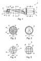
- FIG. 1shows a side view of a machining tool designed as a modular carrier tool
- FIG. 2shows a sectional view through the machining tool as shown in FIG. 1 along intersecting line A-A;
- FIG. 3shows a sectional view through the machining tool as shown in FIG. 1 along intersecting line C-C;
- FIG. 4shows a sectional view through the machining tool along intersecting line B-B;
- FIG. 5shows a sectional view of a grid-like core structure
- FIG. 6shows a sectional view of a bionic core structure in the area of the intersecting line A-A as shown in FIG. 1 ;
- FIG. 7shows a sectional view of a bionic core structure in the area of the intersecting line B-B as shown in FIG. 1 .
- the machining tool 2 illustrated in FIG. 1is designed as a modular drill tool. It has a tool tip 4 in the form of a cutting element made of solid carbide or ceramic, which is reversibly and removably attached to the frontal end of a base body 6 .
- a tool tipis generally understood to mean the frontal end area of the machining tool 2 , i.e. a front end face area of the machining tool. In the exemplary embodiment according to FIG. 1 , this is formed by the replaceable tool tip 4 .
- the area of the plate seatis understood to mean the tool tip.
- a front end area having an axial length, for example, in the range of a nominal diameter of the machining tool 2is referred to as the tool tip.
- the tool tip 4is clamped as a reversibly replaceable insert between two clamping or retaining webs 7 of the base body 6 .
- the machining tool 2and thus also the base body 6 , as well as the tool tip 4 each extend in an axial direction 10 along a center axis 8 from a rearward end to a front end.
- this center axis 8defines a rotational axis around which the machining tool rotates in a rotational direction D during operation.
- the base body 6is in turn divided into a rear shaft part 12 , with which the machining tool 2 is held clamped in a tensioning piece of a machine tool during operation.
- a cutting part 16 provided with chip flutes 14is connected to the shaft part 12 in the axial direction 10 .
- the chip flutes 14extend in a helical pattern.
- the end-face tool tip 4has major cutting edges 18 , each of which typically transitions into a minor cutting edge 20 on the circumferential side. These are continued in the cutting part 16 .
- a support bevel 24adjoins the minor cutting edge 20 opposite to the direction of rotation.
- the base body 6is a monolithic base body 6 , which is formed not from a solid material, but rather—at least in axial sections has a non-solid core structure 26 .
- this core structureis designed as a circular structure in the shaft part 12 , as seen in the cross-sectional view.
- the core structure 26 in this shaft part 12is preferably designed to have a constant radius R 1 .
- a support bevel 24adjoins the minor cutting edge 20 opposite the direction of rotation.
- This cylindrical core structure 26is surrounded by an outer jacket 28 , which, except for a flattening 30 introduced externally, is designed as an annular ring.
- This outer mantel 28has a radius R 2 .
- the radius R 1 of the core structure 26is preferably approximately 50 to 90% of the outer radius R 2 .
- the core structure 26has a core cross-sectional area A 1
- the machining tool 2has a total cross-sectional area A 2 . This area is defined by the area enclosed by the outer jacket 28 , including the surface of the outer jacket 28 .
- the sameis optionally closed off with an end face plate formed of a solid material, i.e. the non-solid core structure 26 is formed only in the interior of the shaft part 12 without being visible from the rearward end face.
- a coolant transfer pointis expediently formed and incorporated into this solid end face plate.
- a transverse groove having through-holes running to the core structure 26is introduced.
- the core structure 26is limited, in a similar manner, also in the axial direction 10 in the end area of the shaft part 12 by a solid partition 32 through which at least one, or in the exemplary example, two, cut-outs 34 , penetrate.
- the core structure 26also spans uninterrupted from the shaft part 12 into the cutting part 6 and without partition 32 .
- a partition 32is provided particularly in machining tools 2 without internal coolant supply. However, coolant supply is made possible in principle via the cut-outs 34 in the cutting part 16 .
- outlet point 35for coolant or lubricant is provided.
- Multiple outlet points 35which are oriented for example toward cutting areas, are preferably formed in a front end face or are also formed circumferentially.
- the outlet point 35can be designed as a borehole in a conventional manner. However, it is likewise preferably created by means of the 3D printing method and is geometrically complex.
- the core structure 26is preferably directed to the outside to form the outlet point 35 .
- an outlet point 35is formed for example in a circumferential wall 36 in the area of the tool tip and is formed in particular as a porous structure. The outlet point 35 in the exemplary embodiment is thus generally integrated into the retaining webs 7 .
- the core structure 26continues into the cutting part 16 itself ( FIG. 4 ). Due to the chip flutes 14 and to the circumferential geometry of the base body 6 modified thereby, the cross-sectional geometry of the core structure 26 is adapted in particular such that it is enveloped entirely by roughly the same wall thickness as that of the outer jacket 28 .
- the core structure 26is designed to be elongated in the cutting part 16 and has a center area 37 , which transitions into widened areas 38 at both ends. The outer edge of each said widened area has an accurate contour, so that they run concentrically to the circumferential line of the base body 6 .
- the core structure 26is preferably homogeneous even over its entire cross sectional area A 1 .
- additional supportscan be provided in a manner not further illustrated here. Separate coolant channels are expediently not formed in the embodiment variants of FIG. 1 .
- the core structure 26is designed as a porous structure.
- the core structure 26is designed as a grid-like structure, in particular as a honeycomb-shaped structure.
- This structurehas a plurality of individual channels 40 extending in the axial direction 10 . Rectangular channels are schematically illustrated in FIG. 5 .
- the individual channels 40are each separated from one another by partitions 42 . These partitions 42 preferably have only a slight material thickness of, for example, below 0.3 mm and, particularly, below 0.15 mm.
- the individual channels 40usually have a channel width W of below 0.5 mm.
- the core structure 26is designed to be what is referred to as a bionic structure, in which—in contrast to the grid-like structure illustrated in FIG. 5 —the individual partitions 42 are unordered and do not follow a pattern, at least not a recurring pattern.
- the different structurescan be combined with one another and, for example, to be formed next to one another within a sectional plane.
- the structurevaries in the axial direction 10 .
- the specific manufacturing methodallows nearly all desired combinations and variations.
- different structures, particularly of different porosityare present in the cutting part 16 and the shaft part 12 .
- the cutting part 16is of greater porosity than the shaft part 12 , or vice versa.
- the base body 6is manufactured using what is referred to as a 3D printing method.
- a metal powderis worked successively and thus layer-by-layer by means of laser treatment according to the desired cross-sectional geometry of each layer and melted or sintered to form a cohesive, monolithic sub-body.
- each cross-sectional contour of each layeris predefined by the laser.
- the core structure 26 described by FIGS. 2 through 5 and having the solid enveloping outer mantel 28is formed using this method.
- the entire base body 6is thus formed as a one-piece, monolithic body by utilizing this manufacturing method. This body can also undergo finishing work, if necessary, following the 3D printing process.
- the base body 6is preferably made of tool steel according to DIN EN 10027, for example with a material number 1.2709 and/or 1.2344.
Landscapes
- Engineering & Computer Science (AREA)
- Mechanical Engineering (AREA)
- Manufacturing & Machinery (AREA)
- Physics & Mathematics (AREA)
- Optics & Photonics (AREA)
- Powder Metallurgy (AREA)
- Drilling Tools (AREA)
- Processing Of Stones Or Stones Resemblance Materials (AREA)
Abstract
Description
This application is a National entry application of German Application No. 102014207507.6, filed on Apr. 17, 2014, the entire contents of which is incorporated herein by reference.
The invention relates to a machining tool, in particular a rotating tool such as a drill or milling tool, having a monolithic base body extending in an axial direction. The invention additionally relates to a method for manufacturing a machining tool of this type.
Machining tools, in particular drills, usually have a clamping shaft extending in the axial direction to which a slotted cutting part connects which extends up to a front tool tip, in particular to a drill bit. In the case of such machining tools, which are also referred to as shaft tools, coolant channels are often formed in the interior of the base body, as can be seen in EP 0 843 609 B1, for example.
In what are referred to as solid carbide drills, a monolithic base body is formed as a sintered body. The manufacturing process involves first making a base body by compression from a metal powder as sinter material, for example, which is then sintered. U.S. Pat. No. 7,226,254 B2 discloses a sintered base body in which, to save sinter material, a central recess is made in the base body in the area of the clamping shaft prior to sintering said base body. The sinter material thus saved is used for manufacturing additional tools.
Based on this, the invention forms a basis for providing a machining tool as well as a method for the manufacturing thereof, in which an efficient use of material and good mechanical properties are both ensured.
The problem is solved according to the invention by a machining tool having the features of claim1. The machining tool is a rotating tool in particular, such as a drill or milling tool, for example. It comprises a monolithic base body extending in the axial direction in which a non-solid core structure is formed, at least in a section extending in the axial direction, which is encased by a solid outer jacket. The outer jacket annularly encases the non-solid core structure preferably at a constant wall thickness. A large part of the base body is deliberately designed to be not solid due to the core structure which is non-solid compared to the solid outer jacket, thereby saving not only weight, but also material. At the same time, sufficiently high mechanical stability is achieved by the special core structure with the solid outer jacket structure. In this way, the core structure provides a type of mechanical support structure.
In this respect, it is especially important that the base body is a monolithic body. This term is understood to mean that the base body, i.e., in particular also the combination of the core structure with the outer jacket, is constructed from a single body, i.e., is made from one piece and is not assembled from two or more parts, e.g., by welding, soldering, bonding or similar.
The term non-solid core structure is generally understood to mean that open areas are formed in the core structure in which no material is present.
The core structure is preferably optionally porous, grid-like or even bionic. The term porous is generally understood to mean a structure in which individual pores are preferably scattered, i.e. unstructured and omnidirectional in the material of the core structure. Both open-pore as well as closed-pore structures are possible. In the case of an open-pore structure, on the whole, the core structure is permeable to a gas or liquid, such as a coolant, for example.
The term grid-like is understood to mean a structure in which areas that are free of material are separated from one another by partitions, in particular channels, usually in an ordered material structure, for example a periodic material structure. These individual channels preferably extend in the axial direction.
A bionic structure, in contrast, is understood to be an unordered, in particular non-periodic arrangement of partitions of this type, based, in particular, on patterns from nature.
According to the invention, the machining tool is manufactured with the aid of a method having the features ofclaim 12, which provides that the base body is manufactured with the aid of a 3D printing method. In the meantime, 3D printing methods have been used for a wide variety of applications. These methods basically involve processing a powdery starting material layer-by-layer with a laser, such that the individual powder particles bond to one another, for example, melt with or sinter with one another layer-by-layer into a solid, rigid body. The layer-by-layer, stratified construction makes it possible to easily form undercuts and complex geometrical structures, which, with previous conventional manufacturing methods, was not possible or required considerable effort and expense. In this case, a metal powder having an average grain size ranging between 10 and 50 μm is used as a starting material in powder form. In particular, the material for the metal powder is a tool steel.
Accordingly, this specific method, which makes it possible to create very fine structures, is provided for forming the specific non-solid core structure in the present invention.
The machining tool is optionally an monolithic tool taken as a whole having a tool tip integrated into the base body or, alternatively, it is what is known as a carrier tool consisting of a support made up of the base body and a preferably reversibly replaceable cutting element applied thereon.
The machining tool generally has at its front end a tool tip which is itself designed as a cutting element or one or more cutting elements are arranged in the area thereof. In the present invention, a tool tip is thus generally understood to mean the frontal end area of the machining tool, i.e. a forward face area of the machining tool. If the tool is designed as a modular carrier tool, a replaceable cutting element (cutting insert) is attached to the base body. According to a preferred variant, the tool tip itself is designed as a replaceable cutting insert. This can be reversibly and replaceably attached to the base body by clamping, for example, with the aid of fastening elements such as screws, or alternatively by simple turning. In this way, it is held clamped in particular between two retaining or clamping strips of the base body. Alternatively, the carrier tool is designed with plate seats for attaching (indexable) cutting inserts. In this case, the area of the plate seats is understood to mean the tool tip. In a non-modular, one-piece tool having, for example, major cutting edges cut into the end face area, a front end face area having an axial length in the range of a nominal diameter, for example, constitutes the tool tip.
Drills and milling tools in general are classified as rotating tools. It is thus understood that, during operation, the machining tool rotates around a center axis which at the same time defines the rotational axis.
A further advantage of the core structure centrally formed in the base body is that it is of lower density than the solid annular outer jacket. This results in a density distribution with greater density in the outer area, which results in a more stable rotation, particularly in rotating tools. The core structure is preferably designed to be rotationally symmetrical and preferably circular, at least rotationally symmetrical with at least a two-fold to six-fold rotational geometry.
To give it an especially high mechanical rigidity, the core structure is expediently designed as a honeycomb structure. This constitutes a special type of grid-like core structure in which the individual channels have a hexagonal cross-section.
In the case of a grid-like core structure, for example a honeycomb structure, a plurality of longitudinally extending channels are formed. In the present invention, the term plurality is understood to mean in particular that at least five, preferably at least eight or even significantly more channels are incorporated. The individual channels expediently have a maximum channel width below 0.5 mm and in particular below 0.10 mm.
If the core structure is porous, it expediently has a porosity ranging between 5 and 90%. This means that, compared to a solid body, between 5 and 90% of the volume consists of pores. The pores preferably have an average pore size ranging between 15 and 45 μm.
The core structure expediently has, at least in a shaft part, a circular cross-section and is designed to be concentric in particular to the annular outer jacket. The core structure as well as the outer jacket are thus coaxial to the center axis and in particular to the rotational axis.
Overall, the core structure covers an area of preferably around 5 to 80% of a total cross-sectional area of the base body. If the core structure is circular, it has a core radius that is preferably between 50 and 90% of an outer radius of the base body. Formed thereon is a comparatively narrower circumferential solid rim forming the outer jacket, preferably of constant wall thickness, which, however, is sufficiently dimensioned for the required mechanical loads, for example the clamping forces present when clamping the base body. The core structure portion expediently varies in the axial direction. In particular, the portion of the core structure differs between a front fluted cutting part and a rear shaft part. In the front cutting part, the portion of the core structure is in the lower range, for example between 5 and 30%, while in the shaft part it is in the upper range, for example between 40 and 80%, relative to the total cross-sectional area (recesses, such as chip flutes for example, do not count toward total cross-sectional surface).
In a useful embodiment, the core structure comprises a cross-sectional area that changes in the axial direction. In principle, the special manufacturing method of 3D printing allows any desired structure to be created. In the present invention, this method is utilized to the extent that a core structure geometry specifically adapted to the base body geometry is created in different axial sections of the base body. Varying the cross-sectional geometry additionally allows mechanical properties to be suitably adjusted at defined axial positions. In particular, allowance is made for highly loaded sections, for example, by enlarging the wall thickness of the solid outer jacket in these sections.
In an especially expedient refinement, solid struts are introduced into the core structure in the direction of the center axis to thereby achieve additional improvement in rigidity. Struts of this type are expediently bent in the shape of a sickle, for example, to transmit increased mechanical loads arising at the cutting edges into the interior of the base body, for example. The number of struts introduced is expediently equal to the number of cutting edges distributed circumferentially. If two circumferential cutting edges are present, the two struts preferably merge into one another in the center axis and are, for example, wound on the whole into the shape of an S. The struts form, for example, a structure in the shape of spokes and spoked wheel. The struts basically have a wall thickness significantly greater than the normal wall thickness of the grid-like core structure. For example, they are many times greater than the normal wall thickness. The wall thickness of the struts also preferably varies depending on their radial position, and specifically preferably varies continuously.
The base body usually comprises a shaft part as a clamping shaft with which it is clamped into a clamping device of a machine tool. The center axis of the machining tool is oriented so that it is precisely coaxial with the rotational axis of the machine tool. Connecting to the front of the shaft part in the axial direction is a front cutting part, which is usually provided with chip flutes. These are designed to either run in a straight line or to run helically. In an expedient design, the core structure further extends into the cutting part starting from the shaft part, so that a continuous core structure is formed. In this case, the core structure preferably has a circular cross-sectional geometry in the shaft part, which transitions into an altered geometry in the cutting part.
The core structure is expediently designed to be elongated in the area of the fluted cutting part and crossing into a center area of the base body. It additionally comprises widened areas on both sides of the center area, giving its cross-section an overall bone-like appearance. Its opposite end areas are spherical or rounded, so that, in particular, the radially outer course of the core structure runs concentrically to the outer jacket.
In an especially expedient embodiment, the core structure is designed to be suitable for conducting coolant and extends from a rearward end to a front end face of the base body. For this purpose, in particular, a conventional, standardized coolant connection is expediently formed at the rearward end of the base body. This typically comprises a transverse groove into which a coolant is fed from the machine tool.
At the front end face, coolant optionally exits the base body or is transferred to an interface with a tool tip into which the coolant can then be further fed.
Taken as a whole, the machining tool is designed in an expedient embodiment as a carrier tool having at least one cutting element that can be secured to the base body, in particular a tool tip or cutting plates. The base body is preferably manufactured from a tool steel. The cutting element, in contrast, is made of a harder material such as a solid carbide or also a ceramic, for example. It is secured to the base body in particular as a reversibly detachable insert.
Exemplary embodiments of the invention are explained below in greater detail based on the figures, some of which are simplified illustrations.
Parts having the same effect are given the same reference numbers in the figures.
Themachining tool 2 illustrated inFIG. 1 is designed as a modular drill tool. It has atool tip 4 in the form of a cutting element made of solid carbide or ceramic, which is reversibly and removably attached to the frontal end of abase body 6. In the present invention, a tool tip is generally understood to mean the frontal end area of themachining tool 2, i.e. a front end face area of the machining tool. In the exemplary embodiment according toFIG. 1 , this is formed by thereplaceable tool tip 4. In the case of a carrier tool having plate seats for attaching (indexable) inserts as a cutting element, the area of the plate seat is understood to mean the tool tip. In a non-modular, one-piece tool, a front end area having an axial length, for example, in the range of a nominal diameter of themachining tool 2 is referred to as the tool tip. In the exemplary embodiment according toFIG. 1 , thetool tip 4 is clamped as a reversibly replaceable insert between two clamping or retainingwebs 7 of thebase body 6.
Themachining tool 2, and thus also thebase body 6, as well as thetool tip 4 each extend in anaxial direction 10 along acenter axis 8 from a rearward end to a front end. At the same time, thiscenter axis 8 defines a rotational axis around which the machining tool rotates in a rotational direction D during operation.
Thebase body 6 is in turn divided into arear shaft part 12, with which themachining tool 2 is held clamped in a tensioning piece of a machine tool during operation. A cuttingpart 16 provided withchip flutes 14 is connected to theshaft part 12 in theaxial direction 10. In the exemplary embodiment, the chip flutes14 extend in a helical pattern. The end-face tool tip 4 hasmajor cutting edges 18, each of which typically transitions into aminor cutting edge 20 on the circumferential side. These are continued in the cuttingpart 16.
Asupport bevel 24 adjoins theminor cutting edge 20 opposite to the direction of rotation.
As is described below based onFIGS. 2 through 5 , thebase body 6 is amonolithic base body 6, which is formed not from a solid material, but rather—at least in axial sections has anon-solid core structure 26. AsFIG. 2 in particular illustrates, this core structure is designed as a circular structure in theshaft part 12, as seen in the cross-sectional view. To do this, thecore structure 26 in thisshaft part 12 is preferably designed to have a constant radius R1.A support bevel 24 adjoins theminor cutting edge 20 opposite the direction of rotation. Thiscylindrical core structure 26 is surrounded by anouter jacket 28, which, except for a flattening30 introduced externally, is designed as an annular ring. Thisouter mantel 28 has a radius R2. The radius R1of thecore structure 26 is preferably approximately 50 to 90% of the outer radius R2. Thecore structure 26 has a core cross-sectional area A1, and themachining tool 2 has a total cross-sectional area A2. This area is defined by the area enclosed by theouter jacket 28, including the surface of theouter jacket 28.
At the rearward end of theshaft part 12, the same is optionally closed off with an end face plate formed of a solid material, i.e. thenon-solid core structure 26 is formed only in the interior of theshaft part 12 without being visible from the rearward end face. A coolant transfer point is expediently formed and incorporated into this solid end face plate. In particular, a transverse groove having through-holes running to thecore structure 26 is introduced.
In the exemplary embodiment, thecore structure 26 is limited, in a similar manner, also in theaxial direction 10 in the end area of theshaft part 12 by asolid partition 32 through which at least one, or in the exemplary example, two, cut-outs 34, penetrate. Alternatively, thecore structure 26 also spans uninterrupted from theshaft part 12 into the cuttingpart 6 and withoutpartition 32. Apartition 32 is provided particularly inmachining tools 2 without internal coolant supply. However, coolant supply is made possible in principle via the cut-outs 34 in the cuttingpart 16.
In the front area of themachining tool 2, i.e. in the area of thetool tip 4, at least oneoutlet point 35 for coolant or lubricant is provided. Multiple outlet points35, which are oriented for example toward cutting areas, are preferably formed in a front end face or are also formed circumferentially. Theoutlet point 35 can be designed as a borehole in a conventional manner. However, it is likewise preferably created by means of the 3D printing method and is geometrically complex. Thecore structure 26 is preferably directed to the outside to form theoutlet point 35. In the exemplary embodiment illustrated inFIG. 1 , anoutlet point 35 is formed for example in acircumferential wall 36 in the area of the tool tip and is formed in particular as a porous structure. Theoutlet point 35 in the exemplary embodiment is thus generally integrated into the retainingwebs 7.
Thecore structure 26 continues into the cuttingpart 16 itself (FIG. 4 ). Due to the chip flutes14 and to the circumferential geometry of thebase body 6 modified thereby, the cross-sectional geometry of thecore structure 26 is adapted in particular such that it is enveloped entirely by roughly the same wall thickness as that of theouter jacket 28. In particular, thecore structure 26 is designed to be elongated in the cuttingpart 16 and has acenter area 37, which transitions into widenedareas 38 at both ends. The outer edge of each said widened area has an accurate contour, so that they run concentrically to the circumferential line of thebase body 6.
Thecore structure 26 is preferably homogeneous even over its entire cross sectional area A1. Alternatively, additional supports can be provided in a manner not further illustrated here. Separate coolant channels are expediently not formed in the embodiment variants ofFIG. 1 .
According to a first embodiment variant, thecore structure 26 is designed as a porous structure. According to a second embodiment variant illustrated inFIG. 5 , in contrast, thecore structure 26 is designed as a grid-like structure, in particular as a honeycomb-shaped structure. This structure has a plurality ofindividual channels 40 extending in theaxial direction 10. Rectangular channels are schematically illustrated inFIG. 5 . Theindividual channels 40 are each separated from one another bypartitions 42. Thesepartitions 42 preferably have only a slight material thickness of, for example, below 0.3 mm and, particularly, below 0.15 mm. Theindividual channels 40 usually have a channel width W of below 0.5 mm.
Further alternatives for thecore structure 26 are illustrated inFIG. 6 andFIG. 7 . In these embodiment variants, thecore structure 26 is designed to be what is referred to as a bionic structure, in which—in contrast to the grid-like structure illustrated inFIG. 5 —theindividual partitions 42 are unordered and do not follow a pattern, at least not a recurring pattern.
It is possible in principle for the different structures to be combined with one another and, for example, to be formed next to one another within a sectional plane. Alternatively, the structure varies in theaxial direction 10. The specific manufacturing method allows nearly all desired combinations and variations. In particular, different structures, particularly of different porosity, are present in the cuttingpart 16 and theshaft part 12. Thus, for example, the cuttingpart 16 is of greater porosity than theshaft part 12, or vice versa.
Thebase body 6 is manufactured using what is referred to as a 3D printing method. In this method, a metal powder is worked successively and thus layer-by-layer by means of laser treatment according to the desired cross-sectional geometry of each layer and melted or sintered to form a cohesive, monolithic sub-body. In this process, each cross-sectional contour of each layer is predefined by the laser. With this 3D printing method, nearly any arbitrary and complex and, in particular, variable cross-sectional geometries can be created. In particular, thecore structure 26 described byFIGS. 2 through 5 and having the solid envelopingouter mantel 28 is formed using this method. Theentire base body 6 is thus formed as a one-piece, monolithic body by utilizing this manufacturing method. This body can also undergo finishing work, if necessary, following the 3D printing process.
Thebase body 6 is preferably made of tool steel according to DIN EN 10027, for example with a material number 1.2709 and/or 1.2344.
Claims (17)
1. A rotary machining tool comprising a monolithic base body extending in an axial direction and comprising a rear shaft part and a fluted cutting part, wherein the base body has a non-solid core structure extending between flutes of the fluted cutting part, the non-solid core structure being encased in a solid outer jacket, the solid outer jacket forming a single body with the non-solid core structure and wherein the non-solid core structure extends into the rear shaft part from the fluted cutting part and has different cross-sectional areas in the rear shaft part relative to the fluted cutting part.
2. The rotary machining tool as claimed inclaim 1 , wherein the core structure is porous, grid-like, bionic or a combination thereof.
3. The rotary machining tool as claimed inclaim 1 , wherein the core structure is a honeycomb-like structure.
4. The rotary machining tool as claimed inclaim 1 , wherein, if the core structure is porous, the core structure has a porosity ranging between 5.2% and 90% and, wherein, if the core structure is grid-like, the core structure has a plurality of canals extending in a longitudinal direction and having a canal width (W) less than 0.5 mm.
5. The rotary machining tool as claimed inclaim 1 , wherein the core structure of the fluted cutting part has a cross-section which transitions from a narrow center area into a widened area at each end.
6. The rotary machining tool as claimed inclaim 1 , wherein the core structure covers 5% to 80% of an entire cross-sectional area (A2) of the cutting part of the base body.
7. The rotary machining tool as claimed inclaim 1 , wherein the core structure is designed to conduct coolant.
8. The rotary machining tool as claimedclaim 1 , wherein the rotary machining tool is designed as a carrier tool having a cutting element that is adapted to be secured onto the monolithic base body, and wherein the monolithic base body is manufactured from tool steel.
9. The rotary machining tool ofclaim 5 , wherein the core structure of the rear shaft part has a radius, R1, extending from a center axis of the machining tool and the solid outer jacket has a radius, R2, extending from the center axis wherein R1 is 50 to 90 percent of R2.
10. The rotary machining tool ofclaim 1 , further comprising a cutting tip coupled to the monolithic base body.
11. The rotary machining tool ofclaim 5 , wherein the widened areas have arcuate contours running concentrically to a circumferential line of the base body.
12. The rotary machining tool ofclaim 1 , wherein the solid outer jacket has one or more flat portions along circumference of the rear shaft part.
13. The rotary machining tool ofclaim 1 , wherein an end face plate divides the rear shaft portion and cutting portion.
14. The rotary machining tool ofclaim 1 , wherein the core structure is porous having an average pore size of 15 μm to 45 μm.
15. A rotary cutting tool comprising a monolithic base body extending in an axial direction and comprising a rear shaft part and a fluted cutting part, wherein the base body-has a non-solid core structure extending between flutes of the fluted cutting part, the non-solid core structure being encased in a solid outer jacket, the solid outer jacket forming a single body with the non-solid core structure and wherein the core structure comprises solid struts extending between cutting edges of the fluted cutting part.
16. The rotary cutting tool ofclaim 15 , wherein the struts are sickle shaped.
17. The rotary cutting tool ofclaim 15 , wherein the struts merge at a common point along a central longitudinal axis of the rotary cutting tool.
Priority Applications (1)
| Application Number | Priority Date | Filing Date | Title |
|---|---|---|---|
| US16/058,556US10646936B2 (en) | 2014-04-17 | 2018-08-08 | Machining tool and method for manufacturing a machining tool |
Applications Claiming Priority (3)
| Application Number | Priority Date | Filing Date | Title |
|---|---|---|---|
| DE102014207507.6ADE102014207507B4 (en) | 2014-04-17 | 2014-04-17 | Cutting tool and method for producing a cutting tool |
| DE102014207507.6 | 2014-04-17 | ||
| DE102014207507 | 2014-04-17 |
Related Child Applications (1)
| Application Number | Title | Priority Date | Filing Date |
|---|---|---|---|
| US16/058,556ContinuationUS10646936B2 (en) | 2014-04-17 | 2018-08-08 | Machining tool and method for manufacturing a machining tool |
Publications (2)
| Publication Number | Publication Date |
|---|---|
| US20150298222A1 US20150298222A1 (en) | 2015-10-22 |
| US10105769B2true US10105769B2 (en) | 2018-10-23 |
Family
ID=54249953
Family Applications (2)
| Application Number | Title | Priority Date | Filing Date |
|---|---|---|---|
| US14/687,189Active2035-11-07US10105769B2 (en) | 2014-04-17 | 2015-04-15 | Machining tool and method for manufacturing a machining tool |
| US16/058,556ActiveUS10646936B2 (en) | 2014-04-17 | 2018-08-08 | Machining tool and method for manufacturing a machining tool |
Family Applications After (1)
| Application Number | Title | Priority Date | Filing Date |
|---|---|---|---|
| US16/058,556ActiveUS10646936B2 (en) | 2014-04-17 | 2018-08-08 | Machining tool and method for manufacturing a machining tool |
Country Status (3)
| Country | Link |
|---|---|
| US (2) | US10105769B2 (en) |
| CN (1) | CN105033331A (en) |
| DE (1) | DE102014207507B4 (en) |
Cited By (2)
| Publication number | Priority date | Publication date | Assignee | Title |
|---|---|---|---|---|
| US20180345388A1 (en)* | 2014-04-17 | 2018-12-06 | Kennametal Inc. | Machining tool and method for manufacturing a machining tool |
| US10960502B2 (en)* | 2017-01-04 | 2021-03-30 | Kennametal Inc. | Metal-cutting tool, in particular a reaming tool and method of making the same |
Families Citing this family (22)
| Publication number | Priority date | Publication date | Assignee | Title |
|---|---|---|---|---|
| WO2016045681A1 (en)* | 2014-09-23 | 2016-03-31 | Danske Vaerktoej Aps | Thread cutting tap |
| DE102014119295B4 (en) | 2014-12-19 | 2023-08-10 | Kennametal Inc. | Tool holder for a cutting insert and method for manufacturing the tool holder |
| US9975182B2 (en)* | 2015-05-13 | 2018-05-22 | Kennametal Inc. | Cutting tool made by additive manufacturing |
| EP3210703B1 (en) | 2016-02-29 | 2018-08-15 | Sandvik Intellectual Property AB | A tool body, a tool and a method for manufacturing a tool body |
| DE102016111934A1 (en)* | 2016-06-29 | 2018-01-04 | Komet Group Gmbh | Chip removing cutting tool and method for its manufacture |
| DE102017108719A1 (en)* | 2017-04-24 | 2018-10-25 | Gühring KG | Method for assembling a tool system module and accordingly manufactured tool system module |
| DE102017112374A1 (en)* | 2017-06-06 | 2018-12-06 | Komet Group Gmbh | Milling tool with changeable cutting ring |
| DE102017115668A1 (en)* | 2017-07-12 | 2019-01-17 | Kennametal Inc. | Method for producing a cutting tool and cutting tool |
| JP6722153B2 (en) | 2017-07-28 | 2020-07-15 | 株式会社Subaru | Drill, drilling unit and drilling method |
| CN107262812B (en)* | 2017-08-06 | 2023-04-07 | 吉林大学 | Bionic curved surface shearing knife |
| JP7207983B2 (en)* | 2018-12-10 | 2023-01-18 | 株式会社Subaru | Drills, drilling units and methods of making workpieces |
| JP7267766B2 (en) | 2019-02-14 | 2023-05-02 | 株式会社Subaru | Rotary cutting tool, rotary cutting unit and method of making workpiece |
| DE102019124223A1 (en) | 2019-09-10 | 2021-03-11 | Franken Gmbh & Co. Kg Fabrik Für Präzisionswerkzeuge | Milling tool with cooling channels |
| EP3815840B1 (en)* | 2019-10-31 | 2023-10-04 | Sandvik Machining Solutions AB | Method for producing a tool part |
| JP7545789B2 (en) | 2020-05-27 | 2024-09-05 | 株式会社Subaru | Hole finishing tool and method for manufacturing hole finishing product |
| US11318541B2 (en)* | 2020-06-30 | 2022-05-03 | Iscar, Ltd. | Light-weight tool holder with coolant cavity having varying cross-sectional area and cutting tool |
| EP4015113A1 (en)* | 2020-12-18 | 2022-06-22 | Bystronic Laser AG | Machine, and construction part |
| DE202021101436U1 (en)* | 2021-03-22 | 2022-03-23 | Zcc Cutting Tools Europe Gmbh | basic tool holder |
| CN114260494A (en)* | 2021-12-15 | 2022-04-01 | 厦门金鹭特种合金有限公司 | Indexable cutting tool |
| CN115229225B (en)* | 2022-05-23 | 2025-09-12 | 厦门金鹭特种合金有限公司 | Tool holder and cutting tool |
| DE102023003258A1 (en)* | 2023-08-07 | 2025-02-13 | Tigra Gmbh | Tool component and method for producing a tool component |
| CN118022682B (en)* | 2024-03-20 | 2024-10-22 | 江苏乾汇和环保再生有限公司 | Modified activated carbon and activated carbon processing method |
Citations (182)
| Publication number | Priority date | Publication date | Assignee | Title |
|---|---|---|---|---|
| US385088A (en) | 1888-06-26 | Drilling-tool | ||
| US864756A (en) | 1907-03-28 | 1907-08-27 | George W Giddings | Drill. |
| US1476019A (en) | 1922-04-26 | 1923-12-04 | Paul Landemare | Cutting tool |
| US1781863A (en) | 1928-03-22 | 1930-11-18 | Shoemaker William Walter | Cutting tool |
| US1951856A (en) | 1930-08-22 | 1934-03-20 | Ramet Corp | Tool and method of making the same |
| US1965950A (en) | 1932-11-07 | 1934-07-10 | Mills Alloys Inc | Scarifier tooth |
| US2289065A (en) | 1941-01-02 | 1942-07-07 | Edd C Oliver | Drill for rifle barrels |
| US2289344A (en) | 1941-04-28 | 1942-07-14 | Forest City Bit & Tool Co | Tool |
| US2682414A (en) | 1950-05-15 | 1954-06-29 | John H Richardson | Longitudinally adjustable screw driver |
| US3455000A (en) | 1966-10-25 | 1969-07-15 | Gen Motors Corp | Cutting tool and tip therefor |
| US3646679A (en) | 1971-03-10 | 1972-03-07 | Gene O Naugle | Tooth extracting instrument |
| US3654681A (en) | 1970-04-22 | 1972-04-11 | Warner Swasey Co | Cutoff tool having improved chip relieving surface |
| US3705447A (en) | 1970-10-22 | 1972-12-12 | Thomas J Kollar | Machine tool bit |
| US3857305A (en) | 1974-04-05 | 1974-12-31 | P Lichtman | Milling cutters |
| US4373518A (en) | 1980-09-26 | 1983-02-15 | Zimmer, Inc. | Method of drilling living bone |
| US4481016A (en) | 1978-08-18 | 1984-11-06 | Campbell Nicoll A D | Method of making tool inserts and drill bits |
| EP0128912A1 (en) | 1982-12-20 | 1984-12-27 | Ptp Patent Tech Prozesse Ag | Hydraulic, pneumatic, pneumatic/hydraulic or combined pneumatic/explosion press. |
| US4505626A (en) | 1983-02-24 | 1985-03-19 | Dexport Tool Company, Inc. | Cutting tool |
| US4591302A (en) | 1984-08-22 | 1986-05-27 | Lovendahl Norman H | Countersink with disposable insert |
| JPS61109606A (en) | 1984-10-29 | 1986-05-28 | Toshiba Tungaloy Co Ltd | Twist drill |
| EP0191203A2 (en) | 1985-01-16 | 1986-08-20 | Jerome Hal Lemelson | Cutting tool structures, apparatus and method for making same |
| US4725171A (en) | 1984-03-02 | 1988-02-16 | Detorre Robert P | Drill for aramid composites |
| US4728231A (en) | 1984-03-12 | 1988-03-01 | Sumitomo Electric Industries, Ltd. | Drill bit structure |
| US4749618A (en)* | 1985-03-11 | 1988-06-07 | Pilot Ink Co., Ltd. | Tip member for coating tool |
| US4826364A (en)* | 1986-08-27 | 1989-05-02 | Stellram S.A. | One-piece rotary material removing tool of sintered hard metal |
| US4844668A (en) | 1986-08-18 | 1989-07-04 | Sandvik Ab | Turning insert |
| USD305498S (en) | 1988-10-05 | 1990-01-16 | Lassiter Will M | Router bit |
| US4898499A (en) | 1987-03-04 | 1990-02-06 | Mitsubishi Kinzoku Kabushiki Kaisha | Ball end mill |
| CN1041897A (en) | 1988-10-20 | 1990-05-09 | A.E.毕晓普及合伙人有限公司 | Rotation groove milling milling cutter and blade thereof |
| US4946319A (en) | 1988-08-12 | 1990-08-07 | Kennametal Inc. | Cutting insert and clamping arrangement therefor |
| US5066170A (en) | 1989-09-14 | 1991-11-19 | Outboard Marine Corporation | Tool bit |
| US5078551A (en) | 1989-09-18 | 1992-01-07 | U.S. Philips Corporation | Diamond tool |
| US5098232A (en) | 1983-10-14 | 1992-03-24 | Stellram Limited | Thread cutting tool |
| JPH04226826A (en) | 1990-07-18 | 1992-08-17 | General Electric Co <Ge> | Drill covered with cvd diamond |
| US5178645A (en) | 1990-10-08 | 1993-01-12 | Sumitomo Electric Industries, Ltd. | Cutting tool of polycrystalline diamond and method of manufacturing the same |
| US5205680A (en) | 1990-07-19 | 1993-04-27 | Sandvik Ab | Metal cutting insert with rounded cutting edge |
| JPH0623615A (en) | 1992-03-09 | 1994-02-01 | Norton Co | Cutting tool using diamond film |
| US5342151A (en) | 1992-01-20 | 1994-08-30 | Iscar Ltd. | Cutting insert having a circular cutting edge with a chip former |
| US5362183A (en) | 1993-10-05 | 1994-11-08 | Joseph Alario | Single point cutting tool |
| US5433280A (en) | 1994-03-16 | 1995-07-18 | Baker Hughes Incorporated | Fabrication method for rotary bits and bit components and bits and components produced thereby |
| JPH08206133A (en) | 1995-02-02 | 1996-08-13 | Manii Kk | Peaso reamer or gates drill |
| US5634933A (en) | 1994-09-29 | 1997-06-03 | Stryker Corporation | Powered high speed rotary surgical handpiece chuck and tools therefore |
| US5685671A (en) | 1993-11-01 | 1997-11-11 | Smith International, Inc. | Diamond or CBN fluted center cutting end mill |
| US5722803A (en) | 1995-07-14 | 1998-03-03 | Kennametal Inc. | Cutting tool and method of making the cutting tool |
| EP0843609A1 (en) | 1995-08-08 | 1998-05-27 | KENNAMETAL HERTEL AG Werkzeuge + Hartstoffe | Method of providing a rotating cutting tool with lubricating coolant, and tool and tool-holder for carrying out the method |
| US5799553A (en) | 1995-02-08 | 1998-09-01 | University Of Connecticut | Apparatus for environmentally safe cooling of cutting tools |
| US5820313A (en)* | 1995-11-29 | 1998-10-13 | Weber; Dieter | Rotating shaft tool |
| JPH1150254A (en) | 1997-07-29 | 1999-02-23 | Mitsubishi Materials Corp | Surface-coated cemented carbide-cutting tool having excellent chipping resistance in thich-film artificial diamond coating layer |
| DE19730539C1 (en) | 1997-07-16 | 1999-04-08 | Fraunhofer Ges Forschung | Lathe tool |
| US6030156A (en) | 1998-04-17 | 2000-02-29 | Andronica; Randall | Drill and sharpening fixture |
| US6053669A (en)* | 1996-11-18 | 2000-04-25 | Sandvik Aktiebolag | Chip forming cutting insert with internal cooling |
| US6062753A (en)* | 1998-08-17 | 2000-05-16 | Pentech International Inc. | Writing instrument with enhanced tactile control and gripping comfort and method of making same |
| DE19860585A1 (en) | 1998-12-29 | 2000-07-20 | Laserpluss Ag | Device for laser-processing workpieces containing diamond |
| US6116825A (en) | 1995-08-08 | 2000-09-12 | Kennametal Hertel Ag Werkzeuge + Hartstoffe | Rotating cutting tool with a coolant passage and a method of providing it with coolant |
| US6116823A (en) | 1994-11-29 | 2000-09-12 | Microna Ab | Slot milling tool |
| US6146476A (en) | 1999-02-08 | 2000-11-14 | Alvord-Polk, Inc. | Laser-clad composite cutting tool and method |
| US6161990A (en) | 1998-11-12 | 2000-12-19 | Kennametal Inc. | Cutting insert with improved flank surface roughness and method of making the same |
| US6315505B1 (en) | 1996-02-16 | 2001-11-13 | Bittmore | Minimum heat-generating work piece cutting tool |
| US20010056309A1 (en) | 2000-06-22 | 2001-12-27 | Prabhat Jain | Three-dimensional replica creation process |
| US6394466B1 (en) | 1999-02-16 | 2002-05-28 | Nikken Kosakusho Works Ltd. | End mill chucking structure |
| US6472029B1 (en) | 1998-06-30 | 2002-10-29 | The P.O.M. Group | Fabrication of laminate structures using direct metal deposition |
| US6524036B1 (en) | 1997-06-10 | 2003-02-25 | Fette Gmbh | Method for influencing the behavior of swarf flow on tool surfaces |
| US6554010B1 (en)* | 1999-07-26 | 2003-04-29 | Tokyo Electron Limited | Substrate cleaning tool, having permeable cleaning head |
| US20030094730A1 (en) | 2001-11-16 | 2003-05-22 | Varel International, Inc. | Method and fabricating tools for earth boring |
| US20030118412A1 (en) | 2001-12-26 | 2003-06-26 | Sumitomo Electric Industries, Ltd. | Surface-coated machining tools |
| US6607533B2 (en) | 2001-09-25 | 2003-08-19 | The Anspbell Effort, Inc | Miniature cutter shaft configuration |
| US20030210963A1 (en) | 2002-03-21 | 2003-11-13 | Sandvik Ab | Rotary tool and cutting part comprised in the tool |
| US6692199B2 (en) | 2002-01-31 | 2004-02-17 | Sandvik Ab | Cutting insert for grooving and profiling |
| US6712564B1 (en) | 2000-09-29 | 2004-03-30 | Greenleaf Technology Corporation | Tool with improved resistance to displacement |
| US6715968B1 (en) | 1998-09-09 | 2004-04-06 | Sandvik Aktiebolag | Cutting insert for grooving operations |
| US6733603B1 (en) | 1999-11-15 | 2004-05-11 | Deloro Stellite Company, Inc. | Cobalt-based industrial cutting tool inserts and alloys therefor |
| US20040107019A1 (en) | 2002-07-18 | 2004-06-03 | Shyam Keshavmurthy | Automated rapid prototyping combining additive and subtractive processes |
| US20040120778A1 (en) | 2001-03-21 | 2004-06-24 | Horst Lach | Profile turning tool |
| US20040120777A1 (en) | 2002-12-24 | 2004-06-24 | Noland Dennis L. | Rotary cutting tool |
| JP2004216483A (en) | 2003-01-10 | 2004-08-05 | Allied Material Corp | Ultra-precision machining tools |
| US6808340B2 (en) | 2002-09-06 | 2004-10-26 | Prototype Productions, Inc. | Tool apparatus |
| US20040221696A1 (en) | 2003-05-08 | 2004-11-11 | Hideaki Matsuhashi | Non-rotary cutting tool and process of machining scroll member by using the same |
| US20040258491A1 (en) | 2001-08-28 | 2004-12-23 | Werner Penkert | Cutting insert and use thereof, and a cutting insert especially for turning aluminum |
| DE10336923A1 (en) | 2003-08-07 | 2005-03-10 | B P S Engineering Ges Fuer Umw | Blow molding tool manufacture involves rapid prototype production of a mineral based model which is divided and each half is placed in a frame and low melting point alloy cast onto the back |
| WO2005025779A2 (en) | 2003-09-11 | 2005-03-24 | Ex One Corporation | Layered manufactured articles having small-width fluid conduction vents and methods of making same |
| EP1537930A1 (en) | 2003-12-04 | 2005-06-08 | WENDT GmbH | Cutting tool and process for finishing a cutting tool |
| US6929426B2 (en) | 2003-02-19 | 2005-08-16 | Kennametal Inc. | Indexable cutting tool |
| US20050238451A1 (en) | 2004-04-22 | 2005-10-27 | Parlec, Inc. | System for mounting a machine tool in a tool holder |
| CN1689739A (en) | 2004-04-21 | 2005-11-02 | 尖点科技股份有限公司 | Semiconductor IC board micro-drill with composite material |
| CA2405109C (en) | 2000-05-03 | 2006-01-10 | Saint-Gobain Abrasives, Inc. | Production tool process |
| US20060039818A1 (en) | 2004-08-18 | 2006-02-23 | Delta Electronics, Inc. | Method of forming a die |
| DE102004042775A1 (en) | 2004-09-03 | 2006-03-09 | Fraunhofer-Gesellschaft zur Förderung der angewandten Forschung e.V. | Production of complex high strength components or tools from metal powders useful in production of forming, injection molding, pressure die casting, cutting tools and turbine components from metal powders |
| US20060048615A1 (en) | 2004-09-08 | 2006-03-09 | Treige Peter J | Multi-radial shaft for releasable shaft holders |
| US20060144198A1 (en) | 2005-01-05 | 2006-07-06 | Sugino Machine Limited | Throw-away burnishing tool for outside diameter and for inside diameter |
| US7112020B2 (en) | 2003-06-10 | 2006-09-26 | Kennametal Inc. | Cutting tool configured for improved engagement with a tool holder |
| US20070006694A1 (en) | 2005-07-11 | 2007-01-11 | Konica Minolta Opto, Inc. | Cutting tool and cutting machine |
| CN1910003A (en) | 2004-03-17 | 2007-02-07 | 钴碳化钨硬质合金公司 | Twist drill |
| EP1534451B1 (en) | 2002-08-20 | 2007-02-14 | Ex One Corporation | Casting process |
| US7226254B2 (en)* | 2001-08-29 | 2007-06-05 | Arno Friedrichs | Rod-shaped tool for machining a workpiece |
| DE102006005401A1 (en) | 2006-02-03 | 2007-08-09 | Gesau-Werkzeuge Fabrikations- Und Service Gmbh | Shaft milling tool, is formed by producing a blank from a hard metal, and applying a hard material layer |
| DE19901777B4 (en) | 1999-01-18 | 2007-08-16 | 3M Espe Ag | Method for producing endodontic instruments by means of laser use |
| US20070212177A1 (en) | 2006-03-13 | 2007-09-13 | Matsushita Electric Industrial Co., Ltd. | Machining tools having concave cutting surfaces for precision machining and methods of manufacturing such |
| WO2007104065A1 (en) | 2006-03-14 | 2007-09-20 | Ceratizit Austria Gesellschaft M.B.H. | Material composite with periodically changed microstructure |
| CN101068644A (en) | 2004-12-02 | 2007-11-07 | 肯纳梅泰尔公司 | Drills and Drilling/Chamfering Tools for Drilling/Chamfering Tools |
| WO2007127899A2 (en) | 2006-04-28 | 2007-11-08 | Halliburton Energy Services, Inc. | Molds and methods of forming molds associated with manufacture of rotary drill bits and other downhole tools |
| US20080065259A1 (en) | 2006-09-11 | 2008-03-13 | Dietrich David M | Method and apparatus for rapidly generating tooling for press machines |
| JP2008062369A (en) | 2006-09-11 | 2008-03-21 | Tungaloy Corp | Method of producing tip to be mounted on boring tool, method of producing boring tool, and boring tool |
| US20080075618A1 (en) | 2006-09-19 | 2008-03-27 | Schlumberger Technology Corporation | Metal Powder Layered Apparatus for Downhole Use |
| US20080080937A1 (en) | 2006-09-28 | 2008-04-03 | Iscar Ltd. | Cutting Tool Having Cutting Insert Secured By Non-Penetrating Abutment of a Threaded Fastener |
| US20080253849A1 (en) | 2004-06-30 | 2008-10-16 | Miki Yoshinaga | Mono Crystalline Diamond Cutting Tool for Ultra Precision Machining |
| US20080260964A1 (en) | 2007-04-17 | 2008-10-23 | Vijayavel Bagavath-Singh | Vision system and method for direct-metal-deposition (dmd) tool-path generation |
| US20080260479A1 (en)* | 2005-10-11 | 2008-10-23 | Dirk Kammermeier | Device for supplying coolant into a shank of a rotary tool as well as a rotary tool, in particular a drill |
| JP2009006436A (en) | 2007-06-27 | 2009-01-15 | Mitsubishi Materials Corp | Manufacturing method of working tool and working tool |
| US20090035411A1 (en) | 2005-05-06 | 2009-02-05 | James Seibert | Solid free-form fabrication apparatus and method |
| US20090035075A1 (en) | 2007-08-05 | 2009-02-05 | Iscar, Ltd. | Cutting tool, tool body and cutting insert therefor |
| US20090114628A1 (en) | 2007-11-05 | 2009-05-07 | Digiovanni Anthony A | Methods and apparatuses for forming cutting elements having a chamfered edge for earth-boring tools |
| US20100086373A1 (en)* | 2007-05-20 | 2010-04-08 | Guehring Ohg | Cutting tool |
| US20100172703A1 (en) | 2007-02-28 | 2010-07-08 | Karl-Heinz Neubold | Spherical milling cutter |
| US7785046B2 (en)* | 2002-07-17 | 2010-08-31 | Advanced Industries | Tool coolant application and direction assembly |
| CN201579425U (en) | 2009-10-21 | 2010-09-15 | 中旸科技有限公司 | Combined cutting tool |
| US20100242696A1 (en)* | 2006-06-28 | 2010-09-30 | Teeness Asa | Container Adapted to be Inserted in a Tool Holder, A Tool Holder and a System |
| US20100254772A1 (en) | 2009-04-06 | 2010-10-07 | Jay Christopher Rozzi | Indirect Cooling of a Cutting Tool |
| US20100270757A1 (en)* | 2002-07-17 | 2010-10-28 | Kevin Beckington | Tool coolant application and direction assembly |
| DE202010015446U1 (en) | 2009-07-08 | 2011-02-24 | MAPAL Fabrik für Präzisionswerkzeuge Dr. Kress KG | Tool, in particular milling tool |
| CN102056696A (en) | 2008-06-04 | 2011-05-11 | 株式会社钨钛合金 | Mechanism for temporarily holding tip, and throw-away cutting tool provided with the mechanism |
| US20110156304A1 (en) | 2009-12-31 | 2011-06-30 | Bryant Walker | Die Tool Production Methods Utilizing Additive Manufacturing Techniques |
| US20110210096A1 (en) | 2010-03-01 | 2011-09-01 | Edris Raji | Printed masking process |
| EP2367669A1 (en) | 2008-12-19 | 2011-09-28 | AS OM BE Plast | A method for the manufacture of products by injection moulding thermoplastic material to the face of a three- dimensional print |
| WO2011135512A1 (en) | 2010-04-26 | 2011-11-03 | Pro-C-Ept | Extrusion die, process for making the extrusion die and use of the extrusion die |
| US20110266068A1 (en) | 2010-04-28 | 2011-11-03 | Baker Hughes Incorporated | Earth-boring tools and methods of forming earth-boring tools |
| US20110291331A1 (en) | 2008-07-18 | 2011-12-01 | Simon Peter Scott | Manufacturing Apparatus and Method |
| US20120018924A1 (en) | 2010-07-22 | 2012-01-26 | Stratasys, Inc. | Multiple-zone liquefier assembly for extrusion-based additive manufacturing systems |
| US20120068378A1 (en) | 2010-09-22 | 2012-03-22 | Stratasys, Inc. | Method for building three-dimensional models with extrusion-based additive manufacturing systems |
| US20120070523A1 (en) | 2010-09-22 | 2012-03-22 | Stratasys, Inc. | Liquefier assembly for use in extrusion-based additive manufacturing systems |
| CN102427858A (en) | 2009-05-19 | 2012-04-25 | 科布拉高尔夫有限公司 | Method of making golf clubs using metal powder and a high energy source |
| US20120103701A1 (en) | 2007-04-03 | 2012-05-03 | Cho H Sam | Contoured pcd and pcbn segments for cutting tools containing such segments |
| US20120135166A1 (en) | 2009-04-02 | 2012-05-31 | Thomas Berglund | Method for Manufacturing a Powder Based Article |
| WO2012071449A2 (en) | 2010-11-22 | 2012-05-31 | Drill Master Inc. | Architectures, methods, and systems for remote manufacturing of earth-penetrating tools |
| US20120141215A1 (en) | 2009-08-26 | 2012-06-07 | Taegutec, Ltd. | Multi-Functional Cutting Tool |
| WO2012073099A2 (en) | 2010-11-29 | 2012-06-07 | Halliburton Energy Services, Inc. | Forming objects by infiltrating a printed matrix |
| US20120183802A1 (en) | 2011-01-13 | 2012-07-19 | Bruck Gerald J | Resistance weld additive manufacturing |
| US20120232857A1 (en) | 2009-10-16 | 2012-09-13 | 3Shape A/S | Individually tailored soft components |
| WO2012146694A1 (en) | 2011-04-28 | 2012-11-01 | Materialise N.V. | Stopping tool guides and combinations thereof with surgical guides, methods for manufacturing and uses thereof |
| US8308403B2 (en) | 2007-04-29 | 2012-11-13 | Iscar, Ltd. | Tool holder |
| US20120326356A1 (en) | 2011-06-23 | 2012-12-27 | Disney Enterprises, Inc. | Fabricating objects with integral and contoured rear projection |
| US20130004680A1 (en) | 2011-06-28 | 2013-01-03 | Honeywell International Inc. | Methods for manufacturing engine components with structural bridge devices |
| US20130015596A1 (en) | 2011-06-23 | 2013-01-17 | Irobot Corporation | Robotic fabricator |
| US20130034399A1 (en)* | 2011-08-03 | 2013-02-07 | Fuji Jukogyo Kabushiki Kaisha | Throw away type rotary cutting apparatus and tip holder |
| US20130040051A1 (en) | 2011-08-09 | 2013-02-14 | GM Global Technology Operations LLC | Method for applying variable magnetic properties to a induction heated tool face and manufacturing parts using the tool |
| US20130059509A1 (en) | 2004-07-21 | 2013-03-07 | Manish Deopura | Methods for producing in-situ grooves in chemical mechanical planarization (cmp) pads, and novel cmp pad designs |
| WO2013030064A1 (en) | 2011-08-26 | 2013-03-07 | Swerea Ivf Ab | Layered manufacturing of free-form multi-material micro-components |
| US20130088364A1 (en) | 2010-01-22 | 2013-04-11 | Halliburton Energy Services, Inc. | Method and apparatus for making resistivity measurements in a wellbore |
| US20130101746A1 (en) | 2011-10-21 | 2013-04-25 | John J. Keremes | Additive manufacturing management of large part build mass |
| US20130105230A1 (en) | 2005-01-27 | 2013-05-02 | Baker Hughes Incorporated | Abrasive-impregnated cutting structure having anisotropic wear resistance and drag bit including same |
| US20130136868A1 (en) | 2011-01-13 | 2013-05-30 | Gerald J. Bruck | Selective laser melting / sintering using powdered flux |
| WO2013087515A1 (en) | 2011-12-14 | 2013-06-20 | Alstom Technology Ltd | Method for additively manufacturing an article made of a difficult-to-weld material |
| US20130161442A1 (en) | 2011-12-22 | 2013-06-27 | Stratasys, Inc. | Spool assembly for additive manufacturing system, and methods of manufacture and use thereof |
| US20130161439A1 (en) | 2011-12-22 | 2013-06-27 | Stratasys, Inc. | Spool assembly with locking mechanism for additive manufacturing system, and methods of use thereof |
| US20130164960A1 (en) | 2011-12-22 | 2013-06-27 | Stratasys, Inc. | Universal adapter for consumable assembly used with additive manufacturing system |
| US20130170171A1 (en) | 2012-01-04 | 2013-07-04 | Board Of Regents, The University Of Texas System | Extrusion-based additive manufacturing system for 3d structural electronic, electromagnetic and electromechanical components/devices |
| WO2013112217A2 (en) | 2011-10-31 | 2013-08-01 | California Institute Of Technology | Methods for fabricating gradient alloy articles with multi-functional properties |
| US20130209600A1 (en) | 2012-02-10 | 2013-08-15 | Adam Perry Tow | Multi-axis, multi-purpose robotics automation and quality adaptive additive manufacturing |
| US20130220570A1 (en) | 2012-02-29 | 2013-08-29 | Ford Motor Company | Additive fabrication technologies for creating molds for die components |
| WO2013124691A1 (en) | 2012-02-24 | 2013-08-29 | Rotite Limited | Device for and method of connecting two items together |
| US20130221191A1 (en) | 2012-02-29 | 2013-08-29 | Ford Motor Company | Mold core package for forming a powder slush molding tool |
| US20130220572A1 (en) | 2012-02-29 | 2013-08-29 | Ford Motor Company | Molding assembly with heating and cooling system |
| US20130224423A1 (en) | 2010-09-17 | 2013-08-29 | Stratasys, Inc. | Additive manufacturing method for building three-dimensional objects with core-shell arrangements, and three-dimensional objects thereof |
| US20130223943A1 (en) | 2012-01-31 | 2013-08-29 | Kennametal Inc. | Tool head for a modular shank tool |
| WO2013126981A1 (en) | 2012-02-27 | 2013-09-06 | Red River College | Method for making an article from a curable material |
| US8534963B2 (en) | 2008-07-30 | 2013-09-17 | Hartmetall-Werkzeugfabrik Paul Horn Gmbh | Tool for machining a workpiece |
| US20130247475A1 (en) | 2009-01-30 | 2013-09-26 | William H. Lind | Matrix drill bit with dual surface compositions and methods of manufacture |
| US20130248260A1 (en) | 2005-12-14 | 2013-09-26 | Baker Hughes Incorporated | Drill bits with bearing elements for reducing exposure of cutters |
| WO2013140146A1 (en) | 2012-03-21 | 2013-09-26 | Eads Uk Limited | Substrate for additive manufacturing |
| US20130255346A1 (en) | 2012-03-29 | 2013-10-03 | A. Raymond Et Cie | Metal-stamping die manufactured by additive manufacturing |
| GB2500996A (en) | 2012-03-19 | 2013-10-09 | Bae Systems Plc | Stress relieving layers in additive layer manufacturing |
| EP2646185A2 (en) | 2010-11-29 | 2013-10-09 | Halliburton Energy Services, Inc. | Improvements in heat flow control for molding downhole equipment |
| EP2646641A2 (en) | 2010-11-29 | 2013-10-09 | Halliburton Energy Services, Inc. | Mold assemblies including a mold insertable in a container |
| EP2646224A1 (en) | 2010-11-29 | 2013-10-09 | Halliburton Energy Services, Inc. | 3d-printed bodies for molding downhole equipment |
| WO2013149659A1 (en) | 2012-04-04 | 2013-10-10 | Mobelife N.V. | Drill alignment device, method for manufacturing the drill alignment device and a method for removing bone cement |
| WO2013154723A1 (en) | 2012-04-10 | 2013-10-17 | A. Raymond Et Cie | Printed encapsulation |
| US20130277121A1 (en) | 2009-06-05 | 2013-10-24 | Baker Hughes Incorporated | Downhole tools and parts and methods of formation |
| EP2654412A1 (en) | 2010-12-21 | 2013-10-30 | Stratasys Ltd. | Method and system for reuse of materials in additive manufacturing systems |
| US8746703B2 (en) | 2010-12-03 | 2014-06-10 | Fu Tai Hua Industry (Shenzhen) Co., Ltd. | Screwdriver head mounting structure |
| US20150042050A1 (en)* | 2012-02-29 | 2015-02-12 | Haimer Gmbh | Shrink-fit chuck with tool cooling |
| US20150298221A1 (en)* | 2014-04-17 | 2015-10-22 | Kennametal Inc. | Machining tool and method for manufacturing a machining tool |
| US20150367423A1 (en)* | 2013-03-01 | 2015-12-24 | Bilz Werkzeugfabrik Gmbh & Co., Kg | Tool head having a shrink-fit chuck |
| US20160031015A1 (en)* | 2013-04-10 | 2016-02-04 | Daishowa Seiki Kabushiki Kaisha | Hydraulic chuck |
Family Cites Families (83)
| Publication number | Priority date | Publication date | Assignee | Title |
|---|---|---|---|---|
| US3754309A (en) | 1972-01-28 | 1973-08-28 | Kennametal Inc | Cutting insert and clamping arrangement therefor |
| US3911543A (en) | 1974-08-01 | 1975-10-14 | Kennametal Inc | Cutting insert and holder |
| IT1106970B (en) | 1978-01-18 | 1985-11-18 | Istituto Per Le Ricerche Di Te | PROCESS FOR SWARF REMOVAL PROCESSING WITH THE USE OF THE LASER BEAM AND APPARATUS FOR THE EXECUTION OF THE PROCEDURE |
| US4459458A (en) | 1982-08-30 | 1984-07-10 | The Warner & Swasey Company | Machine tool with laser heat treating |
| US4755237A (en) | 1984-11-26 | 1988-07-05 | Lemelson Jerome H | Methods for making cutting tools |
| US4797138A (en) | 1986-02-18 | 1989-01-10 | General Electric Company | Polycrystalline diamond and CBN cutting tools |
| US4714385A (en) | 1986-02-27 | 1987-12-22 | General Electric Company | Polycrystalline diamond and CBN cutting tools |
| DE68905106T2 (en) | 1988-06-28 | 1993-09-02 | Camco Drilling Group Ltd | CUTTING ELEMENTS FOR ROTARY DRILL CHISELS. |
| US4849602A (en) | 1988-08-12 | 1989-07-18 | Iscar Ltd. | Method for fabricating cutting pieces |
| US5026960A (en) | 1989-10-31 | 1991-06-25 | The General Electric Company | Chip breaker for polycrystalline CBN and diamond compacts |
| JPH04100689A (en) | 1990-08-14 | 1992-04-02 | Tsubakimoto Chain Co | 5-axis table for laser processing machine |
| DE4040554A1 (en) | 1990-12-18 | 1992-07-02 | Maho Ag | MACHINE TOOL FOR REMOVING WORKPIECE MACHINING BY LASER BEAM |
| FR2673391B1 (en) | 1991-02-28 | 1995-06-16 | Gouttebarge Jean Claude | PROCESS FOR THE MANUFACTURE OF SHARP BLADES AND OBTAINED BLADES. |
| US5247923A (en) | 1992-03-09 | 1993-09-28 | Lebourg Maurice P | Method of forming a diamond drill bit element using laser trimming |
| US5272940A (en) | 1992-06-09 | 1993-12-28 | Dico Corporation | Helically fluted tool |
| DE4233770A1 (en) | 1992-10-07 | 1994-04-14 | Hilti Ag | Process for the production of diamond core bits |
| US5775402A (en) | 1995-10-31 | 1998-07-07 | Massachusetts Institute Of Technology | Enhancement of thermal properties of tooling made by solid free form fabrication techniques |
| US5387776A (en) | 1993-05-11 | 1995-02-07 | General Electric Company | Method of separation of pieces from super hard material by partial laser cut and pressure cleavage |
| US5554415A (en) | 1994-01-18 | 1996-09-10 | Qqc, Inc. | Substrate coating techniques, including fabricating materials on a surface of a substrate |
| US5839329A (en) | 1994-03-16 | 1998-11-24 | Baker Hughes Incorporated | Method for infiltrating preformed components and component assemblies |
| US5488761A (en) | 1994-07-28 | 1996-02-06 | Leone; Ronald P. | Flexible shaft and method for manufacturing same |
| GB9500286D0 (en) | 1995-01-07 | 1995-03-01 | Camco Drilling Group Ltd | Improvements in or relating to the manufacture of rotary drill bits |
| US5643523A (en) | 1995-04-18 | 1997-07-01 | Saint-Gobain/Norton Industrial Ceramics Corp. | Method of manufacturing diamond-coated cutting tool inserts |
| US5660621A (en) | 1995-12-29 | 1997-08-26 | Massachusetts Institute Of Technology | Binder composition for use in three dimensional printing |
| US5776355A (en) | 1996-01-11 | 1998-07-07 | Saint-Gobain/Norton Industrial Ceramics Corp | Method of preparing cutting tool substrate materials for deposition of a more adherent diamond coating and products resulting therefrom |
| WO1998004382A1 (en) | 1996-07-30 | 1998-02-05 | Drukker International B.V. | A method of producing a cutting tool insert |
| US5906053A (en) | 1997-03-14 | 1999-05-25 | Fisher Barton, Inc. | Rotary cutting blade having a laser hardened cutting edge and a method for making the same with a laser |
| US6203861B1 (en) | 1998-01-12 | 2001-03-20 | University Of Central Florida | One-step rapid manufacturing of metal and composite parts |
| AU755889B2 (en) | 1998-05-06 | 2003-01-02 | Click Clack Limited | Improvements in laser cut saw blades |
| US6454030B1 (en) | 1999-01-25 | 2002-09-24 | Baker Hughes Incorporated | Drill bits and other articles of manufacture including a layer-manufactured shell integrally secured to a cast structure and methods of fabricating same |
| DE19903037C2 (en) | 1999-01-26 | 2003-12-04 | Jakob Lach Gmbh & Co Kg | Cutting tool with means for chip control |
| US6200514B1 (en) | 1999-02-09 | 2001-03-13 | Baker Hughes Incorporated | Process of making a bit body and mold therefor |
| US6447560B2 (en) | 1999-02-19 | 2002-09-10 | Us Synthetic Corporation | Method for forming a superabrasive polycrystalline cutting tool with an integral chipbreaker feature |
| DE19931948B4 (en) | 1999-07-09 | 2004-11-11 | Zwilling J. A. Henckels Ag | Method of making a blade of a cutting tool and product made therewith |
| US6776219B1 (en) | 1999-09-20 | 2004-08-17 | Metal Matrix Cast Composites, Inc. | Castable refractory investment mold materials and methods of their use in infiltration casting |
| US6859681B1 (en) | 1999-09-27 | 2005-02-22 | The Pom Group | Multi-material toolpath generation for direct metal deposition |
| FR2803549B1 (en) | 2000-01-10 | 2002-03-29 | Air Liquide | METHOD AND INSTALLATION FOR LASER CUTTING OF SOFT STEEL OR CONSTRUCTION WITH MULTIFOCAL OPTICS |
| DE10016464A1 (en)* | 2000-04-01 | 2001-10-11 | Freundeskreis Des Laboratorium | Machine tool for carrying out turning work, has friction reducing intermediate material provided in contact zones between blade and work piece or shaving |
| DE10018464A1 (en) | 2000-04-14 | 2001-10-18 | Aventis Res & Tech Gmbh & Co | In vivo system for testing slice modulators, useful e.g. for diagnosis, comprises cellular system containing spliceable nucleic acid that generates detectable signal when spliced |
| US6397922B1 (en) | 2000-05-24 | 2002-06-04 | Massachusetts Institute Of Technology | Molds for casting with customized internal structure to collapse upon cooling and to facilitate control of heat transfer |
| US9199315B2 (en) | 2000-06-02 | 2015-12-01 | Kennametal Inc. | Twist drill and method for producing a twist drill which method includes forming a flute of a twist drill |
| JP2003127007A (en) | 2001-08-10 | 2003-05-08 | Sumitomo Electric Ind Ltd | Indexable tip |
| CN101564771A (en) | 2002-02-21 | 2009-10-28 | 六号元素(控股)公司 | Tool insert |
| AU2003226224A1 (en) | 2002-04-17 | 2003-11-03 | Stratasys, Inc. | Layered deposition bridge tooling |
| GB2393681A (en) | 2002-10-03 | 2004-04-07 | Black & Decker Inc | Masonry drilling tool |
| TW580416B (en) | 2002-11-28 | 2004-03-21 | Ind Tech Res Inst | Laser-assisted machining process |
| US7258720B2 (en) | 2003-02-25 | 2007-08-21 | Matsushita Electric Works, Ltd. | Metal powder composition for use in selective laser sintering |
| US6814926B2 (en) | 2003-03-19 | 2004-11-09 | 3D Systems Inc. | Metal powder composition for laser sintering |
| DE10317473B3 (en) | 2003-04-16 | 2005-02-03 | Daimlerchrysler Ag | Ceramic molds for metal casting and their production process |
| US7322776B2 (en) | 2003-05-14 | 2008-01-29 | Diamond Innovations, Inc. | Cutting tool inserts and methods to manufacture |
| US8096221B2 (en) | 2004-02-18 | 2012-01-17 | Societe D'exploitation Tarrerias Bonjean | Method of producing a cutting blade and cutting blade thus produced |
| JP4390627B2 (en) | 2004-05-28 | 2009-12-24 | ヤマザキマザック株式会社 | Laser hardening tool |
| EP1753581A1 (en) | 2004-06-08 | 2007-02-21 | Tag-Heuer S.A. | Method of producing a micro- or nano-mechanical part, comprising a femto-laser-assisted ablation step |
| US7186369B1 (en) | 2004-08-04 | 2007-03-06 | The United States Of America As Represented By The Secretary Of The Navy | Method of forming a part made of a molybdenum-copper composite material |
| US7496424B2 (en) | 2005-09-23 | 2009-02-24 | The Boeing Company | Method of manufacturing a pressure intensifying tool and tool produced thereby |
| JP4728256B2 (en) | 2005-10-06 | 2011-07-20 | 住友電工ハードメタル株式会社 | Cutting tool for high-quality and high-efficiency machining and cutting method using the same |
| CN101395335B (en) | 2006-01-26 | 2013-04-17 | 犹他大学研究基金会 | Polycrystalline abrasive composite cutter |
| US7930054B2 (en) | 2006-03-27 | 2011-04-19 | The Boeing Company | Method and system for toolpath generation |
| DE102006026967A1 (en)* | 2006-06-09 | 2007-12-13 | Rolls-Royce Deutschland Ltd & Co Kg | Method for producing a cutting tool |
| US8568649B1 (en) | 2007-03-20 | 2013-10-29 | Bowling Green State University | Three-dimensional printer, ceramic article and method of manufacture |
| US8052765B2 (en) | 2007-04-03 | 2011-11-08 | Cho H Sam | Contoured PCD and PCBN for twist drill tips and end mills and methods of forming the same |
| US7963348B2 (en) | 2007-10-11 | 2011-06-21 | Smith International, Inc. | Expandable earth boring apparatus using impregnated and matrix materials for enlarging a borehole |
| IL191330A (en) | 2008-05-11 | 2014-11-30 | Kennametal Inc | Milling tool assembly having a replaceable cutter |
| US8551395B2 (en) | 2008-05-28 | 2013-10-08 | Kennametal Inc. | Slurry-based manufacture of thin wall metal components |
| US8383028B2 (en) | 2008-11-13 | 2013-02-26 | The Boeing Company | Method of manufacturing co-molded inserts |
| CN201358732Y (en) | 2008-11-26 | 2009-12-09 | 上海海隆石油管材研究所 | Low stress and high anti-torque double-ended threaded drill stem joint |
| EP2238941B1 (en) | 2009-04-02 | 2015-01-14 | Straumann Holding AG | Method of manufacturing a surgical drill template |
| US20100282026A1 (en) | 2009-05-11 | 2010-11-11 | Baker Hughes Incorporated | Method and system for automated earth boring drill bit manufacturing |
| US8178033B2 (en) | 2009-06-15 | 2012-05-15 | The Boeing Company | Method and apparatus for rapidly generating aerospace tools |
| US9463531B2 (en) | 2009-10-23 | 2016-10-11 | Kennametal Inc. | Three-dimensional surface shaping of rotary cutting tool edges with lasers |
| US8814968B2 (en) | 2010-01-14 | 2014-08-26 | National Oilwell Varco, L.P. | Thermally conductive sand mould shell for manufacturing a matrix bit |
| US8318076B2 (en) | 2010-06-15 | 2012-11-27 | 3D Systems, Inc. | Selective deposition modeling methods for improved support-object interface |
| US8221858B2 (en) | 2010-07-22 | 2012-07-17 | Stratasys, Inc. | Three-dimensional parts having porous protective structures |
| US20120065755A1 (en) | 2010-08-13 | 2012-03-15 | Sensable Technologies, Inc. | Fabrication of non-homogeneous articles via additive manufacturing using three-dimensional voxel-based models |
| GB201016169D0 (en) | 2010-09-27 | 2010-11-10 | Materialise Nv | Method for reducing differential shrinkage in stereolithography |
| DE102010063725B4 (en)* | 2010-12-21 | 2015-10-08 | Siemens Aktiengesellschaft | Component with a filled cavity, use of this component and method for its preparation |
| US8460755B2 (en) | 2011-04-07 | 2013-06-11 | Stratasys, Inc. | Extrusion-based additive manufacturing process with part annealing |
| US20130039799A1 (en) | 2011-08-10 | 2013-02-14 | Summit Materials, Llc | Method of Making Near-Net Shapes From Powdered Metals |
| US20130101728A1 (en) | 2011-10-21 | 2013-04-25 | John J. Keremes | Additive manufacturing in situ stress relief |
| US20130287933A1 (en) | 2012-04-25 | 2013-10-31 | Pierre J. Kaiser | Three-dimensional (3d) printing |
| DE102013104222A1 (en) | 2013-04-25 | 2014-10-30 | Kennametal Inc. | Hybrid cutting tool, chip removal section and method of making a cutting tool |
| US10213850B2 (en) | 2013-04-25 | 2019-02-26 | Kennametal Inc. | Cutting insert, a cutting insert holder, a system including the cutting insert and cutting insert holder, and a method of manufacturing thereof |
| DE102014207507B4 (en)* | 2014-04-17 | 2021-12-16 | Kennametal Inc. | Cutting tool and method for producing a cutting tool |
- 2014
- 2014-04-17DEDE102014207507.6Apatent/DE102014207507B4/enactiveActive
- 2015
- 2015-04-15USUS14/687,189patent/US10105769B2/enactiveActive
- 2015-04-16CNCN201510178840.1Apatent/CN105033331A/enactivePending
- 2018
- 2018-08-08USUS16/058,556patent/US10646936B2/enactiveActive
Patent Citations (185)
| Publication number | Priority date | Publication date | Assignee | Title |
|---|---|---|---|---|
| US385088A (en) | 1888-06-26 | Drilling-tool | ||
| US864756A (en) | 1907-03-28 | 1907-08-27 | George W Giddings | Drill. |
| US1476019A (en) | 1922-04-26 | 1923-12-04 | Paul Landemare | Cutting tool |
| US1781863A (en) | 1928-03-22 | 1930-11-18 | Shoemaker William Walter | Cutting tool |
| US1951856A (en) | 1930-08-22 | 1934-03-20 | Ramet Corp | Tool and method of making the same |
| US1965950A (en) | 1932-11-07 | 1934-07-10 | Mills Alloys Inc | Scarifier tooth |
| US2289065A (en) | 1941-01-02 | 1942-07-07 | Edd C Oliver | Drill for rifle barrels |
| US2289344A (en) | 1941-04-28 | 1942-07-14 | Forest City Bit & Tool Co | Tool |
| US2682414A (en) | 1950-05-15 | 1954-06-29 | John H Richardson | Longitudinally adjustable screw driver |
| US3455000A (en) | 1966-10-25 | 1969-07-15 | Gen Motors Corp | Cutting tool and tip therefor |
| US3654681A (en) | 1970-04-22 | 1972-04-11 | Warner Swasey Co | Cutoff tool having improved chip relieving surface |
| US3705447A (en) | 1970-10-22 | 1972-12-12 | Thomas J Kollar | Machine tool bit |
| US3646679A (en) | 1971-03-10 | 1972-03-07 | Gene O Naugle | Tooth extracting instrument |
| US3857305A (en) | 1974-04-05 | 1974-12-31 | P Lichtman | Milling cutters |
| US4481016A (en) | 1978-08-18 | 1984-11-06 | Campbell Nicoll A D | Method of making tool inserts and drill bits |
| US4373518A (en) | 1980-09-26 | 1983-02-15 | Zimmer, Inc. | Method of drilling living bone |
| EP0128912A1 (en) | 1982-12-20 | 1984-12-27 | Ptp Patent Tech Prozesse Ag | Hydraulic, pneumatic, pneumatic/hydraulic or combined pneumatic/explosion press. |
| US4505626A (en) | 1983-02-24 | 1985-03-19 | Dexport Tool Company, Inc. | Cutting tool |
| US5098232A (en) | 1983-10-14 | 1992-03-24 | Stellram Limited | Thread cutting tool |
| US4725171A (en) | 1984-03-02 | 1988-02-16 | Detorre Robert P | Drill for aramid composites |
| US4728231A (en) | 1984-03-12 | 1988-03-01 | Sumitomo Electric Industries, Ltd. | Drill bit structure |
| US4591302A (en) | 1984-08-22 | 1986-05-27 | Lovendahl Norman H | Countersink with disposable insert |
| JPS61109606A (en) | 1984-10-29 | 1986-05-28 | Toshiba Tungaloy Co Ltd | Twist drill |
| EP0191203A2 (en) | 1985-01-16 | 1986-08-20 | Jerome Hal Lemelson | Cutting tool structures, apparatus and method for making same |
| US4749618A (en)* | 1985-03-11 | 1988-06-07 | Pilot Ink Co., Ltd. | Tip member for coating tool |
| US4844668A (en) | 1986-08-18 | 1989-07-04 | Sandvik Ab | Turning insert |
| US4826364A (en)* | 1986-08-27 | 1989-05-02 | Stellram S.A. | One-piece rotary material removing tool of sintered hard metal |
| US4898499A (en) | 1987-03-04 | 1990-02-06 | Mitsubishi Kinzoku Kabushiki Kaisha | Ball end mill |
| US4946319A (en) | 1988-08-12 | 1990-08-07 | Kennametal Inc. | Cutting insert and clamping arrangement therefor |
| USD305498S (en) | 1988-10-05 | 1990-01-16 | Lassiter Will M | Router bit |
| CN1041897A (en) | 1988-10-20 | 1990-05-09 | A.E.毕晓普及合伙人有限公司 | Rotation groove milling milling cutter and blade thereof |
| US5066170A (en) | 1989-09-14 | 1991-11-19 | Outboard Marine Corporation | Tool bit |
| US5078551A (en) | 1989-09-18 | 1992-01-07 | U.S. Philips Corporation | Diamond tool |
| JPH04226826A (en) | 1990-07-18 | 1992-08-17 | General Electric Co <Ge> | Drill covered with cvd diamond |
| US5205680A (en) | 1990-07-19 | 1993-04-27 | Sandvik Ab | Metal cutting insert with rounded cutting edge |
| US5178645A (en) | 1990-10-08 | 1993-01-12 | Sumitomo Electric Industries, Ltd. | Cutting tool of polycrystalline diamond and method of manufacturing the same |
| US5342151A (en) | 1992-01-20 | 1994-08-30 | Iscar Ltd. | Cutting insert having a circular cutting edge with a chip former |
| JPH0623615A (en) | 1992-03-09 | 1994-02-01 | Norton Co | Cutting tool using diamond film |
| US5362183A (en) | 1993-10-05 | 1994-11-08 | Joseph Alario | Single point cutting tool |
| US5685671A (en) | 1993-11-01 | 1997-11-11 | Smith International, Inc. | Diamond or CBN fluted center cutting end mill |
| US5433280A (en) | 1994-03-16 | 1995-07-18 | Baker Hughes Incorporated | Fabrication method for rotary bits and bit components and bits and components produced thereby |
| US5634933A (en) | 1994-09-29 | 1997-06-03 | Stryker Corporation | Powered high speed rotary surgical handpiece chuck and tools therefore |
| US6116823A (en) | 1994-11-29 | 2000-09-12 | Microna Ab | Slot milling tool |
| JPH08206133A (en) | 1995-02-02 | 1996-08-13 | Manii Kk | Peaso reamer or gates drill |
| US5799553A (en) | 1995-02-08 | 1998-09-01 | University Of Connecticut | Apparatus for environmentally safe cooling of cutting tools |
| US5722803A (en) | 1995-07-14 | 1998-03-03 | Kennametal Inc. | Cutting tool and method of making the cutting tool |
| EP0843609A1 (en) | 1995-08-08 | 1998-05-27 | KENNAMETAL HERTEL AG Werkzeuge + Hartstoffe | Method of providing a rotating cutting tool with lubricating coolant, and tool and tool-holder for carrying out the method |
| US6116825A (en) | 1995-08-08 | 2000-09-12 | Kennametal Hertel Ag Werkzeuge + Hartstoffe | Rotating cutting tool with a coolant passage and a method of providing it with coolant |
| US5820313A (en)* | 1995-11-29 | 1998-10-13 | Weber; Dieter | Rotating shaft tool |
| US6315505B1 (en) | 1996-02-16 | 2001-11-13 | Bittmore | Minimum heat-generating work piece cutting tool |
| US6053669A (en)* | 1996-11-18 | 2000-04-25 | Sandvik Aktiebolag | Chip forming cutting insert with internal cooling |
| US6524036B1 (en) | 1997-06-10 | 2003-02-25 | Fette Gmbh | Method for influencing the behavior of swarf flow on tool surfaces |
| DE19730539C1 (en) | 1997-07-16 | 1999-04-08 | Fraunhofer Ges Forschung | Lathe tool |
| JPH1150254A (en) | 1997-07-29 | 1999-02-23 | Mitsubishi Materials Corp | Surface-coated cemented carbide-cutting tool having excellent chipping resistance in thich-film artificial diamond coating layer |
| US6030156A (en) | 1998-04-17 | 2000-02-29 | Andronica; Randall | Drill and sharpening fixture |
| US6472029B1 (en) | 1998-06-30 | 2002-10-29 | The P.O.M. Group | Fabrication of laminate structures using direct metal deposition |
| US6062753A (en)* | 1998-08-17 | 2000-05-16 | Pentech International Inc. | Writing instrument with enhanced tactile control and gripping comfort and method of making same |
| US6715968B1 (en) | 1998-09-09 | 2004-04-06 | Sandvik Aktiebolag | Cutting insert for grooving operations |
| US6161990A (en) | 1998-11-12 | 2000-12-19 | Kennametal Inc. | Cutting insert with improved flank surface roughness and method of making the same |
| DE19860585A1 (en) | 1998-12-29 | 2000-07-20 | Laserpluss Ag | Device for laser-processing workpieces containing diamond |
| DE19901777B4 (en) | 1999-01-18 | 2007-08-16 | 3M Espe Ag | Method for producing endodontic instruments by means of laser use |
| US6402438B1 (en) | 1999-02-08 | 2002-06-11 | Alvord-Polk, Inc. | Composite Cutting Tool |
| US6146476A (en) | 1999-02-08 | 2000-11-14 | Alvord-Polk, Inc. | Laser-clad composite cutting tool and method |
| US6394466B1 (en) | 1999-02-16 | 2002-05-28 | Nikken Kosakusho Works Ltd. | End mill chucking structure |
| US6554010B1 (en)* | 1999-07-26 | 2003-04-29 | Tokyo Electron Limited | Substrate cleaning tool, having permeable cleaning head |
| US6733603B1 (en) | 1999-11-15 | 2004-05-11 | Deloro Stellite Company, Inc. | Cobalt-based industrial cutting tool inserts and alloys therefor |
| CA2405109C (en) | 2000-05-03 | 2006-01-10 | Saint-Gobain Abrasives, Inc. | Production tool process |
| US20010056309A1 (en) | 2000-06-22 | 2001-12-27 | Prabhat Jain | Three-dimensional replica creation process |
| US6712564B1 (en) | 2000-09-29 | 2004-03-30 | Greenleaf Technology Corporation | Tool with improved resistance to displacement |
| US20040120778A1 (en) | 2001-03-21 | 2004-06-24 | Horst Lach | Profile turning tool |
| US20040258491A1 (en) | 2001-08-28 | 2004-12-23 | Werner Penkert | Cutting insert and use thereof, and a cutting insert especially for turning aluminum |
| US7313991B2 (en) | 2001-08-28 | 2008-01-01 | Kennametal Inc. | Cutting insert and use thereof |
| US7226254B2 (en)* | 2001-08-29 | 2007-06-05 | Arno Friedrichs | Rod-shaped tool for machining a workpiece |
| US6607533B2 (en) | 2001-09-25 | 2003-08-19 | The Anspbell Effort, Inc | Miniature cutter shaft configuration |
| US20030094730A1 (en) | 2001-11-16 | 2003-05-22 | Varel International, Inc. | Method and fabricating tools for earth boring |
| US20030118412A1 (en) | 2001-12-26 | 2003-06-26 | Sumitomo Electric Industries, Ltd. | Surface-coated machining tools |
| US6692199B2 (en) | 2002-01-31 | 2004-02-17 | Sandvik Ab | Cutting insert for grooving and profiling |
| US20030210963A1 (en) | 2002-03-21 | 2003-11-13 | Sandvik Ab | Rotary tool and cutting part comprised in the tool |
| US20100270757A1 (en)* | 2002-07-17 | 2010-10-28 | Kevin Beckington | Tool coolant application and direction assembly |
| US7785046B2 (en)* | 2002-07-17 | 2010-08-31 | Advanced Industries | Tool coolant application and direction assembly |
| US20040107019A1 (en) | 2002-07-18 | 2004-06-03 | Shyam Keshavmurthy | Automated rapid prototyping combining additive and subtractive processes |
| EP1534451B1 (en) | 2002-08-20 | 2007-02-14 | Ex One Corporation | Casting process |
| US6808340B2 (en) | 2002-09-06 | 2004-10-26 | Prototype Productions, Inc. | Tool apparatus |
| US20040120777A1 (en) | 2002-12-24 | 2004-06-24 | Noland Dennis L. | Rotary cutting tool |
| JP2004216483A (en) | 2003-01-10 | 2004-08-05 | Allied Material Corp | Ultra-precision machining tools |
| US6929426B2 (en) | 2003-02-19 | 2005-08-16 | Kennametal Inc. | Indexable cutting tool |
| US20040221696A1 (en) | 2003-05-08 | 2004-11-11 | Hideaki Matsuhashi | Non-rotary cutting tool and process of machining scroll member by using the same |
| US7112020B2 (en) | 2003-06-10 | 2006-09-26 | Kennametal Inc. | Cutting tool configured for improved engagement with a tool holder |
| DE10336923A1 (en) | 2003-08-07 | 2005-03-10 | B P S Engineering Ges Fuer Umw | Blow molding tool manufacture involves rapid prototype production of a mineral based model which is divided and each half is placed in a frame and low melting point alloy cast onto the back |
| WO2005025779A2 (en) | 2003-09-11 | 2005-03-24 | Ex One Corporation | Layered manufactured articles having small-width fluid conduction vents and methods of making same |
| EP1537930A1 (en) | 2003-12-04 | 2005-06-08 | WENDT GmbH | Cutting tool and process for finishing a cutting tool |
| CN1910003A (en) | 2004-03-17 | 2007-02-07 | 钴碳化钨硬质合金公司 | Twist drill |
| CN1689739A (en) | 2004-04-21 | 2005-11-02 | 尖点科技股份有限公司 | Semiconductor IC board micro-drill with composite material |
| US20050238451A1 (en) | 2004-04-22 | 2005-10-27 | Parlec, Inc. | System for mounting a machine tool in a tool holder |
| US20080253849A1 (en) | 2004-06-30 | 2008-10-16 | Miki Yoshinaga | Mono Crystalline Diamond Cutting Tool for Ultra Precision Machining |
| US20130059509A1 (en) | 2004-07-21 | 2013-03-07 | Manish Deopura | Methods for producing in-situ grooves in chemical mechanical planarization (cmp) pads, and novel cmp pad designs |
| US20060039818A1 (en) | 2004-08-18 | 2006-02-23 | Delta Electronics, Inc. | Method of forming a die |
| DE102004042775A1 (en) | 2004-09-03 | 2006-03-09 | Fraunhofer-Gesellschaft zur Förderung der angewandten Forschung e.V. | Production of complex high strength components or tools from metal powders useful in production of forming, injection molding, pressure die casting, cutting tools and turbine components from metal powders |
| US20060048615A1 (en) | 2004-09-08 | 2006-03-09 | Treige Peter J | Multi-radial shaft for releasable shaft holders |
| CN101068644A (en) | 2004-12-02 | 2007-11-07 | 肯纳梅泰尔公司 | Drills and Drilling/Chamfering Tools for Drilling/Chamfering Tools |
| US20060144198A1 (en) | 2005-01-05 | 2006-07-06 | Sugino Machine Limited | Throw-away burnishing tool for outside diameter and for inside diameter |
| US20130105230A1 (en) | 2005-01-27 | 2013-05-02 | Baker Hughes Incorporated | Abrasive-impregnated cutting structure having anisotropic wear resistance and drag bit including same |
| US20090035411A1 (en) | 2005-05-06 | 2009-02-05 | James Seibert | Solid free-form fabrication apparatus and method |
| US20070006694A1 (en) | 2005-07-11 | 2007-01-11 | Konica Minolta Opto, Inc. | Cutting tool and cutting machine |
| US20080260479A1 (en)* | 2005-10-11 | 2008-10-23 | Dirk Kammermeier | Device for supplying coolant into a shank of a rotary tool as well as a rotary tool, in particular a drill |
| US20130248260A1 (en) | 2005-12-14 | 2013-09-26 | Baker Hughes Incorporated | Drill bits with bearing elements for reducing exposure of cutters |
| DE102006005401A1 (en) | 2006-02-03 | 2007-08-09 | Gesau-Werkzeuge Fabrikations- Und Service Gmbh | Shaft milling tool, is formed by producing a blank from a hard metal, and applying a hard material layer |
| US20070212177A1 (en) | 2006-03-13 | 2007-09-13 | Matsushita Electric Industrial Co., Ltd. | Machining tools having concave cutting surfaces for precision machining and methods of manufacturing such |
| US7614831B2 (en) | 2006-03-13 | 2009-11-10 | Panasonic Corporation | Machining tools having concave cutting surfaces for precision machining and methods of manufacturing such |
| WO2007104065A1 (en) | 2006-03-14 | 2007-09-20 | Ceratizit Austria Gesellschaft M.B.H. | Material composite with periodically changed microstructure |
| WO2007127899A2 (en) | 2006-04-28 | 2007-11-08 | Halliburton Energy Services, Inc. | Molds and methods of forming molds associated with manufacture of rotary drill bits and other downhole tools |
| US20100242696A1 (en)* | 2006-06-28 | 2010-09-30 | Teeness Asa | Container Adapted to be Inserted in a Tool Holder, A Tool Holder and a System |
| JP2008062369A (en) | 2006-09-11 | 2008-03-21 | Tungaloy Corp | Method of producing tip to be mounted on boring tool, method of producing boring tool, and boring tool |
| US20080065259A1 (en) | 2006-09-11 | 2008-03-13 | Dietrich David M | Method and apparatus for rapidly generating tooling for press machines |
| US20080075618A1 (en) | 2006-09-19 | 2008-03-27 | Schlumberger Technology Corporation | Metal Powder Layered Apparatus for Downhole Use |
| US20080080937A1 (en) | 2006-09-28 | 2008-04-03 | Iscar Ltd. | Cutting Tool Having Cutting Insert Secured By Non-Penetrating Abutment of a Threaded Fastener |
| US20100172703A1 (en) | 2007-02-28 | 2010-07-08 | Karl-Heinz Neubold | Spherical milling cutter |
| US20120103701A1 (en) | 2007-04-03 | 2012-05-03 | Cho H Sam | Contoured pcd and pcbn segments for cutting tools containing such segments |
| US20080260964A1 (en) | 2007-04-17 | 2008-10-23 | Vijayavel Bagavath-Singh | Vision system and method for direct-metal-deposition (dmd) tool-path generation |
| US8308403B2 (en) | 2007-04-29 | 2012-11-13 | Iscar, Ltd. | Tool holder |
| US20100086373A1 (en)* | 2007-05-20 | 2010-04-08 | Guehring Ohg | Cutting tool |
| JP2009006436A (en) | 2007-06-27 | 2009-01-15 | Mitsubishi Materials Corp | Manufacturing method of working tool and working tool |
| US20090035075A1 (en) | 2007-08-05 | 2009-02-05 | Iscar, Ltd. | Cutting tool, tool body and cutting insert therefor |
| US20090114628A1 (en) | 2007-11-05 | 2009-05-07 | Digiovanni Anthony A | Methods and apparatuses for forming cutting elements having a chamfered edge for earth-boring tools |
| CN102056696A (en) | 2008-06-04 | 2011-05-11 | 株式会社钨钛合金 | Mechanism for temporarily holding tip, and throw-away cutting tool provided with the mechanism |
| US20110291331A1 (en) | 2008-07-18 | 2011-12-01 | Simon Peter Scott | Manufacturing Apparatus and Method |
| US8534963B2 (en) | 2008-07-30 | 2013-09-17 | Hartmetall-Werkzeugfabrik Paul Horn Gmbh | Tool for machining a workpiece |
| EP2367669A1 (en) | 2008-12-19 | 2011-09-28 | AS OM BE Plast | A method for the manufacture of products by injection moulding thermoplastic material to the face of a three- dimensional print |
| US20130247475A1 (en) | 2009-01-30 | 2013-09-26 | William H. Lind | Matrix drill bit with dual surface compositions and methods of manufacture |
| US20120135166A1 (en) | 2009-04-02 | 2012-05-31 | Thomas Berglund | Method for Manufacturing a Powder Based Article |
| US20100254772A1 (en) | 2009-04-06 | 2010-10-07 | Jay Christopher Rozzi | Indirect Cooling of a Cutting Tool |
| CN102427858A (en) | 2009-05-19 | 2012-04-25 | 科布拉高尔夫有限公司 | Method of making golf clubs using metal powder and a high energy source |
| US20130277121A1 (en) | 2009-06-05 | 2013-10-24 | Baker Hughes Incorporated | Downhole tools and parts and methods of formation |
| DE202010015446U1 (en) | 2009-07-08 | 2011-02-24 | MAPAL Fabrik für Präzisionswerkzeuge Dr. Kress KG | Tool, in particular milling tool |
| US20120141215A1 (en) | 2009-08-26 | 2012-06-07 | Taegutec, Ltd. | Multi-Functional Cutting Tool |
| US20120232857A1 (en) | 2009-10-16 | 2012-09-13 | 3Shape A/S | Individually tailored soft components |
| CN201579425U (en) | 2009-10-21 | 2010-09-15 | 中旸科技有限公司 | Combined cutting tool |
| US20110156304A1 (en) | 2009-12-31 | 2011-06-30 | Bryant Walker | Die Tool Production Methods Utilizing Additive Manufacturing Techniques |
| US20130088364A1 (en) | 2010-01-22 | 2013-04-11 | Halliburton Energy Services, Inc. | Method and apparatus for making resistivity measurements in a wellbore |
| US20110210096A1 (en) | 2010-03-01 | 2011-09-01 | Edris Raji | Printed masking process |
| WO2011135512A1 (en) | 2010-04-26 | 2011-11-03 | Pro-C-Ept | Extrusion die, process for making the extrusion die and use of the extrusion die |
| US20110266068A1 (en) | 2010-04-28 | 2011-11-03 | Baker Hughes Incorporated | Earth-boring tools and methods of forming earth-boring tools |
| US20120018924A1 (en) | 2010-07-22 | 2012-01-26 | Stratasys, Inc. | Multiple-zone liquefier assembly for extrusion-based additive manufacturing systems |
| US20130224423A1 (en) | 2010-09-17 | 2013-08-29 | Stratasys, Inc. | Additive manufacturing method for building three-dimensional objects with core-shell arrangements, and three-dimensional objects thereof |
| US20120070523A1 (en) | 2010-09-22 | 2012-03-22 | Stratasys, Inc. | Liquefier assembly for use in extrusion-based additive manufacturing systems |
| US20120068378A1 (en) | 2010-09-22 | 2012-03-22 | Stratasys, Inc. | Method for building three-dimensional models with extrusion-based additive manufacturing systems |
| WO2012071449A2 (en) | 2010-11-22 | 2012-05-31 | Drill Master Inc. | Architectures, methods, and systems for remote manufacturing of earth-penetrating tools |
| WO2012073099A2 (en) | 2010-11-29 | 2012-06-07 | Halliburton Energy Services, Inc. | Forming objects by infiltrating a printed matrix |
| EP2646224A1 (en) | 2010-11-29 | 2013-10-09 | Halliburton Energy Services, Inc. | 3d-printed bodies for molding downhole equipment |
| EP2646641A2 (en) | 2010-11-29 | 2013-10-09 | Halliburton Energy Services, Inc. | Mold assemblies including a mold insertable in a container |
| EP2646185A2 (en) | 2010-11-29 | 2013-10-09 | Halliburton Energy Services, Inc. | Improvements in heat flow control for molding downhole equipment |
| US8746703B2 (en) | 2010-12-03 | 2014-06-10 | Fu Tai Hua Industry (Shenzhen) Co., Ltd. | Screwdriver head mounting structure |
| EP2654412A1 (en) | 2010-12-21 | 2013-10-30 | Stratasys Ltd. | Method and system for reuse of materials in additive manufacturing systems |
| US20120183802A1 (en) | 2011-01-13 | 2012-07-19 | Bruck Gerald J | Resistance weld additive manufacturing |
| US20130136868A1 (en) | 2011-01-13 | 2013-05-30 | Gerald J. Bruck | Selective laser melting / sintering using powdered flux |
| WO2012146694A1 (en) | 2011-04-28 | 2012-11-01 | Materialise N.V. | Stopping tool guides and combinations thereof with surgical guides, methods for manufacturing and uses thereof |
| US20130015596A1 (en) | 2011-06-23 | 2013-01-17 | Irobot Corporation | Robotic fabricator |
| US20120326356A1 (en) | 2011-06-23 | 2012-12-27 | Disney Enterprises, Inc. | Fabricating objects with integral and contoured rear projection |
| US20130004680A1 (en) | 2011-06-28 | 2013-01-03 | Honeywell International Inc. | Methods for manufacturing engine components with structural bridge devices |
| US20130034399A1 (en)* | 2011-08-03 | 2013-02-07 | Fuji Jukogyo Kabushiki Kaisha | Throw away type rotary cutting apparatus and tip holder |
| US20130040051A1 (en) | 2011-08-09 | 2013-02-14 | GM Global Technology Operations LLC | Method for applying variable magnetic properties to a induction heated tool face and manufacturing parts using the tool |
| WO2013030064A1 (en) | 2011-08-26 | 2013-03-07 | Swerea Ivf Ab | Layered manufacturing of free-form multi-material micro-components |
| US20130101746A1 (en) | 2011-10-21 | 2013-04-25 | John J. Keremes | Additive manufacturing management of large part build mass |
| WO2013112217A2 (en) | 2011-10-31 | 2013-08-01 | California Institute Of Technology | Methods for fabricating gradient alloy articles with multi-functional properties |
| WO2013087515A1 (en) | 2011-12-14 | 2013-06-20 | Alstom Technology Ltd | Method for additively manufacturing an article made of a difficult-to-weld material |
| US20130164960A1 (en) | 2011-12-22 | 2013-06-27 | Stratasys, Inc. | Universal adapter for consumable assembly used with additive manufacturing system |
| US20130161439A1 (en) | 2011-12-22 | 2013-06-27 | Stratasys, Inc. | Spool assembly with locking mechanism for additive manufacturing system, and methods of use thereof |
| US20130161442A1 (en) | 2011-12-22 | 2013-06-27 | Stratasys, Inc. | Spool assembly for additive manufacturing system, and methods of manufacture and use thereof |
| US20130170171A1 (en) | 2012-01-04 | 2013-07-04 | Board Of Regents, The University Of Texas System | Extrusion-based additive manufacturing system for 3d structural electronic, electromagnetic and electromechanical components/devices |
| US20130223943A1 (en) | 2012-01-31 | 2013-08-29 | Kennametal Inc. | Tool head for a modular shank tool |
| US20130209600A1 (en) | 2012-02-10 | 2013-08-15 | Adam Perry Tow | Multi-axis, multi-purpose robotics automation and quality adaptive additive manufacturing |
| WO2013124691A1 (en) | 2012-02-24 | 2013-08-29 | Rotite Limited | Device for and method of connecting two items together |
| WO2013126981A1 (en) | 2012-02-27 | 2013-09-06 | Red River College | Method for making an article from a curable material |
| US20150042050A1 (en)* | 2012-02-29 | 2015-02-12 | Haimer Gmbh | Shrink-fit chuck with tool cooling |
| US20130220572A1 (en) | 2012-02-29 | 2013-08-29 | Ford Motor Company | Molding assembly with heating and cooling system |
| US20130221191A1 (en) | 2012-02-29 | 2013-08-29 | Ford Motor Company | Mold core package for forming a powder slush molding tool |
| US20130220570A1 (en) | 2012-02-29 | 2013-08-29 | Ford Motor Company | Additive fabrication technologies for creating molds for die components |
| GB2500996A (en) | 2012-03-19 | 2013-10-09 | Bae Systems Plc | Stress relieving layers in additive layer manufacturing |
| WO2013140146A1 (en) | 2012-03-21 | 2013-09-26 | Eads Uk Limited | Substrate for additive manufacturing |
| US20130255346A1 (en) | 2012-03-29 | 2013-10-03 | A. Raymond Et Cie | Metal-stamping die manufactured by additive manufacturing |
| WO2013149659A1 (en) | 2012-04-04 | 2013-10-10 | Mobelife N.V. | Drill alignment device, method for manufacturing the drill alignment device and a method for removing bone cement |
| WO2013154723A1 (en) | 2012-04-10 | 2013-10-17 | A. Raymond Et Cie | Printed encapsulation |
| US20150367423A1 (en)* | 2013-03-01 | 2015-12-24 | Bilz Werkzeugfabrik Gmbh & Co., Kg | Tool head having a shrink-fit chuck |
| US20160031015A1 (en)* | 2013-04-10 | 2016-02-04 | Daishowa Seiki Kabushiki Kaisha | Hydraulic chuck |
| US20150298221A1 (en)* | 2014-04-17 | 2015-10-22 | Kennametal Inc. | Machining tool and method for manufacturing a machining tool |
Non-Patent Citations (25)
| Title |
|---|
| Apr. 16, 2015 Search Report. |
| Apr. 19, 2017 First office action. |
| Aug. 19, 2014 Office Action. |
| Aug. 21, 2017 Final Office Action. |
| Aug._2014-Technnologietrends-Mapal. |
| Aug._2014—Technnologietrends—Mapal. |
| Beij, K. Hilding, "Pressure Losses for Fluid Flow in 90 Degree Pipe Bends", Journal of Research of the National Bureau of Standards, 1938, vol. 21. |
| Dec. 27, 2017 First Office Action. |
| Feb 12, 2016 Office action (3 months) 1 K-04311-US-NP. |
| Feb. 13, 2018 First Office Action. |
| Fundamental Aspects in Maching of Metals with Short and Ultrashort Laser Pulses. |
| Jan. 12, 2018 Second Office Action. |
| Jan. 9, 2018 Office action (3 months). |
| Jul. 21, 2015 Final Office Action. |
| Jul. 26, 2011 International Search Report. |
| Jul. 7, 2017 Office action (3 months). |
| Lasers: Solve Every Task Perfectly, State-of-the-Art Laser Technology. |
| Mar. 22, 2017 Office action (3 months). |
| May 17, 2017 First office action. |
| Nov. 12, 2015 Final Office Action. |
| Nov. 13, 2017 Second Office Action. |
| Nov. 3, 2016 Final Office Action. |
| Oct. 18, 2016 Second Office Action. |
| Oct. 24, 2017 First office action. |
| Oct. 27, 2015 Office action (3 months). |
Cited By (3)
| Publication number | Priority date | Publication date | Assignee | Title |
|---|---|---|---|---|
| US20180345388A1 (en)* | 2014-04-17 | 2018-12-06 | Kennametal Inc. | Machining tool and method for manufacturing a machining tool |
| US10646936B2 (en)* | 2014-04-17 | 2020-05-12 | Kennametal Inc. | Machining tool and method for manufacturing a machining tool |
| US10960502B2 (en)* | 2017-01-04 | 2021-03-30 | Kennametal Inc. | Metal-cutting tool, in particular a reaming tool and method of making the same |
Also Published As
| Publication number | Publication date |
|---|---|
| US20150298222A1 (en) | 2015-10-22 |
| DE102014207507A1 (en) | 2015-10-22 |
| US10646936B2 (en) | 2020-05-12 |
| DE102014207507B4 (en) | 2021-12-16 |
| US20180345388A1 (en) | 2018-12-06 |
| CN105033331A (en) | 2015-11-11 |
Similar Documents
| Publication | Publication Date | Title |
|---|---|---|
| US10646936B2 (en) | Machining tool and method for manufacturing a machining tool | |
| US10369636B2 (en) | Machining tool and method for manufacturing a machining tool | |
| JP6128997B2 (en) | Milling insert | |
| JP7445566B2 (en) | Milling tools and methods of manufacturing milling tools | |
| KR102320629B1 (en) | Star-shaped cutting inserts for front and rear chamfering rotary milling cutters | |
| EP3634671B1 (en) | Milling tool having a replaceable cutting ring | |
| KR20080047433A (en) | Cutting tools | |
| JP2009536585A (en) | Cutting insert with concave corners | |
| KR20140020952A (en) | Edge replaceable ball end mill | |
| CN104001982A (en) | Cutting insert | |
| JP5306351B2 (en) | Partly ground tool rod made of sintered material | |
| JP2022522805A (en) | Indexable cutting insert | |
| KR20130102620A (en) | Method of making a bit for a rotary drill | |
| CN104999125B (en) | Rotary tool and tool head | |
| JP4590366B2 (en) | Grinding tool and cavity grinding method | |
| JP6666444B2 (en) | Manufacturing method of cutting tool and cut workpiece | |
| KR0148220B1 (en) | Electrodeposition reamer tool | |
| US20230182212A1 (en) | Insert holder having weight-reducing voids and cutting tool | |
| JP6705890B2 (en) | Tip, drill | |
| DE102014020086B4 (en) | Cutting tool and method for producing a cutting tool | |
| JP3657546B2 (en) | drill | |
| WO2015098195A1 (en) | Grinding wheel tool | |
| JP2015209578A (en) | Two-layer structure hard metal | |
| CN113020667B (en) | Inner-cooling split type drilling tool | |
| JP2006136957A (en) | Grinding wheel |
Legal Events
| Date | Code | Title | Description |
|---|---|---|---|
| AS | Assignment | Owner name:KENNAMETAL INC., PENNSYLVANIA Free format text:ASSIGNMENT OF ASSIGNORS INTEREST;ASSIGNORS:ACH, EDUARD;GEY, CHRISTOF;SIGNING DATES FROM 20150408 TO 20150410;REEL/FRAME:035414/0525 | |
| AS | Assignment | Owner name:KENNAMETAL INC., PENNSYLVANIA Free format text:ASSIGNMENT OF ASSIGNORS INTEREST;ASSIGNORS:ACH, EDUARD;GEY, CHRISTOPH;SIGNING DATES FROM 20150408 TO 20150410;REEL/FRAME:035431/0836 | |
| STCF | Information on status: patent grant | Free format text:PATENTED CASE | |
| MAFP | Maintenance fee payment | Free format text:PAYMENT OF MAINTENANCE FEE, 4TH YEAR, LARGE ENTITY (ORIGINAL EVENT CODE: M1551); ENTITY STATUS OF PATENT OWNER: LARGE ENTITY Year of fee payment:4 |