US10105477B2 - High flow rate dialysis catheters and related methods - Google Patents
High flow rate dialysis catheters and related methodsDownload PDFInfo
- Publication number
- US10105477B2 US10105477B2US13/971,879US201313971879AUS10105477B2US 10105477 B2US10105477 B2US 10105477B2US 201313971879 AUS201313971879 AUS 201313971879AUS 10105477 B2US10105477 B2US 10105477B2
- Authority
- US
- United States
- Prior art keywords
- catheter
- conduit
- cross
- lumen
- section
- Prior art date
- Legal status (The legal status is an assumption and is not a legal conclusion. Google has not performed a legal analysis and makes no representation as to the accuracy of the status listed.)
- Expired - Fee Related, expires
Links
- 238000000502dialysisMethods0.000titleabstractdescription19
- 238000000034methodMethods0.000titleabstractdescription16
- 238000004891communicationMethods0.000claimsabstractdescription13
- 239000000463materialSubstances0.000claimsdescription37
- 230000007704transitionEffects0.000claimsdescription9
- HTTJABKRGRZYRN-UHFFFAOYSA-NHeparinChemical compoundOC1C(NC(=O)C)C(O)OC(COS(O)(=O)=O)C1OC1C(OS(O)(=O)=O)C(O)C(OC2C(C(OS(O)(=O)=O)C(OC3C(C(O)C(O)C(O3)C(O)=O)OS(O)(=O)=O)C(CO)O2)NS(O)(=O)=O)C(C(O)=O)O1HTTJABKRGRZYRN-UHFFFAOYSA-N0.000claimsdescription7
- 229960002897heparinDrugs0.000claimsdescription7
- 229920000669heparinPolymers0.000claimsdescription7
- 230000008859changeEffects0.000claimsdescription5
- 239000012530fluidSubstances0.000claimsdescription5
- 239000011800void materialSubstances0.000claimsdescription4
- 238000013461designMethods0.000description44
- 210000004369bloodAnatomy0.000description14
- 239000008280bloodSubstances0.000description14
- 230000009977dual effectEffects0.000description8
- 238000001125extrusionMethods0.000description6
- 230000008901benefitEffects0.000description5
- 239000012620biological materialSubstances0.000description4
- 210000000601blood cellAnatomy0.000description4
- 239000000835fiberSubstances0.000description4
- 238000007373indentationMethods0.000description3
- 230000009467reductionEffects0.000description3
- 239000003146anticoagulant agentSubstances0.000description2
- 229940127219anticoagulant drugDrugs0.000description2
- 210000001124body fluidAnatomy0.000description2
- 210000004027cellAnatomy0.000description2
- 238000011982device technologyMethods0.000description2
- 230000000694effectsEffects0.000description2
- 238000005259measurementMethods0.000description2
- 230000001154acute effectEffects0.000description1
- 230000000712assemblyEffects0.000description1
- 238000000429assemblyMethods0.000description1
- 230000001746atrial effectEffects0.000description1
- 230000015271coagulationEffects0.000description1
- 238000005345coagulationMethods0.000description1
- 230000007423decreaseEffects0.000description1
- 230000003247decreasing effectEffects0.000description1
- 235000012438extruded productNutrition0.000description1
- 210000003191femoral veinAnatomy0.000description1
- 210000004731jugular veinAnatomy0.000description1
- 230000014759maintenance of locationEffects0.000description1
- 238000004519manufacturing processMethods0.000description1
- 238000012986modificationMethods0.000description1
- 230000004048modificationEffects0.000description1
- 238000005457optimizationMethods0.000description1
- 230000035479physiological effects, processes and functionsEffects0.000description1
- 229920001296polysiloxanePolymers0.000description1
- 239000011148porous materialSubstances0.000description1
- 230000002787reinforcementEffects0.000description1
- 238000007789sealingMethods0.000description1
- 238000007920subcutaneous administrationMethods0.000description1
- 210000002620vena cava superiorAnatomy0.000description1
Images


Classifications
- A—HUMAN NECESSITIES
- A61—MEDICAL OR VETERINARY SCIENCE; HYGIENE
- A61M—DEVICES FOR INTRODUCING MEDIA INTO, OR ONTO, THE BODY; DEVICES FOR TRANSDUCING BODY MEDIA OR FOR TAKING MEDIA FROM THE BODY; DEVICES FOR PRODUCING OR ENDING SLEEP OR STUPOR
- A61M1/00—Suction or pumping devices for medical purposes; Devices for carrying-off, for treatment of, or for carrying-over, body-liquids; Drainage systems
- A61M1/14—Dialysis systems; Artificial kidneys; Blood oxygenators ; Reciprocating systems for treatment of body fluids, e.g. single needle systems for hemofiltration or pheresis
- A61M1/30—Single needle dialysis ; Reciprocating systems, alternately withdrawing blood from and returning it to the patient, e.g. single-lumen-needle dialysis or single needle systems for hemofiltration or pheresis
- A—HUMAN NECESSITIES
- A61—MEDICAL OR VETERINARY SCIENCE; HYGIENE
- A61M—DEVICES FOR INTRODUCING MEDIA INTO, OR ONTO, THE BODY; DEVICES FOR TRANSDUCING BODY MEDIA OR FOR TAKING MEDIA FROM THE BODY; DEVICES FOR PRODUCING OR ENDING SLEEP OR STUPOR
- A61M25/00—Catheters; Hollow probes
- A61M25/0021—Catheters; Hollow probes characterised by the form of the tubing
- A61M25/0023—Catheters; Hollow probes characterised by the form of the tubing by the form of the lumen, e.g. cross-section, variable diameter
- A61M25/0026—Multi-lumen catheters with stationary elements
- A61M25/0029—Multi-lumen catheters with stationary elements characterized by features relating to least one lumen located at the middle part of the catheter, e.g. slots, flaps, valves, cuffs, apertures, notches, grooves or rapid exchange ports
- A—HUMAN NECESSITIES
- A61—MEDICAL OR VETERINARY SCIENCE; HYGIENE
- A61M—DEVICES FOR INTRODUCING MEDIA INTO, OR ONTO, THE BODY; DEVICES FOR TRANSDUCING BODY MEDIA OR FOR TAKING MEDIA FROM THE BODY; DEVICES FOR PRODUCING OR ENDING SLEEP OR STUPOR
- A61M25/00—Catheters; Hollow probes
- A61M25/0021—Catheters; Hollow probes characterised by the form of the tubing
- A61M25/0023—Catheters; Hollow probes characterised by the form of the tubing by the form of the lumen, e.g. cross-section, variable diameter
- A61M25/0026—Multi-lumen catheters with stationary elements
- A61M25/003—Multi-lumen catheters with stationary elements characterized by features relating to least one lumen located at the distal part of the catheter, e.g. filters, plugs or valves
- A61M2025/0031—Multi-lumen catheters with stationary elements characterized by features relating to least one lumen located at the distal part of the catheter, e.g. filters, plugs or valves characterized by lumina for withdrawing or delivering, i.e. used for extracorporeal circuit treatment
- A—HUMAN NECESSITIES
- A61—MEDICAL OR VETERINARY SCIENCE; HYGIENE
- A61M—DEVICES FOR INTRODUCING MEDIA INTO, OR ONTO, THE BODY; DEVICES FOR TRANSDUCING BODY MEDIA OR FOR TAKING MEDIA FROM THE BODY; DEVICES FOR PRODUCING OR ENDING SLEEP OR STUPOR
- A61M25/00—Catheters; Hollow probes
- A61M25/0021—Catheters; Hollow probes characterised by the form of the tubing
- A61M25/0023—Catheters; Hollow probes characterised by the form of the tubing by the form of the lumen, e.g. cross-section, variable diameter
- A61M25/0026—Multi-lumen catheters with stationary elements
- A61M2025/0037—Multi-lumen catheters with stationary elements characterized by lumina being arranged side-by-side
- A—HUMAN NECESSITIES
- A61—MEDICAL OR VETERINARY SCIENCE; HYGIENE
- A61M—DEVICES FOR INTRODUCING MEDIA INTO, OR ONTO, THE BODY; DEVICES FOR TRANSDUCING BODY MEDIA OR FOR TAKING MEDIA FROM THE BODY; DEVICES FOR PRODUCING OR ENDING SLEEP OR STUPOR
- A61M25/00—Catheters; Hollow probes
- A61M25/01—Introducing, guiding, advancing, emplacing or holding catheters
- A61M25/02—Holding devices, e.g. on the body
- A61M2025/0293—Catheter, guide wire or the like with means for holding, centering, anchoring or frictionally engaging the device within an artificial lumen, e.g. tube
- A—HUMAN NECESSITIES
- A61—MEDICAL OR VETERINARY SCIENCE; HYGIENE
- A61M—DEVICES FOR INTRODUCING MEDIA INTO, OR ONTO, THE BODY; DEVICES FOR TRANSDUCING BODY MEDIA OR FOR TAKING MEDIA FROM THE BODY; DEVICES FOR PRODUCING OR ENDING SLEEP OR STUPOR
- A61M25/00—Catheters; Hollow probes
- A61M25/0009—Making of catheters or other medical or surgical tubes
Definitions
- This inventionrelates to catheter designs and methods of positioning and making catheter designs. More particularly, the invention relates to catheter designs that increase flow through a catheter as well as methods for positioning a catheter of these designs and making a catheter of these designs.
- Dialysis proceduresfor example, frequently use dual lumen catheters to transport blood from a patient to a dialysis machine and then return processed blood back to the patient. See, e.g., McIntosh et al., JAMA 169(8): 137-38(1959). Functionality, comfort, ease of manufacture, and ease of use are all important considerations for catheter designs. Specifically, high flow rates through catheters are necessary to maximize the efficiency of dialysis procedures. Both the physiology of blood and the designs of conventional catheters limit flow rate. Blood cells cannot survive high pressure differentials or excessive mechanical shear.
- catheter designs of the present inventionone can tailor a catheter's internal geometry, the thickness of a catheter's wall and internal divider, and/or the ability of a catheter's internal divider to resist flexure when exposed to a pressure gradient in order to reduce resistance to flow, reduce the catheter's tendency to kink, and maximize flow rate.
- design conceptsare applicable equally to single lumen catheters, dual lumen catheters, or multiple lumen catheters.
- the presence of a particular tip geometry at the entrance to at least one lumenminimizes the catheter's tendency to become suctioned against the vessel wall and ensures high flow rate.
- the inventionin one aspect, relates to a catheter comprising a hub and a generally elongated conduit having a substantially continuous and smooth wall.
- the conduitdefines at least one lumen and has a length extending from a proximal end to a distal end of the conduit.
- the proximal endis coupled to the hub and the distal end has an opening in communication with the lumen.
- the conduitis conical and tapered along its length from the hub to the opening.
- the substantially continuous and smooth conduit wallhas no openings, apertures, holes, roughness, or indentations over substantially all of its length.
- the wallcan have a notch distal to the distal end, and the notch can communicate with at least one of the lumens.
- the notchcan comprise a longitudinal cut in the conduit.
- the notchcan include a distal appendage.
- the notchcan comprise an opening having an area greater than that of a transverse cross-sectional area of the conduit immediately proximal to the opening.
- a first lumenmay extend from the proximal end to the opening at the distal end and a second lumen may extend from the proximal end to a point distally beyond the opening which may have a second opening.
- the conduitmay be conical and tapered from the proximal end to the point distally beyond the opening.
- the conduit wallcan have a thickness greater at the proximal end than at the distal end, and the thickness of the wall can transition between the proximal end and the distal end. At least one of the lumens can increase in cross-sectional area from the distal end to the proximal end or a portion thereof.
- a surface of the conduitcan be treated, with heparin, for example, to inhibit association of materials, including biological materials, with the conduit (e.g., inhibit deposit of materials on the surface and/or inhibit materials from surrounding the conduit).
- the conduitcan be generally conical, and the conduit can be a truncated cone in shape.
- a transverse cross-section of the conduitcan be round or oval, for example.
- a transverse cross-section of at least one of the lumenscan be circular or partly circular, for example.
- At least a portion of the conduitcan be curved.
- At least a portion of the conduitcan be reinforced with, for example, a fiber, a wire, a material that is harder than the conduit, and/or a material that is softer than the conduit.
- the conduitcan further comprise at least one cuff.
- the conduitalso can further comprise at least one internal divider defining at least two lumens.
- the cathetercan further comprise at least one connecting tube connected to the hub. At least one of the connecting tubes can be in communication with at least one of the lumens. At least one of the connecting tubes can be curved and oriented in parallel with a distal portion of the conduit, straight and oriented approximately 180 degrees from a distal portion of the conduit, or oriented somewhere between these two positions. One or more of the connecting tubes can be selectively removable (e.g., so that it can be replaced if damaged).
- At least one of the internal dividerscan have a thickness greater at the proximal end than at the distal end, and the thickness can transition between the proximal end and the distal end. At least a portion of one of the internal dividers can be reinforced with a material stiffer than the conduit. One or more of the internal dividers can be connected with the wall of the conduit distal to the notch.
- catheters according to the inventioncomprise a hub and a flexible, generally elongated conduit having an outer wall and defining at least one lumen.
- the conduitcomprises a proximal section extending from a proximal end, which is coupled to the hub, to a first point.
- the proximal sectionhas a first cross-sectional area along its length.
- a middle sectionextends from the first point to a second point.
- the first cross-sectional area at the first pointis larger than a second cross-sectional area at the second point.
- a distal sectionextends from the second point to a distal end.
- the distal sectionhas the second cross-sectional area along its length.
- the thickness of the wallincreases in a distal to proximal direction over at least a portion of the conduit.
- At least one lumenhas a cross-sectional area that increases in a distal to proximal direction over at least a portion of the conduit.
- the thickness of the wallincreases in thickness from the second point to the first point and the cross-sectional area of at least one lumen increases from the second point to the first point.
- a surface of the conduitcan be treated, with heparin, for example, to inhibit association of materials, including biological materials, with the conduit (e.g., inhibit deposit of materials on the surface and/or inhibit materials from surrounding the conduit).
- the conduitcan further comprise at least one cuff.
- the conduitalso can further comprise at least one internal divider defining at least two lumens. At least one of the internal dividers can have a thickness greater at the proximal end than at the distal end, and the thickness can transition between the proximal end and the distal end.
- a first lumenmay extend from the proximal end to the opening at the distal end and a second lumen may extend from the proximal end to a point distally beyond the opening which may have a second opening.
- At least a portion of the conduitcan be reinforced with, for example, a fiber, a wire, a material that is harder than the conduit, and/or a material that is softer than the conduit.
- the cathetercan further comprise at least one connecting tube connected to the hub. At least one of the connecting tubes can be in communication with at least one of the lumens.
- One methodinvolves placing a catheter of the type described above by inserting it into a vessel having a breach and then positioning it within the vessel.
- Another methodinvolves making a catheter of the type described above by extruding it into the desired shape such as a conical shape.
- FIG. 1Ais a side view of one embodiment of a conduit of a catheter according to the invention.
- FIG. 1Bis a cross-section of the conduit of FIG. 1A taken along line 1 - 1 ′.
- FIG. 1Cis a cross-section of the conduit of FIG. 1A taken along line 1 ′′- 1 ′′′.
- FIG. 2Ais a side view of another embodiment of a conduit of a catheter according to the invention.
- FIG. 2Bis a cross-section of the conduit of FIG. 2A taken along line 2 - 2 ′.
- FIG. 2Cis a cross-section of the conduit of FIG. 2A taken along line 2 ′′- 2 ′′′.
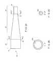
- FIG. 3Ais a side view of one embodiment of a catheter with a conical conduit.
- FIG. 3Bis an enlarged view of a notch and a distal appendage of the catheter of FIG. 3A .
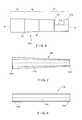
- FIG. 4Ais a side view of one embodiment of the conduit of FIG. 3A produced by extrusion.
- FIG. 4Bis a cross-section of the conduit of FIG. 4A taken along line 4 - 4 ′.
- FIG. 4Cis a cross-section of the conduit of FIG. 4A taken along line 4 ′′- 4 ′′′.
- FIG. 5Ais a side view of one embodiment of a catheter with a conduit having a cylindrical proximal section, a frusto-conical middle section, and a cylindrical distal section.
- FIG. 5Bis a cross-section of the conduit of FIG. 5A taken along line 5 - 5 ′.
- FIG. 5Cis a cross-section of the conduit of FIG. 5A taken along line 5 ′′- 5 ′′′.
- FIG. 5Dis an enlarged view of a notch and a distal appendage of the catheter of FIG. 5A .
- FIG. 6is a stylized side view of one embodiment of the conduit of FIG. 5A produced by extrusion.
- FIG. 7is a section taken along the length of one embodiment of a conical conduit.
- FIG. 8is a section taken along the length of a cylindrical conduit.
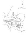
- FIG. 9is a view of one embodiment of a catheter placed within a vessel.
- FIG. 10Ais a side view of one embodiment of a connector tube.
- FIG. 10Bis a cross-section of the connector tube of FIG. 10A taken along line 10 - 10 ′.
- FIG. 11is a graph showing a comparison of flow rate data on existing catheter designs.
- FIG. 12is a sectional view along the length of one embodiment of a conduit.
- FIG. 13is a view of one embodiment of a hub assembly.
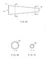
- FIG. 14Ais a side view of one embodiment of a tip configuration.
- FIG. 14Bis a top view of the embodiment of FIG. 14A which has been rotated 90 degrees.
- the present inventionrelates to catheters designed for high flow rates and to methods for positioning and making such catheters.
- the present inventionminimizes the pressure drop across the length of a catheter, minimizes the shear imparted to blood cells traveling through it, and, thus, maximizes the flow rate through it.
- the designs and methods of the present inventionapply equally to single lumen, double lumen, and multiple lumen embodiments. Moreover, the designs and methods of the present invention apply equally to all situations where flow rate (or any other similar measure) through a conduit needs to be increased and/or maximized.
- the present inventionprovides designs for a tip configuration which minimize the occurrence of this problem.
- any section of a conventional catheterbecomes kinked, the effective cross sectional area of at least one of the lumens is reduced and a reduction in flow rate through the catheter occurs.
- Kinkingusually occurs in a tunneled section of a conventional catheter which follows a curved path between the venotomy and the catheter's percutaneous exit site.
- Kinking of conventional cathetersis a problem because many of these catheters minimize wall thickness in order to maximize the lumen size (to, for example, attain a proper flow rate) while maintaining acceptable catheter french size (to, for example, allow the catheter to be placed comfortably into a patient).
- the present inventionprovides designs for a catheter's internal geometry as well as a catheter's wall thickness in order to achieve high flow rates without compromising effective clinical french size and in order to reduce the tendency of the catheter to kink.
- flow rateis reduced if the septum, or divider, that separates the lumen is too flexible.
- the septumdeflects in the proximal portion of the catheter under the flow pressure differential created by the relatively high positive pressure in the discharge (venous) leg/lumen and the relatively low negative pressure created in the intake (arterial) leg/lumen. The deflection restricts flow.
- the present inventionprovides for optimization of internal divider thickness in order to minimize septum flexibility under a pressure differential without compromising lumen cross-sectional area within the constraint of effective clinical french size.
- the present inventionprovides new catheter designs that maximize flow rate through catheters according to three principles: (1) maximizing the catheter's internal volume to surface area ratio, (2) minimizing the potential for a suction lumen entrance to become suctioned against a vessel wall and, (3) minimizing the potential for kinking of the catheter shaft without adding wire reinforcement.
- Increasing lumen sizeis one way to reduce R and generally has been explored.
- Catheters currently in useincreased lumen size, but only within the constraint of an acceptable french size.
- the present inventionmoves beyond simply large lumens and further reduces the catheter's overall resistance to flow.
- Frictionis the source of R.
- the two major sources of frictionarc the viscosity of the blood (i.e., friction generated as cells and molecules move in relation to each other) and the friction imparted by the walls of the catheter defining the lumen on the flow of blood. While varying blood viscosity generally is not an option, catheters of the present invention are designed so that the frictional effects of the catheter wall on the flow of blood are minimized, or at least reduced, over known designs.
- the graphshows Q as a function of .DELTA.P for two existing dialysis catheters (Medcomp's “Hemocath” and Quinton's “Perm Cath”).
- the slope of the curvemeasures each device's R (shallower slope indicates less resistance).
- These cathetershave essentially the same lumen cross-sectional areas. Both are silicone catheters. The primary difference between them is that the Perm Cath has two circular lumens and the Hemocath has one crescent shaped intake lumen and one circular lumen. The surface area of the intake lumen of the Hemocath is 35% greater than that of the Perm Cath. The cross-sectional areas and volumes of the lumens within these two catheter shafts are equal.
- the cross-sectional areas of the lumensare constant along their length for both catheters.
- the Perm Cathhas a larger lumen volume to lumen surface area ratio than does Hemocath.
- the resistance to flow R, as indicated by the slope of the curves,is approximately 20% less for the Perm Cath.
- Embodiments of catheters of the present inventionhave lumens which grow in cross-sectional area along the length of the catheter conduit and through the hub and extension tube assemblies.
- embodiments of catheters of the present inventionmaximize the ratio of lumen volume to lumen surface area. Consequently, R is reduced and Q, flow rate, is increased.
- the increasing cross-sectional areafurther maximizes the ratio of lumen volume to lumen surface area regardless of whether the lumen is circular, semicircular, or non-circular.
- a generally conical catheter conduit 100tapers along its entire length from a proximal end 11 to a distal end 15 ( FIG. 1A ).
- a catheter conduit 102is not a simple cylindrical shape, but is instead comprised of a frusto-conical middle section 20 bounded proximally at a first point 26 by a relatively large-diameter cylindrical proximal section 22 having a proximal end 21 and distally at a second point 28 by a relatively small-diameter cylindrical distal section 24 having a distal end 25 ( FIG. 2A ).
- the cross-sectional area of the lumen 500 , 502 taken along line 1 - 1 ′ or 2 - 2 ′is larger than the cross-sectional area of the lumen 500 , 502 taken along line 1 ′′- 1 ′′′ or 2 ′′- 2 ′′′ ( FIGS. 1B, 1C and FIGS. 2B, 2C , respectively).
- a catheter conduit with any cross-sectional lumen area that increases or maximizes the lumen volume to lumen surface area ratiois a useful catheter design of the present invention.
- a conduit 104is generally conical and tapered.
- the conduit 104is substantially smooth and continuous with no holes, openings, apertures, roughness, or indentations over substantially all of its length. The entire length of the conduit 104 is 28 cm.
- the proximal end 31couples to a hub 900 and a distal end 35 is immediately proximal to a notch 200 .
- the conduit 104comprises a width of 16 F outer diameter at the proximal 31 and a width of 13 F outer diameter at the distal end 35 .
- the conduit 104has a constant taper along its length from the proximal end 31 to the distal end 35 .
- the conduit 104extends beyond the distal end 35 to a notch 200 , distal appendage 202 , and, then, the physical end of the conduit 37 .
- the constant tapermay extend distally beyond the distal end, for example, to the physical end of the conduit.
- FIG. 4Ashows a stylized side view of the embodiment of the conduit 104 , excluding the portion of the conduit 104 which is distal to the distal end 35 .
- the cross-section of the proximal end 31 taken along line 4 - 4 ′has a larger outer diameter french size ( FIG. 4B ) than the cross-section of the distal end 35 taken along line 4 ′′- 4 ′′′ ( FIG. 4C ).
- the wall 400 at the proximal end 31is thicker than the wall 402 at the distal end 35 .
- the embodimentis shown with an internal divider 300 , 302 that divides the internal space of the conduit 104 into two lumen 504 , 506 .
- Each of these two lumen 504 , 506connect with a corresponding connecting tube 600 , 602 through the hub 900 .
- the hubcontains voids that link each of the lumens 504 , 506 to one of the connecting tubes 600 , 602 .
- a catheter conduit of the present inventionneed not have these exact measurements.
- Those skilled in the artare capable of constructing catheters of designs according to the present invention in any form suitable for a particular use. The skilled artisan need only apply the general principles of the present invention to a particular situation.
- outer diameterrefers to the diameter of a conduit as measured from outermost point of an outer wall to outermost point of an outer wall
- widthrefers to the diameter of a conduit as measured from innermost point of an outer wall to an innermost point of an outer wall
- heightrefers to a radius of a conduit as measured from an internal divider, and in a perpendicular orientation to the internal divider, to the innermost point of an outer wall
- internal dividerrefers to the thickness of an internal divider
- outer wallrefers to the thickness of an outer wall
- the distal sectionrefers to a portion of the conduit that is generally towards the tip of the conduit
- proximal sectionrefers to a portion of the conduit that is generally towards the hub.
- Table 1is useful to calculate lumen volumes, lumen
- a conduit 106has a cylindrical proximal section 32 extending from a first point 36 to a proximal end 41 which is coupled to a hub 904 , a frusto-conical middle section 30 , and a cylindrical distal section 34 extending from a second point 38 to a distal end 45 , notch 210 , distal appendage 212 , and, finally, the physical end of the conduit 47 .
- the entire length of the conduit 106is 28 cm and comprises a width of 15 F outer diameter at the proximal end 41 and a width of 13 F outer diameter at the distal end 45 .
- Sections of the conduit 106 taken along lines 5 - 5 ′ and 5 ′′- 5 ′′′reveal that the more proximal locus ( 5 - 5 ′, FIG. 5B ) has a thicker wall 410 and a thicker internal divider 310 than the more distal locus ( 5 ′′- 5 ′′′, FIG. 5C ) with a wall 412 and an internal divider 312 .
- the internal divider 310 , 312divides the internal space of the conduit 106 into two lumens 508 , 510 . Each of these two lumens 508 , 510 connect with a corresponding connecting tube 610 , 612 through the hub 904 .
- the hubcontains voids that link each of the lumens 508 , 510 to one of the connecting tubes 600 , 602 .
- a catheter conduit of the present inventionneed not have these exact measurements.
- Those skilled in the artare capable of constructing catheter designs according to the present invention in any form suitable for a particular use. The skilled artisan need only apply the general principles of the present invention to a particular situation.
- outer diameterrefers to the diameter of a conduit as measured from outermost point of an outer wall to outermost point of an outer wall
- widthrefers to the diameter of a conduit as measured from innermost point of an outer wall to innermost point of an outer wall
- heightrefers to the radius of a conduit as measured from an internal divider, and in a perpendicular orientation to the internal divider, to the innermost point of an outer wall
- internal dividerrefers to the thickness of an internal divider
- outer wallrefers to the thickness of an outer wall.
- proximal section lengthrefers to the length of a proximal section as measured from a proximal end to a first point
- middle section lengthrefers to the length of a middle section as measured from a first point to a second point
- distal section lengthrefers to the length of a distal section as measured from a second point to a distal end.
- Tables 2 and 3are useful to calculate lumen volumes, lumen surface areas, and other physical attributes of the depicted cylindrical/frusto-conical/cylindrical conduit design.
- Catheter designs of the present inventionprovide for tip designs of a catheter that minimize the possibility of restricted flow into the catheter due to contact between a catheter and a vessel.
- a tip configurationincludes a “fin-shaped” distal appendage 202 between a notch 200 and the physical end of the conduit 37 .
- FIGS. 5A and 5Danother embodiment of the invention is shown with another tip configuration. This embodiment also includes a “trapezoidal” distal appendage 212 between a notch 210 and the physical end of the conduit 47 .
- FIG. 9shows another embodiment of the invention with a tip configuration including a distal appendage 222 between a notch 220 and the physical end of the conduit 57 that is positioned against a vessel wall. Note that the distal appendage 222 of the invention prevents the catheter inlet from coming into direct contact with the vessel, reducing the likelihood that the vessel will impede flow into the catheter.
- the tip configurationcomprises an internal divider which is attached to an inside surface of a lumen wall (e.g., an intake lumen) distal of a notch.
- a lumen walle.g., an intake lumen
- This arrangementaccomplishes two things: (1) it closes off the dead lumen space distal of the notch and (2) it expands the cross-sectional area of a second lumen (e.g., a discharge lumen) distal of the notch.
- FIGS. 14A and 14Banother embodiment of a tip configuration does not have a notch or a distal appendage.
- the tipencloses two lumens 522 , 524 defined by an internal divider 322 which terminate at openings at the distal end 65 and at the physical end of the conduit 67 , respectively.
- Holes 69 , 69 ′ in the wall of the conduit immediately proximal to the distal end 65communicate with the lumen 522 .
- the holes 69 , 69 ′are useful, for example, as an alternative fluid intake location if the distal end 65 becomes suctioned against a vessel wall.
- Alternative embodimentsmay have multiple holes positioned immediately proximal to the distal end of a conduit.
- FIGS. 5B and 5Cshow cross-sections of one embodiment of a conduit 106 at points 5 - 5 ′ (towards the proximal end 41 of the conduit 106 ) and 5 ′′- 5 ′′′ (towards the distal end 45 of the conduit 106 ), respectively.
- a wall 410 of the conduit 106 at point 5 - 5 ′ ( FIG. 5B )is thicker than a more distally located wall 412 of the conduit 106 at point 5 ′′- 5 ′′ ( FIG. 5C ).
- the wall of the conduit 106thins in a distal direction along its length.
- This change in thickness of the wallhas two advantages. First a significant increase in the wall thickness in a proximal section reduces the conduit's tendency to kink when curved. Second, the reduced thickness in a distal section allows the lumen cross sectional area to be increased.
- other embodiments of the inventionsuch as catheters with conduits conical along their length from a hub to an opening or to the conduit end, may also have this change in wall thickness from proximal and to distal end.
- a section of conduit 112distal to a venotomy 150 , hangs in a relatively straight fashion inside a vessel, and that a section of conduit 112 , proximal to the venotomy 150 (within the tunnel), is sharply curved.
- the tunnelis the path within the body that a catheter takes, such as, from a point of entry into the body, through an area between the skin and the underlying facia layer, to a point of entry into a vessel.
- Cuffs 910 , 912assist with proper placement and retention of the catheter.
- the physician or other device operatorinserts the catheter into the body at the point of entry, tunnels through the body tissue to the site of a breach in a vessel wall, and advances the catheter through the breach such that at least a portion of the catheter is positioned within the vessel.
- a catheteris inserted into and through a portion of the Internal Jugular Vein.
- a catheter tipis positioned at the Superior Vena Cava and/or the right atrial junction.
- a catheter of the present inventionis useful in any vessel that accommodates the size of the catheter (e.g., inserting the catheter into and through a portion of the femoral vein and positioning a tip of the catheter in the Vena Cava).
- the thicker wall of this embodiment of the inventionallows a more acute curvature of the conduit 112 without kinking than does a conventional catheter.
- the physician or other device operatorhas more options when selecting the tunnel path than with conventional catheters because the catheter of this embodiment of the invention is capable of a greater range of motion than conventional catheters.
- the physician or other device operatorcan take into account other considerations such as patient comfort, appearance, and the presence of other devices when positioning the device.
- FIG. 9shows this embodiment of the catheter with two connector tubes 620 , 622 .
- Each connecting tube 620 , 622has a clamp 720 , 722 and a Luer fitting 820 , 822 which allow the dialysis procedure to be undertaken efficiently.
- At least one of these connecting tubes 620 , 622is connected to a dialysis pump which assists in moving blood through dialysis machinery.
- the connecting tubes 620 , 622also connect with a corresponding lumen through the hub 908 .
- the thicker conduit wall of this embodimentis more resistant to collapse from the suction of the dialysis pump.
- an internal divider 310 of a conduit 106 at one locusis thicker than a more distally located internal divider 312 of the conduit 106 at a second locus ( FIG. 5C ).
- the internal divider within the conduit 106thins in a distal direction along its length. Thickness of the internal divider is tapered so that it is thicker in a section of conduit closer to the proximal end 41 than it is in a section of conduit closer to the distal end 45 . This change in thickness may be accomplished without reducing the cross-section of the lumen and thus restricting flow.
- the added thicknessenables the internal divider in the proximal section to remain fixed in position when exposed to high differential pressures exerted in this region during dialysis or other procedures.
- catheters with conduits conical along their length from a hub to an opening or to the conduit endmay also have this change in internal divider thickness from proximal end to distal end.
- One embodiment of the present inventionprovides catheter designs with conical or generally conical conduits that have the same desirable features as cylindrical shafts. For example, often, during placement, a catheter is twisted. A round cross-section conduit may be twisted in a breach in a vessel without enlarging the breach. In contrast, a non-round cross-section conduit enlarges the breach when twisted, preventing the breach from sealing around the conduit properly.
- catheters of the invention with conical or generally conical conduitshave other advantages that purely cylindrical shafts cannot achieve.
- higher flow ratesmay be achieved because larger lumen volumes may be designed into a proximal section of conduit (i.e., a section of conduit adjacent to a hub).
- thicker wallsmay be designed into a proximal section of the conduit which reduces the tendency of the conduit to kink.
- the final size of the breach in a vesselis determined by a peelable sheath. The sheath normally is inserted into the breach and a catheter is subsequently inserted through the sheath. The sheath is peeled away once the catheter is inserted.
- a distal section of conduit of the present inventioni.e., a section of conduit towards the terminal end and/or tip of the catheter
- smaller sheathsmay be used (such that smaller breaches are necessary).
- conical or generally conical designsare safer than purely conical designs because, as the catheter is advanced through the breach, the increasing cross-sectional area of the conduit seals the breach.
- the site of the breachmust be manually compressed around the catheter until coagulation occurs.
- FIG. 7shows a conical conduit 108 of one embodiment of the invention.
- FIG. 8shows a cylindrical conduit 110 , equal in length to the conduit 108 of FIG. 7 .
- Each conduit 108 , 110has a lumen 516 , 518 ( FIGS. 7 and 8 , respectively).
- wall thickness 432 , 430respectively, increases from distal end to proximal end of the conduit 108 of the embodiment shown in FIG. 7 while wall thickness 442 , 440 remains constant along the length of the conduit 110 shown in FIG. 8 .
- a smaller end of the conical conduit 108has an inner diameter (i.e., measured from inner wall to inner wall) equal to that of the cylindrical conduit 110 .
- the inner diameter at the smaller end of the conical conduit 108is equal to the diameter of the cylindrical conduit 110 . 2 units in this case.
- the inner diameter of a larger end of the conical conduit 108is 3 units.
- the length of both conduits 108 , 110is 10 units.
- the lumen volume (V), surface area (SA), and ratio of volume to surface area, (V/SA)is calculated according to standard geometric principles based on the given dimensions.
- the lumen volume, surface area, and ratio of volume to surface areais 49.74 units.sup.3, 78.64 units.sup.2, and 0.63 units, respectively, for the conical conduit 108 .
- the lumen volume, surface area, and ratio of volume to surface areais 31.42 units.sup.3, 62.83 units.sup.2, and 0.50 units respectively for the cylindrical conduit 110 .
- the V/SA for the conical conduitis greater than that of the cylindrical conduit. This result will always be true if the smaller end of a conical conduit has an inner diameter equal to or greater than that of a cylindrical conduit and if the conduits are of equal length.
- Wall thickness of cylindrical conduitscannot increase without a reduction in lumen cross-sectional area and an increase in resistance to flow. Both wall thickness and cross-sectional area can increase from a distal (near the tip) to proximal (near the hub) end in a conical or generally conical conduit. A proximal section of the catheter typically is curved as it passes through the subcutaneous tunnel. A distal section of the catheter hangs straight in the Vena Cava. Wall thickness is minimized in order to maximize lumen cross sectional area and minimize venotomy size.
- the increased wall thicknessallows the catheter to have greater resistance to kinking and decreases the tendency for a catheter to kink when bent or curved. Kinking invariably restricts flow. Thus, the absence of kinking also adds to increased flow.
- Conical or generally conical cathetersare extrudable.
- a material which forms the conduitis placed in a device. This material often is heated and forced through a die. As the material is moving through the die, a pressurized gas, such as air, is introduced which forms one or more lumen. Additionally, as the material is forced through the die the extruded material is pulled from the leading end. Often the material is cooled as it is pulled.
- a pressurized gassuch as air
- this extrusion systemhas at least three variables that effect the extruded product: the manner in which the material is forced through the die (e.g., the force applied and/or the rate of extrusion), the manner in which gas is introduced (e.g., the pressure of the gas or the length of application) and the manner in which the material is pulled (e.g., the rate at which the material is pulled). If these variables are held constant over time and the extruded tube is pulled at the same rate as it is extruded, a uniform tube is produced. Mismatching the rate of extrusion and the rate of pulling and/or altering these variables over time produces a non-uniform conduit, including designs of the present invention.
- the cathetercomprises a conduit which is conical and tapered along its length from a proximal end to a distal end.
- the conduitis substantially continuous and smooth, having no openings, holes, apertures, roughness, or indentations over substantially all of its length.
- the embodimenthas an internal divider and a conduit wall which define two lumens.
- the catheteris structured such that at least one lumen is tapered along its length.
- the tapered conduit as well as the tapered lumenare substantially larger in cross-sectional area at the proximal end than the distal end.
- the proximal end of the conduitcouples with a hub.
- the hubconnects with connecting tubes on the proximal side of the hub.
- Each of the two lumensconnects with a corresponding connecting tube through the hub.
- the hubcontains voids that link each of the lumens to one of the connecting tubes.
- FIG. 3Ashows two connecting tubes 600 , 602 , each of which communicates with a different one of the lumens through a hub 900 .
- Each connecting tube 600 , 602has a clamp 700 , 702 which may be actuated to restrict or prevent flow through the connecting tubes 600 , 602 , and a Luer fitting 800 , 802 which many be used for connecting other tubing (to a dialysis pump, for example).
- a cuff 902is included for proper positioning and operation of the catheter.
- FIG. 10Ashows a side view of one embodiment of a connecting tube 630 while FIG. 10B shows a cross-sectional view of the same connecting tube 630 .
- One of the tapered lumensterminates at the distal end 35 such that it is in communication with the environment outside of the catheter via an opening at the distal end 35 and via a more distally located notch 200 in a wall of the elongated tapered conduit 104 .
- the notch 200has an area greater than the area of the transverse cross-sectional area of that lumen immediately proximal to the notch 200 .
- the other tapered lumenterminates at the physical end of the conduit 37 and opposite the connecting tubes 600 , 602 such that this lumen is in communication with the environment outside of the catheter.
- a notchcomprises a longitudinal cut in a wall of the catheter.
- a transverse cross-section of a conduitis round or oval.
- a transverse cross-section of a lumenis circular or partly circular (e.g., semi-circular).
- An outside wall at a proximal end of the conduithas a maximum thickness that tapers to a lesser thickness at a distal end of the conduit.
- An internal divider at a proximal end of the conduitis at a maximum thickness that tapers to a lesser thickness at a distal end of the conduit.
- a proximal section and/or a middle section of the conduit, closer to connecting tubes,comprises a curved portion.
- Connecting tubesare straight or curved and oriented such that they point away from a distal end of the conduit, are in parallel with a distal section, or are oriented between these two positions.
- a proximal, middle and/or distal section of the conduitis circumferentially reinforced with a fiber, a wire, a layer of material which is harder than the conduit material, and/or a layer of material which is softer than the conduit material.
- An internal divideris reinforced with a material generally stiffer than that of a wall of the conduit to minimize the tendency to deflect under pressure.
- a connector tubeis selectively removable such that the connector tube is replaceable while the catheter is positioned within the patient. At least one cuff is included on a conduit for proper placement and operation of the invention.
- a surface of a conduitis treated to affect the ability of bodily fluids (e.g., blood) to associate materials, such as biological materials, with the conduit (e.g., affect the ability of material to deposit on the surface of the conduit and/or affect the ability of materials to surround the conduit).
- bodily fluidse.g., blood
- materialssuch as biological materials
- the outside surfaceis coated with an anticoagulant such as heparin.
- heparinto treat surfaces is known in the art and is described, for example, in Riesenfeld et al., MEDICAL DEVICE TECHNOLOGY (March 1995), which is incorporated herein by reference.
- a catheterin another embodiment, comprises a conduit and an internal divider defining two lumens.
- the cathetercomprises three sections, a proximal section, a middle section, and a distal section.
- the proximal sectionis cylindrical with a larger cross-sectional area than the cylindrical distal section.
- the proximal and distal sectionsflank a frusto-conical middle section.
- At least one internal divider and walls of the three sectionsdefine the lumens.
- the sizes of the lumensgenerally are proportional to the sizes of the sections.
- the end of the proximal section of the conduiti.e., the proximal end
- the hubconnects with connecting tubes on the proximal side of the hub.
- Each of the two lumensconnects with a corresponding connecting tube through the hub.
- the hubcontains voids that link each of the lumens to one of the connecting tubes.
- FIG. 5Ashows two connecting tubes 610 , 612 , each of which communicates with a different one of the lumens through a hub 904 .
- Each connecting tube 610 , 612has a clamp 710 , 712 , which may be actuated to restrict or prevent flow through the connecting tubes 610 , 612 , and a Luer fitting 810 , 812 which may be used for connecting other tubing (to a dialysis pump, for example).
- a cuff 906is included for proper positioning and operation of the catheter.
- One of the tapered lumensterminates at the distal end 45 such that it is in communication with the environment outside of the catheter via an opening at the distal end 45 and via a more distally located notch 210 in a wall of the elongated tapered conduit 106 .
- the notch 210has an area greater than the area of the transverse cross-sectional area of that lumen immediately proximal to the notch 210 .
- the other tapered lumenterminates at the physical end of the conduit 47 and opposite the connecting tubes 610 , 612 such that this lumen is in communication with the environment outside of the catheter.
- a notchcomprises a longitudinal cut in a wall of a conduit.
- a transverse cross-section of a connecting tubeis round or oval.
- a transverse cross-section of a lumenis circular or partly circular (e.g., semi-circular).
- An outside wall at a proximal end of a conduithas a maximum thickness and has a lesser thickness at a distal end of the conduit.
- An internal divider at a proximal end of a conduitis at a maximum thickness that tapers to a lesser thickness at the distal end of the conduit.
- a proximal section and/or a middle section of the conduit, closer to connecting tubes,comprises a curved portion.
- Connecting tubesare straight or curved and oriented such that they point away from a distal terminating end of the conduit, are in parallel with a distal section, or are oriented between these two positions.
- a proximal, middle, and/or distal section of a conduitis circumferentially reinforced with a fiber, a wire, a layer of material which is harder than the conduit material, and/or a layer of material which is softer than the conduit material.
- An internal divideris reinforced with a material generally stiffer than that of a wall of a conduit to minimize the tendency to deflect under pressure.
- a connector tubeis selectively removable such that the connector tube is replaceable while the catheter is positioned within the patient. At least one cuff is included on a conduit for proper placement and operation of the invention.
- a surface of a conduitis treated to affect the ability of bodily fluids (e.g., blood) to associate materials, such as biological materials, with the conduit (e.g., affect the ability of material to deposit on the surface of the conduit and/or affect the ability of materials to surround the conduit).
- bodily fluidse.g., blood
- materialssuch as biological materials
- the outside surfaceis coated with an anticoagulant such as heparin.
- heparinto treat surfaces is known in the art and is described, for example, in Riesenfeld et al., MEDICAL DEVICE TECHNOLOGY (March 1995), which is incorporated herein by reference.
- another embodiment of the inventionhas a hub 914 and flexible, generally elongated conduit 108 defining at least one lumen 518 , 520 .
- the conduit 108has a proximal end 71 which is coupled to the hub 914 . From the proximal end 71 , the conduit 108 extends distally to a first point 76 . The proximal end 71 and the first point 76 define a cylindrical proximal section 72 of the conduit 108 . From the first point 76 , the conduit 108 extends to a second point 78 . The first point 76 and the second point 78 define a middle section 70 .
- the middle section 70has a frusto-conical shape with a larger cross-sectional area at the first point 76 than at the second point 78 .
- the conduit 108extends to a distal end 75 having an opening.
- the openingcommunicates with at least one lumen 518 , 520 .
- the second point 78 and the distal end 75define a cylindrical distal section 74 .
- the proximal section 72has a constant cross-sectional area along its length which is the same as the cross-sectional area at the first point 76 .
- the distal section 74has a constant cross-sectional area which is the same as the cross-sectional area at the second point 78 .
- the conduit wall of the distal section 75has a constant thickness T.sub.1 along its length. This thickness T.sub.1 increases proximally, through the middle section 70 , to a larger thickness T.sub.2 at the first point 76 . Thus, the thickness of the conduit wall T.sub.2 at the first point 76 is greater than the thickness of the conduit wall T.sub.1 at the second point 78 .
- the conduit wall of the proximal section 72has a constant thickness T.sub.2 along its length which is the same thickness T.sub.2 as at the first point 76 .
- At least one of the lumens 518 , 520has a constant inner diameter A.sub.1 measured from the internal divider to the wall along the length of the distal section 74 .
- This inner diameter A.sub.1grows proximally along the length of the middle section 70 to the first point 76 where it reaches an inner diameter of A.sub.2.
- the inner diameter of the lumen A.sub.2remains constant along the length of the proximal section 72 and is the same inner diameter A.sub.2 as that at the first point 76 .
- the inner diameter A.sub.2 at the first point 76is larger than the inner diameter A.sub.1 at the second point 78 .
- Simple geometric principlescan be used to convert inner diameters to cross-sectional areas, depending upon the shape of the lumen 518 , 520 cross-section.
- a cross-sectional area calculated from A.sub.2is larger than a cross-sectional area calculated from A.sub.1.
- the cross-sectional area of each lumen 518 , 520also increases correspondingly.
- the conduit 108couples to the hub 914 such that at least one of the lumens 518 , 520 communicates with a void within the hub 914 .
- each lumen 518 , 520communicates with a different void.
- On the side of the hub 914 opposite from the conduit 108at least one, and preferably two, connecting tubes 630 , 632 connect with each void in the hub 914 .
- each of the two lumens 518 , 520are in communication with each of the two connecting tubes 630 , 632 through voids in hub 914 .
- Each of the connecting tubes 630 , 632have Luer fittings 830 , 832 on the end to connect to other tubing and/or devices (such as a dialysis pump) and have a clamp 730 , 732 which can be actuated to restrict or prevent flow through the particular connecting tube 630 , 632 .
- a cuff(not shown in this embodiment but similar to cuff 906 of FIG. 5A ) is provided around the outside of the conduit 108 .
- the cuffis a porous material which allows tissue to grow into it, thereby functioning to anchor the device within the patient.
- the cuffis placed in the middle section 70 .
- one lumen 524extends distally beyond the distal end 75 to the physical end 77 of the conduit 108 .
- an openingcommunicates with the lumen 524 .
- Two holes 69 , 69 ′are located immediately proximal to the distal end 75 which communicate with the lumen 522 .
- Tensile strengthwas determined along the length of a conduit at locations roughly equating with the proximal, middle, and distal sections of the conduit.
- Tensile strength of the proximal sectionwas determined bib clamping the conduit at about a first point which is approximately one third of a conduit length from the proximal end that couples with the hub and pulling the conduit at that point in a direction opposite from the proximal end to which a fixed clamp is attached.
- Tensile strength of the middle sectionwas determined by clamping the conduit at about the first point and about a second point which is approximately two thirds of a conduit length from the proximal end and pulling the clamps at those points apart and in opposite directions.
Landscapes
- Health & Medical Sciences (AREA)
- Life Sciences & Earth Sciences (AREA)
- Heart & Thoracic Surgery (AREA)
- Hematology (AREA)
- Public Health (AREA)
- Anesthesiology (AREA)
- Biomedical Technology (AREA)
- Engineering & Computer Science (AREA)
- Veterinary Medicine (AREA)
- Animal Behavior & Ethology (AREA)
- General Health & Medical Sciences (AREA)
- Pulmonology (AREA)
- Biophysics (AREA)
- Urology & Nephrology (AREA)
- Emergency Medicine (AREA)
- Vascular Medicine (AREA)
- Media Introduction/Drainage Providing Device (AREA)
- External Artificial Organs (AREA)
Abstract
Description
Q=.DELTA.P/Ror .DELTA.P=Q.times.R
| TABLE 1 | |
| CONICAL DESIGN CONDUIT (13-16 F/28 .+−. | |
| 1.5 CM LENGTH) | |
| SECTION OUTER OF DIAMETER INTERNAL | |
| OUTER CONDUIT (IN) WIDTH (IN) | |
| HEIGHT (IN) DIVIDER (IN) WALL (IN) DISTAL .170 .+−. . | |
| 005 .-134.+−. .005 .060 | |
| MIN .008 MIN .013 MIN PROXIMAL .210 .+−. .005 .143 | |
| MIN .068 MIN .009 MIN | |
| .021 MIN | |
| TABLE 2 | |
| CYLINDRICAL/FRUSTO-CONICAL/CYLINDRICAL | |
| DESIGN | |
| CONDUIT (13-15 F) SECTION OUTER INTERNAL OF | |
| DIAMETER DIVIDER | |
| OUTER CONDUIT (IN) WIDTH (IN) HEIGHT (IN) (IN) | |
| WALL (IN) DISTAL .170 .+−. | |
| .005 .134 .+−. .005 .065 .+−. .003 MIN .008 MIN .013 MIN | |
| PROXIMAL .197 .+−. .005 | |
| .143 MIN .068 MIN .009 MIN .021 MIN | |
| TABLE 3 |
| CYLINDRICAL/FRUSTO-CONICAL/CYLINDRICAL |
| DESIGN |
| CONDUIT SECTION LENGTHS PROXIMAL SECTION |
| MIDDLE SECTION |
| DISTAL SECTION LENGTH (CM) LENGTH (CM) LENGTH |
| (CM)16.0 MIN 5.0 .+−. |
| 1.5 16.0 MIN |
| TABLE 4 |
| TENSILE STRENGTH |
| NON-AGED | ||||
| AGED | (MEAN | |||
| (MEAN | AGED | LOAD | NON-AGED | |
| LOAD IN | STANDARD | IN | STANDARD | |
| SECTION | POUNDS) | DEVIATION | POUNDS) | DEVIATION |
| PROXIMAL | 31.77 | 1.40 | 30.52 | 0.86 |
| MIDDLE | 28.51 | 0.97 | 26.91 | 0.86 |
| DISTAL | 17.02 | 0.76 | 14.94 | 1.36 |
Claims (28)
Priority Applications (3)
| Application Number | Priority Date | Filing Date | Title |
|---|---|---|---|
| US13/971,879US10105477B2 (en) | 1998-02-24 | 2013-08-21 | High flow rate dialysis catheters and related methods |
| US15/823,101US10195331B2 (en) | 1998-02-24 | 2017-11-27 | High flow rate dialysis catheters and related methods |
| US16/243,181US20190143022A1 (en) | 1998-02-24 | 2019-01-09 | High Flow Rate Dialysis Catheters and Related Methods |
Applications Claiming Priority (6)
| Application Number | Priority Date | Filing Date | Title |
|---|---|---|---|
| US7572498P | 1998-02-24 | 1998-02-24 | |
| US09/256,421US6280423B1 (en) | 1998-02-24 | 1999-02-23 | High flow rate dialysis catheters and related methods |
| US09/859,090US6595966B2 (en) | 1998-02-24 | 2001-05-16 | High flow rate dialysis catheters and related methods |
| US10/420,277US7410602B2 (en) | 1998-02-24 | 2003-04-22 | High flow rate dialysis catheters and related methods |
| US12/166,962US8540663B2 (en) | 1998-02-24 | 2008-07-02 | High flow rate dialysis catheters and related methods |
| US13/971,879US10105477B2 (en) | 1998-02-24 | 2013-08-21 | High flow rate dialysis catheters and related methods |
Related Parent Applications (1)
| Application Number | Title | Priority Date | Filing Date |
|---|---|---|---|
| US12/166,962ContinuationUS8540663B2 (en) | 1998-02-24 | 2008-07-02 | High flow rate dialysis catheters and related methods |
Related Child Applications (1)
| Application Number | Title | Priority Date | Filing Date |
|---|---|---|---|
| US15/823,101ContinuationUS10195331B2 (en) | 1998-02-24 | 2017-11-27 | High flow rate dialysis catheters and related methods |
Publications (2)
| Publication Number | Publication Date |
|---|---|
| US20130338640A1 US20130338640A1 (en) | 2013-12-19 |
| US10105477B2true US10105477B2 (en) | 2018-10-23 |
Family
ID=22127600
Family Applications (7)
| Application Number | Title | Priority Date | Filing Date |
|---|---|---|---|
| US09/256,421Expired - LifetimeUS6280423B1 (en) | 1998-02-24 | 1999-02-23 | High flow rate dialysis catheters and related methods |
| US09/859,090Expired - LifetimeUS6595966B2 (en) | 1998-02-24 | 2001-05-16 | High flow rate dialysis catheters and related methods |
| US10/420,277Expired - Fee RelatedUS7410602B2 (en) | 1998-02-24 | 2003-04-22 | High flow rate dialysis catheters and related methods |
| US12/166,962Expired - Fee RelatedUS8540663B2 (en) | 1998-02-24 | 2008-07-02 | High flow rate dialysis catheters and related methods |
| US13/971,879Expired - Fee RelatedUS10105477B2 (en) | 1998-02-24 | 2013-08-21 | High flow rate dialysis catheters and related methods |
| US15/823,101Expired - Fee RelatedUS10195331B2 (en) | 1998-02-24 | 2017-11-27 | High flow rate dialysis catheters and related methods |
| US16/243,181AbandonedUS20190143022A1 (en) | 1998-02-24 | 2019-01-09 | High Flow Rate Dialysis Catheters and Related Methods |
Family Applications Before (4)
| Application Number | Title | Priority Date | Filing Date |
|---|---|---|---|
| US09/256,421Expired - LifetimeUS6280423B1 (en) | 1998-02-24 | 1999-02-23 | High flow rate dialysis catheters and related methods |
| US09/859,090Expired - LifetimeUS6595966B2 (en) | 1998-02-24 | 2001-05-16 | High flow rate dialysis catheters and related methods |
| US10/420,277Expired - Fee RelatedUS7410602B2 (en) | 1998-02-24 | 2003-04-22 | High flow rate dialysis catheters and related methods |
| US12/166,962Expired - Fee RelatedUS8540663B2 (en) | 1998-02-24 | 2008-07-02 | High flow rate dialysis catheters and related methods |
Family Applications After (2)
| Application Number | Title | Priority Date | Filing Date |
|---|---|---|---|
| US15/823,101Expired - Fee RelatedUS10195331B2 (en) | 1998-02-24 | 2017-11-27 | High flow rate dialysis catheters and related methods |
| US16/243,181AbandonedUS20190143022A1 (en) | 1998-02-24 | 2019-01-09 | High Flow Rate Dialysis Catheters and Related Methods |
Country Status (7)
| Country | Link |
|---|---|
| US (7) | US6280423B1 (en) |
| EP (1) | EP1056501B1 (en) |
| JP (1) | JP4612186B2 (en) |
| AU (1) | AU733053C (en) |
| CA (2) | CA2320377C (en) |
| DE (1) | DE69928376T2 (en) |
| WO (1) | WO1999042156A1 (en) |
Families Citing this family (163)
| Publication number | Priority date | Publication date | Assignee | Title |
|---|---|---|---|---|
| US6889082B2 (en) | 1997-10-09 | 2005-05-03 | Orqis Medical Corporation | Implantable heart assist system and method of applying same |
| US6610004B2 (en) | 1997-10-09 | 2003-08-26 | Orqis Medical Corporation | Implantable heart assist system and method of applying same |
| US6295990B1 (en)* | 1998-02-03 | 2001-10-02 | Salient Interventional Systems, Inc. | Methods and systems for treating ischemia |
| JP4612186B2 (en)* | 1998-02-24 | 2011-01-12 | ナビリスト メディカル, インコーポレイテッド | High flow dialysis catheter and related methods |
| US6786884B1 (en) | 1999-10-29 | 2004-09-07 | Bard Access Systems, Inc. | Bolus tip design for a multi-lumen catheter |
| US6637435B2 (en)* | 1999-12-07 | 2003-10-28 | Cook Incorporated | Percutaneous dilational device |
| US6497676B1 (en) | 2000-02-10 | 2002-12-24 | Baxter International | Method and apparatus for monitoring and controlling peritoneal dialysis therapy |
| US6482169B1 (en)* | 2000-06-08 | 2002-11-19 | William G. Kuhle | Double-lumen catheter |
| US6976973B1 (en) | 2000-10-12 | 2005-12-20 | Baxter International Inc. | Peritoneal dialysis catheters |
| US7077829B2 (en) | 2001-01-09 | 2006-07-18 | Rex Medical, L.P. | Dialysis catheter |
| US6858019B2 (en)* | 2001-01-09 | 2005-02-22 | Rex Medical, L.P. | Dialysis catheter and methods of insertion |
| US7097635B2 (en)* | 2001-01-09 | 2006-08-29 | Rex Medical, L.P. | Guidewire retrieval member for catheter insertion |
| US6986752B2 (en)* | 2001-01-09 | 2006-01-17 | Rex Medical, Lp | Peritoneal dialysis catheter and insertion method |
| US8323228B2 (en) | 2007-04-12 | 2012-12-04 | Rex Medical L.P. | Dialysis catheter |
| US7011645B2 (en) | 2001-01-09 | 2006-03-14 | Rex Medical, L.P. | Dialysis catheter |
| US20060183973A1 (en)* | 2001-01-12 | 2006-08-17 | Kamrava Michael M | Endoscopic devices and method of use |
| US6623422B2 (en)* | 2001-01-12 | 2003-09-23 | Napoli, Llc | Method and apparatus for assisted embryo implantation |
| US6758806B2 (en) | 2001-01-12 | 2004-07-06 | Napoli, Llc | Endoscopic devices and method of use |
| CN1313059C (en)* | 2001-01-12 | 2007-05-02 | 纳波利有限公司 | A microcatheter for endoscopic embryo transfer |
| US8465412B2 (en)* | 2001-01-12 | 2013-06-18 | Michael Levy | Uterine devices and method of use |
| US7048680B2 (en)* | 2001-06-06 | 2006-05-23 | Orqis Medical Corporation | Multilumen catheter for minimizing limb ischemia |
| US20020188167A1 (en) | 2001-06-06 | 2002-12-12 | Anthony Viole | Multilumen catheter for minimizing limb ischemia |
| DE20110121U1 (en) | 2001-06-19 | 2002-12-05 | B. Braun Melsungen Ag, 34212 Melsungen | catheter |
| WO2003011357A2 (en) | 2001-07-27 | 2003-02-13 | Saab Mark A | Medical device with adjustable epidermal tissue ingrowth cuff |
| WO2003022346A1 (en)* | 2001-09-07 | 2003-03-20 | Tsukada Medical Research Co., Ltd. | Catheter for treatment of prostatic hypertrophy |
| US7147617B2 (en)* | 2001-11-27 | 2006-12-12 | Scimed Life Systems, Inc. | Arterio-venous shunt graft |
| US7033314B2 (en)* | 2002-01-11 | 2006-04-25 | Fidelitycorp Limited | Endoscopic devices and method of use |
| US7037288B2 (en)* | 2002-01-14 | 2006-05-02 | Codman & Shurtleff, Inc. | Anti-block catheter |
| US6758836B2 (en) | 2002-02-07 | 2004-07-06 | C. R. Bard, Inc. | Split tip dialysis catheter |
| IL154391A (en)* | 2002-02-11 | 2009-05-04 | Given Imaging Ltd | Self propelled device |
| AU2003258317A1 (en)* | 2002-08-23 | 2004-03-11 | Medical Components, Inc. | Shielded tip catheter |
| US6991625B1 (en) | 2002-08-23 | 2006-01-31 | Medical Components, Inc. | Shielded tip catheter |
| US8574204B2 (en) | 2002-10-21 | 2013-11-05 | Angiodynamics, Inc. | Implantable medical device for improved placement and adherence in the body |
| US7393339B2 (en) | 2003-02-21 | 2008-07-01 | C. R. Bard, Inc. | Multi-lumen catheter with separate distal tips |
| WO2004091711A2 (en)* | 2003-04-15 | 2004-10-28 | Sda Product, Inc. | Dialysis catheter system |
| US20040210202A1 (en)* | 2003-04-17 | 2004-10-21 | Weinstein Gerald S. | Aortic cannula |
| US7195615B2 (en)* | 2003-05-14 | 2007-03-27 | Boston Scientific Scimed, Inc. | System for providing a medical device with anti-microbial properties |
| US20040243095A1 (en) | 2003-05-27 | 2004-12-02 | Shekhar Nimkar | Methods and apparatus for inserting multi-lumen spit-tip catheters into a blood vessel |
| ATE537866T1 (en)* | 2003-05-28 | 2012-01-15 | Bard Inc C R | HIGH PRESSURE CATHETER AND PRODUCTION METHOD THEREOF |
| US7322953B2 (en)* | 2003-08-04 | 2008-01-29 | Covidien Ag | Catheter device |
| WO2005018712A2 (en)* | 2003-08-20 | 2005-03-03 | Datascope Investment Corp. | Dialysis catheter with stiffner |
| US7635358B2 (en)* | 2003-10-15 | 2009-12-22 | Boston Scientific Scimed, Inc. | Medical device having anti-microbial properties and a false lumen and method of making the same |
| EP1689478A4 (en)* | 2003-11-06 | 2007-01-24 | Radius Int Lp | Catheter and method of manufacture |
| US20070073271A1 (en)* | 2003-11-15 | 2007-03-29 | Brucker Gregory G | Catheter for diagnostic imaging and therapeutic procedures |
| EP1699517B1 (en)* | 2003-12-31 | 2010-04-21 | C.R.Bard, Inc. | Reinforced multi-lumen catheter |
| US20050159696A1 (en)* | 2004-01-21 | 2005-07-21 | Steven Bernard | Tapered tubing for use in extracorporeal circuit for peripheral vein fluid removal |
| US20060100572A1 (en)* | 2004-02-12 | 2006-05-11 | Dimatteo Kristian | Dialysis catheter tip and method of manufacture |
| US20050182352A1 (en)* | 2004-02-12 | 2005-08-18 | Dimatteo Kristian | Dialysis catheter tip |
| US8992454B2 (en) | 2004-06-09 | 2015-03-31 | Bard Access Systems, Inc. | Splitable tip catheter with bioresorbable adhesive |
| US8323227B2 (en)* | 2004-07-02 | 2012-12-04 | C. R. Bard, Inc. | Tip configurations for a multi-lumen catheter |
| US20060004316A1 (en) | 2004-07-02 | 2006-01-05 | Difiore Attilio E | Reduction of recirculation in catheters |
| GB2418361A (en)* | 2004-08-13 | 2006-03-29 | Don Julian De Silva | Intravenous catheter with flow increase |
| US20060074403A1 (en)* | 2004-09-29 | 2006-04-06 | Nasser Rafiee | Curved catheter comprising a solid-walled metal tube with varying stiffness |
| US7951116B2 (en)* | 2004-11-12 | 2011-05-31 | Boston Scientific Scimed, Inc. | Selective surface modification of catheter tubing |
| US8597260B2 (en)* | 2004-12-16 | 2013-12-03 | Smiths Medical Asd, Inc. | Catheter with direction orientation |
| US7931619B2 (en) | 2005-01-04 | 2011-04-26 | C. R. Bard, Inc. | Power injection catheters |
| US9408964B2 (en)* | 2005-01-04 | 2016-08-09 | C. R. Bard, Inc. | Power injection catheters and method of injecting |
| US8100863B2 (en) | 2005-03-04 | 2012-01-24 | C. R. Bard, Inc. | Catheter assembly, catheter systems including same, and method of manufacture |
| JP5112288B2 (en)* | 2005-03-10 | 2013-01-09 | メデイカル コンポーネンツ,インコーポレーテツド | Catheter with large diameter proximal end |
| US20070016124A1 (en)* | 2005-06-23 | 2007-01-18 | Mcgraw J K | Hemodialysis catheter apparatus |
| US20070078478A1 (en)* | 2005-07-27 | 2007-04-05 | Atkins Joseph R | Catheter and tunneling device therefor |
| US20070066964A1 (en)* | 2005-07-27 | 2007-03-22 | Atkins Joseph R | Catheter and Tunneling Device Therefor |
| US8012117B2 (en)* | 2007-02-06 | 2011-09-06 | Medrad, Inc. | Miniature flexible thrombectomy catheter |
| US20070135768A1 (en)* | 2005-12-14 | 2007-06-14 | Carlsen Wayne D | Spinal and epidural regional anesthesia catheter |
| US20070244490A1 (en)* | 2006-02-22 | 2007-10-18 | Moehle Ryan T | Growth cuff removal devices and methods of use |
| DE602007004718D1 (en) | 2006-03-31 | 2010-03-25 | Bard Inc C R | Catheter with arched transition area |
| US8961491B2 (en)* | 2006-04-21 | 2015-02-24 | Bayer Medical Care Inc | Catheters and related equipment |
| US20070282306A1 (en)* | 2006-06-05 | 2007-12-06 | Twincath, Llc | Multi-lumen catheter with protected tip |
| US7654264B2 (en) | 2006-07-18 | 2010-02-02 | Nellcor Puritan Bennett Llc | Medical tube including an inflatable cuff having a notched collar |
| SE530226C2 (en)* | 2006-08-15 | 2008-04-01 | Gestamp Hardtech Ab | Bumper beam for vehicles |
| US20080051759A1 (en)* | 2006-08-24 | 2008-02-28 | Boston Scientific Scimed, Inc. | Polycarbonate polyurethane venous access devices |
| US8556950B2 (en) | 2006-08-24 | 2013-10-15 | Boston Scientific Scimed, Inc. | Sterilizable indwelling catheters |
| US8876754B2 (en)* | 2006-08-31 | 2014-11-04 | Bayer Medical Care Inc. | Catheter with filtering and sensing elements |
| US20080082079A1 (en) | 2006-09-28 | 2008-04-03 | Tyco Healthcare Group Lp | Low profile catheter assembly |
| US9168355B2 (en)* | 2006-09-29 | 2015-10-27 | Covidien Lp | Acute hemodialysis catheter assembly |
| US8562557B2 (en)* | 2007-05-25 | 2013-10-22 | Medical Components, Inc. | Small diameter dual lumen catheter |
| US20090054874A1 (en)* | 2007-08-23 | 2009-02-26 | C. R. Bard, Inc. | Multi-lumen catheter including a lumen having a variable cross sectional area |
| WO2009051967A1 (en) | 2007-10-17 | 2009-04-23 | Spire Corporation | Manufacture of split tip catheters |
| WO2009051969A1 (en)* | 2007-10-17 | 2009-04-23 | Spire Corporation | Catheters with enlarged arterial lumens |
| WO2009052506A1 (en) | 2007-10-19 | 2009-04-23 | Navilyst Medical, Inc. | Recirculation minimizing catheter |
| US8292841B2 (en) | 2007-10-26 | 2012-10-23 | C. R. Bard, Inc. | Solid-body catheter including lateral distal openings |
| US8066660B2 (en) | 2007-10-26 | 2011-11-29 | C. R. Bard, Inc. | Split-tip catheter including lateral distal openings |
| CN101918067B (en) | 2007-11-01 | 2013-04-10 | C·R·巴德股份有限公司 | Catheter assembly including three lumen tips |
| US9579485B2 (en) | 2007-11-01 | 2017-02-28 | C. R. Bard, Inc. | Catheter assembly including a multi-lumen configuration |
| US20090131919A1 (en)* | 2007-11-21 | 2009-05-21 | Christopher Davey | Implantable medical device |
| US20090259089A1 (en)* | 2008-04-10 | 2009-10-15 | Daniel Gelbart | Expandable catheter for delivery of fluids |
| US9364634B2 (en) | 2008-04-22 | 2016-06-14 | Becton, Dickinson And Company | Systems and methods for improving catheter hole array efficiency |
| US8496629B2 (en) | 2008-04-22 | 2013-07-30 | Becton, Dickinson And Company | Catheter hole having a flow breaking feature |
| US9399112B2 (en) | 2008-04-22 | 2016-07-26 | Becton, Dickinson And Company | Catheter hole having an inclined trailing edge |
| JP2009273609A (en) | 2008-05-14 | 2009-11-26 | Nippon Sherwood Medical Industries Ltd | Catheter with valve |
| US8075531B2 (en) | 2008-07-16 | 2011-12-13 | Marvao Medical Ltd. | Modular implantable medical device |
| US9005154B2 (en)* | 2008-09-26 | 2015-04-14 | Covidien Lp | Valved hemodialysis catheter |
| US8491541B2 (en)* | 2008-09-30 | 2013-07-23 | Covidien Lp | Ball-valve actuation mechanism |
| US8808345B2 (en) | 2008-12-31 | 2014-08-19 | Medtronic Ardian Luxembourg S.A.R.L. | Handle assemblies for intravascular treatment devices and associated systems and methods |
| ES2488820T3 (en)* | 2009-01-12 | 2014-08-29 | Becton Dickinson And Company | Intracranial catheters optimized for administration of convection-enhanced therapeutic agents |
| US20100228178A1 (en)* | 2009-03-06 | 2010-09-09 | Mcgraw J Kevin | Hemodialysis catheter apparatus |
| US8617116B2 (en)* | 2009-03-27 | 2013-12-31 | Marvao Medical Devices Ltd. | Deformable medical implant |
| US10272236B2 (en) | 2009-03-27 | 2019-04-30 | Marvao Medical Devices Ltd | Deformable medical implant |
| US20100256546A1 (en)* | 2009-04-03 | 2010-10-07 | Davis Scott A | Polycarbonate Polyurethane Venous Access Devices Having Enhanced Strength |
| US20100256487A1 (en)* | 2009-04-06 | 2010-10-07 | Angiodynamics, Inc. | Micro central line vascular access catheter and method of use |
| US9393382B2 (en)* | 2009-05-05 | 2016-07-19 | Robert W. Heck | High-flow tapered peripheral IV catheter with side outlets |
| JP2011050420A (en)* | 2009-08-31 | 2011-03-17 | Nippon Sherwood Medical Industries Ltd | Valved catheter |
| US20110071500A1 (en)* | 2009-09-21 | 2011-03-24 | Navilyst Medical, Inc. | Branched catheter tip |
| CA2715857A1 (en) | 2009-09-30 | 2011-03-30 | Tyco Healthcare Group Lp | Medical catheter having a design providing low recirculation and reversibility |
| US8328760B2 (en)* | 2010-01-11 | 2012-12-11 | Angiodynamics, Inc. | Occlusion resistant catheter |
| US8591450B2 (en) | 2010-06-07 | 2013-11-26 | Rex Medical L.P. | Dialysis catheter |
| BR112013003333B1 (en) | 2010-08-12 | 2021-12-28 | C.R. Bard, Inc | CATHETER SET INCLUDING DISTAL PORTION STABILITY CHARACTERISTICS |
| US10238833B2 (en) | 2010-08-12 | 2019-03-26 | C. R. Bard, Inc. | Access port and catheter assembly including catheter distal portion stability features |
| WO2012050630A1 (en)* | 2010-10-14 | 2012-04-19 | Medtronic, Inc. | Cannular device and method of manufacture |
| WO2012109462A2 (en) | 2011-02-10 | 2012-08-16 | C. R. Bard, Inc. | Multi-lumen catheter including an elliptical profile |
| US9717883B2 (en) | 2011-02-10 | 2017-08-01 | C. R. Bard, Inc. | Multi-lumen catheter with enhanced flow features |
| JP5713732B2 (en) | 2011-03-08 | 2015-05-07 | 日本コヴィディエン株式会社 | Catheter with valve |
| US9656043B2 (en) | 2011-03-08 | 2017-05-23 | Cook Medical Technologies Llc | Multi-split-tipped catheter |
| US9999746B2 (en) | 2011-03-22 | 2018-06-19 | Angiodynamics, Inc. | High flow catheters |
| US9050435B2 (en) | 2011-03-22 | 2015-06-09 | Angiodynamics, Inc. | High flow catheters |
| US9072867B2 (en) | 2011-09-30 | 2015-07-07 | Covidien Lp | Catheter with external flow channel |
| US8747343B2 (en) | 2011-09-30 | 2014-06-10 | Covidien Lp | Hemodialysis catheter with improved side opening design |
| US10070990B2 (en)* | 2011-12-08 | 2018-09-11 | Alcon Research, Ltd. | Optimized pneumatic drive lines |
| USD736916S1 (en) | 2012-01-09 | 2015-08-18 | Angiodynamics, Inc. | Dialysis catheter tip |
| US9707339B2 (en) | 2012-03-28 | 2017-07-18 | Angiodynamics, Inc. | High flow rate dual reservoir port system |
| US9713704B2 (en) | 2012-03-29 | 2017-07-25 | Bradley D. Chartrand | Port reservoir cleaning system and method |
| US9060724B2 (en) | 2012-05-30 | 2015-06-23 | Magnolia Medical Technologies, Inc. | Fluid diversion mechanism for bodily-fluid sampling |
| US9022950B2 (en) | 2012-05-30 | 2015-05-05 | Magnolia Medical Technologies, Inc. | Fluid diversion mechanism for bodily-fluid sampling |
| US10143822B2 (en) | 2012-07-05 | 2018-12-04 | Covidien Lp | Valved tip catheters |
| US9204864B2 (en) | 2012-08-01 | 2015-12-08 | Magnolia Medical Technologies, Inc. | Fluid diversion mechanism for bodily-fluid sampling |
| US9155862B2 (en) | 2012-09-28 | 2015-10-13 | Covidien Lp | Symmetrical tip acute catheter |
| EP2906269B1 (en) | 2012-10-11 | 2018-01-03 | Magnolia Medical Technologies, Inc. | System for delivering a fluid to a patient with reduced contamination |
| CN107252518B (en)* | 2012-11-13 | 2020-04-14 | 泰尔茂株式会社 | Catheter tube |
| CN109171766A (en) | 2012-11-30 | 2019-01-11 | 木兰医药技术股份有限公司 | Body fluid barrier means and the method for completely cutting off body fluid using body fluid barrier means |
| US10772548B2 (en) | 2012-12-04 | 2020-09-15 | Magnolia Medical Technologies, Inc. | Sterile bodily-fluid collection device and methods |
| CA3183294A1 (en) | 2012-12-04 | 2014-06-12 | Magnolia Medical Technologies, Inc. | Sterile bodily-fluid collection device and methods |
| US10252023B2 (en) | 2013-01-11 | 2019-04-09 | C. R. Bard, Inc. | Curved catheter and methods for making same |
| USD748252S1 (en) | 2013-02-08 | 2016-01-26 | C. R. Bard, Inc. | Multi-lumen catheter tip |
| CN105228688B (en) | 2013-03-15 | 2019-02-19 | 伊瑟拉医疗公司 | Vascular treatment devices and methods |
| US8690907B1 (en) | 2013-03-15 | 2014-04-08 | Insera Therapeutics, Inc. | Vascular treatment methods |
| US8715314B1 (en) | 2013-03-15 | 2014-05-06 | Insera Therapeutics, Inc. | Vascular treatment measurement methods |
| US8679150B1 (en) | 2013-03-15 | 2014-03-25 | Insera Therapeutics, Inc. | Shape-set textile structure based mechanical thrombectomy methods |
| EP4101492A1 (en)* | 2013-12-20 | 2022-12-14 | Coloplast A/S | An intermittent urinary catheter |
| KR102211335B1 (en) | 2013-12-20 | 2021-02-03 | 마이크로벤션, 인코포레이티드 | Device delivery system |
| US10166321B2 (en) | 2014-01-09 | 2019-01-01 | Angiodynamics, Inc. | High-flow port and infusion needle systems |
| WO2016011091A1 (en) | 2014-07-14 | 2016-01-21 | C. R. Bard, Inc. | Apparatuses, systems, and methods for inserting split tip catheters having enhanced stiffening and guiding features |
| US9687269B2 (en) | 2014-10-24 | 2017-06-27 | Theresa Ann Parent | Hemodialysis double lumen needle angio catheter |
| WO2016201406A1 (en) | 2015-06-12 | 2016-12-15 | Bullington Gregory J | Devices and methods for syringe-based fluid transfer for bodily-fluid sampling |
| US20170007451A1 (en)* | 2015-07-08 | 2017-01-12 | Michael Jerome Designs, LLC | Cataract phacoemulsification tip |
| US10166144B2 (en) | 2015-07-08 | 2019-01-01 | Michael Jerome Designs, LLC | Cataract posterior/wedge chopper |
| US10010282B2 (en)* | 2015-07-24 | 2018-07-03 | Kurin, Inc. | Blood sample optimization system and blood contaminant sequestration device and method |
| WO2017019900A1 (en)* | 2015-07-28 | 2017-02-02 | Andrew Ho, M.D., Inc. | Guide catheter extension device and methods of use for cardiology procedures |
| EP4249119A3 (en) | 2015-09-03 | 2023-11-29 | Magnolia Medical Technologies, Inc. | System for maintaining sterility of a specimen container |
| CN108697423A (en) | 2016-02-16 | 2018-10-23 | 伊瑟拉医疗公司 | The part flow arrangement of suction unit and anchoring |
| US10610668B2 (en) | 2016-10-05 | 2020-04-07 | Becton, Dickinson And Company | Catheter with an asymmetric tip |
| EP3524195A4 (en)* | 2016-10-06 | 2020-05-06 | Kitazato Corporation | TOOL FOR TRANSPLANTATION OF LIVING CELLS |
| EP3777684B1 (en) | 2016-12-27 | 2022-06-29 | Kurin, Inc. | Blood contaminat sequestration device |
| US10827964B2 (en)* | 2017-02-10 | 2020-11-10 | Kurin, Inc. | Blood contaminant sequestration device with one-way air valve and air-permeable blood barrier with closure mechanism |
| US11617525B2 (en)* | 2017-02-10 | 2023-04-04 | Kurin, Inc. | Blood contaminant sequestration device with passive fluid control junction |
| US11179516B2 (en) | 2017-06-22 | 2021-11-23 | Baxter International Inc. | Systems and methods for incorporating patient pressure into medical fluid delivery |
| EP4555929A3 (en) | 2017-09-12 | 2025-06-25 | Magnolia Medical Technologies, Inc. | Fluid control device |
| JP7229267B2 (en) | 2017-12-07 | 2023-02-27 | マグノリア メディカル テクノロジーズ,インコーポレイテッド | Fluid control device and method of use |
| USD847864S1 (en) | 2018-01-22 | 2019-05-07 | Insera Therapeutics, Inc. | Pump |
| PL235214B1 (en)* | 2018-03-09 | 2020-06-15 | Univ Medyczny W Lublinie | Catheter for conducting continuous renal replacement therapy |
| WO2020163744A1 (en) | 2019-02-08 | 2020-08-13 | Magnolia Medical Technologies, Inc. | Devices and methods for bodily fluid collection and distribution |
| CN113784793B (en) | 2019-03-11 | 2023-09-19 | 木兰医药技术股份有限公司 | Fluid control device and method of using the same |
| IL286812B1 (en) | 2019-04-01 | 2025-08-01 | Kurin Inc | Device and system for optimizing sampling of non-aerated liquids |
| JPWO2022118714A1 (en)* | 2020-12-01 | 2022-06-09 |
Citations (147)
| Publication number | Priority date | Publication date | Assignee | Title |
|---|---|---|---|---|
| US1653819A (en) | 1926-08-07 | 1927-12-27 | Northcott Ephraim | Electrotherapeutical apparatus |
| US3094124A (en) | 1960-06-30 | 1963-06-18 | Davol Rubber Co | Arterial catheter |
| US3438375A (en) | 1966-03-18 | 1969-04-15 | Kendall & Co | Non-traumatic retention catheter |
| US3978157A (en) | 1974-02-16 | 1976-08-31 | Bayer Aktiengesellschaft | Thermoplastic compositions comprising aromatic polycarbonate urethanes |
| US4016886A (en) | 1974-11-26 | 1977-04-12 | The United States Of America As Represented By The United States Energy Research And Development Administration | Method for localizing heating in tumor tissue |
| US4054139A (en) | 1975-11-20 | 1977-10-18 | Crossley Kent B | Oligodynamic catheter |
| US4142525A (en) | 1977-03-10 | 1979-03-06 | The Kendall Company | Syringe assembly |
| US4226246A (en) | 1977-05-27 | 1980-10-07 | Carba Societe Anonyme | Apparatus for maintaining the negative potential of human, animal, and plant cells |
| US4248224A (en) | 1978-08-01 | 1981-02-03 | Jones James W | Double venous cannula |
| US4262672A (en) | 1978-01-02 | 1981-04-21 | Horst Kief | Acupuncture instrument |
| US4309994A (en) | 1980-02-25 | 1982-01-12 | Grunwald Ronald P | Cardiovascular cannula |
| US4403983A (en) | 1981-11-06 | 1983-09-13 | Shiley Incorporated | Dual lumen subclavian cannula |
| US4407943A (en) | 1976-12-16 | 1983-10-04 | Millipore Corporation | Immobilized antibody or antigen for immunoassay |
| US4423740A (en) | 1981-03-30 | 1984-01-03 | Howmedica, Inc. | Slit catheter method for measuring interstitial pressure |
| US4468224A (en) | 1982-01-28 | 1984-08-28 | Advanced Cardiovascular Systems, Inc. | System and method for catheter placement in blood vessels of a human patient |
| US4469483A (en) | 1982-08-25 | 1984-09-04 | Baxter Travenol Laboratories, Inc. | Radiopaque catheter |
| US4483688A (en) | 1980-09-22 | 1984-11-20 | Hiroshi Akiyama | Catheter |
| US4563180A (en)* | 1984-06-29 | 1986-01-07 | Raychem Corporation | High flow catheter for injecting fluids |
| US4569673A (en) | 1984-01-12 | 1986-02-11 | Battelle Development Corporation | Bacterial barrier for indwelling catheters and other medical devices |
| US4592920A (en) | 1983-05-20 | 1986-06-03 | Baxter Travenol Laboratories, Inc. | Method for the production of an antimicrobial catheter |
| US4603152A (en) | 1982-11-05 | 1986-07-29 | Baxter Travenol Laboratories, Inc. | Antimicrobial compositions |
| US4623327A (en) | 1985-02-12 | 1986-11-18 | Mahurkar Sakharam D | Method and apparatus for using dual-lumen catheters for extracorporeal treatment |
| US4769005A (en) | 1987-08-06 | 1988-09-06 | Robert Ginsburg | Selective catheter guide |
| US4804359A (en) | 1987-10-23 | 1989-02-14 | Research Medical, Inc. | Cardiovascular cannula and obturator |
| US4810963A (en) | 1984-04-03 | 1989-03-07 | Public Health Laboratory Service Board | Method for investigating the condition of a bacterial suspension through frequency profile of electrical admittance |
| US4902503A (en) | 1987-11-25 | 1990-02-20 | Unitika Ltd. | Antimicrobial latex composition |
| US4907601A (en) | 1988-06-15 | 1990-03-13 | Etama Ag | Electrotherapy arrangement |
| EP0378132A2 (en) | 1989-01-09 | 1990-07-18 | S.L. Cit Ionofor | A device for the administration of medication by iontopheresis for local - regional treatment. |
| US4944726A (en) | 1988-11-03 | 1990-07-31 | Applied Vascular Devices | Device for power injection of fluids |
| US4946793A (en) | 1986-05-09 | 1990-08-07 | Electropore, Inc. | Impedance matching for instrumentation which electrically alters vesicle membranes |
| US4999210A (en)* | 1989-01-18 | 1991-03-12 | Becton, Dickinson And Company | Anti-infective and antithrombogenic medical articles and method for their preparation |
| US5019096A (en) | 1988-02-11 | 1991-05-28 | Trustees Of Columbia University In The City Of New York | Infection-resistant compositions, medical devices and surfaces and methods for preparing and using same |
| US5019034A (en) | 1988-01-21 | 1991-05-28 | Massachusetts Institute Of Technology | Control of transport of molecules across tissue using electroporation |
| DE4000893A1 (en) | 1990-01-15 | 1991-07-18 | Bosch Gmbh Robert | Multichannel appts. for electro-simulation - provides several current circuits for patient with electrodes applying pulse signals |
| US5053023A (en)* | 1988-10-25 | 1991-10-01 | Vas-Cath Incorporated | Catheter for prolonged access |
| US5052391A (en) | 1990-10-22 | 1991-10-01 | R.F.P., Inc. | High frequency high intensity transcutaneous electrical nerve stimulator and method of treatment |
| US5059170A (en) | 1990-02-02 | 1991-10-22 | Mallinckrodt Medical, Inc. | Connection adapter for catheters |
| US5058605A (en) | 1989-02-22 | 1991-10-22 | Ceske Vysoke Uceni Technicke | Method and device for the controlled local, non-invasive application of dc pulses to human and animal tissues |
| US5098843A (en) | 1987-06-04 | 1992-03-24 | Calvin Noel M | Apparatus for the high efficiency transformation of living cells |
| US5125893A (en) | 1990-04-16 | 1992-06-30 | Dryden Gale E | Suction catheter with wall lumen for irrigation |
| US5134070A (en) | 1990-06-04 | 1992-07-28 | Casnig Dael R | Method and device for cell cultivation on electrodes |
| US5133742A (en) | 1990-06-15 | 1992-07-28 | Corvita Corporation | Crack-resistant polycarbonate urethane polymer prostheses |
| US5151231A (en) | 1990-03-19 | 1992-09-29 | Becton, Dickinson And Company | Method for making liquid crystalline tube having a point |
| US5173158A (en) | 1991-07-22 | 1992-12-22 | Schmukler Robert E | Apparatus and methods for electroporation and electrofusion |
| US5193537A (en) | 1990-06-12 | 1993-03-16 | Zmd Corporation | Method and apparatus for transcutaneous electrical cardiac pacing |
| US5205834A (en) | 1990-09-04 | 1993-04-27 | Moorehead H Robert | Two-way outdwelling slit valving of medical liquid flow through a cannula and methods |
| US5209723A (en) | 1990-01-08 | 1993-05-11 | The Curators Of The University Of Missouri | Multiple lumen catheter for hemodialysis |
| US5229431A (en) | 1990-06-15 | 1993-07-20 | Corvita Corporation | Crack-resistant polycarbonate urethane polymer prostheses and the like |
| US5249598A (en) | 1992-08-03 | 1993-10-05 | Vernay Laboratories, Inc. | Bi-directional vent and overpressure relief valve |
| US5273525A (en) | 1992-08-13 | 1993-12-28 | Btx Inc. | Injection and electroporation apparatus for drug and gene delivery |
| US5300048A (en) | 1993-05-12 | 1994-04-05 | Sabin Corporation | Flexible, highly radiopaque plastic material catheter |
| US5318563A (en) | 1992-06-04 | 1994-06-07 | Valley Forge Scientific Corporation | Bipolar RF generator |
| US5328451A (en) | 1991-08-15 | 1994-07-12 | Board Of Regents, The University Of Texas System | Iontophoretic device and method for killing bacteria and other microbes |
| US5389069A (en) | 1988-01-21 | 1995-02-14 | Massachusetts Institute Of Technology | Method and apparatus for in vivo electroporation of remote cells and tissue |
| US5403291A (en) | 1993-08-02 | 1995-04-04 | Quinton Instrument Company | Catheter with elongated side holes |
| US5403311A (en) | 1993-03-29 | 1995-04-04 | Boston Scientific Corporation | Electro-coagulation and ablation and other electrotherapeutic treatments of body tissue |
| US5405340A (en) | 1992-10-07 | 1995-04-11 | Abbott Laboratories | Threaded securing apparatus for flow connectors |
| US5425752A (en) | 1991-11-25 | 1995-06-20 | Vu'nguyen; Dung D. | Method of direct electrical myostimulation using acupuncture needles |
| US5439440A (en) | 1993-04-01 | 1995-08-08 | Genetronics, Inc. | Electroporation system with voltage control feedback for clinical applications |
| US5458625A (en) | 1994-05-04 | 1995-10-17 | Kendall; Donald E. | Transcutaneous nerve stimulation device and method for using same |
| US5458582A (en) | 1992-06-15 | 1995-10-17 | Nakao; Naomi L. | Postoperative anesthetic delivery device and associated method for the postoperative treatment of pain |
| US5509897A (en) | 1990-01-08 | 1996-04-23 | The Curators Of The University Of Missouri | Multiple lumen catheter for hemodialysis |
| US5533999A (en) | 1993-08-23 | 1996-07-09 | Refractec, Inc. | Method and apparatus for modifications of visual acuity by thermal means |
| US5536240A (en) | 1992-08-12 | 1996-07-16 | Vidamed, Inc. | Medical probe device and method |
| US5542937A (en) | 1994-06-24 | 1996-08-06 | Target Therapeutics, Inc. | Multilumen extruded catheter |
| US5569182A (en) | 1990-01-08 | 1996-10-29 | The Curators Of The University Of Missouri | Clot resistant multiple lumen catheter and method |
| US5575769A (en) | 1995-05-30 | 1996-11-19 | Vaillancourt; Vincent L. | Cannula for a slit septum and a lock arrangement therefore |
| US5575811A (en) | 1993-07-08 | 1996-11-19 | Urologix, Inc. | Benign prostatic hyperplasia treatment catheter with urethral cooling |
| WO1996039531A1 (en) | 1995-06-06 | 1996-12-12 | Massachusetts Institute Of Technology | Delivery of nucleotides into organisms by electroporation |
| US5614136A (en) | 1995-03-02 | 1997-03-25 | Scimed Life Systems, Inc. | Process to form dimensionally variable tubular members for use in catheter procedures |
| US5626146A (en) | 1992-12-18 | 1997-05-06 | British Technology Group Limited | Electrical impedance tomography |
| US5634899A (en) | 1993-08-20 | 1997-06-03 | Cortrak Medical, Inc. | Simultaneous cardiac pacing and local drug delivery method |
| US5643197A (en) | 1993-12-21 | 1997-07-01 | Angeion Corporation | Fluid cooled and perfused tip for a catheter |
| US5662913A (en) | 1991-04-10 | 1997-09-02 | Capelli; Christopher C. | Antimicrobial compositions useful for medical applications |
| US5674267A (en) | 1993-03-30 | 1997-10-07 | Centre National De La Recherche Scientifique | Electric pulse applicator using pairs of needle electrodes for the treatment of biological tissue |
| US5702359A (en) | 1995-06-06 | 1997-12-30 | Genetronics, Inc. | Needle electrodes for mediated delivery of drugs and genes |
| US5720921A (en) | 1995-03-10 | 1998-02-24 | Entremed, Inc. | Flow electroporation chamber and method |
| US5725510A (en) | 1993-05-20 | 1998-03-10 | Hartmann; Michael | Endotracheal tube |
| US5778894A (en) | 1996-04-18 | 1998-07-14 | Elizabeth Arden Co. | Method for reducing human body cellulite by treatment with pulsed electromagnetic energy |
| US5782882A (en) | 1995-11-30 | 1998-07-21 | Hewlett-Packard Company | System and method for administering transcutaneous cardiac pacing with transcutaneous electrical nerve stimulation |
| US5800414A (en) | 1996-10-18 | 1998-09-01 | Synthelabo | Catheter with flexible and elongate body |
| US5807311A (en) | 1996-11-29 | 1998-09-15 | Palestrant; Aubrey M. | Dialysis catheter having rigid and collapsible lumens and related method |
| US5810762A (en) | 1995-04-10 | 1998-09-22 | Genetronics, Inc. | Electroporation system with voltage control feedback for clinical applications |
| US5827229A (en) | 1995-05-24 | 1998-10-27 | Boston Scientific Corporation Northwest Technology Center, Inc. | Percutaneous aspiration thrombectomy catheter system |
| US5836905A (en) | 1994-06-20 | 1998-11-17 | Lemelson; Jerome H. | Apparatus and methods for gene therapy |
| US5843026A (en) | 1992-08-12 | 1998-12-01 | Vidamed, Inc. | BPH ablation method and apparatus |
| US5873849A (en) | 1997-04-24 | 1999-02-23 | Ichor Medical Systems, Inc. | Electrodes and electrode arrays for generating electroporation inducing electrical fields |
| US5879499A (en) | 1996-06-17 | 1999-03-09 | Heartport, Inc. | Method of manufacture of a multi-lumen catheter |
| US5919142A (en) | 1995-06-22 | 1999-07-06 | Btg International Limited | Electrical impedance tomography method and apparatus |
| US5928174A (en) | 1997-11-14 | 1999-07-27 | Acrymed | Wound dressing device |
| EP0935482A1 (en) | 1996-07-18 | 1999-08-18 | Bertil Persson | A method and an apparatus for treating tumoral diseases (cancer) |
| US5947889A (en) | 1995-01-17 | 1999-09-07 | Hehrlein; Christoph | Balloon catheter used to prevent re-stenosis after angioplasty and process for producing a balloon catheter |
| US5983131A (en) | 1995-08-11 | 1999-11-09 | Massachusetts Institute Of Technology | Apparatus and method for electroporation of tissue |
| US5991697A (en) | 1996-12-31 | 1999-11-23 | The Regents Of The University Of California | Method and apparatus for optical Doppler tomographic imaging of fluid flow velocity in highly scattering media |
| US5999847A (en) | 1997-10-21 | 1999-12-07 | Elstrom; John A. | Apparatus and method for delivery of surgical and therapeutic agents |
| US6001079A (en) | 1995-09-05 | 1999-12-14 | Pourchez; Thierry | Multilumen catheter, particularly for hemodialysis |
| US6009347A (en) | 1998-01-27 | 1999-12-28 | Genetronics, Inc. | Electroporation apparatus with connective electrode template |
| US6010613A (en) | 1995-12-08 | 2000-01-04 | Cyto Pulse Sciences, Inc. | Method of treating materials with pulsed electrical fields |
| US6016452A (en) | 1996-03-19 | 2000-01-18 | Kasevich; Raymond S. | Dynamic heating method and radio frequency thermal treatment |
| US6033393A (en) | 1996-12-31 | 2000-03-07 | Johnson & Johnson Medical, Inc. | Method and apparatus for overpressure protection of a catheter |
| US6041252A (en) | 1995-06-07 | 2000-03-21 | Ichor Medical Systems Inc. | Drug delivery system and method |
| WO2000020554A1 (en) | 1998-10-08 | 2000-04-13 | Astrazeneca Ab | Microfabricated cell injector |
| US6055453A (en) | 1997-08-01 | 2000-04-25 | Genetronics, Inc. | Apparatus for addressing needle array electrodes for electroporation therapy |
| US6085115A (en) | 1997-05-22 | 2000-07-04 | Massachusetts Institite Of Technology | Biopotential measurement including electroporation of tissue surface |
| US6090106A (en) | 1996-01-09 | 2000-07-18 | Gyrus Medical Limited | Electrosurgical instrument |
| US6093180A (en) | 1995-04-28 | 2000-07-25 | Medtronic, Inc. | Intraparenchymal infusion catheter system |
| US6102885A (en) | 1996-08-08 | 2000-08-15 | Bass; Lawrence S. | Device for suction-assisted lipectomy and method of using same |
| US6106521A (en) | 1996-08-16 | 2000-08-22 | United States Surgical Corporation | Apparatus for thermal treatment of tissue |
| US6109270A (en) | 1997-02-04 | 2000-08-29 | The United States Of America As Represented By The Administrator Of The National Aeronautics And Space Administration | Multimodality instrument for tissue characterization |
| US6122599A (en) | 1998-02-13 | 2000-09-19 | Mehta; Shailesh | Apparatus and method for analyzing particles |
| US6132419A (en) | 1992-05-22 | 2000-10-17 | Genetronics, Inc. | Electroporetic gene and drug therapy |
| US6159163A (en) | 1998-05-07 | 2000-12-12 | Cedars-Sinai Medical Center | System for attenuating pain during bone marrow aspiration and method |
| US6177522B1 (en) | 1997-11-07 | 2001-01-23 | Salviac Limited | Biostable polycarbonate urethane products |
| US6197846B1 (en) | 1998-06-10 | 2001-03-06 | River Valley Endodontics, P.A. | Dental root canal filling, retrofilling, and perforation repair material |
| US6200338B1 (en) | 1998-12-31 | 2001-03-13 | Ethicon, Inc. | Enhanced radiopacity of peripheral and central catheter tubing |
| US6208893B1 (en) | 1998-01-27 | 2001-03-27 | Genetronics, Inc. | Electroporation apparatus with connective electrode template |
| US6212433B1 (en) | 1998-07-28 | 2001-04-03 | Radiotherapeutics Corporation | Method for treating tumors near the surface of an organ |
| US6210402B1 (en) | 1995-11-22 | 2001-04-03 | Arthrocare Corporation | Methods for electrosurgical dermatological treatment |
| US6216034B1 (en) | 1997-08-01 | 2001-04-10 | Genetronics, Inc. | Method of programming an array of needle electrodes for electroporation therapy of tissue |
| US6219577B1 (en) | 1998-04-14 | 2001-04-17 | Global Vascular Concepts, Inc. | Iontophoresis, electroporation and combination catheters for local drug delivery to arteries and other body tissues |
| US6217566B1 (en) | 1997-10-02 | 2001-04-17 | Target Therapeutics, Inc. | Peripheral vascular delivery catheter |
| US6227200B1 (en) | 1998-09-21 | 2001-05-08 | Ballard Medical Products | Respiratory suction catheter apparatus |
| US6241702B1 (en) | 1992-08-12 | 2001-06-05 | Vidamed, Inc. | Radio frequency ablation device for treatment of the prostate |
| US6245039B1 (en) | 1998-10-05 | 2001-06-12 | Vasca, Inc. | Methods and apparatus for performing flow-through peritoneal dialysis |
| US6280423B1 (en) | 1998-02-24 | 2001-08-28 | Scimed Life Systems, Inc. | High flow rate dialysis catheters and related methods |
| US6347247B1 (en) | 1998-05-08 | 2002-02-12 | Genetronics Inc. | Electrically induced vessel vasodilation |
| US6349233B1 (en) | 1993-02-22 | 2002-02-19 | Angeion Corporation | Neuro-stimulation to control pain during cardioversion defibrillation |
| US6351674B2 (en) | 1998-11-23 | 2002-02-26 | Synaptic Corporation | Method for inducing electroanesthesia using high frequency, high intensity transcutaneous electrical nerve stimulation |
| US20020055731A1 (en) | 1997-10-24 | 2002-05-09 | Anthony Atala | Methods for promoting cell transfection in vivo |
| US20020091362A1 (en) | 1998-01-06 | 2002-07-11 | Maginot Thomas J. | Medical procedure using catheter system having removability feature |
| US6419674B1 (en) | 1996-11-27 | 2002-07-16 | Cook Vascular Incorporated | Radio frequency dilator sheath |
| US20020099323A1 (en) | 1998-07-13 | 2002-07-25 | Nagendu B. Dev | Skin and muscle-targeted gene therapy by pulsed electrical field |
| US6470211B1 (en) | 1997-06-03 | 2002-10-22 | Uab Research Foundation | Method and apparatus for treating cardiac arrhythmia |
| US6500173B2 (en) | 1992-01-07 | 2002-12-31 | Ronald A. Underwood | Methods for electrosurgical spine surgery |
| US6526320B2 (en) | 1998-11-16 | 2003-02-25 | United States Surgical Corporation | Apparatus for thermal treatment of tissue |
| US6530951B1 (en) | 1996-10-24 | 2003-03-11 | Cook Incorporated | Silver implantable medical device |
| US6605751B1 (en) | 1997-11-14 | 2003-08-12 | Acrymed | Silver-containing compositions, devices and methods for making |
| US6607529B1 (en) | 1995-06-19 | 2003-08-19 | Medtronic Vidamed, Inc. | Electrosurgical device |
| US6611706B2 (en) | 1998-11-09 | 2003-08-26 | Transpharma Ltd. | Monopolar and bipolar current application for transdermal drug delivery and analyte extraction |
| US6653091B1 (en) | 1998-09-30 | 2003-11-25 | Cyngnus, Inc. | Method and device for predicting physiological values |
| US6692493B2 (en) | 1998-02-11 | 2004-02-17 | Cosman Company, Inc. | Method for performing intraurethral radio-frequency urethral enlargement |
| US20040068241A1 (en) | 1996-06-04 | 2004-04-08 | Fischer Frank J. | Implantable medical device |
| US20040153057A1 (en) | 1998-11-20 | 2004-08-05 | Arthrocare Corporation | Electrosurgical apparatus and methods for ablating tissue |
| US20040171747A1 (en) | 1997-06-18 | 2004-09-02 | Sheng-Ping Zhong | Polycarbonate-polyurethane dispersions for thrombo-resistant coatings |
| US20050165393A1 (en) | 1996-12-31 | 2005-07-28 | Eppstein Jonathan A. | Microporation of tissue for delivery of bioactive agents |
| US20060015147A1 (en) | 1998-03-31 | 2006-01-19 | Aditus Medical Ab. | Apparatus for controlling the generation of electric fields |
| US20060052757A1 (en) | 1996-06-04 | 2006-03-09 | Vance Products Incorporated, D/B/A Cook Urological Incorporated | Implantable medical device with analgesic or anesthetic |
Family Cites Families (299)
| Publication number | Priority date | Publication date | Assignee | Title |
|---|---|---|---|---|
| US386603A (en) | 1888-07-24 | Stomach-pump | ||
| US559620A (en) | 1896-05-05 | Joseph shearer | ||
| US234388A (en)* | 1880-11-16 | Toilet-case | ||
| US256590A (en) | 1882-04-18 | Double catheter | ||
| US156430A (en)* | 1874-11-03 | Improvement in way-meters for railway-carriages | ||
| US264912A (en)* | 1882-09-26 | Table | ||
| US191775A (en) | 1877-06-12 | Improvement in syringes | ||
| US153983A (en)* | 1874-08-11 | Improvement in combined hand and stand mirrors | ||
| US51759A (en)* | 1865-12-26 | Improvement in low-water detectors | ||
| US866096A (en)* | 1907-02-18 | 1907-09-17 | Hilaire Vincent | Bottle. |
| US1211928A (en) | 1916-03-25 | 1917-01-09 | Arthur R Fisher | Colon-irrigator. |
| US2257369A (en) | 1939-10-21 | 1941-09-30 | Thomas A Davis | Catheter and drainage tube |
| US3087493A (en) | 1960-04-27 | 1963-04-30 | George W Schossow | Endotracheal tube |
| FR1285953A (en) | 1961-01-16 | 1962-03-02 | Eynard & Cie J | Improvements to surgical tubular probes |
| US3359974A (en) | 1963-10-07 | 1967-12-26 | Hassan H Khalil | Device for the thermal determination of cardiac volumetric performance |
| US3314430A (en) | 1964-04-10 | 1967-04-18 | Brunswick Corp | Sump drain catheter |
| US3394705A (en) | 1965-10-22 | 1968-07-30 | Daniel J. Abramson | Drainage balloon catheter having means for antiseptic treatment of the urethra |
| FR1508959A (en) | 1966-01-21 | 1968-01-12 | A catheter intended to allow the disobstruction of thrombosed vessels of sinuous configuration | |
| US3485234A (en) | 1966-04-13 | 1969-12-23 | Cordis Corp | Tubular products and method of making same |
| US3437088A (en) | 1966-12-01 | 1969-04-08 | Leonard J Bielinski | Apparatus for measuring motility of body organs |
| US3633579A (en) | 1967-05-24 | 1972-01-11 | Sherwood Medical Ind Inc | Catheter placement device and method |
| US3593713A (en) | 1968-07-12 | 1971-07-20 | Stanley A Bogoff | Catheter combination |
| US3612050A (en) | 1969-04-01 | 1971-10-12 | David S Sheridan | Intravascular catheters |
| US3634924A (en) | 1970-04-20 | 1972-01-18 | American Hospital Supply Corp | Method of making multilumen balloon catheter |
| US3788326A (en) | 1970-07-29 | 1974-01-29 | H Jacobs | Distally perforated catheter for use in ventilating system |
| US3726281A (en) | 1971-12-08 | 1973-04-10 | Bard Inc C R | Self-lubricating catheter |
| DE2259865A1 (en) | 1972-12-07 | 1974-06-12 | Josef Magasi | PUNCTURE CANNULA |
| GB1443828A (en) | 1973-05-14 | 1976-07-28 | Greenhalgh R M | Catheters |
| US3906954A (en) | 1973-09-14 | 1975-09-23 | Nasa | Ophthalmic liquifaction pump |
| US3828767A (en) | 1973-10-29 | 1974-08-13 | Fenton J | Angiographic and arteriographic catherters |
| US3995623A (en) | 1974-12-23 | 1976-12-07 | American Hospital Supply Corporation | Multipurpose flow-directed catheter |
| FR2297640A1 (en) | 1975-01-15 | 1976-08-13 | Rhone Poulenc Ind | Catheter for simultaneous blood withdrawal and reinjection - for treatment e.g. with oxygen outside the body using only one incision |
| US4004588A (en) | 1975-05-21 | 1977-01-25 | Wrightson Nma Limited | Apparatus for flushing ova from cows or mares |
| US4096860A (en) | 1975-10-08 | 1978-06-27 | Mclaughlin William F | Dual flow encatheter |
| US4037599A (en) | 1976-01-26 | 1977-07-26 | Raulerson James D | Continuous flow catheter device |
| US4183961A (en) | 1976-02-03 | 1980-01-15 | Shiley Incorporated | Method of oxygenating blood |
| US4182739A (en) | 1976-02-03 | 1980-01-08 | Shiley Incorporated | Blood oxygenator |
| US4134402A (en) | 1976-02-11 | 1979-01-16 | Mahurkar Sakharam D | Double lumen hemodialysis catheter |
| DE2613281C2 (en) | 1976-03-29 | 1984-12-20 | Günter van Dr.med. 4000 Düsseldorf Endert | Double lumen catheter |
| LU77252A1 (en) | 1976-05-06 | 1977-08-22 | ||
| US4069814A (en) | 1976-05-06 | 1978-01-24 | Miles Laboratories, Inc. | Double lumen cannula apparatus |
| US4138288A (en) | 1976-05-10 | 1979-02-06 | Shiley Scientific Incorporated | Method and apparatus for oxygenating and regulating the temperature of blood |
| US4065264A (en) | 1976-05-10 | 1977-12-27 | Shiley Laboratories, Inc. | Blood oxygenator with integral heat exchanger for regulating the temperature of blood in an extracorporeal circuit |
| US4100246A (en) | 1976-06-21 | 1978-07-11 | Dow Corning Corporation | Method of forming a gastrointestinal tube |
| US4138457A (en) | 1976-08-13 | 1979-02-06 | Sherwood Medical Industries Inc. | Method of making a plastic tube with plural lumens |
| USRE31873F1 (en) | 1976-09-08 | 1988-11-15 | Venous catheter device | |
| DE2703087C2 (en) | 1977-01-26 | 1984-11-29 | Günter van Dr.med. 4000 Düsseldorf Endert | Double lumen catheter |
| US4099528A (en) | 1977-02-17 | 1978-07-11 | Sorenson Research Co., Inc. | Double lumen cannula |
| US4129129A (en) | 1977-03-18 | 1978-12-12 | Sarns, Inc. | Venous return catheter and a method of using the same |
| NO139201C (en) | 1977-04-05 | 1979-01-24 | Lars Grimsrud | DEVICE FOR DIVISION OF A HOLE CANNULAL NEEDLE |
| US4173981A (en) | 1977-05-23 | 1979-11-13 | University Of Utah | Cannula for arterial and venous bypass cannulation |
| JPS5740997Y2 (en) | 1977-06-03 | 1982-09-08 | ||
| US4168703A (en) | 1977-07-18 | 1979-09-25 | Kenneth Kenigsberg | Gastroesophageal reflux diagnostic tool |
| US4144844A (en) | 1977-12-12 | 1979-03-20 | Crumpacker William H | Grazing regulator |
| US4223676A (en) | 1977-12-19 | 1980-09-23 | Cavitron Corporation | Ultrasonic aspirator |
| DE2813275A1 (en) | 1978-03-28 | 1979-10-11 | Fresenius Chem Pharm Ind | DOUBLE LUMEN CATHETER |
| US4180068A (en) | 1978-04-13 | 1979-12-25 | Motion Control, Incorporated | Bi-directional flow catheter with retractable trocar/valve structure |
| US4236520A (en) | 1978-12-04 | 1980-12-02 | Anderson Mark L | Fluid drain or injection tube for an animal's udder |
| US4248234A (en) | 1979-03-08 | 1981-02-03 | Critikon, Inc. | Catheter with variable flexural modulus and method of using same |
| US4239042A (en) | 1979-04-05 | 1980-12-16 | Dow Corning K.K. | Catheter placement system |
| US4257416A (en) | 1979-05-03 | 1981-03-24 | David Prager | Multi-channel venipuncture infusion set |
| US4559046A (en) | 1979-08-20 | 1985-12-17 | Catheter Technology Corporation | Apparatus for intravenous therapy and hyperalimentation |
| US4327722A (en) | 1979-08-20 | 1982-05-04 | Groshong Leroy E | Methods and apparatus for intravenous therapy and hyperalimentation |
| US4270535A (en) | 1979-10-18 | 1981-06-02 | Hospal Medical Corp. | Double lumen catheters |
| US4737146A (en) | 1979-12-25 | 1988-04-12 | Yoshikiyo Amaki | Multi-lumen epidural catheter |
| CA1092927A (en) | 1979-12-28 | 1981-01-06 | Allentyne Limited | Hemodialysis cannula for subclavian insertion |
| DE3010841A1 (en) | 1980-03-21 | 1981-10-08 | Ulrich Dr.med. 6936 Haag Uthmann | CATHEDER |
| CA1150122A (en) | 1980-04-16 | 1983-07-19 | Geoffrey S. Martin | Double-lumen cannula |
| US4413989A (en) | 1980-09-08 | 1983-11-08 | Angiomedics Corporation | Expandable occlusion apparatus |
| DE3112762A1 (en) | 1981-03-31 | 1983-01-13 | Jürgen Dr.med. 8700 Würzburg Schrezenmeir | Double-lumen blood sampling, single-lumen infusion, subclavian catheter set |
| US4406656A (en) | 1981-06-01 | 1983-09-27 | Brack Gillium Hattler | Venous catheter having collapsible multi-lumens |
| US4451252A (en) | 1981-07-24 | 1984-05-29 | Vas-Cath Of Canada Limited | Cannula |
| US4456000A (en) | 1981-08-17 | 1984-06-26 | Angiomedics Corporation | Expandable occlusion apparatus |
| FR2512665A1 (en) | 1981-09-12 | 1983-03-18 | Wolf Gmbh Richard | CATHETER FOR MEASURING INTRA-URETRAL PRESSURE |
| US4443333A (en) | 1981-09-24 | 1984-04-17 | Mahurkar Sakharam D | Portable dialysis system and pump therefor |
| USD272651S (en) | 1981-11-02 | 1984-02-14 | Mahurkar Sakharam D | Double lumen catheter |
| US4626240A (en) | 1981-11-06 | 1986-12-02 | Shiley Incorporated | Dual lumen subclavian cannula |
| US4405313A (en) | 1982-01-29 | 1983-09-20 | Sisley James R | Figure-eight, dual-lumen catheter and method of using |
| US4692141A (en) | 1982-03-08 | 1987-09-08 | Mahurkar Sakharam D | Double lumen catheter |
| US4568329A (en) | 1982-03-08 | 1986-02-04 | Mahurkar Sakharam D | Double lumen catheter |
| DE3214397C2 (en) | 1982-04-20 | 1984-07-26 | Karl Dr. 6301 Pohlheim Aigner | Double lumen perfusion catheter |
| FR2530958A1 (en) | 1982-07-29 | 1984-02-03 | Lacour Gayet Francois | Cylindrical catheter with one or several channels |
| DE3228438C2 (en) | 1982-07-30 | 1985-01-17 | Karl Dr. 6301 Pohlheim Aigner | Double lumen catheter |
| US4504264A (en) | 1982-09-24 | 1985-03-12 | Kelman Charles D | Apparatus for and method of removal of material using ultrasonic vibraton |
| DE3364080D1 (en) | 1982-10-29 | 1986-07-17 | Miles Lab | Long indwelling double bore catheter |
| US4722725A (en) | 1983-04-12 | 1988-02-02 | Interface Biomedical Laboratories, Inc. | Methods for preventing the introduction of air or fluid into the body of a patient |
| EP0138905A1 (en) | 1983-04-15 | 1985-05-02 | Baxter Travenol Laboratories, Inc. | A double lumen cannula and its method of manufacture |
| JPS59177445U (en)* | 1983-05-16 | 1984-11-27 | 住友ベークライト株式会社 | catheter |
| US4619643A (en) | 1983-07-25 | 1986-10-28 | Bai Chao Liang | Catheter |
| US4583968A (en)* | 1983-10-03 | 1986-04-22 | Mahurkar Sakharam D | Smooth bore double lumen catheter |
| DE3338909C1 (en) | 1983-10-27 | 1985-03-14 | B. Braun Melsungen Ag, 3508 Melsungen | Catheter hub |
| US4543087A (en) | 1983-11-14 | 1985-09-24 | Quinton Instrument Company | Double lumen catheter tip |
| US5197951A (en) | 1983-12-14 | 1993-03-30 | Mahurkar Sakharam D | Simple double lumen catheter |
| JPS60126170A (en) | 1983-12-14 | 1985-07-05 | テルモ株式会社 | Catheter and its production |
| DE3400874C1 (en) | 1984-01-12 | 1985-02-07 | Karl Dr. 6301 Pohlheim Aigner | Double-lumen catheter for a device for in-vivo blood purification |
| US4838881A (en) | 1984-05-04 | 1989-06-13 | Deseret Medical, Inc. | Multilumen catheter and associated IV tubing |
| EP0168136A1 (en) | 1984-05-15 | 1986-01-15 | Shiley Incorporated | Dual lumen subclavian cannula |
| CA1219785A (en) | 1984-05-24 | 1987-03-31 | Geoffrey S. Martin | Dual lumen cannula |
| US4772268A (en) | 1984-05-25 | 1988-09-20 | Cook Incorporated | Two lumen hemodialysis catheter |
| US4643711A (en) | 1984-05-25 | 1987-02-17 | Cook, Inc. | Two lumen hemodialysis catheter |
| FR2566667B1 (en) | 1984-06-27 | 1986-11-21 | Delcroix Jean Pierre | ANTITHROMBOGENIC TREATMENT PROCESS FOR CATHETERS AND CATHETERS THUS OBTAINED |
| US4608993A (en) | 1984-07-31 | 1986-09-02 | Quinton Instrument Company | Blood flow measurement device and method |
| CA1193508A (en) | 1984-08-15 | 1985-09-17 | Sakharam D. Mahurkar | Smooth bore double lumen catheter |
| US4960411A (en) | 1984-09-18 | 1990-10-02 | Medtronic Versaflex, Inc. | Low profile sterrable soft-tip catheter |
| DE3577188D1 (en) | 1984-11-15 | 1990-05-23 | Shiley Inc | EMBOLECTOMY CATHETER FOR MULTIPLE WORKING METHODS. |
| US4581012A (en) | 1984-12-05 | 1986-04-08 | I-Flow Corporation | Multilumen catheter set |
| US4770652A (en) | 1985-02-12 | 1988-09-13 | Mahurkar Sakharam D | Method and apparatus for using dual-lumen catheters for extracorporeal treatment |
| US4842582A (en) | 1985-02-12 | 1989-06-27 | Mahurkar Sakharam D | Method and apparatus for using dual-lumen catheters for extracorporeal treatment |
| US4601701A (en) | 1985-02-25 | 1986-07-22 | Argon Medical Corp. | Multi-purpose multi-lumen catheter |
| US4596548A (en) | 1985-03-25 | 1986-06-24 | Dlp Inc. | Single stage venous catheter |
| US4675004A (en) | 1985-04-16 | 1987-06-23 | Quinton Instrument Company | Dual-lumen fistula needle |
| US4687471A (en) | 1985-05-01 | 1987-08-18 | Curators Of The University Of Missouri | Peritoneal dialysis catheter |
| CA1225299A (en) | 1985-07-18 | 1987-08-11 | Chao-Liang Bai | Catheter |
| US4808155A (en) | 1986-02-27 | 1989-02-28 | Mahurkar Sakharam D | Simple double lumen catheter |
| US5350395A (en) | 1986-04-15 | 1994-09-27 | Yock Paul G | Angioplasty apparatus facilitating rapid exchanges |
| IL78756A0 (en) | 1986-05-12 | 1986-08-31 | Biodan Medical Systems Ltd | Catheter and probe |
| US4795439A (en) | 1986-06-06 | 1989-01-03 | Edward Weck Incorporated | Spiral multi-lumen catheter |
| US4822345A (en) | 1986-08-14 | 1989-04-18 | Danforth John W | Controllable flexibility catheter |
| US4775371A (en) | 1986-09-02 | 1988-10-04 | Advanced Cardiovascular Systems, Inc. | Stiffened dilatation catheter and method of manufacture |
| US4960409A (en) | 1986-09-11 | 1990-10-02 | Catalano Marc L | Method of using bilumen peripheral venous catheter with adapter |
| US4776841A (en) | 1986-09-11 | 1988-10-11 | Catalano Marc L | Bilumen peripheral venous catheter with adapter |
| US5160325A (en) | 1986-10-06 | 1992-11-03 | C. R. Bard, Inc. | Catheter with novel lumens shapes |
| US4995863A (en) | 1986-10-06 | 1991-02-26 | Catheter Technology Corporation | Catheter with slit valve |
| US4753640A (en) | 1986-10-06 | 1988-06-28 | Catheter Technology Corporation | Catheters and methods |
| US4773432A (en) | 1987-02-09 | 1988-09-27 | Schneider-Shiley (Usa) Inc. | Bail-out catheter |
| US4755176A (en) | 1987-06-11 | 1988-07-05 | Patel Piyush V | Catheter with side hole |
| US4894057A (en) | 1987-06-19 | 1990-01-16 | Howes Randolph M | Flow enhanced multi-lumen venous catheter device |
| US5178803A (en) | 1987-06-25 | 1993-01-12 | Terumo Kabushiki Kaisha | Method of manufacturing a multi-luminal catheter, and multi-luminal catheter assembly |
| KR910002210B1 (en) | 1987-06-25 | 1991-04-08 | 데루모가부시끼가이샤 | Plural lumen catheter, Plural lumen catheter assembly and method of manufacturing the same |
| US4863442A (en) | 1987-08-14 | 1989-09-05 | C. R. Bard, Inc. | Soft tip catheter |
| JPS6431701U (en) | 1987-08-20 | 1989-02-27 | ||
| DE8714529U1 (en) | 1987-10-31 | 1988-12-08 | Lindenberg, Josef, 7500 Karlsruhe | Thromboembolectomy device |
| US5135599A (en) | 1987-12-22 | 1992-08-04 | Vas-Cath Incorporated | Method of making a triple lumen catheter |
| CA1330285C (en) | 1987-12-22 | 1994-06-21 | Geoffrey S. Martin | Triple lumen catheter |
| US4809710A (en) | 1988-01-11 | 1989-03-07 | Williamson Jeffrey L | Multilumen manometer catheter |
| EP0333308B1 (en) | 1988-03-17 | 1995-01-11 | Vas-Cath Incorporated | Dual lumen catheter |
| US5057073A (en) | 1988-04-21 | 1991-10-15 | Vas-Cath Incorporated | Dual lumen catheter |
| US4961809A (en) | 1988-04-21 | 1990-10-09 | Vas-Cath Incorporated | Method of producing a dual lumen catheter including forming a flare |
| US5188593A (en) | 1988-04-21 | 1993-02-23 | Vas-Cath Incorporated | Dual lumen catheter |
| US4994047A (en)* | 1988-05-06 | 1991-02-19 | Menlo Care, Inc. | Multi-layer cannula structure |
| US4895561A (en)* | 1988-05-16 | 1990-01-23 | Mahurkar Sakharam D | Dual-lumen catheter-connecting system |
| JPH01172848U (en)* | 1988-05-26 | 1989-12-07 | ||
| US4874360A (en) | 1988-07-01 | 1989-10-17 | Medical Engineering Corporation | Ureteral stent system |
| US4846791A (en) | 1988-09-02 | 1989-07-11 | Advanced Medical Technology & Development Corp. | Multi-lumen catheter |
| US4995868A (en) | 1988-10-12 | 1991-02-26 | Bard Limited | Catheter |
| MY104678A (en) | 1988-11-10 | 1994-05-31 | Bard Inc C R | Balloon dilatation catheter with integral guidewire. |
| US5156857A (en) | 1988-11-23 | 1992-10-20 | American National Can Company | Extrusion die for extrusion blow molding equipment |
| US4985022A (en) | 1988-11-23 | 1991-01-15 | Med Institute, Inc. | Catheter having durable and flexible segments |
| US5234663A (en) | 1989-01-26 | 1993-08-10 | Shiley, Inc. | Hollow fiber blood oxygenator |
| US5124127A (en) | 1989-01-26 | 1992-06-23 | Shiley, Incorporated | Hollow fiber blood oxygenator |
| US5240677A (en) | 1989-01-26 | 1993-08-31 | Shiley, Inc. | Hollow fiber blood oxygenator |
| DE3907618A1 (en) | 1989-03-09 | 1990-09-20 | Braun Melsungen Ag | CATHETER |
| US5527293A (en)* | 1989-04-03 | 1996-06-18 | Kinetic Concepts, Inc. | Fastening system and method |
| US5015232A (en) | 1989-04-20 | 1991-05-14 | Cook Incorporated | Decompression enteroclysis balloon catheter |
| US4995865A (en) | 1989-06-09 | 1991-02-26 | Worldwide Medical Plastics Inc. | Multi-lumen catheters |
| FR2651135A1 (en) | 1989-08-28 | 1991-03-01 | Thermedics Inc | CATHETER WITH MULTIPLE PASSAGES. |
| US5171216A (en) | 1989-08-28 | 1992-12-15 | Thermedics, Inc. | Multi-lumen catheter coupling |
| US5013296A (en) | 1989-09-21 | 1991-05-07 | Research Medical, Inc. | Antegrade cardioplegia cannula |
| US5318532A (en) | 1989-10-03 | 1994-06-07 | C. R. Bard, Inc. | Multilumen catheter with variable cross-section lumens |
| US5009636A (en) | 1989-12-06 | 1991-04-23 | The Kendall Company | Dual-lumen catheter apparatus and method |
| US5221255A (en) | 1990-01-10 | 1993-06-22 | Mahurkar Sakharam D | Reinforced multiple lumen catheter |
| CA2030638C (en) | 1990-01-10 | 1996-05-28 | Sakharam D. Mahurkar | Reinforced multiple-lumen catheter |
| US5374245A (en) | 1990-01-10 | 1994-12-20 | Mahurkar; Sakharam D. | Reinforced multiple-lumen catheter and apparatus and method for making the same |
| CA2013877C (en) | 1990-04-04 | 2000-09-19 | Geoffrey S. Martin | Pre-curved dual lumen catheter |
| US5342301A (en) | 1992-08-13 | 1994-08-30 | Advanced Polymers Incorporated | Multi-lumen balloons and catheters made therewith |
| US5029580A (en) | 1990-07-18 | 1991-07-09 | Ballard Medical Products | Medical aspirating apparatus with multi-lumen catheter tube and methods |
| US5053004A (en) | 1990-08-24 | 1991-10-01 | Medical Components, Inc. | Catheter having two coaxial lumens |
| US5190520A (en) | 1990-10-10 | 1993-03-02 | Strato Medical Corporation | Reinforced multiple lumen catheter |
| DE4037641C2 (en) | 1990-11-27 | 1995-06-14 | Haindl Hans | catheter |
| US5207648A (en) | 1990-12-14 | 1993-05-04 | The Kendall Company | Multilumen catheter |
| CA2054961C (en) | 1990-12-14 | 1997-09-30 | James R. Gross | Multilumen catheter |
| US5167623A (en) | 1990-12-27 | 1992-12-01 | The Kendall Company | Multilumen catheter |
| FR2671283B1 (en) | 1991-01-08 | 1995-05-12 | Alain Durand | INTRAVASCULAR MULTI-LIGHT CATHETER, LIKELY TO BE IMPLANTED WITH TUNNELLING. |
| US5149330A (en) | 1991-01-10 | 1992-09-22 | The Kendall Company | Catheter convertible from single to multilumen |
| US5330449A (en) | 1991-01-17 | 1994-07-19 | Sherwood Medical Company | Catheter strain relief device |
| US5156596A (en) | 1991-02-04 | 1992-10-20 | Menlo Care, Inc. | Catheter with changeable number of lumens |
| US5211627A (en) | 1991-02-12 | 1993-05-18 | C. R. Bard, Inc. | Catheter and method for infusion of aerated liquid |
| US5308342A (en) | 1991-08-07 | 1994-05-03 | Target Therapeutics, Inc. | Variable stiffness catheter |
| US5141502A (en) | 1991-08-28 | 1992-08-25 | Macaluso Jr Joseph N | Ureteral stent |
| NL9101534A (en) | 1991-09-10 | 1993-04-01 | Cordis Europ | METHOD FOR MANUFACTURING A DOUBLE LUMEN CATHETER, CATHETER AND CATHETER ASSEMBLY MADE THEREOF |
| US5221256A (en) | 1992-02-10 | 1993-06-22 | Mahurkar Sakharam D | Multiple-lumen catheter |
| US5324274A (en) | 1992-03-30 | 1994-06-28 | Med-Pro Design, Inc. | Catheter having rotary valves |
| US5649909A (en) | 1992-04-06 | 1997-07-22 | Scimed Life Systems, Inc. | Variable stiffness multi-lumen catheter |
| US5569184A (en) | 1992-04-29 | 1996-10-29 | Cardiovascular Dynamics, Inc. | Delivery and balloon dilatation catheter and method of using |
| US5843028A (en) | 1992-05-11 | 1998-12-01 | Medical Innovations Corporation | Multi-lumen endoscopic catheter |
| US5275597A (en) | 1992-05-18 | 1994-01-04 | Baxter International Inc. | Percutaneous transluminal catheter and transmitter therefor |
| US5440327A (en) | 1992-07-28 | 1995-08-08 | Calcomp Inc. | Polychromatic pen for pen plotters with color mixing at media surface |
| US5630794A (en) | 1992-08-12 | 1997-05-20 | Vidamed, Inc. | Catheter tip and method of manufacturing |
| US5261879A (en) | 1992-09-03 | 1993-11-16 | Scimed Life Systems, Inc. | Coaxial/side-by-side lumen perfusion dilatation catheter |
| GB2270845B (en) | 1992-09-24 | 1996-07-10 | Smiths Ind Med Syst Inc | Suction catheter assemblies |
| US5250038A (en) | 1992-10-09 | 1993-10-05 | Cook Incorporated | Multiple lumen vascular access introducer sheath |
| WO1994021315A1 (en)* | 1993-03-16 | 1994-09-29 | Med-Pro Design, Inc. | Catheters and method of manufacture |
| US5346471A (en) | 1993-03-22 | 1994-09-13 | Raulerson J Daniel | Dual lumen catheter |
| JPH06296694A (en)* | 1993-04-16 | 1994-10-25 | Toyobo Co Ltd | Multifunction type intra-aorta balloon catheter |
| US5411490A (en) | 1993-04-19 | 1995-05-02 | Hyprotek, Inc. | Initialization and access system for multi-lumen central venous catheters |
| US5308322A (en) | 1993-04-19 | 1994-05-03 | Tennican Patrick O | Central venous catheter access system |
| US5472435A (en) | 1993-05-21 | 1995-12-05 | Navarre Biomedical, Ltd. | Drainage catheter |
| US5405341A (en) | 1993-06-03 | 1995-04-11 | Med-Pro Design, Inc. | Catheter with multiple lumens |
| JPH0751379A (en) | 1993-06-24 | 1995-02-28 | Cardiovascular Dynamics Inc | Injection catheter, intravascular site treating method, and production of catheter |
| US5360397A (en) | 1993-07-02 | 1994-11-01 | Corvita Corporation | Hemodiaylsis catheter and catheter assembly |
| US5366464A (en) | 1993-07-22 | 1994-11-22 | Belknap John C | Atherectomy catheter device |
| US5348536A (en) | 1993-08-02 | 1994-09-20 | Quinton Instrument Company | Coextruded catheter and method of forming |
| US5395316A (en) | 1993-08-11 | 1995-03-07 | Med-Pro Design, Inc. | Triple lumen catheter |
| US5338311A (en) | 1993-08-23 | 1994-08-16 | Mahurkar Sakharam D | Hypodermic needle assembly |
| US5643222A (en) | 1993-08-23 | 1997-07-01 | Mahurkar; Sakharam D. | Hypodermic needle assembly |
| NL9301642A (en) | 1993-09-22 | 1995-04-18 | Cordis Europ | Microcatheter. |
| US5486159A (en)* | 1993-10-01 | 1996-01-23 | Mahurkar; Sakharam D. | Multiple-lumen catheter |
| US5364344A (en) | 1993-10-22 | 1994-11-15 | The Kendall Company | Dual lumen catheter |
| US5695479A (en) | 1993-11-01 | 1997-12-09 | Jagpal; Ravindar | Instrument, system, kit and method for catheterization procedures |
| US5378230A (en) | 1993-11-01 | 1995-01-03 | Mahurkar; Sakharam D. | Triple-lumen critical care catheter |
| US5562617A (en) | 1994-01-18 | 1996-10-08 | Finch, Jr.; Charles D. | Implantable vascular device |
| US5569218A (en) | 1994-02-14 | 1996-10-29 | Scimed Life Systems, Inc. | Elastic guide catheter transition element |
| US5911715A (en) | 1994-02-14 | 1999-06-15 | Scimed Life Systems, Inc. | Guide catheter having selected flexural modulus segments |
| US5380276A (en) | 1994-02-28 | 1995-01-10 | The Kendall Company | Dual lumen catheter and method of use |
| AU2379495A (en) | 1994-04-04 | 1995-10-23 | Brian W. Loggie | Multi-lumen catheter system |
| US5470322A (en) | 1994-04-15 | 1995-11-28 | Danforth Biomedical Inc. | Reinforced multilumen catheter for axially varying stiffness |
| WO1995029051A1 (en) | 1994-04-20 | 1995-11-02 | Wang James C | Extrusion head and system |
| US5533985A (en) | 1994-04-20 | 1996-07-09 | Wang; James C. | Tubing |
| FR2718969B1 (en) | 1994-04-21 | 1996-07-12 | Balt Extrusion | Safety device for catheter, against overpressure during injection of product. |
| US5531701A (en)* | 1994-06-06 | 1996-07-02 | Luther Medical Products, Inc. | Over-the-needle catheter |
| WO1995035130A1 (en) | 1994-06-23 | 1995-12-28 | Med-Pro Design, Inc. | Catheter having ganged rotary valves |
| US5531700A (en)* | 1994-07-29 | 1996-07-02 | Cardiovascular Imaging Systems, Inc. | Convertible tip catheters and sheaths |
| US5554136A (en) | 1994-09-07 | 1996-09-10 | Luther Medical Products, Inc. | Dual lumen infusion/aspiration catheter |
| US5522807A (en) | 1994-09-07 | 1996-06-04 | Luther Medical Products, Inc. | Dual lumen infusion/aspiration catheter |
| US5571093A (en) | 1994-09-21 | 1996-11-05 | Cruz; Cosme | Multiple-lumen catheter |
| US5573508A (en) | 1994-11-22 | 1996-11-12 | Advanced Cardiovascular Systems, Inc. | Catheter with an expandable perfusion lumen |
| US5613980A (en) | 1994-12-22 | 1997-03-25 | Chauhan; Tusharsindhu C. | Bifurcated catheter system and method |
| US5556390A (en) | 1995-03-07 | 1996-09-17 | Quinton Instrument Company | Catheter with oval or elliptical lumens |
| WO1996038194A2 (en) | 1995-06-01 | 1996-12-05 | Scimed Life Systems, Inc. | Flow assisted catheter |
| US5984907A (en) | 1995-06-05 | 1999-11-16 | Ep Technologies, Inc. | Transition sleeve assembly for catheters |
| NZ319403A (en) | 1995-09-21 | 2000-02-28 | Tyco Group Sarl | Tapered and reinforced catheter |
| US5624413A (en) | 1996-02-23 | 1997-04-29 | Medical Components, Inc. | Method for inserting a multiple catheter assembly |
| US5830184A (en) | 1996-03-06 | 1998-11-03 | Medical Components, Inc. | Composite catheter stabilizing devices, methods of making the same and catheter extracting device |
| US5868717A (en) | 1996-04-10 | 1999-02-09 | Biolink Corporation | Dual-lumen catheter and method of use |
| JPH09276410A (en) | 1996-04-11 | 1997-10-28 | Nippon Sherwood Kk | Triple lumen catheter |
| US5741452A (en)* | 1996-05-03 | 1998-04-21 | Baxter International Inc. | Orienting extrusion processes for medical tubing applications |
| US5899892A (en) | 1996-05-31 | 1999-05-04 | Scimed Life Systems, Inc. | Catheter having distal fiber braid |
| US5843161A (en) | 1996-06-26 | 1998-12-01 | Cordis Corporation | Endoprosthesis assembly for percutaneous deployment and method of deploying same |
| US5718678A (en)* | 1996-06-26 | 1998-02-17 | Medical Components, Inc. | Multi-lumen coaxial catheter and method for making same |
| US5792105A (en) | 1996-09-11 | 1998-08-11 | Boston Scientific Corporation | Multichannel balloon catheter for delivering fluid |
| US5968068A (en) | 1996-09-12 | 1999-10-19 | Baxter International Inc. | Endovascular delivery system |
| US5791036A (en) | 1996-12-23 | 1998-08-11 | Schneider (Usa) Inc | Catheter transition system |
| US5931829A (en) | 1997-01-21 | 1999-08-03 | Vasca, Inc. | Methods and systems for establishing vascular access |
| US5795326A (en) | 1997-01-29 | 1998-08-18 | Baxter International Inc. | Double lumen tubing design for catheter |
| AU746984B2 (en) | 1997-03-31 | 2002-05-09 | Kabushikikaisha Igaki Iryo Sekkei | Stent for vessels |
| US5976120A (en) | 1997-05-05 | 1999-11-02 | Micro Therapeutics, Inc. | Single segment microcatheter |
| US5895378A (en) | 1997-05-29 | 1999-04-20 | Target Therapeutics, Inc. | Flow-directed catheter having multiple tapers and radio-opaque markers |
| US6030369A (en)* | 1997-07-03 | 2000-02-29 | Target Therapeutics Inc. | Micro catheter shaft |
| US5947953A (en)* | 1997-08-06 | 1999-09-07 | Hemocleanse, Inc. | Splittable multiple catheter assembly and methods of inserting the same |
| US5858009A (en) | 1997-08-14 | 1999-01-12 | Medtronic, Inc. | Multi-lumen cannula |
| EP0987042A3 (en) | 1998-09-15 | 2000-11-02 | Medtronic, Inc. | Design and method to fabricate PTCA balloon radiopaque marker band |
| US6024693A (en)* | 1998-10-16 | 2000-02-15 | Datascope Investment Corp. | Intra-aortic balloon catheter |
| US6315789B1 (en) | 1999-02-08 | 2001-11-13 | Andrew H. Cragg | Medical device anchoring system and method |
| US6409700B1 (en) | 1999-03-22 | 2002-06-25 | Cfd Research Corporation | Double lumen catheter |
| US6368658B1 (en) | 1999-04-19 | 2002-04-09 | Scimed Life Systems, Inc. | Coating medical devices using air suspension |
| US6442415B1 (en) | 1999-08-12 | 2002-08-27 | Magnetic Moments, L.L.C. | Contrast-enhanced coronary artery and coronary artery bypass graft imaging using an aortic root catheter injection with either magnetic resonance angiography or computed tomographic angiography |
| US6375637B1 (en) | 1999-08-27 | 2002-04-23 | Gore Enterprise Holdings, Inc. | Catheter balloon having a controlled failure mechanism |
| US7179849B2 (en) | 1999-12-15 | 2007-02-20 | C. R. Bard, Inc. | Antimicrobial compositions containing colloids of oligodynamic metals |
| AU2001229351A1 (en) | 2000-01-25 | 2001-08-07 | Boston Scientific Limited | Manufacturing medical devices by vapor deposition |
| US6743253B2 (en) | 2000-02-29 | 2004-06-01 | Biomod Surfaces | Polyurethane-sealed biocompatible device and method for its preparation |
| EP1267984B1 (en) | 2000-03-21 | 2005-11-09 | Cook Incorporated | Introducer sheath |
| US6945969B1 (en) | 2000-03-31 | 2005-09-20 | Medtronic, Inc. | Catheter for target specific drug delivery |
| JP4567847B2 (en)* | 2000-05-30 | 2010-10-20 | ユニチカ株式会社 | Double lumen catheter |
| US6446671B2 (en) | 2000-08-04 | 2002-09-10 | John G. Armenia | Double wall safety hose |
| US6545097B2 (en) | 2000-12-12 | 2003-04-08 | Scimed Life Systems, Inc. | Drug delivery compositions and medical devices containing block copolymer |
| US6517520B2 (en) | 2000-12-21 | 2003-02-11 | Ethicon Endo Surgery, Inc. | Peripherally inserted catheter with flushable guide-tube |
| US20020156430A1 (en) | 2001-04-19 | 2002-10-24 | Haarala Brett T. | Catheter slit valves |
| US6629969B2 (en) | 2001-07-26 | 2003-10-07 | Durect Corporation | Catheter for modification of agent formulation |
| US6663596B2 (en) | 2001-08-13 | 2003-12-16 | Scimed Life Systems, Inc. | Delivering material to a patient |
| CA2457189C (en) | 2001-09-28 | 2011-08-09 | Boston Scientific Limited | Medical devices comprising nanomaterials and therapeutic methods utilizing the same |
| US6777466B2 (en) | 2002-02-08 | 2004-08-17 | Noveon Ip Holdings Corp. | Flame retardant thermoplastic polyurethane containing melamine cyanurate |
| US6887270B2 (en) | 2002-02-08 | 2005-05-03 | Boston Scientific Scimed, Inc. | Implantable or insertable medical device resistant to microbial growth and biofilm formation |
| WO2003077866A2 (en) | 2002-03-14 | 2003-09-25 | Ash Access Technology, Inc. | Medical devices exhibiting antibacterial properties |
| US7008979B2 (en) | 2002-04-30 | 2006-03-07 | Hydromer, Inc. | Coating composition for multiple hydrophilic applications |
| DE20208420U1 (en) | 2002-05-25 | 2002-10-31 | Diez, Claudius, 06114 Halle | Pressure relief cylinder for vascular surgery |
| US20040076582A1 (en) | 2002-08-30 | 2004-04-22 | Dimatteo Kristian | Agent delivery particle |
| US6819951B2 (en) | 2002-09-24 | 2004-11-16 | Mayo Foundation For Medical Education And Research | Peripherally inserted central catheter with continuous central venous oximetry and proximal high flow port |
| US6638301B1 (en) | 2002-10-02 | 2003-10-28 | Scimed Life Systems, Inc. | Medical device with radiopacity |
| US20040073171A1 (en) | 2002-10-10 | 2004-04-15 | Rogers Bobby E. | Needle-free valve and catheter assembly |
| US7794494B2 (en) | 2002-10-11 | 2010-09-14 | Boston Scientific Scimed, Inc. | Implantable medical devices |
| JP4960631B2 (en) | 2002-10-11 | 2012-06-27 | ユニバーシティ オブ コネチカット | Shape memory polymers based on semi-crystalline thermoplastic polyurethane with nanostructured hard segments |
| US7264858B2 (en) | 2002-10-29 | 2007-09-04 | Lubrizol Advanced Materials, Inc. | Multilayered articles having biocompatibility and biostability characteristics |
| US20050013988A1 (en) | 2003-04-16 | 2005-01-20 | Qiang Fu | Stimuli responsive mesoporous materials for control of molecular transport |
| US20040220534A1 (en) | 2003-04-29 | 2004-11-04 | Martens Paul W. | Medical device with antimicrobial layer |
| US8148475B2 (en) | 2003-06-30 | 2012-04-03 | Lubrizol Advanced Materials, Inc. | Melt spun polyether TPU fibers having mixed polyols and process |
| WO2005018712A2 (en) | 2003-08-20 | 2005-03-03 | Datascope Investment Corp. | Dialysis catheter with stiffner |
| US20050182352A1 (en) | 2004-02-12 | 2005-08-18 | Dimatteo Kristian | Dialysis catheter tip |
| CA2558922A1 (en) | 2004-03-23 | 2005-10-13 | Boston Scientific Limited | Agent eluting stent and catheter |
| US8323227B2 (en) | 2004-07-02 | 2012-12-04 | C. R. Bard, Inc. | Tip configurations for a multi-lumen catheter |
| US7862552B2 (en) | 2005-05-09 | 2011-01-04 | Boston Scientific Scimed, Inc. | Medical devices for treating urological and uterine conditions |
| US20070299043A1 (en) | 2005-10-03 | 2007-12-27 | Hunter William L | Anti-scarring drug combinations and use thereof |
| WO2007056762A2 (en) | 2005-11-09 | 2007-05-18 | C.R. Bard Inc. | Grafts and stent grafts having a radiopaque beading |
| US20080051759A1 (en) | 2006-08-24 | 2008-02-28 | Boston Scientific Scimed, Inc. | Polycarbonate polyurethane venous access devices |
| US20080086096A1 (en) | 2006-10-05 | 2008-04-10 | Voznyakovski Alexander Petrovi | Nano particle additives for venous access catheter |
| US8317773B2 (en) | 2006-11-07 | 2012-11-27 | Angio Dynamics, Inc. | Catheter with open faced sloped end portion |
| US20090036768A1 (en) | 2006-11-17 | 2009-02-05 | Boston Scientific Scimed, Inc. | Medical devices |
| WO2008115543A2 (en) | 2007-03-20 | 2008-09-25 | Boston Scientific Scimed, Inc. | Urological medical devices for release of therapeutic agents |
| US8647323B2 (en) | 2007-12-30 | 2014-02-11 | St. Jude Medical, Atrial Fibrillation Division, Inc. | Catheter shaft with multiple reinforcing layers and method of its manufacture |
| US9962523B2 (en) | 2008-06-27 | 2018-05-08 | Merit Medical Systems, Inc. | Catheter with radiopaque marker |
- 1999
- 1999-02-23JPJP2000532168Apatent/JP4612186B2/ennot_activeExpired - Lifetime
- 1999-02-23WOPCT/US1999/003982patent/WO1999042156A1/enactiveIP Right Grant
- 1999-02-23AUAU28754/99Apatent/AU733053C/ennot_activeCeased
- 1999-02-23CACA002320377Apatent/CA2320377C/ennot_activeExpired - Fee Related
- 1999-02-23EPEP99909580Apatent/EP1056501B1/ennot_activeExpired - Lifetime
- 1999-02-23DEDE69928376Tpatent/DE69928376T2/ennot_activeExpired - Lifetime
- 1999-02-23USUS09/256,421patent/US6280423B1/ennot_activeExpired - Lifetime
- 1999-02-23CACA002626830Apatent/CA2626830A1/ennot_activeAbandoned
- 2001
- 2001-05-16USUS09/859,090patent/US6595966B2/ennot_activeExpired - Lifetime
- 2003
- 2003-04-22USUS10/420,277patent/US7410602B2/ennot_activeExpired - Fee Related
- 2008
- 2008-07-02USUS12/166,962patent/US8540663B2/ennot_activeExpired - Fee Related
- 2013
- 2013-08-21USUS13/971,879patent/US10105477B2/ennot_activeExpired - Fee Related
- 2017
- 2017-11-27USUS15/823,101patent/US10195331B2/ennot_activeExpired - Fee Related
- 2019
- 2019-01-09USUS16/243,181patent/US20190143022A1/ennot_activeAbandoned
Patent Citations (161)
| Publication number | Priority date | Publication date | Assignee | Title |
|---|---|---|---|---|
| US1653819A (en) | 1926-08-07 | 1927-12-27 | Northcott Ephraim | Electrotherapeutical apparatus |
| US3094124A (en) | 1960-06-30 | 1963-06-18 | Davol Rubber Co | Arterial catheter |
| US3438375A (en) | 1966-03-18 | 1969-04-15 | Kendall & Co | Non-traumatic retention catheter |
| US3978157A (en) | 1974-02-16 | 1976-08-31 | Bayer Aktiengesellschaft | Thermoplastic compositions comprising aromatic polycarbonate urethanes |
| US4016886A (en) | 1974-11-26 | 1977-04-12 | The United States Of America As Represented By The United States Energy Research And Development Administration | Method for localizing heating in tumor tissue |
| US4054139A (en) | 1975-11-20 | 1977-10-18 | Crossley Kent B | Oligodynamic catheter |
| US4407943A (en) | 1976-12-16 | 1983-10-04 | Millipore Corporation | Immobilized antibody or antigen for immunoassay |
| US4142525A (en) | 1977-03-10 | 1979-03-06 | The Kendall Company | Syringe assembly |
| US4226246A (en) | 1977-05-27 | 1980-10-07 | Carba Societe Anonyme | Apparatus for maintaining the negative potential of human, animal, and plant cells |
| US4262672A (en) | 1978-01-02 | 1981-04-21 | Horst Kief | Acupuncture instrument |
| US4248224A (en) | 1978-08-01 | 1981-02-03 | Jones James W | Double venous cannula |
| US4309994A (en) | 1980-02-25 | 1982-01-12 | Grunwald Ronald P | Cardiovascular cannula |
| US4483688A (en) | 1980-09-22 | 1984-11-20 | Hiroshi Akiyama | Catheter |
| US4423740A (en) | 1981-03-30 | 1984-01-03 | Howmedica, Inc. | Slit catheter method for measuring interstitial pressure |
| US4403983A (en) | 1981-11-06 | 1983-09-13 | Shiley Incorporated | Dual lumen subclavian cannula |
| US4468224A (en) | 1982-01-28 | 1984-08-28 | Advanced Cardiovascular Systems, Inc. | System and method for catheter placement in blood vessels of a human patient |
| US4469483A (en) | 1982-08-25 | 1984-09-04 | Baxter Travenol Laboratories, Inc. | Radiopaque catheter |
| US4603152A (en) | 1982-11-05 | 1986-07-29 | Baxter Travenol Laboratories, Inc. | Antimicrobial compositions |
| US4592920A (en) | 1983-05-20 | 1986-06-03 | Baxter Travenol Laboratories, Inc. | Method for the production of an antimicrobial catheter |
| US4569673A (en) | 1984-01-12 | 1986-02-11 | Battelle Development Corporation | Bacterial barrier for indwelling catheters and other medical devices |
| US4810963A (en) | 1984-04-03 | 1989-03-07 | Public Health Laboratory Service Board | Method for investigating the condition of a bacterial suspension through frequency profile of electrical admittance |
| US4563180A (en)* | 1984-06-29 | 1986-01-07 | Raychem Corporation | High flow catheter for injecting fluids |
| US4623327A (en) | 1985-02-12 | 1986-11-18 | Mahurkar Sakharam D | Method and apparatus for using dual-lumen catheters for extracorporeal treatment |
| US4946793A (en) | 1986-05-09 | 1990-08-07 | Electropore, Inc. | Impedance matching for instrumentation which electrically alters vesicle membranes |
| US5098843A (en) | 1987-06-04 | 1992-03-24 | Calvin Noel M | Apparatus for the high efficiency transformation of living cells |
| US4769005A (en) | 1987-08-06 | 1988-09-06 | Robert Ginsburg | Selective catheter guide |
| US4804359A (en) | 1987-10-23 | 1989-02-14 | Research Medical, Inc. | Cardiovascular cannula and obturator |
| US4902503A (en) | 1987-11-25 | 1990-02-20 | Unitika Ltd. | Antimicrobial latex composition |
| US5389069A (en) | 1988-01-21 | 1995-02-14 | Massachusetts Institute Of Technology | Method and apparatus for in vivo electroporation of remote cells and tissue |
| US5019034B1 (en) | 1988-01-21 | 1995-08-15 | Massachusetts Inst Technology | Control of transport of molecules across tissue using electroporation |
| US5019034A (en) | 1988-01-21 | 1991-05-28 | Massachusetts Institute Of Technology | Control of transport of molecules across tissue using electroporation |
| US5019096A (en) | 1988-02-11 | 1991-05-28 | Trustees Of Columbia University In The City Of New York | Infection-resistant compositions, medical devices and surfaces and methods for preparing and using same |
| US4907601A (en) | 1988-06-15 | 1990-03-13 | Etama Ag | Electrotherapy arrangement |
| US5053023A (en)* | 1988-10-25 | 1991-10-01 | Vas-Cath Incorporated | Catheter for prolonged access |
| US4944726A (en) | 1988-11-03 | 1990-07-31 | Applied Vascular Devices | Device for power injection of fluids |
| EP0378132A2 (en) | 1989-01-09 | 1990-07-18 | S.L. Cit Ionofor | A device for the administration of medication by iontopheresis for local - regional treatment. |
| US4999210A (en)* | 1989-01-18 | 1991-03-12 | Becton, Dickinson And Company | Anti-infective and antithrombogenic medical articles and method for their preparation |
| US5058605A (en) | 1989-02-22 | 1991-10-22 | Ceske Vysoke Uceni Technicke | Method and device for the controlled local, non-invasive application of dc pulses to human and animal tissues |
| US5209723A (en) | 1990-01-08 | 1993-05-11 | The Curators Of The University Of Missouri | Multiple lumen catheter for hemodialysis |
| US5509897A (en) | 1990-01-08 | 1996-04-23 | The Curators Of The University Of Missouri | Multiple lumen catheter for hemodialysis |
| US5569182A (en) | 1990-01-08 | 1996-10-29 | The Curators Of The University Of Missouri | Clot resistant multiple lumen catheter and method |
| DE4000893A1 (en) | 1990-01-15 | 1991-07-18 | Bosch Gmbh Robert | Multichannel appts. for electro-simulation - provides several current circuits for patient with electrodes applying pulse signals |
| US5059170A (en) | 1990-02-02 | 1991-10-22 | Mallinckrodt Medical, Inc. | Connection adapter for catheters |
| US5151231A (en) | 1990-03-19 | 1992-09-29 | Becton, Dickinson And Company | Method for making liquid crystalline tube having a point |
| US5125893A (en) | 1990-04-16 | 1992-06-30 | Dryden Gale E | Suction catheter with wall lumen for irrigation |
| US5134070A (en) | 1990-06-04 | 1992-07-28 | Casnig Dael R | Method and device for cell cultivation on electrodes |
| US5193537A (en) | 1990-06-12 | 1993-03-16 | Zmd Corporation | Method and apparatus for transcutaneous electrical cardiac pacing |
| US5133742A (en) | 1990-06-15 | 1992-07-28 | Corvita Corporation | Crack-resistant polycarbonate urethane polymer prostheses |
| US5229431A (en) | 1990-06-15 | 1993-07-20 | Corvita Corporation | Crack-resistant polycarbonate urethane polymer prostheses and the like |
| US5205834A (en) | 1990-09-04 | 1993-04-27 | Moorehead H Robert | Two-way outdwelling slit valving of medical liquid flow through a cannula and methods |
| US5052391A (en) | 1990-10-22 | 1991-10-01 | R.F.P., Inc. | High frequency high intensity transcutaneous electrical nerve stimulator and method of treatment |
| US5662913A (en) | 1991-04-10 | 1997-09-02 | Capelli; Christopher C. | Antimicrobial compositions useful for medical applications |
| US5173158A (en) | 1991-07-22 | 1992-12-22 | Schmukler Robert E | Apparatus and methods for electroporation and electrofusion |
| US5283194A (en) | 1991-07-22 | 1994-02-01 | Schmukler Robert E | Apparatus and methods for electroporation and electrofusion |
| US5328451A (en) | 1991-08-15 | 1994-07-12 | Board Of Regents, The University Of Texas System | Iontophoretic device and method for killing bacteria and other microbes |
| US5425752A (en) | 1991-11-25 | 1995-06-20 | Vu'nguyen; Dung D. | Method of direct electrical myostimulation using acupuncture needles |
| US6500173B2 (en) | 1992-01-07 | 2002-12-31 | Ronald A. Underwood | Methods for electrosurgical spine surgery |
| US6132419A (en) | 1992-05-22 | 2000-10-17 | Genetronics, Inc. | Electroporetic gene and drug therapy |
| US5318563A (en) | 1992-06-04 | 1994-06-07 | Valley Forge Scientific Corporation | Bipolar RF generator |
| US5458582A (en) | 1992-06-15 | 1995-10-17 | Nakao; Naomi L. | Postoperative anesthetic delivery device and associated method for the postoperative treatment of pain |
| US5249598A (en) | 1992-08-03 | 1993-10-05 | Vernay Laboratories, Inc. | Bi-directional vent and overpressure relief valve |
| US6241702B1 (en) | 1992-08-12 | 2001-06-05 | Vidamed, Inc. | Radio frequency ablation device for treatment of the prostate |
| US5536240A (en) | 1992-08-12 | 1996-07-16 | Vidamed, Inc. | Medical probe device and method |
| US5843026A (en) | 1992-08-12 | 1998-12-01 | Vidamed, Inc. | BPH ablation method and apparatus |
| US5800378A (en) | 1992-08-12 | 1998-09-01 | Vidamed, Inc. | Medical probe device and method |
| US5273525A (en) | 1992-08-13 | 1993-12-28 | Btx Inc. | Injection and electroporation apparatus for drug and gene delivery |
| US5405340A (en) | 1992-10-07 | 1995-04-11 | Abbott Laboratories | Threaded securing apparatus for flow connectors |
| US5626146A (en) | 1992-12-18 | 1997-05-06 | British Technology Group Limited | Electrical impedance tomography |
| US6349233B1 (en) | 1993-02-22 | 2002-02-19 | Angeion Corporation | Neuro-stimulation to control pain during cardioversion defibrillation |
| US5403311A (en) | 1993-03-29 | 1995-04-04 | Boston Scientific Corporation | Electro-coagulation and ablation and other electrotherapeutic treatments of body tissue |
| US5674267A (en) | 1993-03-30 | 1997-10-07 | Centre National De La Recherche Scientifique | Electric pulse applicator using pairs of needle electrodes for the treatment of biological tissue |
| US5439440A (en) | 1993-04-01 | 1995-08-08 | Genetronics, Inc. | Electroporation system with voltage control feedback for clinical applications |
| US5300048A (en) | 1993-05-12 | 1994-04-05 | Sabin Corporation | Flexible, highly radiopaque plastic material catheter |
| US5725510A (en) | 1993-05-20 | 1998-03-10 | Hartmann; Michael | Endotracheal tube |
| US5575811A (en) | 1993-07-08 | 1996-11-19 | Urologix, Inc. | Benign prostatic hyperplasia treatment catheter with urethral cooling |
| US5403291A (en) | 1993-08-02 | 1995-04-04 | Quinton Instrument Company | Catheter with elongated side holes |
| US5634899A (en) | 1993-08-20 | 1997-06-03 | Cortrak Medical, Inc. | Simultaneous cardiac pacing and local drug delivery method |
| US5533999A (en) | 1993-08-23 | 1996-07-09 | Refractec, Inc. | Method and apparatus for modifications of visual acuity by thermal means |
| US5643197A (en) | 1993-12-21 | 1997-07-01 | Angeion Corporation | Fluid cooled and perfused tip for a catheter |
| US5458625A (en) | 1994-05-04 | 1995-10-17 | Kendall; Donald E. | Transcutaneous nerve stimulation device and method for using same |
| US5836905A (en) | 1994-06-20 | 1998-11-17 | Lemelson; Jerome H. | Apparatus and methods for gene therapy |
| US5542937A (en) | 1994-06-24 | 1996-08-06 | Target Therapeutics, Inc. | Multilumen extruded catheter |
| US5947889A (en) | 1995-01-17 | 1999-09-07 | Hehrlein; Christoph | Balloon catheter used to prevent re-stenosis after angioplasty and process for producing a balloon catheter |
| US5614136A (en) | 1995-03-02 | 1997-03-25 | Scimed Life Systems, Inc. | Process to form dimensionally variable tubular members for use in catheter procedures |
| US5720921A (en) | 1995-03-10 | 1998-02-24 | Entremed, Inc. | Flow electroporation chamber and method |
| US5810762A (en) | 1995-04-10 | 1998-09-22 | Genetronics, Inc. | Electroporation system with voltage control feedback for clinical applications |
| US6093180A (en) | 1995-04-28 | 2000-07-25 | Medtronic, Inc. | Intraparenchymal infusion catheter system |
| US5827229A (en) | 1995-05-24 | 1998-10-27 | Boston Scientific Corporation Northwest Technology Center, Inc. | Percutaneous aspiration thrombectomy catheter system |
| US5575769A (en) | 1995-05-30 | 1996-11-19 | Vaillancourt; Vincent L. | Cannula for a slit septum and a lock arrangement therefore |
| US5702359A (en) | 1995-06-06 | 1997-12-30 | Genetronics, Inc. | Needle electrodes for mediated delivery of drugs and genes |
| WO1996039531A1 (en) | 1995-06-06 | 1996-12-12 | Massachusetts Institute Of Technology | Delivery of nucleotides into organisms by electroporation |
| US6041252A (en) | 1995-06-07 | 2000-03-21 | Ichor Medical Systems Inc. | Drug delivery system and method |
| US6607529B1 (en) | 1995-06-19 | 2003-08-19 | Medtronic Vidamed, Inc. | Electrosurgical device |
| US5919142A (en) | 1995-06-22 | 1999-07-06 | Btg International Limited | Electrical impedance tomography method and apparatus |
| US5983131A (en) | 1995-08-11 | 1999-11-09 | Massachusetts Institute Of Technology | Apparatus and method for electroporation of tissue |
| US6001079A (en) | 1995-09-05 | 1999-12-14 | Pourchez; Thierry | Multilumen catheter, particularly for hemodialysis |
| US6210402B1 (en) | 1995-11-22 | 2001-04-03 | Arthrocare Corporation | Methods for electrosurgical dermatological treatment |
| US5782882A (en) | 1995-11-30 | 1998-07-21 | Hewlett-Packard Company | System and method for administering transcutaneous cardiac pacing with transcutaneous electrical nerve stimulation |
| US6010613A (en) | 1995-12-08 | 2000-01-04 | Cyto Pulse Sciences, Inc. | Method of treating materials with pulsed electrical fields |
| US6090106A (en) | 1996-01-09 | 2000-07-18 | Gyrus Medical Limited | Electrosurgical instrument |
| US6016452A (en) | 1996-03-19 | 2000-01-18 | Kasevich; Raymond S. | Dynamic heating method and radio frequency thermal treatment |
| US5778894A (en) | 1996-04-18 | 1998-07-14 | Elizabeth Arden Co. | Method for reducing human body cellulite by treatment with pulsed electromagnetic energy |
| US20060052757A1 (en) | 1996-06-04 | 2006-03-09 | Vance Products Incorporated, D/B/A Cook Urological Incorporated | Implantable medical device with analgesic or anesthetic |
| US20040068241A1 (en) | 1996-06-04 | 2004-04-08 | Fischer Frank J. | Implantable medical device |
| US5879499A (en) | 1996-06-17 | 1999-03-09 | Heartport, Inc. | Method of manufacture of a multi-lumen catheter |
| EP0935482A1 (en) | 1996-07-18 | 1999-08-18 | Bertil Persson | A method and an apparatus for treating tumoral diseases (cancer) |
| US6102885A (en) | 1996-08-08 | 2000-08-15 | Bass; Lawrence S. | Device for suction-assisted lipectomy and method of using same |
| US6106521A (en) | 1996-08-16 | 2000-08-22 | United States Surgical Corporation | Apparatus for thermal treatment of tissue |
| US5800414A (en) | 1996-10-18 | 1998-09-01 | Synthelabo | Catheter with flexible and elongate body |
| US6530951B1 (en) | 1996-10-24 | 2003-03-11 | Cook Incorporated | Silver implantable medical device |
| US6419674B1 (en) | 1996-11-27 | 2002-07-16 | Cook Vascular Incorporated | Radio frequency dilator sheath |
| US5807311A (en) | 1996-11-29 | 1998-09-15 | Palestrant; Aubrey M. | Dialysis catheter having rigid and collapsible lumens and related method |
| US20050165393A1 (en) | 1996-12-31 | 2005-07-28 | Eppstein Jonathan A. | Microporation of tissue for delivery of bioactive agents |
| US5991697A (en) | 1996-12-31 | 1999-11-23 | The Regents Of The University Of California | Method and apparatus for optical Doppler tomographic imaging of fluid flow velocity in highly scattering media |
| US6033393A (en) | 1996-12-31 | 2000-03-07 | Johnson & Johnson Medical, Inc. | Method and apparatus for overpressure protection of a catheter |
| US6109270A (en) | 1997-02-04 | 2000-08-29 | The United States Of America As Represented By The Administrator Of The National Aeronautics And Space Administration | Multimodality instrument for tissue characterization |
| US6278895B1 (en) | 1997-04-24 | 2001-08-21 | Ichor Medical Systems, Inc. | Electrodes and electrode arrays for generating electroporation inducing electrical fields |
| US5873849A (en) | 1997-04-24 | 1999-02-23 | Ichor Medical Systems, Inc. | Electrodes and electrode arrays for generating electroporation inducing electrical fields |
| US6085115A (en) | 1997-05-22 | 2000-07-04 | Massachusetts Institite Of Technology | Biopotential measurement including electroporation of tissue surface |
| US6470211B1 (en) | 1997-06-03 | 2002-10-22 | Uab Research Foundation | Method and apparatus for treating cardiac arrhythmia |
| US20040171747A1 (en) | 1997-06-18 | 2004-09-02 | Sheng-Ping Zhong | Polycarbonate-polyurethane dispersions for thrombo-resistant coatings |
| US6216034B1 (en) | 1997-08-01 | 2001-04-10 | Genetronics, Inc. | Method of programming an array of needle electrodes for electroporation therapy of tissue |
| US6068650A (en) | 1997-08-01 | 2000-05-30 | Gentronics Inc. | Method of Selectively applying needle array configurations |
| US6055453A (en) | 1997-08-01 | 2000-04-25 | Genetronics, Inc. | Apparatus for addressing needle array electrodes for electroporation therapy |
| US6217566B1 (en) | 1997-10-02 | 2001-04-17 | Target Therapeutics, Inc. | Peripheral vascular delivery catheter |
| US5999847A (en) | 1997-10-21 | 1999-12-07 | Elstrom; John A. | Apparatus and method for delivery of surgical and therapeutic agents |
| US20020055731A1 (en) | 1997-10-24 | 2002-05-09 | Anthony Atala | Methods for promoting cell transfection in vivo |
| US6177522B1 (en) | 1997-11-07 | 2001-01-23 | Salviac Limited | Biostable polycarbonate urethane products |
| US6605751B1 (en) | 1997-11-14 | 2003-08-12 | Acrymed | Silver-containing compositions, devices and methods for making |
| US6897349B2 (en) | 1997-11-14 | 2005-05-24 | Acrymed | Silver-containing compositions, devices and methods for making |
| US6355858B1 (en) | 1997-11-14 | 2002-03-12 | Acrymed, Inc. | Wound dressing device |
| US5928174A (en) | 1997-11-14 | 1999-07-27 | Acrymed | Wound dressing device |
| US20020091362A1 (en) | 1998-01-06 | 2002-07-11 | Maginot Thomas J. | Medical procedure using catheter system having removability feature |
| US6208893B1 (en) | 1998-01-27 | 2001-03-27 | Genetronics, Inc. | Electroporation apparatus with connective electrode template |
| US6009347A (en) | 1998-01-27 | 1999-12-28 | Genetronics, Inc. | Electroporation apparatus with connective electrode template |
| US6692493B2 (en) | 1998-02-11 | 2004-02-17 | Cosman Company, Inc. | Method for performing intraurethral radio-frequency urethral enlargement |
| US6122599A (en) | 1998-02-13 | 2000-09-19 | Mehta; Shailesh | Apparatus and method for analyzing particles |
| US7410602B2 (en) | 1998-02-24 | 2008-08-12 | Namic/Va, Inc. | High flow rate dialysis catheters and related methods |
| US6280423B1 (en) | 1998-02-24 | 2001-08-28 | Scimed Life Systems, Inc. | High flow rate dialysis catheters and related methods |
| US6595966B2 (en) | 1998-02-24 | 2003-07-22 | Scimed Life Systems, Inc. | High flow rate dialysis catheters and related methods |
| US8540663B2 (en)* | 1998-02-24 | 2013-09-24 | Navilyst Medical, Inc. | High flow rate dialysis catheters and related methods |
| US20130338640A1 (en) | 1998-02-24 | 2013-12-19 | Angiodynamics, Inc. | High Flow Rate Dialysis Catheters and Related Methods |
| US20070118069A1 (en) | 1998-03-31 | 2007-05-24 | Aditus Medical Ab | Apparatus for controlling the generation of electric fields |
| US20060015147A1 (en) | 1998-03-31 | 2006-01-19 | Aditus Medical Ab. | Apparatus for controlling the generation of electric fields |
| US6219577B1 (en) | 1998-04-14 | 2001-04-17 | Global Vascular Concepts, Inc. | Iontophoresis, electroporation and combination catheters for local drug delivery to arteries and other body tissues |
| US6159163A (en) | 1998-05-07 | 2000-12-12 | Cedars-Sinai Medical Center | System for attenuating pain during bone marrow aspiration and method |
| US6865416B2 (en) | 1998-05-08 | 2005-03-08 | Genetronics, Inc. | Electrically induced vessel vasodilation |
| US6347247B1 (en) | 1998-05-08 | 2002-02-12 | Genetronics Inc. | Electrically induced vessel vasodilation |
| US6197846B1 (en) | 1998-06-10 | 2001-03-06 | River Valley Endodontics, P.A. | Dental root canal filling, retrofilling, and perforation repair material |
| US20020099323A1 (en) | 1998-07-13 | 2002-07-25 | Nagendu B. Dev | Skin and muscle-targeted gene therapy by pulsed electrical field |
| US6697669B2 (en) | 1998-07-13 | 2004-02-24 | Genetronics, Inc. | Skin and muscle-targeted gene therapy by pulsed electrical field |
| US6212433B1 (en) | 1998-07-28 | 2001-04-03 | Radiotherapeutics Corporation | Method for treating tumors near the surface of an organ |
| US6227200B1 (en) | 1998-09-21 | 2001-05-08 | Ballard Medical Products | Respiratory suction catheter apparatus |
| US6653091B1 (en) | 1998-09-30 | 2003-11-25 | Cyngnus, Inc. | Method and device for predicting physiological values |
| US6245039B1 (en) | 1998-10-05 | 2001-06-12 | Vasca, Inc. | Methods and apparatus for performing flow-through peritoneal dialysis |
| WO2000020554A1 (en) | 1998-10-08 | 2000-04-13 | Astrazeneca Ab | Microfabricated cell injector |
| US6611706B2 (en) | 1998-11-09 | 2003-08-26 | Transpharma Ltd. | Monopolar and bipolar current application for transdermal drug delivery and analyte extraction |
| US6526320B2 (en) | 1998-11-16 | 2003-02-25 | United States Surgical Corporation | Apparatus for thermal treatment of tissue |
| US20040153057A1 (en) | 1998-11-20 | 2004-08-05 | Arthrocare Corporation | Electrosurgical apparatus and methods for ablating tissue |
| US6351674B2 (en) | 1998-11-23 | 2002-02-26 | Synaptic Corporation | Method for inducing electroanesthesia using high frequency, high intensity transcutaneous electrical nerve stimulation |
| US6200338B1 (en) | 1998-12-31 | 2001-03-13 | Ethicon, Inc. | Enhanced radiopacity of peripheral and central catheter tubing |
Non-Patent Citations (2)
| Title |
|---|
| International Search Report PCT-US-99-03982_ISR dated Jul. 14, 1999. |
| Olinger et al., Acute clinical hypocalcemic myocardial depression during rapid blood transfusion and postoperative hemodialysis: A preventable complication, The Journal of Thoracic and Cardiovascular Surgery, vol. 72, No. 4, Oct. 1976, pp. 503-511. |
Also Published As
| Publication number | Publication date |
|---|---|
| US20180078693A1 (en) | 2018-03-22 |
| US6595966B2 (en) | 2003-07-22 |
| US10195331B2 (en) | 2019-02-05 |
| US20010051786A1 (en) | 2001-12-13 |
| AU733053C (en) | 2001-11-29 |
| CA2320377A1 (en) | 1999-08-26 |
| US20130338640A1 (en) | 2013-12-19 |
| WO1999042156A1 (en) | 1999-08-26 |
| US6280423B1 (en) | 2001-08-28 |
| CA2320377C (en) | 2008-07-08 |
| AU2875499A (en) | 1999-09-06 |
| US20190143022A1 (en) | 2019-05-16 |
| JP2002503528A (en) | 2002-02-05 |
| JP4612186B2 (en) | 2011-01-12 |
| US7410602B2 (en) | 2008-08-12 |
| DE69928376D1 (en) | 2005-12-22 |
| EP1056501B1 (en) | 2005-11-16 |
| US20090012481A1 (en) | 2009-01-08 |
| AU733053B2 (en) | 2001-05-03 |
| CA2626830A1 (en) | 1999-08-26 |
| US8540663B2 (en) | 2013-09-24 |
| US20030204179A1 (en) | 2003-10-30 |
| EP1056501A1 (en) | 2000-12-06 |
| DE69928376T2 (en) | 2006-08-10 |
Similar Documents
| Publication | Publication Date | Title |
|---|---|---|
| US10195331B2 (en) | High flow rate dialysis catheters and related methods | |
| US6881211B2 (en) | Multilumen catheter assembly and methods for making and inserting the same | |
| US5718678A (en) | Multi-lumen coaxial catheter and method for making same | |
| JP6092301B2 (en) | Multi-lumen catheter and method for manufacturing the catheter | |
| JP3462507B2 (en) | Dual lumen tube design for catheters | |
| US8257298B2 (en) | Multitube catheter | |
| US8241245B2 (en) | Co-axial catheter | |
| US5795326A (en) | Double lumen tubing design for catheter | |
| US5807311A (en) | Dialysis catheter having rigid and collapsible lumens and related method | |
| US5346471A (en) | Dual lumen catheter | |
| US20040167463A1 (en) | Multi-lumen catheter with separate distal tips | |
| US20040059314A1 (en) | Multilumen catheter and methods for making the catheter | |
| CN118526261A (en) | Catheter sheath assembly |
Legal Events
| Date | Code | Title | Description |
|---|---|---|---|
| AS | Assignment | Owner name:JPMORGAN CHASE BANK, N.A., AS ADMINISTRATIVE AGENT, ILLINOIS Free format text:SECURITY AGREEMENT;ASSIGNOR:ANGIODYNAMICS, INC.;REEL/FRAME:031315/0720 Effective date:20130919 Owner name:JPMORGAN CHASE BANK, N.A., AS ADMINISTRATIVE AGENT Free format text:SECURITY AGREEMENT;ASSIGNOR:ANGIODYNAMICS, INC.;REEL/FRAME:031315/0720 Effective date:20130919 | |
| AS | Assignment | Owner name:JPMORGAN CHASE BANK, N.A., AS ADMINISTRATIVE AGENT, ILLINOIS Free format text:SECURITY INTEREST;ASSIGNOR:NAVILYST MEDICAL, INC.;REEL/FRAME:040613/0137 Effective date:20161107 Owner name:JPMORGAN CHASE BANK, N.A., AS ADMINISTRATIVE AGENT Free format text:SECURITY INTEREST;ASSIGNOR:NAVILYST MEDICAL, INC.;REEL/FRAME:040613/0137 Effective date:20161107 | |
| AS | Assignment | Owner name:ANGIODYNAMICS, INC., NEW YORK Free format text:RELEASE BY SECURED PARTY;ASSIGNOR:JPMORGAN CHASE BANK, N.A., AS ADMINISTRATIVE AGENT;REEL/FRAME:040688/0540 Effective date:20161107 | |
| STCF | Information on status: patent grant | Free format text:PATENTED CASE | |
| AS | Assignment | Owner name:JPMORGAN CHASE BANK, N.A., AS ADMINISTRATIVE AGENT Free format text:CONFIRMATORY GRANT OF SECURITY INTEREST IN UNITED STATES PATENTS;ASSIGNOR:NAVILYST MEDICAL, INC.;REEL/FRAME:049371/0645 Effective date:20190603 | |
| FEPP | Fee payment procedure | Free format text:MAINTENANCE FEE REMINDER MAILED (ORIGINAL EVENT CODE: REM.); ENTITY STATUS OF PATENT OWNER: LARGE ENTITY | |
| AS | Assignment | Owner name:NAVILYST MEDICAL, INC., NEW YORK Free format text:RELEASE BY SECURED PARTY;ASSIGNOR:JPMORGAN CHASE BANK, N.A., AS ADMINISTRATIVE AGENT;REEL/FRAME:061363/0508 Effective date:20220830 | |
| LAPS | Lapse for failure to pay maintenance fees | Free format text:PATENT EXPIRED FOR FAILURE TO PAY MAINTENANCE FEES (ORIGINAL EVENT CODE: EXP.); ENTITY STATUS OF PATENT OWNER: LARGE ENTITY | |
| STCH | Information on status: patent discontinuation | Free format text:PATENT EXPIRED DUE TO NONPAYMENT OF MAINTENANCE FEES UNDER 37 CFR 1.362 | |
| FP | Lapsed due to failure to pay maintenance fee | Effective date:20221023 |