US10105476B2 - Fluid purification system - Google Patents
Fluid purification systemDownload PDFInfo
- Publication number
- US10105476B2 US10105476B2US14/808,827US201514808827AUS10105476B2US 10105476 B2US10105476 B2US 10105476B2US 201514808827 AUS201514808827 AUS 201514808827AUS 10105476 B2US10105476 B2US 10105476B2
- Authority
- US
- United States
- Prior art keywords
- fluid
- pathway
- inlet
- water
- flow
- Prior art date
- Legal status (The legal status is an assumption and is not a legal conclusion. Google has not performed a legal analysis and makes no representation as to the accuracy of the status listed.)
- Active, expires
Links
- 239000012530fluidSubstances0.000titledescription382
- 238000000746purificationMethods0.000titledescription45
- XLYOFNOQVPJJNP-UHFFFAOYSA-NwaterSubstancesOXLYOFNOQVPJJNP-UHFFFAOYSA-N0.000claimsabstractdescription137
- 238000000502dialysisMethods0.000claimsabstractdescription42
- 238000010438heat treatmentMethods0.000claimsabstractdescription38
- 238000000034methodMethods0.000claimsabstractdescription28
- 238000001816coolingMethods0.000claimsabstractdescription10
- 238000002156mixingMethods0.000claimsabstractdescription9
- 238000010923batch productionMethods0.000claimsabstractdescription8
- 230000008859changeEffects0.000claimsdescription3
- 238000005086pumpingMethods0.000claims1
- 230000008878couplingEffects0.000abstractdescription3
- 238000010168coupling processMethods0.000abstractdescription3
- 238000005859coupling reactionMethods0.000abstractdescription3
- 238000001914filtrationMethods0.000abstractdescription2
- 230000037361pathwayEffects0.000description186
- 238000012546transferMethods0.000description35
- 238000009928pasteurizationMethods0.000description25
- 239000007788liquidSubstances0.000description24
- 239000010410layerSubstances0.000description18
- 239000000463materialSubstances0.000description12
- 230000001954sterilising effectEffects0.000description12
- 238000004891communicationMethods0.000description10
- 241000894006BacteriaSpecies0.000description9
- 230000008569processEffects0.000description9
- OKTJSMMVPCPJKN-UHFFFAOYSA-NCarbonChemical compound[C]OKTJSMMVPCPJKN-UHFFFAOYSA-N0.000description8
- 229910052799carbonInorganic materials0.000description8
- 238000005530etchingMethods0.000description8
- 238000001223reverse osmosisMethods0.000description8
- 238000011109contaminationMethods0.000description7
- 239000013049sedimentSubstances0.000description7
- 230000001580bacterial effectEffects0.000description6
- 230000000694effectsEffects0.000description6
- 238000009792diffusion processMethods0.000description5
- 229910052751metalInorganic materials0.000description5
- 239000002184metalSubstances0.000description5
- 230000002829reductive effectEffects0.000description5
- 238000009835boilingMethods0.000description4
- 238000000926separation methodMethods0.000description4
- 239000007787solidSubstances0.000description4
- 229910001220stainless steelInorganic materials0.000description4
- 239000010935stainless steelSubstances0.000description4
- RYGMFSIKBFXOCR-UHFFFAOYSA-NCopperChemical compound[Cu]RYGMFSIKBFXOCR-UHFFFAOYSA-N0.000description3
- 239000012141concentrateSubstances0.000description3
- 229910052802copperInorganic materials0.000description3
- 239000010949copperSubstances0.000description3
- 238000009826distributionMethods0.000description3
- 150000002739metalsChemical class0.000description3
- 238000007781pre-processingMethods0.000description3
- 239000008213purified waterSubstances0.000description3
- 239000000126substanceSubstances0.000description3
- ZAMOUSCENKQFHK-UHFFFAOYSA-NChlorine atomChemical compound[Cl]ZAMOUSCENKQFHK-UHFFFAOYSA-N0.000description2
- 206010061217InfestationDiseases0.000description2
- XEEYBQQBJWHFJM-UHFFFAOYSA-NIronChemical compound[Fe]XEEYBQQBJWHFJM-UHFFFAOYSA-N0.000description2
- PXHVJJICTQNCMI-UHFFFAOYSA-NNickelChemical compound[Ni]PXHVJJICTQNCMI-UHFFFAOYSA-N0.000description2
- 230000036760body temperatureEffects0.000description2
- 239000000460chlorineSubstances0.000description2
- 229910052801chlorineInorganic materials0.000description2
- PCHJSUWPFVWCPO-UHFFFAOYSA-NgoldChemical compound[Au]PCHJSUWPFVWCPO-UHFFFAOYSA-N0.000description2
- 229920002521macromoleculePolymers0.000description2
- 238000004519manufacturing processMethods0.000description2
- 229920000642polymerPolymers0.000description2
- 238000012545processingMethods0.000description2
- 230000007704transitionEffects0.000description2
- 230000000007visual effectEffects0.000description2
- QDHHCQZDFGDHMP-UHFFFAOYSA-NChloramineChemical classClNQDHHCQZDFGDHMP-UHFFFAOYSA-N0.000description1
- BQCADISMDOOEFD-UHFFFAOYSA-NSilverChemical compound[Ag]BQCADISMDOOEFD-UHFFFAOYSA-N0.000description1
- 229910001069Ti alloyInorganic materials0.000description1
- ATJFFYVFTNAWJD-UHFFFAOYSA-NTinChemical compound[Sn]ATJFFYVFTNAWJD-UHFFFAOYSA-N0.000description1
- RTAQQCXQSZGOHL-UHFFFAOYSA-NTitaniumChemical compound[Ti]RTAQQCXQSZGOHL-UHFFFAOYSA-N0.000description1
- 239000000654additiveSubstances0.000description1
- 230000000996additive effectEffects0.000description1
- 230000002411adverseEffects0.000description1
- 229910045601alloyInorganic materials0.000description1
- 239000000956alloySubstances0.000description1
- 230000004075alterationEffects0.000description1
- 229910052782aluminiumInorganic materials0.000description1
- XAGFODPZIPBFFR-UHFFFAOYSA-NaluminiumChemical compound[Al]XAGFODPZIPBFFR-UHFFFAOYSA-N0.000description1
- 230000008901benefitEffects0.000description1
- 230000000740bleeding effectEffects0.000description1
- 230000000903blocking effectEffects0.000description1
- 239000008280bloodSubstances0.000description1
- 210000004369bloodAnatomy0.000description1
- 230000036772blood pressureEffects0.000description1
- 230000015556catabolic processEffects0.000description1
- 239000000919ceramicSubstances0.000description1
- 238000003486chemical etchingMethods0.000description1
- 150000001805chlorine compoundsChemical class0.000description1
- 208000020832chronic kidney diseaseDiseases0.000description1
- 238000004140cleaningMethods0.000description1
- 230000001332colony forming effectEffects0.000description1
- 239000002131composite materialSubstances0.000description1
- 239000000498cooling waterSubstances0.000description1
- 230000007797corrosionEffects0.000description1
- 238000005260corrosionMethods0.000description1
- 238000006731degradation reactionMethods0.000description1
- 230000001419dependent effectEffects0.000description1
- 238000013461designMethods0.000description1
- 230000001627detrimental effectEffects0.000description1
- 238000005553drillingMethods0.000description1
- 238000009760electrical discharge machiningMethods0.000description1
- 208000028208end stage renal diseaseDiseases0.000description1
- 201000000523end stage renal failureDiseases0.000description1
- 239000002158endotoxinSubstances0.000description1
- 238000009422external insulationMethods0.000description1
- 230000006870functionEffects0.000description1
- 239000007789gasSubstances0.000description1
- 229910052737goldInorganic materials0.000description1
- 239000010931goldSubstances0.000description1
- 239000008236heating waterSubstances0.000description1
- 239000011261inert gasSubstances0.000description1
- 229910052500inorganic mineralInorganic materials0.000description1
- 238000009434installationMethods0.000description1
- 238000009413insulationMethods0.000description1
- 239000012212insulatorSubstances0.000description1
- 230000003993interactionEffects0.000description1
- 229910052742ironInorganic materials0.000description1
- 230000002147killing effectEffects0.000description1
- 238000002386leachingMethods0.000description1
- 230000000873masking effectEffects0.000description1
- 229910001092metal group alloyInorganic materials0.000description1
- 239000011707mineralSubstances0.000description1
- 239000000203mixtureSubstances0.000description1
- 238000012986modificationMethods0.000description1
- 230000004048modificationEffects0.000description1
- 238000012544monitoring processMethods0.000description1
- 229910052759nickelInorganic materials0.000description1
- 230000036961partial effectEffects0.000description1
- 239000002245particleSubstances0.000description1
- 239000013618particulate matterSubstances0.000description1
- 239000004033plasticSubstances0.000description1
- 229920003023plasticPolymers0.000description1
- 238000003908quality control methodMethods0.000description1
- 230000009467reductionEffects0.000description1
- 238000007789sealingMethods0.000description1
- 229910052709silverInorganic materials0.000description1
- 239000004332silverSubstances0.000description1
- 239000002356single layerSubstances0.000description1
- 238000004659sterilization and disinfectionMethods0.000description1
- 238000010408sweepingMethods0.000description1
- 230000002123temporal effectEffects0.000description1
- 229910052718tinInorganic materials0.000description1
- 239000011135tinSubstances0.000description1
- 239000010936titaniumSubstances0.000description1
- 229910052719titaniumInorganic materials0.000description1
- 239000003053toxinSubstances0.000description1
- 231100000765toxinToxicity0.000description1
- 108700012359toxinsProteins0.000description1
- 229910021642ultra pure waterInorganic materials0.000description1
- 238000000108ultra-filtrationMethods0.000description1
- 239000012498ultrapure waterSubstances0.000description1
- 238000011144upstream manufacturingMethods0.000description1
- 238000009834vaporizationMethods0.000description1
- 230000008016vaporizationEffects0.000description1
- 238000005406washingMethods0.000description1
- 238000005303weighingMethods0.000description1
Images


Classifications
- A—HUMAN NECESSITIES
- A61—MEDICAL OR VETERINARY SCIENCE; HYGIENE
- A61M—DEVICES FOR INTRODUCING MEDIA INTO, OR ONTO, THE BODY; DEVICES FOR TRANSDUCING BODY MEDIA OR FOR TAKING MEDIA FROM THE BODY; DEVICES FOR PRODUCING OR ENDING SLEEP OR STUPOR
- A61M1/00—Suction or pumping devices for medical purposes; Devices for carrying-off, for treatment of, or for carrying-over, body-liquids; Drainage systems
- A61M1/14—Dialysis systems; Artificial kidneys; Blood oxygenators ; Reciprocating systems for treatment of body fluids, e.g. single needle systems for hemofiltration or pheresis
- A61M1/16—Dialysis systems; Artificial kidneys; Blood oxygenators ; Reciprocating systems for treatment of body fluids, e.g. single needle systems for hemofiltration or pheresis with membranes
- A61M1/168—Sterilisation or cleaning before or after use
- A61M1/1686—Sterilisation or cleaning before or after use by heat
- A—HUMAN NECESSITIES
- A61—MEDICAL OR VETERINARY SCIENCE; HYGIENE
- A61M—DEVICES FOR INTRODUCING MEDIA INTO, OR ONTO, THE BODY; DEVICES FOR TRANSDUCING BODY MEDIA OR FOR TAKING MEDIA FROM THE BODY; DEVICES FOR PRODUCING OR ENDING SLEEP OR STUPOR
- A61M1/00—Suction or pumping devices for medical purposes; Devices for carrying-off, for treatment of, or for carrying-over, body-liquids; Drainage systems
- A61M1/14—Dialysis systems; Artificial kidneys; Blood oxygenators ; Reciprocating systems for treatment of body fluids, e.g. single needle systems for hemofiltration or pheresis
- A61M1/16—Dialysis systems; Artificial kidneys; Blood oxygenators ; Reciprocating systems for treatment of body fluids, e.g. single needle systems for hemofiltration or pheresis with membranes
- A61M1/1654—Dialysates therefor
- A61M1/1656—Apparatus for preparing dialysates
- A61M1/1658—Degasification
- A—HUMAN NECESSITIES
- A61—MEDICAL OR VETERINARY SCIENCE; HYGIENE
- A61M—DEVICES FOR INTRODUCING MEDIA INTO, OR ONTO, THE BODY; DEVICES FOR TRANSDUCING BODY MEDIA OR FOR TAKING MEDIA FROM THE BODY; DEVICES FOR PRODUCING OR ENDING SLEEP OR STUPOR
- A61M1/00—Suction or pumping devices for medical purposes; Devices for carrying-off, for treatment of, or for carrying-over, body-liquids; Drainage systems
- A61M1/14—Dialysis systems; Artificial kidneys; Blood oxygenators ; Reciprocating systems for treatment of body fluids, e.g. single needle systems for hemofiltration or pheresis
- A61M1/16—Dialysis systems; Artificial kidneys; Blood oxygenators ; Reciprocating systems for treatment of body fluids, e.g. single needle systems for hemofiltration or pheresis with membranes
- A61M1/1654—Dialysates therefor
- A61M1/1656—Apparatus for preparing dialysates
- A61M1/1672—Apparatus for preparing dialysates using membrane filters, e.g. for sterilising the dialysate
- B—PERFORMING OPERATIONS; TRANSPORTING
- B01—PHYSICAL OR CHEMICAL PROCESSES OR APPARATUS IN GENERAL
- B01D—SEPARATION
- B01D61/00—Processes of separation using semi-permeable membranes, e.g. dialysis, osmosis or ultrafiltration; Apparatus, accessories or auxiliary operations specially adapted therefor
- B01D61/02—Reverse osmosis; Hyperfiltration ; Nanofiltration
- B01D61/08—Apparatus therefor
- B01D61/081—Apparatus therefor used at home, e.g. kitchen
- B—PERFORMING OPERATIONS; TRANSPORTING
- B01—PHYSICAL OR CHEMICAL PROCESSES OR APPARATUS IN GENERAL
- B01D—SEPARATION
- B01D61/00—Processes of separation using semi-permeable membranes, e.g. dialysis, osmosis or ultrafiltration; Apparatus, accessories or auxiliary operations specially adapted therefor
- B01D61/14—Ultrafiltration; Microfiltration
- B01D61/18—Apparatus therefor
- B—PERFORMING OPERATIONS; TRANSPORTING
- B01—PHYSICAL OR CHEMICAL PROCESSES OR APPARATUS IN GENERAL
- B01D—SEPARATION
- B01D61/00—Processes of separation using semi-permeable membranes, e.g. dialysis, osmosis or ultrafiltration; Apparatus, accessories or auxiliary operations specially adapted therefor
- B01D61/24—Dialysis ; Membrane extraction
- B01D61/30—Accessories; Auxiliary operation
- B—PERFORMING OPERATIONS; TRANSPORTING
- B01—PHYSICAL OR CHEMICAL PROCESSES OR APPARATUS IN GENERAL
- B01D—SEPARATION
- B01D61/00—Processes of separation using semi-permeable membranes, e.g. dialysis, osmosis or ultrafiltration; Apparatus, accessories or auxiliary operations specially adapted therefor
- B01D61/58—Multistep processes
- C—CHEMISTRY; METALLURGY
- C02—TREATMENT OF WATER, WASTE WATER, SEWAGE, OR SLUDGE
- C02F—TREATMENT OF WATER, WASTE WATER, SEWAGE, OR SLUDGE
- C02F1/00—Treatment of water, waste water, or sewage
- C02F1/001—Processes for the treatment of water whereby the filtration technique is of importance
- C—CHEMISTRY; METALLURGY
- C02—TREATMENT OF WATER, WASTE WATER, SEWAGE, OR SLUDGE
- C02F—TREATMENT OF WATER, WASTE WATER, SEWAGE, OR SLUDGE
- C02F1/00—Treatment of water, waste water, or sewage
- C02F1/02—Treatment of water, waste water, or sewage by heating
- C—CHEMISTRY; METALLURGY
- C02—TREATMENT OF WATER, WASTE WATER, SEWAGE, OR SLUDGE
- C02F—TREATMENT OF WATER, WASTE WATER, SEWAGE, OR SLUDGE
- C02F1/00—Treatment of water, waste water, or sewage
- C02F1/20—Treatment of water, waste water, or sewage by degassing, i.e. liberation of dissolved gases
- C—CHEMISTRY; METALLURGY
- C02—TREATMENT OF WATER, WASTE WATER, SEWAGE, OR SLUDGE
- C02F—TREATMENT OF WATER, WASTE WATER, SEWAGE, OR SLUDGE
- C02F1/00—Treatment of water, waste water, or sewage
- C02F1/28—Treatment of water, waste water, or sewage by sorption
- C02F1/283—Treatment of water, waste water, or sewage by sorption using coal, charred products, or inorganic mixtures containing them
- C—CHEMISTRY; METALLURGY
- C02—TREATMENT OF WATER, WASTE WATER, SEWAGE, OR SLUDGE
- C02F—TREATMENT OF WATER, WASTE WATER, SEWAGE, OR SLUDGE
- C02F1/00—Treatment of water, waste water, or sewage
- C02F1/44—Treatment of water, waste water, or sewage by dialysis, osmosis or reverse osmosis
- C02F1/441—Treatment of water, waste water, or sewage by dialysis, osmosis or reverse osmosis by reverse osmosis
- C—CHEMISTRY; METALLURGY
- C02—TREATMENT OF WATER, WASTE WATER, SEWAGE, OR SLUDGE
- C02F—TREATMENT OF WATER, WASTE WATER, SEWAGE, OR SLUDGE
- C02F1/00—Treatment of water, waste water, or sewage
- C02F1/44—Treatment of water, waste water, or sewage by dialysis, osmosis or reverse osmosis
- C02F1/444—Treatment of water, waste water, or sewage by dialysis, osmosis or reverse osmosis by ultrafiltration or microfiltration
- C02F9/005—
- C—CHEMISTRY; METALLURGY
- C02—TREATMENT OF WATER, WASTE WATER, SEWAGE, OR SLUDGE
- C02F—TREATMENT OF WATER, WASTE WATER, SEWAGE, OR SLUDGE
- C02F9/00—Multistage treatment of water, waste water or sewage
- C02F9/20—Portable or detachable small-scale multistage treatment devices, e.g. point of use or laboratory water purification systems
- F—MECHANICAL ENGINEERING; LIGHTING; HEATING; WEAPONS; BLASTING
- F24—HEATING; RANGES; VENTILATING
- F24H—FLUID HEATERS, e.g. WATER OR AIR HEATERS, HAVING HEAT-GENERATING MEANS, e.g. HEAT PUMPS, IN GENERAL
- F24H1/00—Water heaters, e.g. boilers, continuous-flow heaters or water-storage heaters
- F24H1/10—Continuous-flow heaters, i.e. heaters in which heat is generated only while the water is flowing, e.g. with direct contact of the water with the heating medium
- F24H1/12—Continuous-flow heaters, i.e. heaters in which heat is generated only while the water is flowing, e.g. with direct contact of the water with the heating medium in which the water is kept separate from the heating medium
- F24H1/121—Continuous-flow heaters, i.e. heaters in which heat is generated only while the water is flowing, e.g. with direct contact of the water with the heating medium in which the water is kept separate from the heating medium using electric energy supply
- A—HUMAN NECESSITIES
- A61—MEDICAL OR VETERINARY SCIENCE; HYGIENE
- A61M—DEVICES FOR INTRODUCING MEDIA INTO, OR ONTO, THE BODY; DEVICES FOR TRANSDUCING BODY MEDIA OR FOR TAKING MEDIA FROM THE BODY; DEVICES FOR PRODUCING OR ENDING SLEEP OR STUPOR
- A61M2205/00—General characteristics of the apparatus
- A61M2205/75—General characteristics of the apparatus with filters
- B—PERFORMING OPERATIONS; TRANSPORTING
- B01—PHYSICAL OR CHEMICAL PROCESSES OR APPARATUS IN GENERAL
- B01D—SEPARATION
- B01D2311/00—Details relating to membrane separation process operations and control
- B01D2311/04—Specific process operations in the feed stream; Feed pretreatment
- B—PERFORMING OPERATIONS; TRANSPORTING
- B01—PHYSICAL OR CHEMICAL PROCESSES OR APPARATUS IN GENERAL
- B01D—SEPARATION
- B01D2311/00—Details relating to membrane separation process operations and control
- B01D2311/06—Specific process operations in the permeate stream
- B—PERFORMING OPERATIONS; TRANSPORTING
- B01—PHYSICAL OR CHEMICAL PROCESSES OR APPARATUS IN GENERAL
- B01D—SEPARATION
- B01D2311/00—Details relating to membrane separation process operations and control
- B01D2311/10—Temperature control
- B01D2311/103—Heating
- B—PERFORMING OPERATIONS; TRANSPORTING
- B01—PHYSICAL OR CHEMICAL PROCESSES OR APPARATUS IN GENERAL
- B01D—SEPARATION
- B01D2311/00—Details relating to membrane separation process operations and control
- B01D2311/25—Recirculation, recycling or bypass, e.g. recirculation of concentrate into the feed
- B01D2311/252—Recirculation of concentrate
- B01D2311/2523—Recirculation of concentrate to feed side
- B—PERFORMING OPERATIONS; TRANSPORTING
- B01—PHYSICAL OR CHEMICAL PROCESSES OR APPARATUS IN GENERAL
- B01D—SEPARATION
- B01D2311/00—Details relating to membrane separation process operations and control
- B01D2311/26—Further operations combined with membrane separation processes
- B01D2311/2649—Filtration
- B—PERFORMING OPERATIONS; TRANSPORTING
- B01—PHYSICAL OR CHEMICAL PROCESSES OR APPARATUS IN GENERAL
- B01D—SEPARATION
- B01D2311/00—Details relating to membrane separation process operations and control
- B01D2311/26—Further operations combined with membrane separation processes
- B01D2311/2653—Degassing
- B—PERFORMING OPERATIONS; TRANSPORTING
- B01—PHYSICAL OR CHEMICAL PROCESSES OR APPARATUS IN GENERAL
- B01D—SEPARATION
- B01D61/00—Processes of separation using semi-permeable membranes, e.g. dialysis, osmosis or ultrafiltration; Apparatus, accessories or auxiliary operations specially adapted therefor
- B01D61/02—Reverse osmosis; Hyperfiltration ; Nanofiltration
- B01D61/025—Reverse osmosis; Hyperfiltration
- B—PERFORMING OPERATIONS; TRANSPORTING
- B01—PHYSICAL OR CHEMICAL PROCESSES OR APPARATUS IN GENERAL
- B01D—SEPARATION
- B01D61/00—Processes of separation using semi-permeable membranes, e.g. dialysis, osmosis or ultrafiltration; Apparatus, accessories or auxiliary operations specially adapted therefor
- B01D61/14—Ultrafiltration; Microfiltration
- B01D61/145—Ultrafiltration
- C—CHEMISTRY; METALLURGY
- C02—TREATMENT OF WATER, WASTE WATER, SEWAGE, OR SLUDGE
- C02F—TREATMENT OF WATER, WASTE WATER, SEWAGE, OR SLUDGE
- C02F2103/00—Nature of the water, waste water, sewage or sludge to be treated
- C02F2103/02—Non-contaminated water, e.g. for industrial water supply
- C02F2103/026—Treating water for medical or cosmetic purposes
- C—CHEMISTRY; METALLURGY
- C02—TREATMENT OF WATER, WASTE WATER, SEWAGE, OR SLUDGE
- C02F—TREATMENT OF WATER, WASTE WATER, SEWAGE, OR SLUDGE
- C02F2209/00—Controlling or monitoring parameters in water treatment
- C02F2209/005—Processes using a programmable logic controller [PLC]
- C—CHEMISTRY; METALLURGY
- C02—TREATMENT OF WATER, WASTE WATER, SEWAGE, OR SLUDGE
- C02F—TREATMENT OF WATER, WASTE WATER, SEWAGE, OR SLUDGE
- C02F2209/00—Controlling or monitoring parameters in water treatment
- C02F2209/005—Processes using a programmable logic controller [PLC]
- C02F2209/006—Processes using a programmable logic controller [PLC] comprising a software program or a logic diagram
- C—CHEMISTRY; METALLURGY
- C02—TREATMENT OF WATER, WASTE WATER, SEWAGE, OR SLUDGE
- C02F—TREATMENT OF WATER, WASTE WATER, SEWAGE, OR SLUDGE
- C02F2209/00—Controlling or monitoring parameters in water treatment
- C02F2209/03—Pressure
- C—CHEMISTRY; METALLURGY
- C02—TREATMENT OF WATER, WASTE WATER, SEWAGE, OR SLUDGE
- C02F—TREATMENT OF WATER, WASTE WATER, SEWAGE, OR SLUDGE
- C02F2301/00—General aspects of water treatment
- C02F2301/04—Flow arrangements
- C02F2301/043—Treatment of partial or bypass streams
- C—CHEMISTRY; METALLURGY
- C02—TREATMENT OF WATER, WASTE WATER, SEWAGE, OR SLUDGE
- C02F—TREATMENT OF WATER, WASTE WATER, SEWAGE, OR SLUDGE
- C02F2301/00—General aspects of water treatment
- C02F2301/04—Flow arrangements
- C02F2301/046—Recirculation with an external loop
- C—CHEMISTRY; METALLURGY
- C02—TREATMENT OF WATER, WASTE WATER, SEWAGE, OR SLUDGE
- C02F—TREATMENT OF WATER, WASTE WATER, SEWAGE, OR SLUDGE
- C02F2303/00—Specific treatment goals
- C02F2303/04—Disinfection
Definitions
- the present disclosureconcerns a fluid purification system, particularly a liquid purification system, and even more particularly a system for preparing fluids for use in dialysis.
- home dialysisprovides the patient with scheduling flexibility as it permits the patient to choose treatment times to fit other activities, such as going to work or caring for a family member.
- One requirement of a home dialysis systemis a reliable water purification system as dialysis requires purified water for mixing with a dialysate concentrate. Even trace amounts of mineral concentrates and biological contamination in the water can have severe adverse effects on a dialysis patient.
- water purification systems in typical dialysis systemsmust be capable of purifying the very large quantities of water required to run a full dialysis session.
- an in-line, non-batch water purification systemthat utilizes a microfluidics heat exchanger for heating, purifying and cooling water.
- the systemis compact and light-weight relative to existing systems and consumes relatively low amounts of energy.
- the water purification systemis suitable for use in a home dialysis system although it can be used in other environments where water purification is desired.
- the systemcan also be used to purify fluids other than water.
- the systemcan be connected to a residential source of water (such as a running water tap to provide a continuous or semi-continuous household stream of water) and can produce real-time pasteurized water for use in home dialysis, without the need to heat and cool large, batched quantities of water.
- a method of preparing dialysate for use in a dialysis systemincludes coupling a water source, such as a household water stream, to a dialysis system; filtering the water stream; heating the water stream to at least about 138 degrees Celsius in a non-batch process to produce a heated water stream; maintaining the heated water stream at or above at least about 138 degrees Celsius for at least about two seconds; cooling the heated water stream to produce a cooled water stream; ultrafiltering the cooled water stream; and mixing dialysate components into the cooled water stream in a non-batch process.
- a water sourcesuch as a household water stream
- a method of preparing dialysate for use in a dialysis systemincludes processing a household water stream in a non-batch process to produce an ultra-high-temperature-pasteurized water stream; and mixing dialysate components into said ultra-high-temperature-pasteurized water stream.
- the mixing of dialysate componentsis performed in a non-batch process.
- a method of ultrapasteurizing a fluidincluding providing a microfluidic heat exchanger having a fluid flowpath for only a single fluid.
- the flowpathincludes multiple fluid pathways for said single fluid to travel.
- the fluid flowpathincludes an inlet portion, a heating portion and an outlet portion that thermally communicates with the inlet portion when the heat exchanger is in operation.
- the methodalso includes introducing the fluid into the inlet portion of the heat exchanger at a selected flow rate; transferring heat to the fluid in the inlet portion from the fluid in the outlet portion, thereby heating the fluid in the inlet portion and cooling the fluid in the outlet portion; further heating the fluid in the heating portion to a temperature greater than about 130 degrees Celsius; maintaining the fluid at a temperature greater than about 130 degrees Celsius for a period of at least about two seconds at the selected flow rate; and cooling the fluid in the outlet portion at least in part by the transfer of heat to the fluid in the inlet portion, and permitting the fluid to exit the microfluidic heat exchanger without interaction with a second fluid within the heat exchanger.
- a fluid purification systemincluding a fluid pathway having an inlet where fluid flows into the system and an outlet where fluid flows out of the system.
- the fluid pathwayfurther includes a first region where fluid flows in a first direction at a first temperature; a heater region downstream of the first region; and a second region downstream of the heater region where fluid flows in a second direction at a temperature greater than the first temperature.
- the heater regionincludes at least one heater that transfers heat into fluid flowing through the heater region to increase the temperature of fluid flowing in the heater region to a second temperature greater than the first temperature.
- Fluid flowing in the second regionthermally communicates with fluid flowing in the first region such that heat transfers from fluid flowing in the second region to fluid flowing in the first region resulting in a temperature reduction in the fluid as it flows through the second region. Fluid flows out of the pathway through the outlet at a temperature less than the second temperature.
- FIG. 1shows a high level, schematic view of a fluid purification system adapted to purify a fluid such as a liquid.
- FIG. 2shows a schematic, plan view of an exemplary embodiment of a microfluidic heat exchange system adapted to heat and cool a single fluid without the use of a second fluid stream to add heat to or remove heat from the fluid.
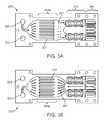
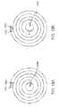
- FIG. 3Ashows an exemplary embodiment of an inlet lamina that forms at least one inlet pathway where fluid flows in an inward direction through the heat exchange system.
- FIG. 3Bshows an exemplary embodiment of an outlet lamina that forms at least one outlet pathway where fluid flows in an outward direction through the heat exchange system.
- FIG. 3Cshows an exemplary embodiment having superimposed inlet and outlet laminae.
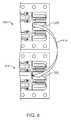
- FIG. 4shows an enlarged view of an inlet region of the inlet lamina.
- FIG. 5shows an enlarged view of a heater region of the inlet lamina.
- FIG. 6shows an enlarged view of a residence chamber of both the inlet lamina and outlet lamina.
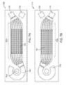
- FIG. 7Ashows a plan view of another embodiment of an inlet lamina.
- FIG. 7Bshows a plan view another embodiment of an outlet lamina.
- FIG. 8shows a perspective view of an exemplary stack 805 of laminae.
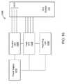
- FIG. 10shows a schematic view of an exemplary heater control system coupled to the microfluidic heat exchange system.
- FIG. 11shows a schematic, plan view of another exemplary embodiment of flow pathways for the microfluidic heat exchange system.
- FIG. 12shows a schematic, plan view of another exemplary embodiment of flow pathways for the microfluidic heat exchange system.
- FIG. 13Ashows another embodiment of an inlet lamina that forms an inlet pathway where fluid flows in an inward direction through the heat exchange system.
- FIG. 13Bshows another embodiment of an outlet lamina that forms an outlet pathway where fluid flows in an outward direction through the heat exchange system.
- FIG. 14is a table illustrating combinations of temperature and time to achieve various pasteurization levels.
- FIG. 1shows a high level, schematic view of a fluid purification system adapted to purify a fluid such as a liquid.
- the systemis adapted to be used for purifying water, such as water obtained from a household tap, in a dialysis system and is sometimes described herein in that context.
- the fluid purification systemcan be used for purifying water in other types of systems and is not limited for use in a dialysis system.
- the purification systemcan be used to purify liquids other than water.
- the fluid purification systemincludes a plurality of subsystems and/or components each of which is schematically represented in FIG. 1 .
- a fluidsuch as water enters the fluid purification system at an entry location 105 and communicates with each of the subsystems and components along a flow pathway toward an exit location 107 .
- the fluidUpon exiting the fluid purification system, the fluid is in a purified state. This may include the fluid being in a pasteurized state although the fluid system does not necessarily pasteurize the fluid in all circumstances.
- the embodiment shown in FIG. 1is exemplary and not all of the components shown in FIG. 1 are necessarily included in the system.
- the individual components included in the systemmay vary depending on the type and level of purification or pasteurization required.
- the quantity and sequential order of the subsystems along the flow pathway shown in FIG. 1is for purposes of example and it should be appreciated that variations are possible.
- the fluid purification systemincludes at least one microfluidic heat exchange (HEX) system 110 adapted to achieve pasteurization of the liquid passing through the fluid purification system, as described more fully below.
- the fluid purification systemmay also include one or more additional purification subsystems, such as a sediment filter system 115 , a carbon filter system 120 , a reverse osmosis system 125 , an ultrafilter system 130 , an auxiliary heater system 135 , a degassifier system 140 , or any combination thereof.
- the fluid purification systemmay also include hardware and/or software to achieve and control fluid flow through the fluid purification system.
- the hardwaremay include one or more pumps 150 or other devices for driving fluid through the system, as well as sensors for sensing characteristics of the fluid and fluid flow. The operation of the fluid purification system is described in detail below.
- FIG. 2shows a schematic, plan view of an exemplary embodiment of the microfluidic heat exchange system 110 , which is configured to achieve pasteurization of a liquid (such as water) flowing through the system without the need for a second fluid stream to add heat to or remove heat from the liquid.
- FIG. 2is schematic and it should be appreciated that variations in the actual configuration of the flow pathway, such as size and shape of the flow pathway, are possible.
- the microfluidic heat exchange systemdefines a fluid flow pathway that includes (1) at least one fluid inlet; (2) a heater region where incoming fluid is heated to a pasteurization temperature via at least one heater; (3) a residence chamber where fluid remains at or above the pasteurization temperature for a predetermined time period; (4) a heat exchange section where incoming fluid receives heat from hotter (relative to the incoming fluid) outgoing fluid, and the outgoing fluid cools as it transfers heat to the incoming fluid; and (5) a fluid outlet where outgoing fluid exits in a cooled, pasteurized state.
- one or more additional heat exchangesmay be required downstream to adjust the actual temperature of the outgoing fluid to the desired temperature for use, for example, in dialysis. This is especially true in warmer climates, where incoming water may be tens of degrees higher than water supplied in colder climates, which will result in higher outlet temperatures than may be desired unless further cooling is applied.
- the flow pathwayis at least partially formed of one or more microchannels, although utilizing microfluidic flow fields as disclosed in U.S. Provisional Patent Application No. 61/220,177, filed on Jun. 24, 2009, and its corresponding utility application entitled “Microfluidic Devices,” filed Jun. 7, 2010, and naming Richard B. Peterson, James R. Curtis, Hailei Wang, Robbie Ingram-Gobel, Luke W. Fisher and Anna E. Garrison, incorporated herein by reference, for portions of the fluid flow pathway such as the heat exchange section is also within the scope of the invention.
- the relatively reduced dimensions of a microchannelenhance heat transfer rates of the heat exchange system by providing a reduced diffusional path length and amount of material between counterflow pathways in the system.
- a microchannelhas at least one dimension less than about 1000 ⁇ m.
- the dimensions of a microchannelcan vary and are generally engineered to achieve desired heat transfer characteristics.
- a microchannel in the range of about 0.1 to about 1 mm in hydraulic diametergenerally achieves laminar fluid flow through the microchannel, particularly in a heat exchange region of the microchannel.
- the small size of a microchannelalso permits the heat exchange system 110 to be compact and lightweight.
- the microchannelsare formed in one or more lamina that are arranged in a stacked configuration, as formed below.
- the flow pathway of the microfluidic heat exchange system 110may be arranged in a counterflow pathway configuration. That is, the flow pathway is arranged such that cooler, incoming fluid flows in thermal communication with hotter, outgoing fluid.
- the hotter, outgoing fluidtransfers thermal energy to the colder, incoming fluid to assist the heaters in heating the incoming fluid to the pasteurization temperature.
- This internal preheating of the incoming fluid to a temperature higher than its temperature at the inlet 205reduces the amount of energy used by the heaters 220 to reach the desired peak temperature.
- the transfer of thermal energy from the outgoing fluid to the incoming fluidcauses the previously heated, outgoing fluid to cool prior to exiting through the fluid outlet.
- the fluidis “cold” as it enters the microfluidic heat exchange system 110 , is then heated (first via heat exchange and then via the heaters) as it passes through the internal fluid pathway, and is “cold” once again as it exits the microfluidic heat exchange system 110 .
- the fluidenters the microfluidic heat exchange system 110 at a first temperature and is heated (via heat exchange and via the heaters) to a second temperature that is greater than the first temperature.
- the fluidtransfers heat to incoming fluid such that the fluid drops to a third temperature that is lower than the second temperature and that is higher than the first temperature.
- FIG. 2depicts a bayonet-style heat exchanger, with the inlet and outlet on one side of the device, a central heat exchange portion, and a heating section toward the opposite end.
- the fluidenters the microfluidic heat exchange system 110 through an inlet 205 .
- the flow pathwaybranches into one or more inflow microchannels 210 that are positioned in a counterflow arrangement with an outflow microchannel 215 .
- microfluidic heat exchange system 110may be formed by a stack of layered lamina.
- the inflow microchannels 210may be positioned in separate layers with respect to the outflow microchannels 215 such that inflow microchannels 210 are positioned above or below the outflow microchannels 215 in an interleaved fashion. In another embodiment, the inflow microchannels 210 and outflow microchannels 215 are positioned on a single layer.
- the outflow microchannel 215communicates with an outlet 207 .
- the inlet 205 and outlet 207are positioned on the same end of the microfluidic heat exchange system 110 , although the inlet 205 and outlet 207 may also be positioned at different positions relative to one another.
- the counterflow arrangementplaces the inflow microchannels 210 in thermal communication with the outflow microchannel 215 .
- fluid in the inflow microchannels 210may flow along a directional vector that is oriented about 180 degrees to a directional vector of fluid flow in the outflow microchannels 215 .
- the inflow and outflow microchannelsmay also be in a cross flow configuration wherein fluid in the inflow microchannels 210 may flow along a directional vector that is oriented between about 180 degrees to about 90 degrees relative to a directional vector of fluid flow in the outflow microchannels 215 .
- the orientation of the inflow microchannels relative to the outflow microchannelsmay vary in any matter that is configured to achieve the desired degree of thermal communication between the inflow and outflow microchannels.
- One or more heaters 220are positioned in thermal communication with at least the inflow microchannels 210 such that the heaters 220 can provide heat to fluid flowing in the system.
- the heaters 220may be positioned inside the inflow microchannels 210 such that fluid must flow around multiple sides of the heaters 220 .
- the heaters 220may be positioned to the side of the inflow microchannels 210 such that fluid flows along one side of the heaters 220 .
- the heaters 220transfer heat to the fluid sufficient to cause the temperature of the fluid to achieve a desired temperature, which may include a pasteurization temperature in the case of water to be purified.
- the fluidis water and the heaters 220 assist in heating the fluid to a temperature of at least 100 degrees Celsius at standard atmospheric pressure. In an embodiment, the fluid is water and the heaters 220 assist in heating the fluid to a temperature of at least 120 degrees Celsius. In an embodiment, the fluid is water and the heaters 220 assist in heating the fluid to a temperature of at least 130 degrees Celsius. In an embodiment, the fluid is water and the heaters 220 assist in heating the fluid to a temperature of at least 138 degrees Celsius. In another embodiment, the fluid is water and is heated to a temperature in the range of about 138 degrees Celsius to about 150 degrees Celsius. In another embodiment, the fluid is heated to the highest temperature possible without achieving vaporization of the fluid.
- the microfluidic heat exchange system 110may maintain the fluid as a single phase liquid. Because water typically changes phases from a liquid into a gaseous state around 100 degrees Celsius, heating water to the temperatures set forth above requires pressurization of the heat exchange system so that the single-phase liquid is maintained throughout. Pressures above the saturation pressure corresponding to the highest temperature in the heat exchange system are sufficient to maintain the fluid in a liquid state. As a margin of safety, the pressure is typically kept at 10 psi or higher above the saturation pressure.
- the pressure of water in the microfluidic heat exchange systemis maintained greater than 485 kPa to prevent boiling of the water, and may be maintained significantly in excess of that level, such as 620 kPa or even as high as 900 kPa, in order to ensure no boiling occurs.
- These pressuresare maintained in the heat exchange system using a pump and a throttling valve.
- a pump upstream of the heat exchange system and a throttling valve downstream of the heat exchange systemare used where the pump and throttling valve operate in a closed loop control setup (such as with sensors) to maintain the desired pressure and flow rate throughout the heat exchange system.
- the fluidpasses into a residence chamber 225 where the fluid remains heated at or above the pasteurization temperature for a predetermined amount of time, referred to as the “residence time”, or sometimes referred to as the “dwell time”.
- the dwell timecan be less than or equal to one second, between one and two seconds, or at least about two seconds depending on the flow path length and flow rate of the fluid. Higher temperatures are more effective at killing bacteria and shorter residence times mean a more compact device.
- Ultrahigh temperature pasteurizationthat is designed to kill all Colony Forming Units (CFUs) of bacteria down to a concentration of less than 10 ⁇ 6 CFU/ml (such as for purifying the water for use with infusible dialysate) is defined to be achieved when water is heated to a temperature of 138 degrees Celsius to 150 degrees Celsius for a dwell time of at least about two seconds. Ultrapure dialysate has a bacterial load no greater than 0.1 CFU/ml.
- FIG. 14indicates the required temperature and residence time to achieve various levels of pasteurization. The heat exchange system described herein is configured to achieve the various levels of pasteurization shown in FIG. 14 .
- the fluidthen flows from the residence chamber 225 to the outflow microchannel 215 , where it flows toward the fluid outlet 207 .
- the outflow microchannel 215is positioned in a counterflow relationship with the inflow microchannel 210 and in thermal communication with the inflow microchannel 210 .
- outgoing fluid(flowing through the outflow microchannel 215 ) thermally communicates with the incoming fluid (flowing through the inflow microchannel 210 ).
- thermal energy from the heated fluidtransfers to the cooler fluid flowing through the adjacent inflow microchannel 210 .
- the exchange of thermal energyresults in cooling of the fluid from its residence chamber temperature as it flows through the outflow microchannel 215 .
- the incoming fluidis preheated via the heat exchange as it flows through the inflow microchannel 210 prior to reaching the heaters 220 .
- the fluid in the outgoing microchannel 210is cooled to a temperature that is no lower than the lowest possible temperature that precludes bacterial infestation of the fluid.
- bacteria in the fluid down to the desired level of purificationare dead as the fluid exits the heat exchange system.
- the temperature of the fluid after exiting the heat exchange systemmay be maintained at room temperature before use in dialysis.
- the fluid exiting the heat exchange systemis cooled to a temperature at or below normal body temperature.
- FIG. 2Although an embodiment is shown in FIG. 2 as having an outlet channel sandwiched between an inflow channel, other arrangements of the channels are possible to achieve the desired degrees of heating and cooling and energy requirements of the heaters. Common to all embodiments, however, is that all fluid pathways within the system are designed to be traveled by a single fluid, without the need for a second fluid to add heat to or remove heat from the single fluid. In other words, the single fluid relies on itself, at various positions in the fluid pathway, to heat and cool itself.
- the dimensions of the microfluidic heat exchange system 110may vary. In an embodiment, the microfluidic heat exchange system 110 is sufficiently small to be held in the hand of a user. In another embodiment, the microfluidic heat exchange system 110 is a single body that weighs less than 5 pounds when dry. In another embodiment, the microfluidic heat exchange portion 350 of the overall system 110 has a volume of about one cubic inch. The dimensions of the microfluidic heat exchange system 110 may be selected to achieve desired temperature and dwell time characteristics.
- an embodiment of the microfluidic heat exchange system 110is made up of multiple laminar units stacked atop one another to form layers of laminae.
- a desired microfluidic fluid flow pathmay be etched into the surface of each lamina such that, when the laminae are stacked atop one another, microfluidic channels or flow fields are formed between the lamina.
- both blind etching and through etchingmay be used for forming the channels in the laminae.
- through etchingallows the fluid to change the plane of laminae and move to other layers of the stack of laminae. This occurs in one embodiment at the outlet of the inflow laminae where the fluid enters the heater section, as described below.
- etchingallows all laminae around the heater section to participate in heating of the fluid instead of maintaining the fluid only in the plane of the inlet laminae.
- This embodimentprovides more surface area and lower overall fluid velocity to facilitate the heating of the fluid to the required temperature and ultimately contributes to the efficiency of the device.
- FIG. 3Ashows a plan view of an exemplary embodiment of an inlet lamina 305 that forms at least one inlet pathway where fluid flows in an inward direction (as represented by arrows 307 ) through the heat exchange system 110 .
- FIG. 3Bshows a plan view an exemplary embodiment of an outlet lamina 310 that forms at least one outlet pathway where fluid flows in an outward direction (as represented by arrows 312 ) through the heat exchange system 110 .
- the inlet pathway and the outlet pathwaymay each comprise one or more microchannels.
- the inlet and outlet pathwaycomprise a plurality of microchannels arranged in parallel relationship.
- FIGS. 3A and 3Bshow the lamina 305 and 310 positioned adjacent each other, although in assembled device the lamina are stacked atop one another in an interleaved configuration.
- FIG. 3Cshows the inlet lamina 305 and outlet lamina 310 superimposed over one another showing both the inlet pathway and outlet pathway.
- the inlet lamina 305 and outlet lamina 310are stacked atop one another with a fluid conduit therebetween so fluid may flow through the conduit from the inlet pathway to the outlet pathway, as described more fully below.
- a transfer layermay be interposed between the inlet lamina 305 and the outlet lamina 310 .
- the transfer layeris configured to permit heat to transfer from fluid in the outlet pathway to fluid in the inlet pathway.
- the transfer layermay be any material capable of conducting heat from one fluid to another fluid at a sufficient rate for the desired application. Relevant factors include, without limitation, the thermal conductivity of the heat transfer layer 110 , the thickness of the heat transfer layer, and the desired rate of heat transfer. Suitable materials include, without limitation, metal, metal alloy, ceramic, polymer, or composites thereof. Suitable metals include, without limitation, stainless steel, iron, copper, aluminum, nickel, titanium, gold, silver, or tin, and alloys of these metals. Copper may be a particularly desirable material. In another embodiment, there is no transfer layer between the inlet and outlet laminae and the laminae themselves serve as the thermal transfer layer between the flow pathways.
- the inlet lamina 305 and outlet lamina 310both include at least one inlet opening 320 and at least one outlet opening 325 .
- the inlet openings 320align to collectively form a fluid pathway that extends through the stack and communicates with the inlet pathway of the inlet laminae 305 , as shown in FIG. 3C .
- the outlet openings 325also align to collectively form a fluid pathway that communicates with the outlet pathway of the outlet laminae 310 .
- Any quantity of inlet lamina and outlet laminacan be stacked to form multiple layers of inlet and outlet pathways for the heat exchange system 110 .
- the quantity of layerscan be selected to provide predetermined characteristics to the microfluidic heat exchange system 110 , such as to vary the amount of heat exchange in the fluid, the flow rate of the fluid capable of being handled by the system, etc.
- the heat exchange system 110achieves incoming liquid flow rates of at least 100 ml/min.
- the heat exchange system 110achieves incoming liquid flow rates of at least 1000 ml/min.
- a heat exchange systemmay be manufactured of a plurality of laminae in which the microfluidic pathways have been formed using a masking/chemical etching process. The laminae are then diffusion bonded in a stack, as described in more detail below.
- the stackincludes 40-50 laminae with a flow rate of 2-3 ml/min occurring over each lamina. Higher flow rates can be achieved by increasing the number of pairs of stacked laminae within the heat exchanger. In other embodiments, much higher flow rates can be handled through the system.
- fluidflows into the inlet pathway of the inlet lamina 305 via the inlet opening 320 .
- FIG. 4shows an enlarged view of an inlet region of the inlet lamina 305 .
- the inlet opening 320communicates with an inlet conduit 405 that guides the fluid to the inlet pathway.
- the inlet opening 320may configured with a predetermined size relative to the size of the inlet conduit 405 , which may have a diameter of 2-mm.
- the inlet opening 320has an associated hydraulic diameter that may be about ten to fifteen times larger than the hydraulic diameter of the inlet conduit 405 .
- a ratio of hydraulic diametershas been found to force fluid to distribute relatively evenly among the multiple inlet laminae.
- a hydraulic diameter ratio of greater than 10:1, such as 15:1may be used to ensure an even distribution of fluid flow over the stack.
- a downstream end of the inlet conduit 405opens into the inlet pathway, which flares outward in size relative to the size of the inlet conduit 405 .
- one or more flow separation guidessuch as fins 410 , may be positioned at the entryway to the inlet pathway.
- the flow separation finsare sized and shaped to encourage an even distribution of fluid as the fluid flows into the inlet pathway from the inlet conduit 405 .
- the size, shape, and contour of the inlet conduit 405 and inlet pathwaymay vary and that the embodiment shown in FIG. 4 is merely exemplary.
- this region of the systemcould also comprise a flow field of pin-shaped members (of the sort disclosed in U.S.
- the inlet pathway and outlet pathwayeach include a heat exchange region.
- the heat exchange regionsare referred to collectively using the reference numeral 350 and individually using reference numeral 350 a (for the inlet pathway) and reference numeral 350 b (for the outlet pathway).
- the heat exchange regions 350are the locations where the colder fluid (relative to the fluid in the outlet pathway) of the inlet pathway receives heat transferred from the hotter fluid (relative to the fluid in the inlet pathway) of the outlet pathway.
- the relatively colder fluid in the inflow pathwayis positioned to flow in thermal communication with the relatively hotter fluid in the outflow pathway.
- the inflow pathwayis positioned immediately above (or below) the outflow pathway when the lamina are stacked. Heat transfers across the transfer layer from the fluid in the outflow pathway to the fluid in the inflow pathway as a result of the temperature differential between the fluid in the inflow pathway and the fluid in the outflow pathway and the thermal conductivity of the material separating the two pathways.
- the heat exchange regionsmay also comprise a microfluidic flow field as described above.
- the fluid in the inflow pathwayflows into a heater region 355 from the heat exchange region 350 .
- a plurality of pins 357may be positioned in the inlet flow pathway between the heat exchange region 350 and the heater region 355 .
- the pins 357disrupt the fluid flow and promote mixing, which may improve both fluid flow and heat distribution.
- FIG. 5shows an enlarged view of the heater region 355 .
- the inflow pathwaybifurcates into at least two flow pathways in the heater region 355 to accommodate a desired flow rate. Alternatively only one flow path through the heater region may be utilized, or three or more flow paths may be selected.
- the heater region 355includes one or more heaters 220 that thermally communicate with fluid flowing through this region, but are hermetically isolated from the flow path.
- the heaters 220add heat to the incoming fluid sufficient to raise temperature of the fluid to the desired temperature, which may include a pasteurization temperature.
- the incoming fluidwas previously preheated as it flowed through the heat exchange region 350 . This advantageously reduced the energy requirements for the heaters.
- the laminae in the stackmay include through-etches at entry locations 505 to the heater region 355 such that fluid entering the heater region can pass through all the laminae in the stack.
- Through etchingallows all laminae around the heater section to participate in heating of the fluid instead of maintaining the fluid only in the plane of the inlet laminae. This provides more surface area between the fluid and the heaters and also provides lower overall fluid velocity to facilitate the heating of the fluid to the required temperature.
- the inflow pathwaymay bifurcate into multiple flow pathways.
- Each pathwaymay include one or more heaters 220 arranged within the pathway so as to maximize or otherwise increase the amount of surface area contact between the heaters 220 and fluid flowing through the pathways.
- the heaters 220may be positioned towards the middle of the pathway such that the fluid must flow around either side of the heaters 220 along a semicircular or otherwise curvilinear pathway around the heaters 220 .
- the heaters 220can vary in configuration.
- the heaters 220are conventional cartridge heaters with a 1 ⁇ 8-inch diameter which can be run in an embodiment at a combined rate of between about 70,000 and 110,000 W/m2, which results in energy usages of less than 100 W in one embodiment, and less than 200 W in another embodiment, for the entire stack running at about 100 mL/minute.
- the systemuses six heaters in a configuration of three heaters per flow pathway wherein each heater uses about 70 W for a 100 ml/min flow rate.
- the fluidis forced to flow around the heaters in paths 1.6 mm wide.
- the inflow pathwaytransitions from the heater section 355 to the residence chamber 360 .
- the fluidflows into the residence chamber 360 , it has been heated to the desired temperature, such as the pasteurization temperature, as a result of the heat transfer in the heat exchange region 350 and/or by being heated in the heater section 355 .
- the residence chamber 360may be a single chamber that spans all of the layers of laminae in the stack such that the fluid from each inlet lamina flows into a single volume of fluid in the residence chamber 360 .
- the residence chamber 360is configured such that fluid flow ‘shortcuts’ are eliminated, all of the fluid is forced to travel a flow pathway such that no portion of the fluid will reside in the residence chamber for the less than the desired duration at a specified flow rate, and the fluid is maintained at or above the pasteurization temperature for the duration of the time (i.e., the dwell time) that the fluid is within the residence chamber 360 .
- the residence timeis a result of the dimensions of the flowpath through the residence area and the flow rate. It will thus be apparent to one of skill in the art how to design a residence pathway for a desired duration.
- FIG. 6shows an enlarged view of the region of the residence chamber 360 for the inlet lamina 305 and outlet lamina 310 .
- FIG. 6shows the inlet lamina 305 and outlet lamina 310 positioned side-by-side although in use the laminae are stacked atop one another such that the residence chambers align to form a residence chamber that spans upward along the stack.
- the residence chamber 360incorporates a serpentine flow path as shown in the enlarged view of the residence chamber of FIG. 6 .
- the serpentine flow pathprovides a longer flow path to increase the likelihood of the liquid spending a sufficient amount of time within the residence chamber 360 .
- the outlet pathwaypasses between the heaters 220 , which act as insulators for the fluid to lessen the likelihood of the fluid losing heat at this stage of the flow pathway.
- the heated fluid of the outlet pathwaythen flows toward the heat exchange region 350 b .
- the outlet flow pathwayexpands prior to reaching the heat exchange region 350 b .
- a set of expansion fans 367directs the fluid into the expanded heat exchange region 350 b of the outlet pathway, where the fluid thermally communicates with the cooler fluid in the inflow pathway.
- heat from the fluid in the hotter outflow pathwaytransfers to the cooler fluid in the inflow pathway. This results in cooling of the outflowing fluid and heating of the inflowing fluid.
- the fluidthen flows from the heat exchange region 350 b to the outlet opening 325 . At this stage, the fluid is in a cooled, pasteurized state.
- laminae having a thickness of 350 microns with an etch-depth of 175 microns, with 2.5-mm wide channels having a hydraulic diameter of 327 micronswere utilized.
- Each pair of laminaewas able to handle a fluid flow rate of approximately 3.3. mL/min of fluid, which thus required 30 pairs of laminae in order to facilitate a flow of 100 mL/min, with only a 15-mm long heat exchanger section.
- the fluid flowpathsare designed in smooth, sweeping curves and are substantially symmetrically designed along the longitudinal axis of the stack; if the flow paths are not designed symmetrically, they are designed to minimize differences in the path line or lengths so as to evenly distribute the flow, the heating of the fluid and the various dwell times.
- the width of the ribs separating channels in the heat exchange portioncan be reduced, which would have the effect of increasing the available heat transfer area and reducing the length of the heat exchange portion required for the desired energy efficiency level of the device.
- Energy efficiency levels of at least about 85%, and in some embodiment of at least about 90%can be achieved, meaning that 90% of the thermal energy from the outgoing fluid can be transferred to the incoming fluid stream and recaptured without loss.
- a heat exchange systemmay be constructed to provide pasteurized water continuously at a desired flow rate for real-time mixing of dialysate in a dialysis system, without the need either to heat, purify and store water in batched quantities or to provide bags of pure water or of premixed dialysate for use by the patient.
- FIG. 7Ashows a plan view of another embodiment of an inlet lamina 705 that forms at least one inlet pathway where fluid flows in an inward direction (as represented by arrows 707 ) through the heat exchange system 110 .
- FIG. 7Bshows a plan view another embodiment of an outlet lamina 710 that forms at least one outlet pathway where fluid flows in an outward direction (as represented by arrows 712 ) through the heat exchange system 110 .
- the flow pathway in this embodimentgenerally follows a different contour than the flow pathway of the embodiment of FIGS. 3A and 3B .
- the inlet lamina 705 and outlet lamina 710are stacked atop one another.
- the fluidenters the inlet pathway of the inlet lamina 705 at an inlet 720 .
- the inlet pathwaythen splits into multiple pathways at the heat exchange region 750 a , which thermally communicates with a corresponding heat exchange region 750 b of the outlet lamina 710 .
- the inlet pathwaydoes not split into multiple pathways but remains a single pathway.
- the inlet pathwaycould also be at least partially formed of one or more microfluidic flow fields as disclosed in U.S. Provisional Patent Application No. 61/220,177, filed on Jun. 24, 2009, and its corresponding utility application entitled “Microfluidic Devices”, filed Jun. 7, 2010, and naming Richard B. Peterson, James R.
- the inlet pathwaytransitions to an arc-shaped heater region 760 that thermally communicates with a heater 765 , such as a 150-Watt McMaster-Carr cartridge heater (model 3618K451).
- a heater 765such as a 150-Watt McMaster-Carr cartridge heater (model 3618K451).
- the heater regionserves as both a region where the heater 765 heats the fluid and as a residence chamber where the fluid remains heated at or above the desired temperature for a predetermined amount of time.
- the fluidflows to the outlet lamina 710 at an entrance location 770 .
- the fluidthen flows into the heat exchange region 750 b of the outlet lamina 710 , where the fluid transfers heat to the incoming fluid flowing through the heat exchange region 750 a of the inlet lamina 705 .
- the fluidthen exits the outlet lamina at an outlet 775 .
- the lamina 705 and 710are about 600 ⁇ m thick and the microfluidic flow pathways have a depth of about 400 ⁇ m to 600 ⁇ m.
- the fluid flow pathcompletely encircles each of the heaters so that any shim material conducting heat away from the heater will have fluid flowing over it to receive the heat, thereby minimizing heat loss to the environment.
- the flowpaths around each heaterwill be relatively narrow so that non-uniform heating due to separation from the heaters will be avoided.
- the microfluidic heat exchange system 110may be formed of a plurality of lamina stacked atop one another and diffusion bonded. Additional information concerning diffusion bonding is provided by U.S. patent application Ser. Nos. 11/897,998 and 12/238,404, which are incorporated herein by reference.
- the stackincludes multiple sets of lamina with each set including an inlet lamina 305 juxtaposed with an outlet lamina 310 . Each set of juxtaposed inlet lamina and outlet lamina forms a single heat exchange unit.
- the stack of laminamay therefore include a plurality of heat exchange units wherein each unit is formed of an inlet lamina 305 coupled to an outlet lamina 310 .
- each laminamay be formed by etching on the surface of the lamina, such as by etching on one side only of each lamina.
- the etched side of a laminaseals against the unetched sided of an adjacent, neighboring lamina. This may provide desirable conditions for heat exchange and separation of the incoming fluid (which is not pasteurized) and the outgoing fluid (which is pasteurized).
- FIG. 8shows a perspective view of an exemplary stack 805 of laminae.
- the stack 805is shown in partial cross-section at various levels of the stack including at an upper-most outlet lamina 310 , a mid-level inlet lamina 305 a , and a lower level inlet lamina 305 b .
- the stack 805is formed of alternating inlet lamina and outlet lamina interleaved with one another.
- the heaters 220are positioned within cut-outs that extend through the entire stack 805 across all the laminae in the stack 805 .
- the residence chamber 360 and the aligned inlet openings 320 and outlet openings 325also extend entirely through the stack 805 .
- the laminaemay also include one or more holes 810 that align when the lamina are stacked to form shafts through which alignment posts may be inserted.
- the quantity of laminae in the stackmay be varied to accommodate desired specifications for the microfluidic heat exchange system 110 , such as the heating specifications.
- the heating specificationsmay be dependent on flow rate of fluid, heater power input, initial temperature of incoming fluid, etc.
- the stack 805is less than about 100 mm long, less than about 50 mm wide at its widest dimension, and less than about 50 mm deep, with a volume of less than about 250 cubic centimeters, although the dimensions may vary.
- the stack 805is about 82 mm long, about 32 mm wide at its widest dimension, and about 26 mm deep, with a volume of about 69-70 cubic centimeters, and a weight of about five pounds when dry, although the dimensions may vary.
- the lamina 305 and 310may be any material capable of being patterned with features useful for a particular application, such as microchannels.
- the thickness of the laminamay vary.
- the laminamay have a thickness in the range of about 200 ⁇ m to about 100 ⁇ m.
- the laminamay have a thickness in the range of about 500 ⁇ m to about 100 ⁇ m.
- Some suitable lamina materialsinclude, without limitation, polymers and metals.
- the laminamay be manufactured of any diffusion bondable metal, including stainless steel, copper, titanium alloy, as well as diffusion bondable plastics.
- the laminaeare stacked in a manner that achieves proper alignment of the lamina.
- the inlet openings 320 of all the laminaalign to collectively form an inlet passage for fluid to flow into the system and the outlet openings 325 align to collectively form an outlet passage, as shown in FIG. 8 .
- the properly-aligned stack of laminamay also include one or more seats for coupling the heaters 220 in the stack.
- One or more featurescan be used to assist in proper alignment of the lamina in the stack, such as alignment posts and/or visual indicators of proper alignment.
- the stackmay include a top cover positioned on the top-most lamina and a bottom cover positioned on the bottom-most lamina.
- the stackmay also include an external insulation wrap to prevent heat loss to the outside environment.
- FIG. 9shows a perspective view of an example of an assembled microfluidic heat exchange system 110 .
- the stack 805 of inlet/outlet laminaeincludes chemically etched upper and lower covers that seal the stack 805 against the atmosphere. These covers typically are thicker than the laminae, and may be about 1 mm or more in thickness in an embodiment to withstand damage and the operating pressures necessary to maintain the fluid in a single state.
- the cartridge heaters 220are mounted in cavities that extend through the entire stack 805 .
- a plate 910is secured (such as via bolts) to the stack and provides a means of securing an inlet port 915 and an outlet port 920 to the stack 805 .
- the inlet port 915 and outlet port 920can be piping having internal lumens that communicate with the inlet openings 320 and outlet openings 325 .
- each hole of each lamina that is to accept a cartridge heateris designed slightly smaller than the diameter of the cartridge heater itself. After assembly of the entire stack, the hole is enlarged for a clearance fit between the hole inner diameter and the cartridge heater outer diameter, taking into account thermal expansion of the heater during operation, to provide a uniform surface for optimum heat transfer from the heater to the pasteurizer. This method avoids any potential issues with misalignment of the shims if the holes in each shim were to be properly sized to the cartridge heater prior to assembly.
- a second plate 925is also secured to the stack 805 .
- the plate 925is used to couple one or more elongated and sheathed thermocouples 930 to the stack 805 .
- the thermocouples 930extend through the stack 805 and communicate with the laminae in the stack 805 in the region of the dwell chamber for monitoring fluid temperature in the dwell chamber.
- the thermocouples that are to be inserted into solid sections of the stackutilize a slip fit for installation.
- the thermocouples that enter into the fluid flow pathsrequire a seal to prevent fluid leakage.
- thermocouplesare generated after the stack is assembled by electrical discharge machining (EDM), because this technique generates very small debris that can easily be flushed out of the system, as compared with traditional drilling, which could result in larger debris blocking some of the flow paths.
- EDMelectrical discharge machining
- Any of a variety of sealing members, such as o-rings or gaskets,may be coupled to the stack to provide a sealed relationship with components attached to the stack, such as the plates 910 and 925 , thermocouples 930 , and inlet port 915 and outlet port 920 . It should be appreciated that the assembled microfluidic heat exchange system 110 shown in FIG. 9 is an example and that other configurations are possible.
- a stack of laminais positioned in a fixture or casing and is then placed into a bonding machine, such as a high temperature vacuum-press oven or an inert gas furnace.
- the machinecreates a high temperature, high pressure environment that causes the lamina to physically bond to one another.
- the weight of the overall stackcan be reduced by removing some of the excess material from the sides of the stack, thereby eliminating the rectangular footprint in favor of a more material-efficient polygonal footprint.
- FIG. 11shows a schematic, plan view of another exemplary embodiment of the microfluidic heat exchange system 110 .
- FIG. 11is schematic and it should be appreciated that variations in the actual configuration of the flow pathway, such as size and shape of the flow pathway, are possible.
- the embodiment of FIG. 11includes a first flow pathway 1105 and a second flow pathway 1110 separated by a transfer layer 1115 . Fluid enters the first flow pathway at an inlet 1120 and exits at an outlet 1125 . Fluid enters the second flow pathway at an inlet 1130 and exits at an outlet 1135 .
- the first and second flow pathwaysare arranged in a counterflow configuration such that fluid flows through the first flow pathway 1105 in a first direction and fluid flows through the second flow pathway 1110 in a direction opposite the first direction.
- the inlet 1120 of the first flow pathway 1105is located on the same side of the device as the outlet 1135 of the second flow pathway 1110 .
- the outlet 1125 of the first flow pathway 1105is located on the same side of the device as the inlet 1130 of the second flow pathway 1110 .
- the flow pathwaysmay be least partially formed of one or more microchannels, although utilizing microfluidic flow fields as disclosed in U.S. Provisional Patent Application No. 61/220,177, filed on Jun. 24, 2009, and its corresponding utility application entitled “Microfluidic Devices”, filed Jun. 7, 2010, and naming Richard B. Peterson, James R. Curtis, Hailei Wang, Robbie Ingram-Gobel, Luke W. Fisher and Anna E. Garrison, incorporated herein by reference, for portions of the fluid flow pathway is also within the scope of the invention.
- fluidenters the first flow pathway 1120 at the inlet 1120 and passes through a heater region 1140 .
- a heateris positioned in thermal communication with the heater region 1140 so as to input heat into the fluid passing through the heater region 1140 .
- the fluidPrior to passing through the heater region 1140 , the fluid passes through a heat exchange region 1145 that is in thermal communication (via the transfer layer 1115 ) with fluid flowing through the second flow pathway 1110 .
- the fluid flowing through the second flow pathway 1110is fluid that previously exited the first flow pathway 1105 (via the outlet 1125 ) and was routed into the inlet 1125 of the second flow pathway 1110 .
- thermal energy from the previously-heated fluid in the second flow pathway 110transfers to the fluid flowing through the first flow pathway 1120 .
- the fluid in the second flow pathway 1110pre-heats the fluid in the heat exchange region 1145 of the first flow pathway prior to the fluid reaching the heater region 1140 .
- the heaterprovides sufficient thermal energy to heat the fluid to a desired temperature, which may be the pasteurization temperature of the fluid.
- a desired temperaturewhich may be the pasteurization temperature of the fluid.
- the fluidflows into a residence chamber 1150 where the fluid remains heated at or above the desired temperature for the residence time.
- the fluiddesirably remains flowing, rather than stagnant, while in the residence chamber 1150 .
- the fluidexits the first flow pathway 1105 through the outlet 1125 and is routed into the inlet 1130 of the second flow pathway 1110 .
- the fluidthen flows through the second flow pathway 1110 toward the outlet 1135 .
- the second flow pathway 1110is in thermal communication with the first flow pathway 1105 at least at the heat exchange region 1145 .
- the previously-heated fluid flowing through the second flow pathway 1110thermally communicates with the fluid flowing through the first flow pathway 1105 .
- thermal energy from the heated fluidtransfers to the fluid flowing through the adjacent heat exchange region 1145 of the first flow pathway 1105 .
- the exchange of thermal energyresults in cooling of the fluid from its residence chamber temperature as it flows through the second flow pathway 1110 .
- the fluid in the second flow pathway 1110is cooled to a temperature that is no lower than the lowest possible temperature that precludes bacterial infestation of the fluid.
- the fluid flowing into the second flow pathway 1110is not fluid re-routed from the first flow pathway 1105 but is rather a separate fluid flow from the same source as, or from a different source than, the source for the first fluid flow pathway 1105 .
- the fluid in the second flow pathway 1110may or may not be the same type of fluid in the first flow pathway 1105 .
- watermay flow through both pathways; or water may flow through one flow pathway and a non-water fluid may flow through the other flow pathway.
- the separate fluidhas desirably been pre-heated in order to be able to transfer heat to the fluid in the first flow pathway 1105 at the heat exchange region 1145 .
- the embodiment of FIG. 11may be made up of multiple laminar units stacked atop one another to form layers of laminae.
- the embodiment of FIG. 11may have the same or similar specifications as the other embodiments described herein, including materials, dimensions, residence times, and temperature levels.
- FIG. 12represents an exemplary flow pathway configuration for a single lamina.
- a plurality of such laminaemay be interleaved to form a stack of lamina as described above for other embodiments.
- the purification of the fluidmay comprise pasteurizing the fluid although pasteurization is not necessary such as where the device is not used for dialysis.
- the heat exchange systemreceives a stream of incoming fluid 1205 , which splits before entering the heat exchange system.
- a first portion of the stream of incoming fluid 1205 aenters at a first inlet 1210 a on one end of the system and a second portion of the stream of incoming fluid 1205 enters at a second inlet 1205 b on the other, opposite end of the system.
- the two streams of incoming fluid 1205are distributed across the stacked laminae in alternating fashion such that there is no direct contact between the two fluid streams.
- Each stream of incoming fluid 1205enters a flow pathway 1207 and flows along the flow pathway toward an outlet 1215 .
- One stream of fluidenters via the inlet 1205 a and exits at an outlet 1215 a positioned on the same end of the system as the inlet 1210 b
- the other stream of fluidenters via the inlet 1205 b and exits at an outlet 1215 b on the same end of the system as the inlet 1210 a
- Each flow pathway 1207includes a first heat exchange region 1220 where heat is exchanged through a transfer layer between the incoming fluid and the previously-heated outgoing fluid flowing through a lamina immediately above (or below) the instant lamina in the stack. As the fluid flows through the heat exchange region 1220 it receives heat via the heat transfer and is pre-heated prior to entering a heater region 1225 .
- the fluidthen flows into the heater region 1225 , which thermally communicates with at least one heater, and preferably multiple heaters, for communicating heat into the flowing fluid.
- the fluidis heated under pressure to a temperature at or above the desired threshold pasteurization temperature as described above for other embodiments.
- the heater region 1225also serves as a residence chamber.
- the fluidflows through the residence chamber while held at or above the desired temperature for the desired residence time.
- the desired residence timemay be achieved, for example, by varying the flow rate and/or by employing a serpentine flow path of the required length within the heater region 1225 .
- the outgoing fluidAfter leaving the heater region 1225 , the outgoing fluid enters a second heat exchange region 1230 where the outgoing fluid exchanges heat with the incoming fluid flowing through a lamina immediately above (or below) the instant lamina in the stack.
- the outgoing fluidthen exits the flow pathways through the outlets 1210 a and 1210 b .
- the two streams of outgoing fluidthen recombine into a single stream of outgoing fluid 1235 before continuing on to the ultrafilter to remove all or substantially all of the dead bacteria killed by the pasteurization process.
- FIG. 13Ashows another embodiment of an inlet lamina that forms a spiral inlet pathway where fluid flows in an inward direction through the heat exchange system.
- FIG. 13Bshows a corresponding outlet lamina that forms a similar spiral pathway where fluid flows in an outward direction.
- a plurality of such inlet and outlet laminaemay be interleaved to form a stack of laminae as described above for other embodiments.
- the laminaeare shown having a circular outer contour although the outer shape may vary as with the other embodiments.
- the inlet laminahas a header forming an inlet 1305 where incoming fluid enters the inlet pathway.
- the inlet pathwayspirals inward toward a center of the pathway, where a heating chamber 1310 is located.
- the heating chamber 1310also serves as a residence chamber for the fluid, as described below.
- One or more heatersare positioned in thermal communication with the heating chamber 1310 to provide heat to fluid flowing in the heating chamber 1310 .
- the heating chamber 1310extends across multiple laminae in the stack and includes a conduit that communicates with the outlet lamina shown in FIG. 13B .
- the fluidenters the outlet lamina from the heating chamber 1310 .
- the outlet laminahas an outflow pathway that spirals outward from the heating chamber 1310 toward an outlet 1320 .
- the fluidenters the inlet pathway of the inlet lamina through the inlet 1305 shown in FIG. 13B .
- the fluidthen flows along the spiral inlet pathway toward the heater chamber 1310 .
- the incoming fluidis at a temperature that is less than the previously-heated fluid flowing through the outlet lamina, which is positioned immediately above or below the inlet lamina.
- the fluidreceives heat from the previously-heated fluid flowing through the outlet pathway of the outlet lamina. This serves to pre-heat the fluid prior to the fluid flowing into the heating chamber 1310 .
- the fluidthen flows into the heating chamber 1310 where the fluid receives heat from the one or more heaters.
- the heating chamber 1310While in the heating chamber 1310 , the fluid is heated under pressure to a temperature at or above the desired threshold pasteurization temperature as described above for other embodiments. As mentioned, the heating chamber 1310 also serves as a residence chamber. The fluid flows through the residence chamber while held at or above the desired temperature for the desired residence time. As in other embodiments, the desired residence time may be achieved, for example, by varying the flow rate and/or by employing a serpentine flow path of the required length within the heater chamber 1310 . After leaving the heater chamber, the outgoing fluid enters the outlet pathway of an outlet lamina such as shown in FIG. 13B . The outgoing fluid flows outward from the heating chamber 1310 along the spiral flow pathway toward the outlet 1320 .
- the spiral pathway of the inlet laminathermally communicates with the spiral pathway of the outlet lamina across a transfer layer. As the outgoing fluid flows along the spiral pathway, it exchanges heat with the incoming fluid flowing through an inlet lamina immediately above (or below) the instant lamina in the stack. The outgoing fluid then exits the stack of lamina via the outlet 1320 before continuing on to the ultrafilter to remove all or substantially all of the dead bacteria killed by the pasteurization process.
- the microfluidic heat exchange system 110may include or may be coupled to a control system adapted to regulate and/or control one or more aspects of the fluid flow through the system, such as fluid flow rate, temperature and/or pressure of the fluid, chemical concentration of the fluid, etc.
- FIG. 10shows a schematic view of an exemplary heater control system 805 communicatively coupled to the microfluidic heat exchange system 110 .
- the heater control system 1005includes at least one power supply 1015 communicatively coupled to a heater control unit 1020 , which communicates with a control logic unit 1025 .
- the heater control unit 1020is adapted to control the power supply to the heaters, either on an individual basis or collectively to a group of heaters. This permits temporal and spatial control of heat supplied to the microfluidic heat exchange system 110 .
- the heater control system 1005may include one or more temperature sensors 1010 positioned in or around the microfluidic heat exchange system 110 for sensing fluid temperature at one or more locations within the fluid flow path.
- the type of sensorcan vary.
- one or more thermocouplesare used as the sensors 1010 .
- the sensors 1010communicate with the heater control unit 1020 and the control logic unit 1025 to provide a temperature feedback loop.
- the heater control system 1005provides for feedback control of fluid temperature in the system to ensure, for example, that fluid is being heated to the required pasteurization temperature and/or that the fluid is not overheated or underheated.
- the heater control unit 1020 in conjunction with the control logic unit 1025may adjust power to one or more of the heaters based on a sensed temperature in order to achieve a desired temperature profile in one or more locations of the fluid flow path.
- the heater control system 1005may include other types of sensors such as, for example, pressure sensors, flow rate sensors, etc. to monitor and adjust other parameters of the fluid as desired.
- the heater control system 1005may also be configured to provide one or more alarms, such as a visual and/or audio indication and/or a telecommunications signal, to the user or a remote monitor of system functions to inform such parties when the temperature is at an undesired level.
- the control unit 1020may comprise one or more temperature set limits within which to maintain, for example, the residence chamber temperature. If a limit is exceeded—i.e., if the temperature falls below the lower operating limit or above the upper operating limit, the control system may bypass the heater, set off an alarm and cease operation of the overall water purification system until the problem can be diagnosed and fixed by the operator.
- the control system 1005may include a reporting unit 1030 that includes a database. The reporting unit 1005 is configured to log and store data from the sensors and to communicate such data to a user or monitor of the system at a remote site.
- the fluid purification systemis described in an exemplary context of being a component of a dialysis system.
- the fluid purification systemis used to purify water that is used by the dialysis system.
- the fluid purification systemis not limited to use for purifying water in dialysis systems.
- the flow pathwaymay be formed by any type of fluid conduit, such as piping.
- the pipingmay include one or more sample ports that provide access to water flowing through the piping.
- One or more subsystems, including the microfluidic heat exchange system 110are positioned along the pathway for processing the water prior to the water exiting the system.
- the subsystemsmay include, for example, a sediment filter system 115 , a carbon filter system 120 , a reverse osmosis system 125 , an ultrafilter system 130 , an auxiliary heater system 135 , a degassifier system 140 , or any combination thereof.
- the fluid purification systemmay also include hardware and/or software to achieve and control fluid flow through the fluid purification system.
- the hardwaremay include one or more pumps 150 and a throttling valve or other devices for driving fluid through the system, as well as sensors for sensing characteristics of the fluid and fluid flow, such as flow sensors, conductivity sensors, pressure sensors, etc.
- the hardwaremay communicate with a control system that controls operation of the hardware.
- the waterflows through at least one sediment filter system 115 , which includes one or more sediment filters that filter sediment from the water flowing therethrough.
- the waterthen flows through a carbon filter system 120 , which includes one or more carbon filters that filter organic chemicals, chlorine and chloramines in particular from the water.
- One or more pumpsmay be positioned at various locations along the water flow pathway such as between the filter subsystems.
- a conductivity sensormay be coupled to the pathway downstream of the carbon filter system 120 and downstream of the reverse osmosis system to determine the percentage of dissolves solids removed.
- the waterflows from the carbon filter system 120 to a reverse osmosis system 125 configured to remove particles from the water pursuant a reverse osmosis procedure.
- the sediment filter 115removes particulate matter down to 5 microns or even 1 micron.
- the carbon filter 120removes chlorine compounds.
- the reverse osmosis system 125usually removes greater than 95% of the total dissolved solids from the water.
- the sediment filter system 115 , carbon filter system 120 , and reverse osmosis system 125collectively form a pre-processing stage that removes a majority of dissolved solids, bacteria contamination, and chemical contamination, if any, from the water.
- the wateris therefore in a somewhat macro-purified state prior to reaching the heat exchange system 110 .
- the preprocessing stagesupplies relatively clean water to the downstream pumps and also to the heat exchange system 110 . This reduces or eliminates the potential for scale build-up and corrosion during heating of the water by the heat exchange system 110 .
- a pump 150may be used to increase the water pressure to a level higher than the saturation pressure encountered in the heat exchange system 110 . This would prevent phase change of the water inside the heat exchange system 110 .
- the highest temperature reached in the heat exchange system 110is 150 degrees Celsius where the water would have a saturation pressure of 475 kPa (approximately 4.7 atmospheres or 69 psia)
- the pressure of the water coming out of the pumpwould exceed the saturation pressure.
- the pumpdesirably increases the water pressure to a level that is at or exceeds the saturation pressure to ensure no localized boiling. This can be important where the heat exchange system is used to pasteurize water and the water is exposed to high temperatures that may be greater than 138 degrees Celsius, i.e., well above the boiling point of water at atmospheric pressure.
- the waterwhich is now pressurized above, or significantly above, the saturation pressure, enters the heat exchange system 110 , which pasteurizes the water as described in detail above.
- the heat exchange system 110may be encased in insulation to reduce the likelihood of heat loss of the water passing therethrough.
- the waterAfter leaving the heat exchange system 110 , the water passes into a throttling valve 160 , which maintains the pressure though the water path from the pump 150 to outlet of the heat exchange system 110 .
- the throttling valve 160 and the pump 150may be controlled and adjusted to achieve a flow rate and a desired pressure configuration.
- the pump 150 and the throttling valve 160may communicate with one another in a closed loop system to ensure the required pressure is maintained for the desired flow rate and temperature.
- a degassifier system 140may also be incorporated into the flow path for removing entrained gas from the water.
- the waterAfter the water leaves the throttling valve 160 , it passes to an ultrafilter system 130 that removes macromolecules and all or substantially all of the dead bacteria killed by the pasteurization process from the water to ensure no endotoxins remain in the water before mixing the dialysate. Where the water is used in a dialysis system, the presence of macromolecules may be detrimental to the dialysis process.
- the waterthen passes through a heater system that may heat the water to a desired temperature, such as to normal body temperature (98.6 degrees Fahrenheit). Where the water is used for dialysis, the water is then passed to a mixer 170 that mixes the clean water with a supply of concentrate solutions in order to make dialysate.
- the heat exchanger system 110which serves as a pasteurizer, is desirably operated in a manner that ensures clean fluid flow upon startup of the fluid purification system and also avoids bacterial contamination of the downstream components, or at least mitigates the contamination effects, upon shut down (i.e., when the heaters 220 are de-powered).
- clean fluid flow upon startupis achieved by initially flowing a sterilizing liquid through the heat exchanger system 110 while the heaters 220 are being powered up.
- the sterilizing liquidthen flows through all the components downstream of the heat exchanger system 110 until the heat exchanger system 110 attains a desired operating temperature.
- fluid flow to the heat exchanger system 110switches to water from the reverse osmosis system 125 .
- the waterpasses through the heat exchanger system 110 (which has achieved the desired operating temperature) to flush the sterilizing liquid out of the flow pathway of the heat exchanger system 110 .
- Various sterilizing solutionsmay be used.
- the solutionfor example, can be a 1% chlorine in water mixture, or some other widely recognized water additive that can kill bacteria.
- the fluid purification systemmay be shut down as follows.
- the heaters 220are de-powered while fluid flow through the heat exchanger system 110 is maintained.
- a sterilizing liquidmay be flowed through the heat exchanger system 110 until the heat exchanger system 110 attains near room temperature conditions. In this manner, the flow pathway is maintained in a sterilized condition as the heat exchanger system 110 shuts down.
- the flow pathway of the heat exchanger system 110is then closed or “locked down” with sterilizing liquid present in the flow pathway of the heat exchanger system 110 .
- the presence of the sterilizing liquidgreatly reduces the likelihood of bacterial contamination during shutdown.
- one or more valvesare positioned in the flow pathway of fluid purification system wherein the valves allow a circulating flow of solution to loop through the pump 150 , heat exchanger system 110 , and downstream components in a recirculation loop until desired pasteurization conditions are achieved during startup. The valves are then set to allow the sterilizing liquid to be flushed from the system.
- An auxiliary componentsuch as a microchannel fluid heater (without heat exchange capability), can also be incorporated to provide the ability to circulated a warmed (e.g., less than 100 degrees Celsius) sterilizing liquid through the downstream components and/or through the unpowered heat exchanger system 110 .
- the sterilizing liquidcan be used during either a start-up or shut-down process for keeping the flow pathway and components clean over the span of weeks and/or months.
- the use of a recirculation loop for sterilizing liquid at start upis another manner to prevent bacteria from entering the fluid purification system before the heat exchanger system 110 achieves operating temperatures.
- a timing control logicmay be used with a temperature sensing capability to implement a process that ensures quality control over the start-up and shut down processes.
- the control logicmay be configured to initiate flow only after the heat exchanger system 110 or a heater attains a preset temperature.
- the flow pathmay include one or more bypass circulation routes that permit circulation of cleaning and/or sterilization fluid through the flow path.
- the circulation routemay be an open flow loop wherein fluid flowing through the circulation route is dischargeable from the system after use.
- the circulation routemay be a closed flow loop wherein fluid flowing the circulation route not dischargeable from the system.
- the systemmay include both open and closed circulation routes.
Landscapes
- Engineering & Computer Science (AREA)
- Chemical & Material Sciences (AREA)
- Water Supply & Treatment (AREA)
- Health & Medical Sciences (AREA)
- Life Sciences & Earth Sciences (AREA)
- Hydrology & Water Resources (AREA)
- Environmental & Geological Engineering (AREA)
- Organic Chemistry (AREA)
- Urology & Nephrology (AREA)
- Heart & Thoracic Surgery (AREA)
- Chemical Kinetics & Catalysis (AREA)
- Biomedical Technology (AREA)
- General Health & Medical Sciences (AREA)
- Veterinary Medicine (AREA)
- Public Health (AREA)
- Animal Behavior & Ethology (AREA)
- Hematology (AREA)
- Emergency Medicine (AREA)
- Anesthesiology (AREA)
- Vascular Medicine (AREA)
- Physics & Mathematics (AREA)
- Nanotechnology (AREA)
- Thermal Sciences (AREA)
- Combustion & Propulsion (AREA)
- General Engineering & Computer Science (AREA)
- Mechanical Engineering (AREA)
- Clinical Laboratory Science (AREA)
- External Artificial Organs (AREA)
- Separation Using Semi-Permeable Membranes (AREA)
Abstract
Description
Claims (5)
Priority Applications (3)
| Application Number | Priority Date | Filing Date | Title |
|---|---|---|---|
| US14/808,827US10105476B2 (en) | 2010-06-07 | 2015-07-24 | Fluid purification system |
| US16/138,441US20190022293A1 (en) | 2010-06-07 | 2018-09-21 | Fluid purification system |
| US17/028,130US11724013B2 (en) | 2010-06-07 | 2020-09-22 | Fluid purification system |
Applications Claiming Priority (4)
| Application Number | Priority Date | Filing Date | Title |
|---|---|---|---|
| US12/795,382US8501009B2 (en) | 2010-06-07 | 2010-06-07 | Fluid purification system |
| US13/068,038US8524086B2 (en) | 2010-06-07 | 2011-04-29 | Fluid purification system |
| US13/965,720US9138687B2 (en) | 2010-06-07 | 2013-08-13 | Fluid purification system |
| US14/808,827US10105476B2 (en) | 2010-06-07 | 2015-07-24 | Fluid purification system |
Related Parent Applications (1)
| Application Number | Title | Priority Date | Filing Date |
|---|---|---|---|
| US13/965,720ContinuationUS9138687B2 (en) | 2010-06-07 | 2013-08-13 | Fluid purification system |
Related Child Applications (1)
| Application Number | Title | Priority Date | Filing Date |
|---|---|---|---|
| US16/138,441DivisionUS20190022293A1 (en) | 2010-06-07 | 2018-09-21 | Fluid purification system |
Publications (2)
| Publication Number | Publication Date |
|---|---|
| US20150328386A1 US20150328386A1 (en) | 2015-11-19 |
| US10105476B2true US10105476B2 (en) | 2018-10-23 |
Family
ID=45064664
Family Applications (6)
| Application Number | Title | Priority Date | Filing Date |
|---|---|---|---|
| US12/795,382Expired - Fee RelatedUS8501009B2 (en) | 2010-06-07 | 2010-06-07 | Fluid purification system |
| US13/068,038Expired - Fee RelatedUS8524086B2 (en) | 2010-06-07 | 2011-04-29 | Fluid purification system |
| US13/965,720ActiveUS9138687B2 (en) | 2010-06-07 | 2013-08-13 | Fluid purification system |
| US14/808,827Active2031-08-25US10105476B2 (en) | 2010-06-07 | 2015-07-24 | Fluid purification system |
| US16/138,441AbandonedUS20190022293A1 (en) | 2010-06-07 | 2018-09-21 | Fluid purification system |
| US17/028,130Active2030-10-06US11724013B2 (en) | 2010-06-07 | 2020-09-22 | Fluid purification system |
Family Applications Before (3)
| Application Number | Title | Priority Date | Filing Date |
|---|---|---|---|
| US12/795,382Expired - Fee RelatedUS8501009B2 (en) | 2010-06-07 | 2010-06-07 | Fluid purification system |
| US13/068,038Expired - Fee RelatedUS8524086B2 (en) | 2010-06-07 | 2011-04-29 | Fluid purification system |
| US13/965,720ActiveUS9138687B2 (en) | 2010-06-07 | 2013-08-13 | Fluid purification system |
Family Applications After (2)
| Application Number | Title | Priority Date | Filing Date |
|---|---|---|---|
| US16/138,441AbandonedUS20190022293A1 (en) | 2010-06-07 | 2018-09-21 | Fluid purification system |
| US17/028,130Active2030-10-06US11724013B2 (en) | 2010-06-07 | 2020-09-22 | Fluid purification system |
Country Status (1)
| Country | Link |
|---|---|
| US (6) | US8501009B2 (en) |
Cited By (4)
| Publication number | Priority date | Publication date | Assignee | Title |
|---|---|---|---|---|
| US20190022293A1 (en)* | 2010-06-07 | 2019-01-24 | Oregon State University | Fluid purification system |
| US11534537B2 (en) | 2016-08-19 | 2022-12-27 | Outset Medical, Inc. | Peritoneal dialysis system and methods |
| US12201762B2 (en) | 2018-08-23 | 2025-01-21 | Outset Medical, Inc. | Dialysis system and methods |
| US12390565B2 (en) | 2019-04-30 | 2025-08-19 | Outset Medical, Inc. | Dialysis systems and methods |
Families Citing this family (50)
| Publication number | Priority date | Publication date | Assignee | Title |
|---|---|---|---|---|
| WO2007051118A2 (en)* | 2005-10-25 | 2007-05-03 | Nxstage Medical, Inc | Safety features for medical devices requiring assistance and supervision |
| US7736328B2 (en) | 2007-07-05 | 2010-06-15 | Baxter International Inc. | Dialysis system having supply container autoconnection |
| US8535522B2 (en) | 2009-02-12 | 2013-09-17 | Fresenius Medical Care Holdings, Inc. | System and method for detection of disconnection in an extracorporeal blood circuit |
| US9308307B2 (en) | 2007-09-13 | 2016-04-12 | Fresenius Medical Care Holdings, Inc. | Manifold diaphragms |
| US9358331B2 (en) | 2007-09-13 | 2016-06-07 | Fresenius Medical Care Holdings, Inc. | Portable dialysis machine with improved reservoir heating system |
| US8597505B2 (en) | 2007-09-13 | 2013-12-03 | Fresenius Medical Care Holdings, Inc. | Portable dialysis machine |
| US8240636B2 (en) | 2009-01-12 | 2012-08-14 | Fresenius Medical Care Holdings, Inc. | Valve system |
| US8040493B2 (en) | 2007-10-11 | 2011-10-18 | Fresenius Medical Care Holdings, Inc. | Thermal flow meter |
| US8105487B2 (en) | 2007-09-25 | 2012-01-31 | Fresenius Medical Care Holdings, Inc. | Manifolds for use in conducting dialysis |
| CA3057807C (en) | 2007-11-29 | 2021-04-20 | Thomas P. Robinson | System and method for conducting hemodialysis and hemofiltration |
| EP3586946B1 (en) | 2008-10-07 | 2023-03-29 | Fresenius Medical Care Holdings, Inc. | Priming system and method for dialysis systems |
| EA024555B1 (en) | 2008-10-30 | 2016-09-30 | Фрезениус Медикал Кеа Холдингс, Инк. | Modular, portable dialysis system |
| WO2010114932A1 (en) | 2009-03-31 | 2010-10-07 | Xcorporeal, Inc. | Modular reservoir assembly for a hemodialysis and hemofiltration system |
| US8685251B2 (en)* | 2009-12-05 | 2014-04-01 | Home Dialysis Plus, Ltd. | Ultra-pasteurization for dialysis machines |
| US8753515B2 (en)* | 2009-12-05 | 2014-06-17 | Home Dialysis Plus, Ltd. | Dialysis system with ultrafiltration control |
| US9168529B2 (en) | 2010-08-31 | 2015-10-27 | Canon U.S. Life Sciences, Inc. | Air cooling systems and methods for microfluidic devices |
| US9585810B2 (en) | 2010-10-14 | 2017-03-07 | Fresenius Medical Care Holdings, Inc. | Systems and methods for delivery of peritoneal dialysis (PD) solutions with integrated inter-chamber diffuser |
| US20120199205A1 (en) | 2011-02-03 | 2012-08-09 | Fresenius Medical Care Deutschland Gmbh | System for preparing a medical fluid and method for preparing a medical fluid |
| WO2012129501A2 (en) | 2011-03-23 | 2012-09-27 | Nxstage Medical, Inc. | Peritoneal dialysis systems, devices, and methods |
| US9861733B2 (en) | 2012-03-23 | 2018-01-09 | Nxstage Medical Inc. | Peritoneal dialysis systems, devices, and methods |
| JP2014533133A (en) | 2011-10-07 | 2014-12-11 | ホーム・ダイアリシス・プラス・リミテッドHome DialysisPlus, Ltd. | Purification of heat exchange fluids for dialysis systems |
| US20130146541A1 (en) | 2011-12-13 | 2013-06-13 | Nxstage Medical, Inc. | Fluid purification methods, devices, and systems |
| US9201036B2 (en) | 2012-12-21 | 2015-12-01 | Fresenius Medical Care Holdings, Inc. | Method and system of monitoring electrolyte levels and composition using capacitance or induction |
| US9157786B2 (en) | 2012-12-24 | 2015-10-13 | Fresenius Medical Care Holdings, Inc. | Load suspension and weighing system for a dialysis machine reservoir |
| US20150374895A1 (en)* | 2013-01-24 | 2015-12-31 | Nxstage Medical, Inc. | Water treatment systems, devices, and methods for fluid preparation |
| US9731059B2 (en) | 2013-07-02 | 2017-08-15 | Fresenius Medical Care Holdings, Inc. | Sensor and method of sensing for dialysis machine |
| US9354640B2 (en) | 2013-11-11 | 2016-05-31 | Fresenius Medical Care Holdings, Inc. | Smart actuator for valve |
| EP3838308A1 (en) | 2014-04-29 | 2021-06-23 | Outset Medical, Inc. | Dialysis system and methods |
| US10179896B2 (en) | 2015-05-12 | 2019-01-15 | Baker Group, LLP | Method and system for a bioartificial organ |
| DE102015217281A1 (en)* | 2015-09-10 | 2017-03-16 | Fresenius Medical Care Deutschland Gmbh | Water treatment system for dialysis treatments |
| US11045596B2 (en) | 2016-05-06 | 2021-06-29 | Gambro Lundia Ab | Systems and methods for peritoneal dialysis having point of use dialysis fluid preparation using water accumulator and disposable set |
| CA2961429C (en)* | 2017-03-20 | 2022-04-26 | Reinhard Schuetz | Uv light reactor for contaminated fluids |
| EP3641850B1 (en) | 2017-06-24 | 2024-10-09 | NxStage Medical Inc. | Peritoneal dialysis fluid preparation systems |
| US10812021B2 (en) | 2017-08-22 | 2020-10-20 | Qorvo Us, Inc. | Antenna waveguide transitions for solid state power amplifiers |
| DE102017215436A1 (en)* | 2017-09-04 | 2019-03-07 | Krones Ag | Apparatus and method for pasteurization and filling of medium |
| ES2910785T3 (en) | 2017-10-11 | 2022-05-13 | Gambro Lundia Ab | Dialysis machines and methods of disinfecting a dialysis machine |
| WO2019079274A1 (en)* | 2017-10-17 | 2019-04-25 | Mar Cor Purification, Inc. | Reverse osmosis water system with heat forward function |
| US11160911B2 (en)* | 2017-10-26 | 2021-11-02 | Iowa State University Research Foundation, Inc. | Electrokinetic route to a wearable device for kidney disease management |
| JP2021516089A (en) | 2018-02-28 | 2021-07-01 | ネクステージ メディカル インコーポレイテッド | Fluid preparation and treatment equipment, methods, and systems |
| US11162734B2 (en)* | 2018-08-06 | 2021-11-02 | Qorvo Us, Inc. | Heat exchanger assemblies for electronic devices and related methods |
| US11255608B2 (en) | 2018-08-06 | 2022-02-22 | Qorvo Us, Inc. | Heat exchanger assemblies for electronic devices |
| US11005437B2 (en) | 2019-02-25 | 2021-05-11 | Qorvo Us, Inc. | Spatial power-combining devices with thin film resistors |
| AU2020328510B2 (en) | 2019-08-09 | 2025-05-15 | Simergent Llc | Automated peritoneal dialysis device, system and method of customizing dialysate solutions |
| US11564337B2 (en) | 2020-03-17 | 2023-01-24 | Qorvo Us, Inc. | Thermal structures for heat transfer devices and spatial power-combining devices |
| US11387791B2 (en) | 2020-03-17 | 2022-07-12 | Qorvo Us, Inc. | Spatial power-combining devices with reduced size |
| US11621469B2 (en) | 2021-02-01 | 2023-04-04 | Qorvo Us, Inc. | Power-combining devices with increased output power |
| CN113072131B (en)* | 2021-03-18 | 2023-06-27 | 新疆宏开电子系统集成有限公司 | RO membrane water purifier wastewater recycling device and application method |
| WO2023033639A1 (en)* | 2021-09-02 | 2023-03-09 | Kaisen Technology Sdn Bhd | A system and method for preparing home-made peritoneal dialysis dialysate |
| CN114046599A (en)* | 2021-11-08 | 2022-02-15 | 镇江市博德电气设备有限公司 | Electric water boiler with filter element replacement reminding function and control method thereof |
| US11955687B2 (en) | 2022-01-10 | 2024-04-09 | Qorvo Us, Inc. | Structural arrangements for spatial power-combining devices |
Citations (177)
| Publication number | Priority date | Publication date | Assignee | Title |
|---|---|---|---|---|
| US3356360A (en) | 1964-08-25 | 1967-12-05 | Task Corp | Apparatus for supporting stacked and bonded laminations for electrical apparatus |
| GB1289738A (en) | 1968-12-05 | 1972-09-20 | ||
| US3695445A (en) | 1969-04-24 | 1972-10-03 | Becton Dickinson Co | Pleated membrane transfer device |
| US3762032A (en) | 1971-08-19 | 1973-10-02 | Gen Motors Corp | Bonding |
| US3809309A (en) | 1970-08-14 | 1974-05-07 | Trw Inc | Diffusion bonding apparatus |
| US3827563A (en) | 1970-07-13 | 1974-08-06 | Danske Sukkerfab | Supporting plates for the membranes of a dialyzer, particularly for hemodialysis |
| US3965008A (en) | 1974-03-15 | 1976-06-22 | Dawson Gerald C | Portable water sterilization device |
| US4080295A (en) | 1976-02-16 | 1978-03-21 | Gambro Ag | Arrangement for the diffusion of substances between two fluids via semipermeable membranes |
| US4089456A (en) | 1977-06-28 | 1978-05-16 | United Technologies Corporation | Controlled-pressure diffusion bonding and fixture therefor |
| US4100068A (en) | 1977-01-13 | 1978-07-11 | The United States Of America As Represented By The Secretary Of The Interior | System for the dielectrophoretic separation of particulate and granular material |
| US4110220A (en) | 1976-10-18 | 1978-08-29 | Lavender Ardis R | Mass transfer device |
| US4115273A (en) | 1976-11-15 | 1978-09-19 | Extracorporeal Medical Specialties, Inc. | Wave patterned support for dialyzer membrane |
| US4155157A (en) | 1978-03-06 | 1979-05-22 | United Aircraft Products, Inc. | Braze fixture |
| US4194014A (en) | 1976-12-30 | 1980-03-18 | Stork Amsterdam B.V. | Method for adjustably heating a liquid |
| US4204628A (en) | 1978-07-24 | 1980-05-27 | General Electric Company | Method for thermo-compression diffusion bonding |
| US4293409A (en) | 1976-10-14 | 1981-10-06 | Gambro Ab | Artificial kidney dialysate preparation system |
| US4310416A (en) | 1977-08-19 | 1982-01-12 | Kuraray Company, Limited | Plate type fluid treatment apparatus |
| US4342651A (en) | 1977-09-01 | 1982-08-03 | Blutspendedientst Der Landesverbande Des Deutshen Roten Kreuzes Niedersachsen Oldenburg And Remen, Gmbh | Process and apparatus for producing sterilized and bacteria-free water |
| US4536201A (en) | 1983-11-29 | 1985-08-20 | Gambro Lundia Ab | System for venting gases in fluids passing through a conduit |
| US4624784A (en) | 1980-09-03 | 1986-11-25 | Memtec Limited | Apparatus including a flow path formed by membrane compression |
| US4647748A (en) | 1984-05-17 | 1987-03-03 | Smith International, Inc. | Graphite electrode construction and method of making |
| US4689108A (en) | 1985-11-04 | 1987-08-25 | Gte Government Systems Corporation | Apparatus for assembling electrochemical batteries and similar articles |
| US4756835A (en) | 1986-08-29 | 1988-07-12 | Advanced Polymer Technology, Inc. | Permeable membranes having high flux-density and low fouling-propensity |
| US4770787A (en) | 1985-06-25 | 1988-09-13 | Cobe Laboratories, Inc. | Method of operating a fluid flow transfer device |
| US4786411A (en) | 1980-11-13 | 1988-11-22 | Hospal Industrie | Fluid treatment apparatus with semi-permeable membranes |
| US4827430A (en) | 1987-05-11 | 1989-05-02 | Baxter International Inc. | Flow measurement system |
| EP0324922A2 (en) | 1988-01-18 | 1989-07-26 | Gambro AG | An arrangement for the diffusion of substances between two fluids |
| US4869421A (en) | 1988-06-20 | 1989-09-26 | Rohr Industries, Inc. | Method of jointing titanium aluminide structures |
| US4875619A (en) | 1988-09-01 | 1989-10-24 | Anderson Jeffrey J | Brazing of ink jet print head components using thin layers of braze material |
| US5087930A (en) | 1989-11-01 | 1992-02-11 | Tektronix, Inc. | Drop-on-demand ink jet print head |
| US5094749A (en) | 1987-05-29 | 1992-03-10 | Terumo Kabushiki Kaisha | Knurled sheetlike permeable membrane, for production thereof, and body fluid filtering apparatus |
| US5147605A (en) | 1989-03-06 | 1992-09-15 | Morita Kagaku Kogyo Co., Ltd. | Method for the sterilization of ultrapure water line |
| US5232145A (en) | 1991-03-29 | 1993-08-03 | Watkins-Johnson Company | Method of soldering in a controlled-convection surface-mount reflow furnace |
| US5313023A (en) | 1992-04-03 | 1994-05-17 | Weigh-Tronix, Inc. | Load cell |
| US5316676A (en) | 1988-03-16 | 1994-05-31 | Mordeki Drori | Coiled filter strip with upstream and downstream butt ends |
| US5334392A (en) | 1991-06-18 | 1994-08-02 | Adir Et Compagnie | Matrix tablet permitting the sustained release of indapamide after oral administration |
| US5385623A (en) | 1992-05-29 | 1995-01-31 | Hexcel Corporation | Method for making a material with artificial dielectric constant |
| US5469264A (en) | 1992-10-07 | 1995-11-21 | Daikin Industries, Ltd. | Optical measurement apparatus |
| US5534328A (en) | 1993-12-02 | 1996-07-09 | E. I. Du Pont De Nemours And Company | Integrated chemical processing apparatus and processes for the preparation thereof |
| US5571754A (en) | 1995-07-26 | 1996-11-05 | International Business Machines Corporation | Method of fabrication of endcap chip with conductive, monolithic L-connect for multichip stack |
| US5580523A (en) | 1994-04-01 | 1996-12-03 | Bard; Allen J. | Integrated chemical synthesizers |
| US5593581A (en) | 1991-06-25 | 1997-01-14 | Societe Anonyme: T.A.M.I. Industries | Inorganic filtration unit |
| US5595712A (en) | 1994-07-25 | 1997-01-21 | E. I. Du Pont De Nemours And Company | Chemical mixing and reaction apparatus |
| US5610645A (en) | 1993-04-30 | 1997-03-11 | Tektronix, Inc. | Ink jet head with channel filter |
| US5611214A (en) | 1994-07-29 | 1997-03-18 | Battelle Memorial Institute | Microcomponent sheet architecture |
| US5689966A (en) | 1996-03-22 | 1997-11-25 | Battelle Memorial Institute | Method and apparatus for desuperheating refrigerant |
| US5749226A (en) | 1993-02-12 | 1998-05-12 | Ohio University | Microminiature stirling cycle cryocoolers and engines |
| US5779833A (en) | 1995-08-04 | 1998-07-14 | Case Western Reserve University | Method for constructing three dimensional bodies from laminations |
| US5796985A (en) | 1996-04-29 | 1998-08-18 | Motorola, Inc. | Method and apparatus for incorporating a miller compensation for modeling electrical circuits |
| US5811062A (en) | 1994-07-29 | 1998-09-22 | Battelle Memorial Institute | Microcomponent chemical process sheet architecture |
| US5813235A (en) | 1997-02-24 | 1998-09-29 | The State Of Oregon Acting By And Through The State Board Of Higher Education On Behalf Of Oregon State University | Resonantly coupled α-stirling cooler |
| US5868930A (en) | 1986-11-26 | 1999-02-09 | Kopf; Henry B. | Filtration cassette article and filter comprising same |
| US5885456A (en) | 1996-08-09 | 1999-03-23 | Millipore Corporation | Polysulfone copolymer membranes and process |
| US5921678A (en) | 1997-02-05 | 1999-07-13 | California Institute Of Technology | Microfluidic sub-millisecond mixers |
| US5932940A (en) | 1996-07-16 | 1999-08-03 | Massachusetts Institute Of Technology | Microturbomachinery |
| US5974867A (en) | 1997-06-13 | 1999-11-02 | University Of Washington | Method for determining concentration of a laminar sample stream |
| US5985068A (en) | 1995-03-16 | 1999-11-16 | Murata Manufacturing Co., Ltd. | Method of manufacturing a monolithic ceramic electronic device |
| US6024276A (en) | 1996-11-19 | 2000-02-15 | Sumitomo Metal Industries, Ltd. | Method for bonding dual-phase stainless steel |
| US6048432A (en) | 1998-02-09 | 2000-04-11 | Applied Metallurgy Corporation | Method for producing complex-shaped objects from laminae |
| US6082891A (en) | 1995-10-28 | 2000-07-04 | Forschungszentrum Karlsruhe Gmbh | Static micromixer |
| US6100463A (en) | 1997-11-18 | 2000-08-08 | The Boeing Company | Method for making advanced thermoelectric devices |
| US6109994A (en) | 1996-12-12 | 2000-08-29 | Candescent Technologies Corporation | Gap jumping to seal structure, typically using combination of vacuum and non-vacuum environments |
| US6121539A (en) | 1998-08-27 | 2000-09-19 | International Business Machines Corporation | Thermoelectric devices and methods for making the same |
| US6123798A (en) | 1998-05-06 | 2000-09-26 | Caliper Technologies Corp. | Methods of fabricating polymeric structures incorporating microscale fluidic elements |
| US6126723A (en) | 1994-07-29 | 2000-10-03 | Battelle Memorial Institute | Microcomponent assembly for efficient contacting of fluid |
| US6129973A (en) | 1994-07-29 | 2000-10-10 | Battelle Memorial Institute | Microchannel laminated mass exchanger and method of making |
| US6143247A (en) | 1996-12-20 | 2000-11-07 | Gamera Bioscience Inc. | Affinity binding-based system for detecting particulates in a fluid |
| US6148635A (en) | 1998-10-19 | 2000-11-21 | The Board Of Trustees Of The University Of Illinois | Active compressor vapor compression cycle integrated heat transfer device |
| US6167910B1 (en) | 1998-01-20 | 2001-01-02 | Caliper Technologies Corp. | Multi-layer microfluidic devices |
| US6192596B1 (en) | 1999-03-08 | 2001-02-27 | Battelle Memorial Institute | Active microchannel fluid processing unit and method of making |
| US6202312B1 (en) | 1999-03-08 | 2001-03-20 | Levelite Technology, Inc. | Laser tool for generating perpendicular lines of light on floor |
| US6212333B1 (en) | 1998-02-13 | 2001-04-03 | M. Joseph Olk | Medical unit water line sterilization system |
| US6225497B1 (en) | 1998-01-09 | 2001-05-01 | Bayer Aktiengesellschaft | Process for the phosgenation of amines in the gas phase using microstructure mixers |
| US6329139B1 (en) | 1995-04-25 | 2001-12-11 | Discovery Partners International | Automated sorting system for matrices with memory |
| US6334301B1 (en) | 1999-02-25 | 2002-01-01 | Vacco Industries, Inc. | Assembly of etched sheets forming a fluidic module |
| US6357332B1 (en) | 1998-08-06 | 2002-03-19 | Thew Regents Of The University Of California | Process for making metallic/intermetallic composite laminate materian and materials so produced especially for use in lightweight armor |
| US6368505B1 (en) | 1998-06-19 | 2002-04-09 | Sartorius Ag | Cross-flow filter cartridge |
| US20020045265A1 (en) | 2000-03-07 | 2002-04-18 | Bergh H. Sam | Parallel flow reactor having variable composition |
| US6375871B1 (en) | 1998-06-18 | 2002-04-23 | 3M Innovative Properties Company | Methods of manufacturing microfluidic articles |
| WO2002040874A1 (en) | 2000-11-16 | 2002-05-23 | California Institute Of Technology | Apparatus and methods for conducting assays and high throughput screening |
| US6415860B1 (en) | 2000-02-09 | 2002-07-09 | Board Of Supervisors Of Louisiana State University And Agricultural And Mechanical College | Crossflow micro heat exchanger |
| US20020108869A1 (en) | 2001-02-09 | 2002-08-15 | Alex Savtchenko | Device and technique for multiple channel patch clamp recordings |
| WO2002076529A1 (en) | 2001-03-12 | 2002-10-03 | Stichting Hogeschool Van Utrecht | Blood processing device |
| US6477058B1 (en) | 2001-06-28 | 2002-11-05 | Hewlett-Packard Company | Integrated circuit device package including multiple stacked components |
| US6488872B1 (en) | 1999-07-23 | 2002-12-03 | The Board Of Trustees Of The University Of Illinois | Microfabricated devices and method of manufacturing the same |
| US6514412B1 (en) | 1998-06-18 | 2003-02-04 | 3M Innovative Properties Company | Microstructured separation device |
| US20030039169A1 (en) | 1999-12-18 | 2003-02-27 | Wolfgang Ehrfeld | Micromixer |
| US20030052429A1 (en) | 2001-09-20 | 2003-03-20 | Vigna James J. | Process for making a fluid processing module |
| US6537506B1 (en) | 2000-02-03 | 2003-03-25 | Cellular Process Chemistry, Inc. | Miniaturized reaction apparatus |
| US6546998B2 (en) | 2000-12-01 | 2003-04-15 | Lg Electronics Inc. | Tube structure of micro-multi channel heat exchanger |
| US20030082066A1 (en) | 1997-12-04 | 2003-05-01 | Hajaligol Mohammad R. | Method of manufacturing aluminide sheet by thermomechanical processing of aluminide powders |
| US6607644B1 (en) | 2000-10-31 | 2003-08-19 | Agilent Technolgoies, Inc. | Microanalytical device containing a membrane for molecular identification |
| US20030156991A1 (en) | 2001-10-23 | 2003-08-21 | William Marsh Rice University | Optomechanically-responsive materials for use as light-activated actuators and valves |
| US6616877B2 (en) | 1999-06-10 | 2003-09-09 | Nicholas H. Danna | Resilient article and method of manufacturing same using recycled material |
| US6616909B1 (en) | 1998-07-27 | 2003-09-09 | Battelle Memorial Institute | Method and apparatus for obtaining enhanced production rate of thermal chemical reactions |
| US20030168590A1 (en) | 2001-11-30 | 2003-09-11 | Bruker Daltonik Gmbh | Pulsers for time-of-flight mass spectrometers with orthogonal ion injection |
| US6623860B2 (en) | 2000-10-10 | 2003-09-23 | Aclara Biosciences, Inc. | Multilevel flow structures |
| US20030183345A1 (en) | 2001-09-12 | 2003-10-02 | Thaddeus Soberay | Low profile vacuum press |
| US6635226B1 (en) | 1994-10-19 | 2003-10-21 | Agilent Technologies, Inc. | Microanalytical device and use thereof for conducting chemical processes |
| US6652627B1 (en) | 2002-10-30 | 2003-11-25 | Velocys, Inc. | Process for separating a fluid component from a fluid mixture using microchannel process technology |
| US6654660B1 (en) | 2002-11-04 | 2003-11-25 | Advanced Micro Devices, Inc. | Controlling thermal expansion of mask substrates by scatterometry |
| US6656315B2 (en) | 2000-11-10 | 2003-12-02 | Gentex Corporation | Visibly transparent dyes for through-transmission laser welding |
| US20030221777A1 (en) | 2002-05-28 | 2003-12-04 | International Business Machines Corporation | Method and apparatus for application of pressure to a workpiece by thermal expansion |
| US6666909B1 (en) | 2000-06-06 | 2003-12-23 | Battelle Memorial Institute | Microsystem capillary separations |
| US6673311B1 (en) | 1997-10-23 | 2004-01-06 | Morinaga Milk Industry Co., Ltd. | Method and apparatus for continuous heat sterilization of liquid |
| US6672502B1 (en) | 2000-11-28 | 2004-01-06 | The State Of Oregon Acting By And Through The State Board Of Higher Education On Behalf Of Oregon State University | Method for making devices having intermetallic structures and intermetallic devices made thereby |
| US20040004589A1 (en) | 2002-07-04 | 2004-01-08 | Li-Wei Shih | Driving circuit of display |
| US6676835B2 (en) | 2000-08-07 | 2004-01-13 | Nanostream, Inc. | Microfluidic separators |
| US20040008370A1 (en) | 2000-01-25 | 2004-01-15 | Robert Keane | Requirements-based print job preparation |
| US20040012122A1 (en) | 2001-05-31 | 2004-01-22 | Tsutomu Nagaoka | Injection and compression molding machine, injection and compression molding method, injection and compression molded product by the method, and thermoplastic resin formed product |
| US20040020286A1 (en) | 2002-07-31 | 2004-02-05 | Blakley Daniel R. | Flow sensor |
| US20040022691A1 (en) | 2001-08-15 | 2004-02-05 | Allen Susan D. | Method of manufacturing and design of microreactors, including microanalytical and separation devices |
| US6688381B2 (en) | 2000-06-05 | 2004-02-10 | The State Of Oregon Acting By And Through The State Board Of Higher Education On Behalf Of Oregon State University | Multiscale transport apparatus and methods |
| US20040035452A1 (en) | 2002-08-22 | 2004-02-26 | Joen-Shen Ma | Umbrella having worm-gear based driving system |
| US20040072278A1 (en) | 2002-04-01 | 2004-04-15 | Fluidigm Corporation | Microfluidic particle-analysis systems |
| US20040086427A1 (en) | 2002-10-31 | 2004-05-06 | Childers Winthrop D. | Microfluidic system utilizing thin-film layers to route fluid |
| US20040084370A1 (en) | 2002-11-01 | 2004-05-06 | Singh Anup K. | Dialysis on microchips using thin porous polymer membranes |
| US6737026B1 (en) | 1999-03-03 | 2004-05-18 | Symyx Technologies, Inc. | Methods for identifying and optimizing materials in microfluidic systems |
| US6744038B2 (en) | 2000-11-13 | 2004-06-01 | Genoptix, Inc. | Methods of separating particles using an optical gradient |
| US20040125689A1 (en) | 2001-05-07 | 2004-07-01 | Wolfgang Ehrfeld | Method and statistical micromixer for mixing at least two liquids |
| US20040157096A1 (en) | 2002-10-07 | 2004-08-12 | Peterson Richard B. | Plug-compatible modular thermal management packages |
| US6793831B1 (en) | 1998-08-06 | 2004-09-21 | State Of Oregon Acting By And Through The State Board Of Higher Education On Behalf Of Oregon State University | Microlamination method for making devices |
| US6797056B2 (en) | 2001-06-08 | 2004-09-28 | Syrrx, Inc. | Microfluidic method employing delivery of plural different fluids to same lumen |
| US6796831B1 (en) | 1999-10-18 | 2004-09-28 | J.S.T. Mfg. Co., Ltd. | Connector |
| US20040208751A1 (en) | 2001-05-22 | 2004-10-21 | Lazar Juliana M | Microchip integrated multi-channel electroosmotic pumping system |
| US20040215129A1 (en) | 1999-09-16 | 2004-10-28 | Gambro Ab | Method and cycler for the administration of a peritoneal dialysis fluid |
| US6814859B2 (en) | 2002-02-13 | 2004-11-09 | Nanostream, Inc. | Frit material and bonding method for microfluidic separation devices |
| US6818179B1 (en) | 1999-03-30 | 2004-11-16 | Gambro Lundia Ab | Method and apparatus for sterilizing a heat sensitive fluid |
| US20040256230A1 (en) | 1999-06-03 | 2004-12-23 | University Of Washington | Microfluidic devices for transverse electrophoresis and isoelectric focusing |
| US6838156B1 (en) | 1999-09-23 | 2005-01-04 | Aclara Biosciences, Inc. | Method for linking two plastic work pieces without using foreign matter |
| US20050007748A1 (en) | 2003-07-08 | 2005-01-13 | Callahan Daniel Lyle | Force distributing spring element |
| US6852231B2 (en) | 2002-02-15 | 2005-02-08 | Denco, Inc. | Spin-hemodialysis assembly and method |
| US6863867B2 (en) | 2001-05-07 | 2005-03-08 | Uop Llc | Apparatus for mixing and reacting at least two fluids |
| US20050074834A1 (en) | 2001-09-12 | 2005-04-07 | The State Of Or Acting By & Through The State Board Of Higher Educ. On Behalf Of Or State Univ. | Method and system for classifying a scenario |
| WO2005045894A2 (en) | 2003-10-24 | 2005-05-19 | State Of Oregon Acting By And Through The State Board Of Higher Education On Behalf Of Oregon State University | High volume microlamination production of devices |
| US20050129580A1 (en) | 2003-02-26 | 2005-06-16 | Swinehart Philip R. | Microfluidic chemical reactor for the manufacture of chemically-produced nanoparticles |
| US20050126211A1 (en) | 2003-12-15 | 2005-06-16 | Drost Kevin M. | Droplet desorption process and system |
| US6913877B1 (en) | 2000-09-11 | 2005-07-05 | State Of Oregon Acting By And Through The State Board Of Higher Education On Behalf Of Oregon State University | Methods for detecting bioactive compounds |
| US20050145497A1 (en) | 2002-09-09 | 2005-07-07 | Cytonome, Inc. | Implementation of microfluidic components in a microfluidic system |
| US20050179748A1 (en) | 2002-10-25 | 2005-08-18 | Craig Malik | Techniques for improving pressure sensor shock robustness in fluid containment devices |
| US20050202557A1 (en) | 2000-04-28 | 2005-09-15 | Jeffrey Borenstein | Micromachined bilayer unit of engineered tissues |
| US20050220681A1 (en) | 2004-03-19 | 2005-10-06 | State of Oregon acting by and through the State Board of Higher Education on behalf of | Microchemical nanofactories |
| US6967002B1 (en) | 1999-09-16 | 2005-11-22 | Gambro Lundia Ab | Method and apparatus for producing a sterile fluid |
| US6981522B2 (en) | 2001-06-07 | 2006-01-03 | Nanostream, Inc. | Microfluidic devices with distributing inputs |
| US6986428B2 (en) | 2003-05-14 | 2006-01-17 | 3M Innovative Properties Company | Fluid separation membrane module |
| US6989134B2 (en) | 2002-11-27 | 2006-01-24 | Velocys Inc. | Microchannel apparatus, methods of making microchannel apparatus, and processes of conducting unit operations |
| US6994829B2 (en) | 2001-06-06 | 2006-02-07 | Battelle Memorial Institute | Fluid processing device and method |
| US7014705B2 (en) | 2001-06-08 | 2006-03-21 | Takeda San Diego, Inc. | Microfluidic device with diffusion between adjacent lumens |
| WO2006042079A1 (en) | 2004-10-06 | 2006-04-20 | State Of Oregon Acting By And Through The State Board Of Higher Education On Behalf Of Oregon State University | Mecs dialyzer |
| US7094345B2 (en) | 2002-09-09 | 2006-08-22 | Cytonome, Inc. | Implementation of microfluidic components, including molecular fractionation devices, in a microfluidic system |
| US7118920B2 (en) | 2002-10-22 | 2006-10-10 | Battelle Memorial Institute | Multiphasic microchannel reactions |
| US7122149B2 (en) | 2002-07-12 | 2006-10-17 | Applied Research Associates, Inc. | Apparatus and method for continuous depyrogenation and production of sterile water for injection |
| US7125540B1 (en) | 2000-06-06 | 2006-10-24 | Battelle Memorial Institute | Microsystem process networks |
| US20060266692A1 (en) | 2005-05-25 | 2006-11-30 | Innovative Micro Technology | Microfabricated cross flow filter and method of manufacture |
| US7150815B2 (en) | 2000-10-05 | 2006-12-19 | E. I. Du Pont De Nemours And Company | Polymeric microfabricated fluidic device suitable for ultraviolet detection |
| US20070020400A1 (en) | 2005-07-22 | 2007-01-25 | State of Oregon acting by and through the State Board of Higher Education on behalf of Oregon | Method and apparatus for chemical deposition |
| US7211442B2 (en) | 2001-06-20 | 2007-05-01 | Cytonome, Inc. | Microfluidic system including a virtual wall fluid interface port for interfacing fluids with the microfluidic system |
| US20070119771A1 (en) | 2005-11-30 | 2007-05-31 | Schukar Gary W | Cross-flow membrane module |
| US20070128707A1 (en) | 2005-11-10 | 2007-06-07 | Oregon State University | Method for making metal oxides |
| US20070125489A1 (en) | 2005-09-08 | 2007-06-07 | Oregon State University | Microfluidic welded devices or components thereof and method for their manufacture |
| US20070131403A1 (en) | 2005-12-09 | 2007-06-14 | The Boeing Company | Microchannel heat exchanger |
| US20070184576A1 (en) | 2005-11-29 | 2007-08-09 | Oregon State University | Solution deposition of inorganic materials and electronic devices made comprising the inorganic materials |
| US20070215644A1 (en) | 2006-03-20 | 2007-09-20 | Otis David R Jr | Volumetric fluid dispensing devices, systems, and methods |
| US7279134B2 (en) | 2002-09-17 | 2007-10-09 | Intel Corporation | Microfluidic devices with porous membranes for molecular sieving, metering, and separations |
| US20070278155A1 (en) | 2004-11-04 | 2007-12-06 | Baxter International Inc. | Medical fluid system with flexible sheeting disposable unit |
| US20080006040A1 (en) | 2004-08-14 | 2008-01-10 | Peterson Richard B | Heat-Activated Heat-Pump Systems Including Integrated Expander/Compressor and Regenerator |
| US20080009780A1 (en) | 2003-03-14 | 2008-01-10 | The Trustees Of Columbia University In The City Of New York | Systems and methods of blood-based therapies having a microfluidic membraneless exchange device |
| US20080108122A1 (en) | 2006-09-01 | 2008-05-08 | State of Oregon acting by and through the State Board of Higher Education on behalf of Oregon | Microchemical nanofactories |
| US20090165366A1 (en) | 2006-06-01 | 2009-07-02 | Goran Nadezda Jovanovic | Microreactor Process for Making Biodiesel |
| US20090211977A1 (en) | 2008-02-27 | 2009-08-27 | Oregon State University | Through-plate microchannel transfer devices |
| US7632470B2 (en) | 2004-12-28 | 2009-12-15 | Fuji Xerox Co., Ltd. | Microstructure, microreactor, micro heat exchanger and method for fabricating microstructure |
| US20100192686A1 (en) | 2007-02-27 | 2010-08-05 | Deka Products Limited Partnership | Blood treatment systems and methods |
| US20100326916A1 (en) | 2009-06-24 | 2010-12-30 | State of Oregon acting by and through the State Board of Higher Education on behalf of Oregon | Dialysis system |
| US7913751B2 (en) | 2005-02-22 | 2011-03-29 | Behr Gmbh & Co. Kg | Micro-heat exchanger |
| US7955504B1 (en) | 2004-10-06 | 2011-06-07 | State Of Oregon Acting By And Through The State Board Of Higher Education On Behalf Of Oregon State University | Microfluidic devices, particularly filtration devices comprising polymeric membranes, and method for their manufacture and use |
| US20110192796A1 (en) | 2009-12-05 | 2011-08-11 | Dalibor Jan Smejtek | Ultra-pasteurization for dialysis machines |
| US8501009B2 (en) | 2010-06-07 | 2013-08-06 | State Of Oregon Acting By And Through The State Board Of Higher Education On Behalf Of Oregon State University | Fluid purification system |
Family Cites Families (499)
| Publication number | Priority date | Publication date | Assignee | Title |
|---|---|---|---|---|
| US1662870A (en) | 1924-10-09 | 1928-03-20 | Stancliffe Engineering Corp | Grooved-plate heat interchanger |
| US3710237A (en) | 1970-09-08 | 1973-01-09 | Nalco Chemical Co | Probe for a conductivity testing device |
| US4172033A (en) | 1974-12-23 | 1979-10-23 | DWS, Inc. | Artificial kidney proportioning system |
| DE2636290A1 (en) | 1976-08-12 | 1978-02-16 | Fresenius Chem Pharm Ind | DEVICE FOR CONTROLLING AND MONITORING BLOOD FLOW DURING BLOOD DIALYSIS, PERFUSION AND DIAFILTRATION USING ONLY ONE CONNECTION POINT TO THE PATIENT'S BLOOD CIRCUIT (SINGLE NEEDLE TECHNOLOGY) |
| US4229299A (en) | 1978-03-22 | 1980-10-21 | Hoechst Aktiengesellschaft | Peristaltic dialysate solution pump |
| GB2023427B (en) | 1978-06-15 | 1982-11-24 | Honda Motor Co Ltd | Artificial kindey |
| DE2838414C2 (en) | 1978-09-02 | 1984-10-31 | Fresenius AG, 6380 Bad Homburg | Device for hemodialysis and for withdrawing ultrafiltrate |
| US4209391A (en) | 1978-11-06 | 1980-06-24 | Cordis Dow Corp. | Apparatus and method for automatically controlling hemodialysis at a pre-selected ultrafiltration rate |
| DE3005408A1 (en) | 1979-02-15 | 1980-08-21 | Daicel Chem | SEMIPERMEABLES MEMBRANE ELEMENT |
| US4486303A (en) | 1981-10-06 | 1984-12-04 | Brous Donald W | Ultrafiltration in hemodialysis |
| DE3223051C2 (en) | 1982-06-21 | 1984-09-13 | Fresenius AG, 6380 Bad Homburg | Dialysis device with regulated dialysis solution |
| JPS5958002A (en) | 1982-09-29 | 1984-04-03 | Japan Atom Energy Res Inst | Fine particle for clinical measurement and its preparation |
| US4560472A (en) | 1982-12-10 | 1985-12-24 | Baxter Travenol Laboratories, Inc. | Peritoneal dialysis apparatus |
| US4476022A (en) | 1983-03-11 | 1984-10-09 | Doll David W | Spirally wrapped reverse osmosis membrane cell |
| JPS60143803A (en) | 1983-12-27 | 1985-07-30 | Asahi Chem Ind Co Ltd | Spacer for dialysis |
| CS248305B1 (en) | 1984-06-18 | 1987-02-12 | Miroslav Skala | Blood cleaning instrument |
| US4661246A (en) | 1984-10-01 | 1987-04-28 | Ash Medical Systems, Inc. | Dialysis instrument with dialysate side pump for moving body fluids |
| US4769134A (en) | 1985-11-20 | 1988-09-06 | C D Medical | Open patient fluid management method and system |
| FR2597753B1 (en) | 1986-04-25 | 1990-09-28 | Hospal Ind | ARTIFICIAL KIDNEY WITH DEVICE FOR CONTROLLING THE QUANTITIES OF LIQUID FLOWING IN THE DIALYSIS LIQUID CIRCUIT |
| DE3636995A1 (en) | 1986-10-30 | 1988-05-11 | Fresenius Ag | METHOD AND DEVICE FOR EXTRACTING HEAT FROM BLOOD IN THE EXTRACORPORAL CIRCUIT |
| US4784495A (en) | 1987-02-06 | 1988-11-15 | Gambro Ab | System for preparing a fluid intended for a medical procedure by mixing at least one concentrate in powder form with water |
| DE8702995U1 (en) | 1987-02-24 | 1987-05-07 | Mehnert, Kurt | Device for carrying out dialysis |
| US4773991A (en) | 1987-03-13 | 1988-09-27 | Baxter Travenol Laboratories, Inc. | Water purification system fluid path |
| FR2615289B1 (en) | 1987-05-15 | 1989-07-21 | Hospal Ind | METHOD FOR DETERMINING THE NATREMIA OF A PATIENT AND ARTIFICIAL KIDNEY USING THE SAME |
| SE465404B (en) | 1988-03-03 | 1991-09-09 | Gambro Ab | DIALYSIS SYSTEM |
| DE3909967A1 (en) | 1989-03-25 | 1990-09-27 | Fresenius Ag | HAEMODIALYSIS DEVICE WITH AUTOMATIC ADJUSTMENT OF THE DIALYSIS FLUID FLOW |
| JPH0435669A (en) | 1990-05-31 | 1992-02-06 | Nippon Zeon Co Ltd | tubular connector |
| US5227049A (en) | 1990-08-20 | 1993-07-13 | Hospal Industrie | Single-needle circuit for circulating blood outside the body in blood treatment apparatus |
| EP0544839A4 (en) | 1990-08-20 | 1993-08-11 | Abbott Laboratories | Medical drug formulation and delivery system |
| US5344392A (en) | 1990-09-28 | 1994-09-06 | Baxter International Inc. | Method and apparatus for preparation of solutions from concentrates |
| US5308320A (en) | 1990-12-28 | 1994-05-03 | University Of Pittsburgh Of The Commonwealth System Of Higher Education | Portable and modular cardiopulmonary bypass apparatus and associated aortic balloon catheter and associated method |
| US5326476A (en) | 1991-04-19 | 1994-07-05 | Althin Medical, Inc. | Method and apparatus for kidney dialysis using machine with programmable memory |
| US5247434A (en) | 1991-04-19 | 1993-09-21 | Althin Medical, Inc. | Method and apparatus for kidney dialysis |
| IT1255260B (en) | 1991-07-16 | 1995-10-20 | Hospal Dasco Spa | METHOD OF SURVEILLANCE OF A THERAPY IN A DIALYTIC TREATMENT. |
| SE502103C2 (en) | 1991-08-01 | 1995-08-14 | Gambro Dialysatoren | Filter unit for transfer of pulp and / or heat containing cavity fibers |
| US5365516A (en) | 1991-08-16 | 1994-11-15 | Pinpoint Communications, Inc. | Communication system and method for determining the location of a transponder unit |
| US5336165A (en) | 1991-08-21 | 1994-08-09 | Twardowski Zbylut J | Artificial kidney for frequent (daily) Hemodialysis |
| FR2680976B1 (en) | 1991-09-10 | 1998-12-31 | Hospal Ind | ARTIFICIAL KIDNEY PROVIDED WITH BLOOD CHARACTERISTIC MEANS OF DETERMINATION AND CORRESPONDING DETERMINATION METHOD. |
| US6139754A (en) | 1991-11-15 | 2000-10-31 | Baxter International Inc. | Hemodialysis conductivity servo-proportioning system and method |
| IT1250558B (en) | 1991-12-30 | 1995-04-20 | Hospal Dasco Spa | DIALYSIS MACHINE WITH SAFETY CONTROL AND RELATED SAFETY CONTROL METHOD. |
| US5236476A (en) | 1992-02-21 | 1993-08-17 | Klick Ronald C | Air purification system for enclosed arenas |
| DE4208274C1 (en) | 1992-03-13 | 1993-10-21 | Medical Support Gmbh | Method and arrangement for rinsing and filling the extracorporeal blood circuit of dialysis machines |
| US5312550B1 (en) | 1992-04-27 | 1996-04-23 | Robert L Hester | Method for detecting undesired dialysis recirculation |
| CA2094102A1 (en) | 1992-04-30 | 1993-10-31 | David S. Utterberg | Blood air trap chamber |
| DE4239937C2 (en) | 1992-11-27 | 1995-08-24 | Fresenius Ag | Method for determining the functionality of a partial device of a hemodialysis machine and device for carrying out this method |
| SE470377B (en) | 1993-02-11 | 1994-02-07 | Gambro Dialysatoren | Drip and / or expansion chamber with built-in filter and method for making one |
| US5540808A (en) | 1993-02-24 | 1996-07-30 | Deka Products Limited Partnership | Energy director for ultrasonic welding and joint produced thereby |
| US5346472A (en) | 1993-06-02 | 1994-09-13 | Baxter International Inc. | Apparatus and method for preventing hypotension in a dialysis patient |
| US5409612A (en) | 1993-07-16 | 1995-04-25 | Cobe Laboratories, Inc. | Method and apparatus for cleaning a dialysate circuit downstream of a dialyzer |
| US5394732A (en) | 1993-09-10 | 1995-03-07 | Cobe Laboratories, Inc. | Method and apparatus for ultrasonic detection of air bubbles |
| JPH0777192A (en) | 1993-09-10 | 1995-03-20 | Nikkiso Co Ltd | Performance Prediction Method of Centrifugal Pump with Thrust Balance Mechanism |
| US5342326A (en) | 1993-09-22 | 1994-08-30 | B. Braun Medical, Inc. | Capless medical valve |
| US5395351A (en) | 1993-09-29 | 1995-03-07 | Baxter International Inc. | Self-valving connector and interface system and a method of using same |
| IT1260992B (en) | 1993-10-15 | 1996-04-29 | Hospal Dasco Spa | MACHINE FOR EXTRA-BODY DIALYSIS. |
| US5498253A (en) | 1993-11-23 | 1996-03-12 | Baxter International Inc. | Port adaptor and protector and container having same |
| US5360395A (en) | 1993-12-20 | 1994-11-01 | Utterberg David S | Pump conduit segment having connected, parallel branch line |
| DE59408473D1 (en) | 1993-12-29 | 1999-08-12 | Braun Melsungen Ag | Infusion system with control device |
| US5536258A (en) | 1994-02-14 | 1996-07-16 | Fresenius Usa, Inc. | Antibacterial medical tubing connector |
| SE513524C2 (en) | 1994-02-18 | 2000-09-25 | Gambro Med Tech Ab | Systems and method for calculating and / or monitoring a fluid flow in a dialysis apparatus |
| US5439451A (en) | 1994-03-22 | 1995-08-08 | B. Braun Medical, Inc. | Capless medical backcheck valve |
| US5421208A (en) | 1994-05-19 | 1995-06-06 | Baxter International Inc. | Instantaneous volume measurement system and method for non-invasively measuring liquid parameters |
| FR2723002B1 (en) | 1994-07-26 | 1996-09-06 | Hospal Ind | DEVICE AND METHOD FOR PREPARING A FILTRATION PROCESSING LIQUID |
| SE504166C2 (en) | 1994-08-15 | 1996-11-25 | Gambro Ab | Drip chamber head |
| SE9402720D0 (en) | 1994-08-15 | 1994-08-15 | Gambro Ab | Insert for pressure transducer |
| US5993174A (en) | 1994-08-23 | 1999-11-30 | Nikkiso Co., Ltd. | Pulsation free pump |
| SE510512C2 (en) | 1994-08-23 | 1999-05-31 | Gambro Lundia Ab | Method and connection unit for sterile transfer of a solution |
| US5533996A (en) | 1994-08-24 | 1996-07-09 | Baxter International, Inc. | Transfer set connector with permanent, integral cam opening closure and a method of using the same |
| WO1996011033A1 (en) | 1994-10-11 | 1996-04-18 | Baxter International Inc. | Easy-to-clamp tubing and a method for clamping the tubing |
| DE4440556A1 (en) | 1994-11-12 | 1996-05-15 | Polaschegg Hans Dietrich Dr | Device and method for determining the amount of uremia toxins removed during hemodialysis treatment |
| DE4442352C1 (en) | 1994-11-29 | 1995-12-21 | Braun Melsungen Ag | Valve arrangement provided in connector for use e.g. with cannula |
| US5591016A (en) | 1994-11-30 | 1997-01-07 | Nikkiso Co., Ltd. | Multistage canned motor pump having a thrust balancing disk |
| US5698916A (en) | 1994-11-30 | 1997-12-16 | Nikkiso Co., Ltd. | Slender motor for canned motor pump |
| US6234773B1 (en) | 1994-12-06 | 2001-05-22 | B-Braun Medical, Inc. | Linear peristaltic pump with reshaping fingers interdigitated with pumping elements |
| SE510513C2 (en) | 1994-12-07 | 1999-05-31 | Gambro Lundia Ab | Method and apparatus for measuring the ultrafiltration volume of a dialysis machine and method for calibrating the apparatus |
| DE4443714C2 (en) | 1994-12-09 | 1996-10-17 | Fresenius Ag | Device for controlling a fluid flow |
| US5643190A (en) | 1995-01-17 | 1997-07-01 | Medisystems Technology Corporation | Flow-through treatment device |
| US5788099A (en) | 1995-02-13 | 1998-08-04 | Akysys, Ltd. | Vessel for containing batch quantities of dialysate or other physiologic solution chemicals |
| US6153102A (en) | 1995-02-13 | 2000-11-28 | Aksys, Ltd. | Disinfection of dead-ended lines in medical instruments |
| US5932103A (en) | 1995-02-13 | 1999-08-03 | Aksys, Ltd. | Withdrawal of priming fluid from extracorporeal circuit of hemodialysis machines or the like |
| US5591344A (en) | 1995-02-13 | 1997-01-07 | Aksys, Ltd. | Hot water disinfection of dialysis machines, including the extracorporeal circuit thereof |
| US5788851A (en) | 1995-02-13 | 1998-08-04 | Aksys, Ltd. | User interface and method for control of medical instruments, such as dialysis machines |
| US5630804A (en) | 1995-02-24 | 1997-05-20 | Baxter International Inc. | Metallic silver-plated silicon ring element for exit site disinfection and a method for preventing contamination at an exit site |
| US5618268A (en) | 1995-06-06 | 1997-04-08 | B. Braun Medical Inc. | Medical infusion devices and medicine delivery systems employing the same |
| US5624572A (en) | 1995-06-07 | 1997-04-29 | Cobe Laboratories, Inc. | Power management system and method for maximizing heat delivered to dialysate in a dialysis machine |
| US5629871A (en) | 1995-06-07 | 1997-05-13 | Cobe Laboratories, Inc. | Wear trend analysis technique for components of a dialysis machine |
| US5620608A (en) | 1995-06-07 | 1997-04-15 | Cobe Laboratories, Inc. | Information entry validation system and method for a dialysis machine |
| US5623969A (en) | 1995-06-07 | 1997-04-29 | B. Braun Medical Inc. | Normally closed aspiration valve |
| US5650071A (en) | 1995-06-07 | 1997-07-22 | Cobe Laboratories, Inc. | Technique for priming and recirculating fluid through a dialysis machine to prepare the machine for use |
| US5618441A (en) | 1995-06-07 | 1997-04-08 | Rosa; Jim | Single microcontroller execution of control and safety system functions in a dialysis machine |
| US5693008A (en) | 1995-06-07 | 1997-12-02 | Cobe Laboratories, Inc. | Dialysis blood tubing set |
| US6790195B2 (en) | 1995-06-07 | 2004-09-14 | Gambro Inc | Extracorporeal blood processing methods and apparatus |
| US5685835A (en) | 1995-06-07 | 1997-11-11 | Cobe Laboratories, Inc. | Technique for using a dialysis machine to disinfect a blood tubing set |
| US5647984A (en) | 1995-06-07 | 1997-07-15 | Cobe Laboratories, Inc. | Extracorporeal fluid treatment systems selectively operable in a treatment mode or a disinfecting mode |
| US5609770A (en) | 1995-06-07 | 1997-03-11 | Cobe Laboratories, Inc. | Graphical operator machine interface and method for information entry and selection in a dialysis machine |
| IT1276468B1 (en) | 1995-07-04 | 1997-10-31 | Hospal Dasco Spa | AUTOMATIC DIALYSIS METHOD AND EQUIPMENT |
| US5772624A (en) | 1995-07-20 | 1998-06-30 | Medisystems Technology Corporation | Reusable blood lines |
| US5582600A (en) | 1995-08-03 | 1996-12-10 | Baxter International Inc. | Transfer set connector with a locking lid and a method of using the same |
| US5938634A (en) | 1995-09-08 | 1999-08-17 | Baxter International Inc. | Peritoneal dialysis system with variable pressure drive |
| US5928177A (en) | 1995-09-15 | 1999-07-27 | Cobe Laboratories, Inc. | Technique for loading a pump header within a peristaltic pump of a dialysis machine |
| US5711883A (en) | 1995-09-27 | 1998-01-27 | Fresenius Usa, Inc. | Method for testing dialyzer integrity prior to use |
| US6003556A (en) | 1995-10-06 | 1999-12-21 | Cobe Laboratories, Inc. | Hinged cap fluid connector |
| EP0856352B1 (en) | 1995-10-09 | 2003-07-09 | Asahi Kasei Kabushiki Kaisha | Polysulfone membrane for purifying blood |
| US6058934A (en) | 1995-11-02 | 2000-05-09 | Chiron Diagnostics Corporation | Planar hematocrit sensor incorporating a seven-electrode conductivity measurement cell |
| WO1997022535A1 (en) | 1995-12-15 | 1997-06-26 | Medisystems Technology Corporation | Medical connector with integral closure |
| FR2742665B1 (en) | 1995-12-21 | 1998-02-27 | Braun Celsa Sa | BI-DIRECTIONAL AXIAL SLOT VALVE CATHETER |
| JP2001524839A (en) | 1996-03-08 | 2001-12-04 | ジョストラ ベントレイ インコーポレイテッド | Collection of autologous blood by selective membrane / adsorption technique |
| IT1285623B1 (en) | 1996-03-18 | 1998-06-18 | Bellco Spa | EQUIPMENT FOR DIALYSIS TREATMENTS |
| US5743892A (en) | 1996-03-27 | 1998-04-28 | Baxter International Inc. | Dual foam connection system for peritoneal dialysis and dual foam disinfectant system |
| US5944709A (en) | 1996-05-13 | 1999-08-31 | B. Braun Medical, Inc. | Flexible, multiple-compartment drug container and method of making and using same |
| US5910138A (en) | 1996-05-13 | 1999-06-08 | B. Braun Medical, Inc. | Flexible medical container with selectively enlargeable compartments and method for making same |
| US5928213A (en) | 1996-05-13 | 1999-07-27 | B. Braun Medical, Inc. | Flexible multiple compartment medical container with preferentially rupturable seals |
| SE510126C2 (en) | 1996-06-13 | 1999-04-19 | Althin Medical Ab | Dialysis machine with movable control panel |
| US7166084B2 (en) | 1996-09-23 | 2007-01-23 | Dsu Medical Corporation | Blood set priming method and apparatus |
| US6387069B1 (en) | 1996-09-23 | 2002-05-14 | Dsu Medical Corporation | Blood set priming method and apparatus |
| US5895368A (en) | 1996-09-23 | 1999-04-20 | Medisystems Technology Corporation | Blood set priming method and apparatus |
| US6258276B1 (en) | 1996-10-18 | 2001-07-10 | Mcmaster University | Microporous membranes and uses thereof |
| US6074559A (en) | 1996-11-21 | 2000-06-13 | Fresenius Medical Care Deutschland Gmbh | Filter device having a hollow fiber bundle and associated sealing devices |
| SE9604370D0 (en) | 1996-11-28 | 1996-11-28 | Gambro Ab | Method and system for preventing intradialytic symptomatology |
| JP3992159B2 (en) | 1997-01-24 | 2007-10-17 | フレセニウス メディカル ケア ドイチランド ゲーエムベーハー | Method for measuring hemodialysis parameters and apparatus for carrying out such a method |
| US6036680A (en) | 1997-01-27 | 2000-03-14 | Baxter International Inc. | Self-priming solution lines and a method and system for using same |
| US5903211A (en) | 1997-02-07 | 1999-05-11 | Althin Medical, Inc. | Medical treatment device with a user interface adapted for home or limited care environments |
| US6554789B1 (en) | 1997-02-14 | 2003-04-29 | Nxstage Medical, Inc. | Layered fluid circuit assemblies and methods for making them |
| US20010016699A1 (en) | 1997-02-14 | 2001-08-23 | Jeffrey H. Burbank | Hemofiltration system |
| US6979309B2 (en) | 1997-02-14 | 2005-12-27 | Nxstage Medical Inc. | Systems and methods for performing blood processing and/or fluid exchange procedures |
| US6579253B1 (en) | 1997-02-14 | 2003-06-17 | Nxstage Medical, Inc. | Fluid processing systems and methods using extracorporeal fluid flow panels oriented within a cartridge |
| US5858239A (en) | 1997-02-14 | 1999-01-12 | Aksys, Ltd. | Methods and apparatus for adjustment of blood drip chamber of dialysis machines using touchscreen interface |
| US5983947A (en) | 1997-03-03 | 1999-11-16 | Medisystems Technology Corporation | Docking ports for medical fluid sets |
| US5928180A (en) | 1997-03-25 | 1999-07-27 | Krivitski; Nikolai M. | Method and apparatus for real time monitoring of blood volume in a filter |
| EP2255866A1 (en) | 1997-05-19 | 2010-12-01 | Asahi Kasei Kuraray Medical Co., Ltd. | Polysulfone type hollow fiber membrane for purifying blood and process for producing the same |
| EP0923391B1 (en) | 1997-05-20 | 2006-08-09 | Baxter International Inc. | Needleless connector |
| US5957898A (en) | 1997-05-20 | 1999-09-28 | Baxter International Inc. | Needleless connector |
| SE509602C2 (en) | 1997-06-05 | 1999-02-15 | Gambro Med Tech Ab | Two-way valve |
| JPH1133111A (en) | 1997-07-14 | 1999-02-09 | Jms Co Ltd | Easily primable blood processor and priming method therefor |
| SE512489C2 (en) | 1997-07-14 | 2000-03-27 | Arom Pak Ab | Aseptic connection device |
| US6010623A (en) | 1997-08-01 | 2000-01-04 | Medisystems Technology Corporation | Bubble trap with flat side |
| DE19734002C1 (en) | 1997-08-06 | 1998-09-17 | Fresenius Medical Care De Gmbh | Blood dialysis process with process monitoring system on dialysis machine |
| EP1927370B1 (en) | 1997-08-13 | 2013-10-02 | Fresenius Medical Care Deutschland GmbH | Method for setting parameters for hemodialysis and blood processing device with a device for setting parameters for hemodialysis |
| FR2767477B1 (en) | 1997-08-21 | 1999-10-08 | Hospal Ind | DIALYSIS APPARATUS FOR INDEPENDENTLY CONTROLLING THE CONCENTRATION OF AT LEAST TWO IONIC SUBSTANCES IN THE INTERIOR OF A PATIENT |
| US6280406B1 (en) | 1997-09-12 | 2001-08-28 | Gambro, Inc | Extracorporeal blood processing system |
| DE19742637C5 (en) | 1997-09-26 | 2005-06-02 | Fresenius Medical Care Deutschland Gmbh | Device and method for operating medical devices |
| US5976115A (en) | 1997-10-09 | 1999-11-02 | B. Braun Medical, Inc. | Blunt cannula spike adapter assembly |
| DE19746377C1 (en) | 1997-10-21 | 1999-07-01 | Fresenius Medical Care De Gmbh | Blood treatment device with a device for continuous monitoring of the patient's blood pressure |
| US5951870A (en) | 1997-10-21 | 1999-09-14 | Dsu Medical Corporation | Automatic priming of blood sets |
| US6187198B1 (en) | 1997-10-21 | 2001-02-13 | Dsu Medical Corporation | Automatic priming of connected blood sets |
| SE9900077D0 (en) | 1999-01-14 | 1999-01-14 | Gambro Ab | Procedure and Device for Uber Testing of Sensors |
| US6365041B1 (en) | 1997-12-23 | 2002-04-02 | Jonathan Hoadley | Filtration process utilizing heat exchanger apparatus |
| DE19757523C1 (en) | 1997-12-23 | 1999-04-22 | Fresenius Medical Care De Gmbh | Method of monitoring functioning of blood distributing machine for dialysis |
| DE29800107U1 (en) | 1998-01-07 | 1998-03-05 | B. Braun Melsungen Ag, 34212 Melsungen | Hose coupling for a medical transfer system |
| DE19801768C2 (en) | 1998-01-19 | 2001-04-19 | Fresenius Medical Care De Gmbh | Method and device for providing operational dialysis fluid |
| SE520638C2 (en) | 1998-01-21 | 2003-08-05 | Gambro Lundia Ab | Safety device for dialysis machine |
| US7004924B1 (en) | 1998-02-11 | 2006-02-28 | Nxstage Medical, Inc. | Methods, systems, and kits for the extracorporeal processing of blood |
| EP1058006B1 (en) | 1998-02-17 | 2012-09-12 | Nikkiso Company, Ltd. | Diaphragm pump |
| US6582385B2 (en) | 1998-02-19 | 2003-06-24 | Nstage Medical, Inc. | Hemofiltration system including ultrafiltrate purification and re-infusion system |
| DE19814687C1 (en) | 1998-04-01 | 1999-02-18 | Fresenius Medical Care De Gmbh | Blood dialysis assembly |
| JP3537349B2 (en) | 1998-04-20 | 2004-06-14 | 日機装株式会社 | Thrust balance device |
| US6071269A (en) | 1998-05-13 | 2000-06-06 | Medisystems Technology Corporation | Blood set and chamber |
| DE19821534C1 (en) | 1998-05-14 | 1999-08-19 | Braun Melsungen Ag | Blood cleaning machine |
| DE19823811C1 (en) | 1998-05-28 | 1999-11-25 | Fresenius Medical Care De Gmbh | Safety device for a blood treatment device and method for increasing the safety of a blood treatment device |
| DE19823836C2 (en) | 1998-05-28 | 2000-05-04 | Fresenius Medical Care De Gmbh | Device and method for non-contact measurement of the conductivity of a liquid in a flow channel |
| DE19824015C1 (en) | 1998-05-29 | 1999-08-26 | Fresenius Ag | Method of cleaning haemodialysis circuit |
| SE525639C2 (en) | 1998-06-04 | 2005-03-22 | Thore Falkvall | Determination of slag products in dialysis fluid by means of optical sensor |
| US6142008A (en) | 1998-06-12 | 2000-11-07 | Abbott Laboratories | Air bubble sensor |
| SE513838C2 (en) | 1998-06-25 | 2000-11-13 | Gambro Lundia Ab | Method and apparatus for calibrating sensing means in a system with a flowing fluid |
| US6323662B2 (en) | 1998-06-26 | 2001-11-27 | B. Braun Melsungen Ag | Device for the precise measurement of magnitudes and method of verification of correct functioning of the device |
| DE19828651C2 (en) | 1998-06-26 | 2000-07-13 | Fresenius Medical Care De Gmbh | Connector element with closure part for medical technology |
| DE29811529U1 (en) | 1998-06-27 | 1999-11-25 | B. Braun Melsungen Ag, 34212 Melsungen | Filters for medical liquids |
| US6041801A (en) | 1998-07-01 | 2000-03-28 | Deka Products Limited Partnership | System and method for measuring when fluid has stopped flowing within a line |
| US6343614B1 (en) | 1998-07-01 | 2002-02-05 | Deka Products Limited Partnership | System for measuring change in fluid flow rate within a line |
| FR2781380B1 (en) | 1998-07-27 | 2000-09-15 | Braun Celsa Sa | RING FOR CONNECTING A DEFORMABLE FLEXIBLE TUBE AND A CRUSH-RESISTANT ROD, AND MEDICAL ASSEMBLY PROVIDED WITH SUCH A RING |
| EP0977030B1 (en) | 1998-07-29 | 2001-03-21 | Hewlett-Packard Company | Chip for performing an electrophoretic separation of molecules and method using same |
| US6331252B1 (en) | 1998-07-31 | 2001-12-18 | Baxter International Inc. | Methods for priming a blood compartment of a hemodialyzer |
| US6044691A (en) | 1998-08-26 | 2000-04-04 | Aksys, Ltd. | Blood tubing set integrity tests for extracorporeal circuits |
| SE513522C2 (en) | 1998-09-10 | 2000-09-25 | Gambro Ab | Device for monitoring a fluid tube |
| AU5926999A (en) | 1998-09-18 | 2000-04-10 | Rockwell Medical Technologies, Inc. | Method and apparatus for preparing liquid dialysate |
| US6050278A (en) | 1998-09-24 | 2000-04-18 | Minntech Corporation | Dialyzer precleaning system |
| US6575927B1 (en) | 1998-09-25 | 2003-06-10 | The Regents Of The University Of Michigan | System and method for determining blood flow rate in a vessel |
| US6117115A (en) | 1998-10-12 | 2000-09-12 | B. Braun Medical, Inc. | Medical tubing slide clamp device for determining proper tubing size and functional characteristics |
| US6064797A (en) | 1998-10-12 | 2000-05-16 | B. Braun Medical, Inc. | Volumetric flow equalizing drive control wheel |
| CA2346814A1 (en) | 1998-10-16 | 2000-04-27 | Mission Medical, Inc. | Blood processing system |
| DE19848235C1 (en) | 1998-10-20 | 2000-03-16 | Fresenius Medical Care De Gmbh | Method for monitoring supply to vessel and extra-corporeal blood treatment device for monitoring supply to vessel; inputs blood circulation pressure to computer to calculate values to identify errors in supply during dialysis |
| US7670491B2 (en) | 1998-10-20 | 2010-03-02 | Advanced Renal Technologies | Buffered compositions for dialysis |
| US6726647B1 (en) | 1998-10-23 | 2004-04-27 | Gambro Ab | Method and device for measuring access flow |
| DE19849787C1 (en) | 1998-10-28 | 2000-02-24 | Fresenius Medical Care De Gmbh | Dialysis machine includes distributed operational and auxiliary computers with bus interconnections, sensors and actuators in high-integrity redundant architecture safeguarding life-critical systems |
| AU1334600A (en) | 1998-11-02 | 2000-05-22 | Lifestream International, Inc. | Cardioplegia heat exchanger |
| DE19852557C2 (en) | 1998-11-13 | 2002-11-07 | Fresenius Medical Care De Gmbh | closure element |
| US6223130B1 (en) | 1998-11-16 | 2001-04-24 | Deka Products Limited Partnership | Apparatus and method for detection of a leak in a membrane of a fluid flow control system |
| DE19852982C1 (en) | 1998-11-17 | 2000-03-16 | Braun Melsungen Ag | Cartridge holder for dialysis machine has lower cheek with outlet connection and upper cheek with inflow connection, with cartridge being insertable between cheeks |
| US6383158B1 (en) | 1998-12-01 | 2002-05-07 | Dsu Medical Corporation | Dialysis pressure monitoring with clot suppression |
| DE60043476D1 (en) | 1999-01-12 | 2010-01-21 | Gambro Ind Sas | Device for dialysis with heating of the blood |
| US7316780B1 (en) | 1999-01-29 | 2008-01-08 | Pall Corporation | Range separation devices and processes |
| DE29903286U1 (en) | 1999-02-24 | 2000-08-10 | B. Braun Melsungen Ag, 34212 Melsungen | Catheter coupling |
| US6488842B2 (en) | 1999-02-26 | 2002-12-03 | Tadayoshi Nagaoka | Filtering device |
| US6254567B1 (en) | 1999-02-26 | 2001-07-03 | Nxstage Medical, Inc. | Flow-through peritoneal dialysis systems and methods with on-line dialysis solution regeneration |
| SE9901165D0 (en) | 1999-03-30 | 1999-03-30 | Gambro Lundia Ab | Method, apparatus and components of dialysis systems |
| DE19917197C1 (en) | 1999-04-16 | 2000-07-27 | Fresenius Medical Care De Gmbh | Method to determine blood flow in vessel entrance of haemodialysis unit; involves measuring arterial and venous pressures when vessel entrance is open to allow blood flow and closed to prevent blood flow |
| DE19925297C1 (en) | 1999-06-02 | 2000-07-13 | Braun Melsungen Ag | Dialysis machine filter cartridge holder uses radial tensioner elements to seal onto cartridge connections when positioned using keyhole holder connections taking cartridge connection grooves. |
| DE69927674D1 (en) | 1999-06-08 | 2006-02-23 | Nitto Denko Corp | Membrane module for separation of liquids and process for its preparation |
| US6322551B1 (en) | 1999-07-09 | 2001-11-27 | Gambro Inc. | Break-apart tubing connectors for use in dialysis blood tubing sets |
| US6604908B1 (en) | 1999-07-20 | 2003-08-12 | Deka Products Limited Partnership | Methods and systems for pulsed delivery of fluids from a pump |
| US6905479B1 (en) | 1999-07-20 | 2005-06-14 | Deka Products Limited Partnership | Pumping cartridge having an integrated filter and method for filtering a fluid with the cartridge |
| US6877713B1 (en) | 1999-07-20 | 2005-04-12 | Deka Products Limited Partnership | Tube occluder and method for occluding collapsible tubes |
| US6302653B1 (en) | 1999-07-20 | 2001-10-16 | Deka Products Limited Partnership | Methods and systems for detecting the presence of a gas in a pump and preventing a gas from being pumped from a pump |
| US6416293B1 (en) | 1999-07-20 | 2002-07-09 | Deka Products Limited Partnership | Pumping cartridge including a bypass valve and method for directing flow in a pumping cartridge |
| US6382923B1 (en) | 1999-07-20 | 2002-05-07 | Deka Products Ltd. Partnership | Pump chamber having at least one spacer for inhibiting the pumping of a gas |
| ITTO990148U1 (en) | 1999-07-30 | 2001-01-30 | Hospal Dasco Spa | FILTRATION UNIT FOR A DIALYSIS MACHINE. |
| IT1310659B1 (en) | 1999-07-30 | 2002-02-19 | Hospal Dasco Spa | METHOD OF CONTROL OF A DIALYSIS MACHINE WITH A SEMI-PERMANENT FILTER. |
| US6526357B1 (en) | 1999-08-09 | 2003-02-25 | Gambro, Inc. | Associated parameter measuring and/or monitoring such as in the evaluation of pressure differences |
| DE19940624C5 (en) | 1999-08-27 | 2006-11-16 | Fresenius Medical Care Deutschland Gmbh | A safety device for a blood treatment device and method for increasing the safety of a blood treatment device |
| US6348156B1 (en) | 1999-09-03 | 2002-02-19 | Baxter International Inc. | Blood processing systems and methods with sensors to detect contamination due to presence of cellular components or dilution due to presence of plasma |
| US6309673B1 (en) | 1999-09-10 | 2001-10-30 | Baxter International Inc. | Bicarbonate-based solution in two parts for peritoneal dialysis or substitution in continuous renal replacement therapy |
| US6355161B1 (en) | 1999-10-12 | 2002-03-12 | Aksys, Ltd. | Bottles for dialysis machines and method for automatically identifying such bottles |
| CN100371595C (en) | 1999-11-12 | 2008-02-27 | 日机装株式会社 | Diaphragm type reciprocating pump |
| US6251279B1 (en) | 1999-12-09 | 2001-06-26 | Dialysis Systems, Inc. | Heat disinfection of a water supply |
| DE19960226C1 (en) | 1999-12-14 | 2001-05-10 | Fresenius Ag | Connection system, for two or more sterile systems, comprises male and female connectors with threshold breakage points inside the fluid supply system. |
| US6346084B1 (en) | 2000-01-10 | 2002-02-12 | Dsu Medical Corporation | Measuring vascular access pressure |
| US6716356B2 (en) | 2000-01-11 | 2004-04-06 | Nephros, Inc. | Thermally enhanced dialysis/diafiltration system |
| EP1120150B1 (en) | 2000-01-26 | 2006-02-08 | ENVIRO-CHEMIE GmbH | Membrane separation apparatus |
| WO2001064262A2 (en) | 2000-02-28 | 2001-09-07 | Valemont Participation Corp. | Method and system for hemodialysis for use in a non-clinical environment |
| DE10011724C1 (en) | 2000-03-10 | 2001-04-26 | Fresenius Medical Care De Gmbh | Connector for sterile packed fluid systems, such as kidney dialysis fluid flow system, comprises connections at both ends, each having inner slides with limit stops |
| DE10013665C2 (en) | 2000-03-20 | 2003-11-06 | Fresenius Medical Care De Gmbh | Medical device with double communication bus |
| DE20005691U1 (en) | 2000-03-28 | 2000-06-29 | B. Braun Melsungen Ag, 34212 Melsungen | Reusable tap |
| IT1320024B1 (en) | 2000-04-07 | 2003-11-12 | Gambro Dasco Spa | METHOD FOR ADJUSTING THE INFUSION IN A DIALYSIS MACHINE AND DIALYSIS MACHINE FOR THE APPLICATION OF THE MENTIONED METHOD. |
| US6544229B1 (en) | 2000-05-01 | 2003-04-08 | Baxter International Inc | Linearly motile infusion pump |
| US7168334B1 (en) | 2000-05-30 | 2007-01-30 | Gambro Lundia Ab | Arrangement for measuring a property of a fluid present in a tube |
| JP2002325837A (en) | 2000-06-15 | 2002-11-12 | Nefuronetto:Kk | Automatic blood dialyzer system |
| US6503062B1 (en) | 2000-07-10 | 2003-01-07 | Deka Products Limited Partnership | Method for regulating fluid pump pressure |
| IT1320247B1 (en) | 2000-07-21 | 2003-11-26 | Gambro Dasco Spa | METHOD AND DEVICE FOR SETTING A DIALYTIC TREATMENT IN A DIALYSIS MACHINE. |
| IT1320784B1 (en) | 2000-07-21 | 2003-12-10 | Gambro Dasco Spa | METHOD OF SETTING A DIALYTIC TREATMENT IN A PERDIALYSIS MACHINE. |
| DE10046651A1 (en) | 2000-09-20 | 2002-04-04 | Fresenius Medical Care De Gmbh | Valve |
| IT1320264B1 (en) | 2000-09-29 | 2003-11-26 | Gambro Dasco Spa | DIALYSIS EQUIPMENT AND METHOD OF VERIFICATION OF THE FUNCTIONALITY OF A DIALYSIS EQUIPMENT. |
| DE10049393A1 (en) | 2000-10-05 | 2002-04-25 | Braun Melsungen Ag | Extracorporeal blood treatment system |
| DE10051943B4 (en) | 2000-10-19 | 2015-01-15 | Fresenius Medical Care Deutschland Gmbh | Method and device for pulse wave transit time determination and extracorporeal blood treatment device with such a device |
| JP2002127492A (en) | 2000-10-27 | 2002-05-08 | Ricoh Co Ltd | Optical writing unit and optical writing unit inspection device |
| US6585675B1 (en) | 2000-11-02 | 2003-07-01 | Chf Solutions, Inc. | Method and apparatus for blood withdrawal and infusion using a pressure controller |
| US20020108859A1 (en) | 2000-11-13 | 2002-08-15 | Genoptix | Methods for modifying interaction between dielectric particles and surfaces |
| JP2002143298A (en) | 2000-11-16 | 2002-05-21 | Toray Ind Inc | Blood treatment apparatus |
| US7033498B2 (en) | 2000-11-28 | 2006-04-25 | Renal Solutions, Inc. | Cartridges useful in cleaning dialysis solutions |
| FR2817754B1 (en) | 2000-12-08 | 2003-09-12 | Hospal Internat Marketing Man | DEVICE FOR PRESSURE MEASUREMENT COMPRISING A MEMBRANE MOLDED IN A CASSETTE |
| FR2817756B1 (en) | 2000-12-08 | 2008-10-31 | Hospal Internat Marketing Man | DEVICE FOR PRESSURE MEASUREMENT COMPRISING A MOTORIZED EFFORT SENSOR |
| FR2817755B1 (en) | 2000-12-08 | 2003-01-24 | Hospal Internat Marketing Man | DEVICE FOR MEASURING NEGATIVE PRESSURES IN AN EXTRACORPOREAL BLOOD CIRCUIT |
| US6936031B2 (en) | 2000-12-12 | 2005-08-30 | Gambro Dasco S.P.A. | Site for access to the inside of a channel, and corresponding cannula |
| US7788038B2 (en) | 2000-12-27 | 2010-08-31 | Koninklijke Philips Electronics N.V. | Biological information and blood treating device information control system, biological information and blood treating device information control device, and biological information and blood treating device information control method |
| US6592558B2 (en) | 2000-12-28 | 2003-07-15 | Baxter International Inc. | Clamp device, method and system for exchanging a solution |
| DE10103048A1 (en) | 2001-01-24 | 2002-07-25 | Braun Melsungen Ag | Therapy apparatus for extracorporeal blood cleaning has blood pressure measuring device, and replaces blood pressure measurements with hypothetical values at some time points |
| US6372635B1 (en) | 2001-02-06 | 2002-04-16 | Advanced Micro Devices, Inc. | Method for making a slot via filled dual damascene low k interconnect structure without middle stop layer |
| US6432695B1 (en) | 2001-02-16 | 2002-08-13 | Institute Of Microelectronics | Miniaturized thermal cycler |
| EP1236479B1 (en) | 2001-02-19 | 2005-05-04 | Nipro Corporation | Dialyzing system |
| EP1383575A4 (en) | 2001-03-28 | 2010-01-20 | Televital Inc | System and method for real-time monitoring, assessment, analysis, retrieval, and storage of physiological data over a wide area network |
| US6572641B2 (en) | 2001-04-09 | 2003-06-03 | Nxstage Medical, Inc. | Devices for warming fluid and methods of use |
| US6773412B2 (en) | 2001-04-13 | 2004-08-10 | Chf Solutions, Inc. | User interface for blood treatment device |
| US7771379B2 (en) | 2001-05-24 | 2010-08-10 | Nxstage Medical, Inc. | Functional isolation of upgradeable components to reduce risk in medical treatment devices |
| ITBO20010355A1 (en) | 2001-06-05 | 2002-12-05 | Gambro Dasco Spa | METHOD AND DEVICE TO DETECT BLOOD PRESSURE IN A CIRCUIT OF A DIALYSIS MACHINE IN A NON-INTRUSIVE WAY |
| ITBO20010354A1 (en) | 2001-06-05 | 2002-12-05 | Gambro Dasco Spa | METHOD OF FILLING AND WASHING OF A FILTER OF A DIALYSIS MACHINE |
| US6685664B2 (en) | 2001-06-08 | 2004-02-03 | Chf Solutions, Inc. | Method and apparatus for ultrafiltration utilizing a long peripheral access venous cannula for blood withdrawal |
| US7147615B2 (en) | 2001-06-22 | 2006-12-12 | Baxter International Inc. | Needle dislodgement detection |
| ITMI20011395A1 (en) | 2001-06-29 | 2002-12-29 | Gambro Dasco Spa | METHOD AND DEVICE FOR DETECTION OF VENOUS NEEDLE FROM A PATIENT DURING AN EXTRACORPOREAL BLOOD TREATMENT IN A MACHINE |
| US6572576B2 (en) | 2001-07-07 | 2003-06-03 | Nxstage Medical, Inc. | Method and apparatus for leak detection in a fluid line |
| US6649063B2 (en) | 2001-07-12 | 2003-11-18 | Nxstage Medical, Inc. | Method for performing renal replacement therapy including producing sterile replacement fluid in a renal replacement therapy unit |
| US20030010718A1 (en) | 2001-07-12 | 2003-01-16 | Nxstage Medical, Inc. | Hemodilution cap and methods of use in blood-processing procedures |
| US20030010717A1 (en) | 2001-07-13 | 2003-01-16 | Nx Stage Medical, Inc. | Systems and methods for handling air and/or flushing fluids in a fluid circuit |
| US6743193B2 (en) | 2001-07-17 | 2004-06-01 | Nx Stage Medical, Inc. | Hermetic flow selector valve |
| US6775577B2 (en) | 2001-07-18 | 2004-08-10 | Fresenius Usa, Inc. | Method and system for controlling a medical device |
| KR100864397B1 (en) | 2001-08-01 | 2008-10-20 | 가부시끼가이샤 제이엠에스 | Blood purification device can improve purification efficiency |
| DE10143137C1 (en) | 2001-09-03 | 2003-04-17 | Fresenius Medical Care De Gmbh | Measuring device and method for determining parameters of medical liquids and method for calibrating such a device |
| US6868309B1 (en) | 2001-09-24 | 2005-03-15 | Aksys, Ltd. | Dialysis machine with symmetric multi-processing (SMP) control system and method of operation |
| DE10147903C1 (en) | 2001-09-28 | 2003-04-17 | Fresenius Medical Care De Gmbh | Membrane device for dialysis and / or filtration and housing jacket of such a membrane device |
| SE523610C2 (en) | 2001-10-02 | 2004-05-04 | Gambro Lundia Ab | Method of controlling dialysis device |
| US7871390B2 (en) | 2001-11-16 | 2011-01-18 | Fresenius Medical Care Holdings, Inc. | Enhanced clearance in an artificial kidney incorporating a pulsatile pump |
| SE525132C2 (en) | 2001-11-23 | 2004-12-07 | Gambro Lundia Ab | Method of operation of dialysis device |
| US6878283B2 (en) | 2001-11-28 | 2005-04-12 | Renal Solutions, Inc. | Filter cartridge assemblies and methods for filtering fluids |
| ITTO20011222A1 (en) | 2001-12-27 | 2003-06-27 | Gambro Lundia Ab | BLOOD FLOW CONTROL EQUIPMENT IN A BLOOD CIRCUIT-EXTRA-BODY. |
| US7040142B2 (en) | 2002-01-04 | 2006-05-09 | Nxstage Medical, Inc. | Method and apparatus for leak detection in blood circuits combining external fluid detection and air infiltration detection |
| US20030128125A1 (en) | 2002-01-04 | 2003-07-10 | Burbank Jeffrey H. | Method and apparatus for machine error detection by combining multiple sensor inputs |
| DE10201109C1 (en) | 2002-01-15 | 2003-01-23 | Fresenius Medical Care De Gmbh | Detecting leak in liquid system of blood treatment system involves deriving leakage rate from change in pressure in defined intervals, driving leakage volume from leakage rate |
| US6695807B2 (en) | 2002-01-18 | 2004-02-24 | Dsu Medical, Inc. | Blood flow reversing system |
| US7918993B2 (en) | 2002-01-24 | 2011-04-05 | James Harraway | Portable dialysis machine |
| US7708714B2 (en) | 2002-02-11 | 2010-05-04 | Baxter International Inc. | Dialysis connector with retention and feedback features |
| ITMI20020359A1 (en) | 2002-02-22 | 2003-08-22 | Gambro Lundia Ab | METHOD OF CONTROL OF THE OPERATION OF A FLOW INTERDICTION BODY AND A FLOW STOP DEVICE FOR AN EXTRA-BODY CIRCUIT |
| KR100450818B1 (en) | 2002-03-09 | 2004-10-01 | 삼성전자주식회사 | Multi chamber PCR chip |
| ES2356345T3 (en) | 2002-03-11 | 2011-04-07 | Fresenius Medical Care Deutschland Gmbh | CONTAINER WITH A CONNECTOR AND A DIALYSIS PREPARATION DEVICE FOR THE SAME. |
| DE10212247C1 (en) | 2002-03-19 | 2003-12-18 | Fresenius Medical Care De Gmbh | Method for determining a treatment parameter on a hemofiltration device and hemofiltration device for using the method |
| US7052480B2 (en) | 2002-04-10 | 2006-05-30 | Baxter International Inc. | Access disconnection systems and methods |
| US7022098B2 (en) | 2002-04-10 | 2006-04-04 | Baxter International Inc. | Access disconnection systems and methods |
| ITMI20020819A1 (en) | 2002-04-18 | 2003-10-20 | Gambro Lundia Ab | CONNECTION ELEMENT AND CONNECTION DEVICE FOR MEDICAL USE PIPES |
| DE20206474U1 (en) | 2002-04-24 | 2003-09-04 | B. Braun Melsungen Ag, 34212 Melsungen | Pressure sensor for infusion hose pumps |
| US7021148B2 (en) | 2002-04-30 | 2006-04-04 | Baxter International Inc. | Apparatus and method for sealing pressure sensor membranes |
| US7455771B2 (en) | 2002-05-14 | 2008-11-25 | Hepa Wash Gmbh | Means for removing protein-bound substances |
| US6731216B2 (en) | 2002-05-20 | 2004-05-04 | B. Braun Medical, Inc. | Proper tubing installation testing method and apparatus for a peristaltic pump |
| US7033539B2 (en) | 2002-05-24 | 2006-04-25 | Baxter International Inc. | Graphical user interface for automated dialysis system |
| US6929751B2 (en) | 2002-05-24 | 2005-08-16 | Baxter International Inc. | Vented medical fluid tip protector methods |
| US7153286B2 (en) | 2002-05-24 | 2006-12-26 | Baxter International Inc. | Automated dialysis system |
| US7115228B2 (en) | 2002-05-24 | 2006-10-03 | Baxter International Inc. | One-piece tip protector and organizer |
| US7087036B2 (en) | 2002-05-24 | 2006-08-08 | Baxter International Inc. | Fail safe system for operating medical fluid valves |
| WO2003103533A2 (en) | 2002-06-06 | 2003-12-18 | Nxstage Medical, Inc. | Last-chance quality check and/or air/pyrogen filter for infusion systems |
| US7063512B2 (en) | 2002-06-21 | 2006-06-20 | Nikkiso Company, Ltd. | Pump stabilizer and method |
| DE20209663U1 (en) | 2002-06-21 | 2003-10-23 | B. Braun Melsungen Ag, 34212 Melsungen | infusion pump |
| ATE426420T1 (en) | 2002-06-24 | 2009-04-15 | Gambro Lundia Ab | GAS SEPARATION DEVICE |
| DE10230413B4 (en) | 2002-07-06 | 2004-07-22 | Fresenius Medical Care Deutschland Gmbh | Device for determining the blood volume during extracorporeal blood treatment |
| DE20210502U1 (en) | 2002-07-06 | 2003-11-20 | B. Braun Melsungen Ag, 34212 Melsungen | Peristaltic peristaltic pump |
| JP3730601B2 (en) | 2002-07-11 | 2006-01-05 | 日機装株式会社 | Self-priming vortex pump |
| JP4129866B2 (en) | 2002-07-18 | 2008-08-06 | 日機装株式会社 | Blood processing equipment |
| JP4129867B2 (en) | 2002-07-18 | 2008-08-06 | 日機装株式会社 | Hematocrit sensor |
| US7238164B2 (en) | 2002-07-19 | 2007-07-03 | Baxter International Inc. | Systems, methods and apparatuses for pumping cassette-based therapies |
| US20040016700A1 (en) | 2002-07-23 | 2004-01-29 | Benjamin Kellam | System and a method for determining integrity of a dialyzer |
| US6746514B2 (en) | 2002-08-08 | 2004-06-08 | Baxter International Inc. | Gas venting device and a system and method for venting a gas from a liquid delivery system |
| US7163531B2 (en) | 2002-08-19 | 2007-01-16 | Baxter International, Inc. | User-friendly catheter connection adapters for optimized connection to multiple lumen catheters |
| US20040035462A1 (en) | 2002-08-20 | 2004-02-26 | Mccarty Michael W. | Integral control valve and actuator |
| EP1396274B2 (en) | 2002-09-05 | 2013-05-22 | Gambro Lundia AB | Controller for a blood treatment equipment |
| ITMI20021895A1 (en) | 2002-09-06 | 2004-03-07 | Gambro Lundia Ab | FLOW INTERCEPTION BODY. |
| EP1539271B1 (en) | 2002-09-11 | 2014-04-16 | Fresenius Medical Care Deutschland GmbH | Blood treatment device for returning blood |
| US7112273B2 (en) | 2002-09-27 | 2006-09-26 | Nxstage Medical, Inc. | Volumetric fluid balance control for extracorporeal blood treatment |
| US8182440B2 (en) | 2002-09-27 | 2012-05-22 | Baxter International Inc. | Dialysis machine having combination display and handle |
| US7115206B2 (en) | 2002-10-15 | 2006-10-03 | Gambro Lundia Ab | Method for in-line preparation of liquid for an extracorporeal blood treatment apparatus |
| ATE417639T1 (en) | 2002-10-30 | 2009-01-15 | Gambro Lundia Ab | DEVICE FOR DETERMINING DIALYSIS EFFICIENCY |
| US20040084371A1 (en) | 2002-11-06 | 2004-05-06 | Kellam Benjamin A. | Dialysis system and method for automatically priming a dialyzer |
| US9700663B2 (en) | 2005-01-07 | 2017-07-11 | Nxstage Medical, Inc. | Filtration system for preparation of fluids for medical applications |
| WO2004062710A2 (en) | 2003-01-07 | 2004-07-29 | Nxstage Medical Inc. | Batch filtration system for preparation of sterile replacement fluid for renal therapy |
| US8235931B2 (en) | 2003-01-15 | 2012-08-07 | Nxstage Medical, Inc. | Waste balancing for extracorporeal blood treatment systems |
| US7686778B2 (en) | 2003-01-15 | 2010-03-30 | Nxstage Medical, Inc. | Waste balancing for extracorporeal blood treatment systems |
| DE10302691B3 (en) | 2003-01-24 | 2004-04-29 | Fresenius Medical Care Deutschland Gmbh | Supplying dialysis device with dialyzing liquid involves adjusting dialyzing liquid rate so that defined residual quantity of concentrate or none remains in accommodation unit at end of treatment |
| EP1930035A1 (en) | 2003-01-28 | 2008-06-11 | Gambro Lundia AB | Apparatus for monitoring a vascular access |
| US7232418B2 (en) | 2003-02-07 | 2007-06-19 | Gambro Lundia Ab | Support element, an integrated module for extracorporeal blood treatment comprising the support element, an apparatus for extracorporeal blood treatment equipped with the integrated module, and an assembly process for an integrated module for extracorporeal blood treatment |
| US7223336B2 (en) | 2003-02-07 | 2007-05-29 | Gambro Lundia Ab | Integrated blood treatment module and extracorporeal blood treatment apparatus |
| US7247146B2 (en) | 2003-02-07 | 2007-07-24 | Gambro Lundia Ab | Support element for an integrated blood treatment module, integrated blood treatment module and extracorporeal blood treatment apparatus equipped with said integrated module |
| US7223338B2 (en) | 2003-02-07 | 2007-05-29 | Gambro Lundia Ab | Support element for an integrated module for blood treatment, an integrated module for blood treatment, and a manufacturing process for an integrated module for blood treatment |
| DE102004011264B4 (en) | 2003-03-11 | 2014-03-27 | B. Braun Medizintechnologie Gmbh | dialysis Center |
| US7470265B2 (en) | 2003-03-20 | 2008-12-30 | Nxstage Medical, Inc. | Dual access spike for infusate bags |
| US7175697B2 (en) | 2003-03-21 | 2007-02-13 | Gambro Lundia Ab | Device for protecting medical apparatus |
| US6871838B2 (en) | 2003-04-03 | 2005-03-29 | B. Braun Medical Inc. | Injection port valve |
| DE10317024A1 (en) | 2003-04-11 | 2004-11-11 | Fresenius Medical Care Deutschland Gmbh | Blood treatment device |
| EP1466657B1 (en) | 2003-04-11 | 2012-10-03 | Gambro Lundia AB | Filter device having more than one filtration compartment |
| US6952963B2 (en) | 2003-05-23 | 2005-10-11 | Gambro Dasco S.P.A. | Method for detecting a liquid level in a container in a circuit and a dialysis machine for actuating the method |
| US7169303B2 (en) | 2003-05-28 | 2007-01-30 | Hemocleanse Technologies, Llc | Sorbent reactor for extracorporeal blood treatment systems, peritoneal dialysis systems, and other body fluid treatment systems |
| US7291123B2 (en) | 2003-06-04 | 2007-11-06 | Gambro Lundia | Joint for fluid transport lines for medical use |
| JP4352775B2 (en) | 2003-06-19 | 2009-10-28 | 株式会社ジェイ・エム・エス | Hemodiafiltration machine |
| DE10328435B3 (en) | 2003-06-25 | 2005-03-24 | Fresenius Medical Care Deutschland Gmbh | Device for extracorporeal blood treatment with a device for checking a sterile filter and method for checking a sterile filter of an extracorporeal blood treatment device |
| US7327443B2 (en) | 2004-07-01 | 2008-02-05 | Gambro Bct, Inc | Stroboscopic LED light source for blood processing apparatus |
| US7191790B1 (en) | 2003-07-04 | 2007-03-20 | Scott Technologies, Inc. | Quick connect pressure reducer/cylinder valve for self-contained breathing apparatus |
| DE602004019550D1 (en) | 2003-08-15 | 2009-04-02 | Gambro Lundia Ab | CONNECTING DEVICE AND METHOD FOR CONNECTING MEDICAL SUB-SYSTEMS |
| US7559911B2 (en) | 2003-09-05 | 2009-07-14 | Gambro Lundia Ab | Blood chamber for extracorporeal blood circuits and a process for manufacturing the blood chamber |
| US7354426B2 (en) | 2003-09-12 | 2008-04-08 | B. Braun Medical Inc. | Flexible container with a flexible port and method for making the same |
| ITMO20030259A1 (en) | 2003-09-25 | 2005-03-26 | Gambro Lundia Ab | USER INTERFACE FOR A TREATMENT MACHINE |
| US7029456B2 (en) | 2003-10-15 | 2006-04-18 | Baxter International Inc. | Medical fluid therapy flow balancing and synchronization system |
| EP1680155B2 (en) | 2003-10-28 | 2015-11-04 | Baxter International Inc. | Dialysis machine with improved integrity test |
| US7671974B2 (en) | 2003-10-29 | 2010-03-02 | Chf Solutions Inc. | Cuvette apparatus and system for measuring optical properties of a liquid such as blood |
| US8029454B2 (en) | 2003-11-05 | 2011-10-04 | Baxter International Inc. | High convection home hemodialysis/hemofiltration and sorbent system |
| EP1691882B1 (en) | 2003-11-07 | 2010-09-08 | NxStage Medical, Inc. | Apparatus for leak detection in blood processing systems |
| WO2005049113A1 (en) | 2003-11-20 | 2005-06-02 | Gambro Lundia Ab | Method, apparatus and software program for measurement of a parameter relating to a heart-lung system of a mammal. |
| US7744553B2 (en) | 2003-12-16 | 2010-06-29 | Baxter International Inc. | Medical fluid therapy flow control systems and methods |
| SE0303416L (en) | 2003-12-18 | 2005-06-19 | Gambro Lundia Ab | Packaging intended for use in a peritoneal dialysis treatment and process for making such a package |
| ES2427513T3 (en) | 2003-12-18 | 2013-10-30 | Gambro Lundia Ab | Apparatus for determining a patient parameter or treatment or device during an extracorporeal blood treatment |
| US7152469B2 (en) | 2004-01-13 | 2006-12-26 | Baxter International Inc. | Fluid flow sensor, method and system |
| SE0400330D0 (en) | 2004-02-12 | 2004-02-12 | Gambro Lundia Ab | Pressure sensing |
| WO2005080901A1 (en) | 2004-02-24 | 2005-09-01 | Spec Co., Ltd | Micro heat exchanger for fuel cell and manufacturing method thereof |
| ITMO20040086A1 (en) | 2004-04-20 | 2004-07-20 | Gambro Lundia Ab | METHOD TO CHECK AN INFUSION DEVICE. |
| ITMO20040085A1 (en) | 2004-04-20 | 2004-07-20 | Gambro Lundia Ab | INFUSION DEVICE FOR MEDICAL FLUIDS. |
| DE102004026561B4 (en) | 2004-05-27 | 2007-02-22 | Fresenius Medical Care Deutschland Gmbh | Hemodialysis machine with emergency activator |
| US7520919B2 (en) | 2004-06-22 | 2009-04-21 | Gambro Lundia Ab | Transducer-protector device for medical apparatus |
| US7648792B2 (en) | 2004-06-25 | 2010-01-19 | Ultracell Corporation | Disposable component on a fuel cartridge and for use with a portable fuel cell system |
| US7968250B2 (en) | 2004-06-25 | 2011-06-28 | Ultracell Corporation | Fuel cartridge connectivity |
| ITMO20040191A1 (en) | 2004-07-23 | 2004-10-23 | Gambro Lundia Ab | MACHINE AND METHOD FOR EXTRA-BODY BLOOD TREATMENT. |
| US20060046113A1 (en) | 2004-08-31 | 2006-03-02 | Sarnoff Corporation | Stacked reactor with microchannels |
| US7204277B2 (en) | 2004-09-16 | 2007-04-17 | B. Braun Medical Inc. | By-pass line connector for compounding system |
| ITMO20040235A1 (en) | 2004-09-17 | 2004-12-17 | Gambro Lundia Ab | SNAGUE ROOM FOR AN EXTRAXORPOREO CIRCUIT. |
| US20080193961A1 (en) | 2004-09-29 | 2008-08-14 | Easley Christopher J | Localized Control of Thermal Properties on Microdevices and Applications Thereof |
| JP4094600B2 (en) | 2004-10-06 | 2008-06-04 | 日機装株式会社 | Blood purification equipment |
| US20060079698A1 (en) | 2004-10-07 | 2006-04-13 | Glenmark Pharmaceuticals Limited | Process for the preparation of intermediates of trandolapril and use thereof for the preparation of trandolapril |
| JP4260092B2 (en) | 2004-10-15 | 2009-04-30 | 日機装株式会社 | Hemodialysis machine |
| US20100096311A1 (en) | 2004-10-28 | 2010-04-22 | Nxstage Medical, Inc | Blood treatment dialyzer/filter design to trap entrained air in a fluid circuit |
| EP1658869A1 (en) | 2004-11-17 | 2006-05-24 | Fresenius Medical Care Deutschland GmbH | Membrane unit, housing of a pressure measuring unit and pressure measuring unit |
| US7615028B2 (en) | 2004-12-03 | 2009-11-10 | Chf Solutions Inc. | Extracorporeal blood treatment and system having reversible blood pumps |
| US7155983B2 (en) | 2005-02-04 | 2007-01-02 | Entegris, Inc. | Magnetic flow meter with unibody construction and conductive polymer electrodes |
| US7510545B2 (en) | 2005-02-09 | 2009-03-31 | B. Braun Medical Inc. | Needleless access port valves |
| SE532147C2 (en) | 2005-02-16 | 2009-11-03 | Triomed Ab | Portable dialysis system |
| US7114701B2 (en) | 2005-03-02 | 2006-10-03 | B. Braun Medical, Inc. | Needleless access port valves |
| DE502005005684D1 (en) | 2005-03-04 | 2008-11-27 | Braun B Avitum Ag | Dialysis machine with maintenance indicator |
| DE102005013418A1 (en) | 2005-03-23 | 2006-09-28 | B. Braun Medizintechnologie Gmbh | Blood treatment device with alarm device |
| US7615035B2 (en) | 2005-03-24 | 2009-11-10 | B. Braun Medical Inc. | Needleless access port valves |
| US7314061B2 (en) | 2005-03-25 | 2008-01-01 | B. Braun Medical Inc. | Needleless access port valves |
| EP1883433B1 (en) | 2005-05-06 | 2014-03-26 | Quanta Fluid Solutions Ltd | Dialysis machine |
| US20100089807A1 (en) | 2006-05-08 | 2010-04-15 | Keith James Heyes | Dialysis machine |
| DE102005022545B4 (en) | 2005-05-17 | 2007-02-15 | Fresenius Medical Care Deutschland Gmbh | A method for air-free filling of the blood side of a hemodialysis apparatus with a physiological electrolyte solution |
| WO2006123197A1 (en) | 2005-05-18 | 2006-11-23 | Gambro Lundia Ab | An apparatus for controlling blood flow in an extracorporeal circuit. |
| WO2006131775A1 (en) | 2005-06-09 | 2006-12-14 | Gambro Lundia Ab | Medical apparatus and method for setting up a medical apparatus |
| JP5158830B2 (en) | 2005-06-22 | 2013-03-06 | 日機装株式会社 | Dialysis treatment device |
| US7337674B2 (en) | 2005-06-29 | 2008-03-04 | Nx Stage Medical, Inc. | Pressure detector for fluid circuits |
| US7503908B2 (en) | 2005-07-22 | 2009-03-17 | B. Braun Medical Inc. | Needleless access port valves |
| US8075509B2 (en) | 2005-08-25 | 2011-12-13 | Gambro Lundia Ab | Medical apparatus |
| US7551043B2 (en) | 2005-08-29 | 2009-06-23 | The Regents Of The University Of Michigan | Micromechanical structures having a capacitive transducer gap filled with a dielectric and method of making same |
| WO2007051118A2 (en) | 2005-10-25 | 2007-05-03 | Nxstage Medical, Inc | Safety features for medical devices requiring assistance and supervision |
| US8092414B2 (en) | 2005-11-09 | 2012-01-10 | Nxstage Medical, Inc. | Diaphragm pressure pod for medical fluids |
| JP4889297B2 (en) | 2005-12-19 | 2012-03-07 | 株式会社ジェイ・エム・エス | Hemodialysis machine |
| BRPI0620935B8 (en) | 2005-12-29 | 2021-06-22 | Cuva Aps | home dialysis method and device |
| WO2007081384A1 (en) | 2006-01-06 | 2007-07-19 | Renal Solutions, Inc. | Dual purpose acute and home treatment dialysis machine |
| US7713226B2 (en) | 2006-01-06 | 2010-05-11 | Renal Solutions, Inc. | On demand and post-treatment delivery of saline to a dialysis patient |
| AU2007211317B2 (en) | 2006-01-30 | 2012-05-31 | The Regents Of The University Of California | Peritoneal dialysis methods and apparatus |
| US7591449B2 (en) | 2006-02-14 | 2009-09-22 | B. Braun Medical Inc. | Needleless access port valves |
| JP2007268490A (en) | 2006-03-31 | 2007-10-18 | Fujifilm Corp | Microdevice and catalytic reaction method using the same |
| ATE477438T1 (en) | 2006-04-07 | 2010-08-15 | Nxstage Medical Inc | HOSE CLAMP FOR MEDICAL APPLICATIONS |
| DE102006016846B4 (en) | 2006-04-07 | 2010-02-11 | Nikkiso Medical Systems Gmbh | Connecting element for releasably sealed connection of a fluid conduit system with a pressure transducer and pressure transducer for this purpose |
| US9717834B2 (en) | 2011-05-24 | 2017-08-01 | Deka Products Limited Partnership | Blood treatment systems and methods |
| US7794141B2 (en) | 2006-04-14 | 2010-09-14 | Deka Products Limited Partnership | Thermal and coductivity sensing systems, devices and methods |
| US7556611B2 (en) | 2006-04-18 | 2009-07-07 | Caridianbct, Inc. | Extracorporeal blood processing apparatus with pump balancing |
| WO2007126360A1 (en) | 2006-04-27 | 2007-11-08 | Gambro Lundia Ab | Remote controlled medical apparatus |
| JP5142587B2 (en) | 2006-05-11 | 2013-02-13 | 株式会社鷺宮製作所 | Chemical concentration meter |
| US8496809B2 (en) | 2006-06-05 | 2013-07-30 | Baxter International Inc. | Dynamic weight balancing of flow in kidney failure treatment systems |
| US20070295651A1 (en) | 2006-06-26 | 2007-12-27 | Martinez F Jesus | Dialysis bag system |
| JP4984685B2 (en) | 2006-06-30 | 2012-07-25 | 澁谷工業株式会社 | Dialysis machine cleaning method |
| JP2008032395A (en) | 2006-07-26 | 2008-02-14 | Yokogawa Electric Corp | Blood diagnostic method and dialysis device for artificial dialysis patients |
| EP1892000A1 (en) | 2006-08-22 | 2008-02-27 | B. Braun Medizintechnologie GmbH | Method for priming the filter element of a dialysis machine |
| CN200951223Y (en) | 2006-08-22 | 2007-09-26 | 重庆山外山科技有限公司 | Flat-plate heating apparatus used blood purification |
| US8926550B2 (en) | 2006-08-31 | 2015-01-06 | Fresenius Medical Care Holdings, Inc. | Data communication system for peritoneal dialysis machine |
| US20080053842A1 (en) | 2006-09-01 | 2008-03-06 | Williams Arnold E | Conductivity cells and manufacturing methods |
| DE102006042564B4 (en) | 2006-09-11 | 2016-07-14 | Probst Gmbh | Stone laying device |
| ES2401073T3 (en) | 2006-10-30 | 2013-04-16 | Gambro Lundia Ab | Air separator for extracorporeal fluid treatment sets |
| US20080108930A1 (en) | 2006-11-03 | 2008-05-08 | The Regents Of The University Of Michigan | Methods and Systems for Determining Volume Flow in a Blood or Fluid Conduit, Motion, and Mechanical Properties of Structures Within the Body |
| US7656527B2 (en) | 2006-11-07 | 2010-02-02 | Deka Products Limited Partnership | Method and apparatus for determining concentration using polarized light |
| US8449487B2 (en) | 2006-12-01 | 2013-05-28 | Gambro Lundia Ab | Blood treatment apparatus |
| US7758082B2 (en) | 2006-12-05 | 2010-07-20 | Nxstage Medical, Inc. | Fluid line connector safety device |
| GB2467062B (en) | 2006-12-06 | 2010-09-29 | Abb Ltd | Conductivity sensor |
| US20080149563A1 (en) | 2006-12-22 | 2008-06-26 | Renal Solutions, Inc. | Method of controlling dialysis using blood circulation times |
| US7661294B2 (en) | 2007-09-21 | 2010-02-16 | Cosense, Inc. | Non-invasive multi-function sensor system |
| US8152751B2 (en) | 2007-02-09 | 2012-04-10 | Baxter International Inc. | Acoustic access disconnection systems and methods |
| US8357298B2 (en) | 2007-02-27 | 2013-01-22 | Deka Products Limited Partnership | Hemodialysis systems and methods |
| US8425471B2 (en) | 2007-02-27 | 2013-04-23 | Deka Products Limited Partnership | Reagent supply for a hemodialysis system |
| KR102444304B1 (en) | 2007-02-27 | 2022-09-19 | 데카 프로덕츠 리미티드 파트너쉽 | hemodialysis system |
| US8562834B2 (en) | 2007-02-27 | 2013-10-22 | Deka Products Limited Partnership | Modular assembly for a portable hemodialysis system |
| US8210049B2 (en) | 2007-03-15 | 2012-07-03 | Nxstage Medical, Inc. | Pressure measurement device |
| CA2682544C (en) | 2007-03-30 | 2012-09-25 | Jms Co., Ltd. | Blood circuit, blood purification control apparatus, and priming method |
| US7775986B2 (en) | 2007-04-10 | 2010-08-17 | B. Braun Medizintechnologie Gmbh | Therapy device with a time-variable blood regulation |
| DE102007024463A1 (en) | 2007-05-25 | 2008-11-27 | Fresenius Medical Care Deutschland Gmbh | Method and device for checking the correct coupling of an adding device to a therapy device |
| WO2008150776A2 (en) | 2007-05-29 | 2008-12-11 | Fresenius Medical Care Holdings, Inc. | Solutions, dialysates, and related methods |
| US8105266B2 (en) | 2007-07-05 | 2012-01-31 | Baxter International Inc. | Mobile dialysis system having supply container detection |
| US8287724B2 (en) | 2007-07-05 | 2012-10-16 | Baxter International Inc. | Dialysis fluid measurement systems using conductive contacts |
| US8512553B2 (en) | 2007-07-05 | 2013-08-20 | Baxter International Inc. | Extracorporeal dialysis ready peritoneal dialysis machine |
| TW200907306A (en) | 2007-08-07 | 2009-02-16 | Promos Technologies Inc | Liquid level sensing apparatus with self-diagnosis function and method for self-diagnosing thereof |
| DE102007039074B4 (en)* | 2007-08-17 | 2018-07-26 | Thyssenkrupp Industrial Solutions Ag | Production of benzene and benzene derivatives from gasoline fractions and refinery streams |
| US8038886B2 (en) | 2007-09-19 | 2011-10-18 | Fresenius Medical Care North America | Medical hemodialysis container including a self sealing vent |
| US7892197B2 (en) | 2007-09-19 | 2011-02-22 | Fresenius Medical Care Holdings, Inc. | Automatic prime of an extracorporeal blood circuit |
| US8622606B2 (en) | 2007-09-25 | 2014-01-07 | State Of Oregon Acting By And Through The State Board Of Higher Education On Behalf Of Oregon State University | Micro-channels, micro-mixers, and micro-reactors |
| US7934912B2 (en) | 2007-09-27 | 2011-05-03 | Curlin Medical Inc | Peristaltic pump assembly with cassette and mounting pin arrangement |
| US7892331B2 (en) | 2007-10-01 | 2011-02-22 | Baxter International Inc. | Dialysis systems having air separation chambers with internal structures to enhance air removal |
| EP3037117B1 (en) | 2007-10-12 | 2017-12-20 | DEKA Products Limited Partnership | Blood line connector |
| WO2009049235A2 (en) | 2007-10-12 | 2009-04-16 | Deka Products Limited Partnership | Systems, devices and methods for cardiopulmonary treatment and procedures |
| US8123947B2 (en) | 2007-10-22 | 2012-02-28 | Baxter International Inc. | Priming and air removal systems and methods for dialysis |
| US8114276B2 (en) | 2007-10-24 | 2012-02-14 | Baxter International Inc. | Personal hemodialysis system |
| US9415150B2 (en) | 2007-11-09 | 2016-08-16 | Baxter Healthcare S.A. | Balanced flow dialysis machine |
| EP2227270B1 (en) | 2007-12-21 | 2015-03-04 | Gambro Lundia AB | Disposable cassette assembly for an extracorporeal blood circuit and medical apparatus comprising the cassette |
| JP5595930B2 (en) | 2008-01-23 | 2014-09-24 | デカ・プロダクツ・リミテッド・パートナーシップ | Disposable components for fluid line automatic connection systems |
| US7892423B2 (en) | 2008-02-14 | 2011-02-22 | Baxter International Inc. | Dialysis system including multi-heater power coordination |
| US8414182B2 (en) | 2008-03-28 | 2013-04-09 | State Of Oregon Acting By And Through The State Board Of Higher Education On Behalf Of Oregon State University | Micromixers for nanomaterial production |
| KR101240773B1 (en) | 2008-05-26 | 2013-03-08 | 감브로 룬디아 아베 | A hemodialysis or hemo(dia)filtration apparatus and a method for controlling a hemodialysis or hemo(dia)filtration apparatus |
| US8323503B2 (en) | 2008-06-11 | 2012-12-04 | Fresenius Medical Care Holdings, Inc. | User interface processing device |
| JP2009297339A (en) | 2008-06-16 | 2009-12-24 | Nikkiso Co Ltd | Blood purifying device and priming method thereof |
| EP2303356B1 (en) | 2008-06-26 | 2016-03-23 | Gambro Lundia AB | Methods and devices for monitoring the integrity of a fluid connection |
| US8062513B2 (en) | 2008-07-09 | 2011-11-22 | Baxter International Inc. | Dialysis system and machine having therapy prescription recall |
| US10265454B2 (en) | 2008-07-25 | 2019-04-23 | Baxter International Inc. | Dialysis system with flow regulation device |
| US8192388B2 (en) | 2008-07-25 | 2012-06-05 | Baxter International Inc. | System and method for detecting access disconnection |
| US20100051552A1 (en) | 2008-08-28 | 2010-03-04 | Baxter International Inc. | In-line sensors for dialysis applications |
| FR2936713B1 (en) | 2008-10-06 | 2012-01-27 | Rd Nephrologie | EXTRACORPOREAL BLOOD TREATMENT APPARATUS AND METHOD FOR MANAGING SUCH APPARATUS. |
| EP3586946B1 (en) | 2008-10-07 | 2023-03-29 | Fresenius Medical Care Holdings, Inc. | Priming system and method for dialysis systems |
| EP2349393A1 (en) | 2008-10-10 | 2011-08-03 | Gambro Lundia AB | Heat exchanger and method for heat exchanging |
| EA024555B1 (en) | 2008-10-30 | 2016-09-30 | Фрезениус Медикал Кеа Холдингс, Инк. | Modular, portable dialysis system |
| JP5294985B2 (en) | 2008-12-16 | 2013-09-18 | 日機装株式会社 | Blood purification apparatus and priming method thereof |
| WO2010085764A2 (en) | 2009-01-23 | 2010-07-29 | State Of Oregon Acting By Andthrough The State Board Of Higher Education On Behalf Of Oregon State University | Method, apparatus, and compositions making anti-reflective coatings for substrates |
| US8506536B2 (en) | 2009-02-20 | 2013-08-13 | Nxstage Medical, Inc. | Medical devices and methods for assisting in sub-scab access |
| EP2411069B1 (en) | 2009-03-24 | 2015-07-22 | Gambro Lundia AB | Dialysis device |
| US8236599B2 (en) | 2009-04-09 | 2012-08-07 | State of Oregon acting by and through the State Board of Higher Education | Solution-based process for making inorganic materials |
| CA3000701A1 (en) | 2009-04-23 | 2010-10-28 | Fresenius Medical Care Deutschland Gmbh | Blood cassette having an arterial pressure measurement chamber and an arterial chamber, blood treatment apparatus for receiving such external functional means, and method |
| US8587516B2 (en) | 2009-04-24 | 2013-11-19 | Baxter International Inc. | User interface powered via an inductive coupling |
| GB0911414D0 (en) | 2009-06-15 | 2009-08-12 | Imi Vision Ltd | Dialysis machine control |
| US20120279910A1 (en) | 2009-06-15 | 2012-11-08 | Mark Wallace | Dialysis Machine |
| US8190651B2 (en) | 2009-06-15 | 2012-05-29 | Nxstage Medical, Inc. | System and method for identifying and pairing devices |
| EP2443446A1 (en) | 2009-06-17 | 2012-04-25 | YSI Incorporated | Wipeable conductivity probe and method of making same |
| US9480455B2 (en) | 2009-06-18 | 2016-11-01 | Quanta Fluid Solutions, Ltd. | Vascular access monitoring device |
| EP2442851B1 (en) | 2009-06-18 | 2013-09-04 | Quanta Fluid Solutions Ltd | Vascular access monitoring device |
| US20100326914A1 (en) | 2009-06-24 | 2010-12-30 | State of Oregon acting by and through the State Board of Higher Education on behalf of Oregon | Microfluidic devices |
| GB0915327D0 (en) | 2009-09-03 | 2009-10-07 | Quanta Fluid Solution Ltd | Pump |
| GB0915311D0 (en) | 2009-09-03 | 2009-10-07 | Quanta Fluid Solutions Ltd | Pressure sensor |
| US8460228B2 (en) | 2009-10-27 | 2013-06-11 | Nxstage Medical Inc. | Methods, devices, and systems for parallel control of infusion device |
| US8585096B2 (en) | 2009-10-27 | 2013-11-19 | Nxstage Medical, Inc. | Fluid line safety device |
| US8632485B2 (en) | 2009-11-05 | 2014-01-21 | Fresenius Medical Care Holdings, Inc. | Patient treatment and monitoring systems and methods |
| US8753515B2 (en) | 2009-12-05 | 2014-06-17 | Home Dialysis Plus, Ltd. | Dialysis system with ultrafiltration control |
| WO2011069110A1 (en) | 2009-12-05 | 2011-06-09 | Home Dialysis Plus, Ltd. | Modular dialysis system |
| WO2011080071A1 (en) | 2009-12-17 | 2011-07-07 | Gambro Lundia Ab | Apparatus for extracorporeal blood treatment and method of operation |
| DE102009060330A1 (en) | 2009-12-23 | 2011-06-30 | Fresenius Medical Care Deutschland GmbH, 61352 | Dialysis machine, in particular peritoneal dialysis machine |
| US8529491B2 (en) | 2009-12-31 | 2013-09-10 | Fresenius Medical Care Holdings, Inc. | Detecting blood flow degradation |
| US9220832B2 (en) | 2010-01-07 | 2015-12-29 | Fresenius Medical Care Holdings, Inc. | Dialysis systems and methods |
| JP5431199B2 (en) | 2010-02-10 | 2014-03-05 | 日機装株式会社 | Blood purification apparatus and priming method thereof |
| US20110295175A1 (en) | 2010-03-16 | 2011-12-01 | Marv Enterprises Llc | Sequential Extracoporeal Treatment of Bodily Fluids |
| US8506513B2 (en) | 2010-04-20 | 2013-08-13 | Sorin Group Italia S.R.L. | Blood reservoir with ultrasonic volume sensor |
| US9333331B2 (en) | 2010-11-08 | 2016-05-10 | Cendres+Metaux Sa | Method for implanting an access port |
| US20120138533A1 (en) | 2010-12-01 | 2012-06-07 | Curtis James R | Dialysis system control system with user interface |
| US20130056419A1 (en) | 2011-08-30 | 2013-03-07 | James R. Curtis | Dialysate mixing and dialyzer control for dialysis system |
| JP2014533133A (en) | 2011-10-07 | 2014-12-11 | ホーム・ダイアリシス・プラス・リミテッドHome DialysisPlus, Ltd. | Purification of heat exchange fluids for dialysis systems |
| EP3838308A1 (en) | 2014-04-29 | 2021-06-23 | Outset Medical, Inc. | Dialysis system and methods |
| JP6637035B2 (en) | 2014-09-18 | 2020-01-29 | アウトセット・メディカル・インコーポレイテッドOutset Medical, Inc. | Dialysis device with conductivity sensor for measuring fluid properties |
| EP3500317B1 (en) | 2016-08-19 | 2022-02-23 | Outset Medical, Inc. | Peritoneal dialysis system and methods |
| US12201762B2 (en) | 2018-08-23 | 2025-01-21 | Outset Medical, Inc. | Dialysis system and methods |
- 2010
- 2010-06-07USUS12/795,382patent/US8501009B2/ennot_activeExpired - Fee Related
- 2011
- 2011-04-29USUS13/068,038patent/US8524086B2/ennot_activeExpired - Fee Related
- 2013
- 2013-08-13USUS13/965,720patent/US9138687B2/enactiveActive
- 2015
- 2015-07-24USUS14/808,827patent/US10105476B2/enactiveActive
- 2018
- 2018-09-21USUS16/138,441patent/US20190022293A1/ennot_activeAbandoned
- 2020
- 2020-09-22USUS17/028,130patent/US11724013B2/enactiveActive
Patent Citations (198)
| Publication number | Priority date | Publication date | Assignee | Title |
|---|---|---|---|---|
| US3356360A (en) | 1964-08-25 | 1967-12-05 | Task Corp | Apparatus for supporting stacked and bonded laminations for electrical apparatus |
| GB1289738A (en) | 1968-12-05 | 1972-09-20 | ||
| US3695445A (en) | 1969-04-24 | 1972-10-03 | Becton Dickinson Co | Pleated membrane transfer device |
| US3827563A (en) | 1970-07-13 | 1974-08-06 | Danske Sukkerfab | Supporting plates for the membranes of a dialyzer, particularly for hemodialysis |
| US3809309A (en) | 1970-08-14 | 1974-05-07 | Trw Inc | Diffusion bonding apparatus |
| US3762032A (en) | 1971-08-19 | 1973-10-02 | Gen Motors Corp | Bonding |
| US3965008A (en) | 1974-03-15 | 1976-06-22 | Dawson Gerald C | Portable water sterilization device |
| US4080295A (en) | 1976-02-16 | 1978-03-21 | Gambro Ag | Arrangement for the diffusion of substances between two fluids via semipermeable membranes |
| US4293409A (en) | 1976-10-14 | 1981-10-06 | Gambro Ab | Artificial kidney dialysate preparation system |
| US4110220A (en) | 1976-10-18 | 1978-08-29 | Lavender Ardis R | Mass transfer device |
| US4115273A (en) | 1976-11-15 | 1978-09-19 | Extracorporeal Medical Specialties, Inc. | Wave patterned support for dialyzer membrane |
| US4194014A (en) | 1976-12-30 | 1980-03-18 | Stork Amsterdam B.V. | Method for adjustably heating a liquid |
| US4100068A (en) | 1977-01-13 | 1978-07-11 | The United States Of America As Represented By The Secretary Of The Interior | System for the dielectrophoretic separation of particulate and granular material |
| US4089456A (en) | 1977-06-28 | 1978-05-16 | United Technologies Corporation | Controlled-pressure diffusion bonding and fixture therefor |
| US4310416A (en) | 1977-08-19 | 1982-01-12 | Kuraray Company, Limited | Plate type fluid treatment apparatus |
| US4342651A (en) | 1977-09-01 | 1982-08-03 | Blutspendedientst Der Landesverbande Des Deutshen Roten Kreuzes Niedersachsen Oldenburg And Remen, Gmbh | Process and apparatus for producing sterilized and bacteria-free water |
| US4155157A (en) | 1978-03-06 | 1979-05-22 | United Aircraft Products, Inc. | Braze fixture |
| US4204628A (en) | 1978-07-24 | 1980-05-27 | General Electric Company | Method for thermo-compression diffusion bonding |
| US4624784A (en) | 1980-09-03 | 1986-11-25 | Memtec Limited | Apparatus including a flow path formed by membrane compression |
| US4786411A (en) | 1980-11-13 | 1988-11-22 | Hospal Industrie | Fluid treatment apparatus with semi-permeable membranes |
| US4536201A (en) | 1983-11-29 | 1985-08-20 | Gambro Lundia Ab | System for venting gases in fluids passing through a conduit |
| US4647748A (en) | 1984-05-17 | 1987-03-03 | Smith International, Inc. | Graphite electrode construction and method of making |
| US4770787A (en) | 1985-06-25 | 1988-09-13 | Cobe Laboratories, Inc. | Method of operating a fluid flow transfer device |
| US4689108A (en) | 1985-11-04 | 1987-08-25 | Gte Government Systems Corporation | Apparatus for assembling electrochemical batteries and similar articles |
| US4756835A (en) | 1986-08-29 | 1988-07-12 | Advanced Polymer Technology, Inc. | Permeable membranes having high flux-density and low fouling-propensity |
| US5868930A (en) | 1986-11-26 | 1999-02-09 | Kopf; Henry B. | Filtration cassette article and filter comprising same |
| US4827430A (en) | 1987-05-11 | 1989-05-02 | Baxter International Inc. | Flow measurement system |
| US5094749A (en) | 1987-05-29 | 1992-03-10 | Terumo Kabushiki Kaisha | Knurled sheetlike permeable membrane, for production thereof, and body fluid filtering apparatus |
| EP0324922A2 (en) | 1988-01-18 | 1989-07-26 | Gambro AG | An arrangement for the diffusion of substances between two fluids |
| US5316676A (en) | 1988-03-16 | 1994-05-31 | Mordeki Drori | Coiled filter strip with upstream and downstream butt ends |
| US4869421A (en) | 1988-06-20 | 1989-09-26 | Rohr Industries, Inc. | Method of jointing titanium aluminide structures |
| US4875619A (en) | 1988-09-01 | 1989-10-24 | Anderson Jeffrey J | Brazing of ink jet print head components using thin layers of braze material |
| US5147605A (en) | 1989-03-06 | 1992-09-15 | Morita Kagaku Kogyo Co., Ltd. | Method for the sterilization of ultrapure water line |
| US5087930A (en) | 1989-11-01 | 1992-02-11 | Tektronix, Inc. | Drop-on-demand ink jet print head |
| US5232145A (en) | 1991-03-29 | 1993-08-03 | Watkins-Johnson Company | Method of soldering in a controlled-convection surface-mount reflow furnace |
| US5334392A (en) | 1991-06-18 | 1994-08-02 | Adir Et Compagnie | Matrix tablet permitting the sustained release of indapamide after oral administration |
| US5593581A (en) | 1991-06-25 | 1997-01-14 | Societe Anonyme: T.A.M.I. Industries | Inorganic filtration unit |
| US5313023A (en) | 1992-04-03 | 1994-05-17 | Weigh-Tronix, Inc. | Load cell |
| US5385623A (en) | 1992-05-29 | 1995-01-31 | Hexcel Corporation | Method for making a material with artificial dielectric constant |
| US5469264A (en) | 1992-10-07 | 1995-11-21 | Daikin Industries, Ltd. | Optical measurement apparatus |
| US5749226A (en) | 1993-02-12 | 1998-05-12 | Ohio University | Microminiature stirling cycle cryocoolers and engines |
| US5610645A (en) | 1993-04-30 | 1997-03-11 | Tektronix, Inc. | Ink jet head with channel filter |
| US5534328A (en) | 1993-12-02 | 1996-07-09 | E. I. Du Pont De Nemours And Company | Integrated chemical processing apparatus and processes for the preparation thereof |
| US5580523A (en) | 1994-04-01 | 1996-12-03 | Bard; Allen J. | Integrated chemical synthesizers |
| US5595712A (en) | 1994-07-25 | 1997-01-21 | E. I. Du Pont De Nemours And Company | Chemical mixing and reaction apparatus |
| US6533840B2 (en) | 1994-07-29 | 2003-03-18 | Battelle Memorial Institute | Microchannel laminated mass exchanger and method of making |
| US5611214A (en) | 1994-07-29 | 1997-03-18 | Battelle Memorial Institute | Microcomponent sheet architecture |
| US6352577B1 (en) | 1994-07-29 | 2002-03-05 | Battelle Memorial Institute | Microchannel laminated mass exchanger and method of making |
| US5811062A (en) | 1994-07-29 | 1998-09-22 | Battelle Memorial Institute | Microcomponent chemical process sheet architecture |
| US6129973A (en) | 1994-07-29 | 2000-10-10 | Battelle Memorial Institute | Microchannel laminated mass exchanger and method of making |
| US6126723A (en) | 1994-07-29 | 2000-10-03 | Battelle Memorial Institute | Microcomponent assembly for efficient contacting of fluid |
| US6635226B1 (en) | 1994-10-19 | 2003-10-21 | Agilent Technologies, Inc. | Microanalytical device and use thereof for conducting chemical processes |
| US5985068A (en) | 1995-03-16 | 1999-11-16 | Murata Manufacturing Co., Ltd. | Method of manufacturing a monolithic ceramic electronic device |
| US6329139B1 (en) | 1995-04-25 | 2001-12-11 | Discovery Partners International | Automated sorting system for matrices with memory |
| US5648684A (en) | 1995-07-26 | 1997-07-15 | International Business Machines Corporation | Endcap chip with conductive, monolithic L-connect for multichip stack |
| US5571754A (en) | 1995-07-26 | 1996-11-05 | International Business Machines Corporation | Method of fabrication of endcap chip with conductive, monolithic L-connect for multichip stack |
| US5779833A (en) | 1995-08-04 | 1998-07-14 | Case Western Reserve University | Method for constructing three dimensional bodies from laminations |
| US6082891A (en) | 1995-10-28 | 2000-07-04 | Forschungszentrum Karlsruhe Gmbh | Static micromixer |
| US5689966A (en) | 1996-03-22 | 1997-11-25 | Battelle Memorial Institute | Method and apparatus for desuperheating refrigerant |
| US5796985A (en) | 1996-04-29 | 1998-08-18 | Motorola, Inc. | Method and apparatus for incorporating a miller compensation for modeling electrical circuits |
| US5932940A (en) | 1996-07-16 | 1999-08-03 | Massachusetts Institute Of Technology | Microturbomachinery |
| US5885456A (en) | 1996-08-09 | 1999-03-23 | Millipore Corporation | Polysulfone copolymer membranes and process |
| US6024276A (en) | 1996-11-19 | 2000-02-15 | Sumitomo Metal Industries, Ltd. | Method for bonding dual-phase stainless steel |
| US6109994A (en) | 1996-12-12 | 2000-08-29 | Candescent Technologies Corporation | Gap jumping to seal structure, typically using combination of vacuum and non-vacuum environments |
| US6143247A (en) | 1996-12-20 | 2000-11-07 | Gamera Bioscience Inc. | Affinity binding-based system for detecting particulates in a fluid |
| US5921678A (en) | 1997-02-05 | 1999-07-13 | California Institute Of Technology | Microfluidic sub-millisecond mixers |
| US5813235A (en) | 1997-02-24 | 1998-09-29 | The State Of Oregon Acting By And Through The State Board Of Higher Education On Behalf Of Oregon State University | Resonantly coupled α-stirling cooler |
| US5974867A (en) | 1997-06-13 | 1999-11-02 | University Of Washington | Method for determining concentration of a laminar sample stream |
| US6673311B1 (en) | 1997-10-23 | 2004-01-06 | Morinaga Milk Industry Co., Ltd. | Method and apparatus for continuous heat sterilization of liquid |
| US6100463A (en) | 1997-11-18 | 2000-08-08 | The Boeing Company | Method for making advanced thermoelectric devices |
| US20030082066A1 (en) | 1997-12-04 | 2003-05-01 | Hajaligol Mohammad R. | Method of manufacturing aluminide sheet by thermomechanical processing of aluminide powders |
| US6225497B1 (en) | 1998-01-09 | 2001-05-01 | Bayer Aktiengesellschaft | Process for the phosgenation of amines in the gas phase using microstructure mixers |
| US6167910B1 (en) | 1998-01-20 | 2001-01-02 | Caliper Technologies Corp. | Multi-layer microfluidic devices |
| US6048432A (en) | 1998-02-09 | 2000-04-11 | Applied Metallurgy Corporation | Method for producing complex-shaped objects from laminae |
| US6212333B1 (en) | 1998-02-13 | 2001-04-03 | M. Joseph Olk | Medical unit water line sterilization system |
| US6123798A (en) | 1998-05-06 | 2000-09-26 | Caliper Technologies Corp. | Methods of fabricating polymeric structures incorporating microscale fluidic elements |
| US6514412B1 (en) | 1998-06-18 | 2003-02-04 | 3M Innovative Properties Company | Microstructured separation device |
| US6375871B1 (en) | 1998-06-18 | 2002-04-23 | 3M Innovative Properties Company | Methods of manufacturing microfluidic articles |
| US6368505B1 (en) | 1998-06-19 | 2002-04-09 | Sartorius Ag | Cross-flow filter cartridge |
| US6616909B1 (en) | 1998-07-27 | 2003-09-09 | Battelle Memorial Institute | Method and apparatus for obtaining enhanced production rate of thermal chemical reactions |
| US6357332B1 (en) | 1998-08-06 | 2002-03-19 | Thew Regents Of The University Of California | Process for making metallic/intermetallic composite laminate materian and materials so produced especially for use in lightweight armor |
| US6793831B1 (en) | 1998-08-06 | 2004-09-21 | State Of Oregon Acting By And Through The State Board Of Higher Education On Behalf Of Oregon State University | Microlamination method for making devices |
| US6121539A (en) | 1998-08-27 | 2000-09-19 | International Business Machines Corporation | Thermoelectric devices and methods for making the same |
| US6148635A (en) | 1998-10-19 | 2000-11-21 | The Board Of Trustees Of The University Of Illinois | Active compressor vapor compression cycle integrated heat transfer device |
| US6334301B1 (en) | 1999-02-25 | 2002-01-01 | Vacco Industries, Inc. | Assembly of etched sheets forming a fluidic module |
| US6737026B1 (en) | 1999-03-03 | 2004-05-18 | Symyx Technologies, Inc. | Methods for identifying and optimizing materials in microfluidic systems |
| US6749814B1 (en) | 1999-03-03 | 2004-06-15 | Symyx Technologies, Inc. | Chemical processing microsystems comprising parallel flow microreactors and methods for using same |
| US6202312B1 (en) | 1999-03-08 | 2001-03-20 | Levelite Technology, Inc. | Laser tool for generating perpendicular lines of light on floor |
| US6490812B1 (en) | 1999-03-08 | 2002-12-10 | Battelle Memorial Institute | Active microchannel fluid processing unit and method of making |
| US6192596B1 (en) | 1999-03-08 | 2001-02-27 | Battelle Memorial Institute | Active microchannel fluid processing unit and method of making |
| US6818179B1 (en) | 1999-03-30 | 2004-11-16 | Gambro Lundia Ab | Method and apparatus for sterilizing a heat sensitive fluid |
| US20040256230A1 (en) | 1999-06-03 | 2004-12-23 | University Of Washington | Microfluidic devices for transverse electrophoresis and isoelectric focusing |
| US6616877B2 (en) | 1999-06-10 | 2003-09-09 | Nicholas H. Danna | Resilient article and method of manufacturing same using recycled material |
| US6488872B1 (en) | 1999-07-23 | 2002-12-03 | The Board Of Trustees Of The University Of Illinois | Microfabricated devices and method of manufacturing the same |
| US6967002B1 (en) | 1999-09-16 | 2005-11-22 | Gambro Lundia Ab | Method and apparatus for producing a sterile fluid |
| US20040215129A1 (en) | 1999-09-16 | 2004-10-28 | Gambro Ab | Method and cycler for the administration of a peritoneal dialysis fluid |
| US6838156B1 (en) | 1999-09-23 | 2005-01-04 | Aclara Biosciences, Inc. | Method for linking two plastic work pieces without using foreign matter |
| US6796831B1 (en) | 1999-10-18 | 2004-09-28 | J.S.T. Mfg. Co., Ltd. | Connector |
| US20030039169A1 (en) | 1999-12-18 | 2003-02-27 | Wolfgang Ehrfeld | Micromixer |
| US20040008370A1 (en) | 2000-01-25 | 2004-01-15 | Robert Keane | Requirements-based print job preparation |
| US6537506B1 (en) | 2000-02-03 | 2003-03-25 | Cellular Process Chemistry, Inc. | Miniaturized reaction apparatus |
| US6415860B1 (en) | 2000-02-09 | 2002-07-09 | Board Of Supervisors Of Louisiana State University And Agricultural And Mechanical College | Crossflow micro heat exchanger |
| US20020045265A1 (en) | 2000-03-07 | 2002-04-18 | Bergh H. Sam | Parallel flow reactor having variable composition |
| US7122156B2 (en) | 2000-03-07 | 2006-10-17 | Symyx Technologies, Inc. | Parallel flow reactor having variable composition |
| US20050202557A1 (en) | 2000-04-28 | 2005-09-15 | Jeffrey Borenstein | Micromachined bilayer unit of engineered tissues |
| US6688381B2 (en) | 2000-06-05 | 2004-02-10 | The State Of Oregon Acting By And Through The State Board Of Higher Education On Behalf Of Oregon State University | Multiscale transport apparatus and methods |
| US7501101B2 (en) | 2000-06-06 | 2009-03-10 | Battelle Memorial Institute | Microchannel apparatus comprising plural microchannels and methods of conducting unit operations |
| US6666909B1 (en) | 2000-06-06 | 2003-12-23 | Battelle Memorial Institute | Microsystem capillary separations |
| US7125540B1 (en) | 2000-06-06 | 2006-10-24 | Battelle Memorial Institute | Microsystem process networks |
| US6676835B2 (en) | 2000-08-07 | 2004-01-13 | Nanostream, Inc. | Microfluidic separators |
| US6913877B1 (en) | 2000-09-11 | 2005-07-05 | State Of Oregon Acting By And Through The State Board Of Higher Education On Behalf Of Oregon State University | Methods for detecting bioactive compounds |
| US7150815B2 (en) | 2000-10-05 | 2006-12-19 | E. I. Du Pont De Nemours And Company | Polymeric microfabricated fluidic device suitable for ultraviolet detection |
| US6623860B2 (en) | 2000-10-10 | 2003-09-23 | Aclara Biosciences, Inc. | Multilevel flow structures |
| US6607644B1 (en) | 2000-10-31 | 2003-08-19 | Agilent Technolgoies, Inc. | Microanalytical device containing a membrane for molecular identification |
| US6911262B2 (en) | 2000-11-10 | 2005-06-28 | Gentex Corporation | Visibly transparent dyes for through-transmission laser welding |
| US6656315B2 (en) | 2000-11-10 | 2003-12-02 | Gentex Corporation | Visibly transparent dyes for through-transmission laser welding |
| US6744038B2 (en) | 2000-11-13 | 2004-06-01 | Genoptix, Inc. | Methods of separating particles using an optical gradient |
| US7378280B2 (en) | 2000-11-16 | 2008-05-27 | California Institute Of Technology | Apparatus and methods for conducting assays and high throughput screening |
| WO2002040874A1 (en) | 2000-11-16 | 2002-05-23 | California Institute Of Technology | Apparatus and methods for conducting assays and high throughput screening |
| US6672502B1 (en) | 2000-11-28 | 2004-01-06 | The State Of Oregon Acting By And Through The State Board Of Higher Education On Behalf Of Oregon State University | Method for making devices having intermetallic structures and intermetallic devices made thereby |
| US6546998B2 (en) | 2000-12-01 | 2003-04-15 | Lg Electronics Inc. | Tube structure of micro-multi channel heat exchanger |
| US20020108869A1 (en) | 2001-02-09 | 2002-08-15 | Alex Savtchenko | Device and technique for multiple channel patch clamp recordings |
| WO2002076529A1 (en) | 2001-03-12 | 2002-10-03 | Stichting Hogeschool Van Utrecht | Blood processing device |
| US20040125689A1 (en) | 2001-05-07 | 2004-07-01 | Wolfgang Ehrfeld | Method and statistical micromixer for mixing at least two liquids |
| US6863867B2 (en) | 2001-05-07 | 2005-03-08 | Uop Llc | Apparatus for mixing and reacting at least two fluids |
| US20040208751A1 (en) | 2001-05-22 | 2004-10-21 | Lazar Juliana M | Microchip integrated multi-channel electroosmotic pumping system |
| US20040012122A1 (en) | 2001-05-31 | 2004-01-22 | Tsutomu Nagaoka | Injection and compression molding machine, injection and compression molding method, injection and compression molded product by the method, and thermoplastic resin formed product |
| US6994829B2 (en) | 2001-06-06 | 2006-02-07 | Battelle Memorial Institute | Fluid processing device and method |
| US6981522B2 (en) | 2001-06-07 | 2006-01-03 | Nanostream, Inc. | Microfluidic devices with distributing inputs |
| US6797056B2 (en) | 2001-06-08 | 2004-09-28 | Syrrx, Inc. | Microfluidic method employing delivery of plural different fluids to same lumen |
| US7014705B2 (en) | 2001-06-08 | 2006-03-21 | Takeda San Diego, Inc. | Microfluidic device with diffusion between adjacent lumens |
| US7211442B2 (en) | 2001-06-20 | 2007-05-01 | Cytonome, Inc. | Microfluidic system including a virtual wall fluid interface port for interfacing fluids with the microfluidic system |
| US6477058B1 (en) | 2001-06-28 | 2002-11-05 | Hewlett-Packard Company | Integrated circuit device package including multiple stacked components |
| US20040022691A1 (en) | 2001-08-15 | 2004-02-05 | Allen Susan D. | Method of manufacturing and design of microreactors, including microanalytical and separation devices |
| US20030183345A1 (en) | 2001-09-12 | 2003-10-02 | Thaddeus Soberay | Low profile vacuum press |
| US20050074834A1 (en) | 2001-09-12 | 2005-04-07 | The State Of Or Acting By & Through The State Board Of Higher Educ. On Behalf Of Or State Univ. | Method and system for classifying a scenario |
| US7097800B2 (en) | 2001-09-20 | 2006-08-29 | Millipore Corporation | Process for making a fluid processing module |
| US20030052429A1 (en) | 2001-09-20 | 2003-03-20 | Vigna James J. | Process for making a fluid processing module |
| US20030156991A1 (en) | 2001-10-23 | 2003-08-21 | William Marsh Rice University | Optomechanically-responsive materials for use as light-activated actuators and valves |
| US6903332B2 (en) | 2001-11-30 | 2005-06-07 | Bruker Daltonik Gmbh | Pulsers for time-of-flight mass spectrometers with orthogonal ion injection |
| US20030168590A1 (en) | 2001-11-30 | 2003-09-11 | Bruker Daltonik Gmbh | Pulsers for time-of-flight mass spectrometers with orthogonal ion injection |
| US6814859B2 (en) | 2002-02-13 | 2004-11-09 | Nanostream, Inc. | Frit material and bonding method for microfluidic separation devices |
| US6852231B2 (en) | 2002-02-15 | 2005-02-08 | Denco, Inc. | Spin-hemodialysis assembly and method |
| US20040072278A1 (en) | 2002-04-01 | 2004-04-15 | Fluidigm Corporation | Microfluidic particle-analysis systems |
| US20030221777A1 (en) | 2002-05-28 | 2003-12-04 | International Business Machines Corporation | Method and apparatus for application of pressure to a workpiece by thermal expansion |
| US6892781B2 (en) | 2002-05-28 | 2005-05-17 | International Business Machines Corporation | Method and apparatus for application of pressure to a workpiece by thermal expansion |
| US20040004589A1 (en) | 2002-07-04 | 2004-01-08 | Li-Wei Shih | Driving circuit of display |
| US7122149B2 (en) | 2002-07-12 | 2006-10-17 | Applied Research Associates, Inc. | Apparatus and method for continuous depyrogenation and production of sterile water for injection |
| US20040020286A1 (en) | 2002-07-31 | 2004-02-05 | Blakley Daniel R. | Flow sensor |
| US20040035452A1 (en) | 2002-08-22 | 2004-02-26 | Joen-Shen Ma | Umbrella having worm-gear based driving system |
| US7094345B2 (en) | 2002-09-09 | 2006-08-22 | Cytonome, Inc. | Implementation of microfluidic components, including molecular fractionation devices, in a microfluidic system |
| US20050145497A1 (en) | 2002-09-09 | 2005-07-07 | Cytonome, Inc. | Implementation of microfluidic components in a microfluidic system |
| US7279134B2 (en) | 2002-09-17 | 2007-10-09 | Intel Corporation | Microfluidic devices with porous membranes for molecular sieving, metering, and separations |
| US20040157096A1 (en) | 2002-10-07 | 2004-08-12 | Peterson Richard B. | Plug-compatible modular thermal management packages |
| US7118920B2 (en) | 2002-10-22 | 2006-10-10 | Battelle Memorial Institute | Multiphasic microchannel reactions |
| US20050179748A1 (en) | 2002-10-25 | 2005-08-18 | Craig Malik | Techniques for improving pressure sensor shock robustness in fluid containment devices |
| US6652627B1 (en) | 2002-10-30 | 2003-11-25 | Velocys, Inc. | Process for separating a fluid component from a fluid mixture using microchannel process technology |
| US20040086427A1 (en) | 2002-10-31 | 2004-05-06 | Childers Winthrop D. | Microfluidic system utilizing thin-film layers to route fluid |
| US20040084370A1 (en) | 2002-11-01 | 2004-05-06 | Singh Anup K. | Dialysis on microchips using thin porous polymer membranes |
| US7264723B2 (en) | 2002-11-01 | 2007-09-04 | Sandia Corporation | Dialysis on microchips using thin porous polymer membranes |
| US7534315B1 (en) | 2002-11-01 | 2009-05-19 | Sandia Corporation | Method for dialysis on microchips using thin porous polymer membrane |
| US6654660B1 (en) | 2002-11-04 | 2003-11-25 | Advanced Micro Devices, Inc. | Controlling thermal expansion of mask substrates by scatterometry |
| US6989134B2 (en) | 2002-11-27 | 2006-01-24 | Velocys Inc. | Microchannel apparatus, methods of making microchannel apparatus, and processes of conducting unit operations |
| US20050129580A1 (en) | 2003-02-26 | 2005-06-16 | Swinehart Philip R. | Microfluidic chemical reactor for the manufacture of chemically-produced nanoparticles |
| US20080009780A1 (en) | 2003-03-14 | 2008-01-10 | The Trustees Of Columbia University In The City Of New York | Systems and methods of blood-based therapies having a microfluidic membraneless exchange device |
| US6986428B2 (en) | 2003-05-14 | 2006-01-17 | 3M Innovative Properties Company | Fluid separation membrane module |
| US20050007748A1 (en) | 2003-07-08 | 2005-01-13 | Callahan Daniel Lyle | Force distributing spring element |
| US20070029365A1 (en) | 2003-10-24 | 2007-02-08 | Paul Brian K | High volume microlamination production of devices |
| WO2005045894A2 (en) | 2003-10-24 | 2005-05-19 | State Of Oregon Acting By And Through The State Board Of Higher Education On Behalf Of Oregon State University | High volume microlamination production of devices |
| US20050126211A1 (en) | 2003-12-15 | 2005-06-16 | Drost Kevin M. | Droplet desorption process and system |
| US20050220681A1 (en) | 2004-03-19 | 2005-10-06 | State of Oregon acting by and through the State Board of Higher Education on behalf of | Microchemical nanofactories |
| US7507380B2 (en) | 2004-03-19 | 2009-03-24 | State Of Oregon Acting By And Through The State Board Of Higher Education On Behalf Of Oregon State University | Microchemical nanofactories |
| US20080006040A1 (en) | 2004-08-14 | 2008-01-10 | Peterson Richard B | Heat-Activated Heat-Pump Systems Including Integrated Expander/Compressor and Regenerator |
| WO2006042079A1 (en) | 2004-10-06 | 2006-04-20 | State Of Oregon Acting By And Through The State Board Of Higher Education On Behalf Of Oregon State University | Mecs dialyzer |
| US8137554B2 (en) | 2004-10-06 | 2012-03-20 | State Of Oregon Acting By And Through The State Board Of Higher Education On Behalf Of Oregon State University | Microfluidic devices, particularly filtration devices comprising polymeric membranes, and method for their manufacture and use |
| US8273245B2 (en) | 2004-10-06 | 2012-09-25 | State Of Oregon Acting By And Through The State Board Of Higher Education On Behalf Of Oregon State University | Microfluidic devices, particularly filtration devices comprising polymeric membranes, and methods for their manufacture and use |
| US20080093298A1 (en) | 2004-10-06 | 2008-04-24 | Browning David M | Mecs Diayzer |
| US7955504B1 (en) | 2004-10-06 | 2011-06-07 | State Of Oregon Acting By And Through The State Board Of Higher Education On Behalf Of Oregon State University | Microfluidic devices, particularly filtration devices comprising polymeric membranes, and method for their manufacture and use |
| US20070278155A1 (en) | 2004-11-04 | 2007-12-06 | Baxter International Inc. | Medical fluid system with flexible sheeting disposable unit |
| US7632470B2 (en) | 2004-12-28 | 2009-12-15 | Fuji Xerox Co., Ltd. | Microstructure, microreactor, micro heat exchanger and method for fabricating microstructure |
| US7913751B2 (en) | 2005-02-22 | 2011-03-29 | Behr Gmbh & Co. Kg | Micro-heat exchanger |
| US20060266692A1 (en) | 2005-05-25 | 2006-11-30 | Innovative Micro Technology | Microfabricated cross flow filter and method of manufacture |
| US20070020400A1 (en) | 2005-07-22 | 2007-01-25 | State of Oregon acting by and through the State Board of Higher Education on behalf of Oregon | Method and apparatus for chemical deposition |
| US7846489B2 (en) | 2005-07-22 | 2010-12-07 | State of Oregon acting by and though the State Board of Higher Education on behalf of Oregon State University | Method and apparatus for chemical deposition |
| US20070125489A1 (en) | 2005-09-08 | 2007-06-07 | Oregon State University | Microfluidic welded devices or components thereof and method for their manufacture |
| US20070128707A1 (en) | 2005-11-10 | 2007-06-07 | Oregon State University | Method for making metal oxides |
| US20070184576A1 (en) | 2005-11-29 | 2007-08-09 | Oregon State University | Solution deposition of inorganic materials and electronic devices made comprising the inorganic materials |
| US20070119771A1 (en) | 2005-11-30 | 2007-05-31 | Schukar Gary W | Cross-flow membrane module |
| US20070131403A1 (en) | 2005-12-09 | 2007-06-14 | The Boeing Company | Microchannel heat exchanger |
| US20070215644A1 (en) | 2006-03-20 | 2007-09-20 | Otis David R Jr | Volumetric fluid dispensing devices, systems, and methods |
| US20090165366A1 (en) | 2006-06-01 | 2009-07-02 | Goran Nadezda Jovanovic | Microreactor Process for Making Biodiesel |
| US20080108122A1 (en) | 2006-09-01 | 2008-05-08 | State of Oregon acting by and through the State Board of Higher Education on behalf of Oregon | Microchemical nanofactories |
| US20100192686A1 (en) | 2007-02-27 | 2010-08-05 | Deka Products Limited Partnership | Blood treatment systems and methods |
| US20090211977A1 (en) | 2008-02-27 | 2009-08-27 | Oregon State University | Through-plate microchannel transfer devices |
| US20100326916A1 (en) | 2009-06-24 | 2010-12-30 | State of Oregon acting by and through the State Board of Higher Education on behalf of Oregon | Dialysis system |
| US20110192796A1 (en) | 2009-12-05 | 2011-08-11 | Dalibor Jan Smejtek | Ultra-pasteurization for dialysis machines |
| US8501009B2 (en) | 2010-06-07 | 2013-08-06 | State Of Oregon Acting By And Through The State Board Of Higher Education On Behalf Of Oregon State University | Fluid purification system |
| US8524086B2 (en) | 2010-06-07 | 2013-09-03 | State Of Oregon Acting By And Through The State Board Of Higher Education On Behalf Of Oregon State University | Fluid purification system |
Non-Patent Citations (149)
| Title |
|---|
| "Technology Development Through Industrial Partnerships," Federal Energy Technology Center, Oct. 1997. |
| Allis and Spencer, "16: Nanostructural Architectures from Molecular Building Blocks," Handbook of Nanoscience, Engineering, and Technology, pp. 16-1-16-32, 2003. |
| Alm, "Diffusion Bonding-Methods and Applications: Part I-Terminology," Systems Group of TRW Inc., Adhesives Age, pp. 28-32, Jul. 1970. |
| Alm, "Diffusion Bonding—Methods and Applications: Part I—Terminology," Systems Group of TRW Inc., Adhesives Age, pp. 28-32, Jul. 1970. |
| Alman et al., "Fabrication, Structure and Properties of Aluminum-Aluminide Layered Composites," Materials Research Society Symp. Proc., 434:255-260, 1996. |
| Alman et al., "Intermetallic Sheets Synthesized from Elemental Ti, Al and Nb Foils," Metallurgical and Materials Transactions, 26A:2759-2762, Oct. 1995. |
| Alman et al., "Processing, Structure and Properties of Aluminum-Aluminide Layered Sheet Composites," Light Weight Alloys for Aerospace Applications III, The Minerals, Metals & Materials Society, pp. 531-544, 1995. |
| Alman et al., Fabrication of NiAl Intermetallic Reactors for Microtechnology-Based Energy Chemical Systems (MECS), Transactions of NAMRI/SME, XXIX:453-459, 2001. |
| Anglès et al., "Plasticized starch/Tunicin Whiskers Nanocomposite Materials. 2. Mechanical behavior," Macromolecules, 34, pp. 2921-2931, 2001. |
| Battezzati et al., "Solid State Reaction in Al/Ni Alternate Foils Induced by Cold Rolling and Annealing," Acta Mater., 47:1901-1914, 1999. |
| Battista, "Chapter Two: Microcrystalline Celluloses," Microcrystal Polymer Science, McGraw-Hill, New York, NY, pp. 17-57, 1975. |
| Benson et al., "Process Miniaturization-A Route to Total Environmental Acceptability?" Trans. IchemE, 71(Part A):160-168, 1993. |
| Benson et al., "Process Miniaturization—A Route to Total Environmental Acceptability?" Trans. IchemE, 71(Part A):160-168, 1993. |
| Bower et al., "Aligned Wafer Bonding: A Key to Three Dimensional Microstructures," Journal of Electronic Materials, 20:383-387, 1991. |
| Chazeau et al., "Mechanical behaviour above Tg of a plasticised PVC reinforced with cellulose whiskers; a SANS structural study," Polymer, vol. 40, pp. 5333-5344, 1999. |
| Chinese State Intellectual Property Office Action dated Feb. 20, 2009, in Chinese Patent Application No. CN 200580041446.8. |
| Colgan, "A Review of Thin-Film Aluminide Formation," Material Science Reports 5:1-44, North-Holland, Jan. 1990. |
| Cuta et al., "Fabrication and testing of microchannel heat exchangers," SPIE Conf., 2640:152-160, 1995. |
| De Souza Lima et al., "Rodlike Cellulose Microcrystals: Structure, Properties, and Applications," Macromolecular Rapid Communications, vol. 25, pp. 771-787, 2004. |
| Deevi et al., "Processing, Properties and Applications of Nickel and Iron Aluminides," Progress in Materials Science, 42:177-192, 1997. |
| Demura et al., "Ductile Thin Foil of Ni3A1," Mechanical Properties of Structural Films, 11-12:248-261, 2000. |
| Demura et al., "Fabrication of Ni3A1 Thin Foil by Cold-Rolling," Intermetallics, 9:157-167, 2001. |
| Derby et al., "Theoretical Model for Diffusion Bonding," Metal Science, 16:49-56, Jan. 1982. |
| D'Heurle, "Reactive Diffusion in a Prototype System: Nickel-Aluminum I: Non-Constant Diffusion Coefficient," Thin Solid Films, 215:19-25, 1992. |
| Dunford et al., "Diffusion Bonding of Al-Li Alloys," Materials Science and Technology, 8:385-398, May 1992. |
| Dunford et al., "Diffusion Bonding of Al—Li Alloys," Materials Science and Technology, 8:385-398, May 1992. |
| Duszczyk et al., "The Characteristics of the Diffusion Between the As-Reaction-Formed Ni3A1 Intermetallic Compound and Pure Nickel for Interfacial Bonding," Journal of Materials Science Letters, 18:111-113, 1999. |
| Ehrfeld et al., "Characterization of mixing in micromixers by a test reaction: Single mixing units and mixer arrays,"Ind. Eng. Chem. Res. 38(3):1075, 1999. |
| Esposito, Fluid Power with Applications, Prentice Hall, pp. 380-381, 1988. |
| Favier et al., "Mechanical Percolation in Cellulose Whisker Nanocomposites," Polymer Engineering and Science, vol. 37, pp. 1732-1739, 1997. |
| Favier et al., "Nanocomposite Materials from Latex and Cellulose Whiskers," Polymers for Advanced Technologies 6:351-355, 1995. |
| Fischer et al., "Manufacturing of Aluminum Nitride Heat Exchangers by Ceramic Injection Molding," Ceramic Engineering and Science Proceedings, 20(4):595-602, 1999. |
| Garmong et al., "Attainment of Full Interfacial Contact During Diffusion Bonding," Metallurgical Transactions, 6A:1269-1279, Jun. 1975. |
| George et al., "Ordered Intermetallics," Annu. Rev. Mater. Sci., 24:409-451, 1994. |
| Glatz et al., "Diffusion Bonding of Intermetallic Ti-47A1-2Cr-0-2Si Sheet Material and Mechanical Properties of Joints at Room Temperature and Elevated Temperatures," Intermetallics, 5:415-423, Sep. 1997. |
| Goldberg, "Narrow Channel Forced Air Heat Sink," IEEE Transactions on Components, Hybrids, and Manufacturing Technology, CHMT-7(1):154-159, Mar. 1984. |
| Grunert et al., "Cellulose Nanocrystal Reinforced Cellulose Acetate Butyrate Nanocomposites," Polymeric Materials: Science and Engineering, vol. 86, pp. 367-368, 2002. |
| Grunert et al., "Progress in the Development of Cellulose Reinforced Nanocomposites," Polymeric Materials: Science and Engineering, Abstracts of papers, Abstract No. 126, 2000. |
| Haas et al., "Fabrication and Performance of MMW and SMMW Platelet Horn Arrays," Intl. J. Infrared and Millimeter Waves, 14(11):2289-2293, 1993. |
| Haas, "Further development of MMW and SMMW platelet feed horn arrays," Astron. Soc. Pac. Conf. Ser., 75:99-105, 1995. |
| Herschberg, "Manufacturing Technology of the Tektronix Digital Ink Jet Head," SPSE 3rdInternational Congress on Advances in Non-Impact Printing Technologies, Journal of Imaging Technology, 14:124-128, 1998. |
| Hessel et al., "High Temperature HCN Generation in an Integrated Microreaction System," Proc. IMRET3, Frankfurt, Germany, pp. 151-164, Apr. 1999. |
| Hill et al., "Modelling Solid-State Diffusion Bonding," Acta Metal. Mater., 37(9):2425-2537, 1989. |
| Humpston et al., "Principles in Soldering and Brazing, 4.4.2. Diffusion Soldering and Brazing," ASM International, pp. 128-143, 1993. |
| International Search Report dated Sep. 16, 2010, from International Patent Application No. PCT/US2010/037621. |
| Islam et al., "Effect of Surface Finish and Sheet Thickness on Isostatic Diffusion Bonding of Superplastic Ti-6A1-4V," Materials Science and Technology, 13:1045-1050, Dec. 1997. |
| Islam et al., "Isostatic Diffusion Bonding of a Microduplex Stainless Steel," Scripta Materialia, 38(8):1187-1193, 1998. |
| Jacobson et al., "Diffusion Soldering," Soldering and Surface Mount Technology, Chap. 10, pp. 27-32, Feb. 1992. |
| Kao et al., "A Theoretical Analysis for the Formation of Periodic Layered Structure in Ternary Diffusion Couples Involving a Displacement Type of Reaction," Acta. Metal. Mater., 41(12):3463-3472, 1993. |
| Khan et al., "Transient liquid phase diffusion bonding and associated recrystalization phenomenon when joining ODS ferritic superalloys," J Mat. Sci., 31:2937-2943, Jun. 1996. |
| Kleiner, "High Performance Forced Air Cooling Scheme Employing Microchannel Heat Exchangers," IEEE Transactions on Components, Packaging, and Manufacturing Technology, 18(4):795-804, Dec. 1995. |
| Knight, "Optimal Thermal Design of Air Cooled Forced Convection Finned Heat Sinks-Environmental Verification," IEEE Transactions on Components, Hybrids, and Manufacturing Technology, 15:754-760, 1992. |
| Koeneman et al., "Feasibility of Micro Power Supplies for MEMS," J. MicroElectoMechanical Sys, 6(4):355-362, 1997. |
| Krause et al., "Microchannel coolers for high power laser diodes in copper technology," Proc. SPIE, 2148:351-385, 1994. |
| Ling et al., "Passive Alignment and its Application in Multi-level X-ray Lithography," Materials and Device Characterization in Micromachining III, Proceedings of SPIE, 4175:43-49, 2000. |
| Little, "Microminiature Refrigerators for Joule-Thomson Cooling of Electronic Chips and Devices," Advances in Cryogenic Engineering, 35:1325-1333, 1990. |
| Liu et al., "Ordered Intermetallic Alloys, Part I: Nickel and Iron Aluminites," Journal of Minerals, Metals, and Materials Society, 45(5):38-44, May 1993. |
| Lopez et al., "Microstructural analysis of steel-nickel alloy clad interfaces," Mat. Sci. and Tech., pp. 45-55, Jan. 1996. |
| Martin et al., "Microchannel heat exchangers for advanced climate control," Proc. SPIE, 2639:82-88, 1995. |
| Martin et al., "Microfabrication Methods for Microchannel Reactors and Separations Systems," Chem. Eng. Comm., 173:245-254, 1999. |
| Martin et al., "Microfabrication methods for microchannel reactors and separations systems," Pacific Northwest National Laboratory, 8 pages, 1997. |
| Matson et al., "Fabrication of Microchannel Chemical Reactors Using a Metal Lamination Process," Proc. IMRET3, 10 pages, Frankfurt, Germany, Apr. 1999. |
| Matson, "Laser micromachined microchannel solvent separator," SPIE, 3223:253-259, 1997. |
| Michaelson et al., "The Early Stages of Solid-State Reactions in Ni/Al Multilayer Films," J. Appl. Phys., 80(12):6689-6698, Dec. 1996. |
| Moore et al., "Diffusion Brazing NiAl with Self-Generated Filler Metal," Materials Research Society, Mat. Res. Soc. Symp. Proc., 288:1173-1178, 1993. |
| Morin et al., "Nanocomposites of Chitin Whiskers from Riftia Tubes and Poly(caprolactone)," Macromolecules, vol. 35, pp. 2190-2199, 2002. |
| Nakamura et al., "Research on Pressure Welding Conditions of Various Work Metals (Effects of Contact Pressure, Surface Expansion Ratio and Temperature)," JSME International Journal, Series III 31(3):612-617, 1988. |
| Nakao et al., "Diffusion Bonding of Intermetallic Compound TiAl," ISIJ International, 31(10):1260-1266, 1991. |
| NASA, "National Space Transportation System Shuttle Reference Manual," p. 8, located at www.ksc.nasa.gov/shuttle/technology/sts-newsref/sts-oms.html, 1988. |
| Oddy et al., "Electrokinetic Instability Micromixing," Anal. Chem., 73:5822-5832, 2001. |
| Orhan et al., "A New Model for Diffusion Bonding and its Application to Duplex Alloys," Materials Science and Engineering, A271:458-468, 1999. |
| Orts et al., "Effect of Fiber Source on Cellulose Reinforced Polymer Nanocomposites," Annual Technical Conference-Society of Plastics Engineers, 62nd, pp. 2427-2431, (2 pages) 2004. |
| Orts et al., "Effect of Fiber Source on Cellulose Reinforced Polymer Nanocomposites," Annual Technical Conference—Society of Plastics Engineers, 62nd, pp. 2427-2431, (2 pages) 2004. |
| Paillet et al., "Chitin Whisker Reinforced Thermoplastic Nanocomposites," Macromolecules, vol. 34, No. 19, pp. 6527-6530, 2001. |
| Paransky et al., "Kinetics of Two-Phase Layer Growth During Reactive Diffusion," Materials Science and Engineering, A270: 231-236, 1999. |
| Paul et al., "An Evaluation of Two Methods for Producing Intermetallic Microchannels," Proceedings of IMEC, pp. 261-266, ASME International Mechanical Engineering Congress of Exposition, New Orleans, Louisiana, Nov. 17-22, 2002. |
| Paul et al., "Intermetallic Microlamination for High-Temperature Microreactors," 4th Int. Conf. Microreaction Tech., Atlanta, Georgia, pp. 236-243, American Institute of Chemical Engineers [AIChE], Mar. 5-9, 2000. |
| Paul et al., "Limits on Aspect Ratio in Two-fluid Micro-scale Heat Exchangers," Transactions of NAMRI XXIX, Gainesville, Florida, 2001. |
| Paul et al., "Microlamination for Microtechnology-based Energy, Chemical, and Biological Systems," ASME IMECE 39:45-52, Nashville, Tennessee, Nov. 15-20, 1999. |
| Paul et al., "Understanding Limits on Fin Aspect Ratios in Counterflow Microchannel Arrays Produced by Diffusion Bonding," J. Manuf. Sci. Eng., 128(4):977, Nov. 2006. |
| Peterson et al.., "Numerical Modeling of Conduction Effects in Microscale Counterflow Heat Exchangers," Microscale Thermophysical Engineering, 3:17-30, 1999. |
| Peterson, "Size Limits for Regenerative Heat Engines," Microscale Thermophysical Engineering, 2:121-131, 1998. |
| Philibert, "Reactive Diffusion in Thin Films," Applied Surface Sciences, 53:74-81, North-Holland, 1991. |
| Pilling, "On the Modeling of Diffusion Bonding in Materials: Superplastic Super Alpha-2," Materials Science and Engineering A205:72-78, 1996. |
| Pilling, "The Kinetics of Isostatic Diffusion Bonding in Superplastic Materials," Materials Science and Engineering, 100:137-144, 1988. |
| Pluess et al., "Application of Controlled Thermal Expansion in Microlamination for the Economical Production of Bulk Microchannel Systems," Chem. Engr. Comm., 194:1259-1270, 2007. |
| Pluess, "Application of Controlled Thermal Expansion in Diffusion Bonding for the High-Volume Microlamination of MECS Devices," Thesis (MS)-Oregon State University, 2004. |
| Pluess, "Application of Controlled Thermal Expansion in Diffusion Bonding for the High-Volume Microlamination of MECS Devices," Thesis (MS)—Oregon State University, 2004. |
| Porter et al., "Cost Drivers in Microlamination Based on a High-Volume Production System Design," Proceedings of IMECE 2002, ASME International Mechanical Engineering Congress & Exposition, Nov. 17-22, 2002, New Orleans, Louisiana. |
| PowerPoint slides presented at 4th International Conference of Microreaction Technology, Atlanta, Georgia, Mar. 5-9, 2000. |
| Raviprasad et al.., "Layered Structures Produced by Rolling Dissimilar Metals," Journal of Materials Science Letters, 15:511-514, 1996. |
| Revol et al., "Cellulose-based Chiral Nematic Structures," in Cellulosics: Chemical, Biochemical and Material Aspects, Eds J.F. Kennedy, G.O. Phillips and P.A. Williams, Ellis Horwood, New York, pp. 115-122, 1993. |
| Ridley et al., "Isostatic diffusion bonding of microduplex stainless steel," Mat. Sci. and Tech., 8: 791-795, Sep. 1992. |
| Robertson et al., "In Situ Interferometric Alignment Systems for the Assembly of Microchannel Relay Systems," Applied Optics, 36:9253-9260, 1997. |
| Rode et al., "Self-Aligned Positioning of Microoptical Components by Precision Prismatic Grooves Impressed in Metal," IEEE Journal of Microelectromechanical Systems, 8:58-64, Mar. 1999. |
| Ruiz et al., "Processing and characterization of new thermoset nanocomposites based on cellulose whiskers," Composite Interfaces, vol. 7, No. 2, pp. 117-131, 2000. |
| Schwab et al., "Molecular Rods. 1. Simple Axial Rods," Chemical Reviews, 99(7):1863-1933, 1999. |
| Sharma et al., "The Application of Surface Mount Technology to Multi-Scale Process Intensification," ASPE, pp. 1-4, Oct. 2003. |
| Spadaccini et al.., "Development of a Catalytic Silicon Micro-Combustor for Hydrocarbon-Fueled Power Mems," The Fifteenth IEEE International Conference on Micro Electro Mechanical Systems, pp. 228-231, Las Vegas, Nevada, Jan. 20-24, 2002. |
| Stroock et al., "Chaotic Mixer for Microchannels," Science, 295:647-651, 2002. |
| Strum et al.., "Liquid-Assisted Diffusion Bonding of NiAl," Advanced Joining Technologies for New Materials II, Conference Proceedings, pp. 76-88, Mar. 1994. |
| Tour, "Chapter 3: Chemical Synthesis," Molecular Electronics, Commercial Insights, Chemistry, Devices, Architecture and Programming, World Scientific, pp. 33-41, Mar. 2003. |
| U.S. Appl. No. 09/369,679-Office Action dated Apr. 11, 2002. |
| U.S. Appl. No. 09/369,679—Office Action dated Apr. 11, 2002. |
| U.S. Appl. No. 09/369,679-Office Action dated Dec. 6, 2002. |
| U.S. Appl. No. 09/369,679—Office Action dated Dec. 6, 2002. |
| U.S. Appl. No. 09/369,679-Office Action dated Jun. 22, 2001. |
| U.S. Appl. No. 09/369,679—Office Action dated Jun. 22, 2001. |
| U.S. Appl. No. 09/996,621-Office Action dated May 16, 2003. |
| U.S. Appl. No. 09/996,621—Office Action dated May 16, 2003. |
| U.S. Appl. No. 10/576,963-Office Action dated Jan. 25, 2010. |
| U.S. Appl. No. 10/576,963—Office Action dated Jan. 25, 2010. |
| U.S. Appl. No. 10/576,963-Office Action dated Jan. 29, 2009. |
| U.S. Appl. No. 10/576,963—Office Action dated Jan. 29, 2009. |
| U.S. Appl. No. 10/576,963-Office Action dated Jul. 28, 2009. |
| U.S. Appl. No. 10/576,963—Office Action dated Jul. 28, 2009. |
| U.S. Appl. No. 10/803,502-Office Action dated Jun. 6, 2008. |
| U.S. Appl. No. 10/803,502—Office Action dated Jun. 6, 2008. |
| U.S. Appl. No. 10/803,502-Office Action dated Mar. 30, 2009. |
| U.S. Appl. No. 10/803,502—Office Action dated Mar. 30, 2009. |
| U.S. Appl. No. 10/803,502-Office Action dated Oct. 21, 2009. |
| U.S. Appl. No. 10/803,502—Office Action dated Oct. 21, 2009. |
| U.S. Appl. No. 11/086,074-Office Action dated Apr. 1, 2008. |
| U.S. Appl. No. 11/086,074—Office Action dated Apr. 1, 2008. |
| U.S. Appl. No. 11/243,937-Office Action dated Apr. 15, 2009. |
| U.S. Appl. No. 11/243,937—Office Action dated Apr. 15, 2009. |
| U.S. Appl. No. 11/243,937-Office Action dated Sep. 20, 2010. |
| U.S. Appl. No. 11/243,937—Office Action dated Sep. 20, 2010. |
| U.S. Appl. No. 11/490,966-Office Action dated Jul. 21, 2008. |
| U.S. Appl. No. 11/490,966—Office Action dated Jul. 21, 2008. |
| U.S. Appl. No. 11/490,966-Office Action dated Oct. 21, 2008. |
| U.S. Appl. No. 11/490,966—Office Action dated Oct. 21, 2008. |
| U.S. Appl. No. 11/517,731-Office Action dated Aug. 29, 2008. |
| U.S. Appl. No. 11/517,731—Office Action dated Aug. 29, 2008. |
| U.S. Appl. No. 11/517,731-Office Action dated Jun. 6, 2008. |
| U.S. Appl. No. 11/517,731—Office Action dated Jun. 6, 2008. |
| U.S. Appl. No. 11/576,804-Notice of Allowance dated Nov. 29, 2010. |
| U.S. Appl. No. 11/576,804—Notice of Allowance dated Nov. 29, 2010. |
| U.S. Appl. No. 11/576,804-Office Action dated Jun. 10, 2010. |
| U.S. Appl. No. 11/576,804—Office Action dated Jun. 10, 2010. |
| Uenishi et al.., "Joining of Intermetallic Compound TiAl by Using A1 Filler Metal," Zeitschrift fur Metallkunde, 86(4):270-274, 1995. |
| Van Loo et al., "Solid State Diffusion and Reactive Phase Formation," Solid State Ionics, 95:95-106, 1997. |
| Wang et al., "Ni-Al2O3 and Ni-Al Composite High-Aspect-Ratio Microstructures," Materials and Device Characterization in Micromachining, 3512:344-352, 1998. |
| Wattanutchariaya et al., "Bonding Fixture Tolerances for High-Volume Metal Microlamination Based on Fin Buckling and Lamina Misalignment Behavior," J. Intl Soc of Precision Engr and Nanotechnology, 2002. |
| Wegeng et al., "Chemical system miniaturization," Proceedings of the AIChE Spring National Meeting, pp. 1-13, Feb. 1996. |
| Wegeng et al., "Energy systems miniaturization technologies, devices, and systems," Proceedings of the International Symposium on Advanced Energy Conversion Systems and Related Technologies (RAN95), 8 pages, Dec. 1995. |
| Welding Institute, http://www.twi.co.uk/j32k/protected/band_3/ksab001.html, accessed on Feb. 22, 2008. |
| Wu et al., "Superplastic Forming/Diffusion Bonding of Laser Surface Melted TiAl Intermetallic Alloy," Scripta Materialia, 45:895-899, 2001. |
| Yussuf et al., "Microwave Welding of Polymeric-Microfluidic Devices," Micromec. Microen., 15:1692-1699, 2005. |
Cited By (7)
| Publication number | Priority date | Publication date | Assignee | Title |
|---|---|---|---|---|
| US20190022293A1 (en)* | 2010-06-07 | 2019-01-24 | Oregon State University | Fluid purification system |
| US20210069401A1 (en)* | 2010-06-07 | 2021-03-11 | Oregon State University | Fluid purification system |
| US11724013B2 (en)* | 2010-06-07 | 2023-08-15 | Outset Medical, Inc. | Fluid purification system |
| US11534537B2 (en) | 2016-08-19 | 2022-12-27 | Outset Medical, Inc. | Peritoneal dialysis system and methods |
| US11951241B2 (en) | 2016-08-19 | 2024-04-09 | Outset Medical, Inc. | Peritoneal dialysis system and methods |
| US12201762B2 (en) | 2018-08-23 | 2025-01-21 | Outset Medical, Inc. | Dialysis system and methods |
| US12390565B2 (en) | 2019-04-30 | 2025-08-19 | Outset Medical, Inc. | Dialysis systems and methods |
Also Published As
| Publication number | Publication date |
|---|---|
| US20190022293A1 (en) | 2019-01-24 |
| US20210069401A1 (en) | 2021-03-11 |
| US9138687B2 (en) | 2015-09-22 |
| US11724013B2 (en) | 2023-08-15 |
| US8501009B2 (en) | 2013-08-06 |
| US20110300231A1 (en) | 2011-12-08 |
| US20150328386A1 (en) | 2015-11-19 |
| US20130327715A1 (en) | 2013-12-12 |
| US8524086B2 (en) | 2013-09-03 |
| US20110300230A1 (en) | 2011-12-08 |
Similar Documents
| Publication | Publication Date | Title |
|---|---|---|
| US11724013B2 (en) | Fluid purification system | |
| US9328969B2 (en) | Heat exchange fluid purification for dialysis system | |
| US8685251B2 (en) | Ultra-pasteurization for dialysis machines | |
| US9895480B2 (en) | Dialysis system | |
| US20130056419A1 (en) | Dialysate mixing and dialyzer control for dialysis system | |
| US9402945B2 (en) | Dialysis system and methods | |
| CN222974906U (en) | A water purification system under the kitchen | |
| HK1218519B (en) | Dialysis system |
Legal Events
| Date | Code | Title | Description |
|---|---|---|---|
| AS | Assignment | Owner name:STATE OF OREGON ACTING BY AND THROUGH THE STATE BO Free format text:ASSIGNMENT OF ASSIGNORS INTEREST;ASSIGNORS:PETERSON, RICHARD B.;WANG, HAILEI;INGRAM-GOBLE, ROBBIE;AND OTHERS;SIGNING DATES FROM 20100806 TO 20100823;REEL/FRAME:036245/0668 Owner name:HOME DIALYSIS PLUS, LTD., OREGON Free format text:ASSIGNMENT OF ASSIGNORS INTEREST;ASSIGNOR:CURTIS, JAMES R.;REEL/FRAME:036245/0698 Effective date:20100902 Owner name:OREGON STATE UNIVERSITY, OREGON Free format text:CHANGE OF NAME;ASSIGNOR:STATE OF OREGON ACTING BY AND THROUGH THE STATE BOARD OF HIGHER EDUCATION ON BEHALF OF OREGON STATE UNIVERSITY;REEL/FRAME:036263/0809 Effective date:20140806 Owner name:OUTSET MEDICAL, INC., CALIFORNIA Free format text:CHANGE OF NAME;ASSIGNOR:HOME DIALYSIS PLUS, LTD.;REEL/FRAME:036263/0813 Effective date:20150105 | |
| AS | Assignment | Owner name:PERCEPTIVE CREDIT HOLDINGS, LP, NEW YORK Free format text:PATENT SECURITY AGREEMENT;ASSIGNOR:OUTSET MEDICAL, INC.;REEL/FRAME:043070/0791 Effective date:20170630 | |
| STCF | Information on status: patent grant | Free format text:PATENTED CASE | |
| AS | Assignment | Owner name:OUTSET MEDICAL, INC., CALIFORNIA Free format text:RELEASE BY SECURED PARTY;ASSIGNOR:PERCEPTIVE CREDIT HOLDINGS, LP, AS COLLATERAL AGENT;REEL/FRAME:053115/0307 Effective date:20200702 | |
| AS | Assignment | Owner name:OUTSET MEDICAL, INC., CALIFORNIA Free format text:ASSIGNMENT OF ASSIGNORS INTEREST;ASSIGNOR:OREGON STATE UNIVERSITY;REEL/FRAME:058112/0875 Effective date:20211025 | |
| FEPP | Fee payment procedure | Free format text:ENTITY STATUS SET TO UNDISCOUNTED (ORIGINAL EVENT CODE: BIG.); ENTITY STATUS OF PATENT OWNER: LARGE ENTITY | |
| MAFP | Maintenance fee payment | Free format text:PAYMENT OF MAINTENANCE FEE, 4TH YEAR, LARGE ENTITY (ORIGINAL EVENT CODE: M1551); ENTITY STATUS OF PATENT OWNER: LARGE ENTITY Year of fee payment:4 | |
| AS | Assignment | Owner name:SLR INVESTMENT CORP., AS AGENT, NEW YORK Free format text:INTELLECTUAL PROPERTY SECURITY AGREEMENT;ASSIGNOR:OUTSET MEDICAL, INC.;REEL/FRAME:061879/0764 Effective date:20221103 | |
| AS | Assignment | Owner name:GEMINO HEALTHCARE FINANCE, LLC, PENNSYLVANIA Free format text:SECURITY INTEREST;ASSIGNOR:OUTSET MEDICAL, INC.;REEL/FRAME:061654/0556 Effective date:20221103 | |
| AS | Assignment | Owner name:OUTSET MEDICAL, INC., CALIFORNIA Free format text:RELEASE BY SECURED PARTY;ASSIGNOR:SLR INVESTMENT CORP., AS AGENT;REEL/FRAME:069858/0267 Effective date:20250108 Owner name:OUTSET MEDICAL, INC., CALIFORNIA Free format text:RELEASE BY SECURED PARTY;ASSIGNOR:GEMINO HEALTHCARE FINANCE, LLC;REEL/FRAME:069800/0767 Effective date:20250108 | |
| AS | Assignment | Owner name:PERCEPTIVE CREDIT HOLDINGS IV, LP, NEW YORK Free format text:SECURITY INTEREST;ASSIGNOR:OUTSET MEDICAL, INC.;REEL/FRAME:069880/0739 Effective date:20250108 |