US10105163B2 - Revision connector for spinal constructs - Google Patents
Revision connector for spinal constructsDownload PDFInfo
- Publication number
- US10105163B2 US10105163B2US12/760,816US76081610AUS10105163B2US 10105163 B2US10105163 B2US 10105163B2US 76081610 AUS76081610 AUS 76081610AUS 10105163 B2US10105163 B2US 10105163B2
- Authority
- US
- United States
- Prior art keywords
- channel
- recited
- head
- rod
- revision connector
- Prior art date
- Legal status (The legal status is an assumption and is not a legal conclusion. Google has not performed a legal analysis and makes no representation as to the accuracy of the status listed.)
- Active, expires
Links
Images


Classifications
- A—HUMAN NECESSITIES
- A61—MEDICAL OR VETERINARY SCIENCE; HYGIENE
- A61B—DIAGNOSIS; SURGERY; IDENTIFICATION
- A61B17/00—Surgical instruments, devices or methods
- A61B17/56—Surgical instruments or methods for treatment of bones or joints; Devices specially adapted therefor
- A61B17/58—Surgical instruments or methods for treatment of bones or joints; Devices specially adapted therefor for osteosynthesis, e.g. bone plates, screws or setting implements
- A61B17/68—Internal fixation devices, including fasteners and spinal fixators, even if a part thereof projects from the skin
- A61B17/70—Spinal positioners or stabilisers, e.g. stabilisers comprising fluid filler in an implant
- A61B17/7049—Connectors, not bearing on the vertebrae, for linking longitudinal elements together
- A61B17/705—Connectors, not bearing on the vertebrae, for linking longitudinal elements together for linking adjacent ends of longitudinal elements
- A—HUMAN NECESSITIES
- A61—MEDICAL OR VETERINARY SCIENCE; HYGIENE
- A61B—DIAGNOSIS; SURGERY; IDENTIFICATION
- A61B17/00—Surgical instruments, devices or methods
- A61B17/56—Surgical instruments or methods for treatment of bones or joints; Devices specially adapted therefor
- A61B17/58—Surgical instruments or methods for treatment of bones or joints; Devices specially adapted therefor for osteosynthesis, e.g. bone plates, screws or setting implements
- A61B17/68—Internal fixation devices, including fasteners and spinal fixators, even if a part thereof projects from the skin
- A61B17/70—Spinal positioners or stabilisers, e.g. stabilisers comprising fluid filler in an implant
- A61B17/7001—Screws or hooks combined with longitudinal elements which do not contact vertebrae
- A61B17/7032—Screws or hooks with U-shaped head or back through which longitudinal rods pass
- A61B17/7034—Screws or hooks with U-shaped head or back through which longitudinal rods pass characterised by a lateral opening
Definitions
- the present inventionrelates generally to orthopedics, and in particular relates to implants and methods for revising existing posterior pedicle screw assemblies to additional levels.
- the patient's existing hardwaremust be identified via X-rays or fluoroscopy and, once identified, the surgeon must determine if the same make and model of hardware is available to the hospital or still on the market. The surgeon must also determine if his experience will allow him to revise and the existing hardware and/or add on new hardware, as some existing hardware systems are more difficult to revise or install. Based on these determinations, the surgeon may decide to revise using new hardware. Although a surgeon can choose the hardware of his choice, a connection between the existing hardware and the new hardware must be made, most often accomplished by removing or cutting the spine fixation rod from the superior most pedicle screw, replacing it with a new pedicle screw, and extending the construct.
- a revision connectoris configured to couple a new spine fixation rod to a previously implanted spine fixation rod that is secured to a plurality of vertebrae.
- the revision connectorincludes a body having a first head and a first rod receiving channel extending into the first head, and a second head and a second rod receiving channel extending into the second head.
- the first and second channelsare configured to receive respective fixation elements therein.
- FIG. 1Ais a perspective view of a bone fixation assembly constructed in accordance with one embodiment including a plurality of bone fixation elements connected to a previously implanted spine fixation rod, and illustrated schematically as each being previously secured to a vertebra;
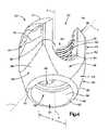
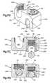
- FIG. 1Bis a perspective view of one of the bone fixation elements illustrated in FIG. 1A constructed in accordance with one embodiment, including an anchor seat, a bone anchor, a collet, and a locking cap;
- FIG. 2is a perspective view of the spine fixation rod illustrated in FIG. 1A ;
- FIG. 3is a perspective view of the bone anchor illustrated in FIG. 1B ;
- FIG. 4is a perspective view of the anchor seat illustrated in FIG. 1B ;
- FIG. 5Ais an exploded perspective view of the locking cap illustrated in FIG. 1B ;
- FIG. 5Bis a top plan view of the locking cap illustrated in FIG. 5A ;
- FIG. 5Cis a sectional side elevation view of the locking cap illustrated in FIG. 5B ;
- FIG. 6is a perspective view of the collet illustrated in FIG. 1B ;
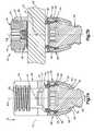
- FIG. 7Ais a sectional side elevation view of the bone fixation element illustrated in FIG. 1B taken along line 7 A- 7 A, with the locking cap removed, to illustrate a pedicle screw assembly;
- FIG. 7Bis a sectional side elevation view similar to FIG. 7B , but showing a spine fixation rod extending through the anchor seat, and a locking cap affixed to the anchor seat;
- FIGS. 8A-Dare schematic views illustrating a method for assembling the bone fixation element illustrated in FIG. 1A ;
- FIG. 9is a perspective view similar to FIG. 1A , but showing a plurality of superior and inferior vertebrae with respect to the previously secured vertebrae;
- FIG. 10Ais a perspective view of a revision connector constructed in accordance with one embodiment
- FIG. 10Bis a top plan view of the revision connector illustrated in FIG. 10A ;
- FIG. 10Cis an end elevation view of the revision connector illustrated in FIG. 10A ;
- FIG. 11Ais a perspective view similar to FIG. 9 , but showing the previously implanted fixation rod cut;
- FIG. 11Bis a perspective view similar to FIG. 9 , but showing a revision connector system including the revision connector illustrated in FIG. 10 secured between a new spine fixation rod to the previously implanted spine fixation rod;
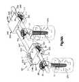
- FIG. 12Ais a schematic end elevation view of the revision connector illustrated in FIG. 11B ;
- FIG. 12Bis a schematic side elevation view of the revision connector illustrated in FIG. 12A ;
- FIG. 12Cis a schematic top plan view of the revision connector illustrated in FIG. 12A ;
- FIG. 13Ais a perspective view of a revision connector constructed in accordance with an alternative embodiment
- FIG. 13Bis a perspective view showing a method for securing the revision connector illustrated in FIG. 13A to the previously implanted spine fixation rod;
- FIG. 14Ais a perspective view of a revision connector constructed in accordance with another alternative embodiment, including a first connector body and a second connector body;
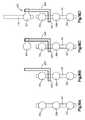
- FIG. 14Bis a schematic elevation view of the first connector body illustrated in FIG. 14A ;
- FIG. 14Cis a schematic elevation view similar to FIG. 14B , but showing the connector body constructed in accordance with an alternative embodiment
- FIG. 14Dis a top plan view of the revision connector shown in FIG. 14C , in accordance with one embodiment.
- FIG. 15Ais a schematic end elevation view of the second connector body illustrated in FIG. 14A ;
- FIG. 15Bis a schematic elevation view similar to FIG. 15A , but showing the second connector body constructed in accordance with an alternative embodiment
- FIG. 15Cis a schematic elevation view similar to FIG. 15B , but showing the second connector body constructed in accordance with another alternative embodiment
- FIGS. 16A-Dare schematic views illustrating a method for assembling the revision connector system illustrated in FIG. 14A ;
- FIG. 17Ais a perspective view of the second revision connector body illustrated in FIG. 14A constructed in accordance with an alternative embodiment
- FIG. 17Bis a perspective view of the second revision connector system illustrated in FIG. 17A with the spine fixation rods removed;
- FIG. 17Cis an end elevation view of the second revision connector system illustrated in FIG. 17B , showing insertion of the previously implanted spine fixation rod;
- FIG. 17Dis an end elevation view of the second revision connector system illustrated in FIG. 17C , showing the previously implanted spine fixation rod secured in the second revision connector body.
- FIG. 18is a schematic view illustrating a revision connector system similar to that illustrated in FIG. 14A with a linkage that is angularly offset with respect to a previously implanted fixation rod.
- a bone fixation assembly 20includes one or more bone fixation elements 22 , and four bone fixation elements 22 A-D as illustrated in FIG. 1A .
- each bone fixation element 22extends vertically along an axial direction A, and generally horizontally along a radial direction R that extends perpendicular to the axial direction A.
- the radial direction Rincludes a longitudinal direction L and a lateral direction LA that extends perpendicular to the longitudinal direction L.
- the bone fixation element 22defines an upper or posterior end 21 and a lower or inferior end 23 , such that the directional terms “upper” and “lower” and derivatives thereof refer to a direction from the lower end 23 towards the upper end 21 , and from the upper end 21 towards the lower end 23 , respectively.
- the words “inward,” “outward,” “upper,” “lower,” “distal,” and “proximal,”refer to directions toward or away from, respectively, the geometric center of the bone fixation assembly 20 and its components.
- the words, “anterior”, “posterior”, “superior,” “inferior” and related words and/or phrasesdesignate preferred positions and orientations in the human body to which reference is made and are not meant to be limiting.
- round structuresdefine diameters as described herein, the round structures could be replaced with alternative (e.g., polygonal) structures which would define alternative cross-sectional dimensions opposed to diameters.
- the term “diameter” as used hereinis intended to include all such alternatives unless otherwise specified.
- the terminologyincludes the above-listed words, derivatives thereof and words of similar import.
- the directional termsare used herein with reference to the orientation of the bone fixation assembly 20 and its components as illustrated, and that the actual orientation of the bone fixation assembly 20 and its components may change during use.
- the axial directionis illustrated as extending along a vertical direction
- the radial directionis illustrated as extending along a horizontal direction, however the directions that encompass the various directions may differ during use, depending, for instance, on the desired orientation of the bone fixation assembly 20 during use.
- the directional termsare used herein merely for the purposes of clarity and convenience only, in a non-limiting manner.
- the bone fixation assembly 20includes a plurality of bone fixation elements, such as bone fixation elements 22 A-D, connected by a spine fixation rod 24 that extends along a longitudinal axis L.
- the bone fixation elements 22 A-Deach include a bone anchor 30 that is implanted (e.g., screwed) into a corresponding vertebra 27 A-D.
- the bone fixation assembly 20 and its componentscan be made from titanium-aluminum-niobium alloy (TAN), implant-grade 316L stainless steel, or any suitable alternative implant-grade material.
- the bone fixation elements 22 A-Dwill be described as and may be generally implanted in the spine, for instance at the pedicle portion of a lumbar, thoracic, or cervical vertebral body.
- the assembly 20fixes the relative position of the vertebrae (illustrated schematically at 27 A-D).
- the bone fixation elements 22 A-Dcan be referred to as spine fixation elements or pedicle screw assemblies
- the spine fixation rod 24can be referred to as a spine fixation rod
- the bone fixation assembly 20can be referred to as a spine fixation assembly.
- the bone fixation assembly 20can also be used for fixation of other parts of the body, such as joints, long bones, or bones in the hands, face, feet, extremities, cranium, and the like.
- the spine fixation rod 24is elongate along a longitudinal axis L, and includes a body 25 that is cylindrical or tubular in shape.
- the longitudinal axis Lextends generally in a cranial-caudal direction when the bone fixation assembly is affixed to the spine.
- the rod body 25may include, but is not limited to, a solid body, a non-solid body, a flexible or dynamic body, or the like, and can assume any alternative shape as desired. It should thus be appreciated that the bone fixation assembly 20 is not limited in use to any particular spine fixation rod 24 .
- the bone fixation element 22generally includes a pedicle screw assembly 75 , and a locking cap 34 .
- the pedicle screw assembly 75is illustrated as including a bone anchor seat 26 , a collet 28 disposed inside the anchor seat 26 , a bone anchor 30 (shown as a threaded bone screw) having a head portion 33 (see FIG. 3 ) attached to the collet 28 .
- the locking cap 34is installed in the anchor seat 26 at a location above the collet 28 , such that the spine fixation rod 24 is located in a rod slot 36 that is disposed, and as illustrated defined, between the collet 28 and the locking cap 34 .
- the bone anchor 30is configured as a bone screw, or pedicle screw, that includes an externally threaded shaft 31 coupled at its upper end to an enlarged curved head 33 .
- the shaft 31extends axially along a central axis B of rotation, and can define any suitable diameter, length, and thread design so as to engage the underlying bone, such as a vertebra 27 .
- the shaft 31can be unthreaded so as to define a pin or a nail if desired.
- the bone anchor 30is not limited to any particular type of shaft 31 .
- the bone anchor 30may also be cannulated and fenestrated such that openings extend radially outward from a central hollow channel in a cannulated shaft to urge fluid out of the bone anchor 30 during injection or draw fluid into the central hollow channel from the radial sides of the anchor during extraction of material adjacent the anchor if desired.
- the bone anchor 30further includes a vertically extending neck 35 connected between the shaft 31 and the head 33 .
- the neck 35is illustrated as extending axially in a direction parallel to axis B, and includes an outer neck surface 37 that defines a neck diameter, which is less than the diameter of the head 33 .
- the head 33can define at least a partially spherical curvature, such as a semi-spherical curvature, or can alternatively define any suitable curvature as desired to facilitate rotation with respect to the collet 28 as is described in more detail below.
- the head 33also includes a drive surface 39 configured to receive a corresponding tip of a drive tool, such as a screw driver configured to rotate the bone anchor 30 into engagement with the vertebrae 27 or other underlying bone surface.
- the drive surface 39can define a hexagon, a star drive pattern, a Phillips head pattern, a slot for a screw driver, threads configured to receive corresponding threads of a threaded drive post, or any suitable drive tool engaging structure as desired.
- the anchor seat 26includes an anchor seat body 38 that can be described as a generally cylindrical tubular body extending centrally along an axial axis A that extends generally in the anterior-posterior direction when the bone fixation element is implanted in the underlying vertebra.
- the body 38includes a base 40 and a pair of spaced opposing arms 42 extending out (up in illustrated the orientation) from the base 40 .
- the arms 42can be substantially identically or identically constructed.
- the arms 42define corresponding upper ends 46 that are also the upper ends of the body 38 , and define an upper opening 48 .
- the base 40defines a lower end 50 that is also the lower end of the body 38 , and defines a lower opening 52 .
- the body 38defines an axial bore 54 extending from the lower opening 52 to the upper opening 48 .
- the body 38includes opposing support walls 56 and a pair of spaced opposing spacer walls 58 connected between the support walls 56 .
- the support walls 56can be substantially identically or identically constructed, and the spacer walls 58 can likewise be substantially identically or identically constructed.
- the arms 42extend up from respective support walls 56 , and can be shaped as desired. As illustrated, the arms 42 are arc-shaped with the axis of the arc passing through the plane of symmetry that bisects the anchor seat 26 .
- Each arm 42extends circumferentially about its axis less than 180°, such as between 60° and 150°, for instance approximately 90°. For instance, each arm 42 can extend circumferentially 90.5° about its axis.
- a gap Gextends circumferentially between adjacent circumferentially outer ends of the arms 42 .
- the opposing gaps Gare in alignment with the axial bore 54 .
- the arms 42can be disposed radially opposite each other such that the gaps G, in combination with the aligned portion of the axial bore 54 , define a rod-receiving channel 36 that is sized and configured to receive the spine fixation rod 24 such that the spine fixation rod 24 extends through the bone fixation element 22 .
- the gaps Gare aligned in the longitudinal direction.
- the spine fixation rod 24can thus extend through the opposing gaps G and the axial bore 54 .
- the arms 42define radially inner and outer surfaces 60 and 62 , respectively.
- the inner surfaces 60define threads 62 , and are configured to threadedly receive the locking cap 34 , as will now be described.
- the locking cap 34is illustrated as a set screw 64 and a saddle 66 operatively coupled to the set screw 64 .
- the set screw 64includes a generally cylindrical set screw body 65 having external threads 68 configured to threadedly engage the threads 62 formed on the inner surfaces 60 of the arms 42 .
- the threads 68 and 62can incorporate inclined load flanks forming an angle with respect to the axis A of the bone fixation element 22 .
- the load flanksmay converge so that the top surface of the thread and the bottom surface of the thread converge.
- the anglemay be between 0 degrees (0°) and 30 degrees (30°), and in one embodiment can be about five degrees (5°).
- the threadsmay take on any alternative form as desired, including negative load threads, perpendicular threads, buttress threads, or the like.
- the externally threaded set screw 64generally provides flexibility when inserting the spine fixation rod 24 into the anchor seat body 38 such that the spine fixation rod 24 need not be completely reduced or seated within the body 38 prior to engagement of the locking cap 34 .
- the set screw 64is configured to be tightened within the anchor seat 26 against the spine fixation rod 24 .
- the locking cap 34may be constructed as desired for this purpose including, but not limited to, an externally threaded cap, a quarter-turn or partial-turn locking cap, a two-piece screw set, or the like.
- the set screw 64is illustrated as including a drive surface 70 provided as an internal recess extending vertically down into the upper end of the screw 64 .
- the drive surfacehas any suitable shape configured to cooperate with a corresponding drive tool for threadedly securing the set screw 64 onto the anchor seat body 38 .
- the drive surface 70can define any shape as desired, for instance an external hexagon, a star drive pattern, a Phillips head pattern, a slot for a screw driver, a threading for a correspondingly threaded post, or the like.
- the saddle 66includes a saddle body 72 having a transverse recess 74 extending up into the bottom end of the saddle body 72 .
- the recess 74can define a round surface that extends about a longitudinally extending axis, such that the recess 74 is configured to receive the spine fixation rod 24 at a rod-contacting surface 76 .
- the rod-contacting surface 76can include a desired surface finish that adds roughness, such as, for example, a knurl, bead blasting, grooves, or other textured finish that increases surface roughness and enhances rod push through strength.
- the saddle 66can be coupled to the set screw 64 in any desired manner, including adhesion, mechanical fastening, and the like.
- the saddle 66includes a stem 78 extending centrally upward from the saddle body 72 .
- the stem 78is configured to be received in a central bore 32 extending vertically into the lower end of the set screw body 65 , and can be fastened within the central bore with a rivet 80 or other like fastener.
- the saddle 66is rotatable relative to the set screw 64 , such that the saddle 66 can self-align with the spine fixation rod 24 as the set screw 64 is being rotated with respect to the anchor seat 26 , for instance when the locking cap 34 is being tightened against the spine fixation rod 24 .
- the anchor seat body 38includes a pair of spaced opposing support walls 56 and a pair of spaced opposing spacer walls 58 connected between the support walls 56 .
- the arms 42extend up from respective support walls 56 , such that the spacer walls 58 are disposed between the arms 42 .
- Each of the spacer walls 58defines opposing upper ends 84 and lower ends 82 that can be shaped as desired.
- the upper ends 84are round in accordance with the illustrated embodiment, such that the upper ends 84 and the circumferentially outer ends of the arms 42 are adjoined to generally define a U-shape from a horizontal view through the gaps G.
- the upper ends 84define the lower end of the gaps G.
- the upper ends 84can be shaped to conform generally with the outer surface of the spine fixation rod 24 , such that the upper ends 84 receive and engage the spine fixation rod 24 during use.
- the upper ends 84can be spaced slightly below the upper surface of the collet 28 , such that the collet 28 supports the spine fixation rod 24 during use, as will be described in more detail below.
- the support walls 56each define opposing inner and outer surfaces 86 and 88 , respectively.
- the support walls 56 and the spacer walls 58flare inward toward the central axis A in a downward direction from the arms 42 , and terminate at respective lower ends 90 .
- the inner surfaces 86 of the opposing support walls 56 and spacer walls 58 at the lower end 90define a distance D therebetween that is less than the distance between opposing radially opposing inner surfaces 60 of the arms 42 .
- the distance Dcan be less than or greater than the diameter of the head 33 of the bone anchor 30 .
- the inner surfaces 86flare radially inward toward the central axis A, and toward each other, along a downward direction, and are each connected to bottommost, and innermost, surfaces that define respective abutment walls 92 .
- each abutment wall 92defines respective inner abutment surfaces 93 that in turn define a distance therebetween that is substantially equal to the diameter of the neck 35 , such that the abutment walls 92 are configured to abut opposing abutment surfaces of the bone anchor, which are illustrated as opposing sides of the outer neck surface 37 when the bone anchor 30 is disposed in the anchor seat 26 .
- the abutment walls 92can prevent or limit pivoting of the bone anchor 30 relative to the anchor seat 26 in a desired plane.
- the collet 28includes a collet body 45 that defines a first or upper end 47 sized and configured to contact or support at least a portion of the spine fixation rod 24 when the rod is received within the rod-receiving channel 36 , and a second or lower end 49 sized and configured to contact or otherwise engage, directly or indirectly, a portion of the bone anchor head 33 .
- the collet body 45is annular, and thus defines an axial bore 53 extending between and through the upper and lower ends 47 and 49 . The axial bore 53 is aligned with the axial bore 54 when the collet 28 is installed in the anchor seat 26 .
- the upper end 47defines radially opposing upwardly facing seat portions 51 having a curvature or semi-spherical shape corresponding to the outer surface of the spine fixation rod 24 , and is therefore configured to receive or otherwise support at least a portion (e.g., a lower portion) of the rod 24 .
- the lower end 49defines an inner surface 55 defining a curvature or semi-spherical shape corresponding to the outer surface of the anchor head 33 , and is therefore configured to receive or otherwise engage at least a portion of the head 33 , so that the head can rotate with respect to the collet 28 and the anchor seat 26 , and can further pivot with respect to the collet 28 as permitted by the anchor seat 26 .
- the bone anchor 30can freely rotate about its axis of rotation B relative to the anchor seat 26 , and thus the anchor seat 26 can likewise rotate about the bone anchor 30 , the rod-receiving channel 36 can be aligned with the spine fixation rod 24 without advancing or withdrawing the bone anchor 30 in or out of the underlying bone.
- the bone anchor 30can maintain a constant insertion depth in the underlying bone (e.g., vertebra 27 ) while adjusting the orientation of the rod-receiving channel 36 .
- the collet 28further includes a pair of flanges 57 extending up from the upper end 47 of the collet body 45 at a location radially between the seat portions 51 .
- a locking lip 59extends radially out from each flange 57 .
- the anchor seat 26defines a pair of opposing recesses 61 (see FIG. 8A ) formed radially in the opposing inner surfaces 86 of the support walls 56 at a location below the threaded inner surfaces 60 of the arms 42 .
- the collet 28can be inserted down into the anchor seat 26 , thereby causing the flanges 57 to flex inwardly past the threaded inner surfaces 60 , until the lips 59 clear the upper ends of the recesses 61 , at which point the flanges 57 snap back out so that the lips 59 are disposed in the recesses 61 . Interference between the lips 59 and the upper ends of the recesses 61 prevent the collet 28 from backing out through the upper end of the anchor seat 26 .
- the recesses 61further define a circumferential length substantially equal to that of the flanges 57 and locking lips 59 , such that the collet 28 is rotationally fixed with respect to the anchor seat 26 in a position whereby the upper surface 47 is aligned with the spine fixation rod 24 when the spine fixation rod 24 is inserted into the anchor seat 26 .
- the lower end 49 of the collet 28defines an outer diameter that is greater than the inner distance between the abutment walls 92 . Accordingly, the collet 28 is unable to pass axially down through the lower end of the anchor body 26 .
- the lower end 49includes one or more slots 67 (illustrated as a plurality of slots) extending radially therethrough so as to define opposing pluralities of fingers 69 that are configured to pop over the head 33 of the bone anchor 30 .
- the fingers 69when the collet 28 and anchor 30 are installed in the anchor seat 24 , the fingers 69 radially expand to conform with the outer surface of the anchor head 33 and the inner surfaces of the anchor seat 26 .
- the inner diameters defined by the opposing fingers 69are less than the outer diameter of the anchor head 33 to prevent the anchor 30 from being removed from the anchor seat 26 in an axially downward direction.
- the lower ends of the fingers 69terminate at a location above the abutment walls 92 . Accordingly, the fingers 69 do not interfere with the engagement between the anchor neck 35 and the abutment walls 92 .
- a method for assembling the pedicle screw assembly 75includes at step 1 , inserting the bone anchor 30 vertically down through the axial bore 54 , such that the shaft 31 extends through the lower opening 52 of the lower end 50 of the anchor seat 26 , and the anchor head 33 is disposed above the abutment walls 92 .
- This method step for inserting the bone anchor 30 into the anchor seat 26can thus be referred to as top-end loading of the bone anchor 30 into the anchor seat 26 .
- the collet 28is inserted into the axial bore 54 to a location whereby the locking lips 59 can engage the lowermost threads 62 of the inner surface 60 of the arms 42 .
- an upward forcecan be applied to the bone anchor 30 so as to insert the anchor head 33 into the lower end 49 of the collet 28 .
- the locking lips 59 of the collet 28brace against the anchor seat 26 inside the threads 62 to prevent the upward force applied by the screw 28 from causing the collet 28 to back out of the upper opening of the anchor seat 26 .
- a downward forceis applied to the collet 28 , thereby inserting the locking lips 59 into the recesses 61 in the manner described above, and locking the anchor 30 and collet 28 in the anchor seat 26 .
- a driving toolcan engage the drive surface 39 of the head 33 so as to insert the threaded shaft 31 into the underlying bone, as shown in FIG. 1A .
- the anchor seat 26can be rotated about axis A in the direction of Arrow R about the full 360° range of angles so as to align the rod-receiving channel 36 with the longitudinal axis of the spine fixation rod 24 .
- the spine fixation rod 24can be inserted into the pedicle screw assembly 75 .
- the spine fixation rod 24is inserted into the axial bore 54 either horizontally through the gaps G, or vertically down into the axial bore 54 . It should be appreciated that the spine fixation rod 24 will be seated in the upper end 47 of the collet 28 .
- the locking cap 34can be attached to the assembly 75 so as to fully assemble the anchor assembly 22 .
- the external threads 68 of the set screw 64are rotated within the inner threads 62 of the anchor seat arms 42 , thereby causing the set screw and saddle 66 to move axially down in the axial bore 54 .
- the saddle 66is rotated with respect to the set screw 64 so as to bring the rod-contacting surface 76 into alignment with the spine fixation rod 24 .
- the set screw 64is continuously threadedly inserted into the bone anchor 26 , such that the locking cap 34 can be tightened against the rod 24 , thereby applying a downward axial force to the rod 24 .
- the locking cap 34can be said to be in an initial position when installed in the locking cap 34 but before applying an axial force against the spine fixation rod 24 .
- the axial force applied to the rod 24 by the locking cap 34is transmitted to the collet 28 , which causes the fingers 69 to ride along the inner surfaces 86 of the support walls 56 and spacer walls 58 .
- the fingers 69ride along the walls 56 and 58 , they become radially inwardly displaced due to the inward flare of the inner surfaces of the walls 56 and 58 , thereby radially biasing, or radially compressing, the fingers 69 against the anchor head 33 .
- Increasing radial compression of the fingers 69 against the anchor head 33causes frictional forces between the fingers 69 and the anchor head 33 that resist rotation of the anchor 30 about the axis A relative to the anchor seat 26 , collet 28 , and spine fixation rod 24 .
- the locking capis fully tightened to a locked position, the resulting frictional forces prevent the anchor 30 from movement relative to the anchor seat 26 , collet 28 , and spine fixation rod 24 .
- the locking cap 34is configured to transmit a locking force onto the collet 28 and bone anchor 30 to fix or lock the position of the bone anchor 30 relative to the anchor seat 26 and spine fixation rod 24 . It should thus be appreciated that the spine fixation rod 24 is thus implanted to the underlying vertebra that is engaged by the bone anchor 30 .
- the above-described method stepscan be performed for each bone fixation element of the bone fixation assembly 20 as desired.
- the bone fixation elements 22 a - dhave been described as each including the pedicle screw assembly 75 described above, the bone fixation elements 22 a - d can include any alternatively constructed pedicle screw assembly suitable for fixing the spine fixation rod 24 to the underlying vertebrae 27 .
- the pedicle screw assembly 75can be constructed so as to permit the bone anchor 30 to be implanted into underlying bone before the anchor head 33 is inserted into the collet 28 .
- the abutment walls 92are slotted so as to expand over the anchor head 33 .
- the anchor seat 26 and collet 28can be popped onto the head 33 from above instead of inserting the anchor 30 down through the anchor seat 26 in the manner described above.
- the method step of popping the anchor seat 26 over the head 33can be referred to as bottom-end loading of the anchor 30 into the anchor seat 26 .
- the spine fixation rod 24is implanted in a plurality of vertebrae 27 a - d in the bone fixation assembly 20 , it may become desirable at a future date to extend the bone fixation assembly 20 to affix at least one such as a plurality of vertebrae to the vertebrae 27 a - d .
- the spine fixation rod 24can be referred to herein as a previously implanted spine fixation rod.
- the vertebra 27 ais the cranial-most vertebra that is secured to the spine fixation rod 24
- the vertebra 27 dis the caudal-most vertebra that is secured to the spine fixation rod 24 .
- the vertebra 27 his superior to the vertebra 27 a
- the vertebra 27 gis superior to the vertebra 27 h .
- the vertebra 27 eis inferior to the vertebra 27 d
- the vertebra 27 fis inferior to the vertebra 27 e
- the vertebrae 27 g - h and 27 e - fcan be referred to as new vertebrae.
- a revision connector 100is configured to couple a new spine fixation rod to the previously implanted spine fixation rod 24 .
- the revision connector 100includes a body 101 having an inner vertebral facing surface 102 , an opposing outer surface 103 separated from the inner surface 102 along the axial direction A, opposing end surfaces 104 connected between the inner and outer surfaces 102 and 103 and spaced apart in the longitudinal direction, and opposing side surfaces 105 connected between the inner and outer surfaces 102 and 103 , further connected between the end surfaces 104 , and spaced apart in the lateral direction.
- one of the end surfaces 104can be positioned as a superior end surface, while the other end surface 104 can be positioned as an inferior end surface once the connector 100 has been implanted.
- the connector 100is illustrated having a generally rectangular structure having the discrete surfaces 102 - 105 , it should be appreciated that any shaped structure can define the surfaces as described herein as desired, even though the surfaces may be curved or angled with respect to the longitudinal, axial, and/or lateral directions.
- the revision connector 100is a dual head connector, such that the body 101 defines a first head 106 and a first rod receiving channel 108 extending into the first head 106 , and a second head 110 and a second rod receiving channel 112 extending into the second head 110 .
- the rod receiving channels 108 and 112include respective round inner surfaces 109 and 111 that can be contoured to generally conform with and support the outer diameter of a new spine fixation rod 116 (see FIG. 11B ) and the previously implanted spine fixation rod 24 . It should be appreciated that the previously implanted rod 24 and the new rod 116 can be more broadly construed as fixation elements.
- the revision connector 100can further include a divider wall 114 that separates the heads 106 and 110 , and further defines opposing stop surfaces 114 a and 114 b in the rod receiving channels 108 and 112 , respectively.
- the revision connector 100includes opposing threaded arcuate cutouts 113 extending axially into the body 101 at the second head 110 .
- the cutouts 113are configured to receive a locking cap such as the locking cap 34 described above.
- the body 101 of the second head 110is constructed generally as described above with respect to the spaced opposing arms 42 that define a rod receiving channel 36 .
- the body 101 of the second head 110likewise defines the rod receiving channel 112 . Furthermore, the body 101 defines a lower opening 118 that extends axially between and through the inner surface 102 and the rod receiving channel 108 in a direction substantially transverse to the rod receiving channel 108 , generally as described above with respect to the lower opening 52 . Thus the lower opening 118 is sized to receive and retain a bone anchor 30 in the manner described above. As will be appreciated from the description below, the opening 118 is in operative alignment with the spine fixation rod that extends into the corresponding channel. That is, the opening 118 can retain the bone anchor 30 that fixes the spine fixation rod to the underlying vertebra.
- the body 101further defines an axial bore 120 extending through the second head 110 in alignment with the lower opening 118 .
- the axial bore 120is generally as described above with respect to the axial bore 54 .
- the first head 106defines an anchor seat 122 generally as described above with respect to the anchor seat 26 .
- the connector body 101can thus also be referred to as an anchor seat body, and the head 110 can be referred to as an anchor seat.
- the body 101 of the first head 106is generally as described above with respect to the second head 110 , however, the first head 106 does not define a lower opening extending between and through the inner surface 102 and the rod receiving channel 108 . Thus, the first head 106 is not configured to support a bone anchor. Alternatively, it should be appreciated that the first head 106 can be constructed as described with respect to the second head 110 so as to allow either head to secure directly to an underlying vertebra via a bone anchor.
- the first fixation rod receiving channel 108extends from the respective end surface 104 of the first head 106 to the stop surface 114 a of the divider wall 114
- the second fixation rod receiving channel 112extends from the respective end surface 104 of the second head 110 to the stop surface 114 b of the divider wall 114
- the connector body 101can be devoid of the divider wall 114 , such that the rod receiving channels 108 and 112 are continuous with each other.
- the heads 106 and 110 , and the respective channels 108 and 112are in lateral alignment with each other, they could alternatively be laterally offset as described in more detail below.
- each head 106 and 110has only one end surface that collectively define the end surfaces 104 of the connector body 101 . In embodiments where the heads 106 and 110 are laterally adjacent, each head 106 and 110 has only one side surface 105 that collectively define the opposing side surfaces 105 of the connector body 101 .
- a revision connector system 121can include the revision connector 100 , the new spine fixation rod 116 , a bone anchor such as the bone anchor 30 as described above, one or more collets such as the collet 28 constructed as described above configured to retain the bone anchor 30 , and one or more locking caps such as the locking cap 34 constructed as described above.
- the revision connector system 121 and its componentscan be made from a titanium-aluminum-niobium alloy (TAN), implant-grade 316L stainless steel, or any suitable alternative implant-grade material
- the colletis configured to capture and lock the head of the bone anchor 30 by popping the connector body 101 down onto the bone anchor 30 so as to “pop” the collet onto the head of the bone anchor 30 as described above.
- the colletcan be configured to couple to the bone anchor 30 by loading the bone anchor 30 down through the top of the connector 100 so that the shaft of the anchor extends through the opening 118 prior coupling the bone anchor 30 to the underlying vertebral body.
- the collapsible colletcan be replaced by other elements that are configured to be disposed interior to rod-to-screw connectors and serve to securely connect the head of the bone anchor 30 to the connector body 101 .
- the locking caps 34are configured to secure the previously implanted rod 24 and the new rod 116 to the connector 100 , and to secure the bone anchor 30 to the connector 30 .
- the previously implanted spine fixation rod 24may define a range of different diameters, as manufacturers often market spine fixation rods of differing diameters.
- the pedicle screw assemblies 75 of the bone fixation elements 22 A-Dcan assume the form of a variety of different makes and models.
- the new spine fixation rod 116can have a diameter that is substantially equal to, greater than, or smaller than, that of the previously implanted spine fixation rod 24 .
- the connector 100can be configured to secure the spine fixation rods 116 and 24 whether their diameters are the same or different.
- pedicle screw assemblies that secure the new spine fixation rod 116 to underlying vertebraecan be constructed the same as or differently than the pedicle screw assemblies 75 .
- the revision connector system 121can extend the previously implanted bone fixation assembly 20 by extending the previously implanted spine fixation rod 24 to other vertebrae. As illustrated in FIG. 11A , the previously implanted rod 24 is cut at a location between the outermost secured vertebra and the adjacent secured vertebra. The bone fixation element 22 associated with the outermost vertebra is then removed. For instance, as shown in FIG. 11A , when extending the spine fixation rod cranially, the spine fixation rod 24 is first cut between the cranial-most secured vertebra 27 a and the adjacent vertebra 27 b , and the bone fixation element 22 a .
- the spine fixation rod 24When extending the spine fixation rod caudally, the spine fixation rod 24 is first cut between the caudal-most secured vertebra 27 d and the adjacent vertebra 27 c , and the bone fixation element 22 d is removed.
- the bone anchor 30is then implanted at or near the point from which the bone anchor portion of the bone fixation element 22 a was removed, or into the vertebral body 27 h adjacent (cranially) to the vertebral body 27 a from which the bone fixation element 22 a was removed.
- the revision connector 100is then placed such that the superior end of the previously implanted spine fixation rod 24 is disposed in the channel 108 of the first head 106 , and the second head 110 is secured to the bone anchor 30 .
- the bone anchor 30can already be implanted in the underlying vertebra, such that the anchor seat 122 is popped over the anchor head 33 in the manner described above.
- the bone anchor 30can be inserted longitudinally through the axial bore 120 in the manner described above, and subsequently affixed to the underlying vertebra.
- the newer rod 130is then implanted and secured to a desirable number of at least one superior vertebral body, such as the superior vertebral bodies 27 h and 27 g , using a corresponding number of additional pedicle screw assemblies, such as pedicle screw assemblies 75 as described above.
- the inferior end of the new spine fixation rod 116which extends over at least one superior vertebra to be secured, is then urged into the rod receiving channel 112 of the second head 110 .
- the spine fixation rods 24 and 116can be inserted until their terminal ends abut the respective stop surfaces 114 a - b of the divider wall 114 .
- the locking cap 34can be threaded into the arcuate cutouts 113 so as to secure the previously implanted spine fixation rod 24 to the first head 106 in the channel 108 , and to secure the new spine fixation rod 116 and the bone anchor 30 to the second head 110 in the channel 112 .
- the new rod 116is then implanted and secured to a desirable number of at least one inferior vertebral body, such as the inferior vertebral bodies 27 e and 27 f , using a corresponding number of additional pedicle screw assemblies, such as pedicle screw assemblies 75 as described above.
- the superior end of the new spine fixation rod 116is then urged into the rod receiving channel 112 of the second head 110 .
- channels 108 and 112are illustrated as extending down through the outer surface 103 toward the inner surface 102 of their respective heads 106 and 110 , it should be appreciated that at least one or both of the channels 108 and 112 could alternatively extend into one of the side surfaces 105 or the inner surface 102 unless otherwise indicated.
- the channel 108 of the first head 106extends into one of the side surfaces 105 .
- the opposed arcuate cutouts 113extend laterally into the channel 108 .
- the bone anchor 30is fastened to the underlying vertebra 27 , such that the anchor head 33 is disposed in the second head 110 .
- the anchorcan be inserted down through the opening 118 , or the second head 110 of the connector body 101 can be popped onto the head of the bone anchor 30 .
- the connector body 101can be rotated through an angle about the central axis B of the bone anchor 30 along the direction R 1 so as to guide the previously implanted spine fixation rod 24 into the channel 108 of the first head 106 , thereby side-loading the rod 24 into the channel 108 .
- the new rod 116is then urged into the second head 110 of the revision connector 200 , and the locking caps 34 can be tightened to secure the connector 200 to previously implanted rod 24 , the new rod 116 , and the bone anchor 30 .
- the channel 108 of the first head 106can be laterally offset with the channel 112 of the second head 110 , or inline with the channel 112 of the second head 110 .
- a revision connector system 221can be provided that is configured to secure one or more new vertebrae to vertebrae that have previously been fixed using the previously implanted spine fixation rod 24 without cutting the spine fixation rod 24 as described above with respect to the revision connector system 121 .
- the revision connector system 221includes a revision connector 200 , the new spine fixation rod 116 , a bone anchor such as the bone anchor 30 as described above, one or more collets such as the collet 28 constructed as described above configured to retain the bone anchor 30 , and one or more locking caps such as the locking cap 34 constructed as described above.
- the revision connector 200includes a first connector body 201 and a second body 240 that is coupled to the first body via a fixation element in the form of a linkage 247 that can be provided as a rod segment that can be integrally connected to the second body 240 , and thus part of the second body 240 , or discretely connected to the second body 240 .
- the first body 201defines an inner vertebral facing surface 202 , an opposing outer surface 203 separated from the inner surface 202 along the axial direction A, opposing end surfaces 204 connected between the inner and outer surfaces 202 and 203 and spaced apart in the longitudinal direction, and opposing side surfaces 205 connected between the inner and outer surfaces 202 and 203 , further connected between the end surfaces 204 , and spaced apart in the lateral direction. It should be appreciated that, depending on the orientation of the first connector body 201 , one of the end surfaces 204 can be positioned as a superior end surface, while the other end surface 204 can be positioned as an inferior end surface once the connector 200 has been implanted.
- connector 200is illustrated having a generally rectangular structure having the discrete surfaces 202 - 205 , it should be appreciated that any shaped structure can define the surfaces as described herein as desired, even though the surfaces may be curved or angled with respect to the longitudinal, axial, and/or lateral directions.
- the first body 201defines a first head 206 and a first rod receiving channel 208 extending into the first head 206 , and a second head 210 and a second rod receiving channel 212 extending into the second head 210 .
- the first rod receiving channel 206extends into one of the side surfaces 205 of the first head 206
- the second rod receiving channel 210extends into the outer surface 203 of the second head 210 .
- the rod receiving channels 208 and 212include respective round inner surfaces 209 and 211 that can be contoured to generally conform with the outer diameter of the new spine fixation rod 116 and the linkage.
- the revision connector 200can further include stop surfaces 214 a and 214 b in the rod receiving channels 208 and 212 , respectively.
- the revision connector 200includes opposing threaded arcuate cutouts 213 extending axially into the body 201 at the first head 206 .
- the cutouts 213are configured to receive a locking cap such as the locking cap 34 described above.
- the body 201 of the first head 206is constructed generally as described above with respect to the spaced opposing arms 42 that define a rod receiving channel 36 .
- the body 201does not define a lower opening (such as opening 118 described above) that extend extends axially between and through the inner surface 202 and either rod receiving channel 208 or 212 .
- a lower openingsuch as opening 118 described above
- either or both ( FIG. 14D ) of the first and second heads 206 and 210can include a lower opening such as opening 118 so as to allow either head to secure directly to an underlying vertebra via a bone anchor.
- the first fixation rod receiving channel 208extends into the side surface 205 , and is elongate from the respective end surface 204 of the first head 206 to the stop surface 114 a .
- the second fixation rod receiving channel 212extends into the outer surface 203 , and is elongate from the respective end surface 204 of the second head 210 to the stop surface 214 b .
- the channels 208 and 212could extend longitudinally entirely through to the connector body 201 .
- the second channel 212is laterally offset with respect to the channel 208 , and is illustrated as laterally outwardly spaced from the channel 208 with respect to the previously implanted rod 24 .
- the channels 208extend longitudinally, in a direction substantially parallel to the previously implanted fixation rod 24 , though it should be appreciated that the linkage 247 , and thus the channel 212 , can alternatively be angularly offset with respect to the fixation rod 24 as illustrated in FIG. 18 .
- the first rod receiving channel 208extends laterally into the side surface 245 , though the first rod receiving channel 208 can alternatively extend vertically into the outer surface 243 of the first connector body 201 as shown in FIGS. 14B-C .
- the second rod receiving channel 212extends vertically into the outer surface 243 of the first connector body 201 as illustrated in FIG. 14A
- the second rod receiving channel 212could alternatively extend laterally into the side surface 245 as illustrated in FIG. 14B .
- the rod receiving channels 208 and 212can be laterally adjacent and aligned with each other.
- the channels 208 and 212could alternatively be vertically or longitudinally aligned with each other, if desired.
- the second body 240defines an inner vertebral facing surface 242 , an opposing outer surface 243 separated from the inner surface 242 along the axial direction A, opposing end surfaces 244 connected between the inner and outer surfaces 242 and 243 and spaced apart in the longitudinal direction L, and opposing side surfaces 245 connected between the inner and outer surfaces 242 and 243 , further connected between the end surfaces 244 , and spaced apart in the lateral direction. It should be appreciated that, depending on the orientation of the second connector body 240 , one of the end surfaces 244 can be positioned as a superior end surface, while the other end surface 244 can be positioned as an inferior end surface once the connector 200 has been implanted.
- connector 200is illustrated having a generally rectangular structure having the discrete surfaces 242 - 245 , it should be appreciated that any shaped structure can define the surfaces as described herein as desired, even though the surfaces may be curved or angled with respect to the longitudinal, axial, and/or lateral directions.
- the second connector body 240defines a head 246 and a rod receiving channel 248 that extends longitudinally through the head 246 between the opposing end surfaces 244 .
- the rod receiving channel 248further extends laterally into the side surface 245 located proximate to the previously implanted fixation rod 24 .
- the rod receiving channel 248is thus configured to receive the previously implanted fixation rod 24 .
- a pair of threaded opposing arcuate cutouts 213extends into each connector body 201 and 204 at locations aligned with the rod receiving channels 208 , 212 , and 248 , and is configured to receive the locking cap in the manner described above with respect to the connector body 101 .
- the second body 240also defines a linkage 247 that extends from the inner end surface 244 , that is the end surface 244 that faces toward the first body, in a direction toward the first body 201 .
- the linkage 247is laterally offset, and displaced laterally outward, with respect to the channel 248 , and thus the previously implanted spinal fixation rod 24 .
- the first body 240extends in a direction angularly offset, and substantially perpendicular, with respect to the previously implanted fixation rod 24 .
- the linkage 247can be provided as cylindrical or tubular, and thus constructed in the same manner as the fixation rods 24 and 116 .
- the linkage 247can be integrally connected or discretely attached to the second body 240 .
- the second body 240can include a head having a rod receiving channel that receives and secures the linkage 247 to the second body in the manner described herein with respect to the channel 212 .
- the rod receiving channel 248can alternatively extend laterally into the side wall 245 that is disposed proximate to the previously implanted rod 24 .
- the rod receiving channel 248can alternatively extend vertically into the outer surface 243 or the inner surface 242 as illustrated in FIGS. 15B and 15C , respectively.
- any of the rod receiving channels described herein in accordance with all embodimentscould alternatively extend longitudinally into the respective end surfaces without also extending into one of the inner, outer, and side surfaces, unless otherwise indicated.
- the fixation rodwould be inserted longitudinally into the respective head of the connector body.
- a method for extending the pre-existing bone fixation assembly 20can be provided without cutting the previously implanted spine fixation rod 24 or removing the outermost bone fixation element 22 .
- the first connector body 201is fixed via one or more bone anchors 30 to at least one such as a plurality of vertebrae (e.g., the pedicle of the vertebrae) that are superior and/or inferior to the previously fixed vertebrae.
- the first connector body 201can be secured to vertebrae 27 g - h to extend the bone fixation assembly 20 cranially, and to vertebrae 27 e - f to extend the bone fixation assembly caudally.
- the second connector body 240is then urged onto the previously implanted fixation rod 24 at a location between a pair of the previously implanted bone fixation elements 22 , so that the rod 24 is disposed in the rod receiving channel 248 .
- the channel 248can receive the rod 24 at a location between inferior to the superior vertebra 271 , such as between the superior vertebra 27 a and the adjacent vertebra 27 b .
- the channel 248can receive the rod 24 at a location superior to the inferior vertebra 27 d , such as between the inferior vertebra 27 d and the adjacent vertebra 27 c.
- the second connector body 240thus extends from the previously implanted spine fixation rod 24 laterally outward such that the linkage 247 is laterally offset from the rod 24 and extends substantially parallel to the rod 24 .
- the first connector body 201is then urged to the linkage 247 so as to receive the linkage 247 in the rod receiving channel 212 .
- the linkage 247can be laterally or vertically inserted into the channel 212 .
- the first connector body 201is then urged to the new spine fixation rod 116 , such that the rod 116 is received in the first rod receiving channel 208 , thereby coupling the bone anchor 30 that is extending from the connector 201 to the second connector body 240 .
- the connector body 201can be secured to the fixation rod 116 and the linkage 247 , and the second connector body 240 can be secured to the fixation rod 24 , by tightening respective locking caps in the channels in the manner described above.
- a locking plugcan be inserted into the channel 208 .
- the locking plugcan be constructed similar to the locking screws known in the art with the exception that a rod segment is attached thereto and fixed to the underlying vertebrae in the manner described above.
- the second connector body 240can be discretely connected to the linkage 247 .
- the connector body 240includes a head 251 laterally adjacent to the head 246 , and a rod receiving channel 250 extending vertically down into the outer surface 243 , and extending longitudinally through the head 251 .
- the channel 250extends longitudinally into the inner end surface 244 , and can extend longitudinally through the connector body 240 and through the opposing outer end surface 244 .
- An arcuate cutout 213can extend vertically into the connector body 240 in a direction transverse to and in alignment with the channel 250 so as to receive a locking cap 34 of the type described above.
- the linkage 247can be provided as a rod segment that is received in the channel 250 , such that the locking cap 34 can be tightened against the linkage 247 to secure the linkage 247 in the channel 250 .
- the channel 250can alternatively extend into the inner surface 242 , or the outer side surface 245 as desired.
- the channel 248is illustrated as extending up into the inner surface 242 of the connector body 240 at a location laterally offset and aligned with the channel 250 . Accordingly, the connector body 240 defines an S-shape as illustrated in end elevation. Alternatively, the channel 248 can extend into any surface of the connector body 240 as desired.
- the channel 248extends in the longitudinal direction L through the connector body 240 , and is thus configured to receive the previously implanted rod 24 extending along the longitudinal direction.
- the connector body 240can define a bore 249 extending vertically down from the outer surface 243 into the channel 248 .
- the revision connector system 221can include a clamp 252 having a clamp body 253 that has an outer diameter substantially equal to the inner diameter of the bore 249 .
- the clamp body 253can include an horizontal support wall 254 and a pair of legs 256 extending down from the upper support wall 254 .
- the upper support wall 254can include a threaded surface 255 configured to engage corresponding external threads 257 of the locking cap 34 inside the bore 249 .
- the clamp 252is moved upwards in the bore, thereby causing the legs 256 to compress toward each other.
- the legs 256are flexible and sized to fit over the previously implanted rod 24 when the legs 256 extend down past the connector body 240 .
- the legs 256 and upper support wall 254thus define a channel 258 that is disposed in the channel 248 defined by the connector body.
- the locking cap 34is tightened so as to cause the connector body 240 to bias the legs 256 toward each other so as to fit around the previously implanted rod 24 and secure the rod 24 to the connector body 240 .
- the linkage 247can be fixed onto one or more cranial or caudal vertebrae via one or more pedicle screw assemblies 75 , or can be secured to the connector body 201 as described above.
- a spine fixation revision connector kitcan be provided that includes a plurality of revision connectors, each revision connector being configured to couple a new spine fixation rod to a previously implanted spine fixation rod that is secured to a plurality of vertebrae.
- Each revision connector in the kitcan include a first head and a first rod receiving channel extending into the first head, and a second head and a second rod receiving channel extending into the second head.
- At least one different revision connector of the plurality of revision connectorsdefines a difference with respect to at least another of the plurality of revision connectors in the kit.
- the different revision connectorcomprises an opening extending into at least a select one of the first and second heads along a direction transverse to the corresponding rod receiving channel.
- the differencecan also be in the form of a shape of the connector body.
- the differencecan be that the connector body defines an anchor seat body.
- the differencecan also be the location of the rod receiving channel.
- the kitcan also be a revision connector system kit that includes a plurality of linkages 247 and/or new fixation rods 116 alone or in combination with the spine fixation revision connector kit.
Landscapes
- Health & Medical Sciences (AREA)
- Orthopedic Medicine & Surgery (AREA)
- Life Sciences & Earth Sciences (AREA)
- Neurology (AREA)
- Surgery (AREA)
- Heart & Thoracic Surgery (AREA)
- Engineering & Computer Science (AREA)
- Biomedical Technology (AREA)
- Nuclear Medicine, Radiotherapy & Molecular Imaging (AREA)
- Medical Informatics (AREA)
- Molecular Biology (AREA)
- Animal Behavior & Ethology (AREA)
- General Health & Medical Sciences (AREA)
- Public Health (AREA)
- Veterinary Medicine (AREA)
- Surgical Instruments (AREA)
- Prostheses (AREA)
Abstract
Description
Claims (43)
Priority Applications (4)
| Application Number | Priority Date | Filing Date | Title |
|---|---|---|---|
| US12/760,816US10105163B2 (en) | 2009-04-15 | 2010-04-15 | Revision connector for spinal constructs |
| US16/140,680US11020152B2 (en) | 2009-04-15 | 2018-09-25 | Revision connector for spinal constructs |
| US17/242,361US12064145B2 (en) | 2009-04-15 | 2021-04-28 | Revision connector for spinal constructs |
| US18/761,487US20240358413A1 (en) | 2009-04-15 | 2024-07-02 | Revision connector for spinal constructs |
Applications Claiming Priority (2)
| Application Number | Priority Date | Filing Date | Title |
|---|---|---|---|
| US16933609P | 2009-04-15 | 2009-04-15 | |
| US12/760,816US10105163B2 (en) | 2009-04-15 | 2010-04-15 | Revision connector for spinal constructs |
Related Child Applications (1)
| Application Number | Title | Priority Date | Filing Date |
|---|---|---|---|
| US16/140,680ContinuationUS11020152B2 (en) | 2009-04-15 | 2018-09-25 | Revision connector for spinal constructs |
Publications (2)
| Publication Number | Publication Date |
|---|---|
| US20110106166A1 US20110106166A1 (en) | 2011-05-05 |
| US10105163B2true US10105163B2 (en) | 2018-10-23 |
Family
ID=42232792
Family Applications (4)
| Application Number | Title | Priority Date | Filing Date |
|---|---|---|---|
| US12/760,816Active2030-06-05US10105163B2 (en) | 2009-04-15 | 2010-04-15 | Revision connector for spinal constructs |
| US16/140,680ActiveUS11020152B2 (en) | 2009-04-15 | 2018-09-25 | Revision connector for spinal constructs |
| US17/242,361Active2032-01-21US12064145B2 (en) | 2009-04-15 | 2021-04-28 | Revision connector for spinal constructs |
| US18/761,487PendingUS20240358413A1 (en) | 2009-04-15 | 2024-07-02 | Revision connector for spinal constructs |
Family Applications After (3)
| Application Number | Title | Priority Date | Filing Date |
|---|---|---|---|
| US16/140,680ActiveUS11020152B2 (en) | 2009-04-15 | 2018-09-25 | Revision connector for spinal constructs |
| US17/242,361Active2032-01-21US12064145B2 (en) | 2009-04-15 | 2021-04-28 | Revision connector for spinal constructs |
| US18/761,487PendingUS20240358413A1 (en) | 2009-04-15 | 2024-07-02 | Revision connector for spinal constructs |
Country Status (8)
| Country | Link |
|---|---|
| US (4) | US10105163B2 (en) |
| EP (1) | EP2419031B1 (en) |
| JP (1) | JP2012523927A (en) |
| KR (1) | KR20120013312A (en) |
| CN (1) | CN102368967B (en) |
| BR (1) | BRPI1008006A2 (en) |
| CA (1) | CA2758590A1 (en) |
| WO (1) | WO2010120989A1 (en) |
Cited By (10)
| Publication number | Priority date | Publication date | Assignee | Title |
|---|---|---|---|---|
| US20170135728A1 (en)* | 2015-11-17 | 2017-05-18 | Warsaw Orthopedic, Inc | Spinal implant system and method |
| US20190090907A1 (en)* | 2009-04-15 | 2019-03-28 | DePuy Synthes Products, Inc. | Revision connector for spinal constructs |
| US10898234B2 (en) | 2007-07-20 | 2021-01-26 | DePuy Synthes Products, Inc. | Polyaxial bone fixation element |
| US11006978B2 (en) | 2009-06-17 | 2021-05-18 | DePuy Synthes Products, Inc. | Revision connector for spinal constructs |
| US11129648B2 (en) | 2008-09-12 | 2021-09-28 | DePuy Synthes Products, Inc. | Spinal stabilizing and guiding fixation system |
| US11337734B2 (en) | 2019-05-22 | 2022-05-24 | Nuvasive, Inc. | Posterior spinal fixation screws |
| US11432850B2 (en) | 2005-11-21 | 2022-09-06 | DePuy Synthes Products, Inc. | Polyaxial bone anchors with increased angulation |
| US11484348B2 (en) | 2008-11-03 | 2022-11-01 | DePuy Synthes Products, Inc. | Uni-planer bone fixation assembly |
| US20230200860A1 (en)* | 2021-12-29 | 2023-06-29 | Zimmer Biomet Spine, Inc. | Rotating rod connectors for spine stabilization |
| US20240058044A1 (en)* | 2022-08-22 | 2024-02-22 | Nexus Spine, LLC | Systems and methods for securely attaching an anchor to an implant body |
Families Citing this family (65)
| Publication number | Priority date | Publication date | Assignee | Title |
|---|---|---|---|---|
| US7833250B2 (en) | 2004-11-10 | 2010-11-16 | Jackson Roger P | Polyaxial bone screw with helically wound capture connection |
| US8876868B2 (en) | 2002-09-06 | 2014-11-04 | Roger P. Jackson | Helical guide and advancement flange with radially loaded lip |
| US7377923B2 (en) | 2003-05-22 | 2008-05-27 | Alphatec Spine, Inc. | Variable angle spinal screw assembly |
| US7967850B2 (en) | 2003-06-18 | 2011-06-28 | Jackson Roger P | Polyaxial bone anchor with helical capture connection, insert and dual locking assembly |
| US8926670B2 (en) | 2003-06-18 | 2015-01-06 | Roger P. Jackson | Polyaxial bone screw assembly |
| US7776067B2 (en) | 2005-05-27 | 2010-08-17 | Jackson Roger P | Polyaxial bone screw with shank articulation pressure insert and method |
| US7766915B2 (en) | 2004-02-27 | 2010-08-03 | Jackson Roger P | Dynamic fixation assemblies with inner core and outer coil-like member |
| US8926672B2 (en) | 2004-11-10 | 2015-01-06 | Roger P. Jackson | Splay control closure for open bone anchor |
| US8444681B2 (en) | 2009-06-15 | 2013-05-21 | Roger P. Jackson | Polyaxial bone anchor with pop-on shank, friction fit retainer and winged insert |
| US9168069B2 (en) | 2009-06-15 | 2015-10-27 | Roger P. Jackson | Polyaxial bone anchor with pop-on shank and winged insert with lower skirt for engaging a friction fit retainer |
| US7901437B2 (en) | 2007-01-26 | 2011-03-08 | Jackson Roger P | Dynamic stabilization member with molded connection |
| US10792074B2 (en) | 2007-01-22 | 2020-10-06 | Roger P. Jackson | Pivotal bone anchor assemly with twist-in-place friction fit insert |
| US8979904B2 (en) | 2007-05-01 | 2015-03-17 | Roger P Jackson | Connecting member with tensioned cord, low profile rigid sleeve and spacer with torsion control |
| US8114141B2 (en) | 2007-12-17 | 2012-02-14 | Synthes Usa, Llc | Dynamic bone fixation element and method of using the same |
| US9579126B2 (en) | 2008-02-02 | 2017-02-28 | Globus Medical, Inc. | Spinal rod link reducer |
| AU2010260521C1 (en) | 2008-08-01 | 2013-08-01 | Roger P. Jackson | Longitudinal connecting member with sleeved tensioned cords |
| KR20110081208A (en) | 2008-09-29 | 2011-07-13 | 신세스 게엠바하 | Multi-Axis Bottom-Loading Screw and Rod Assemblies |
| CN102497828B (en)* | 2009-05-20 | 2015-09-09 | 斯恩蒂斯有限公司 | What patient installed retracts part |
| CN103826560A (en) | 2009-06-15 | 2014-05-28 | 罗杰.P.杰克逊 | Polyaxial Bone Anchor with Socket Stem and Winged Inserts with Friction Fit Compression Collars |
| US11229457B2 (en) | 2009-06-15 | 2022-01-25 | Roger P. Jackson | Pivotal bone anchor assembly with insert tool deployment |
| US9668771B2 (en) | 2009-06-15 | 2017-06-06 | Roger P Jackson | Soft stabilization assemblies with off-set connector |
| US8998959B2 (en) | 2009-06-15 | 2015-04-07 | Roger P Jackson | Polyaxial bone anchors with pop-on shank, fully constrained friction fit retainer and lock and release insert |
| US12383311B2 (en) | 2010-05-14 | 2025-08-12 | Roger P. Jackson | Pivotal bone anchor assembly and method for use thereof |
| US8758411B1 (en) | 2011-10-25 | 2014-06-24 | Nuvasive, Inc. | Implants and methods for treating spinal disorders |
| US8740950B2 (en)* | 2011-12-08 | 2014-06-03 | Spine Wave, Inc. | Methods for percutaneously attaching a cross connector to contralateral spinal constructs |
| EP2606841B1 (en)* | 2011-12-23 | 2016-03-09 | Biedermann Technologies GmbH & Co. KG | Polyaxial bone anchoring device |
| US8911479B2 (en) | 2012-01-10 | 2014-12-16 | Roger P. Jackson | Multi-start closures for open implants |
| US9271759B2 (en) | 2012-03-09 | 2016-03-01 | Institute Of Musculoskeletal Science And Education, Ltd. | Pedicle screw assembly with locking cap |
| JP6174111B2 (en) | 2012-03-13 | 2017-08-02 | シンセス・ゲーエムベーハーSynthes GmbH | Dynamic bone fixation element |
| US9510866B2 (en)* | 2012-08-15 | 2016-12-06 | Blackstone Medical, Inc. | Pivoting spinal fixation devices |
| US8911478B2 (en) | 2012-11-21 | 2014-12-16 | Roger P. Jackson | Splay control closure for open bone anchor |
| US10058354B2 (en) | 2013-01-28 | 2018-08-28 | Roger P. Jackson | Pivotal bone anchor assembly with frictional shank head seating surfaces |
| US8852239B2 (en) | 2013-02-15 | 2014-10-07 | Roger P Jackson | Sagittal angle screw with integral shank and receiver |
| US9566092B2 (en) | 2013-10-29 | 2017-02-14 | Roger P. Jackson | Cervical bone anchor with collet retainer and outer locking sleeve |
| US9717533B2 (en) | 2013-12-12 | 2017-08-01 | Roger P. Jackson | Bone anchor closure pivot-splay control flange form guide and advancement structure |
| US9451993B2 (en) | 2014-01-09 | 2016-09-27 | Roger P. Jackson | Bi-radial pop-on cervical bone anchor |
| EP2932929B1 (en) | 2014-04-15 | 2017-02-08 | Biedermann Technologies GmbH & Co. KG | A screw element for use in spinal, orthopedic or trauma surgery and a system of such a screw element and a screw driver adapted thereto |
| US10064658B2 (en) | 2014-06-04 | 2018-09-04 | Roger P. Jackson | Polyaxial bone anchor with insert guides |
| US9597119B2 (en) | 2014-06-04 | 2017-03-21 | Roger P. Jackson | Polyaxial bone anchor with polymer sleeve |
| CN104207836A (en)* | 2014-09-04 | 2014-12-17 | 浙江嘉佑医疗器械有限公司 | Pedicle screw special for PLIF (Posterior Lumbar Interbody Fusion) |
| JP6643364B2 (en) | 2015-06-25 | 2020-02-12 | インスティテュート フォー マスキュロスケレタル サイエンス アンド エジュケイション,リミテッド | Interbody fusion device and system for implantation |
| US9980755B2 (en) | 2016-03-29 | 2018-05-29 | Globus Medical, Inc. | Revision connectors, systems, and methods thereof |
| US10624679B2 (en) | 2016-03-29 | 2020-04-21 | Globus Medical, Inc. | Revision connectors, systems and methods thereof |
| US10383663B2 (en) | 2016-03-29 | 2019-08-20 | Globus Medical, Inc. | Revision connectors, systems and methods thereof |
| US10307185B2 (en)* | 2016-03-29 | 2019-06-04 | Globus Medical, Inc. | Revision connectors, systems, and methods thereof |
| US10874438B2 (en) | 2016-07-13 | 2020-12-29 | Medos International Sarl | Bone anchor assemblies and related instrumentation |
| US10463402B2 (en) | 2016-07-13 | 2019-11-05 | Medos International Sàrl | Bone anchor assemblies and related instrumentation |
| US10568667B2 (en) | 2016-07-13 | 2020-02-25 | Medos International Sàrl | Bone anchor assemblies and related instrumentation |
| US10363073B2 (en) | 2016-07-13 | 2019-07-30 | Medos International Sàrl | Bone anchor assemblies and related instrumentation |
| US10307265B2 (en) | 2016-10-18 | 2019-06-04 | Institute for Musculoskeletal Science and Education, Ltd. | Implant with deployable blades |
| US10405992B2 (en) | 2016-10-25 | 2019-09-10 | Institute for Musculoskeletal Science and Education, Ltd. | Spinal fusion implant |
| US10492835B2 (en)* | 2016-12-19 | 2019-12-03 | Medos International Sàrl | Offset rods, offset rod connectors, and related methods |
| US10736665B2 (en)* | 2017-02-24 | 2020-08-11 | Warsaw Orthopedic, Inc. | Spinal implant system and method |
| KR101966414B1 (en)* | 2017-08-24 | 2019-04-05 | 강릉원주대학교산학협력단 | Screw head and rod combine type connector |
| KR101870794B1 (en)* | 2017-04-12 | 2018-06-25 | 강릉원주대학교산학협력단 | Screw head and rod combine type connector |
| EP3610812B1 (en)* | 2017-04-12 | 2023-10-11 | Gangneung-Wonju National University Industry Academy Cooperation Group | Connector for simultaneously fixing screw head and rod |
| CN107198561A (en)* | 2017-06-01 | 2017-09-26 | 成都贝施美生物科技有限公司 | A kind of spine fixator |
| EP3420989B1 (en)* | 2017-06-05 | 2020-01-08 | Globus Medical, Inc. | Revision connectors, |
| KR102023127B1 (en)* | 2017-09-21 | 2019-09-20 | 주식회사 코렌텍 | Spinal Connector |
| DE102019005374A1 (en) | 2019-07-30 | 2021-02-04 | Signus Medizintechnik Gmbh | SPINE IMPLANT CONNECTION DEVICE |
| DE102019006963A1 (en)* | 2019-10-07 | 2021-04-08 | Signus Medizintechnik Gmbh | IMPLANT, IN PARTICULAR SPINE IMPLANT |
| CA3166858A1 (en)* | 2020-01-28 | 2021-08-05 | Orthopediatrics Corp. | Spinal rod-to-rod connectors |
| EP4106650A1 (en)* | 2020-02-21 | 2022-12-28 | Inno4Spine AG | Connector implant for connecting two posterior rod portions |
| EP4114292B1 (en)* | 2020-03-03 | 2025-06-11 | Inno4Spine AG | Spinal bone fastener assembly |
| DE102020108276A1 (en)* | 2020-03-25 | 2021-09-30 | Aesculap Ag | Surgical connector and surgical connector system |
Citations (407)
| Publication number | Priority date | Publication date | Assignee | Title |
|---|---|---|---|---|
| US405546A (en) | 1889-06-18 | Insulator | ||
| US513630A (en) | 1894-01-30 | Detachable electric-wire-holding device | ||
| US527678A (en) | 1894-10-16 | Compression-tank | ||
| US802896A (en) | 1904-11-01 | 1905-10-24 | Nicholas W Webb | Electric lock. |
| US2005348A (en) | 1932-05-23 | 1935-06-18 | Anthony G M Michell | Nut, screw, and like article |
| US2338659A (en) | 1942-10-24 | 1944-01-04 | Adel Prec Products Corp | Conduit clip and supporting bracket |
| US2396925A (en) | 1942-08-01 | 1946-03-19 | Adel Prec Products Corp | Subassembly conduit clip |
| US3173987A (en) | 1963-03-04 | 1965-03-16 | Lumidor Products Corp | Terminal box with yoke and clip supporting means for cables |
| US3463427A (en) | 1967-08-07 | 1969-08-26 | Illinois Tool Works | Cable strap |
| US4447934A (en) | 1982-06-07 | 1984-05-15 | National Molding Corporation | Cable harness |
| US4601491A (en) | 1983-10-19 | 1986-07-22 | Vetco Offshore, Inc. | Pipe connector |
| US4719905A (en) | 1985-11-01 | 1988-01-19 | Acromed Corporation | Apparatus and method for maintaining vertebrae in a desired relationship |
| US4805602A (en) | 1986-11-03 | 1989-02-21 | Danninger Medical Technology | Transpedicular screw and rod system |
| US4846614A (en) | 1986-12-08 | 1989-07-11 | Rolf Steinbock | Differential thread for transfer of screw thread forces |
| US4863383A (en) | 1987-03-17 | 1989-09-05 | Grafelmann Hans L | self-taping screw-in bone implant for dental purposes |
| US4936851A (en) | 1988-08-26 | 1990-06-26 | Colin Electronics Co., Ltd. | Analytic bone implant |
| US4944475A (en) | 1987-09-04 | 1990-07-31 | Yazaki Corporation | Electric wire bundler |
| US4946458A (en) | 1986-04-25 | 1990-08-07 | Harms Juergen | Pedicle screw |
| EP0408489A1 (en) | 1989-07-12 | 1991-01-16 | SULZER Medizinaltechnik AG | Implant for the fixation of two vertebrae |
| US5005562A (en) | 1988-06-24 | 1991-04-09 | Societe De Fabrication De Material Orthopedique | Implant for spinal osteosynthesis device, in particular in traumatology |
| US5116337A (en) | 1991-06-27 | 1992-05-26 | Johnson Lanny L | Fixation screw and method for ligament reconstruction |
| US5129388A (en) | 1989-02-09 | 1992-07-14 | Vignaud Jean Louis | Device for supporting the spinal column |
| US5207678A (en) | 1989-07-20 | 1993-05-04 | Prufer | Pedicle screw and receiver member therefore |
| US5242446A (en) | 1992-01-02 | 1993-09-07 | Acromed Corporation | Connector for a spinal column corrective device |
| US5270678A (en) | 1992-03-06 | 1993-12-14 | Walker Magnetics Group, Inc. | Magnetic rail chuck |
| US5282825A (en) | 1993-06-02 | 1994-02-01 | Muck Kin C | Surgical ligaturing and animal restraining device |
| DE9314297U1 (en) | 1993-09-22 | 1994-04-14 | Schäfer micomed GmbH, 73614 Schorndorf | Bone surgery holding device |
| US5304178A (en) | 1992-05-29 | 1994-04-19 | Acromed Corporation | Sublaminar wire |
| US5306275A (en) | 1992-12-31 | 1994-04-26 | Bryan Donald W | Lumbar spine fixation apparatus and method |
| US5306285A (en) | 1993-04-30 | 1994-04-26 | Komet Medical | Surgical saw blade |
| US5312410A (en) | 1992-12-07 | 1994-05-17 | Danek Medical, Inc. | Surgical cable tensioner |
| JPH06154258A (en) | 1992-08-12 | 1994-06-03 | Synthes Ag | Vertebral column fixation element |
| WO1994017736A1 (en) | 1993-02-10 | 1994-08-18 | Rivard Charles Hilaire | Apparatus for treating spinal disorder |
| US5360431A (en) | 1990-04-26 | 1994-11-01 | Cross Medical Products | Transpedicular screw system and method of use |
| US5383882A (en) | 1992-08-28 | 1995-01-24 | Ethicon, Inc. | Ligature and ligature applying endoscopic instrument |
| US5395374A (en) | 1993-09-02 | 1995-03-07 | Danek Medical, Inc. | Orthopedic cabling method and apparatus |
| DE4329220A1 (en) | 1993-08-31 | 1995-03-09 | Volkmar Dipl Ing Dr Me Jansson | Medical wire-twisting forceps |
| US5413602A (en) | 1991-09-30 | 1995-05-09 | Howmedica Gmbh | Vertebral body spacer device |
| US5417684A (en) | 1993-03-11 | 1995-05-23 | Wilson Greatbatch Ltd. | Laparoscopic surgical grasper with a loop with gripping formations |
| US5443467A (en) | 1993-03-10 | 1995-08-22 | Biedermann Motech Gmbh | Bone screw |
| US5449361A (en) | 1993-04-21 | 1995-09-12 | Amei Technologies Inc. | Orthopedic cable tensioner |
| EP0674880A1 (en) | 1994-03-29 | 1995-10-04 | Andreas C. Dr. med. Stähelin | Biodegradable osteosynthesis screw and corresponding screwdriver |
| US5466237A (en) | 1993-11-19 | 1995-11-14 | Cross Medical Products, Inc. | Variable locking stabilizer anchor seat and screw |
| US5468241A (en) | 1988-02-18 | 1995-11-21 | Howmedica Gmbh | Support device for the human vertebral column |
| US5476464A (en) | 1993-02-25 | 1995-12-19 | Howmedica Gmbh | Device for setting a spine |
| US5486174A (en) | 1993-02-24 | 1996-01-23 | Soprane S.A. | Fastener for the osteosynthesis of the spinal column |
| US5496321A (en) | 1993-11-19 | 1996-03-05 | Cross Medical Products, Inc. | Rod anchor seat having a sliding interlocking rod connector |
| US5498262A (en) | 1992-12-31 | 1996-03-12 | Bryan; Donald W. | Spinal fixation apparatus and method |
| US5501684A (en) | 1992-06-25 | 1996-03-26 | Synthes (U.S.A.) | Osteosynthetic fixation device |
| JPH08112291A (en) | 1994-10-17 | 1996-05-07 | Terumo Corp | Screw fixing system |
| US5520689A (en) | 1992-06-04 | 1996-05-28 | Synthes (U.S.A.) | Osteosynthetic fastening device |
| US5520690A (en) | 1995-04-13 | 1996-05-28 | Errico; Joseph P. | Anterior spinal polyaxial locking screw plate assembly |
| US5527183A (en) | 1993-08-18 | 1996-06-18 | Collaborative Enterprises, Inc. | Endosseous implant system |
| US5534001A (en) | 1993-05-11 | 1996-07-09 | Synthes (U.S.A.) | Osteosynthetic fixation element and manipulation device |
| US5536270A (en) | 1994-02-24 | 1996-07-16 | Pioneer Laboratories, Inc. | Cable system for bone securance |
| US5536268A (en) | 1992-12-23 | 1996-07-16 | Plus Endoprothetik Ag | System for osteosynthesis at the vertebral column, connecting element for such a system and tool for its placement and removal |
| US5540698A (en) | 1993-04-21 | 1996-07-30 | Amei Technologies Inc. | System and method for securing a medical cable |
| US5549608A (en) | 1995-07-13 | 1996-08-27 | Fastenetix, L.L.C. | Advanced polyaxial locking screw and coupling element device for use with rod fixation apparatus |
| US5549677A (en) | 1991-05-13 | 1996-08-27 | Walter Durr | Implant with pressing surface |
| US5554157A (en) | 1995-07-13 | 1996-09-10 | Fastenetix, L.L.C. | Rod securing polyaxial locking screw and coupling element assembly |
| US5562661A (en) | 1995-03-16 | 1996-10-08 | Alphatec Manufacturing Incorporated | Top tightening bone fixation apparatus |
| US5575792A (en) | 1995-07-14 | 1996-11-19 | Fastenetix, L.L.C. | Extending hook and polyaxial coupling element device for use with top loading rod fixation devices |
| US5578033A (en) | 1995-07-13 | 1996-11-26 | Fastenetix, L.L.C. | Advanced polyaxial locking hook and coupling element device for use with side loading rod fixation devices |
| US5584834A (en) | 1995-07-13 | 1996-12-17 | Fastenetix, L.L.C. | Polyaxial locking screw and coupling element assembly for use with side loading rod fixation apparatus |
| US5584832A (en) | 1993-03-15 | 1996-12-17 | Synthes (U.S.A.) | Hook with screw for treatment of vertebral column deformities |
| US5586984A (en) | 1995-07-13 | 1996-12-24 | Fastenetix, L.L.C. | Polyaxial locking screw and coupling element assembly for use with rod fixation apparatus |
| WO1997002786A1 (en) | 1995-07-13 | 1997-01-30 | Fastenetix, L.L.C. | A polyaxial locking mechanism |
| US5601261A (en) | 1994-07-29 | 1997-02-11 | Kato Hatsujo Kaisha, Ltd. | Band clip |
| US5601429A (en) | 1995-08-11 | 1997-02-11 | Blacklock; Gordon D. | Dental implant anchor |
| US5605457A (en) | 1995-02-13 | 1997-02-25 | Crystal Medical Technology, A Division Of Folsom Metal Products, Inc. | Implant connector |
| US5605458A (en) | 1995-03-06 | 1997-02-25 | Crystal Medical Technology, A Division Of Folsom Metal Products, Inc. | Negative load flank implant connector |
| US5607304A (en) | 1995-04-17 | 1997-03-04 | Crystal Medical Technology, A Division Of Folsom Metal Products, Inc. | Implant connector |
| US5609594A (en) | 1995-07-13 | 1997-03-11 | Fastenetix Llc | Extending hook and polyaxial coupling element device for use with side loading road fixation devices |
| US5609593A (en) | 1995-07-13 | 1997-03-11 | Fastenetix, Llc | Advanced polyaxial locking hook and coupling element device for use with top loading rod fixation devices |
| US5643262A (en) | 1994-06-04 | 1997-07-01 | Howmedica Gmbh | Device for spinal column |
| US5645544A (en) | 1995-09-13 | 1997-07-08 | Danek Medical, Inc. | Variable angle extension rod |
| US5662651A (en) | 1994-09-15 | 1997-09-02 | Tornier S.A. | External or internal fixator for repairing fractures or arthroplasties of the skeleton |
| US5667508A (en) | 1996-05-01 | 1997-09-16 | Fastenetix, Llc | Unitary locking cap for use with a pedicle screw |
| US5669911A (en) | 1995-04-13 | 1997-09-23 | Fastenetix, L.L.C. | Polyaxial pedicle screw |
| US5672175A (en) | 1993-08-27 | 1997-09-30 | Martin; Jean Raymond | Dynamic implanted spinal orthosis and operative procedure for fitting |
| US5683392A (en) | 1995-10-17 | 1997-11-04 | Wright Medical Technology, Inc. | Multi-planar locking mechanism for bone fixation |
| US5683404A (en) | 1996-06-05 | 1997-11-04 | Metagen, Llc | Clamp and method for its use |
| US5683390A (en) | 1994-02-22 | 1997-11-04 | Howmedica Gmbh | Correcting a spinal column |
| US5688273A (en) | 1995-10-23 | 1997-11-18 | Fastenetix, Llc. | Spinal implant apparatus having a single central rod and plow hooks |
| US5694760A (en) | 1996-07-19 | 1997-12-09 | General Electric Company | Cumbustor lean flameout control |
| US5704939A (en) | 1996-04-09 | 1998-01-06 | Justin; Daniel F. | Intramedullary skeletal distractor and method |
| US5725582A (en) | 1992-08-19 | 1998-03-10 | Surgicraft Limited | Surgical implants |
| US5728098A (en) | 1996-11-07 | 1998-03-17 | Sdgi Holdings, Inc. | Multi-angle bone screw assembly using shape-memory technology |
| US5733285A (en) | 1995-07-13 | 1998-03-31 | Fastenetix, Llc | Polyaxial locking mechanism |
| US5738685A (en) | 1993-05-18 | 1998-04-14 | Schafer Micomed Gmbh | Osteosynthesis device |
| US5772663A (en) | 1994-02-17 | 1998-06-30 | Whiteside; Leo A. | Surgical device for banding bone with cable |
| US5782833A (en) | 1996-12-20 | 1998-07-21 | Haider; Thomas T. | Pedicle screw system for osteosynthesis |
| US5782831A (en) | 1996-11-06 | 1998-07-21 | Sdgi Holdings, Inc. | Method an device for spinal deformity reduction using a cable and a cable tensioning system |
| US5797911A (en)* | 1996-09-24 | 1998-08-25 | Sdgi Holdings, Inc. | Multi-axial bone screw assembly |
| US5810818A (en) | 1995-10-23 | 1998-09-22 | Fastenetix, Llc | Spinal hook implant having a low blade and S swivel hook |
| WO1998052482A1 (en) | 1997-05-17 | 1998-11-26 | Synthes Ag Chur | Device for connecting a longitudinal support with a pedicle screw |
| US5860987A (en) | 1994-10-04 | 1999-01-19 | United States Surgical Corporation | Surgical retractor |
| US5863293A (en) | 1996-10-18 | 1999-01-26 | Spinal Innovations | Spinal implant fixation assembly |
| US5868748A (en) | 1994-03-11 | 1999-02-09 | Burke; Dennis W. | Apparatus for both tensioning and crimping a surgical wire |
| US5879350A (en) | 1996-09-24 | 1999-03-09 | Sdgi Holdings, Inc. | Multi-axial bone screw assembly |
| US5882350A (en) | 1995-04-13 | 1999-03-16 | Fastenetix, Llc | Polyaxial pedicle screw having a threaded and tapered compression locking mechanism |
| US5885286A (en) | 1996-09-24 | 1999-03-23 | Sdgi Holdings, Inc. | Multi-axial bone screw assembly |
| US5888204A (en) | 1996-04-15 | 1999-03-30 | Fastenetix, Llc | Acetabular cup having capped polyaxial locking screws |
| US5891145A (en) | 1997-07-14 | 1999-04-06 | Sdgi Holdings, Inc. | Multi-axial screw |
| US5899940A (en) | 1997-02-11 | 1999-05-04 | Carchidi; Joseph Edward | Maxillofacial anchoring system for alveolar and small bone skeletal distraction |
| US5902305A (en) | 1996-07-11 | 1999-05-11 | Aesculap Ag & Co. Kg | Surgical tensioning device |
| DE29903342U1 (en) | 1999-02-24 | 1999-06-02 | Grzibek, Egbert, 97534 Waigolshausen | Fixing element for holding elements of spinal implants |
| US5938663A (en) | 1995-03-06 | 1999-08-17 | Stryker France, S.A. | Spinal instruments, particularly for a rod |
| US5951287A (en) | 1997-04-17 | 1999-09-14 | Hawkinson; Roy T. | Dental implant failed fastener recovery systems, devices and methods |
| US5961329A (en) | 1997-07-02 | 1999-10-05 | Stucki-Mccormick; Suzanne U. | Combination distraction dental implant and method of use |
| US5964760A (en) | 1996-10-18 | 1999-10-12 | Spinal Innovations | Spinal implant fixation assembly |
| DE29810798U1 (en) | 1998-06-17 | 1999-10-28 | SCHÄFER micomed GmbH, 73035 Göppingen | Osteosynthesis device |
| US6001098A (en) | 1997-01-17 | 1999-12-14 | Howmedica Gmbh | Connecting element for spinal stabilizing system |
| US6010503A (en) | 1998-04-03 | 2000-01-04 | Spinal Innovations, Llc | Locking mechanism |
| US6015409A (en) | 1994-05-25 | 2000-01-18 | Sdgi Holdings, Inc. | Apparatus and method for spinal fixation and correction of spinal deformities |
| US6017177A (en) | 1997-10-06 | 2000-01-25 | Mcgard, Inc. | Multi-tier security fastener |
| US6019760A (en) | 1996-01-19 | 2000-02-01 | Howmedica Gmbh | Spine implant |
| US6022350A (en) | 1996-05-13 | 2000-02-08 | Stryker France S.A. | Bone fixing device, in particular for fixing to the sacrum during osteosynthesis of the backbone |
| WO2000021455A1 (en) | 1998-10-09 | 2000-04-20 | Carmichael Robert P | Bone implant |
| US6063090A (en) | 1996-12-12 | 2000-05-16 | Synthes (U.S.A.) | Device for connecting a longitudinal support to a pedicle screw |
| US6074391A (en)* | 1997-06-16 | 2000-06-13 | Howmedica Gmbh | Receiving part for a retaining component of a vertebral column implant |
| US6077262A (en) | 1993-06-04 | 2000-06-20 | Synthes (U.S.A.) | Posterior spinal implant |
| US6077263A (en)* | 1997-08-13 | 2000-06-20 | Aesculap Ag & Co. Kg | Vertebral osteosynthetic system |
| US6083224A (en) | 1995-01-25 | 2000-07-04 | Sdgi Holdings, Inc. | Dynamic spinal screw-rod connectors |
| US6090110A (en) | 1992-03-02 | 2000-07-18 | Howmedica Gmbh | Apparatus for bracing vertebrae |
| US6126662A (en) | 1998-10-09 | 2000-10-03 | Carmichael; Robert P. | Bone implant |
| DE19912364A1 (en) | 1999-03-19 | 2000-10-12 | Peter Brehm | Screw to fix reinforcement rod along spinal column; has U-shaped recess for reinforcement rod with saw-tooth thread having surfaces at negative angle to secure fixing screw |
| WO2001006940A1 (en) | 1999-07-22 | 2001-02-01 | Stryker Spine | Multiaxial connection for osteosynthesis |
| US6183472B1 (en) | 1998-04-09 | 2001-02-06 | Howmedica Gmbh | Pedicle screw and an assembly aid therefor |
| US6217331B1 (en) | 1997-10-03 | 2001-04-17 | Implant Innovations, Inc. | Single-stage implant system |
| US6224598B1 (en) | 2000-02-16 | 2001-05-01 | Roger P. Jackson | Bone screw threaded plug closure with central set screw |
| US6248105B1 (en) | 1997-05-17 | 2001-06-19 | Synthes (U.S.A.) | Device for connecting a longitudinal support with a pedicle screw |
| WO2001052758A1 (en) | 2000-01-19 | 2001-07-26 | Surgical Dynamics, Inc. | Device for securing spinal rods |
| US6273914B1 (en) | 1995-09-28 | 2001-08-14 | Sparta, Inc. | Spinal implant |
| US6280442B1 (en) | 1999-09-01 | 2001-08-28 | Sdgi Holdings, Inc. | Multi-axial bone screw assembly |
| US6296642B1 (en) | 1998-11-09 | 2001-10-02 | Sdgi Holdings, Inc. | Reverse angle thread for preventing splaying in medical devices |
| US20010047173A1 (en) | 1998-09-29 | 2001-11-29 | Fridolin Schlapfer | Device for connecting a longitudinal support to a bone anchor |
| WO2002000124A1 (en) | 2000-06-30 | 2002-01-03 | Sdgi Holdings, Inc. | Intervertebral linking device |
| WO2002017803A2 (en) | 2000-09-01 | 2002-03-07 | Hôpital Sainte-Justine | Mobile dynamic system for treating spinal disorder |
| US6368321B1 (en) | 2000-12-04 | 2002-04-09 | Roger P. Jackson | Lockable swivel head bone screw |
| US20020045899A1 (en) | 1995-04-13 | 2002-04-18 | Errico Joseph P. | Anterior cervical plate having polyaxial locking screws and sliding coupling elements |
| EP1210914A1 (en) | 1999-08-05 | 2002-06-05 | Traiber, S.A. | Intervertebral fixing system used in treatments of the spinal column |
| US20020068940A1 (en)* | 2000-12-01 | 2002-06-06 | Gaines Robert W. | Method and apparatus for performing spinal procedures |
| US6402752B2 (en) | 2000-02-07 | 2002-06-11 | Ulrich Gmbh & Co. Kg | Polyaxial pedicle-screw |
| US20020069537A1 (en) | 2000-10-27 | 2002-06-13 | Peter Wenzler | Cutting pliers |
| US20020103487A1 (en) | 2001-01-30 | 2002-08-01 | Errico Thomas J. | Porous interbody fusion device having integrated polyaxial locking interference screws |
| US6440132B1 (en) | 2000-05-24 | 2002-08-27 | Roger P. Jackson | Open head bone screw closure with threaded boss |
| US20020117321A1 (en) | 2001-02-26 | 2002-08-29 | Beebe Joyce E. | Rigidized protective sleeving |
| US6443953B1 (en) | 2000-02-08 | 2002-09-03 | Cross Medical Products, Inc. | Self-aligning cap nut for use with a spinal rod anchor |
| US6451021B1 (en) | 2001-02-15 | 2002-09-17 | Third Millennium Engineering, Llc | Polyaxial pedicle screw having a rotating locking element |
| US6454772B1 (en) | 2000-12-08 | 2002-09-24 | Roger P. Jackson | Set screw for medical implant with gripping side slots |
| US6454768B1 (en) | 2000-12-05 | 2002-09-24 | Roger P. Jackson | Removable gripping set screw |
| US20020138077A1 (en)* | 2001-03-26 | 2002-09-26 | Ferree Bret A. | Spinal alignment apparatus and methods |
| US20020143341A1 (en) | 2001-03-27 | 2002-10-03 | Lutz Biedermann | Anchoring element |
| US20020151900A1 (en) | 2001-01-12 | 2002-10-17 | Craig Glascott | Polyaxial screw with improved locking |
| US6471705B1 (en) | 1999-08-02 | 2002-10-29 | Lutz Biedermann | Bone screw |
| US6482207B1 (en) | 2000-07-13 | 2002-11-19 | Fastenetix, Llc | Efficient assembling modular locking pedicle screw |
| US6485491B1 (en) | 2000-09-15 | 2002-11-26 | Sdgi Holdings, Inc. | Posterior fixation system |
| US6491696B1 (en) | 1998-05-20 | 2002-12-10 | Medicon Chirurgiemechaniker-Genossenschaft | Device for distracting bone segments, especially in the area of a jaw |
| EP1269929A1 (en) | 2001-06-20 | 2003-01-02 | Copf jun., Franz | Connection system for the spinal fusion of the lumbar column |
| US6508820B2 (en) | 2000-02-03 | 2003-01-21 | Joel Patrick Bales | Intramedullary interlock screw |
| US6514255B1 (en) | 2000-02-25 | 2003-02-04 | Bret Ferree | Sublaminar spinal fixation apparatus |
| US6520963B1 (en) | 2001-08-13 | 2003-02-18 | Mckinley Lawrence M. | Vertebral alignment and fixation assembly |
| US6533226B2 (en) | 2000-09-14 | 2003-03-18 | Hellermanntyton Corporation | Saddle mount |
| US20030100896A1 (en) | 2001-11-27 | 2003-05-29 | Lutz Biedermann | Element with a shank and a holding element connected to it for connecting to a rod |
| US20030100904A1 (en) | 2001-11-27 | 2003-05-29 | Lutz Biedermann | Locking device for securing a rod-shaped element in a holding element connected to a shank |
| WO2003045261A1 (en) | 2001-11-27 | 2003-06-05 | Eurosurgical Sa | Connector for vertebral anchoring system |
| US6585740B2 (en) | 1998-11-26 | 2003-07-01 | Synthes (U.S.A.) | Bone screw |
| EP1323391A2 (en) | 2001-12-28 | 2003-07-02 | BIEDERMANN MOTECH GmbH | Locking device for securing a rod in a holder, especially of a polyaxial bone screw |
| US20030149431A1 (en) | 2002-02-01 | 2003-08-07 | Varieur Michael S. | Closure system for spinal fixation instrumentation |
| US6616667B1 (en) | 1999-11-25 | 2003-09-09 | Sulzer Orthopedics, Ltd. | Surgical instrument for tensioning a cable-like tensioning element |
| DE20207785U1 (en) | 2002-05-17 | 2003-09-25 | GEOMED Medizin-Technik GmbH & Co., 78532 Tuttlingen | Surgical cutter, has cavities in opposing cutting edges forming locating cavity for object being cut |
| US6626908B2 (en) | 2000-07-22 | 2003-09-30 | Corin Spinal Systems Limited | Pedicle attachment assembly |
| US6641588B2 (en) | 2001-05-08 | 2003-11-04 | Medtronic, Inc. | Surgical tool for tensioning a cranial-flap clamp |
| US20040006342A1 (en) | 2002-02-13 | 2004-01-08 | Moti Altarac | Posterior polyaxial plate system for the spine |
| US6689140B2 (en) | 2000-10-02 | 2004-02-10 | Howmedica Osteonics Corp. | System and method for spinal reconstruction |
| US6695852B2 (en) | 2001-10-31 | 2004-02-24 | Spineology, Inc. | Tension tools for tension band clip |
| US20040039384A1 (en) | 2002-08-21 | 2004-02-26 | Boehm Frank H. | Device and method for pertcutaneous placement of lumbar pedicle screws and connecting rods |
| US6716214B1 (en) | 2003-06-18 | 2004-04-06 | Roger P. Jackson | Polyaxial bone screw with spline capture connection |
| US6726687B2 (en) | 2000-12-08 | 2004-04-27 | Jackson Roger P | Closure plug for open-headed medical implant |
| US6738527B2 (en) | 1997-06-09 | 2004-05-18 | Seiko Epson Corporation | Image processing apparatus, an image processing method, a medium on which an image processing control program is recorded, an image evaluation device, and image evaluation method and a medium on which an image evaluation program is recorded |
| US6736820B2 (en) | 2000-11-10 | 2004-05-18 | Biedermann Motech Gmbh | Bone screw |
| US6740086B2 (en) | 2002-04-18 | 2004-05-25 | Spinal Innovations, Llc | Screw and rod fixation assembly and device |
| US20040111088A1 (en)* | 2002-12-06 | 2004-06-10 | Picetti George D. | Multi-rod bone attachment member |
| US6749613B1 (en) | 1999-02-18 | 2004-06-15 | Stryker Spine | Distraction/contraction device for spinal osteosynthesis system |
| WO2004052218A1 (en) | 2002-12-06 | 2004-06-24 | Synthes Ag Chur | Device for stabilising bones |
| US6755829B1 (en) | 2000-09-22 | 2004-06-29 | Depuy Acromed, Inc. | Lock cap anchor assembly for orthopaedic fixation |
| US20040138660A1 (en) | 2003-01-10 | 2004-07-15 | Serhan Hassan A. | Locking cap assembly for spinal fixation instrumentation |
| US20040143265A1 (en) | 2002-10-30 | 2004-07-22 | Landry Michael E. | Spinal stabilization systems and methods using minimally invasive surgical procedures |
| US6770075B2 (en) | 2001-05-17 | 2004-08-03 | Robert S. Howland | Spinal fixation apparatus with enhanced axial support and methods for use |
| US20040157186A1 (en) | 2001-09-12 | 2004-08-12 | Norbert Abels | Self-ligating orthodontic brackets including a metal ligation cover hingedly connected to a bracket base |
| US20040162558A1 (en)* | 2003-02-18 | 2004-08-19 | Hegde Sajan K. | Spinal plate having an integral rod connector portion |
| US6783527B2 (en) | 2001-10-30 | 2004-08-31 | Sdgi Holdings, Inc. | Flexible spinal stabilization system and method |
| US20040181224A1 (en) | 2003-03-11 | 2004-09-16 | Biedermann Motech Gmbh | Anchoring element for use in spine or bone surgery, methods for use and production thereof |
| US20040186474A1 (en) | 2002-12-02 | 2004-09-23 | Biedermann Motech Gmbh | Implant having a shaft and a holding element connected therewith for connecting with a rod |
| US20040186473A1 (en) | 2003-03-21 | 2004-09-23 | Cournoyer John R. | Spinal fixation devices of improved strength and rigidity |
| US20040199169A1 (en) | 2002-11-20 | 2004-10-07 | Koons Kirk C. | Cable clamp tool for surgical applications |
| WO2004089245A2 (en) | 2003-04-04 | 2004-10-21 | Theken Surgical, Llc | Bone anchor |
| US20040225292A1 (en) | 2003-05-05 | 2004-11-11 | Sasso Ricardo C. | Bone anchor and methods of using the same |
| US20040236330A1 (en) | 2003-05-22 | 2004-11-25 | Thomas Purcell | Variable angle spinal screw assembly |
| US20040267264A1 (en)* | 2003-06-27 | 2004-12-30 | Konieczynski David D. | Polyaxial bone screw |
| US20050033298A1 (en) | 2001-10-31 | 2005-02-10 | Ortho Development Corporation | Cervical plate for stabilizing the human spine |
| WO2005016161A1 (en) | 2003-07-25 | 2005-02-24 | Traiber, S.A. | Vertebral fixation device for the treatment of spondylolisthesis |
| US20050049589A1 (en) | 2003-08-28 | 2005-03-03 | Jackson Roger P. | Polyaxial bone screw apparatus |
| US20050049588A1 (en) | 2003-08-28 | 2005-03-03 | Jackson Roger P. | Polyaxial bone screw with split retainer ring |
| US20050055026A1 (en) | 2002-10-02 | 2005-03-10 | Biedermann Motech Gmbh | Bone anchoring element |
| US20050080415A1 (en) | 2003-10-14 | 2005-04-14 | Keyer Thomas R. | Polyaxial bone anchor and method of spinal fixation |
| US20050080420A1 (en)* | 2003-08-20 | 2005-04-14 | Farris Robert A. | Multi-axial orthopedic device and system |
| US6887275B2 (en) | 2001-12-15 | 2005-05-03 | Ace Surgical Supply Co., Inc. | Maxillofacial anchoring system for alveolar and small bone skeletal distraction |
| US20050143737A1 (en) | 2003-12-31 | 2005-06-30 | John Pafford | Dynamic spinal stabilization system |
| US20050154391A1 (en) | 2003-12-30 | 2005-07-14 | Thomas Doherty | Bone anchor assemblies |
| US20050154389A1 (en) | 2003-12-16 | 2005-07-14 | Depuy Spine, Inc. | Methods and devices for minimally invasive spinal fixation element placement |
| US20050177166A1 (en) | 2003-05-02 | 2005-08-11 | Timm Jens P. | Mounting mechanisms for pedicle screws and related assemblies |
| US20050177179A1 (en) | 2004-02-10 | 2005-08-11 | Baynham Bret O. | Surgical cable system |
| US6933440B2 (en) | 2003-09-02 | 2005-08-23 | Yazaki Corporation | Protector |
| US20050187548A1 (en) | 2004-01-13 | 2005-08-25 | Butler Michael S. | Pedicle screw constructs for spine fixation systems |
| US20050192571A1 (en) | 2004-02-27 | 2005-09-01 | Custom Spine, Inc. | Polyaxial pedicle screw assembly |
| US20050203516A1 (en) | 2004-03-03 | 2005-09-15 | Biedermann Motech Gmbh | Anchoring element and stabilization device for the dynamic stabilization of vertebrae or bones using such anchoring elements |
| US20050209592A1 (en) | 2000-05-11 | 2005-09-22 | Fridolin Schlapfer | Plug-type connection for releasably connecting two bodies |
| US20050216003A1 (en) | 2004-03-03 | 2005-09-29 | Biedermann Motech Gmbh | Bone anchoring element for anchoring in a bone or vertebra, and stabilization device with such a bone anchoring element |
| US20050216001A1 (en) | 2004-03-23 | 2005-09-29 | Stryker Spine | Sphere and bone plate |
| US20050228378A1 (en)* | 2004-03-31 | 2005-10-13 | Iain Kalfas | Spinal rod connector |
| US20050228385A1 (en) | 2004-04-08 | 2005-10-13 | Globus Medical Inc. | Polyaxial screw |
| US20050234451A1 (en) | 2004-04-16 | 2005-10-20 | Markworth Aaron D | Pedicle screw assembly |
| US20050234421A1 (en) | 2004-04-14 | 2005-10-20 | Uni-Charm Corporation | Disposable diaper |
| US6964666B2 (en) | 2003-04-09 | 2005-11-15 | Jackson Roger P | Polyaxial bone screw locking mechanism |
| US20050261687A1 (en) | 2004-04-20 | 2005-11-24 | Laszlo Garamszegi | Pedicle screw assembly |
| US6974460B2 (en) | 2001-09-14 | 2005-12-13 | Stryker Spine | Biased angulation bone fixation assembly |
| US20050277928A1 (en) | 2004-06-14 | 2005-12-15 | Boschert Paul F | Spinal implant fixation assembly |
| US20050283157A1 (en) | 2004-06-17 | 2005-12-22 | Coates Bradley J | Multi-axial bone attachment assembly |
| US6981973B2 (en) | 2003-08-11 | 2006-01-03 | Mckinley Laurence M | Low profile vertebral alignment and fixation assembly |
| US20060025767A1 (en) | 2002-11-04 | 2006-02-02 | Khalili Farid B | Orthopedic rod system |
| US20060036252A1 (en) | 2004-08-12 | 2006-02-16 | Baynham Bret O | Polyaxial screw |
| US7008227B2 (en) | 2002-03-04 | 2006-03-07 | Carmichael Robert P | Self-drilling implant |
| US20060052818A1 (en) | 2004-09-08 | 2006-03-09 | Drake Daniel H | Surgical clamp and cutting blade |
| US20060064091A1 (en) | 2004-03-31 | 2006-03-23 | Depuy Spine, Inc. | Rod attachment for head to head cross connector |
| US7018378B2 (en) | 2000-12-27 | 2006-03-28 | Biedermann Motech Gmbh | Screw |
| US20060079892A1 (en)* | 2001-10-31 | 2006-04-13 | Suranjan Roychowdhury | Adjustable tandem connectors for corrective devices for the spinal column and other bones and joints |
| US20060089634A1 (en) | 2002-05-13 | 2006-04-27 | Anderson Neil L | Ablation catheter |
| US20060089643A1 (en) | 2004-06-09 | 2006-04-27 | Mujwid James R | Spinal fixation device |
| US20060111779A1 (en) | 2004-11-22 | 2006-05-25 | Orthopedic Development Corporation, A Florida Corporation | Minimally invasive facet joint fusion |
| JP2006154258A (en) | 2004-11-29 | 2006-06-15 | Nikon Corp | Autofocus device |
| US20060129149A1 (en) | 2004-04-08 | 2006-06-15 | Andrew Iott | Polyaxial screw |
| US20060149241A1 (en) | 2002-04-18 | 2006-07-06 | Marc Richelsoph | Screw and rod fixation assembly and device |
| US20060149232A1 (en) | 2004-12-15 | 2006-07-06 | Sasing Jude L | Multi-axial bone screw mechanism |
| US20060149233A1 (en) | 2004-12-16 | 2006-07-06 | Richelsoph Marc E | Locking mechanism |
| US20060149265A1 (en) | 2004-09-07 | 2006-07-06 | Anthony James | Minimal thickness bone plate locking mechanism |
| US7073415B2 (en) | 2003-04-24 | 2006-07-11 | Centerpulse Orthopedics Ltd. | Instrument system for pedicle screws |
| US20060155277A1 (en) | 2002-03-21 | 2006-07-13 | Peter Metz-Stavenhagen | Anchoring element for securing a rod of a device for adjusting a human or animal vertrebal column on a vertreba |
| US20060173456A1 (en) | 2005-01-31 | 2006-08-03 | Hawkes David T | Polyaxial pedicle screw assembly |
| WO2006088452A2 (en) | 2005-02-11 | 2006-08-24 | Innovative Spinal Design | Surgical cable system |
| USD527678S1 (en) | 2005-10-13 | 2006-09-05 | Exhart Environmental Systems, Inc. | Fanciful fish novelty |
| US20060200131A1 (en) | 2005-03-04 | 2006-09-07 | Depuy Spine Sarl | Constrained motion bone screw assembly |
| US20060212034A1 (en) | 2005-02-22 | 2006-09-21 | Triplett Daniel J | Polyaxial orhtopedic fastening apparatus with independent locking modes |
| US20060217717A1 (en) | 2005-03-24 | 2006-09-28 | Dale Whipple | Methods and devices for stabilizing a bone anchor |
| US20060229611A1 (en) | 2005-03-30 | 2006-10-12 | Sdgi Holdings, Inc. | Spinal rod connector |
| US20060235385A1 (en) | 2005-03-31 | 2006-10-19 | Dale Whipple | Low profile polyaxial screw |
| US7125410B2 (en) | 2002-05-21 | 2006-10-24 | Spinelab Gmbh | Elastic stabilization system for vertebral columns |
| US20060241624A1 (en) | 2005-04-13 | 2006-10-26 | Padl Inc. | Bone fixation device for surgical operation, cutting device and band head for the same |
| US20060241594A1 (en) | 2005-04-08 | 2006-10-26 | Mccarthy Richard | Systems, devices and methods for stabilization of the spinal column |
| WO2006116437A2 (en) | 2005-04-25 | 2006-11-02 | Synthes (U.S.A.) | Bone anchor with locking cap and method of spinal fixation |
| WO2006114437A1 (en) | 2005-04-26 | 2006-11-02 | Deere & Company | Electric interface device for the transmission of electric power between a vehicle and an implement coupled to the vehicle |
| US20060247668A1 (en) | 2005-04-28 | 2006-11-02 | Park Kee B | Surgical tool |
| US7131467B2 (en) | 2002-10-24 | 2006-11-07 | Pilling Weck Incorporated | Instrument for applying a tie to two items and method of making same |
| US20060271047A1 (en) | 2005-05-10 | 2006-11-30 | Jackson Roger P | Polyaxial bone screw with compound articulation |
| US7144396B2 (en) | 2002-02-13 | 2006-12-05 | Endius Incorporated | Apparatus for connecting a longitudinal member to a bone portion |
| US20060293664A1 (en) | 2005-05-04 | 2006-12-28 | Jorg Schumacher | Orthopaedic anchorage element and osteosynthesis device |
| EP1741396A1 (en) | 2005-07-08 | 2007-01-10 | BIEDERMANN MOTECH GmbH | Bone anchoring device |
| US7163539B2 (en) | 2004-02-27 | 2007-01-16 | Custom Spine, Inc. | Biased angle polyaxial pedicle screw assembly |
| US20070016200A1 (en) | 2003-04-09 | 2007-01-18 | Jackson Roger P | Dynamic stabilization medical implant assemblies and methods |
| US7175622B2 (en) | 2004-06-15 | 2007-02-13 | Warsaw Orthopedic, Inc. | Spinal rod system |
| US20070043365A1 (en) | 2005-07-19 | 2007-02-22 | Stephen Ritland | Rod extension for extending fusion construct |
| US20070049932A1 (en) | 2005-08-23 | 2007-03-01 | Aesculap Ag & Co. Kg | Rod to rod connector |
| WO2007038350A2 (en) | 2005-09-23 | 2007-04-05 | Synthes (Usa) | Bone support apparatus |
| US20070088357A1 (en) | 2005-10-18 | 2007-04-19 | Sdgi Holdings, Inc. | Adjustable bone anchor assembly |
| WO2007047711A2 (en) | 2005-10-20 | 2007-04-26 | Warsaw Orthopedic, Inc. | Bottom loading multi-axial screw assembly |
| WO2007045892A1 (en) | 2005-10-22 | 2007-04-26 | Depuy International Limited | An implant kit for supporting a spinal column |
| US20070118123A1 (en) | 2005-11-21 | 2007-05-24 | Strausbaugh William L | Polyaxial bone anchors with increased angulation |
| US20070118118A1 (en) | 2005-10-21 | 2007-05-24 | Depuy Spine, Inc. | Adjustable bone screw assembly |
| US20070118121A1 (en) | 2005-10-07 | 2007-05-24 | Alphatec Spine, Inc. | Adjustable occipital plate |
| US20070123870A1 (en) | 2005-07-18 | 2007-05-31 | Jeon Dong M | Bi-polar screw assembly |
| US20070123860A1 (en) | 2005-11-04 | 2007-05-31 | Sdgi Holdings, Inc. | Dorsal adjusting multi-rod connector |
| US20070135817A1 (en) | 2005-12-08 | 2007-06-14 | Ensign Michael D | Percutaneous screw assembly |
| US20070161987A1 (en) | 2005-12-15 | 2007-07-12 | Sdgi Holdings, Inc. | Variable angle offset spinal connector assembly |
| US20070161994A1 (en) | 2005-09-30 | 2007-07-12 | Lowery Gary L | Hinged Polyaxial Screw and methods of use |
| US20070167949A1 (en) | 2004-10-20 | 2007-07-19 | Moti Altarac | Screw systems and methods for use in stabilization of bone structures |
| US20070179501A1 (en) | 2006-01-13 | 2007-08-02 | Paul Firkins | Spinal Rod Support Kit |
| US20070191844A1 (en)* | 2006-01-31 | 2007-08-16 | Sdgi Holdings, Inc. | In-series, dual locking mechanism device |
| US20070198014A1 (en) | 2006-02-07 | 2007-08-23 | Sdgi Holdings, Inc. | Articulating connecting member and anchor systems for spinal stabilization |
| US7270665B2 (en) | 2003-06-11 | 2007-09-18 | Sdgi Holdings, Inc. | Variable offset spinal fixation system |
| US20070225711A1 (en) | 2006-03-22 | 2007-09-27 | Ensign Michael D | Low top bone fixation system and method for using the same |
| US20070233087A1 (en) | 2004-07-12 | 2007-10-04 | Fridolin Schlapfer | Device for the dynamic fixation of bones |
| US20070250061A1 (en) | 2006-04-24 | 2007-10-25 | Spinefrontier Lls | Spine fixation method and apparatus |
| US20070250064A1 (en) | 2006-04-21 | 2007-10-25 | Davol, Inc. | Method and apparatus for surgical fastening |
| US20070246614A1 (en) | 2006-04-19 | 2007-10-25 | Veritas Ag | Holding device for at least one pipe |
| WO2007127632A2 (en) | 2006-04-26 | 2007-11-08 | Warsaw Orthopedic, Inc. | Revision fixation plate and method of use |
| US20070270805A1 (en)* | 2006-04-07 | 2007-11-22 | Sdgi Holdings, Inc. | Spinal rod connector system and method for a bone anchor |
| US20070270880A1 (en) | 2006-04-28 | 2007-11-22 | Lindemann Gary S | Bone screw revision tools and methods of use |
| US20070270817A1 (en)* | 2006-04-24 | 2007-11-22 | Sdgi Holdings, Inc. | Connector apparatus |
| US20070282339A1 (en)* | 2006-04-29 | 2007-12-06 | Frank Johann Schwab | Variable connector |
| US20070288004A1 (en) | 2006-06-05 | 2007-12-13 | Luis Marquez Alvarez | Vertebral fixation device and tool for assembling the device |
| WO2007146032A2 (en) | 2006-06-07 | 2007-12-21 | Disc Motion Technologies, Inc. | Pedicle screw system |
| US7322548B2 (en) | 2003-10-17 | 2008-01-29 | Newfrey Llc | Suspension for elongated objects, in particular cables |
| US7330490B2 (en) | 2005-06-30 | 2008-02-12 | Canon Kabushiki Kaisha | Optical wavelength converter and image forming apparatus using the same |
| US20080039843A1 (en) | 2006-08-11 | 2008-02-14 | Abdou M S | Spinal motion preservation devices and methods of use |
| US7338490B2 (en) | 2002-05-21 | 2008-03-04 | Warsaw Orthopedic, Inc. | Reduction cable and bone anchor |
| US20080058805A1 (en) | 2006-08-28 | 2008-03-06 | Microdexterity Systems, Inc. | Spinal fusion implant |
| WO2008027940A1 (en) | 2006-08-31 | 2008-03-06 | Warsaw Orthopedic, Inc | Spinal rod extenders and methods of use |
| US20080058812A1 (en) | 2006-02-03 | 2008-03-06 | Thomas Zehnder | Vertebral column implant |
| US20080086126A1 (en) | 2006-08-31 | 2008-04-10 | Warsaw Orthopedic, Inc. | Spinal Rod Extenders and Methods of Use |
| WO2008048953A2 (en) | 2006-10-16 | 2008-04-24 | Innovative Delta Technology Llc | Bone screw and associated assembly and methods of use thereof |
| US20080103502A1 (en) | 2006-04-26 | 2008-05-01 | Warsaw Orthopedic, Inc. | Revision Fixation Plate and Method of Use |
| WO2008069420A1 (en) | 2006-12-07 | 2008-06-12 | Soo-Kyung Kim | Spinal stabilization apparatus |
| US20080140075A1 (en) | 2006-12-07 | 2008-06-12 | Ensign Michael D | Press-On Pedicle Screw Assembly |
| US20080154308A1 (en) | 2006-12-21 | 2008-06-26 | Warsaw Orthopedic, Inc. | Spinal fixation system |
| WO2008089096A2 (en) | 2007-01-12 | 2008-07-24 | Lanx, Inc. | Bone fastener assembly |
| US20080177323A1 (en)* | 2006-10-18 | 2008-07-24 | Null William B | Orthopedic revision connector |
| US20080188260A1 (en) | 2007-02-02 | 2008-08-07 | Motorola, Inc. | Method and apparatus for uplink power control in a communication system |
| EP1961392A1 (en) | 2007-02-23 | 2008-08-27 | BIEDERMANN MOTECH GmbH | Device for stabilizing vertebrae and rod connector used therefor |
| US20080234743A1 (en) | 2007-02-20 | 2008-09-25 | Warsaw Orthopedic, Inc. | Flexible coupling members for spinal stabilization members |
| US20080243185A1 (en) | 2006-09-27 | 2008-10-02 | Felix Brent A | Spinal stabilizing system |
| US20080249570A1 (en) | 2007-04-06 | 2008-10-09 | Warsaw Orthopedic, Inc. | Adjustable multi-axial spinal coupling assemblies |
| US20080262553A1 (en) | 2007-04-18 | 2008-10-23 | Ebi, Llc | Spinal connector |
| US20080269810A1 (en)* | 2007-04-12 | 2008-10-30 | Texas Scottish Rite Hospital For Children | Orthopedic Fastener for Stabilization and Fixation |
| US7452360B2 (en) | 1999-11-19 | 2008-11-18 | Pioneer Surgical Technology, Inc. | Method and apparatus for clamping surgical wires or cables |
| US20080294194A1 (en) | 2007-05-22 | 2008-11-27 | Marco Dagoberto Capote | Spinal stabilization systems and methods |
| WO2008146185A1 (en) | 2007-05-27 | 2008-12-04 | Simon Christian Hede | A tightening means for orthopaedic surgery |
| US20080306553A1 (en) | 2007-06-05 | 2008-12-11 | Spartek Medical, Inc. | Bone anchor with a compressor element for receiving a rod for a dynamic stabilization and motion preservation spinal implantation system and method |
| US20080312692A1 (en) | 2007-06-15 | 2008-12-18 | Terrence Brennan | Multi-level spinal stabilization system |
| KR20080112851A (en) | 2007-06-22 | 2008-12-26 | 주식회사 지에스메디칼 | Rod clamp |
| WO2009015100A2 (en) | 2007-07-20 | 2009-01-29 | Synthes (U.S.A.) | Polyaxial bone fixation element |
| US20090088803A1 (en) | 2007-10-01 | 2009-04-02 | Warsaw Orthopedic, Inc. | Flexible members for correcting spinal deformities |
| US20090093847A1 (en) | 2007-10-09 | 2009-04-09 | Warsaw Orthopedic, Inc. | Variable angle rod connectors and the methods of use |
| US20090105770A1 (en) | 2007-10-23 | 2009-04-23 | Gregory Berrevoets | Rod Coupling Assembly and Methods for Bone Fixation |
| EP2052690A1 (en) | 2007-10-24 | 2009-04-29 | DePuy Spine Sàrl | Assembly for orthopaedic surgery |
| US7547319B2 (en) | 2005-06-15 | 2009-06-16 | Ouroboros Medical | Mechanical apparatus and method for artificial disc replacement |
| US20090187217A1 (en) | 2008-01-18 | 2009-07-23 | Mark Weiman | Transverse Connector |
| GB2414674B (en) | 2004-06-04 | 2009-08-12 | John Burke | Apparatus for the correction of skeletal deformities |
| US7592546B2 (en) | 2002-11-05 | 2009-09-22 | Volvo Lastvagnar Ab | Cable duct for a vehicle |
| US20090259256A1 (en) | 2008-04-11 | 2009-10-15 | Warsaw Orthopedic, Inc. | Connectors for Elongated Surgical Members and Methods of Use |
| US20090270916A1 (en) | 2008-04-28 | 2009-10-29 | Ramsay Christopher L | Implants for securing spinal fixation elements |
| US20100004694A1 (en) | 2008-07-01 | 2010-01-07 | Alphatec Spine, Inc. | Screw assembly |
| US7645282B2 (en) | 2003-11-20 | 2010-01-12 | Osseus, Llc | Method and device for cutting surgical wire or cable |
| US20100042165A1 (en) | 2008-07-29 | 2010-02-18 | Kamran Aflatoon | Bone anchoring member |
| US20100057125A1 (en)* | 2008-09-03 | 2010-03-04 | Zimmer Spine Inc. | Vertebral fixation system |
| WO2010028287A2 (en) | 2008-09-05 | 2010-03-11 | Synthes Usa, Llc | Bone fixation assembly |
| WO2010030906A1 (en) | 2008-09-12 | 2010-03-18 | Synthes Usa, Llc | Spinal stabilizing and guiding fixation system |
| US20100087864A1 (en) | 2008-10-03 | 2010-04-08 | Assaf Klein | Fastener assembly that fastens to polyaxial pedicle screw |
| US20100094345A1 (en) | 2006-09-26 | 2010-04-15 | Sean Saidha | Transconnector |
| US20100145394A1 (en) | 2008-11-03 | 2010-06-10 | Harvey Dustin M | Uni-planer bone fixation assembly |
| US20100191286A1 (en) | 2008-10-03 | 2010-07-29 | Butler Jesse P | Facet compression system and related surgical methods |
| US7780706B2 (en) | 2005-04-27 | 2010-08-24 | Trinity Orthopedics, Llc | Mono-planar pedicle screw method, system and kit |
| US7785352B2 (en) | 2006-07-13 | 2010-08-31 | Mass Modular Spine Group, Inc. | Modular spinal fixation system |
| US7799054B2 (en) | 2004-12-30 | 2010-09-21 | Depuy Spine, Inc. | Facet joint replacement |
| US20100241172A1 (en) | 2009-03-23 | 2010-09-23 | Ashok Biyani | Pedicle screw including stationary and movable members for facilitating the surgical correction of spinal deformities |
| US7806895B2 (en) | 2006-05-08 | 2010-10-05 | Device Evolutions Llc | Thoracic closure device and methods |
| WO2010120989A1 (en) | 2009-04-15 | 2010-10-21 | Synthes Usa, Llc | Revision connector for spinal constructs |
| US7819902B2 (en) | 2004-02-27 | 2010-10-26 | Custom Spine, Inc. | Medialised rod pedicle screw assembly |
| US20100276051A1 (en) | 2005-08-26 | 2010-11-04 | The Yokohama Rubber Co., Ltd. | Pneumatic tire |
| US20100305621A1 (en) | 2009-06-02 | 2010-12-02 | Alphatec Spine, Inc. | Bone screw assembly for limited angulation |
| US20100313428A1 (en) | 2009-06-12 | 2010-12-16 | Osteomed L.P. | Multifunctional Plate Cutter |
| US20100324599A1 (en) | 2009-06-17 | 2010-12-23 | Albert Montello | Revision connector for spinal constructs |
| US8001946B2 (en) | 2005-12-21 | 2011-08-23 | Mahle International Gmbh | Piston for an internal combustion engine and method for its production |
| US20110213424A1 (en) | 2009-08-12 | 2011-09-01 | Lutz Biedermann | receiving part for receiving a rod for coupling the rod to a bone anchoring element |
| US8029513B2 (en) | 2005-05-02 | 2011-10-04 | Alfresa Pharma Corporation | Tightly binding device for bone joining cable |
| US8038701B2 (en) | 2007-10-22 | 2011-10-18 | K2M, Inc. | Uni-planar, taper lock bone screw |
| US20110270325A1 (en) | 2008-09-29 | 2011-11-03 | Thomas Keyer | Polyaxial bottom-loading screw and rod assembly |
| US20110276051A1 (en) | 2010-03-09 | 2011-11-10 | Vot, Llc | Tether and apparatus for performing a bone resection and method of use |
| US20120010629A1 (en) | 2010-07-08 | 2012-01-12 | Warsaw Orthopedic, Inc. | Surgical assembly with flexible arm |
| US8096998B2 (en) | 2007-09-26 | 2012-01-17 | Ebi, Llc | External fixation tensioner |
| US8137356B2 (en) | 2008-12-29 | 2012-03-20 | Zimmer Spine, Inc. | Flexible guide for insertion of a vertebral stabilization system |
| US20120109200A1 (en) | 2008-11-24 | 2012-05-03 | Simpirica Spine, Inc. | Methods and devices for restricting flexion and extension of a spinal segment |
| US8172772B2 (en) | 2008-12-11 | 2012-05-08 | Ethicon Endo-Surgery, Inc. | Specimen retrieval device |
| US8197517B1 (en) | 2007-05-08 | 2012-06-12 | Theken Spine, Llc | Frictional polyaxial screw assembly |
| US8216245B2 (en) | 2009-10-30 | 2012-07-10 | Warsaw Orthopedic | Apparatus and method for applying sustained tension on a tether |
| US8221464B2 (en) | 2007-09-25 | 2012-07-17 | Zimmer Spine, S.A.S. | Device for clamping two portions of a braid and an intervertebral implant comprising a spacer, a braid, and such a clamping device |
| US8231626B2 (en) | 2009-05-12 | 2012-07-31 | Synthes Usa, Llc | Self-retaining cable tie |
| US8246659B2 (en) | 2007-05-02 | 2012-08-21 | Zimmer Spine, Inc. | Installation systems for spinal stabilization system and related methods |
| US8257367B2 (en) | 2008-08-12 | 2012-09-04 | Pioneer Surgical Technology, Inc. | Surgical cable tensioning apparatus and method |
| US20120265249A1 (en) | 2010-10-06 | 2012-10-18 | Simpirica Spine, Inc. | Device and accessories for limiting flexion |
| US8308782B2 (en) | 2004-11-23 | 2012-11-13 | Jackson Roger P | Bone anchors with longitudinal connecting member engaging inserts and closures for fixation and optional angulation |
| WO2012154772A2 (en) | 2011-05-11 | 2012-11-15 | Babikian George | Cerclage wire insertion device |
| US8323318B2 (en) | 2005-09-21 | 2012-12-04 | Zimmer Spine S.A.S. | Flexible tie fastening system |
| US20130012995A1 (en) | 2009-12-23 | 2013-01-10 | Qspine Limited | Interspinous Implant |
| US20130012955A1 (en) | 2010-03-17 | 2013-01-10 | Dean Lin | System and Method for Pedicle Screw Placement in Vertebral Alignment |
| US20130079827A1 (en) | 2011-09-27 | 2013-03-28 | Douglas Wayne Neary | Spinal rod persuader |
| US8444681B2 (en) | 2009-06-15 | 2013-05-21 | Roger P. Jackson | Polyaxial bone anchor with pop-on shank, friction fit retainer and winged insert |
| US8469966B2 (en) | 2004-09-23 | 2013-06-25 | Smith & Nephew, Inc. | Systems, methods, and apparatuses for tensioning an orthopedic surgical cable |
| US8469960B2 (en) | 2007-10-23 | 2013-06-25 | Alphatec Spine, Inc. | Systems and methods for spinal fixation |
| US20130261680A1 (en) | 2010-12-08 | 2013-10-03 | Implanet, Societe Anonyme | Device for tensioning a flexible band |
| US20130268011A1 (en) | 2012-04-06 | 2013-10-10 | Warsaw Orthopedic, Inc. | Spinal correction system and method |
| US8556938B2 (en) | 2009-06-15 | 2013-10-15 | Roger P. Jackson | Polyaxial bone anchor with non-pivotable retainer and pop-on shank, some with friction fit |
| US8632572B2 (en) | 2007-04-19 | 2014-01-21 | Zimmer Spine, Inc. | Method and associated instrumentation for installation of spinal dynamic stabilization system |
| US8870870B2 (en) | 2005-09-20 | 2014-10-28 | Zimmer Spine S.A.S. | Vertebral fixing system |
| US8870869B2 (en) | 2007-10-23 | 2014-10-28 | Zimmer Spine | Fixing devices and stabilization systems using said fixing devices |
| US8911478B2 (en) | 2012-11-21 | 2014-12-16 | Roger P. Jackson | Splay control closure for open bone anchor |
| US8911479B2 (en) | 2012-01-10 | 2014-12-16 | Roger P. Jackson | Multi-start closures for open implants |
| US8926672B2 (en) | 2004-11-10 | 2015-01-06 | Roger P. Jackson | Splay control closure for open bone anchor |
| US8979904B2 (en) | 2007-05-01 | 2015-03-17 | Roger P Jackson | Connecting member with tensioned cord, low profile rigid sleeve and spacer with torsion control |
| US8998959B2 (en) | 2009-06-15 | 2015-04-07 | Roger P Jackson | Polyaxial bone anchors with pop-on shank, fully constrained friction fit retainer and lock and release insert |
| US9039708B2 (en) | 2009-07-31 | 2015-05-26 | Zimmer Spine | Bone fixing system |
| US9168069B2 (en) | 2009-06-15 | 2015-10-27 | Roger P. Jackson | Polyaxial bone anchor with pop-on shank and winged insert with lower skirt for engaging a friction fit retainer |
| US9216041B2 (en) | 2009-06-15 | 2015-12-22 | Roger P. Jackson | Spinal connecting members with tensioned cords and rigid sleeves for engaging compression inserts |
| US9439681B2 (en) | 2007-07-20 | 2016-09-13 | DePuy Synthes Products, Inc. | Polyaxial bone fixation element |
| US9451993B2 (en) | 2014-01-09 | 2016-09-27 | Roger P. Jackson | Bi-radial pop-on cervical bone anchor |
| US9480517B2 (en) | 2009-06-15 | 2016-11-01 | Roger P. Jackson | Polyaxial bone anchor with pop-on shank, shank, friction fit retainer, winged insert and low profile edge lock |
| US9717533B2 (en) | 2013-12-12 | 2017-08-01 | Roger P. Jackson | Bone anchor closure pivot-splay control flange form guide and advancement structure |
Family Cites Families (43)
| Publication number | Priority date | Publication date | Assignee | Title |
|---|---|---|---|---|
| GB820252A (en) | 1957-10-04 | 1959-09-16 | Standard Telephones Cables Ltd | Semiconductor device |
| US5643260A (en)* | 1995-02-14 | 1997-07-01 | Smith & Nephew, Inc. | Orthopedic fixation system |
| US5716355A (en)* | 1995-04-10 | 1998-02-10 | Sofamor Danek Group, Inc. | Transverse connection for spinal rods |
| US6371957B1 (en) | 1997-01-22 | 2002-04-16 | Synthes (Usa) | Device for connecting a longitudinal bar to a pedicle screw |
| FR2771918B1 (en)* | 1997-12-09 | 2000-04-21 | Dimso Sa | CONNECTOR FOR SPINAL OSTEOSYNTHESIS DEVICE |
| WO2000015125A1 (en) | 1998-09-11 | 2000-03-23 | Synthes Ag Chur | Variable angle spinal fixation system |
| US6482208B1 (en) | 1998-11-25 | 2002-11-19 | Alliance Orthopedic, Inc. | Fracture reduction clamp |
| CN1191791C (en) | 2000-01-13 | 2005-03-09 | 库尔斯恩蒂斯股份公司 | Device for detachably clamping a longitudinal carrier in a surgical implant |
| US7833250B2 (en) | 2004-11-10 | 2010-11-16 | Jackson Roger P | Polyaxial bone screw with helically wound capture connection |
| FR2822053B1 (en) | 2001-03-15 | 2003-06-20 | Stryker Spine Sa | ANCHORING MEMBER WITH SAFETY RING FOR SPINAL OSTEOSYNTHESIS SYSTEM |
| FR2827499B1 (en) | 2001-07-20 | 2004-05-07 | Henry Graf | INTERVERTEBRAL LINK DEVICE |
| FR2830433B1 (en) | 2001-10-04 | 2005-07-01 | Stryker Spine | ASSEMBLY FOR OSTEOSYNTHESIS OF THE SPINACH COMPRISING AN ANCHORING MEMBER HEAD AND A TOOL FOR HEAD FIXING |
| US6800079B2 (en) | 2002-03-15 | 2004-10-05 | Lock-N-Stitch, Inc. | Orthopedic stabilization device and method |
| US7163538B2 (en) | 2002-02-13 | 2007-01-16 | Cross Medical Products, Inc. | Posterior rod system |
| DE10213855A1 (en) | 2002-03-27 | 2003-10-16 | Biedermann Motech Gmbh | Bone anchoring device for stabilizing bone segments and receiving part of a bone anchoring device |
| US7094240B2 (en) | 2003-01-10 | 2006-08-22 | Sdgi Holdings, Inc. | Flexible member tensioning instruments and methods |
| US7083622B2 (en)* | 2003-11-10 | 2006-08-01 | Simonson Peter M | Artificial facet joint and method |
| US8562649B2 (en) | 2004-02-17 | 2013-10-22 | Gmedelaware 2 Llc | System and method for multiple level facet joint arthroplasty and fusion |
| US7572281B2 (en) | 2004-08-06 | 2009-08-11 | Depuy Spine, Inc. | Instrument for guiding a rod into an implant in a spinal fixation system |
| US20080154277A1 (en) | 2004-10-26 | 2008-06-26 | Scott Machalk | Tool apparatus for locking a spinal rod in an anchoring device therefor |
| ES2302173T3 (en) | 2005-01-18 | 2008-07-01 | Synthes Gmbh | DEVICE WITH ANGULAR STABILITY FOR THE MUTUAL FIXATION OF A LONGITUDINAL SUPPORT TO AN ELEMENT TO FIX BONES. |
| US20060282080A1 (en) | 2005-06-08 | 2006-12-14 | Accin Corporation | Vertebral facet stabilizer |
| US20070233091A1 (en)* | 2006-02-23 | 2007-10-04 | Naifeh Bill R | Multi-level spherical linkage implant system |
| US7722648B2 (en)* | 2006-04-10 | 2010-05-25 | Warsaw Orthopedic, Inc. | Crosslink interconnection of bone attachment devices |
| US20080021455A1 (en)* | 2006-07-21 | 2008-01-24 | Depuy Spine, Inc. | Articulating Sacral or Iliac Connector |
| US20080021456A1 (en)* | 2006-07-21 | 2008-01-24 | Depuy Spine, Inc. | Sacral or iliac cross connector |
| US8075594B2 (en)* | 2006-10-06 | 2011-12-13 | Alphatec Spine, Inc | Multi-axial transverse rod connector |
| US8029544B2 (en) | 2007-01-02 | 2011-10-04 | Zimmer Spine, Inc. | Spine stiffening device |
| US9232968B2 (en) | 2007-12-19 | 2016-01-12 | DePuy Synthes Products, Inc. | Polymeric pedicle rods and methods of manufacturing |
| US8366746B2 (en) | 2008-01-03 | 2013-02-05 | Kiester P Douglas | Spine reconstruction rod extender |
| US9408641B2 (en)* | 2008-02-02 | 2016-08-09 | Globus Medical, Inc. | Spinal rod link reducer |
| AU2009257412B2 (en) | 2008-06-11 | 2014-08-14 | K2M, Inc. | Rod reduction device |
| GB2465156B (en) | 2008-11-05 | 2012-09-26 | Dalmatic Lystrup As | Bone fixation system |
| US8998961B1 (en)* | 2009-02-26 | 2015-04-07 | Lanx, Inc. | Spinal rod connector and methods |
| US8911470B2 (en) | 2012-09-04 | 2014-12-16 | A.M. Surgical, Inc. | Compact endoscopic surgical blade assembly and method of use thereof |
| US9351767B2 (en)* | 2009-03-24 | 2016-05-31 | Life Spine, Inc. | Supplementary spinal fixation/stabilization apparatus with dynamic inter-vertebral connection |
| US8882803B2 (en)* | 2009-04-01 | 2014-11-11 | Globus Medical, Inc. | Orthopedic clamp and extension rod |
| US20100292736A1 (en)* | 2009-05-15 | 2010-11-18 | Warsaw Orthopedic, Inc. | Linkage for Connection of Fusion and Non-Fusion Systems |
| US8430913B2 (en) | 2009-06-10 | 2013-04-30 | Spine Wave, Inc. | Devices and methods for adding an additional level of fixation to an existing construct |
| US9814493B2 (en)* | 2009-10-12 | 2017-11-14 | Globus Medical, Inc. | Trans-iliac connector |
| US8834540B2 (en)* | 2010-10-20 | 2014-09-16 | Alphatec Spine, Inc. | Polyaxial bone screw with lateral connector |
| US9649136B2 (en)* | 2011-07-15 | 2017-05-16 | Globus Medical, Inc. | Coupling devices and methods of using the same |
| US8758411B1 (en)* | 2011-10-25 | 2014-06-24 | Nuvasive, Inc. | Implants and methods for treating spinal disorders |
- 2010
- 2010-04-15KRKR1020117023027Apatent/KR20120013312A/ennot_activeWithdrawn
- 2010-04-15EPEP10715418.9Apatent/EP2419031B1/enactiveActive
- 2010-04-15CNCN201080014297.7Apatent/CN102368967B/enactiveActive
- 2010-04-15CACA2758590Apatent/CA2758590A1/ennot_activeAbandoned
- 2010-04-15JPJP2012506207Apatent/JP2012523927A/enactivePending
- 2010-04-15WOPCT/US2010/031178patent/WO2010120989A1/enactiveApplication Filing
- 2010-04-15USUS12/760,816patent/US10105163B2/enactiveActive
- 2010-04-15BRBRPI1008006Apatent/BRPI1008006A2/ennot_activeApplication Discontinuation
- 2018
- 2018-09-25USUS16/140,680patent/US11020152B2/enactiveActive
- 2021
- 2021-04-28USUS17/242,361patent/US12064145B2/enactiveActive
- 2024
- 2024-07-02USUS18/761,487patent/US20240358413A1/enactivePending
Patent Citations (548)
| Publication number | Priority date | Publication date | Assignee | Title |
|---|---|---|---|---|
| US405546A (en) | 1889-06-18 | Insulator | ||
| US513630A (en) | 1894-01-30 | Detachable electric-wire-holding device | ||
| US527678A (en) | 1894-10-16 | Compression-tank | ||
| US802896A (en) | 1904-11-01 | 1905-10-24 | Nicholas W Webb | Electric lock. |
| US2005348A (en) | 1932-05-23 | 1935-06-18 | Anthony G M Michell | Nut, screw, and like article |
| US2396925A (en) | 1942-08-01 | 1946-03-19 | Adel Prec Products Corp | Subassembly conduit clip |
| US2338659A (en) | 1942-10-24 | 1944-01-04 | Adel Prec Products Corp | Conduit clip and supporting bracket |
| US3173987A (en) | 1963-03-04 | 1965-03-16 | Lumidor Products Corp | Terminal box with yoke and clip supporting means for cables |
| US3463427A (en) | 1967-08-07 | 1969-08-26 | Illinois Tool Works | Cable strap |
| US4447934A (en) | 1982-06-07 | 1984-05-15 | National Molding Corporation | Cable harness |
| US4601491A (en) | 1983-10-19 | 1986-07-22 | Vetco Offshore, Inc. | Pipe connector |
| US4719905A (en) | 1985-11-01 | 1988-01-19 | Acromed Corporation | Apparatus and method for maintaining vertebrae in a desired relationship |
| US4719905B1 (en) | 1985-11-01 | 1995-10-31 | Acromed Corp | Apparatus and method for maintaining vertebrae in a desired relationship |
| US4946458A (en) | 1986-04-25 | 1990-08-07 | Harms Juergen | Pedicle screw |
| US4805602A (en) | 1986-11-03 | 1989-02-21 | Danninger Medical Technology | Transpedicular screw and rod system |
| US4846614A (en) | 1986-12-08 | 1989-07-11 | Rolf Steinbock | Differential thread for transfer of screw thread forces |
| US4863383A (en) | 1987-03-17 | 1989-09-05 | Grafelmann Hans L | self-taping screw-in bone implant for dental purposes |
| US4944475A (en) | 1987-09-04 | 1990-07-31 | Yazaki Corporation | Electric wire bundler |
| US5468241A (en) | 1988-02-18 | 1995-11-21 | Howmedica Gmbh | Support device for the human vertebral column |
| US5005562A (en) | 1988-06-24 | 1991-04-09 | Societe De Fabrication De Material Orthopedique | Implant for spinal osteosynthesis device, in particular in traumatology |
| US4936851A (en) | 1988-08-26 | 1990-06-26 | Colin Electronics Co., Ltd. | Analytic bone implant |
| US5129388A (en) | 1989-02-09 | 1992-07-14 | Vignaud Jean Louis | Device for supporting the spinal column |
| EP0408489A1 (en) | 1989-07-12 | 1991-01-16 | SULZER Medizinaltechnik AG | Implant for the fixation of two vertebrae |
| US5207678A (en) | 1989-07-20 | 1993-05-04 | Prufer | Pedicle screw and receiver member therefore |
| US5360431A (en) | 1990-04-26 | 1994-11-01 | Cross Medical Products | Transpedicular screw system and method of use |
| US5474555A (en) | 1990-04-26 | 1995-12-12 | Cross Medical Products | Spinal implant system |
| US5624442A (en) | 1990-04-26 | 1997-04-29 | Cross Medical Products, Inc. | Transverse link for use with a spinal implant system |
| US5549677A (en) | 1991-05-13 | 1996-08-27 | Walter Durr | Implant with pressing surface |
| US5116337A (en) | 1991-06-27 | 1992-05-26 | Johnson Lanny L | Fixation screw and method for ligament reconstruction |
| US5413602A (en) | 1991-09-30 | 1995-05-09 | Howmedica Gmbh | Vertebral body spacer device |
| US5242446A (en) | 1992-01-02 | 1993-09-07 | Acromed Corporation | Connector for a spinal column corrective device |
| US6537276B2 (en) | 1992-03-02 | 2003-03-25 | Stryker Trauma Gmbh | Apparatus for bracing vertebrae |
| US7128743B2 (en) | 1992-03-02 | 2006-10-31 | Stryker Trauma Gmbh | Apparatus for bracing vertebrae |
| US20060084996A1 (en) | 1992-03-02 | 2006-04-20 | Stryker Trauma Gmbh | Apparatus for bracing vertebrae |
| US6261287B1 (en) | 1992-03-02 | 2001-07-17 | Stryker Trauma Gmbh | Apparatus for bracing vertebrae |
| US6214006B1 (en) | 1992-03-02 | 2001-04-10 | Howmedica Gmbh | Apparatus for bracing vertebrae |
| US6090110A (en) | 1992-03-02 | 2000-07-18 | Howmedica Gmbh | Apparatus for bracing vertebrae |
| US5270678A (en) | 1992-03-06 | 1993-12-14 | Walker Magnetics Group, Inc. | Magnetic rail chuck |
| US5304178A (en) | 1992-05-29 | 1994-04-19 | Acromed Corporation | Sublaminar wire |
| US5520689A (en) | 1992-06-04 | 1996-05-28 | Synthes (U.S.A.) | Osteosynthetic fastening device |
| US5501684A (en) | 1992-06-25 | 1996-03-26 | Synthes (U.S.A.) | Osteosynthetic fixation device |
| JPH06154258A (en) | 1992-08-12 | 1994-06-03 | Synthes Ag | Vertebral column fixation element |
| US6325802B1 (en) | 1992-08-12 | 2001-12-04 | Synthes (U.S.A.) | Spinal fixation element |
| US5725582A (en) | 1992-08-19 | 1998-03-10 | Surgicraft Limited | Surgical implants |
| US5383882A (en) | 1992-08-28 | 1995-01-24 | Ethicon, Inc. | Ligature and ligature applying endoscopic instrument |
| US5312410A (en) | 1992-12-07 | 1994-05-17 | Danek Medical, Inc. | Surgical cable tensioner |
| US5536268A (en) | 1992-12-23 | 1996-07-16 | Plus Endoprothetik Ag | System for osteosynthesis at the vertebral column, connecting element for such a system and tool for its placement and removal |
| US5306275A (en) | 1992-12-31 | 1994-04-26 | Bryan Donald W | Lumbar spine fixation apparatus and method |
| US5498262A (en) | 1992-12-31 | 1996-03-12 | Bryan; Donald W. | Spinal fixation apparatus and method |
| EP0683644B1 (en) | 1993-02-10 | 2000-06-28 | Centre De Recherche De L'hopital Ste-Justine | Apparatus for treating spinal disorder |
| WO1994017736A1 (en) | 1993-02-10 | 1994-08-18 | Rivard Charles Hilaire | Apparatus for treating spinal disorder |
| US5413576A (en) | 1993-02-10 | 1995-05-09 | Rivard; Charles-Hilaire | Apparatus for treating spinal disorder |
| US5486174A (en) | 1993-02-24 | 1996-01-23 | Soprane S.A. | Fastener for the osteosynthesis of the spinal column |
| EP0612507B1 (en) | 1993-02-24 | 1998-12-09 | Societe De Fabrication De Materiel Orthopedique Sofamor | Fixator for osteosynthesis of the lumbosacral spine |
| US5476464A (en) | 1993-02-25 | 1995-12-19 | Howmedica Gmbh | Device for setting a spine |
| US5443467A (en) | 1993-03-10 | 1995-08-22 | Biedermann Motech Gmbh | Bone screw |
| US5417684A (en) | 1993-03-11 | 1995-05-23 | Wilson Greatbatch Ltd. | Laparoscopic surgical grasper with a loop with gripping formations |
| US5584832A (en) | 1993-03-15 | 1996-12-17 | Synthes (U.S.A.) | Hook with screw for treatment of vertebral column deformities |
| US5449361A (en) | 1993-04-21 | 1995-09-12 | Amei Technologies Inc. | Orthopedic cable tensioner |
| US5540698A (en) | 1993-04-21 | 1996-07-30 | Amei Technologies Inc. | System and method for securing a medical cable |
| US5306285A (en) | 1993-04-30 | 1994-04-26 | Komet Medical | Surgical saw blade |
| US5534001A (en) | 1993-05-11 | 1996-07-09 | Synthes (U.S.A.) | Osteosynthetic fixation element and manipulation device |
| US5738685A (en) | 1993-05-18 | 1998-04-14 | Schafer Micomed Gmbh | Osteosynthesis device |
| US5282825A (en) | 1993-06-02 | 1994-02-01 | Muck Kin C | Surgical ligaturing and animal restraining device |
| US6077262A (en) | 1993-06-04 | 2000-06-20 | Synthes (U.S.A.) | Posterior spinal implant |
| US5527183A (en) | 1993-08-18 | 1996-06-18 | Collaborative Enterprises, Inc. | Endosseous implant system |
| US5672175A (en) | 1993-08-27 | 1997-09-30 | Martin; Jean Raymond | Dynamic implanted spinal orthosis and operative procedure for fitting |
| DE4329220A1 (en) | 1993-08-31 | 1995-03-09 | Volkmar Dipl Ing Dr Me Jansson | Medical wire-twisting forceps |
| US5395374A (en) | 1993-09-02 | 1995-03-07 | Danek Medical, Inc. | Orthopedic cabling method and apparatus |
| DE9314297U1 (en) | 1993-09-22 | 1994-04-14 | Schäfer micomed GmbH, 73614 Schorndorf | Bone surgery holding device |
| US5466237A (en) | 1993-11-19 | 1995-11-14 | Cross Medical Products, Inc. | Variable locking stabilizer anchor seat and screw |
| US5496321A (en) | 1993-11-19 | 1996-03-05 | Cross Medical Products, Inc. | Rod anchor seat having a sliding interlocking rod connector |
| US5772663A (en) | 1994-02-17 | 1998-06-30 | Whiteside; Leo A. | Surgical device for banding bone with cable |
| US5683390A (en) | 1994-02-22 | 1997-11-04 | Howmedica Gmbh | Correcting a spinal column |
| US5536270A (en) | 1994-02-24 | 1996-07-16 | Pioneer Laboratories, Inc. | Cable system for bone securance |
| US5868748A (en) | 1994-03-11 | 1999-02-09 | Burke; Dennis W. | Apparatus for both tensioning and crimping a surgical wire |
| EP0674880A1 (en) | 1994-03-29 | 1995-10-04 | Andreas C. Dr. med. Stähelin | Biodegradable osteosynthesis screw and corresponding screwdriver |
| US6015409A (en) | 1994-05-25 | 2000-01-18 | Sdgi Holdings, Inc. | Apparatus and method for spinal fixation and correction of spinal deformities |
| US5643262A (en) | 1994-06-04 | 1997-07-01 | Howmedica Gmbh | Device for spinal column |
| US5601261A (en) | 1994-07-29 | 1997-02-11 | Kato Hatsujo Kaisha, Ltd. | Band clip |
| US5662651A (en) | 1994-09-15 | 1997-09-02 | Tornier S.A. | External or internal fixator for repairing fractures or arthroplasties of the skeleton |
| US5860987A (en) | 1994-10-04 | 1999-01-19 | United States Surgical Corporation | Surgical retractor |
| JPH08112291A (en) | 1994-10-17 | 1996-05-07 | Terumo Corp | Screw fixing system |
| US6083224A (en) | 1995-01-25 | 2000-07-04 | Sdgi Holdings, Inc. | Dynamic spinal screw-rod connectors |
| US5605457A (en) | 1995-02-13 | 1997-02-25 | Crystal Medical Technology, A Division Of Folsom Metal Products, Inc. | Implant connector |
| US5938663A (en) | 1995-03-06 | 1999-08-17 | Stryker France, S.A. | Spinal instruments, particularly for a rod |
| US5605458A (en) | 1995-03-06 | 1997-02-25 | Crystal Medical Technology, A Division Of Folsom Metal Products, Inc. | Negative load flank implant connector |
| US5562661A (en) | 1995-03-16 | 1996-10-08 | Alphatec Manufacturing Incorporated | Top tightening bone fixation apparatus |
| US20020045899A1 (en) | 1995-04-13 | 2002-04-18 | Errico Joseph P. | Anterior cervical plate having polyaxial locking screws and sliding coupling elements |
| US5876402A (en) | 1995-04-13 | 1999-03-02 | Errico; Joseph P. | Anterior spinal polyaxial locking screw plate assembly having recessed retaining rings |
| US5520690A (en) | 1995-04-13 | 1996-05-28 | Errico; Joseph P. | Anterior spinal polyaxial locking screw plate assembly |
| US5669911A (en) | 1995-04-13 | 1997-09-23 | Fastenetix, L.L.C. | Polyaxial pedicle screw |
| USRE37665E1 (en) | 1995-04-13 | 2002-04-16 | Fastenetix, Llc | Polyaxial pedicle screw having a threaded and tapered compression locking mechanism |
| US5690630A (en) | 1995-04-13 | 1997-11-25 | Fastenetix, Llc | Polyaxial pedicle screw |
| WO1996032071A1 (en) | 1995-04-13 | 1996-10-17 | Fastenetix, L.L.C. | A polyaxial locking screw collar and plate assembly |
| USRE39089E1 (en) | 1995-04-13 | 2006-05-02 | Fastenetix, Llc | Polyaxial pedicle screw having a threaded and tapered compression locking mechanism |
| US5725588A (en) | 1995-04-13 | 1998-03-10 | Fastenetix, Llc | Acetabular cup having polyaxial locking screws |
| US5531746A (en) | 1995-04-13 | 1996-07-02 | Fastenetix, L.L.C. | Posterior spinal polyaxial locking lateral mass screw plate assembly |
| EP0828459B1 (en) | 1995-04-13 | 2003-09-24 | Fastenetix, L.L.C. | A polyaxial locking screw collar and plate assembly |
| US5607426A (en) | 1995-04-13 | 1997-03-04 | Fastenletix, L.L.C. | Threaded polyaxial locking screw plate assembly |
| US5647873A (en)* | 1995-04-13 | 1997-07-15 | Fastenetix, L.L.C. | Bicentric polyaxial locking screw and coupling element |
| US5882350A (en) | 1995-04-13 | 1999-03-16 | Fastenetix, Llc | Polyaxial pedicle screw having a threaded and tapered compression locking mechanism |
| EP1637085A2 (en) | 1995-04-13 | 2006-03-22 | Fastenetix, L.L.C. | A polyaxial locking screw collar and plate assembly |
| US5643265A (en) | 1995-04-13 | 1997-07-01 | Fastenetix, L.L.C. | Dynamic compression polyaxial locking screw plate assembly |
| US6780186B2 (en) | 1995-04-13 | 2004-08-24 | Third Millennium Engineering Llc | Anterior cervical plate having polyaxial locking screws and sliding coupling elements |
| US5817094A (en) | 1995-04-13 | 1998-10-06 | Fastenetix, Llc | Polyaxial locking screw and coupling element |
| US5607304A (en) | 1995-04-17 | 1997-03-04 | Crystal Medical Technology, A Division Of Folsom Metal Products, Inc. | Implant connector |
| US5586984A (en) | 1995-07-13 | 1996-12-24 | Fastenetix, L.L.C. | Polyaxial locking screw and coupling element assembly for use with rod fixation apparatus |
| US5578033A (en) | 1995-07-13 | 1996-11-26 | Fastenetix, L.L.C. | Advanced polyaxial locking hook and coupling element device for use with side loading rod fixation devices |
| US5733285A (en) | 1995-07-13 | 1998-03-31 | Fastenetix, Llc | Polyaxial locking mechanism |
| US5609593A (en) | 1995-07-13 | 1997-03-11 | Fastenetix, Llc | Advanced polyaxial locking hook and coupling element device for use with top loading rod fixation devices |
| US5584834A (en) | 1995-07-13 | 1996-12-17 | Fastenetix, L.L.C. | Polyaxial locking screw and coupling element assembly for use with side loading rod fixation apparatus |
| US5609594A (en) | 1995-07-13 | 1997-03-11 | Fastenetix Llc | Extending hook and polyaxial coupling element device for use with side loading road fixation devices |
| US5554157A (en) | 1995-07-13 | 1996-09-10 | Fastenetix, L.L.C. | Rod securing polyaxial locking screw and coupling element assembly |
| EP0837656B1 (en) | 1995-07-13 | 2003-12-03 | Fastenetix, L.L.C. | A polyaxial locking mechanism |
| US5549608A (en) | 1995-07-13 | 1996-08-27 | Fastenetix, L.L.C. | Advanced polyaxial locking screw and coupling element device for use with rod fixation apparatus |
| WO1997002786A1 (en) | 1995-07-13 | 1997-01-30 | Fastenetix, L.L.C. | A polyaxial locking mechanism |
| US5575792A (en) | 1995-07-14 | 1996-11-19 | Fastenetix, L.L.C. | Extending hook and polyaxial coupling element device for use with top loading rod fixation devices |
| US5601429A (en) | 1995-08-11 | 1997-02-11 | Blacklock; Gordon D. | Dental implant anchor |
| US5645544A (en) | 1995-09-13 | 1997-07-08 | Danek Medical, Inc. | Variable angle extension rod |
| US6273914B1 (en) | 1995-09-28 | 2001-08-14 | Sparta, Inc. | Spinal implant |
| US5683392A (en) | 1995-10-17 | 1997-11-04 | Wright Medical Technology, Inc. | Multi-planar locking mechanism for bone fixation |
| US5810818A (en) | 1995-10-23 | 1998-09-22 | Fastenetix, Llc | Spinal hook implant having a low blade and S swivel hook |
| US5688273A (en) | 1995-10-23 | 1997-11-18 | Fastenetix, Llc. | Spinal implant apparatus having a single central rod and plow hooks |
| US6019760A (en) | 1996-01-19 | 2000-02-01 | Howmedica Gmbh | Spine implant |
| US5704939A (en) | 1996-04-09 | 1998-01-06 | Justin; Daniel F. | Intramedullary skeletal distractor and method |
| US5888204A (en) | 1996-04-15 | 1999-03-30 | Fastenetix, Llc | Acetabular cup having capped polyaxial locking screws |
| US5667508A (en) | 1996-05-01 | 1997-09-16 | Fastenetix, Llc | Unitary locking cap for use with a pedicle screw |
| US6022350A (en) | 1996-05-13 | 2000-02-08 | Stryker France S.A. | Bone fixing device, in particular for fixing to the sacrum during osteosynthesis of the backbone |
| EP0807420B1 (en) | 1996-05-13 | 2002-07-31 | Stryker France S.A. | Bone fixation device, particularly of the sacrum, for spinal osteosynthesis |
| US5683404A (en) | 1996-06-05 | 1997-11-04 | Metagen, Llc | Clamp and method for its use |
| US5902305A (en) | 1996-07-11 | 1999-05-11 | Aesculap Ag & Co. Kg | Surgical tensioning device |
| US5694760A (en) | 1996-07-19 | 1997-12-09 | General Electric Company | Cumbustor lean flameout control |
| US5797911A (en)* | 1996-09-24 | 1998-08-25 | Sdgi Holdings, Inc. | Multi-axial bone screw assembly |
| US6053917A (en) | 1996-09-24 | 2000-04-25 | Sdgi Holdings, Inc. | Multi-axial bone screw assembly |
| US5879350A (en) | 1996-09-24 | 1999-03-09 | Sdgi Holdings, Inc. | Multi-axial bone screw assembly |
| US5885286A (en) | 1996-09-24 | 1999-03-23 | Sdgi Holdings, Inc. | Multi-axial bone screw assembly |
| US5863293A (en) | 1996-10-18 | 1999-01-26 | Spinal Innovations | Spinal implant fixation assembly |
| US5964760A (en) | 1996-10-18 | 1999-10-12 | Spinal Innovations | Spinal implant fixation assembly |
| US6132432A (en) | 1996-10-18 | 2000-10-17 | Spinal Innovations Llc | Spinal implant fixation assembly |
| US5782831A (en) | 1996-11-06 | 1998-07-21 | Sdgi Holdings, Inc. | Method an device for spinal deformity reduction using a cable and a cable tensioning system |
| US5728098A (en) | 1996-11-07 | 1998-03-17 | Sdgi Holdings, Inc. | Multi-angle bone screw assembly using shape-memory technology |
| US6063090A (en) | 1996-12-12 | 2000-05-16 | Synthes (U.S.A.) | Device for connecting a longitudinal support to a pedicle screw |
| US5782833A (en) | 1996-12-20 | 1998-07-21 | Haider; Thomas T. | Pedicle screw system for osteosynthesis |
| US6001098A (en) | 1997-01-17 | 1999-12-14 | Howmedica Gmbh | Connecting element for spinal stabilizing system |
| US5899940A (en) | 1997-02-11 | 1999-05-04 | Carchidi; Joseph Edward | Maxillofacial anchoring system for alveolar and small bone skeletal distraction |
| US5951287A (en) | 1997-04-17 | 1999-09-14 | Hawkinson; Roy T. | Dental implant failed fastener recovery systems, devices and methods |
| CA2289629A1 (en) | 1997-05-17 | 1998-11-26 | Synthes (U.S.A.) | Device for connecting a longitudinal support with a pedicle screw |
| US6248105B1 (en) | 1997-05-17 | 2001-06-19 | Synthes (U.S.A.) | Device for connecting a longitudinal support with a pedicle screw |
| WO1998052482A1 (en) | 1997-05-17 | 1998-11-26 | Synthes Ag Chur | Device for connecting a longitudinal support with a pedicle screw |
| US6738527B2 (en) | 1997-06-09 | 2004-05-18 | Seiko Epson Corporation | Image processing apparatus, an image processing method, a medium on which an image processing control program is recorded, an image evaluation device, and image evaluation method and a medium on which an image evaluation program is recorded |
| US6074391A (en)* | 1997-06-16 | 2000-06-13 | Howmedica Gmbh | Receiving part for a retaining component of a vertebral column implant |
| US6537070B1 (en) | 1997-07-02 | 2003-03-25 | Osteogen L.L.C. | Combination distraction dental implant and method of use |
| US5961329A (en) | 1997-07-02 | 1999-10-05 | Stucki-Mccormick; Suzanne U. | Combination distraction dental implant and method of use |
| US5891145A (en) | 1997-07-14 | 1999-04-06 | Sdgi Holdings, Inc. | Multi-axial screw |
| US6077263A (en)* | 1997-08-13 | 2000-06-20 | Aesculap Ag & Co. Kg | Vertebral osteosynthetic system |
| US6217331B1 (en) | 1997-10-03 | 2001-04-17 | Implant Innovations, Inc. | Single-stage implant system |
| US6017177A (en) | 1997-10-06 | 2000-01-25 | Mcgard, Inc. | Multi-tier security fastener |
| US6355040B1 (en) | 1998-04-03 | 2002-03-12 | Spinal Innovations, L.L.C. | Locking mechanism |
| US6010503A (en) | 1998-04-03 | 2000-01-04 | Spinal Innovations, Llc | Locking mechanism |
| US6183472B1 (en) | 1998-04-09 | 2001-02-06 | Howmedica Gmbh | Pedicle screw and an assembly aid therefor |
| US6491696B1 (en) | 1998-05-20 | 2002-12-10 | Medicon Chirurgiemechaniker-Genossenschaft | Device for distracting bone segments, especially in the area of a jaw |
| US20050288671A1 (en) | 1998-06-17 | 2005-12-29 | Hansen Yuan | Methods for securing spinal rods |
| US20030125742A1 (en) | 1998-06-17 | 2003-07-03 | Howmedica Osteonics Corp. | Device for securing spinal rods |
| US20060247636A1 (en) | 1998-06-17 | 2006-11-02 | Hansen Yuan | Methods for securing spinal rods |
| DE29810798U1 (en) | 1998-06-17 | 1999-10-28 | SCHÄFER micomed GmbH, 73035 Göppingen | Osteosynthesis device |
| US6565565B1 (en) | 1998-06-17 | 2003-05-20 | Howmedica Osteonics Corp. | Device for securing spinal rods |
| US20020120272A1 (en) | 1998-06-17 | 2002-08-29 | Hansen Yuan | Device for securing spinal rods |
| US20010047173A1 (en) | 1998-09-29 | 2001-11-29 | Fridolin Schlapfer | Device for connecting a longitudinal support to a bone anchor |
| US6126662A (en) | 1998-10-09 | 2000-10-03 | Carmichael; Robert P. | Bone implant |
| WO2000021455A1 (en) | 1998-10-09 | 2000-04-20 | Carmichael Robert P | Bone implant |
| US6296642B1 (en) | 1998-11-09 | 2001-10-02 | Sdgi Holdings, Inc. | Reverse angle thread for preventing splaying in medical devices |
| US6585740B2 (en) | 1998-11-26 | 2003-07-01 | Synthes (U.S.A.) | Bone screw |
| US6749613B1 (en) | 1999-02-18 | 2004-06-15 | Stryker Spine | Distraction/contraction device for spinal osteosynthesis system |
| DE29903342U1 (en) | 1999-02-24 | 1999-06-02 | Grzibek, Egbert, 97534 Waigolshausen | Fixing element for holding elements of spinal implants |
| DE19912364A1 (en) | 1999-03-19 | 2000-10-12 | Peter Brehm | Screw to fix reinforcement rod along spinal column; has U-shaped recess for reinforcement rod with saw-tooth thread having surfaces at negative angle to secure fixing screw |
| US7316684B1 (en) | 1999-07-22 | 2008-01-08 | Stryker Spine | Multiaxial connection for osteosynthesis |
| WO2001006940A1 (en) | 1999-07-22 | 2001-02-01 | Stryker Spine | Multiaxial connection for osteosynthesis |
| EP1198205B1 (en) | 1999-07-22 | 2006-11-15 | Stryker Spine | Multiaxial connection for osteosynthesis |
| US6471705B1 (en) | 1999-08-02 | 2002-10-29 | Lutz Biedermann | Bone screw |
| EP1210914A1 (en) | 1999-08-05 | 2002-06-05 | Traiber, S.A. | Intervertebral fixing system used in treatments of the spinal column |
| US6280442B1 (en) | 1999-09-01 | 2001-08-28 | Sdgi Holdings, Inc. | Multi-axial bone screw assembly |
| US6660004B2 (en) | 1999-09-01 | 2003-12-09 | Sdgi Holdings, Inc. | Multi-axial bone screw assembly |
| US7452360B2 (en) | 1999-11-19 | 2008-11-18 | Pioneer Surgical Technology, Inc. | Method and apparatus for clamping surgical wires or cables |
| US6616667B1 (en) | 1999-11-25 | 2003-09-09 | Sulzer Orthopedics, Ltd. | Surgical instrument for tensioning a cable-like tensioning element |
| EP1248573A1 (en) | 2000-01-19 | 2002-10-16 | Surgical Dynamics, Inc. | Device for securing spinal rods |
| WO2001052758A1 (en) | 2000-01-19 | 2001-07-26 | Surgical Dynamics, Inc. | Device for securing spinal rods |
| US6508820B2 (en) | 2000-02-03 | 2003-01-21 | Joel Patrick Bales | Intramedullary interlock screw |
| US6402752B2 (en) | 2000-02-07 | 2002-06-11 | Ulrich Gmbh & Co. Kg | Polyaxial pedicle-screw |
| US6443953B1 (en) | 2000-02-08 | 2002-09-03 | Cross Medical Products, Inc. | Self-aligning cap nut for use with a spinal rod anchor |
| US6224598B1 (en) | 2000-02-16 | 2001-05-01 | Roger P. Jackson | Bone screw threaded plug closure with central set screw |
| US6361535B2 (en) | 2000-02-16 | 2002-03-26 | Roger P. Jackson | Bone screw threaded plug closure with central set screw |
| US6514255B1 (en) | 2000-02-25 | 2003-02-04 | Bret Ferree | Sublaminar spinal fixation apparatus |
| US20050209592A1 (en) | 2000-05-11 | 2005-09-22 | Fridolin Schlapfer | Plug-type connection for releasably connecting two bodies |
| US6440132B1 (en) | 2000-05-24 | 2002-08-27 | Roger P. Jackson | Open head bone screw closure with threaded boss |
| US20100168797A1 (en) | 2000-06-30 | 2010-07-01 | Warsaw Orthopedic, Inc. | Intervertebral Connecting Device |
| US7691131B2 (en) | 2000-06-30 | 2010-04-06 | Sofamor S.N.C. | Intervertebral connecting device |
| EP1294297B1 (en) | 2000-06-30 | 2010-08-11 | Warsaw Orthopedic, Inc. | Intervertebral linking device |
| US20030153912A1 (en) | 2000-06-30 | 2003-08-14 | Henry Graf | Intervertebral connecting device |
| WO2002000124A1 (en) | 2000-06-30 | 2002-01-03 | Sdgi Holdings, Inc. | Intervertebral linking device |
| US6482207B1 (en) | 2000-07-13 | 2002-11-19 | Fastenetix, Llc | Efficient assembling modular locking pedicle screw |
| US6626908B2 (en) | 2000-07-22 | 2003-09-30 | Corin Spinal Systems Limited | Pedicle attachment assembly |
| EP1665994B1 (en) | 2000-09-01 | 2008-06-04 | Hôpital Sainte Justine | Mobile dynamic anchoring assembly for connecting an implantable rod with a bone |
| WO2002017803A2 (en) | 2000-09-01 | 2002-03-07 | Hôpital Sainte-Justine | Mobile dynamic system for treating spinal disorder |
| US6554831B1 (en) | 2000-09-01 | 2003-04-29 | Hopital Sainte-Justine | Mobile dynamic system for treating spinal disorder |
| EP1313403B1 (en) | 2000-09-01 | 2006-10-04 | Hopital Sainte-Justine | Mobile dynamic system for treating spinal disorder |
| US6533226B2 (en) | 2000-09-14 | 2003-03-18 | Hellermanntyton Corporation | Saddle mount |
| US6485491B1 (en) | 2000-09-15 | 2002-11-26 | Sdgi Holdings, Inc. | Posterior fixation system |
| US20060235393A1 (en) | 2000-09-22 | 2006-10-19 | Depuy Spine, Inc. | Locking cap assembly for spinal fixation instrumentation |
| US7081117B2 (en) | 2000-09-22 | 2006-07-25 | Depuy Acromed, Inc. | Locking cap assembly for spinal fixation instrumentation |
| US6755829B1 (en) | 2000-09-22 | 2004-06-29 | Depuy Acromed, Inc. | Lock cap anchor assembly for orthopaedic fixation |
| US20050177154A1 (en) | 2000-09-22 | 2005-08-11 | Missoum Moumene | Locking cap assembly for spinal fixation instrumentation |
| US7125426B2 (en) | 2000-09-22 | 2006-10-24 | Depuy Spine Sarl | Locking cap assembly for spinal fixation instrumentation |
| US6689140B2 (en) | 2000-10-02 | 2004-02-10 | Howmedica Osteonics Corp. | System and method for spinal reconstruction |
| US20020069537A1 (en) | 2000-10-27 | 2002-06-13 | Peter Wenzler | Cutting pliers |
| US20060106383A1 (en) | 2000-11-10 | 2006-05-18 | Biedermann Motech Gmbh | Bone screw |
| US7785354B2 (en) | 2000-11-10 | 2010-08-31 | Biedermann Motech Gmbh | Bone screw |
| US20040153077A1 (en) | 2000-11-10 | 2004-08-05 | Lutz Biedermann | Bone screw |
| US20060084995A1 (en) | 2000-11-10 | 2006-04-20 | Biedermann Motech Gmbh | Bone screw |
| US6736820B2 (en) | 2000-11-10 | 2004-05-18 | Biedermann Motech Gmbh | Bone screw |
| US20020068940A1 (en)* | 2000-12-01 | 2002-06-06 | Gaines Robert W. | Method and apparatus for performing spinal procedures |
| US6368321B1 (en) | 2000-12-04 | 2002-04-09 | Roger P. Jackson | Lockable swivel head bone screw |
| US6454768B1 (en) | 2000-12-05 | 2002-09-24 | Roger P. Jackson | Removable gripping set screw |
| US6454772B1 (en) | 2000-12-08 | 2002-09-24 | Roger P. Jackson | Set screw for medical implant with gripping side slots |
| US6726687B2 (en) | 2000-12-08 | 2004-04-27 | Jackson Roger P | Closure plug for open-headed medical implant |
| US7018378B2 (en) | 2000-12-27 | 2006-03-28 | Biedermann Motech Gmbh | Screw |
| US20040249380A1 (en) | 2001-01-12 | 2004-12-09 | Craig Glascott | Polyaxial screw with improved locking |
| US20020151900A1 (en) | 2001-01-12 | 2002-10-17 | Craig Glascott | Polyaxial screw with improved locking |
| US6869433B2 (en) | 2001-01-12 | 2005-03-22 | Depuy Acromed, Inc. | Polyaxial screw with improved locking |
| US6558387B2 (en) | 2001-01-30 | 2003-05-06 | Fastemetix, Llc | Porous interbody fusion device having integrated polyaxial locking interference screws |
| US20020103487A1 (en) | 2001-01-30 | 2002-08-01 | Errico Thomas J. | Porous interbody fusion device having integrated polyaxial locking interference screws |
| US20040024464A1 (en) | 2001-01-30 | 2004-02-05 | Errico Thomas J. | Porous interbody fusion device having integrated polyaxial locking interference screws |
| US6840940B2 (en) | 2001-02-15 | 2005-01-11 | K2 Medical, Llc | Polyaxial pedicle screw having a rotating locking element |
| US6827719B2 (en) | 2001-02-15 | 2004-12-07 | K2 Medical, Llc | Polyaxial pedicle screw having a rotating locking element |
| US6451021B1 (en) | 2001-02-15 | 2002-09-17 | Third Millennium Engineering, Llc | Polyaxial pedicle screw having a rotating locking element |
| US20020117321A1 (en) | 2001-02-26 | 2002-08-29 | Beebe Joyce E. | Rigidized protective sleeving |
| US20020138077A1 (en)* | 2001-03-26 | 2002-09-26 | Ferree Bret A. | Spinal alignment apparatus and methods |
| US6802844B2 (en) | 2001-03-26 | 2004-10-12 | Nuvasive, Inc | Spinal alignment apparatus and methods |
| US20020143341A1 (en) | 2001-03-27 | 2002-10-03 | Lutz Biedermann | Anchoring element |
| US6835196B2 (en) | 2001-03-27 | 2004-12-28 | Biedermann Motech Gmbh | Anchoring element |
| US20050171542A1 (en) | 2001-03-27 | 2005-08-04 | Lutz Biedermann | Anchoring element |
| WO2002076314A1 (en) | 2001-03-27 | 2002-10-03 | Biedermann Motech Gmbh | Anchor element |
| US6641588B2 (en) | 2001-05-08 | 2003-11-04 | Medtronic, Inc. | Surgical tool for tensioning a cranial-flap clamp |
| US6770075B2 (en) | 2001-05-17 | 2004-08-03 | Robert S. Howland | Spinal fixation apparatus with enhanced axial support and methods for use |
| EP1269929A1 (en) | 2001-06-20 | 2003-01-02 | Copf jun., Franz | Connection system for the spinal fusion of the lumbar column |
| US6520963B1 (en) | 2001-08-13 | 2003-02-18 | Mckinley Lawrence M. | Vertebral alignment and fixation assembly |
| US20040157186A1 (en) | 2001-09-12 | 2004-08-12 | Norbert Abels | Self-ligating orthodontic brackets including a metal ligation cover hingedly connected to a bracket base |
| US6974460B2 (en) | 2001-09-14 | 2005-12-13 | Stryker Spine | Biased angulation bone fixation assembly |
| US6783527B2 (en) | 2001-10-30 | 2004-08-31 | Sdgi Holdings, Inc. | Flexible spinal stabilization system and method |
| US20050033298A1 (en) | 2001-10-31 | 2005-02-10 | Ortho Development Corporation | Cervical plate for stabilizing the human spine |
| US6695852B2 (en) | 2001-10-31 | 2004-02-24 | Spineology, Inc. | Tension tools for tension band clip |
| US20060079892A1 (en)* | 2001-10-31 | 2006-04-13 | Suranjan Roychowdhury | Adjustable tandem connectors for corrective devices for the spinal column and other bones and joints |
| US7223268B2 (en) | 2001-11-27 | 2007-05-29 | Biedermann Mötech GmbH | Locking device for securing a rod-shaped element in a holding element connected to a shank |
| US20030100904A1 (en) | 2001-11-27 | 2003-05-29 | Lutz Biedermann | Locking device for securing a rod-shaped element in a holding element connected to a shank |
| EP1316295A2 (en) | 2001-11-27 | 2003-06-04 | BIEDERMANN MOTECH GmbH | Element with a shaft and a retaining element connected to the shaft for attaching a rod |
| US20050171537A1 (en)* | 2001-11-27 | 2005-08-04 | Christian Mazel | Connector for vertebral anchoring system |
| WO2003045261A1 (en) | 2001-11-27 | 2003-06-05 | Eurosurgical Sa | Connector for vertebral anchoring system |
| US20030100896A1 (en) | 2001-11-27 | 2003-05-29 | Lutz Biedermann | Element with a shank and a holding element connected to it for connecting to a rod |
| JP2005510286A (en) | 2001-11-27 | 2005-04-21 | ユーロサージカル エスア | Joint for vertebral fixation device |
| US6887275B2 (en) | 2001-12-15 | 2005-05-03 | Ace Surgical Supply Co., Inc. | Maxillofacial anchoring system for alveolar and small bone skeletal distraction |
| US7211086B2 (en) | 2001-12-28 | 2007-05-01 | Biedermann Motech Gmbh | Locking device for securing a rod-shaped element in a holding element connected to a shank |
| EP1323391A2 (en) | 2001-12-28 | 2003-07-02 | BIEDERMANN MOTECH GmbH | Locking device for securing a rod in a holder, especially of a polyaxial bone screw |
| US20030125741A1 (en) | 2001-12-28 | 2003-07-03 | Biedermann Motech Gmbh | Locking device for securing a rod-shaped element in a holding element connected to a shank |
| US20030149431A1 (en) | 2002-02-01 | 2003-08-07 | Varieur Michael S. | Closure system for spinal fixation instrumentation |
| US6641586B2 (en) | 2002-02-01 | 2003-11-04 | Depuy Acromed, Inc. | Closure system for spinal fixation instrumentation |
| US20040006342A1 (en) | 2002-02-13 | 2004-01-08 | Moti Altarac | Posterior polyaxial plate system for the spine |
| US7144396B2 (en) | 2002-02-13 | 2006-12-05 | Endius Incorporated | Apparatus for connecting a longitudinal member to a bone portion |
| US7008227B2 (en) | 2002-03-04 | 2006-03-07 | Carmichael Robert P | Self-drilling implant |
| US20060155277A1 (en) | 2002-03-21 | 2006-07-13 | Peter Metz-Stavenhagen | Anchoring element for securing a rod of a device for adjusting a human or animal vertrebal column on a vertreba |
| US6740086B2 (en) | 2002-04-18 | 2004-05-25 | Spinal Innovations, Llc | Screw and rod fixation assembly and device |
| US20040193160A1 (en) | 2002-04-18 | 2004-09-30 | Marc Richelsoph | Screw and rod fixation asembly and device |
| US20060149241A1 (en) | 2002-04-18 | 2006-07-06 | Marc Richelsoph | Screw and rod fixation assembly and device |
| US20060089634A1 (en) | 2002-05-13 | 2006-04-27 | Anderson Neil L | Ablation catheter |
| DE20207785U1 (en) | 2002-05-17 | 2003-09-25 | GEOMED Medizin-Technik GmbH & Co., 78532 Tuttlingen | Surgical cutter, has cavities in opposing cutting edges forming locating cavity for object being cut |
| US7125410B2 (en) | 2002-05-21 | 2006-10-24 | Spinelab Gmbh | Elastic stabilization system for vertebral columns |
| US7338490B2 (en) | 2002-05-21 | 2008-03-04 | Warsaw Orthopedic, Inc. | Reduction cable and bone anchor |
| US7766944B2 (en) | 2002-05-21 | 2010-08-03 | Peter Metz-Stavenhagen | Anchoring element for fastening a rod of a device for adjusting a human or animal vertebral column on a vertebra |
| US20040039384A1 (en) | 2002-08-21 | 2004-02-26 | Boehm Frank H. | Device and method for pertcutaneous placement of lumbar pedicle screws and connecting rods |
| US20050055026A1 (en) | 2002-10-02 | 2005-03-10 | Biedermann Motech Gmbh | Bone anchoring element |
| US7131467B2 (en) | 2002-10-24 | 2006-11-07 | Pilling Weck Incorporated | Instrument for applying a tie to two items and method of making same |
| US7250052B2 (en) | 2002-10-30 | 2007-07-31 | Abbott Spine Inc. | Spinal stabilization systems and methods |
| US20060142761A1 (en) | 2002-10-30 | 2006-06-29 | Landry Michael E | Spinal stabilization systems and methods |
| US20040143265A1 (en) | 2002-10-30 | 2004-07-22 | Landry Michael E. | Spinal stabilization systems and methods using minimally invasive surgical procedures |
| US20040172022A1 (en) | 2002-10-30 | 2004-09-02 | Landry Michael E. | Bone fastener assembly for a spinal stabilization system |
| US20060084993A1 (en) | 2002-10-30 | 2006-04-20 | Landry Michael E | Spinal stabilization systems and methods |
| US20060025767A1 (en) | 2002-11-04 | 2006-02-02 | Khalili Farid B | Orthopedic rod system |
| US7592546B2 (en) | 2002-11-05 | 2009-09-22 | Volvo Lastvagnar Ab | Cable duct for a vehicle |
| US20040199169A1 (en) | 2002-11-20 | 2004-10-07 | Koons Kirk C. | Cable clamp tool for surgical applications |
| US20040186474A1 (en) | 2002-12-02 | 2004-09-23 | Biedermann Motech Gmbh | Implant having a shaft and a holding element connected therewith for connecting with a rod |
| US20040111088A1 (en)* | 2002-12-06 | 2004-06-10 | Picetti George D. | Multi-rod bone attachment member |
| JP2006508748A (en) | 2002-12-06 | 2006-03-16 | ジンテーズ アクチエンゲゼルシャフト クール | Bone stabilization device |
| US20060025770A1 (en) | 2002-12-06 | 2006-02-02 | Fridolin Schlapfer | Device for stabilizing bones |
| WO2004052218A1 (en) | 2002-12-06 | 2004-06-24 | Synthes Ag Chur | Device for stabilising bones |
| US6843791B2 (en) | 2003-01-10 | 2005-01-18 | Depuy Acromed, Inc. | Locking cap assembly for spinal fixation instrumentation |
| US20040138660A1 (en) | 2003-01-10 | 2004-07-15 | Serhan Hassan A. | Locking cap assembly for spinal fixation instrumentation |
| US20040162558A1 (en)* | 2003-02-18 | 2004-08-19 | Hegde Sajan K. | Spinal plate having an integral rod connector portion |
| US20040181224A1 (en) | 2003-03-11 | 2004-09-16 | Biedermann Motech Gmbh | Anchoring element for use in spine or bone surgery, methods for use and production thereof |
| US20040186473A1 (en) | 2003-03-21 | 2004-09-23 | Cournoyer John R. | Spinal fixation devices of improved strength and rigidity |
| WO2004089245A2 (en) | 2003-04-04 | 2004-10-21 | Theken Surgical, Llc | Bone anchor |
| US20070016200A1 (en) | 2003-04-09 | 2007-01-18 | Jackson Roger P | Dynamic stabilization medical implant assemblies and methods |
| US6964666B2 (en) | 2003-04-09 | 2005-11-15 | Jackson Roger P | Polyaxial bone screw locking mechanism |
| US7073415B2 (en) | 2003-04-24 | 2006-07-11 | Centerpulse Orthopedics Ltd. | Instrument system for pedicle screws |
| US20050177166A1 (en) | 2003-05-02 | 2005-08-11 | Timm Jens P. | Mounting mechanisms for pedicle screws and related assemblies |
| US20040225292A1 (en) | 2003-05-05 | 2004-11-11 | Sasso Ricardo C. | Bone anchor and methods of using the same |
| WO2004098425A2 (en) | 2003-05-05 | 2004-11-18 | Sdgi Holdings, Inc. | Bone screw with means for guiding a screwdriver |
| JP2006525102A (en) | 2003-05-05 | 2006-11-09 | エスディージーアイ・ホールディングス・インコーポレーテッド | Bone anchor |
| US20040236330A1 (en) | 2003-05-22 | 2004-11-25 | Thomas Purcell | Variable angle spinal screw assembly |
| US7270665B2 (en) | 2003-06-11 | 2007-09-18 | Sdgi Holdings, Inc. | Variable offset spinal fixation system |
| US6716214B1 (en) | 2003-06-18 | 2004-04-06 | Roger P. Jackson | Polyaxial bone screw with spline capture connection |
| US20040267264A1 (en)* | 2003-06-27 | 2004-12-30 | Konieczynski David D. | Polyaxial bone screw |
| US20060241599A1 (en) | 2003-06-27 | 2006-10-26 | Konieczynski David D | Polyaxial Bone Screw |
| US7087057B2 (en) | 2003-06-27 | 2006-08-08 | Depuy Acromed, Inc. | Polyaxial bone screw |
| WO2005016161A1 (en) | 2003-07-25 | 2005-02-24 | Traiber, S.A. | Vertebral fixation device for the treatment of spondylolisthesis |
| US20060293659A1 (en) | 2003-07-25 | 2006-12-28 | Alvarez Luis M | Vertebral fixation device for the treatment of spondylolisthesis |
| US6981973B2 (en) | 2003-08-11 | 2006-01-03 | Mckinley Laurence M | Low profile vertebral alignment and fixation assembly |
| US20050080420A1 (en)* | 2003-08-20 | 2005-04-14 | Farris Robert A. | Multi-axial orthopedic device and system |
| US8241333B2 (en) | 2003-08-28 | 2012-08-14 | Jackson Roger P | Polyaxial bone screw with split retainer ring |
| US20050049589A1 (en) | 2003-08-28 | 2005-03-03 | Jackson Roger P. | Polyaxial bone screw apparatus |
| US20050049588A1 (en) | 2003-08-28 | 2005-03-03 | Jackson Roger P. | Polyaxial bone screw with split retainer ring |
| US6933440B2 (en) | 2003-09-02 | 2005-08-23 | Yazaki Corporation | Protector |
| US20050080415A1 (en) | 2003-10-14 | 2005-04-14 | Keyer Thomas R. | Polyaxial bone anchor and method of spinal fixation |
| US7322548B2 (en) | 2003-10-17 | 2008-01-29 | Newfrey Llc | Suspension for elongated objects, in particular cables |
| US7645282B2 (en) | 2003-11-20 | 2010-01-12 | Osseus, Llc | Method and device for cutting surgical wire or cable |
| US20050154389A1 (en) | 2003-12-16 | 2005-07-14 | Depuy Spine, Inc. | Methods and devices for minimally invasive spinal fixation element placement |
| US20050203515A1 (en) | 2003-12-30 | 2005-09-15 | Thomas Doherty | Bone anchor assemblies |
| US20050154391A1 (en) | 2003-12-30 | 2005-07-14 | Thomas Doherty | Bone anchor assemblies |
| US20050143737A1 (en) | 2003-12-31 | 2005-06-30 | John Pafford | Dynamic spinal stabilization system |
| US20050187548A1 (en) | 2004-01-13 | 2005-08-25 | Butler Michael S. | Pedicle screw constructs for spine fixation systems |
| US20050177179A1 (en) | 2004-02-10 | 2005-08-11 | Baynham Bret O. | Surgical cable system |
| US20050192571A1 (en) | 2004-02-27 | 2005-09-01 | Custom Spine, Inc. | Polyaxial pedicle screw assembly |
| US7819902B2 (en) | 2004-02-27 | 2010-10-26 | Custom Spine, Inc. | Medialised rod pedicle screw assembly |
| US7163539B2 (en) | 2004-02-27 | 2007-01-16 | Custom Spine, Inc. | Biased angle polyaxial pedicle screw assembly |
| US20050216003A1 (en) | 2004-03-03 | 2005-09-29 | Biedermann Motech Gmbh | Bone anchoring element for anchoring in a bone or vertebra, and stabilization device with such a bone anchoring element |
| US20050203516A1 (en) | 2004-03-03 | 2005-09-15 | Biedermann Motech Gmbh | Anchoring element and stabilization device for the dynamic stabilization of vertebrae or bones using such anchoring elements |
| US7591839B2 (en) | 2004-03-03 | 2009-09-22 | Biedermann Motech Gmbh | Bone anchoring element for anchoring in a bone or vertebra, and stabilization device with such a bone anchoring element |
| US20050216001A1 (en) | 2004-03-23 | 2005-09-29 | Stryker Spine | Sphere and bone plate |
| US20050228378A1 (en)* | 2004-03-31 | 2005-10-13 | Iain Kalfas | Spinal rod connector |
| US20060064091A1 (en) | 2004-03-31 | 2006-03-23 | Depuy Spine, Inc. | Rod attachment for head to head cross connector |
| US20060129149A1 (en) | 2004-04-08 | 2006-06-15 | Andrew Iott | Polyaxial screw |
| US20050228385A1 (en) | 2004-04-08 | 2005-10-13 | Globus Medical Inc. | Polyaxial screw |
| US20060004357A1 (en) | 2004-04-08 | 2006-01-05 | Andrew Lee | Polyaxial screw |
| US20050234421A1 (en) | 2004-04-14 | 2005-10-20 | Uni-Charm Corporation | Disposable diaper |
| US7648520B2 (en) | 2004-04-16 | 2010-01-19 | Kyphon Sarl | Pedicle screw assembly |
| US20050234451A1 (en) | 2004-04-16 | 2005-10-20 | Markworth Aaron D | Pedicle screw assembly |
| US20050261687A1 (en) | 2004-04-20 | 2005-11-24 | Laszlo Garamszegi | Pedicle screw assembly |
| GB2414674B (en) | 2004-06-04 | 2009-08-12 | John Burke | Apparatus for the correction of skeletal deformities |
| US20060089643A1 (en) | 2004-06-09 | 2006-04-27 | Mujwid James R | Spinal fixation device |
| US20050277928A1 (en) | 2004-06-14 | 2005-12-15 | Boschert Paul F | Spinal implant fixation assembly |
| US7175622B2 (en) | 2004-06-15 | 2007-02-13 | Warsaw Orthopedic, Inc. | Spinal rod system |
| US20050283157A1 (en) | 2004-06-17 | 2005-12-22 | Coates Bradley J | Multi-axial bone attachment assembly |
| US20070233087A1 (en) | 2004-07-12 | 2007-10-04 | Fridolin Schlapfer | Device for the dynamic fixation of bones |
| US7186255B2 (en) | 2004-08-12 | 2007-03-06 | Atlas Spine, Inc. | Polyaxial screw |
| US20060036252A1 (en) | 2004-08-12 | 2006-02-16 | Baynham Bret O | Polyaxial screw |
| US20060149265A1 (en) | 2004-09-07 | 2006-07-06 | Anthony James | Minimal thickness bone plate locking mechanism |
| US20060052818A1 (en) | 2004-09-08 | 2006-03-09 | Drake Daniel H | Surgical clamp and cutting blade |
| US8469966B2 (en) | 2004-09-23 | 2013-06-25 | Smith & Nephew, Inc. | Systems, methods, and apparatuses for tensioning an orthopedic surgical cable |
| US20070167949A1 (en) | 2004-10-20 | 2007-07-19 | Moti Altarac | Screw systems and methods for use in stabilization of bone structures |
| US8926672B2 (en) | 2004-11-10 | 2015-01-06 | Roger P. Jackson | Splay control closure for open bone anchor |
| US20060111779A1 (en) | 2004-11-22 | 2006-05-25 | Orthopedic Development Corporation, A Florida Corporation | Minimally invasive facet joint fusion |
| US9522021B2 (en) | 2004-11-23 | 2016-12-20 | Roger P. Jackson | Polyaxial bone anchor with retainer with notch for mono-axial motion |
| US8308782B2 (en) | 2004-11-23 | 2012-11-13 | Jackson Roger P | Bone anchors with longitudinal connecting member engaging inserts and closures for fixation and optional angulation |
| US8840652B2 (en) | 2004-11-23 | 2014-09-23 | Roger P. Jackson | Bone anchors with longitudinal connecting member engaging inserts and closures for fixation and optional angulation |
| JP2006154258A (en) | 2004-11-29 | 2006-06-15 | Nikon Corp | Autofocus device |
| US20060149232A1 (en) | 2004-12-15 | 2006-07-06 | Sasing Jude L | Multi-axial bone screw mechanism |
| US20060149233A1 (en) | 2004-12-16 | 2006-07-06 | Richelsoph Marc E | Locking mechanism |
| US7799054B2 (en) | 2004-12-30 | 2010-09-21 | Depuy Spine, Inc. | Facet joint replacement |
| US7445627B2 (en) | 2005-01-31 | 2008-11-04 | Alpinespine, Llc | Polyaxial pedicle screw assembly |
| US20060173456A1 (en) | 2005-01-31 | 2006-08-03 | Hawkes David T | Polyaxial pedicle screw assembly |
| WO2006088452A2 (en) | 2005-02-11 | 2006-08-24 | Innovative Spinal Design | Surgical cable system |
| US20060212034A1 (en) | 2005-02-22 | 2006-09-21 | Triplett Daniel J | Polyaxial orhtopedic fastening apparatus with independent locking modes |
| US7951172B2 (en) | 2005-03-04 | 2011-05-31 | Depuy Spine Sarl | Constrained motion bone screw assembly |
| US20060200131A1 (en) | 2005-03-04 | 2006-09-07 | Depuy Spine Sarl | Constrained motion bone screw assembly |
| US20060217717A1 (en) | 2005-03-24 | 2006-09-28 | Dale Whipple | Methods and devices for stabilizing a bone anchor |
| US20060229611A1 (en) | 2005-03-30 | 2006-10-12 | Sdgi Holdings, Inc. | Spinal rod connector |
| US20060235385A1 (en) | 2005-03-31 | 2006-10-19 | Dale Whipple | Low profile polyaxial screw |
| US7708762B2 (en) | 2005-04-08 | 2010-05-04 | Warsaw Orthopedic, Inc. | Systems, devices and methods for stabilization of the spinal column |
| US20060241594A1 (en) | 2005-04-08 | 2006-10-26 | Mccarthy Richard | Systems, devices and methods for stabilization of the spinal column |
| US20060241624A1 (en) | 2005-04-13 | 2006-10-26 | Padl Inc. | Bone fixation device for surgical operation, cutting device and band head for the same |
| US20080294202A1 (en) | 2005-04-25 | 2008-11-27 | Joseph Peterson | Bone Anchor With Locking Cap and Method of Spinal Fixation |
| WO2006116437A2 (en) | 2005-04-25 | 2006-11-02 | Synthes (U.S.A.) | Bone anchor with locking cap and method of spinal fixation |
| WO2006114437A1 (en) | 2005-04-26 | 2006-11-02 | Deere & Company | Electric interface device for the transmission of electric power between a vehicle and an implement coupled to the vehicle |
| US20100298890A1 (en) | 2005-04-27 | 2010-11-25 | James Marino | Mono-planar pedicle screw method, system and kit |
| US7780706B2 (en) | 2005-04-27 | 2010-08-24 | Trinity Orthopedics, Llc | Mono-planar pedicle screw method, system and kit |
| US20060247668A1 (en) | 2005-04-28 | 2006-11-02 | Park Kee B | Surgical tool |
| US8029513B2 (en) | 2005-05-02 | 2011-10-04 | Alfresa Pharma Corporation | Tightly binding device for bone joining cable |
| US20060293664A1 (en) | 2005-05-04 | 2006-12-28 | Jorg Schumacher | Orthopaedic anchorage element and osteosynthesis device |
| US20060271047A1 (en) | 2005-05-10 | 2006-11-30 | Jackson Roger P | Polyaxial bone screw with compound articulation |
| US7476239B2 (en) | 2005-05-10 | 2009-01-13 | Jackson Roger P | Polyaxial bone screw with compound articulation |
| US7547319B2 (en) | 2005-06-15 | 2009-06-16 | Ouroboros Medical | Mechanical apparatus and method for artificial disc replacement |
| US7330490B2 (en) | 2005-06-30 | 2008-02-12 | Canon Kabushiki Kaisha | Optical wavelength converter and image forming apparatus using the same |
| US20070055240A1 (en) | 2005-07-08 | 2007-03-08 | Wilfried Matthis | Bone anchoring device |
| EP1741396A1 (en) | 2005-07-08 | 2007-01-10 | BIEDERMANN MOTECH GmbH | Bone anchoring device |
| US20070123870A1 (en) | 2005-07-18 | 2007-05-31 | Jeon Dong M | Bi-polar screw assembly |
| US20070043365A1 (en) | 2005-07-19 | 2007-02-22 | Stephen Ritland | Rod extension for extending fusion construct |
| US20070049932A1 (en) | 2005-08-23 | 2007-03-01 | Aesculap Ag & Co. Kg | Rod to rod connector |
| US20100276051A1 (en) | 2005-08-26 | 2010-11-04 | The Yokohama Rubber Co., Ltd. | Pneumatic tire |
| US8870870B2 (en) | 2005-09-20 | 2014-10-28 | Zimmer Spine S.A.S. | Vertebral fixing system |
| US8323318B2 (en) | 2005-09-21 | 2012-12-04 | Zimmer Spine S.A.S. | Flexible tie fastening system |
| US8814910B2 (en) | 2005-09-21 | 2014-08-26 | Zimmer Spine S.A.S. | Method and instrument for tensioning a flexible tie |
| US20090149887A1 (en) | 2005-09-23 | 2009-06-11 | Fridolin Schlaepfer | Bone support apparatus |
| WO2007038350A2 (en) | 2005-09-23 | 2007-04-05 | Synthes (Usa) | Bone support apparatus |
| US20070161994A1 (en) | 2005-09-30 | 2007-07-12 | Lowery Gary L | Hinged Polyaxial Screw and methods of use |
| US20070118121A1 (en) | 2005-10-07 | 2007-05-24 | Alphatec Spine, Inc. | Adjustable occipital plate |
| USD527678S1 (en) | 2005-10-13 | 2006-09-05 | Exhart Environmental Systems, Inc. | Fanciful fish novelty |
| US20070088357A1 (en) | 2005-10-18 | 2007-04-19 | Sdgi Holdings, Inc. | Adjustable bone anchor assembly |
| WO2007047711A2 (en) | 2005-10-20 | 2007-04-26 | Warsaw Orthopedic, Inc. | Bottom loading multi-axial screw assembly |
| US8002806B2 (en) | 2005-10-20 | 2011-08-23 | Warsaw Orthopedic, Inc. | Bottom loading multi-axial screw assembly |
| US20070090238A1 (en) | 2005-10-20 | 2007-04-26 | Sdgi Holdings, Inc. | Bottom loading multi-axial screw assembly |
| US20070118118A1 (en) | 2005-10-21 | 2007-05-24 | Depuy Spine, Inc. | Adjustable bone screw assembly |
| WO2007045892A1 (en) | 2005-10-22 | 2007-04-26 | Depuy International Limited | An implant kit for supporting a spinal column |
| US7803174B2 (en) | 2005-11-04 | 2010-09-28 | Warsaw Orthopedic, Inc. | Dorsal adjusting multi-rod connector |
| US20070123860A1 (en) | 2005-11-04 | 2007-05-31 | Sdgi Holdings, Inc. | Dorsal adjusting multi-rod connector |
| US20070118123A1 (en) | 2005-11-21 | 2007-05-24 | Strausbaugh William L | Polyaxial bone anchors with increased angulation |
| US8100946B2 (en) | 2005-11-21 | 2012-01-24 | Synthes Usa, Llc | Polyaxial bone anchors with increased angulation |
| US20120089194A1 (en) | 2005-11-21 | 2012-04-12 | Strausbaugh William L | Polyaxial bone anchors with increased angulation |
| US20070135817A1 (en) | 2005-12-08 | 2007-06-14 | Ensign Michael D | Percutaneous screw assembly |
| US20070161987A1 (en) | 2005-12-15 | 2007-07-12 | Sdgi Holdings, Inc. | Variable angle offset spinal connector assembly |
| US8029546B2 (en) | 2005-12-15 | 2011-10-04 | Warsaw Orthopedic, Inc. | Variable angle offset spinal connector assembly |
| US8001946B2 (en) | 2005-12-21 | 2011-08-23 | Mahle International Gmbh | Piston for an internal combustion engine and method for its production |
| US20070179501A1 (en) | 2006-01-13 | 2007-08-02 | Paul Firkins | Spinal Rod Support Kit |
| US20070191844A1 (en)* | 2006-01-31 | 2007-08-16 | Sdgi Holdings, Inc. | In-series, dual locking mechanism device |
| US20080058812A1 (en) | 2006-02-03 | 2008-03-06 | Thomas Zehnder | Vertebral column implant |
| US20070198014A1 (en) | 2006-02-07 | 2007-08-23 | Sdgi Holdings, Inc. | Articulating connecting member and anchor systems for spinal stabilization |
| US20070225711A1 (en) | 2006-03-22 | 2007-09-27 | Ensign Michael D | Low top bone fixation system and method for using the same |
| US20070270805A1 (en)* | 2006-04-07 | 2007-11-22 | Sdgi Holdings, Inc. | Spinal rod connector system and method for a bone anchor |
| US20070246614A1 (en) | 2006-04-19 | 2007-10-25 | Veritas Ag | Holding device for at least one pipe |
| US20070250064A1 (en) | 2006-04-21 | 2007-10-25 | Davol, Inc. | Method and apparatus for surgical fastening |
| US20070250061A1 (en) | 2006-04-24 | 2007-10-25 | Spinefrontier Lls | Spine fixation method and apparatus |
| US20070270817A1 (en)* | 2006-04-24 | 2007-11-22 | Sdgi Holdings, Inc. | Connector apparatus |
| US20070270820A1 (en) | 2006-04-26 | 2007-11-22 | Sdgi Holdings, Inc. | Revision fixation plate and method of use |
| US20080103502A1 (en) | 2006-04-26 | 2008-05-01 | Warsaw Orthopedic, Inc. | Revision Fixation Plate and Method of Use |
| WO2007127632A2 (en) | 2006-04-26 | 2007-11-08 | Warsaw Orthopedic, Inc. | Revision fixation plate and method of use |
| JP2009535114A (en) | 2006-04-26 | 2009-10-01 | ウォーソー・オーソペディック・インコーポレーテッド | Modified fixing plate |
| US20070270880A1 (en) | 2006-04-28 | 2007-11-22 | Lindemann Gary S | Bone screw revision tools and methods of use |
| US20070282339A1 (en)* | 2006-04-29 | 2007-12-06 | Frank Johann Schwab | Variable connector |
| US7806895B2 (en) | 2006-05-08 | 2010-10-05 | Device Evolutions Llc | Thoracic closure device and methods |
| US20070288004A1 (en) | 2006-06-05 | 2007-12-13 | Luis Marquez Alvarez | Vertebral fixation device and tool for assembling the device |
| WO2007146032A2 (en) | 2006-06-07 | 2007-12-21 | Disc Motion Technologies, Inc. | Pedicle screw system |
| US7785352B2 (en) | 2006-07-13 | 2010-08-31 | Mass Modular Spine Group, Inc. | Modular spinal fixation system |
| US20080039843A1 (en) | 2006-08-11 | 2008-02-14 | Abdou M S | Spinal motion preservation devices and methods of use |
| US20080058805A1 (en) | 2006-08-28 | 2008-03-06 | Microdexterity Systems, Inc. | Spinal fusion implant |
| US20080086126A1 (en) | 2006-08-31 | 2008-04-10 | Warsaw Orthopedic, Inc. | Spinal Rod Extenders and Methods of Use |
| WO2008027940A1 (en) | 2006-08-31 | 2008-03-06 | Warsaw Orthopedic, Inc | Spinal rod extenders and methods of use |
| US20100094345A1 (en) | 2006-09-26 | 2010-04-15 | Sean Saidha | Transconnector |
| US20080243185A1 (en) | 2006-09-27 | 2008-10-02 | Felix Brent A | Spinal stabilizing system |
| WO2008048953A2 (en) | 2006-10-16 | 2008-04-24 | Innovative Delta Technology Llc | Bone screw and associated assembly and methods of use thereof |
| US20080177323A1 (en)* | 2006-10-18 | 2008-07-24 | Null William B | Orthopedic revision connector |
| US20080140075A1 (en) | 2006-12-07 | 2008-06-12 | Ensign Michael D | Press-On Pedicle Screw Assembly |
| US20080262552A1 (en) | 2006-12-07 | 2008-10-23 | Soo-Kyung Kim | Spinal Stabilization Apparatus |
| WO2008069420A1 (en) | 2006-12-07 | 2008-06-12 | Soo-Kyung Kim | Spinal stabilization apparatus |
| US20080154308A1 (en) | 2006-12-21 | 2008-06-26 | Warsaw Orthopedic, Inc. | Spinal fixation system |
| US20080177260A1 (en) | 2007-01-12 | 2008-07-24 | Lanx, Inc. | Bone fastener assembly |
| WO2008089096A2 (en) | 2007-01-12 | 2008-07-24 | Lanx, Inc. | Bone fastener assembly |
| US20080188260A1 (en) | 2007-02-02 | 2008-08-07 | Motorola, Inc. | Method and apparatus for uplink power control in a communication system |
| US20080234743A1 (en) | 2007-02-20 | 2008-09-25 | Warsaw Orthopedic, Inc. | Flexible coupling members for spinal stabilization members |
| EP1961392A1 (en) | 2007-02-23 | 2008-08-27 | BIEDERMANN MOTECH GmbH | Device for stabilizing vertebrae and rod connector used therefor |
| US20080215095A1 (en) | 2007-02-23 | 2008-09-04 | Lutz Biedermann | Stabilization device for stabilizing bones of a vertebra and rod connector used therefor |
| US20110230917A1 (en) | 2007-04-06 | 2011-09-22 | Warsaw Orthopedic, Inc. | Adjustable multi-axial spinal coupling assemblies |
| US7967849B2 (en) | 2007-04-06 | 2011-06-28 | Warsaw Orthopedic, Inc. | Adjustable multi-axial spinal coupling assemblies |
| US20080249570A1 (en) | 2007-04-06 | 2008-10-09 | Warsaw Orthopedic, Inc. | Adjustable multi-axial spinal coupling assemblies |
| US20080269810A1 (en)* | 2007-04-12 | 2008-10-30 | Texas Scottish Rite Hospital For Children | Orthopedic Fastener for Stabilization and Fixation |
| US20080262553A1 (en) | 2007-04-18 | 2008-10-23 | Ebi, Llc | Spinal connector |
| US8632572B2 (en) | 2007-04-19 | 2014-01-21 | Zimmer Spine, Inc. | Method and associated instrumentation for installation of spinal dynamic stabilization system |
| US8979904B2 (en) | 2007-05-01 | 2015-03-17 | Roger P Jackson | Connecting member with tensioned cord, low profile rigid sleeve and spacer with torsion control |
| US8246659B2 (en) | 2007-05-02 | 2012-08-21 | Zimmer Spine, Inc. | Installation systems for spinal stabilization system and related methods |
| US8197517B1 (en) | 2007-05-08 | 2012-06-12 | Theken Spine, Llc | Frictional polyaxial screw assembly |
| US20080294194A1 (en) | 2007-05-22 | 2008-11-27 | Marco Dagoberto Capote | Spinal stabilization systems and methods |
| WO2008146185A1 (en) | 2007-05-27 | 2008-12-04 | Simon Christian Hede | A tightening means for orthopaedic surgery |
| US20080306553A1 (en) | 2007-06-05 | 2008-12-11 | Spartek Medical, Inc. | Bone anchor with a compressor element for receiving a rod for a dynamic stabilization and motion preservation spinal implantation system and method |
| US8317836B2 (en) | 2007-06-05 | 2012-11-27 | Spartek Medical, Inc. | Bone anchor for receiving a rod for stabilization and motion preservation spinal implantation system and method |
| US20080312692A1 (en) | 2007-06-15 | 2008-12-18 | Terrence Brennan | Multi-level spinal stabilization system |
| KR100896043B1 (en) | 2007-06-22 | 2009-05-11 | 주식회사 지에스메디칼 | Rod clamp |
| KR20080112851A (en) | 2007-06-22 | 2008-12-26 | 주식회사 지에스메디칼 | Rod clamp |
| WO2009001978A1 (en) | 2007-06-22 | 2008-12-31 | Gs Medical Co., Ltd. | A rod clamp |
| US8663298B2 (en) | 2007-07-20 | 2014-03-04 | DePuy Synthes Products, LLC | Polyaxial bone fixation element |
| WO2009015100A2 (en) | 2007-07-20 | 2009-01-29 | Synthes (U.S.A.) | Polyaxial bone fixation element |
| US20100198272A1 (en) | 2007-07-20 | 2010-08-05 | Thomas Keyer | Polyaxial bone fixation element |
| US9439681B2 (en) | 2007-07-20 | 2016-09-13 | DePuy Synthes Products, Inc. | Polyaxial bone fixation element |
| US8221464B2 (en) | 2007-09-25 | 2012-07-17 | Zimmer Spine, S.A.S. | Device for clamping two portions of a braid and an intervertebral implant comprising a spacer, a braid, and such a clamping device |
| US8096998B2 (en) | 2007-09-26 | 2012-01-17 | Ebi, Llc | External fixation tensioner |
| US20090088803A1 (en) | 2007-10-01 | 2009-04-02 | Warsaw Orthopedic, Inc. | Flexible members for correcting spinal deformities |
| US20090093847A1 (en) | 2007-10-09 | 2009-04-09 | Warsaw Orthopedic, Inc. | Variable angle rod connectors and the methods of use |
| US8038701B2 (en) | 2007-10-22 | 2011-10-18 | K2M, Inc. | Uni-planar, taper lock bone screw |
| US8469960B2 (en) | 2007-10-23 | 2013-06-25 | Alphatec Spine, Inc. | Systems and methods for spinal fixation |
| US20090105770A1 (en) | 2007-10-23 | 2009-04-23 | Gregory Berrevoets | Rod Coupling Assembly and Methods for Bone Fixation |
| US8870869B2 (en) | 2007-10-23 | 2014-10-28 | Zimmer Spine | Fixing devices and stabilization systems using said fixing devices |
| US20090198280A1 (en) | 2007-10-24 | 2009-08-06 | Frank Spratt | Assembly for Orthopaedic Surgery |
| EP2052690A1 (en) | 2007-10-24 | 2009-04-29 | DePuy Spine Sàrl | Assembly for orthopaedic surgery |
| US20090187217A1 (en) | 2008-01-18 | 2009-07-23 | Mark Weiman | Transverse Connector |
| US20090259256A1 (en) | 2008-04-11 | 2009-10-15 | Warsaw Orthopedic, Inc. | Connectors for Elongated Surgical Members and Methods of Use |
| US20090270916A1 (en) | 2008-04-28 | 2009-10-29 | Ramsay Christopher L | Implants for securing spinal fixation elements |
| US20100004694A1 (en) | 2008-07-01 | 2010-01-07 | Alphatec Spine, Inc. | Screw assembly |
| US20100042165A1 (en) | 2008-07-29 | 2010-02-18 | Kamran Aflatoon | Bone anchoring member |
| US8257367B2 (en) | 2008-08-12 | 2012-09-04 | Pioneer Surgical Technology, Inc. | Surgical cable tensioning apparatus and method |
| US20100057125A1 (en)* | 2008-09-03 | 2010-03-04 | Zimmer Spine Inc. | Vertebral fixation system |
| WO2010028287A2 (en) | 2008-09-05 | 2010-03-11 | Synthes Usa, Llc | Bone fixation assembly |
| WO2010028287A3 (en) | 2008-09-05 | 2010-06-03 | Synthes Usa, Llc | Bone fixation assembly |
| WO2010030906A1 (en) | 2008-09-12 | 2010-03-18 | Synthes Usa, Llc | Spinal stabilizing and guiding fixation system |
| US9320546B2 (en) | 2008-09-29 | 2016-04-26 | DePuy Synthes Products, Inc. | Polyaxial bottom-loading screw and rod assembly |
| US20110270325A1 (en) | 2008-09-29 | 2011-11-03 | Thomas Keyer | Polyaxial bottom-loading screw and rod assembly |
| US20100087864A1 (en) | 2008-10-03 | 2010-04-08 | Assaf Klein | Fastener assembly that fastens to polyaxial pedicle screw |
| US20100191286A1 (en) | 2008-10-03 | 2010-07-29 | Butler Jesse P | Facet compression system and related surgical methods |
| US9326796B2 (en) | 2008-11-03 | 2016-05-03 | DePuy Synthes Products, Inc. | Uni-planer bone fixation assembly |
| US20100145394A1 (en) | 2008-11-03 | 2010-06-10 | Harvey Dustin M | Uni-planer bone fixation assembly |
| US8628558B2 (en) | 2008-11-03 | 2014-01-14 | DePuy Synthes Products, LLC | Uni-planer bone fixation assembly |
| US20120109200A1 (en) | 2008-11-24 | 2012-05-03 | Simpirica Spine, Inc. | Methods and devices for restricting flexion and extension of a spinal segment |
| US8172772B2 (en) | 2008-12-11 | 2012-05-08 | Ethicon Endo-Surgery, Inc. | Specimen retrieval device |
| US8137356B2 (en) | 2008-12-29 | 2012-03-20 | Zimmer Spine, Inc. | Flexible guide for insertion of a vertebral stabilization system |
| US20100241172A1 (en) | 2009-03-23 | 2010-09-23 | Ashok Biyani | Pedicle screw including stationary and movable members for facilitating the surgical correction of spinal deformities |
| KR20120013312A (en) | 2009-04-15 | 2012-02-14 | 신세스 게엠바하 | Orthodontic Connectors for Spinal Structures |
| WO2010120989A1 (en) | 2009-04-15 | 2010-10-21 | Synthes Usa, Llc | Revision connector for spinal constructs |
| JP2012523927A (en) | 2009-04-15 | 2012-10-11 | ジンテス ゲゼルシャフト ミット ベシュレンクテル ハフツング | Correction connector for spinal components |
| CN102368967A (en) | 2009-04-15 | 2012-03-07 | 斯恩蒂斯有限公司 | Revision connector for spinal constructs |
| US20110106166A1 (en) | 2009-04-15 | 2011-05-05 | Tom Keyer | Revision connector for spinal constructs |
| US8231626B2 (en) | 2009-05-12 | 2012-07-31 | Synthes Usa, Llc | Self-retaining cable tie |
| US20100305621A1 (en) | 2009-06-02 | 2010-12-02 | Alphatec Spine, Inc. | Bone screw assembly for limited angulation |
| US20100313428A1 (en) | 2009-06-12 | 2010-12-16 | Osteomed L.P. | Multifunctional Plate Cutter |
| US9393047B2 (en) | 2009-06-15 | 2016-07-19 | Roger P. Jackson | Polyaxial bone anchor with pop-on shank and friction fit retainer with low profile edge lock |
| US9717534B2 (en) | 2009-06-15 | 2017-08-01 | Roger P. Jackson | Polyaxial bone anchor with pop-on shank and friction fit retainer with low profile edge lock |
| US9216041B2 (en) | 2009-06-15 | 2015-12-22 | Roger P. Jackson | Spinal connecting members with tensioned cords and rigid sleeves for engaging compression inserts |
| US9168069B2 (en) | 2009-06-15 | 2015-10-27 | Roger P. Jackson | Polyaxial bone anchor with pop-on shank and winged insert with lower skirt for engaging a friction fit retainer |
| US9504496B2 (en) | 2009-06-15 | 2016-11-29 | Roger P. Jackson | Polyaxial bone anchor with pop-on shank, friction fit retainer and winged insert |
| US8556938B2 (en) | 2009-06-15 | 2013-10-15 | Roger P. Jackson | Polyaxial bone anchor with non-pivotable retainer and pop-on shank, some with friction fit |
| US8998959B2 (en) | 2009-06-15 | 2015-04-07 | Roger P Jackson | Polyaxial bone anchors with pop-on shank, fully constrained friction fit retainer and lock and release insert |
| US9480517B2 (en) | 2009-06-15 | 2016-11-01 | Roger P. Jackson | Polyaxial bone anchor with pop-on shank, shank, friction fit retainer, winged insert and low profile edge lock |
| US8444681B2 (en) | 2009-06-15 | 2013-05-21 | Roger P. Jackson | Polyaxial bone anchor with pop-on shank, friction fit retainer and winged insert |
| KR20120039622A (en) | 2009-06-17 | 2012-04-25 | 신세스 게엠바하 | Revision connector for spinal constructs |
| CN102458279A (en) | 2009-06-17 | 2012-05-16 | 斯恩蒂斯有限公司 | Revision connector for spinal constructs |
| WO2010148231A1 (en) | 2009-06-17 | 2010-12-23 | Synthes Usa, Llc | Revision connector for spinal constructs |
| US20100324599A1 (en) | 2009-06-17 | 2010-12-23 | Albert Montello | Revision connector for spinal constructs |
| JP2012530550A (en) | 2009-06-17 | 2012-12-06 | ジンテス ゲゼルシャフト ミット ベシュレンクテル ハフツング | Correction connector for spine construction |
| US9039708B2 (en) | 2009-07-31 | 2015-05-26 | Zimmer Spine | Bone fixing system |
| US20110213424A1 (en) | 2009-08-12 | 2011-09-01 | Lutz Biedermann | receiving part for receiving a rod for coupling the rod to a bone anchoring element |
| US8216245B2 (en) | 2009-10-30 | 2012-07-10 | Warsaw Orthopedic | Apparatus and method for applying sustained tension on a tether |
| US20130012995A1 (en) | 2009-12-23 | 2013-01-10 | Qspine Limited | Interspinous Implant |
| US20110276051A1 (en) | 2010-03-09 | 2011-11-10 | Vot, Llc | Tether and apparatus for performing a bone resection and method of use |
| US20130012955A1 (en) | 2010-03-17 | 2013-01-10 | Dean Lin | System and Method for Pedicle Screw Placement in Vertebral Alignment |
| US20120010629A1 (en) | 2010-07-08 | 2012-01-12 | Warsaw Orthopedic, Inc. | Surgical assembly with flexible arm |
| US20120265249A1 (en) | 2010-10-06 | 2012-10-18 | Simpirica Spine, Inc. | Device and accessories for limiting flexion |
| US20130261680A1 (en) | 2010-12-08 | 2013-10-03 | Implanet, Societe Anonyme | Device for tensioning a flexible band |
| WO2012154772A2 (en) | 2011-05-11 | 2012-11-15 | Babikian George | Cerclage wire insertion device |
| US20130079827A1 (en) | 2011-09-27 | 2013-03-28 | Douglas Wayne Neary | Spinal rod persuader |
| US8911479B2 (en) | 2012-01-10 | 2014-12-16 | Roger P. Jackson | Multi-start closures for open implants |
| US9636146B2 (en) | 2012-01-10 | 2017-05-02 | Roger P. Jackson | Multi-start closures for open implants |
| US20130268011A1 (en) | 2012-04-06 | 2013-10-10 | Warsaw Orthopedic, Inc. | Spinal correction system and method |
| US8911478B2 (en) | 2012-11-21 | 2014-12-16 | Roger P. Jackson | Splay control closure for open bone anchor |
| US9717533B2 (en) | 2013-12-12 | 2017-08-01 | Roger P. Jackson | Bone anchor closure pivot-splay control flange form guide and advancement structure |
| US9451993B2 (en) | 2014-01-09 | 2016-09-27 | Roger P. Jackson | Bi-radial pop-on cervical bone anchor |
Non-Patent Citations (10)
| Title |
|---|
| Aebi et al., "AO ASIF Principles in Spine Surgery", Springer , 1998, 186-190. |
| International Patent Application No. PCT/US2006/037120: International Search Report dated Jul. 11, 2007, 4 pages. |
| International Patent Application No. PCT/US2006/047986: International Search Report dated May 2, 2007, 2 pages. |
| International Patent Application No. PCT/US2008/070670: International Preliminary Report on Patentability dated Jul. 9, 2009, 6 pages. |
| International Patent Application No. PCT/US2008/070670: International Search Report dated Feb. 17, 2009, 3 pages. |
| International Patent Application No. PCT/US2009/056692: International Search Report and Written Opinion dated Dec. 3, 2009, 14 pages. |
| International Patent Application No. PCT/US2010/031178: International Search Report dated Jun. 22, 2010, 8 pages. |
| International Patent Application No. PCT/US2010/031178: Notification of Transmittal of the International Preliminary Report on Patentability, 21 pages. |
| International Patent Application No. PCT/US2010/039037: International Preliminary Report on Patentability dated Jul. 11, 2011. |
| International Patent Application No. PCT/US2010/039037: International Search Report dated Jan. 9, 2010, 5 pages. |
Cited By (21)
| Publication number | Priority date | Publication date | Assignee | Title |
|---|---|---|---|---|
| US11432850B2 (en) | 2005-11-21 | 2022-09-06 | DePuy Synthes Products, Inc. | Polyaxial bone anchors with increased angulation |
| US11357550B2 (en) | 2007-07-20 | 2022-06-14 | DePuy Synthes Products, Inc. | Polyaxial bone fixation element |
| US11998246B2 (en) | 2007-07-20 | 2024-06-04 | DePuy Synthes Products, Inc. | Polyaxial bone fixation element |
| US10898234B2 (en) | 2007-07-20 | 2021-01-26 | DePuy Synthes Products, Inc. | Polyaxial bone fixation element |
| US11819247B2 (en) | 2007-07-20 | 2023-11-21 | DePuy Synthes Products, Inc. | Polyaxial bone fixation element |
| US11890037B2 (en) | 2008-09-12 | 2024-02-06 | DePuy Synthes Products, Inc. | Spinal stabilizing and guiding fixation system |
| US11129648B2 (en) | 2008-09-12 | 2021-09-28 | DePuy Synthes Products, Inc. | Spinal stabilizing and guiding fixation system |
| US11484348B2 (en) | 2008-11-03 | 2022-11-01 | DePuy Synthes Products, Inc. | Uni-planer bone fixation assembly |
| US20190090907A1 (en)* | 2009-04-15 | 2019-03-28 | DePuy Synthes Products, Inc. | Revision connector for spinal constructs |
| US11020152B2 (en)* | 2009-04-15 | 2021-06-01 | DePuy Synthes Products, Inc. | Revision connector for spinal constructs |
| US12064145B2 (en) | 2009-04-15 | 2024-08-20 | DePuy Synthes Products, Inc. | Revision connector for spinal constructs |
| US11006978B2 (en) | 2009-06-17 | 2021-05-18 | DePuy Synthes Products, Inc. | Revision connector for spinal constructs |
| US12089877B2 (en) | 2009-06-17 | 2024-09-17 | DePuy Synthes Products, Inc. | Revision connector for spinal constructs |
| US10639078B2 (en)* | 2015-11-17 | 2020-05-05 | Warsaw Orthopedic, Inc. | Spinal implant system and method |
| US20170135728A1 (en)* | 2015-11-17 | 2017-05-18 | Warsaw Orthopedic, Inc | Spinal implant system and method |
| US11684395B2 (en) | 2019-05-22 | 2023-06-27 | Nuvasive, Inc. | Posterior spinal fixation screws |
| US11337734B2 (en) | 2019-05-22 | 2022-05-24 | Nuvasive, Inc. | Posterior spinal fixation screws |
| US11571244B2 (en) | 2019-05-22 | 2023-02-07 | Nuvasive, Inc. | Posterior spinal fixation screws |
| US20230200860A1 (en)* | 2021-12-29 | 2023-06-29 | Zimmer Biomet Spine, Inc. | Rotating rod connectors for spine stabilization |
| US12329421B2 (en)* | 2021-12-29 | 2025-06-17 | Zimmer Biomet Spine, Inc. | Rotating rod connectors for spine stabilization |
| US20240058044A1 (en)* | 2022-08-22 | 2024-02-22 | Nexus Spine, LLC | Systems and methods for securely attaching an anchor to an implant body |
Also Published As
| Publication number | Publication date |
|---|---|
| JP2012523927A (en) | 2012-10-11 |
| CA2758590A1 (en) | 2010-10-21 |
| CN102368967B (en) | 2016-03-02 |
| CN102368967A (en) | 2012-03-07 |
| BRPI1008006A2 (en) | 2016-02-23 |
| US20210251663A1 (en) | 2021-08-19 |
| KR20120013312A (en) | 2012-02-14 |
| EP2419031B1 (en) | 2016-11-30 |
| WO2010120989A1 (en) | 2010-10-21 |
| US20190090907A1 (en) | 2019-03-28 |
| EP2419031A1 (en) | 2012-02-22 |
| US20240358413A1 (en) | 2024-10-31 |
| US11020152B2 (en) | 2021-06-01 |
| US20110106166A1 (en) | 2011-05-05 |
| US12064145B2 (en) | 2024-08-20 |
Similar Documents
| Publication | Publication Date | Title |
|---|---|---|
| US20210251663A1 (en) | Revision connector for spinal constructs | |
| US12089877B2 (en) | Revision connector for spinal constructs | |
| US11484348B2 (en) | Uni-planer bone fixation assembly | |
| US9498254B2 (en) | Bottom-loading bone anchor assemblies | |
| US9060814B2 (en) | Spring clip bottom loading polyaxial ball and socket fastener |
Legal Events
| Date | Code | Title | Description |
|---|---|---|---|
| AS | Assignment | Owner name:SYNTHES USA, LLC, PENNSYLVANIA Free format text:ASSIGNMENT OF ASSIGNORS INTEREST;ASSIGNORS:KEYER, TOM;MCDIVITT, ERIC;CAPOZZOLI, JOSEPH;AND OTHERS;SIGNING DATES FROM 20100716 TO 20100907;REEL/FRAME:025320/0334 | |
| AS | Assignment | Owner name:DEPUY SPINE, LLC, MASSACHUSETTS Free format text:ASSIGNMENT OF ASSIGNORS INTEREST;ASSIGNOR:SYNTHES USA, LLC;REEL/FRAME:030358/0945 Effective date:20121230 Owner name:HAND INNOVATIONS LLC, FLORIDA Free format text:ASSIGNMENT OF ASSIGNORS INTEREST;ASSIGNOR:DEPUY SPINE, LLC;REEL/FRAME:030359/0001 Effective date:20121230 Owner name:DEPUY SYNTHES PRODUCTS, LLC, MASSACHUSETTS Free format text:CHANGE OF NAME;ASSIGNOR:HAND INNOVATIONS LLC;REEL/FRAME:030359/0036 Effective date:20121231 | |
| AS | Assignment | Owner name:DEPUY SYNTHES PRODUCTS, INC., MASSACHUSETTS Free format text:CHANGE OF NAME;ASSIGNOR:DEPUY SYNTHES PRODUCTS, LLC;REEL/FRAME:035074/0647 Effective date:20141219 | |
| AS | Assignment | Owner name:HAND INNOVATIONS LLC, FLORIDA Free format text:CORRECTIVE ASSIGNMENT TO CORRECT THE INCORRECT APPL. NO. 13/486,591 PREVIOUSLY RECORDED AT REEL: 030359 FRAME: 0001. ASSIGNOR(S) HEREBY CONFIRMS THE ASSIGNMENT;ASSIGNOR:DEPUY SPINE, LLC;REEL/FRAME:042621/0565 Effective date:20121230 | |
| AS | Assignment | Owner name:DEPUY SPINE, LLC, MASSACHUSETTS Free format text:CORRECTIVE ASSIGNMENT TO CORRECT THE INCORRECT APPLICATION NO. US 13/486,591 PREVIOUSLY RECORDED ON REEL 030358 FRAME 0945. ASSIGNOR(S) HEREBY CONFIRMS THE ASSIGNMENT;ASSIGNOR:SYNTHES USA, LLC;REEL/FRAME:042687/0849 Effective date:20121230 | |
| STCF | Information on status: patent grant | Free format text:PATENTED CASE | |
| MAFP | Maintenance fee payment | Free format text:PAYMENT OF MAINTENANCE FEE, 4TH YEAR, LARGE ENTITY (ORIGINAL EVENT CODE: M1551); ENTITY STATUS OF PATENT OWNER: LARGE ENTITY Year of fee payment:4 |