US10105109B2 - Cushion retainer - Google Patents
Cushion retainerDownload PDFInfo
- Publication number
- US10105109B2 US10105109B2US14/936,773US201514936773AUS10105109B2US 10105109 B2US10105109 B2US 10105109B2US 201514936773 AUS201514936773 AUS 201514936773AUS 10105109 B2US10105109 B2US 10105109B2
- Authority
- US
- United States
- Prior art keywords
- cushion
- magnets
- counter bore
- force distribution
- assembly
- Prior art date
- Legal status (The legal status is an assumption and is not a legal conclusion. Google has not performed a legal analysis and makes no representation as to the accuracy of the status listed.)
- Expired - Fee Related, expires
Links
- 238000007373indentationMethods0.000claimsabstractdescription31
- 239000006260foamSubstances0.000claimsdescription10
- 239000000463materialSubstances0.000claimsdescription7
- BFMKFCLXZSUVPI-UHFFFAOYSA-Nethyl but-3-enoateChemical compoundCCOC(=O)CC=CBFMKFCLXZSUVPI-UHFFFAOYSA-N0.000claimsdescription5
- 230000037396body weightEffects0.000claimsdescription3
- 229910052761rare earth metalInorganic materials0.000claimsdescription3
- 150000002910rare earth metalsChemical class0.000claimsdescription3
- 239000004033plasticSubstances0.000claimsdescription2
- 229920003023plasticPolymers0.000claimsdescription2
- 239000004417polycarbonateSubstances0.000claimsdescription2
- 229920000515polycarbonatePolymers0.000claimsdescription2
- 239000007779soft materialSubstances0.000claims2
- 230000000712assemblyEffects0.000description13
- 238000000429assemblyMethods0.000description13
- 238000007408cone-beam computed tomographyMethods0.000description6
- 238000000034methodMethods0.000description3
- 239000000853adhesiveSubstances0.000description2
- 230000001070adhesive effectEffects0.000description2
- 238000006073displacement reactionMethods0.000description2
- 238000012986modificationMethods0.000description2
- 230000004048modificationEffects0.000description2
- 210000003484anatomyAnatomy0.000description1
- 230000015572biosynthetic processEffects0.000description1
- 238000002405diagnostic procedureMethods0.000description1
- 239000006261foam materialSubstances0.000description1
- 238000009472formulationMethods0.000description1
- 238000003384imaging methodMethods0.000description1
- 238000001746injection mouldingMethods0.000description1
- 238000004519manufacturing processMethods0.000description1
- 230000013011matingEffects0.000description1
- 239000000203mixtureSubstances0.000description1
- 238000000465mouldingMethods0.000description1
- 239000003973paintSubstances0.000description1
- 230000002035prolonged effectEffects0.000description1
- 239000007921spraySubstances0.000description1
- 239000004834spray adhesiveSubstances0.000description1
- 238000007592spray painting techniqueMethods0.000description1
- 238000006467substitution reactionMethods0.000description1
- 239000012815thermoplastic materialSubstances0.000description1
Images


Classifications
- A—HUMAN NECESSITIES
- A61—MEDICAL OR VETERINARY SCIENCE; HYGIENE
- A61B—DIAGNOSIS; SURGERY; IDENTIFICATION
- A61B6/00—Apparatus or devices for radiation diagnosis; Apparatus or devices for radiation diagnosis combined with radiation therapy equipment
- A61B6/02—Arrangements for diagnosis sequentially in different planes; Stereoscopic radiation diagnosis
- A61B6/03—Computed tomography [CT]
- A61B6/032—Transmission computed tomography [CT]
- A—HUMAN NECESSITIES
- A47—FURNITURE; DOMESTIC ARTICLES OR APPLIANCES; COFFEE MILLS; SPICE MILLS; SUCTION CLEANERS IN GENERAL
- A47C—CHAIRS; SOFAS; BEDS
- A47C31/00—Details or accessories for chairs, beds, or the like, not provided for in other groups of this subclass, e.g. upholstery fasteners, mattress protectors, stretching devices for mattress nets
- A47C31/003—Magnets
- A—HUMAN NECESSITIES
- A61—MEDICAL OR VETERINARY SCIENCE; HYGIENE
- A61B—DIAGNOSIS; SURGERY; IDENTIFICATION
- A61B6/00—Apparatus or devices for radiation diagnosis; Apparatus or devices for radiation diagnosis combined with radiation therapy equipment
- A61B6/04—Positioning of patients; Tiltable beds or the like
- A—HUMAN NECESSITIES
- A61—MEDICAL OR VETERINARY SCIENCE; HYGIENE
- A61B—DIAGNOSIS; SURGERY; IDENTIFICATION
- A61B6/00—Apparatus or devices for radiation diagnosis; Apparatus or devices for radiation diagnosis combined with radiation therapy equipment
- A61B6/50—Apparatus or devices for radiation diagnosis; Apparatus or devices for radiation diagnosis combined with radiation therapy equipment specially adapted for specific body parts; specially adapted for specific clinical applications
- H—ELECTRICITY
- H01—ELECTRIC ELEMENTS
- H01F—MAGNETS; INDUCTANCES; TRANSFORMERS; SELECTION OF MATERIALS FOR THEIR MAGNETIC PROPERTIES
- H01F7/00—Magnets
- H01F7/02—Permanent magnets [PM]
- H01F7/0231—Magnetic circuits with PM for power or force generation
- H01F7/0252—PM holding devices
- Y—GENERAL TAGGING OF NEW TECHNOLOGICAL DEVELOPMENTS; GENERAL TAGGING OF CROSS-SECTIONAL TECHNOLOGIES SPANNING OVER SEVERAL SECTIONS OF THE IPC; TECHNICAL SUBJECTS COVERED BY FORMER USPC CROSS-REFERENCE ART COLLECTIONS [XRACs] AND DIGESTS
- Y10—TECHNICAL SUBJECTS COVERED BY FORMER USPC
- Y10S—TECHNICAL SUBJECTS COVERED BY FORMER USPC CROSS-REFERENCE ART COLLECTIONS [XRACs] AND DIGESTS
- Y10S5/00—Beds
- Y10S5/906—Beds with magnetic means
Definitions
- the subject matter disclosed hereinrelates to cushions or padding for use with medical diagnostic equipment.
- a diagnostic devicehaving padding disposed thereon for purposes of patient comfort.
- medical diagnostic examinationrequires patients to come into contact with medical equipment. Hard surfaces and edges may cause patient pain or discomfort, in particular, if the contact is prolonged or requires significant pressure as between the equipment and patient anatomy. Such contact may occur when a patient must present their full or partial body weight against a medical apparatus. Multi-use medical devices may not always require that padding or cushioning be present, and such items may even present an obstruction for certain examination procedures. It would be advantageous for padding to be easily and quickly removed from and replaced on medical diagnostic equipment as needed.
- a cushion assemblycomprises a magnet disposed therewithin proximate one or both of two major surfaces of the cushion assembly.
- a medical diagnostic devicecomprises a contact surface wherein a part of a patient's body may contact the diagnostic device.
- the contact surfacemay be configured with one or more indentations having a shape configured to receive the cushion.
- a magnet disposed in the diagnostic device proximate the indentationis oriented to attract the magnet within the cushion, when the cushion is placed in the indentation, to retain the cushion.
- a cushion retainer assemblyincludes a cushion having two major opposing surfaces.
- a first magnetis disposed within the cushion proximate one or more of the two major surfaces.
- a medical diagnostic deviceincludes a corresponding indentation on a contact surface area wherein a part of a patient's body may contact the diagnostic device during certain procedures.
- the contact surfaceis configured with one or more indentations shaped to receive the cushion.
- a second magnet disposed proximate a surface of the indentationis oriented to attract the first magnet when the cushion is placed in the indentation so as to retain the cushion therein.
- a medical diagnostic assemblyin another embodiment, includes a medical diagnostic device that may physically contact a patient.
- the diagnostic devicehas an indentation to receive a cushion and shaped similar to the cushion.
- a magnet beneath a surface of the indentationis oriented to attract a magnet in the cushion when the cushion is placed in the indentation.
- an assemblyin another embodiment, includes a cushion between about one and one-half inches to about three inches thick. Magnets are disposed within the cushion and are made from a rare earth material and are shaped as discs having a thickness of about 1 ⁇ 4 inch. The cushion has counter bores to receive the magnets that are shaped substantially similar to a shape of the magnets.
- FIG. 1is a perspective view of an exemplary cushion assembly
- FIG. 2is a transparent view of the exemplary cushion assembly of FIG. 1 ;
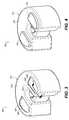
- FIG. 3is a perspective view of an exemplary medical diagnostic device having indentations, or recesses, in its housing to receive the exemplary cushion assembly of FIGS. 1-2 ;
- FIG. 4is a perspective view of the exemplary medical diagnostic device of FIG. 3 having a plurality of the exemplary cushion assembly of FIGS. 1-2 disposed thereon;
- FIG. 5is a side cross sectional view of a portion of the exemplary cushion assembly of FIGS. 1-2 ;
- FIG. 6is a side cross sectional view of a portion of the exemplary medical diagnostic device of FIGS. 3-4 .
- FIGS. 1 and 2each illustrate a perspective view of cushion assembly 100 .
- FIG. 1illustrates a general outline of the cushion assembly 100 and
- FIG. 2illustrates a transparent view of the cushion assembly 100 which makes visible securing assemblies 202 within the cushion assembly 100 each including a magnet 204 and a force distribution disc 203 .
- the cushion assembly 100comprises six securing assemblies 202 although the number may vary.
- Each individual cushion assembly 100comprises a substantially planar top surface 102 and a substantially planar bottom surface 103 .
- the top and bottom surfaces 102 , 103may be said to be disposed on opposite sides of the cushion assembly 100 and comprise the largest planar surfaces of the cushion assembly 100 .
- the cushion assembly 100comprises substantially continuous side surfaces 104 continuously and integrally formed with the top and bottom surfaces 102 , 103 , and substantially perpendicular thereto. The side surfaces may form a corner where they meet the top and bottom surfaces or they may form a rounded edge.
- the bulk 105 of the cushion assembly 100is fabricated from a flexible, spongy, relatively soft foam material that yields to pressure.
- the bulk 105 of the cushion assembly 100may comprise cross-linked closed cell ethyl vinyl acetate (EVA) foam at a density of about 2 lb/ft 3 .
- EVAcross-linked closed cell ethyl vinyl acetate
- the thickness of the cushion assembly 100i.e., a distance between top and bottom surfaces 102 , 103 , may range from about one-half inch to about four inches, more preferably from about one and one-half inch to about three inches, and even more preferably about two and one-quarter inches to about two and three-quarter inches.
- the thickness of the cushion assembly 100may vary depending on the density of the selected cushion material and on the intended medical diagnostic application.
- the general outline, or shape, of the cushion assembly 100may vary and may be selected for various purposes, such as for fitting on a particular medical diagnostic device.
- each securing assembly 202may be disposed in the foam adjacent to the force distribution discs 203 , or they may be attached to the force distribution discs 203 using a suitable adhesive, for example.
- the magnets 204may be formed in the shape of a disc of about one inch diameter and about 1 ⁇ 4 inch thick, although the selected sizes may vary depending on particular applications and materials used, as desired.
- the magnets 204may be formed as rare earth magnets out of a material known in the art as N52 type.
- the force distribution discs 203adjacent the magnets 204 , may be fabricated as plastic discs, such as a polycarbonate material, semi-rigid in structure, having a diameter of about two inches and, if glued, they may be attached to the magnets 204 using Fast 77 spray adhesive made by the 3M Company, for example.
- a thickness of the force distribution discsmay range from about 0.005 inch to about 0.025 inch, more preferably from about 0.010 inch to about 0.020 inch, and may vary somewhat depending on the rigidity or formulation of the thermoplastic material used.
- the securing assemblies 202may be placed in the EVA foam bulk 105 of the cushion assembly 100 during manufacture, such as during injection molding, for example, or they may be placed in counter bored openings 506 ( FIG. 5 ) formed in the bulk 105 of the cushion material after molding.
- the counter bored openings 506match the size of the magnet 204 and the force distribution disc 203 , and may be back filled with foam or closed with a foam plug, for example, after placement of the securing assemblies 202 therein.
- the magnet 204may be disposed on an inward facing side of the force distribution disc 203 (away from a major surface 102 , 103 ) whereby the force distribution disc 203 faces the major surface 102 , 103 , of the cushion assembly 100 at a depth of about 1 ⁇ 4 inch therefrom, for example.
- the surfaces 102 - 104 of the cushion assembly 100may be colored, such as by spray painting, using a spray coated matte black low tack single coat paint, as an example.
- the magnets 204may be disposed in the cushion assemblies 100 such that their north poles face the top surface 102 of the cushion assembly 100 and their south poles face the bottom surface 103 of the cushion assembly 100 .
- Such orientations of the magnets 204facilitate stacking the cushion assemblies 100 as the magnets 204 will assist in holding the cushion assemblies 100 in a stacked formation.
- the magnets 204may be configured in various other orientations such that they cooperate with magnets placed in a medical diagnostic device and in other cushion assemblies 100 .
- FIGS. 3 and 4illustrate a housing 310 of an exemplary medical diagnostic x-ray device 311 known as an Extremity Imager for Cone Beam Computed Tomography (CBCT), such as described in the US Patent Application identified above and incorporated by reference herein.
- the housing 310 of the CBCT imager 311includes indentations 302 formed in a surface thereof which, together with the cushion assembly 100 , forms a cushion retainer assembly 300 of the present invention.
- These indentations 302may be formed integrally in the housing 310 or they may comprise openings in the housing 310 that are fitted with a cover that provides the recess 302 for receiving the cushion assembly 100 .
- the indentations 302are shaped to match the outline of the cushion assembly 100 such that placement of the cushion assembly 100 therein forms a mating fit ( FIG. 4 ).
- the indentations 302are formed at a depth, such as about 1 ⁇ 4 inch, suitable to prevent unwanted sideways displacement of the cushion assembly 100 after placement of the cushion assembly 100 in the indentation 302 .
- the sidewall 304 of the depression 302preferably makes contact with a corner or sidewall 104 of the cushion assembly 100 to prevent such sideward displacement.
- Magnets 306may be placed below a surface of the recessed portion 302 of the housing 310 such that they attract the magnets 204 in the cushion assemblies 100 , i.e., the north poles of the magnets 306 face upward toward the recessed portion 302 and the south poles of the cushion assembly 100 magnets 204 .
- the configuration of the CBCT imager 311together with the cushion assembly 100 facilitate easy removal and replacement of cushion assemblies 100 as needed for diagnostic procedures using the CBCT imager 311 .
- FIG. 5illustrates a cross sectional view of the cushion assembly 100 to better illustrate dimensions of the securing assemblies 202 in relation to the cushion assembly 100 as described herein.
- one of the securing assemblies 202is disposed proximate the top surface 102 of the cushion assembly 100 and comprises a magnet 204 adjacent a force distribution disc 203 disposed in a counter bore 506 formed in the bulk 105 of a foam based cushion assembly 100 .
- a diameter 510 of the magnet 204may be about 1 inch and the diameter 508 of the force distribution disc 203 may be about 2 inches.
- a thickness 504 of the magnet 204may be about 1 ⁇ 4 inch and a depth 502 from the top surface 102 to the force distribution disc 203 may also be about 1 ⁇ 4 inch.
- the depth 502formed by a counter bore in the top surface 102 , may be back filled with foam or closed with a foam plug, for example, after placement of the securing assembly 202 therein.
- the dimensions of the securing assembly 202 that is placed proximate the bottom surface 103 of the cushion assembly 100 and its position within the cushion assembly 100may be similar to the dimensions just described. The dimensions and distances described here may vary without departing from the scope of the present invention.
- FIG. 6illustrates a cross sectional view of the top surface of the housing 310 having an indentation 302 , or cover as explained above, formed therein.
- indentation 302may comprise a sidewall 304 having a depth 603 of about 3 ⁇ 8 inch.
- a magnet 306having a disc shape, for example, may be disposed at a distance 602 of about 0.02 inches to about 0.06 inches, preferably about 0.04 inches, from a surface of the indentation 302 .
- a diameter 606 of the magnet 306may be about 1 inch and a thickness 604 of the magnet 306 may be about 1 ⁇ 4 inch.
- the magnet 306may be affixed, such as by an adhesive, into a counterbored recess 605 , slightly larger than the magnet 306 , formed in the bottom side of the cover or housing 310 .
- the magnet's upper (or top) surfacein the perspective shown in FIG. 6 , comprises a magnetic north pole, opposite the bottom surface south pole.
- the dimensions and distances described hereinmay vary without departing from the scope of the present invention.
Landscapes
- Health & Medical Sciences (AREA)
- Life Sciences & Earth Sciences (AREA)
- Engineering & Computer Science (AREA)
- Medical Informatics (AREA)
- Physics & Mathematics (AREA)
- Radiology & Medical Imaging (AREA)
- Heart & Thoracic Surgery (AREA)
- Veterinary Medicine (AREA)
- Biophysics (AREA)
- High Energy & Nuclear Physics (AREA)
- Public Health (AREA)
- Nuclear Medicine, Radiotherapy & Molecular Imaging (AREA)
- Optics & Photonics (AREA)
- Pathology (AREA)
- General Health & Medical Sciences (AREA)
- Biomedical Technology (AREA)
- Animal Behavior & Ethology (AREA)
- Molecular Biology (AREA)
- Surgery (AREA)
- Electromagnetism (AREA)
- Power Engineering (AREA)
- Oral & Maxillofacial Surgery (AREA)
- Dentistry (AREA)
- Pulmonology (AREA)
- Theoretical Computer Science (AREA)
- Magnetic Resonance Imaging Apparatus (AREA)
- Chemical & Material Sciences (AREA)
- Dispersion Chemistry (AREA)
Abstract
Description
Claims (15)
Priority Applications (1)
| Application Number | Priority Date | Filing Date | Title |
|---|---|---|---|
| US14/936,773US10105109B2 (en) | 2013-10-08 | 2015-11-10 | Cushion retainer |
Applications Claiming Priority (3)
| Application Number | Priority Date | Filing Date | Title |
|---|---|---|---|
| US14/048,599US9717467B2 (en) | 2012-10-08 | 2013-10-08 | Extremity imaging apparatus for cone beam computed tomography |
| US201562112190P | 2015-02-05 | 2015-02-05 | |
| US14/936,773US10105109B2 (en) | 2013-10-08 | 2015-11-10 | Cushion retainer |
Publications (2)
| Publication Number | Publication Date |
|---|---|
| US20160228073A1 US20160228073A1 (en) | 2016-08-11 |
| US10105109B2true US10105109B2 (en) | 2018-10-23 |
Family
ID=56565561
Family Applications (1)
| Application Number | Title | Priority Date | Filing Date |
|---|---|---|---|
| US14/936,773Expired - Fee RelatedUS10105109B2 (en) | 2013-10-08 | 2015-11-10 | Cushion retainer |
Country Status (1)
| Country | Link |
|---|---|
| US (1) | US10105109B2 (en) |
Families Citing this family (3)
| Publication number | Priority date | Publication date | Assignee | Title |
|---|---|---|---|---|
| US10105109B2 (en)* | 2013-10-08 | 2018-10-23 | Carestream Health, Inc. | Cushion retainer |
| US11498014B1 (en) | 2017-11-06 | 2022-11-15 | Amazon Technologies, Inc. | Configurable devices |
| US11541322B1 (en)* | 2017-11-06 | 2023-01-03 | Amazon Technologies, Inc. | Mat controllable by remote computing device |
Citations (19)
| Publication number | Priority date | Publication date | Assignee | Title |
|---|---|---|---|---|
| US3123935A (en)* | 1964-03-10 | Tray means and magnetically cooperably | ||
| US4046365A (en)* | 1976-06-28 | 1977-09-06 | Dungan Shirley A | Stirrup guard for medical examinations |
| US4360193A (en)* | 1980-06-16 | 1982-11-23 | Mitchell Winalee G | Cover for stirrup of physician's examination table |
| US4905712A (en)* | 1989-08-08 | 1990-03-06 | Ergomed, Inc. | Head restraint system |
| US5551110A (en)* | 1994-06-03 | 1996-09-03 | Beachead Products Company | Collapsible shade for head chair |
| US20030093860A1 (en)* | 2001-08-22 | 2003-05-22 | Kramer Kenneth L. | Apparatus and method for closing hospital bed gaps |
| US6824511B1 (en)* | 1999-06-23 | 2004-11-30 | Canica Design Inc. | Surgical fixation and retraction system |
| US20120233777A1 (en)* | 2011-03-20 | 2012-09-20 | Hare Todd C | Magnetic bedding securing system |
| US20130042412A1 (en)* | 2011-08-18 | 2013-02-21 | Chuan-Hang Shih | Adjustable bed having stably mounted mattress |
| US20130074269A1 (en)* | 2011-09-23 | 2013-03-28 | II George R. Phillips | Sliding leg pillow |
| US20140182060A1 (en)* | 2012-12-28 | 2014-07-03 | Tom Mikkelsen | Mattress assembly |
| US20150297302A1 (en)* | 2014-04-17 | 2015-10-22 | Baycare Health System, Llc. | Surgical support system |
| US9254046B1 (en)* | 2015-08-14 | 2016-02-09 | Jon Arenstein | Device and method for securing a bed sheet |
| US20160228073A1 (en)* | 2013-10-08 | 2016-08-11 | Carestream Health, Inc. | Cushion retainer |
| US20170105563A1 (en)* | 2015-10-14 | 2017-04-20 | Milliken & Company | Flooring System |
| US20180098653A1 (en)* | 2015-03-31 | 2018-04-12 | Leonard Pinchuk | Magnetic Base Beverage Container |
| US20180125260A1 (en)* | 2016-11-09 | 2018-05-10 | Select Comfort Corporation | Bed With Magnetic Couplers |
| US20180125259A1 (en)* | 2016-11-09 | 2018-05-10 | Select Comfort Corporation | Bed With Magnetic Couplers |
| US20180202602A1 (en)* | 2015-09-28 | 2018-07-19 | Conti-Bros, Inc. | Magnetic object suspension apparatus and associated methods and systems |
- 2015
- 2015-11-10USUS14/936,773patent/US10105109B2/ennot_activeExpired - Fee Related
Patent Citations (29)
| Publication number | Priority date | Publication date | Assignee | Title |
|---|---|---|---|---|
| US3123935A (en)* | 1964-03-10 | Tray means and magnetically cooperably | ||
| US4046365A (en)* | 1976-06-28 | 1977-09-06 | Dungan Shirley A | Stirrup guard for medical examinations |
| US4360193A (en)* | 1980-06-16 | 1982-11-23 | Mitchell Winalee G | Cover for stirrup of physician's examination table |
| US4407687A (en)* | 1980-06-16 | 1983-10-04 | Mitchell Winalee G | Method of manufacturing cover for stirrup of physician's examination table |
| US4905712A (en)* | 1989-08-08 | 1990-03-06 | Ergomed, Inc. | Head restraint system |
| US5551110A (en)* | 1994-06-03 | 1996-09-03 | Beachead Products Company | Collapsible shade for head chair |
| US6824511B1 (en)* | 1999-06-23 | 2004-11-30 | Canica Design Inc. | Surgical fixation and retraction system |
| US7788747B2 (en)* | 2001-08-22 | 2010-09-07 | Hill-Rom Services, Inc. | Apparatus and method for closing hospital bed gaps |
| US20050166322A1 (en)* | 2001-08-22 | 2005-08-04 | Kramer Kenneth L. | Apparatus and method for closing hospital bed gaps |
| US7028352B2 (en)* | 2001-08-22 | 2006-04-18 | Hill-Rom Services, Inc. | Apparatus and method for closing hospital bed gaps |
| US7222377B2 (en)* | 2001-08-22 | 2007-05-29 | Hill-Rom Services, Inc. | Apparatus and method for closing hospital bed gaps |
| US20070180617A1 (en)* | 2001-08-22 | 2007-08-09 | Kramer Kenneth L | Apparatus and method for closing hospital bed gaps |
| US7591034B2 (en)* | 2001-08-22 | 2009-09-22 | Hill-Rom Services, Inc. | Apparatus and method for closing hospital bed gaps |
| US20100005589A1 (en)* | 2001-08-22 | 2010-01-14 | Kramer Kenneth L | Apparatus and Method for Closing Hospital Bed Gaps |
| US20030093860A1 (en)* | 2001-08-22 | 2003-05-22 | Kramer Kenneth L. | Apparatus and method for closing hospital bed gaps |
| US20120233777A1 (en)* | 2011-03-20 | 2012-09-20 | Hare Todd C | Magnetic bedding securing system |
| US20130042412A1 (en)* | 2011-08-18 | 2013-02-21 | Chuan-Hang Shih | Adjustable bed having stably mounted mattress |
| US20130074269A1 (en)* | 2011-09-23 | 2013-03-28 | II George R. Phillips | Sliding leg pillow |
| US20140182060A1 (en)* | 2012-12-28 | 2014-07-03 | Tom Mikkelsen | Mattress assembly |
| US20150374136A1 (en)* | 2012-12-28 | 2015-12-31 | Tempur-Pedic Management, Llc | Mattress assembly |
| US20160228073A1 (en)* | 2013-10-08 | 2016-08-11 | Carestream Health, Inc. | Cushion retainer |
| US20150297302A1 (en)* | 2014-04-17 | 2015-10-22 | Baycare Health System, Llc. | Surgical support system |
| US9254179B2 (en)* | 2014-04-17 | 2016-02-09 | Baycare Clinic, Llp | Surgical support system |
| US20180098653A1 (en)* | 2015-03-31 | 2018-04-12 | Leonard Pinchuk | Magnetic Base Beverage Container |
| US9254046B1 (en)* | 2015-08-14 | 2016-02-09 | Jon Arenstein | Device and method for securing a bed sheet |
| US20180202602A1 (en)* | 2015-09-28 | 2018-07-19 | Conti-Bros, Inc. | Magnetic object suspension apparatus and associated methods and systems |
| US20170105563A1 (en)* | 2015-10-14 | 2017-04-20 | Milliken & Company | Flooring System |
| US20180125260A1 (en)* | 2016-11-09 | 2018-05-10 | Select Comfort Corporation | Bed With Magnetic Couplers |
| US20180125259A1 (en)* | 2016-11-09 | 2018-05-10 | Select Comfort Corporation | Bed With Magnetic Couplers |
Also Published As
| Publication number | Publication date |
|---|---|
| US20160228073A1 (en) | 2016-08-11 |
Similar Documents
| Publication | Publication Date | Title |
|---|---|---|
| USD908703S1 (en) | Active stylus | |
| US10105109B2 (en) | Cushion retainer | |
| USD907245S1 (en) | Apparatus for doctors, hospitals and laboratories | |
| US10433533B1 (en) | Fishing-hook retention and storage apparatus and method | |
| CN102665817B (en) | Improved external nasal dilator | |
| US8731219B2 (en) | Sound reflector and electronic device with speaker, including sound reflector | |
| CA2974553C (en) | Attachable front for eyeglasses | |
| US20070113383A1 (en) | Magnetic closure particularly for bags, rucksacks and the like | |
| US20160103468A1 (en) | Case for a tablet shaped device and a method for making a case for a tablet shaped device | |
| US20170245622A1 (en) | Container device for cosmetics | |
| USD642621S1 (en) | Writing instrument clip | |
| USD982746S1 (en) | Medical device holder | |
| USD715534S1 (en) | Medical sponge and counting bag | |
| USD878034S1 (en) | Magnetic needle holder | |
| TW201440745A (en) | Portal and septum therefor | |
| USD546453S1 (en) | X-ray film cassette holder | |
| CN209464256U (en) | A medical nursing tray | |
| USD1031536S1 (en) | Vehicle advanced assistant system calibration device | |
| US20150152981A1 (en) | Cable stay | |
| US9901262B2 (en) | Mobile transducer holder assembly | |
| US12118894B2 (en) | Ionic disc bonding model | |
| JP2006325716A (en) | Adhesive plaster with magnet | |
| USD944634S1 (en) | Fixation device | |
| US4228736A (en) | Printing apparatus | |
| WO2016062243A1 (en) | Pillow and resilient cushion core of pillow |
Legal Events
| Date | Code | Title | Description |
|---|---|---|---|
| AS | Assignment | Owner name:CARESTREAM HEALTH, INC., NEW YORK Free format text:ASSIGNMENT OF ASSIGNORS INTEREST;ASSIGNOR:PRUYNE, ADAM D.;REEL/FRAME:037096/0166 Effective date:20151111 | |
| STCF | Information on status: patent grant | Free format text:PATENTED CASE | |
| AS | Assignment | Owner name:CREDIT SUISSE AG, CAYMAN ISLANDS BRANCH, NEW YORK Free format text:SECURITY INTEREST;ASSIGNORS:CARESTREAM HEALTH, INC.;CARESTREAM HEALTH HOLDINGS, INC.;CARESTREAM HEALTH CANADA HOLDINGS, INC.;AND OTHERS;REEL/FRAME:048077/0529 Effective date:20190114 Owner name:CREDIT SUISSE AG, CAYMAN ISLANDS BRANCH, NEW YORK Free format text:SECURITY INTEREST;ASSIGNORS:CARESTREAM HEALTH, INC.;CARESTREAM HEALTH HOLDINGS, INC.;CARESTREAM HEALTH CANADA HOLDINGS, INC.;AND OTHERS;REEL/FRAME:048077/0587 Effective date:20190114 | |
| FEPP | Fee payment procedure | Free format text:MAINTENANCE FEE REMINDER MAILED (ORIGINAL EVENT CODE: REM.); ENTITY STATUS OF PATENT OWNER: LARGE ENTITY | |
| AS | Assignment | Owner name:CARESTREAM HEALTH WORLD HOLDINGS LLC, NEW YORK Free format text:RELEASE OF SECURITY INTEREST IN INTELLECTUAL PROPERTY (FIRST LIEN);ASSIGNOR:CREDIT SUISSE AG, CAYMAN ISLANDS BRANCH;REEL/FRAME:061683/0529 Effective date:20220930 Owner name:CARESTREAM HEALTH ACQUISITION, LLC, NEW YORK Free format text:RELEASE OF SECURITY INTEREST IN INTELLECTUAL PROPERTY (FIRST LIEN);ASSIGNOR:CREDIT SUISSE AG, CAYMAN ISLANDS BRANCH;REEL/FRAME:061683/0529 Effective date:20220930 Owner name:CARESTREAM HEALTH CANADA HOLDINGS, INC., NEW YORK Free format text:RELEASE OF SECURITY INTEREST IN INTELLECTUAL PROPERTY (FIRST LIEN);ASSIGNOR:CREDIT SUISSE AG, CAYMAN ISLANDS BRANCH;REEL/FRAME:061683/0529 Effective date:20220930 Owner name:CARESTREAM HEALTH HOLDINGS, INC., NEW YORK Free format text:RELEASE OF SECURITY INTEREST IN INTELLECTUAL PROPERTY (FIRST LIEN);ASSIGNOR:CREDIT SUISSE AG, CAYMAN ISLANDS BRANCH;REEL/FRAME:061683/0529 Effective date:20220930 Owner name:CARESTREAM HEALTH, INC., NEW YORK Free format text:RELEASE OF SECURITY INTEREST IN INTELLECTUAL PROPERTY (FIRST LIEN);ASSIGNOR:CREDIT SUISSE AG, CAYMAN ISLANDS BRANCH;REEL/FRAME:061683/0529 Effective date:20220930 Owner name:CARESTREAM HEALTH WORLD HOLDINGS LLC, NEW YORK Free format text:RELEASE OF SECURITY INTEREST IN INTELLECTUAL PROPERTY (SECOND LIEN);ASSIGNOR:CREDIT SUISSE AG, CAYMAN ISLANDS BRANCH;REEL/FRAME:061683/0681 Effective date:20220930 Owner name:CARESTREAM HEALTH ACQUISITION, LLC, NEW YORK Free format text:RELEASE OF SECURITY INTEREST IN INTELLECTUAL PROPERTY (SECOND LIEN);ASSIGNOR:CREDIT SUISSE AG, CAYMAN ISLANDS BRANCH;REEL/FRAME:061683/0681 Effective date:20220930 Owner name:CARESTREAM HEALTH CANADA HOLDINGS, INC., NEW YORK Free format text:RELEASE OF SECURITY INTEREST IN INTELLECTUAL PROPERTY (SECOND LIEN);ASSIGNOR:CREDIT SUISSE AG, CAYMAN ISLANDS BRANCH;REEL/FRAME:061683/0681 Effective date:20220930 Owner name:CARESTREAM HEALTH HOLDINGS, INC., NEW YORK Free format text:RELEASE OF SECURITY INTEREST IN INTELLECTUAL PROPERTY (SECOND LIEN);ASSIGNOR:CREDIT SUISSE AG, CAYMAN ISLANDS BRANCH;REEL/FRAME:061683/0681 Effective date:20220930 Owner name:CARESTREAM HEALTH, INC., NEW YORK Free format text:RELEASE OF SECURITY INTEREST IN INTELLECTUAL PROPERTY (SECOND LIEN);ASSIGNOR:CREDIT SUISSE AG, CAYMAN ISLANDS BRANCH;REEL/FRAME:061683/0681 Effective date:20220930 | |
| LAPS | Lapse for failure to pay maintenance fees | Free format text:PATENT EXPIRED FOR FAILURE TO PAY MAINTENANCE FEES (ORIGINAL EVENT CODE: EXP.); ENTITY STATUS OF PATENT OWNER: LARGE ENTITY | |
| STCH | Information on status: patent discontinuation | Free format text:PATENT EXPIRED DUE TO NONPAYMENT OF MAINTENANCE FEES UNDER 37 CFR 1.362 | |
| FP | Lapsed due to failure to pay maintenance fee | Effective date:20221023 |