US10101809B2 - Systems, articles, and methods for capacitive electromyography sensors - Google Patents
Systems, articles, and methods for capacitive electromyography sensorsDownload PDFInfo
- Publication number
- US10101809B2 US10101809B2US15/799,621US201715799621AUS10101809B2US 10101809 B2US10101809 B2US 10101809B2US 201715799621 AUS201715799621 AUS 201715799621AUS 10101809 B2US10101809 B2US 10101809B2
- Authority
- US
- United States
- Prior art keywords
- sensor electrode
- sensor
- dielectric layer
- electrically conductive
- electrode
- Prior art date
- Legal status (The legal status is an assumption and is not a legal conclusion. Google has not performed a legal analysis and makes no representation as to the accuracy of the status listed.)
- Active
Links
Images


Classifications
- G—PHYSICS
- G06—COMPUTING OR CALCULATING; COUNTING
- G06F—ELECTRIC DIGITAL DATA PROCESSING
- G06F3/00—Input arrangements for transferring data to be processed into a form capable of being handled by the computer; Output arrangements for transferring data from processing unit to output unit, e.g. interface arrangements
- G06F3/01—Input arrangements or combined input and output arrangements for interaction between user and computer
- G06F3/011—Arrangements for interaction with the human body, e.g. for user immersion in virtual reality
- G06F3/015—Input arrangements based on nervous system activity detection, e.g. brain waves [EEG] detection, electromyograms [EMG] detection, electrodermal response detection
- A61B5/0492—
- A—HUMAN NECESSITIES
- A61—MEDICAL OR VETERINARY SCIENCE; HYGIENE
- A61B—DIAGNOSIS; SURGERY; IDENTIFICATION
- A61B5/00—Measuring for diagnostic purposes; Identification of persons
- A61B5/24—Detecting, measuring or recording bioelectric or biomagnetic signals of the body or parts thereof
- A61B5/25—Bioelectric electrodes therefor
- A61B5/279—Bioelectric electrodes therefor specially adapted for particular uses
- A61B5/296—Bioelectric electrodes therefor specially adapted for particular uses for electromyography [EMG]
- A—HUMAN NECESSITIES
- A61—MEDICAL OR VETERINARY SCIENCE; HYGIENE
- A61B—DIAGNOSIS; SURGERY; IDENTIFICATION
- A61B5/00—Measuring for diagnostic purposes; Identification of persons
- A61B5/68—Arrangements of detecting, measuring or recording means, e.g. sensors, in relation to patient
- A61B5/6801—Arrangements of detecting, measuring or recording means, e.g. sensors, in relation to patient specially adapted to be attached to or worn on the body surface
- A61B5/6802—Sensor mounted on worn items
- A61B5/681—Wristwatch-type devices
- G—PHYSICS
- G06—COMPUTING OR CALCULATING; COUNTING
- G06F—ELECTRIC DIGITAL DATA PROCESSING
- G06F1/00—Details not covered by groups G06F3/00 - G06F13/00 and G06F21/00
- G06F1/16—Constructional details or arrangements
- G06F1/1613—Constructional details or arrangements for portable computers
- G06F1/163—Wearable computers, e.g. on a belt
- G—PHYSICS
- G06—COMPUTING OR CALCULATING; COUNTING
- G06F—ELECTRIC DIGITAL DATA PROCESSING
- G06F3/00—Input arrangements for transferring data to be processed into a form capable of being handled by the computer; Output arrangements for transferring data from processing unit to output unit, e.g. interface arrangements
- G06F3/01—Input arrangements or combined input and output arrangements for interaction between user and computer
- G06F3/011—Arrangements for interaction with the human body, e.g. for user immersion in virtual reality
- G06F3/014—Hand-worn input/output arrangements, e.g. data gloves
- A—HUMAN NECESSITIES
- A61—MEDICAL OR VETERINARY SCIENCE; HYGIENE
- A61B—DIAGNOSIS; SURGERY; IDENTIFICATION
- A61B2562/00—Details of sensors; Constructional details of sensor housings or probes; Accessories for sensors
- A61B2562/24—Hygienic packaging for medical sensors; Maintaining apparatus for sensor hygiene
- A61B2562/247—Hygienic covers, i.e. for covering the sensor or apparatus during use
Definitions
- the present systems, articles, and methodsgenerally relate to electromyography and particularly relate to capacitive electromyography sensors.
- Electronic devicesare commonplace throughout most of the world today. Advancements in integrated circuit technology have enabled the development of electronic devices that are sufficiently small and lightweight to be carried by the user. Such “portable” electronic devices may include on-board power supplies (such as batteries or other power storage systems) and may be designed to operate without any wire-connections to other electronic systems; however, a small and lightweight electronic device may still be considered portable even if it includes a wire-connection to another electronic system. For example, a microphone may be considered a portable electronic device whether it is operated wirelessly or through a wire-connection.
- on-board power suppliessuch as batteries or other power storage systems
- a wearable electronic deviceis any portable electronic device that a user can carry without physically grasping, clutching, or otherwise holding onto the device with their hands.
- a wearable electronic devicemay be attached or coupled to the user by a strap or straps, a band or bands, a clip or clips, an adhesive, a pin and clasp, an article of clothing, tension or elastic support, an interference fit, an ergonomic form, etc.
- Examples of wearable electronic devicesinclude digital wristwatches, electronic armbands, electronic rings, electronic ankle-bracelets or “anklets,” head-mounted electronic display units, hearing aids, and so on.
- a wearable electronic devicemay provide direct functionality for a user (such as audio playback, data display, computing functions, etc.) or it may provide electronics to interact with, receive information from, or control another electronic device.
- a wearable electronic devicemay include sensors that are responsive to (i.e., detect and provide one or more signal(s) in response to detecting) inputs effected by a user and transmit signals to another electronic device based on those inputs.
- Sensor-types and input-typesmay each take on a variety of forms, including but not limited to: tactile sensors (e.g., buttons, switches, touchpads, or keys) providing manual control, acoustic sensors providing voice-control, electromyography sensors providing gesture control, and/or accelerometers providing gesture control.
- HCIhuman-computer interface
- present systems, articles, and methodsmay be applied to HCIs, but may also be applied to any other form of human-electronics interface.
- Electromyographyis a process for detecting and processing the electrical signals generated by muscle activity.
- EMG devicesemploy EMG sensors that are responsive to the range of electrical potentials (typically ⁇ V-mV) involved in muscle activity.
- EMG signalsmay be used in a wide variety of applications, including: medical monitoring and diagnosis, muscle rehabilitation, exercise and training, prosthetic control, and even in controlling functions of electronic devices.
- intramuscular EMG sensorsThere are two main types of EMG sensors: intramuscular EMG sensors and surface EMG sensors. As the names suggest, intramuscular EMG sensors are designed to penetrate the skin and measure EMG signals from within the muscle tissue, while surface EMG sensors are designed to rest on an exposed surface of the skin and measure EMG signals from there. Intramuscular EMG sensor measurements can be much more precise than surface EMG sensor measurements; however, intramuscular EMG sensors must be applied by a trained professional, are obviously more invasive, and are less desirable from the patient's point of view. The use of intramuscular EMG sensors is generally limited to clinical settings.
- Surface EMG sensorscan be applied with ease, are much more comfortable for the patient/user, and are therefore more appropriate for non-clinical settings and uses.
- human-electronics interfaces that employ EMGsuch as those proposed in U.S. Pat. No. 6,244,873 and U.S. Pat. No. 8,170,656, usually employ surface EMG sensors.
- Surface EMG sensorscome in two forms: resistive EMG sensors and capacitive EMG sensors.
- the sensor electrodetypically includes a plate of electrically conductive material that is placed against or in very close proximity to the exposed surface of the user's skin.
- a resistive EMG sensor electrodeis typically directly electrically coupled to the user's skin while a capacitive EMG sensor electrode is typically capacitively coupled to the user's skin.
- skin and/or environmental conditionssuch as hair density, humidity and moisture levels, and so on, can have a significant impact on the performance of the sensor.
- These parametersare generally controlled for resistive EMG sensors by preparing the user's skin before applying the sensor electrodes. For example, the region of the user's skin where a resistive electrode is to be placed is usually shaved, exfoliated, and slathered with a conductive gel to establish a suitable and stable environment before the resistive electrode is applied. This obviously limits the appeal of resistive EMG sensors to users, in particular for home and/or recreational use.
- Capacitive EMG sensorsare advantageous because they are generally more robust against some skin and environmental conditions, such as hair density, and are typically applied without the elaborate skin preparation measures (e.g., shaving, exfoliating, and applying a conductive gel) that are employed for resistive sensors.
- capacitive EMG sensorsare still very sensitive to moisture and performance can degrade considerably when, for example, a user sweats. There is a need in the art for capacitive EMG sensors with improved robustness against variations in skin and/or environmental conditions.
- a capacitive electromyography (“EMG”) sensormay be summarized as including a substrate; a first sensor electrode carried by the substrate, wherein the first sensor electrode comprises an electrically conductive plate having a first surface that faces the substrate and a second surface that is opposite the first surface; circuitry communicatively coupled to the first sensor electrode; and a dielectric layer formed of a dielectric material that has a relative permittivity of at least about 10, wherein the dielectric layer coats the second surface of the first sensor electrode.
- the first sensor electrodemay be formed of a material including copper.
- the circuitrymay include at least one circuit selected from the group consisting of: an amplification circuit, a filtering circuit, and an analog-to-digital conversion circuit. At least a portion of the circuitry may be carried by the substrate.
- the substratemay include a first surface and a second surface, the second surface opposite the first surface across a thickness of the substrate, and the at least a portion of the circuitry may be carried by the first surface of the substrate and the first sensor electrode may be carried by the second surface of the substrate.
- the dielectric layermay include a ceramic material.
- the dielectric layermay include an X7R ceramic material.
- the substrate, the first sensor electrode, and the dielectric layermay constitute a laminate structure.
- the capacitive EMG sensormay further include an electrically conductive epoxy sandwiched in between the dielectric layer and the first sensor electrode, wherein the dielectric layer is adhered to the first sensor electrode by the electrically conductive epoxy.
- the capacitive EMG sensormay further include an electrically conductive solder sandwiched in between the dielectric layer and the first sensor electrode, wherein the dielectric layer is adhered to the first sensor electrode by the electrically conductive solder.
- the dielectric layermay have a thickness of less than about 10 micrometers.
- the capacitive EMG sensormay be a differential capacitive EMG sensor that further includes a second sensor electrode carried by the substrate, the second sensor electrode comprising an electrically conductive plate having a first surface that faces the substrate and a second surface that is opposite the first surface across a thickness of the second sensor electrode, wherein the second sensor electrode is communicatively coupled to the circuitry, and wherein the dielectric layer coats the second surface of the second sensor electrode.
- the dielectric layermay comprise a single continuous layer of dielectric material that coats both the second surface of the first sensor electrode and the second surface of the second sensor electrode.
- the dielectric layermay comprise a first section that coats the second surface of the first sensor electrode and at least a second section that coats the second surface of the second sensor electrode, wherein the first section of the dielectric layer is physically separate from the second section of the dielectric layer.
- the first sensor electrode and the second sensor electrodemay be substantially coplanar.
- the capacitive EMG sensormay further include a ground electrode carried by the substrate, the ground electrode comprising an electrically conductive plate having a first surface that faces the substrate and a second surface that is opposite the first surface across a thickness of the ground electrode, wherein the ground electrode is communicatively coupled to the circuitry, and wherein the second surface of the ground electrode is exposed and not coated by the dielectric layer.
- the capacitive EMG sensormay further include at least one additional layer that is sandwiched in between the first sensor electrode and the substrate.
- a method of fabricating a capacitive EMG sensormay be summarized as including forming at least a portion of at least one circuit on a first surface of a substrate; forming a first sensor electrode on a second surface of the substrate, the second surface of the substrate opposite the first surface of the substrate across a thickness of the substrate, wherein the first sensor electrode comprises an electrically conductive plate; forming at least one electrically conductive pathway that communicatively couples the first sensor electrode and the at least a portion of at least one circuit; and coating the first sensor electrode with a dielectric layer comprising a dielectric material that has a relative permittivity of at least about 10. Coating the first sensor electrode with a dielectric layer may include coating at least a portion of the second surface of the substrate with the dielectric layer.
- Coating the first sensor electrode with a dielectric layermay include coating the first sensor electrode with a ceramic material. Coating the first sensor electrode with a dielectric layer may include coating the first sensor electrode with an X7R ceramic material.
- the capacitive EMG sensormay be a differential capacitive EMG sensor and the method may further include forming a second sensor electrode on the second surface of the substrate, wherein the second sensor electrode comprises an electrically conductive plate; forming at least one electrically conductive pathway that communicatively couples the second sensor electrode and the at least a portion of at least one circuit; and coating the second sensor electrode with the dielectric layer.
- the methodmay further include forming a ground electrode on the second surface of the substrate, wherein the ground electrode comprises an electrically conductive plate; and forming at least one electrically conductive pathway that communicatively couples the ground electrode and the at least a portion of at least one circuit.
- Coating the first sensor electrode with a dielectric layermay include selectively coating the first sensor electrode with the dielectric layer and not coating the ground electrode with the dielectric layer.
- Coating the first sensor electrode with a dielectric layermay include coating both the first sensor electrode and the ground electrode with the dielectric layer, and the method may further include forming a hole in the dielectric layer to expose the ground electrode.
- Coating the first sensor electrode with a dielectric layermay include depositing a layer of electrically conductive epoxy on the first sensor electrode; and depositing the dielectric layer on the layer of electrically conductive epoxy.
- Coating the first sensor electrode with a dielectric layermay include depositing a layer of electrically conductive solder on the first sensor electrode; and depositing the dielectric layer on the layer of electrically conductive solder.
- a wearable EMG devicemay be summarized as including at least one capacitive EMG sensor responsive to (i.e., to detect and provide one or more signal(s) in response to detecting) muscle activity corresponding to a gesture performed by a user of the wearable EMG device, wherein in response to muscle activity corresponding to a gesture performed by a user of the wearable EMG device, the at least one capacitive EMG sensor provides at least one signal, and wherein the at least one capacitive EMG sensor includes: a first sensor electrode comprising an electrically conductive plate; and a dielectric layer formed of a dielectric material that has a relative permittivity of at least about 10, wherein the dielectric layer coats the first sensor electrode; a processor communicatively coupled to the at least one capacitive EMG sensor to in use process signals provided by the at least one capacitive EMG sensor; and an output terminal communicatively coupled to the processor to transmit signals output by the processor.
- the dielectric layermay include a ceramic material.
- the ceramic materialmay include an X7R ceramic material.
- the wearable EMG devicemay further include circuitry that mediates communicative coupling between the at least one capacitive EMG sensor and the processor, wherein the circuitry includes at least one circuit selected from the group consisting of: an amplification circuit, a filtering circuit, and an analog-to-digital conversion circuit.
- the dielectric layer of the at least one capacitive EMG sensormay have a thickness of less than about 10 micrometers.
- the at least one capacitive EMG sensormay include at least one differential capacitive EMG sensor, and the at least one differential capacitive EMG sensor may further include a second sensor electrode comprising an electrically conductive plate, wherein the dielectric layer coats the second sensor electrode.
- the at least one capacitive EMG sensormay further include a ground electrode comprising an electrically conductive plate, wherein the ground electrode is exposed and not coated by the dielectric layer.
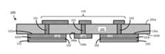
- FIG. 1is a cross-sectional view of an improved capacitive EMG sensor that provides enhanced robustness against variations in skin and/or environmental conditions in accordance with the present systems, articles, and methods.
- FIG. 2is a cross-sectional view of a laminate version of an improved capacitive EMG sensor that provides enhanced robustness against variations in skin and/or environmental conditions in accordance with the present systems, articles, and methods.
- FIG. 3is a flow-diagram showing a method of fabricating an improved capacitive EMG sensor in accordance with the present systems, articles, and methods.
- FIG. 4is a perspective view of an exemplary wearable EMG device that includes improved capacitive EMG sensors in accordance with the present systems, articles, and methods.
- the various embodiments described hereinprovide systems, articles, and methods for capacitive EMG sensors with improved robustness against variations in skin and/or environmental conditions.
- the present systems, articles, and methodsdescribe capacitive EMG sensor designs that employ at least one capacitive electrode having a protective coating that provides a barrier to moisture and a high relative permittivity ⁇ r .
- These capacitive EMG sensor designsmay be used in any device or method involving capacitive EMG sensing, though they are particularly well-suited for use in applications involving long-term coupling to a user's body over a range of evolving skin and/or environmental conditions.
- An example application in a wearable EMG device that forms part of a human-electronics interfaceis described.
- coatingand “coat,” and variants thereof, are used both as nouns and as verbs to indicate a relationship (noun) or the formation of a relationship (verb) in which a layer of material overlies, underlies, or generally “covers” at least a portion of a device or component, either directly or through one or more intervening layers.
- FIG. 1is a cross-sectional view of an example of an improved capacitive EMG sensor 100 that provides enhanced robustness against variations in skin and/or environmental conditions in accordance with the present systems, articles, and methods.
- Exemplary sensor 100is a differential capacitive EMG sensor that includes two capacitive sensor electrodes 121 and 131 , though the teachings described herein are also applicable to single-ended sensor systems that employ only a single capacitive sensor electrode (i.e., one of sensor electrodes 121 or 131 ).
- Differential sensor 100comprises a substrate 101 having a first surface 101 a and a second surface 101 b opposite the first surface 101 a across a thickness of substrate 101 .
- First surface 101 acarries at least a portion of at least one circuit (generally, circuitry 110 ) and second surface 101 b carries first sensor electrode 121 , second sensor electrode 131 , and a ground electrode 140 .
- circuitry 110may include at least a portion of at least one electrical or electronic circuit to process signals provided by first and second sensor electrodes 121 , 131 , including, for example, at least a portion of at least one amplification circuit, at least a portion of at least one filtering circuit, and/or at least a portion of at least one analog-to-digital conversion circuit.
- First sensor electrode 121includes an electrically conductive plate formed of an electrically conductive material (such as, for example, copper or a material including copper) and has a first surface 121 a and a second surface 121 b , second surface 121 b being opposite first surface 121 a across a thickness of electrode 121 .
- First sensor electrode 121is carried by second surface 101 b of substrate 101 such that first surface 121 a of first sensor electrode 121 faces second surface 101 b of substrate 101 .
- circuitry 110is carried by first surface 101 a of substrate 101 and first sensor electrode 121 is carried by second surface 101 b of substrate 101 .
- Circuitry 110is directly carried by first surface 101 a of substrate 101 because there are no intervening layers/components that mediate the physical coupling between circuitry 110 and first surface 101 a of substrate 101 ; however, circuitry 110 would still be considered “carried by” first surface 101 a of substrate 101 even if the physical coupling between circuitry 110 and first surface 101 a of substrate 101 was mediated by at least one intervening layer/component.
- the terms “carries” and “carried by”are not intended to denote a particular orientation with respect to top and bottom and/or left and right.
- First sensor electrode 121is communicatively coupled to circuitry 110 by at least one electrically conductive pathway 151 , which in the illustrated example of FIG. 1 is realized by a via connection that extends through substrate 101 .
- first sensor electrode 121is coated by a dielectric layer 123 formed of a material that has a relative permittivity ⁇ r of at least 10, and by an adhesive layer 122 that is sandwiched in between first sensor electrode 121 and dielectric layer 123 .
- Adhesive layer 122serves to adhere, affix, or otherwise couple dielectric layer 123 to the second surface 121 b of first sensor electrode 121 , and may comprise, for example, an electrically conductive epoxy or an electrically conductive solder.
- adhesive layer 122mediates physical and electrical coupling between dielectric layer 123 and first sensor electrode 121 . Referring back to the definition of the terms “carries” and “carried by,” both adhesive layer 122 and dielectric layer 123 are considered to be carried by second surface 101 b of substrate 101 .
- Dielectric layer 123may comprise any dielectric material that has a large relative permittivity ⁇ r (e.g., a relative permittivity of about 10 or more, including a relative permittivity of about 10, about 20, about 50, about 100, about 1000, etc.).
- dielectric layer 123may comprise a ceramic material, such as an X7R ceramic material.
- X7Rrefers to the EIA RS-198 standard three-digit code for temperature ranges and inherent change of capacitance. Specifically, the code “X7R” indicates a material that will operate in the temperature range of ⁇ 55° C. to +125° C. with a change of capacitance of ⁇ 15%.
- Dielectric layer 123may comprise a resin and/or ceramic powder such as those used in FaradFlex® products available from Oak-Mitsui Technologies.
- Second sensor electrode 131may be substantially similar to first sensor electrode 121 in that second sensor electrode 131 includes an electrically conductive plate formed of an electrically conductive material (e.g., a material including copper) that has a first surface 131 a and a second surface 131 b , second surface 131 b being opposite first surface 131 a across a thickness of electrode 131 . Second sensor electrode 131 is carried by second surface 101 b of substrate 101 such that first surface 131 a of second sensor electrode 131 faces second surface 101 b of substrate 101 .
- an electrically conductive plateformed of an electrically conductive material (e.g., a material including copper) that has a first surface 131 a and a second surface 131 b , second surface 131 b being opposite first surface 131 a across a thickness of electrode 131 .
- Second sensor electrode 131is carried by second surface 101 b of substrate 101 such that first surface 131 a of second sensor electrode 131 faces second surface 101 b of substrate 101 .
- Second sensor electrode 131is also coated by a dielectric layer 133 that is substantially similar to dielectric layer 123 , and dielectric layer 133 is adhered, affixed, or otherwise coupled to second surface 131 b of second sensor electrode 131 by an adhesive layer 132 that is substantially similar to adhesive layer 122 . Second sensor electrode 131 is communicatively coupled to circuitry 110 by at least one electrically conductive pathway 152 , which in the illustrated example of FIG. 1 is realized by a via connection that extends through substrate 101 . As is the case for the illustrated example of FIG. 1 , first sensor electrode 121 and second sensor electrode 131 may be substantially coplanar.
- Capacitive EMG sensor 100also includes a ground electrode 140 .
- Ground electrode 140includes an electrically conductive plate formed of an electrically conductive material (e.g., the same material that makes up first sensor electrode 121 and second sensor electrode 131 ) that has a first surface 141 a and a second surface 141 b , second surface 141 b being opposite first surface 141 a across a thickness of electrode 140 .
- Ground electrode 140is carried by second surface 101 b of substrate 101 such that first surface 140 a of ground electrode 140 faces second surface 101 b of substrate 101 .
- Ground electrode 140is communicatively coupled to circuitry 110 by at least one electrically conductive pathway 153 , which in the illustrated example of FIG. 1 is realized by a via connection that extends through substrate 101 .
- second surface 140 b of ground electrode 140is exposed and not coated by a dielectric layer in order that ground electrode 140 may advantageously provide a directly electrically coupled (i.e., resistively coupled) path to ground.
- capacitive EMG sensor 100is positioned proximate a user's muscle(s) so that dielectric layers 123 , 133 and ground electrode 140 are all in physical contact with the user's skin (or, in some cases, a layer of material such as clothing may mediate physical contact between sensor 100 and the user's skin).
- Dielectric layers 123 , 133are advantageously formed of a dielectric material that has a high relative permittivity (e.g., ⁇ r greater than or equal to about 10) in order to enhance the capacitive coupling between sensor electrodes 121 , 131 and the user's body.
- the respective capacitance that couples the sensor electrode ( 121 , 131 ) to the user's bodyis at least approximately given by equation 1:
- ⁇ ris the relative permittivity of the dielectric material that coats the sensor electrode (i.e., dielectric layers 123 , 133 ), ⁇ G , is the vacuum permittivity (i.e., a constant value of 8.8541878176 ⁇ 10 ⁇ 12 F/m), A is the area of the sensor electrode, and d is the distance between the sensor electrode and the user's body.
- ⁇ ri.e., the relative permittivity of dielectric layers 123 , 133
- a large ⁇ rmay enable a capacitive EMG sensor to employ smaller sensor electrode area(s) A and/or greater separation d between the sensor electrode(s) and the user's body.
- Dielectric layers 123 , 133are advantageously bio-compatible (e.g., non-toxic, etc.) and substantially robust against the corrosive effects of sweat and skin oils. Dielectric layers 123 , 133 are also advantageously non-absorptive and impermeable to water, sweat, and skin oils. Ideally, dielectric layers 123 , 133 provide hermetic barriers between the user's skin and first and second sensor electrodes 121 , 131 such that the presence of sweat, water, and/or skin oils does not substantially degrade the performance of capacitive EMG sensor 100 .
- dielectric layers 123 , 133may protect first sensor electrode 121 and second sensor electrode 131 (respectively) from moisture and/or other aspects of the user's skin, such moisture and/or other aspects that may underlie dielectric layers 123 , 133 (e.g., sweat or skin oils that may mediate coupling between the user's body and dielectric layers 123 , 133 ) may still affect the capacitive coupling between the user's body and first and second sensor electrodes 121 , 131 .
- moisture and/or other aspects that may underlie dielectric layers 123 , 133e.g., sweat or skin oils that may mediate coupling between the user's body and dielectric layers 123 , 133
- dielectric layers 123 , 133are formed of a dielectric material that has a high relative permittivity (i.e., ⁇ r ⁇ 10): the larger the relative permittivity of dielectric layers 123 , 133 , the larger the capacitance that couples the user's body to first and second sensor electrodes 121 , 131 and the smaller the proportionate impact of variations in sweat or skin oil conditions.
- Equation 1shows that the capacitance C that couples the user's body to first and second sensor electrodes 121 , 131 is directly proportional to the relative permittivity ⁇ r and inversely proportional to the thickness d of dielectric layers 123 , 133 .
- dielectric layers 123 , 133may be, for example, approximately 10 ⁇ m or less. Approximately 10 ⁇ m or less is sufficiently thick to provide an adequate barrier to moisture (e.g., sweat/oil) and electrical insulation, and sufficiently thin to provide an adequate capacitance C as per equation 1.
- ground electrode 140is exposed and not coated by a dielectric layer. This is because it is advantageous for ground electrode 140 to be resistively coupled to the user's body as opposed to capacitively coupled thereto in order to provide a lower impedance for return currents.
- first and second sensor electrodes 121 , 131are coated by dielectric layers 123 , 133 (respectively) and ground electrode 140 is not coated by a dielectric layer
- dielectric layers 123 , 133 and ground electrode 140may all still simultaneously contact a user's skin when capacitive EMG sensor 100 is positioned on the user. This is because the surface of the user's skin may have a curvature and/or the surface of the user's skin (and/or the flesh thereunder) may be elastic and compressible such that dielectric layers 123 , 133 can be “pressed” into the user's skin with sufficient depth to enable physical contact between ground electrode 140 and the user's skin. While not drawn to scale, in the illustrated example of FIG.
- dielectric layers 123 , 133are still thinner than the electrically conductive plates that form first and second sensor electrodes 121 , 131 .
- dielectric layers 123 , 133may each have a thickness of less than about 10 ⁇ m while first and second sensor electrodes 121 , 131 may each have a thickness of about 30 ⁇ m or more.
- dielectric layers 123 , 133may be applied to coat first and second sensor electrodes 121 , 131 (respectively) and the specific structural configuration of the corresponding capacitive EMG sensor may vary to reflect this.
- dielectric layers 123 , 133have been individually and separately deposited on first and second sensor electrodes 121 , 131 (respectively). This may be achieved by, for example, brushing a liquid or fluid form of the dielectric material that constitutes dielectric layers 123 and 133 over second surface 121 b of first sensor electrode 121 and second surface 131 b of second sensor electrode 131 .
- dielectric layers 123 , 133may subsequently be hardened or cured (and adhesive layers 122 , 132 may potentially not be required).
- individual and separate sections of a substantially solid or non-fluid form of the dielectric material that constitutes dielectric layers 123 and 133may be sized and dimensioned to at least approximately match the respective areas of first and second sensor electrodes 121 , 131 and then respective ones of such sections may be deposited on first and second sensor electrodes 121 and 131 .
- a first section of a dielectric material(having a high relative permittivity) may be sized and dimensioned to at least approximately match the area of first sensor electrode 121 and this first section of the dielectric material may be adhered, affixed, or otherwise coupled to first sensor electrode 121 by adhesive layer 122 to form dielectric layer 123 .
- a second section of the dielectric materialmay be sized and dimensioned to at least approximately match the area of second sensor electrode 131 and adhered, affixed, or otherwise coupled to second sensor electrode 131 by adhesive layer 132 to form dielectric layer 133 .
- dielectric layers 121 , 131may be deposited over second surface 101 b of substrate 101 , first and second sensor electrodes 121 , 131 , and optionally ground electrode 140 .
- substrate 101 , first and second sensors electrodes 121 , 131 , and dielectric layers 123 , 133may together constitute a laminate structure.
- dielectric layers 123 , 133may be applied to first and second sensor electrodes 121 , 131 as lamination layers using a lamination process.
- the portion of dielectric material that coats ground electrodemay subsequently be removed (e.g., by an etching process) to expose second surface 140 b of ground electrode 140 .
- FIG. 2is a cross-sectional view of an exemplary laminate version of an improved capacitive EMG sensor 200 that provides enhanced robustness against variations in skin and/or environmental conditions in accordance with the present systems, articles, and methods.
- Exemplary sensor 200is a differential capacitive EMG sensor that is substantially similar to sensor 100 from FIG. 1 in that sensor 200 includes a substrate 201 (substantially similar to substrate 101 from sensor 100 ), circuitry 210 (substantially similar to circuitry 110 from sensor 100 ), first and second capacitive sensor electrodes 221 and 231 (substantially similar to first and second sensor electrodes 121 and 131 , respectively, from sensor 100 ), and ground electrode 240 (substantially similar to ground electrode 140 from sensor 100 ).
- Sensor 200also includes a dielectric layer 250 that coats first and second sensor electrodes 221 , 231 in a similar way to dielectric layers 123 , 133 from sensor 100 .
- dielectric layer 250is formed of a dielectric material that has a large relative permittivity (i.e., ⁇ r greater than or equal to about 10).
- dielectric layer 250is deposited as a single continuous layer that coats both first and second sensor electrodes 221 , 231 and also coats at least a portion of substrate 201 .
- sensor 200may be a laminate structure and dielectric layer 250 may be deposited using a lamination process.
- dielectric layer 250may initially coat ground electrode 240 , in which case ground electrode 240 may subsequently be exposed by forming (e.g., etching) a hole 260 in dielectric layer 250 . Otherwise, a temporary mask may cover ground electrode 240 during deposition of dielectric layer 250 to prevent dielectric layer 250 from coating ground electrode 240 and hole 260 may be left as a result when the mask is subsequently removed.
- Dielectric layer 250may be deposited to provide a desired thickness of, for example, less than about 10 ⁇ m measured from the interface with first and second sensor electrodes 221 , 231 .
- an adhesive layermay be used to adhere, affix, or otherwise couple dielectric layer 250 to any or all of substrate 201 , first electrode 221 , and/or second sensor electrode 231 .
- FIG. 3is a flow-diagram showing a method 300 of fabricating an improved capacitive EMG sensor (e.g., sensor 100 and/or sensor 200 ) in accordance with the present systems, articles, and methods.
- Method 300includes four acts 301 , 302 , 303 , and 304 , though those of skill in the art will appreciate that in alternative embodiments certain acts may be omitted and/or additional acts may be added. Those of skill in the art will also appreciate that the illustrated order of the acts is shown for exemplary purposes only and may change in alternative embodiments.
- At 301at least a portion of at least one circuit is formed on a first surface of a substrate.
- the at least a portion of at least one circuitmay include one or more conductive traces and/or one or more electrical or electronic circuits, such as one or more amplification circuit(s), one or more filtering circuit(s), and/or one or more analog-to-digital conversion circuit(s).
- sensor 100 from FIG. 1includes circuitry 110 and sensor 200 from FIG. 2 includes circuitry 210 .
- Forming at least a portion of at least one circuitmay include one or more lithography process(es) and/or soldering one or more component(s) to the substrate.
- a first sensor electrodeis formed on a second surface of the substrate.
- the first sensor electrodemay include an electrically conductive plate formed of, for example, a material including copper.
- sensor 100 from FIG. 1includes first sensor electrode 121 and sensor 200 from FIG. 2 includes first sensor electrode 221 .
- Forming the first sensor electrodemay include, for example, one or more lithography process(es).
- the order of the acts of method 300may change. For example, in some cases it may be advantageous to form the first sensor electrode per act 302 prior to forming the at least a portion of circuitry per act 301 .
- At 303at least one electrically conductive pathway that communicatively couples the at least a portion of at least one circuit and the first sensor electrode is formed.
- the at least one electrically conductive pathwaymay include at least one via through the substrate, at least one conductive trace, and/or at least one wiring component.
- sensor 100includes electrically conductive pathway 151 that communicatively couples circuitry 110 to first sensor electrode 121 .
- all or a portion of a via(e.g., a hole or aperture with or without electrically conductive communicative path therethrough) may be formed in the substrate before either or both of acts 301 and/or 302 .
- the first sensor electrodeis coated with a dielectric layer comprising a dielectric material that has a relative permittivity ⁇ r of at least 10.
- the coatingmay be applied in a variety of different ways, including without limitation: brushing or otherwise applying a fluid form of the dielectric material on the first sensor electrode and curing the dielectric material; adhering, affixing, or otherwise coupling a substantially non-fluid form of the dielectric material to the first sensor electrode using, for example, an adhesive layer such as an electrically conductive epoxy or an electrically conductive solder; or depositing a single continuous layer of the dielectric material over both the first sensor electrode and at least a portion of the substrate using a lamination process or other dielectric deposition process.
- coating the first sensor electrode with a dielectric layermay include depositing a layer of electrically conductive epoxy on the first sensor electrode and depositing the dielectric layer on the layer of electrically conductive epoxy, or depositing a layer of electrically conductive solder on the first sensor electrode and depositing the dielectric layer on the layer of electrically conductive solder.
- sensor 100includes dielectric layer 123 that is adhered to first sensor electrode 121 by adhesive layer 122 and sensor 200 includes dielectric layer 250 that is deposited over first sensor electrode 221 and substrate 201 to form a laminate structure.
- the dielectric layermay include a ceramic material, such as an X7R ceramic material.
- method 300may be extended to include further acts in order to, for example, fabricate some of the additional elements and/or features described for sensors 100 and 200 .
- method 300may include forming a second sensor electrode on the second surface of the substrate, forming at least one electrically conductive pathway that communicatively couples the at least a portion of at least one circuit and the second sensor electrode, and coating the second sensor electrode with the dielectric layer (either with a single continuous dielectric layer or with a separate section of the dielectric layer, as described previously).
- method 300may include forming a ground electrode on the second surface of the substrate and forming at least one electrically conductive pathway that communicatively couples the ground electrode and the at least a portion of at least one circuit.
- coating the first sensor electrode with a dielectric layer per act 303may include selectively coating the first sensor electrode with the dielectric layer and not coating the ground electrode with the dielectric layer, or coating both the first sensor electrode and the ground electrode with the dielectric layer and then forming a hole in the dielectric layer to expose the ground electrode.
- the improved capacitive EMG sensors described hereinmay be implemented in virtually any system, device, or process that makes use of capacitive EMG sensors; however, the improved capacitive EMG sensors described herein are particularly well-suited for use in EMG devices that are intended to be worn by (or otherwise coupled to) a user for an extended period of time and/or for a range of different skin and/or environmental conditions.
- the improved capacitive EMG sensors described hereinmay be implemented in a wearable EMG device that provides gesture-based control in a human-electronics interface.
- the term “gesture”is used to generally refer to a physical action (e.g., a movement, a stretch, a flex, a pose, etc.) performed or otherwise effected by a user. Any physical action performed or otherwise effected by a user that involves detectable muscle activity (detectable, e.g., by at least one appropriately positioned EMG sensor) may constitute a gesture in the present systems, articles, and methods.
- FIG. 4is a perspective view of an exemplary wearable EMG device 400 that includes improved capacitive EMG sensors in accordance with the present systems, articles, and methods.
- Exemplary wearable EMG device 400may, for example, form part of a human-electronics interface.
- Exemplary wearable EMG device 400is an armband designed to be worn on the forearm of a user, though a person of skill in the art will appreciate that the teachings described herein may readily be applied in wearable EMG devices designed to be worn elsewhere on the body of the user, including without limitation: on the upper arm, wrist, hand, finger, leg, foot, torso, or neck of the user.
- Device 400includes a set of eight pod structures 401 , 402 , 403 , 404 , 405 , 406 , 407 , and 408 that form physically coupled links of the wearable EMG device 400 .
- Each pod structure in the set of eight pod structures 401 , 402 , 403 , 404 , 405 , 406 , 407 , and 408is positioned adjacent and in between two other pod structures in the set of eight pod structures such that the set of pod structures forms a perimeter of an annular or closed loop configuration.
- pod structure 401is positioned adjacent and in between pod structures 402 and 408 at least approximately on a perimeter of the annular or closed loop configuration of pod structures
- pod structure 402is positioned adjacent and in between pod structures 401 and 403 at least approximately on the perimeter of the annular or closed loop configuration
- pod structure 403is positioned adjacent and in between pod structures 402 and 404 at least approximately on the perimeter of the annular or closed loop configuration, and so on.
- Each of pod structures 401 , 402 , 403 , 404 , 405 , 406 , 407 , and 408is physically coupled to the two adjacent pod structures by at least one adaptive coupler (not visible in FIG. 4 ).
- pod structure 401is physically coupled to pod structure 408 by an adaptive coupler and to pod structure 402 by an adaptive coupler.
- adaptive coupleris used throughout this specification and the appended claims to denote a system, article or device that provides flexible, adjustable, modifiable, extendable, extensible, or otherwise “adaptive” physical coupling.
- Adaptive couplingis physical coupling between two objects that permits limited motion of the two objects relative to one another.
- An example of an adaptive coupleris an elastic material such as an elastic band.
- each of pod structures 401 , 402 , 403 , 404 , 405 , 406 , 407 , and 408 in the set of eight pod structuresmay be adaptively physically coupled to the two adjacent pod structures by at least one elastic band.
- the set of eight pod structuresmay be physically bound in the annular or closed loop configuration by a single elastic band that couples over or through all pod structures or by multiple separate elastic bands that couple between adjacent pairs of pod structures or between groups of adjacent pairs of pod structures.
- Device 400is depicted in FIG. 4 with the at least one adaptive coupler completely retracted and contained within the eight pod structures 401 , 402 , 403 , 404 , 405 , 406 , 407 , and 408 (and therefore the at least one adaptive coupler is not visible in FIG. 4 ).
- pod structureis used to refer to an individual link, segment, pod, section, structure, component, etc. of a wearable EMG device.
- an “individual link, segment, pod, section, structure, component, etc.”i.e., a “pod structure”
- pod structures 401 and 402 of device 400can each be moved or displaced relative to one another within the constraints imposed by the adaptive coupler providing adaptive physical coupling therebetween.
- the desire for pod structures 401 and 402 to be movable/displaceable relative to one anotherspecifically arises because device 400 is a wearable EMG device that advantageously accommodates the movements of a user and/or different user forms.
- Device 400includes eight pod structures 401 , 402 , 403 , 404 , 405 , 406 , 407 , and 408 that form physically coupled links thereof.
- Wearable EMG devices employing pod structurese.g., device 400
- descriptions relating to pod structurese.g., functions and/or components of pod structures
- each of pod structures 401 , 402 , 403 , 404 , 405 , 406 , 407 , and 408comprises a respective housing having a respective inner volume.
- Each housingmay be formed of substantially rigid material and may be optically opaque.
- substantially rigid materialis used to describe a material that has an inherent tendency to maintain or restore its shape and resist malformation/deformation under the moderate stresses and strains typically encountered by a wearable electronic device.
- FIG. 4Details of the components contained within the housings (i.e., within the inner volumes of the housings) of pod structures 401 , 402 , 403 , 404 , 405 , 406 , 407 , and 408 are not necessarily visible in FIG. 4 .
- some internal componentsare depicted by dashed lines in FIG. 4 to indicate that these components are contained in the inner volume(s) of housings and may not normally be actually visible in the view depicted in FIG. 4 , unless a transparent or translucent material is employed to form the housings.
- any or all of pod structures 401 , 402 , 403 , 404 , 405 , 406 , 407 , and/or 408may include circuitry (i.e., electrical and/or electronic circuitry).
- a first pod structure 401is shown containing circuitry 411 (i.e., circuitry 411 is contained in the inner volume of the housing of pod structure 401 )
- a second pod structure 402is shown containing circuitry 412
- a third pod structure 408is shown containing circuitry 418 .
- the circuitry in any or all pod structuresmay be communicatively coupled to the circuitry in at least one other pod structure by at least one communicative pathway (e.g., by at least one electrically conductive pathway and/or by at least one optical pathway).
- FIG. 4shows a first set of communicative pathways 421 providing communicative coupling between circuitry 418 of pod structure 408 and circuitry 411 of pod structure 401 , and a second set of communicative pathways 422 providing communicative coupling between circuitry 411 of pod structure 401 and circuitry 412 of pod structure 402 .
- communicativeas in “communicative pathway,” “communicative coupling,” and in variants such as “communicatively coupled,” is generally used to refer to any engineered arrangement for transferring and/or exchanging information.
- exemplary communicative pathwaysinclude, but are not limited to, electrically conductive pathways (e.g., electrically conductive wires, electrically conductive traces), magnetic pathways (e.g., magnetic media), and/or optical pathways (e.g., optical fiber), and exemplary communicative couplings include, but are not limited to, electrical couplings, magnetic couplings, and/or optical couplings.
- each individual pod structure within a wearable EMG devicemay perform a particular function, or particular functions.
- each of pod structures 401 , 402 , 403 , 404 , 405 , 406 , and 407includes a respective improved capacitive EMG sensor 410 (only one called out in FIG. 4 to reduce clutter) in accordance with the present systems, articles, and methods.
- Each improved capacitive EMG sensor 410is responsive to muscle activity corresponding to a gesture performed by a user of wearable EMG device 400 .
- each improved capacitive EMG sensor 410is included in device 400 to detect muscle activity of a user and to provide electrical signals in response to the detected muscle activity.
- each of pod structures 401 , 402 , 403 , 404 , 405 , 406 , and 407may be referred to as a respective “sensor pod.”
- the term “sensor pod”is used to denote an individual pod structure that includes at least one sensor to detect muscle activity of a user.
- Pod structure 408 of device 400includes a processor 430 that processes the signals provided by the improved capacitive EMG sensors 410 of sensor pods 401 , 402 , 403 , 404 , 405 , 406 , and 407 in response to detected muscle activity.
- Pod structure 408may therefore be referred to as a “processor pod.”
- processor podis used to denote an individual pod structure that includes at least one processor to process signals.
- the processormay be any type of processor, including but not limited to: a digital microprocessor or microcontroller, an application-specific integrated circuit (ASIC), a field-programmable gate array (FPGA), a digital signal processor (DSP), a graphics processing unit (GPU), a programmable gate array (PGA), a programmable logic unit (PLU), or the like, that analyzes or otherwise processes the signals to determine at least one output, action, or function based on the signals.
- ASICapplication-specific integrated circuit
- FPGAfield-programmable gate array
- DSPdigital signal processor
- GPUgraphics processing unit
- PGAprogrammable gate array
- PLUprogrammable logic unit
- implementations that employ a digital processormay advantageously include a non-transitory processor-readable storage medium or memory communicatively coupled thereto and storing processor-executable instructions that control the operations thereof, whereas implementations that employ an ASIC, FPGA, or analog processor may or may optionally not include a non-transitory processor-readable storage medium, or may include on-board registers or other non-transitory storage structures.
- processor podincludes an improved capacitive EMG sensor 410 (not visible in FIG.
- processor pod 408responsive to (i.e., to sense, measure, transduce or otherwise detect and provide one or more signal(s) in response to sensing, measuring, transducing, or otherwise detecting) muscle activity of a user, so processor pod 408 could be referred to as a sensor pod.
- processor pod 408is the only pod structure that includes a processor 430 , thus processor pod 408 is the only pod structure in exemplary device 400 that can be referred to as a processor pod.
- the processor 430 in processor pod 408also processes the EMG signals provided by the improved capacitive EMG sensor 410 of processor pod 408 .
- multiple pod structuresmay include processors, and thus multiple pod structures may serve as processor pods.
- some pod structuresmay not include sensors, and/or some sensors and/or processors may be laid out in other configurations that do not involve pod structures.
- processor 430includes and/or is communicatively coupled to a non-transitory processor-readable storage medium or memory 440 .
- Memory 440may store processor-executable gesture identification instructions and/or data that, when executed by processor 430 , cause processor 430 to process the EMG signals from improved capacitive EMG sensors 410 and identify a gesture to which the EMG signals correspond.
- wearable EMG device 400includes at least one communication terminal.
- the term “communication terminal”is generally used to refer to any physical structure that provides a telecommunications link through which a data signal may enter and/or leave a device.
- a communication terminalrepresents the end (or “terminus”) of communicative signal transfer within a device and the beginning of communicative signal transfer to/from an external device (or external devices).
- device 400includes a first communication terminal 451 and a second communication terminal 452 .
- First communication terminal 451includes a wireless transmitter (i.e., a wireless communication terminal) and second communication terminal 452 includes a tethered connector port 452 .
- Wireless transmitter 451may include, for example, a Bluetooth® transmitter (or similar) and connector port 452 may include a Universal Serial Bus port, a mini-Universal Serial Bus port, a micro-Universal Serial Bus port, a SMA port, a THUNDERBOLT® port, or the like.
- device 400may also include at least one inertial sensor 460 (e.g., an inertial measurement unit, or “IMU,” that includes at least one accelerometer and/or at least one gyroscope) responsive to (i.e., to detect, sense, or measure and provide one or more signal(s) in response to detecting, sensing, or measuring) motion effected by a user and provide signals in response to the detected motion.
- IMUinertial measurement unit
- Signals provided by inertial sensor 460may be combined or otherwise processed in conjunction with signals provided by improved capacitive EMG sensors 410 .
- each of pod structures 401 , 402 , 403 , 404 , 405 , 406 , 407 , and 408may include circuitry (i.e., electrical and/or electronic circuitry).
- FIG. 4depicts circuitry 411 inside the inner volume of sensor pod 401 , circuitry 412 inside the inner volume of sensor pod 402 , and circuitry 418 inside the inner volume of processor pod 418 .
- the circuitry in any or all of pod structures 401 , 402 , 403 , 404 , 405 , 406 , 407 and 408may include any or all of: an amplification circuit to amplify electrical signals provided by at least one EMG sensor 410 , a filtering circuit to remove unwanted signal frequencies from the signals provided by at least one EMG sensor 410 , and/or an analog-to-digital conversion circuit to convert analog signals into digital signals.
- Device 400may also include at least one battery (not shown in FIG. 4 ) to provide a portable power source for device 400 .
- Each of EMG sensors 410includes a respective improved capacitive EMG sensor per the present systems, articles, and methods, such as for example sensor 100 from FIG. 1 or sensor 200 from FIG. 2 .
- each EMG sensor 410includes a respective first capacitive sensor electrode 471 (only one called out to reduce clutter) that is coated with a dielectric layer formed of a dielectric material having a relative permittivity greater than or equal to about 10, a second capacitive sensor electrode 472 (only one called out to reduce clutter) that is also coated with a dielectric layer formed of a dielectric material having a relative permittivity greater than or equal to about 10, and a ground electrode 473 (only one called out to reduce clutter) that is exposed and not coated by a dielectric layer.
- Each the electrodes 471 , 472 , and 473 of each EMG sensor 410may be carried by a respective substrate, and the respective circuitry (e.g., 411 , 412 , and 418 ) of each pod structure 401 , 402 , 403 , 404 , 405 , 406 , 407 , and 408 may be carried by the same substrate.
- the respective circuitrye.g., 411 , 412 , and 418
- each respective EMG sensor 410 of each pod structure 401 , 402 , 403 , 404 , 405 , 406 , 407 , and 408may include a respective substrate, with the circuitry 411 , 412 , 418 of each pod structure 401 , 402 , 403 , 404 , 405 , 406 , 407 , and 408 carried by a first surface of the substrate and the first and second sensor electrodes 471 , 472 and the ground electrode 473 carried by a second surface of the substrate, the second surface being opposite the first surface.
- the improved capacitive EMG sensors 410 of wearable EMG device 400are differential sensors that each implement two respective sensor electrodes 471 , 472 , though the teachings herein may similarly be applied to wearable EMG devices that employ single-ended improved capacitive EMG sensors that each implement a respective single sensor electrode.
- Device 400employs a set of communicative pathways (e.g., 421 and 422 ) to route the signals that are output by sensor pods 401 , 402 , 403 , 404 , 405 , 406 , and 407 to processor pod 408 .
- communicative pathwayse.g., 421 and 422
- Each respective pod structure 401 , 402 , 403 , 404 , 405 , 406 , 407 , and 408 in device 400is communicatively coupled to, over, or through at least one of the two other pod structures between which the respective pod structure is positioned by at least one respective communicative pathway from the set of communicative pathways.
- Each communicative pathway(e.g., 421 and 422 ) may be realized in any communicative form, including but not limited to: electrically conductive wires or cables, ribbon cables, fiber-optic cables, optical/photonic waveguides, electrically conductive traces carried by a rigid printed circuit board, electrically conductive traces carried by a flexible printed circuit board, and/or electrically conductive traces carried by a stretchable printed circuit board.
- Device 400 from FIG. 4represents an example of a wearable EMG device that incorporates the teachings of the present systems, articles, and methods, though the teachings of the present systems, articles, and methods may be applicable to any wearable EMG device that includes at least one EMG sensor.
- a capacitive EMG sensormay be fabricated directly on a substrate that has a high relative permittivity ⁇ r such as on a ceramic substrate.
- ⁇ rsuch as on a ceramic substrate.
- a capacitive EMG sensor 200may comprise: a substrate 250 that is formed of a material that has a high relative permittivity (i.e., ⁇ r greater than or equal to about 10) such as a ceramic material including but not limited to an X7R ceramic material, at least one sensor electrode 221 , 231 deposited on and carried by the substrate 250 , a dielectric layer 201 deposited on and carried by the at least one sensor electrode 221 , 231 and the substrate 250 , circuitry 210 deposited on and carried by the dielectric layer 201 , and one or more electrically conductive pathway(s) (e.g., via(s)) that communicatively couple the circuitry 210 to the at least one sensor electrode 221 , 231 .
- a material that has a high relative permittivityi.e., ⁇ r greater than or equal to about 10
- a ceramic materialincluding but not limited to an X7R ceramic material
- a dielectric layer 201deposited on and carried by the
- the substrate 250may be thin (e.g., with a thickness of about 10 ⁇ m or less) and/or the at least one sensor electrode 221 , 231 may be deposited on the substrate 250 by first etching a trench into the substrate 250 (to a depth that leaves a thickness of 10 ⁇ m or less of substrate material 250 beneath the trench) and then filling the trench with the sensor electrode material. If the sensor 200 further includes a ground electrode 240 , a hole 260 may be etched in the substrate 250 to expose the ground electrode 240 .
- infinitive verb formsare often used. Examples include, without limitation: “to detect,” “to provide,” “to transmit,” “to communicate,” “to process,” “to route,” and the like. Unless the specific context requires otherwise, such infinitive verb forms are used in an open, inclusive sense, that is as “to, at least, detect,” to, at least, provide,” “to, at least, transmit,” and so on.
- a memoryis a processor-readable medium that is an electronic, magnetic, optical, or other physical device or means that contains or stores a computer and/or processor program.
- Logic and/or the informationcan be embodied in any processor-readable medium for use by or in connection with an instruction execution system, apparatus, or device, such as a computer-based system, processor-containing system, or other system that can fetch the instructions from the instruction execution system, apparatus, or device and execute the instructions associated with logic and/or information.
- a “non-transitory processor-readable medium”can be any element that can store the program associated with logic and/or information for use by or in connection with the instruction execution system, apparatus, and/or device.
- the processor-readable mediumcan be, for example, but is not limited to, an electronic, magnetic, optical, electromagnetic, infrared, or semiconductor system, apparatus or device.
- processor-readable mediumMore specific examples (a non-exhaustive list) of the processor-readable medium would include the following: a portable computer diskette (magnetic, compact flash card, secure digital, or the like), a random access memory (RAM), a read-only memory (ROM), an erasable programmable read-only memory (EPROM, EEPROM, or Flash memory), a portable compact disc read-only memory (CDROM), digital tape, and other non-transitory media.
- portable computer diskettemagnetic, compact flash card, secure digital, or the like
- RAMrandom access memory
- ROMread-only memory
- EPROMerasable programmable read-only memory
- Flash memoryerasable programmable read-only memory
- CDROMcompact disc read-only memory
- digital tapedigital tape
Landscapes
- Engineering & Computer Science (AREA)
- Health & Medical Sciences (AREA)
- Theoretical Computer Science (AREA)
- Life Sciences & Earth Sciences (AREA)
- General Engineering & Computer Science (AREA)
- Physics & Mathematics (AREA)
- Human Computer Interaction (AREA)
- General Physics & Mathematics (AREA)
- General Health & Medical Sciences (AREA)
- Biomedical Technology (AREA)
- Computer Hardware Design (AREA)
- Medical Informatics (AREA)
- Veterinary Medicine (AREA)
- Molecular Biology (AREA)
- Surgery (AREA)
- Animal Behavior & Ethology (AREA)
- Pathology (AREA)
- Public Health (AREA)
- Heart & Thoracic Surgery (AREA)
- Biophysics (AREA)
- Neurology (AREA)
- Neurosurgery (AREA)
- Dermatology (AREA)
- Measurement And Recording Of Electrical Phenomena And Electrical Characteristics Of The Living Body (AREA)
- Investigating Or Analyzing Materials By The Use Of Electric Means (AREA)
Abstract
Description
Claims (14)
Priority Applications (8)
| Application Number | Priority Date | Filing Date | Title |
|---|---|---|---|
| US15/799,621US10101809B2 (en) | 2013-11-12 | 2017-10-31 | Systems, articles, and methods for capacitive electromyography sensors |
| US16/137,960US10429928B2 (en) | 2013-11-12 | 2018-09-21 | Systems, articles, and methods for capacitive electromyography sensors |
| US16/550,905US20200159322A1 (en) | 2013-11-12 | 2019-08-26 | Systems, articles, and methods for capacitive electromyography sensors |
| US17/899,580US20230073303A1 (en) | 2013-08-16 | 2022-08-30 | Wearable devices for sensing neuromuscular signals using a small number of sensor pairs, and methods of manufacturing the wearable devices |
| US17/979,735US11921471B2 (en) | 2013-08-16 | 2022-11-02 | Systems, articles, and methods for wearable devices having secondary power sources in links of a band for providing secondary power in addition to a primary power source |
| US18/887,033US20250013206A1 (en) | 2013-08-16 | 2024-09-16 | Wearable devices and associated band structures for sensing neuromuscular signals using sensor pairs with a communicative pathway to a processor |
| US18/908,662US20250028286A1 (en) | 2013-08-16 | 2024-10-07 | Wearable devices and associated band structures for sensing neuromuscular signals and identifying hand gestures and methods of use thereof |
| US19/211,105US20250278062A1 (en) | 2013-08-16 | 2025-05-16 | Wearable devices and associated band structures for sensing neuromuscular signals and identifying hand gestures and methods of use thereof |
Applications Claiming Priority (3)
| Application Number | Priority Date | Filing Date | Title |
|---|---|---|---|
| US201361903238P | 2013-11-12 | 2013-11-12 | |
| US14/539,773US10042422B2 (en) | 2013-11-12 | 2014-11-12 | Systems, articles, and methods for capacitive electromyography sensors |
| US15/799,621US10101809B2 (en) | 2013-11-12 | 2017-10-31 | Systems, articles, and methods for capacitive electromyography sensors |
Related Parent Applications (1)
| Application Number | Title | Priority Date | Filing Date |
|---|---|---|---|
| US14/539,773DivisionUS10042422B2 (en) | 2013-08-16 | 2014-11-12 | Systems, articles, and methods for capacitive electromyography sensors |
Related Child Applications (1)
| Application Number | Title | Priority Date | Filing Date |
|---|---|---|---|
| US16/137,960ContinuationUS10429928B2 (en) | 2013-08-16 | 2018-09-21 | Systems, articles, and methods for capacitive electromyography sensors |
Publications (2)
| Publication Number | Publication Date |
|---|---|
| US20180067553A1 US20180067553A1 (en) | 2018-03-08 |
| US10101809B2true US10101809B2 (en) | 2018-10-16 |
Family
ID=53173979
Family Applications (7)
| Application Number | Title | Priority Date | Filing Date |
|---|---|---|---|
| US14/539,773Active2036-11-25US10042422B2 (en) | 2013-08-16 | 2014-11-12 | Systems, articles, and methods for capacitive electromyography sensors |
| US15/799,621ActiveUS10101809B2 (en) | 2013-08-16 | 2017-10-31 | Systems, articles, and methods for capacitive electromyography sensors |
| US16/023,276ActiveUS10331210B2 (en) | 2013-11-12 | 2018-06-29 | Systems, articles, and methods for capacitive electromyography sensors |
| US16/023,300ActiveUS10310601B2 (en) | 2013-11-12 | 2018-06-29 | Systems, articles, and methods for capacitive electromyography sensors |
| US16/137,960ActiveUS10429928B2 (en) | 2013-08-16 | 2018-09-21 | Systems, articles, and methods for capacitive electromyography sensors |
| US16/430,299Active2034-12-09US11079846B2 (en) | 2013-11-12 | 2019-06-03 | Systems, articles, and methods for capacitive electromyography sensors |
| US16/550,905AbandonedUS20200159322A1 (en) | 2013-08-16 | 2019-08-26 | Systems, articles, and methods for capacitive electromyography sensors |
Family Applications Before (1)
| Application Number | Title | Priority Date | Filing Date |
|---|---|---|---|
| US14/539,773Active2036-11-25US10042422B2 (en) | 2013-08-16 | 2014-11-12 | Systems, articles, and methods for capacitive electromyography sensors |
Family Applications After (5)
| Application Number | Title | Priority Date | Filing Date |
|---|---|---|---|
| US16/023,276ActiveUS10331210B2 (en) | 2013-11-12 | 2018-06-29 | Systems, articles, and methods for capacitive electromyography sensors |
| US16/023,300ActiveUS10310601B2 (en) | 2013-11-12 | 2018-06-29 | Systems, articles, and methods for capacitive electromyography sensors |
| US16/137,960ActiveUS10429928B2 (en) | 2013-08-16 | 2018-09-21 | Systems, articles, and methods for capacitive electromyography sensors |
| US16/430,299Active2034-12-09US11079846B2 (en) | 2013-11-12 | 2019-06-03 | Systems, articles, and methods for capacitive electromyography sensors |
| US16/550,905AbandonedUS20200159322A1 (en) | 2013-08-16 | 2019-08-26 | Systems, articles, and methods for capacitive electromyography sensors |
Country Status (1)
| Country | Link |
|---|---|
| US (7) | US10042422B2 (en) |
Cited By (39)
| Publication number | Priority date | Publication date | Assignee | Title |
|---|---|---|---|---|
| US10409371B2 (en) | 2016-07-25 | 2019-09-10 | Ctrl-Labs Corporation | Methods and apparatus for inferring user intent based on neuromuscular signals |
| US10460455B2 (en) | 2018-01-25 | 2019-10-29 | Ctrl-Labs Corporation | Real-time processing of handstate representation model estimates |
| US10489986B2 (en) | 2018-01-25 | 2019-11-26 | Ctrl-Labs Corporation | User-controlled tuning of handstate representation model parameters |
| US10496168B2 (en) | 2018-01-25 | 2019-12-03 | Ctrl-Labs Corporation | Calibration techniques for handstate representation modeling using neuromuscular signals |
| US10504286B2 (en) | 2018-01-25 | 2019-12-10 | Ctrl-Labs Corporation | Techniques for anonymizing neuromuscular signal data |
| US10592001B2 (en) | 2018-05-08 | 2020-03-17 | Facebook Technologies, Llc | Systems and methods for improved speech recognition using neuromuscular information |
| US10684692B2 (en) | 2014-06-19 | 2020-06-16 | Facebook Technologies, Llc | Systems, devices, and methods for gesture identification |
| US10687759B2 (en) | 2018-05-29 | 2020-06-23 | Facebook Technologies, Llc | Shielding techniques for noise reduction in surface electromyography signal measurement and related systems and methods |
| US10772519B2 (en) | 2018-05-25 | 2020-09-15 | Facebook Technologies, Llc | Methods and apparatus for providing sub-muscular control |
| US10817795B2 (en) | 2018-01-25 | 2020-10-27 | Facebook Technologies, Llc | Handstate reconstruction based on multiple inputs |
| US10842407B2 (en) | 2018-08-31 | 2020-11-24 | Facebook Technologies, Llc | Camera-guided interpretation of neuromuscular signals |
| US10905383B2 (en) | 2019-02-28 | 2021-02-02 | Facebook Technologies, Llc | Methods and apparatus for unsupervised one-shot machine learning for classification of human gestures and estimation of applied forces |
| US10921764B2 (en) | 2018-09-26 | 2021-02-16 | Facebook Technologies, Llc | Neuromuscular control of physical objects in an environment |
| US10937414B2 (en) | 2018-05-08 | 2021-03-02 | Facebook Technologies, Llc | Systems and methods for text input using neuromuscular information |
| US10970936B2 (en) | 2018-10-05 | 2021-04-06 | Facebook Technologies, Llc | Use of neuromuscular signals to provide enhanced interactions with physical objects in an augmented reality environment |
| US10970374B2 (en) | 2018-06-14 | 2021-04-06 | Facebook Technologies, Llc | User identification and authentication with neuromuscular signatures |
| US10990174B2 (en) | 2016-07-25 | 2021-04-27 | Facebook Technologies, Llc | Methods and apparatus for predicting musculo-skeletal position information using wearable autonomous sensors |
| US11000211B2 (en) | 2016-07-25 | 2021-05-11 | Facebook Technologies, Llc | Adaptive system for deriving control signals from measurements of neuromuscular activity |
| US11045137B2 (en) | 2018-07-19 | 2021-06-29 | Facebook Technologies, Llc | Methods and apparatus for improved signal robustness for a wearable neuromuscular recording device |
| US11069148B2 (en) | 2018-01-25 | 2021-07-20 | Facebook Technologies, Llc | Visualization of reconstructed handstate information |
| US11079846B2 (en) | 2013-11-12 | 2021-08-03 | Facebook Technologies, Llc | Systems, articles, and methods for capacitive electromyography sensors |
| US11179066B2 (en) | 2018-08-13 | 2021-11-23 | Facebook Technologies, Llc | Real-time spike detection and identification |
| US11216069B2 (en) | 2018-05-08 | 2022-01-04 | Facebook Technologies, Llc | Systems and methods for improved speech recognition using neuromuscular information |
| US11331045B1 (en) | 2018-01-25 | 2022-05-17 | Facebook Technologies, Llc | Systems and methods for mitigating neuromuscular signal artifacts |
| US11337652B2 (en) | 2016-07-25 | 2022-05-24 | Facebook Technologies, Llc | System and method for measuring the movements of articulated rigid bodies |
| US11481031B1 (en) | 2019-04-30 | 2022-10-25 | Meta Platforms Technologies, Llc | Devices, systems, and methods for controlling computing devices via neuromuscular signals of users |
| US11481030B2 (en) | 2019-03-29 | 2022-10-25 | Meta Platforms Technologies, Llc | Methods and apparatus for gesture detection and classification |
| US11493993B2 (en) | 2019-09-04 | 2022-11-08 | Meta Platforms Technologies, Llc | Systems, methods, and interfaces for performing inputs based on neuromuscular control |
| US11567573B2 (en) | 2018-09-20 | 2023-01-31 | Meta Platforms Technologies, Llc | Neuromuscular text entry, writing and drawing in augmented reality systems |
| US11635736B2 (en) | 2017-10-19 | 2023-04-25 | Meta Platforms Technologies, Llc | Systems and methods for identifying biological structures associated with neuromuscular source signals |
| US11644799B2 (en) | 2013-10-04 | 2023-05-09 | Meta Platforms Technologies, Llc | Systems, articles and methods for wearable electronic devices employing contact sensors |
| US11666264B1 (en) | 2013-11-27 | 2023-06-06 | Meta Platforms Technologies, Llc | Systems, articles, and methods for electromyography sensors |
| US11797087B2 (en) | 2018-11-27 | 2023-10-24 | Meta Platforms Technologies, Llc | Methods and apparatus for autocalibration of a wearable electrode sensor system |
| US11868531B1 (en) | 2021-04-08 | 2024-01-09 | Meta Platforms Technologies, Llc | Wearable device providing for thumb-to-finger-based input gestures detected based on neuromuscular signals, and systems and methods of use thereof |
| US11907423B2 (en) | 2019-11-25 | 2024-02-20 | Meta Platforms Technologies, Llc | Systems and methods for contextualized interactions with an environment |
| US11921471B2 (en) | 2013-08-16 | 2024-03-05 | Meta Platforms Technologies, Llc | Systems, articles, and methods for wearable devices having secondary power sources in links of a band for providing secondary power in addition to a primary power source |
| US11961494B1 (en) | 2019-03-29 | 2024-04-16 | Meta Platforms Technologies, Llc | Electromagnetic interference reduction in extended reality environments |
| US11974857B2 (en) | 2019-10-08 | 2024-05-07 | Unlimited Tomorrow, Inc. | Biometric sensor array |
| US12089953B1 (en) | 2019-12-04 | 2024-09-17 | Meta Platforms Technologies, Llc | Systems and methods for utilizing intrinsic current noise to measure interface impedances |
Families Citing this family (40)
| Publication number | Priority date | Publication date | Assignee | Title |
|---|---|---|---|---|
| US10921886B2 (en) | 2012-06-14 | 2021-02-16 | Medibotics Llc | Circumferential array of electromyographic (EMG) sensors |
| US20140198034A1 (en) | 2013-01-14 | 2014-07-17 | Thalmic Labs Inc. | Muscle interface device and method for interacting with content displayed on wearable head mounted displays |
| WO2014186370A1 (en) | 2013-05-13 | 2014-11-20 | Thalmic Labs Inc. | Systems, articles and methods for wearable electronic devices that accommodate different user forms |
| US11426123B2 (en) | 2013-08-16 | 2022-08-30 | Meta Platforms Technologies, Llc | Systems, articles and methods for signal routing in wearable electronic devices that detect muscle activity of a user using a set of discrete and separately enclosed pod structures |
| US9788789B2 (en) | 2013-08-30 | 2017-10-17 | Thalmic Labs Inc. | Systems, articles, and methods for stretchable printed circuit boards |
| US11892286B2 (en) | 2013-09-17 | 2024-02-06 | Medibotics Llc | Motion recognition clothing [TM] with an electroconductive mesh |
| US11304628B2 (en) | 2013-09-17 | 2022-04-19 | Medibotics Llc | Smart clothing with dual inertial sensors and dual stretch sensors for human motion capture |
| US11071498B2 (en) | 2013-09-17 | 2021-07-27 | Medibotics Llc | Smart clothing with inertial, strain, and electromyographic sensors for human motion capture |
| EP4588433A3 (en) | 2013-11-29 | 2025-07-30 | Ouraring Inc. | Wearable computing device |
| JP2017509386A (en) | 2014-02-14 | 2017-04-06 | サルミック ラブス インコーポレイテッド | System, product and method for elastic electrical cable and wearable electronic device using the same |
| US10199008B2 (en) | 2014-03-27 | 2019-02-05 | North Inc. | Systems, devices, and methods for wearable electronic devices as state machines |
| US9958444B2 (en)* | 2014-05-30 | 2018-05-01 | Sober stearing Sensors Canada, Inc. | Apparatus, systems and methods for sensing an analyte such as ethanol |
| US9830781B2 (en)* | 2014-06-13 | 2017-11-28 | Verily Life Sciences Llc | Multipurpose contacts for delivering electro-haptic feedback to a wearer |
| US10488936B2 (en) | 2014-09-30 | 2019-11-26 | Apple Inc. | Motion and gesture input from a wearable device |
| US9807221B2 (en) | 2014-11-28 | 2017-10-31 | Thalmic Labs Inc. | Systems, devices, and methods effected in response to establishing and/or terminating a physical communications link |
| US10078435B2 (en) | 2015-04-24 | 2018-09-18 | Thalmic Labs Inc. | Systems, methods, and computer program products for interacting with electronically displayed presentation materials |
| KR102130670B1 (en)* | 2015-05-29 | 2020-07-06 | 삼성전기주식회사 | Coil electronic component |
| JP6506653B2 (en)* | 2015-07-30 | 2019-04-24 | 日本メクトロン株式会社 | Stretchable wiring board |
| US9939899B2 (en) | 2015-09-25 | 2018-04-10 | Apple Inc. | Motion and gesture input from a wearable device |
| EP3185590B1 (en)* | 2015-12-22 | 2020-08-19 | Oticon A/s | A hearing device comprising a sensor for picking up electromagnetic signals from the body |
| US10449672B2 (en)* | 2016-03-14 | 2019-10-22 | California Institute Of Technology | Wearable electromyography sensor array using conductive cloth electrodes for human-robot interactions |
| WO2017156716A1 (en)* | 2016-03-15 | 2017-09-21 | 深圳迈瑞生物医疗电子股份有限公司 | Sensor assembly |
| JP6405334B2 (en) | 2016-04-18 | 2018-10-17 | 日本メクトロン株式会社 | Stretchable wiring board and method for manufacturing stretchable wiring board |
| US10478099B2 (en) | 2016-09-22 | 2019-11-19 | Apple Inc. | Systems and methods for determining axial orientation and location of a user's wrist |
| WO2018152189A1 (en)* | 2017-02-17 | 2018-08-23 | Sensogram Technolgies, Inc. | Photoplethysmographic wearable blood pressure monitoring system and methods |
| CA3094526A1 (en) | 2018-03-23 | 2019-09-26 | The Alfred E. Mann Foundation For Scientific Research | Skin patches for sensing or affecting a body parameter |
| CN109199651B (en)* | 2018-09-22 | 2024-07-12 | 广东兰湾智能科技有限公司 | Artificial limb receiving cavity of myoelectric hand |
| US10678334B1 (en)* | 2018-11-30 | 2020-06-09 | Facebook Technologies, Llc | Systems and methods for providing substantially orthogonal movement of a device about a user's body part |
| CN109637098B (en)* | 2019-01-28 | 2021-03-23 | Oppo广东移动通信有限公司 | Wearable device and control method thereof |
| TWI689859B (en) | 2019-03-19 | 2020-04-01 | 國立臺灣科技大學 | System for recognizing user gestures according to mechanomyogram detected from user's wrist and method thereof |
| US12001601B2 (en)* | 2019-05-28 | 2024-06-04 | Humain Solutions UG (haftungsbeschränkt) | Wearable human-machine interface and method which can be carried out using same |
| US11494147B2 (en)* | 2019-06-26 | 2022-11-08 | Microsoft Technology Licensing, Llc | Sensing bending of multiple joints |
| US11272631B2 (en)* | 2019-09-09 | 2022-03-08 | Apple Inc. | Conductive PVD stack-up design to improve reliability of deposited electrodes |
| US11385716B1 (en)* | 2019-11-08 | 2022-07-12 | Facebook Technologies, Llc | Impedance shaping for haptic interfaces on wearable devices |
| WO2022177588A1 (en)* | 2021-02-19 | 2022-08-25 | Google Llc | Flexible electrical inter-assembly coupling circuit for foldable devices |
| US20220291753A1 (en)* | 2021-03-10 | 2022-09-15 | Finch Technologies Ltd. | Spatial Gesture Recognition using Inputs from Different Devices to Control a Computing Device |
| US12111974B1 (en)* | 2021-03-16 | 2024-10-08 | Zeit Technologies Corporation | Wearable gesture detector |
| US11460919B1 (en)* | 2021-03-16 | 2022-10-04 | Zeit Technologies Corporation | Wearable gesture detector |
| EP4157091B1 (en)* | 2021-07-19 | 2025-04-02 | Fitbit, Inc. | Biometric sensor integrated with electronic display of a wearable device |
| US12433529B1 (en)* | 2021-08-13 | 2025-10-07 | Meta Platforms Technologies, Llc | Wearable device with a band portion for determining gestures using differential neuromuscular sensors and an inertial measurement unit, and methods of use thereof |
Citations (245)
| Publication number | Priority date | Publication date | Assignee | Title |
|---|---|---|---|---|
| US1411995A (en) | 1919-06-20 | 1922-04-04 | Raymond W Dull | Link belt |
| US3620208A (en) | 1969-11-03 | 1971-11-16 | Atomic Energy Commission | Ekg amplifying electrode pickup |
| US3880146A (en) | 1973-06-04 | 1975-04-29 | Donald B Everett | Noise compensation techniques for bioelectric potential sensing |
| US4602639A (en) | 1982-07-01 | 1986-07-29 | Mardice Holding S.A.R.L. | Method and apparatus for contactless measurement of charge concentrations and potential differences in biological organisms |
| US4705408A (en) | 1986-04-01 | 1987-11-10 | Altop S.A. | Watch mounted on a clip |
| EP0301790A2 (en) | 1987-07-24 | 1989-02-01 | BioControl Systems, Inc. | Biopotential digital controller for music and video applications |
| US4817064A (en) | 1985-02-05 | 1989-03-28 | Milles Victor A | Structure for fabricating jewelry parts or wrist watches |
| US5003978A (en) | 1985-08-21 | 1991-04-02 | Technology 21, Inc. | Non-polarizable dry biomedical electrode |
| USD322227S (en) | 1989-03-23 | 1991-12-10 | North American Watch Company | Watch |
| US5081852A (en) | 1991-02-14 | 1992-01-21 | Cox Michael F | Display bracelet |
| US5251189A (en) | 1992-10-16 | 1993-10-05 | Timex Corporation | Wristwatch radiotelephone |
| USD348660S (en) | 1993-04-29 | 1994-07-12 | Micro-Integration Corp. | Hand-held computer input device |
| US5445869A (en) | 1993-01-21 | 1995-08-29 | Matsushita Electric Industrial Co., Ltd. | Composite flexible substrate |
| DE4412278A1 (en) | 1994-04-09 | 1995-10-12 | Bosch Gmbh Robert | Circuit board with both rigid and flexible regions |
| US5482051A (en) | 1994-03-10 | 1996-01-09 | The University Of Akron | Electromyographic virtual reality system |
| US5605059A (en) | 1995-03-09 | 1997-02-25 | Woodward; Robin | Sleeved bangle bracelet |
| US5683404A (en) | 1996-06-05 | 1997-11-04 | Metagen, Llc | Clamp and method for its use |
| US6032530A (en) | 1994-04-29 | 2000-03-07 | Advantedge Systems Inc. | Biofeedback system for sensing body motion and flexure |
| US6184847B1 (en) | 1998-09-22 | 2001-02-06 | Vega Vista, Inc. | Intuitive control of portable data displays |
| US6238338B1 (en) | 1999-07-19 | 2001-05-29 | Altec, Inc. | Biosignal monitoring system and method |
| US6244873B1 (en) | 1998-10-16 | 2001-06-12 | At&T Corp. | Wireless myoelectric control apparatus and methods |
| US20020032386A1 (en) | 2000-04-17 | 2002-03-14 | Sackner Marvin A. | Systems and methods for ambulatory monitoring of physiological signs |
| US6377277B1 (en) | 1995-08-10 | 2002-04-23 | Sega Enterprises, Ltd. | Virtual image generation apparatus and method |
| US20020077534A1 (en) | 2000-12-18 | 2002-06-20 | Human Bionics Llc | Method and system for initiating activity based on sensed electrophysiological data |
| USD459352S1 (en) | 2001-08-10 | 2002-06-25 | Michael C. Giovanniello | Wireless mouse wristband |
| US6487906B1 (en) | 2000-09-18 | 2002-12-03 | Advantedge Systems Inc | Flexible film sensor system for monitoring body motion |
| US6510333B1 (en) | 2000-05-16 | 2003-01-21 | Mark J. Licata | Sensor for biopotential measurements |
| US20030036691A1 (en) | 2000-08-10 | 2003-02-20 | Stanaland Thomas G. | Capacitively coupled electrode system with variable capacitance for sensing potentials at the surface of tissue |
| US6527711B1 (en) | 1999-10-18 | 2003-03-04 | Bodymedia, Inc. | Wearable human physiological data sensors and reporting system therefor |
| US20030051505A1 (en) | 2001-09-14 | 2003-03-20 | Robertson Catrina M. | Selectively self-adjustable jewelry item and method of making same |
| US20030144586A1 (en) | 2002-01-31 | 2003-07-31 | Keisuke Tsubata | Biological information sensing device |
| US6619836B1 (en) | 1999-11-11 | 2003-09-16 | The Swatch Group Management Services Ag | Electronic wristwatch including a printed circuit incorporated in a flexible wristband |
| US6720984B1 (en) | 2000-06-13 | 2004-04-13 | The United States Of America As Represented By The Administrator Of The National Aeronautics And Space Administration | Characterization of bioelectric potentials |
| US20040073104A1 (en) | 2001-02-23 | 2004-04-15 | Riccardo Brun Del Re | Enhanced pickup-electrode |
| US6743982B2 (en) | 2000-11-29 | 2004-06-01 | Xerox Corporation | Stretchable interconnects using stress gradient films |
| US20040194500A1 (en) | 2003-04-03 | 2004-10-07 | Broadway Entertainment, Inc. | Article of jewelry |
| US6807438B1 (en) | 1999-08-26 | 2004-10-19 | Riccardo Brun Del Re | Electric field sensor |
| US20040210165A1 (en) | 2001-10-26 | 2004-10-21 | George Marmaropoulos | Selectively applied wearable medical sensors |
| US20050012715A1 (en) | 2003-06-12 | 2005-01-20 | Peter Charles Shann Hubird Ford | Method, system, and software for interactive communication and analysis |
| USD502662S1 (en) | 2004-02-23 | 2005-03-08 | Broadway Entertainment, Inc. | Bracelet |
| US6865409B2 (en) | 2001-11-07 | 2005-03-08 | Kinesense, Inc. | Surface electromyographic electrode assembly |
| USD502661S1 (en) | 2004-02-23 | 2005-03-08 | Broadway Entertainment, Inc. | Bracelet |
| US20050070227A1 (en) | 2003-09-30 | 2005-03-31 | Chih-Hsiang Shen | Detecting and actuating method of bluetooth devices and a control system thereof |
| USD503646S1 (en) | 2004-02-23 | 2005-04-05 | Broadway Entertainment, Inc. | Bracelet |
| US6880364B1 (en) | 1998-04-23 | 2005-04-19 | Michael F. Vidolin | Friendship band with exchangeable closed loop members |
| US20050119701A1 (en) | 2002-03-29 | 2005-06-02 | Koninklijka Philips Electronics N.V. | Wearable monitoring system and method of manufacturing of a wearable monitoring system |
| US6927343B2 (en) | 2002-01-09 | 2005-08-09 | Fujitsu Limited | Contactor for testing miniaturized devices and components |
| US20050177038A1 (en) | 2002-03-26 | 2005-08-11 | Hans Kolpin | Skin impedance matched biopotential electrode |
| US6965842B2 (en) | 2001-06-01 | 2005-11-15 | Sony Corporation | User input apparatus |
| US6972734B1 (en) | 1999-06-11 | 2005-12-06 | Canon Kabushiki Kaisha | Mixed reality apparatus and mixed reality presentation method |
| US6984208B2 (en) | 2002-08-01 | 2006-01-10 | The Hong Kong Polytechnic University | Method and apparatus for sensing body gesture, posture and movement |
| US20060037359A1 (en) | 2004-08-17 | 2006-02-23 | Carissa Stinespring | Adjustable fashion mechanism |
| US20060061544A1 (en) | 2004-09-20 | 2006-03-23 | Samsung Electronics Co., Ltd. | Apparatus and method for inputting keys using biological signals in head mounted display information terminal |
| US7022919B2 (en) | 2003-06-30 | 2006-04-04 | Intel Corporation | Printed circuit board trace routing method |
| US7028507B2 (en) | 2003-04-03 | 2006-04-18 | Broadway Entertainment, Inc. | Article of jewelry |
| US7086218B1 (en) | 2005-08-18 | 2006-08-08 | M & J - R & R Grosbard, Inc. | Linked ring structures |
| USD535401S1 (en) | 2005-06-21 | 2007-01-16 | Biocare Systems, Inc. | Heat and light therapy device |
| US7173437B2 (en) | 2004-06-10 | 2007-02-06 | Quantum Applied Science And Research, Inc. | Garment incorporating embedded physiological sensors |
| US7209114B2 (en) | 2000-02-28 | 2007-04-24 | Radley-Smith Philip J | Bracelet with information display and imputting capability |
| USD543212S1 (en) | 2006-01-04 | 2007-05-22 | Sony Computer Entertainment Inc. | Object for interfacing with a computer program |
| US20070132785A1 (en) | 2005-03-29 | 2007-06-14 | Ebersole John F Jr | Platform for immersive gaming |
| US7265298B2 (en) | 2003-05-30 | 2007-09-04 | The Regents Of The University Of California | Serpentine and corduroy circuits to enhance the stretchability of a stretchable electronic device |
| US7271774B2 (en) | 2005-10-21 | 2007-09-18 | Suunto Oy | Electronic wearable device |
| US7333090B2 (en) | 2002-10-07 | 2008-02-19 | Sony France S.A. | Method and apparatus for analysing gestures produced in free space, e.g. for commanding apparatus by gesture recognition |
| US20080136775A1 (en) | 2006-12-08 | 2008-06-12 | Conant Carson V | Virtual input device for computing |
| US20090007597A1 (en) | 2007-07-02 | 2009-01-08 | Hanevold Gail F | Body attached band with removal visual image pockets |
| US20090031757A1 (en) | 2007-08-01 | 2009-02-05 | Funki Llc | Modular toy bracelet |
| US20090040016A1 (en) | 2007-08-10 | 2009-02-12 | Sony Corporation | Remote controller, remote control system, and remote control method |
| US7491892B2 (en) | 2003-03-28 | 2009-02-17 | Princeton University | Stretchable and elastic interconnects |
| US20090051544A1 (en) | 2007-08-20 | 2009-02-26 | Ali Niknejad | Wearable User Interface Device, System, and Method of Use |
| JP2009050679A (en) | 2007-07-31 | 2009-03-12 | Equos Research Co Ltd | ECG sensor |
| US7517725B2 (en) | 2005-11-28 | 2009-04-14 | Xci, Inc. | System and method for separating and packaging integrated circuits |
| US20090102580A1 (en) | 2007-10-22 | 2009-04-23 | Uchaykin Sergey V | Systems, methods, and apparatus for electrical filters and input/output systems |
| US20090109241A1 (en) | 2007-10-26 | 2009-04-30 | Canon Kabushiki Kaisha | Image display system, image display apparatus, and control method thereof |
| US20090147004A1 (en) | 2007-12-06 | 2009-06-11 | Barco Nv | Method And System For Combining Images Generated By Separate Sources |
| US7558622B2 (en) | 2006-05-24 | 2009-07-07 | Bao Tran | Mesh network stroke monitoring appliance |
| US20090179824A1 (en) | 2008-01-10 | 2009-07-16 | Canon Kabushiki Kaisha | Image processing method, image processing apparatus, and system |
| US20090189867A1 (en) | 2008-01-30 | 2009-07-30 | Apple, Inc. | Auto Scanning for Multiple Frequency Stimulation Multi-Touch Sensor Panels |
| US7596393B2 (en) | 2004-12-06 | 2009-09-29 | Electronics And Telecommunications Research Institute | Wearable mobile phone using EMG and controlling method thereof |
| US20090251407A1 (en) | 2008-04-03 | 2009-10-08 | Microsoft Corporation | Device interaction with combination of rings |
| US20090258669A1 (en) | 2008-04-15 | 2009-10-15 | Hong Nie | Impulse ultra-wideband radio communication system |
| US7618260B2 (en) | 2004-02-27 | 2009-11-17 | Daniel Simon R | Wearable modular interface strap |
| US7636549B2 (en) | 2006-04-21 | 2009-12-22 | Abbott Medical Optics Inc. | Automated bonding for wireless devices |
| US20090318785A1 (en) | 2008-06-23 | 2009-12-24 | Akihiro Ishikawa | Real - time simultaneous measurement system, real - time simultaneous measurement apparatus, real-time simultaneous measurement method, and storage medium in which program is stored |
| US7640007B2 (en) | 1999-02-12 | 2009-12-29 | Fisher-Rosemount Systems, Inc. | Wireless handheld communicator in a process control environment |
| US7660126B2 (en) | 2004-04-21 | 2010-02-09 | Samsung Electronics Co., Ltd. | Flexible printed circuit board |
| US20100041974A1 (en) | 2003-08-22 | 2010-02-18 | Joseph Ting | Physiological monitoring garment |
| US7809435B1 (en) | 2006-01-11 | 2010-10-05 | Iq Biolabs, Inc. | Adjustable wireless electromyography sensor and system |
| US20100280628A1 (en) | 2003-08-21 | 2010-11-04 | University Of Tsukuba | Wearable action-assist device, and method and program for controlling wearable action-assist device |
| US20100293115A1 (en) | 2006-08-21 | 2010-11-18 | Kaveh Seyed Momen | Method, system and apparatus for real-time classification of muscle signals from self -selected intentional movements |
| US7844310B2 (en) | 2006-07-20 | 2010-11-30 | L3 Communications Corporation | Wearable communication device with contoured back |
| US20100317958A1 (en) | 2007-05-24 | 2010-12-16 | James Beck | Integrated wireless patch for physiological monitoring |
| US7870211B2 (en) | 2008-12-23 | 2011-01-11 | At&T Mobility Ii Llc | Conversation message routing supporting dynamic class transitions |
| US20110018754A1 (en) | 2008-03-28 | 2011-01-27 | Akira Tojima | Remote operation apparatus, operation target apparatus, method for controlling remote operation apparatus, method for controlling operation target apparatus, and remote operation system |
| US20110072510A1 (en) | 2009-09-23 | 2011-03-24 | At&T Intellectual Property I.L.P. | Apparatus, methods, and computer program products for entering secure passwords |
| US7925100B2 (en) | 2007-07-31 | 2011-04-12 | Microsoft Corporation | Tiled packaging of vector image data |
| US7948763B2 (en) | 2003-08-21 | 2011-05-24 | Chimei Innolux Corporation | Module with flexible printed circuit |
| US20110134026A1 (en) | 2009-12-04 | 2011-06-09 | Lg Electronics Inc. | Image display apparatus and method for operating the same |
| WO2011070554A2 (en) | 2009-12-13 | 2011-06-16 | Ringbow Ltd. | Finger-worn input devices and methods of use |
| US20110166434A1 (en) | 2008-07-07 | 2011-07-07 | Gaetano Gargiulo | System for sensing electrophysiological signals |
| US20110172503A1 (en) | 2007-07-16 | 2011-07-14 | Sunrise Medical Hhg, Inc. | Physiological Data Collection System |
| US20110181527A1 (en) | 2010-01-26 | 2011-07-28 | Jay Christopher Capela | Device, Method, and Graphical User Interface for Resizing Objects |
| USD643428S1 (en) | 2010-07-07 | 2011-08-16 | Iota, Inc. | Wearable mobile accessory |
| US20110213278A1 (en) | 2010-02-26 | 2011-09-01 | Apdm, Inc. | Movement monitoring system and apparatus for objective assessment of movement disorders |
| US20110224564A1 (en) | 2010-03-10 | 2011-09-15 | Sotera Wireless, Inc. | Body-worn vital sign monitor |
| USD646192S1 (en) | 2011-03-11 | 2011-10-04 | Jamie Renae Woode | Bracelet |
| US8054061B2 (en) | 2006-07-18 | 2011-11-08 | University Of Sussex | Electric potential sensor |
| CN102246125A (en) | 2008-10-15 | 2011-11-16 | 因文森斯公司 | Mobile devices with motion gesture recognition |
| US20120029322A1 (en) | 2009-04-02 | 2012-02-02 | Koninklijke Philips Electronics N.V. | Processing a bio-physiological signal |
| USD654622S1 (en) | 2011-09-15 | 2012-02-21 | Shih-Ling Hsu | Hair band |
| US20120053439A1 (en)* | 2010-08-27 | 2012-03-01 | Antti Kustaa Antipas Ylostalo | Sensor for measuring biosignals |
| US20120051005A1 (en) | 2009-01-30 | 2012-03-01 | Universiteit Gent | Stretchable electronic device |
| US20120101357A1 (en) | 2009-05-15 | 2012-04-26 | Nox Medical | Systems and methods using flexible capacitve electrodes for measuring biosignals |
| US8170656B2 (en) | 2008-06-26 | 2012-05-01 | Microsoft Corporation | Wearable electromyography-based controllers for human-computer interface |
| US8179604B1 (en) | 2011-07-13 | 2012-05-15 | Google Inc. | Wearable marker for passive interaction |
| US8188937B1 (en) | 1999-09-06 | 2012-05-29 | Shimadzu Corporation | Body mounting type display system |
| USD661613S1 (en) | 2009-02-19 | 2012-06-12 | 1922 Manifatture Preziose Torino SpA | Jewelry |
| US8203502B1 (en) | 2011-05-25 | 2012-06-19 | Google Inc. | Wearable heads-up display with integrated finger-tracking input sensor |
| US20120157789A1 (en) | 2010-12-16 | 2012-06-21 | Nokia Corporation | Method, apparatus and computer program |
| US8207473B2 (en) | 2008-06-24 | 2012-06-26 | Imec | Method for manufacturing a stretchable electronic device |
| US20120165695A1 (en) | 2009-06-26 | 2012-06-28 | Widex A/S | Eeg monitoring apparatus and method for presenting messages therein |
| US8212859B2 (en) | 2006-10-13 | 2012-07-03 | Apple Inc. | Peripheral treatment for head-mounted displays |
| US20120182309A1 (en) | 2011-01-14 | 2012-07-19 | Research In Motion Limited | Device and method of conveying emotion in a messaging application |
| US20120188158A1 (en) | 2008-06-26 | 2012-07-26 | Microsoft Corporation | Wearable electromyography-based human-computer interface |
| US20120203076A1 (en) | 2011-02-08 | 2012-08-09 | Jean Pierre Fatta | Portable Physiological Data Monitoring Device |
| US20120209134A1 (en) | 2009-07-15 | 2012-08-16 | University Of Tsukuba | Classification estimating system and classification estimating program |
| KR20120094870A (en) | 2011-02-17 | 2012-08-27 | 주식회사 라이프사이언스테크놀로지 | System for measure of electromyogram by suit type electromyogram sensors and analisys method of rehabilitation using thereof |
| KR20120097997A (en) | 2011-02-28 | 2012-09-05 | (주)락싸 | Electric contactless electric potential sensor circuit |
| US20120226130A1 (en)* | 2008-10-07 | 2012-09-06 | Mc10, Inc. | Systems, methods, and devices having stretchable integrated circuitry for sensing and delivering therapy |
| US20120265090A1 (en) | 2011-04-13 | 2012-10-18 | Fink Rainer J | System and method of acquiring uterine emg signals and wirelessly transmitting the same |
| US20120293548A1 (en) | 2011-05-20 | 2012-11-22 | Microsoft Corporation | Event augmentation with real-time information |
| US20120302858A1 (en) | 2010-02-01 | 2012-11-29 | Widex A/S | Portable eeg monitor system with wireless communication |
| US20120323521A1 (en) | 2009-09-29 | 2012-12-20 | Commissariat A L'energie Atomique Et Aux Energies Al Ternatives | System and method for recognizing gestures |
| US20130005303A1 (en) | 2011-06-29 | 2013-01-03 | Song Seungkyu | Terminal and control method thereof |
| US8355671B2 (en) | 2008-01-04 | 2013-01-15 | Kopin Corporation | Method and apparatus for transporting video signal over Bluetooth wireless interface |
| US20130020948A1 (en) | 2010-03-22 | 2013-01-24 | Ecosunny Co., Ltd. | Ambient lighting control method and ambient lighting control system |
| US20130027341A1 (en) | 2010-04-16 | 2013-01-31 | Mastandrea Nicholas J | Wearable motion sensing computing interface |
| US8389862B2 (en) | 2008-10-07 | 2013-03-05 | Mc10, Inc. | Extremely stretchable electronics |
| US20130080794A1 (en) | 2011-09-24 | 2013-03-28 | Jawbone Industrial Co., Ltd. | Wireless controller with universal serial bus and system having the same |
| US8421634B2 (en) | 2009-12-04 | 2013-04-16 | Microsoft Corporation | Sensing mechanical energy to appropriate the body for data input |
| US8427977B2 (en) | 2009-06-23 | 2013-04-23 | CSC Holdings, LLC | Wireless network polling and data warehousing |
| USD682727S1 (en) | 2012-03-27 | 2013-05-21 | Bulgari S.P.A. | Bracelet |
| US8447704B2 (en) | 2008-06-26 | 2013-05-21 | Microsoft Corporation | Recognizing gestures from forearm EMG signals |
| US20130127708A1 (en) | 2010-05-28 | 2013-05-23 | The Regents Of The University Of California | Cell-phone based wireless and mobile brain-machine interface |
| US8467270B2 (en) | 2011-10-26 | 2013-06-18 | Google Inc. | Smart-watch with user interface features |
| US8469741B2 (en) | 2008-05-01 | 2013-06-25 | 3M Innovative Properties Company | Stretchable conductive connector |
| US20130165813A1 (en) | 2011-12-23 | 2013-06-27 | Industrial Technology Research Institute | Sensor for acquiring muscle parameters |
| US20130191741A1 (en) | 2012-01-24 | 2013-07-25 | Motorola Mobility, Inc. | Methods and Apparatus for Providing Feedback from an Electronic Device |
| US20130198694A1 (en) | 2011-06-10 | 2013-08-01 | Aliphcom | Determinative processes for wearable devices |
| USD689862S1 (en) | 2012-08-15 | 2013-09-17 | Kye Systems Corp. | Ring mouse |
| US20130265437A1 (en) | 2012-04-09 | 2013-10-10 | Sony Mobile Communications Ab | Content transfer via skin input |
| US20130265229A1 (en) | 2012-04-09 | 2013-10-10 | Qualcomm Incorporated | Control of remote device based on gestures |
| US20130271292A1 (en) | 2011-10-09 | 2013-10-17 | James Andrew McDermott | Driver Alert and Monitoring System |
| US20130312256A1 (en) | 2011-06-09 | 2013-11-28 | Multi-Fineline Electronix, Inc. | Stretchable circuit assemblies |
| US20130317648A1 (en) | 2012-05-25 | 2013-11-28 | California Institute Of Technology | Biosleeve human-machine interface |
| USD695454S1 (en) | 2012-10-24 | 2013-12-10 | Patricia Lynn Moore | Hair holding device |
| US20130332196A1 (en) | 2012-06-07 | 2013-12-12 | The Government Of The United States As Represented By The Secretary Of The Army | Diabetes Monitoring Using Smart Device |
| US8620361B2 (en) | 2009-12-08 | 2013-12-31 | At&T Mobility Ii Llc | Intelligent routing of SMS and MMS messages to short codes |
| US8624124B2 (en) | 2010-05-07 | 2014-01-07 | Samsung Electronics Co., Ltd | Multilayer stretchable cable |
| US20140020945A1 (en) | 2012-07-23 | 2014-01-23 | Zhuhai Advanced Chip Carriers & Electronic Substrate Solutions Technologies Co., Ltd. | Multilayer Electronic Support Structure with Integral Constructional Elements |
| US20140028546A1 (en) | 2012-07-27 | 2014-01-30 | Lg Electronics Inc. | Terminal and control method thereof |
| US20140028539A1 (en) | 2012-07-29 | 2014-01-30 | Adam E. Newham | Anatomical gestures detection system using radio signals |
| US20140045547A1 (en) | 2012-08-10 | 2014-02-13 | Silverplus, Inc. | Wearable Communication Device and User Interface |
| US20140049417A1 (en) | 2012-08-20 | 2014-02-20 | Playtabase, LLC | Wireless motion activated command transfer device, system, and method |
| US20140094675A1 (en) | 2012-09-29 | 2014-04-03 | Aliphcom | Arrayed electrodes in a wearable device for determining physiological characteristics |
| US8702629B2 (en) | 2005-03-17 | 2014-04-22 | Great Lakes Neuro Technologies Inc. | Movement disorder recovery system and method for continuous monitoring |
| US8704882B2 (en) | 2011-11-18 | 2014-04-22 | L-3 Communications Corporation | Simulated head mounted display system and method |
| US20140121471A1 (en) | 2012-10-26 | 2014-05-01 | Nike, Inc. | Athletic Performance Monitoring System Utilizing Heart Rate Information |
| US20140122958A1 (en) | 2008-12-07 | 2014-05-01 | Apdm, Inc | Wireless Synchronized Apparatus and System |
| US20140194062A1 (en) | 2013-01-04 | 2014-07-10 | Nokia Corporation | Method, apparatus, and computer program product for wireless short-range communication |
| US8777668B2 (en) | 2010-04-22 | 2014-07-15 | Yazaki Corporation | Wiring member |
| US20140198034A1 (en) | 2013-01-14 | 2014-07-17 | Thalmic Labs Inc. | Muscle interface device and method for interacting with content displayed on wearable head mounted displays |
| US20140236031A1 (en) | 2013-02-20 | 2014-08-21 | Perminova Inc. | Necklace-shaped physiological monitor |
| US20140240103A1 (en) | 2013-02-22 | 2014-08-28 | Thalmic Labs Inc. | Methods and devices for combining muscle activity sensor signals and inertial sensor signals for gesture-based control |
| US20140249397A1 (en) | 2013-03-01 | 2014-09-04 | Thalmic Labs Inc. | Differential non-contact biopotential sensor |
| US20140257141A1 (en) | 2013-03-05 | 2014-09-11 | Great Lakes Neurotechnologies Inc. | Movement disorder monitoring and symptom quantification system and method |
| US20140285326A1 (en) | 2013-03-15 | 2014-09-25 | Aliphcom | Combination speaker and light source responsive to state(s) of an organism based on sensor data |
| US20140299362A1 (en) | 2013-04-04 | 2014-10-09 | Electronics And Telecommunications Research Institute | Stretchable electric device and manufacturing method thereof |
| USD716457S1 (en) | 2012-05-23 | 2014-10-28 | Neurometrix, Inc. | Transcutaneous electrical nerve stimulation device |
| US8879276B2 (en) | 2011-06-15 | 2014-11-04 | Power Gold LLC | Flexible circuit assembly and method thereof |
| US8883287B2 (en) | 2009-06-29 | 2014-11-11 | Infinite Corridor Technology, Llc | Structured material substrates for flexible, stretchable electronics |
| US20140334083A1 (en) | 2013-05-13 | 2014-11-13 | Thalmic Labs Inc. | Systems, articles and methods for wearable electronic devices that accommodate different user forms |
| US20140337861A1 (en) | 2013-05-10 | 2014-11-13 | Samsung Electronics Co., Ltd. | Method of using use log of portable terminal and apparatus using the same |
| US20140334653A1 (en) | 2013-03-14 | 2014-11-13 | Aliphcom | Combination speaker and light source responsive to state(s) of an organism based on sensor data |
| USD717685S1 (en) | 2014-05-15 | 2014-11-18 | Thalmic Labs Inc. | Expandable armband |
| US20140340857A1 (en) | 2013-05-14 | 2014-11-20 | Mc10, Inc. | Conformal electronics including nested serpentine interconnects |
| US8895865B2 (en) | 2012-09-07 | 2014-11-25 | Conor P. Lenahan | Conductive connections allowing XYZ translation |
| US20140349257A1 (en) | 2013-05-23 | 2014-11-27 | Robert A. Connor | Smart Watch and Food Utensil for Monitoring Food Consumption |
| US20140354528A1 (en) | 2013-05-28 | 2014-12-04 | The Boeing Company | Ubiquitous natural user system |
| US20140354529A1 (en) | 2013-05-28 | 2014-12-04 | The Boeing Company | Tracking a user to support tasks performed on complex-system components |
| US20140364703A1 (en) | 2013-06-10 | 2014-12-11 | Korea Institute Of Science And Technology | Wearable electromyogram sensor system |
| US8912094B2 (en) | 2012-11-12 | 2014-12-16 | Electronics And Telecommunications Research Institute | Method for manufacturing stretchable thin film transistor |
| US20140375465A1 (en) | 2013-06-21 | 2014-12-25 | Mc10, Inc. | Band with conformable electronics |
| US8922481B1 (en) | 2012-03-16 | 2014-12-30 | Google Inc. | Content annotation |
| US20150011857A1 (en) | 2012-02-23 | 2015-01-08 | Bio-Signal Group Corp. | Shielded multi-channel eeg headset systems and methods |
| US8954135B2 (en) | 2012-06-22 | 2015-02-10 | Fitbit, Inc. | Portable biometric monitoring devices and methods of operating same |
| US20150051470A1 (en) | 2013-08-16 | 2015-02-19 | Thalmic Labs Inc. | Systems, articles and methods for signal routing in wearable electronic devices |
| US20150057770A1 (en) | 2013-08-23 | 2015-02-26 | Thaimic Labs Inc. | Systems, articles, and methods for human-electronics interfaces |
| US8970571B1 (en) | 2012-03-13 | 2015-03-03 | Google Inc. | Apparatus and method for display lighting adjustment |
| US8971023B2 (en) | 2012-03-21 | 2015-03-03 | Google Inc. | Wearable computing device frame |
| US20150106052A1 (en) | 2013-10-14 | 2015-04-16 | Nike, Inc. | Calculating Pace and Energy Expenditure from Athletic Movement Attributes |
| US20150124566A1 (en) | 2013-10-04 | 2015-05-07 | Thalmic Labs Inc. | Systems, articles and methods for wearable electronic devices employing contact sensors |
| US20150148641A1 (en) | 2013-11-27 | 2015-05-28 | Thalmic Labs Inc. | Systems, articles, and methods for electromyography sensors |
| US20150160621A1 (en) | 2013-12-10 | 2015-06-11 | Esat Yilmaz | Smart Watch with Adaptive Touch Screen |
| US20150186609A1 (en) | 2013-03-14 | 2015-07-02 | Aliphcom | Data capable strapband for sleep monitoring, coaching, and avoidance |
| US20150182130A1 (en) | 2013-12-31 | 2015-07-02 | Aliphcom | True resting heart rate |
| US20150185838A1 (en) | 2013-12-27 | 2015-07-02 | Jose R. Camacho-Perez | Wrist based wearable virtual keyboard |
| US9086687B2 (en) | 2013-05-07 | 2015-07-21 | Lg Electronics Inc. | Smart watch and method for controlling the same |
| USD736664S1 (en) | 2014-03-18 | 2015-08-18 | Google Technology Holdings LLC | Wrist band for an electronic device |
| US20150237716A1 (en) | 2014-02-20 | 2015-08-20 | Advanced Flexible Circuits Co., Ltd. | Flexible circuit board with tear protection structure |
| US20150261306A1 (en) | 2014-03-17 | 2015-09-17 | Thalmic Labs Inc. | Systems, devices, and methods for selecting between multiple wireless connections |
| US9146730B2 (en) | 2013-03-15 | 2015-09-29 | Netgear, Inc. | System and method for remotely updating cable modem software |
| US20150277575A1 (en) | 2014-03-27 | 2015-10-01 | Thalmic Labs Inc. | Systems, devices, and methods for wearable electronic devices such as state machines |
| US20150296553A1 (en) | 2014-04-11 | 2015-10-15 | Thalmic Labs Inc. | Systems, devices, and methods that establish proximity-based wireless connections |
| USD741855S1 (en) | 2013-05-16 | 2015-10-27 | Samsung Electronics Co., Ltd. | Smart watch |
| USD742874S1 (en) | 2014-04-08 | 2015-11-10 | Wistron Corporation | Wearable electronic device |
| US20150325202A1 (en) | 2014-05-07 | 2015-11-12 | Thalmic Labs Inc. | Systems, devices, and methods for wearable computers with heads-up displays |
| USD743963S1 (en) | 2014-12-22 | 2015-11-24 | Osterhout Group, Inc. | Air mouse |
| US9211417B2 (en) | 2012-09-10 | 2015-12-15 | Great Lakes Neurotechnologies Inc | Movement disorder therapy system, devices and methods, and intelligent methods of tuning |
| US20150370333A1 (en) | 2014-06-19 | 2015-12-24 | Thalmic Labs Inc. | Systems, devices, and methods for gesture identification |
| USD747714S1 (en) | 2014-03-07 | 2016-01-19 | Sony Mobile Communications Ab | Watch shaped communications equipment |
| US20160020500A1 (en) | 2014-06-16 | 2016-01-21 | Nippon Mektron, Ltd. | Flexible printed circuit board and manufacturing method of flexible printed circuit board |
| USD750623S1 (en) | 2013-05-16 | 2016-03-01 | Samsung Electronics Co., Ltd. | Smart watch |
| USD751065S1 (en) | 2013-12-28 | 2016-03-08 | Intel Corporation | Wearable computing device |
| USD756359S1 (en) | 2014-05-15 | 2016-05-17 | Thalmic Labs Inc. | Expandable armband device |
| US20160150636A1 (en) | 2013-09-06 | 2016-05-26 | Murata Manufacturing Co., Ltd. | Multilayer substrate |
| US9367139B2 (en) | 2013-12-12 | 2016-06-14 | Thalmic Labs Inc. | Systems, articles, and methods for gesture identification in wearable electromyography devices |
| US9372535B2 (en) | 2013-09-06 | 2016-06-21 | Thalmic Labs Inc. | Systems, articles, and methods for electromyography-based human-electronics interfaces |
| US9389694B2 (en) | 2013-10-22 | 2016-07-12 | Thalmic Labs Inc. | Systems, articles, and methods for gesture identification in wearable electromyography devices |
| US20160199699A1 (en) | 2008-07-29 | 2016-07-14 | James Brent Klassen | Balance training system |
| US20160202081A1 (en) | 2013-09-04 | 2016-07-14 | Essilor International (Compagnie Genrale d'Optique | Navigation method based on a see-through head-mounted device |
| US9393418B2 (en) | 2011-06-03 | 2016-07-19 | Great Lakes Neuro Technologies Inc. | Movement disorder therapy system, devices and methods of tuning |
| US9408316B2 (en) | 2013-07-22 | 2016-08-02 | Thalmic Labs Inc. | Systems, articles and methods for strain mitigation in wearable electronic devices |
| US9418927B2 (en) | 2009-01-30 | 2016-08-16 | Imec | Stretchable electronic device |
| US9439566B2 (en) | 2008-12-15 | 2016-09-13 | Proteus Digital Health, Inc. | Re-wearable wireless device |
| US20160274758A1 (en) | 2015-03-20 | 2016-09-22 | Thalmic Labs Inc. | Systems, devices, and methods for mitigating false positives in human-electronics interfaces |
| US9472956B2 (en) | 2014-05-12 | 2016-10-18 | Commscope Technologies Llc | Remote radio heads having wireless jumper connections and related equipment, systems and methods |
| US20160309249A1 (en) | 2015-04-16 | 2016-10-20 | Hong Fu Jin Precision Industry (Wuhan) Co., Ltd. | Wearable electronic device |
| US9477313B2 (en) | 2012-11-20 | 2016-10-25 | Samsung Electronics Co., Ltd. | User gesture input to wearable electronic device involving outward-facing sensor of device |
| US20160313899A1 (en) | 2015-04-24 | 2016-10-27 | Thalmic Labs Inc. | Systems, methods, and computer program products for interacting with electronically displayed presentation materials |
| US9483123B2 (en) | 2013-09-23 | 2016-11-01 | Thalmic Labs Inc. | Systems, articles, and methods for gesture identification in wearable electromyography devices |
| US9529434B2 (en) | 2013-06-17 | 2016-12-27 | Samsung Electronics Co., Ltd. | Presentation device and method for operating the device |
| US9600030B2 (en) | 2014-02-14 | 2017-03-21 | Thalmic Labs Inc. | Systems, articles, and methods for elastic electrical cables and wearable electronic devices employing same |
| US9788789B2 (en) | 2013-08-30 | 2017-10-17 | Thalmic Labs Inc. | Systems, articles, and methods for stretchable printed circuit boards |
| US9807221B2 (en) | 2014-11-28 | 2017-10-31 | Thalmic Labs Inc. | Systems, devices, and methods effected in response to establishing and/or terminating a physical communications link |
Family Cites Families (350)
| Publication number | Priority date | Publication date | Assignee | Title |
|---|---|---|---|---|
| US3408133A (en) | 1964-01-23 | 1968-10-29 | Electro Optical Systems Inc | Kerr-cell camera shutter |
| US3712716A (en) | 1971-04-09 | 1973-01-23 | Stanford Research Inst | Eye tracker |
| US4055168A (en) | 1976-09-21 | 1977-10-25 | The Rockefeller University | Posture training device |
| JPS61198892A (en) | 1985-02-27 | 1986-09-03 | Nec Corp | Display device |
| IL78244A0 (en) | 1986-03-24 | 1986-07-31 | Zvi Kamil | Instrumentation amplifier arrangement |
| ATE86459T1 (en) | 1987-08-26 | 1993-03-15 | Hage Sami G El | DEVICE FOR DETERMINING THE CORNEAL CONTOUR OF A HUMAN EYE. |
| US5231674A (en) | 1989-06-09 | 1993-07-27 | Lc Technologies, Inc. | Eye tracking method and apparatus |
| US5103323A (en) | 1990-04-18 | 1992-04-07 | Holographic Optics, Inc. | Multi-layer holographic notch filter |
| US5625577A (en) | 1990-12-25 | 1997-04-29 | Shukyohojin, Kongo Zen Sohonzan Shorinji | Computer-implemented motion analysis method using dynamics |
| JP3103427B2 (en) | 1992-04-01 | 2000-10-30 | ダイヤメディカルシステム株式会社 | Bioelectricity detector |
| JP3151766B2 (en) | 1992-07-31 | 2001-04-03 | キヤノン株式会社 | Image display device |
| US6008781A (en) | 1992-10-22 | 1999-12-28 | Board Of Regents Of The University Of Washington | Virtual retinal display |
| US5467104A (en) | 1992-10-22 | 1995-11-14 | Board Of Regents Of The University Of Washington | Virtual retinal display |
| US5596339A (en) | 1992-10-22 | 1997-01-21 | University Of Washington | Virtual retinal display with fiber optic point source |
| JPH07248873A (en) | 1994-03-08 | 1995-09-26 | Sharp Corp | Control device using myoelectric signals |
| US5742421A (en) | 1996-03-01 | 1998-04-21 | Reflection Technology, Inc. | Split lens video display system |
| USD391597S (en) | 1996-05-17 | 1998-03-03 | Killer Loop S.P.A. | Sunglasses |
| CN1168057C (en) | 1996-08-14 | 2004-09-22 | 挪拉赫梅特·挪利斯拉莫维奇·拉都包夫 | Method for tracking and displaying the position and orientation of a user in space, method for presenting a virtual environment to a user and system for implementing these methods |
| US6009210A (en) | 1997-03-05 | 1999-12-28 | Digital Equipment Corporation | Hands-free interface to a virtual reality environment using head tracking |
| KR100227179B1 (en) | 1997-04-11 | 1999-10-15 | 박호군 | The manufacture apparatus for reflection type holographic optic element of high quality |
| US6027216A (en) | 1997-10-21 | 2000-02-22 | The Johns University School Of Medicine | Eye fixation monitor and tracker |
| AU5900299A (en) | 1998-08-24 | 2000-03-14 | Emory University | Method and apparatus for predicting the onset of seizures based on features derived from signals indicative of brain activity |
| US6745062B1 (en) | 1998-10-05 | 2004-06-01 | Advanced Imaging Systems, Inc. | Emg electrode apparatus and positioning system |
| US6774885B1 (en) | 1999-01-20 | 2004-08-10 | Motek B.V. | System for dynamic registration, evaluation, and correction of functional human behavior |
| US6411843B1 (en) | 1999-05-28 | 2002-06-25 | Respironics, Inc. | Method and apparatus for producing a model EMG signal from a measured EMG signal |
| US6924476B2 (en) | 2002-11-25 | 2005-08-02 | Microvision, Inc. | Resonant beam scanner with raster pinch compensation |
| WO2001059491A1 (en) | 2000-02-10 | 2001-08-16 | Digilens, Inc. | Switchable hologram and method of producing the same |
| US6330064B1 (en) | 2000-03-13 | 2001-12-11 | Satcon Technology Corporation | Doubly-differential interferometer and method for evanescent wave surface detection |
| US6813085B2 (en) | 2000-06-26 | 2004-11-02 | Angus Duncan Richards | Virtual reality display device |
| US7148879B2 (en) | 2000-07-06 | 2006-12-12 | At&T Corp. | Bioacoustic control system, method and apparatus |
| WO2002009037A2 (en) | 2000-07-24 | 2002-01-31 | Reflex Systems Inc. | Modeling human beings by symbol manipulation |
| AU2002230578A1 (en) | 2000-10-30 | 2002-05-15 | Naval Postgraduate School | Method and apparatus for motion tracking of an articulated rigid body |
| US20020120916A1 (en) | 2001-01-16 | 2002-08-29 | Snider Albert Monroe | Head-up display system utilizing fluorescent material |
| US6772074B2 (en) | 2001-02-27 | 2004-08-03 | Sikorsky Aircraft Corporation | Adaptation performance improvements for active control of sound or vibration |
| WO2003063684A2 (en) | 2002-01-25 | 2003-08-07 | Intellipatch, Inc. | Evaluation of a patient and prediction of chronic symptoms |
| JP2003255993A (en) | 2002-03-04 | 2003-09-10 | Ntt Docomo Inc | Speech recognition system, speech recognition method, speech recognition program, speech synthesis system, speech synthesis method, speech synthesis program |
| US7092785B2 (en) | 2002-03-12 | 2006-08-15 | Gunilla Alsio | Data input device |
| US7036077B2 (en) | 2002-03-22 | 2006-04-25 | Xerox Corporation | Method for gestural interpretation in a system for selecting and arranging visible material in document images |
| US6942621B2 (en) | 2002-07-11 | 2005-09-13 | Ge Medical Systems Information Technologies, Inc. | Method and apparatus for detecting weak physiological signals |
| US7409242B2 (en) | 2002-09-11 | 2008-08-05 | National Institute Of Information And Communications Technology | Active muscle display device |
| KR100506084B1 (en) | 2002-10-24 | 2005-08-05 | 삼성전자주식회사 | Apparatus and method for searching acupuncture point |
| SE524003C2 (en) | 2002-11-21 | 2004-06-15 | Tobii Technology Ab | Procedure and facility for detecting and following an eye and its angle of view |
| EP1670547B1 (en) | 2003-08-18 | 2008-11-12 | Cardiac Pacemakers, Inc. | Patient monitoring system |
| CN1838933B (en) | 2003-08-21 | 2010-12-08 | 国立大学法人筑波大学 | Wearable motion assistance device, method for controlling wearable motion assistance device, and control program |
| US7565295B1 (en) | 2003-08-28 | 2009-07-21 | The George Washington University | Method and apparatus for translating hand gestures |
| US7574253B2 (en) | 2003-09-26 | 2009-08-11 | Northwestern University | Signal processing using non-linear regression with a sinusoidal model |
| GB2407378B (en) | 2003-10-24 | 2006-09-06 | Lein Applied Diagnostics Ltd | Ocular property measuring apparatus and method therefor |
| US7961909B2 (en) | 2006-03-08 | 2011-06-14 | Electronic Scripting Products, Inc. | Computer interface employing a manipulated object with absolute pose detection component and a display |
| US7418170B2 (en) | 2004-03-29 | 2008-08-26 | Sony Corporation | Optical device and virtual image display device |
| JP4379214B2 (en) | 2004-06-10 | 2009-12-09 | 日本電気株式会社 | Mobile terminal device |
| JP4590640B2 (en) | 2004-06-16 | 2010-12-01 | 国立大学法人 東京大学 | Method and apparatus for acquiring muscle strength based on musculoskeletal model |
| US20090207464A1 (en) | 2004-11-24 | 2009-08-20 | John David Wiltshire | Holograms and Hologram Fabrication Methods and Apparatus |
| US7066593B1 (en) | 2004-12-22 | 2006-06-27 | High Rainbow Ent. Co., Ltd. | Eyeglasses frame assembly |
| US7901368B2 (en) | 2005-01-06 | 2011-03-08 | Braingate Co., Llc | Neurally controlled patient ambulation system |
| CA2537569C (en) | 2005-02-24 | 2014-04-29 | National Research Council Of Canada | Microblinds and a method of fabrication thereof |
| US7773111B2 (en) | 2005-03-16 | 2010-08-10 | Lc Technologies, Inc. | System and method for perceived image processing in a gaze tracking system |
| US7351975B2 (en) | 2005-03-29 | 2008-04-01 | Duke University | Sensor system for identifying and tracking movements of multiple sources |
| US7428516B2 (en) | 2005-06-23 | 2008-09-23 | Microsoft Corporation | Handwriting recognition using neural networks |
| US8190249B1 (en) | 2005-08-01 | 2012-05-29 | Infinite Biomedical Technologies, Llc | Multi-parametric quantitative analysis of bioelectrical signals |
| US7725147B2 (en) | 2005-09-29 | 2010-05-25 | Nellcor Puritan Bennett Llc | System and method for removing artifacts from waveforms |
| US7733224B2 (en) | 2006-06-30 | 2010-06-08 | Bao Tran | Mesh network personal emergency response appliance |
| US8280503B2 (en) | 2008-10-27 | 2012-10-02 | Michael Linderman | EMG measured during controlled hand movement for biometric analysis, medical diagnosis and related analysis |
| JP4826459B2 (en) | 2006-01-12 | 2011-11-30 | 株式会社豊田中央研究所 | Musculoskeletal model creation method, human stress / strain estimation method, program, and recording medium |
| US8762733B2 (en) | 2006-01-30 | 2014-06-24 | Adidas Ag | System and method for identity confirmation using physiologic biometrics to determine a physiologic fingerprint |
| US7580742B2 (en) | 2006-02-07 | 2009-08-25 | Microsoft Corporation | Using electroencephalograph signals for task classification and activity recognition |
| US7827000B2 (en) | 2006-03-03 | 2010-11-02 | Garmin Switzerland Gmbh | Method and apparatus for estimating a motion parameter |
| US8311623B2 (en) | 2006-04-15 | 2012-11-13 | The Board Of Trustees Of The Leland Stanford Junior University | Systems and methods for estimating surface electromyography |
| EP2010053A4 (en) | 2006-04-21 | 2010-05-12 | Quantum Applied Science And Re | System for measuring electric signals |
| US8120828B2 (en) | 2006-05-12 | 2012-02-21 | Seereal Technologies S.A. | Reflective optical system, tracking system and holographic projection system and method |
| WO2007137047A2 (en) | 2006-05-16 | 2007-11-29 | Greer Douglas S | Modeling the neocortex |
| US7661068B2 (en) | 2006-06-12 | 2010-02-09 | Microsoft Corporation | Extended eraser functions |
| US9405372B2 (en) | 2006-07-14 | 2016-08-02 | Ailive, Inc. | Self-contained inertial navigation system for interactive control using movable controllers |
| US7848797B2 (en) | 2006-08-17 | 2010-12-07 | Neurometrix, Inc. | Motor unit number estimation (MUNE) for the assessment of neuromuscular function |
| JP4267648B2 (en) | 2006-08-25 | 2009-05-27 | 株式会社東芝 | Interface device and method thereof |
| US7885732B2 (en) | 2006-10-25 | 2011-02-08 | The Boeing Company | Systems and methods for haptics-enabled teleoperation of vehicles and other devices |
| GB0622325D0 (en) | 2006-11-09 | 2006-12-20 | Optos Plc | Improvements in or relating to retinal scanning |
| KR100793079B1 (en) | 2006-12-08 | 2008-01-10 | 한국전자통신연구원 | Wrist wearable user command input device and method |
| JP4934813B2 (en) | 2007-02-06 | 2012-05-23 | 国立大学法人広島大学 | INPUT INFORMATION PROCESSING DEVICE, INPUT INFORMATION PROCESSING METHOD, INPUT INFORMATION PROCESSING PROGRAM, AND COMPUTER-READABLE RECORDING MEDIUM CONTAINING THE SAME |
| US20080221487A1 (en) | 2007-03-07 | 2008-09-11 | Motek Bv | Method for real time interactive visualization of muscle forces and joint torques in the human body |
| CN101662984B (en) | 2007-04-24 | 2013-10-30 | 皇家飞利浦电子股份有限公司 | Sensor arrangement and method for monitoring physiological parameters |
| FR2916069B1 (en) | 2007-05-11 | 2009-07-31 | Commissariat Energie Atomique | PROCESSING METHOD FOR MOTION CAPTURE OF ARTICULATED STRUCTURE |
| DE102007044554B3 (en) | 2007-07-18 | 2009-07-16 | Siemens Ag | Sensor band with optical sensor fiber, sensor with this sensor band and method for calibrating an optical sensor fiber |
| US8726194B2 (en) | 2007-07-27 | 2014-05-13 | Qualcomm Incorporated | Item selection using enhanced control |
| WO2009042579A1 (en) | 2007-09-24 | 2009-04-02 | Gesturetek, Inc. | Enhanced interface for voice and video communications |
| US20090082692A1 (en) | 2007-09-25 | 2009-03-26 | Hale Kelly S | System And Method For The Real-Time Evaluation Of Time-Locked Physiological Measures |
| US7714757B2 (en) | 2007-09-26 | 2010-05-11 | Medtronic, Inc. | Chopper-stabilized analog-to-digital converter |
| US7970176B2 (en) | 2007-10-02 | 2011-06-28 | Omek Interactive, Inc. | Method and system for gesture classification |
| US8343079B2 (en) | 2007-10-18 | 2013-01-01 | Innovative Surgical Solutions, Llc | Neural monitoring sensor |
| FI20075798A0 (en) | 2007-11-12 | 2007-11-12 | Polar Electro Oy | The electrode structure |
| GB0800144D0 (en) | 2008-01-04 | 2008-02-13 | Fitzpatrick Adam P | Electrocardiographic device and method |
| US9597015B2 (en) | 2008-02-12 | 2017-03-21 | Portland State University | Joint angle tracking with inertial sensors |
| US20100149073A1 (en) | 2008-11-02 | 2010-06-17 | David Chaum | Near to Eye Display System and Appliance |
| US20100030532A1 (en) | 2008-06-12 | 2010-02-04 | Jasbir Arora | System and methods for digital human model prediction and simulation |
| EP2138886A3 (en) | 2008-06-25 | 2011-10-05 | Samsung Electronics Co., Ltd. | Compact virtual display |
| US7850306B2 (en) | 2008-08-28 | 2010-12-14 | Nokia Corporation | Visual cognition aware display and visual data transmission architecture |
| JP4780186B2 (en) | 2008-12-09 | 2011-09-28 | ソニー株式会社 | Hologram recording film, method for producing the same, and image display device |
| US8444564B2 (en) | 2009-02-02 | 2013-05-21 | Jointvue, Llc | Noninvasive diagnostic system |
| GB0902468D0 (en) | 2009-02-16 | 2009-04-01 | Light Blue Optics Ltd | Optical systems |
| EP2427109A4 (en) | 2009-05-07 | 2015-01-07 | Massachusetts Eye & Ear Infirm | Signal processing in physiological noise |
| US8376968B2 (en) | 2009-05-15 | 2013-02-19 | The Hong Kong Polytechnic University | Method and system for quantifying an intention of movement of a user |
| US20100315266A1 (en) | 2009-06-15 | 2010-12-16 | Microsoft Corporation | Predictive interfaces with usability constraints |
| US9024865B2 (en) | 2009-07-23 | 2015-05-05 | Qualcomm Incorporated | Method and apparatus for controlling mobile and consumer electronic devices |
| WO2011012988A1 (en) | 2009-07-30 | 2011-02-03 | University Of Cape Town | Non-invasive deep muscle electromyography |
| JP2011033857A (en) | 2009-08-03 | 2011-02-17 | Seiko Epson Corp | Projector and method of controlling the same |
| WO2011018655A2 (en) | 2009-08-13 | 2011-02-17 | Bae Systems Plc | Head up display system |
| JP4988016B2 (en) | 2009-08-27 | 2012-08-01 | 韓國電子通信研究院 | Finger motion detection apparatus and method |
| US8718980B2 (en) | 2009-09-11 | 2014-05-06 | Qualcomm Incorporated | Method and apparatus for artifacts mitigation with multiple wireless sensors |
| US20110077484A1 (en) | 2009-09-30 | 2011-03-31 | Nellcor Puritan Bennett Ireland | Systems And Methods For Identifying Non-Corrupted Signal Segments For Use In Determining Physiological Parameters |
| KR101234111B1 (en) | 2009-10-13 | 2013-02-19 | 한국전자통신연구원 | Apparatus for contact-free input interfacing and contact-free input interfacing method using the same |
| TWI496558B (en) | 2009-10-20 | 2015-08-21 | Tatung Co | System and method for measuring electrocardiogram and respiratory signal using two-pole electrode patch |
| USD669522S1 (en) | 2010-08-27 | 2012-10-23 | X6D Limited | 3D glasses |
| USD692941S1 (en) | 2009-11-16 | 2013-11-05 | X6D Limited | 3D glasses |
| USD671590S1 (en) | 2010-09-10 | 2012-11-27 | X6D Limited | 3D glasses |
| USD634771S1 (en) | 2009-11-19 | 2011-03-22 | Silhouette International Schmied Ag | Eyeglasses, sunglasses, goggles, or like eyewear |
| EP2512331A4 (en) | 2009-12-16 | 2015-01-14 | Ictalcare As | A system for the prediction of epileptic seizures |
| US9307326B2 (en) | 2009-12-22 | 2016-04-05 | Mh Acoustics Llc | Surface-mounted microphone arrays on flexible printed circuit boards |
| US8631355B2 (en) | 2010-01-08 | 2014-01-14 | Microsoft Corporation | Assigning gesture dictionaries |
| US9268404B2 (en) | 2010-01-08 | 2016-02-23 | Microsoft Technology Licensing, Llc | Application gesture interpretation |
| JP5471490B2 (en) | 2010-01-20 | 2014-04-16 | オムロンヘルスケア株式会社 | Body motion detection device |
| US20120249797A1 (en) | 2010-02-28 | 2012-10-04 | Osterhout Group, Inc. | Head-worn adaptive display |
| WO2011113478A1 (en) | 2010-03-16 | 2011-09-22 | Carlo Trugenberger | Authentication system, method for authenticating an object, apparatus for producing an identication device, method for producing an identification device |
| US8351651B2 (en) | 2010-04-26 | 2013-01-08 | Microsoft Corporation | Hand-location post-process refinement in a tracking system |
| USD628616S1 (en) | 2010-05-14 | 2010-12-07 | Hi-Shock Digital Electronics Technologies Co., Ltd. | 3D glasses |
| USD633939S1 (en) | 2010-05-17 | 2011-03-08 | Ronald Puentes | Glasses |
| US20110313762A1 (en) | 2010-06-20 | 2011-12-22 | International Business Machines Corporation | Speech output with confidence indication |
| US8634119B2 (en) | 2010-07-09 | 2014-01-21 | Tipd, Llc | System for holography |
| US8754862B2 (en) | 2010-07-11 | 2014-06-17 | Lester F. Ludwig | Sequential classification recognition of gesture primitives and window-based parameter smoothing for high dimensional touchpad (HDTP) user interfaces |
| FR2962821B1 (en) | 2010-07-13 | 2013-02-22 | Commissariat Energie Atomique | METHOD AND SYSTEM FOR CLASSIFYING NEURAL SIGNALS, AND METHOD FOR SELECTING ELECTRODES FOR DIRECT NEURONAL CONTROL. |
| TWD140566S1 (en) | 2010-07-16 | 2011-05-11 | 羅一國際股份有限公司; | glasses |
| EP2600813B1 (en) | 2010-08-02 | 2021-01-20 | The Johns Hopkins University | Surgical system using cooperativ manual/robot-control and audio feedback |
| EP2604180A4 (en) | 2010-08-09 | 2017-07-05 | National University Corporation Shizuoka University | Gaze point detection method and gaze point detection device |
| US20120066163A1 (en) | 2010-09-13 | 2012-03-15 | Nottingham Trent University | Time to event data analysis method and system |
| US8914075B2 (en) | 2010-09-17 | 2014-12-16 | Blackberry Limited | Electronic device including actuator and method of controlling same for providing tactile output |
| AU336341S (en) | 2010-11-02 | 2011-05-03 | Sharp Kk | 3D glasses |
| WO2012062681A1 (en) | 2010-11-08 | 2012-05-18 | Seereal Technologies S.A. | Display device, in particular a head-mounted display, based on temporal and spatial multiplexing of hologram tiles |
| US20130123656A1 (en) | 2010-11-15 | 2013-05-16 | Sandy L. Heck | Control System and Apparatus Utilizing Signals Originating in the Periauricular Neuromuscular System |
| TWI487505B (en) | 2010-12-17 | 2015-06-11 | Ind Tech Res Inst | Mechanomyographic signal input device, human-machine operating system and identification method thereof |
| USD649177S1 (en) | 2011-01-10 | 2011-11-22 | Samsung Electronics Co., Inc. | Glasses for watching 3D image |
| USD667482S1 (en) | 2011-02-17 | 2012-09-18 | Dolby Laboratories Licensing Corporation | 3D eyeglasses |
| US8666212B1 (en) | 2011-04-28 | 2014-03-04 | Google Inc. | Head mounted display using a fused fiber bundle |
| US8760499B2 (en) | 2011-04-29 | 2014-06-24 | Austin Russell | Three-dimensional imager and projection device |
| US8831794B2 (en) | 2011-05-04 | 2014-09-09 | Qualcomm Incorporated | Gesture recognition via an ad-hoc proximity sensor mesh for remotely controlling objects |
| WO2012155157A1 (en) | 2011-05-06 | 2012-11-15 | Azoteq (Pty) Ltd | Multiple media capacitive sensor |
| US9251588B2 (en) | 2011-06-20 | 2016-02-02 | Nokia Technologies Oy | Methods, apparatuses and computer program products for performing accurate pose estimation of objects |
| US8817379B2 (en) | 2011-07-12 | 2014-08-26 | Google Inc. | Whole image scanning mirror display system |
| US9128521B2 (en) | 2011-07-13 | 2015-09-08 | Lumo Bodytech, Inc. | System and method of biomechanical posture detection and feedback including sensor normalization |
| US8471967B2 (en) | 2011-07-15 | 2013-06-25 | Google Inc. | Eyepiece for near-to-eye display with multi-reflectors |
| EP2995986B1 (en) | 2011-08-24 | 2017-04-12 | Rockwell Collins, Inc. | Data display |
| WO2013029196A1 (en) | 2011-08-26 | 2013-03-07 | 国立云林科技大学 | Feedback-control wearable upper-limb electrical stimulation device |
| US20140202643A1 (en) | 2011-08-31 | 2014-07-24 | Koninklijke Philips N.V. | Light control panel |
| KR20140069124A (en) | 2011-09-19 | 2014-06-09 | 아이사이트 모빌 테크놀로지 엘티디 | Touch free interface for augmented reality systems |
| US20130077820A1 (en) | 2011-09-26 | 2013-03-28 | Microsoft Corporation | Machine learning gesture detection |
| FR2981561B1 (en) | 2011-10-21 | 2015-03-20 | Commissariat Energie Atomique | METHOD FOR DETECTING MOTION SENSOR ACTIVITY, CORRESPONDING DEVICE AND COMPUTER PROGRAM |
| US8934160B2 (en) | 2011-10-25 | 2015-01-13 | National Central University | Optical head-mounted display with mechanical one-dimensional scanner |
| ITTO20111024A1 (en) | 2011-11-08 | 2013-05-09 | Bitron Spa | MEASUREMENT DEVICE FOR HIGH-RESOLUTION ELECTROMYOGRAPHIC SIGNALS AND HIGH NUMBER OF CHANNELS. |
| WO2013071285A1 (en) | 2011-11-11 | 2013-05-16 | Rutgers, The State University Of New Jersey | Methods for the diagnosis and treatment of neurological disorders |
| JP5906692B2 (en) | 2011-11-29 | 2016-04-20 | セイコーエプソン株式会社 | Display device |
| WO2013079782A1 (en) | 2011-11-30 | 2013-06-06 | Nokia Corporation | An audio driver user interface |
| US10430066B2 (en) | 2011-12-06 | 2019-10-01 | Nri R&D Patent Licensing, Llc | Gesteme (gesture primitive) recognition for advanced touch user interfaces |
| USD682343S1 (en) | 2011-12-23 | 2013-05-14 | Michael Waters | Lighted glasses |
| JP5464219B2 (en) | 2012-02-03 | 2014-04-09 | 株式会社デンソー | Head-up display device for vehicle |
| US9329384B2 (en) | 2012-03-15 | 2016-05-03 | Panasonic Intellectual Property Management Co., Ltd. | Optical reflecting element and actuator |
| JP2013206273A (en) | 2012-03-29 | 2013-10-07 | Sony Corp | Information processing apparatus, information processing method, and information processing system |
| US10130298B2 (en) | 2012-04-03 | 2018-11-20 | Carnegie Mellon University | Musculoskeletal activity recognition system and method |
| US9221177B2 (en) | 2012-04-18 | 2015-12-29 | Massachusetts Institute Of Technology | Neuromuscular model-based sensing and control paradigm for a robotic leg |
| KR20130121303A (en) | 2012-04-27 | 2013-11-06 | 한국전자통신연구원 | System and method for gaze tracking at a distance |
| US20130297460A1 (en) | 2012-05-01 | 2013-11-07 | Zambala Lllp | System and method for facilitating transactions of a physical product or real life service via an augmented reality environment |
| US9867548B2 (en) | 2012-05-25 | 2018-01-16 | Emotiv, Inc. | System and method for providing and aggregating biosignals and action data |
| US9814426B2 (en) | 2012-06-14 | 2017-11-14 | Medibotics Llc | Mobile wearable electromagnetic brain activity monitor |
| US9891718B2 (en) | 2015-04-22 | 2018-02-13 | Medibotics Llc | Devices for measuring finger motion and recognizing hand gestures |
| US20150366504A1 (en) | 2014-06-20 | 2015-12-24 | Medibotics Llc | Electromyographic Clothing |
| US9582072B2 (en) | 2013-09-17 | 2017-02-28 | Medibotics Llc | Motion recognition clothing [TM] with flexible electromagnetic, light, or sonic energy pathways |
| US10921886B2 (en) | 2012-06-14 | 2021-02-16 | Medibotics Llc | Circumferential array of electromyographic (EMG) sensors |
| US9398229B2 (en) | 2012-06-18 | 2016-07-19 | Microsoft Technology Licensing, Llc | Selective illumination of a region within a field of view |
| US8484022B1 (en) | 2012-07-27 | 2013-07-09 | Google Inc. | Adaptive auto-encoders |
| US20150182165A1 (en) | 2012-08-03 | 2015-07-02 | Neurotopia, Inc. | Neurophysiological training headset |
| USD687087S1 (en) | 2012-09-14 | 2013-07-30 | Michele Iurilli | Eyeglasses |
| US20170277282A1 (en) | 2012-09-14 | 2017-09-28 | Widevantage Inc. | Input device for transmitting user input |
| USD710928S1 (en) | 2012-09-25 | 2014-08-12 | Google Inc. | Wearable display device |
| US10234941B2 (en) | 2012-10-04 | 2019-03-19 | Microsoft Technology Licensing, Llc | Wearable sensor for tracking articulated body-parts |
| GB2507963A (en) | 2012-11-14 | 2014-05-21 | Renergy Sarl | Controlling a Graphical User Interface |
| US10185416B2 (en) | 2012-11-20 | 2019-01-22 | Samsung Electronics Co., Ltd. | User gesture input to wearable electronic device involving movement of device |
| US9182826B2 (en) | 2012-11-21 | 2015-11-10 | Intel Corporation | Gesture-augmented speech recognition |
| US9351653B1 (en) | 2012-11-29 | 2016-05-31 | Intan Technologies, LLC | Multi-channel reconfigurable systems and methods for sensing biopotential signals |
| USD724647S1 (en) | 2012-11-29 | 2015-03-17 | Sbg Revo Holdings, Llc | Eyeglass and eyeglass components |
| US9092121B2 (en) | 2012-11-30 | 2015-07-28 | International Business Machines Corporation | Copy and paste experience |
| US10009644B2 (en) | 2012-12-04 | 2018-06-26 | Interaxon Inc | System and method for enhancing content using brain-state data |
| USD685019S1 (en) | 2012-12-11 | 2013-06-25 | Weihua Li | Sunglasses camera |
| US20140196131A1 (en) | 2013-01-07 | 2014-07-10 | Salutron, Inc. | User authentication based on a wrist vein pattern |
| US9092664B2 (en) | 2013-01-14 | 2015-07-28 | Qualcomm Incorporated | Use of EMG for subtle gesture recognition on surfaces |
| US9459697B2 (en) | 2013-01-15 | 2016-10-04 | Leap Motion, Inc. | Dynamic, free-space user interactions for machine control |
| WO2014115095A2 (en) | 2013-01-28 | 2014-07-31 | Ecole Polytechnique Federale De Lausanne (Epfl) | Transflective holographic film for head worn display |
| US9223139B2 (en) | 2013-02-15 | 2015-12-29 | Google Inc. | Cascading optics in optical combiners of head mounted displays |
| US20140245200A1 (en) | 2013-02-25 | 2014-08-28 | Leap Motion, Inc. | Display control with gesture-selectable control paradigms |
| US9361411B2 (en) | 2013-03-15 | 2016-06-07 | Honeywell International, Inc. | System and method for selecting a respirator |
| US9436287B2 (en) | 2013-03-15 | 2016-09-06 | Qualcomm Incorporated | Systems and methods for switching processing modes using gestures |
| US9392129B2 (en) | 2013-03-15 | 2016-07-12 | John Castle Simmons | Light management for image and data control |
| US9766709B2 (en) | 2013-03-15 | 2017-09-19 | Leap Motion, Inc. | Dynamic user interactions for display control |
| US20140277622A1 (en) | 2013-03-15 | 2014-09-18 | First Principles, Inc. | System and method for bio-signal control of an electronic device |
| WO2014155288A2 (en) | 2013-03-25 | 2014-10-02 | Ecole Polytechnique Federale De Lausanne (Epfl) | Method and apparatus for head worn display with multiple exit pupils |
| IN2013MU01148A (en) | 2013-03-26 | 2015-04-24 | Tata Consultancy Services Ltd | |
| US10620709B2 (en) | 2013-04-05 | 2020-04-14 | Ultrahaptics IP Two Limited | Customized gesture interpretation |
| USD701555S1 (en) | 2013-04-29 | 2014-03-25 | Cross Optical Group, Inc. | Eyeglasses |
| US9717440B2 (en) | 2013-05-03 | 2017-08-01 | The Florida International University Board Of Trustees | Systems and methods for decoding intended motor commands from recorded neural signals for the control of external devices or to interact in virtual environments |
| USD695333S1 (en) | 2013-05-13 | 2013-12-10 | Dolby Laboratories Licensing Corporation | Large format 3D eyeglasses |
| US10314506B2 (en) | 2013-05-15 | 2019-06-11 | Polar Electro Oy | Heart activity sensor structure |
| US10620775B2 (en) | 2013-05-17 | 2020-04-14 | Ultrahaptics IP Two Limited | Dynamic interactive objects |
| US9645652B2 (en) | 2013-05-28 | 2017-05-09 | The Boeing Company | Ubiquitous natural user system for human-machine interaction |
| US9218574B2 (en) | 2013-05-29 | 2015-12-22 | Purepredictive, Inc. | User interface for machine learning |
| CN108670195B (en) | 2013-05-31 | 2022-05-10 | 哈佛大学校长及研究员协会 | Soft Robotic Armor for Assisting Human Movement |
| KR101933921B1 (en) | 2013-06-03 | 2018-12-31 | 삼성전자주식회사 | Method and apparatus for estimating pose |
| EP3003149A4 (en) | 2013-06-03 | 2017-06-14 | Kacyvenski, Isaiah | Motion sensor and analysis |
| US9383819B2 (en) | 2013-06-03 | 2016-07-05 | Daqri, Llc | Manipulation of virtual object in augmented reality via intent |
| US11083402B2 (en) | 2013-06-04 | 2021-08-10 | Medtronic, Inc. | Patient state determination based on one or more spectral characteristics of a bioelectrical brain signal |
| USD704248S1 (en) | 2013-06-17 | 2014-05-06 | Liberty Sport Inc | Sunglasses |
| WO2014204330A1 (en) | 2013-06-17 | 2014-12-24 | 3Divi Company | Methods and systems for determining 6dof location and orientation of head-mounted display and associated user movements |
| US20140376773A1 (en) | 2013-06-21 | 2014-12-25 | Leap Motion, Inc. | Tunable operational parameters in motion-capture and touchless interface operation |
| US10402517B2 (en) | 2013-06-26 | 2019-09-03 | Dassault Systémes Simulia Corp. | Musculo-skeletal modeling using finite element analysis, process integration, and design optimization |
| US20150029092A1 (en) | 2013-07-23 | 2015-01-29 | Leap Motion, Inc. | Systems and methods of interpreting complex gestures |
| US20150036221A1 (en) | 2013-08-04 | 2015-02-05 | Robert S. Stephenson | Wide-field head-up display (HUD) eyeglasses |
| USD738373S1 (en) | 2013-08-09 | 2015-09-08 | Kopin Corporation | Eyewear viewing device |
| US10042422B2 (en) | 2013-11-12 | 2018-08-07 | Thalmic Labs Inc. | Systems, articles, and methods for capacitive electromyography sensors |
| CN105578954B (en) | 2013-09-25 | 2019-03-29 | 迈恩德玛泽控股股份有限公司 | Physiological parameter measurement and feedback system |
| CN103777752A (en) | 2013-11-02 | 2014-05-07 | 上海威璞电子科技有限公司 | Gesture recognition device based on arm muscle current detection and motion sensor |
| GB2519987B (en) | 2013-11-04 | 2021-03-03 | Imperial College Innovations Ltd | Biomechanical activity monitoring |
| US9594433B2 (en) | 2013-11-05 | 2017-03-14 | At&T Intellectual Property I, L.P. | Gesture-based controls via bone conduction |
| EP3068349A4 (en) | 2013-11-13 | 2017-12-13 | Hrl Laboratories, Llc | System for controlling brain machine interfaces and neural prosthetic systems |
| US9349280B2 (en) | 2013-11-18 | 2016-05-24 | At&T Intellectual Property I, L.P. | Disrupting bone conduction signals |
| IL313875A (en) | 2013-11-27 | 2024-08-01 | Magic Leap Inc | Virtual and augmented reality systems and methods |
| US20150157944A1 (en) | 2013-12-06 | 2015-06-11 | Glenn I. Gottlieb | Software Application for Generating a Virtual Simulation for a Sport-Related Activity |
| US9524580B2 (en) | 2014-01-06 | 2016-12-20 | Oculus Vr, Llc | Calibration of virtual reality systems |
| US9659403B1 (en) | 2014-01-06 | 2017-05-23 | Leap Motion, Inc. | Initializing orientation in space for predictive information for free space gesture control and communication |
| US9613262B2 (en) | 2014-01-15 | 2017-04-04 | Leap Motion, Inc. | Object detection and tracking for providing a virtual device experience |
| US20150205134A1 (en) | 2014-01-17 | 2015-07-23 | Thalmic Labs Inc. | Systems, articles, and methods for wearable heads-up displays |
| WO2015123775A1 (en) | 2014-02-18 | 2015-08-27 | Sulon Technologies Inc. | Systems and methods for incorporating a real image stream in a virtual image stream |
| US20150242120A1 (en) | 2014-02-21 | 2015-08-27 | Digimarc Corporation | Data input peripherals and methods |
| JP2017508229A (en) | 2014-02-28 | 2017-03-23 | グプタ ヴィカスGUPTA, Vikas | Wrist-mounted camera system operated by gestures |
| US10613642B2 (en) | 2014-03-12 | 2020-04-07 | Microsoft Technology Licensing, Llc | Gesture parameter tuning |
| US10409382B2 (en) | 2014-04-03 | 2019-09-10 | Honda Motor Co., Ltd. | Smart tutorial for gesture control system |
| GB201406167D0 (en) | 2014-04-04 | 2014-05-21 | Acticheck Ltd | Wearable apparatus and network for communication therewith |
| US9858391B2 (en) | 2014-04-17 | 2018-01-02 | The Boeing Company | Method and system for tuning a musculoskeletal model |
| US20150310766A1 (en) | 2014-04-28 | 2015-10-29 | Saleh A. Alshehri | Portable Multilingual Braille Reader With Words Translator Device And Method |
| US20170080346A1 (en) | 2014-05-01 | 2017-03-23 | Mohamad Abbas | Methods and systems relating to personalized evolving avatars |
| US9785247B1 (en) | 2014-05-14 | 2017-10-10 | Leap Motion, Inc. | Systems and methods of tracking moving hands and recognizing gestural interactions |
| KR101666399B1 (en) | 2014-05-15 | 2016-10-14 | 한국과학기술연구원 | Human joint kinematics information extraction method from multi-channel surface electromyogram signals, recording medium and device for performing the method |
| US9741169B1 (en) | 2014-05-20 | 2017-08-22 | Leap Motion, Inc. | Wearable augmented reality devices with object detection and tracking |
| US10782657B2 (en) | 2014-05-27 | 2020-09-22 | Ultrahaptics IP Two Limited | Systems and methods of gestural interaction in a pervasive computing environment |
| CN106937531B (en) | 2014-06-14 | 2020-11-06 | 奇跃公司 | Method and system for generating virtual and augmented reality |
| US10216274B2 (en) | 2014-06-23 | 2019-02-26 | North Inc. | Systems, articles, and methods for wearable human-electronics interface devices |
| WO2015199747A1 (en) | 2014-06-23 | 2015-12-30 | Thalmic Labs Inc. | Systems, articles, and methods for wearable human-electronics interface devices |
| US9766449B2 (en) | 2014-06-25 | 2017-09-19 | Thalmic Labs Inc. | Systems, devices, and methods for wearable heads-up displays |
| US9552069B2 (en) | 2014-07-11 | 2017-01-24 | Microsoft Technology Licensing, Llc | 3D gesture recognition |
| US9734704B2 (en) | 2014-08-12 | 2017-08-15 | Dominick S. LEE | Wireless gauntlet for electronic control |
| US20160050037A1 (en) | 2014-08-12 | 2016-02-18 | Valcom, Inc. | Emergency alert notification device, system, and method |
| USD747759S1 (en) | 2014-08-13 | 2016-01-19 | Alpha Primitus, Inc. | Clip-on lens carrier for smart eyewear |
| USD723093S1 (en) | 2014-08-13 | 2015-02-24 | Weihua Li | High definition glasses camera |
| WO2016041088A1 (en) | 2014-09-19 | 2016-03-24 | Sulon Technologies Inc. | System and method for tracking wearable peripherals in augmented reality and virtual reality applications |
| US9864461B2 (en) | 2014-09-26 | 2018-01-09 | Sensel, Inc. | Systems and methods for manipulating a virtual environment |
| US9811555B2 (en) | 2014-09-27 | 2017-11-07 | Intel Corporation | Recognition of free-form gestures from orientation tracking of a handheld or wearable device |
| JP6415592B2 (en) | 2014-11-12 | 2018-10-31 | 京セラ株式会社 | Wearable device |
| USD758476S1 (en) | 2014-12-31 | 2016-06-07 | Alpha Primitus, Inc. | Clip-on lens carrier for smart eyewear |
| US9720515B2 (en) | 2015-01-02 | 2017-08-01 | Wearable Devices Ltd. | Method and apparatus for a gesture controlled interface for wearable devices |
| US9612661B2 (en) | 2015-01-02 | 2017-04-04 | Wearable Devices Ltd. | Closed loop feedback interface for wearable devices |
| US9852546B2 (en) | 2015-01-28 | 2017-12-26 | CCP hf. | Method and system for receiving gesture input via virtual control objects |
| US9696795B2 (en) | 2015-02-13 | 2017-07-04 | Leap Motion, Inc. | Systems and methods of creating a realistic grab experience in virtual reality/augmented reality environments |
| USD771735S1 (en) | 2015-02-17 | 2016-11-15 | Electronics And Telecommunications Research Institute | Spectacle frame for measuring bio-signal |
| US9989764B2 (en) | 2015-02-17 | 2018-06-05 | Thalmic Labs Inc. | Systems, devices, and methods for eyebox expansion in wearable heads-up displays |
| WO2016138178A1 (en) | 2015-02-25 | 2016-09-01 | Brian Mullins | Visual gestures for a head mounted device |
| USD766895S1 (en) | 2015-03-13 | 2016-09-20 | Samsung Electronics Co., Ltd. | Display device |
| USD768627S1 (en) | 2015-03-16 | 2016-10-11 | Samsung Electronics Co., Ltd. | Display device |
| US20160274365A1 (en) | 2015-03-17 | 2016-09-22 | Thalmic Labs Inc. | Systems, devices, and methods for wearable heads-up displays with heterogeneous display quality |
| US10432842B2 (en) | 2015-04-06 | 2019-10-01 | The Texas A&M University System | Fusion of inertial and depth sensors for movement measurements and recognition |
| USD760313S1 (en) | 2015-04-10 | 2016-06-28 | Alpha Primitus, Inc. | Full immersive shield for smart glasses |
| CN108883335A (en) | 2015-04-14 | 2018-11-23 | 约翰·詹姆斯·丹尼尔斯 | Wearable electronic multisensory interfaces for man-machine or man-man |
| US9804733B2 (en) | 2015-04-21 | 2017-10-31 | Dell Products L.P. | Dynamic cursor focus in a multi-display information handling system environment |
| GB2537899B (en) | 2015-04-30 | 2018-02-21 | Hy5Pro As | Control of digits for artificial hand |
| US10133075B2 (en) | 2015-05-04 | 2018-11-20 | Thalmic Labs Inc. | Systems, devices, and methods for angle- and wavelength-multiplexed holographic optical elements |
| US9654477B1 (en) | 2015-05-05 | 2017-05-16 | Wells Fargo Bank, N. A. | Adaptive authentication |
| US9898864B2 (en) | 2015-05-28 | 2018-02-20 | Microsoft Technology Licensing, Llc | Shared tactile interaction and user safety in shared space multi-person immersive virtual reality |
| US10078219B2 (en) | 2015-05-28 | 2018-09-18 | Thalmic Labs Inc. | Wearable heads-up display with integrated eye tracker and different optical power holograms |
| ES2940824T3 (en) | 2015-06-02 | 2023-05-11 | Battelle Memorial Institute | Systems for the formation of neural bridges of the central nervous system |
| EP4134125B1 (en) | 2015-06-02 | 2024-11-27 | Battelle Memorial Institute | Neural sleeve for neuromuscular stimulation, sensing and recording |
| EP3302691B1 (en) | 2015-06-02 | 2019-07-24 | Battelle Memorial Institute | Non-invasive motor impairment rehabilitation system |
| US11589814B2 (en) | 2015-06-26 | 2023-02-28 | Carnegie Mellon University | System for wearable, low-cost electrical impedance tomography for non-invasive gesture recognition |
| US9240069B1 (en) | 2015-06-30 | 2016-01-19 | Ariadne's Thread (Usa), Inc. | Low-latency virtual reality display system |
| KR101626748B1 (en) | 2015-08-03 | 2016-06-14 | 숭실대학교산학협력단 | Apparatus for measuring movement pattern using brainwave and electromyogram and Method thereof |
| US10854104B2 (en) | 2015-08-28 | 2020-12-01 | Icuemotion Llc | System for movement skill analysis and skill augmentation and cueing |
| US10387034B2 (en) | 2015-09-03 | 2019-08-20 | Microsoft Technology Licensing, Llc | Modifying captured stroke information into an actionable form |
| CA2996721A1 (en) | 2015-09-04 | 2017-03-09 | Thalmic Labs Inc. | Systems, articles, and methods for integrating holographic optical elements with eyeglass lenses |
| US9824287B2 (en) | 2015-09-29 | 2017-11-21 | Huami Inc. | Method, apparatus and system for biometric identification |
| US10459537B2 (en) | 2015-09-30 | 2019-10-29 | Stmicroelectronics, Inc. | Encapsulated pressure sensor |
| US20170097753A1 (en) | 2015-10-01 | 2017-04-06 | Thalmic Labs Inc. | Systems, devices, and methods for interacting with content displayed on head-mounted displays |
| USD780829S1 (en) | 2015-10-02 | 2017-03-07 | Swatch Ltd | Sunglasses |
| WO2017062544A1 (en) | 2015-10-06 | 2017-04-13 | University Of Pittsburgh-Of The Commonwealth System Of Higher Education | Method, device and system for sensing neuromuscular, physiological, biomechanical, and musculoskeletal activity |
| US9904051B2 (en) | 2015-10-23 | 2018-02-27 | Thalmic Labs Inc. | Systems, devices, and methods for laser eye tracking |
| US9881273B2 (en) | 2015-10-28 | 2018-01-30 | Disney Interprises, Inc. | Automatic object detection and state estimation via electronic emissions sensing |
| US10595941B2 (en) | 2015-10-30 | 2020-03-24 | Orthosensor Inc. | Spine measurement system and method therefor |
| US11106273B2 (en) | 2015-10-30 | 2021-08-31 | Ostendo Technologies, Inc. | System and methods for on-body gestural interfaces and projection displays |
| US20170153701A1 (en) | 2015-12-01 | 2017-06-01 | Thalmic Labs Inc. | Systems, devices, and methods for wearable heads-up displays as wireless controllers |
| US10776712B2 (en) | 2015-12-02 | 2020-09-15 | Preferred Networks, Inc. | Generative machine learning systems for drug design |
| CN105511615B (en) | 2015-12-04 | 2019-03-05 | 深圳大学 | Wearable text input system and method based on EMG |
| WO2017106692A1 (en) | 2015-12-17 | 2017-06-22 | Thalmic Labs Inc. | Systems, devices, and methods for curved holographic optical elements |
| US20170188980A1 (en) | 2016-01-06 | 2017-07-06 | Empire Technology Development Llc | Wearable sensor based body modeling |
| WO2017120669A1 (en) | 2016-01-12 | 2017-07-20 | Bigmotion Technologies Inc. | Systems and methods for human body motion capture |
| US10303246B2 (en) | 2016-01-20 | 2019-05-28 | North Inc. | Systems, devices, and methods for proximity-based eye tracking |
| US10151926B2 (en) | 2016-01-29 | 2018-12-11 | North Inc. | Systems, devices, and methods for preventing eyebox degradation in a wearable heads-up display |
| US20170259167A1 (en) | 2016-03-14 | 2017-09-14 | Nathan Sterling Cook | Brainwave virtual reality apparatus and method |
| KR102158743B1 (en) | 2016-03-15 | 2020-09-22 | 한국전자통신연구원 | Data augmentation method for spontaneous speech recognition |
| US9864434B2 (en) | 2016-03-30 | 2018-01-09 | Huami Inc. | Gesture control of interactive events using multiple wearable devices |
| WO2017173386A1 (en) | 2016-03-31 | 2017-10-05 | Sensel Inc. | Human-computer interface system |
| US10503253B2 (en) | 2016-03-31 | 2019-12-10 | Intel Corporation | Sensor signal processing to determine finger and/or hand position |
| CN109313383A (en) | 2016-04-13 | 2019-02-05 | 赛尔米克实验室公司 | For focusing the system, apparatus and method of laser projecting apparatus |
| US10852835B2 (en) | 2016-04-15 | 2020-12-01 | Board Of Regents, The University Of Texas System | Systems, apparatuses and methods for controlling prosthetic devices by gestures and other modalities |
| US10320071B2 (en) | 2016-04-19 | 2019-06-11 | Skyworks Solutions, Inc. | Methods for selectively shielding radio frequency modules |
| US10203751B2 (en) | 2016-05-11 | 2019-02-12 | Microsoft Technology Licensing, Llc | Continuous motion controls operable using neurological data |
| US9864431B2 (en) | 2016-05-11 | 2018-01-09 | Microsoft Technology Licensing, Llc | Changing an application state using neurological data |
| EP3463550B1 (en) | 2016-05-31 | 2024-03-27 | Lab Schöpfergeist AG | Nerve stimulation apparatus and method |
| US10426371B2 (en) | 2016-06-07 | 2019-10-01 | Smk Corporation | Muscle condition measurement sheet |
| KR101790147B1 (en) | 2016-06-22 | 2017-10-25 | 재단법인 실감교류인체감응솔루션연구단 | Virtual object control system and method |
| WO2018002722A1 (en) | 2016-07-01 | 2018-01-04 | L.I.F.E. Corporation S.A. | Biometric identification by garments having a plurality of sensors |
| US10990174B2 (en) | 2016-07-25 | 2021-04-27 | Facebook Technologies, Llc | Methods and apparatus for predicting musculo-skeletal position information using wearable autonomous sensors |
| EP3487402B1 (en) | 2016-07-25 | 2021-05-05 | Facebook Technologies, LLC | Methods and apparatus for inferring user intent based on neuromuscular signals |
| WO2018022657A1 (en) | 2016-07-25 | 2018-02-01 | Ctrl-Labs Corporation | System and method for measuring the movements of articulated rigid bodies |
| US20190223748A1 (en) | 2018-01-25 | 2019-07-25 | Ctrl-Labs Corporation | Methods and apparatus for mitigating neuromuscular signal artifacts |
| CN110312471B (en) | 2016-07-25 | 2022-04-29 | 脸谱科技有限责任公司 | Adaptive system for deriving control signals from neuromuscular activity measurements |
| US10765363B2 (en) | 2016-09-30 | 2020-09-08 | Cognionics, Inc. | Headgear for dry electroencephalogram sensors |
| US10300372B2 (en) | 2016-09-30 | 2019-05-28 | Disney Enterprises, Inc. | Virtual blaster |
| US10162422B2 (en) | 2016-10-10 | 2018-12-25 | Deere & Company | Control of machines through detection of gestures by optical and muscle sensors |
| US11229787B2 (en) | 2016-11-25 | 2022-01-25 | Kinaptic, LLC | Haptic human machine interface and wearable electronics methods and apparatus |
| EP3548994B1 (en) | 2016-12-02 | 2021-08-11 | Pison Technology, Inc. | Detecting and using body tissue electrical signals |
| US10646139B2 (en) | 2016-12-05 | 2020-05-12 | Intel Corporation | Body movement tracking |
| US20190025919A1 (en) | 2017-01-19 | 2019-01-24 | Mindmaze Holding Sa | System, method and apparatus for detecting facial expression in an augmented reality system |
| WO2018191755A1 (en) | 2017-04-14 | 2018-10-18 | REHABILITATION INSTITUTE OF CHICAGO d/b/a Shirley Ryan AbilityLab | Prosthetic virtual reality training interface and related methods |
| US11259746B2 (en) | 2017-07-10 | 2022-03-01 | General Electric Company | Method and system for neuromuscular transmission measurement |
| US10481699B2 (en) | 2017-07-27 | 2019-11-19 | Facebook Technologies, Llc | Armband for tracking hand motion using electrical impedance measurement |
| US20190076716A1 (en) | 2017-09-12 | 2019-03-14 | Intel Corporation | Activity training system |
| WO2019079757A1 (en) | 2017-10-19 | 2019-04-25 | Ctrl-Labs Corporation | Systems and methods for identifying biological structures associated with neuromuscular source signals |
| US10606620B2 (en) | 2017-11-16 | 2020-03-31 | International Business Machines Corporation | Notification interaction in a touchscreen user interface |
| US20190150777A1 (en) | 2017-11-17 | 2019-05-23 | Ctrl-Labs Corporation | Dual-supply analog circuitry for sensing surface emg signals |
| US10827942B2 (en) | 2018-01-03 | 2020-11-10 | Intel Corporation | Detecting fatigue based on electroencephalogram (EEG) data |
| US10504286B2 (en) | 2018-01-25 | 2019-12-10 | Ctrl-Labs Corporation | Techniques for anonymizing neuromuscular signal data |
| WO2019147958A1 (en) | 2018-01-25 | 2019-08-01 | Ctrl-Labs Corporation | User-controlled tuning of handstate representation model parameters |
| WO2019147956A1 (en) | 2018-01-25 | 2019-08-01 | Ctrl-Labs Corporation | Visualization of reconstructed handstate information |
| EP3742961A4 (en) | 2018-01-25 | 2021-03-31 | Facebook Technologies, Inc. | CALIBRATION TECHNIQUES FOR HAND REPRESENTATION MODELING USING NEUROMUSCULAR SIGNALS |
| WO2019147928A1 (en) | 2018-01-25 | 2019-08-01 | Ctrl-Labs Corporation | Handstate reconstruction based on multiple inputs |
| EP3743901A4 (en) | 2018-01-25 | 2021-03-31 | Facebook Technologies, Inc. | REAL-TIME PROCESSING OF HAND REPRESENTATION MODEL ESTIMATES |
| US20190247650A1 (en) | 2018-02-14 | 2019-08-15 | Bao Tran | Systems and methods for augmenting human muscle controls |
| US20190324549A1 (en) | 2018-04-20 | 2019-10-24 | Immersion Corporation | Systems, devices, and methods for providing immersive reality interface modes |
| JP7341166B2 (en) | 2018-05-22 | 2023-09-08 | マジック リープ, インコーポレイテッド | Transmode input fusion for wearable systems |
| CN112469469B (en) | 2018-05-25 | 2024-11-12 | 元平台技术有限公司 | Method and apparatus for providing submuscular control |
- 2014
- 2014-11-12USUS14/539,773patent/US10042422B2/enactiveActive
- 2017
- 2017-10-31USUS15/799,621patent/US10101809B2/enactiveActive
- 2018
- 2018-06-29USUS16/023,276patent/US10331210B2/enactiveActive
- 2018-06-29USUS16/023,300patent/US10310601B2/enactiveActive
- 2018-09-21USUS16/137,960patent/US10429928B2/enactiveActive
- 2019
- 2019-06-03USUS16/430,299patent/US11079846B2/enactiveActive
- 2019-08-26USUS16/550,905patent/US20200159322A1/ennot_activeAbandoned
Patent Citations (258)
| Publication number | Priority date | Publication date | Assignee | Title |
|---|---|---|---|---|
| US1411995A (en) | 1919-06-20 | 1922-04-04 | Raymond W Dull | Link belt |
| US3620208A (en) | 1969-11-03 | 1971-11-16 | Atomic Energy Commission | Ekg amplifying electrode pickup |
| US3880146A (en) | 1973-06-04 | 1975-04-29 | Donald B Everett | Noise compensation techniques for bioelectric potential sensing |
| US4602639A (en) | 1982-07-01 | 1986-07-29 | Mardice Holding S.A.R.L. | Method and apparatus for contactless measurement of charge concentrations and potential differences in biological organisms |
| US4817064A (en) | 1985-02-05 | 1989-03-28 | Milles Victor A | Structure for fabricating jewelry parts or wrist watches |
| US5003978A (en) | 1985-08-21 | 1991-04-02 | Technology 21, Inc. | Non-polarizable dry biomedical electrode |
| US4705408A (en) | 1986-04-01 | 1987-11-10 | Altop S.A. | Watch mounted on a clip |
| EP0301790A2 (en) | 1987-07-24 | 1989-02-01 | BioControl Systems, Inc. | Biopotential digital controller for music and video applications |
| USD322227S (en) | 1989-03-23 | 1991-12-10 | North American Watch Company | Watch |
| US5081852A (en) | 1991-02-14 | 1992-01-21 | Cox Michael F | Display bracelet |
| US5251189A (en) | 1992-10-16 | 1993-10-05 | Timex Corporation | Wristwatch radiotelephone |
| US5445869A (en) | 1993-01-21 | 1995-08-29 | Matsushita Electric Industrial Co., Ltd. | Composite flexible substrate |
| USD348660S (en) | 1993-04-29 | 1994-07-12 | Micro-Integration Corp. | Hand-held computer input device |
| US5482051A (en) | 1994-03-10 | 1996-01-09 | The University Of Akron | Electromyographic virtual reality system |
| DE4412278A1 (en) | 1994-04-09 | 1995-10-12 | Bosch Gmbh Robert | Circuit board with both rigid and flexible regions |
| US6032530A (en) | 1994-04-29 | 2000-03-07 | Advantedge Systems Inc. | Biofeedback system for sensing body motion and flexure |
| US5605059A (en) | 1995-03-09 | 1997-02-25 | Woodward; Robin | Sleeved bangle bracelet |
| US6377277B1 (en) | 1995-08-10 | 2002-04-23 | Sega Enterprises, Ltd. | Virtual image generation apparatus and method |
| US5683404A (en) | 1996-06-05 | 1997-11-04 | Metagen, Llc | Clamp and method for its use |
| US6880364B1 (en) | 1998-04-23 | 2005-04-19 | Michael F. Vidolin | Friendship band with exchangeable closed loop members |
| US6184847B1 (en) | 1998-09-22 | 2001-02-06 | Vega Vista, Inc. | Intuitive control of portable data displays |
| US6244873B1 (en) | 1998-10-16 | 2001-06-12 | At&T Corp. | Wireless myoelectric control apparatus and methods |
| US7640007B2 (en) | 1999-02-12 | 2009-12-29 | Fisher-Rosemount Systems, Inc. | Wireless handheld communicator in a process control environment |
| US6972734B1 (en) | 1999-06-11 | 2005-12-06 | Canon Kabushiki Kaisha | Mixed reality apparatus and mixed reality presentation method |
| US6238338B1 (en) | 1999-07-19 | 2001-05-29 | Altec, Inc. | Biosignal monitoring system and method |
| US6807438B1 (en) | 1999-08-26 | 2004-10-19 | Riccardo Brun Del Re | Electric field sensor |
| US8188937B1 (en) | 1999-09-06 | 2012-05-29 | Shimadzu Corporation | Body mounting type display system |
| US6527711B1 (en) | 1999-10-18 | 2003-03-04 | Bodymedia, Inc. | Wearable human physiological data sensors and reporting system therefor |
| US6619836B1 (en) | 1999-11-11 | 2003-09-16 | The Swatch Group Management Services Ag | Electronic wristwatch including a printed circuit incorporated in a flexible wristband |
| US7209114B2 (en) | 2000-02-28 | 2007-04-24 | Radley-Smith Philip J | Bracelet with information display and imputting capability |
| US7450107B2 (en) | 2000-02-28 | 2008-11-11 | Radley-Smith Philip J | Bracelet with information display and inputting capability |
| US20020032386A1 (en) | 2000-04-17 | 2002-03-14 | Sackner Marvin A. | Systems and methods for ambulatory monitoring of physiological signs |
| US6510333B1 (en) | 2000-05-16 | 2003-01-21 | Mark J. Licata | Sensor for biopotential measurements |
| US6720984B1 (en) | 2000-06-13 | 2004-04-13 | The United States Of America As Represented By The Administrator Of The National Aeronautics And Space Administration | Characterization of bioelectric potentials |
| US20030036691A1 (en) | 2000-08-10 | 2003-02-20 | Stanaland Thomas G. | Capacitively coupled electrode system with variable capacitance for sensing potentials at the surface of tissue |
| US6487906B1 (en) | 2000-09-18 | 2002-12-03 | Advantedge Systems Inc | Flexible film sensor system for monitoring body motion |
| US6743982B2 (en) | 2000-11-29 | 2004-06-01 | Xerox Corporation | Stretchable interconnects using stress gradient films |
| US20020077534A1 (en) | 2000-12-18 | 2002-06-20 | Human Bionics Llc | Method and system for initiating activity based on sensed electrophysiological data |
| US20040073104A1 (en) | 2001-02-23 | 2004-04-15 | Riccardo Brun Del Re | Enhanced pickup-electrode |
| US6965842B2 (en) | 2001-06-01 | 2005-11-15 | Sony Corporation | User input apparatus |
| USD459352S1 (en) | 2001-08-10 | 2002-06-25 | Michael C. Giovanniello | Wireless mouse wristband |
| US20030051505A1 (en) | 2001-09-14 | 2003-03-20 | Robertson Catrina M. | Selectively self-adjustable jewelry item and method of making same |
| US20040210165A1 (en) | 2001-10-26 | 2004-10-21 | George Marmaropoulos | Selectively applied wearable medical sensors |
| US6865409B2 (en) | 2001-11-07 | 2005-03-08 | Kinesense, Inc. | Surface electromyographic electrode assembly |
| US6927343B2 (en) | 2002-01-09 | 2005-08-09 | Fujitsu Limited | Contactor for testing miniaturized devices and components |
| US20030144586A1 (en) | 2002-01-31 | 2003-07-31 | Keisuke Tsubata | Biological information sensing device |
| US20050177038A1 (en) | 2002-03-26 | 2005-08-11 | Hans Kolpin | Skin impedance matched biopotential electrode |
| US20050119701A1 (en) | 2002-03-29 | 2005-06-02 | Koninklijka Philips Electronics N.V. | Wearable monitoring system and method of manufacturing of a wearable monitoring system |
| US6984208B2 (en) | 2002-08-01 | 2006-01-10 | The Hong Kong Polytechnic University | Method and apparatus for sensing body gesture, posture and movement |
| US7333090B2 (en) | 2002-10-07 | 2008-02-19 | Sony France S.A. | Method and apparatus for analysing gestures produced in free space, e.g. for commanding apparatus by gesture recognition |
| US7491892B2 (en) | 2003-03-28 | 2009-02-17 | Princeton University | Stretchable and elastic interconnects |
| US7028507B2 (en) | 2003-04-03 | 2006-04-18 | Broadway Entertainment, Inc. | Article of jewelry |
| US20040194500A1 (en) | 2003-04-03 | 2004-10-07 | Broadway Entertainment, Inc. | Article of jewelry |
| US7265298B2 (en) | 2003-05-30 | 2007-09-04 | The Regents Of The University Of California | Serpentine and corduroy circuits to enhance the stretchability of a stretchable electronic device |
| US20050012715A1 (en) | 2003-06-12 | 2005-01-20 | Peter Charles Shann Hubird Ford | Method, system, and software for interactive communication and analysis |
| US7022919B2 (en) | 2003-06-30 | 2006-04-04 | Intel Corporation | Printed circuit board trace routing method |
| US7948763B2 (en) | 2003-08-21 | 2011-05-24 | Chimei Innolux Corporation | Module with flexible printed circuit |
| US20100280628A1 (en) | 2003-08-21 | 2010-11-04 | University Of Tsukuba | Wearable action-assist device, and method and program for controlling wearable action-assist device |
| US20100041974A1 (en) | 2003-08-22 | 2010-02-18 | Joseph Ting | Physiological monitoring garment |
| US20050070227A1 (en) | 2003-09-30 | 2005-03-31 | Chih-Hsiang Shen | Detecting and actuating method of bluetooth devices and a control system thereof |
| USD502661S1 (en) | 2004-02-23 | 2005-03-08 | Broadway Entertainment, Inc. | Bracelet |
| USD502662S1 (en) | 2004-02-23 | 2005-03-08 | Broadway Entertainment, Inc. | Bracelet |
| USD503646S1 (en) | 2004-02-23 | 2005-04-05 | Broadway Entertainment, Inc. | Bracelet |
| US7618260B2 (en) | 2004-02-27 | 2009-11-17 | Daniel Simon R | Wearable modular interface strap |
| US7660126B2 (en) | 2004-04-21 | 2010-02-09 | Samsung Electronics Co., Ltd. | Flexible printed circuit board |
| US7173437B2 (en) | 2004-06-10 | 2007-02-06 | Quantum Applied Science And Research, Inc. | Garment incorporating embedded physiological sensors |
| US20060037359A1 (en) | 2004-08-17 | 2006-02-23 | Carissa Stinespring | Adjustable fashion mechanism |
| US20060061544A1 (en) | 2004-09-20 | 2006-03-23 | Samsung Electronics Co., Ltd. | Apparatus and method for inputting keys using biological signals in head mounted display information terminal |
| US7596393B2 (en) | 2004-12-06 | 2009-09-29 | Electronics And Telecommunications Research Institute | Wearable mobile phone using EMG and controlling method thereof |
| US8702629B2 (en) | 2005-03-17 | 2014-04-22 | Great Lakes Neuro Technologies Inc. | Movement disorder recovery system and method for continuous monitoring |
| US20070132785A1 (en) | 2005-03-29 | 2007-06-14 | Ebersole John F Jr | Platform for immersive gaming |
| USD535401S1 (en) | 2005-06-21 | 2007-01-16 | Biocare Systems, Inc. | Heat and light therapy device |
| US7086218B1 (en) | 2005-08-18 | 2006-08-08 | M & J - R & R Grosbard, Inc. | Linked ring structures |
| US7271774B2 (en) | 2005-10-21 | 2007-09-18 | Suunto Oy | Electronic wearable device |
| US7517725B2 (en) | 2005-11-28 | 2009-04-14 | Xci, Inc. | System and method for separating and packaging integrated circuits |
| USD543212S1 (en) | 2006-01-04 | 2007-05-22 | Sony Computer Entertainment Inc. | Object for interfacing with a computer program |
| US7809435B1 (en) | 2006-01-11 | 2010-10-05 | Iq Biolabs, Inc. | Adjustable wireless electromyography sensor and system |
| US7636549B2 (en) | 2006-04-21 | 2009-12-22 | Abbott Medical Optics Inc. | Automated bonding for wireless devices |
| US7558622B2 (en) | 2006-05-24 | 2009-07-07 | Bao Tran | Mesh network stroke monitoring appliance |
| US8054061B2 (en) | 2006-07-18 | 2011-11-08 | University Of Sussex | Electric potential sensor |
| US7844310B2 (en) | 2006-07-20 | 2010-11-30 | L3 Communications Corporation | Wearable communication device with contoured back |
| US20100293115A1 (en) | 2006-08-21 | 2010-11-18 | Kaveh Seyed Momen | Method, system and apparatus for real-time classification of muscle signals from self -selected intentional movements |
| US8212859B2 (en) | 2006-10-13 | 2012-07-03 | Apple Inc. | Peripheral treatment for head-mounted displays |
| US20080136775A1 (en) | 2006-12-08 | 2008-06-12 | Conant Carson V | Virtual input device for computing |
| US20100317958A1 (en) | 2007-05-24 | 2010-12-16 | James Beck | Integrated wireless patch for physiological monitoring |
| US20090007597A1 (en) | 2007-07-02 | 2009-01-08 | Hanevold Gail F | Body attached band with removal visual image pockets |
| US20110172503A1 (en) | 2007-07-16 | 2011-07-14 | Sunrise Medical Hhg, Inc. | Physiological Data Collection System |
| JP2009050679A (en) | 2007-07-31 | 2009-03-12 | Equos Research Co Ltd | ECG sensor |
| US7925100B2 (en) | 2007-07-31 | 2011-04-12 | Microsoft Corporation | Tiled packaging of vector image data |
| US20090031757A1 (en) | 2007-08-01 | 2009-02-05 | Funki Llc | Modular toy bracelet |
| US20090040016A1 (en) | 2007-08-10 | 2009-02-12 | Sony Corporation | Remote controller, remote control system, and remote control method |
| US20090051544A1 (en) | 2007-08-20 | 2009-02-26 | Ali Niknejad | Wearable User Interface Device, System, and Method of Use |
| US20090102580A1 (en) | 2007-10-22 | 2009-04-23 | Uchaykin Sergey V | Systems, methods, and apparatus for electrical filters and input/output systems |
| US20090109241A1 (en) | 2007-10-26 | 2009-04-30 | Canon Kabushiki Kaisha | Image display system, image display apparatus, and control method thereof |
| US20090147004A1 (en) | 2007-12-06 | 2009-06-11 | Barco Nv | Method And System For Combining Images Generated By Separate Sources |
| US8355671B2 (en) | 2008-01-04 | 2013-01-15 | Kopin Corporation | Method and apparatus for transporting video signal over Bluetooth wireless interface |
| US20090179824A1 (en) | 2008-01-10 | 2009-07-16 | Canon Kabushiki Kaisha | Image processing method, image processing apparatus, and system |
| US20090189867A1 (en) | 2008-01-30 | 2009-07-30 | Apple, Inc. | Auto Scanning for Multiple Frequency Stimulation Multi-Touch Sensor Panels |
| US20110018754A1 (en) | 2008-03-28 | 2011-01-27 | Akira Tojima | Remote operation apparatus, operation target apparatus, method for controlling remote operation apparatus, method for controlling operation target apparatus, and remote operation system |
| US20090251407A1 (en) | 2008-04-03 | 2009-10-08 | Microsoft Corporation | Device interaction with combination of rings |
| US20090258669A1 (en) | 2008-04-15 | 2009-10-15 | Hong Nie | Impulse ultra-wideband radio communication system |
| US8469741B2 (en) | 2008-05-01 | 2013-06-25 | 3M Innovative Properties Company | Stretchable conductive connector |
| US20090318785A1 (en) | 2008-06-23 | 2009-12-24 | Akihiro Ishikawa | Real - time simultaneous measurement system, real - time simultaneous measurement apparatus, real-time simultaneous measurement method, and storage medium in which program is stored |
| US8207473B2 (en) | 2008-06-24 | 2012-06-26 | Imec | Method for manufacturing a stretchable electronic device |
| US8447704B2 (en) | 2008-06-26 | 2013-05-21 | Microsoft Corporation | Recognizing gestures from forearm EMG signals |
| US20120188158A1 (en) | 2008-06-26 | 2012-07-26 | Microsoft Corporation | Wearable electromyography-based human-computer interface |
| US8170656B2 (en) | 2008-06-26 | 2012-05-01 | Microsoft Corporation | Wearable electromyography-based controllers for human-computer interface |
| US20110166434A1 (en) | 2008-07-07 | 2011-07-07 | Gaetano Gargiulo | System for sensing electrophysiological signals |
| US20160199699A1 (en) | 2008-07-29 | 2016-07-14 | James Brent Klassen | Balance training system |
| US20120226130A1 (en)* | 2008-10-07 | 2012-09-06 | Mc10, Inc. | Systems, methods, and devices having stretchable integrated circuitry for sensing and delivering therapy |
| US8389862B2 (en) | 2008-10-07 | 2013-03-05 | Mc10, Inc. | Extremely stretchable electronics |
| CN102246125A (en) | 2008-10-15 | 2011-11-16 | 因文森斯公司 | Mobile devices with motion gesture recognition |
| US20140122958A1 (en) | 2008-12-07 | 2014-05-01 | Apdm, Inc | Wireless Synchronized Apparatus and System |
| US9439566B2 (en) | 2008-12-15 | 2016-09-13 | Proteus Digital Health, Inc. | Re-wearable wireless device |
| US7870211B2 (en) | 2008-12-23 | 2011-01-11 | At&T Mobility Ii Llc | Conversation message routing supporting dynamic class transitions |
| US9418927B2 (en) | 2009-01-30 | 2016-08-16 | Imec | Stretchable electronic device |
| US20120051005A1 (en) | 2009-01-30 | 2012-03-01 | Universiteit Gent | Stretchable electronic device |
| USD661613S1 (en) | 2009-02-19 | 2012-06-12 | 1922 Manifatture Preziose Torino SpA | Jewelry |
| US20120029322A1 (en) | 2009-04-02 | 2012-02-02 | Koninklijke Philips Electronics N.V. | Processing a bio-physiological signal |
| US20120101357A1 (en) | 2009-05-15 | 2012-04-26 | Nox Medical | Systems and methods using flexible capacitve electrodes for measuring biosignals |
| US8427977B2 (en) | 2009-06-23 | 2013-04-23 | CSC Holdings, LLC | Wireless network polling and data warehousing |
| US20120165695A1 (en) | 2009-06-26 | 2012-06-28 | Widex A/S | Eeg monitoring apparatus and method for presenting messages therein |
| US8883287B2 (en) | 2009-06-29 | 2014-11-11 | Infinite Corridor Technology, Llc | Structured material substrates for flexible, stretchable electronics |
| US20120209134A1 (en) | 2009-07-15 | 2012-08-16 | University Of Tsukuba | Classification estimating system and classification estimating program |
| US20110072510A1 (en) | 2009-09-23 | 2011-03-24 | At&T Intellectual Property I.L.P. | Apparatus, methods, and computer program products for entering secure passwords |
| US20120323521A1 (en) | 2009-09-29 | 2012-12-20 | Commissariat A L'energie Atomique Et Aux Energies Al Ternatives | System and method for recognizing gestures |
| US20110134026A1 (en) | 2009-12-04 | 2011-06-09 | Lg Electronics Inc. | Image display apparatus and method for operating the same |
| US8421634B2 (en) | 2009-12-04 | 2013-04-16 | Microsoft Corporation | Sensing mechanical energy to appropriate the body for data input |
| US8620361B2 (en) | 2009-12-08 | 2013-12-31 | At&T Mobility Ii Llc | Intelligent routing of SMS and MMS messages to short codes |
| WO2011070554A2 (en) | 2009-12-13 | 2011-06-16 | Ringbow Ltd. | Finger-worn input devices and methods of use |
| US20110181527A1 (en) | 2010-01-26 | 2011-07-28 | Jay Christopher Capela | Device, Method, and Graphical User Interface for Resizing Objects |
| US20120302858A1 (en) | 2010-02-01 | 2012-11-29 | Widex A/S | Portable eeg monitor system with wireless communication |
| US20110213278A1 (en) | 2010-02-26 | 2011-09-01 | Apdm, Inc. | Movement monitoring system and apparatus for objective assessment of movement disorders |
| US20110224564A1 (en) | 2010-03-10 | 2011-09-15 | Sotera Wireless, Inc. | Body-worn vital sign monitor |
| US20110224556A1 (en) | 2010-03-10 | 2011-09-15 | Sotera Wireless, Inc. | Body-worn vital sign monitor |
| US8591411B2 (en) | 2010-03-10 | 2013-11-26 | Sotera Wireless, Inc. | Body-worn vital sign monitor |
| US20130020948A1 (en) | 2010-03-22 | 2013-01-24 | Ecosunny Co., Ltd. | Ambient lighting control method and ambient lighting control system |
| US20130027341A1 (en) | 2010-04-16 | 2013-01-31 | Mastandrea Nicholas J | Wearable motion sensing computing interface |
| US8777668B2 (en) | 2010-04-22 | 2014-07-15 | Yazaki Corporation | Wiring member |
| US8624124B2 (en) | 2010-05-07 | 2014-01-07 | Samsung Electronics Co., Ltd | Multilayer stretchable cable |
| US20130127708A1 (en) | 2010-05-28 | 2013-05-23 | The Regents Of The University Of California | Cell-phone based wireless and mobile brain-machine interface |
| USD643428S1 (en) | 2010-07-07 | 2011-08-16 | Iota, Inc. | Wearable mobile accessory |
| US20120053439A1 (en)* | 2010-08-27 | 2012-03-01 | Antti Kustaa Antipas Ylostalo | Sensor for measuring biosignals |
| US20120157789A1 (en) | 2010-12-16 | 2012-06-21 | Nokia Corporation | Method, apparatus and computer program |
| US20120182309A1 (en) | 2011-01-14 | 2012-07-19 | Research In Motion Limited | Device and method of conveying emotion in a messaging application |
| US20120203076A1 (en) | 2011-02-08 | 2012-08-09 | Jean Pierre Fatta | Portable Physiological Data Monitoring Device |
| KR20120094870A (en) | 2011-02-17 | 2012-08-27 | 주식회사 라이프사이언스테크놀로지 | System for measure of electromyogram by suit type electromyogram sensors and analisys method of rehabilitation using thereof |
| KR20120097997A (en) | 2011-02-28 | 2012-09-05 | (주)락싸 | Electric contactless electric potential sensor circuit |
| USD646192S1 (en) | 2011-03-11 | 2011-10-04 | Jamie Renae Woode | Bracelet |
| US20120265090A1 (en) | 2011-04-13 | 2012-10-18 | Fink Rainer J | System and method of acquiring uterine emg signals and wirelessly transmitting the same |
| US20120293548A1 (en) | 2011-05-20 | 2012-11-22 | Microsoft Corporation | Event augmentation with real-time information |
| US8203502B1 (en) | 2011-05-25 | 2012-06-19 | Google Inc. | Wearable heads-up display with integrated finger-tracking input sensor |
| US9393418B2 (en) | 2011-06-03 | 2016-07-19 | Great Lakes Neuro Technologies Inc. | Movement disorder therapy system, devices and methods of tuning |
| US20130312256A1 (en) | 2011-06-09 | 2013-11-28 | Multi-Fineline Electronix, Inc. | Stretchable circuit assemblies |
| US9018532B2 (en) | 2011-06-09 | 2015-04-28 | Multi-Fineline Electronix, Inc. | Stretchable circuit assemblies |
| US20130198694A1 (en) | 2011-06-10 | 2013-08-01 | Aliphcom | Determinative processes for wearable devices |
| US8879276B2 (en) | 2011-06-15 | 2014-11-04 | Power Gold LLC | Flexible circuit assembly and method thereof |
| US20130005303A1 (en) | 2011-06-29 | 2013-01-03 | Song Seungkyu | Terminal and control method thereof |
| US8179604B1 (en) | 2011-07-13 | 2012-05-15 | Google Inc. | Wearable marker for passive interaction |
| USD654622S1 (en) | 2011-09-15 | 2012-02-21 | Shih-Ling Hsu | Hair band |
| US20130080794A1 (en) | 2011-09-24 | 2013-03-28 | Jawbone Industrial Co., Ltd. | Wireless controller with universal serial bus and system having the same |
| US20130271292A1 (en) | 2011-10-09 | 2013-10-17 | James Andrew McDermott | Driver Alert and Monitoring System |
| US8467270B2 (en) | 2011-10-26 | 2013-06-18 | Google Inc. | Smart-watch with user interface features |
| US8704882B2 (en) | 2011-11-18 | 2014-04-22 | L-3 Communications Corporation | Simulated head mounted display system and method |
| US20130165813A1 (en) | 2011-12-23 | 2013-06-27 | Industrial Technology Research Institute | Sensor for acquiring muscle parameters |
| US20130191741A1 (en) | 2012-01-24 | 2013-07-25 | Motorola Mobility, Inc. | Methods and Apparatus for Providing Feedback from an Electronic Device |
| US20150011857A1 (en) | 2012-02-23 | 2015-01-08 | Bio-Signal Group Corp. | Shielded multi-channel eeg headset systems and methods |
| US8970571B1 (en) | 2012-03-13 | 2015-03-03 | Google Inc. | Apparatus and method for display lighting adjustment |
| US8922481B1 (en) | 2012-03-16 | 2014-12-30 | Google Inc. | Content annotation |
| US8971023B2 (en) | 2012-03-21 | 2015-03-03 | Google Inc. | Wearable computing device frame |
| USD682727S1 (en) | 2012-03-27 | 2013-05-21 | Bulgari S.P.A. | Bracelet |
| US20130265229A1 (en) | 2012-04-09 | 2013-10-10 | Qualcomm Incorporated | Control of remote device based on gestures |
| US20130265437A1 (en) | 2012-04-09 | 2013-10-10 | Sony Mobile Communications Ab | Content transfer via skin input |
| USD716457S1 (en) | 2012-05-23 | 2014-10-28 | Neurometrix, Inc. | Transcutaneous electrical nerve stimulation device |
| US20130317648A1 (en) | 2012-05-25 | 2013-11-28 | California Institute Of Technology | Biosleeve human-machine interface |
| US20130332196A1 (en) | 2012-06-07 | 2013-12-12 | The Government Of The United States As Represented By The Secretary Of The Army | Diabetes Monitoring Using Smart Device |
| US8954135B2 (en) | 2012-06-22 | 2015-02-10 | Fitbit, Inc. | Portable biometric monitoring devices and methods of operating same |
| US20140020945A1 (en) | 2012-07-23 | 2014-01-23 | Zhuhai Advanced Chip Carriers & Electronic Substrate Solutions Technologies Co., Ltd. | Multilayer Electronic Support Structure with Integral Constructional Elements |
| US20140028546A1 (en) | 2012-07-27 | 2014-01-30 | Lg Electronics Inc. | Terminal and control method thereof |
| US20140028539A1 (en) | 2012-07-29 | 2014-01-30 | Adam E. Newham | Anatomical gestures detection system using radio signals |
| US20140045547A1 (en) | 2012-08-10 | 2014-02-13 | Silverplus, Inc. | Wearable Communication Device and User Interface |
| USD689862S1 (en) | 2012-08-15 | 2013-09-17 | Kye Systems Corp. | Ring mouse |
| US20140049417A1 (en) | 2012-08-20 | 2014-02-20 | Playtabase, LLC | Wireless motion activated command transfer device, system, and method |
| US8895865B2 (en) | 2012-09-07 | 2014-11-25 | Conor P. Lenahan | Conductive connections allowing XYZ translation |
| US9211417B2 (en) | 2012-09-10 | 2015-12-15 | Great Lakes Neurotechnologies Inc | Movement disorder therapy system, devices and methods, and intelligent methods of tuning |
| US20150216475A1 (en) | 2012-09-29 | 2015-08-06 | Aliphcom | Determining physiological state(s) of an organism based on data sensed with sensors in motion |
| US20150230756A1 (en) | 2012-09-29 | 2015-08-20 | Aliphcom | Determining physiological characteristics from sensor signals including motion artifacts |
| US20140094675A1 (en) | 2012-09-29 | 2014-04-03 | Aliphcom | Arrayed electrodes in a wearable device for determining physiological characteristics |
| US20150057506A1 (en) | 2012-09-29 | 2015-02-26 | Aliphcom | Arrayed electrodes in a wearable device for determining physiological characteristics |
| USD695454S1 (en) | 2012-10-24 | 2013-12-10 | Patricia Lynn Moore | Hair holding device |
| US20140121471A1 (en) | 2012-10-26 | 2014-05-01 | Nike, Inc. | Athletic Performance Monitoring System Utilizing Heart Rate Information |
| US8912094B2 (en) | 2012-11-12 | 2014-12-16 | Electronics And Telecommunications Research Institute | Method for manufacturing stretchable thin film transistor |
| US9477313B2 (en) | 2012-11-20 | 2016-10-25 | Samsung Electronics Co., Ltd. | User gesture input to wearable electronic device involving outward-facing sensor of device |
| US20140194062A1 (en) | 2013-01-04 | 2014-07-10 | Nokia Corporation | Method, apparatus, and computer program product for wireless short-range communication |
| US20140198035A1 (en) | 2013-01-14 | 2014-07-17 | Thalmic Labs Inc. | Wearable muscle interface systems, devices and methods that interact with content displayed on an electronic display |
| US20140198034A1 (en) | 2013-01-14 | 2014-07-17 | Thalmic Labs Inc. | Muscle interface device and method for interacting with content displayed on wearable head mounted displays |
| US20140236031A1 (en) | 2013-02-20 | 2014-08-21 | Perminova Inc. | Necklace-shaped physiological monitor |
| US20140240103A1 (en) | 2013-02-22 | 2014-08-28 | Thalmic Labs Inc. | Methods and devices for combining muscle activity sensor signals and inertial sensor signals for gesture-based control |
| US9299248B2 (en) | 2013-02-22 | 2016-03-29 | Thalmic Labs Inc. | Method and apparatus for analyzing capacitive EMG and IMU sensor signals for gesture control |
| US20140249397A1 (en) | 2013-03-01 | 2014-09-04 | Thalmic Labs Inc. | Differential non-contact biopotential sensor |
| US20140257141A1 (en) | 2013-03-05 | 2014-09-11 | Great Lakes Neurotechnologies Inc. | Movement disorder monitoring and symptom quantification system and method |
| US20140334653A1 (en) | 2013-03-14 | 2014-11-13 | Aliphcom | Combination speaker and light source responsive to state(s) of an organism based on sensor data |
| US20150182164A1 (en) | 2013-03-14 | 2015-07-02 | Aliphcom | Wearable ring for sleep monitoring |
| US20150186609A1 (en) | 2013-03-14 | 2015-07-02 | Aliphcom | Data capable strapband for sleep monitoring, coaching, and avoidance |
| US9146730B2 (en) | 2013-03-15 | 2015-09-29 | Netgear, Inc. | System and method for remotely updating cable modem software |
| US20140285326A1 (en) | 2013-03-15 | 2014-09-25 | Aliphcom | Combination speaker and light source responsive to state(s) of an organism based on sensor data |
| US20140299362A1 (en) | 2013-04-04 | 2014-10-09 | Electronics And Telecommunications Research Institute | Stretchable electric device and manufacturing method thereof |
| US9086687B2 (en) | 2013-05-07 | 2015-07-21 | Lg Electronics Inc. | Smart watch and method for controlling the same |
| US20140337861A1 (en) | 2013-05-10 | 2014-11-13 | Samsung Electronics Co., Ltd. | Method of using use log of portable terminal and apparatus using the same |
| US20140334083A1 (en) | 2013-05-13 | 2014-11-13 | Thalmic Labs Inc. | Systems, articles and methods for wearable electronic devices that accommodate different user forms |
| US20140340857A1 (en) | 2013-05-14 | 2014-11-20 | Mc10, Inc. | Conformal electronics including nested serpentine interconnects |
| USD750623S1 (en) | 2013-05-16 | 2016-03-01 | Samsung Electronics Co., Ltd. | Smart watch |
| USD741855S1 (en) | 2013-05-16 | 2015-10-27 | Samsung Electronics Co., Ltd. | Smart watch |
| US20140349257A1 (en) | 2013-05-23 | 2014-11-27 | Robert A. Connor | Smart Watch and Food Utensil for Monitoring Food Consumption |
| US20140354528A1 (en) | 2013-05-28 | 2014-12-04 | The Boeing Company | Ubiquitous natural user system |
| US20140354529A1 (en) | 2013-05-28 | 2014-12-04 | The Boeing Company | Tracking a user to support tasks performed on complex-system components |
| US20140364703A1 (en) | 2013-06-10 | 2014-12-11 | Korea Institute Of Science And Technology | Wearable electromyogram sensor system |
| US9529434B2 (en) | 2013-06-17 | 2016-12-27 | Samsung Electronics Co., Ltd. | Presentation device and method for operating the device |
| US20140375465A1 (en) | 2013-06-21 | 2014-12-25 | Mc10, Inc. | Band with conformable electronics |
| US9408316B2 (en) | 2013-07-22 | 2016-08-02 | Thalmic Labs Inc. | Systems, articles and methods for strain mitigation in wearable electronic devices |
| US20150051470A1 (en) | 2013-08-16 | 2015-02-19 | Thalmic Labs Inc. | Systems, articles and methods for signal routing in wearable electronic devices |
| US20150057770A1 (en) | 2013-08-23 | 2015-02-26 | Thaimic Labs Inc. | Systems, articles, and methods for human-electronics interfaces |
| US9788789B2 (en) | 2013-08-30 | 2017-10-17 | Thalmic Labs Inc. | Systems, articles, and methods for stretchable printed circuit boards |
| US20160202081A1 (en) | 2013-09-04 | 2016-07-14 | Essilor International (Compagnie Genrale d'Optique | Navigation method based on a see-through head-mounted device |
| US20160150636A1 (en) | 2013-09-06 | 2016-05-26 | Murata Manufacturing Co., Ltd. | Multilayer substrate |
| US9372535B2 (en) | 2013-09-06 | 2016-06-21 | Thalmic Labs Inc. | Systems, articles, and methods for electromyography-based human-electronics interfaces |
| US9483123B2 (en) | 2013-09-23 | 2016-11-01 | Thalmic Labs Inc. | Systems, articles, and methods for gesture identification in wearable electromyography devices |
| US20150124566A1 (en) | 2013-10-04 | 2015-05-07 | Thalmic Labs Inc. | Systems, articles and methods for wearable electronic devices employing contact sensors |
| US20150106052A1 (en) | 2013-10-14 | 2015-04-16 | Nike, Inc. | Calculating Pace and Energy Expenditure from Athletic Movement Attributes |
| US9389694B2 (en) | 2013-10-22 | 2016-07-12 | Thalmic Labs Inc. | Systems, articles, and methods for gesture identification in wearable electromyography devices |
| US20150148641A1 (en) | 2013-11-27 | 2015-05-28 | Thalmic Labs Inc. | Systems, articles, and methods for electromyography sensors |
| US20150160621A1 (en) | 2013-12-10 | 2015-06-11 | Esat Yilmaz | Smart Watch with Adaptive Touch Screen |
| US9367139B2 (en) | 2013-12-12 | 2016-06-14 | Thalmic Labs Inc. | Systems, articles, and methods for gesture identification in wearable electromyography devices |
| US20150185838A1 (en) | 2013-12-27 | 2015-07-02 | Jose R. Camacho-Perez | Wrist based wearable virtual keyboard |
| USD751065S1 (en) | 2013-12-28 | 2016-03-08 | Intel Corporation | Wearable computing device |
| US20150182113A1 (en) | 2013-12-31 | 2015-07-02 | Aliphcom | Real-time fatigue, personal effectiveness, injury risk device(s) |
| US20150182163A1 (en) | 2013-12-31 | 2015-07-02 | Aliphcom | Wearable device to detect inflamation |
| US20150182130A1 (en) | 2013-12-31 | 2015-07-02 | Aliphcom | True resting heart rate |
| US9600030B2 (en) | 2014-02-14 | 2017-03-21 | Thalmic Labs Inc. | Systems, articles, and methods for elastic electrical cables and wearable electronic devices employing same |
| US20150237716A1 (en) | 2014-02-20 | 2015-08-20 | Advanced Flexible Circuits Co., Ltd. | Flexible circuit board with tear protection structure |
| USD747714S1 (en) | 2014-03-07 | 2016-01-19 | Sony Mobile Communications Ab | Watch shaped communications equipment |
| US20150261306A1 (en) | 2014-03-17 | 2015-09-17 | Thalmic Labs Inc. | Systems, devices, and methods for selecting between multiple wireless connections |
| USD736664S1 (en) | 2014-03-18 | 2015-08-18 | Google Technology Holdings LLC | Wrist band for an electronic device |
| US20150277575A1 (en) | 2014-03-27 | 2015-10-01 | Thalmic Labs Inc. | Systems, devices, and methods for wearable electronic devices such as state machines |
| USD742874S1 (en) | 2014-04-08 | 2015-11-10 | Wistron Corporation | Wearable electronic device |
| US20150296553A1 (en) | 2014-04-11 | 2015-10-15 | Thalmic Labs Inc. | Systems, devices, and methods that establish proximity-based wireless connections |
| US20150325202A1 (en) | 2014-05-07 | 2015-11-12 | Thalmic Labs Inc. | Systems, devices, and methods for wearable computers with heads-up displays |
| US9472956B2 (en) | 2014-05-12 | 2016-10-18 | Commscope Technologies Llc | Remote radio heads having wireless jumper connections and related equipment, systems and methods |
| USD742272S1 (en) | 2014-05-15 | 2015-11-03 | Thalmic Labs Inc. | Portion of an expandable armband |
| USD717685S1 (en) | 2014-05-15 | 2014-11-18 | Thalmic Labs Inc. | Expandable armband |
| USD756359S1 (en) | 2014-05-15 | 2016-05-17 | Thalmic Labs Inc. | Expandable armband device |
| US20160020500A1 (en) | 2014-06-16 | 2016-01-21 | Nippon Mektron, Ltd. | Flexible printed circuit board and manufacturing method of flexible printed circuit board |
| US20150370333A1 (en) | 2014-06-19 | 2015-12-24 | Thalmic Labs Inc. | Systems, devices, and methods for gesture identification |
| US9807221B2 (en) | 2014-11-28 | 2017-10-31 | Thalmic Labs Inc. | Systems, devices, and methods effected in response to establishing and/or terminating a physical communications link |
| USD743963S1 (en) | 2014-12-22 | 2015-11-24 | Osterhout Group, Inc. | Air mouse |
| US20160274758A1 (en) | 2015-03-20 | 2016-09-22 | Thalmic Labs Inc. | Systems, devices, and methods for mitigating false positives in human-electronics interfaces |
| US20160309249A1 (en) | 2015-04-16 | 2016-10-20 | Hong Fu Jin Precision Industry (Wuhan) Co., Ltd. | Wearable electronic device |
| US20160313899A1 (en) | 2015-04-24 | 2016-10-27 | Thalmic Labs Inc. | Systems, methods, and computer program products for interacting with electronically displayed presentation materials |
Non-Patent Citations (24)
| Title |
|---|
| Brownlee, "Finite State Machines (FSM): Finite state machines as a control technique in Artificial Intelligence (AI)," Jun. 2002, 12 pages. |
| Communication pursuant to Rule 164(1) EPC, dated Sep. 30, 2016, for corresponding EP Application No. 14753949.8, 7 pages. |
| Costanza et al., "EMG as a Subtle Input Interface for Mobile Computing," Mobile HCI 2004, LNCS 3160, edited by S. Brewster and M. Dunlop, Springer-Verlag Berlin Heidelberg, pp. 426-430, 2004. |
| Costanza et al., "Toward Subtle Intimate Interfaces for Mobile Devices Using an EMG Controller," CHI 2005, Proceedings of the SIGCHI Conference on Human Factors in Computing Systems, pp. 481-489, 2005. |
| Ghasemzadeh et al., "A Body Sensor Network With Electromyogram and Inertial Sensors: Multimodal Interpretation of Muscular Activities," IEEE Transactions on Information Technology in Biomedicine, vol. 14, No. 2, pp. 198-206, Mar. 2010. |
| Gourmelon et al., "Contactless sensors for Surface Electromyography," Proceedings of the 28th IEEE EMBS Annual International Conference, New York City, NY, Aug. 30-Sep. 3, 2006, pp. 2514-2517. |
| International Search Report and Written Opinion, dated Aug. 21, 2014, for International Application No. PCT/US2014/037863, 12 pages. |
| International Search Report and Written Opinion, dated Feb. 27, 2015, for International Application No. PCT/US2014/067443, 13 pages. |
| International Search Report and Written Opinion, dated May 16, 2014, for International Application No. PCT/US2014/017799, 11 pages. |
| International Search Report and Written Opinion, dated May 27, 2015, for International Application No. PCT/US2015/015675, 9 pages. |
| International Search Report and Written Opinion, dated Nov. 21, 2014, for International Application No. PCT/US2014/052143, 11 pages. |
| Janssen, "Radio Frequency (RF)" 2013, retrieved from https://web.archive.org/web/20130726153946/https://www.techopedia.com/definition/5083/radio-frequency-rf, retrieved on Jul. 12, 2017, 2 pages. |
| Merriam-Webster, "Radio Frequencies" retrieved from https://www.merriam-webster.com/table/collegiate/radiofre.htm, retrieved on Jul. 12, 2017, 2 pages. |
| Morris et al., "Emerging Input Technologies for Always-Available Mobile Interaction," Foundations and Trends in Human-Computer Interaction 4(4):245-316, 2011. (74 total pages). |
| Naik et al., "Real-Time Hand Gesture Identification for Human Computer Interaction Based on ICA of Surface Electromyogram," IADIS International Conference Interfaces and Human Computer Interaction 2007, 8 pages. |
| Picard et al., "Affective Wearables," Proceedings of the IEEE 1st International Symposium on Wearable Computers, ISWC, Cambridge, MA, USA, Oct. 13-14, 1997, pp. 90-97. |
| Rekimoto, "GestureWrist and GesturePad: Unobtrusive Wearable Interaction Devices," ISWC '01 Proceedings of the 5th IEEE International Symposium on Wearable Computers, 2001, 7 pages. |
| Saponas et al., "Making Muscle-Computer Interfaces More Practical," CHI 2010, Atlanta, Georgia, USA, Apr. 10-15, 2010, 4 pages. |
| Sato et al., "Touché: Enhancing Touch Interaction on Humans, Screens, Liquids, and Everyday Objects," CHI' 12, May 5-10, 2012, Austin, Texas. |
| Ueno et al., "A Capacitive Sensor System for Measuring Laplacian Electromyogram through Cloth: A Pilot Study," Proceedings of the 29th Annual International Conference of the IEEE EMBS, Cité Internationale, Lyon, France, Aug. 23-26, 2007, pp. 5731-5734. |
| Ueno et al., "Feasibility of Capacitive Sensing of Surface Electromyographic Potential through Cloth," Sensors and Materials 24(6):335-346, 2012. |
| Xiong et al., "A Novel HCI based on EMG and IMU," Proceedings of the 2011 IEEE International Conference on Robotics and Biomimetics, Phuket, Thailand, Dec. 7-11, 2011, 5 pages. |
| Xu et al., "Hand Gesture Recognition and Virtual Game Control Based on 3D Accelerometer and EMG Sensors," Proceedings of the 14th international conference on Intelligent user interfaces, Sanibel Island, Florida, Feb. 8-11, 2009, pp. 401-406. |
| Zhang et al., "A Framework for Hand Gesture Recognition Based on Accelerometer and EMG Sensors," IEEE Transactions on Systems, Man, and Cybernetics—Part A: Systems and Humans, vol. 41, No. 6, pp. 1064-1076, Nov. 2011. |
Cited By (49)
| Publication number | Priority date | Publication date | Assignee | Title |
|---|---|---|---|---|
| US11921471B2 (en) | 2013-08-16 | 2024-03-05 | Meta Platforms Technologies, Llc | Systems, articles, and methods for wearable devices having secondary power sources in links of a band for providing secondary power in addition to a primary power source |
| US11644799B2 (en) | 2013-10-04 | 2023-05-09 | Meta Platforms Technologies, Llc | Systems, articles and methods for wearable electronic devices employing contact sensors |
| US11079846B2 (en) | 2013-11-12 | 2021-08-03 | Facebook Technologies, Llc | Systems, articles, and methods for capacitive electromyography sensors |
| US11666264B1 (en) | 2013-11-27 | 2023-06-06 | Meta Platforms Technologies, Llc | Systems, articles, and methods for electromyography sensors |
| US10684692B2 (en) | 2014-06-19 | 2020-06-16 | Facebook Technologies, Llc | Systems, devices, and methods for gesture identification |
| US11337652B2 (en) | 2016-07-25 | 2022-05-24 | Facebook Technologies, Llc | System and method for measuring the movements of articulated rigid bodies |
| US11000211B2 (en) | 2016-07-25 | 2021-05-11 | Facebook Technologies, Llc | Adaptive system for deriving control signals from measurements of neuromuscular activity |
| US10990174B2 (en) | 2016-07-25 | 2021-04-27 | Facebook Technologies, Llc | Methods and apparatus for predicting musculo-skeletal position information using wearable autonomous sensors |
| US10656711B2 (en) | 2016-07-25 | 2020-05-19 | Facebook Technologies, Llc | Methods and apparatus for inferring user intent based on neuromuscular signals |
| US10409371B2 (en) | 2016-07-25 | 2019-09-10 | Ctrl-Labs Corporation | Methods and apparatus for inferring user intent based on neuromuscular signals |
| US11635736B2 (en) | 2017-10-19 | 2023-04-25 | Meta Platforms Technologies, Llc | Systems and methods for identifying biological structures associated with neuromuscular source signals |
| US10950047B2 (en) | 2018-01-25 | 2021-03-16 | Facebook Technologies, Llc | Techniques for anonymizing neuromuscular signal data |
| US10496168B2 (en) | 2018-01-25 | 2019-12-03 | Ctrl-Labs Corporation | Calibration techniques for handstate representation modeling using neuromuscular signals |
| US11587242B1 (en) | 2018-01-25 | 2023-02-21 | Meta Platforms Technologies, Llc | Real-time processing of handstate representation model estimates |
| US10817795B2 (en) | 2018-01-25 | 2020-10-27 | Facebook Technologies, Llc | Handstate reconstruction based on multiple inputs |
| US11163361B2 (en) | 2018-01-25 | 2021-11-02 | Facebook Technologies, Llc | Calibration techniques for handstate representation modeling using neuromuscular signals |
| US11331045B1 (en) | 2018-01-25 | 2022-05-17 | Facebook Technologies, Llc | Systems and methods for mitigating neuromuscular signal artifacts |
| US10460455B2 (en) | 2018-01-25 | 2019-10-29 | Ctrl-Labs Corporation | Real-time processing of handstate representation model estimates |
| US11361522B2 (en) | 2018-01-25 | 2022-06-14 | Facebook Technologies, Llc | User-controlled tuning of handstate representation model parameters |
| US11127143B2 (en) | 2018-01-25 | 2021-09-21 | Facebook Technologies, Llc | Real-time processing of handstate representation model estimates |
| US10504286B2 (en) | 2018-01-25 | 2019-12-10 | Ctrl-Labs Corporation | Techniques for anonymizing neuromuscular signal data |
| US11069148B2 (en) | 2018-01-25 | 2021-07-20 | Facebook Technologies, Llc | Visualization of reconstructed handstate information |
| US10489986B2 (en) | 2018-01-25 | 2019-11-26 | Ctrl-Labs Corporation | User-controlled tuning of handstate representation model parameters |
| US11036302B1 (en) | 2018-05-08 | 2021-06-15 | Facebook Technologies, Llc | Wearable devices and methods for improved speech recognition |
| US11216069B2 (en) | 2018-05-08 | 2022-01-04 | Facebook Technologies, Llc | Systems and methods for improved speech recognition using neuromuscular information |
| US10592001B2 (en) | 2018-05-08 | 2020-03-17 | Facebook Technologies, Llc | Systems and methods for improved speech recognition using neuromuscular information |
| US10937414B2 (en) | 2018-05-08 | 2021-03-02 | Facebook Technologies, Llc | Systems and methods for text input using neuromuscular information |
| US10772519B2 (en) | 2018-05-25 | 2020-09-15 | Facebook Technologies, Llc | Methods and apparatus for providing sub-muscular control |
| US10687759B2 (en) | 2018-05-29 | 2020-06-23 | Facebook Technologies, Llc | Shielding techniques for noise reduction in surface electromyography signal measurement and related systems and methods |
| US11129569B1 (en) | 2018-05-29 | 2021-09-28 | Facebook Technologies, Llc | Shielding techniques for noise reduction in surface electromyography signal measurement and related systems and methods |
| US10970374B2 (en) | 2018-06-14 | 2021-04-06 | Facebook Technologies, Llc | User identification and authentication with neuromuscular signatures |
| US11045137B2 (en) | 2018-07-19 | 2021-06-29 | Facebook Technologies, Llc | Methods and apparatus for improved signal robustness for a wearable neuromuscular recording device |
| US11179066B2 (en) | 2018-08-13 | 2021-11-23 | Facebook Technologies, Llc | Real-time spike detection and identification |
| US10842407B2 (en) | 2018-08-31 | 2020-11-24 | Facebook Technologies, Llc | Camera-guided interpretation of neuromuscular signals |
| US10905350B2 (en) | 2018-08-31 | 2021-02-02 | Facebook Technologies, Llc | Camera-guided interpretation of neuromuscular signals |
| US11567573B2 (en) | 2018-09-20 | 2023-01-31 | Meta Platforms Technologies, Llc | Neuromuscular text entry, writing and drawing in augmented reality systems |
| US10921764B2 (en) | 2018-09-26 | 2021-02-16 | Facebook Technologies, Llc | Neuromuscular control of physical objects in an environment |
| US10970936B2 (en) | 2018-10-05 | 2021-04-06 | Facebook Technologies, Llc | Use of neuromuscular signals to provide enhanced interactions with physical objects in an augmented reality environment |
| US11941176B1 (en) | 2018-11-27 | 2024-03-26 | Meta Platforms Technologies, Llc | Methods and apparatus for autocalibration of a wearable electrode sensor system |
| US11797087B2 (en) | 2018-11-27 | 2023-10-24 | Meta Platforms Technologies, Llc | Methods and apparatus for autocalibration of a wearable electrode sensor system |
| US10905383B2 (en) | 2019-02-28 | 2021-02-02 | Facebook Technologies, Llc | Methods and apparatus for unsupervised one-shot machine learning for classification of human gestures and estimation of applied forces |
| US11481030B2 (en) | 2019-03-29 | 2022-10-25 | Meta Platforms Technologies, Llc | Methods and apparatus for gesture detection and classification |
| US11961494B1 (en) | 2019-03-29 | 2024-04-16 | Meta Platforms Technologies, Llc | Electromagnetic interference reduction in extended reality environments |
| US11481031B1 (en) | 2019-04-30 | 2022-10-25 | Meta Platforms Technologies, Llc | Devices, systems, and methods for controlling computing devices via neuromuscular signals of users |
| US11493993B2 (en) | 2019-09-04 | 2022-11-08 | Meta Platforms Technologies, Llc | Systems, methods, and interfaces for performing inputs based on neuromuscular control |
| US11974857B2 (en) | 2019-10-08 | 2024-05-07 | Unlimited Tomorrow, Inc. | Biometric sensor array |
| US11907423B2 (en) | 2019-11-25 | 2024-02-20 | Meta Platforms Technologies, Llc | Systems and methods for contextualized interactions with an environment |
| US12089953B1 (en) | 2019-12-04 | 2024-09-17 | Meta Platforms Technologies, Llc | Systems and methods for utilizing intrinsic current noise to measure interface impedances |
| US11868531B1 (en) | 2021-04-08 | 2024-01-09 | Meta Platforms Technologies, Llc | Wearable device providing for thumb-to-finger-based input gestures detected based on neuromuscular signals, and systems and methods of use thereof |
Also Published As
| Publication number | Publication date |
|---|---|
| US11079846B2 (en) | 2021-08-03 |
| US20180067553A1 (en) | 2018-03-08 |
| US20150141784A1 (en) | 2015-05-21 |
| US20180321745A1 (en) | 2018-11-08 |
| US10331210B2 (en) | 2019-06-25 |
| US10429928B2 (en) | 2019-10-01 |
| US10310601B2 (en) | 2019-06-04 |
| US20200159322A1 (en) | 2020-05-21 |
| US10042422B2 (en) | 2018-08-07 |
| US20190033967A1 (en) | 2019-01-31 |
| US20200125171A1 (en) | 2020-04-23 |
| US20180321746A1 (en) | 2018-11-08 |
Similar Documents
| Publication | Publication Date | Title |
|---|---|---|
| US11079846B2 (en) | Systems, articles, and methods for capacitive electromyography sensors | |
| US11666264B1 (en) | Systems, articles, and methods for electromyography sensors | |
| US20250013206A1 (en) | Wearable devices and associated band structures for sensing neuromuscular signals using sensor pairs with a communicative pathway to a processor | |
| US11644799B2 (en) | Systems, articles and methods for wearable electronic devices employing contact sensors | |
| US9788789B2 (en) | Systems, articles, and methods for stretchable printed circuit boards | |
| US9372535B2 (en) | Systems, articles, and methods for electromyography-based human-electronics interfaces | |
| US11426123B2 (en) | Systems, articles and methods for signal routing in wearable electronic devices that detect muscle activity of a user using a set of discrete and separately enclosed pod structures | |
| US10152082B2 (en) | Systems, articles and methods for wearable electronic devices that accommodate different user forms | |
| US9600030B2 (en) | Systems, articles, and methods for elastic electrical cables and wearable electronic devices employing same | |
| US20230073303A1 (en) | Wearable devices for sensing neuromuscular signals using a small number of sensor pairs, and methods of manufacturing the wearable devices | |
| US20150084860A1 (en) | Systems, articles, and methods for gesture identification in wearable electromyography devices | |
| JP6863385B2 (en) | Sensors, bands, electronic devices and wristwatch-type electronic devices | |
| WO2017044663A1 (en) | Strain sensors in an electronic device |
Legal Events
| Date | Code | Title | Description |
|---|---|---|---|
| FEPP | Fee payment procedure | Free format text:ENTITY STATUS SET TO UNDISCOUNTED (ORIGINAL EVENT CODE: BIG.); ENTITY STATUS OF PATENT OWNER: LARGE ENTITY Free format text:ENTITY STATUS SET TO UNDISCOUNTED (ORIGINAL EVENT CODE: BIG.); ENTITY STATUS OF PATENT OWNER: SMALL ENTITY | |
| FEPP | Fee payment procedure | Free format text:ENTITY STATUS SET TO SMALL (ORIGINAL EVENT CODE: SMAL); ENTITY STATUS OF PATENT OWNER: LARGE ENTITY Free format text:ENTITY STATUS SET TO SMALL (ORIGINAL EVENT CODE: SMAL); ENTITY STATUS OF PATENT OWNER: SMALL ENTITY | |
| STCF | Information on status: patent grant | Free format text:PATENTED CASE | |
| AS | Assignment | Owner name:THALMIC LABS INC., CANADA Free format text:ASSIGNMENT OF ASSIGNORS INTEREST;ASSIGNORS:MORUN, CEZAR;LAKE, STEPHEN;SIGNING DATES FROM 20141120 TO 20150115;REEL/FRAME:049310/0300 | |
| AS | Assignment | Owner name:NORTH INC., CANADA Free format text:CHANGE OF NAME;ASSIGNOR:THALMIC LABS INC.;REEL/FRAME:049548/0200 Effective date:20180830 | |
| AS | Assignment | Owner name:CTRL-LABS CORPORATION, NEW YORK Free format text:ASSIGNMENT OF ASSIGNORS INTEREST;ASSIGNOR:NORTH INC.;REEL/FRAME:049368/0634 Effective date:20190502 | |
| AS | Assignment | Owner name:FACEBOOK TECHNOLOGIES, INC., CALIFORNIA Free format text:ASSIGNMENT OF ASSIGNORS INTEREST;ASSIGNOR:CTRL-LABS CORPORATION;REEL/FRAME:051649/0001 Effective date:20200116 | |
| AS | Assignment | Owner name:FACEBOOK TECHNOLOGIES, LLC, CALIFORNIA Free format text:CORRECTIVE ASSIGNMENT TO CORRECT THE RECEIVING PARTY DATA PREVIOUSLY RECORDED AT REEL: 051649 FRAME: 0001. ASSIGNOR(S) HEREBY CONFIRMS THE ASSIGNMENT;ASSIGNOR:CTRL-LABS CORPORATION;REEL/FRAME:051867/0136 Effective date:20200116 | |
| FEPP | Fee payment procedure | Free format text:ENTITY STATUS SET TO UNDISCOUNTED (ORIGINAL EVENT CODE: BIG.); ENTITY STATUS OF PATENT OWNER: LARGE ENTITY | |
| MAFP | Maintenance fee payment | Free format text:PAYMENT OF MAINTENANCE FEE, 4TH YEAR, LARGE ENTITY (ORIGINAL EVENT CODE: M1551); ENTITY STATUS OF PATENT OWNER: LARGE ENTITY Year of fee payment:4 | |
| AS | Assignment | Owner name:META PLATFORMS TECHNOLOGIES, LLC, CALIFORNIA Free format text:CHANGE OF NAME;ASSIGNOR:FACEBOOK TECHNOLOGIES, LLC;REEL/FRAME:060199/0876 Effective date:20220318 |