US10100927B2 - Controller for variable transmission - Google Patents
Controller for variable transmissionDownload PDFInfo
- Publication number
- US10100927B2 US10100927B2US14/529,773US201414529773AUS10100927B2US 10100927 B2US10100927 B2US 10100927B2US 201414529773 AUS201414529773 AUS 201414529773AUS 10100927 B2US10100927 B2US 10100927B2
- Authority
- US
- United States
- Prior art keywords
- variator
- control
- shift
- module
- controller
- Prior art date
- Legal status (The legal status is an assumption and is not a legal conclusion. Google has not performed a legal analysis and makes no representation as to the accuracy of the status listed.)
- Active
Links
- 230000005540biological transmissionEffects0.000titleclaimsabstractdescription145
- 238000000034methodMethods0.000claimsdescription44
- 230000002441reversible effectEffects0.000claimsdescription39
- 230000007935neutral effectEffects0.000claimsdescription18
- 238000003908quality control methodMethods0.000claimsdescription10
- 239000012530fluidSubstances0.000description46
- 238000010586diagramMethods0.000description45
- 230000001276controlling effectEffects0.000description20
- 238000004891communicationMethods0.000description17
- 230000006870functionEffects0.000description14
- 230000008569processEffects0.000description11
- MROJXXOCABQVEF-UHFFFAOYSA-NActaritChemical compoundCC(=O)NC1=CC=C(CC(O)=O)C=C1MROJXXOCABQVEF-UHFFFAOYSA-N0.000description9
- 230000008878couplingEffects0.000description9
- 238000010168coupling processMethods0.000description9
- 238000005859coupling reactionMethods0.000description9
- 125000006850spacer groupChemical group0.000description8
- 238000004422calculation algorithmMethods0.000description7
- 230000000712assemblyEffects0.000description6
- 238000000429assemblyMethods0.000description6
- 230000000670limiting effectEffects0.000description6
- 238000012546transferMethods0.000description6
- 230000001105regulatory effectEffects0.000description5
- 238000002485combustion reactionMethods0.000description4
- 230000001066destructive effectEffects0.000description4
- 230000000694effectsEffects0.000description4
- 230000013011matingEffects0.000description4
- 230000004044responseEffects0.000description4
- 230000003750conditioning effectEffects0.000description3
- 238000011217control strategyMethods0.000description3
- 239000000446fuelSubstances0.000description3
- 238000005259measurementMethods0.000description3
- 230000007246mechanismEffects0.000description3
- 230000002829reductive effectEffects0.000description3
- 230000003068static effectEffects0.000description3
- 230000007704transitionEffects0.000description3
- 230000009471actionEffects0.000description2
- 230000008901benefitEffects0.000description2
- 238000006243chemical reactionMethods0.000description2
- 230000000295complement effectEffects0.000description2
- 230000001419dependent effectEffects0.000description2
- 238000006073displacement reactionMethods0.000description2
- 238000005516engineering processMethods0.000description2
- 230000005284excitationEffects0.000description2
- 238000010438heat treatmentMethods0.000description2
- 230000002401inhibitory effectEffects0.000description2
- 238000004519manufacturing processMethods0.000description2
- 238000013507mappingMethods0.000description2
- 239000011435rockSubstances0.000description2
- 230000001360synchronised effectEffects0.000description2
- 238000013519translationMethods0.000description2
- 101100135888Mus musculus Pdia5 geneProteins0.000description1
- 230000004913activationEffects0.000description1
- 230000015556catabolic processEffects0.000description1
- 230000008859changeEffects0.000description1
- 230000001143conditioned effectEffects0.000description1
- 239000002826coolantSubstances0.000description1
- 238000006731degradation reactionMethods0.000description1
- 238000001514detection methodMethods0.000description1
- 238000011161developmentMethods0.000description1
- 238000009826distributionMethods0.000description1
- 238000007667floatingMethods0.000description1
- 239000002783friction materialSubstances0.000description1
- 238000005461lubricationMethods0.000description1
- 238000012986modificationMethods0.000description1
- 230000004048modificationEffects0.000description1
- 238000012544monitoring processMethods0.000description1
- 230000000737periodic effectEffects0.000description1
- 238000011084recoveryMethods0.000description1
Images


Classifications
- F—MECHANICAL ENGINEERING; LIGHTING; HEATING; WEAPONS; BLASTING
- F16—ENGINEERING ELEMENTS AND UNITS; GENERAL MEASURES FOR PRODUCING AND MAINTAINING EFFECTIVE FUNCTIONING OF MACHINES OR INSTALLATIONS; THERMAL INSULATION IN GENERAL
- F16H—GEARING
- F16H61/00—Control functions within control units of change-speed- or reversing-gearings for conveying rotary motion ; Control of exclusively fluid gearing, friction gearing, gearings with endless flexible members or other particular types of gearing
- F16H61/70—Control functions within control units of change-speed- or reversing-gearings for conveying rotary motion ; Control of exclusively fluid gearing, friction gearing, gearings with endless flexible members or other particular types of gearing specially adapted for change-speed gearing in group arrangement, i.e. with separate change-speed gear trains arranged in series, e.g. range or overdrive-type gearing arrangements
- F—MECHANICAL ENGINEERING; LIGHTING; HEATING; WEAPONS; BLASTING
- F16—ENGINEERING ELEMENTS AND UNITS; GENERAL MEASURES FOR PRODUCING AND MAINTAINING EFFECTIVE FUNCTIONING OF MACHINES OR INSTALLATIONS; THERMAL INSULATION IN GENERAL
- F16H—GEARING
- F16H61/00—Control functions within control units of change-speed- or reversing-gearings for conveying rotary motion ; Control of exclusively fluid gearing, friction gearing, gearings with endless flexible members or other particular types of gearing
- F16H61/12—Detecting malfunction or potential malfunction, e.g. fail safe ; Circumventing or fixing failures
- F—MECHANICAL ENGINEERING; LIGHTING; HEATING; WEAPONS; BLASTING
- F16—ENGINEERING ELEMENTS AND UNITS; GENERAL MEASURES FOR PRODUCING AND MAINTAINING EFFECTIVE FUNCTIONING OF MACHINES OR INSTALLATIONS; THERMAL INSULATION IN GENERAL
- F16H—GEARING
- F16H61/00—Control functions within control units of change-speed- or reversing-gearings for conveying rotary motion ; Control of exclusively fluid gearing, friction gearing, gearings with endless flexible members or other particular types of gearing
- F16H61/66—Control functions within control units of change-speed- or reversing-gearings for conveying rotary motion ; Control of exclusively fluid gearing, friction gearing, gearings with endless flexible members or other particular types of gearing specially adapted for continuously variable gearings
- F16H61/664—Friction gearings
- F16H61/6649—Friction gearings characterised by the means for controlling the torque transmitting capability of the gearing
- F—MECHANICAL ENGINEERING; LIGHTING; HEATING; WEAPONS; BLASTING
- F16—ENGINEERING ELEMENTS AND UNITS; GENERAL MEASURES FOR PRODUCING AND MAINTAINING EFFECTIVE FUNCTIONING OF MACHINES OR INSTALLATIONS; THERMAL INSULATION IN GENERAL
- F16H—GEARING
- F16H15/00—Gearings for conveying rotary motion with variable gear ratio, or for reversing rotary motion, by friction between rotary members
- F16H15/02—Gearings for conveying rotary motion with variable gear ratio, or for reversing rotary motion, by friction between rotary members without members having orbital motion
- F16H15/04—Gearings providing a continuous range of gear ratios
- F16H15/06—Gearings providing a continuous range of gear ratios in which a member A of uniform effective diameter mounted on a shaft may co-operate with different parts of a member B
- F16H15/26—Gearings providing a continuous range of gear ratios in which a member A of uniform effective diameter mounted on a shaft may co-operate with different parts of a member B in which the member B has a spherical friction surface centered on its axis of revolution
- F16H15/28—Gearings providing a continuous range of gear ratios in which a member A of uniform effective diameter mounted on a shaft may co-operate with different parts of a member B in which the member B has a spherical friction surface centered on its axis of revolution with external friction surface
- F—MECHANICAL ENGINEERING; LIGHTING; HEATING; WEAPONS; BLASTING
- F16—ENGINEERING ELEMENTS AND UNITS; GENERAL MEASURES FOR PRODUCING AND MAINTAINING EFFECTIVE FUNCTIONING OF MACHINES OR INSTALLATIONS; THERMAL INSULATION IN GENERAL
- F16H—GEARING
- F16H37/00—Combinations of mechanical gearings, not provided for in groups F16H1/00 - F16H35/00
- F16H37/02—Combinations of mechanical gearings, not provided for in groups F16H1/00 - F16H35/00 comprising essentially only toothed or friction gearings
- F16H37/06—Combinations of mechanical gearings, not provided for in groups F16H1/00 - F16H35/00 comprising essentially only toothed or friction gearings with a plurality of driving or driven shafts; with arrangements for dividing torque between two or more intermediate shafts
- F16H37/08—Combinations of mechanical gearings, not provided for in groups F16H1/00 - F16H35/00 comprising essentially only toothed or friction gearings with a plurality of driving or driven shafts; with arrangements for dividing torque between two or more intermediate shafts with differential gearing
- F16H37/0833—Combinations of mechanical gearings, not provided for in groups F16H1/00 - F16H35/00 comprising essentially only toothed or friction gearings with a plurality of driving or driven shafts; with arrangements for dividing torque between two or more intermediate shafts with differential gearing with arrangements for dividing torque between two or more intermediate shafts, i.e. with two or more internal power paths
- F16H37/084—Combinations of mechanical gearings, not provided for in groups F16H1/00 - F16H35/00 comprising essentially only toothed or friction gearings with a plurality of driving or driven shafts; with arrangements for dividing torque between two or more intermediate shafts with differential gearing with arrangements for dividing torque between two or more intermediate shafts, i.e. with two or more internal power paths at least one power path being a continuously variable transmission, i.e. CVT
- F16H2037/088—Power-split transmissions with summing differentials, with the input of the CVT connected or connectable to the input shaft
- F16H2037/0886—Power-split transmissions with summing differentials, with the input of the CVT connected or connectable to the input shaft with switching means, e.g. to change ranges
- F—MECHANICAL ENGINEERING; LIGHTING; HEATING; WEAPONS; BLASTING
- F16—ENGINEERING ELEMENTS AND UNITS; GENERAL MEASURES FOR PRODUCING AND MAINTAINING EFFECTIVE FUNCTIONING OF MACHINES OR INSTALLATIONS; THERMAL INSULATION IN GENERAL
- F16H—GEARING
- F16H61/00—Control functions within control units of change-speed- or reversing-gearings for conveying rotary motion ; Control of exclusively fluid gearing, friction gearing, gearings with endless flexible members or other particular types of gearing
- F16H61/12—Detecting malfunction or potential malfunction, e.g. fail safe ; Circumventing or fixing failures
- F16H2061/1208—Detecting malfunction or potential malfunction, e.g. fail safe ; Circumventing or fixing failures with diagnostic check cycles; Monitoring of failures
- F—MECHANICAL ENGINEERING; LIGHTING; HEATING; WEAPONS; BLASTING
- F16—ENGINEERING ELEMENTS AND UNITS; GENERAL MEASURES FOR PRODUCING AND MAINTAINING EFFECTIVE FUNCTIONING OF MACHINES OR INSTALLATIONS; THERMAL INSULATION IN GENERAL
- F16H—GEARING
- F16H61/00—Control functions within control units of change-speed- or reversing-gearings for conveying rotary motion ; Control of exclusively fluid gearing, friction gearing, gearings with endless flexible members or other particular types of gearing
- F16H61/66—Control functions within control units of change-speed- or reversing-gearings for conveying rotary motion ; Control of exclusively fluid gearing, friction gearing, gearings with endless flexible members or other particular types of gearing specially adapted for continuously variable gearings
- F16H2061/6601—Control functions within control units of change-speed- or reversing-gearings for conveying rotary motion ; Control of exclusively fluid gearing, friction gearing, gearings with endless flexible members or other particular types of gearing specially adapted for continuously variable gearings with arrangements for dividing torque and shifting between different ranges
- F—MECHANICAL ENGINEERING; LIGHTING; HEATING; WEAPONS; BLASTING
- F16—ENGINEERING ELEMENTS AND UNITS; GENERAL MEASURES FOR PRODUCING AND MAINTAINING EFFECTIVE FUNCTIONING OF MACHINES OR INSTALLATIONS; THERMAL INSULATION IN GENERAL
- F16H—GEARING
- F16H2200/00—Transmissions for multiple ratios
- F16H2200/003—Transmissions for multiple ratios characterised by the number of forward speeds
- F16H2200/0039—Transmissions for multiple ratios characterised by the number of forward speeds the gear ratios comprising three forward speeds
- F—MECHANICAL ENGINEERING; LIGHTING; HEATING; WEAPONS; BLASTING
- F16—ENGINEERING ELEMENTS AND UNITS; GENERAL MEASURES FOR PRODUCING AND MAINTAINING EFFECTIVE FUNCTIONING OF MACHINES OR INSTALLATIONS; THERMAL INSULATION IN GENERAL
- F16H—GEARING
- F16H2200/00—Transmissions for multiple ratios
- F16H2200/20—Transmissions using gears with orbital motion
- F16H2200/2002—Transmissions using gears with orbital motion characterised by the number of sets of orbital gears
- F16H2200/2005—Transmissions using gears with orbital motion characterised by the number of sets of orbital gears with one sets of orbital gears
- F—MECHANICAL ENGINEERING; LIGHTING; HEATING; WEAPONS; BLASTING
- F16—ENGINEERING ELEMENTS AND UNITS; GENERAL MEASURES FOR PRODUCING AND MAINTAINING EFFECTIVE FUNCTIONING OF MACHINES OR INSTALLATIONS; THERMAL INSULATION IN GENERAL
- F16H—GEARING
- F16H2200/00—Transmissions for multiple ratios
- F16H2200/20—Transmissions using gears with orbital motion
- F16H2200/202—Transmissions using gears with orbital motion characterised by the type of Ravigneaux set
- F16H2200/2023—Transmissions using gears with orbital motion characterised by the type of Ravigneaux set using a Ravigneaux set with 4 connections
- F—MECHANICAL ENGINEERING; LIGHTING; HEATING; WEAPONS; BLASTING
- F16—ENGINEERING ELEMENTS AND UNITS; GENERAL MEASURES FOR PRODUCING AND MAINTAINING EFFECTIVE FUNCTIONING OF MACHINES OR INSTALLATIONS; THERMAL INSULATION IN GENERAL
- F16H—GEARING
- F16H2200/00—Transmissions for multiple ratios
- F16H2200/20—Transmissions using gears with orbital motion
- F16H2200/203—Transmissions using gears with orbital motion characterised by the engaging friction means not of the freewheel type, e.g. friction clutches or brakes
- F16H2200/2041—Transmissions using gears with orbital motion characterised by the engaging friction means not of the freewheel type, e.g. friction clutches or brakes with four engaging means
- F—MECHANICAL ENGINEERING; LIGHTING; HEATING; WEAPONS; BLASTING
- F16—ENGINEERING ELEMENTS AND UNITS; GENERAL MEASURES FOR PRODUCING AND MAINTAINING EFFECTIVE FUNCTIONING OF MACHINES OR INSTALLATIONS; THERMAL INSULATION IN GENERAL
- F16H—GEARING
- F16H3/00—Toothed gearings for conveying rotary motion with variable gear ratio or for reversing rotary motion
- F16H3/44—Toothed gearings for conveying rotary motion with variable gear ratio or for reversing rotary motion using gears having orbital motion
- F16H3/62—Gearings having three or more central gears
- F16H3/66—Gearings having three or more central gears composed of a number of gear trains without drive passing from one train to another
- F16H3/663—Gearings having three or more central gears composed of a number of gear trains without drive passing from one train to another with conveying rotary motion between axially spaced orbital gears, e.g. a stepped orbital gear or Ravigneaux
- F—MECHANICAL ENGINEERING; LIGHTING; HEATING; WEAPONS; BLASTING
- F16—ENGINEERING ELEMENTS AND UNITS; GENERAL MEASURES FOR PRODUCING AND MAINTAINING EFFECTIVE FUNCTIONING OF MACHINES OR INSTALLATIONS; THERMAL INSULATION IN GENERAL
- F16H—GEARING
- F16H37/00—Combinations of mechanical gearings, not provided for in groups F16H1/00 - F16H35/00
- F16H37/02—Combinations of mechanical gearings, not provided for in groups F16H1/00 - F16H35/00 comprising essentially only toothed or friction gearings
- F16H37/06—Combinations of mechanical gearings, not provided for in groups F16H1/00 - F16H35/00 comprising essentially only toothed or friction gearings with a plurality of driving or driven shafts; with arrangements for dividing torque between two or more intermediate shafts
- F16H37/08—Combinations of mechanical gearings, not provided for in groups F16H1/00 - F16H35/00 comprising essentially only toothed or friction gearings with a plurality of driving or driven shafts; with arrangements for dividing torque between two or more intermediate shafts with differential gearing
- F16H37/0833—Combinations of mechanical gearings, not provided for in groups F16H1/00 - F16H35/00 comprising essentially only toothed or friction gearings with a plurality of driving or driven shafts; with arrangements for dividing torque between two or more intermediate shafts with differential gearing with arrangements for dividing torque between two or more intermediate shafts, i.e. with two or more internal power paths
- F16H37/084—Combinations of mechanical gearings, not provided for in groups F16H1/00 - F16H35/00 comprising essentially only toothed or friction gearings with a plurality of driving or driven shafts; with arrangements for dividing torque between two or more intermediate shafts with differential gearing with arrangements for dividing torque between two or more intermediate shafts, i.e. with two or more internal power paths at least one power path being a continuously variable transmission, i.e. CVT
- F16H37/086—CVT using two coaxial friction members cooperating with at least one intermediate friction member
- F—MECHANICAL ENGINEERING; LIGHTING; HEATING; WEAPONS; BLASTING
- F16—ENGINEERING ELEMENTS AND UNITS; GENERAL MEASURES FOR PRODUCING AND MAINTAINING EFFECTIVE FUNCTIONING OF MACHINES OR INSTALLATIONS; THERMAL INSULATION IN GENERAL
- F16H—GEARING
- F16H61/00—Control functions within control units of change-speed- or reversing-gearings for conveying rotary motion ; Control of exclusively fluid gearing, friction gearing, gearings with endless flexible members or other particular types of gearing
- F16H61/66—Control functions within control units of change-speed- or reversing-gearings for conveying rotary motion ; Control of exclusively fluid gearing, friction gearing, gearings with endless flexible members or other particular types of gearing specially adapted for continuously variable gearings
- F16H61/664—Friction gearings
- F16H61/6648—Friction gearings controlling of shifting being influenced by a signal derived from the engine and the main coupling
- Y10T477/45—
- Y10T477/60—
- Y10T477/606—
- Y10T477/613—
- Y10T477/619—
- Y10T477/623—
- Y10T477/6242—
- Y10T477/62429—
- Y10T477/6352—
- Y10T477/636—
- Y10T477/637—
Definitions
- Continuously variable transmissions (CVT) and transmissions that are substantially continuously variableare increasingly gaining acceptance in various applications.
- the process of controlling the ratio provided by the CVTis complicated by the continuously variable or minute gradations in ratio presented by the CVT.
- the range of ratios that may be implemented in a CVTmay not be sufficient for some applications.
- a transmissionmay implement a combination of a CVT with one or more additional CVT stages, one or more fixed ratio range splitters, or some combination thereof in order to extend the range of available ratios.
- the combination of a CVT with one or more additional stagesfurther complicates the ratio control process, as the transmission may have multiple configurations that achieve the same final drive ratio.
- the different transmission configurationscan, for example, multiply input torque across the different transmission stages in different manners to achieve the same final drive ratio. However, some configurations provide more flexibility or better efficiency than other configurations providing the same final drive ratio.
- the criteria for optimizing transmission controlmay be different for different applications of the same transmission.
- the criteria for optimizing control of a transmission for fuel efficiencymay differ based on the type of prime mover applying input torque to the transmission.
- the criteria for optimizing control of the transmissionmay differ depending on whether fuel efficiency or performance is being optimized.
- the electronic controllercan be configured to receive input signals indicative of parameters associated with an engine coupled to the transmission.
- the electronic controllercan also receive one or more control inputs.
- the electronic controllercan determine an active range and an active variator mode based on the input signals and control inputs.
- the electronic controllercan control a final drive ratio of the variable ratio transmission by controlling one or more electronic solenoids that control the ratios of one or more portions of the variable ratio transmission.
- aspects of the inventioninclude a method of controlling a variable ratio transmission.
- the methodincludes receiving a plurality of input signals, determining an active control range from a plurality of control ranges based at least in part on the plurality of input signals, determining an active variator mode from a plurality of variator modes based on the plurality of input signals and the active control range, and controlling an operation of the variator based on the input signals and the active variator mode.
- aspects of the inventioninclude a method of controlling a variable ratio transmission.
- the methodincludes receiving one or more electronic input values, and controlling a current applied to a control solenoid to vary a position of a variator control piston that operates to vary a ratio provided by a variator by varying an angle of a rotation axis for at least one rotating planet in the variator.
- aspects of the inventioninclude a controller system that includes a shift schedule module configured to store a shift schedule map, a shift point module coupled to the shift schedule module, configured to receive a plurality of electronic input signals, and configured to determine an active control range from a plurality of control ranges based at least in part on the plurality of electronic input signals and the shift schedule map, a variator mode module configured to determine a variator mode based on the plurality of electronic input signals and the active control range, and a control module configured to control a ratio of a variator based on the variator mode.
- aspects of the inventioninclude a controller system that includes a transmission having a variable ratio variator whose ratio is varied based at least in part on a position of a longitudinal axis of at least one rotating planet within the variator, and an electronic controller configured to receive a plurality of inputs and generate a control output that varies the position of a longitudinal axis of the at least one rotating planet within the variator based on the plurality of inputs.
- FIG. 1is a simplified functional block diagram of a drive apparatus including a variable ratio transmission.
- FIG. 2is a simplified power flow diagram of an embodiment of a variable ratio transmission with electronic control.
- FIG. 3Ais a simplified diagram of a variable ratio transmission having electronic control.
- FIG. 3Bis a simplified diagram of an embodiment of a variator.
- FIG. 3Cis a simplified fluid flow diagram of an embodiment of a variable ratio transmission.
- FIG. 4is a simplified functional block diagram of an embodiment of an electronic controller for a variable ratio transmission.
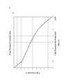
- FIG. 5is a simplified diagram of an embodiment of a transmission shift curve implemented by an electronic controller.
- FIG. 6is a simplified diagram of an embodiment of an engine speed map implemented by an electronic controller.
- FIG. 7is a simplified diagram of an embodiment of a variator map implemented by an electronic controller.
- FIG. 8is a simplified diagram of an embodiment of a variator map implemented by an electronic controller.
- FIG. 9is a simplified diagram of an embodiment of an engine speed limit map implemented by an electronic controller.
- FIG. 10is a simplified diagram of an embodiment of a variator rate limit map implemented by an electronic controller.
- FIG. 11is a simplified diagram mapping estimated engine torque to throttle position.
- FIG. 12is a simplified diagram of an embodiment of a line pressure schedule.
- FIG. 13is a simplified diagram of an embodiment of a line pressure control map.
- FIG. 14is a simplified diagram of an embodiment of a clutch application profile.
- FIG. 15is a simplified diagram of an embodiment of a clutch pressure control map.
- FIG. 16is a simplified diagram of an embodiment of a torque converter clutch curve.
- FIG. 17is a simplified flow chart of an embodiment of a method of controlling a variable ratio transmission.
- FIG. 18is a simplified flowchart of an embodiment of a method of controlling a variator in a variable ratio transmission.
- FIG. 19is a schematic diagram of an embodiment of a fluid flow diagram of an embodiment of a valve system that can be implemented on a variable ratio transmission.
- An electronic controller for a variable ratio transmissionis described herein that enables electronic control over a variable ratio transmission having a continuously variable ratio portion, such as a Continuously Variable Transmission (CVT), Infinitely Variable Transmission (IVT), or variator.
- the electronic controllercan be configured to receive input signals indicative of parameters associated with an engine coupled to the transmission.
- the parameterscan include throttle position sensor values, vehicle speed, gear selector position, user selectable mode configurations, and the like, or some combination thereof.
- the electronic controllercan also receive one or more control inputs.
- the electronic controllercan determine an active range and an active variator mode based on the input signals and control inputs.
- the electronic controllercan control a final drive ratio of the variable ratio transmission by controlling one or more electronic solenoids that control the ratios of one or more portions of the variable ratio transmission.
- the electronic controller described hereinis described in the context of a continuous variable transmission, such as the continuous variable transmission of the type described in International Application Number PCT/US2008/053347, entitled “CONTINUOUSLY VARIABLE TRANSMISSIONS AND METHODS THEREFOR,” assigned to the assignee of the present application and hereby incorporated by reference herein in its entirety.
- the electronic controlleris not limited to controlling a particular type of transmission but can be configured to control any of several types of variable ratio transmissions.
- the terms “operationally connected,” “operationally coupled”, “operationally linked”, “operably connected”, “operably coupled”, “operably linked,” and like termsrefer to a relationship (mechanical, linkage, coupling, etc.) between elements whereby operation of one element results in a corresponding, following, or simultaneous operation or actuation of a second element. It is noted that in using said terms to describe the various embodiments, specific structures or mechanisms that link or couple the elements are typically described. However, unless otherwise specifically stated, when one of said terms is used, the term indicates that the actual linkage or coupling may take a variety of forms, which in certain instances will be obvious to a person of ordinary skill in the relevant technology.
- radialis used herein to indicate a direction or position that is perpendicular relative to a longitudinal axis of a transmission or variator.
- axialrefers to a direction or position along an axis that is parallel to a main or longitudinal axis of a transmission or variator.
- FIG. 1is a simplified functional block diagram of an embodiment of a drive apparatus 100 , which is referred to herein as the drive 100 .
- the drive 100includes a transmission 101 operationally coupled between a prime mover 102 and a load 114 .
- the prime mover 102delivers power to the transmission 101
- the transmission 101delivers power to the load 114 .
- the prime mover 102can be one or more of any number of power generating devices
- the load 114can be one or more of any number of driven devices or components.
- Examples of the prime mover 102include, but are not limited to, engines, including but not limited to internal combustion engines and external combustion engines, motors, such as electric motors, and the like, or some combination thereof.
- Examples of loadsinclude, but are not limited to, drive train differential assemblies, power take-off assemblies, generator assemblies, pump assemblies, and the like.
- the transmission 101includes an input interface 104 , a variator 106 , an output interface 110 , and a range box 112 .
- the input interface 104is operationally coupled to the prime mover 102 .
- the variator 106can be operationally coupled between the input interface 104 and the output interface 110 .
- the range box 112is operationally coupled between the output interface 110 and the load 114 .
- a controller 108such as an electronic controller, can be configured to monitor one or more states, properties, or characteristics of the drive 100 .
- the controller 108can be configured to receive one or more inputs from a user interface 107 , which is typically local to the drive 100 and controller 108 .
- the controller 108may optionally include a remote interface 109 that is configured to receive one or more inputs from a remote controller (not shown).
- the controller 108can be coupled to the prime mover 102 and can be configured to monitor or otherwise determine one or more characteristics of the prime mover 102 .
- the controllercan be configured to monitor, for example, a throttle position, an engine speed, and the like or some combination thereof.
- the controller 108can also be coupled to one or more stages within the transmission 101 , and can be configured to monitor or otherwise determine one or more characteristics of the transmission 101 .
- the controller 108can be configured to monitor or otherwise determine various mechanical characteristics, fluid pressures and temperatures within each of the input interface 104 , variator 106 , output interface 110 , and range box 112 .
- the controller 108can be coupled to the user interface 107 to receive or monitor inputs provided locally.
- the user interface 107can include, for example, a gear shift controller, typically referred to as a gear shift lever.
- the user interface 107may also include one or more manual mode selectors, which can be selectively activated to control an operational mode of the drive 100 .
- the manual mode selectorscan be, for example, one or more switches or programmable elements. In an particular example, the manual mode selectors can selectively indicate an economy mode, a performance mode, a luxury mode, and the like.
- the manual mode selectorsneed not be mutually exclusive, but may be activated or disabled simultaneously or otherwise concurrently.
- the controller 108can be coupled to the remote controller (not shown) via the remote interface 109 and can be configured to receive one or more inputs from the remote controller.
- the remote interface 109can be a wired interface, wireless interface, and the like, or some combination thereof.
- the remote interface 109can support a wired communication standard.
- the remote interface 109can support a wireless communication standard.
- the remote interface 109can support a proprietary wired or wireless communication interface.
- the remote interface 109can be configured to support a combination of wired and wireless interfaces.
- the controller 108can receive, from the remote controller via the remote interface 109 , one or more control inputs or monitor inputs.
- the controller 108can be configured, for example, to receive programmable updates, tables, operational maps, other information, and the like, or some combination thereof from the remote controller.
- the controller 108can be configured to provide one or more outputs, based at least in part on the inputs, and which can be used to control operational characteristics of the drive 100 .
- the controller 10can control operational characteristics of the drive 100 , and in particular the transmission 101 , based on a combination of the inputs and one or more predetermined operational maps, algorithms, or processes.
- the controller 108can also be configured to provide one or more outputs that communicate or otherwise indicate a state, characteristic, or condition of one or more aspects of the drive 100 .
- the controller 108can be configured to control one or more indicators in the user interface 107 or provide diagnostic information to the remote controller via the remote interface 109 .
- the controller 108can be configured to control a final drive ratio of the transmission 101 , including the drive ratio provided by the variator 106 and the drive ratio enabled of the range box 112 .
- the controller 108can also be configured to control operational characteristics such as shifting characteristics.
- the controller 108can be configured to control a plurality of solenoid valves (not shown) that can control aspects of each of the input interface 104 , variator 106 , and range box 112 .
- the controller 108can be configured to control one or more of the solenoid valves using open loop control.
- the controller 108can be configured to control one or more of the solenoid valves in a closed control loop that utilizes feedback information provided to or monitored by one or more inputs to the controller 108 .
- the input interface 104can be configured for receiving power from the prime mover 102 and transferring such power to the variator 106 .
- the output interface 110can be configured for combining power (that is, torque applied at a given rotational speed) from the variator 106 and transferring such combined power to the range box 112 . It is disclosed herein that neither the input interface 104 nor the output interface 110 is necessarily limited to a particular respective physical and/or operational configuration. Accordingly, the input interface 104 may include any gearing or coupling structure suitable for providing such distributed power transfer and distribution functionality, and the output interface 110 may include any gearing or coupling structure suitable for providing such combined power transfer functionality.
- Examples of the input interface 104include, but are not limited to, a torque converter assembly, a hydraulic clutch coupling, a manually actuated clutch assembly, a computer-controlled clutch assembly, a magnetorheological clutch coupling, and the like, or some combination thereof.
- the variator 106can be configured for enabling power distributed thereto from the input interface 104 to be transferred to the output interface 110 in a manner whereby torque and/or rotational speed associated with that power is selectively variable (that is, selectively adjustable).
- the range box 112provides various gear selection and clutch engagement functionalities and operates to extend the range of final drive ratios available from the transmission 101 .
- gear selection functionalityinclude, but are not limited to, selective engagement of available range box gear ratios and selective engagement of various load drive directions.
- clutch engagement functionalityinclude, but are not limited to, passive implementation of various clutch engagement operations and active implementation of various clutch engagement operations.
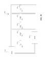
- FIG. 2is a simplified diagram of a variable ratio transmission 101 having electronic control.
- the variable ratio transmission 101 of FIG. 2can be, for example, the transmission implemented in the drive embodiment illustrated in FIG. 1 .
- the transmission 101consists of four major subsystems.
- the subsystemsinclude a torque converter 210 with a lockup clutch 212 , a variator 220 , alternatively referred to as a CVT element, a power combiner 230 , which can be implemented as a combining planetary gearset, and a two-speed range box 240 .
- the two speed range box 240can be implemented, for example, as a Ravigneaux gearset and clutches 242 , 244 , and 246 .
- the transmission 101is illustrated with a two speed range box 240 for purposes of clarity.
- range box 240 and associated clutches 242 , 244 , and 246may be omit the range box 240 and associated clutches 242 , 244 , and 246 in favor of a reverser, while still other embodiments may implement more than one range box 240 or a range box 240 capable of more than two speeds.
- the overall transmission ratiois determined by the torque converter 210 , the variator 220 , and the range box 240 .
- the range of ratios supported by the variator 220may produce an overlap in the range of ratios supported by the transmission 101 in the two different range box 240 configurations.
- the transmission controller 108accepts inputs from one or more system sensors and a driver, and operates one or more hydraulic solenoid valves 243 , 245 , 247 , 213 , and 221 , to control the range clutches 242 , 244 , 246 , variator 220 and torque converter clutch (TCC) 212 .
- the controller 108can be configured to apply and release each of the solenoid valves 213 , 221 , 243 , 245 , and 247 independently based at least in part on the one or more sensor inputs.
- FIG. 3Ais a simplified diagram of a variable ratio transmission 101 having electronic control.
- the transmission 101can include a torque converter subassembly 800 , a main shaft 1000 , a variator 1200 , a combining device 1400 , a range box 1600 , and a transmission housing 1800 .
- the transmission housing 1800can include a bell housing 1810 (that is, a first housing portion) and a rear housing 1820 (that is, a second housing portion) separably connected to the bell housing 1810 .
- the torque converter subassembly 800 , the main shaft 1000 , the variator 1200 , the combining device 1400 , and the range box 1600are operably mounted on or within the transmission housing 1800 in an axially aligned manner.
- the transmission housing 1800is configured for housing and supporting various subassemblies and/or components of the transmission 101 .
- any one of the torque converter subassembly 800 , the variator 1200 , the combining device 1400 , and the range box 1600can be arranged in a parallel shaft configuration relative to the other components.
- the variator 1200 and the main shaft 1000can be operably coupled between a power output portion of the torque converter subassembly 800 and power input portions of the combining device 1400 .
- the torque converter subassembly 800transfers power to the variator 1200 through the main shaft 1000 .
- the variator 1200supplies power to a first power input portion 1410 of the combining device 1400 .
- the main shaft 1000supplies power to a second power input portion 1405 of the combining device 1400 .
- Power from the variator 1200 and the main shaft 1000can be supplied to the combining device 1400 in a selectively variable ratio (for example, power from the variator 1200 in relation to power from the main shaft 1000 ) and can be combined by the combining device 1400 .
- the combining device 1400delivers the combined power to the range box 1600 via a power output portion 1401 of the combining device 1400 .
- the power output portion 1401can include a carrier of planetary gear set and/or a transfer shaft.
- the variator 1200mounts on the main shaft 1000 .
- the variator 1200 and the main shaft 1000form a torque split unit. More specifically, the ratio of torque transferred to the combining device 1400 through the variator 1200 or through the main shaft 1000 is selectively variable dependent upon a torque ratio setting of the variator 1200 .
- the variator 1200transfers power to the combining device 1400 in a manner whereby the torque and/or the rotational speed associated with that power is selectively and continuously variable (that is, adjustable).
- the variator 1200can be configured for receiving power of a first specification (for example, first torque and first rotational shaft speed) and outputting power of a second specification (for example, second torque and second rotational shaft speed).
- the torque converter subassembly 800is one embodiment of an input interface 104 , for example, thereby providing the functionality of transferring power from a prime mover attached to the torque converter subassembly 800 to the variator 1200 via, for example, the main shaft 1000 .
- a different type of input interfacesuch as, for example, a manually controlled clutch subassembly, a computer controlled clutch assembly, or a flywheel can be implemented in place of the torque converter subassembly 800 .
- the combining device 1400is an embodiment of an output interface, thereby providing the functionality of combining power received from the variator 1200 and the main shaft 1000 and transferring such power to the range box 1600 .
- the range box 1600receives power from the combining device 1400 and outputs power in conjunction with providing one or more of the various gear selection and clutch engagement functionalities discussed above in reference to FIG. 1 .
- the range box 1600 in combination with the variator 1200enables the transmission 101 to operate in multiple modes (that is, a multi-mode transmission).
- the variator 1200can include an input load-cam-and-traction-ring subassembly 2000 A, an output load-cam-and-traction-ring subassembly 2000 B, an array of planet-and-shift-lever subassemblies 2100 , a shift-cam-and-sun subassembly 2200 , and a stator-manifold subassembly 2300 .
- the shift-cam-and-sun subassembly 2200is supported by the stator-manifold subassembly 2300 .
- the shift-cam-and-sun subassembly 2200is supported in a manner enabling the shift-cam-and-sun subassembly 2200 to be translated along a longitudinal axis LA 1 of the main shaft 1000 .
- the planet-and-shift-lever subassemblies 2100are arrayed angularly around the main shaft 1000 , and are supported jointly by the shift-cam-and-sun subassembly 2200 and the stator-manifold subassembly 2300 .
- Each one of the planet-and-shift-lever subassemblies 2100is supported in a manner that facilitates synchronous rotation of all the planet-and-shift-lever subassemblies 2100 about a respective reference axis TA 1 extending through a planet 2102 of each one of the planet-and-shift-lever subassemblies 2100 .
- a respective reference axis TA 1extending through a planet 2102 of each one of the planet-and-shift-lever subassemblies 2100 .
- all of the planet-and-shift-lever subassemblies 2100are in the same relative rotational position at a given point in time.
- the axis TA 1 associated with each one of the planet-and-shift-lever subassemblies 2100extends through a center point of the respective planet 2102 substantially perpendicular to a radial reference axis RA 1 extending from the longitudinal axis LA 1 through the center point of the respective planet 2102 .
- the main shaft 1000includes a first end portion 1005 , a central portion 1010 and a second end portion 1015 .
- the first end portion 1005couples to a power output portion 805 of the torque converter assembly 800 (for example, an output hub of a converter turbine) in a manner precluding relative rotation of the main shaft 1000 with respect to the power output portion 805 .
- the central portion 1010 of the main shaft 1000couples to the input load-cam-and-traction-ring subassembly 2000 A in a manner precluding relative rotation of the main shaft 1000 with respect to the input load-cam-and-traction-ring subassembly 2000 A.
- the second end portion 1015 of the main shaft 1000couples to the first power input portion 1405 of the combining device 1400 in a manner precluding relative rotation of the main shaft 1000 with respect to the first power input portion 1405 .
- the output load-cam-and-traction-ring subassembly 2000 B of the variator 1200couples to a first power input portion 1410 of the combining device 1400 in a manner precluding relative rotation of the output load-cam-and-traction-ring subassembly 2000 B with respect to the first power input portion 1410 .
- the main shaft 1000is suitably configured for transferring power from the torque converter subassembly 800 (a) directly to the combining device 1400 , and (b) to the combining device 1400 through the variator 1200 .
- Each of the planets 2102is located by the input load-cam-and-traction-ring subassembly 2000 A, the output load-cam-and-traction-ring subassembly 2000 B, and the shift-cam-and-sun subassembly 2200 .
- the main shaft 1000can be configured to exert torque on the input load-cam-and-traction-ring subassembly 2000 A.
- the input traction interface TI 1is defined, as used here, at a region of contact between the input load-cam-and-traction-ring subassembly 2000 A and the respective planet 2102 .
- traction at each input traction interface TI 1 and each output traction interface TI 2is provided through an elastohydrodynamic layer formed by a traction fluid.
- the output traction interface TI 2is defined, as used here, at a region of contact between the output load-cam-and-traction-ring subassembly 2000 B and the respective planet 2102 .
- the output load-cam-and-traction-ring subassembly 2000 Bcan be coupled to the combining device 1400 . Accordingly, torque can be transferred from the main shaft 1000 to the combining device 1400 through the variator 1200 .
- the ratio of torque transferred to the combining device 1400 through the variator 1200 or through the main shaft 1000can be selectively variable dependent upon the torque ratio of the variator 1200 .
- the torque ratiorefers to a relative position of the input traction interface TI 1 and the output traction interface TI 2 , relative to the axis LA 2 , for a given tilt of the planet-and-shift-lever subassemblies 2100 .
- the torque ratiois substantially equal to 1 and there is no corresponding torque multiplication.
- the ratio of the tangential surface velocity of the planets 2102 at the input traction interface TI 1 to that of the tangential surface velocity of the planets 2102 at the output traction interface TI 2is selectively adjustable.
- the shift-cam-and-sun subassemblycan be configured such that translation of the shift-cam-and-sun subassembly 2200 causes such tilt of the planet-and-shift-lever subassemblies 2100 .
- the direction of tilt of the planet-and-shift-lever subassemblies 2100 from the position corresponding to the torque ratio of 1dictates whether the torque multiplication is greater than 1 (that is, torque output is greater than torque input) or less than 1 (that is, torque input is greater than torque output).
- the input traction interface TB and the output traction interface TI 2are angularly equidistant relative to a radial reference axis RA 1 extending through the tangential reference axis TA 1 .
- the torque ratiois 1 when a longitudinal axis LA 2 of each planet 2102 is parallel with the longitudinal axis LA 1 of the main shaft 1000 .
- Such an equidistant configurationprovides for a balanced adjustment range such that full adjustment of the planet-and-shift-lever subassemblies 2100 in a first adjustment direction results in the same absolute torque multiplication value as full adjustment in a second direction.
- the input traction interface TI 1 and the output traction interface TI 2may be non-equidistant from the reference axis TA 1 when the torque ratio is 1.0 and the longitudinal axis LA 2 is parallel with the longitudinal axis LA 1 .
- Such a non-equidistant configurationprovides for biasing of the adjustment range such that full adjustment of the planet-and-shift-lever subassemblies 2100 in the first adjustment direction results in a different absolute torque multiplication value than full adjustment in the second adjustment direction.
- the variator 1200can be axially constrained on the main shaft 1000 between an axial reaction flange 1020 of the main shaft 1000 and an axial lock nut 1305 .
- the axial lock nut 1305includes a threaded bore configured for mating with a corresponding threaded portion 1025 of the main shaft 1000 .
- the axial reaction flange 1020can be fixedly attached to the main shaft 1000 adjacent the second end portion 1015 of the main shaft 1000 .
- the threaded portion 1025can be an integral component of the main shaft 1000 , adjacent to the central portion 1010 of the main shaft 1000 .
- the main shaft 1000includes an anti-rock piloting surface 1028 configured for engaging a mating anti-rock piloting surface of the axial lock nut 1305 for limiting rocking of the axial lock nut 1305 with respect to the main shaft 1000 .
- a first engagement extension 1030 at the first end portion 1005 of the main shaft 1000can be configured for engaging or supporting a bearing assembly 810 that interfaces with certain components of the torque converter subassembly 800 or other support member.
- a second engagement extension 1035 at the second end portion 1015 of the main shaft 1000can be configured for engaging or supporting a bearing assembly 1415 that interfaces with certain components of the combining device 1400 .
- the bearing assemblies 810 , 1415include each only a bushing or a bearing component.
- the bearing assemblies 810 , 1415each include a bushing or a bearing component and a seal component configured to engage a mating surface of the respective engagement extension 1030 , 1035 .
- FIG. 3Bis a simplified diagram of an embodiment of a variator 1200 that can be, for example, the variator in the transmission of FIG. 3A .
- each one of the planet-and-shift-lever subassemblies 2100includes a planet 2102 rotatably mounted on a planet axle 2104 , which can be positioned on a planet central bore 2103 .
- Spaced apart planet bearings 2108 , an inner spacer 2110 , and outer spacers 2112can mount coaxially on the planet axle 2104 .
- the inner spacer 2110is positioned between the planet bearings 2108 , and each one of the planet bearings 2108 is positioned between a respective one of the outer spacers 2112 and the inner spacer 2110 .
- each planet 2102is rotatably mounted on a respective planet axle 2104 in a load-bearing and rotatable manner.
- the variator 1200is not limited to a particular planet bearing and spacer arrangement for rotatably mounting each planet 2102 on the respective planet axle 2104 .
- a planet bearing and spacer arrangement using more than two or less two planet bearings and more than two or less spacersthat is, inner position and/or outer position
- Planet axle shift levers 2106(“shift levers 2106 ”) can be fixedly attached to opposing end portions 2107 of the planet axle 2104 such that the planet 2102 is positioned between the shift levers 2106 .
- the planet axle 2104extends through a planet axle bore 2111 of each shift lever 2106 .
- the opposing end portions 2107include skew roller shoulders 2109 on which skew rollers 2122 mount.
- Each skew roller 2122can be held in place by a washer 2124 and a clip ring 2126 , which clip ring 2126 can be engaged within a groove in the skew roller shoulder 2109 .
- a shift lever 2106can include one or more features (not shown) such as, for example, a recess, a channel, etc., for providing clearance with other components of the variator 1200 .
- a shift guide roller axle 2116can be engaged within a shift guide roller axle bore 2117 of each shift lever 2106 and within a corresponding axle capturing feature 2119 of the planet axle 2104 .
- the shift guide roller axle bore 2117intersects and is generally perpendicular to the planet axle bore 2111 .
- the shift guide roller axle bore 2117is adjacent to a first end portion 2121 of the shift lever 2106 .
- the axle capturing feature 2119include, but are not limited to, a feature generally characterized as a notch, a cut out, a channel, a seat, or the like.
- the shift guide roller axle 2116 and the corresponding axle capturing feature 2119can be configured for limiting (for example, substantially precluding) radial displacement of the shift guide roller axle 2116 with respect to the engaged axle capturing feature 2119 .
- Such mating configuration of the shift guide roller axle 2116 and the corresponding axle capturing feature 2119limits displacement of the shift lever 2106 along the longitudinal axis LA 2 of the planet axle 2104 when the shift guide roller axle 2116 is mounted on the planet axle 2104 with the shift guide roller axle 2116 engaged within the shift guide roller axle bore 2117 and the corresponding axle capturing feature 2119 .
- Shift guide rollers 2114can be mounted on opposing end portions of each shift guide roller axle 2116 .
- Each shift guide roller axle 2116can be secured in place by, for example, washers 2118 and clip rings 2120 , which clip rings 2120 can be engaged within a groove 2191 of the shift guide roller axle 2116 .
- the shift guide roller axle 2116can be secured by, for example, an interference fit, press fit, etc.
- Side faces 2244can be configured to substantially constrain movement of the shift lever 2106 , thereby limiting rotation of the respective shift lever 2106 about the longitudinal axis LA 1 of the variator 1200 .
- the shift-cam-and-sun subassembly 2200can include sun 2202 , bearings 2204 , shift cams 2206 , control pistons 2208 , piston tube 2210 , shim 2212 , inner seals 2214 , and outer seals 2216 .
- the control pistons 2208are coupled to the shift cams 2206 through the piston tube 2210 .
- the control pistons 2208 and the shift cams 2206can be mounted on the piston tube 2210 by, for example, a press-fit interface.
- the sun 2202can be operationally coupled to the shift cams 2206 through the bearings 2204 .
- the bearings 2204can be configured to transfer axial and radial loads between the sun 2202 and the shift cams 2206 .
- the sun 2202 and the shift cams 2206can be configured to receive the bearings 2204 .
- the variator 1200is not limited to bearings of a particular type.
- an angular contact bearingis a suitable bearing type for the bearings 2204 .
- the position of the control pistons 2208can be selectably controlled, for example, via an electronic solenoid under the control of an electronic controller.
- the controllercan utilize a closed loop control to monitor the transmission state and adjust the electronic solenoid, and thereby the position of the control pistons 2208 , accordingly.
- FIG. 3Cis a simplified fluid flow diagram 300 of an embodiment of a variable ratio transmission.
- the fluid flow diagram 300can illustrate, for example, a fluid flow within the transmission of FIG. 3A .
- the fluid flow diagram 300illustrates schematically the control of fluid flow and fluid pressures through the use of one or more electronic solenoids.
- the fluid flow and controls illustrated in the flow diagram 300 of FIG. 3Care illustrative and not intended to be limiting on the number and type of controls that may be implemented within a transmission.
- the fluid flow diagramgenerally illustrates the electronic solenoids, e.g. 213 , as controlling a fluid exhaust, the electronic solenoids are not limited to controlling fluid exhaust, and may be configured to control inlet fluid flow or a chamber volume in order to effectuate the desired control.
- fluidsuch as hydraulic fluid within the transmission is contained within a sump 350 .
- a pump 310draws the fluid from the sump, pressurizes it, and distributes it to one or more control paths within the transmission.
- the pump 310can be, for example, driven by the primary move via the input interface.
- an internal combustion enginedrives the torque converter, and the torque converter drives the pump 310 .
- the pump 310typically includes one or more mechanisms (not shown) for controlling, regulating, or otherwise limiting the fluid pressure. Such mechanisms include, but are not limited to solenoids, check balls, diaphragms, regulators, and the like, or some combination thereof.
- the line pressurecan be static or may be dynamically regulated by the controller. The pressure regulator is not illustrated for the sake of clarity.
- the pressurized fluid from the pump 310is distributed along a plurality of control passages.
- Each of the control passagescan be sized to minimize the drop in fluid pressure experienced at the output of the pump 310 across the entire control range of flow in the control passage.
- a first control passagecan be, for example, coupled to the torque converter and operate to control the engagement and disengagement of the torque converter clutch.
- a first electronic solenoid 213 under the control of the controllercan selectively control a torque converter clutch piston 312 to selectively control the pressure applied to the torque converter clutch.
- the first electronic solenoid 213can be substantially de-energized when the torque converter clutch is not engaged, where de-energized refers to the currently flowing through the solenoid that is insignificant relative to an actuation current.
- the fluid supplied in the first control passageis permitted to exhaust back to the sump 350 thereby inhibiting sufficient pressure to actuate the torque converter clutch.
- the first electronic solenoid 213can be engaged to substantially limit fluid exhaust from the first control passage, thereby permitting build up of pressure within the first control passage and engaging the torque converter clutch.
- a second control passagemay be implemented in conjunction with a second electronic solenoid 221 and variator control piston 320 to control the ratio provided by the variator.
- the controllercan control the amount of current to the second electronic solenoid 221 to control the fluid exhaust through the second control passage and thereby the position of the variator control piston 320 .
- the position of the variator control piston 320controls the shift-cam-and-sun subassembly and planet-and-shift-lever subassemblies, which control the ratio provided by the variator.
- a third control passagemay be implemented in conjunction with a third electronic solenoid 243 and range clutch control piston 342 to control the engagement of the range clutch.
- the controllercan provide an actuation current to the third electronic solenoid 243 to engage the range clutch control piston 342 and permit fluid pressure to engage the clutch.
- the controllercan inhibit current to the third electronic solenoid 243 to disengage the range clutch control piston 342 and permit fluid in the third control passage to exhaust to the sump 350 , thereby inhibiting pressure applied to the range clutch.
- the position of the range clutchcan be used to control the ratio of the range box.
- a fourth control passagemay be implemented in conjunction with a fourth electronic solenoid 245 and forward clutch control piston 344 to control the engagement of the forward clutch.
- the controllercan provide an actuation current to the fourth electronic solenoid 245 to engage the forward clutch control piston 344 , and can inhibit current to the fourth electronic solenoid 245 to disengage the forward clutch control piston 344 .
- a fifth control passagemay be implemented in conjunction with a fifth electronic solenoid 247 and reverse clutch control piston 346 to control the engagement of the reverse clutch.
- the controllercan provide an actuation current to the fifth electronic solenoid 247 to engage the reverse clutch control piston 346 , and can inhibit current to the fifth electronic solenoid 247 to disengage the reverse clutch control piston 346 .
- FIG. 4is a simplified functional block diagram of an embodiment of an electronic controller 108 for a variable ratio transmission.
- the controller 108can be, for example, the controller illustrated in FIG. 1 and can be used, for example, to control the transmission of FIG. 3A .
- the electronic controller 108 functionsare broken down into system inputs, controller outputs, range control, variator control, torque converter clutch locking and diagnostics.
- the controller 108implements a strategy for controlling the range box and variator.
- the controller 108determines the appropriate functionality as a function of driver (user) and vehicle inputs in the shift point module 410 .
- the shift logic module 430determines the appropriate clutches to apply and their required torque capacity.
- the rate of apply and corresponding solenoid currentare computed in the shift quality control module 450 .
- the controller 108also determines when use of the variator is enabled.
- the controller 108can also be configured to include diagnostics and failure modes to enable the ability to avoid dangerous or destructive conditions and to allow reduced functionality operation in case of failure when possible. Major electrical and hydraulic failures can be addressed, as well as highly degraded performance.
- the controller 108includes a plurality of modules configured to receive input from one or more sensors or controls in the drive system. Each external signal that enters the electronic controller can represent a sensor measurement or a control state. Prior to using the input information, the input data may undergo signal conditioning, scaling, error checking, and the like, or some combination thereof.
- the input signals and control statesmay be analog signals, digital signals, or a combination of analog and digital signals.
- An initial complement of analog inputs for a particular implementationis listed in Table 1 as an illustrative example.
- a controller 108need not support the entire complement of input types.
- the first three analog signal typesmay be implemented within a production controller 108 .
- the others analog inputsmay be supported in the production implementation or may be included for potential use in development units.
- the controller 108may also be configured to accept one or more digital inputs.
- an active signalis pulled to ground. That is, the controller 108 provides a pull-up function.
- the controller 108can be configured to condition or otherwise process the received input signals.
- the controller 108can perform signal conditioning on the input signals to reduce or otherwise mitigate noise effects.
- the controller 108may condition inputs that are provided by a thermistor.
- the controller 108may implement a pull-up resistor at each thermistor input to form a voltage divider, with the junction voltage providing an indication of resistance.
- the controller 108performs a linear translation from input voltage to the engineering units, as indicated in Table 1. Inputs that are scaled, shifted, or otherwise conditioned or processed, such as thermistor inputs, may be translated based on a calibration. A lookup table can be used to perform this calibration. Predetermined input signal ranges can be used by the controller 108 to check for sensor failures. The detection of erroneous values will be flagged by the controller 108 for the diagnostic routines.
- One or more valuesmay be predetermined and stored within one or more modules of the controller 108 .
- physical dimensionscan be used as parameters to estimate variables that are not directly measured.
- the plurality of modulesoperate on the sensors in conjunction with one or more predetermined maps, algorithms, or processes implemented in modules within the controller 108 to determine one or more control signals.
- One or more output control modulescan operate to provide the one or more control signals to their respective control destinations.
- the controller 108 outputscan be primarily solenoid controls to control electronic solenoids in the transmission.
- the controller 108can be configured to provide one or more pieces of diagnostic information.
- the controller 108can be configured, for example, to provide such diagnostic information as a driver warning light.
- the electronic control of the transmissionis achieved through electrohydraulic solenoids.
- a list of the solenoids and their general characteristicsis given in Table 2 as an illustrative example.
- Several different types of solenoidare employed. These may include a variable-force solenoid (VFS), a variable bleed solenoids (VBS), on/off shift solenoids and pulse-width modulated on/off solenoids (PWM).
- VFS and VBS typesare typically used with closed-loop current control in order to maintain accuracy of control.
- the on/off solenoidstypically require no feedback.
- VFS current 9-14 V 1A 300 Hz iLine mA 0-1000 press.
- Low VBS current 9-14 V 1A 300 Hz iLow mA 0-1000 press.
- Direct VBS current 9-14 V 1A 300 Hz iDirect mA 0-1000 exh.
- Reverse VBS current 9-14 V 1A 300 Hz iReverse mA 0-1000 press.
- Ratio VBS current 9-14 V 1A 300 Hz iRatio mA 0-1000 press.
- TCC PWMno 9-14 V 1.5 A 32 Hz TCCduty % 0-100 exh.
- the controller 108can generate PWM signals, using, for example, microcomputer timers. Pulses are generated at the appropriate frequency with width according to duty cycle. Narrow pulses represent low duty cycle and wide pulses for high duty cycle. Although they are not specifically designated as PWM solenoids, the VFS and VBS can use a PWM signal as part of their control. In this case, however, the appropriate output module from the controller 108 adjusts the duty cycle that an average current feedback tracks the command.
- the controller 108can generate PWM signals with a relatively high frequency, that is typically higher than an update rate of non-PWM controlled solenoids, and higher than a response time of the solenoid, so that the solenoid valve does not actually cycle on and off each pulse, but instead, provides a smooth response. In effect, the response time characteristic of the electronic solenoid operates as a lowpass filter to smooth the PWM signal.
- the controller 108includes a shift point module 410 configured to receive input from one or more of a shift schedule module 412 , a plurality of sensors, including, but not limited to, a vehicle speed sensor, a throttle position sensor, one or more control state sensors, such as a shift position lever state sensor, and the like.
- a shift point module 410configured to receive input from one or more of a shift schedule module 412 , a plurality of sensors, including, but not limited to, a vehicle speed sensor, a throttle position sensor, one or more control state sensors, such as a shift position lever state sensor, and the like.
- Table 3The list of sensor signals and switch inputs in Table 3 represents the digital inputs to the transmission controller 108 .
- Table 3is an illustrative example of one embodiment of the sensor signal and switch inputs.
- FIG. 4An embodiment of a pressure switch manifold decoding is shown in Table 4 as an illustrative example.
- logic 0represents a closed switch and 1 is open, or floating. Because neutral and park are identical hydraulically, only two of the bits (N and P) are needed to identify the four possible states. Park and neutral can be distinguished via the park switch on the PRNDL lever.
- the decoded PRNDL positionis represented by the variable lever.
- the third pressure manifold bit, Rindicates the status of the manual low clutch.
- the table entry Mis logic 1 when the clutch is pressurized and logic 0 when it is vented.
- the five speed inputs listed in Table 5can be sensed by the frequencies of toothed wheels passing a magnetic pickup.
- Each speed sensorgenerates a pulse train that triggers timer circuits, for example, within the shift point module 410 or an optional speed sensor conditioning module (not shown).
- the timerscan determine the period of each pulse, and the reciprocal of the period is the frequency of the pulse train. Pulses of a duration that is either much shorter or larger than the trend can be assumed to represent noise and can be discarded. Persistently erratic or lost pulses can be reported to a diagnostic routine.
- the frequencycan be scaled.
- the pulse frequencycan divided by the number of pulses per revolution and the result multiplied by 60 to arrive at the shaft speed in rpm.
- Vehicle speedcan be approximated from tail shaft speed, neglecting slip, which may be negligible.
- the shift point module 410operates on the inputs to determine which one of a plurality of ranges to operate within.
- the electronic controller 108configured to control the transmission of FIG. 3A having a two-ratio range box and a CVT variator can implement virtually an infinite number of ratio combinations within the ratio range.
- the controller 108and in particular, the shift point module 410 is configured to provide transmission control based on a predetermined number of control ranges.
- the number of ranges and the span for each of the predetermined control rangescan be stored, for example, in the shift schedule module 412 .
- the controller 108can implement three control ranges.
- the shift point module 410can determine, based on the inputs, the relevant control range and can identify the active control range by the variable ngear. Table 6 is an example of an embodiment of transmission control range designations. In one example, the shift point module 410 determines the appropriate range based on the shift curves stored in the shift schedule module 412 .
- the shift point module 410can also determine and output a variator flag value.
- the shift point module 410can determine the state of the variator flag based at least in part on the ngear control range state.
- the shift point module 410can output, for example, an active variator flag in those control range states when active variator control is enabled.
- the controller 108controls both the variator and range box to be in low, giving the maximum possible underdrive.
- the controller 108controls the variator ratio and the range of ratios can be shifted toward one-to-one and beyond into overdrive, while the range box remains in low.
- the controller 108controls the range box to shift to one-to-one (direct) with the variator controlled to operate in full overdrive.
- the shift point module 410provides the ngear value and appropriate shift flags to the shift logic module 430 .
- the shift logic module 430operates on the input values and outputs shift control commands as well as a line pressure valve control. For example, the shift logic module 430 can determine the current state of the control range based on the ngear value provided by the shift point module 410 .
- the shift logic module 430operates on an active upshift flag to command an upshift of the transmission. Conversely, the shift logic operates on an active downshift flag to command a downshift of the transmission.
- the shift logic module 430can also be configured to command the application of the torque converter clutch to control whether the torque converter is engaged into a lockup state.
- the controller 108can lock the torque converter clutch in order to operate the transmission more efficiently.
- the shift point module 410 in combination with the shift logic module 430may determine the conditions for torque converter lockup in a manner similar to the range control strategy. The conditions under which the controller 108 applies the torque converter clutch can be determined by driver input and vehicle speed.
- the shift point module 410can implement the conditions for torque converter lockup as another range value in the number of predetermined control ranges.
- the shift point module 410can implement the additional torque converter lockup clutch as an additional shift strategy stored in the shift schedule module 412 .
- the shift logic module 430can be configured to provide line pressure valve control information directly to a line pressure solenoid in order to adjust the line pressure within the transmission. This is discussed in further detail below.
- the shift logic module 430can also be configured to directly control the torque converter clutch solenoid to selectively engage or disengage the torque converter clutch.
- the shift logic module 430sends the shift commands, whether upshift or downshift, to a shift quality control module 450 that operates to control the appropriate pressure control solenoid to achieve a particular shift quality.
- the shift quality control module 450can operate on the shift control from the shift logic module 430 by implementing a particular shift profile.
- the shift quality control module 450implements a particular shift profile, for example, by controlling current applied to the appropriate shift solenoid based on the shift profile.
- the shift quality control module 450can implement different shift profiles to provide differing shift characteristics. For example, the shift quality control module 450 can implement a rapid first shift profile when the transmission is operated in a performance mode and can implement a gentle second shift profile when the transmission is operated in a luxury mode.
- a variator mode module 420operates to control the ratio provided by the variator.
- the variator mode module 420can determine when the variator can be controlled according to several different modes. Typically, the engine speed is controlled by the variator in order to achieve objectives of performance or fuel economy, for example. Alternatively, a specific ratio may be commanded. In each of these cases, the objective can be translated to a desired instantaneous engine (or turbine) speed.
- a variator valvecan be adjusted dynamically to track this setpoint. Full overdrive and underdrive may be commanded at the extremes of operation.
- the variator mode module 420can be configured to receive sensor and control state inputs which may be the same, distinct from, or at least partially overlap the sensor and control state inputs received at the shift point module 410 .
- the variator mode module 420also receives a variator flag value from the shift point module 410 .
- the controller 108may limit dynamic control of the ratio of the variator to those situations where the variator flag is active. If the variator flag is active, the variator mode module 420 can determine a variator mode and a corresponding variator control based on the various inputs. Alternatively, if the variator flag is inactive, the variator mode module 420 determine a static state of the variator based on the input signals. In an alternate embodiment, the variator mode module 420 may also receive the ngear value from the shift point module 410 and determine the state of the variator control based in part on the ngear value as well as the state of the variator flag.
- the variator mode module 420can determine an active one of a plurality of variator modes based on the input signals.
- the controller 108can, for example, implement a plurality of variator modes. Although there is virtually no limit to the number of variator modes that the controller 108 may implement, the majority of driving conditions may be satisfied using fewer than approximately ten variator modes.
- Each variator modeallows the controller 108 to control the variator (or CVT) to provide good drivability according to the driver inputs, engine and vehicle conditions. Examples of the various variator modes and conditions for their operation are provided below.
- the variator mode module 420outputs the variator mode value to an engine speed setpoint module 440 .
- the engine speed setpoint module 440operates to control the variator in order to control at least one of an engine speed or variator ratio that depends on the variator mode.
- the engine speed setpoint module 440can determine a desired engine speed, for example, based in part on one or more algorithms, engine maps, and the like or some combination thereof.
- the various engine maps and algorithmscan be stored within memory within the engine speed setpoint module 440 or in memory otherwise accessible by the engine speed setpoint module 440 .
- the engine speed setpoint module 440provides the target engine speed to a closed loop algorithm control module 460 .
- the closed loop algorithm control module 460receives the target engine speed and actual engine speed as input values.
- the actual engine speedcan be determined based on one or more sensor values, such as, for example provided by a crankshaft sensor or flywheel sensor.
- the engine speed setpoint module 440generates a control output to maintain the actual engine speed to within an error tolerance of the target engine speed.
- the engine speed setpoint module 440outputs a current signal that is used to control a variator valve.
- the engine speed setpoint module 440modulates the current provided to an electronic solenoid that controls a position of a variator control piston within the variator.
- the engine speed setpoint module 440can, for example, compare the target engine speed against the actual engine speed and generate an error signal that is used to control the output signal.
- the engine speed setpoint module 440can implement a loop filter and loop gain to achieve the desired control characteristics. For example, a lower bandwidth on the loop filter may eliminate unwanted spurious effects on the control output, but at a cost of speed at which the engine speed setpoint module 440 can react to sudden changes in either the target engine speed or the actual engine speed.
- the engine speed setpoint module 440can control the ratio solenoid of the variator so that the measured engine speed feedback tracks the setpoint.
- the engine speed setpoint module 440can perform PI (proportional+integral) control. The general form of the equations is shown below.
- the engine speed setpoint module 440can accumulate the integral of the error to minimize steady-state error in the control loop.
- the engine speed setpoint module 440can approximate this integral in discrete time.
- the engine speed setpoint module 440can limit the sum of the control action to be within a usable range of the solenoid.
- the engine speed setpoint module 440can perform ratio limit based on the pseudo code provided below.
- the functions of the various modules within the controller 108may be implemented as hardware, software, or as a combination of hardware and software.
- the controller 108can include a processor 492 or computer and one or more processor readable or computer readable media.
- the one or more processor readable or computer readable mediacan be implemented, for example, as memory 494 .
- the processor readable or computer readable mediacan be encoded with one or more instructions, data, or information that are arranged as software instructions that, when executed by the processor or computer, implement the functionality of portions or all of one or more of the modules within the controller 108 .
- FIG. 5is a simplified diagram of an embodiment of a transmission shift curve 500 implemented by an electronic controller. As described above, the controller may implement three distinct ngear control ranges.
- the appropriate rangeis determined by the controller according to shift curves such as those shown in FIG. 5 .
- a thresholdis calibrated, in terms of vehicle speed as a function of throttle.
- the V21is the downshift curve for the overall transmission into low.
- the curve varlowshows that the variator will be in low ratio prior to the 2-1 downshift. Note that the transition into low is at a somewhat lower speed to prevent hunting.
- the controller 108commands the variator to a predetermined ratio, such as a predetermined overdrive ratio by virtue of the varhigh curve.
- the V32 curve signals, ngear2, the range box to downshift from direct to low and enables the variator back into a control mode.
- the shift curvescan be implemented as table values stored in the shift schedule module.
- the tables values and shift curvescan be changed to achieve a particular vehicle performance criterion.
- the shift schedule modulecan be configured to store a plurality of shift curves corresponding to a plurality of selectable user selectable transmission characteristics.
- the controllercan select or otherwise access a particular shift curve instantiation based on the value of the user selectable characteristic.
- a user interfacemay permit a user to select from a performance mode or an economy mode.
- a distinct shift curvemay be stored within the shift schedule module for each user selectable mode and accessed by the controller upon activation by the user.
- the various shift curvescan be based on maximum engine torque, and may differ based on the type and characteristics of the prime mover coupled to the transmission.
- the variator control described abovecan be implemented, for example, with five variator control modes listed in Table 7. These variator control modes permit the transmission to provide good drivability according to the driver inputs, engine and vehicle conditions.
- FIG. 6is a simplified diagram of an embodiment of an engine speed map 600 implemented by an electronic controller.
- the variator control modescan be implemented directly be the variator mode module.
- the variator mode modulemay implement the ratio control of modes 0, 1, and 3 directly based on a predetermined control value for the variator mode.
- the variator mode modulecan be configured to set the variator ratio to a predetermined underdrive value, such as a minimum underdrive ratio.
- the variator mode modulecan be configured to set the variator ratio to a predetermined overdrive value, such as a maximum overdrive ratio.
- Mode 2is the main dynamic control mode of the variator.
- the control strategy the for mode 2 implemented by the controller, and in particular the variator mode module,can be to maintain the engine speed at some optimum operating point based on a specific criteria.
- the ratio of the variatoris changed to satisfy a closed loop engine speed control system.
- the engine speed set point functionis based on the chosen operating criteria.
- the criterion for this strategyis based on an engine speed set point established near the maximum engine torque for each throttle. This performance criterion can be seen by plotting the engine set points on the engine map 600 .
- Th_setv[0 10 20 40 60 90 100]
- pct throttle angle Ne_set2[1500 1500 1675 2450 3200 4200 rpm engine speed 4200] setpoint mode 2
- FIG. 7is a simplified diagram of an embodiment of a variator ratio map 700 implemented by an electronic controller.
- the variator mode modulemay implement the variator ratio map 700 of FIG. 7 via one or more look up tables for the corresponding modes. An example of the type of information included in the look up tables is provided below.
- the variator mode modulemay map the predetermined ratio to a corresponding solenoid control value.
- FIG. 8is a simplified diagram of an embodiment of a variator ratio map 702 implemented by an electronic controller.
- the variator ratio mapis implemented in a look up table and is used by the variator mode module to control the variator ratio in mode 7, corresponding to reverse.
- An example of the type of information included in the look up tablesis provided below.
- the variator mode modulemay map the predetermined ratio to a corresponding solenoid control value.
- V_set[0 10 20 40 60 90 100 120]
- Ratio_set7[100 100 100 100 100 55 55 variator ratio set point 55] mode 7
- FIG. 9is a simplified diagram of an embodiment of an engine speed limit map 900 implemented by an electronic controller.
- the electronic controllermay implement an engine speed limit that is based on vehicle speed in order to limit or otherwise prevent engine damage that may occur as a result of exceeding reasonable engine speed limits.
- the engine speed limit map 900is implemented in a look up table and is used by the controller to control the engine speed, for example, by providing feedback to an engine control module.
- An example of the type of information included in the look up tableis provided below.
- Neset_limit[20 40 60 80 100 120]
- Neset_limit[4000 4000 4000 5000 6000 rpm Neset limit 6000]
- the variator control modes indicated in Table 9can be implemented in each case entirely with engine speed control. That is, although other operating objectives may indicated, such as underdrive, overdrive, or ratio control, those objectives can generally be translated to a desired engine speed in each case. In modes zero, one, and three, out-of-range speeds can be used to force the controls to saturate towards one of the ratio extremes. For modes four through seven, the variator output speed and desired ratio are used to compute the corresponding engine speed. The desired ratio is calibrated as a function of vehicle speed in these cases. The computed engine speed set point can be filtered with a first-order filter in order to prevent control activity that is too abrupt.
- Neset⁇ 7000 Idle f ⁇ ( throttle , veh_speed ) Drive 500 Transmission g 1 ⁇ ( veh_speed ) * N ⁇ ⁇ var Coast g 2 ⁇ ( veh_speed ) * N ⁇ ⁇ var Manual
- FIG. 10is a simplified diagram of an embodiment of a variator rate limit map 902 implemented by an electronic controller. Limiting may also be applied to restrict the rate of ratio change in the downshift direction.
- the limit values of the ratio valve current(iRatioMax and iRatioMin) can be a function of vehicle speed.
- the rate limit mapmay be implemented as a look up table. An example of the type of data in the look up table is provided below.
- iRat00.7
- V_limit[10 20 40 60 80 100 120]
- kph vehicle speed for variator valve limit iRsol_limitset[1 .85 .8 .78 .75 .75 .75]
- FIG. 11is a simplified diagram 904 mapping estimated engine torque to throttle position.
- the engine torque mapmay be predetermined for particular type of prime mover coupled to the transmission.
- the engine torque mapmay be stored as a lookup table in memory.
- the controller 108can estimate engine torque as a function of throttle. Clutch capacity requirements are computed as a function of engine torque.
- the controllercan implement transmission range selection according to the logic of Table 8, which may be implemented in the shift logic illustrated in FIG. 4 .
- the controllercan, for example, implement the modes in the shift control logic of Table 8 using the following pseudocode, where the parameters Vrev and Vmanlow are constants that represent vehicle speed thresholds, above which the controller inhibits the corresponding shift.
- the controllercan determine the application of the various clutches based on the shift control logic and can implement the logic by selectively enabling or disabling current applied to control solenoids.
- the controllercan implement the logic of Table 8 by setting the solenoid outputs according to the control shown in Table 9.
- the values indicated in the tablerepresent electrical state, with zero for off and one for on.
- the modulated solenoidsreverse, low and direct
- the valueindicates a steady-state value.
- the letter Cindicates that the solenoid is controlled to achieve the speed or ratio objective described in the portion describing variator control.
- the fluid line pressure provided by the pumpmay be dynamically regulated or otherwise dynamically controlled by the controller to enable particular transmission performance in each of the various operating modes.
- FIG. 12is a simplified diagram of an embodiment of a line pressure schedule 906 .
- the line controllercan dynamically regulate the line pressure to a plurality of levels that can map to the various transmission operating modes. As shown in the line pressure schedule 906 of FIG. 12 , the controller can control a solenoid or other pressure regulator to achieve three distinct line pressures. A first lowest line pressure can be implemented when the transmission is selected to be in neutral or park. A second intermediate line pressure can be used when the transmission is selected to be in drive or low. A third highest line pressure can be sued when the transmission is selected to be in reverse. Examples of the values for the line pressures are provided below.
- FIG. 13is a simplified diagram of an embodiment of a line pressure control map 908 .
- the line pressure control map 908can be used to calibrate an electronic solenoid used to control the line pressure.
- portions of the mapmay be stored in memory as a lookup table and accessed by the controller to set the line pressure based on the schedule of FIG. 12 .
- only those information corresponding to the desired line pressures in the line pressure schedule of FIG. 12may be stored in memory for access by the controller.
- FIG. 14is a simplified diagram of an embodiment of a clutch application profile 1402 .
- the shift quality of an automatic range transmissionrequires control of the driveline dynamics during the engagement and disengagement of clutches during gear ratio changes.
- the main performance criteriaare a smooth shift with good clutch durability.
- Shift quality of a shiftis based on the application of hydraulic pressure to the clutch in both amplitude and timing. This control system has several parameters that can be adjusted to modulate the hydraulic pressure and therefore the resultant clutch torque.
- the clutch apply torque set point profile 1402is based on a number of calibration parameters.
- the required clutch torquemust balance the static input torque to the range box in addition to dynamic torque required to synchronize the clutch.
- the required clutch setpointuses a step input based on a single coefficient and an estimated range box input torque.
- a low rate torque rampcan be used for fine-tuning.
- TfCHmaxmaximum torque for lockup
- the main parameter used for shift quality calibrationis the step coefficient Kcxx.
- FIG. 15is a simplified diagram of an embodiment of a clutch pressure control map 1404 .
- the controllerand in particular the shift quality control module, can store one or more clutch pressure control map 1404 as a look up table in memory.
- the shift quality control modulecan access the clutch pressure control map to implement the shift quality as provided in the clutch apply torque set point profile of FIG. 14 .
- the controllercan control the operation of the lockup clutch in the torque converter as an additional control range, the engagement and disengagement of the torque converter lockup clutch need not be controlled to the same extent as, for example, the direct clutch used to engage the ranges of the range box.
- the controllertypically applies the lockup clutch in conditions where the torque converter is operating near 100% efficiency, and thus, the transition to a lockup condition does not result in as great a transition as occurs when shifting the range provided by the range box.
- FIG. 16is a simplified diagram of an embodiment of a torque converter clutch curve 1602 .
- the controllerapplies the torque converter clutch according to logic that is similar to the control range selection described above.
- the controllercan lock the torque converter clutch at low speed with light throttle for efficiency. As the driver steps into the throttle as sensed by the percentage of the throttle position sensor, the controller unlocks the clutch to allow the converter to multiply torque.
- Torque converter lockupcan be inhibited at low oil temperature in order to allow losses in the fluid coupling to heat the oil. Furthermore, the converter can remain locked at excessive temperature in order to prevent the generation of further heat.
- the torque converter clutch control strategyis based on the criteria of minimum operation in the unlocked open converter phase.
- the conditions for open converterare to provide good launch and enhance shift quality.
- the controllercan store the parameters of the torque converter clutch curve in memory. An example of stored parameters is provided below.
- a controllercan thus be configured according to the various embodiments and features described herein to control a transmission, and in particular, a transmission having at least one substantially continuously variable ratio portion, such as a variator, CVT or IVT.
- a transmission having at least one substantially continuously variable ratio portionsuch as a variator, CVT or IVT.
- the examples described aboveuse an example transmission having a variator in combination with a two-speed range box.
- the controllerexecutes various strategies and processes that permit transmission operation to be optimized over various conditions and corresponding criteria.
- FIG. 17is a simplified flow chart of an embodiment of a method 1700 of controlling a variable ratio transmission.
- the method 1700can be implemented, for example, within the controller of FIG. 4 to control the variable ratio transmission of FIGS. 2 and 3A .
- the method 1700begins at block 1710 where the controller, for example at the shift point module and the variator mode module, receives input signals that can include sensor values as well as control input values.
- the controllerproceeds to block 1712 and determines the active control range based on the input values.
- the shift point modulecan determine an active control range from a plurality of control ranges.
- Each of the control rangescan correspond to a range of transmission ratios. Two or more of the control ranges may include overlapping ratios.
- the controllerproceeds to block 1714 and the variator mode module determines the active variator mode from a plurality of variator modes.
- the variator mode modulecan determine the variator mode based on the input values as well as the active control range or a signal, such as the variator flag, that may be based on the active control range.
- the controllerproceeds to block 1716 and determines a range box configuration, which can include a range box clutch engagement configuration, a range box ratio, and the like, or some combination thereof.
- the controllerproceeds to block 1718 and determines the state of a torque converter clutch that can be based on the input signals and the active control range.
- the controllerproceeds to block 1720 and configures the variator based on the mode and input values.
- the controllerproceeds to block 1722 and configures the range box based on its determined configuration.
- the controllerproceeds to block 1724 and configures the torque converter clutch based on whether the controller determines it should be engaged or disengaged.
- FIG. 18is a simplified flowchart of an embodiment of a method 1750 of controlling a variator in a variable ratio transmission.
- the method 1750can be implemented, for example, by the controller of FIG. 4 operating on the transmission of FIGS. 3A-3C .
- the method 1750begins at block 1752 where the controller, for example at the shift point module and the variator mode module, receives input signals that can include sensor values as well as control input values.
- the controllerproceeds to block 1754 where the shift point module can determine a variator mode based on the inputs.
- the controllerproceeds to block 1756 , where the shift point module determines an active control range
- the controllerproceeds to block 1758 where the controller, for example, using the shift point module, determines a range box ratio based on the control range, the input signals, and a shift schedule stored in and accessed from the shift schedule module.
- the controllerproceeds to block 1760 where the variator mode module can determine a desired variator ratio, for example, based in part on the variator mode.
- the controllerproceeds to block 1762 and the engine speed setpoint module maps the ratio to a target engine speed.
- the controllerproceeds to block 1764 and controls the variator to achieve the target engine speed.
- the controllercan, for example, utilize a closed loop control module to monitor an engine speed and control a solenoid that controls a position of a longitudinal axis of a rotating planet within the variator in order to achieve the target engine speed.
- FIG. 19is a schematic diagram of an embodiment of a fluid flow diagram of an embodiment of a valve system 2500 that can be implemented on a variable ratio transmission such as the transmission 101 .
- the associated hardware represented by the symbols and schematic notations illustrated in FIG. 19should be readily apparent to those having ordinary skill in the relevant technology.
- the valve system 2500can include a pump valve subsystem 2502 configured to be in fluid communication with a number of pressure control valves.
- the pump valve subsystem 2502is adapted to cooperate with a pump 806 ( FIG. 3A ) provided on the transmission 101 .
- the pump valve subsystem 2502can include a pressure regulator valve 2504 .
- the pressure regulator valve 2504controls, among other things, the system pressure of the valve system 2500 (sometimes referred to here as “line pressure”).
- the pressure regulator valve 2504is in fluid communication with a number of torque converter control valves 2506 A, 2506 B, 2506 C.
- the torque converter control valves 2506are adapted to control the engagement and disengagement of the torque converter 210 , for example, among other things.
- the valve system 2500includes a manual valve 2508 in fluid communication with the pressure regulator valve 2504 .
- the manual valve 2508can be operably coupled to the PRNDL lever.
- the manual valve 2508is adapted to cooperate with, for example, the pressure switch manifold described in reference to Table 4.
- the range box 1600consists of hydraulic friction clutches in communication with the valve system 1500 that govern the engagement and disengagement of each clutch as governed by the control logic.
- FIG. 19illustrates the hydraulic connection for each clutch in the range box.
- a reverse clutch 2510 , a forward clutch 2512 , a direct clutch 2514 , and a manual low clutch 2516are all engaged and disengaged by hydraulic pressure acting on the face of the clutch.
- the aforementioned clutchescan be substantially similar to the clutches included in the range box 1600 .
- the passage of pressurized fluid to each clutchis achieved through holes in the transmission case, for example, and ports in the valve system 2500 .
- the valve system 2500can include a set of reverse clutch control valves 2518 A and 2518 B in fluid communication with the reverse clutch 2510 .
- the valve system 2500can include a direct clutch control valve 2520 in fluid communication with the direct clutch 2514 .
- the valve system 2500can include a forward clutch control valve 2522 in fluid communication with the forward clutch 2512 .
- the valve system 2500can include a manual low clutch control valve 2524 in fluid communication with the manual low clutch 2516 .
- the manual low clutch control valve 2524is configured to be in fluid communication with the forward clutch control valve 2522 .
- the valve system 2500includes a clutch regulator valve 2526 configured to regulator pressure supplied to the manual low clutch control valve 2524 .
- Each of the control valvescan be adapted to cooperate with electrohydraulic solenoids as indicated in Table 2, for example.
- the manual valve 2508is used to direct line pressure to the appropriate collection of valves for range box control.
- Por “N” is selected
- the manual valvemoves to a position that blocks line pressure to all clutch control valves.
- the manual valvemoves to a position that directs line pressure to the reverse clutch control valves 2518 .
- the selection of “D” or “L”moves the manual valve to a position that directs line pressure to control valves for the direct clutch 2514 , the forward clutch 2512 , and the manual low clutch 2516 .
- the selection of “D” or “L”enables the coordination of the direct clutch 2514 , the forward clutch 2512 , and the manual low clutch 2516 as governed by the control logic.
- the forward clutch 2512 and the manual low clutch 2516are controlled with the forward clutch control valve 2522 (“Fwd Sequence Valve” in FIG. 19 ), the manual low clutch control valve 2524 (“Fwd/Man Shift Valve” in FIG. 19 ), and the clutch regulator valve 2526 (“Fwd/Man (Low) Reg Valve” in FIG. 19 ).
- the forward clutch control valve 2522 and the low clutch control valve 2524are directional control valves in communication with normally exhausted On/Off solenoids.
- the selection of “R”moves the manual valve to a position that directs line pressure to the reverse clutch control valves 1518 .
- the reverse clutch control valvescan include two pressure regulators valves, a passive valve 2518 B and an active valve 2518 A.
- the active valve 2518 A(“Reverse Reg Valve” in FIG. 19 ) is in communication with the control system through a normally pressurized variable bleed solenoid.
- the regulated pressureis directed from the active valve 2518 A to the reverse clutch 2510 and to the passive valve 2518 B (“reverse boost valve” in FIG. 19 ).
- the reverse clutch pressureis exhausted when the manual valve selection is changed from “R” and the control logic coordinates the appropriate solenoid commands.
- the valve system 2500includes a lube pressure regulator 2528 configured to be in communication with the line pressure and a lubrication system of the transmission 101 , for example.
- Lube system pressureis regulated either with a passive pressure regulator or actively controlled with a solenoid in the same manner as the main pressure regulator.
- the valve system 2500can include a solenoid pressure regulator 2530 configured to be in fluid communication with the line pressure.
- the solenoid pressure regulator 2530supplies pressurized fluid to a number of solenoids in the valve system 2500 .
- the valve system 2500includes a torque converter regulator valve 2531 configured to be in fluid communication with the torque converter control valves 2506 .
- the valve system 2500includes a ratio control valve 2532 configured to cooperate with the variator 1200 , for example. In one embodiment, the ratio control valve 2532 is an open-center pressure control valve.
- the controlleris not limited to controlling the transmission, but can also serve to provide diagnostic information based on the various input signals provided to the controller.
- the controllercan be configured to control the transmission when detecting failure modes to prevent catastrophic failure of the transmission and to permit limited operation in failure modes.
- solenoidsIn the case of complete loss of electric power, all solenoids will operate with zero current.
- the internal pressures controlled by the solenoidswill revert to default pressure states.
- the hydraulic system within the transmissioncan be designed so that this represents a usable “limp home” mode.
- the variatorcan default to full overdrive and the torque converter can default to an unlocked condition.
- the range box statecan depend on the PRNDL position, and can operate, for example, in under driver control. In Drive the default range is Low and in Reverse, Reverse. This facilitates vehicle launch and driving at reasonable speed. Furthermore, if the failure occurs at high vehicle speed, the one-way clutch can overrun to prevent excessive engine speed.
- controller circuitsare designed to be highly robust, the remote chance of loss of control can be addressed with a watchdog timer.
- Thisis an internal circuit that requires periodic timer resets during normal operation. If the controller program hangs up and doesn't perform the reset within the prescribed interval, the timer resets the controller system. This allows the controller to come back on line and maintain control of the system.
- Unexpectedly low pressurecan be detected in two ways.
- the controllercan directly measure or otherwise receive signals indicative of various system pressure levels and can compared the values to expected ranges. Even without the direct measurement of pressure, loss of pressure may lead to excessive clutch slip as indicated by speed inputs. In either case, excessive clutch slip will deteriorate friction plates and low variator pressure will lead to loss of control.
- the prescribed countermeasure for this conditionis to place the transmission in neutral by releasing all clutches. This removes all load from the friction plates and the variator. Although the vehicle can not be driven in this condition, potentially destructive component wear is prevented. An indication to the driver of transmission failure may also be given.
- the controllercan measure or otherwise monitor the lube pressure an input variable. In the event that lube pressure is lost or unexpectedly low, a destructive situation is imminent. In this case the transmission will immediately shift to neutral so that no components will need to carry power.
- the controllercan illuminate the diagnostic lamp.
- Two temperature sensorsmay be implemented in the controller system.
- the firstmonitors the sump oil to indicate the mean fluid temperature.
- the secondis located in the variator to sense the temperature of the traction fluid splashing on the ball (planet) contact patches.
- High fluid temperaturecan accelerate degradation of friction and traction properties.
- the converter of a moving vehiclecan be controlled to always run locked in order to reduce further heating. If the temperature continues to rise a warning light will alert the driver.
- An inputcan be provided to the controller to measure the variator servo position.
- the ring contact radiican be computed from this information, hence the mechanical ratio of the ball variator. This can be compared to the speed ratio in order to determine the slip at the ring contact patches. If the slip is determined to be above a calibrated threshold the variator is unloaded to prevent potential damage. As in the case of high variator lube temperature, this is achieved by shifting the transmission to neutral, resulting in a loss of vehicle power.
- coupled or connectedis used to mean an indirect coupling as well as a direct coupling or connection. Where two or more blocks, modules, devices, or apparatus are coupled, there may be one or more intervening blocks between the two coupled blocks.
- DSPdigital signal processor
- RISCReduced Instruction Set Computer
- ASICapplication specific integrated circuit
- FPGAfield programmable gate array
- a general purpose processormay be a microprocessor, but in the alternative, the processor may be any processor, controller, microcontroller, or state machine.
- a controller or processormay also be implemented as a combination of computing devices, for example, a combination of a DSP and a microprocessor, a plurality of microprocessors, one or more microprocessors in conjunction with a DSP core, or any other such configuration.
Landscapes
- Engineering & Computer Science (AREA)
- General Engineering & Computer Science (AREA)
- Mechanical Engineering (AREA)
- Control Of Transmission Device (AREA)
Abstract
Description
| TABLE 1 |
| Analog Inputs |
| Input | Range | Excitation | Variable | Units | Range | Type |
| throttle position | 0-5 V | 5 V | throttle | % | 0-100 | potentiometer |
| sump temperature | 0-5 V | 5 V | Tsump | deg. C | −50 . . . 200 | thermistor |
| variator temperature | 0-5 V | 5 V | Tcool | deg. C | −50 . . . 200 | thermistor |
| P1 servo pressure | 0-5 V | P1 | kPa (gauge) | 0-3400 | transducer | |
| P2 servo pressure | 0-5 V | P2 | kPa (gauge) | 0-3400 | transducer | |
| reverse clutch pressure | 0-5 V | Prev | kPa (gauge) | 0-3400 | transducer | |
| forward clutch pressure | 0-5 V | Pfwd | kPa (gauge) | 0-3400 | transducer | |
| direct clutch pressure | 0-5 V | Pdir | kPa (gauge) | 0-3400 | transducer | |
| manual low clutch pressure | 0-5 V | Pmlow | kPa (gauge) | 0-3400 | transducer | |
| line pressure | 0-5 V | Pline | kPa (gauge) | 0-3400 | transducer | |
| lube pressure | 0-5 V | Plube | kPa (gauge) | 0-3400 | transducer | |
| servo position A | +/−5 V | XservoA | mm | +/−15.5 | transducer | |
| servo position B | +/−5 V | XservpB | mm | +/−15.5 | transducer | |
P1m=3.62 rationring/nsum1
P2m=2.77 rationring/nsum2
Rballm=31.75e−5mmodel variator ball radius
| TABLE 2 |
| Solenoid Control Outputs |
| Solenoid | Feedback | Voltage | Current | Freq | Variable | Units | Range | Default |
| Line pressure VFS | current | 9-14 V | 1 A | 300 Hz | iLine | mA | 0-1000 | press. |
| Low VBS | current | 9-14 V | 1 A | 300 Hz | iLow | mA | 0-1000 | press. |
| Direct VBS | current | 9-14 V | 1 A | 300 Hz | iDirect | mA | 0-1000 | exh. |
| Reverse VBS | current | 9-14 V | 1 A | 300 Hz | iReverse | mA | 0-1000 | press. |
| Ratio VBS | current | 9-14 V | 1 A | 300 Hz | iRatio | mA | 0-1000 | press. |
| Forward shift | no | 9-14 V | 1 A | 0 Hz | ManShift | logic | 0-1 | exh. |
| Forward sequence | no | 9-14 V | 1 A | 0 Hz | FwdOn | logic | 0-1 | exh. |
| TCC PWM | no | 9-14 V | 1.5 A | 32 Hz | TCCduty | % | 0-100 | exh. |
| TABLE 3 |
| Digital Inputs |
| Input | Range | Sense | Variable | Logic | Type |
| pressure switch N | 0-12 V | ground | PRNDLN | code | boolean |
| pressure switch R | 0-12 V | ground | PRNDLR | code | boolean |
| pressure switch P | 0-12 V | ground | PRNDLP | code | boolean |
| zero throttle | 0-12 V | ground | throttle0 | inverted | |
| switch | |||||
| 100% throttle | 0-12 V | ground | throttle100 | inverted | boolean |
| switch | |||||
| PRNDL Park | 0-12 V | ground | ParkSwitch | inverted | boolean |
| Switch | |||||
| PRNDL Manual+ | 0-12 V | ground | ManualUp | inverted | boolean |
| PRNDL Manual− | 0-12 V | ground | ManualDown | inverted | boolean |
| Brake | 0-12 V | ground | BrakeSwitch | inverted | boolean |
| Perf/Economy | 0-12 V | ground | Performance | TRUE | boolean |
| Switch | |||||
| TABLE 4 |
| Pressure Manifold Logic |
| Range | N | R | Lever | |||
| Park | ||||||
| 1 | 0 | 1 | 0 | |||
| 0 | 0 | 1 | 1 | |||
| 1 | 0 | 1 | 2 | |||
| Drive | 1 | 0 | 3 | |||
| Low | 0 | 0 | 4 | |||
| TABLE 5 |
| Speed Inputs |
| Input | Pulse/Rev | Type | Voltage | Variable | Units | Range | Type |
| Engine speed | TBD | Hall | 5 V | Ne | rpm | 0-10000 | unsigned |
| Turbine speed | TBD | Hall | 5 V | Nturb | rpm | 0-10000 | unsigned |
| Variator output speed | TBD | Hall | 5 V | Nvar | rpm | 0-10000 | unsigned |
| Reverse ring speed | TBD | Hall | 5 V | Nring | rpm | 0-10000 | unsigned |
| Tail shaft speed | TBD | Hall | 5 V | Ntail | rpm | 0-10000 | unsigned |
| TABLE 6 |
| Transmission Control Range Designations |
| variator | range | ||
| 1 | Low | ||
| 2 | Engine | Low | |
| 3 | Overdrive | Direct | |
e0=Neset−Ne
u0=Kvarp*e0,Kvarp=1e−4 A/rpm,proportional gain
e1=e1+Ts*e0,
uI=Kvari*e1,
Kvari=0 A/rpm/sec integral gain
Talg=0.01 sec sample time interval
| if (u0 + ul > iRatioMax) | |
| iRatio = iRatioMax | |
| freeze the value of e1 | |
| else if (u0 + | |
| iRatio = iRatioMin | |
| freeze the value of el | |
| else | |
| iRatio = u0 + u1 | |
| Th_set = [0 10 20 40 60 90 91 100] | pct | throttle angle |
| V12 = [12 12 12 20 25 30 30 30] | kph | 1-2 upshift |
| V21 = [10 10 10 10 10 10 10 10] | kph | 2-1 downshift |
| V23 = [45 45 60 80 100 125 130 130] | kph | 2-3 upshift |
| V32 = [42 42 50 73 92 120 125 125] | kph | 3-2 downshift |
| Tconfirm | sec | delay time for shift point |
| TABLE 7 |
| Variator Control Mode Definition |
| Variator | Name | Function | |
| 0 | Underdrive | ||
| 1 | Underdrive | ||
| 2 | Drive | ||
| 3 | Overdrive | ||
| 4 | Ratio Control | ||
| 5 | Ratio Control | ||
| 6 | Low Freewheel | Ratio Control | |
| 7 | Reverse | Ratio Control | |
| Th_setv = [0 10 20 40 60 90 100] | pct | throttle angle |
| Ne_set2 = [1500 1500 1675 2450 3200 4200 | rpm | engine speed |
| 4200] | ||
| V_set = [ | kph | |
| 4, 5, 6 | ||
| Ratio_set4 = [1.88 1.88 .55 .55 .55 .55 .55 | variator ratio set | |
| .55] | ||
| Ratio_set5 = [1.88 1.88 1.5 1.15 .75 .55 .55 | variator ratio set | |
| .55] | point mode 5&6 | |
| V_set = [0 10 20 40 60 90 100 120] | kph | Vehicle speed set point |
| mode 7 | ||
| Ratio_set7 = [100 100 100 100 100 55 55 | variator ratio set point | |
| 55] | mode 7 | |
| Veh_limit = [20 40 60 80 100 120] | kph | Vehicle speed for |
| Neset limit | ||
| Neset_limit = [4000 4000 4000 5000 6000 | rpm | Neset limit |
| 6000] | ||
| iRat0 = 0.7 | A | null current |
| V_limit = [10 20 40 60 80 100 120] | kph | vehicle speed for |
| variator valve limit | ||
| iRsol_limitset = [1 .85 .8 .78 .75 .75 .75] | A | current limit |
| TABLE 8 |
| Shift Control Logic |
| Clutch Capacity |
| Manual | Variator |
| Operating Mode | Reverse | Forward | Direct | Low | Control |
| Park | Underdrive | |||||
| Reverse | TfCR | Underdrive | ||||
| Neutral | Hold | |||||
| Drive | ngear = 1 | TfCL | Underdrive | |||
| ngear = 2 | TfCL | Enable | ||||
| ngear = 3 | TfCL | TfCH | Overdrive | |||
| Low | ngear = 1 | TfCL | TfCL | Underdrive | ||
| ngear = 2 | TfCL | TfCL | Enable | |||
| TABLE 9 |
| Solenoid Control Logic |
| Solenoid Excitation |
| Operating Mode | SHIFT | SEQ | REV | LOW | RATIO | |
| Park |
| 0 | 0 | 1 | 1 | 0 | 1 | ||
| 0 | 0 | 0 | 1 | 0 | 1 | ||
| 0 | 0 | 1 | 1 | 0 | C | ||
| Drive | ngear = 1 | 0 | 0 | 1 | 0 | 0 | 1 |
| ngear = 2 | 0 | 0 | 1 | 0 | 0 | C | |
| ngear = 3 | 0 | 0 | 1 | 0 | 1 | 0 | |
| Low | ngear = 1 | 1 | 1 | 1 | 0 | 0 | 1 |
| ngear = 2 | 1 | 1 | 1 | 0 | 0 | C | |
| if lever is in Park or Neutral |
| release all clutches |
| if lever is shifted to Reverse |
| if Vkph ≤ Vrev |
| apply Reverse clutch |
| else |
| inhibit reverse range until Vkph ≤Vrev, then apply clutch |
| if lever is shifted to Drive |
| from Park, Reverse or Neutral (with ngear < 3) |
| apply Forward clutch |
| from Low |
| keep Forward clutch locked and release Manual Low clutch |
| from Neutral with ngear = 3 |
| apply Direct clutch, then lock Forward clutch |
| if lever is shifted to Low |
| from Park or Reverse |
| apply Manual Low clutch, then lock Forward clutch |
| from Drive or Neutral |
| if Vkph > VmanLow |
| inhibit shift |
| else if powered with one-way holding |
| lock Manual Low clutch and keep Forward clutch locked |
| else |
| apply Manual Low clutch, then lock Forward clutch |
| if lever is in Drive |
| if an upshift to ngear = 3 is detected |
| apply Direct clutch to shift off one-way (Forward clutch locked) |
| if a downshift to ngear < 3 is detected |
| release Direct clutch and keep Forward locked so one-way holds | |
| Plinemin = 6.8e5 | n/m{circumflex over ( )}2 | min line pressure |
| LineSF = 1.25 | safety factor for minimum | |
| line pressure | ||
| PlineSetMin = 8.5e5 | n/m{circumflex over ( )}2 | lowest setpoint |
| PlineSetNom = 13.6e5 | n/m{circumflex over ( )}2 | nominal line pressure |
| PlineSetMax = 22e5 | n/m{circumflex over ( )}2 | maximum line pressure for |
| high torque reverse | ||
| pLinemset = le5*[6 8 10 12 14 16 18 | ||
| 20 221] | ||
| llinem = [1 0.78 0.7 0.63 0.55 0.47 | A solenoid valve current | |
| 0.37 0.2 0] | amps | |
Tfc=Kcratio*Tinest+Kcratiole*(Ne0−Ne1)/tshift
| Forward clutch/manual |
| TfCLmax = 540 | nm | max torque | |
| Kcls310 = 2.0 | nm/nm | drive 1st gear | |
| Kclp400 = 1.15 | nm/nm | manual low | |
| dTfCL = 1 0 | nm/sec | torque ramp | |
| TdoneCL = 2.0 | sec | timer for max torque series | |
| Tmandone = 2.0 | sec | timer for max torque manual |
| Reverse clutch |
| TfCRmax = 1600 | nm | max torque | |
| Kcrl00 = 8 | nm/nm | ||
| Kcrl01 = 16 | nm/nm | ||
| dTfCR = 200 | nm/sec | ||
| TdoneCR = 5 |
| Direct clutch |
| TfCHmax = 400 | ||||
| Kch330 = 0.45 | ||||
| dTfCH = 20 | ||||
| TdoneCH = 5 | ||||
| Th_settcc = [0 10 20 40 60 90 91 100] | pct | throttle angle |
| VTClock = [14 14 18 28 34 44 44 44] | kph | Torque converter |
| lock up | ||
| VTCunlock = [12 12 12 12 22 34 34 34] | kph | Torque converter |
| unlock | ||
Claims (16)
Priority Applications (3)
| Application Number | Priority Date | Filing Date | Title |
|---|---|---|---|
| US14/529,773US10100927B2 (en) | 2007-11-16 | 2014-10-31 | Controller for variable transmission |
| US16/160,624US11125329B2 (en) | 2007-11-16 | 2018-10-15 | Controller for variable transmission |
| US17/481,091US20220003312A1 (en) | 2007-11-16 | 2021-09-21 | Controller for variable transmission |
Applications Claiming Priority (3)
| Application Number | Priority Date | Filing Date | Title |
|---|---|---|---|
| US98856007P | 2007-11-16 | 2007-11-16 | |
| US12/271,611US8996263B2 (en) | 2007-11-16 | 2008-11-14 | Controller for variable transmission |
| US14/529,773US10100927B2 (en) | 2007-11-16 | 2014-10-31 | Controller for variable transmission |
Related Parent Applications (1)
| Application Number | Title | Priority Date | Filing Date |
|---|---|---|---|
| US12/271,611DivisionUS8996263B2 (en) | 2007-11-16 | 2008-11-14 | Controller for variable transmission |
Related Child Applications (1)
| Application Number | Title | Priority Date | Filing Date |
|---|---|---|---|
| US16/160,624ContinuationUS11125329B2 (en) | 2007-11-16 | 2018-10-15 | Controller for variable transmission |
Publications (2)
| Publication Number | Publication Date |
|---|---|
| US20150051801A1 US20150051801A1 (en) | 2015-02-19 |
| US10100927B2true US10100927B2 (en) | 2018-10-16 |
Family
ID=40344662
Family Applications (4)
| Application Number | Title | Priority Date | Filing Date |
|---|---|---|---|
| US12/271,611Expired - Fee RelatedUS8996263B2 (en) | 2007-11-16 | 2008-11-14 | Controller for variable transmission |
| US14/529,773ActiveUS10100927B2 (en) | 2007-11-16 | 2014-10-31 | Controller for variable transmission |
| US16/160,624Active2029-08-08US11125329B2 (en) | 2007-11-16 | 2018-10-15 | Controller for variable transmission |
| US17/481,091AbandonedUS20220003312A1 (en) | 2007-11-16 | 2021-09-21 | Controller for variable transmission |
Family Applications Before (1)
| Application Number | Title | Priority Date | Filing Date |
|---|---|---|---|
| US12/271,611Expired - Fee RelatedUS8996263B2 (en) | 2007-11-16 | 2008-11-14 | Controller for variable transmission |
Family Applications After (2)
| Application Number | Title | Priority Date | Filing Date |
|---|---|---|---|
| US16/160,624Active2029-08-08US11125329B2 (en) | 2007-11-16 | 2018-10-15 | Controller for variable transmission |
| US17/481,091AbandonedUS20220003312A1 (en) | 2007-11-16 | 2021-09-21 | Controller for variable transmission |
Country Status (4)
| Country | Link |
|---|---|
| US (4) | US8996263B2 (en) |
| CN (2) | CN103939602B (en) |
| TW (2) | TWI541460B (en) |
| WO (1) | WO2009065055A2 (en) |
Cited By (9)
| Publication number | Priority date | Publication date | Assignee | Title |
|---|---|---|---|---|
| US20210009232A1 (en)* | 2018-06-29 | 2021-01-14 | Zhejiang Chaoji Electrical Technology Co., Ltd. | Intelligent electric wheel hub |
| US11125329B2 (en) | 2007-11-16 | 2021-09-21 | Fallbrook Intellectual Property Company Llc | Controller for variable transmission |
| US11174922B2 (en) | 2019-02-26 | 2021-11-16 | Fallbrook Intellectual Property Company Llc | Reversible variable drives and systems and methods for control in forward and reverse directions |
| US11215268B2 (en)* | 2018-11-06 | 2022-01-04 | Fallbrook Intellectual Property Company Llc | Continuously variable transmissions, synchronous shifting, twin countershafts and methods for control of same |
| US11306818B2 (en) | 2016-01-15 | 2022-04-19 | Fallbrook Intellectual Property Company Llc | Systems and methods for controlling rollback in continuously variable transmissions |
| US11454303B2 (en) | 2005-12-09 | 2022-09-27 | Fallbrook Intellectual Property Company Llc | Continuously variable transmission |
| US11598397B2 (en) | 2005-12-30 | 2023-03-07 | Fallbrook Intellectual Property Company Llc | Continuously variable gear transmission |
| US11667351B2 (en) | 2016-05-11 | 2023-06-06 | Fallbrook Intellectual Property Company Llc | Systems and methods for automatic configuration and automatic calibration of continuously variable transmissions and bicycles having continuously variable transmission |
| US12442434B2 (en) | 2024-06-04 | 2025-10-14 | Enviolo B.V. | Reversible variable drives and systems and methods for control in forward and reverse directions |
Families Citing this family (83)
| Publication number | Priority date | Publication date | Assignee | Title |
|---|---|---|---|---|
| US7011600B2 (en) | 2003-02-28 | 2006-03-14 | Fallbrook Technologies Inc. | Continuously variable transmission |
| WO2006041718A2 (en) | 2004-10-05 | 2006-04-20 | Fallbrook Technologies, Inc. | Continuously variable transmission |
| WO2007070167A2 (en) | 2005-10-28 | 2007-06-21 | Fallbrook Technologies Inc. | Electromotive drives |
| PL1954959T3 (en) | 2005-11-22 | 2013-10-31 | Fallbrook Ip Co Llc | Continuously variable transmission |
| CN102269055B (en) | 2006-06-26 | 2013-08-28 | 福博科技术公司 | Continuously variable transmission |
| PL2089642T3 (en) | 2006-11-08 | 2013-09-30 | Fallbrook Ip Co Llc | Clamping force generator |
| EP2125469A2 (en)* | 2007-02-01 | 2009-12-02 | Fallbrook Technologies Inc. | System and methods for control of transmission and/or prime mover |
| US20100093479A1 (en) | 2007-02-12 | 2010-04-15 | Fallbrook Technologies Inc. | Continuously variable transmissions and methods therefor |
| TWI461615B (en) | 2007-02-16 | 2014-11-21 | Fallbrook Ip Co Llc | Infinitely variable transmissions, continuously variable transmissions, methods, assemblies, subassemblies, and components therefor |
| EP2142826B1 (en) | 2007-04-24 | 2015-10-28 | Fallbrook Intellectual Property Company LLC | Electric traction drives |
| US8641577B2 (en) | 2007-06-11 | 2014-02-04 | Fallbrook Intellectual Property Company Llc | Continuously variable transmission |
| CN103697120B (en) | 2007-07-05 | 2017-04-12 | 福博科技术公司 | Continuously variable transmission |
| US8321097B2 (en) | 2007-12-21 | 2012-11-27 | Fallbrook Intellectual Property Company Llc | Automatic transmissions and methods therefor |
| JP5173459B2 (en)* | 2008-01-31 | 2013-04-03 | 本田技研工業株式会社 | Shift control method for continuously variable transmission |
| US8313405B2 (en) | 2008-02-29 | 2012-11-20 | Fallbrook Intellectual Property Company Llc | Continuously and/or infinitely variable transmissions and methods therefor |
| US8317651B2 (en) | 2008-05-07 | 2012-11-27 | Fallbrook Intellectual Property Company Llc | Assemblies and methods for clamping force generation |
| CN102112778B (en) | 2008-06-06 | 2013-10-16 | 福博科技术公司 | Infinitely variable transmission, continuously variable transmission, methods, assemblies, subassemblies and components therefor |
| EP2304272B1 (en) | 2008-06-23 | 2017-03-08 | Fallbrook Intellectual Property Company LLC | Continuously variable transmission |
| CA2732668C (en) | 2008-08-05 | 2017-11-14 | Fallbrook Technologies Inc. | Methods for control of transmission and prime mover |
| US8469856B2 (en) | 2008-08-26 | 2013-06-25 | Fallbrook Intellectual Property Company Llc | Continuously variable transmission |
| US8167759B2 (en) | 2008-10-14 | 2012-05-01 | Fallbrook Technologies Inc. | Continuously variable transmission |
| ES2439647T3 (en) | 2009-04-16 | 2014-01-24 | Fallbrook Intellectual Property Company Llc | Stator set and speed change mechanism for a continuously variable transmission |
| EP3477160B1 (en)* | 2009-12-16 | 2021-09-22 | Allison Transmission, Inc. | Variator fault detection system |
| EP2513514A4 (en)* | 2009-12-16 | 2013-08-07 | Allison Transm Inc | System and method for controlling endload force of a variator |
| US8346451B2 (en)* | 2010-02-23 | 2013-01-01 | GM Global Technology Operations LLC | Realtime estimation of clutch piston position |
| US8512195B2 (en) | 2010-03-03 | 2013-08-20 | Fallbrook Intellectual Property Company Llc | Infinitely variable transmissions, continuously variable transmissions, methods, assemblies, subassemblies, and components therefor |
| US8968152B2 (en) | 2010-03-08 | 2015-03-03 | Transmission Cvtcorp Inc. | Transmission arrangement comprising a power mixing mechanism |
| US8521382B2 (en) | 2010-08-30 | 2013-08-27 | GM Global Technology Operations LLC | Transmission oil temperature estimation systems and methods |
| US8888643B2 (en) | 2010-11-10 | 2014-11-18 | Fallbrook Intellectual Property Company Llc | Continuously variable transmission |
| US8622871B2 (en) | 2010-12-20 | 2014-01-07 | Caterpillar Inc. | Control arrangement and method of controlling a transmission in a machine |
| US9347532B2 (en) | 2012-01-19 | 2016-05-24 | Dana Limited | Tilting ball variator continuously variable transmission torque vectoring device |
| CN104302949B (en)* | 2012-01-23 | 2017-05-03 | 福博科知识产权有限责任公司 | Infinitely variable continuously variable transmission, continuously variable continuously variable transmission, method, assembly, subassembly, and parts thereof |
| CN104204615B (en)* | 2012-02-15 | 2017-10-24 | 德纳有限公司 | Transmission device and the power train with tilt ball speed changer infinitely variable speed transmission |
| EP2893219A4 (en) | 2012-09-06 | 2016-12-28 | Dana Ltd | Transmission having a continuously or infinitely variable variator drive |
| US9689477B2 (en) | 2012-09-07 | 2017-06-27 | Dana Limited | Ball type continuously variable transmission/infinitely variable transmission |
| WO2014039708A1 (en) | 2012-09-07 | 2014-03-13 | Dana Limited | Ball type cvt including a direct drive mode |
| WO2014039713A1 (en) | 2012-09-07 | 2014-03-13 | Dana Limited | Ivt based on a ball type cvp including powersplit paths |
| CN104768787A (en) | 2012-09-07 | 2015-07-08 | 德纳有限公司 | Ball type CVT with powersplit paths |
| US9599204B2 (en) | 2012-09-07 | 2017-03-21 | Dana Limited | Ball type CVT with output coupled powerpaths |
| US9903471B2 (en)* | 2012-09-12 | 2018-02-27 | GM Global Technology Operations LLC | Control system and method for continuously variable transmission with variator speed ratio closed-loop feedback |
| US10030748B2 (en) | 2012-11-17 | 2018-07-24 | Dana Limited | Continuously variable transmission |
| WO2014078764A1 (en)* | 2012-11-19 | 2014-05-22 | Allison Transmission, Inc. | Adjustable control of power take-off subsystem damping and system thereof |
| WO2014124063A1 (en) | 2013-02-08 | 2014-08-14 | Microsoft Corporation | Pervasive service providing device-specific updates |
| US9551404B2 (en) | 2013-03-14 | 2017-01-24 | Dana Limited | Continuously variable transmission and an infinitely variable transmission variator drive |
| US9133918B2 (en)* | 2013-03-14 | 2015-09-15 | Team Industries, Inc. | Continuously variable transmission with differential controlling assemblies |
| CN105121905A (en)* | 2013-03-14 | 2015-12-02 | 德纳有限公司 | Ball type continuously variable transmission |
| KR102433297B1 (en) | 2013-04-19 | 2022-08-16 | 폴브룩 인텔렉츄얼 프로퍼티 컴퍼니 엘엘씨 | Continuously variable transmission |
| EP3004686B1 (en) | 2013-06-06 | 2018-08-08 | Dana Limited | 3-mode front wheel drive and rear wheel drive continuously variable planetary transmission |
| WO2015073948A2 (en) | 2013-11-18 | 2015-05-21 | Dana Limited | Torque peak detection and control mechanism for cvp |
| US10030751B2 (en) | 2013-11-18 | 2018-07-24 | Dana Limited | Infinite variable transmission with planetary gear set |
| US9278698B2 (en) | 2014-04-23 | 2016-03-08 | Honda Motor Co., Ltd. | Methods and apparatus for limiting engine speed |
| US9670972B2 (en)* | 2014-04-28 | 2017-06-06 | Twin Disc, Inc. | Trimmed lock-up clutch |
| CN106536987A (en) | 2014-06-17 | 2017-03-22 | 德纳有限公司 | Off-highway continuously variable planetary-based multimore transmission including infinite variable transmission and direct continuously variable tranmission |
| EP3161347A4 (en)* | 2014-06-27 | 2018-04-11 | Dana Limited | 4-mode powersplit transmission based on continuously variable planetary technology |
| US9651127B2 (en) | 2014-10-17 | 2017-05-16 | Allison Transmission, Inc. | Split power infinitely variable transmission architecture incorporating a planetary type ball variator with low part count |
| US9382988B2 (en)* | 2014-10-17 | 2016-07-05 | Allison Transmission, Inc. | Split power infinitely variable transmission architecture incorporating a planetary type ball variator with multiple fixed ranges |
| US9644721B2 (en) | 2014-10-17 | 2017-05-09 | Allison Transmission, Inc. | Split power infinitely variable transmission architecture incorporating a planetary type ball variator with multiple fixed ranges and low variator load at vehicle launch |
| US9772017B2 (en) | 2014-10-17 | 2017-09-26 | Allison Transmission, Inc. | Split power infinitely variable transmission architecture incorporating a planetary type ball variator with low variator loading at vehicle launch |
| US9512911B2 (en) | 2014-10-17 | 2016-12-06 | Allison Transmission, Inc. | Split power continuously variable transmission architecture incorporating a planetary type ball variator with multiple fixed ranges |
| US9644724B2 (en) | 2014-10-17 | 2017-05-09 | Allison Transmission, Inc. | Split power infinitely variable transmission architecture incorporating a planetary type ball variator with multiple fixed ranges |
| JP2017537285A (en)* | 2014-12-08 | 2017-12-14 | ダナ リミテッド | Three-mode planetary mechanism continuously variable transmission for front wheel drive and rear wheel drive |
| JP2018519478A (en)* | 2015-05-08 | 2018-07-19 | ダナ リミテッド | Control method for synchronous shift of transmission with continuously variable planetary mechanism |
| CN107683379A (en)* | 2015-06-18 | 2018-02-09 | 德纳有限公司 | A kind of method for synchronizing gearshift between two patterns of multi-mode infinitely variable transmission device with ball speed changer and dog-clutch or synchronizer |
| WO2017027472A1 (en)* | 2015-08-10 | 2017-02-16 | Dana Limited | System and method of determining an actuator position offset from an infinintely variable transmission output speed |
| US10030594B2 (en) | 2015-09-18 | 2018-07-24 | Dana Limited | Abuse mode torque limiting control method for a ball-type continuously variable transmission |
| US20180259064A1 (en)* | 2015-09-22 | 2018-09-13 | Dana Limited | Method of raising engine speed of a vehicle in response to a hydraulic load |
| WO2017062607A1 (en)* | 2015-10-09 | 2017-04-13 | Dana Limited | Method of controlling rollback in a continuously variable transmission |
| US9964203B2 (en) | 2016-01-15 | 2018-05-08 | Dana Limited | Passive method of preventing ball axle movement during a rollback event in a ball-planetary type continuously variable transmission |
| CN108603595A (en)* | 2016-01-26 | 2018-09-28 | 德纳有限公司 | The sliding avoiding method of ball planet type continuous variable transmission |
| KR102364407B1 (en) | 2016-03-18 | 2022-02-16 | 폴브룩 인텔렉츄얼 프로퍼티 컴퍼니 엘엘씨 | continuously variable transmission system and method |
| WO2018016391A1 (en)* | 2016-07-19 | 2018-01-25 | ジヤトコ株式会社 | Vehicle control device and vehicle control method |
| JP6617693B2 (en)* | 2016-12-09 | 2019-12-11 | トヨタ自動車株式会社 | Vehicle control device |
| WO2018128829A1 (en)* | 2017-01-03 | 2018-07-12 | Dana Limited | Method for control diagnostics of a continuously variable drive having ball planetary type continuously variable transmission |
| WO2018217704A1 (en) | 2017-05-22 | 2018-11-29 | Dana Limited | Lubricant flow control for a ball-type continuously variable planetary transmission |
| KR102336400B1 (en)* | 2017-06-26 | 2021-12-08 | 현대자동차주식회사 | Method for controlling gear ratio of continuously variable transmission vehicle |
| JP6819547B2 (en)* | 2017-11-13 | 2021-01-27 | トヨタ自動車株式会社 | Vehicle driving force control device |
| DE102018209786A1 (en)* | 2018-06-18 | 2019-12-19 | Zf Friedrichshafen Ag | Control method and control device for operating an automatic transmission in a motor vehicle |
| TWI680639B (en)* | 2018-07-23 | 2019-12-21 | 林政寬 | Drive integrated circuit for stepless speed change of AC fan motor |
| TWI688509B (en)* | 2018-11-23 | 2020-03-21 | 彥豪金屬工業股份有限公司 | Control method for accessory of vehicle |
| CN109595337B (en)* | 2018-12-28 | 2020-11-03 | 潍柴动力股份有限公司 | Method and device for controlling transmission ratio change speed of gearbox |
| US11198356B2 (en)* | 2019-04-11 | 2021-12-14 | Dana Heavy Vehicle Systems Group, Llc | Methods and systems for an electric drive arrangement |
| CN112487634B (en)* | 2020-11-25 | 2022-12-30 | 上汽通用五菱汽车股份有限公司 | Point selection method for gear shifting impulse calculation |
| KR102855498B1 (en) | 2022-05-03 | 2025-09-04 | 엔비올로 비.브이. | Manual calibration of mechatronic devices aligned with continuously variable planetary (CVP) hubs |
Citations (693)
| Publication number | Priority date | Publication date | Assignee | Title |
|---|---|---|---|---|
| US719595A (en) | 1901-07-06 | 1903-02-03 | Jacob B Huss | Bicycle driving mechanism. |
| US1121210A (en) | 1914-12-15 | Fried Krupp Germaniawerft Ag | Submarine boat. | |
| US1175677A (en) | 1914-10-24 | 1916-03-14 | Roderick Mcclure | Power-transmitting device. |
| US1207985A (en) | 1914-08-17 | 1916-12-12 | Charles I Null | Antifriction-hanger. |
| US1380006A (en) | 1917-08-04 | 1921-05-31 | Hamilton Beach Mfg Co | Variable-speed transmission |
| US1390971A (en) | 1921-01-24 | 1921-09-13 | Samain Pierre | Gearing |
| US1558222A (en) | 1924-01-14 | 1925-10-20 | Beetow Albert | Backlash take-up for gears |
| CH118064A (en) | 1924-08-07 | 1926-12-16 | Jakob Arter | Friction change transmission. |
| FR620375A (en) | 1926-06-24 | 1927-04-21 | Automatic pressure device for friction plates | |
| US1629092A (en) | 1918-09-10 | 1927-05-17 | Whitin Machine Works | Waste-removal apparatus |
| US1629902A (en) | 1924-08-07 | 1927-05-24 | Arter Jakob | Power-transmitting device |
| US1686446A (en) | 1926-04-15 | 1928-10-02 | John A Gilman | Planetary transmission mechanism |
| DE498701C (en) | 1927-11-18 | 1930-05-31 | Jakob Arter | Friction ball change gear |
| US1774254A (en) | 1927-06-28 | 1930-08-26 | John F Daukus | Clutch mechanism |
| US1793571A (en) | 1929-12-14 | 1931-02-24 | Frank O Vaughn | Variable-speed drive |
| US1847027A (en) | 1930-02-19 | 1932-02-23 | Thomsen Thomas Peter | Change-speed gear |
| US1850189A (en) | 1930-07-16 | 1932-03-22 | Carl W Weiss | Transmission device |
| US1858696A (en) | 1931-07-08 | 1932-05-17 | Carl W Weiss | Transmission |
| US1865102A (en) | 1929-05-07 | 1932-06-28 | Frank A Hayes | Variable speed transmission mechanism |
| US1903228A (en) | 1927-10-21 | 1933-03-28 | Gen Motors Corp | Frictional gearing |
| GB391448A (en) | 1930-08-02 | 1933-04-27 | Frank Anderson Hayes | Improvements in or relating to friction transmission |
| US1978439A (en) | 1930-04-01 | 1934-10-30 | John S Sharpe | Variable transmission |
| US2030203A (en) | 1934-05-31 | 1936-02-11 | Gen Motors Corp | Torque loading lash adjusting device for friction roller transmissions |
| US2060884A (en) | 1933-09-19 | 1936-11-17 | Erban Operating Corp | Power transmission mechanism |
| US2086491A (en) | 1932-04-11 | 1937-07-06 | Adiel Y Dodge | Variable speed transmission |
| US2100629A (en) | 1936-07-18 | 1937-11-30 | Chilton Roland | Transmission |
| US2109845A (en) | 1932-07-23 | 1938-03-01 | Erban Operating Corp | Power transmission mechanism |
| US2112763A (en) | 1933-12-28 | 1938-03-29 | Cloudsley John Leslie | Variable speed power transmission mechanism |
| US2131158A (en) | 1932-02-03 | 1938-09-27 | Gen Motors Corp | Continuously variable transmission |
| US2134225A (en) | 1935-03-13 | 1938-10-25 | Christiansen Ejnar | Variable speed friction gear |
| US2152796A (en) | 1935-03-13 | 1939-04-04 | Erban Patents Corp | Variable speed transmission |
| US2196064A (en) | 1933-02-04 | 1940-04-02 | Erban Patents Corp | Driving energy consumer |
| US2209254A (en) | 1938-07-29 | 1940-07-23 | Yrjo A Ahnger | Friction transmission device |
| US2259933A (en) | 1939-02-20 | 1941-10-21 | John O Holloway | Clutch coupling for motor vehicles |
| US2269434A (en) | 1940-11-18 | 1942-01-13 | Cuyler W Brooks | Automatic transmission mechanism |
| US2325502A (en) | 1940-03-08 | 1943-07-27 | Georges Auguste Felix | Speed varying device |
| USRE22761E (en) | 1946-05-28 | Transmission | ||
| GB592320A (en) | 1945-03-13 | 1947-09-15 | Frederick Whigham Mcconnel | Improvements in or relating to variable speed-gears |
| US2461258A (en) | 1946-06-06 | 1949-02-08 | Cuyler W Brooks | Automatic transmission mechanism |
| US2469653A (en) | 1945-02-01 | 1949-05-10 | Kopp Jean | Stepless variable change-speed gear with roller bodies |
| US2480968A (en) | 1944-08-30 | 1949-09-06 | Ronai Ernest | Variable transmission means |
| US2553465A (en) | 1946-11-30 | 1951-05-15 | Monge Jean Raymond Barthelemy | Manual or power-operated planetary transmission |
| US2563370A (en) | 1946-12-03 | 1951-08-07 | Raymond E Reese | Wheel mounting |
| US2586725A (en) | 1950-02-08 | 1952-02-19 | Roller Gear Corp | Variable-speed transmission |
| US2595367A (en) | 1943-11-09 | 1952-05-06 | Picanol Jaime | Toroidal variable-speed gear drive |
| US2596538A (en) | 1946-07-24 | 1952-05-13 | Allen A Dicke | Power transmission |
| US2597849A (en) | 1948-04-17 | 1952-05-27 | Svenska Prec Sverktyg Ab | Thread-cutting device |
| US2675713A (en) | 1954-04-20 | Protective mechanism for variable | ||
| US2696888A (en) | 1951-05-26 | 1954-12-14 | Curtiss Wright Corp | Propeller having variable ratio transmission for changing its pitch |
| US2716357A (en) | 1952-07-07 | 1955-08-30 | Rennerfelt Sven Bernhard | Continuously variable speed gears |
| US2730904A (en) | 1952-07-14 | 1956-01-17 | Rennerfelt Sven Bernhard | Continuously variable speed gears |
| US2748614A (en) | 1953-06-23 | 1956-06-05 | Zenas V Weisel | Variable speed transmission |
| US2868038A (en) | 1955-05-26 | 1959-01-13 | Liquid Controls Corp | Infinitely variable planetary transmission |
| US2873911A (en) | 1955-05-26 | 1959-02-17 | Librascope Inc | Mechanical integrating apparatus |
| US2874592A (en) | 1955-11-07 | 1959-02-24 | Mcculloch Motors Corp | Self-controlled variable speed planetary type drive |
| US2883883A (en) | 1957-11-13 | 1959-04-28 | Curtiss Wright Corp | Variable speed transmission |
| US2891213A (en) | 1956-10-30 | 1959-06-16 | Electric Control Corp | Constant frequency variable input speed alternator apparatuses |
| US2901924A (en) | 1954-08-05 | 1959-09-01 | New Prod Corp | Accessory drive |
| US2913932A (en) | 1955-10-04 | 1959-11-24 | Mcculloch Motors Corp | Variable speed planetary type drive |
| US2931234A (en) | 1957-11-12 | 1960-04-05 | George Cohen 600 Group Ltd | Variable speed friction drive trans-mission units |
| US2931235A (en) | 1957-11-12 | 1960-04-05 | George Cohen 600 Group Ltd | Variable speed friction drive transmissions |
| US2949800A (en) | 1959-05-11 | 1960-08-23 | Neuschotz Robert | Tool for installing threaded elements |
| US2959070A (en) | 1959-01-09 | 1960-11-08 | Borg Warner | Accessory drive |
| US2959063A (en) | 1956-09-11 | 1960-11-08 | Perbury Engineering Ltd | Infinitely variable change speed gears |
| US2959972A (en) | 1959-02-11 | 1960-11-15 | Avco Mfg Corp | Single ball joint roller support for toroidal variable ratio transmissions |
| US2964959A (en) | 1957-12-06 | 1960-12-20 | Gen Motors Corp | Accessory drive transmission |
| US3008061A (en) | 1959-04-21 | 1961-11-07 | Barden Corp | Slow speed motor |
| US3035460A (en) | 1958-12-02 | 1962-05-22 | Guichard Louis | Automatic infinitely variablespeed drive |
| US3048056A (en) | 1958-04-10 | 1962-08-07 | Gen Motors Corp | Drive system |
| US3051020A (en) | 1959-02-16 | 1962-08-28 | Thornton Axle Inc | Locking differential with pressure relief device |
| GB906002A (en) | 1958-01-09 | 1962-09-19 | Unicum Societe Des Fabrications | Improvement in or relating to power transmission devices for friction type change speed gearing arrangements. |
| GB919430A (en) | 1960-11-04 | 1963-02-27 | Manabu Kashihara | An infinitely variable speed change gear |
| US3086704A (en) | 1961-11-24 | 1963-04-23 | Ryan Aeronautical Co | Cosine-secant multiplier |
| US3087348A (en) | 1961-03-08 | 1963-04-30 | Excelermatic | Variable speed-ratio toroidal transmission |
| DE1171692B (en) | 1958-01-09 | 1964-06-04 | Fabrications Unicum Soc D | Friction gear with several flat friction discs |
| US3154957A (en) | 1961-10-16 | 1964-11-03 | Kashihara Manabu | Infinitely variable speed change gear utilizing a ball |
| US3163050A (en) | 1963-06-19 | 1964-12-29 | Excelermatic | Toroidal transmission bearing means |
| US3176542A (en) | 1959-12-03 | 1965-04-06 | Motoren Werke Mannheim Ag | Connecting rod arrangement |
| US3184983A (en) | 1963-10-30 | 1965-05-25 | Excelermatic | Toroidal transmission mechanism with torque loading cam means |
| US3204476A (en) | 1960-04-05 | 1965-09-07 | William S Rouverol | Variable speed transmission |
| US3207248A (en) | 1964-10-07 | 1965-09-21 | Edgar T Strom | Resilient hitch |
| US3209606A (en) | 1962-09-20 | 1965-10-05 | Yamamoto Sota | Friction type continuous speed variation device |
| US3211364A (en) | 1963-10-30 | 1965-10-12 | Lau Blower Co | Blower wheel |
| US3216283A (en) | 1963-03-04 | 1965-11-09 | Ford Motor Co | Variable speed torque transmitting means |
| US3229538A (en) | 1961-09-25 | 1966-01-18 | Roller Gear Ltd | Variable speed drive transmission |
| JPS413126Y1 (en) | 1965-08-04 | 1966-02-23 | ||
| US3237468A (en) | 1960-05-13 | 1966-03-01 | Roller Gear Ltd | Variable speed drive transmission |
| US3246531A (en) | 1960-11-04 | 1966-04-19 | Kashihara Manabu | Infinitely variable speed change gear |
| US3248960A (en) | 1959-11-13 | 1966-05-03 | Roller Gear Ltd | Variable speed drive transmission |
| US3273468A (en) | 1965-01-26 | 1966-09-20 | Fawick Corp | Hydraulic system with regenerative position |
| US3280646A (en) | 1966-02-02 | 1966-10-25 | Ford Motor Co | Control system for an infinitely variable speed friction drive |
| US3283614A (en) | 1963-04-10 | 1966-11-08 | Gen Motors Corp | Friction drive mechanism |
| US3292443A (en) | 1963-12-05 | 1966-12-20 | Fabrications Unicum Soc D | Devices for regulating transmission gears |
| JPS422844Y1 (en) | 1965-02-06 | 1967-02-20 | ||
| JPS422843Y1 (en) | 1965-01-18 | 1967-02-20 | ||
| US3340895A (en) | 1965-08-27 | 1967-09-12 | Sanders Associates Inc | Modular pressure regulating and transfer valve |
| US3407687A (en) | 1967-03-27 | 1968-10-29 | Hayashi Tadashi | Variable ratio power transmission device |
| GB1132473A (en) | 1965-11-15 | 1968-11-06 | James Robert Young | Variable ratio friction transmission and control system therefor |
| JPS441098Y1 (en) | 1964-12-24 | 1969-01-17 | ||
| US3430504A (en) | 1966-08-29 | 1969-03-04 | Gen Motors Corp | Transmission |
| US3439563A (en) | 1965-10-14 | 1969-04-22 | Nat Res Dev | Transmission system for interconnecting two rotary machines |
| US3440895A (en) | 1966-09-12 | 1969-04-29 | Nat Res Dev | Toroidal race transmission units |
| US3464281A (en) | 1965-10-27 | 1969-09-02 | Hiroshi Azuma | Friction-type automatic variable speed means |
| US3477315A (en) | 1967-12-18 | 1969-11-11 | Elmer Fred Macks | Dynamoelectric device with speed change mechanism |
| US3487727A (en) | 1966-11-30 | 1970-01-06 | Bror Artur Gustafsson | Continuously variable speed variators |
| US3487726A (en) | 1966-07-04 | 1970-01-06 | Self Changing Gears Ltd | Auxiliary overdrive gear |
| DE2021027A1 (en) | 1969-05-06 | 1970-12-03 | Gen Motors Corp | Friction disc transmission, especially for motor vehicles |
| US3574289A (en) | 1969-05-06 | 1971-04-13 | Gen Motors Corp | Transmission and control system |
| JPS47448B1 (en) | 1966-07-08 | 1972-01-07 | ||
| JPS47962Y1 (en) | 1967-05-09 | 1972-01-14 | ||
| US3661404A (en) | 1969-05-13 | 1972-05-09 | Camille M Bossaer | Bicycle |
| JPS47207U (en) | 1971-08-05 | 1972-05-22 | ||
| JPS4720535Y1 (en) | 1968-06-14 | 1972-07-10 | ||
| US3695120A (en) | 1971-01-14 | 1972-10-03 | Georg Titt | Infinitely variable friction mechanism |
| JPS4729762U (en) | 1971-04-24 | 1972-12-05 | ||
| US3707888A (en) | 1970-07-31 | 1973-01-02 | Roller Gear Ltd | Variable speed transmission |
| US3727474A (en) | 1971-10-04 | 1973-04-17 | Fullerton Transiission Co | Automotive transmission |
| US3727473A (en) | 1971-04-14 | 1973-04-17 | E Bayer | Variable speed drive mechanisms |
| US3736803A (en) | 1970-04-01 | 1973-06-05 | Philips Corp | Variable speed transmission mechanism |
| JPS4854371A (en) | 1971-11-13 | 1973-07-31 | ||
| US3768715A (en) | 1972-05-01 | 1973-10-30 | Bell & Howell Co | Planetary differential and speed servo |
| JPS4912742B1 (en) | 1969-10-15 | 1974-03-27 | ||
| US3800607A (en) | 1971-02-18 | 1974-04-02 | A Zurcher | Friction ring drive with intermediate disks |
| US3802284A (en) | 1972-08-02 | 1974-04-09 | Rotax Ltd | Variable-ratio toric drive with hydraulic relief means |
| US3810398A (en) | 1972-11-16 | 1974-05-14 | Tracor | Toric transmission with hydraulic controls and roller damping means |
| US3820416A (en) | 1973-01-05 | 1974-06-28 | Excelermatic | Variable ratio rotary motion transmitting device |
| DE2310880A1 (en) | 1973-03-05 | 1974-09-12 | Helmut Koerner | RING ADJUSTMENT DEVICE FOR CONTINUOUSLY ADJUSTABLE BALL REVERSING GEAR |
| JPS4941536B1 (en) | 1969-11-27 | 1974-11-09 | ||
| GB1376057A (en) | 1973-08-01 | 1974-12-04 | Allspeeds Ltd | Steplessly variable friction transmission gears |
| US3866985A (en) | 1974-03-04 | 1975-02-18 | Caterpillar Tractor Co | Track roller |
| DE2436496A1 (en) | 1973-07-30 | 1975-02-20 | Jean Valdenaire | Continuously adjustable transmission for vehicles - utilizes centrifugal force to move spherical ball members outward and operate lever mechanism |
| US3891235A (en) | 1974-07-02 | 1975-06-24 | Cordova James De | Bicycle wheel drive |
| JPS50114581A (en) | 1974-02-27 | 1975-09-08 | ||
| US3934493A (en) | 1973-12-15 | 1976-01-27 | Raleigh Industries Limited | Epicyclic change speed gears |
| US3954282A (en) | 1974-07-15 | 1976-05-04 | Hege Advanced Systems Corporation | Variable speed reciprocating lever drive mechanism |
| US3987681A (en) | 1972-08-09 | 1976-10-26 | Gulf & Western Industrial Products Company | Clamp for presses |
| US3996807A (en) | 1974-03-05 | 1976-12-14 | Cam Gears Limited | Centrifugally controlled toroidal transmission |
| JPS51150380A (en) | 1975-06-18 | 1976-12-23 | Babcock Hitachi Kk | Response property variable ae sensor |
| JPS5235481A (en) | 1975-09-13 | 1977-03-18 | Matsushita Electric Works Ltd | Discharge light starting system |
| US4023442A (en) | 1973-08-16 | 1977-05-17 | Oklahoma State University | Automatic control means for infinitely variable transmission |
| JPS5348166A (en) | 1976-10-13 | 1978-05-01 | Toyoda Mach Works Ltd | Stepless change gear |
| US4098146A (en) | 1976-09-10 | 1978-07-04 | Textron Inc. | Traction-drive transmission |
| US4103514A (en) | 1975-07-22 | 1978-08-01 | Jean Walterscheid Gmbh | Telescoping torque transmitting shaft |
| US4159653A (en) | 1977-10-05 | 1979-07-03 | General Motors Corporation | Torque-equalizing means |
| US4169609A (en) | 1978-01-26 | 1979-10-02 | Zampedro George P | Bicycle wheel drive |
| US4177683A (en) | 1977-09-19 | 1979-12-11 | Darmo Corporation | Power transmission mechanism |
| GB2031822A (en) | 1978-09-01 | 1980-04-30 | Vadetec Corp | A method and apparatus for driving a load, such as a vehicle |
| GB2035482A (en) | 1978-11-20 | 1980-06-18 | Beka St Aubin Sa | Infinitely variable friction drive |
| GB2035481A (en) | 1978-11-16 | 1980-06-18 | Cam Gears Ltd | Speed control systems |
| US4227712A (en) | 1979-02-14 | 1980-10-14 | Timber Dick | Pedal driven vehicle |
| JPS55135259A (en) | 1979-04-05 | 1980-10-21 | Toyota Motor Corp | Cup-type stepless speed change gear |
| FR2460427A1 (en) | 1979-06-29 | 1981-01-23 | Seux Jean | Speed variator with coaxial input and output shafts - has friction discs on intermediate spheres with variable axes retained by thrust washers |
| JPS5624251A (en) | 1979-07-31 | 1981-03-07 | Mitsubishi Heavy Ind Ltd | Rolling transmission planetary roller device with combined clutch function |
| JPS5647231A (en) | 1979-09-25 | 1981-04-28 | Komatsu Metsuku Kk | Forming method for fan blade of cooling fan |
| JPS56101448A (en) | 1980-01-10 | 1981-08-14 | Nissan Motor Co Ltd | Frictional transmission device |
| JPS56127852A (en) | 1980-03-12 | 1981-10-06 | Toyoda Mach Works Ltd | Stepless transmission device |
| GB2080452A (en) | 1980-07-17 | 1982-02-03 | Franklin John Warrender | Variable speed gear box |
| US4314485A (en) | 1978-11-16 | 1982-02-09 | Cam Gears Limited | Speed control systems |
| US4345486A (en) | 1978-03-22 | 1982-08-24 | Olesen Henry T | Power transmission having a continuously variable gear ratio |
| US4369667A (en) | 1981-07-10 | 1983-01-25 | Vadetec Corporation | Traction surface cooling method and apparatus |
| JPS5865361A (en) | 1981-10-09 | 1983-04-19 | Mitsubishi Electric Corp | roller transmission |
| US4382186A (en) | 1981-01-12 | 1983-05-03 | Energy Sciences Inc. | Process and apparatus for converged fine line electron beam treatment of objects |
| US4391156A (en) | 1980-11-10 | 1983-07-05 | William R. Loeffler | Electric motor drive with infinitely variable speed transmission |
| JPS5969565A (en) | 1982-10-13 | 1984-04-19 | Mitsubishi Electric Corp | Stepless speed change gear |
| US4456233A (en) | 1978-12-23 | 1984-06-26 | Eisen- Und Drahtwerk Erlau Aktiengesellschaft | Tensioning device for chains |
| US4459873A (en) | 1982-02-22 | 1984-07-17 | Twin Disc, Incorporated | Marine propulsion system |
| US4464952A (en) | 1980-05-31 | 1984-08-14 | Bl Technology Limited | Control systems for continuously variable ratio transmissions (CVT) |
| JPS59144826A (en) | 1983-02-02 | 1984-08-20 | Nippon Denso Co Ltd | One-way clutch |
| US4468984A (en) | 1982-02-25 | 1984-09-04 | Centro Ricerche Fiat S.P.A. | Epicyclic transmission |
| JPS59190557A (en) | 1983-04-13 | 1984-10-29 | Tokyo Gijutsu Kenkyusho:Kk | Friction ball type stepless transmission |
| US4494524A (en) | 1982-07-19 | 1985-01-22 | Lee Wagner | Centrifugal heating unit |
| US4496051A (en) | 1981-06-09 | 1985-01-29 | Ortner Georg J | Container with information-carrying element |
| US4501172A (en) | 1982-08-16 | 1985-02-26 | Excelermatic Inc. | Hydraulic speed control arrangement for an infinitely variable transmission |
| US4515040A (en) | 1981-08-27 | 1985-05-07 | Nissan Motor Company, Limited | Control apparatus and method for engine-continuously variable transmission |
| US4526255A (en) | 1981-03-03 | 1985-07-02 | J. I. Case Company | Fluid drive transmission employing lockup clutch |
| US4546673A (en) | 1982-08-04 | 1985-10-15 | Toyota Jidosha Kabushiki Kaisha | Control for vehicle provided with continuously variable speed system power transmission |
| JPS60247011A (en) | 1984-05-22 | 1985-12-06 | Nippon Seiko Kk | Engine auxiliary drive device |
| US4560369A (en) | 1981-12-10 | 1985-12-24 | Honda Giken Kogyo Kabushiki Kaisha | Belt type continuous reduction gear mechanism |
| US4567781A (en) | 1984-06-08 | 1986-02-04 | Norman Russ | Steady power |
| US4569670A (en) | 1984-05-31 | 1986-02-11 | Borg-Warner Corporation | Variable pulley accessory drive |
| JPS6131754A (en) | 1984-07-21 | 1986-02-14 | Yutaka Abe | Non-stage transmission with semispherical top |
| US4574649A (en) | 1982-03-10 | 1986-03-11 | B. D. Yim | Propulsion and speed change mechanism for lever propelled bicycles |
| JPS6153423A (en) | 1984-08-20 | 1986-03-17 | Diesel Kiki Co Ltd | Engine auxiliary machine driving controller |
| US4585429A (en) | 1984-09-19 | 1986-04-29 | Yamaha Hatsudoki Kabushiki Kaisha | V-belt type continuously variable transmission |
| JPS61144466A (en) | 1984-12-17 | 1986-07-02 | Mitsubishi Electric Corp | Auxiliary equipment drive unit for engine |
| JPS61173722A (en) | 1985-01-25 | 1986-08-05 | ヤンマー農機株式会社 | Seedling raising facility |
| US4617838A (en) | 1984-04-06 | 1986-10-21 | Nastec, Inc. | Variable preload ball drive |
| JPS61270552A (en) | 1985-05-25 | 1986-11-29 | Matsushita Electric Works Ltd | Transmission |
| US4630839A (en) | 1985-07-29 | 1986-12-23 | Alenax Corp. | Propulsion mechanism for lever propelled bicycles |
| US4631469A (en) | 1981-04-14 | 1986-12-23 | Honda Giken Kogyo Kabushiki Kaisha | Device for driving electrical current generator for use in motorcycle |
| US4643048A (en) | 1983-06-30 | 1987-02-17 | Isuzu Motors Limited | Method of controlling automatic transmission in accordance with determination of optimum gear ratio |
| US4651082A (en) | 1985-04-03 | 1987-03-17 | Mitsubishi Denki Kabushiki Kaisha | Generating apparatus with an adjustable speed change mechanism |
| JPS6275170A (en) | 1985-09-28 | 1987-04-07 | Daihatsu Motor Co Ltd | Torque cam device |
| US4663990A (en) | 1983-05-23 | 1987-05-12 | Toyota Jidosha Kabushiki Kaisha | Method for controlling continuously variable transmission |
| FR2590638A1 (en) | 1985-11-27 | 1987-05-29 | Sperry Corp | VARIABLE SPEED DRIVE WITH BALL COUPLING |
| US4700581A (en) | 1982-02-05 | 1987-10-20 | William R. Loeffler | Single ball traction drive assembly |
| US4706518A (en) | 1984-04-30 | 1987-11-17 | Aisin Warner Kabushiki Kaisha | Automatic transmission having C.V.T. system for a vehicle |
| US4713976A (en) | 1985-03-22 | 1987-12-22 | Vern Heinrichs | Differential having a generally spherical differencing element |
| US4717368A (en) | 1986-01-23 | 1988-01-05 | Aisin-Warner Kabushiki Kaisha | Stepless belt transmission |
| US4735430A (en) | 1984-11-13 | 1988-04-05 | Philip Tomkinson | Racing bicycle having a continuously variable traction drive |
| US4738164A (en) | 1985-04-01 | 1988-04-19 | Mitsubishi Denki Kabushiki Kaisha | Centrifugal force adjusted infinitely variable drive apparatus for auxiliary equipment |
| US4744261A (en) | 1985-11-27 | 1988-05-17 | Honeywell Inc. | Ball coupled compound traction drive |
| JPS63125854A (en) | 1986-11-15 | 1988-05-30 | Shimpo Ind Co Ltd | Automatic transmission for vehicle |
| JPS63160465A (en) | 1986-12-24 | 1988-07-04 | Nec Corp | Facsimile scanning system |
| US4756211A (en) | 1985-09-13 | 1988-07-12 | Fellows Thomas G | Continuously-variable ratio transmission for an automobile vehicle |
| JPS63219953A (en) | 1987-03-10 | 1988-09-13 | Kubota Ltd | Disc type continuously variable transmission |
| US4781663A (en) | 1984-03-27 | 1988-11-01 | Reswick James B | Torque responsive automatic bicycle transmission with hold system |
| US4838122A (en) | 1986-09-18 | 1989-06-13 | Bridgestone Cycle Co., Ltd. | Speed change device for bicycle |
| US4856374A (en) | 1987-03-02 | 1989-08-15 | Planetroll Antriebe Gmbh | Adjustable transmission |
| US4869130A (en) | 1987-03-10 | 1989-09-26 | Ryszard Wiecko | Winder |
| JPH01286750A (en) | 1988-05-10 | 1989-11-17 | Fuji Heavy Ind Ltd | Generator for motorcar |
| US4881925A (en) | 1987-04-24 | 1989-11-21 | Honda Giken Kogyo Kabushiki Kaisha | Belt type continuously variable transmission for vehicle |
| JPH0139865Y2 (en) | 1984-03-23 | 1989-11-30 | ||
| JPH01308142A (en) | 1988-06-01 | 1989-12-12 | Mazda Motor Corp | Engine charge generator |
| US4900046A (en) | 1987-10-06 | 1990-02-13 | Aranceta Angoitia Inaki | Transmission for bicycles |
| US4909101A (en) | 1988-05-18 | 1990-03-20 | Terry Sr Maurice C | Continuously variable transmission |
| US4918344A (en) | 1987-08-04 | 1990-04-17 | Koyo Seiko Co., Ltd. | Electric motor with frictional planetary speed reducer |
| JPH02130224A (en) | 1988-11-09 | 1990-05-18 | Mitsuboshi Belting Ltd | Auxiliary machinery driving device |
| JPH02157483A (en) | 1988-12-07 | 1990-06-18 | Nippon Seiko Kk | wind power generator |
| JPH02182593A (en) | 1989-01-10 | 1990-07-17 | Shimpo Ind Co Ltd | Automatic speed change device for motorcycle |
| US4964312A (en) | 1988-10-17 | 1990-10-23 | Excelermatic Inc. | Infinitely variable traction roller transmission |
| JPH02271142A (en) | 1989-04-12 | 1990-11-06 | Nippondenso Co Ltd | Frictional type continuously variable transmission |
| US4976170A (en) | 1987-08-11 | 1990-12-11 | Honda Giken Kabushiki Kaisha | Method for controlling stepless automatic transmission and apparatus therefor |
| US5006093A (en) | 1989-02-13 | 1991-04-09 | Toyota Jidosha Kabushiki Kaisha | Hydraulic control apparatus for vehicle power transmitting system having continuously variable transmission |
| US5020384A (en) | 1988-10-17 | 1991-06-04 | Excelermatic Inc. | Infinitely variable traction roller transmission |
| DE3940919A1 (en) | 1989-12-12 | 1991-06-13 | Fichtel & Sachs Ag | DRIVE HUB WITH CONTINUOUSLY ADJUSTABLE FRICTION GEARBOX |
| US5025685A (en) | 1988-07-29 | 1991-06-25 | Honda Giken Kogyo Kabushiki Kaisha | Controlling device for non-stage transmission for vehicles |
| JPH03149442A (en) | 1989-11-02 | 1991-06-26 | Mitsuo Okamoto | Friction type continuously variable transmission |
| US5033322A (en) | 1989-04-25 | 1991-07-23 | Nissan Motor Co., Ltd. | Continuously variable traction roller transmission |
| US5033571A (en) | 1987-08-31 | 1991-07-23 | Fuji Jukogyo Kabushiki Kaisha | Drive speed control system for a motor vehicle having a continuously variable transmission |
| US5037361A (en) | 1990-10-12 | 1991-08-06 | Takashi Takahashi | Traction type transmission |
| US5044214A (en) | 1989-12-11 | 1991-09-03 | Barber Jr John S | Toroidal transmission with split torque and equalization planetary drive |
| CN1054340A (en) | 1990-02-24 | 1991-09-04 | 李培基 | Differential variable frequency generator set |
| JPH03223555A (en) | 1990-01-26 | 1991-10-02 | Nippon Seiko Kk | Toroidal continuously variable transmission |
| US5059158A (en) | 1990-05-08 | 1991-10-22 | E.B.T., Inc. | Electronic transmission control system for a bicycle |
| US5083982A (en) | 1990-04-13 | 1992-01-28 | Fuji Jukogyo Kabushiki Kaisha | System for controlling a continuously variable transmission of a motor vehicle |
| US5099710A (en) | 1988-12-16 | 1992-03-31 | Nissan Motor Co., Ltd. | Continuously variable transmission system having parallel drive paths with fluid control valve including pressure equalization |
| JPH04166619A (en) | 1990-10-30 | 1992-06-12 | Mazda Motor Corp | Accessory driving device in power unit |
| US5121654A (en) | 1990-09-04 | 1992-06-16 | Hector G. Fasce | Propulsion and transmission mechanism for bicycles, similar vehicles and exercise apparatus |
| US5125677A (en) | 1991-01-28 | 1992-06-30 | Ogilvie Frank R | Human powered machine and conveyance with reciprocating pedals |
| US5138894A (en) | 1992-01-06 | 1992-08-18 | Excelermatic Inc. | Axial loading cam arrangement in or for a traction roller transmission |
| JPH04272553A (en) | 1991-02-26 | 1992-09-29 | Suzuki Motor Corp | Friction continuously variable transmission |
| US5156412A (en) | 1991-02-08 | 1992-10-20 | Ohannes Meguerditchian | Rectilinear pedal movement drive system |
| DE4120540C1 (en) | 1991-06-21 | 1992-11-05 | Dr.Ing.H.C. F. Porsche Ag, 7000 Stuttgart, De | |
| JPH04327055A (en) | 1991-04-23 | 1992-11-16 | Nissan Motor Co Ltd | Continuously variable transmission |
| US5166879A (en) | 1990-12-03 | 1992-11-24 | Ford Motor Company | Load condition preemption of scheduled gearshifts in an automatic transmission |
| JPH04351361A (en) | 1991-05-28 | 1992-12-07 | Nissan Motor Co Ltd | Continuously variable transmission with friction wheel |
| EP0528381A1 (en) | 1991-08-16 | 1993-02-24 | Fichtel & Sachs AG | Hub, particularly for bicycles, with continuously-variable transmission |
| EP0528382A1 (en) | 1991-08-16 | 1993-02-24 | Fichtel & Sachs AG | Drive hub for a vehicle, in particular for bicycle, with continuous variable transmission ratio |
| US5194052A (en) | 1991-03-29 | 1993-03-16 | Mazda Motor Corporation | Stepless transmission for vehicles |
| JPH0587154A (en) | 1991-09-26 | 1993-04-06 | Ntn Corp | Torque limiter |
| US5230258A (en) | 1989-09-06 | 1993-07-27 | Nissan Motor Co., Ltd. | Gear housing for accommodating gear train of toroidal continuously variable transmission |
| US5236211A (en) | 1991-02-08 | 1993-08-17 | Ohannes Meguerditchian | Drive system |
| US5269726A (en) | 1991-06-26 | 1993-12-14 | Borg-Warner Automotive, Inc. | Control system and strategies for a double acting secondary sheave servo for a continuously variable transmission |
| US5273501A (en) | 1991-08-16 | 1993-12-28 | Fichtel & Sachs Ag | Driving hub for a vehicle |
| TW218909B (en) | 1992-09-02 | 1994-01-11 | Song-Tyan Uen | A continuous transmission of eccentric slide block clutch type |
| JPH0650358A (en) | 1992-07-30 | 1994-02-22 | Ntn Corp | Torque limitter equipped with automatic reset function |
| JPH0650169A (en) | 1992-07-31 | 1994-02-22 | Koyo Seiko Co Ltd | Gear shift unit for driving engine auxiliary machine |
| US5319486A (en) | 1989-12-12 | 1994-06-07 | Ascom Tech Ag | Transmission equipment with an optical transmission line |
| US5330396A (en) | 1992-12-16 | 1994-07-19 | The Torax Company, Inc. | Loading device for continuously variable transmission |
| US5355749A (en) | 1991-12-20 | 1994-10-18 | Hitachi, Ltd. | Control apparatus and control method for motor drive vehicle |
| US5375865A (en) | 1993-09-16 | 1994-12-27 | Terry, Sr.; Maurice C. | Multiple rider bicycle drive line system including multiple continuously variable transmissions |
| US5379661A (en) | 1992-03-13 | 1995-01-10 | Nsk Ltd. | Loading cam device |
| US5383677A (en) | 1994-03-14 | 1995-01-24 | Thomas; Timothy N. | Bicycle body support apparatus |
| EP0635639A1 (en) | 1993-07-21 | 1995-01-25 | Ashot Ashkelon Industries Ltd. | Improved wind turbine transmission |
| US5387000A (en) | 1992-07-22 | 1995-02-07 | Sato; Yasunori | Hydraulic drive system for bicycles and the like |
| JPH0742799A (en) | 1993-08-02 | 1995-02-10 | Koyo Seiko Co Ltd | Auxiliary driving device |
| EP0638741A1 (en) | 1993-08-11 | 1995-02-15 | Excelermatic Inc. | Planetary type traction roller transmission |
| US5401221A (en) | 1990-08-17 | 1995-03-28 | Torotrak (Development) Limited | Transmission of the toroidal-race, rolling-traction type having a mixer and a reducer epicyclic type gearing with clutches brakes |
| US5413540A (en) | 1992-07-21 | 1995-05-09 | Robert Bosch Gmbh | Torque-setting system for vehicle with continuously variable transmission (CVT) |
| JPH07133857A (en) | 1993-11-10 | 1995-05-23 | Mitsubishi Heavy Ind Ltd | Continuously variable transmission for normal and reverse rotation |
| JPH07139600A (en) | 1993-11-15 | 1995-05-30 | Mazda Motor Corp | Toroidal type continuously variable transmission |
| US5451070A (en) | 1993-05-26 | 1995-09-19 | Lindsay; Stuart M. W. | Treadle drive system with positive engagement clutch |
| JPH07259950A (en) | 1994-03-17 | 1995-10-13 | Kawasaki Heavy Ind Ltd | Hydraulic continuously variable transmission |
| US5476019A (en) | 1994-03-07 | 1995-12-19 | Sram Corporation | Rotatable handgrip actuating system |
| US5489003A (en) | 1992-05-29 | 1996-02-06 | Honda Giken Kogyo Kabushiki Kaisha | Electric vehicle |
| US5508574A (en) | 1994-11-23 | 1996-04-16 | Vlock; Alexander | Vehicle transmission system with variable speed drive |
| US5514047A (en) | 1993-03-08 | 1996-05-07 | Ford Motor Company | Continuously variable transmission |
| JPH08135748A (en) | 1994-11-04 | 1996-05-31 | Isao Matsui | Automatic continuously variable transmitter |
| US5526261A (en) | 1991-05-15 | 1996-06-11 | Phoenix International Corporation | Pseudo-gear transmission control system and method |
| JPH08170706A (en) | 1994-12-14 | 1996-07-02 | Yasukuni Nakawa | Automatic continuously variable transmission |
| JPH08247245A (en) | 1995-03-07 | 1996-09-24 | Koyo Seiko Co Ltd | Continuously variable transmission |
| US5562564A (en) | 1991-03-14 | 1996-10-08 | Synkinetics, Inc. | Integral balls and cams type motorized speed converter with bearings arrangement |
| US5564998A (en) | 1993-01-18 | 1996-10-15 | Torotrak (Development) Limited | Continuously-variable-ratio-transmissions |
| JPH08270772A (en) | 1995-03-29 | 1996-10-15 | Nissan Motor Co Ltd | Shift control device for toroidal type continuously variable transmission |
| CN2245830Y (en) | 1995-07-30 | 1997-01-22 | 朱向阳 | Electromagnetism-planet driving infinitely speed variator |
| JPH0924743A (en) | 1995-07-13 | 1997-01-28 | Toyota Motor Corp | Vehicle drive system |
| US5601301A (en) | 1989-12-18 | 1997-02-11 | Liu; Qingshan | Drive system for muscle-powered equipment and vehicles, in particular bicycles |
| US5607373A (en) | 1994-04-28 | 1997-03-04 | Nissan Motor Co., Ltd. | CVT ratio rate control as a function of throttle release rate |
| JPH0989064A (en) | 1995-09-27 | 1997-03-31 | Ntn Corp | Friction type continuously variable transmission |
| US5645507A (en) | 1992-03-17 | 1997-07-08 | Eryx Limited | Continuously variable transmission system |
| US5651750A (en) | 1994-08-26 | 1997-07-29 | Nsk Ltd. | Dual cavity toroidal type continuously variable transmission |
| CN1157379A (en) | 1995-12-28 | 1997-08-20 | 本田技研工业株式会社 | Stepless speed variator |
| US5664636A (en) | 1993-10-29 | 1997-09-09 | Yamaha Hatsudoki Kabushiki Kaisha | Vehicle with electric motor |
| US5669846A (en) | 1995-03-24 | 1997-09-23 | Aisin Aw Co., Ltd. | Continuously variable transmission with control of switching between a high mode and a low mode |
| US5683322A (en) | 1993-04-21 | 1997-11-04 | Meyerle; Michael | Continuous hydrostatic-mechanical branch power split transmission particularly for power vehicles |
| US5690346A (en) | 1995-07-31 | 1997-11-25 | Keskitalo; Antti M. | Human powered drive-mechanism with versatile driving modes |
| CN1167221A (en) | 1996-11-08 | 1997-12-10 | 邢万义 | Planetary gearing stepless speed regulator |
| US5701786A (en) | 1993-06-17 | 1997-12-30 | Shimano, Inc. | Shifting device for a bicycle |
| US5722502A (en) | 1995-05-24 | 1998-03-03 | Toyota Jidosha Kabushiki Kaisha | Hybrid vehicle and its control method |
| JPH1061739A (en) | 1996-08-22 | 1998-03-06 | Mamoru Ishikuri | Continuously variable transmission |
| USD391825S (en) | 1996-11-01 | 1998-03-10 | Sram Corporation | Bicycle handle shifter grip |
| USD391824S (en) | 1996-11-01 | 1998-03-10 | Sram Corporation | Bicycle handle shifter grip |
| JPH1078094A (en) | 1996-08-30 | 1998-03-24 | Mamoru Ishikuri | Continuously variable transmission using casing as pulley |
| EP0831249A2 (en) | 1996-09-19 | 1998-03-25 | Toyota Jidosha Kabushiki Kaisha | Drive system for electric vehicles |
| EP0832816A1 (en) | 1996-09-26 | 1998-04-01 | Mitsubishi Heavy Industries, Ltd. | Driving unit for electric motor driven bicycle |
| JPH1089435A (en) | 1996-09-11 | 1998-04-07 | Mamoru Ishikuri | Continuously variable transmission |
| CN1178573A (en) | 1995-03-16 | 1998-04-08 | 托罗特拉克(开发)有限公司 | Improvements in or relating to continuously-variable-ratios transmission |
| CN1178751A (en) | 1996-09-20 | 1998-04-15 | 株式会社岛野 | Speed changing control method of bicycle and its speed changing controller |
| US5746676A (en) | 1994-05-31 | 1998-05-05 | Ntn Corporation | Friction type continuously variable transmission |
| JPH10115356A (en) | 1996-10-11 | 1998-05-06 | Isuzu Motors Ltd | Planetary friction wheel type continuously variable transmission |
| JPH10115355A (en) | 1996-10-08 | 1998-05-06 | Mamoru Ishikuri | Driven biaxial continuously variable transmission |
| US5755303A (en) | 1996-04-02 | 1998-05-26 | Honda Giken Kogyo Kabushiki Kaisha | Power transmitting apparatus for a hybrid vehicle |
| USD396396S (en) | 1994-10-31 | 1998-07-28 | Sram Corporation | Bicycle handle shifter grip |
| JPH10194186A (en) | 1997-01-13 | 1998-07-28 | Yamaha Motor Co Ltd | Motor-assisted bicycle |
| JPH10225053A (en) | 1997-02-05 | 1998-08-21 | Moriyama Kogyo Kk | Motor |
| US5799541A (en) | 1994-12-02 | 1998-09-01 | Fichtel & Sachs Ag | Twist-grip shifter for bicycles and a bicycle having a twist-grip shifter |
| US5819864A (en) | 1995-01-30 | 1998-10-13 | Seiko Epson Corporation | Battery low capacity alarm device for use in an electric vehicle |
| US5823052A (en) | 1996-03-29 | 1998-10-20 | Mazda Motor Corporat Ion | Automatic transmission control system |
| US5823058A (en) | 1994-12-02 | 1998-10-20 | Mannesmann Sachs Ag | Twist-grip shifter for bicycles and a bicycle having a twist-grip shifter |
| US5839083A (en) | 1996-05-10 | 1998-11-17 | Toyota Jidosha Kabushiki Kaisha | Gear shift control device of automatic transmission with estimation of tire grip limit |
| US5846155A (en) | 1995-07-19 | 1998-12-08 | Aisin Aw Co., Ltd. | Vehicular drive unit |
| US5857387A (en) | 1994-03-07 | 1999-01-12 | Sram Corporation | Nubbed grip for rotatable bicycle gear shifter |
| CN1204991A (en) | 1995-11-20 | 1999-01-13 | 托罗特拉克(开发)有限公司 | Improvement in or relating to position servo systems |
| WO1999008024A1 (en) | 1997-08-08 | 1999-02-18 | Nissan Motor Co., Ltd. | Toroidal type automatic transmission for motor vehicles |
| JPH1163130A (en) | 1997-08-07 | 1999-03-05 | Nidec Shimpo Corp | Traction transmission gear |
| US5888160A (en) | 1996-11-13 | 1999-03-30 | Nsk Ltd. | Continuously variable transmission |
| JPH1191411A (en) | 1997-09-19 | 1999-04-06 | Nissan Motor Co Ltd | Control device for continuously variable transmission |
| WO1999020918A1 (en) | 1997-10-22 | 1999-04-29 | Linear Bicycles, Inc. | Continuously variable transmission |
| US5899827A (en) | 1996-04-26 | 1999-05-04 | Nissan Mvtor Co., Ltd. | Loading cam for continuously variable toroidal transmissions |
| US5902207A (en) | 1996-11-19 | 1999-05-11 | Nissan Motor Co., Ltd. | Oil pressure controller for continuously variable transmission |
| TW360184U (en) | 1998-04-18 | 1999-06-01 | Jun-Liang Chen | Improved structure for bicycle |
| JPH11210850A (en) | 1998-01-26 | 1999-08-03 | Tokyo Jido Kiko Kk | Transmitting wheel |
| TW366396B (en) | 1997-03-22 | 1999-08-11 | Mazda Motor | Circular non-stage transmission system |
| JPH11240481A (en) | 1997-12-26 | 1999-09-07 | Matsushita Electric Ind Co Ltd | Drive assist device for electric assist bicycle |
| JPH11257479A (en) | 1998-03-10 | 1999-09-21 | Honda Motor Co Ltd | Control device for toroidal type continuously variable transmission |
| US5964123A (en) | 1996-12-12 | 1999-10-12 | Mannesmann Sachs Ag | Twist-grip shifter bicycle transmissions |
| US5967933A (en) | 1994-05-04 | 1999-10-19 | Valdenaire; Jean | Automatic continuously variable positive mechanical transmission with adjustable centrifugal eccentric weights and method for actuating same |
| US5976054A (en) | 1997-06-27 | 1999-11-02 | Nissan Motor Co., Ltd. | Shift shock reducing apparatus of CVT equipped vehicle |
| US5984826A (en) | 1996-07-16 | 1999-11-16 | Nissan Motor Co., Ltd. | Toroidal continuously variable transmission for preventing the loosening of a loading nut |
| US5995895A (en) | 1997-07-15 | 1999-11-30 | Case Corporation | Control of vehicular systems in response to anticipated conditions predicted using predetermined geo-referenced maps |
| US6000707A (en) | 1997-09-02 | 1999-12-14 | Linear Bicycles, Inc. | Linear driving apparatus |
| US6006151A (en) | 1996-01-11 | 1999-12-21 | Siemens Aktiengesellschaft | Controller for an automatic transmission in a motor vehicle |
| US6003649A (en) | 1996-04-03 | 1999-12-21 | Luk Getreibe-Systeme Gmbh | Method and apparatus for actuating a transmission |
| US6004239A (en) | 1997-03-31 | 1999-12-21 | Ntn Corporation | Friction type continuously variable speed changing mechanism |
| JP2000006877A (en) | 1998-06-22 | 2000-01-11 | Yamaha Motor Co Ltd | Power unit for motor-driven vehicle |
| US6015359A (en) | 1919-03-17 | 2000-01-18 | Honda Giken Kogyo Kabushiki Kaisha | Belt type continuously variable transmission |
| US6019701A (en) | 1997-03-07 | 2000-02-01 | Nissan Motor Co., Ltd. | Shift control apparatus for continuously variable transmission |
| EP0976956A1 (en) | 1998-07-28 | 2000-02-02 | Nissan Motor Company Limited | Toroidal continuously variable transmission |
| US6029990A (en) | 1997-05-13 | 2000-02-29 | Gt Bicycles, Inc. | Direct drive bicycle |
| US6042132A (en) | 1995-03-13 | 2000-03-28 | Sakae Co., Ltd. | Bicycle and bicycle speed change operation assembly |
| US6045477A (en) | 1999-06-14 | 2000-04-04 | General Motors Corporation | Continuously variable multi-range powertrain with a geared neutral |
| US6054844A (en) | 1998-04-21 | 2000-04-25 | The Regents Of The University Of California | Control method and apparatus for internal combustion engine electric hybrid vehicles |
| US6053833A (en) | 1998-02-19 | 2000-04-25 | Hitachi, Ltd. | Transmission, and vehicle and bicycle using the same |
| DE19851738A1 (en) | 1998-11-10 | 2000-05-18 | Getrag Getriebe Zahnrad | Drive train for motor vehicle has input for engine connection, wheel drive output and control element that is axially displaceable on shaft by at least one electromechanical actuator |
| US6066067A (en) | 1995-11-20 | 2000-05-23 | Torotrak Limited | Position servo systems |
| US6071210A (en) | 1997-11-11 | 2000-06-06 | Nsk Ltd. | Troidal-type continuously variable transmission and a ball spline for use in the same |
| US6074320A (en) | 1997-10-02 | 2000-06-13 | Nsk Ltd. | Continuously variable transmission |
| US6076846A (en) | 1998-08-06 | 2000-06-20 | Clardy; Carl S. | Bicycle chest rest system |
| EP1010612A1 (en) | 1998-12-18 | 2000-06-21 | Shimano Inc. | Motion sensor for use with a bicycle sprocket assembly |
| US6083139A (en) | 1998-07-03 | 2000-07-04 | Nissan Motor Co., Ltd. | Hybrid drive system for vehicle with clutch control |
| US6085140A (en) | 1997-12-05 | 2000-07-04 | Hyundai Motor Company | Shift control method and system for an automatic transmission |
| US6095940A (en) | 1999-02-12 | 2000-08-01 | The Timken Company | Traction drive transmission |
| US6095945A (en) | 1997-01-24 | 2000-08-01 | Siemens Aktiengesellschaft | Combined engine and transmission control for a motor vehicle |
| US6099431A (en) | 1999-05-06 | 2000-08-08 | Ford Global Technologies, Inc. | Method for operating a traction drive automatic transmission for automotive vehicles |
| TW401496B (en) | 1997-09-11 | 2000-08-11 | Honda Motor Co Ltd | Swash plate type continuously variable transmission |
| US6101895A (en) | 1997-07-25 | 2000-08-15 | Shimano, Inc. | Grip for a bicycle shift control device |
| US6113513A (en) | 1997-02-26 | 2000-09-05 | Nsk Ltd. | Toroidal type continuously variable transmission |
| US6119800A (en) | 1997-07-29 | 2000-09-19 | The Gates Corporation | Direct current electric vehicle drive |
| US6119539A (en) | 1998-02-06 | 2000-09-19 | Galaxy Shipping Enterprises, Inc. | Infinitely and continuously variable transmission system |
| US6159126A (en) | 1998-06-22 | 2000-12-12 | Nissan Motor Co., Ltd. | Toroidal continuously variable transmission |
| US6171210B1 (en) | 1997-08-12 | 2001-01-09 | Nsk Ltd. | Toroidal type continuous variable transmission system |
| US6174260B1 (en) | 1998-03-20 | 2001-01-16 | Honda Giken Kogyo Kabushiki Kaisha | Continuously variable transmission |
| US6182000B1 (en) | 1996-12-24 | 2001-01-30 | Toyota Jidosha Kabushiki Kaisha | Control system for transmissions |
| JP2001027298A (en) | 1999-07-15 | 2001-01-30 | Nsk Ltd | Rotary shaft of toroidal type continuously variable transmission |
| CN1283258A (en) | 1997-12-24 | 2001-02-07 | 托罗特拉克(开发)有限公司 | Drive mechanism for infinitely-variable-transmission |
| US6186922B1 (en) | 1997-03-27 | 2001-02-13 | Synkinetics, Inc. | In-line transmission with counter-rotating outputs |
| JP2001071986A (en) | 1999-09-03 | 2001-03-21 | Akebono Brake Ind Co Ltd | Automatic transmission for bicycle |
| US6210297B1 (en) | 1992-12-10 | 2001-04-03 | Ivat Technologies Inc. | Transmission having torque converter and planetary gear train |
| JP2001107827A (en) | 1999-10-07 | 2001-04-17 | Toyota Motor Corp | Internal combustion engine starting device and internal combustion engine starting method |
| US6217478B1 (en) | 1998-07-14 | 2001-04-17 | Zf Friedrichshafen Ag | Position and/or angle control method and device without absolute positions sensor |
| US6243638B1 (en) | 1998-12-25 | 2001-06-05 | Nissan Motor Co., Ltd. | Electronic transmission control system for automotive vehicle with continuously variable automatic transmission |
| JP2001165296A (en) | 1999-12-06 | 2001-06-19 | Nissan Motor Co Ltd | Transmission control device for infinitely variable speed ratio transmission |
| CN1300355A (en) | 1998-05-08 | 2001-06-20 | 托罗特拉克(开发)有限公司 | An hydraulic control circuit for continuously-variariable-transmission |
| US6251038B1 (en) | 1998-10-21 | 2001-06-26 | Nsk Ltd. | Continuously variable transmission unit |
| US6251043B1 (en) | 1998-11-06 | 2001-06-26 | Zf Batavia, L.L.C. | Device for controlling an automatic transmission |
| US6258003B1 (en) | 1999-02-15 | 2001-07-10 | Nissan Motor Co., Ltd. | Infinite speed ratio transmission device and assembly method thereof |
| US6261200B1 (en) | 1997-10-02 | 2001-07-17 | Nsk Ltd. | Continuously variable transmission |
| US20010008192A1 (en) | 2000-01-19 | 2001-07-19 | Toyota Jidosha Kabushiki Kaisha | Control system for vehicle having fuel cell |
| US6266931B1 (en) | 1999-06-10 | 2001-07-31 | Atwood Industries, Inc. | Screw drive room slideout assembly |
| JP2001234999A (en) | 2000-02-21 | 2001-08-31 | Advanced Technology Inst Of Commuter Helicopter Ltd | Axial force generator and traction transmission |
| US20010023217A1 (en) | 2000-03-17 | 2001-09-20 | Yoshikazu Miyagawa | Hydraulic control system for a continuously variable transmission |
| EP1136724A2 (en) | 2000-03-23 | 2001-09-26 | Nissan Motor Company, Limited | Toroidal-type continuously variable transmission for automobiles |
| US6296593B1 (en) | 1998-11-04 | 2001-10-02 | Nissan Motor Co., Ltd. | Electromagnetic clutch control device and control method for hybrid drive vehicle |
| WO2001073319A1 (en) | 2000-03-29 | 2001-10-04 | B A Tech Company Limited | Continuous variable transmission |
| US6311113B1 (en) | 1999-02-25 | 2001-10-30 | Zf Batavia, L.L.C. | Control method for adjusting the transmission ratio of a CVT |
| US6312358B1 (en) | 1999-05-21 | 2001-11-06 | Advanced Technology Institute Of Commuter-Helicopter, Ltd. | Constant speed drive apparatus for aircraft generator and traction speed change apparatus |
| US20010041644A1 (en) | 2000-03-14 | 2001-11-15 | Masayuki Yasuoka | Drive force control system for vehicle with infinite speed ratio continuously variable transmission |
| US20010044358A1 (en) | 2000-05-19 | 2001-11-22 | Toyota Jidosha Kabushiki Kaisha | Shift control system for continuously variable transmission |
| US20010044361A1 (en) | 2000-05-19 | 2001-11-22 | Toyota Jidosha Kabushiki Kaisha | Hydraulic control system for transmissions |
| US6325386B1 (en) | 1999-03-30 | 2001-12-04 | Shimano, Inc. | Rotatable seal assembly for a bicycle hub transmission |
| US20020019285A1 (en) | 2000-08-11 | 2002-02-14 | Steffen Henzler | Transmission arrangement |
| US20020028722A1 (en) | 2000-07-21 | 2002-03-07 | Nissan Motor Co., Ltd. | Control of infinitely variable transmission |
| US6358174B1 (en) | 1997-11-12 | 2002-03-19 | Folsom Technologies, Inc. | Hydraulic machine |
| US6358178B1 (en) | 2000-07-07 | 2002-03-19 | General Motors Corporation | Planetary gearing for a geared neutral traction drive |
| US20020037786A1 (en) | 2000-01-07 | 2002-03-28 | Hiroyuki Hirano | Infinite speed ratio continuously variable transmission |
| US6367833B1 (en) | 2000-09-13 | 2002-04-09 | Shimano, Inc. | Automatic shifting control device for a bicycle |
| US6371878B1 (en) | 2000-08-22 | 2002-04-16 | New Venture Gear, Inc. | Electric continuously variable transmission |
| US20020045511A1 (en) | 2000-05-05 | 2002-04-18 | Daimlerchrysler Ag. | Continuously variable vehicle transmission |
| US6375412B1 (en) | 1999-12-23 | 2002-04-23 | Daniel Christopher Dial | Viscous drag impeller components incorporated into pumps, turbines and transmissions |
| US20020049113A1 (en) | 2000-10-25 | 2002-04-25 | Nissan Motor Co., Ltd. | Cooling and lubricating mechanism of toroidal continuously variable transmission |
| US6390945B1 (en) | 2001-04-13 | 2002-05-21 | Ratio Disc Corp. | Friction gearing continuously variable transmission |
| JP2002147558A (en) | 2000-11-15 | 2002-05-22 | Nsk Ltd | Toroidal type continuously variable transmission |
| US6406399B1 (en) | 2000-07-28 | 2002-06-18 | The Timken Company | Planetary traction drive transmission |
| US6414401B1 (en) | 1999-10-08 | 2002-07-02 | Honda Giken Kogyo Kabushiki Kaisha | Regeneration control system and method of hybrid vehicle |
| KR20020054126A (en) | 2000-12-27 | 2002-07-06 | 이계안 | Clutch of vehicle |
| US6419608B1 (en) | 1999-10-22 | 2002-07-16 | Motion Technologies, Llc | Continuously variable transmission |
| US6425838B1 (en) | 1999-09-20 | 2002-07-30 | Hitachi, Ltd. | Motor/generator apparatus for motor vehicle |
| US6434960B1 (en) | 2001-07-02 | 2002-08-20 | Carrier Corporation | Variable speed drive chiller system |
| US6440037B2 (en) | 2000-03-10 | 2002-08-27 | Toyota Jidosha Kabushiki Kaisha | Control system for vehicle having continuously variable transmission |
| US20020117860A1 (en) | 1998-09-09 | 2002-08-29 | Luk Lamellen Und Kupplungsbau Beteiligungs Kg | Power train for a motor vehicle |
| JP2002250421A (en) | 2000-12-21 | 2002-09-06 | Kayseven Co Ltd | Variable speed change gear |
| US6449548B1 (en) | 2001-02-14 | 2002-09-10 | Ford Global Technologies, Inc. | Automatic transmission shift control |
| US20020128107A1 (en) | 2001-03-09 | 2002-09-12 | Jatco Transtechnology Ltd. | Cooling system for working fluid used in automatic transmission of automotive vehicle |
| KR20020071699A (en) | 2001-03-01 | 2002-09-13 | 가부시끼가이샤 히다치 세이사꾸쇼 | A driving apparatus for a vehicle |
| US6459978B2 (en) | 2000-05-23 | 2002-10-01 | Toyota Jidosha Kabushiki Kaisha | Method and apparatus to control continuously variable transmission of motor vehicle |
| JP2002291272A (en) | 2001-03-29 | 2002-10-04 | Toyo Electric Mfg Co Ltd | Velocity control device and its control method |
| JP2002533626A (en) | 1998-12-18 | 2002-10-08 | ツェットエフ、フリードリッヒスハーフェン、アクチエンゲゼルシャフト | Continuously adjustable automotive transmission |
| US6461268B1 (en) | 1998-01-12 | 2002-10-08 | Orbital Traction Ltd. | Continuously variable transmission device |
| US6470252B2 (en) | 2000-06-22 | 2002-10-22 | Denso Corporation | Integrated vehicle control system having manager ECU |
| EP1251294A2 (en) | 2001-04-19 | 2002-10-23 | Kawasaki Jukogyo Kabushiki Kaisha | Speed change control method and speed change controller |
| JP2002307956A (en) | 2001-04-11 | 2002-10-23 | Suzuki Motor Corp | Driving device for vehicle |
| US20020161503A1 (en) | 2001-02-06 | 2002-10-31 | Nissan Motor Co., Ltd. | Enhanced ratio control in a toroidal drive |
| US20020169051A1 (en) | 2001-05-08 | 2002-11-14 | Nissan Motor Co., Ltd | Toroidal continuously variable transmission |
| US6482094B2 (en) | 2001-03-16 | 2002-11-19 | Schenck Rotec Gmbh | Self-aligning splined male shaft head and engagement method |
| TW510867B (en) | 2000-10-23 | 2002-11-21 | Honda Motor Co Ltd | Control device for hybrid vehicles |
| TW512211B (en) | 1999-03-16 | 2002-12-01 | Sumitomo Heavy Industries | Driving device |
| US20020179348A1 (en) | 2001-05-30 | 2002-12-05 | Goro Tamai | Apparatus and method for controlling a hybrid vehicle |
| US6492785B1 (en) | 2000-06-27 | 2002-12-10 | Deere & Company | Variable current limit control for vehicle electric drive system |
| US6494805B2 (en) | 2000-07-27 | 2002-12-17 | Honda Giken Kogyo Kabushiki Kaisha | Continuously variable transmission system for vehicle |
| US20020189524A1 (en) | 2001-06-14 | 2002-12-19 | Chieh-Yuan Chen | Speed indicator for a shifting device of bicycle |
| JP2002372114A (en) | 2001-06-13 | 2002-12-26 | Ntn Corp | Frictional continuously variable transmission |
| US6499373B2 (en) | 1999-12-17 | 2002-12-31 | Dale E. Van Cor | Stack of gears and transmission system utilizing the same |
| US20030015358A1 (en) | 2001-07-18 | 2003-01-23 | Nissan Motor Co., Ltd. | Hybrid vehicle |
| US20030015874A1 (en) | 2001-07-18 | 2003-01-23 | Nissan Motor Co., Ltd. | Hybrid vehicle |
| JP2003028257A (en) | 2001-05-08 | 2003-01-29 | Nsk Ltd | Toroidal-type continuously variable transmission and continuously variable transmission |
| US20030022753A1 (en) | 2001-07-26 | 2003-01-30 | Toyota Jidosha Kabushiki Kaisha | Control system and method for vehicle having continuously variable transmission |
| US6513405B1 (en) | 1999-04-03 | 2003-02-04 | Sram Deutschland Gmbh | Twist grip shift lever for bicycles |
| US6520878B1 (en) | 1999-04-23 | 2003-02-18 | Cvtech R & D Inc. | Driving pulley for scooters and other vehicles |
| US6522965B1 (en) | 1998-07-27 | 2003-02-18 | Zf Freidrichshafen Ag | Method for setting a multiplication of a continuously variable automatic transmission equipped with a variator |
| US20030036456A1 (en) | 2000-03-23 | 2003-02-20 | Alfred Skrabs | Method for assembling a planetary gear unit in a precise position |
| JP2003056662A (en) | 2001-08-09 | 2003-02-26 | Nsk Ltd | Toroidal continuously variable transmission |
| US6551210B2 (en) | 2000-10-24 | 2003-04-22 | Motion Technologies, Llc. | Continuously variable transmission |
| CN1412033A (en) | 2001-10-19 | 2003-04-23 | 本田技研工业株式会社 | Power transmitting device |
| US6558285B1 (en) | 1999-06-26 | 2003-05-06 | Robert Bosch Gmbh | Friction-wheel planetary gear with bevel gears |
| DE10155372A1 (en) | 2001-11-10 | 2003-05-22 | Bosch Gmbh Robert | System and method for specifying an engine torque and a transmission ratio in a vehicle with a continuously variable transmission |
| JP2003161357A (en) | 2001-11-27 | 2003-06-06 | Ntn Corp | Speed-increasing gear for wind power generator |
| US6575047B2 (en) | 2000-09-08 | 2003-06-10 | Wk Lamellen Und Kupplungsban Beteiligungs Kg | Torque sensor for a continuously variable transmission |
| US6588296B2 (en) | 2000-05-25 | 2003-07-08 | Sram Deutschland Gmbh | Integrated twist grip shifter |
| JP2003194206A (en) | 2001-12-28 | 2003-07-09 | Jatco Ltd | Torque shift compensating device for toroidal type continuously variable transmission |
| JP2003194207A (en) | 2001-12-25 | 2003-07-09 | Nsk Ltd | Toroidal-type continuously variable transmission |
| US20030132051A1 (en) | 2002-01-17 | 2003-07-17 | Nsk Ltd. | Toroidal-type continuously variable transmission |
| US20030144105A1 (en)* | 2002-01-28 | 2003-07-31 | O'hora Gerard M. | Continuously variable transmission |
| CN1434229A (en) | 2002-01-19 | 2003-08-06 | 刘亚军 | Multiple transmission pair stepless speed variation transmission device |
| US20030160420A1 (en) | 2002-02-21 | 2003-08-28 | Shimano, Inc. | Method and apparatus for controlling a bicycle transmission with combined shift commands |
| WO2003086849A1 (en) | 2002-04-10 | 2003-10-23 | Sram Corporation | Bicycle gear indicator mechanism |
| JP2003320987A (en) | 2002-05-02 | 2003-11-11 | Shimano Inc | Control unit for transmission for bicycle |
| EP1362783A2 (en) | 2002-05-14 | 2003-11-19 | Shimano Inc. | Method and apparatus for controlling an automatic bicycle transmission |
| US20030216216A1 (en) | 2002-04-18 | 2003-11-20 | Nsk Ltd. | Apparatus and method for controlling transmission ratio of toroidal-type continuously variable transmission unit for continuously variable transmission apparatus |
| JP2003336732A (en) | 2002-05-17 | 2003-11-28 | Toyota Central Res & Dev Lab Inc | Transmission control device for toroidal CVT |
| EP1366978A1 (en) | 2002-05-31 | 2003-12-03 | Honda Giken Kogyo Kabushiki Kaisha | Continuously variable transmission for bicycles |
| WO2003100294A1 (en) | 2002-05-25 | 2003-12-04 | Bayerische Motoren Werke Aktiengesellschaft | Infinitely variable friction roller toroidal transmission |
| US6659901B2 (en) | 2000-03-30 | 2003-12-09 | Nissan Motor Co., Ltd. | Infinite speed ratio continuously variable transmission |
| US6672418B1 (en) | 1998-06-29 | 2004-01-06 | Yamaha Hatsudoki Kabushiki Kaisha | Electric motor-assisted vehicle |
| JP2004011834A (en) | 2002-06-10 | 2004-01-15 | Nissan Motor Co Ltd | Toroidal type continuously variable transmission |
| US6679109B2 (en) | 2000-11-30 | 2004-01-20 | Zf Batavia Llc | Acoustic recognition of variator slip of a continuously variable transmission |
| US6681652B2 (en) | 2000-02-26 | 2004-01-27 | Sram Deutschland Gmbh | Gear selection device for a variable gear mechanism, especially for a bicycle drive train |
| US6684143B2 (en) | 2001-04-03 | 2004-01-27 | Siemens Aktiengesellschaft | Method for controlling an automatic transmission and controller suitable for such a method |
| US6682432B1 (en) | 2002-09-04 | 2004-01-27 | Kinzou Shinozuka | Multiple shaft diameter flexible coupling system |
| JP2004038722A (en) | 2002-07-05 | 2004-02-05 | Sunstar Eng Inc | Server system for providing power-assisted bicycle |
| US6689012B2 (en) | 2001-04-26 | 2004-02-10 | Motion Technologies, Llc | Continuously variable transmission |
| CN1474917A (en) | 2000-11-16 | 2004-02-11 | ���չ�˾ | Control system and method for continously variable transmission |
| US6694241B2 (en) | 2001-11-28 | 2004-02-17 | Hyundai Motor Company | Shift control method and system for automatic transmission |
| US20040038772A1 (en) | 1999-09-20 | 2004-02-26 | Mcindoe Gordon M. | Dual strategy control for a toroidal drive type continuously variable transmission |
| CN1483235A (en) | 2001-01-03 | 2004-03-17 | ���������Ǵ�ѧ���»� | Method for controlling operating characteristics of a hybrid electric vehicle |
| US20040051375A1 (en) | 2002-07-15 | 2004-03-18 | Shimano, Inc. | Circuit for providing electrical current to a bicycle device |
| US20040058772A1 (en) | 2002-08-23 | 2004-03-25 | Nsk Ltd. | Toroidal-type continuously variable transmission and continuously variable transmission apparatus |
| TW582363U (en) | 2000-01-14 | 2004-04-01 | World Ind Co Ltd | Apparatus for changing speed of bicycles |
| US6718247B1 (en) | 1998-10-23 | 2004-04-06 | Siemens Aktiengesellschaft | Control method and system for an infinitely variable automatic automobile transmission |
| US20040067816A1 (en) | 2000-12-28 | 2004-04-08 | Yasuji Taketsuna | Toroidal type continuoulsy variable transmission |
| US6723014B2 (en) | 2000-03-21 | 2004-04-20 | Jatco Transtechnology Ltd. | Control device of continuously variable transmission |
| US6723016B2 (en) | 2001-09-27 | 2004-04-20 | Jatco Ltd | Torque split infinitely variable transmission |
| US20040082421A1 (en) | 2002-10-24 | 2004-04-29 | Jurgen Wafzig | Split performance power train |
| US20040087412A1 (en) | 2001-02-13 | 2004-05-06 | Nissan Motor Co., Ltd. | Toroidal continuously variable transmission |
| US20040092359A1 (en) | 2002-08-02 | 2004-05-13 | Nsk Ltd. | Toroidal-type continuously variable transmission |
| JP2004162652A (en) | 2002-11-14 | 2004-06-10 | Nsk Ltd | Wind power generator |
| TW590955B (en) | 2002-03-08 | 2004-06-11 | Shimano Kk | Sprocket assembly for a bicycle |
| US20040119345A1 (en) | 2002-12-19 | 2004-06-24 | Kabushiki Kaisha Moric | Construction of power assisting synchronous motor |
| EP1433641A1 (en) | 2002-12-26 | 2004-06-30 | HONDA MOTOR CO., Ltd. | Drive control apparatus for hybrid vehicle |
| JP2004189222A (en) | 2002-12-06 | 2004-07-08 | Campagnolo Spa | Gear shift for bicycle electronically utilizing servo and its related method |
| EP1452441A2 (en) | 2003-02-25 | 2004-09-01 | Shimano Inc. | Bicycle shift control apparatus |
| US20040171457A1 (en) | 2001-06-04 | 2004-09-02 | Fuller John William Edward | Hydraulic control circuit for a continuously variable transmission |
| US20040204283A1 (en) | 2003-02-14 | 2004-10-14 | Nsk Ltd. | Continuously variable transmission apparatus |
| US6805654B2 (en) | 2001-07-19 | 2004-10-19 | Nsk Ltd. | Toroidal-type continuously variable transmission |
| US6808053B2 (en) | 2003-02-21 | 2004-10-26 | New Venture Gear, Inc. | Torque transfer device having an electric motor/brake actuator and friction clutch |
| JP2004301251A (en) | 2003-03-31 | 2004-10-28 | Koyo Seiko Co Ltd | Full toroidal-type continuously variable transmission |
| US20040231331A1 (en) | 2003-05-20 | 2004-11-25 | Denso Corporation | Fluid machine |
| TWI225129B (en) | 2003-01-21 | 2004-12-11 | Honda Motor Co Ltd | Transmission |
| US20040254047A1 (en) | 2003-03-19 | 2004-12-16 | The Regents Of The University Of California | Method and system for controlling rate of change of ratio in a continuously variable transmission |
| TWI225912B (en) | 2003-09-12 | 2005-01-01 | Ind Tech Res Inst | The mechanism for reverse gear of a belt-type continuously variable transmission |
| US6839617B2 (en) | 2002-04-11 | 2005-01-04 | Nissan Motor Co., Ltd. | Extension of operating range of feedback in CVT ratio control |
| JP2005003063A (en) | 2003-06-11 | 2005-01-06 | Nissan Motor Co Ltd | Vibration reduction device for internal combustion engine |
| CN1568407A (en) | 2001-09-08 | 2005-01-19 | 轨道牵引有限公司 | An improved continuously variable transmission device |
| US6849020B2 (en) | 2002-08-07 | 2005-02-01 | Jatco Ltd | Continuously variable power-split transmission |
| US20050037876A1 (en) | 2001-12-04 | 2005-02-17 | Toshio Unno | Continuously variable transmission and method of controlling it |
| US6859709B2 (en) | 2001-12-04 | 2005-02-22 | Nissan Motor Co., Ltd. | Enhanced ratio control to establish CVT ratio with excellent precision |
| US6868949B2 (en) | 2003-02-06 | 2005-03-22 | Borgwarner, Inc. | Start-up clutch assembly |
| EP1518785A2 (en) | 2003-09-24 | 2005-03-30 | Shimano Inc. | Bicycle shift controller |
| US20050085979A1 (en)* | 2002-07-18 | 2005-04-21 | Sauer-Danfoss Inc. | Hydromechanical transmission electronic control system for high speed vehicles |
| US6909953B2 (en) | 2002-06-05 | 2005-06-21 | Nissan Motor Co., Ltd. | Shift control of continuously-variable transmission |
| TWI235214B (en) | 2002-06-18 | 2005-07-01 | Yung-Tung Chen | Transmission system |
| JP2005188694A (en) | 2003-12-26 | 2005-07-14 | Koyo Seiko Co Ltd | Toroidal continuously variable transmission |
| CN2714896Y (en) | 2004-05-08 | 2005-08-03 | 颜广博 | Electronic multifunctional stepless speed change device |
| US6931316B2 (en) | 2002-06-05 | 2005-08-16 | Nissan Motor Co., Ltd. | Toroidal continuously variable transmission control apparatus |
| CN1654858A (en) | 2004-02-14 | 2005-08-17 | 通用汽车公司 | Switching Inhibit Control for Multi-Mode Hybrid Drives |
| US20050181905A1 (en) | 2004-02-18 | 2005-08-18 | Imtiaz Ali | Transmission and constant speed accessory drive |
| US6932739B2 (en) | 2001-12-25 | 2005-08-23 | Nsk Ltd. | Continuously variable transmission apparatus |
| US20050184580A1 (en) | 2004-02-20 | 2005-08-25 | Shimano Inc. | Bicycle hub sealing assembly |
| JP2005240928A (en) | 2004-02-27 | 2005-09-08 | Motron Drive:Kk | Rotary cam pressure regulating device |
| US20050227809A1 (en) | 2002-02-07 | 2005-10-13 | Luk Lamellen Und Kupplungsbau Beteiligungs Kg | Methods for regulating the gear ratio of an automatic power-branched transmission, and automatic power-branched transmission |
| US20050233846A1 (en) | 2002-08-12 | 2005-10-20 | Green Arthur G | Variable radius continuously variable transmission |
| US20050229731A1 (en) | 2004-04-01 | 2005-10-20 | Bhsci Llc | Continuously variable transmission |
| US6958029B2 (en) | 2002-11-28 | 2005-10-25 | Nsk Ltd. | Continuously variable transmission apparatus |
| JP2005312121A (en) | 2004-04-19 | 2005-11-04 | Toyota Motor Corp | Rotating electric machine having planetary gear transmission and method for manufacturing rotor support shaft constituting the same |
| WO2005108825A1 (en) | 2004-04-30 | 2005-11-17 | Getrag Getriebe- Und Zahnradfabrik Hermann Hagenmeyer Gmbh & Cie Kg | Toroidal transmission |
| WO2005111472A1 (en) | 2004-05-11 | 2005-11-24 | Getrag Getriebe- Und Zahnradfabrik Hermann Hagenmeyer Gmbh & Cie Kg | Hydraulic circuit for a toroidal transmission |
| US20060000684A1 (en) | 2004-06-21 | 2006-01-05 | Luk Lamellen Und Kupplungsbau Beteiligungs Kg | Torque transmitting unit and power train having a torque transmitting unit |
| US20060006008A1 (en) | 2004-07-07 | 2006-01-12 | Brunemann George A | Shift point strategy for hybrid electric vehicle transmission |
| JP2006015025A (en) | 2004-07-02 | 2006-01-19 | National Maritime Research Institute | Manual wheelchair with continuously variable transmission mechanism |
| US6991579B2 (en) | 2001-10-19 | 2006-01-31 | Nsk Ltd. | Toroidal type continuously variable transmission |
| EP1624230A2 (en) | 2004-08-05 | 2006-02-08 | Honda Motor Co., Ltd. | Motor cooling structure for electric vehicle |
| US7000496B2 (en) | 2002-05-31 | 2006-02-21 | Sram Deutschland Gmbh | Cable retraction mechanism for trigger shifters |
| CN1736791A (en) | 2004-07-02 | 2006-02-22 | 雅马哈发动机株式会社 | vehicle |
| US20060052204A1 (en) | 2002-09-05 | 2006-03-09 | Harald Eckert | Electromagnetic selection device for a two-stage planetary gear set |
| US7011602B2 (en) | 2002-11-13 | 2006-03-14 | Nissan Motor Co., Ltd. | Shift control for continuously-variable transmission |
| US7011600B2 (en) | 2003-02-28 | 2006-03-14 | Fallbrook Technologies Inc. | Continuously variable transmission |
| US20060054422A1 (en) | 2004-06-18 | 2006-03-16 | Hayes Disc Brake, Llc | Bicycle disc brake having non-continuous spline surface for quick connection to or release from a wheel hub |
| US20060108956A1 (en) | 2004-10-28 | 2006-05-25 | Textron Inc. | AC drive system for electrically operated vehicle |
| US20060111212A9 (en) | 2003-08-26 | 2006-05-25 | Xiaolan Ai | Method and apparatus for power flow management in electro-mechanical transmissions |
| US7063195B2 (en) | 2004-07-27 | 2006-06-20 | Ford Global Technologies, Llc | Dual clutch assembly for a motor vehicle powertrain |
| US7077777B2 (en) | 2001-10-05 | 2006-07-18 | Nsk Ltd. | Continuously variable transmission |
| TWM294598U (en) | 2005-11-08 | 2006-07-21 | Tuan Huei | Improved continuous stepless transmission structure |
| US20060172829A1 (en) | 2005-01-18 | 2006-08-03 | Fujitsu Ten Limited | Method of controlling continuously variable transmission and control system |
| US7086979B2 (en) | 2001-05-18 | 2006-08-08 | Gustav Klauke Gmbh | Friction-wheel planetary gear for converting a rotating movement into a back and forth movement with decreased frequency |
| US20060180363A1 (en) | 2005-02-15 | 2006-08-17 | Honda Motor Co., Ltd. | Power control unit |
| US7094171B2 (en) | 2002-12-05 | 2006-08-22 | Nsk Ltd. | Continuously variable transmission apparatus |
| WO2006091503A1 (en) | 2005-02-22 | 2006-08-31 | Timken Us Corporation | Thrust bearing assembly |
| US7111860B1 (en) | 2002-10-25 | 2006-09-26 | Jorge Grimaldos | Treadle scooter |
| US20060223667A1 (en) | 2003-02-10 | 2006-10-05 | Tsugito Nakazeki | Traction drive type continuously varible transmission |
| CN1847702A (en) | 2005-04-14 | 2006-10-18 | 三菱自动车工业株式会社 | Control device for continuously variable transmission |
| JP2006283900A (en) | 2005-04-01 | 2006-10-19 | Nsk Ltd | Toroidal continuously variable transmission and continuously variable transmission |
| US20060234826A1 (en) | 2005-04-07 | 2006-10-19 | Reinhard Moehlmann, Martin Leibbrandt | Switching-valve arrangement for a shifting system of an automatic transmission |
| US20060234822A1 (en) | 2005-04-15 | 2006-10-19 | Eaton Corporation | Continuously variable dual mode transmission |
| TW200637745A (en) | 2005-04-18 | 2006-11-01 | Sanyang Industry Co Ltd | Motorbike mixed power apparatus |
| JP2006300241A (en) | 2005-04-21 | 2006-11-02 | Pentax Corp | Unidirectional input / output rotation transmission mechanism |
| CN1860315A (en) | 2003-03-27 | 2006-11-08 | 托罗特拉克(开发)有限公司 | Method of controlling a continuously variable transmission |
| US20060276299A1 (en) | 2001-11-22 | 2006-12-07 | Nsk Ltd. | Toroidal-type continuously variable transmission |
| US20070004552A1 (en) | 2005-06-30 | 2007-01-04 | Honda Motor Co., Ltd. | Continuously variable transmission controller |
| US20070004556A1 (en) | 2002-09-30 | 2007-01-04 | Ulrich Rohs | Transmission |
| US7160220B2 (en) | 2003-07-14 | 2007-01-09 | Nsk Ltd. | Continuously variable transmission apparatus |
| US7166052B2 (en) | 2003-08-11 | 2007-01-23 | Fallbrook Technologies Inc. | Continuously variable planetary gear set |
| CN1940348A (en) | 2005-09-26 | 2007-04-04 | 日本电产新宝株式会社 | Stepless speed changer |
| JP2007085404A (en) | 2005-09-20 | 2007-04-05 | Yanmar Co Ltd | Hydraulic continuously variable transmission device |
| US20070099753A1 (en) | 2005-10-31 | 2007-05-03 | Toyota Jidosha Kabushiki Kaisha | Speed-ratio control apparatus for vehicular continuously variable transmission |
| US7214159B2 (en) | 2003-08-11 | 2007-05-08 | Fallbrook Technologies Inc. | Continuously variable planetary gear set |
| US7217220B2 (en) | 2002-09-05 | 2007-05-15 | S.O.E. Technologies Inc. | Drive roller control for toric-drive transmission |
| US7234873B2 (en) | 2003-02-26 | 2007-06-26 | Nippon Thompson Co., Ltd. | Rolling-contact bearing containing solid lubricant therein |
| US7238139B2 (en) | 2005-01-06 | 2007-07-03 | Ford Global Technologies, Inc. | Electric and hybrid electric powertrain for motor vehicles |
| US20070155552A1 (en) | 2003-05-01 | 2007-07-05 | De Cloe Daniel J | Road vehicle with auxiliary installation |
| US20070155567A1 (en) | 2005-11-22 | 2007-07-05 | Fallbrook Technologies Inc. | Continuously variable transmission |
| US7246672B2 (en) | 2002-11-29 | 2007-07-24 | Kabushikikaisha Equos Research | Hybrid-vehicle power train |
| CN101016076A (en) | 2002-07-24 | 2007-08-15 | 株式会社岛野 | Bicycle computer control arrangement and method |
| US20070193391A1 (en) | 2006-01-30 | 2007-08-23 | Oronde Armstrong | System for manipulating a continuously variable transmission |
| US7275610B2 (en) | 2003-02-27 | 2007-10-02 | Ford Global Technologies, Llc | Closed-loop power control for hybrid electric vehicles |
| US20070228687A1 (en) | 2006-03-17 | 2007-10-04 | Rodger Parker | Bicycle propulsion mechanism |
| US20070232423A1 (en)* | 2006-03-17 | 2007-10-04 | Jatco Ltd | Hydraulic control apparatus and method for belt-type continuously-variable transmission |
| US7285068B2 (en) | 2005-10-25 | 2007-10-23 | Yamaha Hatsudoki Kabushiki Kaisha | Continuously variable transmission and engine |
| US7288043B2 (en) | 2004-05-06 | 2007-10-30 | Toyota Jidosha Kabushiki Kaisha | Belt type continuously variable transmission |
| TW200741116A (en) | 2006-04-18 | 2007-11-01 | Yamaha Motor Co Ltd | Clutch actuator, engine unit, and saddle-type vehicle |
| JP2007321931A (en) | 2006-06-02 | 2007-12-13 | Nsk Ltd | Toroidal continuously variable transmission |
| JP2008002687A (en) | 2007-09-25 | 2008-01-10 | Fujitsu Ten Ltd | Control device for continuously variable transmission |
| US20080009389A1 (en) | 2006-07-06 | 2008-01-10 | Eaton Corporation | Method and apparatus for controlling a contiuously variable transmission |
| US20080032852A1 (en) | 2004-10-05 | 2008-02-07 | Fallbrook Technologies Inc. | Continuously variable transmission |
| US7343236B2 (en) | 2005-10-24 | 2008-03-11 | Autocraft Industries, Inc. | Electronic control system |
| US20080081728A1 (en) | 2006-09-01 | 2008-04-03 | Faulring Eric L | Continuously Variable Transmission with Mutliple Outputs |
| TW200821218A (en) | 2006-08-30 | 2008-05-16 | Yamaha Motor Co Ltd | Belt type continuously variable transmission |
| US7383749B2 (en) | 2004-01-07 | 2008-06-10 | Volkswagen Ag | Twin-clutch transmission for a motor vehicle |
| US7383748B2 (en) | 2004-05-28 | 2008-06-10 | Rankin Charles G | Automotive drivetrain having deflection compensation |
| JP2008133896A (en) | 2006-11-28 | 2008-06-12 | Kubota Corp | Work vehicle |
| US20080139363A1 (en) | 2006-12-08 | 2008-06-12 | Sauer-Danfoss Inc. | Engine speed control for a low power hydromechanical transmission |
| US20080149407A1 (en) | 2006-12-25 | 2008-06-26 | Toyota Jidosha Kabushiki Kaisha | Control apparatus and control method for vehicular drive system |
| WO2008078047A2 (en) | 2006-12-15 | 2008-07-03 | Valeo Equipements Electriques Moteur | Coupling between the thermal engine and the air conditioning compressor of an automotive vehicle |
| US20080183358A1 (en) | 2007-01-31 | 2008-07-31 | Caterpillar Inc. | CVT system having discrete selectable speed ranges |
| WO2008100792A1 (en) | 2007-02-12 | 2008-08-21 | Fallbrook Technologies Inc. | Continuously variable transmissions and methods therefor |
| US20080228362A1 (en) | 2005-07-06 | 2008-09-18 | Zf Friedrichshafen Ag | Method for Controlling a Drive Train of a Vehicle, with a Drive Motor and a Gearbox |
| US20080284170A1 (en) | 2007-05-16 | 2008-11-20 | V3 Technologies, L.L.C. | Augmented wind power generation system using continuously variable transmission and methd of operation |
| US7455617B2 (en) | 2004-07-21 | 2008-11-25 | Fallbrook Technologies Inc. | Rolling traction planetary drive |
| US20080305920A1 (en) | 2007-06-06 | 2008-12-11 | Nsk Ltd. | Toroidal continuously variable transmission |
| US7478885B2 (en) | 2005-07-29 | 2009-01-20 | Shimano Inc. | Cap member for internally geared bicycle hub |
| US20090023545A1 (en) | 2004-09-27 | 2009-01-22 | Samuel Beaudoin | Steady-state and transitory control for transmission between engine and electrical power generator |
| US20090082169A1 (en) | 2005-12-30 | 2009-03-26 | Fallbrook Technologies Inc. | Continuously variable gear transmission |
| US20090107454A1 (en) | 2007-10-29 | 2009-04-30 | Nissan Motor Co., Ltd. | Multi-link variable compression ratio engine |
| US7547264B2 (en) | 2006-08-14 | 2009-06-16 | Gm Global Technology Operations, Inc. | Starter alternator accessory drive system for a hybrid vehicle |
| US20090251013A1 (en) | 2004-12-15 | 2009-10-08 | Siemens Aktiengesellschaft | Electric Motor for Rotation and Axial Movement |
| US7632203B2 (en) | 2005-10-28 | 2009-12-15 | Fallbrook Technologies Inc. | Electromotive drives |
| WO2010017242A1 (en) | 2008-08-05 | 2010-02-11 | Fallbrook Technologies Inc. | Methods for control of transmission and prime mover |
| US7670243B2 (en) | 2005-08-24 | 2010-03-02 | Fallbrook Technologies, Inc. | Continuously variable transmission |
| JP2010069005A (en) | 2008-09-18 | 2010-04-02 | Tohoku Univ | Device for driving and rotating wheels for wheelchair |
| US7727106B2 (en) | 2004-10-01 | 2010-06-01 | Pierre Maheu | Continuously variable transmission |
| US7727115B2 (en) | 2004-01-13 | 2010-06-01 | The Gates Corporation | Two speed transmission and belt drive system |
| US20100181130A1 (en) | 2009-01-21 | 2010-07-22 | Wen-Cheng Chou | Dual-Drivetrain of Power-Assist Vehicle |
| US7770674B2 (en) | 2006-03-14 | 2010-08-10 | Fallbrook Technologies Inc. | Wheel chair |
| WO2010135407A2 (en) | 2009-05-19 | 2010-11-25 | Carrier Corporation | Variable speed compressor |
| US7871353B2 (en) | 2005-12-09 | 2011-01-18 | Fallbrook Technologies Inc. | Continuously variable transmission |
| US7885747B2 (en) | 2006-03-14 | 2011-02-08 | Fallbrook Technologies Inc. | Scooter shifter |
| US7887032B2 (en) | 2007-11-07 | 2011-02-15 | Fallbrook Technologies Inc. | Self-centering control rod |
| US7909723B2 (en) | 2007-01-24 | 2011-03-22 | Luk Lamellen Und Kupplungsbau Beteiligungs Kg | Adjusting device with a CVT planetary roller transmission |
| US20110127096A1 (en) | 2009-11-30 | 2011-06-02 | Toyota Motor Engineering & Manufacturing North America, Inc. | Energy Recovery Systems for Vehicles and Vehicle Wheels Comprising the Same |
| WO2011064572A2 (en) | 2009-11-24 | 2011-06-03 | Torotrak (Development) Limited | Drive mechanism for infinitely variable transmission |
| WO2011101991A1 (en) | 2010-02-22 | 2011-08-25 | トヨタ自動車株式会社 | Power transmission device |
| US20110230297A1 (en) | 2010-03-18 | 2011-09-22 | Toyota Jidosha Kabushiki Kaisha | Continuously variable transmission |
| US20110237385A1 (en) | 2008-10-02 | 2011-09-29 | Luis Andre Parise | Continuous transmission system |
| WO2011121743A1 (en) | 2010-03-30 | 2011-10-06 | トヨタ自動車株式会社 | Engine start-up control device for hybrid vehicle |
| US20110291507A1 (en) | 2010-06-01 | 2011-12-01 | Post Richard F | Magnetic bearing element with adjustable stiffness |
| US20110319222A1 (en) | 2009-02-10 | 2011-12-29 | Toyota Jidosha Kabushiki Kaisha | Continuously variable transmission mechanism and transmission using the same |
| US20120035011A1 (en) | 2010-08-09 | 2012-02-09 | Menachem Haim | Electro mechanical bicycle derailleur actuator system and method |
| US20120035015A1 (en) | 2009-04-23 | 2012-02-09 | Toyota Jidosha Kabushiki Kaisha | Speed change control system for transmission of vehicle |
| WO2012030213A1 (en) | 2010-09-01 | 2012-03-08 | Fides5 B.V. | Bicycle with electric drive |
| US8142323B2 (en) | 2005-03-31 | 2012-03-27 | Torotrak (Development) Limited | Continuously variable transmission |
| US8167759B2 (en) | 2008-10-14 | 2012-05-01 | Fallbrook Technologies Inc. | Continuously variable transmission |
| US8230961B2 (en) | 2009-11-04 | 2012-07-31 | Toyota Motor Engineering & Manufacturing North America, Inc. | Energy recovery systems for vehicles and wheels comprising the same |
| DE102011016672A1 (en) | 2011-04-09 | 2012-10-11 | Peter Strauss | Stepless gearbox for e.g. pedal electric cycle, has frictional bodies whose rotational axis is inclined to main axis and lies tangential or perpendicular to imaginary cylindrical periphery of main axis |
| US20120258839A1 (en) | 2011-04-04 | 2012-10-11 | Fallbrook Technologies Inc. | Auxiliary power unit having a continuously variable transmission |
| JP2012225390A (en) | 2011-04-18 | 2012-11-15 | Toyota Motor Corp | Continuously variable transmission |
| US8313405B2 (en) | 2008-02-29 | 2012-11-20 | Fallbrook Intellectual Property Company Llc | Continuously and/or infinitely variable transmissions and methods therefor |
| US8313404B2 (en) | 2007-02-16 | 2012-11-20 | Fallbrook Intellectual Property Company Llc | Infinitely variable transmissions, continuously variable transmissions, methods, assemblies, subassemblies, and components therefor |
| US8317651B2 (en) | 2008-05-07 | 2012-11-27 | Fallbrook Intellectual Property Company Llc | Assemblies and methods for clamping force generation |
| US8321097B2 (en) | 2007-12-21 | 2012-11-27 | Fallbrook Intellectual Property Company Llc | Automatic transmissions and methods therefor |
| US8360917B2 (en) | 2009-04-16 | 2013-01-29 | Fallbrook Intellectual Property Company Llc | Continuously variable transmission |
| US20130035200A1 (en) | 2011-02-03 | 2013-02-07 | Nsk Ltd | Toroidal continuously variable transmission |
| US8376903B2 (en) | 2006-11-08 | 2013-02-19 | Fallbrook Intellectual Property Company Llc | Clamping force generator |
| US8376889B2 (en) | 2010-12-07 | 2013-02-19 | Ford Global Technologies, Llc | Transmission producing continuously variable speed ratios |
| US8382631B2 (en) | 2010-07-21 | 2013-02-26 | Ford Global Technologies, Llc | Accessory drive and engine restarting system |
| US8382637B2 (en) | 2008-08-29 | 2013-02-26 | Jatco Ltd | Transmission |
| US20130053211A1 (en) | 2011-02-17 | 2013-02-28 | Nsk Ltd. | Toroidal continuously variable transmission |
| US8393989B2 (en) | 2007-04-24 | 2013-03-12 | Fallbrook Intellectual Property Company Llc | Electric traction drives |
| US8398518B2 (en) | 2008-06-23 | 2013-03-19 | Fallbrook Intellectual Property Company Llc | Continuously variable transmission |
| WO2013042226A1 (en) | 2011-09-21 | 2013-03-28 | トヨタ自動車株式会社 | Continuously variable transmission |
| US8469856B2 (en) | 2008-08-26 | 2013-06-25 | Fallbrook Intellectual Property Company Llc | Continuously variable transmission |
| US8480529B2 (en) | 2006-06-26 | 2013-07-09 | Fallbrook Intellectual Property Company Llc | Continuously variable transmission |
| US8512195B2 (en) | 2010-03-03 | 2013-08-20 | Fallbrook Intellectual Property Company Llc | Infinitely variable transmissions, continuously variable transmissions, methods, assemblies, subassemblies, and components therefor |
| US8517888B1 (en) | 2011-01-07 | 2013-08-27 | Ernie Brookins | Mechanical power transmission system and method |
| US8535199B2 (en) | 2008-06-06 | 2013-09-17 | Fallbrook Intellectual Property Company Llc | Infinitely variable transmissions, continuously variable transmissions, methods, assemblies, subassemblies, and components therefor |
| US20130324344A1 (en) | 2007-07-05 | 2013-12-05 | Fallbrook Intellectual Property Comapny LLC | Continuously variable transmission |
| US8608609B2 (en) | 2010-12-23 | 2013-12-17 | Vandyne Superturbo, Inc. | Symmetrical traction drive |
| US8641577B2 (en) | 2007-06-11 | 2014-02-04 | Fallbrook Intellectual Property Company Llc | Continuously variable transmission |
| US8738255B2 (en) | 2007-02-01 | 2014-05-27 | Fallbrook Intellectual Property Company Llc | Systems and methods for control of transmission and/or prime mover |
| DE102012023551A1 (en) | 2012-12-01 | 2014-06-05 | Peter Strauss | Infinitely variable gear system for e.g. bicycles, has chain drive whose gear is located outside gear housing, and pinion bolt driven over chain of chain ring that is rotationally and axial fixedly connected to drive wheel of bicycle |
| US8827856B1 (en) | 2013-03-14 | 2014-09-09 | Team Industries, Inc. | Infinitely variable transmission with an IVT stator controlling assembly |
| US8827864B2 (en) | 2009-10-08 | 2014-09-09 | Ultimate Transmissions Pty Ltd | Full toroidal traction drive |
| US20140274536A1 (en) | 2013-03-14 | 2014-09-18 | Dana Limited | Ball type continuously variable transmission |
| US20140329637A1 (en) | 2012-01-23 | 2014-11-06 | Fallbrook Intellectual Property Company Llc | Infinitely variable transmissions, continuously variable transmissions, methods, assemblies, subassemblies, and components therefor |
| US8888643B2 (en) | 2010-11-10 | 2014-11-18 | Fallbrook Intellectual Property Company Llc | Continuously variable transmission |
| WO2014186732A1 (en) | 2013-05-17 | 2014-11-20 | Dana Limited | 3-mode front-wheel drive continuously variable planetary transmission with stacked gearsets |
| DE102014007271A1 (en) | 2013-06-15 | 2014-12-18 | Peter Strauss | Stepless bottom bracket gearbox for LEVs (Light electric vehicles) with integrated electric motor |
| US8924111B2 (en) | 2008-03-20 | 2014-12-30 | Torotrak (Development) Limited | Electronic controller for a continuously variable transmission and a method of control of a continuously variable transmission |
| US8961363B2 (en) | 2011-03-29 | 2015-02-24 | Toyota Jidosha Kabushiki Kaisha | Continuously variable transmission |
| US8996263B2 (en) | 2007-11-16 | 2015-03-31 | Fallbrook Intellectual Property Company Llc | Controller for variable transmission |
| EP2893219A1 (en) | 2012-09-06 | 2015-07-15 | Dana Limited | Transmission having a continuously or infinitely variable variator drive |
| US20150345599A1 (en) | 2014-05-30 | 2015-12-03 | Toyota Jidosha Kabushiki Kaisha | Continuously variable transmission |
| JP2015227690A (en) | 2014-05-30 | 2015-12-17 | トヨタ自動車株式会社 | Continuously variable transmission |
| JP2015227691A (en) | 2014-05-30 | 2015-12-17 | トヨタ自動車株式会社 | Continuously variable transmission |
| US20160003349A1 (en) | 2014-07-02 | 2016-01-07 | Denso Corporation | Shift position switching device |
| US20160031526A1 (en) | 2014-07-30 | 2016-02-04 | Shimano Inc. | Bicycle shifting control apparatus |
| US20160040763A1 (en) | 2013-04-19 | 2016-02-11 | Fallbrook Intellectual Property Company Llc | Continuously variable transmission |
| WO2016062461A1 (en) | 2014-10-23 | 2016-04-28 | Robert Bosch Gmbh | Adjustable friction ring-type transmission for a vehicle operated using motor power and/or pedal force |
| US20160290451A1 (en) | 2015-03-31 | 2016-10-06 | Fallbrook Intellectual Property Company Llc | Balanced split sun assemblies with integrated differential mechanisms, and variators and drive trains including balanced split sun assemblies |
| US20160347411A1 (en) | 2015-05-25 | 2016-12-01 | Shimano Inc. | Bicycle transmission system |
| US20170082049A1 (en) | 2015-09-18 | 2017-03-23 | Dana Limited | Abuse mode torque limiting control method for a ball-type continuously variable transmission |
| US20170103053A1 (en) | 2015-10-12 | 2017-04-13 | Sugarcrm Inc. | Structured touch screen interface for mobile forms generation for customer relationship management (crm) |
| US9656672B2 (en) | 2015-02-13 | 2017-05-23 | Civilized Cycles Incorporated | Electric bicycle transmission systems, methods, and devices |
| US20170204969A1 (en) | 2016-01-15 | 2017-07-20 | Fallbrook Intellectual Property Company Llc | Systems and methods for controlling rollback in continuously variable transmissions |
| US20170268638A1 (en) | 2016-03-18 | 2017-09-21 | Fallbrook Intellectual Property Company Llc | Continuously variable transmissions, systems and methods |
Family Cites Families (207)
| Publication number | Priority date | Publication date | Assignee | Title |
|---|---|---|---|---|
| US225933A (en) | 1880-03-30 | Mechanism for forming wire staples and securing them in paper | ||
| US721663A (en) | 1902-07-01 | 1903-03-03 | Henry James Brooke | Ship's anchor. |
| US1947044A (en) | 1931-06-11 | 1934-02-13 | Gen Motors Res Corp | Friction transmission |
| US2123008A (en) | 1932-06-18 | 1938-07-05 | Frank A Hayes | Power transmission mechanism |
| US2097631A (en) | 1932-12-09 | 1937-11-02 | Erban Operating Corp | Power transmission mechanism |
| GB772749A (en) | 1954-09-21 | 1957-04-17 | David Brown And Sons Huddersfi | An improvement in or relating to steplessly variable speed gears |
| BE571424A (en) | 1957-11-12 | |||
| DE1165372B (en) | 1957-11-12 | 1964-03-12 | George Cohen 600 Group Ltd | Swivel ball gear |
| US3088704A (en) | 1959-04-02 | 1963-05-07 | Maurice J Grady | Supplemental seat for vehicles |
| NL98467C (en) | 1961-06-16 | 1961-07-17 | ||
| US3277745A (en) | 1964-10-19 | 1966-10-11 | Gen Motors Corp | Drive transfer mechanism |
| JPS479762Y1 (en) | 1967-02-01 | 1972-04-13 | ||
| US3413896A (en) | 1967-05-22 | 1968-12-03 | Wildhaber Ernest | Planetary motion mechanism |
| JPS471621Y1 (en) | 1967-09-30 | 1972-01-20 | ||
| JPS47207Y1 (en) | 1968-06-24 | 1972-01-07 | ||
| JPS4912742Y1 (en) | 1968-12-18 | 1974-03-28 | ||
| JPS4729762Y1 (en) | 1969-03-03 | 1972-09-06 | ||
| DE2020668B1 (en) | 1970-04-28 | 1971-10-28 | Bayerische Motoren Werke Ag | Arrangement for ventilating drum brakes for vehicles, especially for two-wheeled vehicles |
| JPS5022987Y2 (en) | 1971-01-21 | 1975-07-11 | ||
| JPS5232351Y2 (en) | 1971-02-05 | 1977-07-23 | ||
| JPS5032867Y2 (en) | 1971-10-21 | 1975-09-25 | ||
| US3749453A (en) | 1972-03-29 | 1973-07-31 | Westinghouse Air Brake Co | Apparatus for detecting emergency venting of brake pipe |
| US3745844A (en) | 1972-04-18 | 1973-07-17 | Roller Gear Ltd | Variable speed drive transmission |
| JPS5320180B2 (en) | 1972-05-09 | 1978-06-24 | ||
| US3929838A (en) | 1972-05-27 | 1975-12-30 | Bayer Ag | N-methyl-n-(3-trifluoromethylphenylmercapto)-carbamic acid dihydrobenzofuranyl esters |
| US3769849A (en) | 1972-08-02 | 1973-11-06 | E Hagen | Bicycle with infinitely variable ratio drive |
| JPS5235481B2 (en) | 1972-09-29 | 1977-09-09 | ||
| FR2204697B1 (en) | 1972-10-30 | 1975-01-03 | Metaux Speciaux Sa | |
| JPS5618748Y2 (en) | 1974-02-28 | 1981-05-01 | ||
| GB1461355A (en) | 1974-05-29 | 1977-01-13 | Coates Bros Co Ltd | Rheological agents |
| US3984129A (en) | 1974-07-15 | 1976-10-05 | Hege Advanced Systems Corporation | Reciprocating pedal drive mechanism for a vehicle |
| JPS5125903A (en) | 1974-08-28 | 1976-03-03 | Hitachi Ltd | |
| JPS51150380U (en) | 1975-05-26 | 1976-12-01 | ||
| JPS5350395U (en) | 1976-09-30 | 1978-04-27 | ||
| JPS5834381Y2 (en) | 1979-03-20 | 1983-08-02 | 株式会社ガスタ− | Solar hot water heating storage device |
| JPS6120285Y2 (en) | 1980-02-29 | 1986-06-18 | ||
| US4382188A (en) | 1981-02-17 | 1983-05-03 | Lockheed Corporation | Dual-range drive configurations for synchronous and induction generators |
| JPS58126965A (en) | 1982-01-22 | 1983-07-28 | Hitachi Ltd | Shroud for gas turbine |
| FI69867C (en) | 1982-03-29 | 1986-05-26 | Unilever Nv | BEHANDLING AV EN TVAETTMEDELSTAONG |
| JPS5969565U (en) | 1982-10-29 | 1984-05-11 | コニカ株式会社 | Video camera |
| DE3335445A1 (en) | 1983-09-30 | 1985-04-18 | Neuweg Fertigung GmbH für Präzisionstechnik, 7932 Munderkingen | CONTINUOUSLY ADJUSTABLE BALL PLANETARY GEARBOX |
| GB2150240B (en) | 1983-11-17 | 1987-03-25 | Nat Res Dev | Continuously-variable ratio transmission |
| US4667525A (en) | 1984-12-19 | 1987-05-26 | Henry Schottler | Variable speed frictional drive transmissions |
| JPS61144466U (en) | 1985-02-28 | 1986-09-06 | ||
| JPH0330583Y2 (en) | 1985-04-17 | 1991-06-27 | ||
| JPH0650169B2 (en) | 1985-08-01 | 1994-06-29 | 松下電器産業株式会社 | Catalytic combustion device |
| JPH0426603Y2 (en) | 1985-10-31 | 1992-06-25 | ||
| US4735541A (en) | 1986-06-17 | 1988-04-05 | Westinghouse Electric Corp. | Tube drive apparatus employing flexible drive belts |
| US4884473A (en) | 1987-02-09 | 1989-12-05 | Lew Hyok S | Dual epicyclic speed changer |
| JPH0722526Y2 (en) | 1987-04-09 | 1995-05-24 | 日産自動車株式会社 | Variable speed auxiliary drive control device for internal combustion engine |
| JPS63262877A (en) | 1987-04-20 | 1988-10-31 | Semiconductor Energy Lab Co Ltd | Superconducting element |
| JPS6439865A (en) | 1987-08-05 | 1989-02-10 | Toshiba Corp | Private branch exchange |
| JPH01210653A (en) | 1988-02-17 | 1989-08-24 | Nippon Denso Co Ltd | Continuously variable transmission |
| US4961477A (en) | 1988-06-08 | 1990-10-09 | Sweeney John F | Wheel chair transporter |
| US4857035A (en) | 1988-07-21 | 1989-08-15 | Anderson Cyril F | Continuous, variable power bicycle transmission device |
| CN1016375B (en)* | 1988-12-24 | 1992-04-22 | 五十铃汽车有限公司 | Controller of gear-boxes |
| FR2647518B1 (en) | 1989-05-24 | 1991-09-06 | Guichard Louis | AUTOMATIC MECHANICAL TRANSMISSION APPARATUS WITH CONTINUOUSLY VARIABLE TRANSMISSION RATIO FROM AN INFINITE RATIO UP TO A LESS THAN 1/1 RATIO |
| JPH0742799B2 (en) | 1992-05-20 | 1995-05-10 | 石塚硝子株式会社 | Insect tatami mat |
| US5261858A (en) | 1992-06-19 | 1993-11-16 | Browning Automatic Transmission | Method and system for computer-controlled bicycle gear shifting |
| US5383000A (en)* | 1992-11-24 | 1995-01-17 | General Signal Corporation | Partial coherence varier for microlithographic system |
| JP2593889Y2 (en) | 1993-04-30 | 1999-04-19 | 株式会社シマノ | Bicycle hub axle |
| JP2561437Y2 (en) | 1993-06-18 | 1998-01-28 | 新東工業株式会社 | Wall cleaning equipment |
| GB9323706D0 (en) | 1993-11-17 | 1994-01-05 | Massey Ferguson Mfg | Transmissions |
| AU678091B2 (en) | 1994-03-04 | 1997-05-15 | Kenji Mimura | Differential gear |
| DE69525774T2 (en) | 1994-11-21 | 2002-08-01 | Riso Kagaku Corp., Tokio/Tokyo | Rotary screen printing machine |
| DE19637210B4 (en) | 1996-09-12 | 2007-05-24 | Siemens Ag | Powertrain control for a motor vehicle |
| DE19648055A1 (en) | 1996-11-20 | 1998-06-04 | Siemens Ag | Powertrain control for a motor vehicle |
| US6047230A (en) | 1997-02-27 | 2000-04-04 | Spencer; Marc D. | Automatic bicycle transmission |
| JP3596579B2 (en) | 1997-05-09 | 2004-12-02 | 本田技研工業株式会社 | Electric vehicle rental system |
| EP0877341B1 (en) | 1997-05-09 | 2007-02-07 | Honda Giken Kogyo Kabushiki Kaisha | Vehicle rental system |
| US6171212B1 (en) | 1997-08-26 | 2001-01-09 | Luk Getriebe Systeme Gmbh | Method of and apparatus for controlling the operation of a clutch in the power train of a motor vehicle |
| JP3231006B2 (en) | 1997-08-28 | 2001-11-19 | 株式会社シマノ | Gear change control device for bicycle |
| CN2320843Y (en) | 1997-11-16 | 1999-05-26 | 陈金龙 | Planetary steel ball stepless speed change device |
| JPH11227669A (en) | 1998-02-16 | 1999-08-24 | Toshiba Tec Corp | Bicycle with electric auxiliary power unit |
| US6085521A (en) | 1998-04-10 | 2000-07-11 | Folsom Technologies, Inc. | Concentric axial piston transmission |
| JP3156771B2 (en) | 1998-05-01 | 2001-04-16 | 日本電気株式会社 | Method and circuit for slew rate control including through current prevention |
| JP2000142549A (en) | 1998-11-11 | 2000-05-23 | Sony Corp | Bicycle having auxiliary drive |
| DE19915714A1 (en) | 1999-04-08 | 2000-10-12 | Sram De Gmbh | Hub for bicycles |
| JP3494074B2 (en) | 1999-05-18 | 2004-02-03 | トヨタ自動車株式会社 | Power output device, control method therefor, and hybrid vehicle |
| US6056661A (en) | 1999-06-14 | 2000-05-02 | General Motors Corporation | Multi-range transmission with input split planetary gear set and continuously variable transmission unit |
| IT1310144B1 (en) | 1999-08-24 | 2002-02-11 | Ferrero Spa | SYSTEM AND PROCEDURE FOR THE CONTROL OF TRANSMISSIONS WITH VARIABLE RATIO |
| CN100529470C (en) | 1999-11-12 | 2009-08-19 | 福尔布鲁克科技公司 | Supporting frame for draction roller of stepless variable transmission |
| ATE256831T1 (en) | 1999-11-12 | 2004-01-15 | Motion Technologies Llc | CONTINUOUSLY VARIABLE TRANSMISSION |
| US6348021B1 (en) | 1999-12-15 | 2002-02-19 | Alphonse J. Lemanski | Variable speed power transmission |
| JP4511668B2 (en) | 2000-02-02 | 2010-07-28 | 本田技研工業株式会社 | Continuously variable transmission for vehicle |
| JP4351361B2 (en) | 2000-04-28 | 2009-10-28 | 東洋インキ製造株式会社 | Aroma-free recycled vegetable oil ink and printed matter using the same |
| JP3702799B2 (en) | 2000-05-15 | 2005-10-05 | 日産自動車株式会社 | Shift control device for toroidal type continuously variable transmission |
| JP2001329948A (en) | 2000-05-23 | 2001-11-30 | Nsk Ltd | Pump drive |
| JP3473554B2 (en) | 2000-06-28 | 2003-12-08 | 日産自動車株式会社 | Infinite transmission ratio transmission |
| JP2002098200A (en) | 2000-07-17 | 2002-04-05 | Toshiaki Tsujioka | Planetaly gear transmission |
| US6386644B2 (en) | 2000-08-08 | 2002-05-14 | Kun Teng Industry Co., Ltd. | Bicycle hub provided with a seal member for preventing entrance of dust |
| JP3791315B2 (en) | 2000-09-18 | 2006-06-28 | 日産自動車株式会社 | Driving force control device |
| JP3644633B2 (en) | 2001-11-21 | 2005-05-11 | 株式会社シマノ | Bicycle shift control device |
| JP3825315B2 (en) | 2001-12-21 | 2006-09-27 | 株式会社ササクラ | Method for measuring roundness in cylindrical body and jig used for this measurement |
| CA2415809A1 (en) | 2002-01-09 | 2003-07-09 | First Principles Engineering Inc. | Hub adapter for a bicycle disc brake |
| US7147583B2 (en) | 2002-02-19 | 2006-12-12 | Lemanski Alphonse J | Variable speed power transmission |
| US7207918B2 (en) | 2002-07-10 | 2007-04-24 | Tadahiro Shimazu | Continuously variable transmission |
| JP4115228B2 (en) | 2002-09-27 | 2008-07-09 | 三洋電機株式会社 | Circuit device manufacturing method |
| JP2004232776A (en) | 2003-01-31 | 2004-08-19 | Honda Motor Co Ltd | Toroidal continuously variable transmission |
| CN1283258C (en) | 2003-03-11 | 2006-11-08 | 北京金桥时代生物医药研究发展中心 | Medicine for preventing fibrous liver and preparing method thereof |
| US6994189B2 (en) | 2003-03-18 | 2006-02-07 | Kun Teng Industry Co., Ltd | Brakable wheel hub device |
| CN1791731B (en) | 2003-04-25 | 2011-06-01 | 因特森Ip控股有限公司 | Systems and methods using a continuously variable transmission to control one or more system components |
| DE10330952B4 (en) | 2003-07-08 | 2010-11-11 | Daimler Ag | Method for operating a drive train of a motor vehicle |
| DE10338530A1 (en) | 2003-08-19 | 2005-03-17 | Ina-Schaeffler Kg | seal |
| JP4038460B2 (en) | 2003-09-04 | 2008-01-23 | 株式会社日立製作所 | Active shift transmission, transmission control device, and automobile |
| JP2007535715A (en) | 2004-05-01 | 2007-12-06 | ケイデンス デザイン システムズ インコーポレイテッド | Method and apparatus for designing an integrated circuit layout |
| US7706935B2 (en) | 2004-09-14 | 2010-04-27 | Systemes D'energie Et Propulsion Eps Inc. | Energy management system for motor-assisted user-propelled vehicles |
| WO2006047887A1 (en) | 2004-11-04 | 2006-05-11 | Groupe Newtech International Inc. | Rotor disk support for a full contact annular disk brake assembly |
| TWM275872U (en) | 2004-12-02 | 2005-09-21 | Wan Way Co Ltd | Improved structure of roller skate frame |
| DE112006001409B4 (en) | 2005-05-30 | 2019-10-31 | Toyota Jidosha Kabushiki Kaisha | Control device for vehicle switching mechanism |
| CN101228370B (en) | 2005-07-23 | 2013-05-29 | 舍弗勒技术股份两合公司 | Power split transmission with a plurality of transmission ratio ranges, the transmission ratios of which can be adjusted steplessly |
| WO2007044128A2 (en) | 2005-08-22 | 2007-04-19 | Viryd Technologies Inc. | Fluid energy converter |
| US7731300B2 (en) | 2005-09-02 | 2010-06-08 | Hendrickson Usa, L.L.C. | Hubcap for heavy-duty vehicles |
| WO2007040164A1 (en) | 2005-09-30 | 2007-04-12 | Jtekt Corporation | Drive control device for vehicle |
| JP4532384B2 (en) | 2005-10-06 | 2010-08-25 | ジヤトコ株式会社 | Gear ratio control device for belt type continuously variable transmission |
| JP4414972B2 (en) | 2006-02-08 | 2010-02-17 | ジヤトコ株式会社 | Vehicle control device |
| CN101037087A (en) | 2006-03-14 | 2007-09-19 | 朱荣辉 | mix-driving and energy-saving device of continuously variable motor vehicle |
| US20080070729A1 (en) | 2006-05-11 | 2008-03-20 | Fallbrook Technologies Inc. | Continuously variable drivetrain |
| JP4912742B2 (en) | 2006-05-18 | 2012-04-11 | パナソニック株式会社 | Hydrogen generator and fuel cell system |
| US8831603B2 (en) | 2006-06-30 | 2014-09-09 | Agere Systems Llc | Communications circuit and method with reduced power consumption |
| JP2008014412A (en) | 2006-07-06 | 2008-01-24 | Jtekt Corp | Vehicle drive control device |
| JP4913823B2 (en) | 2006-11-01 | 2012-04-11 | 株式会社ディジタルメディアプロフェッショナル | A device to accelerate the processing of the extended primitive vertex cache |
| WO2008157443A2 (en) | 2007-06-13 | 2008-12-24 | Intrago Corporation | Shared vehicle management system |
| US7833135B2 (en) | 2007-06-27 | 2010-11-16 | Scott B. Radow | Stationary exercise equipment |
| KR100992771B1 (en) | 2007-09-05 | 2010-11-05 | 기아자동차주식회사 | Control Method for Idle Stop Entry in Hybrid Vehicles |
| JP5173459B2 (en)* | 2008-01-31 | 2013-04-03 | 本田技研工業株式会社 | Shift control method for continuously variable transmission |
| DE102008001326A1 (en) | 2008-04-23 | 2009-10-29 | Zf Friedrichshafen Ag | Stepless transmission device of a drive train of a vehicle |
| WO2009137572A2 (en) | 2008-05-06 | 2009-11-12 | Alba Therapeutics Corporation | Inhibition of gliadin peptides |
| ES2423934T3 (en) | 2008-10-14 | 2013-09-25 | Fallbrook Intellectual Property Company Llc | Continuously variable transmission |
| TWI378192B (en) | 2008-11-07 | 2012-12-01 | Ind Tech Res Inst | Speed adjusting mechanism for roller traction toroidal continuously variable transmission |
| FR2938233B1 (en) | 2008-11-07 | 2011-08-26 | Bruno Garin | METHOD FOR MANAGING THE EFFORT OF A USER OF A HUMAN PROPULSION VEHICLE AND VEHICLE ADAPTED THEREFOR |
| JP2010144906A (en) | 2008-12-22 | 2010-07-01 | Equos Research Co Ltd | Continuously variable transmission |
| US8364389B2 (en) | 2009-02-02 | 2013-01-29 | Apple Inc. | Systems and methods for integrating a portable electronic device with a bicycle |
| DE102009000919B4 (en) | 2009-02-17 | 2021-01-28 | Robert Bosch Gmbh | Method for operating a motor-assisted pedal vehicle, in particular a bicycle, and a device for using the method and a pedal vehicle with this device |
| DE102009016869A1 (en) | 2009-04-08 | 2010-10-14 | Li-Tec Battery Gmbh | Method for operating a vehicle |
| CN102395496B (en) | 2009-04-13 | 2014-10-15 | 丰田自动车株式会社 | drive force control device |
| US8044215B2 (en) | 2009-04-29 | 2011-10-25 | Juvaris Biotherapeutics, Inc. | Methods for the preparation of amphillic nitrogen containing imidazolinium derivative compounds |
| US20100313614A1 (en) | 2009-06-12 | 2010-12-16 | Rzepecki S Ryan | Municipal bicycle sharing system |
| DE102009028407A1 (en) | 2009-08-10 | 2011-02-17 | Robert Bosch Gmbh | An energy management system for a combined electric and muscular powered vehicle and method of operating such a vehicle |
| DE102009029658A1 (en) | 2009-09-22 | 2011-03-24 | Robert Bosch Gmbh | Device and method for regulating a recuperation in a pedal-driven vehicle |
| JP4941536B2 (en) | 2009-11-02 | 2012-05-30 | 株式会社デンソー | Engine control device |
| CN201777370U (en) | 2009-11-13 | 2011-03-30 | 郭文瑞 | Speed-sensing power-assisted control device for electric bicycle |
| KR101224751B1 (en) | 2010-01-21 | 2013-01-21 | 가부시끼 가이샤 구보다 | Speed control structure for work vehicle, information display structure therefor, and speed shift manipulating structure therefor |
| US8585529B2 (en) | 2010-01-29 | 2013-11-19 | Wayne Paul Bishop | Positive drive infinitely variable transmission |
| DE102010001980A1 (en) | 2010-02-16 | 2011-08-18 | Robert Bosch GmbH, 70469 | Drive device for a particular two-wheeler |
| JP5570248B2 (en) | 2010-03-03 | 2014-08-13 | 株式会社東京アールアンドデー | Electric assist control method and electric assist bicycle |
| US8968152B2 (en) | 2010-03-08 | 2015-03-03 | Transmission Cvtcorp Inc. | Transmission arrangement comprising a power mixing mechanism |
| DE102010003650A1 (en) | 2010-04-06 | 2011-10-06 | Robert Bosch Gmbh | Drive device for a bicycle |
| DE102010028648A1 (en) | 2010-05-06 | 2011-11-10 | Robert Bosch Gmbh | Drive unit with locking mechanism and method for blocking a drive unit |
| CN102946784A (en) | 2010-06-22 | 2013-02-27 | 皇家飞利浦电子股份有限公司 | System and method for real-time endoscope calibration |
| KR101202336B1 (en) | 2010-07-28 | 2012-11-16 | 삼성에스디아이 주식회사 | Electric vehicle and control method |
| CN103109110B (en) | 2010-08-16 | 2016-03-23 | 艾里逊变速箱公司 | Gear systems for continuously variable transmissions |
| JP2012107725A (en) | 2010-11-18 | 2012-06-07 | Toyota Motor Corp | Continuously variable transmission |
| WO2012068265A1 (en) | 2010-11-18 | 2012-05-24 | Sean Michael Simpson | System and method for controlling a transmission of a human-powered vehicle |
| JP2012121338A (en) | 2010-12-06 | 2012-06-28 | Panasonic Corp | Navigation apparatus |
| JP2012122568A (en) | 2010-12-09 | 2012-06-28 | Toyota Motor Corp | Continuously variable transmission |
| US8622871B2 (en)* | 2010-12-20 | 2014-01-07 | Caterpillar Inc. | Control arrangement and method of controlling a transmission in a machine |
| JP5348166B2 (en) | 2011-03-30 | 2013-11-20 | ブラザー工業株式会社 | Relay device, communication method, and communication system |
| JP5626076B2 (en) | 2011-03-30 | 2014-11-19 | トヨタ自動車株式会社 | Continuously variable transmission and method of assembling continuously variable transmission |
| CN103492759A (en) | 2011-04-28 | 2014-01-01 | 传输Cvt股份有限公司 | Drivetrain provided with a cvt |
| EP2719923A4 (en) | 2011-06-10 | 2016-03-02 | Toyota Motor Co Ltd | TRANSMISSION WITH CONTINUOUS VARIATION |
| US8956262B2 (en) | 2011-09-22 | 2015-02-17 | Toyota Jidosha Kabushiki Kaisha | Continuously variable transmission |
| CN103814239A (en) | 2011-09-22 | 2014-05-21 | 丰田自动车株式会社 | Continuously variable transmission |
| EP2764305A2 (en) | 2011-10-03 | 2014-08-13 | Fallbrook Intellectual Property Company LLC | Refrigeration system having a continuously variable transmission |
| DE102012200597A1 (en) | 2012-01-17 | 2013-07-18 | Robert Bosch Gmbh | Device for signaling information to the driver of a bicycle |
| CN104204615B (en) | 2012-02-15 | 2017-10-24 | 德纳有限公司 | Transmission device and the power train with tilt ball speed changer infinitely variable speed transmission |
| WO2013125041A1 (en) | 2012-02-24 | 2013-08-29 | トヨタ自動車株式会社 | Continuously variable transmission |
| TW201339049A (en) | 2012-03-23 | 2013-10-01 | jin-he Qiu | Automatic shifting bicycle structure |
| MX2014014101A (en) | 2012-05-22 | 2015-06-23 | Honda Motor Co Ltd | Continuously variable transmission. |
| DE102012210842B4 (en) | 2012-06-26 | 2023-06-29 | Robert Bosch Gmbh | System comprising a speedometer for an electric powered bicycle |
| DE102012212526B4 (en) | 2012-07-18 | 2022-12-22 | Robert Bosch Gmbh | Process for monitoring the operating status of a vehicle and vehicle and assembly |
| GB201214316D0 (en) | 2012-08-10 | 2012-09-26 | Torotrak Dev Ltd | Infinitely-variable transmission for a vehicle |
| JP6320386B2 (en) | 2012-09-07 | 2018-05-09 | デーナ リミテッド | Ball type CVT / IVT including planetary gear set |
| CN104768787A (en) | 2012-09-07 | 2015-07-08 | 德纳有限公司 | Ball type CVT with powersplit paths |
| US9599204B2 (en) | 2012-09-07 | 2017-03-21 | Dana Limited | Ball type CVT with output coupled powerpaths |
| FR2996276B1 (en) | 2012-09-28 | 2014-10-31 | Renault Sa | "TRANSMISSION WITH CONTINUOUS VARIATION OF BALL SPEED" |
| JP5590098B2 (en) | 2012-10-31 | 2014-09-17 | トヨタ自動車株式会社 | Continuously variable transmission |
| DE102012222087A1 (en) | 2012-12-03 | 2014-06-05 | Robert Bosch Gmbh | Electrical bicycle, has chain drive transferring drive force of electric motor on rear wheel, pedal drive inputting body force of driver of bicycle into chain drive, and clutch and free-wheel separably coupling pedal drive at chain drive |
| DE102013200485A1 (en) | 2013-01-15 | 2014-07-17 | Robert Bosch Gmbh | Method and device for detecting a maintenance situation in a two-wheeler |
| DE102013201101B4 (en) | 2013-01-24 | 2023-10-19 | Robert Bosch Gmbh | Method and device for controlling a drive power of a motor of an electrically operated two-wheeler |
| US9833201B2 (en) | 2013-02-14 | 2017-12-05 | The Board Of Trustees Of The University Of Illinois | Monitoring a physiological parameter of a cyclist |
| KR101339282B1 (en) | 2013-02-22 | 2014-01-07 | 주식회사 허즈앤티 | Surface roughness measurement system and method that filtering of the bicycle is driving situations |
| US8814739B1 (en) | 2013-03-14 | 2014-08-26 | Team Industries, Inc. | Continuously variable transmission with an axial sun-idler controller |
| CN203358799U (en) | 2013-04-12 | 2013-12-25 | 浙江绿源电动车有限公司 | Electric-bicycle control system and electric bicycle |
| DE102013214169A1 (en) | 2013-07-19 | 2015-01-22 | Robert Bosch Gmbh | Method and device Realization of a situation-dependent boost mode in an electrically operated two-wheeler |
| JP6131754B2 (en) | 2013-07-23 | 2017-05-24 | アイシン・エィ・ダブリュ株式会社 | Drive device and inverter control device |
| JP6153423B2 (en) | 2013-08-27 | 2017-06-28 | 花王株式会社 | Nanofiber sheet |
| JP2015075148A (en) | 2013-10-08 | 2015-04-20 | 日本精工株式会社 | Toroidal type continuously variable transmission |
| JP2017523079A (en) | 2014-08-05 | 2017-08-17 | フォールブルック インテレクチュアル プロパティー カンパニー エルエルシー | Bicycle-based network connectivity components, systems, and methods and methods for controlling bicycles with network connectivity |
| US20170225742A1 (en) | 2014-08-05 | 2017-08-10 | Fallbrook Intellectual Property Company Llc | Components, systems and methods of bicycle-based network connectivity and methods for controlling a bicycle having network connectivity |
| JP5969565B2 (en) | 2014-10-07 | 2016-08-17 | 嘉義 辻本 | Floating reefs and ring-shaped fishery floating islands |
| WO2016079620A1 (en) | 2014-11-18 | 2016-05-26 | Vanhawks Inc. | Network-enabled bicycles, bicycles interconnected into a mesh network, electronic devices for bicycles and related methods |
| CN107635902B (en) | 2015-05-22 | 2021-01-15 | 通力股份公司 | Passenger transportation system |
| CN107683379A (en)* | 2015-06-18 | 2018-02-09 | 德纳有限公司 | A kind of method for synchronizing gearshift between two patterns of multi-mode infinitely variable transmission device with ball speed changer and dog-clutch or synchronizer |
| US10502289B2 (en) | 2015-06-27 | 2019-12-10 | Supra Lumina Technologies Inc. | Asymmetric toroidal transmission system |
| US10247303B2 (en) | 2016-01-25 | 2019-04-02 | GM Global Technology Operations LLC | System and method for calculating vehicle speed and controlling a continuously variable transmission |
| JP6275170B2 (en) | 2016-02-04 | 2018-02-07 | 高荷 喜三 | Slitting tool holder |
| BE1023741B1 (en) | 2016-04-28 | 2017-07-07 | Punch Powertrain Nv | A vehicle, a continuously variable transmission system, a control method and a computer program product |
| US10023266B2 (en) | 2016-05-11 | 2018-07-17 | Fallbrook Intellectual Property Company Llc | Systems and methods for automatic configuration and automatic calibration of continuously variable transmissions and bicycles having continuously variable transmissions |
| US10253881B2 (en) | 2016-05-20 | 2019-04-09 | Fallbrook Intellectual Property Company Llc | Systems and methods for axial force generation |
| JP2018025315A (en) | 2016-08-08 | 2018-02-15 | シャープ株式会社 | Air conditioner |
| JP6477656B2 (en) | 2016-10-14 | 2019-03-06 | トヨタ自動車株式会社 | Oil passage structure of power transmission device |
| US11022216B2 (en) | 2016-12-01 | 2021-06-01 | Transmission Cvtcorp Inc. | CVT ratio control with respect to the actual engine torque of the prime mover |
| US20180306283A1 (en) | 2017-04-24 | 2018-10-25 | Fallbrook Intellectual Property Company Llc | Disc with insertable pins and method of manufacture for same |
| US10173757B2 (en) | 2017-05-11 | 2019-01-08 | Jimmy Styks Llc | Watersport board fins with fin retention systems and watersport boards containing the same |
| US20180119786A1 (en) | 2017-10-26 | 2018-05-03 | Dana Limited | Continuously Variable Transmission Having A Ball-Type Continuously Variable Transmission |
| US20190323582A1 (en) | 2018-04-24 | 2019-10-24 | Dana Limited | Idler assembly for a ball variator continuously variable transmission |
- 2008
- 2008-11-14CNCN201410145485.3Apatent/CN103939602B/ennot_activeExpired - Fee Related
- 2008-11-14WOPCT/US2008/083660patent/WO2009065055A2/enactiveApplication Filing
- 2008-11-14CNCN200880116244.9Apatent/CN101861482B/ennot_activeExpired - Fee Related
- 2008-11-14USUS12/271,611patent/US8996263B2/ennot_activeExpired - Fee Related
- 2008-11-17TWTW097144386Apatent/TWI541460B/ennot_activeIP Right Cessation
- 2008-11-17TWTW104136235Apatent/TWI545279B/ennot_activeIP Right Cessation
- 2014
- 2014-10-31USUS14/529,773patent/US10100927B2/enactiveActive
- 2018
- 2018-10-15USUS16/160,624patent/US11125329B2/enactiveActive
- 2021
- 2021-09-21USUS17/481,091patent/US20220003312A1/ennot_activeAbandoned
Patent Citations (928)
| Publication number | Priority date | Publication date | Assignee | Title |
|---|---|---|---|---|
| USRE22761E (en) | 1946-05-28 | Transmission | ||
| US1121210A (en) | 1914-12-15 | Fried Krupp Germaniawerft Ag | Submarine boat. | |
| US2675713A (en) | 1954-04-20 | Protective mechanism for variable | ||
| US719595A (en) | 1901-07-06 | 1903-02-03 | Jacob B Huss | Bicycle driving mechanism. |
| US1207985A (en) | 1914-08-17 | 1916-12-12 | Charles I Null | Antifriction-hanger. |
| US1175677A (en) | 1914-10-24 | 1916-03-14 | Roderick Mcclure | Power-transmitting device. |
| US1380006A (en) | 1917-08-04 | 1921-05-31 | Hamilton Beach Mfg Co | Variable-speed transmission |
| US1629092A (en) | 1918-09-10 | 1927-05-17 | Whitin Machine Works | Waste-removal apparatus |
| US6015359A (en) | 1919-03-17 | 2000-01-18 | Honda Giken Kogyo Kabushiki Kaisha | Belt type continuously variable transmission |
| US1390971A (en) | 1921-01-24 | 1921-09-13 | Samain Pierre | Gearing |
| US1558222A (en) | 1924-01-14 | 1925-10-20 | Beetow Albert | Backlash take-up for gears |
| US1629902A (en) | 1924-08-07 | 1927-05-24 | Arter Jakob | Power-transmitting device |
| CH118064A (en) | 1924-08-07 | 1926-12-16 | Jakob Arter | Friction change transmission. |
| US1686446A (en) | 1926-04-15 | 1928-10-02 | John A Gilman | Planetary transmission mechanism |
| FR620375A (en) | 1926-06-24 | 1927-04-21 | Automatic pressure device for friction plates | |
| US1774254A (en) | 1927-06-28 | 1930-08-26 | John F Daukus | Clutch mechanism |
| US1903228A (en) | 1927-10-21 | 1933-03-28 | Gen Motors Corp | Frictional gearing |
| DE498701C (en) | 1927-11-18 | 1930-05-31 | Jakob Arter | Friction ball change gear |
| US1865102A (en) | 1929-05-07 | 1932-06-28 | Frank A Hayes | Variable speed transmission mechanism |
| US1793571A (en) | 1929-12-14 | 1931-02-24 | Frank O Vaughn | Variable-speed drive |
| US1847027A (en) | 1930-02-19 | 1932-02-23 | Thomsen Thomas Peter | Change-speed gear |
| US1978439A (en) | 1930-04-01 | 1934-10-30 | John S Sharpe | Variable transmission |
| US1850189A (en) | 1930-07-16 | 1932-03-22 | Carl W Weiss | Transmission device |
| GB391448A (en) | 1930-08-02 | 1933-04-27 | Frank Anderson Hayes | Improvements in or relating to friction transmission |
| US1858696A (en) | 1931-07-08 | 1932-05-17 | Carl W Weiss | Transmission |
| US2131158A (en) | 1932-02-03 | 1938-09-27 | Gen Motors Corp | Continuously variable transmission |
| US2086491A (en) | 1932-04-11 | 1937-07-06 | Adiel Y Dodge | Variable speed transmission |
| US2109845A (en) | 1932-07-23 | 1938-03-01 | Erban Operating Corp | Power transmission mechanism |
| US2196064A (en) | 1933-02-04 | 1940-04-02 | Erban Patents Corp | Driving energy consumer |
| US2060884A (en) | 1933-09-19 | 1936-11-17 | Erban Operating Corp | Power transmission mechanism |
| US2112763A (en) | 1933-12-28 | 1938-03-29 | Cloudsley John Leslie | Variable speed power transmission mechanism |
| US2030203A (en) | 1934-05-31 | 1936-02-11 | Gen Motors Corp | Torque loading lash adjusting device for friction roller transmissions |
| US2134225A (en) | 1935-03-13 | 1938-10-25 | Christiansen Ejnar | Variable speed friction gear |
| US2152796A (en) | 1935-03-13 | 1939-04-04 | Erban Patents Corp | Variable speed transmission |
| US2100629A (en) | 1936-07-18 | 1937-11-30 | Chilton Roland | Transmission |
| US2209254A (en) | 1938-07-29 | 1940-07-23 | Yrjo A Ahnger | Friction transmission device |
| US2259933A (en) | 1939-02-20 | 1941-10-21 | John O Holloway | Clutch coupling for motor vehicles |
| US2325502A (en) | 1940-03-08 | 1943-07-27 | Georges Auguste Felix | Speed varying device |
| US2269434A (en) | 1940-11-18 | 1942-01-13 | Cuyler W Brooks | Automatic transmission mechanism |
| US2595367A (en) | 1943-11-09 | 1952-05-06 | Picanol Jaime | Toroidal variable-speed gear drive |
| US2480968A (en) | 1944-08-30 | 1949-09-06 | Ronai Ernest | Variable transmission means |
| US2469653A (en) | 1945-02-01 | 1949-05-10 | Kopp Jean | Stepless variable change-speed gear with roller bodies |
| GB592320A (en) | 1945-03-13 | 1947-09-15 | Frederick Whigham Mcconnel | Improvements in or relating to variable speed-gears |
| US2461258A (en) | 1946-06-06 | 1949-02-08 | Cuyler W Brooks | Automatic transmission mechanism |
| US2596538A (en) | 1946-07-24 | 1952-05-13 | Allen A Dicke | Power transmission |
| US2553465A (en) | 1946-11-30 | 1951-05-15 | Monge Jean Raymond Barthelemy | Manual or power-operated planetary transmission |
| US2563370A (en) | 1946-12-03 | 1951-08-07 | Raymond E Reese | Wheel mounting |
| US2597849A (en) | 1948-04-17 | 1952-05-27 | Svenska Prec Sverktyg Ab | Thread-cutting device |
| US2586725A (en) | 1950-02-08 | 1952-02-19 | Roller Gear Corp | Variable-speed transmission |
| US2696888A (en) | 1951-05-26 | 1954-12-14 | Curtiss Wright Corp | Propeller having variable ratio transmission for changing its pitch |
| US2716357A (en) | 1952-07-07 | 1955-08-30 | Rennerfelt Sven Bernhard | Continuously variable speed gears |
| US2730904A (en) | 1952-07-14 | 1956-01-17 | Rennerfelt Sven Bernhard | Continuously variable speed gears |
| US2748614A (en) | 1953-06-23 | 1956-06-05 | Zenas V Weisel | Variable speed transmission |
| US2901924A (en) | 1954-08-05 | 1959-09-01 | New Prod Corp | Accessory drive |
| US2873911A (en) | 1955-05-26 | 1959-02-17 | Librascope Inc | Mechanical integrating apparatus |
| US2868038A (en) | 1955-05-26 | 1959-01-13 | Liquid Controls Corp | Infinitely variable planetary transmission |
| US2913932A (en) | 1955-10-04 | 1959-11-24 | Mcculloch Motors Corp | Variable speed planetary type drive |
| US2874592A (en) | 1955-11-07 | 1959-02-24 | Mcculloch Motors Corp | Self-controlled variable speed planetary type drive |
| US2959063A (en) | 1956-09-11 | 1960-11-08 | Perbury Engineering Ltd | Infinitely variable change speed gears |
| US2891213A (en) | 1956-10-30 | 1959-06-16 | Electric Control Corp | Constant frequency variable input speed alternator apparatuses |
| US2931235A (en) | 1957-11-12 | 1960-04-05 | George Cohen 600 Group Ltd | Variable speed friction drive transmissions |
| US2931234A (en) | 1957-11-12 | 1960-04-05 | George Cohen 600 Group Ltd | Variable speed friction drive trans-mission units |
| US2883883A (en) | 1957-11-13 | 1959-04-28 | Curtiss Wright Corp | Variable speed transmission |
| US2964959A (en) | 1957-12-06 | 1960-12-20 | Gen Motors Corp | Accessory drive transmission |
| DE1171692B (en) | 1958-01-09 | 1964-06-04 | Fabrications Unicum Soc D | Friction gear with several flat friction discs |
| GB906002A (en) | 1958-01-09 | 1962-09-19 | Unicum Societe Des Fabrications | Improvement in or relating to power transmission devices for friction type change speed gearing arrangements. |
| US3048056A (en) | 1958-04-10 | 1962-08-07 | Gen Motors Corp | Drive system |
| US3035460A (en) | 1958-12-02 | 1962-05-22 | Guichard Louis | Automatic infinitely variablespeed drive |
| US2959070A (en) | 1959-01-09 | 1960-11-08 | Borg Warner | Accessory drive |
| US2959972A (en) | 1959-02-11 | 1960-11-15 | Avco Mfg Corp | Single ball joint roller support for toroidal variable ratio transmissions |
| US3051020A (en) | 1959-02-16 | 1962-08-28 | Thornton Axle Inc | Locking differential with pressure relief device |
| US3008061A (en) | 1959-04-21 | 1961-11-07 | Barden Corp | Slow speed motor |
| US2949800A (en) | 1959-05-11 | 1960-08-23 | Neuschotz Robert | Tool for installing threaded elements |
| US3248960A (en) | 1959-11-13 | 1966-05-03 | Roller Gear Ltd | Variable speed drive transmission |
| US3176542A (en) | 1959-12-03 | 1965-04-06 | Motoren Werke Mannheim Ag | Connecting rod arrangement |
| US3204476A (en) | 1960-04-05 | 1965-09-07 | William S Rouverol | Variable speed transmission |
| US3237468A (en) | 1960-05-13 | 1966-03-01 | Roller Gear Ltd | Variable speed drive transmission |
| US3246531A (en) | 1960-11-04 | 1966-04-19 | Kashihara Manabu | Infinitely variable speed change gear |
| GB919430A (en) | 1960-11-04 | 1963-02-27 | Manabu Kashihara | An infinitely variable speed change gear |
| US3087348A (en) | 1961-03-08 | 1963-04-30 | Excelermatic | Variable speed-ratio toroidal transmission |
| US3229538A (en) | 1961-09-25 | 1966-01-18 | Roller Gear Ltd | Variable speed drive transmission |
| US3154957A (en) | 1961-10-16 | 1964-11-03 | Kashihara Manabu | Infinitely variable speed change gear utilizing a ball |
| US3086704A (en) | 1961-11-24 | 1963-04-23 | Ryan Aeronautical Co | Cosine-secant multiplier |
| US3209606A (en) | 1962-09-20 | 1965-10-05 | Yamamoto Sota | Friction type continuous speed variation device |
| US3216283A (en) | 1963-03-04 | 1965-11-09 | Ford Motor Co | Variable speed torque transmitting means |
| US3283614A (en) | 1963-04-10 | 1966-11-08 | Gen Motors Corp | Friction drive mechanism |
| US3163050A (en) | 1963-06-19 | 1964-12-29 | Excelermatic | Toroidal transmission bearing means |
| US3211364A (en) | 1963-10-30 | 1965-10-12 | Lau Blower Co | Blower wheel |
| US3184983A (en) | 1963-10-30 | 1965-05-25 | Excelermatic | Toroidal transmission mechanism with torque loading cam means |
| US3292443A (en) | 1963-12-05 | 1966-12-20 | Fabrications Unicum Soc D | Devices for regulating transmission gears |
| US3207248A (en) | 1964-10-07 | 1965-09-21 | Edgar T Strom | Resilient hitch |
| JPS441098Y1 (en) | 1964-12-24 | 1969-01-17 | ||
| JPS422843Y1 (en) | 1965-01-18 | 1967-02-20 | ||
| US3273468A (en) | 1965-01-26 | 1966-09-20 | Fawick Corp | Hydraulic system with regenerative position |
| JPS422844Y1 (en) | 1965-02-06 | 1967-02-20 | ||
| JPS413126Y1 (en) | 1965-08-04 | 1966-02-23 | ||
| US3340895A (en) | 1965-08-27 | 1967-09-12 | Sanders Associates Inc | Modular pressure regulating and transfer valve |
| US3439563A (en) | 1965-10-14 | 1969-04-22 | Nat Res Dev | Transmission system for interconnecting two rotary machines |
| US3464281A (en) | 1965-10-27 | 1969-09-02 | Hiroshi Azuma | Friction-type automatic variable speed means |
| GB1165545A (en) | 1965-10-27 | 1969-10-01 | Hiroshi Azuma | A Friction-Type Transmission Apparatus. |
| GB1132473A (en) | 1965-11-15 | 1968-11-06 | James Robert Young | Variable ratio friction transmission and control system therefor |
| US3280646A (en) | 1966-02-02 | 1966-10-25 | Ford Motor Co | Control system for an infinitely variable speed friction drive |
| US3487726A (en) | 1966-07-04 | 1970-01-06 | Self Changing Gears Ltd | Auxiliary overdrive gear |
| JPS47448B1 (en) | 1966-07-08 | 1972-01-07 | ||
| US3430504A (en) | 1966-08-29 | 1969-03-04 | Gen Motors Corp | Transmission |
| JPS4913823B1 (en) | 1966-09-12 | 1974-04-03 | ||
| US3440895A (en) | 1966-09-12 | 1969-04-29 | Nat Res Dev | Toroidal race transmission units |
| US3487727A (en) | 1966-11-30 | 1970-01-06 | Bror Artur Gustafsson | Continuously variable speed variators |
| US3407687A (en) | 1967-03-27 | 1968-10-29 | Hayashi Tadashi | Variable ratio power transmission device |
| JPS47962Y1 (en) | 1967-05-09 | 1972-01-14 | ||
| US3477315A (en) | 1967-12-18 | 1969-11-11 | Elmer Fred Macks | Dynamoelectric device with speed change mechanism |
| JPS4720535Y1 (en) | 1968-06-14 | 1972-07-10 | ||
| US3574289A (en) | 1969-05-06 | 1971-04-13 | Gen Motors Corp | Transmission and control system |
| US3581587A (en) | 1969-05-06 | 1971-06-01 | Gen Motors Corp | Transmission |
| DE2021027A1 (en) | 1969-05-06 | 1970-12-03 | Gen Motors Corp | Friction disc transmission, especially for motor vehicles |
| US3661404A (en) | 1969-05-13 | 1972-05-09 | Camille M Bossaer | Bicycle |
| JPS4912742B1 (en) | 1969-10-15 | 1974-03-27 | ||
| JPS4941536B1 (en) | 1969-11-27 | 1974-11-09 | ||
| US3736803A (en) | 1970-04-01 | 1973-06-05 | Philips Corp | Variable speed transmission mechanism |
| US3707888A (en) | 1970-07-31 | 1973-01-02 | Roller Gear Ltd | Variable speed transmission |
| DE2136243B2 (en) | 1970-07-31 | 1975-01-16 | Roller Gear Ltd., Zug (Schweiz) | Torque-dependent drive device for a continuously adjustable planetary planetary gear |
| US3695120A (en) | 1971-01-14 | 1972-10-03 | Georg Titt | Infinitely variable friction mechanism |
| US3800607A (en) | 1971-02-18 | 1974-04-02 | A Zurcher | Friction ring drive with intermediate disks |
| US3727473A (en) | 1971-04-14 | 1973-04-17 | E Bayer | Variable speed drive mechanisms |
| JPS4729762U (en) | 1971-04-24 | 1972-12-05 | ||
| JPS47207U (en) | 1971-08-05 | 1972-05-22 | ||
| US3727474A (en) | 1971-10-04 | 1973-04-17 | Fullerton Transiission Co | Automotive transmission |
| JPS4854371A (en) | 1971-11-13 | 1973-07-31 | ||
| JPS5125903B2 (en) | 1971-11-13 | 1976-08-03 | ||
| US3768715A (en) | 1972-05-01 | 1973-10-30 | Bell & Howell Co | Planetary differential and speed servo |
| US3802284A (en) | 1972-08-02 | 1974-04-09 | Rotax Ltd | Variable-ratio toric drive with hydraulic relief means |
| US3987681A (en) | 1972-08-09 | 1976-10-26 | Gulf & Western Industrial Products Company | Clamp for presses |
| US3810398A (en) | 1972-11-16 | 1974-05-14 | Tracor | Toric transmission with hydraulic controls and roller damping means |
| US3820416A (en) | 1973-01-05 | 1974-06-28 | Excelermatic | Variable ratio rotary motion transmitting device |
| DE2310880A1 (en) | 1973-03-05 | 1974-09-12 | Helmut Koerner | RING ADJUSTMENT DEVICE FOR CONTINUOUSLY ADJUSTABLE BALL REVERSING GEAR |
| DE2436496A1 (en) | 1973-07-30 | 1975-02-20 | Jean Valdenaire | Continuously adjustable transmission for vehicles - utilizes centrifugal force to move spherical ball members outward and operate lever mechanism |
| GB1376057A (en) | 1973-08-01 | 1974-12-04 | Allspeeds Ltd | Steplessly variable friction transmission gears |
| US4023442A (en) | 1973-08-16 | 1977-05-17 | Oklahoma State University | Automatic control means for infinitely variable transmission |
| US3934493A (en) | 1973-12-15 | 1976-01-27 | Raleigh Industries Limited | Epicyclic change speed gears |
| JPS50114581A (en) | 1974-02-27 | 1975-09-08 | ||
| US3866985A (en) | 1974-03-04 | 1975-02-18 | Caterpillar Tractor Co | Track roller |
| US3996807A (en) | 1974-03-05 | 1976-12-14 | Cam Gears Limited | Centrifugally controlled toroidal transmission |
| US3891235A (en) | 1974-07-02 | 1975-06-24 | Cordova James De | Bicycle wheel drive |
| US3954282A (en) | 1974-07-15 | 1976-05-04 | Hege Advanced Systems Corporation | Variable speed reciprocating lever drive mechanism |
| JPS51150380A (en) | 1975-06-18 | 1976-12-23 | Babcock Hitachi Kk | Response property variable ae sensor |
| US4103514A (en) | 1975-07-22 | 1978-08-01 | Jean Walterscheid Gmbh | Telescoping torque transmitting shaft |
| JPS5235481A (en) | 1975-09-13 | 1977-03-18 | Matsushita Electric Works Ltd | Discharge light starting system |
| US4098146A (en) | 1976-09-10 | 1978-07-04 | Textron Inc. | Traction-drive transmission |
| JPS5348166A (en) | 1976-10-13 | 1978-05-01 | Toyoda Mach Works Ltd | Stepless change gear |
| US4177683A (en) | 1977-09-19 | 1979-12-11 | Darmo Corporation | Power transmission mechanism |
| US4159653A (en) | 1977-10-05 | 1979-07-03 | General Motors Corporation | Torque-equalizing means |
| US4169609A (en) | 1978-01-26 | 1979-10-02 | Zampedro George P | Bicycle wheel drive |
| US4345486A (en) | 1978-03-22 | 1982-08-24 | Olesen Henry T | Power transmission having a continuously variable gear ratio |
| GB2031822A (en) | 1978-09-01 | 1980-04-30 | Vadetec Corp | A method and apparatus for driving a load, such as a vehicle |
| GB2035481A (en) | 1978-11-16 | 1980-06-18 | Cam Gears Ltd | Speed control systems |
| US4314485A (en) | 1978-11-16 | 1982-02-09 | Cam Gears Limited | Speed control systems |
| GB2035482A (en) | 1978-11-20 | 1980-06-18 | Beka St Aubin Sa | Infinitely variable friction drive |
| US4456233A (en) | 1978-12-23 | 1984-06-26 | Eisen- Und Drahtwerk Erlau Aktiengesellschaft | Tensioning device for chains |
| US4227712A (en) | 1979-02-14 | 1980-10-14 | Timber Dick | Pedal driven vehicle |
| JPS55135259A (en) | 1979-04-05 | 1980-10-21 | Toyota Motor Corp | Cup-type stepless speed change gear |
| FR2460427A1 (en) | 1979-06-29 | 1981-01-23 | Seux Jean | Speed variator with coaxial input and output shafts - has friction discs on intermediate spheres with variable axes retained by thrust washers |
| JPS5624251A (en) | 1979-07-31 | 1981-03-07 | Mitsubishi Heavy Ind Ltd | Rolling transmission planetary roller device with combined clutch function |
| JPS5647231A (en) | 1979-09-25 | 1981-04-28 | Komatsu Metsuku Kk | Forming method for fan blade of cooling fan |
| JPS56101448A (en) | 1980-01-10 | 1981-08-14 | Nissan Motor Co Ltd | Frictional transmission device |
| JPS56127852A (en) | 1980-03-12 | 1981-10-06 | Toyoda Mach Works Ltd | Stepless transmission device |
| US4464952A (en) | 1980-05-31 | 1984-08-14 | Bl Technology Limited | Control systems for continuously variable ratio transmissions (CVT) |
| GB2080452A (en) | 1980-07-17 | 1982-02-03 | Franklin John Warrender | Variable speed gear box |
| US4391156A (en) | 1980-11-10 | 1983-07-05 | William R. Loeffler | Electric motor drive with infinitely variable speed transmission |
| US4382186A (en) | 1981-01-12 | 1983-05-03 | Energy Sciences Inc. | Process and apparatus for converged fine line electron beam treatment of objects |
| US4526255A (en) | 1981-03-03 | 1985-07-02 | J. I. Case Company | Fluid drive transmission employing lockup clutch |
| US4631469A (en) | 1981-04-14 | 1986-12-23 | Honda Giken Kogyo Kabushiki Kaisha | Device for driving electrical current generator for use in motorcycle |
| US4496051A (en) | 1981-06-09 | 1985-01-29 | Ortner Georg J | Container with information-carrying element |
| US4369667A (en) | 1981-07-10 | 1983-01-25 | Vadetec Corporation | Traction surface cooling method and apparatus |
| US4515040A (en) | 1981-08-27 | 1985-05-07 | Nissan Motor Company, Limited | Control apparatus and method for engine-continuously variable transmission |
| JPS5865361A (en) | 1981-10-09 | 1983-04-19 | Mitsubishi Electric Corp | roller transmission |
| US4560369A (en) | 1981-12-10 | 1985-12-24 | Honda Giken Kogyo Kabushiki Kaisha | Belt type continuous reduction gear mechanism |
| US4700581A (en) | 1982-02-05 | 1987-10-20 | William R. Loeffler | Single ball traction drive assembly |
| US4459873A (en) | 1982-02-22 | 1984-07-17 | Twin Disc, Incorporated | Marine propulsion system |
| US4468984A (en) | 1982-02-25 | 1984-09-04 | Centro Ricerche Fiat S.P.A. | Epicyclic transmission |
| US4574649A (en) | 1982-03-10 | 1986-03-11 | B. D. Yim | Propulsion and speed change mechanism for lever propelled bicycles |
| US4494524A (en) | 1982-07-19 | 1985-01-22 | Lee Wagner | Centrifugal heating unit |
| US4546673A (en) | 1982-08-04 | 1985-10-15 | Toyota Jidosha Kabushiki Kaisha | Control for vehicle provided with continuously variable speed system power transmission |
| US4501172A (en) | 1982-08-16 | 1985-02-26 | Excelermatic Inc. | Hydraulic speed control arrangement for an infinitely variable transmission |
| JPS5969565A (en) | 1982-10-13 | 1984-04-19 | Mitsubishi Electric Corp | Stepless speed change gear |
| JPS59144826A (en) | 1983-02-02 | 1984-08-20 | Nippon Denso Co Ltd | One-way clutch |
| JPS59190557A (en) | 1983-04-13 | 1984-10-29 | Tokyo Gijutsu Kenkyusho:Kk | Friction ball type stepless transmission |
| US4663990A (en) | 1983-05-23 | 1987-05-12 | Toyota Jidosha Kabushiki Kaisha | Method for controlling continuously variable transmission |
| US4643048A (en) | 1983-06-30 | 1987-02-17 | Isuzu Motors Limited | Method of controlling automatic transmission in accordance with determination of optimum gear ratio |
| JPH0139865Y2 (en) | 1984-03-23 | 1989-11-30 | ||
| US4781663A (en) | 1984-03-27 | 1988-11-01 | Reswick James B | Torque responsive automatic bicycle transmission with hold system |
| US4617838A (en) | 1984-04-06 | 1986-10-21 | Nastec, Inc. | Variable preload ball drive |
| US4706518A (en) | 1984-04-30 | 1987-11-17 | Aisin Warner Kabushiki Kaisha | Automatic transmission having C.V.T. system for a vehicle |
| JPS60247011A (en) | 1984-05-22 | 1985-12-06 | Nippon Seiko Kk | Engine auxiliary drive device |
| US4569670A (en) | 1984-05-31 | 1986-02-11 | Borg-Warner Corporation | Variable pulley accessory drive |
| US4567781A (en) | 1984-06-08 | 1986-02-04 | Norman Russ | Steady power |
| JPS6131754A (en) | 1984-07-21 | 1986-02-14 | Yutaka Abe | Non-stage transmission with semispherical top |
| JPS6153423A (en) | 1984-08-20 | 1986-03-17 | Diesel Kiki Co Ltd | Engine auxiliary machine driving controller |
| US4585429A (en) | 1984-09-19 | 1986-04-29 | Yamaha Hatsudoki Kabushiki Kaisha | V-belt type continuously variable transmission |
| US4735430A (en) | 1984-11-13 | 1988-04-05 | Philip Tomkinson | Racing bicycle having a continuously variable traction drive |
| JPS61144466A (en) | 1984-12-17 | 1986-07-02 | Mitsubishi Electric Corp | Auxiliary equipment drive unit for engine |
| JPS61173722A (en) | 1985-01-25 | 1986-08-05 | ヤンマー農機株式会社 | Seedling raising facility |
| US4713976A (en) | 1985-03-22 | 1987-12-22 | Vern Heinrichs | Differential having a generally spherical differencing element |
| US4738164A (en) | 1985-04-01 | 1988-04-19 | Mitsubishi Denki Kabushiki Kaisha | Centrifugal force adjusted infinitely variable drive apparatus for auxiliary equipment |
| US4651082A (en) | 1985-04-03 | 1987-03-17 | Mitsubishi Denki Kabushiki Kaisha | Generating apparatus with an adjustable speed change mechanism |
| JPS61270552A (en) | 1985-05-25 | 1986-11-29 | Matsushita Electric Works Ltd | Transmission |
| US4630839A (en) | 1985-07-29 | 1986-12-23 | Alenax Corp. | Propulsion mechanism for lever propelled bicycles |
| US4756211A (en) | 1985-09-13 | 1988-07-12 | Fellows Thomas G | Continuously-variable ratio transmission for an automobile vehicle |
| JPS6275170A (en) | 1985-09-28 | 1987-04-07 | Daihatsu Motor Co Ltd | Torque cam device |
| US4744261A (en) | 1985-11-27 | 1988-05-17 | Honeywell Inc. | Ball coupled compound traction drive |
| FR2590638A1 (en) | 1985-11-27 | 1987-05-29 | Sperry Corp | VARIABLE SPEED DRIVE WITH BALL COUPLING |
| US4717368A (en) | 1986-01-23 | 1988-01-05 | Aisin-Warner Kabushiki Kaisha | Stepless belt transmission |
| US4838122A (en) | 1986-09-18 | 1989-06-13 | Bridgestone Cycle Co., Ltd. | Speed change device for bicycle |
| JPS63125854A (en) | 1986-11-15 | 1988-05-30 | Shimpo Ind Co Ltd | Automatic transmission for vehicle |
| JPS63160465A (en) | 1986-12-24 | 1988-07-04 | Nec Corp | Facsimile scanning system |
| US4856374A (en) | 1987-03-02 | 1989-08-15 | Planetroll Antriebe Gmbh | Adjustable transmission |
| JPS63219953A (en) | 1987-03-10 | 1988-09-13 | Kubota Ltd | Disc type continuously variable transmission |
| US4869130A (en) | 1987-03-10 | 1989-09-26 | Ryszard Wiecko | Winder |
| US4881925A (en) | 1987-04-24 | 1989-11-21 | Honda Giken Kogyo Kabushiki Kaisha | Belt type continuously variable transmission for vehicle |
| US4918344A (en) | 1987-08-04 | 1990-04-17 | Koyo Seiko Co., Ltd. | Electric motor with frictional planetary speed reducer |
| US4976170A (en) | 1987-08-11 | 1990-12-11 | Honda Giken Kabushiki Kaisha | Method for controlling stepless automatic transmission and apparatus therefor |
| US5033571A (en) | 1987-08-31 | 1991-07-23 | Fuji Jukogyo Kabushiki Kaisha | Drive speed control system for a motor vehicle having a continuously variable transmission |
| US4900046A (en) | 1987-10-06 | 1990-02-13 | Aranceta Angoitia Inaki | Transmission for bicycles |
| JPH01286750A (en) | 1988-05-10 | 1989-11-17 | Fuji Heavy Ind Ltd | Generator for motorcar |
| US4909101A (en) | 1988-05-18 | 1990-03-20 | Terry Sr Maurice C | Continuously variable transmission |
| JPH01308142A (en) | 1988-06-01 | 1989-12-12 | Mazda Motor Corp | Engine charge generator |
| US5025685A (en) | 1988-07-29 | 1991-06-25 | Honda Giken Kogyo Kabushiki Kaisha | Controlling device for non-stage transmission for vehicles |
| US5020384A (en) | 1988-10-17 | 1991-06-04 | Excelermatic Inc. | Infinitely variable traction roller transmission |
| US4964312A (en) | 1988-10-17 | 1990-10-23 | Excelermatic Inc. | Infinitely variable traction roller transmission |
| JPH02130224A (en) | 1988-11-09 | 1990-05-18 | Mitsuboshi Belting Ltd | Auxiliary machinery driving device |
| JPH02157483A (en) | 1988-12-07 | 1990-06-18 | Nippon Seiko Kk | wind power generator |
| US5099710A (en) | 1988-12-16 | 1992-03-31 | Nissan Motor Co., Ltd. | Continuously variable transmission system having parallel drive paths with fluid control valve including pressure equalization |
| JPH02182593A (en) | 1989-01-10 | 1990-07-17 | Shimpo Ind Co Ltd | Automatic speed change device for motorcycle |
| US5006093A (en) | 1989-02-13 | 1991-04-09 | Toyota Jidosha Kabushiki Kaisha | Hydraulic control apparatus for vehicle power transmitting system having continuously variable transmission |
| JPH02271142A (en) | 1989-04-12 | 1990-11-06 | Nippondenso Co Ltd | Frictional type continuously variable transmission |
| US5033322A (en) | 1989-04-25 | 1991-07-23 | Nissan Motor Co., Ltd. | Continuously variable traction roller transmission |
| US5230258A (en) | 1989-09-06 | 1993-07-27 | Nissan Motor Co., Ltd. | Gear housing for accommodating gear train of toroidal continuously variable transmission |
| JPH03149442A (en) | 1989-11-02 | 1991-06-26 | Mitsuo Okamoto | Friction type continuously variable transmission |
| US5044214A (en) | 1989-12-11 | 1991-09-03 | Barber Jr John S | Toroidal transmission with split torque and equalization planetary drive |
| US5069655A (en) | 1989-12-12 | 1991-12-03 | Fichtel & Sachs Ag | Driving hub for a vehicle |
| US5319486A (en) | 1989-12-12 | 1994-06-07 | Ascom Tech Ag | Transmission equipment with an optical transmission line |
| DE3940919A1 (en) | 1989-12-12 | 1991-06-13 | Fichtel & Sachs Ag | DRIVE HUB WITH CONTINUOUSLY ADJUSTABLE FRICTION GEARBOX |
| EP0432742A1 (en) | 1989-12-12 | 1991-06-19 | Fichtel & Sachs AG | Drive hub for a vehicle |
| US5601301A (en) | 1989-12-18 | 1997-02-11 | Liu; Qingshan | Drive system for muscle-powered equipment and vehicles, in particular bicycles |
| JPH03223555A (en) | 1990-01-26 | 1991-10-02 | Nippon Seiko Kk | Toroidal continuously variable transmission |
| CN1054340A (en) | 1990-02-24 | 1991-09-04 | 李培基 | Differential variable frequency generator set |
| US5083982A (en) | 1990-04-13 | 1992-01-28 | Fuji Jukogyo Kabushiki Kaisha | System for controlling a continuously variable transmission of a motor vehicle |
| JPH10511621A (en) | 1990-05-08 | 1998-11-10 | イー・ビー・ティー,インコーポレーテッド | Electronic conduction control device for bicycles etc. |
| US5356348A (en) | 1990-05-08 | 1994-10-18 | E.B.T., Inc. | Electronic transmission control system for a bicycle or the like |
| US5059158A (en) | 1990-05-08 | 1991-10-22 | E.B.T., Inc. | Electronic transmission control system for a bicycle |
| US5401221A (en) | 1990-08-17 | 1995-03-28 | Torotrak (Development) Limited | Transmission of the toroidal-race, rolling-traction type having a mixer and a reducer epicyclic type gearing with clutches brakes |
| US5121654A (en) | 1990-09-04 | 1992-06-16 | Hector G. Fasce | Propulsion and transmission mechanism for bicycles, similar vehicles and exercise apparatus |
| US5037361A (en) | 1990-10-12 | 1991-08-06 | Takashi Takahashi | Traction type transmission |
| JPH04166619A (en) | 1990-10-30 | 1992-06-12 | Mazda Motor Corp | Accessory driving device in power unit |
| US5166879A (en) | 1990-12-03 | 1992-11-24 | Ford Motor Company | Load condition preemption of scheduled gearshifts in an automatic transmission |
| US5125677A (en) | 1991-01-28 | 1992-06-30 | Ogilvie Frank R | Human powered machine and conveyance with reciprocating pedals |
| US5236211A (en) | 1991-02-08 | 1993-08-17 | Ohannes Meguerditchian | Drive system |
| US5156412A (en) | 1991-02-08 | 1992-10-20 | Ohannes Meguerditchian | Rectilinear pedal movement drive system |
| JPH04272553A (en) | 1991-02-26 | 1992-09-29 | Suzuki Motor Corp | Friction continuously variable transmission |
| US5562564A (en) | 1991-03-14 | 1996-10-08 | Synkinetics, Inc. | Integral balls and cams type motorized speed converter with bearings arrangement |
| US5194052A (en) | 1991-03-29 | 1993-03-16 | Mazda Motor Corporation | Stepless transmission for vehicles |
| JPH04327055A (en) | 1991-04-23 | 1992-11-16 | Nissan Motor Co Ltd | Continuously variable transmission |
| US5526261A (en) | 1991-05-15 | 1996-06-11 | Phoenix International Corporation | Pseudo-gear transmission control system and method |
| JPH04351361A (en) | 1991-05-28 | 1992-12-07 | Nissan Motor Co Ltd | Continuously variable transmission with friction wheel |
| US5267920A (en) | 1991-05-28 | 1993-12-07 | Nissan Motor Co., Ltd. | Friction roller type continuously variable transmission |
| US6086506A (en) | 1991-06-21 | 2000-07-11 | Dr. Ing. H.C.F. Porsche Ag | Method of controlling a continuously variable transmission automatically or as a driver-controlled manual stepped transmission |
| DE4120540C1 (en) | 1991-06-21 | 1992-11-05 | Dr.Ing.H.C. F. Porsche Ag, 7000 Stuttgart, De | |
| US5269726A (en) | 1991-06-26 | 1993-12-14 | Borg-Warner Automotive, Inc. | Control system and strategies for a double acting secondary sheave servo for a continuously variable transmission |
| US5273501A (en) | 1991-08-16 | 1993-12-28 | Fichtel & Sachs Ag | Driving hub for a vehicle |
| EP0528381A1 (en) | 1991-08-16 | 1993-02-24 | Fichtel & Sachs AG | Hub, particularly for bicycles, with continuously-variable transmission |
| US5318486A (en) | 1991-08-16 | 1994-06-07 | Fichtel & Sachs Ag | Driving hub for a vehicle, particularly a bicycle, with an infinitely adjustable transmission ratio |
| US5236403A (en) | 1991-08-16 | 1993-08-17 | Fichtel & Sachs Ag | Driving hub for a vehicle, particularly a bicycle, with an infinitely variable adjustable transmission ratio |
| EP0528382A1 (en) | 1991-08-16 | 1993-02-24 | Fichtel & Sachs AG | Drive hub for a vehicle, in particular for bicycle, with continuous variable transmission ratio |
| JPH0587154A (en) | 1991-09-26 | 1993-04-06 | Ntn Corp | Torque limiter |
| US5355749A (en) | 1991-12-20 | 1994-10-18 | Hitachi, Ltd. | Control apparatus and control method for motor drive vehicle |
| US5138894A (en) | 1992-01-06 | 1992-08-18 | Excelermatic Inc. | Axial loading cam arrangement in or for a traction roller transmission |
| US5379661A (en) | 1992-03-13 | 1995-01-10 | Nsk Ltd. | Loading cam device |
| US5645507A (en) | 1992-03-17 | 1997-07-08 | Eryx Limited | Continuously variable transmission system |
| US5489003A (en) | 1992-05-29 | 1996-02-06 | Honda Giken Kogyo Kabushiki Kaisha | Electric vehicle |
| US5413540A (en) | 1992-07-21 | 1995-05-09 | Robert Bosch Gmbh | Torque-setting system for vehicle with continuously variable transmission (CVT) |
| US5387000A (en) | 1992-07-22 | 1995-02-07 | Sato; Yasunori | Hydraulic drive system for bicycles and the like |
| JPH0650358A (en) | 1992-07-30 | 1994-02-22 | Ntn Corp | Torque limitter equipped with automatic reset function |
| JPH0650169A (en) | 1992-07-31 | 1994-02-22 | Koyo Seiko Co Ltd | Gear shift unit for driving engine auxiliary machine |
| TW218909B (en) | 1992-09-02 | 1994-01-11 | Song-Tyan Uen | A continuous transmission of eccentric slide block clutch type |
| US6210297B1 (en) | 1992-12-10 | 2001-04-03 | Ivat Technologies Inc. | Transmission having torque converter and planetary gear train |
| US5330396A (en) | 1992-12-16 | 1994-07-19 | The Torax Company, Inc. | Loading device for continuously variable transmission |
| US5564998A (en) | 1993-01-18 | 1996-10-15 | Torotrak (Development) Limited | Continuously-variable-ratio-transmissions |
| US5514047A (en) | 1993-03-08 | 1996-05-07 | Ford Motor Company | Continuously variable transmission |
| US5683322A (en) | 1993-04-21 | 1997-11-04 | Meyerle; Michael | Continuous hydrostatic-mechanical branch power split transmission particularly for power vehicles |
| US5451070A (en) | 1993-05-26 | 1995-09-19 | Lindsay; Stuart M. W. | Treadle drive system with positive engagement clutch |
| US5701786A (en) | 1993-06-17 | 1997-12-30 | Shimano, Inc. | Shifting device for a bicycle |
| EP0635639A1 (en) | 1993-07-21 | 1995-01-25 | Ashot Ashkelon Industries Ltd. | Improved wind turbine transmission |
| JPH0742799A (en) | 1993-08-02 | 1995-02-10 | Koyo Seiko Co Ltd | Auxiliary driving device |
| EP0638741A1 (en) | 1993-08-11 | 1995-02-15 | Excelermatic Inc. | Planetary type traction roller transmission |
| US5375865A (en) | 1993-09-16 | 1994-12-27 | Terry, Sr.; Maurice C. | Multiple rider bicycle drive line system including multiple continuously variable transmissions |
| US5664636A (en) | 1993-10-29 | 1997-09-09 | Yamaha Hatsudoki Kabushiki Kaisha | Vehicle with electric motor |
| JPH07133857A (en) | 1993-11-10 | 1995-05-23 | Mitsubishi Heavy Ind Ltd | Continuously variable transmission for normal and reverse rotation |
| JPH07139600A (en) | 1993-11-15 | 1995-05-30 | Mazda Motor Corp | Toroidal type continuously variable transmission |
| US5857387A (en) | 1994-03-07 | 1999-01-12 | Sram Corporation | Nubbed grip for rotatable bicycle gear shifter |
| US5476019A (en) | 1994-03-07 | 1995-12-19 | Sram Corporation | Rotatable handgrip actuating system |
| US5383677A (en) | 1994-03-14 | 1995-01-24 | Thomas; Timothy N. | Bicycle body support apparatus |
| JPH07259950A (en) | 1994-03-17 | 1995-10-13 | Kawasaki Heavy Ind Ltd | Hydraulic continuously variable transmission |
| US5607373A (en) | 1994-04-28 | 1997-03-04 | Nissan Motor Co., Ltd. | CVT ratio rate control as a function of throttle release rate |
| US5967933A (en) | 1994-05-04 | 1999-10-19 | Valdenaire; Jean | Automatic continuously variable positive mechanical transmission with adjustable centrifugal eccentric weights and method for actuating same |
| US5746676A (en) | 1994-05-31 | 1998-05-05 | Ntn Corporation | Friction type continuously variable transmission |
| US5651750A (en) | 1994-08-26 | 1997-07-29 | Nsk Ltd. | Dual cavity toroidal type continuously variable transmission |
| USD396396S (en) | 1994-10-31 | 1998-07-28 | Sram Corporation | Bicycle handle shifter grip |
| JPH08135748A (en) | 1994-11-04 | 1996-05-31 | Isao Matsui | Automatic continuously variable transmitter |
| US5508574A (en) | 1994-11-23 | 1996-04-16 | Vlock; Alexander | Vehicle transmission system with variable speed drive |
| US5799541A (en) | 1994-12-02 | 1998-09-01 | Fichtel & Sachs Ag | Twist-grip shifter for bicycles and a bicycle having a twist-grip shifter |
| US5823058A (en) | 1994-12-02 | 1998-10-20 | Mannesmann Sachs Ag | Twist-grip shifter for bicycles and a bicycle having a twist-grip shifter |
| JPH08170706A (en) | 1994-12-14 | 1996-07-02 | Yasukuni Nakawa | Automatic continuously variable transmission |
| US5819864A (en) | 1995-01-30 | 1998-10-13 | Seiko Epson Corporation | Battery low capacity alarm device for use in an electric vehicle |
| JPH08247245A (en) | 1995-03-07 | 1996-09-24 | Koyo Seiko Co Ltd | Continuously variable transmission |
| US6042132A (en) | 1995-03-13 | 2000-03-28 | Sakae Co., Ltd. | Bicycle and bicycle speed change operation assembly |
| US5895337A (en) | 1995-03-16 | 1999-04-20 | Torotrak (Development) Limited | Continuously-variable-ratios transmissions |
| CN1178573A (en) | 1995-03-16 | 1998-04-08 | 托罗特拉克(开发)有限公司 | Improvements in or relating to continuously-variable-ratios transmission |
| US5669846A (en) | 1995-03-24 | 1997-09-23 | Aisin Aw Co., Ltd. | Continuously variable transmission with control of switching between a high mode and a low mode |
| US5669845A (en) | 1995-03-29 | 1997-09-23 | Nissan Motor Co., Ltd. | Shift control system for troidal continuously variable transmission |
| JPH08270772A (en) | 1995-03-29 | 1996-10-15 | Nissan Motor Co Ltd | Shift control device for toroidal type continuously variable transmission |
| US5722502A (en) | 1995-05-24 | 1998-03-03 | Toyota Jidosha Kabushiki Kaisha | Hybrid vehicle and its control method |
| JPH0924743A (en) | 1995-07-13 | 1997-01-28 | Toyota Motor Corp | Vehicle drive system |
| US5846155A (en) | 1995-07-19 | 1998-12-08 | Aisin Aw Co., Ltd. | Vehicular drive unit |
| CN2245830Y (en) | 1995-07-30 | 1997-01-22 | 朱向阳 | Electromagnetism-planet driving infinitely speed variator |
| US5690346A (en) | 1995-07-31 | 1997-11-25 | Keskitalo; Antti M. | Human powered drive-mechanism with versatile driving modes |
| JPH0989064A (en) | 1995-09-27 | 1997-03-31 | Ntn Corp | Friction type continuously variable transmission |
| US6066067A (en) | 1995-11-20 | 2000-05-23 | Torotrak Limited | Position servo systems |
| CN1204991A (en) | 1995-11-20 | 1999-01-13 | 托罗特拉克(开发)有限公司 | Improvement in or relating to position servo systems |
| CN1157379A (en) | 1995-12-28 | 1997-08-20 | 本田技研工业株式会社 | Stepless speed variator |
| US6006151A (en) | 1996-01-11 | 1999-12-21 | Siemens Aktiengesellschaft | Controller for an automatic transmission in a motor vehicle |
| US5823052A (en) | 1996-03-29 | 1998-10-20 | Mazda Motor Corporat Ion | Automatic transmission control system |
| US5755303A (en) | 1996-04-02 | 1998-05-26 | Honda Giken Kogyo Kabushiki Kaisha | Power transmitting apparatus for a hybrid vehicle |
| US6003649A (en) | 1996-04-03 | 1999-12-21 | Luk Getreibe-Systeme Gmbh | Method and apparatus for actuating a transmission |
| US5899827A (en) | 1996-04-26 | 1999-05-04 | Nissan Mvtor Co., Ltd. | Loading cam for continuously variable toroidal transmissions |
| US5839083A (en) | 1996-05-10 | 1998-11-17 | Toyota Jidosha Kabushiki Kaisha | Gear shift control device of automatic transmission with estimation of tire grip limit |
| US5984826A (en) | 1996-07-16 | 1999-11-16 | Nissan Motor Co., Ltd. | Toroidal continuously variable transmission for preventing the loosening of a loading nut |
| JPH1061739A (en) | 1996-08-22 | 1998-03-06 | Mamoru Ishikuri | Continuously variable transmission |
| JPH1078094A (en) | 1996-08-30 | 1998-03-24 | Mamoru Ishikuri | Continuously variable transmission using casing as pulley |
| JPH1089435A (en) | 1996-09-11 | 1998-04-07 | Mamoru Ishikuri | Continuously variable transmission |
| US6053841A (en) | 1996-09-19 | 2000-04-25 | Toyota Jidosha Kabushiki Kaisha | Toroidal drive system for electric vehicles |
| EP0831249A2 (en) | 1996-09-19 | 1998-03-25 | Toyota Jidosha Kabushiki Kaisha | Drive system for electric vehicles |
| CN1178751A (en) | 1996-09-20 | 1998-04-15 | 株式会社岛野 | Speed changing control method of bicycle and its speed changing controller |
| US6012538A (en) | 1996-09-26 | 2000-01-11 | Mitsubishi Heavy Industries, Ltd. | Driving unit for an electric motor driven bicycle |
| EP0832816A1 (en) | 1996-09-26 | 1998-04-01 | Mitsubishi Heavy Industries, Ltd. | Driving unit for electric motor driven bicycle |
| JPH10115355A (en) | 1996-10-08 | 1998-05-06 | Mamoru Ishikuri | Driven biaxial continuously variable transmission |
| JPH10115356A (en) | 1996-10-11 | 1998-05-06 | Isuzu Motors Ltd | Planetary friction wheel type continuously variable transmission |
| USD391825S (en) | 1996-11-01 | 1998-03-10 | Sram Corporation | Bicycle handle shifter grip |
| USD391824S (en) | 1996-11-01 | 1998-03-10 | Sram Corporation | Bicycle handle shifter grip |
| CN1167221A (en) | 1996-11-08 | 1997-12-10 | 邢万义 | Planetary gearing stepless speed regulator |
| US5888160A (en) | 1996-11-13 | 1999-03-30 | Nsk Ltd. | Continuously variable transmission |
| US5902207A (en) | 1996-11-19 | 1999-05-11 | Nissan Motor Co., Ltd. | Oil pressure controller for continuously variable transmission |
| US5964123A (en) | 1996-12-12 | 1999-10-12 | Mannesmann Sachs Ag | Twist-grip shifter bicycle transmissions |
| US6182000B1 (en) | 1996-12-24 | 2001-01-30 | Toyota Jidosha Kabushiki Kaisha | Control system for transmissions |
| JPH10194186A (en) | 1997-01-13 | 1998-07-28 | Yamaha Motor Co Ltd | Motor-assisted bicycle |
| US6095945A (en) | 1997-01-24 | 2000-08-01 | Siemens Aktiengesellschaft | Combined engine and transmission control for a motor vehicle |
| JPH10225053A (en) | 1997-02-05 | 1998-08-21 | Moriyama Kogyo Kk | Motor |
| US6113513A (en) | 1997-02-26 | 2000-09-05 | Nsk Ltd. | Toroidal type continuously variable transmission |
| US6019701A (en) | 1997-03-07 | 2000-02-01 | Nissan Motor Co., Ltd. | Shift control apparatus for continuously variable transmission |
| US6217473B1 (en) | 1997-03-22 | 2001-04-17 | Mazda Motor Corporation | Toroidal continuously variable transmission |
| TW366396B (en) | 1997-03-22 | 1999-08-11 | Mazda Motor | Circular non-stage transmission system |
| US6186922B1 (en) | 1997-03-27 | 2001-02-13 | Synkinetics, Inc. | In-line transmission with counter-rotating outputs |
| US6004239A (en) | 1997-03-31 | 1999-12-21 | Ntn Corporation | Friction type continuously variable speed changing mechanism |
| US6079726A (en) | 1997-05-13 | 2000-06-27 | Gt Bicycles, Inc. | Direct drive bicycle |
| US6029990A (en) | 1997-05-13 | 2000-02-29 | Gt Bicycles, Inc. | Direct drive bicycle |
| US5976054A (en) | 1997-06-27 | 1999-11-02 | Nissan Motor Co., Ltd. | Shift shock reducing apparatus of CVT equipped vehicle |
| US5995895A (en) | 1997-07-15 | 1999-11-30 | Case Corporation | Control of vehicular systems in response to anticipated conditions predicted using predetermined geo-referenced maps |
| US6101895A (en) | 1997-07-25 | 2000-08-15 | Shimano, Inc. | Grip for a bicycle shift control device |
| US6119800A (en) | 1997-07-29 | 2000-09-19 | The Gates Corporation | Direct current electric vehicle drive |
| JPH1163130A (en) | 1997-08-07 | 1999-03-05 | Nidec Shimpo Corp | Traction transmission gear |
| US6390946B1 (en) | 1997-08-08 | 2002-05-21 | Nissan Motor Co., Ltd. | Toroidal type automatic transmission for motor vehicles |
| WO1999008024A1 (en) | 1997-08-08 | 1999-02-18 | Nissan Motor Co., Ltd. | Toroidal type automatic transmission for motor vehicles |
| US6171210B1 (en) | 1997-08-12 | 2001-01-09 | Nsk Ltd. | Toroidal type continuous variable transmission system |
| US7217219B2 (en) | 1997-09-02 | 2007-05-15 | Fallbrook Technologies Inc. | Continuously variable transmission |
| US7011601B2 (en) | 1997-09-02 | 2006-03-14 | Fallbrook Technologies Inc. | Continuously variable transmission |
| US7140999B2 (en) | 1997-09-02 | 2006-11-28 | Fallbrook Technologies Inc. | Continuously variable transmission |
| US6322475B2 (en) | 1997-09-02 | 2001-11-27 | Donald C. Miller | Continuously variable transmission |
| US7837592B2 (en) | 1997-09-02 | 2010-11-23 | Fallbrook Technologies Inc. | Continuously variable transmission |
| US7156770B2 (en) | 1997-09-02 | 2007-01-02 | Fallbrook Technologies Inc. | Continuously variable transmission |
| US7160222B2 (en) | 1997-09-02 | 2007-01-09 | Fallbrook Technologies Inc. | Continuously variable transmission |
| US6000707A (en) | 1997-09-02 | 1999-12-14 | Linear Bicycles, Inc. | Linear driving apparatus |
| US7074155B2 (en) | 1997-09-02 | 2006-07-11 | Fallbrook Technologies Inc. | Continuously variable transmission |
| US7163485B2 (en) | 1997-09-02 | 2007-01-16 | Fallbrook Technologies Inc. | Continuously variable transmission |
| US7727107B2 (en) | 1997-09-02 | 2010-06-01 | Fallbrook Technologies Inc. | Continuously variable transmission |
| US7175564B2 (en) | 1997-09-02 | 2007-02-13 | Fallbrook Technologies Inc. | Continuously variable transmission |
| US7427253B2 (en) | 1997-09-02 | 2008-09-23 | Fallbrook Technologies Inc. | Continuously variable transmission |
| US6241636B1 (en) | 1997-09-02 | 2001-06-05 | Motion Technologies, Llc | Continuously variable transmission |
| US7320660B2 (en) | 1997-09-02 | 2008-01-22 | Fallbrook Technologies Inc. | Continuously variable transmission |
| US7422541B2 (en) | 1997-09-02 | 2008-09-09 | Fallbrook Technologies Inc. | Continuously variable transmission |
| US7074007B2 (en) | 1997-09-02 | 2006-07-11 | Fallbrook Technologies Inc. | Continuously variable transmission |
| US7419451B2 (en) | 1997-09-02 | 2008-09-02 | Fallbrook Technologies Inc. | Continuously variable transmission |
| US7063640B2 (en) | 1997-09-02 | 2006-06-20 | Fallbrook Technologies Inc. | Continuously variable transmission |
| US7384370B2 (en) | 1997-09-02 | 2008-06-10 | Fallbrook Technologies Inc. | Continuously variable transmission |
| US7393302B2 (en) | 1997-09-02 | 2008-07-01 | Fallbrook Technologies Inc. | Continuously variable transmission |
| US7044884B2 (en) | 1997-09-02 | 2006-05-16 | Fallbrook Technologies Inc. | Continuously variable transmission |
| US7393303B2 (en) | 1997-09-02 | 2008-07-01 | Fallbrook Technologies Inc. | Continuously variable transmission |
| US6676559B2 (en) | 1997-09-02 | 2004-01-13 | Motion Technologies, Llc | Continuously variable transmission |
| US7402122B2 (en) | 1997-09-02 | 2008-07-22 | Fallbrook Technologies Inc. | Continuously variable transmission |
| US6945903B2 (en) | 1997-09-02 | 2005-09-20 | Fallbrook Technologies, Inc. | Continuously variable transmission |
| US7014591B2 (en) | 1997-09-02 | 2006-03-21 | Fallbrook Technologies Inc. | Continuously variable transmission |
| US7410443B2 (en) | 1997-09-02 | 2008-08-12 | Fallbrook Technologies Inc. | Continuously variable transmission |
| US7112158B2 (en) | 1997-09-02 | 2006-09-26 | Fallbrook Technologies Inc. | Continuously variable transmission |
| TW401496B (en) | 1997-09-11 | 2000-08-11 | Honda Motor Co Ltd | Swash plate type continuously variable transmission |
| JPH1191411A (en) | 1997-09-19 | 1999-04-06 | Nissan Motor Co Ltd | Control device for continuously variable transmission |
| US6261200B1 (en) | 1997-10-02 | 2001-07-17 | Nsk Ltd. | Continuously variable transmission |
| US6074320A (en) | 1997-10-02 | 2000-06-13 | Nsk Ltd. | Continuously variable transmission |
| WO1999020918A1 (en) | 1997-10-22 | 1999-04-29 | Linear Bicycles, Inc. | Continuously variable transmission |
| US6071210A (en) | 1997-11-11 | 2000-06-06 | Nsk Ltd. | Troidal-type continuously variable transmission and a ball spline for use in the same |
| US6358174B1 (en) | 1997-11-12 | 2002-03-19 | Folsom Technologies, Inc. | Hydraulic machine |
| US6085140A (en) | 1997-12-05 | 2000-07-04 | Hyundai Motor Company | Shift control method and system for an automatic transmission |
| CN1283258A (en) | 1997-12-24 | 2001-02-07 | 托罗特拉克(开发)有限公司 | Drive mechanism for infinitely-variable-transmission |
| JPH11240481A (en) | 1997-12-26 | 1999-09-07 | Matsushita Electric Ind Co Ltd | Drive assist device for electric assist bicycle |
| US6461268B1 (en) | 1998-01-12 | 2002-10-08 | Orbital Traction Ltd. | Continuously variable transmission device |
| JPH11210850A (en) | 1998-01-26 | 1999-08-03 | Tokyo Jido Kiko Kk | Transmitting wheel |
| US6119539A (en) | 1998-02-06 | 2000-09-19 | Galaxy Shipping Enterprises, Inc. | Infinitely and continuously variable transmission system |
| US6053833A (en) | 1998-02-19 | 2000-04-25 | Hitachi, Ltd. | Transmission, and vehicle and bicycle using the same |
| US6045481A (en) | 1998-03-10 | 2000-04-04 | Honda Giken Kogyo Kabushiki Kaisha | Control system for a toroidal continuously variable transmission |
| JPH11257479A (en) | 1998-03-10 | 1999-09-21 | Honda Motor Co Ltd | Control device for toroidal type continuously variable transmission |
| US6174260B1 (en) | 1998-03-20 | 2001-01-16 | Honda Giken Kogyo Kabushiki Kaisha | Continuously variable transmission |
| TW360184U (en) | 1998-04-18 | 1999-06-01 | Jun-Liang Chen | Improved structure for bicycle |
| US6054844A (en) | 1998-04-21 | 2000-04-25 | The Regents Of The University Of California | Control method and apparatus for internal combustion engine electric hybrid vehicles |
| CN1300355A (en) | 1998-05-08 | 2001-06-20 | 托罗特拉克(开发)有限公司 | An hydraulic control circuit for continuously-variariable-transmission |
| US6159126A (en) | 1998-06-22 | 2000-12-12 | Nissan Motor Co., Ltd. | Toroidal continuously variable transmission |
| JP2000006877A (en) | 1998-06-22 | 2000-01-11 | Yamaha Motor Co Ltd | Power unit for motor-driven vehicle |
| US6672418B1 (en) | 1998-06-29 | 2004-01-06 | Yamaha Hatsudoki Kabushiki Kaisha | Electric motor-assisted vehicle |
| US6083139A (en) | 1998-07-03 | 2000-07-04 | Nissan Motor Co., Ltd. | Hybrid drive system for vehicle with clutch control |
| US6217478B1 (en) | 1998-07-14 | 2001-04-17 | Zf Friedrichshafen Ag | Position and/or angle control method and device without absolute positions sensor |
| US6522965B1 (en) | 1998-07-27 | 2003-02-18 | Zf Freidrichshafen Ag | Method for setting a multiplication of a continuously variable automatic transmission equipped with a variator |
| EP0976956A1 (en) | 1998-07-28 | 2000-02-02 | Nissan Motor Company Limited | Toroidal continuously variable transmission |
| JP2000046135A (en) | 1998-07-28 | 2000-02-18 | Nissan Motor Co Ltd | Transmission control device for toroidal type continuously variable transmission |
| US6076846A (en) | 1998-08-06 | 2000-06-20 | Clardy; Carl S. | Bicycle chest rest system |
| US7074154B2 (en) | 1998-08-12 | 2006-07-11 | Fallbrook Technologies Inc. | Continuously variable transmission |
| US20020117860A1 (en) | 1998-09-09 | 2002-08-29 | Luk Lamellen Und Kupplungsbau Beteiligungs Kg | Power train for a motor vehicle |
| US6251038B1 (en) | 1998-10-21 | 2001-06-26 | Nsk Ltd. | Continuously variable transmission unit |
| US6718247B1 (en) | 1998-10-23 | 2004-04-06 | Siemens Aktiengesellschaft | Control method and system for an infinitely variable automatic automobile transmission |
| US6296593B1 (en) | 1998-11-04 | 2001-10-02 | Nissan Motor Co., Ltd. | Electromagnetic clutch control device and control method for hybrid drive vehicle |
| US6251043B1 (en) | 1998-11-06 | 2001-06-26 | Zf Batavia, L.L.C. | Device for controlling an automatic transmission |
| DE19851738A1 (en) | 1998-11-10 | 2000-05-18 | Getrag Getriebe Zahnrad | Drive train for motor vehicle has input for engine connection, wheel drive output and control element that is axially displaceable on shaft by at least one electromechanical actuator |
| EP1010612A1 (en) | 1998-12-18 | 2000-06-21 | Shimano Inc. | Motion sensor for use with a bicycle sprocket assembly |
| JP2000177673A (en) | 1998-12-18 | 2000-06-27 | Shimano Inc | Sensor holder for sprocket assembly of bicycle, sensor assembly, and sprocket assembly |
| JP2002533626A (en) | 1998-12-18 | 2002-10-08 | ツェットエフ、フリードリッヒスハーフェン、アクチエンゲゼルシャフト | Continuously adjustable automotive transmission |
| US6243638B1 (en) | 1998-12-25 | 2001-06-05 | Nissan Motor Co., Ltd. | Electronic transmission control system for automotive vehicle with continuously variable automatic transmission |
| US6095940A (en) | 1999-02-12 | 2000-08-01 | The Timken Company | Traction drive transmission |
| US6258003B1 (en) | 1999-02-15 | 2001-07-10 | Nissan Motor Co., Ltd. | Infinite speed ratio transmission device and assembly method thereof |
| US6311113B1 (en) | 1999-02-25 | 2001-10-30 | Zf Batavia, L.L.C. | Control method for adjusting the transmission ratio of a CVT |
| TW512211B (en) | 1999-03-16 | 2002-12-01 | Sumitomo Heavy Industries | Driving device |
| US6325386B1 (en) | 1999-03-30 | 2001-12-04 | Shimano, Inc. | Rotatable seal assembly for a bicycle hub transmission |
| US6513405B1 (en) | 1999-04-03 | 2003-02-04 | Sram Deutschland Gmbh | Twist grip shift lever for bicycles |
| US6520878B1 (en) | 1999-04-23 | 2003-02-18 | Cvtech R & D Inc. | Driving pulley for scooters and other vehicles |
| US6099431A (en) | 1999-05-06 | 2000-08-08 | Ford Global Technologies, Inc. | Method for operating a traction drive automatic transmission for automotive vehicles |
| US6312358B1 (en) | 1999-05-21 | 2001-11-06 | Advanced Technology Institute Of Commuter-Helicopter, Ltd. | Constant speed drive apparatus for aircraft generator and traction speed change apparatus |
| US6266931B1 (en) | 1999-06-10 | 2001-07-31 | Atwood Industries, Inc. | Screw drive room slideout assembly |
| US6045477A (en) | 1999-06-14 | 2000-04-04 | General Motors Corporation | Continuously variable multi-range powertrain with a geared neutral |
| US6558285B1 (en) | 1999-06-26 | 2003-05-06 | Robert Bosch Gmbh | Friction-wheel planetary gear with bevel gears |
| JP2001027298A (en) | 1999-07-15 | 2001-01-30 | Nsk Ltd | Rotary shaft of toroidal type continuously variable transmission |
| JP2001071986A (en) | 1999-09-03 | 2001-03-21 | Akebono Brake Ind Co Ltd | Automatic transmission for bicycle |
| US6425838B1 (en) | 1999-09-20 | 2002-07-30 | Hitachi, Ltd. | Motor/generator apparatus for motor vehicle |
| US20040038772A1 (en) | 1999-09-20 | 2004-02-26 | Mcindoe Gordon M. | Dual strategy control for a toroidal drive type continuously variable transmission |
| JP2001107827A (en) | 1999-10-07 | 2001-04-17 | Toyota Motor Corp | Internal combustion engine starting device and internal combustion engine starting method |
| US6414401B1 (en) | 1999-10-08 | 2002-07-02 | Honda Giken Kogyo Kabushiki Kaisha | Regeneration control system and method of hybrid vehicle |
| US6419608B1 (en) | 1999-10-22 | 2002-07-16 | Motion Technologies, Llc | Continuously variable transmission |
| JP2001165296A (en) | 1999-12-06 | 2001-06-19 | Nissan Motor Co Ltd | Transmission control device for infinitely variable speed ratio transmission |
| US6499373B2 (en) | 1999-12-17 | 2002-12-31 | Dale E. Van Cor | Stack of gears and transmission system utilizing the same |
| US6375412B1 (en) | 1999-12-23 | 2002-04-23 | Daniel Christopher Dial | Viscous drag impeller components incorporated into pumps, turbines and transmissions |
| US20020037786A1 (en) | 2000-01-07 | 2002-03-28 | Hiroyuki Hirano | Infinite speed ratio continuously variable transmission |
| TW582363U (en) | 2000-01-14 | 2004-04-01 | World Ind Co Ltd | Apparatus for changing speed of bicycles |
| US20010008192A1 (en) | 2000-01-19 | 2001-07-19 | Toyota Jidosha Kabushiki Kaisha | Control system for vehicle having fuel cell |
| JP2001234999A (en) | 2000-02-21 | 2001-08-31 | Advanced Technology Inst Of Commuter Helicopter Ltd | Axial force generator and traction transmission |
| US6681652B2 (en) | 2000-02-26 | 2004-01-27 | Sram Deutschland Gmbh | Gear selection device for a variable gear mechanism, especially for a bicycle drive train |
| US6440037B2 (en) | 2000-03-10 | 2002-08-27 | Toyota Jidosha Kabushiki Kaisha | Control system for vehicle having continuously variable transmission |
| US20010041644A1 (en) | 2000-03-14 | 2001-11-15 | Masayuki Yasuoka | Drive force control system for vehicle with infinite speed ratio continuously variable transmission |
| JP2001328466A (en) | 2000-03-14 | 2001-11-27 | Nissan Motor Co Ltd | Driving force control device for infinitely variable speed ratio transmission |
| US20010023217A1 (en) | 2000-03-17 | 2001-09-20 | Yoshikazu Miyagawa | Hydraulic control system for a continuously variable transmission |
| US6723014B2 (en) | 2000-03-21 | 2004-04-20 | Jatco Transtechnology Ltd. | Control device of continuously variable transmission |
| US20030036456A1 (en) | 2000-03-23 | 2003-02-20 | Alfred Skrabs | Method for assembling a planetary gear unit in a precise position |
| EP1136724A2 (en) | 2000-03-23 | 2001-09-26 | Nissan Motor Company, Limited | Toroidal-type continuously variable transmission for automobiles |
| WO2001073319A1 (en) | 2000-03-29 | 2001-10-04 | B A Tech Company Limited | Continuous variable transmission |
| US6659901B2 (en) | 2000-03-30 | 2003-12-09 | Nissan Motor Co., Ltd. | Infinite speed ratio continuously variable transmission |
| US20020045511A1 (en) | 2000-05-05 | 2002-04-18 | Daimlerchrysler Ag. | Continuously variable vehicle transmission |
| US20010044358A1 (en) | 2000-05-19 | 2001-11-22 | Toyota Jidosha Kabushiki Kaisha | Shift control system for continuously variable transmission |
| US20010044361A1 (en) | 2000-05-19 | 2001-11-22 | Toyota Jidosha Kabushiki Kaisha | Hydraulic control system for transmissions |
| US6514175B2 (en) | 2000-05-19 | 2003-02-04 | Toyota Jidosha Kabushiki Kaisha | Hydraulic control system for transmissions |
| US6459978B2 (en) | 2000-05-23 | 2002-10-01 | Toyota Jidosha Kabushiki Kaisha | Method and apparatus to control continuously variable transmission of motor vehicle |
| US6588296B2 (en) | 2000-05-25 | 2003-07-08 | Sram Deutschland Gmbh | Integrated twist grip shifter |
| US6470252B2 (en) | 2000-06-22 | 2002-10-22 | Denso Corporation | Integrated vehicle control system having manager ECU |
| US6492785B1 (en) | 2000-06-27 | 2002-12-10 | Deere & Company | Variable current limit control for vehicle electric drive system |
| US6358178B1 (en) | 2000-07-07 | 2002-03-19 | General Motors Corporation | Planetary gearing for a geared neutral traction drive |
| US20020028722A1 (en) | 2000-07-21 | 2002-03-07 | Nissan Motor Co., Ltd. | Control of infinitely variable transmission |
| US6494805B2 (en) | 2000-07-27 | 2002-12-17 | Honda Giken Kogyo Kabushiki Kaisha | Continuously variable transmission system for vehicle |
| US6406399B1 (en) | 2000-07-28 | 2002-06-18 | The Timken Company | Planetary traction drive transmission |
| US20020019285A1 (en) | 2000-08-11 | 2002-02-14 | Steffen Henzler | Transmission arrangement |
| US6371878B1 (en) | 2000-08-22 | 2002-04-16 | New Venture Gear, Inc. | Electric continuously variable transmission |
| US6575047B2 (en) | 2000-09-08 | 2003-06-10 | Wk Lamellen Und Kupplungsban Beteiligungs Kg | Torque sensor for a continuously variable transmission |
| US6367833B1 (en) | 2000-09-13 | 2002-04-09 | Shimano, Inc. | Automatic shifting control device for a bicycle |
| TW510867B (en) | 2000-10-23 | 2002-11-21 | Honda Motor Co Ltd | Control device for hybrid vehicles |
| US7032914B2 (en) | 2000-10-24 | 2006-04-25 | Fallbrook Technologies, Inc. | Continuously visible transmission |
| US6551210B2 (en) | 2000-10-24 | 2003-04-22 | Motion Technologies, Llc. | Continuously variable transmission |
| US20020049113A1 (en) | 2000-10-25 | 2002-04-25 | Nissan Motor Co., Ltd. | Cooling and lubricating mechanism of toroidal continuously variable transmission |
| JP2002147558A (en) | 2000-11-15 | 2002-05-22 | Nsk Ltd | Toroidal type continuously variable transmission |
| CN1474917A (en) | 2000-11-16 | 2004-02-11 | ���չ�˾ | Control system and method for continously variable transmission |
| US6679109B2 (en) | 2000-11-30 | 2004-01-20 | Zf Batavia Llc | Acoustic recognition of variator slip of a continuously variable transmission |
| JP2002250421A (en) | 2000-12-21 | 2002-09-06 | Kayseven Co Ltd | Variable speed change gear |
| KR20020054126A (en) | 2000-12-27 | 2002-07-06 | 이계안 | Clutch of vehicle |
| US7029418B2 (en) | 2000-12-28 | 2006-04-18 | Toyota Jidosha Kabushiki Kaisha | Toroidal type continuoulsy variable transmission |
| US20040067816A1 (en) | 2000-12-28 | 2004-04-08 | Yasuji Taketsuna | Toroidal type continuoulsy variable transmission |
| CN1483235A (en) | 2001-01-03 | 2004-03-17 | ���������Ǵ�ѧ���»� | Method for controlling operating characteristics of a hybrid electric vehicle |
| US20020161503A1 (en) | 2001-02-06 | 2002-10-31 | Nissan Motor Co., Ltd. | Enhanced ratio control in a toroidal drive |
| US20040087412A1 (en) | 2001-02-13 | 2004-05-06 | Nissan Motor Co., Ltd. | Toroidal continuously variable transmission |
| US6449548B1 (en) | 2001-02-14 | 2002-09-10 | Ford Global Technologies, Inc. | Automatic transmission shift control |
| KR20020071699A (en) | 2001-03-01 | 2002-09-13 | 가부시끼가이샤 히다치 세이사꾸쇼 | A driving apparatus for a vehicle |
| US20020128107A1 (en) | 2001-03-09 | 2002-09-12 | Jatco Transtechnology Ltd. | Cooling system for working fluid used in automatic transmission of automotive vehicle |
| US6482094B2 (en) | 2001-03-16 | 2002-11-19 | Schenck Rotec Gmbh | Self-aligning splined male shaft head and engagement method |
| JP2002291272A (en) | 2001-03-29 | 2002-10-04 | Toyo Electric Mfg Co Ltd | Velocity control device and its control method |
| US6684143B2 (en) | 2001-04-03 | 2004-01-27 | Siemens Aktiengesellschaft | Method for controlling an automatic transmission and controller suitable for such a method |
| JP2002307956A (en) | 2001-04-11 | 2002-10-23 | Suzuki Motor Corp | Driving device for vehicle |
| JP2004526917A (en) | 2001-04-13 | 2004-09-02 | ヤング、ジェイムス、ロバート | Friction transmission type continuously variable transmission |
| US6390945B1 (en) | 2001-04-13 | 2002-05-21 | Ratio Disc Corp. | Friction gearing continuously variable transmission |
| EP1251294A2 (en) | 2001-04-19 | 2002-10-23 | Kawasaki Jukogyo Kabushiki Kaisha | Speed change control method and speed change controller |
| US7163486B2 (en) | 2001-04-26 | 2007-01-16 | Fallbrook Technologies Inc. | Continuously variable transmission |
| US7166057B2 (en) | 2001-04-26 | 2007-01-23 | Fallbrook Technologies Inc. | Continuously variable transmission |
| US7192381B2 (en) | 2001-04-26 | 2007-03-20 | Fallbrook Technologies Inc. | Continuously variable transmission |
| US7112159B2 (en) | 2001-04-26 | 2006-09-26 | Fallbrook Technologies Inc. | Continuously variable transmission |
| US7131930B2 (en) | 2001-04-26 | 2006-11-07 | Fallbrook Technologies Inc. | Continuously variable transmission |
| US7883442B2 (en) | 2001-04-26 | 2011-02-08 | Fallbrook Technologies Inc. | Continuously variable transmission |
| US7147586B2 (en) | 2001-04-26 | 2006-12-12 | Fallbrook Technologies Inc. | Continuously variable transmission |
| US7153233B2 (en) | 2001-04-26 | 2006-12-26 | Fallbrook Technologies Inc. | Continuously variable transmission |
| US6949049B2 (en) | 2001-04-26 | 2005-09-27 | Fallbrook Technologies, Inc. | Continuously variable transmission |
| US7175566B2 (en) | 2001-04-26 | 2007-02-13 | Fallbrook Technologies Inc. | Continuously variable transmission |
| US6689012B2 (en) | 2001-04-26 | 2004-02-10 | Motion Technologies, Llc | Continuously variable transmission |
| US7510499B2 (en) | 2001-04-26 | 2009-03-31 | Fallbrook Technologies Inc. | Continuously variable transmission |
| US7175565B2 (en) | 2001-04-26 | 2007-02-13 | Fallbrook Technologies Inc. | Continuously variable transmission |
| US7166058B2 (en) | 2001-04-26 | 2007-01-23 | Fallbrook Technologies Inc. | Continuously variable transmission |
| US7462127B2 (en) | 2001-04-26 | 2008-12-09 | Fallbrook Technologies Inc. | Continuously variable transmission |
| US7172529B2 (en) | 2001-04-26 | 2007-02-06 | Fallbrook Technologies Inc. | Continuously variable transmission |
| JP2003028257A (en) | 2001-05-08 | 2003-01-29 | Nsk Ltd | Toroidal-type continuously variable transmission and continuously variable transmission |
| US20020169051A1 (en) | 2001-05-08 | 2002-11-14 | Nissan Motor Co., Ltd | Toroidal continuously variable transmission |
| US7086979B2 (en) | 2001-05-18 | 2006-08-08 | Gustav Klauke Gmbh | Friction-wheel planetary gear for converting a rotating movement into a back and forth movement with decreased frequency |
| US20020179348A1 (en) | 2001-05-30 | 2002-12-05 | Goro Tamai | Apparatus and method for controlling a hybrid vehicle |
| US20040171457A1 (en) | 2001-06-04 | 2004-09-02 | Fuller John William Edward | Hydraulic control circuit for a continuously variable transmission |
| JP2002372114A (en) | 2001-06-13 | 2002-12-26 | Ntn Corp | Frictional continuously variable transmission |
| US20020189524A1 (en) | 2001-06-14 | 2002-12-19 | Chieh-Yuan Chen | Speed indicator for a shifting device of bicycle |
| US6532890B2 (en) | 2001-06-14 | 2003-03-18 | Ad-Ii Engineering Inc. | Speed indicator for a shifting device of bicycle |
| US6434960B1 (en) | 2001-07-02 | 2002-08-20 | Carrier Corporation | Variable speed drive chiller system |
| US6721637B2 (en) | 2001-07-18 | 2004-04-13 | Nissan Motor Co., Ltd. | Hybrid vehicle |
| US20030015874A1 (en) | 2001-07-18 | 2003-01-23 | Nissan Motor Co., Ltd. | Hybrid vehicle |
| US20030015358A1 (en) | 2001-07-18 | 2003-01-23 | Nissan Motor Co., Ltd. | Hybrid vehicle |
| US6805654B2 (en) | 2001-07-19 | 2004-10-19 | Nsk Ltd. | Toroidal-type continuously variable transmission |
| US20030022753A1 (en) | 2001-07-26 | 2003-01-30 | Toyota Jidosha Kabushiki Kaisha | Control system and method for vehicle having continuously variable transmission |
| JP2003056662A (en) | 2001-08-09 | 2003-02-26 | Nsk Ltd | Toroidal continuously variable transmission |
| CN1568407A (en) | 2001-09-08 | 2005-01-19 | 轨道牵引有限公司 | An improved continuously variable transmission device |
| US6723016B2 (en) | 2001-09-27 | 2004-04-20 | Jatco Ltd | Torque split infinitely variable transmission |
| US7077777B2 (en) | 2001-10-05 | 2006-07-18 | Nsk Ltd. | Continuously variable transmission |
| CN1412033A (en) | 2001-10-19 | 2003-04-23 | 本田技研工业株式会社 | Power transmitting device |
| US6991579B2 (en) | 2001-10-19 | 2006-01-31 | Nsk Ltd. | Toroidal type continuously variable transmission |
| DE10155372A1 (en) | 2001-11-10 | 2003-05-22 | Bosch Gmbh Robert | System and method for specifying an engine torque and a transmission ratio in a vehicle with a continuously variable transmission |
| US7197915B2 (en) | 2001-11-10 | 2007-04-03 | Robert Bosch Gmbh | System and method for the setting of an engine torque and a gearbox ratio in a vehicle with a continuously variable gearbox |
| US20060276299A1 (en) | 2001-11-22 | 2006-12-07 | Nsk Ltd. | Toroidal-type continuously variable transmission |
| JP2003161357A (en) | 2001-11-27 | 2003-06-06 | Ntn Corp | Speed-increasing gear for wind power generator |
| US6694241B2 (en) | 2001-11-28 | 2004-02-17 | Hyundai Motor Company | Shift control method and system for automatic transmission |
| US6859709B2 (en) | 2001-12-04 | 2005-02-22 | Nissan Motor Co., Ltd. | Enhanced ratio control to establish CVT ratio with excellent precision |
| US20050037876A1 (en) | 2001-12-04 | 2005-02-17 | Toshio Unno | Continuously variable transmission and method of controlling it |
| JP2003194207A (en) | 2001-12-25 | 2003-07-09 | Nsk Ltd | Toroidal-type continuously variable transmission |
| US6932739B2 (en) | 2001-12-25 | 2005-08-23 | Nsk Ltd. | Continuously variable transmission apparatus |
| US20030135316A1 (en) | 2001-12-28 | 2003-07-17 | Jatco Ltd | Shift control system of continuously variable transmission |
| JP2003194206A (en) | 2001-12-28 | 2003-07-09 | Jatco Ltd | Torque shift compensating device for toroidal type continuously variable transmission |
| DE10261372A1 (en) | 2001-12-28 | 2003-07-10 | Jatco Ltd | Shift control system for a continuously variable transmission |
| US20030132051A1 (en) | 2002-01-17 | 2003-07-17 | Nsk Ltd. | Toroidal-type continuously variable transmission |
| US6942593B2 (en) | 2002-01-17 | 2005-09-13 | Nsk Ltd. | Toroidal-type continuously variable transmission |
| CN1434229A (en) | 2002-01-19 | 2003-08-06 | 刘亚军 | Multiple transmission pair stepless speed variation transmission device |
| US20030144105A1 (en)* | 2002-01-28 | 2003-07-31 | O'hora Gerard M. | Continuously variable transmission |
| US20050227809A1 (en) | 2002-02-07 | 2005-10-13 | Luk Lamellen Und Kupplungsbau Beteiligungs Kg | Methods for regulating the gear ratio of an automatic power-branched transmission, and automatic power-branched transmission |
| US20030160420A1 (en) | 2002-02-21 | 2003-08-28 | Shimano, Inc. | Method and apparatus for controlling a bicycle transmission with combined shift commands |
| TW590955B (en) | 2002-03-08 | 2004-06-11 | Shimano Kk | Sprocket assembly for a bicycle |
| WO2003086849A1 (en) | 2002-04-10 | 2003-10-23 | Sram Corporation | Bicycle gear indicator mechanism |
| US6839617B2 (en) | 2002-04-11 | 2005-01-04 | Nissan Motor Co., Ltd. | Extension of operating range of feedback in CVT ratio control |
| US20030216216A1 (en) | 2002-04-18 | 2003-11-20 | Nsk Ltd. | Apparatus and method for controlling transmission ratio of toroidal-type continuously variable transmission unit for continuously variable transmission apparatus |
| JP2003320987A (en) | 2002-05-02 | 2003-11-11 | Shimano Inc | Control unit for transmission for bicycle |
| EP1362783A2 (en) | 2002-05-14 | 2003-11-19 | Shimano Inc. | Method and apparatus for controlling an automatic bicycle transmission |
| JP2003336732A (en) | 2002-05-17 | 2003-11-28 | Toyota Central Res & Dev Lab Inc | Transmission control device for toroidal CVT |
| WO2003100294A1 (en) | 2002-05-25 | 2003-12-04 | Bayerische Motoren Werke Aktiengesellschaft | Infinitely variable friction roller toroidal transmission |
| US20050064986A1 (en) | 2002-05-25 | 2005-03-24 | Bayerische Motoren Werke Ag | Continuously variable friction roll toroidal drive |
| US7000496B2 (en) | 2002-05-31 | 2006-02-21 | Sram Deutschland Gmbh | Cable retraction mechanism for trigger shifters |
| EP1366978A1 (en) | 2002-05-31 | 2003-12-03 | Honda Giken Kogyo Kabushiki Kaisha | Continuously variable transmission for bicycles |
| US20030221892A1 (en) | 2002-05-31 | 2003-12-04 | Shinya Matsumoto | Continuously variable transmission for bicycles |
| US6931316B2 (en) | 2002-06-05 | 2005-08-16 | Nissan Motor Co., Ltd. | Toroidal continuously variable transmission control apparatus |
| US6909953B2 (en) | 2002-06-05 | 2005-06-21 | Nissan Motor Co., Ltd. | Shift control of continuously-variable transmission |
| JP2004011834A (en) | 2002-06-10 | 2004-01-15 | Nissan Motor Co Ltd | Toroidal type continuously variable transmission |
| TWI235214B (en) | 2002-06-18 | 2005-07-01 | Yung-Tung Chen | Transmission system |
| JP2004038722A (en) | 2002-07-05 | 2004-02-05 | Sunstar Eng Inc | Server system for providing power-assisted bicycle |
| US20040051375A1 (en) | 2002-07-15 | 2004-03-18 | Shimano, Inc. | Circuit for providing electrical current to a bicycle device |
| US20050085979A1 (en)* | 2002-07-18 | 2005-04-21 | Sauer-Danfoss Inc. | Hydromechanical transmission electronic control system for high speed vehicles |
| CN101016076A (en) | 2002-07-24 | 2007-08-15 | 株式会社岛野 | Bicycle computer control arrangement and method |
| US20040092359A1 (en) | 2002-08-02 | 2004-05-13 | Nsk Ltd. | Toroidal-type continuously variable transmission |
| US6849020B2 (en) | 2002-08-07 | 2005-02-01 | Jatco Ltd | Continuously variable power-split transmission |
| US20050233846A1 (en) | 2002-08-12 | 2005-10-20 | Green Arthur G | Variable radius continuously variable transmission |
| US20040058772A1 (en) | 2002-08-23 | 2004-03-25 | Nsk Ltd. | Toroidal-type continuously variable transmission and continuously variable transmission apparatus |
| US6682432B1 (en) | 2002-09-04 | 2004-01-27 | Kinzou Shinozuka | Multiple shaft diameter flexible coupling system |
| US20060052204A1 (en) | 2002-09-05 | 2006-03-09 | Harald Eckert | Electromagnetic selection device for a two-stage planetary gear set |
| US7217220B2 (en) | 2002-09-05 | 2007-05-15 | S.O.E. Technologies Inc. | Drive roller control for toric-drive transmission |
| US20070004556A1 (en) | 2002-09-30 | 2007-01-04 | Ulrich Rohs | Transmission |
| US7574935B2 (en) | 2002-09-30 | 2009-08-18 | Ulrich Rohs | Transmission |
| US20040082421A1 (en) | 2002-10-24 | 2004-04-29 | Jurgen Wafzig | Split performance power train |
| US7111860B1 (en) | 2002-10-25 | 2006-09-26 | Jorge Grimaldos | Treadle scooter |
| US7011602B2 (en) | 2002-11-13 | 2006-03-14 | Nissan Motor Co., Ltd. | Shift control for continuously-variable transmission |
| JP2004162652A (en) | 2002-11-14 | 2004-06-10 | Nsk Ltd | Wind power generator |
| US6958029B2 (en) | 2002-11-28 | 2005-10-25 | Nsk Ltd. | Continuously variable transmission apparatus |
| US7246672B2 (en) | 2002-11-29 | 2007-07-24 | Kabushikikaisha Equos Research | Hybrid-vehicle power train |
| US7094171B2 (en) | 2002-12-05 | 2006-08-22 | Nsk Ltd. | Continuously variable transmission apparatus |
| US7217216B2 (en) | 2002-12-05 | 2007-05-15 | Nsk Ltd. | Continuously variable transmission apparatus |
| JP2004189222A (en) | 2002-12-06 | 2004-07-08 | Campagnolo Spa | Gear shift for bicycle electronically utilizing servo and its related method |
| US20040119345A1 (en) | 2002-12-19 | 2004-06-24 | Kabushiki Kaisha Moric | Construction of power assisting synchronous motor |
| EP1433641A1 (en) | 2002-12-26 | 2004-06-30 | HONDA MOTOR CO., Ltd. | Drive control apparatus for hybrid vehicle |
| TWI225129B (en) | 2003-01-21 | 2004-12-11 | Honda Motor Co Ltd | Transmission |
| US6868949B2 (en) | 2003-02-06 | 2005-03-22 | Borgwarner, Inc. | Start-up clutch assembly |
| US20060223667A1 (en) | 2003-02-10 | 2006-10-05 | Tsugito Nakazeki | Traction drive type continuously varible transmission |
| US20040204283A1 (en) | 2003-02-14 | 2004-10-14 | Nsk Ltd. | Continuously variable transmission apparatus |
| US6991575B2 (en) | 2003-02-14 | 2006-01-31 | Nsk Ltd | Continuously variable transmission apparatus |
| US6808053B2 (en) | 2003-02-21 | 2004-10-26 | New Venture Gear, Inc. | Torque transfer device having an electric motor/brake actuator and friction clutch |
| EP1452441A2 (en) | 2003-02-25 | 2004-09-01 | Shimano Inc. | Bicycle shift control apparatus |
| US7234873B2 (en) | 2003-02-26 | 2007-06-26 | Nippon Thompson Co., Ltd. | Rolling-contact bearing containing solid lubricant therein |
| US7275610B2 (en) | 2003-02-27 | 2007-10-02 | Ford Global Technologies, Llc | Closed-loop power control for hybrid electric vehicles |
| US8267829B2 (en) | 2003-02-28 | 2012-09-18 | Fallbrook Intellectual Property Company Llc | Continuously variable transmission |
| US8066614B2 (en) | 2003-02-28 | 2011-11-29 | Fallbrook Technologies, Inc. | Continuously variable transmission |
| US7036620B2 (en) | 2003-02-28 | 2006-05-02 | Fallbrook Technologies Inc. | Continuously variable transmission |
| US7396209B2 (en) | 2003-02-28 | 2008-07-08 | Fallbrook Technologies Inc. | Continuously variable transmission |
| US7232395B2 (en) | 2003-02-28 | 2007-06-19 | Fallbrook Technologies Inc. | Continuously variable transmission |
| US20150260284A1 (en) | 2003-02-28 | 2015-09-17 | Fallbrook Intellectual Property Company Llc | Continuously variable transmission |
| US7198585B2 (en) | 2003-02-28 | 2007-04-03 | Fallbrook Technologies Inc. | Continuously variable transmission |
| US7125297B2 (en) | 2003-02-28 | 2006-10-24 | Fallbrook Technologies Inc. | Continuously variable transmission |
| US7651437B2 (en) | 2003-02-28 | 2010-01-26 | Fallbrook Technologies Inc. | Continuously variable transmission |
| US7238137B2 (en) | 2003-02-28 | 2007-07-03 | Fallbrook Technologies Inc. | Continuously variable transmission |
| US7250018B2 (en) | 2003-02-28 | 2007-07-31 | Fallbrook Technologies Inc. | Continuously variable transmission |
| US7235031B2 (en) | 2003-02-28 | 2007-06-26 | Fallbrook Technologies Inc. | Continuously variable transmission |
| US7686729B2 (en) | 2003-02-28 | 2010-03-30 | Fallbrook Technologies Inc. | Continuously variable transmission |
| US20140128195A1 (en) | 2003-02-28 | 2014-05-08 | Fallbrook Intellectual Property Company Llc | Continuously variable transmission |
| US8628443B2 (en) | 2003-02-28 | 2014-01-14 | Fallbrook Intellectual Property Company Llc | Continuously variable transmission |
| US7166056B2 (en) | 2003-02-28 | 2007-01-23 | Fallbrook Technologies Inc. | Continuously variable transmission |
| US7238136B2 (en) | 2003-02-28 | 2007-07-03 | Fallbrook Technologies Inc. | Continuously variable transmission |
| US7288042B2 (en) | 2003-02-28 | 2007-10-30 | Fallbrook Technologies Inc. | Continuously variable transmission |
| US8469853B2 (en) | 2003-02-28 | 2013-06-25 | Fallbrook Intellectual Property Company Llc | Continuously variable transmission |
| US7169076B2 (en) | 2003-02-28 | 2007-01-30 | Fallbrook Technologies Inc. | Continuously variable transmission |
| US7011600B2 (en) | 2003-02-28 | 2006-03-14 | Fallbrook Technologies Inc. | Continuously variable transmission |
| US7322901B2 (en) | 2003-02-28 | 2008-01-29 | Fallbrook Technologies Inc. | Continuously variable transmission |
| US7238138B2 (en) | 2003-02-28 | 2007-07-03 | Fallbrook Technologies Inc. | Continuously variable transmission |
| US7731615B2 (en) | 2003-02-28 | 2010-06-08 | Fallbrook Technologies Inc. | Continuously variable transmission |
| US7727108B2 (en) | 2003-02-28 | 2010-06-01 | Fallbrook Technologies Inc. | Continuously variable transmission |
| US20040254047A1 (en) | 2003-03-19 | 2004-12-16 | The Regents Of The University Of California | Method and system for controlling rate of change of ratio in a continuously variable transmission |
| CN1860315A (en) | 2003-03-27 | 2006-11-08 | 托罗特拉克(开发)有限公司 | Method of controlling a continuously variable transmission |
| JP2004301251A (en) | 2003-03-31 | 2004-10-28 | Koyo Seiko Co Ltd | Full toroidal-type continuously variable transmission |
| US20070155552A1 (en) | 2003-05-01 | 2007-07-05 | De Cloe Daniel J | Road vehicle with auxiliary installation |
| US20040231331A1 (en) | 2003-05-20 | 2004-11-25 | Denso Corporation | Fluid machine |
| JP2005003063A (en) | 2003-06-11 | 2005-01-06 | Nissan Motor Co Ltd | Vibration reduction device for internal combustion engine |
| US7160220B2 (en) | 2003-07-14 | 2007-01-09 | Nsk Ltd. | Continuously variable transmission apparatus |
| US7395731B2 (en) | 2003-08-11 | 2008-07-08 | Fallbrook Technologies Inc. | Continuously variable planetary gear set |
| US7198583B2 (en) | 2003-08-11 | 2007-04-03 | Fallbrook Technologies Inc. | Continuously variable planetary gear set |
| US7201693B2 (en) | 2003-08-11 | 2007-04-10 | Fallbrook Technologies Inc. | Continuously variable planetary gear set |
| US7204777B2 (en) | 2003-08-11 | 2007-04-17 | Fallbrook Technologies Inc. | Continuously variable planetary gear set |
| US7481736B2 (en) | 2003-08-11 | 2009-01-27 | Fallbrook Technologies Inc. | Continuously variable planetary gear set |
| US7214159B2 (en) | 2003-08-11 | 2007-05-08 | Fallbrook Technologies Inc. | Continuously variable planetary gear set |
| US7201695B2 (en) | 2003-08-11 | 2007-04-10 | Fallbrook Technologies Inc. | Continuously variable planetary gear set |
| US7462123B2 (en) | 2003-08-11 | 2008-12-09 | Fallbrook Technologies Inc. | Continuously variable planetary gear set |
| US7540818B2 (en) | 2003-08-11 | 2009-06-02 | Fallbrook Technologies Inc. | Continuously variable planetary gear set |
| US7217215B2 (en) | 2003-08-11 | 2007-05-15 | Miller Donald C | Continuously variable planetary gear set |
| US7198584B2 (en) | 2003-08-11 | 2007-04-03 | Fallbrook Technologies Inc. | Continuously variable planetary gear set |
| US7727110B2 (en) | 2003-08-11 | 2010-06-01 | Fallbrook Technologies Inc. | Continuously variable planetary gear set |
| US7198582B2 (en) | 2003-08-11 | 2007-04-03 | Fallbrook Technologies Inc. | Continuously variable planetary gear set |
| US7455611B2 (en) | 2003-08-11 | 2008-11-25 | Fallbrook Technologies Inc. | Continuously variable planetary gear set |
| US7452297B2 (en) | 2003-08-11 | 2008-11-18 | Fallbrook Technologies Inc. | Continuously variable planetary gear set |
| US7166052B2 (en) | 2003-08-11 | 2007-01-23 | Fallbrook Technologies Inc. | Continuously variable planetary gear set |
| US7393300B2 (en) | 2003-08-11 | 2008-07-01 | Fallbrook Technologies Inc. | Continuously variable planetary gear set |
| US7201694B2 (en) | 2003-08-11 | 2007-04-10 | Fallbrook Technologies Inc. | Continuously variable planetary gear set |
| US7654928B2 (en) | 2003-08-11 | 2010-02-02 | Fallbrook Technologies Inc. | Continuously variable planetary gear set |
| US7431677B2 (en) | 2003-08-11 | 2008-10-07 | Fallbrook Technologies Inc. | Continuously variable planetary gear set |
| US7470210B2 (en) | 2003-08-11 | 2008-12-30 | Fallbrook Technologies Inc. | Continuously variable planetary gear set |
| US7422546B2 (en) | 2003-08-11 | 2008-09-09 | Fallbrook Technologies Inc. | Continuously variable planetary gear set |
| US7261663B2 (en) | 2003-08-11 | 2007-08-28 | Fallbrook Technologies Inc. | Continuously variable planetary gear set |
| US20060111212A9 (en) | 2003-08-26 | 2006-05-25 | Xiaolan Ai | Method and apparatus for power flow management in electro-mechanical transmissions |
| TWI225912B (en) | 2003-09-12 | 2005-01-01 | Ind Tech Res Inst | The mechanism for reverse gear of a belt-type continuously variable transmission |
| EP1518785A2 (en) | 2003-09-24 | 2005-03-30 | Shimano Inc. | Bicycle shift controller |
| JP2005096537A (en) | 2003-09-24 | 2005-04-14 | Shimano Inc | Shift controller for bicycle |
| JP2005188694A (en) | 2003-12-26 | 2005-07-14 | Koyo Seiko Co Ltd | Toroidal continuously variable transmission |
| US7383749B2 (en) | 2004-01-07 | 2008-06-10 | Volkswagen Ag | Twin-clutch transmission for a motor vehicle |
| US7727115B2 (en) | 2004-01-13 | 2010-06-01 | The Gates Corporation | Two speed transmission and belt drive system |
| CN1654858A (en) | 2004-02-14 | 2005-08-17 | 通用汽车公司 | Switching Inhibit Control for Multi-Mode Hybrid Drives |
| US20060154775A1 (en) | 2004-02-18 | 2006-07-13 | Imtiaz Ali | Transmission and constant speed accessory drive |
| US20050181905A1 (en) | 2004-02-18 | 2005-08-18 | Imtiaz Ali | Transmission and constant speed accessory drive |
| US7086981B2 (en) | 2004-02-18 | 2006-08-08 | The Gates Corporation | Transmission and constant speed accessory drive |
| WO2005083305A1 (en) | 2004-02-18 | 2005-09-09 | The Gates Corporation | Transmission and constant speed accessory drive |
| US20050184580A1 (en) | 2004-02-20 | 2005-08-25 | Shimano Inc. | Bicycle hub sealing assembly |
| JP2005240928A (en) | 2004-02-27 | 2005-09-08 | Motron Drive:Kk | Rotary cam pressure regulating device |
| US20050229731A1 (en) | 2004-04-01 | 2005-10-20 | Bhsci Llc | Continuously variable transmission |
| JP2005312121A (en) | 2004-04-19 | 2005-11-04 | Toyota Motor Corp | Rotating electric machine having planetary gear transmission and method for manufacturing rotor support shaft constituting the same |
| WO2005108825A1 (en) | 2004-04-30 | 2005-11-17 | Getrag Getriebe- Und Zahnradfabrik Hermann Hagenmeyer Gmbh & Cie Kg | Toroidal transmission |
| US20070149342A1 (en) | 2004-04-30 | 2007-06-28 | Ruehle Guenter | Toroidal transmission |
| US7347801B2 (en) | 2004-04-30 | 2008-03-25 | Getrag Getriebe-Und Zahnradfabrik Hermann Hagenmeyer Gmbh & Cie Kg | Toroidal transmission |
| US7288043B2 (en) | 2004-05-06 | 2007-10-30 | Toyota Jidosha Kabushiki Kaisha | Belt type continuously variable transmission |
| CN2714896Y (en) | 2004-05-08 | 2005-08-03 | 颜广博 | Electronic multifunctional stepless speed change device |
| WO2005111472A1 (en) | 2004-05-11 | 2005-11-24 | Getrag Getriebe- Und Zahnradfabrik Hermann Hagenmeyer Gmbh & Cie Kg | Hydraulic circuit for a toroidal transmission |
| US7591755B2 (en) | 2004-05-11 | 2009-09-22 | Getrag Getriebe-Und Zahnradfabrik Hermann Hagenmeyer Gmbh | Hydraulic circuit for a toroidal transmission |
| US7383748B2 (en) | 2004-05-28 | 2008-06-10 | Rankin Charles G | Automotive drivetrain having deflection compensation |
| US20060054422A1 (en) | 2004-06-18 | 2006-03-16 | Hayes Disc Brake, Llc | Bicycle disc brake having non-continuous spline surface for quick connection to or release from a wheel hub |
| US20060000684A1 (en) | 2004-06-21 | 2006-01-05 | Luk Lamellen Und Kupplungsbau Beteiligungs Kg | Torque transmitting unit and power train having a torque transmitting unit |
| JP2006015025A (en) | 2004-07-02 | 2006-01-19 | National Maritime Research Institute | Manual wheelchair with continuously variable transmission mechanism |
| CN1736791A (en) | 2004-07-02 | 2006-02-22 | 雅马哈发动机株式会社 | vehicle |
| US20060006008A1 (en) | 2004-07-07 | 2006-01-12 | Brunemann George A | Shift point strategy for hybrid electric vehicle transmission |
| US7455617B2 (en) | 2004-07-21 | 2008-11-25 | Fallbrook Technologies Inc. | Rolling traction planetary drive |
| US7063195B2 (en) | 2004-07-27 | 2006-06-20 | Ford Global Technologies, Llc | Dual clutch assembly for a motor vehicle powertrain |
| EP1624230A2 (en) | 2004-08-05 | 2006-02-08 | Honda Motor Co., Ltd. | Motor cooling structure for electric vehicle |
| US20090023545A1 (en) | 2004-09-27 | 2009-01-22 | Samuel Beaudoin | Steady-state and transitory control for transmission between engine and electrical power generator |
| US7727106B2 (en) | 2004-10-01 | 2010-06-01 | Pierre Maheu | Continuously variable transmission |
| US8133149B2 (en) | 2004-10-05 | 2012-03-13 | Fallbrook Technologies Inc. | Continuously variable transmission |
| US7785228B2 (en) | 2004-10-05 | 2010-08-31 | Fallbrook Technologies Inc. | Torsion disc for use in a continuously variable transmission |
| US8066613B2 (en) | 2004-10-05 | 2011-11-29 | Fallbrook Technologies Inc. | Continuously variable transmission |
| US7976426B2 (en) | 2004-10-05 | 2011-07-12 | Fallbrook Technologies Inc. | Continuously variable transmission |
| US7967719B2 (en) | 2004-10-05 | 2011-06-28 | Fallbrook Technologies Inc. | Continuously variable transmission |
| US20080200300A1 (en) | 2004-10-05 | 2008-08-21 | Fallbrook Technologies Inc. | Continuously variable transmission |
| US7963880B2 (en) | 2004-10-05 | 2011-06-21 | Fallbrook Technologies Inc. | Continuously variable transmission |
| US8123653B2 (en) | 2004-10-05 | 2012-02-28 | Fallbrook Technologies Inc. | Continuously variable transmission |
| US7909727B2 (en) | 2004-10-05 | 2011-03-22 | Fallbrook Technologies Inc. | Continuously variable transmission |
| US20130095977A1 (en) | 2004-10-05 | 2013-04-18 | Fallbrook Intellectual Property Company Llc | Continuously variable transmission |
| US20150337928A1 (en) | 2004-10-05 | 2015-11-26 | Fallbrook Intellectual Property Company Llc | Continuously variable transmission |
| US20080032852A1 (en) | 2004-10-05 | 2008-02-07 | Fallbrook Technologies Inc. | Continuously variable transmission |
| US8171636B2 (en) | 2004-10-05 | 2012-05-08 | Fallbrook Technologies Inc. | Method of manufacturing a stator of a cage for a continuously variable transmission (CVT) |
| US20080032854A1 (en) | 2004-10-05 | 2008-02-07 | Fallbrook Technologies Inc. | Continuously variable transmission |
| US8920285B2 (en) | 2004-10-05 | 2014-12-30 | Fallbrook Intellectual Property Company Llc | Continuously variable transmission |
| US7762920B2 (en) | 2004-10-05 | 2010-07-27 | Fallbrook Technologies Inc. | Continuously variable transmission |
| US20080039276A1 (en) | 2004-10-05 | 2008-02-14 | Fallbrook Technologies Inc. | Continuously variable transmission |
| US20080039273A1 (en) | 2004-10-05 | 2008-02-14 | Fallbrook Technologies Inc. | Continuously variable transmission |
| US7762919B2 (en) | 2004-10-05 | 2010-07-27 | Fallbrook Technologies Inc. | Continuously variable transmission |
| US20080039269A1 (en) | 2004-10-05 | 2008-02-14 | Fallbrook Technologies Inc. | Continuously variable transmission |
| US20060108956A1 (en) | 2004-10-28 | 2006-05-25 | Textron Inc. | AC drive system for electrically operated vehicle |
| US20090251013A1 (en) | 2004-12-15 | 2009-10-08 | Siemens Aktiengesellschaft | Electric Motor for Rotation and Axial Movement |
| US7238139B2 (en) | 2005-01-06 | 2007-07-03 | Ford Global Technologies, Inc. | Electric and hybrid electric powertrain for motor vehicles |
| US20060172829A1 (en) | 2005-01-18 | 2006-08-03 | Fujitsu Ten Limited | Method of controlling continuously variable transmission and control system |
| US20060180363A1 (en) | 2005-02-15 | 2006-08-17 | Honda Motor Co., Ltd. | Power control unit |
| WO2006091503A1 (en) | 2005-02-22 | 2006-08-31 | Timken Us Corporation | Thrust bearing assembly |
| US8142323B2 (en) | 2005-03-31 | 2012-03-27 | Torotrak (Development) Limited | Continuously variable transmission |
| JP2006283900A (en) | 2005-04-01 | 2006-10-19 | Nsk Ltd | Toroidal continuously variable transmission and continuously variable transmission |
| US20060234826A1 (en) | 2005-04-07 | 2006-10-19 | Reinhard Moehlmann, Martin Leibbrandt | Switching-valve arrangement for a shifting system of an automatic transmission |
| CN1847702A (en) | 2005-04-14 | 2006-10-18 | 三菱自动车工业株式会社 | Control device for continuously variable transmission |
| US20060234822A1 (en) | 2005-04-15 | 2006-10-19 | Eaton Corporation | Continuously variable dual mode transmission |
| TW200637745A (en) | 2005-04-18 | 2006-11-01 | Sanyang Industry Co Ltd | Motorbike mixed power apparatus |
| JP2006300241A (en) | 2005-04-21 | 2006-11-02 | Pentax Corp | Unidirectional input / output rotation transmission mechanism |
| US20070004552A1 (en) | 2005-06-30 | 2007-01-04 | Honda Motor Co., Ltd. | Continuously variable transmission controller |
| US20080228362A1 (en) | 2005-07-06 | 2008-09-18 | Zf Friedrichshafen Ag | Method for Controlling a Drive Train of a Vehicle, with a Drive Motor and a Gearbox |
| US7478885B2 (en) | 2005-07-29 | 2009-01-20 | Shimano Inc. | Cap member for internally geared bicycle hub |
| US7670243B2 (en) | 2005-08-24 | 2010-03-02 | Fallbrook Technologies, Inc. | Continuously variable transmission |
| JP2007085404A (en) | 2005-09-20 | 2007-04-05 | Yanmar Co Ltd | Hydraulic continuously variable transmission device |
| CN1940348A (en) | 2005-09-26 | 2007-04-04 | 日本电产新宝株式会社 | Stepless speed changer |
| US7343236B2 (en) | 2005-10-24 | 2008-03-11 | Autocraft Industries, Inc. | Electronic control system |
| US7285068B2 (en) | 2005-10-25 | 2007-10-23 | Yamaha Hatsudoki Kabushiki Kaisha | Continuously variable transmission and engine |
| US20140038771A1 (en) | 2005-10-28 | 2014-02-06 | Fallbrook Intellectual Property Company Llc | Electromotive drives |
| US7828685B2 (en) | 2005-10-28 | 2010-11-09 | Fallbrook Technologies Inc. | Electromotive drives |
| US7727101B2 (en) | 2005-10-28 | 2010-06-01 | Fallbrook Technologies Inc. | Electromotive drives |
| US20170072782A1 (en) | 2005-10-28 | 2017-03-16 | Fallbrook Intellectual Property Company Llc | Electromotive drives |
| US8342999B2 (en) | 2005-10-28 | 2013-01-01 | Fallbrook Intellectual Property Company Llc | Electromotive drives |
| US20150233473A1 (en) | 2005-10-28 | 2015-08-20 | Fallbrook Intellectual Property Company Llc | Electromotive drives |
| US8070635B2 (en) | 2005-10-28 | 2011-12-06 | Fallbrook Technologies Inc. | Electromotive drives |
| US7632203B2 (en) | 2005-10-28 | 2009-12-15 | Fallbrook Technologies Inc. | Electromotive drives |
| US8550949B2 (en) | 2005-10-28 | 2013-10-08 | Fallbrook Intellectual Property Company Llc | Electromotive drives |
| US20070099753A1 (en) | 2005-10-31 | 2007-05-03 | Toyota Jidosha Kabushiki Kaisha | Speed-ratio control apparatus for vehicular continuously variable transmission |
| TWM294598U (en) | 2005-11-08 | 2006-07-21 | Tuan Huei | Improved continuous stepless transmission structure |
| US7914029B2 (en) | 2005-11-22 | 2011-03-29 | Fallbrook Technologies Inc. | Continuously variable transmission |
| US20170314655A1 (en) | 2005-11-22 | 2017-11-02 | Fallbrook Intellectual Property Company Llc | Continuously variable transmission |
| US8708360B2 (en) | 2005-11-22 | 2014-04-29 | Fallbrook Intellectual Property Company Llc | Continuously variable transmission |
| US20140323260A1 (en) | 2005-11-22 | 2014-10-30 | Fallbrook Intellectual Property Company Llc | Continuously variable transmission |
| US20160273627A1 (en) | 2005-11-22 | 2016-09-22 | Fallbrook Intellectual Property Company Llc | Continuously variable transmission |
| US20070155567A1 (en) | 2005-11-22 | 2007-07-05 | Fallbrook Technologies Inc. | Continuously variable transmission |
| US8262536B2 (en) | 2005-12-09 | 2012-09-11 | Fallbrook Intellectual Property Company Llc | Continuously variable transmission |
| US7871353B2 (en) | 2005-12-09 | 2011-01-18 | Fallbrook Technologies Inc. | Continuously variable transmission |
| US20150369348A1 (en) | 2005-12-09 | 2015-12-24 | Fallbrook Intellectual Property Company Llc | Continuously variable transmission |
| US8317650B2 (en) | 2005-12-09 | 2012-11-27 | Fallbrook Intellectual Property Company Llc | Continuously variable transmission |
| US7959533B2 (en) | 2005-12-09 | 2011-06-14 | Fallbrook Technologies Inc. | Continuously variable transmission |
| US20130146406A1 (en) | 2005-12-09 | 2013-06-13 | Fallbrook Intellectual Property Company Llc | Continuously variable transmission |
| US8506452B2 (en) | 2005-12-30 | 2013-08-13 | Fallbrook Intellectual Property Company Llc | Continuously variable transmission |
| US20130337971A1 (en) | 2005-12-30 | 2013-12-19 | Fallbrook Intellectual Property Company Llc | Continuously variable gear transmission |
| US20090082169A1 (en) | 2005-12-30 | 2009-03-26 | Fallbrook Technologies Inc. | Continuously variable gear transmission |
| US20170284519A1 (en) | 2005-12-30 | 2017-10-05 | Fallbrook Intellectual Property Company Llc | Continuously variable gear transmission |
| US7882762B2 (en) | 2006-01-30 | 2011-02-08 | Fallbrook Technologies Inc. | System for manipulating a continuously variable transmission |
| US8776633B2 (en) | 2006-01-30 | 2014-07-15 | Fallbrook Intellectual Property Company Llc | System for manipulating a continuously variable transmission |
| US20070193391A1 (en) | 2006-01-30 | 2007-08-23 | Oronde Armstrong | System for manipulating a continuously variable transmission |
| US7885747B2 (en) | 2006-03-14 | 2011-02-08 | Fallbrook Technologies Inc. | Scooter shifter |
| US8087482B2 (en) | 2006-03-14 | 2012-01-03 | Fallbrook Technologies Inc. | Wheelchair |
| US7770674B2 (en) | 2006-03-14 | 2010-08-10 | Fallbrook Technologies Inc. | Wheel chair |
| US20070228687A1 (en) | 2006-03-17 | 2007-10-04 | Rodger Parker | Bicycle propulsion mechanism |
| US20070232423A1 (en)* | 2006-03-17 | 2007-10-04 | Jatco Ltd | Hydraulic control apparatus and method for belt-type continuously-variable transmission |
| TW200741116A (en) | 2006-04-18 | 2007-11-01 | Yamaha Motor Co Ltd | Clutch actuator, engine unit, and saddle-type vehicle |
| JP2007321931A (en) | 2006-06-02 | 2007-12-13 | Nsk Ltd | Toroidal continuously variable transmission |
| US20140011619A1 (en) | 2006-06-26 | 2014-01-09 | Fallbrook Intellectual Property Company Llc | Continuously variable transmission |
| US20150226323A1 (en) | 2006-06-26 | 2015-08-13 | Fallbrook Intellectual Property Company Llc | Continuously variable transmission |
| US8480529B2 (en) | 2006-06-26 | 2013-07-09 | Fallbrook Intellectual Property Company Llc | Continuously variable transmission |
| US20080009389A1 (en) | 2006-07-06 | 2008-01-10 | Eaton Corporation | Method and apparatus for controlling a contiuously variable transmission |
| US7547264B2 (en) | 2006-08-14 | 2009-06-16 | Gm Global Technology Operations, Inc. | Starter alternator accessory drive system for a hybrid vehicle |
| TW200821218A (en) | 2006-08-30 | 2008-05-16 | Yamaha Motor Co Ltd | Belt type continuously variable transmission |
| US20080081728A1 (en) | 2006-09-01 | 2008-04-03 | Faulring Eric L | Continuously Variable Transmission with Mutliple Outputs |
| US20130152715A1 (en) | 2006-11-08 | 2013-06-20 | Fallbrook Intellectual Property Company Llc | Clamping force generator |
| US8376903B2 (en) | 2006-11-08 | 2013-02-19 | Fallbrook Intellectual Property Company Llc | Clamping force generator |
| JP2008133896A (en) | 2006-11-28 | 2008-06-12 | Kubota Corp | Work vehicle |
| US20080139363A1 (en) | 2006-12-08 | 2008-06-12 | Sauer-Danfoss Inc. | Engine speed control for a low power hydromechanical transmission |
| WO2008078047A2 (en) | 2006-12-15 | 2008-07-03 | Valeo Equipements Electriques Moteur | Coupling between the thermal engine and the air conditioning compressor of an automotive vehicle |
| US20100145573A1 (en) | 2006-12-15 | 2010-06-10 | Claudiu Vasilescu | Coupling between the thermal engine and the air conditioning compressor of an automotive vehicle |
| US20080149407A1 (en) | 2006-12-25 | 2008-06-26 | Toyota Jidosha Kabushiki Kaisha | Control apparatus and control method for vehicular drive system |
| US7909723B2 (en) | 2007-01-24 | 2011-03-22 | Luk Lamellen Und Kupplungsbau Beteiligungs Kg | Adjusting device with a CVT planetary roller transmission |
| US20080183358A1 (en) | 2007-01-31 | 2008-07-31 | Caterpillar Inc. | CVT system having discrete selectable speed ranges |
| US20170274903A1 (en) | 2007-02-01 | 2017-09-28 | Fallbrook Intellectual Property Company Llc | Systems and methods for control of transmission and/or prime mover |
| US20140257650A1 (en) | 2007-02-01 | 2014-09-11 | Fallbrook Intellectual Property Company Llc | Systems and methods for control of transmission and/or prime mover |
| US20160244063A1 (en) | 2007-02-01 | 2016-08-25 | Fallbrook Intellectual Property Company Llc | Systems and methods for control of transmission and/or prime mover |
| US8738255B2 (en) | 2007-02-01 | 2014-05-27 | Fallbrook Intellectual Property Company Llc | Systems and methods for control of transmission and/or prime mover |
| US20130288848A1 (en) | 2007-02-12 | 2013-10-31 | Fallbrook Intellectual Property Company Llc | Continuously variable transmissions and methods therefor |
| US20100093479A1 (en) | 2007-02-12 | 2010-04-15 | Fallbrook Technologies Inc. | Continuously variable transmissions and methods therefor |
| WO2008100792A1 (en) | 2007-02-12 | 2008-08-21 | Fallbrook Technologies Inc. | Continuously variable transmissions and methods therefor |
| US20160298740A1 (en) | 2007-02-12 | 2016-10-13 | Fallbrook Intellectual Property Company Llc | Continuously variable transmissions and methods therefor |
| US8313404B2 (en) | 2007-02-16 | 2012-11-20 | Fallbrook Intellectual Property Company Llc | Infinitely variable transmissions, continuously variable transmissions, methods, assemblies, subassemblies, and components therefor |
| US8585528B2 (en) | 2007-02-16 | 2013-11-19 | Fallbrook Intellectual Property Company Llc | Infinitely variable transmissions, continuously variable transmissions, methods, assemblies, subassemblies, and components therefor |
| US20160131231A1 (en) | 2007-02-16 | 2016-05-12 | Fallbrook Intellectual Property Company Llc | Infinitely variable transmissions, continuously variable transmissions, methods, assemblies, subassemblies, and components therefor |
| US20140073470A1 (en) | 2007-02-16 | 2014-03-13 | Fallbrook Intellectual Property Company Llc | Infinitely variable transmissions, continuously variable transmissions, methods, assemblies, subassemblies, and components therefor |
| US20170163138A1 (en) | 2007-04-24 | 2017-06-08 | Fallbrook Intellectual Property Company Llc | Electric traction drives |
| US8393989B2 (en) | 2007-04-24 | 2013-03-12 | Fallbrook Intellectual Property Company Llc | Electric traction drives |
| US20130190123A1 (en) | 2007-04-24 | 2013-07-25 | Fallbrook Intellectual Property Company Llc | Electric traction drives |
| US20160178037A1 (en) | 2007-04-24 | 2016-06-23 | Fallbrook Intellectual Property Company Llc | Electric traction drives |
| US20080284170A1 (en) | 2007-05-16 | 2008-11-20 | V3 Technologies, L.L.C. | Augmented wind power generation system using continuously variable transmission and methd of operation |
| US20080305920A1 (en) | 2007-06-06 | 2008-12-11 | Nsk Ltd. | Toroidal continuously variable transmission |
| US20140148303A1 (en) | 2007-06-11 | 2014-05-29 | Fallbrook Intellectual Property Company Llc | Continuously variable transmission |
| US8641577B2 (en) | 2007-06-11 | 2014-02-04 | Fallbrook Intellectual Property Company Llc | Continuously variable transmission |
| US20150080165A1 (en) | 2007-07-05 | 2015-03-19 | Fallbrook Intellectual Property Company Llc | Continuously variable transmission |
| US20130324344A1 (en) | 2007-07-05 | 2013-12-05 | Fallbrook Intellectual Property Comapny LLC | Continuously variable transmission |
| US8900085B2 (en) | 2007-07-05 | 2014-12-02 | Fallbrook Intellectual Property Company Llc | Continuously variable transmission |
| JP2008002687A (en) | 2007-09-25 | 2008-01-10 | Fujitsu Ten Ltd | Control device for continuously variable transmission |
| US20090107454A1 (en) | 2007-10-29 | 2009-04-30 | Nissan Motor Co., Ltd. | Multi-link variable compression ratio engine |
| US7887032B2 (en) | 2007-11-07 | 2011-02-15 | Fallbrook Technologies Inc. | Self-centering control rod |
| US8996263B2 (en) | 2007-11-16 | 2015-03-31 | Fallbrook Intellectual Property Company Llc | Controller for variable transmission |
| US20160146342A1 (en) | 2007-12-21 | 2016-05-26 | Fallbrook Intellectual Property Company Llc | Automatic transmissions and methods therefor |
| US8321097B2 (en) | 2007-12-21 | 2012-11-27 | Fallbrook Intellectual Property Company Llc | Automatic transmissions and methods therefor |
| US20140121922A1 (en) | 2007-12-21 | 2014-05-01 | Fallbrook Intellectual Property Company Llc | Automatic transmissions and methods therefor |
| US8626409B2 (en) | 2007-12-21 | 2014-01-07 | Fallbrook Intellectual Property Company Llc | Automatic transmissions and methods therefor |
| US8313405B2 (en) | 2008-02-29 | 2012-11-20 | Fallbrook Intellectual Property Company Llc | Continuously and/or infinitely variable transmissions and methods therefor |
| US20160061301A1 (en) | 2008-02-29 | 2016-03-03 | Fallbrook Intellectual Property Company Llc | Continuously and/or infinitely variable transmissions and methods therefor |
| US8622866B2 (en) | 2008-02-29 | 2014-01-07 | Fallbrook Intellectual Property Company Llc | Continuously and/or infinitely variable transmissions and methods therefor |
| US20140141919A1 (en) | 2008-02-29 | 2014-05-22 | Fallbrook Intellectual Property Company Llc | Continuously and/or infinitely variable transmissions and methods therefor |
| US8924111B2 (en) | 2008-03-20 | 2014-12-30 | Torotrak (Development) Limited | Electronic controller for a continuously variable transmission and a method of control of a continuously variable transmission |
| US20140206499A1 (en) | 2008-05-07 | 2014-07-24 | Fallbrook Intellectual Property Company Llc | Assemblies and methods for clamping force generation |
| US20170211698A1 (en) | 2008-05-07 | 2017-07-27 | Fallbrook Intellectual Property Company Llc | Assemblies and methods for clamping force generation |
| US8678974B2 (en) | 2008-05-07 | 2014-03-25 | Fallbrook Intellectual Property Company Llc | Assemblies and methods for clamping force generation |
| US8317651B2 (en) | 2008-05-07 | 2012-11-27 | Fallbrook Intellectual Property Company Llc | Assemblies and methods for clamping force generation |
| US8535199B2 (en) | 2008-06-06 | 2013-09-17 | Fallbrook Intellectual Property Company Llc | Infinitely variable transmissions, continuously variable transmissions, methods, assemblies, subassemblies, and components therefor |
| US8790214B2 (en) | 2008-06-06 | 2014-07-29 | Fallbrook Intellectual Property Company Llc | Infinitely variable transmissions, continuously variable transmissions, methods, assemblies, subassemblies, and components therefor |
| US20140335991A1 (en) | 2008-06-06 | 2014-11-13 | Fallbrook Intellectual Property Company Llc | Infinitely variable transmissions, continuously variable transmissions, methods, assemblies, subassemblies, and components therefor |
| US20170284520A1 (en) | 2008-06-06 | 2017-10-05 | Fallbrook Intellectual Property Company Llc | Infinitely variable transmissions, continuously variable transmissions, methods, assemblies, subassemblies, and components therefor |
| US8641572B2 (en) | 2008-06-23 | 2014-02-04 | Fallbrook Intellectual Property Company Llc | Continuously variable transmission |
| US8398518B2 (en) | 2008-06-23 | 2013-03-19 | Fallbrook Intellectual Property Company Llc | Continuously variable transmission |
| US20140144260A1 (en) | 2008-06-23 | 2014-05-29 | Fallbrook Intellectual Property Company Llc | Continuously variable transmission |
| US20150377305A1 (en) | 2008-06-23 | 2015-12-31 | Fallbrook Intellectual Property Company Llc | Continuously variable transmission |
| US20160362108A1 (en) | 2008-08-05 | 2016-12-15 | Fallbrook Intellectual Property Company Llc | Systems and methods for control of transmission and/or prime mover |
| US20140365059A1 (en) | 2008-08-05 | 2014-12-11 | Fallbrook Intellectual Property Company Llc | Systems and methods for control of transmission and/or prime mover |
| WO2010017242A1 (en) | 2008-08-05 | 2010-02-11 | Fallbrook Technologies Inc. | Methods for control of transmission and prime mover |
| US8818661B2 (en) | 2008-08-05 | 2014-08-26 | Fallbrook Intellectual Property Company Llc | Methods for control of transmission and prime mover |
| US8852050B2 (en) | 2008-08-26 | 2014-10-07 | Fallbrook Intellectual Property Company Llc | Continuously variable transmission |
| US20150018154A1 (en) | 2008-08-26 | 2015-01-15 | Fallbrook Intellectual Property Company Llc | Continuously variable transmission |
| US8469856B2 (en) | 2008-08-26 | 2013-06-25 | Fallbrook Intellectual Property Company Llc | Continuously variable transmission |
| US8382637B2 (en) | 2008-08-29 | 2013-02-26 | Jatco Ltd | Transmission |
| JP2010069005A (en) | 2008-09-18 | 2010-04-02 | Tohoku Univ | Device for driving and rotating wheels for wheelchair |
| US20110237385A1 (en) | 2008-10-02 | 2011-09-29 | Luis Andre Parise | Continuous transmission system |
| US20130310214A1 (en) | 2008-10-14 | 2013-11-21 | Fallbrook Intellectual Property Company Llc | Continuously variable transmission |
| US20170159812A1 (en) | 2008-10-14 | 2017-06-08 | Fallbrook Intellectual Property Company Llc | Continuously variable transmission |
| US20150039195A1 (en) | 2008-10-14 | 2015-02-05 | Fallbrook Intellectual Property Company Llc | Continuously variable transmission |
| US8167759B2 (en) | 2008-10-14 | 2012-05-01 | Fallbrook Technologies Inc. | Continuously variable transmission |
| US8870711B2 (en) | 2008-10-14 | 2014-10-28 | Fallbrook Intellectual Property Company Llc | Continuously variable transmission |
| US8496554B2 (en) | 2008-10-14 | 2013-07-30 | Fallbrook Intellectual Property Company Llc | Continuously variable transmission |
| US20100181130A1 (en) | 2009-01-21 | 2010-07-22 | Wen-Cheng Chou | Dual-Drivetrain of Power-Assist Vehicle |
| US20110319222A1 (en) | 2009-02-10 | 2011-12-29 | Toyota Jidosha Kabushiki Kaisha | Continuously variable transmission mechanism and transmission using the same |
| US20140179479A1 (en) | 2009-04-16 | 2014-06-26 | Fallbrook Intellectual Property Company Llc | Continuously variable transmission |
| US8663050B2 (en) | 2009-04-16 | 2014-03-04 | Fallbrook Intellectual Property Company Llc | Continuously variable transmission |
| US20160186847A1 (en) | 2009-04-16 | 2016-06-30 | Fallbrook Intellectual Property Company Llc | Continuously variable transmission |
| US8360917B2 (en) | 2009-04-16 | 2013-01-29 | Fallbrook Intellectual Property Company Llc | Continuously variable transmission |
| US20120035015A1 (en) | 2009-04-23 | 2012-02-09 | Toyota Jidosha Kabushiki Kaisha | Speed change control system for transmission of vehicle |
| WO2010135407A2 (en) | 2009-05-19 | 2010-11-25 | Carrier Corporation | Variable speed compressor |
| US8827864B2 (en) | 2009-10-08 | 2014-09-09 | Ultimate Transmissions Pty Ltd | Full toroidal traction drive |
| US8230961B2 (en) | 2009-11-04 | 2012-07-31 | Toyota Motor Engineering & Manufacturing North America, Inc. | Energy recovery systems for vehicles and wheels comprising the same |
| WO2011064572A2 (en) | 2009-11-24 | 2011-06-03 | Torotrak (Development) Limited | Drive mechanism for infinitely variable transmission |
| US20110127096A1 (en) | 2009-11-30 | 2011-06-02 | Toyota Motor Engineering & Manufacturing North America, Inc. | Energy Recovery Systems for Vehicles and Vehicle Wheels Comprising the Same |
| US8992376B2 (en) | 2010-02-22 | 2015-03-31 | Toyota Jidosha Kabushiki Kaisha | Power transmission device |
| WO2011101991A1 (en) | 2010-02-22 | 2011-08-25 | トヨタ自動車株式会社 | Power transmission device |
| US8512195B2 (en) | 2010-03-03 | 2013-08-20 | Fallbrook Intellectual Property Company Llc | Infinitely variable transmissions, continuously variable transmissions, methods, assemblies, subassemblies, and components therefor |
| US20140248988A1 (en) | 2010-03-03 | 2014-09-04 | Fallbrook Intellectual Property Company Llc | Infinitely variable transmissions, continuously variable transmissions, methods, assemblies, subassemblies, and components therefor |
| US8721485B2 (en) | 2010-03-03 | 2014-05-13 | Fallbrook Intellectual Property Company Llc | Infinitely variable transmissions, continuously variable transmissions, methods, assemblies, subassemblies, and components therefor |
| US20160281825A1 (en) | 2010-03-03 | 2016-09-29 | Fallbrook Intellectual Property Company Llc | Infinitely variable transmissions, continuously variable transmissions, methods, assemblies, subassemblies, and components therefor |
| US20110230297A1 (en) | 2010-03-18 | 2011-09-22 | Toyota Jidosha Kabushiki Kaisha | Continuously variable transmission |
| US8784248B2 (en) | 2010-03-30 | 2014-07-22 | Toyota Jidosha Kabushiki Kaisha | Engine start control device of hybrid vehicle |
| WO2011121743A1 (en) | 2010-03-30 | 2011-10-06 | トヨタ自動車株式会社 | Engine start-up control device for hybrid vehicle |
| US20110291507A1 (en) | 2010-06-01 | 2011-12-01 | Post Richard F | Magnetic bearing element with adjustable stiffness |
| US8382631B2 (en) | 2010-07-21 | 2013-02-26 | Ford Global Technologies, Llc | Accessory drive and engine restarting system |
| US20120035011A1 (en) | 2010-08-09 | 2012-02-09 | Menachem Haim | Electro mechanical bicycle derailleur actuator system and method |
| WO2012030213A1 (en) | 2010-09-01 | 2012-03-08 | Fides5 B.V. | Bicycle with electric drive |
| US20160201772A1 (en) | 2010-11-10 | 2016-07-14 | Fallbrook Intellectual Property Company Llc | Continuously variable transmission |
| US8888643B2 (en) | 2010-11-10 | 2014-11-18 | Fallbrook Intellectual Property Company Llc | Continuously variable transmission |
| US9291251B2 (en) | 2010-11-10 | 2016-03-22 | Fallbrook Intellectual Property Company Llc | Continuously variable transmission |
| US8376889B2 (en) | 2010-12-07 | 2013-02-19 | Ford Global Technologies, Llc | Transmission producing continuously variable speed ratios |
| US8608609B2 (en) | 2010-12-23 | 2013-12-17 | Vandyne Superturbo, Inc. | Symmetrical traction drive |
| US8517888B1 (en) | 2011-01-07 | 2013-08-27 | Ernie Brookins | Mechanical power transmission system and method |
| US20130035200A1 (en) | 2011-02-03 | 2013-02-07 | Nsk Ltd | Toroidal continuously variable transmission |
| US20130053211A1 (en) | 2011-02-17 | 2013-02-28 | Nsk Ltd. | Toroidal continuously variable transmission |
| US8961363B2 (en) | 2011-03-29 | 2015-02-24 | Toyota Jidosha Kabushiki Kaisha | Continuously variable transmission |
| US20120258839A1 (en) | 2011-04-04 | 2012-10-11 | Fallbrook Technologies Inc. | Auxiliary power unit having a continuously variable transmission |
| US8845485B2 (en) | 2011-04-04 | 2014-09-30 | Fallbrook Intellectual Property Company Llc | Auxiliary power unit having a continuously variable transmission |
| DE102011016672A1 (en) | 2011-04-09 | 2012-10-11 | Peter Strauss | Stepless gearbox for e.g. pedal electric cycle, has frictional bodies whose rotational axis is inclined to main axis and lies tangential or perpendicular to imaginary cylindrical periphery of main axis |
| JP2012225390A (en) | 2011-04-18 | 2012-11-15 | Toyota Motor Corp | Continuously variable transmission |
| WO2013042226A1 (en) | 2011-09-21 | 2013-03-28 | トヨタ自動車株式会社 | Continuously variable transmission |
| US20140329637A1 (en) | 2012-01-23 | 2014-11-06 | Fallbrook Intellectual Property Company Llc | Infinitely variable transmissions, continuously variable transmissions, methods, assemblies, subassemblies, and components therefor |
| US20170204948A1 (en) | 2012-01-23 | 2017-07-20 | Fallbrook Intellectual Property Company Llc | Infinitely variable transmissions, continuously variable transmissions, methods, assemblies, subassemblies, and components therefor |
| EP2893219A1 (en) | 2012-09-06 | 2015-07-15 | Dana Limited | Transmission having a continuously or infinitely variable variator drive |
| DE102012023551A1 (en) | 2012-12-01 | 2014-06-05 | Peter Strauss | Infinitely variable gear system for e.g. bicycles, has chain drive whose gear is located outside gear housing, and pinion bolt driven over chain of chain ring that is rotationally and axial fixedly connected to drive wheel of bicycle |
| US8827856B1 (en) | 2013-03-14 | 2014-09-09 | Team Industries, Inc. | Infinitely variable transmission with an IVT stator controlling assembly |
| US20140274536A1 (en) | 2013-03-14 | 2014-09-18 | Dana Limited | Ball type continuously variable transmission |
| US20160040763A1 (en) | 2013-04-19 | 2016-02-11 | Fallbrook Intellectual Property Company Llc | Continuously variable transmission |
| US20170276217A1 (en) | 2013-04-19 | 2017-09-28 | Fallbrook Intellectual Property Company Llc | Continuously variable transmission |
| WO2014186732A1 (en) | 2013-05-17 | 2014-11-20 | Dana Limited | 3-mode front-wheel drive continuously variable planetary transmission with stacked gearsets |
| DE102014007271A1 (en) | 2013-06-15 | 2014-12-18 | Peter Strauss | Stepless bottom bracket gearbox for LEVs (Light electric vehicles) with integrated electric motor |
| JP2015227690A (en) | 2014-05-30 | 2015-12-17 | トヨタ自動車株式会社 | Continuously variable transmission |
| JP2015227691A (en) | 2014-05-30 | 2015-12-17 | トヨタ自動車株式会社 | Continuously variable transmission |
| US20150345599A1 (en) | 2014-05-30 | 2015-12-03 | Toyota Jidosha Kabushiki Kaisha | Continuously variable transmission |
| US20160003349A1 (en) | 2014-07-02 | 2016-01-07 | Denso Corporation | Shift position switching device |
| US20160031526A1 (en) | 2014-07-30 | 2016-02-04 | Shimano Inc. | Bicycle shifting control apparatus |
| WO2016062461A1 (en) | 2014-10-23 | 2016-04-28 | Robert Bosch Gmbh | Adjustable friction ring-type transmission for a vehicle operated using motor power and/or pedal force |
| US9656672B2 (en) | 2015-02-13 | 2017-05-23 | Civilized Cycles Incorporated | Electric bicycle transmission systems, methods, and devices |
| US20160290451A1 (en) | 2015-03-31 | 2016-10-06 | Fallbrook Intellectual Property Company Llc | Balanced split sun assemblies with integrated differential mechanisms, and variators and drive trains including balanced split sun assemblies |
| US20160347411A1 (en) | 2015-05-25 | 2016-12-01 | Shimano Inc. | Bicycle transmission system |
| US20170082049A1 (en) | 2015-09-18 | 2017-03-23 | Dana Limited | Abuse mode torque limiting control method for a ball-type continuously variable transmission |
| US20170103053A1 (en) | 2015-10-12 | 2017-04-13 | Sugarcrm Inc. | Structured touch screen interface for mobile forms generation for customer relationship management (crm) |
| US20170204969A1 (en) | 2016-01-15 | 2017-07-20 | Fallbrook Intellectual Property Company Llc | Systems and methods for controlling rollback in continuously variable transmissions |
| US20170268638A1 (en) | 2016-03-18 | 2017-09-21 | Fallbrook Intellectual Property Company Llc | Continuously variable transmissions, systems and methods |
Non-Patent Citations (13)
| Title |
|---|
| First Office Action dated Sep. 2, 2015 in Chinese Patent Application No. 201410145485.3. |
| International Search Report and Written Opinion dated Feb. 2, 2010 from International Patent Application No. PCT/US2008/068929, filed on Jan. 7, 2008. |
| International Search Report and Written Opinion dated May 19, 2009 from International Patent Application No. PCT/US2008/083660, filed on Nov. 14, 2008. |
| Office Action dated Dec. 12, 2011 for U.S. Appl. No. 12/271,611. |
| Office Action dated Feb. 17, 2010 from Japanese Patent Application No. 2009-294086. |
| Office Action dated Feb. 24, 2010 from Japanese Patent Application No. 2006-508892. |
| Office Action dated Jul. 16, 2012 for U.S. Appl. No. 12/271,611. |
| Office Action dated May 29, 2013 for Chinese Patent Application No. 200880116244.9. |
| Office Action dated Sep. 24, 2012 for Chinese Patent Application No. 200880116244.9. |
| Preliminary Notice of First Office Action dated Jun. 20, 2014 in Taiwanese patent application No. 97144386. |
| Rejection Decision dated Mar. 29, 2015 in Taiwanese Patent Application No. 97144386. |
| Second Office Action dated Feb. 24, 2016 in Chinese Patent Application No. 201410145485.3. |
| Thomassy: An Engineering Approach to Simulating Traction EHL. CVT-Hybrid International Conference Mecc/Maastricht/The Netherlands, Nov. 17-19, 2010, p. 97. |
Cited By (16)
| Publication number | Priority date | Publication date | Assignee | Title |
|---|---|---|---|---|
| US11454303B2 (en) | 2005-12-09 | 2022-09-27 | Fallbrook Intellectual Property Company Llc | Continuously variable transmission |
| US11598397B2 (en) | 2005-12-30 | 2023-03-07 | Fallbrook Intellectual Property Company Llc | Continuously variable gear transmission |
| US20220003312A1 (en)* | 2007-11-16 | 2022-01-06 | Fallbrook Intellectual Property Company Llc | Controller for variable transmission |
| US11125329B2 (en) | 2007-11-16 | 2021-09-21 | Fallbrook Intellectual Property Company Llc | Controller for variable transmission |
| US11306818B2 (en) | 2016-01-15 | 2022-04-19 | Fallbrook Intellectual Property Company Llc | Systems and methods for controlling rollback in continuously variable transmissions |
| US12145690B2 (en) | 2016-05-11 | 2024-11-19 | Enviolo B.V. | Systems and methods for automatic configuration and automatic calibration of continuously variable transmissions and bicycles having continuously variable transmissions |
| US11667351B2 (en) | 2016-05-11 | 2023-06-06 | Fallbrook Intellectual Property Company Llc | Systems and methods for automatic configuration and automatic calibration of continuously variable transmissions and bicycles having continuously variable transmission |
| US20210009232A1 (en)* | 2018-06-29 | 2021-01-14 | Zhejiang Chaoji Electrical Technology Co., Ltd. | Intelligent electric wheel hub |
| US11873058B2 (en)* | 2018-06-29 | 2024-01-16 | Zhejiang Chaoji Electrical Technology Co., Ltd. | Intelligent electric wheel hub |
| US11215268B2 (en)* | 2018-11-06 | 2022-01-04 | Fallbrook Intellectual Property Company Llc | Continuously variable transmissions, synchronous shifting, twin countershafts and methods for control of same |
| US12173778B2 (en) | 2018-11-06 | 2024-12-24 | Enviolo B.V. | Continuously variable transmissions, synchronous shifting, twin countershafts and methods for control of same |
| US11624432B2 (en) | 2018-11-06 | 2023-04-11 | Fallbrook Intellectual Property Company Llc | Continuously variable transmissions, synchronous shifting, twin countershafts and methods for control of same |
| US11174922B2 (en) | 2019-02-26 | 2021-11-16 | Fallbrook Intellectual Property Company Llc | Reversible variable drives and systems and methods for control in forward and reverse directions |
| US12000458B2 (en) | 2019-02-26 | 2024-06-04 | Fallbrook Intellectual Property Company Llc | Reversible variable drives and systems and methods for control in forward and reverse directions |
| US11530739B2 (en) | 2019-02-26 | 2022-12-20 | Fallbrook Intellectual Property Company Llc | Reversible variable drives and systems and methods for control in forward and reverse directions |
| US12442434B2 (en) | 2024-06-04 | 2025-10-14 | Enviolo B.V. | Reversible variable drives and systems and methods for control in forward and reverse directions |
Also Published As
| Publication number | Publication date |
|---|---|
| US20190049004A1 (en) | 2019-02-14 |
| CN103939602B (en) | 2016-12-07 |
| US20220003312A1 (en) | 2022-01-06 |
| US20090132135A1 (en) | 2009-05-21 |
| TW201604449A (en) | 2016-02-01 |
| TWI541460B (en) | 2016-07-11 |
| US11125329B2 (en) | 2021-09-21 |
| CN101861482B (en) | 2014-05-07 |
| WO2009065055A2 (en) | 2009-05-22 |
| CN101861482A (en) | 2010-10-13 |
| TWI545279B (en) | 2016-08-11 |
| US8996263B2 (en) | 2015-03-31 |
| TW200936914A (en) | 2009-09-01 |
| US20150051801A1 (en) | 2015-02-19 |
| CN103939602A (en) | 2014-07-23 |
| WO2009065055A3 (en) | 2009-07-02 |
Similar Documents
| Publication | Publication Date | Title |
|---|---|---|
| US20220003312A1 (en) | Controller for variable transmission | |
| EP0615082B1 (en) | Continuously variable transmission | |
| US8840522B2 (en) | Variator switching valve scheme for a torroidal traction drive transmision | |
| US9103434B2 (en) | Fail-to-neutral system and method for a toroidal traction drive automatic transmission | |
| US9562594B2 (en) | Variator multiplex valve scheme for a torroidal traction drive transmission | |
| CN103370256A (en) | Dual pump regulation system for motor vehicle transmission | |
| US20190128414A1 (en) | Control system for a continuously variable transmission in a vehicle propulsion system | |
| US8795134B2 (en) | Control apparatus for vehicular automatic transmission | |
| HK1149312A (en) | Controller for variable transmission | |
| CN108799485B (en) | CVT low oil pressure input clutch fill compensation | |
| JP2000179669A (en) | Control device of power train |
Legal Events
| Date | Code | Title | Description |
|---|---|---|---|
| STCF | Information on status: patent grant | Free format text:PATENTED CASE | |
| AS | Assignment | Owner name:FALLBROOK TECHNOLOGIES INC., CALIFORNIA Free format text:ASSIGNMENT OF ASSIGNORS INTEREST;ASSIGNORS:QUINN, STANLEY B, JR.;MILLER, ALAN L;ANDERSON, SCOTT R;SIGNING DATES FROM 20081205 TO 20081209;REEL/FRAME:057575/0235 Owner name:FALLBROOK INTELLECTUAL PROPERTY COMPANY LLC, CALIFORNIA Free format text:ASSIGNMENT OF ASSIGNORS INTEREST;ASSIGNOR:FALLBROOK TECHNOLOGIES INC.;REEL/FRAME:057574/0978 Effective date:20120725 | |
| MAFP | Maintenance fee payment | Free format text:PAYMENT OF MAINTENANCE FEE, 4TH YEAR, LARGE ENTITY (ORIGINAL EVENT CODE: M1551); ENTITY STATUS OF PATENT OWNER: LARGE ENTITY Year of fee payment:4 | |
| AS | Assignment | Owner name:ENVIOLO INC., TEXAS Free format text:ASSIGNMENT OF ASSIGNORS INTEREST;ASSIGNOR:FALLBROOK INTELLECTUAL PROPERTY COMPANY LLC;REEL/FRAME:068511/0716 Effective date:20240401 Owner name:ENVIOLO INTERNATIONAL INC., TEXAS Free format text:ASSIGNMENT OF ASSIGNORS INTEREST;ASSIGNOR:ENVIOLO INC.;REEL/FRAME:068098/0023 Effective date:20240401 Owner name:ENVIOLO B.V., NETHERLANDS Free format text:ASSIGNMENT OF ASSIGNORS INTEREST;ASSIGNOR:ENVIOLO INTERNATIONAL INC.;REEL/FRAME:067964/0001 Effective date:20240401 |