US10100861B2 - Beam clamp for strut channel - Google Patents
Beam clamp for strut channelDownload PDFInfo
- Publication number
- US10100861B2 US10100861B2US14/939,830US201514939830AUS10100861B2US 10100861 B2US10100861 B2US 10100861B2US 201514939830 AUS201514939830 AUS 201514939830AUS 10100861 B2US10100861 B2US 10100861B2
- Authority
- US
- United States
- Prior art keywords
- strut
- base
- leg
- slot
- beam clamp
- Prior art date
- Legal status (The legal status is an assumption and is not a legal conclusion. Google has not performed a legal analysis and makes no representation as to the accuracy of the status listed.)
- Active
Links
Images


Classifications
- F—MECHANICAL ENGINEERING; LIGHTING; HEATING; WEAPONS; BLASTING
- F16—ENGINEERING ELEMENTS AND UNITS; GENERAL MEASURES FOR PRODUCING AND MAINTAINING EFFECTIVE FUNCTIONING OF MACHINES OR INSTALLATIONS; THERMAL INSULATION IN GENERAL
- F16B—DEVICES FOR FASTENING OR SECURING CONSTRUCTIONAL ELEMENTS OR MACHINE PARTS TOGETHER, e.g. NAILS, BOLTS, CIRCLIPS, CLAMPS, CLIPS OR WEDGES; JOINTS OR JOINTING
- F16B7/00—Connections of rods or tubes, e.g. of non-circular section, mutually, including resilient connections
- F16B7/04—Clamping or clipping connections
- F16B7/044—Clamping or clipping connections for rods or tubes being in angled relationship
- F16B7/048—Clamping or clipping connections for rods or tubes being in angled relationship for rods or for tubes without using the innerside thereof
- F16B7/0493—Clamping or clipping connections for rods or tubes being in angled relationship for rods or for tubes without using the innerside thereof forming a crossed-over connection
- E—FIXED CONSTRUCTIONS
- E04—BUILDING
- E04B—GENERAL BUILDING CONSTRUCTIONS; WALLS, e.g. PARTITIONS; ROOFS; FLOORS; CEILINGS; INSULATION OR OTHER PROTECTION OF BUILDINGS
- E04B1/00—Constructions in general; Structures which are not restricted either to walls, e.g. partitions, or floors or ceilings or roofs
- E04B1/38—Connections for building structures in general
- E04B1/388—Separate connecting elements
- E04B1/40—
- E—FIXED CONSTRUCTIONS
- E04—BUILDING
- E04B—GENERAL BUILDING CONSTRUCTIONS; WALLS, e.g. PARTITIONS; ROOFS; FLOORS; CEILINGS; INSULATION OR OTHER PROTECTION OF BUILDINGS
- E04B1/00—Constructions in general; Structures which are not restricted either to walls, e.g. partitions, or floors or ceilings or roofs
- E04B1/38—Connections for building structures in general
- E04B1/58—Connections for building structures in general of bar-shaped building elements
- E04B1/5806—Connections for building structures in general of bar-shaped building elements with a cross-section having an open profile
- E04B1/5812—Connections for building structures in general of bar-shaped building elements with a cross-section having an open profile of substantially I - or H - form
- F—MECHANICAL ENGINEERING; LIGHTING; HEATING; WEAPONS; BLASTING
- F16—ENGINEERING ELEMENTS AND UNITS; GENERAL MEASURES FOR PRODUCING AND MAINTAINING EFFECTIVE FUNCTIONING OF MACHINES OR INSTALLATIONS; THERMAL INSULATION IN GENERAL
- F16B—DEVICES FOR FASTENING OR SECURING CONSTRUCTIONAL ELEMENTS OR MACHINE PARTS TOGETHER, e.g. NAILS, BOLTS, CIRCLIPS, CLAMPS, CLIPS OR WEDGES; JOINTS OR JOINTING
- F16B2/00—Friction-grip releasable fastenings
- F16B2/02—Clamps, i.e. with gripping action effected by positive means other than the inherent resistance to deformation of the material of the fastening
- F16B2/06—Clamps, i.e. with gripping action effected by positive means other than the inherent resistance to deformation of the material of the fastening external, i.e. with contracting action
- F16B2/065—Clamps, i.e. with gripping action effected by positive means other than the inherent resistance to deformation of the material of the fastening external, i.e. with contracting action using screw-thread elements
- F—MECHANICAL ENGINEERING; LIGHTING; HEATING; WEAPONS; BLASTING
- F16—ENGINEERING ELEMENTS AND UNITS; GENERAL MEASURES FOR PRODUCING AND MAINTAINING EFFECTIVE FUNCTIONING OF MACHINES OR INSTALLATIONS; THERMAL INSULATION IN GENERAL
- F16L—PIPES; JOINTS OR FITTINGS FOR PIPES; SUPPORTS FOR PIPES, CABLES OR PROTECTIVE TUBING; MEANS FOR THERMAL INSULATION IN GENERAL
- F16L3/00—Supports for pipes, cables or protective tubing, e.g. hangers, holders, clamps, cleats, clips, brackets
- F16L3/24—Supports for pipes, cables or protective tubing, e.g. hangers, holders, clamps, cleats, clips, brackets with special member for attachment to profiled girders
- E—FIXED CONSTRUCTIONS
- E04—BUILDING
- E04B—GENERAL BUILDING CONSTRUCTIONS; WALLS, e.g. PARTITIONS; ROOFS; FLOORS; CEILINGS; INSULATION OR OTHER PROTECTION OF BUILDINGS
- E04B1/00—Constructions in general; Structures which are not restricted either to walls, e.g. partitions, or floors or ceilings or roofs
- E04B1/38—Connections for building structures in general
- E04B1/58—Connections for building structures in general of bar-shaped building elements
- E04B2001/5875—Connections for building structures in general of bar-shaped building elements using exterior clamping plates or shells
- E—FIXED CONSTRUCTIONS
- E04—BUILDING
- E04C—STRUCTURAL ELEMENTS; BUILDING MATERIALS
- E04C3/00—Structural elongated elements designed for load-supporting
- E04C3/02—Joists; Girders, trusses, or trusslike structures, e.g. prefabricated; Lintels; Transoms; Braces
- E04C3/04—Joists; Girders, trusses, or trusslike structures, e.g. prefabricated; Lintels; Transoms; Braces of metal
- E04C2003/0404—Joists; Girders, trusses, or trusslike structures, e.g. prefabricated; Lintels; Transoms; Braces of metal beams, girders, or joists characterised by cross-sectional aspects
- E04C2003/0443—Joists; Girders, trusses, or trusslike structures, e.g. prefabricated; Lintels; Transoms; Braces of metal beams, girders, or joists characterised by cross-sectional aspects characterised by substantial shape of the cross-section
- E04C2003/0473—U- or C-shaped
- F—MECHANICAL ENGINEERING; LIGHTING; HEATING; WEAPONS; BLASTING
- F16—ENGINEERING ELEMENTS AND UNITS; GENERAL MEASURES FOR PRODUCING AND MAINTAINING EFFECTIVE FUNCTIONING OF MACHINES OR INSTALLATIONS; THERMAL INSULATION IN GENERAL
- F16B—DEVICES FOR FASTENING OR SECURING CONSTRUCTIONAL ELEMENTS OR MACHINE PARTS TOGETHER, e.g. NAILS, BOLTS, CIRCLIPS, CLAMPS, CLIPS OR WEDGES; JOINTS OR JOINTING
- F16B7/00—Connections of rods or tubes, e.g. of non-circular section, mutually, including resilient connections
- F16B7/04—Clamping or clipping connections
- F16B7/044—Clamping or clipping connections for rods or tubes being in angled relationship
- F16B7/0446—Clamping or clipping connections for rods or tubes being in angled relationship for tubes using the innerside thereof
- F16B7/0473—Clamping or clipping connections for rods or tubes being in angled relationship for tubes using the innerside thereof with hook-like parts gripping, e.g. by expanding, behind the flanges of a profile
Definitions
- the present disclosuregenerally relates to a beam clamp for use with strut channel.
- Strut channel or channel framingalso referred to as simply “strut,” is used in the construction and electrical industries for structural support, often for supporting wiring, plumbing, or mechanical components such as air conditioning or ventilation systems.
- Strutis usually formed from metal sheet, folded over into an open channel shape with inturned lips to provide additional stiffness and as a location to mount fittings for securing one or more components to the strut.
- a new design of channel framing suitable for use as strutis disclosed in co-pending U.S. application Ser. No. 13/966,897 filed Aug. 14, 2013.
- the strut disclosed in the '897 applicationincludes the open channel and the inturned lips for mounting conventional fitting(s) thereto and also offers additional sides that are functional for mounting additional fitting(s) to secure one or more components to other sides of the strut.
- a beam clamp for securing strut to a beamcomprises a clamp body including a first strut engagement portion configured for engaging a first attachment structure of a strut, and a second strut engagement portion separate from the first strut engagement portion and configured for engaging a second attachment structure of a strut.
- a beam clamp for mounting a strut on a beamcomprises a clamp body including a base having a first side, a second side opposite the first side, a first end extending between the first and second sides, and a second end opposite the first end and extending between the first and second sides.
- the basedefines a first slot extending inward from the first end in a direction toward the second end and a second slot extending inward from the second side in a direction toward the first side.
- a first legextends from the first side of the base in a first direction.
- the first legincludes a first strut engagement portion configured for engaging a first attachment structure of a strut.
- a second legextends from the second side of the base in a second direction opposite the first direction.
- the second legincludes a second strut engagement portion configured for engaging a second attachment structure of a strut.
- a U-bolthas a first shank configured to be received in the first slot and a second shank configured to be received in the second slot, wherein the U-bolt is configured for securing the clamp body and a strut to a beam.
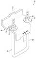
- FIG. 1is a perspective of a beam clamp for use in mounting a strut to a beam, with a clamp body of the beam clamp in a first orientation;
- FIG. 2is a perspective of the beam clamp, with the clamp body in a second orientation
- FIG. 3is a perspective of the clamp body
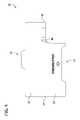
- FIG. 4is a front elevation of FIG. 3 ;
- FIG. 5is a rear elevation of FIG. 3 ;
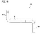
- FIG. 6is a right side elevation of FIG. 3 ;
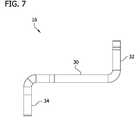
- FIG. 7is a left side elevation of FIG. 3 ;
- FIG. 8is a top plan view of FIG. 3 ;
- FIG. 9is a bottom plan view of FIG. 3 ;
- FIG. 10is a perspective of the beam clamp secured to a beam and mounting a first embodiment of conventional strut on the beam, with the clamp body in the first orientation;
- FIG. 11is a front elevation of FIG. 10 ;
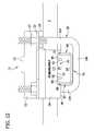
- FIG. 12is an enlarged fragmentary front elevation of FIG. 10 ;
- FIG. 13is a perspective of the beam clamp secured to the beam and mounting a first embodiment of new strut on the beam, with the clamp body in the second orientation;
- FIG. 14is a front elevation of FIG. 13 ;
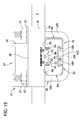
- FIG. 15is an enlarged fragmentary front elevation of FIG. 13 ;
- FIG. 16is a perspective of the beam clamp secured to the beam and mounting a second embodiment of conventional strut on the beam, with the clamp body in the first orientation;
- FIG. 17is a perspective of the beam clamp secured to the beam and mounting a second embodiment of new strut on the beam, with the clamp body in the second orientation;
- FIG. 18is a perspective showing multiple beam clamps securing strut to the beam
- FIG. 19is a perspective showing the beam clamp securing multiple new struts to the beam.
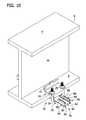
- FIG. 20is a perspective showing the beam clamp securing multiple conventional struts to the beam.
- a beam clamp for mounting strut channel(also referred to in the below disclosure as simply “strut”) on a support member (e.g., beam B) is generally indicated at 10 .
- the beam clamp 10is configured for use with multiple strut configurations.
- the beam clamp 10includes separate first and second strut engagement portions 12 , 14 (indicated generally) for use with strut types having different fitting attachment structures, as described in detail below.
- the beam clamp 10includes a clamp body, generally indicated at 16 , and a fastener (e.g., bolt assembly 18 ) configured to attach the clamp body to the beam B.
- the bolt assembly 18includes U-bolt 20 , washers 22 , and nuts 24 for securing the clamp body 16 (and strut) to the beam B.
- the clamp body 16includes a base 30 and first and second legs 32 , 34 extending from opposite ends of the base.
- the first leg 32extends from a first end 36 of the base 30 in a first direction generally perpendicular to the base (e.g., upward in FIG. 3 ).
- the second leg 34extends from a second end 38 of the base 30 in a second direction generally perpendicular to the base and opposite the first direction (e.g., downward in FIG. 3 ).
- the base 30 , first leg 32 , and second leg 34are generally planar.
- the clamp body 16is formed as a unitary structure.
- the clamp body 16may be formed from rigid metal, such as low carbon steel, stainless steel, aluminum, or other metals, or from other material.
- the base 30includes first and second slots 40 , 42 configured to receive the U-bolt 20 therethrough.
- the first slot 40extends inward from a first side 44 of the base 30 in a direction toward a second side 46 of the base.
- the second slot 42extends inward from the second end 38 of the base 30 in a direction toward the first end 36 of the base.
- the first and second slots 40 , 42extend generally perpendicular to each other.
- the first and second slots 40 , 42are located closer to the second end 38 than the first end 36 , although other configurations are within the scope of the present invention.
- the second leg 34does not extend all the way from the first side 44 of the base 30 to the second side 46 of the base due to the slot 42 .
- the second leg 34has a shorter length than the first leg 32 .
- the second slot 42is partially defined by a curved wall 48 .
- the slots 40 , 42permit the U-bolt 20 to be quickly and easily swung or pivoted into position for connecting the clamp body 16 to the beam B. For example, once a first shank 104 of the U-bolt 20 is inserted into the first slot 40 , the second shank of the U-bolt can be swung or pivoted about the first shank into the second slot 42 along the curved wall 48 .
- the clamp body 16can be swung or pivoted about the first shank toward the second shank so that the second shank enters the second slot 42 along the curved wall 48 .
- the first leg 32includes the first strut engagement portion 12 configured for attachment to strut having a first attachment structure
- the second leg 34includes the second strut engagement portion 14 configured for attachment to strut having a second attachment structure different from the first attachment structure.
- the first strut engagement portion 12includes a tab 52
- the second strut engagement portion 14includes a notch 54 .
- the first and second strut engagement portions 12 , 14can have different configurations within the scope of the present invention.
- the clamp body 16includes two different strut engagement portions 12 , 14
- the beam clamp 10can be used with strut including different attachment structures.
- the clamp body 16can be attached to strut in the appropriate orientation depending on the attachment structure of the strut and which strut engagement portion 12 , 14 is used to engage the strut attachment structure.
- the tab 52extends outward from a free end 56 of the first leg 32 .
- the tab 52is generally centered along a length of the first leg 32 , although other configurations are within the scope of the present invention.
- the tab 52includes sides 58 , 60 and a free end 62 extending between the side walls.
- the side walls 58 , 60 of the tab 52flare away from each other as they extend from the free end 62 of the tab to the free end 56 of the first leg 32 .
- the tab 52has a first relatively narrower width (e.g., a minimum width) adjacent the free end 62 and a second relatively wider width (e.g., a maximum width) adjacent the free end 56 of the first leg 32 .
- the tab 52is configured for engaging strut, as described below.
- the second leg 34includes a notch 54 extending inward from a free end 66 of the second leg.
- the notch 54is defined by opposing side walls 68 , 70 and an inner wall 72 extending between the side walls.
- the side walls 68 , 70flare away from each other as they extend from the inner wall 72 to the free end 66 of the second leg 34 .
- the notch 54has a first relatively narrower width (e.g., a minimum width) adjacent the inner wall 72 and a second relatively wider width (e.g., a maximum width) at its entrance adjacent the free end 66 of the second leg 34 .
- the beam clamp 10is configured for attachment to multiple types of strut 76 .
- the strut 76is of a first type having an elongate body 78 with a generally square or rectangular cross-sectional shape having an upper side 80 , a planar lower side 82 , a planar right side 84 , and a planar left side 86 (each indicated generally).
- the upper side 80defines a continuous slot 88 (i.e., the upper side is open).
- the upper side 80has outside surfaces 90 on either side of the slot 88 , and inwardly (or downwardly) depending lips 92 leading to an open interior 94 of the strut 76 .
- the slot 88is the only attachment structure of the strut 76 (see, e.g., FIGS. 10-12, 16, and 20 ).
- the strut 76can be of a second type including one or more fitting grooves 98 extending lengthwise of the body 78 (see, e.g., FIGS. 13-15, 17, and 19 ).
- the strutcan be strut as described in co-pending U.S. application Ser. No. 13/966,897 filed Aug. 14, 2013, the entirety of which is hereby incorporated by reference.
- At least one of the lower, right, and left sides 82 , 84 , 86can define a fitting groove 98 (see, e.g., FIG.
- the side (e.g., lower side 82 ) opposite the slotted side (e.g., upper side 80 )defines a fitting groove 98
- the other two sidese.g., the right and left sides 84 , 86
- the strutmay include at least one fitting groove 98 and no continuous slot (i.e., the upper side is closed).
- each fitting groove 98is defined by opposing side walls 100 extending inwardly from generally planar outer surfaces of the corresponding side 82 , 84 , 86 and toward the interior 94 of the body 78 ( FIG. 15 ).
- the side walls 100extend to a bottom wall 102 that spans between and interconnects the side walls.
- the side walls 100flare away from one another as they extend inward from the outer surfaces toward the bottom 102 of the fitting groove 98 so that each fitting groove has a generally dovetail cross-sectional shape.
- each fitting groove 98has a first relatively narrower width (e.g., a minimum width) at its entrance and a second relatively wider width (e.g., a maximum width) adjacent the bottom wall 102 .
- the fitting grooves 98are configured for receiving a coupling component of a fitting for use in attaching or securing the fitting to any one of the sides 82 , 84 , 86 of the strut channel 76 .
- the beam clamp 10is in a first orientation wherein the second strut engagement portion 14 is positioned for engagement with the strut 76 .
- At least a portion of the base 30 of the clamp body 16rests upon and is supported by a flange F of the beam B such that the first leg 32 extends generally upward from the base and the second leg 34 extends generally downward from the base.
- the second strut engagement portion 14engages the strut 76 supported on the beam.
- a portion of the strut 76is received in the notch 54 such that the outside surfaces 90 of the upper side 80 engage the inner wall 72 of the notch.
- the side walls 68 , 70 of the notch 54may engage the side walls 84 , 86 of the strut 76 or may be slightly spaced from the side walls to define small gaps therebetween.
- the strut 76can be received in the notch 54 in a different orientation, such that the inner wall 72 of the notch engages one of the lower, left, and right sides 82 , 84 , 86 of the strut 76 (not shown). Engagement between the strut 76 and the second strut engagement portion 14 maintains alignment of the strut on the beam B and prevents rotation of the strut relative to the beam.
- the U-bolt 20is connected to the clamp body 16 such that shanks 104 of the U-bolt extend through the slots 40 , 42 , and the bottom 106 of the U-bolt extends below and supports the strut 76 .
- Washers 22are positioned on the shanks 104 of the U-bolt 20 adjacent the base 30 , and nuts 24 are threaded onto the shanks and tightened to attach the beam clamp 10 , and therefore the strut 76 , to the beam B.
- the beam clamp 10is in a second orientation wherein the first strut engagement portion 12 is positioned for engagement with the strut 76 .
- At least a portion of the base 30 of the clamp body 16rests upon and is supported by the flange F of the beam B such that the second leg 34 extends generally upward from the base and the first leg 32 extends generally downward from the base.
- the first strut engagement portion 12engages the strut 76 supported on the beam B.
- the tab 52is inserted into the open slot 88 of the strut 76 .
- the side walls 58 , 60may engage the lips 92 on either side of the open slot (or be slightly spaced from the lips) and the free end 56 of the first leg 32 may engage the outside surfaces 90 of the upper side 80 .
- the tab 52can be inserted into the dovetail fitting groove 98 of the strut 76 .
- the side walls 58 , 60 of the tabmay engage the side walls 100 of the fitting groove (or be slightly spaced from the side walls of the fitting groove) and the free end 56 of the first leg 32 engages the lower side 82 (not shown). Engagement between the strut 76 and the first strut engagement portion 12 maintains alignment of the strut on the beam B and prevents rotation of the strut relative to the beam.
- the U-bolt 20is connected to the clamp body 16 such that the shanks 104 of the U-bolt extend through the slots 40 , 42 , and the bottom 106 of the U-bolt extends below and supports the strut 76 .
- Washers 22are positioned on the shanks 104 of the U-bolt adjacent the base 30 , and nuts 24 are threaded onto the legs and tightened to attach the beam clamp 10 , and therefore the strut 76 , to the beam B.
- a pair of beam clamps 10is used to attach strut 76 to the beam B, one beam clamp on each side of a web W of the beam.
- more than one strut 76can be attached to the beam B by the beam clamp 10 .
- the shanks 104 of the U-bolt 20can have any desired length to accommodate supporting one or more strut 76 on the beam B.
- the first strut engagement portion 12is configured for engagement with a new strut, such as the new strut described in the '897 application
- the second strut engagement portion 14is configured for engagement with a standard or conventional strut.
- other configurationsare within the scope of the present invention.
- the tab 52can be configured for insertion into the open slot 88 of a standard strut.
- the notch 54can be configured for receiving a portion of a new strut.
- Both of the first and second engagement portions 12 , 14can be tabs configured for engagement with different types of strut.
- both of the first and second engagement portions 12 , 14can be notches configured for engagement with different types of strut. Either and/or both of the first and second engagement portions 12 , 14 can be configured for engagement with one or more types of strut.
- the beam clamp 10is suitable for mounting known strut configurations, such as, for example, the following channel product numbers sold by Cooper B-Line: B 22 (see, e.g., FIG. 16 ), B 54 (see, e.g., FIG. 10 ), Z 22 (see, e.g., FIG. 17 ), Z 52 (see, e.g., FIG. 13 ), and any other known strut.
- the beam clamp 10is also suitable for attachment to strut having a different attachment structure than conventional strut, such as the strut having additional functional sides as described in U.S. application Ser. No. 13/966,897.
- workers at the job sitehave the flexibility to mount the strut in any orientation, according to the needs at the job site.
- the workersneed only have one type of beam clamp, rather than requiring different clamp structures for mounting different struts.
Landscapes
- Engineering & Computer Science (AREA)
- General Engineering & Computer Science (AREA)
- Mechanical Engineering (AREA)
- Architecture (AREA)
- Physics & Mathematics (AREA)
- Electromagnetism (AREA)
- Civil Engineering (AREA)
- Structural Engineering (AREA)
- Mutual Connection Of Rods And Tubes (AREA)
- Clamps And Clips (AREA)
Abstract
Description
Claims (12)
Priority Applications (2)
| Application Number | Priority Date | Filing Date | Title |
|---|---|---|---|
| US14/939,830US10100861B2 (en) | 2014-11-14 | 2015-11-12 | Beam clamp for strut channel |
| PCT/US2015/060601WO2016077708A1 (en) | 2014-11-14 | 2015-11-13 | Beam clamp for strut channel |
Applications Claiming Priority (2)
| Application Number | Priority Date | Filing Date | Title |
|---|---|---|---|
| US201462079984P | 2014-11-14 | 2014-11-14 | |
| US14/939,830US10100861B2 (en) | 2014-11-14 | 2015-11-12 | Beam clamp for strut channel |
Publications (2)
| Publication Number | Publication Date |
|---|---|
| US20160138634A1 US20160138634A1 (en) | 2016-05-19 |
| US10100861B2true US10100861B2 (en) | 2018-10-16 |
Family
ID=55955113
Family Applications (1)
| Application Number | Title | Priority Date | Filing Date |
|---|---|---|---|
| US14/939,830ActiveUS10100861B2 (en) | 2014-11-14 | 2015-11-12 | Beam clamp for strut channel |
Country Status (2)
| Country | Link |
|---|---|
| US (1) | US10100861B2 (en) |
| WO (1) | WO2016077708A1 (en) |
Cited By (8)
| Publication number | Priority date | Publication date | Assignee | Title |
|---|---|---|---|---|
| US20190071859A1 (en)* | 2017-09-01 | 2019-03-07 | Urban Solution Group, LLC | Perimeter wall for an industrial worksite |
| US20190300072A1 (en)* | 2018-03-31 | 2019-10-03 | Jeffrey William Ash | Clamping System |
| US10811857B2 (en) | 2019-03-06 | 2020-10-20 | Panduit Corp. | Bracket for cable management |
| US11407270B2 (en)* | 2019-04-15 | 2022-08-09 | Rv Ride Control Llc | Adjustable spring mounting assembly for vehicle |
| US20240353032A1 (en)* | 2023-04-20 | 2024-10-24 | Shoals Technologies Group, Llc | Adjustable messenger cable clamp |
| US12187092B2 (en) | 2022-08-11 | 2025-01-07 | Rv Ride Control, Llc | Tandem axle suspension system with keeper having sliding slipper blocks |
| US12191802B2 (en)* | 2022-01-05 | 2025-01-07 | Nextracker Llc | Rapid clamping systems for solar trackers |
| US12388199B1 (en)* | 2023-01-12 | 2025-08-12 | Edel Deniz | Electrical conduit clamp |
Families Citing this family (13)
| Publication number | Priority date | Publication date | Assignee | Title |
|---|---|---|---|---|
| GB201416798D0 (en)* | 2014-09-23 | 2014-11-05 | Alphastrut Ltd And Munro Andrew And Amtec Solutions Ltd | Clamping arrangement |
| US20170089058A1 (en)* | 2015-09-29 | 2017-03-30 | Steven A. Roth | Method of clamping to a strut channel |
| US10718111B2 (en) | 2017-03-13 | 2020-07-21 | Herman Miller, Inc. | Subarchitectural office system |
| CN110017415B (en)* | 2018-01-08 | 2023-09-15 | 启碁科技股份有限公司 | Suspension type fixing seat |
| US10538913B2 (en)* | 2018-05-23 | 2020-01-21 | Herman Miller, Inc. | Connection assembly for an architectural structure |
| US11437791B2 (en)* | 2018-08-14 | 2022-09-06 | Panduit Corp. | Cable management assembly |
| NO344796B1 (en)* | 2018-12-14 | 2020-04-27 | Future Tech As | Subsea cooler |
| USD985380S1 (en)* | 2019-02-20 | 2023-05-09 | Polyplas International Pty Ltd. | Beam clamp |
| KR102070238B1 (en)* | 2019-04-22 | 2020-01-29 | 김상문 | Beam clamp with means that prevents from escaping |
| CN110397163B (en)* | 2019-08-06 | 2021-01-15 | 马小云 | Portable steel structure connecting piece |
| JP7433141B2 (en)* | 2020-06-10 | 2024-02-19 | 株式会社サンユー | Mounting devices and coupling fittings |
| GB2595896A (en)* | 2020-06-10 | 2021-12-15 | Reform Systems Ltd | Panel mounting system |
| CA3186798A1 (en)* | 2022-01-12 | 2023-07-12 | Nexii Building Solutions Inc. | Systems and methods for coupling prefabricated panels to structures |
Citations (252)
| Publication number | Priority date | Publication date | Assignee | Title |
|---|---|---|---|---|
| US1319652A (en)* | 1919-10-21 | Coothtit-suppobt | ||
| US1813545A (en) | 1929-04-03 | 1931-07-07 | Reinhold William | Device for supporting beams from columns in the construction of welded buildings |
| US1934760A (en) | 1931-05-25 | 1933-11-14 | Floor Accessories Company Inc | Construction tie |
| US1963908A (en) | 1932-07-19 | 1934-06-19 | Manasek Emil | Clamp |
| US2307653A (en) | 1939-05-10 | 1943-01-05 | Gyproc Products Ltd | Wall and ceiling construction |
| US2375513A (en) | 1943-09-30 | 1945-05-08 | William F Bach | Pipe hanger system |
| GB569377A (en) | 1943-04-13 | 1945-05-22 | Mark Myers | Improvements in constructional toys |
| US2420826A (en) | 1944-03-24 | 1947-05-20 | Louis J Irrgang | Strain relief for electrical conductors |
| US2470991A (en) | 1948-01-13 | 1949-05-24 | Harry L Kindorf | Adjustable beam clamp |
| US2567463A (en)* | 1948-07-15 | 1951-09-11 | Earl B Atkinson | Conduit hanger |
| GB687403A (en) | 1949-01-12 | 1953-02-11 | Rech S Ind Et Minieres S E R I | Improvements in and relating to pit-props and like strut members |
| US2676680A (en) | 1952-02-05 | 1954-04-27 | Orlan C Kindorf | Beam structure and associated securing means |
| US2767951A (en) | 1953-11-06 | 1956-10-23 | Ex Corp | Shelf lock |
| US2767609A (en) | 1952-06-24 | 1956-10-23 | Ex Corp | Spring urged nut having outwardly projecting teeth thereon |
| US2804180A (en) | 1955-02-16 | 1957-08-27 | Frederick G Richardson | Cage nut |
| US2846169A (en) | 1953-05-18 | 1958-08-05 | John J Sullivan | Four-way channel support |
| US2944642A (en) | 1956-10-04 | 1960-07-12 | Robert C Evans | Dismantleable framing structures |
| US3005292A (en) | 1957-10-31 | 1961-10-24 | Gateway Erectors Inc | Anchor slot channel attachment block with resilient anti-skid retaining means |
| US3226069A (en) | 1964-02-03 | 1965-12-28 | Leonard O Clarke | Hanger for cylindrical conduits and the like |
| US3266761A (en)* | 1963-09-18 | 1966-08-16 | Ellsworth T Walton | Pipe hanger and apparatus and method of making same |
| US3310264A (en) | 1966-10-13 | 1967-03-21 | Arthur I Appleton | Quick mounting hanger for pipe and conduit |
| US3312034A (en) | 1964-03-06 | 1967-04-04 | Pollak Steel Company | Sign support post |
| US3396499A (en) | 1965-10-05 | 1968-08-13 | Biffani Raffaele | Structural members for building construction |
| US3417951A (en) | 1966-10-07 | 1968-12-24 | Unistrut Corp | Pipe support |
| US3451183A (en) | 1965-03-16 | 1969-06-24 | Ind De Transformation Des Plas | Metal frame for partitions and similar constructions |
| GB1157545A (en) | 1967-05-05 | 1969-07-09 | Brockhouse Steel Structures Lt | Improvements in or relating to Building Structures. |
| US3463428A (en) | 1967-06-20 | 1969-08-26 | Robert D Kindorf | Multi-purpose pipe clamp |
| US3486726A (en) | 1968-07-09 | 1969-12-30 | Robert D Kindorf | Universal pipe clamp |
| US3513606A (en) | 1968-02-21 | 1970-05-26 | Vernon H Jones | Structural framework and connector joint therefor |
| US3527432A (en) | 1968-06-03 | 1970-09-08 | Superior Strut & Hanger Co Inc | Pipe or tubing support |
| US3547385A (en) | 1968-05-02 | 1970-12-15 | Robert D Kindorf | Structual form for pipe clamp support |
| US3566561A (en) | 1968-10-08 | 1971-03-02 | Francis P Tozer | Channelled structural elements |
| US3592493A (en) | 1968-05-30 | 1971-07-13 | Aluminum Systems Ltd | Constructional systems |
| US3601347A (en) | 1969-09-30 | 1971-08-24 | Unistrut Corp | Perforated strut member |
| US3612461A (en) | 1970-04-20 | 1971-10-12 | Minerallac Electric Co | Light fixture supporting clip |
| US3650499A (en) | 1971-01-11 | 1972-03-21 | Superior Strut & Hanger Co | Clamp for pipe support with slanting pivotal assembly |
| US3748808A (en) | 1970-06-25 | 1973-07-31 | P Brodeur | Wire furring hangers |
| US3752198A (en) | 1971-10-27 | 1973-08-14 | Thomas & Betts Corp | Harness board module |
| US3757485A (en) | 1971-10-04 | 1973-09-11 | Promotion Entreprises Soc Et | Lightweight composite building construction |
| US3836936A (en) | 1972-11-24 | 1974-09-17 | Ite Imperial Corp | Electrified duct and fittings therefor |
| GB1370645A (en) | 1970-10-02 | 1974-10-16 | Vincens R | Lightweight composite structures |
| US3863300A (en) | 1972-08-18 | 1975-02-04 | Trw Inc | Molding retainer and method of coupling the component parts thereof |
| US3944308A (en) | 1973-08-17 | 1976-03-16 | Expo Nord Ab | Frame for supporting articles |
| US3986314A (en) | 1974-12-23 | 1976-10-19 | Moeller Wolfgang W | Ceiling assembly with removable partition walls |
| US3998419A (en) | 1975-11-03 | 1976-12-21 | United States Gypsum Company | Swivel type hanger bracket |
| DE7701100U1 (en) | 1977-01-15 | 1977-05-05 | Fa. Hermann Kleinhuis, 5880 Luedenscheid | Cable duct made up of several sections to be assembled |
| US4044428A (en) | 1975-09-08 | 1977-08-30 | B-Line Systems, Inc. | Conduit clamp |
| US4185802A (en) | 1978-09-13 | 1980-01-29 | Fischer Sherman, Inc. | Anti-vibration pad for pipe support clamp |
| US4211381A (en) | 1977-05-31 | 1980-07-08 | Heard Robert A H | Mounting device |
| US4216930A (en) | 1978-08-24 | 1980-08-12 | Amp Incorporated | Strain relief |
| US4227355A (en) | 1978-03-30 | 1980-10-14 | United States Gypsum Company | Support system for sound absorbing panels |
| US4358216A (en) | 1980-09-02 | 1982-11-09 | Illinois Tool Works Inc. | Resilient retaining clip |
| US4379651A (en) | 1980-07-07 | 1983-04-12 | Masaya Nagashima | Method for releasably rigidly fastening two intersected overlapping metal profiles and means therefor |
| DE8232700U1 (en) | 1982-11-22 | 1983-06-23 | BNA-Augustin GmbH & CO KG, 7631 Kappel | Cable duct |
| US4397437A (en)* | 1980-07-21 | 1983-08-09 | Robroy Industries | Beam clamp |
| US4417711A (en) | 1982-05-17 | 1983-11-29 | Robroy Industries | Pipe hanger |
| US4479341A (en) | 1982-04-02 | 1984-10-30 | Fastway Fasteners, Inc. | Clips for T-bar grid ceiling arrangement |
| US4490064A (en) | 1981-07-29 | 1984-12-25 | Jacques Ducharme | Joint for modular frame construction |
| US4506418A (en)* | 1982-12-20 | 1985-03-26 | Parker-Hannifin Corporation | Muffler clamp |
| US4516296A (en) | 1983-10-05 | 1985-05-14 | Zsi, Inc. | Tubing clamp and method of making the same |
| US4556148A (en) | 1982-01-08 | 1985-12-03 | Ernst Koller | Rack formed of a plurality of profiled bars |
| US4610562A (en) | 1985-08-29 | 1986-09-09 | Chicago Metallic Corporation | Perimeter clip |
| DE3513382A1 (en) | 1985-04-15 | 1986-10-23 | Moeller automation GmbH, 5303 Bornheim | Load-bearing profiles for assembly installations, supporting structures and conveyor belts, and process for the production thereof |
| US4637748A (en) | 1985-06-07 | 1987-01-20 | T. A. Pelsue Company | Hub and strut-endcap assembly for tent frame struts |
| US4652170A (en) | 1984-09-24 | 1987-03-24 | Lew Hyok S | Slide connectors with frictional locking means |
| US4657458A (en) | 1983-11-07 | 1987-04-14 | Phillips Plastics Corporation | Anchor nut for threaded member |
| US4666355A (en) | 1986-08-04 | 1987-05-19 | Usg Industries, Inc. | Top grip lock nut assembly |
| DE8704502U1 (en) | 1987-03-26 | 1987-05-27 | Albert Ackermann GmbH & Co KG, 5270 Gummersbach | Wall duct for accommodating electrical installation equipment |
| US4708554A (en) | 1985-04-08 | 1987-11-24 | Howard William A | Strut |
| US4726165A (en) | 1985-06-26 | 1988-02-23 | Hunter Douglas International N.V. | Understructure for a panel lining |
| US4729532A (en)* | 1985-04-23 | 1988-03-08 | Billy Moss | Safety valve anchoring device |
| US4784552A (en) | 1982-02-01 | 1988-11-15 | Unistrut International Corp. | Nuts for channeled structural members |
| US4830531A (en) | 1985-10-04 | 1989-05-16 | Unistrut International Corp. | Unitary connection assembly for metal channels and method for assembly |
| US4895412A (en) | 1987-11-05 | 1990-01-23 | Ecia - Equipements Et Composants Pour L'industrie Automobile | Motor-vehicle seat having lateral wings |
| US4934886A (en) | 1988-10-07 | 1990-06-19 | Gulton Industries, Inc. | Fastening assembly and method of fastening |
| US4948313A (en) | 1988-11-23 | 1990-08-14 | Wesanco, Inc. | Nut platform for framing channels |
| US4950099A (en) | 1988-12-20 | 1990-08-21 | Swiss Aluminum Ltd. | Releasable clamping-type compressive joint |
| US4961553A (en) | 1988-10-03 | 1990-10-09 | Todd George R | Support system for pipes and other loads |
| US4962914A (en) | 1990-02-26 | 1990-10-16 | Taylor Alva R | Fence |
| US4993670A (en)* | 1984-08-15 | 1991-02-19 | Perfection Corporation | Universal bracket assembly |
| US5003741A (en) | 1988-06-20 | 1991-04-02 | Yeh Kuo Huei | Structure of multi-function frame members |
| US5014940A (en)* | 1989-08-28 | 1991-05-14 | Zsi, Inc. | Clamp assembly |
| US5022614A (en) | 1989-08-17 | 1991-06-11 | B-Line Systems, Inc. | One piece conduit clip |
| USD322929S (en) | 1989-06-20 | 1992-01-07 | Skf Specialty Products Ab | Track-guided nut |
| US5078537A (en) | 1990-11-01 | 1992-01-07 | Nic Autotec Co., Ltd. | Connecting device |
| US5102074A (en) | 1989-11-17 | 1992-04-07 | Kyokuto Kogyo Kabushiki Kaisha | Supporting apparatus for piping, supporting instrument for piping and retaining body |
| US5116161A (en) | 1990-04-11 | 1992-05-26 | Alusuisse-Lonza Services, Ltd. | Corner joint between two sections having a c-shaped attaching portion by means of a corner connector, and angle piece for producing the joint |
| US5118233A (en) | 1990-03-15 | 1992-06-02 | T. C. Bolt Corporation | Pre-setting and controlling the tightening of stud bolts and the like and novel stud bolts |
| US5127758A (en) | 1987-09-11 | 1992-07-07 | Ulrich Kreusel | Pipe joint |
| US5141186A (en) | 1991-07-16 | 1992-08-25 | Cusic Industries, Inc. | Pipe clamp |
| US5146724A (en) | 1991-04-03 | 1992-09-15 | Intertrack Management, Inc. | Two-part clamp for connecting intersecting i-beams |
| US5163644A (en) | 1991-08-01 | 1992-11-17 | B-Line Systems, Inc. | Conduit clamp |
| US5175971A (en) | 1991-06-17 | 1993-01-05 | Mccombs P Roger | Utility power pole system |
| US5205022A (en)* | 1992-06-09 | 1993-04-27 | Norton John F | U-bolt clamp assembly |
| US5215281A (en)* | 1991-09-27 | 1993-06-01 | Zsi, Inc. | Two-piece cushion insert for U-bolt clamp assembly |
| US5228263A (en) | 1991-08-16 | 1993-07-20 | James Vaughn | T-bar partition support clip |
| US5271586A (en) | 1991-08-24 | 1993-12-21 | Walter Stauffenberg Gmbh & Co. Kg | Fixing arrangement |
| US5274888A (en)* | 1993-04-05 | 1994-01-04 | Gto, Inc. | Adjustable U-bolt type pipe clamp |
| US5292013A (en) | 1992-10-23 | 1994-03-08 | E-Systems, Inc. | Support ferrules |
| EP0592743A1 (en) | 1992-10-16 | 1994-04-20 | Rapid S.A. | Fastener for assembly of profiles and structure of profiles made therewith |
| US5335890A (en) | 1992-07-20 | 1994-08-09 | Pryor Products, Inc. | Ceiling track mounting apparatus |
| US5351926A (en) | 1992-03-25 | 1994-10-04 | Unistrut International Corp. | Support structure beam |
| US5356234A (en) | 1992-10-26 | 1994-10-18 | 506567 Ontario Limited | Separable joint for arm and hub constructions |
| US5375798A (en) | 1992-07-06 | 1994-12-27 | Hungerford, Jr.; Charles S. | Connector for facilitating a connection between a channel member and a support member |
| US5489173A (en) | 1992-12-19 | 1996-02-06 | Hilti Aktiengesellschaft | Device for attachment to a fastening rail |
| US5503511A (en) | 1992-12-18 | 1996-04-02 | Knurr-Mechanik Fur Die Elektronik Aktiengesellschaft | Arrangement for the spring elastic position fixing of fastening means in recesses |
| US5531539A (en) | 1993-02-12 | 1996-07-02 | Exposystems, Inc. | Tightly fitting panel connection assembly |
| US5566916A (en)* | 1995-05-26 | 1996-10-22 | Bailey; Michael E. | Adjustable pipe brace |
| US5595363A (en) | 1995-09-18 | 1997-01-21 | De Leebeeck; Marcel | Plastic pipe beam support |
| US5628598A (en) | 1994-09-16 | 1997-05-13 | Hilti Aktiengesellschaft | Attachment nut for profiled rails |
| US5628508A (en) | 1996-05-21 | 1997-05-13 | Schelde International B.V. | Basketball-stand |
| US5655865A (en) | 1994-06-17 | 1997-08-12 | Hilti Aktiengeschaft | Attachment arrangement |
| US5655816A (en) | 1994-09-24 | 1997-08-12 | American Seating Company | Seat assembly for mass transit vehicle |
| US5718403A (en)* | 1994-04-12 | 1998-02-17 | Deere & Company | Mounting hardware for a toolbar |
| US5729948A (en) | 1996-08-29 | 1998-03-24 | Levy; Tzadok | Apparatus and method for rigidly joining construction elements to one another |
| US5746535A (en) | 1995-06-08 | 1998-05-05 | Heron Sondermaschinen Und Steuerungen Ges.M.B.H | Plate fastener |
| US5779412A (en) | 1996-05-02 | 1998-07-14 | Smc Corporation | Profile frame and connector |
| WO1998037349A1 (en) | 1997-02-25 | 1998-08-27 | Thomas & Betts International, Inc. | Modular cable tray assembly |
| US5799907A (en) | 1996-02-26 | 1998-09-01 | Andronica; Ronald | Pipe straps |
| US5799452A (en) | 1997-06-11 | 1998-09-01 | Moore; Kenneth G. | Log construction |
| US5806897A (en) | 1995-10-03 | 1998-09-15 | Smc Corporation | Mechanism for attaching a fluid-related device to a device-attaching frame member |
| US5806268A (en) | 1996-01-13 | 1998-09-15 | Koller; Ernst | Building skeleton of profiled bars |
| US5820322A (en) | 1996-09-03 | 1998-10-13 | Hilti Aktiengesellschaft | Fastening element for a shaped rail |
| US5833417A (en) | 1997-02-12 | 1998-11-10 | Quality Boat Lifts, Inc. | Adjustable clamping assembly |
| US5855342A (en) | 1996-10-21 | 1999-01-05 | Pipe Pier, Inc. | System for mounting elongate structures and wiring |
| US5864997A (en)* | 1995-01-28 | 1999-02-02 | Brickel Designs | Junction members and their uses |
| US5915803A (en) | 1995-04-21 | 1999-06-29 | Metro Industries, Inc. | Modular storage and support assembly |
| US5918999A (en) | 1998-03-27 | 1999-07-06 | Lamarca; Guy M. | Geometric spacial frame assembly |
| US5924650A (en) | 1996-12-31 | 1999-07-20 | Northrop Grumman Corporation | Method and system for fastening aircraft assemblies |
| US5927041A (en)* | 1996-03-28 | 1999-07-27 | Hilti Aktiengesellschaft | Mounting rail |
| US5934818A (en) | 1997-04-12 | 1999-08-10 | Wago Verwaltungsgesellschaft Mbh | Screen connector |
| US5970679A (en) | 1994-08-19 | 1999-10-26 | Amore; Gregorio | Metal loadbearing structure having structural connections with no welding or drilling |
| US5984243A (en) | 1997-09-09 | 1999-11-16 | Thomas & Betts International, Inc. | Pipe cushion |
| US5988930A (en) | 1996-11-11 | 1999-11-23 | Inventio Ag | Connecting apparatus for profile members |
| USD421655S (en) | 1998-07-07 | 2000-03-14 | Metro Industries, Inc. | Flanged support post interfacing with side panel insert |
| US6062764A (en) | 1993-08-30 | 2000-05-16 | Rixen; Wolfgang | Inserted tongue |
| US6061984A (en) | 1998-07-30 | 2000-05-16 | Rose; Robert L. | Under floor reconfigurable utilities support structure |
| JP2000139583A (en) | 1998-11-11 | 2000-05-23 | Tokyo Shashi Kk | Frame forming member for rack and sectional rack using the same |
| US6106189A (en)* | 1995-09-23 | 2000-08-22 | Robert Janos Bokros | Clamping arrangements |
| US6195953B1 (en) | 1997-07-18 | 2001-03-06 | Alusisse Technology & Management Ltd. | Beam, that is rectangular in cross-section, in particular made from a hollow section of an extruded light metal alloy, and a construction unit made up of such beams |
| US6322030B1 (en) | 1999-11-12 | 2001-11-27 | Robert T. Marra | Marine bilge pump mount |
| US20020000498A1 (en) | 2000-06-22 | 2002-01-03 | Workman David E. | Pipe attaching apparatus |
| US6347904B1 (en)* | 1998-04-14 | 2002-02-19 | George Stuart Knighton | Fly clamp for reinforcing bars in concrete construction |
| US20020060280A1 (en) | 2000-09-28 | 2002-05-23 | Howard Yaphe | Fixture suspension bracket assembly |
| US20020110435A1 (en) | 2000-10-23 | 2002-08-15 | Armin Herb | Fastening devices |
| US20020122691A1 (en) | 2001-03-01 | 2002-09-05 | John Wood | Hardware mounting connector for profile extrusions |
| US6454232B1 (en)* | 2000-07-06 | 2002-09-24 | Steven A. Roth | Stiffener apparatus for stabilizing a hanger rod |
| US6484358B1 (en) | 2000-09-28 | 2002-11-26 | Robertshaw Controls Company | Flame proof sealing mechanism |
| US6494415B1 (en) | 2001-01-25 | 2002-12-17 | Steven A. Roth | Multi-purpose hanger apparatus for use with a building structure |
| US20030043033A1 (en) | 2001-08-28 | 2003-03-06 | Lee Gul Nam | Vehicle safety warning control system |
| US20030042033A1 (en) | 2001-08-30 | 2003-03-06 | Armin Herb | Shaped mounting rail |
| US20030063961A1 (en) | 2001-09-25 | 2003-04-03 | Alec Lay | Snap-in threaded fastener and stemmed washer assembly |
| US6554235B1 (en) | 1999-10-29 | 2003-04-29 | Force Et Forme | Support post with adjustable accessory supports |
| US6561473B1 (en)* | 2001-03-30 | 2003-05-13 | Pirod, Inc. | Universal pipe mounting clamp and assembly |
| US6572057B1 (en) | 2001-01-25 | 2003-06-03 | Steven A. Roth | Hanger system for conduits and channel members |
| US20030122044A1 (en) | 2001-12-05 | 2003-07-03 | Stefan Unverzagt | Anchoring device |
| US6588713B2 (en) | 2001-08-01 | 2003-07-08 | Magnetek, Inc. | Anchor assembly for electrified conductor bar |
| US20030159397A1 (en) | 2002-02-22 | 2003-08-28 | Ulrich Birnbaum | Elongated hollow member for suspending objects |
| US20030185643A1 (en) | 2002-04-02 | 2003-10-02 | Thompson William J. | Flexible bridge for a strut nut |
| US6655099B1 (en) | 1998-09-14 | 2003-12-02 | Spanbilt Pty Ltd | Clip fastening system for walls |
| US6679461B1 (en) | 2001-04-26 | 2004-01-20 | Pipe Pier | Mounting device |
| US6682253B2 (en) | 1999-10-07 | 2004-01-27 | Halfen Gmbh & Co. Kg | Assembly railed formed out of at least one profile element |
| US6712543B1 (en) | 1999-07-21 | 2004-03-30 | Fms Forder-Und Montage-Systeme Schmalzhofer Gmbh | Connecting device for profiled bars with grooves |
| US6726117B2 (en) | 2000-10-23 | 2004-04-27 | Hilti Aktiengesellschaft | Rail fastener |
| US6751914B2 (en) | 2002-03-01 | 2004-06-22 | Steelcase Development Corporation | Post and beam furniture system |
| US6766992B1 (en)* | 2003-04-24 | 2004-07-27 | The United States Of America As Represented By The Secretary Of The Navy | Mounting bracket for attachment to flat or cylindrical surfaces |
| US20040165947A1 (en) | 2002-12-05 | 2004-08-26 | Armin Herb | Attachment system |
| US20040165943A1 (en) | 2002-12-05 | 2004-08-26 | Armin Herb | Attachment system |
| US20040165965A1 (en) | 2002-12-05 | 2004-08-26 | Stefan Unverzagt | Quick-mountable nut |
| US6802171B2 (en) | 2002-10-18 | 2004-10-12 | Mckinnon Duane | Framing member with fastener attachments having square threads |
| US20040228681A1 (en) | 2003-02-15 | 2004-11-18 | Armin Herb | Attachment element |
| US6899511B2 (en) | 2000-10-19 | 2005-05-31 | Rapid Development Services, Inc, Mo. Corp | Modular robotic device and manufacturing system |
| US20050116123A1 (en) | 2003-10-02 | 2005-06-02 | Bailey Randy J. | Method and apparatus for supporting an insulated pipe |
| US20050129458A1 (en) | 2003-12-11 | 2005-06-16 | Armin Hoffmann | Attachment system |
| US6991198B1 (en)* | 2000-07-06 | 2006-01-31 | Roth Steven A | Apparatus for stiffening a hanger rod |
| US20060027715A1 (en) | 2004-08-05 | 2006-02-09 | Thomas & Betts International, Inc. | Pipe clamp |
| US20060038398A1 (en) | 2004-08-23 | 2006-02-23 | Thomas & Betts International, Inc. | Scissor type pipe clamp |
| US7014213B1 (en) | 1999-10-16 | 2006-03-21 | Christof Kaiser | Conduit system |
| US7044701B2 (en) | 2002-12-05 | 2006-05-16 | Hilti Aktiengesellschaft | Fastening system |
| US7070374B2 (en) | 2003-01-03 | 2006-07-04 | Nissan Technical Center North America, Inc. | Track slot fastener |
| WO2006085185A1 (en) | 2005-02-09 | 2006-08-17 | Robert James Waller Hamlin | Rolled metal section; posts and frame members made from same; and assembly fittings |
| US7096641B2 (en) | 2003-05-19 | 2006-08-29 | Hilti Aktiengesellschaft | Hollow profile |
| US7165361B2 (en) | 2003-04-24 | 2007-01-23 | Peter Vanagan | Building construction shores |
| US7179010B2 (en) | 2004-01-23 | 2007-02-20 | Zsi, Inc. | Adjustable pipe clamp assembly |
| US20070040075A1 (en) | 2005-08-05 | 2007-02-22 | Moretto S.P.A. | Device for fixing pipes to supporting structures |
| US20070075213A1 (en) | 2005-09-22 | 2007-04-05 | Hilti Aktiengesellschaft | Holding element for grating |
| US20070101670A1 (en) | 2005-10-24 | 2007-05-10 | Ahren Gregory M | Panel attachment clip |
| US20070120036A1 (en) | 2005-11-30 | 2007-05-31 | Olle Raymond M | Rooftop equipment support and method of use |
| US20070145222A1 (en) | 2005-12-16 | 2007-06-28 | Rausch Matthew S | Hanger |
| US7240884B2 (en) | 2003-12-24 | 2007-07-10 | Paradise Industry Co., Ltd. | Mounting device of sprinkler |
| US20070248793A1 (en) | 2006-04-20 | 2007-10-25 | Armin Herb | Open elongate profile |
| US7287733B2 (en) | 2002-05-14 | 2007-10-30 | Sullivan, Bazinet, Bongio, Inc. | Ceiling suspension structure |
| DE102006035405A1 (en) | 2006-11-06 | 2008-05-08 | Hilti Ag | System beam's carrier element e.g. pipe and channel, connecting element for conduit installation, has contact surfaces arranged at sides of support section, and clamping unit with springy rest unit projecting above free ends of sides |
| US7389621B2 (en) | 2004-02-11 | 2008-06-24 | International Property Rights Ltd. | Rapidly deployable temporary modular structures and component elements thereof |
| US20080217490A1 (en)* | 2007-03-08 | 2008-09-11 | Panduit Corp. | Common bonding network clamp |
| US20080229699A1 (en) | 2007-03-21 | 2008-09-25 | Unistrut International Corporation | Fittings for metal framing |
| US7448822B2 (en) | 2006-03-15 | 2008-11-11 | The Boeing Company | Retaining member and method for use with a seat track |
| US7478787B2 (en) | 2005-06-02 | 2009-01-20 | Usg Interiors, Inc. | Paired main tee clip |
| US7484697B1 (en) | 2005-03-21 | 2009-02-03 | Timothy Andrew Nelson | Universal strut end clamp |
| US7600724B2 (en) | 2006-05-08 | 2009-10-13 | Panduit Corp. | Mounting device and apparatus for use with studs comprising T-shaped channels |
| US7604444B2 (en) | 2006-10-23 | 2009-10-20 | Cooper Technologies Company | Fastener assembly |
| US7661915B2 (en) | 2006-10-02 | 2010-02-16 | Whipple Charles E | Trapeze hanger |
| US20100102011A1 (en) | 2008-10-23 | 2010-04-29 | Robert Bosch Gmbh | Connector assembly |
| DE202010004406U1 (en) | 2010-03-31 | 2010-07-01 | Rehau Ag + Co | Cable duct made of metal |
| US20100193645A1 (en) | 2009-02-04 | 2010-08-05 | Hilti Aktiengesellschaft | Channel joining system with a mounting channel and a joining part for joining the mounting channel to a support |
| DE102009000603A1 (en) | 2009-02-04 | 2010-09-09 | Hilti Aktiengesellschaft | Assembly rail for rail binding system in which lines for e.g. water installation, in building are fixed by binders, has side panels connected with each other, where height of rail corresponds to distance from edge to inner side of panels |
| US7818925B2 (en) | 2006-06-12 | 2010-10-26 | Bryan Benedict | Stay-in-place concrete footing forms |
| US7922417B2 (en) | 2007-05-25 | 2011-04-12 | Luis Alejandro Jimenez | Interlocking structural element for cabinets and enclosures |
| US7922130B2 (en) | 2001-04-26 | 2011-04-12 | Pipe Pier | Mounting device |
| US7934896B2 (en) | 2006-02-08 | 2011-05-03 | Dietmar Schnier | Nut having at least two parts |
| US7984601B2 (en) | 2007-05-30 | 2011-07-26 | Hilti Aktiengesellschaft | Profiled rail |
| US8020328B2 (en) | 2005-05-17 | 2011-09-20 | Erez Lavi | Connecting elements for construction |
| USD654064S1 (en)* | 2011-05-13 | 2012-02-14 | Sergi Paul D | Plate for an antenna mast |
| US20120110788A1 (en) | 2009-07-07 | 2012-05-10 | 3Form, Inc. | Front-loadable track mounting systems |
| US20120119037A1 (en) | 2009-07-08 | 2012-05-17 | Advance Co., Ltd. | Pipe support base |
| US8225581B2 (en) | 2006-05-18 | 2012-07-24 | SUR-Stud Structural Technology Inc | Light steel structural members |
| DE202012102394U1 (en) | 2012-06-28 | 2012-07-26 | Federnfabrik Dietz Gmbh | fastener |
| CN202416847U (en) | 2012-01-30 | 2012-09-05 | 宋佩瑜 | Novel scaffold connecting piece |
| US8277158B2 (en) | 2007-11-15 | 2012-10-02 | The Monadnock Company | Floating nut plate |
| US8303223B2 (en) | 2009-02-10 | 2012-11-06 | Hilti Aktiengesellschaft | Fastener for arranging a rod element on a mounting channel |
| US20120286110A1 (en) | 2011-05-10 | 2012-11-15 | Hill Douglas C | Conduit support |
| US20120297723A1 (en) | 2011-05-27 | 2012-11-29 | Illinois Tool Works Inc. | Wall stud mounting bracket for securing and positioning flexible conduit and cable |
| US20120315106A1 (en) | 2010-12-08 | 2012-12-13 | United States Government, As Represented By The Secretary Of The Navy | Fastener for strut channel |
| US8341913B2 (en) | 2006-12-27 | 2013-01-01 | Rockwool International A/S | Ceiling suspension system |
| US8366340B2 (en) | 2007-11-02 | 2013-02-05 | Sus Co., Ltd. | Structural member joint structure |
| US20130047541A1 (en) | 2011-08-26 | 2013-02-28 | Hunter Douglas Inc. | Suspension ceiling with parallel vanes for building structures |
| US8454259B2 (en) | 2010-04-26 | 2013-06-04 | Blanking Systems, Inc. | Connection assembly for interconnecting to a frame |
| US8511929B2 (en) | 2009-02-25 | 2013-08-20 | Haldex Brake Corporation | Trailer/dolly ABS system module |
| WO2013125821A1 (en) | 2012-02-23 | 2013-08-29 | Lee Jung-Yeop | Hexahedron unit for prefabricated buildings and method of assembling the hexahedron units |
| US8523923B2 (en) | 2006-02-21 | 2013-09-03 | Stryker Trauma Sa | Clamping and articulation element |
| US8567030B2 (en) | 2009-05-27 | 2013-10-29 | Schletter Gmbh | Apparatus for fastening a mounting rail to a threaded shaft |
| US8596009B2 (en) | 2010-11-01 | 2013-12-03 | Awi Licensing Company | Suspended ceiling system, securing members, and process of installing a suspended ceiling system |
| US20140042286A1 (en) | 2012-08-08 | 2014-02-13 | Thomas & Betts International, Inc. | Universal panel clamp |
| US8661765B2 (en) | 2009-02-05 | 2014-03-04 | D Three Enterprises, Llc | Interlocking shape for use in construction members |
| US8662455B2 (en) | 2011-07-14 | 2014-03-04 | Raytheon Company | Spring clip retention systems suitable for usage within vehicles and guided munitions |
| US20140093307A1 (en) | 2012-09-28 | 2014-04-03 | Hon Hai Precision Industry Co., Ltd. | Locking apparatus |
| US20140091050A1 (en) | 2012-09-28 | 2014-04-03 | Hon Hai Precision Industry Co., Ltd. | Locking apparatus |
| US20140097304A1 (en) | 2012-10-10 | 2014-04-10 | Ronald J. Mastro | Slanted bolstering device for pipe support system |
| US8695296B2 (en) | 2011-05-17 | 2014-04-15 | Awi Licensing Company | Mounting hardware and mounting system for vertical panels |
| US20140197284A1 (en) | 2013-01-16 | 2014-07-17 | Susumu Hikoyama | Angled pipe clamp |
| US20140260083A1 (en) | 2013-03-14 | 2014-09-18 | Cooper Technologies Company | Channel Framing with Additional Functional Side |
| USD728753S1 (en) | 2013-01-16 | 2015-05-05 | Susumu Hikoyama | Angled pipe clamp |
| US20150176631A1 (en) | 2013-12-23 | 2015-06-25 | Cooper Technologies Company | Fastener nut for channel framing |
| US20150276092A1 (en) | 2014-03-27 | 2015-10-01 | Unistrut International Corporation | Enhanced corrosion resistant channels, fittings and fasteners |
| US20150316203A1 (en) | 2014-04-30 | 2015-11-05 | Cooper Technologies Company | Trapeze hanger system including twist-locking fitting |
| US20150316178A1 (en) | 2014-05-02 | 2015-11-05 | Cooper Technologies Company | Conduit clamp for strut channel |
| US20150322669A1 (en)* | 2014-05-09 | 2015-11-12 | Sucoot Industrial Co., Ltd. | Construction beam connection device |
| US9187898B1 (en) | 2014-09-24 | 2015-11-17 | Usg Interiors, Llc | Perimeter trim clip for suspended ceilings |
| US9194418B2 (en) | 2014-02-19 | 2015-11-24 | Thomas & Betts International Llc | Cone nut |
| US9249994B2 (en)* | 2011-04-05 | 2016-02-02 | Michael Zuritis | Solar array support structure, mounting rail and method of installation thereof |
| EP2838170B1 (en) | 2013-08-12 | 2016-03-16 | Gewiss France SAS | Raceway including a chute made of a lattice of soldered wires and an attachment element, and attachment element for such a chute |
| US20160138633A1 (en) | 2014-11-14 | 2016-05-19 | Cooper Technologies Company | Fitting for strut channel |
- 2015
- 2015-11-12USUS14/939,830patent/US10100861B2/enactiveActive
- 2015-11-13WOPCT/US2015/060601patent/WO2016077708A1/enactiveApplication Filing
Patent Citations (259)
| Publication number | Priority date | Publication date | Assignee | Title |
|---|---|---|---|---|
| US1319652A (en)* | 1919-10-21 | Coothtit-suppobt | ||
| US1813545A (en) | 1929-04-03 | 1931-07-07 | Reinhold William | Device for supporting beams from columns in the construction of welded buildings |
| US1934760A (en) | 1931-05-25 | 1933-11-14 | Floor Accessories Company Inc | Construction tie |
| US1963908A (en) | 1932-07-19 | 1934-06-19 | Manasek Emil | Clamp |
| US2307653A (en) | 1939-05-10 | 1943-01-05 | Gyproc Products Ltd | Wall and ceiling construction |
| GB569377A (en) | 1943-04-13 | 1945-05-22 | Mark Myers | Improvements in constructional toys |
| US2375513A (en) | 1943-09-30 | 1945-05-08 | William F Bach | Pipe hanger system |
| US2420826A (en) | 1944-03-24 | 1947-05-20 | Louis J Irrgang | Strain relief for electrical conductors |
| US2470991A (en) | 1948-01-13 | 1949-05-24 | Harry L Kindorf | Adjustable beam clamp |
| US2567463A (en)* | 1948-07-15 | 1951-09-11 | Earl B Atkinson | Conduit hanger |
| GB687403A (en) | 1949-01-12 | 1953-02-11 | Rech S Ind Et Minieres S E R I | Improvements in and relating to pit-props and like strut members |
| US2676680A (en) | 1952-02-05 | 1954-04-27 | Orlan C Kindorf | Beam structure and associated securing means |
| US2767609A (en) | 1952-06-24 | 1956-10-23 | Ex Corp | Spring urged nut having outwardly projecting teeth thereon |
| US2846169A (en) | 1953-05-18 | 1958-08-05 | John J Sullivan | Four-way channel support |
| US2767951A (en) | 1953-11-06 | 1956-10-23 | Ex Corp | Shelf lock |
| US2804180A (en) | 1955-02-16 | 1957-08-27 | Frederick G Richardson | Cage nut |
| US2944642A (en) | 1956-10-04 | 1960-07-12 | Robert C Evans | Dismantleable framing structures |
| US3005292A (en) | 1957-10-31 | 1961-10-24 | Gateway Erectors Inc | Anchor slot channel attachment block with resilient anti-skid retaining means |
| US3266761A (en)* | 1963-09-18 | 1966-08-16 | Ellsworth T Walton | Pipe hanger and apparatus and method of making same |
| US3226069A (en) | 1964-02-03 | 1965-12-28 | Leonard O Clarke | Hanger for cylindrical conduits and the like |
| US3312034A (en) | 1964-03-06 | 1967-04-04 | Pollak Steel Company | Sign support post |
| US3451183A (en) | 1965-03-16 | 1969-06-24 | Ind De Transformation Des Plas | Metal frame for partitions and similar constructions |
| US3396499A (en) | 1965-10-05 | 1968-08-13 | Biffani Raffaele | Structural members for building construction |
| US3417951A (en) | 1966-10-07 | 1968-12-24 | Unistrut Corp | Pipe support |
| US3310264A (en) | 1966-10-13 | 1967-03-21 | Arthur I Appleton | Quick mounting hanger for pipe and conduit |
| GB1157545A (en) | 1967-05-05 | 1969-07-09 | Brockhouse Steel Structures Lt | Improvements in or relating to Building Structures. |
| US3463428A (en) | 1967-06-20 | 1969-08-26 | Robert D Kindorf | Multi-purpose pipe clamp |
| US3513606A (en) | 1968-02-21 | 1970-05-26 | Vernon H Jones | Structural framework and connector joint therefor |
| US3547385A (en) | 1968-05-02 | 1970-12-15 | Robert D Kindorf | Structual form for pipe clamp support |
| US3592493A (en) | 1968-05-30 | 1971-07-13 | Aluminum Systems Ltd | Constructional systems |
| US3527432A (en) | 1968-06-03 | 1970-09-08 | Superior Strut & Hanger Co Inc | Pipe or tubing support |
| US3486726A (en) | 1968-07-09 | 1969-12-30 | Robert D Kindorf | Universal pipe clamp |
| US3566561A (en) | 1968-10-08 | 1971-03-02 | Francis P Tozer | Channelled structural elements |
| US3601347A (en) | 1969-09-30 | 1971-08-24 | Unistrut Corp | Perforated strut member |
| US3612461A (en) | 1970-04-20 | 1971-10-12 | Minerallac Electric Co | Light fixture supporting clip |
| US3748808A (en) | 1970-06-25 | 1973-07-31 | P Brodeur | Wire furring hangers |
| GB1370645A (en) | 1970-10-02 | 1974-10-16 | Vincens R | Lightweight composite structures |
| US3650499A (en) | 1971-01-11 | 1972-03-21 | Superior Strut & Hanger Co | Clamp for pipe support with slanting pivotal assembly |
| US3757485A (en) | 1971-10-04 | 1973-09-11 | Promotion Entreprises Soc Et | Lightweight composite building construction |
| US3752198A (en) | 1971-10-27 | 1973-08-14 | Thomas & Betts Corp | Harness board module |
| US3863300A (en) | 1972-08-18 | 1975-02-04 | Trw Inc | Molding retainer and method of coupling the component parts thereof |
| US3836936A (en) | 1972-11-24 | 1974-09-17 | Ite Imperial Corp | Electrified duct and fittings therefor |
| US3944308A (en) | 1973-08-17 | 1976-03-16 | Expo Nord Ab | Frame for supporting articles |
| US3986314A (en) | 1974-12-23 | 1976-10-19 | Moeller Wolfgang W | Ceiling assembly with removable partition walls |
| US4044428A (en) | 1975-09-08 | 1977-08-30 | B-Line Systems, Inc. | Conduit clamp |
| US3998419A (en) | 1975-11-03 | 1976-12-21 | United States Gypsum Company | Swivel type hanger bracket |
| DE7701100U1 (en) | 1977-01-15 | 1977-05-05 | Fa. Hermann Kleinhuis, 5880 Luedenscheid | Cable duct made up of several sections to be assembled |
| US4211381A (en) | 1977-05-31 | 1980-07-08 | Heard Robert A H | Mounting device |
| US4227355A (en) | 1978-03-30 | 1980-10-14 | United States Gypsum Company | Support system for sound absorbing panels |
| US4216930A (en) | 1978-08-24 | 1980-08-12 | Amp Incorporated | Strain relief |
| US4185802A (en) | 1978-09-13 | 1980-01-29 | Fischer Sherman, Inc. | Anti-vibration pad for pipe support clamp |
| US4379651A (en) | 1980-07-07 | 1983-04-12 | Masaya Nagashima | Method for releasably rigidly fastening two intersected overlapping metal profiles and means therefor |
| US4397437A (en)* | 1980-07-21 | 1983-08-09 | Robroy Industries | Beam clamp |
| US4358216A (en) | 1980-09-02 | 1982-11-09 | Illinois Tool Works Inc. | Resilient retaining clip |
| US4490064A (en) | 1981-07-29 | 1984-12-25 | Jacques Ducharme | Joint for modular frame construction |
| US4556148A (en) | 1982-01-08 | 1985-12-03 | Ernst Koller | Rack formed of a plurality of profiled bars |
| US4784552A (en) | 1982-02-01 | 1988-11-15 | Unistrut International Corp. | Nuts for channeled structural members |
| US4479341A (en) | 1982-04-02 | 1984-10-30 | Fastway Fasteners, Inc. | Clips for T-bar grid ceiling arrangement |
| US4417711A (en) | 1982-05-17 | 1983-11-29 | Robroy Industries | Pipe hanger |
| DE8232700U1 (en) | 1982-11-22 | 1983-06-23 | BNA-Augustin GmbH & CO KG, 7631 Kappel | Cable duct |
| US4506418A (en)* | 1982-12-20 | 1985-03-26 | Parker-Hannifin Corporation | Muffler clamp |
| US4516296A (en) | 1983-10-05 | 1985-05-14 | Zsi, Inc. | Tubing clamp and method of making the same |
| US4657458A (en) | 1983-11-07 | 1987-04-14 | Phillips Plastics Corporation | Anchor nut for threaded member |
| US4993670A (en)* | 1984-08-15 | 1991-02-19 | Perfection Corporation | Universal bracket assembly |
| US4652170A (en) | 1984-09-24 | 1987-03-24 | Lew Hyok S | Slide connectors with frictional locking means |
| US4708554A (en) | 1985-04-08 | 1987-11-24 | Howard William A | Strut |
| DE3513382A1 (en) | 1985-04-15 | 1986-10-23 | Moeller automation GmbH, 5303 Bornheim | Load-bearing profiles for assembly installations, supporting structures and conveyor belts, and process for the production thereof |
| US4729532A (en)* | 1985-04-23 | 1988-03-08 | Billy Moss | Safety valve anchoring device |
| US4637748A (en) | 1985-06-07 | 1987-01-20 | T. A. Pelsue Company | Hub and strut-endcap assembly for tent frame struts |
| US4726165A (en) | 1985-06-26 | 1988-02-23 | Hunter Douglas International N.V. | Understructure for a panel lining |
| US4610562A (en) | 1985-08-29 | 1986-09-09 | Chicago Metallic Corporation | Perimeter clip |
| US4830531A (en) | 1985-10-04 | 1989-05-16 | Unistrut International Corp. | Unitary connection assembly for metal channels and method for assembly |
| US4666355A (en) | 1986-08-04 | 1987-05-19 | Usg Industries, Inc. | Top grip lock nut assembly |
| DE8704502U1 (en) | 1987-03-26 | 1987-05-27 | Albert Ackermann GmbH & Co KG, 5270 Gummersbach | Wall duct for accommodating electrical installation equipment |
| US5127758A (en) | 1987-09-11 | 1992-07-07 | Ulrich Kreusel | Pipe joint |
| US4895412A (en) | 1987-11-05 | 1990-01-23 | Ecia - Equipements Et Composants Pour L'industrie Automobile | Motor-vehicle seat having lateral wings |
| US5003741A (en) | 1988-06-20 | 1991-04-02 | Yeh Kuo Huei | Structure of multi-function frame members |
| US4961553A (en) | 1988-10-03 | 1990-10-09 | Todd George R | Support system for pipes and other loads |
| US4934886A (en) | 1988-10-07 | 1990-06-19 | Gulton Industries, Inc. | Fastening assembly and method of fastening |
| US4948313A (en) | 1988-11-23 | 1990-08-14 | Wesanco, Inc. | Nut platform for framing channels |
| US4950099A (en) | 1988-12-20 | 1990-08-21 | Swiss Aluminum Ltd. | Releasable clamping-type compressive joint |
| USD322929S (en) | 1989-06-20 | 1992-01-07 | Skf Specialty Products Ab | Track-guided nut |
| US5022614A (en) | 1989-08-17 | 1991-06-11 | B-Line Systems, Inc. | One piece conduit clip |
| US5014940A (en)* | 1989-08-28 | 1991-05-14 | Zsi, Inc. | Clamp assembly |
| US5102074A (en) | 1989-11-17 | 1992-04-07 | Kyokuto Kogyo Kabushiki Kaisha | Supporting apparatus for piping, supporting instrument for piping and retaining body |
| US4962914A (en) | 1990-02-26 | 1990-10-16 | Taylor Alva R | Fence |
| US5118233A (en) | 1990-03-15 | 1992-06-02 | T. C. Bolt Corporation | Pre-setting and controlling the tightening of stud bolts and the like and novel stud bolts |
| US5116161A (en) | 1990-04-11 | 1992-05-26 | Alusuisse-Lonza Services, Ltd. | Corner joint between two sections having a c-shaped attaching portion by means of a corner connector, and angle piece for producing the joint |
| US5078537A (en) | 1990-11-01 | 1992-01-07 | Nic Autotec Co., Ltd. | Connecting device |
| US5146724A (en) | 1991-04-03 | 1992-09-15 | Intertrack Management, Inc. | Two-part clamp for connecting intersecting i-beams |
| US5175971A (en) | 1991-06-17 | 1993-01-05 | Mccombs P Roger | Utility power pole system |
| US5141186A (en) | 1991-07-16 | 1992-08-25 | Cusic Industries, Inc. | Pipe clamp |
| US5163644A (en) | 1991-08-01 | 1992-11-17 | B-Line Systems, Inc. | Conduit clamp |
| US5228263A (en) | 1991-08-16 | 1993-07-20 | James Vaughn | T-bar partition support clip |
| US5271586A (en) | 1991-08-24 | 1993-12-21 | Walter Stauffenberg Gmbh & Co. Kg | Fixing arrangement |
| US5215281A (en)* | 1991-09-27 | 1993-06-01 | Zsi, Inc. | Two-piece cushion insert for U-bolt clamp assembly |
| US5351926A (en) | 1992-03-25 | 1994-10-04 | Unistrut International Corp. | Support structure beam |
| US5205022A (en)* | 1992-06-09 | 1993-04-27 | Norton John F | U-bolt clamp assembly |
| US5375798A (en) | 1992-07-06 | 1994-12-27 | Hungerford, Jr.; Charles S. | Connector for facilitating a connection between a channel member and a support member |
| US5335890A (en) | 1992-07-20 | 1994-08-09 | Pryor Products, Inc. | Ceiling track mounting apparatus |
| EP0592743A1 (en) | 1992-10-16 | 1994-04-20 | Rapid S.A. | Fastener for assembly of profiles and structure of profiles made therewith |
| US5292013A (en) | 1992-10-23 | 1994-03-08 | E-Systems, Inc. | Support ferrules |
| US5356234A (en) | 1992-10-26 | 1994-10-18 | 506567 Ontario Limited | Separable joint for arm and hub constructions |
| US5503511A (en) | 1992-12-18 | 1996-04-02 | Knurr-Mechanik Fur Die Elektronik Aktiengesellschaft | Arrangement for the spring elastic position fixing of fastening means in recesses |
| US5489173A (en) | 1992-12-19 | 1996-02-06 | Hilti Aktiengesellschaft | Device for attachment to a fastening rail |
| US5531539A (en) | 1993-02-12 | 1996-07-02 | Exposystems, Inc. | Tightly fitting panel connection assembly |
| US5274888A (en)* | 1993-04-05 | 1994-01-04 | Gto, Inc. | Adjustable U-bolt type pipe clamp |
| US6062764A (en) | 1993-08-30 | 2000-05-16 | Rixen; Wolfgang | Inserted tongue |
| US5718403A (en)* | 1994-04-12 | 1998-02-17 | Deere & Company | Mounting hardware for a toolbar |
| US5655865A (en) | 1994-06-17 | 1997-08-12 | Hilti Aktiengeschaft | Attachment arrangement |
| US5970679A (en) | 1994-08-19 | 1999-10-26 | Amore; Gregorio | Metal loadbearing structure having structural connections with no welding or drilling |
| US5628598A (en) | 1994-09-16 | 1997-05-13 | Hilti Aktiengesellschaft | Attachment nut for profiled rails |
| US5655816A (en) | 1994-09-24 | 1997-08-12 | American Seating Company | Seat assembly for mass transit vehicle |
| US5864997A (en)* | 1995-01-28 | 1999-02-02 | Brickel Designs | Junction members and their uses |
| US5915803A (en) | 1995-04-21 | 1999-06-29 | Metro Industries, Inc. | Modular storage and support assembly |
| US5566916A (en)* | 1995-05-26 | 1996-10-22 | Bailey; Michael E. | Adjustable pipe brace |
| US5746535A (en) | 1995-06-08 | 1998-05-05 | Heron Sondermaschinen Und Steuerungen Ges.M.B.H | Plate fastener |
| US5595363A (en) | 1995-09-18 | 1997-01-21 | De Leebeeck; Marcel | Plastic pipe beam support |
| US6106189A (en)* | 1995-09-23 | 2000-08-22 | Robert Janos Bokros | Clamping arrangements |
| US5806897A (en) | 1995-10-03 | 1998-09-15 | Smc Corporation | Mechanism for attaching a fluid-related device to a device-attaching frame member |
| US5806268A (en) | 1996-01-13 | 1998-09-15 | Koller; Ernst | Building skeleton of profiled bars |
| US5799907A (en) | 1996-02-26 | 1998-09-01 | Andronica; Ronald | Pipe straps |
| US5927041A (en)* | 1996-03-28 | 1999-07-27 | Hilti Aktiengesellschaft | Mounting rail |
| US5779412A (en) | 1996-05-02 | 1998-07-14 | Smc Corporation | Profile frame and connector |
| US5628508A (en) | 1996-05-21 | 1997-05-13 | Schelde International B.V. | Basketball-stand |
| US5729948A (en) | 1996-08-29 | 1998-03-24 | Levy; Tzadok | Apparatus and method for rigidly joining construction elements to one another |
| US5820322A (en) | 1996-09-03 | 1998-10-13 | Hilti Aktiengesellschaft | Fastening element for a shaped rail |
| US5855342A (en) | 1996-10-21 | 1999-01-05 | Pipe Pier, Inc. | System for mounting elongate structures and wiring |
| US5988930A (en) | 1996-11-11 | 1999-11-23 | Inventio Ag | Connecting apparatus for profile members |
| US5924650A (en) | 1996-12-31 | 1999-07-20 | Northrop Grumman Corporation | Method and system for fastening aircraft assemblies |
| US5833417A (en) | 1997-02-12 | 1998-11-10 | Quality Boat Lifts, Inc. | Adjustable clamping assembly |
| WO1998037349A1 (en) | 1997-02-25 | 1998-08-27 | Thomas & Betts International, Inc. | Modular cable tray assembly |
| US5934818A (en) | 1997-04-12 | 1999-08-10 | Wago Verwaltungsgesellschaft Mbh | Screen connector |
| US5799452A (en) | 1997-06-11 | 1998-09-01 | Moore; Kenneth G. | Log construction |
| US6195953B1 (en) | 1997-07-18 | 2001-03-06 | Alusisse Technology & Management Ltd. | Beam, that is rectangular in cross-section, in particular made from a hollow section of an extruded light metal alloy, and a construction unit made up of such beams |
| US5984243A (en) | 1997-09-09 | 1999-11-16 | Thomas & Betts International, Inc. | Pipe cushion |
| US5918999A (en) | 1998-03-27 | 1999-07-06 | Lamarca; Guy M. | Geometric spacial frame assembly |
| US6347904B1 (en)* | 1998-04-14 | 2002-02-19 | George Stuart Knighton | Fly clamp for reinforcing bars in concrete construction |
| USD421655S (en) | 1998-07-07 | 2000-03-14 | Metro Industries, Inc. | Flanged support post interfacing with side panel insert |
| US6061984A (en) | 1998-07-30 | 2000-05-16 | Rose; Robert L. | Under floor reconfigurable utilities support structure |
| US6655099B1 (en) | 1998-09-14 | 2003-12-02 | Spanbilt Pty Ltd | Clip fastening system for walls |
| JP2000139583A (en) | 1998-11-11 | 2000-05-23 | Tokyo Shashi Kk | Frame forming member for rack and sectional rack using the same |
| US6712543B1 (en) | 1999-07-21 | 2004-03-30 | Fms Forder-Und Montage-Systeme Schmalzhofer Gmbh | Connecting device for profiled bars with grooves |
| US6682253B2 (en) | 1999-10-07 | 2004-01-27 | Halfen Gmbh & Co. Kg | Assembly railed formed out of at least one profile element |
| US7014213B1 (en) | 1999-10-16 | 2006-03-21 | Christof Kaiser | Conduit system |
| US6554235B1 (en) | 1999-10-29 | 2003-04-29 | Force Et Forme | Support post with adjustable accessory supports |
| US6322030B1 (en) | 1999-11-12 | 2001-11-27 | Robert T. Marra | Marine bilge pump mount |
| US20020000498A1 (en) | 2000-06-22 | 2002-01-03 | Workman David E. | Pipe attaching apparatus |
| US6454232B1 (en)* | 2000-07-06 | 2002-09-24 | Steven A. Roth | Stiffener apparatus for stabilizing a hanger rod |
| US6991198B1 (en)* | 2000-07-06 | 2006-01-31 | Roth Steven A | Apparatus for stiffening a hanger rod |
| US6484358B1 (en) | 2000-09-28 | 2002-11-26 | Robertshaw Controls Company | Flame proof sealing mechanism |
| US20020060280A1 (en) | 2000-09-28 | 2002-05-23 | Howard Yaphe | Fixture suspension bracket assembly |
| US6899511B2 (en) | 2000-10-19 | 2005-05-31 | Rapid Development Services, Inc, Mo. Corp | Modular robotic device and manufacturing system |
| US6726117B2 (en) | 2000-10-23 | 2004-04-27 | Hilti Aktiengesellschaft | Rail fastener |
| US20020110435A1 (en) | 2000-10-23 | 2002-08-15 | Armin Herb | Fastening devices |
| US6494415B1 (en) | 2001-01-25 | 2002-12-17 | Steven A. Roth | Multi-purpose hanger apparatus for use with a building structure |
| US6572057B1 (en) | 2001-01-25 | 2003-06-03 | Steven A. Roth | Hanger system for conduits and channel members |
| US20020122691A1 (en) | 2001-03-01 | 2002-09-05 | John Wood | Hardware mounting connector for profile extrusions |
| US6561473B1 (en)* | 2001-03-30 | 2003-05-13 | Pirod, Inc. | Universal pipe mounting clamp and assembly |
| US7922130B2 (en) | 2001-04-26 | 2011-04-12 | Pipe Pier | Mounting device |
| US6679461B1 (en) | 2001-04-26 | 2004-01-20 | Pipe Pier | Mounting device |
| US6588713B2 (en) | 2001-08-01 | 2003-07-08 | Magnetek, Inc. | Anchor assembly for electrified conductor bar |
| US20030043033A1 (en) | 2001-08-28 | 2003-03-06 | Lee Gul Nam | Vehicle safety warning control system |
| US20030042033A1 (en) | 2001-08-30 | 2003-03-06 | Armin Herb | Shaped mounting rail |
| US6660938B2 (en) | 2001-08-30 | 2003-12-09 | Hilti Aktiengesellschaft | Shaped mounting rail |
| US20030063961A1 (en) | 2001-09-25 | 2003-04-03 | Alec Lay | Snap-in threaded fastener and stemmed washer assembly |
| US20030122044A1 (en) | 2001-12-05 | 2003-07-03 | Stefan Unverzagt | Anchoring device |
| US20030159397A1 (en) | 2002-02-22 | 2003-08-28 | Ulrich Birnbaum | Elongated hollow member for suspending objects |
| US6751914B2 (en) | 2002-03-01 | 2004-06-22 | Steelcase Development Corporation | Post and beam furniture system |
| US20030185643A1 (en) | 2002-04-02 | 2003-10-02 | Thompson William J. | Flexible bridge for a strut nut |
| US7287733B2 (en) | 2002-05-14 | 2007-10-30 | Sullivan, Bazinet, Bongio, Inc. | Ceiling suspension structure |
| US6802171B2 (en) | 2002-10-18 | 2004-10-12 | Mckinnon Duane | Framing member with fastener attachments having square threads |
| US20040165943A1 (en) | 2002-12-05 | 2004-08-26 | Armin Herb | Attachment system |
| US20040165965A1 (en) | 2002-12-05 | 2004-08-26 | Stefan Unverzagt | Quick-mountable nut |
| US20040165947A1 (en) | 2002-12-05 | 2004-08-26 | Armin Herb | Attachment system |
| US7044701B2 (en) | 2002-12-05 | 2006-05-16 | Hilti Aktiengesellschaft | Fastening system |
| US7070374B2 (en) | 2003-01-03 | 2006-07-04 | Nissan Technical Center North America, Inc. | Track slot fastener |
| US20040228681A1 (en) | 2003-02-15 | 2004-11-18 | Armin Herb | Attachment element |
| US7165361B2 (en) | 2003-04-24 | 2007-01-23 | Peter Vanagan | Building construction shores |
| US6766992B1 (en)* | 2003-04-24 | 2004-07-27 | The United States Of America As Represented By The Secretary Of The Navy | Mounting bracket for attachment to flat or cylindrical surfaces |
| US7096641B2 (en) | 2003-05-19 | 2006-08-29 | Hilti Aktiengesellschaft | Hollow profile |
| US20050116123A1 (en) | 2003-10-02 | 2005-06-02 | Bailey Randy J. | Method and apparatus for supporting an insulated pipe |
| US20050129458A1 (en) | 2003-12-11 | 2005-06-16 | Armin Hoffmann | Attachment system |
| US7240884B2 (en) | 2003-12-24 | 2007-07-10 | Paradise Industry Co., Ltd. | Mounting device of sprinkler |
| US7179010B2 (en) | 2004-01-23 | 2007-02-20 | Zsi, Inc. | Adjustable pipe clamp assembly |
| US7389621B2 (en) | 2004-02-11 | 2008-06-24 | International Property Rights Ltd. | Rapidly deployable temporary modular structures and component elements thereof |
| US20060027715A1 (en) | 2004-08-05 | 2006-02-09 | Thomas & Betts International, Inc. | Pipe clamp |
| US20060038398A1 (en) | 2004-08-23 | 2006-02-23 | Thomas & Betts International, Inc. | Scissor type pipe clamp |
| WO2006085185A1 (en) | 2005-02-09 | 2006-08-17 | Robert James Waller Hamlin | Rolled metal section; posts and frame members made from same; and assembly fittings |
| US7484697B1 (en) | 2005-03-21 | 2009-02-03 | Timothy Andrew Nelson | Universal strut end clamp |
| US8020328B2 (en) | 2005-05-17 | 2011-09-20 | Erez Lavi | Connecting elements for construction |
| US7478787B2 (en) | 2005-06-02 | 2009-01-20 | Usg Interiors, Inc. | Paired main tee clip |
| US20070040075A1 (en) | 2005-08-05 | 2007-02-22 | Moretto S.P.A. | Device for fixing pipes to supporting structures |
| US20070075213A1 (en) | 2005-09-22 | 2007-04-05 | Hilti Aktiengesellschaft | Holding element for grating |
| US20070101670A1 (en) | 2005-10-24 | 2007-05-10 | Ahren Gregory M | Panel attachment clip |
| US20070120036A1 (en) | 2005-11-30 | 2007-05-31 | Olle Raymond M | Rooftop equipment support and method of use |
| US20070145222A1 (en) | 2005-12-16 | 2007-06-28 | Rausch Matthew S | Hanger |
| US7934896B2 (en) | 2006-02-08 | 2011-05-03 | Dietmar Schnier | Nut having at least two parts |
| US8523923B2 (en) | 2006-02-21 | 2013-09-03 | Stryker Trauma Sa | Clamping and articulation element |
| US7448822B2 (en) | 2006-03-15 | 2008-11-11 | The Boeing Company | Retaining member and method for use with a seat track |
| US20070248793A1 (en) | 2006-04-20 | 2007-10-25 | Armin Herb | Open elongate profile |
| US7600724B2 (en) | 2006-05-08 | 2009-10-13 | Panduit Corp. | Mounting device and apparatus for use with studs comprising T-shaped channels |
| US8225581B2 (en) | 2006-05-18 | 2012-07-24 | SUR-Stud Structural Technology Inc | Light steel structural members |
| US7818925B2 (en) | 2006-06-12 | 2010-10-26 | Bryan Benedict | Stay-in-place concrete footing forms |
| US7661915B2 (en) | 2006-10-02 | 2010-02-16 | Whipple Charles E | Trapeze hanger |
| US7604444B2 (en) | 2006-10-23 | 2009-10-20 | Cooper Technologies Company | Fastener assembly |
| DE102006035405A1 (en) | 2006-11-06 | 2008-05-08 | Hilti Ag | System beam's carrier element e.g. pipe and channel, connecting element for conduit installation, has contact surfaces arranged at sides of support section, and clamping unit with springy rest unit projecting above free ends of sides |
| US8341913B2 (en) | 2006-12-27 | 2013-01-01 | Rockwool International A/S | Ceiling suspension system |
| US20080217490A1 (en)* | 2007-03-08 | 2008-09-11 | Panduit Corp. | Common bonding network clamp |
| US20080229699A1 (en) | 2007-03-21 | 2008-09-25 | Unistrut International Corporation | Fittings for metal framing |
| US7922417B2 (en) | 2007-05-25 | 2011-04-12 | Luis Alejandro Jimenez | Interlocking structural element for cabinets and enclosures |
| US7984601B2 (en) | 2007-05-30 | 2011-07-26 | Hilti Aktiengesellschaft | Profiled rail |
| US8366340B2 (en) | 2007-11-02 | 2013-02-05 | Sus Co., Ltd. | Structural member joint structure |
| US8277158B2 (en) | 2007-11-15 | 2012-10-02 | The Monadnock Company | Floating nut plate |
| US20100102011A1 (en) | 2008-10-23 | 2010-04-29 | Robert Bosch Gmbh | Connector assembly |
| US8100600B2 (en) | 2008-10-23 | 2012-01-24 | Robert Bosch Gmbh | Pivoting connector assembly for connecting two members |
| US20100193645A1 (en) | 2009-02-04 | 2010-08-05 | Hilti Aktiengesellschaft | Channel joining system with a mounting channel and a joining part for joining the mounting channel to a support |
| DE102009000603A1 (en) | 2009-02-04 | 2010-09-09 | Hilti Aktiengesellschaft | Assembly rail for rail binding system in which lines for e.g. water installation, in building are fixed by binders, has side panels connected with each other, where height of rail corresponds to distance from edge to inner side of panels |
| US8661765B2 (en) | 2009-02-05 | 2014-03-04 | D Three Enterprises, Llc | Interlocking shape for use in construction members |
| US8303223B2 (en) | 2009-02-10 | 2012-11-06 | Hilti Aktiengesellschaft | Fastener for arranging a rod element on a mounting channel |
| US8511929B2 (en) | 2009-02-25 | 2013-08-20 | Haldex Brake Corporation | Trailer/dolly ABS system module |
| US8567030B2 (en) | 2009-05-27 | 2013-10-29 | Schletter Gmbh | Apparatus for fastening a mounting rail to a threaded shaft |
| US20120110788A1 (en) | 2009-07-07 | 2012-05-10 | 3Form, Inc. | Front-loadable track mounting systems |
| US20120119037A1 (en) | 2009-07-08 | 2012-05-17 | Advance Co., Ltd. | Pipe support base |
| DE202010004406U1 (en) | 2010-03-31 | 2010-07-01 | Rehau Ag + Co | Cable duct made of metal |
| US8454259B2 (en) | 2010-04-26 | 2013-06-04 | Blanking Systems, Inc. | Connection assembly for interconnecting to a frame |
| US8596009B2 (en) | 2010-11-01 | 2013-12-03 | Awi Licensing Company | Suspended ceiling system, securing members, and process of installing a suspended ceiling system |
| US20120315106A1 (en) | 2010-12-08 | 2012-12-13 | United States Government, As Represented By The Secretary Of The Navy | Fastener for strut channel |
| US8465242B2 (en) | 2010-12-08 | 2013-06-18 | The United States Of America As Represented By The Secretary Of The Navy | Fastener for strut channel |
| US9249994B2 (en)* | 2011-04-05 | 2016-02-02 | Michael Zuritis | Solar array support structure, mounting rail and method of installation thereof |
| US20120286110A1 (en) | 2011-05-10 | 2012-11-15 | Hill Douglas C | Conduit support |
| USD654064S1 (en)* | 2011-05-13 | 2012-02-14 | Sergi Paul D | Plate for an antenna mast |
| US8695296B2 (en) | 2011-05-17 | 2014-04-15 | Awi Licensing Company | Mounting hardware and mounting system for vertical panels |
| US20120297723A1 (en) | 2011-05-27 | 2012-11-29 | Illinois Tool Works Inc. | Wall stud mounting bracket for securing and positioning flexible conduit and cable |
| US8662455B2 (en) | 2011-07-14 | 2014-03-04 | Raytheon Company | Spring clip retention systems suitable for usage within vehicles and guided munitions |
| US20130047541A1 (en) | 2011-08-26 | 2013-02-28 | Hunter Douglas Inc. | Suspension ceiling with parallel vanes for building structures |
| CN202416847U (en) | 2012-01-30 | 2012-09-05 | 宋佩瑜 | Novel scaffold connecting piece |
| WO2013125821A1 (en) | 2012-02-23 | 2013-08-29 | Lee Jung-Yeop | Hexahedron unit for prefabricated buildings and method of assembling the hexahedron units |
| DE202012102394U1 (en) | 2012-06-28 | 2012-07-26 | Federnfabrik Dietz Gmbh | fastener |
| US20140042286A1 (en) | 2012-08-08 | 2014-02-13 | Thomas & Betts International, Inc. | Universal panel clamp |
| US20140093307A1 (en) | 2012-09-28 | 2014-04-03 | Hon Hai Precision Industry Co., Ltd. | Locking apparatus |
| US20140091050A1 (en) | 2012-09-28 | 2014-04-03 | Hon Hai Precision Industry Co., Ltd. | Locking apparatus |
| US20140097304A1 (en) | 2012-10-10 | 2014-04-10 | Ronald J. Mastro | Slanted bolstering device for pipe support system |
| US20140197284A1 (en) | 2013-01-16 | 2014-07-17 | Susumu Hikoyama | Angled pipe clamp |
| USD728753S1 (en) | 2013-01-16 | 2015-05-05 | Susumu Hikoyama | Angled pipe clamp |
| US20140283475A1 (en) | 2013-03-14 | 2014-09-25 | Cooper Technologies Company | Fitting for connecting two pieces of channel framing to one another |
| WO2014159372A1 (en) | 2013-03-14 | 2014-10-02 | Cooper Technologies Company | Channel framing with additional functional side and fittings therefor |
| US20140260083A1 (en) | 2013-03-14 | 2014-09-18 | Cooper Technologies Company | Channel Framing with Additional Functional Side |
| US9746105B2 (en) | 2013-03-14 | 2017-08-29 | Cooper Technologies Company | Conduit clamp for channel framing |
| US9651171B2 (en) | 2013-03-14 | 2017-05-16 | Cooper Technologies Company | Nut-washer assembly for channel framing |
| EP2838170B1 (en) | 2013-08-12 | 2016-03-16 | Gewiss France SAS | Raceway including a chute made of a lattice of soldered wires and an attachment element, and attachment element for such a chute |
| US20150176631A1 (en) | 2013-12-23 | 2015-06-25 | Cooper Technologies Company | Fastener nut for channel framing |
| US9194418B2 (en) | 2014-02-19 | 2015-11-24 | Thomas & Betts International Llc | Cone nut |
| US20150276092A1 (en) | 2014-03-27 | 2015-10-01 | Unistrut International Corporation | Enhanced corrosion resistant channels, fittings and fasteners |
| US20150316203A1 (en) | 2014-04-30 | 2015-11-05 | Cooper Technologies Company | Trapeze hanger system including twist-locking fitting |
| US20150316178A1 (en) | 2014-05-02 | 2015-11-05 | Cooper Technologies Company | Conduit clamp for strut channel |
| US20150322669A1 (en)* | 2014-05-09 | 2015-11-12 | Sucoot Industrial Co., Ltd. | Construction beam connection device |
| US9187898B1 (en) | 2014-09-24 | 2015-11-17 | Usg Interiors, Llc | Perimeter trim clip for suspended ceilings |
| US20160138633A1 (en) | 2014-11-14 | 2016-05-19 | Cooper Technologies Company | Fitting for strut channel |
Non-Patent Citations (14)
| Title |
|---|
| "Dovetail" Google.com, retrieved online on Sep. 18, 2017 from URL:https://www.google.com/search?q+define%A+dovetail. |
| "Power-Strut®Engineering Catalog, Tyco International, 2008, pp. 63, 65". |
| 4.2 MQ Systems Components Page (2015), 1 page. |
| A guide to threadlocking adhesives, Reliable Plant, May 28, 2013, (online), retrieved on Apr. 27, 2017, retrieved from the internet, https://web.archive.org/web/20130528020650/http://www.reliableplant.com/Read/27159/Guide-to-threadlocking-adhesives. |
| B-Line by Eaton—Channel Nuts Hardware, Strut Systems, 9 pages. |
| Drawing of MQM Wing Nut, 1 page. |
| International Search Report and Written Opinion for PCT/US2015/060601, dated Jan. 29, 2016, 12 pages. |
| Power Strut Engineering Catalog—Pictorial Table of Contents, pp. 11-14, www.alliedeg.com, 4 pages. |
| Unistrut General Engineering Catalog, Unistrut Corporation, Mar. 1, 1998; pp. 117, 118. |
| Unistrut, Channels Nuts, Top Retainer Nut, 1 page. |
| Unistrut, P1000® P1001 Channels, 1 page. |
| Unistrut, P1100® P1101 Channels, 1 page. |
| Unistrut, P2000® P2001 Channels, 1 page. |
| Unistrut—General Engineering Catalog. North American Edition No. 12.* |
Cited By (11)
| Publication number | Priority date | Publication date | Assignee | Title |
|---|---|---|---|---|
| US20190071859A1 (en)* | 2017-09-01 | 2019-03-07 | Urban Solution Group, LLC | Perimeter wall for an industrial worksite |
| US10767362B2 (en)* | 2017-09-01 | 2020-09-08 | Urban Solution Group, LLC | Articulated perimeter wall for an industrial worksite |
| US11767666B2 (en) | 2017-09-01 | 2023-09-26 | Urban Solution Group, LLC | Articulated perimeter wall for an industrial worksite |
| US20190300072A1 (en)* | 2018-03-31 | 2019-10-03 | Jeffrey William Ash | Clamping System |
| US11104389B2 (en)* | 2018-03-31 | 2021-08-31 | Jeffrey William Ash | Clamping system |
| US10811857B2 (en) | 2019-03-06 | 2020-10-20 | Panduit Corp. | Bracket for cable management |
| US11407270B2 (en)* | 2019-04-15 | 2022-08-09 | Rv Ride Control Llc | Adjustable spring mounting assembly for vehicle |
| US12191802B2 (en)* | 2022-01-05 | 2025-01-07 | Nextracker Llc | Rapid clamping systems for solar trackers |
| US12187092B2 (en) | 2022-08-11 | 2025-01-07 | Rv Ride Control, Llc | Tandem axle suspension system with keeper having sliding slipper blocks |
| US12388199B1 (en)* | 2023-01-12 | 2025-08-12 | Edel Deniz | Electrical conduit clamp |
| US20240353032A1 (en)* | 2023-04-20 | 2024-10-24 | Shoals Technologies Group, Llc | Adjustable messenger cable clamp |
Also Published As
| Publication number | Publication date |
|---|---|
| WO2016077708A1 (en) | 2016-05-19 |
| US20160138634A1 (en) | 2016-05-19 |
Similar Documents
| Publication | Publication Date | Title |
|---|---|---|
| US10100861B2 (en) | Beam clamp for strut channel | |
| US9989169B2 (en) | Conduit clamp for strut channel | |
| US9580900B2 (en) | Fitting for channel framing | |
| US10541522B2 (en) | Electrical box bar hanger | |
| US9982695B2 (en) | Fitting for strut channel | |
| US9745746B2 (en) | False ceiling suspension system, profile and method | |
| US10359068B2 (en) | Fastener system for use in securing an object to a channel beam | |
| US20170089058A1 (en) | Method of clamping to a strut channel | |
| KR20150129842A (en) | Channel framing with additional functional side and fittings therefor | |
| US20180335072A1 (en) | Push-On Spring Nut | |
| EP3097240B1 (en) | Suspended ceiling grid clip for securing an unopposed cross tee to a main runner | |
| JP2003276513A (en) | Adapter bracket | |
| US9926957B2 (en) | Fitting for strut channel | |
| US9989079B2 (en) | Attachment of channel elements | |
| JP6888805B2 (en) | Connecting bracket and ceiling structure | |
| JP6516982B2 (en) | Ceiling fall prevention device | |
| JP3123692U (en) | Metal base material fixing clip | |
| JP2017155838A (en) | Hanger support tool | |
| GB2585157A (en) | Fitting for channel framing | |
| US10100865B2 (en) | Fastening system | |
| US20170059103A1 (en) | Fixture hanger assembly | |
| TH5371C3 (en) | Hook system for connecting and fixing the frame of the information booth | |
| TH5371A3 (en) | Hook system for connecting and fixing the frame of the information booth |
Legal Events
| Date | Code | Title | Description |
|---|---|---|---|
| AS | Assignment | Owner name:COOPER TECHNOLOGIES COMPANY, TEXAS Free format text:ASSIGNMENT OF ASSIGNORS INTEREST;ASSIGNOR:ZHANG, ZHIHUI;REEL/FRAME:037083/0071 Effective date:20141117 | |
| STCF | Information on status: patent grant | Free format text:PATENTED CASE | |
| AS | Assignment | Owner name:EATON INTELLIGENT POWER LIMITED, IRELAND Free format text:ASSIGNMENT OF ASSIGNORS INTEREST;ASSIGNOR:COOPER TECHNOLOGIES COMPANY;REEL/FRAME:048207/0819 Effective date:20171231 | |
| AS | Assignment | Owner name:EATON INTELLIGENT POWER LIMITED, IRELAND Free format text:CORRECTIVE ASSIGNMENT TO CORRECT THE COVER SHEET TO REMOVE APPLICATION NO. 15567271 PREVIOUSLY RECORDED ON REEL 048207 FRAME 0819. ASSIGNOR(S) HEREBY CONFIRMS THE ASSIGNMENT;ASSIGNOR:COOPER TECHNOLOGIES COMPANY;REEL/FRAME:048655/0114 Effective date:20171231 | |
| MAFP | Maintenance fee payment | Free format text:PAYMENT OF MAINTENANCE FEE, 4TH YEAR, LARGE ENTITY (ORIGINAL EVENT CODE: M1551); ENTITY STATUS OF PATENT OWNER: LARGE ENTITY Year of fee payment:4 |