US10099050B2 - Interventional medical devices, device systems, and fixation components thereof - Google Patents
Interventional medical devices, device systems, and fixation components thereofDownload PDFInfo
- Publication number
- US10099050B2 US10099050B2US15/410,161US201715410161AUS10099050B2US 10099050 B2US10099050 B2US 10099050B2US 201715410161 AUS201715410161 AUS 201715410161AUS 10099050 B2US10099050 B2US 10099050B2
- Authority
- US
- United States
- Prior art keywords
- tine
- segment
- degrees
- proximal
- distal end
- Prior art date
- Legal status (The legal status is an assumption and is not a legal conclusion. Google has not performed a legal analysis and makes no representation as to the accuracy of the status listed.)
- Active, expires
Links
- 230000001154acute effectEffects0.000claimsabstractdescription19
- 238000010408sweepingMethods0.000claimsdescription6
- 238000013459approachMethods0.000claimsdescription5
- 230000000149penetrating effectEffects0.000claimsdescription4
- 239000007943implantSubstances0.000description18
- 210000003205muscleAnatomy0.000description14
- 238000000034methodMethods0.000description9
- 230000035515penetrationEffects0.000description8
- 210000001519tissueAnatomy0.000description8
- 210000003516pericardiumAnatomy0.000description7
- 229910001000nickel titaniumInorganic materials0.000description6
- HLXZNVUGXRDIFK-UHFFFAOYSA-Nnickel titaniumChemical compound[Ti].[Ti].[Ti].[Ti].[Ti].[Ti].[Ti].[Ti].[Ti].[Ti].[Ti].[Ni].[Ni].[Ni].[Ni].[Ni].[Ni].[Ni].[Ni].[Ni].[Ni].[Ni].[Ni].[Ni].[Ni]HLXZNVUGXRDIFK-UHFFFAOYSA-N0.000description5
- 230000000747cardiac effectEffects0.000description4
- 210000005245right atriumAnatomy0.000description4
- 210000001008atrial appendageAnatomy0.000description3
- 230000001746atrial effectEffects0.000description2
- 238000005452bendingMethods0.000description2
- 210000001631vena cava inferiorAnatomy0.000description2
- 101000607909Homo sapiens Ubiquitin carboxyl-terminal hydrolase 1Proteins0.000description1
- 208000005228Pericardial EffusionDiseases0.000description1
- RTAQQCXQSZGOHL-UHFFFAOYSA-NTitaniumChemical compound[Ti]RTAQQCXQSZGOHL-UHFFFAOYSA-N0.000description1
- 102100039865Ubiquitin carboxyl-terminal hydrolase 1Human genes0.000description1
- 239000004020conductorSubstances0.000description1
- 238000010276constructionMethods0.000description1
- 230000003247decreasing effectEffects0.000description1
- 238000011161developmentMethods0.000description1
- 238000010586diagramMethods0.000description1
- 239000013013elastic materialSubstances0.000description1
- 230000003628erosive effectEffects0.000description1
- 229910052751metalInorganic materials0.000description1
- 239000002184metalSubstances0.000description1
- 238000012986modificationMethods0.000description1
- 230000004048modificationEffects0.000description1
- 229920000052poly(p-xylylene)Polymers0.000description1
- 229920001296polysiloxanePolymers0.000description1
- 229920002635polyurethanePolymers0.000description1
- 239000004814polyurethaneSubstances0.000description1
- 210000005247right atrial appendageAnatomy0.000description1
- 238000007920subcutaneous administrationMethods0.000description1
- 239000000126substanceSubstances0.000description1
- 239000010936titaniumSubstances0.000description1
- 229910052719titaniumInorganic materials0.000description1
- 238000012800visualizationMethods0.000description1
Images


Classifications
- A—HUMAN NECESSITIES
- A61—MEDICAL OR VETERINARY SCIENCE; HYGIENE
- A61N—ELECTROTHERAPY; MAGNETOTHERAPY; RADIATION THERAPY; ULTRASOUND THERAPY
- A61N1/00—Electrotherapy; Circuits therefor
- A61N1/18—Applying electric currents by contact electrodes
- A61N1/32—Applying electric currents by contact electrodes alternating or intermittent currents
- A61N1/36—Applying electric currents by contact electrodes alternating or intermittent currents for stimulation
- A61N1/372—Arrangements in connection with the implantation of stimulators
- A—HUMAN NECESSITIES
- A61—MEDICAL OR VETERINARY SCIENCE; HYGIENE
- A61N—ELECTROTHERAPY; MAGNETOTHERAPY; RADIATION THERAPY; ULTRASOUND THERAPY
- A61N1/00—Electrotherapy; Circuits therefor
- A61N1/02—Details
- A61N1/04—Electrodes
- A61N1/05—Electrodes for implantation or insertion into the body, e.g. heart electrode
- A61N1/056—Transvascular endocardial electrode systems
- A61N1/057—Anchoring means; Means for fixing the head inside the heart
- A61N1/0573—Anchoring means; Means for fixing the head inside the heart chacterised by means penetrating the heart tissue, e.g. helix needle or hook
- A—HUMAN NECESSITIES
- A61—MEDICAL OR VETERINARY SCIENCE; HYGIENE
- A61N—ELECTROTHERAPY; MAGNETOTHERAPY; RADIATION THERAPY; ULTRASOUND THERAPY
- A61N1/00—Electrotherapy; Circuits therefor
- A61N1/18—Applying electric currents by contact electrodes
- A61N1/32—Applying electric currents by contact electrodes alternating or intermittent currents
- A61N1/36—Applying electric currents by contact electrodes alternating or intermittent currents for stimulation
- A61N1/362—Heart stimulators
- A—HUMAN NECESSITIES
- A61—MEDICAL OR VETERINARY SCIENCE; HYGIENE
- A61N—ELECTROTHERAPY; MAGNETOTHERAPY; RADIATION THERAPY; ULTRASOUND THERAPY
- A61N1/00—Electrotherapy; Circuits therefor
- A61N1/18—Applying electric currents by contact electrodes
- A61N1/32—Applying electric currents by contact electrodes alternating or intermittent currents
- A61N1/36—Applying electric currents by contact electrodes alternating or intermittent currents for stimulation
- A61N1/372—Arrangements in connection with the implantation of stimulators
- A61N1/375—Constructional arrangements, e.g. casings
- A61N1/37512—Pacemakers
- A—HUMAN NECESSITIES
- A61—MEDICAL OR VETERINARY SCIENCE; HYGIENE
- A61N—ELECTROTHERAPY; MAGNETOTHERAPY; RADIATION THERAPY; ULTRASOUND THERAPY
- A61N1/00—Electrotherapy; Circuits therefor
- A61N1/18—Applying electric currents by contact electrodes
- A61N1/32—Applying electric currents by contact electrodes alternating or intermittent currents
- A61N1/36—Applying electric currents by contact electrodes alternating or intermittent currents for stimulation
- A61N1/372—Arrangements in connection with the implantation of stimulators
- A61N1/375—Constructional arrangements, e.g. casings
- A61N1/37518—Anchoring of the implants, e.g. fixation
- A—HUMAN NECESSITIES
- A61—MEDICAL OR VETERINARY SCIENCE; HYGIENE
- A61N—ELECTROTHERAPY; MAGNETOTHERAPY; RADIATION THERAPY; ULTRASOUND THERAPY
- A61N1/00—Electrotherapy; Circuits therefor
- A61N1/18—Applying electric currents by contact electrodes
- A61N1/32—Applying electric currents by contact electrodes alternating or intermittent currents
- A61N1/36—Applying electric currents by contact electrodes alternating or intermittent currents for stimulation
- A61N1/372—Arrangements in connection with the implantation of stimulators
- A61N1/375—Constructional arrangements, e.g. casings
- A61N1/3756—Casings with electrodes thereon, e.g. leadless stimulators
- A—HUMAN NECESSITIES
- A61—MEDICAL OR VETERINARY SCIENCE; HYGIENE
- A61N—ELECTROTHERAPY; MAGNETOTHERAPY; RADIATION THERAPY; ULTRASOUND THERAPY
- A61N1/00—Electrotherapy; Circuits therefor
- A61N1/18—Applying electric currents by contact electrodes
- A61N1/32—Applying electric currents by contact electrodes alternating or intermittent currents
- A61N1/36—Applying electric currents by contact electrodes alternating or intermittent currents for stimulation
- A61N1/372—Arrangements in connection with the implantation of stimulators
- A61N1/37205—Microstimulators, e.g. implantable through a cannula
- A—HUMAN NECESSITIES
- A61—MEDICAL OR VETERINARY SCIENCE; HYGIENE
- A61N—ELECTROTHERAPY; MAGNETOTHERAPY; RADIATION THERAPY; ULTRASOUND THERAPY
- A61N1/00—Electrotherapy; Circuits therefor
- A61N1/02—Details
- A61N1/04—Electrodes
- A61N1/05—Electrodes for implantation or insertion into the body, e.g. heart electrode
- A61N1/056—Transvascular endocardial electrode systems
- A61N1/057—Anchoring means; Means for fixing the head inside the heart
- A61N2001/058—Fixing tools
Definitions
- the plurality of tinesextend from the base, and each tine includes: a proximal, spring portion (corresponding to the aforementioned first segment) being fixedly attached to the base and having a spring-biased pre-formed curvature, the pre-formed curvature, in proximity to the base, extending in a first direction, generally parallel to the axis of the component, and then sweeping laterally, outward from the axis; and a distal portion (corresponding to the aforementioned second and third segments) including a proximal section, a hook section, and tip section terminated by a rounded free distal end, the proximal section extending from the proximal, spring portion and being pre-formed to extend in a second direction and along a relatively straight line to the hook section, the proximal section being oriented, by the spring-biased pre-formed curvature of the proximal, spring portion, so that the second direction is generally opposite the first direction, and the relatively straight line intersects the axis at an acute angle of between
- FIG. 2Bis a schematic section showing the device of FIG. 2A implanted, according to some embodiments and methods;
- FIG. 3Dis a plan view of a portion of the component of FIGS. 3A-B , prior to forming, according to some alternate embodiments;
- each distal portion hook section 35 -Hhas a deformable pre-formed curvature that extends from proximal, spring portion 33 back toward axis 3 .
- FIG. 3Afurther illustrates tip section 35 -T of distal portion 35 extending from hook section 35 -T along a relatively straight line to rounded free distal end 352 .
- tines 303may be employed to secure device 20 in atrial appendage 102 in an alternative fashion, wherein tines 303 are fully released from the spring-loaded condition without engaging any tissue ( FIG. 5F ), and then device 20 is advanced to the implant site so that tines 303 wedge between opposing surfaces of pectinate muscle PM within atrial appendage 102 to secure device 20 in place.
Landscapes
- Health & Medical Sciences (AREA)
- Life Sciences & Earth Sciences (AREA)
- Animal Behavior & Ethology (AREA)
- General Health & Medical Sciences (AREA)
- Biomedical Technology (AREA)
- Nuclear Medicine, Radiotherapy & Molecular Imaging (AREA)
- Radiology & Medical Imaging (AREA)
- Veterinary Medicine (AREA)
- Public Health (AREA)
- Engineering & Computer Science (AREA)
- Cardiology (AREA)
- Heart & Thoracic Surgery (AREA)
- Vascular Medicine (AREA)
- Biophysics (AREA)
- Surgical Instruments (AREA)
- Prostheses (AREA)
Abstract
Description
The instant application claims priority to U.S. Provisional Patent Application having the Ser. No. 62/281,403, and the Attorney Docket No. C00012850.USP1, which was filed on Jan. 21, 2016, and which is hereby incorporated by reference in its entirety. The instant application is also related to the United States Patent Application entitled, INTERVENTIONAL MEDICAL SYSTEMS, which is filed concurrently herewith.
The present disclosure pertains to medical device systems, and, more particularly, to relatively compact implantable medical devices thereof and associated fixation components.
The traditional implantable cardiac pacemaker includes a pulse generator device to which one or more flexible elongate lead wires are coupled. The device is typically implanted in a subcutaneous pocket, remote from the heart, and each of the one or more lead wires extends therefrom to a corresponding electrode, coupled thereto and positioned at a pacing site, either endocardial or epicardial. Mechanical complications and/or MRI compatibility issues, which are sometimes associated with elongate lead wires and well known to those skilled in the art, have motivated the development of implantable cardiac pacing devices that are wholly contained within a relatively compact package, the entirety of which is configured for implant in close proximity to the pacing site.FIG. 1 is a schematic that shows a potential cardiac implant site for such a device within anappendage 102 of a right atrium RA. An implanting physician may employ adelivery tool 400 to deploy a relatively compact medical device to the site, for example, after maneuveringtool 400, with the device loaded therein, up through the inferior vena cava IVC and into the right atrium RA. Although some suitable configurations of a fixation component for such an implantable medical device have been disclosed, for example, in a co-pending and commonly assigned U.S. patent application having the Ser. No. 14/518,211, there is a need for new configurations of fixation components that can enhance the stability of fixation.
Embodiments of medical device systems disclosed herein include an implantable medical device and a delivery tool, wherein the device has a fixation mechanism formed by a plurality of tines fixedly mounted and spaced from one another around a perimeter of a distal end of the device, and the tool includes a tubular sidewall that defines a lumen into which the device may be loaded, the lumen having a distal opening through which the device may be deployed. In some embodiments, each tine of the device fixation mechanism includes: a first segment fixedly attached to the device and extending therefrom; a second segment extending from the first segment; and a third segment, to which the second segment extends, the third segment having a rounded free distal end spaced from the perimeter of the device housing distal end; and wherein: the first segment has a spring-biased pre-formed curvature, extending distally from the device distal end, and then sweeping laterally outward from the axis of the device and then proximally to the second segment; the second segment is pre-formed to extend proximally along a relatively straight line to the third segment, the relatively straight line of the second segment being oriented, by the spring-biased preformed curvature of the first segment, to intersect the axis of the device at an acute angle of between about 30 degrees and about 50 degrees; the third segment has a deformable pre-formed curvature that extends back toward the axis of the device such that, when the curvature of the third segment is un-deformed, the second and third segments enclose an angle in a range from about 70 degrees to about 120 degrees; and the tines are each configured such that when the device is loaded in the lumen of the tool and the rounded free distal end of the third segment of each tine engages the delivery tool sidewall to hold the tines in a spring-loaded condition, the first segment of each tine becomes relatively straightened, and the third segment of each tine extends away from the axis of the device at an acute angle in a range from about 45 degrees to about 75 degrees.
According to some embodiments, the aforementioned tines are part of a tissue penetrating fixation component that also includes a base configured to be fixedly attached to the device so that a perimeter of the component extends around an electrode of the device, and so that a longitudinal axis of the component is generally aligned along that of the device. The plurality of tines extend from the base, and each tine includes: a proximal, spring portion (corresponding to the aforementioned first segment) being fixedly attached to the base and having a spring-biased pre-formed curvature, the pre-formed curvature, in proximity to the base, extending in a first direction, generally parallel to the axis of the component, and then sweeping laterally, outward from the axis; and a distal portion (corresponding to the aforementioned second and third segments) including a proximal section, a hook section, and tip section terminated by a rounded free distal end, the proximal section extending from the proximal, spring portion and being pre-formed to extend in a second direction and along a relatively straight line to the hook section, the proximal section being oriented, by the spring-biased pre-formed curvature of the proximal, spring portion, so that the second direction is generally opposite the first direction, and the relatively straight line intersects the axis at an acute angle of between about 30 degrees and about 50 degrees, the hook section having a deformable pre-formed curvature that extends from the proximal section back toward the axis of the component, the tip section being pre-formed to extend along a relatively straight line from the hook section to the rounded free distal end, and the tip section being oriented by the pre-formed curvature of the hook section, when un-deformed, to extend toward the axis of the component, such that the tip section and the proximal section enclose an angle in a range from about 70 degrees to about 120 degrees; and wherein: when the device, having the fixation component fixedly attached thereto, is loaded within a tubular sidewall of a delivery tool, so that the rounded free distal end of each tine of the component engages an inner surface of the sidewall in proximity to a distal opening of the tool, to hold the proximal, spring portion of each tine of the component in a spring-loaded condition, each tip section of the distal portion extends away from the axis of the component at an acute angle in a range from about 45 degrees to about 75 degrees for deployment of the corresponding rounded free distal end out from the distal opening of the tool tubular sidewall; and upon deployment of the rounded free distal end of each tine, the tip section of each distal portion rotates away from the axis to approach an angle of 90 degrees, relative to the axis, in response to an initial release of the spring-loaded condition of the corresponding proximal, spring portion.
The following drawings are illustrative of particular embodiments of the present invention and therefore do not limit the scope of the invention. The drawings are not to scale (unless so stated) and are intended for use in conjunction with the explanations in the following detailed description. Embodiments will hereinafter be described in conjunction with the appended drawings wherein like numerals denote like elements, and:
The following detailed description is exemplary in nature and is not intended to limit the scope, applicability, or configuration of the invention in any way. Rather, the following description provides practical examples, and those skilled in the art will recognize that some of the examples may have suitable alternatives.
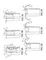
InFIG. 2A , one oftines 303 is shown divided into first, second, and third segments S1, S2, S3, each of which is pre-formed into, and elastically deformable from, the illustrated shape thereof. According to the illustrated embodiment, first segment S1 is fixedly attached todistal end 202 ofdevice housing 205 and extends around a pre-formed curvature to second segment S2, which extends proximally along a relatively straight line to third segment S3.FIG. 2A illustrates third segment S3 extending around a pre-formed curvature to a freedistal end 352 oftine 303.
With further reference toFIG. 3A , according to the illustrated embodiment, each proximal,spring portion 33 is fixedly attached tobase 301 and has a spring-biased pre-formed curvature, which, in proximity to the base, extends in a first direction d1, generally parallel toaxis 3, and then sweeps laterally, outward fromaxis 3 to distal portion proximal section35-P. Distal portion proximal section35-P, according to the illustrate embodiment, is pre-formed to extend in a second direction d2 and along a relatively straight line (dashed line), being oriented, by the spring-biased pre-formed curvature of proximal,spring portion 33, so that second direction d2 is generally opposite first direction d1, and the relatively straight line intersectsaxis 3 at an acute angle θ. According to some embodiments, angle θ is between about 30 degrees and about 50 degrees. In an exemplary embodiment ofcomponent 300, to be employed by an exemplary embodiment ofdevice 20 that hashousing 205 sized to an outer diameter of about 0.26 inch (20 French), the spring-biased pre-formed curvature of each proximal,spring portion 33 is defined by a single radius of 0.067 inch±0.010 inch; a distance A betweenbase 301 and each intersection of proximal,spring portion 33 and distal portion proximal segment35-P is 0.092 inch±0.005 inch; a length of each distal portion proximal segment35-P is 0.100 inch±0.005 inch; and angle θ is about 45 degrees.
With further reference toFIG. 3A , each distal portion hook section35-H has a deformable pre-formed curvature that extends from proximal,spring portion 33 back towardaxis 3.FIG. 3A further illustrates tip section35-T ofdistal portion 35 extending from hook section35-T along a relatively straight line to rounded freedistal end 352. Tip section35-T is shown oriented by the pre-formed curvature of hook section35-H, when un-deformed, to extend towardaxis 3, such that tip section35-T and proximal section35-P are shown enclosing an angle φ, which, according to the illustrated embodiment, is no less than about 90 degrees, but can be up to about 120 degrees. In the aforementioned exemplary embodiment ofcomponent 300, the deformable pre-formed curvature of each hook section35-H, when un-deformed, is defined by a single radius of about 0.05 inch; and a length of each tip section35-T is 0.064 inch±0.005 inch.
With further reference toFIG. 4 , a proximal end ofouter member 430 is coupled to acontrol member 412 ofhandle 410 such that an entirety ofouter member 430 is movable with respect toinner member 420, viacontrol member 412, for example, so that an operator may retractouter member 430, per arrow W, relative todevice 20 andinner member 420, to deploydevice 20 out throughdistal opening 403, after positioning the system in proximity to a target implant site. The operator may position the system by advancingtool 400 through a venous system of the patient, for example, from a femoral venous access site and up through the inferior vena cava IVC (FIG. 1 ).Delivery tool 400 may include articulating features to facilitate the navigation of the distal portion ofdelivery tool 400. For example,inner member 420 ofdelivery tool 400 may include a pull wire assembly (not shown) integrated therein and being coupled to anothercontrol member 411 ofhandle 410 that, when moved per arrow A, causesinner member 420 andouter member 430 to bend along distal portions thereof. A length ofouter member 430, betweenhandle 410 anddistal opening 403, whenouter member 430 is in the position shown inFIG. 4 , may be between about 103 cm and about 107 cm, for example, to reach into the right atrium RA from the femoral access site. Suitable construction detail for a delivery tool liketool 400 is described in co-pending and commonly assigned U.S. Patent Application 2015/0094668, Ser. No. 14/039,937 (Atty. Docket No. C00005393.USU1; filed on Sep. 27, 2013), the description of which is hereby incorporated by reference.
According to some methods, once the operator has advanced the system ofFIG. 4 into atrial appendage102 (FIG. 1 ), so thatdistal opening 403 abuts pectinate muscle PM therein (FIG. 2B ) at the target implant site, the operator can movecontrol member 412, per arrow B, to retractouter member 430 relative todevice 20 and thereby release the spring loading offixation component 300 so thattines 303 engage with pectinate muscle PM to securedevice 20 at the implant site, as illustrated inFIG. 2B . However, it should be noted that, according to alternative embodiments and methods,delivery tool 400 may be configured so that an operator can advanceinner member 420 relative toouter member 430 to pushdevice 20 out throughdistal opening 403 for deployment.FIGS. 5A-F are schematics outlining a sequence of events corresponding to the release of above-described embodiments offixation tines 303. (Although the schematics showtines 303 integrally formed withbase 301, as in above-described embodiments ofcomponent 300, it should be understood that the sequence of events inFIGS. 5A-F may also apply to alternate embodiments in whichtines 303 are not integrally formed withbase 301.)FIG. 5A illustrates a maximum deformation oftines 303 when held in the spring-loaded condition by the engagement of rounded freedistal end 352 withinner surface 42 of outer membertubular sidewall 432, wherein proximal,spring portion 33 becomes relatively straightened, and a location of the maximum principle strain along eachtine 303 is in relatively close proximity to base301 (designated by dashed-line circle). With reference back toFIG. 3A , the aforementioned exemplary length of distal portion tip section35-T and the aforementioned associated angle φ (no less than 90 degrees) help to keep thedeformed tines 303 from touching one another withinlumen 435 and to prevent free distal ends352 from being pulled proximally, per arrow P, whenouter member 430 is retracted to release the spring loading oftines 303.FIG. 5A further illustrates tip section35-T extending away fromaxis 3 at an acute angle δ, which is preferably in a range from about 45 degrees to about 75 degrees for an initial release of the spring loading of eachtine 303, upon retraction ofouter member 430, as depicted inFIG. 5B . With reference toFIG. 5C , once freedistal end 352 is released from engagement withinner surface 42 for deployment into tissue at the implant site, the spring force of proximal,spring portion 33 and the pre-formed curvature of distal portion hook section35-T cause distal portion tip section35-T to immediately rotate away fromaxis 3 to an angle π, which approaches 90 degrees, so that tip section35-T is oriented approximately normal toaxis 3 for initial penetration of pectinate muscle PM. Thus each tine freedistal end 352 is deployed in a direction toward pectinate muscle PM that ultimately preventstines 303 from perforating the underlying visceral pericardium VP (referenceFIG. 2B ).FIGS. 5D-F illustrates the subsequent movement oftines 303, being driven by the release of proximal,spring portion 33 from the spring loading. According to the illustrated embodiment, this release of proximal,spring portion 33 causes freedistal end 352, after penetrating through pectinate muscle PM in a first direction, at a first location P1, to penetrate back through in an opposite direction, at a second location P2, so thatdevice 20 may be securely fixed at the implant site, as illustrated inFIG. 2B .
The configuration of tinedistal portion 35, for example, embodied by the aforementioned exemplary lengths of proximal section35-P and tip section35-T, and the pre-formed curvature of hook section35-H, provide a structural stiffness and reach to eachtine 303 that is sufficient for deformation and subsequent penetration of freedistal end 352 through pectinate muscle PM, as shown inFIG. 2B , but is not sufficient for penetration through visceral pericardium VP. Even if the operator ends up advancing the system intoappendage 102 so thatdistal opening 403 oftool 400 abuts visceral pericardium VP, between folds of pectinate muscle PM, freedistal end 352, according to this configuration oftines 303, is not backed-up by sufficient stiffness to penetrate through visceral pericardium VP, so tip section35-T of tinedistal portion 35 is redirected, laterally, toward pectinate muscle PM.
It should be noted that an operator may employtines 303 to securedevice 20 inatrial appendage 102 in an alternative fashion, whereintines 303 are fully released from the spring-loaded condition without engaging any tissue (FIG. 5F ), and thendevice 20 is advanced to the implant site so thattines 303 wedge between opposing surfaces of pectinate muscle PM withinatrial appendage 102 to securedevice 20 in place.
With reference back toFIGS. 2A-B , according to some preferred embodiments, for example, in order to assure intimate contact ofelectrode 206 with tissue, whenfixation tines 303secure device 20 at a target implant site,electrode 206 is spaced distally apart from device housingdistal end 202 by a distance alonglongitudinal axis 2.Electrode 206 may be approximately flush with an intersection between proximal,spring portion 33 anddistal portion 35, or spaced distally apart from the intersection by a distance X that may be up to about 2 mm, as depicted inFIG. 2A .
Likecomponent 300,component 700 may be cut from the aforementioned medical grade Nitinol tubing, and eachtine 703, integrally formed withbase 701, may have a constant thickness t of 0.005 inch±0.001 inch. After cutting the tubing,tines 703 are shaped into the configuration shown inFIG. 6A by bending and holdingtines 703, while heat treating according to methods known to those skilled in the art.FIG. 6A illustrates eachtine 703 including a proximal,spring portion 73 anddistal portion 75, which is terminated by a rounded freedistal end 752, wherein bothportions tine 703, along with the super-elastic stiffness properties of Nitinol, provide a sufficient spring force and structural stiffness fortines 703 to engage tissue for the fixation ofdevice 20 at an implant site when deployed bydelivery tool 400, as described above forcomponent 300. Furthermore, eachtine 703, whendevice 20 is loaded indelivery tool 400, becomes deformed as generally shown inFIG. 4 .
According to the illustrated embodiment, each proximal,spring portion 73 is fixedly attached tobase 701 and has a spring-biased pre-formed curvature, which, in proximity to the base, extends in a first direction d1, generally parallel to axis7, and then sweeps laterally, outward from axis7 to a proximal section73-P ofdistal portion 75. Proximal section73-P is shown pre-formed to extend in a second direction d2 and along a relatively straight line (dashed line), being oriented, by the spring-biased pre-formed curvature of proximal,spring portion 73, so that second direction d2 is generally opposite first direction d1, and the relatively straight line intersects axis7 at acute angle θ, which, according to some embodiments, is between about 30 degrees and about 50 degrees. In an exemplary embodiment ofcomponent 700, to be employed by an exemplary embodiment ofdevice 20 that hashousing 205 sized to an outer diameter of about 0.26 inch (20 French), the spring-biased pre-formed curvature of each proximal,spring portion 73 is defined by a single radius of 0.067 inch ±0.010 inch; a distance A betweenbase 701 and each intersection of proximal,spring portion 73 and distal portion proximal segment75-P is 0.092 inch ±0.005 inch; a length of each spring segment distal segment73-D is 0.085 inch ±0.005 inch; and angle θ is about 34 degrees.
With further reference toFIG. 6A , eachdistal portion 75 further includes a hook section75-H, which has a deformable pre-formed curvature extending from distal proximal,spring portion 73 back toward axis7, and a tip section75-T, which is pre-formed to extend along a relatively straight line. Tip section75-T is shown oriented, by un-deformed hook segment74, to extend toward axis7, such that tip section75-T and proximal section75-D enclose an angle φ, which may be about70 degrees. According to the illustrated embodiment, distal portion hook section75-H is defined by proximal and distal radii75-HRp,75-HRd, and a straight length75-HS that extends therebetween. In the aforementioned exemplary embodiment ofcomponent 700, each hook section proximal radius75-HRp, when un-deformed, is about 0.040 inch, each hook section distal radius75-HRd is about 0.030 inch, and each straight length75-HS is about 0.040 inch; and a length of each tip section75-T is 0.062 inch ±0.005 inch. It is contemplated that this double radius configuration of distal portion hook sections75-H ofcomponent 700 enhances a stability of fixation fordevice 20 over that ofcomponent 300, by a decreased stiffness oftines 703 in proximity to freedistal end 752 and additional spring energy to draw eachtine 703 further away from the aforementioned second location P2 of penetration through pectinate muscle PM (FIG. 2B ).
In the foregoing detailed description, specific exemplary embodiments have been described. However, it may be appreciated that various modifications and changes can be made without departing from the scope of the invention as set forth in the appended claims.
Claims (31)
1. A tissue penetrating fixation component for an implantable medical device, the component comprising a base and a plurality of tines, the base defining a longitudinal axis of the component and being configured to be fixedly attached to the device so that a perimeter of the component extends around an electrode of the device, and so that the longitudinal axis of the component is generally aligned along a longitudinal axis of the device, the plurality of tines extending from the base and being spaced apart from one another around a perimeter thereof, and each tine comprising:
a proximal, spring portion being fixedly attached to the base and having a spring-biased pre-formed curvature, the pre-formed curvature, in proximity to the base, extending in a first direction, generally parallel to the axis of the component, and then sweeping laterally, outward from the axis; and
a distal portion including a proximal section, a hook section, and tip section terminated by a rounded free distal end, the proximal section extending from the proximal, spring portion and being pre-formed to extend in a second direction and along a relatively straight line to the hook section, the proximal section being oriented, by the spring-biased pre-formed curvature of the proximal, spring portion, so that the second direction is generally opposite the first direction, and the relatively straight line intersects the axis at an acute angle of between about 30 degrees and about 50 degrees, the hook section having a deformable pre-formed curvature that extends from the proximal section back toward the axis of the component, the tip section being pre-formed to extend along a relatively straight line from the hook section to the rounded free distal end, and the tip section being oriented by the pre-formed curvature of the hook section, when un-deformed, to extend toward the axis of the component, such that the tip section and the proximal section enclose an angle in a range from about 70 degrees to about 120 degrees; and
wherein, when the device, having the fixation component fixedly attached thereto, is loaded within a tubular sidewall of a delivery tool, so that the rounded free distal end of each tine of the component engages an inner surface of the sidewall in proximity to a distal opening of the tool, to hold the proximal, spring portion of each tine of the component in a spring-loaded condition, each tip section of the distal portion extends away from the axis of the component at an acute angle in a range from about 45 degrees to about 75 degrees for deployment of the corresponding rounded free distal end out from the distal opening of the tool tubular sidewall; and
upon deployment of the rounded free distal end of each tine, the tip section of each distal portion rotates away from the axis to approach an angle of 90 degrees, relative to the axis, in response to an initial release of the spring-loaded condition of the corresponding proximal, spring portion.
2. The component ofclaim 1 , wherein each tine has a constant thickness of about 0.005 inch and a width no less than about 0.02 inch.
3. The component ofclaim 2 , wherein the width of each tine tapers from a greater width in proximity to the base to a lesser width in proximity to the hook section of the distal portion.
4. The component ofclaim 3 , wherein the rounded free distal end of each tine has an enlarged width relative to a remainder of the tip section of the corresponding distal portion.
5. The component ofclaim 1 , wherein the spring-biased pre-formed curvature of the proximal, spring portion of each tine is defined by a single radius, the radius being between about 0.06 inch and about 0.08 inch.
6. The component ofclaim 1 , wherein the tip section of the distal portion of each tine has a length of about 0.06 inch.
7. The component ofclaim 1 , wherein the proximal section of the distal portion of each tine has a length of about 0.1 inch.
8. The component ofclaim 1 , wherein the deformable pre-formed curvature of the hook section of the distal portion of each tine is defined by a single radius, when un-deformed, the radius being about 0.05 inch.
9. The component ofclaim 1 , wherein the acute angle of the relatively straight line of the proximal section of the distal portion of each tine is about 45 degrees.
10. The component ofclaim 1 , wherein the deformable pre-formed curvature of the hook section of the distal portion of each tine, when un-deformed, orients the corresponding tip section to enclose, with the corresponding proximal section, an angle of no less than about 90 degrees.
11. The component ofclaim 1 , wherein:
the deformable pre-formed curvature of the hook section of the distal portion of each tine, when un-deformed, is defined by two radii and a straight length extending therebetween, the straight length being about 0.04 inch; and
the proximal section of the distal portion of each tine has a length of about 0.085 inch.
12. An implantable medical device having a longitudinal axis and including a housing, an electrode, and a fixation mechanism, the housing having a proximal end and a distal end, between which the longitudinal axis extends, the electrode being mounted in proximity to the housing distal end, and the fixation mechanism comprising a plurality of tines formed from an elastically deformable material, the tines being fixedly mounted and spaced from one another around a perimeter of the housing distal end, and wherein each tine of the fixation mechanism comprises:
a proximal, spring portion being fixedly attached to the device housing and having a spring-biased pre-formed curvature, the pre-formed curvature, in proximity to the housing, extending in a first direction, generally parallel to the axis of the device, and then sweeping laterally, outward from the axis; and
a distal portion including a proximal section, a hook section, and tip section terminated by a rounded free distal end, the proximal section extending from the proximal, spring portion and being pre-formed to extend in a second direction and along a relatively straight line to the hook section, the proximal section being oriented, by the spring-biased pre-formed curvature of the proximal, spring portion, so that the second direction is generally opposite the first direction, and the relatively straight line intersects the axis of the device at an acute angle of between about 30 degrees and about 50 degrees, the hook section having a deformable pre-formed curvature that extends from the proximal section back toward the axis of the device, the tip section being pre-formed to extend along a relatively straight line from the hook section to the rounded free distal end, and the tip section being oriented by the pre-formed curvature of the hook section, when un-deformed, to extend toward the axis of the device, such that the tip section and the proximal section enclose an angle in a range from about 70 degrees to about 120 degrees; and
wherein, when the device is loaded within a tubular sidewall of a delivery tool, so that the rounded free distal end of each tine of the fixation mechanism engages an inner surface of the sidewall in proximity to a distal opening of the tool, to hold the proximal, spring portion of each tine in a spring-loaded condition, each tip section of the distal portion extends away from the axis of the component at an acute angle in a range from about 45 degrees to about 75 degrees for deployment of the corresponding rounded free distal end out from the distal opening of the tool tubular sidewall; and
upon deployment of the rounded free distal end of each tine, the tip section of each distal portion rotates away from the axis to approach an angle of 90 degrees, relative to the axis, in response to an initial release of the spring-loaded condition of the corresponding proximal, spring portion.
13. The device ofclaim 12 , wherein each tine of the fixation mechanism has a constant thickness of about 0.005 inch and a width no less than about 0.02 inch, and the width of each tine tapers from a greater width in proximity to the device housing, where the tine is fixedly attached, to a lesser width in proximity to the hook section of the distal portion.
14. The device ofclaim 13 , wherein the rounded free distal end of each tine of the fixation mechanism has an enlarged width relative to a remainder of the tip section of the corresponding distal portion.
15. The device ofclaim 12 , wherein the spring-biased pre-formed curvature of the proximal, spring portion of each tine of the fixation mechanism is defined by a single radius, the radius being between about 0.06 inch and about 0.08 inch.
16. The device ofclaim 12 , wherein the tip section of the distal portion of each tine of the fixation mechanism has a length of about 0.06 inch.
17. The device ofclaim 12 , wherein the proximal section of the distal portion of each tine of the fixation mechanism has a length of about 0.1 inch.
18. The device ofclaim 12 , wherein the deformable pre-formed curvature of the hook section of the distal portion of each tine of the fixation mechanism is defined by a single radius, when un-deformed, the radius being about 0.05 inch.
19. The device ofclaim 12 , wherein the acute angle of the relatively straight line of the proximal section of the distal portion of each tine of the fixation mechanism is about 45 degrees.
20. The device ofclaim 12 , wherein the deformable pre-formed curvature of the hook section of the distal portion of each tine of the fixation mechanism, when un-deformed, orients the corresponding tip section to enclose, with the corresponding proximal section, an angle of no less than about 90 degrees.
21. The device ofclaim 12 , wherein:
the deformable pre-formed curvature of the hook section of the distal portion of each tine of the fixation mechanism, when un-deformed, is defined by two radii and a straight length extending therebetween, the straight length being about 0.04 inch; and
the proximal section of the distal portion of each tine of the fixation mechanism has a length of about 0.085 inch.
22. The device ofclaim 12 , wherein:
an intersection between the proximal, spring portion and the distal portion of each tine of the fixation mechanism is spaced distally from the housing distal end; and
the electrode is flush with, or spaced distally apart from the intersection between the proximal, spring portion and the distal portion of each tine by a distance in a range from about 0 mm to about 2 mm.
23. An implantable medical device having a longitudinal axis and including a housing, an electrode, and a fixation mechanism, the housing having a proximal end and a distal end, between which the longitudinal axis extends, the electrode being mounted in proximity to the housing distal end, and the fixation mechanism comprising a plurality of tines formed from an elastically deformable material, the tines being fixedly mounted and spaced from one another around a perimeter of the housing distal end, and wherein each tine of the fixation mechanism comprises:
a first segment fixedly attached to the device housing and extending therefrom;
a second segment extending from the first segment; and
a third segment, to which the second segment extends, the third segment having a rounded free distal end spaced from the perimeter of the device housing distal end; and
wherein the first segment has a spring-biased pre-formed curvature, the pre-formed curvature extending distally from the device housing distal end, and then sweeping laterally outward from the axis of the device and then proximally to the second segment;
the second segment is pre-formed to extend proximally along a relatively straight line to the third segment, the relatively straight line of the second segment being oriented, by the spring-biased preformed curvature of the first segment, to intersect the axis of the device at an acute angle of between about 30 degrees and about 50 degrees; and
the third segment has a deformable pre-formed curvature that extends back toward the axis of the device, such that, when the curvature of the third segment is un-deformed, the second and third segments enclose an angle in a range from about 70 degrees to about 120 degrees.
24. The device ofclaim 23 , wherein the acute angle of the relatively straight line of the second segment of each tine of the fixation mechanism is about 45 degrees.
25. The device ofclaim 23 , wherein the second and third segments of each tine of the fixation mechanism enclose an angle of no less than about 90 degrees, when the corresponding third segment is un-deformed.
26. The device ofclaim 23 , wherein:
an intersection between the first segment and the second segment of each tine of the fixation mechanism is spaced distally from the housing distal end; and
the electrode is flush with, or spaced distally apart from the intersection between the first segment and the second segment of each tine by a distance in a range from about 0 mm to about 2 mm.
27. A medical device system comprising an implantable medical device and a delivery tool, the device having a proximal end, a distal end and a longitudinal axis extending between the proximal and distal ends, the delivery tool including a tubular sidewall that defines a lumen into which the device may be loaded, the lumen having a distal opening through which the device may be deployed; and the device further comprising:
an electrode mounted in proximity to the distal end;
a fixation mechanism comprising a plurality of tines formed from an elastically deformable material, the tines being fixedly mounted and spaced from one another around a perimeter of the device distal end, and each tine comprising:
a first segment fixedly attached to the device and extending therefrom;
a second segment extending from the first segment; and
a third segment, to which the second segment extends, having a rounded free distal end spaced from the perimeter of the device distal end; and
wherein the first segment has a spring-biased pre-formed curvature, extending distally from the device distal end, and then sweeping laterally outward from the axis of the device and then proximally to the second segment;
the second segment is pre-formed to extend proximally along a relatively straight line to the third segment, the relatively straight line of the second segment being oriented, by the spring-biased preformed curvature of the first segment, to intersect the axis of the device at an acute angle of between about 30 degrees and about 50 degrees;
the third segment has a deformable pre-formed curvature that extends back toward the axis of the device such that, when the curvature of the third segment is un-deformed, the second and third segments enclose an angle in a range from about 70 degrees to about 120 degrees; and
the tines are each configured such that when the device is loaded in the lumen of the tool and the rounded free distal end of the third segment of each tine engages the delivery tool sidewall to hold the tines in a spring-loaded condition, the first segment of each tine becomes relatively straightened, and the third segment of each tine extends away from the axis of the device at an acute angle in a range from about 45 degrees to about 75 degrees.
28. The device system ofclaim 27 , wherein the tines are each configured such that, upon deployment of the third segments thereof, out from the distal opening of the tool, each third segment rotates away from the axis of the device to extend at an angle that approaches 90 degrees relative to the axis.
29. The device system ofclaim 27 , wherein the acute angle of the relatively straight line of the second segment of each tine of the device fixation mechanism is about 45 degrees.
30. The device system ofclaim 27 , wherein the second and third segments of each tine of the device fixation mechanism enclose an angle of no less than about 90 degrees, when the corresponding third segment is un-deformed.
31. The device system ofclaim 27 , wherein:
an intersection between the first segment and the second segment of each tine of the device fixation mechanism is spaced distally from the housing distal end; and
the electrode is flush with, or spaced distally apart from the intersection between the first segment and the second segment of each tine by a distance in a range from about 0 mm to about 2 mm.
Priority Applications (9)
| Application Number | Priority Date | Filing Date | Title |
|---|---|---|---|
| US15/410,161US10099050B2 (en) | 2016-01-21 | 2017-01-19 | Interventional medical devices, device systems, and fixation components thereof |
| CN202210282823.2ACN114768096A (en) | 2016-01-21 | 2017-01-20 | Interventional medical device, device system and fixing assembly thereof |
| CN201780018926.5ACN108883267B (en) | 2016-01-21 | 2017-01-20 | Interventional medical device, device system and fixing assembly thereof |
| EP22156586.4AEP4056225A1 (en) | 2016-01-21 | 2017-01-20 | Interventional medical devices, device systems, and fixation components thereof |
| EP17702740.6AEP3405253B1 (en) | 2016-01-21 | 2017-01-20 | Interventional medical devices, device systems, and fixation components thereof |
| PCT/US2017/014369WO2017127701A1 (en) | 2016-01-21 | 2017-01-20 | Interventional medical devices, device systems, and fixation components thereof |
| US16/158,724US11027125B2 (en) | 2016-01-21 | 2018-10-12 | Interventional medical devices, device systems, and fixation components thereof |
| US17/306,032US12251559B2 (en) | 2016-01-21 | 2021-05-03 | Interventional medical devices, device systems, and fixation components thereof |
| US19/081,610US20250213858A1 (en) | 2016-01-21 | 2025-03-17 | Interventional medical devices, device systems, and fixation components thereof |
Applications Claiming Priority (2)
| Application Number | Priority Date | Filing Date | Title |
|---|---|---|---|
| US201662281403P | 2016-01-21 | 2016-01-21 | |
| US15/410,161US10099050B2 (en) | 2016-01-21 | 2017-01-19 | Interventional medical devices, device systems, and fixation components thereof |
Related Child Applications (1)
| Application Number | Title | Priority Date | Filing Date |
|---|---|---|---|
| US16/158,724ContinuationUS11027125B2 (en) | 2016-01-21 | 2018-10-12 | Interventional medical devices, device systems, and fixation components thereof |
Publications (2)
| Publication Number | Publication Date |
|---|---|
| US20170209689A1 US20170209689A1 (en) | 2017-07-27 |
| US10099050B2true US10099050B2 (en) | 2018-10-16 |
Family
ID=59360852
Family Applications (4)
| Application Number | Title | Priority Date | Filing Date |
|---|---|---|---|
| US15/410,161Active2037-04-15US10099050B2 (en) | 2016-01-21 | 2017-01-19 | Interventional medical devices, device systems, and fixation components thereof |
| US16/158,724Active2037-07-02US11027125B2 (en) | 2016-01-21 | 2018-10-12 | Interventional medical devices, device systems, and fixation components thereof |
| US17/306,032Active2039-05-09US12251559B2 (en) | 2016-01-21 | 2021-05-03 | Interventional medical devices, device systems, and fixation components thereof |
| US19/081,610PendingUS20250213858A1 (en) | 2016-01-21 | 2025-03-17 | Interventional medical devices, device systems, and fixation components thereof |
Family Applications After (3)
| Application Number | Title | Priority Date | Filing Date |
|---|---|---|---|
| US16/158,724Active2037-07-02US11027125B2 (en) | 2016-01-21 | 2018-10-12 | Interventional medical devices, device systems, and fixation components thereof |
| US17/306,032Active2039-05-09US12251559B2 (en) | 2016-01-21 | 2021-05-03 | Interventional medical devices, device systems, and fixation components thereof |
| US19/081,610PendingUS20250213858A1 (en) | 2016-01-21 | 2025-03-17 | Interventional medical devices, device systems, and fixation components thereof |
Country Status (4)
| Country | Link |
|---|---|
| US (4) | US10099050B2 (en) |
| EP (2) | EP4056225A1 (en) |
| CN (2) | CN108883267B (en) |
| WO (1) | WO2017127701A1 (en) |
Cited By (62)
| Publication number | Priority date | Publication date | Assignee | Title |
|---|---|---|---|---|
| US10463853B2 (en) | 2016-01-21 | 2019-11-05 | Medtronic, Inc. | Interventional medical systems |
| US10518084B2 (en) | 2013-07-31 | 2019-12-31 | Medtronic, Inc. | Fixation for implantable medical devices |
| USD894396S1 (en) | 2019-03-08 | 2020-08-25 | Pacesetter, Inc. | Leadless biostimulator attachment feature |
| WO2020198287A1 (en) | 2019-03-28 | 2020-10-01 | Medtronic, Inc. | Fixation components for implantable medical devices |
| US10874850B2 (en) | 2018-09-28 | 2020-12-29 | Medtronic, Inc. | Impedance-based verification for delivery of implantable medical devices |
| WO2021030392A1 (en) | 2019-08-13 | 2021-02-18 | Medtronic, Inc. | Fixation component for multi-electrode implantable medical device |
| US11027125B2 (en) | 2016-01-21 | 2021-06-08 | Medtronic, Inc. | Interventional medical devices, device systems, and fixation components thereof |
| US11058880B2 (en) | 2018-03-23 | 2021-07-13 | Medtronic, Inc. | VFA cardiac therapy for tachycardia |
| US11058539B2 (en)* | 2017-04-18 | 2021-07-13 | Edwards Lifesciences Corporation | Heart valve sealing devices and delivery devices therefor |
| US11083582B2 (en) | 2018-10-10 | 2021-08-10 | Edwards Lifesciences Corporation | Heart valve sealing devices and delivery devices therefor |
| WO2021158352A1 (en) | 2020-02-04 | 2021-08-12 | Medtronic, Inc. | Implantable medical device including a tine housing |
| US11110251B2 (en) | 2017-09-19 | 2021-09-07 | Edwards Lifesciences Corporation | Multi-direction steerable handles for steering catheters |
| US11160657B2 (en) | 2017-04-18 | 2021-11-02 | Edwards Lifesciences Corporation | Heart valve sealing devices and delivery devices therefor |
| US11166778B2 (en) | 2017-04-28 | 2021-11-09 | Edwards Lifesciences Corporation | Medical device stabilizing apparatus and method of use |
| US11185704B2 (en) | 2017-11-06 | 2021-11-30 | Pacesetter, Inc. | Biostimulator having fixation element |
| US11207181B2 (en) | 2018-04-18 | 2021-12-28 | Edwards Lifesciences Corporation | Heart valve sealing devices and delivery devices therefor |
| US11213676B2 (en) | 2019-04-01 | 2022-01-04 | Medtronic, Inc. | Delivery systems for VfA cardiac therapy |
| US11219746B2 (en) | 2016-03-21 | 2022-01-11 | Edwards Lifesciences Corporation | Multi-direction steerable handles for steering catheters |
| US11235161B2 (en) | 2018-09-26 | 2022-02-01 | Medtronic, Inc. | Capture in ventricle-from-atrium cardiac therapy |
| US11235159B2 (en) | 2018-03-23 | 2022-02-01 | Medtronic, Inc. | VFA cardiac resynchronization therapy |
| US11259927B2 (en) | 2018-01-09 | 2022-03-01 | Edwards Lifesciences Corporation | Native valve repair devices and procedures |
| US11298228B2 (en) | 2018-01-09 | 2022-04-12 | Edwards Lifesciences Corporation | Native valve repair devices and procedures |
| US11305127B2 (en) | 2019-08-26 | 2022-04-19 | Medtronic Inc. | VfA delivery and implant region detection |
| US11331475B2 (en) | 2019-05-07 | 2022-05-17 | Medtronic, Inc. | Tether assemblies for medical device delivery systems |
| US11389297B2 (en) | 2018-04-12 | 2022-07-19 | Edwards Lifesciences Corporation | Mitral valve spacer device |
| US11400296B2 (en) | 2018-03-23 | 2022-08-02 | Medtronic, Inc. | AV synchronous VfA cardiac therapy |
| WO2022173646A1 (en) | 2021-02-15 | 2022-08-18 | Medtronic, Inc. | Fixation component for multi-electrode implantable medical device |
| US11517718B2 (en) | 2016-11-07 | 2022-12-06 | Edwards Lifesciences Corporation | Apparatus for the introduction and manipulation of multiple telescoping catheters |
| US11541243B2 (en) | 2019-03-15 | 2023-01-03 | Pacesetter, Inc. | Biostimulator having coaxial fixation elements |
| US11547564B2 (en) | 2018-01-09 | 2023-01-10 | Edwards Lifesciences Corporation | Native valve repair devices and procedures |
| US11577086B2 (en) | 2018-08-20 | 2023-02-14 | Pacesetter, Inc. | Fixation mechanisms for a leadless cardiac biostimulator |
| US11612485B2 (en) | 2018-01-09 | 2023-03-28 | Edwards Lifesciences Corporation | Native valve repair devices and procedures |
| US11660185B2 (en) | 2009-12-04 | 2023-05-30 | Edwards Lifesciences Corporation | Ventricular anchors for valve repair and replacement devices |
| US11679265B2 (en) | 2019-02-14 | 2023-06-20 | Medtronic, Inc. | Lead-in-lead systems and methods for cardiac therapy |
| US11690621B2 (en) | 2014-12-04 | 2023-07-04 | Edwards Lifesciences Corporation | Percutaneous clip for repairing a heart valve |
| US11697025B2 (en) | 2019-03-29 | 2023-07-11 | Medtronic, Inc. | Cardiac conduction system capture |
| US11712188B2 (en) | 2019-05-07 | 2023-08-01 | Medtronic, Inc. | Posterior left bundle branch engagement |
| US11730598B2 (en) | 2017-09-07 | 2023-08-22 | Edwards Lifesciences Corporation | Prosthetic device for heart valve |
| US11793642B2 (en) | 2015-05-14 | 2023-10-24 | Edwards Lifesciences Corporation | Heart valve sealing devices and delivery devices therefor |
| US11813464B2 (en) | 2020-07-31 | 2023-11-14 | Medtronic, Inc. | Cardiac conduction system evaluation |
| US11813466B2 (en) | 2020-01-27 | 2023-11-14 | Medtronic, Inc. | Atrioventricular nodal stimulation |
| US11839544B2 (en) | 2019-02-14 | 2023-12-12 | Edwards Lifesciences Corporation | Heart valve sealing devices and delivery devices therefor |
| US11911168B2 (en) | 2020-04-03 | 2024-02-27 | Medtronic, Inc. | Cardiac conduction system therapy benefit determination |
| US11918469B2 (en) | 2018-01-09 | 2024-03-05 | Edwards Lifesciences Corporation | Native valve repair devices and procedures |
| US11951263B2 (en) | 2016-03-21 | 2024-04-09 | Edwards Lifesciences Corporation | Multi-direction steerable handles |
| US11951313B2 (en) | 2018-11-17 | 2024-04-09 | Medtronic, Inc. | VFA delivery systems and methods |
| US11969346B2 (en) | 2017-01-05 | 2024-04-30 | Edwards Lifesciences Corporation | Heart valve coaptation device |
| US12048625B2 (en) | 2017-05-10 | 2024-07-30 | Edwards Lifesciences Corporation | Valve repair delivery handle |
| US12083010B2 (en) | 2013-02-04 | 2024-09-10 | Edwards Lifesciences Corporation | Method of implanting a spacer body in a mitral valve |
| US12090052B2 (en) | 2018-01-09 | 2024-09-17 | Edwards Lifesciences Corporation | Native valve repair devices and procedures |
| US12138165B2 (en) | 2011-06-23 | 2024-11-12 | Edwards Lifesciences Innovation (Israel) Ltd. | Annuloplasty implants |
| US12151100B2 (en) | 2019-05-07 | 2024-11-26 | Medtronic, Inc. | Tether assemblies for medical device delivery systems |
| US12156813B2 (en) | 2013-11-22 | 2024-12-03 | Edwards Lifesciences Corporation | Valvular insufficiency repair device and method |
| US12179016B2 (en) | 2021-02-15 | 2024-12-31 | Medtronic, Inc. | Fixation component for multi-electrode implantable medical device |
| US12245942B2 (en) | 2018-11-20 | 2025-03-11 | Edwards Lifesciences Corporation | Deployment tools and methods for delivering a device to a native heart valve |
| US12251309B2 (en) | 2016-07-07 | 2025-03-18 | Edwards Lifesciences Corporation | Device and method for treating vascular insufficiency |
| USD1071198S1 (en) | 2023-06-28 | 2025-04-15 | Edwards Lifesciences Corporation | Cradle |
| US12279982B2 (en) | 2018-11-21 | 2025-04-22 | Edwards Lifesciences Corporation | Retrieval devices for heart valve sealing devices |
| US12296177B2 (en) | 2018-12-21 | 2025-05-13 | Medtronic, Inc. | Delivery systems and methods for left ventricular pacing |
| US12350149B2 (en) | 2009-05-04 | 2025-07-08 | Edwards Lifesciences Innovation (Israel) Ltd. | Method and apparatus for repairing a heart valve |
| US12396850B2 (en) | 2018-11-29 | 2025-08-26 | Edwards Lifesciences Corporation | Catheterization method and apparatus |
| US12409033B2 (en) | 2017-09-08 | 2025-09-09 | Edwards Lifesciences Corporation | Axisymmetric adjustable device for treating mitral regurgitation |
Families Citing this family (20)
| Publication number | Priority date | Publication date | Assignee | Title |
|---|---|---|---|---|
| WO2018094193A1 (en) | 2016-11-21 | 2018-05-24 | Cardiac Pacemakers, Inc. | Delivery devices and wall apposition sensing |
| US11198013B2 (en) | 2016-11-21 | 2021-12-14 | Cardiac Pacemakers, Inc. | Catheter and leadless cardiac devices including electrical pathway barrier |
| US10806931B2 (en) | 2016-12-27 | 2020-10-20 | Cardiac Pacemakers, Inc. | Delivery devices and methods for leadless cardiac devices |
| US10485981B2 (en) | 2016-12-27 | 2019-11-26 | Cardiac Pacemakers, Inc. | Fixation methods for leadless cardiac devices |
| CN110114114B (en) | 2016-12-27 | 2023-05-02 | 心脏起搏器股份公司 | Delivery devices and methods for leadless cardiac devices |
| AU2017387024B2 (en) | 2016-12-27 | 2020-04-09 | Cardiac Pacemakers, Inc. | Leadless delivery catheter with conductive pathway |
| WO2018140597A2 (en) | 2017-01-26 | 2018-08-02 | Cardiac Pacemakers, Inc. | Delivery devices and methods for leadless cardiac devices |
| CN110418661B (en) | 2017-03-10 | 2024-01-02 | 心脏起搏器股份公司 | Fixing piece for leadless cardiac device |
| US10737092B2 (en) | 2017-03-30 | 2020-08-11 | Cardiac Pacemakers, Inc. | Delivery devices and methods for leadless cardiac devices |
| US10905872B2 (en)* | 2017-04-03 | 2021-02-02 | Cardiac Pacemakers, Inc. | Implantable medical device with a movable electrode biased toward an extended position |
| US11577085B2 (en) | 2017-08-03 | 2023-02-14 | Cardiac Pacemakers, Inc. | Delivery devices and methods for leadless cardiac devices |
| US11426578B2 (en) | 2017-09-15 | 2022-08-30 | Medtronic, Inc. | Electrodes for intra-cardiac pacemaker |
| EP3946556B1 (en) | 2019-03-29 | 2024-06-19 | Cardiac Pacemakers, Inc. | Systems for treating cardiac arrhythmias |
| CN113660977B (en) | 2019-03-29 | 2024-12-17 | 心脏起搏器股份公司 | Systems and methods for treating cardiac arrhythmias |
| US20200360687A1 (en)* | 2019-05-16 | 2020-11-19 | Biotronik Se & Co. Kg | Implantable medical device comprising an anchoring device |
| EP3789084A1 (en) | 2019-09-09 | 2021-03-10 | BIOTRONIK SE & Co. KG | Implantable medical device comprising an anchoring device |
| US11510697B2 (en) | 2019-09-11 | 2022-11-29 | Cardiac Pacemakers, Inc. | Tools and systems for implanting and/or retrieving a leadless cardiac pacing device with helix fixation |
| WO2021050685A1 (en) | 2019-09-11 | 2021-03-18 | Cardiac Pacemakers, Inc. | Tools and systems for implanting and/or retrieving a leadless cardiac pacing device with helix fixation |
| EP4046681A1 (en)* | 2021-02-23 | 2022-08-24 | BIOTRONIK SE & Co. KG | Intra-cardiac device |
| EP4630108A1 (en)* | 2022-12-09 | 2025-10-15 | BIOTRONIK SE & Co. KG | Anchoring arrangement for anchoring an implantable medical device in the tissue of a patient |
Citations (42)
| Publication number | Priority date | Publication date | Assignee | Title |
|---|---|---|---|---|
| US3814104A (en) | 1971-07-05 | 1974-06-04 | W Irnich | Pacemaker-electrode |
| US4103690A (en) | 1977-03-21 | 1978-08-01 | Cordis Corporation | Self-suturing cardiac pacer lead |
| US6055457A (en) | 1998-03-13 | 2000-04-25 | Medtronic, Inc. | Single pass A-V lead with active fixation device |
| US20020095203A1 (en) | 2001-01-18 | 2002-07-18 | Intra Therapeutics, Inc. | Catheter system with spacer member |
| US6738672B2 (en) | 2001-06-18 | 2004-05-18 | The Alfred E. Mann Foundation For Scientific Research | Miniature implantable connectors |
| US20040147973A1 (en) | 2002-06-27 | 2004-07-29 | Hauser Robert G. | Intra cardiac pacer and method |
| US6823217B2 (en) | 2001-08-21 | 2004-11-23 | Medtronic, Inc. | Method and apparatus for imparting curves in elongated implantable medical instruments |
| US7082336B2 (en) | 2003-06-04 | 2006-07-25 | Synecor, Llc | Implantable intravascular device for defibrillation and/or pacing |
| US7130700B2 (en) | 2002-11-19 | 2006-10-31 | Medtronic, Inc. | Multilumen body for an implantable medical device |
| US20060247753A1 (en) | 2005-04-29 | 2006-11-02 | Wenger William K | Subcutaneous lead fixation mechanisms |
| US7331922B2 (en) | 2001-07-17 | 2008-02-19 | Werner Mohl | Method and device for the intermittent occlusion of the coronary sinus |
| US20090082828A1 (en) | 2007-09-20 | 2009-03-26 | Alan Ostroff | Leadless Cardiac Pacemaker with Secondary Fixation Capability |
| US7647109B2 (en) | 2004-10-20 | 2010-01-12 | Boston Scientific Scimed, Inc. | Leadless cardiac stimulation systems |
| US7949395B2 (en) | 1999-10-01 | 2011-05-24 | Boston Scientific Neuromodulation Corporation | Implantable microdevice with extended lead and remote electrode |
| US8012127B2 (en) | 2007-02-28 | 2011-09-06 | Medtronic, Inc. | Systems and methods for gaining access around an implanted medical device |
| US8032219B2 (en) | 2005-04-22 | 2011-10-04 | Biotronik Crm Patent Ag | Cardiac pacemaker having a sealed oblong housing |
| US20110251661A1 (en) | 2005-08-15 | 2011-10-13 | Fifer Daniel W | Lead fixation and extraction |
| US20110270340A1 (en) | 2010-04-30 | 2011-11-03 | Medtronic Vascular,Inc. | Two-Stage Delivery Systems and Methods for Fixing a Leadless Implant to Tissue |
| US20120172690A1 (en) | 2010-12-29 | 2012-07-05 | Medtronic, Inc. | Implantable medical device fixation |
| US20120172892A1 (en) | 2010-12-29 | 2012-07-05 | Medtronic, Inc. | Implantable medical device fixation |
| US8262672B2 (en) | 2008-04-16 | 2012-09-11 | Medtronic, Inc. | Medical delivery device construction |
| US20130110127A1 (en) | 2011-10-31 | 2013-05-02 | Pacesetter, Inc. | Multi-piece dual-chamber leadless intra-cardiac medical device and method of implanting same |
| US20130116738A1 (en) | 2011-11-03 | 2013-05-09 | Pacesetter, Inc. | Single chamber leadless intra-cardiac medical device with dual-chamber functionality |
| US8478431B2 (en) | 2010-04-13 | 2013-07-02 | Medtronic, Inc. | Slidable fixation device for securing a medical implant |
| US8532790B2 (en) | 2010-04-13 | 2013-09-10 | Medtronic, Inc. | Slidable fixation device for securing a medical implant |
| US20130253345A1 (en) | 2012-03-26 | 2013-09-26 | Medtronic, Inc. | Implantable medical device delivery catheter with tether |
| US8615310B2 (en) | 2010-12-13 | 2013-12-24 | Pacesetter, Inc. | Delivery catheter systems and methods |
| US8634912B2 (en) | 2011-11-04 | 2014-01-21 | Pacesetter, Inc. | Dual-chamber leadless intra-cardiac medical device with intra-cardiac extension |
| US8670842B1 (en) | 2012-12-14 | 2014-03-11 | Pacesetter, Inc. | Intra-cardiac implantable medical device |
| US20140107723A1 (en) | 2012-10-16 | 2014-04-17 | Pacesetter, Inc. | Single-chamber leadless intra-cardiac medical device with dual-chamber functionality |
| US8755909B2 (en) | 2012-06-01 | 2014-06-17 | Medtronic, Inc. | Active fixation medical electrical lead |
| US20150039070A1 (en) | 2013-07-31 | 2015-02-05 | Medtronic, Inc. | Fixation for implantable medical devices |
| US20150039071A1 (en) | 2013-07-31 | 2015-02-05 | Medtronic, Inc. | Fixation for implantable medical devices |
| US20150051682A1 (en) | 2013-08-16 | 2015-02-19 | Cardiac Pacemakers, Inc. | Leadless cardiac pacemaker with delivery and/or retrieval features |
| US20150051616A1 (en) | 2013-08-16 | 2015-02-19 | Cardiac Pacemakers, Inc | Leadless cardiac pacing devices |
| US20150094668A1 (en) | 2013-09-27 | 2015-04-02 | Medtronic, Inc. | Interventional medical systems, tools, and assemblies |
| US9119959B2 (en) | 2013-07-31 | 2015-09-01 | Medtronic, Inc. | Tine fixation components for implantable medical devices |
| US20160059002A1 (en) | 2014-08-26 | 2016-03-03 | Medtronic, Inc. | Interventional medical systems, devices, and components thereof |
| US9414857B2 (en) | 2014-11-20 | 2016-08-16 | Medtronic, Inc. | Delivery system assemblies for implantable medical devices |
| US9446248B2 (en) | 2014-07-17 | 2016-09-20 | Medtronic, Inc. | Interventional medical systems, tools, and methods of use |
| US9526891B2 (en) | 2015-04-24 | 2016-12-27 | Medtronic, Inc. | Intracardiac medical device |
| US9539423B2 (en) | 2014-07-17 | 2017-01-10 | Medtronic, Inc. | Interventional medical systems, tools, and methods of use |
Family Cites Families (271)
| Publication number | Priority date | Publication date | Assignee | Title |
|---|---|---|---|---|
| US3943936A (en) | 1970-09-21 | 1976-03-16 | Rasor Associates, Inc. | Self powered pacers and stimulators |
| US3835864A (en) | 1970-09-21 | 1974-09-17 | Rasor Ass Inc | Intra-cardiac stimulator |
| DE2053919A1 (en) | 1970-10-24 | 1972-05-04 | Schaldach M | Pacemaker detector and stimulation electrode |
| US3717151A (en) | 1971-03-11 | 1973-02-20 | R Collett | Flesh penetrating apparatus |
| US3754555A (en) | 1971-10-05 | 1973-08-28 | G Schmitt | Controllable barbed intracardial electrode |
| US3902501A (en) | 1973-06-21 | 1975-09-02 | Medtronic Inc | Endocardial electrode |
| NL7502008A (en) | 1974-02-25 | 1975-08-27 | German Schmitt | INTRAKARDIAL STIMULATING ELECTRODE. |
| US3971364A (en) | 1975-05-16 | 1976-07-27 | Nasa | Catheter tip force transducer for cardiovascular research |
| US4112952A (en) | 1977-02-11 | 1978-09-12 | The United States Of America As Represented By The Secretary Of Health, Education And Welfare | Electrode for artificial pacemaker |
| US4142530A (en) | 1978-03-06 | 1979-03-06 | Vitatron Medical B. V. | Epicardial lead |
| DE2843096A1 (en) | 1978-09-30 | 1980-04-10 | Biotronik Mess & Therapieg | PACEMAKER ELECTRODE FOR TRANSVENOUS APPLICATION |
| US4236529A (en) | 1979-02-21 | 1980-12-02 | Daig Corporation | Tined lead |
| US4269198A (en) | 1979-12-26 | 1981-05-26 | Medtronic, Inc. | Body implantable lead |
| US4301815A (en) | 1980-01-23 | 1981-11-24 | Telectronics Pty. Limited | Trailing tine electrode lead |
| US4402328A (en) | 1981-04-28 | 1983-09-06 | Telectronics Pty. Limited | Crista terminalis atrial electrode lead |
| US4409994A (en) | 1981-06-02 | 1983-10-18 | Telectronics Pty., Ltd. | Lap joint molding member for a pacemaker electrode lead |
| US4502492A (en) | 1983-04-28 | 1985-03-05 | Medtronic, Inc. | Low-polarization low-threshold electrode |
| US4662382A (en) | 1985-01-16 | 1987-05-05 | Intermedics, Inc. | Pacemaker lead with enhanced sensitivity |
| DE3529578A1 (en) | 1985-08-17 | 1987-02-19 | Bisping Hans Juergen | IMPLANTABLE ELECTRODE |
| US4858623A (en) | 1987-07-13 | 1989-08-22 | Intermedics, Inc. | Active fixation mechanism for lead assembly of an implantable cardiac stimulator |
| US4936823A (en) | 1988-05-04 | 1990-06-26 | Triangle Research And Development Corp. | Transendoscopic implant capsule |
| DE3825631A1 (en) | 1988-07-28 | 1990-02-08 | Osypka Peter | DEVICE FOR TRANSVENOUS OR ARTERIAL INSERTION BY MEANS OF A GUIDE WIRE |
| JPH0288666A (en) | 1988-09-27 | 1990-03-28 | Hitachi Chem Co Ltd | Thermosetting resin composition |
| US4913164A (en) | 1988-09-27 | 1990-04-03 | Intermedics, Inc. | Extensible passive fixation mechanism for lead assembly of an implantable cardiac stimulator |
| US4898577A (en) | 1988-09-28 | 1990-02-06 | Advanced Cardiovascular Systems, Inc. | Guiding cathether with controllable distal tip |
| US5697936A (en) | 1988-11-10 | 1997-12-16 | Cook Pacemaker Corporation | Device for removing an elongated structure implanted in biological tissue |
| JPH0288666U (en) | 1988-12-28 | 1990-07-13 | ||
| US5267960A (en) | 1990-03-19 | 1993-12-07 | Omnitron International Inc. | Tissue engaging catheter for a radioactive source wire |
| JPH04558U (en) | 1990-04-17 | 1992-01-06 | ||
| US5171233A (en) | 1990-04-25 | 1992-12-15 | Microvena Corporation | Snare-type probe |
| US5057114A (en) | 1990-09-18 | 1991-10-15 | Cook Incorporated | Medical retrieval basket |
| US5282845A (en) | 1990-10-01 | 1994-02-01 | Ventritex, Inc. | Multiple electrode deployable lead |
| US5193540A (en) | 1991-12-18 | 1993-03-16 | Alfred E. Mann Foundation For Scientific Research | Structure and method of manufacture of an implantable microstimulator |
| JPH05245215A (en) | 1992-03-03 | 1993-09-24 | Terumo Corp | Heart pace maker |
| US5314462A (en) | 1992-05-27 | 1994-05-24 | Cardiac Pacemakers, Inc. | Positive fixation device |
| US5257634A (en) | 1992-07-16 | 1993-11-02 | Angeion Corporation | Low impedence defibrillation catheter electrode |
| US5300107A (en) | 1992-10-22 | 1994-04-05 | Medtronic, Inc. | Universal tined myocardial pacing lead |
| US5336253A (en) | 1993-02-23 | 1994-08-09 | Medtronic, Inc. | Pacing and cardioversion lead systems with shared lead conductors |
| US5318528A (en) | 1993-04-13 | 1994-06-07 | Advanced Surgical Inc. | Steerable surgical devices |
| US5405374A (en) | 1993-08-25 | 1995-04-11 | Medtronic, Inc. | Transvenous defibrillation lead and method of use |
| US5492119A (en) | 1993-12-22 | 1996-02-20 | Heart Rhythm Technologies, Inc. | Catheter tip stabilizing apparatus |
| US5443492A (en) | 1994-02-02 | 1995-08-22 | Medtronic, Inc. | Medical electrical lead and introducer system for implantable pulse generator |
| US5573540A (en) | 1994-07-18 | 1996-11-12 | Yoon; Inbae | Apparatus and method for suturing an opening in anatomical tissue |
| US5522875A (en) | 1994-07-28 | 1996-06-04 | Medtronic, Inc. | Medical electrical lead system having a torque transfer stylet |
| US5562723A (en) | 1994-10-06 | 1996-10-08 | Medtronic, Inc. | Medical electrical lead having a reinforced tine assembly |
| US5522876A (en) | 1994-10-26 | 1996-06-04 | Vitatron Medical, B.V. | Screw-in pacing lead |
| US5545206A (en) | 1994-12-22 | 1996-08-13 | Ventritex, Inc. | Low profile lead with automatic tine activation |
| US5575814A (en) | 1995-01-27 | 1996-11-19 | Medtronic, Inc. | Active fixation medical electrical lead having mapping capability |
| US5551427A (en) | 1995-02-13 | 1996-09-03 | Altman; Peter A. | Implantable device for the effective elimination of cardiac arrhythmogenic sites |
| US6575967B1 (en) | 1995-03-24 | 2003-06-10 | The Board Of Regents Of The University Of Nebraska | Method and systems for volumetric tissue ablation |
| US5545201A (en) | 1995-03-29 | 1996-08-13 | Pacesetter, Inc. | Bipolar active fixation lead for sensing and pacing the heart |
| US5578068A (en) | 1995-05-08 | 1996-11-26 | Medtronic, Inc. | Medical electrical lead with radially asymmetric tip |
| US6322548B1 (en) | 1995-05-10 | 2001-11-27 | Eclipse Surgical Technologies | Delivery catheter system for heart chamber |
| US6251104B1 (en) | 1995-05-10 | 2001-06-26 | Eclipse Surgical Technologies, Inc. | Guiding catheter system for ablating heart tissue |
| US5716391A (en) | 1995-08-23 | 1998-02-10 | Medtronic, Inc. | Medical electrical lead having temporarily rigid fixation |
| FR2742058B1 (en) | 1995-12-12 | 1998-03-06 | Ela Medical Sa | FOLDABLE ANCHOR BARS PROBES FOR AN IMPLANTED MEDICAL DEVICE, IN PARTICULAR FOR A HEART STIMULATOR |
| US5683447A (en) | 1995-12-19 | 1997-11-04 | Ventritex, Inc. | Lead with septal defibrillation and pacing electrodes |
| US5658327A (en) | 1995-12-19 | 1997-08-19 | Ventritex, Inc. | Intracardiac lead having a compliant fixation device |
| US6915149B2 (en) | 1996-01-08 | 2005-07-05 | Biosense, Inc. | Method of pacing a heart using implantable device |
| US5776178A (en) | 1996-02-21 | 1998-07-07 | Medtronic, Inc. | Medical electrical lead with surface treatment for enhanced fixation |
| US5716390A (en) | 1996-08-09 | 1998-02-10 | Pacesetter, Inc. | Reduced diameter active fixation pacing lead using concentric interleaved coils |
| US5837006A (en) | 1996-09-10 | 1998-11-17 | Medtronic, Inc. | Retraction stop for helical medical lead electrode |
| US5755764A (en) | 1996-09-10 | 1998-05-26 | Sulzer Intermedics Inc. | Implantable cardiac stimulation catheter |
| US5851226A (en) | 1996-10-22 | 1998-12-22 | Medtronic, Inc. | Temporary transvenous endocardial lead |
| US5807399A (en) | 1996-10-23 | 1998-09-15 | Medtronic, Inc. | Method for removal of chronically implanted leads and leads optimized for use therewith |
| US5971993A (en) | 1996-11-07 | 1999-10-26 | Myocardial Stents, Inc. | System for delivery of a trans myocardial device to a heart wall |
| SE9604143D0 (en) | 1996-11-13 | 1996-11-13 | Pacesetter Ab | Implantable electrode cable |
| US6074401A (en) | 1997-01-09 | 2000-06-13 | Coalescent Surgical, Inc. | Pinned retainer surgical fasteners, instruments and methods for minimally invasive vascular and endoscopic surgery |
| US6093177A (en) | 1997-03-07 | 2000-07-25 | Cardiogenesis Corporation | Catheter with flexible intermediate section |
| US5908381A (en) | 1997-04-30 | 1999-06-01 | C. R. Bard Inc. | Directional surgical device for use with endoscope, gastroscope, colonoscope or the like |
| US6078840A (en) | 1997-04-30 | 2000-06-20 | Medtronic, Inc. | Medical electrical lead having improved fixation |
| US6321124B1 (en) | 1997-05-28 | 2001-11-20 | Transneuronix, Inc. | Implant device for electrostimulation and/or monitoring of endo-abdominal cavity tissue |
| US6381495B1 (en) | 1997-05-28 | 2002-04-30 | Transneuronix, Inc. | Medical device for use in laparoscopic surgery |
| IT1292016B1 (en) | 1997-05-28 | 1999-01-25 | Valerio Cigaina | IMPLANT DEVICE PARTICULARLY FOR ELECTROSTIMULATION AND / OR ELECTRO-REGISTRATION OF ENDOABDOMINAL VISCERS |
| US6477423B1 (en) | 1997-05-28 | 2002-11-05 | Transneuronix, Inc. | Medical device for use in laparoscopic surgery |
| IT1293973B1 (en) | 1997-08-13 | 1999-03-15 | Sorin Biomedica Cardio Spa | ELEMENT FOR ANCHORING OF INSTALLATION DEVICES IN SITU. |
| US5871531A (en) | 1997-09-25 | 1999-02-16 | Medtronic, Inc. | Medical electrical lead having tapered spiral fixation |
| US6409674B1 (en) | 1998-09-24 | 2002-06-25 | Data Sciences International, Inc. | Implantable sensor with wireless communication |
| US6151525A (en) | 1997-11-07 | 2000-11-21 | Medtronic, Inc. | Method and system for myocardial identifier repair |
| US6286512B1 (en) | 1997-12-30 | 2001-09-11 | Cardiodyne, Inc. | Electrosurgical device and procedure for forming a channel within tissue |
| US5908447A (en) | 1998-02-06 | 1999-06-01 | Intermedics Inc. | Breakaway structure for body implantable medical device |
| US6132456A (en) | 1998-03-10 | 2000-10-17 | Medtronic, Inc. | Arrangement for implanting an endocardial cardiac lead |
| AU746955B2 (en) | 1998-03-27 | 2002-05-09 | Cook Urological Inc. | Minimally-invasive medical retrieval device |
| JP2002503140A (en) | 1998-04-23 | 2002-01-29 | サイムド ライフ システムズ,インコーポレイテッド | Non-traumatic medical recovery device |
| US6592581B2 (en) | 1998-05-05 | 2003-07-15 | Cardiac Pacemakers, Inc. | Preformed steerable catheter with movable outer sleeve and method for use |
| US6108582A (en) | 1998-07-02 | 2000-08-22 | Intermedics Inc. | Cardiac pacemaker lead with extendable/retractable fixation |
| US6129749A (en) | 1998-08-25 | 2000-10-10 | Cardiac Pacemakers, Inc. | Monorail left ventricular access lead |
| US6007558A (en) | 1998-09-25 | 1999-12-28 | Nitinol Medical Technologies, Inc. | Removable embolus blood clot filter |
| US6240322B1 (en) | 1998-11-04 | 2001-05-29 | Cardiac Pacemakers, Inc. | System and apparatus having low profile collapsible tines |
| US6200330B1 (en) | 1998-11-23 | 2001-03-13 | Theodore V. Benderev | Systems for securing sutures, grafts and soft tissue to bone and periosteum |
| US6363938B2 (en) | 1998-12-22 | 2002-04-02 | Angiotrax, Inc. | Methods and apparatus for perfusing tissue and/or stimulating revascularization and tissue growth |
| DE69921447T2 (en) | 1999-04-02 | 2005-11-24 | Sorin Biomedica Crm S.R.L., Saluggia | Anchor structure for implantable electrodes |
| DE19928901C2 (en) | 1999-06-24 | 2003-06-05 | Vasco Med Inst Fuer Katheterte | Device for pulling an object having an elongated inner lumen out of its anchoring in a body |
| AU6953300A (en) | 1999-07-07 | 2001-01-22 | Cardiac Pacemakers, Inc. | Endocardial electrode assembly having conductive fixation features |
| US6510332B1 (en) | 1999-08-30 | 2003-01-21 | Transneuronix, Inc. | Electrode leads for use in laparoscopic surgery |
| US6572587B2 (en) | 2000-01-10 | 2003-06-03 | Benjamin S. Lerman | Anchoring device for medical apparatus |
| GB2359024A (en) | 2000-02-09 | 2001-08-15 | Anson Medical Ltd | Fixator for arteries |
| SE0000548D0 (en) | 2000-02-18 | 2000-02-18 | Pacesetter Ab | Electrode |
| US6582441B1 (en) | 2000-02-24 | 2003-06-24 | Advanced Bionics Corporation | Surgical insertion tool |
| US6638268B2 (en) | 2000-04-07 | 2003-10-28 | Imran K. Niazi | Catheter to cannulate the coronary sinus |
| US6510345B1 (en) | 2000-04-24 | 2003-01-21 | Medtronic, Inc. | System and method of bridging a transreceiver coil of an implantable medical device during non-communication periods |
| US6408214B1 (en) | 2000-07-11 | 2002-06-18 | Medtronic, Inc. | Deflectable tip catheter for CS pacing |
| US6684109B1 (en) | 2000-09-13 | 2004-01-27 | Oscor Inc. | Endocardial lead |
| US6522915B1 (en) | 2000-10-26 | 2003-02-18 | Medtronic, Inc. | Surround shroud connector and electrode housings for a subcutaneous electrode array and leadless ECGS |
| US6458145B1 (en) | 2000-11-28 | 2002-10-01 | Hatch Medical L.L.C. | Intra vascular snare and method of forming the same |
| US6716226B2 (en) | 2001-06-25 | 2004-04-06 | Inscope Development, Llc | Surgical clip |
| US6783499B2 (en) | 2000-12-18 | 2004-08-31 | Biosense, Inc. | Anchoring mechanism for implantable telemetric medical sensor |
| US6746404B2 (en) | 2000-12-18 | 2004-06-08 | Biosense, Inc. | Method for anchoring a medical device between tissue |
| SE0004765D0 (en) | 2000-12-20 | 2000-12-20 | St Jude Medical | An electrode head fixation arrangement |
| US6754536B2 (en) | 2001-01-31 | 2004-06-22 | Medtronic, Inc | Implantable medical device affixed internally within the gastrointestinal tract |
| US6623518B2 (en) | 2001-02-26 | 2003-09-23 | Ev3 Peripheral, Inc. | Implant delivery system with interlock |
| US6909920B2 (en) | 2001-04-27 | 2005-06-21 | Medtronic, Inc. | System and method for positioning an implantable medical device within a body |
| US6535764B2 (en) | 2001-05-01 | 2003-03-18 | Intrapace, Inc. | Gastric treatment and diagnosis device and method |
| US7678128B2 (en) | 2001-06-29 | 2010-03-16 | Advanced Cardiovascular Systems, Inc. | Delivery and recovery sheaths for medical devices |
| US6711443B2 (en) | 2001-07-25 | 2004-03-23 | Oscor Inc. | Implantable coronary sinus lead and method of implant |
| US6776784B2 (en) | 2001-09-06 | 2004-08-17 | Core Medical, Inc. | Clip apparatus for closing septal defects and methods of use |
| US7027876B2 (en) | 2001-10-12 | 2006-04-11 | Medtronic, Inc. | Lead system for providing electrical stimulation to the Bundle of His |
| US20030078618A1 (en) | 2001-10-19 | 2003-04-24 | Fey Kate E. | System and method for removing implanted devices |
| US6745079B2 (en) | 2001-11-07 | 2004-06-01 | Medtronic, Inc. | Electrical tissue stimulation apparatus and method |
| US6755812B2 (en) | 2001-12-11 | 2004-06-29 | Cardiac Pacemakers, Inc. | Deflectable telescoping guide catheter |
| US7717899B2 (en) | 2002-01-28 | 2010-05-18 | Cardiac Pacemakers, Inc. | Inner and outer telescoping catheter delivery system |
| US6978178B2 (en) | 2002-04-30 | 2005-12-20 | Medtronic, Inc. | Method and apparatus for selecting an optimal electrode configuration of a medical electrical lead having a multiple electrode array |
| US7462184B2 (en) | 2002-05-06 | 2008-12-09 | Pressure Products Medical Supplies Inc. | Introducer for accessing the coronary sinus of a heart |
| US6792318B2 (en) | 2002-06-13 | 2004-09-14 | Pacesetter, Inc. | Technique for fixating a lead |
| US7181288B1 (en) | 2002-06-24 | 2007-02-20 | The Cleveland Clinic Foundation | Neuromodulation device and method of using the same |
| US7993351B2 (en) | 2002-07-24 | 2011-08-09 | Pressure Products Medical Supplies, Inc. | Telescopic introducer with a compound curvature for inducing alignment and method of using the same |
| WO2004011081A1 (en) | 2002-07-25 | 2004-02-05 | Oscor Inc. | Epicardial screw-in lead |
| US7731655B2 (en) | 2002-09-20 | 2010-06-08 | Id, Llc | Tissue retractor and method for using the retractor |
| US7092765B2 (en) | 2002-09-23 | 2006-08-15 | Medtronic, Inc. | Non-sheath based medical device delivery system |
| US7313445B2 (en) | 2002-09-26 | 2007-12-25 | Medtronic, Inc. | Medical lead with flexible distal guidewire extension |
| WO2004028348A2 (en) | 2002-09-26 | 2004-04-08 | Savacor, Inc. | Cardiovascular anchoring device and method of deploying same |
| US8303511B2 (en) | 2002-09-26 | 2012-11-06 | Pacesetter, Inc. | Implantable pressure transducer system optimized for reduced thrombosis effect |
| US7082335B2 (en) | 2002-09-30 | 2006-07-25 | Medtronic, Inc. | Multipolar pacing method and apparatus |
| US8252019B2 (en) | 2003-01-31 | 2012-08-28 | Cordis Corporation | Filter retrieval catheter system, and methods |
| US7158838B2 (en) | 2003-01-31 | 2007-01-02 | Medtronic, Inc. | Arrangement for implanting a miniaturized cardiac lead having a fixation helix |
| WO2004066825A2 (en) | 2003-01-31 | 2004-08-12 | The Board Of Trustees Of The Leland Stanford Junior University | Detection of apex motion for monitoring cardiac dysfunction |
| US7618435B2 (en) | 2003-03-04 | 2009-11-17 | Nmt Medical, Inc. | Magnetic attachment systems |
| US7349742B2 (en) | 2003-04-11 | 2008-03-25 | Cardiac Pacemakers, Inc. | Expandable fixation elements for subcutaneous electrodes |
| US7499758B2 (en) | 2003-04-11 | 2009-03-03 | Cardiac Pacemakers, Inc. | Helical fixation elements for subcutaneous electrodes |
| DE10323016A1 (en) | 2003-05-15 | 2004-12-02 | Biotronik Meß- und Therapiegeräte GmbH & Co. Ingenieurbüro Berlin | Epicardium electrode |
| US7617007B2 (en) | 2003-06-04 | 2009-11-10 | Synecor Llc | Method and apparatus for retaining medical implants within body vessels |
| US7383091B1 (en) | 2003-06-05 | 2008-06-03 | Pacesetter, Inc. | Medical electrical lead providing far-field signal attenuation |
| US7561916B2 (en) | 2005-06-24 | 2009-07-14 | Ethicon Endo-Surgery, Inc. | Implantable medical device with indicator |
| EP1488735B1 (en) | 2003-06-17 | 2007-06-13 | Raymond Moser | Instrumented retrievable implantable device |
| US7317951B2 (en) | 2003-07-25 | 2008-01-08 | Integrated Sensing Systems, Inc. | Anchor for medical implant placement and method of manufacture |
| US7187982B2 (en) | 2003-08-08 | 2007-03-06 | Medtronic, Inc. | Medical electrical lead anchoring |
| US20050038491A1 (en) | 2003-08-11 | 2005-02-17 | Haack Scott Graham | Cardiac pacing lead having dual fixation and method of using the same |
| US7289853B1 (en) | 2003-08-28 | 2007-10-30 | David Campbell | High frequency wireless pacemaker |
| US7993384B2 (en) | 2003-09-12 | 2011-08-09 | Abbott Cardiovascular Systems Inc. | Delivery system for medical devices |
| JP4722850B2 (en) | 2003-09-15 | 2011-07-13 | アラーガン、インコーポレイテッド | Implantable device clamping system and method of use |
| US7251532B2 (en) | 2003-10-17 | 2007-07-31 | Medtronic, Inc. | Medical lead fixation |
| US20050137672A1 (en) | 2003-10-24 | 2005-06-23 | Cardiac Pacemakers, Inc. | Myocardial lead |
| US7092766B1 (en) | 2003-11-19 | 2006-08-15 | Pacesetter, Inc. | Active fixation lead with multiple density |
| US8142347B2 (en) | 2003-11-20 | 2012-03-27 | Boston Scientific Scimed, Inc. | Self-orienting polypectomy snare device |
| EP1768604B1 (en) | 2003-12-04 | 2018-01-24 | Boston Scientific Scimed, Inc. | System for delivering a left atrial appendage containment device |
| CN100558423C (en) | 2003-12-18 | 2009-11-11 | 泰尔茂株式会社 | guide line |
| US7212869B2 (en) | 2004-02-04 | 2007-05-01 | Medtronic, Inc. | Lead retention means |
| US8480742B2 (en) | 2005-08-02 | 2013-07-09 | Perumala Corporation | Total artificial disc |
| US7162310B2 (en) | 2004-05-10 | 2007-01-09 | Pacesetter, Inc. | Flat wire helix electrode used in screw-in cardiac stimulation leads |
| US20050267555A1 (en) | 2004-05-28 | 2005-12-01 | Marnfeldt Goran N | Engagement tool for implantable medical devices |
| CA2477207A1 (en)* | 2004-08-11 | 2006-02-11 | Scott Graham Haack | Cardiac pacing lead having dual fixation and method for using the same |
| US7458971B2 (en) | 2004-09-24 | 2008-12-02 | Boston Scientific Scimed, Inc. | RF ablation probe with unibody electrode element |
| US7875049B2 (en) | 2004-10-04 | 2011-01-25 | Medtronic, Inc. | Expandable guide sheath with steerable backbone and methods for making and using them |
| US7200437B1 (en) | 2004-10-13 | 2007-04-03 | Pacesetter, Inc. | Tissue contact for satellite cardiac pacemaker |
| US7229438B2 (en) | 2004-10-14 | 2007-06-12 | Boston Scientific Scimed, Inc. | Ablation probe with distal inverted electrode array |
| US7532933B2 (en) | 2004-10-20 | 2009-05-12 | Boston Scientific Scimed, Inc. | Leadless cardiac stimulation systems |
| EP1812104B1 (en)* | 2004-10-20 | 2012-11-21 | Boston Scientific Limited | Leadless cardiac stimulation systems |
| US8489189B2 (en) | 2004-10-29 | 2013-07-16 | Medtronic, Inc. | Expandable fixation mechanism |
| US7558631B2 (en) | 2004-12-21 | 2009-07-07 | Ebr Systems, Inc. | Leadless tissue stimulation systems and methods |
| US7450999B1 (en) | 2005-02-07 | 2008-11-11 | Pacesetter, Inc. | Trans-septal intra-cardiac lead system |
| US7785264B2 (en) | 2005-07-19 | 2010-08-31 | Medtronic, Inc. | System and method of determining cardiac pressure |
| US7532939B2 (en) | 2005-07-21 | 2009-05-12 | Medtronic, Inc. | Active fixation medical lead |
| US7515971B1 (en) | 2005-09-09 | 2009-04-07 | Pacesetter, Inc. | Left atrial pressure sensor lead |
| US7328071B1 (en) | 2005-10-12 | 2008-02-05 | Pacesetter, Inc. | Lead placement device |
| EP1948296B2 (en) | 2005-10-14 | 2017-10-11 | Pacesetter, Inc. | Leadless cardiac pacemaker and system |
| WO2007064251A1 (en) | 2005-11-29 | 2007-06-07 | St. Jude Medical Ab | An implantable lead |
| EP1957147B1 (en) | 2005-12-09 | 2010-12-29 | Boston Scientific Scimed, Inc. | Cardiac stimulation system |
| US7290743B2 (en) | 2005-12-14 | 2007-11-06 | Clifford William Nowack | Device that attaches to a surface |
| US8219213B2 (en) | 2005-12-30 | 2012-07-10 | Medtronic, Inc. | Active fixation cardiac vein medical lead |
| US7657325B2 (en) | 2005-12-30 | 2010-02-02 | Medtronic, Inc. | Implantable medical lead including a helical fixation member |
| US8160722B2 (en) | 2006-02-28 | 2012-04-17 | Medtronic, Inc. | Subcutaneous lead fixation mechanisms |
| DE102006014698A1 (en) | 2006-03-30 | 2007-10-04 | Biotronik Crm Patent Ag | Medical implantable electrode device |
| US7937161B2 (en) | 2006-03-31 | 2011-05-03 | Boston Scientific Scimed, Inc. | Cardiac stimulation electrodes, delivery devices, and implantation configurations |
| US7860580B2 (en) | 2006-04-24 | 2010-12-28 | Medtronic, Inc. | Active fixation medical electrical lead |
| US8244379B2 (en) | 2006-04-26 | 2012-08-14 | Medtronic, Inc. | Pericardium fixation concepts of epicardium pacing leads and tools |
| US8406901B2 (en) | 2006-04-27 | 2013-03-26 | Medtronic, Inc. | Sutureless implantable medical device fixation |
| US20070276444A1 (en) | 2006-05-24 | 2007-11-29 | Daniel Gelbart | Self-powered leadless pacemaker |
| US20070293904A1 (en) | 2006-06-20 | 2007-12-20 | Daniel Gelbart | Self-powered resonant leadless pacemaker |
| US7840281B2 (en) | 2006-07-21 | 2010-11-23 | Boston Scientific Scimed, Inc. | Delivery of cardiac stimulation devices |
| US8036757B2 (en) | 2006-09-10 | 2011-10-11 | Seth Worley | Pacing lead and method for pacing in the pericardial space |
| US7840283B1 (en) | 2006-09-21 | 2010-11-23 | Pacesetter, Inc. | Bipolar screw-in lead |
| US7801624B1 (en) | 2007-01-16 | 2010-09-21 | Pacesetter, Inc. | Reduced perforation distal tip for an implantable cardiac electrotherapy lead |
| US7920928B1 (en) | 2007-01-31 | 2011-04-05 | Pacesetter, Inc. | Passive fixation for epicardial lead |
| US7835801B1 (en) | 2007-02-13 | 2010-11-16 | Pacesetter, Inc. | Electric lead with controllable fixation |
| WO2008106338A2 (en) | 2007-02-28 | 2008-09-04 | Medtronic, Inc. | Implantable medical device system with fixation member |
| US8057486B2 (en) | 2007-09-18 | 2011-11-15 | Bioness Inc. | Apparatus and method for inserting implants into the body |
| US20090082827A1 (en) | 2007-09-26 | 2009-03-26 | Cardiac Pacemakers, Inc. | Hinged anchors for wireless pacing electrodes |
| US8364277B2 (en) | 2008-01-10 | 2013-01-29 | Bioness Inc. | Methods and apparatus for implanting electronic implants within the body |
| JP5153892B2 (en) | 2008-02-07 | 2013-02-27 | カーディアック ペースメイカーズ, インコーポレイテッド | Wireless tissue electrical stimulation |
| WO2009120636A1 (en) | 2008-03-25 | 2009-10-01 | Ebr Systems, Inc. | Temporary electrode connection for wireless pacing systems |
| DE102008024924A1 (en) | 2008-05-23 | 2009-11-26 | Biotronik Crm Patent Ag | Implantable electrode lead |
| DE102008040773A1 (en) | 2008-07-28 | 2010-02-04 | Biotronik Crm Patent Ag | Implantable catheter or electrode lead |
| US8494650B2 (en) | 2008-08-07 | 2013-07-23 | Bioness, Inc. | Insertion tools and methods for an electrical stimulation implant |
| US8527068B2 (en) | 2009-02-02 | 2013-09-03 | Nanostim, Inc. | Leadless cardiac pacemaker with secondary fixation capability |
| US8108054B2 (en) | 2009-02-04 | 2012-01-31 | Pacesetter, Inc. | Active fixation implantable medical lead configured to indicate via fluoroscopy embedment of helical anchor in cardiac tissue |
| US8170690B2 (en) | 2009-02-13 | 2012-05-01 | Pacesetter, Inc. | Implantable medical lead having an anchor providing enhanced fixation |
| US8518060B2 (en) | 2009-04-09 | 2013-08-27 | Medtronic, Inc. | Medical clip with radial tines, system and method of using same |
| EP2429653A1 (en) | 2009-05-15 | 2012-03-21 | Koninklijke Philips Electronics N.V. | Implantable device with communication means |
| US20110112548A1 (en) | 2009-11-06 | 2011-05-12 | Daniel Fifer | Methods and systems for removal of implantable intravascular devices |
| US8801728B2 (en) | 2010-01-29 | 2014-08-12 | Medtronic, Inc. | Introduction of medical lead into patient |
| US9724126B2 (en) | 2010-01-29 | 2017-08-08 | Medtronic, Inc. | Introduction of medical lead into patient |
| US8352028B2 (en) | 2010-03-26 | 2013-01-08 | Medtronic, Inc. | Intravascular medical device |
| US20110270339A1 (en) | 2010-04-30 | 2011-11-03 | Medtronic Vascular, Inc. | Two-Stage Delivery Systems and Methods for Fixing a Leadless Implant to Tissue |
| EP2394695B1 (en) | 2010-06-14 | 2012-09-26 | Sorin CRM SAS | Standalone intracardiac capsule and implantation accessory |
| EP2433675B1 (en) | 2010-09-24 | 2013-01-09 | Sorin CRM SAS | Active implantable medical device including a means for wireless communication via electric pulses conducted by the interstitial tissue of the body |
| EP2627406A1 (en) | 2010-10-13 | 2013-08-21 | Nanostim, Inc. | Leadless cardiac pacemaker with anti-unscrewing feature |
| US20120095539A1 (en) | 2010-10-13 | 2012-04-19 | Alexander Khairkhahan | Delivery Catheter Systems and Methods |
| US9504820B2 (en) | 2010-10-29 | 2016-11-29 | Medtronic, Inc. | System and method for implantation of an implantable medical device |
| US9072872B2 (en) | 2010-10-29 | 2015-07-07 | Medtronic, Inc. | Telescoping catheter delivery system for left heart endocardial device placement |
| US9204842B2 (en) | 2010-10-29 | 2015-12-08 | Medtronic, Inc. | Medical device fixation attachment mechanism |
| US8864676B2 (en) | 2010-10-29 | 2014-10-21 | Medtronic Vascular, Inc. | Implantable medical sensor and fixation system |
| US20120109148A1 (en) | 2010-10-29 | 2012-05-03 | Medtronic, Inc. | System and method for retrieval of an implantable medical device |
| EP2651502B1 (en) | 2010-12-13 | 2016-11-09 | Pacesetter, Inc. | Pacemaker retrieval systems |
| WO2012088118A1 (en) | 2010-12-20 | 2012-06-28 | Nanostim, Inc. | Leadless pacemaker with radial fixation mechanism |
| US20120172891A1 (en) | 2010-12-29 | 2012-07-05 | Medtronic, Inc. | Implantable medical device fixation testing |
| EP2661233A4 (en) | 2011-01-04 | 2014-09-03 | Merit Medical Systems Inc | Multiple loop snare |
| WO2012135530A1 (en) | 2011-03-29 | 2012-10-04 | Ocunetics, Inc. | Fasteners, deployment systems, and methods for ophthalmic tissue closure and fixation of ophthalmic prostheses and other uses |
| US8727996B2 (en) | 2011-04-20 | 2014-05-20 | Medtronic Vascular, Inc. | Delivery system for implantable medical device |
| EP2537555B1 (en) | 2011-06-24 | 2013-05-01 | Sorin CRM SAS | Leadless autonomous intracardiac implant with disengageable attachment element |
| US8926588B2 (en) | 2011-07-05 | 2015-01-06 | Medtronic Vascular, Inc. | Steerable delivery catheter |
| US20130035636A1 (en) | 2011-08-03 | 2013-02-07 | Medtronic Vascular, Inc. | Delivery and Deployment Catheter for an Implantable Medical Device |
| US8758365B2 (en) | 2011-08-03 | 2014-06-24 | Medtronic, Inc. | Implant system including guiding accessory and methods of use |
| US8504156B2 (en) | 2011-08-26 | 2013-08-06 | Medtronic, Inc. | Holding members for implantable cardiac stimulation devices |
| US8945145B2 (en) | 2011-09-22 | 2015-02-03 | Medtronic, Inc. | Delivery system assemblies for implantable medical devices |
| EP2757979B1 (en) | 2011-09-23 | 2018-09-19 | Cook Medical Technologies LLC | Snare system |
| US9101281B2 (en) | 2011-09-27 | 2015-08-11 | Medtronic, Inc. | IMD stability monitor |
| US8945146B2 (en) | 2011-10-24 | 2015-02-03 | Medtronic, Inc. | Delivery system assemblies and associated methods for implantable medical devices |
| US10086190B2 (en) | 2011-10-25 | 2018-10-02 | Medtronic, Inc. | Methods, tools, and assemblies for implantation of medical leads having distal tip anchors |
| US8781605B2 (en) | 2011-10-31 | 2014-07-15 | Pacesetter, Inc. | Unitary dual-chamber leadless intra-cardiac medical device and method of implanting same |
| US8700181B2 (en) | 2011-11-03 | 2014-04-15 | Pacesetter, Inc. | Single-chamber leadless intra-cardiac medical device with dual-chamber functionality and shaped stabilization intra-cardiac extension |
| US9511236B2 (en) | 2011-11-04 | 2016-12-06 | Pacesetter, Inc. | Leadless cardiac pacemaker with integral battery and redundant welds |
| US8721587B2 (en) | 2011-11-17 | 2014-05-13 | Medtronic, Inc. | Delivery system assemblies and associated methods for implantable medical devices |
| US9216293B2 (en) | 2011-11-17 | 2015-12-22 | Medtronic, Inc. | Delivery system assemblies for implantable medical devices |
| US9138121B2 (en) | 2012-03-07 | 2015-09-22 | Byron Keith Baarsch | Scraper attachment for sponges |
| US9833625B2 (en) | 2012-03-26 | 2017-12-05 | Medtronic, Inc. | Implantable medical device delivery with inner and outer sheaths |
| US9339197B2 (en) | 2012-03-26 | 2016-05-17 | Medtronic, Inc. | Intravascular implantable medical device introduction |
| US9220906B2 (en) | 2012-03-26 | 2015-12-29 | Medtronic, Inc. | Tethered implantable medical device deployment |
| US20130253342A1 (en) | 2012-03-26 | 2013-09-26 | Medtronic, Inc. | Pass-through implantable medical device delivery catheter |
| US10485435B2 (en) | 2012-03-26 | 2019-11-26 | Medtronic, Inc. | Pass-through implantable medical device delivery catheter with removeable distal tip |
| US8920483B2 (en) | 2012-06-12 | 2014-12-30 | Atrium Medical Corporation | Surgical prosthesis deployment device |
| US20150157268A1 (en) | 2012-07-04 | 2015-06-11 | Vectorious Medical Technologies Ltd | Organ wall retention mechanism for implants |
| WO2014031752A1 (en) | 2012-08-21 | 2014-02-27 | Nanostim, Inc. | X-ray identification for active implantable medical device |
| US9238145B2 (en) | 2012-11-27 | 2016-01-19 | Biotronik Se & Co. Kg | Leadless implantable device delivery apparatus |
| WO2014087402A1 (en) | 2012-12-06 | 2014-06-12 | Valtech Cardio, Ltd. | Techniques for guide-wire based advancement of a tool |
| US9168372B2 (en) | 2013-03-07 | 2015-10-27 | Pacesetter, Inc. | Temporary leadless implantable medical device with indwelling retrieval mechanism |
| US9358387B2 (en)* | 2013-04-09 | 2016-06-07 | Biotronik Se & Co Kg | Leadless pacemaker |
| US10478620B2 (en) | 2014-08-26 | 2019-11-19 | Medtronic, Inc. | Interventional medical systems, devices, and methods of use |
| US20160094668A1 (en) | 2014-09-29 | 2016-03-31 | Alcatel-Lucent Usa Inc. | Method and apparatus for distributed customized data plane processing in a data center |
| US10099050B2 (en) | 2016-01-21 | 2018-10-16 | Medtronic, Inc. | Interventional medical devices, device systems, and fixation components thereof |
| US10463853B2 (en)* | 2016-01-21 | 2019-11-05 | Medtronic, Inc. | Interventional medical systems |
| EP3292884B1 (en) | 2016-09-12 | 2019-09-04 | BIOTRONIK SE & Co. KG | Modified implantation tool tip configuration for the improved installation of leadless pacemakers with short tine-based anchors |
| US10328257B2 (en)* | 2016-10-27 | 2019-06-25 | Medtronic, Inc. | Electrode fixation in interventional medical systems |
| US11426578B2 (en) | 2017-09-15 | 2022-08-30 | Medtronic, Inc. | Electrodes for intra-cardiac pacemaker |
| WO2019169259A1 (en) | 2018-03-02 | 2019-09-06 | Medtronic, Inc. | Implantable medical electrode assemblies and devices |
| US11759632B2 (en) | 2019-03-28 | 2023-09-19 | Medtronic, Inc. | Fixation components for implantable medical devices |
| US11541232B2 (en) | 2019-06-18 | 2023-01-03 | Medtronic, Inc. | Electrode configuration for a medical device |
| US11524143B2 (en) | 2019-07-15 | 2022-12-13 | Medtronic, Inc. | Catheter with distal and proximal fixation members |
| US11684776B2 (en) | 2019-08-13 | 2023-06-27 | Medtronic, Inc. | Fixation component for multi-electrode implantable medical device |
| US11992675B2 (en) | 2020-02-04 | 2024-05-28 | Medtronic, Inc. | Implantable medical device including a tine housing |
| US11975206B2 (en) | 2020-03-06 | 2024-05-07 | Medtronic, Inc. | Multi-electrode implantable medical device (IMD) |
| US20220032047A1 (en) | 2020-07-30 | 2022-02-03 | Medtronic, Inc. | Electrode placement apparatus and methods |
- 2017
- 2017-01-19USUS15/410,161patent/US10099050B2/enactiveActive
- 2017-01-20WOPCT/US2017/014369patent/WO2017127701A1/ennot_activeCeased
- 2017-01-20CNCN201780018926.5Apatent/CN108883267B/enactiveActive
- 2017-01-20CNCN202210282823.2Apatent/CN114768096A/ennot_activeWithdrawn
- 2017-01-20EPEP22156586.4Apatent/EP4056225A1/enactivePending
- 2017-01-20EPEP17702740.6Apatent/EP3405253B1/enactiveActive
- 2018
- 2018-10-12USUS16/158,724patent/US11027125B2/enactiveActive
- 2021
- 2021-05-03USUS17/306,032patent/US12251559B2/enactiveActive
- 2025
- 2025-03-17USUS19/081,610patent/US20250213858A1/enactivePending
Patent Citations (46)
| Publication number | Priority date | Publication date | Assignee | Title |
|---|---|---|---|---|
| US3814104A (en) | 1971-07-05 | 1974-06-04 | W Irnich | Pacemaker-electrode |
| US4103690A (en) | 1977-03-21 | 1978-08-01 | Cordis Corporation | Self-suturing cardiac pacer lead |
| US6055457A (en) | 1998-03-13 | 2000-04-25 | Medtronic, Inc. | Single pass A-V lead with active fixation device |
| US7949395B2 (en) | 1999-10-01 | 2011-05-24 | Boston Scientific Neuromodulation Corporation | Implantable microdevice with extended lead and remote electrode |
| US20020095203A1 (en) | 2001-01-18 | 2002-07-18 | Intra Therapeutics, Inc. | Catheter system with spacer member |
| US6738672B2 (en) | 2001-06-18 | 2004-05-18 | The Alfred E. Mann Foundation For Scientific Research | Miniature implantable connectors |
| US7331922B2 (en) | 2001-07-17 | 2008-02-19 | Werner Mohl | Method and device for the intermittent occlusion of the coronary sinus |
| US6823217B2 (en) | 2001-08-21 | 2004-11-23 | Medtronic, Inc. | Method and apparatus for imparting curves in elongated implantable medical instruments |
| US20040147973A1 (en) | 2002-06-27 | 2004-07-29 | Hauser Robert G. | Intra cardiac pacer and method |
| US7130700B2 (en) | 2002-11-19 | 2006-10-31 | Medtronic, Inc. | Multilumen body for an implantable medical device |
| US7082336B2 (en) | 2003-06-04 | 2006-07-25 | Synecor, Llc | Implantable intravascular device for defibrillation and/or pacing |
| US7647109B2 (en) | 2004-10-20 | 2010-01-12 | Boston Scientific Scimed, Inc. | Leadless cardiac stimulation systems |
| US8032219B2 (en) | 2005-04-22 | 2011-10-04 | Biotronik Crm Patent Ag | Cardiac pacemaker having a sealed oblong housing |
| US20060247753A1 (en) | 2005-04-29 | 2006-11-02 | Wenger William K | Subcutaneous lead fixation mechanisms |
| US20110251661A1 (en) | 2005-08-15 | 2011-10-13 | Fifer Daniel W | Lead fixation and extraction |
| US8012127B2 (en) | 2007-02-28 | 2011-09-06 | Medtronic, Inc. | Systems and methods for gaining access around an implanted medical device |
| US20090082828A1 (en) | 2007-09-20 | 2009-03-26 | Alan Ostroff | Leadless Cardiac Pacemaker with Secondary Fixation Capability |
| US8262672B2 (en) | 2008-04-16 | 2012-09-11 | Medtronic, Inc. | Medical delivery device construction |
| US8532790B2 (en) | 2010-04-13 | 2013-09-10 | Medtronic, Inc. | Slidable fixation device for securing a medical implant |
| US8478431B2 (en) | 2010-04-13 | 2013-07-02 | Medtronic, Inc. | Slidable fixation device for securing a medical implant |
| US20110270340A1 (en) | 2010-04-30 | 2011-11-03 | Medtronic Vascular,Inc. | Two-Stage Delivery Systems and Methods for Fixing a Leadless Implant to Tissue |
| US8615310B2 (en) | 2010-12-13 | 2013-12-24 | Pacesetter, Inc. | Delivery catheter systems and methods |
| US20120172690A1 (en) | 2010-12-29 | 2012-07-05 | Medtronic, Inc. | Implantable medical device fixation |
| US20120172892A1 (en) | 2010-12-29 | 2012-07-05 | Medtronic, Inc. | Implantable medical device fixation |
| US20140180306A1 (en) | 2010-12-29 | 2014-06-26 | Medtronic, Inc. | Implantable medical device fixation |
| US20130110127A1 (en) | 2011-10-31 | 2013-05-02 | Pacesetter, Inc. | Multi-piece dual-chamber leadless intra-cardiac medical device and method of implanting same |
| US20130116738A1 (en) | 2011-11-03 | 2013-05-09 | Pacesetter, Inc. | Single chamber leadless intra-cardiac medical device with dual-chamber functionality |
| US8634912B2 (en) | 2011-11-04 | 2014-01-21 | Pacesetter, Inc. | Dual-chamber leadless intra-cardiac medical device with intra-cardiac extension |
| US20130253345A1 (en) | 2012-03-26 | 2013-09-26 | Medtronic, Inc. | Implantable medical device delivery catheter with tether |
| US8755909B2 (en) | 2012-06-01 | 2014-06-17 | Medtronic, Inc. | Active fixation medical electrical lead |
| US20140107723A1 (en) | 2012-10-16 | 2014-04-17 | Pacesetter, Inc. | Single-chamber leadless intra-cardiac medical device with dual-chamber functionality |
| US8670842B1 (en) | 2012-12-14 | 2014-03-11 | Pacesetter, Inc. | Intra-cardiac implantable medical device |
| US20150352353A1 (en) | 2013-07-31 | 2015-12-10 | Medtronic, Inc. | Tine fixation components for implantable medical devices |
| US20160001068A1 (en) | 2013-07-31 | 2016-01-07 | Medtronic, Inc. | Fixation for implantable medical devices |
| US20150039071A1 (en) | 2013-07-31 | 2015-02-05 | Medtronic, Inc. | Fixation for implantable medical devices |
| US9119959B2 (en) | 2013-07-31 | 2015-09-01 | Medtronic, Inc. | Tine fixation components for implantable medical devices |
| US9155882B2 (en) | 2013-07-31 | 2015-10-13 | Medtronic, Inc. | Implantable medical devices including tine fixation component having hook segment |
| US20150039070A1 (en) | 2013-07-31 | 2015-02-05 | Medtronic, Inc. | Fixation for implantable medical devices |
| US20150051682A1 (en) | 2013-08-16 | 2015-02-19 | Cardiac Pacemakers, Inc. | Leadless cardiac pacemaker with delivery and/or retrieval features |
| US20150051616A1 (en) | 2013-08-16 | 2015-02-19 | Cardiac Pacemakers, Inc | Leadless cardiac pacing devices |
| US20150094668A1 (en) | 2013-09-27 | 2015-04-02 | Medtronic, Inc. | Interventional medical systems, tools, and assemblies |
| US9446248B2 (en) | 2014-07-17 | 2016-09-20 | Medtronic, Inc. | Interventional medical systems, tools, and methods of use |
| US9539423B2 (en) | 2014-07-17 | 2017-01-10 | Medtronic, Inc. | Interventional medical systems, tools, and methods of use |
| US20160059002A1 (en) | 2014-08-26 | 2016-03-03 | Medtronic, Inc. | Interventional medical systems, devices, and components thereof |
| US9414857B2 (en) | 2014-11-20 | 2016-08-16 | Medtronic, Inc. | Delivery system assemblies for implantable medical devices |
| US9526891B2 (en) | 2015-04-24 | 2016-12-27 | Medtronic, Inc. | Intracardiac medical device |
Non-Patent Citations (5)
| Title |
|---|
| (PCT/US2017/014352) PCT Invitation to Pay Additional Fees and, Where Applicable, Protest Fee, dated Apr. 3, 2017, 7 pages. |
| (PCT/US2017/014361) PCT Notification of Transmittal of the International Search Report and the Written Opinion of the International Searching Authority, dated Apr. 3, 2017, 11 pages. |
| (PCT/US2017/014369) PCT Notification of Transmittal of the International Search Report and the Written Opinion of the International Searching Authority, dated May 10, 2017, 13 pages. |
| http://www.mana-tech.com/factsheets/HomerMammalok.pdf. |
| Medtronic model SELECTSURE™ 3830 manual, 2013, 20 pages. |
Cited By (107)
| Publication number | Priority date | Publication date | Assignee | Title |
|---|---|---|---|---|
| US12350149B2 (en) | 2009-05-04 | 2025-07-08 | Edwards Lifesciences Innovation (Israel) Ltd. | Method and apparatus for repairing a heart valve |
| US11660185B2 (en) | 2009-12-04 | 2023-05-30 | Edwards Lifesciences Corporation | Ventricular anchors for valve repair and replacement devices |
| US12115062B2 (en) | 2009-12-04 | 2024-10-15 | Edwards Lifesciences Corporation | Prosthetic valve having multi-part frame |
| US11911264B2 (en) | 2009-12-04 | 2024-02-27 | Edwards Lifesciences Corporation | Valve repair and replacement devices |
| US12409031B2 (en) | 2009-12-04 | 2025-09-09 | Edwards Lifesciences Corporation | Prosthetic valve having a multi-part frame |
| US12138165B2 (en) | 2011-06-23 | 2024-11-12 | Edwards Lifesciences Innovation (Israel) Ltd. | Annuloplasty implants |
| US12303385B2 (en) | 2013-02-04 | 2025-05-20 | Edwards Lifesciences Corporation | Method of implanting a spacer body in a mitral valve |
| US12083010B2 (en) | 2013-02-04 | 2024-09-10 | Edwards Lifesciences Corporation | Method of implanting a spacer body in a mitral valve |
| US12357453B2 (en) | 2013-02-04 | 2025-07-15 | Edwards Lifesciences Corporation | Prosthetic heart valve with atrial sealing member |
| US10518084B2 (en) | 2013-07-31 | 2019-12-31 | Medtronic, Inc. | Fixation for implantable medical devices |
| US11400281B2 (en) | 2013-07-31 | 2022-08-02 | Medtronic, Inc. | Fixation for implantable medical devices |
| US12208259B2 (en) | 2013-07-31 | 2025-01-28 | Medtronic, Inc. | Fixation for implantable medical devices |
| US12419746B2 (en) | 2013-11-22 | 2025-09-23 | Edwards Lifesciences Corporation | Valvular insufficiency repair device and method |
| US12156813B2 (en) | 2013-11-22 | 2024-12-03 | Edwards Lifesciences Corporation | Valvular insufficiency repair device and method |
| US11690621B2 (en) | 2014-12-04 | 2023-07-04 | Edwards Lifesciences Corporation | Percutaneous clip for repairing a heart valve |
| US12419639B2 (en) | 2014-12-04 | 2025-09-23 | Edwards Lifesciences Corporation | Percutaneous clip for repairing a heart valve |
| US11793642B2 (en) | 2015-05-14 | 2023-10-24 | Edwards Lifesciences Corporation | Heart valve sealing devices and delivery devices therefor |
| US12011353B2 (en) | 2015-05-14 | 2024-06-18 | Edwards Lifesciences Corporation | Heart valve sealing devices and delivery devices therefor |
| US12251559B2 (en) | 2016-01-21 | 2025-03-18 | Medtronic, Inc. | Interventional medical devices, device systems, and fixation components thereof |
| US10463853B2 (en) | 2016-01-21 | 2019-11-05 | Medtronic, Inc. | Interventional medical systems |
| US11027125B2 (en) | 2016-01-21 | 2021-06-08 | Medtronic, Inc. | Interventional medical devices, device systems, and fixation components thereof |
| US11951263B2 (en) | 2016-03-21 | 2024-04-09 | Edwards Lifesciences Corporation | Multi-direction steerable handles |
| US11219746B2 (en) | 2016-03-21 | 2022-01-11 | Edwards Lifesciences Corporation | Multi-direction steerable handles for steering catheters |
| US12097337B2 (en) | 2016-03-21 | 2024-09-24 | Edwards Lifesciences Corporation | Multi-direction steerable handles for steering catheters |
| US12251309B2 (en) | 2016-07-07 | 2025-03-18 | Edwards Lifesciences Corporation | Device and method for treating vascular insufficiency |
| US11517718B2 (en) | 2016-11-07 | 2022-12-06 | Edwards Lifesciences Corporation | Apparatus for the introduction and manipulation of multiple telescoping catheters |
| US12178973B2 (en) | 2016-11-07 | 2024-12-31 | Edwards Lifesciences Corporation | Apparatus for the introduction and manipulation of multiple telescoping catheters |
| US11969346B2 (en) | 2017-01-05 | 2024-04-30 | Edwards Lifesciences Corporation | Heart valve coaptation device |
| US11096784B2 (en)* | 2017-04-18 | 2021-08-24 | Edwards Lifesciences Corporation | Heart valve sealing devices and delivery devices therefor |
| US12274621B2 (en) | 2017-04-18 | 2025-04-15 | Edwards Lifesciences Corporation | Heart valve sealing devices and delivery devices therefor |
| US12161554B2 (en) | 2017-04-18 | 2024-12-10 | Edwards Lifesciences Corporation | Heart valve sealing devices and delivery devices therefor |
| US20220133470A1 (en)* | 2017-04-18 | 2022-05-05 | Edwards Lifesciences Corporation | Heart valve sealing devices and delivery devices therefor |
| US11058539B2 (en)* | 2017-04-18 | 2021-07-13 | Edwards Lifesciences Corporation | Heart valve sealing devices and delivery devices therefor |
| US11224511B2 (en)* | 2017-04-18 | 2022-01-18 | Edwards Lifesciences Corporation | Heart valve sealing devices and delivery devices therefor |
| US12186191B2 (en) | 2017-04-18 | 2025-01-07 | Edwards Lifesciences Corporation | Heart valve sealing devices and delivery devices therefor |
| US12220315B2 (en) | 2017-04-18 | 2025-02-11 | Edwards Lifesciences Corporation | Heart valve sealing devices and delivery devices therefor |
| US11179240B2 (en) | 2017-04-18 | 2021-11-23 | Edwards Lifesciences Corporation | Heart valve sealing devices and delivery devices therefor |
| US11723772B2 (en)* | 2017-04-18 | 2023-08-15 | Edwards Lifesciences Corporation | Heart valve sealing devices and delivery devices therefor |
| US11602431B2 (en) | 2017-04-18 | 2023-03-14 | Edwards Lifesciences Corporation | Heart valve sealing devices and delivery devices therefor |
| US11160657B2 (en) | 2017-04-18 | 2021-11-02 | Edwards Lifesciences Corporation | Heart valve sealing devices and delivery devices therefor |
| US11850153B2 (en) | 2017-04-18 | 2023-12-26 | Edwards Lifesciences Corporation | Heart valve sealing devices and delivery devices therefor |
| US11234822B2 (en) | 2017-04-18 | 2022-02-01 | Edwards Lifesciences Corporation | Heart valve sealing devices and delivery devices therefor |
| US12343181B2 (en) | 2017-04-28 | 2025-07-01 | Edwards Lifesciences Corporation | Medical device stabilizing apparatus and method of use |
| US11166778B2 (en) | 2017-04-28 | 2021-11-09 | Edwards Lifesciences Corporation | Medical device stabilizing apparatus and method of use |
| US11406468B2 (en) | 2017-04-28 | 2022-08-09 | Edwards Lifesciences Corporation | Medical device stabilizing apparatus and method of use |
| US12048625B2 (en) | 2017-05-10 | 2024-07-30 | Edwards Lifesciences Corporation | Valve repair delivery handle |
| US11730598B2 (en) | 2017-09-07 | 2023-08-22 | Edwards Lifesciences Corporation | Prosthetic device for heart valve |
| US12409033B2 (en) | 2017-09-08 | 2025-09-09 | Edwards Lifesciences Corporation | Axisymmetric adjustable device for treating mitral regurgitation |
| US11110251B2 (en) | 2017-09-19 | 2021-09-07 | Edwards Lifesciences Corporation | Multi-direction steerable handles for steering catheters |
| US11944762B2 (en) | 2017-09-19 | 2024-04-02 | Edwards Lifesciences Corporation | Multi-direction steerable handles for steering catheters |
| US11850435B2 (en) | 2017-11-06 | 2023-12-26 | Pacesetter, Inc. | Biostimulator having fixation element |
| US12427326B2 (en) | 2017-11-06 | 2025-09-30 | Pacesetter, Inc. | Biostimulator having fixation element |
| US11185704B2 (en) | 2017-11-06 | 2021-11-30 | Pacesetter, Inc. | Biostimulator having fixation element |
| US12090052B2 (en) | 2018-01-09 | 2024-09-17 | Edwards Lifesciences Corporation | Native valve repair devices and procedures |
| US11612485B2 (en) | 2018-01-09 | 2023-03-28 | Edwards Lifesciences Corporation | Native valve repair devices and procedures |
| US11547564B2 (en) | 2018-01-09 | 2023-01-10 | Edwards Lifesciences Corporation | Native valve repair devices and procedures |
| US11259927B2 (en) | 2018-01-09 | 2022-03-01 | Edwards Lifesciences Corporation | Native valve repair devices and procedures |
| US11298228B2 (en) | 2018-01-09 | 2022-04-12 | Edwards Lifesciences Corporation | Native valve repair devices and procedures |
| US11918469B2 (en) | 2018-01-09 | 2024-03-05 | Edwards Lifesciences Corporation | Native valve repair devices and procedures |
| US11850154B2 (en) | 2018-01-09 | 2023-12-26 | Edwards Lifesciences Corporation | Native valve repair devices and procedures |
| US11058880B2 (en) | 2018-03-23 | 2021-07-13 | Medtronic, Inc. | VFA cardiac therapy for tachycardia |
| US11235159B2 (en) | 2018-03-23 | 2022-02-01 | Medtronic, Inc. | VFA cardiac resynchronization therapy |
| US11819699B2 (en) | 2018-03-23 | 2023-11-21 | Medtronic, Inc. | VfA cardiac resynchronization therapy |
| US11400296B2 (en) | 2018-03-23 | 2022-08-02 | Medtronic, Inc. | AV synchronous VfA cardiac therapy |
| US12232961B2 (en) | 2018-04-12 | 2025-02-25 | Edwards Lifesciences Corporation | Mitral valve spacer device |
| US11389297B2 (en) | 2018-04-12 | 2022-07-19 | Edwards Lifesciences Corporation | Mitral valve spacer device |
| US11207181B2 (en) | 2018-04-18 | 2021-12-28 | Edwards Lifesciences Corporation | Heart valve sealing devices and delivery devices therefor |
| US11577086B2 (en) | 2018-08-20 | 2023-02-14 | Pacesetter, Inc. | Fixation mechanisms for a leadless cardiac biostimulator |
| US11235161B2 (en) | 2018-09-26 | 2022-02-01 | Medtronic, Inc. | Capture in ventricle-from-atrium cardiac therapy |
| US12172021B2 (en) | 2018-09-26 | 2024-12-24 | Medtronic, Inc. | Capture in ventricle-from-atrium cardiac therapy |
| US10874850B2 (en) | 2018-09-28 | 2020-12-29 | Medtronic, Inc. | Impedance-based verification for delivery of implantable medical devices |
| US11129717B2 (en) | 2018-10-10 | 2021-09-28 | Edwards Lifesciences Corporation | Heart valve sealing devices and delivery devices therefor |
| US11083582B2 (en) | 2018-10-10 | 2021-08-10 | Edwards Lifesciences Corporation | Heart valve sealing devices and delivery devices therefor |
| US11344415B2 (en) | 2018-10-10 | 2022-05-31 | Edwards Lifesciences Corporation | Heart valve sealing devices and delivery devices therefor |
| US11278409B2 (en) | 2018-10-10 | 2022-03-22 | Edwards Lifesciences Corporation | Heart valve sealing devices and delivery devices therefor |
| US11766330B2 (en) | 2018-10-10 | 2023-09-26 | Edwards Lifesciences Corporation | Valve repair devices for repairing a native valve of a patient |
| US11234823B2 (en) | 2018-10-10 | 2022-02-01 | Edwards Lifesciences Corporation | Heart valve sealing devices and delivery devices therefor |
| US11147672B2 (en) | 2018-10-10 | 2021-10-19 | Edwards Lifesciences Corporation | Heart valve sealing devices and delivery devices therefor |
| US11951313B2 (en) | 2018-11-17 | 2024-04-09 | Medtronic, Inc. | VFA delivery systems and methods |
| US12245942B2 (en) | 2018-11-20 | 2025-03-11 | Edwards Lifesciences Corporation | Deployment tools and methods for delivering a device to a native heart valve |
| US12279982B2 (en) | 2018-11-21 | 2025-04-22 | Edwards Lifesciences Corporation | Retrieval devices for heart valve sealing devices |
| US12396850B2 (en) | 2018-11-29 | 2025-08-26 | Edwards Lifesciences Corporation | Catheterization method and apparatus |
| US12296177B2 (en) | 2018-12-21 | 2025-05-13 | Medtronic, Inc. | Delivery systems and methods for left ventricular pacing |
| US11679265B2 (en) | 2019-02-14 | 2023-06-20 | Medtronic, Inc. | Lead-in-lead systems and methods for cardiac therapy |
| US11839544B2 (en) | 2019-02-14 | 2023-12-12 | Edwards Lifesciences Corporation | Heart valve sealing devices and delivery devices therefor |
| USD894396S1 (en) | 2019-03-08 | 2020-08-25 | Pacesetter, Inc. | Leadless biostimulator attachment feature |
| US12179030B2 (en) | 2019-03-15 | 2024-12-31 | Pacesetter, Inc. | Biostimulator having coaxial fixation elements |
| US11541243B2 (en) | 2019-03-15 | 2023-01-03 | Pacesetter, Inc. | Biostimulator having coaxial fixation elements |
| US11759632B2 (en) | 2019-03-28 | 2023-09-19 | Medtronic, Inc. | Fixation components for implantable medical devices |
| WO2020198287A1 (en) | 2019-03-28 | 2020-10-01 | Medtronic, Inc. | Fixation components for implantable medical devices |
| US11697025B2 (en) | 2019-03-29 | 2023-07-11 | Medtronic, Inc. | Cardiac conduction system capture |
| US11213676B2 (en) | 2019-04-01 | 2022-01-04 | Medtronic, Inc. | Delivery systems for VfA cardiac therapy |
| US11331475B2 (en) | 2019-05-07 | 2022-05-17 | Medtronic, Inc. | Tether assemblies for medical device delivery systems |
| US11712188B2 (en) | 2019-05-07 | 2023-08-01 | Medtronic, Inc. | Posterior left bundle branch engagement |
| US12151100B2 (en) | 2019-05-07 | 2024-11-26 | Medtronic, Inc. | Tether assemblies for medical device delivery systems |
| US11931567B2 (en) | 2019-05-07 | 2024-03-19 | Medtronic, Inc. | Tether assemblies for medical device delivery systems |
| US11684776B2 (en) | 2019-08-13 | 2023-06-27 | Medtronic, Inc. | Fixation component for multi-electrode implantable medical device |
| WO2021030392A1 (en) | 2019-08-13 | 2021-02-18 | Medtronic, Inc. | Fixation component for multi-electrode implantable medical device |
| US11305127B2 (en) | 2019-08-26 | 2022-04-19 | Medtronic Inc. | VfA delivery and implant region detection |
| US11813466B2 (en) | 2020-01-27 | 2023-11-14 | Medtronic, Inc. | Atrioventricular nodal stimulation |
| WO2021158352A1 (en) | 2020-02-04 | 2021-08-12 | Medtronic, Inc. | Implantable medical device including a tine housing |
| US11992675B2 (en) | 2020-02-04 | 2024-05-28 | Medtronic, Inc. | Implantable medical device including a tine housing |
| US11911168B2 (en) | 2020-04-03 | 2024-02-27 | Medtronic, Inc. | Cardiac conduction system therapy benefit determination |
| US11813464B2 (en) | 2020-07-31 | 2023-11-14 | Medtronic, Inc. | Cardiac conduction system evaluation |
| WO2022173646A1 (en) | 2021-02-15 | 2022-08-18 | Medtronic, Inc. | Fixation component for multi-electrode implantable medical device |
| US12179016B2 (en) | 2021-02-15 | 2024-12-31 | Medtronic, Inc. | Fixation component for multi-electrode implantable medical device |
| USD1071198S1 (en) | 2023-06-28 | 2025-04-15 | Edwards Lifesciences Corporation | Cradle |
Also Published As
| Publication number | Publication date |
|---|---|
| CN108883267A (en) | 2018-11-23 |
| EP4056225A1 (en) | 2022-09-14 |
| CN108883267B (en) | 2022-03-15 |
| US20210252283A1 (en) | 2021-08-19 |
| US20170209689A1 (en) | 2017-07-27 |
| EP3405253A1 (en) | 2018-11-28 |
| CN114768096A (en) | 2022-07-22 |
| EP3405253B1 (en) | 2022-03-09 |
| US20190046789A1 (en) | 2019-02-14 |
| WO2017127701A1 (en) | 2017-07-27 |
| US11027125B2 (en) | 2021-06-08 |
| WO2017127701A8 (en) | 2018-02-22 |
| US20250213858A1 (en) | 2025-07-03 |
| US12251559B2 (en) | 2025-03-18 |
Similar Documents
| Publication | Publication Date | Title |
|---|---|---|
| US20250213858A1 (en) | Interventional medical devices, device systems, and fixation components thereof | |
| US10463853B2 (en) | Interventional medical systems | |
| US11759632B2 (en) | Fixation components for implantable medical devices | |
| US20250177736A1 (en) | Interventional medical device and method of use | |
| US11684776B2 (en) | Fixation component for multi-electrode implantable medical device | |
| US10376690B2 (en) | Interventional medical systems, devices, and components thereof | |
| US20250114596A1 (en) | Fixation component for multi-electrode implantable medical device |
Legal Events
| Date | Code | Title | Description |
|---|---|---|---|
| AS | Assignment | Owner name:MEDTRONIC, INC., MINNESOTA Free format text:ASSIGNMENT OF ASSIGNORS INTEREST;ASSIGNORS:CHEN, XIN;DRAKE, RONALD A;EGGEN, MICHAEL D;AND OTHERS;SIGNING DATES FROM 20170117 TO 20170118;REEL/FRAME:041018/0280 | |
| AS | Assignment | Owner name:MEDTRONIC, INC., MINNESOTA Free format text:ASSIGNMENT OF ASSIGNORS INTEREST;ASSIGNORS:CHEN, XIN;EGGEN, MICHAEL D.;GRUBAC, VLADIMIR;AND OTHERS;REEL/FRAME:044690/0433 Effective date:20170120 | |
| STCF | Information on status: patent grant | Free format text:PATENTED CASE | |
| MAFP | Maintenance fee payment | Free format text:PAYMENT OF MAINTENANCE FEE, 4TH YEAR, LARGE ENTITY (ORIGINAL EVENT CODE: M1551); ENTITY STATUS OF PATENT OWNER: LARGE ENTITY Year of fee payment:4 |