US10097745B2 - Head rotation tracking device for video highlights identification - Google Patents
Head rotation tracking device for video highlights identificationDownload PDFInfo
- Publication number
- US10097745B2 US10097745B2US15/139,683US201615139683AUS10097745B2US 10097745 B2US10097745 B2US 10097745B2US 201615139683 AUS201615139683 AUS 201615139683AUS 10097745 B2US10097745 B2US 10097745B2
- Authority
- US
- United States
- Prior art keywords
- rotation
- rotary
- data
- user
- head
- Prior art date
- Legal status (The legal status is an assumption and is not a legal conclusion. Google has not performed a legal analysis and makes no representation as to the accuracy of the status listed.)
- Active, expires
Links
Images


Classifications
- H04N5/23203—
- G—PHYSICS
- G06—COMPUTING OR CALCULATING; COUNTING
- G06F—ELECTRIC DIGITAL DATA PROCESSING
- G06F3/00—Input arrangements for transferring data to be processed into a form capable of being handled by the computer; Output arrangements for transferring data from processing unit to output unit, e.g. interface arrangements
- G06F3/01—Input arrangements or combined input and output arrangements for interaction between user and computer
- G06F3/011—Arrangements for interaction with the human body, e.g. for user immersion in virtual reality
- G06F3/012—Head tracking input arrangements
- G06K9/00335—
- G—PHYSICS
- G06—COMPUTING OR CALCULATING; COUNTING
- G06V—IMAGE OR VIDEO RECOGNITION OR UNDERSTANDING
- G06V20/00—Scenes; Scene-specific elements
- G06V20/40—Scenes; Scene-specific elements in video content
- G06V20/41—Higher-level, semantic clustering, classification or understanding of video scenes, e.g. detection, labelling or Markovian modelling of sport events or news items
- G06V20/42—Higher-level, semantic clustering, classification or understanding of video scenes, e.g. detection, labelling or Markovian modelling of sport events or news items of sport video content
- G—PHYSICS
- G06—COMPUTING OR CALCULATING; COUNTING
- G06V—IMAGE OR VIDEO RECOGNITION OR UNDERSTANDING
- G06V40/00—Recognition of biometric, human-related or animal-related patterns in image or video data
- G06V40/10—Human or animal bodies, e.g. vehicle occupants or pedestrians; Body parts, e.g. hands
- G06V40/16—Human faces, e.g. facial parts, sketches or expressions
- G06V40/161—Detection; Localisation; Normalisation
- G—PHYSICS
- G06—COMPUTING OR CALCULATING; COUNTING
- G06V—IMAGE OR VIDEO RECOGNITION OR UNDERSTANDING
- G06V40/00—Recognition of biometric, human-related or animal-related patterns in image or video data
- G06V40/20—Movements or behaviour, e.g. gesture recognition
- H—ELECTRICITY
- H04—ELECTRIC COMMUNICATION TECHNIQUE
- H04N—PICTORIAL COMMUNICATION, e.g. TELEVISION
- H04N23/00—Cameras or camera modules comprising electronic image sensors; Control thereof
- H04N23/60—Control of cameras or camera modules
- H04N23/66—Remote control of cameras or camera parts, e.g. by remote control devices
- H—ELECTRICITY
- H04—ELECTRIC COMMUNICATION TECHNIQUE
- H04N—PICTORIAL COMMUNICATION, e.g. TELEVISION
- H04N23/00—Cameras or camera modules comprising electronic image sensors; Control thereof
- H04N23/60—Control of cameras or camera modules
- H04N23/69—Control of means for changing angle of the field of view, e.g. optical zoom objectives or electronic zooming
- H—ELECTRICITY
- H04—ELECTRIC COMMUNICATION TECHNIQUE
- H04N—PICTORIAL COMMUNICATION, e.g. TELEVISION
- H04N23/00—Cameras or camera modules comprising electronic image sensors; Control thereof
- H04N23/60—Control of cameras or camera modules
- H04N23/695—Control of camera direction for changing a field of view, e.g. pan, tilt or based on tracking of objects
- H04N5/23219—
- H04N5/23296—
- H—ELECTRICITY
- H04—ELECTRIC COMMUNICATION TECHNIQUE
- H04N—PICTORIAL COMMUNICATION, e.g. TELEVISION
- H04N23/00—Cameras or camera modules comprising electronic image sensors; Control thereof
- H04N23/60—Control of cameras or camera modules
- H04N23/61—Control of cameras or camera modules based on recognised objects
- H04N23/611—Control of cameras or camera modules based on recognised objects where the recognised objects include parts of the human body
Definitions
- This disclosurerelates generally to digital content processing and particularly to capturing video highlights in sports videos by tracking a viewer's head rotation movement and synchronizing a video capturing device (e.g., a mobile phone) on a rotary station with the viewer's head rotation movement.
- a video capturing devicee.g., a mobile phone
- a video highlight of a sports videois a portion of the sports video and represents a semantically important event captured in the sports video (e.g., a short video clip capturing goals or goal attempts in a soccer game video).
- Embodiments of the disclosureprovide a solution for conveniently capturing video highlights in a sports event by tracking head rotation movement of a user and synchronizing rotation of a video capturing device (e.g. a mobile phone) on a rotary station with the head rotation movement of the user.
- a control module of a rotary stationreceives from a rotation tracking device worn by the user head rotation data of the user in connection with watching an event.
- the control modulefilters out noise motions in the received head rotation data and generates filtered head rotation data.
- the control modulealso generates corresponding rotary control data based on the filtered head rotation data.
- the control moduleinstructs a rotary system of the rotary station to rotate synchronously with head rotations of the user based on the rotary control data.
- FIG. 1is a block diagram of an environment for tracking a user's head rotation movement and synchronizing a video capturing device (e.g. a mobile phone) connected to a rotary station with the head rotation movement of the user during a sports event, according to one embodiment.
- a video capturing devicee.g. a mobile phone
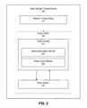
- FIG. 2is a block diagram of a video highlight tracking system for synchronizing rotations of a video capturing device (e.g., a mobile phone) on a rotary station with head rotations of a user, according to one embodiment.
- a video capturing devicee.g., a mobile phone
- FIG. 3is a flow diagram of a sensor data analysis module of a control module of a rotary station, according to one embodiment.
- FIG. 4is a flow diagram of a rotatory control module of a control module of a rotary station, according to one embodiment.
- FIG. 5is a flow chart illustrating a process for synchronizing rotations of a video capturing device (e.g., a mobile phone) mounted on a rotary station with head rotations of a user in connection with the user watching a sports event, according to one embodiment.
- a video capturing devicee.g., a mobile phone
- a solutionis provided to conveniently capture video highlights in a sports event by tracking head rotation movement of a user and synchronizing rotations of a video capturing device (e.g., a mobile phone) on a rotary station with the head rotation movement of the user.
- the userwears a tracking device (e.g., a rotation tracking device with one or more motion sensors) on a part of his/her body (e.g., head, a cap on his/her head) while watching the sports event.
- the tracking devicetracks head movement of the user (e.g., the rotation of the head in a horizontal plane).
- Motion data describing the head rotation movement of the useris transmitted to the rotary station, and processed to generate commands to drive the video capturing device (e.g., a mobile phone) mounted on the rotary station, to follow the head rotation movement of the user.
- the useruses a remote control to activate the video capturing device mounted on the rotary station to capture a video clip of the sports event, which is of interest to the user.
- the video capturing device mounted on the rotary stationkeeps following the view of the user during the sports event.
- the captured video of the sports eventis analyzed to identify one or more video highlights in the sports event.
- the useris free from constantly checking whether the video capturing device captures what he/she wants; instead, the user can focus on the sports event and enjoying it.
- digital contentgenerally refers to any machine-readable and machine-storable work.
- Digital contentcan include, for example, a combination of video and audio.
- digital contentcan be a still image.
- the digital contentwill be referred to as a “video” but no limitation on the type of digital content that can be analyzed are intended by this terminology.
- FIG. 1is a block diagram of an environment 100 for tracking head rotation movement of a user and synchronizing a video capturing device connected to a rotary station 130 with the head rotation movement of the user during a sports event, according to one embodiment.
- the embodiment illustrated in FIG. 1includes a user 102 wearing a head rotation tracking device 104 on his/her cap, a video capturing device 106 (e.g., a mobile phone of the user 102 ), a remote control 112 used by the user 102 to control the video capturing device 106 mounted on a rotary station 130 , which includes a control module 108 and a rotary system 110 .
- the user 102watches a sports event happening on a sports field 120 and controls the video capturing device 106 to capture one or more videos of the sports event.
- the functions performed by the various entities of FIG. 1may differ in different embodiments.
- Each of these entitiesincludes computing devices that may be physically remote from each other but which are communicatively coupled by a computer network.
- the computer networkis typically the Internet, but can be any network(s), including but not limited to a LAN, a MAN, a WAN, a mobile wired or wireless network, a cloud network, a private network, a virtual private network, a Bluetooth or Bluetooth Low Energy (BLE) wireless network, a point-to-point network, or a combination thereof.
- the entitiesuse custom and/or dedicated communications technologies to communicate.
- the user 102follows activities occurring on the sports field 120 .
- the user 102follows ball movement, player movement, and/or other actions occurring on the sports field 120 or in the near vicinity of the sports field 120 , such as on the sidelines of the sports field 120 .
- the user 102follows activities occurring on the sports field 120 by rotating his/her head left or right horizontally or moving his/her head up and down vertically (e.g., nodding).
- the head movement of the user 102 along a horizontal axis in a three-dimensional (3D) navigation systemis also referred to as a “yaw rotation” or “rotation.”
- the head movement of the user 102 along a vertical axis in the 3D navigation systemis also referred to as a “pitch.”
- yaw rotationof the head of the user 102 is analyzed herein with various embodiments, but no limitation on the type of head movement of the user that can be analyzed are intended.
- the user 102wears the head rotation tracking device 104 (also referred to as “tracking device 104 ”) on his/her cap, which tracks the head rotation movement of the user 102 in connection with watching the sports activities in the sports field 120 .
- the tracking device 104includes one or more small sized sensors, which can be worn on the user's head, baseball cap/hat, ear or other part of the user's head. The tracking device 104 is further described with reference to FIG. 2 .
- Head rotation data of the useris transmitted to the control module 108 of the rotary station 130 to control the rotary system 110 to follow the head rotation of the user 102 in a synchronized way.
- the user 102uses a remote control 112 to control the video capturing device 106 mounted on the rotary station 130 , such as turning on and off the video capturing device 106 during a video capturing process.
- the remote control 112is an electronic device used by the user 102 to perform functions such as, activating the video capturing device 106 to capture a video clip of a sports event happening on the sports field 120 .
- the remote control 112can have a user interface (UI), such as physical buttons, with which the user 102 may interact with the remote control 112 . Examples of the remote control 112 include conventional electronic remote control devices and modern consumer electronic devices such as smart watches.
- the remote control 112is communicatively coupled to the video capturing device 106 via a wire or wirelessly.
- the video capturing device 106is an electronic device used by the user 102 to capture digital content such as recoding a video clip of a sports event happening on the sports field 120 .
- the video capturing device 106is a mobile phone of the user 102 and includes an image capturing device and a transmitter for transmitting the captured digital content.
- the video capturing device 106can be, for example, a smart phone (e.g., the mobile phone of the user 102 ), a tablet, a digital single-lens reflex camera (DSLR), or any other suitable user device or computing device for capturing digital content.
- DSLRdigital single-lens reflex camera
- the various electronic devices that are capable of capturing digital contentare generally referred to as the video capturing device 106 .
- the video capturing device 106can be remotely triggered by the remote control 112 to capture digital content. In some configurations, the video capturing device 106 captures digital content for a predetermined period of time (e.g., 30 seconds). In other configurations, the video capturing device 106 begins capturing digital content when remotely triggered by the remote control 112 and ends capturing digital content when again remotely triggered by the remote control 112 . The video capturing device 106 can transmit the captured digital content to a cloud storage service. The video capturing device 106 is mounted on or otherwise connected to the rotary station 130 . In other embodiments, the video capturing device 106 and the mobile device of the user 102 can be two separate entities.
- the user 102uses a mobile device as a video capturing device to record video clips of a sports event and to consume digital content, such as the recorded video clips or highlights thereof.
- the user 102uses the mobile device to perform functions such as, consuming video clip(s) captured by the video capturing device 106 , and video highlights generated from the captured video clip(s).
- the mobile device of the user 102can be a smart phone, a tablet, or any other suitable user device or computing device for consuming video clip(s).
- the mobile device of the user 102provides a user interface, such as physical and/or on-screen buttons, with which the user 102 may interact with the mobile device to perform functions such as viewing, sharing, and/or otherwise consuming the video clip(s).
- the rotary station 130is configured to drive a video capturing device 106 (e.g., a mobile phone of the user 102 having a digital camera) mounted on the rotary station 130 to follow the head rotations of the user 102 based on commands generated from the head rotation data captured by the tracking device 104 .
- the rotary station 130has the control module 108 for receiving the head rotation data of the user 102 from the tracking device 104 , processing the head rotation data to generate rotary control data (e.g., rotary movement commands and instructions), and transmitting the rotary control data to the rotary system 110 .
- rotary control datae.g., rotary movement commands and instructions
- the rotary system 110receives the rotary control data, and executes one or more commands based on the instructions to rotate the video capturing device 106 mounted on the rotary station 130 in synchronization with the head rotation movement of the user 102 .
- the control module 108 and the rotary system 110are communicatively coupled to one another.
- the rotary station 130is further described with respect to FIG. 2 .
- FIG. 2is a block diagram of a video highlight tracking system 200 for synchronizing rotations of a video capturing device (e.g., the video capturing device 106 as shown in FIG. 1 ) on a rotary station (e.g., the rotary system 110 as shown in FIG. 1 ) with head rotations of a user (e.g., the user 102 as shown in FIG. 1 ), according to one embodiment.
- the video highlight tracking system 200(also referred to as “tracking system 200 ”) includes a rotation tracking device 210 (e.g., the head rotation tracking device 104 shown in FIG. 1 ) and a rotary station 220 (e.g., the rotary station 130 shown in FIG. 1 ).
- the rotary station 220includes a control module 222 (e.g., the control module 108 shown in FIG. 1 ) and a rotary system 224 (e.g., the rotary system 110 shown in FIG. 1 ).
- the control module 222includes a sensor data analysis module 204 (also referred to as “analysis module 204 ”) and rotary control module 206 .
- the tracking system 200may include additional and/or different modules, such as a remote control 112 used by the user 102 shown in FIG. 1 .
- the rotation tracking device 210tracks head movement of a user (e.g., the user 102 as shown in FIG. 1 ) in connection with the user watching an event (e.g., a sports game).
- the head movement of the userincludes yaw rotations of the head of the user (e.g., user rotating his/her head left and right along the horizontal view of the eyes of the user).
- Other embodimentsinclude pitch movement of the head of the user (e.g., user nodding up and down) or both yaw rotations and pitch movement of the head of the user.
- the rotation tracking device 210includes one or more small sized sensors, which can be worn on the user's head, baseball cap/hat, ear or other part of the head of the user.
- the sensors of the rotation tracking device 210tracks the head rotation of the user in connection with the user watching the sports game and transmit the captured head rotation data to the control module 222 via a transmitter.
- the rotation tracking device 210can include an inertial magnetic unit (IMU), which can include one or more sensors such as 3-axis electronic compasses, gyroscopes, 3-axis accelerometers, among other devices for capturing motion data representative of movement of the head of the user.
- IMUinertial magnetic unit
- the rotation tracking device 210continually tracks head rotations of a user in real-time in connection with the user watching sports game.
- the rotation tracking device 210transmits the head rotation data wirelessly via a Bluetooth module to the control module 222 of the rotary station 220 continually as the head rotation data is captured. In other configurations, the rotation tracking device 210 transmits the head rotation data to the control module 222 periodically (e.g., every 10 seconds).
- the rotary station 220includes the control module 222 and the rotary system 224 .
- the control module 222receives the head rotation data of a user from the rotation tracking device 210 , processes the head rotation data to generate rotary control data, and transmits the rotary control data to the rotary system 224 .
- the control module 222includes the sensor data analysis module 204 (also referred to as “analysis module 204 ”) and the rotary control module 206 .
- the analysis module 204receives the head rotation data of a user from the rotation tracking device 210 , processes the received head rotation data to generate analyzed head rotation data, and transmits the analyzed head rotation data to the rotary control module 206 .
- the rotary control module 206generates rotary control data based on the analyzed head rotation data, and transmits the rotary control data to the rotary system 224 .
- the rotary control dataincludes instructions for calibrating the rotary system 224 with the rotation tracking device 210 (e.g., by aligning the rotation of a rotary DC motor of the rotary system 224 with the head rotations of the user) and instructions for driving a motor gear of the rotary system 224 to rotate a video capturing device (not shown) mounted on the rotary system 224 to follow the head rotations of the user in a synchronized fashion.
- the analysis module 204 and the rotary control module 206are further described with reference to FIGS. 3 and 4 , respectively. In alternative configurations, different or additional components can be used.
- the analysis module 204is included as an entity of the rotation tracking device 210 and the rotary control module 206 is included as an entity of the rotary system 224 .
- the rotary system 224receives the rotary control data from the rotary control module 206 , and rotates a video capturing device mounted on the rotary system 224 to follow the head rotations of the user in a synchronized fashion.
- the rotary system 224transmits feedback data to the rotary control module 206 for adjusting the rotary control data for subsequent rotations to be performed by the rotary system 224 .
- the rotary system 224includes a transceiver (e.g., a Bluetooth module), a rotary DC motor with a motor gear and an encoder, a motor controller, a driver and one or more mechanical components.
- the transceiverreceives the rotary control data from the rotary control module 206 and transmits feedback data to the rotary control module 206 .
- the motor gearamplifies the rotary DC motor's torque to enable the motor to drive rotation of the rotary system 224 .
- the encodermeasures the rotation of the motor, where the measurement of the rotation of the motor can be used as feedback data for controlling subsequent rotations of the motor.
- the motor controllerinterprets the received instructions in the rotary control data and executes the one or more commands included in the instructions to control the position and speed of the rotary system 224 .
- the motor driverdrives the DC motor directly with controllable voltage for speed and position control of the rotary system 224 .
- One of the mechanical components of the rotary system 224includes an end effector to mount a video capturing device onto the rotary system 224 .
- the rotary system 224also includes two or more mechanical limit switches, which define a rotation region of the end effector.
- the rotation region of the end effectoris also referred to as the workspace of the end effector.
- a limit switchis triggered when the end effector reaches a boundary of the workspace of the end effect such that the motor of the rotary system 224 should stop rotating further.
- the encoderis used to measure the relative position of the end effector of the rotary system 224 .
- the two limit switchescan act as a baseline for the position of the end effector.
- the head rotation data analyzed by the analysis module 204is in a different coordinate system (e.g., geomagnetic coordinate system).
- a calibration processis performed (e.g., by the rotary control module 206 ) to align the rotation of the end effector with the head rotation of the user.
- the calibration processis further explained with reference to the calibration module 402 in FIG. 4 .
- FIG. 3is a flow diagram including the sensor data analysis module 204 of the control module 222 of the rotary station 220 , according to one embodiment.
- the analysis module 204receives head rotation data of a user from the rotation tracking device 210 , processes the received head rotation data to generate analyzed head rotation data, and outputs the analyzed head rotation data to the rotary control module 206 of the control module 222 .
- the analysis module 204includes a receiver 302 , a motion sensor database 304 , a filtering module 306 , and a motion processing module 308 .
- the filtering module 306can be included in the rotation tracking device 210 to filter noise motions from the tracked head rotation of the user.
- the receiver 302receives head rotation data 310 from the rotation tracking device 210 and stores the received head rotation data in the motion sensor database 304 .
- the motion sensor database 304further stores filtered head rotation data output from the filtering module 306 and/or analyzed head rotation data 320 output from the motion processing module 308 .
- the filtering module 306filters the received head rotation data to filter out noise motions in the received head rotation data to generate filtered head rotation data, and stores the filtered head rotation data at the motion sensor database 304 .
- the noise motions in the received head rotation data in connection with the user watching a sports eventrefer to the motion data, which are likely to cause jilter when used to control the rotary station 220 to capture a video clip of the sports event.
- the useris very likely to turn his/her head around randomly.
- the eye view of the usermay be off a sports field (e.g., the sports field 120 shown in FIG. 1 ) when he/she talks with friends nearby, or checking out activities of other spectators in the stands.
- the filtering module 306filters the received head rotation data by implementing one or more filtering techniques known to those of ordinary skill in the art, such as, low-pass filtering, high-pass filtering, complementary filtering, and Kalman filtering.
- the filtering module 306first selects a proper filter (e.g., a low-pass filter) based on the sampling rate of processing the received head rotation data including the noise motions.
- the filtering module 306filters the noise motions in the received head rotation data (e.g., using a fixed length sliding window buffer of a predetermined length to store the received head rotation data).
- the varying patterns of the head rotation data stored in the sliding window bufferare checked. If the received head rotation data varies linearly, the filtered head rotation data at the sampling point is the received head rotation data regressed by linear regression.
- the filtered head rotation data at the sampling pointis the median of the received head rotation data in the fixed length sliding window buffer.
- the filtering module 306is able to quickly and accurately filter the received head rotation data of the user.
- the filtering module 306compares the filtered head rotation data with a predetermined threshold value ⁇ , which can be set during the calibration process or set to a default value.
- the motion processing module 308processes the filtered head rotation data to generate analyzed head rotation data, and stores the analyzed head rotation data at the motion sensor database 304 .
- the analyzed head rotation dataincludes a data structure, which accurately describes the head movement of the user being tracked by the rotation tracking device 210 , associated timing information and any other information, which can be used to calibrate and control the rotation of the rotary system 224 (e.g., information describing the various sensors of the head rotation tracking device 210 ).
- the analyzed head rotation datafurther includes a rotation tracking device direction relative to a rotation tracking device direction in the calibration process in a horizontal plane. The rotation tracking device direction in the horizontal plane is also referred to as yaw.
- FIG. 4is a flow diagram of the rotary control module 206 of the control module 222 of the rotary station 220 , according to one embodiment.
- the rotary control module 206receives analyzed head rotation data 410 from the analysis module 204 , generates rotary control data based on the received analyzed head rotation data, and controls the rotary system 224 to rotate in synchronization with the head rotations of the user.
- the rotary control module 206includes a calibration module 402 , a transformation module 404 , a feedback control module 406 , and a transceiver 408 . In alternative configurations, different or additional components can be used.
- the calibration module 402calibrates the rotary system 224 with the rotation tracking device 210 , which generates the head rotation data of a user (e.g., the user 102 ) wearing the rotation tracking device 210 .
- the rotary system 224has a calibration button for initiating and stopping a calibration process, and a mark line to indicate which direction the user should face his/her head during calibration.
- the head rotation being tracked by the rotation tracking device 210can be in a coordinate system different from the coordinate system used by the rotary system 224 (e.g., geomagnetic coordinate system vs. rotary station coordinate system).
- the tracking system 200initiates, the head rotation measured in the geomagnetic coordinate needs to be aligned with the rotation of the end effector of the rotary system 224 .
- the calibration module 402performs a calibration process as follows: (1) the calibration module 402 instructs the rotation tracking device 210 to point its rotation tracking sensor to the middle of a sports field (e.g., the sports field 120 shown in FIG. 1 ) and keep it still for a predefined period of time (e.g., 10 seconds); (2) the calibration module 402 instructs the end effector to rotate towards the first limit switch at a fixed rotation speed until it triggers the first limit switch; (3) the calibration module 402 instructs the end effector to rotate towards the second limit switch at a fixed rotation speed until it triggers the second limit switch; and (4) the calibration module 402 instructs the end effector to rotate towards the middle point between the first limit switch and the second limit switch and stays there for a predetermined of period of time.
- a sports fielde.g., the sports field 120 shown in FIG. 1
- a predefined period of timee.g. 10 seconds
- the transformation module 404receives the analyzed head rotation data 410 from the analysis module 204 , and generates rotary control data based on the received head rotation data.
- the rotary control dataincludes instructions or commands, which instruct the rotary system 224 to rotate its end effector in synchronization with the head rotation of the user.
- the rotary system 224synchronously follows the head rotations of the user. For example, as the user rotates his/her head ⁇ degrees to the left side, the rotary system 224 will also rotate ⁇ degrees to the left side.
- the transformation module 404generates rotary control data in connection with the rotation region boundaries of the end effector of the rotary system 224 . For example, the transformation module 404 determines whether rotating a current angle of the end effector by following corresponding head rotation would keep the video capturing device mounted by the end effector to the rotary system 224 within the rotation region boundaries of the end effector. If the rotation by the rotary system 224 is beyond the rotation region boundaries, the transformation module 404 generates instructions to instruct the rotary system 224 to stop rotating and to record the actual rotation performed by the rotary system 224 for feedback purposes.
- the transformation module 404Upon receiving the feedback data from the feedback control module 406 , the transformation module 404 updates the rotation control data for subsequent rotations by the rotary system 224 .
- the rotation command for a current rotation being performed by the rotary system 224can be 20 degrees to the left side, but the rotary system 224 can have rotated only 15 degrees to the left side.
- the rotary system 224provides the current rotation (i.e., 15 degrees to the left) to the transformation module 404 through the feedback control module 406 .
- the transformation module 404adjusts the rotation control data for next rotation point based on the actual rotation performed for the current point.
- the adjusted rotation command for the next rotation pointis 15 degrees to the left side (assuming the rotary system 224 is still within the rotation region boundary when executing the rotation command for the next rotation point).
- the feedback control module 404measures the actual rotation performed by the rotary system 224 for each rotation point and provides the actual rotation as feedback data for each rotation point to the transformation module 404 for rotation control data adjustment. Alternatively, the feedback control module 404 calculates a difference between the actual rotation performed by the rotary system 224 and expected rotation (i.e., the corresponding head rotation of the user) for each rotation point provides the difference as the feedback data to the transformation module 404 for rotation control data adjustment.
- the transceiver 408transmits the rotary control data 430 generated by the transformation module 404 to the rotary system 224 .
- the transceiver 708receives feedback data 420 from the feedback control module 406 and transmits the feedback data to the transformation module 404 for adjusting rotary control data for subsequent rotations.
- FIG. 5is a flow chart illustrating a process for synchronizing rotations of a video capturing device (e.g., the video capturing device 106 shown in FIG. 1 ) mounted on a rotary station (e.g., the rotary station 130 shown in FIG. 1 ) with head rotation movement of a user (e.g., the user 102 shown in FIG. 1 ) in connection with the user watching a sports event, according to one embodiment.
- the video highlight tracking system 200calibrates 502 the rotation tracking device 210 worn by the user with the rotary system 224 .
- the calibration processsets the two boundaries defining the workspace of an end effector of the rotary system 224 .
- the end effectormounts a video capturing device (e.g., a digital camera) onto the rotary system 224 for capturing a video clip of the sports event.
- the rotation tracking device 210tracks the head movement of the user (e.g., yaw rotations) during the viewing of the sports event.
- the video highlight tracking system 200receives 504 the head rotation data from the rotation tracking device 210 and filters 506 noise motions (e.g., motions from the user chewing gum, shaking his/her legs while watching the sports event) from the head rotation data (e.g., by using a fixed length sliding window buffer).
- the video highlight tracking system 200generates 508 the analyzed head rotation data, which accurately describes the head movement of the user in a data structure.
- the video highlight tracking system 200generates 510 corresponding rotary control data based on the analyzed head rotation data.
- the rotary control dataincludes instructions 512 , when executed by the rotary system 224 , to cause the rotary system 224 to rotate the video capturing device mounted onto the rotary system to synchronously follow the head rotations of the user.
- the solution provided by the embodiments of the disclosureenables a user to enjoy a sports event while being capable of conveniently recording one or more video clips of the event.
- the useruses a remote controller to activate the video capturing device mounted on the rotary station to capture a video clip of the sports event, which is of interest to the user.
- the rotation tracking devicetracking the head movement of the user
- the video capturing device mounted on the rotary stationkeeps following the view of the user during the whole sports event.
- the captured video of the sports eventis analyzed to identify one or more video highlights in the sports event.
- the useris free from constantly checking whether the video capturing device captures what he/she wants; instead, the user can focus on the sports event and enjoy it.
- a software moduleis implemented with a computer program product comprising a computer-readable medium containing computer program code, which can be executed by a computer processor for performing any or all of the steps, operations, or processes described.
- Embodiments of the disclosedmay also relate to an apparatus for performing the operations herein.
- This apparatusmay be specially constructed for the required purposes, and/or it may comprise a general-purpose computing device selectively activated or reconfigured by a computer program stored in the computer.
- a computer programmay be stored in a non-transitory, tangible computer readable storage medium, or any type of media suitable for storing electronic instructions, which may be coupled to a computer system bus.
- any computing systems referred to in the specificationmay include a single processor or may be architectures employing multiple processor designs for increased computing capability.
- Embodiments of the disclosedmay also relate to a product that is produced by a computing process described herein.
- a productmay comprise information resulting from a computing process, where the information is stored on a non-transitory, tangible computer readable storage medium and may include any embodiment of a computer program product or other data combination described herein.
Landscapes
- Engineering & Computer Science (AREA)
- Theoretical Computer Science (AREA)
- Multimedia (AREA)
- Physics & Mathematics (AREA)
- General Physics & Mathematics (AREA)
- General Engineering & Computer Science (AREA)
- Human Computer Interaction (AREA)
- Signal Processing (AREA)
- Health & Medical Sciences (AREA)
- General Health & Medical Sciences (AREA)
- Software Systems (AREA)
- Computational Linguistics (AREA)
- Oral & Maxillofacial Surgery (AREA)
- Computer Vision & Pattern Recognition (AREA)
- Psychiatry (AREA)
- Social Psychology (AREA)
- User Interface Of Digital Computer (AREA)
- Accessories Of Cameras (AREA)
- Studio Devices (AREA)
- Image Analysis (AREA)
Abstract
Description
Claims (24)
Priority Applications (6)
| Application Number | Priority Date | Filing Date | Title |
|---|---|---|---|
| US15/139,683US10097745B2 (en) | 2016-04-27 | 2016-04-27 | Head rotation tracking device for video highlights identification |
| JP2018556334AJP7026638B2 (en) | 2016-04-27 | 2016-09-29 | Head rotation tracking device for recognizing video highlights |
| CN201680085019.8ACN109155818B (en) | 2016-04-27 | 2016-09-29 | Head rotation tracking device for video highlight recognition |
| KR1020187034285AKR102107923B1 (en) | 2016-04-27 | 2016-09-29 | Head rotation tracking device to identify video highlights |
| PCT/US2016/054540WO2017189036A1 (en) | 2016-04-27 | 2016-09-29 | Head rotation tracking device for video highlights identification |
| EP16900764.8AEP3449623A4 (en) | 2016-04-27 | 2016-09-29 | HEAD ROTATION TRACKING DEVICE FOR IDENTIFYING STRONG VIDEO MOMENTS |
Applications Claiming Priority (1)
| Application Number | Priority Date | Filing Date | Title |
|---|---|---|---|
| US15/139,683US10097745B2 (en) | 2016-04-27 | 2016-04-27 | Head rotation tracking device for video highlights identification |
Publications (2)
| Publication Number | Publication Date |
|---|---|
| US20170318214A1 US20170318214A1 (en) | 2017-11-02 |
| US10097745B2true US10097745B2 (en) | 2018-10-09 |
Family
ID=60157047
Family Applications (1)
| Application Number | Title | Priority Date | Filing Date |
|---|---|---|---|
| US15/139,683Active2036-12-08US10097745B2 (en) | 2016-04-27 | 2016-04-27 | Head rotation tracking device for video highlights identification |
Country Status (6)
| Country | Link |
|---|---|
| US (1) | US10097745B2 (en) |
| EP (1) | EP3449623A4 (en) |
| JP (1) | JP7026638B2 (en) |
| KR (1) | KR102107923B1 (en) |
| CN (1) | CN109155818B (en) |
| WO (1) | WO2017189036A1 (en) |
Families Citing this family (2)
| Publication number | Priority date | Publication date | Assignee | Title |
|---|---|---|---|---|
| US11166051B1 (en)* | 2018-08-31 | 2021-11-02 | Amazon Technologies, Inc. | Automatically generating content streams based on subscription criteria |
| US11095923B1 (en) | 2018-08-31 | 2021-08-17 | Amazon Technologies, Inc. | Automatically processing inputs to generate content streams |
Citations (36)
| Publication number | Priority date | Publication date | Assignee | Title |
|---|---|---|---|---|
| US5610590A (en) | 1995-05-18 | 1997-03-11 | The United States Of America As Represented By The Secretary Of The Army | Motion sensor |
| US5819206A (en) | 1994-01-21 | 1998-10-06 | Crossbow Technology, Inc. | Method and apparatus for determining position and orientation of a moveable object using accelerometers |
| US6133944A (en) | 1995-12-18 | 2000-10-17 | Telcordia Technologies, Inc. | Head mounted displays linked to networked electronic panning cameras |
| US6224493B1 (en) | 1999-05-12 | 2001-05-01 | Callaway Golf Company | Instrumented golf club system and method of use |
| US20050032582A1 (en) | 2002-12-19 | 2005-02-10 | Satayan Mahajan | Method and apparatus for determining orientation and position of a moveable object |
| US20050272516A1 (en) | 2004-06-07 | 2005-12-08 | William Gobush | Launch monitor |
| US20060025229A1 (en) | 2003-12-19 | 2006-02-02 | Satayan Mahajan | Motion tracking and analysis apparatus and method and system implementations thereof |
| US20060119576A1 (en)* | 2004-12-06 | 2006-06-08 | Naturalpoint, Inc. | Systems and methods for using a movable object to control a computer |
| US20060166738A1 (en) | 2003-09-08 | 2006-07-27 | Smartswing, Inc. | Method and system for golf swing analysis and training for putters |
| US20080085778A1 (en) | 2006-10-07 | 2008-04-10 | Dugan Brian M | Systems and methods for measuring and/or analyzing swing information |
| US20080136916A1 (en)* | 2005-01-26 | 2008-06-12 | Robin Quincey Wolff | Eye tracker/head tracker/camera tracker controlled camera/weapon positioner control system |
| US20090048044A1 (en) | 2007-08-17 | 2009-02-19 | Adidas International Marketing B.V. | Sports electronic training system with sport ball, and applications thereof |
| US20100103269A1 (en) | 2008-10-23 | 2010-04-29 | Microsoft Corporation | Determining orientation in an external reference frame |
| US20100144414A1 (en) | 2008-12-04 | 2010-06-10 | Home Box Office, Inc. | System and method for gathering and analyzing objective motion data |
| US20100323794A1 (en) | 2009-06-18 | 2010-12-23 | Yui-Zhang Su | Sensor based human motion detection gaming with false positive detection |
| US7978081B2 (en) | 2006-01-09 | 2011-07-12 | Applied Technology Holdings, Inc. | Apparatus, systems, and methods for communicating biometric and biomechanical information |
| KR20110102593A (en) | 2010-03-11 | 2011-09-19 | 이열 | Selfie camera |
| US8109816B1 (en) | 2007-05-31 | 2012-02-07 | Yale University | Method and apparatus for measurement and analysis of a golf swing |
| US8135183B2 (en)* | 2003-05-30 | 2012-03-13 | Microsoft Corporation | Head pose assessment methods and systems |
| US8409024B2 (en) | 2001-09-12 | 2013-04-02 | Pillar Vision, Inc. | Trajectory detection and feedback system for golf |
| US8409025B2 (en) | 2004-03-23 | 2013-04-02 | Nike Inc. | System for determining performance characteristics of a golf swing |
| US8449402B2 (en) | 2008-03-22 | 2013-05-28 | Richard Jaekel | Device and method for monitoring the striking accuracy and the swing movement of a golf club |
| US8523696B2 (en) | 2009-06-17 | 2013-09-03 | Sri Sports Limited | Golf swing analysis method using attachable acceleration sensors |
| WO2013158050A1 (en) | 2012-04-16 | 2013-10-24 | Airnamics, Napredni Mehatronski Sistemi D.O.O. | Stabilization control system for flying or stationary platforms |
| KR20130124422A (en) | 2012-05-04 | 2013-11-13 | (주)컨벡스 | Panning and tilting apparatus and wireless control system with the same for photographing |
| US8589114B2 (en) | 2008-08-19 | 2013-11-19 | Angelo Gregory Papadourakis | Motion capture and analysis |
| US8593286B2 (en) | 2010-12-01 | 2013-11-26 | At&T Intellectual Property I, L.P. | System and method for wireless monitoring of sports activities |
| US20140313295A1 (en)* | 2013-04-21 | 2014-10-23 | Zspace, Inc. | Non-linear Navigation of a Three Dimensional Stereoscopic Display |
| US8903521B2 (en) | 2010-08-26 | 2014-12-02 | Blast Motion Inc. | Motion capture element |
| US8905855B2 (en) | 2010-08-26 | 2014-12-09 | Blast Motion Inc. | System and method for utilizing motion capture data |
| US8941723B2 (en) | 2010-08-26 | 2015-01-27 | Blast Motion Inc. | Portable wireless mobile device motion capture and analysis system and method |
| US8944928B2 (en) | 2010-08-26 | 2015-02-03 | Blast Motion Inc. | Virtual reality system for viewing current and previously stored or calculated motion data |
| US8956238B2 (en) | 2011-04-28 | 2015-02-17 | Nike, Inc. | Golf clubs and golf club heads |
| US9039527B2 (en) | 2010-08-26 | 2015-05-26 | Blast Motion Inc. | Broadcasting method for broadcasting images with augmented motion data |
| US9399523B2 (en)* | 2011-06-30 | 2016-07-26 | General Electric Company | Method of operating a synthetic vision system in an aircraft |
| US20160335483A1 (en)* | 2014-11-13 | 2016-11-17 | Intel Corporation | Facial liveness detection in image biometrics |
Family Cites Families (14)
| Publication number | Priority date | Publication date | Assignee | Title |
|---|---|---|---|---|
| JPH0486906A (en)* | 1990-07-31 | 1992-03-19 | Suzuki Motor Corp | Remote controller |
| WO1994017636A1 (en)* | 1993-01-29 | 1994-08-04 | Bell Communications Research, Inc. | Automatic tracking camera control system |
| JPH07199281A (en)* | 1993-12-30 | 1995-08-04 | Canon Inc | Camera system |
| JPH0937137A (en)* | 1995-07-25 | 1997-02-07 | Minolta Co Ltd | Mobile stereoscopic camera apparatus |
| EP1168830A1 (en)* | 2000-06-30 | 2002-01-02 | Wells & Verne Investments Ltd | Computer aided image capturing system |
| JP2002135641A (en) | 2000-10-27 | 2002-05-10 | Nippon Telegr & Teleph Corp <Ntt> | Viewpoint / line-of-sight free-moving camera system |
| JP4320572B2 (en) | 2003-07-11 | 2009-08-26 | ソニー株式会社 | Signal processing apparatus and method, recording medium, and program |
| US7379664B2 (en)* | 2005-07-26 | 2008-05-27 | Tinkers & Chance | Remote view and controller for a camera |
| CN104380749A (en) | 2012-04-16 | 2015-02-25 | 诺基亚公司 | Method and apparatus for video encoding |
| US9609290B2 (en) | 2013-07-10 | 2017-03-28 | Subc Control Limited | Telepresence method and system for supporting out of range motion by aligning remote camera with user's head |
| US9336440B2 (en) | 2013-11-25 | 2016-05-10 | Qualcomm Incorporated | Power efficient use of a depth sensor on a mobile device |
| WO2015143067A1 (en)* | 2014-03-19 | 2015-09-24 | Intuitive Surgical Operations, Inc. | Medical devices, systems, and methods using eye gaze tracking |
| KR20160133328A (en)* | 2015-05-12 | 2016-11-22 | 삼성전자주식회사 | Remote control method and device using wearable device |
| CN205123878U (en)* | 2015-11-30 | 2016-03-30 | 吕衍荣 | Portable phone automatic tracking is from taking photograph ware |
- 2016
- 2016-04-27USUS15/139,683patent/US10097745B2/enactiveActive
- 2016-09-29WOPCT/US2016/054540patent/WO2017189036A1/ennot_activeCeased
- 2016-09-29KRKR1020187034285Apatent/KR102107923B1/ennot_activeExpired - Fee Related
- 2016-09-29JPJP2018556334Apatent/JP7026638B2/enactiveActive
- 2016-09-29EPEP16900764.8Apatent/EP3449623A4/ennot_activeWithdrawn
- 2016-09-29CNCN201680085019.8Apatent/CN109155818B/enactiveActive
Patent Citations (38)
| Publication number | Priority date | Publication date | Assignee | Title |
|---|---|---|---|---|
| US5819206A (en) | 1994-01-21 | 1998-10-06 | Crossbow Technology, Inc. | Method and apparatus for determining position and orientation of a moveable object using accelerometers |
| US5610590A (en) | 1995-05-18 | 1997-03-11 | The United States Of America As Represented By The Secretary Of The Army | Motion sensor |
| US6133944A (en) | 1995-12-18 | 2000-10-17 | Telcordia Technologies, Inc. | Head mounted displays linked to networked electronic panning cameras |
| US6224493B1 (en) | 1999-05-12 | 2001-05-01 | Callaway Golf Company | Instrumented golf club system and method of use |
| US8409024B2 (en) | 2001-09-12 | 2013-04-02 | Pillar Vision, Inc. | Trajectory detection and feedback system for golf |
| US20050032582A1 (en) | 2002-12-19 | 2005-02-10 | Satayan Mahajan | Method and apparatus for determining orientation and position of a moveable object |
| US8135183B2 (en)* | 2003-05-30 | 2012-03-13 | Microsoft Corporation | Head pose assessment methods and systems |
| US20060166738A1 (en) | 2003-09-08 | 2006-07-27 | Smartswing, Inc. | Method and system for golf swing analysis and training for putters |
| US20060025229A1 (en) | 2003-12-19 | 2006-02-02 | Satayan Mahajan | Motion tracking and analysis apparatus and method and system implementations thereof |
| US8409025B2 (en) | 2004-03-23 | 2013-04-02 | Nike Inc. | System for determining performance characteristics of a golf swing |
| US20050272516A1 (en) | 2004-06-07 | 2005-12-08 | William Gobush | Launch monitor |
| US20060119576A1 (en)* | 2004-12-06 | 2006-06-08 | Naturalpoint, Inc. | Systems and methods for using a movable object to control a computer |
| US20080136916A1 (en)* | 2005-01-26 | 2008-06-12 | Robin Quincey Wolff | Eye tracker/head tracker/camera tracker controlled camera/weapon positioner control system |
| US7978081B2 (en) | 2006-01-09 | 2011-07-12 | Applied Technology Holdings, Inc. | Apparatus, systems, and methods for communicating biometric and biomechanical information |
| US20080085778A1 (en) | 2006-10-07 | 2008-04-10 | Dugan Brian M | Systems and methods for measuring and/or analyzing swing information |
| US8337335B2 (en) | 2006-10-07 | 2012-12-25 | Dugan Brian M | Systems and methods for measuring and/or analyzing swing information |
| US8109816B1 (en) | 2007-05-31 | 2012-02-07 | Yale University | Method and apparatus for measurement and analysis of a golf swing |
| US20090048044A1 (en) | 2007-08-17 | 2009-02-19 | Adidas International Marketing B.V. | Sports electronic training system with sport ball, and applications thereof |
| US8449402B2 (en) | 2008-03-22 | 2013-05-28 | Richard Jaekel | Device and method for monitoring the striking accuracy and the swing movement of a golf club |
| US8589114B2 (en) | 2008-08-19 | 2013-11-19 | Angelo Gregory Papadourakis | Motion capture and analysis |
| US8282487B2 (en) | 2008-10-23 | 2012-10-09 | Microsoft Corporation | Determining orientation in an external reference frame |
| US20100103269A1 (en) | 2008-10-23 | 2010-04-29 | Microsoft Corporation | Determining orientation in an external reference frame |
| US20100144414A1 (en) | 2008-12-04 | 2010-06-10 | Home Box Office, Inc. | System and method for gathering and analyzing objective motion data |
| US8523696B2 (en) | 2009-06-17 | 2013-09-03 | Sri Sports Limited | Golf swing analysis method using attachable acceleration sensors |
| US20100323794A1 (en) | 2009-06-18 | 2010-12-23 | Yui-Zhang Su | Sensor based human motion detection gaming with false positive detection |
| KR20110102593A (en) | 2010-03-11 | 2011-09-19 | 이열 | Selfie camera |
| US8903521B2 (en) | 2010-08-26 | 2014-12-02 | Blast Motion Inc. | Motion capture element |
| US8905855B2 (en) | 2010-08-26 | 2014-12-09 | Blast Motion Inc. | System and method for utilizing motion capture data |
| US8941723B2 (en) | 2010-08-26 | 2015-01-27 | Blast Motion Inc. | Portable wireless mobile device motion capture and analysis system and method |
| US8944928B2 (en) | 2010-08-26 | 2015-02-03 | Blast Motion Inc. | Virtual reality system for viewing current and previously stored or calculated motion data |
| US9039527B2 (en) | 2010-08-26 | 2015-05-26 | Blast Motion Inc. | Broadcasting method for broadcasting images with augmented motion data |
| US8593286B2 (en) | 2010-12-01 | 2013-11-26 | At&T Intellectual Property I, L.P. | System and method for wireless monitoring of sports activities |
| US8956238B2 (en) | 2011-04-28 | 2015-02-17 | Nike, Inc. | Golf clubs and golf club heads |
| US9399523B2 (en)* | 2011-06-30 | 2016-07-26 | General Electric Company | Method of operating a synthetic vision system in an aircraft |
| WO2013158050A1 (en) | 2012-04-16 | 2013-10-24 | Airnamics, Napredni Mehatronski Sistemi D.O.O. | Stabilization control system for flying or stationary platforms |
| KR20130124422A (en) | 2012-05-04 | 2013-11-13 | (주)컨벡스 | Panning and tilting apparatus and wireless control system with the same for photographing |
| US20140313295A1 (en)* | 2013-04-21 | 2014-10-23 | Zspace, Inc. | Non-linear Navigation of a Three Dimensional Stereoscopic Display |
| US20160335483A1 (en)* | 2014-11-13 | 2016-11-17 | Intel Corporation | Facial liveness detection in image biometrics |
Non-Patent Citations (52)
| Title |
|---|
| Affidavit of Christopher Butler dated Feb. 19, 2016 regarding "Concept2: Training," 5 pages, [Archived on web.archive.org on Feb. 5, 2009] Can be Retrieved at <URL:http://web.archive.org/web/20090205092657/http://concept2.com/us/training/default.asp>. |
| Affidavit of Christopher Butler dated Jan. 15, 2016 regarding "Rinton Press-Publisher in Science and Technology," 6 pages, [Archived on web.archive.org on Jan. 3, 2007] Can be Retrieved at <URL:https://web.archive.org/web/20070103234656/http://rintonspress.com/journals/jmmonline.html>. |
| Affidavit of Christopher Butler dated Jan. 15, 2016 regarding "Rinton Press—Publisher in Science and Technology," 6 pages, [Archived on web.archive.org on Jan. 3, 2007] Can be Retrieved at <URL:https://web.archive.org/web/20070103234656/http://rintonspress.com/journals/jmmonline.html>. |
| Affidavit of Christopher Butler dated Jan. 25, 2016 regarding "SmartWing Intelligent Clubs," 46 Pages, [Archived on web.archive.org on Apr. 11, 2006] Can be Retrieved at <URL:https://web.archive.org/web/20060411113841/http://www.smartswinggolf.com/site/>. |
| Allen, R., "Wireless Sensor Architecture Uses Bluetooth Standard" Electronic Design, Aug. 7, 2000, 5 Pages, Can be retrieved from <URL:http://electronicdesign.com/communications/wireless-sensor-architecture-uses-bluetooth-standard>. |
| Arfwedson, H., et al., "Ericsson's Bluetooth Modules," Ericsson Review, 1999, No. 4, pp. 198-205, <URL:http://www.ericsson.com/ericsson/corpinfo/Pub.s/review/1999_04/files/19990404.pdf>. |
| Bishop, R., "LabVIEW 8 Student Edition," 2007, 12 pages, Pearson Prentice-Hall, Upper Saddle River, NJ. |
| Certified File History of U.S. Pat. No. 8,905,855, Feb. 2, 2016, 709 Pages. |
| Certified File History of U.S. Pat. No. 8,941,723, Feb. 2, 2016, 929 Pages. |
| Certified File History of U.S. Pat. No. 8,944,928, Feb. 2, 2016, 647 Pages. |
| Certified File History of U.S. Pat. No. 9,039,527, Feb. 2, 2016, 1047 Pages. |
| Claim Limitation Reference Nos. '521 Petition, Feb. 24, 2016, 4 pages. |
| Claim Limitation Reference Nos. '527 Petition, Feb. 24, 2016, 4 pages. |
| Claim Limitation Reference Nos. '723 Petition, Feb. 24, 2016, 5 pages. |
| Claim Limitation Reference Nos. '855 Petition, Feb. 24, 2016, 6 pages. |
| Claim Limitation Reference Nos. '928 Petition, Feb. 24, 2016, 3 pages. |
| Curriculum Vitae of Dr. Steven M. Nesbit, Feb. 24, 2016, 10 pages. |
| Declaration of Dr. Steven M. Nesbit, U.S. Pat. No. 8,903,521, Feb. 24, 2016, 250 Pages. |
| Declaration of Dr. Steven M. Nesbit, U.S. Pat. No. 8,905,855, Feb. 24, 2016, 235 Pages. |
| Declaration of Dr. Steven M. Nesbit, U.S. Pat. No. 8,941,723, Feb. 24, 2016, 219 Pages. |
| Declaration of Dr. Steven M. Nesbit, U.S. Pat. No. 8,944,928, Feb. 24, 2016, 195 Pages. |
| Declaration of Dr. Steven M. Nesbit, U.S. Pat. No. 9,039,527, Feb. 24, 2016, 227 Pages. |
| File History of U.S. Pat. No. 8,903,521, 2015, 406 pages. |
| First Annual "Better Golf Through Technology," Better Golf Through Technology Conference, Feb. 17-18, 2006, 1 page, [Archived on web.archive.org on Mar. 14, 2006] Can be Retrieved at <URL: https://web.archive.org/web/20060314063211/http:/www.bettergolfthroughtechnology.com/>. |
| Home Page For "Concept2: Training," 1 page, [Archived on web.archive.org on Feb. 5, 2009] Can be Retrieved at <URL:http://web.archive.org/web/20090205092657/http://concept2.com/us/training/default.asp>. |
| Home Page For Expresso.com, 2 pages, [Archived on web.archive.org on Apr. 29, 2009] Can be Retrieved at <URL:http://web.archive.org/web/20090426023759/http://expresso.com/products_services/index.html#>. |
| Honan, M., "Apple unveils iPhone," Macworld, Jan. 89, 2007, 4 Pages, can be retrieved at <URL:http://www.macworld.corn/article/1054769/iphone.html>. |
| InvenSense, "InvenSense™ Unveils World's 1st IMU Solution for Consumer Appl.s" InvenSense, Apr. 6, 2010, 2 pages. |
| Kalia, M., et al., "Efficient Policies for Increasing Capacity in Bluetooth: An Indoor Pico-Cellular Wireless System," IBM India Research Laboratory, 2000, 5 pages. |
| Linx Technologies, "HP3 Series Transmitter Module Data Guide" Linx Technologies, Inc., 2008, Revised Jul. 27, 2011, 13 Pages. |
| Otto, C., et al., "System Architecture of a Wireless Body Area Sensor Network for Ubiquitous Health Monitoring," Journal of Mobile Multimedia, 2006, pp. 307-326, vol. 1, No. 4. |
| PCT International Search Report and Written Opinion for PCT/US2016/054540, dated Jan. 17, 2017, 14 Pages. |
| Rao, R., et al., "Demand-based Bluetooth Scheduling," Pennsyvania State University, Sep. 27, 2001, 13 pages, Can be retrieved at <URL:http://www.cse.psu.edu/˜gik2/papers/Bluetooth1.doc>. |
| Roving Networks, "Blue Sentry RN-8005-CB Data Sheet," 2009, 1 page. |
| Sanders, K., "Japanese Wii Price, Release Date Revealed," IGN US, Sep. 13, 2006, 1 Page, can be retrieved at <URL:http://www.ign.com/articles/2006/09/14/japanese-wii-price-release-date-revealed>. |
| Smartswing, "SmartSwing Introduces Affordable Intelligent Golf Club," Press Release, Jul. 19, 2005, 2 pages, [Archived on web.archive.org on Jun. 13, 2006] Can be Retrieved at <URL:https://web.archive.org/web/20060613114451/http://www.smartswinggolf.com/site/news/pr_2006_jan_23_aus.html>. |
| Solid State Technology, "MEMS Enable Smart Golf Clubs," Extension Media, Jan. 6, 2005, 3 pages,[Archived on web.archive.org on Jan. 15, 2016] Can be Retrieved at <URL:https://web.archive.org/web/20160115202844/http://electroiq.com/blog/2005/01/mems-enable-smart-golf-clubs/>. |
| Takahashi, D., "Facebook, Twitter, Last.fm coming to Xbox Live this fall" Venture Beat, Jun. 1, 2009, 5 Pages, Can be retrieved from <URL:http://venturebeat.com/2009/06/01/facebook-coming-to-xbox-live-as-microsoft-beefs-up-other-entertainment-on-xbox-360/>. |
| The iClub Product Brochure, 2001-2005, 2 pages. |
| The iClub System™ "iClub.net- Products ICLUBe," Fortescue Corp. 2001-2005, 1 Page, [Archived on web.archive.org on Apr. 14, 2005] Can be Retrieved at <URL: https://web.archive.org/web/20050414233840/http://www.iclub.net/products-iclube.html. |
| The iClub System™ "iClub.net-Contact," Fortescue Corp. 2001-2005, 1 Page, [Archived on web.archive.org on Apr. 9, 2005] Can be Retrieved at <URL:https://web.archive.org/web/20050409111624/http://www.iclub.net/contact.html>. |
| The iClub System™ "iClub.net-Products ICLUB (Full Swing)," Fortescue Corp. 2001-2005, 1 Page, [Archived on web.archive.org on Apr. 14, 2005] Can be Retrieved at <URL:https://web.archive.org/web/20050414233828/http://www.iclub.net/products-iclub.html. |
| The iClub System™ "iClub.net-Products," Fortescue Corp. 2001-2005, 1 Page, [Archived on web.archive.org on Jul. 10, 2005] Can be Retrieved at <URL:https://web.archive.org/web/20050710075533/http://www.iclub.net/products-iclub.html. |
| The iClub System™ "iClub.net— Products ICLUBe," Fortescue Corp. 2001-2005, 1 Page, [Archived on web.archive.org on Apr. 14, 2005] Can be Retrieved at <URL: https://web.archive.org/web/20050414233840/http://www.iclub.net/products-iclube.html. |
| The iClub System™ "iClub.net—Contact," Fortescue Corp. 2001-2005, 1 Page, [Archived on web.archive.org on Apr. 9, 2005] Can be Retrieved at <URL:https://web.archive.org/web/20050409111624/http://www.iclub.net/contact.html>. |
| The iClub System™ "iClub.net—Products ICLUB (Full Swing)," Fortescue Corp. 2001-2005, 1 Page, [Archived on web.archive.org on Apr. 14, 2005] Can be Retrieved at <URL:https://web.archive.org/web/20050414233828/http://www.iclub.net/products-iclub.html. |
| The iClub System™ "iClub.net—Products," Fortescue Corp. 2001-2005, 1 Page, [Archived on web.archive.org on Jul. 10, 2005] Can be Retrieved at <URL:https://web.archive.org/web/20050710075533/http://www.iclub.net/products-iclub.html. |
| Tuite, D., "Motion-Sensing MEMS Gyros and Accelerometers Are Everywhere," Electronic Design, Jul., 9, 2009, 6 pages, Can be retrieved from <URL:http://electronicdesign.com/analog/motion-sensing-mems-gyros-and-accelerometers-are-everywhere>. |
| Webpage for zigbees.com, 4 Pages, [online] [retrieved on Mar. 14, 2016] Can be retrieved at <URL:http://www.zigbees.com/h_start.htm>. |
| Webster's New College Dictionary, Definition for "Virtual Reality," (3rd ed. 2008), 3 Pages. |
| Wheeler, A, et al., "Introduction to Engineering Experimentation," 2nd Edition, 2004, Chapter 4, 10 pages, Pearson-Prentice-Hall, Upper Saddle River, NJ. |
| Wheeler, A, et al., "Introduction to Engineering Experimentation," 2nd Edition, 2004, Chapter 4, 10 pages, Pearson—Prentice-Hall, Upper Saddle River, NJ. |
Also Published As
| Publication number | Publication date |
|---|---|
| JP2019515341A (en) | 2019-06-06 |
| KR20190008257A (en) | 2019-01-23 |
| CN109155818A (en) | 2019-01-04 |
| KR102107923B1 (en) | 2020-05-07 |
| WO2017189036A1 (en) | 2017-11-02 |
| JP7026638B2 (en) | 2022-02-28 |
| EP3449623A1 (en) | 2019-03-06 |
| US20170318214A1 (en) | 2017-11-02 |
| EP3449623A4 (en) | 2019-05-01 |
| CN109155818B (en) | 2020-09-08 |
Similar Documents
| Publication | Publication Date | Title |
|---|---|---|
| US10650533B2 (en) | Apparatus and method for estimating eye gaze location | |
| EP3854071B1 (en) | Systems and methods for stabilizing videos | |
| EP3055990B1 (en) | Applying video stabilization to a multimedia clip | |
| CN108139204B (en) | Information processing apparatus, method for estimating position and/or orientation, and recording medium | |
| US10063776B2 (en) | Camera mode control | |
| US20160150196A1 (en) | Movement and distance triggered image recording system | |
| US11609428B2 (en) | Information processing apparatus and information processing method | |
| US9215362B2 (en) | Image capturing system and image capturing method | |
| CN105117022A (en) | Method and device for controlling unmanned aerial vehicle to rotate along with face | |
| JP6348665B2 (en) | Head mounted display, display control method and program | |
| US9098243B2 (en) | Display device and method for adjusting observation distances thereof | |
| US10881937B2 (en) | Image processing apparatus, analysis system, and method for processing images | |
| US20190313020A1 (en) | Mobile Tracking Camera Device | |
| KR101703924B1 (en) | 3d virtual reality system using 3d-spectacles for virtual image display | |
| JP2017072986A (en) | Autonomous flying device, control method and program of autonomous flying device | |
| WO2015154359A1 (en) | Method and device for implementing photographing | |
| US10097745B2 (en) | Head rotation tracking device for video highlights identification | |
| CN109842793A (en) | A kind of naked eye 3D display method, apparatus and terminal | |
| TWI521962B (en) | And a method and a method for reducing the occurrence of the captured object by the captured object | |
| KR20230060768A (en) | Tracking Smart Shooting Equipment for Personal Media | |
| TW201601118A (en) | Screen center tracing system and method thereof |
Legal Events
| Date | Code | Title | Description |
|---|---|---|---|
| AS | Assignment | Owner name:ZEPP LABS, INC., CALIFORNIA Free format text:ASSIGNMENT OF ASSIGNORS INTEREST;ASSIGNORS:HAN, ZHENG;DAI, XIAOWEI;YE, YUSHENG;REEL/FRAME:038453/0870 Effective date:20160429 | |
| AS | Assignment | Owner name:HUAMI HK LIMITED, CHINA Free format text:ASSIGNMENT OF ASSIGNORS INTEREST;ASSIGNOR:ZEPP LABS, INC.;REEL/FRAME:046756/0986 Effective date:20180726 | |
| FEPP | Fee payment procedure | Free format text:ENTITY STATUS SET TO UNDISCOUNTED (ORIGINAL EVENT CODE: BIG.); ENTITY STATUS OF PATENT OWNER: LARGE ENTITY | |
| STCF | Information on status: patent grant | Free format text:PATENTED CASE | |
| AS | Assignment | Owner name:BEIJING SHUNYUAN KAIHUA TECHNOLOGY LIMITED, CHINA Free format text:ASSIGNMENT OF ASSIGNORS INTEREST;ASSIGNOR:HUAMI HK LIMITED;REEL/FRAME:047175/0408 Effective date:20180726 | |
| MAFP | Maintenance fee payment | Free format text:PAYMENT OF MAINTENANCE FEE, 4TH YEAR, LARGE ENTITY (ORIGINAL EVENT CODE: M1551); ENTITY STATUS OF PATENT OWNER: LARGE ENTITY Year of fee payment:4 |