US10092975B2 - Solid state additive manufacturing system - Google Patents
Solid state additive manufacturing systemDownload PDFInfo
- Publication number
- US10092975B2 US10092975B2US12/069,714US6971408AUS10092975B2US 10092975 B2US10092975 B2US 10092975B2US 6971408 AUS6971408 AUS 6971408AUS 10092975 B2US10092975 B2US 10092975B2
- Authority
- US
- United States
- Prior art keywords
- rod
- deposition
- deposition zone
- deposition material
- pressure
- Prior art date
- Legal status (The legal status is an assumption and is not a legal conclusion. Google has not performed a legal analysis and makes no representation as to the accuracy of the status listed.)
- Active, expires
Links
- 239000007787solidSubstances0.000titleclaimsabstractdescription18
- 239000000654additiveSubstances0.000titledescription9
- 230000000996additive effectEffects0.000titledescription9
- 238000004519manufacturing processMethods0.000titledescription8
- 230000008021depositionEffects0.000claimsabstractdescription78
- 239000000463materialSubstances0.000claimsabstractdescription57
- 238000000034methodMethods0.000claimsabstractdescription18
- 230000008569processEffects0.000claimsabstractdescription18
- 238000000151depositionMethods0.000claimsdescription79
- 230000007246mechanismEffects0.000claimsdescription15
- 229910052751metalInorganic materials0.000claimsdescription10
- 239000002184metalSubstances0.000claimsdescription10
- 238000010438heat treatmentMethods0.000claimsdescription7
- 239000012530fluidSubstances0.000claimsdescription5
- HSFWRNGVRCDJHI-UHFFFAOYSA-Nalpha-acetyleneNatural productsC#CHSFWRNGVRCDJHI-UHFFFAOYSA-N0.000claimsdescription4
- 125000002534ethynyl groupChemical group[H]C#C*0.000claimsdescription4
- 230000006698inductionEffects0.000claimsdescription4
- 239000007769metal materialSubstances0.000description8
- 239000000758substrateSubstances0.000description5
- 238000005137deposition processMethods0.000description3
- 230000008439repair processEffects0.000description3
- 238000003756stirringMethods0.000description3
- PXHVJJICTQNCMI-UHFFFAOYSA-NNickelChemical compound[Ni]PXHVJJICTQNCMI-UHFFFAOYSA-N0.000description2
- 230000007547defectEffects0.000description2
- 238000012986modificationMethods0.000description2
- 230000004048modificationEffects0.000description2
- 239000000843powderSubstances0.000description2
- 229910000851Alloy steelInorganic materials0.000description1
- RTAQQCXQSZGOHL-UHFFFAOYSA-NTitaniumChemical compound[Ti]RTAQQCXQSZGOHL-UHFFFAOYSA-N0.000description1
- 229910052782aluminiumInorganic materials0.000description1
- XAGFODPZIPBFFR-UHFFFAOYSA-NaluminiumChemical compound[Al]XAGFODPZIPBFFR-UHFFFAOYSA-N0.000description1
- 238000005266castingMethods0.000description1
- 238000005336crackingMethods0.000description1
- 230000000694effectsEffects0.000description1
- 238000010894electron beam technologyMethods0.000description1
- 238000005516engineering processMethods0.000description1
- 238000005242forgingMethods0.000description1
- 238000010100freeform fabricationMethods0.000description1
- 230000004927fusionEffects0.000description1
- 229910001119inconels 625Inorganic materials0.000description1
- 229910000816inconels 718Inorganic materials0.000description1
- 229910052759nickelInorganic materials0.000description1
- 238000003825pressingMethods0.000description1
- 239000007779soft materialSubstances0.000description1
- 229910000601superalloyInorganic materials0.000description1
- 229910052719titaniumInorganic materials0.000description1
- 239000010936titaniumSubstances0.000description1
- 238000003466weldingMethods0.000description1
Images

Classifications
- B—PERFORMING OPERATIONS; TRANSPORTING
- B23—MACHINE TOOLS; METAL-WORKING NOT OTHERWISE PROVIDED FOR
- B23K—SOLDERING OR UNSOLDERING; WELDING; CLADDING OR PLATING BY SOLDERING OR WELDING; CUTTING BY APPLYING HEAT LOCALLY, e.g. FLAME CUTTING; WORKING BY LASER BEAM
- B23K20/00—Non-electric welding by applying impact or other pressure, with or without the application of heat, e.g. cladding or plating
- B23K20/12—Non-electric welding by applying impact or other pressure, with or without the application of heat, e.g. cladding or plating the heat being generated by friction; Friction welding
- B23K20/1215—Non-electric welding by applying impact or other pressure, with or without the application of heat, e.g. cladding or plating the heat being generated by friction; Friction welding for other purposes than joining, e.g. built-up welding
- B—PERFORMING OPERATIONS; TRANSPORTING
- B33—ADDITIVE MANUFACTURING TECHNOLOGY
- B33Y—ADDITIVE MANUFACTURING, i.e. MANUFACTURING OF THREE-DIMENSIONAL [3-D] OBJECTS BY ADDITIVE DEPOSITION, ADDITIVE AGGLOMERATION OR ADDITIVE LAYERING, e.g. BY 3-D PRINTING, STEREOLITHOGRAPHY OR SELECTIVE LASER SINTERING
- B33Y30/00—Apparatus for additive manufacturing; Details thereof or accessories therefor
- B—PERFORMING OPERATIONS; TRANSPORTING
- B23—MACHINE TOOLS; METAL-WORKING NOT OTHERWISE PROVIDED FOR
- B23K—SOLDERING OR UNSOLDERING; WELDING; CLADDING OR PLATING BY SOLDERING OR WELDING; CUTTING BY APPLYING HEAT LOCALLY, e.g. FLAME CUTTING; WORKING BY LASER BEAM
- B23K2101/00—Articles made by soldering, welding or cutting
- B23K2101/001—Turbines
- B23K2201/001—
Definitions
- the present disclosurerelates to a system and a process for depositing a metallic material on a substrate.
- Additive manufacturing processesare able to deposit metallic materials to add features on existing work pieces for repair operations and to create near net shape work pieces through solid free form fabrication.
- the current additive manufacturing systemsemploy a variety of technologies including lasers, electron beams, wire feed stock, powder delivery systems, and powder beds. These systems all share the common characteristic of a molten melt pool to effect deposition of new material on a substrate.
- the microstructure of a weld deposited metal massfrequently has inherent defects in the form of thermally induced residual stress, fusion bond line flaws, micro cracking, and epitaxial growth of grains.
- the material properties of such weld deposited metal massnominally exceed those of castings, but typically fall short of wrought material.
- a system for depositing material onto a workpiecebroadly comprises a rod of metallic deposition material, means for exerting pressure at one end of said rod to move said metallic deposition material into a deposition zone, means for rotating said rod while said pressure is being exerted to generate frictional heat when said rod contacts a surface of said workpiece, and means for raising the temperature of the metallic deposition material.
- a process for depositing material onto a workpiecebroadly comprises the steps of providing a rod of metallic deposition material, exerting pressure at one end of said rod to move said metallic deposition material into a deposition zone, rotating said rod while said pressure is being exerted to generate frictional heat when said rod contacts a surface of said workpiece, and raising the temperature of said metallic deposition material while an end of said rod is in said deposition zone.
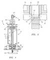
- FIG. 1is a sectional view of a solid state additive deposition system
- FIG. 2is an enlarged view of the deposition zone formed by the system of FIG. 1
- the deposition process and system described hereinperforms deposition of metallic material in a solid plastic state. This results in defect free material with a grain structure that will provide full wrought properties following heat treatment.
- the process and system described hereinuse a consumable rotating rod of metallic material.
- the consumable, rotating rod of metallic materialcan be progressively fed into the workpiece or substrate, which may comprise a part or a turbine engine component undergoing repair. This can be done using a pneumatic, hydraulic or mechanical feed mechanism. Localized heat may be added to the rod stock just above the deposition point. The heat may be added using an induction coil, a laser, acetylene torch flame, etc.
- the temperature of the metallic material forming the rodmay be raised to reduce the amount of heat needed to be produced by friction. By preheating the deposition rod to a near plastic state, the energy needed to spin the rod to generate frictional heat and the vertical force of the rod on the work piece may be reduced to a practical level.
- Lateral confinement of the deposited metalmay be progressively achieved by shaped cam followers spaced at a desired wall thickness.
- Upper confinement of the deposited metalmay be provided by the solid feed rod.
- the lower surface confinementmay be provided by the substrate.
- Recently deposited materialwill provide the aft confinement.
- the forward face of the deposition zoneis unconfined and may be characterized by a bow wave of plastic material.
- the plastic nature of the metallic material in the deposition zone along with the stirring motioninsures that the microstructure will be substantially free of porosity and have a fine grain size.
- FIG. 1illustrates a solid state deposition system 8 which includes a spindle 10 .
- the spindle 10has a housing 12 which may be formed from any suitable material. Located within the housing 12 is a rotatable hollow shaft 14 supported for rotation by bearings 16 and 18 . Attached to the shaft 14 may be a drive pulley 20 or other suitable device for rotating the shaft. When used, the drive pulley 20 may be connected to a motor (not shown) via a belt or chain (not shown) for rotating the pulley 20 and thus, the shaft 14 .
- a solid feed rod 24 of consumable metallic deposition materialPositioned within the core 22 of the hollow shaft 14 is a solid feed rod 24 of consumable metallic deposition material. Suitable materials for the feed rod 24 include: Aerospace Grades of Aluminum, Titanium, Low Alloy Steel and Nickel Based Super Alloys such as Inconel 625 and 718. Attached to the upper end 29 of the shaft 14 is a feed mechanism 26 for exerting pressure on an upper end of the feed rod 24 and for thus feeding the consumable deposition material into the deposition zone 28 .
- the feed mechanism 26may comprise a fitting 27 for introducing a high pressure fluid, such as air, into the hollow core 22 of the shaft 14 and into contact with the upper end of the solid feed rod 24 .
- a rotating pressure union 25may be provided to join the fitting 27 to the upper end 29 of the shaft 14 .
- the high pressure fluidmay be used to feed the consumable deposition material in the rod 24 into the deposition zone 28 .
- the feed mechanism 26may comprise a hydraulic or mechanical feed mechanism positioned adjacent the upper end 29 of the shaft 14 to apply a pressure force to the upper end of the solid feed rod 24 .
- the hydraulic or mechanical feed mechanismmay be any suitable device.
- a heating element 30may be positioned adjacent the deposition zone 28 at a location just above the deposition point 31 .
- the heating element 30may be positioned within the housing 12 or external to the housing 12 .
- the heating element 30may be an induction coil, a laser, or an acetylene torch flame.
- the heating element 30may be used to raise the temperature of the metallic deposition material forming the rod 24 to approximately 0.8 of the deposition material melt temperature.
- the temperature of the material forming the rod 24is raised to reduce the amount of heat needed to be produced by friction.
- By preheating the feed rod 24 in this manner to a near plastic statethe energy needed to spin the feed rod 24 to generate frictional heat and the vertical force of the rod on a workpiece 40 is reduced to a practical level.
- metalmay be deposited on a surface of the workpiece 40 for a desired purpose such as effecting a repair.
- lateral confinement of the deposited metalmay be progressively achieved by shaped cam followers 42 spaced at a desired wall thickness for the deposited material.
- the shaped cam followers 42may be conical rollers whose outer diameter surface insures that the rollers only contact relatively soft material 43 in the current deposition layer.
- Upper confinement of the deposited metalmay be provided by the solid feed rod 24 .
- the substrate or target plate 40provides lower confinement. Aft confinement is provided by the recently deposited material.
- metallic materialmay be deposited in layers 46 on a surface of the workpiece 40 .
- the forward face of the deposition zonemay be unconfined and may be characterized by a bow wave of plastic deposition material.
- the plastic state of the deposited material in the deposition zone, along with the stirring motion caused by rotation of the feed rod 24leads to the microstructure being substantially free of porosity and having a fine grain size.
- the porosity and grain sizeare equivalent to what is seen in a forging for any given material.
- the process of the present inventionmay be used to add features to bosses, flanges and stiffening blades to a diffuser case.
- the process described hereinmay also be used to free form fabricate diffuser cases, turbine exhaust cases, and intermediate cases.
- the solid state additive manufacturing system and process disclosed hereinovercomes the material properties limitations inherent in melt pool deposition processes.
- the approach described hereinenables full wrought properties to be realized directly from an additive manufacturing process.
Landscapes
- Engineering & Computer Science (AREA)
- Chemical & Material Sciences (AREA)
- Manufacturing & Machinery (AREA)
- Materials Engineering (AREA)
- Mechanical Engineering (AREA)
- Pressure Welding/Diffusion-Bonding (AREA)
- Laser Beam Processing (AREA)
Abstract
Description
Claims (13)
Priority Applications (2)
| Application Number | Priority Date | Filing Date | Title |
|---|---|---|---|
| US12/069,714US10092975B2 (en) | 2008-02-12 | 2008-02-12 | Solid state additive manufacturing system |
| EP09250262.4AEP2090396B1 (en) | 2008-02-12 | 2009-01-30 | System an process for solid state depositing of metals |
Applications Claiming Priority (1)
| Application Number | Priority Date | Filing Date | Title |
|---|---|---|---|
| US12/069,714US10092975B2 (en) | 2008-02-12 | 2008-02-12 | Solid state additive manufacturing system |
Publications (2)
| Publication Number | Publication Date |
|---|---|
| US20090200275A1 US20090200275A1 (en) | 2009-08-13 |
| US10092975B2true US10092975B2 (en) | 2018-10-09 |
Family
ID=40640385
Family Applications (1)
| Application Number | Title | Priority Date | Filing Date |
|---|---|---|---|
| US12/069,714Active2032-10-27US10092975B2 (en) | 2008-02-12 | 2008-02-12 | Solid state additive manufacturing system |
Country Status (2)
| Country | Link |
|---|---|
| US (1) | US10092975B2 (en) |
| EP (1) | EP2090396B1 (en) |
Cited By (6)
| Publication number | Priority date | Publication date | Assignee | Title |
|---|---|---|---|---|
| US20180200956A1 (en)* | 2015-07-13 | 2018-07-19 | Stratasys Ltd. | Leveling apparatus for a 3d printer |
| US20210178510A1 (en)* | 2019-12-17 | 2021-06-17 | Physical Optics Corporation | Swappable retractable tool tip (srtt) |
| US11097478B2 (en)* | 2017-04-24 | 2021-08-24 | Desktop Metal, Inc. | System and method for moving a rod of build material using a pusher in a 3D printing system |
| US20210370434A1 (en)* | 2018-12-14 | 2021-12-02 | The Boeing Company | Friction stir additive manufacturing systems and methods |
| US20230356322A1 (en)* | 2022-05-06 | 2023-11-09 | Bond Technologies, Inc. | Friction stir additive method and machine |
| US20250229312A1 (en)* | 2023-12-14 | 2025-07-17 | MELD Manufacturing Corporation | Solid state manufacturing tools and methods using them |
Families Citing this family (59)
| Publication number | Priority date | Publication date | Assignee | Title |
|---|---|---|---|---|
| US9266191B2 (en) | 2013-12-18 | 2016-02-23 | Aeroprobe Corporation | Fabrication of monolithic stiffening ribs on metallic sheets |
| US9511445B2 (en) | 2014-12-17 | 2016-12-06 | Aeroprobe Corporation | Solid state joining using additive friction stir processing |
| US8632850B2 (en) | 2005-09-26 | 2014-01-21 | Schultz-Creehan Holdings, Inc. | Friction fabrication tools |
| US9511446B2 (en) | 2014-12-17 | 2016-12-06 | Aeroprobe Corporation | In-situ interlocking of metals using additive friction stir processing |
| US8066174B2 (en)* | 2010-04-30 | 2011-11-29 | Siemens Energy, Inc. | Filler rotated friction stir welding |
| US9175568B2 (en) | 2010-06-22 | 2015-11-03 | Honeywell International Inc. | Methods for manufacturing turbine components |
| US9085980B2 (en) | 2011-03-04 | 2015-07-21 | Honeywell International Inc. | Methods for repairing turbine components |
| US8506836B2 (en) | 2011-09-16 | 2013-08-13 | Honeywell International Inc. | Methods for manufacturing components from articles formed by additive-manufacturing processes |
| US9266170B2 (en) | 2012-01-27 | 2016-02-23 | Honeywell International Inc. | Multi-material turbine components |
| US9120151B2 (en) | 2012-08-01 | 2015-09-01 | Honeywell International Inc. | Methods for manufacturing titanium aluminide components from articles formed by consolidation processes |
| WO2014105616A1 (en)* | 2012-12-29 | 2014-07-03 | United Technologies Corporation | Turbine exhaust case architecture |
| US20150183164A1 (en)* | 2013-12-30 | 2015-07-02 | Chad E. Duty | Rapid electro-magnetic heating of nozzle in polymer extrusion based deposition for additive manufacturing |
| US10124531B2 (en) | 2013-12-30 | 2018-11-13 | Ut-Battelle, Llc | Rapid non-contact energy transfer for additive manufacturing driven high intensity electromagnetic fields |
| EP4624072A1 (en) | 2014-01-09 | 2025-10-01 | RTX Corporation | Material and processes for additively manufacturing one or more parts |
| EP3094435B1 (en) | 2014-01-14 | 2022-07-13 | Raytheon Technologies Corporation | System and process for distributing material during additive manufacturing |
| EP3096939B1 (en) | 2014-01-24 | 2021-08-25 | Raytheon Technologies Corporation | Monitoring material solidification byproducts during additive manufacturing |
| WO2015112723A1 (en) | 2014-01-24 | 2015-07-30 | United Technologies Corporation | Conditioning one or more additive manufactured objects |
| EP3096909B1 (en) | 2014-01-24 | 2024-11-27 | RTX Corporation | Alloying metal materials together during additive manufacturing of one or more parts |
| US10913129B2 (en) | 2014-01-24 | 2021-02-09 | Raytheon Technologies Corporation | Additive manufacturing an object from material with a selective diffusion barrier |
| US9950392B2 (en) | 2014-03-04 | 2018-04-24 | Rohr, Inc. | Forming one or more apertures in a fiber-reinforced composite object with a laser |
| US9650537B2 (en) | 2014-04-14 | 2017-05-16 | Ut-Battelle, Llc | Reactive polymer fused deposition manufacturing |
| US10208673B2 (en) | 2014-07-03 | 2019-02-19 | United Technologies Corporation | Fuel dispensing apparatus and method of operation |
| US9915480B2 (en) | 2014-07-03 | 2018-03-13 | United Technologies Corporation | Tube assembly |
| US9759356B2 (en) | 2014-07-03 | 2017-09-12 | United Technologies Corporation | Insulated flowpath assembly |
| US9976743B2 (en) | 2014-07-03 | 2018-05-22 | United Technologies Corporation | Dilution hole assembly |
| CN108372374B (en)* | 2017-01-04 | 2020-01-14 | 中国航空制造技术研究院 | Method and device for refining crystal grains in additive manufacturing |
| CN107052560B (en)* | 2017-03-15 | 2019-01-11 | 天津大学 | A kind of axis system for realizing the friction surfacing with the shaft shoulder |
| IT201700052877A1 (en)* | 2017-05-16 | 2018-11-16 | Starfort Des Stubenruss Moritz | A 3D printer head for use in a 3D printer with a 3D printer head of this type, a method for operating a 3D printer of this type and a printed product made with a 3D printer of this type |
| US10688588B2 (en) | 2017-06-12 | 2020-06-23 | Raytheon Technologies Corporation | Continuous feed spindle attachment |
| CN107414325B (en) | 2017-07-12 | 2020-01-03 | 北京工业大学 | Micro-area semi-solid additive manufacturing method |
| JP7089034B2 (en) | 2017-10-31 | 2022-06-21 | メルド マニファクチャリング コーポレーション | Solid-state laminated modeling system as well as material composition and structural background |
| DE102018207520A1 (en)* | 2018-05-15 | 2019-11-21 | Airbus Defence and Space GmbH | Method for producing a component |
| CN109014560B (en)* | 2018-08-13 | 2019-08-23 | 燕山大学 | The on-line measuring device and detection method of stirring-head drafts |
| CN109108505A (en)* | 2018-08-20 | 2019-01-01 | 西安增材制造国家研究院有限公司 | A kind of method that electric arc increasing material manufacturing Al alloy parts are strengthened in agitating friction weldering |
| US11465349B2 (en)* | 2019-04-22 | 2022-10-11 | The Boeing Co. | Tool head assembly for solid state additive manufacturing |
| US11370058B2 (en)* | 2019-08-13 | 2022-06-28 | The Boeing Company | Loading feedstock into an additive friction stir deposition machine |
| US11845141B2 (en) | 2020-01-08 | 2023-12-19 | The Boeing Company | Additive friction stir deposition method for manufacturing an article |
| DE102020113012B4 (en)* | 2020-05-13 | 2024-02-15 | Fraunhofer-Gesellschaft zur Förderung der angewandten Forschung eingetragener Verein | Processing unit for laser deposition welding with a feed device for feeding an additional welding element |
| CN111805105B (en)* | 2020-07-31 | 2022-03-29 | 贵州航天天马机电科技有限公司 | Electric arc additive composite friction stir welding processing method and path planning method thereof |
| CN113020625B (en)* | 2021-02-08 | 2024-01-12 | 苏州万智新能源科技有限公司 | Additive manufacturing mechanism and manufacturing method based on short rod materials |
| EP4301575A4 (en) | 2021-03-04 | 2024-07-10 | Kumar Kandasamy | METHODS AND/OR MACHINES FOR CONTINUOUS PLASTIC DEFORMATION AND/OR COMPOSITIONS AND/OR PRODUCTIONS THEREOF |
| CN113500287B (en)* | 2021-09-10 | 2021-12-07 | 长沙仪秀兴智能科技有限公司 | Friction welding material increase equipment and method |
| CN113828793B (en)* | 2021-10-12 | 2022-07-12 | 广东省科学院新材料研究所 | A rocket engine thrust chamber sandwich wall structure and its manufacturing method |
| CN113927150A (en)* | 2021-11-02 | 2022-01-14 | 上海航天设备制造总厂有限公司 | Middle wire filling type negative pressing-in amount low-acting-force friction stir welding method and equipment |
| CN114131176B (en)* | 2021-12-21 | 2022-08-02 | 天津大学 | Main shaft system for solid-phase friction extrusion additive manufacturing |
| CN114682989A (en)* | 2022-03-14 | 2022-07-01 | 航天工程装备(苏州)有限公司 | Method and device for repairing casting in solid state |
| CN115283813B (en)* | 2022-03-28 | 2024-09-13 | 江苏大学 | Main shaft system and method for differential friction extrusion additive manufacturing |
| CN114951958B (en)* | 2022-06-23 | 2023-05-26 | 华中科技大学 | High-strength aluminum alloy powder core wire friction stir additive manufacturing system and method |
| CN115283700A (en)* | 2022-08-05 | 2022-11-04 | 中国兵器装备集团西南技术工程研究所 | Defect repairing device and method for metal structural parts |
| CN115319269B (en)* | 2022-08-24 | 2024-04-09 | 江苏大学 | Multi-channel high-flux device for friction extrusion deposition of metal material and processing method |
| CN115122632B (en)* | 2022-08-31 | 2022-11-15 | 安徽万宇机械设备科技有限公司 | Additive manufacturing shaft center |
| CN116275455A (en)* | 2022-09-08 | 2023-06-23 | 江苏大学 | A thin-walled friction extrusion additive manufacturing device and processing method |
| CN115555586B (en)* | 2022-09-27 | 2025-05-30 | 西北工业大学 | A rotatable telescopic friction stir processing head and processing method |
| CN115415520B (en)* | 2022-10-13 | 2024-01-26 | 中国兵器装备集团西南技术工程研究所 | Gradient heterogeneous alloy shell solid-state additive manufacturing device and manufacturing method |
| CN115446314B (en)* | 2022-10-13 | 2024-06-04 | 中国兵器装备集团西南技术工程研究所 | Preparation device and preparation method of coarse-fine grain composite multilayer structure material |
| WO2024148020A1 (en)* | 2023-01-03 | 2024-07-11 | Virginia Tech Intellectual Properties | Small-scale solid-state additive manufacturing tools and designs |
| CN116100139B (en)* | 2023-04-10 | 2023-07-11 | 北京科技大学 | A friction stir additive device and additive method |
| CN116618816A (en)* | 2023-04-12 | 2023-08-22 | 南昌航空大学 | Wire feeding type electromagnetic jet additive manufacturing device and method |
| CN118404182A (en)* | 2024-05-07 | 2024-07-30 | 博科数联(青岛)智能科技有限公司 | Friction stir additive manufacturing device and method thereof |
Citations (29)
| Publication number | Priority date | Publication date | Assignee | Title |
|---|---|---|---|---|
| US4165212A (en)* | 1978-03-02 | 1979-08-21 | Hoover Universal, Inc. | Multiple extrusion head assembly |
| US4556775A (en)* | 1983-10-26 | 1985-12-03 | Inoue-Japax Research Incorporated | Automatic spark-depositing apparatus |
| FR2672831A1 (en) | 1991-02-15 | 1992-08-21 | Smf Int | High-rate friction welding machine |
| US5262123A (en) | 1990-06-06 | 1993-11-16 | The Welding Institute | Forming metallic composite materials by urging base materials together under shear |
| US5697544A (en)* | 1996-03-21 | 1997-12-16 | Boeing North American, Inc. | Adjustable pin for friction stir welding tool |
| US5713507A (en) | 1996-03-21 | 1998-02-03 | Rockwell International Corporation | Programmable friction stir welding process |
| US20020027155A1 (en)* | 2000-02-24 | 2002-03-07 | Hisanori Okamura | Friction stir welding method |
| US6457629B1 (en)* | 1999-10-04 | 2002-10-01 | Solidica, Inc. | Object consolidation employing friction joining |
| US20030042292A1 (en)* | 2001-09-05 | 2003-03-06 | Hatten Timothy E. | Apparatus and method for friction stir welding using filler material |
| US6533974B1 (en)* | 1998-08-07 | 2003-03-18 | Industrial Thermo Polymers Limited | Method of forming a profile on a foam rod |
| US6553974B1 (en) | 2001-10-24 | 2003-04-29 | Brunswick Corporation | Engine fuel system with a fuel vapor separator and a fuel vapor vent canister |
| US6572007B1 (en)* | 2002-01-23 | 2003-06-03 | General Motors Corporation | Method for attaching metal members |
| US20040046003A1 (en)* | 2003-09-11 | 2004-03-11 | The Boeing Company | Apparatus and method for friction stir welding with a variable speed pin |
| US6726084B2 (en)* | 2001-06-15 | 2004-04-27 | Lockheed Martin Corporation | Friction stir heating/welding with pin tool having rough distal region |
| US6776328B2 (en)* | 2002-09-17 | 2004-08-17 | The Boeing Company | Radiation assisted friction welding |
| US6811632B2 (en)* | 2000-05-05 | 2004-11-02 | Brigham Young University | Friction stir welding of polymeric materials |
| US6814823B1 (en)* | 1999-09-16 | 2004-11-09 | Solidica, Inc. | Object consolidation through sequential material deposition |
| US20050150871A1 (en)* | 2004-01-12 | 2005-07-14 | Offer Henry P. | Apparatus and method for electrofriction welding |
| US6926970B2 (en)* | 2001-11-02 | 2005-08-09 | The Boeing Company | Apparatus and method for forming weld joints having compressive residual stress patterns |
| US20060102689A1 (en)* | 2003-04-11 | 2006-05-18 | Trapp Timothy J | Method and apparatus for locally clamping components that are to be joined by friction stir welding |
| US20060163328A1 (en)* | 2003-08-29 | 2006-07-27 | General Electric Company | Apparatus and method for friction stir welding using a consumable pin tool |
| US20060263328A1 (en) | 2005-05-19 | 2006-11-23 | Sang Van | Hydrophilic polymers with pendant functional groups and method thereof |
| US7156277B2 (en)* | 2004-09-27 | 2007-01-02 | Mitsubishi Heavy Industries, Ltd. | Friction stir welding method and apparatus |
| US20070040006A1 (en)* | 2005-08-16 | 2007-02-22 | Battelle Energy Alliance, Llc | Material forming tool and method for forming a material |
| US20070080191A1 (en)* | 2005-09-26 | 2007-04-12 | Gkss-Forschungszentrum Geesthacht Gmbh | Method and apparatus of producing a welded connection between the surfaces of two planar workpieces |
| US7225966B2 (en)* | 2002-08-07 | 2007-06-05 | Eclipse Aviation Corporation | Welded joints with polymer sealant |
| US20070241167A1 (en)* | 2006-04-13 | 2007-10-18 | Mazda Motor Corporation | Joining method and joining apparatus |
| EP1872893A1 (en) | 2005-04-19 | 2008-01-02 | Sumitomo Light Metal Industries, Ltd. | Rotary tool for friction stirring-spot welding and friction stirring-spot welding method using the rotary tool |
| US20080099533A1 (en)* | 2006-10-31 | 2008-05-01 | General Electric | Method for controlling microstructure via thermally managed solid state joining |
Family Cites Families (2)
| Publication number | Priority date | Publication date | Assignee | Title |
|---|---|---|---|---|
| AU2002352844A1 (en) | 2001-11-27 | 2003-06-10 | The United States Of America As Represented By The Administrator Of The National Aeronautics And Spa | Thermal stir welding process and apparatus |
| US20130309387A1 (en) | 2011-02-08 | 2013-11-21 | Dow Global Technologies Llc | Liquid comprising animal protein and a carboxy-c1-c3-alkyl cellulose |
- 2008
- 2008-02-12USUS12/069,714patent/US10092975B2/enactiveActive
- 2009
- 2009-01-30EPEP09250262.4Apatent/EP2090396B1/ennot_activeRevoked
Patent Citations (31)
| Publication number | Priority date | Publication date | Assignee | Title |
|---|---|---|---|---|
| US4165212A (en)* | 1978-03-02 | 1979-08-21 | Hoover Universal, Inc. | Multiple extrusion head assembly |
| US4556775A (en)* | 1983-10-26 | 1985-12-03 | Inoue-Japax Research Incorporated | Automatic spark-depositing apparatus |
| US5262123A (en) | 1990-06-06 | 1993-11-16 | The Welding Institute | Forming metallic composite materials by urging base materials together under shear |
| FR2672831A1 (en) | 1991-02-15 | 1992-08-21 | Smf Int | High-rate friction welding machine |
| US5697544A (en)* | 1996-03-21 | 1997-12-16 | Boeing North American, Inc. | Adjustable pin for friction stir welding tool |
| US5713507A (en) | 1996-03-21 | 1998-02-03 | Rockwell International Corporation | Programmable friction stir welding process |
| US6533974B1 (en)* | 1998-08-07 | 2003-03-18 | Industrial Thermo Polymers Limited | Method of forming a profile on a foam rod |
| US6814823B1 (en)* | 1999-09-16 | 2004-11-09 | Solidica, Inc. | Object consolidation through sequential material deposition |
| US6457629B1 (en)* | 1999-10-04 | 2002-10-01 | Solidica, Inc. | Object consolidation employing friction joining |
| US20020027155A1 (en)* | 2000-02-24 | 2002-03-07 | Hisanori Okamura | Friction stir welding method |
| US6811632B2 (en)* | 2000-05-05 | 2004-11-02 | Brigham Young University | Friction stir welding of polymeric materials |
| US6726084B2 (en)* | 2001-06-15 | 2004-04-27 | Lockheed Martin Corporation | Friction stir heating/welding with pin tool having rough distal region |
| US20030042292A1 (en)* | 2001-09-05 | 2003-03-06 | Hatten Timothy E. | Apparatus and method for friction stir welding using filler material |
| US6553974B1 (en) | 2001-10-24 | 2003-04-29 | Brunswick Corporation | Engine fuel system with a fuel vapor separator and a fuel vapor vent canister |
| US6926970B2 (en)* | 2001-11-02 | 2005-08-09 | The Boeing Company | Apparatus and method for forming weld joints having compressive residual stress patterns |
| US6572007B1 (en)* | 2002-01-23 | 2003-06-03 | General Motors Corporation | Method for attaching metal members |
| US7225966B2 (en)* | 2002-08-07 | 2007-06-05 | Eclipse Aviation Corporation | Welded joints with polymer sealant |
| US6776328B2 (en)* | 2002-09-17 | 2004-08-17 | The Boeing Company | Radiation assisted friction welding |
| US20060102689A1 (en)* | 2003-04-11 | 2006-05-18 | Trapp Timothy J | Method and apparatus for locally clamping components that are to be joined by friction stir welding |
| US20060163328A1 (en)* | 2003-08-29 | 2006-07-27 | General Electric Company | Apparatus and method for friction stir welding using a consumable pin tool |
| US6913186B2 (en)* | 2003-09-11 | 2005-07-05 | The Boeing Company | Apparatus and method for friction stir welding with a variable speed pin |
| US20040046003A1 (en)* | 2003-09-11 | 2004-03-11 | The Boeing Company | Apparatus and method for friction stir welding with a variable speed pin |
| US20050150871A1 (en)* | 2004-01-12 | 2005-07-14 | Offer Henry P. | Apparatus and method for electrofriction welding |
| US7156277B2 (en)* | 2004-09-27 | 2007-01-02 | Mitsubishi Heavy Industries, Ltd. | Friction stir welding method and apparatus |
| EP1872893A1 (en) | 2005-04-19 | 2008-01-02 | Sumitomo Light Metal Industries, Ltd. | Rotary tool for friction stirring-spot welding and friction stirring-spot welding method using the rotary tool |
| US7654435B2 (en) | 2005-04-19 | 2010-02-02 | Sumitomo Light Metal Industries, Ltd. | Rotary tool for friction stir spot welding and method of friction stir spot welding using the same |
| US20060263328A1 (en) | 2005-05-19 | 2006-11-23 | Sang Van | Hydrophilic polymers with pendant functional groups and method thereof |
| US20070040006A1 (en)* | 2005-08-16 | 2007-02-22 | Battelle Energy Alliance, Llc | Material forming tool and method for forming a material |
| US20070080191A1 (en)* | 2005-09-26 | 2007-04-12 | Gkss-Forschungszentrum Geesthacht Gmbh | Method and apparatus of producing a welded connection between the surfaces of two planar workpieces |
| US20070241167A1 (en)* | 2006-04-13 | 2007-10-18 | Mazda Motor Corporation | Joining method and joining apparatus |
| US20080099533A1 (en)* | 2006-10-31 | 2008-05-01 | General Electric | Method for controlling microstructure via thermally managed solid state joining |
Non-Patent Citations (1)
| Title |
|---|
| European opposition for European patent Apln. No. EP09250262.4 dated Mar. 12, 2018. |
Cited By (12)
| Publication number | Priority date | Publication date | Assignee | Title |
|---|---|---|---|---|
| US20180200956A1 (en)* | 2015-07-13 | 2018-07-19 | Stratasys Ltd. | Leveling apparatus for a 3d printer |
| US10786947B2 (en)* | 2015-07-13 | 2020-09-29 | Stratasys Ltd. | Leveling apparatus for a 3D printer |
| US11097478B2 (en)* | 2017-04-24 | 2021-08-24 | Desktop Metal, Inc. | System and method for moving a rod of build material using a pusher in a 3D printing system |
| US11097477B2 (en)* | 2017-04-24 | 2021-08-24 | Desktop Metal, Inc. | System and method for moving a rod of build material using a pusher in a 3D printing system |
| US11097479B2 (en)* | 2017-04-24 | 2021-08-24 | Desktop Metal, Inc. | System and method for moving a rod of build material using a pusher in a 3D printing system |
| US20210370434A1 (en)* | 2018-12-14 | 2021-12-02 | The Boeing Company | Friction stir additive manufacturing systems and methods |
| US11865635B2 (en)* | 2018-12-14 | 2024-01-09 | The Boeing Company | Friction stir additive manufacturing methods |
| US20210178510A1 (en)* | 2019-12-17 | 2021-06-17 | Physical Optics Corporation | Swappable retractable tool tip (srtt) |
| US11931820B2 (en)* | 2019-12-17 | 2024-03-19 | Mercury Mission Systems, Llc | Swappable retractable tool tip (SRTT) |
| US20230356322A1 (en)* | 2022-05-06 | 2023-11-09 | Bond Technologies, Inc. | Friction stir additive method and machine |
| US12290873B2 (en)* | 2022-05-06 | 2025-05-06 | Bond Technologies, Inc. | Friction stir additive method and machine |
| US20250229312A1 (en)* | 2023-12-14 | 2025-07-17 | MELD Manufacturing Corporation | Solid state manufacturing tools and methods using them |
Also Published As
| Publication number | Publication date |
|---|---|
| EP2090396A3 (en) | 2010-12-29 |
| US20090200275A1 (en) | 2009-08-13 |
| EP2090396B1 (en) | 2017-06-07 |
| EP2090396A2 (en) | 2009-08-19 |
Similar Documents
| Publication | Publication Date | Title |
|---|---|---|
| US10092975B2 (en) | Solid state additive manufacturing system | |
| US8056793B2 (en) | Apparatus and method for friction surfacing using a consumable pin tool | |
| Liu et al. | Parameter optimization and experimental study of the sprocket repairing using laser cladding | |
| Gatto et al. | Plasma Transferred Arc deposition of powdered high performances alloys: process parameters optimisation as a function of alloy and geometrical configuration | |
| US10260585B2 (en) | Brake disc and manufacturing method thereof | |
| TWI584890B (en) | Systems and methods for processing alloy ingots | |
| CN107400887A (en) | A kind of method that ultrasonic burnishing strengthens laser cladding layer | |
| US20060231535A1 (en) | Method of welding a gamma-prime precipitate strengthened material | |
| FR3001166A1 (en) | METHOD FOR RECHARGING A PIECE | |
| EP2938456A1 (en) | Method for regenerating and/or increasing the durability of a mill roll | |
| JPWO2019151057A1 (en) | Repair / modification method for metal-based substrates | |
| CN111945156A (en) | Method for preparing centrifugal roller through laser cladding | |
| CN106270876A (en) | A kind of aluminium lithium alloy and titanium alloy electron beam melt pricker welding method | |
| US20130156586A1 (en) | Method for connecting a turbine blade or vane to a turbine disc or a turbine ring | |
| Oh et al. | Excess deposition for suppressing interfacial defects induced on parts repaired using direct energy deposition | |
| He et al. | Wire-feed laser additive manufacturing of dissimilar metals via dual molten pool interface interlocking mechanism | |
| Nikam et al. | Laser-based repair of damaged dies, molds, and gears | |
| Pattanayak et al. | Experimental investigation on deposits of ER70S-6 wire on SiO2 substrate using non-transferred arc-based wire arc additive manufacturing | |
| Sadhu et al. | Performance evaluation of laser-deposited functionally graded Stellite 6-WC tools in friction stir lap welding of CuCrZr-SS304 | |
| CN102453895A (en) | Preparation method of heat-resistant and wear-resistant alloy coating on surface of hot-rolled plate finish rolling conveying roller | |
| EP3969213B1 (en) | Additive manufacturing process for a metal part | |
| Karşi et al. | Optimization of Laser Cladding Process Parameters of a Martensitic Stainless Steel Coating on GGG70L Ductile Cast Iron. | |
| JP2008215181A (en) | Turbine rotor | |
| CN115386870B (en) | Processing method for composite magnetic field assisted ultra-high speed laser cladding | |
| JP4174496B2 (en) | Method for forming abrasion-resistant thermal spray coating and thermal spray machine |
Legal Events
| Date | Code | Title | Description |
|---|---|---|---|
| AS | Assignment | Owner name:UNITED TECHNOLOGIES CORPORATION, CONNECTICUT Free format text:ASSIGNMENT OF ASSIGNORS INTEREST;ASSIGNORS:TWELVES, WENDELL V., JR.;LIN, WANGEN;ALEXANDER, DAVID G.;REEL/FRAME:020561/0688;SIGNING DATES FROM 20071102 TO 20080212 Owner name:UNITED TECHNOLOGIES CORPORATION, CONNECTICUT Free format text:ASSIGNMENT OF ASSIGNORS INTEREST;ASSIGNORS:TWELVES, WENDELL V., JR.;LIN, WANGEN;ALEXANDER, DAVID G.;SIGNING DATES FROM 20071102 TO 20080212;REEL/FRAME:020561/0688 | |
| STCF | Information on status: patent grant | Free format text:PATENTED CASE | |
| AS | Assignment | Owner name:RAYTHEON TECHNOLOGIES CORPORATION, MASSACHUSETTS Free format text:CHANGE OF NAME;ASSIGNOR:UNITED TECHNOLOGIES CORPORATION;REEL/FRAME:054062/0001 Effective date:20200403 | |
| AS | Assignment | Owner name:RAYTHEON TECHNOLOGIES CORPORATION, CONNECTICUT Free format text:CORRECTIVE ASSIGNMENT TO CORRECT THE AND REMOVE PATENT APPLICATION NUMBER 11886281 AND ADD PATENT APPLICATION NUMBER 14846874. TO CORRECT THE RECEIVING PARTY ADDRESS PREVIOUSLY RECORDED AT REEL: 054062 FRAME: 0001. ASSIGNOR(S) HEREBY CONFIRMS THE CHANGE OF ADDRESS;ASSIGNOR:UNITED TECHNOLOGIES CORPORATION;REEL/FRAME:055659/0001 Effective date:20200403 | |
| MAFP | Maintenance fee payment | Free format text:PAYMENT OF MAINTENANCE FEE, 4TH YEAR, LARGE ENTITY (ORIGINAL EVENT CODE: M1551); ENTITY STATUS OF PATENT OWNER: LARGE ENTITY Year of fee payment:4 | |
| AS | Assignment | Owner name:RTX CORPORATION, CONNECTICUT Free format text:CHANGE OF NAME;ASSIGNOR:RAYTHEON TECHNOLOGIES CORPORATION;REEL/FRAME:064714/0001 Effective date:20230714 |