US10090631B2 - Cladding light stripper and method of manufacturing - Google Patents
Cladding light stripper and method of manufacturingDownload PDFInfo
- Publication number
- US10090631B2 US10090631B2US15/393,887US201615393887AUS10090631B2US 10090631 B2US10090631 B2US 10090631B2US 201615393887 AUS201615393887 AUS 201615393887AUS 10090631 B2US10090631 B2US 10090631B2
- Authority
- US
- United States
- Prior art keywords
- cladding
- optical fiber
- notches
- light
- exposed section
- Prior art date
- Legal status (The legal status is an assumption and is not a legal conclusion. Google has not performed a legal analysis and makes no representation as to the accuracy of the status listed.)
- Active
Links
Images


Classifications
- H—ELECTRICITY
- H01—ELECTRIC ELEMENTS
- H01S—DEVICES USING THE PROCESS OF LIGHT AMPLIFICATION BY STIMULATED EMISSION OF RADIATION [LASER] TO AMPLIFY OR GENERATE LIGHT; DEVICES USING STIMULATED EMISSION OF ELECTROMAGNETIC RADIATION IN WAVE RANGES OTHER THAN OPTICAL
- H01S3/00—Lasers, i.e. devices using stimulated emission of electromagnetic radiation in the infrared, visible or ultraviolet wave range
- H01S3/05—Construction or shape of optical resonators; Accommodation of active medium therein; Shape of active medium
- H01S3/06—Construction or shape of active medium
- H01S3/063—Waveguide lasers, i.e. whereby the dimensions of the waveguide are of the order of the light wavelength
- H01S3/067—Fibre lasers
- H01S3/06708—Constructional details of the fibre, e.g. compositions, cross-section, shape or tapering
- H01S3/06729—Peculiar transverse fibre profile
- H—ELECTRICITY
- H01—ELECTRIC ELEMENTS
- H01S—DEVICES USING THE PROCESS OF LIGHT AMPLIFICATION BY STIMULATED EMISSION OF RADIATION [LASER] TO AMPLIFY OR GENERATE LIGHT; DEVICES USING STIMULATED EMISSION OF ELECTROMAGNETIC RADIATION IN WAVE RANGES OTHER THAN OPTICAL
- H01S3/00—Lasers, i.e. devices using stimulated emission of electromagnetic radiation in the infrared, visible or ultraviolet wave range
- H01S3/05—Construction or shape of optical resonators; Accommodation of active medium therein; Shape of active medium
- H01S3/06—Construction or shape of active medium
- H01S3/063—Waveguide lasers, i.e. whereby the dimensions of the waveguide are of the order of the light wavelength
- H01S3/067—Fibre lasers
- H01S3/06708—Constructional details of the fibre, e.g. compositions, cross-section, shape or tapering
- B—PERFORMING OPERATIONS; TRANSPORTING
- B23—MACHINE TOOLS; METAL-WORKING NOT OTHERWISE PROVIDED FOR
- B23K—SOLDERING OR UNSOLDERING; WELDING; CLADDING OR PLATING BY SOLDERING OR WELDING; CUTTING BY APPLYING HEAT LOCALLY, e.g. FLAME CUTTING; WORKING BY LASER BEAM
- B23K26/00—Working by laser beam, e.g. welding, cutting or boring
- B23K26/02—Positioning or observing the workpiece, e.g. with respect to the point of impact; Aligning, aiming or focusing the laser beam
- B23K26/06—Shaping the laser beam, e.g. by masks or multi-focusing
- B23K26/062—Shaping the laser beam, e.g. by masks or multi-focusing by direct control of the laser beam
- B23K26/0622—Shaping the laser beam, e.g. by masks or multi-focusing by direct control of the laser beam by shaping pulses
- B—PERFORMING OPERATIONS; TRANSPORTING
- B23—MACHINE TOOLS; METAL-WORKING NOT OTHERWISE PROVIDED FOR
- B23K—SOLDERING OR UNSOLDERING; WELDING; CLADDING OR PLATING BY SOLDERING OR WELDING; CUTTING BY APPLYING HEAT LOCALLY, e.g. FLAME CUTTING; WORKING BY LASER BEAM
- B23K26/00—Working by laser beam, e.g. welding, cutting or boring
- B23K26/02—Positioning or observing the workpiece, e.g. with respect to the point of impact; Aligning, aiming or focusing the laser beam
- B23K26/06—Shaping the laser beam, e.g. by masks or multi-focusing
- B23K26/062—Shaping the laser beam, e.g. by masks or multi-focusing by direct control of the laser beam
- B23K26/0626—Energy control of the laser beam
- B—PERFORMING OPERATIONS; TRANSPORTING
- B23—MACHINE TOOLS; METAL-WORKING NOT OTHERWISE PROVIDED FOR
- B23K—SOLDERING OR UNSOLDERING; WELDING; CLADDING OR PLATING BY SOLDERING OR WELDING; CUTTING BY APPLYING HEAT LOCALLY, e.g. FLAME CUTTING; WORKING BY LASER BEAM
- B23K26/00—Working by laser beam, e.g. welding, cutting or boring
- B23K26/36—Removing material
- B—PERFORMING OPERATIONS; TRANSPORTING
- B29—WORKING OF PLASTICS; WORKING OF SUBSTANCES IN A PLASTIC STATE IN GENERAL
- B29D—PRODUCING PARTICULAR ARTICLES FROM PLASTICS OR FROM SUBSTANCES IN A PLASTIC STATE
- B29D11/00—Producing optical elements, e.g. lenses or prisms
- B29D11/00663—Production of light guides
- G—PHYSICS
- G02—OPTICS
- G02B—OPTICAL ELEMENTS, SYSTEMS OR APPARATUS
- G02B6/00—Light guides; Structural details of arrangements comprising light guides and other optical elements, e.g. couplings
- G02B6/02—Optical fibres with cladding with or without a coating
- G02B6/02057—Optical fibres with cladding with or without a coating comprising gratings
- G02B6/02066—Gratings having a surface relief structure, e.g. repetitive variation in diameter of core or cladding
- G—PHYSICS
- G02—OPTICS
- G02B—OPTICAL ELEMENTS, SYSTEMS OR APPARATUS
- G02B6/00—Light guides; Structural details of arrangements comprising light guides and other optical elements, e.g. couplings
- G02B6/02—Optical fibres with cladding with or without a coating
- G02B6/02295—Microstructured optical fibre
- G02B6/02314—Plurality of longitudinal structures extending along optical fibre axis, e.g. holes
- G02B6/02342—Plurality of longitudinal structures extending along optical fibre axis, e.g. holes characterised by cladding features, i.e. light confining region
- G—PHYSICS
- G02—OPTICS
- G02B—OPTICAL ELEMENTS, SYSTEMS OR APPARATUS
- G02B6/00—Light guides; Structural details of arrangements comprising light guides and other optical elements, e.g. couplings
- G02B6/10—Light guides; Structural details of arrangements comprising light guides and other optical elements, e.g. couplings of the optical waveguide type
- G02B6/14—Mode converters
- G—PHYSICS
- G02—OPTICS
- G02B—OPTICAL ELEMENTS, SYSTEMS OR APPARATUS
- G02B6/00—Light guides; Structural details of arrangements comprising light guides and other optical elements, e.g. couplings
- G02B6/24—Coupling light guides
- G02B6/26—Optical coupling means
- G02B6/28—Optical coupling means having data bus means, i.e. plural waveguides interconnected and providing an inherently bidirectional system by mixing and splitting signals
- G02B6/2804—Optical coupling means having data bus means, i.e. plural waveguides interconnected and providing an inherently bidirectional system by mixing and splitting signals forming multipart couplers without wavelength selective elements, e.g. "T" couplers, star couplers
- G02B6/2852—Optical coupling means having data bus means, i.e. plural waveguides interconnected and providing an inherently bidirectional system by mixing and splitting signals forming multipart couplers without wavelength selective elements, e.g. "T" couplers, star couplers using tapping light guides arranged sidewardly, e.g. in a non-parallel relationship with respect to the bus light guides (light extraction or launching through cladding, with or without surface discontinuities, bent structures)
- H—ELECTRICITY
- H01—ELECTRIC ELEMENTS
- H01S—DEVICES USING THE PROCESS OF LIGHT AMPLIFICATION BY STIMULATED EMISSION OF RADIATION [LASER] TO AMPLIFY OR GENERATE LIGHT; DEVICES USING STIMULATED EMISSION OF ELECTROMAGNETIC RADIATION IN WAVE RANGES OTHER THAN OPTICAL
- H01S3/00—Lasers, i.e. devices using stimulated emission of electromagnetic radiation in the infrared, visible or ultraviolet wave range
- H01S3/05—Construction or shape of optical resonators; Accommodation of active medium therein; Shape of active medium
- H01S3/06—Construction or shape of active medium
- H01S3/063—Waveguide lasers, i.e. whereby the dimensions of the waveguide are of the order of the light wavelength
- H01S3/067—Fibre lasers
- H01S3/06708—Constructional details of the fibre, e.g. compositions, cross-section, shape or tapering
- H01S3/06729—Peculiar transverse fibre profile
- H01S3/06733—Fibre having more than one cladding
- H—ELECTRICITY
- H01—ELECTRIC ELEMENTS
- H01S—DEVICES USING THE PROCESS OF LIGHT AMPLIFICATION BY STIMULATED EMISSION OF RADIATION [LASER] TO AMPLIFY OR GENERATE LIGHT; DEVICES USING STIMULATED EMISSION OF ELECTROMAGNETIC RADIATION IN WAVE RANGES OTHER THAN OPTICAL
- H01S3/00—Lasers, i.e. devices using stimulated emission of electromagnetic radiation in the infrared, visible or ultraviolet wave range
- H01S3/09—Processes or apparatus for excitation, e.g. pumping
- H01S3/091—Processes or apparatus for excitation, e.g. pumping using optical pumping
- H01S3/094—Processes or apparatus for excitation, e.g. pumping using optical pumping by coherent light
- H01S3/094003—Processes or apparatus for excitation, e.g. pumping using optical pumping by coherent light the pumped medium being a fibre
- H01S3/094007—Cladding pumping, i.e. pump light propagating in a clad surrounding the active core
- H—ELECTRICITY
- H01—ELECTRIC ELEMENTS
- H01S—DEVICES USING THE PROCESS OF LIGHT AMPLIFICATION BY STIMULATED EMISSION OF RADIATION [LASER] TO AMPLIFY OR GENERATE LIGHT; DEVICES USING STIMULATED EMISSION OF ELECTROMAGNETIC RADIATION IN WAVE RANGES OTHER THAN OPTICAL
- H01S3/00—Lasers, i.e. devices using stimulated emission of electromagnetic radiation in the infrared, visible or ultraviolet wave range
- H01S3/09—Processes or apparatus for excitation, e.g. pumping
- H01S3/091—Processes or apparatus for excitation, e.g. pumping using optical pumping
- H01S3/094—Processes or apparatus for excitation, e.g. pumping using optical pumping by coherent light
- H01S3/0941—Processes or apparatus for excitation, e.g. pumping using optical pumping by coherent light of a laser diode
- G—PHYSICS
- G02—OPTICS
- G02B—OPTICAL ELEMENTS, SYSTEMS OR APPARATUS
- G02B6/00—Light guides; Structural details of arrangements comprising light guides and other optical elements, e.g. couplings
- G02B6/24—Coupling light guides
- G02B6/26—Optical coupling means
- G02B6/264—Optical coupling means with optical elements between opposed fibre ends which perform a function other than beam splitting
Definitions
- the present inventionrelates to optical fiber devices and related methods, and in particular to devices and methods for removing cladding light in fiber amplifiers and lasers.
- Fiber lasersare an important new class of lasers that provide significant advantages of efficiency and practicality in comparison with other laser types such as free-space lasers.
- DCFdouble-clad fiber
- fiber lasershave been scaled to kilowatt (kW) power levels.
- pump lightpropagates in a relatively large inner cladding, typically 125 to 600 micrometers in diameter, and the laser light propagates in the much smaller core, typically 5 to 100 micrometers in diameter.
- the coreis doped with ions of a rare-earth element, such as Ytterbium, and is surrounded by the inner cladding, which guides the pump light to be absorbed in the doped core for laser light amplification along the entire fiber length.
- a rare-earth elementsuch as Ytterbium
- the output of a fiber laser or amplifier based on a DCFconsists of some core light and some cladding light.
- the cladding lightmay contain residual unabsorbed pump light and any laser light that has escaped from the core into the cladding e.g. due to scattering or spontaneous emission in the core.
- the cladding lightmay contain optical beams at a large range of divergence angles and a variety of wavelengths, depending on their source(s) and the construction of the laser system.
- the cladding lightis deleterious for a number of applications, and should preferably be removed, or “stripped”, from the fiber. For high-power fiber sources, more than 300 W of cladding light may be present, and safely and efficiently removing this light represents a significant technological challenge.
- the stripped cladding lightis converted to heat, and care must be taken to avoid overheating fiber coatings or other components such as ferrules, splice protectors, and the like.
- Fiberoptic componentsfrequently contain polymers with a limited operating temperature range, e.g. less than 85° C. maximum continuous operating temperature for some common fiber-optic polymers.
- the stripped cladding lightmust be prevented from re-entering the inner cladding.
- the device used to strip the cladding lightshould not introduce optical losses or otherwise perturb light propagating in the fiber core.
- CLScladding light strippers
- a thin layer of a high index polymerwhich is applied to the cladding to “un-guide” cladding light.
- Vilhelmsson in U.S. Pat. No. 4,678,273; Pratt in U.S. Pat. No. 6,865,316; and Frith in U.S. Pat. Nos. 8,027,557 and 8,229,260disclose devices for stripping cladding light, which operate by coupling to the cladding a layer or layers that are index-matched to the cladding, or have a refractive index higher than the refractive index of the cladding.
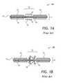
- an index-matching cladding light stripper 10 Aincludes an optical fiber 11 having a core 19 , a cladding 12 , and a coating 13 , which is stripped from the cladding 12 in a middle area 14 of the optical fiber 11 .
- a high-index polymer layer 15is applied to the cladding 12 in the middle area 14 .
- cladding light 16is guided by the cladding 12 .
- the cladding light 16is coupled out of the cladding 12 , as shown in FIG. 1A .
- the index-matching cladding light stripper 10 Acan sometimes achieve good efficiency of stripping cladding light, yet its optical power scalability is limited by the highest temperature the high-index polymer layer 15 can handle, typically in the range of 100° C. to 150° C. Scaling up cladding light power using high-index or index-matched layers is challenging and limited, because using high index polymer to strip out the light has no or little ability to control stripping rate. Hence, the power handling capability of the index-matching cladding light stripper 10 A is limited by localized heating.
- refractive index or the thickness of polymeris selected to facilitate more even temperature distribution.
- Meleshkevich et al. in U.S. Pat. No. 7,839,901disclose a polymer coating having a refractive index that decreases with temperature. The polymer is index-matched to a cladding it is coated upon. When the polymer overheats due to absorption of released cladding light, its refractive index decreases, thereby limiting the local release of light from the cladding and the resultant heating, causing the cladding light to be released at some location downstream of the overheated point. As a result, the heat release becomes more uniform.
- cladding lightusually includes high numerical aperture (NA) residual pump light and low NA scattered core light.
- NAnumerical aperture
- the low NA lightis difficult to remove with polymer based cladding light strippers, since the strip rate of these strippers is very sensitive to NA of the light.
- High NA lighttends to strip out in a much shorter distance compared to low NA light.
- Heat load of polymer based cladding light strippersis highly non-uniform, and extra length must be used to achieve desired strip rate for the low NA cladding light.
- a roughened-surface cladding light stripper 10 Bincludes the optical fiber 11 having the core 19 , the cladding 12 , and the coating 13 , which is stripped off the cladding 12 in the middle area 14 of the optical fiber 11 .
- An outer surface 18 of the cladding 12is roughened in the exposed middle area 14 .
- the cladding light 16is guided by the cladding 12 .
- the cladding light 16is scattered out of the cladding 12 as shown in FIG. 1B .
- the cladding strippercan be polymer free. Detrimentally, most of the cladding light is stripped in the upstream portion of the cladding stripper, creating uneven temperature distribution in the stripper. Furthermore, roughening the surface may generate micro-cracks that can propagate over time and cause the fiber to fail.
- a cladding stripper of the inventionincludes a plurality of transversal notches or grooves in an outer surface of an inner cladding of a double clad optical fiber.
- position and orientation of the notchescan be selected to even out cladding light release along the cladding light stripper, enabling a more even temperature distribution due to released cladding light.
- a cladding strippercan be made polymer-free, thus allowing scaling to high optical power levels.
- a cladding light strippercomprising:
- the cladding light strippercan include an opaque screen or heat sink disposed adjacent the stripped portion of the outer cladding, for absorbing light escaped the inner cladding, and for dissipating heat produced by the absorbed light.
- an optical fiber amplifiercomprising the cladding light stripper, an amplifier double-clad optical fiber portion coupled to the double-clad optical fiber of the cladding light stripper at a first end of the amplifier double clad optical fiber portion, and a pump diode optically coupled to the inner cladding at a second opposing end of the amplifier double clad optical fiber portion, for providing the pump light for propagation from the second end to the first end of the amplifier double clad optical fiber portion.
- a fiber lasercomprising the optical fiber amplifier including the cladding light stripper, and an oscillator optically coupled to the optical fiber amplifier.
- FIGS. 1A and 1Bare side cross-sectional views of prior-art index-matching and roughened-surface cladding light strippers, respectively;
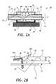
- FIG. 2Ais a side cross-sectional view of a cladding light stripper according to one embodiment of the invention.
- FIG. 2Bis a magnified view of FIG. 1A showing cladding light reflecting and refracting at a surface of a notch;
- FIG. 3is an exploded three-dimensional view of a neat sink of the cladding light stripper of FIG. 2A ;
- FIGS. 4A, 4B, 4C, and 4Dare cross-sectional views of a double-clad optical fiber having notches on one, two, three, and four sides, respectively;
- FIG. 5is an experimental plot of strip efficiency vs. number of notches for two-sided and three-sided notches
- FIG. 6is an experimental plot of strip efficiency vs. notch depth
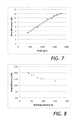
- FIG. 7is an experimental plot of strip efficiency vs. notch pitch
- FIG. 8is an experimental plot of strip efficiency vs. fiber bending radius
- FIG. 9is an experimental plot of optical transmission of low NA and high NA light as a function of bending radius
- FIG. 10is a calculated plot of transmitter power vs. cladding light stripper length for uniformly distributed notches
- FIG. 11is a calculated plot of strip efficiency vs. cladding light stripper length
- FIGS. 12 and 13are a side cross-sectional views of a cladding light stripper of the invention having varying notch pitch and notch depth, respectively;
- FIG. 14Ais a measured surface temperature distribution of a cladding mode stripper prototype having a constant notch pitch and depth
- FIG. 14Bis a measured surface temperature distribution of a cladding mode stripper prototype having a varying notch pitch and depth;
- FIG. 15is a schematic view of an optical fiber amplifier including a cladding light stripper of the invention.
- FIG. 16is a schematic view of a fiber laser including the optical fiber amplifier of FIG. 15 ;
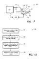
- FIG. 17is a schematic side view of a system for making notches on an optical fiber according to the invention.
- FIG. 18is a flow chart of a method of manufacturing the cladding mode stripper of FIG. 2A using the system of FIG. 17 .
- a cladding light stripper 20includes a double-clad optical fiber 21 having a core 22 for guiding signal light 23 , an inner cladding 24 surrounding the core 22 , and an outer cladding 25 surrounding the inner cladding 24 .
- the optical fiber 21includes a stripped portion 26 wherein the outer cladding 25 is removed, forming an exposed section 27 of an outer surface 28 of the inner cladding 24 .
- the stripped portion 26is absent the outer cladding 25 .
- the exposed section 27includes a plurality of transversal notches 29 disposed along the fiber 21 in the exposed section 27 of the outer surface 28 of the inner cladding 24 to enable cladding light portions 30 A, 30 B ( FIG.
- each of the plurality of notches 29has a width w and a depth d of only a part of a distance D ( FIG. 2B ) to the fiber core 22 . In other words, each notch 29 is clear of the fiber core 22 , not touching or expanding into the fiber core 22 .
- At least 10 notches 29and more preferably at least 30 notches 29 can be provided.
- the depths of the notches 29can be e.g. between 5% and 20% of the diameter of the inner cladding, or 20 micrometers to 80 micrometers deep.
- the cladding light stripper 20includes an optional heat sink 34 disposed adjacent the stripped portion 26 of the outer cladding 25 , for absorbing the light portions 30 A, 30 B that escaped the inner cladding 24 , and for dissipating heat produced by the absorbed light portions 30 A, 30 B.
- the heat sink 34forms a cavity 35 around the stripped portion 26 for intercepting the light portions 30 A, 30 B, which escaped the inner cladding 24 .
- the cavity 35has an absorbing portion 36 and a reflecting portion 37 for directing the escaped light portions 30 A, 30 B to the absorbing portion 36 .
- the absorbing portion 36can be thermally connected to an external heat sink 38 .
- the heat sink 34can also be made out of other material with high heat conductivity of at least 10 W/m-K, more preferably greater than at least 100 W/m-K such as aluminum or copper, for example.
- FIG. 3A prototype of the heat sink 34 is shown in FIG. 3 .
- the absorbing 36 and reflecting 37 portions of the heat sink 34 of FIG. 3are made out of aluminum blocks.
- the cavity 35is machined in the absorbing portion 36 .
- Grooves 39are machined in the absorbing portion 36 for guiding and holding the optical fiber 21 .
- the grooves 39ensure that the optical fiber 21 is slightly bent in the heat sink 34 , preferably to a bending radius of between 50 cm and 200 cm. The bending is done for two reasons: first, to relieve thermally induced stresses in the fiber 21 and second, to improve stripping rate, as will be explained below.
- the absorbing portion 36is black-anodized, while the reflecting portion 37 is polished or white-anodized.
- 3are 220 mm ⁇ 32 mm ⁇ 11 mm.
- at least 40 mm, and more preferably at least 160 mm of the outer cladding 25 of the fiber 21can be stripped to form the stripped portion 26 .
- at least 140 mm of the outer surface 28 of the inner cladding 24can be made available for forming the notches 29 .
- the number of the notches 29 per unit length, herein termed “pitch”,can vary from 1 notch/cm to 1000 notches/cm, and more preferably from 10 notches/cm to 500 notches/cm.
- the optical fiber 21can be either an active fiber providing gain in fiber lasers and fiber optical amplifiers or a passive fiber, e.g. an output fiber spliced onto an active fiber or a power-delivery fiber that can be used with any laser.
- the core 22includes a dopant, e.g. rare earth ions such as Ytterbium and/or Erbium ions, for amplifying the signal light 23 when pumped by pump light 33 ( FIGS. 2A and 2B ) guided by the inner cladding 24 .
- the optical fiber 21is pumped by coupling a pump light source, not shown in FIGS. 2A and 2B , into the inner cladding 24 .
- the pump light 33is mostly absorbed by the rare earth ions in the core 22 .
- the rare earth ionsamplify the signal light 23 propagating in the core 22 .
- a portion of the pump light 33herein termed “residual pump light”, remains unabsorbed.
- the light portions 30 A and 30 Boriginate mostly from the residual pump light 33 ; however, they can also originate from the signal light 23 scattered or spontaneously emitted from the core 22 .
- the residual pump light 33is a high NA light and the scattered signal light 23 is a low NA light.
- the amount of light escaping from the cladding 24depends on the divergence of the cladding light 33 and the depth of the notches 29 .
- Cladding light strip ratecan be adjusted by adjusting size of the notches 29 , angle of incident and the geometry of the notches 29 , the pitch of the notches 29 , and some other parameters, as discussed below.
- the notches 29can be made on multiple sides of the optical fiber 21 . Referring to FIGS. 4A to 4D with further reference to FIG. 2A , the notches 29 can be made on one side ( FIG. 4A ), on two sides ( FIG. 4B ), three sides ( FIG. 4C ), four sides ( FIG. 4D ), and so on, spaced around a circumference of the exposed section 27 . The notches 29 can be spaced both along the length of the exposed section 27 and around the circumference of the exposed section 27 . Furthermore, the notches 29 can be disposed in a helical pattern around the core 22 of the double-clad optical fiber 21 .
- the “strip rate”is defined as optical power loss of the cladding light 33 per unit length of the inner cladding 24 , for example optical power loss in dB per unit length in mm.
- the desired strip rateis selected based on thermal management requirements, length limitation of the cladding mode stripper 20 , and other material properties limitations.
- the strip ratecan be varied by number of sides of the optical fiber 21 where the notches 29 are made.
- the strip rateis typically higher as the number of sides increases, since it provides more escaping points for the cladding 24 to scatter light out.
- the strip ratealso increases with the density and the depth d of the notches 29 .
- the total number of notches 29impacts strip efficiency.
- the “strip efficiency”is defined herein as a total optical power loss after propagating through the cladding light stripper 20 .
- the strip efficiencygenerally increases as the total number of the notches 29 increases.
- the strip efficiency shown in FIG. 5is higher by about 3-4 dB for three-sided notches ( FIG. 4C ) as compared with two-sided notches ( FIG. 4B ).
- the strip rate and efficiencyalso depend on the geometry, for example, the width w, the depth d ( FIG. 2B ) of the notches 29 , hence providing another engineering degree of freedom to control the strip efficiency.
- the depth d of the notches 29is usually kept in between 5% and 20% of the fiber 21 diameter, to maintain the tensile strength of the fiber 21 , and to lessen micro-bending on the core 22 due to the notches 29 .
- the strip efficiencyhas been measured as a function of the depth d of the notches 29 , while other parameters such as the number of sides 31 , the number of notches 29 , and a distance between the notches 29 were kept the same. It is seen that the strip efficiency changes by over 7 dB as the depth d increases from 30 micrometers to 80 micrometers.
- strip efficiencyis shown as a function of the pitch parameter.
- the strip efficiencyvaries by approximately 9 dB as the pitch varies from 400 to 1800 micrometers.
- the strip rate and efficiencyare also sensitive to bending of the exposed section 27 of the cladding mode stripper 20 .
- incident angle relative to the surface of the notches 29increases, therefore reducing the amount of light that will couple back to the inner cladding 24 .
- the amount of light escaping from individual notches 29increases, especially for low NA light, as shown in FIG. 8 .
- the capability of the light cladding stripper 20 to remove low NA lightis very important, since it can narrow down the strip rate difference for the low and high NA light, making it easier to control the heat distribution in the heat sink 34 .
- FIG. 9One example of influence of the bending is shown in FIG. 9 , showing that the difference in the strip efficiency for low and high NA light is greatly reduced when the optical fiber 21 is moderately bent to a radius of 35 cm.
- the dependence of the strip rate and the strip efficiency on the number and depth d of notches 29 , notch pitch, and the bending radius of the optical fiber 21allows one to accommodate various cladding light stripping requirements in specific laser systems, such as power handling capability, cooling requirements, material constraints, requirement on device foot-print, and other constraints and requirements. Accordingly, one benefit of the cladding light stripper 20 is a highly flexible control of heat distribution. It is generally preferable to have very low strip rate at the beginning, or upstream, of the stripped portion 26 , to limit optical power density of the light portions 30 A, 30 B escaping from the inner cladding 24 . At the downstream of the stripped portion 26 , it is desirable to increase the strip rate, in order to clean up the residual cladding mode light.
- the amount of heat dissipated at a given point of the inner cladding 24can be calculated by remaining cladding light power and the strip rate.
- the heat loadwill be much higher at the beginning of the device, and decrease exponentially along the device. As the desired strip power goes up, this characteristic will cause very high temperatures at the beginning of the device, thereby limiting the amount of total power that the device can dissipate.
- the desired dissipating power per unit lengthwhich is dictated by the amount of total cladding light power, desired device footprint or the length of the cladding mode stripper 20 , or maximum heat density that the heat sink 34 can handle.
- FIG. 10an example of cladding light power dissipated at a constant strip rate is shown in FIG. 10 .
- the transmitted optical powerdecreases almost linearly with the length along the cladding light stripper 20 ( FIG. 2A ).
- the strip ratemust be made lower at the beginning of the stripped portion 26 , as illustrated in FIG. 11 .
- either the notch densityneeds to be decreased in the beginning of the stripped portion 26 , as shown in a cladding mode stripper 20 A of FIG.
- the notch pitch of the cladding light stripper 20 A of FIG. 12is gradually increasing from 2 notches/cm to 200 notches/cm, and more preferably from 5 notches/cm to 20 notches/cm, in going from left to right in FIGS. 12 and 13 .
- FIG. 14Aa heat distribution in the heat sink 34 at a constant notch 29 depth d and spacing (pitch) is shown. One can see that most of the heat is dissipated at the beginning at left-hand side of the heat sink 34 . This type of heat distribution is also common in prior-art cladding mode strippers, where the strip rate is constant along the device.
- a heat distribution in the heat sink 34 at a varying notch 29 depth d and spacing (pitch)is shown.
- the temperature profile of the heat sink 34is more even, indicating a more distributed heat load along the heat sink 34 .
- the benefit of the varying notch 29 size and spacingcan be quantified by temperature increase of the heat sink 34 .
- the temperature increase on the heat sinkis only 34 degrees C. for total stripped power of approximately 450 W, which is only half of the temperature increase for the non-distributed heat load cladding mode stripping ( FIG. 14A ) at the same stripped power level of approximately 450 W.
- an optical fiber amplifier 150includes the cladding light stripper 20 and an amplifier double clad optical fiber portion 159 , which is coupled to the double clad optical fiber 21 of the cladding light stripper 20 at a first end 151 of the amplifier double clad optical fiber portion 159 .
- a pump diode 153is optically coupled e.g. via lenses 155 and a dichroic mirror 156 , to a second opposing end 152 of the amplifier double clad optical fiber portion 159 .
- the pump diode 153In operation, the pump diode 153 generates pump light 154 shown in dashed lines, which is coupled to the amplifier double clad optical fiber portion 159 for propagation from the second end 152 to the first end 151 of the amplifier double clad optical fiber portion 159 .
- the dichroic mirror 156reflects light at the pump wavelength, but transmits light at the signal wavelength.
- an input optical signal 157is amplified, and an output optical signal 158 shown in solid lines, or laser light 158 , exits the amplifier via the dichroic mirror 156 .
- the cladding light stripper 20removes most of the residual pump light 154 that has not been absorbed in the doped core 162 of the amplifier double clad optical fiber portion 159 .
- the cladding mode stripper 20can include e.g. an undoped double clad fiber section spliced to the amplifier double clad optical fiber portion 159 , or it can include another portion of a same active (doped) double clad optical fiber that includes the amplifier double clad optical fiber portion 159 .
- the cladding light stripper 20can have a light stripping efficiency of at least 15 dB at residual optical power levels of the pump diode 153 of at least 200 W.
- a fiber laser 160includes the optical fiber amplifier 150 and an oscillator 161 optically coupled to the optical fiber amplifier 150 for generating the input optical signal 157 .
- the function of the cladding light stripper 20is to remove as much cladding light as possible from the inner cladding 24 , to prevent overheating, damage, or de-stabilization of the oscillator 161 .
- the cladding light stripper 20can also be used in various other configurations, for example (1) in a fiber amplifier, not shown, in which the propagation direction of the signal 157 is in the same direction as that of the pump, and the cladding light stripper 20 is disposed near the output end of the active fiber or in a passive delivery fiber spliced to the active fiber, thus stripping both pump and signal light in the cladding; (2) in a double-pass fiber amplifier, not shown, in which the optical signal 157 in the core is reflected so that the optical signal 157 passes twice through the active fiber; (3) in a fiber oscillator, not shown, formed by an active fiber and two reflectors, the cladding light stripper 20 being disposed at the opposite end of the oscillator from the pump; or (4) in an autonomous power-delivery fiber, not shown, that can be attached, e.g. by pluggable connectors or by fiber splicing, to a laser system.
- the cladding light stripper 20is preferably manufactured by laser-material ablation using a manufacturing system 170 shown in FIG. 17 .
- the manufacturing system 170includes a CO 2 laser 171 , a beam delivery system 172 including a delivery fiber 173 and a process head 174 , a motorized translation/rotation stage 175 , and a computer 176 configured for controlling the CO 2 laser 171 and the translation/rotation stage 175 .
- a method 180 of manufacturing the cladding light stripper 20includes a step 181 of removing the portion 26 of the outer cladding 25 leaving the section 27 of the outer surface 28 of the inner cladding 24 exposed.
- the stripped fiber 21is placed onto the motorized translation/rotation stage 175 , and the process head 174 focuses an output laser beam 177 of the CO 2 laser 171 .
- the output laser beam 177can be focused in a spherical or elliptical focal spot 178 on the outer surface 28 of the exposed section 27 .
- the process head 174can include a combination of spherical/meniscus and/or cylindrical lenses, not shown.
- the CO 2 laser 171is preferably operated in gated mode in tens to hundreds of microseconds, and the peak intensity of the focused laser beam is selected to be above the damage threshold of the inner cladding material, for example between 100 kW/cm 2 and 200 kW/cm 2 for fused silica, depending on pulse duration.
- the focal spot 178can be between 80 micrometers and 200 micrometers in size.
- the focal spot 178can shaped, and/or the laser beam 177 can be angled, to produce a desired shape of the notch 29 .
- the laser beam 177is focused on to the next position in a step 183 , by moving either the fiber 21 as indicated by an arrow 179 using the translation/rotation stage 175 , or the laser beam 177 , to create consequent notches 29 . Then, in a step 184 , the focusing and ablating step 182 is repeated, the fiber 21 is shifted to a next position, and so on.
- the spacing between adjacent notches 29can be identical or varying, controlled either manually or automatically via the computer 176 and the translation/rotation stage 175 to displace the optical fiber 21 lengthwise, to achieve desired stripping efficiency and/or heat load distribution as explained above.
- the width w and the depth d of the notches 29is controlled by changing the CO 2 laser 171 and/or focusing parameters, i.e. numbers of shots on each notch 29 , peak power, laser pulse duration, laser temporal waveform, laser focus intensity, laser focal spot size, position of the fiber 21 relative to laser focus 178 , and the like.
- the manufacturing system 170can be used to make the cladding light stripper 20 in any fiber even on an existing laser system, with no additional splice required. This is advantageous, because additional splices could further introduce core light loss and degradation in output laser beam quality.
- the notches 29can be made on one or multiple sides of the fiber 21 as shown in FIGS. 4A to 4D , by either rotating the fiber 21 using the translation/rotation stage 175 , or using multiple laser beams, not shown.
- the number of sides where the notches 29 are madeis dictated by the desired stripping efficiency and/or other requirements.
- Other laser typescan be used to form the notches, for example UV lasers.
- the cladding mode stripper 20 manufactured using the CO 2 laser system 170 ( FIG. 17 ) and the method 180 ( FIG. 18 )has been demonstrated to strip up to 500 W of the inner cladding light 33 , with very low temperature coefficient for fused silica inner cladding 24 , typically about 0.06° C. per one Watt (W) of removed optical power, and for polymer outer cladding 25 , typically ⁇ 0.03° C./W.
- a cladding mode stripper 20only 40 millimeters long can create about 19 dB of attenuation for low NA of less than 0.08 cladding light portions 30 A, 30 B, at the power level of 500 W. Typically, at least 16-23 dB stripping efficiency was achieved, with an occasional efficiency of up to 32 dB for low NA cladding light portions 30 A, 30 B of less than 0.08.
- Another advantage of the cladding light stripper 20is that even with extensive modifications on the surface 28 of the inner cladding 24 , little or no degradation of the tensile strength of the optical fiber 21 was observed. All prototype devices had been tested with bending test and all passed equivalent tensile strength of 50 kPSI. Furthermore, a packaged prototype cladding light stripper 20 has passed standard industrial 25G shock test and 5G sine sweep vibration test.
- laser notching fabrication method 180 of FIG. 18could introduce refractive index change on the core 22 of the optical fiber 21 , it is possible that such device could introduce insertion loss or degradation in mode quality.
- One way to mitigate this effectis to lessen the depth d of the notches 29 , or select a notch pitch that is different from a resonance frequency which will couple the fundamental mode of the core light 23 into a higher order mode. These factors are preferably taken into consideration when selecting notch pitch. It has been experimentally confirmed that no loss in the core optical power or degradation in the mode quality was observed with prototypes of the cladding light strippers 20 .
Landscapes
- Physics & Mathematics (AREA)
- Optics & Photonics (AREA)
- Engineering & Computer Science (AREA)
- Electromagnetism (AREA)
- Plasma & Fusion (AREA)
- Mechanical Engineering (AREA)
- General Physics & Mathematics (AREA)
- Ophthalmology & Optometry (AREA)
- Manufacturing & Machinery (AREA)
- Health & Medical Sciences (AREA)
- Lasers (AREA)
- Optical Couplings Of Light Guides (AREA)
- Light Guides In General And Applications Therefor (AREA)
- Optical Fibers, Optical Fiber Cores, And Optical Fiber Bundles (AREA)
Abstract
Description
- a double-clad optical fiber having a core for guiding signal light, an inner cladding surrounding the core, and an outer cladding surrounding the inner cladding,
- wherein the optical fiber includes a stripped portion wherein the outer cladding is removed, forming an exposed section of an outer surface of the inner cladding, wherein the exposed section includes a plurality of transversal notches disposed along the fiber, to enable light to escape the inner cladding upon impinging on the notches, wherein each of the plurality of notches has a depth of only a partial distance to the fiber core.
- a) removing a portion of the outer cladding leaving the exposed section of the inner cladding;
- b) focusing a laser beam on the outer surface of the inner cladding in the exposed section to evaporate and remove the inner cladding locally to form a transversal notch in the inner cladding; and
- c) repeating step b) a plurality of times at different locations along the exposed section.
Claims (20)
Priority Applications (2)
| Application Number | Priority Date | Filing Date | Title |
|---|---|---|---|
| US15/393,887US10090631B2 (en) | 2013-01-28 | 2016-12-29 | Cladding light stripper and method of manufacturing |
| US15/687,052US10802209B2 (en) | 2013-01-28 | 2017-08-25 | Cladding light stripper |
Applications Claiming Priority (3)
| Application Number | Priority Date | Filing Date | Title |
|---|---|---|---|
| US201361757434P | 2013-01-28 | 2013-01-28 | |
| US14/166,600US9547121B2 (en) | 2013-01-28 | 2014-01-28 | Cladding light stripper and method of manufacturing |
| US15/393,887US10090631B2 (en) | 2013-01-28 | 2016-12-29 | Cladding light stripper and method of manufacturing |
Related Parent Applications (1)
| Application Number | Title | Priority Date | Filing Date |
|---|---|---|---|
| US14/166,600ContinuationUS9547121B2 (en) | 2013-01-28 | 2014-01-28 | Cladding light stripper and method of manufacturing |
Related Child Applications (1)
| Application Number | Title | Priority Date | Filing Date |
|---|---|---|---|
| US15/687,052Continuation-In-PartUS10802209B2 (en) | 2013-01-28 | 2017-08-25 | Cladding light stripper |
Publications (2)
| Publication Number | Publication Date |
|---|---|
| US20170110845A1 US20170110845A1 (en) | 2017-04-20 |
| US10090631B2true US10090631B2 (en) | 2018-10-02 |
Family
ID=50287512
Family Applications (2)
| Application Number | Title | Priority Date | Filing Date |
|---|---|---|---|
| US14/166,600Active2034-12-15US9547121B2 (en) | 2013-01-28 | 2014-01-28 | Cladding light stripper and method of manufacturing |
| US15/393,887ActiveUS10090631B2 (en) | 2013-01-28 | 2016-12-29 | Cladding light stripper and method of manufacturing |
Family Applications Before (1)
| Application Number | Title | Priority Date | Filing Date |
|---|---|---|---|
| US14/166,600Active2034-12-15US9547121B2 (en) | 2013-01-28 | 2014-01-28 | Cladding light stripper and method of manufacturing |
Country Status (4)
| Country | Link |
|---|---|
| US (2) | US9547121B2 (en) |
| JP (2) | JP6189223B2 (en) |
| DE (1) | DE102014201504B4 (en) |
| GB (1) | GB2511923B (en) |
Cited By (3)
| Publication number | Priority date | Publication date | Assignee | Title |
|---|---|---|---|---|
| US11502477B2 (en) | 2020-02-26 | 2022-11-15 | Lumentum Operations Llc | In-fiber retroreflector |
| US11531162B2 (en) | 2020-03-27 | 2022-12-20 | University Of Seoul Industry Cooperation Foundation | Optical fiber device for removing cladding light, apparatus and method for etching the same |
| US11901691B2 (en) | 2020-03-18 | 2024-02-13 | Lumentum Operations Llc | Subsurface induced scattering centers |
Families Citing this family (72)
| Publication number | Priority date | Publication date | Assignee | Title |
|---|---|---|---|---|
| GB2511923B (en)* | 2013-01-28 | 2018-10-03 | Lumentum Operations Llc | A cladding light stripper and method of manufacturing |
| US10802209B2 (en) | 2013-01-28 | 2020-10-13 | Lumentum Operations Llc | Cladding light stripper |
| US20140363125A1 (en)* | 2013-06-06 | 2014-12-11 | Prima Electro North America, LLC | Cladding mode stripper |
| US9946040B2 (en)* | 2014-01-17 | 2018-04-17 | Empire Technology Development Llc | Optical fibers without cladding |
| JP6010565B2 (en)* | 2014-02-03 | 2016-10-19 | 株式会社フジクラ | Excess light removal structure and fiber laser |
| US10069271B2 (en) | 2014-06-02 | 2018-09-04 | Nlight, Inc. | Scalable high power fiber laser |
| CN105720463B (en) | 2014-08-01 | 2021-05-14 | 恩耐公司 | Protection and monitoring of back reflection in optical fiber and fiber-optic transmission lasers |
| JP2016061944A (en)* | 2014-09-18 | 2016-04-25 | 住友電気工業株式会社 | Fan-out parts |
| JP5834125B1 (en)* | 2014-09-29 | 2015-12-16 | 株式会社フジクラ | Optical fiber module |
| US9837783B2 (en) | 2015-01-26 | 2017-12-05 | Nlight, Inc. | High-power, single-mode fiber sources |
| US10050404B2 (en) | 2015-03-26 | 2018-08-14 | Nlight, Inc. | Fiber source with cascaded gain stages and/or multimode delivery fiber with low splice loss |
| CN104749694B (en)* | 2015-03-30 | 2016-03-02 | 深圳市创鑫激光股份有限公司 | The method for making of optical fiber mode stripper and optical fiber mode stripper |
| US9551839B2 (en)* | 2015-03-31 | 2017-01-24 | Raytheon Company | Optical component including nanoparticle heat sink |
| US10520671B2 (en) | 2015-07-08 | 2019-12-31 | Nlight, Inc. | Fiber with depressed central index for increased beam parameter product |
| JP6743136B2 (en) | 2015-09-24 | 2020-08-19 | エヌライト,インコーポレーテッド | Beam Parameter Product (BPP) Control by Changing Fiber to Fiber Angle |
| US11072554B2 (en) | 2015-11-10 | 2021-07-27 | Nkt Photonics A/S | Element for a preform, a fiber production method and an optical fiber drawn from the preform |
| WO2017091505A1 (en) | 2015-11-23 | 2017-06-01 | Nlight, Inc. | Fine-scale temporal control for laser material processing |
| US11179807B2 (en) | 2015-11-23 | 2021-11-23 | Nlight, Inc. | Fine-scale temporal control for laser material processing |
| US11114813B2 (en)* | 2015-11-25 | 2021-09-07 | Raytheon Company | Integrated pumplight homogenizer and signal injector for high-power laser system |
| US10297968B2 (en) | 2015-11-25 | 2019-05-21 | Raytheon Company | High-gain single planar waveguide (PWG) amplifier laser system |
| SG11201804738SA (en) | 2015-12-23 | 2018-07-30 | Nkt Photonics As | Hollow core optical fiber and a laser system |
| GB2545730B (en)* | 2015-12-23 | 2018-11-14 | Afl Global | A mechanical fuse for use with overhead telecommunications cable |
| JP7136695B2 (en) | 2015-12-23 | 2022-09-13 | エヌケイティー フォトニクス アクティーゼルスカブ | Photonic crystal fiber assembly |
| CN105676354A (en)* | 2016-04-13 | 2016-06-15 | 昆山华辰光电科技有限公司 | Novel high-power fiber mode stripper capable of polishing and grinding lateral side of fiber |
| EP3448818B1 (en) | 2016-04-27 | 2024-09-25 | NKT Photonics A/S | A method of fiber production |
| EP3458890B1 (en) | 2016-05-15 | 2021-12-29 | NLIGHT, Inc. | High-numerical aperture light stripper |
| EP3453085A4 (en) | 2016-05-16 | 2019-06-05 | NLIGHT, Inc. | Light trap for high power fiber laser connector |
| CN106019476A (en)* | 2016-07-14 | 2016-10-12 | 华中科技大学 | Optical fiber cladding optical power stripper and quartz casing thereof |
| CN105977774A (en)* | 2016-07-15 | 2016-09-28 | 中国科学院半导体研究所 | Fiber used for laser-mode stripping, and laser-mode stripper applying same |
| US9905989B1 (en) | 2016-07-25 | 2018-02-27 | Bae Systems Information And Electronic Systems Integration Inc. | Method for high-rate fiber laser manufacturing |
| WO2018039498A2 (en)* | 2016-08-26 | 2018-03-01 | Nlight, Inc. | Splice with cladding mode light stripping |
| US10730785B2 (en) | 2016-09-29 | 2020-08-04 | Nlight, Inc. | Optical fiber bending mechanisms |
| US10673197B2 (en) | 2016-09-29 | 2020-06-02 | Nlight, Inc. | Fiber-based optical modulator |
| US10673198B2 (en) | 2016-09-29 | 2020-06-02 | Nlight, Inc. | Fiber-coupled laser with time varying beam characteristics |
| CN109791252B (en) | 2016-09-29 | 2021-06-29 | 恩耐公司 | Adjustable beam characteristics |
| US10673199B2 (en) | 2016-09-29 | 2020-06-02 | Nlight, Inc. | Fiber-based saturable absorber |
| US10732439B2 (en) | 2016-09-29 | 2020-08-04 | Nlight, Inc. | Fiber-coupled device for varying beam characteristics |
| CN106405737B (en)* | 2016-10-09 | 2019-08-09 | 武汉锐科光纤激光技术股份有限公司 | A kind of Cladding Power Stripper and production method removing higher order mode laser |
| AU2017344058B2 (en) | 2016-10-11 | 2022-11-10 | Boston Scientific Scimed, Inc. | Medical laser device and related methods |
| JP6423914B1 (en)* | 2017-04-28 | 2018-11-14 | 株式会社フジクラ | Clad mode stripper |
| CN107425404B (en)* | 2017-05-19 | 2020-11-03 | 大族激光科技产业集团股份有限公司 | Processing method of cladding light stripper |
| CN107069393A (en)* | 2017-06-12 | 2017-08-18 | 中国工程物理研究院激光聚变研究中心 | Cladding power stripper and optical fiber laser |
| JP7361459B2 (en)* | 2017-08-25 | 2023-10-16 | ルーメンタム オペレーションズ エルエルシー | clad light remover |
| JP2019070760A (en)* | 2017-10-10 | 2019-05-09 | 株式会社フジクラ | Optical device and laser device |
| CN107845945B (en)* | 2017-11-02 | 2024-04-12 | 武汉锐科光纤激光技术股份有限公司 | Mode stripper for high-power optical fiber laser and manufacturing method thereof |
| TWI654918B (en)* | 2017-11-10 | 2019-03-21 | 國家中山科學研究院 | Cooling structure for a package of an optical fiber |
| US11448825B2 (en) | 2017-12-19 | 2022-09-20 | Afl Telecommunications Llc | Methods for forming side-pumped optical fiber combiners |
| US20200041719A1 (en)* | 2018-08-03 | 2020-02-06 | Afl Telecommunications Llc | Ablated end fibers and methods for ablating optical fibers |
| EP3850408A4 (en)* | 2018-09-10 | 2022-05-18 | nLIGHT, Inc. | OPTICAL FIBER SPLICE ENCAPSULATED BY SHEATH MODE LIGHT SUPPRESSOR |
| WO2020061505A1 (en) | 2018-09-21 | 2020-03-26 | Nlight, Inc. | Optical fiber cladding light stripper |
| KR102094468B1 (en)* | 2018-10-12 | 2020-03-27 | 국방과학연구소 | Cladding light stripper and method of manufacturing the same |
| CN109599740A (en)* | 2019-01-31 | 2019-04-09 | 天津大学 | With the two directional pump double-cladding fiber laser amplifier for inhibiting SBS effect |
| JP6966491B2 (en) | 2019-02-01 | 2021-11-17 | ファナック株式会社 | Laser oscillator with a housing heat suppression function |
| JP6903696B2 (en)* | 2019-02-05 | 2021-07-14 | 三菱電線工業株式会社 | Clad mode stripper structure |
| KR102269317B1 (en)* | 2019-06-14 | 2021-06-28 | 포미주식회사 | Cladding Power Stripper and Apparatus for Manufacturing the Same |
| US11641089B2 (en)* | 2019-09-30 | 2023-05-02 | Nlight, Inc. | Cladless fiber for fiber laser pump and combiner |
| WO2021155043A1 (en)* | 2020-01-30 | 2021-08-05 | Nlight, Inc. | Capillary tube to strip back-reflected light |
| KR102387158B1 (en)* | 2020-03-27 | 2022-04-14 | 서울시립대학교 산학협력단 | Optical fiber device for removing cladding light |
| WO2021211195A1 (en)* | 2020-04-14 | 2021-10-21 | Luna Innovations Incorporated | Modification of internally clad sapphire fiber to attenuate cladding modes at high temperatures |
| DE102020113731B4 (en)* | 2020-05-20 | 2024-02-08 | FiberBridge Photonics GmbH | Fiberglass and fiberglass product |
| CN111596408B (en)* | 2020-05-25 | 2022-01-25 | 光惠(上海)激光科技有限公司 | High-power fiber laser indication light protection device and implementation method thereof |
| DE102020115555A1 (en) | 2020-06-11 | 2021-12-16 | FiberBridge Photonics GmbH | Fiber amplifiers or fiber lasers |
| WO2022015718A1 (en)* | 2020-07-14 | 2022-01-20 | Nlight, Inc. | Clad light stripper with light traps |
| CN112234418A (en)* | 2020-12-11 | 2021-01-15 | 中国工程物理研究院激光聚变研究中心 | Packaging shell of cladding power stripper |
| US11415751B2 (en)* | 2020-12-17 | 2022-08-16 | Lumentum Operations Llc | Free space coupling of an aiming beam using tapered or grated cladding |
| CN112629825B (en)* | 2021-03-05 | 2021-06-18 | 武汉光谷航天三江激光产业技术研究院有限公司 | Device and method for radially measuring stripping efficiency of optical fiber cladding light stripper |
| JP2023019638A (en)* | 2021-07-29 | 2023-02-09 | 株式会社アマダ | Clad light stripper and method for manufacturing the clad light stripper |
| CN114527534B (en)* | 2022-04-24 | 2022-06-24 | 武汉锐科光纤激光技术股份有限公司 | Optical fiber mold stripper, preparation method of optical fiber mold stripper and laser equipment |
| CN115220147A (en)* | 2022-08-31 | 2022-10-21 | 北京凯普林光电科技股份有限公司 | A kind of cladding light stripper and preparation method thereof |
| CN115291327B (en)* | 2022-10-10 | 2023-02-03 | 武汉锐科光纤激光技术股份有限公司 | Optical fiber stripper, preparation method of optical fiber stripper and laser |
| CN115657214B (en)* | 2022-12-08 | 2023-03-07 | 武汉锐科光纤激光技术股份有限公司 | Clad light stripper, method for manufacturing clad light stripper, and laser device |
| CN117111204B (en)* | 2023-10-24 | 2024-03-19 | 中国工程物理研究院激光聚变研究中心 | Optical fiber, cladding power stripper and optical fiber laser |
Citations (58)
| Publication number | Priority date | Publication date | Assignee | Title |
|---|---|---|---|---|
| US3933455A (en) | 1973-06-14 | 1976-01-20 | International Standard Electric Corporation | Method for joining optical fibre bundles |
| US3958188A (en) | 1974-12-11 | 1976-05-18 | Nasa | Fiber distributed feedback laser |
| US4049413A (en) | 1976-06-21 | 1977-09-20 | Bell Telephone Laboratories, Incorporated | Method for making optical fibers with variations in core diameter |
| US4097118A (en) | 1975-10-30 | 1978-06-27 | Rca Corporation | Optical waveguide coupler employing deformed shape fiber-optic core coupling portion |
| US4400056A (en) | 1980-07-09 | 1983-08-23 | Her Majesty The Queen As Represented By The Minister Of National Defence Of Her Majesty's Canadian Government | Evanescent-wave fiber reflector |
| US4465335A (en) | 1982-10-12 | 1984-08-14 | The United States Of America As Represented By The Secretary Of The Army | Concentric core optical fiber coupler |
| US4678273A (en) | 1983-12-23 | 1987-07-07 | Radians Ab | High power optical fiber with improved covering |
| US4710605A (en) | 1985-04-08 | 1987-12-01 | American Telephone And Telegraph Company, At&T Bell Laboratories | Laser nibbling of optical waveguides |
| US4842405A (en) | 1987-04-03 | 1989-06-27 | El Sherif Mahmoud | Process for producing a grating on an optical fiber |
| US4911516A (en) | 1989-02-27 | 1990-03-27 | General Electric Company | Optical device with mode selecting grating |
| US4955028A (en) | 1988-03-25 | 1990-09-04 | At&T Bell Laboratories | Wavelength tunable composite cavity laser |
| US5037172A (en) | 1989-03-22 | 1991-08-06 | Teledyne Industry, Inc. | Fiber optic device with a reflective notch coupler |
| US5321257A (en) | 1991-07-31 | 1994-06-14 | Danisch Lee A | Fiber optic bending and positioning sensor including a light emission surface formed on a portion of a light guide |
| US5432876A (en) | 1992-10-19 | 1995-07-11 | Minnesota Mining And Manufacturing Company | Illumination devices and optical fibres for use therein |
| US5500913A (en) | 1993-03-15 | 1996-03-19 | Administrators Of The Tulane Educational Fund | Apparatus and method of fabricating directional fiber optic taps, sensors and other devices with variable angle output |
| JPH08304857A (en) | 1995-05-09 | 1996-11-22 | Atr Kodenpa Tsushin Kenkyusho:Kk | Optical amplifier |
| US5659643A (en) | 1995-01-23 | 1997-08-19 | Minnesota Mining And Manufacturing Company | Notched fiber array illumination device |
| US5790735A (en) | 1995-08-31 | 1998-08-04 | Sdl, Inc. | Optical fibre for improved power coupling |
| US5854865A (en) | 1995-12-07 | 1998-12-29 | The United States Of America As Represented By The Secretary Of The Navy | Method and apparatus for side pumping an optical fiber |
| US6087655A (en) | 1998-05-19 | 2000-07-11 | Kobrin; Boris | Fiber grating encoders and methods for fabricating the same |
| US6243515B1 (en) | 1999-06-18 | 2001-06-05 | Trw Inc. | Apparatus for optically pumping an optical fiber from the side |
| WO2001067908A1 (en) | 2000-03-14 | 2001-09-20 | Hasan Misedovich Tkhazeplov | Heel for shoes |
| US20030174962A1 (en) | 2002-03-18 | 2003-09-18 | Poole Craig D. | Low-loss optical fiber tap with integral reflecting surface |
| US6624927B1 (en) | 2001-03-14 | 2003-09-23 | Onetta, Inc. | Raman optical amplifiers |
| US6801550B1 (en)* | 2003-05-30 | 2004-10-05 | Bae Systems Information And Electronic Systems Integration Inc. | Multiple emitter side pumping method and apparatus for fiber lasers |
| US6865316B1 (en) | 2002-10-23 | 2005-03-08 | Nlight Photonics Corporation | System and method of operating low coupling efficiency optical source by dissipating cladding modes |
| US20050117860A1 (en) | 2002-03-15 | 2005-06-02 | Guillaume Vienne | Microstructured optical fibre with cladding recess, a method of its production, and apparatus comprising same |
| US6975792B1 (en) | 2001-11-09 | 2005-12-13 | Keopsys, Inc. | Method and apparatus for coupling light into a waveguide using a slit |
| US20070071389A1 (en) | 2005-09-28 | 2007-03-29 | Yoon Shin Y | Wavelength selective optical focusing device using optical fiber and optical module using the same |
| WO2007080703A1 (en) | 2006-01-16 | 2007-07-19 | Hamamatsu Photonics K.K. | Optical fiber |
| JP2007227713A (en) | 2006-02-24 | 2007-09-06 | Fujikura Ltd | Fusion splicing structure between fibers, optical amplifier and optical fiber laser |
| US20070258673A1 (en) | 2006-05-08 | 2007-11-08 | El-Sherif Mahmoud A | On-fiber tunable bragg gratings for DWDM applications |
| US7324723B2 (en) | 2003-10-06 | 2008-01-29 | Mitsui Chemicals, Inc. | Optical waveguide having specular surface formed by laser beam machining |
| US7373070B2 (en) | 2006-01-23 | 2008-05-13 | Itf Laboratories Inc. | Optical fiber component package for high power dissipation |
| JP2008187100A (en) | 2007-01-31 | 2008-08-14 | Fujikura Ltd | Residual light removal structure, optical fiber laser and optical fiber amplifier using the same |
| US20080247424A1 (en) | 2005-10-02 | 2008-10-09 | Zachary Sacks | Fiber lasers |
| WO2008123609A1 (en) | 2007-04-04 | 2008-10-16 | Mitsubishi Electric Corporation | Laser processing apparatus and laser processing method |
| JP2008268747A (en) | 2007-04-24 | 2008-11-06 | Furukawa Electric Co Ltd:The | Optical fiber leakage light processing structure and optical fiber laser |
| JP2008293004A (en) | 2007-04-24 | 2008-12-04 | Furukawa Electric Co Ltd:The | Optical fiber grating device and optical fiber laser |
| US7526165B2 (en) | 2004-03-19 | 2009-04-28 | Crystal Fibre A/S | Optical coupler devices, methods of their production and use |
| US20100135339A1 (en) | 2008-12-03 | 2010-06-03 | Mikhail Meleshkevich | High power fiber laser system with cladding light stripper |
| JP2010181574A (en) | 2009-02-04 | 2010-08-19 | Olympus Corp | Method and apparatus for light filtering of double clad fiber |
| WO2010128675A1 (en) | 2009-05-08 | 2010-11-11 | 三菱電線工業株式会社 | Structure for mounting connector on end of optical fiber |
| US20110103743A1 (en)* | 2008-06-23 | 2011-05-05 | Imec | Method and system for coupling radiation |
| WO2011067908A1 (en) | 2009-12-04 | 2011-06-09 | 三菱電線工業株式会社 | Optical fiber and method for working optical fiber |
| JP2011525706A (en) | 2008-06-25 | 2011-09-22 | コラクティヴ ハイ−テック インコーポレイティド | Energy dissipation package for high power optical fiber components |
| US8027557B2 (en) | 2007-09-24 | 2011-09-27 | Nufern | Optical fiber laser, and components for an optical fiber laser, having reduced susceptibility to catastrophic failure under high power operation |
| CN102255227A (en) | 2011-04-29 | 2011-11-23 | 中国科学院上海光学精密机械研究所 | Optical fiber cladding light filter and manufacturing method thereof |
| JP2012014173A (en) | 2010-06-30 | 2012-01-19 | Jds Uniphase Corp | Scalable cladding mode stripper device |
| US20120070115A1 (en) | 2010-09-21 | 2012-03-22 | Textron Systems Corporation | All glass fiber laser cladding mode stripper |
| JP2012114299A (en) | 2010-11-25 | 2012-06-14 | Fujikura Ltd | Fiber laser device |
| WO2012088267A2 (en) | 2010-12-23 | 2012-06-28 | Nufern | Rough-clad optical fibers |
| WO2012099116A1 (en) | 2011-01-18 | 2012-07-26 | 古河電気工業株式会社 | Fiber laser apparatus and method for aligning laser light irradiation position |
| US20120262781A1 (en) | 2008-08-21 | 2012-10-18 | Nlight Photonics Corporation | Hybrid laser amplifier system including active taper |
| US8355608B2 (en) | 2010-04-12 | 2013-01-15 | Lockheed Martin Corporation | Method and apparatus for in-line fiber-cladding-light dissipation |
| JP2014010427A (en) | 2012-07-03 | 2014-01-20 | Sumitomo Electric Ind Ltd | Optical fiber and optical cable |
| JP2014126687A (en) | 2012-12-26 | 2014-07-07 | Mitsubishi Cable Ind Ltd | Optical fiber structure and manufacturing method for the same |
| US9547121B2 (en)* | 2013-01-28 | 2017-01-17 | Lumentum Operations Llc | Cladding light stripper and method of manufacturing |
Family Cites Families (1)
| Publication number | Priority date | Publication date | Assignee | Title |
|---|---|---|---|---|
| US7862219B2 (en) | 2008-10-22 | 2011-01-04 | Advanced Photodynamic Technologies, Inc. | Optical fiber light diffusing device |
- 2014
- 2014-01-24GBGB1401226.4Apatent/GB2511923B/enactiveActive
- 2014-01-27JPJP2014012031Apatent/JP6189223B2/enactiveActive
- 2014-01-28USUS14/166,600patent/US9547121B2/enactiveActive
- 2014-01-28DEDE102014201504.9Apatent/DE102014201504B4/enactiveActive
- 2016
- 2016-12-29USUS15/393,887patent/US10090631B2/enactiveActive
- 2017
- 2017-08-02JPJP2017149917Apatent/JP6727172B2/enactiveActive
Patent Citations (64)
| Publication number | Priority date | Publication date | Assignee | Title |
|---|---|---|---|---|
| US3933455A (en) | 1973-06-14 | 1976-01-20 | International Standard Electric Corporation | Method for joining optical fibre bundles |
| US3958188A (en) | 1974-12-11 | 1976-05-18 | Nasa | Fiber distributed feedback laser |
| US4097118A (en) | 1975-10-30 | 1978-06-27 | Rca Corporation | Optical waveguide coupler employing deformed shape fiber-optic core coupling portion |
| US4049413A (en) | 1976-06-21 | 1977-09-20 | Bell Telephone Laboratories, Incorporated | Method for making optical fibers with variations in core diameter |
| US4400056A (en) | 1980-07-09 | 1983-08-23 | Her Majesty The Queen As Represented By The Minister Of National Defence Of Her Majesty's Canadian Government | Evanescent-wave fiber reflector |
| US4465335A (en) | 1982-10-12 | 1984-08-14 | The United States Of America As Represented By The Secretary Of The Army | Concentric core optical fiber coupler |
| US4678273A (en) | 1983-12-23 | 1987-07-07 | Radians Ab | High power optical fiber with improved covering |
| US4710605A (en) | 1985-04-08 | 1987-12-01 | American Telephone And Telegraph Company, At&T Bell Laboratories | Laser nibbling of optical waveguides |
| US4842405A (en) | 1987-04-03 | 1989-06-27 | El Sherif Mahmoud | Process for producing a grating on an optical fiber |
| US4955028A (en) | 1988-03-25 | 1990-09-04 | At&T Bell Laboratories | Wavelength tunable composite cavity laser |
| US4911516A (en) | 1989-02-27 | 1990-03-27 | General Electric Company | Optical device with mode selecting grating |
| US5037172A (en) | 1989-03-22 | 1991-08-06 | Teledyne Industry, Inc. | Fiber optic device with a reflective notch coupler |
| US5321257A (en) | 1991-07-31 | 1994-06-14 | Danisch Lee A | Fiber optic bending and positioning sensor including a light emission surface formed on a portion of a light guide |
| US5432876A (en) | 1992-10-19 | 1995-07-11 | Minnesota Mining And Manufacturing Company | Illumination devices and optical fibres for use therein |
| US5432876C1 (en) | 1992-10-19 | 2002-05-21 | Minnesota Mining & Mfg | Illumination devices and optical fibres for use therein |
| US5500913A (en) | 1993-03-15 | 1996-03-19 | Administrators Of The Tulane Educational Fund | Apparatus and method of fabricating directional fiber optic taps, sensors and other devices with variable angle output |
| US5659643A (en) | 1995-01-23 | 1997-08-19 | Minnesota Mining And Manufacturing Company | Notched fiber array illumination device |
| JPH08304857A (en) | 1995-05-09 | 1996-11-22 | Atr Kodenpa Tsushin Kenkyusho:Kk | Optical amplifier |
| US5790735A (en) | 1995-08-31 | 1998-08-04 | Sdl, Inc. | Optical fibre for improved power coupling |
| US5854865A (en) | 1995-12-07 | 1998-12-29 | The United States Of America As Represented By The Secretary Of The Navy | Method and apparatus for side pumping an optical fiber |
| US6087655A (en) | 1998-05-19 | 2000-07-11 | Kobrin; Boris | Fiber grating encoders and methods for fabricating the same |
| US6243515B1 (en) | 1999-06-18 | 2001-06-05 | Trw Inc. | Apparatus for optically pumping an optical fiber from the side |
| WO2001067908A1 (en) | 2000-03-14 | 2001-09-20 | Hasan Misedovich Tkhazeplov | Heel for shoes |
| US6624927B1 (en) | 2001-03-14 | 2003-09-23 | Onetta, Inc. | Raman optical amplifiers |
| US6975792B1 (en) | 2001-11-09 | 2005-12-13 | Keopsys, Inc. | Method and apparatus for coupling light into a waveguide using a slit |
| US20050117860A1 (en) | 2002-03-15 | 2005-06-02 | Guillaume Vienne | Microstructured optical fibre with cladding recess, a method of its production, and apparatus comprising same |
| US7221840B2 (en) | 2002-03-15 | 2007-05-22 | Crystal Fibre A/S | Microstructured optical fibre with cladding recess, a method of its production, and apparatus comprising same |
| US20030174962A1 (en) | 2002-03-18 | 2003-09-18 | Poole Craig D. | Low-loss optical fiber tap with integral reflecting surface |
| US6865316B1 (en) | 2002-10-23 | 2005-03-08 | Nlight Photonics Corporation | System and method of operating low coupling efficiency optical source by dissipating cladding modes |
| US6801550B1 (en)* | 2003-05-30 | 2004-10-05 | Bae Systems Information And Electronic Systems Integration Inc. | Multiple emitter side pumping method and apparatus for fiber lasers |
| US7324723B2 (en) | 2003-10-06 | 2008-01-29 | Mitsui Chemicals, Inc. | Optical waveguide having specular surface formed by laser beam machining |
| US7526165B2 (en) | 2004-03-19 | 2009-04-28 | Crystal Fibre A/S | Optical coupler devices, methods of their production and use |
| US20070071389A1 (en) | 2005-09-28 | 2007-03-29 | Yoon Shin Y | Wavelength selective optical focusing device using optical fiber and optical module using the same |
| US20080247424A1 (en) | 2005-10-02 | 2008-10-09 | Zachary Sacks | Fiber lasers |
| WO2007080703A1 (en) | 2006-01-16 | 2007-07-19 | Hamamatsu Photonics K.K. | Optical fiber |
| US7373070B2 (en) | 2006-01-23 | 2008-05-13 | Itf Laboratories Inc. | Optical fiber component package for high power dissipation |
| JP2007227713A (en) | 2006-02-24 | 2007-09-06 | Fujikura Ltd | Fusion splicing structure between fibers, optical amplifier and optical fiber laser |
| US20070258673A1 (en) | 2006-05-08 | 2007-11-08 | El-Sherif Mahmoud A | On-fiber tunable bragg gratings for DWDM applications |
| JP2008187100A (en) | 2007-01-31 | 2008-08-14 | Fujikura Ltd | Residual light removal structure, optical fiber laser and optical fiber amplifier using the same |
| WO2008123609A1 (en) | 2007-04-04 | 2008-10-16 | Mitsubishi Electric Corporation | Laser processing apparatus and laser processing method |
| US20100163537A1 (en) | 2007-04-04 | 2010-07-01 | Mitsubishi Electric Corporation | Apparatus and method for laser machining |
| JP2008268747A (en) | 2007-04-24 | 2008-11-06 | Furukawa Electric Co Ltd:The | Optical fiber leakage light processing structure and optical fiber laser |
| JP2008293004A (en) | 2007-04-24 | 2008-12-04 | Furukawa Electric Co Ltd:The | Optical fiber grating device and optical fiber laser |
| US8229260B2 (en) | 2007-09-24 | 2012-07-24 | Nefern | Optical fiber laser, and components for an optical fiber laser, having reduced susceptibility to catastrophic failure under high power operation |
| US8027557B2 (en) | 2007-09-24 | 2011-09-27 | Nufern | Optical fiber laser, and components for an optical fiber laser, having reduced susceptibility to catastrophic failure under high power operation |
| US20110103743A1 (en)* | 2008-06-23 | 2011-05-05 | Imec | Method and system for coupling radiation |
| JP2011525706A (en) | 2008-06-25 | 2011-09-22 | コラクティヴ ハイ−テック インコーポレイティド | Energy dissipation package for high power optical fiber components |
| US20120262781A1 (en) | 2008-08-21 | 2012-10-18 | Nlight Photonics Corporation | Hybrid laser amplifier system including active taper |
| US7839901B2 (en) | 2008-12-03 | 2010-11-23 | Ipg Photonics Corporation | High power fiber laser system with cladding light stripper |
| US20100135339A1 (en) | 2008-12-03 | 2010-06-03 | Mikhail Meleshkevich | High power fiber laser system with cladding light stripper |
| JP2010181574A (en) | 2009-02-04 | 2010-08-19 | Olympus Corp | Method and apparatus for light filtering of double clad fiber |
| WO2010128675A1 (en) | 2009-05-08 | 2010-11-11 | 三菱電線工業株式会社 | Structure for mounting connector on end of optical fiber |
| WO2011067908A1 (en) | 2009-12-04 | 2011-06-09 | 三菱電線工業株式会社 | Optical fiber and method for working optical fiber |
| US8355608B2 (en) | 2010-04-12 | 2013-01-15 | Lockheed Martin Corporation | Method and apparatus for in-line fiber-cladding-light dissipation |
| JP2012014173A (en) | 2010-06-30 | 2012-01-19 | Jds Uniphase Corp | Scalable cladding mode stripper device |
| US20120070115A1 (en) | 2010-09-21 | 2012-03-22 | Textron Systems Corporation | All glass fiber laser cladding mode stripper |
| JP2012114299A (en) | 2010-11-25 | 2012-06-14 | Fujikura Ltd | Fiber laser device |
| WO2012088267A2 (en) | 2010-12-23 | 2012-06-28 | Nufern | Rough-clad optical fibers |
| WO2012099116A1 (en) | 2011-01-18 | 2012-07-26 | 古河電気工業株式会社 | Fiber laser apparatus and method for aligning laser light irradiation position |
| US20130299474A1 (en) | 2011-01-18 | 2013-11-14 | Furukawa Electric Co. Ltd. | Fiber Laser Apparatus and Method of Aligning Laser Light Irradiation Position |
| CN102255227A (en) | 2011-04-29 | 2011-11-23 | 中国科学院上海光学精密机械研究所 | Optical fiber cladding light filter and manufacturing method thereof |
| JP2014010427A (en) | 2012-07-03 | 2014-01-20 | Sumitomo Electric Ind Ltd | Optical fiber and optical cable |
| JP2014126687A (en) | 2012-12-26 | 2014-07-07 | Mitsubishi Cable Ind Ltd | Optical fiber structure and manufacturing method for the same |
| US9547121B2 (en)* | 2013-01-28 | 2017-01-17 | Lumentum Operations Llc | Cladding light stripper and method of manufacturing |
Non-Patent Citations (5)
| Title |
|---|
| Alexandre Wetter et al., "High power cladding light strippers," Fiber Lasers V: Technology, Systems, and Applications, ed. Jes Broeng and Clifford Headley, Proc. of SPIE vol. 6873,687327, (2008), pp. 1-8. |
| Boyd et al., "Advances in CO2 laser fabrication for high power fibre laser devices," Proceedings of the SPIE, vol. 9728, pp. 972838-1-972838-7, Mar. 2016, 7 pages. |
| Co-pending U.S. Appl. No. 15/687,052, entitled "Cladding Light Stripper", by Zong Kwei Wu et al., filed Aug. 25, 2017, 60 pages. |
| Heptonstall et al., "CO2 laser production of fused silica fibers for use in interferometric gravitational wave detector mirror suspensions," Review of Scientific Instruments, vol. 52, Issue 1, pp. 011301-011301-9, Jan. 2011, 9 pages. |
| K. Imen et al., "Laser-fabricated fiber-optic taps," Optic Letters, vol. 15, No. 17, Sep. 1, 1990, pp. 950-952. |
Cited By (4)
| Publication number | Priority date | Publication date | Assignee | Title |
|---|---|---|---|---|
| US11502477B2 (en) | 2020-02-26 | 2022-11-15 | Lumentum Operations Llc | In-fiber retroreflector |
| US11901691B2 (en) | 2020-03-18 | 2024-02-13 | Lumentum Operations Llc | Subsurface induced scattering centers |
| US11531162B2 (en) | 2020-03-27 | 2022-12-20 | University Of Seoul Industry Cooperation Foundation | Optical fiber device for removing cladding light, apparatus and method for etching the same |
| US11635572B2 (en) | 2020-03-27 | 2023-04-25 | University Of Seoul Industry Cooperation Foundation | Apparatus and method for etching optical fiber device for removing cladding light |
Also Published As
| Publication number | Publication date |
|---|---|
| JP2017223974A (en) | 2017-12-21 |
| JP6189223B2 (en) | 2017-08-30 |
| GB201401226D0 (en) | 2014-03-12 |
| US20140211818A1 (en) | 2014-07-31 |
| JP2014146800A (en) | 2014-08-14 |
| GB2511923A (en) | 2014-09-17 |
| US20170110845A1 (en) | 2017-04-20 |
| DE102014201504B4 (en) | 2022-11-24 |
| GB2511923B (en) | 2018-10-03 |
| DE102014201504A1 (en) | 2014-08-07 |
| JP6727172B2 (en) | 2020-07-22 |
| US9547121B2 (en) | 2017-01-17 |
Similar Documents
| Publication | Publication Date | Title |
|---|---|---|
| US10090631B2 (en) | Cladding light stripper and method of manufacturing | |
| EP3457185B1 (en) | Cladding light stripper | |
| US10802209B2 (en) | Cladding light stripper | |
| US20140363125A1 (en) | Cladding mode stripper | |
| EP1485737B1 (en) | Microstructured optical fibre with cladding recess, a method of its production, and apparatus comprising same | |
| US8433161B2 (en) | All glass fiber laser cladding mode stripper | |
| US8948218B2 (en) | High power fiber laser system with distributive mode absorber | |
| JP6008815B2 (en) | High-power optical device using multimode gain-generating optical fiber with large mode area | |
| JP6683775B2 (en) | Ultra-high power single mode fiber laser system with non-uniformly configured fiber-fiber rod multimode amplifier | |
| US8885993B2 (en) | Dual-index optical pump stripper assembly | |
| US11575239B2 (en) | Optical fiber cladding light stripper | |
| EP2402801A2 (en) | A scalable cladding mode stripper device | |
| EP2795746B1 (en) | High power fiber laser system with distributive mode absorber | |
| JP2008199025A (en) | Optical fiber configuration for dissipating stray light | |
| CA2810351C (en) | Dual-index optical pump stripper assembly | |
| US10775575B1 (en) | Packaging of a fiber-optic transport head with enhanced heat dispersion | |
| CN113311540B (en) | Fiber Optic Retroreflector | |
| RU2803143C1 (en) | Active fibre light guide with various cross-section area, method for its manufacture (versions) and optical signal amplifier on its basis | |
| WO2021242133A1 (en) | Optical fibre, method for manufacturing same and optical signal amplifier |
Legal Events
| Date | Code | Title | Description |
|---|---|---|---|
| AS | Assignment | Owner name:LUMENTUM OPERATIONS LLC, CALIFORNIA Free format text:ASSIGNMENT OF ASSIGNORS INTEREST;ASSIGNOR:JDS UNIPHASE CORPORATION;REEL/FRAME:040855/0853 Effective date:20150731 Owner name:JDS UNIPHASE CORPORATION, CALIFORNIA Free format text:ASSIGNMENT OF ASSIGNORS INTEREST;ASSIGNORS:HOU, KAI-CHUNG;KLINER, DAHV;MUENDEL, MARTIN H.;AND OTHERS;SIGNING DATES FROM 20140117 TO 20141002;REEL/FRAME:040855/0866 | |
| STCF | Information on status: patent grant | Free format text:PATENTED CASE | |
| AS | Assignment | Owner name:DEUTSCHE BANK AG NEW YORK BRANCH, AS COLLATERAL AGENT, NEW YORK Free format text:PATENT SECURITY AGREEMENT;ASSIGNORS:LUMENTUM OPERATIONS LLC;OCLARO FIBER OPTICS, INC.;OCLARO, INC.;REEL/FRAME:047788/0511 Effective date:20181210 Owner name:DEUTSCHE BANK AG NEW YORK BRANCH, AS COLLATERAL AG Free format text:PATENT SECURITY AGREEMENT;ASSIGNORS:LUMENTUM OPERATIONS LLC;OCLARO FIBER OPTICS, INC.;OCLARO, INC.;REEL/FRAME:047788/0511 Effective date:20181210 | |
| AS | Assignment | Owner name:OCLARO, INC., CALIFORNIA Free format text:RELEASE BY SECURED PARTY;ASSIGNOR:DEUTSCHE AG NEW YORK BRANCH;REEL/FRAME:051287/0556 Effective date:20191212 Owner name:LUMENTUM OPERATIONS LLC, CALIFORNIA Free format text:RELEASE BY SECURED PARTY;ASSIGNOR:DEUTSCHE AG NEW YORK BRANCH;REEL/FRAME:051287/0556 Effective date:20191212 Owner name:OCLARO FIBER OPTICS, INC., CALIFORNIA Free format text:RELEASE BY SECURED PARTY;ASSIGNOR:DEUTSCHE AG NEW YORK BRANCH;REEL/FRAME:051287/0556 Effective date:20191212 | |
| MAFP | Maintenance fee payment | Free format text:PAYMENT OF MAINTENANCE FEE, 4TH YEAR, LARGE ENTITY (ORIGINAL EVENT CODE: M1551); ENTITY STATUS OF PATENT OWNER: LARGE ENTITY Year of fee payment:4 |