US10087701B2 - Low profile rotating control device - Google Patents
Low profile rotating control deviceDownload PDFInfo
- Publication number
- US10087701B2 US10087701B2US14/496,681US201414496681AUS10087701B2US 10087701 B2US10087701 B2US 10087701B2US 201414496681 AUS201414496681 AUS 201414496681AUS 10087701 B2US10087701 B2US 10087701B2
- Authority
- US
- United States
- Prior art keywords
- housing
- rcd
- bearing assembly
- seal
- port
- Prior art date
- Legal status (The legal status is an assumption and is not a legal conclusion. Google has not performed a legal analysis and makes no representation as to the accuracy of the status listed.)
- Active, expires
Links
Images


Classifications
- E—FIXED CONSTRUCTIONS
- E21—EARTH OR ROCK DRILLING; MINING
- E21B—EARTH OR ROCK DRILLING; OBTAINING OIL, GAS, WATER, SOLUBLE OR MELTABLE MATERIALS OR A SLURRY OF MINERALS FROM WELLS
- E21B33/00—Sealing or packing boreholes or wells
- E21B33/02—Surface sealing or packing
- E21B33/08—Wipers; Oil savers
- E21B33/085—Rotatable packing means, e.g. rotating blow-out preventers
- E—FIXED CONSTRUCTIONS
- E21—EARTH OR ROCK DRILLING; MINING
- E21B—EARTH OR ROCK DRILLING; OBTAINING OIL, GAS, WATER, SOLUBLE OR MELTABLE MATERIALS OR A SLURRY OF MINERALS FROM WELLS
- E21B21/00—Methods or apparatus for flushing boreholes, e.g. by use of exhaust air from motor
- E21B21/08—Controlling or monitoring pressure or flow of drilling fluid, e.g. automatic filling of boreholes, automatic control of bottom pressure
- E21B21/085—Underbalanced techniques, i.e. where borehole fluid pressure is below formation pressure
- E—FIXED CONSTRUCTIONS
- E21—EARTH OR ROCK DRILLING; MINING
- E21B—EARTH OR ROCK DRILLING; OBTAINING OIL, GAS, WATER, SOLUBLE OR MELTABLE MATERIALS OR A SLURRY OF MINERALS FROM WELLS
- E21B21/00—Methods or apparatus for flushing boreholes, e.g. by use of exhaust air from motor
- E21B21/10—Valve arrangements in drilling-fluid circulation systems
- E21B21/106—Valve arrangements outside the borehole, e.g. kelly valves
- E—FIXED CONSTRUCTIONS
- E21—EARTH OR ROCK DRILLING; MINING
- E21B—EARTH OR ROCK DRILLING; OBTAINING OIL, GAS, WATER, SOLUBLE OR MELTABLE MATERIALS OR A SLURRY OF MINERALS FROM WELLS
- E21B33/00—Sealing or packing boreholes or wells
- E21B33/02—Surface sealing or packing
- E21B33/03—Well heads; Setting-up thereof
- E21B33/06—Blow-out preventers, i.e. apparatus closing around a drill pipe, e.g. annular blow-out preventers
- E21B2021/006—
- E—FIXED CONSTRUCTIONS
- E21—EARTH OR ROCK DRILLING; MINING
- E21B—EARTH OR ROCK DRILLING; OBTAINING OIL, GAS, WATER, SOLUBLE OR MELTABLE MATERIALS OR A SLURRY OF MINERALS FROM WELLS
- E21B7/00—Special methods or apparatus for drilling
- E21B7/02—Drilling rigs characterised by means for land transport with their own drive, e.g. skid mounting or wheel mounting
- Y—GENERAL TAGGING OF NEW TECHNOLOGICAL DEVELOPMENTS; GENERAL TAGGING OF CROSS-SECTIONAL TECHNOLOGIES SPANNING OVER SEVERAL SECTIONS OF THE IPC; TECHNICAL SUBJECTS COVERED BY FORMER USPC CROSS-REFERENCE ART COLLECTIONS [XRACs] AND DIGESTS
- Y10—TECHNICAL SUBJECTS COVERED BY FORMER USPC
- Y10T—TECHNICAL SUBJECTS COVERED BY FORMER US CLASSIFICATION
- Y10T29/00—Metal working
- Y10T29/49—Method of mechanical manufacture
- Y10T29/49636—Process for making bearing or component thereof
- Y10T29/49643—Rotary bearing
- Y10T29/49679—Anti-friction bearing or component thereof
- Y—GENERAL TAGGING OF NEW TECHNOLOGICAL DEVELOPMENTS; GENERAL TAGGING OF CROSS-SECTIONAL TECHNOLOGIES SPANNING OVER SEVERAL SECTIONS OF THE IPC; TECHNICAL SUBJECTS COVERED BY FORMER USPC CROSS-REFERENCE ART COLLECTIONS [XRACs] AND DIGESTS
- Y10—TECHNICAL SUBJECTS COVERED BY FORMER USPC
- Y10T—TECHNICAL SUBJECTS COVERED BY FORMER US CLASSIFICATION
- Y10T29/00—Metal working
- Y10T29/49—Method of mechanical manufacture
- Y10T29/49826—Assembling or joining
Definitions
- This inventionrelates to rotating control devices to be used in the field of fluid drilling equipment.
- Managed pressure drillingis an adaptive drilling process used to more precisely control the annular pressure profile throughout the wellbore.
- the annular pressure profileis controlled in such a way that the well is either balanced at all times, or nearly balanced with low change in pressure.
- Underbalanced drillingis drilling with the hydrostatic head of the drilling fluid intentionally designed to be lower than the pressure of the formations being drilled.
- the hydrostatic head of the fluidmay naturally be less than the formation pressure, or it can be induced.
- RCDspressure management devices
- rotating control heads or devicesreferred to as RCDs
- RCDssuch as proposed in U.S. Pat. No. 5,662,181
- a member of the RCDis designed to rotate with the tubular along with an internal sealing element(s) or seal(s) enabled by bearings.
- the seal of the RCDpermits the tubular to move axially and slidably through the RCD. As best shown in FIG.
- the RCDhas its bearings positioned above a lower sealing element or stripper rubber seal, and an upper sealing element or stripper rubber seal is positioned directly and completely above the bearings.
- the '181 patentproposes positioning the RCD with a housing with a lateral outlet or port with a circular cross section for drilling fluid returns. As shown in FIG. 3 of the '181 patent, the diameter of a circular flange at the end of a circular conduit communicating with the port is substantially smaller than the combined height of the RCD and housing.
- tubularas used herein means all forms of drill pipe, tubing, casing, riser, drill collars, liners, and other tubulars for drilling operations as are understood in the art.
- U.S. Pat. No. 6,138,774proposes a pressure housing assembly with a RCD and an adjustable constant pressure regulator positioned at the sea floor over the well head for drilling at least the initial portion of the well with only sea water, and without a marine riser.
- the diameters of the circular flangesare substantially smaller than the combined height of the RCD and pressure housing.
- a lubrication unit pressurized by a spring loaded pistonis proposed that is separated from but in fluid communication with a housing disposed with a sealed bearing assembly. It is proposed that lubricant may be injected into fissures at the top and bottom of the bearing assembly to lubricate the internal components of the bearing assembly.
- U.S. Pat. No. 6,913,092 B2proposes a seal housing with a RCD positioned above sea level on the upper section of a marine riser to facilitate a mechanically controlled pressurized system that is useful in underbalanced subsea drilling.
- a remote controlled external disconnect/connect clampis proposed for hydraulically clamping the bearing and seal assembly of the RCD to the seal housing.
- the seal housing of the RCDis proposed to contain two lateral conduits extending radially outward to respective T-connectors for the return pressurized drilling fluid flow.
- each diameter of the two lateral conduits extending radially outwardare substantially smaller than the combined height of the RCD and seal housing.
- U.S. Pat. No. 4,949,796proposes a bearing assembly with a rotatable sealing element disposed with an assembly carrier.
- the assembly carrieris proposed to be removably attached with a stationary housing with a clamping assembly.
- U.S. Pat. No. 7,159,669 B2proposes that the RCD positioned with an internal housing member be self-lubricating.
- the RCD proposedis similar to the Weatherford-Williams Model 7875 RCD available from Weatherford International of Houston, Tex.
- the '669 patentproposes two pressure compensation mechanisms that maintain a desired lubricant pressure in the bearing assembly.
- One pressure compensation mechanismis proposed to be disposed directly and completely above the bearings, and the other pressure compensation mechanism is proposed to be disposed directly and completely below the bearings. Both pressure compensation mechanisms are proposed to be disposed directly and completely between the upper and lower rotatable seals.
- U.S. Pat. No. 7,487,837proposes a remotely actuated hydraulic piston latching assembly for latching and sealing a RCD with the upper section of a marine riser or a bell nipple positioned on the riser.
- An annular blowout preventerhas been often used in conventional hydrostatic pressure drilling.
- BOPannular blowout preventer
- U.S. Pat. No. 4,626,135when the BOP's annular seals are closed upon the drill string tubular, fluid is diverted via a lateral outlet or port away from the drill floor.
- drillingmust cease because movement of the drill string tubular will damage or destroy the non-rotatable annular seals.
- the BOP's annular sealsare open, and drilling mud and cuttings return to the rig through the annular space.
- the Hydril Company of Houston, Tex.has offered the Compact GK® 7 1/16′′—3000 and 5000 psi annular blowout preventers.
- Small drilling rigs with short substructure heightshave been used to drill shallow wells with conventional drilling techniques as described above. Some small land drilling rigs are even truck mounted. However, smaller drilling rigs and structures are generally not equipped for managed pressure and/or underbalanced drilling because they lack pressure containment or management capability. At the time many such rigs were developed and constructed, managed pressure and/or underbalanced drilling was not used. As a result of their limited substructure height, there is little space left for additional equipment, particularly if the rig already uses a BOP.
- H 2 Ssour gas
- methanemethane
- HSEhealth, safety, and environmental
- RCDs and their housings proposed in the prior artcannot fit on many smaller drilling rigs or structures due to the combined height of the RCDs and their housings, particularly if the rigs or structures already use a BOP.
- the RCD's heightis a result in part of the RCD's bearings being positioned above the RCD's lower sealing element, the RCD's accommodation, when desired, for an upper sealing element, the means for changing the sealing element(s), the configurations of the housing, the area of the lateral outlet or port in the housing, the thickness of the bottom flange of the housing, and the allowances made for bolts or nuts on the mounting threaded rods positioned with the bottom flange of the housing.
- RCDshave also been proposed in U.S. Pat. Nos. 3,128,614; 4,154,448; 4,208,056; 4,304,310; 4,361,185; 4,367,795; 4,441,551; 4,531,580; and 4,531,591.
- Each of the referenced patentsproposes a conduit in communication with a housing port with the port diameter substantially smaller than the height of the respective combined RCD and its housing.
- U.S. Pat. No. 4,531,580proposes a RCD with a body including an upper outer member and a lower inner member. As shown in FIG. 2 of the '580 patent, a pair of bearing assemblies are located between the two members to allow rotation of the upper outer member about the lower inner member.
- each of the above referenced RCDsproposes a conduit communicating with a housing port with the port diameter substantially smaller than the height of the respective combined RCD and its housing
- some of the referencesalso propose a flange on one end of the conduit.
- the diameter of the proposed flangeis also substantially smaller than the height of the respective combined RCD and its housing.
- the '796, '181, '774, '092, '669 and '837 patents and the '622 patent publicationhave been assigned to the assignee of the present invention.
- the '614 patentis assigned on its face to Grant Oil Tool Company.
- the '310 patentis assigned on its face to Smith International, Inc. of Houston, Tex.
- the '580 patentis assigned on its face to Cameron Iron Works, Inc. of Houston, Tex.
- the '591 patentis assigned on its face to Washington Rotating Control Heads.
- the '135 patentis assigned on its face to the Hydril Company of Houston, Tex.
- the '379 publicationis assigned on its face to AGR Subsea AS of Straume, Norway.
- LP-RCDlow profile RCD
- a low profile RCD (LP-RCD) system and method for managed pressure drilling, underbalanced drilling, and for drilling with compressible fluidsis disclosed.
- the LP-RCDis positioned with a LP-RCD housing, both of which are configured to fit within the limited space available on some rigs, typically on top of a BOP or surface casing wellhead in advance of deploying a BOP.
- the lateral outlet or port in the LP-RCD housing for drilling fluid returnsmay have a flange having a diameter that is substantially the same as the height of the combined LP-RCD and LP-RCD housing.
- annular BOP sealis integral with a RCD housing so as to eliminate an attachment member, thereby resulting in a lower overall height of the combined BOP/RCD and easy access to the annular BOP seal upon removal of the RCD.
- the ability to fit a LP-RCD in a limited spaceenables H 2 S and other dangerous gases to be being diverted away from the area immediately beneath the rig floor during drilling operations.
- the sealing element of the LP-RCDcan be advantageously replaced from above, such as through the rotary table of the drilling rig, eliminating the need for physically dangerous and time consuming work under the drill rig floor.
- the LP-RCDenables smaller rigs with short substructure heights to drill with compressible fluids, such as air, mist, gas, or foam.
- One embodiment of the LP-RCDallows rotation of the inserted tubular about its longitudinal axis in multiple planes, which is beneficial if there is misalignment with the wellbore or if there are bent pipe sections in the drill string.
- the LP-RCDallows the LP-RCD to be removably disposed with a LP-RCD housing by rotating a bearing assembly rotating plate.
- the bearing assembly rotating plateis positioned with the LP-RCD housing on roller bearings.
- the LP-RCD bearing assembly outer membermay have tabs positioned with receiving slots in the LP-RCD housing.
- the bearing assembly rotating platemay be rotated to a blocking position covering the bearing assembly outer member tabs and blocking removal of the LP-RCD from the LP-RCD housing.
- the bearing assembly rotating platemay also be rotated to an access position uncovering the bearing assembly outer member tabs and allowing removal of the LP-RCD from the LP-RCD housing.
- a spring loaded lock member or pinmay be movably disposed with the bearing assembly rotating plate.
- the lock pinmay provide an attachment point for rotation of the plate.
- the lock pinmay be moved to a locked position resisting relative rotation between the bearing assembly rotating plate and the LP-RCD housing.
- the lock pinmay also be moved to an unlocked position allowing relative rotation between the bearing assembly rotating plate and the LP-RCD housing.
- the bearing assembly rotating platemay be locked in the access position and in a blocking position.
- a rodmay be positioned through an access opening in the LP-RCD housing into a port in the bearing assembly rotating plate to rotate the bearing assembly rotating plate between blocking and access positions.
- a bearing assembly retainer platemay be disposed over the bearing assembly rotating plate and attached with the LP-RCD housing to block removal of the bearing assembly rotating plate.
- the sealing elementmay be removably disposed with the LP-RCD bearing assembly by rotating a seal retainer ring.
- Tabs on a seal support member or ring that supports the sealmay be disposed in slots in the LP-RCD bearing assembly inner member.
- the seal retainer ringmay be disposed over the seal support ring.
- Tabs on the seal retainer ringmay be positioned over the seal support ring tabs in the bearing assembly inner member slots.
- the seal retainer ring and its tabsmay be rotated through a horizontal groove to a blocking position blocking removal of the sealing element from the bearing assembly.
- the seal retainer ringmay also be rotated to an access position allowing removal of the sealing element from the bearing assembly.
- Spring loaded flipper dogs on the seal retainer ringmay be moved to locked positions when the seal retainer ring is in the blocking position preventing relative rotation between the seal retainer ring and the LP-RCD bearing assembly inner member.
- the flipper dogsmay also be moved to unlocked positions allowing relative rotation between the seal retainer ring and the LP-RCD bearing assembly inner member.
- the sealing elementmay be removably disposed with the LP-RCD bearing assembly with a seal support member threadedly attached with the LP-RCD bearing assembly.
- the seal support membermay be locked into position with a seal locking ring threadedly attached with the LP-RCD bearing assembly over the seal support member.
- the LP-RCD bearing assemblymay be self-lubricating with a plurality of spaced apart accumulators disposed radially outward of the bearings in the bearing assembly outer member. Each accumulator may have a spring loaded piston.
- FIG. 1Ais a side elevational view of a low profile rotating control device (LP-RCD), illustrated in phantom view, disposed in a LP-RCD housing positioned on a well head, along with an exemplary truck mounted drilling rig.
- LP-RCDlow profile rotating control device
- FIG. 1Bis a prior art elevational view in partial cut away section of a nipple with a lateral conduit positioned on an annular BOP that is, in turn, mounted on a ram-type BOP stack.
- FIG. 1Cis similar to FIG. 1B , except that nipple has been replaced with a LP-RCD disposed in a LP-RCD housing, which housing is positioned with an attachment retainer ring mounted on the annular BOP, all of which are shown in elevational view in a cut away section.
- FIG. 2is an elevational section view of a LP-RCD and LP-RCD housing, which LP-RCD allows rotation of the inserted tubular about its longitudinal axis in a horizontal plane, and which LP-RCD housing is attached to a lower housing with swivel hinges.
- FIG. 3is similar to FIG. 2 , except that the LP-RCD housing is directly attached to a lower housing.
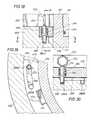
- FIG. 3 Ais a section view taken along line 3 A- 3 A of FIGS. 2-3 , to better illustrate the lateral conduit and its flange.
- FIG. 4is similar to FIG. 2 , except that the LP-RCD housing is clamped to an attachment retainer ring that is bolted to a lower housing.
- FIG. 5is an elevational section view of a LP-RCD and LP-RCD housing, which LP-RCD allows rotation of the inserted tubular about its longitudinal axis in multiple planes, and which LP-RCD housing is threadably connected to an attachment retainer ring that is bolted to a lower housing.
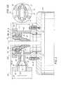
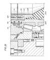
- FIG. 6is an elevational section view of a LP-RCD and LP-RCD housing, which LP-RCD allows rotation of the inserted tubular about its longitudinal axis in a horizontal plane, and which LP-RCD bearings are positioned external to the stationary LP-RCD housing so that the outer member is rotatable.
- FIG. 6 Ais a section view taken along line 6 A- 6 A of FIG. 6 , showing the cross section of an eccentric bolt.
- FIG. 7is an elevational section view of a nipple with a lateral conduit positioned on an integral combination housing for use with an annular BOP seal and a RCD, and a valve attached with the housing, which housing is mounted on a ram-type BOP stack.
- FIG. 8is an elevational section view of the integral housing as shown in FIG. 7 but with the nipple removed and a LP-RCD installed.
- FIG. 9is a schematic plan view of an integral housing with LP-RCD removed as shown in FIG. 7 with the valves positioned for communication between the housing and a shale shakers and/or other non-pressurized mud treatment.
- FIG. 10is a schematic plan view of an integral housing with LP-RCD installed as shown in FIG. 8 with the valves positioned for communication between the housing and a choke manifold.
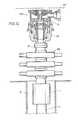
- FIG. 11is an elevational section view of a LP-RCD bearing assembly inner member and outer member disposed with a LP-RCD housing, with a bearing assembly retainer plate secured over a bearing assembly rotating plate, and bearing assembly outer member tabs in corresponding LP-RCD housing bearing assembly receiving slots, and a seal retainer ring with seal retainer ring tabs and spring loaded flipper dogs secured in bearing assembly inner member receiving slots over a seal support ring with seal support ring tabs positioned in the corresponding bearing assembly inner member receiving slots, and accumulators with accumulator pistons and springs disposed in the outer member.
- FIG. 12is a detail view of the upper left portion of FIG. 11 to better illustrate the bearing assembly retainer plate secured over the bearing assembly rotating plate, and one bearing assembly outer member tab in a corresponding LP-RCD housing bearing assembly receiving slot, and the seal retainer ring with a seal retainer ring tab and a spring loaded flipper dog secured in a corresponding bearing assembly inner member receiving slot over a seal support ring with a seal support ring tab positioned in a corresponding bearing assembly inner member receiving slot, and an accumulator with accumulator piston and spring.
- FIG. 13is a plan view of the LP-RCD of FIG. 11 with the bearing assembly retainer plate over the bearing assembly rotating plate both partially cut away to show a LP-RCD housing rotating plate roller bearing, and in phantom three other LP-RCD housing rotating plate roller bearings, four bearing assembly outer member tabs disposed in corresponding LP-RCD housing bearing assembly receiving slots, and a bearing assembly rotating plate rotation access opening in the LP-RCD housing, a bearing assembly rotating plate lock member or pin, the seal retainer ring with seal retainer ring spring loaded flipper dogs in the locked position, and in phantom the four seal retainer ring tabs positioned in the corresponding bearing assembly inner member receiving slots.
- FIG. 14is an exploded isometric view of the seal retainer ring with four seal retainer ring tabs and two spring loaded flippers over a top partial isometric view of the seal support ring disposed with the bearing assembly inner member with the seal support ring tabs aligned with corresponding bearing assembly inner member receiving slots.
- FIG. 15is a partial cross-sectional detail view of an exemplary seal retainer ring tab in a bearing assembly inner member receiving slot with a seal retainer ring spring loaded flipper dog in the unlocked position.
- FIG. 16is a similar view as FIG. 15 except with the spring loaded flipper dog in the locked position.
- FIG. 17is an exploded isometric view of the bearing assembly retainer plate with an exemplary socket head cap screw, a partial isometric view of the top of the bearing assembly outer member with bearing assembly outer member tabs, the bearing assembly rotating plate with rotating plate receiving slots and lock pin, and the top of the LP-RCD housing with LP-RCD housing rotating plate roller bearings and receiving slots for bearing assembly outer member tabs.
- FIG. 18is partial cross-sectional view of the bearing assembly retainer plate over the LP-RCD housing, the bearing assembly rotating plate over a bearing assembly outer member tab disposed in a corresponding LP-RCD housing bearing assembly receiving slot, with a bearing assembly rotating plate spring loaded lock member or pin disposed with the rotating plate and in a locked position with a LP-RCD housing lock pin receiving port.
- FIG. 19is a section view along line 19 - 19 of FIG. 18 illustrating the LP-RCD housing lock pin receiving groove and two lock pin receiving ports, and a bearing assembly outer member tab in a corresponding LP-RCD housing bearing assembly receiving slot.
- FIG. 20is a section view along line 20 - 20 of FIG. 18 illustrating the bearing assembly rotating plate spring loaded lock pin in the locked position with the LP-RCD housing lock pin receiving groove and one of the two lock pin receiving ports.
- FIG. 21is an partial elevational view along line 21 - 21 of FIG. 13 of the bearing assembly retainer plate over the LP-RCD housing, a bearing assembly rotating plate rotation opening in the LP-RCD housing exposing the bearing assembly rotating plate, a rod shown in phantom inserted in a rod insertion port in the bearing assembly rotating plate, also in phantom both an LP-RCD housing rotating plate roller bearing and the bearing assembly rotating plate spring loaded lock pin in the locked position with one of the two lock pin receiving ports.
- FIG. 22is the same view as FIG. 21 except with the spring loaded lock pin is shown in the unlocked position and moved to the right along the LP-RCD housing lock pin receiving groove when the bearing assembly rotating plate is rotated to the right with the inserted rod.
- FIG. 23is a plan view of FIG. 22 with the bearing assembly retainer plate partially cut away to expose the bearing assembly rotating plate rotation opening in the LP-RCD housing and the bearing assembly rotating plate partially cut away to show the rod insertion port.
- FIG. 24is an elevational section view similar to FIG. 11 with an alternative embodiment seal support ring threadedly attached with a LP-RCD bearing assembly inner member, and a seal locking ring threadedly attached with the LP-RCD bearing assembly inner member in a locked position over the seal support ring.
- FIG. 25is a detail view of FIG. 24 showing the seal support ring and seal locking ring.
- a system and methodfor converting a smaller drilling rig with a limited substructure height between a conventional open and non-pressurized mud-return system for hydrostatic pressure drilling, and a closed and pressurized mud-return system for managed pressure drilling or underbalanced drilling, using a low profile rotating control device (LP-RCD), generally designated as 10 in FIG. 1 .
- the LP-RCDis positioned with a desired RCD housing ( 18 , 40 , 50 , 80 , 132 , 172 , 200 ).
- the LP-RCDis further designated as 10 A, 10 B, 10 C, or 10 D in FIGS.
- the LP-RCDis designated as 10 A or 10 D if it only allows rotation of the inserted tubular 14 about its longitudinal axis in a substantially horizontal plane, and has its bearings ( 24 , 228 ) located inside of the LP-RCD housing ( 18 , 40 , 50 , 172 , 200 ) ( FIGS. 2-4, 7-8, and 11-13 ), 10 B if it allows rotation of the inserted tubular 110 about its longitudinal axis in multiple planes ( FIGS.
- 2-6 and 11-13may be relatively short, preferably ranging from approximately 15.0 inches (38.1 cm) to approximately 20.77 inches (52.8 cm), depending on the type of LP-RCD 10 and LP-RCD housing ( 18 , 40 , 50 , 80 , 132 , 200 ) as described below, although other heights are contemplated as well.
- FIG. 1Aan exemplary embodiment of a truck mounted drilling rig R is shown converted from conventional hydrostatic pressure drilling to managed pressure drilling and/or underbalanced drilling.
- LP-RCD 10in phantom, is shown clamped with radial clamp 12 with an LP-RCD housing 80 , which housing 80 is positioned directly on a well head W.
- the well head Wis positioned over borehole B as is known in the art.
- a truck mounted drilling rig Ris shown in FIG. 1 , other drilling rig configurations and embodiments are contemplated for use with LP-RCD 10 for offshore and land drilling, including semi-submersibles, submersibles, drill ships, barge rigs, platform rigs, and land rigs.
- LP-RCD 10is shown mounted on well head W, it is contemplated that LP-RCD 10 may be mounted on an annular BOP (See e.g. FIG. 1C ), casing, or other housing that are known in the art.
- LP-RCD 10could be mounted on a Compact GK® annular BOP offered by the Hydril Company or annular BOPs offered by Cameron, both of Houston, Tex.
- the preferred use of any of the disclosed LP-RCDs 10is for drilling for oil and gas, any of the disclosed LP-RCDs 10 may be used for drilling for other fluids and/or substances, such as water.
- FIG. 1Bshows a prior art assembly of a tubular T with lateral conduit O mounted on an annular BOP AB below a rig floor RF.
- Annular BOP ABis directly positioned on well head W.
- a ram-type BOP stack RBis shown below the well head W, and, if desired, over another annular BOP J positioned with casing C in a borehole B.
- LP-RCD 10 Bwhich will be discussed below in detail in conjunction with the embodiment of FIG. 5 , is mounted below rig floor RF on an annular BOP AB using an attachment member or retainer ring 96 , which will also be discussed below in detail in conjunction with FIG. 5 .
- any of the LP-RCDs 10can be mounted on the top of an annular BOP AB using alternative attachment means, such as for example by bolting or nuts used with a threaded rod.
- LP-LCD 10 Bis shown in FIG. 1C
- any LP-RCD 10may be similarly positioned with the annular BOP AB of FIG. 1C or a gas handler BOP as proposed in U.S. Pat. No. 4,626,135.
- FIG. 2shows tubular 14 , in phantom view, inserted through LP-RCD 10 A so that tubular 14 can extend through the lower member or housing HS below.
- Tubular 14can move slidingly through the LP-RCD 10 A, and is rotatable about its longitudinal axis in a horizontal plane.
- the lower housing HS in FIGS. 2-6is preferably a compact BOP, although other lower housings are contemplated as described above.
- LP-RCD 10 Aincludes a bearing assembly and a sealing element, which includes a radial stripper rubber seal 16 supported by a metal seal support member or ring 17 having a thread 19 A on the ring 17 radially exterior surface.
- the bearing assemblyincludes an inner member 26 , an outer member 28 , and a plurality of bearings 24 therebetween.
- Inner member 26has a passage with thread 19 B on the top of its interior surface for a threaded connection with corresponding thread 19 A of metal seal ring 17 .
- LP-RCD 10 Ais positioned with an LP-RCD housing 18 with radial clamp 12 .
- Clamp 12may be manual, mechanical, hydraulic, pneumatic, or some other form of remotely operated means.
- Bottom or lower flange 23 of LP-RCD housing 18is positioned and fixed on top of the lower housing HS with a plurality of equally spaced attachment members or swivel hinges 20 that are attached to the lower housing HS with threaded rod/nut 22 assemblies. Swivel hinges 20 can be rotated about a vertical axis prior to tightening of the threaded rod/nut 22 assemblies.
- swivel hinges 20allow for rotation of the LP-RCD housing 18 so that conduit 29 , further described below, can be aligned with the drilling rig's existing line or conduit to, for example, its mud pits, shale shakers or choke manifold as discussed herein.
- Other types of connection meansare contemplated as well, some of which are shown in FIGS. 3-6 and/or described below.
- Stripper rubber seal 16seals radially around tubular 14 , which extends through passage 8 .
- Metal seal support member or ring 17is sealed with radial seal 21 in inner member 26 of LP-RCD 10 A.
- Inner member 26 and seal 16are rotatable in a horizontal plane with tubular 14 .
- a plurality of bearings 24 positioned between inner member 26 and outer member 28enable inner member 26 and seal 16 to rotate relative to stationary outer member 28 .
- bearings 24 for the LP-RCD 10 Aare positioned radially inside LP-RCD housing 18 .
- the threaded connection between metal seal support ring 17 and inner member 26allows seal 16 to be inspected for wear and/or replaced from above.
- stripper rubber seal 16may be inspected and/or replaced from above, such as through the rotary table or floor RF of the drilling rig, in all embodiments of the LP-RCD 10 , eliminating the need for physically dangerous and time consuming work under drill rig floor RF.
- LP-RCD housing conduit 29initially extends laterally from the housing port, generally shown as 30 , with the conduit width greater than its height, and transitions, generally shown as 31 , to a flange port, generally shown as 32 , that is substantially circular, as is best shown in FIG. 3 A.
- the shape of conduit 29allows access to threaded rod/nut assemblies 22 .
- conduit 29may be manufactured as a separate part from LP-RCD housing 18 , and may be welded to or otherwise sealed with LP-RCD housing 18 .
- the cross sectional or flow areas of the two ports ( 30 , 32 ), as well as the cross sectional or flow areas of the transition 31are substantially identical, and as such are maximized, as is shown in FIGS. 2, 3 and 3A .
- conduit 29 and port 30may be in alignment with a portion of seal 16 .
- a line or conduit (not shown), including a flexible conduit,may be connected to the flange 34 .
- a flexible conduitcould be attached directly to the port 30 as compared to a rigid conduit 29 .
- return drilling fluidwould flow from the annulus A through ports ( 30 , 32 ), which are in communication, as shown with arrows in FIG. 2 .
- height H 1 of the combined LP-RCD 10 A positioned with LP-RCD housing 18would be approximately 16 inches (40.6 cm), although other heights are contemplated. It is further contemplated that outer diameter D 1 of flange 34 would be approximately 15 inches (38.1 cm), although other diameters, shapes and sizes are contemplated as well. As can now be understood, it is contemplated that the outer flange diameter D 1 may be substantially the same as housing height H 1 . For the embodiment shown in FIG. 2 , it is contemplated that the ratio of diameter D 1 to height H 1 may be 0.94, although other optimized ratios are contemplated as well.
- outer diameter D 1 of flange 34may be substantially parallel with height H 1 . It is also contemplated that diameter D 2 of port 32 may be greater than fifty percent of the height H 1 . It is also contemplated that the seal height S 1 may be greater than fifty percent of height H 1 .
- the LP-RCD housing 40is sealed with radial seal 42 and attached with threaded rod/nut assemblies 22 to lower member or housing HS using attachment member 43 .
- Attachment member 43may have a plurality of radially equally spaced openings 44 for threaded rod/nut assemblies 22 .
- height H 2 of the combined LP-RCD 10 A positioned with LP-RCD housing 40would be 18.69 inches (47.5 cm), although other heights are contemplated.
- the outer diameter D 1 of flange 34may be 15.0 inches (38.1 cm), although other diameters, shapes and sizes are contemplated as well.
- the ratio of diameter D 1 to height H 2may be 0.80, although other ratios are contemplated as well.
- seal height S 2may be greater than fifty percent of height H 2 .
- LP-RCD housing 50is sealed with radial seal 70 and clamped with radial clamp 62 to an attachment member or retainer ring 64 .
- Clamp 62may be manual, mechanical, hydraulic, pneumatic, or some other form of remotely operated means.
- Clamp 62is received about base shoulder 51 of LP-RCD housing 50 and radial shoulder 65 of retainer ring 64 .
- LP-RCD housing 50may be rotated so that conduit 60 , described below, is aligned with the drilling rig's existing line or conduit to, for example, its mud pits, shale shakers or choke manifold as discussed herein.
- Retainer ring 64is sealed with radial seal 68 and bolted with bolts 66 to lower housing HS.
- the retainer ringhas a plurality of equally spaced openings 69 with recesses 67 for receiving bolts 66 .
- LP-RCD housing conduit 60extends from the housing port, shown generally as 52 .
- Conduit 60has a width greater than its height, and then transitions, generally shown as 54 , to a flange port, shown generally as 56 , that is substantially circular.
- the cross sectional or flow areas of the two ports ( 52 , 56 ), which are in communication, as well as the cross sectional or flow areas of the transition 54 therebetween,are substantially identical. However, different cross sectional areas and shapes are contemplated as well. It is contemplated that conduit 60 and port 52 may be in alignment with a portion of seal 16 .
- a line or conduit(not shown), including a flexible conduit, may be connected to the flange 58 .
- a flexible conduitmay be attached directly to port 52 as compared to rigid conduit 60 .
- height H 3 of the combined LP-RCD 10 A and LP-RCD housing 50 in FIG. 4would be 19.27 inches (49 cm), although other heights are contemplated.
- outer diameter D 1 of flange 58may be 15.0 inches (38.1 cm), although other diameters and sizes are contemplated as well.
- the ratio of diameter D 1 to height H 3may be 0.78, although other ratios are contemplated as well.
- the seal height S 3may be greater than fifty percent of height H 3 .
- FIG. 5shows a tubular 110 , in phantom view, inserted through LP-RCD 10 B to lower member or housing HS.
- Tubular 110is rotatable in its inserted position about its longitudinal axis CL in multiple planes. This is desirable when the longitudinal axis CL of tubular 110 is not completely vertical, which can occur, for example, if there is misalignment with the wellbore or if there are bent pipe sections in the drill string.
- the longitudinal axis CL of the tubular 110is shown in FIG. 5 deviated from the vertical axis V of the wellbore, resulting in the tubular 110 rotating about its longitudinal axis CL in a plane that is not horizontal.
- longitudinal axis CLWhile it is contemplated that longitudinal axis CL, would be able to deviate from vertical axis V, it is also contemplated that longitudinal axis CL of tubular 110 may be coaxial with vertical axis V, and tubular 110 may rotate about its longitudinal axis CL in a horizontal plane.
- LP-RCD 10 Bincludes a bearing assembly and a sealing element, which includes a stripper rubber seal 83 supported by a metal seal support member or ring 85 having a thread 87 A on ring 85 radially exterior surface.
- the bearing assemblyincludes an inner member 82 , an outer ball member 84 , and a plurality of bearings 90 therebetween.
- the inner member 82has thread 87 B on the top of its interior surface for a threaded connection with metal seal support ring 85 .
- Exterior surface 84 A of outer ball member 84is preferably convex.
- Outer member 84is sealed with seals 86 to socket member 88 that is concave on its interior surface 88 A corresponding with the convex surface 84 A of the outer member 84 .
- LP-RCD 10 B and socket member 88thereby form a ball and socket type joint or connection.
- LP-RCD 10 Bis held by socket member 88 , which is in turn attached to LP-RCD housing 80 with a radial clamp 12 .
- clamp 12may be manual, mechanical, hydraulic, pneumatic, or some other form of remotely operated means.
- socket member 88may be manufactured as a part of LP-RCD housing 80 , and not clamped thereto.
- LP-RCD housing 80is sealed with radial seal 94 and threadably connected with radial thread 92 A to attachment member or retainer ring 96 .
- radial thread 92 Ais shown on the inside of the LP-RCD housing 80 and thread 92 B on the radially outwardly facing surface of retainer ring 96 , it is also contemplated that a radial thread could alternatively be located on the radially outwardly facing surface of a LP-RCD housing 80 , and a corresponding thread on the inside of a retainer ring. In such an alternative embodiment, the retainer ring would be located outside of the LP-RCD housing. As best shown in FIG.
- the threaded connectionallows for some rotation of LP-RCD housing 80 so that the conduit 100 , described below, can be aligned with the drilling rig's existing line or conduit, for example, to its mud pits, shale shakers or choke manifold as discussed herein.
- Retainer ring 96is sealed with radial seal 98 and bolted with bolts 114 to the lower member or housing HS.
- Retainer ring 96has a plurality of equally spaced openings 117 spaced radially inward of thread 92 B with recesses 116 sized for the head of bolts 114 .
- Stripper rubber seal 83seals radially around tubular 110 , which extends through passage 7 .
- Metal seal support member or ring 85is sealed by radial seal 89 with inner member 82 of LP-RCD 10 B.
- Inner member 82 and seal 83are rotatable with tubular 110 in a plane that is 90° from the longitudinal axis or center line CL of tubular 110 .
- a plurality of bearings 90 positioned between inner member 82 and outer member 84allow inner member 82 to rotate relative to outer member 84 .
- the ball and socket type jointadditionally allows outer member 84 , bearings 90 , and inner member 82 to rotate together relative to socket member 88 .
- LP-RCD 10 Ballows the inserted tubular 110 to rotate about its longitudinal axis in multiple planes, including the horizontal plane. Also, as can now be understood, LP-RCD 10 B accommodates misaligned and/or bent tubulars 110 , and reduces side loading. It is contemplated that stripper rubber seal 83 may be inspected and, if needed, replaced through the rotary table of the drilling rig in all embodiments of the disclosed LP-RCDs, eliminating the need for physically dangerous and time consuming work under the drill rig floor.
- LP-RCD housing 80includes conduit 100 that initially extends from the housing port, generally shown as 102 , with conduit 100 having a width greater than its height, and transitions, generally shown as 118 , to a flange port, generally shown as 106 , that is substantially circular.
- the cross sectional or flow areas of the two ports ( 102 , 106 ), which are in communication, as well as the different cross sectional areas of the transition 118 therebetween,are substantially identical, similar to that shown in FIG. 3 A. However, different cross sectional areas and shapes are contemplated as well. It is contemplated that conduit 100 and port 102 may be in alignment with a portion of seal 83 .
- a line or conduit(not shown), including a flexible conduit, may be connected to the flange 108 . It is also contemplated that outlet conduit 100 may be manufactured as a separate part from LP-RCD housing 80 , and may be welded to LP-RCD housing 80 . It is also contemplated that a flexible conduit may be attached directly to port 102 as compared to a rigid conduit 100 .
- height H 4 of the combined LP-RCD 10 B and the LP-RCD housing 80 in FIG. 5may be 14.50 inches (38.1 cm), although other heights are contemplated. It is further contemplated that the outer diameter D 1 of flange 108 may be approximately 15.0 inches (38.1 cm), although other diameters and sizes are contemplated as well. For the embodiment shown in FIG. 5 , it is contemplated that the ratio of diameter D 1 to height H 4 may be 1.03, although other ratios are contemplated as well. It is also contemplated that seal height S 4 may be greater than fifty percent of height H 4 .
- a tubular 14in phantom view, is shown inserted through LP-RCD 10 C to the lower housing HS.
- Tubular 14can move slidingly through LP-RCD 10 C, and is rotatable about its longitudinal axis in a horizontal plane.
- LP-RCD 10 Cincludes a bearing assembly and a sealing element, which includes a radial stripper rubber seal 138 supported by metal seal support member or ring 134 attached thereto.
- the bearing assemblyincludes top ring 120 , side ring 122 , eccentric bolts 124 , a plurality of radial bearings 128 , and a plurality of thrust bearings 126 .
- Metal seal support ring 134has a plurality of openings, and top ring 120 has a plurality of equally spaced threaded bores 137 , that may be aligned for connection using bolts 136 .
- Bolts 136enable inspection and replacement of stripper rubber seal 138 from above.
- Other connection meansas are known in the art, are contemplated as well.
- LP-RCD 10 Cis positioned with an LP-RCD housing 132 with the bearing assembly.
- eccentric bolts 124may be positioned through oval shaped bolt channels 130 through side ring 122 .
- Bolts 124are threadably connected into threaded bores 131 in top ring 120 .
- side ring 122moves upward and inward, creating pressure on thrust bearings 126 , which creates pressure against radial flange 125 of LP-RCD housing 132 , positioning LP-RCD 10 C with LP-RCD housing 132 .
- variable pressure on thrust bearings 126which may be induced before a tubular 14 is inserted into or rotating about its longitudinal axis in the LP-RCD 10 C, allows improved thrust bearing 126 performance.
- Bolts 124may be tightened manually, mechanically, hydraulically, pneumatically, or some other form of remotely operated means.
- washers, shims, or spacersas are known in the art, may be positioned on non-eccentric bolts inserted into top ring 120 and side ring 122 . It is also contemplated that spacers may be positioned above thrust bearings 126 .
- Other connection meansas are known in the art are contemplated as well.
- the bottom or lower flange 163 of LP-RCD housing 132is positioned on top of lower member or housing HS with a plurality of attachment members or swivel hinges 140 that may be bolted to lower housing HS with bolts 142 .
- Swivel hinges 140similar to swivel hinges 20 shown in FIG. 2 , may be rotated about a vertical axis prior to tightening of the bolts 142 .
- Other types of connections as are known in the artare contemplated as well, some of which are shown in FIGS. 2-5 and/or described above.
- the stripper rubber seal 138seals radially around the tubular 14 , which extends through passage 6 .
- seal 138may be attached to the metal seal support member or ring 134 , which support ring 134 may be, in turn, bolted to top ring 120 with bolts 136 .
- stripper rubber seal 138may be inspected and, if needed, replaced through the rotary table of the drilling rig in all embodiments of the LP-RCD 10 , eliminating the need for physically dangerous and time consuming work under the drill rig floor.
- Top ring 120 , side ring 122 , and stripper rubber seal 138are rotatable in a horizontal plane with the tubular 14 .
- a plurality of radial 128 and thrust 126 bearingspositioned between the LP-RCD housing 132 on the one hand, and the top ring 120 and side ring 122 on the other hand, allow seal 138 , top ring 120 , and side ring 122 to rotate relative to the LP-RCD stationary housing 132 .
- the inner race for the radial bearings, shown generally as 128may be machined in the outside surfaces of the LP-RCD housing 132 .
- the bearings ( 126 , 128 ) of LP-RCD 10 Care positioned outside of LP-RCD housing 132 .
- LP-RCD housing 132includes dual and opposed conduits ( 144 , 162 ) that initially extend from dual and opposed housing ports, generally shown as ( 146 , 160 ), with a width (preferably 14 inches or 35.6 cm) greater than their height (preferably 2 inches or 5.1 cm), and transition, generally shown as ( 150 , 158 ), to flange ports, generally shown as ( 148 , 156 ), that are substantially circular.
- the shape of conduits ( 144 , 162 )allow access to bolts 142 .
- Housing ports ( 146 , 160 )are in communication with their respective flange ports ( 148 , 156 ). The two ports, each of equal area, provide twice as much flow area than a single port. Other dimensions are also contemplated.
- conduits ( 144 , 162 )may be manufactured as a separate part from the LP-RCD housing 132 , and be welded to the LP-RCD housing 132 .
- the cross sectional or flow areas of the ports ( 146 , 148 , 156 , 160 ), as well as the cross sectional or flow areas of the transition between them ( 150 , 158 )are preferably substantially identical. However, different cross sectional areas and shapes are contemplated as well.
- Lines or conduits(not shown), including flexible conduits, may be connected to flanges ( 152 , 154 ).
- height H 5 of the combined LP-RCD 10 C positioned with LP-RCD housing 132 in FIG. 6may be 15.0 inches (38.1 cm), although other heights are contemplated. It is further contemplated that the outer diameter D 3 of flanges ( 152 , 154 ) may be 6.0 inches (15.2 cm), although other diameters and sizes are contemplated as well. For the embodiment shown in FIG. 6 , it is contemplated that the ratio of diameter D 3 to height H 5 may be 0.4, although other ratios are contemplated as well. In the preferred embodiment, it is contemplated that diameter D 3 of flanges ( 152 , 154 ) may be substantially parallel with height H 5 .
- conduits ( 144 , 162 )are shown in FIG. 6 , it is also contemplated that only one larger area conduit may be used instead, such as shown in FIGS. 1A, 1C, 2-5 and 7 . Also, although two conduits ( 144 , 162 ) are shown only in FIG. 6 , it is also contemplated that two conduits could be used with any LP-RCD and LP-RCD housing ( 18 , 40 , 50 , 80 , 132 , 172 ) of the present invention shown in FIGS. 1A, 1C, 2-7 to provide more flow area or less flow area per conduit.
- two conduitsmay be useful to reduce a restriction of the flow of mud returns if the stripper rubber seal ( 16 , 83 , 138 ) is stretched over the outside diameter of an oversized tool joint or if a foreign obstruction, partly restricts the returns into the conduits.
- the two conduitswould also reduce pressure spikes within the wellbore whenever a tool joint is tripped into or out of the LP-RCD with the rig pumps operating.
- one of the two conduitsmay be used as an inlet channel for the pumping of mud from the surface to replace the volume of drill string and bottom hole assembly that is being removed from the wellbore.
- a vacuummay be created on the wellbore when tripping out, in a piston effect known as swabbing, thereby inviting kicks. It is also contemplated that two conduits may facilitate using lifting slings or fork trucks to more easily maneuver the LP-RCD on location. It is further contemplated, though not shown, that seal 138 may have a height greater than fifty percent of height H 5 .
- Integral housing 172is mounted above a ram-type BOP stack RB shown below the well head W, and, if desired, over another annular BOP J positioned with casing C in a borehole B.
- Integral housing 172contains known components K, such as piston P, containment member 184 , and a plurality of connectors 182 , for an annular BOP, such as proposed in U.S. Pat. No. 4,626,135.
- Annular seal E along axis DLmay be closed upon the inserted tubular 14 with components K, such as proposed in the '135 patent. It is contemplated that components K may preferably be compact, such as those in the Compact GK® annular BOP offered by the Hydril Company of Houston, Tex.
- Housing 172has a lateral conduit 174 with housing port 178 that is substantially circular, and perpendicular to axis DL. Port 178 is above seal E while being in communication with seal E. It is also contemplated that conduit 174 may be manufactured as a separate part from LP-RCD housing 172 , and may be welded to LP-RCD housing 172 . If desired, valve V 1 may be attached to flange 176 , and a second lateral conduit 192 may be attached with valve V 1 . Valve V 1 may be manual, mechanical, electrical, hydraulic, pneumatic, or some other remotely operated means. Sensors S will be discussed below in detail in conjunction with FIG. 8 .
- FIG. 7shows how integral housing 172 may be configured for conventional drilling. It is contemplated that when valve V 1 is closed, drilling returns may flow through open conduit OA to mud pits, shale shakers and/or other non-pressurized mud treatment equipment. It should be noted that the presence of nipple or tubular TA with lateral conduit OA is optional, depending upon the desired configuration. Should nipple or tubular TA with lateral conduit OA not be present, returns during conventional drilling may be taken through port 178 (optional), valve V 1 and conduit 192 . As will be discussed below in conjunction with FIG. 9 , other valves (V 2 , V 3 ) and conduits ( 194 , 196 ) are also contemplated, in both configurations valve V 1 is opened.
- LP-RCD 10 Ais now attached with integral housing 172 using radial clamp 12 .
- LP-RCD 10 Aincludes a bearing assembly and a sealing element, which includes radial stripper rubber seal 16 supported with metal seal support member or ring 17 having thread 19 A on ring 17 exterior radial surface. While FIG. 8 is shown with LP-RCD 10 A, other LP-RCDs as disclosed herein, such as LP-RCD 10 B, 10 C, could be used.
- the bearing assemblyincludes inner member 26 , outer member 170 , and a plurality of bearings 24 therebetween, which bearings 24 enable inner member 26 to rotate relative to the stationary outer member 170 .
- Inner member 26 and outer member 170are coaxial with longitudinal axis DL.
- Inner member 26 and seal 16are rotatable with inserted tubular 14 in a horizontal plane about axis DL.
- Inner member 26has thread 19 B on the top of its interior surface for a threaded connection with corresponding thread 19 A of the metal seal support member or ring 17 .
- Valve V 1is attached to flange 176 , and a second lateral conduit 192 is attached with valve V 1 . It is contemplated that conduit 174 and port 178 may be in alignment with a portion of seal 16 .
- Annular seal Eis coaxial with and below seal 16 along axis DL.
- FIG. 8shows how integral housing 172 and LP-RCD 10 A may be configured for managed pressure drilling. It is contemplated that valve V 1 is open, and drilling returns may flow through housing port 178 and lateral conduit 192 to a pressure control device, such as a choke manifold (not shown). As will be discussed below in conjunction with FIG. 10 , other valves (V 2 , V 3 ) and conduits ( 194 , 196 ) are also contemplated.
- annular BOP seal E and its operating components Kare integral with housing 172 and the LP-RCD 10 A to provide an overall reduction in height H 6 while providing functions of both an RCD and an annular BOP.
- an attachment member between a LP-RCD 10 and the BOP seal Esuch as attachment members ( 20 , 43 , 64 , 96 , 140 ) along with a bottom or lower flange ( 23 , 163 ) in FIGS. 2-6 , have been eliminated.
- both the time needed and the complexity required for rigging up and rigging downmay be reduced, as there is no need to align and attach (or detach) a LP-RCD housing ( 18 , 40 , 50 , 80 , 132 ), such as shown in FIGS. 2-6 , with a lower housing HS using one of the methods previously described in conjunction with FIGS. 2-6 .
- height H 6 in FIG. 8 of the integral RCD and annular BOPmay be less than a combination of any one of the heights (H 1 , H 2 , H 3 , H 4 , H 5 ) shown in FIGS. 2-6 and the height of lower housing HS (which preferably is an annular BOP). This is made possible in part due to the elimination of the thicknesses of the attachment member ( 20 , 43 , 64 , 96 , 140 ), a bottom or lower flange ( 23 , 163 ) and the top of lower housing HS.
- the operation of the integral housing 172 with annular BOP and LP-RCD 10 Amay be controlled remotely from a single integrated panel or console.
- Sensors S in housing 172may detect pressure, temperature, flow, and/or other information as is known in the art, and relay such information to the panel or console.
- Such sensors Smay be mechanical, electrical, hydraulic, pneumatic, or some other means as is known in the art.
- Control of LP-RCD 10 A from such remote meansincludes bearing lubrication flow and cooling.
- Threaded connection ( 19 A, 19 B) between ring 17 and inner member 26allows seal 16 to be inspected or replaced from above when the seal 16 is worn.
- Full bore accessmay be obtained by removing clamp 12 and LP-RCD 10 A including bearing assembly ( 24 , 26 , 170 ).
- Seal Emay then be inspected or replaced from above by disconnecting connectors 182 from containment member 184 , removing containment member 184 from housing 172 via the full bore access, thereby exposing seal E from above. It is also contemplated that removal of ring 17 while leaving the bearing assembly ( 24 , 26 , 170 ) in place may allow limited access to seal E for inspection from above.
- housing lower flange 180is shown over ram-type BOP stack RB in FIGS. 7-8 , it may be positioned upon a lower housing, tubular, casing, riser, or other member using any connection means either described above or otherwise known in the art. It should also be understood that although LP-RCD 10 A is shown in FIG. 8 , it is contemplated that LP-RCD ( 10 B, 10 C) may be used as desired with housing 172 .
- integral housing 172is shown, as in FIG. 7 , with no LP-RCD 10 A installed.
- Valve V 1is attached to housing 172 (e.g. such as shown in FIG. 7 ), and lateral conduit 192 is attached to valve V 1 .
- Other conduits ( 194 , 196 ) and valves (V 2 , V 3 )are shown in communication with conduit 192 , for example by a T-connection.
- Valves (V 2 , V 3 )may be manual, mechanical, electrical, hydraulic, pneumatic, or some other form of remotely operated means.
- FIG. 9shows a configuration for conventional drilling, as it is contemplated that valves (V 1 , V 3 ) may be open, valve V 2 may be closed, and drilling returns may flow through housing port 178 (shown in FIG. 7 ) and conduits ( 192 , 196 ) to mud pits, shale shakers and/or other non-pressurized mud treatment equipment.
- FIG. 10integral housing 172 is shown, as in FIG. 8 , with LP-RCD 10 A installed and attached.
- FIG. 10shows a configuration for managed pressure drilling, as it is contemplated that valves (V 1 , V 2 ) are open, valve V 3 is closed, and drilling returns may flow through housing port 178 and conduits ( 192 , 194 ) to a pressure control device, such as a choke manifold.
- a pressure control devicesuch as a choke manifold.
- the desired LP-RCD 10may have any type or combination of seals to seal with inserted tubulars ( 14 , 110 ), including active and/or passive stripper rubber seals. It is contemplated that the connection means between the different LP-RCD housings ( 18 , 40 , 50 , 80 , 132 , 172 ) and the lower member or housing HS shown in FIGS.
- threaded rod/nut assemblies 22such as with threaded rod/nut assemblies 22 , bolts ( 22 , 66 , 114 , 142 ), swivel hinges ( 20 , 140 ), retainer rings ( 64 , 96 ), clamps 62 , threads 92 , and seals ( 42 , 68 , 94 , 98 ), may be used interchangeably.
- Other attachment methodsas are known in the art are contemplated as well.
- LP-RCD 10may be used for converting a smaller drilling rig or structure between conventional hydrostatic pressure drilling and managed pressure drilling or underbalanced drilling.
- a LP-RCD ( 10 A, 10 B, 10 C) and corresponding LP-RCD housing ( 18 , 40 , 50 , 80 , 132 , 172 )may be mounted on top of a lower member or housing HS (which may be a BOP) using one of the attachment members and connection means shown in FIGS. 2-6 and/or described above, such as for example swivel hinges 140 and bolts 142 with LP-RCD 10 C.
- Integral housing 172may be used to house an annular BOP seal E, and a desired LP-RCD ( 10 A, 10 B, 10 C) may then be positioned with housing 172 using one of the means shown in FIGS. 2-8 and/or described above, such as for example using radial clamp 12 with LP-RCD 10 A.
- Conduit(s)may be attached to the flange(s) ( 34 , 58 , 108 , 152 , 154 , 176 ), including the conduit configurations and valves shown in FIGS. 9 and 10 .
- the thrust bearings 126 for LP-RCD 10 Cmay be preloaded with eccentric bolts 124 as described above.
- Drill string tubulars ( 14 , 110 ), as shown in FIGS. 2-8may then be inserted through a desired LP-RCD 10 for drilling or other operations.
- LP-RCD stripper rubber seal( 16 , 83 , 138 ) rotates with tubulars ( 14 , 110 ), allows them to slide through, and seals the annular space A so that drilling fluid returns (shown with arrows in FIG. 2 ) will be directed through the conduit(s) ( 29 , 60 , 100 , 144 , 162 , 174 ).
- the stripper rubber seal ( 16 , 83 , 138 )may be inspected and, if needed, replaced from above, by removing ring ( 17 , 85 , 134 ).
- annular BOP seal Emay be inspected and/or removed as described above.
- valve V 1may be closed, so that drilling returns flow through lateral conduit OA to the mud pits, shale shakers or other non-pressurized mud treatment equipment.
- valves (V 1 , V 3 )are open, valve V 2 is closed so that drilling returns may flow through housing port 178 and conduits ( 192 , 196 ) to mud pits, shale shakers and/or other non-pressurized mud treatment equipment.
- valve V 1is opened, so that drilling returns flow through housing port 178 and conduit 192 to a pressure control device, such as a choke manifold.
- a pressure control devicesuch as a choke manifold.
- valves (V 1 , V 2 )are open, valve V 3 is closed so that drilling returns may flow through housing port 178 and conduits ( 192 , 194 ) to a pressure control device, such as a choke manifold.
- integral housing 172allows for conversion in such circumstances, as well as others, to managed pressure drilling.
- seal Emay be closed upon the static inserted tubular 14 . It is contemplated that, if desired, the operator may kill the well temporarily by circulating a weighted fluid prior to effecting the conversion from conventional to managed pressure drilling. The operator may then insure that no pressure exists above seal E by checking the information received from sensor S. If required, any pressure above seal E may be bled via a suitable bleed port (not shown). Valve V 1 may then be closed. If present, the nipple or tubular TA may then be removed, and the LP-RCD 10 positioned with housing 172 as shown in FIG.
- Valves (V 1 , V 2 )are then opened for the configuration shown in FIG. 10 , and valve V 3 is closed to insure that drilling returns flowing through housing port 178 are directed or diverted to the choke manifold.
- Seal Emay then be opened, drilling operations resumed, and the well controlled using a choke and/or pumping rate for managed pressure drilling. If the operator had previously killed the well by circulating a weighted fluid, this fluid may then be replaced during managed pressure drilling by circulating a lighter weight drilling fluid, such as that in use prior to the kick.
- the operation of the integral annular BOP and LP-RCD 10 Amay be controlled remotely from a single integrated panel or console in communication with sensor S.
- conversion back to conventional drillingmay be simply achieved by first ensuring that no pressure exists at surface under static conditions, then configuring valves V 1 , V 2 and V 3 to divert returns directly to the shale shakers and/or other non-pressurized mud treatment system, as shown in FIG. 9 .
- LP-RCD housing 200is disposed over lower member or housing 202 with LP-RCD housing retainer ring or attachment member 206 .
- Lower housing 202may be a compact BOP, although other lower housings are contemplated.
- LP-RCD housing attachment member 206has a plurality of openings for receiving bolts 204 .
- Attachment member blocking shoulder 205may be disposed with LP-RCD housing blocking shoulder 262 .
- LP-RCD housing attachment member 206may be a 135 ⁇ 8 inch—5000 psi flange designed as an Other End Connector (OEC) in accordance with both the American Petroleum Institute (API) Specification 6 A and the American Society of Mechanical Engineers (ASME) Section VIII Division 2 Pressure Vessel Code.
- OECOther End Connector
- APIAmerican Petroleum Institute
- ASMEAmerican Society of Mechanical Engineers
- LP-RCD housing attachment member 206allows for the rotation of LP-RCD housing 200 about a vertical axis so that LP-RCD housing outlet conduit 266 and flange 258 may be aligned with the drilling rig's existing line or conduit to, for example, its mud pits, shale shakers or choke manifold.
- Other attachment means for LP-RCD housing 200 to lower member 202are contemplated, including any means shown in any of the other Figures for any of the other embodiments, such as swivel hinges ( FIGS. 2 and 6 ), direct attachment ( FIG. 3 ) and clamping ( FIG. 4 ).
- LP-RCD 10 Dcomprises a bearing assembly and a sealing element.
- the bearing assemblyincludes an inner member 226 , an outer member 212 , and a plurality of bearings 228 therebetween. It is contemplated that bearings 228 may be tapered to take both thrust and radial loads. However, other bearing shapes are contemplated, including cylindrical with no taper.
- the sealing elementincludes a radial stripper rubber seal 230 supported by a seal support member or ring 232 . Seal support ring 232 may be metal, although other materials are contemplated.
- the stripper rubber seal 230is advantageously disposed radially inward from bearings 228 within the inside bore of the bearing assembly inner member 226 .
- the seal elementis removably positioned with bearing assembly inner member 226 with seal support ring tabs 234 in bearing assembly inner member receiving slots 236 .
- Seal support ring tabs 234 in bearing assembly inner member receiving slots 236resist relative rotation between seal support ring 232 and bearing assembly inner member 226 .
- Seal retainer ring 238is disposed over seal support ring 232 with seal retainer ring tabs 240 also in bearing assembly inner member receiving slots 236 .
- seal retainer ring tabs 240may be aligned with bearing assembly inner member receiving slots 236 in the access position that allows seal support ring 232 to be positioned with or removed from bearing assembly inner member 226 .
- Seal support ring tabs 234are disposed in bearing assembly inner member receiving slots 236 providing support for seal support ring 232 and preventing relative rotation between seal support ring 232 and bearing assembly inner member 226 .
- seal retainer ring 238may then be rotated counterclockwise about a vertical axis moving seal retainer ring tabs 240 through the horizontal grooves 236 A of receiving slots 236 from the access position to the blocking position. In the blocking position, at least some portion of seal retainer ring tabs 240 are in horizontal grooves 236 A of receiving slots 236 , thereby blocking removal of seal support ring 232 from bearing assembly inner member 226 .
- seal retainer ring 238When seal retainer ring 238 may not be rotated counterclockwise any further with seal retainer ring tabs 240 in the horizontal grooves 236 A of receiving slots 236 , seal retainer ring 238 is in its locked position. As can be understood, the locked position for seal retainer ring 238 is also a blocking position.
- Spring loaded flipper dogs 242are in their unlocked positions as shown in FIG. 15 when seal retainer ring 238 is not in its locked position.
- seal retainer ring 238is in its locked position after being rotated completely counterclockwise with seal retainer ring tabs 240 in the horizontal grooves 236 A of receiving slots 236 , flipper dogs 242 may be moved into their locked positions as shown in FIGS. 11-14 and 16 .
- Flipper dogs 242are disposed in bearing assembly inner member receiving slots 236 when in their locked positions.
- the seal element 230may be blocked and resisted from removal from the bearing assembly by moving seal retainer ring 238 counterclockwise to its blocking position.
- Seal retainer ring 238may be locked with and prevented from rotating relative to the bearing assembly by moving the flipper dogs 242 to their locked positions.
- Other means for removably attaching the seal element with the bearing assemblyare contemplated, including any means shown in any of the other Figures for any of the other embodiments, such as threads ( FIGS. 2-5 ) and bolts ( FIG. 6 ).
- flipper dogs 242may be unlocked and seal retainer ring 238 may be rotated clockwise about a vertical axis moving seal retainer ring tabs 240 through the horizontal grooves 236 A of receiving slots 236 from the blocking position to the access position. The access position allows for removal of seal 230 from the bearing assembly. Seal retainer ring 238 and seal support ring 232 with seal 230 may then be removed.
- LP-RCD 10 Dis removably positioned with LP-RCD housing 200 with bearing assembly outer member tabs 214 in LP-RCD housing receiving slots 218 .
- Bearing assembly rotating plate 210is disposed with LP-RCD housing 200 over bearing assembly outer member tabs 214 .
- Bearing assembly retainer plate 208is positioned over bearing assembly rotating plate 210 and attached with LP-RCD housing 200 with exemplary screws 216 . Other attachment means are contemplated.
- bearing assembly rotating plate 210may be positioned with LP-RCD housing 200 on LP-RCD housing rotating plate roller bearings 250 .
- Rotating plate receiving slots 254may be aligned with LP-RCD housing receiving slots 218 when bearing assembly rotating plate 210 is first disposed or assembled with LP-RCD housing 200 .
- bearing assembly rotating plate 210is in the access position.
- bearing assembly outer member tabs 214may be moved through rotating plate receiving slots 254 for placement in LP-RCD housing receiving slots 218 .
- the bearing assembly rotating plate access positionallows access to the bearing assembly for its placement with or removal from the LP-RCD housing 200 .
- bearing assembly rotating plate 210may be rotated clockwise about a vertical axis, such as with lock member or pin 252 as an attachment point or other means, which are described in detail below with FIGS. 18-23 , so that rotating plate receiving slots 254 are not in alignment with LP-RCD housing receiving slots 218 .
- bearing assembly rotating plate 210is in the blocking position.
- the bearing assembly rotating plate 210 in the blocking positionblocks and resists removal of the LP-RCD 10 D from the LP-RCD housing 200 .
- Bearing assembly rotating plate 210 in the access positionallows and does not resist removal of the LP-RCD 10 D from the LP-RCD housing 200 .
- bearing assembly rotating plate 210when bearing assembly rotating plate 210 is rotated fully clockwise about a vertical axis, it may be locked in the blocking position. In the locked position, bearing assembly outer member tabs 214 are covered by bearing assembly rotating plate 210 , and the bearing assembly is blocked from being removed from LP-RCD housing 200 . When bearing assembly rotating plate 210 is fully rotated counterclockwise about a vertical axis, it may also be locked in the access position with lock pin 252 . When lock pin 252 is in its locked position, it resists relative rotation between bearing assembly rotating plate 210 and LP-RCD housing 200 . Other means for removably attaching the bearing assembly with the LP-RCD housing 200 are contemplated, including any means shown in any of the other Figures for any of the other embodiments, such as a clamping ( FIGS. 2-5 ).
- each seal sleeve( 268 A, 268 B) may be held between an inner seal sleeve retaining ring 272 A and an outer seal sleeve retainer ring 2728 .
- Seal sleeve retaining rings( 272 A, 272 B) may be Spirolox retaining rings available from Smalley® Steel Ring Company of Lake Zurich, Ill., although other types of retaining rings are contemplated.
- An inner radial seal 270 A and an outer radial seal 2708may be disposed with each seal sleeve ( 268 A, 268 B).
- Inner seals 270 A and outer seals 270 Bmay be hydrodynamic rotary Kalsi Seals® available from Kalsi Engineering, Inc. of Sugar Land, Tex., although other types of seals are contemplated.
- Bearing assembly outer member 212may have a top packing box 274 and a bottom packing box 276 .
- the bearings 228may be preloaded with top packing box 274 , and the top packing box 274 and the preload held in place with angled bearing assembly set screws 278 .
- Cylindrical shaped accumulators( 220 , 220 A) may be disposed in bearing assembly outer member 212 .
- An accumulator piston ( 222 , 222 A) and spring ( 224 , 224 A)are disposed in each accumulator ( 220 , 220 A).
- two accumulators ( 220 , 220 A)are shown, it is also contemplated that there may be only one accumulator, or preferably a plurality of spaced apart accumulators that are disposed radially outward from the bearings 228 in bearing assembly outer member 212 .
- the plurality of accumulatorsmay be spaced a substantially equal distance apart from each other.
- accumulatorsthere may be thirty (30) spaced apart accumulators ( 220 , 220 A) of 1 inch (2.54 cm) diameter, although other amounts and sizes are contemplated. It is also contemplated that there may be only one accumulator extending continuously radially around the entire circumference of bearing assembly outer member 212 . Such an accumulator may have a single ring shaped piston and a spring.
- each accumulator ( 220 , 220 A)may contain a lubricant that may be supplied through its accumulator lubricant port ( 256 , 256 A) to bearings 228 .
- Springs ( 224 , 224 A)may supply the force to keep the bearing pressure above the wellbore pressure. It is contemplated that there may be a minimum lubricant pressure of 15 psi higher than the environment pressure, although other amounts are contemplated.
- Pistons ( 222 , 222 A)may move vertically to adjust as temperature changes affect the lubricant volume. The maximum piston stroke may be 3.46 inches (8.79 cm), although other piston strokes are contemplated.
- the bearing assemblymay be self lubricating. An external source of lubrication during operation may not be required. It is contemplated that accumulators ( 220 , 220 A) may collectively have a 200 hour or greater supply of lubricant. As can also now be understood, accumulators ( 220 , 220 A) advantageously are positioned radially outside of the bearings 228 , allowing for a shorter LP-RCD housing height H 7 than would be possible if the accumulators ( 220 , 220 A) were located directly above and below the bearings 228 .
- Accumulators ( 220 , 220 A)may be in radial alignment with the bearings 228 .
- Seal retainer ring 238 and seal 230may be directly radially inward of and in alignment with the bearing assembly.
- Accumulators ( 220 , 220 A)may be directly radially outward of and in alignment with the bearings 228 .
- Bearing assembly rotating plate 210may be directly radially outward of and in alignment with the bearing assembly.
- LP-RCD housing 200may be directly radially outward of and in alignment with the bearing assembly.
- LP-RCD housing 200may also be directly radially outward of and in alignment with the bearing assembly rotating plate 210 .
- Bearing assembly retainer plate 208may be directly radially outward of and in alignment with the bearing assembly.
- Bearing assembly retainer plate 208may also be at least partially radially outward of the bearing assembly rotating plate 210 .
- LP-RCD housing height H 7may be approximately 20.77 inches (52.8 cm), although other LP-RCD housing heights H 7 are contemplated.
- the combined LP-RCD 10 D positioned with LP-RCD housing 200may be height H 7 .
- Outer diameter D 5 of LP-RCD housing outlet flange 258may be approximately 15 inches (38.1 cm), although other diameters are contemplated.
- the ratio of outlet flange diameter D 5 to LP-RCD housing height H 7may be 0.7 (or 70%) or higher, although other optimized ratios are contemplated.
- Outer diameter D 5 of outlet flange 258may be substantially parallel with LP-RCD housing height H 7 .
- Diameter D 6 of LP-RCD housing outlet port 260may be approximately 7.06 inches (17.9 cm), although other diameters are contemplated.
- the ratio of LP-RCD housing outlet port diameter D 6 to LP-RCD housing height H 7may be 0.3 (or 30%) or higher, although other optimized ratios are contemplated.
- Bearing assembly height B 1may be 9.62 inches (24.4 cm), although other bearing assembly heights are contemplated.
- the ratio of bearing assembly height H 1 to LP-RCD housing height H 7may be 0.45 (or 45%) or higher, although other optimized ratios are contemplated.
- Seal height S 5may be approximately 8.5 inches (21.6 cm) or higher, although other seal heights are contemplated.
- the ratio of seal height S 5 to LP-RCD housing height H 7may be 0.4 (or 40%) or higher, although other optimized ratios are contemplated.
- the diameter of LP-RCD housing well bore 264may be approximately 13.63 inches (34.6 cm), although other diameters are contemplated.
- outlet conduit 266is shown unitary or monolithic with LP-RCD housing 200 , it is also contemplated that outlet conduit 266 may not be unitary with LP-RCD housing 200 and may be welded to the side of LP-RCD housing 200 .
- Distance D 7 between the bearing assembly and the inside surface of LP-RCD housing 200may be 1.69 inches (4.3 cm), although other distances are contemplated.
- bearing assembly retainer plate 208is disposed with LP-RCD housing 200 with a plurality of screws 216 .
- Bearing assembly rotating plate 210may be rotated about a vertical axis on LP-RCD housing rotating plate rollers or roller bearings 250 with lock member or pin 252 as an attachment point, which will be described below in detail with FIGS. 18-20 , or with a rod through bearing assembly rotating plate rotation access opening 284 in LP-RCD housing 200 , which will be described below in detail with FIGS. 21-23 .
- bearing assembly outer member tabs 214are disposed in and supported by LP-RCD housing receiving slots 218 .
- Bearing assembly rotating plate 210has been rotated clockwise to a blocking position as the rotating plate receiving slots 254 are not in alignment with the LP-RCD housing receiving slots 218 .
- Bearing assembly rotating plate 210has been fully rotated in the clockwise direction so that it may be locked with lock member 252 .
- bearing assembly rotating plate 210blocks the removal of LP-RCD bearing assembly from LP-RCD housing 200 since bearing assembly rotating plate 210 covers the bearing assembly outer member tabs 214 .
- lock member 252With lock member 252 is in its locked position, as will be described below with FIGS. 18-20 , lock member 252 advantageously resists bearing assembly rotating plate 210 from rotating to the access position.
- Seal retainer ring 238is also in a blocking position and is locked with bearing assembly inner member 226 .
- Seal support ring 232(not shown) with seal 230 are held by bearing assembly inner member 226 .
- Seal retainer ring tabs 240are disposed in and supported by bearing assembly inner member receiving slots 236 .
- Seal retainer ring tabs 240have been lowered into bearing assembly inner member receiving slots 236 over seal support ring tabs 234 (not shown) in the access position.
- Seal retainer ring 238has then been rotated counterclockwise about a vertical axis to a blocking position with seal retainer ring tabs 240 in horizontal grooves 236 A of receiving slots 236 .
- Seal retainer ring 238has been fully rotated in a counterclockwise direction with seal retainer ring tabs 240 in horizontal grooves 236 A of receiving slots 236 .
- Seal retainer ring flipper dogs 242are in their locked positions in bearing assembly inner member receiving slots 236 as shown in detail view in FIG. 16 .
- FIG. 15seal retainer ring flipper dogs 242 are in their unlocked position.
- the flipper dogs 242 in their locked positionsresist rotation of seal retainer ring 238 relative to bearing assembly inner member 226 , thereby keeping seal retainer ring 238 from moving to its access position.
- Flipper dogs 242 in their unlocked positionsdo not resist rotation of seal retainer ring 238 relative to bearing assembly inner member 226 .
- lock member or pin 252is disposed in bearing assembly rotating plate spring cavity 294 .
- Lock member 252has an eye hook ring 290 attached with lock pin shaft 292 .
- Lock member 252is spring loaded with spring 296 in cavity 294 .
- Lock member 252is in its first locked position with lock pin shaft 292 extending in LP-RCD housing lock pin receiving port 286 A.
- lock pin 252 in its first locked positionresists rotation of bearing assembly rotating plate 210 relative to LP-RCD housing 200 .
- Lock pin 252 in its unlocked positionsuch as shown in FIG. 22 , does not resist the rotation of bearing assembly rotating plate 210 relative to LP-RCD housing 200 .
- Spring 296exerts a downward force on pin shaft 292 to resist retraction of shaft 292 from port 286 A.
- LP-RCD housing lock pin receiving groove 288is disposed in LP-RCD housing 200 between the two LP-RCD housing lock pin receiving ports ( 286 A. 286 B).
- Lock pin 252is in its locked position when lock pin shaft 292 is extending into either of the two LP-RCD housing lock pin receiving ports ( 286 A, 286 B).
- Bearing assembly outer member tab 214is positioned in LP-RCD housing receiving slot 218 .
- bearing assembly rotating plate receiving slots 254are not aligned with LP-RCD housing receiving slots 218 since rotating plate 210 is in the locked position and a blocking position covering tabs 214 .
- a force with an upward componentmay be applied to ring 290 , such as may be applied with a hook extending downward from the rig floor hooking ring 290 , to lift the end of lock pin shaft 292 out of port 286 A.
- the upward forcemust be sufficient to overcome the downward force of spring 296 on lock pin 252 .
- the bearing assembly rotating plate 210may then be rotated counterclockwise about a vertical axis, or to the right in FIGS. 20 and 22 , with a force with a horizontal component applied to lock pin ring 290 so that the lifted lock pin shaft 292 moves along groove 288 from port 286 A to port 286 B.
- bearing assembly rotating plate 210may be locked in a blocking position when lock pin 252 is in its first locking position. Bearing assembly rotating plate 210 may also be locked in the access position when lock pin 252 is in its second locking position. Lock pin 252 is in its unlocked position when shaft 292 is not resting in either port ( 286 A, 286 B), such as for example in FIG. 22 .
- bearing assembly rotating plate 210is disposed on LP-RCD housing rotating plate rollers or roller bearings 250 .
- Bearing assembly retainer plate 208is disposed with LP-RCD housing 200 .
- Bearing assembly rotating plate rotation access opening 284 in LP-RCD housing 200allows access to the side of bearing assembly rotating plate 210 through LP-RCD housing 200 .
- Two rod insertion ports( 302 A, 302 B) are disposed in the side of bearing assembly rotating plate 210 . However, other numbers of rod insertion ports are contemplated, including only one port. If bearing assembly rotating plate 210 needs to be rotated, it is contemplated that it may be rotated exclusively using lock pin 252 as an attachment point.
- bearing assembly rotating plate 210cannot be moved by a force applied to lock pin 252 alone, such as if rotation is resisted by damaged roller bearings 250 or other causes, then as shown in FIG. 21 a rod 300 may be inserted into rod insertion port 302 A and bearing assembly rotating plate 210 moved or rotated about a vertical axis with a force applied to rod 300 .
- FIG. 22lock pin 252 has been lifted to allow rotation of bearing assembly rotating plate 210 with rod 300 in port 302 A.
- rod 300has moved rotating plate 210 to the right or counterclockwise from its position in FIG. 21 .
- a rod 300 in a port302 A, 302 B
- moving bearing assembly rotating plate 210 counterclockwise about a vertical axis or to the right as shownmoves bearing assembly rotating plate 210 toward its access position since rotating plate receiving slots 254 are moved toward alignment with bearing assembly outer member tabs 214 .
- seal support ring or member 232 Asupports seal 230 A.
- Thread 310 of seal support ring 232 Ais engaged with thread 312 of LP-RCD bearing assembly inner member 226 A.
- Seal support ring receiving ports 318may be used for rotating seal support ring 232 A to threadingly attach with LP-RCD bearing assembly inner member 226 A. Ports 318 may be threaded.
- Seal locking ring 314is in a locked position over seal support ring 232 A. Seal locking ring 314 may be removed to allow access to seal support ring 232 A.
- Thread 316 of seal locking ring 314is engaged with thread 312 of LP-RCD bearing assembly inner member 226 A.
- FIG. 24is otherwise the same as FIG. 11 .
- seal 230 A of FIGS. 24 and 25may be removably attached with the LP-RCD bearing assembly.
- Seal locking ring 314may be used to prevent seal support ring 232 A from becoming loosened or unattached from LP-RCD bearing assembly inner member 226 A.
- seal 230may be disposed with the bearing assembly by aligning and resting seal support ring tabs 234 in bearing assembly inner member receiving slots 236 .
- Seal retainer ring 238may be disposed over seal support ring 232 by aligning and lowering seal retainer ring tabs 240 over seal support ring tabs 234 in bearing assembly inner member receiving slots 236 .
- Seal retainer ring 238may be rotated in a counterclockwise direction about a vertical axis with seal retainer ring tabs 240 in horizontal grooves 236 A of bearing assembly inner member receiving slots 236 .
- seal retainer ring flipper dogs 242may be moved to their locked positions in bearing assembly inner member receiving slots 236 .
- seal 230is locked with the bearing assembly and blocked from removal.
- the bearing assemblymay be disposed with LP-RCD housing 200 by rotating bearing assembly rotating plate 210 to its access position in which bearing assembly rotating plate receiving slots 254 are aligned with LP-RCD housing receiving slots 218 .
- Bearing assembly rotating plate 210may be locked in its access position with lock pin 252 in its second locking position.
- the bearing assemblymay be positioned with the LP-RCD housing 200 by aligning and lowering bearing assembly outer member tabs 214 through the bearing assembly receiving slots 254 .
- the bearing assembly outer member tabs 214may be supported in LP-RCD housing receiving slots 218 .
- Lock member or pin 252may then be retracted from its second locking position to the unlocked position.
- Bearing assembly rotating plate 210may be rotated clockwise about a vertical axis to the blocking position. Lock pin 252 may then be moved to its first locking position to prevent relative rotation of bearing assembly rotating plate 210 with LP-RCD housing 200 .
- the bearing assemblyis locked with the LP-RCD housing 200 and is blocked from
- LP-RCD 10 Dmay be used for converting a smaller drilling rig or structure between conventional hydrostatic pressure drilling and managed pressure drilling or underbalanced drilling.
- LP-RCD 10 D and corresponding LP-RCD housing 200 as shown in FIG. 11may be mounted on top of a lower member or housing ( 202 , HS) (which may be a BOP) using one of the attachment members and connection means shown in FIGS. 2-6 and 11 and/or described above, such as for example LP-RCD housing attachment member 206 in FIG. 11 and swivel hinges 140 in FIG. 6 .
- Outlet flange 258may be aligned as necessary before LP-RCD housing 200 is fully tightened against the lower member ( 202 , HS).
- Conduit(s)may be attached to the outlet flange 258 , including the conduit configurations and valves shown in FIGS. 9 and 10 .
- the bearings 228 for LP-RCD 10 Dmay be preloaded with top packing box 274 , and the top packing box 274 and the preload held in place with angled bearing assembly set screws 278 .
- Drill string tubularsmay be inserted through the LP-RCD 10 D for drilling or other operations.
- LP-RCD stripper rubber seal 230rotates with tubulars, allows them to slide through, and seals the annular space so that drilling fluid returns will be directed through the outlet conduit 266 .
- the bearings 228may be self lubricated with accumulators ( 220 , 220 A).
- the stripper rubber seal 230may be inspected and, if needed, replaced from above, by removing seal retainer ring 238 and lifting out seal support ring 232 and seal 230 .
- Seal retainer ring 238may be removed by moving flipper dogs 242 from their locked positions as shown in FIG. 16 to their unlocked positions as shown in FIG. 15 , and then rotating seal retainer ring 238 clockwise about a vertical axis from a blocking position to its access position.
- seal retainer ring tabs 240are aligned over seal support ring tabs 234 in the access position, then seal retainer ring 238 and seal support ring 232 may be lifted out of the bearing assembly. The process may be reversed to assemble seal 230 back into the bearing assembly.
- the bearing assemblymay be inspected and, if needed, replaced from above, by rotating bearing assembly rotating plate 210 counterclockwise about a vertical axis from a blocking position to its access position either with lock pin 252 as an attachment point, or with a rod 300 in rod receiving port 302 A in bearing assembly rotating plate 210 , or with both.
- lock pin 252may be lifted from its first locked position then moved to the right or counterclockwise about a vertical axis to move rotating plate 210 on rotating plate roller bearings 250 .
- Lock pin 252may be moved from a first locked position in port 286 A to a second locked position in port 286 B.
- Bearing assembly rotating plate receiving slots 254may be aligned with LP-RCD housing receiving slots 218 in the access position, uncovering bearing assembly outer member tabs 214 .
- the bearing assemblymay then be lifted from the LP-RCD housing 200 .
- the processmay be reversed to assemble the bearing assembly back into the bearing assembly.
- To remove lower seal sleeve 268 B from the bearing assembly inner member 226its inner seal sleeve retaining ring 272 A may be removed to allow access for a pulling tool to grab the back side of the lower seal sleeve 268 B.
- seal 230 Amay be removably attached with LP-RCD bearing assembly inner member 226 A by threadedly attaching or unattaching seal support ring 232 A with LP-RCD bearing assembly inner member 226 A.
- Seal locking ring 314may be threaded into the locked position over seal support ring 232 A as shown in FIGS. 24 and 25 to prevent seal support ring 232 A from loosening during operations.
- seal locking ring 314may be unthreaded, and then seal support ring 232 A with seal 230 A may be unthreaded and removed.
Landscapes
- Engineering & Computer Science (AREA)
- Geology (AREA)
- Mining & Mineral Resources (AREA)
- Life Sciences & Earth Sciences (AREA)
- General Life Sciences & Earth Sciences (AREA)
- Fluid Mechanics (AREA)
- Environmental & Geological Engineering (AREA)
- Physics & Mathematics (AREA)
- Geochemistry & Mineralogy (AREA)
- Mechanical Engineering (AREA)
- Earth Drilling (AREA)
- Rolling Contact Bearings (AREA)
- Sealing Of Bearings (AREA)
- Sealing Devices (AREA)
- Magnetic Bearings And Hydrostatic Bearings (AREA)
Abstract
Description
Claims (18)
Priority Applications (1)
| Application Number | Priority Date | Filing Date | Title |
|---|---|---|---|
| US14/496,681US10087701B2 (en) | 2007-10-23 | 2014-09-25 | Low profile rotating control device |
Applications Claiming Priority (3)
| Application Number | Priority Date | Filing Date | Title |
|---|---|---|---|
| US11/975,946US8286734B2 (en) | 2007-10-23 | 2007-10-23 | Low profile rotating control device |
| US12/893,391US8844652B2 (en) | 2007-10-23 | 2010-09-29 | Interlocking low profile rotating control device |
| US14/496,681US10087701B2 (en) | 2007-10-23 | 2014-09-25 | Low profile rotating control device |
Related Parent Applications (1)
| Application Number | Title | Priority Date | Filing Date |
|---|---|---|---|
| US12/893,391ContinuationUS8844652B2 (en) | 2007-10-23 | 2010-09-29 | Interlocking low profile rotating control device |
Publications (2)
| Publication Number | Publication Date |
|---|---|
| US20150027688A1 US20150027688A1 (en) | 2015-01-29 |
| US10087701B2true US10087701B2 (en) | 2018-10-02 |
Family
ID=45688070
Family Applications (2)
| Application Number | Title | Priority Date | Filing Date |
|---|---|---|---|
| US12/893,391Active2028-08-16US8844652B2 (en) | 2007-10-23 | 2010-09-29 | Interlocking low profile rotating control device |
| US14/496,681Active2029-04-27US10087701B2 (en) | 2007-10-23 | 2014-09-25 | Low profile rotating control device |
Family Applications Before (1)
| Application Number | Title | Priority Date | Filing Date |
|---|---|---|---|
| US12/893,391Active2028-08-16US8844652B2 (en) | 2007-10-23 | 2010-09-29 | Interlocking low profile rotating control device |
Country Status (5)
| Country | Link |
|---|---|
| US (2) | US8844652B2 (en) |
| EP (1) | EP2622173B1 (en) |
| BR (1) | BR112013007268A2 (en) |
| CA (1) | CA2813072C (en) |
| WO (1) | WO2012041996A2 (en) |
Cited By (6)
| Publication number | Priority date | Publication date | Assignee | Title |
|---|---|---|---|---|
| US11118421B2 (en) | 2020-01-14 | 2021-09-14 | Saudi Arabian Oil Company | Borehole sealing device |
| US11384876B2 (en) | 2020-07-07 | 2022-07-12 | Safoco, Inc. | Fluid conduit connector system |
| US11519536B2 (en) | 2020-07-07 | 2022-12-06 | Safoco, Inc. | Fluid conduit connector system |
| US11530601B2 (en) | 2020-07-07 | 2022-12-20 | Safoco, Inc. | Fluid conduit connector system |
| US20230265733A1 (en)* | 2022-02-22 | 2023-08-24 | Saudi Arabian Oil Company | Installing a shooting nipple on a rotating control device |
| US12442267B1 (en) | 2024-07-29 | 2025-10-14 | Schlumberger Technology Corporation | Control systems and methods for RCD active pressure compensation |
Families Citing this family (52)
| Publication number | Priority date | Publication date | Assignee | Title |
|---|---|---|---|---|
| US7836946B2 (en)* | 2002-10-31 | 2010-11-23 | Weatherford/Lamb, Inc. | Rotating control head radial seal protection and leak detection systems |
| US8826988B2 (en) | 2004-11-23 | 2014-09-09 | Weatherford/Lamb, Inc. | Latch position indicator system and method |
| US7926593B2 (en) | 2004-11-23 | 2011-04-19 | Weatherford/Lamb, Inc. | Rotating control device docking station |
| GB2453125B (en)* | 2007-09-25 | 2012-02-08 | Statoilhydro Asa | Deadleg |
| US8844652B2 (en) | 2007-10-23 | 2014-09-30 | Weatherford/Lamb, Inc. | Interlocking low profile rotating control device |
| US8286734B2 (en) | 2007-10-23 | 2012-10-16 | Weatherford/Lamb, Inc. | Low profile rotating control device |
| US9359853B2 (en) | 2009-01-15 | 2016-06-07 | Weatherford Technology Holdings, Llc | Acoustically controlled subsea latching and sealing system and method for an oilfield device |
| US8322432B2 (en) | 2009-01-15 | 2012-12-04 | Weatherford/Lamb, Inc. | Subsea internal riser rotating control device system and method |
| US8347983B2 (en)* | 2009-07-31 | 2013-01-08 | Weatherford/Lamb, Inc. | Drilling with a high pressure rotating control device |
| US8347982B2 (en) | 2010-04-16 | 2013-01-08 | Weatherford/Lamb, Inc. | System and method for managing heave pressure from a floating rig |
| US9175542B2 (en) | 2010-06-28 | 2015-11-03 | Weatherford/Lamb, Inc. | Lubricating seal for use with a tubular |
| US9476347B2 (en) | 2010-11-23 | 2016-10-25 | Woodward, Inc. | Controlled spark ignited flame kernel flow in fuel-fed prechambers |
| US9172217B2 (en) | 2010-11-23 | 2015-10-27 | Woodward, Inc. | Pre-chamber spark plug with tubular electrode and method of manufacturing same |
| US8584648B2 (en) | 2010-11-23 | 2013-11-19 | Woodward, Inc. | Controlled spark ignited flame kernel flow |
| US8939218B2 (en)* | 2012-04-26 | 2015-01-27 | Jtb Tools & Oilfield Services, Llc | Apparatus and method for the installation or removal of a rotary control device insert or a component thereof |
| US9494002B2 (en) | 2012-09-06 | 2016-11-15 | Reform Energy Services Corp. | Latching assembly |
| US9828817B2 (en) | 2012-09-06 | 2017-11-28 | Reform Energy Services Corp. | Latching assembly |
| AU2013315440A1 (en)* | 2012-09-12 | 2015-03-26 | Weatherford Technology Holdings, Llc | Tachometer for a rotating control device |
| US9410392B2 (en)* | 2012-11-08 | 2016-08-09 | Cameron International Corporation | Wireless measurement of the position of a piston in an accumulator of a blowout preventer system |
| NL2009935C2 (en)* | 2012-12-05 | 2014-06-10 | A M N Dev B V | Radial clamping/sealing system and drilling system provided therewith for (semi)-continuous drilling a borehole, drilling rig comprising such system, and method there for. |
| US9856848B2 (en) | 2013-01-08 | 2018-01-02 | Woodward, Inc. | Quiescent chamber hot gas igniter |
| US9765682B2 (en) | 2013-06-10 | 2017-09-19 | Woodward, Inc. | Multi-chamber igniter |
| US8839762B1 (en) | 2013-06-10 | 2014-09-23 | Woodward, Inc. | Multi-chamber igniter |
| AU2014203399A1 (en)* | 2014-03-21 | 2015-10-08 | Jtb Tools & Oilfield Services Llc | Apparatus and Method for the Installation or Removal of a Rotary Control Device Insert or a Component Thereof |
| GB2524789B (en)* | 2014-04-02 | 2019-01-02 | Schlumberger Holdings | Methods of monitoring the condition of a sealing element of a rotating control device |
| ES2967358T3 (en)* | 2014-04-28 | 2024-04-29 | Drill Rig Spares Pty Ltd | Rod rotation apparatus |
| EA201692501A1 (en)* | 2014-05-29 | 2017-04-28 | Везерфорд Текнолоджи Холдингз, ЛЛК | PROTECTION OF A RADIAL SEAL OF A ROTATING ANTI-BROADCAST PROVENTOR |
| SG11201609034RA (en)* | 2014-05-29 | 2016-11-29 | Weatherford Technology Holdings Llc | Misalignment mitigation in a rotating control device |
| WO2016028937A1 (en)* | 2014-08-19 | 2016-02-25 | Halliburton Energy Services, Inc. | Pressurizing rotating control devices |
| US10612336B2 (en) | 2014-08-21 | 2020-04-07 | Halliburton Energy Services, Inc. | Rotating control device |
| US9650852B2 (en) | 2014-08-27 | 2017-05-16 | Halliburton Energy Services, Inc. | Running and pulling tool for use with rotating control device |
| JP6580701B2 (en) | 2015-03-20 | 2019-09-25 | ウッドワード, インコーポレーテッドWoodward, Inc. | Parallel pre-combustion chamber ignition system |
| US9653886B2 (en) | 2015-03-20 | 2017-05-16 | Woodward, Inc. | Cap shielded ignition system |
| CA2982278C (en)* | 2015-05-26 | 2019-12-03 | Halliburton Energy Services, Inc. | Thrust bearing alignment |
| US10435980B2 (en) | 2015-09-10 | 2019-10-08 | Halliburton Energy Services, Inc. | Integrated rotating control device and gas handling system for a marine drilling system |
| BR112018008568A2 (en)* | 2015-10-27 | 2018-10-30 | Weatherford Tech Holdings Llc | radial seal pressure reduction using internal pump |
| US9890689B2 (en) | 2015-10-29 | 2018-02-13 | Woodward, Inc. | Gaseous fuel combustion |
| US9592738B1 (en)* | 2015-10-30 | 2017-03-14 | Faraday&Future Inc. | Serial communication safety controller |
| WO2017132104A1 (en)* | 2016-01-25 | 2017-08-03 | Schlumberger Technology Corporation | Pressure system for bearing assembly |
| US10408000B2 (en)* | 2016-05-12 | 2019-09-10 | Weatherford Technology Holdings, Llc | Rotating control device, and installation and retrieval thereof |
| US10167694B2 (en) | 2016-08-31 | 2019-01-01 | Weatherford Technology Holdings, Llc | Pressure control device, and installation and retrieval of components thereof |
| US10392872B2 (en)* | 2017-05-17 | 2019-08-27 | Weatherford Technology Holdings, Llc | Pressure control device for use with a subterranean well |
| US20190078415A1 (en)* | 2017-09-12 | 2019-03-14 | Baker Hughes, A Ge Company, Llc | Single-cone bidirectional slip system |
| US10865621B2 (en) | 2017-10-13 | 2020-12-15 | Weatherford Technology Holdings, Llc | Pressure equalization for well pressure control device |
| AU2018373161B2 (en)* | 2017-11-22 | 2024-05-23 | Quanta Associates, L.P. | Annular pressure reduction system for horizontal directional drilling |
| CA3091994A1 (en) | 2018-05-02 | 2019-11-07 | Ameriforge Group Inc. | Improved rotating control device for land rigs |
| EP3788230B1 (en) | 2018-05-02 | 2023-06-07 | Grant Prideco, Inc. | Improved rotating control device for jackup rigs |
| CN112081538B (en)* | 2019-06-13 | 2024-09-17 | 中石化石油工程技术服务有限公司 | Double-channel fluid injection device |
| RU2721016C1 (en)* | 2019-07-30 | 2020-05-15 | Публичное акционерное общество "Татнефть" имени В.Д. Шашина | Apparatus for inputting and extracting equipment |
| US11415041B2 (en) | 2019-09-16 | 2022-08-16 | Woodward, Inc. | Flame triggered and controlled volumetric ignition |
| EP4107363A4 (en)* | 2020-02-19 | 2024-08-07 | Noble Rig Holdings Limited | SEALING ELEMENTS FOR RING-SHAPED CONTROL DEVICES |
| CA3198145A1 (en)* | 2020-11-19 | 2022-05-27 | Vitaliy Shpak | Rotating control device |
Citations (494)
| Publication number | Priority date | Publication date | Assignee | Title |
|---|---|---|---|---|
| US517509A (en) | 1894-04-03 | Stuffing-box | ||
| US1157644A (en) | 1911-07-24 | 1915-10-19 | Terry Steam Turbine Company | Vertical bearing. |
| US1472952A (en) | 1922-02-13 | 1923-11-06 | Longyear E J Co | Oil-saving device for oil wells |
| US1503476A (en) | 1921-05-24 | 1924-08-05 | Hughes Tool Co | Apparatus for well drilling |
| US1528560A (en) | 1923-10-20 | 1925-03-03 | Herman A Myers | Packing tool |
| US1546467A (en) | 1924-01-09 | 1925-07-21 | Joseph F Bennett | Oil or gas drilling mechanism |
| US1560763A (en) | 1925-01-27 | 1925-11-10 | Frank M Collins | Packing head and blow-out preventer for rotary-type well-drilling apparatus |
| US1700894A (en) | 1924-08-18 | 1929-02-05 | Joyce | Metallic packing for alpha fluid under pressure |
| US1708316A (en) | 1926-09-09 | 1929-04-09 | John W Macclatchie | Blow-out preventer |
| US1769921A (en) | 1928-12-11 | 1930-07-08 | Ingersoll Rand Co | Centralizer for drill steels |
| US1776797A (en) | 1928-08-15 | 1930-09-30 | Sheldon Waldo | Packing for rotary well drilling |
| US1813402A (en) | 1927-06-01 | 1931-07-07 | Evert N Hewitt | Pressure drilling head |
| US1831956A (en) | 1930-10-27 | 1931-11-17 | Reed Roller Bit Co | Blow out preventer |
| US1836470A (en) | 1930-02-24 | 1931-12-15 | Granville A Humason | Blow-out preventer |
| US1902906A (en) | 1931-08-12 | 1933-03-28 | Seamark Lewis Mervyn Cecil | Casing head equipment |
| US1942366A (en) | 1930-03-29 | 1934-01-02 | Seamark Lewis Mervyn Cecil | Casing head equipment |
| US2036537A (en) | 1935-07-22 | 1936-04-07 | Herbert C Otis | Kelly stuffing box |
| US2038140A (en) | 1931-07-06 | 1936-04-21 | Hydril Co | Packing head |
| US2071197A (en) | 1934-05-07 | 1937-02-16 | Burns Erwin | Blow-out preventer |
| US2085777A (en) | 1935-03-27 | 1937-07-06 | John C Williams Corp | Pressure-balance sealed bearing |
| US2124015A (en) | 1935-11-19 | 1938-07-19 | Hydril Co | Packing head |
| US2126007A (en) | 1937-04-12 | 1938-08-09 | Guiberson Corp | Drilling head |
| US2144682A (en) | 1936-08-12 | 1939-01-24 | Macclatchie Mfg Company | Blow-out preventer |
| US2148844A (en) | 1936-10-02 | 1939-02-28 | Hydril Co | Packing head for oil wells |
| US2163813A (en) | 1936-08-24 | 1939-06-27 | Hydril Co | Oil well packing head |
| US2165410A (en) | 1937-05-24 | 1939-07-11 | Arthur J Penick | Blowout preventer |
| US2170916A (en) | 1938-05-09 | 1939-08-29 | Frank J Schweitzer | Rotary collar passing blow-out preventer and stripper |
| US2170915A (en) | 1937-08-09 | 1939-08-29 | Frank J Schweitzer | Collar passing pressure stripper |
| US2175648A (en) | 1937-01-18 | 1939-10-10 | Edmund J Roach | Blow-out preventer for casing heads |
| US2176355A (en) | 1939-10-17 | Drumng head | ||
| US2185822A (en) | 1937-11-06 | 1940-01-02 | Nat Supply Co | Rotary swivel |
| US2199735A (en) | 1938-12-29 | 1940-05-07 | Fred G Beckman | Packing gland |
| US2211122A (en) | 1938-03-10 | 1940-08-13 | J H Mcevoy & Company | Tubing head and hanger |
| US2222082A (en) | 1938-12-01 | 1940-11-19 | Nat Supply Co | Rotary drilling head |
| US2233041A (en) | 1939-09-14 | 1941-02-25 | Arthur J Penick | Blowout preventer |
| US2243439A (en) | 1938-01-18 | 1941-05-27 | Guiberson Corp | Pressure drilling head |
| US2243340A (en) | 1938-05-23 | 1941-05-27 | Frederic W Hild | Rotary blowout preventer |
| US2287205A (en) | 1939-01-27 | 1942-06-23 | Hydril Company Of California | Packing head |
| US2303090A (en) | 1938-11-08 | 1942-11-24 | Guiberson Corp | Pressure drilling head |
| US2313169A (en) | 1940-05-09 | 1943-03-09 | Arthur J Penick | Well head assembly |
| US2325556A (en) | 1941-03-22 | 1943-07-27 | Guiberson Corp | Well swab |
| US2338093A (en) | 1941-06-28 | 1944-01-04 | George E Failing Supply Compan | Kelly rod and drive bushing therefor |
| US2480955A (en) | 1945-10-29 | 1949-09-06 | Oil Ct Tool Company | Joint sealing means for well heads |
| US2506538A (en) | 1950-05-02 | Means for protecting well drilling | ||
| US2529744A (en) | 1946-05-18 | 1950-11-14 | Frank J Schweitzer | Choking collar blowout preventer and stripper |
| US2609836A (en) | 1946-08-16 | 1952-09-09 | Hydril Corp | Control head and blow-out preventer |
| US2628852A (en) | 1949-02-02 | 1953-02-17 | Crane Packing Co | Cooling system for double seals |
| US2646999A (en) | 1948-01-23 | 1953-07-28 | Filton Ltd | Fluid seal |
| US2649318A (en) | 1950-05-18 | 1953-08-18 | Blaw Knox Co | Pressure lubricating system |
| US2731281A (en) | 1950-08-19 | 1956-01-17 | Hydril Corp | Kelly packer and blowout preventer |
| US2746781A (en) | 1952-01-26 | 1956-05-22 | Petroleum Mechanical Dev Corp | Wiping and sealing devices for well pipes |
| US2760795A (en) | 1953-06-15 | 1956-08-28 | Shaffer Tool Works | Rotary blowout preventer for well apparatus |
| US2760750A (en) | 1953-08-13 | 1956-08-28 | Shaffer Tool Works | Stationary blowout preventer |
| US2764999A (en) | 1951-08-31 | 1956-10-02 | British Messier Ltd | Hydraulic accumulators |
| US2808229A (en) | 1954-11-12 | 1957-10-01 | Shell Oil Co | Off-shore drilling |
| US2808230A (en) | 1955-01-17 | 1957-10-01 | Shell Oil Co | Off-shore drilling |
| US2846178A (en) | 1955-01-24 | 1958-08-05 | Regan Forge & Eng Co | Conical-type blowout preventer |
| US2846247A (en) | 1953-11-23 | 1958-08-05 | Guiberson Corp | Drilling head |
| US2853274A (en) | 1955-01-03 | 1958-09-23 | Henry H Collins | Rotary table and pressure fluid seal therefor |
| US2862735A (en) | 1950-08-19 | 1958-12-02 | Hydril Co | Kelly packer and blowout preventer |
| US2886350A (en) | 1957-04-22 | 1959-05-12 | Horne Robert Jackson | Centrifugal seals |
| US2904357A (en) | 1958-03-10 | 1959-09-15 | Hydril Co | Rotatable well pressure seal |
| US2927774A (en) | 1957-05-10 | 1960-03-08 | Phillips Petroleum Co | Rotary seal |
| US2929610A (en) | 1954-12-27 | 1960-03-22 | Shell Oil Co | Drilling |
| US2962096A (en) | 1957-10-22 | 1960-11-29 | Hydril Co | Well head connector |
| US2995196A (en) | 1957-07-08 | 1961-08-08 | Shaffer Tool Works | Drilling head |
| US3023012A (en) | 1959-06-09 | 1962-02-27 | Shaffer Tool Works | Submarine drilling head and blowout preventer |
| US3029083A (en) | 1958-02-04 | 1962-04-10 | Shaffer Tool Works | Seal for drilling heads and the like |
| US3032125A (en) | 1957-07-10 | 1962-05-01 | Jersey Prod Res Co | Offshore apparatus |
| US3033011A (en) | 1960-08-31 | 1962-05-08 | Drilco Oil Tools Inc | Resilient rotary drive fluid conduit connection |
| US3052300A (en) | 1959-02-06 | 1962-09-04 | Donald M Hampton | Well head for air drilling apparatus |
| US3096999A (en) | 1958-07-07 | 1963-07-09 | Cameron Iron Works Inc | Pipe joint having remote control coupling means |
| US3100015A (en) | 1959-10-05 | 1963-08-06 | Regan Forge & Eng Co | Method of and apparatus for running equipment into and out of wells |
| US3128614A (en) | 1961-10-27 | 1964-04-14 | Grant Oil Tool Company | Drilling head |
| US3134613A (en) | 1961-03-31 | 1964-05-26 | Regan Forge & Eng Co | Quick-connect fitting for oil well tubing |
| US3176996A (en) | 1962-10-12 | 1965-04-06 | Barnett Leon Truman | Oil balanced shaft seal |
| US3203358A (en) | 1962-08-13 | 1965-08-31 | Regan Forge & Eng Co | Fluid flow control apparatus |
| US3209829A (en) | 1961-05-08 | 1965-10-05 | Shell Oil Co | Wellhead assembly for under-water wells |
| US3216731A (en) | 1962-02-12 | 1965-11-09 | Otis Eng Co | Well tools |
| US3225831A (en) | 1962-04-16 | 1965-12-28 | Hydril Co | Apparatus and method for packing off multiple tubing strings |
| US3259198A (en) | 1963-05-28 | 1966-07-05 | Shell Oil Co | Method and apparatus for drilling underwater wells |
| US3268233A (en) | 1963-10-07 | 1966-08-23 | Brown Oil Tools | Rotary stripper for well pipe strings |
| US3285352A (en) | 1964-12-03 | 1966-11-15 | Joseph M Hunter | Rotary air drilling head |
| US3288472A (en) | 1963-07-01 | 1966-11-29 | Regan Forge & Eng Co | Metal seal |
| US3289761A (en) | 1964-04-15 | 1966-12-06 | Robbie J Smith | Method and means for sealing wells |
| US3294112A (en) | 1963-07-01 | 1966-12-27 | Regan Forge & Eng Co | Remotely operable fluid flow control valve |
| US3302048A (en) | 1965-09-23 | 1967-01-31 | Barden Corp | Self-aligning gas bearing |
| US3313345A (en) | 1964-06-02 | 1967-04-11 | Chevron Res | Method and apparatus for offshore drilling and well completion |
| US3313358A (en) | 1964-04-01 | 1967-04-11 | Chevron Res | Conductor casing for offshore drilling and well completion |
| US3323773A (en) | 1963-02-01 | 1967-06-06 | Shaffer Tool Works | Blow-out preventer |
| US3333870A (en) | 1965-12-30 | 1967-08-01 | Regan Forge & Eng Co | Marine conductor coupling with double seal construction |
| US3347567A (en) | 1963-11-29 | 1967-10-17 | Regan Forge & Eng Co | Double tapered guidance apparatus |
| US3360048A (en) | 1964-06-29 | 1967-12-26 | Regan Forge & Eng Co | Annulus valve |
| US3372761A (en) | 1965-06-30 | 1968-03-12 | Adrianus Wilhelmus Van Gils | Maximum allowable back pressure controller for a drilled hole |
| US3387851A (en) | 1966-01-12 | 1968-06-11 | Shaffer Tool Works | Tandem stripper sealing apparatus |
| US3397928A (en) | 1965-11-08 | 1968-08-20 | Edward M. Galle | Seal means for drill bit bearings |
| US3400938A (en) | 1966-09-16 | 1968-09-10 | Williams Bob | Drilling head assembly |
| US3401600A (en) | 1965-12-23 | 1968-09-17 | Bell Aerospace Corp | Control system having a plurality of control chains each of which may be disabled in event of failure thereof |
| US3405763A (en) | 1966-02-18 | 1968-10-15 | Gray Tool Co | Well completion apparatus and method |
| US3421580A (en) | 1966-08-15 | 1969-01-14 | Rockwell Mfg Co | Underwater well completion method and apparatus |
| US3424197A (en) | 1966-03-25 | 1969-01-28 | Sumitomo Precision Prod Co | Indication apparatus of displacement by means of liquid pressure |
| US3443643A (en) | 1966-12-30 | 1969-05-13 | Cameron Iron Works Inc | Apparatus for controlling the pressure in a well |
| US3445126A (en) | 1966-05-19 | 1969-05-20 | Regan Forge & Eng Co | Marine conductor coupling |
| US3452815A (en) | 1967-07-31 | 1969-07-01 | Regan Forge & Eng Co | Latching mechanism |
| GB1161299A (en) | 1966-08-31 | 1969-08-13 | Knorr Bremse Gmbh | Indicating Means for the State of Application of Brakes |
| US3472518A (en) | 1966-10-24 | 1969-10-14 | Texaco Inc | Dynamic seal for drill pipe annulus |
| US3476195A (en) | 1968-11-15 | 1969-11-04 | Hughes Tool Co | Lubricant relief valve for rock bits |
| US3481610A (en) | 1967-06-02 | 1969-12-02 | Bowen Tools Inc | Seal valve assembly |
| US3485051A (en) | 1963-11-29 | 1969-12-23 | Regan Forge & Eng Co | Double tapered guidance method |
| US3492007A (en) | 1967-06-07 | 1970-01-27 | Regan Forge & Eng Co | Load balancing full opening and rotating blowout preventer apparatus |
| US3493043A (en) | 1967-08-09 | 1970-02-03 | Regan Forge & Eng Co | Mono guide line apparatus and method |
| US3503460A (en) | 1968-07-03 | 1970-03-31 | Byron Jackson Inc | Pipe handling and centering apparatus for well drilling rigs |
| US3522709A (en) | 1967-02-24 | 1970-08-04 | Metalliques Cie Franc Entrepri | Marine platform structure |
| US3529835A (en) | 1969-05-15 | 1970-09-22 | Hydril Co | Kelly packer and lubricator |
| US3561723A (en) | 1968-05-07 | 1971-02-09 | Edward T Cugini | Stripping and blow-out preventer device |
| US3583480A (en) | 1970-06-10 | 1971-06-08 | Regan Forge & Eng Co | Method of providing a removable packing insert in a subsea stationary blowout preventer apparatus |
| US3587734A (en) | 1969-09-08 | 1971-06-28 | Shafco Ind Inc | Adapter for converting a stationary blowout preventer to a rotary blowout preventer |
| US3603409A (en) | 1969-03-27 | 1971-09-07 | Regan Forge & Eng Co | Method and apparatus for balancing subsea internal and external well pressures |
| US3621912A (en) | 1969-12-10 | 1971-11-23 | Exxon Production Research Co | Remotely operated rotating wellhead |
| US3631834A (en) | 1970-01-26 | 1972-01-04 | Waukesha Bearings Corp | Pressure-balancing oil system for stern tubes of ships |
| US3638742A (en) | 1970-01-06 | 1972-02-01 | William A Wallace | Well bore seal apparatus for closed fluid circulation assembly |
| US3638721A (en) | 1969-12-10 | 1972-02-01 | Exxon Production Research Co | Flexible connection for rotating blowout preventer |
| US3653350A (en) | 1970-12-04 | 1972-04-04 | Waukesha Bearings Corp | Pressure balancing oil system for stern tubes of ships |
| US3661409A (en) | 1969-08-14 | 1972-05-09 | Gray Tool Co | Multi-segment clamp |
| US3664376A (en) | 1970-01-26 | 1972-05-23 | Regan Forge & Eng Co | Flow line diverter apparatus |
| US3667721A (en) | 1970-04-13 | 1972-06-06 | Rucker Co | Blowout preventer |
| US3677353A (en) | 1970-07-15 | 1972-07-18 | Cameron Iron Works Inc | Apparatus for controlling well pressure |
| US3724862A (en) | 1971-08-21 | 1973-04-03 | M Biffle | Drill head and sealing apparatus therefore |
| US3741296A (en) | 1971-06-14 | 1973-06-26 | Hydril Co | Replacement of sub sea blow out preventer packing units |
| US3779313A (en) | 1971-07-01 | 1973-12-18 | Regan Forge & Eng Co | Le connecting apparatus for subsea wellhead |
| US3815673A (en) | 1972-02-16 | 1974-06-11 | Exxon Production Research Co | Method and apparatus for controlling hydrostatic pressure gradient in offshore drilling operations |
| US3827511A (en) | 1972-12-18 | 1974-08-06 | Cameron Iron Works Inc | Apparatus for controlling well pressure |
| US3847215A (en) | 1971-01-04 | 1974-11-12 | Mcevoy Oilfield Equipment Co | Underwater well completion method and apparatus |
| US3868832A (en) | 1973-03-08 | 1975-03-04 | Morris S Biffle | Rotary drilling head assembly |
| US3872717A (en) | 1972-01-03 | 1975-03-25 | Nathaniel S Fox | Soil testing method and apparatus |
| US3924678A (en) | 1974-07-15 | 1975-12-09 | Vetco Offshore Ind Inc | Casing hanger and packing running apparatus |
| US3934887A (en) | 1975-01-30 | 1976-01-27 | Dresser Industries, Inc. | Rotary drilling head assembly |
| US3952526A (en) | 1975-02-03 | 1976-04-27 | Regan Offshore International, Inc. | Flexible supportive joint for sub-sea riser flotation means |
| US3955622A (en) | 1975-06-09 | 1976-05-11 | Regan Offshore International, Inc. | Dual drill string orienting apparatus and method |
| US3965987A (en) | 1973-03-08 | 1976-06-29 | Dresser Industries, Inc. | Method of sealing the annulus between a toolstring and casing head |
| US3976148A (en) | 1975-09-12 | 1976-08-24 | The Offshore Company | Method and apparatus for determining onboard a heaving vessel the flow rate of drilling fluid flowing out of a wellhole and into a telescoping marine riser connecting between the wellhouse and the vessel |
| US3984990A (en) | 1975-06-09 | 1976-10-12 | Regan Offshore International, Inc. | Support means for a well riser or the like |
| US3992889A (en) | 1975-06-09 | 1976-11-23 | Regan Offshore International, Inc. | Flotation means for subsea well riser |
| US3999766A (en) | 1975-11-28 | 1976-12-28 | General Electric Company | Dynamoelectric machine shaft seal |
| US4037890A (en) | 1974-04-26 | 1977-07-26 | Hitachi, Ltd. | Vertical type antifriction bearing device |
| US4046191A (en) | 1975-07-07 | 1977-09-06 | Exxon Production Research Company | Subsea hydraulic choke |
| US4052703A (en) | 1975-05-05 | 1977-10-04 | Automatic Terminal Information Systems, Inc. | Intelligent multiplex system for subsurface wells |
| US4053023A (en) | 1971-01-04 | 1977-10-11 | Mcevoy Oilfield Equipment Co. | Underwater well completion method and apparatus |
| US4063602A (en) | 1975-08-13 | 1977-12-20 | Exxon Production Research Company | Drilling fluid diverter system |
| US4087097A (en) | 1976-02-09 | 1978-05-02 | Commissariat A L'energie Atomique | Sealing device for the emergent shaft end of a rotating machine |
| US4091881A (en) | 1977-04-11 | 1978-05-30 | Exxon Production Research Company | Artificial lift system for marine drilling riser |
| US4098341A (en) | 1977-02-28 | 1978-07-04 | Hydril Company | Rotating blowout preventer apparatus |
| US4099583A (en) | 1977-04-11 | 1978-07-11 | Exxon Production Research Company | Gas lift system for marine drilling riser |
| US4109712A (en) | 1977-08-01 | 1978-08-29 | Regan Offshore International, Inc. | Safety apparatus for automatically sealing hydraulic lines within a sub-sea well casing |
| US4143880A (en) | 1978-03-23 | 1979-03-13 | Dresser Industries, Inc. | Reverse pressure activated rotary drill head seal |
| US4143881A (en) | 1978-03-23 | 1979-03-13 | Dresser Industries, Inc. | Lubricant cooled rotary drill head seal |
| US4149603A (en) | 1977-09-06 | 1979-04-17 | Arnold James F | Riserless mud return system |
| US4154448A (en) | 1977-10-18 | 1979-05-15 | Biffle Morris S | Rotating blowout preventor with rigid washpipe |
| US4157186A (en) | 1977-10-17 | 1979-06-05 | Murray Donnie L | Heavy duty rotating blowout preventor |
| GB2019921A (en) | 1978-05-01 | 1979-11-07 | Reed Tool Co | Drill bit air clearing system |
| US4183562A (en) | 1977-04-01 | 1980-01-15 | Regan Offshore International, Inc. | Marine riser conduit section coupling means |
| US4200312A (en) | 1978-02-06 | 1980-04-29 | Regan Offshore International, Inc. | Subsea flowline connector |
| US4208056A (en) | 1977-10-18 | 1980-06-17 | Biffle Morris S | Rotating blowout preventor with index kelly drive bushing and stripper rubber |
| US4216835A (en) | 1977-09-07 | 1980-08-12 | Nelson Norman A | System for connecting an underwater platform to an underwater floor |
| US4222590A (en) | 1978-02-02 | 1980-09-16 | Regan Offshore International, Inc. | Equally tensioned coupling apparatus |
| US4249600A (en) | 1978-06-06 | 1981-02-10 | Brown Oil Tools, Inc. | Double cylinder system |
| GB2067235A (en) | 1980-01-14 | 1981-07-22 | Wkm Wellhead Systems | Wellhead assembly |
| US4281724A (en) | 1979-08-24 | 1981-08-04 | Smith International, Inc. | Drilling head |
| US4282939A (en) | 1979-06-20 | 1981-08-11 | Exxon Production Research Company | Method and apparatus for compensating well control instrumentation for the effects of vessel heave |
| US4285406A (en) | 1979-08-24 | 1981-08-25 | Smith International, Inc. | Drilling head |
| US4291772A (en) | 1980-03-25 | 1981-09-29 | Standard Oil Company (Indiana) | Drilling fluid bypass for marine riser |
| US4293047A (en) | 1979-08-24 | 1981-10-06 | Smith International, Inc. | Drilling head |
| US4304310A (en) | 1979-08-24 | 1981-12-08 | Smith International, Inc. | Drilling head |
| US4310058A (en) | 1980-04-28 | 1982-01-12 | Otis Engineering Corporation | Well drilling method |
| US4312404A (en) | 1980-05-01 | 1982-01-26 | Lynn International Inc. | Rotating blowout preventer |
| US4313054A (en) | 1980-03-31 | 1982-01-26 | Carrier Corporation | Part load calculator |
| US4326584A (en) | 1980-08-04 | 1982-04-27 | Regan Offshore International, Inc. | Kelly packing and stripper seal protection element |
| US4335791A (en) | 1981-04-06 | 1982-06-22 | Evans Robert F | Pressure compensator and lubricating reservoir with improved response to substantial pressure changes and adverse environment |
| US4336840A (en) | 1978-06-06 | 1982-06-29 | Hughes Tool Company | Double cylinder system |
| US4337653A (en) | 1981-04-29 | 1982-07-06 | Koomey, Inc. | Blowout preventer control and recorder system |
| US4345769A (en) | 1981-03-16 | 1982-08-24 | Washington Rotating Control Heads, Inc. | Drilling head assembly seal |
| US4349204A (en) | 1981-04-29 | 1982-09-14 | Lynes, Inc. | Non-extruding inflatable packer assembly |
| US4353420A (en) | 1980-10-31 | 1982-10-12 | Cameron Iron Works, Inc. | Wellhead apparatus and method of running same |
| US4355784A (en) | 1980-08-04 | 1982-10-26 | Warren Automatic Tool Company | Method and apparatus for controlling back pressure |
| US4361185A (en) | 1980-10-31 | 1982-11-30 | Biffle John M | Stripper rubber for rotating blowout preventors |
| US4363357A (en) | 1980-10-09 | 1982-12-14 | Hunter Joseph M | Rotary drilling head |
| US4367795A (en) | 1980-10-31 | 1983-01-11 | Biffle Morris S | Rotating blowout preventor with improved seal assembly |
| US4378849A (en) | 1981-02-27 | 1983-04-05 | Wilks Joe A | Blowout preventer with mechanically operated relief valve |
| US4383577A (en) | 1981-02-10 | 1983-05-17 | Pruitt Alfred B | Rotating head for air, gas and mud drilling |
| US4384724A (en) | 1978-08-17 | 1983-05-24 | Derman Karl G E | Sealing device |
| US4386667A (en) | 1980-05-01 | 1983-06-07 | Hughes Tool Company | Plunger lubricant compensator for an earth boring drill bit |
| US4387771A (en) | 1981-02-17 | 1983-06-14 | Jones Darrell L | Wellhead system for exploratory wells |
| US4398599A (en) | 1981-02-23 | 1983-08-16 | Chickasha Rentals, Inc. | Rotating blowout preventor with adaptor |
| US4406333A (en) | 1981-10-13 | 1983-09-27 | Adams Johnie R | Rotating head for rotary drilling rigs |
| US4407375A (en) | 1981-05-29 | 1983-10-04 | Tsukamoto Seiki Co., Ltd. | Pressure compensator for rotary earth boring tool |
| US4413653A (en) | 1981-10-08 | 1983-11-08 | Halliburton Company | Inflation anchor |
| US4416340A (en) | 1981-12-24 | 1983-11-22 | Smith International, Inc. | Rotary drilling head |
| US4423776A (en) | 1981-06-25 | 1984-01-03 | Wagoner E Dewayne | Drilling head assembly |
| US4424861A (en) | 1981-10-08 | 1984-01-10 | Halliburton Company | Inflatable anchor element and packer employing same |
| US4427072A (en) | 1982-05-21 | 1984-01-24 | Armco Inc. | Method and apparatus for deep underwater well drilling and completion |
| US4439068A (en) | 1982-09-23 | 1984-03-27 | Armco Inc. | Releasable guide post mount and method for recovering guide posts by remote operations |
| US4440232A (en) | 1982-07-26 | 1984-04-03 | Koomey, Inc. | Well pressure compensation for blowout preventers |
| US4440239A (en) | 1981-09-28 | 1984-04-03 | Exxon Production Research Co. | Method and apparatus for controlling the flow of drilling fluid in a wellbore |
| US4441551A (en) | 1981-10-15 | 1984-04-10 | Biffle Morris S | Modified rotating head assembly for rotating blowout preventors |
| US4444401A (en) | 1982-12-13 | 1984-04-24 | Hydril Company | Flow diverter seal with respective oblong and circular openings |
| US4444250A (en) | 1982-12-13 | 1984-04-24 | Hydril Company | Flow diverter |
| US4448255A (en) | 1982-08-17 | 1984-05-15 | Shaffer Donald U | Rotary blowout preventer |
| US4456063A (en) | 1982-12-13 | 1984-06-26 | Hydril Company | Flow diverter |
| US4456062A (en) | 1982-12-13 | 1984-06-26 | Hydril Company | Flow diverter |
| US4457489A (en) | 1981-07-13 | 1984-07-03 | Gilmore Samuel E | Subsea fluid conduit connections for remote controlled valves |
| US4478287A (en) | 1983-01-27 | 1984-10-23 | Hydril Company | Well control method and apparatus |
| US4480703A (en) | 1979-08-24 | 1984-11-06 | Smith International, Inc. | Drilling head |
| US4484753A (en) | 1983-01-31 | 1984-11-27 | Nl Industries, Inc. | Rotary shaft seal |
| US4486025A (en) | 1984-03-05 | 1984-12-04 | Washington Rotating Control Heads, Inc. | Stripper packer |
| US4488703A (en) | 1983-02-18 | 1984-12-18 | Marvin R. Jones | Valve apparatus |
| US4497592A (en) | 1981-12-01 | 1985-02-05 | Armco Inc. | Self-levelling underwater structure |
| US4500094A (en) | 1982-05-24 | 1985-02-19 | Biffle Morris S | High pressure rotary stripper |
| US4502534A (en) | 1982-12-13 | 1985-03-05 | Hydril Company | Flow diverter |
| US4508313A (en) | 1982-12-02 | 1985-04-02 | Koomey Blowout Preventers, Inc. | Valves |
| US4509405A (en) | 1979-08-20 | 1985-04-09 | Nl Industries, Inc. | Control valve system for blowout preventers |
| US4519577A (en) | 1982-12-02 | 1985-05-28 | Koomey Blowout Preventers, Inc. | Flow controlling apparatus |
| US4524832A (en) | 1983-11-30 | 1985-06-25 | Hydril Company | Diverter/BOP system and method for a bottom supported offshore drilling rig |
| US4526243A (en) | 1981-11-23 | 1985-07-02 | Smith International, Inc. | Drilling head |
| US4527632A (en) | 1982-06-08 | 1985-07-09 | Geard Chaudot | System for increasing the recovery of product fluids from underwater marine deposits |
| US4529210A (en) | 1983-04-01 | 1985-07-16 | Biffle Morris S | Drilling media injection for rotating blowout preventors |
| US4531951A (en) | 1983-12-19 | 1985-07-30 | Cellu Products Company | Method and apparatus for recovering blowing agent in foam production |
| US4531580A (en) | 1983-07-07 | 1985-07-30 | Cameron Iron Works, Inc. | Rotating blowout preventers |
| US4531593A (en) | 1983-03-11 | 1985-07-30 | Elliott Guy R B | Substantially self-powered fluid turbines |
| US4531591A (en) | 1983-08-24 | 1985-07-30 | Washington Rotating Control Heads | Drilling head method and apparatus |
| US4533003A (en) | 1984-03-08 | 1985-08-06 | A-Z International Company | Drilling apparatus and cutter therefor |
| US4540053A (en) | 1982-02-19 | 1985-09-10 | Smith International, Inc. | Breech block hanger support well completion method |
| US4546828A (en) | 1984-01-10 | 1985-10-15 | Hydril Company | Diverter system and blowout preventer |
| US4553591A (en) | 1984-04-12 | 1985-11-19 | Mitchell Richard T | Oil well drilling apparatus |
| USD282073S (en) | 1983-02-23 | 1986-01-07 | Arkoma Machine Shop, Inc. | Rotating head for drilling |
| US4566494A (en) | 1983-01-17 | 1986-01-28 | Hydril Company | Vent line system |
| US4575426A (en) | 1984-06-19 | 1986-03-11 | Exxon Production Research Co. | Method and apparatus employing oleophilic brushes for oil spill clean-up |
| US4595343A (en) | 1984-09-12 | 1986-06-17 | Baker Drilling Equipment Company | Remote mud pump control apparatus |
| US4597447A (en) | 1983-11-30 | 1986-07-01 | Hydril Company | Diverter/bop system and method for a bottom supported offshore drilling rig |
| US4597448A (en) | 1982-02-16 | 1986-07-01 | Smith International, Inc. | Subsea wellhead system |
| US4610319A (en) | 1984-10-15 | 1986-09-09 | Kalsi Manmohan S | Hydrodynamic lubricant seal for drill bits |
| US4611661A (en) | 1985-04-15 | 1986-09-16 | Vetco Offshore Industries, Inc. | Retrievable exploration guide base/completion guide base system |
| US4618314A (en) | 1984-11-09 | 1986-10-21 | Hailey Charles D | Fluid injection apparatus and method used between a blowout preventer and a choke manifold |
| US4621655A (en) | 1985-03-04 | 1986-11-11 | Hydril Company | Marine riser fill-up valve |
| US4623020A (en) | 1984-09-25 | 1986-11-18 | Cactus Wellhead Equipment Co., Inc. | Communication joint for use in a well |
| US4626135A (en) | 1984-10-22 | 1986-12-02 | Hydril Company | Marine riser well control method and apparatus |
| US4630680A (en) | 1983-01-27 | 1986-12-23 | Hydril Company | Well control method and apparatus |
| US4632188A (en) | 1985-09-04 | 1986-12-30 | Atlantic Richfield Company | Subsea wellhead apparatus |
| US4646826A (en) | 1985-07-29 | 1987-03-03 | A-Z International Tool Company | Well string cutting apparatus |
| US4646844A (en) | 1984-12-24 | 1987-03-03 | Hydril Company | Diverter/bop system and method for a bottom supported offshore drilling rig |
| US4651830A (en) | 1985-07-03 | 1987-03-24 | Cameron Iron Works, Inc. | Marine wellhead structure |
| US4660863A (en) | 1985-07-24 | 1987-04-28 | A-Z International Tool Company | Casing patch seal |
| US4688633A (en) | 1985-04-04 | 1987-08-25 | Barkley Stephen H | Wellhead connecting apparatus |
| US4690220A (en) | 1985-05-01 | 1987-09-01 | Texas Iron Works, Inc. | Tubular member anchoring arrangement and method |
| US4697484A (en) | 1984-09-14 | 1987-10-06 | Gerhard Klee | Rotating drilling head |
| US4709900A (en) | 1985-04-11 | 1987-12-01 | Einar Dyhr | Choke valve especially used in oil and gas wells |
| US4712620A (en) | 1985-01-31 | 1987-12-15 | Vetco Gray Inc. | Upper marine riser package |
| US4719937A (en) | 1985-11-29 | 1988-01-19 | Hydril Company | Marine riser anti-collapse valve |
| US4722615A (en) | 1986-04-14 | 1988-02-02 | A-Z International Tool Company | Drilling apparatus and cutter therefor |
| US4727942A (en) | 1986-11-05 | 1988-03-01 | Hughes Tool Company | Compensator for earth boring bits |
| US4736799A (en) | 1987-01-14 | 1988-04-12 | Cameron Iron Works Usa, Inc. | Subsea tubing hanger |
| US4745970A (en) | 1983-02-23 | 1988-05-24 | Arkoma Machine Shop | Rotating head |
| US4749035A (en) | 1987-04-30 | 1988-06-07 | Cameron Iron Works Usa, Inc. | Tubing packer |
| US4754820A (en) | 1986-06-18 | 1988-07-05 | Drilex Systems, Inc. | Drilling head with bayonet coupling |
| US4757584A (en) | 1985-07-23 | 1988-07-19 | Kleinewefers Gmbh | Roll for use in calenders and the like |
| US4759413A (en) | 1987-04-13 | 1988-07-26 | Drilex Systems, Inc. | Method and apparatus for setting an underwater drilling system |
| US4765404A (en) | 1987-04-13 | 1988-08-23 | Drilex Systems, Inc. | Whipstock packer assembly |
| US4783084A (en) | 1986-07-21 | 1988-11-08 | Biffle Morris S | Head for a rotating blowout preventor |
| EP0290250A2 (en) | 1987-05-05 | 1988-11-09 | Conoco Inc. | Method and apparatus for deepwater drilling |
| US4807705A (en) | 1987-09-11 | 1989-02-28 | Cameron Iron Works Usa, Inc. | Casing hanger with landing shoulder seal insert |
| US4817724A (en) | 1988-08-19 | 1989-04-04 | Vetco Gray Inc. | Diverter system test tool and method |
| US4822212A (en) | 1987-10-28 | 1989-04-18 | Amoco Corporation | Subsea template and method for using the same |
| US4825938A (en) | 1987-08-03 | 1989-05-02 | Kenneth Davis | Rotating blowout preventor for drilling rig |
| US4828024A (en) | 1984-01-10 | 1989-05-09 | Hydril Company | Diverter system and blowout preventer |
| US4832126A (en) | 1984-01-10 | 1989-05-23 | Hydril Company | Diverter system and blowout preventer |
| US4836289A (en) | 1988-02-11 | 1989-06-06 | Southland Rentals, Inc. | Method and apparatus for performing wireline operations in a well |
| US4844406A (en) | 1988-02-09 | 1989-07-04 | Double-E Inc. | Blowout preventer |
| US4865137A (en) | 1986-08-13 | 1989-09-12 | Drilex Systems, Inc. | Drilling apparatus and cutter |
| US4882830A (en) | 1987-10-07 | 1989-11-28 | Carstensen Kenneth J | Method for improving the integrity of coupling sections in high performance tubing and casing |
| US4909327A (en) | 1989-01-25 | 1990-03-20 | Hydril Company | Marine riser |
| US4949796A (en) | 1989-03-07 | 1990-08-21 | Williams John R | Drilling head seal assembly |
| US4955436A (en) | 1989-12-18 | 1990-09-11 | Johnston Vaughn R | Seal apparatus |
| US4955949A (en) | 1989-02-01 | 1990-09-11 | Drilex Systems, Inc. | Mud saver valve with increased flow check valve |
| US4962819A (en) | 1989-02-01 | 1990-10-16 | Drilex Systems, Inc. | Mud saver valve with replaceable inner sleeve |
| US4971148A (en) | 1989-01-30 | 1990-11-20 | Hydril Company | Flow diverter |
| US4984636A (en) | 1989-02-21 | 1991-01-15 | Drilex Systems, Inc. | Geothermal wellhead repair unit |
| US4995464A (en) | 1989-08-25 | 1991-02-26 | Dril-Quip, Inc. | Well apparatus and method |
| US5009265A (en) | 1989-09-07 | 1991-04-23 | Drilex Systems, Inc. | Packer for wellhead repair unit |
| US5022472A (en) | 1989-11-14 | 1991-06-11 | Masx Energy Services Group, Inc. | Hydraulic clamp for rotary drilling head |
| US5028056A (en) | 1986-11-24 | 1991-07-02 | The Gates Rubber Company | Fiber composite sealing element |
| US5035292A (en) | 1989-01-11 | 1991-07-30 | Masx Energy Service Group, Inc. | Whipstock starter mill with pressure drop tattletale |
| US5040600A (en) | 1989-02-21 | 1991-08-20 | Drilex Systems, Inc. | Geothermal wellhead repair unit |
| US5048621A (en) | 1990-08-10 | 1991-09-17 | Masx Energy Services Group, Inc. | Adjustable bent housing for controlled directional drilling |
| US5062450A (en) | 1989-02-21 | 1991-11-05 | Masx Energy Services Group, Inc. | Valve body for oilfield applications |
| US5062479A (en) | 1990-07-31 | 1991-11-05 | Masx Energy Services Group, Inc. | Stripper rubbers for drilling heads |
| US5072795A (en) | 1991-01-22 | 1991-12-17 | Camco International Inc. | Pressure compensator for drill bit lubrication system |
| US5076364A (en) | 1990-03-30 | 1991-12-31 | Shell Oil Company | Gas hydrate inhibition |
| US5082020A (en) | 1989-02-21 | 1992-01-21 | Masx Energy Services Group, Inc. | Valve body for oilfield applications |
| US5085277A (en) | 1989-11-07 | 1992-02-04 | The British Petroleum Company, P.L.C. | Sub-sea well injection system |
| US5101897A (en) | 1991-01-14 | 1992-04-07 | Camco International Inc. | Slip mechanism for a well tool |
| US5137084A (en) | 1990-12-20 | 1992-08-11 | The Sydco System, Inc. | Rotating head |
| US5147559A (en) | 1989-09-26 | 1992-09-15 | Brophey Robert W | Controlling cone of depression in a well by microprocessor control of modulating valve |
| US5154231A (en) | 1990-09-19 | 1992-10-13 | Masx Energy Services Group, Inc. | Whipstock assembly with hydraulically set anchor |
| US5163514A (en) | 1991-08-12 | 1992-11-17 | Abb Vetco Gray Inc. | Blowout preventer isolation test tool |
| US5165480A (en) | 1991-08-01 | 1992-11-24 | Camco International Inc. | Method and apparatus of locking closed a subsurface safety system |
| US5178215A (en) | 1991-07-22 | 1993-01-12 | Folsom Metal Products, Inc. | Rotary blowout preventer adaptable for use with both kelly and overhead drive mechanisms |
| US5182979A (en) | 1992-03-02 | 1993-02-02 | Caterpillar Inc. | Linear position sensor with equalizing means |
| US5184686A (en) | 1991-05-03 | 1993-02-09 | Shell Offshore Inc. | Method for offshore drilling utilizing a two-riser system |
| US5195754A (en) | 1991-05-20 | 1993-03-23 | Kalsi Engineering, Inc. | Laterally translating seal carrier for a drilling mud motor sealed bearing assembly |
| WO1993006335A1 (en) | 1991-09-13 | 1993-04-01 | Rig Technology Limited | Method and apparatus for smoothing mud return fluctuations caused by platform heave |
| US5205165A (en) | 1991-02-07 | 1993-04-27 | Schlumberger Technology Corporation | Method for determining fluid influx or loss in drilling from floating rigs |
| US5213158A (en) | 1991-12-20 | 1993-05-25 | Masx Entergy Services Group, Inc. | Dual rotating stripper rubber drilling head |
| US5215151A (en) | 1991-09-26 | 1993-06-01 | Cudd Pressure Control, Inc. | Method and apparatus for drilling bore holes under pressure |
| US5224557A (en) | 1991-07-22 | 1993-07-06 | Folsom Metal Products, Inc. | Rotary blowout preventer adaptable for use with both kelly and overhead drive mechanisms |
| US5230520A (en) | 1992-03-13 | 1993-07-27 | Kalsi Engineering, Inc. | Hydrodynamically lubricated rotary shaft seal having twist resistant geometry |
| US5243187A (en) | 1989-07-01 | 1993-09-07 | Teldix Gmbh | High resolution absolute encoder for position measurement |
| US5251869A (en) | 1992-07-16 | 1993-10-12 | Mason Benny M | Rotary blowout preventer |
| US5255745A (en) | 1992-06-18 | 1993-10-26 | Cooper Industries, Inc. | Remotely operable horizontal connection apparatus and method |
| US5305839A (en) | 1993-01-19 | 1994-04-26 | Masx Energy Services Group, Inc. | Turbine pump ring for drilling heads |
| US5320325A (en) | 1993-08-02 | 1994-06-14 | Hydril Company | Position instrumented blowout preventer |
| US5322137A (en) | 1992-10-22 | 1994-06-21 | The Sydco System | Rotating head with elastomeric member rotating assembly |
| US5325925A (en) | 1992-06-26 | 1994-07-05 | Ingram Cactus Company | Sealing method and apparatus for wellheads |
| US5348107A (en) | 1993-02-26 | 1994-09-20 | Smith International, Inc. | Pressure balanced inner chamber of a drilling head |
| US5375476A (en) | 1993-09-30 | 1994-12-27 | Wetherford U.S., Inc. | Stuck pipe locator system |
| US5427179A (en) | 1992-11-19 | 1995-06-27 | Smith International, Inc. | Retrievable whipstock |
| US5431220A (en) | 1994-03-24 | 1995-07-11 | Smith International, Inc. | Whipstock starter mill assembly |
| US5443129A (en) | 1994-07-22 | 1995-08-22 | Smith International, Inc. | Apparatus and method for orienting and setting a hydraulically-actuatable tool in a borehole |
| US5495872A (en) | 1994-01-31 | 1996-03-05 | Integrity Measurement Partners | Flow conditioner for more accurate measurement of fluid flow |
| US5588491A (en) | 1995-08-10 | 1996-12-31 | Varco Shaffer, Inc. | Rotating blowout preventer and method |
| US5607019A (en) | 1995-04-10 | 1997-03-04 | Abb Vetco Gray Inc. | Adjustable mandrel hanger for a jackup drilling rig |
| US5647444A (en) | 1992-09-18 | 1997-07-15 | Williams; John R. | Rotating blowout preventor |
| US5657820A (en) | 1995-12-14 | 1997-08-19 | Smith International, Inc. | Two trip window cutting system |
| US5662181A (en) | 1992-09-30 | 1997-09-02 | Williams; John R. | Rotating blowout preventer |
| US5671812A (en) | 1995-05-25 | 1997-09-30 | Abb Vetco Gray Inc. | Hydraulic pressure assisted casing tensioning system |
| US5678829A (en) | 1996-06-07 | 1997-10-21 | Kalsi Engineering, Inc. | Hydrodynamically lubricated rotary shaft seal with environmental side groove |
| US5735502A (en) | 1996-12-18 | 1998-04-07 | Varco Shaffer, Inc. | BOP with partially equalized ram shafts |
| US5738358A (en) | 1996-01-02 | 1998-04-14 | Kalsi Engineering, Inc. | Extrusion resistant hydrodynamically lubricated multiple modulus rotary shaft seal |
| US5755372A (en) | 1995-07-20 | 1998-05-26 | Ocean Engineering & Manufacturing, Inc. | Self monitoring oil pump seal |
| US5823541A (en) | 1996-03-12 | 1998-10-20 | Kalsi Engineering, Inc. | Rod seal cartridge for progressing cavity artificial lift pumps |
| US5829531A (en) | 1996-01-31 | 1998-11-03 | Smith International, Inc. | Mechanical set anchor with slips pocket |
| US5848643A (en) | 1996-12-19 | 1998-12-15 | Hydril Company | Rotating blowout preventer |
| US5873576A (en) | 1995-06-27 | 1999-02-23 | Kalsi Engineering, Inc. | Skew and twist resistant hydrodynamic rotary shaft seal |
| US5901964A (en) | 1997-02-06 | 1999-05-11 | John R. Williams | Seal for a longitudinally movable drillstring component |
| US5944111A (en) | 1997-11-21 | 1999-08-31 | Abb Vetco Gray Inc. | Internal riser tensioning system |
| WO1999045228A1 (en) | 1998-03-02 | 1999-09-10 | Weatherford/Lamb, Inc. | Method and apparatus for drilling a borehole into a subsea abnormal pore pressure environment |
| US5952569A (en) | 1996-10-21 | 1999-09-14 | Schlumberger Technology Corporation | Alarm system for wellbore site |
| US5960881A (en) | 1997-04-22 | 1999-10-05 | Jerry P. Allamon | Downhole surge pressure reduction system and method of use |
| WO1999050524A2 (en) | 1998-03-27 | 1999-10-07 | Hydril Company | Subsea mud pump |
| WO1999051852A1 (en) | 1998-04-06 | 1999-10-14 | Abb Vetco Gray Inc. | Subsea diverter and rotating drilling head |
| US6007105A (en) | 1997-02-07 | 1999-12-28 | Kalsi Engineering, Inc. | Swivel seal assembly |
| US6016880A (en) | 1997-10-02 | 2000-01-25 | Abb Vetco Gray Inc. | Rotating drilling head with spaced apart seals |
| US6017168A (en) | 1997-12-22 | 2000-01-25 | Abb Vetco Gray Inc. | Fluid assist bearing for telescopic joint of a RISER system |
| US6039118A (en) | 1997-05-01 | 2000-03-21 | Weatherford/Lamb, Inc. | Wellbore tool movement control and method of controlling a wellbore tool |
| US6050348A (en) | 1997-06-17 | 2000-04-18 | Canrig Drilling Technology Ltd. | Drilling method and apparatus |
| US6070670A (en) | 1997-05-01 | 2000-06-06 | Weatherford/Lamb, Inc. | Movement control system for wellbore apparatus and method of controlling a wellbore tool |
| US6076606A (en) | 1998-09-10 | 2000-06-20 | Weatherford/Lamb, Inc. | Through-tubing retrievable whipstock system |
| US6102123A (en) | 1996-05-03 | 2000-08-15 | Smith International, Inc. | One trip milling system |
| US6109348A (en) | 1996-08-23 | 2000-08-29 | Caraway; Miles F. | Rotating blowout preventer |
| US6109618A (en) | 1997-05-07 | 2000-08-29 | Kalsi Engineering, Inc. | Rotary seal with enhanced lubrication and contaminant flushing |
| US6112810A (en) | 1998-10-31 | 2000-09-05 | Weatherford/Lamb, Inc. | Remotely controlled assembly for wellbore flow diverter |
| WO2000052299A1 (en) | 1999-03-02 | 2000-09-08 | Weatherford/Lamb, Inc. | Internal riser rotating control head |
| WO2000052300A1 (en) | 1999-03-02 | 2000-09-08 | Weatherford/Lamb, Inc. | Rotating blowout preventer |
| US6129152A (en) | 1998-04-29 | 2000-10-10 | Alpine Oil Services Inc. | Rotating bop and method |
| US6170576B1 (en) | 1995-09-22 | 2001-01-09 | Weatherford/Lamb, Inc. | Mills for wellbore operations |
| US6202745B1 (en) | 1998-10-07 | 2001-03-20 | Dril-Quip, Inc | Wellhead apparatus |
| US6209663B1 (en) | 1998-05-18 | 2001-04-03 | David G. Hosie | Underbalanced drill string deployment valve method and apparatus |
| US6213228B1 (en) | 1997-08-08 | 2001-04-10 | Dresser Industries Inc. | Roller cone drill bit with improved pressure compensation |
| US6227547B1 (en) | 1998-06-05 | 2001-05-08 | Kalsi Engineering, Inc. | High pressure rotary shaft sealing mechanism |
| US6230824B1 (en) | 1998-03-27 | 2001-05-15 | Hydril Company | Rotating subsea diverter |
| US6273193B1 (en) | 1997-12-16 | 2001-08-14 | Transocean Sedco Forex, Inc. | Dynamically positioned, concentric riser, drilling method and apparatus |
| WO2001079654A1 (en) | 2000-04-17 | 2001-10-25 | Weatherford/Lamb, Inc. | High pressure rotating blowout preventer assembly |
| US6315302B1 (en) | 1999-04-26 | 2001-11-13 | Kalsi Engineering, Inc. | Skew resisting hydrodynamic seal |
| US6315813B1 (en) | 1999-11-18 | 2001-11-13 | Northland Energy Corporation | Method of treating pressurized drilling fluid returns from a well |
| GB2362668A (en) | 2000-05-10 | 2001-11-28 | Vetco Gray Inc Abb | Rotating drilling head system with static seals |
| US6325159B1 (en) | 1998-03-27 | 2001-12-04 | Hydril Company | Offshore drilling system |
| US6334619B1 (en) | 1998-05-20 | 2002-01-01 | Kalsi Engineering, Inc. | Hydrodynamic packing assembly |
| US6352129B1 (en) | 1999-06-22 | 2002-03-05 | Shell Oil Company | Drilling system |
| US6354385B1 (en) | 2000-01-10 | 2002-03-12 | Smith International, Inc. | Rotary drilling head assembly |
| US6361830B1 (en) | 1995-05-16 | 2002-03-26 | Elringklinger Ag | Process for manufacturing metal sheet gaskets coated with elastomer |
| US6375895B1 (en) | 2000-06-14 | 2002-04-23 | Att Technology, Ltd. | Hardfacing alloy, methods, and products |
| WO2002036928A1 (en) | 2000-10-31 | 2002-05-10 | Coupler Developments Limited | Continuous circulation drilling method |
| US6386291B1 (en) | 2000-10-12 | 2002-05-14 | David E. Short | Subsea wellhead system and method for drilling shallow water flow formations |
| WO2002050398A1 (en) | 2000-12-18 | 2002-06-27 | Impact Engineering Solutions Limited | Cloded loop fluid-handing system for well drilling |
| US6413297B1 (en) | 2000-07-27 | 2002-07-02 | Northland Energy Corporation | Method and apparatus for treating pressurized drilling fluid returns from a well |
| US6450262B1 (en) | 1999-12-09 | 2002-09-17 | Stewart & Stevenson Services, Inc. | Riser isolation tool |
| US6454007B1 (en) | 2000-06-30 | 2002-09-24 | Weatherford/Lamb, Inc. | Method and apparatus for casing exit system using coiled tubing |
| US6457529B2 (en) | 2000-02-17 | 2002-10-01 | Abb Vetco Gray Inc. | Apparatus and method for returning drilling fluid from a subsea wellbore |
| US6478303B1 (en) | 2000-04-10 | 2002-11-12 | Hoerbiger Ventilwerke Gmbh | Sealing ring packing |
| US6494462B2 (en) | 1998-05-06 | 2002-12-17 | Kalsi Engineering, Inc. | Rotary seal with improved dynamic interface |
| US6504982B1 (en) | 1999-06-30 | 2003-01-07 | Alcatel | Incorporation of UV transparent perlescent pigments to UV curable optical fiber materials |
| US6536520B1 (en) | 2000-04-17 | 2003-03-25 | Weatherford/Lamb, Inc. | Top drive casing system |
| US6536525B1 (en) | 2000-09-11 | 2003-03-25 | Weatherford/Lamb, Inc. | Methods and apparatus for forming a lateral wellbore |
| US20030056992A1 (en) | 2001-09-27 | 2003-03-27 | Looper Patrick M. | Erosion resistent drilling head assembly |
| US6554016B2 (en) | 2000-12-12 | 2003-04-29 | Northland Energy Corporation | Rotating blowout preventer with independent cooling circuits and thrust bearing |
| US6561520B2 (en) | 2000-02-02 | 2003-05-13 | Kalsi Engineering, Inc. | Hydrodynamic rotary coupling seal |
| US20030106712A1 (en) | 1999-03-02 | 2003-06-12 | Weatherford/Lamb, Inc. | Internal riser rotating control head |
| US6581681B1 (en) | 2000-06-21 | 2003-06-24 | Weatherford/Lamb, Inc. | Bridge plug for use in a wellbore |
| US6607042B2 (en) | 2001-04-18 | 2003-08-19 | Precision Drilling Technology Services Group Inc. | Method of dynamically controlling bottom hole circulation pressure in a wellbore |
| WO2003071091A1 (en) | 2002-02-20 | 2003-08-28 | Shell Internationale Research Maatschappij B.V. | Dynamic annular pressure control apparatus and method |
| US6655460B2 (en) | 2001-10-12 | 2003-12-02 | Weatherford/Lamb, Inc. | Methods and apparatus to control downhole tools |
| EP1375817A1 (en) | 2002-06-24 | 2004-01-02 | Services Petroliers Schlumberger | Underbalance drilling downhole choke |
| US20040017190A1 (en) | 2002-07-17 | 2004-01-29 | Mcdearmon Graham F. | Apparatus and method for absolute angular position sensing |
| US6685194B2 (en) | 1999-05-19 | 2004-02-03 | Lannie Dietle | Hydrodynamic rotary seal with varying slope |
| US6720764B2 (en) | 2002-04-16 | 2004-04-13 | Thomas Energy Services Inc. | Magnetic sensor system useful for detecting tool joints in a downhold tubing string |
| CA2447196A1 (en) | 2002-10-31 | 2004-04-30 | Weatherford/Lamb, Inc. | Active/passive seal rotating control head |
| US6732804B2 (en) | 2002-05-23 | 2004-05-11 | Weatherford/Lamb, Inc. | Dynamic mudcap drilling and well control system |
| US6767016B2 (en) | 1998-05-20 | 2004-07-27 | Jeffrey D. Gobeli | Hydrodynamic rotary seal with opposed tapering seal lips |
| US6843313B2 (en) | 2000-06-09 | 2005-01-18 | Oil Lift Technology, Inc. | Pump drive head with stuffing box |
| US6851476B2 (en) | 2001-08-03 | 2005-02-08 | Weather/Lamb, Inc. | Dual sensor freepoint tool |
| EP1519003A1 (en) | 2003-09-24 | 2005-03-30 | Cooper Cameron Corporation | Removable seal |
| US6877565B2 (en) | 1998-05-26 | 2005-04-12 | Agr Services As | Arrangement for the removal of cuttings and gas arising from drilling operations |
| US6886631B2 (en) | 2002-08-05 | 2005-05-03 | Weatherford/Lamb, Inc. | Inflation tool with real-time temperature and pressure probes |
| US6896048B2 (en) | 2001-12-21 | 2005-05-24 | Varco I/P, Inc. | Rotary support table |
| US6896076B2 (en) | 2001-12-04 | 2005-05-24 | Abb Vetco Gray Inc. | Rotating drilling head gripper |
| US6904981B2 (en) | 2002-02-20 | 2005-06-14 | Shell Oil Company | Dynamic annular pressure control apparatus and method |
| US20050133266A1 (en) | 2003-12-17 | 2005-06-23 | Smith International, Inc. | Rotating drilling head drive |
| US6913092B2 (en) | 1998-03-02 | 2005-07-05 | Weatherford/Lamb, Inc. | Method and system for return of drilling fluid from a sealed marine riser to a floating drilling rig while drilling |
| US20050151107A1 (en) | 2003-12-29 | 2005-07-14 | Jianchao Shu | Fluid control system and stem joint |
| US20050161228A1 (en) | 1998-12-07 | 2005-07-28 | Cook Robert L. | Apparatus for radially expanding and plastically deforming a tubular member |
| US6945330B2 (en) | 2002-08-05 | 2005-09-20 | Weatherford/Lamb, Inc. | Slickline power control interface |
| US20050236158A1 (en) | 2002-06-07 | 2005-10-27 | Kenichiro Miyahara | Rotating diverter head |
| US20060037782A1 (en) | 2004-08-06 | 2006-02-23 | Martin-Marshall Peter S | Diverter heads |
| US20060037744A1 (en)* | 2004-08-19 | 2006-02-23 | Hughes William J | Rotating pressure control head |
| US7011167B2 (en) | 2000-05-17 | 2006-03-14 | VOEST-ALPINE Bergetechnik Gesellschaft m.b.H. | Device for sealing a drill hole and for discharging drillings or stripped extraction material |
| US7028777B2 (en) | 2002-10-18 | 2006-04-18 | Dril-Quip, Inc. | Open water running tool and lockdown sleeve assembly |
| US7032691B2 (en) | 2003-10-30 | 2006-04-25 | Stena Drilling Ltd. | Underbalanced well drilling and production |
| EP1659260A2 (en) | 2004-11-23 | 2006-05-24 | Weatherford/Lamb, Inc. | Riser rotating control device |
| US20060144622A1 (en) | 2002-10-31 | 2006-07-06 | Weatherford/Lamb, Inc. | Rotating control head radial seal protection and leak detection systems |
| US7077212B2 (en) | 2002-09-20 | 2006-07-18 | Weatherford/Lamb, Inc. | Method of hydraulically actuating and mechanically activating a downhole mechanical apparatus |
| US20060157282A1 (en) | 2002-05-28 | 2006-07-20 | Tilton Frederick T | Managed pressure drilling |
| US7086481B2 (en) | 2002-10-11 | 2006-08-08 | Weatherford/Lamb | Wellbore isolation apparatus, and method for tripping pipe during underbalanced drilling |
| WO2006088379A1 (en) | 2005-02-21 | 2006-08-24 | Agr Subsea As | Centralization and running tool and method |
| US7174956B2 (en) | 2004-02-11 | 2007-02-13 | Williams John R | Stripper rubber adapter |
| US7178600B2 (en) | 2002-11-05 | 2007-02-20 | Weatherford/Lamb, Inc. | Apparatus and methods for utilizing a downhole deployment valve |
| US20070051512A1 (en) | 2005-09-08 | 2007-03-08 | Schlumberger Technology Corporation | Magnetic Locator Systems and Methods of Use at a Well Site |
| US7191840B2 (en) | 2003-03-05 | 2007-03-20 | Weatherford/Lamb, Inc. | Casing running and drilling system |
| US7198098B2 (en) | 2004-04-22 | 2007-04-03 | Williams John R | Mechanical connection system |
| US7204315B2 (en) | 2000-10-18 | 2007-04-17 | Weatherford/Lamb, Inc. | Dual valve well control in underbalanced wells |
| US20070095540A1 (en) | 2005-10-20 | 2007-05-03 | John Kozicz | Apparatus and method for managed pressure drilling |
| US7219729B2 (en) | 2002-11-05 | 2007-05-22 | Weatherford/Lamb, Inc. | Permanent downhole deployment of optical sensors |
| US7237618B2 (en) | 2004-02-20 | 2007-07-03 | Williams John R | Stripper rubber insert assembly |
| US7237623B2 (en) | 2003-09-19 | 2007-07-03 | Weatherford/Lamb, Inc. | Method for pressurized mud cap and reverse circulation drilling from a floating drilling rig using a sealed marine riser |
| US7240727B2 (en) | 2004-02-20 | 2007-07-10 | Williams John R | Armored stripper rubber |
| US7243958B2 (en) | 2004-04-22 | 2007-07-17 | Williams John R | Spring-biased pin connection system |
| US7255173B2 (en) | 2002-11-05 | 2007-08-14 | Weatherford/Lamb, Inc. | Instrumentation for a downhole deployment valve |
| WO2007092956A2 (en) | 2006-02-09 | 2007-08-16 | Weatherford/Lamb, Inc. | Managed pressure and/or temperature drilling system and method |
| US7296628B2 (en) | 2004-11-30 | 2007-11-20 | Mako Rentals, Inc. | Downhole swivel apparatus and method |
| US7325610B2 (en) | 2000-04-17 | 2008-02-05 | Weatherford/Lamb, Inc. | Methods and apparatus for handling and drilling with tubulars or casing |
| US7350590B2 (en) | 2002-11-05 | 2008-04-01 | Weatherford/Lamb, Inc. | Instrumentation for a downhole deployment valve |
| US7363860B2 (en) | 2004-11-30 | 2008-04-29 | Weatherford/Lamb, Inc. | Non-explosive two component initiator |
| US7383876B2 (en) | 2001-08-03 | 2008-06-10 | Weatherford/Lamb, Inc. | Cutting tool for use in a wellbore tubular |
| US7389183B2 (en) | 2001-08-03 | 2008-06-17 | Weatherford/Lamb, Inc. | Method for determining a stuck point for pipe, and free point logging tool |
| US7392860B2 (en) | 2006-03-07 | 2008-07-01 | Johnston Vaughn R | Stripper rubber on a steel core with an integral sealing gasket |
| US20080169107A1 (en) | 2007-01-16 | 2008-07-17 | Redlinger Thomas M | Apparatus and method for stabilization of downhole tools |
| US7413018B2 (en) | 2002-11-05 | 2008-08-19 | Weatherford/Lamb, Inc. | Apparatus for wellbore communication |
| US20080210471A1 (en) | 2004-11-23 | 2008-09-04 | Weatherford/Lamb, Inc. | Rotating control device docking station |
| US20080236819A1 (en) | 2007-03-28 | 2008-10-02 | Weatherford/Lamb, Inc. | Position sensor for determining operational condition of downhole tool |
| US20080245531A1 (en) | 2007-04-04 | 2008-10-09 | Joe Noske | Downhole deployment valves |
| WO2008133523A1 (en) | 2007-04-27 | 2008-11-06 | Siem Wis As | Seal for a drill string |
| US7451809B2 (en) | 2002-10-11 | 2008-11-18 | Weatherford/Lamb, Inc. | Apparatus and methods for utilizing a downhole deployment valve |
| US20080296016A1 (en) | 2007-06-04 | 2008-12-04 | William James Hughes | Force Balanced Rotating Pressure Control Device |
| WO2008156376A1 (en) | 2007-06-21 | 2008-12-24 | Siem Wis As | Device and method for maintaining constant pressure on, and flow drill fluid, in a drill string |
| US20090025930A1 (en) | 2007-07-27 | 2009-01-29 | David Iblings | Continuous flow drilling systems and methods |
| WO2009017418A1 (en) | 2007-07-27 | 2009-02-05 | Siem Wis As | Sealing arrangement, and corresponding method |
| US20090050373A1 (en) | 2007-08-21 | 2009-02-26 | Schlumberger Technology Corporation | Providing a rechargeable hydraulic accumulator in a wellbore |
| CA2641238A1 (en) | 2007-10-23 | 2009-04-23 | Weatherford/Lamb, Inc. | Fluid drilling equipment |
| US20090101351A1 (en) | 2007-10-19 | 2009-04-23 | Weatherford/Lamb, Inc. | Universal marine diverter converter |
| US20090139724A1 (en) | 2004-11-23 | 2009-06-04 | Weatherford/Lamb, Inc. | Latch position indicator system and method |
| US20090152006A1 (en) | 2007-12-12 | 2009-06-18 | Smith International, Inc. | Dual stripper rubber cartridge with leak detection |
| US20090161997A1 (en) | 2007-12-21 | 2009-06-25 | Optimal Pressure Drilling Services Inc. | Seal cleaning and lubricating bearing assembly for a rotating flow diverter |
| US20090166046A1 (en) | 2005-07-13 | 2009-07-02 | Per Espen Edvardson | System and Method for Dynamic Sealing Of a Drill String |
| US7559359B2 (en) | 2007-08-27 | 2009-07-14 | Williams John R | Spring preloaded bearing assembly and well drilling equipment comprising same |
| US20090200747A1 (en) | 2008-02-07 | 2009-08-13 | Williams John R | Breech lock stripper rubber pot mounting structure and well drilling equipment comprising same |
| US20090211239A1 (en) | 2005-07-18 | 2009-08-27 | Siem Wis As | Pressure accumulator to establish sufficient power to handle and operate external equipment and use thereof |
| WO2009123476A1 (en) | 2008-04-04 | 2009-10-08 | Ocean Riser Systems As | Systems and methods for subsea drilling |
| US20090301723A1 (en) | 2008-06-04 | 2009-12-10 | Gray Kevin L | Interface for deploying wireline tools with non-electric string |
| US7635034B2 (en) | 2007-08-27 | 2009-12-22 | Theresa J. Williams, legal representative | Spring load seal assembly and well drilling equipment comprising same |
| US20100008190A1 (en) | 2008-07-09 | 2010-01-14 | Gray Kevin L | Apparatus and Method for Data Transmission from a Rotating Control Device |
| US20100025047A1 (en) | 2008-08-01 | 2010-02-04 | Sokol Jonathan P | Method and apparatus for retrieving an assembly from a wellbore |
| US7669649B2 (en) | 2007-10-18 | 2010-03-02 | Theresa J. Williams, legal representative | Stripper rubber with integral retracting retention member connection apparatus |
| US7699109B2 (en) | 2006-11-06 | 2010-04-20 | Smith International | Rotating control device apparatus and method |
| US7717170B2 (en) | 2007-08-27 | 2010-05-18 | Williams John R | Stripper rubber pot mounting structure and well drilling equipment comprising same |
| US7717169B2 (en) | 2007-08-27 | 2010-05-18 | Theresa J. Williams, legal representative | Bearing assembly system with integral lubricant distribution and well drilling equipment comprising same |
| US7726416B2 (en) | 2007-08-27 | 2010-06-01 | Theresa J. Williams, legal representative | Bearing assembly retaining apparatus and well drilling equipment comprising same |
| US20100175882A1 (en) | 2009-01-15 | 2010-07-15 | Weatherford/Lamb, Inc. | Subsea Internal Riser Rotating Control Device System and Method |
| US7762320B2 (en) | 2007-08-27 | 2010-07-27 | Williams John R | Heat exchanger system and method of use thereof and well drilling equipment comprising same |
| US7766100B2 (en) | 2007-08-27 | 2010-08-03 | Theresa J. Williams, legal representative | Tapered surface bearing assembly and well drilling equiment comprising same |
| US7779903B2 (en) | 2002-10-31 | 2010-08-24 | Weatherford/Lamb, Inc. | Solid rubber packer for a rotating control device |
| US7789132B2 (en) | 2007-08-29 | 2010-09-07 | Theresa J. Williams, legal representative | Stripper rubber retracting connection system |
| US7789172B2 (en) | 2007-08-27 | 2010-09-07 | Williams John R | Tapered bearing assembly cover plate and well drilling equipment comprising same |
| US7798250B2 (en) | 2007-08-27 | 2010-09-21 | Theresa J. Williams, legal representative | Bearing assembly inner barrel and well drilling equipment comprising same |
| US7823665B2 (en) | 2006-08-08 | 2010-11-02 | Weatherford/Lamb, Inc. | Milling of cemented tubulars |
| US7836973B2 (en) | 2005-10-20 | 2010-11-23 | Weatherford/Lamb, Inc. | Annulus pressure control drilling systems and methods |
| US20110024195A1 (en) | 2009-07-31 | 2011-02-03 | Weatherford/Lamb, Inc. | Drilling with a high pressure rotating control device |
| US20110036638A1 (en) | 2007-10-23 | 2011-02-17 | Weatherford/Lamb, Inc. | Interlocking Low Profile Rotating Control Device |
- 2010
- 2010-09-29USUS12/893,391patent/US8844652B2/enactiveActive
- 2011
- 2011-09-29BRBR112013007268Apatent/BR112013007268A2/ennot_activeIP Right Cessation
- 2011-09-29WOPCT/EP2011/067057patent/WO2012041996A2/enactiveApplication Filing
- 2011-09-29EPEP11770723.2Apatent/EP2622173B1/ennot_activeNot-in-force
- 2011-09-29CACA2813072Apatent/CA2813072C/ennot_activeExpired - Fee Related
- 2014
- 2014-09-25USUS14/496,681patent/US10087701B2/enactiveActive
Patent Citations (577)
| Publication number | Priority date | Publication date | Assignee | Title |
|---|---|---|---|---|
| US2506538A (en) | 1950-05-02 | Means for protecting well drilling | ||
| US2176355A (en) | 1939-10-17 | Drumng head | ||
| US517509A (en) | 1894-04-03 | Stuffing-box | ||
| US1157644A (en) | 1911-07-24 | 1915-10-19 | Terry Steam Turbine Company | Vertical bearing. |
| US1503476A (en) | 1921-05-24 | 1924-08-05 | Hughes Tool Co | Apparatus for well drilling |
| US1472952A (en) | 1922-02-13 | 1923-11-06 | Longyear E J Co | Oil-saving device for oil wells |
| US1528560A (en) | 1923-10-20 | 1925-03-03 | Herman A Myers | Packing tool |
| US1546467A (en) | 1924-01-09 | 1925-07-21 | Joseph F Bennett | Oil or gas drilling mechanism |
| US1700894A (en) | 1924-08-18 | 1929-02-05 | Joyce | Metallic packing for alpha fluid under pressure |
| US1560763A (en) | 1925-01-27 | 1925-11-10 | Frank M Collins | Packing head and blow-out preventer for rotary-type well-drilling apparatus |
| US1708316A (en) | 1926-09-09 | 1929-04-09 | John W Macclatchie | Blow-out preventer |
| US1813402A (en) | 1927-06-01 | 1931-07-07 | Evert N Hewitt | Pressure drilling head |
| US1776797A (en) | 1928-08-15 | 1930-09-30 | Sheldon Waldo | Packing for rotary well drilling |
| US1769921A (en) | 1928-12-11 | 1930-07-08 | Ingersoll Rand Co | Centralizer for drill steels |
| US1836470A (en) | 1930-02-24 | 1931-12-15 | Granville A Humason | Blow-out preventer |
| US1942366A (en) | 1930-03-29 | 1934-01-02 | Seamark Lewis Mervyn Cecil | Casing head equipment |
| US1831956A (en) | 1930-10-27 | 1931-11-17 | Reed Roller Bit Co | Blow out preventer |
| US2038140A (en) | 1931-07-06 | 1936-04-21 | Hydril Co | Packing head |
| US1902906A (en) | 1931-08-12 | 1933-03-28 | Seamark Lewis Mervyn Cecil | Casing head equipment |
| US2071197A (en) | 1934-05-07 | 1937-02-16 | Burns Erwin | Blow-out preventer |
| US2085777A (en) | 1935-03-27 | 1937-07-06 | John C Williams Corp | Pressure-balance sealed bearing |
| US2036537A (en) | 1935-07-22 | 1936-04-07 | Herbert C Otis | Kelly stuffing box |
| US2124015A (en) | 1935-11-19 | 1938-07-19 | Hydril Co | Packing head |
| US2144682A (en) | 1936-08-12 | 1939-01-24 | Macclatchie Mfg Company | Blow-out preventer |
| US2163813A (en) | 1936-08-24 | 1939-06-27 | Hydril Co | Oil well packing head |
| US2148844A (en) | 1936-10-02 | 1939-02-28 | Hydril Co | Packing head for oil wells |
| US2175648A (en) | 1937-01-18 | 1939-10-10 | Edmund J Roach | Blow-out preventer for casing heads |
| US2126007A (en) | 1937-04-12 | 1938-08-09 | Guiberson Corp | Drilling head |
| US2165410A (en) | 1937-05-24 | 1939-07-11 | Arthur J Penick | Blowout preventer |
| US2170915A (en) | 1937-08-09 | 1939-08-29 | Frank J Schweitzer | Collar passing pressure stripper |
| US2185822A (en) | 1937-11-06 | 1940-01-02 | Nat Supply Co | Rotary swivel |
| US2243439A (en) | 1938-01-18 | 1941-05-27 | Guiberson Corp | Pressure drilling head |
| US2211122A (en) | 1938-03-10 | 1940-08-13 | J H Mcevoy & Company | Tubing head and hanger |
| US2170916A (en) | 1938-05-09 | 1939-08-29 | Frank J Schweitzer | Rotary collar passing blow-out preventer and stripper |
| US2243340A (en) | 1938-05-23 | 1941-05-27 | Frederic W Hild | Rotary blowout preventer |
| US2303090A (en) | 1938-11-08 | 1942-11-24 | Guiberson Corp | Pressure drilling head |
| US2222082A (en) | 1938-12-01 | 1940-11-19 | Nat Supply Co | Rotary drilling head |
| US2199735A (en) | 1938-12-29 | 1940-05-07 | Fred G Beckman | Packing gland |
| US2287205A (en) | 1939-01-27 | 1942-06-23 | Hydril Company Of California | Packing head |
| US2233041A (en) | 1939-09-14 | 1941-02-25 | Arthur J Penick | Blowout preventer |
| US2313169A (en) | 1940-05-09 | 1943-03-09 | Arthur J Penick | Well head assembly |
| US2325556A (en) | 1941-03-22 | 1943-07-27 | Guiberson Corp | Well swab |
| US2338093A (en) | 1941-06-28 | 1944-01-04 | George E Failing Supply Compan | Kelly rod and drive bushing therefor |
| US2480955A (en) | 1945-10-29 | 1949-09-06 | Oil Ct Tool Company | Joint sealing means for well heads |
| US2529744A (en) | 1946-05-18 | 1950-11-14 | Frank J Schweitzer | Choking collar blowout preventer and stripper |
| US2609836A (en) | 1946-08-16 | 1952-09-09 | Hydril Corp | Control head and blow-out preventer |
| US2646999A (en) | 1948-01-23 | 1953-07-28 | Filton Ltd | Fluid seal |
| US2628852A (en) | 1949-02-02 | 1953-02-17 | Crane Packing Co | Cooling system for double seals |
| US2649318A (en) | 1950-05-18 | 1953-08-18 | Blaw Knox Co | Pressure lubricating system |
| US2731281A (en) | 1950-08-19 | 1956-01-17 | Hydril Corp | Kelly packer and blowout preventer |
| US2862735A (en) | 1950-08-19 | 1958-12-02 | Hydril Co | Kelly packer and blowout preventer |
| US2764999A (en) | 1951-08-31 | 1956-10-02 | British Messier Ltd | Hydraulic accumulators |
| US2746781A (en) | 1952-01-26 | 1956-05-22 | Petroleum Mechanical Dev Corp | Wiping and sealing devices for well pipes |
| US2760795A (en) | 1953-06-15 | 1956-08-28 | Shaffer Tool Works | Rotary blowout preventer for well apparatus |
| US2760750A (en) | 1953-08-13 | 1956-08-28 | Shaffer Tool Works | Stationary blowout preventer |
| US2846247A (en) | 1953-11-23 | 1958-08-05 | Guiberson Corp | Drilling head |
| US2808229A (en) | 1954-11-12 | 1957-10-01 | Shell Oil Co | Off-shore drilling |
| US2929610A (en) | 1954-12-27 | 1960-03-22 | Shell Oil Co | Drilling |
| US2853274A (en) | 1955-01-03 | 1958-09-23 | Henry H Collins | Rotary table and pressure fluid seal therefor |
| US2808230A (en) | 1955-01-17 | 1957-10-01 | Shell Oil Co | Off-shore drilling |
| US2846178A (en) | 1955-01-24 | 1958-08-05 | Regan Forge & Eng Co | Conical-type blowout preventer |
| US2886350A (en) | 1957-04-22 | 1959-05-12 | Horne Robert Jackson | Centrifugal seals |
| US2927774A (en) | 1957-05-10 | 1960-03-08 | Phillips Petroleum Co | Rotary seal |
| US2995196A (en) | 1957-07-08 | 1961-08-08 | Shaffer Tool Works | Drilling head |
| US3032125A (en) | 1957-07-10 | 1962-05-01 | Jersey Prod Res Co | Offshore apparatus |
| US2962096A (en) | 1957-10-22 | 1960-11-29 | Hydril Co | Well head connector |
| US3029083A (en) | 1958-02-04 | 1962-04-10 | Shaffer Tool Works | Seal for drilling heads and the like |
| US2904357A (en) | 1958-03-10 | 1959-09-15 | Hydril Co | Rotatable well pressure seal |
| US3096999A (en) | 1958-07-07 | 1963-07-09 | Cameron Iron Works Inc | Pipe joint having remote control coupling means |
| US3052300A (en) | 1959-02-06 | 1962-09-04 | Donald M Hampton | Well head for air drilling apparatus |
| US3023012A (en) | 1959-06-09 | 1962-02-27 | Shaffer Tool Works | Submarine drilling head and blowout preventer |
| US3100015A (en) | 1959-10-05 | 1963-08-06 | Regan Forge & Eng Co | Method of and apparatus for running equipment into and out of wells |
| US3033011A (en) | 1960-08-31 | 1962-05-08 | Drilco Oil Tools Inc | Resilient rotary drive fluid conduit connection |
| US3134613A (en) | 1961-03-31 | 1964-05-26 | Regan Forge & Eng Co | Quick-connect fitting for oil well tubing |
| US3209829A (en) | 1961-05-08 | 1965-10-05 | Shell Oil Co | Wellhead assembly for under-water wells |
| US3128614A (en) | 1961-10-27 | 1964-04-14 | Grant Oil Tool Company | Drilling head |
| US3216731A (en) | 1962-02-12 | 1965-11-09 | Otis Eng Co | Well tools |
| US3225831A (en) | 1962-04-16 | 1965-12-28 | Hydril Co | Apparatus and method for packing off multiple tubing strings |
| US3203358A (en) | 1962-08-13 | 1965-08-31 | Regan Forge & Eng Co | Fluid flow control apparatus |
| US3176996A (en) | 1962-10-12 | 1965-04-06 | Barnett Leon Truman | Oil balanced shaft seal |
| US3323773A (en) | 1963-02-01 | 1967-06-06 | Shaffer Tool Works | Blow-out preventer |
| US3259198A (en) | 1963-05-28 | 1966-07-05 | Shell Oil Co | Method and apparatus for drilling underwater wells |
| US3288472A (en) | 1963-07-01 | 1966-11-29 | Regan Forge & Eng Co | Metal seal |
| US3294112A (en) | 1963-07-01 | 1966-12-27 | Regan Forge & Eng Co | Remotely operable fluid flow control valve |
| US3268233A (en) | 1963-10-07 | 1966-08-23 | Brown Oil Tools | Rotary stripper for well pipe strings |
| US3485051A (en) | 1963-11-29 | 1969-12-23 | Regan Forge & Eng Co | Double tapered guidance method |
| US3347567A (en) | 1963-11-29 | 1967-10-17 | Regan Forge & Eng Co | Double tapered guidance apparatus |
| US3313358A (en) | 1964-04-01 | 1967-04-11 | Chevron Res | Conductor casing for offshore drilling and well completion |
| US3289761A (en) | 1964-04-15 | 1966-12-06 | Robbie J Smith | Method and means for sealing wells |
| US3313345A (en) | 1964-06-02 | 1967-04-11 | Chevron Res | Method and apparatus for offshore drilling and well completion |
| US3360048A (en) | 1964-06-29 | 1967-12-26 | Regan Forge & Eng Co | Annulus valve |
| US3285352A (en) | 1964-12-03 | 1966-11-15 | Joseph M Hunter | Rotary air drilling head |
| US3372761A (en) | 1965-06-30 | 1968-03-12 | Adrianus Wilhelmus Van Gils | Maximum allowable back pressure controller for a drilled hole |
| US3302048A (en) | 1965-09-23 | 1967-01-31 | Barden Corp | Self-aligning gas bearing |
| US3397928A (en) | 1965-11-08 | 1968-08-20 | Edward M. Galle | Seal means for drill bit bearings |
| US3401600A (en) | 1965-12-23 | 1968-09-17 | Bell Aerospace Corp | Control system having a plurality of control chains each of which may be disabled in event of failure thereof |
| US3333870A (en) | 1965-12-30 | 1967-08-01 | Regan Forge & Eng Co | Marine conductor coupling with double seal construction |
| US3387851A (en) | 1966-01-12 | 1968-06-11 | Shaffer Tool Works | Tandem stripper sealing apparatus |
| US3405763A (en) | 1966-02-18 | 1968-10-15 | Gray Tool Co | Well completion apparatus and method |
| US3424197A (en) | 1966-03-25 | 1969-01-28 | Sumitomo Precision Prod Co | Indication apparatus of displacement by means of liquid pressure |
| US3445126A (en) | 1966-05-19 | 1969-05-20 | Regan Forge & Eng Co | Marine conductor coupling |
| US3421580A (en) | 1966-08-15 | 1969-01-14 | Rockwell Mfg Co | Underwater well completion method and apparatus |
| GB1161299A (en) | 1966-08-31 | 1969-08-13 | Knorr Bremse Gmbh | Indicating Means for the State of Application of Brakes |
| US3400938A (en) | 1966-09-16 | 1968-09-10 | Williams Bob | Drilling head assembly |
| US3472518A (en) | 1966-10-24 | 1969-10-14 | Texaco Inc | Dynamic seal for drill pipe annulus |
| US3443643A (en) | 1966-12-30 | 1969-05-13 | Cameron Iron Works Inc | Apparatus for controlling the pressure in a well |
| US3522709A (en) | 1967-02-24 | 1970-08-04 | Metalliques Cie Franc Entrepri | Marine platform structure |
| US3481610A (en) | 1967-06-02 | 1969-12-02 | Bowen Tools Inc | Seal valve assembly |
| US3492007A (en) | 1967-06-07 | 1970-01-27 | Regan Forge & Eng Co | Load balancing full opening and rotating blowout preventer apparatus |
| US3452815A (en) | 1967-07-31 | 1969-07-01 | Regan Forge & Eng Co | Latching mechanism |
| US3493043A (en) | 1967-08-09 | 1970-02-03 | Regan Forge & Eng Co | Mono guide line apparatus and method |
| US3561723A (en) | 1968-05-07 | 1971-02-09 | Edward T Cugini | Stripping and blow-out preventer device |
| US3503460A (en) | 1968-07-03 | 1970-03-31 | Byron Jackson Inc | Pipe handling and centering apparatus for well drilling rigs |
| US3476195A (en) | 1968-11-15 | 1969-11-04 | Hughes Tool Co | Lubricant relief valve for rock bits |
| US3603409A (en) | 1969-03-27 | 1971-09-07 | Regan Forge & Eng Co | Method and apparatus for balancing subsea internal and external well pressures |
| US3529835A (en) | 1969-05-15 | 1970-09-22 | Hydril Co | Kelly packer and lubricator |
| US3661409A (en) | 1969-08-14 | 1972-05-09 | Gray Tool Co | Multi-segment clamp |
| US3587734A (en) | 1969-09-08 | 1971-06-28 | Shafco Ind Inc | Adapter for converting a stationary blowout preventer to a rotary blowout preventer |
| US3621912A (en) | 1969-12-10 | 1971-11-23 | Exxon Production Research Co | Remotely operated rotating wellhead |
| US3638721A (en) | 1969-12-10 | 1972-02-01 | Exxon Production Research Co | Flexible connection for rotating blowout preventer |
| US3638742A (en) | 1970-01-06 | 1972-02-01 | William A Wallace | Well bore seal apparatus for closed fluid circulation assembly |
| US3631834A (en) | 1970-01-26 | 1972-01-04 | Waukesha Bearings Corp | Pressure-balancing oil system for stern tubes of ships |
| US3664376A (en) | 1970-01-26 | 1972-05-23 | Regan Forge & Eng Co | Flow line diverter apparatus |
| US3667721A (en) | 1970-04-13 | 1972-06-06 | Rucker Co | Blowout preventer |
| US3583480A (en) | 1970-06-10 | 1971-06-08 | Regan Forge & Eng Co | Method of providing a removable packing insert in a subsea stationary blowout preventer apparatus |
| US3677353A (en) | 1970-07-15 | 1972-07-18 | Cameron Iron Works Inc | Apparatus for controlling well pressure |
| US3653350A (en) | 1970-12-04 | 1972-04-04 | Waukesha Bearings Corp | Pressure balancing oil system for stern tubes of ships |
| US3847215A (en) | 1971-01-04 | 1974-11-12 | Mcevoy Oilfield Equipment Co | Underwater well completion method and apparatus |
| US4053023A (en) | 1971-01-04 | 1977-10-11 | Mcevoy Oilfield Equipment Co. | Underwater well completion method and apparatus |
| US3741296A (en) | 1971-06-14 | 1973-06-26 | Hydril Co | Replacement of sub sea blow out preventer packing units |
| US3779313A (en) | 1971-07-01 | 1973-12-18 | Regan Forge & Eng Co | Le connecting apparatus for subsea wellhead |
| US3724862A (en) | 1971-08-21 | 1973-04-03 | M Biffle | Drill head and sealing apparatus therefore |
| US3872717A (en) | 1972-01-03 | 1975-03-25 | Nathaniel S Fox | Soil testing method and apparatus |
| US3815673A (en) | 1972-02-16 | 1974-06-11 | Exxon Production Research Co | Method and apparatus for controlling hydrostatic pressure gradient in offshore drilling operations |
| US3827511A (en) | 1972-12-18 | 1974-08-06 | Cameron Iron Works Inc | Apparatus for controlling well pressure |
| US3868832A (en) | 1973-03-08 | 1975-03-04 | Morris S Biffle | Rotary drilling head assembly |
| US3965987A (en) | 1973-03-08 | 1976-06-29 | Dresser Industries, Inc. | Method of sealing the annulus between a toolstring and casing head |
| US4037890A (en) | 1974-04-26 | 1977-07-26 | Hitachi, Ltd. | Vertical type antifriction bearing device |
| US3924678A (en) | 1974-07-15 | 1975-12-09 | Vetco Offshore Ind Inc | Casing hanger and packing running apparatus |
| US3934887A (en) | 1975-01-30 | 1976-01-27 | Dresser Industries, Inc. | Rotary drilling head assembly |
| US3952526A (en) | 1975-02-03 | 1976-04-27 | Regan Offshore International, Inc. | Flexible supportive joint for sub-sea riser flotation means |
| US4052703A (en) | 1975-05-05 | 1977-10-04 | Automatic Terminal Information Systems, Inc. | Intelligent multiplex system for subsurface wells |
| US3992889A (en) | 1975-06-09 | 1976-11-23 | Regan Offshore International, Inc. | Flotation means for subsea well riser |
| US3984990A (en) | 1975-06-09 | 1976-10-12 | Regan Offshore International, Inc. | Support means for a well riser or the like |
| US3955622A (en) | 1975-06-09 | 1976-05-11 | Regan Offshore International, Inc. | Dual drill string orienting apparatus and method |
| US4046191A (en) | 1975-07-07 | 1977-09-06 | Exxon Production Research Company | Subsea hydraulic choke |
| US4063602A (en) | 1975-08-13 | 1977-12-20 | Exxon Production Research Company | Drilling fluid diverter system |
| US3976148A (en) | 1975-09-12 | 1976-08-24 | The Offshore Company | Method and apparatus for determining onboard a heaving vessel the flow rate of drilling fluid flowing out of a wellhole and into a telescoping marine riser connecting between the wellhouse and the vessel |
| US3999766A (en) | 1975-11-28 | 1976-12-28 | General Electric Company | Dynamoelectric machine shaft seal |
| US4087097A (en) | 1976-02-09 | 1978-05-02 | Commissariat A L'energie Atomique | Sealing device for the emergent shaft end of a rotating machine |
| US4098341A (en) | 1977-02-28 | 1978-07-04 | Hydril Company | Rotating blowout preventer apparatus |
| US4183562A (en) | 1977-04-01 | 1980-01-15 | Regan Offshore International, Inc. | Marine riser conduit section coupling means |
| US4099583A (en) | 1977-04-11 | 1978-07-11 | Exxon Production Research Company | Gas lift system for marine drilling riser |
| US4091881A (en) | 1977-04-11 | 1978-05-30 | Exxon Production Research Company | Artificial lift system for marine drilling riser |
| US4109712A (en) | 1977-08-01 | 1978-08-29 | Regan Offshore International, Inc. | Safety apparatus for automatically sealing hydraulic lines within a sub-sea well casing |
| US4149603A (en) | 1977-09-06 | 1979-04-17 | Arnold James F | Riserless mud return system |
| US4216835A (en) | 1977-09-07 | 1980-08-12 | Nelson Norman A | System for connecting an underwater platform to an underwater floor |
| US4157186A (en) | 1977-10-17 | 1979-06-05 | Murray Donnie L | Heavy duty rotating blowout preventor |
| US4154448A (en) | 1977-10-18 | 1979-05-15 | Biffle Morris S | Rotating blowout preventor with rigid washpipe |
| US4208056A (en) | 1977-10-18 | 1980-06-17 | Biffle Morris S | Rotating blowout preventor with index kelly drive bushing and stripper rubber |
| US4222590A (en) | 1978-02-02 | 1980-09-16 | Regan Offshore International, Inc. | Equally tensioned coupling apparatus |
| US4200312A (en) | 1978-02-06 | 1980-04-29 | Regan Offshore International, Inc. | Subsea flowline connector |
| US4143880A (en) | 1978-03-23 | 1979-03-13 | Dresser Industries, Inc. | Reverse pressure activated rotary drill head seal |
| US4143881A (en) | 1978-03-23 | 1979-03-13 | Dresser Industries, Inc. | Lubricant cooled rotary drill head seal |
| GB2019921A (en) | 1978-05-01 | 1979-11-07 | Reed Tool Co | Drill bit air clearing system |
| US4336840A (en) | 1978-06-06 | 1982-06-29 | Hughes Tool Company | Double cylinder system |
| US4249600A (en) | 1978-06-06 | 1981-02-10 | Brown Oil Tools, Inc. | Double cylinder system |
| US4384724A (en) | 1978-08-17 | 1983-05-24 | Derman Karl G E | Sealing device |
| US4282939A (en) | 1979-06-20 | 1981-08-11 | Exxon Production Research Company | Method and apparatus for compensating well control instrumentation for the effects of vessel heave |
| US4509405A (en) | 1979-08-20 | 1985-04-09 | Nl Industries, Inc. | Control valve system for blowout preventers |
| US4304310A (en) | 1979-08-24 | 1981-12-08 | Smith International, Inc. | Drilling head |
| US4293047A (en) | 1979-08-24 | 1981-10-06 | Smith International, Inc. | Drilling head |
| US4480703A (en) | 1979-08-24 | 1984-11-06 | Smith International, Inc. | Drilling head |
| US4285406A (en) | 1979-08-24 | 1981-08-25 | Smith International, Inc. | Drilling head |
| US4281724A (en) | 1979-08-24 | 1981-08-04 | Smith International, Inc. | Drilling head |
| GB2067235A (en) | 1980-01-14 | 1981-07-22 | Wkm Wellhead Systems | Wellhead assembly |
| US4291772A (en) | 1980-03-25 | 1981-09-29 | Standard Oil Company (Indiana) | Drilling fluid bypass for marine riser |
| US4313054A (en) | 1980-03-31 | 1982-01-26 | Carrier Corporation | Part load calculator |
| US4310058A (en) | 1980-04-28 | 1982-01-12 | Otis Engineering Corporation | Well drilling method |
| US4312404A (en) | 1980-05-01 | 1982-01-26 | Lynn International Inc. | Rotating blowout preventer |
| US4386667A (en) | 1980-05-01 | 1983-06-07 | Hughes Tool Company | Plunger lubricant compensator for an earth boring drill bit |
| US4326584A (en) | 1980-08-04 | 1982-04-27 | Regan Offshore International, Inc. | Kelly packing and stripper seal protection element |
| US4355784A (en) | 1980-08-04 | 1982-10-26 | Warren Automatic Tool Company | Method and apparatus for controlling back pressure |
| US4363357A (en) | 1980-10-09 | 1982-12-14 | Hunter Joseph M | Rotary drilling head |
| US4361185A (en) | 1980-10-31 | 1982-11-30 | Biffle John M | Stripper rubber for rotating blowout preventors |
| US4353420A (en) | 1980-10-31 | 1982-10-12 | Cameron Iron Works, Inc. | Wellhead apparatus and method of running same |
| US4367795A (en) | 1980-10-31 | 1983-01-11 | Biffle Morris S | Rotating blowout preventor with improved seal assembly |
| US4383577A (en) | 1981-02-10 | 1983-05-17 | Pruitt Alfred B | Rotating head for air, gas and mud drilling |
| US4387771A (en) | 1981-02-17 | 1983-06-14 | Jones Darrell L | Wellhead system for exploratory wells |
| US4398599A (en) | 1981-02-23 | 1983-08-16 | Chickasha Rentals, Inc. | Rotating blowout preventor with adaptor |
| US4378849A (en) | 1981-02-27 | 1983-04-05 | Wilks Joe A | Blowout preventer with mechanically operated relief valve |
| US4345769A (en) | 1981-03-16 | 1982-08-24 | Washington Rotating Control Heads, Inc. | Drilling head assembly seal |
| US4335791A (en) | 1981-04-06 | 1982-06-22 | Evans Robert F | Pressure compensator and lubricating reservoir with improved response to substantial pressure changes and adverse environment |
| US4337653A (en) | 1981-04-29 | 1982-07-06 | Koomey, Inc. | Blowout preventer control and recorder system |
| US4349204A (en) | 1981-04-29 | 1982-09-14 | Lynes, Inc. | Non-extruding inflatable packer assembly |
| US4407375A (en) | 1981-05-29 | 1983-10-04 | Tsukamoto Seiki Co., Ltd. | Pressure compensator for rotary earth boring tool |
| US4423776A (en) | 1981-06-25 | 1984-01-03 | Wagoner E Dewayne | Drilling head assembly |
| US4457489A (en) | 1981-07-13 | 1984-07-03 | Gilmore Samuel E | Subsea fluid conduit connections for remote controlled valves |
| US4440239A (en) | 1981-09-28 | 1984-04-03 | Exxon Production Research Co. | Method and apparatus for controlling the flow of drilling fluid in a wellbore |
| US4413653A (en) | 1981-10-08 | 1983-11-08 | Halliburton Company | Inflation anchor |
| US4424861A (en) | 1981-10-08 | 1984-01-10 | Halliburton Company | Inflatable anchor element and packer employing same |
| US4406333A (en) | 1981-10-13 | 1983-09-27 | Adams Johnie R | Rotating head for rotary drilling rigs |
| US4441551A (en) | 1981-10-15 | 1984-04-10 | Biffle Morris S | Modified rotating head assembly for rotating blowout preventors |
| US4526243A (en) | 1981-11-23 | 1985-07-02 | Smith International, Inc. | Drilling head |
| US4497592A (en) | 1981-12-01 | 1985-02-05 | Armco Inc. | Self-levelling underwater structure |
| US4416340A (en) | 1981-12-24 | 1983-11-22 | Smith International, Inc. | Rotary drilling head |
| US4615544A (en) | 1982-02-16 | 1986-10-07 | Smith International, Inc. | Subsea wellhead system |
| US4597448A (en) | 1982-02-16 | 1986-07-01 | Smith International, Inc. | Subsea wellhead system |
| US4540053A (en) | 1982-02-19 | 1985-09-10 | Smith International, Inc. | Breech block hanger support well completion method |
| US4427072A (en) | 1982-05-21 | 1984-01-24 | Armco Inc. | Method and apparatus for deep underwater well drilling and completion |
| US4500094A (en) | 1982-05-24 | 1985-02-19 | Biffle Morris S | High pressure rotary stripper |
| US4527632A (en) | 1982-06-08 | 1985-07-09 | Geard Chaudot | System for increasing the recovery of product fluids from underwater marine deposits |
| US4440232A (en) | 1982-07-26 | 1984-04-03 | Koomey, Inc. | Well pressure compensation for blowout preventers |
| US4448255A (en) | 1982-08-17 | 1984-05-15 | Shaffer Donald U | Rotary blowout preventer |
| US4439068A (en) | 1982-09-23 | 1984-03-27 | Armco Inc. | Releasable guide post mount and method for recovering guide posts by remote operations |
| US4508313A (en) | 1982-12-02 | 1985-04-02 | Koomey Blowout Preventers, Inc. | Valves |
| US4519577A (en) | 1982-12-02 | 1985-05-28 | Koomey Blowout Preventers, Inc. | Flow controlling apparatus |
| US4444250A (en) | 1982-12-13 | 1984-04-24 | Hydril Company | Flow diverter |
| US4502534A (en) | 1982-12-13 | 1985-03-05 | Hydril Company | Flow diverter |
| US4456063A (en) | 1982-12-13 | 1984-06-26 | Hydril Company | Flow diverter |
| US4456062A (en) | 1982-12-13 | 1984-06-26 | Hydril Company | Flow diverter |
| US4444401A (en) | 1982-12-13 | 1984-04-24 | Hydril Company | Flow diverter seal with respective oblong and circular openings |
| US4566494A (en) | 1983-01-17 | 1986-01-28 | Hydril Company | Vent line system |
| US4630680A (en) | 1983-01-27 | 1986-12-23 | Hydril Company | Well control method and apparatus |
| US4478287A (en) | 1983-01-27 | 1984-10-23 | Hydril Company | Well control method and apparatus |
| US4484753A (en) | 1983-01-31 | 1984-11-27 | Nl Industries, Inc. | Rotary shaft seal |
| US4488703A (en) | 1983-02-18 | 1984-12-18 | Marvin R. Jones | Valve apparatus |
| US4745970A (en) | 1983-02-23 | 1988-05-24 | Arkoma Machine Shop | Rotating head |
| USD282073S (en) | 1983-02-23 | 1986-01-07 | Arkoma Machine Shop, Inc. | Rotating head for drilling |
| US4531593A (en) | 1983-03-11 | 1985-07-30 | Elliott Guy R B | Substantially self-powered fluid turbines |
| US4529210A (en) | 1983-04-01 | 1985-07-16 | Biffle Morris S | Drilling media injection for rotating blowout preventors |
| US4531580A (en) | 1983-07-07 | 1985-07-30 | Cameron Iron Works, Inc. | Rotating blowout preventers |
| US4531591A (en) | 1983-08-24 | 1985-07-30 | Washington Rotating Control Heads | Drilling head method and apparatus |
| US4597447A (en) | 1983-11-30 | 1986-07-01 | Hydril Company | Diverter/bop system and method for a bottom supported offshore drilling rig |
| US4524832A (en) | 1983-11-30 | 1985-06-25 | Hydril Company | Diverter/BOP system and method for a bottom supported offshore drilling rig |
| US4531951A (en) | 1983-12-19 | 1985-07-30 | Cellu Products Company | Method and apparatus for recovering blowing agent in foam production |
| US4832126A (en) | 1984-01-10 | 1989-05-23 | Hydril Company | Diverter system and blowout preventer |
| US4546828A (en) | 1984-01-10 | 1985-10-15 | Hydril Company | Diverter system and blowout preventer |
| US4828024A (en) | 1984-01-10 | 1989-05-09 | Hydril Company | Diverter system and blowout preventer |
| US4486025A (en) | 1984-03-05 | 1984-12-04 | Washington Rotating Control Heads, Inc. | Stripper packer |
| US4533003A (en) | 1984-03-08 | 1985-08-06 | A-Z International Company | Drilling apparatus and cutter therefor |
| US4553591A (en) | 1984-04-12 | 1985-11-19 | Mitchell Richard T | Oil well drilling apparatus |
| US4575426A (en) | 1984-06-19 | 1986-03-11 | Exxon Production Research Co. | Method and apparatus employing oleophilic brushes for oil spill clean-up |
| US4595343A (en) | 1984-09-12 | 1986-06-17 | Baker Drilling Equipment Company | Remote mud pump control apparatus |
| US4697484A (en) | 1984-09-14 | 1987-10-06 | Gerhard Klee | Rotating drilling head |
| US4623020A (en) | 1984-09-25 | 1986-11-18 | Cactus Wellhead Equipment Co., Inc. | Communication joint for use in a well |
| US4610319A (en) | 1984-10-15 | 1986-09-09 | Kalsi Manmohan S | Hydrodynamic lubricant seal for drill bits |
| US4626135A (en) | 1984-10-22 | 1986-12-02 | Hydril Company | Marine riser well control method and apparatus |
| US4618314A (en) | 1984-11-09 | 1986-10-21 | Hailey Charles D | Fluid injection apparatus and method used between a blowout preventer and a choke manifold |
| US4646844A (en) | 1984-12-24 | 1987-03-03 | Hydril Company | Diverter/bop system and method for a bottom supported offshore drilling rig |
| US4712620A (en) | 1985-01-31 | 1987-12-15 | Vetco Gray Inc. | Upper marine riser package |
| US4621655A (en) | 1985-03-04 | 1986-11-11 | Hydril Company | Marine riser fill-up valve |
| US4688633A (en) | 1985-04-04 | 1987-08-25 | Barkley Stephen H | Wellhead connecting apparatus |
| US4709900A (en) | 1985-04-11 | 1987-12-01 | Einar Dyhr | Choke valve especially used in oil and gas wells |
| US4611661A (en) | 1985-04-15 | 1986-09-16 | Vetco Offshore Industries, Inc. | Retrievable exploration guide base/completion guide base system |
| US4690220A (en) | 1985-05-01 | 1987-09-01 | Texas Iron Works, Inc. | Tubular member anchoring arrangement and method |
| US4651830A (en) | 1985-07-03 | 1987-03-24 | Cameron Iron Works, Inc. | Marine wellhead structure |
| US4757584A (en) | 1985-07-23 | 1988-07-19 | Kleinewefers Gmbh | Roll for use in calenders and the like |
| US4660863A (en) | 1985-07-24 | 1987-04-28 | A-Z International Tool Company | Casing patch seal |
| US4646826A (en) | 1985-07-29 | 1987-03-03 | A-Z International Tool Company | Well string cutting apparatus |
| US4632188A (en) | 1985-09-04 | 1986-12-30 | Atlantic Richfield Company | Subsea wellhead apparatus |
| US4719937A (en) | 1985-11-29 | 1988-01-19 | Hydril Company | Marine riser anti-collapse valve |
| US4722615A (en) | 1986-04-14 | 1988-02-02 | A-Z International Tool Company | Drilling apparatus and cutter therefor |
| US4754820A (en) | 1986-06-18 | 1988-07-05 | Drilex Systems, Inc. | Drilling head with bayonet coupling |
| US4783084A (en) | 1986-07-21 | 1988-11-08 | Biffle Morris S | Head for a rotating blowout preventor |
| US4865137A (en) | 1986-08-13 | 1989-09-12 | Drilex Systems, Inc. | Drilling apparatus and cutter |
| US4727942A (en) | 1986-11-05 | 1988-03-01 | Hughes Tool Company | Compensator for earth boring bits |
| EP0267140B1 (en) | 1986-11-05 | 1993-03-31 | Hughes Tool Company | Compensator for earth boring bits |
| US5028056A (en) | 1986-11-24 | 1991-07-02 | The Gates Rubber Company | Fiber composite sealing element |
| US4736799A (en) | 1987-01-14 | 1988-04-12 | Cameron Iron Works Usa, Inc. | Subsea tubing hanger |
| US4765404A (en) | 1987-04-13 | 1988-08-23 | Drilex Systems, Inc. | Whipstock packer assembly |
| US4759413A (en) | 1987-04-13 | 1988-07-26 | Drilex Systems, Inc. | Method and apparatus for setting an underwater drilling system |
| US4749035A (en) | 1987-04-30 | 1988-06-07 | Cameron Iron Works Usa, Inc. | Tubing packer |
| EP0290250A2 (en) | 1987-05-05 | 1988-11-09 | Conoco Inc. | Method and apparatus for deepwater drilling |
| EP0290250A3 (en) | 1987-05-05 | 1989-11-08 | Conoco Inc. | Method and apparatus for deepwater drilling |
| US4813495A (en) | 1987-05-05 | 1989-03-21 | Conoco Inc. | Method and apparatus for deepwater drilling |
| US4825938A (en) | 1987-08-03 | 1989-05-02 | Kenneth Davis | Rotating blowout preventor for drilling rig |
| US4807705A (en) | 1987-09-11 | 1989-02-28 | Cameron Iron Works Usa, Inc. | Casing hanger with landing shoulder seal insert |
| US4882830A (en) | 1987-10-07 | 1989-11-28 | Carstensen Kenneth J | Method for improving the integrity of coupling sections in high performance tubing and casing |
| US4822212A (en) | 1987-10-28 | 1989-04-18 | Amoco Corporation | Subsea template and method for using the same |
| US4844406A (en) | 1988-02-09 | 1989-07-04 | Double-E Inc. | Blowout preventer |
| US4836289A (en) | 1988-02-11 | 1989-06-06 | Southland Rentals, Inc. | Method and apparatus for performing wireline operations in a well |
| US4817724A (en) | 1988-08-19 | 1989-04-04 | Vetco Gray Inc. | Diverter system test tool and method |
| US5035292A (en) | 1989-01-11 | 1991-07-30 | Masx Energy Service Group, Inc. | Whipstock starter mill with pressure drop tattletale |
| US4909327A (en) | 1989-01-25 | 1990-03-20 | Hydril Company | Marine riser |
| US4971148A (en) | 1989-01-30 | 1990-11-20 | Hydril Company | Flow diverter |
| US4955949A (en) | 1989-02-01 | 1990-09-11 | Drilex Systems, Inc. | Mud saver valve with increased flow check valve |
| US4962819A (en) | 1989-02-01 | 1990-10-16 | Drilex Systems, Inc. | Mud saver valve with replaceable inner sleeve |
| US4984636A (en) | 1989-02-21 | 1991-01-15 | Drilex Systems, Inc. | Geothermal wellhead repair unit |
| US5062450A (en) | 1989-02-21 | 1991-11-05 | Masx Energy Services Group, Inc. | Valve body for oilfield applications |
| US5082020A (en) | 1989-02-21 | 1992-01-21 | Masx Energy Services Group, Inc. | Valve body for oilfield applications |
| US5040600A (en) | 1989-02-21 | 1991-08-20 | Drilex Systems, Inc. | Geothermal wellhead repair unit |
| US4949796A (en) | 1989-03-07 | 1990-08-21 | Williams John R | Drilling head seal assembly |
| US5243187A (en) | 1989-07-01 | 1993-09-07 | Teldix Gmbh | High resolution absolute encoder for position measurement |
| US4995464A (en) | 1989-08-25 | 1991-02-26 | Dril-Quip, Inc. | Well apparatus and method |
| US5009265A (en) | 1989-09-07 | 1991-04-23 | Drilex Systems, Inc. | Packer for wellhead repair unit |
| US5147559A (en) | 1989-09-26 | 1992-09-15 | Brophey Robert W | Controlling cone of depression in a well by microprocessor control of modulating valve |
| US5085277A (en) | 1989-11-07 | 1992-02-04 | The British Petroleum Company, P.L.C. | Sub-sea well injection system |
| US5022472A (en) | 1989-11-14 | 1991-06-11 | Masx Energy Services Group, Inc. | Hydraulic clamp for rotary drilling head |
| US4955436A (en) | 1989-12-18 | 1990-09-11 | Johnston Vaughn R | Seal apparatus |
| US5076364A (en) | 1990-03-30 | 1991-12-31 | Shell Oil Company | Gas hydrate inhibition |
| US5062479A (en) | 1990-07-31 | 1991-11-05 | Masx Energy Services Group, Inc. | Stripper rubbers for drilling heads |
| US5048621A (en) | 1990-08-10 | 1991-09-17 | Masx Energy Services Group, Inc. | Adjustable bent housing for controlled directional drilling |
| US5154231A (en) | 1990-09-19 | 1992-10-13 | Masx Energy Services Group, Inc. | Whipstock assembly with hydraulically set anchor |
| US5137084A (en) | 1990-12-20 | 1992-08-11 | The Sydco System, Inc. | Rotating head |
| US5101897A (en) | 1991-01-14 | 1992-04-07 | Camco International Inc. | Slip mechanism for a well tool |
| US5072795A (en) | 1991-01-22 | 1991-12-17 | Camco International Inc. | Pressure compensator for drill bit lubrication system |
| US5205165A (en) | 1991-02-07 | 1993-04-27 | Schlumberger Technology Corporation | Method for determining fluid influx or loss in drilling from floating rigs |
| US5184686A (en) | 1991-05-03 | 1993-02-09 | Shell Offshore Inc. | Method for offshore drilling utilizing a two-riser system |
| US5195754A (en) | 1991-05-20 | 1993-03-23 | Kalsi Engineering, Inc. | Laterally translating seal carrier for a drilling mud motor sealed bearing assembly |
| US5279365A (en) | 1991-07-22 | 1994-01-18 | Folsom Metal Products, Inc. | Rotary blowout preventer adaptable for use with both kelly and overhead drive mechanisms |
| US5178215A (en) | 1991-07-22 | 1993-01-12 | Folsom Metal Products, Inc. | Rotary blowout preventer adaptable for use with both kelly and overhead drive mechanisms |
| US5224557A (en) | 1991-07-22 | 1993-07-06 | Folsom Metal Products, Inc. | Rotary blowout preventer adaptable for use with both kelly and overhead drive mechanisms |
| US5277249A (en) | 1991-07-22 | 1994-01-11 | Folsom Metal Products, Inc. | Rotary blowout preventer adaptable for use with both kelly and overhead drive mechanisms |
| US5165480A (en) | 1991-08-01 | 1992-11-24 | Camco International Inc. | Method and apparatus of locking closed a subsurface safety system |
| US5163514A (en) | 1991-08-12 | 1992-11-17 | Abb Vetco Gray Inc. | Blowout preventer isolation test tool |
| WO1993006335A1 (en) | 1991-09-13 | 1993-04-01 | Rig Technology Limited | Method and apparatus for smoothing mud return fluctuations caused by platform heave |
| US5215151A (en) | 1991-09-26 | 1993-06-01 | Cudd Pressure Control, Inc. | Method and apparatus for drilling bore holes under pressure |
| US5213158A (en) | 1991-12-20 | 1993-05-25 | Masx Entergy Services Group, Inc. | Dual rotating stripper rubber drilling head |
| US5182979A (en) | 1992-03-02 | 1993-02-02 | Caterpillar Inc. | Linear position sensor with equalizing means |
| US5230520A (en) | 1992-03-13 | 1993-07-27 | Kalsi Engineering, Inc. | Hydrodynamically lubricated rotary shaft seal having twist resistant geometry |
| US5255745A (en) | 1992-06-18 | 1993-10-26 | Cooper Industries, Inc. | Remotely operable horizontal connection apparatus and method |
| US5325925A (en) | 1992-06-26 | 1994-07-05 | Ingram Cactus Company | Sealing method and apparatus for wellheads |
| US5251869A (en) | 1992-07-16 | 1993-10-12 | Mason Benny M | Rotary blowout preventer |
| US5647444A (en) | 1992-09-18 | 1997-07-15 | Williams; John R. | Rotating blowout preventor |
| US5662181A (en) | 1992-09-30 | 1997-09-02 | Williams; John R. | Rotating blowout preventer |
| US5322137A (en) | 1992-10-22 | 1994-06-21 | The Sydco System | Rotating head with elastomeric member rotating assembly |
| US5427179A (en) | 1992-11-19 | 1995-06-27 | Smith International, Inc. | Retrievable whipstock |
| US5305839A (en) | 1993-01-19 | 1994-04-26 | Masx Energy Services Group, Inc. | Turbine pump ring for drilling heads |
| US5348107A (en) | 1993-02-26 | 1994-09-20 | Smith International, Inc. | Pressure balanced inner chamber of a drilling head |
| US5320325A (en) | 1993-08-02 | 1994-06-14 | Hydril Company | Position instrumented blowout preventer |
| US5375476A (en) | 1993-09-30 | 1994-12-27 | Wetherford U.S., Inc. | Stuck pipe locator system |
| US5495872A (en) | 1994-01-31 | 1996-03-05 | Integrity Measurement Partners | Flow conditioner for more accurate measurement of fluid flow |
| US5529093A (en) | 1994-01-31 | 1996-06-25 | Integrity Measurement Partners | Flow conditioner profile plate for more accurate measurement of fluid flow |
| US5431220A (en) | 1994-03-24 | 1995-07-11 | Smith International, Inc. | Whipstock starter mill assembly |
| US5443129A (en) | 1994-07-22 | 1995-08-22 | Smith International, Inc. | Apparatus and method for orienting and setting a hydraulically-actuatable tool in a borehole |
| US5607019A (en) | 1995-04-10 | 1997-03-04 | Abb Vetco Gray Inc. | Adjustable mandrel hanger for a jackup drilling rig |
| US6361830B1 (en) | 1995-05-16 | 2002-03-26 | Elringklinger Ag | Process for manufacturing metal sheet gaskets coated with elastomer |
| US5671812A (en) | 1995-05-25 | 1997-09-30 | Abb Vetco Gray Inc. | Hydraulic pressure assisted casing tensioning system |
| US5873576A (en) | 1995-06-27 | 1999-02-23 | Kalsi Engineering, Inc. | Skew and twist resistant hydrodynamic rotary shaft seal |
| US6036192A (en) | 1995-06-27 | 2000-03-14 | Kalsi Engineering, Inc. | Skew and twist resistant hydrodynamic rotary shaft seal |
| US5755372A (en) | 1995-07-20 | 1998-05-26 | Ocean Engineering & Manufacturing, Inc. | Self monitoring oil pump seal |
| US5662171A (en) | 1995-08-10 | 1997-09-02 | Varco Shaffer, Inc. | Rotating blowout preventer and method |
| USRE38249E1 (en) | 1995-08-10 | 2003-09-16 | James D. Brugman | Rotating blowout preventer and method |
| US5588491A (en) | 1995-08-10 | 1996-12-31 | Varco Shaffer, Inc. | Rotating blowout preventer and method |
| US6170576B1 (en) | 1995-09-22 | 2001-01-09 | Weatherford/Lamb, Inc. | Mills for wellbore operations |
| US5657820A (en) | 1995-12-14 | 1997-08-19 | Smith International, Inc. | Two trip window cutting system |
| US5738358A (en) | 1996-01-02 | 1998-04-14 | Kalsi Engineering, Inc. | Extrusion resistant hydrodynamically lubricated multiple modulus rotary shaft seal |
| US6120036A (en) | 1996-01-02 | 2000-09-19 | Kalsi Engineering, Inc. | Extrusion resistant hydrodynamically lubricated rotary shaft seal |
| US5829531A (en) | 1996-01-31 | 1998-11-03 | Smith International, Inc. | Mechanical set anchor with slips pocket |
| US5878818A (en) | 1996-01-31 | 1999-03-09 | Smith International, Inc. | Mechanical set anchor with slips pocket |
| US5823541A (en) | 1996-03-12 | 1998-10-20 | Kalsi Engineering, Inc. | Rod seal cartridge for progressing cavity artificial lift pumps |
| US6102123A (en) | 1996-05-03 | 2000-08-15 | Smith International, Inc. | One trip milling system |
| US5678829A (en) | 1996-06-07 | 1997-10-21 | Kalsi Engineering, Inc. | Hydrodynamically lubricated rotary shaft seal with environmental side groove |
| US6109348A (en) | 1996-08-23 | 2000-08-29 | Caraway; Miles F. | Rotating blowout preventer |
| US5952569A (en) | 1996-10-21 | 1999-09-14 | Schlumberger Technology Corporation | Alarm system for wellbore site |
| US5735502A (en) | 1996-12-18 | 1998-04-07 | Varco Shaffer, Inc. | BOP with partially equalized ram shafts |
| US5848643A (en) | 1996-12-19 | 1998-12-15 | Hydril Company | Rotating blowout preventer |
| US5901964A (en) | 1997-02-06 | 1999-05-11 | John R. Williams | Seal for a longitudinally movable drillstring component |
| US6007105A (en) | 1997-02-07 | 1999-12-28 | Kalsi Engineering, Inc. | Swivel seal assembly |
| US5960881A (en) | 1997-04-22 | 1999-10-05 | Jerry P. Allamon | Downhole surge pressure reduction system and method of use |
| US6039118A (en) | 1997-05-01 | 2000-03-21 | Weatherford/Lamb, Inc. | Wellbore tool movement control and method of controlling a wellbore tool |
| US6070670A (en) | 1997-05-01 | 2000-06-06 | Weatherford/Lamb, Inc. | Movement control system for wellbore apparatus and method of controlling a wellbore tool |
| US6109618A (en) | 1997-05-07 | 2000-08-29 | Kalsi Engineering, Inc. | Rotary seal with enhanced lubrication and contaminant flushing |
| US6050348A (en) | 1997-06-17 | 2000-04-18 | Canrig Drilling Technology Ltd. | Drilling method and apparatus |
| US6213228B1 (en) | 1997-08-08 | 2001-04-10 | Dresser Industries Inc. | Roller cone drill bit with improved pressure compensation |
| US6016880A (en) | 1997-10-02 | 2000-01-25 | Abb Vetco Gray Inc. | Rotating drilling head with spaced apart seals |
| US5944111A (en) | 1997-11-21 | 1999-08-31 | Abb Vetco Gray Inc. | Internal riser tensioning system |
| US6273193B1 (en) | 1997-12-16 | 2001-08-14 | Transocean Sedco Forex, Inc. | Dynamically positioned, concentric riser, drilling method and apparatus |
| US6017168A (en) | 1997-12-22 | 2000-01-25 | Abb Vetco Gray Inc. | Fluid assist bearing for telescopic joint of a RISER system |
| US6913092B2 (en) | 1998-03-02 | 2005-07-05 | Weatherford/Lamb, Inc. | Method and system for return of drilling fluid from a sealed marine riser to a floating drilling rig while drilling |
| WO1999045228A1 (en) | 1998-03-02 | 1999-09-10 | Weatherford/Lamb, Inc. | Method and apparatus for drilling a borehole into a subsea abnormal pore pressure environment |
| US6138774A (en) | 1998-03-02 | 2000-10-31 | Weatherford Holding U.S., Inc. | Method and apparatus for drilling a borehole into a subsea abnormal pore pressure environment |
| AU752847B2 (en) | 1998-03-02 | 2002-10-03 | Weatherford Technology Holdings, Llc | Method and apparatus for drilling a borehole into a subsea abnormal pore pressure environment |
| US7448454B2 (en) | 1998-03-02 | 2008-11-11 | Weatherford/Lamb, Inc. | Method and system for return of drilling fluid from a sealed marine riser to a floating drilling rig while drilling |
| US6263982B1 (en) | 1998-03-02 | 2001-07-24 | Weatherford Holding U.S., Inc. | Method and system for return of drilling fluid from a sealed marine riser to a floating drilling rig while drilling |
| US6230824B1 (en) | 1998-03-27 | 2001-05-15 | Hydril Company | Rotating subsea diverter |
| US6505691B2 (en) | 1998-03-27 | 2003-01-14 | Hydril Company | Subsea mud pump and control system |
| US6102673A (en) | 1998-03-27 | 2000-08-15 | Hydril Company | Subsea mud pump with reduced pulsation |
| WO1999050524A2 (en) | 1998-03-27 | 1999-10-07 | Hydril Company | Subsea mud pump |
| US6325159B1 (en) | 1998-03-27 | 2001-12-04 | Hydril Company | Offshore drilling system |
| WO1999050524A3 (en) | 1998-03-27 | 1999-12-02 | Hydril Co | Subsea mud pump |
| US6244359B1 (en) | 1998-04-06 | 2001-06-12 | Abb Vetco Gray, Inc. | Subsea diverter and rotating drilling head |
| WO1999051852A1 (en) | 1998-04-06 | 1999-10-14 | Abb Vetco Gray Inc. | Subsea diverter and rotating drilling head |
| US6129152A (en) | 1998-04-29 | 2000-10-10 | Alpine Oil Services Inc. | Rotating bop and method |
| US6494462B2 (en) | 1998-05-06 | 2002-12-17 | Kalsi Engineering, Inc. | Rotary seal with improved dynamic interface |
| US6209663B1 (en) | 1998-05-18 | 2001-04-03 | David G. Hosie | Underbalanced drill string deployment valve method and apparatus |
| US6767016B2 (en) | 1998-05-20 | 2004-07-27 | Jeffrey D. Gobeli | Hydrodynamic rotary seal with opposed tapering seal lips |
| US6334619B1 (en) | 1998-05-20 | 2002-01-01 | Kalsi Engineering, Inc. | Hydrodynamic packing assembly |
| US6877565B2 (en) | 1998-05-26 | 2005-04-12 | Agr Services As | Arrangement for the removal of cuttings and gas arising from drilling operations |
| US6227547B1 (en) | 1998-06-05 | 2001-05-08 | Kalsi Engineering, Inc. | High pressure rotary shaft sealing mechanism |
| US7513300B2 (en) | 1998-08-24 | 2009-04-07 | Weatherford/Lamb, Inc. | Casing running and drilling system |
| US6076606A (en) | 1998-09-10 | 2000-06-20 | Weatherford/Lamb, Inc. | Through-tubing retrievable whipstock system |
| US6202745B1 (en) | 1998-10-07 | 2001-03-20 | Dril-Quip, Inc | Wellhead apparatus |
| US6112810A (en) | 1998-10-31 | 2000-09-05 | Weatherford/Lamb, Inc. | Remotely controlled assembly for wellbore flow diverter |
| US20050161228A1 (en) | 1998-12-07 | 2005-07-28 | Cook Robert L. | Apparatus for radially expanding and plastically deforming a tubular member |
| WO2000052299A1 (en) | 1999-03-02 | 2000-09-08 | Weatherford/Lamb, Inc. | Internal riser rotating control head |
| AU764993B2 (en) | 1999-03-02 | 2003-09-04 | Weatherford Technology Holdings, Llc | Internal riser rotating control head |
| CA2363132A1 (en) | 1999-03-02 | 2000-09-08 | Weatherford/Lamb, Inc. | Internal riser rotating control head |
| US7159669B2 (en) | 1999-03-02 | 2007-01-09 | Weatherford/Lamb, Inc. | Internal riser rotating control head |
| WO2000052300A1 (en) | 1999-03-02 | 2000-09-08 | Weatherford/Lamb, Inc. | Rotating blowout preventer |
| US20030106712A1 (en) | 1999-03-02 | 2003-06-12 | Weatherford/Lamb, Inc. | Internal riser rotating control head |
| US7258171B2 (en) | 1999-03-02 | 2007-08-21 | Weatherford/Lamb, Inc. | Internal riser rotating control head |
| US6470975B1 (en) | 1999-03-02 | 2002-10-29 | Weatherford/Lamb, Inc. | Internal riser rotating control head |
| US6382634B1 (en) | 1999-04-26 | 2002-05-07 | Kalsi Engineering, Inc. | Hydrodynamic seal with improved extrusion abrasion and twist resistance |
| US6315302B1 (en) | 1999-04-26 | 2001-11-13 | Kalsi Engineering, Inc. | Skew resisting hydrodynamic seal |
| US6685194B2 (en) | 1999-05-19 | 2004-02-03 | Lannie Dietle | Hydrodynamic rotary seal with varying slope |
| US6352129B1 (en) | 1999-06-22 | 2002-03-05 | Shell Oil Company | Drilling system |
| US6504982B1 (en) | 1999-06-30 | 2003-01-07 | Alcatel | Incorporation of UV transparent perlescent pigments to UV curable optical fiber materials |
| US6315813B1 (en) | 1999-11-18 | 2001-11-13 | Northland Energy Corporation | Method of treating pressurized drilling fluid returns from a well |
| US6450262B1 (en) | 1999-12-09 | 2002-09-17 | Stewart & Stevenson Services, Inc. | Riser isolation tool |
| US6354385B1 (en) | 2000-01-10 | 2002-03-12 | Smith International, Inc. | Rotary drilling head assembly |
| US6561520B2 (en) | 2000-02-02 | 2003-05-13 | Kalsi Engineering, Inc. | Hydrodynamic rotary coupling seal |
| US6457529B2 (en) | 2000-02-17 | 2002-10-01 | Abb Vetco Gray Inc. | Apparatus and method for returning drilling fluid from a subsea wellbore |
| US6478303B1 (en) | 2000-04-10 | 2002-11-12 | Hoerbiger Ventilwerke Gmbh | Sealing ring packing |
| US6536520B1 (en) | 2000-04-17 | 2003-03-25 | Weatherford/Lamb, Inc. | Top drive casing system |
| WO2001079654A1 (en) | 2000-04-17 | 2001-10-25 | Weatherford/Lamb, Inc. | High pressure rotating blowout preventer assembly |
| US6547002B1 (en) | 2000-04-17 | 2003-04-15 | Weatherford/Lamb, Inc. | High pressure rotating drilling head assembly with hydraulically removable packer |
| US20070163784A1 (en) | 2000-04-17 | 2007-07-19 | Bailey Thomas F | High pressure rotating drilling head assembly with hydraulically removable packer |
| US7325610B2 (en) | 2000-04-17 | 2008-02-05 | Weatherford/Lamb, Inc. | Methods and apparatus for handling and drilling with tubulars or casing |
| US7712523B2 (en) | 2000-04-17 | 2010-05-11 | Weatherford/Lamb, Inc. | Top drive casing system |
| US20030164276A1 (en) | 2000-04-17 | 2003-09-04 | Weatherford/Lamb, Inc. | Top drive casing system |
| US7793719B2 (en) | 2000-04-17 | 2010-09-14 | Weatherford/Lamb, Inc. | Top drive casing system |
| US6702012B2 (en) | 2000-04-17 | 2004-03-09 | Weatherford/Lamb, Inc. | High pressure rotating drilling head assembly with hydraulically removable packer |
| US7654325B2 (en) | 2000-04-17 | 2010-02-02 | Weatherford/Lamb, Inc. | Methods and apparatus for handling and drilling with tubulars or casing |
| US7080685B2 (en) | 2000-04-17 | 2006-07-25 | Weatherford/Lamb, Inc. | High pressure rotating drilling head assembly with hydraulically removable packer |
| GB2362668A (en) | 2000-05-10 | 2001-11-28 | Vetco Gray Inc Abb | Rotating drilling head system with static seals |
| US6520253B2 (en) | 2000-05-10 | 2003-02-18 | Abb Vetco Gray Inc. | Rotating drilling head system with static seals |
| US7011167B2 (en) | 2000-05-17 | 2006-03-14 | VOEST-ALPINE Bergetechnik Gesellschaft m.b.H. | Device for sealing a drill hole and for discharging drillings or stripped extraction material |
| US6843313B2 (en) | 2000-06-09 | 2005-01-18 | Oil Lift Technology, Inc. | Pump drive head with stuffing box |
| US6375895B1 (en) | 2000-06-14 | 2002-04-23 | Att Technology, Ltd. | Hardfacing alloy, methods, and products |
| US6581681B1 (en) | 2000-06-21 | 2003-06-24 | Weatherford/Lamb, Inc. | Bridge plug for use in a wellbore |
| US6454007B1 (en) | 2000-06-30 | 2002-09-24 | Weatherford/Lamb, Inc. | Method and apparatus for casing exit system using coiled tubing |
| US6413297B1 (en) | 2000-07-27 | 2002-07-02 | Northland Energy Corporation | Method and apparatus for treating pressurized drilling fluid returns from a well |
| US6536525B1 (en) | 2000-09-11 | 2003-03-25 | Weatherford/Lamb, Inc. | Methods and apparatus for forming a lateral wellbore |
| US6708762B2 (en) | 2000-09-11 | 2004-03-23 | Weatherford/Lamb, Inc. | Methods and apparatus for forming a lateral wellbore |
| US6386291B1 (en) | 2000-10-12 | 2002-05-14 | David E. Short | Subsea wellhead system and method for drilling shallow water flow formations |
| US7204315B2 (en) | 2000-10-18 | 2007-04-17 | Weatherford/Lamb, Inc. | Dual valve well control in underbalanced wells |
| WO2002036928A1 (en) | 2000-10-31 | 2002-05-10 | Coupler Developments Limited | Continuous circulation drilling method |
| US6749172B2 (en) | 2000-12-12 | 2004-06-15 | Precision Drilling Technology Services Group, Inc. | Rotating blowout preventer with independent cooling circuits and thrust bearing |
| US6554016B2 (en) | 2000-12-12 | 2003-04-29 | Northland Energy Corporation | Rotating blowout preventer with independent cooling circuits and thrust bearing |
| US7007913B2 (en) | 2000-12-12 | 2006-03-07 | Precision Drilling Technology Services Group, Inc. | Rotating blowout preventer with independent cooling circuits and thrust bearing |
| US7004444B2 (en) | 2000-12-12 | 2006-02-28 | Precision Drilling Technology Services Group, Inc. | Rotating blowout preventer with independent cooling circuits and thrust bearing |
| US7278496B2 (en) | 2000-12-18 | 2007-10-09 | Christian Leuchtenberg | Drilling system and method |
| US7367411B2 (en) | 2000-12-18 | 2008-05-06 | Secure Drilling International, L.P. | Drilling system and method |
| WO2002050398A1 (en) | 2000-12-18 | 2002-06-27 | Impact Engineering Solutions Limited | Cloded loop fluid-handing system for well drilling |
| US7044237B2 (en) | 2000-12-18 | 2006-05-16 | Impact Solutions Group Limited | Drilling system and method |
| US7650950B2 (en) | 2000-12-18 | 2010-01-26 | Secure Drilling International, L.P. | Drilling system and method |
| US6607042B2 (en) | 2001-04-18 | 2003-08-19 | Precision Drilling Technology Services Group Inc. | Method of dynamically controlling bottom hole circulation pressure in a wellbore |
| US7389183B2 (en) | 2001-08-03 | 2008-06-17 | Weatherford/Lamb, Inc. | Method for determining a stuck point for pipe, and free point logging tool |
| US6851476B2 (en) | 2001-08-03 | 2005-02-08 | Weather/Lamb, Inc. | Dual sensor freepoint tool |
| US7383876B2 (en) | 2001-08-03 | 2008-06-10 | Weatherford/Lamb, Inc. | Cutting tool for use in a wellbore tubular |
| US20030056992A1 (en) | 2001-09-27 | 2003-03-27 | Looper Patrick M. | Erosion resistent drilling head assembly |
| US6725951B2 (en) | 2001-09-27 | 2004-04-27 | Diamond Rotating Heads, Inc. | Erosion resistent drilling head assembly |
| US6655460B2 (en) | 2001-10-12 | 2003-12-02 | Weatherford/Lamb, Inc. | Methods and apparatus to control downhole tools |
| US7025130B2 (en) | 2001-10-12 | 2006-04-11 | Weatherford/Lamb, Inc. | Methods and apparatus to control downhole tools |
| US6896076B2 (en) | 2001-12-04 | 2005-05-24 | Abb Vetco Gray Inc. | Rotating drilling head gripper |
| US6896048B2 (en) | 2001-12-21 | 2005-05-24 | Varco I/P, Inc. | Rotary support table |
| US6904981B2 (en) | 2002-02-20 | 2005-06-14 | Shell Oil Company | Dynamic annular pressure control apparatus and method |
| WO2003071091A1 (en) | 2002-02-20 | 2003-08-28 | Shell Internationale Research Maatschappij B.V. | Dynamic annular pressure control apparatus and method |
| US6720764B2 (en) | 2002-04-16 | 2004-04-13 | Thomas Energy Services Inc. | Magnetic sensor system useful for detecting tool joints in a downhold tubing string |
| US6732804B2 (en) | 2002-05-23 | 2004-05-11 | Weatherford/Lamb, Inc. | Dynamic mudcap drilling and well control system |
| US20060157282A1 (en) | 2002-05-28 | 2006-07-20 | Tilton Frederick T | Managed pressure drilling |
| US20050236158A1 (en) | 2002-06-07 | 2005-10-27 | Kenichiro Miyahara | Rotating diverter head |
| US7308954B2 (en) | 2002-06-07 | 2007-12-18 | Stacey Oil Services, Ltd. | Rotating diverter head |
| EP1375817A1 (en) | 2002-06-24 | 2004-01-02 | Services Petroliers Schlumberger | Underbalance drilling downhole choke |
| US20040017190A1 (en) | 2002-07-17 | 2004-01-29 | Mcdearmon Graham F. | Apparatus and method for absolute angular position sensing |
| US6945330B2 (en) | 2002-08-05 | 2005-09-20 | Weatherford/Lamb, Inc. | Slickline power control interface |
| US7073580B2 (en) | 2002-08-05 | 2006-07-11 | Weatherford/Lamb, Inc. | Inflation tool with real-time temperature and pressure probes |
| US7152680B2 (en) | 2002-08-05 | 2006-12-26 | Weatherford/Lamb, Inc. | Slickline power control interface |
| US6886631B2 (en) | 2002-08-05 | 2005-05-03 | Weatherford/Lamb, Inc. | Inflation tool with real-time temperature and pressure probes |
| US7077212B2 (en) | 2002-09-20 | 2006-07-18 | Weatherford/Lamb, Inc. | Method of hydraulically actuating and mechanically activating a downhole mechanical apparatus |
| US7086481B2 (en) | 2002-10-11 | 2006-08-08 | Weatherford/Lamb | Wellbore isolation apparatus, and method for tripping pipe during underbalanced drilling |
| US7451809B2 (en) | 2002-10-11 | 2008-11-18 | Weatherford/Lamb, Inc. | Apparatus and methods for utilizing a downhole deployment valve |
| US7028777B2 (en) | 2002-10-18 | 2006-04-18 | Dril-Quip, Inc. | Open water running tool and lockdown sleeve assembly |
| GB2394738A (en) | 2002-10-28 | 2004-05-05 | Weatherford Lamb | Internal riser rotating control head |
| CA2447196A1 (en) | 2002-10-31 | 2004-04-30 | Weatherford/Lamb, Inc. | Active/passive seal rotating control head |
| US20060144622A1 (en) | 2002-10-31 | 2006-07-06 | Weatherford/Lamb, Inc. | Rotating control head radial seal protection and leak detection systems |
| US20110036629A1 (en) | 2002-10-31 | 2011-02-17 | Weatherford/Lamb, Inc. | Rotating control head leak detection systems |
| US7040394B2 (en) | 2002-10-31 | 2006-05-09 | Weatherford/Lamb, Inc. | Active/passive seal rotating control head |
| GB2394741A (en) | 2002-10-31 | 2004-05-05 | Weatherford Lamb | Rotating blow-out preventer with active and passive seal and cooling system |
| US7836946B2 (en) | 2002-10-31 | 2010-11-23 | Weatherford/Lamb, Inc. | Rotating control head radial seal protection and leak detection systems |
| US7779903B2 (en) | 2002-10-31 | 2010-08-24 | Weatherford/Lamb, Inc. | Solid rubber packer for a rotating control device |
| US7413018B2 (en) | 2002-11-05 | 2008-08-19 | Weatherford/Lamb, Inc. | Apparatus for wellbore communication |
| US7350590B2 (en) | 2002-11-05 | 2008-04-01 | Weatherford/Lamb, Inc. | Instrumentation for a downhole deployment valve |
| US7475732B2 (en) | 2002-11-05 | 2009-01-13 | Weatherford/Lamb, Inc. | Instrumentation for a downhole deployment valve |
| US7219729B2 (en) | 2002-11-05 | 2007-05-22 | Weatherford/Lamb, Inc. | Permanent downhole deployment of optical sensors |
| US7255173B2 (en) | 2002-11-05 | 2007-08-14 | Weatherford/Lamb, Inc. | Instrumentation for a downhole deployment valve |
| US7178600B2 (en) | 2002-11-05 | 2007-02-20 | Weatherford/Lamb, Inc. | Apparatus and methods for utilizing a downhole deployment valve |
| US7191840B2 (en) | 2003-03-05 | 2007-03-20 | Weatherford/Lamb, Inc. | Casing running and drilling system |
| US7237623B2 (en) | 2003-09-19 | 2007-07-03 | Weatherford/Lamb, Inc. | Method for pressurized mud cap and reverse circulation drilling from a floating drilling rig using a sealed marine riser |
| EP1519003A1 (en) | 2003-09-24 | 2005-03-30 | Cooper Cameron Corporation | Removable seal |
| US7165610B2 (en) | 2003-09-24 | 2007-01-23 | Cameron International Corporation | Removable seal |
| US7032691B2 (en) | 2003-10-30 | 2006-04-25 | Stena Drilling Ltd. | Underbalanced well drilling and production |
| US20060191716A1 (en) | 2003-10-30 | 2006-08-31 | Gavin Humphreys | Well drilling and production using a surface blowout preventer |
| US20050133266A1 (en) | 2003-12-17 | 2005-06-23 | Smith International, Inc. | Rotating drilling head drive |
| US7377334B2 (en) | 2003-12-17 | 2008-05-27 | Smith International, Inc. | Rotating drilling head drive |
| US20050151107A1 (en) | 2003-12-29 | 2005-07-14 | Jianchao Shu | Fluid control system and stem joint |
| US7334633B2 (en) | 2004-02-11 | 2008-02-26 | Williams John R | Stripper rubber adapter |
| US7174956B2 (en) | 2004-02-11 | 2007-02-13 | Williams John R | Stripper rubber adapter |
| US7237618B2 (en) | 2004-02-20 | 2007-07-03 | Williams John R | Stripper rubber insert assembly |
| US7240727B2 (en) | 2004-02-20 | 2007-07-10 | Williams John R | Armored stripper rubber |
| US7416021B2 (en) | 2004-02-20 | 2008-08-26 | Williams John R | Armored stripper rubber |
| US7380610B2 (en) | 2004-02-20 | 2008-06-03 | Williams John R | Stripper rubber insert assembly |
| US7278494B2 (en) | 2004-02-20 | 2007-10-09 | Williams John R | Stripper rubber insert assembly |
| US7380591B2 (en) | 2004-04-22 | 2008-06-03 | Williams John R | Mechanical connection system |
| US7416226B2 (en) | 2004-04-22 | 2008-08-26 | Williams John R | Spring-biased pin connection system |
| US7198098B2 (en) | 2004-04-22 | 2007-04-03 | Williams John R | Mechanical connection system |
| US7243958B2 (en) | 2004-04-22 | 2007-07-17 | Williams John R | Spring-biased pin connection system |
| US20060037782A1 (en) | 2004-08-06 | 2006-02-23 | Martin-Marshall Peter S | Diverter heads |
| US20060037744A1 (en)* | 2004-08-19 | 2006-02-23 | Hughes William J | Rotating pressure control head |
| US7380590B2 (en) | 2004-08-19 | 2008-06-03 | Sunstone Corporation | Rotating pressure control head |
| US7926593B2 (en) | 2004-11-23 | 2011-04-19 | Weatherford/Lamb, Inc. | Rotating control device docking station |
| US7487837B2 (en) | 2004-11-23 | 2009-02-10 | Weatherford/Lamb, Inc. | Riser rotating control device |
| EP1659260A2 (en) | 2004-11-23 | 2006-05-24 | Weatherford/Lamb, Inc. | Riser rotating control device |
| US20080210471A1 (en) | 2004-11-23 | 2008-09-04 | Weatherford/Lamb, Inc. | Rotating control device docking station |
| US20090139724A1 (en) | 2004-11-23 | 2009-06-04 | Weatherford/Lamb, Inc. | Latch position indicator system and method |
| US20060108119A1 (en) | 2004-11-23 | 2006-05-25 | Weatherford/Lamb, Inc. | Riser rotating control device |
| US7296628B2 (en) | 2004-11-30 | 2007-11-20 | Mako Rentals, Inc. | Downhole swivel apparatus and method |
| US7363860B2 (en) | 2004-11-30 | 2008-04-29 | Weatherford/Lamb, Inc. | Non-explosive two component initiator |
| WO2006088379A1 (en) | 2005-02-21 | 2006-08-24 | Agr Subsea As | Centralization and running tool and method |
| US20090166046A1 (en) | 2005-07-13 | 2009-07-02 | Per Espen Edvardson | System and Method for Dynamic Sealing Of a Drill String |
| US20090211239A1 (en) | 2005-07-18 | 2009-08-27 | Siem Wis As | Pressure accumulator to establish sufficient power to handle and operate external equipment and use thereof |
| US20070051512A1 (en) | 2005-09-08 | 2007-03-08 | Schlumberger Technology Corporation | Magnetic Locator Systems and Methods of Use at a Well Site |
| US7347261B2 (en) | 2005-09-08 | 2008-03-25 | Schlumberger Technology Corporation | Magnetic locator systems and methods of use at a well site |
| US7836973B2 (en) | 2005-10-20 | 2010-11-23 | Weatherford/Lamb, Inc. | Annulus pressure control drilling systems and methods |
| US20070095540A1 (en) | 2005-10-20 | 2007-05-03 | John Kozicz | Apparatus and method for managed pressure drilling |
| GB2449010A (en) | 2006-02-09 | 2008-11-05 | Weatherford Lamb | Managed pressure and/or temperature drilling system and method |
| US20090236144A1 (en) | 2006-02-09 | 2009-09-24 | Todd Richard J | Managed pressure and/or temperature drilling system and method |
| WO2007092956A2 (en) | 2006-02-09 | 2007-08-16 | Weatherford/Lamb, Inc. | Managed pressure and/or temperature drilling system and method |
| US7392860B2 (en) | 2006-03-07 | 2008-07-01 | Johnston Vaughn R | Stripper rubber on a steel core with an integral sealing gasket |
| US7823665B2 (en) | 2006-08-08 | 2010-11-02 | Weatherford/Lamb, Inc. | Milling of cemented tubulars |
| US7699109B2 (en) | 2006-11-06 | 2010-04-20 | Smith International | Rotating control device apparatus and method |
| US20080169107A1 (en) | 2007-01-16 | 2008-07-17 | Redlinger Thomas M | Apparatus and method for stabilization of downhole tools |
| US20080236819A1 (en) | 2007-03-28 | 2008-10-02 | Weatherford/Lamb, Inc. | Position sensor for determining operational condition of downhole tool |
| US20080245531A1 (en) | 2007-04-04 | 2008-10-09 | Joe Noske | Downhole deployment valves |
| WO2008133523A1 (en) | 2007-04-27 | 2008-11-06 | Siem Wis As | Seal for a drill string |
| US20080296016A1 (en) | 2007-06-04 | 2008-12-04 | William James Hughes | Force Balanced Rotating Pressure Control Device |
| US7743823B2 (en) | 2007-06-04 | 2010-06-29 | Sunstone Technologies, Llc | Force balanced rotating pressure control device |
| WO2008156376A1 (en) | 2007-06-21 | 2008-12-24 | Siem Wis As | Device and method for maintaining constant pressure on, and flow drill fluid, in a drill string |
| US20090025930A1 (en) | 2007-07-27 | 2009-01-29 | David Iblings | Continuous flow drilling systems and methods |
| WO2009017418A1 (en) | 2007-07-27 | 2009-02-05 | Siem Wis As | Sealing arrangement, and corresponding method |
| US20090050373A1 (en) | 2007-08-21 | 2009-02-26 | Schlumberger Technology Corporation | Providing a rechargeable hydraulic accumulator in a wellbore |
| US7559359B2 (en) | 2007-08-27 | 2009-07-14 | Williams John R | Spring preloaded bearing assembly and well drilling equipment comprising same |
| US7766100B2 (en) | 2007-08-27 | 2010-08-03 | Theresa J. Williams, legal representative | Tapered surface bearing assembly and well drilling equiment comprising same |
| US7635034B2 (en) | 2007-08-27 | 2009-12-22 | Theresa J. Williams, legal representative | Spring load seal assembly and well drilling equipment comprising same |
| US7798250B2 (en) | 2007-08-27 | 2010-09-21 | Theresa J. Williams, legal representative | Bearing assembly inner barrel and well drilling equipment comprising same |
| US7717170B2 (en) | 2007-08-27 | 2010-05-18 | Williams John R | Stripper rubber pot mounting structure and well drilling equipment comprising same |
| US7717169B2 (en) | 2007-08-27 | 2010-05-18 | Theresa J. Williams, legal representative | Bearing assembly system with integral lubricant distribution and well drilling equipment comprising same |
| US7726416B2 (en) | 2007-08-27 | 2010-06-01 | Theresa J. Williams, legal representative | Bearing assembly retaining apparatus and well drilling equipment comprising same |
| US7789172B2 (en) | 2007-08-27 | 2010-09-07 | Williams John R | Tapered bearing assembly cover plate and well drilling equipment comprising same |
| US7762320B2 (en) | 2007-08-27 | 2010-07-27 | Williams John R | Heat exchanger system and method of use thereof and well drilling equipment comprising same |
| US7789132B2 (en) | 2007-08-29 | 2010-09-07 | Theresa J. Williams, legal representative | Stripper rubber retracting connection system |
| US7669649B2 (en) | 2007-10-18 | 2010-03-02 | Theresa J. Williams, legal representative | Stripper rubber with integral retracting retention member connection apparatus |
| US7997345B2 (en) | 2007-10-19 | 2011-08-16 | Weatherford/Lamb, Inc. | Universal marine diverter converter |
| US20090101351A1 (en) | 2007-10-19 | 2009-04-23 | Weatherford/Lamb, Inc. | Universal marine diverter converter |
| US20110036638A1 (en) | 2007-10-23 | 2011-02-17 | Weatherford/Lamb, Inc. | Interlocking Low Profile Rotating Control Device |
| CA2641238A1 (en) | 2007-10-23 | 2009-04-23 | Weatherford/Lamb, Inc. | Fluid drilling equipment |
| US9004181B2 (en) | 2007-10-23 | 2015-04-14 | Weatherford/Lamb, Inc. | Low profile rotating control device |
| US8844652B2 (en) | 2007-10-23 | 2014-09-30 | Weatherford/Lamb, Inc. | Interlocking low profile rotating control device |
| US20130009366A1 (en) | 2007-10-23 | 2013-01-10 | Weatherford/Lamb, Inc. | Low Profile Rotating Control Device |
| EP2053197A2 (en) | 2007-10-23 | 2009-04-29 | Weatherford/Lamb Inc. | Rotating blow out preventer |
| US20090101411A1 (en) | 2007-10-23 | 2009-04-23 | Weatherford/Lamb, Inc. | Low profile rotating control device |
| US8286734B2 (en) | 2007-10-23 | 2012-10-16 | Weatherford/Lamb, Inc. | Low profile rotating control device |
| US7802635B2 (en) | 2007-12-12 | 2010-09-28 | Smith International, Inc. | Dual stripper rubber cartridge with leak detection |
| US20090152006A1 (en) | 2007-12-12 | 2009-06-18 | Smith International, Inc. | Dual stripper rubber cartridge with leak detection |
| US20090161997A1 (en) | 2007-12-21 | 2009-06-25 | Optimal Pressure Drilling Services Inc. | Seal cleaning and lubricating bearing assembly for a rotating flow diverter |
| US8096711B2 (en) | 2007-12-21 | 2012-01-17 | Beauchamp Jim | Seal cleaning and lubricating bearing assembly for a rotating flow diverter |
| US7708089B2 (en) | 2008-02-07 | 2010-05-04 | Theresa J. Williams, legal representative | Breech lock stripper rubber pot mounting structure and well drilling equipment comprising same |
| US20090200747A1 (en) | 2008-02-07 | 2009-08-13 | Williams John R | Breech lock stripper rubber pot mounting structure and well drilling equipment comprising same |
| WO2009123476A1 (en) | 2008-04-04 | 2009-10-08 | Ocean Riser Systems As | Systems and methods for subsea drilling |
| US20090301723A1 (en) | 2008-06-04 | 2009-12-10 | Gray Kevin L | Interface for deploying wireline tools with non-electric string |
| US20100008190A1 (en) | 2008-07-09 | 2010-01-14 | Gray Kevin L | Apparatus and Method for Data Transmission from a Rotating Control Device |
| US20100025047A1 (en) | 2008-08-01 | 2010-02-04 | Sokol Jonathan P | Method and apparatus for retrieving an assembly from a wellbore |
| US20100175882A1 (en) | 2009-01-15 | 2010-07-15 | Weatherford/Lamb, Inc. | Subsea Internal Riser Rotating Control Device System and Method |
| US20110024195A1 (en) | 2009-07-31 | 2011-02-03 | Weatherford/Lamb, Inc. | Drilling with a high pressure rotating control device |
| WO2012041996A2 (en) | 2010-09-29 | 2012-04-05 | Weatherford/Lamb, Inc. | Rotating control device |
Non-Patent Citations (215)
| Title |
|---|
| "2003 SPE Calendar," Society of Petroleum Engineers, Google cache of http:/www.spe.org/spe/cda/views/events/eventMaster/0,1470,1648_2194_632303.00.html; for "mud cap drilling", 2 pages (2001). |
| "BG in the Caspian region," SPE Review, Issue 164, 3 unnumbered pages (May 2003). |
| "Determine in the Safe Application of Underbalanced Drilling Technologies in Marine Environments—Technical Proposal," Maurer Technology, Inc., Cover Page and pp. 2-13 (Jun. 17, 2002). |
| "Drilling conference promises to be informative," Drilling Contractor, p. 10 (Jan./Feb. 2002). |
| "Drilling equipment: Improvements from data recording to slim hole," Drilling Contractor, pp. 30-32, (Mar./Apr. 2000). |
| "Field Cases as of Mar. 3, 2003," Impact Fluid Solutions, 6 pages (Mar. 3, 2003). |
| "History and Development of a Rotating Preventer," by A. Cress, Rick Stone, and Mike Tangedahl, IADC/SPE 23931, 1992 IADC/SPE Drilling Conference, Feb. 1992, pp. 757-773. |
| "JIP's Worl Brightens Outlook for UBD in Deep Waters" by Edson Yoshihito Nakagawa, Hello Santos and Jose Carlos Cunha, American Oil & Gas Reporter, Apr. 1999, pp. 53, 56, 58-60 and 63. |
| "Oilfield Glossary: reverse-circulating valve," Schlumberger Limited, 1 page (2003). |
| "PETEX Publications," Petroleum Extension Service, University of Texas at Austin, 12 pages, (last modified Dec. 6, 2002). |
| "Pressure Control While Drilling," Shaffer® A Varco Company, Rev. A (2 unnumbered pages). Publically available before Oct. 23, 2006. |
| "Pressured Mud Cap Drilling from a Semi-Submersible Drilling Rig," J.H. Terwogt, SPE, L.B. Makiaho and N. van Beelen, SPE, Shell Malaysia Exploration and Production; B.J. Gedge, SPE, and J. Jenkins, Weatherford Drilling and Well Services (6 pages total); © 2005 (This paper was prepared for presentation at the SPE/IADC Drilling Conference held in Amsterdam, The Netherlands, Feb. 23-25, 2005). |
| "RiserCap™ Materials Presented at the 1999 LSU/MMS/IADC Well Control Workshop", by Williams Tool Company, Inc., Mar. 24-25, pp. 1-14. |
| "RPM System 3000™ Rotating Blowout Preventer, Setting a new standard in Well Control," by Techcorp Industries, Undated, 4 pages. Publically available before Oct. 23, 2006. |
| "Seal-Tech 1500 PSI Rotating Blowout Preventer," Undated, 3 pages. Publically available before Oct. 23, 2006. |
| "Technical Training Courses," Parker Drilling Co., http:/www.parkerdrilling.com/news/tech.html, 5 pages (last visited, Sep. 5, 2003). |
| "The 1999 LSU/MMS Well Control Workshop: An overview," by John Rogers Smith. World Oil, Jun. 1999. Cover page and pp. 4, 41-42, and 44-45. |
| "Underbalanced and Air Drilling," OGCI, Inc., http:/www.ogci.com/course_info.asp?counseID=410, 2 pages, (2003). |
| "Weatherford UnderBalanced Services: General Underbalance Presentation to the DTI," 71 unnumbered pages, © 2002. |
| 1966-1967 Composite Catalog-Grant Rotating Drilling Head for Air, Gas or Mud Drilling (1 page). |
| 1976-1977 Composite Catalog Grant Oil Tool Company Rotating Drilling Head Models 7068, 7368, 8068 (Patented), Equally Effective with Air, Gas, or Mud Circulation Media (3 pages). |
| 2003/0106712 Family Lookup Report (Jun. 15, 2006) (5 pages). |
| 3.3 Floating Offshore Drilling Rigs. (Floaters); 3.3.1 Technologies Required by Floaters; paper, cited Jun. 30, 2011 in parent U.S. Appl. No. 12/893,391 (now U.S. Pat. No. 8,844,652), 5 pages. |
| A reprint from the Oct. 9, 1995 edition of Oil & Gas Journal, "Rotating control head applications increasing," by Adam T. Bourgoyne, Jr., Copyright 1995 by PennWell Publishing Company (6 pages). |
| A Subsea Rotating Control Head for Riserless Drilling Applications; Daryl A. Bourgoyne, Adam T. Bourgoyne, and Don Hannegan—1998 (International Association of Drilling Contractors International Deep Water Well Control Conference held in Houston, Texas, Aug. 26-27, 1998) (14 pages). |
| Active heave compensator available from National Oilwell Varco of Houston, Texas, printed Mar. 23, 2010 from http://www.nov.com/ProductDisplay.aspx?ID=3677&taxID=740&terms=active+heave+compensator (3 pages). |
| Active Heave Compensator, Ocean Drilling Program, www.oceandrilling.org, cited Jun. 30, 2011 in parent U.S. Appl. No. 12/893,391 (now U.S. Pat. No. 8,844,652), 3 pages. |
| Amendment/Remarks After Examiner's Report filed in the Canadian Patent Office dated Apr. 25, 2012 (17 pages). |
| American Petroleum Institute Specification for Drill Through Equipment—Rotating Control Devices, API Specification 16RCD, First Edition, Feb. 2005 (84 pages). |
| An article—The Brief Jan. 1996, The Brief's Guest Columnists, Williams Tool Co., Inc., Communicating Dec. 13, 1995 (Fort Smith, Arkansas), The When? and Why? of Rotating Control Head Usage, Copyright © Murphy Publishing, Inc, 1996 (2 pages). |
| Antonio C.V.M. Lage, Helio, Santos and Paulo R.C. Silva, Drilling With Aerated Drilling Fluid From a Floating Unit Part 2: Drilling the Well, SPE 71361, 11 pages (© 2001, Society of Petroleum Engineers, Inc.). |
| Apr. 1998 Offshore Drilling with Light Weight Fluids Joint Industry Project Presentation (9 unnumbered pages). |
| AU S/N 27822/99 Examination Report corresponding to U.S. Pat. No. 6,138,774 (1 page) (dated Oct. 15, 2001). |
| AU S/N 28181/00 Examination Report corresponding to U.S. Pat. No. 6,263,982 (1 page) (dated Sep. 6, 2002). |
| AU S/N 28183/00 Examination Report corresponding to U.S. Pat. No. 6,470,975 (1 page) (dated Sep. 9, 2002). |
| Avoiding Explosive Unloading of Gas in a Deep Water Riser When SOBM in Use; Colin P. Leach & Joseph R. Roche—1998 (The Paper Describes an Application for the Hydril Gas Handler, The Hydril GH 211-2000 Gas Handler is Depicted in Figure 1 of the Paper) (9 unnumbered pages). |
| Baker, Ron, "A Primer of Oilwell Drilling," Fourth Edition, Published Petroleum Extension Service, The University of Texas at Austin, Austin, Texas, in cooperation with International Association of Drilling Contractors Houston, Texas © 1979 (3 cover pages and pp. 42-49 re Circulation System). |
| Balluff Sensors Worldwide; Object Detection Catalog Aug. 2009—Industrial Proximity Sensors for Non-Contact Detection of Metallic Targets at Ranges Generally inder 50mm (2 inches); Linear Position and Measurement; Linear Position Transducers; Inductive Distance Sensors; Photoelectric Distance Sensors; Magneto-Inductive Linear Position Sensors; Magnetic Linear/Rotary Encoder System; printed Dec. 23, 2008 (8 pages). |
| Blowout Preventer Testing for Underbalanced Drilling by Charles R. "Rick" Stone and Larry A. Cress, Signa Engineering Corp., Houston, Texas (24 pages) Sep. 1997. |
| Bourgoyne, Darryl A.; Bourgoyne, Adam T.; Hannegan, Don; "A Subsea Rotating Control Head for Riserless Drilling Applications," IADC International Deep Water Well Control Conference, pp. 1-14 (Aug. 26-27, 1998). |
| Bourgoyne, Jr., Adam T., et al., "Applied Drilling Engineering," pp. 168-171, © 1991 Society of Petroleum Engineers (6 pages). |
| Boye, John: "Multi Purpose Intervention Vessel Presentation," M.O.S.T. Multi Operational Service Tankers, Weatherford International, Jan. 2004, 43 pages (© 2003). |
| Brochure, Lock down Lubricator System, Dutch Enterprises, Inc., "Safety with Savings" (cover sheet and 16 unnumbered pages); see above U.S. Pat. No. 4,836,286 referred to therein. Publically available before Oct. 23, 2006. |
| Brochure, Shaffer Type 79 Rotating Blowout Preventer, NL Rig Equipment/NL Industries, Inc., (6 unnumbered pages). Publically available before Oct. 23, 2006. |
| Brochure: "Inter-Tech Drilling Solutions, Ltd.'s RBOP™ Means Safety and Experience for Underbalanced Drilling," Inter-Tech Drilling Solutions Ltd./Big D Rentals & Sales (1981) Ltd. and Color Copy of "Rotating BOP" (2 unnumbered pages). |
| Bybee, Karen, "Offshore Applications of Underbalanced—Drilling Technology," Journal of Petroleum Technology, Cover Page and pp. 51-52, (Jan. 2004). |
| Cameron HC Collet Connector, © 1996 Cooper Cameron Corporation, Cameron Division (12 pages). |
| Canadian Intellectual Property Office Action dated Feb. 3, 2010, Application No. 2,641,238 entitled "Fluid Drilling Equipment" for Canadian Application corresponding to U.S. Appl. No. 11/945,946, published as US-2009-0101411 on Apr. 23, 2009 (2 pages). |
| Canadian Intellectual Property Office Action dated Oct. 25, 2011, Application No. 2,641,238 entitled "Fluid Drilling Equipment" for Canadian Application corresponding to U.S. Appl. No. 11/945,946, published as US-2009-0101411 on Apr. 23, 2009 (4 pages). |
| Canadian Intellectual Property Office Office Action dated Aug. 21, 2014, Application No. 2,641,238 entitled "Fluid Drilling Equipment" for Canadian Application corresponding to U.S. Appl. No. 11/975,946, now U.S. Pat. No. 8,286,734 B4 (3 pages). |
| Canadian Intellectual Property Office Office Action dated Dec. 7, 2010, Application No. 2,641,238 entiltled "Fluid Drilling Equipment" for Canadian Application corresponding to U.S. Appl. No. 11/975,946, published as US2009-0101411 A1 (4 pages). |
| Canadian Intellectual Property Office Office Action dated Oct. 1, 2012, Application No. 2,641,238 entitled "Fluid Drilling Equipment" for Canadian Application corresponding to U.S. Appl. No. 11/975,946, published as US 2009-0101411 A1, now U.S. Pat. No. 8,286,734 B2 dated Oct. 16, 2012 (3 pages). |
| Coflexip Brochure; 1—Coflexip Sales Offices, 2—the Flexible Steel Pipe for Drilling and Service Applications, 3—New 5″ I.D. General Drilling Flexible, 4—Applications, and 5—Illustration (5 unnumbered pages). Publically available before Oct. 23, 2006. |
| Colbert, John W., "John W. Colbert, P.E. Vice President Engineering Biographical Data," Signa Engineering Corp., 2 unnumbered pages (undated). Publically available before Oct. 23, 2006. |
| Composite Catalog, Hughes Offshore 1982/1983, Regan Products, © Copyright 1982 (Two cover sheets and 4308-27 thru 4308-43, and end sheet). See p. 4308-36 Type KFD Diverter. |
| Composite Catalog, Hughes Offshore 1986-87 Subsea Systems and Equipment, Hughes Drilling Equipment Composite Catalog (pp. 2986-3004). |
| D.O. Nessa, "Offshore underbalanced drilling system could revive field developments," World Oil Exploration Drilling Production, vol. 218, No. 7, Color pages of Cover Page and pp. 3, 61-64, and 66, Jul. 1997. |
| Dag Oluf Nessa, "Offshore underbalanced drilling system could revive field developments," World Oil, vol. 218, No. 10, Oct. 1997, 1 unnumbered page and pp. 83-84, 86, and 88. |
| Dietle, Lannie L., et al., Kalsi Seals Handbook, Document. 2137 Revision 1, © 1992-2005 Kalsi Engineering, Inc. of Sugar Land, Texas USA; front and back covers and 164 total pages; in particular forward p. ii for "Patent Rights"; Appendix A-6 for Kalsi seal part No. 381-6- and A-10 for Kalsi seal part No. 432-32-. as discussed in U.S. Appl. No. 11/366,078 application (now U.S. Pat. No. 7,836,946 B2) at number paragraph 70 and 71. |
| Durst, Doug, et al., "Subsea Downhole Motion Compensator (SDMC): Field History, Enhancements, and the Next Generation," IADC/SPE 59152, Feb. 2000, pp. 1-12, © 2000 Society of Petroleum Engineers, Inc. (12 pages). |
| E.Y. Nakagawa, H. Santos, J.C. Cunha and S. Shayegi, Planning of Deepwater Drilling Operations with Aerated Fluids, SPE 54283, 7 pages, (© 1999, Society of Petroleum Engineers). |
| E.Y. Nakagawa, H.M.R. Santos and J.C. Cunha, Implementing the Light-Weight Fluids Drilling Technology in Deepwater Scenarios, 1999 LSU/MMS Well Control Workshop Mar. 24-25, 1999, 12 pages (1999). |
| EU 99908371.0-1266-US99/03888 European Search Report corresponding to U.S. Pat. No. 6,138,774 (3 pages) (dated Nov. 2, 2004). |
| EU Examination Report for 05270083.8-2315 corresponding to U.S. Appl. No. 10/995,980, published as US 2006/0108119 A1 (now U.S. Pat. No. 7,487,837 B2) (11 pages) (dated May 10, 2006). |
| EU Examination Report for WO 00/906522.8-2315 corresponding to U.S. Pat. No. 6,263,982 (4 pages) (dated Nov. 29, 2004). |
| European Search Report for EP 05 27 0083, Application No. 05270083.8-2315, European Patent Office, dated Mar. 2, 2006, corresponding to U.S. Appl. No. 10/995,980, published as US2006/0108119 A1 (now U.S. Pat. No. 7,487,837 B2) (5 pages). |
| Examiner's First Report on Australian Patent Application No. 2005234651 from the Australian Patent Office dated Jul. 22, 2010 corresponding to U.S. Appl. No. 10/995,980, published as US-2006/0108119 A1, now U.S. Pat. No. 7,487,837 B2 (2 pages). |
| Extended European Search Report (R 61 EPC) dated Mar. 4, 2011 for European Application No. 08166658.8-1266/2053197 corresponding to U.S. Appl. No. 11/975,946, publised as US 2009-0101411 A1 (13 pages). |
| Extended European search report R.44 EPC dated Oct. 9, 2007 for European Patent Application 07103416.9-2315 corresponding to U.S. Appl. No. 11/366,078, published as US-2006/0144622 A1, now U.S. Pat. No. 7,836,946 (8 pages). |
| Extended European Search Report R.61 EPC dated Sep. 16, 2010 for European Patent Application 08166660.4-1266/2050924 corresponding to U.S. Appl. No. 11/975,554, now US 2009/0101351 A1 (7 pages). |
| Feasibility Study of Dual Density Mud System for Deepwater Drilling Operations; Clovis A. Lopes & A.T. Bourgoyne, Jr.—1997 (Offshore Technology Conference Paper No. 8465); (pp. 254-266). |
| Field Exposure (As of Aug. 1998), Shaffer® A Varco Company (1 unnumbered page). |
| FIG. 19 Floating Piston Drilling Choke Design: May 1997. |
| Forrest, Neil et al., Subsea Equipment for Deep Water Drilling Using Dual Gradient Mud System, SPE/IADC Drilling Conference held in Amsterdam, The Netherlands, Feb. 27, 2001 to Mar. 1, 2001, Paper SPE/IADC 67707, © 2001 SPE/IADC Drilling Conference (8 pages); particularly see p. 3, col. 1, ¶ 4 and col. 2, ¶ 5 and FIGS. 4-6. |
| Furlow, William; "Shell's seafloor pump, solids removal key to ultra-deep, dual-gradient drilling (Skid ready for commercialization)," Offshore World Trends and Technology for Offshore Oil and Gas Operations, Cover page, table of contents, pp. 54, 2 unnumbered pages, and 106 (Jun. 2001). |
| GB Search Report, International Application No. GB 0324939,8, 1 page (dated Jan. 21, 2004). |
| GB0324939.8 Examination Report corresponding to U.S. Pat. No. 6,470,975 (dated Mar. 21, 2006) (6 pages). |
| GB0324939.8 Examination Report corresponding to U.S. Pat. No. 6,470,975 dated Jan. 22, 2004) (3 pages). |
| General Catalog, 1970-1971, Vetco Offshore, Inc., Subsea Systems; cover page, company page and numbered pp. 4800, 4816-4818; 6 pages total, in particular see numbered page 4816 for "patented" Vetco H-4 connectors. |
| General Catalog, 1972-73, Vetco Offshore, Inc., Subsea Systems; cover page; company page and numbered pp. 4498, 4509-4510; 5 pages total. |
| General Catalog, 1974-75, Vetco Offshore, Inc.; cover page, company page and numbered pp. 5160, 5178-5179; 5 pages total. |
| General Catalog, 1976-1977, Vetco Offshore, Inc., Subsea Drilling and Completion Systems; cover page and numbered pp. 5862-5863; 4 pages total. |
| General Catalog, 1982-1983, Vetco; cover page and numbered pp. 8454-8455, 8479; 4 pages total. |
| Graphic: "Rotating Spherical BOP" (1 unnumbered page). Publically available before Oct. 23, 2006. |
| Gray, Kenneth; Dynamic Density Control Quantifies Well Bore Conditions in Real Time During Drilling; American Oil & Gas Reporter, Jan. 2009 (4 pages). |
| Grosso, J.A., "An Analysis of Well Kicks on Offshore Floating Drilling Vessels," SPE 4134, Oct. 1972, pp. 1-20. © 1972 Society of Petroleum Engineers (20 pages). |
| Hannegan, "Applications Widening for Rotating Control Heads," Drilling Contractor, cover page, table of contents and pp. 17 and 19, Drilling Contractor Publications Inc., Houston, Texas, Jul. 1996. |
| Hannegan, D. and Divine, R., "Underbalanced Drilling—Perceptions and Realities of Today's Technology in Offshore Applications," IADC/SPE 74448, p. 1-9, (© 2002, IADC/SPE Drilling Conference). |
| Hannegan, D.M.; Bourgoyne, Jr., A.T.: "Deepwater Drilling with Lightweight Fluids—Essential Equipment Required," SPE/IADC 67708, pp. 1-6 (© 2001, SPE/IADC Drilling Conference). |
| Hannegan, Don M. and Wanzer, Glen: "Well Control Considerations—Offshore Applications of Underbalanced Drilling Technology," SPE/IADC 79854, pp. 1-14, (© 2003, SPE/IADC Drilling Conference). |
| Hannegan, Don M., "Underbalanced Operations Continue Offshore Movement," SPE 68491, pp. 1-3, (© 2001, Society of Petroleum Engineers, Inc.). |
| Hannegan, Don M.; Managed Pressure Drilling—A New Way of Looking at Drilling Hydraulics—Overcoming Conventional Drilling Challenges; SPE 2006-2007 Distinguished Lecturer Series presentaiton (29 pages); see all but particulauly see FIGS. 14-20. |
| Hargreaves, David, et al., "Early Kick Detection for Deepwater Drilling: New Probabilistic Methods Applied in the Field", SPE 71369, © 2001, Society of Petroleum Engineers, Inc. (11 pages). |
| Helio Santos, Fabio Rosa, and Christian Leuchtenberg, Drilling and Aerated Fluid from a Floating Unit, Part 1: Planning, Equipment, Tests, and Rig Modifications, SPE/IADC 67748, 8 pages (© 2001 SPE/IADC Drilling Conference). |
| Hello Santos, Email message to Don Hannegan, et al., 1 page (Aug. 20, 2001). |
| HH Heavy-Duty Hydraulic Cylinders catalog, The Sheffer Corporation, printed Mar. 5, 2010 from http://www.sheffercorp.com/layout_contact.shtm (27 pages). |
| Hold™ 2500 RCD Rotating Control Device web page and brochure, http://www.smith.com/hold2500; printed Oct. 27, 2004, 5 pages. |
| Hydril Blowout Preventers Catalog M-9402 D (44 pages) © 2004 Hydrill Company LP; see annular and ram BOP seals on p. 41. |
| Hydril Compact GK® 7 1/16″—3000 & 5000 psi Annular Blowout Preventers, Catalog 9503B © 1999 Hydril Company (4 pages). |
| Hydrill GL series Annual Blowout Preveters (Pateneted—see Roche patents above), (cover sheet and 2 pages). Publically available before Oct. 23, 2006. |
| Inductive Sensors AC 2-Wire Tubular Sensors, Balluff product catalog pp. 1.109-1.120 (12 pages) (no date). |
| Inductive Sensors Analog Inductive Sensors, Balluff product catalog pp. 1.157-1.170 (14 pages) (no date). |
| Inductive Sensors DC 2-Wire Tubular Sensors, Balluff product catalog pp. 1.125-1.136 (12 pages) (no date). |
| Inductive Sensors DC 3-/4-Wire Inductive Sensors, Balluff product catalog pp. 1.72-1.92 (21 pages). |
| Int'l. Preliminary Examination Report for PCT/GB 00/00731 corresponding to U.S. Pat. No. 6,470,975 (7 pages) (dated Dec. 14, 2000). |
| Int'l. Search Report for PCT/GB 00/00731 corresponding to U.S. Pat. No. 6,470,975 (4 pages) (dated Jun. 27, 2000). |
| Int'l. Search Report for PCT/GB 00/00731 corresponding to U.S. Pat. No. 6,470,975 (dated Jun. 16, 2000) (2 pages). |
| Kotow, Kenneth J.; Pritchard, David M.; Riserless Drilling with Casing: A New Paradigm for Deepwater Well Design, OTC-19914-PP, 201 2009 Offshore Technology Conference, Houston, TX May 4-7, 2009 (13 pages). |
| Kotow, Kenneth J.; Pritchard, David M.; Riserless Drilling with Casing: A New Paradigm for Deepwater Well Design, OTC-19914-PP, 201 2009 Offshore Technology Conference, Houston, TX May 4-7, 2009 (13 pages). |
| Lage, Antonio C.V.M.; Santos, Helio; Silva, Paulo R.C.; "Drilling With Aerated Drilling Fluid From a Floating Unit Part 2: Drilling the Well," Society of Petroleum Engineers, SPE 71361, pp. 1-11 (Sep. 30-Oct. 3, 2001). |
| Liquid Flowmeters, Omega.com website; printed Jan. 26, 2009 (13 pages). |
| LSU PERTT Lab; 10-Rate Step Pump Shut-Down and Start-Up Example Procedure for Constant Bottom Hole Pressure Manage Pressure Drilling Applications, cited Jun. 30, 2011 in parent U.S. Appl. No. 12/893,391 (now U.S. Pat. No. 8,844,652), 8 pages. |
| Managed Pressure Drilling in Marine Environments, Don Hannegan, P.E.; Drilling Engineering Association Workshop, Moody Gardens, Galveston, Jun. 22-23, 2004; © 2004 Weatherford, 28 pages. |
| Medley, George; Moore, Dennis; Nauduri, Sagar; Signa Engineering Corp.; SPE/IADC Managed Pressure Drilling & Underbalanced Operations (PowerPoint presentation; 22 pages) Nov. 29, 2005. |
| MicroPatent® list of patents citing U.S. Pat. No. 3,476,195, printed on Jan. 24, 2003. |
| Murphy, Ross D. and Thompson, Paul B., "A drilling contractor's view of underbalanced drilling," World Oil Magazine, vol. 223, No. 5, 9 pages (May 2002). |
| Nakagawa, Edson Y., Santos, Helio and Cunha, J.C., "Application of Aerated-Fluid Drilling in Deepwater," SPE/IACDC 52787 Presented by Don Hannegan, P.E., SPE © 1999 SPE/IADC Drilling Conference, Amserdam, Holland, Mar. 9-11, 1999 (5 unnumbered pages). |
| National Academy of Sciences—National Research Council, "Design of a Deep Ocean Drilling Ship," Cover Page and pp. 114-121. Undated but cited in above U.S. Pat. No. 6,230,824B1. Publically available before Oct. 23, 2006. |
| Nessa, D.O. & Tangedahl, M.L. & Saponia, J: Part 1: "Offshore underbalanced drilling system could revive field developments," World Oil, vol. 218, No. 7, Cover Page, 3, 61-64 and 66 (Jul. 1997); and Part 2: "Making this valuable reservoir drilling/completion technique work on a conventional offshore drilling platform." World Oil, vol. 218 No. 10, Cover Page, 3, 83, 84, 86 and 88 (Oct. 1997). |
| Netherlands Search Report for NL No. 1026044, dated Dec. 14, 2005 (3 pages). |
| NL Examination Report for WO 00/52299 corresponding to this U.S. Appl. No. 10/281,534 (3 pages) (dated Dec. 19, 2003). |
| NO S/N 20003950 Examination Report w/one page of English translation corresponding to U.S. Pat. No. 6,138,774 (3 pages) (dated Nov. 1, 2004). |
| NO S/N 20013952 Examination Report w/two pages of English translation corresponding to U.S. Pat. No. 6,263,982 (4 pages) (dated Jul. 2, 2005). |
| NO S/N 20013953 Examination Report corresponding to U.S. Pat. No. 6,470,975 w/one page of English translation (3 pages) (dated Apr. 29, 2003). |
| Office Action from the Canadian Intellectual Property Office dated Apr. 15, 2008 for Canadian Application No. 2,527,395, corresponding to U.S. Appl. No. 10/995,980, published as US-2006/0108119 A1, now U.S. Pat. No. 7,487,837 B2 (3 pages). |
| Office Action from the Canadian Intellectual Property Office dated Apr. 9, 2009 for Canadian Application No. 2,527,395, corresponding to U.S. Appl. No. 10/995,980, published as US-2006/0108119 A1, now U.S. Pat. No. 7,487,837 B2 (2 pages). |
| Office Action from the Canadian Intellectual Property Office dated Dec. 15, 2009 for Canadian Application No. 2,681,868 corresponding to U.S. Appl. No. 10/995,980, published as US-2006/0108119 A1, now U.S. Pat. No. 7,487,837 B2 (2 pages). |
| Office Action from the Canadian Intellectual Property Office dated Nov. 13, 2008 for Canadian Application No. 2,580,177 corresponding to U.S. Appl. No. 11/366,078, published as US-2006/0144622 A1, now U.S. Pat. No. 7,836,946 B2 (3 pages). |
| Office Action from the Canadian Intellectual Property Office dated Sep. 9, 2010 for Canadian Application No. 2,707,738 corresponding to U.S. Appl. No. 10/995,980, published as US-2006/0108119 A1, now U.S. Pat. No. 7,487,837 B2 (2 pages). |
| Offshore—World Trends and Technology for Offshore Oil and Gas Operations, Mar. 1998, Seismic: Article entitled, "Shallow Flow Diverter JIP Spurred by Deepwater Washouts" (3 pages including cover page, table of contents and p. 90). |
| Other Hydril Product Information (The GH Gas Handler Series Product is Listed), © 1996, Hydril Comapny (Cover sheet and 19 pages). |
| Partial European search report R.46 EPC dated Jun. 27, 2007 for European Patent Application EP07103416.9-2315 corresponding to U.S. Appl. No. 11/366,078, published as US 2006/0144622 A1, now U.S. Pat. No. 7,836,946 (5 pages). |
| Patent Cooperation Treaty International Searching Authority Invitation to Pay Additional Fees and, where Applicable, Protest Fee with Communication relating to the Results of the Partial International Search dated Apr. 3, 2013, International Application No. PCT/EP2011/067057, now published as WO2012/041996 A2 (7 pages). |
| Patent Cooperation Treaty Notification of Transmittal of the International Search Report and Written Opinion of the International Searching Authority, or the Declaration, dated May 27, 2013; International Application No. PCT-EP2011-067057, now published as WO-2012041996 A2 (21 pages). |
| PCT Search Report, International Application No. PCT/EP2004/052167, 4 pages (Date of Completion Nov. 25, 2004). |
| PCT Search Report, International Application No. PCT/GB00/00731, 3 pages (Date of Completion Jun. 16, 2000). |
| PCT Search Report, International Application No. PCT/US99/06695, 4 pages (Date of Completion May 27, 1999). |
| PCT Written Opinion of the International Searching Authority, International Application No. PCT/EP2004/052167, 6 pages. |
| PCT/GB00/00726 International Search Report corresponding to U.S. Pat. No. 6,263,982 (3 pages (dated Mar. 2, 1999). |
| PCT/GB00/00726 Int'l. Preliminary Examination Report corresponding to U.S. Pat. No. 6,263,982 (10 pages) (dated Jun. 26, 2001). |
| PCT/GB00/00726 Written Opinion corresponding to U.S. Pat. No. 6,263,982 (7 pages) (dated Dec. 18, 2000). |
| PCT/GB2008/050239 (corresponding to US2008/0210471 A1; now issued as U.S. Pat. No. 7,926,593) Annex to Form PCT/ISA/206 Communication Relating to the Results of the Partial International Search dated Aug. 26, 2008 (4 pages). |
| PCT/GB2008/050239 (corresponding to US2008/0210471 A1; now issued as U.S. Pat. No. 7,926,593) International Search Report and Written Opinion of the International Searching Authority (19 pages). |
| PCT/US99/03888 Notice of Transmittal of International Preliminary Examination Report corresponding to U.S. Pat. No. 6,138,774 (15 pages) (dated Jun. 12, 2000). |
| PCT/US99/03888 Written Opinion corresponding to U.S. Pat. No. 6,138,744 (5 pages) (dated Dec. 21, 1999). |
| PCT/US990/03888 Notice of Transmittal of International Search Report corresponding to U.S. Pat. No. 6,138,774 (6 pages) (dated Aug. 4, 1999). |
| Performance Drilling by Precision Drilling, A Smart Equation, Precision Drilling, © 2002 Precision Drilling Corporation; 12 pages, in particular see 9th page for "Northland's patented RBOP . . ." |
| Press Release, "Stewart & Stevenson Introduces First Dual Gradient Riser," Stewart & Stevenson, http:/www.ssss/com/ssss/20000831.asp, 2 pages (Aug. 31, 2000). |
| Press Release: "Stewart & Stevenson introduces First Dual Gradient Riser," Stewart & Stevenson, http:www/ssss/com/ssss/20000831.asp, 2 pages (Aug. 31, 2000). |
| Rach, Nina M., "Underbalanced near-balanced drilling are possible offshore," Oil & Gas Journal, Color Copies, pp. 39-44, (Dec. 1, 2003). |
| Rasmussen, Ovle Sunde, et al., "Evaluation of MPD Mehods for Compensation of Surge-and-Swab Pressures in Floating Drilling Operations," IADC/SPE 108346, Mar. 2007, pp. 1-11, © 2007 IADC/SPE Managed Pressure Drilling and Underbalanced Operations Conference and Exhibition (11 pages). |
| Rehm, Bill, "Practical Underbalanced Drilling and Workover," Petroleum Extension Service, The University of Texas at Austin Continuing & Extended Education, cover page, title page, copyright page and pp. 6-1 to 6-9, 7-1 to 7-9 (2002). |
| Rehm, Bill, "Practical Underbalanced Drilling and Workover," Petroleum Extension Service, The University of Texas at Austin Continuing & Extended Education, Cover page, title page, copyright page, and pp. 6-6, 11-2, 11-3, G-9, and G-10 (2002). |
| Response to European Patent Application No. 08719084.9 (corresponding to the present published application US2008/0210471 A1, now U.S. Pat. No. 7,926,593) datd Nov. 16, 2010 (4 pages). |
| Response to the European Search Report filed in the European Patent Office on Oct. 6, 2011, for European Application No. 08166658.8 corresponding to U.S. Appl. No. 11/945,946, published as US-2009-0101411 on Apr. 23, 2009 (5 pages). |
| Riserless drilling: circumventing the size/cost cycle in deepwater—Conoco, Hydril project seek enabling technologies to drill in deepest water depths economically, May 1986 Offshore Drilling Technology (pp. 49, 50, 52, 53, 54 and 55). |
| Rowden, Michael V.: "Advances in riserless drilling pushing the deepwater surface string envelope (Alternative to seawater, CaCl2 sweeps);" Offshore World Trends and Technology for Offshore Oil and Gas Operations, Cover page, table of contents, pp. 56, 58, and 106 (Jun. 2001). |
| RPM System, 3000™ Rotating Blowout Preventer: Setting a New Standard in Well Control, Weatherford, Underbalanced Systems: © 2002-2005 Weatherford; Brochure #333.01, 4 pages. |
| Secure Drilling Well Controlled, Secure Drilling™ System using Micro-Flux Control Technology, © 2007 Secure Drilling (12 pages). |
| Selecting Position Transducers: How to Choose Among Displacement Sensor Technologies; How to Choose Among Draw Wire, LVDT, RVDT, Potnetiometer, Optical Encoder, Ultrasonic, Magnetostrictive, and Other Technologies; © 1996-2010, Space Age Control, Inc., printed Jan. 11, 2009 (7 pages) (www.spaceagecontrol.com/selpt.htm). |
| Sensoy, Taner, et al., Weatherford Secure Drilling Well Controlled Report "Surge and Swab effects d ue to the Heave motion of floating rigs", Nov. 10, 2009 (7 pages). |
| Shaffer Crown Mounted Compensator available from National Oilwell Varco of Houston, Texas, printed Mar. 23, 2010 from http://www.nov.com/ProductDisplay.aspx?ID=4949&taxID=121&terms=active+drill+string+compensator (3 pages). |
| Shaffer Drill String Compensator available from National Oilwell Varco of Houston, Texas, printed Mar. 23, 2010 from http://www.nov.com/ProductDisplay.aspx?ID=4954&taxID=121&terms=drill+string+compensators (1 page). |
| Shaffer, A Varco Company, (Cover page and pp. 1562-1568). Publically available before Oct. 23, 2006. |
| Shaffer, A Varco Company: Pressure Control While Drilling System, http:/www.tulsaequipm.com; printed Jun. 21, 2004; 2 pages. |
| Smalley® Steel Ring Company, Spirolox®; pages from website http://www.spirolox.com/what_happened.php printed Apr. 27, 2010 (5 pages). |
| Smith Services product details for Rotating Control Device—RDH 500® printed Nov. 24, 2008 (4 pages). |
| Solvang, S.A., et al., "Managed Pressure Drilling Resolves Pressure Depletion Related Problems in the Development of the HPHT Kristin Field," SPE/IADC 113672, Jan. 2008, pp. 1-9, © 2008 IADC/SPE Managed Pressure Drilling and Underbalanced Operations Conference and Exhibition (9 pages). |
| Super Autochoke—Automatic Pressure Regulation Under All Conditions © 2009 M-I, LLC; MI Swaco website; printed Apr. 2, 2009 (1 page). |
| Supplementary European Search Report No. EP 99908371, 3 pages (Date of Completion Oct. 22, 2004). |
| TANGEDAHL M. J., STONE C. R.: "ROTATING PREVENTERS: TECHNOLOGY FOR BETTER WELL CONTROL.", WORLD OIL., GULF PUBLISHING COMPAGNY, HOUSTON, TX., US, vol. 213., no. 10., 1 October 1992 (1992-10-01), US, pages 63 - 64 + 66., XP000288328, ISSN: 0043-8790 |
| Tangedahl, M.J., et al. "Rotating Preventers: Technology for Better Well Control," World Oil, Gulf Publishing Company, Houston, TX, US, vol. 213, No. 10, Oct. 1992, (Oct. 1, 1992) numbered pp. 63-64 and 66 (3 pages) XP 000288328 ISSN: 0043-8790. |
| Tangedahl, M.J., et al., "Rotating Preventers: Technology for Better Well Control," World Oil, Gulf Publishing Company, Houston, TX, US, vol. 213, No. 10, Oct. 1992, numbered pp. 63-64 and 66 (3 pages). |
| The Modular T BOP Stack System, Cameron Iron Works © 1985 (5 pages). |
| Thomson, William T., Professor of Engineering, University of California, "Vibration Theory and Applications", © 1848, 1953, 1965 by Prentice-Hall, Inc. title page, copyright page, contents page and numbered pp. 3-9 (10 pages). |
| Turck Works Industrial Automation; Factor 1 Sensing for Metal Detection, cover page, first page and numbered pp. 1.157 to 1.170 (16 pages) (printed in Jan. 2009). |
| U.S. Appl. No. 60/079,641, filed Mar. 27, 1998. |
| U.S. Appl. No. 60/079,641, Mudlift System for Deep Water Drilling, filed Mar. 27, 1998, abandoned, but priority claimed in above U.S. Pat. No. 6,230,824 B1 and U.S. Pat. No. 6,102,673 and PCT WO-99/50524 (54 pages). |
| U.S. Appl. No. 60/122,530, Concepts for the Application of Rotating Control Head Technology to Deepwater Drilling Operations, filed Mar. 2, 1999, abandoned, but priority claimed in above U.S. Pat. No. 6,470,975 B1 (54 pages). |
| U.S. Appl. No. 60/122,530, filed Mar. 2, 1999. |
| U.S. Appl. No. 61/205,209, filed Jan. 15, 2009. |
| U.S. Appl. No. 61/205,209, filed Jan. 15, 2009; Abandoned, but priority claimed in US2010/0175882A1 (24 pages). |
| U.S. Pat. No. 6,470,975 Family Lookup Report (Jun. 15, 2006) (5 pages). |
| UK Examination Report for Application No. GB 0325423.2; searched Jan. 30, 2004 (4 pages, dated Jun. 30, 2005). |
| UK Search Report for Application No. GB 0325423.2, searched Jan. 30, 2004 corresponding to above U.S. Pat. No. 7,040,394 (one page). |
| United States Department of the Interior Minerals Management Service Gulf of Mexico OCS Region NTL No. 2008-G07; Notice to Lessees and Operators of Federal Oil, Gas, and Sulphur Leases in the Outer Continental Shelf, Gulf of Mexico OCS Region, Managed Pressure Drilling Projects; Issue Date: May 15, 2008; Effective Date: Jun. 15, 2008; Expiration Date: Jun. 15, 2013 (9 pages). |
| Unocal Baroness Surface Stack Upgrade Modifications (5 pages) Mar. 6, 2003. |
| Vetco Gray Capital Drilling Equipment, KFDJ and KFDJ Model "J", Diverters, citedJun. 30, 2011 in parent U.S. Appl. No. 12/893,391 (now U.S. Pat. No. 8,844,652), 1 page. |
| Vetco Gray Product Information CDE-PI-0007 dated Mar. 1999 for 59.0″ Standard Bore CSO Diverter (2 pages) © 1999 by Vetco Gray Inc. |
| Voluntary Amendment filed in the Canadian Patent Office on Apr. 30, 2012 in Application No. 2,641,238 entitled "Fluid Drilling Equipment" for Canadian Application corresponding to U.S. Appl. No. 11/945,946, published as US-2009-0101411 on Apr. 23, 2009 (21 pages). |
| Wagner, R.R., et al., "Surge Field Tests Highlight Dynamic Fluid Response," SPE/IADC 25771, Feb. 1993, pp. 883-892, © 1993 SPE/IADC Drilling Conference (10 pages). |
| Washington Rotating Control Heads, Inc. Series 1400 Rotating Control Heads ("Shorty") printed Nov. 21, 2008 (2 pages). |
| Weatherford "Real Results Rotating Control Device Resolves Mud Return Issues in Extended-Reach Well, Saves Equipment Costs and Rig Time" © 2007 Weatherford and "Rotating Control Device Ensures Safety of Crew Drilling Surface-Hole Section" © 2008 Weatherford (2 pages). |
| Weatherford Controlled Pressure Drilling Model 7800 Rotating Control Device © 2007 Weatherford(5 pages). |
| Weatherford Controlled Pressure Drilling® and Testing Services Williams® Model 8000/9000 Conventional Heads © 2002-2006 Weatherford(2 pages). |
| Weatherford Drilling & Intervention Services Underbalanced Systems RPM System 3000™ Rotating Blowout Preventer, Setting a New Standard in Well Control, An Advanced Well Control System for Underbalanced Drilling Operations, Brochure #333.00, © 2002 Weatherford (4 pages). |
| Weatherford; "Williams Rotating Marine Diverter Insert", company insert, cited Jun. 30, 2011 in parent U.S. Appl. No. 12/893,391 (now U.S. Pat. No. 8,844,652), 2 pages. |
| Weatherford® Real Results First Rig Systems Solutions for Thailand Provides Safer, More Efficient Operations with Stabmaster® and Automated Side Doors, © 2009 Weatherford document No. 6909.00 discussing Weatherford's Integrated Safety Interlock System (ISIS) (1 page). |
| Web page of Ace Wire Spring & Form Company Inc. printed Dec. 8, 2009 for "Garter Springs—Helical Extension & Compression" www..acewirespring.com/garter-springs.html (1 page). |
| Williams Rotating Control Heads, Reduce Costs Increase Safety Reduce Environmental Impact (4 pages) (@1995). |
| Williams Rotating Control Heads, Reduce Costs Increase Safety Reduce Environmental Impact, 4 pages, (© 1995). |
| Williams Tool Co., Inc. 19 page brochure © 1991 Williams Tool Co., Inc. (19 pages). |
| Williams Tool Co., Inc. Instructions, Assemble & Disassemble Model 9000 Bearing Assembly (cover page and 27 numbered pages). Publically available before Oct. 23, 2006. |
| Williams Tool Co., Inc. Rotating Control Heads and Strippers for Air, Gas, Mud, and Geothermal Drilling Worldwide—Sales Rental Service, © 1988 (19 pages). |
| Williams Tool Co., Inc. Rotating Control Heads Making Drilling Safer While Reducing Costs Since 1968, © 1989 (4 pages). |
| Williams Tool Co., Inc. Sales-Rental-Service, Williams Rotating Control Heads and Strippers for Air, Gas, Mud, and Geothermal Drilling, © 1982 (7 pages). |
| Williams Tool Co., Inc. Technical Specifications Model for the Model 7100, (3 pages). Publically available before Oct. 23, 2006. |
| Williams Tool Co., Inc. Website, "Model 7100," (3 pages). Publically available before Oct. 23, 2006. |
| Williams Tool Co., Inc. Website, Underbalanced Drilling (UBD), The Attraction of UBD (2 pages). |
| Williams Tool Co., Inc. Website,. "Applications, Where Using a Williams Rotating Control Head While Drilling is a Plus" (2 pages). Publically available before Oct. 23, 2006. |
| Williams Tool Co., Inc., Rotating Control Heads and Strippers for Air, Gas, Mud, Geothermal and Pressure Drilling, © 1991 (19 pages). |
| Williams Tool Company Inc., "RISERCAP™: Rotating Control Head System for Floating Drilling Rig Applications," 4 unnumbered pages, (© 1999 Williams Tool Company, Inc.). |
| Williams Tool Company Inc., "Williams Tool Company Introduces the . . . Virtual Riser™," 4 unnumbered pages, (© 1998 Williams Tool Company, Inc.). |
| Williams Tool Company, Inc. International Model 7000 Rotating Control Head, 1991 (4 pages). |
| Williams Tool Company—Home Page—Under Construction Williams Rotating Control Heads (2 pages); Seal-Ability for the pressures of drilling (2 pages); Williams Model 7000 Series Rotating Control Heads (1 page); Williams Model 7000 & 7100 Series Rotating Control Heads (2 pages); Williams Model IP1000 Rotating Control Head (2 pages); Williams Conventional Models 8000 & 9000 (2 pages); Applications Where Using a Williams rotating control head while drilling is a plus (1 page); Williams higher pressure rotating control head systems are Ideally Suited for New Technology Flow Drilling and Closed Loop Underbalanced Drilling (UBD) Vertical and Horizontal (2 pages); and How to Contact US (2 pages). Publically available before Oct. 23, 2006. |
Cited By (9)
| Publication number | Priority date | Publication date | Assignee | Title |
|---|---|---|---|---|
| US11118421B2 (en) | 2020-01-14 | 2021-09-14 | Saudi Arabian Oil Company | Borehole sealing device |
| US11384876B2 (en) | 2020-07-07 | 2022-07-12 | Safoco, Inc. | Fluid conduit connector system |
| US11519536B2 (en) | 2020-07-07 | 2022-12-06 | Safoco, Inc. | Fluid conduit connector system |
| US11530601B2 (en) | 2020-07-07 | 2022-12-20 | Safoco, Inc. | Fluid conduit connector system |
| US11852267B2 (en) | 2020-07-07 | 2023-12-26 | Safoco, Inc. | Fluid conduit connector system |
| US11905811B2 (en) | 2020-07-07 | 2024-02-20 | Safoco, Inc. | Fluid conduit connector system |
| US20230265733A1 (en)* | 2022-02-22 | 2023-08-24 | Saudi Arabian Oil Company | Installing a shooting nipple on a rotating control device |
| US11933130B2 (en)* | 2022-02-22 | 2024-03-19 | Saudi Arabian Oil Company | Installing a shooting nipple on a rotating control device |
| US12442267B1 (en) | 2024-07-29 | 2025-10-14 | Schlumberger Technology Corporation | Control systems and methods for RCD active pressure compensation |
Also Published As
| Publication number | Publication date |
|---|---|
| WO2012041996A3 (en) | 2013-07-18 |
| BR112013007268A2 (en) | 2017-11-21 |
| EP2622173B1 (en) | 2018-07-25 |
| US8844652B2 (en) | 2014-09-30 |
| EP2622173A2 (en) | 2013-08-07 |
| US20110036638A1 (en) | 2011-02-17 |
| CA2813072C (en) | 2018-08-28 |
| CA2813072A1 (en) | 2012-04-05 |
| WO2012041996A2 (en) | 2012-04-05 |
| US20150027688A1 (en) | 2015-01-29 |
Similar Documents
| Publication | Publication Date | Title |
|---|---|---|
| US10087701B2 (en) | Low profile rotating control device | |
| US8286734B2 (en) | Low profile rotating control device | |
| US8701796B2 (en) | System for drilling a borehole | |
| CA2363495C (en) | A method and apparatus for drilling off a floating structure | |
| CA2539337C (en) | Method for pressurized mud cap and reverse circulation drilling from a floating drilling rig using a sealed marine riser | |
| US7699109B2 (en) | Rotating control device apparatus and method | |
| US6554072B1 (en) | Co-linear tensioner and methods for assembling production and drilling risers using same | |
| US8381816B2 (en) | Flushing procedure for rotating control device | |
| AU2015202203B2 (en) | Rotating control device docking station |
Legal Events
| Date | Code | Title | Description |
|---|---|---|---|
| AS | Assignment | Owner name:WEATHERFORD/LAMB, INC., TEXAS Free format text:ASSIGNMENT OF ASSIGNORS INTEREST;ASSIGNORS:SOKOL, JONATHAN P.;WAGONER, DANNY W.;BAILEY, THOMAS F.;AND OTHERS;SIGNING DATES FROM 20100915 TO 20100927;REEL/FRAME:033821/0010 | |
| AS | Assignment | Owner name:WEATHERFORD/LAMB, INC., TEXAS Free format text:ASSIGNMENT OF ASSIGNORS INTEREST;ASSIGNORS:HANNEGAN, DON M.;BAILEY, THOMAS F.;CHAMBERS, JAMES W.;AND OTHERS;SIGNING DATES FROM 20071015 TO 20071022;REEL/FRAME:034583/0885 | |
| AS | Assignment | Owner name:WEATHERFORD TECHNOLOGY HOLDINGS, LLC, TEXAS Free format text:NUNC PRO TUNC ASSIGNMENT;ASSIGNOR:WEATHERFORD/LAMB, INC.;REEL/FRAME:037968/0863 Effective date:20160310 | |
| STCF | Information on status: patent grant | Free format text:PATENTED CASE | |
| AS | Assignment | Owner name:WELLS FARGO BANK NATIONAL ASSOCIATION AS AGENT, TEXAS Free format text:SECURITY INTEREST;ASSIGNORS:WEATHERFORD TECHNOLOGY HOLDINGS LLC;WEATHERFORD NETHERLANDS B.V.;WEATHERFORD NORGE AS;AND OTHERS;REEL/FRAME:051891/0089 Effective date:20191213 | |
| AS | Assignment | Owner name:DEUTSCHE BANK TRUST COMPANY AMERICAS, AS ADMINISTR Free format text:SECURITY INTEREST;ASSIGNORS:WEATHERFORD TECHNOLOGY HOLDINGS, LLC;WEATHERFORD NETHERLANDS B.V.;WEATHERFORD NORGE AS;AND OTHERS;REEL/FRAME:051419/0140 Effective date:20191213 Owner name:DEUTSCHE BANK TRUST COMPANY AMERICAS, AS ADMINISTRATIVE AGENT, NEW YORK Free format text:SECURITY INTEREST;ASSIGNORS:WEATHERFORD TECHNOLOGY HOLDINGS, LLC;WEATHERFORD NETHERLANDS B.V.;WEATHERFORD NORGE AS;AND OTHERS;REEL/FRAME:051419/0140 Effective date:20191213 | |
| AS | Assignment | Owner name:PRECISION ENERGY SERVICES, INC., TEXAS Free format text:RELEASE BY SECURED PARTY;ASSIGNOR:WELLS FARGO BANK, NATIONAL ASSOCIATION;REEL/FRAME:053838/0323 Effective date:20200828 Owner name:HIGH PRESSURE INTEGRITY, INC., TEXAS Free format text:RELEASE BY SECURED PARTY;ASSIGNOR:WELLS FARGO BANK, NATIONAL ASSOCIATION;REEL/FRAME:053838/0323 Effective date:20200828 Owner name:WEATHERFORD NETHERLANDS B.V., TEXAS Free format text:RELEASE BY SECURED PARTY;ASSIGNOR:WELLS FARGO BANK, NATIONAL ASSOCIATION;REEL/FRAME:053838/0323 Effective date:20200828 Owner name:WEATHERFORD CANADA LTD., TEXAS Free format text:RELEASE BY SECURED PARTY;ASSIGNOR:WELLS FARGO BANK, NATIONAL ASSOCIATION;REEL/FRAME:053838/0323 Effective date:20200828 Owner name:WEATHERFORD SWITZERLAND TRADING AND DEVELOPMENT GMBH, TEXAS Free format text:RELEASE BY SECURED PARTY;ASSIGNOR:WELLS FARGO BANK, NATIONAL ASSOCIATION;REEL/FRAME:053838/0323 Effective date:20200828 Owner name:WEATHERFORD U.K. LIMITED, TEXAS Free format text:RELEASE BY SECURED PARTY;ASSIGNOR:WELLS FARGO BANK, NATIONAL ASSOCIATION;REEL/FRAME:053838/0323 Effective date:20200828 Owner name:WEATHERFORD NORGE AS, TEXAS Free format text:RELEASE BY SECURED PARTY;ASSIGNOR:WELLS FARGO BANK, NATIONAL ASSOCIATION;REEL/FRAME:053838/0323 Effective date:20200828 Owner name:PRECISION ENERGY SERVICES ULC, TEXAS Free format text:RELEASE BY SECURED PARTY;ASSIGNOR:WELLS FARGO BANK, NATIONAL ASSOCIATION;REEL/FRAME:053838/0323 Effective date:20200828 Owner name:WEATHERFORD TECHNOLOGY HOLDINGS, LLC, TEXAS Free format text:RELEASE BY SECURED PARTY;ASSIGNOR:WELLS FARGO BANK, NATIONAL ASSOCIATION;REEL/FRAME:053838/0323 Effective date:20200828 Owner name:WILMINGTON TRUST, NATIONAL ASSOCIATION, MINNESOTA Free format text:SECURITY INTEREST;ASSIGNORS:WEATHERFORD TECHNOLOGY HOLDINGS, LLC;WEATHERFORD NETHERLANDS B.V.;WEATHERFORD NORGE AS;AND OTHERS;REEL/FRAME:054288/0302 Effective date:20200828 | |
| AS | Assignment | Owner name:WILMINGTON TRUST, NATIONAL ASSOCIATION, MINNESOTA Free format text:SECURITY INTEREST;ASSIGNORS:WEATHERFORD TECHNOLOGY HOLDINGS, LLC;WEATHERFORD NETHERLANDS B.V.;WEATHERFORD NORGE AS;AND OTHERS;REEL/FRAME:057683/0706 Effective date:20210930 Owner name:WEATHERFORD U.K. LIMITED, TEXAS Free format text:RELEASE BY SECURED PARTY;ASSIGNOR:WILMINGTON TRUST, NATIONAL ASSOCIATION;REEL/FRAME:057683/0423 Effective date:20210930 Owner name:PRECISION ENERGY SERVICES ULC, TEXAS Free format text:RELEASE BY SECURED PARTY;ASSIGNOR:WILMINGTON TRUST, NATIONAL ASSOCIATION;REEL/FRAME:057683/0423 Effective date:20210930 Owner name:WEATHERFORD SWITZERLAND TRADING AND DEVELOPMENT GMBH, TEXAS Free format text:RELEASE BY SECURED PARTY;ASSIGNOR:WILMINGTON TRUST, NATIONAL ASSOCIATION;REEL/FRAME:057683/0423 Effective date:20210930 Owner name:WEATHERFORD CANADA LTD, TEXAS Free format text:RELEASE BY SECURED PARTY;ASSIGNOR:WILMINGTON TRUST, NATIONAL ASSOCIATION;REEL/FRAME:057683/0423 Effective date:20210930 Owner name:PRECISION ENERGY SERVICES, INC., TEXAS Free format text:RELEASE BY SECURED PARTY;ASSIGNOR:WILMINGTON TRUST, NATIONAL ASSOCIATION;REEL/FRAME:057683/0423 Effective date:20210930 Owner name:HIGH PRESSURE INTEGRITY, INC., TEXAS Free format text:RELEASE BY SECURED PARTY;ASSIGNOR:WILMINGTON TRUST, NATIONAL ASSOCIATION;REEL/FRAME:057683/0423 Effective date:20210930 Owner name:WEATHERFORD NORGE AS, TEXAS Free format text:RELEASE BY SECURED PARTY;ASSIGNOR:WILMINGTON TRUST, NATIONAL ASSOCIATION;REEL/FRAME:057683/0423 Effective date:20210930 Owner name:WEATHERFORD NETHERLANDS B.V., TEXAS Free format text:RELEASE BY SECURED PARTY;ASSIGNOR:WILMINGTON TRUST, NATIONAL ASSOCIATION;REEL/FRAME:057683/0423 Effective date:20210930 Owner name:WEATHERFORD TECHNOLOGY HOLDINGS, LLC, TEXAS Free format text:RELEASE BY SECURED PARTY;ASSIGNOR:WILMINGTON TRUST, NATIONAL ASSOCIATION;REEL/FRAME:057683/0423 Effective date:20210930 | |
| MAFP | Maintenance fee payment | Free format text:PAYMENT OF MAINTENANCE FEE, 4TH YEAR, LARGE ENTITY (ORIGINAL EVENT CODE: M1551); ENTITY STATUS OF PATENT OWNER: LARGE ENTITY Year of fee payment:4 | |
| AS | Assignment | Owner name:WELLS FARGO BANK, NATIONAL ASSOCIATION, NORTH CAROLINA Free format text:PATENT SECURITY INTEREST ASSIGNMENT AGREEMENT;ASSIGNOR:DEUTSCHE BANK TRUST COMPANY AMERICAS;REEL/FRAME:063470/0629 Effective date:20230131 |