US10085778B2 - Rod reducer instrument for spinal surgery - Google Patents
Rod reducer instrument for spinal surgeryDownload PDFInfo
- Publication number
- US10085778B2 US10085778B2US15/447,661US201715447661AUS10085778B2US 10085778 B2US10085778 B2US 10085778B2US 201715447661 AUS201715447661 AUS 201715447661AUS 10085778 B2US10085778 B2US 10085778B2
- Authority
- US
- United States
- Prior art keywords
- sleeve
- engagement member
- marking
- rod
- rod reducer
- Prior art date
- Legal status (The legal status is an assumption and is not a legal conclusion. Google has not performed a legal analysis and makes no representation as to the accuracy of the status listed.)
- Active
Links
Images


Classifications
- A—HUMAN NECESSITIES
- A61—MEDICAL OR VETERINARY SCIENCE; HYGIENE
- A61B—DIAGNOSIS; SURGERY; IDENTIFICATION
- A61B17/00—Surgical instruments, devices or methods
- A61B17/56—Surgical instruments or methods for treatment of bones or joints; Devices specially adapted therefor
- A61B17/58—Surgical instruments or methods for treatment of bones or joints; Devices specially adapted therefor for osteosynthesis, e.g. bone plates, screws or setting implements
- A61B17/68—Internal fixation devices, including fasteners and spinal fixators, even if a part thereof projects from the skin
- A61B17/70—Spinal positioners or stabilisers, e.g. stabilisers comprising fluid filler in an implant
- A61B17/7074—Tools specially adapted for spinal fixation operations other than for bone removal or filler handling
- A61B17/7083—Tools for guidance or insertion of tethers, rod-to-anchor connectors, rod-to-rod connectors, or longitudinal elements
- A61B17/7086—Rod reducers, i.e. devices providing a mechanical advantage to allow a user to force a rod into or onto an anchor head other than by means of a rod-to-bone anchor locking element; rod removers
- A—HUMAN NECESSITIES
- A61—MEDICAL OR VETERINARY SCIENCE; HYGIENE
- A61B—DIAGNOSIS; SURGERY; IDENTIFICATION
- A61B17/00—Surgical instruments, devices or methods
- A61B17/56—Surgical instruments or methods for treatment of bones or joints; Devices specially adapted therefor
- A61B17/58—Surgical instruments or methods for treatment of bones or joints; Devices specially adapted therefor for osteosynthesis, e.g. bone plates, screws or setting implements
- A61B17/68—Internal fixation devices, including fasteners and spinal fixators, even if a part thereof projects from the skin
- A61B17/70—Spinal positioners or stabilisers, e.g. stabilisers comprising fluid filler in an implant
- A61B17/7074—Tools specially adapted for spinal fixation operations other than for bone removal or filler handling
- A61B17/7083—Tools for guidance or insertion of tethers, rod-to-anchor connectors, rod-to-rod connectors, or longitudinal elements
- A61B17/7085—Tools for guidance or insertion of tethers, rod-to-anchor connectors, rod-to-rod connectors, or longitudinal elements for insertion of a longitudinal element down one or more hollow screw or hook extensions, i.e. at least a part of the element within an extension has a component of movement parallel to the extension's axis
- A—HUMAN NECESSITIES
- A61—MEDICAL OR VETERINARY SCIENCE; HYGIENE
- A61B—DIAGNOSIS; SURGERY; IDENTIFICATION
- A61B17/00—Surgical instruments, devices or methods
- A61B17/56—Surgical instruments or methods for treatment of bones or joints; Devices specially adapted therefor
- A61B17/58—Surgical instruments or methods for treatment of bones or joints; Devices specially adapted therefor for osteosynthesis, e.g. bone plates, screws or setting implements
- A61B17/68—Internal fixation devices, including fasteners and spinal fixators, even if a part thereof projects from the skin
- A61B17/70—Spinal positioners or stabilisers, e.g. stabilisers comprising fluid filler in an implant
- A61B17/7074—Tools specially adapted for spinal fixation operations other than for bone removal or filler handling
- A61B17/7091—Tools specially adapted for spinal fixation operations other than for bone removal or filler handling for applying, tightening or removing longitudinal element-to-bone anchor locking elements, e.g. caps, set screws, nuts or wedges
- A—HUMAN NECESSITIES
- A61—MEDICAL OR VETERINARY SCIENCE; HYGIENE
- A61B—DIAGNOSIS; SURGERY; IDENTIFICATION
- A61B90/00—Instruments, implements or accessories specially adapted for surgery or diagnosis and not covered by any of the groups A61B1/00 - A61B50/00, e.g. for luxation treatment or for protecting wound edges
- A61B90/08—Accessories or related features not otherwise provided for
- A61B2090/0807—Indication means
- A61B2090/0808—Indication means for indicating correct assembly of components, e.g. of the surgical apparatus
- A—HUMAN NECESSITIES
- A61—MEDICAL OR VETERINARY SCIENCE; HYGIENE
- A61B—DIAGNOSIS; SURGERY; IDENTIFICATION
- A61B90/00—Instruments, implements or accessories specially adapted for surgery or diagnosis and not covered by any of the groups A61B1/00 - A61B50/00, e.g. for luxation treatment or for protecting wound edges
- A61B90/08—Accessories or related features not otherwise provided for
- A61B2090/0807—Indication means
- A61B2090/0811—Indication means for the position of a particular part of an instrument with respect to the rest of the instrument, e.g. position of the anvil of a stapling instrument
Definitions
- the present disclosurerelates to surgical instruments and in some arrangements to a surgical instrument for moving one part of a surgical implant into an adjacent position or contact with another.
- rod systemshave been developed for correcting the positioning of and stabilizing of the spine, and for facilitating fusion at various levels of the spine.
- the rod or elongated implantcan be disposed longitudinally along a length of the spine.
- the rodcan be bent, either prior to or during surgery, to correspond to the normal curvature of the spine in the particular region being instrumented, or to such other curvature as the surgeon may deem appropriate to correct the defect.
- the rodcan be bent to form a normal kyphotic curvature for the thoracic region of the spine, or to form a normal lordotic curvature for the lumbar region.
- the rodcan then be attached or engaged to a number of fasteners which have been inserted or implanted into the vertebrae along the segment of the spinal column.
- Fastenersare well known in the art and can include all types of bone screws, hooks, bolts, etc. configured to engage the vertebrae.
- one such fasteneris a laminar hook, configured to engage a lamina of the vertebra.
- Another prevalent fasteneris a spinal screw which can be threaded into a pedicle or other portion of vertebral bone. Examples of spinal screws include monoaxial spinal screws and polyaxial spinal screws.
- rodsare coupled to two or more fasteners that are fixed to vertebrae, for instance at opposite sides of the spine or spinous processes.
- the fastenerscan be threaded into a portion of several vertebral bodies, such as the pedicles of these vertebrae.
- the rodcan be coupled to the bone screws to provide corrective and stabilizing forces to the spine. Affixing a rod to a fastener generally requires the rod to be in an adjacent position or in contact with the fastener. This may require that the rod and implanted fastener be moved with respect to each other so that the rod occupies space within a channel or other opening in the fastener.
- the rodcan be coupled to the implanted fastener using a set screw, plug or other appropriate closure device. The process of placing a rod within or adjacent to an implanted fastener so that they can be coupled together is termed “reducing” the rod.
- Rod reductionis commonly performed by a surgeon using his or her hands and/or rigid tools such as pliers, levers or other instruments able to create the necessary pushing and/or pulling forces on the implanted fastener and rod.
- Such proceduresgenerally require the surgeon to place the rod directly over the implanted fastener, often intersecting a longitudinal axis of the fastener. Consequently, access to the rod and the fastener directly above the channel in the fastener into which the rod is to be placed can be necessary or at least highly desirable.
- accesscan be difficult depending on such factors as the malformation to be corrected and the overall physiology of the patient. Additionally, during minimally invasive surgery, access can be very difficult as a result of the small ports or incisions of such procedures.
- a rod reduceris provided.
- the rod reducercan include a sleeve comprising a lumen and one or more tabs.
- the rod reducercan include an engagement member comprising a distal portion and a proximal portion.
- the proximal portionis configured to be rotated relative to the distal portion.
- the rod reducercan include a collar coupled to the sleeve. In some embodiments, the collar is configured to deflect the tabs inward into the lumen.
- the rod reducerhas a first configuration wherein the tabs engage the proximal portion and the proximal portion is configured to be rotated to translate the engagement member.
- the rod reducerhas a second configuration wherein the proximal portion can be pushed or pulled to translate the engagement member.
- the sleevecomprises a pair of legs separated by a slot. In some embodiments, the pair of legs is configured to remain straight in the first configuration and the second configuration. In some embodiments, the collar is configured to be rotated to switch between the first configuration and the second configuration. In some embodiments, the sleeve and the engagement member each comprise a marking, wherein alignment of the markings indicates a position to switch between the first configuration and the second configuration. In some embodiments, the sleeve and the engagement member each comprise a marking, wherein alignment of the markings indicates a distal position of the engagement member.
- the sleeve and the engagement membereach comprise a marking, wherein alignment of the markings indicate a maximum distal position of the engagement member for coupling the rod reducer to a fastener.
- the tabscomprise threads and the proximal portion of the engagement member comprises threads.
- the sleevecomprises one or more notches near a distal end, the one or more notches configured to allow the sleeve to rotate relative to a fastener.
- the sleeve and the distal portion of the engagement membercomprise a mating configuration. In some embodiments, the mating configuration comprises an undercut.
- the rod reducerincludes one or more alignment features configured to ensure alignment of the mating configuration.
- the distal portion of the engagement memberprevents a pair of legs of the sleeve from deflecting.
- the engagement membercomprises a lumen configured to accept a set screw.
- a method of using a rod reducercan include the step of pushing or pulling a proximal portion of an engagement member to translate a distal portion of the engagement member within a lumen of a sleeve.
- the methodcan include the step of rotating a collar to deflect one or more tabs into engagement with the proximal portion of the engagement member.
- the methodcan include the step of rotating the proximal portion of the engagement member to translate the distal portion of the engagement member within the lumen of the sleeve.
- the methodcan include the step of engaging a thread of one or more tabs with a thread of the proximal portion of the engagement member.
- the methodcan include the step of rotating the proximal portion of the engagement member relative to the distal portion of the engagement member.
- the methodcan include the step of engaging an undercut of the sleeve with the distal portion of the engagement member.
- the methodcan include the step of coupling the distal portion of the sleeve to a fastener.
- the methodcan include the step of rotating the sleeve to decouple the distal portion of the sleeve from the fastener.
- the methodcan include the step of aligning a marking of the sleeve with a marking of the engagement member prior to rotating the collar.
- aligning a marking of the sleeve with a marking of the engagement memberindicates that a thread of the one or more tabs aligns with a thread of the proximal portion of the engagement member.
- the proximal portion of the engagement memberis rotated until a marking of the sleeve is aligned with a marking of the engagement member indicating that the distal portion of the engagement member is in a distalmost position.
- aligning a marking of the sleeve with a marking of the engagement memberindicates when the distal portion of the engagement member is sufficiently coupled with the sleeve to prevent a pair of legs of the sleeve from unintentionally disengaging from a fastener.
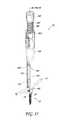
- FIG. 1illustrates a perspective view of a rod reducer according to an embodiment.
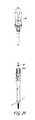
- FIG. 2is a front view of the sleeve of FIG. 1 .
- FIG. 3is a perspective view of the proximal end of the sleeve of FIG. 2 .
- FIG. 4is a top view of the sleeve of FIG. 2 .
- FIG. 5is a cross-sectional view of the sleeve of FIG. 2 along lines 5 - 5 in FIG. 4 .
- FIG. 6is a perspective view of the distal end of the sleeve of FIG. 2 .
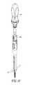
- FIG. 7is a front view of the engagement member of FIG. 1 .
- FIG. 8is a cross-sectional view of the engagement member of FIG. 7 along lines 8 - 8 in FIG. 7 .
- FIG. 9is a cross-sectional view of the engagement member of FIG. 7 along lines 9 - 9 in FIG. 7 .
- FIG. 10is a front view of the collar of FIG. 1 .
- FIG. 11is a top view of the collar of FIG. 10 .
- FIG. 12is a cross-sectional view of the collar of FIG. 10 along lines 12 - 12 .
- FIG. 13is an embodiment of a rod and a fastener.
- FIG. 14is an embodiment of a method step of using the rod reducer of FIG. 1 .
- FIG. 15is an embodiment of a method step of using the rod reducer of FIG. 1 .
- FIG. 16is an embodiment of a method step of using the rod reducer of FIG. 1 .
- FIG. 17is an embodiment of a method step of using the rod reducer of FIG. 1 .
- FIG. 18is an embodiment of a method step of using the rod reducer of FIG. 1 .
- FIG. 19is an embodiment of a method step of using the rod reducer of FIG. 1 .
- FIG. 20is an embodiment of a method step of using the rod reducer of FIG. 1 .
- FIG. 21is an embodiment of a method step of using the rod reducer of FIG. 1 .
- Orthopedic devicessuch as rods can be secured to a bone using fasteners.
- the reduction of the rod within a channel of fastenermay be directed by a rod reducer for more precise placement, especially for surgical sites with limited access or visibility, such as the cervical spine.
- the success or failure of the rodcan often depend upon the precise placement of the rod within the channel of fastener.
- the rods utilized for spinal surgerycan often be bent away from the fastener.
- the preferred trajectory of the rodmay be perpendicular to the channel of the fastener such that the rod can be seated within the channel of the fastener.
- the rodmay need to be lowered or reduced relative to the channel of the fastener.
- a rod reduceris provided that facilitates proper placement of the rod relative to the fastener.
- the rod reducercan have the additional functionality of reliably and rapidly releasing the rod reducer after rod reduction.
- rod reducer instrumentsAlthough referred to as rod reducer instruments, these instruments need not be used with only rods but can be used for the movement of any two objects toward each other for any of a number of purposes.
- the rod reducer instrumentscan also facilitate delivery of components within interbody implants.
- the vertebral columncomprises a series of alternating vertebrae and fibrous discs that provide axial support and movement to the upper portions of the body.
- the vertebral columntypically comprises thirty-three vertebrae, with seven cervical (C1-C7), twelve thoracic (T1-T12), five lumbar (L1-15), five fused sacral (S1-S5) and four fused coccygeal vertebrae.
- Each vertebraincludes an anterior body with a posterior arch.
- the posterior archcomprises two pedicles and two laminae that join posteriorly to form a spinous process. Projecting from each side of the posterior arch is a transverse, superior and inferior articular process.
- the facets of the superior and inferior articular processesform facet joints with the articular processes of the adjacent vertebrae.
- the typical cervical vertebraediffer from the other vertebrae with relatively larger spinal canals, oval shaped vertebral bodies, bifid spinous processes and foramina in their transverse processes. These foramina transversaria contain the vertebral artery and vein.
- the first and second cervical vertebraealso further differentiated from the other vertebrae.
- the first cervical vertebralacks a vertebral body and instead contains an anterior tubercle. Its superior articular facets articulate with the occipital condyles of the skull and are oriented in a roughly parasagittal plane. The cranium is able to slide forward and backwards on this vertebra.
- the second cervical vertebracontains an odontoid process, or dens, which projects superiorly from its body. It articulates with the anterior tubercle of the atlas, forming a pivot joint. Side to side movements of the head occur at this joint.
- the seventh cervical vertebrais sometimes considered atypical since it lacks a bifid
- the typical lumbar vertebraeare distinguishable from the other vertebrae by the absence of foramina transversaria and the absence of facets on the surface of the vertebral body.
- the lumbar vertebral bodiesare larger than the thoracic vertebral bodies and have thicker pedicles and laminae projecting posteriorly.
- the vertebral foramenis triangular in shape and larger than the foramina in the thoracic spine but smaller than the foramina in the cervical spine.
- the superior and inferior articular processesproject superiorly and inferiorly from the pedicles, respectively.
- the rods described hereincan be located at any level of the vertebral column.
- the rodscan be positioned between adjacent vertebra in the vertebral column.
- the rodis described as positioned between a superior vertebra and an inferior vertebra. It should be appreciated that the rod can be utilized in other portions of the spine other than between adjacent vertebra.
- the desired orientation of the rodcan depend on the adjacent vertebra.
- the rodcan be placed at any angle to the transverse plane, including parallel, substantially parallel, perpendicular, substantially perpendicular, 0 degrees, 15 degrees, 30 degrees, 45 degrees, 60 degrees, 75 degrees, 90 degrees, etc.
- the rodcan be placed at any angle to the frontal plane, including parallel, substantially parallel, perpendicular, substantially perpendicular, 0 degrees, 15 degrees, 30 degrees, 45 degrees, 60 degrees, 75 degrees, 90 degrees, etc.
- the rod reducer instrumentcan facilitate placement of the rod relative to the fasteners while maintaining the desired orientation of the rod.
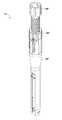
- FIG. 1depicts a perspective view of an embodiment of a rod reducer 10 .
- the rod reducer 10can comprise a sleeve 100 .
- the sleeve 100can facilitate placement of the rod reducer 10 relative to a fastener (not shown).
- the rod reducer 10can comprise an engagement member 200 .
- the engagement member 200can facilitate movement of the rod (not shown) relative to the fastener.
- the rod reducer 10can comprise a collar 300 .
- the collar 300can allow for rapid release of the engagement member 200 relative to the sleeve 100 . Further functionality of the rod reducer 10 is described in greater detail herein.
- the rod reducer 10can be used to engage the fastener and the rod to reduce the rod, or force the rod into engagement with the fastener such as a channel of a fastener.
- the sleeve 100can be used to engage and secure the rod reducer 10 to a fastener, such as a bone screw.
- the collar 300is rotated to a disengaged position. This disengages a threaded portion of the sleeve 100 with a threaded portion of the engagement member 200 .
- the engagement member 200can be pushed in a longitudinal direction.
- the engagement member 200can be moved distally until a first marking on the engagement member 200 aligns with a marking on the sleeve 100 .
- the collar 300is rotated to an engagement position. This engages the threaded portion of the sleeve 100 with the threaded portion of the engagement member 200 .
- the engagement member 200can be rotated which causes longitudinal translation of the engagement member 200 within the sleeve 100 .
- the engagement member 200slides within a lumen of the sleeve 100 and makes contact with the rod. Further movement of the engagement member 200 causes the rod to be drawn toward the fastener to seat the rod within a channel of the fastener.
- the engagement member 200can be moved distally until a second marking on the engagement member 200 aligns with a marking on the sleeve 100 . The second marking can indicate that the rod has been fully reduced relative to the fastener.
- Additional instrumentscan be inserted within the engagement member 200 to secure the rod to the fastener.
- a closure devicesuch as a set screw is inserted within a lumen of the engagement member 200 toward the fastener. The closure device can maintain the position of the rod within the channel of the fastener.
- the rod reducer 10can be released from the fastener.
- the engagement member 200can be rotated which causes longitudinal translation of the engagement member 200 within the sleeve 100 .
- the engagement member 200slides within a lumen of the sleeve 100 .
- the collar 300is rotated to a disengaged position. This disengages the threaded portion of the sleeve 100 with the threaded portion of the engagement member 200 .
- the engagement member 200can be pulled in a longitudinal direction.
- the engagement member 200is removed from the sleeve 100 prior to disengaging the fastener.
- the engagement member 200is removed from the sleeve 100 after disengaging the fastener.
- the sleeve 100can be rotated to disengage the rod reducer 10 from the fastener. The components that perform these functions are described in greater detail herein.
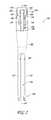
- FIG. 2is a front view of the sleeve 100 of FIG. 1 .
- the sleeve 100includes a distal end 102 and a proximal end 104 .
- the distal end 102can engage a fastener as described herein.
- the proximal end 104can engage the collar 300 as described herein.
- the sleevecan include a grip 106 which facilitates the grip of the sleeve 100 during rod reduction.
- the grip 106can include a plurality of longitudinal grooves. Other configurations are contemplated including raised protrusion, textured surfaces, etc.
- the distal portion of the sleeve 100includes a plurality of legs.
- the distal portioncan include two legs, 110 , 112 .
- the legs 110 , 112can be disposed 180 degrees relative to each other.
- Disposed between the legs 110 , 112can be a slot 114 which separates the legs 110 , 112 .
- the slot 114can allow the distal end 102 to flex around a fastener as described herein.
- Each leg 110 , 112can be generally straight.
- Each leg 110 , 112can be parallel or substantially parallel to a longitudinal axis 116 of the sleeve 100 .
- Each leg 110 , 112can have a neutral position in which the leg 110 , 112 is equidistant from the longitudinal axis 116 from the proximal end of each leg 110 , 112 , to a distal end of each leg 110 , 112 .
- the external surface shape of the legs 110 , 112can be generally circular or circular, as shown in FIG. 2 . Other external shapes are contemplated including rectangular, polygonal, elliptical, etc.
- the external shape of the legs 110 , 112can mitigate trauma to the surrounding tissue during rod reduction.
- the external shape of the legs 110 , 112can correspond with the internal shape of a cannula utilized to insert the fastener and/or the rod reducer 10 .
- the sleeve 100can include a marking 120 .
- the markingcan be a line, shape, icon, letter, number, word or other indicia.
- FIG. 2shows a line as the marking 120 .
- the marking 120can include a plurality of markings, for instance diametrically opposed markings. Such diametrically opposed markings may allow the surgeon to view the markings 120 regardless of the orientation of the sleeve 100 .
- the marking 120can extend in a horizontal direction.
- the marking 120can extend along a portion of a leg 110 , 112 .
- the marking 120can extend along a portion of both legs 110 , 112 as shown in FIG. 2 .
- the sleeve 100can include a taper 122 that extends between the legs 110 , 112 and the grip 106 .
- the taper 122can increase the cross-section of a proximal portion of the sleeve 100 .
- the increased cross-sectioncan help facilitate gripping of the rod reducer 10 during reduction.
- the sleeve 100can include a marking 124 .
- the marking 124can include a line, shape, icon, letter, number, or other indicia.
- the marking 124can indicate the rotational position for an engaged position of the collar 300 .
- the sleeve 10can include a marking 126 .
- the marking 126can include a line, shape, icon, letter, number, or other indicia.
- the marking 126can indicate the rotational position for an disengaged position of the collar 300 .
- the marking 124 , 126can include a plurality of markings, for instance diametrically opposed markings. Such diametrically opposed markings may allow the surgeon to view the markings 124 , 126 regardless of the orientation of the sleeve 100 .
- FIG. 2shows words to indicate each rotational position.
- the marking 124is labeled as “LOCK” and the marking 126 is labeled as “UNLOCK.”
- Each marking 124 , 126is at a different rotational position along the sleeve 100 .
- the markings 124 , 126are separated by 45 degrees.
- Other rotational positionsare contemplated for the markings 124 , 126 including separated by 30 degrees, 60 degrees, 75 degrees, 90 degrees, etc.
- the position of the markings 124 , 126corresponds to the position of the collar 300 in the engaged position and disengaged position, respectively.
- the sleeve 100can include a cut out portion 130 .
- the cut out portion 130can be located proximal to the markings 124 , 126 .
- the cut out portion 130can be shaped to accept the collar 300 as described herein.
- the collar 300can be rotated to align with the markings 124 , 126 as described herein.
- the cut out portion 130limits the rotational freedom of the collar 300 relative to the sleeve 100 .
- the cut out portion 130can have a smaller diameter or width than the grip 106 .
- the cut out portion 130can have a diameter or width such that the collar 300 , when placed within the cut out portion 130 , and the grip 106 have the same or similar diameter or width.
- the sleeve 100can include one or more tabs 132 .
- the sleeve 100includes four tabs 132 .
- Other configurationsare contemplated, e.g., one tabs, two tabs, three tabs, five tabs, six tabs, seven tabs, eight tabs, nine tabs, ten tabs, etc.
- Each tab 132can comprise a cut 134 along three sides of a generally rectangular shape to form a perimeter of the tab. The cut 134 can begin in the grip 106 and extend to the cut out portion 130 . In the illustrated embodiment, the cut 134 does not form a closed shape and the distal end of the tab 132 remains attached to the grip 106 . As illustrated in FIG.
- the distal end of the cut 134can have round reliefs to help prevent the cut 134 from extending and to help the tab 132 flex at the distal hinge.
- the cut 134allows the tab 132 to flex inward and outward as described herein.
- Each tab 132can have a distal portion 136 .
- the distal portion 136can have the same or similar external shape as the grip 106 .
- the distal portion 136can include a taper. The taper can increase the width of the tab from the distal portion 136 to a middle portion 140 .
- the middle portion 140 of the tab 132can have the same or similar external shape as the cut out portion 130 .
- Each tab 132can have a proximal portion 142 .
- the proximal portion 142can include a first engagement feature 144 .
- the first engagement feature 144is a protrusion. The first engagement feature 144 can engage a portion of the collar 300 to move the tab 132 inward.
- the neutral position of the tab 132can be outward as shown in FIG. 2 .
- the collar 300can engage the first engagement feature 144 and move the tab 132 inward as described herein.
- the collar 300can disengage the first engagement feature 144 thereby allowing the tab 132 to regain the neutral position of the tab 132 .
- FIG. 3is a perspective view of the proximal end 104 of the sleeve 100 .
- the internal surface of the sleeve 100can include threads 146 .
- the threads 146can extend from the proximal end 104 of the sleeve 100 .
- the threads 146can extend along the length of the cut out portion 130 .
- the threads 146can be formed during manufacturing. In some embodiments, the threads 146 do not threadingly engage with another component of the rod reducer 10 when the tabs 132 are in the neutral position.
- Each tab 132can include threads 150 .
- the threads 146 , 150can be correspondingly timed to form continuous threads.
- the threads 150 on each tab 132are correspondingly timed to form continuous threads.
- the threads 150can extend from a distal end of the tab 132 along the length of the tab 132 .
- the threads 150extend along at least part of the length of the proximal portion 142 , the middle portion 140 and/or the distal portion 136 of the tab 132 .
- the threads 150are disposed on only part of the length of the tab 132 , such as on portions of only the proximal portion 142 and middle portion 140 .
- the sleeve 100can include a lumen 152 extending from the distal end 102 to the proximal end 104 .
- the lumen 152allows the engagement member 200 to be at least partially inserted within the sleeve 100 as described herein.
- the lumen 152can have various shapes along the length of the sleeve. For instance, near the proximal end 104 , the lumen 152 is formed from the threads 146 , 150 . For instance, near the distal end 102 , the lumen 152 is formed from the legs 110 , 112 .
- FIG. 4is a top view of the sleeve 100 of FIG. 2 .
- FIG. 4is a top view of the sleeve 100 of FIG. 2 .
- the lumen 152can include a mating portion 154 having mating geometry.
- the mating geometrycan be any cross-sectional shape that ensures a mating configuration between the sleeve 100 and the engagement member 200 .
- the mating portion 154 of the lumen 152has a x-ring cross sectional shaped.
- the x-ringis formed of a generally circular cross-sectional shape having two intersecting longitudinal bars.
- the mating portion 154can include undercuts 156 which guide the engagement member 200 relative to the sleeve 100 .
- the mating portion 154can extend from the distal end 102 as shown in FIG. 5 .
- the mating portion 154can extend to through the taper 122 as shown in FIG. 5 .
- the mating portion 154can extend any length along the lumen 152 .
- FIG. 6is a perspective view of the distal end 102 of the sleeve 100 .
- the distal end 102is configured to couple with the fastener (not shown).
- the distal end 102can be shaped to accept a head of a polyaxial screw as described herein.
- the distal end 102can be designed to mate with any known fastener, for instance, by including specific undercuts and shapes that can engage external features of the fastener.
- the distal end 102can include a pair of notches 160 , 162 .
- the notch 160can be located on the leg 110
- the notch 162can be located on the leg 112 .
- the notches 160 , 162can be diametrically opposed.
- the notches 160 , 162can be designed to provide clearance around the head of the fastener when the sleeve 100 is rotated to disengage the sleeve 100 from the fastener.
- the notches 160 , 162can accommodate a leading edge of the head of the fastener as described herein.
- Each leg 110 , 112can include one or more first couplers 164 to engage the head of the fastener.
- the first couplers 164are tabs which engage corresponding recesses in the head of the fastener.
- the sleeve 100can be configured to accept the fastener in one of two orientations. For instance, each first coupler 164 can accept either one of two sides of the fastener. In other configurations, the sleeve 100 is configured to accept the fastener in only one orientation. For instance, each first coupler 164 can be unique such that each leg 110 , 112 only mates with one particular side of the fastener. Other configurations for the distal end 102 of the sleeve 100 are contemplated based on the configuration of the fastener.
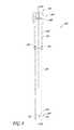
- FIG. 7is a front view of the engagement member 200 of FIG. 1 .
- FIG. 8is a cross-section view of FIG. 7 .
- the engagement member 200includes a distal end 202 and a proximal end 204 .
- the distal end 202can engage the rod as described herein.
- the proximal end 204can include a handle 206 .
- the handle 206facilitates the grip of the engagement member 200 during rod reduction.
- the handle 206can include a plurality of longitudinal grooves. Other configurations are contemplated including raised protrusion, textured surfaces, etc.
- the engagement member 200can include a first marking 226 .
- the markingcan be a line, shape, icon, letter, number, word or other indicia.
- FIG. 7shows a line as the marking 226 .
- the marking 226can include a plurality of markings, for instance diametrically opposed markings. Such diametrically opposed markings may allow the surgeon to view the markings 226 regardless of the orientation of the engagement member 200 within the sleeve 100 .
- the marking 226can extend in a horizontal direction.
- the marking 226can extend at a specific location along the longitudinal axis 216 of the engagement member 200 .
- the engagement member 200can include a second marking 228 .
- the markingcan be a line, shape, icon, letter, number, word or other indicia.
- FIG. 7shows a line as the second marking 228 .
- the second marking 228can include a plurality of markings, for instance diametrically opposed markings. Such diametrically opposed markings may allow the surgeon to view the second markings 228 regardless of the orientation of the engagement member 200 within the sleeve 100 .
- the second marking 228can extend in a horizontal direction.
- the second marking 228can be more proximal than the first marking 226 .
- the second marking 228can extend at a specific location along the longitudinal axis 216 of the engagement member 200 .
- the first marking 226 and the second marking 228are the same indicia. In other embodiments, the first marking and the second marking are distinct indicia. For instance, the indicia can include different colors, shapes, thicknesses, etc.
- the engagement member 200has more than two markings, such as three or four markings at different vertical positions on the engagement member 200 .
- the engagement member 200can have a third marking (not shown) between the first marking 226 and second marking 228 .
- the third markingcan be a line, shape, icon, letter, number, word or other indicia and can be similar to the first and second markings.
- the distal portion of the engagement member 200includes one or more of flanges to engage the rod.
- the distal portioncan include two flanges, 210 , 212 .
- the flanges 210 , 212can be disposed 180 degrees relative to each other.
- the flanges 210 , 212can include a slot 214 which separates the flanges 210 , 212 .
- Flanges 210 , 212can be relatively straight.
- Each flanges 210 , 212can be parallel or substantially parallel to a longitudinal axis 216 of the engagement member 200 .
- Each flange 210 , 212can have a distal end 220 to engage the rod.
- the distal end 220can be rounded to correspond to the rounded surface of a rod. Other shapes are contemplated.
- the engagement member 200can include a lumen 250 extending from the distal end 202 to the proximal end 204 , as shown in FIG. 8 .
- the lumen 250allows other instrumentation to be at least partially inserted within the engagement member 200 as described herein.
- a closure devicecan be inserted within the lumen 250 to couple the rod to the fastener.
- the lumencan be sized to accept a driver for the closure device.
- the engagement member 200can include a shaft 222 .
- FIG. 9is a cross-sectional view of the engagement member 200 of FIG. 7 along lines 9 - 9 in FIG. 7 .
- the external surface of the shaft 222can have a mating geometry.
- the engagement geometrycan be any cross-sectional shape that ensures a mating configuration between the sleeve 100 and the engagement member 200 .
- the shaft 222has a x-ring cross sectional shaped.
- the x-ringis formed of a generally circular cross-sectional shape having two intersecting longitudinal bars.
- the shaft 222can include ridges 224 which interact with the undercuts 156 of the sleeve 100 , shown in FIG. 4 .
- the ridges 224guide the engagement member 200 relative to the sleeve 100 .
- the ridges 224can extend above the slot 214 .
- the ridges 224can extend the length of the shaft 222 .
- the ridge 224can extend above the slot 214 and along a portion of the length of the shaft (e.g., half of the length of the shaft, a quarter of the length of the shaft, etc.).
- the ridges 224can extend any length along the shaft 222 .
- the engagement member 200can include a junction 232 .
- the junction 232can be located at the proximal end of the shaft 222 .
- the junction 232is integrally formed with the proximal end of the shaft 222 .
- the junction 232is a separate component from the shaft 222 .
- the junction 232can include a first alignment feature 234 .
- the first alignment feature 234can be a pair of diametrically opposed pegs.
- the junction 232can include a cut out portion 236 .
- the junction 232can include an undercut 240 .
- the undercut 240can allow portions of the engagement member 200 to rotate relative to each other.
- the engagement member 200can include a threaded member 242 .
- the threaded membercan include a ridge 244 as shown in FIG. 8 .
- the ridge 244can mate with the undercut 240 of the junction 232 .
- the ridge 244can allow the threaded member 242 to rotate relative to the junction 232 .
- the ridge 244prevents the threaded member from translating relative to the junction 232 .
- the cut out portion 236can allow the threaded member 242 to be disengaged from the junction 232 .
- the cut out portion 236can allow disassembly of the threaded member 242 for sterilization or for other purposes.
- the threaded member 242can include threads 246 .
- the threads 246can form a continuous helix.
- the threads 246can begin at a location proximal to the ridge 244 .
- the threads 246can be correspondingly timed to engage the threads 150 of each tab 132 , as described herein.
- the threads 246can terminate near the handle 206 .
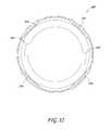
- FIG. 10is a front view of the collar 300 of FIG. 1 .
- the collar 300includes a distal end 302 and a proximal end 304 .
- the collar 300is shaped and sized to rotate relative to the cut out portion of 130 of the sleeve 100 as described herein.
- the collar 300can include a cross sectional shape that is the same or similar to the sleeve 100 .
- the collar 300can include one or more flanges.
- the collar 300includes two flanges 306 , 308 .
- Other configurationsare contemplated.
- the flanges 306 , 308can be near the distal end 302 of the collar 300 .
- the flange 306can include a marking 310 .
- the marking 310can be a line, shape, icon, letter, number, or other indicia.
- FIG. 10shows the marking 310 to be a dot.
- the marking 310can include a plurality of markings, for instance diametrically opposed markings. Such diametrically opposed markings may allow the surgeon to view the markings 310 regardless of the orientation of the collar 300 .
- the marking 310can indicate the rotational position of the collar 300 .
- the collar 300can be rotated relative to the sleeve 100 as described herein.
- the collar 300can be rotated to align the marking 310 with marking 124 of the sleeve 100 . This position can indicate that the collar 300 is in the engaged position.
- the collar 300can be rotated to align the marking 310 with the marking 126 of the sleeve 100 . This position can indicate that the collar 300 is in the disengaged position.
- FIG. 11is a top view of the collar 300 .
- the collar 300can include a second alignment feature 312 .
- the second alignment feature 312is a pair of diametrically opposed slots.
- the second alignment feature 312 of the collar 300are sized to accept the first alignment feature 234 of the junction 232 .
- the opposed slots of the collar 300are sized to accept the pegs of the junction 232 .
- the collar 300can be configured to accept the junction 232 in one of two orientations.
- each second alignment feature 312can accept either first alignment feature 234 .
- the collar 300is configured to accept the junction 232 in only one orientation.
- each second alignment feature 312can be unique such that each second alignment feature 312 of the collar 300 only accepts a particular first alignment feature 234 of the junction 232 .
- FIG. 12is a cross-sectional view of the collar 300 of FIG. 10 along lines 12 - 12 .
- the collar 300can include one or more second engagement features 314 .
- the second engagement features 314are a plurality of ramps.
- the second engagement features 314interact with the first engagement features 144 of the tabs 132 .
- the ramps of the collar 300interact with the protrusions of the tabs 132 .
- the second engagement features 314push the tabs 132 inward.
- the second engagement features 314do not push the tabs 132 inward.
- the tabs 132can have a neutral position. In the disengaged configuration of the collar 300 , the tabs 132 can regain the neutral position.
- the reducer 10can have other functional engagement mechanisms to engage the sleeve 100 with the engagement member 200 .
- the reducercan include a clamp around the proximal end 104 of the sleeve 100 .
- the clampcan have an inner diameter disposed around the tabs. When the clamp is actuated, the inner diameter can contract to engage the tabs and push the tabs inward, as described above.
- the reducerinstead of a collar that is rotated to engage the tabs, can have a collar that is translated in the proximal-distal direction.
- the collarcan have an inner diameter that decreases from the distal end to the proximal end. As the collar is translated distally, the decreasing inner diameter engages the tabs to push the tabs inward.
- Other functional engagement mechanismsare also contemplated.
- FIG. 13is an embodiment of a rod 12 .
- the rod 12can include a bend 14 .
- the bend 14can correspond to a bend of the anatomy.
- the bend 14can correspond to a desired outcome of the surgical procedure.
- the bend 14can cause the rod 12 to extend proximally from a fastener 16 .
- the fastener 16can be a polyaxial screw.
- the fastener 16can include a screw 20 .
- the screw 20has a distal end 22 and a proximal end 24 .
- the distal end 22 of the screw 20can be driven into a vertebra.
- the fastener 16can include a head 26 .
- the head 26can include a distal end 30 and a proximal end 32 .
- the screw 20 and the head 26can be coupled to allow polyaxial or uniaxial movement.
- the head 26includes a channel 34 . In FIG. 13 , the channel 34 is U-shaped but other configurations are contemplated.
- the channel 34is sized to accept the rod 12 .
- the rod 12can be inserted from the proximal end 32 of the head 26 toward the distal end 30 of the head 26 .
- the head 26can include a longitudinal axis 36 .
- the fastener 16can include two sides 40 , 42 . Each side 40 , 42 can include one or more second couplers 44 .
- the second couplers 44are configured to engage the first couplers 164 of the legs 110 , 112 of the sleeve 100 .
- the second couplers 44are recesses in the head 26 of the fastener 16 .
- the head 26 of the fastener 16can be accepted by the sleeve 100 in one of two orientations.
- each second coupler 44can be accepted by either leg 110 , 112 .
- the sleeve 100is configured to accept the head 26 in only one orientation.
- each second coupler 44can be unique such that each leg 110 , 112 only mates with one particular side 40 , 42 of the fastener 16 .
- the proximal end 32 of the head 26can include an opening 46 .
- the opening 46can be configured to accept a closure device (not shown). In some embodiments, the opening 46 is threaded to engage the corresponding threads of the closure device.
- the closure devicecan secure the rod 12 to the fastener 16 , as described herein.
- the head 26is integrally formed with the screw 20 .
- the fastener 16includes a hook.
- the fastener 16can include any structure having a corresponding channel 34 for the rod 12 .
- FIGS. 13-21illustrate various method steps which may be performed utilizing the rod reducer 10 described herein.
- a methodcan comprise one or more of these steps.
- a methodcan comprise any of the steps below in any order.
- a methodcan include the same step at multiple times during the method of use.
- FIG. 13shows the head 26 coupled with the screw 20 .
- the screw 20can be driven into a vertebra.
- the rod 12can be positioned adjacent to the fastener 16 .
- the rod 12can be aligned with the channel 34 of the head 26 of the fastener 16 .
- the rod 12can be a distance from the distal end 30 of the head 26 . This distance is decreased during rod reduction such that the rod 12 is seated within the head 26 of the fastener 16 .
- FIG. 14shows the assembled rod reducer 10 .
- the engagement member 200can be inserted at least partially through the collar 300 .
- the engagement member 200can be inserted at least partially through the sleeve 100 .
- the rod reducer 10is provided in the assembled state as shown in FIG. 14 .
- the rod reducer 10is in a disassembled state.
- each component of the rod reducer 10is uncoupled as shown in FIGS. 1-12 .
- To assemble the rod reducer 10one or more of the following steps can be performed.
- the collar 300can engage the cut out portion 130 of the sleeve 100 .
- the collar 300is free to rotate within the cut out portion 130 between an engaged position and a disengaged position as described herein.
- the collar 300 and the cut out portion 130have stop features at the engaged position and/or the disengaged position to help maintain the collar 300 in position.
- the collar 300can have detents and the cut out portion 130 can have a ball such that the ball engages the detents in the engaged position and the disengaged position. Any of a plurality of different types of stop features can be used.
- the stop featurecan advantageously provide a tactile signal to the user to indicate when the engaged or disengaged position is reached.
- the shaft 222 of the engagement member 200can be inserted into the collar 300 .
- the shaft 222 of the engagement member 200can be inserted into the lumen 152 of the sleeve 100 .
- the lumen 152can have various shapes along the length of the sleeve. For instance, near the proximal end 104 , the lumen 152 is formed from the threads 146 , 150 .
- the shaft 222 of the engagement member 200can pass through the threads 146 , 150 .
- the shaft 222 of the engagement member 200can couple with the mating portion 154 having engagement geometry.
- the engagement geometrycan be any cross-sectional shape that ensures a mating configuration between the sleeve 100 and the engagement member 200 .
- the mating portion 154can include undercuts 156 which guide the engagement member 200 relative to the sleeve 100 .
- the shaft 222can include ridges 224 which interact with the undercuts 156 of the sleeve 100 .
- the ridges 224guide the engagement member 200 relative to the sleeve 100 .
- one or more components of the rod reducer 10can include an alignment feature to aid in the alignment of the engagement member 200 and the sleeve 100 .
- the first alignment feature 234 of the junction 232 of the engagement member 200can be aligned with a second alignment feature 312 of the collar 300 .
- the pegs of the junction 232can be aligned with the slots of the collar 300 .
- the alignment of the first alignment feature 234 of the junction 232 with the second alignment feature 312 of the collar 300allows the engagement member 200 to be inserted through the collar 300 and into the sleeve 100 .
- the collar 300can be rotated to the engaged position to align the first alignment features 234 of the junction 232 and the collar 300 .
- the position of the first alignment feature 234 on the perimeter of the junction 232is correlated with the position of the second alignment feature 312 on the inner perimeter of the collar 300 such that the first alignment feature 234 of the junction 232 can pass through the second alignment feature 312 of the collar 300 when the collar 300 is in the engaged position on the sleeve 100 .
- the tabs 132are pushed inward, as described herein. The tabs 132 prevent the junction 232 from passing through the sleeve 100 .
- the collar 300can be rotated after the first alignment feature 234 of the junction 232 pass through the second alignment feature 312 of the collar 300 . In some methods of use, the collar 300 can be rotated to the disengaged position after the first alignment feature 234 of the junction 232 pass through the second alignment feature 312 of the collar 300 .
- the marking 310can be aligned with the marking 126 of the sleeve 100 . In the disengaged position, the second engagement feature 314 of the collar 300 does not engage the first engagement feature 144 of the tabs 132 . In the disengaged position, the collar 300 does not push the tabs 132 inward.
- the collar 300can be in the disengaged position as shown in FIG. 14 .
- the engagement member 200In the disengaged position, the engagement member 200 can move longitudinally without engaging the threaded member 242 of the engagement member 200 with the threads 150 of the tabs 132 .
- the tabs 132do not engage the threaded member 242 of the engagement member 200 .
- the engagement member 200In the disengaged position, the engagement member 200 can be pushed to move distally within the sleeve 100 . In the disengaged position, the engagement member 200 can be pulled to move proximally within the sleeve 100 .
- the engagement member 200is translated within the sleeve 100 until the first marking 226 of the engagement member 200 aligns with the marking 120 of the sleeve 100 .
- FIG. 14shows the alignment of the markings 120 , 226 .
- the first marking 226can indicate the maximum distal position of the engagement member 200 within the sleeve 100 in order to couple the reducer 10 to the head 26 of the fastener 16 . For instance, if the engagement member 200 is moved too far distally such that the first marking 226 is distal to the marking 120 , then the shaft 222 may be too far in the lumen 152 and prevent the legs 110 , 112 from deflecting sufficiently to couple around the head 26 .
- FIG. 14shows each leg 110 , 112 of the sleeve 100 which can be relatively straight when the engagement member 200 is inserted therein.
- Each leg 110 , 112can be parallel or substantially parallel to a longitudinal axis 116 of the sleeve 100 when the engagement member 200 is inserted therein.
- Each leg 110 , 112can have a neutral position in which the leg 110 , 112 is equidistant from the longitudinal axis 116 from the proximal end of each leg 110 , 112 , to a distal end of each leg 110 , 112 .
- the engagement member 200does not pull the legs 110 , 112 inward toward the longitudinal axis 116 .
- the engagement member 200does not push the legs 110 , 112 outward away from the longitudinal axis 116 .
- the engagement member 200enforces the neutral position of the legs 110 , 112 .
- the rod reducer 10is configured to be moved in a longitudinal direction toward the fastener 16 .
- the longitudinal axis 116 of sleeve 100can align with the longitudinal axis 36 of the head 26 of the fastener 16 .
- the longitudinal axis 216 of engagement member 200can align with the longitudinal axis 36 of the head 26 of the fastener 16 .
- each leg 110 , 112can be deflected to accept the head 26 of the fastener 16 .
- the head 26can interact with the first couplers 164 of each leg 110 , 112 of the sleeve 100 to cause outward movement of the legs 110 , 112 .
- the first couplers 164are shown in FIG. 6 .
- the head 26can interact with another component of the sleeve 100 to cause outward movement of the legs 110 , 112 .
- the legs 110 , 112are deflected from a neutral position.
- the legs 110 , 112can be straight or substantially straight in the neutral position.
- the legs 110 , 112are equidistant from the longitudinal axis 116 along a distal portion of the sleeve 100 .
- the legs 110 , 112can be defected outward from the neutral position.
- the distal end 102 of the sleeveis a greater distance from the longitudinal axis 116 than a proximal portion of the legs 110 , 112 .
- the sleeve 100can be moved longitudinally until first couplers 164 of each leg 110 , 112 of the sleeve 100 engage the corresponding second couplers 44 of each side 40 , 42 of the head 26 of the fastener 16 .
- the fastener 16is shown in FIG. 13 .
- the legs 110 , 112can resume the neutral position when they are fully seated onto the head 26 of the fastener 16 .
- the legs 110 , 112can be straight or substantially straight in the neutral position.
- FIG. 15shows the rod reducer 10 coupled with the fastener 16 .
- the first couplers 164 of each leg 110 , 112 of the sleeve 100engage the corresponding second couplers 44 of each side 40 , 42 of the head 26 of the fastener 16 .
- the channel 34 of the head 26 of the fastener 16aligns with the slot 114 between the legs 110 , 112 of the sleeve 100 .
- the rod 12can be located within the slot 114 .
- the rod 12can be located within the channel 34 .
- Each notch 160 , 162can extend beyond the head 26 of the fastener 16 .
- Each notch 160 , 162can extend more proximal than the proximal end 24 of the head 26 of the fastener 16 .
- the engagement member 200is pushed within the sleeve 100 .
- the engagement member 200can be pushed into contact with the rod 12 .
- FIG. 16shows the engagement member 200 being pushed into contact with the rod.
- the engagement member 200can be pushed within the sleeve 100 until a third marking is aligned with the marking 120 on the sleeve 100 .
- the third markingcan be between the first marking 226 and the second marking 228 .
- the third markingcan indicate when the engagement member 200 is sufficiently coupled with the sleeve 100 in order to provide enough holding force to prevent the legs 110 , 112 from deflecting and unintentionally disengaging from the head 26 of the fastener 16 as the rod 12 is reduced.
- the alignment of the first marking 226 of the engagement member 200 with the marking 120 of the sleeve 100indicates alignment of the threads 150 of the tabs 132 with the threads 246 of the threaded member 242 .
- the alignment of the third marking of the engagement member 200 with the marking 120 of the sleeve 100indicates alignment of the threads 150 of the tabs 132 with the threads 246 of the threaded member 242 .
- the collar 300can be rotated to the engaged position, as shown in FIG. 17 .
- the marking 310is aligned with the marking 124 of the sleeve 100 .
- the second engagement feature 314 of the collar 300can engage the first engagement feature 144 of the tabs 132 .
- the collar 300can push the tabs 132 inward.
- the tabs 132 when pushed inwardform a smaller diameter than the threads 146 of the sleeve 100 .
- the tabs 132 when pushed inwardform a diameter which is the same or substantially similar to the diameter of the threaded member 242 of the engagement member 200 .
- the threads 150 of the tabs 132can interlock with the threads 246 of the threaded member 242 .
- the threads 150 of the tabs 132can engage the threaded member 242 and the rotation of the threaded member 242 can cause linear translation of the engagement member 200 within the sleeve 100 .
- the tabs 132can engage the threaded member 242 of the engagement member 200 .
- the engagement member 200in the engaged position, the engagement member 200 cannot be pushed within the sleeve 100 .
- the engagement member 200cannot be pulled within the sleeve 100 .
- the engagement member 200can linearly translate when the threaded member 242 is rotated.
- the threads 150 of the tabs 132can form a ratchet structure.
- the ratchet structurecan allow the engagement member 200 to move longitudinally in a particular direction relative to the sleeve 100 and still allow the threaded member 242 of the engagement member 200 to engage with the threads 150 of the tabs 132 .
- the ratchet structurecan allow the engagement member 200 to be pushed distally within the sleeve 100 , but engages the engagement member 200 when pulled proximally within the sleeve 100 .
- the engagement member 200can be pushed to a position adjacent the rod 12 and the handle 206 can be rotated, which rotates the threaded member 242 to engage the threads 150 and drive the engagement member 200 distally.
- FIG. 18shows a driver 52 .
- the driver 52can facilitate motion of the engagement member 200 .
- the driver 52is utilized after the engagement member 200 makes contact with the rod 12 .
- the driver 52is utilized before the engagement member 200 makes contact with the rod 12 .
- the driver 52can be utilized anytime the collar 300 is in the disengaged position to push or pull the engagement member 200 as shown in FIG. 18 .
- the driver 52can be utilized anytime the collar 300 is in the engaged position to rotate the engagement member 200 as shown in FIG. 19 .
- the driver 52is not utilized.
- the handle 206can be rotated to rotate the threaded member 242 .
- FIG. 19shows the contact of the engagement member 200 with the rod 12 .
- the distal end 202 of the engagement member 200can include flange 210 , 212 .
- Each flange 210 , 212can have a distal end 220 to engage the rod 12 .
- Each flange 210 , 212can have the same or similar dimension as the slot 114 of the sleeve 100 .
- Each flange 210 , 212can have the same or similar dimension as the channel 34 of the head 26 .
- each flange 210 , 212can extend external to the head 26 of the fastener 16 .
- each flange 210 , 212can extend partially or completely within the head 26 of the fastener 16 .
- the flanges 210 , 212can be points of contact between the engagement member 200 and the rod 12 .
- the threaded member 242is rotated until the rod 12 is pushed distally within the channel 34 of the head 26 of the fastener. In some methods of use, the rod 12 is pushed into contact with the screw 20 . In some methods of use, the rod 12 is pushed into contact with an intermediate object and the intermediate objected is pushed into contact with the screw 20 .
- the engagement member 200is translated within the sleeve 100 until the second marking 228 of the engagement member 200 aligns with the marking 120 of the sleeve 100 .
- FIG. 19shows the alignment of the markings 120 , 228 .
- the alignment of the second marking 228 of the engagement member 200 with the marking 120 of the sleeve 100indicates that the rod 12 is lowered into the channel 34 of the head 26 .
- the alignment of the markings 120 , 228can indicate that the rod 12 has been fully reduced.
- FIG. 20shows a driver 54 .
- the driver 54can be coupled to the closure device 50 .
- the driver 54 and the closure device 50can be inserted within the lumen 250 of the engagement member 200 as shown in FIG. 21 .
- the closure device 50can engage the threads of the opening 46 of the head 26 of the fastener 16 .
- the closure device 50can secure the rod 12 to the fastener 16 .
- the rod reducer 10can be removed from the fastener 16 after the rod 12 is secured.
- the engagement member 200is rotated to translate the shaft 222 proximally within the sleeve 100 .
- the collar 300can be in the engaged position.
- the collar 300is rotated to the disengaged position.
- the engagement member 200can be pulled to translate the shaft 222 proximally within the sleeve 200 .
- the distal end 202 of the engagement member 200is retracted beyond the legs 110 , 112 prior to disengagement of the sleeve 100 from the fastener 16 .
- the distal end 202 of the engagement member 200is retracted about to a midpoint of the legs 110 , 112 prior to disengagement of the sleeve 100 from the fastener 16 .
- the engagement member 200can be retracted proximally until at least the first marking 226 is aligned with or proximal of the marking 120 of the sleeve 100 prior to disengagement of the sleeve 100 from the fastener 16 .
- the retraction of the engagement member 200allows the legs 110 , 112 to be deflected by the fastener 16 , as described herein.
- the sleeve 100can be rotated to remove the rod reducer 10 from the fastener 16 .
- the sleeve 100can be rotated about the longitudinal axis 116 of the sleeve 100 .
- the head 26 of the fastener 16can deflect the legs 110 , 112 outward.
- the rotation of the sleeve 100 relative to the fastener 16can disengage the first couplers 164 of the sleeve from the second couplers 44 of the fastener 16 .
- the external surface of the head 26 of the fastener 16can interact with the first couplers 164 of the sleeve 100 to defect the legs 110 , 112 outward.
- the notches 160 , 162can be sized to permit the sleeve 100 to be rotated past a leading edge of the head 26 of the fastener.
- the notches 160 , 162help facilitate uncoupling of the fastener 16 and the sleeve 100 .
- the engagement member 200can be translated proximally until the first alignment feature 234 of the junction 232 abuts the collar 300 in the disengaged position.
- the collar 300can be rotated to the engaged position.
- the first alignment feature 234 of the junction 232can align with the second alignment feature 312 of the collar 300 in the engaged position.
- the collaris configured so that the first alignment feature 234 is aligned with the second alignment feature 312 when the collar is in the disengaged position, so that the engagement member 200 can be removed from the sleeve 100 without obstruction or without repositioning the collar.
- the engagement member 200can be removed from the sleeve 100 .
- the collar 300can be removed from the sleeve 100 .
- the threaded member 242can be removed from the junction 232 .
Landscapes
- Health & Medical Sciences (AREA)
- Orthopedic Medicine & Surgery (AREA)
- Neurology (AREA)
- Life Sciences & Earth Sciences (AREA)
- Surgery (AREA)
- Heart & Thoracic Surgery (AREA)
- Engineering & Computer Science (AREA)
- Biomedical Technology (AREA)
- Nuclear Medicine, Radiotherapy & Molecular Imaging (AREA)
- Medical Informatics (AREA)
- Molecular Biology (AREA)
- Animal Behavior & Ethology (AREA)
- General Health & Medical Sciences (AREA)
- Public Health (AREA)
- Veterinary Medicine (AREA)
- Surgical Instruments (AREA)
Abstract
Description
Claims (24)
Priority Applications (1)
| Application Number | Priority Date | Filing Date | Title |
|---|---|---|---|
| US15/447,661US10085778B2 (en) | 2016-03-04 | 2017-03-02 | Rod reducer instrument for spinal surgery |
Applications Claiming Priority (2)
| Application Number | Priority Date | Filing Date | Title |
|---|---|---|---|
| US201662303593P | 2016-03-04 | 2016-03-04 | |
| US15/447,661US10085778B2 (en) | 2016-03-04 | 2017-03-02 | Rod reducer instrument for spinal surgery |
Publications (2)
| Publication Number | Publication Date |
|---|---|
| US20170252074A1 US20170252074A1 (en) | 2017-09-07 |
| US10085778B2true US10085778B2 (en) | 2018-10-02 |
Family
ID=59723080
Family Applications (1)
| Application Number | Title | Priority Date | Filing Date |
|---|---|---|---|
| US15/447,661ActiveUS10085778B2 (en) | 2016-03-04 | 2017-03-02 | Rod reducer instrument for spinal surgery |
Country Status (1)
| Country | Link |
|---|---|
| US (1) | US10085778B2 (en) |
Cited By (7)
| Publication number | Priority date | Publication date | Assignee | Title |
|---|---|---|---|---|
| US20190274740A1 (en)* | 2018-03-12 | 2019-09-12 | Zimmer Biomet Spine, Inc. | Rod reducer ratchet lock-out mechanism |
| US11439441B2 (en) | 2017-09-05 | 2022-09-13 | Medos International Sarl | Modular surgical instruments and related methods |
| US11553947B2 (en) | 2019-07-16 | 2023-01-17 | Aesculap Implant Systems, Llc | Spinal deformity sequential persuader |
| US12053214B2 (en) | 2021-03-05 | 2024-08-06 | Medos International Sårl | Sequential reducer |
| WO2025082962A1 (en)* | 2023-10-16 | 2025-04-24 | Medos International Sarl | Combination derotation and reducer instruments |
| US12324610B2 (en) | 2021-04-28 | 2025-06-10 | Spinal Elements, Inc. | Lever reducer |
| US12369955B2 (en) | 2021-05-07 | 2025-07-29 | Highridge Medical, Llc | Ratcheting rapid rod reduction instrument |
Families Citing this family (9)
| Publication number | Priority date | Publication date | Assignee | Title |
|---|---|---|---|---|
| US8545505B2 (en)* | 2010-01-15 | 2013-10-01 | Pioneer Surgical Technology, Inc. | Low friction rod persuader |
| US8206395B2 (en)* | 2010-06-18 | 2012-06-26 | Spine Wave, Inc. | Surgical instrument and method for the distraction or compression of bones |
| US9750548B2 (en)* | 2011-10-11 | 2017-09-05 | Globus Medical, Inc. | Rod-reducing apparatus and associated methods |
| DE102016106608A1 (en)* | 2016-04-11 | 2017-10-12 | Aesculap Ag | Instrument for guiding a rod into an implant receptacle |
| JP7037487B2 (en)* | 2016-02-02 | 2022-03-16 | エースクラップ アーゲー | A device that guides the rod into the implant holder |
| US11051861B2 (en)* | 2018-06-13 | 2021-07-06 | Nuvasive, Inc. | Rod reduction assemblies and related methods |
| US10779893B2 (en)* | 2018-10-18 | 2020-09-22 | Warsaw Orthopedic, Inc. | Spinal implant system and method |
| US10799300B2 (en)* | 2018-10-18 | 2020-10-13 | Warsaw Orthopedic, Inc. | Spinal implant system and method |
| US11439444B1 (en)* | 2021-07-22 | 2022-09-13 | Globus Medical, Inc. | Screw tower and rod reduction tool |
Citations (99)
| Publication number | Priority date | Publication date | Assignee | Title |
|---|---|---|---|---|
| US2102602A (en)* | 1935-09-28 | 1937-12-21 | Steel Nut & Joseph Hampton Ltd | Vise |
| US3604487A (en) | 1969-03-10 | 1971-09-14 | Richard S Gilbert | Orthopedic screw driving means |
| US4411259A (en) | 1980-02-04 | 1983-10-25 | Drummond Denis S | Apparatus for engaging a hook assembly to a spinal column |
| US5020519A (en) | 1990-12-07 | 1991-06-04 | Zimmer, Inc. | Sagittal approximator |
| DE4238339A1 (en) | 1992-11-13 | 1994-05-19 | Peter Brehm | Fastening screw for spinal column support rod - has hollow slotted head with female thread to accommodate grub-screw to firmly clamp rod in place |
| US5364397A (en) | 1993-06-01 | 1994-11-15 | Zimmer, Inc. | Spinal coupler seater with dual jaws and an independent plunger |
| US5449361A (en) | 1993-04-21 | 1995-09-12 | Amei Technologies Inc. | Orthopedic cable tensioner |
| US5720751A (en) | 1996-11-27 | 1998-02-24 | Jackson; Roger P. | Tools for use in seating spinal rods in open ended implants |
| US5782830A (en) | 1995-10-16 | 1998-07-21 | Sdgi Holdings, Inc. | Implant insertion device |
| US5810878A (en) | 1997-02-12 | 1998-09-22 | Sdgi Holdings, Inc. | Rod introducer forceps |
| US5810378A (en) | 1996-05-14 | 1998-09-22 | Brinkley; Robert S. | Collapsible cargo trailer |
| US5910141A (en) | 1997-02-12 | 1999-06-08 | Sdgi Holdings, Inc. | Rod introduction apparatus |
| US6342057B1 (en) | 2000-04-28 | 2002-01-29 | Synthes (Usa) | Remotely aligned surgical drill guide |
| US6440133B1 (en) | 2001-07-03 | 2002-08-27 | Sdgi Holdings, Inc. | Rod reducer instruments and methods |
| US6530929B1 (en) | 1999-10-20 | 2003-03-11 | Sdgi Holdings, Inc. | Instruments for stabilization of bony structures |
| US20030225408A1 (en) | 2002-06-04 | 2003-12-04 | Howmedica Osteonics Corp. | Apparatus for securing a spinal rod system |
| US6660022B1 (en) | 1999-06-01 | 2003-12-09 | Smith & Nephew, Inc. | Rotor blade anchor and tool for installing same |
| US6660006B2 (en) | 2002-04-17 | 2003-12-09 | Stryker Spine | Rod persuader |
| US6736829B1 (en) | 1999-11-11 | 2004-05-18 | Linvatec Corporation | Toggle anchor and tool for insertion thereof |
| US20040172022A1 (en) | 2002-10-30 | 2004-09-02 | Landry Michael E. | Bone fastener assembly for a spinal stabilization system |
| US6830574B2 (en) | 2000-03-10 | 2004-12-14 | Richard Wolf Gmbh | Surgical instrument for applying implants |
| WO2005023125A1 (en) | 2003-09-08 | 2005-03-17 | Synthes Gmbh | Longitudinal support |
| US20050090824A1 (en) | 2003-10-22 | 2005-04-28 | Endius Incorporated | Method and surgical tool for inserting a longitudinal member |
| US6916323B2 (en) | 2001-08-21 | 2005-07-12 | Depuy Products, Inc. | Method and apparatus for percutaneously securing a bone screw and a bone plate to a bone of a patient |
| US20050192579A1 (en) | 2004-02-27 | 2005-09-01 | Jackson Roger P. | Orthopedic implant rod reduction tool set and method |
| US20050192571A1 (en) | 2004-02-27 | 2005-09-01 | Custom Spine, Inc. | Polyaxial pedicle screw assembly |
| US20050240275A1 (en) | 2004-04-13 | 2005-10-27 | Chappuis James L | Cannulated femoral hip implant apparatus |
| US20060079909A1 (en) | 2003-12-17 | 2006-04-13 | Runco Thomas J | Instruments and methods for bone anchor engagement and spinal rod reduction |
| US7083612B2 (en) | 2003-01-15 | 2006-08-01 | Cryodynamics, Llc | Cryotherapy system |
| US20060200128A1 (en) | 2003-04-04 | 2006-09-07 | Richard Mueller | Bone anchor |
| US20070005146A1 (en) | 2005-06-30 | 2007-01-04 | Howmedica Osteonics Corp. | Hip stem for receiving intramedullary nail |
| US7160300B2 (en) | 2004-02-27 | 2007-01-09 | Jackson Roger P | Orthopedic implant rod reduction tool set and method |
| US20070016194A1 (en) | 2003-04-25 | 2007-01-18 | Shaolian Samuel M | Articulating spinal fixation rod and system |
| US7179261B2 (en)* | 2003-12-16 | 2007-02-20 | Depuy Spine, Inc. | Percutaneous access devices and bone anchor assemblies |
| US20070173831A1 (en) | 2005-11-14 | 2007-07-26 | Abdou M S | Device and method for the placement of spinal fixators |
| US20070270867A1 (en) | 2006-04-11 | 2007-11-22 | Sdgi Holdings, Inc. | Multi-directional rod reducer instrument and method |
| US20070270869A1 (en) | 2006-04-25 | 2007-11-22 | Young John S | Surgical instrumentation for rod reduction |
| US7306603B2 (en) | 2002-08-21 | 2007-12-11 | Innovative Spinal Technologies | Device and method for percutaneous placement of lumbar pedicle screws and connecting rods |
| US7322979B2 (en) | 2000-03-15 | 2008-01-29 | Warsaw Orthopedic, Inc. | Multidirectional pivoting bone screw and fixation system |
| US20080039839A1 (en) | 2005-02-23 | 2008-02-14 | Pioneer Laboratories, Inc. | Minimally invasive surgical system |
| US20080077138A1 (en) | 2006-09-26 | 2008-03-27 | Cohen Dan S | Percutaneous instrument assembly |
| US20080077139A1 (en) | 2002-10-30 | 2008-03-27 | Landry Michael E | Spinal stabilization systems with quick-connect sleeve assemblies for use in surgical procedures |
| US20080161857A1 (en) | 2006-10-06 | 2008-07-03 | Zimmer Spine, Inc. | Spinal stabilization system with flexible guides |
| US20080243190A1 (en)* | 2007-03-29 | 2008-10-02 | Depuy Spine, Inc. | In-line rod reduction device and methods |
| US20080249531A1 (en) | 2007-02-27 | 2008-10-09 | Warsaw Orthopedic, Inc. | Instruments and methods for minimally invasive insertion of dynamic implants |
| US20080269805A1 (en) | 2007-04-25 | 2008-10-30 | Warsaw Orthopedic, Inc. | Methods for correcting spinal deformities |
| US20080312703A1 (en) | 2007-06-12 | 2008-12-18 | Zimmer Spine, Inc. | Instrumentation and associated techniques for minimally invasive vertebral rod installation |
| US20090012563A1 (en) | 2006-10-11 | 2009-01-08 | Nas Medical Technologies, Inc. | Spinal fixation devices and methods |
| US7476240B2 (en) | 2004-02-06 | 2009-01-13 | Depuy Spine, Inc. | Devices and methods for inserting a spinal fixation element |
| US20090062857A1 (en) | 2007-08-31 | 2009-03-05 | Ramsay Christopher L | Minimally invasive guide system |
| US7520879B2 (en) | 2006-02-07 | 2009-04-21 | Warsaw Orthopedic, Inc. | Surgical instruments and techniques for percutaneous placement of spinal stabilization elements |
| US20090105774A1 (en) | 2007-10-23 | 2009-04-23 | K2M, Inc. | Rod insertion instrument and method of use |
| US7527638B2 (en) | 2003-12-16 | 2009-05-05 | Depuy Spine, Inc. | Methods and devices for minimally invasive spinal fixation element placement |
| US20090125032A1 (en) | 2007-11-14 | 2009-05-14 | Gutierrez Robert C | Rod removal instrument |
| US20090143828A1 (en) | 2007-10-04 | 2009-06-04 | Shawn Stad | Methods and Devices For Minimally Invasive Spinal Connection Element Delivery |
| US20090171391A1 (en) | 2007-10-23 | 2009-07-02 | Alphatec Spine, Inc. | Systems and methods for spinal fixation |
| US7572276B2 (en) | 2002-05-06 | 2009-08-11 | Warsaw Orthopedic, Inc. | Minimally invasive instruments and methods for inserting implants |
| US7588588B2 (en) | 2003-10-21 | 2009-09-15 | Innovative Spinal Technologies | System and method for stabilizing of internal structures |
| US7588575B2 (en) | 2003-10-21 | 2009-09-15 | Innovative Spinal Technologies | Extension for use with stabilization systems for internal structures |
| US7597694B2 (en) | 2004-01-30 | 2009-10-06 | Warsaw Orthopedic, Inc. | Instruments and methods for minimally invasive spinal stabilization |
| US20090326586A1 (en) | 2008-06-30 | 2009-12-31 | Duarte Luis E | Percutaneous spinal rod insertion system and related methods |
| US7648507B2 (en) | 2003-12-16 | 2010-01-19 | Depuy Acromed, Inc. | Pivoting implant holder |
| US7648506B2 (en) | 2003-12-16 | 2010-01-19 | Depuy Acromed, Inc. | Pivoting implant holder |
| US7650919B2 (en) | 1999-12-10 | 2010-01-26 | Michelin Recherche of Technique S.A. | Non-pneumatic tire having web spokes |
| US7666189B2 (en)* | 2004-09-29 | 2010-02-23 | Synthes Usa, Llc | Less invasive surgical system and methods |
| US7686809B2 (en) | 2006-09-25 | 2010-03-30 | Stryker Spine | Rod inserter and rod with reduced diameter end |
| US7695475B2 (en) | 2005-08-26 | 2010-04-13 | Warsaw Orthopedic, Inc. | Instruments for minimally invasive stabilization of bony structures |
| US7749232B2 (en) | 2005-05-24 | 2010-07-06 | Anthony Salerni | Electromagnetically guided spinal rod system and related methods |
| US7758617B2 (en) | 2005-04-27 | 2010-07-20 | Globus Medical, Inc. | Percutaneous vertebral stabilization system |
| US7763030B2 (en) | 2002-10-25 | 2010-07-27 | Brainlab Ag | Device and method for calibrating an element and device and system for positioning an element |
| US20100222828A1 (en) | 2009-02-27 | 2010-09-02 | Depuy Spine, Inc. | Spinal fixation element rotation instrument |
| US7794479B2 (en) | 2002-07-10 | 2010-09-14 | Zimmer Spine, Inc. | Spinal support coupling device |
| US20100249856A1 (en) | 2009-03-27 | 2010-09-30 | Andrew Iott | Devices and Methods for Inserting a Vertebral Fixation Member |
| US7824410B2 (en) | 2001-10-30 | 2010-11-02 | Depuy Spine, Inc. | Instruments and methods for minimally invasive spine surgery |
| US7871413B2 (en) | 2004-07-21 | 2011-01-18 | Solco Biomedical Co., Ltd. | Pedicle screw and operating device thereof |
| US7871424B2 (en) | 2005-05-23 | 2011-01-18 | Custom Spine, Inc. | Spinal rod inserter |
| US7875031B2 (en) | 2003-09-24 | 2011-01-25 | Spinefrontier, LLS | System and method for implanting spinal stabilization devices |
| US20110022088A1 (en) | 2009-07-23 | 2011-01-27 | Zimmer Spine Austin, Inc. | Spinal rod insertion tool and method |
| US7909830B2 (en) | 2005-08-25 | 2011-03-22 | Synthes Usa, Llc | Methods of spinal fixation and instrumentation |
| US7922731B2 (en) | 2006-12-22 | 2011-04-12 | Aesculap Ag | Surgical instrument and osteosynthesis device |
| US7951152B2 (en) | 2005-11-23 | 2011-05-31 | Trinity Orthopedics, Llc | Spinal distractor, compressor, and rod engaging system and method |
| US20110152942A1 (en) | 2009-12-17 | 2011-06-23 | Custom Spine, Inc. | Method and Apparatus for Using a Multi-Hinged Longitudinal Member |
| US7967826B2 (en) | 2003-10-21 | 2011-06-28 | Theken Spine, Llc | Connector transfer tool for internal structure stabilization systems |
| US7976546B2 (en) | 2006-08-04 | 2011-07-12 | Magrod, Llc | Magnetic targeting system for facilitating navigation |
| US20110184464A1 (en) | 2010-01-27 | 2011-07-28 | Warsaw Orthopedic, Inc. | Systems and methods for minimally invasive stabilization of bony structures |
| US20110196426A1 (en) | 2010-02-09 | 2011-08-11 | Andrea Peukert | Percutaneous rod insertion system and method |
| US7998144B2 (en) | 2006-12-22 | 2011-08-16 | Aesculap Ag | Surgical instrument and osteosynthesis device |
| US8002798B2 (en) | 2003-09-24 | 2011-08-23 | Stryker Spine | System and method for spinal implant placement |
| US20110218581A1 (en) | 2010-03-02 | 2011-09-08 | Warsaw Orthopedic, Inc. | Systems and methods for minimally invasive surgical procedures |
| US8043343B2 (en) | 2007-06-28 | 2011-10-25 | Zimmer Spine, Inc. | Stabilization system and method |
| US8048129B2 (en) | 2007-08-15 | 2011-11-01 | Zimmer Spine, Inc. | MIS crosslink apparatus and methods for spinal implant |
| US20120283786A1 (en)* | 2011-05-05 | 2012-11-08 | Warsaw Orthopedic, Inc. | Anchors extender assemblies and methods for using |
| US8439924B1 (en)* | 2012-04-02 | 2013-05-14 | Warsaw Orthopedic, Inc. | Spinal implant system and method |
| US8603094B2 (en) | 2010-07-26 | 2013-12-10 | Spinal Usa, Inc. | Minimally invasive surgical tower access devices and related methods |
| US20140148865A1 (en)* | 2012-11-29 | 2014-05-29 | Warsaw Orthopedic, Inc. | Spinal implant system and method |
| US8864767B2 (en) | 2008-11-10 | 2014-10-21 | Spinal Elements, Inc. | Rod reducer instrument for spinal surgery |
| US20150066042A1 (en) | 2012-01-25 | 2015-03-05 | Spinal Usa, Inc. | Minimally invasive devices and methods for delivering fixation devices and implants into a spine |
| WO2016077208A1 (en) | 2014-11-10 | 2016-05-19 | Spinal Usa, Inc. | Percutaneous rod inserter and method of use |
| US9833268B2 (en)* | 2014-07-31 | 2017-12-05 | Innovasis, Inc. | Reduction jack for spinal rod placement and method of use |
- 2017
- 2017-03-02USUS15/447,661patent/US10085778B2/enactiveActive
Patent Citations (144)
| Publication number | Priority date | Publication date | Assignee | Title |
|---|---|---|---|---|
| US2102602A (en)* | 1935-09-28 | 1937-12-21 | Steel Nut & Joseph Hampton Ltd | Vise |
| US3604487A (en) | 1969-03-10 | 1971-09-14 | Richard S Gilbert | Orthopedic screw driving means |
| US4411259A (en) | 1980-02-04 | 1983-10-25 | Drummond Denis S | Apparatus for engaging a hook assembly to a spinal column |
| US5020519A (en) | 1990-12-07 | 1991-06-04 | Zimmer, Inc. | Sagittal approximator |
| DE4238339A1 (en) | 1992-11-13 | 1994-05-19 | Peter Brehm | Fastening screw for spinal column support rod - has hollow slotted head with female thread to accommodate grub-screw to firmly clamp rod in place |
| US5449361A (en) | 1993-04-21 | 1995-09-12 | Amei Technologies Inc. | Orthopedic cable tensioner |
| US5364397A (en) | 1993-06-01 | 1994-11-15 | Zimmer, Inc. | Spinal coupler seater with dual jaws and an independent plunger |
| US5782830A (en) | 1995-10-16 | 1998-07-21 | Sdgi Holdings, Inc. | Implant insertion device |
| US5810378A (en) | 1996-05-14 | 1998-09-22 | Brinkley; Robert S. | Collapsible cargo trailer |
| US5720751A (en) | 1996-11-27 | 1998-02-24 | Jackson; Roger P. | Tools for use in seating spinal rods in open ended implants |
| US5810878A (en) | 1997-02-12 | 1998-09-22 | Sdgi Holdings, Inc. | Rod introducer forceps |
| US5910141A (en) | 1997-02-12 | 1999-06-08 | Sdgi Holdings, Inc. | Rod introduction apparatus |
| US6036692A (en) | 1997-02-12 | 2000-03-14 | Sdgi Holdings, Inc. | Rod introducer forceps |
| US6660022B1 (en) | 1999-06-01 | 2003-12-09 | Smith & Nephew, Inc. | Rotor blade anchor and tool for installing same |
| US7717944B2 (en) | 1999-10-20 | 2010-05-18 | Warsaw Orthopedic, Inc. | Instruments and methods for stabilization of bony structures |
| US7763055B2 (en) | 1999-10-20 | 2010-07-27 | Warsaw Orthopedic, Inc. | Instruments and methods for stabilization of bony structures |
| US20060229614A1 (en) | 1999-10-20 | 2006-10-12 | Foley Kevin T | Instruments and methods for stabilization of bony structures |
| US7862595B2 (en) | 1999-10-20 | 2011-01-04 | Warsaw Orthopedic, Inc. | Instruments and methods for stabilization of bony structures |
| US7011660B2 (en) | 1999-10-20 | 2006-03-14 | Sdgi Holdings, Inc. | Instruments and methods for stabilization of bony structures |
| US6530929B1 (en) | 1999-10-20 | 2003-03-11 | Sdgi Holdings, Inc. | Instruments for stabilization of bony structures |
| US7008422B2 (en) | 1999-10-20 | 2006-03-07 | Sdgi Holdings, Inc. | Instruments and methods for stabilization of bony structures |
| US7188626B2 (en) | 1999-10-20 | 2007-03-13 | Warsaw Orthopedic, Inc. | Instruments and methods for stabilization of bony structures |
| US6736829B1 (en) | 1999-11-11 | 2004-05-18 | Linvatec Corporation | Toggle anchor and tool for insertion thereof |
| US7041120B2 (en) | 1999-11-11 | 2006-05-09 | Linvatec Corporation | Toggle anchor and tool for insertion thereof |
| US7650919B2 (en) | 1999-12-10 | 2010-01-26 | Michelin Recherche of Technique S.A. | Non-pneumatic tire having web spokes |
| US6830574B2 (en) | 2000-03-10 | 2004-12-14 | Richard Wolf Gmbh | Surgical instrument for applying implants |
| US7322979B2 (en) | 2000-03-15 | 2008-01-29 | Warsaw Orthopedic, Inc. | Multidirectional pivoting bone screw and fixation system |
| US6342057B1 (en) | 2000-04-28 | 2002-01-29 | Synthes (Usa) | Remotely aligned surgical drill guide |
| USRE44813E1 (en) | 2001-07-03 | 2014-03-18 | Warsaw Orthopedic, Inc. | Rod reducer instruments and methods |
| US6790209B2 (en) | 2001-07-03 | 2004-09-14 | Sdgi Holdings, Inc. | Rod reducer instruments and methods |
| US6440133B1 (en) | 2001-07-03 | 2002-08-27 | Sdgi Holdings, Inc. | Rod reducer instruments and methods |
| US6916323B2 (en) | 2001-08-21 | 2005-07-12 | Depuy Products, Inc. | Method and apparatus for percutaneously securing a bone screw and a bone plate to a bone of a patient |
| US7431731B2 (en) | 2001-08-21 | 2008-10-07 | Depuy Products, Inc. | Method and apparatus for percutaneously securing a bone screw and a bone plate to a bone of a patient |
| US7824410B2 (en) | 2001-10-30 | 2010-11-02 | Depuy Spine, Inc. | Instruments and methods for minimally invasive spine surgery |
| US7776040B2 (en) | 2002-04-17 | 2010-08-17 | Stryker Spine | System for use in spinal stabilization |
| US6660006B2 (en) | 2002-04-17 | 2003-12-09 | Stryker Spine | Rod persuader |
| US7572276B2 (en) | 2002-05-06 | 2009-08-11 | Warsaw Orthopedic, Inc. | Minimally invasive instruments and methods for inserting implants |
| US20090312797A1 (en) | 2002-05-06 | 2009-12-17 | Roy Lim | Minimally invasive instruments and methods for inserting implants |
| US8097027B2 (en) | 2002-05-06 | 2012-01-17 | Warsaw Orthopedic, Inc. | Minimally invasive instruments and methods for inserting implants |
| US20030225408A1 (en) | 2002-06-04 | 2003-12-04 | Howmedica Osteonics Corp. | Apparatus for securing a spinal rod system |
| US7794479B2 (en) | 2002-07-10 | 2010-09-14 | Zimmer Spine, Inc. | Spinal support coupling device |
| US7306603B2 (en) | 2002-08-21 | 2007-12-11 | Innovative Spinal Technologies | Device and method for percutaneous placement of lumbar pedicle screws and connecting rods |
| US7763030B2 (en) | 2002-10-25 | 2010-07-27 | Brainlab Ag | Device and method for calibrating an element and device and system for positioning an element |
| EP1558157B1 (en) | 2002-10-30 | 2012-11-21 | Zimmer Spine, Inc. | Spinal stabilization system insertion |
| US7250052B2 (en) | 2002-10-30 | 2007-07-31 | Abbott Spine Inc. | Spinal stabilization systems and methods |
| US8075592B2 (en) | 2002-10-30 | 2011-12-13 | Zimmer Spine, Inc. | Spinal stabilization systems and methods |
| US20040172022A1 (en) | 2002-10-30 | 2004-09-02 | Landry Michael E. | Bone fastener assembly for a spinal stabilization system |
| US7691132B2 (en) | 2002-10-30 | 2010-04-06 | Zimmer Spine, Inc. | Spinal stabilization systems and methods |
| US7491218B2 (en) | 2002-10-30 | 2009-02-17 | Abbott Spine, Inc. | Spinal stabilization systems and methods using minimally invasive surgical procedures |
| US20080077139A1 (en) | 2002-10-30 | 2008-03-27 | Landry Michael E | Spinal stabilization systems with quick-connect sleeve assemblies for use in surgical procedures |
| US8034084B2 (en) | 2002-10-30 | 2011-10-11 | Zimmer Spine, Inc. | Spinal stabilization systems and methods |
| US7914558B2 (en) | 2002-10-30 | 2011-03-29 | Zimmer Spine, Inc. | Spinal stabilization systems and methods using minimally invasive surgical procedures |
| US7563264B2 (en) | 2002-10-30 | 2009-07-21 | Zimmer Spine Austin, Inc. | Spinal stabilization systems and methods |
| US20060142761A1 (en) | 2002-10-30 | 2006-06-29 | Landry Michael E | Spinal stabilization systems and methods |
| US7083612B2 (en) | 2003-01-15 | 2006-08-01 | Cryodynamics, Llc | Cryotherapy system |
| US20060200128A1 (en) | 2003-04-04 | 2006-09-07 | Richard Mueller | Bone anchor |
| US20070016194A1 (en) | 2003-04-25 | 2007-01-18 | Shaolian Samuel M | Articulating spinal fixation rod and system |
| EP2098178B1 (en) | 2003-04-25 | 2011-12-28 | Warsaw Orthopedic, Inc. | System for minimally invasive posterior spinal fixation |
| US7473267B2 (en) | 2003-04-25 | 2009-01-06 | Warsaw Orthopedic, Inc. | System and method for minimally invasive posterior fixation |
| US20090082809A1 (en) | 2003-04-25 | 2009-03-26 | Warsaw Orthopedic, Inc. | System and Method for Minimally Invasive Posterior Fixation |
| WO2005023125A1 (en) | 2003-09-08 | 2005-03-17 | Synthes Gmbh | Longitudinal support |
| US8002798B2 (en) | 2003-09-24 | 2011-08-23 | Stryker Spine | System and method for spinal implant placement |
| US7875031B2 (en) | 2003-09-24 | 2011-01-25 | Spinefrontier, LLS | System and method for implanting spinal stabilization devices |
| US7967826B2 (en) | 2003-10-21 | 2011-06-28 | Theken Spine, Llc | Connector transfer tool for internal structure stabilization systems |
| US7905907B2 (en) | 2003-10-21 | 2011-03-15 | Theken Spine, Llc | Internal structure stabilization system for spanning three or more structures |
| US7618442B2 (en) | 2003-10-21 | 2009-11-17 | Theken Spine, Llc | Implant assembly and method for use in an internal structure stabilization system |
| US7588575B2 (en) | 2003-10-21 | 2009-09-15 | Innovative Spinal Technologies | Extension for use with stabilization systems for internal structures |
| US7588588B2 (en) | 2003-10-21 | 2009-09-15 | Innovative Spinal Technologies | System and method for stabilizing of internal structures |
| US20050090824A1 (en) | 2003-10-22 | 2005-04-28 | Endius Incorporated | Method and surgical tool for inserting a longitudinal member |
| US7648507B2 (en) | 2003-12-16 | 2010-01-19 | Depuy Acromed, Inc. | Pivoting implant holder |
| US7648506B2 (en) | 2003-12-16 | 2010-01-19 | Depuy Acromed, Inc. | Pivoting implant holder |
| US8734490B2 (en) | 2003-12-16 | 2014-05-27 | DePuy Synthes Products, LLC | Methods and devices for minimally invasive spinal fixation element placement |
| US8343160B2 (en) | 2003-12-16 | 2013-01-01 | Depuy Spine, Inc. | Pivoting implant holder |
| US8105361B2 (en) | 2003-12-16 | 2012-01-31 | Depuy Spine, Inc. | Methods and devices for minimally invasive spinal fixation element placement |
| US7527638B2 (en) | 2003-12-16 | 2009-05-05 | Depuy Spine, Inc. | Methods and devices for minimally invasive spinal fixation element placement |
| US7179261B2 (en)* | 2003-12-16 | 2007-02-20 | Depuy Spine, Inc. | Percutaneous access devices and bone anchor assemblies |
| US20100094359A1 (en) | 2003-12-16 | 2010-04-15 | Depuy Spine, Inc. | Pivoting implant holder |
| US20060079909A1 (en) | 2003-12-17 | 2006-04-13 | Runco Thomas J | Instruments and methods for bone anchor engagement and spinal rod reduction |
| US7597694B2 (en) | 2004-01-30 | 2009-10-06 | Warsaw Orthopedic, Inc. | Instruments and methods for minimally invasive spinal stabilization |
| US7476240B2 (en) | 2004-02-06 | 2009-01-13 | Depuy Spine, Inc. | Devices and methods for inserting a spinal fixation element |
| US7160300B2 (en) | 2004-02-27 | 2007-01-09 | Jackson Roger P | Orthopedic implant rod reduction tool set and method |
| US20050192579A1 (en) | 2004-02-27 | 2005-09-01 | Jackson Roger P. | Orthopedic implant rod reduction tool set and method |
| US20050192571A1 (en) | 2004-02-27 | 2005-09-01 | Custom Spine, Inc. | Polyaxial pedicle screw assembly |
| US20050240275A1 (en) | 2004-04-13 | 2005-10-27 | Chappuis James L | Cannulated femoral hip implant apparatus |
| US7871413B2 (en) | 2004-07-21 | 2011-01-18 | Solco Biomedical Co., Ltd. | Pedicle screw and operating device thereof |
| US7666189B2 (en)* | 2004-09-29 | 2010-02-23 | Synthes Usa, Llc | Less invasive surgical system and methods |
| US20080039839A1 (en) | 2005-02-23 | 2008-02-14 | Pioneer Laboratories, Inc. | Minimally invasive surgical system |
| US7918878B2 (en) | 2005-02-23 | 2011-04-05 | Pioneer Surgical Technology, Inc. | Minimally invasive surgical system |
| US7922727B2 (en) | 2005-02-23 | 2011-04-12 | Pioneer Surgical Technology, Inc. | Minimally invasive surgical system |
| US8308728B2 (en) | 2005-04-27 | 2012-11-13 | Globus Medical, Inc. | Percutaneous vertebral stabilization system |
| US7758617B2 (en) | 2005-04-27 | 2010-07-20 | Globus Medical, Inc. | Percutaneous vertebral stabilization system |
| US20100331901A1 (en) | 2005-04-27 | 2010-12-30 | Andrew Iott | Percutaneous Vertebral Stabilization System |
| US20110071571A1 (en) | 2005-05-23 | 2011-03-24 | Custom Spine, Inc | Spinal Rod Insertion Method |
| US7871424B2 (en) | 2005-05-23 | 2011-01-18 | Custom Spine, Inc. | Spinal rod inserter |
| US7749232B2 (en) | 2005-05-24 | 2010-07-06 | Anthony Salerni | Electromagnetically guided spinal rod system and related methods |
| US20100228303A1 (en) | 2005-05-24 | 2010-09-09 | Anthony Salerni | Electromagnetically guided spinal rod system and related methods |
| US20070005146A1 (en) | 2005-06-30 | 2007-01-04 | Howmedica Osteonics Corp. | Hip stem for receiving intramedullary nail |
| US7909830B2 (en) | 2005-08-25 | 2011-03-22 | Synthes Usa, Llc | Methods of spinal fixation and instrumentation |
| US20110152940A1 (en) | 2005-08-25 | 2011-06-23 | Robert Frigg | Methods of spinal fixation and instrumentation |
| US8070751B2 (en) | 2005-08-26 | 2011-12-06 | Warsaw Orthopedic, Inc | Instruments for minimally invasive stabilization of bony structures |
| US7695475B2 (en) | 2005-08-26 | 2010-04-13 | Warsaw Orthopedic, Inc. | Instruments for minimally invasive stabilization of bony structures |
| US20070173831A1 (en) | 2005-11-14 | 2007-07-26 | Abdou M S | Device and method for the placement of spinal fixators |
| US7951152B2 (en) | 2005-11-23 | 2011-05-31 | Trinity Orthopedics, Llc | Spinal distractor, compressor, and rod engaging system and method |
| US20090182382A1 (en) | 2006-02-07 | 2009-07-16 | Warsaw Orthopedic, Inc. | Surgical instruments and techniques for percutaneous placement of spinal stablization elements |
| US7520879B2 (en) | 2006-02-07 | 2009-04-21 | Warsaw Orthopedic, Inc. | Surgical instruments and techniques for percutaneous placement of spinal stabilization elements |
| US20070270867A1 (en) | 2006-04-11 | 2007-11-22 | Sdgi Holdings, Inc. | Multi-directional rod reducer instrument and method |
| US20070270869A1 (en) | 2006-04-25 | 2007-11-22 | Young John S | Surgical instrumentation for rod reduction |
| US20110238117A1 (en) | 2006-08-04 | 2011-09-29 | Wyatt Drake Geist | Magnetic Targeting System For Facilitating Navigation |
| US7976546B2 (en) | 2006-08-04 | 2011-07-12 | Magrod, Llc | Magnetic targeting system for facilitating navigation |
| US7686809B2 (en) | 2006-09-25 | 2010-03-30 | Stryker Spine | Rod inserter and rod with reduced diameter end |
| US20080077138A1 (en) | 2006-09-26 | 2008-03-27 | Cohen Dan S | Percutaneous instrument assembly |
| US20080228228A1 (en) | 2006-10-06 | 2008-09-18 | Zimmer Spine, Inc. | Spinal stabilization system with flexible guides |
| US20080161857A1 (en) | 2006-10-06 | 2008-07-03 | Zimmer Spine, Inc. | Spinal stabilization system with flexible guides |
| US20090012563A1 (en) | 2006-10-11 | 2009-01-08 | Nas Medical Technologies, Inc. | Spinal fixation devices and methods |
| US7998144B2 (en) | 2006-12-22 | 2011-08-16 | Aesculap Ag | Surgical instrument and osteosynthesis device |
| US7922731B2 (en) | 2006-12-22 | 2011-04-12 | Aesculap Ag | Surgical instrument and osteosynthesis device |
| US20080249531A1 (en) | 2007-02-27 | 2008-10-09 | Warsaw Orthopedic, Inc. | Instruments and methods for minimally invasive insertion of dynamic implants |
| US20080243190A1 (en)* | 2007-03-29 | 2008-10-02 | Depuy Spine, Inc. | In-line rod reduction device and methods |
| US20080269805A1 (en) | 2007-04-25 | 2008-10-30 | Warsaw Orthopedic, Inc. | Methods for correcting spinal deformities |
| US20080312703A1 (en) | 2007-06-12 | 2008-12-18 | Zimmer Spine, Inc. | Instrumentation and associated techniques for minimally invasive vertebral rod installation |
| US8043343B2 (en) | 2007-06-28 | 2011-10-25 | Zimmer Spine, Inc. | Stabilization system and method |
| US8048129B2 (en) | 2007-08-15 | 2011-11-01 | Zimmer Spine, Inc. | MIS crosslink apparatus and methods for spinal implant |
| US20090062857A1 (en) | 2007-08-31 | 2009-03-05 | Ramsay Christopher L | Minimally invasive guide system |
| US20090143828A1 (en) | 2007-10-04 | 2009-06-04 | Shawn Stad | Methods and Devices For Minimally Invasive Spinal Connection Element Delivery |
| US20090171391A1 (en) | 2007-10-23 | 2009-07-02 | Alphatec Spine, Inc. | Systems and methods for spinal fixation |
| US20090105774A1 (en) | 2007-10-23 | 2009-04-23 | K2M, Inc. | Rod insertion instrument and method of use |
| US20090125032A1 (en) | 2007-11-14 | 2009-05-14 | Gutierrez Robert C | Rod removal instrument |
| US20090326586A1 (en) | 2008-06-30 | 2009-12-31 | Duarte Luis E | Percutaneous spinal rod insertion system and related methods |
| US8864767B2 (en) | 2008-11-10 | 2014-10-21 | Spinal Elements, Inc. | Rod reducer instrument for spinal surgery |
| US20100222828A1 (en) | 2009-02-27 | 2010-09-02 | Depuy Spine, Inc. | Spinal fixation element rotation instrument |
| US20100249856A1 (en) | 2009-03-27 | 2010-09-30 | Andrew Iott | Devices and Methods for Inserting a Vertebral Fixation Member |
| US8246624B2 (en) | 2009-07-23 | 2012-08-21 | Zimmer Spine, Inc. | Spinal rod insertion tool and method |
| US20110022088A1 (en) | 2009-07-23 | 2011-01-27 | Zimmer Spine Austin, Inc. | Spinal rod insertion tool and method |
| US20110152942A1 (en) | 2009-12-17 | 2011-06-23 | Custom Spine, Inc. | Method and Apparatus for Using a Multi-Hinged Longitudinal Member |
| US20110184464A1 (en) | 2010-01-27 | 2011-07-28 | Warsaw Orthopedic, Inc. | Systems and methods for minimally invasive stabilization of bony structures |
| US20110196426A1 (en) | 2010-02-09 | 2011-08-11 | Andrea Peukert | Percutaneous rod insertion system and method |
| US20110218581A1 (en) | 2010-03-02 | 2011-09-08 | Warsaw Orthopedic, Inc. | Systems and methods for minimally invasive surgical procedures |
| US8603094B2 (en) | 2010-07-26 | 2013-12-10 | Spinal Usa, Inc. | Minimally invasive surgical tower access devices and related methods |
| US20120283786A1 (en)* | 2011-05-05 | 2012-11-08 | Warsaw Orthopedic, Inc. | Anchors extender assemblies and methods for using |
| US20150066042A1 (en) | 2012-01-25 | 2015-03-05 | Spinal Usa, Inc. | Minimally invasive devices and methods for delivering fixation devices and implants into a spine |
| US8439924B1 (en)* | 2012-04-02 | 2013-05-14 | Warsaw Orthopedic, Inc. | Spinal implant system and method |
| US20140148865A1 (en)* | 2012-11-29 | 2014-05-29 | Warsaw Orthopedic, Inc. | Spinal implant system and method |
| US9833268B2 (en)* | 2014-07-31 | 2017-12-05 | Innovasis, Inc. | Reduction jack for spinal rod placement and method of use |
| WO2016077208A1 (en) | 2014-11-10 | 2016-05-19 | Spinal Usa, Inc. | Percutaneous rod inserter and method of use |
Non-Patent Citations (13)
| Title |
|---|
| Foley et al., "Minimally Invasive Lumbar Fusion", Spine, 2003, vol. 28, No. 15S, pp. S26-S35. |
| Foley et al., "Percutaneous Pedicle Screw Fixation of the Lumbar Spine: Preliminary Clinical Results", Journal of Neurosurgery, Spine 1, 2002, vol. 97, pp. 7-12. |
| Khoo et al., "Minimally Invasive Percutaneous Posterior Lumbar Interbody Fusion", Neurosurgery, Nov. 2002, vol. 51, No. 2, pp. 166-181. |
| Kim et al., "Minimally Invasive Spine Instrumentation", Neurosurgery, Nov. 2002, vol. 51, No. 2, pp. 15-25. |
| McAfee et al., "Minimally Invasive Anterior Retroperitoneal Approach to the Lumbar Spine", SPINE, 1998, vol. 23, No. 13, pp. 1476-1484. |
| Newton et al., "Thoracoscopic Multilevel Anterior Instrumented Fusion in a Goat Model", SPINE, 2003, vol. 28, No. 14, pp. 1614-1620. |
| Onibokun et al., "Minimally Invasive Pedicle Screw Fixation", Operative Techniques in Neurosurgery, 2005, vol. 7, pp. 72-78. |
| Salerni, Anthony A., "Minimally Invasive Removal or Revision of Lumbar Spinal Fixation", The Spine Journal, 2004, vol. 4, No. 6, pp. 701-705. |
| Shamie et al., "Minimally Invasive Spinal Surgery", Operative Techniques in Orthopaedics, Jul. 2003, vol. 13, No. 3, pp. 202-206. |
| Teitelbaum et al., "New Percutaneously Inserted Spinal Fixation System", SPINE, Mar. 15, 2004, vol. 29, No. 6, pp. 703-709. |
| U.S. Appl. No. 60/422,455, filed Oct. 30, 2003, Landry et al. |
| U.S. Appl. No. 60/466,091, filed Apr. 28, 2003, Landry et al. |
| Wang et al., "Minimally Invasive Lateral Mass Screws in the Treatment of Cervical Facet Dislocations: Technical Note", Neurosurgery, Feb. 2003, vol. 52, No. 2, pp. 444-448. |
Cited By (10)
| Publication number | Priority date | Publication date | Assignee | Title |
|---|---|---|---|---|
| US11439441B2 (en) | 2017-09-05 | 2022-09-13 | Medos International Sarl | Modular surgical instruments and related methods |
| US12053213B2 (en) | 2017-09-05 | 2024-08-06 | Medos International Sárl | Modular surgical instruments and related methods |
| US20190274740A1 (en)* | 2018-03-12 | 2019-09-12 | Zimmer Biomet Spine, Inc. | Rod reducer ratchet lock-out mechanism |
| US10918424B2 (en)* | 2018-03-12 | 2021-02-16 | Zimmer Biomet Spine, Inc. | Rod reducer ratchet lock-out mechanism |
| US11730523B2 (en) | 2018-03-12 | 2023-08-22 | Zimmer Biomet Spine, Inc. | Rod reducer ratchet lock-out mechanism |
| US11553947B2 (en) | 2019-07-16 | 2023-01-17 | Aesculap Implant Systems, Llc | Spinal deformity sequential persuader |
| US12053214B2 (en) | 2021-03-05 | 2024-08-06 | Medos International Sårl | Sequential reducer |
| US12324610B2 (en) | 2021-04-28 | 2025-06-10 | Spinal Elements, Inc. | Lever reducer |
| US12369955B2 (en) | 2021-05-07 | 2025-07-29 | Highridge Medical, Llc | Ratcheting rapid rod reduction instrument |
| WO2025082962A1 (en)* | 2023-10-16 | 2025-04-24 | Medos International Sarl | Combination derotation and reducer instruments |
Also Published As
| Publication number | Publication date |
|---|---|
| US20170252074A1 (en) | 2017-09-07 |
Similar Documents
| Publication | Publication Date | Title |
|---|---|---|
| US10085778B2 (en) | Rod reducer instrument for spinal surgery | |
| US20220249130A1 (en) | Derotation apparatus for treating spinal irregularities | |
| US11020153B2 (en) | Method and instruments for interbody fusion and posterior fixation through a single incision | |
| US9314280B2 (en) | Minimally invasive tool to facilitate implanting a pedicle screw and housing | |
| CA2717758C (en) | Derotation instrument with reduction functionality | |
| US8992536B2 (en) | Coplanar deformity correction system | |
| US9232965B2 (en) | Press-on link for surgical screws | |
| US8096996B2 (en) | Rod reducer | |
| US11752010B2 (en) | Spinal surgery devices, systems, and methods | |
| US20190223917A1 (en) | Bone anchor, instruments, and methods for use | |
| EP2878276A2 (en) | System for corrective spinal surgery | |
| US11317948B2 (en) | Fusion systems and methods of assembly and use | |
| US9757158B2 (en) | Minimally invasive spinal column realignment system and method | |
| US20250248743A1 (en) | Presson pedicle screw variations | |
| US12324610B2 (en) | Lever reducer | |
| US20250221743A1 (en) | Pedicle screw stabilization systems and instruments | |
| US9968387B2 (en) | Rod inserter, system and method |
Legal Events
| Date | Code | Title | Description |
|---|---|---|---|
| AS | Assignment | Owner name:ANTARES CAPITAL LP, AS AGENT, ILLINOIS Free format text:SECURITY INTEREST;ASSIGNOR:SPINAL ELEMENTS, INC.;REEL/FRAME:042247/0572 Effective date:20170413 | |
| AS | Assignment | Owner name:CORTLAND CAPITAL MARKET SERVICES LLC, AS AGENT, ILLINOIS Free format text:SECURITY INTEREST;ASSIGNOR:SPINAL ELEMENTS, INC.;REEL/FRAME:042369/0295 Effective date:20170413 Owner name:CORTLAND CAPITAL MARKET SERVICES LLC, AS AGENT, IL Free format text:SECURITY INTEREST;ASSIGNOR:SPINAL ELEMENTS, INC.;REEL/FRAME:042369/0295 Effective date:20170413 | |
| AS | Assignment | Owner name:SPINAL ELEMENTS, INC., CALIFORNIA Free format text:ASSIGNMENT OF ASSIGNORS INTEREST;ASSIGNORS:SEMINGSON, TAYLOR;SHOSHTAEV, EUGENE;MARTIN, GREG;AND OTHERS;SIGNING DATES FROM 20160629 TO 20160701;REEL/FRAME:046680/0089 | |
| STCF | Information on status: patent grant | Free format text:PATENTED CASE | |
| AS | Assignment | Owner name:AMENDIA, INC., CALIFORNIA Free format text:MERGER;ASSIGNOR:SPINAL ELEMENTS, INC.;REEL/FRAME:052372/0207 Effective date:20191231 | |
| AS | Assignment | Owner name:SPINAL ELEMENTS, INC., CALIFORNIA Free format text:CHANGE OF NAME;ASSIGNOR:AMENDIA, INC.;REEL/FRAME:052919/0070 Effective date:20191231 | |
| MAFP | Maintenance fee payment | Free format text:PAYMENT OF MAINTENANCE FEE, 4TH YR, SMALL ENTITY (ORIGINAL EVENT CODE: M2551); ENTITY STATUS OF PATENT OWNER: SMALL ENTITY Year of fee payment:4 | |
| AS | Assignment | Owner name:PERCEPTIVE CREDIT HOLDINGS IV, LP, NEW YORK Free format text:SECURITY INTEREST;ASSIGNORS:SPINAL ELEMENTS, INC.;CUSTOM SPINE ACQUISITION, INC.;OMNI ACQUISITION INC.;REEL/FRAME:067596/0295 Effective date:20240531 | |
| AS | Assignment | Owner name:SPINAL ELEMENTS, INC. (F.K.A. AMENDIA, INC.), CALIFORNIA Free format text:RELEASE BY SECURED PARTY;ASSIGNOR:CORTLAND CAPITAL MARKET SERVICES LLC, AS AGENT;REEL/FRAME:067605/0676 Effective date:20240531 Owner name:SPINAL ELEMENTS, INC. (F.K.A. AMENDIA, INC.), CALIFORNIA Free format text:RELEASE BY SECURED PARTY;ASSIGNOR:ANTARES CAPITAL LP, AS ADMINISTRATIVE AGENT;REEL/FRAME:067605/0626 Effective date:20240531 |