US10085713B2 - Methods, assemblies, and devices for positioning a catheter tip using an ultrasonic imaging system - Google Patents
Methods, assemblies, and devices for positioning a catheter tip using an ultrasonic imaging systemDownload PDFInfo
- Publication number
- US10085713B2 US10085713B2US14/691,930US201514691930AUS10085713B2US 10085713 B2US10085713 B2US 10085713B2US 201514691930 AUS201514691930 AUS 201514691930AUS 10085713 B2US10085713 B2US 10085713B2
- Authority
- US
- United States
- Prior art keywords
- elongated member
- end portion
- distal end
- catheter
- power supply
- Prior art date
- Legal status (The legal status is an assumption and is not a legal conclusion. Google has not performed a legal analysis and makes no representation as to the accuracy of the status listed.)
- Active
Links
- 238000000034methodMethods0.000titledescription33
- 238000003384imaging methodMethods0.000titledescription20
- 238000000429assemblyMethods0.000titledescription3
- 230000000712assemblyEffects0.000titledescription3
- 238000002604ultrasonographyMethods0.000claimsabstractdescription23
- 239000000463materialSubstances0.000claimsdescription5
- 210000003462veinAnatomy0.000claimsdescription5
- 238000004382pottingMethods0.000claimsdescription4
- 230000002093peripheral effectEffects0.000claimsdescription2
- 210000003484anatomyAnatomy0.000abstractdescription10
- 238000003780insertionMethods0.000description6
- 230000037431insertionEffects0.000description6
- 238000012285ultrasound imagingMethods0.000description4
- 210000002620vena cava superiorAnatomy0.000description4
- 238000001514detection methodMethods0.000description3
- 238000011835investigationMethods0.000description3
- 210000004731jugular veinAnatomy0.000description3
- 238000012545processingMethods0.000description3
- 230000005855radiationEffects0.000description3
- 238000011282treatmentMethods0.000description3
- 230000000007visual effectEffects0.000description3
- 239000003242anti bacterial agentSubstances0.000description2
- 229940088710antibiotic agentDrugs0.000description2
- 230000008901benefitEffects0.000description2
- 230000005540biological transmissionEffects0.000description2
- 238000002512chemotherapyMethods0.000description2
- 239000013078crystalSubstances0.000description2
- 230000006378damageEffects0.000description2
- 238000010586diagramMethods0.000description2
- 238000000502dialysisMethods0.000description2
- 239000003814drugSubstances0.000description2
- 239000012530fluidSubstances0.000description2
- 238000002594fluoroscopyMethods0.000description2
- 238000012544monitoring processMethods0.000description2
- 230000035764nutritionEffects0.000description2
- 235000016709nutritionNutrition0.000description2
- 210000005245right atriumAnatomy0.000description2
- 210000001321subclavian veinAnatomy0.000description2
- 206010011224CoughDiseases0.000description1
- BQCADISMDOOEFD-UHFFFAOYSA-NSilverChemical compound[Ag]BQCADISMDOOEFD-UHFFFAOYSA-N0.000description1
- 208000007536ThrombosisDiseases0.000description1
- 206010047700VomitingDiseases0.000description1
- 208000027418Wounds and injuryDiseases0.000description1
- 230000001154acute effectEffects0.000description1
- 210000001367arteryAnatomy0.000description1
- 230000009286beneficial effectEffects0.000description1
- 230000004397blinkingEffects0.000description1
- 239000008280bloodSubstances0.000description1
- 210000004369bloodAnatomy0.000description1
- 230000008859changeEffects0.000description1
- 230000001684chronic effectEffects0.000description1
- 230000006835compressionEffects0.000description1
- 238000007906compressionMethods0.000description1
- 238000013500data storageMethods0.000description1
- 230000001934delayEffects0.000description1
- 230000005672electromagnetic fieldEffects0.000description1
- 230000004907fluxEffects0.000description1
- 230000006870functionEffects0.000description1
- 210000004013groinAnatomy0.000description1
- 238000001802infusionMethods0.000description1
- 208000014674injuryDiseases0.000description1
- 238000012423maintenanceMethods0.000description1
- 230000007257malfunctionEffects0.000description1
- 238000004519manufacturing processMethods0.000description1
- 238000012986modificationMethods0.000description1
- 230000004048modificationEffects0.000description1
- 230000002035prolonged effectEffects0.000description1
- 230000033764rhythmic processEffects0.000description1
- 229910052709silverInorganic materials0.000description1
- 239000004332silverSubstances0.000description1
- 208000017520skin diseaseDiseases0.000description1
- 238000007920subcutaneous administrationMethods0.000description1
- 238000002560therapeutic procedureMethods0.000description1
- 238000012549trainingMethods0.000description1
- 230000008673vomitingEffects0.000description1
Images


Classifications
- A—HUMAN NECESSITIES
- A61—MEDICAL OR VETERINARY SCIENCE; HYGIENE
- A61B—DIAGNOSIS; SURGERY; IDENTIFICATION
- A61B8/00—Diagnosis using ultrasonic, sonic or infrasonic waves
- A61B8/08—Clinical applications
- A61B8/0833—Clinical applications involving detecting or locating foreign bodies or organic structures
- A61B8/0841—Clinical applications involving detecting or locating foreign bodies or organic structures for locating instruments
- A—HUMAN NECESSITIES
- A61—MEDICAL OR VETERINARY SCIENCE; HYGIENE
- A61B—DIAGNOSIS; SURGERY; IDENTIFICATION
- A61B8/00—Diagnosis using ultrasonic, sonic or infrasonic waves
- A61B8/12—Diagnosis using ultrasonic, sonic or infrasonic waves in body cavities or body tracts, e.g. by using catheters
- A—HUMAN NECESSITIES
- A61—MEDICAL OR VETERINARY SCIENCE; HYGIENE
- A61M—DEVICES FOR INTRODUCING MEDIA INTO, OR ONTO, THE BODY; DEVICES FOR TRANSDUCING BODY MEDIA OR FOR TAKING MEDIA FROM THE BODY; DEVICES FOR PRODUCING OR ENDING SLEEP OR STUPOR
- A61M25/00—Catheters; Hollow probes
- A61M25/01—Introducing, guiding, advancing, emplacing or holding catheters
- A61M25/0102—Insertion or introduction using an inner stiffening member, e.g. stylet or push-rod
- A—HUMAN NECESSITIES
- A61—MEDICAL OR VETERINARY SCIENCE; HYGIENE
- A61M—DEVICES FOR INTRODUCING MEDIA INTO, OR ONTO, THE BODY; DEVICES FOR TRANSDUCING BODY MEDIA OR FOR TAKING MEDIA FROM THE BODY; DEVICES FOR PRODUCING OR ENDING SLEEP OR STUPOR
- A61M25/00—Catheters; Hollow probes
- A61M25/01—Introducing, guiding, advancing, emplacing or holding catheters
- A61M25/0105—Steering means as part of the catheter or advancing means; Markers for positioning
- A61M25/0108—Steering means as part of the catheter or advancing means; Markers for positioning using radio-opaque or ultrasound markers
- A—HUMAN NECESSITIES
- A61—MEDICAL OR VETERINARY SCIENCE; HYGIENE
- A61M—DEVICES FOR INTRODUCING MEDIA INTO, OR ONTO, THE BODY; DEVICES FOR TRANSDUCING BODY MEDIA OR FOR TAKING MEDIA FROM THE BODY; DEVICES FOR PRODUCING OR ENDING SLEEP OR STUPOR
- A61M25/00—Catheters; Hollow probes
- A61M25/01—Introducing, guiding, advancing, emplacing or holding catheters
- A61M25/09—Guide wires
- A—HUMAN NECESSITIES
- A61—MEDICAL OR VETERINARY SCIENCE; HYGIENE
- A61B—DIAGNOSIS; SURGERY; IDENTIFICATION
- A61B34/00—Computer-aided surgery; Manipulators or robots specially adapted for use in surgery
- A61B34/20—Surgical navigation systems; Devices for tracking or guiding surgical instruments, e.g. for frameless stereotaxis
- A61B2034/2046—Tracking techniques
- A61B2034/2063—Acoustic tracking systems, e.g. using ultrasound
- A—HUMAN NECESSITIES
- A61—MEDICAL OR VETERINARY SCIENCE; HYGIENE
- A61B—DIAGNOSIS; SURGERY; IDENTIFICATION
- A61B90/00—Instruments, implements or accessories specially adapted for surgery or diagnosis and not covered by any of the groups A61B1/00 - A61B50/00, e.g. for luxation treatment or for protecting wound edges
- A61B90/39—Markers, e.g. radio-opaque or breast lesions markers
- A61B2090/3925—Markers, e.g. radio-opaque or breast lesions markers ultrasonic
- A61B2090/3929—Active markers
- A—HUMAN NECESSITIES
- A61—MEDICAL OR VETERINARY SCIENCE; HYGIENE
- A61M—DEVICES FOR INTRODUCING MEDIA INTO, OR ONTO, THE BODY; DEVICES FOR TRANSDUCING BODY MEDIA OR FOR TAKING MEDIA FROM THE BODY; DEVICES FOR PRODUCING OR ENDING SLEEP OR STUPOR
- A61M25/00—Catheters; Hollow probes
- A61M2025/0008—Catheters; Hollow probes having visible markings on its surface, i.e. visible to the naked eye, for any purpose, e.g. insertion depth markers, rotational markers or identification of type
- A—HUMAN NECESSITIES
- A61—MEDICAL OR VETERINARY SCIENCE; HYGIENE
- A61M—DEVICES FOR INTRODUCING MEDIA INTO, OR ONTO, THE BODY; DEVICES FOR TRANSDUCING BODY MEDIA OR FOR TAKING MEDIA FROM THE BODY; DEVICES FOR PRODUCING OR ENDING SLEEP OR STUPOR
- A61M2210/00—Anatomical parts of the body
- A61M2210/12—Blood circulatory system
Definitions
- the present inventionrelates generally to positioning a catheter tip such as within a human body. More specifically, the invention relates to methods, assemblies, and devices for positioning a catheter tip using an ultrasonic imaging system.
- cathetersfor gaining prolonged access to an area within the body. Once the catheter tip is positioned at the target location, treatments such as antibiotics, chemotherapy, pain medicine, and nutrition can be administered. However, if the catheter tip is improperly positioned during insertion, or if the catheter tip migrates out of position after insertion, various risks arise, including a fluid infusion that causes pain or injury to the patient, complications due to increased thrombosis rates, delays in therapy, catheter malfunction and additional costs.
- peripherally inserted central cathetersare commonly inserted into a brachial, cephalic or basilic vein in the arm and advanced through the venous system towards the superior vena cava.
- Current medical standardsrecommended that the distal tip of the catheter terminate in the lower 1 ⁇ 3 of the superior vena cave, close to the junction of the superior vena cave and the right atrium.
- the PICC line tipmay be inadvertently positioned in a non-target area, such as the internal jugular or subclavian vein. Further, even if a PICC is property inserted, the catheter tip could later shift out of position if for example the patient coughs violently, moves a lot, or experiences severe vomiting.
- Catheter tip location techniqueshave improved the ability of medical professionals to verify the location of the catheter tip.
- One techniqueuses fluoroscopy to confirm tip location. Fluoroscopy provides the operator with real-time images of the patient's anatomy using a fluoroscope.
- Another techniqueuses electromagnetic detection and a stylet having an electromagnetic sensor placed inside the lumen of the catheter tip. Electromagnetic systems use an external device positioned directly over the internal target area for generating a magnetic field outside of the body. The electromagnetic sensor on the stylet is then inserted into the body through the catheter lumen and measures when the magnetic flux is at its greatest. A monitor indicates to the user when the electromagnetic sensor on the stylet is centered underneath the external device. In a variation of this technique, the external device senses the electromagnetic field. Electrocardiogram technology is also used determine catheter tip location by measuring the change of the P wave as the catheter progresses down the superior vena cave.
- U.S. Pat. No. 5,161,536 issued to Vilkomerson at al.disclose an ultrasonic imaging system employing a processing circuit which enables the imaging system to accurately display the location of an element in a body by utilizing a transducer which provides an electric signal when an ultrasonic wave impinges thereon.
- the electric signalis processed to determine the maximum amplitude signals during an entire frame of the ultrasonic imaging system.
- the signalsare characterized in terms of the line at which the signal appears or the ray at which the signal appears and the pixel or location along that line.
- the information regarding ray and pixelserves as X-Y coordinates enabling one to accurately locate the element and transducer on the displayed image by intensifying the display at that location or by adding color or by producing some other visual effect such as blinking, and so on.
- the present inventionprovides a method for positioning a catheter tip of a catheter within a human body.
- the methodincludes obtaining an elongated member having a proximal end portion and a distal end portion.
- An ultrasonic beaconis operably attached to the distal end portion of the elongated member, and a power supply releasably attaches adjacent to the proximal end portion of the elongated member and releasably electrically connects to energize the ultrasonic beacon.
- the distal end portion of the elongated member having the ultrasonic beaconis inserted into an anatomical structure of the human body.
- An ultrasonic transmitter/receiveris positioned adjacent to the outer surface of the human body and to the location of the inserted distal end portion of the elongated member, and the ultrasonic beacon is powered with the power supply.
- a display of an ultrasound imageis observed of the internal structure of the human body and an image representing the energized ultrasonic beacon based on ultrasonic waves received by the ultrasound transmitter/receiver.
- the power supplyis disconnected from a proximal end portion of the elongated member, and the catheter tip is inserted over the proximal end portion of elongated member.
- the catheter tipis positioned relative to the elongated member, and the elongated member is removed from the catheter.
- the present inventionprovides a catheter assembly comprising an elongated member having a proximal end portion and a distal end portion, an ultrasonic beacon is operably attached to the distal end portion of the elongated member, a power supply is releasably attachable adjacent to the proximal end portion of the elongated member and releasably electrically connects to the ultrasonic beacon, and a catheter includes a proximal end portion and a distal end portion. The distal end portion of the catheter being slideably receivable over the proximal end portion of the elongated member when the power supply is detached from the elongated member.
- the present inventionprovides a method for repositioning a catheter tip of a catheter within a human body.
- the methodincludes obtaining an elongated member having a proximal end portion and a distal end portion.
- the distal end portionhas an ultrasonic beacon, and the proximal end portion having a power supply operably electrically connectable to energize the ultrasonic beacon.
- the distal end portion of the elongated member having the ultrasonic beaconis inserted in a catheter disposed in anatomical structure of the human body with the ultrasonic beacon disposed adjacent to the catheter tip.
- Ultrasonic transmitter/receiveris positioned adjacent to the human body and to the location of the inserted distal end portion of the elongated member, and the ultrasonic beacon is powered with the power supply.
- a displayis observed of an ultrasound image of the internal structure of the human body and an image representing the energized ultrasonic beacon based on ultrasonic waves received by the ultrasound transmitter/receiver.
- the observed image representing the energized ultrasonic beaconis tracked as the distal end portion of the elongated member and the catheter tip of the catheter are repositioned at a desired location. The elongated member is then removed from the catheter.
- the present inventionprovides a method for positioning a catheter tip of a catheter within a human body.
- the methodincludes obtaining an elongated member having a proximal end portion and a distal end portion.
- An ultrasonic beaconis operably attached to the distal end portion of the elongated member, and a power supply is operably attached to the proximal end portion of the elongated member and operably electrically connected to energize the ultrasonic beacon.
- the distal end portion of the elongated member with the ultrasonic beaconis inserted into an anatomical structure of the human body.
- An ultrasonic transmitter/receiveris positioned adjacent to the outer surface of the human body and to the location of the inserted distal end portion of the elongated member with the ultrasonic beacon, and the ultrasonic beacon is powered with the power supply.
- a displayis observed of an ultrasound image of the internal structure of the human body and an image representing the energized ultrasonic beacon based on ultrasonic waves received by the ultrasound transmitter/receiver.
- the catheter tipis slid along the elongated member in the human body, the catheter tip is positioned relative to the elongated member, and the elongated member is removed from the human body and from the catheter.
- the present inventionprovides an ultrasonic device for use within a human body.
- the deviceincludes an elongated member having a proximal end, a distal end, and one or more ultrasonic beacons.
- a power supplyis operably attached to the proximal end portion of the elongated member and operably attached to the one or more ultrasonic beacons.
- FIG. 1is a side elevational view of one embodiment of an energizable guidewire in accordance with an aspect of the present invention
- FIG. 2is an enlarged side elevational view, partially cut away, of the distal end of the energizable guidewire of FIG. 1 ;
- FIG. 3is an enlarged side elevational view, partially cut away, of the power supply and proximal end of the energizable guidewire of FIG. 1 ;
- FIG. 4is a diagrammatic illustration of one embodiment of a system for positioning the tip of the energized guidewire of FIG. 1 in a human body in accordance with an aspect of the present invention
- FIG. 5is a block diagram of the ultrasonic imaging system of FIG. 4 ;
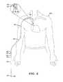
- FIG. 6is a diagrammatic illustration similar to FIG. 4 of catheter slid onto the guidewire in FIG. 4 ;
- FIG. 7is a diagrammatic illustration similar to FIG. 6 of confirming the location of the tip of the catheter in a human body using the energizable guidewire;
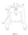
- FIG. 8is a diagrammatic illustration, similar to FIG. 7 , in which the guidewire is removed from the catheter;
- FIG. 9is a flowchart of one embodiment of a method for positioning a catheter having a tip within a human body in accordance with an aspect of the present invention.
- FIG. 10is a flowchart of an embodiment of a method for repositioning a catheter tip of a catheter within a human body in accordance with an aspect of the present invention
- FIG. 11is a flowchart of an embodiment of a method for positioning a catheter tip of a catheter within a human body in accordance with an aspect of the present invention
- FIG. 12is a side elevational view of another embodiment of an energizable guidewire in accordance with an aspect of the present invention.
- FIG. 13is an enlarged side elevational view, partially cut away, of the distal end of the energizable guidewire of FIG. 12 ;
- FIG. 14is a side elevational view of another embodiment of an energizable guidewire having a plurality of ultrasonic beacons in accordance with an aspect of the present invention.
- FIG. 15is an enlarged side elevational view, partially cut away, of a portion of the energizable guidewire of FIG. 14 .
- the present inventionin one aspect is directed to methods and apparatus for positioning and/or confirming a desired location of a catheter tip of a catheter in a body such as a human body using an energizable guidewire having an ultrasonic beacon and using an ultrasonic imaging system to locate and/or trace the movement of the distal end of the energizable guidewire.
- an exemplary embodiment of an energizable guidewire 10 in accordance with an aspect of the present inventionincludes an elongated member 20 and a releasably attachable power supply 40 .
- Elongated member 20may include a distal end portion 22 and a proximal end portion 24 .
- Distal end portion 22includes a distal end 23 .
- the elongated membermay be a flexible elongated member made from a medical grade flexible material having a diameter of about 0.014 inch to about 0.038 inch and smaller than the diameter of a lumen or passageway in a catheter as described below.
- the regions along the flexible elongated member 20can vary in stiffness, depending on the application.
- the guidewiremay be a wire coil formed from a helix of wire having a generally constant outer diameter or varying outer diameter. While the present description refers to an energizable guidewire, it will be appreciated the present invention may be suitably configured as an energizable stylet, inner catheter, guide catheter, or other medical component that may be inserted into the catheter lumen.
- ultrasonic beacon 30adjacent to distal end portion 22 of the elongated member is an ultrasonic beacon 30 such as a piezoelectric transmitter, crystal, or film.
- Ultrasonic beacon 30is passive in that it emits ultrasound waves but does not receive.
- the beaconemits identifying signals related to its position so that the information so produced can be used, as explained below, for guidance orientation, position, or location.
- Plurality of wires 32 and 34may be operably electrically connected to the ultrasonic beacon.
- a distal end portion 33 of wire 32may be operatively connected to ultrasonic beacon 30
- a distal end portion 35 of wire 34may be operatively connected to ultrasonic beacon 30 .
- the proximal end of the wiresmay be connected to a suitable driver and electrical power supply.
- Distal end portion 22 of the elongated membermay be filled with gel or other suitable potting material 21 around beacon 30 to reduce the likelihood of an air cavity attenuating or preventing transmission of waves from beacon 30 .
- power supply 40may include a housing 41 which is releasably attachable to proximal end portion 24 of elongated member 20 .
- housing 41may include a cavity 42 sized and configured for receiving therein proximal end portion 24 of elongated member 20 .
- Proximal end portion 24 of elongated member 20may include a plurality of spaced-apart contacts 36 and 38 which extend circumferentially around an outer peripheral surface of proximal end portion 24 of elongated member 20 and which are operably connected to wires 32 and 34 in elongated member 20 .
- Housing 41may include a chamber for containing a battery and suitable connectors for connecting the different polarities of battery 50 via suitable wires for connecting battery 50 to a suitable driver 51 such as an oscillator for driving ultrasonic beacon 30 ( FIG. 2 ).
- Driver 51maybe operably connected to wires 52 and 54 for supplying electric power to contacts 56 and 58 , respectively, positioned in cavity 42 of housing 41 .
- Contacts 56 and 58may be spaced a similar distance as contacts 36 and 38 so that when proximal end portion 24 of elongated member 20 is inserted in cavity 42 of power supply 40 , electrical power is supplied to ultrasonic beacon 30 ( FIG. 2 ).
- cavity 42may be sized so that when proximal end portion 24 of elongated member 20 inserted in cavity 42 , a compression force is applied between contacts 56 and 58 and contacts 36 and 38 , respectively. It will be appreciated that other suitable means for releasably connecting the proximal end of the elongated member to the housing, and other suitable means for electrically connecting the power supply to the ultrasonic transmitter may be employed.
- FIG. 4illustrates one embodiment of the initial steps for positioning a catheter tip of a catheter in a body such as a human body using energizable guidewire 10 in accordance with an aspect of the present invention.
- an introducer needle, dilator, and splitable sheathmay be used to gain access to a vein of a patient.
- Distal end portion 22 of elongated member 20may be introduced into the splittable sheath and positioned at a desired location in the patient.
- the releasably attachable power supplymay be attached or disconnected from the proximal end of the elongated member.
- a venipunctureis performed with the introducer needle, and guidewire 10 is inserted through the needle and advanced into the vessel. Once guidewire 10 is positioned, the introducer needle can be retracted of guidewire 10 .
- a venipunctureis performed with the introducer needle, and a small guidewire is inserted through the needle and advanced into the vessel. The introducer needle is retracted off the small guidewire, and a dilator and splittable sheath assembly is advanced over the small guidewire and into the vessel.
- a conventional ultrasonic imaging system 100may be employed to confirm the location of the distal end 22 of guidewire 10 , or monitor and/or track the location of distal end 22 of energized guidewire 10 , which may be inserted into a vein, an artery, or other body part of a patient under investigation and moved by a practitioner.
- the guidewiremay be initially positioned without monitoring the progress or location of the distal end 22 or with monitoring the progress or location of the distal end 22 as described below.
- an ultrasonic imaging system 100generally includes a display 112 , and a scanning head 130 .
- Ultrasonic imaging systemsenable imaging of internal structures of the body generally without the use of harmful forms of radiation.
- Display 112enables the practitioner or user of the system to visualize the portion of a patient's body that is being scanned.
- the scanning head 130may be a single hand held unit which the physician manually moves about the outer surface of the body of a patient to thereby perform imaging of the internal structure of the body.
- Scanning head 130includes an ultrasonic transducer or transmitter/receiver 135 , and utilizes emitted ultrasonic waves to provide a clear scan picture of the volume of tissue and other structures under investigation.
- energized ultrasonic beacon 30( FIG. 2 ) disposed in distal end 22 of guidewire 10 is capable of providing a real-time observable image 120 on display 112 such as a bright illuminated spot on the displayed real-time image of the internal structure of the body.
- ultrasonic beacon 30converts electrical signals received from power supply 40 into ultrasound waves which are then picked up by transmitter/receiver 135 of scanning head 130 which then converts the wave pattern into electrical signals which are transmitted to and imaged on display 112 .
- the ultrasonic waves emitted from energized ultrasonic beacon 130is automatically detected and processed by ultrasonic imaging system 100 along with the image of internal structure of the body.
- Scanning head 130provides a beam of ultrasonic waves which beam is directed into the body 200 of a typical patient under investigation.
- the internal structure of the bodyis imaged by detection of the reflected waves along with the image of emitted ultrasonic waves from ultrasonic beacon 30 ( FIG. 2 ).
- transmitter/receiver 135performs two functions. First, it acts as a standard ultrasound transducer which transmits and receives ultrasonic waves to create the image of the target area, e.g. the heart and the superior vena cave.
- the beacon 30receives the ultrasonic waves from the beacon 30 and converts them into a visual image or illuminated dot on the ultrasound display.
- the ultrasonic wavesfrom the beacon 30 and converts them into a visual image or illuminated dot on the ultrasound display.
- no physical connectionis needed between guidewire 10 and ultrasonic imaging system 100 .
- a physician or techniciancan monitor and locate distal end 22 of energized guidewire 10 by viewing display 112 to determine the progress and/or location of distal end 22 of energized guidewire 10 .
- FIG. 5is a block diagram of one embodiment of ultrasonic imaging system 100 which may include, for example, a computing unit or processor 130 , one or more data storage units 132 such as memory, and one or more input/output devices 134 such as display 112 ( FIG. 4 ) and transmitter/receiver 135 ( FIG. 4 ).
- a computing unit or processor 130may include, for example, a computing unit or processor 130 , one or more data storage units 132 such as memory, and one or more input/output devices 134 such as display 112 ( FIG. 4 ) and transmitter/receiver 135 ( FIG. 4 ).
- a catheter 60may include a distal end portion 62 and a proximal end portion 64 .
- Distal end portion 62includes a tip 63 . Tip 63 of a catheter 60 is inserted over proximal end 24 of elongated member 20 , and advanced over the guidewire into the body.
- Suitable guide markings 25may be used to position tip 63 of catheter 60 relative to and adjacent to distal end 23 of elongated member 20 .
- the proximal edge of the catheter hub 65may be aligned with one of a plurality of guide marking 12 on the guidewire so that the catheter tip 63 is positioned flush with distal end 23 of elongated member 20 and adjacent beacon 30 .
- the markingsmay be spaced every 1 or 2 centimeters and numbered corresponding to the distance from the distal end. If the catheter has a length of 50 centimeters, the catheter hub can be aligned with the 50 cm marking on the elongated member to position the catheter tip even with the distal end of the elongated member.
- the ultrasonic beaconis illustrated as being disposed adjacent to the distal end of the elongated member, it will be appreciated that the beacon need not be positioned at the distal end of the elongated member.
- the beaconmay be positioned at any location along the elongated member.
- the beaconmay be positioned away from the distal end of the elongated member which may be beneficial for other procedures such as when attempting to locate a desired anatomical site in which the distal end not may extend past a treatment site.
- power supply 40may be reconnected to the proximal end 24 of elongated member 20 and using ultrasonic imaging system 100 and display 112 , the observable image 120 displayed on the display may be used to confirm that the location of the tip 63 of catheter 60 is at the desired location in the body.
- the target location for catheter tip 63may be just outside of the heart 272 in the lower 1 ⁇ 3 of the superior vena cava 273 .
- a non-target locatione.g.
- the observable image 120 displayed on the displaymay be used to confirm the non-target location of the tip 63 of catheter 60 in the body, and allow the operator to reposition the distal end of the elongated member and the catheter tip.
- the proximal end of catheter 60may be secured relative to the human body (not shown in FIG. 8 ), and the guidewire (not shown in FIG. 8 ) may be completely removed from catheter 60 .
- the guidewiremay be reinserted into the catheter, the guide marks aligned, and the position of the catheter tip 63 located and/or repositioned using ultrasonic imaging system 100 as described above.
- the cathetermay comprise a single lumen catheter, but it can have multiple lumens. As noted above, the proximal portion of the catheter may terminate at catheter hub 65 . As shown in FIGS. 7 and 8 , catheter 60 can be advanced to a target location, such as the superior vena cava 273 , or some other site within human body 200 , for delivery of fluids such as antibiotics, chemotherapy, pain medicine, nutrition, or for withdrawing blood.
- a target locationsuch as the superior vena cava 273 , or some other site within human body 200 , for delivery of fluids such as antibiotics, chemotherapy, pain medicine, nutrition, or for withdrawing blood.
- ultrasonic imaging system 100may incorporate suitable software or processing capability for providing an audio or visual signal (in addition to the displayed image of the ultrasonic transmitter) alerting the operator that the distal end of the guidewire is at the desired location or not at the desired location.
- the image of the ultrasonic transmittermay be color coded, e.g., a red color indicating that the catheter tip has been located and is not in the target location, or a green light indicating that the catheter tip has been located and is in the target location.
- the user notification signalcan also take other forms, including an audio notification or a message display.
- the ultrasonic transmittermay resonate at about the same frequency of the ultrasound transmitter/receiver.
- the ultrasonic transmittermay resonate at a frequency between about 2 MHz and about 18 MHz, and desirably at a frequency of about 910 MHz.
- the ultrasonic resonatormay comprise a piezo film, with an upper electrode, a lower electrode, and a piece of piezo film configured between the upper and lower electrodes.
- the electrodesmay be silver ink screen printed electrodes, which offer high conductivity, high flexibility and a thin profile.
- the upper electrode and lower electrodeoverlap at the active piezo film area.
- ultrasonic wavesmay be generated between the upper electrode and lower electrode surfaces at the active piezo film area.
- the ultrasonic wavesmay be proportional to the amount of energy provided by the power supply.
- FIG. 9illustrates one embodiment of a method 300 for positioning a catheter having a tip within a human body in accordance with an aspect of the present invention.
- an energizable guidewiremay be installed first in a human body, then the catheter slid onto the guidewire, and then the guidewire removed.
- method 300includes at 310 , obtaining an elongated member having a proximal end portion and a distal end portion, an ultrasonic beacon operably attached to the distal end portion, and a power supply releasably attachable to the proximal end portion of the elongated member and releasably electrically connectable to energize the ultrasonic beacon.
- the distal end portion of the elongated member with the ultrasonic beaconis inserted into an anatomical structure of the human body.
- An ultrasonic transmitter/receiveris positioned adjacent to the outer surface of the human body and the ultrasonic beacon, at 320 , and the ultrasonic beacon is powered with the power supply, at 325 .
- a displayis observed of an ultrasound image of the internal structure of the human body and an image representing the energized ultrasonic beacon based on ultrasonic waves received by the ultrasound transmitter/receiver.
- the power supplyis disconnected from the proximal end portion of the elongated member, at 335 , and the catheter tip is inserted over the proximal end portion of elongated member at 340 .
- the catheter tipis positioned relative to the elongated member at 345 , and the elongated member is removed from the catheter at 350 .
- FIG. 10illustrates another embodiment of a method 400 for repositioning a catheter tip of a catheter within a human body in accordance with an aspect of the present invention.
- a catheter tip of a catheter that has already been installed in a human bodymay be repositioned employing the energized guidewire of the present invention.
- the power supplymay be permanently attached to the proximal end portion of the guidewire as the power supply need not be removed from the guidewire.
- method 400includes at 410 , obtaining an elongated member having a proximal end portion and a distal end portion, an ultrasonic beacon operably attached to the distal end portion of the elongated member, and a power supply operably attached to the proximal end portion of the elongated member and operably electrically connectable to energize the ultrasonic beacon.
- the distal end portion of the elongated member with the ultrasonic beaconis positioned in a catheter disposed in anatomical structure of the human body, at 415 .
- an ultrasonic transmitter/receiveris positioned adjacent to the human body and to the ultrasonic beacon, and at 425 , the ultrasonic beacon is powered with the power supply.
- a displayis observed of an ultrasound image of the internal structure of the human body and an image representing the energized ultrasonic beacon based on ultrasonic waves received by the ultrasound transmitter/receiver.
- the observed image representing the energized ultrasonic beaconis tracked to reposition the catheter tip of the catheter in the human body at 435 , and the elongated member is removed from the catheter at 440 .
- FIG. 11illustrates another embodiment of a method 500 for positioning a catheter tip of a catheter within a human body in accordance with an aspect of the present invention.
- method 500may include, at 510 , obtaining an elongated member having a proximal end portion and a distal end portion, an ultrasonic beacon operably attached to the distal end portion of the elongated member, and a power supply operably attached to the proximal end portion of said elongated member and operably electrically connected to energize the ultrasonic beacon.
- the distal end portion of the elongated member with the ultrasonic beaconis inserted into an anatomical structure of the human body at 515 , and an ultrasonic transmitter/receiver is positioned adjacent to the outer surface of the human body and to the ultrasonic beacon at 520 .
- the ultrasonic beaconis powered with the power supply at 525 , and at 530 , a display is observed of an ultrasound image of the internal structure of the human body and an image representing the energized ultrasonic beacon based on ultrasonic waves received by the ultrasound transmitter/receiver.
- the catheter tipis slid along the elongated member in the human body, and at 540 , the catheter tip is positioned relative to the elongated member.
- the elongated memberis removed from the human body and from the catheter.
- a cathetermay be installed on an energizable guidewire having a permanently attached power supply.
- the energized guidewiremay be about twice as long to allow the catheter to be restrained on one end portion of the guidewire as the other end portion of the guidewire is installed in the human body. Thereafter, the catheter may be slid into position in the human body, and then the guidewire removed.
- the power supplymay be releasably attachable to the proximal end of the elongated member and releasably electrically connectable to energize the ultrasonic beacon.
- the inserting the distal end portion of the elongated member with the ultrasonic beacon into an anatomical structure of the human bodymay be performed with the power supply is not attached to proximal end portion of said elongated member, and the powering of the ultrasonic beacon, may include attaching the power supply to the proximal end portion of the elongated member.
- FIG. 12illustrates another exemplary embodiment of an energizable guidewire 610 in accordance with an aspect of the present invention.
- guidewire 610may be essentially the same as guidewire 10 ( FIG. 1 ) as described above with the exception of the distal end portion of the guidewire.
- Guidewire 610may include an elongated member 620 and a releasably attachable power supply 640 .
- Elongated member 620may include a distal end portion 622 and a proximal end portion 624 .
- Distal end portion 622may terminate in a curved portion 629 such as having a curved J-shaped configuration which terminates in a distal end 623 to reduce the likelihood of damage to internal structures in the body.
- an ultrasonic beacon 630such as a piezoelectric transmitter, crystal, or film.
- pluraliturality of wires 632 and 634may be operably electrically connected to the ultrasonic beacon.
- a distal end portion 633 of wire 632may be operatively connected to ultrasonic beacon 630
- a distal end portion 635 of wire 634may be operatively connected to ultrasonic beacon 630 .
- the proximal end of the wiresmay be connected to a suitable driver and electrical power supply.
- Distal end portion 622 of the elongated membermay be filled with gel or other suitable potting material 621 around beacon 630 to reduce the likelihood of an air cavity attenuating or prevent transmission of ultrasonic waves from beacon 630 .
- FIG. 14is an embodiment of an energizable guidewire 710 in accordance with an aspect of the present invention.
- guidewire 710may be essentially the same as guidewire 10 ( FIG. 1 ) as described above with the exception of having a plurality of spaced-apart ultrasonic beacons 730 .
- the beaconsmay be spaced apart at regular intervals such as every 1 or 2 centimeters or 10 centimeters.
- Ultrasonic beaconsmay be serially electronically connected to power supply as shown in FIG. 14 .
- ultrasonic beaconsmay be separately connected to power supply 740 , and may be operatively configured to emit ultrasonic waves at different frequencies.
- the plurality of ultrasonic beaconsmay be evenly spaced-apart at known distances, and used to confirm sizes of anatomical structure or positions in a human body using the ultrasound imaging system.
- the elongated member noted abovemay have a “window” at distal end portion of guidewire through which ultrasonic wave may be directed. It will be appreciated that the ultrasonic beacon may be disposed on the outer surface of the elongated member.
- the various cathetersmay be coaxially disposed on an elongated member.
- the energizable guidewiremay be pre-loaded into the catheter such as a PICC catheter.
- the energizable guidewirewill be about twice as long as the catheter.
- the power supplymay be permanently attached to the distal end of the guidewire, e.g., it does not have to be removed to insert the catheter.
- the method according to the present inventioncan be used for procedures that target any site within the body.
- any type of catheter tipcan be positioned, including acute and chronic dialysis catheters, subcutaneous port catheters, and central venous catheters.
- access sitesdo not need to be in the arm. For example, for a patient with amputated arms, the access site may be in the groin or in the back.
Landscapes
- Health & Medical Sciences (AREA)
- Life Sciences & Earth Sciences (AREA)
- Heart & Thoracic Surgery (AREA)
- Biophysics (AREA)
- Engineering & Computer Science (AREA)
- Biomedical Technology (AREA)
- Animal Behavior & Ethology (AREA)
- Veterinary Medicine (AREA)
- Public Health (AREA)
- General Health & Medical Sciences (AREA)
- Hematology (AREA)
- Anesthesiology (AREA)
- Pulmonology (AREA)
- Pathology (AREA)
- Surgery (AREA)
- Molecular Biology (AREA)
- Medical Informatics (AREA)
- Radiology & Medical Imaging (AREA)
- Physics & Mathematics (AREA)
- Nuclear Medicine, Radiotherapy & Molecular Imaging (AREA)
- Ultra Sonic Daignosis Equipment (AREA)
- Media Introduction/Drainage Providing Device (AREA)
Abstract
Description
- a) enhanced imaging capabilities using the energized guidewire and standard ultrasound imaging systems producing a readily observable image of the ultrasonic beacon on a display compared to simply imaging the catheter alone with standard ultrasound imaging systems;
- b) not require specialized ultrasound transmitter/receivers or other capital equipment as the present invention employs standard ultrasound imaging systems;
- c) no specialized training required;
- d) determine location of catheter tip even if mispositioned;
- e) use with any PICC, dialysis catheter, other central venous catheter, or other catheters, even previously placed catheters;
- f) use as a standard guidewire for initial PICC placement and then as a tip locator;
- g) use with any catheter regardless of length, size or manufacturer;
- h) eliminates a separate stylet component, or separate electromagnetic detecting and separate processing capability for superimposing the location of the ultrasonic transmitter on the ultrasonic image;
- i) reduces operator and patient exposure to harmful radiation such as X-ray radiation;
- j) because the beacon (transmitter) is passive in only transmitting ultrasonic waves and not operable for receiving or detecting ultrasonic waves the size of the guidewire may be small compared to guidewires having thereby eliminating additional wiring/components for receiving and detecting ultrasonic waves;
- k) overcoming problems with electrocardiogram detection which require a normal sinus rhythm, and cannot indicate when the catheter tip is in locations including the jugular vein and the subclavian;
- l) reduced costs in manufacture and equipment compared to prior art locating techniques;
- m) increasing the number of facilities equipped to perform catheter insertion and maintenance procedures compared to prior art locating techniques;
- n) operable with patients having pacemakers or skin disorders, or other ailments.
Claims (11)
Priority Applications (2)
| Application Number | Priority Date | Filing Date | Title |
|---|---|---|---|
| US14/691,930US10085713B2 (en) | 2012-01-11 | 2015-04-21 | Methods, assemblies, and devices for positioning a catheter tip using an ultrasonic imaging system |
| US16/148,656US20190029638A1 (en) | 2012-01-11 | 2018-10-01 | Methods, Assemblies, and Devices for Positioning a Catheter Tip Using an Ultrasonic Imaging System |
Applications Claiming Priority (4)
| Application Number | Priority Date | Filing Date | Title |
|---|---|---|---|
| US13/347,786US8663116B2 (en) | 2012-01-11 | 2012-01-11 | Methods, assemblies, and devices for positioning a catheter tip using an ultrasonic imaging system |
| US14/146,779US9033889B2 (en) | 2012-01-11 | 2014-01-03 | Methods, assemblies, and devices for positioning a catheter tip using an ultrasonic imaging system |
| US14/146,778US9403274B2 (en) | 2010-07-12 | 2014-01-03 | Robotic device and method of controlling robotic device |
| US14/691,930US10085713B2 (en) | 2012-01-11 | 2015-04-21 | Methods, assemblies, and devices for positioning a catheter tip using an ultrasonic imaging system |
Related Parent Applications (1)
| Application Number | Title | Priority Date | Filing Date |
|---|---|---|---|
| US14/146,779ContinuationUS9033889B2 (en) | 2012-01-11 | 2014-01-03 | Methods, assemblies, and devices for positioning a catheter tip using an ultrasonic imaging system |
Related Child Applications (1)
| Application Number | Title | Priority Date | Filing Date |
|---|---|---|---|
| US16/148,656ContinuationUS20190029638A1 (en) | 2012-01-11 | 2018-10-01 | Methods, Assemblies, and Devices for Positioning a Catheter Tip Using an Ultrasonic Imaging System |
Publications (2)
| Publication Number | Publication Date |
|---|---|
| US20150223775A1 US20150223775A1 (en) | 2015-08-13 |
| US10085713B2true US10085713B2 (en) | 2018-10-02 |
Family
ID=48744373
Family Applications (4)
| Application Number | Title | Priority Date | Filing Date |
|---|---|---|---|
| US13/347,786Active2032-03-07US8663116B2 (en) | 2012-01-11 | 2012-01-11 | Methods, assemblies, and devices for positioning a catheter tip using an ultrasonic imaging system |
| US14/146,779ActiveUS9033889B2 (en) | 2012-01-11 | 2014-01-03 | Methods, assemblies, and devices for positioning a catheter tip using an ultrasonic imaging system |
| US14/691,930ActiveUS10085713B2 (en) | 2012-01-11 | 2015-04-21 | Methods, assemblies, and devices for positioning a catheter tip using an ultrasonic imaging system |
| US16/148,656AbandonedUS20190029638A1 (en) | 2012-01-11 | 2018-10-01 | Methods, Assemblies, and Devices for Positioning a Catheter Tip Using an Ultrasonic Imaging System |
Family Applications Before (2)
| Application Number | Title | Priority Date | Filing Date |
|---|---|---|---|
| US13/347,786Active2032-03-07US8663116B2 (en) | 2012-01-11 | 2012-01-11 | Methods, assemblies, and devices for positioning a catheter tip using an ultrasonic imaging system |
| US14/146,779ActiveUS9033889B2 (en) | 2012-01-11 | 2014-01-03 | Methods, assemblies, and devices for positioning a catheter tip using an ultrasonic imaging system |
Family Applications After (1)
| Application Number | Title | Priority Date | Filing Date |
|---|---|---|---|
| US16/148,656AbandonedUS20190029638A1 (en) | 2012-01-11 | 2018-10-01 | Methods, Assemblies, and Devices for Positioning a Catheter Tip Using an Ultrasonic Imaging System |
Country Status (1)
| Country | Link |
|---|---|
| US (4) | US8663116B2 (en) |
Families Citing this family (35)
| Publication number | Priority date | Publication date | Assignee | Title |
|---|---|---|---|---|
| GB0120645D0 (en) | 2001-08-24 | 2001-10-17 | Smiths Group Plc | Medico-surgical devices |
| GB0307350D0 (en) | 2003-03-29 | 2003-05-07 | Smiths Group Plc | Catheters |
| US8784336B2 (en) | 2005-08-24 | 2014-07-22 | C. R. Bard, Inc. | Stylet apparatuses and methods of manufacture |
| US8781555B2 (en) | 2007-11-26 | 2014-07-15 | C. R. Bard, Inc. | System for placement of a catheter including a signal-generating stylet |
| US10751509B2 (en) | 2007-11-26 | 2020-08-25 | C. R. Bard, Inc. | Iconic representations for guidance of an indwelling medical device |
| US9521961B2 (en) | 2007-11-26 | 2016-12-20 | C. R. Bard, Inc. | Systems and methods for guiding a medical instrument |
| ES2465915T3 (en) | 2007-11-26 | 2014-06-09 | C.R. Bard, Inc. | Integrated system for intravascular catheter placement |
| US9649048B2 (en) | 2007-11-26 | 2017-05-16 | C. R. Bard, Inc. | Systems and methods for breaching a sterile field for intravascular placement of a catheter |
| US10524691B2 (en) | 2007-11-26 | 2020-01-07 | C. R. Bard, Inc. | Needle assembly including an aligned magnetic element |
| US9901714B2 (en) | 2008-08-22 | 2018-02-27 | C. R. Bard, Inc. | Catheter assembly including ECG sensor and magnetic assemblies |
| US9532724B2 (en) | 2009-06-12 | 2017-01-03 | Bard Access Systems, Inc. | Apparatus and method for catheter navigation using endovascular energy mapping |
| EP2464407A4 (en) | 2009-08-10 | 2014-04-02 | Bard Access Systems Inc | Devices and methods for endovascular electrography |
| WO2011097312A1 (en) | 2010-02-02 | 2011-08-11 | C.R. Bard, Inc. | Apparatus and method for catheter navigation and tip location |
| EP2912999B1 (en) | 2010-05-28 | 2022-06-29 | C. R. Bard, Inc. | Apparatus for use with needle insertion guidance system |
| EP4122385A1 (en) | 2010-05-28 | 2023-01-25 | C. R. Bard, Inc. | Insertion guidance system for needles and medical components |
| BR112013002431B1 (en) | 2010-08-20 | 2021-06-29 | C.R. Bard, Inc | SYSTEM FOR RECONFIRMING THE POSITION OF A CATHETER INSIDE A PATIENT |
| US10188831B2 (en) | 2013-03-14 | 2019-01-29 | Angiodynamics, Inc. | Systems and methods for catheter tip placement using ECG |
| US10154826B2 (en) | 2013-07-17 | 2018-12-18 | Tissue Differentiation Intelligence, Llc | Device and method for identifying anatomical structures |
| US10716536B2 (en) | 2013-07-17 | 2020-07-21 | Tissue Differentiation Intelligence, Llc | Identifying anatomical structures |
| WO2016044411A1 (en)* | 2014-09-17 | 2016-03-24 | Avaz Surgical, Llc | Identifying anatomical structures |
| GB201321430D0 (en)* | 2013-12-04 | 2014-01-15 | Spd Swiss Prec Diagnostics Gmbh | Assay device |
| WO2015120256A2 (en) | 2014-02-06 | 2015-08-13 | C.R. Bard, Inc. | Systems and methods for guidance and placement of an intravascular device |
| US20150282734A1 (en) | 2014-04-08 | 2015-10-08 | Timothy Schweikert | Medical device placement system and a method for its use |
| US10973584B2 (en) | 2015-01-19 | 2021-04-13 | Bard Access Systems, Inc. | Device and method for vascular access |
| WO2016210325A1 (en) | 2015-06-26 | 2016-12-29 | C.R. Bard, Inc. | Connector interface for ecg-based catheter positioning system |
| US11000207B2 (en) | 2016-01-29 | 2021-05-11 | C. R. Bard, Inc. | Multiple coil system for tracking a medical device |
| US11986341B1 (en) | 2016-05-26 | 2024-05-21 | Tissue Differentiation Intelligence, Llc | Methods for accessing spinal column using B-mode imaging to determine a trajectory without penetrating the the patient's anatomy |
| US11701086B1 (en) | 2016-06-21 | 2023-07-18 | Tissue Differentiation Intelligence, Llc | Methods and systems for improved nerve detection |
| JP6499621B2 (en) | 2016-08-08 | 2019-04-10 | ファナック株式会社 | Control device and control system |
| EP3613351A1 (en)* | 2018-08-22 | 2020-02-26 | Koninklijke Philips N.V. | Coronary circulation using intra-cardiac echo |
| US10992079B2 (en) | 2018-10-16 | 2021-04-27 | Bard Access Systems, Inc. | Safety-equipped connection systems and methods thereof for establishing electrical connections |
| CN110051439A (en)* | 2019-04-29 | 2019-07-26 | 隋君 | PICC sets length of tube measurement method |
| JP7610929B2 (en)* | 2020-05-29 | 2025-01-09 | 富士フイルム株式会社 | Ultrasound imaging device and medical support system |
| WO2022084825A1 (en)* | 2020-10-19 | 2022-04-28 | Baylis Medical Company Inc. | Medical tubular assembly |
| GB2608648B (en)* | 2021-07-09 | 2024-06-26 | Intelligent Ultrasound Ltd | Apparatus and method for positioning a tube |
Citations (4)
| Publication number | Priority date | Publication date | Assignee | Title |
|---|---|---|---|---|
| US20060173407A1 (en)* | 2005-01-13 | 2006-08-03 | Shaughnessy Michael C | Tubing assembly and signal generator placement control device and method for use with catheter guidance systems |
| US20100036284A1 (en)* | 2006-09-08 | 2010-02-11 | Micronix Pty Ltd | Guide-Wire and Guiding Insert Placement Assembly for Over-the-Wire Catheter Placement and Method of Use |
| US20110201990A1 (en)* | 2010-02-17 | 2011-08-18 | Novita Therapeutics, Llc | System and method to increase the overall diameter of veins |
| US20140296767A1 (en)* | 2011-08-17 | 2014-10-02 | Novita Therapeutics, Llc | System and method to increase the overall diameter of veins and arteries |
Family Cites Families (68)
| Publication number | Priority date | Publication date | Assignee | Title |
|---|---|---|---|---|
| JPS5921495B2 (en) | 1977-12-15 | 1984-05-21 | 株式会社豊田中央研究所 | Capillary pressure gauge |
| US4249539A (en) | 1979-02-09 | 1981-02-10 | Technicare Corporation | Ultrasound needle tip localization system |
| US4407294A (en) | 1982-01-07 | 1983-10-04 | Technicare Corporation | Ultrasound tissue probe localization system |
| US4821731A (en) | 1986-04-25 | 1989-04-18 | Intra-Sonix, Inc. | Acoustic image system and method |
| US5372138A (en)* | 1988-03-21 | 1994-12-13 | Boston Scientific Corporation | Acousting imaging catheters and the like |
| US4951677A (en)* | 1988-03-21 | 1990-08-28 | Prutech Research And Development Partnership Ii | Acoustic imaging catheter and the like |
| US4905698A (en) | 1988-09-13 | 1990-03-06 | Pharmacia Deltec Inc. | Method and apparatus for catheter location determination |
| US4947852A (en) | 1988-10-05 | 1990-08-14 | Cardiometrics, Inc. | Apparatus and method for continuously measuring volumetric blood flow using multiple transducer and catheter for use therewith |
| CN1049287A (en) | 1989-05-24 | 1991-02-20 | 住友电气工业株式会社 | The treatment conduit |
| US5038789A (en) | 1989-09-28 | 1991-08-13 | Frazin Leon J | Method and device for doppler-guided retrograde catheterization |
| EP0419729A1 (en) | 1989-09-29 | 1991-04-03 | Siemens Aktiengesellschaft | Position finding of a catheter by means of non-ionising fields |
| AU648773B2 (en)* | 1990-01-19 | 1994-05-05 | Sony Corporation | Apparatus for reproduction apparatus |
| US5078714A (en) | 1990-03-02 | 1992-01-07 | Jefferson Katims | Method and apparatus for placement of a probe in the body and the medical procedure for guiding and locating a catheter or probe in the body |
| US5131397A (en) | 1990-09-07 | 1992-07-21 | Boston Scientific Corp. | Imaging system for producing ultrasonic images and insonifier for such systems |
| US5156157A (en) | 1991-03-08 | 1992-10-20 | Telectronics Pacing Systems, Inc. | Catheter-mounted doppler ultrasound transducer and signal processor |
| US5161536A (en) | 1991-03-22 | 1992-11-10 | Catheter Technology | Ultrasonic position indicating apparatus and methods |
| US5645065A (en) | 1991-09-04 | 1997-07-08 | Navion Biomedical Corporation | Catheter depth, position and orientation location system |
| US5425367A (en) | 1991-09-04 | 1995-06-20 | Navion Biomedical Corporation | Catheter depth, position and orientation location system |
| ATE177612T1 (en) | 1991-12-23 | 1999-04-15 | Sims Deltec Inc | GUIDE WIRE DEVICE WITH LOCATING LINK |
| US5280786A (en) | 1992-01-21 | 1994-01-25 | Fiberoptic Sensor Technologies, Inc. | Fiberoptic blood pressure and oxygenation sensor |
| US5425382A (en) | 1993-09-14 | 1995-06-20 | University Of Washington | Apparatus and method for locating a medical tube in the body of a patient |
| EP0779790A1 (en) | 1994-09-06 | 1997-06-25 | Sims Deltec, Inc. | Method and apparatus for location of a catheter tip |
| US5526820A (en) | 1994-09-19 | 1996-06-18 | Myelotec, Inc. | Catheter with integral pressure sensor |
| US6690963B2 (en) | 1995-01-24 | 2004-02-10 | Biosense, Inc. | System for determining the location and orientation of an invasive medical instrument |
| US5666958A (en) | 1995-04-06 | 1997-09-16 | Rothenberg; Peter M. | Interface module for electrically connecting medical equipment |
| JP3782113B2 (en) | 1995-06-12 | 2006-06-07 | コーディス ウェブスター,インコーポレイティド | Catheter with electromagnetic guidance sensor |
| US5592939A (en) | 1995-06-14 | 1997-01-14 | Martinelli; Michael A. | Method and system for navigating a catheter probe |
| US5588436A (en)* | 1995-10-11 | 1996-12-31 | Cook Pacemaker Corporation | Pulsed doppler probe |
| US5697377A (en) | 1995-11-22 | 1997-12-16 | Medtronic, Inc. | Catheter mapping system and method |
| US5944023A (en) | 1995-12-07 | 1999-08-31 | Sims Deltec, Inc. | Systems and methods for determining the location of an implanted device including a magnet |
| US5727552A (en) | 1996-01-11 | 1998-03-17 | Medtronic, Inc. | Catheter and electrical lead location system |
| US6618612B1 (en) | 1996-02-15 | 2003-09-09 | Biosense, Inc. | Independently positionable transducers for location system |
| US5727553A (en) | 1996-03-25 | 1998-03-17 | Saad; Saad A. | Catheter with integral electromagnetic location identification device |
| SE9603314D0 (en) | 1996-09-12 | 1996-09-12 | Siemens Elema Ab | Method and apparatus for determining the location of a catheter within the body of a patient |
| US6128958A (en)* | 1997-09-11 | 2000-10-10 | The Regents Of The University Of Michigan | Phased array system architecture |
| GB2329708B (en) | 1997-09-24 | 2002-05-08 | Roke Manor Research | Catheter localisation system |
| GB2329709B (en) | 1997-09-26 | 2001-12-19 | Roke Manor Research | Catheter localisation system |
| US6304769B1 (en) | 1997-10-16 | 2001-10-16 | The Regents Of The University Of California | Magnetically directable remote guidance systems, and methods of use thereof |
| US5954649A (en)* | 1997-10-20 | 1999-09-21 | Irvine Biomedical, Inc. | Catheter system having ultrasound locating capabilities |
| US6246899B1 (en)* | 1997-10-20 | 2001-06-12 | Irvine Biomedical, Inc. | Ultrasound locating system having ablation capabilities |
| US6259941B1 (en)* | 1997-10-20 | 2001-07-10 | Irvine Biomedical, Inc. | Intravascular ultrasound locating system |
| US6233477B1 (en)* | 1997-10-20 | 2001-05-15 | Irvine Biomedical, Inc. | Catheter system having controllable ultrasound locating means |
| GB2331365B (en) | 1997-11-15 | 2002-03-13 | Roke Manor Research | Catheter tracking system |
| US6052610A (en) | 1998-01-09 | 2000-04-18 | International Business Machines Corporation | Magnetic catheter tracker and method therefor |
| SE9801006D0 (en) | 1998-03-25 | 1998-03-25 | Siemens Elema Ab | Method and arrangement for determining the location of a catheter within an animal body |
| US6215231B1 (en)* | 1998-05-04 | 2001-04-10 | The Penn State Research Foundation | Hollow sphere transducers |
| AU5882599A (en) | 1998-09-24 | 2000-04-10 | Super Dimension Ltd. | System and method for determining the location of a catheter during an intra-body medical procedure |
| US6061588A (en) | 1998-09-29 | 2000-05-09 | Advanced Cardiovascular Systems, Inc. | Catheter apparatus for positioning a wire |
| WO2000038571A1 (en) | 1998-12-31 | 2000-07-06 | Ball Semiconductor, Inc. | Position sensing system |
| US7914442B1 (en) | 1999-03-01 | 2011-03-29 | Gazdzinski Robert F | Endoscopic smart probe and method |
| US7575550B1 (en) | 1999-03-11 | 2009-08-18 | Biosense, Inc. | Position sensing based on ultrasound emission |
| US6629987B1 (en) | 1999-07-30 | 2003-10-07 | C. R. Bard, Inc. | Catheter positioning systems |
| US6695782B2 (en) | 1999-10-05 | 2004-02-24 | Omnisonics Medical Technologies, Inc. | Ultrasonic probe device with rapid attachment and detachment means |
| US6705319B1 (en) | 2000-05-26 | 2004-03-16 | Purdue Research Foundation | Miniature acoustical guidance and monitoring system for tube or catheter placement |
| US7992573B2 (en) | 2001-06-19 | 2011-08-09 | The Trustees Of The University Of Pennsylvania | Optically guided system for precise placement of a medical catheter in a patient |
| US6741883B2 (en) | 2002-02-28 | 2004-05-25 | Houston Stereotactic Concepts, Inc. | Audible feedback from positional guidance systems |
| WO2004018031A2 (en) | 2002-08-22 | 2004-03-04 | William A. Cook Australia Pty. Ltd. | Guide wire |
| US7244234B2 (en) | 2003-11-11 | 2007-07-17 | Soma Development Llc | Ultrasound guided probe device and method of using same |
| US6977504B2 (en) | 2003-12-31 | 2005-12-20 | Calypso Medical Technologies, Inc. | Receiver used in marker localization sensing system using coherent detection |
| GB2410147A (en) | 2004-01-13 | 2005-07-20 | Health & Life Co Ltd | Electronic stethoscope with piezo-electrical film contact microphone |
| EP2289392B1 (en) | 2004-11-24 | 2012-05-09 | Remon Medical Technologies Ltd. | Implantable medical device with integrated acoustic transducer |
| EP1830713B1 (en)* | 2004-11-29 | 2011-03-16 | Granit Medical Innovations, LLC | Rotating fine needle for core tissue sampling |
| US20070213616A1 (en)* | 2005-10-20 | 2007-09-13 | Thomas Anderson | Systems and methods for arteriotomy localization |
| US7794407B2 (en) | 2006-10-23 | 2010-09-14 | Bard Access Systems, Inc. | Method of locating the tip of a central venous catheter |
| US8226675B2 (en)* | 2007-03-22 | 2012-07-24 | Ethicon Endo-Surgery, Inc. | Surgical instruments |
| ES2465915T3 (en) | 2007-11-26 | 2014-06-09 | C.R. Bard, Inc. | Integrated system for intravascular catheter placement |
| US20100010393A1 (en)* | 2008-07-08 | 2010-01-14 | Medtronic Vascular, Inc. | Treatment of Occlusions by External High Intensity Focused Ultrasound |
| US8992513B2 (en)* | 2011-06-30 | 2015-03-31 | Angiodynamics, Inc | Endovascular plasma treatment device and method of use |
- 2012
- 2012-01-11USUS13/347,786patent/US8663116B2/enactiveActive
- 2014
- 2014-01-03USUS14/146,779patent/US9033889B2/enactiveActive
- 2015
- 2015-04-21USUS14/691,930patent/US10085713B2/enactiveActive
- 2018
- 2018-10-01USUS16/148,656patent/US20190029638A1/ennot_activeAbandoned
Patent Citations (6)
| Publication number | Priority date | Publication date | Assignee | Title |
|---|---|---|---|---|
| US20060173407A1 (en)* | 2005-01-13 | 2006-08-03 | Shaughnessy Michael C | Tubing assembly and signal generator placement control device and method for use with catheter guidance systems |
| US20100036284A1 (en)* | 2006-09-08 | 2010-02-11 | Micronix Pty Ltd | Guide-Wire and Guiding Insert Placement Assembly for Over-the-Wire Catheter Placement and Method of Use |
| US20110201990A1 (en)* | 2010-02-17 | 2011-08-18 | Novita Therapeutics, Llc | System and method to increase the overall diameter of veins |
| US20160030648A1 (en)* | 2010-02-17 | 2016-02-04 | Flow Forward Medical, Inc. | System and method to increase the overall diameter of veins |
| US20160030647A1 (en)* | 2010-02-17 | 2016-02-04 | Flow Forward Medical, Inc. | System and method to increase the overall diameter of veins |
| US20140296767A1 (en)* | 2011-08-17 | 2014-10-02 | Novita Therapeutics, Llc | System and method to increase the overall diameter of veins and arteries |
Also Published As
| Publication number | Publication date |
|---|---|
| US20150223775A1 (en) | 2015-08-13 |
| US20190029638A1 (en) | 2019-01-31 |
| US20140121503A1 (en) | 2014-05-01 |
| US9033889B2 (en) | 2015-05-19 |
| US20130178739A1 (en) | 2013-07-11 |
| US8663116B2 (en) | 2014-03-04 |
Similar Documents
| Publication | Publication Date | Title |
|---|---|---|
| US10085713B2 (en) | Methods, assemblies, and devices for positioning a catheter tip using an ultrasonic imaging system | |
| US12343091B2 (en) | Apparatus and methods relating to intravascular positioning of distal end of catheter | |
| US11707205B2 (en) | Integrated system for intravascular placement of a catheter | |
| CN104114104B (en) | Ultrasonic probe | |
| US10159460B2 (en) | Method for locating a catheter tip using audio detection | |
| JP4166277B2 (en) | Medical method and apparatus using in-vivo probe | |
| WO1997029682A1 (en) | Locatable biopsy needle | |
| US12011228B2 (en) | Medical device position notification system | |
| JP2020532331A (en) | Detection systems and methods for automatic detection of surgical instruments | |
| US11759268B2 (en) | Apparatus and methods relating to intravascular positioning of distal end of catheter | |
| CN115363709A (en) | Bending-adjustable intravascular ultrasound-guided puncture method | |
| US11406353B2 (en) | Device for utilizing transmission ultrasonography to enable ultrasound-guided placement of central venous catheters | |
| US7645238B2 (en) | Regional anesthetic method and apparatus | |
| US20200205774A1 (en) | Methods for Needle Identification on an Ultrasound Display Screen | |
| Gibbs et al. | Ultrasound guidance for central venous catheter placement | |
| WO2020081725A1 (en) | Biopsy navigation system and method | |
| WO2005007228A1 (en) | Ultrasonically marked delivery system for left heart pacing lead | |
| US20200337781A1 (en) | Systems and methods for locating an inserted catheter tip | |
| US20200345985A1 (en) | Systems and methods for locating an inserted catheter tip | |
| US20220226609A1 (en) | System and Method for Medical Device Position Guidance | |
| KR101108492B1 (en) | Probe with small projector | |
| JP2001293091A (en) | Catheter and catheter distal end position detector | |
| WO2024089043A1 (en) | A catheter for placement in a ventricular system |
Legal Events
| Date | Code | Title | Description |
|---|---|---|---|
| AS | Assignment | Owner name:JPMORGAN CHASE BANK, N.A., AS ADMINISTRATIVE AGENT, ILLINOIS Free format text:SECURITY INTEREST;ASSIGNOR:ANGIODYNAMICS, INC.;REEL/FRAME:040613/0049 Effective date:20161107 Owner name:JPMORGAN CHASE BANK, N.A., AS ADMINISTRATIVE AGENT Free format text:SECURITY INTEREST;ASSIGNOR:ANGIODYNAMICS, INC.;REEL/FRAME:040613/0049 Effective date:20161107 | |
| STCF | Information on status: patent grant | Free format text:PATENTED CASE | |
| AS | Assignment | Owner name:JPMORGAN CHASE BANK, N.A., AS ADMINISTRATIVE AGENT Free format text:CONFIRMATORY GRANT OF SECURITY INTEREST IN UNITED STATES PATENTS;ASSIGNOR:ANGIODYNAMICS, INC.;REEL/FRAME:049371/0657 Effective date:20190603 Owner name:JPMORGAN CHASE BANK, N.A., AS ADMINISTRATIVE AGENT, ILLINOIS Free format text:CONFIRMATORY GRANT OF SECURITY INTEREST IN UNITED STATES PATENTS;ASSIGNOR:ANGIODYNAMICS, INC.;REEL/FRAME:049371/0657 Effective date:20190603 | |
| MAFP | Maintenance fee payment | Free format text:PAYMENT OF MAINTENANCE FEE, 4TH YEAR, LARGE ENTITY (ORIGINAL EVENT CODE: M1551); ENTITY STATUS OF PATENT OWNER: LARGE ENTITY Year of fee payment:4 | |
| AS | Assignment | Owner name:JPMORGAN CHASE BANK, N.A., AS ADMINISTRATIVE AGENT, ILLINOIS Free format text:SECURITY INTEREST;ASSIGNOR:ANGIODYNAMICS, INC.;REEL/FRAME:061360/0668 Effective date:20220830 Owner name:ANGIODYNAMICS, INC., NEW YORK Free format text:RELEASE BY SECURED PARTY;ASSIGNOR:JPMORGAN CHASE BANK, N.A., AS ADMINISTRATIVE AGENT;REEL/FRAME:061363/0446 Effective date:20220830 | |
| AS | Assignment | Owner name:ANGIODYNAMICS, INC., NEW YORK Free format text:RELEASE BY SECURED PARTY;ASSIGNOR:JPMORGAN CHASE BANK, N.A., AS ADMINISTRATIVE AGENT;REEL/FRAME:063940/0362 Effective date:20230608 | |
| AS | Assignment | Owner name:ANGIODYNAMICS, INC., NEW YORK Free format text:ASSIGNMENT OF ASSIGNORS INTEREST;ASSIGNOR:HAMILTON, WILLIAM C., JR.;REEL/FRAME:066446/0747 Effective date:20120111 | |
| AS | Assignment | Owner name:JPMORGAN CHASE BANK, N.A., AS ADMINISTRATIVE AGENT, ILLINOIS Free format text:SECURITY INTEREST;ASSIGNOR:ECS OPCO 1, LLC;REEL/FRAME:066470/0314 Effective date:20240215 | |
| AS | Assignment | Owner name:ECS OPCO 1, LLC, NEW YORK Free format text:ASSIGNMENT OF ASSIGNORS INTEREST;ASSIGNOR:ANGIODYNAMICS, INC.;REEL/FRAME:066548/0253 Effective date:20240215 | |
| AS | Assignment | Owner name:KEYBANK NATIONAL ASSOCIATION, AS COLLATERAL AGENT, OHIO Free format text:SECURITY INTEREST;ASSIGNORS:ECS OPCO 1, LLC;SPECTRUM VASCULAR SUB 2, LLC;REEL/FRAME:070635/0678 Effective date:20250326 | |
| AS | Assignment | Owner name:ECS OPCO 1, LLC, NEW YORK Free format text:RELEASE OF SECURITY INTEREST RECORDED AT REEL/FRAME 066470/0314;ASSIGNOR:JPMORGAN CHASE BANK, N.A., AS ADMINISTRATIVE AGENT;REEL/FRAME:070647/0789 Effective date:20250326 |