US10085531B2 - Case for electronic tablet - Google Patents
Case for electronic tabletDownload PDFInfo
- Publication number
- US10085531B2 US10085531B2US15/472,202US201715472202AUS10085531B2US 10085531 B2US10085531 B2US 10085531B2US 201715472202 AUS201715472202 AUS 201715472202AUS 10085531 B2US10085531 B2US 10085531B2
- Authority
- US
- United States
- Prior art keywords
- cover
- electronic device
- edge
- hinge
- portable electronic
- Prior art date
- Legal status (The legal status is an assumption and is not a legal conclusion. Google has not performed a legal analysis and makes no representation as to the accuracy of the status listed.)
- Active
Links
Images


Classifications
- A—HUMAN NECESSITIES
- A45—HAND OR TRAVELLING ARTICLES
- A45C—PURSES; LUGGAGE; HAND CARRIED BAGS
- A45C11/00—Receptacles for purposes not provided for in groups A45C1/00-A45C9/00
- A—HUMAN NECESSITIES
- A45—HAND OR TRAVELLING ARTICLES
- A45C—PURSES; LUGGAGE; HAND CARRIED BAGS
- A45C13/00—Details; Accessories
- A45C13/005—Hinges
- B—PERFORMING OPERATIONS; TRANSPORTING
- B65—CONVEYING; PACKING; STORING; HANDLING THIN OR FILAMENTARY MATERIAL
- B65B—MACHINES, APPARATUS OR DEVICES FOR, OR METHODS OF, PACKAGING ARTICLES OR MATERIALS; UNPACKING
- B65B5/00—Packaging individual articles in containers or receptacles, e.g. bags, sacks, boxes, cartons, cans, jars
- B65B5/04—Packaging single articles
- B—PERFORMING OPERATIONS; TRANSPORTING
- B65—CONVEYING; PACKING; STORING; HANDLING THIN OR FILAMENTARY MATERIAL
- B65D—CONTAINERS FOR STORAGE OR TRANSPORT OF ARTICLES OR MATERIALS, e.g. BAGS, BARRELS, BOTTLES, BOXES, CANS, CARTONS, CRATES, DRUMS, JARS, TANKS, HOPPERS, FORWARDING CONTAINERS; ACCESSORIES, CLOSURES, OR FITTINGS THEREFOR; PACKAGING ELEMENTS; PACKAGES
- B65D85/00—Containers, packaging elements or packages, specially adapted for particular articles or materials
- G—PHYSICS
- G06—COMPUTING OR CALCULATING; COUNTING
- G06F—ELECTRIC DIGITAL DATA PROCESSING
- G06F1/00—Details not covered by groups G06F3/00 - G06F13/00 and G06F21/00
- G06F1/16—Constructional details or arrangements
- G06F1/1613—Constructional details or arrangements for portable computers
- G06F1/1626—Constructional details or arrangements for portable computers with a single-body enclosure integrating a flat display, e.g. Personal Digital Assistants [PDAs]
- G—PHYSICS
- G06—COMPUTING OR CALCULATING; COUNTING
- G06F—ELECTRIC DIGITAL DATA PROCESSING
- G06F1/00—Details not covered by groups G06F3/00 - G06F13/00 and G06F21/00
- G06F1/16—Constructional details or arrangements
- G06F1/1613—Constructional details or arrangements for portable computers
- G06F1/1628—Enclosures for carrying portable computers with peripheral devices, e.g. cases for a laptop and a printer
- H—ELECTRICITY
- H04—ELECTRIC COMMUNICATION TECHNIQUE
- H04M—TELEPHONIC COMMUNICATION
- H04M1/00—Substation equipment, e.g. for use by subscribers
- H04M1/02—Constructional features of telephone sets
- H04M1/04—Supports for telephone transmitters or receivers
- H—ELECTRICITY
- H05—ELECTRIC TECHNIQUES NOT OTHERWISE PROVIDED FOR
- H05K—PRINTED CIRCUITS; CASINGS OR CONSTRUCTIONAL DETAILS OF ELECTRIC APPARATUS; MANUFACTURE OF ASSEMBLAGES OF ELECTRICAL COMPONENTS
- H05K13/00—Apparatus or processes specially adapted for manufacturing or adjusting assemblages of electric components
- A—HUMAN NECESSITIES
- A45—HAND OR TRAVELLING ARTICLES
- A45C—PURSES; LUGGAGE; HAND CARRIED BAGS
- A45C11/00—Receptacles for purposes not provided for in groups A45C1/00-A45C9/00
- A45C11/003—Receptacles for purposes not provided for in groups A45C1/00-A45C9/00 for storing portable computing devices, e.g. laptops, tablets or calculators
- A45C2011/003—
- A—HUMAN NECESSITIES
- A45—HAND OR TRAVELLING ARTICLES
- A45C—PURSES; LUGGAGE; HAND CARRIED BAGS
- A45C13/00—Details; Accessories
- A45C13/02—Interior fittings; Means, e.g. inserts, for holding and packing articles
- A45C2013/025—Interior fittings; Means, e.g. inserts, for holding and packing articles for holding portable computers or accessories therefor
- A—HUMAN NECESSITIES
- A45—HAND OR TRAVELLING ARTICLES
- A45C—PURSES; LUGGAGE; HAND CARRIED BAGS
- A45C2200/00—Details not otherwise provided for in A45C
- A45C2200/15—Articles convertible into a stand, e.g. for displaying purposes
- A—HUMAN NECESSITIES
- A45—HAND OR TRAVELLING ARTICLES
- A45C—PURSES; LUGGAGE; HAND CARRIED BAGS
- A45C5/00—Rigid or semi-rigid luggage
- A45C5/02—Materials therefor
- G—PHYSICS
- G06—COMPUTING OR CALCULATING; COUNTING
- G06F—ELECTRIC DIGITAL DATA PROCESSING
- G06F2200/00—Indexing scheme relating to G06F1/04 - G06F1/32
- G06F2200/16—Indexing scheme relating to G06F1/16 - G06F1/18
- G06F2200/163—Indexing scheme relating to constructional details of the computer
- G06F2200/1633—Protecting arrangement for the entire housing of the computer
- Y—GENERAL TAGGING OF NEW TECHNOLOGICAL DEVELOPMENTS; GENERAL TAGGING OF CROSS-SECTIONAL TECHNOLOGIES SPANNING OVER SEVERAL SECTIONS OF THE IPC; TECHNICAL SUBJECTS COVERED BY FORMER USPC CROSS-REFERENCE ART COLLECTIONS [XRACs] AND DIGESTS
- Y10—TECHNICAL SUBJECTS COVERED BY FORMER USPC
- Y10T—TECHNICAL SUBJECTS COVERED BY FORMER US CLASSIFICATION
- Y10T29/00—Metal working
- Y10T29/49—Method of mechanical manufacture
- Y10T29/49002—Electrical device making
- Y—GENERAL TAGGING OF NEW TECHNOLOGICAL DEVELOPMENTS; GENERAL TAGGING OF CROSS-SECTIONAL TECHNOLOGIES SPANNING OVER SEVERAL SECTIONS OF THE IPC; TECHNICAL SUBJECTS COVERED BY FORMER USPC CROSS-REFERENCE ART COLLECTIONS [XRACs] AND DIGESTS
- Y10—TECHNICAL SUBJECTS COVERED BY FORMER USPC
- Y10T—TECHNICAL SUBJECTS COVERED BY FORMER US CLASSIFICATION
- Y10T29/00—Metal working
- Y10T29/49—Method of mechanical manufacture
- Y10T29/49826—Assembling or joining
Definitions
- This inventionrelates to accessories for electronic devices and more specifically to cases for portable electronic devices and electronic tablets.
- portable electronic devicesprovide greater functionality and have more capabilities. These portable electronic devices allow people to play and record music, send and receive e-mail, send text messages, browse Web pages, make phone calls, play and record video, take and view pictures, edit documents, and much more. These devices continue to revolutionize the way people interact, learn, connect with other people, conduct business, and find things. They help people manage their daily lives and can be a source of entertainment. These devices can be used to store valuable information including personal information (e.g., phone numbers, financial information, private photos or videos, and favorite music tracks).
- personal informatione.g., phone numbers, financial information, private photos or videos, and favorite music tracks.
- these devicesare intended to be carried or moved about. As such, these devices are more vulnerable to damage as compared to nonportable devices. These devices are more likely to be accidentally dropped, hit, or scratched. Some types of damage may be cosmetic (e.g., scratch). However, other types of damage may ruin or limit the functionality of the device. Often these devices contain sensitive and fragile components (e.g., screen, camera lens, flash, processors, accelerometers, and sensors). Accidentally dropping the device could render various features unusable.
- sensitive and fragile componentse.g., screen, camera lens, flash, processors, accelerometers, and sensors.
- Protective casesare used to protect these devices from possible damage. It is desirable that these cases allow users to use the functionality of their devices, while devices remain in their cases. Cases can also be used to enhance the functionality and capabilities of the device.
- a caseincorporates a built-in stand for the device which the case houses.
- the built-in standallows using the case as a stand without needing to carry a separate standalone stand device.
- the casehas additional functionality and usability. Since the stand is built-in or integrated, the stand will be available wherever the case is and is harder to lose than having a separate stand.
- a case for a portable electronic deviceincludes a bezel defining a rectangular front opening through which a screen of the portable electronic device will be visible, a backing, opposite the rectangular front opening, including a first surface against which a back of the portable electronic device will be placed, and an outer cover.
- the outer coverincludes first, second, third, and fourth cover edges, where the second and fourth cover edges are longer than the first and third cover edges, first, second, and third hinges, each hinge extending from the second cover edge to the fourth cover edge, and at least one edge stop on an inside surface of the outer cover.
- the at least one edge stopextends in a direction from the second cover edge to the fourth cover edge.
- a first portion of the inside surface of the outer cover from the third cover edge to the first hingeis connected to a second surface of the backing, opposite the first surface of the backing.
- the caseincludes a sleeve having the bezel and the backing.
- the sleeveincludes first, second, third, and fourth sides.
- the first and third sidesare longer than the second and fourth sides.
- the first sideincludes a side opening through which the portable electronic device can be inserted into the sleeve, and a latch to removably secure the portable electronic device in the sleeve.
- the caseincludes a frame having the bezel and the backing.
- the bezelincludes an elastic material to permit the bezel to be peeled back thereby enlarging the front opening and permitting the electronic device to be inserted through the enlarged front opening.
- the casemay further include an elastic band, connected to the outer cover.
- the elastic bandextends from the second cover edge to the fourth cover edge.
- the elastic bandcan be positioned to hold the outer cover against the front opening, thus preventing rotating of the first and second hinges.
- the elastic bandmay be between the first hinge and the third cover edge.
- a width of a gap between the third cover edge and the elastic bandmay be at least a width of the elastic band.
- the at least one edge stopincludes a groove extending from the second cover edge to the fourth cover edge. In another embodiment, the at least one edge stop includes a rail projecting above the inside surface of the outer cover.
- a portion of the outer coverdefines a base surface of the stand.
- a first portion of the base surfaceextends from the at least one edge stop to the first cover edge.
- the second hingemay be between the first and third hinges, a length of the base surface may be from the first cover edge to at least the third hinge, and the length of the base surface may be greater than a length from the third hinge to the second hinge.
- a case for a portable electronic deviceincludes an enclosure or holder portion including first, second, third, fourth, front, and back sides. The first and third sides are longer than the second and fourth sides.
- the front sideincludes a bezel defining a rectangular front opening through which a screen of the portable electronic device will be visible.
- An outer cover portionincludes first, second, third, and fourth cover edges, where the second and fourth cover edges are longer than the first and third cover edges. There are first and second hinges, each hinge extending from the second cover edge to the fourth cover edge.
- the outer cover portionis connected to the back side of the enclosure portion at the third edge, and the outer cover portion is not connected to the back side of the enclosure portion at the first and second hinges, allowing the outer cover portion to rotate at the first and second hinges.
- the elastic bandextends from the second cover edge to the fourth cover edge. The elastic band can be positioned to hold the outer cover portion against the front opening, thereby preventing rotating of the first and second hinges.
- a gap between the third edge and the elastic bandmay be at least a width of the elastic band.
- a distance from any one of the first or second hinges to the elastic bandmay be greater than a distance from the elastic band to the third edge.
- the first side of the enclosure portionincludes a side opening through which the portable electronic device can be inserted into the enclosure.
- the enclosure portionmay include a latch on the first side to removably secure the portable electronic device in the enclosure.
- the bezelincludes an elastic material to permit the bezel to be elastically deformed, thereby enlarging the rectangular front opening and permitting the portable electronic device to be inserted through the enlarged rectangular front opening.
- a methodincludes forming an outer cover having first, second, third, and fourth cover edges, where the second and fourth cover edges are longer than the first and third cover edges. Creating first, second, and third hinges in the outer cover. Creating at least one edge stop on an inside surface of the outer cover.
- Positioning an elastic band on the outer coverPositioning an elastic band on the outer cover. And attaching the elastic band and a portion of the enclosure to the outer cover, where an attached portion of the enclosure is between the first hinge and the third cover edge.
- positioning an elastic bandincludes positioning ends of the elastic band between the enclosure and the outer cover. In another implementation, positioning an elastic band includes positioning ends of the elastic band on an outside surface of the outer cover. An unattached portion of the enclosure may be between the first hinge and the second hinge.
- a case for a portable electronic deviceincludes a rectangularly shaped cover including first, second, third, and fourth cover edges.
- the first and third cover edgesextend in a first direction and are parallel to each other.
- the second and fourth cover edgesextend in a second direction and are parallel to each other.
- the second directionis transverse to the first direction, and the second cover edge is longer than the first cover edge.
- the cover from the first cover edge to the first hingeis a front flap, and the front flap has a first length from the first hinge to the first cover edge that is sufficiently long to cover a front screen of the portable electronic device.
- first hingeformed in the cover, between the third cover edge and the first hinge, extending in the first direction, parallel to the first hinge.
- second hingeformed in the cover, between the third cover edge and the first hinge, extending in the first direction, parallel to the first hinge.
- set of groovesformed between the first cover edge and the first hinge on an inside of the cover.
- the portable electronic deviceis inserted into the holder in a direction from the second hinge to the third cover edge, and when inserted into the holder, the second hinge will positioned behind a back of the portable electronic device.
- a case for a portable electronic deviceincludes a rectangularly shaped cover including first, second, third, and fourth cover edges.
- the first and third cover edgesextend in a first direction and are parallel to each other, the second and fourth cover edges extend in a second direction and are parallel to each other, the second direction is transverse to the first direction, and the second cover edge is longer than the first cover edge.
- first hingeformed in the cover between the first and third cover edges and extending in the first direction.
- the cover from the first cover edge to the first hingeis a front flap.
- the front flaphas a first length from the first cover edge to the first hinge that is sufficiently long to cover a front screen of the portable electronic device when the front flap is folded via the first hinge to close the case.
- first hingeformed in the cover, between the third cover edge and the first hinge, extending in the first direction, and parallel to the first hinge.
- second hingeformed in the cover, between the third cover edge and the first hinge, extending in the first direction, and parallel to the first hinge.
- set of groovesformed between the first cover edge and the first hinge on an inside of the front flap.
- the portable electronic deviceis to be inserted into the holder in a direction from the first hinge to the third cover edge, and when the portable electronic device is inserted into the holder, the second hinge will be positioned behind a back of the portable electronic device.
- the rectangularly shaped covermay include rounded corners.
- the cover from the third edge to the second hingehas a second length, and the cover from the second hinge to the first hinge includes a third length, and the third length is greater than the second length.
- the cover from the third edge to the second hingehas a second length, and the cover from the second hinge to the first hinge includes a third length, and a sum of the first, second, and third lengths is at least about 407 millimeters.
- a fourth length of the first hingemay be at least about 245 millimeters.
- the holderincludes a bezel forming a front opening of the holder through which a screen will be visible.
- the holdermay include a backing material including a textured surface.
- the covermay include a polycarbonate material.
- the covermay include a composite including polyurethane and polycarbonate.
- the inside of the front coverhas three grooves.
- a built-in stand of the casehas an angle of about 45 degrees.
- a built-in stand of the casehas an angle of about 60 degrees.
- a built-in stand of the casehas an angle of about 75 degrees.
- a built-in stand of the casewhen utilizing a first of the grooves, has an angle of about 45 degrees. When utilizing a second of the grooves, the built-in stand of the case has an angle of about 60 degrees. When utilizing a third of the grooves, the built-in stand of the case has an angle of about 75 degrees. When portions of the cover on either side of the second hinge are folded against each other, the built-in stand of the case has an angle of about 8 degrees.
- the casemay further include an elastic band, attached to the cover between the second hinge and the third cover edge, where the elastic band extends in the first direction.
- a case for a portable electronic deviceincludes a rectangularly shaped cover including first, second, third, and fourth cover edges.
- the first and third cover edgesextend in a first direction and are parallel to each other, the second and fourth cover edges extend in a second direction and are parallel to each other, the second direction is transverse to the first direction, and the second cover edge is longer than the first cover edge.
- first hingeformed in the cover, between the first and third cover edges, extending in the first direction, and the cover from the first cover edge to the first hinge is a front flap, and the front flap has a first length from the first cover edge to the first hinge to the first cover edge that is sufficiently long to cover a front screen of the portable electronic device when the front flap is folded via the first hinge to close the case.
- a second hingeformed in the cover, between the third cover edge and the first hinge, extending in the first direction, and parallel to the first hinge.
- a holderattached to the rectangularly shaped cover, that removably attaches the portable electronic device to the case between the second hinge and the third cover edge.
- the portable electronic deviceis to be inserted into the holder in a direction from the first to second hinge to the third cover edge, and when the portable electronic device is inserted into the holder, the second hinge will be positioned behind a back of the portable electronic device.
- a built-in stand of the casewhen utilizing a first of the rails, has an first tilt angle. When utilizing a second of the grooves, the built-in stand of the case has a second tilt angle. When utilizing a third of the grooves, the built-in stand of the case has a third tilt angle, the first, second, and third tilt angles being different from each other.
- the built-in stand of the casewhen portions of the cover on either side of the second hinge are folded against each other, the built-in stand of the case has a fourth tilt angle, less than the first, second, and third tilt angles.
- an elastic bandattached to the cover between the second hinge and the third cover edge, where the elastic band extends in the first direction.
- a first embodiment of the casemay be referred to as a Convertible Book JacketTM or CBJTM case.
- a second embodiment the casemay be referred to as a Convertible Maki JacketTM or CMJTM case.
- the CBJ and CMJ casescan be folded into a stand for the electronic device.
- stand viewing anglesinclude about 45, 60, and 75 degrees for the CMJ and CBJ cases.
- Each casecan also be folded into a working angle.
- the working angle on the CBJ caseis about 8 degrees and the working angle on the CMJ case is about 6 degrees.
- the CMJ caseis a polyurethane (PU) laminate with a polycarbonate (PC) reinforcement structure. The case hinges in the thin areas where the laminate is not reinforced with polycarbonate.
- a method of making a case for an electronic tabletincludes: providing a front cover portion having interior and exterior sides, and a first edge, second edge, and third edge; forming a plurality of grooves on the interior side of the front cover, where the grooves extend in a first direction parallel to the first edge of the front cover; providing a back cover portion having a fourth edge extending in the first direction; providing an inside holder portion, where the inside holder portion is adapted to retain the electronic tablet in the case while a screen of the electronic tablet device remains visible; providing a spine edge portion that joins the front and back cover portions; coupling a first folding hinge, extending in the first direction, between the back cover portion and the inside holder portion; coupling a second folding hinge, extending in the first direction, between the front cover and spine edge portions; coupling a third folding hinge, extending in the first direction, between the back cover and spine edge portions, where a first length of the first edge is longer than a second length of the second edge from the first edge to the second
- a case for an electronic tablet deviceincludes: a front cover portion, including interior and exterior sides, where the front cover portion is rectangularly shaped, planar, and defined by a first edge, second edge, and third edge, the first edge extending in a first direction and being longer than the second and third edges, and the interior side of the front cover includes a plurality of grooves, and the grooves extend in the first direction; a back cover portion, including interior and exterior sides, where the back cover portion is rectangularly shaped, planar, and defined by a fourth edge, fifth edge, and sixth edge, the fourth edge extending in the first direction and being longer than the fifth and sixth edges, and the back cover portion includes a first folding hinge extending in the first direction; a spine edge portion, coupling the front and back cover portions together, where a second folding hinge separates the front cover and spine portions, a third folding hinge separates the back cover and spine edge portions, the second and third folding hinges extend in the first direction, and the second edge extends from the first edge to the second folding
- a method of making a case for an electronic tabletincludes: providing a front cover portion having interior and exterior sides, and a first edge, second edge, and third edge; forming a plurality of bumps on the interior side of the front cover, where the bumps extend in a first direction parallel to the first edge of the front cover; providing a back cover portion having a fourth edge extending in the first direction; providing an inside holder portion, where the inside holder portion is adapted to retain the electronic tablet in the case while a screen of the electronic tablet device remains visible; providing a spine edge portion that joins the front and back cover portions; coupling a first folding hinge, extending in the first direction, between the back cover portion and the inside holder portion; coupling a second folding hinge, extending in the first direction, between the front cover and spine edge portions; coupling a third folding hinge, extending in the first direction, between the back cover and spine edge portions, where a first length of the first edge is longer than a second length of the second edge from the first edge to the second
- FIGS. 1A-1Hshow various views of a first embodiment of a case for a portable electronic device.
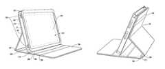
- FIG. 2Ashows a front perspective view of the open case after the case is folded into a stand.
- FIG. 2Bshows a back perspective view after the case is folded into a stand.
- FIG. 2Cshows how the stand can be adjusted into various viewing angles.
- FIG. 2Dshows a first viewing angle of the stand in a landscape orientation.
- FIG. 2Eshows a second viewing angle of the stand.
- FIG. 2Fshows a third viewing angle of the stand.
- FIG. 2Gshows a close-up view of the stand.
- FIG. 2Hshows a working angle of the stand.
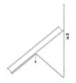
- FIG. 2Ishows a side view of the stand in a viewing angle.
- FIGS. 3A-3Bshow the stand folded in a portrait orientation.
- FIG. 3Cshows a top view of the stand in the portrait orientation.
- FIG. 4shows an inside view of the case.
- FIGS. 5-7show some individual pieces used to make the case.
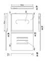
- FIG. 8shows a top view the assembled case pieces.
- FIG. 9shows a cross section of the assembled case pieces.
- FIGS. 10-29show various views of a second embodiment of a case for a portable electronic device.
- FIGS. 30-42show various views of a third embodiment of a case for a portable electronic device.
- FIGS. 43-44show a comparison of thickness between the first and second case embodiments.
- FIGS. 1A-1Hshow various views of an embodiment of a case for a tablet computer.
- This embodiment of a casemay be referred to as a Convertible Book JacketTM or CBJTM case.
- Convertible Book Jacket and CBJare trademarks of Incase Designs Corp.
- FIGS. 1A-1Eshow top, side, and bottom views of the case.
- the caseis for a tablet computer, tablet PC, or other tablet-type electronic device.
- electronic tabletsinclude Apple iPad, Dell Streak, HP TouchSmart, Toshiba Portege, Fujitsu Lifebook, Lenovo IdeaPad, Toshiba Libretto, Amazon Kindle, Sony Reader, Barnes & Noble Nook, Microsoft Courier, and others.
- smartphonessuch as the Apple iPhone and Google Android phones
- PDAspersonal digital assistants
- handheld computersand notebook computers. Any trademarks listed in this patent application are the property of their respective owners
- Portable electronic deviceare valuable because their functionality, the information they contain, and time and expense to replace. A case is typically much easier and less expensive to replace than the device which it houses and protects.
- a caseprotects the portable electronic device from scratches, dings, dents, and other damage.
- the casealso provides shock absorption.
- the casewill absorb impacts, preventing shock to the components of the device which are often delicate.
- the casecan also improve the grip to the device and case combination.
- the casemay include a texture pattern, be made from a tacky material, or have a tacky coating, or include a wrist or neck strap.
- the casemay also be waterproof or water resistant to protect the device from rain, snow, and surf.
- a casemay include a battery to lengthen a battery life of the device.
- a battery caseis described in U.S. Pat. No. 7,612,997, issued Nov. 3, 2009, which is incorporated by reference.
- a casemay include a stand (e.g., built-in stand). With such a stand, a user can stand the device on a table and watch the screen hands-free.
- Some examples of some case designsare in U.S. patent application 61/365,302, which is incorporated by reference along with all other references cited in this application.
- a caseis typically an important accessory for the device that it protects. For, a person might accidentally drop a portable electronic device in the case on the floor when running to catch a flight for a business trip at the airport.
- the casemay cushion the drop, thus preventing major damage to the portable electronic device.
- the portable electronic devicewill remain intact and unbroken, saved by the case. The person can pick up the portable electronic device, continue on the flight, and use the portable electronic device on the business trip.
- the portable electronic devicehad not been protected by a case, the portable electronic device might have become broken.
- the screenmay become cracked or there might have been other damage rendering the device inoperable.
- the persontypically would not have been able to replace the portable electronic device soon enough, especially if there was important information saved on the portable electronic device (e.g., sales presentation slides) that are needed for the business trip.
- FIGS. 1A-1Eshow different views of a case for an electronic tablet device. As discussed above, this case may also be used for other types of electronic devices including, for example, electronic book readers, electronic books, personal digital assistants (PDAs), and smartphones.
- PDAspersonal digital assistants
- FIG. 1Ashows a front view of the case.
- the casehas an elastic band closure 103 .
- the elastic bandsecures a front flap 106 of the case against the screen of the electronic device; this protects the screen from damage.
- FIG. 1Bshows a side 109 view of the case, showing a spine panel 110 of the case.
- FIG. 1Cshows a side 112 view of the case.
- FIG. 1Dshows a side 115 view of the case.
- FIGS. 1C and 1Dshow a sleeve 117 which holds the electronic device. Sides 112 and 115 of the sleeve have openings that allow access to ports and like features of the electronic device.
- FIG. 1Eshows a back view of the case.
- the casehas a back flap 119 .
- Elastic band 103is attached to the back flap at locations 127 and 125 of the back flap. So, the elastic back is stretched to hold the front flap to the back flap with tension, thus securing the electronic device (in the sleeve) between the flaps.
- the casecan be folded to act as a stand for the electronic device.
- the back flap of the casehas a crease hinge 129 . Further details follow below.
- the front flapdoes not have a hinge, crease or otherwise, running through it.
- the flaps of the casehave rounded corners 131 , 133 , 135 , and 137 .
- Rounded cornersprovide a smoother edging without hard angles, which makes sliding into a bag easier and less likely to catch. Rounding also helps prevent bending or dog-earing of the corners.
- a length of the caseis about 250 millimeters (about 9.8 inches), and a width of the case is about 200 millimeters (about 7.9 inches).
- the case (or spine)is about 30 millimeters (about 1.2 inches) thick. These dimensions of the case can vary to accommodate the electronic device being housed. There are openings in sides of the case that allow access to ports and buttons of the electronic tablet without needing to remove the electronic tablet from the case.
- the casehas a back surface with a groove, break, or crease that allows bending of this back surface to make a stand for the electronic tablet.
- FIGS. 1F-1Hshows front, side, and back views of a specific implementation of a case.
- FIGS. 2A-2Hshow the case being used as a stand for the electronic device, where the stand is in a landscape orientation.
- FIG. 2Ashows a front perspective view the open case after the case has been converted, by folding, into a stand.
- FIG. 2Bshows a back perspective view.
- FIG. 2Cshows how the sleeve and front flap of the case can be adjusted to be placed into one of three viewing angles.
- FIG. 2Dshows a first viewing angle
- FIG. 2Eshows a second viewing angle
- FIG. 2Fshows a third viewing angle.
- FIG. 2Gshows a close-up view of an edge 204 of the front flap placed into a groove 206 that holds the case at the first viewing angle.
- FIG. 2Hshows the case folded in a working angle view position.
- FIGS. 2A-2Gthere are three grooves 206 , 208 , and 210 in a back (or inside surface) of the front panel 106 . These grooves are used to form a built-in stand for the device. There are multiple grooves (such as three) to permit multiple different viewing angles. Three grooves allow for positioning the display of the electronic device into three viewing angles, viewing angle 1 ( FIG. 2D ), viewing angle 2 ( FIG. 2E ), and viewing angle 3 ( FIG. 2F ). These viewing angles are different from each other. There is no need to flip or turn the case upside down to access any of the different viewing angles. The viewing angle may be adjusted by sliding edge 204 of the sleeve forward or back along the back of the front panel until it fits into one of the grooves. The electronic device need not be removed from the case to use the stand feature of the case.
- two groovesallow for two viewing angles, and one groove allows for one viewing angle.
- There may be more than three groovese.g., four, five, six, or seven) to allow for more than three viewing angles.
- four groovesallow for four viewing angles, and five groves allow for five viewing angles.
- the casecan allow for a viewing angle when not using any of the grooves.
- the casehas a working angle view ( FIG. 2H ) which is discussed below.
- the caseis made from a neoprene material.
- Neopreneprovides cushioning and shock absorption for the device which the case protects.
- other materialscan be used including silicone, rubber, fabric, and many others.
- case materialinclude vinyl, polyvinyl chloride (PVC), plastic, thermoplastic, cloth, leather, artificial leather, synthetic leather, synthetic leather made of plastic (sometimes referred to as pleather), poromeric imitation leather, koskin, leatherette, metal (e.g., stainless steel, aluminum, or titanium), and carbon fiber.
- a representative electronic tablet device 215is shown in sleeve 117 of the case.
- the screen of this electronic tabletis viewable through a front opening 219 formed in a bezel 222 of the sleeve.
- the bezelsurrounds the front opening on four sides, holding the electronic tablet in the sleeve so that the electronic tablet can not easily come loose or detached from the case.
- the front openinghas about a 4:3 aspect ratio.
- the front openinghas a length of at least about 198 millimeters (7.8 inches) and a width of at least about 147 millimeters (5.8 inches).
- the aspect ratiomay vary slightly or be different, such as 16:9 or 16:10.
- the size of the front openingis larger than the screen size of the electronic device to allow the user access to any buttons, controls, or ports in the front of the device. Also by making the front opening larger than the screen, if the electronic tablet were to shift in position in the sleeve slightly, the entire screen would remain visible and not be partially blocked by the bezel.
- the sides of the sleevecan have die cut openings or holes 225 positioned to allow access to controls and ports of the electronic tablet. The tablet device does not need to be removed from the case to view the screen or access the device's controls or ports.
- the front flat of the caseis rigid and forms a flat base surface 228 of the stand.
- This relatively large flat base surfacegives stability when the case is used as a stand.
- a length of the flat base surfaceis at least about 200 millimeters (width of the case), while a width is about 250 millimeters (length of the case).
- the flat base surface of the standwill be at least a footprint size of the front flap.
- the flat base surface feature of the casemakes the stand unlikely to rock or tip over when it is used.
- a tablet stand without a relatively large flat base surfaceit is easier for someone to accidentally knock the tablet and have it flip over and drop off, for example, a table onto a hard floor.
- the case in FIG. 2Ais accidentally knocked, the tablet would fall back and fall onto the front flap, but the relatively large flat base surface would prevent the tablet from dropping on the floor.
- damage to the tabletis avoided.
- the spinehas a length of about 30 millimeters and the flat base surface a length of about 200 millimeters.
- a length of the flat base surface(in a direction perpendicular to the bottom edge of the sleeve) is at least 2 times greater than the spine length. This will provide greater stability for the stand than having a footprint length of only the spine.
- the length of the flat base surfaceis at least 3 times greater than the spine, at least 4 times greater than the spine, at least 5 times greater than the spine, or at least 6 times greater than the spine length. Further, for stability, wherever the sleeve is placed on the flat base surface to make a stand, a portion of the flat base surface will be behind the sleeve and a portion will be in front of the sleeve.
- a case in the closed positionsuch as shown in FIGS. 1A-1E
- Elastic band 103is stretched and flipped from the front flap to the back flap as shown in FIG. 2B .
- the standhas three hinges that facilitate folding the case into a stand. Hinge 129 is on the back flap, while hinges 238 and 234 are positioned on either side of spine 110 .
- FIG. 2Hshows the case in a working angle position.
- the working angleis less sloped than the other three viewing angles described in FIGS. 2D-2F .
- the working angleis more ergonomic for when the user wants to type on an on-screen keyboard, such when a student takes notes in a classroom.
- the edge of the back of the caseis not placed in any of the viewing angle grooves.
- the back of the caseis folded to provide the working angle slope, and the elastic band is used to hold the case in the working angle position.
- edge 204 of the sleeveis not placed into any of the grooves. Rather, hinge 129 is folded until sides 241 and 243 of the back flap 119 (on either side of hinge 129 ) come into contact with each other.
- Spine 110is rotated (via hinges 238 and 234 ) into position to lift and tilt the sleeve and electronic tablet into the working angle.
- the working anglecan vary depending on the rotation of the hinges 238 and 234 .
- hinges 238 and 234are rotated so that the spine is approximately perpendicular with respect to flat base surface 228 .
- the spinecan be rotated so that it is in an angle (e.g., 30, 45, 60, or 0 to 90 degrees) with respect to the flat base surface to give the desired working angle tilt.
- elastic band 103can be stretched over the folded sides 241 and 243 and flat base surface 228 to hold the stand in the working angle position using tension.
- FIG. 2Halso shows a latch 246 .
- the latchspans across a slot 247 of the sleeve and holds the electronic device in the sleeve.
- the latchcan be removably secured using hook-and-loop fastener (e.g., Velcro) with an attachment point on an underside of the bezel. Other types of fasteners may be used.
- hook-and-loop fastenere.g., Velcro
- Other types of fastenersmay be used.
- FIG. 2Ishows another side view the case being used as a stand for the electronic device.
- the casehas crease hinge 129 to facilitate folding the case into a stand.
- Crease hinge 129 on the back flapis at a position below the top edge of the back of the sleeve rather than at the top edge of the sleeve. This positioning allows the back flap to be folded into the working angle shown in FIG. 2H .
- the contents of screen of the electronic devicemay viewed in the landscape orientation (e.g. for a movie) or portrait orientation (e.g., for a Web page).
- the orientationmay be changed by simply flipping the screen ninety degrees (which is sensed by an internal accelerometer of the electronic device).
- the case of the inventionsupports this feature of the electronic device.
- FIGS. 3A-3Cshow the case being used as a stand in the portrait orientation.
- FIG. 3Ashows a front perspective view of the case partially opened in the portrait orientation.
- FIG. 3Bshows a front perspective view of the case in the portrait orientation where the front flap has been flipped open to expose the screen of the electronic device.
- FIG. 3Cshows a top view of the case in the portrait orientation.
- FIG. 3Bshows the grooves on an inside surface of the front flap for multiple viewing angles when the case is in the landscape orientation.
- the groovesmay not be used. Rather, when the case is folded into a stand having the portrait orientation, the edges of the case provide the stability for the stand.
- hinges 129 , 234 , and 238allow the front and back flaps, spine panel, and sleeve edges to be independently positioned so that there is sufficient stability to hold the electronic device in the portrait position.
- this standis unlikely to tip over because the stand can resist the touch forces being applied to the touch screen.
- hinge 129allows turning the screen to allow a greater unblocked viewing angle. More people can view the screen at the same time.
- the screenwill not be blocked or partially blocked by the front flap, which may prevent a person viewing from the left of the screen (when the flap is on the left-hand side as in FIGS. 3A-3C ).
- the outline of the stand in FIG. 3Cis an open polygon. However, by adjusting the pivoting of the hinges, an edge of the sleeve can touch the front flap to form a closed polygon.
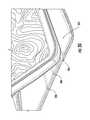
- FIG. 4shows an inside of the case.
- An interior surface inside the case, against which a back of the electronic tablet is placed,is suede backed with a debossed print pattern.
- the patternis a topographic pattern.
- topographic patternsare in U.S. Pat. D579,213, issued Oct. 28, 2008; D581,151, issued Nov. 25, 2008; and D587,896, issued Mar. 10, 2009.
- Various materialscan be used for the interior surface including microfiber, velvet, silicone, rubber, fabric, and carbon fiber.
- the materialmay be tacky to grip the back of the electronic tablet, and also provide cushioning to protect the electronic tablet.
- the backingcan grip the back of the electronic tablet without scratching or otherwise damaging the back of the electronic tablet.
- a debossed textured patternis formed by printing onto the suede material.
- the patternforms grooves, indentations, or recesses into the suede material.
- Other textured patternsmay be used such as an embossed pattern having raised features, rising from or on the surface of the material.
- Some processes to form the texture patternmay include etching, silk-screening, stamps, dies, rollers, thermal printing, deposition, coating, and many others.
- the patternmay include topographic lines as shown in FIG. 4A , vertical lines, horizontal lines, diagonal lines, dots, shapes (e.g., circles, rectangles, boxes), or combinations of these.
- the patterncan help to removably grip the back of the electronic device and prevent the electronic device from sliding or shifting within the sleeve.
- the patterncan increase the friction between the back of the electronic device and the sleeve. With the bezel, textured backing, and latch, the case will hold electronic device securely. There will not be a need to apply an adhesive, adhesive strip, double-side tape, or the like to the back of the electronic device, which may damage or mar the back of the device.
- tacky or texture materialsmay be formed, molded, or attached on the sleeve backing.
- a protective spine (see below) or slider railsmay be positioned in the sleeve backing.
- the protective spine or slider railsmay be made from a material such as silicone, rubber, thermoplastic elastomer, carbon fiber, or the like.
- FIGS. 5-9show the case at specific points in the flow.
- FIG. 5shows a front view of an outer cover 610 which forms the front and back flaps and spine panel of the case.
- FIG. 6shows a front view of sleeve 117 .
- FIG. 7shows a front view of elastic band 103 .
- FIG. 8shows a top view of the assembled pieces of the case.
- FIG. 9shows a cross section of the assembled pieces of the case.
- Step 1Form outer cover 610. See FIG. 5.
- Step 2Make hinges 238, 234, and 129 in outer cover. This divides the outer cover into the front flap, back flap, and spine panel. See FIG. 5.
- Step 3Make grooves 206, 208, and 210 in outer cover. See FIG. 5.
- Step 4Form sleeve 117. See FIG. 6.
- Step 5Create bezel of sleeve, and slot and latch. See FIG. 6.
- Step 6Position sleeve on back flap. Position ends of elastic band (FIG. 7) between sleeve and back flap.
- FIG. 8shows a top view, while FIG. 9 shows a cross section.
- Step 7Attach sleeve, elastic band, and outer cover to finish the case.
- step 1to form outer cover 610 , there is a rectangular sheet of material cut to the desired dimensions to form the case.
- a length of the materialmay be at least about 430 millimeters (about 16.9 inches) and a width of at least about 250 millimeters (about 9.8 inches).
- the length of materialmay be about at least twice or two times the width of the front or back flap.
- a single sheet layermay be used.
- the single layermay be a thermoplastic or other plastic or polymer.
- multiple or composite sheets or layersmay be used.
- Leather, synthetic leather, or vinylcan be used to sandwich a more rigid material or stiffening layer, such as flexible plastic or cardboard.
- An additional layermay be a foam or other padding material.
- a foam or padding layercan help to provide cushioning for the electronic device.
- first and second flexible layersthere can be first and second flexible layers and four rigid or stiffening (or padding such as foam, or both) layers.
- the rigid layersare to be sandwiched between the first and second flexible layers.
- the rigid layerswill form the front and back flaps and spine panel of the case.
- the first flexible layerwill form the outside surface of the case.
- the second flexible layerwill form the inside surface of the case.
- the first and second flexible layershave about the desired dimensions of the outer cover when the outer cover is laid flat and open.
- the composite layerscan be combined or attached together by stitching, adhesives, bonding, glue, fusing, or the like.
- hingesare formed in the outer cover.
- the first and second flexible layersare sealed or otherwise fused together to form a seam.
- the seamforms the crease hinge (or fabric hinge) and the rigid layers can swing about the flexible material of the crease hinge.
- a rigid layer representing the front flapis placed on the first flexible layer.
- a rigid layer representing the spine panelis placed on the first flexible layer.
- the spine panel rigid layeris placed next to or adjacent to the front flap rigid layer.
- the second flexible layeris placed over the rigid layers and the first flexible layer.
- the first and second flexible layersare sealed together to form a seam.
- the front flap rigid layeris on one side of the seam.
- the spine panel rigid layeris on an opposite side of the seam.
- the seamforms the crease hinge, i.e., crease hinge 238 and the front flap and spine panel can swing about the crease hinge.
- Other hinges 234 and 129can be made similarly to hinge 238 .
- the hingesshow as visible crease lines in the outer cover.
- the materiale.g., plastic, fabric, or leather
- the material at the crease linecan be flexed in a hinge-like fashion—allowing flaps or panels connected by a hinge to swing or rotate with respect to each other.
- hinges and techniques of forming hingesmay be used in a case of the invention.
- Some hingesinclude fabric hinges, living hinges, piano hinges, continuous hinges, butt hinges, butterfly hinges, flush hinges, barrel hinges, concealed hinges, and spring hinges.
- the hingecan be made from materials including fabric, leather or other natural skin materials, synthetic leather, microfiber or polyester, metal (e.g., brass), plastic (e.g., polypropylene, polyethylene, or thermoplastic), rubber, silicone, carbon fiber, and others.
- hingesmay not result in visible creases in the material. These hinges may be referred to as invisible or hidden hinges, but these hinges allowing flaps or panels connected by a hinge to swing or rotate with respect to each other.
- groovesare formed in the outer cover. These grooves are used to hold the edge of the sleeve when the case is used as a stand in the landscape orientation.
- Each grooveis an indentation, which the sleeve edge can rest in, to prevent the sleeve from sliding backwards or forwards on flat base surface 228 .
- the grooveprojects into or below the inside surface of the base surface.
- a depth of the grooveis less than a thickness of the front flap.
- a groovemay also be also referred to as a channel, recess, cavity, depression, indentation, notch, passage, furrow, slot, or flute.
- each grooveis formed as a line ( 206 , 208 , and 210 ) that extends across the entire base surface as shown in FIG. 5 .
- the material in the base surface of the front flapis depressed (or compressed together) to result in a plastic deformation. This may be done by a pressing a hard material (e.g., metal) at the position of a groove.
- a hard materiale.g., metal
- making the groovesmay use a technique similar to making the hinges.
- the outside and inside flexible layersare not sealed together at the grooves. This is so that at the grooves the front flap remains rigid and resists bending about the grooves. Rather, the rigid front flap layer will form the base of the grooves.
- a first additional layer stripis placed on the rigid front flap layer.
- a second additional layer stripis placed on the rigid front flap layer.
- the second additional layer stripis placed next to and is spaced apart from the first rigid layer strip.
- the spacing between the additional layer stripsindicates a width of the groove to be made.
- the inner flexible layeris placed over the rigid front flap layer and the first and second additional layer strips.
- the inner flexible layeris sealed together with the rigid front flap layer to form a groove.
- the first and second additional layer stripsare on either side of the groove and the thickness of the additional layer strips form the walls of the groove.
- the rigid front flap layerforms the base of the groove.
- the other groovesmay be formed using a similar technique.
- the groovesact as a stop mechanism or edge stop to hold the sleeve and prevent the sleeve (and thus electronic device) from slipping or sliding out of place. Specifically, grooves hold the sleeve in the various viewing angles shown in FIGS. 2D-2F . With the grooves, the user does not have to physically hold or touch the case to keep the device in a selected viewing angle.
- stop mechanismsmay be used to retain the edge of the sleeve to prevent the sleeve from sliding and keep the sleeve stationary at the selected viewing angle. These other mechanisms may be used instead of or in combination with grooves.
- the projectionsmay be protrusions, anchors, levees, studs, posts, and the like.
- the projectionis an extra layer of material attached to the base surface.
- a strip of materialis attached (e.g., glued or fused) onto the flat base surface to form the rails.
- the projection and front flapare two separate pieces of material.
- the rails or projectionsmay be molded as part of the flat base surface.
- the strips of materialmay attached to an inner layer of the rectangular sheet of FIG. 5 . Then, the outer layer will also have a protrusion caused by the inner strips of material.
- the projectionextends in a direction across flat base surface, similarly to the groove lines as shown as FIG. 5 .
- the projection or railmay extend as a single line from one edge of the base surface the opposite edge. A length of the projection will be about the same as a length of the case.
- the length of the projectionis less than the length of the case.
- the projectionmay be a single rail approximately centered between the two edges (where there are gaps between the edges and where the rail begins).
- the projection or railcan be a series of projections (e.g., analogous to a broken line with two or more segments).
- the projectioncan be one or more studs, posts, or buttons extending from the inside surface of the front flap to stop the sleeve from sliding.
- the projectionmay be referred to as a ridge or bump. The can be one or more of these posts used for each viewing position.
- a thickness of a railis less than or equal to a thickness of the bezel.
- the railis positioned on the front flap such that there is a first gap between a top edge of the flap and an end of the rail, and a second gap between a bottom edge of the flap and an opposite end of the rail.
- the lengths of the gapsare greater than or equal to a width of the bezel. This allows the front flap to be closed over the bezel where the thickness and location of the rail does not interfere with the inside surface of the front flap pressing against the bezel.
- one or more rows of fastenersare attached lengthwise along the inside surface of the front flap.
- the methodincludes providing a strip having a series of corresponding fasteners to act as the stop. The user can fasten the strip to the inside surface of the front flap and the sleeve will butt against the fastened strip to act as a stop at the desired viewing angle.
- a rectangular sheet of materialcut to the desired dimensions to form the backing ( FIG. 4 ) of the sleeve.
- a length of the backingmay be at least about 250 millimeters (about 9.8 inches) and a width of at least about 190 millimeters (about 7.5 inches).
- the backingcan be a single sheet layer or multiple layers, such as described for the outer cover described in step 1 above.
- a suede surface of the backingis printed with a debossed pattern to provide a textured surface that will grip the electronic device.
- the suede surfaceis combined with a stiffening layer, and a sleeve back layer.
- the stiffening layeris sandwiched between the sleeve back layer and the suede layer, which will be against the back of the electronic device.
- the sleevehas bezel 222 .
- the sleeve backing, sleeve sides, and bezelare attached together. For example, they may be attached by stitching, an adhesive, bonding, or other.
- the slotalso has a latch 246 .
- This latchmay be a piece of material that will go across the slot, which will block the electronic device from dropping out of the slot.
- Latch 246can have a width of material as shown in FIG. 2H , or the width of the latch may run the entire length of the slot.
- step 6the sleeve is positioned on the back flap as shown in FIG. 8 .
- FIG. 9shows a cross-sectional view. Hinge 129 is shown using a broken line to indicate that it is behind the sleeve.
- ends of elastic band 103( FIG. 7 ) are positioned between the sleeve and the back flap.
- the elastic bandwraps around a top edge of the back panel, extends across an outside surface of the back panel, and wraps around a bottom edge of the back panel.
- the elastic bandis oriented so that it runs parallel with the case hinges ( FIGS. 8-9 ).
- step 7the sleeve, elastic band, and outer cover are attached together to finish the case.
- the sleeve, elastic band, and outer coverare stitched together along the edges of the pieces, to the right of hinge of 129 (as represented in FIG. 8 ).
- an adhesive or glue 925FIG. 9
- adhesive 925without stitching, may be used to attach the pieces of the case together.
- this portion of the outer coveris not attached to the sleeve. Not fixing the sleeve to the movable back flap portion allows the movable back flap to swing or move independently of the sleeve and allows the sleeve to be positioned at the desired viewing angle, working angle, or both. Hinge 129 is not attached to the sleeve so that it can swing and rotate freely.
- the elastic bandis provided as a strip, i.e., having an end and an opposite end.
- the elastic bandis provided as a loop, i.e., a continuous strip or circle of band material.
- the bandmay be referred to as a belt, strap, strip, or cord.
- the bandis thin so that it remains unobtrusive.
- a cross section of the bandis rectangular and when viewed in cross section the band has a length that is substantially greater than a width.
- the bandcan be thick.
- the bandcan have a square cross section or a circular cross section (e.g., bungee cord).
- the bandincludes an elastic type material that is capable of being easily stretched and recovering size and shape after deformation.
- the bandmay include materials such as rubber, silicone, gum, latex, cloth, fabric, nylon, leather, or combinations of these.
- the bandmay be designed so that it is not to be stretched like a rubber band.
- the bandmay be webbing, i.e., a strong narrow closely woven fabric. Buckles, hook-and-loop fasteners, buttons, and the like may be provided so that the band webbing can removably secure the front flap to the back flap.
- FIG. 8shows a top view of an open case.
- grooves 206 , 208 , and 210are approximately equally spaced from each other.
- the viewing angles the case provides forinclude about 45, 60, and 75 degrees.
- the working viewing angleis about 8 degrees. In another specific implementation, the viewing angles are about 34, 50, and 60 degrees.
- the groovesare not equally spaced from each other.
- the viewing angleswill be different from those listed above.
- the selected viewing anglewill be between about 0 degrees and about 90 degrees, such as 30, 31, 32, 33, 34, 35, 36, 37, 38, 39, 40, 45, 46, 47, 48, 49, 50, 51, 52, 53, 54, 55, 56, 57, 58, 59, 60, 61, 62, 63, 64, 65, 70, 75, 80, or 85 degrees (or any combination of these).
- the working viewing anglecan range from about 5 degrees to about 15 degrees, such as 6, 7, 8, 9, 10, 11, 12, 13, or 14 degrees.
- the sleevehas slot or side opening 247 which is indicated by the dashed lines.
- a removable latch(shown in FIG. 2H ) spans across the slot to removably secure the electronic device within the sleeve.
- the slotis on a side of the sleeve that is nearest to the spine panel.
- a length of the slotis parallel with a length of the case, elastic band, or both.
- the slotWhen the case is closed as shown in FIG. 1A the slot will be covered by the spine panel of the case.
- This location of the slot with respect to the sleeve sidesallows for a relatively small amount of latch material to be used, but still allows the slot to be covered when the case is closed, thus protecting the electronic device. For example, when the latch is closed the side of the electronic device is still visible through the slot. When the case is closed the slot will be covered by the spine panel and the side of the electronic device will not be visible.
- the slotcan be located on any side of the sleeve.
- the slotis located on a side of the sleeve opposite from the side shown in FIG. 9 . That is, the slot is on a side of the sleeve nearest the elastic band, furthest from the spine panel, or both.
- the slotis located on a side of the sleeve transverse to the side shown in FIG. 9 . That is, a length of the slot is transverse or perpendicular to the length of the case, the elastic band, or both. The length of the slot is parallel with a width of the case.
- the latch for the slot shown in FIG. 2His merely one type of retention mechanism that may be used to removably secure the electronic device within the sleeve.
- Other retention mechanismsmay be used instead of or in addition to the latch and hook-and-loop fastener shown in FIG. 2H .
- one or more buttonsare used instead of the Velcro so that the latch is removably snapped across the slot.
- the retention mechanismincludes a long flap that extends out from the bezel, wraps around the side of the electronic device, and tucks under the electronic device to removably secure the device within the sleeve.
- a zipperis stitched or otherwise attached to the slot to open and close the slot.
- the casehas a band to hold front flap of the case against the sleeve when in the closed position.
- FIGS. 1A and 8-9show the positioning of band 103 .
- the bandis positioned between hinge 129 and a right side edge 940 of the outer cover.
- the bandis positioned so that it is closer to the right side edge than hinge 129 . This allows for the user to more easily pull the band over the front flap.
- the bandwhen the case is closed as in FIG. 1A , the band rests on the front flap at a position further away from the spine than an edge 955 opposite the spine. A distance from edge 955 to the band will be greater than a width of the band, and greater than a distance from the band to the spine.
- the bandhas a width of about 20 millimeters units and the distance from edge 955 to the band is about 25 millimeters, where the front flap is about 200 millimeters. So the band is about 10 percent of the front flap, and edge 955 to the band is about 125 percent of the band width. The percentages can vary such as 6 to 15 percent for the band width, and 100 to about 150 percent for edge 955 to the band.
- a distance from edge 955 to the bandis in a range from about 5 to 10 millimeters, about 15 to 30 millimeters, or up to about 80 millimeters from the edge. These distances allows for ease in slipping on and off the band, but is also a sufficient distance so the band does not accidently slip off.
- the bandSince the band is attached to the case, the band is unlikely to become lost or misplaced.
- the positioning of the bandallows the band to be easily pulled over the right side edge of the back flap to secure and unsecure the front flap to the back flap. As shown in FIG. 2H , the band holds the back flap together for the working angle.
- ends of the bandare attached between the sleeve and the outer cover.
- the ends of the bandmay be attached at different points of the outer cover.
- the bandmay be attached at points on the back flap 119 of FIG. 1B (such as part 241 of FIG. 2H ).
- the bandmay be attached at points on an inside of back flap 119 .
- the bandcan be a continuous piece or loop of material.
- the band loopcan be attached to the case using one or more rivets or other fastening means to the back flap.
- FIG. 8shows positioning of hinge 129 behind the sleeve.
- this positionmay be about 80 millimeters from the edge 940 , where an overall length of the back flap is 200 millimeters. Therefore, hinge 129 is closer to edge 940 than hinge 234 (or the spine).
- the hingemay be positioned at about 40 percent of the length of the back flap. So about 40 percent of the flap is attached to the sleeve, while about 60 percent is unattached.
- the positioning of the hinge behind the sleevecan vary.
- the hingemay be positioned from about 25 to about 75 percent the length of the back flap (e.g., 30, 33, 45, 60, or other percent).
- hinge 129is positioned at edge 940 , so the entire back flap is not attached to the sleeve except at the hinge. With this positioning of hinge 129 , viewing angles 1 , 2 , and 3 described above will be available, but the working angle will be omitted.
- the coverincludes a left, top, right, and bottom cover edges which may be referred to as first, second, third, and fourth cover edges.
- a front flap of the coveris from the first cover edge to hinge 238 .
- the front flaphas a first length from the first cover edge to hinge 238 that is sufficiently long to cover a front screen of the electronic device when the front flap is folded via the first hinge to close the case.
- a second lengthis from the third cover edge to hinge 129 .
- a third lengthis from hinge 129 to hinge 238 .
- the third lengthis greater than the second length.
- the third and second lengthare equal.
- the second lengthis greater than the third length.
- a sum of the first, second, and third lengthsis at least about 407 millimeters.
- a length of hinge 238is at least about 245 millimeters.
- any attachment technique or mechanismmay be used to attach or bond the case pieces together. Attachment may be by way of an adhesive such as a glue (e.g., fabric glue) or epoxy.
- a bonding agentcan be used.
- portions or the entire surface of the fixed back flapcan include a temperature activated adhesive that helps bond the sleeve and back flap together when heat, pressure, or both is applied.
- Such an adhesivecan be in the form of a coating, powder, or lacquer, such as a heat sealing lacquer. Sufficient heat is applied in order to bring the temperature up to or above the activation temperature of the adhesive. Curing can occur upon cooling. Using such a bonding or adhesive process to make the case allows the case to be made quickly and cost effectively and very little labor is used.
- Attachmentmay be by way of stitches or stitching.
- first attachment stepthe sleeve is positioned over the back flap.
- second attachment stepthe sleeve is stitched to the fixed back flap, but is not stitched to the movable back flap.
- the stitching processmay include using a needle and thread.
- the stitchingmay be done using a sewing machine or may be done by hand.
- a rivetis a pin or bolt of material (e.g., metal) used for uniting two or more pieces.
- One end of the rivet shankhas a head and an opposite end of the shank has a plain end.
- the plain endpasses through a hole in each piece.
- the diameter of the headis larger than the diameter of the hole so that the rivet can not pass completely through.
- the plain endis beat or pressed down so as to make an another head having a diameter larger than the diameter of the hole—thus securing the material pieces together between the heads.
- Attachmentmay be by way of welding such as plastic welding or radio frequency (RF) bonding to seal or bond the sleeve to the fixed back panel portion, but not the movable back panel portion.
- weldingsuch as plastic welding or radio frequency (RF) bonding to seal or bond the sleeve to the fixed back panel portion, but not the movable back panel portion.
- RFradio frequency
- Some examples of specific welding techniques that may be usedinclude hot gas welding, freehand welding, speed tip welding, extrusion welding, contact welding, hot plate welding, high frequency welding, injection welding, ultrasonic welding, friction welding, spin welding, laser welding, or solvent welding.
- the attachment mechanismpermits the user to separate the sleeve from the back flap or outer cover.
- the usermay remove a sleeve from a first outer cover.
- the usermay then attach the sleeve to a second outer cover, different from the first outer cover.
- a color of or image on the first outer covermay be different from a color of or image on the second outer cover.
- Such a featurecan be used to permit the user to coordinate or match the color of their clothes with the color of the case.
- the featurecan also allow the user to replace just the outer cover (and keep the sleeve) when the outer cover becomes damaged or worn.
- an attachmentincludes a hook-and-loop attachment mechanism (e.g., Velcro).
- Other nonpermanent attachment mechanisms that allow the user to replace the outer coverinclude zippers, latches, buckles, buttons, straps, tongue and groove, and the like.
- FIGS. 10-29show various views of a second embodiment of a case for a portable electronic device.
- This second embodiment of a casemay be referred to as a Convertible Maki JacketTM or CMJTM case with OPTM flap.
- Convertible Maki Jacket, CMJ, and OPare trademarks of Incase Designs Corp.
- OPrefers to a polyurethane (PU) laminate with a polycarbonate (PC) reinforcement structure.
- FIG. 10shows a back perspective view of a closed case.
- FIG. 11shows a front perspective view of the closed case.
- This caseincludes a thermoplastic polyurethane-polycarbonate (TPU-PC) frame construction.
- the casehas an edge welded outer cover and can provide functionality and features similar to the first embodiment of the case described above. This construction allows for a thin, light, and durable design.
- Some features of the caseinclude full hard shell protection, access to all ports, over-molded power and volume buttons, display protection, three different viewing angles, a working angle, and a rubber band closing mechanism.
- FIG. 12-14show the case being used a stand for the electronic device.
- FIG. 12shows how a frame 1302 of the case can be adjusted to be placed into one of the three viewing angles.
- FIG. 13shows a front perspective view of the case in one of the viewing angles.
- the framehas a bezel and front opening defined by the bezel through which the screen of the electronic device will be visible.
- the electronic deviceis inserted into frame 1302 through the front opening.
- frame 1302has four sides without a slot into which to slide the electronic device.
- the sides of the framehave openings and over-molded buttons to allow access to the ports and buttons of device.
- the frameis made from an elastic material which allows the frame to be stretched around the sides of the electronic device.
- the electronic devicemay be fitted into the frame through the front opening of the bezel by peeling back the bezel so as to enlarge the front opening.
- the electronic devicecan be fitted into the enlarged front opening.
- the bezelUpon releasing the bezel, the bezel can recover its former size so as to hold the electronic device.
- the bezelis made of an elastic material (e.g., rubber, latex, or silicone) to permit the bezel to be stretched.
- this embodimentuses over-molded rails 1305 as edge stops.
- the railsare over molded on the base surface or the inside surface of the front flap.
- Each railis formed as a line that extends across at least a portion of the base surface as shown in FIG. 13 . Although possible, each rail does not necessarily extend entirely across the base surface.
- a single railcan stop the edge of the frame from sliding in one direction (e.g., forwards) along the base surface when the frame edge butts up against the rail. In comparison, a single groove can prevent the sleeve from slipping in two directions (e.g., forwards and backwards).
- FIG. 14shows a back perspective view of the case in one of the viewing angles.
- the framehas a full thermoplastic polyurethane (TPU) back 1410 .
- TPUthermoplastic polyurethane
- the frameis attached to the back flap by adhesion.
- the framecan be attached to the outer cover by using an adhesive, bonding, fusing, or other adhesion technique.
- An adhesion area 1405(OP to thermoplastic elastomer (TPE)) indicates the attachment of the frame to the back flap.
- FIG. 15shows a back perspective view of the case folded into the working angle.
- FIG. 16shows a front perspective view of the case folded into the working angle.
- the working angleis about 6 degrees. However, as was in the first embodiment of the case, this angle can vary.
- FIG. 17shows an outside view of the case.
- FIGS. 18-21show various side, bottom, and top views of the case.
- the caseincludes three hinges 1705 , 1710 , and 1715 and a rubber strap 1720 attached to the back flap.
- Case outer cover 1730is made of the OP material with reinforced polycarbonate (PC) panels that are edge welded. There can be a printed logo on the outside surface of the front flap.
- PCpolycarbonate
- the frameis made from a different material than the outer cover.
- the frameis a thermoplastic elastomer with polycarbonate back.
- the outer coveris an edge-welded polymer with polycarbonate panels.
- the framecan be made from thermoplastic polyurethane.
- the thermoplastic elastomer framecan include thermoplastic polyurethane. By adhering the back of the frame to the outer cover, this forms a composite of the layers of different materials.
- the caseis made from a polyurethane (PC) laminate with a polycarbonate (PU) reinforcement structure. The case hinges in the thin areas where the laminate is not reinforced with polycarbonate.
- FIG. 18shows a top view of the case.
- a width of the frameis about 194 millimeters (about 7.6 inches).
- FIG. 19shows a bottom view of the case.
- FIG. 20shows a side view of the case.
- the caseincludes frame or frame case construction 1302 to removably secure the electronic device.
- the framehas over-molded buttons 2005 to access controls of the electronic device.
- the device's buttonswill be positioned underneath the case's over-molded buttons.
- the case's over-molded buttonsare made from a flexible material that allows them to be pressed and also cause pressing the device's buttons.
- FIG. 21shows a side view of the spine panel.
- a length of the caseis about 246 millimeters (about 9.7 inches).
- a thickness of the caseis about 22 millimeters (about 0.9 inches)— FIG. 20 .
- the Incase lettering, logo, and leaf logo shown in the figuresare trademarks of Incase Design Corp.
- FIG. 22shows an inside view of the case.
- FIGS. 23-26show various side, bottom, and top views of the case.
- frame 1302is of a thermoplastic polyurethane-polycarbonate (TPU-PC) frame case construction.
- the frameincludes a thermoplastic polyurethane (TPU) protective spine 2220 that is co-molded to a back of the frame.
- the protective spinecan help to grip the back of the electronic device, and also prevent scratching of the back.
- the back or interior surface 2225 of the frameis a polished polycarbonate (PC) interior.
- outer cover 1730is made of the OP material with reinforced polycarbonate (PC) panels that are edge welded.
- Thermoplastic polyurethane (TPU) over-molded rubber rails 1305project from the inside surface of the front flap to allow the frame to be positioned into a viewing angle. There can be a printed logo on the inside surface of the front flap.
- FIG. 25shows a side view of the case with printed leaf logo.
- FIG. 27shows a close-up view of a closed case.
- outer cover 1730is edge welded and is made with the OP material.
- the outer cover edgecan have a chamfer (e.g., furrow or groove) extending around the perimeter of the outer cover.
- the edgemay be beveled or tapered.
- the coveris a composite of materials, i.e., is made of two or more different materials.
- An inner layer of the covercan be a rigid material (e.g., polycarbonate). The inner layer may be between two outer layers made of a rubberized material.
- rubber strap 1720to removably hold the front flap over frame or frame case construction 1302 and over-molded buttons 2005 on a side of the frame to allow controls of the electronic device to be accessed.
- the casecan be made in any color, combination of colors (e.g., black, blue, white, or pink), combination of hues or shades (e.g., light blue or dark blue), or combinations of colors and hues.
- FIG. 27shows a case having an outer cover, rubber strap, and frame that are in the same color (e.g., black).
- FIG. 28shows a case having an outer cover and rubber strap in a first shade of a color (e.g., blue), and a frame in a second shade of the same color (e.g., light blue), different from the first shade or hue.
- FIG. 29shows a case having an outer cover and rubber strap in a first color (e.g., white), and a frame in a second color (e.g., pink) different from the first color.
- FIGS. 30-42show various views of a third embodiment of a case for a portable electronic device.
- This third embodiment of a casemay be referred to as a Convertible Maki JacketTM or CMJTM case with thermoplastic polyurethane (TPU) flap.
- This caseincludes a thermoplastic polyurethane-polycarbonate (TPU-PC) frame construction with a thermoplastic polyurethane molded cover. This construction provides a thin, light, and durable design.
- This casecan provide functionality and features similar to the first embodiment of the case described above. Some features of this case include full hard shell protection, access to all ports, over-molded power and volume buttons, display protection, three different viewing angles, a working angle, and a rubber band closing mechanism.
- FIG. 30shows an outside view of the case.
- FIGS. 31-34show various side, bottom, and top views of the case.
- outer cover 3005 of this caseis made of a thermoplastic polyurethane material.
- the coveris formed from a thermoplastic polyurethane mold.
- the outer coveris made of a single type of material—thermoplastic polyurethane.
- the single type of materialis an thermoplastic elastomer.
- the caseincludes hinges 3010 , 3015 , and 3020 , and a rubber strap 3025 .
- An outside surface of the front flapcan include a debossed logo.
- FIG. 31shows a top view of the case.
- FIG. 32shows a bottom view of the case.
- FIG. 33shows a side view of the frame and over-molded buttons 3305 .
- FIG. 34shows a side view of the spine panel and a debossed leaf logo on the spine panel.
- a width of the frameis about 194 millimeters (about 7.6 inches)— FIG. 31 .
- a thickness of the caseis about 22 millimeters (about 0.9 inches)— FIG. 33 .
- a length of the caseis about 246 millimeters (about 9.7 inches)— FIG. 34 .
- FIG. 35shows an inside view of the case.
- FIGS. 36-39show various side, bottom, and top views of the case.
- FIG. 36shows a top view.
- FIG. 37shows a bottom view.
- FIG. 38shows a side view of the spine panel.
- FIG. 39shows a side view of the frame.
- FIG. 35this figure shows outer cover 3005 (including the rails) which, as discussed above, is made from a thermoplastic polyurethane (TPU) material.
- TPUthermoplastic polyurethane
- Frame 3515can made of using a thermoplastic elastomer-polycarbonate (TPE-PC) frame case construction.
- the thermoplastic elastomer-polycarbonateis a different material from the thermoplastic polyurethane material of the outer cover. These different materials are attached in the adhesion region shown in FIG. 14 to form a composite.
- the framecan be made from a thermoplastic urethane-polycarbonate (TPU-PC) frame case construction.
- the material of the outer coveris the same as the material of the frame, except for the polycarbonate.
- the polycarbonatecan be optional, and omitted in some implementations, to form an entirely thermoplastic urethane version.
- the outer cover(including the rails) are made from a thermoplastic elastomer (TPE) material via a mold.
- Frame 3515can made of using a thermoplastic elastomer-polycarbonate (TPE-PC) frame case construction.
- the material of the outer coveris the same as the material of the frame, except for the polycarbonate.
- the polycarbonatecan be optional, and omitted in some implementations, to form an entirely thermoplastic elastomer version.
- the framecan be made from a thermoplastic urethane-polycarbonate (TPU-PC) frame case construction.
- TPU-PCthermoplastic urethane-polycarbonate
- the material of the outer coveris different from the material of the frame. These different materials are attached in the adhesion region shown in FIG. 14 to form composite.
- the frameincludes a thermoplastic elastomer (TPE) protective spine 3520 that is co-molded and has a polished polycarbonate (PC) interior 3525 .
- TPEthermoplastic elastomer
- PCpolycarbonate
- a debossed logois on the inside surface of the front flap.
- Debossed leaf logois on the outside surface of the spine panel.
- FIG. 40shows a close-up view of a closed case.
- outer cover 3005can be made of a thermoplastic polyurethane material.
- the outer covermay be made from a thermoplastic elastomer (TPE) material.
- TPEthermoplastic elastomer
- This outer coverhas a non-chamfered or straight edge (without a bevel) as compared to the edge in the second embodiment of the case.
- rubber strap 3025over-molded buttons 3305 , and frame 3515 .
- FIG. 40shows a case having a black outer cover, rubber strap, and frame.
- FIG. 41shows a case having a blue outer cover and rubber strap, and a light blue frame.
- FIG. 42shows a case having a white outer cover and rubber strap, and a pink frame.
- FIGS. 43-44show a comparison of the thicknesses of two of the case embodiments.
- FIG. 43shows a side of the second embodiment of the case. This case has a thickness of about 22 millimeters (about 0.9 inches).
- FIG. 33shows a side of the first embodiment of the case. This case has a thickness of about 30.5 millimeters (about 1.2 inches).
- case sleeveFIG. 2A
- case frameFIGS. 13 and 35
- Any retaining mechanismmay be used to removably hold the electronic device against the cover so long as a portion of the back flap can be folded away from the electronic device so that the cover can be folded into a stand.
- a set of clips attached to the coveris used to removably hold the electronic device against the cover.
- a first clipis attached to the second cover edge
- a second clipis attached to the fourth cover edge.
- the first clipis positioned along the second cover edge so that it is between the first hinge and the third cover edge.
- the second clipis similarly positioned on the fourth cover edge. That is, the second clip is positioned along the fourth cover edge so that it is between the first hinge and the third cover edge.
- the first hingewill be behind the electronic device when the electronic device is in the case.
- This position of the first and second clipsallows the back flap (or the portion of the back flap not connected to the electronic device) to be folded away from the electronic device via the first hinge when folding the case into a stand.
- the clipsare rigid. To insert the electronic device into the case, the electronic device is slid underneath the clips in a direction from the first hinge towards the third cover edge.
- the coverincludes one or more guards or stops to prevent the electronic device from sliding past the third cover edge.
- a first guardis attached to a first corner of the cover defined by the intersection of the second and third cover edges.
- a second guardis attached to a second corner of the cover defined by the fourth and third cover edges.
- a guardmay be placed anywhere along the third cover edge to stop the electronic device from sliding past the third cover edge.
- a guardmay be referred to as a bumper, corner guard, wall, or tab.
- the clipsare bendable or flexible. To insert the electronic device the clips are bent around an edge of the electronic device. Upon release of the clip, the clip recovers its previous form.
- a clipmay be referred to as bracket, grip, claw, pincher, or hook.
- a case coverincludes a set of grooves and a clasp.
- the claspis attached to the first cover edge.
- the claspcan act as a stop for the electronic device and provide one of the viewing or working angles.
- the claspcan also act as a closure mechanism to hold the front and back flaps of the case together when the case is closed.
- the claspcan be removably fastened to the third cover edge.
- the claspis designed to snap in and out of place and is made of a flexible material.
- a strap having a button, Velcro, or bothis used to fasten the front and back flaps of the case together when the case is closed.
- the clasp and groovesallow the electronic device to be positioned at one of five different angles.
- the claspprovides the angle having the most slope.
- a case as described in this applicationmay be referred to as a portfolio, a portable electronic device enclosure, wallet, container, folder, folding case, pocketbook, folding pocketbook, box, jacket, or envelope.
- the casemay include one or more pockets.
- the pocketscan be used to hold pens, pencils, papers, business cards, credit cards, money, accessories for the portable electronic device (e.g., stylus), and so forth.
- a sleeve, frame, or both as described in this applicationmay be referred to as a portable electronic device holder, enclosure, container, or receptacle.
Landscapes
- Engineering & Computer Science (AREA)
- Theoretical Computer Science (AREA)
- Mechanical Engineering (AREA)
- Physics & Mathematics (AREA)
- General Engineering & Computer Science (AREA)
- General Physics & Mathematics (AREA)
- Human Computer Interaction (AREA)
- Computer Hardware Design (AREA)
- Signal Processing (AREA)
- Manufacturing & Machinery (AREA)
- Microelectronics & Electronic Packaging (AREA)
- Telephone Set Structure (AREA)
- Casings For Electric Apparatus (AREA)
Abstract
Description
| Step | |
| 1 | Form |
| Step 2 | Make hinges 238, 234, and 129 in outer cover. This divides the outer cover into the |
| front flap, back flap, and spine panel. See FIG. 5. | |
| Step 3 | |
| Step 4 | |
| Step 5 | Create bezel of sleeve, and slot and latch. See FIG. 6. |
| Step 6 | Position sleeve on back flap. Position ends of elastic band (FIG. 7) between sleeve |
| and back flap. FIG. 8 shows a top view, while FIG. 9 shows a cross section. | |
| Attach sleeve, elastic band, and outer cover to finish the case. | |
Claims (18)
Priority Applications (2)
| Application Number | Priority Date | Filing Date | Title |
|---|---|---|---|
| US15/472,202US10085531B2 (en) | 2010-08-10 | 2017-03-28 | Case for electronic tablet |
| US16/140,262US20190021465A1 (en) | 2010-08-10 | 2018-09-24 | Case for electronic tablet |
Applications Claiming Priority (7)
| Application Number | Priority Date | Filing Date | Title |
|---|---|---|---|
| US37245010P | 2010-08-10 | 2010-08-10 | |
| US38247210P | 2010-09-13 | 2010-09-13 | |
| US12/892,736US8328008B2 (en) | 2010-08-10 | 2010-09-28 | Case for electronic tablet |
| US13/069,207US8312991B2 (en) | 2010-08-10 | 2011-03-22 | Case for electronic tablet |
| US13/682,627US8875879B2 (en) | 2010-08-10 | 2012-11-20 | Case for electronic tablet |
| US14/532,994US9603425B2 (en) | 2010-08-10 | 2014-11-04 | Case for electronic tablet |
| US15/472,202US10085531B2 (en) | 2010-08-10 | 2017-03-28 | Case for electronic tablet |
Related Parent Applications (1)
| Application Number | Title | Priority Date | Filing Date |
|---|---|---|---|
| US14/532,994ContinuationUS9603425B2 (en) | 2010-08-10 | 2014-11-04 | Case for electronic tablet |
Related Child Applications (1)
| Application Number | Title | Priority Date | Filing Date |
|---|---|---|---|
| US16/140,262ContinuationUS20190021465A1 (en) | 2010-08-10 | 2018-09-24 | Case for electronic tablet |
Publications (2)
| Publication Number | Publication Date |
|---|---|
| US20170196329A1 US20170196329A1 (en) | 2017-07-13 |
| US10085531B2true US10085531B2 (en) | 2018-10-02 |
Family
ID=45563931
Family Applications (8)
| Application Number | Title | Priority Date | Filing Date |
|---|---|---|---|
| US12/892,736ActiveUS8328008B2 (en) | 2010-08-10 | 2010-09-28 | Case for electronic tablet |
| US13/069,207ActiveUS8312991B2 (en) | 2010-08-10 | 2011-03-22 | Case for electronic tablet |
| US13/682,627ActiveUS8875879B2 (en) | 2010-08-10 | 2012-11-20 | Case for electronic tablet |
| US13/711,607ActiveUS8887903B2 (en) | 2010-08-10 | 2012-12-11 | Protective cover for electronic tablet with adjustable viewing stand |
| US14/532,994Active2031-01-26US9603425B2 (en) | 2010-08-10 | 2014-11-04 | Case for electronic tablet |
| US14/547,070Expired - Fee RelatedUS9661906B2 (en) | 2010-08-10 | 2014-11-18 | Protective cover for electronic tablet with adjustable viewing stand |
| US15/472,202ActiveUS10085531B2 (en) | 2010-08-10 | 2017-03-28 | Case for electronic tablet |
| US16/140,262AbandonedUS20190021465A1 (en) | 2010-08-10 | 2018-09-24 | Case for electronic tablet |
Family Applications Before (6)
| Application Number | Title | Priority Date | Filing Date |
|---|---|---|---|
| US12/892,736ActiveUS8328008B2 (en) | 2010-08-10 | 2010-09-28 | Case for electronic tablet |
| US13/069,207ActiveUS8312991B2 (en) | 2010-08-10 | 2011-03-22 | Case for electronic tablet |
| US13/682,627ActiveUS8875879B2 (en) | 2010-08-10 | 2012-11-20 | Case for electronic tablet |
| US13/711,607ActiveUS8887903B2 (en) | 2010-08-10 | 2012-12-11 | Protective cover for electronic tablet with adjustable viewing stand |
| US14/532,994Active2031-01-26US9603425B2 (en) | 2010-08-10 | 2014-11-04 | Case for electronic tablet |
| US14/547,070Expired - Fee RelatedUS9661906B2 (en) | 2010-08-10 | 2014-11-18 | Protective cover for electronic tablet with adjustable viewing stand |
Family Applications After (1)
| Application Number | Title | Priority Date | Filing Date |
|---|---|---|---|
| US16/140,262AbandonedUS20190021465A1 (en) | 2010-08-10 | 2018-09-24 | Case for electronic tablet |
Country Status (1)
| Country | Link |
|---|---|
| US (8) | US8328008B2 (en) |
Cited By (4)
| Publication number | Priority date | Publication date | Assignee | Title |
|---|---|---|---|---|
| USD851405S1 (en) | 2019-02-01 | 2019-06-18 | R.D.S. Industries, Inc. | Adjustable viewing stand for a carrying case |
| US10702033B1 (en) | 2018-12-27 | 2020-07-07 | R.D.S. Industries, Inc. | Carrying case with adjustable viewing stand |
| USD1002634S1 (en) | 2021-11-24 | 2023-10-24 | Landleben Designs LLC | Inclined tablet display stand |
| USD1020764S1 (en) | 2021-11-24 | 2024-04-02 | Landleben Designs LLC | Upright tablet display stand |
Families Citing this family (413)
| Publication number | Priority date | Publication date | Assignee | Title |
|---|---|---|---|---|
| US9123935B2 (en) | 2008-01-18 | 2015-09-01 | Mophie, Inc. | Wireless communication accessory for a mobile device |
| US8367235B2 (en) | 2008-01-18 | 2013-02-05 | Mophie, Inc. | Battery pack, holster, and extendible processing and interface platform for mobile devices |
| US8567578B2 (en) | 2008-03-13 | 2013-10-29 | Targus Group International, Inc. | Portable computer case |
| US7782610B2 (en) | 2008-11-17 | 2010-08-24 | Incase Designs Corp. | Portable electronic device case with battery |
| US9687062B2 (en) | 2009-05-06 | 2017-06-27 | Tumi, Inc. | Checkpoint-friendly backpack |
| EP2572395A4 (en) | 2010-05-19 | 2014-07-23 | Mophie Inc | MODULAR MOBILE ACCESSORY FOR MOBILE DEVICE |
| NZ594007A (en) | 2010-06-07 | 2014-03-28 | Targus Group Internat Inc | Portable electronic device case accessories and related systems and methods |
| US20110297581A1 (en)* | 2010-06-08 | 2011-12-08 | Timothy Charles Angel | Portable, adjustable protective case for electronic devices and methods of use thereof |
| USD669480S1 (en)* | 2010-07-06 | 2012-10-23 | Marware Inc. | Tablet computer case |
| US20140061084A1 (en)* | 2010-08-20 | 2014-03-06 | Cyber Acoustics, Llc | Portable electronic device protector |
| EP2609480B1 (en)* | 2010-08-23 | 2020-08-19 | Samsonite IP Holdings S.àr.l | A case for enclosing and remaining attached to a tablet-computing device |
| US8749960B2 (en)* | 2010-08-23 | 2014-06-10 | Belkin International, Inc. | Electronic device accessory and method of providing and using the same |
| USD658187S1 (en) | 2011-03-17 | 2012-04-24 | Incase Designs Corp. | Foldable front cover for electronic tablet |
| USD658188S1 (en)* | 2011-03-17 | 2012-04-24 | Incase Designs Corp. | Foldable front cover for electronic tablet |
| US8344836B2 (en) | 2010-09-17 | 2013-01-01 | Apple Inc. | Protective cover for a tablet computer |
| USD658186S1 (en)* | 2010-09-17 | 2012-04-24 | Apple Inc. | Cover |
| USD671114S1 (en)* | 2011-02-25 | 2012-11-20 | Apple Inc. | Portable display device with cover |
| HK1144881A2 (en)* | 2010-11-22 | 2011-03-11 | 梁树球 | One kind of protection case for tablet computer |
| US20120160720A1 (en)* | 2010-12-27 | 2012-06-28 | Ryan Hill Mongan | Exterior cover for a hinged computing device with modified footprint |
| US8434951B2 (en)* | 2011-01-10 | 2013-05-07 | Apple Inc. | Systems and methods for coupling a cover to an enclosure |
| TWI435645B (en)* | 2011-01-31 | 2014-04-21 | D Link Corp | A set of routers that can be used with a mobile terminal device |
| JP5148722B2 (en)* | 2011-02-28 | 2013-02-20 | 株式会社東芝 | Electronic equipment and cover |
| JP3168009U (en)* | 2011-03-16 | 2011-05-26 | 怡利電子工業股▲ふん▼有限公司 | Adjustable protective cover for portable electronic devices |
| ITMI20110127U1 (en)* | 2011-04-14 | 2012-10-15 | Tucano S R L | HOUSING FOR A TABLET ELECTRONIC DEVICE, IN PARTICULAR A COMPUTER TABLET |
| USD683731S1 (en)* | 2011-05-31 | 2013-06-04 | Compal Electronics, Inc. | Tablet computer combined with cover with keyboard |
| US20120305413A1 (en)* | 2011-05-31 | 2012-12-06 | Marware, Inc. | Tri-fold case for a tablet computer |
| KR101862130B1 (en)* | 2011-06-15 | 2018-05-29 | 삼성전자 주식회사 | Cover Case For Portable Device |
| TWM421679U (en)* | 2011-07-01 | 2012-01-21 | Pei-Lin Huang | Sound guiding protection cover for tablet electronic device |
| US20130016467A1 (en)* | 2011-07-11 | 2013-01-17 | Allen Ku | Leather case with keyboard |
| US9362970B2 (en)* | 2011-07-20 | 2016-06-07 | Shih-Hsun Chiou | Cover for packaging and supporting tablet computer |
| TWM418323U (en)* | 2011-07-22 | 2011-12-11 | Fu-Yi Hsu | Protective sheath |
| EP2564722A1 (en)* | 2011-08-31 | 2013-03-06 | Targus Group International, Inc. | Universal case for portable electronic devices |
| TWD147195S (en)* | 2011-09-02 | 2012-05-21 | 廣達電腦股份有限公司 | Tablet computer and its stand |
| WO2013043462A1 (en) | 2011-09-19 | 2013-03-28 | Speculative Product Design, Llc | Case for a portable electronic device with over-molded thermo-formed film |
| US20130241381A1 (en)* | 2011-09-20 | 2013-09-19 | Speculative Product Design, Llc | One-piece case for enclosing a tablet-computing device |
| KR101222173B1 (en)* | 2011-10-07 | 2013-01-17 | (주)펜앤프리 | Mobile phone case and tablet pc case |
| CN202257383U (en)* | 2011-10-10 | 2012-05-30 | 深圳市保绿源硅橡胶科技有限公司 | Support device of tablet personal computer |
| US9227763B2 (en)* | 2011-11-09 | 2016-01-05 | Zagg Intellectual Property Holding Co., Inc. | Multi-functional protective cover for a computing accessory and support accessory for a portable electronic device, and methods and systems relating thereto |
| USD718289S1 (en) | 2011-11-11 | 2014-11-25 | Mophie, Inc. | Multi-piece case |
| TWI433634B (en)* | 2011-11-25 | 2014-04-01 | Primax Electronics Ltd | Electronic device storage device |
| US8746446B2 (en) | 2011-12-01 | 2014-06-10 | Htc Corporation | Protective cover |
| USD694523S1 (en)* | 2012-03-23 | 2013-12-03 | Htc Corporation | Protective cover |
| USD697508S1 (en)* | 2011-12-20 | 2014-01-14 | Hon Hai Precision Industry Co., Ltd. | Electronic device |
| US8925722B2 (en)* | 2011-12-22 | 2015-01-06 | Thule Organization Solutions, Inc. | Protective case for an electronic device |
| JP5173040B1 (en)* | 2012-01-06 | 2013-03-27 | 株式会社東芝 | Television receiver and electronic device |
| US9235230B1 (en) | 2012-01-09 | 2016-01-12 | Logitech Europe S.A. | Magnetic stand, mount and cord wrap for mobile devices and accessories |
| US8724300B2 (en)* | 2012-02-24 | 2014-05-13 | Blackberry Limited | Mechanically attached folding cover |
| USD696256S1 (en)* | 2012-02-27 | 2013-12-24 | Marware Inc. | E-book reader case |
| US9315004B2 (en) | 2012-03-06 | 2016-04-19 | Apple Inc. | Accessory units for consumer electronic devices and related assemblies and methods |
| USD713402S1 (en)* | 2012-03-06 | 2014-09-16 | Apple Inc. | Portable display device with case |
| US8659893B2 (en)* | 2012-03-06 | 2014-02-25 | Triangus Co., Ltd | Protection casing of electronic device with function of supporting |
| USD696253S1 (en)* | 2012-03-06 | 2013-12-24 | Apple Inc. | Portable display device with case |
| US20130242490A1 (en)* | 2012-03-13 | 2013-09-19 | Allen Ku | Leather case and hand-held device having touch panel |
| FR2987984B1 (en) | 2012-03-15 | 2014-07-04 | Modelabs Group | PORTABLE ELECTRONIC DEVICE PROTECTION CASE |
| US20130265643A1 (en)* | 2012-04-04 | 2013-10-10 | Steven Armstrong | Shielding apparatus and system for electronc device |
| GB2500947A (en)* | 2012-04-06 | 2013-10-09 | Fu-Yi Hsu | A tablet cover which can be folded to make a stand |
| US9007758B2 (en) | 2012-04-13 | 2015-04-14 | Wimo Labs LLC | Portable electronic device case |
| US8787009B2 (en) | 2012-04-13 | 2014-07-22 | Wimo Labs LLC | Portable electronic device case |
| EP2761393A1 (en) | 2012-04-19 | 2014-08-06 | Graphique de France, Ltd. | Cover and packaging for tablet computer |
| WO2013158110A1 (en)* | 2012-04-20 | 2013-10-24 | Intel Corporation | Hybrid computing device, apparatus and system |
| KR101425443B1 (en)* | 2012-05-09 | 2014-08-04 | 엘지전자 주식회사 | Pouch and mobile device having the same |
| USD678877S1 (en) | 2012-05-16 | 2013-03-26 | Microsoft Corporation | Electronic tablet |
| TWD150840S (en)* | 2012-05-24 | 2013-04-01 | 宏碁股份有限公司 | Tablet pc assembling apparatus |
| USD721356S1 (en) | 2012-05-25 | 2015-01-20 | Mophie, Inc. | Mobile phone case |
| USD721685S1 (en) | 2012-05-25 | 2015-01-27 | Mophie, Inc. | Mobile phone case |
| USD701200S1 (en)* | 2012-06-05 | 2014-03-18 | Compal Electronics, Inc. | Computer with sliding keyboard |
| USD693338S1 (en)* | 2012-06-05 | 2013-11-12 | Compal Electronics, Inc. | Computer with sliding keyboard |
| USD702678S1 (en)* | 2012-06-05 | 2014-04-15 | Compal Electronics, Inc. | Computer sliding keyboard |
| USD700907S1 (en)* | 2012-06-05 | 2014-03-11 | Compal Electronics, Inc. | Computer with sliding keyboard |
| USD693337S1 (en)* | 2012-06-05 | 2013-11-12 | Compal Electronics, Inc. | Computer with sliding keyboard |
| USD709057S1 (en) | 2012-06-12 | 2014-07-15 | Wimo Labs LLC | Portable electronic device case |
| USD726730S1 (en)* | 2012-07-12 | 2015-04-14 | Tahir Mahmood | Touch-pad computer carrying case |
| USD727883S1 (en) | 2012-07-20 | 2015-04-28 | Mophie, Inc. | Mobile phone case |
| JP5896149B2 (en) | 2012-07-24 | 2016-03-30 | カシオ計算機株式会社 | cover |
| JP5975273B2 (en)* | 2012-07-24 | 2016-08-23 | カシオ計算機株式会社 | cover |
| JP5915434B2 (en)* | 2012-07-26 | 2016-05-11 | カシオ計算機株式会社 | cover |
| US20140030474A1 (en)* | 2012-07-30 | 2014-01-30 | Fu-Yi Hsu | Leather protective cover |
| US9489015B2 (en)* | 2012-07-31 | 2016-11-08 | Hewlett-Packard Development Company, L.P. | Cover for a tablet computing device having retaining mechanisms |
| US9310835B2 (en)* | 2012-07-31 | 2016-04-12 | Hewlett-Packard Development Company, L.P. | Cover for a tablet computing device |
| US10361741B2 (en) | 2012-08-02 | 2019-07-23 | GoDirectInc.com, Inc. | Mobile device enclosure system |
| US8708140B2 (en)* | 2012-08-02 | 2014-04-29 | Warren Liu | Mobile device enclosure system |
| US20140177196A1 (en)* | 2012-08-03 | 2014-06-26 | Alaey Kumar | Collapsible Protective Case for Electronic Devices with Incorporated Radiation Shielding |
| USD692237S1 (en)* | 2012-08-07 | 2013-10-29 | Chi Mei Communications Systems, Inc. | Protecting case for portable electronic device |
| US9326576B2 (en) | 2012-08-08 | 2016-05-03 | Apple Inc. | Cover for an electronic device |
| USD706783S1 (en)* | 2012-08-15 | 2014-06-10 | Restoration Hardware, Inc. | Electronic device cover |
| USD707229S1 (en)* | 2012-08-15 | 2014-06-17 | Restoration Hardware, Inc. | Electronic device cover |
| USD729218S1 (en) | 2012-08-17 | 2015-05-12 | Wimo Labs, LLC | Portable electronic device case |
| KR102012958B1 (en)* | 2012-08-29 | 2019-08-21 | 삼성전자주식회사 | Tablet apparatus |
| USD691805S1 (en)* | 2012-08-30 | 2013-10-22 | Chi Mei Communication Systems, Inc. | Protecting case for portable electronic device |
| WO2014036248A1 (en) | 2012-09-01 | 2014-03-06 | Mophie, Inc. | Wireless communication accessory for a mobile device |
| US9494976B2 (en)* | 2012-09-11 | 2016-11-15 | Logitech Europe S.A. | Protective cover for a tablet computer |
| US20140069792A1 (en)* | 2012-09-11 | 2014-03-13 | Logitech Europe S.A. | Protective Cover for a Tablet Computer |
| USD705764S1 (en) | 2012-09-12 | 2014-05-27 | Targus Group International, Inc. | Wallet portable electronic device case |
| CA2886158A1 (en)* | 2012-09-26 | 2014-04-03 | Xciel, Inc. | Explosion proof assembly |
| USD723530S1 (en) | 2012-10-03 | 2015-03-03 | Mophie, Inc. | Unbanded battery case for a mobile device |
| TWM459753U (en)* | 2012-10-11 | 2013-08-21 | Fu-Yi Hsu | Protective sheath |
| USD689501S1 (en)* | 2012-10-22 | 2013-09-10 | Chung Fong Fong | Tablet or mobile device friction/adhesive tilt mechanism |
| USD721687S1 (en) | 2012-10-30 | 2015-01-27 | Mophie, Inc. | High capacity banded battery case for a mobile device |
| USD718754S1 (en) | 2012-10-30 | 2014-12-02 | Mophie, Inc. | Thin banded battery case for a mobile device |
| WO2014070157A1 (en)* | 2012-10-31 | 2014-05-08 | Hewlett-Packard Development Company, L.P. | Pliable member panel support |
| US8905231B2 (en)* | 2012-11-12 | 2014-12-09 | Quest C. Couch, III | Cover for portable electronic device |
| WO2014078728A1 (en) | 2012-11-16 | 2014-05-22 | Belkin International Inc. | Tablet keyboard case and method of providing the same |
| EP2922437A4 (en)* | 2012-11-20 | 2016-12-21 | Samsonite Ip Holdings Sarl | PORTFOLIO CASE FOR PORTABLE ELECTRONIC DEVICE WITH ENHANCED TISSUE |
| JP6197797B2 (en)* | 2012-11-22 | 2017-09-20 | 日本電気株式会社 | Electronic device, unlocking method and program |
| WO2014080545A1 (en)* | 2012-11-22 | 2014-05-30 | Necカシオモバイルコミュニケーションズ株式会社 | Portable terminal apparatus, portable terminal, and portable terminal cover |
| US9259076B2 (en)* | 2012-11-30 | 2016-02-16 | Origin Applications, Llc | Case for electronic tablet device |
| USD718293S1 (en) | 2012-11-30 | 2014-11-25 | Mophie, Inc. | Unbanded snap battery case for a mobile device |
| USD718230S1 (en) | 2012-12-04 | 2014-11-25 | Mophie, Inc. | High capacity banded snap battery case for a mobile device |
| US9131756B2 (en) | 2012-12-05 | 2015-09-15 | Newflux, Llc | Device covering, protecting, and positioning a portable electronic device |
| US9104371B2 (en) | 2012-12-07 | 2015-08-11 | Apple Inc. | Integrated visual notification system in an accessory device |
| CN203759583U (en) | 2012-12-12 | 2014-08-06 | 拓乐组织解决方案公司 | Protective shell used for electronic device |
| USD718755S1 (en) | 2012-12-18 | 2014-12-02 | Mophie, Inc. | Thin banded snap battery case for a mobile device |
| USD740882S1 (en) | 2012-12-20 | 2015-10-13 | Thule Organization Solutions, Inc. | Protective case |
| US20150319874A1 (en)* | 2012-12-28 | 2015-11-05 | Design Pool Limited | Foldable cover |
| USD771030S1 (en) | 2013-01-09 | 2016-11-08 | Kevin Alan Tussy | Mobile telephone case |
| US8931635B2 (en)* | 2013-01-22 | 2015-01-13 | Joel G. Bell | Portable case for a tablet computer |
| US9261912B2 (en) | 2013-01-22 | 2016-02-16 | Joel G. Bell | Portable cases for a tablet |
| US8763795B1 (en) | 2013-01-23 | 2014-07-01 | Targus Group International, Inc. | Dual support flap case |
| USD741867S1 (en)* | 2013-01-31 | 2015-10-27 | GoDirectInc.com, Inc. | Compact tablet computer case |
| US8887910B2 (en)* | 2013-02-05 | 2014-11-18 | M-Edge International Corp. | Low profile protective cover configurable as a stand |
| US20140224676A1 (en)* | 2013-02-05 | 2014-08-14 | M-Edge Accessories, Llc | Low profile protective cover configurable as a stand with integrated battery |
| USD698773S1 (en)* | 2013-02-08 | 2014-02-04 | Htc Corporation | Case for a portable electronic device |
| US9755444B2 (en) | 2013-02-25 | 2017-09-05 | Mophie, Inc. | Protective case with switch cover |
| US9086845B2 (en)* | 2013-02-26 | 2015-07-21 | Superior Communications, Inc. | Folio case |
| JP2014180161A (en)* | 2013-03-15 | 2014-09-25 | Nec Casio Mobile Communications Ltd | Terminal unit, terminal table, and terminal |
| WO2014150555A1 (en) | 2013-03-15 | 2014-09-25 | Mophie, Inc. | Protective case for mobile device |
| US8985543B2 (en) | 2013-03-15 | 2015-03-24 | Superior Communications, Inc. | Mobile device case with a spring loaded stand |
| US20140291174A1 (en)* | 2013-04-01 | 2014-10-02 | Marware, Inc | Tablet computer cover and stand |
| US20140291176A1 (en)* | 2013-04-01 | 2014-10-02 | Marware, Inc. | Tablet Computer Cover and Stand |
| USD732012S1 (en) | 2013-04-06 | 2015-06-16 | Mophie, Inc. | Curved battery case for a mobile device |
| USD716783S1 (en) | 2013-04-15 | 2014-11-04 | Targus Group International, Inc. | Slim case |
| KR102037673B1 (en)* | 2013-04-18 | 2019-11-26 | 삼성전자주식회사 | Exterior cover for portable user apparatus |
| TWM464715U (en)* | 2013-05-03 | 2013-11-01 | Wistron Corp | Fixing device for fixing a portable electronic device and portable electronic apparatus therewith |
| USD749078S1 (en)* | 2013-05-07 | 2016-02-09 | Antenna79, Inc. | Tablet cover |
| USD718768S1 (en)* | 2013-05-08 | 2014-12-02 | Oliver Page | Cross strap case for electronic computer |
| US9389641B2 (en) | 2013-05-10 | 2016-07-12 | Blackberry Limited | Carrying case with peek functionality |
| US20140333542A1 (en)* | 2013-05-10 | 2014-11-13 | Research In Motion Limited | Carrying case used with a portable electronic device |
| US9065932B2 (en) | 2013-05-10 | 2015-06-23 | Blackberry Limited | Device for providing notifications while mated with a carrying case |
| WO2014190293A2 (en)* | 2013-05-24 | 2014-11-27 | New York University | Haptic force-feedback for computing interfaces |
| US9268363B2 (en)* | 2013-06-12 | 2016-02-23 | Andrew Bradford Green | Case for a tablet computing device |
| US9565279B2 (en)* | 2013-06-18 | 2017-02-07 | Tracer Imaging Llc | Mobile terminal case with displaceable bezel |
| USD725659S1 (en)* | 2013-06-25 | 2015-03-31 | Kevin Alan Tussy | Mobile device case |
| AU350222S (en)* | 2013-07-01 | 2013-08-20 | Stm Man Pty Ltd | Case for a tablet computer |
| US9185275B2 (en)* | 2013-07-09 | 2015-11-10 | Lenovo (Singapore) Pte. Ltd. | Control flap |
| EP2978338B1 (en)* | 2013-07-19 | 2017-05-10 | Hewlett Packard Development Company, L.P. | Cover with shape memory material |
| US9110630B2 (en) | 2013-07-25 | 2015-08-18 | Targus Group International, Inc. | Portable electronic device case with an adhesive panel |
| US9075570B2 (en)* | 2013-07-30 | 2015-07-07 | Luhui Yuan | Protective case with heat dissipation structure for electronic products |
| USD719169S1 (en)* | 2013-07-31 | 2014-12-09 | Brian Dale McBroom | Tablet keyboard cover |
| US9149100B2 (en) | 2013-08-07 | 2015-10-06 | ACCO Brands Corporation | Case for a portable electronic device |
| USD723568S1 (en)* | 2013-08-12 | 2015-03-03 | Samsung Electronics Co., Ltd. | Cover for mobile communication terminal |
| USD724090S1 (en)* | 2013-08-12 | 2015-03-10 | Samsung Electronics Co., Ltd. | Cover for mobile communication terminal |
| US9474345B2 (en) | 2013-08-13 | 2016-10-25 | Apple Inc. | Magnetic related features of a cover for an electronic device |
| US10973293B2 (en) | 2013-08-15 | 2021-04-13 | Urban Armor Gear, Llc | Composite protective case for phones, other portable electronic devices and other apparatus |
| US9600028B2 (en)* | 2013-08-19 | 2017-03-21 | Mildef, Inc. | Enclosures for protecting devices and methods of manufacturing enclosures for protecting devices |
| US9223346B2 (en) | 2013-08-27 | 2015-12-29 | Wimo Labs LLC | Mobile device case |
| TWD161840S (en)* | 2013-08-28 | 2014-07-21 | 富士康(香港)有限公司 | Mult-function case of electronic device |
| JP6216068B2 (en) | 2013-09-04 | 2017-10-18 | アップル インコーポレイテッド | Case for electronic device and manufacturing method for making case |
| US9485338B2 (en) | 2013-09-04 | 2016-11-01 | Apple Inc. | Features and manufacturing methods for a case for a portable electronic device |
| USD727915S1 (en)* | 2013-09-20 | 2015-04-28 | Amazon Technologies, Inc. | Electronic device cover |
| USD737276S1 (en) | 2013-09-20 | 2015-08-25 | Urban Armor Gear, Llc | Protective case for electronic tablet |
| USD728579S1 (en)* | 2013-09-20 | 2015-05-05 | Amazon Technologies, Inc. | Electronic device cover |
| US10078346B2 (en)* | 2013-09-21 | 2018-09-18 | Otter Products, Llc | Magnetic mounting system for electronic device |
| US9326404B1 (en) | 2013-09-23 | 2016-04-26 | Amazon Technologies, Inc. | Electronic device cover |
| US9298216B1 (en) | 2013-09-23 | 2016-03-29 | Amazon Technologies, Inc. | Electronic device cover with device activating mechanism |
| US9049911B1 (en)* | 2013-09-23 | 2015-06-09 | Amazon Technologies, Inc. | Electronic device cover |
| USD723037S1 (en)* | 2013-09-24 | 2015-02-24 | Triangus Group Co., Ltd. | Tablet computer case |
| US9578941B2 (en)* | 2013-10-21 | 2017-02-28 | Select Comfort Corporation | Tablet or laptop support cushion |
| USD735205S1 (en)* | 2013-10-22 | 2015-07-28 | Apple Inc. | Case |
| USD720355S1 (en)* | 2013-10-22 | 2014-12-30 | Apple Inc. | Case |
| EP2866121A1 (en)* | 2013-10-28 | 2015-04-29 | Acco Brands Corporation | Portable electronic device case, folio, and dock |
| US9310019B2 (en)* | 2013-11-01 | 2016-04-12 | Howard McDonough | Multi-position holder for mobile electronic device |
| US9318904B2 (en) | 2013-11-13 | 2016-04-19 | Google Technology Holdings LLC | Battery-charging device and method of manufacturing same |
| CN105706019B (en)* | 2013-11-15 | 2019-10-18 | 惠普发展公司,有限责任合伙企业 | Flexible hinge for computing device |
| USD718769S1 (en)* | 2013-11-19 | 2014-12-02 | Peter N Bassil | Tablet case |
| US20150138697A1 (en)* | 2013-11-21 | 2015-05-21 | Nvidia Corporation | Protective Cover for an Electronic Device and Method of Manufacturing the Same |
| WO2015081125A1 (en) | 2013-11-27 | 2015-06-04 | Mophie, Inc. | Battery pack with supplemental memory |
| USD723569S1 (en)* | 2013-12-10 | 2015-03-03 | Hon Hai Precision Industry Co., Ltd. | Cover for portable electronic device |
| US9827807B2 (en) | 2013-12-11 | 2017-11-28 | David T. Cooper | Clipboard and portable computing device system |
| CN104715269A (en)* | 2013-12-16 | 2015-06-17 | 鸿富锦精密工业(深圳)有限公司 | Data read-write module and message delivering and processing system applying the same |
| TWM475789U (en)* | 2013-12-17 | 2014-04-01 | Aevoe Incorporated | Carrying apparatus for flat portable electronic device |
| ES2727423T3 (en)* | 2013-12-20 | 2019-10-16 | Wally Products Llc | Device to support objects |
| USD734761S1 (en)* | 2013-12-20 | 2015-07-21 | Pelican Products, Inc. | Case for electronic pad |
| USD733714S1 (en)* | 2013-12-20 | 2015-07-07 | Pelican Products, Inc. | Case for electronic pad |
| TWI532447B (en)* | 2013-12-27 | 2016-05-11 | 元太科技工業股份有限公司 | protective case |
| US9832367B2 (en)* | 2013-12-31 | 2017-11-28 | Optelec Holding B.V. | Viewing device |
| USD727916S1 (en)* | 2014-01-07 | 2015-04-28 | TouchFire, Inc. | Protective case |
| US20200313713A1 (en)* | 2014-01-07 | 2020-10-01 | Incipio, Llc | Protective case for mobile device with integrated latch |
| USD732542S1 (en) | 2014-01-07 | 2015-06-23 | Thule Organization Solutions, Inc. | Protective cover for an electronic device |
| USD731495S1 (en) | 2014-01-07 | 2015-06-09 | Thule Organization Solutions, Inc. | Protective case for an electronic device |
| US9419670B2 (en)* | 2014-01-07 | 2016-08-16 | Incipio, Llc | Protective case for mobile device with integrated latch |
| WO2015116355A1 (en) | 2014-01-07 | 2015-08-06 | Otter Products, Llc | Protective enclosure for an electronic device |
| US9425848B2 (en) | 2014-01-07 | 2016-08-23 | Incipio, Llc | Protective case having modular components |
| CN206378766U (en)* | 2014-01-27 | 2017-08-04 | 美泰有限公司 | Type Covers for Tablets |
| US10761565B2 (en)* | 2014-01-27 | 2020-09-01 | Lenovo (Singapore) Pte. Ltd. | Multi-angle stand for an information handling device |
| USD726191S1 (en)* | 2014-01-28 | 2015-04-07 | Asustek Computer Inc. | Cover |
| USD721080S1 (en)* | 2014-02-21 | 2015-01-13 | Amazon Technologies, Inc. | Electronic device cover |
| US9778702B2 (en)* | 2014-02-27 | 2017-10-03 | Hewlett-Packard Development Company, L.P. | Protective cover for a device |
| GB2523572A (en)* | 2014-02-27 | 2015-09-02 | Lazerbuilt Ltd | Device for holding a flat item |
| USD730913S1 (en)* | 2014-03-11 | 2015-06-02 | Aevoe International Ltd. | Tablet computer sleeve |
| GR20140100146A (en)* | 2014-03-19 | 2015-10-22 | Αθανασιος Κωνσταντινου Βογιατζης | Portable jointed system of casing(s) for the keeping and in-situ use of electronic and personal accessories via a connection-support mechanism |
| USD733150S1 (en)* | 2014-03-22 | 2015-06-30 | World Richman Manufacturing Corporation | Reversible case for mobile communications device with rotatable device-holding cradle |
| USD733151S1 (en)* | 2014-03-23 | 2015-06-30 | Malcolm Brierley | Case for an E-reader device with viewing stand and a ‘Y’ shaped ergonomic hand strap |
| USD733152S1 (en)* | 2014-03-24 | 2015-06-30 | World Richman Manufacturing Corporation | Reversible case for mobile communications device |
| USD745013S1 (en)* | 2014-03-24 | 2015-12-08 | Malcolm Brierley | Case for an E-reader device with viewing stand and hand strap |
| US9642428B2 (en) | 2014-03-28 | 2017-05-09 | Incase Designs Corp. | Hybrid frame sleeve case |
| USD762218S1 (en)* | 2014-03-28 | 2016-07-26 | World Richman Manufacturing Corporation | Reversible case for mobile communications device with universal device-holding mechanism |
| USD724095S1 (en)* | 2014-03-31 | 2015-03-10 | Samsung Electronics Co., Ltd. | Cover for electronic device |
| USD726731S1 (en)* | 2014-03-31 | 2015-04-14 | Samsung Electronics Co., Ltd. | Cover for electronic device |
| USD723041S1 (en)* | 2014-03-31 | 2015-02-24 | Samsung Electronics Co., Ltd. | Cover for electronic device |
| EP3129848A4 (en)* | 2014-04-09 | 2017-04-19 | Microsoft Technology Licensing, LLC | Hinged cover for computing device |
| AT13801U3 (en)* | 2014-04-09 | 2016-05-15 | Woodero Gmbh | Container for receiving a substantially plate-shaped object |
| EP3129864B1 (en)* | 2014-04-09 | 2018-06-20 | Microsoft Technology Licensing, LLC | Input device with bendable support mechanism for a computing device |
| KR20160143784A (en)* | 2014-04-10 | 2016-12-14 | 마이크로소프트 테크놀로지 라이센싱, 엘엘씨 | Slider cover for computing devices |
| KR102107275B1 (en) | 2014-04-10 | 2020-05-06 | 마이크로소프트 테크놀로지 라이센싱, 엘엘씨 | Collapsible shell cover for computing device |
| USD756364S1 (en)* | 2014-04-11 | 2016-05-17 | Hewlett-Packard Development Company, L.P. | Tablet cover |
| USD725118S1 (en)* | 2014-04-15 | 2015-03-24 | Hewlett-Packard Development Company, L.P. | Soft cover for mobile PC |
| USD726193S1 (en)* | 2014-04-29 | 2015-04-07 | Samsung Electronics Co., Ltd. | Case for electronic device |
| USD734340S1 (en)* | 2014-04-29 | 2015-07-14 | Samsung Electronics Co., Ltd. | Case for electronic device |
| USD724094S1 (en)* | 2014-04-29 | 2015-03-10 | Otter Products, Llc | Case for electronic device |
| USD722059S1 (en)* | 2014-05-07 | 2015-02-03 | Marvelpress Limited | Tablet personal computer flip case |
| USD721081S1 (en)* | 2014-05-14 | 2015-01-13 | Marvelpress Limited | Tablet personal computer flip case |
| USD727919S1 (en) | 2014-06-09 | 2015-04-28 | TouchFire, Inc. | Protective case |
| US9750321B2 (en) | 2014-06-13 | 2017-09-05 | Targus Group International, Inc. | Case for portable electronic devices with internal support |
| USD726192S1 (en)* | 2014-06-25 | 2015-04-07 | Htc Corporation | Foldable front cover for electronic device |
| USD770457S1 (en)* | 2014-06-25 | 2016-11-01 | Htc Corporation | Foldable cover for electronic device |
| US9717314B2 (en) | 2014-06-27 | 2017-08-01 | Targus International Llc | Case for portable electronic devices with shutter stand |
| USD727331S1 (en)* | 2014-07-24 | 2015-04-21 | Blackberry Limited | Electronic device cover |
| USD748097S1 (en)* | 2014-07-25 | 2016-01-26 | Youru Feng | Tablet case |
| US9225377B1 (en) | 2014-08-11 | 2015-12-29 | Brookstone Purchasing, Inc. | Modular electronic device case for use with tablet-shaped electronic devices |
| TWM493693U (en)* | 2014-08-18 | 2015-01-11 | Ozaki Int Co Ltd | Keyboard and protection cover and assembly structure thereof |
| USD791754S1 (en) | 2014-08-20 | 2017-07-11 | Urban Armor Gear, Llc | Case for a mobile communications device |
| USD733154S1 (en)* | 2014-08-20 | 2015-06-30 | Urban Armor Gear LLC | Tablet computer case |
| USD744489S1 (en)* | 2014-08-23 | 2015-12-01 | World Richman Manufacturing Corporation | Cradle-case combination for an electronic device |
| US10033204B2 (en) | 2014-09-03 | 2018-07-24 | Mophie, Inc. | Systems and methods for battery charging and management |
| USD745525S1 (en)* | 2014-09-08 | 2015-12-15 | Logitech Europe S.A. | Protective folio for an input device |
| US20160066667A1 (en)* | 2014-09-09 | 2016-03-10 | Huanson Enterprise Co., Ltd. | Transformable Protective Apparatus for Mobile Device |
| USD743406S1 (en)* | 2014-09-15 | 2015-11-17 | Amazon Technologies, Inc. | Tablet device case |
| TWI528889B (en)* | 2014-09-19 | 2016-04-01 | 緯創資通股份有限公司 | Electronic device having support and support kit |
| USD727332S1 (en)* | 2014-10-08 | 2015-04-21 | PBD, Patent Business & Development AG | Tablet cover |
| USD743967S1 (en)* | 2014-10-15 | 2015-11-24 | Triangus Group Co., Ltd. | Tablet computer case |
| USD744490S1 (en)* | 2014-10-21 | 2015-12-01 | Logitech Europe S.A. | Protective folio for multiple types of input devices |
| CN106662891B (en) | 2014-10-30 | 2019-10-11 | 微软技术许可有限责任公司 | Multi-configuration input equipment |
| TWI603663B (en)* | 2014-11-05 | 2017-10-21 | 鴻海精密工業股份有限公司 | Housing, electronic device having the same, and method of manufacturing the same |
| US9762279B2 (en) | 2014-11-07 | 2017-09-12 | Logitech Europe S.A. | Adjustable protective cover for an input device |
| USD744491S1 (en)* | 2014-11-10 | 2015-12-01 | Logitech Europe S.A. | Adjustable protective cover for an input device |
| CN204215311U (en)* | 2014-11-18 | 2015-03-18 | 惠州Tcl移动通信有限公司 | Tablet computer protective sleeve |
| CN104375576A (en)* | 2014-11-18 | 2015-02-25 | 惠州Tcl移动通信有限公司 | Multifunctional tablet personal computer protective jacket |
| USD797092S1 (en) | 2014-11-25 | 2017-09-12 | Mophie, Inc. | Case for a mobile electronic device |
| USD797091S1 (en) | 2014-11-25 | 2017-09-12 | Mophie, Inc. | Case for a mobile electronic device |
| USD797093S1 (en) | 2014-12-03 | 2017-09-12 | Mophie, Inc. | Case for a mobile electronic device |
| USD750086S1 (en) | 2015-08-17 | 2016-02-23 | FLB Group Limited | Tablet computer case |
| FR3029752A1 (en)* | 2014-12-15 | 2016-06-17 | Bigben Connected | PORTABLE ELECTRONIC DEVICE PROTECTION CASE |
| US9356267B1 (en) | 2014-12-17 | 2016-05-31 | Mophie, Inc. | Protective battery case to partially enclose a mobile electronic device |
| USD754666S1 (en)* | 2014-12-31 | 2016-04-26 | The Tiffen Company, Llc | Case for image-taking device |
| USD772880S1 (en)* | 2015-01-05 | 2016-11-29 | Logitec Europe S.A. | Protective case and support for a mobile display device |
| USD764472S1 (en)* | 2015-01-05 | 2016-08-23 | Logitech Europe S.A. | Protective case and cover for a mobile display device |
| USD766885S1 (en) | 2015-02-09 | 2016-09-20 | Urban Armor Gear, Llc | Wireless device case |
| USD768123S1 (en) | 2015-02-09 | 2016-10-04 | Urban Armor Gear, Llc | Wireless device case |
| USD762204S1 (en) | 2015-02-26 | 2016-07-26 | Urban Armor Gear, Llc | Wireless device case |
| US9871547B2 (en)* | 2015-03-16 | 2018-01-16 | Andrew Bradford Green | Case and shell for a smart phone |
| WO2016149101A1 (en) | 2015-03-18 | 2016-09-22 | Targus International Llc | Extendable, universal case for portable electronic devices |
| USD776120S1 (en) | 2015-03-30 | 2017-01-10 | Incase Designs Corp. | Sleeve case for electronic device |
| US9986805B2 (en) | 2015-03-30 | 2018-06-05 | Otter Products, Llc | Protective enclosure for an electronic device |
| USD775628S1 (en) | 2015-03-30 | 2017-01-03 | Incase Designs Corp. | Sleeve case for electronic device |
| USD766819S1 (en) | 2015-04-06 | 2016-09-20 | Mophie, Inc. | Protective battery case |
| USD767485S1 (en) | 2015-04-07 | 2016-09-27 | Mophie, Inc. | Battery case |
| US9814289B2 (en)* | 2015-04-08 | 2017-11-14 | Otter Products, Llc | Protective folio case for an electronic device |
| USD861653S1 (en) | 2015-05-27 | 2019-10-01 | Mophie Inc. | Protective battery case for mobile communications device |
| GB201509751D0 (en) | 2015-06-05 | 2015-07-22 | Hartley & Marks Publishers Inc | Tablet case and method of manufacture |
| MX373978B (en)* | 2015-06-15 | 2020-07-06 | Comau Spa | PORTABLE SAFETY CONTROL DEVICE FOR INDUSTRIAL MACHINES, PARTICULARLY ROBOTS. |
| US20160380454A1 (en)* | 2015-06-25 | 2016-12-29 | Intel Corporation | Wireless charging sleeve for electronic devices |
| US10058155B2 (en) | 2015-07-19 | 2018-08-28 | Otter Products, Llc | Protective case system |
| USD766907S1 (en) | 2015-08-05 | 2016-09-20 | Urban Armor Gear, Llc | Case for a computing device |
| USD766249S1 (en) | 2015-08-05 | 2016-09-13 | Urban Armor Gear, Llc | Case for a computing device |
| US9823704B2 (en) | 2015-08-14 | 2017-11-21 | Urban Armor Gear, Llc | Protective case for a computing device with adjustable stand |
| USD776122S1 (en) | 2015-09-08 | 2017-01-10 | Apple Inc. | Case |
| WO2017062285A1 (en) | 2015-10-09 | 2017-04-13 | Urban Armor Gear, Llc | Protective case for a computing device and method of use |
| KR102386034B1 (en)* | 2015-10-13 | 2022-04-14 | 삼성전자주식회사 | Electronic device and manufacturing method of external housing of eletronic device |
| CN105245656A (en)* | 2015-11-01 | 2016-01-13 | 钟琳 | Underwater box-shape waterproof mobile phone case with universal sphere |
| CN105208164A (en)* | 2015-11-01 | 2015-12-30 | 陈春艳 | Waterproof cellphone case with steerable diving box |
| CN105208163A (en)* | 2015-11-01 | 2015-12-30 | 钟琳 | Box-shaped waterproof mobile-phone case with universal joint for diving |
| CN105208162A (en)* | 2015-11-01 | 2015-12-30 | 钟琳 | Box-shaped waterproof mobile-phone case with rotating shaft for diving |
| CN105292386A (en)* | 2015-11-01 | 2016-02-03 | 陈春艳 | Horizontal mobile phone sleeve for submersible ship |
| CN105245657A (en)* | 2015-11-01 | 2016-01-13 | 钟琳 | Underwater box-shape horizontal waterproof mobile phone case |
| CN105208157A (en)* | 2015-11-01 | 2015-12-30 | 钟琳 | Box-shaped inclined waterproof mobile-phone case for diving |
| US10231043B2 (en)* | 2015-12-18 | 2019-03-12 | Zagg Amplified, Inc. | Protective cover for portable wireless speaker and protective cover system |
| USD820267S1 (en) | 2015-12-24 | 2018-06-12 | Intel Corporation | Bendable device case |
| US10177801B2 (en)* | 2015-12-26 | 2019-01-08 | Intel Corporation | Flip device case |
| US20200170365A1 (en)* | 2017-01-06 | 2020-06-04 | Incipio, Llc | Protective case for mobile electronic device with storage compartment |
| US10206471B2 (en)* | 2017-01-06 | 2019-02-19 | Incipio, Llc | Protective case for mobile electronic device with storage compartment |
| US9746881B2 (en)* | 2016-01-14 | 2017-08-29 | Phillip Q. Owens, JR. | Apparatus for port expansion |
| USD785135S1 (en)* | 2016-01-20 | 2017-04-25 | Cc International, Llc | Airbrush system |
| USD786256S1 (en)* | 2016-02-25 | 2017-05-09 | Griffin Technology, Llc | Electronic device case |
| USD786881S1 (en)* | 2016-02-25 | 2017-05-16 | Griffin Technology, Llc | Electronic device case |
| US9966984B2 (en) | 2016-02-26 | 2018-05-08 | Apple Inc. | Device case with balanced hinge |
| USD950538S1 (en)* | 2016-03-03 | 2022-05-03 | Mophie Inc. | Case for a mobile electronic device |
| US9625950B1 (en) | 2016-03-21 | 2017-04-18 | Max Interactive, Inc. | Protective cover for convertible laptop and tablet |
| US9685984B1 (en)* | 2016-03-25 | 2017-06-20 | Microsoft Technology Licensing, Llc | Feet for multi-position computing device |
| US9918534B2 (en) | 2016-03-29 | 2018-03-20 | Microsoft Technology Licensing, Llc | Cover for an electronic device |
| US10101773B2 (en) | 2016-04-08 | 2018-10-16 | Microsoft Technology Licensing, Llc | Non-woven material device covering |
| KR102443975B1 (en)* | 2016-04-12 | 2022-09-19 | 삼성전자주식회사 | protective cover |
| US9768822B1 (en)* | 2016-07-11 | 2017-09-19 | Forever Holdings, Inc. | Smart phone carrying case with stand |
| US10480706B2 (en) | 2016-07-29 | 2019-11-19 | Cynthia Sanders | Adjustable electronic device holder |
| US9935357B2 (en)* | 2016-08-02 | 2018-04-03 | Dell Products L.P. | Antenna solution for narrow bezel system |
| CN205901851U (en)* | 2016-08-11 | 2017-01-18 | 叶秋霞 | An ultra-thin portable mobile phone holder |
| USD840996S1 (en) | 2016-08-23 | 2019-02-19 | Wally Products, Llc | Stand |
| USD837193S1 (en) | 2016-09-15 | 2019-01-01 | Scott Wilson Design, Ltd. | Protective casing with integral bumper for an electronic communications device |
| US10389398B1 (en)* | 2017-01-23 | 2019-08-20 | Dennis Garcia | Folio boost for tablet device |
| US11103327B2 (en)* | 2017-05-17 | 2021-08-31 | Lsi Solutions, Inc. | Surgical procedure kit |
| US20180335802A1 (en)* | 2017-05-19 | 2018-11-22 | Mobile Tech, Inc. | Mobile computing device protector |
| US10368628B1 (en)* | 2017-06-01 | 2019-08-06 | David L. Durfee, Jr. | Cell phone accessories |
| USD806713S1 (en) | 2017-07-07 | 2018-01-02 | Catalyst Lifestyle Limited | Tablet case |
| US10705577B2 (en)* | 2017-07-11 | 2020-07-07 | Asustek Computer Inc. | Electronic device and cover adapted to electronic device |
| USD923615S1 (en)* | 2017-08-10 | 2021-06-29 | Apple Inc. | Case for electronic communications device or the like |
| TWI646881B (en)* | 2017-08-23 | 2019-01-01 | 愛進化科技股份有限公司 | Handheld device protection case |
| GB201713813D0 (en)* | 2017-08-29 | 2017-10-11 | Zodiac Seats Uk Ltd | Deployable table assembly |
| USD889453S1 (en) | 2017-09-08 | 2020-07-07 | Samsonite Ip Holdings S.Àr.L. | Case for an electronic device |
| US10743630B2 (en) | 2017-09-08 | 2020-08-18 | Samsonite Ip Holdings S.Àr.L. | Dual-layer bumper for a case for a mobile device |
| US10654619B2 (en)* | 2017-09-08 | 2020-05-19 | Hydration Junkie | Fluid bottle with external accessories |
| JP7180062B2 (en)* | 2017-09-14 | 2022-11-30 | カシオ計算機株式会社 | protective case |
| US10348354B1 (en) | 2018-06-07 | 2019-07-09 | Xciel, Inc. | Explosion proof assembly |
| US10097677B1 (en) | 2017-10-30 | 2018-10-09 | Xciel, Inc. | Explosion proof assembly |
| US10609995B2 (en)* | 2017-11-21 | 2020-04-07 | Pioneer Square Brands, Inc. | Portable electronic device case |
| US10516431B2 (en) | 2017-11-21 | 2019-12-24 | Mophie Inc. | Mobile device case for receiving wireless signals |
| US10361740B2 (en)* | 2017-12-09 | 2019-07-23 | Smart Product Innovations, LLC | Method and apparatus for holding electronic devices |
| US10383416B2 (en)* | 2018-01-05 | 2019-08-20 | Samsonite Ip Holdings S.Àr.L. | Folio case with card holder and shock-absorbing impact geometry |
| CN111788536A (en) | 2018-01-05 | 2020-10-16 | 惠普发展公司,有限责任合伙企业 | Electronic Device Covers |
| US10628637B2 (en) | 2018-01-16 | 2020-04-21 | Bank Of America Corporation | Enclosure for card reader equipped device |
| USD855057S1 (en) | 2018-01-16 | 2019-07-30 | Bank Of America Corporation | Enclosure for electronic device |
| US10838455B2 (en)* | 2018-01-22 | 2020-11-17 | Pioneer Square Brands, Inc. | Portable electronic device case |
| US10623043B2 (en) | 2018-01-23 | 2020-04-14 | Otter Products, Llc | Protective case for electronic device |
| USD848436S1 (en) | 2018-02-07 | 2019-05-14 | Bank Of America Corporation | Enclosure for electronic device |
| US11371649B2 (en)* | 2018-02-22 | 2022-06-28 | Flipstik, Llc | Reusable adhesive mount device for portable electronics |
| US10750844B2 (en) | 2018-03-15 | 2020-08-25 | Otter Products, Llc | Protective case for use with device grip |
| US10694835B2 (en) | 2018-03-15 | 2020-06-30 | Otter Products, Llc | Protective case for use with device grip |
| US10928854B1 (en)* | 2018-04-06 | 2021-02-23 | Pioneer Square Brands, Inc. | Portable electronic device case |
| WO2019236066A1 (en)* | 2018-06-05 | 2019-12-12 | Hewlett-Packard Development Company, L.P. | Covers for electronic devices |
| CA3007549A1 (en)* | 2018-06-07 | 2019-12-07 | Michael Furshman | An apparatus for holding a portable electronic device |
| US11305876B2 (en)* | 2018-07-10 | 2022-04-19 | Rockwell Collins, Inc. | Aircraft cabin apparatus including personal electronic device holder |
| USD883986S1 (en) | 2018-07-13 | 2020-05-12 | Apple Inc. | Cover |
| USD947855S1 (en) | 2018-07-13 | 2022-04-05 | Apple Inc. | Cover |
| USD837797S1 (en) | 2018-07-24 | 2019-01-08 | Catalyst Lifestyle Limited | Protective case |
| USD984425S1 (en) | 2018-09-11 | 2023-04-25 | Catalyst Lifestyle Limited | Mobile phone protection case |
| USD924863S1 (en) | 2018-09-11 | 2021-07-13 | Catalyst Lifestyle Limited | Phone case |
| KR102550771B1 (en)* | 2018-09-13 | 2023-07-04 | 삼성전자주식회사 | Electronic device including injection molded form, and injection molding structure |
| US11190035B2 (en)* | 2018-12-21 | 2021-11-30 | Adeeb SOBH | Device for charging portable electronic devices |
| USD868073S1 (en) | 2018-12-28 | 2019-11-26 | R.D.S. Industries, Inc. | Adjustable viewing stand |
| US11086354B1 (en)* | 2019-01-04 | 2021-08-10 | Roger E. Walker | Automated retractable information display device |
| US10470621B1 (en) | 2019-01-04 | 2019-11-12 | Julie Moore | Universal cover for hygiene cloth dispensers |
| USD893498S1 (en) | 2019-01-09 | 2020-08-18 | Urban Armor Gear, Llc | Case for a computing device |
| US11907021B2 (en)* | 2019-02-01 | 2024-02-20 | Urban Armor Gear, Llc | Deployable case for electronic device and method of deploying a deployable case |
| CN109917855A (en)* | 2019-03-04 | 2019-06-21 | 联想(北京)有限公司 | A kind of electronic equipment |
| USD903685S1 (en) | 2019-03-29 | 2020-12-01 | Catalyst Lifestyle Limited | Electronic case |
| US12326759B2 (en) | 2019-04-24 | 2025-06-10 | Urban Armor Gear, Llc | Deployable case for electronic device and method of deploying a deployable case |
| US10790869B1 (en) | 2019-06-07 | 2020-09-29 | Fosmon IP Holding Company, LLC | Split screen phone carrying case with stand |
| USD958146S1 (en) | 2019-06-20 | 2022-07-19 | Catalyst Lifestyle Limited | Case for electronic device |
| USD933075S1 (en) | 2019-06-26 | 2021-10-12 | Catalyst Lifestyle Limited | Case for a mobile communication device |
| USD974330S1 (en) | 2019-06-26 | 2023-01-03 | Catalyst Lifestyle Limited | Case for electronic device |
| USD897329S1 (en) | 2019-07-02 | 2020-09-29 | Otter Products, Llc | Case for a smartphone |
| CN210831087U (en)* | 2019-08-14 | 2020-06-23 | 贺佳佳 | Support device for mobile terminal |
| USD941824S1 (en)* | 2019-08-16 | 2022-01-25 | Samsung Electronics Co., Ltd. | Case for electronic device |
| USD928788S1 (en)* | 2019-08-16 | 2021-08-24 | Samsung Electronics Co., Ltd. | Case for electronic device |
| US11076028B2 (en) | 2019-08-30 | 2021-07-27 | Catalyst Lifestyle Limited | Switch assembly for engaging a switch of an electronic device |
| USD908709S1 (en) | 2019-09-10 | 2021-01-26 | Seth Fine | Holder for a portable electronic device |
| KR102833777B1 (en)* | 2019-10-22 | 2025-07-15 | 삼성전자주식회사 | Protective cover for a foldable electronic device |
| US11522571B2 (en) | 2019-10-28 | 2022-12-06 | Speculative Product Design, Llc | Mobile device case with bonded soft resin insert and shell |
| US11999547B2 (en)* | 2019-10-30 | 2024-06-04 | Media Fast, Lc | Systems and apparatuses for an interactive media package |
| USD957519S1 (en)* | 2019-12-10 | 2022-07-12 | Worklife Brands Llc | Notebook |
| USD957520S1 (en) | 2019-12-10 | 2022-07-12 | Worklife Brands Llc | Notebook |
| USD947281S1 (en)* | 2019-12-10 | 2022-03-29 | Worklife Brands Llc | Notebook |
| USD957518S1 (en) | 2019-12-10 | 2022-07-12 | Worklife Brands Llc | Notebook |
| USD936969S1 (en) | 2020-01-31 | 2021-11-30 | Targus International Llc | Pocket for portable electronic device |
| USD932479S1 (en) | 2020-02-11 | 2021-10-05 | Catalyst Lifestyle Limited | Case for electronic communications device |
| USD931845S1 (en) | 2020-02-11 | 2021-09-28 | Catalyst Lifestyle Limited | Case for electronic communications device |
| USD1033894S1 (en) | 2020-02-13 | 2024-07-09 | Samsung Electronics Co., Ltd. | Case for portable electronic device |
| US10849397B1 (en)* | 2020-02-28 | 2020-12-01 | Pioneer Square Brands, Inc. | Case for portable electronic computing tablet device |
| USD984449S1 (en) | 2020-02-28 | 2023-04-25 | Catalyst Lifestyle Limited | Case for electronic device |
| USD981406S1 (en)* | 2020-03-18 | 2023-03-21 | Apple Inc. | Electronic device with cover |
| USD960154S1 (en) | 2020-03-17 | 2022-08-09 | Apple Inc. | Electronic device with cover |
| US11388992B2 (en)* | 2020-06-01 | 2022-07-19 | Shayne M. Stockberger | Foldable mobile device stand |
| CN212545990U (en)* | 2020-06-03 | 2021-02-19 | 深圳市乐沐营销顾问有限公司 | a foldable bag |
| USD949138S1 (en) | 2020-06-19 | 2022-04-19 | Speculative Product Design, Llc | Case for an electronic communications device |
| USD943589S1 (en)* | 2020-06-22 | 2022-02-15 | Jumei He | Ipad leather case |
| CN113900528B (en)* | 2020-06-22 | 2024-11-29 | 华为技术有限公司 | Electronic equipment protective sheath and electronic equipment subassembly |
| CN111616561B (en)* | 2020-06-29 | 2023-10-24 | 北京大学 | Exhibition Chen Zhijia and manufacturing method thereof |
| USD978865S1 (en)* | 2020-07-02 | 2023-02-21 | Samsung Electronics Co., Ltd. | Cover for electronic device |
| USD978151S1 (en)* | 2020-07-02 | 2023-02-14 | Samsung Electronics Co., Ltd. | Cover for electronic device |
| US11812831B1 (en) | 2020-07-21 | 2023-11-14 | Apple Inc. | Fabric covers for electronic devices |
| KR102810781B1 (en)* | 2020-07-22 | 2025-05-21 | 삼성전자 주식회사 | Cover for electronic devcie |
| USD958796S1 (en)* | 2020-07-30 | 2022-07-26 | James Dalton | Articulated light transmitting cover |
| FR3116189B1 (en)* | 2020-11-16 | 2022-11-11 | Mobilis Dev | PROTECTIVE LAPTOP COVER |
| US11278095B1 (en)* | 2021-01-23 | 2022-03-22 | Pioneer Square Brands, Inc. | Case for portable electronic computing device |
| JP1702763S (en)* | 2021-02-10 | 2021-12-20 | keyboard cover | |
| USD987644S1 (en)* | 2021-02-10 | 2023-05-30 | Huawei Technologies Co., Ltd. | Keyboard cover |
| USD987647S1 (en)* | 2021-03-12 | 2023-05-30 | Huawei Technologies Co., Ltd. | Keyboard leather sheath |
| US11963315B2 (en) | 2021-03-19 | 2024-04-16 | Deere & Company | Housing for a portable electronic device |
| USD991894S1 (en) | 2021-03-19 | 2023-07-11 | Deere & Company | Housing for an electronic device with a display screen |
| US11500426B2 (en)* | 2021-03-23 | 2022-11-15 | Lenovo (Singapore) Pte. Ltd. | Display system |
| US12433391B2 (en) | 2021-03-29 | 2025-10-07 | Otter Products, Llc | Collapsible and extendable device grip |
| USD949867S1 (en)* | 2021-06-08 | 2022-04-26 | Shenzhen Huaruixin Trading Co., Ltd. | Tablet case |
| US12017589B2 (en)* | 2021-07-20 | 2024-06-25 | Faurecia Interior Systems, Inc. | Vehicle interior assembly with foldable device holder |
| USD1044125S1 (en) | 2021-09-24 | 2024-09-24 | Conair Llc | Mirror |
| US11731817B2 (en)* | 2021-11-02 | 2023-08-22 | Poésie LLC | Modular packaging container system |
| CN114431588A (en)* | 2022-01-12 | 2022-05-06 | 深圳市可信华成通信科技有限公司 | Terminal protection clamp |
| USD1085093S1 (en)* | 2022-03-22 | 2025-07-22 | Samsung Electronics Co., Ltd. | Case for electronic device |
| US12089706B1 (en) | 2022-04-04 | 2024-09-17 | Fosmon IP Holding Company, LLC | Detachable phone wallet |
| US12298813B2 (en)* | 2022-06-29 | 2025-05-13 | Logitech Europe S.A. | Multiple peripheral case and portable computing device stand |
| US12310472B1 (en) | 2022-08-24 | 2025-05-27 | Apple Inc. | Cases for electronic devices |
| USD983803S1 (en)* | 2022-12-14 | 2023-04-18 | Shenzhen Jinchannel Innovation Technology Co., Lld. | Tablet case |
| USD991263S1 (en)* | 2023-03-16 | 2023-07-04 | Huiqin Wu | Tablet case |
| USD1023015S1 (en)* | 2023-04-18 | 2024-04-16 | Huiqin Wu | Tablet case |
| USD1014508S1 (en)* | 2023-08-17 | 2024-02-13 | Dongguan Kaishuo Electronics Technology Co., Ltd. | Keyboard case |
| USD1086143S1 (en)* | 2025-04-07 | 2025-07-29 | Kaiming SHI | Tablet case |
Citations (115)
| Publication number | Priority date | Publication date | Assignee | Title |
|---|---|---|---|---|
| US1347839A (en) | 1919-06-03 | 1920-07-27 | Edwin Wolf | Box |
| US1659395A (en) | 1927-03-05 | 1928-02-14 | James D Douglas | Portfolio |
| US4515272A (en) | 1983-03-29 | 1985-05-07 | Newhouse Denis P | Rosin bar holder |
| USD284372S (en) | 1983-07-25 | 1986-06-24 | Lowell Carpenter | Carrying case for cordless phone |
| USD312534S (en) | 1987-11-13 | 1990-12-04 | John Fluke Mfg. Co., Inc. | Multimeter holster |
| USD322719S (en) | 1990-05-24 | 1991-12-31 | Jayez Ali R | Carrying case for a portable telephone |
| US5360108A (en) | 1993-08-24 | 1994-11-01 | Sedi S.R.L. | Electronic device shock absorber |
| US5368159A (en) | 1991-06-14 | 1994-11-29 | Daniels S.R.L. | Protection case for remote controls |
| US5383091A (en) | 1993-02-22 | 1995-01-17 | Sony Electronics, Inc. | Grip and protective casing for cellular telephone |
| USD357918S (en) | 1992-12-28 | 1995-05-02 | Daniels S.R.L. | Protective rim for remote controls |
| US5439101A (en) | 1993-07-30 | 1995-08-08 | Waldorf Corporation | Convertible envelope |
| USD372896S (en) | 1995-06-13 | 1996-08-20 | Motorola, Inc. | Battery housing |
| US5586002A (en) | 1992-06-24 | 1996-12-17 | John Notarianni | Protective case and interface housing containing computer devices and the like |
| US5604050A (en) | 1995-06-13 | 1997-02-18 | Motorola Inc. | Latching mechanism and method of latching thereby |
| US5610979A (en) | 1995-09-19 | 1997-03-11 | Yu; Wen-Chung | Mobile phone holder having security and charging function |
| US5708707A (en) | 1995-01-20 | 1998-01-13 | Nokia Mobile Phones Limited | Telephone holder |
| US5711013A (en) | 1995-01-18 | 1998-01-20 | Cycomm Corporation | Conformant compact portable cellular phone case system and connector |
| USD392248S (en) | 1995-09-13 | 1998-03-17 | Nokia Mobile Phones Limited | Battery |
| USD392939S (en) | 1996-02-23 | 1998-03-31 | Nokia Mobile Phone Limited | Battery |
| USD400495S (en) | 1997-12-23 | 1998-11-03 | Motorola, Inc. | Auxiliary battery encasement |
| US5864766A (en) | 1996-08-13 | 1999-01-26 | Chiang; Chih-Cheng | Cellular telephone battery with auto-answering and hand-free functions |
| USD405801S (en) | 1997-02-18 | 1999-02-16 | Motorola, Inc. | Receptacle for a cordless portable telephone handset |
| US5887723A (en) | 1997-08-05 | 1999-03-30 | Assistive Technology, Inc. | Computer jacket |
| US5896277A (en) | 1996-12-12 | 1999-04-20 | Motorola, Inc. | Slidable cover for a battery housing |
| US5996778A (en) | 1997-12-09 | 1999-12-07 | Two Powers Enterprise Co., Ltd. | Structure of markers box |
| US6043626A (en) | 1996-10-29 | 2000-03-28 | Ericsson Inc. | Auxiliary battery holder with multicharger functionality |
| US6184654B1 (en) | 1998-07-28 | 2001-02-06 | Double-Time Battery Corporation | Wearable docking-holster system, with energy management, to support portable electronic devices |
| US6201867B1 (en) | 1997-05-14 | 2001-03-13 | Kunihiko Koike | Portable telephone having a removable covering |
| US6317313B1 (en) | 1999-11-09 | 2001-11-13 | Interlogix, Inc. | Case and cover for an electronic device |
| US6324380B1 (en) | 1997-02-28 | 2001-11-27 | Kyocera Corporation | Dual-mode satellite/terrestrial mobile communication unit |
| USD460411S1 (en) | 2000-08-28 | 2002-07-16 | Shu Jane Wang | Battery for a handsfree mobile phone |
| US20020147035A1 (en) | 2001-04-10 | 2002-10-10 | Den-Tsai Su | Multifunctional battery box of a mobile telephone |
| USD469427S1 (en) | 2002-04-30 | 2003-01-28 | Motorola, Inc. | Holder for a communication device or for similar articles |
| US6538413B1 (en) | 1995-09-07 | 2003-03-25 | Intermec Ip Corp. | Battery pack with capacity and pre-removal indicators |
| US6555990B1 (en) | 2002-03-29 | 2003-04-29 | Fu-I Yang | Mobile telephone battery charger with power indicator means |
| US20030096642A1 (en) | 2001-11-19 | 2003-05-22 | Jerry Bessa | Case for cellular phone |
| US6614722B2 (en) | 1999-10-04 | 2003-09-02 | Diver Entertainment Systems, Inc. | System for housing an audio system in an aquatic environment |
| US6626362B1 (en) | 1999-02-16 | 2003-09-30 | Mark Steiner | Protective cover for a hand held device |
| US20030218445A1 (en) | 2002-05-21 | 2003-11-27 | Behar Brad M. | Portable electronic device carrier and charger |
| USD484874S1 (en) | 2002-03-13 | 2004-01-06 | Incase Design Llc | Phone case |
| US20040097256A1 (en) | 2000-08-31 | 2004-05-20 | Clemens Kujawski | Protective cover |
| US20040114315A1 (en) | 2002-12-17 | 2004-06-17 | Nokia Corporation | Convertible mobile computing device |
| US6763942B1 (en) | 2003-01-10 | 2004-07-20 | Mitac International Corp. | Carrying bag for portable computer |
| US6772879B1 (en) | 2002-06-25 | 2004-08-10 | The Gem Group, Inc. | Standing case for personal digital assistant |
| US6829140B2 (en) | 2001-12-17 | 2004-12-07 | Toshiba America Information Services, Inc. | Portable computer usable in laptop and tablet configurations |
| US20050090301A1 (en) | 2002-02-06 | 2005-04-28 | Thorsten Lange | Holder for an electronic device |
| US20050105264A1 (en)* | 2003-11-14 | 2005-05-19 | Tatung Co., Ltd. | Notebook computer with a hanging type display screen |
| USD506612S1 (en) | 2004-04-05 | 2005-06-28 | Norma Rosa | Remote control cover |
| US6929140B2 (en) | 2002-09-09 | 2005-08-16 | Frank P. Rose | Universal junction box |
| US20050231159A1 (en) | 2004-04-14 | 2005-10-20 | Jones James A Sr | Portable electronic device charger and method |
| US20050248312A1 (en) | 2004-05-05 | 2005-11-10 | Advanced Connectek Inc. | Portable power supply with computer port |
| US6982866B2 (en) | 2003-02-14 | 2006-01-03 | Intel Corporation | Lightweight robust enclosure design for a mobile computing system |
| US20060007645A1 (en) | 2004-07-09 | 2006-01-12 | Tatung Co., Ltd. | Foldable computer cover |
| US6992461B2 (en) | 2003-10-29 | 2006-01-31 | Hui-Hu Liang | Automotive-use charger flashing light array |
| US20060058073A1 (en) | 2004-01-29 | 2006-03-16 | Duck-Young Kim | Portable cellular phone holder which has an electric charging ability |
| US20060099999A1 (en) | 2002-08-17 | 2006-05-11 | Young-Tae Park | Connector for charging cellular phone |
| US7050841B1 (en) | 2004-08-30 | 2006-05-23 | Hideki Francis Onda | Protective enclosure for a hand-held electronic device that both stores and plays digital audio recordings |
| US7166987B2 (en) | 2003-10-10 | 2007-01-23 | R. F. Tech Co., Ltd | Portable charger for mobile phone |
| USD537063S1 (en) | 2005-09-09 | 2007-02-20 | Samsung Electronics Co., Ltd. | Portable phone with interchangeable rear covers |
| US7194291B2 (en) | 2001-06-26 | 2007-03-20 | Gregory Kim | Protective mask of mobile phone |
| USD540539S1 (en) | 2005-06-13 | 2007-04-17 | Griffin Technology, Inc. | Protective case for a memory storage device which is connectable to a computer or an MP3 player device |
| USD543541S1 (en) | 2004-11-16 | 2007-05-29 | Samsung Electronics Co., Ltd. | Cover for cellular phone |
| US20070152633A1 (en) | 2006-01-04 | 2007-07-05 | Samsung Electronics Co., Ltd. | Cradle for use with a portable electronic appliance and a portable electronic appliance set including the cradle |
| US20070167190A1 (en) | 2006-01-18 | 2007-07-19 | Research In Motion Limited | Component-based mobile device |
| USD547057S1 (en) | 2007-01-22 | 2007-07-24 | Griffin Technology, Inc. | Decorative case for an MP3 player device |
| USD547056S1 (en) | 2007-01-22 | 2007-07-24 | Griffin Technology, Inc. | Decorative case for an MP3 player device |
| USD551252S1 (en) | 2005-09-02 | 2007-09-18 | Apple Inc. | Sleeve |
| USD551856S1 (en) | 2006-11-30 | 2007-10-02 | Hon Hai Precision Industry Co., Ltd. | Protective apparatus |
| US20070236180A1 (en) | 2006-04-11 | 2007-10-11 | Andrew Rodgers | Recharging device for use with portable electronic devices |
| US20070261978A1 (en) | 2006-05-10 | 2007-11-15 | David Sanderson | Waterproof case for electronic devices |
| USD556681S1 (en) | 2007-03-07 | 2007-12-04 | Jwin Electronics Corp. | Battery pack with case for multimedia phone |
| USD557205S1 (en) | 2006-05-03 | 2007-12-11 | Jwin Electronics Corp. | Protective holder for portable electronic devices with auxiliary battery and charger |
| USD558972S1 (en) | 2005-11-22 | 2008-01-08 | Jwin Electronics Corp. | Protective portable electronic device holder with auxiliary battery and charger |
| USD558973S1 (en) | 2007-04-23 | 2008-01-08 | I-Tec Electronics, Inc. | Audio accessory and storage case for portable digital electronic device |
| US20080007214A1 (en) | 2006-07-10 | 2008-01-10 | Lucent Trans Electronic Co., Ltd. | Carrying case with an emergency charger |
| US7318521B2 (en) | 2004-09-21 | 2008-01-15 | Creative Technology Ltd | Pouch with integrated stand |
| USD561092S1 (en) | 2007-03-07 | 2008-02-05 | Jwin Electronics Corp. | Combined battery pack and silicone case for multimedia phone |
| USD563093S1 (en) | 2005-10-10 | 2008-03-04 | Odenwalder Kunstsoffwerke Gehausesysteme Gmbh | Enclosure for portable electronic equipment |
| US20080096620A1 (en) | 2006-10-20 | 2008-04-24 | Lee Min-Soo | Mobile terminal and case for mobile terminal |
| US20080108395A1 (en) | 2006-11-06 | 2008-05-08 | Samsung Electronics Co., Ltd. | Portable sub-battery pack, portable communication terminal, and system for cradling portable communication terminal |
| US20080123287A1 (en) | 2006-11-27 | 2008-05-29 | Addonit Limited | Casings for hand-held electronic devices |
| US20080132289A1 (en) | 2004-01-30 | 2008-06-05 | Nokia Corporation | Protective devices for a mobile terminal |
| US20080142518A1 (en) | 2006-09-02 | 2008-06-19 | Maistrellis Stephanie Catherin | Compact storage device for receipts, coupons and other small paper documents |
| USD574819S1 (en) | 2007-06-25 | 2008-08-12 | Apple Inc. | Case |
| USD575056S1 (en) | 2008-02-19 | 2008-08-19 | Incase Designs Corporation | Portable electronic device case |
| US7428427B2 (en) | 2005-11-02 | 2008-09-23 | Sony Ericsson Mobile Communications Ab | IMF cover for a portable electronic device |
| US20080237432A1 (en) | 2002-08-23 | 2008-10-02 | Case Logic, Inc. | Multi-Positionable Notebook Computer Case |
| USD581151S1 (en) | 2008-02-19 | 2008-11-25 | Incase Designs Corporation | Portable electronic device case |
| US20080302687A1 (en) | 2007-06-06 | 2008-12-11 | Belkin International, Inc. | Case for electrical device and method of using same |
| US20090017883A1 (en) | 2007-07-13 | 2009-01-15 | Tso Wei Lin | Cell phone case |
| US7479759B2 (en) | 2004-02-26 | 2009-01-20 | Research In Motion Limited | Electronic device including handheld electronic device with dual battery configuration, and associated method |
| USD587896S1 (en) | 2008-02-19 | 2009-03-10 | Incase Designs Corporation | Portable electronic device case |
| US20090111543A1 (en) | 2007-10-31 | 2009-04-30 | Hong Fu Jin Precision Industry (Shenzhen) Co., Ltd. | Protective sleeve for portable electronic devices |
| US20090159763A1 (en) | 2007-12-20 | 2009-06-25 | Sang Kwon Kim | Portable laptop stand |
| USD597089S1 (en) | 2008-08-21 | 2009-07-28 | Research In Motion Limited | Hand-held electronic device cover |
| US20090194209A1 (en) | 2007-10-26 | 2009-08-06 | 1747108 Ontario Inc. | Laptop computer case |
| US20090205983A1 (en) | 2008-02-19 | 2009-08-20 | Sony Ericsson Mobile Communications Ab | Metal cover for portable electronic device |
| US7584841B2 (en) | 2007-01-05 | 2009-09-08 | Belkin International, Inc. | Holding device for holding and positioning a portable object |
| USD600699S1 (en) | 2006-09-08 | 2009-09-22 | Amazon Technologies, Inc. | Slip cover |
| US7612997B1 (en) | 2008-11-17 | 2009-11-03 | Incase Designs Corp. | Portable electronic device case with battery |
| USD603603S1 (en) | 2009-01-06 | 2009-11-10 | Powermat Usa, Llc | Case for an electronic device |
| USD606529S1 (en) | 2009-06-17 | 2009-12-22 | Research In Motion Limited | Handheld electronic device skin |
| US7643274B2 (en) | 2006-04-21 | 2010-01-05 | Tech Shell Inc. | Protective cover for laptop computer |
| USD609228S1 (en) | 2009-06-17 | 2010-02-02 | Research In Motion Limited | Handheld electronic device skin |
| USD609463S1 (en) | 2009-03-31 | 2010-02-09 | Solar Components Llc | Case for a cell phone |
| US20100048267A1 (en) | 2008-08-19 | 2010-02-25 | Beyond Electronics Inc. | Disposable protector case for cell phone with touchable lens to be used with a touchscreen cell phone |
| USD610807S1 (en) | 2008-09-23 | 2010-03-02 | Switcheasy Limited | Protective case for portable handheld electronic device |
| USD611042S1 (en) | 2009-06-24 | 2010-03-02 | Research In Motion Limited | Handheld electronic device skin |
| US20100093412A1 (en) | 2008-10-09 | 2010-04-15 | Inside Contactless | Protective envelope for a handheld electronic device |
| US20100122924A1 (en) | 2008-11-20 | 2010-05-20 | John Andrews | Case and stand for a portable computer |
| USD617787S1 (en) | 2009-10-02 | 2010-06-15 | Otter Products, Llc | Case |
| US20100294909A1 (en) | 2006-03-23 | 2010-11-25 | Hauser Stephen G | Deployable support unit for reading material |
| US20110297564A1 (en) | 2010-06-03 | 2011-12-08 | Mozen Cna Co., Ltd. | Case for tablet personal computer |
| US20110297566A1 (en) | 2010-06-07 | 2011-12-08 | Targus Group International, Inc. | Portable electronic device case with cleaning accessory |
| US20120012483A1 (en) | 2010-07-13 | 2012-01-19 | Eagle Fan | Protective apparatus for tablet electronic device |
Family Cites Families (11)
| Publication number | Priority date | Publication date | Assignee | Title |
|---|---|---|---|---|
| US5413305A (en)* | 1993-07-29 | 1995-05-09 | Joseph Leeb Enterprises, Inc. | Lightweight collapsible book stand |
| US5607054A (en)* | 1995-03-14 | 1997-03-04 | Port, Inc. | Folio carrying case for a notebook computer |
| KR200234701Y1 (en)* | 1997-12-31 | 2001-10-25 | 윤종용 | Flat and versatile flat panel display |
| US7280348B2 (en)* | 2003-02-14 | 2007-10-09 | Intel Corporation | Positioning mechanism for a pen-based computing system |
| US6980423B2 (en)* | 2003-11-18 | 2005-12-27 | Kabushiki Kaisha Toshiba | Tablet interlocking mechanism |
| TW200912446A (en)* | 2007-09-10 | 2009-03-16 | Hannspree Inc | Liquid crystal display with adjustable view angle |
| TWM390689U (en)* | 2010-05-27 | 2010-10-21 | Xiu-Ping Han | Improved protection cover |
| US8281924B2 (en)* | 2010-08-20 | 2012-10-09 | Cyber Acoustics, Llc | Cover for portable electronic device |
| TWI433634B (en)* | 2011-11-25 | 2014-04-01 | Primax Electronics Ltd | Electronic device storage device |
| FR2987984B1 (en)* | 2012-03-15 | 2014-07-04 | Modelabs Group | PORTABLE ELECTRONIC DEVICE PROTECTION CASE |
| US8851280B2 (en)* | 2012-05-22 | 2014-10-07 | Feng Wen | Tablet cover |
- 2010
- 2010-09-28USUS12/892,736patent/US8328008B2/enactiveActive
- 2011
- 2011-03-22USUS13/069,207patent/US8312991B2/enactiveActive
- 2012
- 2012-11-20USUS13/682,627patent/US8875879B2/enactiveActive
- 2012-12-11USUS13/711,607patent/US8887903B2/enactiveActive
- 2014
- 2014-11-04USUS14/532,994patent/US9603425B2/enactiveActive
- 2014-11-18USUS14/547,070patent/US9661906B2/ennot_activeExpired - Fee Related
- 2017
- 2017-03-28USUS15/472,202patent/US10085531B2/enactiveActive
- 2018
- 2018-09-24USUS16/140,262patent/US20190021465A1/ennot_activeAbandoned
Patent Citations (119)
| Publication number | Priority date | Publication date | Assignee | Title |
|---|---|---|---|---|
| US1347839A (en) | 1919-06-03 | 1920-07-27 | Edwin Wolf | Box |
| US1659395A (en) | 1927-03-05 | 1928-02-14 | James D Douglas | Portfolio |
| US4515272A (en) | 1983-03-29 | 1985-05-07 | Newhouse Denis P | Rosin bar holder |
| USD284372S (en) | 1983-07-25 | 1986-06-24 | Lowell Carpenter | Carrying case for cordless phone |
| USD312534S (en) | 1987-11-13 | 1990-12-04 | John Fluke Mfg. Co., Inc. | Multimeter holster |
| USD322719S (en) | 1990-05-24 | 1991-12-31 | Jayez Ali R | Carrying case for a portable telephone |
| US5368159A (en) | 1991-06-14 | 1994-11-29 | Daniels S.R.L. | Protection case for remote controls |
| US5586002A (en) | 1992-06-24 | 1996-12-17 | John Notarianni | Protective case and interface housing containing computer devices and the like |
| USD357918S (en) | 1992-12-28 | 1995-05-02 | Daniels S.R.L. | Protective rim for remote controls |
| US5383091A (en) | 1993-02-22 | 1995-01-17 | Sony Electronics, Inc. | Grip and protective casing for cellular telephone |
| US5439101A (en) | 1993-07-30 | 1995-08-08 | Waldorf Corporation | Convertible envelope |
| US5360108A (en) | 1993-08-24 | 1994-11-01 | Sedi S.R.L. | Electronic device shock absorber |
| US5711013A (en) | 1995-01-18 | 1998-01-20 | Cycomm Corporation | Conformant compact portable cellular phone case system and connector |
| US5708707A (en) | 1995-01-20 | 1998-01-13 | Nokia Mobile Phones Limited | Telephone holder |
| USD372896S (en) | 1995-06-13 | 1996-08-20 | Motorola, Inc. | Battery housing |
| US5604050A (en) | 1995-06-13 | 1997-02-18 | Motorola Inc. | Latching mechanism and method of latching thereby |
| US6538413B1 (en) | 1995-09-07 | 2003-03-25 | Intermec Ip Corp. | Battery pack with capacity and pre-removal indicators |
| USD392248S (en) | 1995-09-13 | 1998-03-17 | Nokia Mobile Phones Limited | Battery |
| US5610979A (en) | 1995-09-19 | 1997-03-11 | Yu; Wen-Chung | Mobile phone holder having security and charging function |
| USD392939S (en) | 1996-02-23 | 1998-03-31 | Nokia Mobile Phone Limited | Battery |
| US5864766A (en) | 1996-08-13 | 1999-01-26 | Chiang; Chih-Cheng | Cellular telephone battery with auto-answering and hand-free functions |
| US6043626A (en) | 1996-10-29 | 2000-03-28 | Ericsson Inc. | Auxiliary battery holder with multicharger functionality |
| US5896277A (en) | 1996-12-12 | 1999-04-20 | Motorola, Inc. | Slidable cover for a battery housing |
| USD405801S (en) | 1997-02-18 | 1999-02-16 | Motorola, Inc. | Receptacle for a cordless portable telephone handset |
| US6324380B1 (en) | 1997-02-28 | 2001-11-27 | Kyocera Corporation | Dual-mode satellite/terrestrial mobile communication unit |
| US6201867B1 (en) | 1997-05-14 | 2001-03-13 | Kunihiko Koike | Portable telephone having a removable covering |
| US5887723A (en) | 1997-08-05 | 1999-03-30 | Assistive Technology, Inc. | Computer jacket |
| US5996778A (en) | 1997-12-09 | 1999-12-07 | Two Powers Enterprise Co., Ltd. | Structure of markers box |
| USD400495S (en) | 1997-12-23 | 1998-11-03 | Motorola, Inc. | Auxiliary battery encasement |
| US6184654B1 (en) | 1998-07-28 | 2001-02-06 | Double-Time Battery Corporation | Wearable docking-holster system, with energy management, to support portable electronic devices |
| US6626362B1 (en) | 1999-02-16 | 2003-09-30 | Mark Steiner | Protective cover for a hand held device |
| US6614722B2 (en) | 1999-10-04 | 2003-09-02 | Diver Entertainment Systems, Inc. | System for housing an audio system in an aquatic environment |
| US6317313B1 (en) | 1999-11-09 | 2001-11-13 | Interlogix, Inc. | Case and cover for an electronic device |
| USD460411S1 (en) | 2000-08-28 | 2002-07-16 | Shu Jane Wang | Battery for a handsfree mobile phone |
| US20040097256A1 (en) | 2000-08-31 | 2004-05-20 | Clemens Kujawski | Protective cover |
| US20020147035A1 (en) | 2001-04-10 | 2002-10-10 | Den-Tsai Su | Multifunctional battery box of a mobile telephone |
| US7194291B2 (en) | 2001-06-26 | 2007-03-20 | Gregory Kim | Protective mask of mobile phone |
| US20030096642A1 (en) | 2001-11-19 | 2003-05-22 | Jerry Bessa | Case for cellular phone |
| US6829140B2 (en) | 2001-12-17 | 2004-12-07 | Toshiba America Information Services, Inc. | Portable computer usable in laptop and tablet configurations |
| US20050090301A1 (en) | 2002-02-06 | 2005-04-28 | Thorsten Lange | Holder for an electronic device |
| USD484874S1 (en) | 2002-03-13 | 2004-01-06 | Incase Design Llc | Phone case |
| US6555990B1 (en) | 2002-03-29 | 2003-04-29 | Fu-I Yang | Mobile telephone battery charger with power indicator means |
| USD469427S1 (en) | 2002-04-30 | 2003-01-28 | Motorola, Inc. | Holder for a communication device or for similar articles |
| US20030218445A1 (en) | 2002-05-21 | 2003-11-27 | Behar Brad M. | Portable electronic device carrier and charger |
| US6772879B1 (en) | 2002-06-25 | 2004-08-10 | The Gem Group, Inc. | Standing case for personal digital assistant |
| US20060099999A1 (en) | 2002-08-17 | 2006-05-11 | Young-Tae Park | Connector for charging cellular phone |
| US20080237432A1 (en) | 2002-08-23 | 2008-10-02 | Case Logic, Inc. | Multi-Positionable Notebook Computer Case |
| US6929140B2 (en) | 2002-09-09 | 2005-08-16 | Frank P. Rose | Universal junction box |
| US20040114315A1 (en) | 2002-12-17 | 2004-06-17 | Nokia Corporation | Convertible mobile computing device |
| US6763942B1 (en) | 2003-01-10 | 2004-07-20 | Mitac International Corp. | Carrying bag for portable computer |
| US6982866B2 (en) | 2003-02-14 | 2006-01-03 | Intel Corporation | Lightweight robust enclosure design for a mobile computing system |
| US7166987B2 (en) | 2003-10-10 | 2007-01-23 | R. F. Tech Co., Ltd | Portable charger for mobile phone |
| US6992461B2 (en) | 2003-10-29 | 2006-01-31 | Hui-Hu Liang | Automotive-use charger flashing light array |
| US20050105264A1 (en)* | 2003-11-14 | 2005-05-19 | Tatung Co., Ltd. | Notebook computer with a hanging type display screen |
| US20060058073A1 (en) | 2004-01-29 | 2006-03-16 | Duck-Young Kim | Portable cellular phone holder which has an electric charging ability |
| US20080132289A1 (en) | 2004-01-30 | 2008-06-05 | Nokia Corporation | Protective devices for a mobile terminal |
| US7400917B2 (en) | 2004-01-30 | 2008-07-15 | Nokia Corporation | Protective devices for a mobile terminal |
| US7479759B2 (en) | 2004-02-26 | 2009-01-20 | Research In Motion Limited | Electronic device including handheld electronic device with dual battery configuration, and associated method |
| USD506612S1 (en) | 2004-04-05 | 2005-06-28 | Norma Rosa | Remote control cover |
| US20050231159A1 (en) | 2004-04-14 | 2005-10-20 | Jones James A Sr | Portable electronic device charger and method |
| US20050248312A1 (en) | 2004-05-05 | 2005-11-10 | Advanced Connectek Inc. | Portable power supply with computer port |
| US20060007645A1 (en) | 2004-07-09 | 2006-01-12 | Tatung Co., Ltd. | Foldable computer cover |
| US7050841B1 (en) | 2004-08-30 | 2006-05-23 | Hideki Francis Onda | Protective enclosure for a hand-held electronic device that both stores and plays digital audio recordings |
| US7318521B2 (en) | 2004-09-21 | 2008-01-15 | Creative Technology Ltd | Pouch with integrated stand |
| USD543541S1 (en) | 2004-11-16 | 2007-05-29 | Samsung Electronics Co., Ltd. | Cover for cellular phone |
| USD540539S1 (en) | 2005-06-13 | 2007-04-17 | Griffin Technology, Inc. | Protective case for a memory storage device which is connectable to a computer or an MP3 player device |
| USD551252S1 (en) | 2005-09-02 | 2007-09-18 | Apple Inc. | Sleeve |
| USD537063S1 (en) | 2005-09-09 | 2007-02-20 | Samsung Electronics Co., Ltd. | Portable phone with interchangeable rear covers |
| USD563093S1 (en) | 2005-10-10 | 2008-03-04 | Odenwalder Kunstsoffwerke Gehausesysteme Gmbh | Enclosure for portable electronic equipment |
| US7428427B2 (en) | 2005-11-02 | 2008-09-23 | Sony Ericsson Mobile Communications Ab | IMF cover for a portable electronic device |
| USD558972S1 (en) | 2005-11-22 | 2008-01-08 | Jwin Electronics Corp. | Protective portable electronic device holder with auxiliary battery and charger |
| US20070152633A1 (en) | 2006-01-04 | 2007-07-05 | Samsung Electronics Co., Ltd. | Cradle for use with a portable electronic appliance and a portable electronic appliance set including the cradle |
| US20070167190A1 (en) | 2006-01-18 | 2007-07-19 | Research In Motion Limited | Component-based mobile device |
| US20100294909A1 (en) | 2006-03-23 | 2010-11-25 | Hauser Stephen G | Deployable support unit for reading material |
| US20070236180A1 (en) | 2006-04-11 | 2007-10-11 | Andrew Rodgers | Recharging device for use with portable electronic devices |
| US7643274B2 (en) | 2006-04-21 | 2010-01-05 | Tech Shell Inc. | Protective cover for laptop computer |
| USD557205S1 (en) | 2006-05-03 | 2007-12-11 | Jwin Electronics Corp. | Protective holder for portable electronic devices with auxiliary battery and charger |
| US20070261978A1 (en) | 2006-05-10 | 2007-11-15 | David Sanderson | Waterproof case for electronic devices |
| US20080007214A1 (en) | 2006-07-10 | 2008-01-10 | Lucent Trans Electronic Co., Ltd. | Carrying case with an emergency charger |
| US7909234B2 (en) | 2006-09-02 | 2011-03-22 | Stephanie Catherine Maistrellis | Compact storage device for receipts, coupons and other small paper documents |
| US20080142518A1 (en) | 2006-09-02 | 2008-06-19 | Maistrellis Stephanie Catherin | Compact storage device for receipts, coupons and other small paper documents |
| USD600699S1 (en) | 2006-09-08 | 2009-09-22 | Amazon Technologies, Inc. | Slip cover |
| US20080096620A1 (en) | 2006-10-20 | 2008-04-24 | Lee Min-Soo | Mobile terminal and case for mobile terminal |
| US20080108395A1 (en) | 2006-11-06 | 2008-05-08 | Samsung Electronics Co., Ltd. | Portable sub-battery pack, portable communication terminal, and system for cradling portable communication terminal |
| US20080123287A1 (en) | 2006-11-27 | 2008-05-29 | Addonit Limited | Casings for hand-held electronic devices |
| USD551856S1 (en) | 2006-11-30 | 2007-10-02 | Hon Hai Precision Industry Co., Ltd. | Protective apparatus |
| US7584841B2 (en) | 2007-01-05 | 2009-09-08 | Belkin International, Inc. | Holding device for holding and positioning a portable object |
| USD547056S1 (en) | 2007-01-22 | 2007-07-24 | Griffin Technology, Inc. | Decorative case for an MP3 player device |
| USD547057S1 (en) | 2007-01-22 | 2007-07-24 | Griffin Technology, Inc. | Decorative case for an MP3 player device |
| USD561092S1 (en) | 2007-03-07 | 2008-02-05 | Jwin Electronics Corp. | Combined battery pack and silicone case for multimedia phone |
| USD556681S1 (en) | 2007-03-07 | 2007-12-04 | Jwin Electronics Corp. | Battery pack with case for multimedia phone |
| USD558973S1 (en) | 2007-04-23 | 2008-01-08 | I-Tec Electronics, Inc. | Audio accessory and storage case for portable digital electronic device |
| US7735644B2 (en) | 2007-06-06 | 2010-06-15 | Belkin International, Inc. | Case for electrical device and method of using same |
| US20080302687A1 (en) | 2007-06-06 | 2008-12-11 | Belkin International, Inc. | Case for electrical device and method of using same |
| USD574819S1 (en) | 2007-06-25 | 2008-08-12 | Apple Inc. | Case |
| US20090017883A1 (en) | 2007-07-13 | 2009-01-15 | Tso Wei Lin | Cell phone case |
| US20090194209A1 (en) | 2007-10-26 | 2009-08-06 | 1747108 Ontario Inc. | Laptop computer case |
| US20090111543A1 (en) | 2007-10-31 | 2009-04-30 | Hong Fu Jin Precision Industry (Shenzhen) Co., Ltd. | Protective sleeve for portable electronic devices |
| US20090159763A1 (en) | 2007-12-20 | 2009-06-25 | Sang Kwon Kim | Portable laptop stand |
| USD582149S1 (en) | 2008-02-19 | 2008-12-09 | Incase Designs Corporation | Portable electronic device case |
| USD587896S1 (en) | 2008-02-19 | 2009-03-10 | Incase Designs Corporation | Portable electronic device case |
| US20090205983A1 (en) | 2008-02-19 | 2009-08-20 | Sony Ericsson Mobile Communications Ab | Metal cover for portable electronic device |
| USD581151S1 (en) | 2008-02-19 | 2008-11-25 | Incase Designs Corporation | Portable electronic device case |
| USD575056S1 (en) | 2008-02-19 | 2008-08-19 | Incase Designs Corporation | Portable electronic device case |
| US20100048267A1 (en) | 2008-08-19 | 2010-02-25 | Beyond Electronics Inc. | Disposable protector case for cell phone with touchable lens to be used with a touchscreen cell phone |
| USD597089S1 (en) | 2008-08-21 | 2009-07-28 | Research In Motion Limited | Hand-held electronic device cover |
| USD610807S1 (en) | 2008-09-23 | 2010-03-02 | Switcheasy Limited | Protective case for portable handheld electronic device |
| US20100093412A1 (en) | 2008-10-09 | 2010-04-15 | Inside Contactless | Protective envelope for a handheld electronic device |
| US7612997B1 (en) | 2008-11-17 | 2009-11-03 | Incase Designs Corp. | Portable electronic device case with battery |
| US20100122924A1 (en) | 2008-11-20 | 2010-05-20 | John Andrews | Case and stand for a portable computer |
| USD603603S1 (en) | 2009-01-06 | 2009-11-10 | Powermat Usa, Llc | Case for an electronic device |
| USD609463S1 (en) | 2009-03-31 | 2010-02-09 | Solar Components Llc | Case for a cell phone |
| USD609228S1 (en) | 2009-06-17 | 2010-02-02 | Research In Motion Limited | Handheld electronic device skin |
| USD606529S1 (en) | 2009-06-17 | 2009-12-22 | Research In Motion Limited | Handheld electronic device skin |
| USD611042S1 (en) | 2009-06-24 | 2010-03-02 | Research In Motion Limited | Handheld electronic device skin |
| USD617787S1 (en) | 2009-10-02 | 2010-06-15 | Otter Products, Llc | Case |
| US20110297564A1 (en) | 2010-06-03 | 2011-12-08 | Mozen Cna Co., Ltd. | Case for tablet personal computer |
| US20110297566A1 (en) | 2010-06-07 | 2011-12-08 | Targus Group International, Inc. | Portable electronic device case with cleaning accessory |
| US20120012483A1 (en) | 2010-07-13 | 2012-01-19 | Eagle Fan | Protective apparatus for tablet electronic device |
Non-Patent Citations (32)
| Title |
|---|
| "Acase Leather Flip Book Jacket Product Reference," Apr. 28, 2010, 15 pages. |
| "Apple's iPad Case Design is now Registered with Patent Office," Patently Apple, Aug. 2, 2010, available at <http://www.patentlyapple.com/patently-apple/2010/08/apples-ipad-case-design-is-now-registered-with-patent-office.html#more>, retrieved Aug. 27, 2010, 2 pages. |
| "Cheap DIY iPhone External Battery," Michael Fisher's Web Log, Jul. 22, 2008, available at <http://fastdad.wordpress.com/2008/07/22/cheap-diy-iphone-external-battery/>, retrieved May 12, 2009, 10 pages. |
| "Mini Battery Pack and Charger for iPhone and iPod," Kensington, May 1, 2008, available at <http://files.acco.com/KENSINGTON/K33442US/K33442US-usconsumer.pdf>, retrieved May 12, 2009, 1 page. |
| "Targus Truss Case and Stand for iPad Product Reference," Jun. 22, 2010, 20 pages. |
| Agent 18, Eco iPhone Shield, available at http://www.agent18.com, Sep. 2007 (accessed Feb. 6, 2008). |
| Agent 18, iPhone Shield, available at http://www.agent18.com, Dec. 2007 (accessed Feb. 6, 2008). |
| Apple iPad Case Product Reference, Mar. 15, 2010, 12 pages. |
| Coldewey, Devin, "Combination iPhone Battery Pack and Flash From FastMac," CrunchGear, Nov. 4, 2008, available at <http://www.crunchgear.com/2008/11/04/combination-iphone-battery-pack-and-flash-from-fastmac/>, retrieved May 12, 2009, 3 pages. |
| Gamet, Jeff, "Apple iPad Case," the Mac Observer, Apr. 30, 2010, available at <http://www.madobserver.com/tmo/review/apple_ipad_case/>, retrieved Sep. 13, 2010, 3 pages. |
| Horowitz, Jeremy, "iLuv i603/i604 Rechargeable Lithium Polymer Batteries with Silicone Skin," iLounge, Jun. 27, 2006, available at <http://www.ilounge.com/index.php/reviews/entry/iluv-i603-rechargeable-lithium-polymer-battery-with-silicone-skin>, retrieved May 12, 2009, 3 pages. |
| Horowitz, Jeremy, "Kensington Mini Battery Pack and Charger for iPhone and iPod," iLounge, May 16, 2008, available at <http://www.ilounge.com/index.php/reviews/entry/kensington-mini-battery-pack-and-charger-for-iphone-and-ipod/>, retrieved May 12, 2009, 3 pages. |
| iSkin, Inc., revo for iPhone, available at http://www.iskin.com, announced Jul. 25, 2007 (accessed Feb. 6, 2008). |
| Mophie Juice Pack iPhone 1G Product Reference, May 1, 2008, 22 pages. |
| Mophie Juice Pack iPhone 3G Product Reference, Aug. 4, 2008, 33 pages. |
| Rafferty, Sven, "Mybat External Battery for iPhone and iPod," SvenOnTech, May 18, 2008, available at <http://svenontech.com/reviews/?p=74>, retrieved May 12, 2009, 4 pages. |
| Rees, Dave, "Richard Solo Backup Battery for iPhone/iPod Review," Gadgeteer, Jun. 16, 2008, available at <http://the-gadgeteer.com/2008/06/16/richard_solo_backup_battery_for_iphone_ipod/>, retrieved May 12, 2009, 8 pages. |
| Review of Agent 18 iPhone Shield, available at http://www.ilounge.com, Jan. 4, 2008 (accessed Feb. 6, 2008). |
| Review of Artwizz SeeJacket Crystal for Apple iPhone, available at http://www.ilounge.com, Nov. 29, 2007 (accessed Feb. 6, 2008). |
| Review of Belkin Acrylic Case for iPhone, available at http://www.ilounge.com, Jul. 7, 2007 (accessed Feb. 6, 2008). |
| Review of Belkin Clear Case for iPhone, available at http://www.ilounge.com, Jan. 4, 2008 (accessed Feb. 6, 2008). |
| Review of Belkin Sport Armband for iPhone, available at http://www.ilounge.com, Jul. 19, 2007 (accessed Feb. 6, 2008). |
| Review of BoxWave FlexiSkin for Apple iPhone, available at http://www.ilounge.com, Jul. 6, 2007 (accessed Feb. 6, 2008). |
| Review of CoverCase SlimSkin Silicon Case for iPhone, available at http://www.ilounge.com, Jan. 10, 2008 (accessed Feb. 6, 2008). |
| Review of DLO Jam Jacket for iPhone, available at http://www.ilounge.com, Jul. 6, 2007 (accessed Feb. 6, 2008). |
| Review of Incipio dermaSHOT Silicone Case for Apple iPhone, available at http://www.ilounge.com, Jul. 6, 2007 (accessed Feb. 6, 2008). |
| Review of Marware SportGrip Smooth Silicone Protection for iPhone, available at http://www.ilounge.com, Jul. 6, 2007 (accessed Feb. 6, 2008). |
| Review of Speck SkinTight 2-Pack for iPhone, available at http://www.ilounge.com, Jul. 6, 2007 (accessed Feb. 6, 2008). |
| Review of Speck ToughSkin for iPhone, available at http://www.ilounge.com, Jul. 6, 2007 (accessed Feb. 6, 2008). |
| Seidio, Inc., Innocase for iPhone, available at http://www.seidioonline.com, Jan. 2008 (accessed Feb. 6, 2008). |
| Seidlo, Inc., Super Slim Rubberized Hard Case for iPhone, available at http://www.seidioonline.com, Sep. 2007 (accessed Feb. 6, 2008). |
| The Agent 18 Eco iPhone Shield Case Review, available at http://blog.monkeykit.com, Sep. 14, 2007 (accessed Feb. 6, 2008). |
Cited By (5)
| Publication number | Priority date | Publication date | Assignee | Title |
|---|---|---|---|---|
| US10702033B1 (en) | 2018-12-27 | 2020-07-07 | R.D.S. Industries, Inc. | Carrying case with adjustable viewing stand |
| US11051597B2 (en) | 2018-12-27 | 2021-07-06 | R.D.S. Industries, Inc. | Carrying case with adjustable viewing stand |
| USD851405S1 (en) | 2019-02-01 | 2019-06-18 | R.D.S. Industries, Inc. | Adjustable viewing stand for a carrying case |
| USD1002634S1 (en) | 2021-11-24 | 2023-10-24 | Landleben Designs LLC | Inclined tablet display stand |
| USD1020764S1 (en) | 2021-11-24 | 2024-04-02 | Landleben Designs LLC | Upright tablet display stand |
Also Published As
| Publication number | Publication date |
|---|---|
| US20170196329A1 (en) | 2017-07-13 |
| US8312991B2 (en) | 2012-11-20 |
| US20150069099A1 (en) | 2015-03-12 |
| US8328008B2 (en) | 2012-12-11 |
| US9661906B2 (en) | 2017-05-30 |
| US20120037285A1 (en) | 2012-02-16 |
| US20130075281A1 (en) | 2013-03-28 |
| US20130098782A1 (en) | 2013-04-25 |
| US20150052854A1 (en) | 2015-02-26 |
| US8887903B2 (en) | 2014-11-18 |
| US9603425B2 (en) | 2017-03-28 |
| US20190021465A1 (en) | 2019-01-24 |
| US8875879B2 (en) | 2014-11-04 |
| US20120037523A1 (en) | 2012-02-16 |
Similar Documents
| Publication | Publication Date | Title |
|---|---|---|
| US10085531B2 (en) | Case for electronic tablet | |
| US8960421B1 (en) | Foldable front cover for electronic tablet | |
| US10211872B1 (en) | Case for electronic tablet | |
| US8763795B1 (en) | Dual support flap case | |
| US10820674B2 (en) | Hybrid frame sleeve case | |
| US6772879B1 (en) | Standing case for personal digital assistant | |
| US8915357B2 (en) | Transformable carrying case | |
| US8997983B2 (en) | Combination protective case and stand for a tablet device and keyboard | |
| US5870282A (en) | Reconfigurable enclosure panel for a mobile computer | |
| US20120211377A1 (en) | Combination protective case and stand for a tablet device and keyboard | |
| US7281877B1 (en) | Padfolio with work area | |
| US20210266029A1 (en) | Protective case for mobile devices | |
| US20040113036A1 (en) | Surface embedded collapsible support | |
| US20070090007A1 (en) | Laptop Pockets | |
| KR200464678Y1 (en) | Tablet PC Bag | |
| US7077596B1 (en) | Notebook with two-way pocket | |
| US20150129438A1 (en) | Electronic device case for selectively tilting an electronic device | |
| US7487871B1 (en) | Padfolio with tapered elastic outer pocket | |
| CA2391573C (en) | Notebook with two-way pocket | |
| HK1190047B (en) | Protective apparatus for tablet electronic device |
Legal Events
| Date | Code | Title | Description |
|---|---|---|---|
| AS | Assignment | Owner name:WELLS FARGO BANK, NATIONAL ASSOCIATION, AS ADMINISTRATIVE AGENT, CALIFORNIA Free format text:SECURITY INTEREST;ASSIGNOR:INCASE DESIGNS CORP.;REEL/FRAME:047247/0438 Effective date:20180706 Owner name:WELLS FARGO BANK, NATIONAL ASSOCIATION, AS ADMINIS Free format text:SECURITY INTEREST;ASSIGNOR:INCASE DESIGNS CORP.;REEL/FRAME:047247/0438 Effective date:20180706 | |
| AS | Assignment | Owner name:MONROE CAPITAL MANAGEMENT ADVISORS, LLC, ILLINOIS Free format text:SECURITY INTEREST;ASSIGNOR:INCASE DESIGNS CORP.;REEL/FRAME:046466/0325 Effective date:20180706 | |
| STCF | Information on status: patent grant | Free format text:PATENTED CASE | |
| AS | Assignment | Owner name:MIDCAP FUNDING IV TRUST, MARYLAND Free format text:SECURITY INTEREST;ASSIGNORS:INCIPIO, LLC;INCASE DESIGNS CORP.;GRIFFIN TECHNOLOGY, LLC;AND OTHERS;REEL/FRAME:050129/0814 Effective date:20190521 | |
| AS | Assignment | Owner name:INCASE DESIGNS CORP., CALIFORNIA Free format text:RELEASE OF SECURITY INTEREST IN PATENTS AT REEL/FRAME NO. 47247/0438;ASSIGNOR:WELLS FARGO BANK, NATIONAL ASSOCIATION, AS ADMINISTRATIVE AGENT;REEL/FRAME:049345/0845 Effective date:20190521 | |
| AS | Assignment | Owner name:SIENA LENDING GROUP LLC, CONNECTICUT Free format text:SECURITY INTEREST;ASSIGNOR:ARMOR ACQUISITION LLC;REEL/FRAME:057112/0057 Effective date:20210806 | |
| AS | Assignment | Owner name:ARMOR ACQUISITION LLC, CALIFORNIA Free format text:ASSIGNMENT OF ASSIGNORS INTEREST;ASSIGNOR:INCASE DESIGNS CORP.;REEL/FRAME:058176/0805 Effective date:20210806 | |
| MAFP | Maintenance fee payment | Free format text:PAYMENT OF MAINTENANCE FEE, 4TH YR, SMALL ENTITY (ORIGINAL EVENT CODE: M2551); ENTITY STATUS OF PATENT OWNER: SMALL ENTITY Year of fee payment:4 | |
| AS | Assignment | Owner name:VINCI BRANDS LLC, CALIFORNIA Free format text:CHANGE OF NAME;ASSIGNOR:ARMOR ACQUISITION LLC;REEL/FRAME:059912/0179 Effective date:20210824 | |
| AS | Assignment | Owner name:VEVEY LLC, NEW YORK Free format text:ASSIGNMENT OF ASSIGNORS INTEREST;ASSIGNOR:ACS GROUP ACQUISITION LLC;REEL/FRAME:070610/0873 Effective date:20231201 Owner name:ACS GROUP ACQUISITION LLC, NEW YORK Free format text:ASSIGNMENT OF ASSIGNORS INTEREST;ASSIGNOR:VINCI BRANDS LLC;REEL/FRAME:070610/0783 Effective date:20231201 |